Embed Size (px)
Citation preview

Extrusion technology
Process Controlled Containers – Smart ContainersWolfgang EckenbachMarx GmbH & Co. KG · Iserlohn – Germany
Extrusion technology
1. Introduction
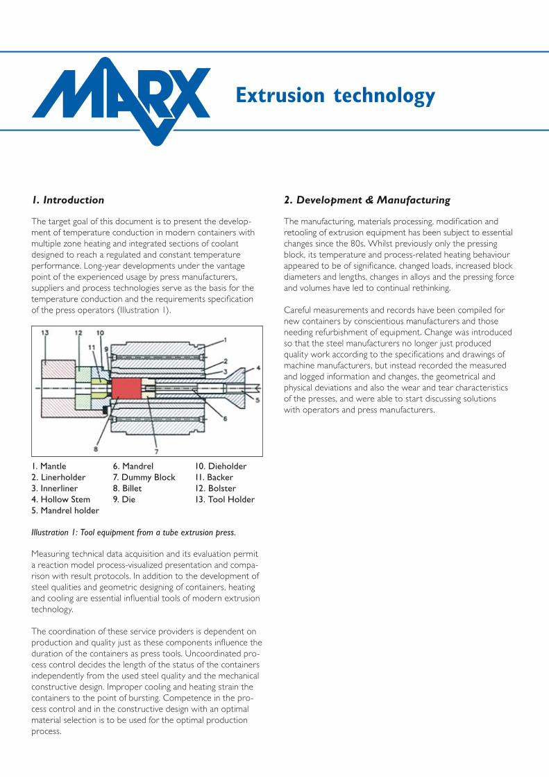
The target goal of this document is to present the develop-ment of temperature conduction in modern containers with multiple zone heating and integrated sections of coolant designed to reach a regulated and constant temperature performance. Long-year developments under the vantage point of the experienced usage by press manufacturers, suppliers and process technologies serve as the basis for the temperature conduction and the requirements specification of the press operators (Illustration 1).
Measuring technical data acquisition and its evaluation permit a reaction model process-visualized presentation and compa-rison with result protocols. In addition to the development of steel qualities and geometric designing of containers, heating and cooling are essential influential tools of modern extrusion technology.
The coordination of these service providers is dependent on production and quality just as these components influence the duration of the containers as press tools. Uncoordinated pro-cess control decides the length of the status of the containers independently from the used steel quality and the mechanical constructive design. Improper cooling and heating strain the containers to the point of bursting. Competence in the pro-cess control and in the constructive design with an optimal material selection is to be used for the optimal production process.
1. Mantle2. Linerholder3. Innerliner4. Hollow Stem5. Mandrel holder
6. Mandrel7. Dummy Block8. Billet9. Die
10. Dieholder11. Backer12. Bolster13. Tool Holder
Illustration 1: Tool equipment from a tube extrusion press.
2. Development & Manufacturing
The manufacturing, materials processing, modification and retooling of extrusion equipment has been subject to essential changes since the 80s. Whilst previously only the pressing block, its temperature and process-related heating behaviour appeared to be of significance, changed loads, increased block diameters and lengths, changes in alloys and the pressing force and volumes have led to continual rethinking.
Careful measurements and records have been compiled for new containers by conscientious manufacturers and those needing refurbishment of equipment. Change was introduced so that the steel manufacturers no longer just produced quality work according to the specifications and drawings of machine manufacturers, but instead recorded the measured and logged information and changes, the geometrical and physical deviations and also the wear and tear characteristics of the presses, and were able to start discussing solutions with operators and press manufacturers.

Process Controlled Containers – Smart Containers
2.1 Material Selection
MantlesThere is currently a large variety of deployed heat resistant materials which are used for the individual components of the container. Whereas it was once so that mainly material qualities with a rating of 1.2311 were used for mantles to be used with aluminium extrusion presses, we now know that the heat consistency and fatigue no longer sufficient for the current standards. As a standard material for mantles, metal quality 1.2343 is practically solely used because of its good combination of heat consistency, long-time rupture strength and tenacity (Illustration 2).
Liner HoldersIf liner holders are deployed, the same quality of steel should be used. For cooled containers which will be described later,
WerkstoffNr.
AISI / SAE
Analyse – Chemical CompositionC Cr Mo V Ni Others
Mantel / Mantle
1.2311 P20 0,40 2,0 0,2 -- -- + 1,5 Mn
1.2323 -- 0,45 1,4 0,8 0,3 --
4340 0,40 0,8 0,3 -- 1,8
1.2343 H11(H13) 0,38 5,0 1,3 0,4 --
Zwischenbüchse / Liner Holder
1.2323 4340 Siehe oben / see above
1.2343 H11(H13)
Siehe oben / see above
1.2367 -- 0,37 5,0 3,0 0,6 --
Innenbüchse /Liner
1.2323 -- 0,45 1,4 0,8 0,3 --
1.2343 H11 0,38 5,0 1,3 0,4 --
1.2344 H13 0,40 5,0 1,3 1,0
1.2367 -- 0,37 5,0 3,0 0,6
Nicht mehr zu empfehlenNo longer recommended
Heute gebräuchlichCurrent recommendation
Bedingt empfehlenswertLimited recommendation
Illustration 2: Material selection for containers made for light metal extrusion presses
the usage of heat resistant steel as per material number 1.2367 is preferred, which has a better heat resistance than 1.2343 due to its higher amount of MO content (Illustration 2).
LinerThe same applies for liners. In this case there is also a corres-ponding quality change of the material being used. In this case, quality 1.2343 is also deployed, sometimes 1.2344 also, which is more common overseas and with pretty much the same properties. For hard pressing aluminium alloys, the material quality 1.2367 is used because the heat wear resistance is higher than it is with 1.2343 and 1.2344. The change of the material qualities is especially a result of the experience with selection criteria for containers. Here, we've experienced the limit resiliency and thus, were able to produce relief (Illustration 2).

Extrusion technology
3. Error Analysis – Thermal Stress
The essential source of errors are caused by thermal stress and overload which result in tension and pressure in the containers, and thus lead to the breakdown of the containers together with the metallurgic attributes. Such breakdown situations are furthered with originating cracks to heating and cooling holes because these holes play host to clearly larger and more complex tension strain.
This is why container suppliers specify a heating speed of app. 40°/hour as a maximum value for their steel quality. Balance phases are also expected in which a conductive balance can take place in the container over a period of stagnation. When taking into account the strong stress in the container caused by the thermal tension when it's heated, one also has to take into account the other side of the pro-cess, namely the too abrupt cooling when activating existing cooling facilities. This is especially the case when both heating and cooling of the mantle are being conducted in a small space, particularly when the cooling system starts up while the mantle is hot and the heating process hasn't discontinued.
4. Process Control – Regulation Mechanisms
In order to counteract this change affect between cool air and surface heating via heating elements, it is necessary to make use of an intelligent control system. This control technology must know which temperatures are dominant at which points, must be able to process the differences between the individual temperature points and then make possible a turning on and off of the heating and cooling with suitable means. The cooling must also be designed in a controlled manner and the heating should be operated in timely set or regulated intervals (Illustration 3).
Thus, it has been proven that the steel is pushed to its stress limits during the production process despite its high quality of material and requires an intelligent support through thermal systems.
Illustration 3: Software tool
Process-Software

Process Controlled Containers – Smart Containers
4.1 Zone Heating
For this, it was necessary to develop new, fitting loadable heating systems with segmented allocation (Illustration 4). Cooling via air pressure in a segmented form of construction with regulation possibilities for the amount of airflow was installed with the goal to have the container facing as little stress as possible so that an almost temperature-homoge-neous condition can be achieved. That is, the neutralization of the influence of the container with as little temperature stress as possible from the press block, no irregular expansion and geometric change to the liner and liner holder in the mantle served as the goals. Stress and shrinking strains to the contai-ner such as is in the unused, cold manufacturing status should be achieved optimally (Illustration 5+6).
Illustration 4: Heating zones

Extrusion technology
4.2 Air Regulation
For this, measurement-technical facilities were created which could determine the temperature of the container in various operation statuses, allocate the energy distribution and be in a position to implement corresponding countermeasures. The influence of energy influx through various billet lengths, press temperatures, press times, etc. were also to be taken into consideration. It was especially important here to show the differences at various measuring points, link them together and develop from them a regulation sequence which could heat as well as cool-always with the aim of evening out the temperature levels and temperature distribution throughout the entire container.
Illustration 5: Air regulation
Illustration 6: Constructive construction of the airflow canals
Process Controlled Containers – Smart Containers
4.3 Recording Temperature
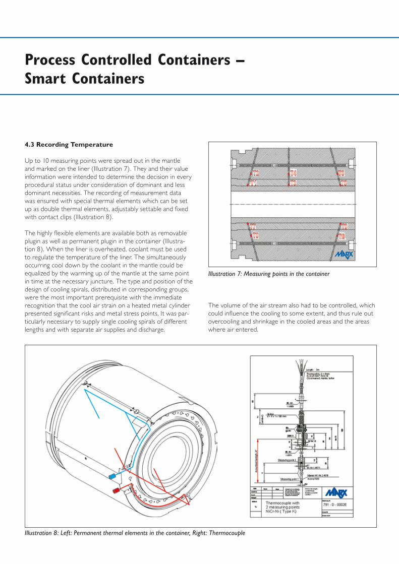
Up to 10 measuring points were spread out in the mantle and marked on the liner (Illustration 7). They and their value information were intended to determine the decision in every procedural status under consideration of dominant and less dominant necessities. The recording of measurement data was ensured with special thermal elements which can be set up as double thermal elements, adjustably settable and fixed with contact clips (Illustration 8).
The highly flexible elements are available both as removable plugin as well as permanent plugin in the container (Illustra-tion 8). When the liner is overheated, coolant must be used to regulate the temperature of the liner. The simultaneously occurring cool down by the coolant in the mantle could be equalized by the warming up of the mantle at the same point in time at the necessary juncture. The type and position of the design of cooling spirals, distributed in corresponding groups, were the most important prerequisite with the immediate recognition that the cool air strain on a heated metal cylinder presented significant risks and metal stress points. It was par-ticularly necessary to supply single cooling spirals of different lengths and with separate air supplies and discharge.
Illustration 7: Measuring points in the container
Illustration 8: Left: Permanent thermal elements in the container, Right: Thermocouple
The volume of the air stream also had to be controlled, which could influence the cooling to some extent, and thus rule out overcooling and shrinkage in the cooled areas and the areas where air entered.
Extrusion technology
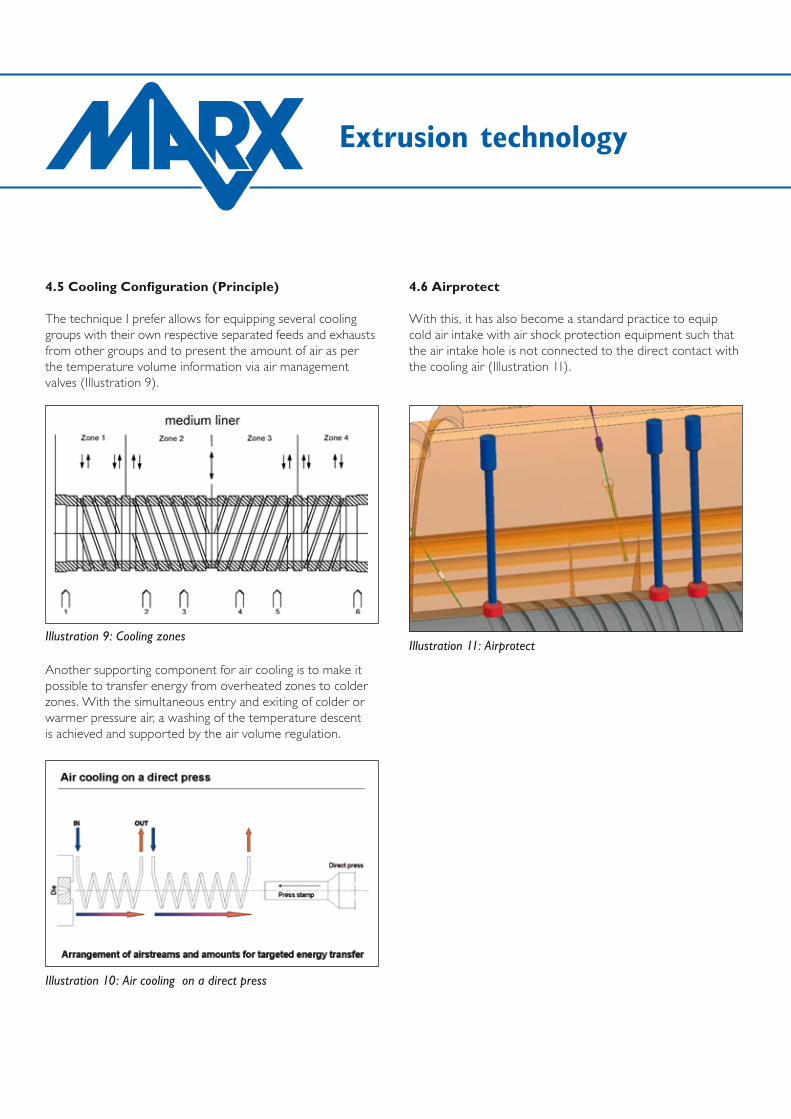
4.5 Cooling Configuration (Principle)
The technique I prefer allows for equipping several cooling groups with their own respective separated feeds and exhausts from other groups and to present the amount of air as per the temperature volume information via air management valves (Illustration 9).
Another supporting component for air cooling is to make it possible to transfer energy from overheated zones to colder zones. With the simultaneous entry and exiting of colder or warmer pressure air, a washing of the temperature descent is achieved and supported by the air volume regulation.
Illustration 9: Cooling zones
Illustration 10: Air cooling on a direct press
Illustration 11: Airprotect
4.6 Airprotect
With this, it has also become a standard practice to equip cold air intake with air shock protection equipment such that the air intake hole is not connected to the direct contact with the cooling air (Illustration 11).
Process Controlled Containers – Smart Containers
4.7 Heating Cartridges
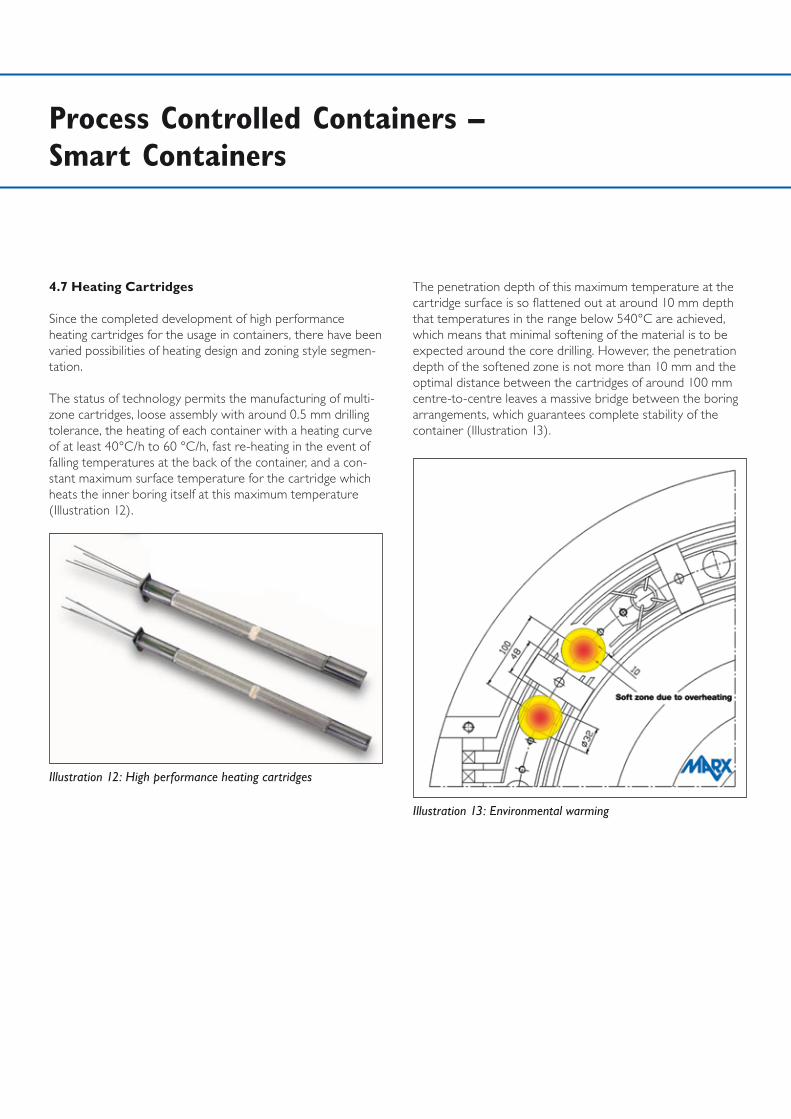
Since the completed development of high performance heating cartridges for the usage in containers, there have been varied possibilities of heating design and zoning style segmen-tation.
The status of technology permits the manufacturing of multi-zone cartridges, loose assembly with around 0.5 mm drilling tolerance, the heating of each container with a heating curve of at least 40°C/h to 60 °C/h, fast re-heating in the event of falling temperatures at the back of the container, and a con-stant maximum surface temperature for the cartridge which heats the inner boring itself at this maximum temperature (Illustration 12).
Illustration 12: High performance heating cartridges
Illustration 13: Environmental warming
The penetration depth of this maximum temperature at the cartridge surface is so flattened out at around 10 mm depth that temperatures in the range below 540°C are achieved, which means that minimal softening of the material is to be expected around the core drilling. However, the penetration depth of the softened zone is not more than 10 mm and the optimal distance between the cartridges of around 100 mm centre-to-centre leaves a massive bridge between the boring arrangements, which guarantees complete stability of the container (Illustration 13).
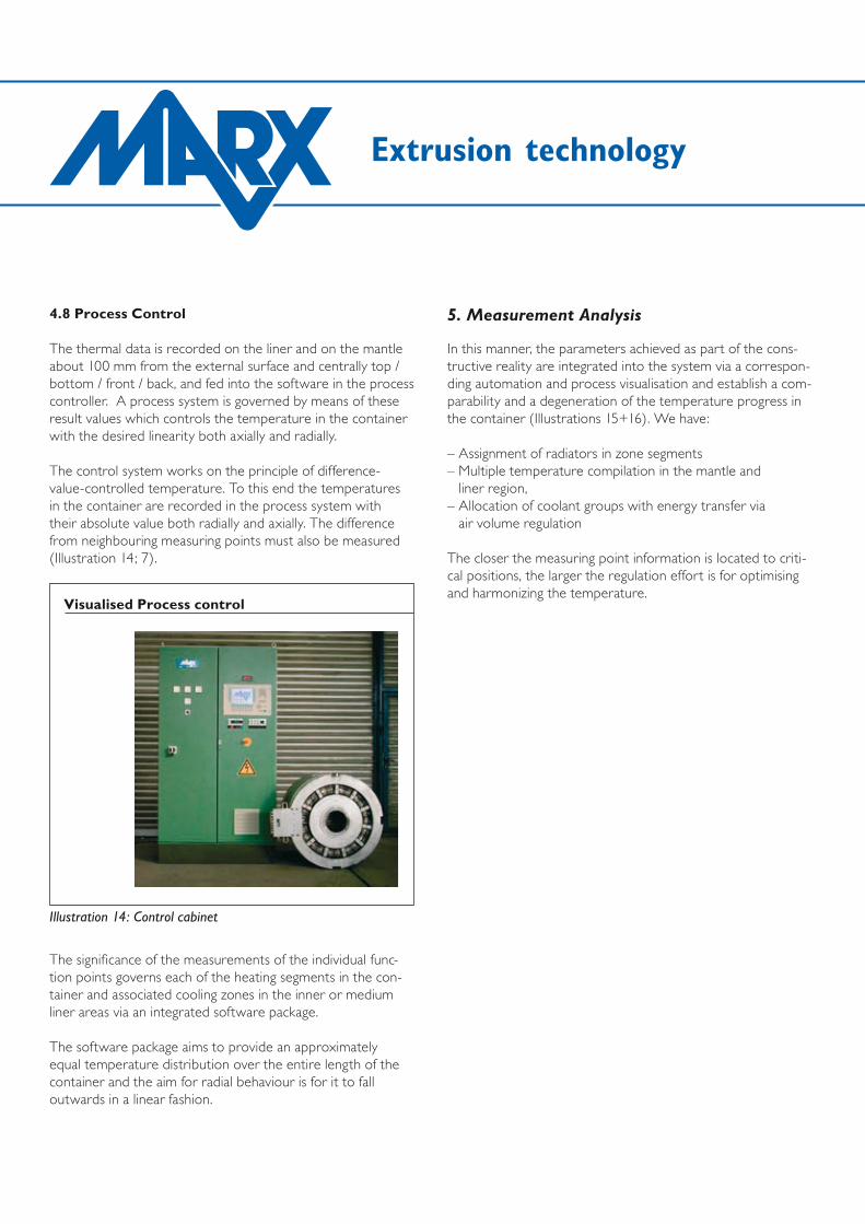
4.8 Process Control
The thermal data is recorded on the liner and on the mantle about 100 mm from the external surface and centrally top / bottom / front / back, and fed into the software in the process controller. A process system is governed by means of these result values which controls the temperature in the container with the desired linearity both axially and radially. The control system works on the principle of difference- value-controlled temperature. To this end the temperatures in the container are recorded in the process system with their absolute value both radially and axially. The difference from neighbouring measuring points must also be measured (Illustration 14; 7).
The significance of the measurements of the individual func-tion points governs each of the heating segments in the con-tainer and associated cooling zones in the inner or medium liner areas via an integrated software package.
The software package aims to provide an approximately equal temperature distribution over the entire length of the container and the aim for radial behaviour is for it to fall outwards in a linear fashion.
Extrusion technology
5. Measurement Analysis
In this manner, the parameters achieved as part of the cons-tructive reality are integrated into the system via a correspon-ding automation and process visualisation and establish a com-parability and a degeneration of the temperature progress in the container (Illustrations 15+16). We have:
– Assignment of radiators in zone segments – Multiple temperature compilation in the mantle and
liner region, – Allocation of coolant groups with energy transfer via
air volume regulation
The closer the measuring point information is located to criti-cal positions, the larger the regulation effort is for optimising and harmonizing the temperature.
Illustration 14: Control cabinet
Visualised Process control
Process Controlled Containers – Smart Containers
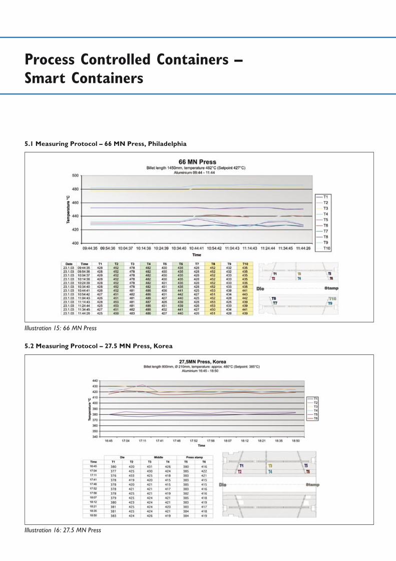
5.1 Measuring Protocol – 66 MN Press, Philadelphia
Illustration 15: 66 MN Press
Illustration 16: 27.5 MN Press
5.2 Measuring Protocol – 27.5 MN Press, Korea
Extrusion technology
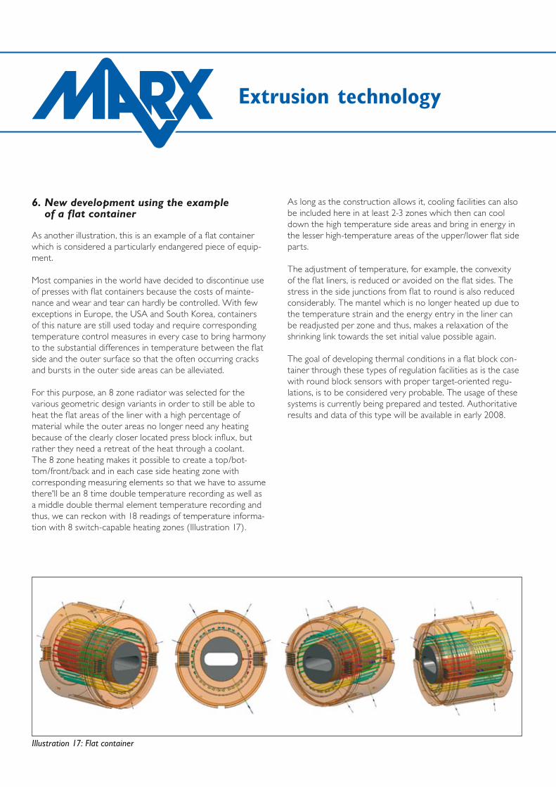
6. New development using the example of a flat container
As another illustration, this is an example of a flat container which is considered a particularly endangered piece of equip-ment.
Most companies in the world have decided to discontinue use of presses with flat containers because the costs of mainte-nance and wear and tear can hardly be controlled. With few exceptions in Europe, the USA and South Korea, containers of this nature are still used today and require corresponding temperature control measures in every case to bring harmony to the substantial differences in temperature between the flat side and the outer surface so that the often occurring cracks and bursts in the outer side areas can be alleviated.
For this purpose, an 8 zone radiator was selected for the various geometric design variants in order to still be able to heat the flat areas of the liner with a high percentage of material while the outer areas no longer need any heating because of the clearly closer located press block influx, but rather they need a retreat of the heat through a coolant. The 8 zone heating makes it possible to create a top/bot-tom/front/back and in each case side heating zone with corresponding measuring elements so that we have to assume there'll be an 8 time double temperature recording as well as a middle double thermal element temperature recording and thus, we can reckon with 18 readings of temperature informa-tion with 8 switch-capable heating zones (Illustration 17).
Illustration 17: Flat container
As long as the construction allows it, cooling facilities can also be included here in at least 2-3 zones which then can cool down the high temperature side areas and bring in energy in the lesser high-temperature areas of the upper/lower flat side parts.
The adjustment of temperature, for example, the convexity of the flat liners, is reduced or avoided on the flat sides. The stress in the side junctions from flat to round is also reduced considerably. The mantel which is no longer heated up due to the temperature strain and the energy entry in the liner can be readjusted per zone and thus, makes a relaxation of the shrinking link towards the set initial value possible again.
The goal of developing thermal conditions in a flat block con-tainer through these types of regulation facilities as is the case with round block sensors with proper target-oriented regu-lations, is to be considered very probable. The usage of these systems is currently being prepared and tested. Authoritative results and data of this type will be available in early 2008.

Process Controlled Containers – Smart Containers
Illustration 18: 80 MN Press - Flat container, Korea
Illustration 19: 80 MN Press, Korea

Extrusion technology
Illustration 20: 35 MN Press
As an alternative the results of a 35 MN copper alloy press and a 130 MN copper alloy press are displayed as an acquired production result:
6.1 Measuring Protocol – 35 MN Press, Italy
Process Controlled Containers – Smart Containers
7. Literature
[1] W. Kortmann, Werkzeugtechnologie für Aluminium-Strangpressen, S+C Märker GmbH, Lindlar
[2] K. Gillmeister, Moderne Anwendungsentwicklungen für Werkzeugstahl in der Strang-presstechnologie, Kind & Co Edelstahlwerk, Wiehl
[3] V. Wieser, Simulationsergebnisse bei Strangpress- Werkzeugen im Produktionsprozess, Forschungszentrum Böhler AG, Kapfenberg
[4] K. Brümmer, Druckluft-Prozessautomatisierung, MARX GmbH & Co. KG, Iserlohn
[5] M. Bauser, G. Sauer, K. Siegert, Aluminium Fachbuchreihe Strangpressen, 2. Auflage, Düsseldorf, 2001
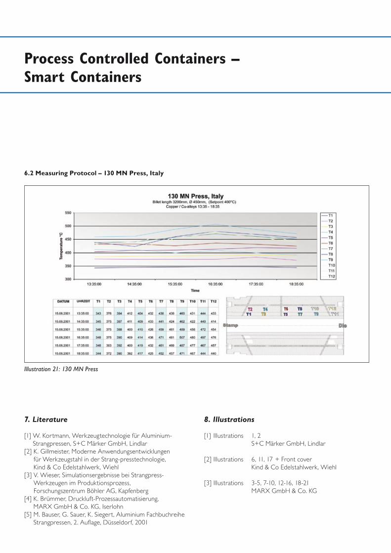
Illustration 21: 130 MN Press
6.2 Measuring Protocol – 130 MN Press, Italy
8. Illustrations
[1] Illustrations 1, 2 S+C Märker GmbH, Lindlar
[2] Illustrations 6, 11, 17 + Front cover Kind & Co Edelstahlwerk, Wiehl
[3] Illustrations 3-5, 7-10, 12-16, 18-21 MARX GmbH & Co. KG
MARX GmbH & Co. KG
Lilienthalstraße 6-1358638 Iserlohn
Postfach 202258590 Iserlohn
Telefon +49 2371 2105-0Telefax +49 2371 2105-11Emergency call : 0172 / 279 95 64
E-Mail [email protected]: www.marx-gmbh.de
MARX Elektrowärme GmbH
Philipp-Pforr-Straße 616761 Hennigsdorf
Telefon +49 3302 200930Telefax +49 3302 200938
E-Mail [email protected]: www.marx-gmbh.de
MARX Ofenbau GmbH
Joseph-Gänsler-Straße 1286609 Donauwörth
Telefon +49 906 3090Telefax +49 906 22576
E-Mail: [email protected]: www.marx-gmbh.de
Hamburg
München
Köln
DortmundBerlin