Embed Size (px)
Citation preview

COMOS
ProcessFEED Operation
Operating Manual
04/2014A5E32035528-AB
Publisher 1
Introduction 2
Overview of various workflows
3
Creating a project structure 4
Creating pure components 5
Editing a block flow diagram 6
Preparing the simulation import
7
Carrying out a simulation import
8
Working in the process flow diagram (PFD)
9
Specifying equipment 10
Design case-specific data 11
Data flow 12
PFD and P&ID 13
Managing design cases 14
Knowledge base 15
User interface reference 16
Database reference 17

Legal informationWarning notice system
This manual contains notices you have to observe in order to ensure your personal safety, as well as to prevent damage to property. The notices referring to your personal safety are highlighted in the manual by a safety alert symbol, notices referring only to property damage have no safety alert symbol. These notices shown below are graded according to the degree of danger.
DANGER
indicates that death or severe personal injury will result if proper precautions are not taken.
WARNING
indicates that death or severe personal injury may result if proper precautions are not taken.
CAUTION
indicates that minor personal injury can result if proper precautions are not taken.
NOTICEindicates that property damage can result if proper precautions are not taken.If more than one degree of danger is present, the warning notice representing the highest degree of danger will be used. A notice warning of injury to persons with a safety alert symbol may also include a warning relating to property damage.
Qualified PersonnelThe product/system described in this documentation may be operated only by personnel qualified for the specific task in accordance with the relevant documentation, in particular its warning notices and safety instructions. Qualified personnel are those who, based on their training and experience, are capable of identifying risks and avoiding potential hazards when working with these products/systems.
Proper use of Siemens productsNote the following:
WARNING
Siemens products may only be used for the applications described in the catalog and in the relevant technical documentation. If products and components from other manufacturers are used, these must be recommended or approved by Siemens. Proper transport, storage, installation, assembly, commissioning, operation and maintenance are required to ensure that the products operate safely and without any problems. The permissible ambient conditions must be complied with. The information in the relevant documentation must be observed.
TrademarksAll names identified by ® are registered trademarks of Siemens AG. The remaining trademarks in this publication may be trademarks whose use by third parties for their own purposes could violate the rights of the owner.
Disclaimer of LiabilityWe have reviewed the contents of this publication to ensure consistency with the hardware and software described. Since variance cannot be precluded entirely, we cannot guarantee full consistency. However, the information in this publication is reviewed regularly and any necessary corrections are included in subsequent editions.
Siemens AGIndustry SectorPostfach 48 4890026 NÜRNBERGGERMANY
A5E32035528-ABⓅ 03/2014 Subject to change
Copyright © Siemens AG 2014.All rights reserved

Table of contents
1 Publisher.......................................................................................................................................................7
2 Introduction...................................................................................................................................................9
3 Overview of various workflows...................................................................................................................11
4 Creating a project structure........................................................................................................................15 4.1 Creating an engineering project..................................................................................................15 4.2 Creating a process......................................................................................................................15 4.3 Configuration options of the process...........................................................................................16
5 Creating pure components.........................................................................................................................17 5.1 "Pure components" folder............................................................................................................17 5.2 Creating a new pure component.................................................................................................17
6 Editing a block flow diagram.......................................................................................................................19 6.1 Basic functions of a block flow diagram......................................................................................19 6.2 Contents of the "A70 Process units" folder.................................................................................19 6.3 Creating and specifying process units.........................................................................................20 6.4 Creating a process unit manually................................................................................................22 6.5 Using material input arrows and material output arrows.............................................................22 6.6 Drawing and specifying boundary streams.................................................................................23 6.7 Placing boundary stream flags....................................................................................................24
7 Preparing the simulation import..................................................................................................................25 7.1 Supported third-party software....................................................................................................25 7.2 Interfaces to simulators...............................................................................................................25 7.3 Structures for the import..............................................................................................................25 7.3.1 Required engineering structure...................................................................................................25 7.3.2 Number of PFDs..........................................................................................................................25 7.3.3 Structure for import below a process unit....................................................................................26 7.3.4 Structure for import below a process...........................................................................................26 7.4 Creating a simulation case (SIMCASE)......................................................................................27
8 Carrying out a simulation import.................................................................................................................29 8.1 General workflow for the import..................................................................................................29 8.2 Data import from Aspen Plus and ProMax..................................................................................29 8.2.1 Setting options for XML nodes in Aspen Plus.............................................................................29 8.2.2 Creating an import document......................................................................................................30 8.2.3 Specifying the import file.............................................................................................................30 8.2.4 Import step 1: Start import...........................................................................................................31
FEED OperationOperating Manual, 04/2014, A5E32035528-AB 3

8.2.4.1 Overview of the import options....................................................................................................31 8.2.4.2 Performing a complete import.....................................................................................................31 8.2.4.3 Performing a partial import..........................................................................................................32 8.2.4.4 Performing a reimport..................................................................................................................33 8.2.5 Import step 2: Create PFD objects..............................................................................................34 8.2.6 Import step 3: Place PFD streams on the PFD...........................................................................36 8.2.6.1 Place equipment..........................................................................................................................36 8.2.6.2 Placing PFD streams...................................................................................................................37 8.3 Data import from CHEMCAD, EbsilonProfessional, HYSYS, PRO/II, UniSim Design................37 8.3.1 Creating an import document......................................................................................................37 8.3.2 Import step 1: Start import...........................................................................................................38 8.3.2.1 Overview of the import options....................................................................................................38 8.3.2.2 Performing a complete import.....................................................................................................38 8.3.2.3 Performing a partial import..........................................................................................................39 8.3.2.4 Performing a reimport..................................................................................................................39 8.3.3 Import step 2: Create PFD objects..............................................................................................40 8.3.4 Import step 3: Place the equipment on the PFD.........................................................................40 8.3.4.1 Place the equipment on the predefined PFD..............................................................................40 8.3.4.2 Placing equipment on a different PFD.........................................................................................41 8.3.4.3 Distributing equipment to multiple PFDs.....................................................................................42 8.3.5 Import step 4: Place PFD streams on the PFD...........................................................................42 8.3.6 PRO/II: Automatic deletion during a reimport..............................................................................43 8.4 Importing additional design cases...............................................................................................43 8.5 Wildcard objects..........................................................................................................................45 8.5.1 Principles of placeholder objects.................................................................................................45 8.5.2 Importing wildcard objects...........................................................................................................45 8.6 Log files for simulator import.......................................................................................................47 8.7 Creating a folder for SIM objects.................................................................................................48 8.8 Batch import of simulation files....................................................................................................48 8.8.1 Basics..........................................................................................................................................48 8.8.2 Creating "Batch Import Control Center"......................................................................................49 8.8.3 Using "Batch Import Control Center"...........................................................................................49
9 Working in the process flow diagram (PFD)...............................................................................................53 9.1 Principles of a process flow diagram (PFD)................................................................................53 9.2 Manual placing and editing of PFD objects.................................................................................53 9.2.1 Placing equipment manually.......................................................................................................53 9.2.2 Placing objects from the report bar.............................................................................................54 9.2.3 Editing objects via the properties tree.........................................................................................55 9.2.4 Using the navigator to place objects ..........................................................................................55 9.2.5 Editing objects via the properties................................................................................................56 9.3 Working with process streams....................................................................................................56 9.3.1 "Connection" tool.........................................................................................................................56 9.3.2 Creating process streams with the "Connection" tool.................................................................57 9.3.3 Creating and placing process streams from the Navigator.........................................................57 9.3.4 Exchanging process streams for one another.............................................................................58 9.3.5 Editing process streams on the PFD...........................................................................................58 9.3.6 Properties of the process streams...............................................................................................58
Table of contents
FEED Operation4 Operating Manual, 04/2014, A5E32035528-AB
9.4 Configuring a material balance....................................................................................................59 9.5 Other placeable objects...............................................................................................................60 9.5.1 Placing process stream flags......................................................................................................60 9.5.2 Creating page references automatically......................................................................................61 9.5.3 Creating a page reference manually...........................................................................................62
10 Specifying equipment.................................................................................................................................63 10.1 Determining the main equipment for a process unit....................................................................63 10.2 Evaluating report under equipment.............................................................................................63 10.3 Changing the graphical display...................................................................................................63 10.4 Specifying the maximum and minimum of the design pressure and design temperature...........64 10.5 Tray mapping..............................................................................................................................64 10.6 Performing base object changes.................................................................................................64 10.7 HTRI import/export......................................................................................................................65 10.7.1 Using HTRI import/export............................................................................................................65 10.7.2 Example of the HTRI import/export of the heat exchanger.........................................................65
11 Design case-specific data...........................................................................................................................67 11.1 Basics on the topic "Design case-specific data"..........................................................................67 11.2 Creating design case-specific objects.........................................................................................67 11.3 Standard cases...........................................................................................................................67 11.4 Design cases for streams............................................................................................................68 11.4.1 Basics..........................................................................................................................................68 11.4.2 Editing design cases for streams................................................................................................68 11.4.3 Determining the active design case............................................................................................69 11.4.4 Using design cases with identical values....................................................................................69 11.4.5 Determining the components of a design case...........................................................................71 11.5 Components................................................................................................................................71 11.5.1 Editing components.....................................................................................................................71 11.5.2 Automatic attribute calculation....................................................................................................72 11.6 Equipment cases.........................................................................................................................72 11.6.1 Editing equipment cases.............................................................................................................73 11.6.2 Determining the active equipment case......................................................................................73
12 Data flow.....................................................................................................................................................75 12.1 Overview of data flows................................................................................................................75 12.2 Data flow between boundary stream and assigned process stream...........................................75 12.2.1 Basic information about the data flow between the boundary stream and process stream. .......75 12.2.2 Assigning a process stream to a boundary stream.....................................................................76 12.2.3 Passing data from the boundary stream to the process stream..................................................76 12.2.4 Passing data from the process stream to the boundary stream..................................................77 12.3 Data flow between a process stream and its design cases.........................................................77 12.3.1 Basics on the data flow between a process stream and its design cases..................................77 12.3.2 Viewing and editing design cases of the process stream ...........................................................78
Table of contents
FEED OperationOperating Manual, 04/2014, A5E32035528-AB 5
12.4 Data flow between the equipment and its design cases.............................................................78 12.4.1 Basic information about data flow between equipment and design cases..................................78 12.4.2 Viewing or editing the data flow between equipment and design cases.....................................79 12.5 Data flow from process stream to the connected equipment......................................................80
13 PFD and P&ID............................................................................................................................................81 13.1 Converting a PFD into a P&ID.....................................................................................................81 13.2 Using P&ID default templates.....................................................................................................83 13.3 Selecting P&ID templates............................................................................................................84 13.4 Creating multiple P&IDs from a PFD...........................................................................................85
14 Managing design cases..............................................................................................................................87 14.1 Set active case............................................................................................................................87 14.2 Create new case.........................................................................................................................88 14.3 Complete case............................................................................................................................88 14.4 Delete case.................................................................................................................................89 14.5 Rename case..............................................................................................................................90 14.6 Copy case...................................................................................................................................90
15 Knowledge base.........................................................................................................................................93 15.1 Basics on the knowledge base....................................................................................................93 15.2 Creating the knowledge base, status display..............................................................................93 15.3 Checking a process against all rules...........................................................................................94 15.4 Checking a process against an individual rule............................................................................94
16 User interface reference.............................................................................................................................97 16.1 "Import options" tab.....................................................................................................................97 16.2 "Partial import" window................................................................................................................98 16.3 "Component lumping" window.....................................................................................................99 16.4 "Stream selection" window........................................................................................................100 16.5 "Material balance" tab...............................................................................................................101 16.6 "Case manager" tab..................................................................................................................102 16.7 COMOS FEED Log...................................................................................................................104
17 Database reference..................................................................................................................................105
Table of contents
FEED Operation6 Operating Manual, 04/2014, A5E32035528-AB

Publisher 1● The software product HYSYS is a product of the AspenTech company, and is referred to
simply as HYSYS in the rest of this document.
● The software product AspenPlus is a product of the AspenTech company, and is referred to simply as AspenPlus in the rest of this document.
● The software product ProMax is a product of the Bryan Research & Engineering company, and is referred to simply as ProMax in the rest of this document.
● The software product PRO/II is a product of the Invensys Operations Management company, and is referred to simply as PRO/II in the rest of this document.
● The software product EbsilonProfessional is a product of the company Evonik Energy Services GmbH, and is referred to simply as EbsilonProfessional in the rest of this document.
● The software product UniSim Design is a product of the Honeywell Process Solution company, and is referred to simply as UniSim in the rest of this document.
● The software product ChemCad is a product of the Chemstations Inc. company, and is referred to simply as ChemCad in the rest of this document.
FEED OperationOperating Manual, 04/2014, A5E32035528-AB 7


Introduction 2Objective
COMOS FEED is used in the initial phase of plant engineering. Its scope of functions covers all areas of process engineering:
● General modeling of the process in the block flow diagram
● Specific description of process units and their equipment in a process flow diagram (PFD)
● Management of design case-specific process data
● Pure component management
● Automatic documentation of engineering in datasheets
Functions● Import of all design cases from the simulation programs AspenPlus, ProMax, PRO/II,
HYSYS, ChemCad, EbsilonProfessional and UniSim Design
● User-friendly design case management
● Automatic data exchange between PFD objects and their design case-specific objects
● Calculate technical data in Excel sheets for designing pumps
● Assignment between the theoretical levels of a column and its trays
● Status check according to predefined rules (engineering rules) in the knowledge base
FEED OperationOperating Manual, 04/2014, A5E32035528-AB 9


Overview of various workflows 3Various workflows are available in the FEED module. The variant you select depends on the following points:
1. Are you using a block flow diagram for process engineering purposes?
2. Is your PFD based on a simulation imported to COMOS?
The manual assumes that a block flow diagram is being used and that the PFD is based on a simulation.
Variant 1: With block flow diagram and simulation import
Step Description1 Create a process.
See also chapter Creating a process (Page 15).2 Create the components required for the process.
See also chapter Creating pure components (Page 17).3 Describe the process in general terms on a block flow diagram.
See also chapter Editing a block flow diagram (Page 19).4 Assign the pure components of the "Pure components" folder to the material input arrows
and material output arrows of the block flow diagram.See also chapter Using material input arrows and material output arrows (Page 22).
For each process unit:5 Outside of COMOS:
Create a simulation of the process unit in a simulation software6 Create a process flow diagram (PFD).
See also chapter Principles of a process flow diagram (PFD) (Page 53).7 Carry out steps 1 and 2 of the simulation import; i.e. import the design case specific process
data from the required simulation software.See also chapter Carrying out a simulation import (Page 29).Result:● The relevant PFD objects and their design case-specific data are automatically created
in COMOS and sorted into the "Equipment", "Process streams", and "Other" folders below the process unit in the Navigator.
● If necessary, any missing components are imported to the "Pure components" folder.8 Carry out simulation import steps 3 and 4 (in the case of Aspen, step 3 only); i.e. have the
PFD objects placed on the PFD of the process unit automatically. See also chapter Import step 3: Place PFD streams on the PFD (Page 36)),
FEED OperationOperating Manual, 04/2014, A5E32035528-AB 11

Step Description9 Carry out the finishing touches on the PFD:
● Carry out graphical adjustments (moving objects, adjusting the path of the process stream, etc.)
● Place process stream flags on the PFD for the purpose of outputting stream-related data● Place any other required objects (for example, functions, pipe breaks, plant limits, flow
direction arrows, etc.)10 Specify the properties of the equipment.
See also chapter Specifying equipment (Page 63).11 Miscellaneous:
● Assign a piece of main equipment to each process unit● If required: Assign a boundary stream from the block flow diagram to each process
stream12 If required:
Import additional design cases, reimport a design case, etc. (Design Case manager)13 Documentation and evaluation of the engineering by means of automatic generation of
various evaluating reports (datasheets).The following datasheet is available for use while working with FEED; it is created automatically and synchronized with the engineering data: "DA Datasheet <equipment type>".
Variant 2: With block flow diagram and without simulation import
Step Description1 to 4 As variant 1, steps 1 to 4For each process unit:5 Create a process flow diagram (PFD).
See also chapter Creating a process unit manually (Page 22).6 Create the required design cases in the design case manager and enter the design case
specific data manually.7 and 8 As variant 1, steps 10 and 119 As variant 1, step 13
Variant 3: Without block flow diagram and with simulation import
Step 1 Create a process.2 Create the required process units below the processFor each process unit:3 to 11 As variant 1, steps 5 to 13
Overview of various workflows
FEED Operation12 Operating Manual, 04/2014, A5E32035528-AB

Variant 4: Without block flow diagram and without simulation import
Step Description1 Create a process.
See also chapter Creating a process (Page 15).2 Create the pure components required for the process3 Create the required process units below the processFor each process unit:4 Create a process flow diagram (PFD). See also chapter Creating a process unit manually
(Page 22).5 Create the required design cases in the design case manager and enter the design case
specific data manually.6 and 7 As variant 1, steps 10 and 11 As variant 1, step 13
Overview of various workflows
FEED OperationOperating Manual, 04/2014, A5E32035528-AB 13


Creating a project structure 44.1 Creating an engineering project
RequirementYou have the necessary rights for creating an engineering project.
Procedure1. Start COMOS.
2. Select the "File > Open project" command in the menu bar.
3. In the "Open project" tab, select the "Engineering" option.
4. To open the context menu, right-click in the table area.
5. Select the "New > Project" command in the context menu.The new project is created and the project properties open.
6. Enter a "Name" and a "Description" for the project in the "Project" category.By default, the "Type" of the project matches the option selected in the "Open project" tab.
7. Click the "..." button next to "Project structure".The "Select project structure for <project name>" window opens.
8. Select the node "A10 > A20 Project presetting, FEED example" here.
9. Confirm your selection with "OK".
ResultYou have now created a new engineering project that you can select from the list of available projects.
4.2 Creating a processIn COMOS, the chemical process that you model is encapsulated in a "Process" object. All the work you carry out is conducted underneath this object.
Procedure1. Right-click the project root.
2. Select "New > A30 Process" in the context menu.
FEED OperationOperating Manual, 04/2014, A5E32035528-AB 15

Result● A new process is created underneath the project root.
● On the basis of the project structure specifications, the following documents/document groups and folders are automatically created underneath the process:
Object DescriptionInteractive report "Block flow diagram" The block flow diagram in which the process is
described. "Boundary streams" folder A folder in which the boundary streams of the
process are collected. "Pure components" folder A folder in which the components for the process
are collected."Process units" folder A folder in which the process units for the process
are collected.
In the context menu for the process, the "New" command offers additional folders, documents, and document groups. In most cases, you will only require these if you are carrying out a simulation for the entire process, rather than at process unit level.
4.3 Configuration options of the processIn the properties of the process in the "Case manager" tab, you can manage the design cases on the level of the process.
See also chapter Managing design cases (Page 87).
Creating a project structure4.3 Configuration options of the process
FEED Operation16 Operating Manual, 04/2014, A5E32035528-AB

Creating pure components 55.1 "Pure components" folder
The "Pure components" folder is located under the process in the "Units" tab in the Navigator. You manage the pure components of your process in this folder.
The folder contains all pure components used in a process.
● If your engineering work is based on a block flow diagram, this is where you create the pure components used. You can then assign the material input arrows and material output arrows references to their pure components while working in the block flow diagram. This enables data to be output in the block flow diagram.
● If your engineering work does not require a block flow diagram, all required pure components are imported to COMOS from the simulation software.
5.2 Creating a new pure component
Procedure1. In the context menu of the "Pure components" folder, select the "New > Pure component"
command.A new pure component is created in the folder.
2. Open the properties of the new pure component and specify the properties.
FEED OperationOperating Manual, 04/2014, A5E32035528-AB 17

Editing a block flow diagram 66.1 Basic functions of a block flow diagram
A block flow diagram is an interactive report. You use such a report to describe the process by means of process units, material input arrows and material output arrows, boundary streams, and boundary stream flags.
A block flow diagram has the same basic functions as all other interactive reports. You can find additional information on this topic in the "COMOS Platform Operation" manual, keyword "Working with interactive reports".
Important functions● Placing objects from the symbol bar
When you use the report symbol bar to place a symbol on the block flow diagram, a corresponding object is automatically created in the Navigator. By default, the new object is sorted into one of the folders located on the same level as the block flow diagram.
● Editing an object selected in the block flow diagram on the report bar
– When you select an object on the report, the VSUI attributes of the object appear in the properties tree. You can edit the properties of the object directly from the report.
– Save your entries by clicking the "Apply" button.
Creating a block flow diagramWhen you create a process, a block flow diagram is automatically created below it. See also chapter Creating a process (Page 15).
Alternatively, you can create a block flow diagram in the Navigator in the "Units" tab using the context menu of a process.
6.2 Contents of the "A70 Process units" folderThe "A70 Process units" folder contains all process units that have been drawn on the block flow diagram.
On the basis of the project structures, the following documents/document groups and folders are automatically created underneath each process unit:
FEED OperationOperating Manual, 04/2014, A5E32035528-AB 19

Two document groups below which the equipment lists and mass balances of the process unit are collected:
Interactive Report "FB.001" The process flow diagram (PFD) that describes the process unit in greater detail.
"A30 Equipment", "A60 Process streams","A90 Other" folders
These folders are initially empty, but are automatically filled when you carry out a simulation import or draw new objects on the PFD.
"A10SIMD Simulation data, process unit" folder You carry out the simulation imports in this folder.
See also chapter Working in the process flow diagram (PFD) (Page 53).
See also chapter Carrying out a simulation import (Page 29).
6.3 Creating and specifying process units
RequirementA block flow diagram is open.
Editing a block flow diagram6.3 Creating and specifying process units
FEED Operation20 Operating Manual, 04/2014, A5E32035528-AB

Procedure1. To create a process unit, activate the "Process unit" button in the toolbar.
2. Move the mouse to the required point in the block flow diagram and left-click to place the process unit.The process unit symbol is placed on the block flow diagram.A process unit is created in the Navigator and is automatically sorted into the "A70 Process units" folder under the process. See also chapter Contents of the "A70 Process units" folder (Page 19).
3. Complete placing of process units by right-clicking.
4. To place a description of the process unit, select the process unit on the report by left-clicking.
5. Select the attribute filter in the properties tree.The VSUI attributes of the object are displayed.
6. Make the desired entries in the "Name" and "Description" fields as needed and confirm your entries using the button with the check mark.The new description is output on the block flow diagram, in the top text field of the process unit symbol.
ResultYou have created a symbol for a process unit on the block flow diagram and have added a name and a description.
At this point in the engineering process, no equipment exists. How you proceed in order to assign a piece of main equipment to a process unit is, therefore, described later in this documentation. See also chapter Determining the main equipment for a process unit (Page 63).
The main equipment is output on the block flow diagram, in the second text field to the top of the process unit symbol.
See alsoUsing material input arrows and material output arrows (Page 22)
Editing a block flow diagram6.3 Creating and specifying process units
FEED OperationOperating Manual, 04/2014, A5E32035528-AB 21

6.4 Creating a process unit manuallyIf you do not use a block flow diagram for your planning, create process units manually.
Requirement● You have opened your FEED engineering project.
● The "Units" tab is open in the COMOS Navigator.
Procedure1. Select the "A70 Process units" folder.
2. Select the "New > A10 Process unit" command in the context menu.
ResultA new process unit including substructure is created in the folder. See also chapter Contents of the "A70 Process units" folder (Page 19).
6.5 Using material input arrows and material output arrowsDefine which materials are input or output for the process. For this, you use arrow symbols to which you assign references to pure components: material input arrows and material output arrows.
Requirement● You have created process units in a block flow diagram.
See also chapter Creating and specifying process units (Page 20).
● You have opened this block flow diagram.
Procedure1. To place material input arrows and material output arrows, activate the button for the
material input and output arrows on the report bar.
2. Left-click to stamp the required arrows onto the report.In the Navigator, the corresponding database objects are created below the block flow diagram.
3. To assign a pure component to an initially empty arrow symbol on the report, mark the arrow symbol in the block flow diagram and open the properties using the context menu.
4. Go to the "Component data" tab.
5. In the Navigator, open the "Pure components" folder.
6. Drag&drop the required pure component from the "Pure components" folder to the "Component" field of the "Component data" tab.
Editing a block flow diagram6.5 Using material input arrows and material output arrows
FEED Operation22 Operating Manual, 04/2014, A5E32035528-AB

ResultThe arrow symbol on the block flow diagram contains the description of the referenced pure component.
6.6 Drawing and specifying boundary streamsBoundary streams represent the flow of material components between the process units.
Requirement● You have opened a block flow diagram.
● You have created process units.See also chapter Creating and specifying process units (Page 20).
● You have placed material input arrows and material output arrows.See also chapter Using material input arrows and material output arrows (Page 22).
Procedure1. Select the "Connection" tool on the report bar. See also chapter "Connection" tool
(Page 56).Several fields appear in the properties tree. You can specify the properties of the boundary stream in these fields.
2. Define the properties of the boundary stream in the "Attribute filter" view of the properties tree and confirm your entries:
– "Description" fieldYour entry will only be used for this boundary stream. and the field will then be reset to the default setting "Description".
– "Temperature", "Pressure", "Mass flow" fieldsYour entries will be set as the new default setting, which means that they will continue to be used for any subsequent boundary streams you draw until you enter new values.
3. Connect the process units to one another.
4. Connect the material input arrow and material output arrow to the process units.
ResultA boundary stream is created in the Navigator and automatically sorted into the "A20 Boundary streams" folder under the process.
You can specify additional stream data via the properties of the boundary stream in the "General stream data" tab.
Editing a block flow diagram6.6 Drawing and specifying boundary streams
FEED OperationOperating Manual, 04/2014, A5E32035528-AB 23

6.7 Placing boundary stream flagsBoundary stream flags read out the most important data of the boundary stream on the block flow diagram with which they were connected. They are purely graphical elements for which no objects are created in the Navigator.
Requirement● You have created boundary streams in a block flow diagram.
See also chapter Drawing and specifying boundary streams (Page 23).
● You have opened this block flow diagram.
Procedure1. Activate the "Boundary stream flag" button on the report bar:
2. Move the mouse to the point of the boundary stream where the flag is to be placed. The boundary stream will turn yellow.
3. Left-click to place the flag.
ResultThe flag is connected to the boundary stream. If you move the boundary stream, the flag automatically moves with it.
The example below shows flags placed horizontally and vertically in relation to a boundary stream
Editing a block flow diagram6.7 Placing boundary stream flags
FEED Operation24 Operating Manual, 04/2014, A5E32035528-AB
Preparing the simulation import 77.1 Supported third-party software
You can find additional information on this topic in the "COMOS Platform Administration" manual, keyword "Third-party software in the FEED environment".
7.2 Interfaces to simulatorsCOMOS has interfaces to various simulators.
If you have created a simulation in one of the simulators linked to COMOS, you can import it to COMOS and carry out engineering work there.
All PFD objects, all pure components and components, as well as all design case-specific data are automatically created in COMOS during the import.
The interfaces import objects from the simulators to COMOS without changing the source file. The mapping of the object attributes between the simulator and COMOS is defined in the COMOS DLLs (standard import) and is based on the formats stipulated by the simulator.
You can extend the standard import using VB scripts. You can find additional information on this topic in the "FEED Administration" manual, keyword "Adjusting the standard import".
7.3 Structures for the import
7.3.1 Required engineering structureA simulation either applies to a single process unit or the entire process. Accordingly, you import the simulation data either below a process unit or below a process.
Default: Import into a process unit
This is the focus of the information presented in this manual.
7.3.2 Number of PFDsPlace only one PFD under a process unit or a process. If COMOS finds more than one PFD during an import, it places the PFD objects on the first PFD under the process unit or process. Placing is independent of the report name.
FEED OperationOperating Manual, 04/2014, A5E32035528-AB 25

Import from PRO/II, ChemCad, EbsilonProfessional, HYSYS and UniSimWhen you import to a process, define in the properties of the import document the PFD which COMOS is to use as target PFD.
1. Open the "Attributes > Import data" tab of an import document.
2. Drag&drop a PFD to the "Import into document" field.
COMOS then places the PFD objects on this PFD, even if it is not the first PFD under the process.
7.3.3 Structure for import below a process unitWhen you import a simulation for a process unit, the following engineering structure has to be available:
This engineering structure is automatically created when the process unit is generated. The folders are recognized by COMOS based on their classification key.
The import starts in the "Simulation data, process unit" folder in which you create import objects that control the import.
The PFD objects created as a result of the import are sorted into the "Pure components", "Boundary streams", "Process streams" and "Other" folders and placed on the PFD of the process unit.
7.3.4 Structure for import below a processWhen you import a simulation for an entire process, the following engineering structure has to be available:
"P001 Process" "Other" "Equipment" "Process streams"
Preparing the simulation import7.3 Structures for the import
FEED Operation26 Operating Manual, 04/2014, A5E32035528-AB

"Process units" "Simulation data, process unit"
● You must create the PFD as well as the "Equipment", "Process streams", "Other" and "Simulation data, process unit" folders manually. To do this, select the "New" command from the process context menu.
● The other folders and documents were generated automatically when the process was created.
● Your administrator must have adjusted the relative path reference to the simulation data folder in the import options
In the same way as for the import to a process unit, the following applies:
● The import is started in the " Simulation data, process unit" folder.
● The imported objects are sorted into the "Pure components", "Equipment", "Process streams" and "Other" folders, and placed on the PFD of the process.
7.4 Creating a simulation case (SIMCASE)For each design case you import, you create a simulation case object (referred to as a "SIMCASE") in the "Simulation data, process unit" folder. All data relevant for this export is collected under the SIMCASE.
The import document is also created there. This plays an important role in controlling the import and storage of important data from the simulation run.
Procedure1. In the Navigator, select the "Simulation data, process unit" folder of the process unit.
In the context menu of the folder, select the "New > A10 Simulation case process unit" command.
2. Open the SIMCASE properties.
3. Enter the name of the design case you are importing in the "Name" field and confirm your entry.If you are reimporting a simulation, this step is not carried out. since the SIMCASE already exists.
Result● You have created a simulation case object under the "Simulation data, process unit" folder.
● In addition, you require an import document under the SIMCASE. The way in which this is created depends on the simulator used.The procedure you use to create and configure the import document and start the import steps for the respective simulator is described at the individual simulators:
– See chapter Data import from Aspen Plus and ProMax (Page 29)
– See chapter Data import from CHEMCAD, EbsilonProfessional, HYSYS, PRO/II, UniSim Design (Page 37)
Preparing the simulation import7.4 Creating a simulation case (SIMCASE)
FEED OperationOperating Manual, 04/2014, A5E32035528-AB 27


Carrying out a simulation import 88.1 General workflow for the import
● Each import process is controlled by an import document.which is used to configure the import options and start the individual import steps.
● The configuration options are practically identical for each simulator.
● The import process consists of four steps (Aspen: three steps):
– Step 1: Start import
– Step 2: Create PFD objects
– Step 3: Place PFD equipment on PFD (this step is carried out manually for Aspen)
– Step 4: Place PFD streams on PFD
TerminologyIn cases where information about the simulation import document or simulation import object applies to all interfaces, the term "import document" is used. You can import as many design cases as you wish, but only one design case per import.
8.2 Data import from Aspen Plus and ProMax
8.2.1 Setting options for XML nodes in Aspen Plus
Required settings for the creation of subobjectsIn order for COMOS to be able to create specific subobjects during the course of an Aspen import operation (column trays and pure components, for example), the XML source file must have the XML nodes listed below.
These XML nodes are automatically available if particular options are employed in Aspen Plus:
● B_TEMP:This XML node is required to create simulation objects for trays below simulation objects for columns. It is located below the BlockRadfrac XML node.
● X:This XML node is required to create component simulation objects below simulation objects for trays. It is located below the BlockRadfrac XML node.
FEED OperationOperating Manual, 04/2014, A5E32035528-AB 29

● MOLEFRAC:This XML node is required to create component simulation objects below material stream simulation objects. It is located below the StreamMaterial XML node.If it should not be available, ensure that the "Fraction basis: Mole" attribute is activated in Aspen Plus.
● ComponentsMain:This XML node is required to create the component simulation objects below which the simulation pure components are located. It is located below the XML root node. If it should not exist, ensure that the attribute list for component IDs, formulas and names is activated.
8.2.2 Creating an import document
RequirementThe required folder structures have been created in COMOS.
See also chapter Structures for the import (Page 25).
Procedure1. In the Navigator, select the SIMCASE for which you wish to import data. See also chapter
Creating a simulation case (SIMCASE) (Page 27).
2. Select "New > <Import document>" from the context menu.Note: You can create an import document of a specific type only once under the same SIMCASE.The import document is created below the SIMCASE.
8.2.3 Specifying the import fileThe import options must be set before the import is started.
Procedure1. Open the import object properties.
2. Go to the "Import options" tab.
3. Click the "..." button next to the "Import file" field.The "Open file" window opens.
4. Select the file that you wish to import.
5. The import document is linked to the selected file.
Carrying out a simulation import8.2 Data import from Aspen Plus and ProMax
FEED Operation30 Operating Manual, 04/2014, A5E32035528-AB

8.2.4 Import step 1: Start import
8.2.4.1 Overview of the import optionsThe first step involves starting the import and importing the simulation data to COMOS.
You have the following import options:
● Complete importAll objects in a simulation file are imported. See chapter Performing a complete import (Page 31).
● Partial importSelected objects in a simulation file are imported. See chapter Performing a partial import (Page 32).Note: A partial import from ProMax is not possible.
8.2.4.2 Performing a complete import
Requirement● Your administrator has made an assignment between AspenPlus units and COMOS units,
as well as between ProMax units and COMOS units.You can find additional information on this topic in the "FEED Administration" manual, keyword "Unit assignment between Aspen Plus or ProMax and COMOS".
● An import object has been created and configured.See also chapter Creating an import document (Page 30) and chapter Specifying the import file (Page 30).
Procedure1. Open the import object properties.
2. Go to the "Import data" tab.
3. Click the "Start import" button.During an import from Aspen Plus, the "COMOS FEED Log" window opens. See also chapter COMOS FEED Log (Page 104).
Carrying out a simulation import8.2 Data import from Aspen Plus and ProMax
FEED OperationOperating Manual, 04/2014, A5E32035528-AB 31

Result● The data from the import file is imported to COMOS. Objects known as simulation objects
are created below the import object for this purpose. The simulation objects are given the same names as the objects in the simulator.Simulation objects are simply auxiliary objects - you do not edit them. PDF counterparts are automatically created in the second import step for the simulation objects. You then work with these PFD objects.
● The following information from the simulation run is written to the fields in the "Import data" tab:
– "Description simulation run"
– "Date simulation run"
– "User information"
– "User ID"
– "Aspen version" or "ProMax version"
● Entries about possible errors or incorrect configurations during the import are logged in the "COMOS FEED Log" status window or, alternatively, in the properties of the import object. In the properties: "Log text" field of the "Import data" tab.
8.2.4.3 Performing a partial importThe partial import is possible from AspenTech Aspen Plus.
RequirementYour administrator has made an assignment between AspenPlus units and COMOS units, as well as between ProMax units and COMOS units.
You can find additional information on this topic in the "FEED Administration" manual, keyword "Unit assignment between Aspen Plus or ProMax and COMOS".
Procedure1. Select the import simulation in the navigator.
2. Open the properties of the import simulation.
3. Click the "Start partial import" button in the "Import data" tab.The "Partial import" window opens. See also chapter "Partial import" window (Page 98).
4. You have the option of configuring the view of the objects you want to import in the "Display" control group.
5. Select the objects to be imported in the "Selection" control group or manually in the "Import" column.
6. Click "OK".During an import from Aspen Plus, the "COMOS FEED Log" window opens. See also chapter COMOS FEED Log (Page 104).
Carrying out a simulation import8.2 Data import from Aspen Plus and ProMax
FEED Operation32 Operating Manual, 04/2014, A5E32035528-AB

Result● The data from the import file is imported to COMOS. For this purpose, so-called simulation
objects are created below the import simulation. The simulation objects are given the same names as the objects in the simulator.Simulation objects are simply auxiliary objects - you do not edit them. PDF counterparts are automatically created in the second import step for the simulation objects. You then work with these PFD objects.
● The following information from the simulation run is written to the fields in the "Import data" tab:
– "Description simulation run"
– "Date simulation run"
– "User information"
– "User ID"
– "Aspen version" or "ProMax version"
● Entries about possible errors or incorrect configurations during the import are logged in the "COMOS FEED Log" status window or, alternatively, in the properties of the import object. In the properties: "Log text" field of the "Import data" tab.
8.2.4.4 Performing a reimport
RequirementYou have already performed an import for an import object.
Procedure1. Open the import object properties.
2. You can choose to activate the "Delete unused objects on reimport" option on the "Import options" tab.Simulation objects that no longer exist in the new import file and were present in the old import file are deleted.
3. Go to the "Import data" tab.
4. Click the "Start import" button.During an import from Aspen Plus, the "COMOS FEED Log" window opens. See also chapter COMOS FEED Log (Page 104).
ResultThe simulation objects are updated according to the information from the import file.
See also chapter Performing a complete import (Page 31).
Carrying out a simulation import8.2 Data import from Aspen Plus and ProMax
FEED OperationOperating Manual, 04/2014, A5E32035528-AB 33

8.2.5 Import step 2: Create PFD objectsYou create PFD objects from the simulation objects during the second step. You then work with these PFD objects during the subsequent engineering activities.
Procedure1. Open the import object properties.
2. Go to the "Import data" tab.
– By default, PFD objects are created below the process unit under which the import object is located in the Navigator.
– To create them in a different location, make your setting in the "Import in process unit" field.
3. Press the "Create PFD objects" button.
Result● The equipment and process streams are created and automatically sorted into the
"Equipment" and "Process streams" folders.COMOS performs a name comparison for this and only creates the equipment and process streams again if there are no objects with the same names in the"Equipment" and "Process streams" folders.
● The name of its simulation object which was created during the first import step is applied to each piece of equipment .
● The name of its simulation material stream, which was created during the first import step is applied to each process stream.
● Block equipment, for example, a column:If your administrator has configured the base data accordingly, an entire assembly is created automatically (for example: column, heat exchanger, pump, valve, and container).The individual components of the assembly are automatically connected to one another as defined by the assembly. In addition, COMOS generates a copy of the PFD template prepared in the base project under the assembly, and saves this copy below the simulation object of the equipment. Use this copy to place the entire assembly on the PFD before you carry out the third import step. See Placing PFD streams (Page 37) for more information about this.
● For columns:No sections or trays are created; you have to do this manually. The assignment between the theoretical level from the simulation and the actual tray is also carried out manually. More information is provided in Tray mapping (Page 64).You have the option of using BlockPetrofrac and BlockMultifrac.
● For compressors:You can import Stage objects from compressors.
● An equipment case is created below the equipment for the imported design case, along with (under certain circumstances) equipment cases for the standard cases DESIGN, MIN, and MAX.
Carrying out a simulation import8.2 Data import from Aspen Plus and ProMax
FEED Operation34 Operating Manual, 04/2014, A5E32035528-AB

● If an equipment case with the same name already exists, its values are overwritten (reimport).
● A design case is created under the process streams along with the default cases DESIGN, MIN and MAX.
● If a design case with the same name already exists, its values are overwritten (reimport).
● If your administrator has prepared the connections accordingly in the base data, the connections of the equipment and the process streams are connected correctly in the database.
● If the simulation uses pure components that are not yet contained in the "Pure components" folder, these missing pure components are created there along with their group assignments.
● The components are created under the imported design case.
● Each component gets a pointer to the pure component assigned to it.To navigate to the pure component, select the "Navigate > Implementation" command in the context menu for the component.
● Each pure component obtains a pointer to its components. You can find references to these components in the Navigator, below the pure component.You can navigate to a component by calling the context menu for the relevant reference in the Navigator and selecting "Navigate > Object".
First-time import versus reimportThe following graphics illustrate the difference between a first-time import and a reimport:
Carrying out a simulation import8.2 Data import from Aspen Plus and ProMax
FEED OperationOperating Manual, 04/2014, A5E32035528-AB 35

8.2.6 Import step 3: Place PFD streams on the PFD
8.2.6.1 Place equipmentThere are two different cases that need to be differentiated when placing the equipment:
1. The equipment is part of an assembly.If a piece of equipment that was created during the second import step is part of an assembly, you find a PFD under the simulation object for the equipment. This PFD is a copy of the PFD template that was prepared in the base project in order to define the assembly. As soon as you place an element of the assembly on the PFD of the process unit, the entire PFD template is placed on the PFD and is then deleted. The collective placing function is not available a second time.
2. The equipment is not part of an assembly.
ProcedureYou have the following options when placing equipment:
● If the equipment is part of an assembly, drag&drop equipment from the assembly onto the PFD.The entire assembly is placed on the PFD.
● If the equipment is not part of an assembly, drag&drop the equipment onto the PFD.
Carrying out a simulation import8.2 Data import from Aspen Plus and ProMax
FEED Operation36 Operating Manual, 04/2014, A5E32035528-AB

8.2.6.2 Placing PFD streams
Requirement● You have imported process streams.
See also chapter Import step 1: Start import (Page 31) and chapter Import step 2: Create PFD objects (Page 34).
● You have placed the equipment manually on the PFD.See also chapter Place equipment (Page 36).
ProcedureProceed as follows to place the imported process streams on the PFD:
1. Open the import object properties.
2. Go to the "Import data" tab.
3. Click the "Place PFD streams" button.
Result● All process streams of the PFD process streams created in step 2 for which the following
applies are placed:
– The process stream is connected to a piece of equipment that is placed on a PFD.
– The "Visible in mass balance on PFD" attribute in the "System data" tab is active.
– The process stream is connected to a piece of equipment and the equipment is placed on a PFD.
● If the equipment is located on different reports, the process stream is segmented. The segments are then placed, each with a page reference to the other report.
● If equipment linked to a process stream is placed on multiple PFDs, the process stream is placed on the first PFD that COMOS finds.
8.3 Data import from CHEMCAD, EbsilonProfessional, HYSYS, PRO/II, UniSim Design
8.3.1 Creating an import document
RequirementDocument type mapping is enabled on the base data side.
Carrying out a simulation import8.3 Data import from CHEMCAD, EbsilonProfessional, HYSYS, PRO/II, UniSim Design
FEED OperationOperating Manual, 04/2014, A5E32035528-AB 37

You can find additional information on this topic in the "FEED Administration" manual, keyword "Requirements for document type mapping (PRO/II)" and "Requirements for document type mapping (HYSIS)".
Procedure1. In the Navigator, navigate to the SIMCASE for which you want to import the data.
2. Open a file explorer in Windows and navigate to the simulation filethat you wish to import.
3. Drag&drop the file to the SIMCASE.A dialog opens in which you can define the import mode of the document. You have the option of creating a copy of the import file or a link to the originalfile.Recommendation: Create a copy.
ResultAn import document is created under the SIMCASE. You use this document to import the import file to COMOS.
The import file is referenced in the "PRO/II" tab.
8.3.2 Import step 1: Start import
8.3.2.1 Overview of the import optionsThe first step involves starting the import and importing the simulation data to COMOS.
You have the following import options:
● Complete importAll objects in a simulation file are imported.See chapter Performing a complete import (Page 38).
● Partial importSelected objects in a simulation file are imported.The partial import can be made from Invensys PRO/II.See chapter Performing a partial import (Page 39).
8.3.2.2 Performing a complete import
Procedure1. Select the import document in the Navigator.
2. Select the "Start import" command from the context menu of the import document.During an import from PRO/II and UniSim Design, the "COMOS FEED Log" window opens. See also chapter COMOS FEED Log (Page 104).
Carrying out a simulation import8.3 Data import from CHEMCAD, EbsilonProfessional, HYSYS, PRO/II, UniSim Design
FEED Operation38 Operating Manual, 04/2014, A5E32035528-AB

Result● The data from the import file is imported to COMOS. For this purpose, so-called simulation
objects are created below the simulation import document.
● Information from the simulation run is written to the properties of the simulation import document.
● Entries concerning possible errors or incorrect configurations are logged in the properties of the simulation import document.
The import results correspond to those of the AspenTech Aspen Plus import. The description includes a detailed results list. See also chapter Performing a complete import (Page 31).
8.3.2.3 Performing a partial importThe partial import can be made from Invensys PRO/II.
Procedure1. Select the import document in the Navigator.
2. Open the import document properties.
3. Click the "Start partial import" button in the "Attributes > Import data" tab.The "Partial import" window opens. See also chapter "Partial import" window (Page 98).
4. You have the option of configuring the view of the objects you want to import in the "Display" control group.
5. Select the objects to be imported in the "Selection" control group or manually in the "Import" column.
6. Click "OK".During an import from PRO/II and UniSim Design, the "COMOS FEED Log" window opens. See also chapter COMOS FEED Log (Page 104).
Result● The selected data from the import file is imported to COMOS. For this purpose, so-called
simulation objects are created below the simulation import document.
● Information from the simulation run is written to the properties of the simulation import document.
● Entries concerning possible errors or incorrect configurations are logged in the properties of the simulation import document.
8.3.2.4 Performing a reimport
RequirementYou have already performed an import for an import object.
Carrying out a simulation import8.3 Data import from CHEMCAD, EbsilonProfessional, HYSYS, PRO/II, UniSim Design
FEED OperationOperating Manual, 04/2014, A5E32035528-AB 39
Procedure1. Open the import object properties.
2. You can choose to activate the "Delete unused objects on reimport" option on the "Import options" tab.This option is available for import objects for PRO/II and UniSim Design.Simulation objects that no longer exist in the new import file and were present in the old import file are deleted.
3. Go to the "Import data" tab.
4. Click the "Start import" button.During an import from PRO/II and UniSim Design, the "COMOS FEED Log" window opens. See also chapter COMOS FEED Log (Page 104).
ResultThe simulation objects are updated according to the information from the import file.
See also chapter Performing a complete import (Page 38).
8.3.3 Import step 2: Create PFD objectsThe second import step involves creating PFD objects from the simulation objects. You then work with these PFD objects during the subsequent engineering activities.
Procedure1. Select the import document in the Navigator.
2. Select the "Create PFD objects" command from the document context menu.
As an alternative, you can also open the properties of the import document and select the "Create PFD objects" button in the "Import data" tab.
ResultCOMOS creates PFD counterpart objects for all simulation objects imported during step 1.
The import results are the same as those for the AspenTech Aspen Plus import. The results are shown in detail in the description. See also chapter Import step 2: Create PFD objects (Page 34).
8.3.4 Import step 3: Place the equipment on the PFD
8.3.4.1 Place the equipment on the predefined PFDIf your administrator has set the report up so that equipment cannot be placed in certain areas on the margins of the report, this is taken into account when equipment is placed automatically.
Carrying out a simulation import8.3 Data import from CHEMCAD, EbsilonProfessional, HYSYS, PRO/II, UniSim Design
FEED Operation40 Operating Manual, 04/2014, A5E32035528-AB

You can find additional information on this topic in the "FEED Administration" manual, keyword "Setting margins for automatic placement of equipment on reports".
RequirementYou have performed import step 1 and 2.
See also chapter Import step 1: Start import (Page 38) and chapter Import step 2: Create PFD objects (Page 40).
Procedure1. Select the import document in the Navigator.
2. Select the "Place PFD equipment" command from the context menu of the import document.
Result● A check is performed to determine which PFD pieces of equipment created in step 2 have
not yet been placed on the diagram. These objects are placed on the first PFD under the process unit. Placing is independent of the report name.If you have specified a PFD in the import document properties ("Attributes > Import data" tab, "Import into document" field), the equipment will be placed there.
● If positions have been saved in the simulation object, COMOS uses the coordinates exported from the simulator for placing purposes.
● If one of the simulation objects created during step 1 has a reference to an assembly, the PFD template of the assembly is pasted into the PFD. This occurs at the coordinates specified for the equipment simulation object. The PFD template of the assembly is deleted afterwards.
Placing equipment manuallyAs an alternative to placing equipment automatically, you can drag&drop equipment to the report from the "Equipment" folder. See also chapter Placing equipment manually (Page 53).
8.3.4.2 Placing equipment on a different PFDIn order, for example, to use a different sheet size to place equipment, place the equipment on a different PFD.
Carrying out a simulation import8.3 Data import from CHEMCAD, EbsilonProfessional, HYSYS, PRO/II, UniSim Design
FEED OperationOperating Manual, 04/2014, A5E32035528-AB 41

Requirement● You have performed import step 1 and 2.
See also chapter Import step 1: Start import (Page 38) and chapter Import step 2: Create PFD objects (Page 40).
Procedure1. If you need to place equipment on a different PFD, set a reference to the required PFD at
the import object in the "Import into document" field of the "Import data" tab.
2. Confirm your selection.
Result● All the PFD objects are placed on the selected PFD when the equipment is placed.
● COMOS uses the coordinates from the simulator for placing purposes.
See alsoPlacing equipment manually (Page 53)
Distributing equipment to multiple PFDs (Page 42)
8.3.4.3 Distributing equipment to multiple PFDs
Requirement● You have performed import step 1 and 2.
See also chapter Import step 1: Start import (Page 38) and chapter Import step 2: Create PFD objects (Page 40).
Procedure1. To distribute equipment to several PFDs, first place the complete equipment automatically
onto one PFD.See also chapter Place the equipment on the predefined PFD (Page 40).
2. Then distribute the equipment manually onto other PFDs.See also chapter Placing equipment manually (Page 53).
8.3.5 Import step 4: Place PFD streams on the PFD
Procedure1. Select the simulation import document in the Navigator.
2. Select the "Place PFD streams" command from the document's context menu.
Carrying out a simulation import8.3 Data import from CHEMCAD, EbsilonProfessional, HYSYS, PRO/II, UniSim Design
FEED Operation42 Operating Manual, 04/2014, A5E32035528-AB

Result● All process streams of the in step 1 and step 2 imported process streams are placed, for
which the following applies:
– The process stream is connected to a piece of equipment that is placed on a PFD.
– The "Visible in mass balance on PFD" option in the "System data" tab is active.
● If the equipment that connects the process stream is located on different diagrams, the process stream is segmented. The segments are then placed, each with a page reference to the other diagram.
● If a piece of equipment to which a process stream is connected was placed on multiple PFDs, the process stream is placed on the first PFD that COMOS finds.
8.3.6 PRO/II: Automatic deletion during a reimportWhen you reimport a PRO/II file, COMOS checks whether any simulation objects that are no longer in the import file are still present under the import document.
If so, these simulation objects are deleted. Any PFD objects that have already been created are not deleted.
As a result, all attribute values that the PFD object has inherited from the simulation object are lost. If an inherited attribute on the PFD object has been overwritten, however, the value is retained.
ExampleA PRO/II file is imported. The first two import steps are carried out, i.e. the simulation objects and PFD objects are created.
Equipment A is then deleted in PRO/II and the file is imported to COMOS once more (same SIMCASE, same import document).
COMOS detects that the simulation object for equipment A is no longer in the file and deletes it. PFD equipment A remains unchanged. All data that the PFD equipment was previously applied from the simulation object via its equipment case is lost. Data that was checked in at the PFD equipment is retained.
8.4 Importing additional design cases
You can import additional design cases for all simulators. The following description is based on the example of importing from Aspen Plus and ProMax.
Carrying out a simulation import8.4 Importing additional design cases
FEED OperationOperating Manual, 04/2014, A5E32035528-AB 43
Procedure1. Create an additional SIMCASE in the Navigator.
See also chapter Creating a simulation case (SIMCASE) (Page 27).
2. Create an import object in the Navigator and create a link to the new import file.See also chapter Creating an import document (Page 30).
3. Open the properties of the import object, select the "Import data" tab and press the "Start import" or "Start partial import" button.See also chapter Import step 1: Start import (Page 31).
4. Click the "Create PFD objects" button in the "Import data" tab.See also chapter Import step 2: Create PFD objects (Page 34).
ResultCOMOS checks whether the objects that are located below the design case import object were already imported for another design case. It checks all import objects. The check is based on identical names.
Equipment:
● If the equipment has already been imported once, the corresponding PFD object will already exist and is not recreated. A new design case is created below the PFD object.
● If the equipment is being imported for the first time, a new piece of PFD equipment is created and a new design case is created below the equipment.
Design cases of process streams and components:
● If the design case has already been imported, the associated PFD process stream exists already and, below it, the corresponding design case.The current design case is created parallel to the existing design case. It gets the same name as the current design case.
● If the design case has been imported for the first time, a new PFD process stream is created. The process stream gets the same name as the simulation object of the design case.A PFD design case is created below the process stream and is assigned the same name as the current design case.The PFD components are created below the PFD design case.
Pure components
● If the pure component already exists in the "Pure components" folder, a new pure component is not created. Nothing further is done, because pure components do not represent design case-specific information.
● If the pure component does not yet exist in the "Pure components" folder, the pure component is created in this folder.
Carrying out a simulation import8.4 Importing additional design cases
FEED Operation44 Operating Manual, 04/2014, A5E32035528-AB

8.5 Wildcard objects
8.5.1 Principles of placeholder objects
ObjectiveYou can import objects from simulation files that are not defined in COMOS with attributes, values, and units to COMOS. Wildcard objects are used for the import.
This function applies to the following simulators:
● Aspen Plus
● ProMax
● PRO/II: Only objects are imported in the case of PRO/II; attributes cannot be imported.
● EbsilonProfessional
● UniSim Design
8.5.2 Importing wildcard objectsBy default, all attributes found are imported to the relevant COMOS simulation objects for simulation objects that are known to COMOS.
For all simulation objects that are not known to COMOS, all attributes found can be imported into the data list of the relevant wildcard object.
To set simulation types with a simulator that are to become placeholder objects, contact your administrator.
Your administrator will make the necessary presettings for the base object "A40 Dummy simulation object". Database path: See also chapter Database reference (Page 105).
The administrator can also define exception classes that are not to be imported.
You can find additional information on this topic in the "FEED Administration" manual, keyword "Excluding the import of specific simulation objects".
Procedure1. Create the required import object in the Navigator.
2. Open the properties of the object.
3. Go to the "Import options" tab.
Carrying out a simulation import8.5 Wildcard objects
FEED OperationOperating Manual, 04/2014, A5E32035528-AB 45
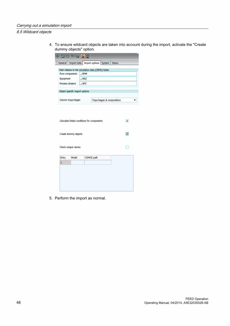
4. To ensure wildcard objects are taken into account during the import, activate the "Create dummy objects" option.
5. Perform the import as normal.
Carrying out a simulation import8.5 Wildcard objects
FEED Operation46 Operating Manual, 04/2014, A5E32035528-AB

ResultWildcard simulation objects are created for objects from the simulation file whose name is not defined in COMOS. You can see the imported attributes in the "Data list" tab.
8.6 Log files for simulator import
OverviewAll of the following simulator imports create a log file:
● HYSYS
● UniSim Design
● ChemCad
● PRO/II
● AspenPlus
● EbsilonProfessional
Log fileWhen you perform an import, the "ComosImport" folder is created inside the user's temporary folder. This is where you will find the log file in XML format.
The name of the log file is determined automatically; in the case of Aspen, it is taken from an Aspen attribute.
The log file displays the path to the simulator object under which you performed the import. Additionally, a message is displayed for each object.
Carrying out a simulation import8.6 Log files for simulator import
FEED OperationOperating Manual, 04/2014, A5E32035528-AB 47
8.7 Creating a folder for SIM objectsYou can create additional folders for PFD objects, so that folders other than "Equipment" and "Process streams" are available.
Procedure1. In the base project, open the base object of the import document.
2. Click the "Import options" tab.
– Some folders are already specified in the "Path relative to the simulation data folder (SIMD)" control group.
– You will also see a table in which you can configure the folders you require.If the desired folder does not exist, contact your administrator.If settings are made in this table, then the ones in the "Path relative to the simulation data folder (SIMD)" control group will be ignored. If no settings are made in this table, then the ones in the "Path relative to the simulation data folder (SIMD)" control group will apply.
8.8 Batch import of simulation files
8.8.1 Basics● The "Batch Import Control Center" is used to import multiple simulation files at the same
time.
● A link to a suitable PFD template for the PFD equipment and PFD process streams is set by default.
● Your administrator can view this default setting and link a different PFD template if required.You can find additional information on this topic in the "FEED Administration" manual, keyword "Default settings for importing several files simultaneously".
Carrying out a simulation import8.8 Batch import of simulation files
FEED Operation48 Operating Manual, 04/2014, A5E32035528-AB

8.8.2 Creating "Batch Import Control Center"
Procedure1. To create a "Batch Import Control Center" object in the "Units" tab in the Navigator, select
one of the two possible storage locations:
– "Simulation data, process unit" folder below a process
– "Simulation data, process unit" folder below a process unitIf there is no folder at the required place, create it via the context menu of the higher-level folder. See also chapter Structures for the import (Page 25).
2. Go to the "Base objects" tab in the Navigator. If you are not authorized to access base objects, contact your administrator.
3. Select the node "@10 > A10 > A10 > A10 > A30 > A40 > A30 Batch Import Control Center".
4. Drag&drop this object onto the empty bar below the Navigator tree.A new tab named after the object is displayed towards the bottom of the Navigator.
5. Open the "Units" tab at the top of the Navigator.
6. Drag&drop the selected object from the bottom of the Navigator to the selected "Simulation data, process unit" folder.The "Batch Import Control Center" object is created below this folder.
8.8.3 Using "Batch Import Control Center"
RequirementThere is a "Batch Import Control Center" object below an "SIMD" folder in the "Units" tab. See also chapter Creating "Batch Import Control Center" (Page 49).
Carrying out a simulation import8.8 Batch import of simulation files
FEED OperationOperating Manual, 04/2014, A5E32035528-AB 49

Procedure1. Open the properties of the "Batch Import Control Center" object.
2. Go to the "Bulk import" tab.
3. To select a folder as the source for simulation files, click the "..." button next to the "Select folder" field.
4. To load simulation files from the selected folder, click the "1. Load sim files from folder" button.The simulation files are added to the list view below the button. Their name, type, and other information is displayed. The "Import step 3" and "Import step 4" columns are empty in the case of simulation files from Aspen Plus or ProMax.
Carrying out a simulation import8.8 Batch import of simulation files
FEED Operation50 Operating Manual, 04/2014, A5E32035528-AB

5. If necessary, change the settings in the list view:
– To change the simulation type displayed for a simulation file, click the required cell in the "Sim type" column. Select a different simulation type from the selection button.
– To exclude individual steps from the import process, click in the required cell and remove the "X", which is set by default.
– To rename individual field contents, click inside the required cell and edit the required name.
– To import a sim file under a different process unit or under a different sim type, edit the corresponding fields.
6. Click the "2. Create sim-cases and copy sim-files" button.Simulation data is created in the Navigator. Any missing process units and simulation cases are also recreated, if required.
7. If you need to move the bulk import to a more suitable time, make your settings under "Counter" and, if necessary, "Start date for bulk import":
– To set the timer, select "H" for hour or "Min" for minute and click the "+" or "-" button.
– To set the date, activate the "Activate date (timer default setting)" option. Then enter the required date in the "Start date for batch import" field.
8. To start the "batch import" for all simulation data listed, click the "3. Start bulk import" button.The counter and date settings are taken into consideration.
9. Save your entries.
Carrying out a simulation import8.8 Batch import of simulation files
FEED OperationOperating Manual, 04/2014, A5E32035528-AB 51


Working in the process flow diagram (PFD) 99.1 Principles of a process flow diagram (PFD)
A process flow diagram (PFD) is an interactive report. You can use such a report to describe a process unit more precisely.
A PFD has the same basic properties and functions as all other interactive reports.
You can find additional information on this topic in the "COMOS Platform Operation" manual, keyword "Working with interactive reports".
Important basic functions in a PFD ● Placing equipment and machines
● Using stream flags for outputting stream data
● Using additional symbols such as battery limits, pipe breaks, and flow direction arrows
In the default configuration, a process stream list with mass balance is automatically inserted in the report header.
Creating a PFDIf you create a process unit, a PFD is automatically created at the same time. You can find the PFD in the COMOS Navigator, directly under the process unit.
See also chapter Creating and specifying process units (Page 20) or chapter Creating a process unit manually (Page 22).
9.2 Manual placing and editing of PFD objects
9.2.1 Placing equipment manuallyTo create your PFD manually, you normally begin by placing the equipment manually.
Requirement● You have created a PFD by creating a process unit. See also chapter Principles of a process
flow diagram (PFD) (Page 53).
● You have opened this PFD.
FEED OperationOperating Manual, 04/2014, A5E32035528-AB 53

ProcedureThe following two options are available to place equipment:
● Through the symbol bar that offers the most important pieces of equipment for you to place, as well as a valve and measuring function
– Activate the desired button in the symbol bar.
– Move the mouse to the desired point in the report and left-click to place the object.As long as the button is enabled, you can place the object on the report as often as you wish.The symbol for the relevant object is placed on the PFD.The object is created in the Navigator and automatically sorted into the "Equipment" folder under the process unit.
● Via the navigator
– Create the equipment in the Navigator: "Equipment" folder, "New > ..." context menu
– Drag&drop the equipment on the PFD.
ResultYou have placed the selected equipment on the PFD.
You can now specify equipment objects. See also chapter Specifying equipment (Page 63).
9.2.2 Placing objects from the report barYou can use the report bar to place the following objects:
● Process stream flags
● Tees
● Plant limits
● Flow direction arrow
● Pipe breaks
● Process streams
RequirementYou have opened a PFD.
Procedure1. Activate the button for the object that you wish to place.
2. Move the mouse to the required point and left-click.
Working in the process flow diagram (PFD)9.2 Manual placing and editing of PFD objects
FEED Operation54 Operating Manual, 04/2014, A5E32035528-AB

Result● The symbol for the relevant object is placed on the PFD.
● The object is created in the Navigator.Exactly where the object is created depends on the object you placed. See also chapter Other placeable objects (Page 60) and the subchapters relating to each object.
Special case: The "Connection" toolYou also find the button for the "Connection" tool on the report bar. This tool is used to draw process streams.
Since this tool is not operated in the same way as the one used for placing a symbol, the "Connection" tool is covered in a separate section. See also chapter Working with process streams (Page 56).
9.2.3 Editing objects via the properties treeYou can edit the properties of some objects on the PFD in the "Attributes filter" view of the properties tree. Your administrator defines which fields are offered for which objects in the base data.
RequirementThe PFD is opened.
Procedure1. Select the desired object on the PFD.
2. Open the "Attribute filter" view in the properties tree.The attributes of the object configured as VSUI attributes are displayed.
3. Enter the desired values.
4. Save your entries.
9.2.4 Using the navigator to place objects You can place objects from the Navigator on the PFD.
Requirement● The required object already exists at the time at which you place it.
If necessary, first create the objects in the Navigator using the "New" context menu.
● You have opened the desired PFD.
Working in the process flow diagram (PFD)9.2 Manual placing and editing of PFD objects
FEED OperationOperating Manual, 04/2014, A5E32035528-AB 55

ProcedureDrag&drop the desired objects from the Navigator onto the PFD.
9.2.5 Editing objects via the propertiesThe fields on the report bar only allow you access to the most important attributes of an object.
ProcedureIf you require access to all the object attributes, select the desired object in the report or in the Navigator and select the "Properties" command in the context menu.
ResultThere, you can obtain precise information on the properties of the object and to configure them.
9.3 Working with process streams
9.3.1 "Connection" toolBoundary streams or process streams are drawn with the "Connection" tool that is located in the report bar. See also chapter Drawing and specifying boundary streams (Page 23) or chapter Creating process streams with the "Connection" tool (Page 57).
Using the "Connection" toolThe "Connection" tool is one of the standard tools offered by interactive reports and works in a similar way in all modules.
The only difference to other modules is: in the FEED module, process streams are created when you use the "Connection" tool.
You can find additional information on this topic in the "COMOS Platform Operation" manual, keyword "General information on the "Connection" tool".
Functions of the "Connection" tool when drawing a process streamThe following options are available:
● Set the "Connection" tool on the connectors predefined in the equipment symbol.
● Set the "Connection" tool on any point in the equipment symbol. Doing this will create dynamic connectors.
Working in the process flow diagram (PFD)9.3 Working with process streams
FEED Operation56 Operating Manual, 04/2014, A5E32035528-AB

● You only need to define the start and end points of the process stream. COMOS will then draw in a connecting line automatically.
● To define the precise route that a process stream is to take, define intermediate points.
9.3.2 Creating process streams with the "Connection" tool
RequirementYou have opened a PFD.
Procedure1. Select the "Connection" tool on the report bar.
2. Use the "Connection" tool to connect the equipment. See also chapter "Connection" tool (Page 56).
3. Optional: Define the properties of the process stream in the properties tree and confirm your entries.The entry in the "Name" field is generated automatically and does not have to be changed.
ResultProcess streams are created automatically in the Navigator and sorted into the "Process streams" folder below the process unit.
9.3.3 Creating and placing process streams from the NavigatorYou can create and place a process stream on a PFD using the "Connection" tool. See also chapter Creating process streams with the "Connection" tool (Page 57).
Alternatively, you can create the process stream in the Navigator first and then place it on the PFD:
Procedure1. To create a process stream in the Navigator, select the "Process steams" folder there.
2. Select the "New > A10 Process stream" command in the context menu.In the Navigator, a new process stream is created in the "Process streams" folder.
3. To place the process stream from the Navigator on the PFD, select it in the "Process streams" folder.
Working in the process flow diagram (PFD)9.3 Working with process streams
FEED OperationOperating Manual, 04/2014, A5E32035528-AB 57

4. Drag&drop the process stream from the folder to the PFD.The "Connection" tool is activated automatically.
5. You now need to define the start and end points of the process stream.The process stream selected in the Navigator is assigned to the process line you have specified.
9.3.4 Exchanging process streams for one anotherWith heat exchangers, you can exchange the incoming for the outgoing process stream.
Procedure1. On the report, open the context menu of a heat exchanger.
2. Click the "Switch connectors" entry.
Result● If an incoming and an outgoing process stream are present, these are interchanged on the
report and in the Navigator.
● If, for example, only an incoming process stream is present, it becomes an outgoing process stream on the report and in the Navigator.
9.3.5 Editing process streams on the PFDYou can edit a process stream that has already been placed as follows:
1. Changing the exact path of the stream by activating the grab points.
2. To reverse the flow direction of the process stream, select the "Options > Change flow direction" command in the context menu of a process stream on the PFD.
3. Configure the display of the flows that intersect. To do this, select the context menu command "Options > To foreground" or "Options > To background".
4. Setting components on a process stream that has already been drawn.The process stream is divided up and another process stream is created.
5. Specify the key stream data on the PFD by placing a process stream flag on the process stream. See also chapter Placing process stream flags (Page 60).
9.3.6 Properties of the process streamsBelow, you will get to know the attributes of a process stream and how to edit them.
Working in the process flow diagram (PFD)9.3 Working with process streams
FEED Operation58 Operating Manual, 04/2014, A5E32035528-AB

Quick access via the attribute filter in the properties treeThe attribute filter provides fast access to the most important attributes of a process stream. There, the attributes set in the properties of the process stream in the "VSUI attributes" field of the "Attributes > System data" tab are displayed.
Overview of the process stream tabsYou can access all attributes of a process stream via its properties, in the "Attributes" tab. The following tabs are relevant for the work you carry out in the FEED module:
Tab Use"Current stream data"
This is where you define the design case that is the active design case of the process stream. The tab reads the most important general stream data for this design case.
"Technical data 1" This is where you find the technical data for the process stream."Graphical options":
Here you have the option of defining the graphical properties of the process stream on the PFD.
"System data" "Visible in mass balance on PFD" option
See alsoDesign cases for streams (Page 68)
Basics on the data flow between a process stream and its design cases (Page 77)
9.4 Configuring a material balanceYou have the option of configuring the contents and layout of the material balance on the PFD.
You can:
● Specify process streams
● Specify the sequence of the process streams
● Specify components
● Specify the sequence of the components
Procedure1. Open the PFD properties and go to the "Attributes > Document options" tab.
2. Activate the "Display process stream list on PFD" option.
3. Go to the "Material balance" tab.
4. Click the "Stream selection" button to specify the order in which the process streams are displayed in the process stream list.The "Stream selection" window opens. See also chapter "Stream selection" window (Page 100).
Working in the process flow diagram (PFD)9.4 Configuring a material balance
FEED OperationOperating Manual, 04/2014, A5E32035528-AB 59

5. Move the required process streams from the "Available streams" list to the "Selected stream" list.
6. Determine the order in which the streams are to appear in the "Selected streams" list.If a process stream does not appear in the "Stream selection" window, the "Visible in mass balance on PFD" option is deactivated in its properties in the "System" tab.Select this option if you want the corresponding process stream to appear on the mass balance of the PFD.
7. Click the "Component lumping" button to specify the components to be displayed and their order in the mass balance.The "Component lumping" window that is available at several points in the engineering structure is opened. See also chapter "Component lumping" window (Page 99).
9.5 Other placeable objects
9.5.1 Placing process stream flagsA process stream flag reads the following properties of the process stream that is connected to it:
● Name
● Temperature
● Pressure
● Mass flow
RequirementA PFD with a created process stream is opened.
Procedure1. Activate the "Process stream flag" button on the report bar.
2. Move the mouse to the desired process stream. It turns yellow as soon as the mouse touches the process stream.
3. Left-click to drop the flag.
ResultThe flag is placed on the PFD and connected to the process stream. A process stream flag is a purely graphical symbol. No object is created for it in the Navigator.
A process stream flag reads the following properties of the process stream to which it is connected:
Working in the process flow diagram (PFD)9.5 Other placeable objects
FEED Operation60 Operating Manual, 04/2014, A5E32035528-AB

● Name
● Temperature
● Pressure
● Mass flow
Note: If the process stream is moved or deleted, the flag is moved or deleted along with it.
9.5.2 Creating page references automaticallyYou can show process streams distributed over several PFDs. A page reference to the respective other PFD serves as orientation.
If you are using a process stream on multiple PFDs (pages), COMOS automatically inserts a page reference.
You can also create page references manually. See also chapter Creating a page reference manually (Page 62).
Requirement● In order to display process streams on several PFDs, you have specified at least two PFDs.
If necessary, create an additional PFD in the Navigator using the context menu.
Procedure1. Open the first PFD and place the process stream.
2. Open the second PFD.
3. In the Navigator, navigate to the process stream.
4. Drag&drop the process stream from the Navigator to the second PFD.
Result● The process stream is segmented. The segments are now placed on the PFDs.
● A page reference is automatically inserted on both PFDs.
● The flow direction and, therefore, the source and target roles depend on which segment is created first: The segment called SEG1 is always the source stream, while the one called SEG2 is the target stream.
● To change the flow direction, swap the names of the segments.
Working in the process flow diagram (PFD)9.5 Other placeable objects
FEED OperationOperating Manual, 04/2014, A5E32035528-AB 61

9.5.3 Creating a page reference manuallyYou can set page references manually to display process streams distributed on several PFDs. In the process, you first place a so-called sheet connector, a symbol that bundles the connections across sheets of a report visually at a one point.
You can also create page references automatically. See also chapter Creating page references automatically (Page 61).
Requirement● In order to display process streams on several PFDs, you have specified at least two PFDs.
If necessary, create an additional PFD in the Navigator using the context menu.
Procedure1. To place a sheet connector on each of the PFDs involved, first open the PFDs between
which connections are to be made.
2. Go to the "Base objects" tab in the Navigator.
3. Drag&drop the following base object from the Navigator to each PFD: "@10 > A10 > A10 > A20 > A40 Sheet connector"The sheet connector is placed on the PFDs.
An engineering object for the sheet connector is created below each of the PFDs, meaning that each PFD has its own sheet connector.
4. Connect the process streams that you intend to link to the other PFD with the sheet connector using drag&drop. Do this on each PFD involved.
5. To increase the number of connection points, activate the grab points of the sheet connector symbol and enlarge the symbol.
6. Open the properties of one of the two sheet connectors, go to the "Attributes > Reference" tab and drag&drop the other sheet connector from the Navigator to the "To drawing reference" field.
ResultThe references to the respective other PFD are displayed in both sheet connector symbols:
Working in the process flow diagram (PFD)9.5 Other placeable objects
FEED Operation62 Operating Manual, 04/2014, A5E32035528-AB

Specifying equipment 1010.1 Determining the main equipment for a process unit
Procedure1. Open the properties of the process unit and go to the "General data" tab.
2. In the Navigator, open the "Equipment" folder located below the process unit.
3. Drag&drop the desired equipment from the Navigator into the "Main equipment" field in the "General data" tab.
ResultThe equipment is assigned as the main equipment. Its description is output on the process unit symbol on the block flow diagram.
10.2 Evaluating report under equipment
Document "DA.001 <equipment type>"The database is prepared in such a way that an evaluating report is created automatically below the equipment.
The report reads out the following properties:
● General information
● The most important process data of the equipment
● The technical data of the equipment
10.3 Changing the graphical displayYou have the option of changing the graphical display of the equipment on the PFD. To do this, select the symbol on the PFD:
● Select the "Options" command in the context menu of the symbol to mirror a symbol, edit symbol texts or edit the symbol in the symbol editor.
● To extend some symbols with agitators and drives, select the "Graphical properties" command in the context menu.
● To change the appearance of certain symbols, change the values in the respective fields in the "Attribute filter" view of the properties tree. The fields offered may differ depending on the type of equipment selected.
FEED OperationOperating Manual, 04/2014, A5E32035528-AB 63

10.4 Specifying the maximum and minimum of the design pressure and design temperature
The equipment automatically takes its minimum and maximum design pressure and minimum and maximum design temperature values from the process streams connected to it.
ProcedureTo specify the maximum and minimum value for the design pressure and design temperature, open the properties of the equipment and make the desired settings in the "Design data" tab.
More information on automatic data flow can be found in Data flow from process stream to the connected equipment (Page 80).
10.5 Tray mapping
Assigning physical information from the simulation to traysThe first step of a simulation import involves importing the physical information relating to the theoretical levels to COMOS. However, no trays are created under the PFD column during the second import step.
If you wish to assign physical information to column trays, you need to create the trays and then carry out the assignment manually as part of a process known as "tray mapping".
10.6 Performing base object changes
RequirementThe PFD object has already been created.
ProcedureTo assign a different base object to existing equipment, proceed as follows:
1. Select one of the following options:
– In the Navigator, right-click the required object of the PFD equipment.
– Open the PFD and right-click a placed object.
2. Select the "Change Base Object" command from the context menu.The base objects with which you can replace the selected object are listed under the "Change Base Object" command.
3. Click the desired base object.
Specifying equipment10.6 Performing base object changes
FEED Operation64 Operating Manual, 04/2014, A5E32035528-AB

ResultOnce you have changed the base object in the Navigator, the documents that use this object are also changed. Once you have changed the base object on the PFD, the corresponding object in the Navigator also changes.
10.7 HTRI import/export
10.7.1 Using HTRI import/export
Supported functions● Heating curves
● Design cases for pipe bundle heat exchangers
● Air cooler designs
Call using objectYou can only use the HTRI import/export in COMOS if the HTRI base software has been installed and activated with the dongle. Reason: COMOS uses an HTRI-API for the import and export.
● The HTRI import/export is integrated in the database under specific base objects. If required, contact your administrator. You can find additional information on this topic in the "FEED Administration" manual, keyword "HCSIM heating curve simulation object" or keyword "HEX heat exchanger".
See alsoExample of the HTRI import/export of the heat exchanger (Page 65)
10.7.2 Example of the HTRI import/export of the heat exchanger
Requirement● The HTRI basic software is installed.
● The HTRI basic software has been activated by means of a dongle.
Specifying equipment10.7 HTRI import/export
FEED OperationOperating Manual, 04/2014, A5E32035528-AB 65

Procedure1. To create a process in a project with a link to the FEED project specifications, right-click
the open project or the open working layer and select the "New > PR Process" command in the context menu.
2. Right-click the process and select the "New > AEQ Equipment" command in the context menu.
3. Right-click the "AEQ Equipment" folder and select the "New > 04 heat transport > HEX heat exchanger" command in the context menu.
4. Expand the structure below the heat exchanger.Here you will find, among others, the case object "DESIGN case".
5. In the context menu of the case object "DESIGN case", select the command "New > Xist HTRI design case for pipe bundle heat exchanger".
6. In the context menu of the created object Xist, select the command "Import from HTRI" or the command "Export to HTRI".
ResultAn import or export is performed depending on the selected command, "Import from HTRI" or the command "Export to HTRI" respectively.
Additional informationThe HTRI import is controlled via script by the "ComosHTRIImport.dll" file. If you want to have the settings checked, contact your administrator. This also applies to script blocks used in the base object "@20 > A60 > A10 > A50 > A60 HTRI import".
You can find additional information on this topic in the "FEED Administration" manual, keyword "Adjusting the HTRI import/export".
See alsoUsing HTRI import/export (Page 65)
Specifying equipment10.7 HTRI import/export
FEED Operation66 Operating Manual, 04/2014, A5E32035528-AB
Design case-specific data 1111.1 Basics on the topic "Design case-specific data"
Definition of design case: You can find additional information on this topic in the "Glossary" manual, keyword "Design case".
In COMOS, design case-specific data for equipment and process streams is managed in self-contained objects. These objects are located in the Navigator underneath their PFD object. The following objects are created automatically:
● "MIN"
● "MAX"
● "DESIGN"
See also chapter Standard cases (Page 67).
The advantage of this separation is that the data structure remains clearly arranged even when there are many design cases for a single process unit.
The database is configured in such a way that design case-specific data is displayed directly on the PFD objects and can be edited there.
For the same reason, the components are managed separately from the pure components.
11.2 Creating design case-specific objects
ProcedureYou have two options for creating design case specific objects:
● Import the required design case from a simulation.The corresponding design case specific objects are created in the database. These objects contain the simulation data. See also chapter Carrying out a simulation import (Page 29).
● Use the Design Case manager.The corresponding design case specific objects are created in the database. The objects do not yet contain any data. See also chapter Managing design cases (Page 87).
11.3 Standard casesStandard cases are design cases that are automatically created under each process stream and under each piece of equipment. In the database, these are the cases "DESIGN", "MAX", and "MIN".
FEED OperationOperating Manual, 04/2014, A5E32035528-AB 67
11.4 Design cases for streams
11.4.1 BasicsIn COMOS, design case-specific data for a process stream is managed in the form of design case objects. The design cases are located directly below the process stream in the Navigator.
The attributes of the design cases are linked to the attributes of their process stream, enabling you to view and edit the most important design case-specific data directly in the properties of the process stream.
11.4.2 Editing design cases for streamsYou have three options for determining the properties of design cases for streams:
● By means of a simulation import
● In the properties of the process stream
● In the properties of the respective design case
Simulation importPerform a simulation import. The design case assumes all data that is specified by the simulation.
Properties of the process stream● In the "Current stream data" tab, you can edit the general stream data for the active design
case.
● The most important attributes of all design cases of the process stream are displayed in the "Material stream list" tab.Please contact your base data administrator if you would like additional attributes to be added to this list.
Design case-specific data11.4 Design cases for streams
FEED Operation68 Operating Manual, 04/2014, A5E32035528-AB

Properties of the design case of the streamYou can edit all attributes of the design case in its properties.
● In the "Components" tab, you can see the components that are assigned to the design case and the values they have. You have the option of assigning additional components. See also chapter Determining the components of a design case (Page 71).The total of the individual values is calculated in the columns "Mass fraction" and "Molar fraction". You can find this sum in the lower half of the tab, above the horizontal scroll bar.
● The attributes "Mass flow" and "Volume flow" are calculated automatically in the "Attributes > General stream data" tab: COMOS adds the values of the "Mass flow" and "Volume flow" columns in the "Components" tab, and enters the total in the "Mass flow" and "Volume flow" attributes.
● Other tabs:Self-explanatory
11.4.3 Determining the active design case
Procedure1. Open the properties of the process stream and go to the "Current stream data" tab.
2. Select the active design case in the "Design/hydraulic case" field.
11.4.4 Using design cases with identical values
Linking the attributes of the design casesIn some cases, it may be necessary for design cases to work with the same attribute values. This is why you are given the option of linking the attributes in the material stream list in the "Material stream list" tab at the process stream.
This means that you only need to edit the attribute at one design case (source attribute); COMOS will write the corresponding value to all design cases to which you have linked this attribute (target attributes).
Note: It is not possible to link just any attributes, but rather only attributes of the same column.
Procedure● Establish the link via drag&drop, or select the required command from the context menu
of the material stream list.The data only flows in one direction: from the source attribute to the target attributes.
● If orange at the target attribute signals that the value of the target attribute deviates from that of the source attribute, apply the linked value using the context menu of the cell of the target attribute.
Design case-specific data11.4 Design cases for streams
FEED OperationOperating Manual, 04/2014, A5E32035528-AB 69

Overview of the commands in the context menu for the material stream list
Command Function"Apply min. value of column","Apply max. value of column"
See "Linking minimum values and maximum values" later in this documentation.
"Delete link for material stream" Deletes all links that were set for attributes of this design case in the material stream list.
"Delete link for attribute" Deletes the link for the attribute whose context menu was called.
"Update static links for material stream" Updates all links that were set for attributes of this design case in the material stream list.
"Update static links for attribute" Updates the link for the attribute whose context menu was called.
Linking an attribute to the minimum value or maximum value of the column1. Open the properties of the process stream and go to the "Material stream list" tab.
2. Left-click the cell of the target attribute and select the "Apply min. value of column" or "Apply max. value of column" command from the context menu.
Result ● COMOS checks which cell of the current column contains the lowest or highest value and
links the target attribute to this cell.
● If a different cell contains a lower value at a later point in time, the link will not be reset automatically; instead, you will need to call the "Apply min. value of column" command again and establish a new link.
Interlinking two attributes1. Open the properties of the process stream and go to the "Material stream list" tab.
2. In the material stream list, left-click the cell of the source attribute, i.e. the attribute of the design case whose value you wish to pass on.
3. Drag&drop the source attribute from the list to the cell of the target attribute, that is, the attribute of the design case to which the value is to be applied.
The target attribute is linked to the source attribute.
Design case-specific data11.4 Design cases for streams
FEED Operation70 Operating Manual, 04/2014, A5E32035528-AB

11.4.5 Determining the components of a design case
Procedure1. In the Navigator, open the "Pure components" folder.
2. Open the "Components" tab of a design case for a stream.
3. Drag the desired pure components into the tab with drag&drop.
ResultA component with a reference to this pure component is created under the design case.
Procedure for transferring components from another design case1. Open the "Components" tab of a design case for a stream.
2. In the context menu, select the command "Copy components from > <other design case of the stream>".
ResultThe components of the design case that you have selected are transferred to the design case.
11.5 Components
Design case-specific material data for a process stream is managed in components. The components are located directly below the corresponding design case of the process stream.
Each component has a reference to the pure component on which it is based.
11.5.1 Editing componentsYou have three options to determine the properties of components:
● By means of a simulation import
● In the properties of the material stream
● In the properties of the component concerned
Simulation importPerform a simulation import.
Applies all data that is specified by the simulation to the component.
Design case-specific data11.5 Components
FEED OperationOperating Manual, 04/2014, A5E32035528-AB 71

Properties of the design case of the streamThe most important attributes of all components of the process stream are displayed in the "Components" tab.
Please contact your base data administrator if you would like additional attributes to be added to this list.
In the properties of the componentYou can edit all attributes of the component here.
● You can enter the material data for the component in the "Component data" tab.
● The pure component data of the assigned component is displayed in the "Actual component data" tab for informational purposes. The data cannot be edited.
11.5.2 Automatic attribute calculationOnce you have entered the mass flow for all components of a design case, COMOS automatically calculates the following component attributes:
● Mass fraction
● Molar stream
● Molar fraction
11.6 Equipment cases
Design case-specific data for a piece of equipment is managed in equipment cases (EC objects). The equipment cases are located directly underneath the equipment in the Navigator.
The attributes of the equipment cases are linked to the attributes of their equipment, enabling you to view and edit the most important equipment case-specific data directly in the properties of the equipment.
Design case-specific data11.6 Equipment cases
FEED Operation72 Operating Manual, 04/2014, A5E32035528-AB

11.6.1 Editing equipment casesYou have three options for influencing the properties of equipment cases:
● By means of a simulation import
● In the properties of the equipment
● In the properties of the respective equipment case
Simulation importIf you perform a simulation import, all data that is specified by the simulation is applied to the equipment case.
Equipment properties● To edit the process data of the active design case, switch to the "Process data 1" tab.
● To edit the technical data of the equipment case that is set as the active design case, switch to the "Technical data 1" tab.
● To view the most important attributes of all the equipment cases of the process stream, switch to the "Design data" tab.Contact your administrator if you would like additional attributes to be added to this list.
Properties of the equipment caseYou can edit all the attributes of an equipment case in its properties.
The following tabs of an equipment case are relevant for your work:
● "Design data" tab:Self-explanatory
● "Technical data 1" tab:Self-explanatory
11.6.2 Determining the active equipment case
Procedure1. Open the properties of the equipment and go to the "Process data 1" tab.
2. In the "Active equipment case" field, select the active equipment case and save this setting.
Design case-specific data11.6 Equipment cases
FEED OperationOperating Manual, 04/2014, A5E32035528-AB 73


Data flow 1212.1 Overview of data flows
In the FEED module, data is exchanged between the following PFD objects. For the most part, the data flows by means of automated processes.
● Boundary stream <-> assigned process streamChapter Data flow between boundary stream and assigned process stream (Page 75).
● Process stream <-> material streamsChapter Data flow between a process stream and its design cases (Page 77).
● Equipment <-> Equipment casesChapter Data flow between the equipment and its design cases (Page 78).
● Equipment <-> connected process streamsChapter Data flow from process stream to the connected equipment (Page 80).
12.2 Data flow between boundary stream and assigned process stream
12.2.1 Basic information about the data flow between the boundary stream and process stream
ObjectiveIf your engineering work begins with a block flow diagram, you can enter the initial stream data as early as at the boundary stream and then pass it on to the assigned process stream.
Values changed later at the process stream can be written back to the boundary stream.
FEED OperationOperating Manual, 04/2014, A5E32035528-AB 75

Graphical overviewThe following graphic illustrates the data flow between the boundary stream and process stream:
12.2.2 Assigning a process stream to a boundary streamTo enable data communication between boundary stream and process stream, first assign a process stream to a boundary stream.
Procedure1. Open the properties of the boundary stream.
2. In the Navigator, navigate to the process stream you want to assign.
3. Drag&drop the process stream to the "Process stream" field in the "General stream data" tab in the boundary stream properties.
ResultA process stream is assigned to the boundary stream.
12.2.3 Passing data from the boundary stream to the process stream
RequirementA process stream is assigned to a boundary stream.
See also chapter Assigning a process stream to a boundary stream (Page 76).
Data flow12.2 Data flow between boundary stream and assigned process stream
FEED Operation76 Operating Manual, 04/2014, A5E32035528-AB

Procedure1. Open the properties of the boundary stream and go to the "General stream data" tab.
2. Select the following value from the list in the "Reference" control group: "To process stream".
3. Press the "Copy values" button.
ResultThe stream data is passed on to the process stream, "Current stream data" tab.
12.2.4 Passing data from the process stream to the boundary stream
Requirement● A process stream is assigned to a boundary stream.
See also chapter Passing data from the boundary stream to the process stream (Page 76).
● You have specified the stream data of the process stream more exactly (for example, with a simulator import).Deviations in the values at the boundary stream are indicated by orange.
Procedure1. Open the properties of the boundary stream and go to the "General stream data" tab.
2. Select the following value from the list in the "Reference" control group: "From process stream".
3. Click the "Copy values" button.
12.3 Data flow between a process stream and its design cases
12.3.1 Basics on the data flow between a process stream and its design casesThe attributes of a process stream and its design cases are linked in such a way that you are able to view and edit the most important stream data of the active design case from the process stream properties.
Any new values that you enter and save at the process stream are automatically written to the active design case. If you change the active design case, the stream data for the new active design case is automatically displayed at the process stream.
The data flow is implemented by means of a fully dynamic link.
Data flow12.3 Data flow between a process stream and its design cases
FEED OperationOperating Manual, 04/2014, A5E32035528-AB 77

Graphical overviewThe following graphic illustrates the data flow between the process stream and active design case:
12.3.2 Viewing and editing design cases of the process stream
RequirementYou have selected the active design case from the "Active material stream case" list in the properties of the process stream in the "Current stream data" tab.
Procedure● To view and edit all the design cases of the process stream and their most important data
in a tabular overview, open the properties of the process stream and switch to the "Material stream list" tab.
● To view and edit the attributes of the active design case, open the "Current stream data" tab in the properties of the process stream.Its attributes are linked dynamically to the attributes of the "General stream data" tab of the active design case.
12.4 Data flow between the equipment and its design cases
12.4.1 Basic information about data flow between equipment and design casesThe attributes of a piece of equipment and its design cases are linked in such a way that you are able to view and edit the most important design case specific data from the equipment properties.
Data flow12.4 Data flow between the equipment and its design cases
FEED Operation78 Operating Manual, 04/2014, A5E32035528-AB
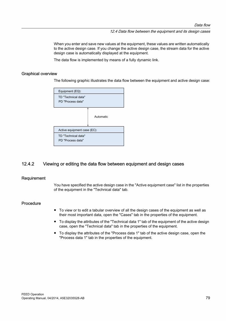
When you enter and save new values at the equipment, these values are written automatically to the active design case. If you change the active design case, the stream data for the active design case is automatically displayed at the equipment.
The data flow is implemented by means of a fully dynamic link.
Graphical overviewThe following graphic illustrates the data flow between the equipment and active design case:
12.4.2 Viewing or editing the data flow between equipment and design cases
RequirementYou have specified the active design case in the "Active equipment case" list in the properties of the equipment in the "Technical data" tab.
Procedure● To view or to edit a tabular overview of all the design cases of the equipment as well as
their most important data, open the "Cases" tab in the properties of the equipment.
● To display the attributes of the "Technical data 1" tab of the equipment of the active design case, open the "Technical data" tab in the properties of the equipment.
● To display the attributes of the "Process data 1" tab of the active design case, open the "Process data 1" tab in the properties of the equipment.
Data flow12.4 Data flow between the equipment and its design cases
FEED OperationOperating Manual, 04/2014, A5E32035528-AB 79

12.5 Data flow from process stream to the connected equipmentThe equipment automatically takes its minimum and maximum design temperature and minimum and maximum design pressure values from the process streams connected to it.
● At the equipment, you find these attributes on the "Design data" tab.
● At the process streams, you find corresponding attributes on the "Current stream data" tab.
The data flow is realized by means of a dynamic link.
Minimum design temperatureThe process stream with the lowest temperature value of all process streams connected to the equipment is identified and this value is automatically entered at the equipment, in the "Design temperature, min." field on the "Design data" tab.
Exactly the same procedure is followed for the "Design temperature, max.", "Design pressure, min.", and "Design pressure, max." attributes.
If the following project option is enabled: "General settings > Standard", "Change from dynamic to static on first change" option: you can enter a different value at the equipment. The data between the equipment and the process stream is then no longer consistent.
Graphical overviewThe following graphic illustrates the data flow between the equipment and connected process stream:
Data flow12.5 Data flow from process stream to the connected equipment
FEED Operation80 Operating Manual, 04/2014, A5E32035528-AB

PFD and P&ID 1313.1 Converting a PFD into a P&ID
Workflow1. Create P&ID templates for the PFD equipment.
2. Create a P&ID.
3. Place the PFD on the P&ID and dissolve the PFD.
Creating P&ID templatesCreate P&ID templates for the objects in the "Equipment" folder. You have two options:
● Use the default templates: See Using P&ID default templates (Page 83).
● Select the templates yourself: See Selecting P&ID templates (Page 84).The "P&ID assembly template" object is inserted under the PFD objects in the Navigator. The P&ID objects of the assembly and a P&ID that maps the assembly are located under this node.No pipes are created in this step. The connectors of the P&ID equipment are not yet connected.
Creating a P&ID1. Select the process unit and then select the "New > Conversion" command from the context
menu.The "Conversion" folder is created under the process unit.
2. Create a P&ID under the folder by means of the context menu.
FEED OperationOperating Manual, 04/2014, A5E32035528-AB 81

Placing and dissolving the PFDThe P&ID objects that are created automatically as a result of creating the template do not need to be placed and connected manually on the P&ID. Instead, you place the PFD on the P&ID and then dissolve the drawing.
1. Open the P&ID.
2. Drag&drop the process unit PFD from the Navigator to the P&ID. Place it in the top left corner.The objects and symbols placed on the PFD are displayed on the P&ID, together with the anchor symbol of the PFD:
3. Select the anchor symbol of the PFD and, from the context menu, select the "Convert placed document" command.
PFD and P&ID13.1 Converting a PFD into a P&ID
FEED Operation82 Operating Manual, 04/2014, A5E32035528-AB

Result● If an object that has a P&ID assembly is placed on the PFD, the objects in the assembly
are placed on the P&ID.
● The objects placed on the P&ID are connected to one another by means of pipes (pipes, pipe sections, and segments). Tees for branches are inserted automatically.Pipes that connect objects in an assembly are created under the assembly in the Navigator. Pipes that connect two assemblies are created under the corresponding process streams in the Navigator.
● Tees for branches are automatically inserted in the P&ID and are created under the assemblies in the Navigator.
Optimizing the graphicYou need to make adjustments to the P&ID manually to optimize the graphic. Since the assemblies are initially still grouped, you will need to undo the grouping for this purpose.
1. Select an assembly.
2. Select the "Grouping > Undo" command from the context menu.
13.2 Using P&ID default templatesIf you are using default templates, you have the option of creating templates for all objects of a process unit at once, or creating one for an individual object.
PFD and P&ID13.2 Using P&ID default templates
FEED OperationOperating Manual, 04/2014, A5E32035528-AB 83

Procedure● To create default templates for all objects under the process unit, open the properties of
the process unit, switch to the "General data" tab and click the "Copy default template" button.The default assemblies are created under the PFD objects.
● To create a standard template for an individual object, select the object in the Navigator or on the PFD and then the command "Select default template" in the context menu.The default assembly is created under the PFD object.
Which standard template is used in COMOS?Your administrator has already determined which assembly is to be used as the default assembly in the base data beforehand:
In the properties of the PFD objects, "System data" tab, in the "Conversion to a P&ID object" control group, "Standard P&ID assembly" field.
13.3 Selecting P&ID templates
Procedure1. Select a PFD object in the Navigator.
2. Select the "Select P&ID template" command from the context menu.The "Select template" window opens.
3. Select a template and confirm your selection with "OK".
Options of the "Select template" window
Number Option Function1 "Templates" Activated:
The templates table lists all templates found in the "@Template > M21 > A20 Templates for conversion PFD to P&ID" node in the base project.
2 "From project" Activated: A drop-down list from which you select a project appears in the window. The templates table then offers all templates contained in the "@Template > M21 > A20 Templates for conversion PFD to P&ID" node in this project.
PFD and P&ID13.3 Selecting P&ID templates
FEED Operation84 Operating Manual, 04/2014, A5E32035528-AB

Number Option Function3 "Filter" Activated:
COMOS selects the most suitable template for the equipment from all templates.Deactivated: All templates with an appropriate function code are listed for selection.
4 Template table A table containing templates. The table has the following columns:● SystemFullName● DescriptionTo sort the table, move the mouse to one of the table columns. Buttons which allow you to sort or filter the table based on the content of the column in question will appear.
ResultThe P&ID assembly is created under the PFD object.
13.4 Creating multiple P&IDs from a PFDTo create multiple P&IDs from a PFD, distribute the equipment across several P&IDs manually.
Procedure1. Create P&ID templates for the PFD objects.
2. In the navigator, navigate to the P&ID objects under the "P&ID assembly template" object.
3. Place the P&ID equipment on the P&IDs.
4. Click an empty area of the P&ID workspace and select the "Connect automatically" command from the context menu.
ResultThe P&ID objects are automatically connected on the report. The corresponding pipes, pipe sections and segments are created in the database.
PFD and P&ID13.4 Creating multiple P&IDs from a PFD
FEED OperationOperating Manual, 04/2014, A5E32035528-AB 85


Managing design cases 14
You manage the design cases for your process in the "Case manager" tab. See also chapter "Case manager" tab (Page 102).
The case management is available on two levels of your engineering structure:
● At process level:Any action that you carry out in the case management applies to the entire process.
● At process unit level:Any action that you carry out in the case management only applies to the process unit.
14.1 Set active case
RequirementYou have opened the "Case manager" tab in the properties of a process or a process unit.
Procedure1. Select the active design case in the standard table on the right.
The table lists all design cases located under the process or process unit in the structure.
2. In the "Apply actions to" control group, specify where your action is to apply. You can activate or deactivate the following options to this purpose:
– "Equipment"
– "Process streams"
These options are activated in accordance with these options.
3. Click the "Set active case" button.
4. Confirm your selection.
ResultThe design case is entered as an active design case in accordance with the activated options.
See also"Case manager" tab (Page 102)
FEED OperationOperating Manual, 04/2014, A5E32035528-AB 87

14.2 Create new case
RequirementYou have opened the "Case manager" tab in the properties of a process or a process unit.
Procedure1. Enter the name of the new design case in the field on the right.
2. In the "Apply actions to" control group, specify where your action is to apply. You can activate or deactivate the following options to this purpose:
– "Equipment"
– "Process streams"
3. Click the "Create new case" button.
4. Confirm your selection.
ResultEquipment cases and design cases for process streams are created with this name in accordance with the activated options.
See also"Case manager" tab (Page 102)
14.3 Complete case
ObjectivePFD objects are available. A specific case is missing for some of them, and you want correct this.
RequirementYou have opened the "Case manager" tab in the properties of a process or a process unit.
Managing design cases14.3 Complete case
FEED Operation88 Operating Manual, 04/2014, A5E32035528-AB

Procedure1. Select a design case in the standard table on the right.
2. In the "Apply actions to" control group, specify where your action is to apply. You can activate or deactivate the following options to this purpose:
– "Equipment"
– "Process streams"
3. Click the "Complete case" button.
4. Confirm your selection.
Result● A case is completed in accordance with the activated options.
● If, for example, an equipment case of the same name does not exist under a piece of equipment, it is created.
● If, for example, there is no design case with the same name under a process stream, it is created.
See also"Case manager" tab (Page 102)
14.4 Delete case
RequirementYou have opened the "Case manager" tab in the properties of a process or a process unit.
Procedure1. Select a design case in the standard table on the right.
2. In the "Apply actions to" control group, specify where your action is to apply. You can activate or deactivate the following options to this purpose:
– "Equipment"
– "Process streams"
3. Click the "Delete case" button.
4. Confirm your selection.
ResultThe corresponding case is deleted in accordance with the activated options, for example all the equipment cases and design cases for process streams of the same name.
Managing design cases14.4 Delete case
FEED OperationOperating Manual, 04/2014, A5E32035528-AB 89

See also"Case manager" tab (Page 102)
14.5 Rename case
RequirementYou have opened the "Case manager" tab in the properties of a process or a process unit.
Procedure1. Select a design case that you want to rename in the standard table on the right.
2. In the "Apply actions to" control group, specify where your action is to apply. You can activate or deactivate the following options to this purpose:
– "Equipment"
– "Process streams"
3. Click the "Rename case" button.The "Rename case" window opens.
4. Enter the new name of the design case and press the "OK" button to confirm your entry.
ResultThe selected design case is renamed in accordance with the activated options.
See also"Case manager" tab (Page 102)
14.6 Copy case
RequirementYou have opened the "Case manager" tab in the properties of a process or a process unit.
Managing design cases14.6 Copy case
FEED Operation90 Operating Manual, 04/2014, A5E32035528-AB

Procedure1. Select a design case in the standard table on the right.
2. In the "Apply actions to" control group, specify where your action is to apply. You can activate or deactivate the following options to this purpose:
– "Equipment"
– "Process streams"
3. Click the "Copy case" button.The "Copy case" window opens.
4. Enter the name of the new design case and press the "OK" button to confirm your entry.
Result● The selected design case is copied to the corresponding positions in accordance with the
activated options.
● For example, a copy of the selected equipment case with the name you have specified is created under each piece of equipment.
● For example, a copy of the selected design case with the name you have specified is created under each process stream.
● If COMOS cannot find the selected design case, it does not create a copy.
See also"Case manager" tab (Page 102)
Managing design cases14.6 Copy case
FEED OperationOperating Manual, 04/2014, A5E32035528-AB 91


Knowledge base 1515.1 Basics on the knowledge base
DefinitionThe knowledge base consists of a set of engineering rules that define when alarms or warning messages are issued for a process. These rules are defined in queries.
Execute these queries in order to check whether a process follows the rules. You have two options:
● Check all rules at once. Critical objects are marked in color in the Navigator.
● Check an individual rule. The result is displayed on the rules tab.
What rules are there?● Some engineering rules are pre-configured in the database, for example, "Check process
stream design temperature".
● Your administrator can set up additional rules at the base data end.
15.2 Creating the knowledge base, status display
Procedure1. Select the process in the Navigator.
2. Select the "New > AKB knowledge base" command from the context menu.The "AKB knowledge base" folder is created under the process.
3. To create a query, select the "AKB" folder and then select the "New > ..." command in the context menu to select the rule you require:
– "RU000 General rules"
– "RU001 Check process stream design temperature"
– "RU002 Pump pressure too high"
– "RU003 Temperature too high"
The selected rule is created in the folder.
4. Create all rules that apply to your process.
FEED OperationOperating Manual, 04/2014, A5E32035528-AB 93

Activating the status display for the knowledge base in the Navigator1. Click an empty area of the Navigator.
2. Select the "Status display > 13 Knowledge base" command from the context menu.On the basis of the rules in the knowledge base, each object is assigned a color according to its status.
15.3 Checking a process against all rules
Procedure ● Select the "AKB" folder and then select the "Check rules" command from the context menu.
Result ● The entire process is always checked.
● All rules of the folder are executed.
● The results of the check are displayed in color in the Navigator:
Color StatusRed ErrorYellow WarningLight blue NoteGreen OK
15.4 Checking a process against an individual rule
Procedure● Open the desired rule by double-clicking it.
The rule automatically checks the entire process.
● To check a specific node of the process (a process unit, for example), drag&drop the node to the "Starting point" field.The rule automatically checks all objects under this node.
Knowledge base15.4 Checking a process against an individual rule
FEED Operation94 Operating Manual, 04/2014, A5E32035528-AB

Result● The result of the check is displayed in the window of the rule, in the following columns.
– Error
– Warning
– Note
● Erroneous values are indicated by an orange background in the value columns.
● It is possible to correct invalid values directly at this point.
Example: "Check process stream design temperature" query
● When you open this query, you see different default columns. Do not delete the "Error", "Warning", and "Message" columns.
● You will also see various columns that display attributes. You can delete these columns or add new columns with attributes.
Knowledge base15.4 Checking a process against an individual rule
FEED OperationOperating Manual, 04/2014, A5E32035528-AB 95

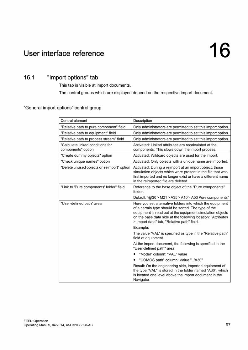
User interface reference 1616.1 "Import options" tab
This tab is visible at import documents.
The control groups which are displayed depend on the respective import document.
"General import options" control group
Control element Description"Relative path to pure component" field Only administrators are permitted to set this import option."Relative path to equipment" field Only administrators are permitted to set this import option."Relative path to process stream" field Only administrators are permitted to set this import option."Calculate linked conditions for components" option
Activated: Linked attributes are recalculated at the components. This slows down the import process.
"Create dummy objects" option Activated: Wildcard objects are used for the import."Check unique names" option Activated: Only objects with a unique name are imported."Delete unused objects on reimport" option Activated: During a reimport at an import object, those
simulation objects which were present in the file that was first imported and no longer exist or have a different name in the reimported file are deleted.
"Link to 'Pure components' folder" field Reference to the base object of the "Pure components" folder.Default: "@30 > M21 > A35 > A10 > A50 Pure components"
"User-defined path" area Here you set alternative folders into which the equipment of a certain type should be sorted. The type of the equipment is read out at the equipment simulation objects on the base data side at the following location: "Attributes > Import data" tab, "Relative path" field.Example:The value "VAL" is specified as type in the "Relative path" field at equipment.At the import document, the following is specified in the "User-defined path" area:● "Model" column: "VAL" value● "COMOS path" column: Value "../A30"Result: On the engineering side, imported equipment of the type "VAL" is stored in the folder named "A30", which is located one level above the import document in the Navigator.
FEED OperationOperating Manual, 04/2014, A5E32035528-AB 97

Simulator-specific import options
Control element Description"Columns/trays/stages" standard table Make your selection from the following options in the
standard table:● "Not imported" value:
Only the data of the column is imported. The data of the associated trays and components is not imported.
● "Trays/stages without composition" value:The data of the trays is imported, but the composition is not.
● "Trays/stages & compositions" value:The data of the column, trays, and components is imported. (default setting)
"Components stream/tray/stage" standard table
Defines the attributes that are imported when importing components to the "Components" tab. Possible values:● "Only bulk mole fractions"● "Mole fractions of all phases"● "Bulk fractions and flows"
Others
Control element Description"Calculate stream properties" option Activated (default setting): The simulator is triggered once
again and the stream properties are recalculated. Any stream properties that are missing in the source file are calculated and are also imported.
"Map by name" option Activated: If a PFD object with the same name as the simulation object already exists, the simulation object gets a link to this PFD object.
16.2 "Partial import" window
"Display" control group
Option Description"Streams" Displays only objects whose simulation object is a stream."Equipment" Displays only objects whose simulation object is equipment."Not importable objects" Does not show any objects which are assigned to a simulation object."Group objects" option Activated: Groups the objects that are assigned to the same simulation
object.
User interface reference16.2 "Partial import" window
FEED Operation98 Operating Manual, 04/2014, A5E32035528-AB

"Selection" control group
Option Description"All" Activates the option for all objects in the "Import" column of the import
table."None" Deactivates the option for all objects in the "Import" column of the import
table."Streams" Displays only objects whose simulation object is a stream."Equipment" Displays only objects whose simulation object is equipment."User-defined" Allows the user to customize the selection of objects in the import table.
Import tableThe import table shows the objects of the simulation file corresponding to the options you have selected in this window.
If the option of an object is activated in the "Import" column, this object will be imported when you click on the "OK" button.
Status displayA status display is located below the import table. This indicates how many importable objects are available and how many of them you have selected.
16.3 "Component lumping" window
Interface
Control element DescriptionWorking area with elements within a tree structure
● Shows all the components that are used in the process or process unit
● Shows all the groups into which the components in the mass balance are sorted.
"Group" button For creating a new group under which all the components marked beforehand in the tree structure are moved.The components in the mass balance are sorted under the group.
"Undo group" button To dissolve the groups marked in the tree structure. Afterwards, the components are back on the top level of the tree.
"To top", "Up", "Down", and "To bottom" buttons
Used to define the order of groups and components in the mass balance.The components or groups selected in the tree structure are moved accordingly.
User interface reference16.3 "Component lumping" window
FEED OperationOperating Manual, 04/2014, A5E32035528-AB 99

Control element Description"Hide", "Show" buttons For hiding and showing components and groups in the mass
balance."Reset" button For using default settings.
● If component grouping settings have been defined at the process unit, these are used.
● If component grouping settings have not been defined at the process unit, but have been defined at the process, the component grouping settings for the process are used.
16.4 "Stream selection" window
Interface
User interface reference16.4 "Stream selection" window
FEED Operation100 Operating Manual, 04/2014, A5E32035528-AB

Number
Control element Description
1 "Available streams" list: Listing of all the streams that are located under the process unit and in whose properties the "Visible in mass balance on PFD" option is activated in the "System" tab.
2 "Add all", "Add"; "Remove", and "Remove all" buttons:
For specifying the available streams that are to appear in the process stream list.
3 "Selected streams" list: Overview of all the streams that are output in the process stream list.
4 "To top", "Top", "Down", and "To bottom" buttons:
For specifying the order in which the process streams are displayed in the process stream list.
16.5 "Material balance" tabTo open the "Material balance" tab, switch to the "Attributes > Material balance" tab in the properties of the PFD.
Control element Description"Case, current" list Optional. For selecting multiple list entries of the
current design case."Template" list For selecting "Extended" or "Short".
Used for selecting either an extended template or a short version in accordance with the default setting. The default is "Short".The selection of possible entries depends on the set reference in the "Template folder" field, see below.
"Stream selection" button For determining the process streams to be incorporated into the material balance.
"Component lumping" button For determining the components to be incorporated into the material balance and in what order.
Table
Control element Description"Description" column Pre-filled with descriptions of attributes of PFD
objects that are displayed on the PFD.Column "Design" The standard table contained in the respective
field allows you to switch between subreports that are defined as a template.
"Attribute name" column Pre-filled with name of attributes of PFD objects that are displayed on the PFD.
"Accuracy" column Pre-filled with specification of the number of decimal points to be evaluated.Example: "2"
User interface reference16.5 "Material balance" tab
FEED OperationOperating Manual, 04/2014, A5E32035528-AB 101

Control element Description"Design" list For selecting between
● Default layout● Large layout● Small layoutRows and field sizes differ depending on the selected layout.
"Component header row" control group
Control element Description"Component mode" list Optional. For selecting
● Displayed above● Displayed below● Not displayed● Row No.For displaying whether and where components are to be displayed on the subreport.
"Number of rows, max" For entering the maximum number of rows on the report.
"With component header row" option Option activated: Displays the row with the title "Comp.".
"Text" field Replaces the name "Comp" on the PFD with the text entered in the field.
"Attribute" list For selecting the unit from the list on the PFD."Precision" field For setting the decimal places of the components
on the PFD. "4" is the default."Input row number for components" field Optional. Specifies where the components are to
be entered on the PFD."Show "0" values for components on PFD" option Option activated: If the components with an empty
string on the PFD are replaced and displayed by a "0".
Control element Description"Template folder" field For setting a reference to a local template folder
through drag&drop or through a Browse dialog.
16.6 "Case manager" tabThe "Case manager" tab is located in the properties of the process or the process unit.
User interface reference16.6 "Case manager" tab
FEED Operation102 Operating Manual, 04/2014, A5E32035528-AB

Buttons
Button Description"Set active case" button For setting the active case in accordance with options set in the
"Actions apply on" control group.See also chapter Set active case (Page 87).
"Create new case" button For creating a new case in accordance with the options set in the "Actions apply on" control group.See also chapter Create new case (Page 88).
"Complete case" For completing cases in accordance with the options set in the "Actions apply on" control group.See also chapter Complete case (Page 88).
"Delete case" For deleting a case in accordance with the options set in the "Actions apply on" control group.See also chapter Delete case (Page 89).
"Rename case" For renaming a case in accordance with the options set in the "Actions apply on" control group.See also chapter Rename case (Page 90).
"Copy case" For copying a case in accordance with the options set in the "Actions apply on" control group.See also chapter Copy case (Page 90).
"Actions work on" control group
Option Function"Equipment" Activated (default setting): The actions you perform using the
buttons on the left are also applied to the equipment. This means that new equipment cases are created, existing ones are renamed, and so on.Deactivated: The actions are not applied to the equipment.
"Process streams" Activated (default setting): The actions you perform using the buttons on the left are also applied to the process streams. This means that new design cases are created, existing ones are renamed, and so on.Deactivated: The actions are not applied to the process streams.
Other control elements
Control element Function"Log text" field COMOS logs the result of the action in this text field."Extended log texts" option Self-explanatory
User interface reference16.6 "Case manager" tab
FEED OperationOperating Manual, 04/2014, A5E32035528-AB 103

16.7 COMOS FEED Log
Control element DescriptionList Objects from the import file that were selected for the current import are listed
here.COMOS checks whether the import settings are correct. If the settings are not correct, COMOS aborts the import. You can recognize from the symbols whether an object was imported or an error occurred. In the case of errors, detailed information is shown below the objects.If errors occurred during an import, you can navigate to the created simulation object.At the end of the import, a log file containing additional information and warnings is created in XML format. You open the file with the "Open file" button.
User interface reference16.7 COMOS FEED Log
FEED Operation104 Operating Manual, 04/2014, A5E32035528-AB

Database reference 17● Dummy simulation object
"@30 > M21 > A50 > A10 > A20 > A10 > A40 Dummy simulation object"See also chapter Importing wildcard objects (Page 45).
FEED OperationOperating Manual, 04/2014, A5E32035528-AB 105