Embed Size (px)
Citation preview
MPS
Process Engineering
B2 Concern – Few control valves are there in MPS area without bypass.
Brief description of concern – If control valve is stuck closed or fails, there is no provision to maintain downstream operation.
Mitigation/Action – Manual bypass to be provided for all control valve assembly.
On review of the MPS area P&ID’s and as observed during site visit of MPS area, control valves were found without bypass valves. As per international best practices control valve assembly should have a bypass manual valve for operational flexibility and ease of maintenance.
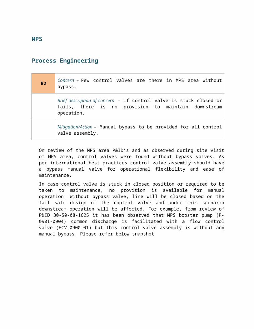
In case control valve is stuck in closed position or required to be taken to maintenance, no provision is available for manual operation. Without bypass valve, line will be closed based on the fail safe design of the control valve and under this scenario downstream operation will be affected. For example, from review of P&ID 30-50-08-1625 it has been observed that MPS booster pump (P-0901-0904) common discharge is facilitated with a flow control valve (FCV-0900-01) but this control valve assembly is without any manual bypass. Please refer below snapshot
This is to state that this flow control valve (FCV-0900-01) is designed as “FC”. Hence for any certain unavoidable scenario of control failure, valve will be closed and flow will be restricted to the downstream. If buffer tanks (T-1501/1502) are emptied with flow from MP-21, the booster pumps will be operated in serial arrangement of 2+2 combination with maximum flow of 0.75 MMBPD, hence under this scenario if valve (FCV-0900-01) is closed
due to control failure there is no such provision to maintain flow to downstream. Therefore entire downstream flow will be suffered and will be lowered than desired 1.5 MMBPD flow.
Use of manual bypass valve across control valve assembly therefore very useful for operational flexibility and is a standard practice internationally. For hydrocarbon service and based on criticality of the system, API RP-550 recommends use of bypass manual valve across control valve.
Recommendations
Bypass valve is required for manual operation in case of control valve failure.
B3 Concern – Continuous dead liquid leg in the buffer tank diversion line.
Brief description of concern – Pressure monitoring at buffer tank diversion line demands a constant dead leg at diversion line inlet, and pressure control valve is closed under normal operating scenario.
Mitigation/Action – Removal of dead leg to maintain operation flexibility.
From review of P&ID 30-50-08-1625 and as observed during site visit, there is a 2oo3 voting IPF (PT-1500-01A/B/C) for pressure monitoring available in MPS suction manifold at buffer tank diversion line to continuously monitor pressure in MPS suction manifold. These particular configuration demands first isolation valves (MOV-0200-04) always open (“LO”). It has been observed during site visits that distance from tap off of buffer tank diversion line to PCV-1500-01A/B is considerable which leads to generation of a continuous dead liquid leg in the diversion line as inline pressure control valves are closed under normal operating scenario and isolation MOV is open.
Liquid collected in dead leg of pipe elements tend to cause freezing of any residual water / moisture. There will be chances in that case for rupture of the pipeline due excessive corrosion and freezing. Hence this dead liquid leg needs to be avoided as part of good engineering practice either be continuously draining or recycling to induce a flexible and trouble free operation.
Following is a real time example of hazardous situation that could arrive due to dead liquid leg. In February 2007 an oil and gas refinery witnessed the destruction in its de-asphalting unit caused by a forgotten dead leg in the process piping for liquid propane. Valves were used to isolate a section of process piping when the process sequence was changed; however, a foreign object prohibited one of the valves from closing completely. As a result, moisture from the processing of the liquid propane leaked through the valve into the dead leg. Weather conditions during February were below freezing for four days, which was long enough for the moisture to freeze and rupture the piping. Once the temperature rose above freezing, the ice melted, allowing liquid propane to flow from the ruptured piping into the dead leg. This quickly formed a vapor cloud that was carried by the wind to an ignition source nearby. The Chemical Safety Board, which investigated the accident, said, “The accident resulted in multiple injuries, damage exceeding US$50 million and reduced operation for nearly a year.”
Recommendation: Locate first isolation MOV as close as possible to the main line.
Relocate 2oo3 pressure sensor to main pipeline (Common suction manifold of MPS pumps) or constant recirculation of dead liquid to main pipeline.
B4 Concern – Nitrogen blanketing is not available in the oil drain collection vessel.
Brief description of concern – A nitrogen blanket (which artificially pressurizes the system and prevents oxygen from entering the system) is necessary to ensure the oil does not flash its light ends and subsequently cause a fire. Without a nitrogen blanket, safety is compromised, even under normal operating conditions.
Mitigation/Action – Blanketing is required.
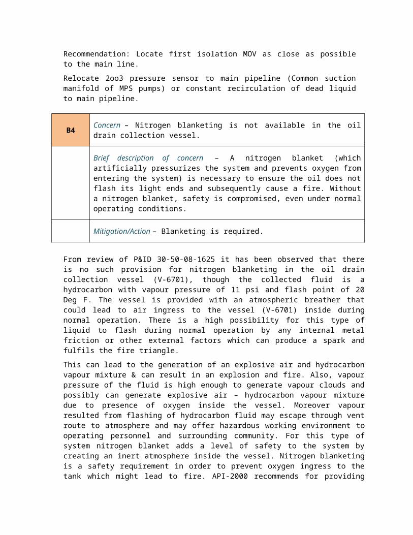
From review of P&ID 30-50-08-1625 it has been observed that there is no such provision for nitrogen blanketing in the oil drain collection vessel (V-6701), though the collected fluid is a hydrocarbon with vapour pressure of 11 psi and flash point of 20 Deg F. The vessel is provided with an atmospheric breather that could lead to air ingress to the vessel (V-6701) inside during normal operation. There is a high possibility for this type of liquid to flash during normal operation by any internal metal friction or other external factors which can produce a spark and fulfils the fire triangle.
This can lead to the generation of an explosive air and hydrocarbon vapour mixture & can result in an explosion and fire. Also, vapour pressure of the fluid is high enough to generate vapour clouds and possibly can generate explosive air – hydrocarbon vapour mixture due to presence of oxygen inside the vessel. Moreover vapour resulted from flashing of hydrocarbon fluid may escape through vent route to atmosphere and may offer hazardous working environment to operating personnel and surrounding community. For this type of system nitrogen blanket adds a level of safety to the system by creating an inert atmosphere inside the vessel. Nitrogen blanketing is a safety requirement in order to prevent oxygen ingress to the tank which might lead to fire. API-2000 recommends for providing inert gas for padding/purging on containment to protect the contents from contamination and maintain non-flammable atmosphere inside the vessel and suppresses vapour emissions. However for vessel also nitrogen blanketing is an international standard practice based on criticality of the service fluid.
Recommendations
Suitable blanketing is to be provided.
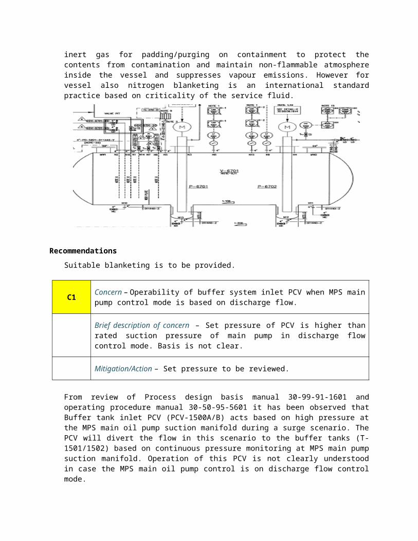
C1Concern – Operability of buffer system inlet PCV when MPS main pump control mode is based on discharge flow.
Brief description of concern – Set pressure of PCV is higher than rated suction pressure of main pump in discharge flow control mode. Basis is not clear.
Mitigation/Action – Set pressure to be reviewed.
From review of Process design basis manual 30-99-91-1601 and operating procedure manual 30-50-95-5601 it has been observed that Buffer tank inlet PCV (PCV-1500A/B) acts based on high pressure at the MPS main oil pump suction manifold during a surge scenario. The PCV will divert the flow in this scenario to the buffer tanks (T-1501/1502) based on continuous pressure monitoring at MPS main pump suction manifold. Operation of this PCV is not clearly understood in case the MPS main oil pump control is on discharge flow control mode.
Buffer tank inlet PCV (PCV-1500A/B) set pressure in pump discharge flow control mode is 30 bar g. In discharge flow control, pump corresponding suction and discharge pressure are 10 bar g and 87 bar g respectively, which seems in suction manifold if pressure soot up is more than 10 bar g, it leads to generation of pressure surge and subsequently PCV-1500A/B is required to take preventive action by opening. As set pressure of PCV-1500A/B is kept at 30 bar g, control valve will start to take action only after pressure at MPS main pump suction manifold reaches 30 bar g or more. Reason for keeping PCV set pressure at 30 bar g is not clear. If PCV fails to open at the right moment there will be a subsequent overpressure scenario at inlet of MPS manifold. It is not mentioned clearly in any of the document about the basis of selection of 30 bar g set pressure of PCV-1500 A/B in case MPS main pumps are in discharge flow control.
Recommendations
Set pressure needs to be reviewed.
C2 Concern – Flow control valve utility in MPS main pump suction manifold.
Brief description of concern – Flow control valve functioning is similar almost to pressure control valve and redundant, also flow control valve is present at bypass.
Mitigation/Action – Flow control valve should have been located in main line, not in bypass line.
From review of P&ID 30-50-08-1624 and 1625 there is a flow control valve (FCV-1301-01) at the MPS common suction manifold inlet which is in the MOV-1301-09 bypass line. From an engineering perspective, it is unclear why this valve is placed here.
Flow control valve is used to take care off excess flow entering to MPS main oil pump suction manifold and thus maintaining the flow as well as indirectly the pressure in the facility. Main design criteria here are to divert flow into the buffer tank (T-1501/1502) due to pressure spikes so that system consistency can be maintained. The pressure spike may occur either due to downstream facility obstruction or from excess flow from upstream. PCV-1500A/B is provided at the buffer tank inlet line to take care off excess pressure at MPS main oil pump suction manifold. PCV shall indirectly control flow (Set pr.-19 bar g) to buffer tank on basis of suction pressure at suction manifold in case pump control is based on suction pressure control. In case, pump control is based on discharge flow, then diversion to buffer tank will take place in case MPS downstream is not in operation and pressure is building in pump suction manifold. Excess pressure shall open PCV-1500A/B (Set pr-30 bar g).
Flow control valve is serving here the similar purpose like surge control. Moreover, centrifugal pump can adjust pumping rate based on available back pressure and discharge flow control is already provided for main oil pumps. Therefore it can be concluded that flow control at inlet of MPS main pump suction manifold is not a mandatory requirement.
Also it has been observed as per review of P&ID 30-50-08-1624 that flow control valve (FCV-1301-01) is located in bypass line of MOV-1301-09. Moreover document 30-99-91-1601 section 7.3.3.2 states that Flow control valve FCV-1301-01 A/ B is provided in the station inlet piping with parallel configuration. Normally one control valve will be in line and the other will be automatic standby. This is to state that this document is contradictory with the P&ID 30-50-08-1624 where only one flow control valve is available in the facility in the bypass line of MOV-1301-09. Basis of using flow control valve also is not explained clearly.
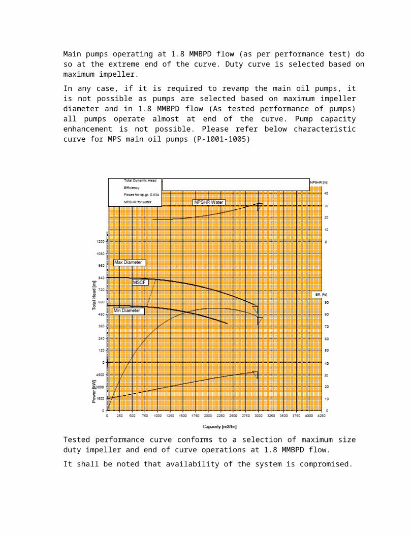
C3Concern – Main oil pumps have to operate near the end of the curve to reach 1.8 MMBPD flow, and duty curve is at the maximum impeller diameter.
Brief description of concern – Selection of main pump is at its maximum duty impeller and pump is extended to operate at 1.8 MMBPD near end of curve. No chance for capacity enhancement in the future.
Mitigation/Action – Further system review required.
Main pumps operating at 1.8 MMBPD flow (as per performance test) do so at the extreme end of the curve. Duty curve is selected based on maximum impeller.
In any case, if it is required to revamp the main oil pumps, it is not possible as pumps are selected based on maximum impeller diameter and in 1.8 MMBPD flow (As tested performance of pumps) all pumps operate almost at end of the curve. Pump capacity enhancement is not possible. Please refer below characteristic curve for MPS main oil pumps (P-1001-1005)
Tested performance curve conforms to a selection of maximum size duty impeller and end of curve operations at 1.8 MMBPD flow.
It shall be noted that availability of the system is compromised.
C4Concern – Operational redundancy in the buffer system due to the presence of PCV, as well as surge skid.
Brief description of concern – Buffer tank inlet PCV and surge skid are serving same purpose.
Mitigation/Action – Any of these can be used.
From system design review of MPS facility, it has been observed that there are two safeguards available to handle surge in MPS main pump suction manifold, one is Surge relief skid and other pressure control valves (PCV-1500A/B) at buffer tank inlet.
Surge due to pressure spike in MPS main pump suction manifold primarily will be taken care off by Buffer tank inlet pressure control valve (PCV-1500A/B). These PCVs are working in one operating and one standby combination. Set pressure of PCV is 19 bar g in case main pumps of MPS are on suction pr. control mode. It is understood, that if pressure at main pumps inlet reaches to 19 bar g and above, PCV will start to act and divert the flow towards the MPS buffer tank to prevent surge and normalize the system pressure. Similarly PCV will act against possible surge if main pumps of MPS are on discharge flow control and will take corrective necessary action. Two scenarios have been captured during designing of the MPS buffer system, first shutdown of the MPS inlet manifold and second downstream facility shutdown. For both the cases, consequence is pressure soot up at the MPS inlet. As PCVs are acting in one working plus one stand by combination so it is truly unexpected that both the PCV will fail together and pressure will be increased further at MPS main pump suction inlet. API 521 section 5.10.3 recommends that if system has multiple inlets with multiple control valves, then position of any control device in those remaining lines other than failed control valves shall be assumed to remain in its normal operating position.
Therefore it can be concluded that use of surge skid and (1w + 1 s) PCVs are redundant as failure of both the PCVs is a double jeopardy situation which is not in compliance to international standards.
Two PCVs (one working and one stand by) could have served the purpose.
C5Concern – Buffer tank manual draining for maintenance and tank clean up.
Brief description of concern – No major provision is provided for complete draining of liquid in buffer tank in order to facilitate tank cleaning or maintenance.
Mitigation/Action – Either oil drain transfer pumps can be operated in a stage-wise planned manner to transfer oil back to one set of buffer tank or portable pump can be utilized for quick draining operation.
It has been observed during system review that no major provision is available for complete draining of liquid in buffer tank (T-1501/1502) in order to facilitate tank cleaning or maintenance. All buffer tanks are connected to booster pumps (P-0901-0904) for tank emptying. Limitation of booster pump operation at low-low level in the tanks will cause considerable amount of dead volume which cannot be drained by the installed facilities.
Dead liquid volume of 110 m dia x 2.5 meter height vertical cylindrical tank is a considerable volume, which could be troublesome for the operator to drain manually. All oil drains are collected in the oil drain collection vessel (V-6701) and need to be evacuated by oil drain collection transfer pumps (P-6701/6702). From verification of oil drain collection vessel (V-6701) capacity and transfer pumps (P-6701/6702) capacity it has been observed that draining of hydrocarbon liquid from buffer tank is going to take prolonged time and needs to be conducted in a planned and stage wise manner. However, there is no specified procedure documented for this purpose. Operating procedure / manual shall address the requirement of buffer tanks manual draining in the above manner which shall be conducted in a stage-wise manner and in a planned way by operator intervention.
Recommendations
It is recommended to prepare an operating procedure for draining the buffer tanks during operation and maintenance for maintenance and clean up. Portable pumps also can be useful to empty the buffer tank in order to facilitate the draining action quickly.
C6Concern – All flow element minimum straight run requirement at upstream and downstream.
Brief description of concern – Minimum 10D and 5D straight run requirement at upstream and downstream of flow element is not properly maintained.
Mitigation/Action – For flawless flow reading in flow meter, minimum straight run to be provided at upstream and downstream of flow element to comply with project P&ID and best engineering practice.
Flow element minimum straight run requirement; 10D minimum straight run at upstream of flow meter and 5D minimum straight run at downstream of flow meter has not been maintained properly, which could lead to erroneous reading of the flow element.
For all flow elements at MPS, there is a minimum straight run requirement stated in P&ID at flow meter upstream and downstream (respectively 10D and 5D) which is a standard code requirement from ASME for installation of flow meter. However, as per construction review, it is observed that in most of the cases, this philosophy is not maintained properly on site. It is an International Standard practice to use 10D minimum straight run upstream of flow meter and 5D minimum straight run downstream of flow meter.
For example, following flow elements in MPS area is not complying to minimum upstream and downstream straight run requirement as indicated in the project P&ID.
30-50-FE/FT-0900-01 (MPS station inlet @ pig receiver bypass, P&ID 30-50-08-1624) 30-50-FE/FT-1301-01 (MPS station inlet manifold, P&ID 30-50-08-1625) 30-50-FE/FT-1500-01 (MPS station inlet manifold, Buffer tank surge diversion line, P&ID 30-50-08-1625) 30-50-FE/FT-1600-01 (MPS station crude export manifold, P&ID 30-50-08-1637)
Moreover in many places standard 10D and 5D minimum straight run requirement across the flow element is not indicated in the project P&ID.
For example, in P&ID 30-50-08-1658 (Produced water system), across orifice flow element 30-50-FE/FT-2400-01 at treated produced water pump (P-2421/2422) discharge, 10D and 5D straight run requirement is not captured which may lead to discontinuous flow pattern and hamper flow meter reading for turbulence.
Recommendations
Standard 10D and 5D minimum straight run requirement across the flow element upstream and downstream shall be followed during construction to comply with International Standard practice and to ensure proper reading.
IPS
Process Engineering
B2 Concern – Tank type selection for Surge Tank at IPS
Brief description of concern- Based on the ADCOP crude Oil Properties and Shell DEP 34.51.01.31-Gen. February 2011 a floating roof tank that conforms to DEP requirement should be specified for this service. However selection of fixed roof surge tanks has been allowed under concession from ADCO.
Suggested Mitigation/Action– Further review required to understand the concession granted.
A study should be carried out to assess the maximum extent of the vapour cloud based on realistic worst case surge event, and necessary risk control measures identified to remove the possibility of ignition.
As a concession has been approved by ADCO to allow the use of a fixed roof tank as the surge tank (T-1101/1102) at the Intermediate pump station, the possibility exists that a flammable atmosphere could exist inside this tank when crude oil is present. However as per Shell DEP 34.51.01.31-Gen. February 2011, selection of storage tank is dependant on flash point and vapour pressure of service fluid and from analysis of physical properties of crude oil it is preferable to use floating roof tank.
Crude oil stored in these tanks cannot be completely emptied with the available pumping arrangement, therefore following operation of the surge system a heel of crude oil is left in the tank. Due to the vapour pressure of the oil (True Vapour Pressure - 11 psia and flash point- -6 °C) a flammable vapour layer will form above this crude oil layer. If a subsequent operation of the surge system occurs, the flammable vapour may be discharged to the atmosphere through the tank vent.
This flammable vapour cloud may disperse harmlessly into the atmosphere, however if this flammable vapour cloud were to find an ignition source, a fire and or explosion could result,
injuring personnel present and causing equipment damage and the potential for the incident to escalate.
For atmospheric pressure storage tanks containing a flammable material inert gas blanketing is commonly used to prevent air ingress into the tank leading to a flammable atmosphere. Air ingress into the tank occurs during tank emptying but can also occur during “breathing” due to thermal contraction of the vapour space in the tank. As per recommendation in API 2000 a breather valve to be provided to take care off thermal expansion and contraction inside the storage tank and will also necessarily serve the purpose for emergency venting.
Fuel gas is often used as an inert gas blanket on hydrocarbon storage sites as it is readily available and can easily be discharged via a flare. Nitrogen is also widely used where fuel gas disposal is not possible due to the lack of a flare or where the gas may react with the tank contents.
Recommendations
It is therefore recommended that a further review be undertaken to understand why inert gas blanketing is not provided for these tanks and based on the outcome of that review suitable inert gas blanketing provided if necessary.
A study should therefore be carried out to assess the maximum extent of the vapour cloud discharged during tank filling, based on realistic worst case surge event, and necessary risk control measures identified to remove the possibility of ignition.
MOT
Process Engineering
B1 Concern – Due to a limitation of the NPSHA on pumps, ship loading time is increased.
Brief description of concern – A Low Level situation occurs in the crude tanks when the level falls below set points. When the level goes below 5 meters, NPSHA becomes lower and that affects the efficiency of dispatching crude to the ship.
Mitigation/Action- Further design review required for system analysis.
The Ship loading facilities in MOT have a low NPSH margin, which is further aggravated by acceptance of the pumps with higher NPSHR than considered in design. Due to low NPSH margin available, the higher level of crude to be maintained in the tanks to enable normal operation of ship loading pumps. In case the level of the tanks from which the pumps draw suction fall below a set point the through put of the pumps has to be reduced to avoid cavitations and pump damage. This in turn will affect the pumping time for dispatching crude oil via SPM.
It shall be noted that availability of the system will be compromised.
B2 Concern – Nitrogen blanketing is not available in the oil drain collection vessel.
Brief description of concern – A nitrogen blanket (which artificially pressurizes the system and prevents oxygen from entering the system) is necessary to ensure the oil does not flash its light ends and subsequently cause a fire. Without a nitrogen blanket, safety is compromised, even under normal operating conditions.
Mitigation/Action – Blanketing is required.
From review of P&ID 30-50-08-1625 it has been observed that there is no such provision for nitrogen blanketing in the oil drain collection vessel (V-6701), though the collected fluid is a hydrocarbon with vapour pressure of 11 psi and flash point of 20 Deg F. The vessel is provided with an atmospheric breather that could lead to air ingress to the vessel (V-6701) inside during normal operation. There is a high possibility for this type of liquid to flash during normal operation by any internal metal friction or other external factors which can produce a spark and fulfils the fire triangle.
This can lead to the generation of an explosive air and hydrocarbon vapour mixture & can result in an explosion and fire. Also, vapour pressure of the fluid is high enough to generate vapour clouds and possibly can generate explosive air – hydrocarbon vapour mixture due to presence of oxygen inside the vessel. Moreover vapour resulted from flashing of hydrocarbon fluid may escape through vent route to atmosphere and may offer hazardous working environment to operating personnel and surrounding community. For this type of system nitrogen blanket adds a level of safety to the system by creating an inert atmosphere inside the vessel. Nitrogen blanketing is a safety requirement in order to prevent oxygen ingress to the tank which might lead to fire. API-2000 recommends for providing inert gas for padding/purging on containment to protect the contents from contamination and maintain non-flammable atmosphere inside the vessel and suppresses vapour emissions. However for vessel also nitrogen blanketing is an international standard practice based on criticality of the service fluid.
Recommendations
Suitable blanketing is to be provided.
C1Concern – High-High level inside surge relief tank would cause pipeline shutdown.
Brief description of concern – Operational flexibility issue against pipeline shutdown when spare inventory is available.
Mitigation/Action – Operational procedures shall ensure that the surge relief tanks are maintained at minimum level after each occurrence of surge.
In case of High-High level inside surge relief tank, pipeline shutdown is triggered, in spite of having spare tank available.
There are three surge tanks available to take care of additional pressure surge from IPS inlet. One tank is always available and inline. Pipeline shutdown is initiated in case of High-High liquid level in surge tank.
Spare storage capacity is always available when one surge tank is in operation. Spare capacity can be used in case of High-High level of tanks, instead of tripping the whole system.
Operational procedures shall ensure that the surge relief tanks are maintained at minimum level after each occurrence of surge.


![The Process of Architecting for Software / System Engineering · IBM Professional Certification Program [IBM 2010]. ... Section 2 presents an overview of the architecting process](https://img.pdfslide.net/doc/110x75/5f4c5ab91f96b05bcc4017ec/the-process-of-architecting-for-software-system-engineering-ibm-professional-certification.jpg)