Embed Size (px)
Citation preview

PROCESS MANUFACTURING SIMULATION USING ISA-88 BATCH CONTROL
Peter C. Bosch Adam Lalonde S42 W27451 Oak Grove Lane 555 Long Wharf Drive
Highpoint Software Systems, LLC Neo PLM, Inc.
Waukesha, WI, 53189, USA New Haven, CT 06511, USA ABSTRACT
Design of batch process recipes is often done via spreadsheet or Matlab analysis. This technique relatively easily allows for mass balance and timescale computation, but can fall short in other analytical areas such as equipment utilization efficiency and maintenance needs. We present a mechanism for modeling recipes with the same control structure used in logic controllers designed to the ANSI/ISA-88 standard as it applies to Batch Control Language. This mechanism enables the engineering of recipes through the modeling environment and into the plant floor operational recipes. The use case we present is that of manufacturing the active ingredient in Aspirin – acetyl salicylic acid. We use a simple production recipe and generate a simulation model from that recipe, collecting data on that process. We have developed campaign and multi-campaign models using this technique as well, and have automatically generated production recipes for control systems such as Provox and DeltaV.
1 INTRODUCTION
ANSI/ISA-88 (S-88), is a standard for batch manufacturing process control. Batch process design is typically done by a chemist or materials scientist, and control recipe design is typically done by a control system engineer with expertise in the particular system on which the recipe will be done. As a result, the batch process design is usually done on a computational platform with which the process engineer is familiar, such as Excel, Matlab, or a chemistry- or materials-specific tool. Following that design activity, the control engineer translates that recipe into an executable form of the control system’s recipe structure.
This raises several issues. First, the design process has a clear dividing point with a significant mismatch. The first, by the chemist or materials scientist, focuses on mass and energy balance, and the basic reactions necessary to the process. The second, by the process control engineer, focuses on assignment of steps to specific equipment with specific components, parallelization of operations across equipment, and to some degree, issues of cycle time and equipment and campaign efficiency. This imposes differing design concerns, and can lead to designers working at crossed purposes. Second, any iteration in the design process requires synchronizing two very different intellectual approaches, two stages of revision, and the performance of consistency checks between them. Design concerns that are introduced in the second design stage (the execution model) can drive updates into the chemists’ models, which may in turn impact the execution model. Finally, simulation of multiple batches or campaigns in a production facility requires another toolset, and probably another engineer.
A project recently completed at a major client entails a design environment that incorporates a control-system-specific representation of a process model whose steps are automatically assigned to equipment and finally used to generate a control system recipe. This paper discusses the simulation control mechanism, and in addition to the as-built execution engine, describes some elements of the proof-of-concept demo that was used by the team to drive further development into batch and campaign simulation as well as a tactical representation of current progress to the operations department’s supervisory personnel.
Bosch and Lalonde
2 MECHANISM DESCRIPTION
We have used the S-88 standard as the philosophical and structural basis for designing our simulation control mechanism, in order to minimize mismatch between plant floor data and simulation data, and to enable conceptual, data and recipe reuse throughout the range of applications (analysis, scheduling, maintenance, runtime optimization) to which a production model is subjected.
2.1 The S-88 Standard
The basis of the simulation control mechanism described in this paper is the S-88 Batch Process Control standard. This standard provides a consistent set of standards and terminology for batch control and defines the physical model, procedures, and recipes - see ANSI/ISA-88.01-1995, Batch Control Part 1. Most importantly to this paper, it specifies a hierarchical taxonomy of recipes, each focused on a different level of detail, and also specifies a control mechanism called a Sequential Function Chart.
2.1.1 Recipe Structure
The ISA S-88 standard describes four layers of recipes. These include General, Site, Master, and Control recipes, as shown in Figure 1. In that order, they proceed from the most general, and enterprise-level to the most specific and equipment-centric. The general recipe is enterprise-level and may contain input and output materials, general processing steps and chemical or physical transformations. The general recipe may be used to create site recipes. Site recipes are still general in nature, but are localized to a particular site in terms of their language, nuances of locally-used materials, and perhaps regulatory requirements. Site recipes are typically used for long-term planning and scheduling. General or Site recipes may be used to create one or more master recipes. A Master recipe is tailored to describe a detailed process to take place in a particular manufacturing cell or production line. The Master recipe is typically normalized to a standard quantity, and is used for detailed scheduling. Master recipes must exist, as they are used to create Control Recipes. Control recipe instances exist one-per-batch, are scaled to the specific batch size and assigned equipment, and may be adjusted to reflect unplanned or unexpected activities.
Figure 1: The Four Recipe Types of S-88
Within each of the recipes, there is a common structure. This structure may have different names under
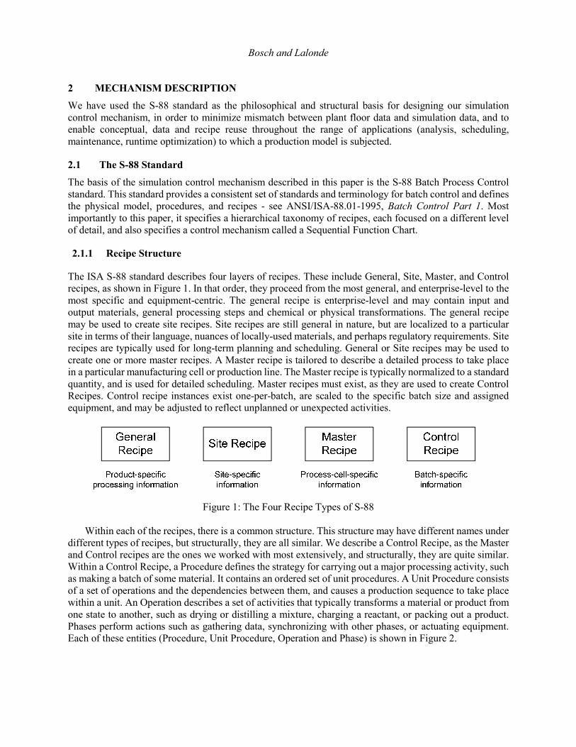
different types of recipes, but structurally, they are all similar. We describe a Control Recipe, as the Master and Control recipes are the ones we worked with most extensively, and structurally, they are quite similar. Within a Control Recipe, a Procedure defines the strategy for carrying out a major processing activity, such as making a batch of some material. It contains an ordered set of unit procedures. A Unit Procedure consists of a set of operations and the dependencies between them, and causes a production sequence to take place within a unit. An Operation describes a set of activities that typically transforms a material or product from one state to another, such as drying or distilling a mixture, charging a reactant, or packing out a product. Phases perform actions such as gathering data, synchronizing with other phases, or actuating equipment. Each of these entities (Procedure, Unit Procedure, Operation and Phase) is shown in Figure 2.
Bosch and Lalonde
Figure 2: The Four Execution Layers of a Control Recipe in S-88
2.1.2 Sequential Function Charts
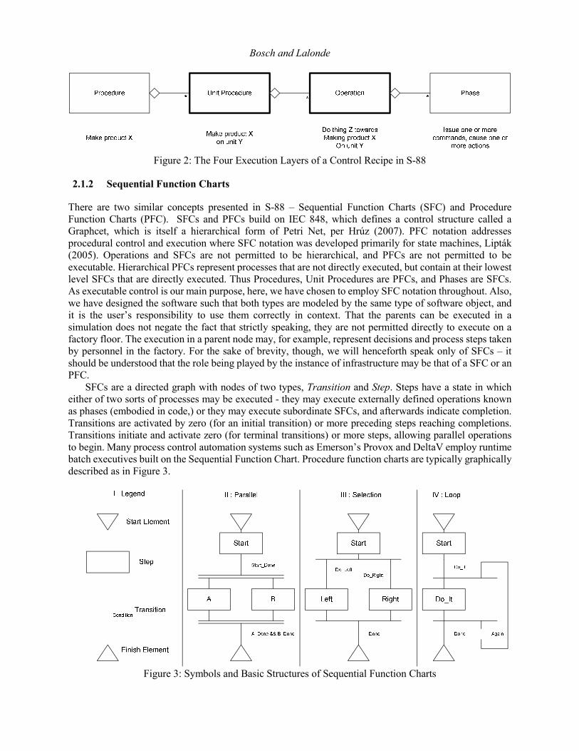
There are two similar concepts presented in S-88 – Sequential Function Charts (SFC) and Procedure Function Charts (PFC). SFCs and PFCs build on IEC 848, which defines a control structure called a Graphcet, which is itself a hierarchical form of Petri Net, per Hrúz (2007). PFC notation addresses procedural control and execution where SFC notation was developed primarily for state machines, Lipták (2005). Operations and SFCs are not permitted to be hierarchical, and PFCs are not permitted to be executable. Hierarchical PFCs represent processes that are not directly executed, but contain at their lowest level SFCs that are directly executed. Thus Procedures, Unit Procedures are PFCs, and Phases are SFCs. As executable control is our main purpose, here, we have chosen to employ SFC notation throughout. Also, we have designed the software such that both types are modeled by the same type of software object, and it is the user’s responsibility to use them correctly in context. That the parents can be executed in a simulation does not negate the fact that strictly speaking, they are not permitted directly to execute on a factory floor. The execution in a parent node may, for example, represent decisions and process steps taken by personnel in the factory. For the sake of brevity, though, we will henceforth speak only of SFCs – it should be understood that the role being played by the instance of infrastructure may be that of a SFC or an PFC.
SFCs are a directed graph with nodes of two types, Transition and Step. Steps have a state in which either of two sorts of processes may be executed - they may execute externally defined operations known as phases (embodied in code,) or they may execute subordinate SFCs, and afterwards indicate completion. Transitions are activated by zero (for an initial transition) or more preceding steps reaching completions. Transitions initiate and activate zero (for terminal transitions) or more steps, allowing parallel operations to begin. Many process control automation systems such as Emerson’s Provox and DeltaV employ runtime batch executives built on the Sequential Function Chart. Procedure function charts are typically graphically described as in Figure 3.
Figure 3: Symbols and Basic Structures of Sequential Function Charts

Bosch and Lalonde
The legend shows the symbols for start and finish elements, which each have cardinality of one in a given SFC. The legend also shows the symbol for a step and a transition. In theory, there is not a limit to the number of steps and transitions contained in one SFC.
There are a very wide range of control constructs that can be represented in an SFC. In section II of Figure 3, we show a basic parallel task. After Start_Done is true, both A and B will run until ‘A_Done && B_Done’ is true. In section III, we show a selection structure wherein the values of Do_Left and Do_Right (which must be mutually exclusive) determine which of the steps “Left” or “Right” will run until the transition condition “Done” is satisfied. In section IV, we describe a basic loop, which begins when Do_It is satisfied, and continues cycling through the step “Do_It” as long as transition condition “Again” is true, and “Done” is false. As in section III, the conditions “Again” and “Done” must be mutually exclusive.
This is a brief treatment of the structure and operation of a Procedure Function Chart. It leaves out important aspects such as resource acquisition and synchronization. For more detail, see ANSI/ISA S-88.00.02.
2.2 Baseline Software Implementation
In our work on a Product Lifecycle Management application suite, we are using an executable SFC implementation underneath application modules for batch process recipe design and analysis, schedule validation and recipe generation. As we have shown above, S-88 dictates, and to varying degrees, control system vendors support, the use of what amount to hierarchical SFC in organizing the core manufacturing software entities, control system recipes. We will describe the Sage framework that enables an engineer to build a simulation-capable model that conforms to the structure and behaviors dictated by S88.
2.2.1 Sage® Libraries
The Sage libraries consist of many packages, or namespaces, each of which contributes a piece of functionality to a potential user’s overall simulation needs - see Bosch (2003). The representation of a batch processing model relies on several of these. At the base level is the SimCore package, which provides the elemental Discrete Event Simulation engine, including the implementations of executives, models, errors and warnings, start/pause/resume/stop model state management and a host of other services necessary for simulation but not germane to this discussion. Other important contributors from the Sage libraries into this modeling effort are the resource, equipment, and Materials packages (for thermodynamics and chemistry.) The mathematics package is used to generate distributions for processing durations.
2.2.2 SFC Package
The Sage simulation libraries include classes that support the construction and manipulation of Sequential Function Chart control structures. A Unified Modeling Language (UML) diagram of the major structural classes is shown in Figure 4, below – see Object Modeling Group (2012).
2.2.2.1 SequentialFunctionChart Class
Structurally, the SequentialFunctionChart class is responsible for creating and containing all of the steps, transitions, links and expressions that make up the chart. It provides network analysis as well as single-layer and multi-layer complexity reduction methods, used primarily for validation of the structure, to ensure that it can be run.

Bosch and Lalonde
Figure 4: Class Diagram for Sage PFC Structural Classes
2.2.2.2 SfcStep
Steps are the part of the SFC in which external actions are imposed. Steps’ execution is controlled through a state chart that dictates when, and what, things may happen. This state chart is depicted in Figure 5 below. The leftmost representation is the standard-specified state machine, and the rightmost is a simplified representation that is useful for understanding the flow through the states. Each step may have one or more actions which are executed in parallel when the step is in the “Running” state. An action is a subordinate execution entity, and can therefore be a SFC or any method which fulfills a specific call signature, and has been designated to the step as one of its actions. Actions are the only mechanism through which phases may run, and are the only link to the real world of hardware and process actuation. Replacing one set of actions with another set of actions can completely alter the effect of running a recipe without altering its structure. As such, they are also a good entity to use in switching between desired recipe behaviors - code for that hardware and process actuation, for simulation, for history tracking and for reporting applications may be switched in and out. A convenience class, SfcAction, provides basic implementation of framework details for the case where a Step will have only one action.
Figure 5: Full and Simplified Step State Machine per S-88

Bosch and Lalonde 2.2.2.3 Transitions
Transitions are the part of the SFC in which logical choices that affect control flow are made. Those choices are made through the evaluation of a condition, provided in the form of a Boolean code expression. Transitions are initially in the Inactive state, but when a step transitions to “Running”, it moves all of its successor transitions to “Active,” in which state, they periodically reevaluate their conditions. When a condition evaluates to true, predecessor steps are transitioned to “Stopped” and then to “Idle,” following which, successor steps are transitioned to “Running.”
Self-i
mpo
sed
afte
r
expr
==tru
e,
stop
/rese
t of p
reds
.
All Predecessors Non-Final
& Some are Q
uiescent
All Pre
dece
ssor
s Non
-Fin
al
& Non
e ar
e Qui
esce
nt
Figure 6: Transition State Machine
Sage transitions manage their own expressions, providing executable, human-readable, and other
representations of those expressions for various uses.
2.2.2.4 Links
Links are the mechanisms through which state transitions are imposed on a step’s or a transition’s predecessor or successor transitions or steps. They are a very simple construct and get very little treatment in the ANSI/ISA S-88 standard.
Sage links maintain data for graph analysis, and provide connectivity between Steps and Transitions. They are treated as edges in the graph that is a SFC, and are important for validity-checking and other analytical functions.
2.2.2.5 Execution Engine
Sage has an execution engine which is attached to each SFC, knows how to coordinate with super- and sub-ordinate SFCs’ execution engines, and holds state machines for all of its steps and transitions. The execution engine interacts with the simulation engine (the Sage executive) and manages all run-time state of the SFC that is not held in the SfcActors.
2.2.2.6 SFC Execution Context
We desire statelessness in SFCs, so that multiple processes can use them as a control structure simultaneously. Therefore, runtime data are contained in a hierarchical dictionary called an execution context. When a SFC is executed, an execution context (EC) is created for it, and passed into the execution engine for that SFC. As each step in that SFC is run, an EC is created as a child of the SFC’s EC, and that EC is passed into the step. A step’s code may create, read, update and delete data elements at its own level (i.e. its own EC) as well as upward, downward or laterally in its runtime tree of ECs. A time-period data element is built-in and automatically updated to record the start time and end time of the step’s or SFC’s activity.

Bosch and Lalonde
Run-time decisions at any level, whether control-flow or modeling-related may require state data. Historical analysis may require state data. Correlation of execution instances between two or more (e.g. Monte-Carlo) runs of a simulation may require state data. Different entities in a model may need to exchange data, sometimes with and sometimes without knowledge of the other.
A step that occurs in a loop may need to create and access data that are unique to each iteration through the loop, data that are common to all iterations in that execution of the loop, and data that are common to all iterations in all executions of the containing loop. For this reason, ECs are generated for a step for each iteration through a loop. The above data requirements are met by a step’s depositing its data in its own or an ancestor’s EC. The key under which it is deposited can be an object owned by the step itself, which prevents another object’s overwriting the element.
2.3 Derived Software Implementation
This section describes the implementation that was built on top of the existing SFC framework. Much of the GUI work was done by a third party named MSolutions, to the specifications of our joint customer. The integration effort between their visualization layer and the underlying simulation layer was comparatively simple.
The reuse employed over the Sage libraries meant that 330 lines of new code were required for the aspirin model implementation (not including visualization code) and an additional 300 to 400 were used to drive the nineteen unit test cases built for it. Below, we describe the classes created, and the resultant data obtained, and insights gained - from the model.
2.3.1 Aspirin SFC Structure
A subclass of SFC called AspirinSFC was created using the primitives described above and contained the structure of the recipe. The control structure is shown in Figure 6 below.
Figure 6 : AspirinSFC structure

Bosch and Lalonde 2.3.1 Aspirin Recipe
A class called AspirinRecipe was created, containing physical constants, quantities, durations and temperatures, as well as the methods that serve as each SFC step’s actions. A partial list of the members of the AspirinRecipe class are shown in Figure 7.
Figure 7 : Partial Listing of AspirinRecipe class properties
2.3.2 Aspirin Simulation Visualization
The Aspirin Model is run in the simulation engine, and can be run for one or more batches, with equipment being the constrained resource that governs progress. Execution can be tracked live, and the speed of the simulation can be varied as it runs. There are several visualizations that were built, but all sink the same data that are sourced from the core Aspirin Model.
2.3.2.1 Equipment Flow Diagram
One visualization module represents the four units in the recipe graphically, as well as the waste and product receivers to which discharges are sent. This representation shows the vessels’ mixture constituents in terms of chemical names, mass and energy balance, and reactions. This view aggregates the results of multiple batches’ execution. See Figure 8, below.

Bosch and Lalonde
Figure 8 : Equipment Flow Diagram of Aspirin Recipe
2.3.2.2 Sequential Function Chart
The Sequential Function Chart visualization is shown in Figure 6 above. It is the full-fidelity model view, and describes steps with their sequences, running and completion conditions as well as synchronizations for material transfer and equipment acquisition and release.
2.3.2.3 Condensed Model View
The client specified a condensed model view that collapses the complexity of the Sequential Function Chart representation above into a concise representation that non-control-system-literate personnel such as shift supervisors, chemists and lab technicians. This is shown in Figure 9 below.
Figure 9 : Condensed Model View

Bosch and Lalonde
2.3.2.4 Schedule
The data are extracted from the structure and expected durations as well as the stochastically-driven actual durations in a running model to represent planned and actual durations of tasks. The most abbreviated form of the schedule shows only the batch-level plan and actual durations. See Figure 10.
Figure 10 : Abbreviated Schedule View
There are other detailed uses to which schedule data are put. For example, in Figure 10 we show the
presentation of an equipment-centric view that shows the utilization of each piece of equipment (Unit A is the Reactor, B is the Crystallizer, and so forth) for each batch.
Figure 11 : Condensed Model View
3 MODEL REUSE
There are many places in the application that executable models are used. Their structure as nestable SFCs enables fine-grained simulation of a single recipe at a low (i.e. phase) level, or broad-brush simulation of operations at an enterprise level, as a part of a schedule object. Their close fidelity to the operational control structure allows us to create parallels between the plant floor and the design environment. Some of these usages are shown below.
3.1 Multi-batch Execution
By separating the runtime data (kept in Execution Contexts) from the process control structure, we can start two or more batches running on the same SFC. Since the first step in a unit’s SFC is to acquire the equipment necessary to run, the batches will naturally serialize themselves to the degree imposed by any equipment limitations. For example, if there is only one centrifuge available, the batches will run serially, gated by centrifuge availability.

Bosch and Lalonde 3.2 Mock Data Generation
Phases can be written such that they generate appropriate representation of data generated by controllers on a plant floor. This allows a running simulation to generate a history data stream for feeding to other support systems to test for proper operation.
3.3 Live Data Analysis
We have written algorithms that match history data streams from the plant floor to the production recipe models, and construct a simulation that proceeds from an estimated current state of the plant floor. This will allow us to predict bottlenecks arising from variations in production flow on the plant floor.
3.4 Recipe Generation
The current implementation of the PLM application’s Active Ingredient recipe simulation modeler uses a task-graph (as opposed to SFC) control mechanism that is described in Bosch (2003). However, two of the recipe generators for the application convert the task graphs to Sage SFCs and perform structural validation against the Executable SFC library. The SFCs are then used to generate control system recipes for Emerson’s and Rockwell’s control systems.
In our experience, and using the Sage SFC framework, this provides a direct link between the modeling of a recipe for simulation, and the modeling of a recipe for plant floor execution. This allows engineering staff to keep simulation models up to date at the same time that the manufacturing execution models are kept up to date, allowing systems such as scheduling and operational monitoring to remain in sync with what is happening on the plant floor. Related Usages
3.5 Scheduling Application
The same module that translates the task graph based recipes for control recipe generation, can generate executable SFCs that are integrated into higher-level schedule SFC representations. In these models, which we call Stochastic Facility Models, a facility can contain child facilities, and all facilities can have resources, recipes that manage those resources (e.g. Head Tank refill, Coating Solution Makeup), and a schedule containing campaigns of batches, each of which holds an executable recipe. A facility’s schedule is a roll-up not only of its own campaigns and batches, but also those of its subordinate facilities’ campaigns.
This overall SFC representation is then used with stochastic distributions applied to variable properties such as transfer, reaction and distillation rates, iteration counts for titrations and operator response delays to create a stochastically variant representation of a high level schedule. By replacing any step’s subordinate SFC (and thereby the functionality embedded in it) with a summary representation of that functionality, analyses can make arbitrary tradeoff of detail-versus-performance.
4 SUMMARY
By aligning our simulation control structure with industry-standard S-88 Sequential Function Charts in use across multiple plant floor execution systems in use at our client, we were able to build a software substrate that embodies the bulk of material, chemistry, thermodynamics, resource, and Sequential Function Chart control behaviors, so that specific recipe models can be easily created with a minimum of additional code. These tailored recipes enable robust stochastic or deterministic modeling of batch manufacturing processes in per-batch or schedule-wide context, for either design-time or run-time analytical use, as well as easy translation from the process and chemical engineers’ conceptual, process and facility-specific models into the control system recipes they generated.

Bosch and Lalonde REFERENCES
Bosch, P. C. 2003. Introduction to HighMAST. In Proceedings of the 2003 Winter Simulation Conference, ed. S. Chick, P.J. Sanchez, D. Ferrin and D.J. Morrice, 1852-1859. Piscataway, New Jersey: Institute of Electrical and Electronics Engineers, Inc.
Béla G. Lipták. 2005. Instrument Engineers' Handbook: Process control and optimization. 4th ed. Research Triangle Park, North Carolina, CRC Press
American National Standards Institute & Instrumentation, Systems and Automation Society, Standard ANSI/ISA-88.01-1995, Batch Control Part 1: Models and Terminology, ISA, Research Triangle Park, North Carolina, USA.
American National Standards Institute & Instrumentation, Systems and Automation Society, Standard ANSI/ISA-88.03-2003, Batch Control Part 3:General and Site Recipe Models and Representation, ISA, Research Triangle Park, North Carolina, USA.
Object Modeling Group. 2012. Unified Modeling Language Standard, version 2.4.1. Accessed April 13, 2016. http://www.omg.org/spec/UML/ISO/19505-1/PDF
Branislav Hrúz, MengChu Zhou 2007. Modeling and Control of Discrete-event Dynamic Systems. Springer Science & Business Media
AUTHOR BIOGRAPHIES
PETER C. BOSCH is a founder of Highpoint Software Systems, a small and attentive decision-support technology firm in the upper Midwest. He holds a BSEE from the State University of New York, and is a Certified Java Developer and Microsoft Certified Solution Developer. Pete has published numerous technical articles on object-oriented development in these environments. Pete has been designing and building simulations since 1991, for Fortune 100 firms in aerospace, medical imaging, pharmaceutical manufacturing and investment banking. He has had leadership roles on large software projects since 1995.
ADAM LALONDE has an M.S. in Chemical Engineering from the University of Connecticut. He is currently Program Director for Neo PLM Inc., a software company that incorporates chemical process modelling into a suite of tools for managing batch manufacturing. Over the past 15 years, he has partnered with Mr. Bosch on a number of projects involving the application of process simulation in batch manufacturing environments.