Embed Size (px)
Citation preview

Process WiringApplication Guide
Your Global Automation Partner

Connectivity | Process WiringQuestions that will be answered:
• What color of ITC cable do I specify?• Which ITC cable do I specify and why?• What parts go together as a system solution?
What is ITC cable?
Instrument tray cable.
Can you use ITC cable in Division 2?
In 1996, the NEC allowed ITC as a Division 2 wiring method.
NEC article 727 - Instrumentation tray cable: Type ITC
Wiring for instrumentation and control circuits operating at 150 volts or less and 5 amps or less.
For industrial establishments where a qualified person services the installation.
Permitted uses:
• In cable trays• In raceways• Armored cable• ITC-ER rated cable with mechanical protection
Not permitted:
• Must not be run with power, lighting, Class I, or non-power-limited circuits

Contents
How to Specify the Most Common Process Wiring Applications. . . . . . . . . . . . . . . . . . . . . . . . . . . . . . . . . . . . . . . . 5
What Color of ITC Cable Do I Specify?Which ITC Cable Do I Specify and Why?Exposed Run or ITC-ER is a Very High-spec CableAdding Quick-DisconnectsLokfast® GuardsMultifast® is Available with Integral LocksAll Connectors in Class I, Division 2 Require a Lokfast Guard or Locking Home Run ConnectorAvailable for all M12 Eurofast® and Minifast® Body StylesCable Seals in Division 2
Quick Disconnect Solution for Explosion-proof Devices in Division 2 . . . . . . . . . . . . . . . . . . . . . . . . . . . . . . . . . . 1 3
Explosion Protection is Suitable for Division 1 or Division 2Explosion-proof Feed-Thru Application
Cordset Solution Components . . . . . . . . . . . . . . . . . . . . . . . . . . . . . . . . . . . . . . . . . . . . . . . . . . . . . . . . . . . . . . . . . . . . . . 1 4
The Parts You Will Need: Class I Division 2 Hazardous AreasReceptaclesCordsetsRecommended Receptacle Gender PlacementInstallation Instructions for Turck’s 7/8-16 UN Minifast and M12 Eurofast Connectivity Products
Process Wiring Physical Layer Guidelines . . . . . . . . . . . . . . . . . . . . . . . . . . . . . . . . . . . . . . . . . . . . . . . . . . . . . . . . . . . 1 7
Process
What Parts go Together as a System Solution?. . . . . . . . . . . . . . . . . . . . . . . . . . . . . . . . . . . . . . . . . . . . . . . . . . . . 1 9
4-Port Junction Box Options Typical Field Instrument Application: Non-Armored ITC-ERTypical Field Instrument Application: Armored ITC-ER (Armorfast)Instrument Wire to 4-Port Box PinoutSingle Analog 4-Port BoxDivision 1 HART/Analog Intrinsic Safety
4-Port Junction Box for Mixing Valve and Transmitter Applications . . . . . . . . . . . . . . . . . . . . . . . . . . . . . . . . . . . . . 2 4
Process Wiring Matching Assembly Part NumbersTypical Field Instrument Application: ITC-ER4-Port Box with ITC-ER, Direct Burial (6-pin, 2 Analog/Port)
V-Prox Valve Box Application . . . . . . . . . . . . . . . . . . . . . . . . . . . . . . . . . . . . . . . . . . . . . . . . . . . . . . . . . . . . . . . . . . . . . . 2 7
V-Prox 4-Port Box with Grey ITC Drop and Black ITC-ER Direct Burial Colored Jacket
8-Port Junction Box Options . . . . . . . . . . . . . . . . . . . . . . . . . . . . . . . . . . . . . . . . . . . . . . . . . . . . . . . . . . . . . . . . . . . . . . . . . . 2 8
Process Wiring Matching Assembly Part NumbersTypical Field Instrument Applications: ITC-ERTypical Field Instrument Applications: Armored ITCInstrument Wire to 8-Port Box PinoutSingle Analog 8-Port Box ITC-ER
Retrofit to Existing Division 2 Conduit Systems . . . . . . . . . . . . . . . . . . . . . . . . . . . . . . . . . . . . . . . . . . . . . . . . . . 3 2
Harsh Environment Applications . . . . . . . . . . . . . . . . . . . . . . . . . . . . . . . . . . . . . . . . . . . . . . . . . . . . . . . . . . . . . . . . . . . . . 3 5
Harsh Environment Cable: Non-Armored and Braided Armor Construction . . . . . . . . . . . . . . . . . . . . . . . . . . . . 3 6
Harsh Environment: 4-Port Junction Box Options . . . . . . . . . . . . . . . . . . . . . . . . . . . . . . . . . . . . . . . . . . . . . . . . . . . . . . 3 7
4-Port Junction Box Options for Mixing Analog and Digital Signals . . . . . . . . . . . . . . . . . . . . . . . . . . . . . . . . . . . . . 3 9
Harsh Environment Cable: 8-Port Junction Box Options . . . . . . . . . . . . . . . . . . . . . . . . . . . . . . . . . . . . . . . . . . . . . . . . 4 1
Retrofit to Existing Class I Division 2 Conduit System. . . . . . . . . . . . . . . . . . . . . . . . . . . . . . . . . . . . . . . . . . . . . . . . . . . 4 3
AC Power Applications for Control Equipment. . . . . . . . . . . . . . . . . . . . . . . . . . . . . . . . . . . . . . . . . . . . . . . . . . . . . . . . 4 4
MC-HL Receptacle Extensions . . . . . . . . . . . . . . . . . . . . . . . . . . . . . . . . . . . . . . . . . . . . . . . . . . . . . . . . . . . . . . . . . . . . . . . . 4 7
Accessories . . . . . . . . . . . . . . . . . . . . . . . . . . . . . . . . . . . . . . . . . . . . . . . . . . . . . . . . . . . . . . . . . . . . . . . . . . . . . . . . . . . . . . . 5 0
Connectivity | Process Wiring
We
rese
rve
the
right
to m
ake
tech
nica
l alte
ratio
ns w
ithou
t prio
r not
ice.
How to Specify the Most Common Process Wiring Applications
Turck Offers 3 Types of Rated ITC Cable: Basic ITC, ITC-ER & Armorfast®
ITC Cable is an NEC Division 2 Wiring Method
What Color of ITC Cable Do I Specify?
ITC cable comes in three colors:
Plum - original color
Black - preferred for direct sunlight applications
Blue - for intrinsically safe circuits
Armorfast: ITC cable with interlocking tape armor
Basic ITC Cable ‘Exposed Run’ rated ITC Cable
NON-HAZARDOUS LOCATIONHAZARDOUS LOCATIONClass I, Division 2
NEC 501.10(B)(1)(5):“ITC cable as permitted in 727.4”.
6
Connectivity | Process Wiring
We reserve the right to m
ake technical alterations without prior notice.
How to Specify the Most Common Process Wiring Applications
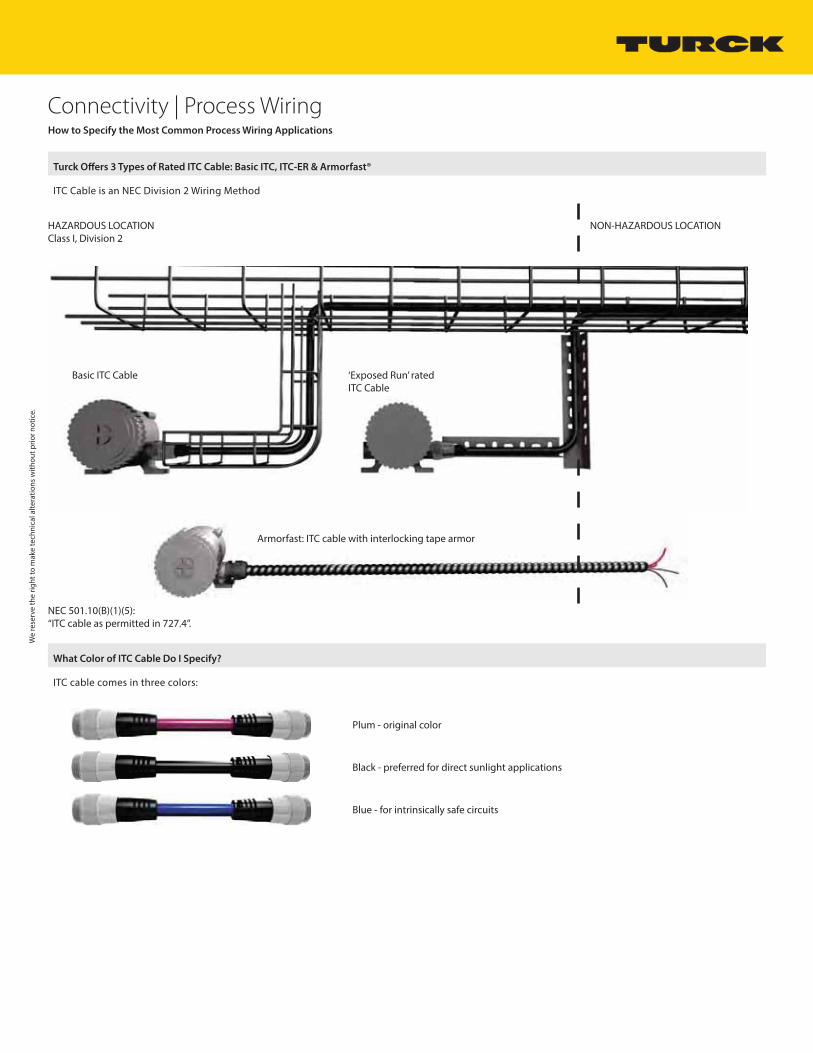
Which ITC Cable Do I Specify and Why?
Basic ITC Cable
NON-HAZARDOUS LOCATIONHAZARDOUS LOCATIONClass I, Division 2
NEC 727.4 Uses Permitted (1) “In cable trays”.
Key Point:
Basic ITC cable should be installed in tray.

Connectivity | Process Wiring
We
rese
rve
the
right
to m
ake
tech
nica
l alte
ratio
ns w
ithou
t prio
r not
ice.
How to Specify the Most Common Process Wiring Applications
Which ITC Cable Do I Specify and Why?
ITC-ER Cable
NON-HAZARDOUS LOCATIONHAZARDOUS LOCATIONClass I, Division 2
NEC 727.4 Uses Permitted (5) “Cable without a metallic sheath or armor that complies with the crush and impact requirements of type MC cable and is identified for such use with the marking ITC-ER shall be permitted to be installed exposed.”
Key Point:
Customer has to mechanically protect ITC-ER cable when run out of tray.
Exposed Run or ITC-ER is a Very High-Spec Cable
Basic ITC is already a premium cable. The flammability and temperature requirements of UL 2250 dictate a rugged cable.
Crush and impact requirements for ER cable are extremely difficult for unarmored cable to meet.• Crush – Cable is crushed 10 times between a flat plate and a ¾ inch rod. The average force to
produce an electrical short must exceed 1000 lbs.• Impact – Cable is impacted 10 times by a 10 lb. ball dropped from
1 ½ ft. at least eight impacts must produce no electrical shorts.
Formerly identified as ‘OPEN WIRING’.

Connectivity | Process Wiring
We reserve the right to m
ake technical alterations without prior notice.
How to Specify the Most Common Process Wiring Applications
Which ITC Cable Do I Specify and Why?
Armorfast ITC Cable
ITC cable with interlocking tape armor
Key Point:
Additional mechanical protection not required.
NON-HAZARDOUS LOCATIONHAZARDOUS LOCATIONClass I, Division 2
NEC 727.4 Uses Permitted (4) “Enclosed in a smooth metallic sheath, continuous corrugated metallic sheath, or interlocking tape armor applied over the nonmetallic sheath in accordance with 727.6. The cable shall be supported and secured at intervals not exceeding 1.8 m (6 ft).”
9
Connectivity | Process Wiring
We
rese
rve
the
right
to m
ake
tech
nica
l alte
ratio
ns w
ithou
t prio
r not
ice.
How to Specify the Most Common Process Wiring Applications
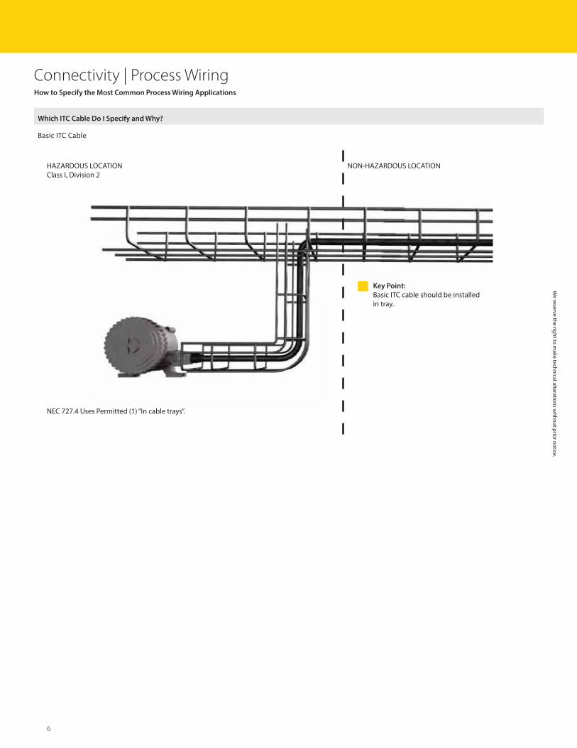
Adding Quick-Disconnects
ITC rated cable
A Turck receptacle installed in an instrument certified for Class I, Division 2, coupled with a Turck cordset with ITC rated cable offers the benefits of quick-disconnect wiring in hazardous locations, BUT...
NON-HAZARDOUS LOCATIONHAZARDOUS LOCATIONClass I, Division 2
Connectors that do not require the use of a tool to disconnect are ‘normally arcing’ , and therefore not allowed in ignition-capable circuits in hazardous locations.
NON-HAZARDOUS LOCATIONHAZARDOUS LOCATIONClass I, Division 2
The simple addition of a Lokfast guard solves this problem!Note: All connectors in Class I, Division 2, require a Lokfast guard
NON-HAZARDOUS LOCATIONHAZARDOUS LOCATIONClass I, Division 2

Connectivity | Process Wiring
Multifast is Available with Integral Locks
P-C.ML .. P-C.MT ..
We reserve the right to m
ake technical alterations without prior notice.
How to Specify the Most Common Process Wiring Applications
Lokfast Guards
Lokfast guards render a quick-disconnect connection not ‘normally arcing’ by:• Making disconnection impossible while in place by eliminating access to coupling nut• Warning the user to disconnect power before removing• Requiring a tool for removal
Multifast cords have optional locking set-screws for use in Division 2
For Class I, Division 2 hazardous areas you MUST use M23 Multifast with locking set-screw
11
Connectivity | Process Wiring
NON-HAZARDOUS LOCATIONHAZARDOUS LOCATIONClass I, Division 2
We
rese
rve
the
right
to m
ake
tech
nica
l alte
ratio
ns w
ithou
t prio
r not
ice.
How to Specify the Most Common Process Wiring Applications
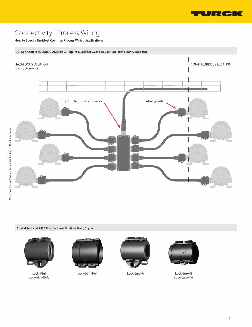
All Connectors in Class I, Division 2 Require a Lokfast Guard or Locking Home Run Connector
Available for all M12 Eurofast and Minifast Body Styles
Locking home run connector Lokfast guards
Lock-Mini Lock-Mini-B&C
Lock-Mini-FW Lock-Euro-A Lock-Euro-G Lock-Euro-FW
Connectivity | Process Wiring
We reserve the right to m
ake technical alterations without prior notice.
How to Specify the Most Common Process Wiring Applications
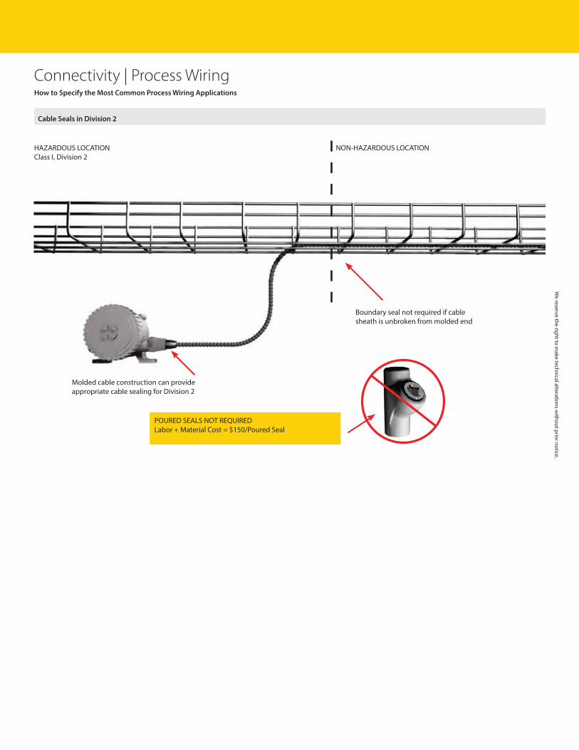
Cable Seals in Division 2
Molded cable construction can provide appropriate cable sealing for Division 2
Boundary seal not required if cable sheath is unbroken from molded end
POURED SEALS NOT REQUIREDLabor + Material Cost = $150/Poured Seal
NON-HAZARDOUS LOCATIONHAZARDOUS LOCATIONClass I, Division 2

13
Connectivity | Process Wiring
NON-HAZARDOUS LOCATIONHAZARDOUS LOCATIONClass I, Division 2
For installation of explosion-proof rated field device with 1/2-14NPT entry threads in Class I, Division 2:• Install 7/8-16 UN Minifast receptacle, e.g. P-RSFV 40EX-*14.5/NPT• Connect with Minifast cordset and Lokfast® guard• Install cable per ITC rules for Class I, Division 2
Note: These are not explosion-proof connectors. They are an explosion-proof feed-thru that provide an explosion-proof penetration into an explosion-proof enclosure. The external pin/socket interface is not explosion-proof.
EXP limit switches. EXP pressure switches, temperature switches, etc. EXP instruments without NI approval.
Bringing intrinsically safe or nonincendive circuits out of EXP enclosures.
We
rese
rve
the
right
to m
ake
tech
nica
l alte
ratio
ns w
ithou
t prio
r not
ice.
Quick Disconnect Solution for Explosion-proof Devices in Division 2
Explosion Protection is Suitable for Division 1 or Division 2
Explosion-proof Feed-Thru Applications

Connectivity | Process Wiring
Male receptacle forfield instrument
Female receptacle forcustomer suppliedjunction box or integralto Turck junction box
2 pcs of Lokfast one for eachconnector
Extension cordset
Male receptacle visual cues:
• Male pins are visible from front view of receptacle• Mating threads are on outside of receptacle housing• Male threads mount to field instrument
Female receptacle visual cues:
• No pins visible from front view of receptacle• Mating threads are on inside of receptacle housing• Male threads mount to junction boxes
We reserve the right to m
ake technical alterations without prior notice.
Cordset Solution Components
The Parts You Will Need: Class I, Division 2 Hazardous Areas
Receptacles

15
Connectivity | Process Wiring
Lokfast for each 7/8-16 UN connector (2 pcs needed)
Use male receptacle at instrument
Use female receptacle at junction box
Cordset extension visual cues: Quick-disconnect cordset extension
• Cable has connectors on both ends• Male connector on one end• Female connector on other end
Single ended cord visual cues: Quick-disconnect single ended cord
• Cable has single connector on one end• Connector can be male or female to
meet an application• Flying lead terminates into junction
boxes with cable gland approved for hazardous area classification
We
rese
rve
the
right
to m
ake
tech
nica
l alte
ratio
ns w
ithou
t prio
r not
ice.
Cordset Solution Components
Cordsets
Recommended Receptacle Gender Placement

Connectivity | Process Wiring
We reserve the right to m
ake technical alterations without prior notice.
Cordset Solution Components
Installation Instructions for Turck’s 7/8-16 UN Minifast® and M12 Eurofast®Installation Instructions for Turck’s 7/8-16 UN Minifast and M12 Eurofast Connectivity Products
Step One:
Many instruments are available with a Turck receptacle pre-installed. If a receptacle is already installed, proceed to Step Two. If field installation of a receptacle is necessary, feed the receptacle leads through the instrument’s conduit entry and thread the receptacle into the entry threads. Receptacles with NPT threads should be tightened per the requirements for NPT conduit fittings. Receptacles with straight threads (M20 or NPSM) should be tightened to deflect the O-ring sufficiently to create a good seal. The receptacle leads should then be connected to the terminals of the instrument. Consult the instrument manual for terminal identification and preferred method of connection. Also, please refer to the product catalog or visit www.turck.us for the pin-out of the receptacle.
Step Two:
Minifast connectors are designed to industry standards SAE H1738 and ANSI/B93.55M. The environmental seal for mated connectors is formed by the ‘cork and bottle’ design of the pin and socket carriers in which each connection chamber is individually sealed. The connection must be properly secured to achieve this seal, as well as to ensure a good electrical performance.
The keyed cordset should be aligned with the key on the instrument receptacle. The cordset should then be pushed into the receptacle and the coupling nut turned until hand tight. The cordset should then be pushed firmly into the receptacle a second time and the coupling nut hand tightened again. This generally allows an additional 1/8 - 1/4 turn and ensures that a tight, weather-proof connection is made. No tools should be used in tightening the connections, as damage to the contacts could occur if the connection is over-tightened.
Eurofast connectors are designed to industry standard SAE H1738. The environmental seal for mated connectors is formed by an O-ring seal. The connection must be properly secured to achieve this seal, as well as to ensure a good electrical performance.
The keyed cordset should be aligned with the key on the instrument receptacle. The cordset should then be pushed into the receptacle and the coupling nut turned until hand tight. While rotating the coupling nut, the installer may notice a ‘ratcheting’ sensation. This is an anti-vibration feature designed to maintain the connection in high-vibration environments. No tools should be used in tightening the connection, as damage to the contacts could occur if the connection is over-tightened.
Step Three:
Most Turck process wiring products are designed and approved for use in hazardous locations. If the installation is in a hazardous location, there may be additional actions necessary, such as locking the connection with a Lokfast® guard (as shown in the figure below), using an approved energy limiting source of power, or ensuring that the instrument has the appropriate approval. FM approved control drawings detail the requirements for compliant installation of Turck products. The appropriate control drawing number will be identified in the product markings and may be viewed or downloaded from www.turck.us/fmcd. Consult the instrument manual to ensure the instrument has the appropriate approval and to determine if the approval imposes any additional constraints.
17
Connectivity | Process Wiring
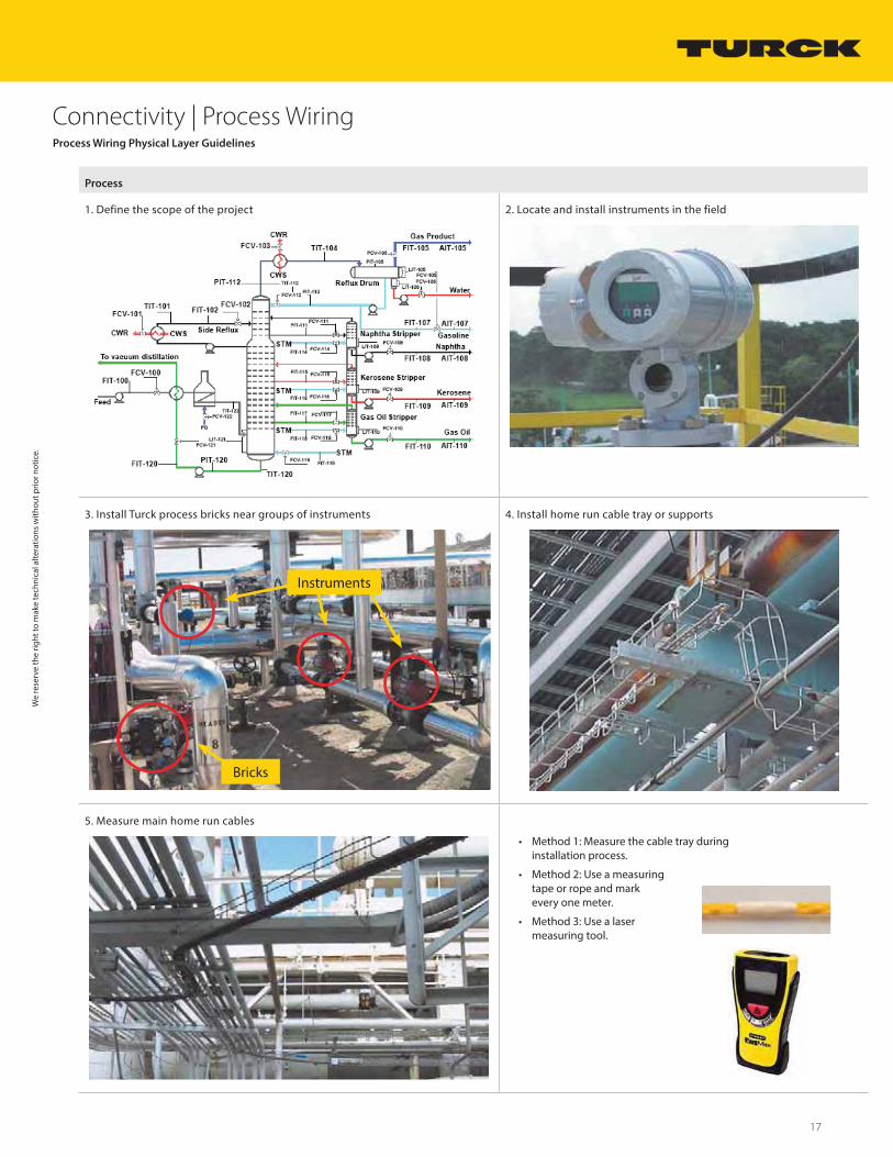
Process
1. Define the scope of the project 2. Locate and install instruments in the field
3. Install Turck process bricks near groups of instruments 4. Install home run cable tray or supports
Bricks
Instruments
Bricks
5. Measure main home run cables
• Method 1: Measure the cable tray during installation process.
• Method 2: Use a measuring tape or rope and mark every one meter.
• Method 3: Use a laser measuring tool.
Process Wiring Physical Layer Guidelines
We
rese
rve
the
right
to m
ake
tech
nica
l alte
ratio
ns w
ithou
t prio
r not
ice.
Connectivity | Process Wiring
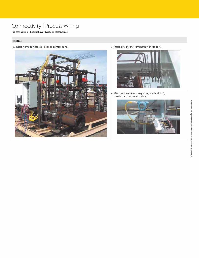
Process
6. Install home run cables - brick to control panel 7. Install brick to instrument tray or supports
8. Measure instruments tray using method 1 - 3,then install instrument cable
Process Wiring Physical Layer Guidelines(continue)
We reserve the right to m
ake technical alterations without prior notice.
19
Connectivity | Process Wiring
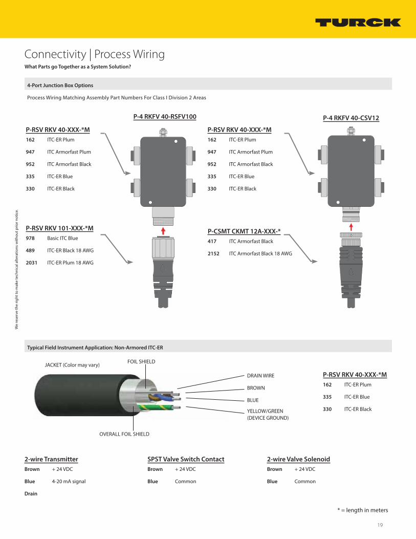
* = length in meters
P-4 RKFV 40-CSV12P-4 RKFV 40-RSFV100
P-RSV RKV 40-XXX-*M
162 ITC-ER Plum
947 ITC Armorfast Plum
952 ITC Armorfast Black
335 ITC-ER Blue
330 ITC-ER Black
P-RSV RKV 101-XXX-*M
978 Basic ITC Blue
489 ITC-ER Black 18 AWG
2031 ITC-ER Plum 18 AWG
P-RSV RKV 40-XXX-*M
162 ITC-ER Plum
947 ITC Armorfast Plum
952 ITC Armorfast Black
335 ITC-ER Blue
330 ITC-ER Black
P-CSMT CKMT 12A-XXX-*
417 ITC Armorfast Black
2152 ITC Armorfast Black 18 AWG
P-RSV RKV 40-XXX-*M
162 ITC-ER Plum
335 ITC-ER Blue
330 ITC-ER Black
What Parts go Together as a System Solution?
4-Port Junction Box Options
Process Wiring Matching Assembly Part Numbers For Class I Division 2 Areas
Typical Field Instrument Application: Non-Armored ITC-ER
DRAIN WIRE
BROWN
BLUE
YELLOW/GREEN (DEVICE GROUND)
FOIL SHIELD
OVERALL FOIL SHIELD
JACKET (Color may vary)
We
rese
rve
the
right
to m
ake
tech
nica
l alte
ratio
ns w
ithou
t prio
r not
ice.
2-wire Transmitter
Brown + 24 VDC
Blue 4-20 mA signal
Drain
SPST Valve Switch Contact
Brown + 24 VDC
Blue Common
2-wire Valve Solenoid
Brown + 24 VDC
Blue Common
Connectivity | Process Wiring
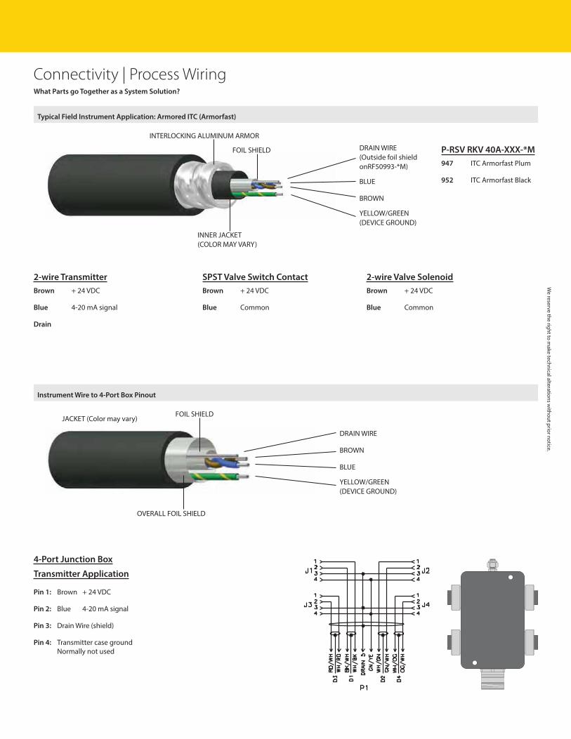
P-RSV RKV 40A-XXX-*M
947 ITC Armorfast Plum
952 ITC Armorfast Black
Typical Field Instrument Application: Armored ITC (Armorfast)
DRAIN WIRE(Outside foil shield onRF50993-*M)
BLUE
BROWN
YELLOW/GREEN (DEVICE GROUND)
INNER JACKET(COLOR MAY VARY)
INTERLOCKING ALUMINUM ARMOR
FOIL SHIELD
What Parts go Together as a System Solution?
Instrument Wire to 4-Port Box Pinout
DRAIN WIRE
BROWN
BLUE
YELLOW/GREEN (DEVICE GROUND)
FOIL SHIELD
OVERALL FOIL SHIELD
JACKET (Color may vary)
We reserve the right to m
ake technical alterations without prior notice.
2-wire Transmitter
Brown + 24 VDC
Blue 4-20 mA signal
Drain
SPST Valve Switch Contact
Brown + 24 VDC
Blue Common
2-wire Valve Solenoid
Brown + 24 VDC
Blue Common
4-Port Junction Box
Transmitter Application
Pin 1: Brown + 24 VDC
Pin 2: Blue 4-20 mA signal
Pin 3: Drain Wire (shield)
Pin 4: Transmitter case groundNormally not used
21
Connectivity | Process Wiring
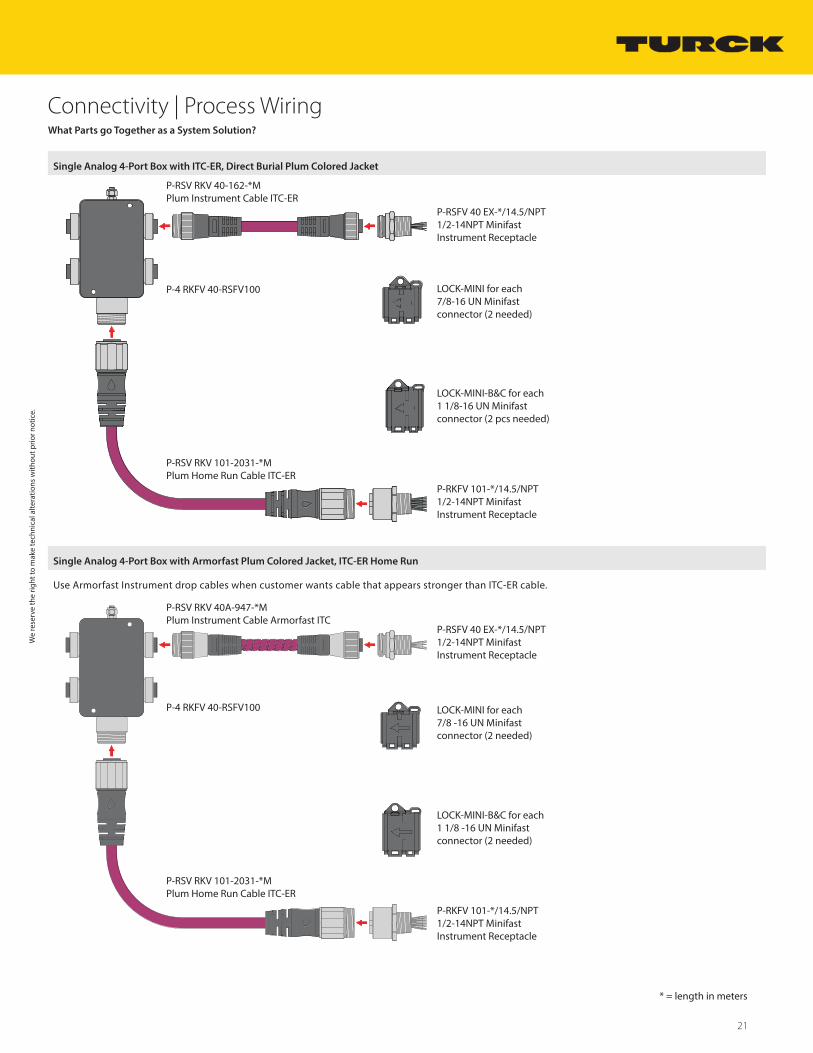
* = length in meters
What Parts go Together as a System Solution?
Single Analog 4-Port Box with ITC-ER, Direct Burial Plum Colored Jacket
P-4 RKFV 40-RSFV100
P-RSV RKV 40-162-*MPlum Instrument Cable ITC-ER
P-RKFV 101-*/14.5/NPT1/2-14NPT MinifastInstrument Receptacle
P-RSV RKV 101-2031-*MPlum Home Run Cable ITC-ER
P-RSFV 40 EX-*/14.5/NPT1/2-14NPT MinifastInstrument Receptacle
LOCK-MINI for each 7/8-16 UN Minifast connector (2 needed)
LOCK-MINI-B&C for each 1 1/8-16 UN Minifast connector (2 pcs needed)
Single Analog 4-Port Box with Armorfast Plum Colored Jacket, ITC-ER Home Run
Use Armorfast Instrument drop cables when customer wants cable that appears stronger than ITC-ER cable.
P-RKFV 101-*/14.5/NPT1/2-14NPT MinifastInstrument Receptacle
P-RSFV 40 EX-*/14.5/NPT1/2-14NPT MinifastInstrument Receptacle
LOCK-MINI for each7/8 -16 UN Minifastconnector (2 needed)
LOCK-MINI-B&C for each1 1/8 -16 UN Minifastconnector (2 needed)
P-4 RKFV 40-RSFV100
P-RSV RKV 40A-947-*MPlum Instrument Cable Armorfast ITC
P-RSV RKV 101-2031-*MPlum Home Run Cable ITC-ER
We
rese
rve
the
right
to m
ake
tech
nica
l alte
ratio
ns w
ithou
t prio
r not
ice.
Connectivity | Process Wiring
* = length in meters
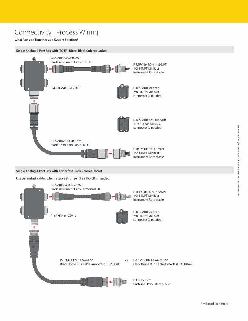
What Parts go Together as a System Solution?
Single Analog 4-Port Box with ITC-ER, Direct Black Colored Jacket
P-4 RKFV 40-RSFV100
P-RSV RKV 40-330-*MBlack Instrument Cable ITC-ER
P-RKFV 101-*/14.5/NPT1/2-14NPT MinifastInstrument Receptacle
P-RSV RKV 101-489-*MBlack Home Run Cable ITC-ER
P-RSFV 40 EX-*/14.5/NPT1/2-14NPT MinifastInstrument Receptacle
LOCK-MINI for each7/8 -16 UN Minifastconnector (2 needed)
LOCK-MINI-B&C for each11/8 -16 UN Minifastconnector (2 needed)
Single Analog 4-Port Box with Armorfast Black Colored Jacket
Use Armorfast cables when a cable stronger than ITC-ER is needed.
P-CKFLV 12-*Customer Panel Receptacle
P-RSFV 40 EX-*/14.5/NPT1/2-14NPT MinifastInstrument Receptacle
LOCK-MINI for each7/8 -16 UN Minifastconnector (2 needed)
P-4 RKFV 40-CSV12
P-RSV RKV 40A-952-*MBlack Instrument Cable Armorfast ITC
P-CSMT CKMT 12A-417-*Black Home Run Cable Armorfast ITC 22AWG
P-CSMT CKMT 12A-2152-*Black Home Run Cable Armorfast ITC 18AWG
or
We reserve the right to m
ake technical alterations without prior notice.
23
Connectivity | Process Wiring
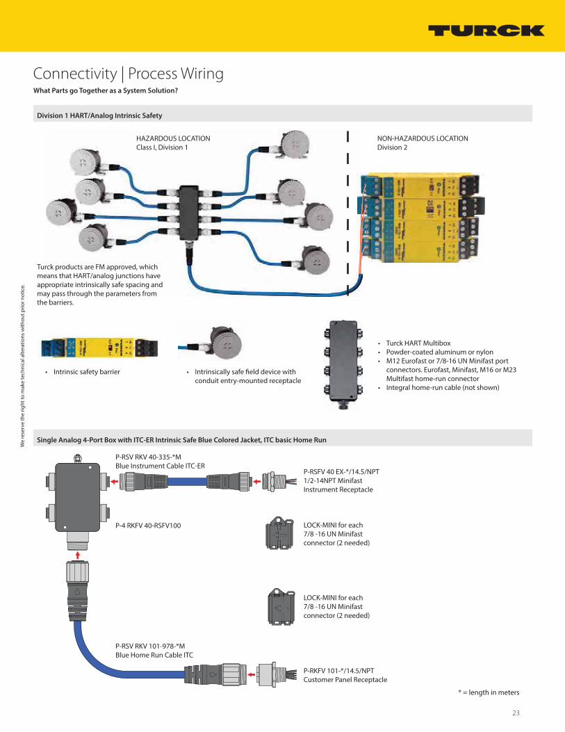
• Turck HART Multibox• Powder-coated aluminum or nylon• M12 Eurofast or 7/8-16 UN Minifast port
connectors. Eurofast, Minifast, M16 or M23 Multifast home-run connector
• Integral home-run cable (not shown)
• Intrinsic safety barrier • Intrinsically safe field device with conduit entry-mounted receptacle
Single Analog 4-Port Box with ITC-ER Intrinsic Safe Blue Colored Jacket, ITC basic Home Run
P-4 RKFV 40-RSFV100
P-RSV RKV 40-335-*MBlue Instrument Cable ITC-ER
P-RKFV 101-*/14.5/NPTCustomer Panel Receptacle
P-RSV RKV 101-978-*MBlue Home Run Cable ITC
P-RSFV 40 EX-*/14.5/NPT1/2-14NPT MinifastInstrument Receptacle
LOCK-MINI for each7/8 -16 UN Minifastconnector (2 needed)
LOCK-MINI for each7/8 -16 UN Minifastconnector (2 needed)
Division 1 HART/Analog Intrinsic Safety
HAZARDOUS LOCATIONClass I, Division 1
NON-HAZARDOUS LOCATIONDivision 2
What Parts go Together as a System Solution?
We
rese
rve
the
right
to m
ake
tech
nica
l alte
ratio
ns w
ithou
t prio
r not
ice.
* = length in meters
Turck products are FM approved, whichmeans that HART/analog junctions haveappropriate intrinsically safe spacing andmay pass through the parameters fromthe barriers.
24 Turck Inc. | 3000 Campus Drive, Minneapolis, MN 55441 | T +1 800 544 7769 | F +1 763 553 0708 | www.turck.com
Connectivity | Process Wiring
* = length in meters
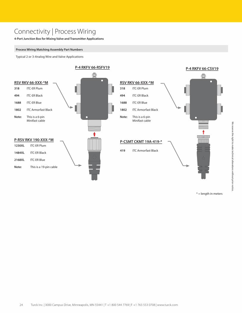
RSV RKV 66-XXX-*M
318 ITC-ER Plum
494 ITC-ER Black
1688 ITC-ER Blue
1802 ITC Armorfast Black
Note: This is a 6-pinMinifast cable
P-RSV RKV 190-XXX-*M
1230XL ITC-ER Plum
1484XL ITC-ER Black
2168XL ITC-ER Blue
Note: This is a 19-pin cable
RSV RKV 66-XXX-*M
318 ITC-ER Plum
494 ITC-ER Black
1688 ITC-ER Blue
1802 ITC Armorfast Black
Note: This is a 6-pinMinifast cable
P-CSMT CKMT 19A-419-*
419 ITC Armorfast Black
P-4 RKFV 66-CSV19P-4 RKFV 66-RSFV19
4-Port Junction Box for Mixing Valve and Transmitter Applications
Process Wiring Matching Assembly Part Numbers
Typical 2 or 3-Analog Wire and Valve Applications
We reserve the right to m
ake technical alterations without prior notice.
25
Connectivity | Process Wiring
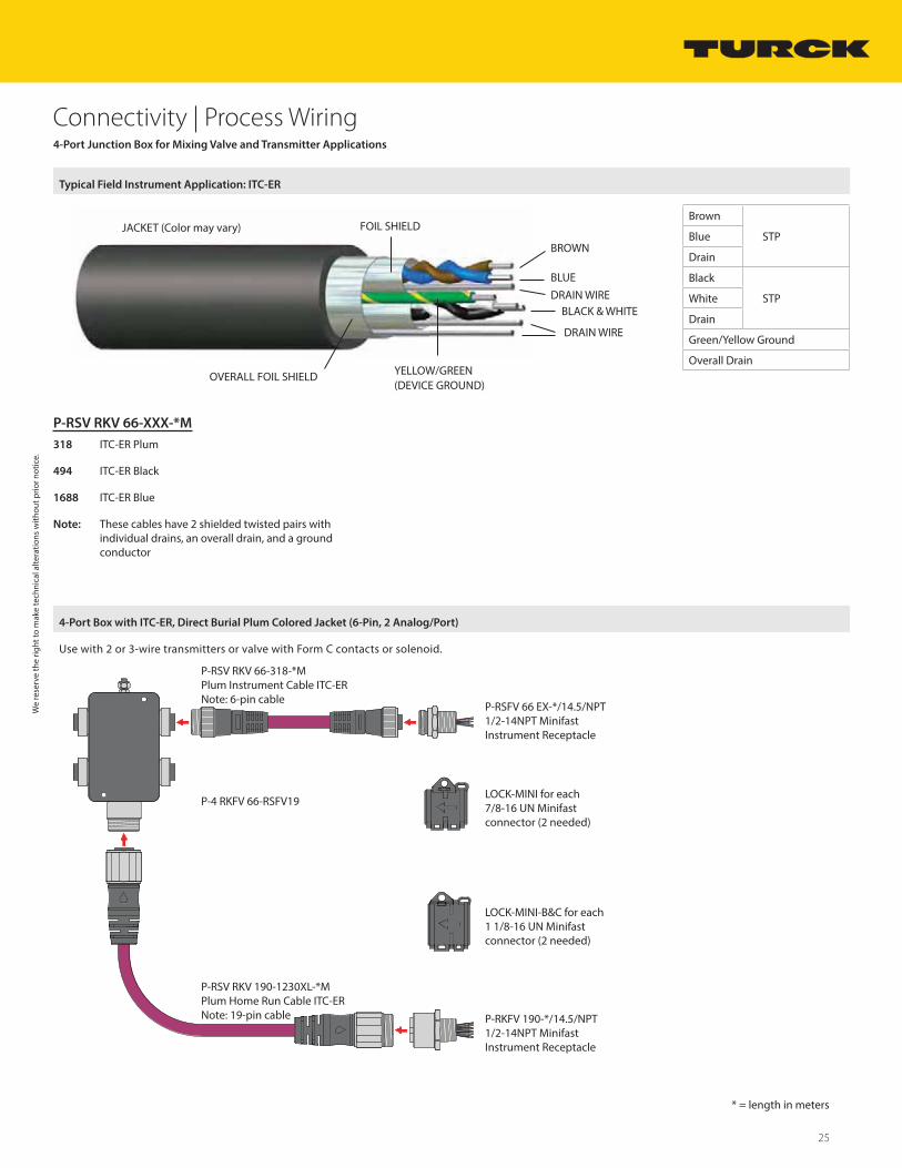
P-RSV RKV 66-XXX-*M
318 ITC-ER Plum
494 ITC-ER Black
1688 ITC-ER Blue
Note: These cables have 2 shielded twisted pairs with individual drains, an overall drain, and a ground conductor
Typical Field Instrument Application: ITC-ER
FOIL SHIELD
BLUE
BLACK & WHITE
OVERALL FOIL SHIELD YELLOW/GREEN (DEVICE GROUND)
BROWN
DRAIN WIRE
DRAIN WIRE
JACKET (Color may vary)
4-Port Junction Box for Mixing Valve and Transmitter Applications
4-Port Box with ITC-ER, Direct Burial Plum Colored Jacket (6-Pin, 2 Analog/Port)
Use with 2 or 3-wire transmitters or valve with Form C contacts or solenoid.
P-RSV RKV 66-318-*MPlum Instrument Cable ITC-ERNote: 6-pin cable
P-4 RKFV 66-RSFV19
P-RKFV 190-*/14.5/NPT1/2-14NPT MinifastInstrument Receptacle
P-RSV RKV 190-1230XL-*MPlum Home Run Cable ITC-ERNote: 19-pin cable
P-RSFV 66 EX-*/14.5/NPT1/2-14NPT MinifastInstrument Receptacle
LOCK-MINI for each 7/8-16 UN Minifast connector (2 needed)
LOCK-MINI-B&C for each 1 1/8-16 UN Minifast connector (2 needed)
We
rese
rve
the
right
to m
ake
tech
nica
l alte
ratio
ns w
ithou
t prio
r not
ice.
* = length in meters
Brown
STPBlue
Drain
Black
STPWhite
Drain
Green/Yellow Ground
Overall Drain
26 Turck Inc. | 3000 Campus Drive, Minneapolis, MN 55441 | T +1 800 544 7769 | F +1 763 553 0708 | www.turck.com
Connectivity | Process Wiring4-Port Junction Box for Mixing Valve and Transmitter Applications
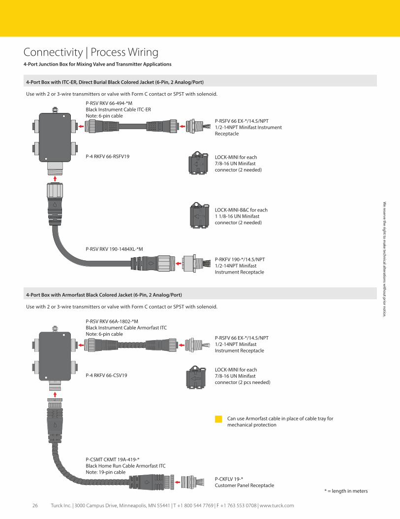
4-Port Box with Armorfast Black Colored Jacket (6-Pin, 2 Analog/Port)
Use with 2 or 3-wire transmitters or valve with Form C contact or SPST with solenoid.
4-Port Box with ITC-ER, Direct Burial Black Colored Jacket (6-Pin, 2 Analog/Port)
Use with 2 or 3-wire transmitters or valve with Form C contact or SPST with solenoid.
P-RSV RKV 66-494-*MBlack Instrument Cable ITC-ERNote: 6-pin cable
P-4 RKFV 66-RSFV19
P-RKFV 190-*/14.5/NPT1/2-14NPT MinifastInstrument Receptacle
P-RSV RKV 190-1484XL-*M
P-RSFV 66 EX-*/14.5/NPT1/2-14NPT Minifast Instrument Receptacle
LOCK-MINI for each 7/8-16 UN Minifast connector (2 needed)
LOCK-MINI-B&C for each 1 1/8-16 UN Minifast connector (2 needed)
P-4 RKFV 66-CSV19
P-CKFLV 19-*Customer Panel Receptacle
* = length in meters
P-RSFV 66 EX-*/14.5/NPT1/2-14NPT MinifastInstrument Receptacle
Can use Armorfast cable in place of cable tray for mechanical protection
P-CSMT CKMT 19A-419-*Black Home Run Cable Armorfast ITCNote: 19-pin cable
LOCK-MINI for each 7/8-16 UN Minifast connector (2 pcs needed)
P-RSV RKV 66A-1802-*MBlack Instrument Cable Armorfast ITCNote: 6-pin cable
We reserve the right to m
ake technical alterations without prior notice.

27
Connectivity | Process Wiring
Class I, Division 2
P-4 RKFV 56-RSFV190
P-RSV RKV 52-972-*MGrey Instrument Cable ITCNote: 5-pin connector
P-RKFV 190-*/14.5/NPTCustomer Panel Receptacle
P-RSV RKV 190-1484XL-*MBlack Home Run Cable ITC-ER
Bi 2.5-EG16CA-FDZ32X2-B1151
LOCK-MINI for each 7/8-16 UN Minifast connector (2 needed)
LOCK-MINI-B&C for each 1 1/8-16 UN Minifast connector (2 needed)
V-Prox 4-Port Box with Grey ITC Drop and Black ITC-ER Direct Burial Colored Jacket
* = length in meters
V-Prox Valve Box Application
In automated manufacturing and processing plants, position sensors help monitor and control plant processes by confirming that critical activities are completed as intended. More specifically, their primary function is to detect the presence, or absence, of a moving object, or ‘target’.
The advantages of inductive proximity sensors:• No physical contact is required• No moving parts to jam, wear, or break
results in less maintenance• Not affected by dust or dirt
Turck V-Prox Bi 2.5-EG16CA-FDZ32X2
We
rese
rve
the
right
to m
ake
tech
nica
l alte
ratio
ns w
ithou
t prio
r not
ice.
28 Turck Inc. | 3000 Campus Drive, Minneapolis, MN 55441 | T +1 800 544 7769 | F +1 763 553 0708 | www.turck.com
Connectivity | Process Wiring
P-RSV RKV 40-XXX-*M
162 ITC-ER Plum
335 ITC-ER Blue
330 ITC-ER Black
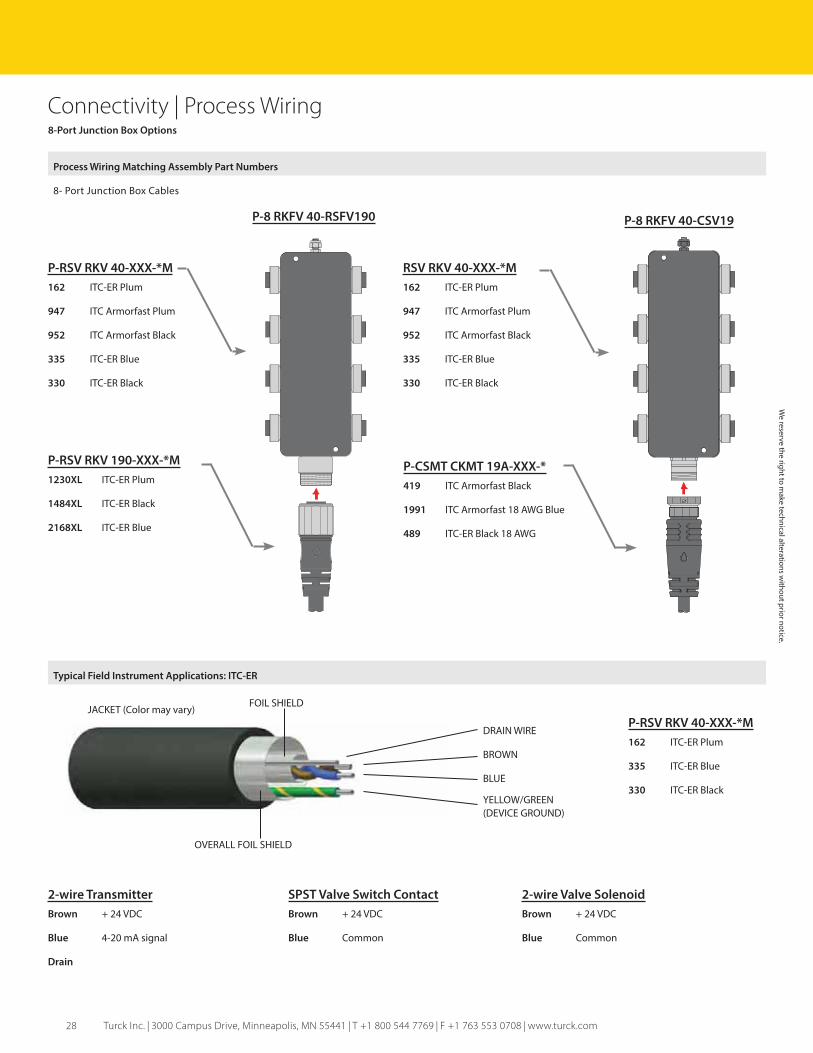
8-Port Junction Box Options
Process Wiring Matching Assembly Part Numbers
8- Port Junction Box Cables
P-RSV RKV 40-XXX-*M
162 ITC-ER Plum
947 ITC Armorfast Plum
952 ITC Armorfast Black
335 ITC-ER Blue
330 ITC-ER Black
P-RSV RKV 190-XXX-*M
1230XL ITC-ER Plum
1484XL ITC-ER Black
2168XL ITC-ER Blue
RSV RKV 40-XXX-*M
162 ITC-ER Plum
947 ITC Armorfast Plum
952 ITC Armorfast Black
335 ITC-ER Blue
330 ITC-ER Black
P-CSMT CKMT 19A-XXX-*
419 ITC Armorfast Black
1991 ITC Armorfast 18 AWG Blue
489 ITC-ER Black 18 AWG
P-8 RKFV 40-CSV19P-8 RKFV 40-RSFV190
Typical Field Instrument Applications: ITC-ER
DRAIN WIRE
BROWN
BLUE
YELLOW/GREEN (DEVICE GROUND)
FOIL SHIELD
OVERALL FOIL SHIELD
JACKET (Color may vary)
2-wire Transmitter
Brown + 24 VDC
Blue 4-20 mA signal
Drain
SPST Valve Switch Contact
Brown + 24 VDC
Blue Common
2-wire Valve Solenoid
Brown + 24 VDC
Blue Common
We reserve the right to m
ake technical alterations without prior notice.
29
Connectivity | Process Wiring
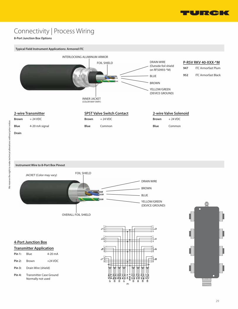
4-Port Junction Box
Transmitter Application
Pin 1: Blue 4-20 mA
Pin 2: Brown +24 VDC
Pin 3: Drain Wire (shield)
Pin 4: Transmitter Case Ground Normally not used
Instrument Wire to 8-Port Box Pinout
DRAIN WIRE
BROWN
BLUE
YELLOW/GREEN (DEVICE GROUND)
FOIL SHIELD
OVERALL FOIL SHIELD
JACKET (Color may vary)
8-Port Junction Box Options
Typical Field Instrument Applications: Armored ITC
DRAIN WIRE(Outside foil shieldon RF50993-*M)
BLUE
BROWN
YELLOW/GREEN (DEVICE GROUND)
INNER JACKET(COLOR MAY VARY)
INTERLOCKING ALUMINUM ARMOR
FOIL SHIELD P-RSV RKV 40-XXX-*M
947 ITC Armorfast Plum
952 ITC Armorfast Black
2-wire Transmitter
Brown + 24 VDC
Blue 4-20 mA signal
Drain
SPST Valve Switch Contact
Brown + 24 VDC
Blue Common
2-wire Valve Solenoid
Brown + 24 VDC
Blue Common
We
rese
rve
the
right
to m
ake
tech
nica
l alte
ratio
ns w
ithou
t prio
r not
ice.
30 Turck Inc. | 3000 Campus Drive, Minneapolis, MN 55441 | T +1 800 544 7769 | F +1 763 553 0708 | www.turck.com
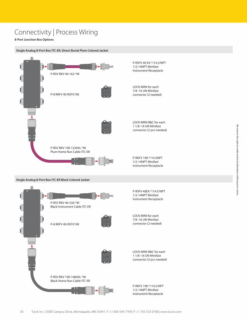
Connectivity | Process Wiring8-Port Junction Box Options
Single Analog 8-Port Box ITC-ER, Direct Burial Plum Colored Jacket
P-8 RKFV 40-RSFV190
P-RSV RKV 40-162-*M
P-RKFV 190-*/14.5NPT1/2-14NPT MinifastInstrument Receptacle
P-RSV RKV 190-1230XL-*MPlum Home Run Cable ITC-ER
P-RSFV 40 EX-*/14.5/NPT1/2-14NPT MinifastInstrument Receptacle
LOCK-MINI for each7/8 -16 UN Minifastconnector (2 needed)
LOCK-MINI-B&C for each1 1/8 -16 UN Minifastconnector (2 pcs needed)
Single Analog 8-Port Box ITC-ER Black Colored Jacket
P-RKFV 190-*/14.5/NPT1/2-14NPT MinifastInstrument Receptacle
P-RSFV 40EX-*/14.5/NPT1/2-14NPT MinifastInstrument Receptacle
LOCK-MINI for each7/8 -16 UN Minifastconnector (2 needed)
LOCK-MINI-B&C for each1 1/8 -16 UN Minifastconnector (2 pcs needed)
P-8 RKFV 40-RSFV190
P-RSV RKV 40-330-*MBlack Instrument Cable ITC-ER
P-RSV RKV 190-1484XL-*MBlack Home Run Cable ITC-ER
We reserve the right to m
ake technical alterations without prior notice.
31
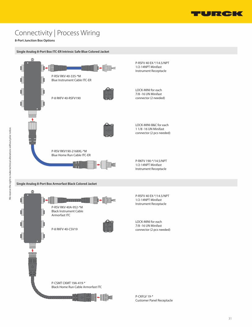
Connectivity | Process Wiring8-Port Junction Box Options
Single Analog 8-Port Box ITC-ER Intrinsic Safe Blue Colored Jacket
P-8 RKFV 40-RSFV190
P-RKFV 190-*/14.5/NPT1/2-14NPT MinifastInstrument Receptacle
P-RSV RKV190-2168XL-*MBlue Home Run Cable ITC-ER
P-RSFV 40 EX-*/14.5/NPT1/2-14NPT MinifastInstrument Receptacle
LOCK-MINI for each7/8 -16 UN Minifastconnector (2 needed)
LOCK-MINI-B&C for each1 1/8 -16 UN Minifastconnector (2 pcs needed)
Single Analog 8-Port Box Armorfast Black Colored Jacket
P-CKFLV 19-*Customer Panel Receptacle
P-RSFV 40 EX-*/14.5/NPT1/2-14NPT MinifastInstrument Receptacle
LOCK-MINI for each7/8 -16 UN Minifastconnector (2 pcs needed)P-8 RKFV 40-CSV19
P-RSV RKV 40A-952-*MBlack Instrument CableArmorfast ITC
P-CSMT CKMT 19A-419-*Black Home Run Cable Armorfast ITC
P-RSV RKV 40-335-*MBlue Instrument Cable ITC-ER
We
rese
rve
the
right
to m
ake
tech
nica
l alte
ratio
ns w
ithou
t prio
r not
ice.
32 Turck Inc. | 3000 Campus Drive, Minneapolis, MN 55441 | T +1 800 544 7769 | F +1 763 553 0708 | www.turck.com
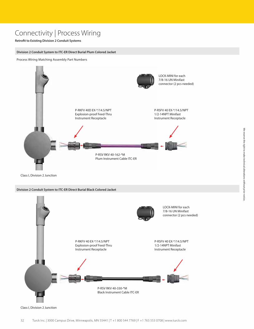
Connectivity | Process WiringRetrofit to Existing Division 2 Conduit Systems
Division 2 Conduit System to ITC-ER Direct Burial Plum Colored Jacket
Process Wiring Matching Assembly Part Numbers
P-RSV RKV 40-162-*MPlum Instrument Cable ITC-ER
Class I, Division 2 Junction
P-RKFV 40D EX-*/14.5/NPTExplosion-proof Feed-ThruInstrument Receptacle
P-RSFV 40 EX-*/14.5/NPT1/2-14NPT MinifastInstrument Receptacle
LOCK-MINI for each 7/8-16 UN Minifast connector (2 pcs needed)
Division 2 Conduit System to ITC-ER Direct Burial Black Colored Jacket
P-RSV RKV 40-330-*MBlack Instrument Cable ITC-ER
Class I, Division 2 Junction
P-RKFV 40 EX-*/14.5/NPTExplosion-proof Feed-ThruInstrument Receptacle
P-RSFV 40 EX-*/14.5/NPT1/2-14NPT Minifast Instrument Receptacle
LOCK-MINI for each 7/8-16 UN Minifast connector (2 pcs needed)
We reserve the right to m
ake technical alterations without prior notice.

33
Connectivity | Process WiringRetrofit to Existing Division 2 Conduit Systems
Division 2 Conduit System to ITC Armorfast Black Colored Jacket
P-RSV RKV 40A-952-*MBlack Armorfast Cable ITC
Class I, Division 2 Junction
P-RKFV 40 EX-*/14.5/NPTExplosion-proof Feed-ThruInstrument Receptacle
P-RSFV 40 EX-*/14.5/NPT1/2-14NPT Minifast Instrument Receptacle
LOCK-MINI for each 7/8-16 UN Minifast connector (2 pcs needed)
Division 2 Conduit System to ITC-ER Direct Burial Plum Colored Jacket
Conduit Body
P-RSV RKV 40-162-*MPlum Instrument Cable ITC-ER
P-RSFV 40 EX-*/14.5/NPT1/2-14NPT Minifast Instrument Receptacle
CA-1/RKFV 40Conduit Body Adapter
LOCK-MINI for each 7/8-16 UN Minifast connector (2 pcs needed)
We
rese
rve
the
right
to m
ake
tech
nica
l alte
ratio
ns w
ithou
t prio
r not
ice.

34 Turck Inc. | 3000 Campus Drive, Minneapolis, MN 55441 | T +1 800 544 7769 | F +1 763 553 0708 | www.turck.com
Connectivity | Process WiringRetrofit to Existing Division 2 Conduit Systems
Division 2 Conduit System to ITC-ER Direct Burial Black Colored Jacket
P-RSV RKV 40-330-*MBlack Instrument Cable ITC-ER
CA-1/RKFV 40Conduit Body Adapter
Conduit Body
P-RSFV 40 EX-*/14.5/NPT1/2-14NPT MinifastInstrument Receptacle
LOCK-MINI for each 7/8-16 UN Minifast connector (2 pcs needed)
We reserve the right to m
ake technical alterations without prior notice.
35
Connectivity | Process Wiring
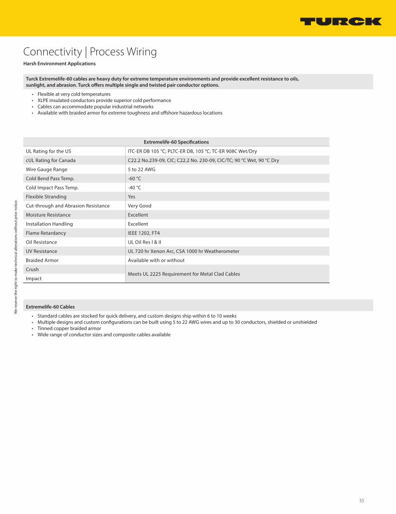
Extremelife-60 Specifications
UL Rating for the US ITC-ER DB 105 °C; PLTC-ER DB, 105 °C; TC-ER 908C Wet/Dry
cUL Rating for Canada C22.2 No.239-09, CIC; C22.2 No. 230-09, CIC/TC; 90 °C Wet, 90 °C Dry
Wire Gauge Range 5 to 22 AWG
Cold Bend Pass Temp. -60 °C
Cold Impact Pass Temp. -40 °C
Flexible Stranding Yes
Cut-through and Abrasion Resistance Very Good
Moisture Resistance Excellent
Installation Handling Excellent
Flame Retardancy IEEE 1202, FT4
Oil Resistance UL Oil Res I & II
UV Resistance UL 720 hr Xenon Arc, CSA 1000 hr Weatherometer
Braided Armor Available with or without
CrushMeets UL 2225 Requirement for Metal Clad Cables
Impact
Harsh Environment Applications
Turck Extremelife-60 cables are heavy duty for extreme temperature environments and provide excellent resistance to oils,
sunlight, and abrasion. Turck offers multiple single and twisted pair conductor options.
• Flexible at very cold temperatures• XLPE insulated conductors provide superior cold performance• Cables can accommodate popular industrial networks• Available with braided armor for extreme toughness and offshore hazardous locations
Extremelife-60 Cables
• Standard cables are stocked for quick delivery, and custom designs ship within 6 to 10 weeks• Multiple designs and custom configurations can be built using 5 to 22 AWG wires and up to 30 conductors, shielded or unshielded• Tinned copper braided armor• Wide range of conductor sizes and composite cables available
We
rese
rve
the
right
to m
ake
tech
nica
l alte
ratio
ns w
ithou
t prio
r not
ice.
36 Turck Inc. | 3000 Campus Drive, Minneapolis, MN 55441 | T +1 800 544 7769 | F +1 763 553 0708 | www.turck.com
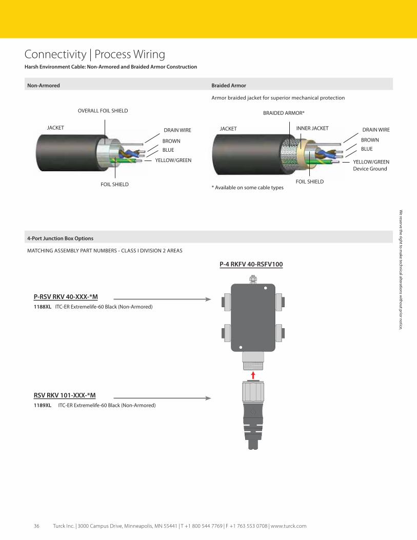
Connectivity | Process WiringHarsh Environment Cable: Non-Armored and Braided Armor Construction
Non-Armored Braided Armor
Armor braided jacket for superior mechanical protection
JACKET
OVERALL FOIL SHIELD
BLUE
DRAIN WIRE
FOIL SHIELD
YELLOW/GREEN
BROWN
JACKET
BRAIDED ARMOR*
BLUE
DRAIN WIRE
FOIL SHIELD
YELLOW/GREEN Device Ground
BROWN
INNER JACKET
* Available on some cable types
4-Port Junction Box Options
MATCHING ASSEMBLY PART NUMBERS - CLASS I DIVISION 2 AREAS
P-4 RKFV 40-RSFV100
P-RSV RKV 40-XXX-*M
1188XL ITC-ER Extremelife-60 Black (Non-Armored)
RSV RKV 101-XXX-*M
1189XL ITC-ER Extremelife-60 Black (Non-Armored)
We reserve the right to m
ake technical alterations without prior notice.
37
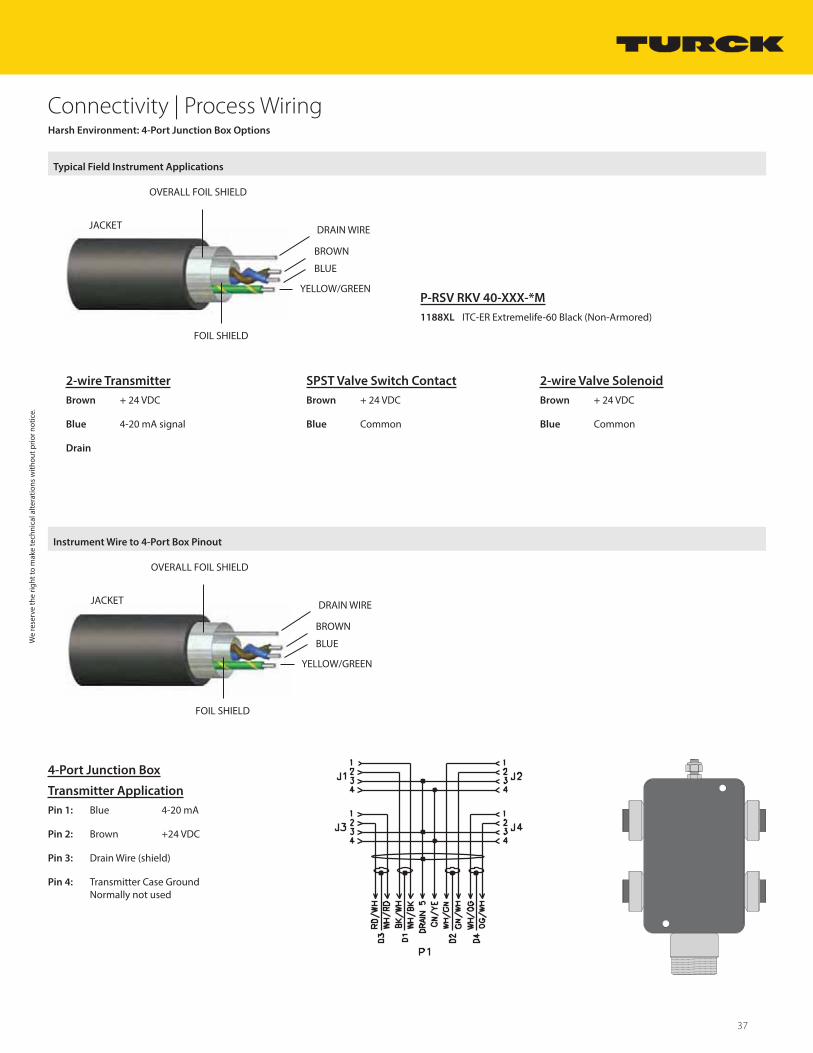
Connectivity | Process WiringHarsh Environment: 4-Port Junction Box Options
Typical Field Instrument Applications
JACKET
OVERALL FOIL SHIELD
BLUE
DRAIN WIRE
FOIL SHIELD
YELLOW/GREEN
BROWN
2-wire Transmitter
Brown + 24 VDC
Blue 4-20 mA signal
Drain
SPST Valve Switch Contact
Brown + 24 VDC
Blue Common
2-wire Valve Solenoid
Brown + 24 VDC
Blue Common
P-RSV RKV 40-XXX-*M
1188XL ITC-ER Extremelife-60 Black (Non-Armored)
Instrument Wire to 4-Port Box Pinout
JACKET
OVERALL FOIL SHIELD
BLUE
DRAIN WIRE
FOIL SHIELD
YELLOW/GREEN
BROWN
4-Port Junction Box
Transmitter Application
Pin 1: Blue 4-20 mA
Pin 2: Brown +24 VDC
Pin 3: Drain Wire (shield)
Pin 4: Transmitter Case Ground Normally not used
We
rese
rve
the
right
to m
ake
tech
nica
l alte
ratio
ns w
ithou
t prio
r not
ice.

38 Turck Inc. | 3000 Campus Drive, Minneapolis, MN 55441 | T +1 800 544 7769 | F +1 763 553 0708 | www.turck.com
Connectivity | Process WiringHarsh Environment: 4-Port Junction Box Options
Single Analog 4-Port Box with Extremelife-60 Cable Black Colored Jacket Single Analog
P-4 RKFV 40-RSFV100
P-RSV RKV 40-1188XL-*MExtremelife-60 non-armored
P-RKFV 101-*/14.5/NPT1/2-14NPT MinifastInstrument Receptacle
P-RSV RKV 101-1189XL-*MExtremelife-60 Non-Armored
P-RSFV 40 EX-*/14.5/NPT1/2-14NPT MinifastInstrument Receptacle
LOCK-MINI for each7/8 -16 UN Minifastconnector (2 needed)
LOCK-MINI-B&C for each1 1/8 -16 UN Minifastconnector (2 needed)
We reserve the right to m
ake technical alterations without prior notice.
39
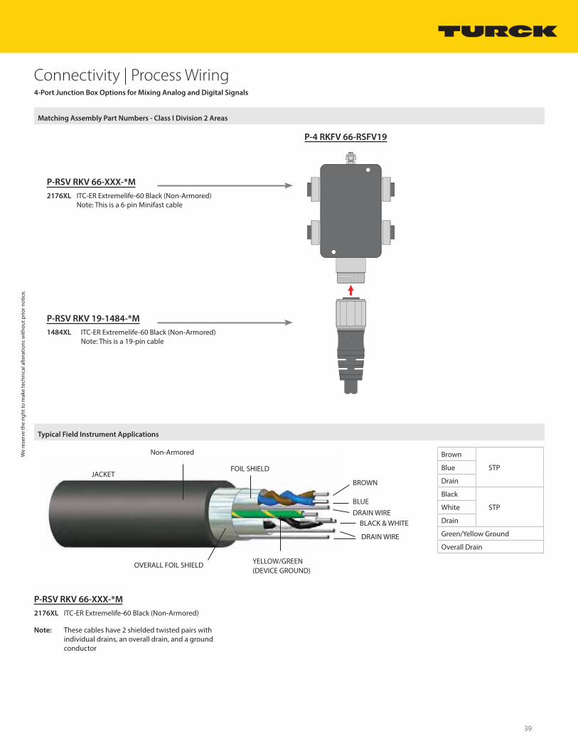
Connectivity | Process Wiring4-Port Junction Box Options for Mixing Analog and Digital Signals
Matching Assembly Part Numbers - Class I Division 2 Areas
P-4 RKFV 66-RSFV19
P-RSV RKV 66-XXX-*M
2176XL ITC-ER Extremelife-60 Black (Non-Armored)Note: This is a 6-pin Minifast cable
P-RSV RKV 19-1484-*M
1484XL ITC-ER Extremelife-60 Black (Non-Armored)Note: This is a 19-pin cable
Brown
STPBlue
Drain
Black
STPWhite
Drain
Green/Yellow Ground
Overall Drain
P-RSV RKV 66-XXX-*M
2176XL ITC-ER Extremelife-60 Black (Non-Armored)
Note: These cables have 2 shielded twisted pairs withindividual drains, an overall drain, and a ground conductor
Typical Field Instrument Applications
FOIL SHIELDJACKET
BLUE
BLACK & WHITE
OVERALL FOIL SHIELD YELLOW/GREEN (DEVICE GROUND)
BROWN
DRAIN WIRE
DRAIN WIRE
Non-ArmoredWe
rese
rve
the
right
to m
ake
tech
nica
l alte
ratio
ns w
ithou
t prio
r not
ice.
40 Turck Inc. | 3000 Campus Drive, Minneapolis, MN 55441 | T +1 800 544 7769 | F +1 763 553 0708 | www.turck.com
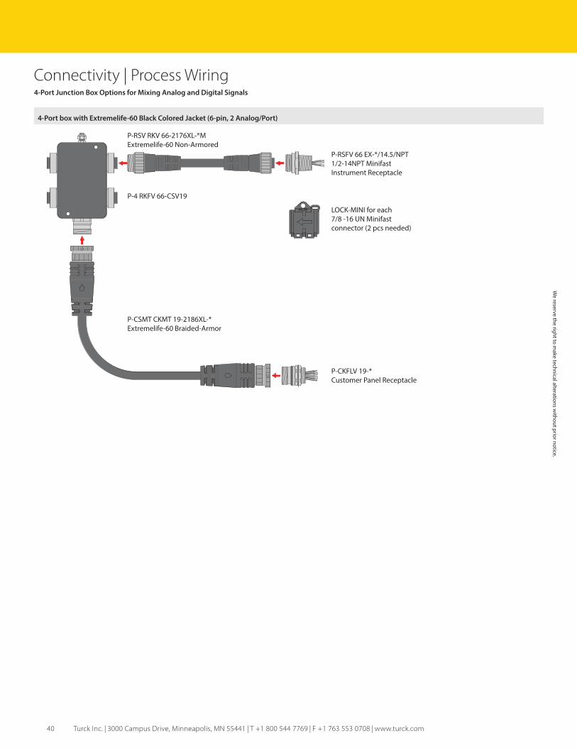
Connectivity | Process Wiring4-Port Junction Box Options for Mixing Analog and Digital Signals
4-Port box with Extremelife-60 Black Colored Jacket (6-pin, 2 Analog/Port)
P-4 RKFV 66-CSV19
P-RSV RKV 66-2176XL-*MExtremelife-60 Non-Armored
P-CKFLV 19-*Customer Panel Receptacle
P-CSMT CKMT 19-2186XL-*Extremelife-60 Braided-Armor
P-RSFV 66 EX-*/14.5/NPT1/2-14NPT MinifastInstrument Receptacle
LOCK-MINI for each7/8 -16 UN Minifastconnector (2 pcs needed)
We reserve the right to m
ake technical alterations without prior notice.
41
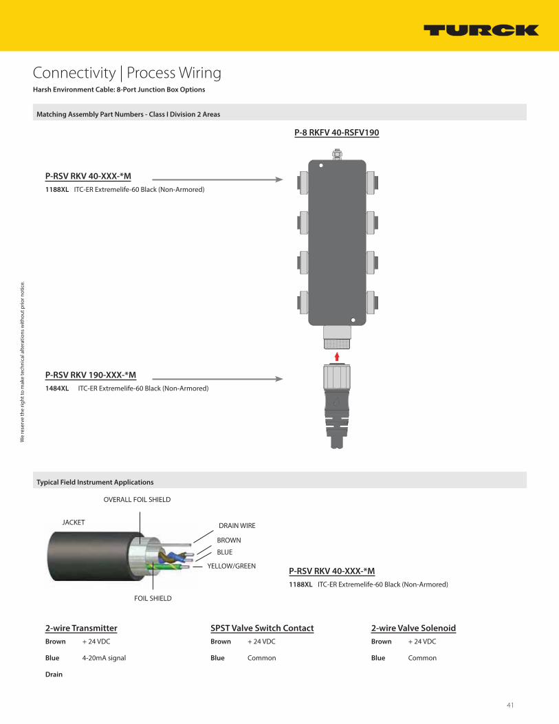
Connectivity | Process WiringHarsh Environment Cable: 8-Port Junction Box Options
Matching Assembly Part Numbers - Class I Division 2 Areas
P-8 RKFV 40-RSFV190
P-RSV RKV 40-XXX-*M
1188XL ITC-ER Extremelife-60 Black (Non-Armored)
P-RSV RKV 190-XXX-*M
1484XL ITC-ER Extremelife-60 Black (Non-Armored)
Typical Field Instrument Applications
2-wire Transmitter
Brown + 24 VDC
Blue 4-20mA signal
Drain
SPST Valve Switch Contact
Brown + 24 VDC
Blue Common
2-wire Valve Solenoid
Brown + 24 VDC
Blue Common
P-RSV RKV 40-XXX-*M
1188XL ITC-ER Extremelife-60 Black (Non-Armored)
JACKET
OVERALL FOIL SHIELD
BLUE
DRAIN WIRE
FOIL SHIELD
YELLOW/GREEN
BROWN
We
rese
rve
the
right
to m
ake
tech
nica
l alte
ratio
ns w
ithou
t prio
r not
ice.
42 Turck Inc. | 3000 Campus Drive, Minneapolis, MN 55441 | T +1 800 544 7769 | F +1 763 553 0708 | www.turck.com
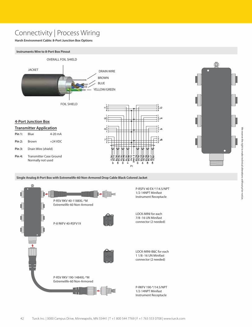
Connectivity | Process WiringHarsh Environment Cable: 8-Port Junction Box Options
Instruments Wire to 8-Port Box Pinout
JACKET
OVERALL FOIL SHIELD
BLUE
DRAIN WIRE
FOIL SHIELD
YELLOW/GREEN
BROWN
4-Port Junction Box
Transmitter Application
Pin 1: Blue 4-20 mA
Pin 2: Brown +24 VDC
Pin 3: Drain Wire (shield)
Pin 4: Transmitter Case Ground Normally not used
Single Analog 8-Port Box with Extremelife-60 Non-Armored Drop Cable Black Colored Jacket
P-8 RKFV 40-RSFV19
P-RSV RKV 40-1188XL-*MExtremelife-60 Non-Armored
P-RKFV 190-*/14.5/NPT1/2-14NPT MinifastInstrument Receptacle
P-RSV RKV 190-1484XL-*MExtremelife-60 Non-Armored
P-RSFV 40 EX-*/14.5/NPT1/2-14NPT MinifastInstrument Receptacle
LOCK-MINI for each7/8 -16 UN Minifastconnector (2 needed)
LOCK-MINI-B&C for each1 1/8 -16 UN Minifastconnector (2 needed)
We reserve the right to m
ake technical alterations without prior notice.

43
Connectivity | Process WiringRetrofit to Existing Class I Division 2 Conduit System
Division 2 Conduit System to Extremelife-60 Non-Armored Black Colored Jacket
Matching Assembly Part Numbers
Division 2 Conduit System to Extremelife-60 Non-Armored Black Colored Jacket
P-RSV RKV 40-1188XL-*MExtremelife-60 Non-Armored
Class I, Division 2 Junction
P-RKFV 40D EX-*/14.5/NPTExplosion-proof Feed-ThruInstrument Receptacle
P-RSFV 40 EX-*/14.5/NPT1/2-14NPT MinifastInstrument Receptacle
LOCK-MINI for each7/8 -16 UN Minifastconnector (2 pcs needed)
P-RSV RKV 40-1188XL-*MExtremelife-60 Non-Armored
Conduit Body
CA-1/RKFV 40Conduit Body Adapter
P-RSFV40 EX-*/14.5/NPT1/2-14NPT MinifastInstrument Receptacle
LOCK-MINI for each7/8 -16 UN Minifastconnector (2 pcs needed)
We
rese
rve
the
right
to m
ake
tech
nica
l alte
ratio
ns w
ithou
t prio
r not
ice.

44 Turck Inc. | 3000 Campus Drive, Minneapolis, MN 55441 | T +1 800 544 7769 | F +1 763 553 0708 | www.turck.com
Connectivity | Process WiringAC Power Applications for Control Equipment
Typical TC-ER and TC-ER/STOOW Cables for AC Power
P-PWR-GSDV GKDV 30-xxx-*M
1667 TC-ER/STOOW Black
1742 TC-ER Black
P-PWR-GSDV GKDV 32-xxx-*M
1669 TC-ER/STOOW Black
1851 TC-ER Black
P-PWR-GSDV GKDV 34-xxx-*M
1671 TC-ER/STOOW Black
1198 TC-ER Black
P-PWR-RSV RKV 34-xxx-*M
1671 TC-ER/STOOW Black
1198 TC-ER Black
P-PWR-GSDV GKDV 40-xxx-*M
1666 TC-ER/STOOW Black
1743 TC-ER Black
P-PWR-GSDV GKDV 42-xxx-*M
1668 TC-ER/STOOW Black
1850 TC-ER Black
P-PWR-GSDV GKDV 44-xxx-*M
1672 TC-ER/STOOW Black
1193 TC-ER Black
P-PWR-RSV RKV 44-xxx-*M
1672 TC-ER/STOOW Black
1750 TC-ER Black
We reserve the right to m
ake technical alterations without prior notice.
45
Connectivity | Process WiringAC Power Applications for Control Equipment
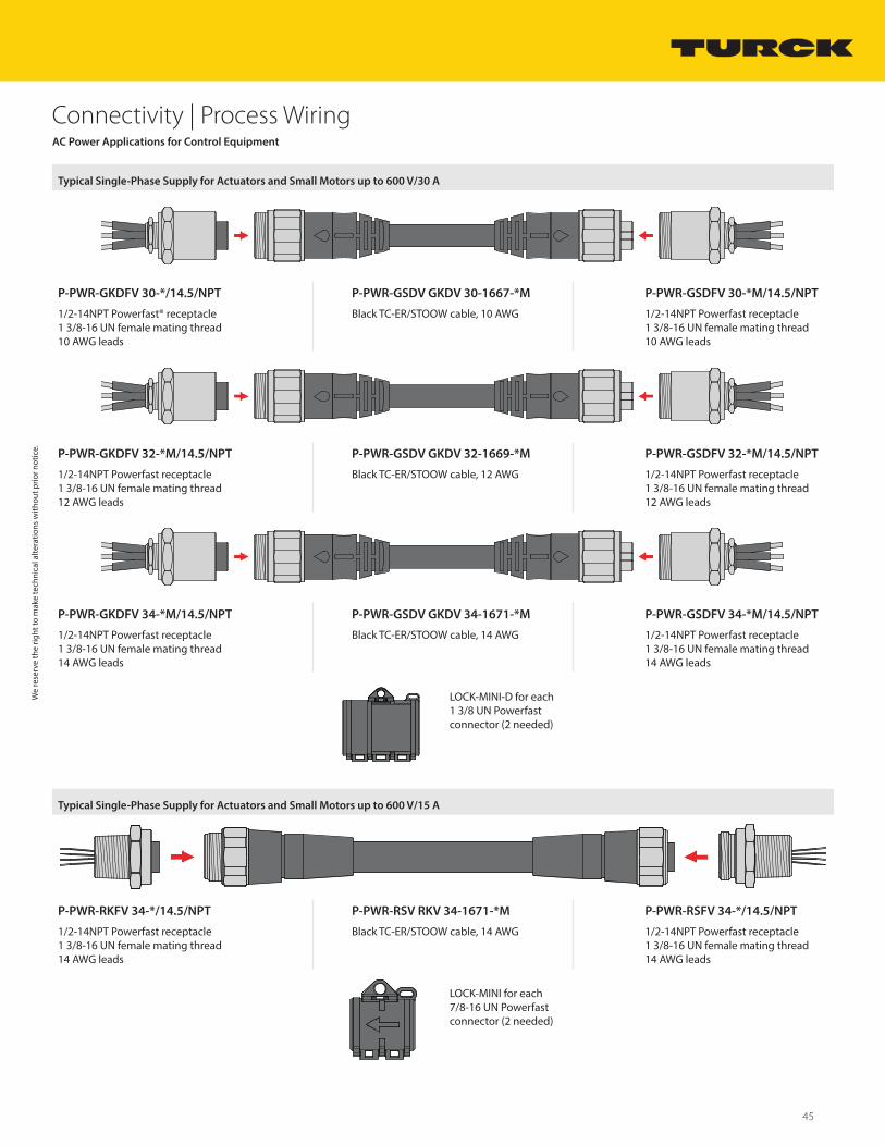
Typical Single-Phase Supply for Actuators and Small Motors up to 600 V/30 A
P-PWR-GKDFV 30-*/14.5/NPT P-PWR-GSDV GKDV 30-1667-*M P-PWR-GSDFV 30-*M/14.5/NPT
1/2-14NPT Powerfast® receptacle1 3/8-16 UN female mating thread10 AWG leads
Black TC-ER/STOOW cable, 10 AWG 1/2-14NPT Powerfast receptacle1 3/8-16 UN female mating thread10 AWG leads
P-PWR-GKDFV 32-*M/14.5/NPT P-PWR-GSDV GKDV 32-1669-*M P-PWR-GSDFV 32-*M/14.5/NPT
1/2-14NPT Powerfast receptacle1 3/8-16 UN female mating thread12 AWG leads
Black TC-ER/STOOW cable, 12 AWG 1/2-14NPT Powerfast receptacle1 3/8-16 UN female mating thread12 AWG leads
P-PWR-GKDFV 34-*M/14.5/NPT P-PWR-GSDV GKDV 34-1671-*M P-PWR-GSDFV 34-*M/14.5/NPT
1/2-14NPT Powerfast receptacle1 3/8-16 UN female mating thread14 AWG leads
Black TC-ER/STOOW cable, 14 AWG 1/2-14NPT Powerfast receptacle1 3/8-16 UN female mating thread14 AWG leads
LOCK-MINI-D for each1 3/8 UN Powerfastconnector (2 needed)
Typical Single-Phase Supply for Actuators and Small Motors up to 600 V/15 A
P-PWR-RKFV 34-*/14.5/NPT P-PWR-RSV RKV 34-1671-*M P-PWR-RSFV 34-*/14.5/NPT
1/2-14NPT Powerfast receptacle1 3/8-16 UN female mating thread14 AWG leads
Black TC-ER/STOOW cable, 14 AWG 1/2-14NPT Powerfast receptacle1 3/8-16 UN female mating thread14 AWG leads
LOCK-MINI for each7/8-16 UN Powerfastconnector (2 needed)
We
rese
rve
the
right
to m
ake
tech
nica
l alte
ratio
ns w
ithou
t prio
r not
ice.
46 Turck Inc. | 3000 Campus Drive, Minneapolis, MN 55441 | T +1 800 544 7769 | F +1 763 553 0708 | www.turck.com
Connectivity | Process Wiring
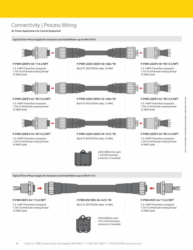
Typical Three-Phase Supply For Actuators and Small Motors up to 600 V/30 A
P-PWR-GKDFV 40-*/14.5/NPT P-PWR-GSDV GKDV 40-1666-*M P-PWR-GSDFV 40-*M/14.5/NPT
1/2-14NPT Powerfast receptacle1 3/8-16 UN female mating thread10 AWG leads
Black TC-ER/STOOW cable, 10 AWG 1/2-14NPT Powerfast receptacle1 3/8-16 UN female mating thread10 AWG leads
P-PWR-GKDFV 42-*M/14.5/NPT P-PWR-GSDV GKDV 42-1666-*M P-PWR-GSDFV 42-*M/14.5/NPT
1/2-14NPT Powerfast receptacle1 3/8-16 UN female mating thread12 AWG leads
Black TC-ER/STOOW cable, 12 AWG 1/2-14NPT Powerfast receptacle1 3/8-16 UN female mating thread12 AWG leads
P-PWR-GKDFV 44-*M/14.5/NPT P-PWR-GSDV GKDV 44-1672-*M P-PWR-GSDFV 44-*M/14.5/NPT
1/2-14NPT Powerfast receptacle1 3/8-16 UN female mating thread14 AWG leads
Black TC-ER/STOOW cable, 14 AWG 1/2-14NPT Powerfast receptacle1 3/8-16 UN female mating thread14 AWG leads
LOCK-MINI-D for each1 3/8 UN Powerfastconnector (2 needed)
AC Power Applications for Control Equipment
Typical Three-Phase Supply for Actuators and Small Motors up to 600 V/15 A
P-PWR-RKFV 44-*/14.5/NPT P-PWR-RSV RKV 44-1672-*M P-PWR-RSFV 44-*/14.5/NPT
1/2-14NPT Powerfast receptacle1 3/8-16 UN female mating thread14 AWG leads
Black TC-ER/STOOW cable, 14 AWG 1/2-14NPT Powerfast receptacle1 3/8-16 UN female mating thread14 AWG leads
LOCK-MINI for each7/8-16 UN Powerfastconnector (2 needed)
We reserve the right to m
ake technical alterations without prior notice.
47
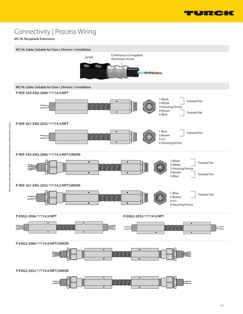
Connectivity | Process WiringMC-HL Receptacle Extensions
MC-HL Cable: Suitable for Class I, Division 1 Installation
JacketContinuous Corrugated Aluminum Armor
MC-HL Cable: Suitable for Class I, Division 1 Installation
P-RSF-543-EXG-2006-*/*/14.5/NPT
1-Black2-White3-Housing/Armor4-Brown5-Blue
Twisted Pair
Twisted Pair
P-RSF-421-EXG-2032-*/*/14.5/NPT
1-Blue2-Brown3-n/c4-Housing/Armor
Twisted Pair
P-RSF-543-EXG-2006-*/*/14.5/NPT/UNION
1-Black2-White3-Housing/Armor4-Brown5-Blue
Twisted Pair
Twisted Pair
P-RSF-421-EXG-2032-*/*/14.5/NPT/UNION
1-Blue2-Brown3-n/c4-Housing/Armor
Twisted Pair
P-EXG2-2006-*/*/14.5/NPT P-EXG2-2032-*/*/14.5/NPT
P-EXG2-2006-*/*/14.5/NPT/UNION
P-EXG2-2032-*/*/14.5/NPT/UNION
We
rese
rve
the
right
to m
ake
tech
nica
l alte
ratio
ns w
ithou
t prio
r not
ice.

48 Turck Inc. | 3000 Campus Drive, Minneapolis, MN 55441 | T +1 800 544 7769 | F +1 763 553 0708 | www.turck.com
Connectivity | Process WiringMC-HL Receptacle Extensions
Typical Field Applications
P-RSF 421-EXG-2032-*/*/14.5/NPT/UNION
2-Wire Transmitter
Class I, Div 2 Minifast cordset with LOCK-MINIe.g. P-RSV RKV 40-30-*M
Class I, Division 1 Class I, Division 2
Class I, Division 1 Class I, Division 1
Transmitter RequiringDaisy-Chain Connection
2-WIRE:P-EXG2-2032-*M/14.5/NPT/UNION4-WIRE:P-EXG2-2006-*M/14.5/NPT/UNION
Transmitter RequiringDaisy-Chain Connection
We reserve the right to m
ake technical alterations without prior notice.
49
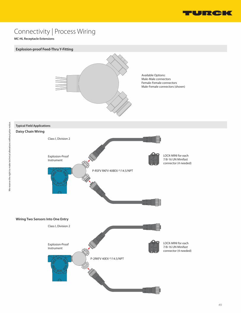
Connectivity | Process WiringMC-HL Receptacle Extensions
Explosion-proof Feed-Thru Y-Fitting
Available Options:Male-Male connectorsFemale-Female connectorsMale-Female connectors (shown)
Typical Field Applications
Daisy Chain Wiring
Explosion-Proof Instrument
Class I, Division 2
LOCK-MINI for each 7/8-16 UN Minifast connector (4 needed)
P-RSFV RKFV 40BEX-*/14.5/NPT
Wiring Two Sensors Into One Entry
Explosion-Proof Instrument
Class I, Division 2
LOCK-MINI for each 7/8-16 UN Minifast connector (4 needed)
P-2RKFV 40EX-*/14.5/NPT
We
rese
rve
the
right
to m
ake
tech
nica
l alte
ratio
ns w
ithou
t prio
r not
ice.
50 Turck Inc. | 3000 Campus Drive, Minneapolis, MN 55441 | T +1 800 544 7769 | F +1 763 553 0708 | www.turck.com
Connectivity | Process Wiring
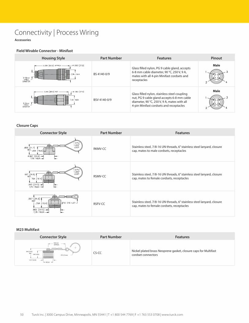
Field Wirable Connector - Minifast
Housing Style Part Number Features Pinout
BS 4140-0/9
Glass filled nylon, PG 9 cable gland, accepts6-8 mm cable diameter, 90 °C, 250 V, 9 A,mates with all 4-pin Minifast cordsets andreceptacles
Male
BSV 4140-0/9
Glass filled nylon, stainless steel couplingnut, PG 9 cable gland accepts 6-8 mm cablediameter, 90 °C, 250 V, 9 A, mates with all4-pin Minifast cordsets and receptacles
Male
Accessories
Closure Caps
Connector Style Part Number Features
RKMV-CC Stainless steel, 7/8-16 UN threads, 6” stainless steel lanyard, closurecap, mates to male cordsets, receptacles
RSMV-CC Stainless steel, 7/8-16 UN threads, 6” stainless steel lanyard, closurecap, mates to female cordsets, receptacles
RSFV-CC Stainless steel, 7/8-16 UN threads, 6” stainless steel lanyard, closurecap, mates to female cordsets, receptacles
M23 Multifast
Connector Style Part Number Features
Ă19-21mm
M23x1
.709 [18.0]
.945 [24.0]REF
1.017 [25.8]
180 mmAPPROX.
CS-CC Nickel plated brass Neoprene gasket, closure caps for Multifastcordset connectors

51
Connectivity | Process WiringAccessories
Junction Box Mounting Kits
Connector Style Part Number Features
KIT, J-BOX MOUNTING, 4-PORT METALGalvanized steel mounting bracket for 4-port junctionboxes. Includes mounting hardware. U-bolt fits up to2 1/2” outside diameter pipe.
KIT, J-BOX MOUNTING, 8-PORT METALGalvanized steel mounting bracket for 8-port junctionboxes. Includes mounting hardware. U-bolt fits up to2 1/2” outside diameter pipe.