Embed Size (px)
Citation preview

Siemens Energy & Automation, Inc. Configuration Guide
CGQL-4 Rev: 6 June 2004
ProcessSuite® 4-mation Configuration
QUADLOG® I/O Module Configuration Version 3.32 or Higher

Notes

CGQL-4 Contents
June 2004 i
Table of Contents
Section Title Page
1.0 Introduction....................................................................................................................1-1 1.1 Product Description ......................................................................................................1-1 1.2 Software Compatability................................................................................................1-2 1.3 Product Support ............................................................................................................1-4 1.4 Related Literature .........................................................................................................1-6
2.0 Critical Analog Input (CAI)..........................................................................................2-1 2.1 CAI Scope Parameter ...................................................................................................2-1 2.2 CAI Channel Types ......................................................................................................2-1 2.2.1 CAI Analog Input...................................................................................................2-1 2.2.2 Critical Analog Input, Programmable Limits.........................................................2-3 2.2.3 Critical Discrete Supervised Input Channel ...........................................................2-5
3.0 Critical Analog Module (CAM)....................................................................................3-1 3.1 CAM Scope Parameter .................................................................................................3-1 3.2 CAM Channel Types ....................................................................................................3-1 3.2.1 CAM Analog Input Channel ..................................................................................3-2 3.2.2 Critical Analog Input, Programmable Limits.........................................................3-4 3.2.3 CAM Analog Output Channel ...............................................................................3-6 3.2.4 CAM Discrete Supervised Input ............................................................................3-7
4.0 Critical Discrete Input (CDI) Modules ........................................................................4-1 4.1 AC Critical Discrete Input Module (CDI_AC) ............................................................4-1 4.1.1 CDI_AC Module Scope Parameter ........................................................................4-1 4.1.2 CDI_AC Channel Types ........................................................................................4-1 4.1.2.1 CDI De-Energize-To-Trip AC Input............................................................4-2 4.1.2.2 CDI Energize-To-Trip AC Input..................................................................4-2 4.2 DC Critical Discrete Input Module (CDI_DC) ............................................................4-3 4.2.1 CDI_DC Module Scope Parameter ........................................................................4-3 4.2.2 CDI_DC Channel Types ........................................................................................4-3 4.2.2.1 CDI De-Energize-To-Trip DC Input............................................................4-3 4.2.2.2 CDI Energize-To-Trip DC Input..................................................................4-4 4.3 Softlist Parameters........................................................................................................4-4
5.0 Critical Discrete Module (CDM) ..................................................................................5-1 5.1 CDM Module Scope Parameter....................................................................................5-2 5.2 CDM Channel Types ....................................................................................................5-2 5.2.1 Discrete Input.........................................................................................................5-3 5.2.2 Discrete Output ......................................................................................................5-4 5.2.3 SOE Discrete Input ................................................................................................5-5 5.2.4 SOE Discrete Output..............................................................................................5-6 5.2.5 Discrete Pulse Output.............................................................................................5-8

Contents CGQL-4
ii June 2004
6.0 Critical Discrete Output (CDO) Modules....................................................................6-1 6.1 AC Critical Discrete Output Module (CDO-AC).........................................................6-1 6.1.1 CDO-AC Module Scope Parameter .......................................................................6-1 6.1.2 CDO-AC Channel Types .......................................................................................6-1 6.1.2.1 CDO-AC De-Energize-To-Trip AC Output.................................................6-2 6.1.2.2 CDO-AC Energize-To-Trip AC Output.......................................................6-2 6.2 DC Critical Discrete Output Module (CDO-DC).........................................................6-3 6.2.1 CDO-DC Module Scope Parameter .......................................................................6-3 6.2.2 CDO-DC Channel Types .......................................................................................6-4 6.2.2.1 CDO-DC De-Energize-To-Trip DC Output.................................................6-4 6.2.2.2 CDO-DC Energize-To-Trip DC Output.......................................................6-4 6.3 Softlist Parameters........................................................................................................6-5
7.0 Enhanced Analog Module (EAM) ................................................................................7-1 7.1 EAM Module Scope Parameter ....................................................................................7-1 7.2 EAM Channel Types ....................................................................................................7-1 7.2.1 EAM Analog In Current ........................................................................................7-2 7.2.2 EAM Analog Out Current......................................................................................7-3 7.2.3 EAM Analog In Voltage ........................................................................................7-4 7.2.4 EAM Voltage Pulse In-Freq...................................................................................7-6 7.2.5 EAM Current Pulse In-Freq ...................................................................................7-8 7.2.6 EAM Voltage Pulse In-Total .................................................................................7-9 7.2.7 EAM Current Pulse In-Total................................................................................7-10 7.2.8 EAM Disc In Voltage ..........................................................................................7-11 7.2.9 EAM Disc In Current ...........................................................................................7-11 7.2.10 EAM Disc Out .....................................................................................................7-12
8.0 Input Discrete Module (IDM) .......................................................................................8-1 8.1 IDM Module Scope Parameter .....................................................................................8-1 8.2 IDM Channel Types .....................................................................................................8-1 8.2.1 IDM Disc In ...........................................................................................................8-1
9.0 Output Discrete Module (ODM)...................................................................................9-1 9.1 ODM Module Scope Parameter ...................................................................................9-1 9.2 ODM Channel Type .....................................................................................................9-1 9.2.1 ODM Disc Out .......................................................................................................9-1
10.0 Resistance Temperature Module (RTM)...................................................................10-1 10.1 RTM Module Scope Parameters.................................................................................10-1 10.2 RTM CHANNEL TYPES ..........................................................................................10-1 10.2.1 RTM RTD Input...................................................................................................10-1 10.2.2 RTM Resistance Input .........................................................................................10-4
11.0 Standard Analog Module (SAM)................................................................................11-1 11.1 SAM Module Scope Parameter ..................................................................................11-1 11.2 SAM Channel Types ..................................................................................................11-1

CGQL-4 Contents
June 2004 iii
11.2.1 SAM Analog In....................................................................................................11-2 11.2.2 SAM Analog Out .................................................................................................11-4 11.2.3 SAM Disc Out......................................................................................................11-6
12.0 Standard Discrete Module Plus (SDM+) ...................................................................12-1 12.1 SDM+ Module Scope Parameter ................................................................................12-1 12.2 SDM+ Channel Types ................................................................................................12-2 12.2.1 Discrete Input.......................................................................................................12-2 12.2.2 Discrete Output ....................................................................................................12-3 12.2.3 SOE Discrete Output............................................................................................12-5 12.2.4 Disc Pulse Out Channel .......................................................................................12-6
13.0 Voltage Input Module (VIM)......................................................................................13-1 13.1 VIM Module Scope Parameters..................................................................................13-1 13.2 VIM Channel Types ...................................................................................................13-1 13.2.1 Voltage Input........................................................................................................13-3
List of Tables
Table Title Page
Table 1–1 Configuration Software Compatible with QUADLOG System Software Version 3.30..........1-3 Table 1–2 Module ROMs Compatible with QUADLOG System Software Version 3.30 Software ........1-3 Table 1–3 Technical Support Center Contact Information .......................................................................1-5
Table 2–1 CAI Scope Parameter...............................................................................................................2-1 Table 2–2 CAI Analog Input Channel Softlist Parameters .......................................................................2-1 Table 2–3 XTC_CriticalXMTR Analog Input Current Range Definitions...............................................2-3 Table 2–4 CAIP Channel Softlist Parameters...........................................................................................2-3 Table 2–5 CAIP Channel Programming Considerations ..........................................................................2-5 Table 2–6 Critical Discrete Supervised Input Softlist Parameter .............................................................2-5
Table 3–1 CAM Scope Parameter ............................................................................................................3-1 Table 3–2 CAM Analog Input Channel Softlist Parameters.....................................................................3-2 Table 3–3 XTC_CriticalXMTR Analog Input Current Range Definitions...............................................3-3 Table 3–4 CAM Analog Input, Programmable Limits Channel Softlist Parameters................................3-4 Table 3–5 CAIP Channel Programming Considerations ..........................................................................3-6 Table 3–6 CAM Analog Output Channel Softlist Parameters ..................................................................3-6 Table 3–7 CAM Discrete Supervised Input Softlist Parameter ................................................................3-8
Table 4–1 CDI_AC Module Scope Parameter..........................................................................................4-1 Table 4–2 Softlist Parameters for the CDI De-Energize-To-Trip AC Input Channel Type .....................4-2 Table 4–3 Softlist Parameters for the CDI Energize-To-Trip AC Input Channel Type ...........................4-2 Table 4–4 CDI_DC Module Scope Parameter..........................................................................................4-3 Table 4–5 Softlist Parameters for the CDI De-Energize-To-Trip DC Input Channel Type .....................4-4 Table 4–6 Softlist Parameters for the CDI Energize-To-Trip DC Input Channel Type ...........................4-4

Contents CGQL-4
iv June 2004
Table 5–1 Limits for Open Load Diagnostics...........................................................................................5-1 Table 5–2 CDM Module Scope Parameter ...............................................................................................5-2 Table 5–3 Discrete Input Softlist Parameters ...........................................................................................5-3 Table 5–4 Discrete Output Softlist Parameters.........................................................................................5-4 Table 5–5 SOE Discrete Input Softlist Parameters ...................................................................................5-5 Table 5–6 SOE Discrete Output Softlist Parameters ................................................................................5-6 Table 5–7 Discrete Pulse Output Softlist Parameters ...............................................................................5-9 Table 5–8 Examples of Pulse Round Up Operation .................................................................................5-9
Table 6–1 CDO-AC Module Scope Parameter.........................................................................................6-1 Table 6–2 Softlist Parameters for the CDO-AC De-Energize-To-Trip AC Output..................................6-2 Table 6–3 Softlist Parameters for the CDO-AC Energize-To-Trip AC Output........................................6-3 Table 6–4 CDO-DC Module Scope Parameter.........................................................................................6-3 Table 6–5 Softlist Parameters for the CDO-DC De-Energize-To-Trip DC Output..................................6-4 Table 6–6 Softlist Parameters for the CDO-DC Energize-To-Trip DC Output........................................6-5
Table 7–1 EAM Module Scope Parameter ...............................................................................................7-1 Table 7–2 EAM Analog In Current Softlist Parameters ...........................................................................7-2 Table 7–3 EAM Analog Out Current Softlist Parameters ........................................................................7-3 Table 7–4 EAM Analog In Voltage Softlist Parameters...........................................................................7-4 Table 7–5 EAM Voltage Pulse In-Freq Softlist Parameters .....................................................................7-6 Table 7–6 EAM Current Pulse In-Freq Softlist Parameters......................................................................7-8 Table 7–7 EAM Voltage Pulse In-Total Softlist Parameters ....................................................................7-9 Table 7–8 EAM Current Pulse In-Total Softlist Parameter ....................................................................7-10 Table 7–9 EAM Disc In Voltage Softlist Parameters .............................................................................7-11 Table 7–10 EAM Disc Input Current Softlist Parameters ......................................................................7-11 Table 7–11 EAM Disc Output Softlist Parameter...................................................................................7-12
Table 8–1 IDM Module Scope Parameter ................................................................................................8-1 Table 8–2 IDM Disc In Softlist Parameters..............................................................................................8-1
Table 9–1 ODM Module Scope Parameter...............................................................................................9-1 Table 9–2 ODM Discrete Output Softlist Parameters...............................................................................9-1
Table 10–1 RTM Module Scope Parameters ..........................................................................................10-1 Table 10–2 RTM RTD Input Softlist Parameters ...................................................................................10-2 Table 10–3 RTM Resistance Input Softlist Parameters ..........................................................................10-4
Table 11–1 SAM Module Scope Parameter ...........................................................................................11-1 Table 11–2 SAM Analog In Softlist Parameters.....................................................................................11-2 Table 11–3 SAM Analog Out Softlist Parameters..................................................................................11-4 Table 11–4 SAM Discrete Input Softlist Parameters ..............................................................................11-5 Table 11–5 SAM Discrete Output Softlist Parameters ...........................................................................11-6
CGQL-4 Contents
June 2004 v
Table 12–1 SDM+ Module Scope Parameter .........................................................................................12-1 Table 12–2 Discrete Input Softlist Parameters .......................................................................................12-2 Table 12–3 Discrete Output Softlist Parameters.....................................................................................12-3 Table 12–4 SOE Discrete Input Softlist Parameters ...............................................................................12-4 Table 12–5 SOE Discrete Output Softlist Parameters ............................................................................12-5 Table 12–6 Disc Pulse Out Channel Softlist Parameters ........................................................................12-7 Table 12–7 Examples of Pulse Round Up Operation .............................................................................12-8
Table 13–1 VIM Module Scope Parameters...........................................................................................13-1 Table 13–2 Thermocouple Input Softlist Parameters..............................................................................13-2 Table 13–3 Voltage Input Softlist Parameters ........................................................................................13-3
List of Illustrations
Figure Title Page
Figure 5–1 Discrete Pulse Output Timing Diagram .................................................................................5-9
Figure 11–1 Step Time Response of Digital Filter .................................................................................11-3
Figure 12–1 Disc Pulse Out Channel Timing Diagram ..........................................................................12-7
Significant Changes for Revision 6
Entire document updated for consistency with current Help Files.
1.0 Introduction—Section 1.3 product support information updated.
6.0 Critical Discrete Output (CDO) Modules—
Table 6–5 Softlist Parameters for the CDO-DC De-Energize-To-Trip DC Output—Open Circuit Test parameter changed to FieldWiringDiag.
Table 6–6 Softlist Parameters for the CDO-DC Energize-To-Trip DC Output—Protected Output parameter deleted and Open Circuit Test parameter changed to FieldWiringDiag.
Siemens Energy & Automation, Inc., assumes no liability for errors or omissions in this document or for the application and use of information included in this document. The information herein is subject to change without notice.
Procedures included in this document have been reviewed for compliance with applicable approval agency requirements and are considered sound practice. Neither Siemens Energy & Automation, Inc., nor these agencies are responsible for repairs made by the user.
ProcessSuite, QUADLOG, 4-mation, and APACS+ are trademarks of Siemens Energy & Automation, Inc. All other trademarks are the property of their respective owners.
© 2004 Siemens Energy & Automation, Inc. All rights reserved.

Contents CGQL-4
vi June 2004
Notes

CGQL-4 Introduction
June 2004 1-1
1.0 Introduction
This Configuration Guide provides information on the configurable elements of QUADLOG® safety PLC I/O modules. It is intended to be used in conjunction with the configuration procedures located in Using the 4-mation Configuration Software (document number CG39-20).
Starting with section 2.0, each section of this guide presents the parameters and channel types of an individual QUADLOG I/O module, as follows:
• Section 2.0, Critical Analog Input (CAI) Module • Section 3.0, Critical Analog Module (CAM) • Section 4.0, Critical Discrete Input (CDI) Module • Section 5.0, Critical Discrete Module (CDM) • Section 6.0, Critical Discrete Output (CDO) Module • Section 7.0, Enhanced Analog Module (EAM) • Section 8.0, Input Discrete Module (IDM) • Section 9.0, Output Discrete Module (ODM) • Section 10.0, Resistance Temperature Module (RTM) • Section 11.0, Standard Analog Module (SAM) • Section 12.0, Standard Discrete Module Plus (SDM+) • Section 13.0, Voltage Input Module (VIM)
1.1 Product Description
The QUADLOG safety PLC provides a safer, more reliable control solution for potentially dangerous applications (e.g. burner management, emergency shutdown, fire and gas detection systems). Traditional choices for a safety system include mechanical relays, a programmable logic controller (PLC), or a triple modular redundant (TMR) system. As with many choices, each of the options comes with its advantages and disadvantages. QUADLOG has been designed to provide the optimal mix of each option’s strengths, essentially providing a safety PLC.
Historically, safety systems consisted of mechanical relays. These systems provide high safety; however, they come with significant maintenance demands and lack the communication capabilities, self-diagnostics, configuration flexibility, and calculation tools needed in today’s highly automated plants.
Due to the limitations posed by relays, programmable logic controllers (PLCs) have been replacing them as the most commonly used safety system. As safety and availability become more critical, a conventional PLC will not provide adequate protection. A major concern with a conventional PLC is the potential for a dangerous failure. This is because a PLC only provides one solid state circuit path. An input circuit receives a signal from a sensor, the main processor solves logic functions and performs calculations required to generate an output, and the output circuit typically energizes or de-energizes a solid-state switch (TRIAC or FET) to control an actuator. A component in this circuit could fail in a way that energizes the output switch. In this state, the controller cannot de-energize the output and perform its protection function, and the condition is not likely to be detected by diagnostics. This type of failure could lead to a condition threatening to both equipment and personnel.

Introduction CGQL-4
1-2 June 2004
To remedy this problem, QUADLOG incorporates two circuit paths. QUADLOG’s standard “dual” architecture provides Protected Outputs™. Output energy flows through diverse technology dual switches. A solid state switch provides the normal controller output. A relay, controlled by built-in diagnostics, supplies the second switch through a set of normally-open contacts. If a dangerous failure is detected within the output channel, the relay contacts can be opened, de-energizing the output to ensure a safe failure.
This standard “dual” QUADLOG architecture features a single controller; single I/O with Protected Outputs and “fail on” and “fail off” diagnostic output options; redundant power supplies; redundant communication links with CRC checking and watchdog timers; redundant, diverse watchdog timers; CPU instruction tests and exhaustive RAM tests; and program flow control checks. The standard architecture can also be expanded to include optional redundant control modules, providing a low-cost option for redundancy of critical functions.
QUADLOG incorporates a modular design for flexible control of plant operations. The QUADLOG modules are rack-mounted, DIN-sized intelligent (microprocessor-based) modules designed to perform a specific application function, such as control or I/O. They are selected individually and combined to accommodate a process application. Each QUADLOG system typically consists of a control module and a complement of I/O modules.
Connection between the individual QUADLOG modules is provided by three busses:
MODULBUS Used by control, communications and computer modules to share process and system information.
IOBUS Provides a control module with dedicated, secure access to field I/O points which terminate at I/O modules.
POWER BUS A triple-redundant bus providing power to QUADLOG modules.
The QUADLOG I/O modules are a series of configurable modules acting as interfaces between control modules and field termination signals, offering a broad range of analog, discrete, and special condition I/O points. All QUADLOG I/O modules are configured using the 4-mation configuration software. During configuration, 4-mation is used to define the channel type and several parameters that vary according to channel type. After a configuration is created, it is loaded into the I/O module’s memory, and a copy of the configuration is stored in the controller’s non-volatile memory. This allows on-line removal and replacement of the module without the need for reconfiguration.
1.2 Software Compatability
QUADLOG System Software Version 3.30 is compatible with the 4-mation versions listed in Table 1-1 and the QUADLOG module ROMs listed in Table 1-2. QUADLOG System Software Version 3.30 is compatible with all QUADLOG CCMs (Critical Control Modules) and Advanced Control Module Plus (ACM+) model QLACM12BBN. QUADLOG System Software Version 3.30 requires QUADLOG I/O modules to have 3.x version ROMs.

CGQL-4 Introduction
June 2004 1-3
Table 1–1 Configuration Software Compatible with QUADLOG System Software Version 3.30
SOFTWARE VERSION ProcessSuite 4-mation Configuration Software 3.03, 4.0x, 4.1x, 4.2x, 4.3x
Table 1–2 Module ROMs Compatible with QUADLOG System Software Version 3.30 Software
ROM SOFTWARE (1) VERSION (2) (3) (4)
QUADLOG Critical Control Module (CCM) 3.00, 3.10
QUADLOG Critical Discrete Module (CDM) 3.02
QUADLOG Enhanced Analog Module (EAM) 3.01
QUADLOG Input Discrete Module (IDM) 3.00
QUADLOG Output Discrete Module (ODM) 3.01
QUADLOG Resistance Temperature Module (RTM) 3.00
QUADLOG Standard Analog Module (SAM) 3.00
QUADLOG Standard Discrete Module Plus (SDM+) 3.02
QUADLOG Voltage Input Module (VIM) 3.00, 3.01
NOTES: 1. In modules with more than one ROM, each ROM must be the same version. 2. The ROM version number is listed on the module’s identification label. 3. Where a range of ROM versions is listed, install the highest version. 4. To ensure proper operation, a redundant pair of modules must have the same ROM version number.

Introduction CGQL-4
1-4 June 2004
1.3 Product Support
Product support can be obtained from a Technical Support Center (TSC). Each regional TSC is a customer service center that provides direct telephone support on technical issues related to the functionality, application, and integration of all products supplied by Siemens. Regional TSC contact information is provided in Table 1–3. Your regional TSC is the first place you should call when seeking product support information. When calling, it is helpful to have the following information ready:
• Caller name and company name
• Product part number or model number and version
• If there is a problem with product operation:
- Whether the problem is intermittent - The steps performed before the problem occurred - Any error messages or LED indications displayed - Installation environment
Product documentation is now located in the Library forum of the Process Automation User Connection at: http://sitescape.sea.siemens.com/. The Process Automation User Connection is a secure site. Registration is open to all verified users of Siemens process automation systems. If you are not already, and would like to become a member, please visit our Process Automation User Connection web page at: http://www.sea.siemens.com/process/support/papauc.html
Contained within the Process Automation User Connection is the APACS+/QUADLOG Secure Site at: http://sitescape.sea.siemens.com/forum/aca-1/dispatch.cgi/f.apacsquadlo forum. This site is only open to customers with an active service agreement. It contains all service manuals, service memos, service notes, configuration manuals, etc. for the APACS+ and QUADLOG family of products. If you are experiencing technical difficulties with the site, please contact SiteScape technical support at: toll free 1-877-234-1122 (US) or 1-513-336-1474.

CGQL-4 Introduction
June 2004 1-5
Table 1–3 Technical Support Center Contact Information
Tel: +1 215 646 7400, extension 4842
Fax: +1 215 283 6343
E-mail: [email protected]
Hours of Operation: 8 a.m. to 5 p.m. eastern time Monday – Friday (except holidays)
NORTH AMERICA
Secure Web Site: www.sea.siemens.com/process/product/papao.html
Tel: +011 65 740 7818
Fax: +011 65 740 7817
E-mail: [email protected]
Hours of Operation: 8:30 a.m. to 5:30 p.m. Singapore time Monday – Friday (except holidays)
ASIA
Secure Web Site: www.siemens.com
Tel: +44 (0) 1905 450930
Fax: +44 (0) 1905 450931
E-mail: [email protected]
Hours of Operation: 8:30 a.m. to 4:30 p.m. GMT/BST Monday – Friday (except holidays)
EUROPE
Secure Web Site: www.siemens.com

Introduction CGQL-4
1-6 June 2004
1.4 Related Literature
The following literature applicable to this configuration guide is available from Siemens. Generally, all needed software documentation is supplied on CD-ROM with your system. Refer to it as needed or as directed in text.
• QUADLOG User’s Manual, I/O Modules (binder number UMQL-1)
• QUADLOG User’s Manual, Control and Communications Modules (binder number UMQL-2)
• Safety Manual for QUADLOG Version 3.30 or Higher (document CGQLSAFETY-1)
• ProcessSuite Control Function Block Library for Use with QUADLOG Version 3.30 or Higher (document CGQL-6)
• Using the ProcessSuite 4-mation Configuration Software (document CG39-20, located in the BOOKS directory of the ProcessSuite Control CD and in binder UM39-11)
• The ProcessSuite Control Simulator (document CG39CTRLSIM-1, located in the BOOKS directory of the ProcessSuite Control CD and in binder UM39-11)
• 4-mation User’s Manual, Configuring APACS & QUADLOG Hardware (binder number UM39-14)
• APACS+ User’s Manual, Packaging and Power (binder number UM39-5)
• Sequence of Events Viewer Operator’s Guide (document OG39SOE-2)
Documents supplied with ProcessSuite products may be located on your workstation’s hard drive or on the appropriate ProcessSuite CD (e.g. ProcessSuite Control CD).
To access ProcessSuite document files:
1. If applicable, load the ProcessSuite CD containing the document files.
2. From the Windows taskbar, press the Start button, then press and hold the left mouse button and point to Programs.
3. Continue by pointing to ProcessSuite, Documentation, ProcessSuite Documentation then release the mouse button. This starts the document viewing software and displays a table of contents.
4. Scroll through the table of contents until you find the title of the desired document, then click on the title to open the document.

CGQL-4 Critical Analog Input (CAI)
June 2004 2-1
2.0 Critical Analog Input (CAI)
The CAI Module interfaces up to 32 channels of analog input signals from field devices to a control module's IOBUS.
2.1 CAI Scope Parameter
Table 2-1 shows the module scope softlist parameter for the CAI Module. To view/edit the Module Scope Parameter, place the cursor on the desired module in the module tree. From the Main Menu Bar, select Edit, Object/Item to open the Hardware Modules dialog box. Click the Softlist command button to open the Module Scope Softlist dialog box.
Table 2–1 CAI Scope Parameter
PARAMETER SELECTION DEFAULT
ScanRate Not applicable Not applicable
ScanRate: This is a read-only parameter that displays the current scan rate of the module. The scan rate is fixed at 50 msec. The CAI Module scans asynchronous to the CCM.
2.2 CAI Channel Types
The CAI supports the following channel types:
• CAI Analog Input • Critical Analog Input, Programmable Limits • Critical Discrete (Disc) Supervised Input
2.2.1 CAI Analog Input
The CAI Analog Input channel type returns a REAL variable. Table 2-2 shows the softlist parameters for this channel type:
Table 2–2 CAI Analog Input Channel Softlist Parameters
PARAMETER SELECTION DEFAULT
Shutdown_Channel TRUE, FALSE FALSE
InputFaultState No_Change, MinRange, MaxRange No_Change
MinScale Any REAL Number 0.0
MaxScale Any REAL Number 100.0

Critical Analog Input (CAI) CGQL-4
2-2 June 2004
EngUnits in, ft, mm, cm, m, in3, ft3, bbl, ml, liter, m3, lb, ton, mol, g, kg, ft/sec, m/sec,ft/sec2, msec2, DegF, DegR, DegC, DegK, psi, psia, psig, InH2O, InHg, ATM, kPa, kPaa, kPag, mmHg, kg/cm2, mbar, bar, lb/ft3, g/cm3, kg/m3, mol/m3, ft3/lb, m3/kg, ppm, pH, PPH, KPPH, t/day, kg/hr, kg/day, gal/min, GPM, GPH, GPD, ACFM, ACFH, SCCM, SCFH, SCFM, MCFH, yd3/hr, yd3/day, BPD, gal/hr, gal/day, m3/hr, m3/day, l/min, l/hr, l/day, mV, Volts, mA, AMPS, Ohms, mhos, W, kW, MW, Btu, Btu/SCF, Btu/lbm, Btu/hr, hp, bhp, vars, VA, kVA, joules, Percent, pulses, Hz, rpm, deg, rad, cal, cal/SCF, cal/hr, cal/lbm, kcal, kcal/SCF, kcal/hr, kcal/lbm, tonne, tonne/day
Percent
Bias Any REAL Number 0.0
OpenCircuitTest Enabled, Disabled Enabled
XTC_CriticalXMTR TRUE, FALSE FALSE
Softlist Parameters:
Shutdown_Channel: When TRUE and channel quality is BAD or QUESTIONABLE, the CAI reports a shutdown error. The configuration can be changed to only shut down the affected inputs or not to shut down at all. Only channels that are critical to the process should be configured as shutdown_channels. Note that in rack-to-rack redundant systems, a switchover to the verify side, rather than a system shutdown, occurs if an I/O failure occurs. Both sides of a redundant system would have to fail for a shutdown to occur.
InputFaultState: When the input channel is faulted (BAD, QUESTIONABLE, or UNAVAILABLE data quality), the channel reports the value configured in this softlist parameter. No_Change returns the actual value. MinRange returns the smallest value (MinScale). MaxRange returns the largest value (MaxScale).
MinScale: The module will linearly scale raw data (4-20 mA) to engineering units for each channel. The scaling algorithm uses the MinScale/MaxScale parameters set by the user. For example, given a MinScale of 0.0 and a MaxScale of 100.0. If the input to the channel is 12mA, the scaled value will be 50.0. MinScale can be any REAL number (REAL numbers are valid between -3.4028E38 and +3.4028E38)
MaxScale: MaxScale can be any REAL number.
EngUnits: Engineering units for the scaled value can be selected from a list of common engineering units.
Bias: The user can enter a bias in engineering units on a per channel basis to compensate for known offsets. The bias value is added to the scaled input.
OpenCircuitTest: The user can enable or disable open circuit testing. An open circuit condition exists if the reading is <= 3.6mA.

CGQL-4 Critical Analog Input (CAI)
June 2004 2-3
XTC_CriticalXMTR: When this parameter is TRUE, the Model 345 XTC Critical Transmitter limits will be used for over/under range, open/short circuit, and transducer failure indications, as defined in Table 2-3. When this parameter is FALSE, the over/under range is extended to include the transmitter failure range, so transmitter failure is not reported. This parameter should be set to FALSE for non-critical transmitters.
Table 2–3 XTC_CriticalXMTR Analog Input Current Range Definitions
Current Range (mA) XTC_CriticalXMTR = TRUE XTC_CriticalXMTR = FALSE
>= 21.0 Short circuit (or transducer failed high) Short circuit > 20.5 to < 21.0 Transducer failed high Over range
>20.0 to <= 20.5 Over range Over range 20.0 MaxScale MaxScale
4.0 MinScale MinScale >= 3.8 to < 4.0 Under range Under range
> 3.6 to < 3.8 Transducer failed (safe) low Under range <= 3.6 Open circuit Open circuit
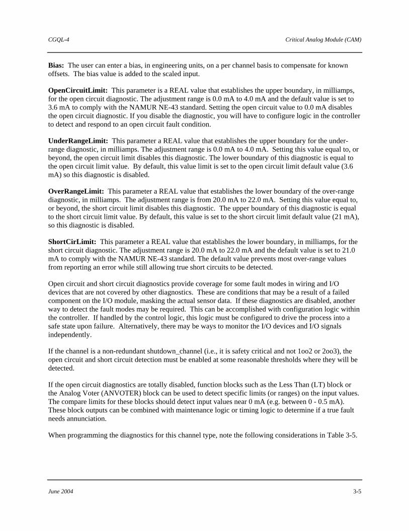
2.2.2 Critical Analog Input, Programmable Limits
The Critical Analog Input, Programmable Limits (CAIP) channel type returns a REAL variable. This channel type allows the diagnostic ranges to be configured by the user. These diagnostic ranges are configured in milliamps (mA). Table 2-4 shows the softlist parameters for this channel type:
Table 2–4 CAIP Channel Softlist Parameters
Softlist Parameter Settings DefaultShutdown_Channel TRUE/FALSE FALSE InputFaultState Min/Max/NoChange NoChange Min Scale Any REAL Value 0.0 Max Scale Any REAL Value 100.0 EngUnits Pick from list Percent Bias Any REAL Number 0.0 OpenCircuitLimit 0.0 mA – 4.0 mA 3.6 mA UnderRangeLimit 0.0 mA – 4.0 mA 3.6 mA OverRangeLimit 20.0 mA – 22.0 mA 21.0 mA ShortCirLimit 20.0 mA- 22.0 mA 21.0 mA
Shutdown_Channel: When TRUE and channel quality is BAD or QUESTIONABLE, the CAI reports a shutdown error. The configuration can be changed to only shut down the affected inputs or not to shut down at all. Only channels that are critical to the process should be configured as shutdown_channels. Note that in rack-to-rack redundant systems, a switchover to the verify side, rather than a system shutdown, occurs if an I/O failure occurs. Both sides of a redundant system would have to fail for a shutdown to occur.

Critical Analog Input (CAI) CGQL-4
2-4 June 2004
InputFaultState: When the input channel is faulted (BAD, QUESTIONABLE, or UNAVAILABLE data quality), the channel reports the value configured in this softlist parameter. No_Change returns the actual value. MinRange returns the smallest value (MinScale). MaxRange returns the largest value (MaxScale).
MinScale: The module will linearly scale raw data (4-20 mA) to engineering units for each channel. The scaling algorithm uses the MinScale/MaxScale parameters set by the user. For example, given a MinScale of 0.0 and a MaxScale of 100.0. If the input to the channel is 12mA, the scaled value will be 50.0. MinScale can be any REAL number (REAL numbers are valid between -3.4028E38 and +3.4028E38)
MaxScale: MaxScale can be any REAL number.
EngUnits: Engineering units for the scaled value can be selected from a list of common engineering units.
Bias: The user can enter a bias, in engineering units, on a per channel basis to compensate for known offsets. The bias value is added to the scaled input.
OpenCircuitLimit: This parameter is a REAL value that establishes the upper boundary, in milliamps, for the open circuit diagnostic. The adjustment range is 0.0 mA to 4.0 mA and the default value is set to 3.6 mA to comply with the NAMUR NE-43 standard. Setting the open circuit value to 0.0 mA disables the open circuit diagnostic. If you disable the diagnostic for a safety critical channel, you will have to configure logic in the controller to detect and respond to an open circuit fault condition.
UnderRangeLimit: This parameter a REAL value that establishes the upper boundary for the under-range diagnostic, in milliamps. The adjustment range is 0.0 mA to 4.0 mA. Setting this value equal to, or beyond, the open circuit limit disables this diagnostic. The lower boundary of this diagnostic is equal to the open circuit limit value. By default, this value limit is set to the open circuit limit default value (3.6 mA) so this diagnostic is disabled.
OverRangeLimit: This parameter a REAL value that establishes the lower boundary of the over-range diagnostic, in milliamps. The adjustment range is from 20.0 mA to 22.0 mA. Setting this value equal to, or beyond, the short circuit limit disables this diagnostic. The upper boundary of this diagnostic is equal to the short circuit limit value. By default, this value is set to the short circuit limit default value (21 mA), so this diagnostic is disabled.
ShortCirLimit: This parameter a REAL value that establishes the lower boundary, in milliamps, for the short circuit diagnostic. The adjustment range is 20.0 mA to 22.0 mA and the default value is set to 21.0 mA to comply with the NAMUR NE-43 standard. The default value prevents most over-range values from reporting an error while still allowing true short circuits to be detected. The default value permits a defective (open) sense resistor on the CAI Marshalled Termination Assembly (MTA) to be detected.
Open circuit and short circuit diagnostics provide coverage for some fault modes in wiring and I/O devices that are not covered by other diagnostics. These are conditions that may be a result of a failed component on the I/O module, masking the actual sensor data.. If these diagnostics are disabled for safety critical channels, another way to detect the fault modes may be required. This can be accomplished with configuration logic within the controller. If handled by the control logic, this logic must be configured to

CGQL-4 Critical Analog Input (CAI)
June 2004 2-5
drive the process into a safe state upon failure. Alternatively, there may be ways to monitor the I/O devices and I/O signals independently.
If the channel is a non-redundant shutdown_channel (i.e., it is safety critical and not 1oo2 or 2oo3), the open circuit and short circuit detection must be enabled at some reasonable thresholds where they will be detected.
If the open circuit diagnostics are totally disabled, function blocks such as the Less Than (LT) block or the Analog Voter (ANVOTER) block can be used to detect specific limits (or ranges) on the input values. The compare limits for these blocks should detect input values near 0 mA (e.g. between 0 - 0.5 mA). These block outputs can be combined with maintenance logic or timing logic to determine if a true fault needs annunciation.
When programming the diagnostics for this channel type, note the following considerations listed in Table 2-5.
Table 2–5 CAIP Channel Programming Considerations
Input Value (mA) Diagnostic Result >ShortCirLimit Short Circuit Error <= ShortCirLimit and >OverRangeLimit Over Range Error <=OverRangeLimit and >=UnderRangeLimit None <UnderRangeLimit and >=OpenCircuitLimit Under Range Error <OpenCiruitLimit Open Circuit Error
2.2.3 Critical Discrete Supervised Input Channel
The CDSI (Critical Discrete Supervised Input) channel type returns an analog variable, automatically ranged and scaled to 0-20 mA, which may be converted to discrete values by the Critical Discrete Supervised Input (CDSI) function block. When this channel type is selected, it should be connected to the CDSI function block in the controller logic. This function block contains the fixed thresholds that convert the analog signal from the CAM to a boolean value. Refer to Standard Function Blocks for QUADLOG (document number CGQL-7) and the CDSI block for detailed information. Also refer to the QUADLOG Critical Analog Input Module (CAI) Installation and Service Instruction (document number SDQLCAI-1) for information on CDSI channel type wiring details. Table 2-6 lists the softlist parameter for this channel type.
Table 2–6 Critical Discrete Supervised Input Softlist Parameter
PARAMETER SELECTION DEFAULT Shutdown_Channel TRUE, FALSE FALSE
Shutdown_Channel: When TRUE and channel quality is BAD or QUESTIONABLE, the CAM reports a shutdown error (Class 4, SSC 37, EC 31). Based on the default configuration supplied with QUADLOG, a class 4 error causes all outputs to shut down to their de-energized state (i.e. 0 volts or 0 mA). The configuration can be changed to only shut down the affected outputs or not to shut down at all.

Critical Analog Input (CAI) CGQL-4
2-6 June 2004
Only channels that are critical to the process should be configured as shutdown_channels. Note that in rack-to-rack redundant systems, a switchover to the verify side, rather than a system shutdown, occurs if an I/O failure occurs. Both sides of a redundant system would have to fail for a shutdown to occur. Refer to the Safety Manual for QUADLOG Version 3.30 or Higher (document number CGQLSAFETY-2) for details of the shutdown configuration logic.

CGQL-4 Critical Analog Module (CAM)
June 2004 3-1
3.0 Critical Analog Module (CAM)
The CAM can interface 32 channels of analog I/O and discrete input signals to a control module’s IOBUS. To isolate field faults, all channels are electrically isolated from the module’s CPU, IOBUS, and ground. Also, each channel uses an isolated 28 V power source, and all channels are current-limited to protect against short-circuits.
3.1 CAM Scope Parameter
Table 3-1 shows the Module Scope softlist parameter for the CAM. To view/edit the module scope parameter, place the cursor on the desired module in the module tree and select the Edit, Object/Item menu item. The Hardware Modules dialog box opens. Choose the Softlist command button to open the Module Scope Softlist dialog box.
Table 3–1 CAM Scope Parameter
PARAMETER SELECTION DEFAULT
ScanRate Not applicable Not applicable
ScanRate: This is a read-only parameter that displays the current scan rate of the module.
3.2 CAM Channel Types
The channel types supported for the CAM are listed as follows:
• CAM Analog Input • Critical Analog Input, Programmable Limits • CAM Analog Output • Critical Discrete (Disc) Supervised Input
For information on configuring I/O channels, refer to “Configuring I/O Channels” section of Using the ProcessSuite 4-mation Configuration Software (document number CG39-20).

Critical Analog Module (CAM) CGQL-4
3-2 June 2004
3.2.1 CAM Analog Input Channel
The CAM Analog Input Channel returns a REAL variable. Table 3-2 shows the softlist parameters for this channel type.
Table 3–2 CAM Analog Input Channel Softlist Parameters
PARAMETER SELECTION DEFAULT
Shutdown_Channel TRUE, FALSE FALSE
InputFaultState No_Change, MinRange, MaxRange No_Change
MinScale Any REAL Number 0.0
MaxScale Any REAL Number 100.0
EngUnits in, ft, mm, cm, m, in3, ft3, bbl, ml, liter, m3, lb, ton, mol, g, kg, ft/sec, m/sec,ft/sec2, msec2, DegF, DegR, DegC, DegK, psi, psia, psig, InH2O, InHg, ATM, kPa, kPaa, kPag, mmHg, kg/cm2, mbar, bar, lb/ft3, g/cm3, kg/m3, mol/m3, ft3/lb, m3/kg, ppm, pH, PPH, KPPH, t/day, kg/hr, kg/day, gal/min, GPM, GPH, GPD, ACFM, ACFH, SCCM, SCFH, SCFM, MCFH, yd3/hr, yd3/day, BPD, gal/hr, gal/day, m3/hr, m3/day, l/min, l/hr, l/day, mV, Volts, mA, AMPS, Ohms, mhos, W, kW, MW, Btu, Btu/SCF, Btu/lbm, Btu/hr, hp, bhp, vars, VA, kVA, joules, Percent, pulses, Hz, rpm, deg, rad, cal, cal/SCF, cal/hr, cal/lbm, kcal, kcal/SCF, kcal/hr, kcal/lbm, tonne, tonne/day
Percent
Bias Any REAL Number 0.0
OpenCircuitTest Enabled, Disabled Enabled
XTC_CriticalXMTR TRUE, FALSE TRUE
Shutdown_Channel: When TRUE and channel quality is BAD or QUESTIONABLE, the CAM reports a shutdown error (Class 4, SSC 37, EC 31). Based on the default configuration supplied with QUADLOG, a class 4 error causes all outputs to shut down to their de-energized state (i.e. 0 volts or 0 mA). The configuration can be changed to only shut down the affected outputs or not to shut down at all. Only channels that are critical to the process should be configured as shutdown_channels. Note that in rack-to-rack redundant systems, a switchover to the verify side, rather than a system shutdown, occurs if an I/O failure occurs. Both sides of a redundant system would have to fail for a shutdown to occur. Refer to the Safety Manual for QUADLOG Version 3.30 or Higher (document number CGQLSAFETY-2), section 6.7 (Shutdown Logic), for details of the shutdown configuration logic.

CGQL-4 Critical Analog Module (CAM)
June 2004 3-3
InputFaultState: When the input channel is faulted (BAD, QUESTIONABLE, or UNAVAILABLE data quality), the channel reports the value configured in this softlist parameter. No_Change returns the actual value. MinRange returns the smallest value (MinScale). MaxRange returns the largest value (MaxScale).
MinScale: The module linearly scales raw data (4-20 mA) to engineering units for each channel. The scaling algorithm uses the MinScale/MaxScale parameters that you set. For example, given a MinScale of 0.0 and a MaxScale of 100.0, if the input to the channel is 12 mA, the scaled value is 50.0. MinScale can be any REAL number (REAL numbers are valid between -3.4028E38 and +3.4028E38)
MaxScale: MaxScale can be any REAL number.
EngUnits: Engineering units for the scaled value can be selected from a list of common engineering units.
Bias: The user can enter a bias (in engineering units) on a per channel basis to compensate for known offsets. The bias value is added to the scaled input.
OpenCircuitTest: The user can enable or disable open circuit testing. An open circuit condition exists if the reading is < 3.6 mA. If this diagnostic is disabled, an under range error is reported.
XTC_CriticalXMTR: When this parameter is TRUE, the Model 345 XTC Critical Transmitter limits are used for over/under range, open/short circuit, and transducer failure indications, as defined in the following table. When this parameter is FALSE, the over/under range is extended to include the transmitter failure range, so transmitter failure is not reported. This parameter should be set to FALSE for non-critical transmitters.
Table 3–3 XTC_CriticalXMTR Analog Input Current Range Definitions
CURRENT RANGE (ma) XTC_CriticalXMTR = TRUE XTC_criticalXMTR = FALSE
>= 21.0 Short circuit (or transducer failed high) Short circuit
> 20.5 to < 21.0 Transducer failed high Over range
>20.0 to <= 20.5 Over range Over range
20.0 MaxScale MaxScale
4.0 MinScale MinScale
>= 3.8 to < 4.0 Under range Under range
> 3.6 to < 3.8 Transducer failed (safe) low Under range
<= 3.6 Open circuit Open circuit

Critical Analog Module (CAM) CGQL-4
3-4 June 2004
3.2.2 Critical Analog Input, Programmable Limits
The Critical Analog Input, Programmable Limits (CAIP) channel type returns a REAL variable. This channel type allows the diagnostic ranges to be configured by the user. These diagnostic ranges are configured in milliamps (mA). Table 3-4 shows the softlist parameters for this channel type.
Table 3–4 CAM Analog Input, Programmable Limits Channel Softlist Parameters
PARAMETER SELECTION DEFAULT
ShutdownChannel TRUE, FALSE FALSE
InputFaultState No_Change, MinRange, MaxRange No_Change
MinScale Any REAL Number 0.0
MaxScale Any REAL Number 100.0
EngUnits Pick from list Percent
Bias Any REAL Number 0.0
OpenCircuitLimit 0.0 mA ─ 4.0 mA 3.6 mA
UnderRangeLimit 0.0 mA ─ 4.0 mA 3.6 mA
OverRangeLimit 20.0 mA ─ 22.0 mA 21.0 mA
ShortCirLimit 20.0 mA ─ 22.0 mA 21.0 mA
Shutdown_Channel: When TRUE and channel quality is BAD or QUESTIONABLE, the CAI reports a shutdown error. The configuration can be changed to only shut down the affected inputs or not to shut down at all. Only channels that are critical to the process should be configured as shutdown_channels. Note that in rack-to-rack redundant systems, a switchover to the verify side, rather than a system shutdown, occurs if an I/O failure occurs. Both sides of a redundant system would have to fail for a shutdown to occur.
InputFaultState: When the input channel is faulted (BAD, QUESTIONABLE, or UNAVAILABLE data quality), the channel reports the value configured in this softlist parameter. No_Change returns the actual value. MinRange returns the smallest value (MinScale). MaxRange returns the largest value (MaxScale).
MinScale: The module will linearly scale raw data (4-20 mA) to engineering units for each channel. The scaling algorithm uses the MinScale/MaxScale parameters set by the user. For example, given a MinScale of 0.0 and a MaxScale of 100.0. If the input to the channel is 12mA, the scaled value will be 50.0. MinScale can be any REAL number (REAL numbers are valid between -3.4028E38 and +3.4028E38)
MaxScale: MaxScale can be any REAL number.
EngUnits: Engineering units for the scaled value can be selected from a list of common engineering units.
CGQL-4 Critical Analog Module (CAM)
June 2004 3-5
Bias: The user can enter a bias, in engineering units, on a per channel basis to compensate for known offsets. The bias value is added to the scaled input.
OpenCircuitLimit: This parameter is a REAL value that establishes the upper boundary, in milliamps, for the open circuit diagnostic. The adjustment range is 0.0 mA to 4.0 mA and the default value is set to 3.6 mA to comply with the NAMUR NE-43 standard. Setting the open circuit value to 0.0 mA disables the open circuit diagnostic. If you disable the diagnostic, you will have to configure logic in the controller to detect and respond to an open circuit fault condition.
UnderRangeLimit: This parameter a REAL value that establishes the upper boundary for the under-range diagnostic, in milliamps. The adjustment range is 0.0 mA to 4.0 mA. Setting this value equal to, or beyond, the open circuit limit disables this diagnostic. The lower boundary of this diagnostic is equal to the open circuit limit value. By default, this value limit is set to the open circuit limit default value (3.6 mA) so this diagnostic is disabled.
OverRangeLimit: This parameter a REAL value that establishes the lower boundary of the over-range diagnostic, in milliamps. The adjustment range is from 20.0 mA to 22.0 mA. Setting this value equal to, or beyond, the short circuit limit disables this diagnostic. The upper boundary of this diagnostic is equal to the short circuit limit value. By default, this value is set to the short circuit limit default value (21 mA), so this diagnostic is disabled.
ShortCirLimit: This parameter a REAL value that establishes the lower boundary, in milliamps, for the short circuit diagnostic. The adjustment range is 20.0 mA to 22.0 mA and the default value is set to 21.0 mA to comply with the NAMUR NE-43 standard. The default value prevents most over-range values from reporting an error while still allowing true short circuits to be detected.
Open circuit and short circuit diagnostics provide coverage for some fault modes in wiring and I/O devices that are not covered by other diagnostics. These are conditions that may be a result of a failed component on the I/O module, masking the actual sensor data. If these diagnostics are disabled, another way to detect the fault modes may be required. This can be accomplished with configuration logic within the controller. If handled by the control logic, this logic must be configured to drive the process into a safe state upon failure. Alternatively, there may be ways to monitor the I/O devices and I/O signals independently.
If the channel is a non-redundant shutdown_channel (i.e., it is safety critical and not 1oo2 or 2oo3), the open circuit and short circuit detection must be enabled at some reasonable thresholds where they will be detected.
If the open circuit diagnostics are totally disabled, function blocks such as the Less Than (LT) block or the Analog Voter (ANVOTER) block can be used to detect specific limits (or ranges) on the input values. The compare limits for these blocks should detect input values near 0 mA (e.g. between 0 - 0.5 mA). These block outputs can be combined with maintenance logic or timing logic to determine if a true fault needs annunciation.
When programming the diagnostics for this channel type, note the following considerations in Table 3-5.

Critical Analog Module (CAM) CGQL-4
3-6 June 2004
Table 3–5 CAIP Channel Programming Considerations
Input Value (mA) Diagnostic Result >ShortCirLimit Short Circuit Error <= ShortCirLimit and >OverRangeLimit Over Range Error <=OverRangeLimit and >=UnderRangeLimit None <UnderRangeLimit and >=OpenCircuitLimit Under Range Error <OpenCiruitLimit Open Circuit Error
3.2.3 CAM Analog Output Channel
The CAM Analog Output Channel accepts a REAL variable. Table 3-6 shows the softlist parameters for this channel type.
Table 3–6 CAM Analog Output Channel Softlist Parameters
PARAMETER SELECTION DEFAULT
Shutdown_Channel TRUE, FALSE FALSE
MinScale Any REAL Number 0.0
MaxScale Any REAL Number 100.0
OutputRange MA_4to20, mA_0to20 mA_4to20
EngUnits in, ft, mm, cm, m, in3, ft3, bbl, ml, liter, m3, lb, ton, mol, g, kg, ft/sec, m/sec,ft/sec2, msec2, DegF, DegR, DegC, DegK, psi, psia, psig, InH2O, InHg, ATM, kPa, Kpaa, kPag, mmHg, kg/cm2, mbar, bar, lb/ft3, g/cm3, kg/m3, mol/m3, ft3/lb, m3/kg, ppm, pH, PPH, KPPH, t/day, kg/hr, kg/day, gal/min, GPM, GPH, GPD, ACFM, ACFH, SCCM, SCFH, SCFM, MCFH, yd3/hr, yd3/day, BPD, gal/hr, gal/day, m3/hr, m3/day, l/min, l/hr, l/day, mV, Volts, mA, AMPS, Ohms, mhos, W, kW, MW, Btu, Btu/SCF, Btu/lbm, Btu/hr, hp, bhp, vars, VA, kVA, joules, Percent, pulses, Hz, rpm, deg, rad, cal, cal/SCF, cal/hr, cal/lbm, kcal, kcal/SCF, kcal/hr, kcal/lbm, tonne, tonne/day
Percent
ProtectedOutput Enabled, Disabled Enabled
Bias Any REAL Number 0.0
ReadBack Enabled, Disabled Enabled

CGQL-4 Critical Analog Module (CAM)
June 2004 3-7
Shutdown_Channel: When TRUE and channel quality is BAD or QUESTIONABLE, the CAM reports a shutdown error (Class 4, SSC 37, EC 31). Based on the default configuration supplied with QUADLOG, a class 4 error causes all outputs to shut down to their de-energized state (i.e. 0 volts or 0 mA). The configuration can be changed to only shut down the affected outputs or not to shut down at all. Only channels that are critical to the process should be configured as shutdown_channels. Note that in rack-to-rack redundant systems, a switchover to the verify side, rather than a system shutdown, occurs if an I/O failure occurs. Both sides of a redundant system would have to fail for a shutdown to occur. Refer to the Safety Manual for QUADLOG Version 3.30 or Higher (document number CGQLSAFETY-2) for details of the shutdown configuration logic.
Enabling this parameter also enables the controller readback diagnostic. This diagnostic compares the output value sent by the controller to the value "read back" by the CAM.
MinScale: The module performs a linear conversion from engineering units to the selected OuputRange for each channel. The scaling algorithm uses the MinScale/MaxScale and OutputRange parameters that you set. For example, given a MinScale of 0.0, a MaxScale of 100.0, and an OutputRange of 4-20 mA, if the value written to the CAM Analog Out channel is 50, the module will output 12 mA. MinScale can be any REAL number (REAL numbers are valid between -3.4028E38 and +3.4028E38).
MaxScale: MaxScale can be any REAL number.
OutputRange: CAM Analog Output channels are configurable to operate with two current ranges: 4-20 mA and 0-20 mA
EngUnits: Engineering units for the scaled value can be selected from a list of common engineering units.
ProtectedOutput: Each output can be configured to turn off (0 mA = -25%) all CAM I/Os in the event that diagnostics determine that the output current is greater than it is intended to be by 2% or more. You may want to configure an output as a ProtectedOutput if it is critical to the process, or if it presents a possible hazard to personnel or equipment.
Bias: The user can enter a bias (in engineering units) on a per channel basis to compensate for known offsets. The bias value is added to the scaled output.
ReadBack: The state of an output channel is automatically "read back" by input circuitry on the same channel. ReadBack is used to diagnose and report faults. You can disable ReadBack, which, in turn, disables reporting of readback-related faults (i.e. Calculate Readback Data Mismatch, Verify & Calculate Readback Mismatch, Verify Readback Data Mismatch, Partner Readback Data Mismatch).
NOTE
Disabling ReadBack does not disable the controller readback diagnostic. ReadBack should be enabled if Shutdown_Channel = TRUE.
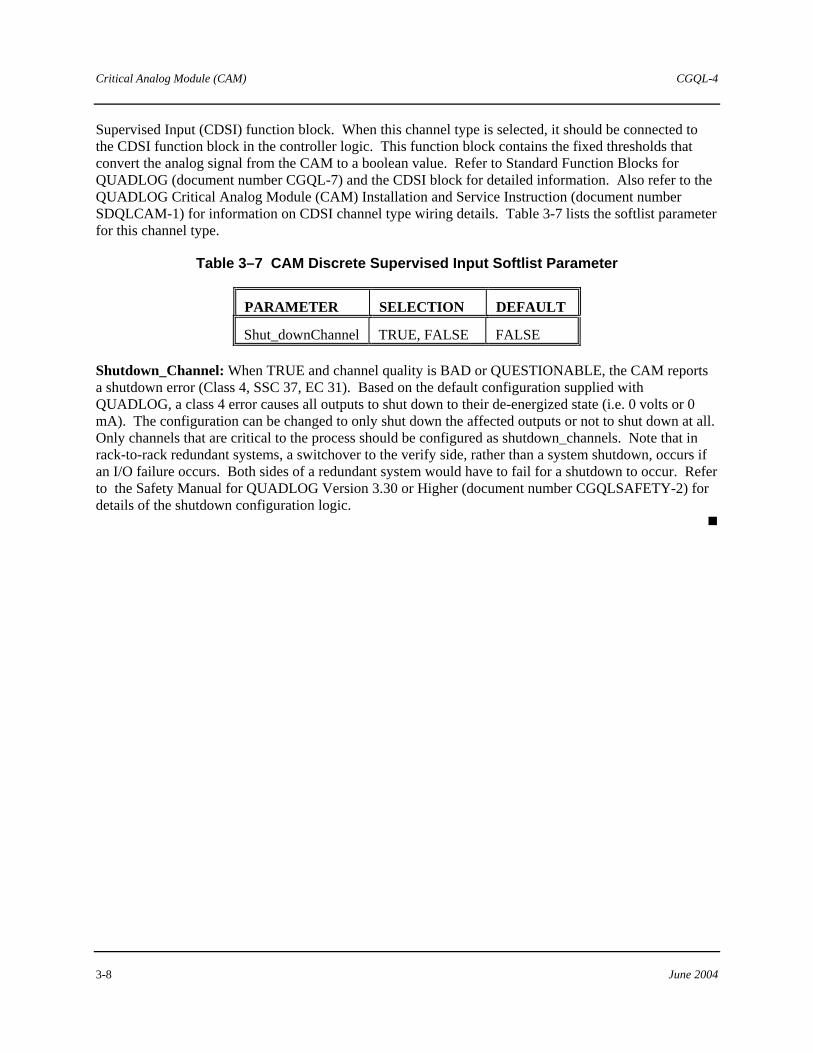
3.2.4 CAM Discrete Supervised Input
The CDSI Critical Discrete Supervised Input channel type returns an analog variable, automatically ranged and scaled to 0-20 mA, which may be converted to discrete values by the Critical Discrete
Critical Analog Module (CAM) CGQL-4
3-8 June 2004
Supervised Input (CDSI) function block. When this channel type is selected, it should be connected to the CDSI function block in the controller logic. This function block contains the fixed thresholds that convert the analog signal from the CAM to a boolean value. Refer to Standard Function Blocks for QUADLOG (document number CGQL-7) and the CDSI block for detailed information. Also refer to the QUADLOG Critical Analog Module (CAM) Installation and Service Instruction (document number SDQLCAM-1) for information on CDSI channel type wiring details. Table 3-7 lists the softlist parameter for this channel type.
Table 3–7 CAM Discrete Supervised Input Softlist Parameter
PARAMETER SELECTION DEFAULT
Shut_downChannel TRUE, FALSE FALSE
Shutdown_Channel: When TRUE and channel quality is BAD or QUESTIONABLE, the CAM reports a shutdown error (Class 4, SSC 37, EC 31). Based on the default configuration supplied with QUADLOG, a class 4 error causes all outputs to shut down to their de-energized state (i.e. 0 volts or 0 mA). The configuration can be changed to only shut down the affected outputs or not to shut down at all. Only channels that are critical to the process should be configured as shutdown_channels. Note that in rack-to-rack redundant systems, a switchover to the verify side, rather than a system shutdown, occurs if an I/O failure occurs. Both sides of a redundant system would have to fail for a shutdown to occur. Refer to the Safety Manual for QUADLOG Version 3.30 or Higher (document number CGQLSAFETY-2) for details of the shutdown configuration logic.

CGQL-4 Critical Discrete Input (CDI) Modules
June 2004 4-1
4.0 Critical Discrete Input (CDI) Modules
The Critical Discrete Input (CDI) modules include the AC Critical Discrete Input Module (CDI_AC) and the DC Critical Discrete Input Module (CDI_DC).
4.1 AC Critical Discrete Input Module (CDI_AC)
The CDI_AC module interfaces discrete 115 Vac input signals with a control module’s IOBUS, supporting 24 isolated AC inputs. This enables AC inputs from different power sources to be connected to the same module. Furthermore, each channel is electrically isolated from the module’s CPU, IOBUS, and ground.
Event recording inputs and outputs are high-speed channels used in conjunction with the functions blocks of the Sequence of Events Recorder Function Block Library for detecting, monitoring, controlling, and recording discrete state changes (i.e. events). This data is collected by a Sequence of Events (SOE)-compatible module, such as the CDI, that is capable of high-speed event gathering. Events are stored to an array of strings. The data can then be viewed through the Sequence of Events Viewer, a utility program. Refer to Sequence of Events Viewer Operator’s Guide (document number OG39SOE-2) for information on using this utility.
4.1.1 CDI_AC Module Scope Parameter
Table 4-1 shows the module scope softlist parameter for the CDI_AC. To view/edit the module scope parameter, place the cursor on the desired module in the module tree and select the Edit, Object/Item menu item. The Hardware Modules dialog box opens. Choose the Softlist command button to open the Module Scope Softlist dialog box.
Table 4–1 CDI_AC Module Scope Parameter
PARAMETER SELECTION DEFAULT
ScanRate Not applicable 25 ms
ScanRate: This is a read-only parameter that displays the current scan rate of the module.
4.1.2 CDI_AC Channel Types
The following channel types are supported for the CDI_AC module. For information on configuring I/O channels, refer to the "Configuring I/O Channels" section of Using the ProcessSuite 4-mation Configuration Software in 4-mation help.
• CDI De-Energize-To-Trip AC Input • CDI Energize-To-Trip AC Input
Critical Discrete Input (CDI) Modules CGQL-4
4-2 June 2004
4.1.2.1 CDI De-Energize-To-Trip AC Input
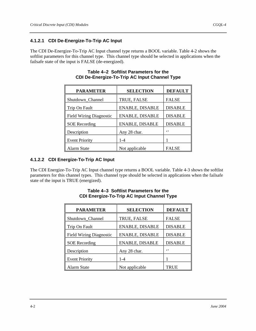
The CDI De-Energize-To-Trip AC Input channel type returns a BOOL variable. Table 4-2 shows the softlist parameters for this channel type. This channel type should be selected in applications when the failsafe state of the input is FALSE (de-energized).
Table 4–2 Softlist Parameters for the CDI De-Energize-To-Trip AC Input Channel Type
PARAMETER SELECTION DEFAULT
Shutdown_Channel TRUE, FALSE FALSE
Trip On Fault ENABLE, DISABLE DISABLE
Field Wiring Diagnostic ENABLE, DISABLE DISABLE
SOE Recording ENABLE, DISABLE DISABLE
Description Any 28 char. ‘’
Event Priority 1-4 1
Alarm State Not applicable FALSE
4.1.2.2 CDI Energize-To-Trip AC Input
The CDI Energize-To-Trip AC Input channel type returns a BOOL variable. Table 4-3 shows the softlist parameters for this channel types. This channel type should be selected in applications when the failsafe state of the input is TRUE (energized).
Table 4–3 Softlist Parameters for the CDI Energize-To-Trip AC Input Channel Type
PARAMETER SELECTION DEFAULT
Shutdown_Channel TRUE, FALSE FALSE
Trip On Fault ENABLE, DISABLE DISABLE
Field Wiring Diagnostic ENABLE, DISABLE DISABLE
SOE Recording ENABLE, DISABLE DISABLE
Description Any 28 char. ‘’
Event Priority 1-4 1
Alarm State Not applicable TRUE

CGQL-4 Critical Discrete Input (CDI) Modules
June 2004 4-3
4.2 DC Critical Discrete Input Module (CDI_DC)
The CDI_DC module interfaces discrete 125 Vdc input signals with a control module’s IOBUS, supporting 24 isolated DC inputs. This enables DC inputs from different power sources to be connected to the same module. Furthermore, each channel is electrically isolated from the module’s CPU, IOBUS, and ground.
Event recording inputs and outputs are high-speed channels used in conjunction with the function blocks of the Sequence of Events Recorder Function Block Library for detecting, monitoring, controlling, and recording discrete state changes (i.e. events). This data is collected by a Sequence of Events (SOE)-compatible module, such as the CDI, that is capable of high-speed event gathering. Events are stored to an array of strings. The data can then be viewed through the Sequence of Events Viewer, a utility program. Refer to Sequence of Events Viewer Operator’s Guide(document number OG39SOE-2) for information on using this utility.
4.2.1 CDI_DC Module Scope Parameter
Table 4-4 shows the module scope softlist parameter for the CDI_DC. To view/edit the module scope parameter, place the cursor on the desired module in the module tree and select the Edit, Object/Item menu item. The Hardware Modules dialog box opens. Choose the Softlist command button to open the Module Scope Softlist dialog box.
Table 4–4 CDI_DC Module Scope Parameter
PARAMETER SELECTION DEFAULT
ScanRate Not applicable 25 ms
ScanRate: This is a read-only parameter that displays the current scan rate of the module.
4.2.2 CDI_DC Channel Types
The following channel types are supported for the CDI_DC module. For information on configuring I/O channels, refer to the “Configuring I/O Channels” section of Using the ProcessSuite 4-mation Configuration Software in 4-mation help.
• CDI De-Energize-To-Trip DC Input • CDI Energize-To-Trip DC Input
4.2.2.1 CDI De-Energize-To-Trip DC Input
The CDI De-Energize-To-Trip DC Input channel type returns a BOOL variable. Table 4-5 shows the softlist parameters for this channel type. This channel type should be selected in applications when the failsafe state of the input is FALSE (de-energized).

Critical Discrete Input (CDI) Modules CGQL-4
4-4 June 2004
Table 4–5 Softlist Parameters for the CDI De-Energize-To-Trip DC Input Channel Type
PARAMETER SELECTION DEFAULT
Shutdown_Channel TRUE, FALSE FALSE
Trip On Fault ENABLE, DISABLE DISABLE
Field Wiring Diagnostic ENABLE, DISABLE DISABLE
SOE Recording ENABLE, DISABLE DISABLE
Description Any 28 char. ‘’
Event Priority 1-4 1
Alarm State Not applicable FALSE
4.2.2.2 CDI Energize-To-Trip DC Input
The CDI Energize-To-Trip DC Input channel type returns a BOOL variable. Table 4-6 shows the softlist parameters for this channel type. This channel type should be selected in applications when the failsafe state of the input is TRUE (energized).
Table 4–6 Softlist Parameters for the CDI Energize-To-Trip DC Input Channel Type
PARAMETER SELECTION DEFAULT
Shutdown_Channel TRUE, FALSE FALSE
Trip On Fault ENABLE, DISABLE DISABLE
SOE Recording ENABLE, DISABLE DISABLE
Description Any 28 char. ‘’
Event Priority 1-4 1
Alarm State Not applicable TRUE
4.3 Softlist Parameters
Shutdown_Channel: When TRUE and channel quality is BAD or QUESTIONABLE, the CDI reports a shutdown error (Class 4, SSC 37, EC 31). Based on the default configuration supplied with QUADLOG, a class 4 error causes all system outputs to shut down to their de-energized state (i.e. 0 volts or 0 mA). The configuration can be changed to only shut down the affected outputs or not to shut down at all. Only channels that are critical to the process should be configured as shutdown_channels. Note that in rack-to-rack redundant systems, a switchover to the verify side, rather than a system shutdown, occurs if an I/O failure occurs. Both sides of a redundant system would have to fail for a shutdown to occur. Refer to the
CGQL-4 Critical Discrete Input (CDI) Modules
June 2004 4-5
Safety Manual for QUADLOG Version 3.30 or Higher (document number CGQLSAFETY-2), section 6.7 (Shutdown Logic), for details of the shutdown configuration logic.
Trip On Fault: If Trip On Fault is enabled and channel quality is BAD, QUESTIONABLE, or UNAVAILABLE, the channel will report the Alarm State value.
Field Wiring Diagnostic: This parameter enables the field wiring diagnostic, which allows certain types of field wiring problems to be detected. Additional hardware is required to be installed in the field for this diagnostic to operate properly. See ProcessSuite® Installation Instructions (document 15941-56) for details.
SOE Recording: This parameter enables SOE (sequence of Events) recording for this channel.
Description: This parameter is relevant if SOE Recording is enabled. It is a description, up to 28 characters, of the channel monitored for configuration by the Sequence of Events Recorder block. The description is formatted as a STRING data type. It is inserted as a substring within the EVENTS string of the Sequence of Events Recorder block.
Event Priority: This parameter is relevant if SOE Recording is enabled. This data is used for establishing an event’s priority. You can set a channel’s priority from 1 (highest) to 4 (lowest). This priority value can then be used to sort events, such as when they are being formatted for viewing. This priority value is inserted within the EVENTS string of the Sequence of Events Recorder block.
Alarm State: This parameter is used to establish the alarm and/or trip state of the channel. If the channel type is De-Energize-to-Trip, the alarm state is by definition FALSE. This parameter is not configurable.

Critical Discrete Input (CDI) Modules CGQL-4
4-6 June 2004
Notes

CGQL-4 Critical Discrete Module (CDM)
June 2004 5-1
5.0 Critical Discrete Module (CDM)
The Critical Discrete Module (CDM) interfaces discrete DC sensors and actuators with a control module’s IOBUS. It provides 32 channels. Each channel can be configured as any of the five discrete channel types: an input, an output, an event recording input, an event recording output, or a pulse output.
The CDM’s inputs are current sinking (i.e. the input device is wired between the power supply positive and the I/O terminal). Outputs are current sourced (i.e. the output device is wired between the output terminal and power supply common). In addition, a soft-fuse circuit protects each output channel from a short-circuit in the field wiring and prevents a short from affecting other CDM channels. Note that a soft-fuse can be reset locally or remotely.
Event recording inputs and outputs are high-speed channels used in conjunction with the function blocks of the Sequence of Events Recorder Function Block Library for detecting, monitoring, controlling, and recording discrete state changes (i.e. events). This data is collected by a Sequence of Events (SOE)-compatible module, such as the CDM, that is capable of high-speed event gathering. Events are stored to an array of strings. The data can then be viewed through the Sequence of Events Viewer, a utility program. Refer to Sequence of Events Viewer Operator's Guide (document number OG39SOE-2) for information on using this utility.
All channel types, except pulse output, can be configured to run pulse test diagnostics to ensure the channel is in working order. The diagnostics require inputs to have an external device called a Safety-Related Switch Adapter (SRSA). The diagnostics detect shorts in the field, channel-to-channel shorts, and channel-to-power shorts.
IMPORTANT
To avoid signal interference, do not externally wire an output channel to other QUADLOG or APACS input channels if it is configured to use pulse test diagnostics. The short pulses emitted by the diagnostics are not intended to be connected directly to these input types.
Starting with version 3.1 of the CDM software (firmware), each output channel can be configured so the diagnostics can also detect an open load condition (i.e. when there is no load attached to that channel’s I/O termination). When an open load condition is detected, the module reports a module error (SSC 07, EC 37). The following table lists the criteria necessary to determine if the load connected to an output channel is compatible with the open load diagnostics. It applies to both redundant and non-redundant CDM configurations.
Table 5–1 Limits for Open Load Diagnostics
CDM MODEL
OPEN LOAD DETECTION THRESHOLD
CONNECTED LOAD DETECTION THRESHOLD
QLCDM024DCxAN (24 V) A load resistance greater than 4,050 ohms is considered open.
A load resistance less than 496 ohms is considered connected.
QLCDM048DCxAN (48 V) A load resistance greater than 4,271 ohms is considered open.
A load resistance less than 1,030 ohms is considered connected.

Critical Discrete Module (CDM) CGQL-4
5-2 June 2004
TABLE NOTES: 1. A load resistance value in the range between the open and connected thresholds can be detected as either
open or connected. 2. If an output channel is connected to a load, but the module still reports an error (SSC 07, EC37), you can
disable the open load diagnostics by setting the channel’s PulseDiagTest softlist value to disable. However, this parameter must be enabled for a safety critical output channel. Starting with firmware 3.02, the OpenCircuitTest softlist parameter disables open load diagnostics.
A discrete pulse output channel type is configurable so it is on for a time duration that you define (within a range of 25 to 2000 ms and a resolution of 25 ms).
Every input and output circuit is electrically isolated from the CDM's CPU, IOBUS, and ground. In addition, a soft-fuse circuit protects each output channel from a short circuit in the field wiring and prevents a short from affecting other CDM channels. Note that a soft-fuse can be reset locally or remotely.
5.1 CDM Module Scope Parameter
Table 5-2 shows the Module Scope softlist parameter for the CDM. To view/edit the module scope parameter, place the cursor on the desired module in the module tree and select the Edit, Object/Item menu item. The Hardware Modules dialog box opens. Select the Softlist command button to open the Module Scope Softlist dialog box.
Table 5–2 CDM Module Scope Parameter
PARAMETER SELECTION DEFAULT
ScanRate Not applicable Not applicable
ScanRate: This is a read-only parameter that displays the current scan rate of the module. Generally, the scan rate will be the same as the scan rate of the control module, but can be a multiple of the control module's scan rate.
5.2 CDM Channel Types
The following channel types are supported for the CDM. For information on configuring I/O channels, refer to the “Configuring I/O Channels” section of Using the 4-mation Configuration Software (document number CG39-20).
• Discrete Input • CDM Discrete Output • SOE Discrete Input • SOE Discrete Output • Discrete Pulse Output

CGQL-4 Critical Discrete Module (CDM)
June 2004 5-3
5.2.1 Discrete Input
The Discrete Input channel type returns a BOOL variable. Table 5-3 lists the softlist parameters for this channel type.
Table 5–3 Discrete Input Softlist Parameters
PARAMETER SELECTION DEFAULT
InputFaultState TRUE, FALSE FALSE
Shutdown_Channel TRUE, FALSE FALSE
PulseDiagTest Enabled, Disabled Enabled
InputFaultState: When an input channel has a hardware failure that makes the channel value impossible to discern, the channel reports the BOOL value configured in this softlist parameter.
Shutdown_Channel: When the Shutdown_Channel parameter is set to TRUE, a shutdown error (class 4, SSC 37, EC 31) is reported in addition to a class 2 or class 3 channel error that affects channel quality (when BAD or QUESTIONABLE quality is set). When this parameter is FALSE, the shutdown error is not reported. Based on the default configuration supplied with QUADLOG, a class 4 error causes all outputs to shut down to their de-energized state (i.e. 0 volts or 0 mA). The configuration can be changed to only shut down the affected outputs or not to shut down at all. Only channels that are critical to the process should be configured as shutdown_channels. Note that in rack-to-rack redundant systems, a switchover to the verify side, rather than a system shutdown, occurs if an I/O failure occurs. Both sides of a redundant system would have to fail for a shutdown to occur. Refer to the Safety Manual for QUADLOG Version 3.30 or Higher (document number CGQLSAFETY-2), section 6.7 (Shutdown Logic), for details of the shutdown configuration logic.
PulseDiagTest: This parameter is used to enable or disable pulse diagnostic testing. It is used to detect channel anomalies such as shorts in the field, channel-to-channel shorts, and channel-to-power shorts. It is an added protection measure for safety critical channels. Channels which perform safety critical I/O functions must have this parameter enabled. An input channel that uses this parameter must be wired to an external Safety-Related Switch Adapter.

Critical Discrete Module (CDM) CGQL-4
5-4 June 2004
5.2.2 Discrete Output
The Discrete Output channel type accepts a BOOL variable. Table 5-4 lists the softlist parameters for this channel type.
Table 5–4 Discrete Output Softlist Parameters
PARAMETER SELECTION DEFAULT
ProtectedOutput Enabled, Disabled Enabled
Readback Enabled, Disabled Enabled
Shutdown_Channel TRUE, FALSE FALSE
PulseDiagTest Enabled, Disabled Enabled
OpenCircuitTest Enabled, Disabled Enabled
ProtectedOutput: Each output can be configured to turn off all CDM outputs in the event that a channel is intended to be off, but diagnostics have determined that it is on. You may want to configure an output as ProtectedOutput if it is critical to the process or if it presents a possible hazard to personnel or equipment.
Readback: The state of an output channel is automatically “readback” by input circuitry on the same channel. The Readback is used to diagnose and report the following five types of faults. Disabling Readback disables reporting of the first four types.
1. Diagnostic Read Error 2. Output Failed ON (energized) 3. Protected Output Failed ON (energized) 4. Output Failed OFF (de-energized, blown hard fuse) 5. Output Failed OFF (de-energized, tripped soft-fuse)
NOTES
Disabling ReadBack does not disable the controller readback diagnostic. ReadBack should be enabled if Shutdown_Channel = TRUE.
As listed above, there are two possibilities for an output channel to fail OFF. One way is when the hard fuse blows (it is not field-replaceable); the other is when the soft-fuse trips (it is locally or remotely resettable). The soft-fuse trip error cannot be disabled by the Readback softlist.
Shutdown_Channel: When the Shutdown_Channel parameter is set to TRUE, a shutdown error (class 4, SSC 37, EC 31) is reported in addition to a class 2 or class 3 channel error that affects channel quality (when BAD or QUESTIONABLE quality is set). When this parameter is FALSE, the shutdown error is not reported. Based on the default configuration supplied with QUADLOG, a class 4 error causes all outputs to shut down to their de-energized state (i.e. 0 volts or 0 mA). The configuration can be changed

CGQL-4 Critical Discrete Module (CDM)
June 2004 5-5
to only shut down the affected outputs or not to shut down at all. Only channels that are critical to the process should be configured as shutdown_channels. Note that in rack-to-rack redundant systems, a switchover to the verify side, rather than a system shutdown, occurs if an I/O failure occurs. Both sides of a redundant system would have to fail for a shutdown to occur. Refer to the Safety Manual for QUADLOG Version 3.30 or Higher (document number CGQLSAFETY-2), section 6.7 (Shutdown Logic), for details of the shutdown configuration logic.
Enabling this parameter also enables the controller readback diagnostic. This diagnostic compares the output value sent by the controller to the value “read back” by the CDM.
PulseDiagTest: This parameter is used to enable or disable pulse diagnostic testing. It is used to detect channel anomalies such as shorts in the field, channel-to-channel shorts, and channel-to-power shorts. It is an added protection measure for safety critical channels.
OpenCircuitTest: This parameter is used to enable or disable open load (circuit) testing. Starting with version 3.01 of the CDM software (firmware), each output channel can be configured so the diagnostics can also detect an open condition (i.e. when there is no load attached to that channel's I/O termination). When an open load condition is detected, the module reports a module error (SSC 07, EC 37).
5.2.3 SOE Discrete Input
The Sequence of Events (SOE) Discrete Input channel type returns SOE information. Table 5-5 shows the softlist parameters for this channel type.
Table 5–5 SOE Discrete Input Softlist Parameters
PARAMETER SELECTION DEFAULT
InputFaultState TRUE, FALSE FALSE
Shutdown_Channel TRUE, FALSE FALSE
Description 28 Character String ‘’ (null string)
EventPriority 1,2,3, or 4 1
AlarmState TRUE, FALSE FALSE
PulseDiagTest Enabled, Disabled Enabled
InputFaultState: When an input channel has a hardware failure that makes the channel value impossible to discern, the channel reports the value configured in this softlist parameter.
Shutdown_Channel: When the Shutdown_Channel parameter is set to TRUE, a shutdown error (class 4, SSC 37, EC 31) is reported in addition to a class 2 or class 3 channel error that affects channel quality (when BAD or QUESTIONABLE quality is set). When this parameter is FALSE, the shutdown error is not reported. Based on the default configuration supplied with QUADLOG, a class 4 error causes all outputs to shut down to their de-energized state (i.e. 0 volts or 0 mA). The configuration can be changed to only shut down the affected outputs or not to shut down at all. Only channels that are critical to the process should be configured as shutdown_channels. Note that in rack-to-rack redundant systems, a
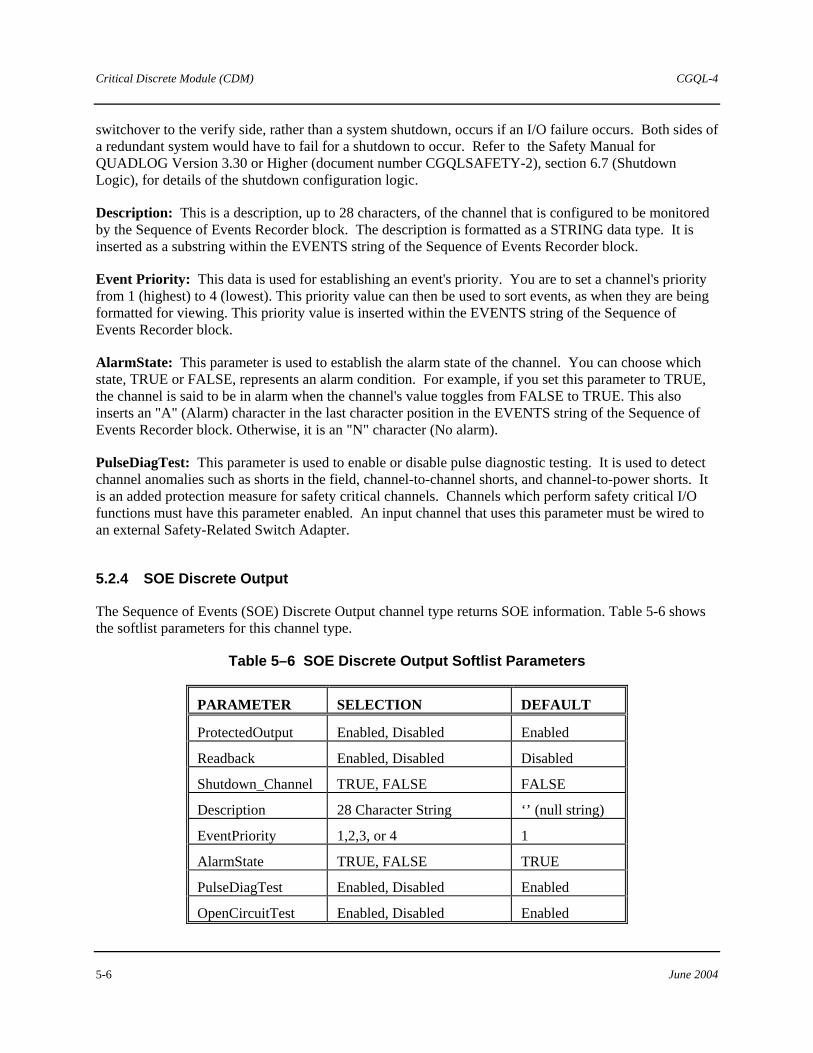
Critical Discrete Module (CDM) CGQL-4
5-6 June 2004
switchover to the verify side, rather than a system shutdown, occurs if an I/O failure occurs. Both sides of a redundant system would have to fail for a shutdown to occur. Refer to the Safety Manual for QUADLOG Version 3.30 or Higher (document number CGQLSAFETY-2), section 6.7 (Shutdown Logic), for details of the shutdown configuration logic.
Description: This is a description, up to 28 characters, of the channel that is configured to be monitored by the Sequence of Events Recorder block. The description is formatted as a STRING data type. It is inserted as a substring within the EVENTS string of the Sequence of Events Recorder block.
Event Priority: This data is used for establishing an event's priority. You are to set a channel's priority from 1 (highest) to 4 (lowest). This priority value can then be used to sort events, as when they are being formatted for viewing. This priority value is inserted within the EVENTS string of the Sequence of Events Recorder block.
AlarmState: This parameter is used to establish the alarm state of the channel. You can choose which state, TRUE or FALSE, represents an alarm condition. For example, if you set this parameter to TRUE, the channel is said to be in alarm when the channel's value toggles from FALSE to TRUE. This also inserts an "A" (Alarm) character in the last character position in the EVENTS string of the Sequence of Events Recorder block. Otherwise, it is an "N" character (No alarm).
PulseDiagTest: This parameter is used to enable or disable pulse diagnostic testing. It is used to detect channel anomalies such as shorts in the field, channel-to-channel shorts, and channel-to-power shorts. It is an added protection measure for safety critical channels. Channels which perform safety critical I/O functions must have this parameter enabled. An input channel that uses this parameter must be wired to an external Safety-Related Switch Adapter.
5.2.4 SOE Discrete Output
The Sequence of Events (SOE) Discrete Output channel type returns SOE information. Table 5-6 shows the softlist parameters for this channel type.
Table 5–6 SOE Discrete Output Softlist Parameters
PARAMETER SELECTION DEFAULT
ProtectedOutput Enabled, Disabled Enabled
Readback Enabled, Disabled Disabled
Shutdown_Channel TRUE, FALSE FALSE
Description 28 Character String ‘’ (null string)
EventPriority 1,2,3, or 4 1
AlarmState TRUE, FALSE TRUE
PulseDiagTest Enabled, Disabled Enabled
OpenCircuitTest Enabled, Disabled Enabled

CGQL-4 Critical Discrete Module (CDM)
June 2004 5-7
ProtectedOutput: Each output can be configured to turn off all CDM outputs in the event that a channel is intended to be off but diagnostics have determined that it is on. You may want to configure an output as ProtectedOutput if it is critical to the process or if it presents a possible hazard to personnel or equipment.
Readback: The state of an output channel is automatically “readback” by input circuitry on the same channel. The Readback is used to diagnose and report the following five types of faults. Disabling Readback disables reporting of the first four types.
1. Diagnostic Read Error 2. Output Failed ON (energized) 3. Protected Output Failed ON (energized) 4. Output Failed OFF (de-energized, blown hard fuse). 5. Output Failed OFF (de-energized, tripped soft-fuse)
As listed above, there are two possibilities for an output channel to fail off. One way is when the hard fuse blows (it is not field replaceable); the other is when the soft-fuse trips (it is locally or remotely resettable). The soft-fuse trip error cannot be disabled by the softlist.
NOTES
Disabling ReadBack does not disable the controller readback diagnostic. ReadBack should be enabled if Shutdown_Channel = TRUE.
As listed above, there are two possibilities for an output channel to fail off. One way is when the hard fuse blows (it is not field replaceable); the other is when the soft-fuse trips (it is locally or remotely resettable). The soft-fuse trip error cannot be disabled by the softlist.
Shutdown_Channel: When the Shutdown_Channel parameter is set to TRUE, a shutdown error (class 4, SSC 37, EC 31) is reported in addition to a class 2 or class 3 channel error that affects channel quality (when BAD or QUESTIONABLE quality is set). When this parameter is FALSE, the shutdown error is not reported. Based on the default configuration supplied with QUADLOG, a class 4 error causes all outputs to shut down to their de-energized state (i.e. 0 volts or 0 mA). The configuration can be changed to only shut down the affected outputs or not to shut down at all. Only channels that are critical to the process should be configured as shutdown_channels. Note that in rack-to-rack redundant systems, a switchover to the verify side, rather than a system shutdown, occurs if an I/O failure occurs. Both sides of a redundant system would have to fail for a shutdown to occur. Refer to the Safety Manual for QUADLOG Version 3.30 or Higher (document number CGQLSAFETY-2), section 6.7 (Shutdown Logic), for details of the shutdown configuration logic.
Enabling this parameter also enables the controller readback diagnostic. This diagnostic compares the output value sent by the controller to the value “read back” by the CDM.
Description: This is a description, up to 28 characters, of the channel that is configured to be monitored by the Sequence of Events Recorder block. The description is formatted as a STRING data type. It is inserted as a substring within the EVENTS string of the Sequence of Events Recorder block.

Critical Discrete Module (CDM) CGQL-4
5-8 June 2004
Event Priority: This data is used for establishing an event's priority. You are to set a channel's priority from 1 (highest) to 4 (lowest). This priority value can then be used to sort events, as when they are being formatted for viewing. This priority value is inserted within the EVENTS string of the Sequence of Events Recorder block.
AlarmState: This parameter is used to establish the alarm state of the channel. You can choose which state, TRUE or FALSE, represents an alarm condition. For example, if you set this parameter to TRUE, the channel is said to be in alarm when the channel's value toggles from FALSE to TRUE. This also inserts an "A" (Alarm) character in the last character position in the EVENTS string of the Sequence of Events Recorder block. Otherwise, it is an "N" character (No alarm).
PulseDiagTest: This parameter is used to enable or disable pulse diagnostic testing. It is used to detect channel anomalies such as shorts in the field, channel-to-channel shorts, and channel-to-power shorts. It is an added protection measure for safety critical channels. Channels which perform safety critical I/O functions must have this parameter enabled.
OpenCircuitTest: This parameter enables or disables open load diagnostics, which detect when an output channel has no load attached to its I/O termination.
5.2.5 Discrete Pulse Output
The Discrete Pulse Output channel type accepts a BOOL variable. This channel type turns on its assigned output for a pre-determined time period (the resolution of the pulse output is ±25 ms, accurate to within ±2 ms). The time period is established by the Duration softlist parameter value. It can be set between 25 ms and 2000 ms.
When the BOOL output value, sent from the control module [e.g. Critical Control Module (CCM)] to the CDM, transitions from FALSE to TRUE, the corresponding output will turn on for the specified duration. However, if another FALSE to TRUE transition occurs before the end of the pulse, the pulse output is retriggered. Therefore, to keep a pulse output channel constantly on, you must write a FALSE to TRUE transition to the channel at a faster rate than the pulse duration.
The following timing diagram shows the output value being sent from a CCM to the CDM. In this example, the CCM scan rate is set to 50 ms; therefore, the CCM can only change the state of the output every 50ms. The CDM output is configured as a Discrete Pulse Output channel with a duration of 150 ms. Figure 4-1 shows how a FALSE to TRUE transition of the CCM output triggers a pulse output. It also illustrates that once a pulse output has been triggered, it can be retriggered before the end of the pulse duration. Table 4-7 lists the softlist parameters for the CDM Discrete Output Pulse channel type.

CGQL-4 Critical Discrete Module (CDM)
June 2004 5-9
Figure 5–1 Discrete Pulse Output Timing Diagram
Table 5–7 Discrete Pulse Output Softlist Parameters
PARAMETER SELECTION DEFAULT
Duration 25 to 2000 ms 25 ms
Readback Enabled, Disabled Enabled
ProtectedOutput Enabled, Disabled Enabled
Shutdown_Channel TRUE, FALSE FALSE
Duration: The duration of a pulse output channel can be specified between 25 ms and 2000 ms in 25 ms increments. Any value not in 25 ms increments is rounded up to the next 25 ms increment, however, there is a 5 ms deadband before rounding occurs. For example, if the duration specified is 28 ms, the actual pulse will be 25ms because of the deadband. Likewise, if the duration specified is 31 ms, the actual pulse will be rounded up to 50 ms. Use the examples in Table 5-8 as a guideline.
Table 5–8 Examples of Pulse Round Up Operation
EXAMPLE DURATION VALUE
ACTUAL PULSE DURATION
25 ms 25 ms
26 to 30 ms 25 ms (because of 5 ms deadband)
31 to 50 ms 50 ms (rounded up)
Critical Discrete Module (CDM) CGQL-4
5-10 June 2004
Readback: The state of an output channel is automatically “readback” by input circuitry on the same channel. The Readback is used to diagnose and report the following five types of faults. Disabling Readback disables reporting of the first four types.
1. Diagnostic Read Error 2. Output Failed ON (energized) 3. Protected Output Failed ON (energized) 4. Output Failed OFF (de-energized, blown hard fuse) 5. Output Failed OFF (de-energized, tripped soft-fuse)
NOTES
Disabling ReadBack does not disable the controller readback diagnostic. ReadBack should be enabled if Shutdown_Channel = TRUE.
As listed above, there are two possibilities for an output channel to fail off. One way is when the hard fuse blows (it is not field replaceable); the other is when the soft-fuse trips (it is locally or remotely resettable). The soft-fuse trip error cannot be disabled by the softlist.
ProtectedOutput: Each output can be configured to turn off all CDM outputs in the event that a channel is intended to be off but diagnostics have determined that it is on. You may want to configure an output as ProtectedOutput if it is critical to the process, or if it presents a possible hazard to personnel or equipment.
Shutdown_Channel: When the Shutdown_Channel parameter is set to TRUE, a shutdown error (class 4, SSC 37, EC 31) is reported in addition to a class 2 or class 3 channel error that affects channel quality (when BAD or QUESTIONABLE quality is set). When this parameter is FALSE, the shutdown error is not reported. Based on the default configuration supplied with QUADLOG, a class 4 error causes all outputs to shut down to their de-energized state (i.e. 0 volts or 0 mA). The configuration can be changed to only shut down the affected outputs or not to shut down at all. Only channels that are critical to the process should be configured as shutdown_channels. Note that in rack-to-rack redundant systems, a switchover to the verify side, rather than a system shutdown, occurs if an I/O failure occurs. Both sides of a redundant system would have to fail for a shutdown to occur. Refer to the Safety Manual for QUADLOG Version 3.30 or Higher (document number CGQLSAFETY-2), section 6.7 (Shutdown Logic), for details of the shutdown configuration logic.
Enabling this parameter also enables the controller readback diagnostic. This diagnostic compares the output value sent by the controller to the value “read back” by the CDM.
CGQL-4 Critical Discrete Output (CDO) Modules
June 2004 6-1
6.0 Critical Discrete Output (CDO) Modules
The Critical Discrete Output (CDO) modules include the AC Critical Discrete Output (CDO-AC) module and the DC Critical Discrete Output (CDO-DC) module.
Event recording inputs and outputs are high-speed channels used in conjunction with the functions blocks of the Sequence of Events Recorder Function Block Library for detecting, monitoring, controlling, and recording discrete state changes (i.e. events). This data is collected by a Sequence of Events (SOE)-compatible module, such as the CDO, that is capable of high-speed event gathering. Events are stored to an array of strings. The data can then be viewed through the Sequence of Events Viewer, a utility program. Refer to Sequence of Events Viewer Operator’s Guide (document number OG39SOE-2) for information on using this utility.
6.1 AC Critical Discrete Output Module (CDO-AC)
The CDO-AC module interfaces discrete 24 to 125 Vac output devices with a control module’s IOBUS, supporting 16 isolated outputs. This enables outputs requiring different power sources to be connected to the same module. Furthermore, each channel is electrically isolated from the module’s CPU, IOBUS, and ground.
6.1.1 CDO-AC Module Scope Parameter
Table 6-1 shows the Module Scope softlist parameter for the CDO-AC module. To view/edit the module scope parameter, place the cursor on the desired module in the module tree and select the Edit, Object/Item menu item. The Hardware Modules dialog box opens. Choose the Softlist command button to open the Module Scope Softlist dialog box.
Table 6–1 CDO-AC Module Scope Parameter
PARAMETER SELECTION DEFAULT
ScanRate Not applicable Not applicable
ScanRate: This is a read-only parameter that displays the current scan rate of the module.
6.1.2 CDO-AC Channel Types
The following channel types are supported for the CDO-AC. For information on configuring I/O channels, refer to the “Configuring I/O Channels” section of Using the ProcessSuite 4-mation Configuration Software (document number CG39-20 located in binder UM39-11):
• CDO-AC De-energize-To-Trip AC Output • CDO-AC Energize-To-Trip AC Output

Critical Discrete Output (CDO) Modules CGQL-4
6-2 June 2004
6.1.2.1 CDO-AC De-Energize-To-Trip AC Output
The CDO-AC De-Energize-To-Trip AC Output channel type accepts a BOOL variable. Table 6-2 shows the softlist parameters for this channel type. This channel type should be selected for applications when the failsafe state of the output is FALSE (de-energized).
Table 6–2 Softlist Parameters for the CDO-AC De-Energize-To-Trip AC Output
PARAMETER SELECTION DEFAULT
Shutdown_Channel TRUE, FALSE FALSE
Protected Output YES, NO YES
Open Circuit Test ENABLE, DISABLE ENABLE
Readback ENABLE, DISABLE ENABLE
PulseTestDiag ENABLE, DIABLE ENABLE
SOE Recording ENABLE, DISABLE DISABLE
Description Any 28 char. ‘’
Event Priority 1-4 1
Alarm State TRUE, FALSE FALSE
6.1.2.2 CDO-AC Energize-To-Trip AC Output
The CDO-AC Energize-To-Trip AC Output channel type accepts a BOOL variable. Table 6-3 shows the softlist parameters for this channel type. This channel type should be selected for applications when the failsafe state of the output is TRUE (energized).

CGQL-4 Critical Discrete Output (CDO) Modules
June 2004 6-3
Table 6–3 Softlist Parameters for the CDO-AC Energize-To-Trip AC Output
PARAMETER SELECTION DEFAULT
Shutdown_Channel TRUE, FALSE FALSE
IOBUS Fault OFF, ON, HOLD ON
Protected Output YES, NO YES
Open Circuit Test ENABLE, DISABLE ENABLE
Readback ENABLE, DISABLE ENABLE
PulseTestDiag ENABLE, DISABLE ENABLE
SOE Recording ENABLE, DISABLE DISABLE
Description Any 28 char. ‘’
Event Priority 1-4 1
Alarm State Not applicable TRUE
6.2 DC Critical Discrete Output Module (CDO-DC)
The CDO-DC module interfaces discrete 24 to 125 Vdc output devices with a control module’s IOBUS, supporting 16 isolated outputs. This enables outputs requiring different power sources to be connected to the same module. Furthermore, each channel is electrically isolated from the module’s CPU, IOBUS, and ground.
6.2.1 CDO-DC Module Scope Parameter
Table 6-4 shows the Module Scope softlist parameter for the CDO-DC module. To view/edit the module scope parameter, place the cursor on the desired module in the module tree and select the Edit, Object/Item menu item. The Hardware Modules dialog box opens. Choose the Softlist command button to open the Module Scope Softlist dialog box.
Table 6–4 CDO-DC Module Scope Parameter
PARAMETER SELECTION DEFAULT
ScanRate Not applicable Not applicable
ScanRate: This is a read-only parameter that displays the current scan rate of the module.

Critical Discrete Output (CDO) Modules CGQL-4
6-4 June 2004
6.2.2 CDO-DC Channel Types
The following channel types are supported for the CDO-DC. For information on configuring I/O channels, refer to the “Configuring I/O Channels” section of Using the ProcessSuite 4-mation Configuration Software (document number CG39-20 located in binder UM39-11):
• CDO-DC De-energize-To-Trip DC Output • CDO-DC Energize-To-Trip DC Output
6.2.2.1 CDO-DC De-Energize-To-Trip DC Output
The CDO-DC De-Energize-To-Trip DC Output channel type accepts a BOOL variable. Table 6-5 shows the softlist parameters for this channel type. This channel type should be selected for applications when the failsafe state of the output is FALSE (de-energized).
Table 6–5 Softlist Parameters for the CDO-DC De-Energize-To-Trip DC Output
PARAMETER SELECTION DEFAULT
Shutdown_Channel TRUE, FALSE FALSE
Protected Output YES, NO YES
FieldWiringDiag ENABLE, DISABLE ENABLE
Readback ENABLE, DISABLE ENABLE
PulseTestDiag ENABLE, DISABLE ENABLE
SOE Recording ENABLE, DISABLE DISABLE
Description Any 28 char. ‘’
Event Priority 1-4 1
Alarm State Not applicable FALSE
6.2.2.2 CDO-DC Energize-To-Trip DC Output
The CDO-DC Energize-To-Trip DC Output channel type accepts a BOOL variable. Table 6-6 shows the softlist parameters for this channel type. This channel type should be selected for applications when the failsafe state of the output is TRUE (energized).

CGQL-4 Critical Discrete Output (CDO) Modules
June 2004 6-5
Table 6–6 Softlist Parameters for the CDO-DC Energize-To-Trip DC Output
PARAMETER SELECTION DEFAULT
Shutdown_Channel TRUE, FALSE FALSE
IOBUS Fault OFF, ON, HOLD ON
FieldWiringDiag ENABLE, DISABLE ENABLE
Readback ENABLE, DISABLE ENABLE
PulseTestDiag ENABLE, DISABLE ENABLE
SOE Recording ENABLE, DISABLE DISABLE
Description Any 28 char. ‘’
Event Priority 1-4 1
Alarm State Not applicable TRUE
6.3 Softlist Parameters
Shutdown_Channel: When TRUE and channel quality is BAD or QUESTIONABLE, the CDI reports a shutdown error (Class 4, SSC 37, EC 31). Based on the default configuration supplied with QUADLOG, a class 4 error causes all system outputs to shut down to their de-energized state (i.e. 0 volts or 0 mA). The configuration can be changed to only shut down the affected outputs or not to shut down at all. Only channels that are critical to the process should be configured as shutdown_channels. Note that in rack-to-rack redundant systems, a switchover to the verify side, rather than a system shutdown, occurs if an I/O failure occurs. Both sides of a redundant system would have to fail for a shutdown to occur. Refer to the Shutdown Logic section of the QUADLOG Safety Manual forVersion 3.30 or Higher (document number CGQLSAFETY-2) for details about shutdown configuration logic.
IOBUS Fault: If the CDO module is unable to communicate with the controller (loss of IOBUS), the output is set to the IOBUS Fault state. Once set to the IOBUS Fault, the diagnostic must be acknowledged for normal output updates to occur again.
Protected Output: When Protected Output is set to Enable, the module will de-energize the output via the diagnostic cutoff switch if diagnostics detect that the output is ON when it is supposed to be OFF.
Open Circuit Test: This enables a diagnostic which determines whether a load is present. Note that loads of less than 50 mA may not be reported correctly by this diagnostic.
Readback: The CDO contains circuitry on every output to “read back” the actual output current. Readback is used to diagnose the following faults (see APS for list of Readback diagnostics). Disabling Readback inhibits reporting of Readback-related diagnostics.
PulseTestDiag: Enables pulse diagnostic testing for this channel.
SOE Recording: Enables SOE recording for this channel.
Critical Discrete Output (CDO) Modules CGQL-4
6-6 June 2004
Description: This parameter is valid if SOE Recording is enabled. It is a description, up to 28 characters, of the channel that is monitored to be configured by the Sequence of Events Recorder block. The description is formatted as a STRING data type. It is inserted as a substring within the EVENTS string of the Sequence of Events Recorder block.
Event Priority: This parameter is valid if SOE Recording is enabled. This data is used for establishing an event’s priority. You can set a channel’s priority from 1 (highest) to 4 (lowest). This priority value can then be used to sort events, such as when they are being formatted for viewing. This priority value is inserted within the EVENTS string of the Sequence of Events Recorder block.
Alarm State: This read-only parameter is used to establish the alarm and/or trip state of the channel. If the channel type is De-Energize-to-Trip, the alarm state is by definition FALSE. If the channel type is Energize-to-Trip, the alarm state is TRUE. This parameter is not configurable.

CGQL-4 Enhanced Analog Module (EAM)
June 2004 7-1
7.0 Enhanced Analog Module (EAM)
The Enhanced Analog Module (EAM) interfaces both analog and discrete I/O signals to a control module's IOBUS. Each of its 16 configurable channels can be configured as an analog input, analog output, frequency input, totalizer input, discrete input, or discrete output. Related signals, such as the I/O for a particular loop, can be grouped together to permit isolation and ease in responding to faults. Each channel is electrically isolated from the module's CPU, IOBUS, and ground, as well as from every other channel.
7.1 EAM Module Scope Parameter
Table 7-1 shows the module scope parameter for the EAM. To view/edit the module scope parameter, place the cursor on the desired module in the module tree and select the Edit, Object/Item menu item. The Hardware Modules dialog box opens. Choose the Softlist command button to open the Module Scope Softlist dialog box.
Table 7–1 EAM Module Scope Parameter
PARAMETER SELECTION DEFAULT
ScanRate Not Applicable Not Applicable
ScanRate: This is a read-only parameter that displays the current scan period of the module.
7.2 EAM Channel Types
The channel types supported for the EAM are listed here. For information on configuring I/O channels, refer to the “Configuring I/O Channels” section of Using the 4-mation Configuration Software (document number CG39-20).
• EAM Analog In Current • EAM Analog Out Current • EAM Analog In Voltage • EAM Voltage Pulse In-Freq • EAM Current Pulse In-Freq • EAM Voltage Pulse In-Total • EAM Current Pulse In-Total • EAM Disc In Voltage • EAM Disc In Current • EAM Disc Out

Enhanced Analog Module (EAM) CGQL-4
7-2 June 2004
7.2.1 EAM Analog In Current
The EAM Analog In Current channel type returns a REAL variable. Table 7-2 shows the softlist parameters for this channel type.
Table 7–2 EAM Analog In Current Softlist Parameters
PARAMETER SELECTION DEFAULT
InputRange 4-20mA, 0-20Ma 4-20 mA
Resolution 13 bits, 14 bits, 15 bits, 16 bits 13 bits
MinScale Any REAL Number 0.0
MaxScale Any REAL Number 100.0
EngUnits in, ft, mm, cm, m, in3, ft3, bbl, ml, liter, m3, lb, ton, mol, g, kg, ft/sec, m/sec,ft/sec2, msec2, DegF, DegR, DegC, DegK, psi, psia, psig, InH2O, InHg, ATM, kPa, kPaa, kPag, mmHg, kg/cm2, mbar, bar, lb/ft3, g/cm3, kg/m3, mol/m3, ft3/lb, m3/kg, ppm, pH, PPH, KPPH, t/day, kg/hr, kg/day, gal/min, GPM, GPH, GPD, ACFM, ACFH, SCCM, SCFH, SCFM, MCFH, yd3/hr, yd3/day, BPD, gal/hr, gal/day, m3/hr, m3/day, l/min, l/hr, l/day, mV, Volts, mA, AMPS, Ohms, mhos, W, kW, MW, Btu, Btu/SCF, Btu/lbm, Btu/hr, hp, bhp, vars, VA, kVA, joules, Percent, pulses, Hz, rpm, deg, rad, cal, cal/SCF, cal/hr, cal/lbm, kcal, kcal/SCF, kcal/hr, kcal/lbm, tonne, tonne/day
Percent
Shutdown_Channel TRUE, FALSE FALSE
InputRange: EAM analog input channels are configurable to operate with two current ranges: 4-20 mA or 0-20 mA.
Resolution: The EAM employs the sigma-delta method of analog to digital conversion. Both the resolution of a sigma-delta converter and normal mode rejection are improved by increasing the filtering amount. The degree of filtering appropriate for the selected resolution is applied to the signal within the EAM, before the signal is scanned by the control module.
MinScale: The module will linearly scale raw data (mA) to engineering units for each channel. The scaling algorithm uses the MinScale/MaxScale and InputRange parameters set by the user. For example, given a MinScale of 0.0, a MaxScale of 100.0, and an InputRange of 4-20 mA, if the input to the channel is 12 mA, the scaled value will be 50.0.
MinScale can be any REAL number (REAL numbers are valid between -3.4028E38 and +3.4028E38).
MaxScale: MaxScale can be any REAL number.

CGQL-4 Enhanced Analog Module (EAM)
June 2004 7-3
EngUnits: Engineering units for the scaled value can be selected from a list of common engineering units.
Shutdown_Channel: When TRUE and channel quality is BAD or QUESTIONABLE, the EAM disables (0V or 0 mA) all of its output channels and reports a shutdown error (class 4, SSC 37, EC 31). Based on the default configuration supplied with QUADLOG, a class 4 error causes all outputs to shut down to their de-energized state (i.e. 0 volts or 0 mA). The configuration can be changed to only shut down the affected outputs or not to shut down at all. Only channels that are critical to the process should be configured as shutdown_channels. Note that in rack-to-rack redundant systems, a switchover to the verify side, rather than a system shutdown, occurs if an I/O failure occurs. Both sides of a redundant system would have to fail for a shutdown to occur. Refer to the Safety Manual for QUADLOG Version 3.30 or Higher (document number CGQLSAFETY-2), section 6.7 (Shutdown Logic), for details of the shutdown configuration logic.
7.2.2 EAM Analog Out Current
The EAM Analog Out Current channel type accepts a REAL variable. Table 7-3 shows the softlist parameters for this channel type.
Table 7–3 EAM Analog Out Current Softlist Parameters
PARAMETER SELECTION DEFAULT
OutputRange 4-20 mA, 0-20 mA 4-20 Ma
MinScale Any REAL Number 0.0
MaxScale Any REAL Number 100.0
EngUnits In, ft, mm, cm, m, in3, ft3, bbl, ml, liter, m3, lb, ton, mol, g, kg, ft/sec, m/sec,ft/sec2, msec2, DegF, DegR, DegC, DegK, psi, psia, psig, InH2O, InHg, ATM, kPa, kPaa, kPag, mmHg, kg/cm2, mbar, bar, lb/ft3, g/cm3, kg/m3, mol/m3, ft3/lb, m3/kg, ppm, pH, PPH, KPPH, t/day, kg/hr, kg/day, gal/min, GPM, GPH, GPD, ACFM, ACFH, SCCM, SCFH, SCFM, MCFH, yd3/hr, yd3/day, BPD, gal/hr, gal/day, m3/hr, m3/day, l/min, l/hr, l/day, mV, Volts, mA, AMPS, Ohms, mhos, W, kW, MW, Btu, Btu/SCF, Btu/lbm, Btu/hr, hp, bhp, vars, VA, kVA, joules, Percent, pulses, Hz, rpm, deg, rad, cal, cal/SCF, cal/hr, cal/lbm, kcal, kcal/SCF, kcal/hr, kcal/lbm, tonne, tonne/day
Percent
ProtectedOutput Enabled, Disabled Enabled
Shutdown_Channel TRUE, FALSE FALSE

Enhanced Analog Module (EAM) CGQL-4
7-4 June 2004
OutputRange: EAM Analog Output Current channels are configurable to operate with two current ranges: 4-20 mA or 0-20 mA.
MinScale: The module performs a linear conversion from engineering units to the selected OuputRange for each channel. The scaling algorithm uses the MinScale/MaxScale and OutputRange parameters that you set. For example, given a MinScale of 0.0, a MaxScale of 100.0, and an OutputRange of 4-20 mA, if the value written to the EAM Analog Output Channel is 50, the module outputs 12 mA.
MinScale can be any REAL number (REAL numbers are valid between -3.4028E38 and +3.4028E38).
MaxScale: MaxScale can be any REAL number.
EngUnits: Engineering units for the scaled value can be selected from a list of common engineering units.
ProtectedOutput: If ProtectedOutput is enabled and an error condition exists for which the channel cannot be turned off individually, then all channels of the module are turned off.
Shutdown_Channel: When TRUE and channel quality is BAD or QUESTIONABLE, the EAM disables (0V or 0 mA) all of its output channels and reports a shutdown error (class 4, SSC 37, EC 31). Based on the default configuration supplied with QUADLOG, a class 4 error causes all outputs to shut down to their de-energized state (i.e. 0 volts or 0 mA). The configuration can be changed to only shut down the affected outputs or not to shut down at all. Only channels that are critical to the process should be configured as shutdown_channels. Note that in rack-to-rack redundant systems, a switchover to the verify side, rather than a system shutdown, occurs if an I/O failure occurs. Both sides of a redundant system would have to fail for a shutdown to occur. Refer to the Safety Manual for QUADLOG Version 3.30 or Higher (document number CGQLSAFETY-2), section 6.7 (Shutdown Logic), for details of the shutdown configuration logic.
7.2.3 EAM Analog In Voltage
The EAM Analog In Voltage channel type returns a REAL variable. Table 7-4 shows the softlist parameters this channel type.
Table 7–4 EAM Analog In Voltage Softlist Parameters
PARAMETER SELECTION DEFAULT
InputRange 1-5 V, 0-5 V 1-5 V
Resolution 13 bits, 14 bits, 15 bits, 16 bits 13 bits
MinScale Any REAL Number 0.0
MaxScale Any REAL Number 100.0

CGQL-4 Enhanced Analog Module (EAM)
June 2004 7-5
EngUnits in, ft, mm, cm, m, in3, ft3, bbl, ml, liter, m3, lb, ton, mol, g, kg, ft/sec, m/sec,ft/sec2, msec2, DegF, DegR, DegC, DegK, psi, psia, psig, InH2O, InHg, ATM, kPa, kPaa, kPag, mmHg, kg/cm2, mbar, bar, lb/ft3, g/cm3, kg/m3, mol/m3, ft3/lb, m3/kg, ppm, pH, PPH, KPPH, t/day, kg/hr, kg/day, gal/min, GPM, GPH, GPD, ACFM, ACFH, SCCM, SCFH, SCFM, MCFH, yd3/hr, yd3/day, BPD, gal/hr, gal/day, m3/hr, m3/day, l/min, l/hr, l/day, mV, Volts, mA, AMPS, Ohms, mhos, W, kW, MW, Btu, Btu/SCF, Btu/lbm, Btu/hr, hp, bhp, vars, VA, kVA, joules, Percent, pulses, Hz, rpm, deg, rad, cal, cal/SCF, cal/hr, cal/lbm, kcal, kcal/SCF, kcal/hr, kcal/lbm, tonne, tonne/day
Percent
Shutdown_Channel TRUE, FALSE FALSE
InputRange: EAM Analog In Voltage channels are configurable to operate with two voltage ranges: 1-5 V or 0-5 V.
Resolution: The EAM employs the sigma-delta method of analog to digital conversion. The resolution of a sigma-delta converter and normal mode rejection are improved by increasing the amount of filtering. The degree of filtering, appropriate for the selected resolution, is applied to the signal within the EAM, before the signal is scanned by the control module.
MinScale: The module will linearly scale raw data (volts) to engineering units for each channel. The scaling algorithm uses the MinScale/MaxScale and InputRange parameters set by the user. For example, given a MinScale of 0.0, a MaxScale of 100.0, and an InputRange of 1-5 Volts. If the input to the channel is 3 Volts, the scaled value will be 50.0.
MinScale can be any REAL number (REAL numbers are valid between -3.4028E38 and +3.4028E38).
MaxScale: MaxScale can be any REAL number.
EngUnits: Engineering units for the scaled value can be selected from a list of common engineering units.
Shutdown_Channel: When TRUE and channel quality is BAD or QUESTIONABLE, the EAM disables (0V or 0 mA) all of its output channels and reports a shutdown error (class 4, SSC 37, EC 31). Based on the default configuration supplied with QUADLOG, a class 4 error causes all outputs to shut down to their de-energized state (i.e. 0 volts or 0 mA). The configuration can be changed to only shut down the affected outputs or not to shut down at all. Only channels that are critical to the process should be configured as shutdown_channels. Note that in rack-to-rack redundant systems, a switchover to the verify side, rather than a system shutdown, occurs if an I/O failure occurs. Both sides of a redundant system would have to fail for a shutdown to occur. Refer to the Safety Manual for QUADLOG Version 3.30 or Higher (document number CGQLSAFETY-2), section 6.7 (Shutdown Logic), for details of the shutdown configuration logic.
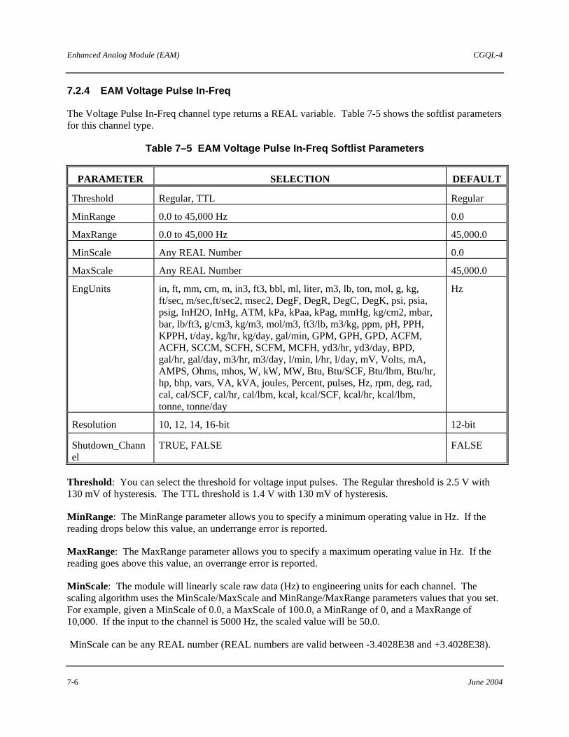
Enhanced Analog Module (EAM) CGQL-4
7-6 June 2004
7.2.4 EAM Voltage Pulse In-Freq
The Voltage Pulse In-Freq channel type returns a REAL variable. Table 7-5 shows the softlist parameters for this channel type.
Table 7–5 EAM Voltage Pulse In-Freq Softlist Parameters
PARAMETER SELECTION DEFAULT
Threshold Regular, TTL Regular
MinRange 0.0 to 45,000 Hz 0.0
MaxRange 0.0 to 45,000 Hz 45,000.0
MinScale Any REAL Number 0.0
MaxScale Any REAL Number 45,000.0
EngUnits in, ft, mm, cm, m, in3, ft3, bbl, ml, liter, m3, lb, ton, mol, g, kg, ft/sec, m/sec,ft/sec2, msec2, DegF, DegR, DegC, DegK, psi, psia, psig, InH2O, InHg, ATM, kPa, kPaa, kPag, mmHg, kg/cm2, mbar, bar, lb/ft3, g/cm3, kg/m3, mol/m3, ft3/lb, m3/kg, ppm, pH, PPH, KPPH, t/day, kg/hr, kg/day, gal/min, GPM, GPH, GPD, ACFM, ACFH, SCCM, SCFH, SCFM, MCFH, yd3/hr, yd3/day, BPD, gal/hr, gal/day, m3/hr, m3/day, l/min, l/hr, l/day, mV, Volts, mA, AMPS, Ohms, mhos, W, kW, MW, Btu, Btu/SCF, Btu/lbm, Btu/hr, hp, bhp, vars, VA, kVA, joules, Percent, pulses, Hz, rpm, deg, rad, cal, cal/SCF, cal/hr, cal/lbm, kcal, kcal/SCF, kcal/hr, kcal/lbm, tonne, tonne/day
Hz
Resolution 10, 12, 14, 16-bit 12-bit
Shutdown_Channel
TRUE, FALSE FALSE
Threshold: You can select the threshold for voltage input pulses. The Regular threshold is 2.5 V with 130 mV of hysteresis. The TTL threshold is 1.4 V with 130 mV of hysteresis.
MinRange: The MinRange parameter allows you to specify a minimum operating value in Hz. If the reading drops below this value, an underrange error is reported.
MaxRange: The MaxRange parameter allows you to specify a maximum operating value in Hz. If the reading goes above this value, an overrange error is reported.
MinScale: The module will linearly scale raw data (Hz) to engineering units for each channel. The scaling algorithm uses the MinScale/MaxScale and MinRange/MaxRange parameters values that you set. For example, given a MinScale of 0.0, a MaxScale of 100.0, a MinRange of 0, and a MaxRange of 10,000. If the input to the channel is 5000 Hz, the scaled value will be 50.0.
MinScale can be any REAL number (REAL numbers are valid between -3.4028E38 and +3.4028E38).

CGQL-4 Enhanced Analog Module (EAM)
June 2004 7-7
MaxScale: MaxScale can be any REAL number.
EngUnits: Engineering units for the scaled value can be selected from a list of common engineering units.
Resolution: The EAM counts the number of pulses occurring in a measured length of time. The frequency of the waveform is calculated by dividing the number of pulses by the corresponding length of time. Increasing the resolution increases the length of time in which pulses are accumulated.
To meet certain application requirements, the selection of 10-bit resolution actually yields 11-bit resolution. This provides better than 0.06% accuracy with a minimal delay.
Shutdown_Channel: When TRUE and channel quality is BAD or QUESTIONABLE, the EAM disables (0V or 0 mA) all of its output channels and reports a shutdown error (class 4, SSC 37, EC 31). Based on the default configuration supplied with QUADLOG, a class 4 error causes all outputs to shut down to their de-energized state (i.e. 0 volts or 0 mA). The configuration can be changed to only shut down the affected outputs or not to shut down at all. Only channels that are critical to the process should be configured as shutdown_channels. Note that in rack-to-rack redundant systems, a switchover to the verify side, rather than a system shutdown, occurs if an I/O failure occurs. Both sides of a redundant system would have to fail for a shutdown to occur. Refer to the Safety Manual for QUADLOG Version 3.30 or Higher (document number CGQLSAFETY-2), section 6.7 (Shutdown Logic), for details of the shutdown configuration logic.

Enhanced Analog Module (EAM) CGQL-4
7-8 June 2004
7.2.5 EAM Current Pulse In-Freq
The Current Pulse In-Freq channel type returns a REAL variable. Table 7-6 shows the softlist parameters for this channel type.
Table 7–6 EAM Current Pulse In-Freq Softlist Parameters
PARAMETER SELECTION DEFAULT
InputRange 4-20mA, 0-20mA 0-20Ma
MinRange 0.0 to 45,000 Hz 0.0
MaxRange 0.0 to 45,000 Hz 45,000.0
MinScale Any REAL Number 0.0
MaxScale Any REAL Number 45,000.0
EngUnits in, ft, mm, cm, m, in3, ft3, bbl, ml, liter, m3, lb, ton, mol, g, kg, ft/sec, m/sec,ft/sec2, msec2, DegF, DegR, DegC, DegK, psi, psia, psig, InH2O, InHg, ATM, kPa, kPaa, kPag, mmHg, kg/cm2, mbar, bar, lb/ft3, g/cm3, kg/m3, mol/m3, ft3/lb, m3/kg, ppm, pH, PPH, KPPH, t/day, kg/hr, kg/day, gal/min, GPM, GPH, GPD, ACFM, ACFH, SCCM, SCFH, SCFM, MCFH, yd3/hr, yd3/day, BPD, gal/hr, gal/day, m3/hr, m3/day, l/min, l/hr, l/day, mV, Volts, mA, AMPS, Ohms, mhos, W, kW, MW, Btu, Btu/SCF, Btu/lbm, Btu/hr, hp, bhp, vars, VA, kVA, joules, Percent, pulses, Hz, rpm, deg, rad, cal, cal/SCF, cal/hr, cal/lbm, kcal, kcal/SCF, kcal/hr, kcal/lbm, tonne, tonne/day
Hz
Resolution 10, 12, 14, 16-bit 12-bit
Shutdown_Channel TRUE, FALSE FALSE
InputRange: Current Pulse In-Freq channels are configurable to operate with two current ranges: 4-20 mA or 0-20mA. The threshold for both ranges is fixed at 10 mA with a hysteresis of 0.5 mA.
MinRange: The MinRange parameter allows you to specify a minimum operating value in Hz. If the reading drops below this value, an underrange error is reported.
MaxRange: The MaxRange parameter allows you to specify a maximum operating value in Hz. If the reading goes above this value, an overrange error is reported.
MinScale: The module will linearly scale raw data (Hz) to engineering units for each channel. The scaling algorithm uses the MinScale/MaxScale and MinRange/MaxRange parameter values that you set. For example, given a MinScale of 0.0, a MaxScale of 100.0, a MinRange of 0, and a MaxRange of 10,000. If the input to the channel is 5000 Hz, the scaled value will be 50.0.
MinScale can be any REAL number (REAL numbers are valid between -3.4028E38 and +3.4028E38).

CGQL-4 Enhanced Analog Module (EAM)
June 2004 7-9
MaxScale: MaxScale can be any REAL number.
EngUnits: Engineering units for the scaled value can be selected from a list of common engineering units.
Resolution: The EAM counts the number of pulses occurring in a measured length of time. The frequency of the waveform is calculated by dividing the number of pulses by the corresponding of time. Increasing the resolution increases the length of time in which pulses are accumulated.
To meet certain application requirements, the selection of 10-bit resolution actually yields 11-bit resolution. This provides better than 0.06% accuracy with a minimal delay.
Shutdown_Channel: When TRUE and channel quality is BAD or QUESTIONABLE, the EAM disables (0V or 0 mA) all of its output channels and reports a shutdown error (class 4, SSC 37, EC 31). Based on the default configuration supplied with QUADLOG, a class 4 error causes all outputs to shut down to their de-energized state (i.e. 0 volts or 0 mA). The configuration can be changed to only shut down the affected outputs or not to shut down at all. Only channels that are critical to the process should be configured as shutdown_channels. Note that in rack-to-rack redundant systems, a switchover to the verify side, rather than a system shutdown, occurs if an I/O failure occurs. Both sides of a redundant system would have to fail for a shutdown to occur. Refer to the Safety Manual for QUADLOG Version 3.30 or Higher (document number CGQLSAFETY-2), section 6.7 (Shutdown Logic), for details of the shutdown configuration logic.
7.2.6 EAM Voltage Pulse In-Total
The EAM Voltage Pulse In-Total channel type returns a UDINT variable. This channel type must be used with the EAM_TOT (Enhanced Analog Module Totalizer) function block. For more information on this function block, refer to QUADLOG Standard Function Blocks (document number CGQL-3). Table 7-7 shows the softlist parameters for this channel type.
Table 7–7 EAM Voltage Pulse In-Total Softlist Parameters
PARAMETER SELECTION DEFAULT
Threshold Regular, TTL Regular
Shutdown_Channel TRUE, FALSE FALSE
Threshold: You can select the threshold for voltage input pulses. The Regular threshold is 2.5 V with 130 mV of hysteresis. The TTL threshold is 1.4 V with 130 mV of hysteresis.
Shutdown_Channel: When TRUE and channel quality is BAD or QUESTIONABLE, the EAM disables (0V or 0 mA) all of its output channels and reports a shutdown error (class 4, SSC 37, EC 31). Based on the default configuration supplied with QUADLOG, a class 4 error causes all outputs to shut down to their de-energized state (i.e. 0 volts or 0 mA). The configuration can be changed to only shut down the affected outputs or not to shut down at all. Only channels that are critical to the process should be configured as shutdown_channels. Note that in rack-to-rack redundant systems, a switchover to the verify side, rather than a system shutdown, occurs if an I/O failure occurs. Both sides of a redundant system

Enhanced Analog Module (EAM) CGQL-4
7-10 June 2004
would have to fail for a shutdown to occur. Refer to the Safety Manual for QUADLOG Version 3.30 or Higher (document number CGQLSAFETY-2), section 6.7 (Shutdown Logic), for details of the shutdown configuration logic.
7.2.7 EAM Current Pulse In-Total
The Current Pulse In-Total channel type returns a UDINT variable. The Current Pulse In-Total channel type must be used with the EAM_TOT (Enhanced Analog Module Totalizer) function block. Table 7-8 shows the softlist parameter for the EAM Current Pulse In-Total channel type.
Table 7–8 EAM Current Pulse In-Total Softlist Parameter
PARAMETER SELECTIONS DEFAULT
InputRange 4-20 mA, 0-20 mA 0-20 mA
Shutdown_Channel TRUE, FALSE FALSE
InputRange: Current Pulse In-Total channels are configurable to operate with two current ranges: 4-20mA or 0-20mA. The threshold for both ranges is fixed at 10 mA with a hysteresis of 0.5 mA.
Shutdown_Channel: When TRUE and channel quality is BAD or QUESTIONABLE, the EAM disables (0V or 0 mA) all of its output channels and reports a shutdown error (class 4, SSC 37, EC 31). Based on the default configuration supplied with QUADLOG, a class 4 error causes all outputs to shut down to their de-energized state (i.e. 0 volts or 0 mA). The configuration can be changed to only shut down the affected outputs or not to shut down at all. Only channels that are critical to the process should be configured as shutdown_channels. Note that in rack-to-rack redundant systems, a switchover to the verify side, rather than a system shutdown, occurs if an I/O failure occurs. Both sides of a redundant system would have to fail for a shutdown to occur. Refer to the Safety Manual for QUADLOG Version 3.30 or Higher (document number CGQLSAFETY-2), section 6.7 (Shutdown Logic), for details of the shutdown configuration logic.
NOTE
Selecting 0-20 mA disables "open-input" diagnostic errors.

CGQL-4 Enhanced Analog Module (EAM)
June 2004 7-11
7.2.8 EAM Disc In Voltage
The EAM Disc In Voltage channel type returns a BOOL variable. Table 7-9 shows the softlist parameters for this channel type.
Table 7–9 EAM Disc In Voltage Softlist Parameters
PARAMETER SELECTION DEFAULT
MinOnStatePct 0.0 to 100 80.0
MaxOffStatePct 0.0 to 100 20.0
Shutdown_Channel TRUE, FALSE FALSE
MinOnStatePct: The reading is automatically scaled from 0-5 V to 0-100%. A scaled reading greater than or equal to MinOnStatePct returns a TRUE to the control module.
MaxOffStatePct: The reading is automatically scaled from 0-5 V to 0-100%. A reading less than or equal to MaxOffStatePct returns a FALSE to the control module.
Shutdown_Channel: When TRUE and channel quality is BAD or QUESTIONABLE, the EAM disables (0V or 0 mA) all of its output channels and reports a shutdown error (class 4, SSC 37, EC 31). Based on the default configuration supplied with QUADLOG, a class 4 error causes all outputs to shut down to their de-energized state (i.e. 0 volts or 0 mA). The configuration can be changed to only shut down the affected outputs or not to shut down at all. Only channels that are critical to the process should be configured as shutdown_channels. Note that in rack-to-rack redundant systems, a switchover to the verify side, rather than a system shutdown, occurs if an I/O failure occurs. Both sides of a redundant system would have to fail for a shutdown to occur. Refer to the Safety Manual for QUADLOG Version 3.30 or Higher (document number CGQLSAFETY-2), section 6.7 (Shutdown Logic), for details of the shutdown configuration logic.
7.2.9 EAM Disc In Current
The EAM Disc In Current channel type returns a BOOL variable. Table 7-10 shows the softlist parameters for this channel type.
Table 7–10 EAM Disc Input Current Softlist Parameters
PARAMETER SELECTION DEFAULT
MinOnStatePct 0.0 to 100 80.0
MaxOffStatePct 0.0 to 100 20.0
Shutdown_Channel TRUE, FALSE FALSE

Enhanced Analog Module (EAM) CGQL-4
7-12 June 2004
MinOnStatePct: The reading is automatically scaled from 0-20mA to 0-100%. A scaled reading greater than or equal to MinOnStatePct returns a TRUE to the control module.
MaxOffStatePct: The reading is automatically scaled from 0-20 mA to 0-100%. A reading less than or equal to MaxOffStatePct returns a FALSE to the control module.
Shutdown_Channel: When TRUE and channel quality is BAD or QUESTIONABLE, this module reports a shutdown error (Class 4, SSC 37, EC 31). Based on the default configuration supplied with QUADLOG, a class 4 error causes all outputs to shut down to their de-energized state (i.e. 0 volts or 0 mA). The configuration can be changed to only shut down the affected outputs or not to shut down at all. Only channels that are critical to the process should be configured as shutdown_channels. Note that in rack-to-rack redundant systems, a switchover to the verify side, rather than a system shutdown, occurs if an I/O failure occurs. Both sides of a redundant system would have to fail for a shutdown to occur. Refer to the Safety Manual for QUADLOG Version 3.30 or Higher (document number CGQLSAFETY-2), section 6.7 (Shutdown Logic), for details of the shutdown configuration logic.
7.2.10 EAM Disc Out
The EAM Disc Out channel type accepts a BOOL variable. Table 7-11 shows the softlist parameters for this channel type.
Table 7–11 EAM Disc Output Softlist Parameter
PARAMETER SELECTION DEFAULT
ProtectedOutput Enabled, Disabled Enabled
Shutdown_Channel TRUE, FALSE FALSE
ProtectedOutput: If ProtectedOutput is enabled and an error condition exists for which the channel cannot be turned off individually, then all channels of the module are turned off. You may want to configure an output as a ProtectedOutput if it is critical to the process, or if it presents a possible hazard to personnel or equipment.
Shutdown_Channel: When TRUE and channel quality is BAD or QUESTIONABLE, the EAM disables (0V or 0 mA) all of its output channels and reports a shutdown error (class 4, SSC 37, EC 31). Based on the default configuration supplied with QUADLOG, a class 4 error causes all outputs to shut down to their de-energized state (i.e. 0 volts or 0 mA). The configuration can be changed to only shut down the affected outputs or not to shut down at all. Only channels that are critical to the process should be configured as shutdown_channels. Note that in rack-to-rack redundant systems, a switchover to the verify side, rather than a system shutdown, occurs if an I/O failure occurs. Both sides of a redundant system would have to fail for a shutdown to occur. Refer to the Safety Manual for QUADLOG Version 3.30 or Higher (document number CGQLSAFETY-2), section 6.7 (Shutdown Logic), for details of the shutdown configuration logic.

CGQL-4 Input Discrete Module (IDM)
June 2004 8-1
8.0 Input Discrete Module (IDM)
The Input Discrete Module (IDM) interfaces discrete 115 or 230 Vac input devices with a control module's IOBUS. It supports 32 AC inputs in eight isolated groups of four channels each. This allows AC inputs from different power sources to be connected to the same module. To isolate field faults, each channel is electrically isolated from the module s CPU, IOBUS, and ground.
8.1 IDM Module Scope Parameter
Table 8-1 shows the module scope softlist parameter for the IDM. To view/edit the module scope parameter, place the cursor on the desired module in the module tree and select the Edit, Object/Item menu item. The Hardware Modules dialog box opens. Choose the Softlist command button to open the Module Scope Softlist dialog box.
Table 8–1 IDM Module Scope Parameter
PARAMETER SELECTION DEFAULT
ScanRate Not Applicable Not Applicable
ScanRate: This is a read-only parameter that displays the current scan rate of the module. Generally, the scan rate will be the same as the scan rate of the control module, but can be a multiple of the control module's scan rate.
8.2 IDM Channel Types
The channel type supported for the IDM is listed below. For information on configuring I/O channels, refer to the “Configuring I/O Channels” section of Using the 4-mation Configuration Software (document number CG39-20).
8.2.1 IDM Disc In
The IDM Disc In channel type returns a BOOL variable. Table 8-2 shows the softlist parameters for this channel type.
Table 8–2 IDM Disc In Softlist Parameters
PARAMETER SELECTION DEFAULT
InputFaultState TRUE, FALSE TRUE
Shutdown_Channel TRUE, FALSE FALSE
InputFaultState: When an input channel has a hardware failure that makes the channel value impossible to discern, the channel will report the value configured in this softlist parameter.

Input Discrete Module (IDM) CGQL-4
8-2 June 2004
Shutdown_Channel: When TRUE and channel quality is BAD or QUESTIONABLE, this module reports a shutdown error (Class 4, SSC 37, EC 31). Based on the default configuration supplied with QUADLOG, a class 4 error causes all outputs to shut down to their de-energized state (i.e. 0 volts or 0 mA). The configuration can be changed to only shut down the affected outputs or not to shut down at all. Only channels that are critical to the process should be configured as shutdown_channels. Note that in rack-to-rack redundant systems, a switchover to the verify side, rather than a system shutdown, occurs if an I/O failure occurs. Both sides of a redundant system would have to fail for a shutdown to occur. Refer to the Safety Manual for QUADLOG Version 3.30 or Higher (document number CGQLSAFETY-2), section 6.7 (Shutdown Logic), for details of the shutdown configuration logic.

CGQL-4 Output Discrete Module (ODM)
June 2004 9-1
9.0 Output Discrete Module (ODM)
The ODM interfaces discrete 115 Vac devices with a control module’s IOBUS. It supports 32 AC outputs in eight isolated groups of four channels each. This allows each group to use a separate power supply. Each group is individually fused with a 5.0 amp fuse to protect the group from a short-circuit in the field wiring and prevents a short-circuit from affecting other channel groups in the module. To isolate field faults, every output circuit is electrically isolated from the module’s CPU, IOBUS, and ground.
9.1 ODM Module Scope Parameter
Table 9-1 shows the Module Scope softlist parameter for the ODM. To view/edit the module scope parameter, place the cursor on the desired module in the module tree and select the Edit, Object/Item menu item. The Hardware Modules dialog box opens. Choose the Softlist command button to open the Module Scope Softlist dialog box.
Table 9–1 ODM Module Scope Parameter
PARAMETER SELECTION DEFAULT
ScanRate Not Applicable Not Applicable
ScanRate: This is a read-only parameter that displays the current scan rate of the module.
9.2 ODM Channel Type
The channel type supported for the ODM is listed below. For information on configuring I/O channels, refer to the “Configuring I/O Channels” section of Using the 4-mation Configuration Software (document number CG39-20).
9.2.1 ODM Disc Out
The Disc Out channel type accepts a BOOL variable. Table 9-2 shows the softlist parameters for this channel type.
Table 9–2 ODM Discrete Output Softlist Parameters
PARAMETER SELECTION DEFAULT
ProtectedOutput Enabled, Disabled Enabled
Readback Enabled, Disabled Enabled
Shutdown_Channel TRUE, FALSE FALSE
ProtectedOutput: Each output can be configured to turn off all outputs in the group in the event that a channel is intended to be off but diagnostics have determined that it is on or open circuited. You may

Output Discrete Module (ODM) CGQL-4
9-2 June 2004
want to configure an output as a ProtectedOutput if it is critical to the process, or if it presents a possible hazard to personnel or equipment.
Readback: The state of an output channel is automatically "read back" by input circuitry on the same channel. The readback is used to diagnose and report faults. You can disable readback, which, in turn, disables reporting of readback related faults (i.e. Output Open Circuit or Failed ON, Output Failed OFF, Protected Output Open Circuit or Failed ON).
Shutdown_Channel: When TRUE and channel quality is BAD or QUESTIONABLE, this module reports a shutdown error (Class 4, SSC 37, EC 31). Based on the default configuration supplied with QUADLOG, a class 4 error causes all outputs to shut down to their de-energized state (i.e. 0 volts or 0 mA). The configuration can be changed to only shut down the affected outputs or not to shut down at all. Only channels that are critical to the process should be configured as shutdown_channels. Note that in rack-to-rack redundant systems, a switchover to the verify side, rather than a system shutdown, occurs if an I/O failure occurs. Both sides of a redundant system would have to fail for a shutdown to occur. Refer to the Safety Manual for QUADLOG Version 3.30 or Higher (document number CGQLSAFETY-2), section 6.7 (Shutdown Logic), for details of the shutdown configuration logic.

CGQL-4 Resistance Temperature Module (RTM)
June 2004 10-1
10.0 Resistance Temperature Module (RTM)
The RTM interfaces RTDs (resistance temperature devices) and other resistance input signals to a control module’s IOBUS. It provides 16 configurable channels isolated into eight groups of two channels each. Each input circuit is isolated from the module’s CPU, IOBUS, and ground. In addition, each two-channel group is electrically isolated from the other groups.
10.1 RTM Module Scope Parameters
Table 10-1 shows the Module Scope softlist parameters for the RTM. To view/edit the module scope parameters, place the cursor on the desired module in the module tree and select the Edit, Object/Item menu item. The Hardware Modules dialog box opens. Choose the Softlist command button to open the Module Scope Softlist dialog box.
Table 10–1 RTM Module Scope Parameters
PARAMETER SELECTION DEFAULT
SCANRATE Not Applicable Not Applicable
SHARED_RTD NO, YES NO
ScanRate: This is a read-only parameter that displays the current scan rate of the module. Generally, the scan rate will be the same as the scan rate of the control module, but can be a multiple of the control module's scan rate.
Shared_RTD: This parameter is no longer used.
10.2 RTM CHANNEL TYPES
The channel types supported for the RTM are listed here. For information on configuring I/O channels, refer to the “Configuring I/O Channels” section of Using the 4-mation Configuration Software (document number CG39-20).
• TM RTD Input • RTM Resistance Input
10.2.1 RTM RTD Input
The RTD Input channel type returns a REAL variable. Table 10-2 shows the softlist parameters for this channel type.

Resistance Temperature Module (RTM) CGQL-4
10-2 June 2004
Table 10–2 RTM RTD Input Softlist Parameters
PARAMETER SELECTION DEFAULT
RTD_Type Pt_100_IEC/DIN Pt_100_JIC/SAMA Pt_200_IEC/DIN Pt_200_JIC/SAMA Ni_100 _DIN Linear
Pt_100_IEC/DIN
Alpha Any REAL Number 0.00385
Resistance 10.0 to 200.0 Ohms 100.0
Bias Any REAL Number 0.0
EngUnits DegF, DegC, DegK, Deg R Deg C
MinRange Any REAL Number >= MinRange of selected RTD
Min Range of selected RTD Type (on-line)
-200.0 (off-line)
MaxRange Any REAL Number <= MaxRange of selected RTD
Max Range of selected RTD Type (on-line)
+850.0 (off-line)
Scale_To_Percent Yes_No Enforced by RTM board
No
Input_Fault_State No_Change, MinRange, MaxRange MinRange
DigFiltTimeCnst 0.0 to 159.0 sec. 0.016
StepResponseTime 0.100 to 40.000 sec. 1.0
RTD_Type: Select from the list of supported RTD types. If Linear is selected, the measured input, R, is linearized using a straight line approximation as detailed in QUADLOG I/O Module Configuration (V3.03 document number CGQL-2, V4.00 document number CGQL-4).
Alpha: Alpha is the average percent change, in resistance per degree, of a pure metal resistance device between 0 and 100 C. The most commonly used element material is the standard platinum with a resistance of 100 ohms at 0 deg.C and a temperature coefficient resistance of 0.00385 ohms/ohm/ C (IEC 751 and DIN 43760).
This parameter need only be specified when the RTD_Type specified is Linear.
Resistance: The resistance, in ohms, of the RTD at 0°C. This parameter need be specified only when the RTD Type specified is Linear.
Bias: You can enter a bias, in engineering units, on a per channel basis to compensate for known offsets. The bias value is added to the linearized input.

CGQL-4 Resistance Temperature Module (RTM)
June 2004 10-3
EngUnits: You can select from the following engineering units: DegF, DegC, DegK, DegR.
MinRange: MinRange is an optional parameter that allows you to specify a minimum operating value in EngUnits. If the reading drops 5% below this value, an underrange error is reported.
MaxRange: MaxRange is an optional parameter that allows you to specify a maximum operating value in EngUnits. If the reading goes 5% above this value, an overrange error is reported.
Scale_To_Percent: If Scale_To_Percent is TRUE, the linearized temperature reading, T, is scaled to a percent.
Input_Fault_State: If a channel is faulted (quality is set to bad or questionable), you can select to have the module return the actual reading (No_Change), the largest value for the channel (Maxscale), or the smallest value (Minscale). The default is to return the actual reading.
DigFiltTimeCnst: Digital filtering can be applied to RTD input signals to reduce the effects of electrical noise. The digital filter is a first order lag, adjustable for time constants of 0.0159 to 159.0 seconds. Equivalent breakpoint frequencies are 10.0 to 0.001 Hz. The default value can be increased for noisy signals.
StepResponseTime: This is parameter determines the time for the channel to fully respond to a step input. A longer StepResponseTime will provide more accurate readings. The valid range is between 0.100 and 40.00 seconds.

Resistance Temperature Module (RTM) CGQL-4
10-4 June 2004
10.2.2 RTM Resistance Input
The Resistance Input channel type returns a REAL variable. Table 10-3 shows the softlist parameters for this channel type.
Table 10–3 RTM Resistance Input Softlist Parameters
PARAMETER SELECTION DEFAULT
MinRange 15 to 1015 Ohms 15.0
MaxRange 15 to 1015 Ohms 1015
MinScale Any REAL Number 0.0
MaxScale Any REAL Number 100.0
EngUnits in, ft, mm, cm, m, in3, ft3, bbl, ml, liter, m3, lb, ton, mol, g, kg, ft/sec, m/sec,ft/sec2, msec2, DegF, DegR, DegC, DegK, psi, psia, psig, InH2O, InHg, ATM, kPa, kPaa, kPag, mmHg, kg/cm2, mbar, bar, lb/ft3, g/cm3, kg/m3, mol/m3, ft3/lb, m3/kg, ppm, pH, PPH, KPPH, t/day, kg/hr, kg/day, gal/min, GPM, GPH, GPD, ACFM, ACFH, SCCM, SCFH, SCFM, MCFH, yd3/hr, yd3/day, BPD, gal/hr, gal/day, m3/hr, m3/day, l/min, l/hr, l/day, mV, Volts, mA, AMPS, Ohms, mhos, W, kW, MW, Btu, Btu/SCF, Btu/lbm, Btu/hr, hp, bhp, vars, VA, kVA, joules, Percent, pulses, Hz, rpm, deg, rad, cal, cal/SCF, cal/hr, cal/lbm, kcal, kcal/SCF, kcal/hr, kcal/lbm, tonne, tonne/day
Percent
Bias Any REAL Number 0.0
Input_Fault_State No_Change, MinRange, MaxRange MinRange
DigFiltTimeCnst 0.0 to 159.0 sec. 0.016
StepResponseTime 0.100 to 40.000 sec. 1.0
MinRange: MinRange is an optional parameter that allows you to specify a minimum operating value in EngUnits. If the reading drops below this value, an underrange error is reported.
MaxRange: MaxRange is an optional parameter that allows you to specify a maximum operating value in EngUnits. If the reading goes above this value, an overrange error is reported.
MinScale: The module will linearly scale raw data (ohms) to engineering units for each channel. The scaling algorithm uses the MinScale/MaxScale and MinRange/MaxRange parameters that you set. For example, given a MinScale of 0.0, a MaxScale of 100.0, a MinRange of 0.0, and a MaxRange of 1000, if the input to the channel is 500 ohms, the scaled value will be 50.0.
MinScale can be any REAL number (REAL numbers are valid between -3.4028E38 and +3.4028E38).

CGQL-4 Resistance Temperature Module (RTM)
June 2004 10-5
MaxScale: MaxScale can be any REAL number.
EngUnits: Engineering units for the scaled value can be selected from a list of common engineering units.
Bias: You can enter a bias in engineering units, on a per channel basis, to compensate for known offsets. The bias value is added to the linearized input.
Input_Fault_State: If channel quality is bad or questionable, you can select to have the module return the actual reading (No_Change), the largest value for the channel (Maxscale), or the smallest value (Minscale). The default is to return the actual reading.
DigFiltTimeCnst: Digital filtering can be applied to resistance input channel signals to reduce the effects of electrical noise. The digital filter is a first order lag, adjustable for time constants of 0.0159 to 159.0 seconds. Equivalent breakpoint frequencies are 10.0 to 0.001 Hz. The default value can be increased for noisy signals.
StepResponseTime: This parameter determines the time for the channel to fully respond to a step input. A longer StepResponseTime provides more accurate readings. The valid range is between 0.1 and 40.00 seconds.

Resistance Temperature Module (RTM) CGQL-4
10-6 June 2004
Notes

CGQL-4 Standard Analog Module (SAM)
June 2004 11-1
11.0 Standard Analog Module (SAM)
The Standard Analog Module (SAM) can interface both analog and discrete I/O signals to a control module’s IOBUS. It provides 32 channels, each of which can be configured for standard I/O types. Related signals, such as the I/O for a particular loop, can be grouped together. To isolate field faults, each channel is electrically isolated from the module’s CPU, IOBUS, and ground. Also, each channel uses an isolated 24 V power source, and all channels are current-limited to protect against short circuits.
11.1 SAM Module Scope Parameter
Table 11-1 shows the Module Scope softlist parameter for the SAM. To view/edit the module scope parameters, place the cursor on the desired module in the module tree and select the Edit, Object/Item menu item. The Hardware Modules dialog box opens. Choose the Softlist command button to open the Module Scope Softlist dialog box.
Table 11–1 SAM Module Scope Parameter
PARAMETER SELECTION DEFAULT
SCANRATE Not Applicable Not Applicable
ScanRate: This is a read-only parameter that displays the current scan rate of the module. Generally, the scan rate will be the same as the scan rate of the control module but can be a multiple of the control module's scan rate.
11.2 SAM Channel Types
The channel types supported for the SAM are listed here. For information on configuring I/O channels, refer to the “Configuring I/O Channels” section of Using the ProcessSuite 4-mation Configuration Software (document number CG39-20).
• SAM Analog In • SAM Analog Out • SAM Disc In • SAM Disc Out

Standard Analog Module (SAM) CGQL-4
11-2 June 2004
11.2.1 SAM Analog In
The SAM Analog In channel type returns a REAL variable. Table 11-2 shows the softlist parameters for this channel type.
Table 11–2 SAM Analog In Softlist Parameters
PARAMETER SELECTION DEFAULT
MinScale Any REAL Number 0.0
MaxScale Any REAL Number 100.0
EngUnits in, ft, mm, cm, m, in3, ft3, bbl, ml, liter, m3, lb, ton, mol, g, kg, ft/sec, m/sec,ft/sec2, msec2, DegF, DegR, DegC, DegK, psi, psia, psig, InH2O, InHg, ATM, kPa, kPaa, kPag, mmHg, kg/cm2, mbar, bar, lb/ft3, g/cm3, kg/m3, mol/m3, ft3/lb, m3/kg, ppm, pH, PPH, KPPH, t/day, kg/hr, kg/day, gal/min, GPM, GPH, GPD, ACFM, ACFH, SCCM, SCFH, SCFM, MCFH, yd3/hr, yd3/day, BPD, gal/hr, gal/day, m3/hr, m3/day, l/min, l/hr, l/day, mV, Volts, mA, AMPS, Ohms, mhos, W, kW, MW, Btu, Btu/SCF, Btu/lbm, Btu/hr, hp, bhp, vars, VA, kVA, joules, Percent, pulses, Hz, rpm, deg, rad, cal, cal/SCF, cal/hr, cal/lbm, kcal, kcal/SCF, kcal/hr, kcal/lbm, tonne, tonne/day
Percent
DigFiltTimeCnst 0.0 to 159.0 sec 0.0
Bias Any REAL Number 0.0
OpenCircuitTest Enabled, Disabled Enabled
Shutdown_Channel TRUE, FALSE FALSE
MinScale: The module linearly scales raw data (4-20 mA) to engineering units for each channel. The scaling algorithm uses the MinScale/MaxScale parameters that you set. For example, given a MinScale of 0.0 and a MaxScale of 100.0, if the input to the channel is 12 mA, the scaled value will be 50.0.
MinScale can be any REAL number (REAL numbers are valid between -3.4028E38 and +3.4028E38)
MaxScale: MaxScale can be any REAL number.
EngUnits: Engineering units for the scaled value can be selected from a list of common engineering units.
DigFiltTimeCnst: Digital filtering can be applied to analog input signals to reduce the effects of electrical noise. The digital filter is a first order lag, adjustable for time constants of 0.0159 to 159.0 seconds (0.0 disables the filter). Equivalent breakpoint frequencies are 10.0 to 0.001 Hz. The default value can be increased for noisy signals.
Figure 11-1 shows the step release time of the digital filter.

CGQL-4 Standard Analog Module (SAM)
June 2004 11-3
Step Response Time of Digital Filter
Time (seconds)
mA
0
5
10
15
20
0 1 2 3 4 5 6 7
Filter Input
Filter Output
Scan Rate = 100ms T (DigFiltTimeCnst) = 1.0 sec.
T
14 (63%)
Figure 11–1 Step Time Response of Digital Filter
Bias: You can enter a bias, in engineering units, on a per channel basis to compensate for known offsets. The bias value is added to the scaled input.
OpenCircuitTest: You can enable or disable open circuit testing. An open circuit condition exists if the reading is < 0.02 mA.
Shutdown_Channel: When TRUE and channel quality is BAD or QUESTIONABLE, the SAM module disables (0 mA) all of its I/O and reports a shutdown error (Class 4, SSC 37, EC 31). Based on the default configuration supplied with QUADLOG, a class 4 error causes all outputs to shut down to their de-energized state (i.e. 0 volts or 0 mA). The configuration can be changed to only shut down the affected outputs or not to shut down at all. Only channels that are critical to the process should be configured as shutdown_channels. Note that in rack-to-rack redundant systems, a switchover to the verify side, rather than a system shutdown, occurs if an I/O failure occurs. Both sides of a redundant system would have to fail for a shutdown to occur. Refer to the Safety Manual for QUADLOG Version 3.30 or Higher (document number CGQLSAFETY-2), section 6.7 (Shutdown Logic), for details of the shutdown configuration logic.

Standard Analog Module (SAM) CGQL-4
11-4 June 2004
11.2.2 SAM Analog Out
The SAM Analog Out channel type accepts a REAL variable. Table 11-3 shows the softlist parameters for this channel type.
Table 11–3 SAM Analog Out Softlist Parameters
PARAMETER SELECTION DEFAULT
OutputRange mA_4to20, mA_0to20 mA_4to20
MinScale Any REAL Number 0.0
MaxScale Any REAL Number 100.0
EngUnits in, ft, mm, cm, m, in3, ft3, bbl, ml, liter, m3, lb, ton, mol, g, kg, ft/sec, m/sec,ft/sec2, msec2, DegF, DegR, DegC, DegK, psi, psia, psig, InH2O, InHg, ATM, kPa, kPaa, kPag, mmHg, kg/cm2, mbar, bar, lb/ft3, g/cm3, kg/m3, mol/m3, ft3/lb, m3/kg, ppm, pH, PPH, KPPH, t/day, kg/hr, kg/day, gal/min, GPM, GPH, GPD, ACFM, ACFH, SCCM, SCFH, SCFM, MCFH, yd3/hr, yd3/day, BPD, gal/hr, gal/day, m3/hr, m3/day, l/min, l/hr, l/day, mV, Volts, mA, AMPS, Ohms, mhos, W, kW, MW, Btu, Btu/SCF, Btu/lbm, Btu/hr, hp, bhp, vars, VA, kVA, joules, Percent, pulses, Hz, rpm, deg, rad, cal, cal/SCF, cal/hr, cal/lbm, kcal, kcal/SCF, kcal/hr, kcal/lbm, tonne, tonne/day
Percent
ProtectedOutput Enabled, Disabled Enabled
Bias Any REAL Number 0.0
ReadBack Enabled, Disabled Enabled
Shutdown_Channel
TRUE, FALSE FALSE
OutputRange: SAM Analog Output channels are configurable to operate with two current ranges:
• 4-20 mA • 0-20 mA
MinScale: The module performs a linear conversion from engineering units to the selected OuputRange for each channel. The scaling algorithm uses the MinScale/MaxScale and OutputRange parameter values that you set. For example, given a MinScale of 0.0, a MaxScale of 100.0, and an OutputRange of 4-20 mA, if the value written to the SAM Analog Output Channel is 50, the module will output 12 mA.
MinScale can be any REAL number (REAL numbers are valid between -3.4028E38 and +3.4028E38).
MaxScale: MaxScale can be any REAL number.

CGQL-4 Standard Analog Module (SAM)
June 2004 11-5
EngUnits: Engineering units for the scaled value can be selected from a list of common engineering units.
ProtectedOutput: Each output can be configured to turn off (0 mA) all SAM outputs in the event that diagnostics determine that the output current is greater than it is intended to be by 9% or more. You may want to configure an output as a ProtectedOutput if it is critical to the process or if it may present a hazard to personnel or equipment.
Bias: You can enter a bias in engineering units, on a per channel basis, to compensate for known offsets. The bias value is added to the scaled output.
ReadBack: The state of an output channel is automatically “read back” by input circuitry on the same channel. The readback is used to diagnose and report faults. You can disable readback, which, in turn, disables reporting of readback-related faults (i.e. Open Circuit, Readback Lower than Output, Readback > Output, Readback > Output on Critical Channel).
Shutdown_Channel: When TRUE and channel quality is BAD or QUESTIONABLE, the SAM module disables (0 mA) all of its I/O and reports a shutdown error (Class 4, SSC 37, EC 31). Based on the default configuration supplied with QUADLOG, a class 4 error causes all outputs to shut down to their de-energized state (i.e. 0 volts or 0 mA). The configuration can be changed to only shut down the affected outputs or not to shut down at all. Only channels that are critical to the process should be configured as shutdown_channels. Note that in rack-to-rack redundant systems, a switchover to the verify side, rather than a system shutdown, occurs if an I/O failure occurs. Both sides of a redundant system would have to fail for a shutdown to occur. Refer to the Safety Manual for QUADLOG Version 3.30 or Higher (document number CGQLSAFETY-2), section 6.7 (Shutdown Logic), for details of the shutdown configuration logic.
10.2.3 SAM Disc In
The SAM Disc In channel type returns a BOOL variable. Table 11-4 shows the softlist parameters for this channel type.
Table 11–4 SAM Discrete Input Softlist Parameters
PARAMETER SELECTION DEFAULT
MinOnStatePct 0.0 to 100.0 80.0
MaxOffStatePct 0.0 to 100.0 20.0
Shutdown_Channel TRUE, FALSE FALSE
MinOnStatePct: The reading is automatically scaled from 0-10 mA to 0-100%. A scaled reading greater than or equal to MinOnStatePct will report a boolean TRUE to the control module.
MaxOffStatePct: The reading is automatically scaled from 0-10 mA to 0-100%. A reading less than or equal to MaxOffStatePct will report a boolean FALSE to the control module.
Shutdown_Channel: When TRUE and channel quality is BAD or QUESTIONABLE, the SAM module disables (0 mA) all of its I/O and reports a shutdown error (Class 4, SSC 37, EC 31). Based on the

Standard Analog Module (SAM) CGQL-4
11-6 June 2004
default configuration supplied with QUADLOG, a class 4 error causes all outputs to shut down to their de-energized state (i.e. 0 volts or 0 mA). The configuration can be changed to only shut down the affected outputs or not to shut down at all. Only channels that are critical to the process should be configured as shutdown_channels. Note that in rack-to-rack redundant systems, a switchover to the verify side, rather than a system shutdown, occurs if an I/O failure occurs. Both sides of a redundant system would have to fail for a shutdown to occur. Refer to the Safety Manual for QUADLOG Version 3.30 or Higher (document number CGQLSAFETY-2), section 6.7 (Shutdown Logic), for details of the shutdown configuration logic.
11.2.3 SAM Disc Out
The SAM Disc Out channel type accepts a BOOL variable. Table 11-5 shows the softlist parameters for this channel type.
Table 11–5 SAM Discrete Output Softlist Parameters
PARAMETER SELECTION DEFAULT
ProtectedOutput Enabled, Disabled Enabled
ReadBack Enabled, Disabled Enabled
Shutdown_Channel TRUE, FALSE FALSE
ProtectedOutput: Each output can be configured to turn off (0 mA) all SAM outputs in the event that diagnostics determine that the output current is greater than it is intended to be by 9% or more. You may want to configure an output as a ProtectedOutput if it is critical to the process, or if it presents a possible hazard to personnel or equipment.
ReadBack: The state of an output channel is automatically "read back" by input circuitry on the same channel. The readback is used to diagnose and report faults. You can disable readback which, in turn, disables reporting of readback related faults (i.e. Readback Lower than Output, Readback > Output, Readback > Output on Critical Channel).
Shutdown_Channel: When TRUE and channel quality is BAD or QUESTIONABLE, the SAM module disables (0 mA) and reports a shutdown error (Class 4, SSC 37, EC 31). Based on the default configuration supplied with QUADLOG, a class 4 error causes all outputs to shut down to their de-energized state (i.e. 0 volts or 0 mA). The configuration can be changed to only shut down the affected outputs or not to shut down at all. Only channels that are critical to the process should be configured as shutdown_channels. Note that in rack-to-rack redundant systems, a switchover to the verify side, rather than a system shutdown, occurs if an I/O failure occurs. Both sides of a redundant system would have to fail for a shutdown to occur. Refer to the Safety Manual for QUADLOG Version 3.30 or Higher (document number CGQLSAFETY-2), section 6.7 (Shutdown Logic), for details of the shutdown configuration logic.

CGQL-4 Standard Discrete Module Plus (SDM+)
June 2004 12-1
12.0 Standard Discrete Module Plus (SDM+)
The Standard Discrete Module Plus (SDM+) interfaces discrete DC sensors and actuators with a control module’s IOBUS. It provides 32 channels. Each channel can be configured to any of five discrete channel types: an input, an output, an event recording input, an event recording output, or a pulse output.
The SDM+’s inputs are current sinking (i.e. the input device is wired between the power supply positive (+) and the I/O terminal). Outputs are current sourced (i.e. the output device is wired between the output terminal and the power supply common). A pulsed output is an output channel which is on for a user-defined duration (within the range of 25 to 2000 ms and a resolution of 25 ms).
Event recording inputs and outputs are high speed channels used in conjunction with the function blocks of the Sequence of Events Recorder Function Block Library for detecting, monitoring, controlling, and recording discrete state changes (i.e. events). This data is collected by a Sequence of Events (SOE)-compatible module, such as the SDM+, that is capable of high speed event gathering. Events are stored to an array of strings. The data can then be viewed through the Sequence of Events Viewer, a PC Utility program. Refer to the Sequence of Events Viewer (document number SG39SOE-2) for information on using this utility.
Each input and output circuit is electrically isolated from the module’s CPU, IOBUS, and ground. In addition, a soft-fuse (TM) circuit protects each output channel from a short circuit in the field wiring and prevents a short from affecting other SDM+ channels. Note that a soft-fuse can be reset locally or remotely.
12.1 SDM+ Module Scope Parameter
Table 12-1 shows the Module Scope softlist parameter for the SDM+. To view/edit the module scope parameter, place the cursor on the desired module in the module tree and select the Edit, Object/Item menu item. The Hardware Modules dialog box opens. Choose the Softlist command button to open the Module Scope Softlist dialog box.
Table 12–1 SDM+ Module Scope Parameter
PARAMETER SELECTION DEFAULT
ScanRate Not Applicable Not Applicable
ScanRate: This is a read-only parameter that displays the current scan rate of the module. Generally, the scan rate will be the same as the scan rate of the control module, but can be a multiple of the control module's scan rate.

Standard Discrete Module Plus (SDM+) CGQL-4
12-2 June 2004
12.2 SDM+ Channel Types
The channel types supported for the SDM+ are listed here. For information on configuring I/O channels, refer to the “Configuring I/O Channels” section of Using the 4-mation Configuration Software (document number CG39-20).
• SDM+ Disc In • SDM+ Disc Out • SDM+ SOE Disc In • SDM+ SOE Disc Out • SDM+ Disc Pulse Out
12.2.1 Discrete Input
The Discrete Input channel type returns a BOOL variable. Table 12-2 lists the softlist parameters for this channel type.
Table 12–2 Discrete Input Softlist Parameters
PARAMETER SELECTION DEFAULT
INPUTFAULTSTATE TRUE, FALSE FALSE
Shutdown_Channel TRUE, FALSE FALSE
PulseDiagTest* Enabled, Disabled Enabled
* This parameter is not used in this module, but is listed because its channel type is shared with other modules.
InputFaultState: When an input channel has a hardware failure that makes the channel value impossible to discern, the channel reports the value configured in this softlist parameter.
Shutdown_Channel: When TRUE and channel quality is BAD or QUESTIONABLE, the SDM+ module disables (0 mA) all of its output channels and reports a shutdown error (Class 4, SSC 37, EC 31). Based on the default configuration supplied with QUADLOG, a class 4 error causes all outputs to shut down to their de-energized state (i.e. 0 volts or 0 mA). The configuration can be changed to only shut down the affected outputs or not to shut down at all. Only channels that are critical to the process should be configured as shutdown_channels. Note that in rack-to-rack redundant systems, a switchover to the verify side, rather than a system shutdown, occurs if an I/O failure occurs. Both sides of a redundant system would have to fail for a shutdown to occur. Refer to the Safety Manual for QUADLOG Version 3.30 or Higher (document number CGQLSAFETY-2), section 6.7 (Shutdown Logic), for details of the shutdown configuration logic.
PulseDiagTest: This softlist parameter is not used in this module. It is listed here because this channel type is shared with other modules.
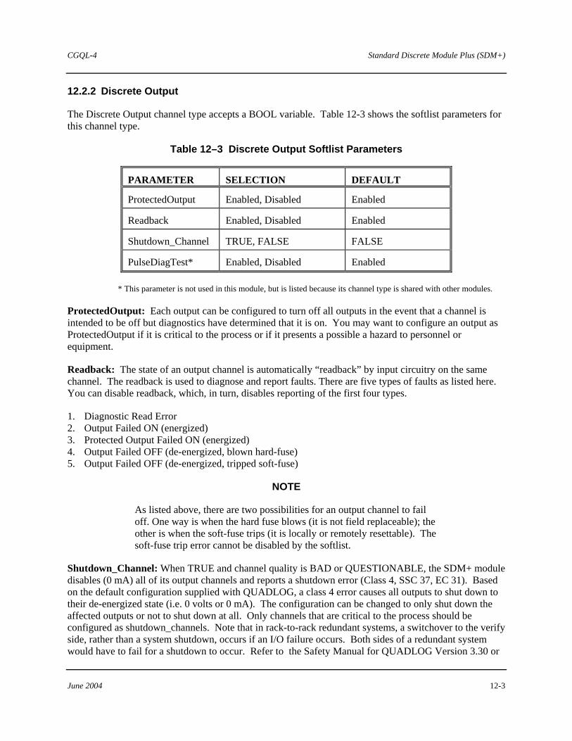
CGQL-4 Standard Discrete Module Plus (SDM+)
June 2004 12-3
12.2.2 Discrete Output
The Discrete Output channel type accepts a BOOL variable. Table 12-3 shows the softlist parameters for this channel type.
Table 12–3 Discrete Output Softlist Parameters
PARAMETER SELECTION DEFAULT
ProtectedOutput Enabled, Disabled Enabled
Readback Enabled, Disabled Enabled
Shutdown_Channel TRUE, FALSE FALSE
PulseDiagTest* Enabled, Disabled Enabled
* This parameter is not used in this module, but is listed because its channel type is shared with other modules.
ProtectedOutput: Each output can be configured to turn off all outputs in the event that a channel is intended to be off but diagnostics have determined that it is on. You may want to configure an output as ProtectedOutput if it is critical to the process or if it presents a possible a hazard to personnel or equipment.
Readback: The state of an output channel is automatically “readback” by input circuitry on the same channel. The readback is used to diagnose and report faults. There are five types of faults as listed here. You can disable readback, which, in turn, disables reporting of the first four types.
1. Diagnostic Read Error 2. Output Failed ON (energized) 3. Protected Output Failed ON (energized) 4. Output Failed OFF (de-energized, blown hard-fuse) 5. Output Failed OFF (de-energized, tripped soft-fuse)
NOTE
As listed above, there are two possibilities for an output channel to fail off. One way is when the hard fuse blows (it is not field replaceable); the other is when the soft-fuse trips (it is locally or remotely resettable). The soft-fuse trip error cannot be disabled by the softlist.
Shutdown_Channel: When TRUE and channel quality is BAD or QUESTIONABLE, the SDM+ module disables (0 mA) all of its output channels and reports a shutdown error (Class 4, SSC 37, EC 31). Based on the default configuration supplied with QUADLOG, a class 4 error causes all outputs to shut down to their de-energized state (i.e. 0 volts or 0 mA). The configuration can be changed to only shut down the affected outputs or not to shut down at all. Only channels that are critical to the process should be configured as shutdown_channels. Note that in rack-to-rack redundant systems, a switchover to the verify side, rather than a system shutdown, occurs if an I/O failure occurs. Both sides of a redundant system would have to fail for a shutdown to occur. Refer to the Safety Manual for QUADLOG Version 3.30 or
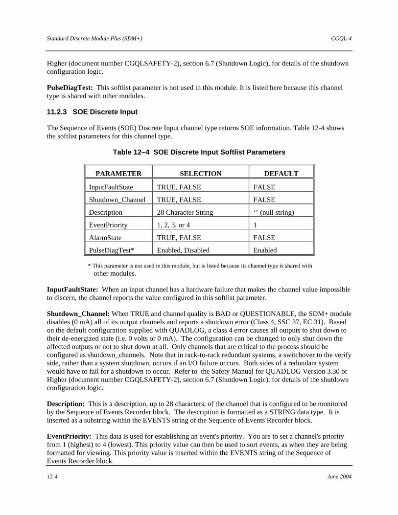
Standard Discrete Module Plus (SDM+) CGQL-4
12-4 June 2004
Higher (document number CGQLSAFETY-2), section 6.7 (Shutdown Logic), for details of the shutdown configuration logic.
PulseDiagTest: This softlist parameter is not used in this module. It is listed here because this channel type is shared with other modules.
11.2.3 SOE Discrete Input
The Sequence of Events (SOE) Discrete Input channel type returns SOE information. Table 12-4 shows the softlist parameters for this channel type.
Table 12–4 SOE Discrete Input Softlist Parameters
PARAMETER SELECTION DEFAULT
InputFaultState TRUE, FALSE FALSE
Shutdown_Channel TRUE, FALSE FALSE
Description 28 Character String ‘’ (null string)
EventPriority 1, 2, 3, or 4 1
AlarmState TRUE, FALSE FALSE
PulseDiagTest* Enabled, Disabled Enabled
* This parameter is not used in this module, but is listed because its channel type is shared with other modules.
InputFaultState: When an input channel has a hardware failure that makes the channel value impossible to discern, the channel reports the value configured in this softlist parameter.
Shutdown_Channel: When TRUE and channel quality is BAD or QUESTIONABLE, the SDM+ module disables (0 mA) all of its output channels and reports a shutdown error (Class 4, SSC 37, EC 31). Based on the default configuration supplied with QUADLOG, a class 4 error causes all outputs to shut down to their de-energized state (i.e. 0 volts or 0 mA). The configuration can be changed to only shut down the affected outputs or not to shut down at all. Only channels that are critical to the process should be configured as shutdown_channels. Note that in rack-to-rack redundant systems, a switchover to the verify side, rather than a system shutdown, occurs if an I/O failure occurs. Both sides of a redundant system would have to fail for a shutdown to occur. Refer to the Safety Manual for QUADLOG Version 3.30 or Higher (document number CGQLSAFETY-2), section 6.7 (Shutdown Logic), for details of the shutdown configuration logic.
Description: This is a description, up to 28 characters, of the channel that is configured to be monitored by the Sequence of Events Recorder block. The description is formatted as a STRING data type. It is inserted as a substring within the EVENTS string of the Sequence of Events Recorder block.
EventPriority: This data is used for establishing an event's priority. You are to set a channel's priority from 1 (highest) to 4 (lowest). This priority value can then be used to sort events, as when they are being formatted for viewing. This priority value is inserted within the EVENTS string of the Sequence of Events Recorder block.

CGQL-4 Standard Discrete Module Plus (SDM+)
June 2004 12-5
AlarmState: This parameter is used to establish the alarm state of the channel. You can choose which state, TRUE or FALSE, represents an alarm condition. For example, if you set this parameter to TRUE, the channel is said to be in alarm when the channel's value toggles from FALSE to TRUE. This also inserts an "A" (Alarm) character in the last character position in the EVENTS string of the Sequence of Events Recorder block. Otherwise, it is an "N" character (No alarm).
PulseDiagTest: This softlist parameter is not used in this module. It is listed here because this channel type is shared with other modules.
12.2.3 SOE Discrete Output
The Sequence of Events (SOE) Discrete Output channel type returns SOE information. Table 12-5 shows the softlist parameters for this channel type.
Table 12–5 SOE Discrete Output Softlist Parameters
PARAMETER SELECTION DEFAULT
ProtectedOutput Enabled, Disabled Enabled
Readback Enabled, Disabled Disabled
Shutdown_Channel TRUE, FALSE FALSE
Description 28 Character String ‘’ (null string)
EventPriority 1, 2, 3, or 4 1
PulseDiagTest* Enabled, Disabled Enabled
* This parameter is not used in this module, but is listed because its channel type is shared with other modules.
ProtectedOutput: Each output can be configured to turn off all SDM+ outputs in the event that a channel is intended to be off but diagnostics have determined that it is on. You may want to configure an output as ProtectedOutput if it is critical to the process or if it presents a possible a hazard to personnel or equipment.
Readback: The state of an output channel is automatically “readback” by input circuitry on the same channel. The readback is used to diagnose and report faults. There are five types of faults as listed here. You can disable readback, which, in turn, disables reporting of the first four types.
1. Diagnostic Read Error 2. Output Failed ON (energized) 3. Protected Output Failed ON (energized) 4. Output Failed OFF (de-energized, blown hard-fuse). 5. Output Failed OFF (de-energized, tripped soft-fuse)

Standard Discrete Module Plus (SDM+) CGQL-4
12-6 June 2004
NOTE
As listed on the previous page, there are two possibilities for an output channel to fail off. One way is when the hard-fuse blows (it is not field replaceable), the other is when the soft-fuse trips (it is locally or remotely resettable). The soft-fuse trip error cannot be disabled by the softlist.
Shutdown_Channel: When TRUE and channel quality is BAD or QUESTIONABLE, the SDM+ module disables (0 mA) all of its output channels and reports a shutdown error (Class 4, SSC 37, EC 31). Based on the default configuration supplied with QUADLOG, a class 4 error causes all outputs to shut down to their de-energized state (i.e. 0 volts or 0 mA). The configuration can be changed to only shut down the affected outputs or not to shut down at all. Only channels that are critical to the process should be configured as shutdown_channels. Note that in rack-to-rack redundant systems, a switchover to the verify side, rather than a system shutdown, occurs if an I/O failure occurs. Both sides of a redundant system would have to fail for a shutdown to occur. Refer to the Safety Manual for QUADLOG Version 3.30 or Higher (document number CGQLSAFETY-2), section 6.7 (Shutdown Logic), for details of the shutdown configuration logic.
Description: This is a description, up to 28 characters, of the channel that is configured to be monitored by the Sequence of Events Recorder block. The description is formatted as a STRING data type. It is inserted as a substring within the EVENTS string of the Sequence of Events Recorder block.
EventPriority: This data is used for establishing an event's priority. You are to set a channel's priority from 1 (highest) to 4 (lowest). This priority value can then be used to sort events, as when they are being formatted for viewing. This priority value is inserted within the EVENTS string of the Sequence of Events Recorder block.
AlarmState: This parameter is used to establish the alarm state of the channel. You can choose which state, TRUE or FALSE, represents an alarm condition. For example, if you set this parameter to TRUE, the channel is said to be in alarm when the channel's value toggles from FALSE to TRUE. This also inserts an "A" (Alarm) character in the last character position in the EVENTS string of the Sequence of Events Recorder block. Otherwise, it is an "N" character (No alarm).
PulseDiagTest: This softlist parameter is not used in this module. It is listed here because this channel type is shared with other modules.
12.2.4 Disc Pulse Out Channel
The Disc Pulse Out channel type accepts a BOOL variable.
The Disc Pulse Out channel type is triggered by a BOOL variable. This channel type turns on its assigned output for a pre-determined time period (the resolution of the pulse output is ±25 ms, accurate to within ±2 ms). The time period is established by the Duration softlist parameter value. It can be set between 25 ms and 2000 ms.
When the BOOL output value sent from the control module to the SDM+ module transitions from FALSE to TRUE, the corresponding output turns on for the specified duration. However, if another FALSE to TRUE transition occurs before the end of the pulse, the pulse is retriggered. Therefore, to keep
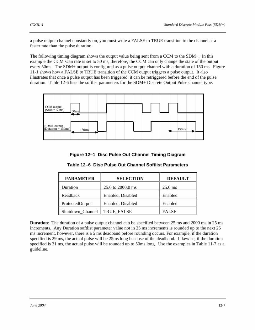
CGQL-4 Standard Discrete Module Plus (SDM+)
June 2004 12-7
a pulse output channel constantly on, you must write a FALSE to TRUE transition to the channel at a faster rate than the pulse duration.
The following timing diagram shows the output value being sent from a CCM to the SDM+. In this example the CCM scan rate is set to 50 ms, therefore, the CCM can only change the state of the output every 50ms. The SDM+ output is configured as a pulse output channel with a duration of 150 ms. Figure 11-1 shows how a FALSE to TRUE transition of the CCM output triggers a pulse output. It also illustrates that once a pulse output has been triggered, it can be retriggered before the end of the pulse duration. Table 12-6 lists the softlist parameters for the SDM+ Discrete Output Pulse channel type.
CCM output(Scan = 50ms) 50ms
150msSDM+ output(Duration = 150ms) 150ms
Figure 12–1 Disc Pulse Out Channel Timing Diagram
Table 12–6 Disc Pulse Out Channel Softlist Parameters
PARAMETER SELECTION DEFAULT
Duration 25.0 to 2000.0 ms 25.0 ms
Readback Enabled, Disabled Enabled
ProtectedOutput Enabled, Disabled Enabled
Shutdown_Channel TRUE, FALSE FALSE
Duration: The duration of a pulse output channel can be specified between 25 ms and 2000 ms in 25 ms increments. Any Duration softlist parameter value not in 25 ms increments is rounded up to the next 25 ms increment, however, there is a 5 ms deadband before rounding occurs. For example, if the duration specified is 29 ms, the actual pulse will be 25ms long because of the deadband. Likewise, if the duration specified is 31 ms, the actual pulse will be rounded up to 50ms long. Use the examples in Table 11-7 as a guideline.

Standard Discrete Module Plus (SDM+) CGQL-4
12-8 June 2004
Table 12–7 Examples of Pulse Round Up Operation
EXAMPLE DURATION VALUE
ACTUAL PULSE DURATION
25 ms 25 ms
26 to 30 ms 25 ms (because of 5 ms dead band)
31 to 50 ms 50 ms (rounded up)
Readback: The state of an output channel is automatically “readback” by input circuitry on the same channel. The readback is used to diagnose and report faults. There are five types of faults as listed here. You can disable readback, which, in turn, disables reporting of the first four types.
1. Diagnostic Read Error 2. Output Failed ON (energized) 3. Protected Output Failed ON (energized) 4. Output Failed OFF (de-energized, blown hard fuse) 5. Output Failed OFF (de-energized, tripped soft-fuse)
NOTE
As listed above, there are two possibilities for an output channel to fail off. One way is when the hard-fuse blows (it is not field replaceable); the other is when the soft-fuse trips (it is locally or remotely resettable). The soft-fuse trip error cannot be disabled by the softlist.
ProtectedOutput: Each output can be configured to turn off all outputs in the event that a channel is intended to be off but diagnostics have determined that it is on. You may want to configure an output as ProtectedOutput if it is critical to the process or if it presents a possible hazard to personnel or equipment.
Shutdown_Channel: When TRUE and channel quality is BAD or QUESTIONABLE, the SDM+ module disables (0 mA) all of its output channels and reports a shutdown error (Class 4, SSC 37, EC 31). Based on the default configuration supplied with QUADLOG, a class 4 error causes all outputs to shut down to their de-energized state (i.e. 0 volts or 0 mA). The configuration can be changed to only shut down the affected outputs or not to shut down at all. Only channels that are critical to the process should be configured as shutdown_channels. Note that in rack-to-rack redundant systems, a switchover to the verify side, rather than a system shutdown, occurs if an I/O failure occurs. Both sides of a redundant system would have to fail for a shutdown to occur. Refer to the Safety Manual for QUADLOG Version 3.30 or Higher (document number CGQLSAFETY-2), section 6.7 (Shutdown Logic), for details of the shutdown configuration logic.

CGQL-4 Voltage Input Module (VIM)
June 2004 13-1
13.0 Voltage Input Module (VIM)
The Voltage Input Module (VIM) interfaces thermocouple and voltage input signals to a control module’s IOBUS. It provides 16 channels, each of which can be configured to be a thermocouple or voltage input. The VIM can accommodate many input types with minimal configuration and high accuracy. Each input is electrically isolated from the module’s CPU, IOBUS, and ground to isolate field faults. In addition, each channel is isolated from other channels.
13.1 VIM Module Scope Parameters
Table 13-1 lists the Module Scope softlist parameters for the VIM. To view/edit the module scope parameters, place the cursor on the desired module in the module tree and select the Edit, Object/Item menu item. The Hardware Modules dialog box opens. Choose the Softlist command button to open the Module Scope Softlist dialog box.
Table 13–1 VIM Module Scope Parameters
PARAMETER SELECTION DEFAULT
ScanRate Not Applicable Not Applicable
LineFreq 50 Hz, 60 Hz 60 Hz
SharedTC Yes, No Yes
ScanRate: This is a read-only parameter that displays the current scan rate of the module. Generally, the scan rate will be the same as the scan rate of the control module, but can be a multiple of the control module's scan rate.
LineFreq: The module software utilizes a notch filter to reduce noise from AC power sources. Specifying the line frequency of AC power will optimize the filtering algorithm.
SharedTC: This parameter only applies when using VIMs in a redundant system. Often, one thermocouple is wired to both the calculate (primary) and verify (backup) VIMs. If this is the wiring arrangement for the VIMs being configured, set SharedTC to Yes. If each VIM has its own thermocouples, set SharedTC to No. For non-redundant VIMs, set SharedTC to No (default).
13.2 VIM Channel Types
The channel types supported for the VIM are listed here. For information on configuring I/O channels, refer to the “Configuring I/O Channels” section of Using the ProcessSuite 4-mation Configuration Software (document number CG39-20).
• VIM TIC - Thermocouple Input • VIM VIC - Voltage Input Thermocouple Input

Voltage Input Module (VIM) CGQL-4
13-2 June 2004
The Thermocouple Input channel type returns a REAL variable. Table 13-2 shows the softlist parameters for this channel type.
Table 13–2 Thermocouple Input Softlist Parameters
PARAMETER SELECTION DEFAULT
TCType B, E, J, K, N1, R, S, T, N2 J
EngUnits DegF, DegC, DegK, DegR DegC
StepResponseTime 0.100 to 2.000 Seconds 1.0
Bias Any REAL number 0.0
MinRange Any REAL number Min. range of TC type selected. (on-line)
-1000.0 (off-line)
MaxRange Any REAL number Max. range of TC type selected. (on-line)
+5000.0 (off-line)
Scale_To_Percent Boolean FALSE
Burnout Disable, Up, Down Disable
DigFiltTimeCnst 0.0 to 159.0 sec. 0.016
TCType: The types of thermocouple must be specified from the list of selections.
EngUnits: You can select from the following engineering units: DegF, DegC, DegK, DegR.
Bias: A bias value can be entered to adjust for any known offset (usually due to thermocouple aging). The bias value can be any REAL number and will be added to the scaled thermocouple reading.
MinRange: MinRange is an optional parameter that allows you to specify a minimum operating value in EngUnits. If the reading drops below this value, an underrange error is reported. The MinRange can be any REAL number.
MaxRange: MaxRange is an optional parameter that allows you to specify a maximum operating value in EngUnits. If the reading goes above this value, an overrange error is reported. The MaxRange can be any REAL number.
Scale_To_Percent: This is a Boolean softlist parameter whose default value is FALSE. Burnout: You can specify burnout detection or open circuit detection for a thermocouple:
Disable = No burnout or open circuit detection Up = Return max operating value for TCType selected Down = Return min operating value for TCType selected

CGQL-4 Voltage Input Module (VIM)
June 2004 13-3
DigFiltTimeCnst: Digital filtering can be applied to thermocouple input signals to reduce the effects of electrical noise. The digital filter is a first order lag, adjustable for time constants of 0.0159 to 159.0 seconds. Equivalent breakpoint frequencies are 10.0 to 0.001 Hz. The default value can be increased for noisy signals.
StepResponseTime: This parameter determines the time for the channel to fully respond to a step input. A longer StepResponseTime will provide higher resolution and better repeatability of the signal.
13.2.1 Voltage Input
The Voltage Input channel type returns a REAL variable. Table 12-3 shows the softlist parameters for this channel type.
Table 13–3 Voltage Input Softlist Parameters
PARAMETER SELECTION DEFAULT
InputRange VDC1to5, VDC0to5, VDCNeg10to10, VDCNeg5to5, VDCNeg1to1,
Custom
VDC1to5
Custom_Range_Low -10 to 10 0
Custom_Range_High -10 to 10 0
MinScale Any REAL number 0.0
MaxScale Any REAL number 100.0
EngUnits In, ft, mm, cm, m, in3, ft3, bbl, ml, liter, m3, lb, ton, mol, g, kg, ft/sec, m/sec,ft/sec2, msec2, DegF, DegR, DegC, DegK, psi, psia, psig, InH2O, InHg, ATM, kPa, kPaa, kPag, mmHg, kg/cm2, mbar, bar, lb/ft3, g/cm3, kg/m3, mol/m3, ft3/lb, m3/kg, ppm, pH, PPH, KPPH, t/day, kg/hr, kg/day, gal/min, GPM, GPH, GPD, ACFM, ACFH, SCCM, SCFH, SCFM, MCFH, yd3/hr, yd3/day, BPD, gal/hr, gal/day, m3/hr, m3/day, l/min, l/hr, l/day, mV, Volts, mA, AMPS, Ohms, mhos, W, kW, MW, Btu, Btu/SCF, Btu/lbm, Btu/hr, hp, bhp, vars, VA, kVA, joules, Percent, pulses, Hz, rpm, deg, rad, cal, cal/SCF, cal/hr, cal/lbm, kcal, kcal/SCF, kcal/hr, kcal/lbm, tonne, tonne/day
Percent
StepResponseTime 0.050 to 2.000 sec. 1.0
DigFiltTimeCnst 0.0 to 159.0 sec. 0.016
InputRange: Voltage input channels are able to read any voltage between -10 and +10. The module utilizes auto-ranging circuitry to provide high resolution even at millivolt levels. For scaling and diagnostic purposes, the range of values being measured by the channel must be specified. Several standard ranges are selectable from a list, or, a custom range can be selected

Voltage Input Module (VIM) CGQL-4
13-4 June 2004
by specifying Custom for the InputRange and editing Custom_Range_Low and Custom_Range_High values.
Custom_Range_Low: An optional parameter that allows you to specify a minimum input range in volts. If the reading drops below this value, an underrange error is reported. This parameter is only used when InputRange is specified as Custom.
Custom_Range_High: An optional parameter that allows you to specify a maximum input range in volts. If the reading goes above this value, an underrange error is reported. This parameter is only used when InputRange is specified as Custom.
MinScale: The module will linearly scale raw data (volts) to engineering units for each channel. The scaling algorithm uses the MinScale/MaxScale parameter values that you set. For example, given a MinScale of 0.0, a MaxScale of 100.0, and an InputRange of 1-5 Volts, if the input to the channel is 3 Volts, the scaled value will be 50.0. MinScale can be any REAL number (REAL numbers are valid between -3.4028E38 and +3.4028E38).
MaxScale: MaxScale can be any REAL number.
EngUnits: Engineering units for the scaled value can be selected from a list of common engineering units.
DigFiltTimeCnst: This parameter sets the time constant of a low-pass digital filter applied to the input data. This filter reduces non-repetitive noise from the input data and can be disabled by setting this parameter to 0.0.
StepResponseTime: This parameter sets the length of a moving-average digital filter applied to the input data. It determines the time to fully respond to an input step. Increasing this parameter reduces periodic or repetitive noise and improves repeatability and resolution. The recommended setting for this parameter is between 0.5 and 4.0 seconds.