Embed Size (px)
Citation preview

WTCR – W30-2011-31 Addendum No. 5 Page 1 of 10
PROCUREMENT DEPARTMENT
2 MONTGOMERY STREET, 3RD FL. JERSEY CITY, NJ 07302
February 27, 2015
ADDENDUM #5
TO PROSPECTIVE BIDDER(S) ON CONTRACT # WTCR – W30-2011-31 WTC REDEVELOPMENT – WTC TOWER 2 PLAZA INTERIM IMPROVEMENTS
Bid Due Date March 5th, 2015, no later than 11:00 AM
The following changes are hereby made to the Bid Solicitation Document:
I. BIDDER’S QUESTIONS AND ANSWERS
The following information is made available in response to questions submitted by prospective Bidder(s). It should not be deemed to answer all questions that have been submitted by Bidder(s) to the Port Authority. It addresses only those questions which the Port Authority has deemed to require additional information and/or clarification. The fact that information has not been supplied with respect to a question asked by a Bidder(s) does not mean or imply, nor should it be deemed to mean or imply, any meaning, construction, or implication with respect to the terms.
The Port Authority makes no representations, warranties or guarantees that the information contained herein is accurate, complete or timely or that such information accurately represents the conditions that would be encountered during the performance of the Agreement. The furnishing of such information by the Port Authority shall not create or be deemed to create any obligation or liability upon it for any reason whatsoever and each Bidder, by submitting its proposal, expressly agrees that it has not relied upon the foregoing information, and that it shall not hold the Port Authority liable or responsible therefor in any manner whatsoever. Accordingly, nothing contained herein and no representation, statement or promise, of the Port Authority, its directors, officers, agents, representatives or employees, oral or in writing, shall impair or limit the effect of the warranties of the Bidder(s) required by this Proposal or Agreement and the Bidder(s) agrees that it shall not hold the Port Authority liable or responsible therefor in any manner whatsoever.

WTCR – W30-2011-31 Addendum No. 5 Page 2 of 10
Question #83
RE: Sheet LT-100 - Please clarify the fixture drivers, as there are 66 drivers called for and only four locations. As per the spec dimensions we would be looking at an array of 8' x 8' for the largest grouping behind the wall. Is this acceptable?
Answer #83
8’ x 8’ group spacing is acceptable, provided minimum 2” spacing between individual drivers is maintained.
Question #84
RIDER “A”, page 35, B.1.9, 2., o. says “Install heat trace on temp on buried or exposed permanent and temporary pipe.” Some CW shows as encased in 6” TH REINFORCED CONCRETE paver base slab, some CW is shown in rigid insulation, some CW is shown encased in lightweight concrete fill, and some CW goes through the existing structural slab. Please advise the method of heat tracing for these lines. Please advise the electrical conduit routing and the circuit and the panel which will provide power for heat tracing. - Ditto above for the storm drainage lines.
Answer #84
a) Install heat trace cable against bare domestic water piping only, prior to installing insulation on the piping. Heat trace not required for storm piping. Pipe insulation required on all storm piping. b) Contractor shall furnish and install 2#12, 1#12G, 3/4”C from panel PP-Plaza located in the MER of T2 Level 1. Terminate in a spare 20A circuit breaker with panel. Electrical/Plumbing Contract Drawings will be updated post award.
Question #85
On Drawing L-601 at detail 3 “STONE WALL DETAILS”, center says “SHIM (BY OTHERS)”. Is it by others?
Answer #85 All items shown in Detail 3 are part of the contract scope.
Question #86
If a 3D CAD files was available for review, it would immensely help in understanding the 2D details of the super structure and the connection detail of the panels.
Answer #86
As a "reference document" only, a 3D Revit model with the filename "WSPSTR_2012061_WTC_Greenwall_RST2015.rvt" is available upon request for bidders' use. Users must have the AutoCAD Revit software program or a Revit viewer program. This model was not intended to be issued, the design team makes no representation regarding the accuracy or scale and this should not be considered a contractual document. Contact Joann Spirito at 212.435.5640, or [email protected], if you would like a CD with this Revit file.
Question #87
Rider “A”, B1.7, page 33, 7. Says “ The architect shall provide a CAD file providing all working points and geometry necessary…” Some of our potential Subcontractors and Suppliers have asked if this CAD File can be made available at this time for them to prepare their cost estimate. Needless to say NDA procedures will be applicable.
Answer #87
As a "reference document" only, a 3D Revit model with the filename "WSPSTR_2012061_WTC_Greenwall_RST2015.rvt" is available upon request for bidders' use. Users must have the AutoCAD Revit software program or a Revit viewer program. This model was not intended to be issued, the design team makes no representation regarding the accuracy or scale and this should not be considered a contractual document. Contact Joann Spirito at 212.435.5640, or [email protected], if you would like a CD with this Revit file.
Question #88
Drawing P.01.01 right hand side shows the 4 Trench Drain connections with the note “ 6” UP TO PLAZA TRENCH DRAIN”. At detail “1 PLAZA DRAINAGE @ PAVED AREAS” one of the connecting pipes is shown meeting to ‘ 8” STORM HEADER’. The relative size of the 6” connecting pipe is the same as the 8” STORM HEADER.

WTCR – W30-2011-31 Addendum No. 5 Page 3 of 10
Are we missing something?
Answer #88
Detail is diagrammatic. 6" trench drains shall tie into larger 8" storm header.
Question #89
Drawing S-101.00 at the bottom of the drawing Note 2. says “ALL EXPOSED STEEL MEMBERS TO BE POWDER COATED (REFER TO ARCHITECT DETAILS). The entire structure will be composed of EXPOSED STEEL MEMBERS, so should the entire structure, including the galvanized members, be powder coated? How about the “ 16” x ½” PLATE (A36) at 4’-0” LONG SPACED AT 8’-0” O/C” as shown on Detail 3/A-300? Is that considered part of the “TRUSS MEMBERs”?
Answer #89
Galvanizing not required. Wire mesh screen panel assemblies including bent plates shall be powder coated per Contract Drawing(??) L-700. All other steel framed members to be coated with two pack shop applied epoxy coated system, with field touch-up, as follows: SCHEDULE OF COATING SYSTEMS A. Exterior Exposed Steel: 1. Primer: Tnemec (or approved equal) Series 394 Perimeprime, Dry Film Thickness: 2.5 to 3.5 mils 2. First Coat: Tnemec (or approved equal) Series N69 Epoxoline II, Dry Film Thickness: 4.0 to 6.0 mils 3. Finish Coat: Tnemec (or approved equal) Series 1075U, Dry Film Thickness: 2.0 to 3.0 mils. 4. Total Dry Film Thickness: 8.5 to 12.5 mils
Question #90
RIDER “A” page 32, B1.7, 3. says “Provide shop applied paint to all support frame steel…” No mention of galvanizing nor powder coating here?
Answer #90
Galvanizing not required. Wire mesh screen panel assemblies including bent plates shall be powder coated per L-700 Contract Drawing(??). All other steel framed members to be coated with two pack shop applied epoxy coated system, with field touch-up, as follows: SCHEDULE OF COATING SYSTEMS A. Exterior Exposed Steel: 1. Primer: Tnemec (or approved equal) Series 394 Perimeprime, Dry Film Thickness: 2.5 to 3.5 mils 2. First Coat: Tnemec (or approved equal) Series N69 Epoxoline II, Dry Film Thickness: 4.0 to 6.0 mils 3. Finish Coat: Tnemec (or approved equal) Series 1075U, Dry Film Thickness: 2.0 to 3.0 mils. 4. Total Dry Film Thickness: 8.5 to 12.5 mils
Question #91
Addendum No 2, SK-2A, at the bottom, shows “LIGHT WT. CONC. FILL SLOPED TO DRAIN.” If on SK-7 (Sheet 1 of 3) does show 6 ‘cels’, to where will the drainage flow?
Answer #91
It is sloped to the drains as shown on Contract Drawing(??) L-200, 4/L-600 and the Plumbing Contract Drawings.
Question #92
Drawing L-600 detail 2 BENCH DETAIL shows the light trough lined with stone and covered by “ ½” TEMPERED GLASS”. It has been suggested by our glass specialists that “wire reinforced glass” should be the choice for this installation. Would that be a consideration?
Answer #92 No. Tempered glass was specified by design architect for aesthetics.

WTCR – W30-2011-31 Addendum No. 5 Page 4 of 10
Question #93
Spec section 033050 paragraph 2.8 refers to spec section 02710 which was not part of bidding documents. Please provide.
Answer #93
Paragraph 2.8 will be deleted; Specification 02710 is not applicable for this project.
Question #94
Please be informed that the specification section 033050-13 under the 2.8 Porous Fill paragraph is requiring us to provide drain course as porous fill and it is referring to spec section 02710 subdrain system. Nevertheless, we could not find the specification section 02710 subdrain system within our bid documents. In order for us to purchase the required porous fill and price it up accordingly, we need to obtain specification section 02710 subdrain system including the gradation of porous fill. Please provide us with the missing specification section 02710 Subdrain system including the gradation of porous fill at your earliest convenience.
Answer #94 Paragraph 2.8 will be deleted; Specification 02710 is not applicable for this project.
Question #95
On Drawing S-300 at DETAIL 8, on the left side there is a dimension of 1’-0” given for the vertical leg of what appears to be a plate bent to a right angle. A bent plate very similar appears in detail “7 TYPICAL CONNECTION OF GREENWALL TO CONCRETE PLINTH AT BASE”. This detail 7/S-300 contains a note on the lower left hand side “BENT PL 9” x 13” x ½” x 24” LONG BOLTED TO CONCRETE…” If this is the same plate shown in 8/S-300 that has the dimension of 1’-0”, then there is a contradiction on the dimension. Please advise.
Answer #95
Please adopt the plate size shown on Section 7/S-300. The dimension on Section 8 will be updated accordingly.
Question #96
On Drawing LT-100, the top portion of the drawing has very light line weight and is tedious to read. But we do see a reference to “CURB BELOW”. The reference to CURB BELOW also appears on Dwg L-601, at the bottom. We cannot find any further details on this “curb”. Please advise. And could you please provide drawing with heavier line weight for the top portion?
Answer # 96
Please refer to electronic pdf file of drawing, which will portray all information and eliminate any concerns about line weight. Please refer to Detail 2 on Contract Drawing L-600 for further details on "CURB BELOW".
Question #97
On Drawing L-601 at detail 2 “TYPICAL STONEWALL SECTION” at the top it says “STONE WALL BEYOND”. Can you please provide more information about how this Stone Wall is installed?
Answer #97
Refer to SK-4 and SK-5 dated 2/10/15 for additional details.
Question #98
Drawing P.01.01 at the CONSTRUCTION NOTES. “1. STORM AND CW PIPING TO RUN BURIED THROUGH INFILL SLAB. REFER TO ARCHITECTURAL SET FOR TRENCHING DETAILS”. We cannot find trenching details on either A.01.100 or A.03.101. Are there other architectural drawings?
Answer #98
Refer to Contract Drawing L-600 for trenching and pipe embedment details. Also refer to SK-14 dated 2/17/15 for a typical pipe crossing detail.
Question #99
RIDER “A” page 32, B1.7, 1. says “Provide tube steel structural support frames…including base plates, full penetration welds, …” (emphasis added). Many of the support frame welds will necessarily need to be made in the field. Full penetration welds may be superfluous and will be very expensive, especially in the field. Please confirm the necessity.

WTCR – W30-2011-31 Addendum No. 5 Page 5 of 10
Answer #99
Refer to note 3 on Contract Drawing S-101. We anticipate full penetration welds will be required at all facet point locations of the HSS horizontal sloping members that support the mesh panels (HSS14x10x5/8 and HSS12x6x1/2). All other locations can be fillet welds provided they are designed for the forces shown on the Contract Drawings.
Question #100
On Drawing L-601 at detail 1A “STONE WALL PLANS”, at the “PLANS @ SECOND STEPBACK” and at the “PLANS @ FIRST STEPBACK” there are call-outs for ‘SECOND STEPBACK CHANNEL’ and ‘FIRST STEPBACK CHANNEL’ respectively. Please provide information as to the size of the channel, the finish, and how it is attached to the structural steel.
Answer #100
Refer to Contract Drawing S-300 for structural attachment details.
Question #101
RE: Structural Drawings (S-100, S-101, S-102) – Please provide horizontal and vertical dimensions on the structural drawings. All of the elevations read “see plan” and there are no horizontal dimensions.
Answer #101
Refer to SK-11 and SK-12 dated 2/13/15.
Question #102
We presume that this bluestone slab is to be installed at the 3 set-back stone wall areas. If so, the bluestone slab dimensions shown on L-102 and L-103 are excessively long at 8’-10”, 8’-4”, and 12’-3”; being approximately 4’-3”, 4’-0”, and 3’-9” wide and only 2” thick. Please provide a joint pattern to minimize the length and/or width of these slabs because handling such long, wide, thin stone panels is virtually impossible.
Answer #102
Refer to SK-13 dated 2/17/15.
Question #103
Drawing P.01.01 at the table DRAIN SCHEDULE, DESIGNATION A is for “PLAZA AREA DRAINS”; TOP SIZE 14”; the information is in conflict with the plan view on the same Dwg which says “ 3” PLAZA DRAIN (510 SQ.FT.)” and in conflict with the CONSTRUCTION NOTES. 2. which calls for “ 3” PLAZA AREA DRAINS (…TO BE BOTTOM OUTLET TYPE UNITS…”.; and in conflict with detail “3 PLAZA DRAINAGE @ PAVED AREAS” which calls for “ 3” SURFACE DRAIN BODY (510 SQ.FT.); and in conflict with Dwg L-600 detail “5 SIDE OUTLET PLAZA DRAIN”. Please clarify.
Answer #103
Refer to Contract Specification 230593, Plumbing Fixture Schedule.
Question #104
Drawing P.01.01 at the table DRAIN SCHEDULE, DESIGNATION B is for “PLAZA TRENCH DRAINS”; TOP SIZE 12”; the information is in conflict with the plan view on the same Dwg which says “ 6” PLAZA TRENCH DRAIN” and in conflict with the Dwg L-600 detail “detail “3 TRENCH DRAIN DETAIL” which calls for “K100 TRENCH DRAIN AS MFD BY ACO-LD4”. Please clarify.
Answer #104 Refer to Contract Specification 230593, Plumbing Fixture Schedule.
Question #105
Drawing S-300.00 contains a detail “ 3A SECTION”. From where was this section taken?
Answer #105
Section 3A is cut horizontally through the new concrete pier shown on Section 3.
Question #106
Drawing S-300.00 contains a detail “ 5 SECTION”. From where was this section taken, it does not show a location on S-100 ?
Answer #106 Section 5 is similar to Section 4 but occurs when the finished slab elevation of the plaza

WTCR – W30-2011-31 Addendum No. 5 Page 6 of 10
is less than 324’-1”.
Question #107 Drawing P.01.01 at detail “1 PLAZA DRAINAGE @ PAVED AREAS” right hand side shows the note “ 6” TRENCH DRAIN (1720 SQ.FT.) MODEL TYPE SPECIFIED BY ARCH.” But Dwg L-600 at 3 TRENCH DRAIN DETAIL shows a note saying “K100 TRENCH DRAIN AS MFD BY ACO-LD4 ” Is that the type ‘SPECIFIED BY ARCHITECT’?
Answer #107
Yes. Refer also to Contract Specification 230593, Plumbing Fixture Schedule
Question #108 Drawing S-300.00, SECTION 5/S-300 shows the ‘trough’ with dimensions of 5” wide; SECTION 4/S-300 shows the light ‘trough’ with dimensions of 4“ deep and 5” wide. Drawing L-600 detail 2 BENCH DETAIL shows the trough LINED WITH STONE which has what looks to be mortar holding it in the trough. We don’t know the thickness of the STONE lining but if the trough is only 5” wide, there seems to be little room left for the stone lining. mortar, and the light. Please advise
Answer #108
Structural trough dimensions are 8" deep and 9" wide. Details on Contract Drawing S-300.00 will be revised post bid.
Question #109 On Drawing L-601 at detail 1 “STONE WALL ELEVATIONS”, at the left hand side ELEVATION (which we assume is Elevation of WALL A) shows 3 sets of horizontal lines, 2 lines in each set are dashed. The top set of lines is labeled “JOINT”, the halfway down set of lines is labeled “C-CHANNEL” and the bottom set of lines is not labeled. The next Elevation, center, which we assume to be WALL B has 3 sets of similar horizontal lines, the top one labeled JOINT”. The next Elevation, on the right hand side , which we assume to be WALL C has 3 sets of similar horizontal lines, the top one is labeled JOINT and the bottom set is labeled C-CHANNEL”. Please advise how we can find further detail on these lines marked “JOINT” and these lines marked “C”-CHANNEL”; i.e. sizes, materials, finishes, installation procedures, etc..
Answer #109
The call-outs are typical across all elevations. The dashed lines represent the steel HSS beam (see Structural Contract Drawings) beyond the stone wall and the solid line between represents the joint locations of the stone panels. This holds true for all of the occurrences across all elevations.
Question #110 Drawing S-300.00 contains the details “ 4 SECTION” and “ 5 SECTION”. To the left of the bench plinth they both show a rectangle formed by dashed lines with diagonal dashed lines connecting opposite corners. What do these rectangles represent?
Answer # 110
The dashed lines indicates the outline of finishes by the landscape consultant; please refer to Landscape Contract Drawings.
Question #111 On Drawing L-601 at 1A STONEWALL PLANS there is a “NOTE: DASHED LINES REPRESENTS FACES TO BE CLAD IN MARINE GRADE PLYWOOD PAINTED BLACK OR APPROVED EQUAL”. Each of the nine plan views of various portions of the stonewall shows the MARINE GRADE PLYWOOD PAINTED BLACK OR APPROVED EQUAL”. But at 3 STONE WALL DETAILS there is no mention of the plywood. Please provide further details on the size, thickness, connection methods, etc. for this plywood.
Answer #111
The marine grade plywood is no longer part of the Contract. Please disregard. Backs of the stone panels to be painted black instead.
Question #112 On Drawing L-601 at detail 1A “STONE WALL PLANS”, shows a “NOTE: “DASHED LINES REPRESENT FACES TO BE CLAD IN MARINE GRADE PLYWOOD PAINTED BLACK OR APPROVED EQUAL”, and each plan detail

WTCR – W30-2011-31 Addendum No. 5 Page 7 of 10
shows a call-out saying “MARINE GRADE PLYWOOD PAINTED BLACK OR APPROVED EQUAL”. Is this plywood in this scope? If so, please advise thickness and attachment details.
Answer # 112
The marine grade plywood is no longer part of the Contract. Please disregard. Backs of the stone panels to be painted black instead.
Question #113 On Drawing S-300.00 at detail 9 DETAIL OF PLANTER SUPPORT, upper left side of detail say “PLANTER BOX BY OTHERS”. We are under the impression that the Planter Box is in this scope. Please advise.
Answer # 113
The plate that is shown as an obtuse angle is the bottom chord of the triangular panels that support the mesh of the green wall. The actual bracket that supports these triangular panels is called out on Section 7 and 8 of Contract Drawing S-300.
Question #114 On Drawing L-601 at detail 3 “STONE WALL DETAILS”, upper left side says “STEEL STUD FRAMING (BY OTHERS)”. Is it by others?
Answer # 114
The steel stud framing is part of the Contract scope. This is a reference to Structural Contract Drawings.
Question #115 Addendum No 2, SK-4 shows the ½” BLUESTONE PANEL” on the “ 1 ½” HONEYCOMB BACKING”. There is another line parallel to the back of the honeycomb backing. What is that line?
Answer # 115
These are the horizontal HSS beams below as shown on Contract Drawing S-100.
Question #116 Drawing E.01.01 plan shows 4 locations noted as “FURNISH AND INSTALL (1) PULL BOX WITH POWER/DATA-WITH BARRIER. SIZE AS REQUIRED. TYPE NEMA 3R, INSIDE SERVICE DOOR/HATCH (SPECS AND EXACT LOC. BY OTHERS).” a) This box requirement differs from Question 3. above. Please advise. b) “(SPECS AND EXACT LOCATION BY OTHERS)”, please describe whom are the OTHERS and are these boxes part of this Contract?
Answer # 116
These boxes are part of this Contract. As indicated on the Electrical Contract Drawing E.01.01, the pull boxes /outlet boxes (4) shall be rated for exterior usage (Nema 3R ). The size of the pull boxes shall be per code and furnished and installed by Contractor. Contractor shall coordinate final locations with the Authority.
Question #117 On Drawing L-601 at detail 3 “STONE WALL DETAILS”, extreme right hand side says “STONE IS TO BE AMERICAN BLUESTONE NEW YORK NORTH RIVER BLUE WITH THERMAL FINISH AS MANUFACTURED BY FURLONG AND LEE STONE SALES OR APPROVED EQUAL”. This might be the “STONE WALL BEYOND” referenced above in 1.; and if it is we will need some guidance on how it goes together.
Answer #117
This is the stone and finish that shall be on the Stonelite panel adjacent to the note. The detail describes the manufacturer’s typical construction of the panels while the note describes the stone and finish of the panels for the stone wall.
Question #118 Drawing S-300.00 contains the details “ 2 SECTION” and “ 3 SECTION”. On the right hand side of each of these sections shows a vertical dimension line marked as “SEE PLAN”. What plan? This looks perhaps like a slab extension from an obsolete plaza design. Please advise.

WTCR – W30-2011-31 Addendum No. 5 Page 8 of 10
Answer #118
This section was generated from the base building structural drawings and is a slab extension for when the tower is constructed; it has no relevance for the plaza project and may be ignored.
Question #119 Drawing L-200, at 1 GRADING PLAN, upper left corner shows “TD 323.00”, and another “TD 323.00” appears a short distance to the right. We would interpret “TD” to be “Top of Drain”. Is that correct? If not, what is “TD”? If so is this “Drain” part of the project scope? If it is please provide details of the paver interfaces with the drain.
Answer #119
Yes, TD is an abbreviation for “Top of Drain.” Please disregard the "TD" label outside of the property line, as it is N.I.C.
Question #120 On Drawing S-300.00 at detail 9 DETAIL OF PLANTER SUPPORT, upper left side of detail say “PLANTER BOX BY OTHERS”. We are under the impression that the Planter Box is in this scope. Please advise.
Answer #120
Yes, these planter boxes are part of the Contract scope, as shown on Contract Drawing L-301.
Question #121 Drawing L-600 detail 2 BENCH DETAIL shows the light trough LINED WITH STONE. To the left of the detail the encircled enlargement shows a vertical dimension of 5” from the bottom of the stone lining to the bottom of the rabbet for the glass. Is that a correct dimension?
Answer #121
Yes.
Question #122 On Drawing L-601 at detail 3 “STONE WALL DETAILS”, upper left side says “STEEL STUD FRAMING (BY OTHERS)”. Is it by others
Answer #122
The steel stud framing is part of the Contract scope. This is a reference to Structural Contract Drawings.
Question #123 On Drawing L-601 at detail 3 “STONE WALL DETAILS”, center says “SHIM (BY OTHERS)”. Is it by others?
Answer #123
All items shown in Detail 3 are part of the Contract scope.
Question #124 On Drawing S-300 at detail “11 TYPICAL CONNECTION OF GREENWALL TO TRUSS (NO PLINTH)” on the right hand side the note says “WALL PANEL CONNECTED BACK TO HSS…WELDED TO HSS WITH 1/16” FILLET WELD”. All other references to this weld call for ¼” Fillet Weld. Should we assume that this weld should also be ¼” Fillet Weld?
Answer #124
Correct; weld shall be 1/4" fillet weld, similar to other locations.
Question #125 On Drawing S-300 at detail “11 TYPICAL CONNECTION OF GREENWALL TO TRUSS (NO PLINTH)” on the upper left side says “FINISHES (SEE ARCH)”. We cannot find any finishes on the 2 Arch drawings. Does it mean to say “LANDSCAPE DRAWINGS”? But we cannot find any “FINISHES” on the HSS Columns except paint. Please advise to what FINISHES are being referred.
Answer #125
HSS columns to be two pack shop applied epoxy coated system, with field touch-up, as follows: SCHEDULE OF COATING SYSTEMS A. Exterior Exposed Steel: 1. Primer: Tnemec (or approved equal) Series 394 Perimeprime, Dry Film Thickness:

WTCR – W30-2011-31 Addendum No. 5 Page 9 of 10
2.5 to 3.5 mils 2. First Coat: Tnemec (or approved equal) Series N69 Epoxoline II, Dry Film Thickness: 4.0 to 6.0 mils 3. Finish Coat: Tnemec (or approved equal) Series 1075U, Dry Film Thickness: 2.0 to 3.0 mils. 4. Total Dry Film Thickness: 8.5 to 12.5 mils
Question #126 Drawing S-300.00.00 at details “ 2 SECTION” and “ 3 SECTION” shows the concrete foundations for the Green Wall Columns at “EL. 322’-8” (322.67’). The sections show what would appear to be a grout bed between the concrete foundation and the column base plate. What is the design thickness of the grout bed?
Answer # 126
Assume grout thickness shall be maximum 2" as per typical baseplate detail shown on Contract Drawing S-200.
Question #127 Addendum No 2, SK-4 shows the ½” BLUESTONE PANEL” on the “ 1 ½” HONEYCOMB BACKING”. The panels follow the indentation of the Structural Frame, however the panels continue a short distance parallel to the North South Structural Frame Axis. Please provide more information on the geometry and the mounting of this portion of the stone panel.
Answer #127 All panels are to be mounted as shown. Detail is typical of all locations throughout.
Question #128 Drawing L-101 at the lower left corner and upper left corner of the Plaza shows the “pavers” in a markedly different legend than “ 4” x 4” PAVERS” or “ 8“ x 4” PAVER BAND” What is the pattern at these tow corners?
Answer # 128
These are the 8”x4” pavers as shown on the Legend. In this area there are 3 bands of 8”x4” pavers as shown.

WTCR – W30-2011-31 Addendum No. 5 Page 10 of 10
This communication should be initialed by you and annexed to your response to the above-referenced Bid upon submission. In case any Respondent fails to conform to these instructions, its submission will nevertheless be construed as though this communication had been so physically annexed and initialed. QUESTIONS CONCERNING THIS ADDENDUM MAY BE ADDRESSED TO JOANN SPIRITO, WHO CAN BE REACHED AT (212) 435-5640 or at [email protected]. THE PORT AUTHORITY OF NY & NJ JOANN SPIRITO
ASSISTANT PROCUREMENT MANAGER FTA/WTC SITE PROJECTS
RESPONDENT’S FIRM NAME: ____________________________________________ INITIALED: ____________________________________________________________ DATE: _________________________________________________________________


Extract From Floor Plan showing Temp Slab Build up (Sheet 1 of 3)

Extract From Floor Plan showing Temp Slab Build up (Sheet 2 of 3)
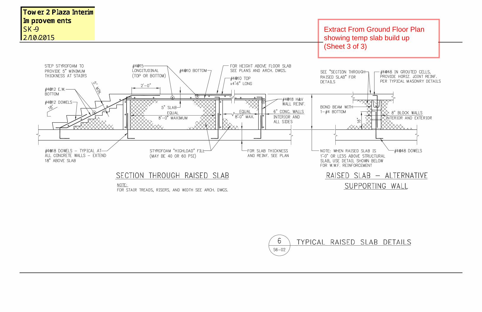
Extract From Ground Floor Plan showing temp slab build up (Sheet 3 of 3)

HSS12X8X5/8(TYP.)
HSS12X8X5/8
HSS12X6X1/2
HSS12X8X5/8
HSS10X8X3/8
HSS12X8X5/8
HSS12X6X1/2
HSS12X8X5/8
HSS10X8X3/8
HSS12X8X5/8
HSS12X6X1/2
HSS12X8X5/
8
HSS12X8X5/8
HSS10X8X3/8
H SS14X10X5/8
HSS12X8X5/8
(FLAT, SLOPING)(FLAT, SLOPING)
(FLAT, S
LOPIN
G)
(FLAT, S
LOPIN
G)
HSS12X8X5/8
HSS12X8X5/8
HSS12X6X1/2
(FLAT, S
LOPIN
G)
(FLAT, SLOPING)HSS12X6X1/2
HSS4X4X5/16
HSS12X6X1/2
(FLAT, SLOPING)
8S-102
7S-102
12S-102
6S-102
5S-102
11S-102
4S-102
9S-102
3S-102
2S-102
1S-102
10S-102
OUTLINE OFEXISTING BLDG
13S-102
14S-102
HSS12X8X5/8HSS12X8X5/8
HSS12X6X1/2
HSS12X8X5/8
HSS10X8X3/8
HSS12X8X5/8
HSS10X8X3/8
HSS12X8X5/8
HSS12X8X5/
8
HSS12X8X5/8HSS10X8X3/8
HSS10X8X3/8
(FLAT, S
LOPIN
G)
(TYP.)
HSS12X8X5/8HSS12X8X5/8
HSS12X8X5/8
HSS12X6X1/2
(FLAT, SLOPING)HSS14X10X5/8
HSS14X10X5/8
(FLAT, S
LOPIN
G)
(FLAT, SLOPING)
4'-0"
3'-7 1/2"
HSS4X4X5/1
6
HSS4X4X5/16
HSS12X6X1/2
HSS12X6X1/2
(FLAT, S
LOPIN
G)
(FLAT, SLOPING)
HSS12X6X1/2
HSS12X6X1/2
(FLAT, S
LOPIN
G)
(FLAT, SLOPING)
8S-102
7S-102
12S-102
6S-102
5S-102
11S-102
4S-102
9S-102
3S-102
2S-102
1S-102
10S-102
OUTLINE OFEXISTING BLDG
NOTE:AT THIS LOCATION HSS MEMBERIS FACETED IN BOTH VERTICAL ANDHORIZONTAL PLANE (SEE ELEV. DWG)
13S-102
14S-102
HSS12X8X5/8
HSS12X8X5/8
HSS12X6X1/2
HSS12X8X5/8
HSS10X8X3/8
HSS12X8X5/8
HSS12X6X1/2
HSS12X8X5/8
HSS10X8X3/8
HSS12X8X5/8
HSS12X6X1/2
HSS14X10X5/8
HSS12X8X5/8
(FLAT, SLOPING)
(FLAT, S
LOPIN
G)(FLAT, S
LOPIN
G)
(FLAT, SLOPING)
(TYP.)
HSS12X8X5/8
HSS12X8X5/8
HSS12X6X1/2
(FLAT, S
LOPIN
G)
HSS12X6X1/2(FLAT, SLOPING)
HSS1 4X10 X5/8(F LAT, SLO PING )
HSS4X4X5/16
HSS4X4X5/16
HSS12X6X1/2(FLAT, SLOPING)
8S-102
7S-102
12S-102
6S-102
5S-102
11S-102
4S-102
9S-102
3S-102
2S-102
1S-102
10S-102
HSS12X8X5/
8
HSS12X8X5/8
13S-102
14S-102
HSS12X8X5/8
HSS10X8X3/8
HSS12X8X5/8
HSS12X8X5/8
HSS10X8X3/8
HSS12X8X5/8
HSS12X8X5/
8
HSS12X8X5/8
HSS12X8X5/8
(TYP.)HSS12X8X5/8
HSS12X6X1/2
(FLAT, SLOPING)
HSS12X6X1/2
(FLAT, S
LOPIN
G)H SS 12X6X1/2
(FLA T, S
L OPI N
G)HSS14X10X5/8(FLAT, S
LOPIN
G)
HSS12X8X5/8
HSS12X8X5/8
HSS12X8X5/8
HSS12X6X1/2
(FLAT, S
LOPIN
G)
(FLAT, S
LOPI N
G)HSS12X6X1/ 2
(FLAT, SLOPING)HSS14X10X5/8
HSS4X4X5/16
HSS4X4X5/1
6
HSS12X6X1 /2(F LAT , SL OPING)
8S-102
7S-102
12S-102
6S-102
11S-102
5S-102
4S-102
9S-102
3S-102
2S-102
1S-102
10S-102
H S S1 0X 8X 3/8
13S-102
14S-102
24" SLABT/SLAB EL. 319'-7"
24" SLABT/SLAB EL. 322'-8"
215
EXTENT OF SLURRY WALL& CAPPING BEAM BELOW
1S-300
2S-300
1S-300
SIM
6S-300
6S-300
SIM
3S-300
4S-300
1S-300
SIM
OUTLINE OFEXISTING BLDG
24" SLABT/SLAB EL. 322'-8"
TYP.
13S-102
14S-102
T4
T3
T2
DRAWING TITLE
DRAWN
SCALE DATE
CHECKED
PROJECT NO.
DRAWING NO.
STAMP
REVISION NO.
T2 INTERIM PLAZAIMPROVEMENTS
MEP EngineerAKFConsulting Engineers1501 BroadwayNew York, NY 10036USATel: 212. 354. 5656Fax: 212. 354. 5668
Executive ArchitectBeyer Blinder BelleArchitects and Planners LLP41 East 11th StreetNew York, NY 10003 USATel: 212. 777. 7800Fax: 212. 475. 7424
Design Architect:
WORLD TRADE CENTER
No. Date Description
PLOT
DAT
E:FI
LE N
AME:
WTC Redevelopment DepartmentOwner:
Landscape ArchitectMPFP LLC / M. Paul Friedberg & Partners41 East 11th StreetNew York, NY 10003 USATel: 212. 477. 6366Fax: 212. 477. 6548
Discrepancies must be reported immediately tothe
Architect before proceeding.Only figured dimensions are to be used.
Contractors must check all dimensions on site.This drawing is protected by copyright.
SECURE DOCUMENTCONFIDENTIAL FOR OFFICIAL
USE ONLYDo not remove this notice.
Properly destroy document if being discarded(if permitted by law).
Structural EngineerWSP Cantor Seinuk228East 45th Street, Third FloorNew York, NY 10017 USATel: 212. 687. 9888Fax: 646. 487. 5501
Lighting ConsultantTilotson DesignAssociates40 Worth Street,New York, NY 10013 USATel: 212. 675. 7760Fax: 212. 675. 7826
Gabellini Sheppard Associates,LLP665 Broadway, Suite 706New York, NY 10012 USATel: 212. 388. 1700Fax: 212. 388. 1808
1 09/15/14 100% CD SET IN PROGRESS
CADD M.B.
2 10/08/14 100% CD SET
3/16" = 1'-0"
PLAN VIEWS
S-100.00
07/17/14
2012061
SCALE:S-100 3/16" = 1'-0"
2 PART PLAN AT STEEL LEVEL 2
SCALE:S-100
2A AREA SHOWN
SCALE:S-100 3/16" = 1'-0"
1 PART PLAN AT STEEL LEVEL 1
SCALE:S-100
1A AREA SHOWN
SCALE:S-100 3/16" = 1'-0"
3 PART PLAN AT STEEL LEVEL 3
SCALE:S-100
3A AREA SHOWN
SCALE:S-100 3/16" = 1'-0"
4 PART PLAN AT STEEL LEVEL 4
SCALE:S-100
4A AREA SHOWN
SCALE:S-100 3/16" = 1'-0"
5 GROUND FLOOR PLAN

EL. SEE PLAN0
EL. SEE PLANLEVEL 1
EL. SEE PLANLEVEL 2
EL. SEE PLANLEVEL 3
EL. SEE PLANLEVEL 4
HSS6X6X
5/8
HSS6X6X5/8
HSS6X6X5/8
P=20K
P=32K
P=76K
7"
1/8"
HSS 6x4x1/2"DOOR FRAME
HSS12X8X5/8
HSS12X8X5/8
0"
0"
HSS12X8X5/8
HSS12X8X5/8
HSS12X8X5/8
4'-0"
8'-7 1/8"
6'-5 1/4"
9'-4 1/8"
8'-9 1/2"
EL. SEE PLAN0
EL. SEE PLANLEVEL 1
EL. SEE PLANLEVEL 2
EL. SEE PLANLEVEL 3
EL. SEE PLANLEVEL 4
HSS12X8X5/8
HSS12X8X5/8
HSS16X8X5/8
HSS16X8X5/8
HSS16X8X5/8
HSS16X8X5/8
4'-7 5/8"
4'-7 5/8"
5'-0"
5'-0"
5'-8 1/4"
5'-8 1/4"
4'-7 7/8"
11 7/8"
4'-0"
EL. SEE PLAN0
EL. SEE PLANLEVEL 1
EL. SEE PLANLEVEL 2
EL. SEE PLANLEVEL 3
EL. SEE PLANLEVEL 4
HSS12X8X5/8
HSS12X8X5/8
HSS16X8X5/8
HSS16X8X5/8
5'-11 7/8"
5'-11 7/8"
9'-7"
7'-4 3/8"
5'-4 7/8"
1'-8 7/8"
4'-0"
EL. SEE PLAN0
EL. SEE PLANLEVEL 1
EL. SEE PLANLEVEL 2
EL. SEE PLANLEVEL 3
EL. SEE PLANLEVEL 4
EL. SEE PLANL1HS
S12X8X5/8
HSS12X8X5/8
HSS16X8X5/8
HSS16X8X5/8
5'-11 7/8"
5'-11 7/8"
9'-7"
7'-4 3/8"
5'-4 7/8"
1'-8 7/8"
4'-0"
EL. SEE PLAN0
EL. SEE PLANLEVEL 1
EL. SEE PLANLEVEL 2
EL. SEE PLANLEVEL 3
EL. SEE PLANLEVEL 4
HSS12X8X5/8
HSS12X8X5/8
HSS16X8X5/8
HSS16X8X5/8
6'-8"
4'-5 1/8"
10'-0 3/4"
8'-6 1/8"
5'-1 7/8"
1'-5 7/8"
4'-0"
EL. SEE PLAN0
EL. SEE PLANLEVEL 1
EL. SEE PLANLEVEL 2
EL. SEE PLANLEVEL 3
EL. SEE PLANLEVEL 4
HSS4X4X5/16
HSS4X4X5/16
HSS4X4X5/16
P=10K
P=20K
P=40K
5 1/4"
HSS 6x4x1/2"DOOR FRAME
0"
0"
HSS12X8X5/8
HSS12X8X5/8
7" 0"
0"
HSS12X8X5/8
HSS12X8X5/8
HSS12X8X5/8
4'-0"
6'-6 3/4"
9'-5 1/4"
10'-4 1/4"
8'-2 3/4"
EL. SEE PLAN0
EL. SEE PLANLEVEL 1
EL. SEE PLANLEVEL 2
EL. SEE PLANLEVEL 3
EL. SEE PLANLEVEL 4
EL. SEE PLANL1
9'-6"
10'-0"
11'-4 1/2"
5'-4"
EL. SEE PLAN0
EL. SEE PLANLEVEL 1
EL. SEE PLANLEVEL 2
EL. SEE PLANLEVEL 3
EL. SEE PLANLEVEL 4
EL. SEE PLANL1HS
S12X8X5/8
HSS12X8X5/8
HSS16X8X5/8
HSS16X8X5/8
HSS16X8X5/8
HSS16X8X5/8
4'-0"
11 7/8"
4'-7 7/8"
5'-8 1/4"
5'-8 1/4"
5'-0"
5'-0"
5'-2 3/8"
5'-2 3/8"
EL. SEE PLAN0
EL. SEE PLANLEVEL 1
EL. SEE PLANLEVEL 2
EL. SEE PLANLEVEL 3
EL. SEE PLANLEVEL 4
HSS12X8X5/8
HSS12X8X5/8
HSS16X8X5/8
HSS16X8X5/8
4'-0"1'-5 7/8"
5'-1 7/8"
8'-6 1/8"
10'-0 3/4"
5'-5 1/8"
5'-5 1/8"
EL. SEE PLAN0
EL. SEE PLANLEVEL 1
EL. SEE PLANLEVEL 2
EL. SEE PLANLEVEL 3
EL. SEE PLANLEVEL 4
HSS4X4X1/2
P=10K
HSS4X
4X1/2
P=10K
P=10K
HSS4X4X1/2HSS4X4X1/2
HSS12X8X5/8
HSS12X8X5/8
HSS10X8X3/8
HSS10X8X3/8
HSS10X8X3/8
HSS10X8X3/8
9'-6"
10'-0"
11'-4 1/2"
5'-4"
4'-0"
EL. SEE PLAN0
EL. SEE PLANLEVEL 1
EL. SEE PLANLEVEL 2
EL. SEE PLANLEVEL 3
EL. SEE PLANLEVEL 4
HSS4X4X1/2
HSS4X4X1/2
HSS4X4X1/2
HSS4X4X1/2
P=10K
P=10K
P=10K
P=10K
HSS12X8X5/8
HSS12X8X5/8
HSS10X8X3/8
HSS10X8X3/8
HSS10X8X3/8
HSS10X8X3/8
12'-1"
9'-7"
7'-0 3/8"
7'-1 5/8"
4'-0"
EL. SEE PLAN0
EL. SEE PLANLEVEL 1
EL. SEE PLANLEVEL 2
EL. SEE PLANLEVEL 3
EL. SEE PLANLEVEL 4
HSS4X4X1/2
HSS4X
4X1/2
HSS4X4X1/2
HSS4X
4X1/2
P=10K
P=10K
P=10K
P=10K
HSS12X8X5/8
HSS12X8X5/8
HSS10X8X3/8
HSS10X8X3/8
HSS10X8X3/8
HSS10X8X3/8
10'-10"
10'-0"
8'-6"
6'-4"
4'-0"
EL. SEE PLAN0
EL. SEE PLANLEVEL 1
EL. SEE PLANLEVEL 2
EL. SEE PLANLEVEL 3
EL. SEE PLANLEVEL 4
EL. SEE PLANL1
12'-1"
9'-7"
7'-0 3/8"
7'-1 5/8"
EL. SEE PLAN0
EL. SEE PLANLEVEL 1
EL. SEE PLANLEVEL 2
EL. SEE PLANLEVEL 3
EL. SEE PLANLEVEL 4
EL. SEE PLANL1
10'-0"
8'-6"
6'-4"
T4
T3
T2
DRAWING TITLE
DRAWN
SCALE DATE
CHECKED
PROJECT NO.
DRAWING NO.
STAMP
REVISION NO.
T2 INTERIM PLAZAIMPROVEMENTS
MEP EngineerAKFConsulting Engineers1501 BroadwayNew York, NY 10036USATel: 212. 354. 5656Fax: 212. 354. 5668
Executive ArchitectBeyer Blinder BelleArchitects and Planners LLP41 East 11th StreetNew York, NY 10003 USATel: 212. 777. 7800Fax: 212. 475. 7424
Design Architect:
WORLD TRADE CENTER
No. Date Description
PLOT
DAT
E:FI
LE N
AME:
WTC Redevelopment DepartmentOwner:
Landscape ArchitectMPFP LLC / M. Paul Friedberg & Partners41 East 11th StreetNew York, NY 10003 USATel: 212. 477. 6366Fax: 212. 477. 6548
Discrepancies must be reported immediately tothe
Architect before proceeding.Only figured dimensions are to be used.
Contractors must check all dimensions on site.This drawing is protected by copyright.
SECURE DOCUMENTCONFIDENTIAL FOR OFFICIAL
USE ONLYDo not remove this notice.
Properly destroy document if being discarded(if permitted by law).
Structural EngineerWSP Cantor Seinuk228East 45th Street, Third FloorNew York, NY 10017 USATel: 212. 687. 9888Fax: 646. 487. 5501
Lighting ConsultantTilotson DesignAssociates40 Worth Street,New York, NY 10013 USATel: 212. 675. 7760Fax: 212. 675. 7826
Gabellini Sheppard Associates,LLP665 Broadway, Suite 706New York, NY 10012 USATel: 212. 388. 1700Fax: 212. 388. 1808
1 09/15/14 100% CD SET IN PROGRESS
CADD M.B.
2 10/08/14 100% CD SET
3/16" = 1'-0"
SUPERSTRUCTURESECTIONS 1
S-102.00
08/19/14
2012061
SCALE:S-102 3/16" = 1'-0"
1 SECTIONSCALE:S-102 3/16" = 1'-0"
3 SECTIONSCALE:S-102 3/16" = 1'-0"
4 SECTIONSCALE:S-102 3/16" = 1'-0"
5 SECTION
SCALE:S-102 3/16" = 1'-0"
7 SECTIONSCALE:S-102 3/16" = 1'-0"
8 SECTIONSCALE:S-102 3/16" = 1'-0"
9 SECTION
SCALE:S-102 3/16" = 1'-0"
2 SECTION
SCALE:S-102 3/16" = 1'-0"
6 SECTION
SCALE:S-102 3/16" = 1'-0"
10 SECTIONSCALE:S-102 3/16" = 1'-0"
11 SECTIONSCALE:S-102 3/16" = 1'-0"
12 SECTION
SCALE:S-102 3/16" = 1'-0"
13 S-102/13_SECTIONSCALE:S-102 3/16" = 1'-0"
14 S-102/14_SECTION