Embed Size (px)
Citation preview
PRODUCING METHANE GAS FROM EFFLUENT
Luke Jenangi
Adelaide UniversityDiploma in Agricultural Production
Individual Project
Supervisor - Mr. Paul Harris
2
1 Contents
1 CONTENTS ............................................................................................................................ 2
2 OBJECTIVES ......................................................................................................................... 3
3 INTRODUCTION................................................................................................................... 3
4 DIGESTION OF ORGANIC MATTER ................................................................................ 3
4.1 DIRECT COMBUSTION ............................................................................................................ 44.2 GASIFICATION ....................................................................................................................... 44.3 AEROBIC PROCESSES ............................................................................................................. 44.4 ANAEROBIC PROCESSES ......................................................................................................... 4
5 ANAEROBIC WASTE TREATMENTS AND BIOGAS PRODUCTION............................ 5
5.1 TEMPERATURE....................................................................................................................... 55.2 RETENTION TIMES ................................................................................................................. 55.3 LOADING RATE...................................................................................................................... 65.4 VOLATILE SOLIDS.................................................................................................................. 65.5 SIZE ...................................................................................................................................... 65.6 DIGESTER PERFORMANCE ...................................................................................................... 75.7 DIGESTERS ............................................................................................................................ 8
6 OTHER OPERATIONAL CONSIDERATIONS................................................................... 9
6.1 NUTRIENT BALANCE .............................................................................................................. 96.2 SEEDING ............................................................................................................................. 106.3 MIXING OF DIGESTER CONTENT ........................................................................................... 106.4 SCUM FORMATION ............................................................................................................... 106.5 SLUDGE REMOVAL............................................................................................................... 106.6 ALKALINITY AND PH............................................................................................................ 10
7 USE OF BIOGAS.................................................................................................................. 11
7.1 REMOVING IMPURITIES FROM THE GAS ................................................................................. 117.2 STORING METHANE GAS ...................................................................................................... 117.3 USING METHANE GAS.......................................................................................................... 12
7.3.1 Direct Combustion .................................................................................................... 127.3.2 Fuel for Internal Combustion Engines ....................................................................... 12
8 PILOT PROJECT WORK ................................................................................................... 12
8.1 INTRODUCTION.................................................................................................................... 128.2 MATERIALS USED ................................................................................................................ 128.3 METHODOLOGY................................................................................................................... 138.4 RESULTS ............................................................................................................................. 148.5 DISCUSSION......................................................................................................................... 158.6 CHECK LIST......................................................................................................................... 158.7 PROBLEMS ENCOUNTERED ................................................................................................... 15
9 CONCLUSION...................................................................................................................... 16
10 ACKNOWLEDGMENT....................................................................................................... 16
11 REFERENCES...................................................................................................................... 17
12 APPENDIX I - GLOSSARY ................................................................................................. 18
13 APPENDIX II - PHOTOGRAPHS ....................................................................................... 22
3
2 ObjectivesThe purpose of this project is to set up a “ Plug Flow’’ Anaerobic Digester to:
n Monitor start up, check sensitivity to alteration in input, look at optimum loadingrate for gas production and compare to a computer model.
n Look at methods of monitoring digester performance. n Investigate the application of Plug Flow Anaerobic Digesters by small farmers in
rural areas of Papua New Guinea (PNG) to produce methane gas for cooking,lighting, heating and internal combustion engines.
3 IntroductionMethane was first recognised as having practical and commercial value in England,where a specially designed septic was used to generate gas for the purpose of lightingin the 1890s (Cheremisinoff, Cheremisinoff et al. c1980). There are also reports ofsuccessful methane production units in several parts of the world, and many farmerswonder if such small scale methane production units can be installed at their farms toconvert waste into something more valuable (Lewis 1983). Units to produce methanegas have been successfully applied in meeting energy needs in rural areas, particularlyin India and China (Lewis 1983) and are more recently being installed in Vietnam (An,Rodriguez et al. 1997). Small-scale plant can be operated on farms and wastetreatment plants in temperate and tropical climates.
In most of the South Pacific Island countries, livestock producers simply drain animalmanure into creeks, streams and rivers. Because farmers lack skills and knowledge inlivestock waste management, they are wasting potential organic fertilizers, livestockfeed and energy resources. Small scale anaerobic digesters for farmers would betterutilize livestock waste. The current disposal system for waste has created a negativeimpact through pollution and disease problems. Valuable marine resources andunderground water are also threatened (Ajuyah 1998).
The concept of integrated biosystems incorporating livestock, anaerobic digesters andaquaculture is beginning to create interest in the Pacific region by Non GovernmentOrganizations (NGOs), Colleges and Universities with livestock farms. For example atMontfort Boys Town, Fiji, and The University of South Pacific College of Agriculture,Samoa, the integration of pig, talapia and biogas production is in progress (Ajuyah1998). Anaerobic digestion is best seen as part of a system, but this project isspecifically concentrating on anaerobic digestion (Harris, P.L., pers comm).
4 Digestion of Organic MatterAll organic matter, or biomass, can in one way or other be used as fuel. It is composedmainly of carbohydrate compounds, the building blocks of which are the elementscarbon, hydrogen and oxygen. All ultimately derive from the process of photosynthesisin plants, but may be in many forms, vegetable or animal. Biomass from which energycan be reclaimed can be harvested as specifically grown crops or natural stands, assurpluses or waste from crops grown primarily for food or manufacturing, or as
4
municipal and industrial waste (White and Plaskett 1981). There are a number of waysof utilising these resources, which are discussed below.
4.1 Direct CombustionDirect combustion of biomass can be preceded by physical or chemical pre-treatment,or a combination of both. Physical conversion techniques are aimed of physicallyaltering the biomass form, for example by chipping, drying to reduce water content orselecting specific species of the biomass for certain properties. Chemical conversiontechniques are aimed at altering the molecular structure of the biomass to improveutilization. Examples include combustion operations to produce thermal energy andincomplete combustion to produce chemical products and synthesis gas(Cheremisinoff, Cheremisinoff et al. c1980.).
4.2 Gasification(Bungay c1981.) stated that the reaction of carbonaceous materials with steam andoxygen to produce a mixture of carbon monoxide, hydrogen, carbon dioxide, methane,unreacted steam, some tar and char is termed gasification. When biomass is heated inthe presence of some air or oxygen, but insufficient to combust it completely, gasformation is generally maximised and temperatures within the reactor rise on accountof the oxygen consuming reaction. The resulting gases provide useful fuel for ICengines or other applications.
4.3 Aerobic ProcessesAerobic bacteria, those that require oxygen, are able to break down organic waste toCO2 and water quite rapidly. Techniques developed in the pharmaceutical industry,which are usually aerobic, have been applied to improve treatment, but aerobicdigestion of wastes produces CO2 and bacterial sludge and uses energy for aeration.(Cheremisinoff, Cheremisinoff et al. c1980.).
4.4 Anaerobic ProcessesThe anaerobic bacteria responsible for digestion cannot survive with even the slightesttrace of oxygen. Thus, because of the oxygen present in the manure mixture fed to thedigester, a period of time passes after loading before actual digestion takes place.During this initial aerobic period, traces of oxygen are used up by oxygen lovingbacteria.
After oxygen has disappeared, the digestion process can begin. That process involves aseries of reactions by several kinds of anaerobic bacteria feeding on the raw organicmatter. As these different kinds of bacteria become active, the by products of one typeof bacteria provide the food for another bacterial population. In the first stages ofdigestion, often called liquefaction, organic material which is digestible (fats, proteinsand most starches) is broken down by acid-producing bacteria into simple compounds.The role of acid bacteria is to excrete enzymes, liquefy the raw materials and convertthe complex materials into simpler substances, especially volatile acids that are of lowmolecular weight. The most important volatile acid is acetic acid, a very common by-product of all fat, starch and protein digestion. In the second stage of the process,known as gasification, the methane-producing bacteria utilize enzymes that break downthe acid. About 70% of the methane produced during fermentation comes from aceticacid (Fry 1975) with the balance coming from direct reduction of CO2 (Lapp, Schulteet al. 1975).
5
5 Anaerobic Waste Treatments and Biogas ProductionMethane is insoluble, already separated from the fermentation system and is easilycollected in a gas container. Methane gas is readily combustible and is a valuableenergy source. The gas is also explosive and high-care safety standards must bemaintained at all times during the operation period. The pressure in the cylinder mustbe above 34,450 kPa for liquefaction of methane (Meuhling 1981), so gas is best usedon site as it is generated, rather than being stored in bottles for mobile use.
The amount of gas produced increases with digester temperature, with retention timeand with the percentage of total solid in the slurry. Typically for 25oC to 44oC, 0.25 to0.40 m3 of methane gas is produced for each kilogram of volatile solids destroyed.
5.1 TemperatureAnaerobic digestion can take place at any temperature between 4oC and 60oC. Thereappear to be two main temperature ranges within this wider range corresponding totwo different sets of bacteria, usually called the mesophiles, those which operate bestat 20-40oC, and the thermophiles, which prefer to live at temperatures between40oCand 60oC. Digestion can also occur in the psychrophilic range, 4-20oC, but ismuch slower. The rate of gas production increases with increased temperature butthere is a distinct break in the rise around 40oC, as this favours neither the mesophilesnor the thermophiles.
As reported by (Pharaoh 1976), a small capacity digester can be used if supplementaryheat is supplied to maintain a constant temperature of 35oC, if it is to be loaded withone type of material (for example pig manure) and if it has some form of agitation tokeep slurry gently stirred. Methane bacteria can tolerate a minimum temperature ofabout 4oC but function best in higher temperature ranges up to 60oC
The range most commonly used in municipal sewage treatment plants is 33- 38oCThermophilic temperatures of 55-58oC have been investigated for anaerobic digestionbut high heating requirements and unstable operation have restricted practicalapplication of this technology. The methane forming bacteria are very sensitive tothermal changes and for optimum operation the temperature should be controlledwithin a narrow range of the selected operating temperature (Lapp, Schulte et al.1975).
5.2 Retention TimesThe length of time that volatile solids remain in an anaerobic digester is an importantfactor in the digestion process. The solids retention time (SRT) represents the averagetime microorganisms spend in the system. Minimum solids retention times foranaerobic digestion systems are in the range of 2-6 days, depending on thetemperature. In completely mixed anaerobic digesters where no recycling occurs, theSRT is equal to the hydraulic retention time (HRT). Hydraulic retention times usuallyvary from 10 to 30 days depending on the temperature. If solid retention time is tooshort the microbes are “washed out” of the digester and digestion process fails, while along retention time requires a large digester (Lapp, Schulte et al. 1975).
6
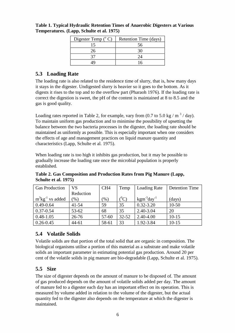
Table 1. Typical Hydraulic Retention Times of Anaerobic Digesters at VariousTemperatures. (Lapp, Schulte et al. 1975)
Digester Temp (o C) Retention Time (days)15 5626 3037 2449 16
5.3 Loading RateThe loading rate is also related to the residence time of slurry, that is, how many daysit stays in the digester. Undigested slurry is heavier so it goes to the bottom. As itdigests it rises to the top and to the overflow part (Pharaoh 1976). If the loading rate iscorrect the digestion is sweet, the pH of the content is maintained at 8 to 8.5 and thegas is good quality.
Loading rates reported in Table 2, for example, vary from (0.7 to 5.0 kg / m 3 / day).To maintain uniform gas production and to minimise the possibility of upsetting thebalance between the two bacteria processes in the digester, the loading rate should bemaintained as uniformly as possible. This is especially important when one considersthe effects of age and management practices on liquid manure quantity andcharacteristics (Lapp, Schulte et al. 1975).
When loading rate is too high it inhibits gas production, but it may be possible togradually increase the loading rate once the microbial population is properlyestablished.
Table 2. Gas Composition and Production Rates from Pig Manure (Lapp,Schulte et al. 1975)
Gas Production VSReduction
CH4 Temp Loading Rate Detention Time
m3kg-1 vs added (%) (%) (0C) kgm-3day-1 (days)0.49-0.64 41-54 59 35 0.32-3.20 10-500.37-0.54 53-62 68 35 2.40-3.04 200.48-1.05 26-76 57-60 32-52 2.40-4.00 10-150.26-0.45 44-61 58-61 33 1.92-3.84 10-15
5.4 Volatile SolidsVolatile solids are that portion of the total solid that are organic in composition. Thebiological organisms utilise a portion of this material as a substrate and make volatilesolids an important parameter in estimating potential gas production. Around 20 percent of the volatile solids in pig manure are bio-degradable (Lapp, Schulte et al. 1975).
5.5 SizeThe size of digester depends on the amount of manure to be disposed of. The amountof gas produced depends on the amount of volatile solids added per day. The amountof manure fed to a digester each day has an important effect on its operation. This ismeasured by volume added in relation to the volume of the digester, but the actualquantity fed to the digester also depends on the temperature at which the digester ismaintained.
7
If a farmer wants to process all his manure he can calculate the size of his digester. Themanure to go into the digester must be about 10 to 20 per cent solids. When undilutedfresh manure is used with an equal volume of water, slurry of the correct consistencyresults (Lewis 1983).
Alternatively, An, Rodriguez et al. (1997) recommend about 5kg of fresh manure (1kgsolid matter) for every 1m3 of digester volume. To this amount of solids 15 litres ofwater should be added so that the solids content is approximately 5 per cent. On thisbasis, if the total amount of raw slurry per day is 50 litres the digester capacity must befrom 10 to 40 times the daily volume of effluent produced, i.e. 500 litres if warmertemperatures can be maintained to 2000 litres at lower temperatures.
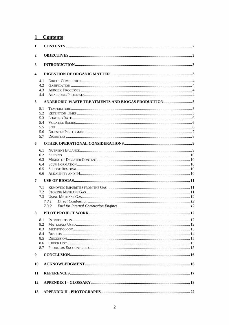
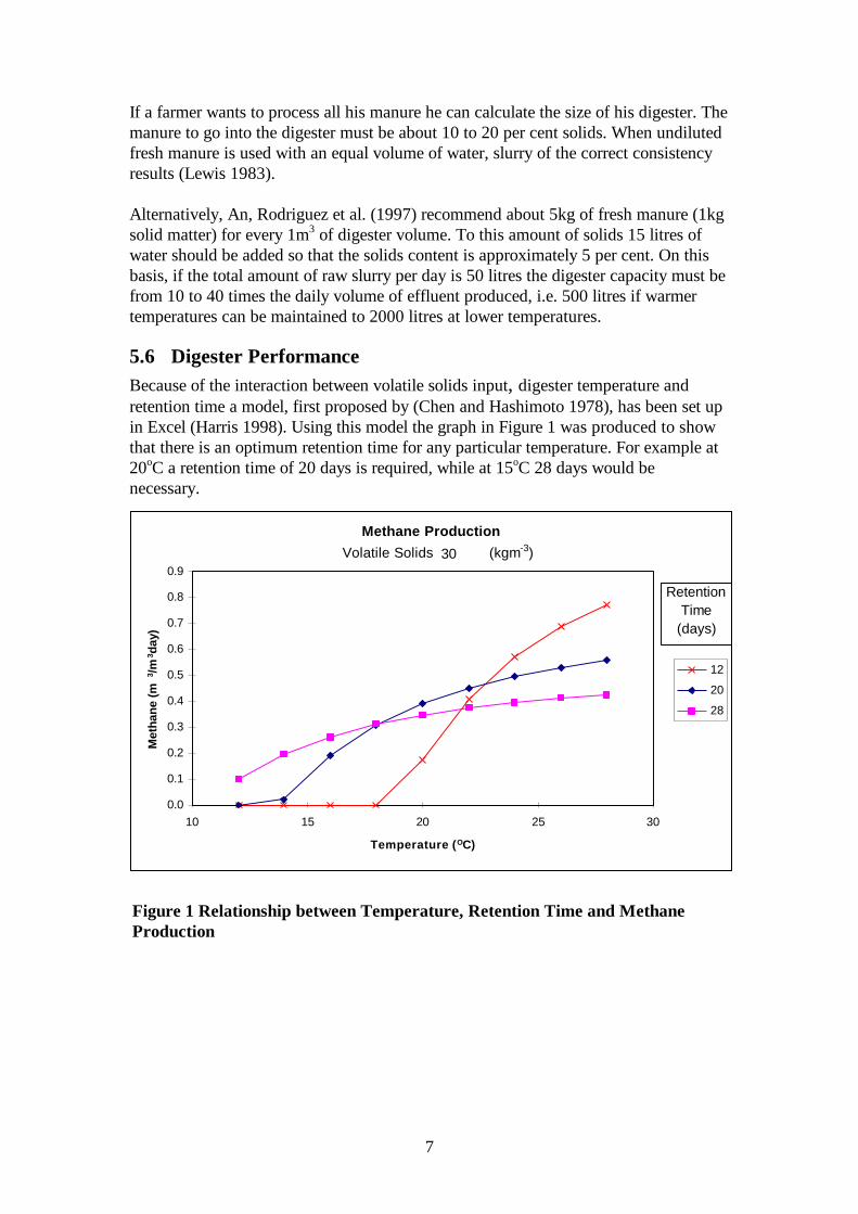
5.6 Digester PerformanceBecause of the interaction between volatile solids input, digester temperature andretention time a model, first proposed by (Chen and Hashimoto 1978), has been set upin Excel (Harris 1998). Using this model the graph in Figure 1 was produced to showthat there is an optimum retention time for any particular temperature. For example at20oC a retention time of 20 days is required, while at 15oC 28 days would benecessary.
Methane Production
0.0
0.1
0.2
0.3
0.4
0.5
0.6
0.7
0.8
0.9
10 15 20 25 30
Temperature (OC)
Met
hane
(m3 /m
3 day
)
12
20
28
Retention Time
(days)
Volatile Solids (kgm-3)30
Figure 1 Relationship between Temperature, Retention Time and MethaneProduction
8
5.7 DigestersIn planning a digester there must be clear objectives. This will enable choice of theright type of digester and the criteria on which it must be designed. Commercialdigesters are not widely available but producers can make their own quite cheaply, inline with their set objectives.
During the last century a number of different types of simple digester have beendeveloped and they can be of the following kinds :
n Batch- filled in one go and allow to digest, then emptied and refilledn Continuously Expanding- start one third full, filled in stages and then emptiedn Plug flow- waste added regularly at one end and over-flows the othern Contact- a support medium is provided for bacterian Continuous Flow-filled initially and waste added and removed regularly(Harris 1998).
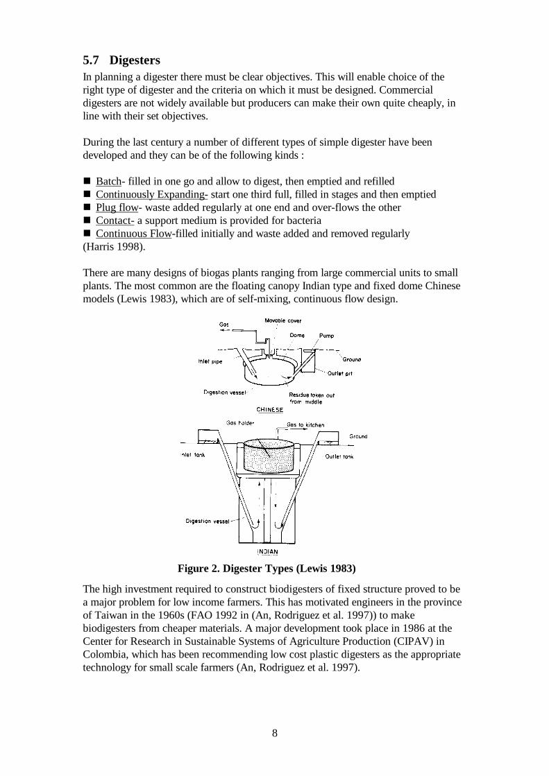
There are many designs of biogas plants ranging from large commercial units to smallplants. The most common are the floating canopy Indian type and fixed dome Chinesemodels (Lewis 1983), which are of self-mixing, continuous flow design.
The high investment required to construct biodigesters of fixed structure proved to bea major problem for low income farmers. This has motivated engineers in the provinceof Taiwan in the 1960s (FAO 1992 in (An, Rodriguez et al. 1997)) to makebiodigesters from cheaper materials. A major development took place in 1986 at theCenter for Research in Sustainable Systems of Agriculture Production (CIPAV) inColombia, which has been recommending low cost plastic digesters as the appropriatetechnology for small scale farmers (An, Rodriguez et al. 1997).
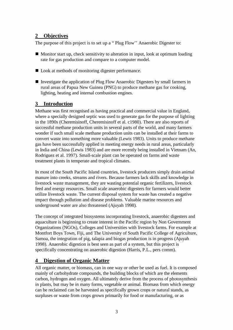
Figure 2. Digester Types (Lewis 1983)
9
The Indian type digester consists of a floating drum originally made of mild steel butlater replaced by fibre-glass reinforced plastic to overcome the problem of corrosion.The wall and bottom are usually constructed of brick, although reinforced concrete issometimes used. The Chinese type consists of a gas-tight chamber constructed ofbricks, stone or poured concrete. Top and bottom are joined together by straight sides.The inside surface is sealed by many thin layers of mortar to make it gas-tight. (SeeFigure Error! Not a valid link.).
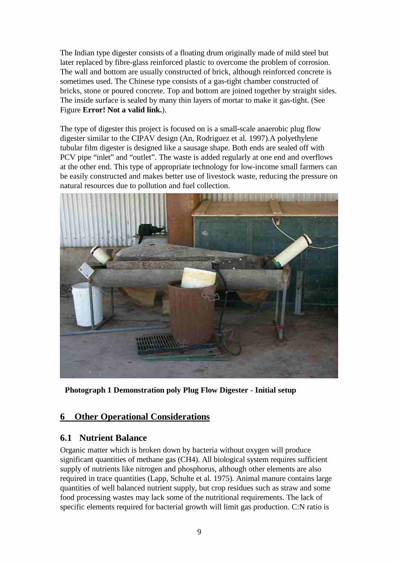
The type of digester this project is focused on is a small-scale anaerobic plug flowdigester similar to the CIPAV design (An, Rodriguez et al. 1997).A polyethylenetubular film digester is designed like a sausage shape. Both ends are sealed off withPCV pipe “inlet” and “outlet”. The waste is added regularly at one end and overflowsat the other end. This type of appropriate technology for low-income small farmers canbe easily constructed and makes better use of livestock waste, reducing the pressure onnatural resources due to pollution and fuel collection.
6 Other Operational Considerations
6.1 Nutrient BalanceOrganic matter which is broken down by bacteria without oxygen will producesignificant quantities of methane gas (CH4). All biological system requires sufficientsupply of nutrients like nitrogen and phosphorus, although other elements are alsorequired in trace quantities (Lapp, Schulte et al. 1975). Animal manure contains largequantities of well balanced nutrient supply, but crop residues such as straw and somefood processing wastes may lack some of the nutritional requirements. The lack ofspecific elements required for bacterial growth will limit gas production. C:N ratio is
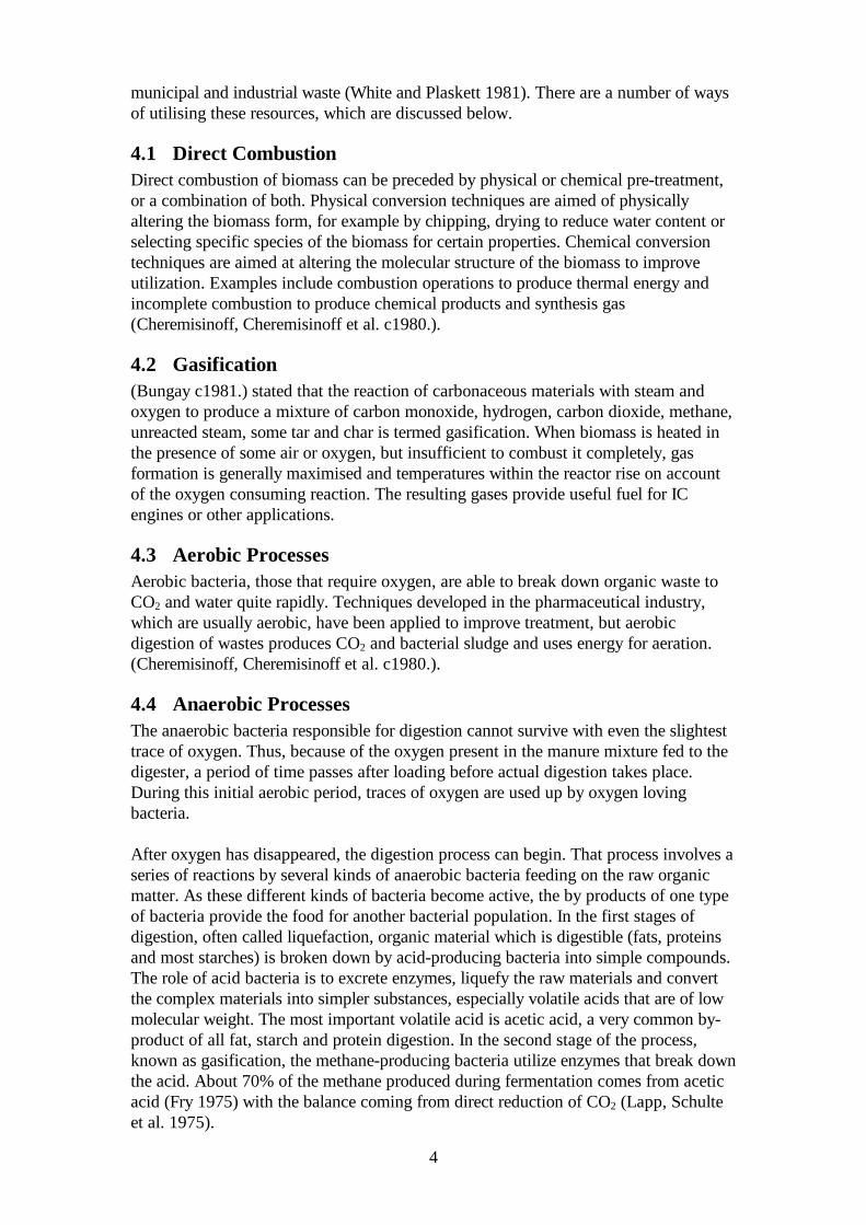
Photograph 1 Demonstration poly Plug Flow Digester - Initial setup
10
one parameter considered to be significant and should be in the range 15-19 (Lapp,Schulte et al. 1975).
6.2 SeedingSeeding generally is recommended as a start-up practice. Seeding consists of theaddition of actively digesting material to a new digester to ensure that a culture ofmethane producing bacteria is present for start-up. The time to start-up, as stated by(Pharaoh 1976), is normally one to four weeks.
6.3 Mixing of Digester ContentSome method of slow stirring of the digester contents is necessary for efficient andrapid digestion. It is possible for the momentum of the daily load to give a stirringaction. If the inlet pipe is set so that the force of the ingoing load makes the contentsswirl, then some stirring is achieved. Self-mixing by gas generation may provideenough agitation in some situations. Where the daily load is pumped in, an even betterstirring effect can be achieved by recirculation. When the digester is large and efficientdigestion is required, a paddle system or gas recirculation is used so that stirring isgentle, constant and reliable.
6.4 Scum FormationAs the gas rises through the slurry it carries some of the lighter particles, which cometo the top and form a scum. This scum always contains a certain amount of gas andtherefore gas can pass through. Because it contains gas the scum is lighter and stays ontop, gradually building up in thickness until it has to be removed, unless agitation isadequate.
One method of removal is to scoop it out at intervals through a trap door at the top ofthe digester. The time between intervals would depend on the loading rate. If paddlesare used for agitation they might also be used to minimise scum.
Any material that floats, such as straw, hay or grass, is undesirable in a digester.Therefore, when the slurry is mixed, remove anything that floats. Floating material canalso cause pump troubles unless it is chopped up finely before going into the digester.
6.5 Sludge RemovalSome solids do not digest and accumulate at the bottom, so the design of the digestershould allow for their removal. A sludge pump may be used in larger installations.Access for removal of sludge in smaller installations may be gained by way of a trapdoor in the lid, which must be gas tight when not in use.
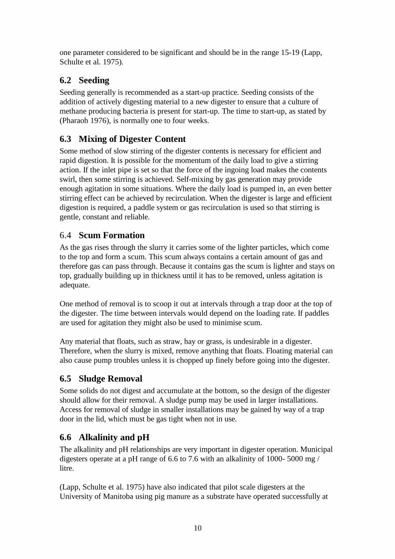
6.6 Alkalinity and pHThe alkalinity and pH relationships are very important in digester operation. Municipaldigesters operate at a pH range of 6.6 to 7.6 with an alkalinity of 1000- 5000 mg /litre.
(Lapp, Schulte et al. 1975) have also indicated that pilot scale digesters at theUniversity of Manitoba using pig manure as a substrate have operated successfully at
11
levels up to pH 8.5 and alkalinity of 14000 mg/litter. If the digester is operatingproperly it will maintain itself at a suitable pH (Fry 1975).
7 Use of BiogasBiogas, a mixture of methane and carbon dioxide, can be used in just as many ways astown or natural gas. If it is worthwhile installing a digester, it is equally worthwhilefinding the most efficient use for the gas. Since methane is a greenhouse gas some 23times worse than CO2 any methane generated should be flared off if there is no otheruse. Obviously, as stated by (Meynell 1976), this depends in the first instance on howmuch gas is produced. Methane is fairly high-grade source of energy. It can provideintense localised heat compared to energy from solar panels. The important uses ofhigh-grade energy are for heating, lighting, cooking and fuel for internal combustionengines.
If biogas provides energy for cooking, lighting and fuel, it also replaces wood for fires.Thus leads to conservation of forests, less labour requirement and fertile soil forfarming, creates new businesses and is of course much cleaner for air contamination.
7.1 Removing Impurities from the GasWhen a digester is working well, the contents are alkaline rather than acid, with a pHof 7.5 -8.0. The gas has fewer impurities when this condition is reached, just carbondioxide and a small amount of hydrogen sulphide.
(Pharaoh 1976) stated that it is better to remove the impurities, particularly hydrogensulphide, which can cause corrosion of metals and create a foul smell if allowed toaccumulate. Hydrogen sulphide (H2S) can be removed by several different methods.
Two effective methods suggested by (Pharaoh 1976) are:
• To pass the gas through a solution of copper sulphate (bluestone) and water. H2Scombines with the copper and settles out in a black precipitate.
• To pass gas through a 51mm P.V.C pipe filled with steel wool. The indication of
effectiveness is that the steel wool becomes corroded at the inlet but not at theoutlet.
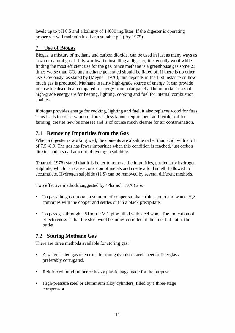
7.2 Storing Methane GasThere are three methods available for storing gas:
• A water sealed gasometer made from galvanised steel sheet or fiberglass,preferably corrugated.
• Reinforced butyl rubber or heavy plastic bags made for the purpose. • High-pressure steel or aluminium alloy cylinders, filled by a three-stage
compressor.
12
(Pharaoh 1976) suggests the steel gasometer because it is sturdy. It consists of twotanks, one upside down and inside the other, which is filled with water. Gas is simplydischarged into the top tank, which rises with the gas pressure. Gas cannot escapebecause the water seals it, providing a safety valve.Methane, known as a permanent gas, does not liquefy at low pressure as L.P. gas does.Heavy steel cylinders or special aluminium alloy cylinders are necessary so the gas canbe compressed to a high pressure of 28 to 35 MPa. This is the only way sufficient gascan be carried to give reasonably long operating periods for mobile use, so use instationary application is simpler.
7.3 Using Methane GasMethane gas can either be burned directly as a source of energy for heating or cookingor it can be compressed and used for fuel for internal combustion engines.
7.3.1 Direct CombustionMethane burns well in burners that were made for coal and LP gas, but those fornatural gas need modification. Basically a large jet opening and a slow flame speed arerequired. Pressure of between 1 to 1.5 kPa is required for a slow flame speed (Pharaoh1976).
7.3.2 Fuel for Internal Combustion EnginesBoth petrol and diesel engines will run on methane gas. Gas carburetors are availablefor most engines and no other modification is need for a spark ignition (petrol) engine.(Lapp, Schulte et al. 1975) have indicated that it is also possible to fit a gas carburetoron the intake and still use the diesel injectors to fire the mixture, using10% diesel fuel.
The obvious use for methane as a fuel on a farm is in engines producing electricity andpumping. It is a simple matter to have a gasometer alongside the plant to fuel theengines.
8 Pilot Project Work
8.1 IntroductionAnimal wastes contain large quantities of organic matter, which if processed byanaerobic digestion will produce significant quantities of methane gas, which can becaptured and used as a fuel. The objective of this pilot project was to build a smallscale “Plug Flow” anaerobic digester and operate with pig wastes at RoseworthyCampus, Adelaide University.
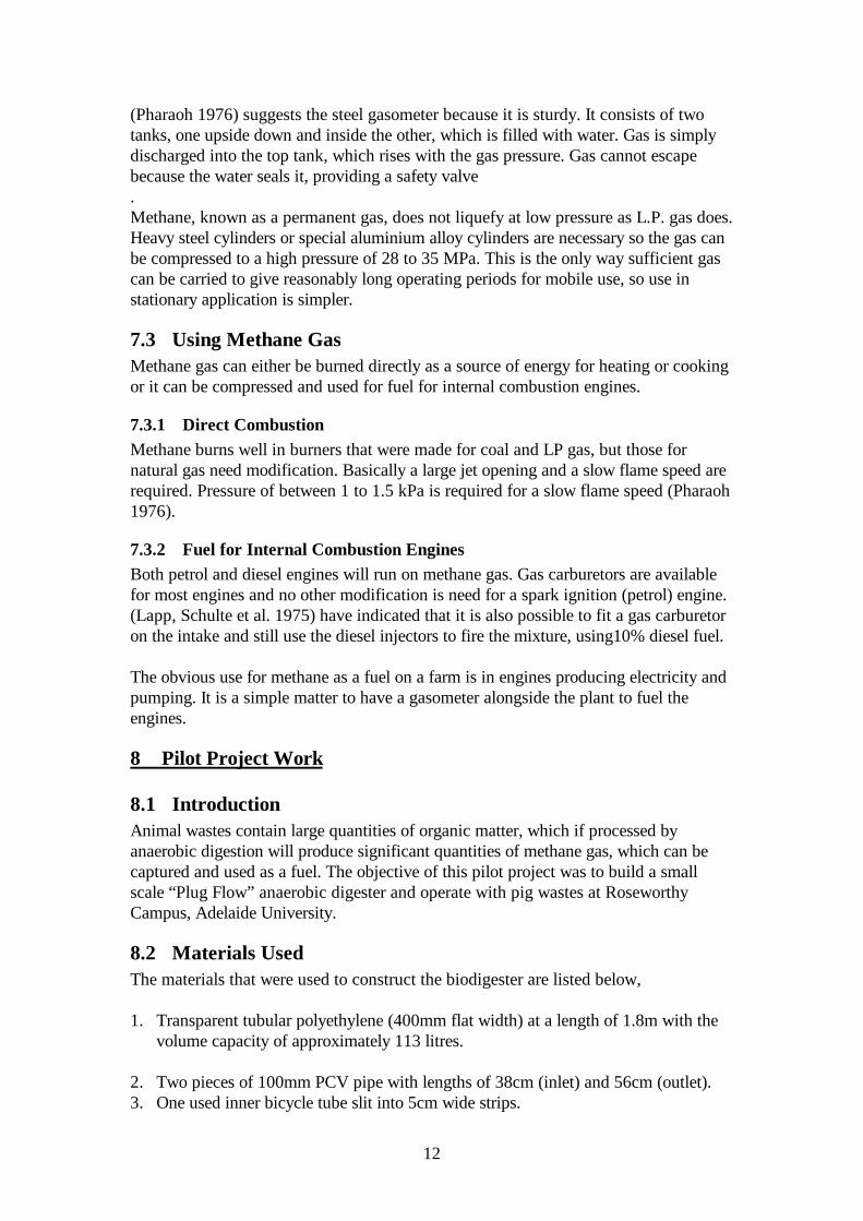
8.2 Materials UsedThe materials that were used to construct the biodigester are listed below,
1. Transparent tubular polyethylene (400mm flat width) at a length of 1.8m with thevolume capacity of approximately 113 litres.
2. Two pieces of 100mm PCV pipe with lengths of 38cm (inlet) and 56cm (outlet).3. One used inner bicycle tube slit into 5cm wide strips.
13
4. Two 40 litres plastic bins, one 20 litre plastic bucket and a galvanized iron
container. 5. Five meters of 12mm plastic irrigation pipe, four elbows, one cross joint, one
500ml bottle and 20 cm of plastic hose 8mm in diameter. 6. One burn back and back flow arrester. 7. One Bunsen burner, a gas stove burner, a home made burner and a burner
enclosure. 8. A shovel, 1.5 litre plastic bottle, one billy can, two boxes of matches, a ruler and a
tape measure. 9. A gas testing kit, 5 x 20 litre plastic buckets, pairs of rubber gloves, overalls and
pairs of gum boots.
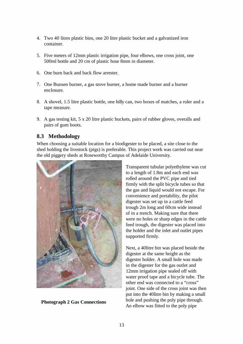
8.3 MethodologyWhen choosing a suitable location for a biodigester to be placed, a site close to theshed holding the livestock (pigs) is preferable. This project work was carried out nearthe old piggery sheds at Roseworthy Campus of Adelaide University.
Transparent tubular polyethylene was cutto a length of 1.8m and each end wasrolled around the PVC pipe and tiedfirmly with the split bicycle tubes so thatthe gas and liquid would not escape. Forconvenience and portability, the pilotdigester was set up in a cattle feedtrough 2m long and 60cm wide insteadof in a trench. Making sure that therewere no holes or sharp edges in the cattlefeed trough, the digester was placed intothe holder and the inlet and outlet pipessupported firmly.
Next, a 40litre bin was placed beside thedigester at the same height as thedigester holder. A small hole was madein the digester for the gas outlet and12mm irrigation pipe sealed off withwater proof tape and a bicycle tube. Theother end was connected to a “cross”joint. One side of the cross joint was thenput into the 40litre bin by making a smallhole and pushing the poly pipe through.An elbow was fitted to the poly pipe
Photograph 2 Gas Connections
14
inside the 40litre bin and a poly pipe riser made to the top of the 40litre bin. A 20litrebucket was placed up side down into the 40litre bin (over the riser) as a gas collectorand the 40litre bin was filled up with water. The gas collection pipe was fitted to theother side of the cross and the bottom of the cross was extended with poly pipe intothe 500ml container, which was filled with water as a water trap/safety valve, as shownin Photograph 2 .
Making sure all connections from the digester to the gas collector were well sealed offthe end of the gas outlet tube was placed into the water bottle. The first feeding witheffluent from the sump was poured into the digester via the inlet end.
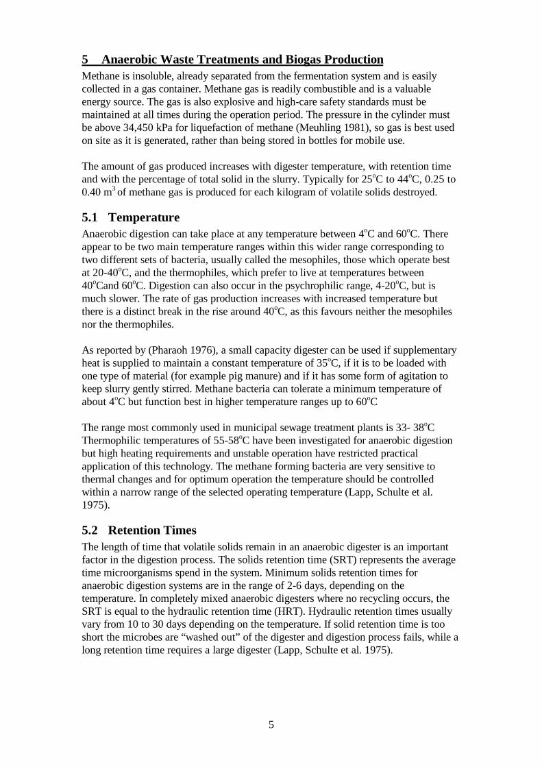
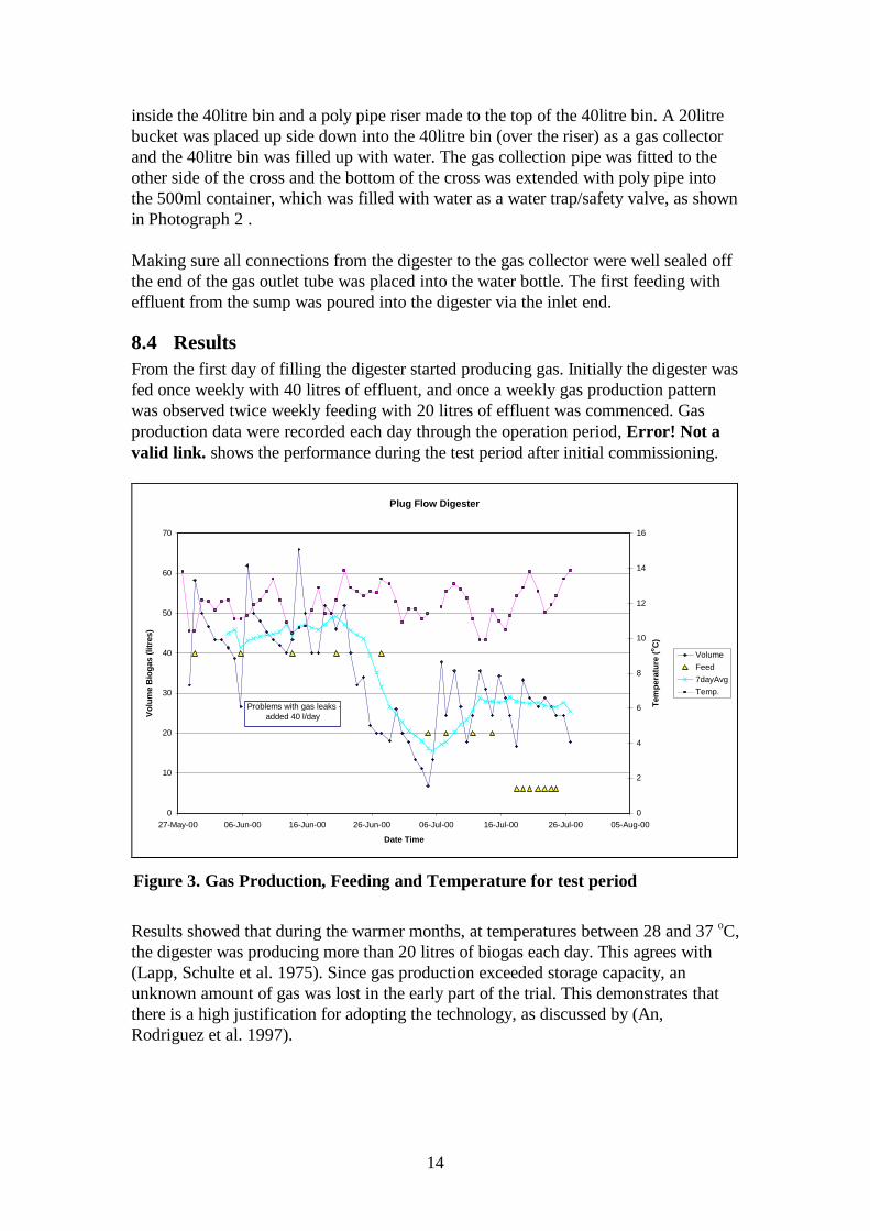
8.4 ResultsFrom the first day of filling the digester started producing gas. Initially the digester wasfed once weekly with 40 litres of effluent, and once a weekly gas production patternwas observed twice weekly feeding with 20 litres of effluent was commenced. Gasproduction data were recorded each day through the operation period, Error! Not avalid link. shows the performance during the test period after initial commissioning.
Plug Flow Digester
0
10
20
30
40
50
60
70
27-May-00 06-Jun-00 16-Jun-00 26-Jun-00 06-Jul-00 16-Jul-00 26-Jul-00 05-Aug-00
Date Time
Vol
ume
Bio
gas
(litr
es)
0
2
4
6
8
10
12
14
16
Tem
pera
ture
(o C)
VolumeFeed7dayAvgTemp.
Problems with gas leaks - added 40 l/day
Results showed that during the warmer months, at temperatures between 28 and 37 oC,the digester was producing more than 20 litres of biogas each day. This agrees with(Lapp, Schulte et al. 1975). Since gas production exceeded storage capacity, anunknown amount of gas was lost in the early part of the trial. This demonstrates thatthere is a high justification for adopting the technology, as discussed by (An,Rodriguez et al. 1997).
Figure 3. Gas Production, Feeding and Temperature for test period
15
8.5 DiscussionWith this small scale “Plug Flow” digester, the first seeding was collected from thepiggery effluent collector tank to start up the digester. The digester did not take longto start up because the methane-producing bacteria were already present in thedigesting material. After initial filling, the digester was not fed until gas production hadbegan to drop off. After a couple of feeds from the tank it was decided to scrape upmanure from the pen floor and dilute this with water, to get a more constant result andto use techniques like in Papua New Guinea.
Loading rate is another important factor to consider. It will relate to the slurry thatstays in the digester. For this digester the slurry was digested slowly so it took a longertime. The feeding intervals were at 40 litres per week for 3 months, with 5kg ofmanure made to 20 litres of effluent with tap water. After mixing, the effluent waspoured through a 20 mm opening mesh to strain out any lumps before it was pouredinto the digester at the inlet end. This was changed to 20 litres fed twice weekly andfinally to 6 litres of effluent fed daily for a week.
Monitoring and collecting data from the digester is an important part of the operation.Gas production for this project was measured firstly from the gas drum that was placedinto the water tank. A daily height measurement was taken by measuring the rising gasdrum with a ruler. Another method of measuring was to connect the gas outlet tube tothe bunsen burner and burn the gas off, noting the time taken to return the drum tostarting level.
8.6 Check ListIt is essential to draw up a checklist for day to day monitoring and observation for thedigester. This will enable quick detection and fixing of faults. A suitable checklist for asimple plug flow poly digester can be:
• Check water in the backflow preventer. If the water is low then it can be filled up. • Refill water in the second water trap and the water tanks when the water levels are
low. • Check any leakage from the joint connections if gas production appears to be lower
than normal and digester is inflated. • If digester is not under pressure, check the digester for any holes for the escape of
gas.
8.7 Problems EncounteredAlthough the project work was successful, some of the main problems encounteredduring the operation period were:
• The inlet hole that was wrapped and tied to the PVC pipe got twisted and blockedup and effluent could not go through to the digester smoothly. This was overcomeby inserting a smaller diameter pipe to hold the polyethylene open.
16
• Gas escaped through the digester because of the holes caused by cats. This was
fixed by placing duct tape or plastic packing tape over the problem areas. A sheetof galvanised iron was also used to keep the cats off the warm digester at night.
• Gas collector bags had holes that were caused by small sharp objects or careless
handling and the gas escaped as well. A second, larger, gas holder was added byusing a 40 litre bin in a galvanised container.
9 ConclusionBiodigesters can play a vital role in integrated farming systems by contributing to thecontrol of pollution and at the same time add value to livestock manure.
The impact of the low-cost biodigester is variable. Adoption of the technique andsuccessful results depend on aspects such as location (availability of traditional fuel)and the way in which the technology is introduced, adapted and improved according tolocal conditions.
Transparent polyethylene tubular film digesters, like the one this project used, providea cheap and simple way to produce gas. They can appeal to small farmers because oflow installation cost and also because of environmental advantages. The technologycan be applied in rural or urban areas.
The technology has been developed sufficiently to justify large- scale implementation incountries where socio-economic conditions facilitate its rapid adoption, such as hasoccurred in Vietnam and Cambodia. Nevertheless, research should continue in closeconsultation with users so that the technology continues to improve.
10 AcknowledgmentThe author wishes to thank his supervisor, Mr. Paul Harris, from the Department ofAgronomy and Farming Systems, Roseworthy Campus, Adelaide University andacknowledges the financial support and assistance to implement the project.
17
11 References
Ajuyah, A. O. (1998). The Potential of Integrated Bio-Systems in Small Pacific IslandCountries. Internet Conference on Integrated Biosystems, WWW.
An, B. X., L. Rodriguez, et al. (1997). “Installation and performance of low-costpolyethylene tube digesters on small-scale farms.” World Animal Review. 88( (1)): 38-47.
Bungay, H. R. H. R., 1928- (c1981.). Energy, the biomass options. New York :,Wiley,.
Chen, Y. R. and A. G. Hashimoto (1978). Kinetics of Methane Formation.Biotechnology and Bioengineering Symposium No 8, Gatlinburg, Tennessee, JohnWiley & Sons Inc.
Cheremisinoff, N. P., P. N. j. a. Cheremisinoff, et al. (c1980.). Biomass : applications,technology, and production. New York :, M. Dekker,.
Fry, L. J. (1975). Practical Building of Power Plants for Rural Energy Independence.Andover, Hampshire, Chapel River Press.
Harris, P. L. (1998). Beginners Tour of Biogas.http://www.roseworthy.adelaide.edu.au/~pharris/biogas/beginners.html.
Lapp, H. M., D. D. Schulte, et al. (1975). “Methane Production from Animal Wastes.1. Fundamental Considerations.” Canadian Agricultural Engineering 17(2): 97-102.
Lewis, C. (1983). Biological fuels. London :, Arnold,.
Meuhling, A. J. (1981). Producing Methane Gas from Pig Effluent. Adelaide,Department of Agriculture, South Australia.
Meynell, P. J. (1976). Methane: Planning a Digester. Old Working, Surrey, TheGresham Press.
Pharaoh, D. M. (1976). Manure digesters and methane gas production. Sydney :, NewSouth Wales Dept. of Agriculture, Agricultural Engineering Section,.
White, L. P. L. P., 1936- and L. G. Plaskett (1981). Biomass as fuel. London ; NewYork :, Academic Press,.
18
12 APPENDIX I - GlossaryFrom Whessoe Varec Product Catalogue 1996 Anaerobic Bacteria - Microorganisms that live and reproduce in an environment containing no"free" or dissolved oxygen. Used for anaerobic digestion.Anaerobic DigestionDecomposition process using microorganisms to stabilize organic solids or biosolids. Thisprocess generates biogas.Biochemical Oxygen Demand (BOD)Rate of oxygen utilized by wastewater under controlled conditions of temperature and time.BiogasBy-product of anaerobic digestion. A saturated gas consisting of approximately 55 to 70%methane, 25 to 35% carbon dioxide, and trace amounts of nitrogen and hydrogen sulfide.BiosolidsOld term used was "Sludge". It is the waste material from animal or vegetable sources. Wastecontains mainly carbon and hydrogen.Check ValveA device to prevent the reversal of gas flow.Chemical Oxygen Demand (COD)Amount of oxygen from potassium dichromate required to chemically oxidize wastewater.CogenerationGas-driven turbines produce heat in the process of generating electricity. The heat is fed togenerators that produce steam. This steam is used to generate more electricity.Complete CombustionProducts arising from the combustible elements carbon, hydrogen, and sulfur. May includenitrogen brought in with the air and oxygen in excess of air. The products of completecombustion are principally C02, H20, S02, N2, and 02. Usually, the presence of CO indicatesincomplete combustion.Condensate and Sediment TrapDevice used to remove liquid and solids entrapped in the biogas. Dead Weight Loaded-ValvePressure or vacuum relief setting is achieved by loading properly weighted discs on top ofpallet or disc in a valve.Design PressureMaximum Pressure above which tank or piping may sustain structural damage or fatigue.DiaphragmThin, flexible disc that moves in response to changes in pressure.DigesterTank used to contain biosolids during the anaerobic digestion process.Differential PressureDifference between inlet pressure and outlet pressure of a device.DownstreamIn the direction of the gas flow.Drip TrapDevice used to safely remove accumulated condensate from gas piping without interruptinggas flow.
19
ExothermicChemical reaction that releases energy in the form of heat. May cause an increase intemperature.Explosive RangeA mixture of gas and oxygen capable of combustion.(Note - 5%-15% for Methane)ExtensibleCan be extended. A flame arrester bank frame is referred to as "extensible" because the framecan slide apart providing access to individual bank sheets. Flame ArresterA device that prevents flame propagation.Flame CheckSimilar function as a flame arrester, except it is used in smaller diameter lines with low gasflows.Flame PropagationA flammable mixture from ignition source spreads through the gas pipe train starting at lowflows and increases in speed as it travels through a long pipe run.Flame Trap AssemblyAn assembly consisting of a flame arrester and a thermal shut-off valve. Gas Collection
• A network of wells and trenches that "honeycomb" the landfill.• At an anaerobic digester, the gas piping system taken from the top of the digester.
Gas PurifierA device that removes H2S from biogas.Gas Storage HolderLow-pressure gas holder or high-pressure sphere used to maintain uniform gas systempressure during periods of varying biogas production or consumption.Gas UtilizationBiogas may be burned as fuel by engine generators to produce electrical power for the plant.Heat recovered from the engine coolant and exhaust provides heating for the plant and thedigesters. Biogas-fired boilers may be provided for supplemental heat when necessary. Hydrogen sulfide (H2S)A flammable, highly poisonous gas having an unpleasant odor. Ignition TemperatureMinimum temperature required that initiates or causes self-sustained combustion. Landfill Gas (LFG)By-product of the natural decomposition process occurring at a landfill. Comprised of 50 to60% methane, 40 to 50% carbon dioxide, and less than 1- percent hydrogen, oxygen, nitrogen,and other trace gases.LEL (Lower Explosive Limit)Minimum concentration of gas vapor in air or oxygen where propagation of flame does notoccur on contact with a source of ignition. Municipal Landfill
20
Piece of land where household waste and/or treated domestic sewage biosolids are disposed. Net Free AreaTotal surface area of passageways permitting flow through a flame arrester bank. Operating PressurePressure of the gas system or digester during normal operation.OverpressureThe amount of pressure above the desired pressure setting necessary to relieve full flowcapacity.OxidationThe addition of oxygen, removal of hydrogen, or the removal of electrons from an element orcompound. PalletA disc or round plate that fits over a valve seat port opening.pHAn expression of the intensity of the alkaline or acidic strength of water. Values range from 0-14, where 0 is most acid, 14 most alkaline, and 7 neutral.Pressure Drop (Head Loss)Difference between inlet pressure and outlet pressure of a device. Also, loss of pressurethrough a length of pipe.Pressure Relief ValveA valve which opens upon rising inlet pressure.Pressure and Vacuum Relief ValveA device for the relief of excess pressure or vacuum on the digester or gas holder cover. RegulatorA device which controls either valve upstream or downstream pressure. Sampling HatchSmall access cover installed on digester or gas holder roof, which allows sampling of contents.Sanitary LandfillA landfill permitted to accept household and commercial waste (solid and liquid non-hazardouswaste).Saturated GasGas containing maximum water vapor for a given pressure and temperature. If more watervapor is added to the gas stream, or the pressure increases or temperature drops,condensation will occur.Seat InsertA soft material which improves the seal between the valve cover and seat, or pallet and seatring.Seat RingThe part of a valve where the pallet rests and allows for gas-tight sealing.SedimentSolid particles entrapped in the biogas stream.SludgeBiosolids separated from liquids during processing. May contain up to 97% water by volume.Specific Gravity
21
The ratio of the density of a particular gas to that of air.Spring LoadedValve relief setting achieved by properly compressing a spring against the top of the pallet.Stoichiometric PilotA pilot having a perfect theoretical fuel to air ratio. Thermal Shut-off ValveA valve that immediately shuts-off gas flow when the fusible element is subjected to excessiveheat. UpstreamIn the opposite direction of the gas flow. Waste Gas (see Biogas)Waste Gas BurnerA device that safely combusts biogas.
22
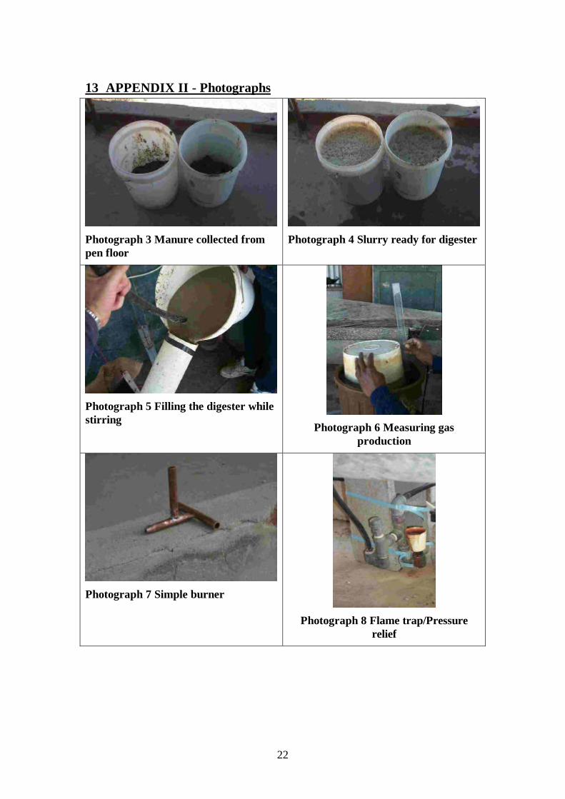
13 APPENDIX II - Photographs
Photograph 3 Manure collected frompen floor
Photograph 4 Slurry ready for digester
Photograph 5 Filling the digester whilestirring
Photograph 6 Measuring gasproduction
Photograph 7 Simple burner
Photograph 8 Flame trap/Pressurerelief
23
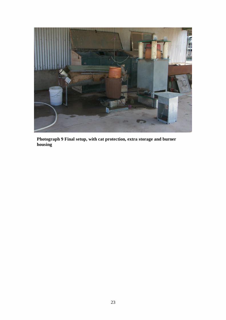
Photograph 9 Final setup, with cat protection, extra storage and burnerhousing