Embed Size (px)
Citation preview
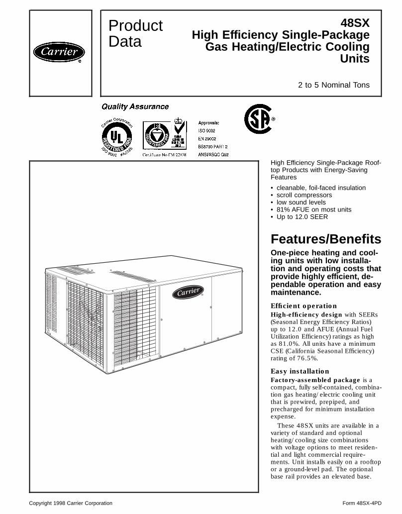
High Efficiency Single-Package Roof-top Products with Energy-SavingFeatures
• cleanable, foil-faced insulation• scroll compressors• low sound levels• 81% AFUE on most units• Up to 12.0 SEER
Features/BenefitsOne-piece heating and cool-ing units with low installa-tion and operating costs thatprovide highly efficient, de-pendable operation and easymaintenance.
Efficient operationHigh-efficiency design with SEERs(Seasonal Energy Efficiency Ratios)up to 12.0 and AFUE (Annual FuelUtilization Efficiency) ratings as highas 81.0%. All units have a minimumCSE (California Seasonal Efficiency)rating of 76.5%.
Easy installationFactory-assembled package is acompact, fully self-contained, combina-tion gas heating/electric cooling unitthat is prewired, prepiped, andprecharged for minimum installationexpense.These 48SX units are available in a
variety of standard and optionalheating/cooling size combinationswith voltage options to meet residen-tial and light commercial require-ments. Unit installs easily on a rooftopor a ground-level pad. The optionalbase rail provides an elevated base.
ProductData
48SXHigh Efficiency Single-PackageGas Heating/Electric Cooling
Units
2 to 5 Nominal Tons
Copyright 1998 Carrier Corporation Form 48SX-4PD

Convertible duct configurationUnit is designed for easy use ineither downflow or horizontalapplications.Downflow option unit is convertedfor downflow at factory to allowvertical ductwork connections. Unit isequipped with base rail. Ideal forlight commercial applications.
Carrier means Top Qualityand ReliabilityEach component is designed andtested for many years of operationunder the harshest conditions. Every48SX unit is thoroughly run-testedat the factory in each operating mode,and is evacuated prior to final charg-ing. Every coil is leak-tested withhelium particles. Factory run-testingallows accurate, undisputed tests andmeasurements which are second tonone in the industry.Energy-saving, direct-spark igni-tion saves gas by operating onlywhen the room thermostat calls forheating. Standard units are furnishedwith natural gas controls.48SX units meet California AirQuality Management NOx require-ment of 40 nanograms/jouleor less when NOx kit no.CRLOWNOX001A00 is installed.Scroll compressors are designedfor high efficiency. Each scrollcompressor is hermetically sealedagainst contamination to help pro-mote longer life and dependable opera-tion. Vibration isolation providesquiet operation. All compressors haveinternal high-pressure and overcur-rent protection. Scroll compressorsare standard on all units.Direct-drive multispeed, PSC(permanent split capacitor)blower motor is standard for unitsizes 024-048. Variable-speed inte-grated control motor is standard forunit size 048 and 060.Direct-drive, PSC condenser-fanmotors are designed to help reduceenergy consumption and providefor cooling operation down to 40 Foutdoor temperature.Refrigerant system is designed toprovide dependability. Liquid refriger-ant strainers are used to promoteclean, unrestricted operation. Eachunit leaves the factory with a full refrig-erant charge. Refrigerant serviceconnections make checking operatingpressures easier.Evaporator and condenser coilsare computer-designed for optimumheat transfer and cooling efficiency.
Coils are fabricated of copper tubeand aluminum fins and are locatedinside the unit to protect against dam-age and ensure long life and reliableoperation. Condenser coils areprotected by a grille. Copper fin coilsare also available from the factoryby special order. These coils are rec-ommended in applications wherealuminum fins are likely to be dam-aged due to corrosion and are idealfor seacoast applications.Low sound ratings ensure a quietindoor and outdoor environment withsound ratings as low as 8.0 bels.Easy to service cabinets provideaccessibility to serviceable componentsduring maintenance and installation.Rounded corners are an importantsafety feature. A high quality fin-ish ensures an attractive appearance.Optional base rails provide holesfor rigging and forklifts, as well as anelevated mounting frame that givesstructural support to horizontal instal-lations. Ideal for light commercialapplications.Low and high voltage electricalentries allow low and high voltage tobe brought in through either thefront duct panel or rear flue panel.Monoport, inshot burners produceprecise air-to-gas mixture which pro-vides for clean and efficient com-bustion. The large monoport on theinshot (or injection type) burnersseldom, if ever, needs cleaning. Allgas furnace components are accessiblein one compartment.Tubular heat exchangers are con-structed of aluminized steel for cor-rosion resistance and optimum heattransfer for improved efficiency.The tubular design permits hot gasesto make multiple passes across thepath of the supply air. In addition,dimples, located on the heat exchangerwalls, force the hot gases to stay inclose contact with the walls, improv-ing heat transfer.The induced draft combustionsystem eliminates the unsightly ap-pearance of flue stacks, and diminishesthe effects of wind on heating opera-tion. The induced draft also pre-vents contaminants from entering thesupply air if a leak in the heat ex-changer occurs.The direct spark ignition systemsaves operating expense whencompared to old-style pilot ignitionsystems. No crossover tube is required,therefore no sooting or pilot foulingproblems can occur.
Integrated gas unit controller(IGC) contains all the ignitioncomponents and is easily accessiblefor service. The IGC provides built-indiagnostic capabilities. A light-emittingdiode (LED) simplifies troubleshoot-ing by providing visual fault notifi-cation and system status information.The IGC board provides exclusiveanti-cycle protection for gas heatoperation. The IGC also containsburner control logic for dependableheating operation. The 48SX unitsmaximize heating efficiency throughthe IGC’s control of evaporator fanON/OFF delays. The IGC helps make48SX units reliable for many years.The standard control systemis readily adaptable to all conventionaland programmable thermostats. Inaddition, units are suitable for integra-tion into monitor control systems ifrequired.Weatherized cabinets are con-structed of heavy-duty, phosphated,zinc-coated, prepainted steel capableof withstanding the 500 hour saltspray test (method Standard No. 141,Method 6061). Interior surfaces ofthe evaporator/heat exchanger com-partment are insulated with foil-facedcleanable insulation to help keepthe conditioned air from being affectedby the outdoor ambient temperatureand to provide improved air qual-ity. Use of a sloped condensate drainpan conforms to American Societyof Heating, Refrigeration and AirConditioning Engineers (ASHRAE)Standard 62P.) Sloped condensatepan permits an external drain.Standardized components for thecomplete 48SX line of products arefound in all safety devices, condenser-fan motors, evaporator-fan motors,and control boards, while the gas sec-tions use common inducer motors,limit switches, and roll-out switches.This allows for greater inventory con-trol, familiarity of parts, and fewerstocked parts.Color-coded wires permit easy trac-ing and diagnostics.
2

Table of contents
PageFeatures/Benefits . . . . . . . . . . . . . . . . . . . . . . . . . . . . . . . . . . . . . . . . . . . . . . . . . . 1,2Model Number Nomenclature . . . . . . . . . . . . . . . . . . . . . . . . . . . . . . . . . . . . . . . . 3ARI Capacities . . . . . . . . . . . . . . . . . . . . . . . . . . . . . . . . . . . . . . . . . . . . . . . . . . . . 4,5Physical Data . . . . . . . . . . . . . . . . . . . . . . . . . . . . . . . . . . . . . . . . . . . . . . . . . . . . . . 6Options and Accessories . . . . . . . . . . . . . . . . . . . . . . . . . . . . . . . . . . . . . . . . . . . . . 7Base Unit Dimensions . . . . . . . . . . . . . . . . . . . . . . . . . . . . . . . . . . . . . . . . . . . . . 8-11Accessory Dimensions . . . . . . . . . . . . . . . . . . . . . . . . . . . . . . . . . . . . . . . . . . . 12,13Selection Procedure . . . . . . . . . . . . . . . . . . . . . . . . . . . . . . . . . . . . . . . . . . . . . . . . 13Performance Data . . . . . . . . . . . . . . . . . . . . . . . . . . . . . . . . . . . . . . . . . . . . . . . 14-16Typical Piping and Wiring . . . . . . . . . . . . . . . . . . . . . . . . . . . . . . . . . . . . . . . . 16,17Application Data . . . . . . . . . . . . . . . . . . . . . . . . . . . . . . . . . . . . . . . . . . . . . . . . . . 17Electrical Data . . . . . . . . . . . . . . . . . . . . . . . . . . . . . . . . . . . . . . . . . . . . . . . . . . . . 18Controls . . . . . . . . . . . . . . . . . . . . . . . . . . . . . . . . . . . . . . . . . . . . . . . . . . . . . . . . . . 19Typical Wiring Schematic . . . . . . . . . . . . . . . . . . . . . . . . . . . . . . . . . . . . . . . . . 20,21Guide Specifications . . . . . . . . . . . . . . . . . . . . . . . . . . . . . . . . . . . . . . . . . . . . . 22,23
Model number nomenclature
3

ARI* capacities
COOLING CAPACITIES AND EFFICIENCIES
UNIT 48SX NOMINALTONS
STANDARDCFM
NET COOLING†CAPACITIES SEER† SOUND RATINGS**
(Bels)024040024060 2 785 23,400 12.0 8.0
030040030060030080
21⁄2 990 29,800 12.0 8.0
036060036080036100036120
3 1225 36,800 12.0 8.0
042060042080042100042120
31⁄2 1400 41,500 12.0 8.0
048080048100048120048140
4 1585 47,500 12.0†† 8.2
060080060100060120060140
5 1995 60,000 11.0 8.2
LEGENDBels — Sound Levels (1 bel = 10 decibels)db — Dry BulbSEER — Seasonal Energy Efficiency Ratiowb — Wet Bulb
*Air-Conditioning & Refrigeration Institute.†Rated in accordance with U.S. Government DOE (Department ofEnergy) test procedures and/or ARI Standard 210/240.
**Rated in accordance with ARI Standard 270.††The SEER for unit size 048, 460 v is 11.3.
NOTES:1. Cooling capacity ratings are net values, reflecting the effects of cir-
culating fan heat. Ratings are based on:Cooling Standard: 80 F db, 67 F wb evaporator entering-air tem-perature and 95 F db condenser entering-air temperature.
2. Before purchasing this appliance, read important energy cost and ef-ficiency information available from your retailer.
HEATING CAPACITIES AND EFFICIENCIES
UNIT 48SX HEATING INPUT(Btuh)
OUTPUT CAPACITY(Btuh)
TEMPERATURERISE RANGE (F) AFUE (%) CSE (%)
024040030040 40,000 32,800 20-50 81 76.5
024060030060036060042060
56,000 45,400 25-55 81 77.5
030080036080042080048080060080
80,000 64,800 40-70 81 77.5
036100042100048100060100
95,000 77,000 50-80 81 78.0
036120042120048120060120
120,000 97,200 60-90 80 77.5
048140060140 136,000 110,160 50-80 80 77.9
LEGENDAFUE — Annual Fuel Utilization EfficiencyCSE — California Seasonal EfficiencyNOTE: Before purchasing this appliance, read important energy costand efficiency information available from your retailer.
4

OUTDOOR SOUND: ONE-THIRD OCTAVE BAND DATA — DECIBELS
FREQUENCY(Hz)
SOUND POWER LEVEL FOR 48SX UNIT024 030 036 042 048 060
63 45.7 48.7 49.1 48.4 56.0 54.3125 60.7 61.9 65.5 61.9 65.6 65.1250 74.8 76.5 71.6 71.3 71.5 71.5500 73.4 69.7 71.6 71.3 71.4 72.71000 74.0 72.1 71.7 72.7 74.2 73.92000 71.8 69.2 70.0 70.3 73.3 73.44000 69.2 64.3 68.7 66.6 69.6 71.78000 60.8 57.2 63.7 59.2 67.1 66.3
5

Physical data
UNIT SIZE 48SX 024040 024060 030040 030060 030080 036060 036080 036100 036120NOMINAL CAPACITY (ton) 2 2 21⁄2 21⁄2 21⁄2 3 3 3 3OPERATING WEIGHT (lb)Without Base Rail 333 345 336 348 348 366 366 378 378With Optional Base Rail 357 369 360 372 372 390 390 402 402
COMPRESSORS ScrollQuantity 1
REFRIGERANT (R-22)Charge (lb) 3.9 3.9 4.5 4.5 4.5 5.4 5.4 5.4 5.4
REFRIGERANT METERING DEVICE Acutrol™ DeviceOrifice ID (in.) .034 .034 .030 .030 .030 .032 .032 .032 .032
CONDENSER COILRows...Fins/in. 2...17 2...17 2...17 2...17 2...17 2...17 2...17 2...17 2...17Face Area (sq ft) 7.0 7.0 7.0 7.0 7.0 7.0 7.0 7.0 7.0
CONDENSER FANNominal Cfm 2200 2200 2200 2200 2200 2200 2200 2200 2200Diameter (in.) 20 20 20 20 20 20 20 20 20Motor Hp (Rpm) 1⁄4 (1100) 1⁄4 (1100) 1⁄4 (1100) 1⁄4 (1100) 1⁄4 (1100) 1⁄4 (1100) 1⁄4 (1100) 1⁄4 (1100) 1⁄4 (1100)
EVAPORATOR COILRows Fins/in. 2...15 2...15 3...15 3...15 3...15 4...15 4...15 4...15 4...15Face Area (sq ft) 3.6 3.6 2.7 2.7 2.7 3.6 3.6 3.6 3.6
EVAPORATOR FAN* Direct DriveNominal Airflow (Cfm) 800 800 1000 1000 1000 1200 1200 1200 1200Size (in.) 10 x 10 10 x 10 10 x 10 10 x 10 10 x 10 10 x 10 10 x 10 10 x 10 10 x 10
FURNACE SECTION†Burner Orifice No. (Qty...drill size)Natural Gas 1...32 2...40 1...32 2...40 2...32 2...40 2...32 2...30 3...32
Burner Orifice No. (Qty...drill size)Propane Gas 1...41 2...47 1...41 2...47 2...42 2...47 2...42 2...40 3...42
RETURN-AIR FILTERS (in.)**Disposable 24 x 24 24 x 24 24 x 24 24 x 24 24 x 24 24 x 24 24 x 24 24 x 24 24 x 24
UNIT SIZE 48SX 042060 042080 042100 042120 048080 048100 048120 048140 060080 060100 060120 060140NOMINAL CAPACITY (ton) 31⁄2 31⁄2 31⁄2 31⁄2 4 4 4 4 5 5 5 5OPERATING WEIGHT (lb)Without Base Rail 391 391 403 403 422 434 434 434 453 465 465 465With Optional Base Rail 415 415 427 427 446 458 458 458 477 489 489 489
COMPRESSORS ScrollQuantity 1
REFRIGERANT (R-22)Charge (lb) 5.7 5.7 5.7 5.7 5.8 5.8 5.8 5.8 7.0 7.0 7.0 7.0
REFRIGERANT METERING Acutrol DeviceDEVICE
Orifice ID (in.) .034 .034 .034 .034 .034 .034 .034 .034 .030 .030 .030 .030CONDENSER COILRows...Fins/in. 2...17 2...17 2...17 2...17 2...17 2...17 2...17 2...17 2...17 2...17 2...17 2...17Face Area (sq ft) 8.7 8.7 8.7 8.7 8.7 8.7 8.7 8.7 8.67 8.67 8.67 8.67
CONDENSER FANNominal Cfm 2400 2400 2400 2400 2400 2400 2400 2400 2400 2400 2400 2400Diameter (in.) 20 20 20 20 20 20 20 20 20 20 20 20Motor Hp (Rpm) 1⁄4 (1100) 1⁄4 (1100) 1⁄4 (1100) 1⁄4 (1100) 1⁄4 (1100) 1⁄4 (1100) 1⁄4 (1100) 1⁄4 (1100) 1⁄3 (1050) 1⁄3 (1050) 1⁄3 (1050) 1⁄3 (1050)
EVAPORATOR COILRows Fins/in. 3...15 3...15 3...15 3...15 4...15 4...15 4...15 4...15 4...15 4...15 4...15 4...15Face Area (sq ft) 4.4 4.4 4.4 4.4 4.4 4.4 4.4 4.4 4.44 4.44 4.44 4.44
EVAPORATOR FAN* Direct DriveNominal Airflow (Cfm) 1400 1400 1400 1400 1600 1600 1600 1600 1995 1995 1995 1995Size (in.) 10 x 10 10 x 10 10 x 10 10 x 10 10 x 10 10 x 10 10 x 10 10 x 10 10 x 10 10 x 10 10 x 10 10 x 10
FURNACE SECTION†Burner Orifice No.(Qty...drill size)Natural Gas
2...40 2...32 2...30 3...32 2...32 2...30 3...32 3...31 2...32 2...30 3...32 3...31
Burner Orifice No.(Qty...drill size)Propane Gas
2...47 2...42 2...40 3...42 2...42 2...40 3...42 3...40 3...42 2...40 3...42 3...40
RETURN-AIR FILTERS (in.)**Disposable 24 x 30 24 x 30 24 x 30 24 x 30 24 x 30 24 x 30 24 x 30 816†† 24 x 30 24 x 30 24 x 30 960††
*Size 048 evaporator fan is equipped with a 460-v or integrated control motor (ICM). Size 060 evaporator fan isequipped with an ICM only. The ICM provides variable speed.
†Based on an altitude of 0 to 2000 feet.**Required filter sizes shown are based on the ARI (Air Conditioning & Refrigeration Institute) rated heating airflowat a velocity of 300 ft/min for throwaway type or 450 ft/min for high-capacity type. For non-standard air filters, airfilter pressure drop must not exceed 0.08 in. wg.
††Sq inch. Filter is mounted external to unit.
6

Options and accessories
Factory-installed optionsUnit with base rail provides holes for rigging and han-dling as well as an elevated mounting frame that gives ad-ditional structural support for horizontal installations. Idealfor light commercial applications.Downflow option is shipped from factory configured fordownflow (vertical) ductwork connection. Unit is equippedwith base rail.
Field-installed accessories
ACCESSORY
Roof Curb8 in.11 in.14 in.
25% Open Manual Outdoor-Air DamperFilter Rack (Downflow)Downshot-to-Sideshot Conversion Kit
Square-to-Round Transition14-in.16-in.18-in.
Lifting Bracket KitElectronic Programmable ThermostatThermostat, Manual ChangeoverThermostat, AutochangeoverHigh Altitude KitLow- and High-Pressure Switch KitLow-Ambient Kit (Motormaster® II Device)Time Guard T II KitNatural-to-Propane Conversion KitLow NO x Kit
High altitude kit consists of burner orifices that com-pensate for gas heat operation at elevations of 2,001 to5,000 feet above sea level.Factory-assembled roof curbs are designed for use ondownflow discharge applications. Heavy gage, galvanized
steel construction provides one-piece support. The curbcomplies with the standards of the NRCA (National Roof-ingContractors Association). A wood nailing strip is providedfor attaching the roofing to the curb.25% open manual outdoor-air damper provides forminimum outdoor air and is manually adjustable.Manual and autochangeover thermostats provide heat-ing and cooling unit control.Electronic programmable thermostat provides 2-stageheating and 2-stage cooling control with remote communi-cation ability.Low-ambient kit (Motormaster II device) allows the useof mechanical cooling down to outdoor ambient tempera-tures as low as 0° F.Solid-state Time Guard II device protects compressorby preventing short cycling on 3-phase units.High- and low-pressure switches provide additionalsafety features and protect the unit from running at unsuit-able pressures.Filter rack features easy installation, serviceability, and highfiltering performance for downflow installations.Lifting bracket kit provides attachment points for riggingstraps. The kit is not required when the unit is equippedwith an optional base rail or downflow application.Downshot-to-sideshot conversion kit converts a dedi-cated downflow (vertical) discharge unit to a sideshot (hori-zontal) discharge unit.Natural-to-propane conversion kit allows for simple con-version from natural gas to liquid propane.Square-to-round transition enables the building’s roundduct system to be attached to the unit’s square ductwork.Low NOx kit provides compliance with low NOx emissionsrequirements for units being installed in California Air Qual-ity Management Districts, which require NOx emissions of40 nanograms/joule or less.
7

Base unit dimensions
48SX024-036 WITHOUT BASE RAIL
REQ’D CLEARANCES FOR SERVICING. in. (mm)
Duct panel . . . . . . . . . . . . . . . . . . . . . . . . . . . . . . . . . . . . . . . . 0Unit top . . . . . . . . . . . . . . . . . . . . . . . . . . . . . . . . . . . . . 36 (914)Side opposite ducts . . . . . . . . . . . . . . . . . . . . . . . . . . . . . . 36 (914)Compressor access . . . . . . . . . . . . . . . . . . . . . . . . . . . . . . 36 (914)(Except for NEC requirements)REQ’D CLEARANCES TO COMBUSTIBLE MAT’L. in. (mm)
Maximum extension of overhangs . . . . . . . . . . . . . . . . . . . . 48 (1219)Unit top . . . . . . . . . . . . . . . . . . . . . . . . . . . . . . . . . . . . . 14 (356)Duct side of unit . . . . . . . . . . . . . . . . . . . . . . . . . . . . . . . . . 2 (51)Side opposite ducts . . . . . . . . . . . . . . . . . . . . . . . . . . . . . . 14 (356)Bottom of unit . . . . . . . . . . . . . . . . . . . . . . . . . . . . . . . . . . . . . . 0Flue panel . . . . . . . . . . . . . . . . . . . . . . . . . . . . . . . . . . . 36 (914)NEC REQ’D CLEARANCES. in. (mm)Between units, control box side . . . . . . . . . . . . . . . . . . . . . . 42 (1067)Unit and ungrounded surfaces, control box side . . . . . . . . . . . . 36 (914)Unit and block or concrete walls and other groundedsurfaces, control box side . . . . . . . . . . . . . . . . . . . . . . . . . 42 (1067)
UNIT ELECTRICALCHARACTERISTICS
UNIT WEIGHT CORNER WEIGHT(lb/kg)
lb kg A B C D48SX024040 208/230-1-60 333 151 104/47 50/23 130/59 49/2248SX024060 208/230-1-60 345 157 107/49 53/24 133/60 52/2448SX030040 208/230-1-60 336 153 97/44 66/30 118/54 55/2548SX030060,080 208/230-1-60 348 158 100/45 69/31 121/55 58/2648SX036060,080 208/230-1-60, 208/230-3-60, 460-3-60 366 166 94/43 84/38 117/53 71/3248SX036100,120 208/230-1-60, 208/230-3-60, 460-3-60 378 172 97/44 87/40 120/55 74/34
UNITCENTER OF GRAVITY (in./mm)
X Y Z48SX024040 26.71/678 20.06/510 12.65/32148SX024060 26.64/677 20.12/511 12.65/32148SX030040 27.06/687 21.05/535 12.65/32148SX030060,080 26.98/685 21.07/535 12.65/32148SX036060,080 27.14/689 21.10/536 12.65/32148SX036100,120 27.06/687 21.12/536 12.65/321
LEGEND
CG — Center of Gravity MAT’L — MaterialCOND — Condenser NEC — National Electrical CodeLV — Low Voltage REQ’D — Required
NOTES:1. Clearancesmust bemaintained to prevent recirculation of air from condenser-
fan discharge.2. Adequate clearance around air openings into combustion chamber must
be provided.
8

48SX024-036 WITH OPTIONAL BASE RAIL
REQ’D CLEARANCES FOR SERVICING. in. (mm)
Duct panel . . . . . . . . . . . . . . . . . . . . . . . . . . . . . . . . . . . . . . . . 0Unit top . . . . . . . . . . . . . . . . . . . . . . . . . . . . . . . . . . . . . 36 (914)Side opposite ducts . . . . . . . . . . . . . . . . . . . . . . . . . . . . . . 36 (914)Compressor access . . . . . . . . . . . . . . . . . . . . . . . . . . . . . . 36 (914)(Except for NEC requirements)
REQ’D CLEARANCES TO COMBUSTIBLE MAT’L. in. (mm)
Maximum extension of overhangs . . . . . . . . . . . . . . . . . . . . 48 (1219)Unit top . . . . . . . . . . . . . . . . . . . . . . . . . . . . . . . . . . . . . 14 (356)Duct side of unit . . . . . . . . . . . . . . . . . . . . . . . . . . . . . . . . . 2 (51)Side opposite ducts . . . . . . . . . . . . . . . . . . . . . . . . . . . . . . 14 (356)Bottom of unit . . . . . . . . . . . . . . . . . . . . . . . . . . . . . . . . . . . . . . 0Flue panel . . . . . . . . . . . . . . . . . . . . . . . . . . . . . . . . . . . 36 (914)
NEC REQ’D CLEARANCES. in. (mm)Between units, control box side . . . . . . . . . . . . . . . . . . . . . . 42 (1067)Unit and ungrounded surfaces, control box side . . . . . . . . . . . . 36 (914)Unit and block or concrete walls and other groundedsurfaces, control box side . . . . . . . . . . . . . . . . . . . . . . . . . 42 (1067)
UNIT ELECTRICALCHARACTERISTICS
UNIT WEIGHT CORNER WEIGHT (lb/kg)lb kg A B C D
48SX024040 208/230-1-60 357 163 110/50 56/25 136/62 55/2548SX024060 208/230-1-60 369 168 113/51 59/27 139/63 58/2648SX030040 208/230-1-60 360 164 103/47 72/33 124/56 61/2848SX030060,080 208/230-1-60 372 169 106/48 75/34 127/58 64/2948SX036060,080 208/230-1-60, 208/230-3-60, 460-3-60 390 177 100/45 90/41 123/56 77/3548SX036100,120 208/230-1-60, 208/230-3-60, 460-3-60 402 183 103/47 93/42 127/57 80/36
UNITCENTER OF GRAVITY (in./mm)
X Y Z48SX024040 26.57/674.9 20.17/512.3 14.96/380.048SX024060 26.51/673.3 20.22/513.6 14.96/380.048SX030040 26.90/683.3 21.09/535.7 14.96/380.048SX030060,080 26.83/681.5 21.11/536.2 14.96/380.048SX036060,080 26.99/685.5 21.14/537.0 14.96/380.048SX036100,120 26.92/683.8 21.14/537.0 14.96/380.0
LEGEND
CG — Center of Gravity MAT’L — MaterialCOND — Condenser NEC — National Electrical CodeLV — Low Voltage REQ’D — Required
NOTES:1. Clearancesmust bemaintained to prevent recirculation of air from condenser-
fan discharge.2. Adequate clearance around air openings into combustion chamber must
be provided.
9

Base unit dimensions (cont)
48SX042-060 WITHOUT BASE RAIL
REQ’D CLEARANCES FOR SERVICING. in. (mm)
Duct panel . . . . . . . . . . . . . . . . . . . . . . . . . . . . . . . . . . . . . . . . 0Unit top . . . . . . . . . . . . . . . . . . . . . . . . . . . . . . . . . . . . . 36 (914)Side opposite ducts . . . . . . . . . . . . . . . . . . . . . . . . . . . . . . 36 (914)Compressor access . . . . . . . . . . . . . . . . . . . . . . . . . . . . . . 36 (914)(Except for NEC requirements)
REQ’D CLEARANCES TO COMBUSTIBLE MAT’L. in. (mm)
Maximum extension of overhangs . . . . . . . . . . . . . . . . . . . . 48 (1219)Unit top . . . . . . . . . . . . . . . . . . . . . . . . . . . . . . . . . . . . . 14 (356)Duct side of unit . . . . . . . . . . . . . . . . . . . . . . . . . . . . . . . . . 2 (51)Side opposite ducts . . . . . . . . . . . . . . . . . . . . . . . . . . . . . . 14 (356)Bottom of unit . . . . . . . . . . . . . . . . . . . . . . . . . . . . . . . . . . . . . . 0Flue panel . . . . . . . . . . . . . . . . . . . . . . . . . . . . . . . . . . . 36 (914)
NEC REQ’D CLEARANCES. in. (mm)Between units, control box side . . . . . . . . . . . . . . . . . . . . . . 42 (1067)Unit and ungrounded surfaces, control box side . . . . . . . . . . . . 36 (914)Unit and block or concrete walls and other groundedsurfaces, control box side . . . . . . . . . . . . . . . . . . . . . . . . . 42 (1067)
UNIT ELECTRICALCHARACTERISTICS
UNIT WEIGHT CORNER WEIGHT (lb/kg)lb kg A B C D
48SX042060,080 208/230-1-60, 208/230-3-60, 460-3-60 391 178 100/45 91/41 120/55 80/3648SX042100,120 208/230-1-60, 208/230-3-60, 460-3-60 403 183 103/47 94/43 123/56 83/3848SX048080 208/230-1-60, 208/230-3-60, 460-3-60 422 192 109/50 85/39 158/72 70/3248SX048100,120,140 208/230-1-60, 208/230-3-60, 460-3-60 434 197 112/51 88/40 161/73 73/3348SX060080 208/230-1-60, 208/230-3-60 453 206 117/53 93/42 167/76 76/3548SX060100,120,140 208/230-1-60, 208/230-3-60 465 211 120/55 96/44 167/76 82/37
UNITCENTER OF GRAVITY (in./mm)
X Y Z48SX042060,080 26.66/677 21.19/538 15.35/39048SX042100,120 26.61/676 21.21/539 15.35/39048SX048080 28.45/723 19.95/507 15.35/39048SX048100,120,140 28.35/720 19.99/508 15.35/39048SX060080 28.36/720 23.27/591 15.35/39048SX060100,120,140 27.95/710 23.23/590 15.35/390
LEGEND
CG — Center of Gravity MAT’L — MaterialCOND — Condenser NEC — National Electrical CodeLV — Low Voltage REQ’D — Required
NOTES:1. Clearancesmust bemaintained to prevent recirculation of air from condenser-
fan discharge.2. Adequate clearance around air openings into combustion chamber must
be provided.
10

48SX042-060 WITH OPTIONAL BASE RAIL
REQ’D CLEARANCES FOR SERVICING. in. (mm)
Duct panel . . . . . . . . . . . . . . . . . . . . . . . . . . . . . . . . . . . . . . . . 0Unit top . . . . . . . . . . . . . . . . . . . . . . . . . . . . . . . . . . . . . 36 (914)Side opposite ducts . . . . . . . . . . . . . . . . . . . . . . . . . . . . . . 36 (914)Compressor access . . . . . . . . . . . . . . . . . . . . . . . . . . . . . . 36 (914)(Except for NEC requirements)
REQ’D CLEARANCES TO COMBUSTIBLE MAT’L. in. (mm)
Maximum extension of overhangs . . . . . . . . . . . . . . . . . . . . 48 (1219)Unit top . . . . . . . . . . . . . . . . . . . . . . . . . . . . . . . . . . . . . 14 (356)Duct side of unit . . . . . . . . . . . . . . . . . . . . . . . . . . . . . . . . . 2 (51)Side opposite ducts . . . . . . . . . . . . . . . . . . . . . . . . . . . . . . 14 (356)Bottom of unit . . . . . . . . . . . . . . . . . . . . . . . . . . . . . . . . . . . . . . 0Flue panel . . . . . . . . . . . . . . . . . . . . . . . . . . . . . . . . . . . 36 (914)
NEC REQ’D CLEARANCES. in. (mm)Between units, control box side . . . . . . . . . . . . . . . . . . . . . . 42 (1067)Unit and ungrounded surfaces, control box side . . . . . . . . . . . . 36 (914)Unit and block or concrete walls and other groundedsurfaces, control box side . . . . . . . . . . . . . . . . . . . . . . . . . 42 (1067)
UNIT ELECTRICALCHARACTERISTICS
UNIT WEIGHT CORNER WEIGHT(lb/kg)
lb kg A B C D48SX042060,080 208/230-1-60, 208/230-3-60, 460-3-60 415 189 106/48 97/44 126/57 86/3948SX042100,120 208/230-1-60, 208/230-3-60, 460-3-60 427 194 109/50 100/45 129/59 89/4048SX048080 208/230-1-60, 208/230-3-60, 460-3-60 446 293 115/52 91/41 164/75 76/3548SX048100,120,140 208/230-1-60, 208/230-3-60, 460-3-60 458 208 118/54 94/43 167/76 79/3648SX060080 208/230-1-60, 208/230-3-60 477 217 123/56 99/45 173/79 82/3748SX060100,120,140 208/230-1-60, 208/230-3-60 489 222 126/57 102/46 173/79 88/40
UNITCENTER OF GRAVITY (in./mm)
X Y Z48SX042060,080 26.55/674.4 21.22/539.0 17.66/448.648SX042100,120 26.50/673.0 21.24/539.6 17.66/448.648SX048080 28.25/717.6 20.04/509.0 17.66/448.648SX048100,120,140 28.16/715.3 20.08/510.0 17.66/448.648SX060080 28.18/715.6 20.19/512.8 17.66/448.648SX060100,120,140 27.79/705.9 20.23/513.8 17.66/448.6
LEGEND
CG — Center of Gravity MAT’L — MaterialCOND — Condenser NEC — National Electrical CodeLV — Low Voltage REQ’D — Required
NOTES:1. Clearancesmust bemaintained to prevent recirculation of air from condenser-
fan discharge.2. Adequate clearance around air openings into combustion chamber must
be provided.
11

Accessory dimensions
ROOF CURB, SIZES 024-060
UNIT PART NUMBER ‘‘A’’
48SXCPRFCURB001A00 89 [203]CPRFCURB002A00 119 [279]CPRFCURB003A00 149 [356]
NOTES:1. Roof curb must be set up for unit being installed.2. Seal strip must be applied as required for unit being
installed.3. Dimensions in [ ] are in millimeters.4. Roof curb is made of 16 gage steel.5. Attach ductwork to curb (flanges of duct rest on curb).6. Service clearance 4 ft on each side.7. Direction of airflow.
8. Insulated panels: 1-in. thick fiberglass 1 lb density.
12
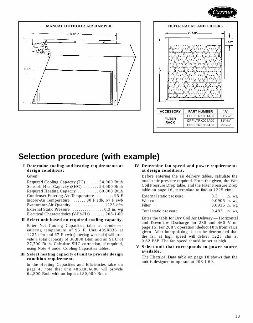
Selection procedure (with example)I Determine cooling and heating requirements atdesign conditions:Given:Required Cooling Capacity (TC) . . . . . . 34,000 BtuhSensible Heat Capacity (SHC) . . . . . . . 24,000 BtuhRequired Heating Capacity . . . . . . . . . . 60,000 BtuhCondenser Entering-Air Temperature . . . . . . . . 95 FIndoor-Air Temperature . . . . . . . 80 F edb, 67 F ewbEvaporator-Air Quantity . . . . . . . . . . . . . . . 1225 cfmExternal Static Pressure . . . . . . . . . . . . . . . 0.3 in. wgElectrical Characteristics (V-Ph-Hz) . . . . . . . 208-1-60
II Select unit based on required cooling capacity.Enter Net Cooling Capacities table at condenserentering temperature of 95 F. Unit 48SX036 at1225 cfm and 67 F ewb (entering wet bulb) will pro-vide a total capacity of 36,800 Btuh and an SHC of27,700 Btuh. Calculate SHC correction, if required,using Note 4 under Cooling Capacities tables.
III Select heating capacity of unit to provide designcondition requirement.In the Heating Capacities and Efficiencies table onpage 4, note that unit 48SX036080 will provide64,800 Btuh with an input of 80,000 Btuh.
IV Determine fan speed and power requirementsat design conditions.Before entering the air delivery tables, calculate thetotal static pressure required. From the given, the WetCoil Pressure Drop table, and the Filter Pressure Droptable on page 16, interpolate to find at 1225 cfm:External static pressure 0.3 in. wgWet coil 0.0905 in. wgFilter 0.0925 in. wgTotal static pressure 0.483 in. wg
Enter the table for Dry Coil Air Delivery — Horizontaland Downflow Discharge for 230 and 460 V onpage 15. For 208 v operation, deduct 10% from valuegiven. After interpolating, it can be determined thatthe fan at high speed will deliver 1225 cfm at0.62 ESP. The fan speed should be set at high.
V Select unit that corresponds to power sourceavailable.The Electrical Data table on page 18 shows that theunit is designed to operate at 208-1-60.
MANUAL OUTDOOR AIR DAMPER FILTER RACKS AND FILTERS
ACCESSORY PART NUMBER ‘‘A’’
FILTERRACK
CPFILTRK001A00 2111⁄169CPFILTRK002A00 3111⁄169CPFILTRK003A00 2511⁄169
13

Performance data
COOLING CAPACITIES
48SX024
Temp (F)Air EntCond
Evap Air — Cfm/BF700/0.13 785/0.14 900/0.15
Evap Air — Ewb (F)72 67 62 72 67 62 72 67 62
85TC 26.2 24.0 21.8 26.5 24.3 22.1 26.8 24.6 22.5SHC 12.2 15.6 18.8 12.5 16.4 19.7 12.9 17.1 20.7kW 2.00 1.99 1.99 2.04 2.03 2.02 2.07 2.07 2.06
95TC 25.5 23.1 20.6 25.8 23.4 21.2 25.8 23.7 21.5SHC 12.0 15.4 18.3 12.4 16.1 19.5 12.5 16.9 20.5kW 2.18 2.17 2.17 2.22 2.21 2.21 2.25 2.25 2.24
105TC 24.5 22.1 19.0 24.9 22.5 19.5 25.0 22.7 20.2SHC 11.7 15.1 17.6 12.2 16.0 18.8 12.5 16.7 19.9kW 2.39 2.38 2.36 2.42 2.42 2.40 2.46 2.45 2.44
115TC 23.3 20.8 18.1 23.6 21.1 18.0 23.8 21.4 18.6SHC 11.4 14.6 17.1 11.9 15.5 17.9 12.2 16.4 18.5kW 2.61 2.60 2.58 2.65 2.64 2.62 2.68 2.68 2.67
48SX030
Temp (F)Air EntCond
Evap Air — Cfm/BF875/0.10 990/0.11 1125/0.12
Evap Air — Ewb (F)72 67 62 72 67 62 72 67 62
85TC 33.3 30.5 27.8 33.6 31.1 28.4 34.2 31.4 28.9SHC 16.4 20.9 25.3 16.9 22.2 26.9 17.6 23.3 28.2kW 2.59 2.56 2.54 2.64 2.61 2.59 2.70 2.66 2.64
95TC 32.0 29.3 25.9 32.4 29.8 27.0 32.9 30.1 27.6SHC 15.9 20.5 24.4 16.5 21.7 26.2 17.3 22.8 27.4kW 2.82 2.79 2.75 2.87 2.84 2.81 2.93 2.89 2.86
105TC 30.8 27.8 24.0 31.1 28.3 24.8 31.3 28.7 26.1SHC 15.5 20.1 23.4 16.1 21.3 24.8 16.7 22.5 26.1kW 3.07 3.04 2.99 3.13 3.10 3.05 3.18 3.14 3.11
115TC 29.2 25.7 22.9 29.6 25.9 23.1 29.9 26.4 24.0SHC 15.1 19.3 22.7 15.8 20.5 23.1 16.5 21.8 24.0kW 3.36 3.31 3.26 3.41 3.37 3.33 3.46 3.42 3.39
48SX036
Temp (F)Air EntCond
Evap Air — Cfm/BF1050/0.04 1225/0.04 1350/0.05
Evap Air — Ewb (F)72 67 62 72 67 62 72 67 62
85TC 41.6 37.9 34.6 42.1 38.5 35.2 42.7 39.1 35.9SHC 20.9 26.7 32.1 21.8 28.4 34.3 22.8 30.1 35.9kW 3.25 3.17 3.09 3.31 3.24 3.17 3.39 3.31 3.24
95TC 39.7 36.2 32.6 40.5 36.8 33.7 40.8 37.3 34.7SHC 20.2 26.0 31.3 21.3 27.7 33.5 22.2 29.5 34.6kW 3.52 3.43 3.36 3.60 3.50 3.44 3.66 3.58 3.52
105TC 37.9 34.4 30.1 38.4 35.0 31.7 38.9 35.3 33.0SHC 19.7 25.3 30.0 20.6 27.1 31.7 21.6 28.8 33.0kW 3.81 3.73 3.63 3.88 3.80 3.72 3.97 3.87 3.82
115TC 35.8 31.5 28.4 36.4 31.8 29.1 36.6 32.5 30.3SHC 18.9 24.2 28.4 19.9 25.9 29.1 20.9 27.8 30.3kW 4.12 4.02 3.92 4.19 4.10 4.03 4.26 4.18 4.12
LEGENDBF — Bypass FactorEdb — Entering Dry-BulbEwb — Entering Wet-BulbLdb — Leaving Dry-BulbLwb — Leaving Wet-BulbkW — Total Unit Power InputSHC — Sensible Heat Capacity, 1000 BtuhTC — Total Cooling Capacity, 1000 Btuh (net)
NOTES:1. Ratings are net; they account for the effects of the evaporator-fan
motor power and heat.2. Direct interpolation is permissible. Do not extrapolate.3. The following formulas may be used:
sensible capacity (Btuh)t = t –ldb edb
1.10 x cfm
48SX042
Temp (F)Air EntCond
Evap Air — Cfm/BF1225/0.07 1400/0.08 1575/0.09
Evap Air — Ewb (F)72 67 62 72 67 62 72 67 62
85TC 49.0 43.0 37.0 49.8 44.2 38.2 50.3 44.8 39.8SHC 24.0 30.1 35.2 25.1 32.3 37.8 26.2 34.2 39.8kW 3.67 3.60 3.52 3.75 3.69 3.61 3.82 3.77 3.71
95TC 47.0 40.8 35.0 47.7 41.5 36.0 48.2 42.3 38.1SHC 23.3 29.3 34.2 24.4 31.2 36.0 25.5 33.2 38.1kW 4.02 3.95 3.86 4.10 4.03 3.95 4.18 4.11 4.05
105TC 44.8 38.7 33.4 45.5 38.8 34.2 45.9 39.6 35.9SHC 22.5 28.4 33.3 23.7 30.2 34.2 24.8 32.2 35.9kW 4.41 4.32 4.24 4.49 4.40 4.33 4.57 4.49 4.43
115TC 42.0 36.8 32.8 42.7 36.2 32.3 43.3 36.6 33.2SHC 21.6 27.7 32.8 22.8 29.2 32.3 24.0 31.0 33.2kW 4.83 4.73 4.65 4.92 4.82 4.75 5.00 4.90 4.84
48SX048
Temp (F)Air EntCond
Evap Air — Cfm/BF1400/0.03 1585/0.04 1800/0.05
Evap Air — Ewb (F)72 67 62 72 67 62 72 67 62
85TC 54.4 49.2 44.4 55.0 50.0 45.1 55.6 50.3 45.8SHC 26.3 33.8 40.9 27.5 36.0 43.9 28.6 38.0 45.8kW 4.46 4.38 4.33 4.57 4.50 4.44 4.68 4.60 4.54
95TC 51.9 46.9 42.1 52.6 47.5 42.9 52.9 47.8 44.0SHC 25.5 33.1 40.0 26.8 35.2 42.8 27.7 37.2 44.0kW 4.91 4.84 4.77 5.03 4.95 4.89 5.13 5.05 5.00
105TC 49.5 44.3 38.5 50.1 44.9 40.7 50.4 45.2 41.9SHC 24.8 32.2 38.3 26.0 34.4 40.7 27.1 36.4 41.9kW 5.41 5.33 5.24 5.53 5.44 5.38 5.63 5.55 5.49
115TC 46.5 41.2 35.9 47.1 41.7 37.0 47.4 42.0 39.0SHC 23.8 31.0 35.9 25.1 33.3 37.0 26.3 35.4 39.0kW 5.92 5.84 5.74 6.05 5.96 5.88 6.16 6.06 6.02
48SX060
Temp (F)Air EntCond
Evap Air — Cfm/BF1750/0.03 2000/0.04 2250/0.05
Evap Air — Ewb (F)72 67 62 72 67 62 72 67 62
85TC 69.4 61.9 54.9 70.6 63.2 56.4 71.4 64.1 58.6SHC 34.8 44.0 52.4 36.5 47.1 56.2 37.9 50.0 58.5kW 5.95 5.77 5.60 6.07 5.89 5.74 6.18 6.01 5.88
95TC 66.3 58.7 52.1 67.4 60.0 54.0 68.4 60.9 56.1SHC 33.7 42.7 51.2 35.5 46.0 54.0 37.2 48.9 56.1kW 6.44 6.25 6.08 6.58 6.38 6.23 6.70 6.50 6.38
105TC 63.1 55.6 49.4 64.2 56.7 51.5 65.1 57.4 53.6SHC 32.6 41.7 49.3 34.5 44.8 51.5 36.1 47.7 53.5kW 6.99 6.78 6.61 7.11 6.91 6.77 7.23 7.02 6.92
115TC 59.5 52.3 46.7 60.6 53.2 48.6 61.4 53.9 50.5SHC 31.5 40.4 46.7 33.3 43.5 48.5 35.1 46.4 50.5kW 7.56 7.34 7.19 7.69 7.47 7.36 7.82 7.59 7.51
t = Wet-bulb temperature corresponding to enthalpy of airlwbleaving evaporator coil (h )lwb
total capacity (Btuh)h = h –lwb ewb4.5 x cfm
Where: h = Enthalpy of air entering evaporator coilewb4. The SHC is based on 80 F edb temperature of air entering evapo-
rator coil.Below 80 F edb, subtract (corr factor x cfm) from SHC.Above 80 F edb, add (corr factor x cfm) to SHC.Correction Factor = 1.10 x (1 – BF) x (edb – 80).
14

DRY COIL AIR DELIVERY* — HORIZONTAL AND DOWNFLOW DISCHARGE — UNITS 024-048(Deduct 10% for 208 v)
230 AND 460 VOLTUnit48SX
MotorSpeed
External Static Pressure (in. wg)0.0 0.1 0.2 0.3 0.4 0.5 0.6 0.7 0.8 0.9 1.0
024,030
LowWatts 280 275 265 255 250 245 240 † † † †Cfm 820 810 755 700 660 600 560 † † † †
MedWatts 365 360 350 345 340 330 320 310 300 † †Cfm 1025 1010 975 940 900 850 800 720 630 † †
HighWatts † † 490 480 470 460 445 430 410 390 380Cfm † † 1300 1255 1200 1150 1080 1005 915 790 620
036
LowWatts 520 495 474 458 445 425 † † † † †Cfm 1375 1335 1290 1240 1200 1140 † † † † †
MedWatts 575 560 535 510 480 460 440 425 † † †Cfm 1520 1490 1450 1400 1380 1300 1200 1080 † † †
HighWatts † † † † 650 614 575 540 510 480 †Cfm † † † † 1560 1500 1380 1280 1170 1060 †
042
LowWatts 490 480 470 460 450 430 410 390 † † †Cfm 1400 1380 1340 1300 1250 1200 1140 1070 † † †
MedWatts 590 580 560 545 525 505 480 450 420 † †Cfm 1600 1560 1540 1470 1430 1360 1300 1220 1120 † †
HighWatts † † † † † 700 670 640 600 560 500Cfm † † † † † 1780 1670 1600 1480 1340 1100
048**Low
Watts 1050 1000 970 930 870 810 750 680 600 † †Cfm 1850 1830 1800 1785 1750 1700 1640 1500 1330 † †
HighWatts † † † 1050 1000 930 870 810 740 665 †Cfm † † † 2000 1940 1850 1750 1635 1500 1300 †
*Air delivery values are without air filter and are for dry coil. See Wet Coil Pressure Drop table. Deductfield-supplied air filter pressure drop and wet coil pressure drop to obtain external static pressureavailable for ducting.†Unit air delivery is outside of operating range.**For 460 v units only.NOTE: Do not operate the unit at a cooling airflow that is less than 350 cfm for each 12,000 Btuh ofrated cooling capacity. Evaporator-coil icing may occur at airflows below this point. Water blow-off mayoccur at airflows above 450 cfm per 12,000 Btuh of rated cooling capacity.
DRY COIL AIR DELIVERY* — HEATING —HORIZONTAL AND DOWNFLOW DISCHARGE FORINTEGRATED CONTROL MOTOR UNITS AT 230-V
(Deduct 10% from Cfm for 208-V Operation)
HEATINGINPUT(Btuh)
EASY SELECT BOARD TERMINALS (Cfm)
1 2 3 4
80,000 1300 1400 1600 175095,000 — 1400 1600 1750120,000 — — 1600 1750136,000 — — 1750
*Air delivery values are for dry coil at 230 v. Airflow is independent ofexternal static pressure within 65% of table values up to 0.8 in. wg.NOTES:1. Dashed areas do not fall within approved range.2. The above values occur with the AC/HP CFMADJUST select jumper
on Easy Select interface board set on MED.3. Airflow can be adjusted 110% or −10% by selecting HI or LO for all
modes except FAN ONLY.
DRY COIL AIR DELIVERY* FAN ONLY AND COOLING —HORIZONTAL AND DOWNFLOW DISCHARGE FORINTEGRATED CONTROL MOTOR UNITS AT 230-V
(Deduct 10% from Cfm for 208-V Operation)
UNIT 48SX FAN ONLY (Cfm) COOLING (Cfm)048 1400 1600060 1750 2000
*Air delivery values are for dry coil at 230 v. Airflow is independent ofexternal static pressure within 65% of table values up to 0.8 in. wg.
NOTE: Do not operate the unit at a cooling airflow that is less than350 cfm for each 12,000 Btuh of rated cooling capacity. Evaporator-coilicing may occur at airflows below this point. Water blow-off may occur atairflows above 450 cfm per 12,000 Btuh of rated cooling capacity.
15

Performance data (cont)
WET COIL PRESSURE DROP
UNIT 48SX AIRFLOW(cfm)
PRESSURE DROP(in. wg)
024
600 0.039700 0.058800 0.075900 0.088
030900 0.0881000 0.0951200 0.123
036
1000 0.0681200 0.0881400 0.1081600 0.123
042
1000 0.0481200 0.0691400 0.0881600 0.102
0481400 0.0681600 0.0751800 0.088
060
1700 0.0821900 0.0952100 0.1082300 0.123
FILTER PRESSURE DROP (in. wg)
UNIT48SX
FILTERSIZE (in.)
CFM700 800 900 1000 1100 1200 1300 1400 1500 1600 1700 1800 1900 2000 2100 2200 2300
024-036 24 x 24 .06 .06 .07 .07 .08 .09 .10 — — — — — — — — — —042-060 24 x 30 — — — — — — .08 .09 .09 .10 .11 .12 .13 .14 .15 .17 .18
Typical piping and wiringDOWNFLOW DISCHARGE
CEILING
SUPPLY-AIRFLEXIBLE DUCT
ROOF-MOUNTINGCURB
ROOF
RETURN-AIRFLEXIBLE DUCT
16

Typical piping and wiring (cont)
Application data
Condensate trap — A 2-in. condensate trap must be fieldsupplied.
Ductwork — Secure downflow discharge ductwork to roofcurb. For horizontal discharge applications, attach duct-work to unit with flanges.
To convert a unit to downflow discharge or horizon-tal discharge — Units are equipped with factory-installedduct covers on both the downflow and horizontal openings.Remove appropriate duct panel covers for intended dis-charge application. Units utilizing downflow configurationoption do not require duct panel cover removal.
Airflow — Units are draw-thru on cooling and blow-thruon heating.Maximum cooling airflow — To minimize the possibilityof condensate blow-off from evaporator, airflow through unitsshould not exceed 450 cfm/ton.Minimum cooling airflow — Minimum airflow throughunits is 350 cfm/ton.Minimum ambient operating temperature — For allstandard units, minimum ambient operating temperature is40 F. With accessory low ambient temperature kit, units canoperate at temperatures down to 0° F.
HORIZONTAL DISCHARGE
Power WiringControl Wiring
Outdoor Airflow
Indoor Airflow
NEC — National Electrical Code
17

Electrical data
UNIT48SX V-PH-Hz
VOLTAGE RANGE COMPRESSOR OUTDOORFAN MOTOR
FLA
INDOORFANFLA
POWER SUPPLY FUSEOR HACR BREAKER AWG 60 C
MIN WIRE SIZEMAX WIRELENGTH (ft)
Min Max RLA LRA MCA MOCP024 208/230-1-60 187 253 12.9 62.5 1.4 2.0 19.5 30 12 75030 208/230-1-60 187 253 15.0 76.0 1.4 2.6 22.8 30 10 100
036208/230-1-60 187 253 16.7 95.0 1.4 2.8 25.1 30 10 95208/230-3-60 187 253 10.9 75.0 1.4 2.8 17.8 25 12 70460-3-60 414 506 5.4 40.0 0.8 1.4 9.0 10 14 100
042208/230-1-60 187 253 20.0 104.0 1.4 3.1 29.5 45 10 80208/230-3-60 187 253 13.9 88.0 1.4 3.1 21.9 30 10 60460-3-60 414 506 6.8 44.0 0.8 1.6 10.9 15 14 100
048208/230-1-60 187 253 26.4 129.0 1.4 7.2 41.6 60 6 100208/230-3-60 187 253 15.0 99.0 1.4 7.2 27.4 40 10 70460-3-60 414 506 8.2 49.5 0.8 2.3 13.4 20 14 100
060208/230-1-60 187 253 32.1 169.0 2.1 7.2 49.4 60 6 100208/230-3-60 187 253 19.3 123.0 2.1 7.2 33.4 50 8 90
LEGENDAWG — American Wire GageBRKR — Circuit BreakerFLA — Full Load AmpsHACR — Heating, Air Conditioning and RefrigerationLRA — Locked Rotor AmpsMCA — Minimum Circuit AmpsMOCP — Maximum Overcurrent ProtectionRLA — Rated Load Amps
NOTES:1. In compliance with NEC (National Electrical Code) requirements for
multimotor and combination load equipment (refer to NECArticles 430 and 440), the overcurrent protective device for the unitshall be fuse or HACR breaker. To comply with CSA (CanadianStandards Association) requirements, a fuse or circuit breaker over-current protection device must be used.
2. Minimum wire size is based on 60 C copper wire. If other than60 C wire is used, or if length exceeds wire length in table, deter-mine size from NEC.
3. Unbalanced 3-Phase Supply VoltageNever operate a motor where a phase imbalance in supply voltage isgreater than 2%. Use the following formula to determine the percentof voltage imbalance.
% Voltage imbalance
max voltage deviation from average voltage= 100 xaverage voltage
Example: Supply voltage is 460-3-60.
AB = 452 vBC = 464 vAC = 455 v
452 1 464 1 455Average Voltage =3
1371=3
= 457
Determine maximum deviation from average voltage.(AB) 457 − 452 = 5 v(BC) 464 − 457 = 7 v(AC) 457 − 455 = 2 vMaximum deviation is 7 v.Determine percent of voltage imbalance.
7% Voltage Imbalance = 100 x457
= 1.53%
This amount of phase imbalance is satisfactory as it is below the maxi-mum allowable 2%.
IMPORTANT: If the supply voltage phase imbalance is more than2%, contact your local electric utility company immediately.
18

Controls
Operating sequence
Heating—On a call for heating, terminal ‘‘W’’ of the ther-mostat is energized, starting the induced-draft motor. Whenthe hall-effect sensor on the induced-draft motor senses thatit has reached the required speed, the burner sequence be-gins. The indoor (evaporator) fan motor (IFM) is energized45 seconds after flame is established. When the thermostatis satisfied and ‘‘W’’ is deenergized, the IFM stops after a45-second time-off delay.Cooling — On a call for cooling 24 v is supplied to the‘‘Y’’ and ‘‘G’’ terminals of the thermostat. This completesthe circuit to the contactor coil (C) and indoor (evaporator)fan relay (IFR).
The normally-open contacts of energized C close and com-plete the circuit through compressor motor (COMP) to out-door (condenser) fan motor (OFM). Both motors start in-stantly. The set of normally-open contacts of energized IFRclose and complete the circuit through IFM. The IFM startsinstantly.On the loss of the call for cooling, 24 v is removed from
both the ‘‘Y’’ and ‘‘G’’ terminals of the thermostat (provid-ing the fan switch is in the ‘‘AUTO.’’ position) deenergiz-ing the compressor contactor and opening the contactssupplying power to compressor and OFM. After a30-second delay, the IFM shuts off. If the thermostat fanselector switch is in the ‘‘ON’’ position, the IFM will runcontinuously.
19

Typical wiring schematic
LEGENDAWG — American Wire GageBR — Blower RelayC — ContactorCAP — CapacitorCOMP — Compressor MotorCR — Combustion RelayDT — Discharge ThermostatEQUIP — EquipmentFL — Fuse LinkFS — Flame SensorFU — FuseGND — GroundGVR — Gas Valve RelayHS — Hall Effect SensorHV TRAN — High-Voltage TransformerI — IgnitorIDM — Induced-Draft MotorIFM — Indoor-Fan MotorIGC — Integrated Gas ControlLS — Limit SwitchMGV — Main Gas ValveNEC — National Electrical CodeOFM — Outdoor-Fan Motor
PWR — PowerQT — Quadruple TerminalRS — Rollout SwitchRT — Red TerminalST — Start ThermistorTRAN — Transformer
Field Splice
Terminal (Marked)
Terminal (Unmarked)
Splice
Splice (Marked)
Factory WiringField Control WiringField Power WiringAccessory or Optional WiringTo Indicate Common PotentialOnly, Not to Represent WiringNOTES:
1. If any of the original wire furnished must be replaced, it must bereplaced with type 90 C wire or its equivalent.
2. Use copper conductors only.
208/230-1-60, SIZES 024-042
20

LEGENDAWG — American Wire GageBR — Blower RelayC — ContactorCAP — CapacitorCOMP — Compressor MotorCR — Combustion RelayEQUIP — EquipmentFL — Fuse LinkFS — Flame SensorFU — FuseGND — GroundGVR — Gas Valve RelayHS — Hall Effect SensorHV TRAN — High-Voltage TransformerI — IgnitorICM — Integrated Control MotorIDM — Induced-Draft MotorIGC — Integrated Gas ControlLS — Limit SwitchMGV — Main Gas ValveNEC — National Electrical CodeOFM — Outdoor-Fan MotorPWR — Power
QT — Quadruple TerminalRS — Rollout SwitchSEC — SecondaryTRAN — Transformer
Field Splice
Terminal (Marked)
Terminal (Unmarked)
Splice
Splice (Marked)
Factory WiringField Control WiringField Power WiringAccessory or Optional WiringTo Indicate Common PotentialOnly, Not to Represent Wiring
NOTES:1. If any of the original wire furnished must be replaced, it must be
replaced with type 90 C wire or its equivalent.2. Use copper conductors only.
208/230-1-60, SIZES 048,060
21

Guide specifications
Packaged Heating/Cooling UnitsConstant Volume ApplicationHVAC Guide SpecificationsSize Range: 2 to 5 Tons, Nominal Cooling
40,000 to 136,000 Btuh,Nominal Heating Input
Carrier Model Number: 48SX
Part 1 — General1.01 SYSTEM DESCRIPTION
Outdoor rooftop mounted, gas heating/electric cool-ing unit utilizing a scroll hermetic compressor for cool-ing duty. Unit shall discharge supply air vertically orhorizontally as shown on contract drawings. Con-denser fan/coil section shall have a blow-thru designfor minimum sound levels.
1.02 QUALITY ASSURANCEA. Unit shall be rated in accordance with ARI Standards
210/240 and 270, latest revisions.B. Unit shall be designed in accordance with UL Stand-
ard 564.C. Unit shall be manufactured in a facility registered to
ISO 9002 manufacturing quality standard.D. Unit shall be UL listed and CSA certified as a total
package for safety requirements.E. Roof curb shall be designed to conform to NRCA
Standards.F. Insulation and adhesive shall meet NFPA 90A require-
ments for flame spread and smoke generation.G. Cabinet insulation shall meet ASHRAE Standard
62P.1.03 DELIVERY, STORAGE, AND HANDLING
Unit shall be stored and handled per manufacturer’srecommendations.
Part 2 — Products2.01 EQUIPMENTA. General:
Factory-assembled, single-piece heating and coolingunit. Contained within the enclosure shall be allfactory wiring, piping, controls, refrigerant charge(R-22), and special features required prior to fieldstart-up.
B. Unit Cabinet:1. Unit cabinet shall be constructed of phosphated,
zinc-coated, prepainted steel, capable of withstand-ing 500 hours in salt spray (Federal StandardNo. 141, Method 6061).
2. Cabinet panels shall be easily removed forservicing.
3. Evaporator fan compartment interior cabinet sur-faces shall be insulated with aminimum 1⁄2-in. thick,cleanable foil face insulation, coated on the air side.Aluminum foil-faced cleanable insulation shall beused in the entire section.
4. Unit shall be equipped with sloped condensate drainpan to meet ASHRAE Standard 52P.
5. Unit shall have a field-supplied condensate trap.C. Fans:
1. The evaporator fan shall be 2- or 3-speed (sizes024-048) or variable speed (sizes 048,060) direct-drive, as shown on equipment drawings.
2. Fan wheel shall be made from steel, be double-inlet type with forward curved blades with corro-sion resistant finish and be dynamically balanced.
3. Condenser fan shall be of the direct driven, pro-peller type with aluminum blades riveted to corro-sion resistant steel spiders, be dynamically balanced,and discharge air vertically upwards andhorizontally.
D. Compressor:1. Fully hermetic compressor with factory-installed vi-
bration isolation.2. Scroll compressors shall be standard on all units.
E. Coils:Evaporator and condenser coils shall have aluminumplate fins mechanically bonded to seamless coppertubes with all joints brazed. Tube sheet openings shallbe belled to prevent tube wear.
F. Heating Section:1. Induced-draft combustion type with energy saving
direct spark ignition system and redundant maingas valve.
2. Induced-draft motors shall be provided with solid-state hall effects sensor to ensure adequate airflowfor combustion.
3. The heat exchangers shall be constructed of alu-minized steel for corrosion resistance.
4. Burners shall be of the in-shot type constructed ofaluminum coated steel.
5. All gas piping and electric power shall enter theunit cabinet at a single location.
6. The integrated gas control (IGC) board shall pro-vide timed control of evaporator fan function andburner ignition. A light-emitting diode (LED) shallprovide service diagnostic information. The IGCboard shall also contain anti-cycle protection forgas heat operation and shall lock out heat after4 continuous cycles on high temperature, and onecycle on flame roll-out switch.
G. Refrigerant Components:Refrigerant components shall be of the Acutrol™ feedsystem type. Unit shall be equipped with liquid linestrainers.
H. Filter section shall consist of field-installed, throw-away, 1-in. thick fiberglass filters of commercially avail-able sizes.
22

I. Controls and Safeties:1. Unit Controls:
Unit shall be complete with self-contained low-voltage control circuit.
2. Safeties:Compressors shall incorporate a solid-state com-pressor protector which provides reset capability.
J. Operating Characteristics:1. Unit shall be capable of starting and running at
125 F ambient outdoor temperature per maxi-mum load criteria of ARI Standard 210.
2. Compressor with standard controls shall be ca-pable of operation down to 40 F ambient outdoortemperature.
3. Unit shall be provided with fan time delay to pre-vent cold air delivery before heat exchangerwarms up.
4. Unit shall be provided with 30-second fan time-delay after the thermostat is satisfied.
K. Electrical Requirements:All unit power wiring shall enter unit cabinet at a singlelocation.
L. Motors:1. Compressor motors shall be of the refrigerant-
cooled type with line break thermal and currentoverload protection.
2. All fan motors shall have permanently lubricated-bearings, and inherent automatic reset thermaloverload protection.
3. Condenser fan motor shall be totally enclosed.M. Special Features:
1. Roof Curb:Curb shall have seal strip and a wood nailer forflashing and shall be installed per manufacturer’sinstructions.
2. 25% Open Manual Outdoor-Air Damper:Manual damper package shall consist of damper,birdscreen, and rainhood which can be preset toadmit outdoor air for year-round ventilation.
3. Thermostat:To provide for one-stage heating and cooling inaddition to manual or automatic changeover andfan control.
4. Electronic Programmable Thermostat:Thermostat provides 2-stage heating and 2-stagecooling control with remote communicationability.
5. Natural-to-Propane Conversion Kit:Kit shall be complete with regulator spring, burnerorifice, and pilot orifice.
6. Low Ambient Package:Package shall consist of a solid-state control andcondenser coil temperature sensor for control-ling condenser-fan motor operation, which shallallow unit to operate down to 0° F outdoor am-bient temperature.
7. Lifting Bracket Kit:Kit shall provide attachment points for riggingstraps.
8. Filter Rack:Filter rack shall provide filter mounting for down-flow applications.
9. High- and Low-Pressure Switch Kit:Kit shall provide high- and low-pressure safetyprotection.
10. Square-to-Round Transitions:Transition ability shall enable the conversion fromsquare unit ductwork to round building ductwork.
11. Compressor Protection Device:Solid-state control shall protect compressor bypreventing short cycling.
12. Downshot-to-Sideshot Conversion Kit:Kit shall enable conversion of a dedicated down-shot discharge unit to horizontal discharge unit.
13. Base Rail:Provides holes for rigging and forklifts as well asan elevated base for horizontal applications.
14. Downflow Option:Provides for easy vertical ductwork connections.
15. Low NOx Kit:Kit shall provide low NOx emissions for units be-ing installed in California Air Quality Manage-ment Districts which require NOx emissions of40 nanograms/joule or less.
23

Carrier Corporation • Syracuse, New York 13221 9-98
Manufacturer reserves the right to discontinue, or change at any time, specifications or designs without notice and without incurring obligations.
Book 1 4Tab 1a 6a
Page 24 Catalog No. 524-892 Printed in U.S.A. PC 111 Form 48SX-4PDReplaces: 48SX-3PD