Embed Size (px)
Citation preview
© Carrier Corporation 2015 Form 62D-8PD
Carrier’s 62D Series commercial dedi-cated outdoor air units offer:• Capacities up to 35 nominal tons• Vertical or horizontal configurations• Puron® environmentally balanced
refrigerant (R-410A) as standard• Double wall construction• Optional AHRI (Air-Conditioning,
Heating, and Refrigeration Institute) listed energy recovery wheel
• Multiple heating options• Multiple fan options• Microprocessor control with
accessory keypad and easy to view display
• Multiple reheat option• Remote communication capability• Digital compressor option• 100% outdoor air operation
Features/BenefitsCarrier’s 62D commercial packaged, dedicated, outdoor air unit offers efficiency, application flexibility, quality, reliability and easy maintenance.High efficiencyThe Carrier dedicated outdoor air unit utilizes highly efficient scroll compres-sors that have been optimally designed for use with Puron refrigerant (R-410A). Operating efficiency of the unit may be increased by adding the optional energy recovery system.
62DA,DB,DC,DD07-38Dedicated Vertical or Horizontal
Outdoor Air Unitwith Optional Energy Wheel
6 to 35 Nominal Tons
ProductData
62D22-38
a62-393
a62-395
62D07-09
62D12-20
a62-394

2
The energy recovery system uses an AHRI listed energy recovery wheel to transfer sensible and latent heat be-tween the incoming air and the ex-haust air, reducing energy consump-tion and improving indoor conditions.
Flexibility to suit many appli-cationsThe Carrier 62D units are designed to meet customer’s requirements for new construction, replacement opportuni-ties, and special applications. The cus-tomer can choose from vertical or hor-izontal supply configurations and over 6 supply fan motor horsepower rat-ings, with backward curved, forward curved, airfoil or backward inclined supply fans. Supply fans may be provided with spring isolation and seismic restraints to address earthquake design requirements. Staged or modulating heat sources are available, including gas furnace, electric insert, hot water coil or steam coil. Also available are digital compressor, hot gas reheat, power exhaust, 2 or 4-in. filters, and rotary energy recovery wheel. Roof curbs that follow the NRCA (National Roofing Contractors Associa-tion) guidelines are available for vertical applications in 14-in. and 24-in. heights and are installed and weather-proofed by the roofing contractor. Units with horizontal connections may be either curb or slab mounted. All 62DA and DB units bring in 100% outdoor air through the outdoor air intake hood and do not have a re-turn air connection. The 62DA units have a vertical supply duct opening in the bottom of the unit. The 62DB units have a horizontal supply duct opening in the side of the unit. All 62DC and DD units bring in 100% outdoor air through the outdoor air intake hood. They may also be equipped with factory-installed power exhaust and/or an energy conserva-tion wheel. The return air to these units is not re-circulated or mixed with the incoming outdoor air. The return air may be used to transfer energy to the incoming air via the energy conser-vation wheel and is then exhausted. The 62DC units have a vertical supply
and return duct opening in the bottom of the unit. The 62DD units have a horizontal supply duct opening in the side of the unit and a vertical return opening in the bottom of the unit.
Durable constructionCabinets are constructed of heavy gage galvanized steel with a pre-painted ex-terior finish to protect the cabinet and preserve the appearance through a long operating life. The cabinet features a double wall design with a galvanized inner liner. The double wall design is insulated with closed-cell foam which adds rigidity to the structure and resists moistureintrusion.
Quality and reliabilityAll units are run tested prior to leaving the factory to help ensure proper oper-ation and enhance life expectancy of key components. Components undergo numerous checks and inspec-tions throughout the manufacturing process to eliminate components that do not meet Carrier’s high quality standards. Reliable, hermetic scroll compres-sors, equipped with crankcase heat-ers, are mounted on rubber isolation mounts for smooth, quiet operation. Mechanically and electrically inde-pendent dual refrigeration circuits (size 12 and larger) provide redundancy in the event that one circuit should re-quire service. All refrigerant circuits uti-lize a thermostatic expansion valve (TXV) to ensure proper refrigerant me-tering throughout the unit’s broad op-erating envelope. The refrigeration
circuits are protected by filter driers specifically designed for Puron® refrig-erant (R-410A). Standard warranty coverage provides a one-year parts warranty and 5 years on the stainless steel gas heat exchanger.
Easy to install, maintain and serviceMaintaining and servicing a dedicated outdoor air unit is critical in maximiz-ing the life expectancy and efficient operation of the unit. The Carrier unit has been designed for easy access with simple maintenance procedures. Hinged access panels provide easy access to controls, fans, coils and fil-ters. Slide-out supply fan system allows easy maintenance of belts, bearings, blower wheels and motors. A dedicated vertical or horizontal de-sign does not require conversion time during the unit installation. Through the curb power connection minimizes roof penetrations. Power connections are in a protect-ed area, away from harsh environmen-tal conditions. All units feature heavy gage formed galvanized steel base rails with rigging openings to simplify han-dling and lifting at the job site.
Indoor air qualityThe Carrier dedicated outdoor air unit offers 2 and 4-in. filter tracks that ac-cept a variety of filter types and filter MERV ratings. The condensate drain pan is double sloped to eliminate standing water per ASHRAE (American Society of
Features/Benefits (cont)
Table of contentsPage
Features/Benefits. . . . . . . . . . . . . . . . . . . . . . . . . . . . . . . . . . . . . . . . . .1-3Model Number Nomenclature . . . . . . . . . . . . . . . . . . . . . . . . . . . . . . . . .4,5Ratings and Capacities . . . . . . . . . . . . . . . . . . . . . . . . . . . . . . . . . . . . . .6,7Physical Data. . . . . . . . . . . . . . . . . . . . . . . . . . . . . . . . . . . . . . . . . . . .8-12Options and Accessories. . . . . . . . . . . . . . . . . . . . . . . . . . . . . . . . . . . . . 13Base Unit Dimensions . . . . . . . . . . . . . . . . . . . . . . . . . . . . . . . . . . . .14-22Accessory Dimensions . . . . . . . . . . . . . . . . . . . . . . . . . . . . . . . . . . . . . . 23Selection Procedure . . . . . . . . . . . . . . . . . . . . . . . . . . . . . . . . . . . . . . . . 23Performance Data . . . . . . . . . . . . . . . . . . . . . . . . . . . . . . . . . . . . . . .24-47Electrical Data . . . . . . . . . . . . . . . . . . . . . . . . . . . . . . . . . . . . . . . . . . . . 48Controls . . . . . . . . . . . . . . . . . . . . . . . . . . . . . . . . . . . . . . . . . . . . . .49-51Typical Wiring Schematics . . . . . . . . . . . . . . . . . . . . . . . . . . . . . . . . .52-67Guide Specifications. . . . . . . . . . . . . . . . . . . . . . . . . . . . . . . . . . . . . .68-72
3
Heating, Refrigerating, and Air-Condi-tioning Engineers) Standard 62-1089R. The drain pan is fabricated of heavy gage stainless steel to resist cor-rosion and is insulated on the bottom with closed cell insulation. The double wall design of the unit with galvanized interior liners allows easy cleaning of the interior surfaces.
Energy recovery The Carrier dedicated outdoor air unit may be optionally equipped with an energy recovery (enthalpy) wheel. The enthalpy wheel meets the requirements of AHRI standard 1060 and is certified by AHRI. This energy recovery wheel is sized to provide increased energy recovery and humidity control based on the application requirements. The energy wheel is mounted in a slide-out cassette for simplified maintenance.
Heating systemsCarrier dedicated outdoor air units may be equipped with a variety of heat sys-tem types: gas heat (natural gas or liq-uefied petroleum gas), electric, steam, or hot water. Precise leaving air tem-perature control is provided via staged
or modulating heat controlsystems. The gas heating systems are of the induced-draft design that draws hot combustion gases through the heat ex-changer at the ideal rate for maximum heat transfer. Induced-draft systems are an inherently safer design than forced draft, positive pressure designs. Induced-draft designs operate the heat exchanger under negative pres-sure, helping to prevent leakage of flue gases into the supply airstream. The gas heat system utilizes a direct-spark ignition and is protected by numerous safety circuits.
Microprocessor controlThe microprocessor-based controller provides complete system control of unit operation. The controller monitors all system sensors and makesoperating decisions based upon the us-er’s configuration inputs. Local access to the microprocessor control may be accomplished via the accessory BACview handheld keypad/display unit. The BACview handheld keypad/display features a numeric keypad, direction keys, four
programmable function keys, and a backlit LCD (liquid crystal diode) dis-play. The display is a large 4-line by 40-character display that is easy to read, even in low light conditions. Ac-cess to the microprocessor may also be accomplished via a PC using Carrier software. In addition, the microprocessor con-trol has the following features:• simple access to set points, time
schedules, status values, and unit configuration parameters
• supports communications with BACnet*, Modbus†, and optionally with LonWorks** building automa-tion protocols
• alarm conditions are indicated via an alarm LED and an audible signal
• alarm history is recorded and may be accessed via the BACview hand-held keypad/display
• password protection• compressor minimum off time
(5 minutes) feature• service test and a service diagnostic
mode
* Sponsored by ASHRAE (American Society of Heating, Refrigerating, and Air-Conditioning Engineers).† Registered trademark of Schneider Electric.** Registered trademark of Echelon Corporation.
4
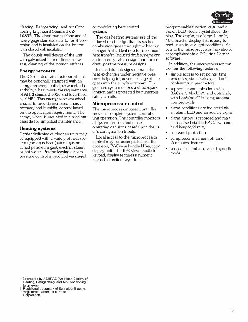
DA – 100% OA Vertical Supply / No ReturnDB – 100% OA Horizontal Supply / No ReturnDC – 100% OA Vertical Supply / Vertical ReturnDD – 100% OA Horizontal Supply / Vertical Return
DA – 100% OA Vertical Supply / No ReturnDB – 100% OA Horizontal Supply / No ReturnDC – 100% OA Vertical Supply / Vertical ReturnDD – 100% OA Horizontal Supply / Vertical Return
62 – Dedicated Outdoor Air Unit
Configuration
Heat Options*- – NoneA – 75,000 Btuh Gas HeatB – 100,000 Btuh Gas HeatC – 150,000 Btuh Gas HeatD – 200,000 Btuh Gas HeatE – 250,000 Btuh Gas HeatF – 300,000 Btuh Gas Heat
G – 400,000 Btuh Gas HeatH – 500,000 Btuh Gas HeatJ – 600,000 Btuh Gas HeatW – Hot Water Heating Coil†Y – Steam Heating Coil†1 – 7.5 / 10 kW Elect Heat2 – 11.3 / 15 kW Elect Heat
3 – 15 / 20 kW Elect Heat4 – 18.8 / 25 kW Elect Heat5 – 22.6 / 30 kW Elect Heat6 – 26.3 / 35 kW Elect Heat7 – 30 / 40 kW Elect Heat8 – 35.7 / 50 kW Elect Heat9 – 45 / 60 kW Elect Heat
0 – NoneA – ECW (36 in.)B – ECW (42 in.)C – ECW (48 in.)D – ECW (54 in.)E – ECW (36 in.) with BypF – ECW (42 in.) with BypG – ECW (48 in.) with BypH – ECW (54 in.) with Byp
J – ECW (36 in.) with VFD TDK – ECW (42 in.) with VFD TDL – ECW (48 in.) with VFD TDM – ECW (54 in.) with VFD TDN – ECW (36 in.) with Byp and VFD TDP – ECW (42 in.) with Byp and VFD TDQ – ECW (48 in.) with Byp and VFD TDR – ECW (54 in.) with Byp and VFD TD
Energy Conservation Wheel (ECW) Options **
Unit Size – Nominal Tons30 – 27 34 – 3038 – 35
07 – 608 – 709 – 812 – 10
14 – 12 15 – 14 16 – 15
20 – 1822 – 19 24 – 20
Control Options- – NoneA – Filter Status SwitchC – FirestatD – RA Smoke DetectorG – Filter Status Switch and FirestatH – Filter Status Switch and RA Smoke DetectorN – Firestat and RA Smoke DetectorV – Filter Status Switch and Firestat and RA Smoke Detector
Supply Fan Motor OptionsR – 3 HP with VFDS – 5 HP with VFDT – 7 1/2 HP with VFDV – 10 HP with VFDW – 15 HP with VFDX – 20 HP with VFD
A – 1/2 HPB – 3/4 HPC – 1 HPD – 1 1/2 HPE – 2 HPF – 3 HPG – 5 HP
H – 7 1/2 HPJ – 10 HPK – 15 HPL – 20 HPN – 1 HP with VFDP – 1 1/2 HP with VFDQ – 2 HP with VFD
SEE NEXT PAGEFOR REMAINDER
OF MODEL NUMBERNOMENCLATURE
DA 3 CAEF C4 6 -
a62-686
Model number nomenclature
5
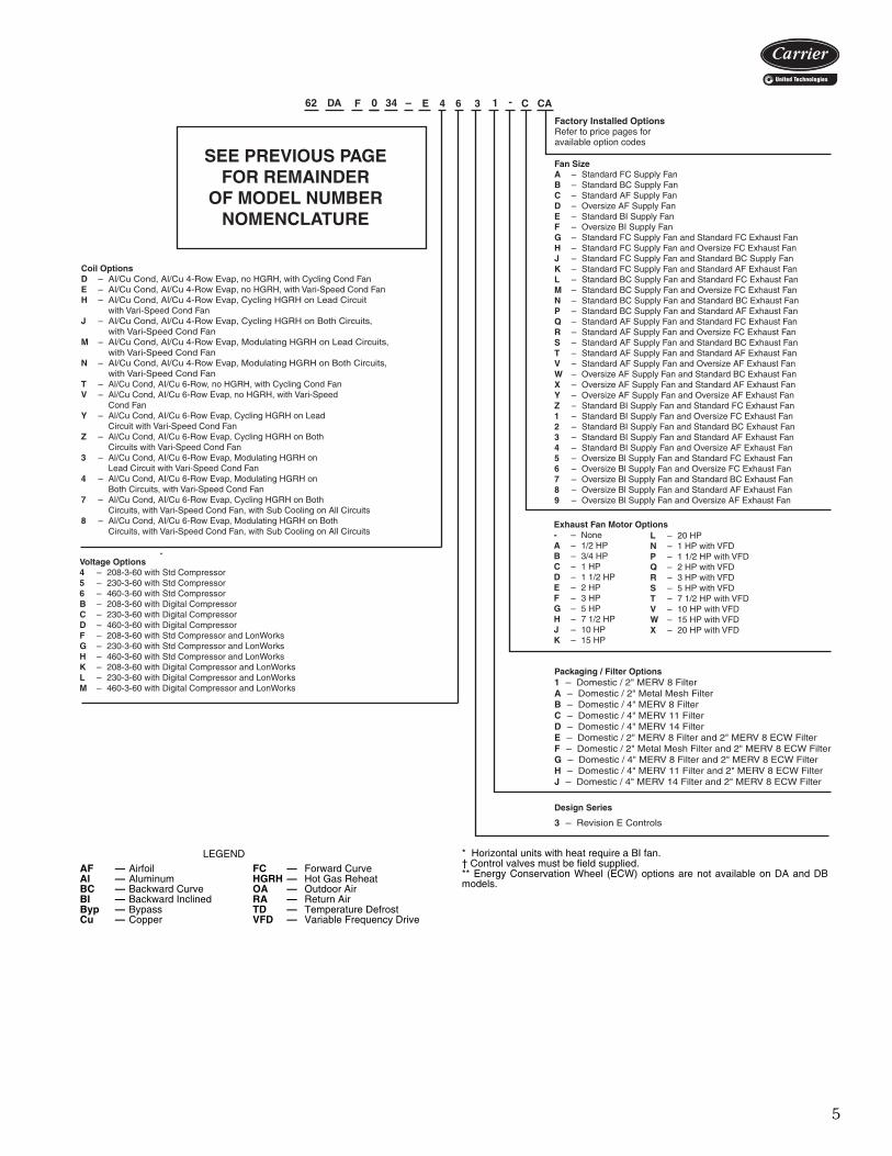
Packaging / Filter Options1 – Domestic / 2" MERV 8 FilterA – Domestic / 2" Metal Mesh FilterB – Domestic / 4" MERV 8 FilterC – Domestic / 4" MERV 11 FilterD – Domestic / 4" MERV 14 FilterE – Domestic / 2" MERV 8 Filter and 2" MERV 8 ECW FilterF – Domestic / 2" Metal Mesh Filter and 2" MERV 8 ECW FilterG – Domestic / 4" MERV 8 Filter and 2" MERV 8 ECW FilterH – Domestic / 4" MERV 11 Filter and 2" MERV 8 ECW FilterJ – Domestic / 4" MERV 14 Filter and 2" MERV 8 ECW Filter
Exhaust Fan Motor Options- – NoneA – 1/2 HPB – 3/4 HPC – 1 HPD – 1 1/2 HPE – 2 HPF – 3 HPG – 5 HPH – 7 1/2 HPJ – 10 HPK – 15 HP
L – 20 HPN – 1 HP with VFDP – 1 1/2 HP with VFDQ – 2 HP with VFDR – 3 HP with VFDS – 5 HP with VFDT – 7 1/2 HP with VFDV – 10 HP with VFDW – 15 HP with VFDX – 20 HP with VFD
Fan SizeA – Standard FC Supply FanB – Standard BC Supply FanC – Standard AF Supply FanD – Oversize AF Supply FanE – Standard BI Supply FanF – Oversize BI Supply FanG – Standard FC Supply Fan and Standard FC Exhaust FanH – Standard FC Supply Fan and Oversize FC Exhaust FanJ – Standard FC Supply Fan and Standard BC Supply FanK – Standard FC Supply Fan and Standard AF Exhaust FanL – Standard BC Supply Fan and Standard FC Exhaust FanM – Standard BC Supply Fan and Oversize FC Exhaust FanN – Standard BC Supply Fan and Standard BC Exhaust FanP – Standard BC Supply Fan and Standard AF Exhaust FanQ – Standard AF Supply Fan and Standard FC Exhaust FanR – Standard AF Supply Fan and Oversize FC Exhaust FanS – Standard AF Supply Fan and Standard BC Exhaust FanT – Standard AF Supply Fan and Standard AF Exhaust FanV – Standard AF Supply Fan and Oversize AF Exhaust FanW – Oversize AF Supply Fan and Standard BC Exhaust FanX – Oversize AF Supply Fan and Standard AF Exhaust FanY – Oversize AF Supply Fan and Oversize AF Exhaust FanZ – Standard BI Supply Fan and Standard FC Exhaust Fan1 – Standard BI Supply Fan and Oversize FC Exhaust Fan2 – Standard BI Supply Fan and Standard BC Exhaust Fan3 – Standard BI Supply Fan and Standard AF Exhaust Fan4 – Standard BI Supply Fan and Oversize AF Exhaust Fan5 – Oversize Bl Supply Fan and Standard FC Exhaust Fan6 – Oversize Bl Supply Fan and Oversize FC Exhaust Fan7 – Oversize Bl Supply Fan and Standard BC Exhaust Fan8 – Oversize Bl Supply Fan and Standard AF Exhaust Fan9 – Oversize Bl Supply Fan and Oversize AF Exhaust Fan
SEE PREVIOUS PAGEFOR REMAINDER
OF MODEL NUMBERNOMENCLATURE
3 – Revision E Controls
Voltage Options4 – 208-3-60 with Std Compressor5 – 230-3-60 with Std Compressor6 – 460-3-60 with Std CompressorB – 208-3-60 with Digital CompressorC – 230-3-60 with Digital CompressorD – 460-3-60 with Digital CompressorF – 208-3-60 with Std Compressor and LonWorksG – 230-3-60 with Std Compressor and LonWorksH – 460-3-60 with Std Compressor and LonWorksK – 208-3-60 with Digital Compressor and LonWorksL – 230-3-60 with Digital Compressor and LonWorksM – 460-3-60 with Digital Compressor and LonWorks
Design Series
Coil OptionsD – Al/Cu Cond, Al/Cu 4-Row Evap, no HGRH, with Cycling Cond FanE – Al/Cu Cond, Al/Cu 4-Row Evap, no HGRH, with Vari-Speed Cond FanH – Al/Cu Cond, Al/Cu 4-Row Evap, Cycling HGRH on Lead Circuit with Vari-Speed Cond FanJ – Al/Cu Cond, Al/Cu 4-Row Evap, Cycling HGRH on Both Circuits, with Vari-Speed Cond FanM – Al/Cu Cond, Al/Cu 4-Row Evap, Modulating HGRH on Lead Circuits, with Vari-Speed Cond FanN – Al/Cu Cond, Al/Cu 4-Row Evap, Modulating HGRH on Both Circuits, with Vari-Speed Cond FanT – Al/Cu Cond, AI/Cu 6-Row, no HGRH, with Cycling Cond FanV – Al/Cu Cond, AI/Cu 6-Row Evap, no HGRH, with Vari-Speed Cond FanY – Al/Cu Cond, AI/Cu 6-Row Evap, Cycling HGRH on Lead Circuit with Vari-Speed Cond FanZ – Al/Cu Cond, AI/Cu 6-Row Evap, Cycling HGRH on Both Circuits with Vari-Speed Cond Fan3 – Al/Cu Cond, AI/Cu 6-Row Evap, Modulating HGRH on Lead Circuit with Vari-Speed Cond Fan4 – Al/Cu Cond, AI/Cu 6-Row Evap, Modulating HGRH on Both Circuits, with Vari-Speed Cond Fan7 – Al/Cu Cond, AI/Cu 6-Row Evap, Cycling HGRH on Both Circuits, with Vari-Speed Cond Fan, with Sub Cooling on All Circuits8 – Al/Cu Cond, AI/Cu 6-Row Evap, Modulating HGRH on Both Circuits, with Vari-Speed Cond Fan, with Sub Cooling on All Circuits
DA CAF C3E 4 6 -
a62-546
* Horizontal units with heat require a BI fan.† Control valves must be field supplied.** Energy Conservation Wheel (ECW) options are not available on DA and DBmodels.
LEGENDAF — Airfoil FC — Forward CurveAl — Aluminum HGRH — Hot Gas ReheatBC — Backward Curve OA — Outdoor AirBI — Backward Inclined RA — Return AirByp — Bypass TD — Temperature DefrostCu — Copper VFD — Variable Frequency Drive
a62-687
6
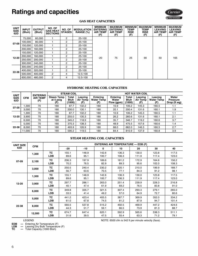
GAS HEAT CAPACITIES
HYDRONIC HEATING COIL CAPACITIES
STEAM HEATING COIL CAPACITIES
LEGEND NOTE: 6500 cfm is 542 ft per minute velocity (face).
UNITSIZE62D
INPUT(Btuh)
OUTPUT(Btuh)
NO. OFGAS HEATSECTIONS
NO. OFSTAGES
MODULATIONRANGE (%)
MINIMUMENTERINGAIR TEMP
(F)
MAXIMUMENTERINGAIR TEMP
(F)
MINIMUMTEMPRISE(F)
MAXIMUMTEMPRISE(F)
MINIMUMLEAVINGAIR TEMP
(F)
MAXIMUMLEAVINGAIR TEMP
(F)
07-09
75,000 60,000 1 2 25-100
-20 75 25 90 50 165
100,000 80,000 1 2 25-100150,000 120,000 1 2 25-100200,000 160,000 1 2 25-100
12-20
150,000 120,000 1 2 25-100200,000 160,000 1 2 25-100250,000 200,000 1 2 25-100300,000 240,000 1 2 25-100
22-38
300,000 240,000 1 2 25-100400,000 320,000 1 2 25-100500,000 400,000 2 4 12.5-100600,000 480,000 2 4 12.5-100
UNITSIZE62D
CFMENTERINGAIR TEMP
(F)
STEAM COIL HOT WATER COILSteam Temp
at 5 psig(F)
TotalBtuh
(1000)
LeavingAir Temp
(F)
EnteringWater Temp
(F)
EnteringWater
Flow (gpm)
TotalBtuh
(1000)
LeavingAir Temp
(F)
LeavingWater Temp
(F)
WaterPressure
Drop (ft wg)
07-09 1,300 70 180 87.7 132.2 180 10.9 106.2 145.3 160.5 1.1 3,000 70 180 200.0 130.1 180 20.1 200.4 131.6 160.1 1.9
12-20 1,300 70 180 87.7 132.2 180 10.9 106.2 145.3 160.5 1.1 3,900 70 180 255.0 130.3 180 26.2 260.6 131.6 160.1 2.1 6,500 70 180 345.2 118.9 180 35.7 346.7 119.2 160.6 3.7
22-38 5,000 70 180 370.3 138.3 180 48.9 475.5 157.6 160.6 1.4 8,000 70 180 493.9 126.9 180 68.0 662.0 146.3 160.5 2.711,000 70 180 590.2 119.5 180 84.4 810.9 137.9 160.8 3.9
UNIT SIZE62D CFM
ENTERING AIR TEMPERATURE — EDB (F)
-20 -10 0 10 20 30 40
07-09
1,300 TC 155.1 148.9 142.6 136.3 130.0 123.8 117.5LDB 89.6 95.1 100.7 106.3 111.9 117.4 123.0
2,100 TC 206.3 197.9 189.6 181.2 172.9 164.6 156.2LDB 70.2 76.5 82.9 89.3 95.6 102.0 108.3
3,000 TC 250.5 240.4 230.2 220.1 210.0 199.9 189.7LDB 56.7 63.6 70.5 77.1 84.3 91.2 98.1
12-20
1,300 TC 155.1 148.9 142.6 136.3 130.0 123.8 117.5LDB 89.6 95.1 100.7 106.3 111.9 117.4 123.0
3,900 TC 297.7 286.1 263.0 251.4 239.9 228.3 216.8LDB 40.1 47.4 61.9 69.2 76.5 83.8 91.0
6,000 TC 349.8 335.7 321.5 307.4 293.3 279.1 265.0LDB 33.5 41.4 49.2 57.0 64.9 72.7 80.6
22-38
5,000 TC 441.2 423.4 405.5 387.7 369.9 352.0 334.2LDB 61.0 67.8 74.5 81.2 87.9 94.7 101.4
8,000 TC 560.5 537.8 515.2 492.5 469.9 447.2 424.6LDB 44.3 51.7 59.1 66.5 73.9 81.3 88.7
12,000 TC 674.7 647.4 620.1 592.9 565.6 538.3 511.1LDB 31.6 39.5 47.5 55.4 63.3 71.2 79.1
EDB — Entering Air Temperature (F)LDB — Leaving Dry Bulb Temperature (F)TC — Total Capacity (1000 Btuh)
Ratings and capacities
7
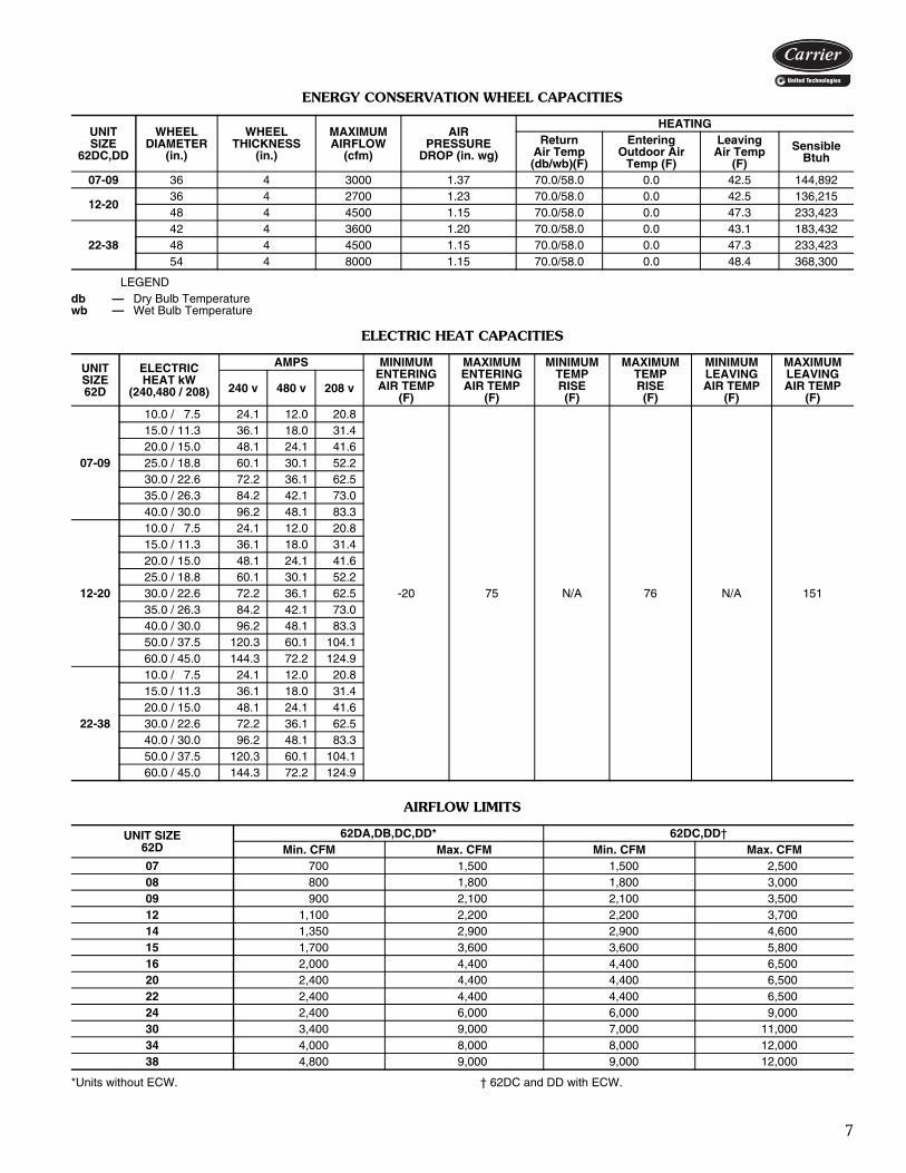
ENERGY CONSERVATION WHEEL CAPACITIES
LEGEND
ELECTRIC HEAT CAPACITIES
AIRFLOW LIMITS
*Units without ECW. † 62DC and DD with ECW.
UNITSIZE
62DC,DD
WHEELDIAMETER
(in.)
WHEELTHICKNESS
(in.)
MAXIMUMAIRFLOW
(cfm)
AIRPRESSURE
DROP (in. wg)
HEATINGReturn
Air Temp(db/wb)(F)
EnteringOutdoor Air
Temp (F)
LeavingAir Temp
(F)
SensibleBtuh
07-09 36 4 3000 1.37 70.0/58.0 0.0 42.5 144,892
12-2036 4 2700 1.23 70.0/58.0 0.0 42.5 136,21548 4 4500 1.15 70.0/58.0 0.0 47.3 233,423
22-3842 4 3600 1.20 70.0/58.0 0.0 43.1 183,43248 4 4500 1.15 70.0/58.0 0.0 47.3 233,42354 4 8000 1.15 70.0/58.0 0.0 48.4 368,300
db — Dry Bulb Temperaturewb — Wet Bulb Temperature
UNITSIZE62D
ELECTRICHEAT kW
(240,480 / 208)
AMPS MINIMUMENTERINGAIR TEMP
(F)
MAXIMUMENTERINGAIR TEMP
(F)
MINIMUMTEMPRISE(F)
MAXIMUMTEMPRISE(F)
MINIMUMLEAVINGAIR TEMP
(F)
MAXIMUMLEAVINGAIR TEMP
(F)240 v 480 v 208 v
07-09
10.0 / 7.5 24.1 12.0 20.8
-20 75 N/A 76 N/A 151
15.0 / 11.3 36.1 18.0 31.4 20.0 / 15.0 48.1 24.1 41.6 25.0 / 18.8 60.1 30.1 52.2 30.0 / 22.6 72.2 36.1 62.5 35.0 / 26.3 84.2 42.1 73.0 40.0 / 30.0 96.2 48.1 83.3
12-20
10.0 / 7.5 24.1 12.0 20.8 15.0 / 11.3 36.1 18.0 31.4 20.0 / 15.0 48.1 24.1 41.6 25.0 / 18.8 60.1 30.1 52.2 30.0 / 22.6 72.2 36.1 62.5 35.0 / 26.3 84.2 42.1 73.0 40.0 / 30.0 96.2 48.1 83.3 50.0 / 37.5 120.3 60.1 104.1 60.0 / 45.0 144.3 72.2 124.9
22-38
10.0 / 7.5 24.1 12.0 20.8 15.0 / 11.3 36.1 18.0 31.4 20.0 / 15.0 48.1 24.1 41.6 30.0 / 22.6 72.2 36.1 62.5 40.0 / 30.0 96.2 48.1 83.3 50.0 / 37.5 120.3 60.1 104.1 60.0 / 45.0 144.3 72.2 124.9
UNIT SIZE62D
62DA,DB,DC,DD* 62DC,DD†Min. CFM Max. CFM Min. CFM Max. CFM
07 700 1,500 1,500 2,50008 800 1,800 1,800 3,00009 900 2,100 2,100 3,50012 1,100 2,200 2,200 3,70014 1,350 2,900 2,900 4,60015 1,700 3,600 3,600 5,80016 2,000 4,400 4,400 6,50020 2,400 4,400 4,400 6,50022 2,400 4,400 4,400 6,50024 2,400 6,000 6,000 9,00030 3,400 9,000 7,000 11,00034 4,000 8,000 8,000 12,00038 4,800 9,000 9,000 12,000
8
LEGEND
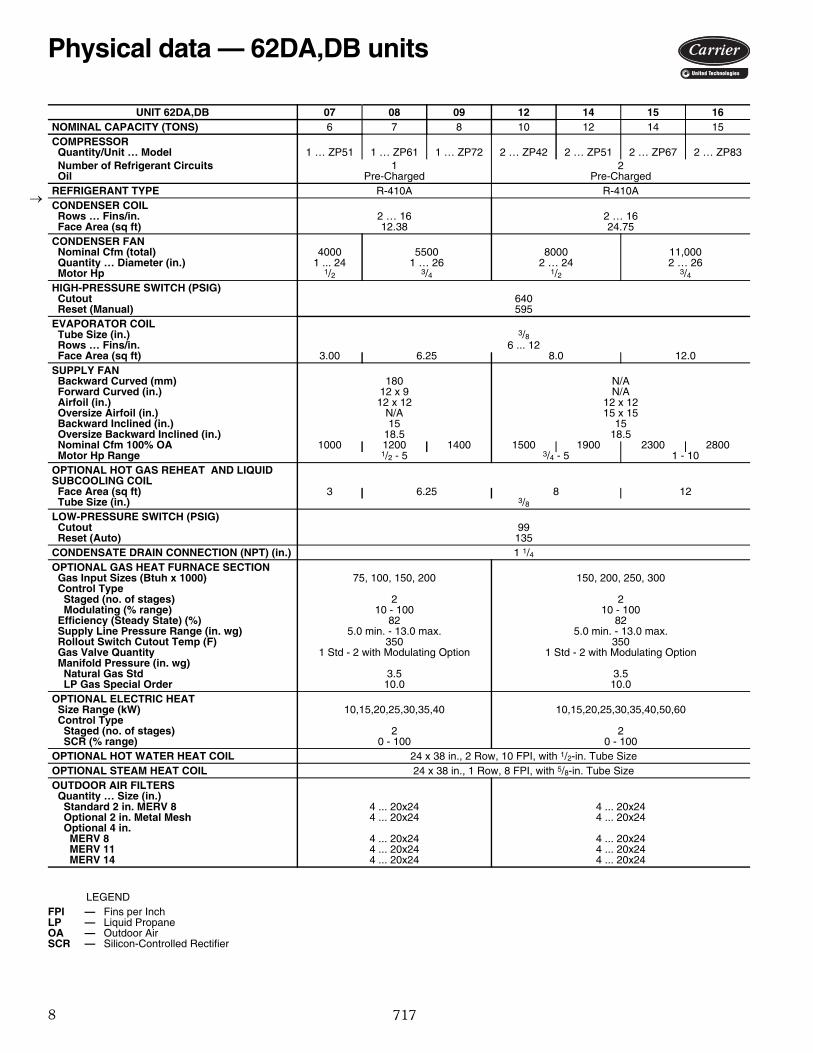
UNIT 62DA,DB 07 08 09 12 14 15 16NOMINAL CAPACITY (TONS) 6 7 8 10 12 14 15COMPRESSOR Quantity/Unit … Model 1 … ZP51 1 … ZP61 1 … ZP72 2 … ZP42 2 … ZP51 2 … ZP67 2 … ZP83 Number of Refrigerant Circuits 1 2 Oil Pre-Charged Pre-ChargedREFRIGERANT TYPE R-410A R-410ACONDENSER COIL Rows … Fins/in. 2 … 16 2 … 16 Face Area (sq ft) 12.38 24.75CONDENSER FAN Nominal Cfm (total) 4000 5500 8000 11,000 Quantity … Diameter (in.) 1 ... 24 1 … 26 2 … 24 2 … 26 Motor Hp 1/2 3/4 1/2 3/4HIGH-PRESSURE SWITCH (PSIG) Cutout 640 Reset (Manual) 595EVAPORATOR COIL Tube Size (in.) 3/8 Rows … Fins/in. 6 ... 12 Face Area (sq ft) 3.00 6.25 8.0 12.0SUPPLY FAN Backward Curved (mm) 180 N/A Forward Curved (in.) 12 x 9 N/A Airfoil (in.) 12 x 12 12 x 12 Oversize Airfoil (in.) N/A 15 x 15 Backward Inclined (in.) 15 15 Oversize Backward Inclined (in.) 18.5 18.5 Nominal Cfm 100% OA 1000 1200 1400 1500 1900 2300 2800 Motor Hp Range 1/2 - 5 3/4 - 5 1 - 10OPTIONAL HOT GAS REHEAT AND LIQUID SUBCOOLING COIL Face Area (sq ft) 3 6.25 8 12 Tube Size (in.) 3/8LOW-PRESSURE SWITCH (PSIG) Cutout 99 Reset (Auto) 135CONDENSATE DRAIN CONNECTION (NPT) (in.) 1 1/4OPTIONAL GAS HEAT FURNACE SECTION Gas Input Sizes (Btuh x 1000) 75, 100, 150, 200 150, 200, 250, 300 Control Type Staged (no. of stages) 2 2 Modulating (% range) 10 - 100 10 - 100 Efficiency (Steady State) (%) 82 82 Supply Line Pressure Range (in. wg) 5.0 min. - 13.0 max. 5.0 min. - 13.0 max. Rollout Switch Cutout Temp (F) 350 350 Gas Valve Quantity 1 Std - 2 with Modulating Option 1 Std - 2 with Modulating Option Manifold Pressure (in. wg) Natural Gas Std 3.5 3.5 LP Gas Special Order 10.0 10.0OPTIONAL ELECTRIC HEAT Size Range (kW) 10,15,20,25,30,35,40 10,15,20,25,30,35,40,50,60 Control Type Staged (no. of stages) 2 2 SCR (% range) 0 - 100 0 - 100OPTIONAL HOT WATER HEAT COIL 24 x 38 in., 2 Row, 10 FPI, with 1/2-in. Tube SizeOPTIONAL STEAM HEAT COIL 24 x 38 in., 1 Row, 8 FPI, with 5/8-in. Tube SizeOUTDOOR AIR FILTERS Quantity … Size (in.) Standard 2 in. MERV 8 4 ... 20x24 4 ... 20x24 Optional 2 in. Metal Mesh 4 ... 20x24 4 ... 20x24 Optional 4 in. MERV 8 4 ... 20x24 4 ... 20x24 MERV 11 4 ... 20x24 4 ... 20x24 MERV 14 4 ... 20x24 4 ... 20x24
FPI — Fins per InchLP — Liquid PropaneOA — Outdoor AirSCR — Silicon-Controlled Rectifier
Physical data — 62DA,DB units
717
9
LEGEND
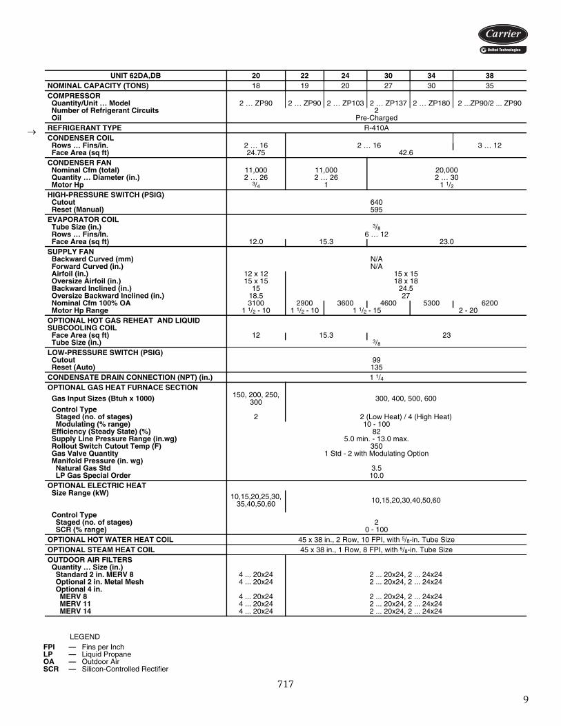
UNIT 62DA,DB 20 22 24 30 34 38NOMINAL CAPACITY (TONS) 18 19 20 27 30 35COMPRESSOR Quantity/Unit … Model 2 … ZP90 2 … ZP90 2 … ZP103 2 … ZP137 2 … ZP180 2 ...ZP90/2 ... ZP90 Number of Refrigerant Circuits 2 Oil Pre-ChargedREFRIGERANT TYPE R-410ACONDENSER COIL Rows … Fins/in. 2 … 16 2 … 16 3 … 12 Face Area (sq ft) 24.75 42.6CONDENSER FAN Nominal Cfm (total) 11,000 11,000 20,000 Quantity … Diameter (in.) 2 … 26 2 … 26 2 … 30 Motor Hp 3/4 1 1 1/2HIGH-PRESSURE SWITCH (PSIG) Cutout 640 Reset (Manual) 595EVAPORATOR COIL Tube Size (in.) 3/8 Rows … Fins/In. 6 … 12 Face Area (sq ft) 12.0 15.3 23.0SUPPLY FAN Backward Curved (mm) N/A Forward Curved (in.) N/A Airfoil (in.) 12 x 12 15 x 15 Oversize Airfoil (in.) 15 x 15 18 x 18 Backward Inclined (in.) 15 24.5 Oversize Backward Inclined (in.) 18.5 27 Nominal Cfm 100% OA 3100 2900 3600 4600 5300 6200 Motor Hp Range 1 1/2 - 10 1 1/2 - 10 1 1/2 - 15 2 - 20OPTIONAL HOT GAS REHEAT AND LIQUID SUBCOOLING COIL Face Area (sq ft) 12 15.3 23 Tube Size (in.) 3/8LOW-PRESSURE SWITCH (PSIG) Cutout 99 Reset (Auto) 135CONDENSATE DRAIN CONNECTION (NPT) (in.) 1 1/4OPTIONAL GAS HEAT FURNACE SECTION
Gas Input Sizes (Btuh x 1000) 150, 200, 250, 300 300, 400, 500, 600
Control Type Staged (no. of stages) 2 2 (Low Heat) / 4 (High Heat) Modulating (% range) 10 - 100 Efficiency (Steady State) (%) 82 Supply Line Pressure Range (in.wg) 5.0 min. - 13.0 max. Rollout Switch Cutout Temp (F) 350 Gas Valve Quantity 1 Std - 2 with Modulating Option Manifold Pressure (in. wg) Natural Gas Std 3.5 LP Gas Special Order 10.0OPTIONAL ELECTRIC HEAT Size Range (kW) 10,15,20,25,30,
35,40,50,60 10,15,20,30,40,50,60
Control Type Staged (no. of stages) 2 SCR (% range) 0 - 100OPTIONAL HOT WATER HEAT COIL 45 x 38 in., 2 Row, 10 FPI, with 5/8-in. Tube SizeOPTIONAL STEAM HEAT COIL 45 x 38 in., 1 Row, 8 FPI, with 5/8-in. Tube SizeOUTDOOR AIR FILTERS Quantity … Size (in.) Standard 2 in. MERV 8 4 ... 20x24 2 ... 20x24, 2 ... 24x24 Optional 2 in. Metal Mesh 4 ... 20x24 2 ... 20x24, 2 ... 24x24 Optional 4 in. MERV 8 4 ... 20x24 2 ... 20x24, 2 ... 24x24 MERV 11 4 ... 20x24 2 ... 20x24, 2 ... 24x24 MERV 14 4 ... 20x24 2 ... 20x24, 2 ... 24x24
FPI — Fins per InchLP — Liquid PropaneOA — Outdoor AirSCR — Silicon-Controlled Rectifier
717

10
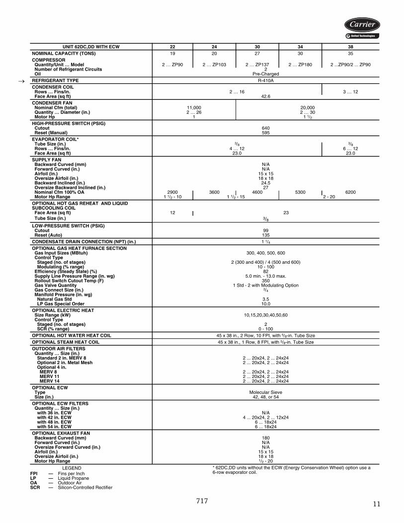
LEGEND * 62DC,DD units without the ECW (Energy Conservation Wheel) option use a 6-row evaporator coil.
UNIT 62DC,DD WITH ECW 07 08 09 12 14 15 16 20NOMINAL CAPACITY (TONS) 6 7 8 10 12 14 15 18COMPRESSOR Quantity/Unit … Model 1 … ZP51 1 … ZP61 1 … ZP72 2 … ZP42 2 … ZP51 2 … ZP67 2 … ZP83 2 … ZP90 Number of Refrigerant Circuits 1 2 Oil Pre-Charged Pre-ChargedREFRIGERANT TYPE R-410A R-410ACONDENSER COIL Rows … Fins/in. 2 … 16 2 … 16 Face Area (sq ft) 12.38 24.75CONDENSER FAN Nominal Cfm (total) 4000 5500 8000 11,000 Quantity … Diameter (in.) 1 … 24 1 … 26 2 … 24 2 … 26 Motor Hp 1/2 3/4 1/2 3/4HIGH-PRESSURE SWITCH (PSIG) Cutout 640 Reset (Manual) 595EVAPORATOR COIL* Tube Size (in.) 3/8 3/8 3/8 Rows … Fins/in. 4 ... 12 4 … 12 6 … 12 Face Area (sq ft) 4.0 7.5 12.0 12.0SUPPLY FAN Backward Curved (mm) 180 N/A Forward Curved (in.) 12 x 9 N/A Airfoil (in.) 12 x 12 12 x 12 Oversize Airfoil (in.) N/A 15 x 15 Backward Inclined (in.) 15 15 Oversize Backward Inclined (in.) 18.5 18.5 Nominal Cfm 100% OA 1000 1200 1400 1500 1900 2300 2800 3100 Motor Hp Range 1/2 - 5 3/4 - 5 1 - 10 1 1/2 - 10OPTIONAL HOT GAS REHEAT AND LIQUID SUBCOOLING COIL Face Area (sq ft) 4 7.5 12 Tube Size (in.) 3/8LOW-PRESSURE SWITCH (PSIG) Cutout 99 Reset (Auto) 135CONDENSATE DRAIN CONNECTION (NPT) (in.) 1 1/4OPTIONAL GAS HEAT FURNACE SECTION Gas Input Sizes (Btuh x 1000) 75, 100, 150, 200 150, 200, 250, 300 Control Type Staged (no. of stages) 2 2 Modulating (% range) 10 - 100 10 - 100 Efficiency (Steady State) (%) 82 82 Supply Line Pressure Range (in. wg) 5.0 min. - 13.0 max. 5.0 min. - 13.0 max. Rollout Switch Cutout Temp (F) 350 350 Gas Valve Quantity 1 Std - 2 with Modulating Option 1 Std - 2 with Modulating Option Gas Connect Size (in.) 3/4 3/4 Manifold Pressure (in. wg) Natural Gas Std 3.5 3.5 LP Gas Special Order 10.0 10.0OPTIONAL ELECTRIC HEAT Size Range (kW) 10,15,20,25,30,35,40 10,15,20,25,30,35,40,50,60 Control Type Staged (no. of stages) 2 2 SCR (% range) 0 - 100 0 - 100OPTIONAL HOT WATER HEAT COIL 24 x 38 in., 2 Row, 10 FPI, with 1/2-in. Tube SizeOPTIONAL STEAM HEAT COIL 24 x 38 in., 1 Row, 8 FPI, with 5/8-in. Tube SizeOUTDOOR AIR FILTERS Quantity … Size (in.) Standard 2 in. MERV 8 4 ... 20x24 Optional 2 in. Metal Mesh 4 ... 20x24 Optional 4 in. MERV 8 4 ... 20x24 MERV 11 4 ... 20x24 MERV 14 4 ... 20x24OPTIONAL ECW Type Molecular Sieve Molecular Sieve Size (in.) 36 36 or 48OPTIONAL ECW FILTERS Quantity … Size (in.) with 36 in. ECW 2 ... 20x24, 2 ... 20x20 2 ... 20x24, 2 ... 20x20 with 42 in. ECW N/A N/A with 48 in. ECW N/A 4 ... 20x24, 2 ... 12x24 with 54 in. ECW N/A N/AOPTIONAL EXHAUST FAN Backward Curved (mm) 180 mm 180 mm Forward Curved (in.) 9 x 7 N/A Oversize Forward Curved (in.) 12 x 9 N/A Airfoil (in.) 12 x 12 12 x 12 Oversize Airfoil (in.) N/A N/A Motor Hp Range 1/2 - 5 1/2 - 10
FPI — Fins per InchLP — Liquid PropaneOA — Outdoor AirSCR — Silicon-Controlled Rectifier
Physical data — 62DC,DD units
717
11
LEGEND * 62DC,DD units without the ECW (Energy Conservation Wheel) option use a 6-row evaporator coil.
UNIT 62DC,DD WITH ECW 22 24 30 34 38NOMINAL CAPACITY (TONS) 19 20 27 30 35COMPRESSOR Quantity/Unit … Model 2 … ZP90 2 … ZP103 2 … ZP137 2 … ZP180 2 ...ZP90/2 ... ZP90 Number of Refrigerant Circuits 2 Oil Pre-ChargedREFRIGERANT TYPE R-410ACONDENSER COIL Rows … Fins/in. 2 … 16 3 … 12 Face Area (sq ft) 42.6CONDENSER FAN Nominal Cfm (total) 11,000 20,000 Quantity … Diameter (in.) 2 … 26 2 … 30 Motor Hp 1 1 1/2HIGH-PRESSURE SWITCH (PSIG) Cutout 640 Reset (Manual) 595EVAPORATOR COIL* Tube Size (in.) 3/8 3/8 Rows … Fins/in. 4 … 12 6 … 12 Face Area (sq ft) 23.0 23.0SUPPLY FAN Backward Curved (mm) N/A Forward Curved (in.) N/A Airfoil (in.) 15 x 15 Oversize Airfoil (in.) 18 x 18 Backward Inclined (in.) 24.5 Oversize Backward Inclined (in.) 27 Nominal Cfm 100% OA 2900 3600 4600 5300 6200 Motor Hp Range 1 1/2 - 10 1 1/2 - 15 2 - 20OPTIONAL HOT GAS REHEAT AND LIQUID SUBCOOLING COIL Face Area (sq ft) 12 23 Tube Size (in.) 3/8LOW-PRESSURE SWITCH (PSIG) Cutout 99 Reset (Auto) 135CONDENSATE DRAIN CONNECTION (NPT) (in.) 1 1/4OPTIONAL GAS HEAT FURNACE SECTION Gas Input Sizes (MBtuh) 300, 400, 500, 600 Control Type Staged (no. of stages) 2 (300 and 400) / 4 (500 and 600) Modulating (% range) 10 - 100 Efficiency (Steady State) (%) 82 Supply Line Pressure Range (in. wg) 5.0 min. - 13.0 max. Rollout Switch Cutout Temp (F) 350 Gas Valve Quantity 1 Std - 2 with Modulating Option Gas Connect Size (in.) 3/4 Manifold Pressure (in. wg) Natural Gas Std 3.5 LP Gas Special Order 10.0OPTIONAL ELECTRIC HEAT Size Range (kW) 10,15,20,30,40,50,60 Control Type Staged (no. of stages) 2 SCR (% range) 0 - 100OPTIONAL HOT WATER HEAT COIL 45 x 38 in., 2 Row, 10 FPI, with 5/8-in. Tube SizeOPTIONAL STEAM HEAT COIL 45 x 38 in., 1 Row, 8 FPI, with 5/8-in. Tube SizeOUTDOOR AIR FILTERS Quantity … Size (in.) Standard 2 in. MERV 8 2 ... 20x24, 2 ... 24x24 Optional 2 in. Metal Mesh 2 ... 20x24, 2 ... 24x24 Optional 4 in. MERV 8 2 ... 20x24, 2 ... 24x24 MERV 11 2 ... 20x24, 2 ... 24x24 MERV 14 2 ... 20x24, 2 ... 24x24OPTIONAL ECW Type Molecular Sieve Size (in.) 42, 48, or 54OPTIONAL ECW FILTERS Quantity … Size (in.) with 36 in. ECW N/A with 42 in. ECW 4 ... 20x24, 2 ... 12x24 with 48 in. ECW 6 ... 18x24 with 54 in. ECW 6 ... 18x24OPTIONAL EXHAUST FAN Backward Curved (mm) 180 Forward Curved (in.) N/A Oversize Forward Curved (in.) N/A Airfoil (in.) 15 x 15 Oversize Airfoil (in.) 18 x 18 Motor Hp Range 1/2 - 20
FPI — Fins per InchLP — Liquid PropaneOA — Outdoor AirSCR — Silicon-Controlled Rectifier
717
12
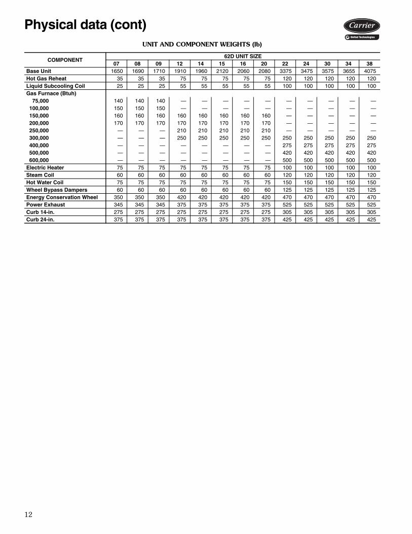
UNIT AND COMPONENT WEIGHTS (lb)
COMPONENT62D UNIT SIZE
07 08 09 12 14 15 16 20 22 24 30 34 38Base Unit 1650 1690 1710 1910 1960 2120 2060 2080 3375 3475 3575 3655 4075Hot Gas Reheat 35 35 35 75 75 75 75 75 120 120 120 120 120Liquid Subcooling Coil 25 25 25 55 55 55 55 55 100 100 100 100 100Gas Furnace (Btuh) 75,000 140 140 140 — — — — — — — — — — 100,000 150 150 150 — — — — — — — — — — 150,000 160 160 160 160 160 160 160 160 — — — — — 200,000 170 170 170 170 170 170 170 170 — — — — — 250,000 — — — 210 210 210 210 210 — — — — — 300,000 — — — 250 250 250 250 250 250 250 250 250 250 400,000 — — — — — — — — 275 275 275 275 275 500,000 — — — — — — — — 420 420 420 420 420 600,000 — — — — — — — — 500 500 500 500 500Electric Heater 75 75 75 75 75 75 75 75 100 100 100 100 100Steam Coil 60 60 60 60 60 60 60 60 120 120 120 120 120Hot Water Coil 75 75 75 75 75 75 75 75 150 150 150 150 150Wheel Bypass Dampers 60 60 60 60 60 60 60 60 125 125 125 125 125Energy Conservation Wheel 350 350 350 420 420 420 420 420 470 470 470 470 470Power Exhaust 345 345 345 375 375 375 375 375 525 525 525 525 525Curb 14-in. 275 275 275 275 275 275 275 275 305 305 305 305 305Curb 24-in. 375 375 375 375 375 375 375 375 425 425 425 425 425
Physical data (cont)

13
Options and accessories
LEGEND
*Factory installed.†Field installed.
ITEM OPTION* ACCESSORY†Heat Options Staged Gas Heat (LP or NG) X Modulating Gas Heat (10:1 or 5:1 Turndown) X Staged Electric Heat X SCR Controlled Electric Heat X Hot Water Heating Coil X Steam Heating Coil X NG to LP Conversion Kit XEnergy Conservation Wheel X Wheel VFD Defrost Control X Wheel Bypass Dampers XControl Options Filter Status Switch X Return Air Smoke Detector X Convenience Outlet X Fused Disconnect Switch X Lead Circuit Digital Compressor X BACview Keypad/Display X LonWorks Communication X Variable Speed Condenser Fans XCoil Options Hot Gas Reheat X Liquid Subcooling Coil X Corrosion Protection XFilter Options 2-in. MERV 8 Filters X X 4-in. MERV 8 Filters X X 4-in. MERV 11 Filters X X 4-in. MERV 14 Filters X 2-in. Metal Mesh Filters XSupply Fan Options Backward Curved Fan X Forward Curved Fan X Airfoil Fan X Oversize Airfoil Fan X Backward Inclined Fan X Oversize Backward Inclined Fan X VFD Control XExhaust Fan Options Backward Curved Fan X Forward Curved Fan X Oversized Forward Curved Fan X Airfoil Fan X Oversize Airfoil Fan X VFD Control X14-in. Factory-Assembled Roof Curb X24-in. Factory-Assembled Roof Curb X14-in. Field-Assembled Roof Curb X24-in. Field-Assembled Roof Curb XSpring Type Fan Isolation XFirestat X
LP — Liquid PropaneNG — Natural GasSCR — Silicon Controlled RectifierVFD — Variable Frequency Drive
14
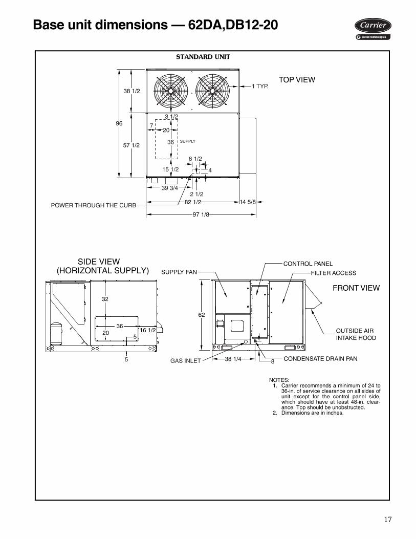
TOP VIEW
FRONT VIEW
38 1/2
57 1/2
82 1/2
38 1/4
62
8
97 1/814 5/8
FILTER ACCESS
OUTSIDE AIRINTAKE HOOD
CONTROL PANELSUPPLY FAN
CONDENSATE DRAIN PAN
96
SU
PP
LY
720
36
3 1/2
1 TYP.
4
39 3/4 2 1/2
6 1/2
15 1/2
POWER THROUGH THE CURB
GAS INLET
SIDE VIEW(HORIZONTAL SUPPLY)
36
5
520 16 1/2
32
STANDARD UNIT
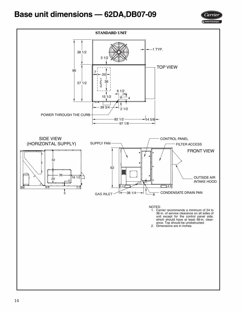
NOTES:1. Carrier recommends a minimum of 24 to
36-in. of service clearance on all sides ofunit except for the control panel side,which should have at least 48-in. clear-ance. Top should be unobstructed.
2. Dimensions are in inches.
a62-564
Base unit dimensions — 62DA,DB07-09
15
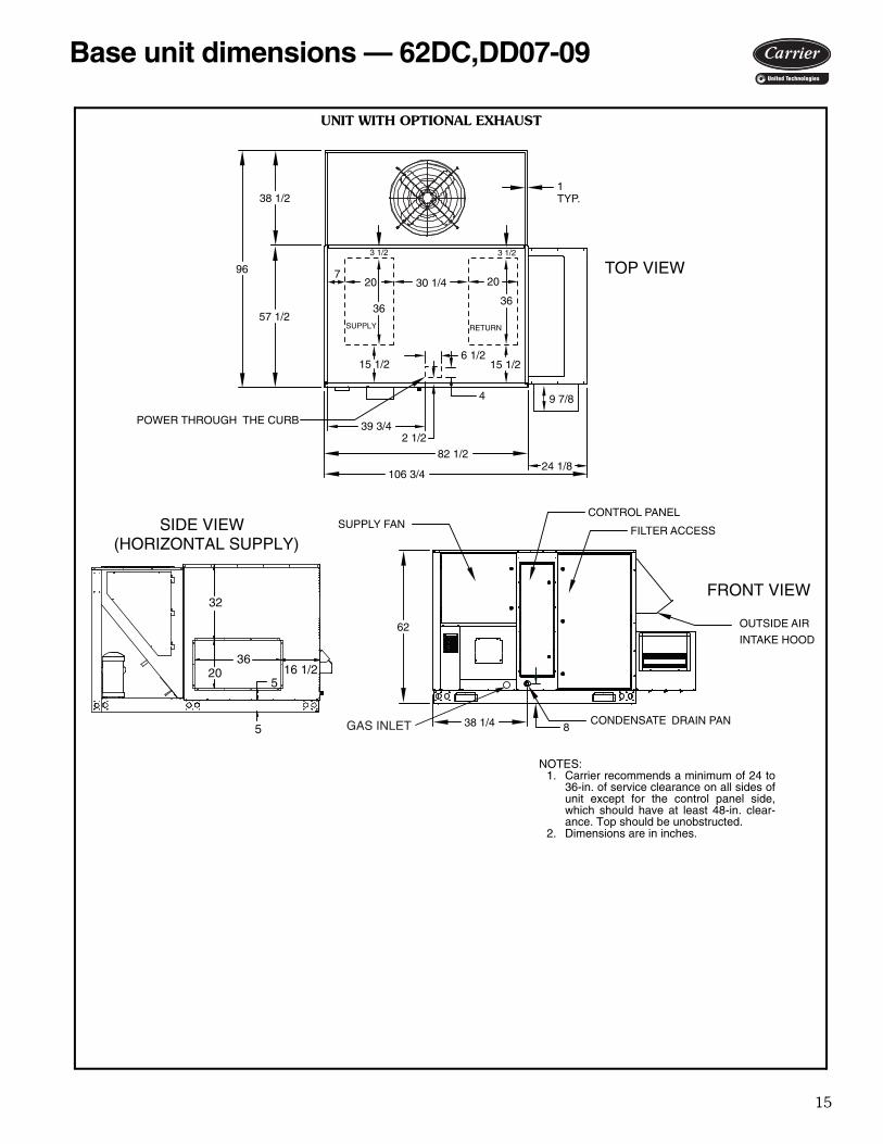
Base unit dimensions — 62DC,DD07-09
SUPPLY RETURN
TOP VIEW
FRONT VIEW
SUPPLY FANFILTER ACCESS
CONTROL PANEL
OUTSIDE AIR
INTAKE HOOD
CONDENSATE DRAIN PAN
POWER THROUGH THE CURB
7
15 1/2
3 1/2
36
838 1/4
1TYP.
30 1/4 20
38 1/2
57 1/2
96
82 1/2
4
6 1/2
2 1/2 39 3/4
62
106 3/4
9 7/8
24 1/8
3 1/2
20
36
15 1/2
GAS INLET
SIDE VIEW(HORIZONTAL SUPPLY)
36
5
520 16 1/2
32
UNIT WITH OPTIONAL EXHAUST
NOTES:1. Carrier recommends a minimum of 24 to
36-in. of service clearance on all sides ofunit except for the control panel side,which should have at least 48-in. clear-ance. Top should be unobstructed.
2. Dimensions are in inches.
a62-565
16
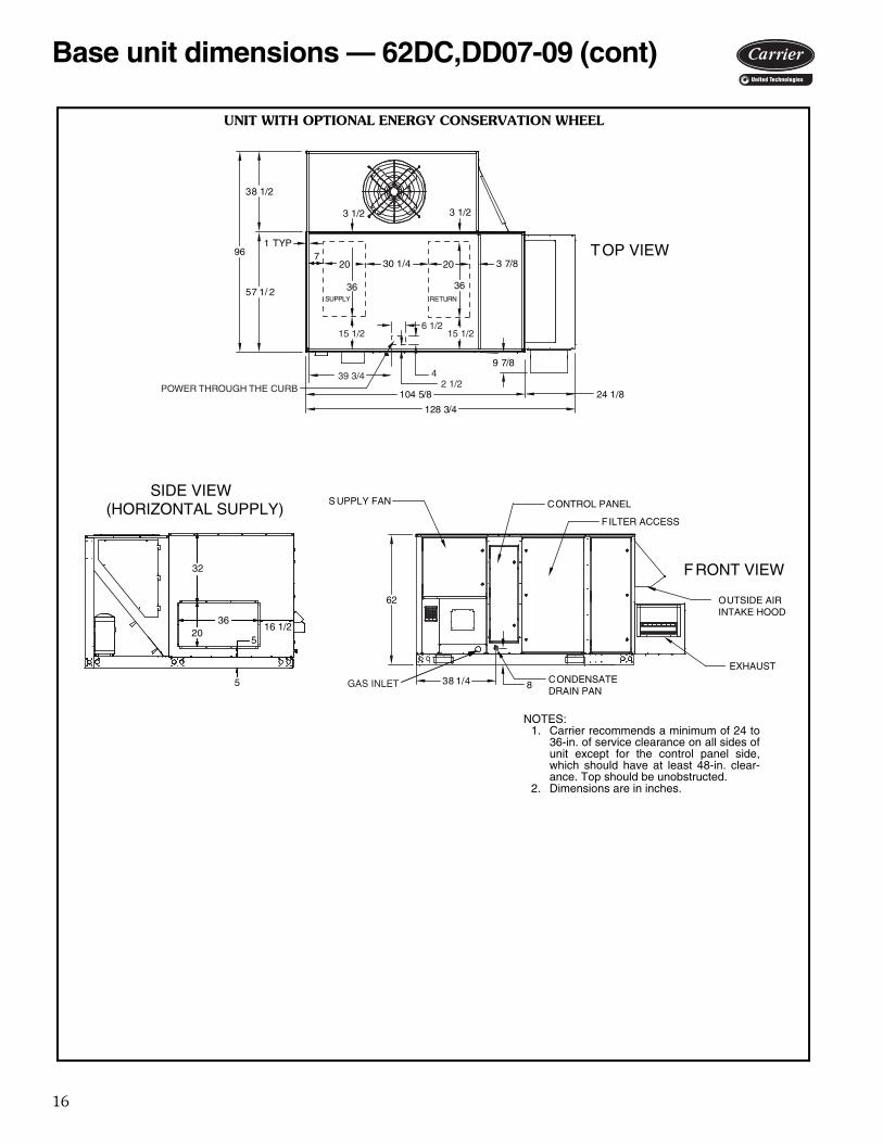
S UPPLY FAN
FILTER ACCESS
CONTROL PANEL
SUPPLY RETURN
TOP VIEW
FRONT VIEW
OUTSIDE AIRINTAKE HOOD
720
3 1/2
36
838 1/4 CONDENSATEDRAIN PAN
38 1/2
57 1/ 2
104 5/8
30 1/4
24 1/8
9 7/8
128 3/4
96
EXHAUST
1 TYP
62
3 7/8
3 1/2
20
36
15 1/2 15 1/26 1/2
42 1/2POWER THROUGH THE CURB
39 3/4
GAS INLET
SIDE VIEW(HORIZONTAL SUPPLY)
36
5
520
16 1/2
32
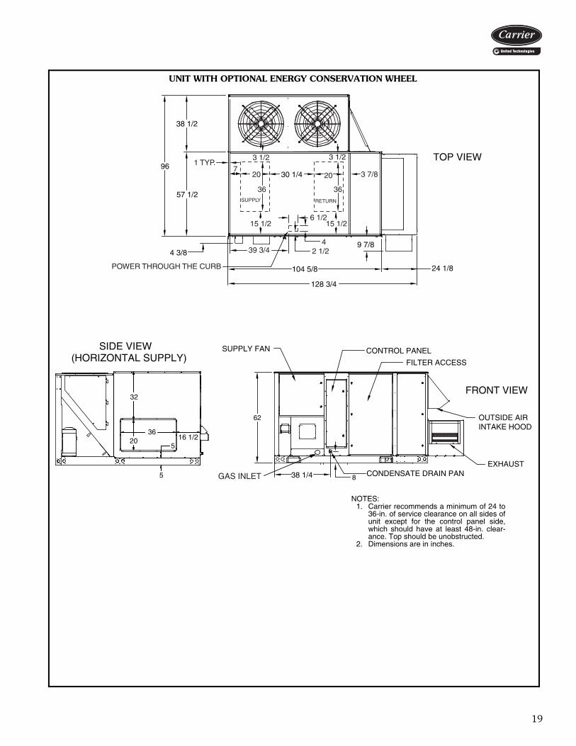
UNIT WITH OPTIONAL ENERGY CONSERVATION WHEEL
NOTES:1. Carrier recommends a minimum of 24 to
36-in. of service clearance on all sides ofunit except for the control panel side,which should have at least 48-in. clear-ance. Top should be unobstructed.
2. Dimensions are in inches.
a62-566
Base unit dimensions — 62DC,DD07-09 (cont)
17
Base unit dimensions — 62DA,DB12-20
TOP VIEW
FRONT VIEW
38 1/2
57 1/2
82 1/2
97 1/8
38 1/4
62
8
14 5/8
FILTER ACCESS
OUTSIDE AIRINTAKE HOOD
CONTROL PANELSUPPLY FAN
CONDENSATE DRAIN PAN
9620
36
4
6 1/2
SUPPLY
15 1/2
1 TYP.
3 1/2
7
POWER THROUGH THE CURB
2 1/239 3/4
GAS INLET
SIDE VIEW(HORIZONTAL SUPPLY)
36
5
520 16 1/2
32
STANDARD UNIT
NOTES:1. Carrier recommends a minimum of 24 to
36-in. of service clearance on all sides ofunit except for the control panel side,which should have at least 48-in. clear-ance. Top should be unobstructed.
2. Dimensions are in inches.
a62-567
18
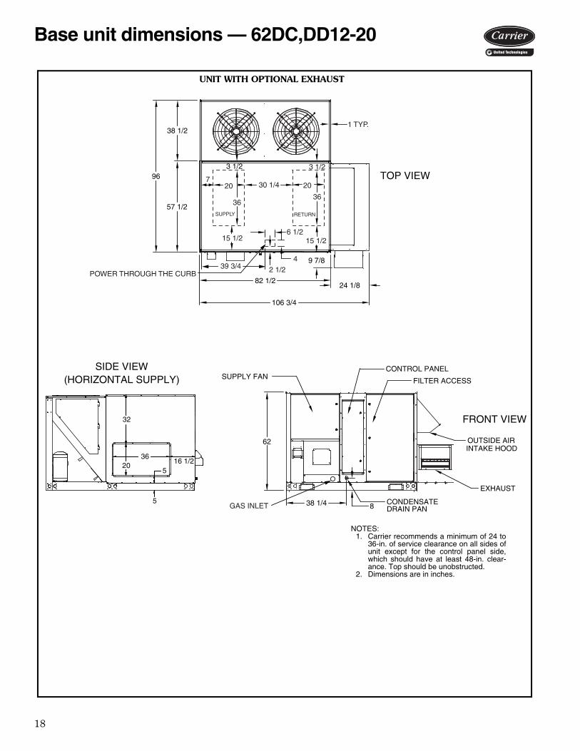
SUPPLY FAN FILTER ACCESS
CONTROL PANEL
TOP VIEW
FRONT VIEW
OUTSIDE AIRINTAKE HOOD
838 1/4 CONDENSATEDRAIN PAN
EXHAUST
38 1/2
57 1/2
96
9 7/8
24 1/882 1/2
106 3/4
3 1/2
62
1 TYP.
4
2 1/2POWER THROUGH THE CURB
6 1/215 1/2
39 3/4
7
3 1/2
20 2030 1/4
3636
15 1/2
SUPPLY RETURN
GAS INLET
SIDE VIEW(HORIZONTAL SUPPLY)
36
5
520
16 1/2
32
UNIT WITH OPTIONAL EXHAUST
NOTES:1. Carrier recommends a minimum of 24 to
36-in. of service clearance on all sides ofunit except for the control panel side,which should have at least 48-in. clear-ance. Top should be unobstructed.
2. Dimensions are in inches.
a62-568
Base unit dimensions — 62DC,DD12-20
19
8
62
TOP VIEW
FRONT VIEW
OUTSIDE AIRINTAKE HOOD
EXHAUST
FILTER ACCESS
CONTROL PANELSUPPLY FAN
38 1/2
57 1/2
4 3/8
38 1/4
104 5/8
128 3/4
9 7/8
24 1/8
96
CONDENSATE DRAIN PAN
30 1/4
1 TYP.7
20 20
36 36
3 1/2 3 1/2
3 7/8
2 1/24
15 1/26 1/2
15 1/2
POWER THROUGH THE CURB
39 3/4
SUPPLY RETURN
GAS INLET
SIDE VIEW(HORIZONTAL SUPPLY)
36
5
520 16 1/2
32
UNIT WITH OPTIONAL ENERGY CONSERVATION WHEEL
NOTES:1. Carrier recommends a minimum of 24 to
36-in. of service clearance on all sides ofunit except for the control panel side,which should have at least 48-in. clear-ance. Top should be unobstructed.
2. Dimensions are in inches.
a62-569
20
TOP VIEW
FRONT VIEW
33 3/4
62 1/4
131
18 1/2
112 9/16
62 5/8
83
8
2 13/16
FILTER ACCESS
OUTSIDE AIRINTAKE HOOD
CONTROL PANELSUPPLY FAN
CONDENSATE DRAIN PAN
96
10 7/8
1 TYP.
30
40
SUPPLY
17 6 1/262 3/8
4POWER THROUGH THE CURB
GAS INLET
GAS INLET
SIDE VIEW(HORIZONTAL SUPPLY)
40 1/2
30 1/218 1/2
4 1/2
43 1/2
4 1/2
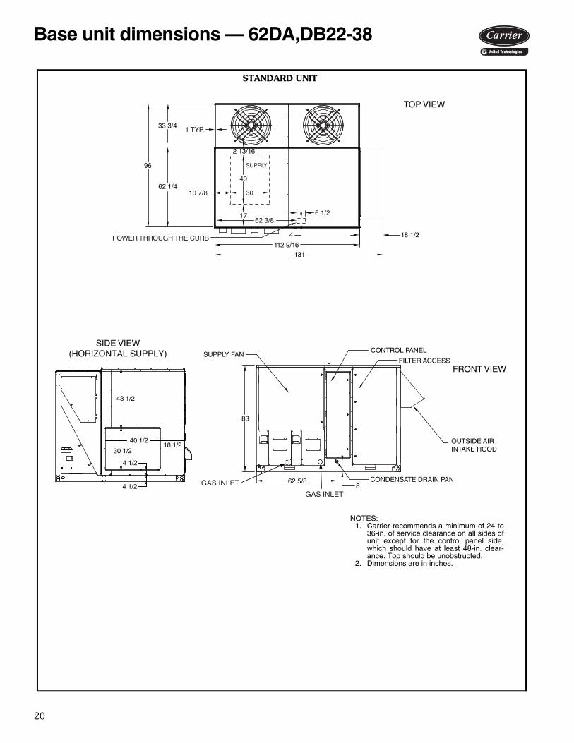
STANDARD UNIT
NOTES:1. Carrier recommends a minimum of 24 to
36-in. of service clearance on all sides ofunit except for the control panel side,which should have at least 48-in. clear-ance. Top should be unobstructed.
2. Dimensions are in inches.a62-570
Base unit dimensions — 62DA,DB22-38
21
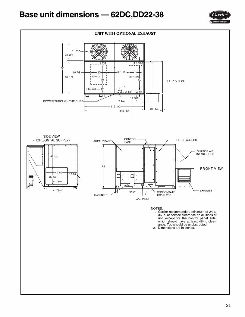
Base unit dimensions — 62DC,DD22-38
EXHAUST
FILTER ACCESS
TOP VIEW
FR ONT VIEW
OUTSIDE AIRINTAKE HOOD
83
CONDENSATEDRAIN PAN
112 1/234 1/4
146 3 /4
96
33 3/4
62 1/4
SUPPLY FANCONTROLPANEL
62 5/88
1 TYP.
10 7/8
2 7/8 4 15/16
30 24
40 50
42 1/16
SUPPLY RETURN
2 1/4POWER THROUGH THE CURB
62 3/8 176 1/2
4
4 7/8
14 3/8
GAS INLET
GAS INLET
SIDE VIEW(HORIZONTAL SUPPLY)
40 1/2
30 1/218 1/2
4 1/2
43 1/2
4 1/2
UNIT WITH OPTIONAL EXHAUST
NOTES:1. Carrier recommends a minimum of 24 to
36-in. of service clearance on all sides ofunit except for the control panel side,which should have at least 48-in. clear-ance. Top should be unobstructed.
2. Dimensions are in inches.
a62-571
22
TOP VIEW
FRONT VIEW
33 3/4
62 1/4
136 5/8
83
62 5/88
15 3/8
34 3/16
FILTER ACCESSENERGY RECOVERY WHEEL
OUTSIDE AIRINTAKE HOOD
CONTROLPANEL
SUPPLY FAN
CONDENSATE DRAIN PAN
EXHAUST
170 3/4
96
1 TYP.
10 7/8 30
40 50
2442 1/16
4 7/83 1/4
POWER THROUGH THE CURB
174
6 1/263 1/2
SUPPLY
RETURN
2 13/16 4 15/16
GAS INLETGAS INLET
SIDE VIEW(HORIZONTAL SUPPLY)
40 1/2
30 1/218 1/2
4 1/2
43 1/2
4 1/2
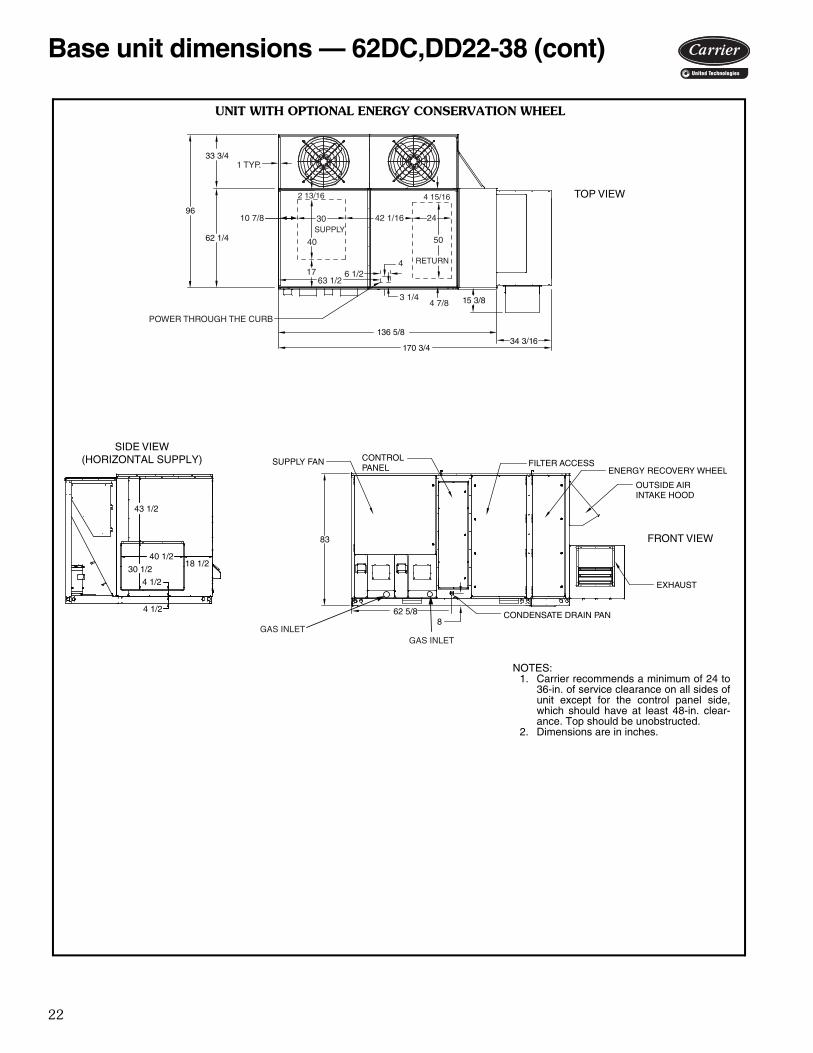
UNIT WITH OPTIONAL ENERGY CONSERVATION WHEEL
NOTES:1. Carrier recommends a minimum of 24 to
36-in. of service clearance on all sides ofunit except for the control panel side,which should have at least 48-in. clear-ance. Top should be unobstructed.
2. Dimensions are in inches.
a62-572
Base unit dimensions — 62DC,DD22-38 (cont)
23
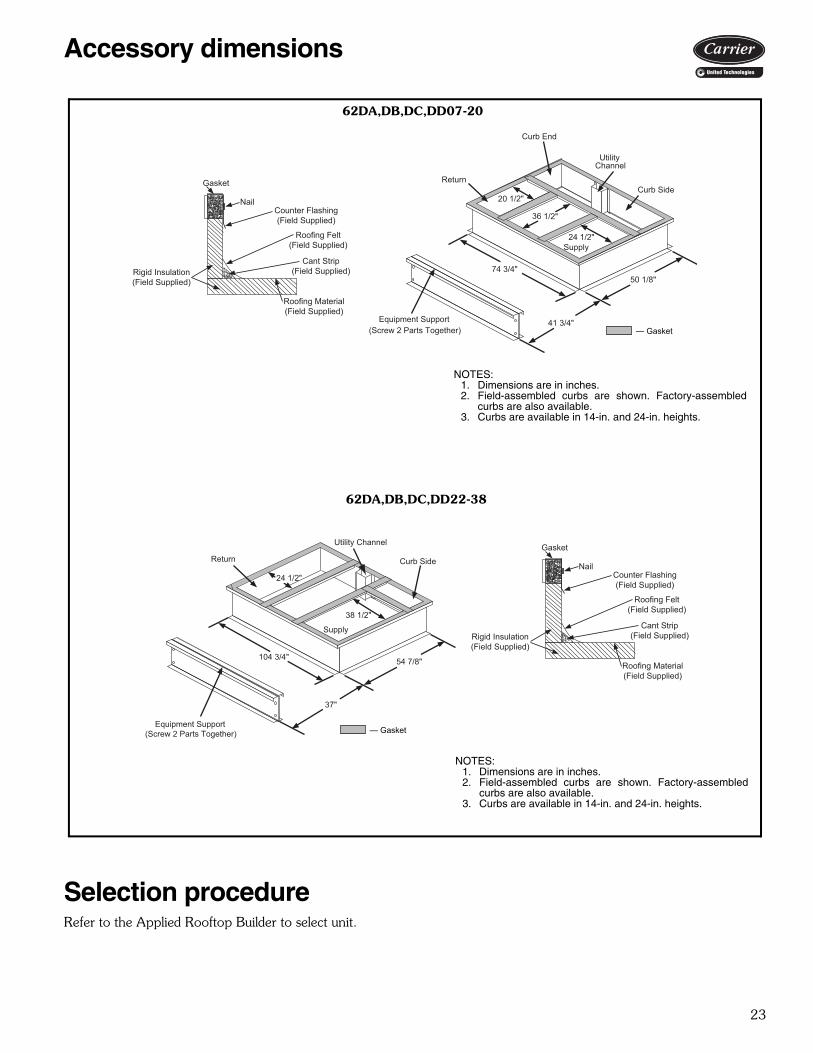
Accessory dimensions
Selection procedureRefer to the Applied Rooftop Builder to select unit.
Curb End
UtilityChannel
Curb Side
Equipment Support (Screw 2 Parts Together)
Supply24 1/2"
36 1/2"
20 1/2"
50 1/8"
41 3/4"
74 3/4"
Return
— Gasket
Gasket
NailCounter Flashing(Field Supplied)
Roofing Felt(Field Supplied)
Cant Strip(Field Supplied)
Roofing Material(Field Supplied)
Rigid Insulation(Field Supplied)
Gasket
NailCounter Flashing(Field Supplied)
Roofing Felt(Field Supplied)
Cant Strip(Field Supplied)
Roofing Material(Field Supplied)
Rigid Insulation(Field Supplied)
Equipment Support(Screw 2 Parts Together)
Curb Side
54 7/8"
37"
104 3/4"
Supply
24 1/2"
38 1/2"
Return
Utility Channel
— Gasket
62DA,DB,DC,DD07-20
62DA,DB,DC,DD22-38
a62-549
NOTES:1. Dimensions are in inches.2. Field-assembled curbs are shown. Factory-assembled
curbs are also available.3. Curbs are available in 14-in. and 24-in. heights.
a62-550
NOTES:1. Dimensions are in inches.2. Field-assembled curbs are shown. Factory-assembled
curbs are also available.3. Curbs are available in 14-in. and 24-in. heights.

24
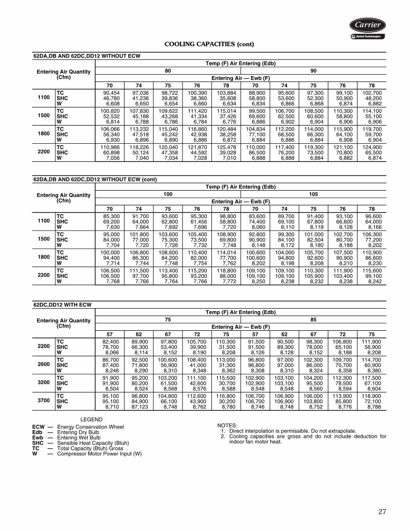
COOLING CAPACITIES
LEGEND
NOTES:1. Direct interpolation is permissible. Do not extrapolate.2. Cooling capacities are gross and do not include deduction for
indoor fan motor heat.
62DA,DB07 AND 62DC,DD07 WITHOUT ECW
Entering Air Quantity (Cfm)
Temp (F) Air Entering (Edb)80 90
Entering Air — Ewb (F)70 74 75 76 78 70 74 75 76 78
700TC 55,818 59,797 60,819 61,852 63,944 53,844 57,803 58,819 59,845 61,913SHC 28,835 25,326 24,422 23,551 21,691 35,572 32,221 31,370 30,499 28,697W 3,804 3,839 3,849 3,854 3,874 4,232 4,268 4,278 4,289 4,314
950TC 61,617 65,773 66,844 67,907 70,055 59,230 63,318 64,369 65,439 67,570SHC 32,270 27,523 26,309 25,099 22,604 41,761 37,042 35,874 34,712 32,312W 3,954 3,992 4,003 4,014 4,037 4,383 4,431 4,443 4,456 4,482
1250TC 65,784 69,992 71,066 72,140 74,278 63,010 67,163 68,225 69,296 71,445SHC 35,796 29,568 27,987 26,400 23,195 48,544 42,432 40,896 39,349 36,244W 4,111 4,157 4,169 4,181 4,206 4,542 4,595 4,608 4,623 4,652
1500TC 67,946 72,192 73,256 74,326 76,440 65,023 69,218 70,273 71,336 73,442SHC 38,458 31,071 29,201 27,323 23,557 54,005 46,930 45,103 43,284 39,509W 4,231 420 4,292 4,305 4,331 4,666 4,714 4,729 4,744 4,776
62DA,DB07 AND 62DC,DD07 WITHOUT ECW (cont)
Entering Air Quantity (Cfm)
Temp (F) Air Entering (Edb)100 105
Entering Air — Ewb (F)70 74 75 76 78 70 74 75 76 78
700TC 51,638 55,466 56,450 57,445 59,441 50,452 54,129 55,137 56,107 58,064SHC 42,199 38,929 38,084 37,231 35,431 45,437 42,134 41,397 40,547 38,818W 4,734 4,776 4,787 4,799 4,823 5,024 5,071 5,079 5,093 5,121
950TC 56,503 60,414 61,423 62,449 64,573 56,353 58,845 59,800 60,796 62,807SHC 50,902 46,387 45,265 44,124 41,898 56,074 51,001 49,853 48,732 46,501W 4,892 4,941 4,955 4,969 4,995 5,208 5,240 5,255 5,270 5,300
1250TC 61,484 63,876 64,930 65,927 67,862 62,799 62,405 63,255 64,058 66,077SHC 61,484 55,025 53,616 52,113 48,993 62,799 60,415 58,981 57,385 55,475W 5,089 5,110 5,127 5,136 5,173 5,436 5,415 5,430 5,450 5,474
1500TC 65,431 65,806 66,728 67,776 69,628 66,819 66,977 67,018 66,077 67,780SHC 65,431 60,774 59,054 57,576 54,928 66,819 66,977 67,018 64,563 61,206W 5,232 5,235 5,253 5,265 5,302 5,594 5,592 5,590 5,586 5,602
62DC,DD07 WITH ECW
Entering Air Quantity (Cfm)
Temp (F) Air Entering (Edb)75 85
Entering Air — Ewb (F)57 62 67 72 75 57 62 67 72 75
1500TC 51,900 56,500 61,400 66,100 68,900 58,400 58,500 61,800 66,800 69,900SHC 51,400 42,900 34,100 24,900 19,300 58,400 58,500 51,000 42,100 36,400W 4,701 4,734 4,783 4,836 4,869 4,756 4,757 4,785 4,839 4,882
1800TC 55,300 58,200 63,100 67,700 70,500 61,900 62,000 63,300 68,500 71,600SHC 55,300 47,300 36,700 25,600 19,000 61,900 62,000 56,700 46,200 39,600W 4,840 4,861 4,916 4,970 5,004 4,900 4,901 4,922 4,976 5,020
2200TC 58,300 59,500 64,400 69,100 71,700 65,200 65,300 65,000 69,800 73,000SHC 58,300 52,500 40,100 26,600 18,400 65,200 65,300 62,800 51,400 43,600W 5,017 5,030 5,074 5,139 5,174 5,089 5,090 5,085 5,150 5,192
2500TC 59,900 60,200 65,000 69,700 72,300 67,200 67,300 67,400 70,400 73,700SHC 59,900 54,900 42,500 27,500 18,300 67,200 67,300 67,400 55,500 46,900W 5,147 5,147 5,198 5,258 5,293 5,226 5,227 5,228 5,272 5,313
ECW — Energy Conservation WheelEdb — Entering Dry BulbEwb — Entering Wet BulbSHC — Sensible Heat Capacity (Btuh)TC — Total Capacity (Btuh) GrossW — Compressor Motor Power Input (W)
Performance data

25
COOLING CAPACITIES (cont)
LEGEND
NOTES:1. Direct interpolation is permissible. Do not extrapolate.2. Cooling capacities are gross and do not include deduction for
indoor fan motor heat.
62DA,DB AND 62DC,DD08 WITHOUT ECW
Entering Air Quantity (Cfm)
Temp (F) Air Entering (Edb)80 90
Entering Air — Ewb (F)70 74 75 76 78 70 74 75 76 78
800TC 66,638 71,484 72,775 74,033 76,603 64,098 69,000 70,236 71,510 74,058SHC 34,460 30,404 28,409 28,355 26,330 41,968 38,234 37,256 36,252 34,223W 4,938 4,940 4,941 4,942 4,943 5,385 5,384 5,384 5,385 5,390
1150TC 75,798 84,071 82,404 83,722 86,431 72,615 77,876 79,212 80,538 83,261SHC 39,543 33,931 32,469 30,947 27,998 50,861 45,476 44,059 42,651 39,771W 5,077 5,082 5,083 5,084 5,086 5,521 5,523 5,524 5,525 5,526
1450TC 80,669 86,035 87,389 88,739 91,427 77,190 82,406 83,752 85,106 87,901SHC 43,262 36,138 34,300 32,450 28,715 58,044 50,911 49,127 47,330 43,909W 5,197 5,201 5,201 5,202 5,203 5,635 5,639 5,639 5,640 5,640
1800TC 84,407 89,794 91,148 92,499 95,159 80,610 85,921 87,138 88,530 91,259SHC 47,247 38,349 36,111 33,856 29,320 65,907 57,295 54,838 52,708 48,315W 5,329 5,333 5,334 5,334 5,334 5,768 5,770 5,772 5,771 5,771
62DA,DB AND DC,DD08 WITHOUT ECW (cont)
Entering Air Quantity (Cfm)
Temp (F) Air Entering (Edb)100 105
Entering Air — Ewb (F)70 74 75 76 78 70 74 75 76 78
800TC 61,364 66,088 67,307 68,595 71,108 59,845 64,573 65,766 66,998 69,466SHC 49,392 45,643 44,704 43,819 41,879 52,914 49,456 48,528 47,580 45,650W 5,895 5,899 5,899 5,900 5,900 6,193 6,192 6,194 6,196 6,200
1150TC 69,217 74,102 75,416 76,692 79,328 68,694 72,108 73,447 74,595 77,272SHC 62,109 56,519 55,212 53,800 51,010 68,080 62,072 60,900 59,337 56,768W 6,038 6,042 6,042 6,044 6,046 6,338 6,342 6,343 6,347 6,345
1450TC 73,339 78,207 79,495 80,947 83,415 75,812 76,128 77,420 78,573 81,155SHC 72,256 65,352 6,368 62,145 58,390 75,812 72,636 70,930 69,118 65,683W 6,154 6,158 6,158 6,159 6,163 6,465 6,466 6,468 6,468 6,447
1800TC 80,418 81,541 82,624 83,979 86,392 82,352 82,563 82,636 81,841 82,922SHC 80,418 75,679 73,275 71,367 66,807 82,352 82,563 82,636 80,619 74,466W 6,292 6,291 6,293 6,293 6,297 6,578 6,573 6,578 6,572 6,579
62DC,DD08 WITH ECW
Entering Air Quantity (Cfm)
Temp (F) Air Entering (Edb)75 85
Entering Air — Ewb (F)57 62 67 72 75 57 62 67 72 75
1800TC 61,600 67,110 72,900 77,560 82,100 69,700 69,900 73,450 79,550 83,300SHC 60,300 51,000 40,500 31,800 22,800 69,700 69,900 60,900 50,000 43,500W 5,994 5,999 6,004 6,010 6,015 6,002 6,005 6,008 6,013 6,015
2200TC 66,300 69,100 75,000 79,700 84,200 74,200 74,350 75,600 81,780 85,500SHC 66,300 56,700 43,900 33,500 22,700 74,200 74,350 67,000 55,800 47,960W 6,144 6,147 6,153 6,158 6,163 6,150 6,151 6,154 6,160 6,164
2600TC 69,200 70,700 76,500 81,000 85,400 77,500 77,660 77,300 82,970 86,830SHC 69,200 60,800 47,500 34,900 22,300 77,500 77,660 74,000 60,900 52,000W 6,293 6,294 6,300 6,306 6,311 6,300 6,305 6,307 6,309 6,312
3000TC 71,300 71,500 77,370 81,800 86,200 80,100 80,190 80,300 84,100 87,675SHC 71,300 65,100 50,700 36,400 21,900 80,100 80,190 80,300 64,500 56,100W 6,442 6,445 6,448 6,453 6,458 6,450 6,452 6,454 6,455 6,460
ECW — Energy Conservation WheelEdb — Entering Dry BulbEwb — Entering Wet BulbSHC — Sensible Heat Capacity (Btuh)TC — Total Capacity (Btuh) GrossW — Compressor Motor Power Input (W)

26
COOLING CAPACITIES (cont)
LEGENDNOTES:
1. Direct interpolation is permissible. Do not extrapolate.2. Cooling capacities are gross and do not include deduction for
indoor fan motor heat.
62DA,DB AND 62DC,DD09 WITHOUT ECW
Entering Air Quantity (Cfm)
Temp (F) Air Entering (Edb)80 90
Entering Air — Ewb (F)70 74 75 76 78 70 74 75 76 78
900TC 75,277 80,741 82,146 83,552 86,430 72,682 78,051 79,429 80,808 83,646SHC 38,936 34,355 33,198 32,027 29,735 47,523 43,205 42,103 40,951 38,674W 5,647 5,728 5,749 5,770 5,811 6,208 6,292 6,313 6,336 6,383
1300TC 85,683 91,515 92,985 94,493 97,490 82,172 87,987 89,430 90,899 93,842SHC 44,821 38,308 36,604 34,938 31,545 57,521 51,387 49,769 48,163 44,837W 5,962 6,053 6,078 6,102 6,152 6,526 6,622 6,648 6,674 6,728
1600TC 90,591 96,479 97,988 99,497 102,482 86,594 92,502 93,977 95,462 95,446SHC 48,575 50,445 38,428 36,378 32,224 64,444 56,956 54,968 52,977 48,985W 6,159 6,260 6,284 6,310 6,361 6,725 6,824 6,851 6,878 6,933
2100TC 95,723 101,757 103,249 104,741 107,603 91,258 97,211 98,518 100,177 103,148SHC 54,041 43,897 41,276 38,631 33,001 75,601 65,778 62,904 60,703 55,593W 6,444 6,544 6,570 6,597 6,653 7,004 7,109 7,142 7,165 7,222
62DA,DB AND 62DC,DD09 WITHOUT ECW (cont)
Entering Air Quantity (Cfm)
Temp (F) Air Entering (Edb)100 105
Entering Air — Ewb (F)70 74 75 76 78 70 74 75 76 78
900TC 69,743 74,852 76,182 77,535 80,281 68,071 73,110 74,405 75,693 78,431SHC 55,953 51,576 50,510 49,444 47,235 60,006 55,840 54,782 53,678 51,478W 6,861 6,957 6,981 7,006 7,057 7,238 7,341 7,369 7,396 7,437
1300TC 78,432 83,740 85,061 86,559 89,362 76,359 81,686 83,051 84,360 87,352SHC 70,210 64,017 62,334 60,923 57,510 76,282 70,396 68,855 67,122 64,178W 7,192 7,295 7,327 7,352 7,404 7,577 7,639 7,666 7,695 7,730
1600TC 82,513 87,827 89,036 90,600 93,536 83,387 85,668 87,220 88,566 91,126SHC 80,472 72,902 70,614 68,866 64,948 83,387 80,687 79,054 77,051 72,996W 7,392 7,489 7,525 7,536 7,584 7,788 7,837 7,848 7,868 7,918
2100TC 91,872 92,242 93,530 94,186 98,193 94,128 94,365 94,428 94,479 95,494SHC 91,872 87,061 84,468 80,876 77,380 94,128 94,365 94,428 93,616 87,945W 7,765 7,765 7,791 7,830 7,842 8,178 8,176 8,175 8,163 8,195
62DC,DD09 WITH ECW
Entering Air Quantity (Cfm)
Temp (F) Air Entering (Edb)75 85
Entering Air — Ewb (F)57 62 67 72 75 57 62 67 72 75
2100TC 71,000 77,000 83,500 89,900 93,700 80,300 80,500 83,900 90,900 95,100SHC 69,600 59,000 46,900 33,800 26,000 80,300 80,500 70,100 57,900 50,300W 6,857 6,939 7,025 7,129 7,186 6,985 6,987 7,038 7,137 7,203
2550TC 76,100 78,900 85,600 92,000 95,700 85,000 85,200 86,500 93,000 97,200SHC 76,100 65,200 50,400 35,200 25,500 85,000 85,200 77,100 63,900 54,700W 7,097 7,137 7,234 7,329 7,393 7,227 7,229 7,242 7,347 7,417
3050TC 79,400 80,600 87,100 93,500 97,000 88,900 89,000 88,200 94,400 98,700SHC 79,400 69,600 54,700 36,400 24,800 88,900 89,000 85,000 68,300 59,800W 7,339 7,353 7,442 7,543 7,609 7,473 7,475 7,460 7,566 7,631
3500TC 81,600 81,500 87,900 94,300 97,800 91,500 91,600 91,700 95,400 99,400SHC 81,600 74,500 58,200 37,500 24,500 91,500 91,600 91,700 73,400 64,200W 7,543 7,538 7,629 7,729 7,788 7,687 7,689 7,691 7,754 7,822
ECW — Energy Conservation WheelEdb — Entering Dry BulbEwb — Entering Wet BulbSHC — Sensible Heat Capacity (Btuh)TC — Total Capacity (Btuh) GrossW — Compressor Motor Power Input (W)
Performance data (cont)
27
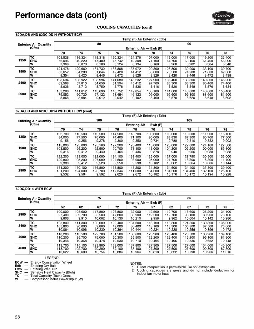
COOLING CAPACITIES (cont)
LEGENDNOTES:
1. Direct interpolation is permissible. Do not extrapolate.2. Cooling capacities are gross and do not include deduction for
indoor fan motor heat.
62DA,DB AND 62DC,DD12 WITHOUT ECW
Entering Air Quantity (Cfm)
Temp (F) Air Entering (Edb)80 90
Entering Air — Ewb (F)70 74 75 76 78 70 74 75 76 78
1100TC 90,454 97,036 98,722 100,390 103,884 88,900 95,600 97,300 99,100 102,700SHC 46,780 41,236 39,836 38,360 35,608 58,800 53,600 52,300 50,900 48,200W 6,608 6,650 6,654 6,660 6,634 6,834 6,866 6,868 6,874 6,882
1500TC 100,820 107,830 109,622 111,420 115,014 99,500 106,700 108,500 110,300 114,100SHC 52,532 45,188 43,268 41,334 37,426 69,600 62,500 60,600 58,800 55,100W 6,814 6,788 6,786 6,784 6,776 6,886 6,902 6,904 6,906 6,906
1800TC 106,066 113,232 115,040 116,860 120,484 104,834 112,200 114,000 115,900 119,700SHC 56,340 47,518 45,242 42,938 38,258 77,100 68,500 66,300 64,100 59,700W 6,930 6,896 6,890 6,886 6,872 6,884 6,886 6,884 6,908 6,904
2200TC 110,966 118,226 120,040 121,870 125,478 110,000 117,400 119,300 121,100 124,900SHC 60,898 50,124 47,358 44,592 39,028 86,500 76,200 73,500 70,800 65,500W 7,056 7,040 7,034 7,028 7,010 6,888 6,888 6,884 6,882 6,874
62DA,DB AND 62DC,DD12 WITHOUT ECW (cont)
Entering Air Quantity (Cfm)
Temp (F) Air Entering (Edb)100 105
Entering Air — Ewb (F)70 74 75 76 78 70 74 75 76 78
1100TC 85,300 91,700 93,600 95,300 98,800 83,600 89,700 91,400 93,100 96,600SHC 69,200 64,000 62,800 61,456 58,800 74,400 69,100 67,800 66,600 64,000W 7,630 7,664 7,692 7,696 7,720 8,060 8,110 8,118 8,128 8,166
1500TC 95,000 101,800 103,600 105,400 108,900 92,800 99,300 101,000 102,700 106,300SHC 84,000 77,000 75,300 73,500 69,800 90,900 84,100 82,504 80,700 77,200W 7,704 7,720 7,726 7,732 7,748 8,148 8,172 8,180 8,188 8,202
1800TC 100,000 106,800 108,600 110,400 114,014 100,600 104,000 105,700 107,500 110,900SHC 94,400 86,300 84,200 82,000 77,700 100,600 94,800 92,600 90,900 86,600W 7,714 7,744 7,748 7,754 7,762 8,202 8,198 8,208 8,210 8,230
2200TC 106,500 111,500 113,400 115,200 118,800 109,100 109,100 110,300 111,900 115,600SHC 106,500 97,700 95,800 93,200 88,000 109,100 109,100 105,900 103,400 99,100W 7,768 7,766 7,764 7,766 7,772 8,250 8,238 8,232 8,238 8,242
62DC,DD12 WITH ECW
Entering Air Quantity (Cfm)
Temp (F) Air Entering (Edb)75 85
Entering Air — Ewb (F)57 62 67 72 75 57 62 67 72 75
2200TC 82,400 89,900 97,800 105,700 110,300 91,500 90,500 98,300 106,800 111,900SHC 78,700 66,300 53,400 39,900 31,500 91,500 89,300 78,000 65,100 56,900W 8,066 8,114 8,152 8,190 8,208 8,126 8,128 8,152 8,188 8,208
2600TC 86,700 92,500 100,600 108,400 113,000 96,800 97,000 102,300 109,700 114,700SHC 87,400 71,800 56,900 41,000 31,300 96,800 97,000 86,000 70,700 60,900W 8,246 8,290 8,310 8,348 8,362 8,308 8,310 8,324 8,358 8,380
3200TC 91,900 95,200 103,200 111,100 115,500 102,900 103,100 104,200 112,300 117,500SHC 91,900 80,200 61,500 42,600 30,700 102,900 103,100 95,500 78,500 67,100W 8,504 8,524 8,568 8,576 8,588 8,548 8,548 8,560 8,594 8,604
3700TC 95,100 96,800 104,800 112,600 116,800 106,700 106,900 106,000 113,900 118,900SHC 95,100 84,900 66,100 43,900 30,200 106,700 106,900 103,800 85,800 72,100W 8,710 87,123 8,748 8,762 8,780 8,746 8,748 8,752 8,776 8,788
ECW — Energy Conservation WheelEdb — Entering Dry BulbEwb — Entering Wet BulbSHC — Sensible Heat Capacity (Btuh)TC — Total Capacity (Btuh) GrossW — Compressor Motor Power Input (W)
28
COOLING CAPACITIES (cont)
LEGEND
NOTES:1. Direct interpolation is permissible. Do not extrapolate.2. Cooling capacities are gross and do not include deduction for
indoor fan motor heat.
62DA,DB AND 62DC,DD14 WITHOUT ECW
Entering Air Quantity (Cfm)
Temp (F) Air Entering (Edb)80 90
Entering Air — Ewb (F)70 74 75 76 78 70 74 75 76 78
1350TC 108,528 116,324 118,318 120,324 124,376 107,000 115,000 117,000 119,200 123,400SHC 56,096 49,220 47,480 45,742 42,308 71,100 64,700 63,100 61,400 58,000W 7,968 8,078 8,100 8,124 8,134 8,168 8,260 8,282 8,304 8,348
1900TC 121,478 129,662 131,732 133,808 137,972 120,300 128,800 130,900 133,100 130,700SHC 63,652 54,280 51,844 49,420 44,412 85,600 76,500 74,200 71,800 62,300W 8,354 8,420 8,446 8,472 8,526 8,326 8,420 8,446 8,472 8,438
2400TC 128,634 136,922 138,994 141,080 145,232 127,900 136,400 138,600 140,800 145,200SHC 69,568 57,810 54,656 51,594 45,412 97,700 86,300 83,300 80,400 74,400W 8,636 8,712 8,750 8,778 8,836 8,416 8,520 8,548 8,576 8,634
2900TC 133,296 141,612 143,696 145,752 149,854 133,100 141,600 143,800 146,000 150,400SHC 75,052 60,720 57,122 53,454 46,122 109,000 95,600 92,100 88,600 81,500W 8,868 8,984 9,012 9,042 9,102 8,460 8,570 8,620 8,648 8,692
62DA,DB AND 62DC,DD14 WITHOUT ECW (cont)
Entering Air Quantity (Cfm)
Temp (F) Air Entering (Edb)100 105
Entering Air — Ewb (F)70 74 75 76 78 70 74 75 76 78
1350TC 102,700 110,500 112,500 114,500 118,700 100,600 108,000 110,000 111,900 116,100SHC 84,000 77,500 76,000 74,400 71,100 90,000 83,830 82,300 80,700 77,500W 9,156 9,256 9,278 9,300 9,350 9,734 9,788 9,810 9,832 9,902
1900TC 115,000 123,000 125,100 127,200 125,400 113,000 120,000 122,000 124,100 122,500SHC 103,800 95,200 92,900 90,700 78,100 113,000 104,200 102,200 100,000 85,800W 9,316 9,412 9,440 9,464 9,436 9,878 9,940 9,966 9,988 9,988
2400TC 122,200 123,000 132,000 134,100 138,400 125,000 127,000 128,790 130,900 135,000SHC 120,800 95,200 107,000 104,600 98,900 125,000 121,700 118,800 116,300 111,100W 9,388 9,412 9,520 9,550 9,598 10,182 10,062 10,064 10,086 10,144
2900TC 131,200 130,100 136,800 138,800 143,200 134,300 134,500 134,400 135,800 139,400SHC 131,200 124,000 120,700 117,344 111,600 134,300 134,500 134,400 132,100 125,100W 9,532 9,564 9,592 9,620 9,672 10,182 10,176 10,172 10,194 10,228
62DC,DD14 WITH ECW
Entering Air Quantity (Cfm)
Temp (F) Air Entering (Edb)75 85
Entering Air — Ewb (F)57 62 67 72 75 57 62 67 72 75
2900TC 100,000 108,600 117,800 126,800 132,000 112,500 112,700 118,600 128,200 134,100SHC 97,400 82,700 65,500 47,800 36,900 112,500 112,700 98,100 80,900 70,100W 9,806 9,910 10,002 10,130 10,210 9,958 9,962 10,004 10,142 10,280
3400TC 105,800 111,300 120,600 129,400 134,600 118,100 118,300 121,300 130,800 136,900SHC 105,800 90,000 69,800 49,000 36,400 118,100 118,300 105,300 87,500 75,600W 10,064 10,096 10,230 10,364 10,444 10,224 10,228 10,256 10,396 10,472
4000TC 110,200 113,500 122,700 131,500 136,600 123,200 123,400 123,500 133,200 139,100SHC 110,200 95,700 75,000 50,300 35,500 123,200 123,400 115,200 96,100 81,800W 10,348 10,368 10,478 10,630 10,710 10,494 10,496 10,536 10,652 10,748
4600TC 113,700 115,100 123,900 133,000 137,800 127,300 127,500 127,600 134,600 140,300SHC 113,700 102,700 79,200 52,100 35,100 127,300 127,500 127,600 100,800 87,300W 10,622 10,600 10,754 10,884 10,964 10,818 10,822 10,790 10,906 11,016
ECW — Energy Conservation WheelEdb — Entering Dry BulbEwb — Entering Wet BulbSHC — Sensible Heat Capacity (Btuh)TC — Total Capacity (Btuh) GrossW — Compressor Motor Power Input (W)
Performance data (cont)

29
COOLING CAPACITIES (cont)
LEGENDNOTES:
1. Direct interpolation is permissible. Do not extrapolate.2. Cooling capacities are gross and do not include deduction for
indoor fan motor heat.
62DA,DB AND 62DC,DD15 WITHOUT ECW
Entering Air Quantity (Cfm)
Temp (F) Air Entering (Edb)80 90
Entering Air — Ewb (F)70 74 75 76 78 70 74 75 76 78
1700TC 143,266 153,674 156,344 159,044 164,492 138,266 148,622 151,302 153,942 159,416SHC 74,148 65,570 63,386 61,190 56,768 90,276 82,200 80,148 77,978 73,726W 10,586 10,642 10,656 10,670 10,692 11,614 11,674 11,690 11,706 11,744
2300TC 159,700 170,712 173,526 176,346 182,002 153,630 164,462 167,246 170,050 175,736SHC 82,970 71,594 68,624 65,618 59,576 105,704 94,416 91,558 88,692 82,920W 10,908 10,966 10,382 11,000 11,036 11,952 12,026 12,046 12,066 12,110
3000TC 171,770 183,030 185,884 188,742 194,404 164,736 175,714 178,574 181,434 187,278SHC 91,766 76,830 73,028 69,180 61,366 122,206 107,332 103,636 99,910 92,716W 11,246 11,318 11,336 11,354 11,392 12,296 12,382 12,404 12,428 12,476
3600TC 178,510 189,884 192,726 195,574 201,220 170,808 182,134 184,962 187,806 193,446SHC 98,392 80,670 76,132 71,586 62,468 135,306 118,372 113,944 109,448 100,392W 11,518 11,594 11,612 11,632 11,672 12,574 12,654 12,678 12,704 12,756
62DA,DB AND 62DC,DD15 WITHOUT ECW (cont)
Entering Air Quantity (Cfm)
Temp (F) Air Entering (Edb)100 105
Entering Air — Ewb (F)70 74 75 76 78 70 74 75 76 78
1700TC 132,748 142,674 145,272 147,952 153,254 129,742 139,516 142,038 144,644 149,820SHC 106,130 98,058 96,054 94,078 89,914 113,922 106,102 104,120 102,094 97,922W 12,822 12,878 12,896 12,916 12,958 13,496 13,572 13,594 13,618 13,666
2300TC 146,660 157,156 160,020 162,708 168,190 143,026 153,080 155,890 158,598 163,868SHC 127,572 116,796 114,376 111,580 105,910 138,584 127,748 125,376 122,698 116,680W 13,160 13,246 13,264 13,288 13,340 13,854 13,946 13,958 13,970 14,014
3000TC 157,084 167,238 170,138 172,826 178,334 161,024 162,950 165,880 168,646 173,954SHC 151,924 137,316 134,066 130,440 123,156 161,024 152,134 149,054 145,544 138,030W 13,510 13,614 13,634 13,662 13,708 14,282 14,276 14,276 14,288 14,338
3600TC 168,538 172,766 175,394 178,136 184,096 172,716 173,310 171,632 174,296 179,268SHC 168,538 154,380 150,082 145,782 137,794 172,716 173,310 168,756 164,730 155,740W 13,848 13,904 13,930 13,954 13,972 14,552 14,672 14,554 14,540 14,582
62DC,DD15 WITH ECW
Entering Air Quantity (Cfm)
Temp (F) Air Entering (Edb)75 85
Entering Air — Ewb (F)57 62 67 72 75 57 62 67 72 75
3600TC 130,800 142,300 154,600 166,800 174,100 146,200 143,900 155,300 168,800 176,700SHC 123,900 105,900 85,100 62,800 49,300 146,200 142,400 124,900 104,100 90,800W 12,726 12,760 12,806 12,878 12,916 12,772 12,770 12,818 12,880 12,926
4300TC 138,400 146,200 158,800 171,000 178,200 154,600 154,900 159,900 172,800 180,900SHC 138,400 113,200 91,000 64,500 48,700 154,600 154,900 135,100 113,200 98,200W 13,894 13,036 13,086 13,162 13,202 13,070 13,070 13,100 13,166 13,214
5300TC 145,900 150,000 162,600 174,700 181,700 163,400 163,600 164,300 176,800 184,600SHC 145,900 124,800 99,400 67,300 47,400 163,400 163,600 151,600 123,400 107,900W 13,398 13,422 13,476 13,548 13,598 13,480 13,482 13,486 13,558 13,616
5800TC 148,800 151,400 163,700 175,900 182,800 166,800 167,100 166,000 177,800 186,800SHC 148,800 130,200 102,800 68,500 46,700 166,800 167,100 159,100 128,200 113,400W 13,596 13,614 13,676 13,742 13,972 13,686 13,686 13,682 13,760 13,798
ECW — Energy Conservation WheelEdb — Entering Dry BulbEwb — Entering Wet BulbSHC — Sensible Heat Capacity (Btuh)TC — Total Capacity (Btuh) GrossW — Compressor Motor Power Input (W)
30
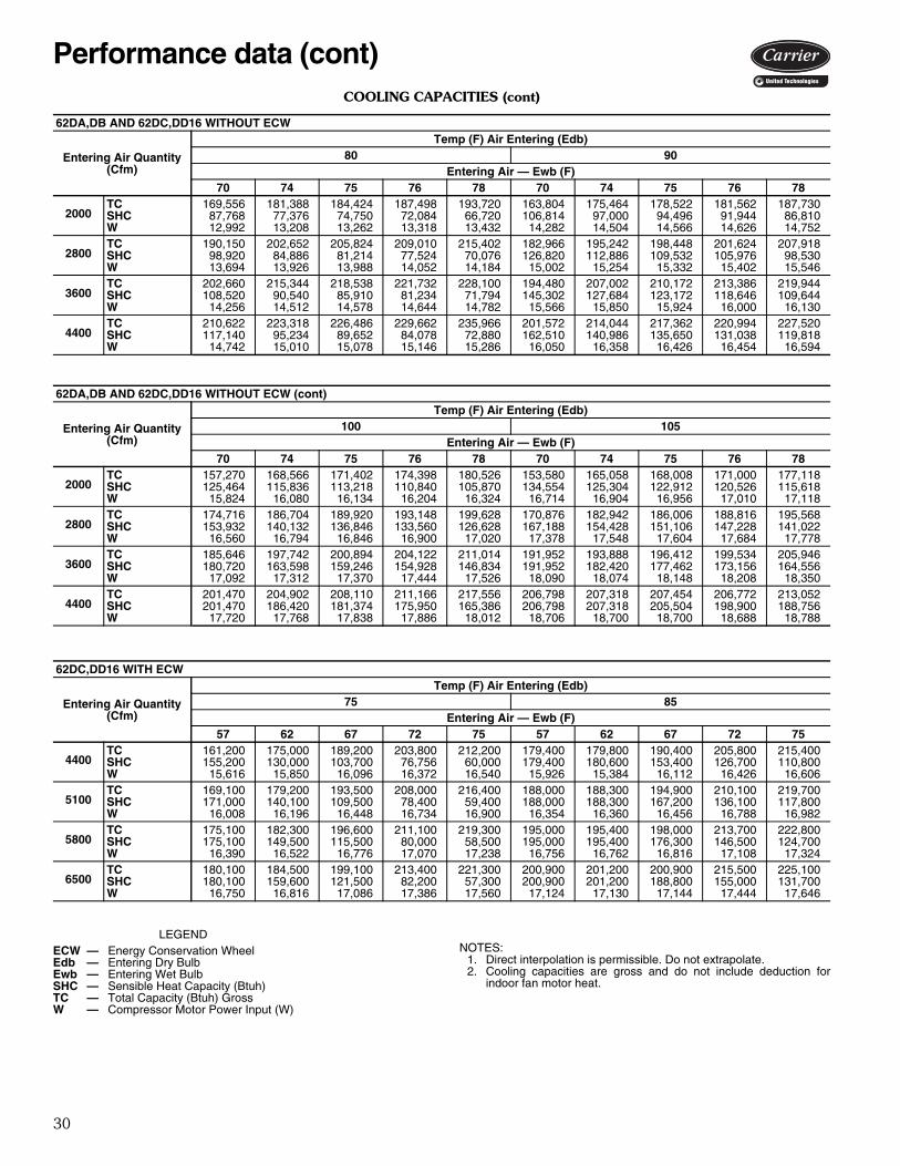
COOLING CAPACITIES (cont)
LEGENDNOTES:
1. Direct interpolation is permissible. Do not extrapolate.2. Cooling capacities are gross and do not include deduction for
indoor fan motor heat.
62DA,DB AND 62DC,DD16 WITHOUT ECW
Entering Air Quantity (Cfm)
Temp (F) Air Entering (Edb)80 90
Entering Air — Ewb (F)70 74 75 76 78 70 74 75 76 78
2000TC 169,556 181,388 184,424 187,498 193,720 163,804 175,464 178,522 181,562 187,730SHC 87,768 77,376 74,750 72,084 66,720 106,814 97,000 94,496 91,944 86,810W 12,992 13,208 13,262 13,318 13,432 14,282 14,504 14,566 14,626 14,752
2800TC 190,150 202,652 205,824 209,010 215,402 182,966 195,242 198,448 201,624 207,918SHC 98,920 84,886 81,214 77,524 70,076 126,820 112,886 109,532 105,976 98,530W 13,694 13,926 13,988 14,052 14,184 15,002 15,254 15,332 15,402 15,546
3600TC 202,660 215,344 218,538 221,732 228,100 194,480 207,002 210,172 213,386 219,944SHC 108,520 90,540 85,910 81,234 71,794 145,302 127,684 123,172 118,646 109,644W 14,256 14,512 14,578 14,644 14,782 15,566 15,850 15,924 16,000 16,130
4400TC 210,622 223,318 226,486 229,662 235,966 201,572 214,044 217,362 220,994 227,520SHC 117,140 95,234 89,652 84,078 72,880 162,510 140,986 135,650 131,038 119,818W 14,742 15,010 15,078 15,146 15,286 16,050 16,358 16,426 16,454 16,594
62DA,DB AND 62DC,DD16 WITHOUT ECW (cont)
Entering Air Quantity (Cfm)
Temp (F) Air Entering (Edb)100 105
Entering Air — Ewb (F)70 74 75 76 78 70 74 75 76 78
2000TC 157,270 168,566 171,402 174,398 180,526 153,580 165,058 168,008 171,000 177,118SHC 125,464 115,836 113,218 110,840 105,870 134,554 125,304 122,912 120,526 115,618W 15,824 16,080 16,134 16,204 16,324 16,714 16,904 16,956 17,010 17,118
2800TC 174,716 186,704 189,920 193,148 199,628 170,876 182,942 186,006 188,816 195,568SHC 153,932 140,132 136,846 133,560 126,628 167,188 154,428 151,106 147,228 141,022W 16,560 16,794 16,846 16,900 17,020 17,378 17,548 17,604 17,684 17,778
3600TC 185,646 197,742 200,894 204,122 211,014 191,952 193,888 196,412 199,534 205,946SHC 180,720 163,598 159,246 154,928 146,834 191,952 182,420 177,462 173,156 164,556W 17,092 17,312 17,370 17,444 17,526 18,090 18,074 18,148 18,208 18,350
4400TC 201,470 204,902 208,110 211,166 217,556 206,798 207,318 207,454 206,772 213,052SHC 201,470 186,420 181,374 175,950 165,386 206,798 207,318 205,504 198,900 188,756W 17,720 17,768 17,838 17,886 18,012 18,706 18,700 18,700 18,688 18,788
62DC,DD16 WITH ECW
Entering Air Quantity (Cfm)
Temp (F) Air Entering (Edb)75 85
Entering Air — Ewb (F)57 62 67 72 75 57 62 67 72 75
4400TC 161,200 175,000 189,200 203,800 212,200 179,400 179,800 190,400 205,800 215,400SHC 155,200 130,000 103,700 76,756 60,000 179,400 180,600 153,400 126,700 110,800W 15,616 15,850 16,096 16,372 16,540 15,926 15,384 16,112 16,426 16,606
5100TC 169,100 179,200 193,500 208,000 216,400 188,000 188,300 194,900 210,100 219,700SHC 171,000 140,100 109,500 78,400 59,400 188,000 188,300 167,200 136,100 117,800W 16,008 16,196 16,448 16,734 16,900 16,354 16,360 16,456 16,788 16,982
5800TC 175,100 182,300 196,600 211,100 219,300 195,000 195,400 198,000 213,700 222,800SHC 175,100 149,500 115,500 80,000 58,500 195,000 195,400 176,300 146,500 124,700W 16,390 16,522 16,776 17,070 17,238 16,756 16,762 16,816 17,108 17,324
6500TC 180,100 184,500 199,100 213,400 221,300 200,900 201,200 200,900 215,500 225,100SHC 180,100 159,600 121,500 82,200 57,300 200,900 201,200 188,800 155,000 131,700W 16,750 16,816 17,086 17,386 17,560 17,124 17,130 17,144 17,444 17,646
ECW — Energy Conservation WheelEdb — Entering Dry BulbEwb — Entering Wet BulbSHC — Sensible Heat Capacity (Btuh)TC — Total Capacity (Btuh) GrossW — Compressor Motor Power Input (W)
Performance data (cont)

31
COOLING CAPACITIES (cont)
LEGENDNOTES:
1. Direct interpolation is permissible. Do not extrapolate.2. Cooling capacities are gross and do not include deduction for
indoor fan motor heat.
62DA,DB AND 62DC,DD20 WITHOUT ECW
Entering Air Quantity (Cfm)
Temp (F) Air Entering (Edb)80 90
Entering Air — Ewb (F)70 74 75 76 78 70 74 75 76 78
2400TC 189,252 202,584 206,012 209,458 216,428 182,674 195,758 199,098 202,472 209,290SHC 97,788 85,516 82,410 79,310 73,112 121,016 109,364 106,406 103,370 97,152W 14,588 14,816 14,874 14,932 15,042 16,008 16,258 16,322 16,388 16,520
3100TC 205,842 219,612 223,172 226,704 233,730 197,936 211,322 214,810 218,354 225,538SHC 107,298 91,654 87,928 83,904 75,720 138,366 122,936 119,288 115,496 107,636W 15,156 15,388 15,446 15,506 15,626 16,602 16,858 16,934 16,980 17,076
3700TC 215,634 229,604 233,114 236,626 243,636 206,822 220,622 224,194 227,784 235,016SHC 114,668 96,340 91,604 86,804 77,076 152,270 134,386 129,814 125,194 115,904W 15,562 15,800 15,860 15,920 16,040 17,018 17,248 17,296 17,344 17,438
4400TC 223,766 237,742 241,230 244,708 251,788 213,794 228,020 231,596 235,222 242,454SHC 122,500 100,818 95,218 89,598 78,338 167,194 146,068 140,662 135,278 124,452W 15,978 16,222 16,282 16,340 16,452 17,454 17,658 17,706 17,752 17,830
62DA,DB AND 62DC,DD20 WITHOUT ECW (cont)
Entering Air Quantity (Cfm)
Temp (F) Air Entering (Edb)100 105
Entering Air — Ewb (F)70 74 75 76 78 70 74 75 76 78
2400TC 175,048 187,956 191,262 194,604 201,304 171,206 183,802 187,070 190,352 197,256SHC 143,742 132,514 129,608 126,648 120,448 154,662 143,556 140,722 137,840 132,422W 17,702 17,902 17,954 18,006 18,106 18,560 18,764 18,814 18,864 18,940
3100TC 189,298 202,512 205,638 209,142 216,076 185,040 197,974 201,238 204,492 211,332SHC 168,618 153,882 149,676 146,008 138,294 183,332 169,148 165,466 161,662 154,198W 18,204 18,408 18,480 18,528 18,632 19,054 19,240 19,292 19,346 19,444
3700TC 197,904 210,598 213,948 217,406 224,400 202,648 205,780 208,894 212,602 218,826SHC 189,098 170,978 166,466 161,988 152,916 202,648 189,496 185,012 181,138 171,516W 18,580 18,792 18,842 18,890 19,006 19,614 19,632 19,678 19,708 19,846
4400TC 211,252 217,504 221,100 224,250 231,112 216,396 216,962 216,250 218,976 225,692SHC 211,252 190,910 186,060 180,416 169,902 216,396 215,196 208,848 202,902 192,812W 19,100 19,194 19,200 19,266 19,356 20,108 20,098 20,042 20,128 20,214
62DC,DD20 WITH ECW
Entering Air Quantity (Cfm)
Temp (F) Air Entering (Edb)75 85
Entering Air — Ewb (F)57 62 67 72 75 57 62 67 72 75
4400TC 170,300 185,200 200,900 216,800 226,100 188,100 186,600 202,100 219,000 229,400SHC 159,800 135,100 108,700 81,900 65,000 188,100 181,800 158,000 131,600 115,800W 16,982 17,200 17,476 17,702 17,848 17,268 17,220 17,494 17,750 17,912
5100TC 175,600 190,300 206,200 221,900 231,000 197,800 198,200 207,600 224,400 234,500SHC 171,400 145,400 115,200 83,500 64,400 197,800 198,200 172,200 141,800 122,600W 17,336 17,550 17,814 18,068 18,208 17,690 17,696 17,834 18,096 18,264
5800TC 184,500 193,900 210,000 225,600 234,500 205,800 206,200 211,600 228,300 238,400SHC 184,500 155,000 121,100 85,100 63,600 205,800 206,200 186,000 151,700 130,400W 17,750 17,890 18,144 18,398 18,536 18,088 18,094 18,164 18,428 18,584
6500TC 190,200 196,900 212,700 228,400 237,100 212,400 212,800 214,700 231,200 241,400SHC 190,200 165,000 126,500 87,400 62,700 212,400 212,800 194,700 161,200 137,900W 18,106 18,188 18,454 18,706 18,846 18,462 18,468 18,472 18,744 18,900
ECW — Energy Conservation WheelEdb — Entering Dry BulbEwb — Entering Wet BulbSHC — Sensible Heat Capacity (Btuh)TC — Total Capacity (Btuh) GrossW — Compressor Motor Power Input (W)

32
COOLING CAPACITIES (cont)
LEGENDNOTES:
1. Direct interpolation is permissible. Do not extrapolate.2. Cooling capacities are gross and do not include deduction for
indoor fan motor heat.
62DA,DB AND 62DC,DD22 WITHOUT ECW
Entering Air Quantity (Cfm)
Temp (F) Air Entering (Edb)80 90
Entering Air — Ewb (F)70 74 75 76 78 70 74 75 76 78
2400TC 190,934 204,832 208,390 211,980 219,276 184,322 197,990 201,440 204,948 212,148SHC 98,648 86,450 83,394 80,328 74,364 121,880 110,476 107,516 104,476 98,428W 14,364 14,566 14,610 14,656 14,704 15,748 15,936 15,984 16,034 16,130
3100TC 208,624 223,192 226,890 230,598 238,062 200,556 214,858 218,448 222,102 229,488SHC 108,428 93,512 89,516 85,506 77,442 139,286 124,664 120,794 116,930 109,144W 14,896 15,040 15,086 15,132 15,222 16,268 16,468 16,516 16,564 16,662
3700TC 219,260 234,132 237,856 241,612 249,094 210,204 224,848 228,504 232,194 239,620SHC 116,042 98,246 93,534 88,792 79,130 153,356 136,032 131,458 126,846 117,536W 15,274 15,416 15,462 15,508 15,596 16,642 16,840 16,888 16,936 17,032
4400TC 228,270 243,162 246,914 250,694 258,154 218,140 232,972 236,646 240,326 247,762SHC 124,134 102,576 97,030 91,496 80,230 168,770 148,258 142,826 137,338 125,984W 15,664 15,822 15,866 15,910 15,996 17,072 17,222 17,272 17,320 17,456
62DA,DB AND 62DC,DD22 WITHOUT ECW (cont)
Entering Air Quantity (Cfm)
Temp (F) Air Entering (Edb)100 105
Entering Air — Ewb (F)70 74 75 76 78 70 74 75 76 78
2400TC 176,958 190,056 193,298 196,714 203,746 172,788 185,664 188,922 192,292 199,272SHC 144,654 133,424 130,252 127,376 121,530 155,438 144,450 141,566 138,732 133,186W 17,342 17,542 17,590 17,638 17,738 18,232 18,430 18,482 18,532 18,620
3100TC 191,776 205,048 208,574 212,320 219,160 186,822 200,310 203,622 207,026 213,962SHC 169,692 154,528 150,888 147,558 139,478 183,860 170,048 166,366 162,646 155,112W 17,852 18,070 18,118 18,154 18,270 18,840 18,926 18,978 19,028 19,132
3700TC 200,594 214,228 217,744 220,938 227,940 204,732 208,656 212,474 215,442 221,792SHC 189,922 172,848 168,398 163,344 154,042 204,732 190,612 186,806 182,084 172,440W 18,244 18,424 18,474 18,538 18,672 19,302 19,316 19,352 19,394 19,510
4400TC 214,036 221,634 225,140 228,182 235,740 218,946 219,542 219,260 222,170 229,358SHC 214,036 192,576 187,762 181,810 171,954 218,946 216,104 209,554 203,900 193,896W 18,834 18,852 18,856 18,918 19,000 19,806 19,796 19,748 19,840 19,950
62DC,DD22 WITH ECW
Entering Air Quantity (Cfm)
Temp (F) Air Entering (Edb)75 85
Entering Air — Ewb (F)57 62 67 72 75 57 62 67 72 75
4400TC 170,400 185,600 201,700 217,800 227,200 187,800 186,800 203,100 220,300 230,600SHC 160,200 135,000 109,400 82,300 65,500 187,800 181,500 159,000 132,900 116,322W 17,080 17,324 17,556 17,800 17,934 17,382 17,342 17,562 17,820 17,970
5100TC 175,500 190,700 207,100 223,100 232,400 197,600 198,000 208,400 225,700 236,000SHC 171,200 144,900 115,600 84,200 65,000 197,600 198,000 172,700 142,500 123,200W 17,438 17,676 17,900 18,144 18,270 17,804 17,810 17,930 18,180 18,338
5800TC 184,200 194,700 211,100 227,000 236,200 205,600 206,000 212,600 229,700 240,200SHC 184,200 155,600 121,800 86,100 64,400 205,600 206,000 186,400 152,100 131,300W 17,836 17,992 18,222 18,464 18,586 18,166 18,172 18,262 18,504 18,640
6500TC 189,900 197,500 213,800 229,900 239,000 212,300 212,700 215,700 232,700 242,900SHC 189,900 165,300 126,600 87,900 63,700 212,300 212,700 195,200 161,700 137,700W 18,194 18,306 18,570 18,766 18,890 18,538 18,542 18,578 18,810 18,964
ECW — Energy Conservation WheelEdb — Entering Dry BulbEwb — Entering Wet BulbSHC — Sensible Heat Capacity (Btuh)TC — Total Capacity (Btuh) GrossW — Compressor Motor Power Input (W)
Performance data (cont)

33
COOLING CAPACITIES (cont)
LEGENDNOTES:
1. Direct interpolation is permissible. Do not extrapolate.2. Cooling capacities are gross and do not include deduction for
indoor fan motor heat.
62DA,DB AND 62DC,DD24 WITHOUT ECW
Entering Air Quantity (Cfm)
Temp (F) Air Entering (Edb)80 90
Entering Air — Ewb (F)70 74 75 76 78 70 74 75 76 78
2400TC 205,724 220,558 224,386 228,256 236,080 198,676 213,372 217,158 220,960 228,678SHC 106,552 94,520 91,062 87,906 81,544 129,188 117,794 114,826 111,820 105,696W 15,932 16,174 16,284 16,352 16,488 17,698 17,934 18,002 18,070 18,212
3600TC 236,784 252,612 256,646 260,812 269,054 227,472 243,254 247,296 251,348 259,564SHC 123,340 105,172 100,486 96,510 87,104 159,394 142,134 137,694 133,236 124,090W 17,008 17,304 17,382 17,400 17,536 18,712 18,992 19,070 19,140 19,284
4800TC 253,822 270,020 274,414 278,556 286,802 242,914 258,870 262,954 267,106 270,540SHC 137,372 113,102 108,422 102,296 89,896 186,266 162,766 156,828 150,974 139,180W 17,818 18,168 18,118 18,192 18,344 18,910 19,922 20,008 20,044 20,192
6000TC 264,360 280,650 284,744 288,838 296,822 253,068 268,782 272,780 276,420 285,028SHC 157,414 121,828 114,318 106,904 90,794 211,176 184,850 177,464 169,284 155,412W 18,436 12,728 18,806 18,886 19,072 20,160 20,424 20,508 20,616 20,760
62DA,DB AND 62DC,DD24 WITHOUT ECW (cont)
Entering Air Quantity (Cfm)
Temp (F) Air Entering (Edb)100 105
Entering Air — Ewb (F)70 74 75 76 78 70 74 75 76 78
2400TC 191,034 205,130 208,796 212,546 220,094 186,920 200,720 204,430 209,408 215,308SHC 151,736 140,210 137,352 134,470 128,608 162,738 151,330 148,736 145,882 139,622W 19,690 19,952 20,018 20,088 20,232 20,794 21,076 21,126 21,200 21,358
3600TC 217,720 231,952 235,862 239,948 247,480 212,712 226,586 230,418 233,694 241,576SHC 194,634 176,898 172,750 168,774 159,338 211,946 194,832 190,842 185,982 177,556W 20,722 21,022 21,098 21,164 21,354 21,834 22,100 22,176 22,280 22,426
4800TC 237,886 246,560 250,428 254,274 261,214 243,270 241,056 244,378 247,470 254,868SHC 237,144 211,640 205,998 200,856 188,258 243,270 236,682 230,402 224,196 212,742W 21,698 21,920 21,926 21,960 22,250 23,086 22,912 23,026 23,192 23,354
6000TC 256,524 255,400 258,486 262,360 269,858 262,074 262,726 262,898 262,964 262,470SHC 256,524 245,806 238,254 231,494 215,568 262,074 262,726 262,898 262,964 247,418W 22,556 22,610 22,702 22,772 22,982 23,980 23,966 23,962 24,258 24,140
62DC,DD24 WITH ECW
Entering Air Quantity (Cfm)
Temp (F) Air Entering (Edb)75 85
Entering Air — Ewb (F)57 62 67 72 75 57 62 67 72 75
6000TC 200,100 216,900 234,900 252,200 262,300 226,000 226,400 236,500 255,200 266,400SHC 197,400 167,500 131,800 95,000 72,600 22,600 226,400 199,500 163,800 141,200W 2,092 20,462 20,768 21,136 21,348 20,644 20,652 20,778 21,172 21,516
7000TC 211,900 221,800 239,200 256,800 266,700 236,400 236,800 241,400 259,600 271,400SHC 211,900 182,000 139,600 97,300 71,300 236,400 236,800 213,600 176,600 152,300W 20,748 20,868 21,316 21,636 21,862 21,242 21,250 21,278 21,710 21,942
8000TC 218,900 225,200 242,700 260,100 269,700 244,400 244,800 244,500 263,300 274,300SHC 218,900 190,100 148,500 100,400 69,900 244,400 244,800 228,700 191,100 161,200W 21,282 21,342 21,698 22,092 22,332 21,806 21,814 21,822 22,156 22,456
9000TC 224,500 227,200 245,300 262,300 271,700 251,000 251,300 251,700 265,000 276,500SHC 224,500 200,100 157,200 102,800 69,400 251,000 251,300 251,700 196,200 171,300W 21,782 21,802 22,122 22,534 22,758 22,270 22,278 22,286 22,626 22,904
ECW — Energy Conservation WheelEdb — Entering Dry BulbEwb — Entering Wet BulbSHC — Sensible Heat Capacity (Btuh)TC — Total Capacity (Btuh) GrossW — Compressor Motor Power Input (W)

34
COOLING CAPACITIES (cont)
LEGENDNOTES:
1. Direct interpolation is permissible. Do not extrapolate.2. Cooling capacities are gross and do not include deduction for
indoor fan motor heat.
62DA,DB AND 62DC,DD30 WITHOUT ECW
Entering Air Quantity (Cfm)
Temp (F) Air Entering (Edb)80 90
Entering Air — Ewb (F)70 74 75 76 78 70 74 75 76 78
3400TC 283,720 304,194 309,482 314,870 325,740 273,728 294,058 299,386 304,614 315,358SHC 146,666 129,070 124,708 120,304 111,406 179,140 162,874 158,848 154,534 145,930W 22,016 22,314 22,372 22,432 22,556 24,074 24,296 24,356 24,420 24,556
4600TC 316,004 337,748 343,410 348,998 360,196 303,746 325,326 330,852 334,340 347,518SHC 163,710 140,662 135,736 129,734 117,652 209,524 187,672 182,112 176,312 164,734W 22,924 23,184 23,152 23,224 23,370 24,916 25,176 25,266 25,342 25,498
5800TC 336,956 359,378 365,012 370,640 381,904 322,928 345,216 350,752 356,334 367,622SHC 178,770 151,016 143,632 136,132 120,976 237,440 210,516 203,292 196,024 181,484W 23,646 23,838 23,914 23,990 24,146 25,638 25,936 26,018 26,100 26,266
7000TC 366,406 386,560 390,358 395,978 406,642 350,208 371,840 376,480 381,366 393,382SHC 215,052 171,558 158,522 148,012 125,044 308,806 266,366 255,284 242,972 222,516W 25,204 25,502 26,010 26,068 26,244 27,266 27,588 27,772 27,886 28,036
62DA,DB AND 62DC,DD30 WITHOUT ECW (cont)
Entering Air Quantity (Cfm)
Temp (F) Air Entering (Edb)100 105
Entering Air — Ewb (F)70 74 75 76 78 70 74 75 76 78
3400TC 262,690 282,546 287,606 292,748 303,270 256,810 276,654 281,608 286,550 296,874SHC 210,490 194,824 190,684 186,718 178,424 226,016 211,248 207,294 203,014 194,754W 26,510 26,692 26,772 26,830 26,962 27,830 28,012 28,074 28,152 28,294
4600TC 290,578 311,174 316,118 321,880 332,468 283,608 303,756 308,346 314,072 324,684SHC 254,600 232,710 226,490 221,794 209,940 275,760 255,080 248,734 244,094 232,944W 27,282 27,570 27,674 27,718 27,874 28,706 28,868 28,978 29,026 29,186
5800TC 308,130 329,032 333,708 339,018 350,358 316,096 320,506 325,740 330,974 340,728SHC 294,908 268,314 260,294 252,964 239,638 316,096 296,266 289,348 282,440 267,844W 28,042 28,306 28,414 28,556 28,650 29,646 29,642 29,726 29,818 30,032
7000TC 360,364 361,266 359,030 362,328 378,506 367,208 368,054 368,278 368,508 368,984SHC 360,364 361,266 348,704 337,130 272,428 367,208 368,054 368,278 368,508 364,742W 30,110 30,240 30,052 30,284 30,300 31,956 31,944 31,940 31,938 31,930
62DC,DD30 WITH ECW
Entering Air Quantity (Cfm)
Temp (F) Air Entering (Edb)75 85
Entering Air — Ewb (F)57 62 67 72 75 57 62 67 72 75
7,000TC 256,800 278,600 301,800 324,900 338,600 285,700 281,600 303,700 328,500 343,300SHC 242,200 206,900 165,700 123,100 96,300 285,700 277,900 244,400 202,700 176,600W 26,482 26,796 27,144 27,468 27,698 26,950 26,884 27,158 27,556 27,812
8,400TC 271,200 286,300 309,700 333,000 246,300 301,900 302,400 311,700 336,600 351,600SHC 271,200 221,400 177,000 127,000 95,300 301,900 302,400 263,200 221,700 191,400W 27,270 27,456 27,824 28,138 28,368 27,736 27,744 27,864 28,236 28,492
9,600TC 280,500 290,800 314,800 337,400 350,700 312,800 313,300 316,800 341,300 356,400SHC 280,500 235,100 188,000 129,200 92,800 312,800 313,300 282,600 238,100 203,700W 27,866 27,990 28,326 28,720 28,986 28,364 28,372 28,404 28,766 29,038
11,000TC 289,100 295,200 318,200 341,200 354,100 322,900 323,400 322,200 345,100 360,000SHC 289,100 251,600 197,800 132,700 90,600 322,900 323,400 305,200 247,100 217,300W 28,532 28,564 28,962 29,320 29,596 29,070 29,076 28,996 29,388 29,650
ECW — Energy Conservation WheelEdb — Entering Dry BulbEwb — Entering Wet BulbSHC — Sensible Heat Capacity (Btuh)TC — Total Capacity (Btuh) GrossW — Compressor Motor Power Input (W)
Performance data (cont)
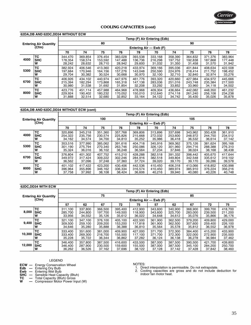
35
COOLING CAPACITIES (cont)
LEGENDNOTES:
1. Direct interpolation is permissible. Do not extrapolate.2. Cooling capacities are gross and do not include deduction for
indoor fan motor heat.
62DA,DB AND 62DC,DD34 WITHOUT ECW
Entering Air Quantity (Cfm)
Temp (F) Air Entering (Edb)80 90
Entering Air — Ewb (F)70 74 75 76 78 70 74 75 76 78
4000TC 344,470 369,854 376,454 383,028 393,538 333,168 358,390 364,832 371,376 383,964SHC 178,354 158,574 153,592 147,488 136,736 216,298 197,752 192,838 187,868 177,448W 28,242 28,632 28,710 28,942 29,600 31,032 31,350 31,458 31,570 31,942
5300TC 382,924 406,546 413,360 420,218 433,974 369,166 395,036 401,844 408,634 422,508SHC 197,684 170,946 164,156 157,276 143,048 250,590 224,976 218,414 211,752 198,452W 29,704 30,382 30,524 30,668 30,970 32,100 32,710 32,840 32,974 33,276
6700TC 406,926 434,102 440,974 447,976 461,776 393,320 420,660 427,984 434,972 445,666SHC 215,394 182,294 173,868 165,318 147,138 283,036 251,016 243,748 235,384 217,500W 30,980 31,538 31,692 31,854 32,208 33,292 33,852 33,960 34,118 34,502
8000TC 423,776 451,114 457,988 464,968 478,968 409,304 436,664 442,082 448,350 461,232SHC 229,924 190,402 180,232 170,052 150,010 312,640 274,118 261,240 256,108 234,238W 31,888 32,514 32,680 32,852 33,164 34,122 34,742 35,430 35,026 35,878
62DA,DB AND 62DC,DD34 WITHOUT ECW (cont)
Entering Air Quantity (Cfm)
Temp (F) Air Entering (Edb)100 105
Entering Air — Ewb (F)70 74 75 76 78 70 74 75 76 78
4000TC 320,896 345,218 351,360 357,768 369,806 313,896 337,698 343,962 350,428 361,910SHC 254,322 235,756 230,574 225,826 215,668 272,032 253,600 248,972 244,750 234,512W 34,162 34,574 34,700 34,810 35,252 35,986 36,418 36,532 36,614 37,142
5300TC 353,516 377,990 385,062 391,616 404,718 345,916 369,362 375,126 381,624 395,168SHC 301,190 275,794 270,340 263,746 250,086 326,120 301,960 294,716 288,388 276,310W 35,324 36,016 36,102 36,248 36,564 37,234 37,846 38,024 38,168 38,438
6700TC 376,804 401,302 407,752 415,210 428,288 382,518 391,332 398,442 405,670 417,644SHC 349,972 317,424 309,222 302,246 284,916 382,518 349,804 342,548 335,612 319,102W 36,562 37,096 37,248 37,360 37,724 39,020 39,170 39,170 39,286 39,578
8000TC 401,102 417,422 423,200 430,406 442,536 410,450 406,318 413,066 418,852 430,998SHC 396,964 355,896 346,162 336,334 316,574 410,450 389,974 385,910 376,224 356,216W 37,758 37,992 38,108 38,424 36,606 40,216 39,940 40,080 40,226 40,748
62DC,DD34 WITH ECW
Entering Air Quantity (Cfm)
Temp (F) Air Entering (Edb)75 85
Entering Air — Ewb (F)57 62 67 72 75 57 62 67 72 75
8,000TC 311,100 337,800 366,500 395,400 412,900 343,600 340,900 368,900 399,700 418,700SHC 285,700 244,800 197,700 149,500 118,900 343,600 325,700 283,000 239,500 211,200W 33,956 34,552 35,126 35,612 36,022 34,648 34,612 35,076 35,866 36,176
9,400TC 321,100 347,100 376,100 405,100 422,500 361,900 362,500 379,200 409,800 429,000SHC 309,500 259,100 209,200 153,200 117,818 361,900 362,500 307,600 259,400 226,100W 34,646 35,280 35,888 36,388 36,810 35,564 35,578 35,812 36,552 36,978
10,300TC 333,400 351,600 381,000 409,900 427,000 371,700 372,300 384,400 415,200 433,900SHC 333,400 269,300 216,700 155,500 117,100 371,700 372,300 322,000 272,900 235,500W 35,228 35,722 36,344 36,862 37,282 36,124 36,138 36,278 36,984 37,462
12,000TC 346,400 357,800 387,500 416,600 433,500 387,000 387,500 390,500 421,700 439,800SHC 346,400 287,900 230,500 159,600 155,500 387,000 387,500 345,100 284,200 250,700W 36,262 36,526 37,162 37,696 38,122 37,128 37,142 37,428 37,842 38,460
ECW — Energy Conservation WheelEdb — Entering Dry BulbEwb — Entering Wet BulbSHC — Sensible Heat Capacity (Btuh)TC — Total Capacity (Btuh) GrossW — Compressor Motor Power Input (W)

36
COOLING CAPACITIES (cont)
LEGENDNOTES:
1. Direct interpolation is permissible. Do not extrapolate.2. Cooling capacities are gross and do not include deduction for
indoor fan motor heat.
62DA,DB AND 62DC,DD38 WITHOUT ECW
Entering Air Quantity (Cfm)
Temp (F) Air Entering (Edb)80 90
Entering Air — Ewb (F)70 74 75 76 78 70 74 75 76 78
4800TC 368,166 391,784 398,130 404,726 418,482 355,204 380,434 387,074 393,778 407,372SHC 190,186 166,594 159,084 151,634 140,088 237,128 213,868 207,946 201,946 189,708W 30,154 30,582 31,142 31,358 31,418 32,964 33,476 33,570 33,666 33,862
6200TC 396,396 423,290 430,088 436,972 450,808 383,208 410,282 417,196 424,058 437,890SHC 208,090 177,452 169,226 161,328 145,040 270,500 241,130 233,752 226,136 210,378W 31,686 32,056 32,160 32,260 32,460 34,122 34,486 34,586 34,686 34,886
7600TC 417,110 443,990 450,840 458,008 471,714 402,150 429,294 436,232 442,762 453,166SHC 225,458 186,900 177,206 168,580 148,364 302,314 265,890 276,604 246,156 227,072W 32,522 32,958 33,056 33,102 33,310 34,960 35,368 35,464 35,666 36,268
9000TC 430,838 458,128 464,968 472,116 485,826 416,014 440,160 447,016 452,304 465,776SHC 239,662 195,446 184,164 173,742 150,906 334,658 292,024 281,288 267,468 244,922W 33,328 33,722 33,818 33,872 34,060 35,688 36,076 36,170 36,802 37,028
62DA,DB AND 62DC,DD38 WITHOUT ECW (cont)
Entering Air Quantity (Cfm)
Temp (F) Air Entering (Edb)100 105
Entering Air — Ewb (F)70 74 75 76 78 70 74 75 76 78
4800TC 340,208 364,578 371,028 377,116 390,390 333,808 355,594 361,688 367,910 380,760SHC 282,066 259,862 254,200 247,546 235,972 305,710 282,066 276,078 270,166 258,748W 36,236 36,794 36,898 37,030 37,226 38,018 38,670 38,810 38,926 39,138
6200TC 366,972 391,410 397,914 403,944 417,646 367,720 382,334 388,634 393,332 405,832SHC 331,890 302,274 294,850 286,420 271,758 366,062 332,780 325,466 316,664 301,458W 37,440 37,806 37,916 38,056 38,252 39,316 39,720 39,828 39,932 40,172
7600TC 384,776 409,714 414,818 420,524 433,608 399,194 398,862 404,314 411,168 422,316SHC 378,480 343,112 332,942 322,708 304,178 399,194 380,428 370,900 362,932 342,734W 38,390 38,708 38,802 39,030 39,238 40,840 40,640 40,732 40,800 41,226
9000TC 415,364 420,640 426,688 433,270 447,612 423,956 425,076 425,368 421,648 432,908SHC 415,364 381,356 370,486 359,786 340,280 423,956 425,076 420,390 405,804 383,594W 39,520 39,596 39,692 39,796 39,842 41,888 41,858 41,850 41,786 42,010
62DC,DD38 WITH ECW
Entering Air Quantity (Cfm)
Temp (F) Air Entering (Edb)75 85
Entering Air — Ewb (F)57 62 67 72 75 57 62 67 72 75
9,000TC 328,500 357,200 387,000 417,300 434,800 366,900 367,700 389,200 421,500 441,500SHC 312,100 266,400 211,800 157,500 123,100 366,900 369,300 312,500 258,900 227,200W 36,024 36,492 37,160 37,570 37,866 36,796 36,696 37,202 37,768 37,976
10,000TC 335,900 363,300 393,600 423,800 441,000 379,800 380,600 396,100 428,600 447,700SHC 331,500 279,600 220,300 160,000 122,300 379,800 380,600 332,200 273,800 236,100W 36,512 37,058 37,666 38,074 38,362 37,410 37,424 37,708 38,140 38,604
11,000TC 350,900 368,400 399,400 429,100 445,800 391,000 391,700 401,900 434,100 453,400SHC 350,900 293,900 230,300 163,000 120,300 391,000 391,700 352,400 288,100 247,600W 37,276 37,536 38,022 38,542 38,868 37,996 38,010 38,068 38,618 38,952
12,000TC 358,900 372,800 403,100 433,200 449,900 400,800 401,400 406,100 437,600 457,200SHC 358,900 308,000 23,700 165,700 120,800 400,800 401,400 362,300 300,000 256,900W 37,814 38,058 38,606 38,996 39,282 38,556 38,600 38,570 39,112 39,440
ECW — Energy Conservation WheelEdb — Entering Dry BulbEwb — Entering Wet BulbSHC — Sensible Heat Capacity (Btuh)TC — Total Capacity (Btuh) GrossW — Compressor Motor Power Input (W)
Performance data (cont)
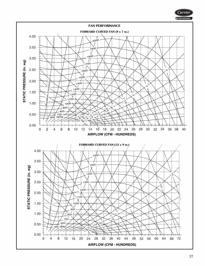
37
86420
Syste
mC
urv
e(s
)
1/6HP
1/41/3
1/2
3/4
1
1-1
/2
2
3
5
600 RPM700
800900
1000
1100
1200
31 00
1400
1500
1600
1700
1800
1900
2000
AIRFLOW (CFM - HUNDREDS)
ST
AT
IC P
RE
SS
UR
E (
in. w
g)
4.00
3.50
3.00
2.50
2.00
1.50
1.00
0.50
0.0010 12 14 16 18 20 22 24 26 28 30 32 34 36 38 40
FAN PERFORMANCE
FORWARD CURVED FAN (9 x 7 in.)a62-407
840
Syste
mC
urv
e(s
)
1/3HP
1/2
3/4
1
1-1
/2
2
3
5
7-1
/2
10
MPR005
600
700
08 0
900
1000
1100
1200
1300
1400
1500
1600
AIRFLOW (CFM - HUNDREDS)
ST
AT
IC P
RE
SS
UR
E (
in. w
g)
4.00
3.50
3.00
2.50
2.00
1.50
1.00
0.50
0.0012 16 20 24 28 32 36 40 44 48 52 56 60 64 68 72
FORWARD CURVED FAN (12 x 9 in.)
a62-408
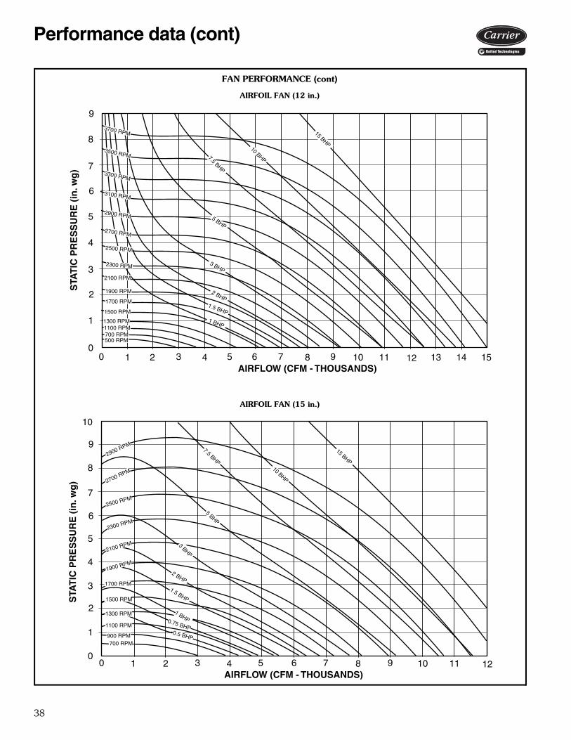
38
AIRFLOW (CFM - THOUSANDS)
STA
TIC
PR
ES
SU
RE
(in
. wg
)
0
1
2
3
4
5
6
7
8
9
0 1 2 3 4 5 6 7 8 9 10 11 12 13 14 15
500 RPM700 RPM1100 RPM
1500 RPM
1700 RPM
1900 RPM
2100 RPM
2300 RPM
2500 RPM
2700 RPM
2900 RPM
3100 RPM
3300 RPM
3500 RPM
3700 RPM
1 BHP
1.5 BHP
2 BHP
3 BHP
5 BHP
7.5 BHP
10 BHP
15 BHP
1300 RPM
AIRFLOW (CFM - THOUSANDS)
STA
TIC
PR
ES
SU
RE
(in
. wg
)
0
1
2
3
4
5
6
7
8
9
0 1 2 3 4 5 6 7 8 9 10 11 12
700 RPM900 RPM
1100 RPM
15 BHP
10
1500 RPM
1700 RPM
1900 RPM
2100 RPM
2300 RPM
2700 RPM
2500 RPM
2900 RPM
10 BHP
7.5 BHP
5 BHP
3 BHP
2 BHP
1300 RPM
1.5 BHP
1 BHP
0.5 BHP
0.75 BHP
FAN PERFORMANCE (cont)
AIRFOIL FAN (12 in.)
AIRFOIL FAN (15 in.)
Performance data (cont)
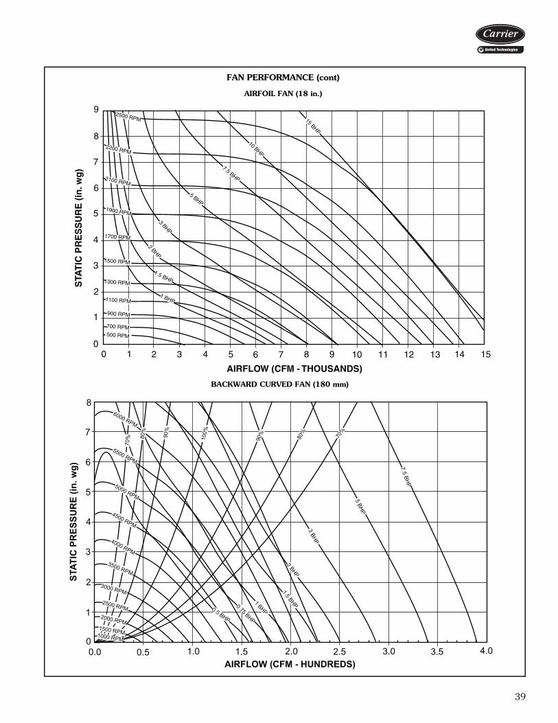
39
0 1 2 3 4 5 6 7 8 9 10 11 12 13 14 15
AIRFLOW (CFM - THOUSANDS)
STA
TIC
PR
ES
SU
RE
(in
. wg
)
0
1
2
3
4
5
6
7
8
9
15 BHP
10 BHP
7.5 BHP
5 BHP
3 BHP
2 BHP
1.5 BHP
1 BHP
500 RPM
700 RPM
900 RPM
1100 RPM
1300 RPM
1500 RPM
1700 RPM
1900 RPM
2100 RPM
2200 RPM
2500 RPM
FAN PERFORMANCE (cont)
AIRFOIL FAN (18 in.)
0
1
2
3
4
5
6
7
8
STAT
IC P
RES
SUR
E (in
. wg)
0.0AIRFLOW (CFM - HUNDREDS)
6000 RPM
5500 RPM
5000 RPM
4500 RPM
4000 RPM
3500 RPM
3000 RPM
2500 RPM2000 RPM
1500 RPM1000 RPM
70%
80%
90%
100%90%
80%
70%
7.5 BHP
5 BHP
3 BHP
2 BHP
1.5 BHP1 BHP
0.75 BHP
0.5 BHP
0.5 1.0 1.5 2.0 2.5 3.0 3.5 4.0
BACKWARD CURVED FAN (180 mm)
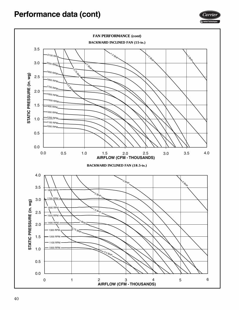
40
0.0 0.5 1.0 1.5 2.0 2.5 3.0 3.5 4.0
0.0
0.5
1.0
1.5
2.0
2.5
3.0
3.5
AIRFLOW (CFM - THOUSANDS)
STA
TIC
PR
ES
SU
RE
(in
. wg
)
1000 RPM
1100 RPM
1200 RPM
1300 RPM
1400 RPM
1500 RPM
1600 RPM
1700 RPM
1800 RPM
1900 RPM
2000 RPM
2100 RPM 3 BHP
2 BHP
1.5 BHP
1 BHP0.75 BHP
0.5 BHP
0 1 2 3 4 5 6
0.0
0.5
1.0
1.5
2.0
2.5
3.0
3.5
AIRFLOW (CFM - THOUSANDS)
STA
TIC
PR
ES
SU
RE
(in
. wg
)
4.0
1000 RPM
1100 RPM
1300 RPM
1400 RPM
1500 RPM
1600 RPM
1700 RPM
1800 RPM
0.5 BHP
0.75 BHP
1 BHP
5 BHP
1200 RPM
1.5 BHP
2 BHP
3 BHP
FAN PERFORMANCE (cont)
BACKWARD INCLINED FAN (15-in.)
BACKWARD INCLINED FAN (18.5-in.)
Performance data (cont)
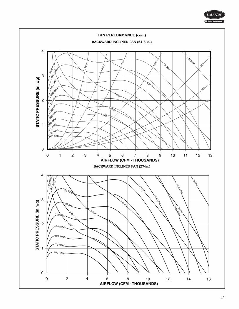
41
0 1 2 3 4 5 6 7 8 9 10 11 12 13
0
1
2
3
4
AIRFLOW (CFM - THOUSANDS)
STA
TIC
PR
ES
SU
RE
(in
. wg
)
600 RPM700 RPM80
0 RPM90
0 RPM10
00 R
PM1100
RPM12
00 R
PM
1300
RPM14
00 R
PM
1500
RPM1600
RP
M
70%
80%
90%
100%90
%
80%70
%
10 BHP7.5 BHP
5 BHP
3 BHP
2 BHP
1 BHP
0 2 4 6 8 10 12 14 16
0
1
2
3
4
AIRFLOW (CFM - THOUSANDS)
STA
TIC
PR
ES
SU
RE
(in
. wg
)
600 RPM
700 RPM
800 RPM
900 RPM
1000 RPM
1100 RPM
1200 RPM
1300
RP
M
1400
RP
M 15 BHP
10 BHP
7.5 BHP
1600 RPM
1500 RPM
5 BHP
3 BHP2 BHP
1.5 BHP
1400 RPM
FAN PERFORMANCE (cont)
BACKWARD INCLINED FAN (24.5-in.)
BACKWARD INCLINED FAN (27-in.)
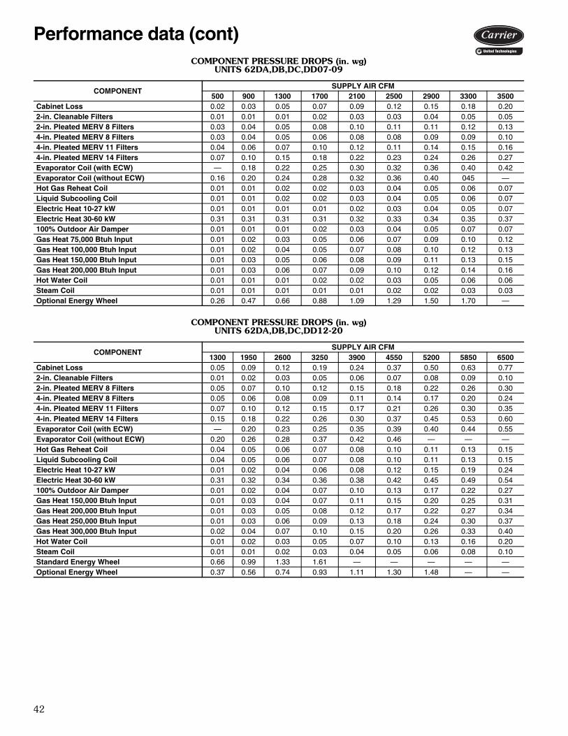
42
COMPONENT PRESSURE DROPS (in. wg)UNITS 62DA,DB,DC,DD07-09
COMPONENT PRESSURE DROPS (in. wg)UNITS 62DA,DB,DC,DD12-20
COMPONENTSUPPLY AIR CFM
500 900 1300 1700 2100 2500 2900 3300 3500Cabinet Loss 0.02 0.03 0.05 0.07 0.09 0.12 0.15 0.18 0.202-in. Cleanable Filters 0.01 0.01 0.01 0.02 0.03 0.03 0.04 0.05 0.052-in. Pleated MERV 8 Filters 0.03 0.04 0.05 0.08 0.10 0.11 0.11 0.12 0.134-in. Pleated MERV 8 Filters 0.03 0.04 0.05 0.06 0.08 0.08 0.09 0.09 0.104-in. Pleated MERV 11 Filters 0.04 0.06 0.07 0.10 0.12 0.11 0.14 0.15 0.164-in. Pleated MERV 14 Filters 0.07 0.10 0.15 0.18 0.22 0.23 0.24 0.26 0.27Evaporator Coil (with ECW) — 0.18 0.22 0.25 0.30 0.32 0.36 0.40 0.42Evaporator Coil (without ECW) 0.16 0.20 0.24 0.28 0.32 0.36 0.40 045 —Hot Gas Reheat Coil 0.01 0.01 0.02 0.02 0.03 0.04 0.05 0.06 0.07Liquid Subcooling Coil 0.01 0.01 0.02 0.02 0.03 0.04 0.05 0.06 0.07Electric Heat 10-27 kW 0.01 0.01 0.01 0.01 0.02 0.03 0.04 0.05 0.07Electric Heat 30-60 kW 0.31 0.31 0.31 0.31 0.32 0.33 0.34 0.35 0.37100% Outdoor Air Damper 0.01 0.01 0.01 0.02 0.03 0.04 0.05 0.07 0.07Gas Heat 75,000 Btuh Input 0.01 0.02 0.03 0.05 0.06 0.07 0.09 0.10 0.12Gas Heat 100,000 Btuh Input 0.01 0.02 0.04 0.05 0.07 0.08 0.10 0.12 0.13Gas Heat 150,000 Btuh Input 0.01 0.03 0.05 0.06 0.08 0.09 0.11 0.13 0.15Gas Heat 200,000 Btuh Input 0.01 0.03 0.06 0.07 0.09 0.10 0.12 0.14 0.16Hot Water Coil 0.01 0.01 0.01 0.02 0.02 0.03 0.05 0.06 0.06Steam Coil 0.01 0.01 0.01 0.01 0.01 0.02 0.02 0.03 0.03Optional Energy Wheel 0.26 0.47 0.66 0.88 1.09 1.29 1.50 1.70 —
COMPONENTSUPPLY AIR CFM
1300 1950 2600 3250 3900 4550 5200 5850 6500Cabinet Loss 0.05 0.09 0.12 0.19 0.24 0.37 0.50 0.63 0.772-in. Cleanable Filters 0.01 0.02 0.03 0.05 0.06 0.07 0.08 0.09 0.102-in. Pleated MERV 8 Filters 0.05 0.07 0.10 0.12 0.15 0.18 0.22 0.26 0.304-in. Pleated MERV 8 Filters 0.05 0.06 0.08 0.09 0.11 0.14 0.17 0.20 0.244-in. Pleated MERV 11 Filters 0.07 0.10 0.12 0.15 0.17 0.21 0.26 0.30 0.354-in. Pleated MERV 14 Filters 0.15 0.18 0.22 0.26 0.30 0.37 0.45 0.53 0.60Evaporator Coil (with ECW) — 0.20 0.23 0.25 0.35 0.39 0.40 0.44 0.55Evaporator Coil (without ECW) 0.20 0.26 0.28 0.37 0.42 0.46 — — —Hot Gas Reheat Coil 0.04 0.05 0.06 0.07 0.08 0.10 0.11 0.13 0.15Liquid Subcooling Coil 0.04 0.05 0.06 0.07 0.08 0.10 0.11 0.13 0.15Electric Heat 10-27 kW 0.01 0.02 0.04 0.06 0.08 0.12 0.15 0.19 0.24Electric Heat 30-60 kW 0.31 0.32 0.34 0.36 0.38 0.42 0.45 0.49 0.54100% Outdoor Air Damper 0.01 0.02 0.04 0.07 0.10 0.13 0.17 0.22 0.27Gas Heat 150,000 Btuh Input 0.01 0.03 0.04 0.07 0.11 0.15 0.20 0.25 0.31Gas Heat 200,000 Btuh Input 0.01 0.03 0.05 0.08 0.12 0.17 0.22 0.27 0.34Gas Heat 250,000 Btuh Input 0.01 0.03 0.06 0.09 0.13 0.18 0.24 0.30 0.37Gas Heat 300,000 Btuh Input 0.02 0.04 0.07 0.10 0.15 0.20 0.26 0.33 0.40Hot Water Coil 0.01 0.02 0.03 0.05 0.07 0.10 0.13 0.16 0.20Steam Coil 0.01 0.01 0.02 0.03 0.04 0.05 0.06 0.08 0.10Standard Energy Wheel 0.66 0.99 1.33 1.61 — — — — —Optional Energy Wheel 0.37 0.56 0.74 0.93 1.11 1.30 1.48 — —
Performance data (cont)
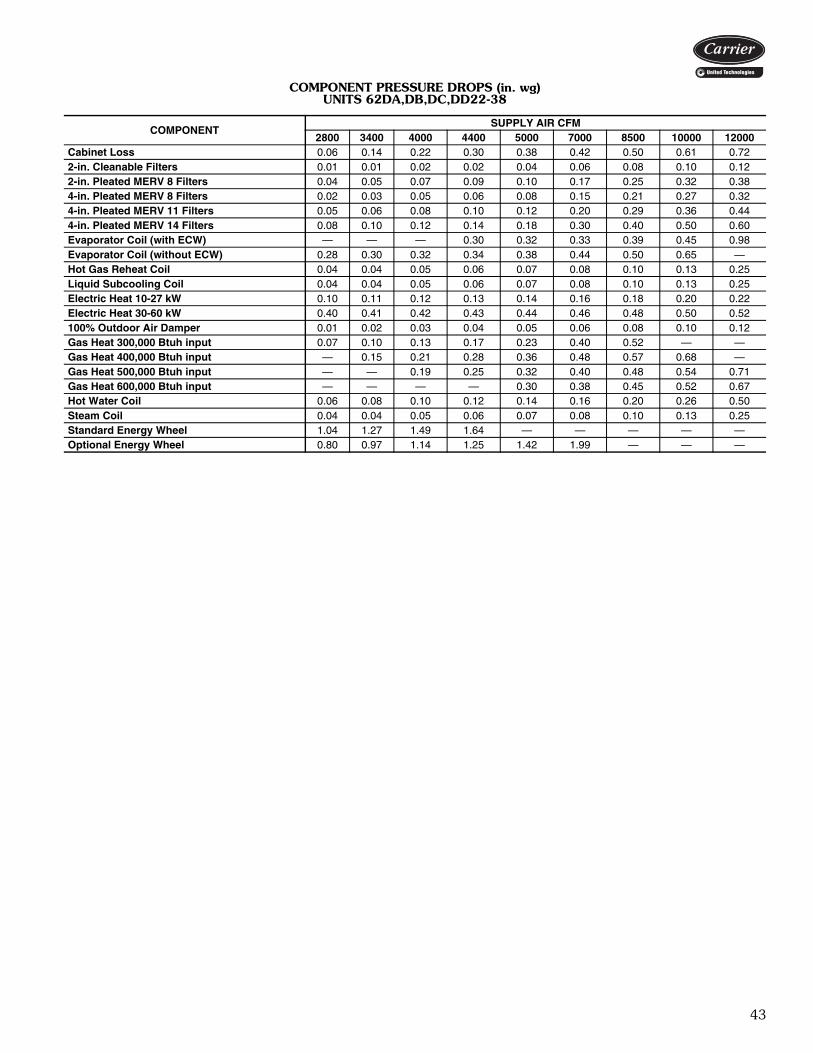
43
COMPONENT PRESSURE DROPS (in. wg)UNITS 62DA,DB,DC,DD22-38
COMPONENTSUPPLY AIR CFM
2800 3400 4000 4400 5000 7000 8500 10000 12000Cabinet Loss 0.06 0.14 0.22 0.30 0.38 0.42 0.50 0.61 0.722-in. Cleanable Filters 0.01 0.01 0.02 0.02 0.04 0.06 0.08 0.10 0.122-in. Pleated MERV 8 Filters 0.04 0.05 0.07 0.09 0.10 0.17 0.25 0.32 0.384-in. Pleated MERV 8 Filters 0.02 0.03 0.05 0.06 0.08 0.15 0.21 0.27 0.324-in. Pleated MERV 11 Filters 0.05 0.06 0.08 0.10 0.12 0.20 0.29 0.36 0.444-in. Pleated MERV 14 Filters 0.08 0.10 0.12 0.14 0.18 0.30 0.40 0.50 0.60Evaporator Coil (with ECW) — — — 0.30 0.32 0.33 0.39 0.45 0.98Evaporator Coil (without ECW) 0.28 0.30 0.32 0.34 0.38 0.44 0.50 0.65 —Hot Gas Reheat Coil 0.04 0.04 0.05 0.06 0.07 0.08 0.10 0.13 0.25Liquid Subcooling Coil 0.04 0.04 0.05 0.06 0.07 0.08 0.10 0.13 0.25Electric Heat 10-27 kW 0.10 0.11 0.12 0.13 0.14 0.16 0.18 0.20 0.22Electric Heat 30-60 kW 0.40 0.41 0.42 0.43 0.44 0.46 0.48 0.50 0.52100% Outdoor Air Damper 0.01 0.02 0.03 0.04 0.05 0.06 0.08 0.10 0.12Gas Heat 300,000 Btuh input 0.07 0.10 0.13 0.17 0.23 0.40 0.52 — —Gas Heat 400,000 Btuh input — 0.15 0.21 0.28 0.36 0.48 0.57 0.68 —Gas Heat 500,000 Btuh input — — 0.19 0.25 0.32 0.40 0.48 0.54 0.71Gas Heat 600,000 Btuh input — — — — 0.30 0.38 0.45 0.52 0.67Hot Water Coil 0.06 0.08 0.10 0.12 0.14 0.16 0.20 0.26 0.50Steam Coil 0.04 0.04 0.05 0.06 0.07 0.08 0.10 0.13 0.25Standard Energy Wheel 1.04 1.27 1.49 1.64 — — — — —Optional Energy Wheel 0.80 0.97 1.14 1.25 1.42 1.99 — — —

44
ENERGY CONSERVATION WHEEL PERFORMANCE
36-in. WHEEL
LEGEND
COOLING MODE HEATING MODE Return Air = 75 db / 63 wb Return Air = 70 db / 58 wb
db 95 90 -10 0 10 20 30 wb 63 67 71 75 78 80 63 67 71 75 78 80 -11 -1 9 19 29
900 CFM Total MBH -0.1 10.3 21.9 34.5 44.9 52.2 -0.1 10.4 21.9 34.6 45.0 52.3 95.3 85.6 75.3 63.9 50.8 Sens. MBH 16.9 16.9 16.9 16.9 16.9 16.9 12.7 12.7 12.7 12.7 12.7 12.7 67.8 59.3 50.8 42.4 33.9 Lvg. DB 77.6 77.6 77.6 77.6 77.6 77.6 76.9 76.9 76.9 76.9 76.9 76.9 59.8 61.0 62.3 63.6 64.9 Lvg. WB 63.0 63.6 64.2 64.9 65.5 65.9 63.0 63.6 64.3 65.0 65.5 65.9 52.1 52.7 53.4 54.1 55.0
1200 CFM Total MBH 0.0 13.2 27.8 43.9 57.0 66.2 0.0 13.3 27.9 43.9 57.0 66.3 121.1 108.9 95.8 81.3 64.6 Sens. MBH 21.6 21.6 21.6 21.6 21.6 21.6 16.2 16.2 16.2 16.2 16.2 16.2 86.4 75.6 64.8 54.0 43.2 Lvg. DB 78.3 78.3 78.3 78.3 78.3 78.3 77.5 77.5 77.5 77.5 77.5 77.5 56.7 58.4 60.0 61.7 63.3 Lvg. WB 63.0 63.7 64.6 65.6 66.2 66.7 63.0 63.8 64.6 65.5 66.2 66.8 50.1 51.0 51.9 52.9 54.0
1500 CFM Total MBH 0.2 16.9 35.2 55.3 67.8 83.4 0.1 16.9 35.2 55.3 67.8 83.5 144.4 129.8 114.2 96.9 77.1 Sens. MBH 27.3 27.3 27.3 27.3 27.3 27.3 20.5 20.5 20.5 20.5 20.5 20.5 103.3 90.3 77.4 64.5 51.6 Lvg. DB 78.1 78.1 78.1 78.1 78.1 78.1 77.3 77.3 77.3 77.3 77.3 77.3 53.8 55.8 57.8 59.9 61.9 Lvg. WB 62.9 63.7 64.5 65.4 66.0 66.6 63.0 63.7 64.5 65.4 66.0 66.6 48.2 49.3 50.4 51.6 53.0
1800 CFM Total MBH 0.4 18.3 38.1 59.8 77.5 89.9 0.3 18.3 38.0 59.7 77.4 89.9 165.3 148.6 130.7 110.9 88.2 Sens. MBH 29.6 29.6 29.6 29.6 29.6 29.6 22.2 22.2 22.2 22.2 22.2 22.2 118.5 103.7 88.9 74.0 59.2 Lvg. DB 79.8 79.8 79.8 79.8 79.8 79.8 78.6 78.6 78.6 78.6 78.6 78.6 51.0 53.3 55.7 58.1 60.5 Lvg. WB 62.9 64.0 65.2 66.5 67.5 68.2 63.0 64.1 65.3 66.5 67.5 68.2 46.3 47.6 49.0 50.4 52.1
2100 CFM Total MBH 0.6 20.6 42.4 66.5 86.0 99.9 0.5 20.4 42.3 66.3 85.9 99.8 184.0 165.4 145.4 124.4 98.2 Sens. MBH 33.0 33.0 33.0 33.0 33.0 33.0 24.5 24.5 24.5 24.5 24.5 24.5 132.2 115.7 99.2 82.6 66.1 Lvg. DB 80.4 80.4 80.4 80.4 80.4 80.4 79.1 79.1 79.1 79.1 79.1 79.1 48.3 51.0 53.7 56.4 59.2 Lvg. WB 62.9 64.2 65.5 66.9 68.0 68.8 63.0 64.2 65.5 67.0 68.1 68.9 44.5 46.0 47.6 49.3 51.2
2400 CFM Total MBH 0.9 22.6 46.3 72.4 93.7 108.7 0.7 22.4 46.1 72.2 93.5 108.6 200.7 180.4 158.6 134.6 107.1 Sens. MBH 36.1 36.1 36.1 36.1 36.1 36.1 27.1 27.1 27.1 27.1 27.1 27.1 144.6 126.5 108.5 90.3 72.3 Lvg. DB 81.1 81.1 81.1 81.1 81.1 81.1 79.5 79.5 79.5 79.5 79.5 79.5 45.8 48.8 51.8 54.9 57.9 Lvg. DB 62.8 64.3 65.8 67.3 68.6 69.4 62.9 64.3 65.8 67.4 68.6 69.5 42.6 44.4 46.2 48.2 50.4
2700 CFM Total MBH 1.3 24.4 49.8 77.7 100.4 117 1.0 24.1 49.5 77.4 100.2 116.3 215.6 193.7 170.3 144.5 115.0 Sens. MBH 38.9 38.9 38.9 38.9 38.9 38.9 29.2 29.2 29.2 29.2 29.2 29.2 155.6 136.2 116.7 97.3 77.8 Lvg. DB 81.7 81.7 81.7 81.7 81.7 81.7 80.0 80.0 80.0 80.0 80.0 80.0 43.4 46.7 50.0 53.4 56.7 Lvg. WB 62.8 64.4 66.0 67.7 69.1 70.0 62.9 64.5 66.1 67.8 69.1 70.1 40.9 42.8 44.9 47.1 49.6
3000 CFM Total MBH 1.6 26.1 52.9 82.4 106.4 123.4 1.2 25.7 52.6 82.0 106.0 123.1 228.8 205.6 180.7 153.4 122.0 Sens. MBH 41.4 41.4 41.4 41.4 41.4 41.4 31.0 31.0 31.0 31.0 31.0 31.0 165.6 144.9 124.2 103.5 82.8 Lvg. DB 82.2 82.2 82.2 82.2 82.2 82.2 80.4 80.4 80.4 80.4 80.4 80.4 41.1 44.7 48.3 51.9 55.6 Lvg. WB 62.8 64.5 66.3 68.1 69.5 70.5 62.9 64.6 66.3 68.2 69.6 70.6 39.1 41.3 43.6 46.1 48.8
DB — Dry Bulb Temperature (F)Lvg. — LeavingMBH — Btuh x 1000Sens. — SensibleWB — Wet Bulb Temperature (F)
Performance data (cont)

45
ENERGY CONSERVATION WHEEL PERFORMANCE (cont)
42-in. WHEEL
LEGEND
COOLING MODE HEATING MODE Return Air = 75 db / 63 wb Return Air = 70 db / 58 wb
db 95 90 -10 0 10 20 30 wb 63 67 71 75 78 80 63 67 71 75 78 80 -11 -1 9 19 29
1200 CFM Total MBH -0.2 13.9 29.3 46.2 60.1 69.9 -0.1 13.9 29.4 46.3 60.2 70.0 127.5 114.7 100.9 85.6 52.8 Sens. MBH 22.7 22.7 22.7 22.7 22.7 22.7 17.0 17.0 17.0 17.0 17.0 17.0 90.7 79.4 68.0 56.7 35.1 Lvg. DB 77.5 77.5 77.5 77.5 77.5 77.5 76.9 76.9 76.9 76.9 76.9 76.9 60.0 61.3 62.5 63.8 66.2 Lvg. WB 63.0 63.6 64.2 64.9 65.5 65.8 63.0 63.6 64.2 64.9 65.5 65.9 52.2 52.8 53.5 54.2 55.8
1600 CFM Total MBH -0.1 17.7 37.3 58.8 76.4 88.8 0.0 17.8 37.4 58.9 76.5 88.9 162.3 145.9 128.4 108.9 86.6 Sens. MBH 28.9 28.9 28.9 28.9 28.9 28.9 21.7 21.7 21.7 21.7 21.7 21.7 114.9 101.3 86.8 72.3 57.9 Lvg. DB 78.2 78.2 78.2 78.2 78.2 78.2 77.4 77.4 77.4 77.4 77.4 77.4 57.0 58.6 60.3 61.9 63.5 Lvg. WB 63.0 63.7 64.5 65.4 66.1 66.6 63.0 63.8 64.6 65.6 66.2 66.7 50.3 51.1 52.0 53.0 54.1
2000 CFM Total MBH 0.1 21.3 44.6 70.1 91.0 105.7 0.1 21.3 44.6 70.1 91.0 105.8 193.7 174.2 153.2 130.0 103.4 Sens. MBH 34.6 34.6 34.6 34.6 34.6 34.6 25.9 25.9 25.9 25.9 25.9 25.9 138.5 121.2 103.9 86.5 69.3 Lvg. DB 79.0 79.0 79.0 79.0 79.0 79.0 78.0 78.0 78.0 78.0 78.0 78.0 54.1 56.1 58.1 60.1 62.1 Lvg. WB 62.9 63.9 64.9 65.9 66.8 67.4 63.0 63.9 64.9 66.0 66.8 67.4 48.4 49.5 50.6 51.8 53.2
2400 CFM Total MBH 0.5 24.6 51.1 80.3 104.0 120.9 0.3 24.5 51.1 80.2 104.0 120.9 222.0 199.6 175.5 148.9 118.5 Sens. MBH 39.8 39.8 39.8 39.8 39.8 39.8 29.8 29.8 29.8 29.8 29.8 29.8 159.1 139.2 119.4 66.4 79.5 Lvg. DB 79.7 79.7 79.7 79.7 79.7 79.7 78.5 78.5 78.5 78.5 78.5 78.5 51.4 53.7 56.0 58.4 60.7 Lvg. WB 62.9 64.0 65.2 66.4 67.4 68.1 63.0 64.0 65.2 66.4 67.4 68.1 46.6 47.8 49.2 50.6 52.3
2800 CFM Total MBH 0.8 27.6 57.0 89.3 115.7 134.4 0.6 27.5 56.9 89.2 115.6 134.3 274.4 222.4 195.5 165.9 132.0 Sens. MBH 44.4 44.4 44.4 44.4 44.4 44.4 33.3 33.3 33.3 33.3 33.3 33.3 177.7 155.5 133.3 111.1 88.9 Lvg. DB 80.3 80.3 80.3 80.3 80.3 80.3 79.0 79.0 79.0 79.0 79.0 79.0 48.8 51.4 54.1 56.7 59.4 Lvg. WB 62.9 64.1 65.4 66.8 67.9 68.7 63.0 64.2 65.5 66.9 68.0 68.8 44.8 46.3 47.8 49.5 51.4
3200 CFM Total MBH 2.2 30.3 61.2 95.2 126.1 142.5 1.2 32.5 66.7 104.4 125.6 156.8 270.1 242.8 213.5 181.1 144.1 Sens. MBH 47.9 47.9 47.9 47.9 47.9 47.9 39.3 39.3 39.3 39.3 39.3 39.3 194.5 170.2 145.9 121.6 97.2 Lvg. DB 81.1 81.1 81.1 81.1 81.1 81.1 79.9 79.9 79.9 79.9 79.9 79.9 46.3 49.3 50.4 55.2 58.1 Lvg. WB 62.8 64.3 65.8 67.5 68.5 69.6 62.9 64.4 66.0 67.7 68.5 69.7 43.0 44.7 45.2 48.4 50.6
3600 CFM Total MBH 2.8 32.8 65.8 101.9 135.4 152.3 2.1 32.2 65.1 101.3 135.1 156.8 290.5 261.0 229.5 194.7 154.9 Sens. MBH 51.6 51.6 51.6 51.6 51.6 51.6 38.7 38.7 38.7 38.7 38.7 38.7 209.6 183.4 157.2 131.0 104.8 Lvg. DB 81.7 81.7 81.7 81.7 81.7 81.7 80.0 80.0 80.0 80.0 80.0 80.0 43.9 47.2 50.4 53.7 57.0 Lvg. WB 62.7 64.3 66.1 67.9 69.0 70.2 62.8 64.5 66.1 67.9 69.0 69.9 43.0 43.2 45.2 47.3 49.7
4000 CFM Total MBH 2.1 35.1 71.3 111.1 143.6 166.5 1.6 34.7 70.9 110.7 143.2 166.1 308.6 277.3 243.8 206.8 164.6 Sens. MBH 55.8 55.8 55.8 55.8 55.8 55.8 41.8 41.8 41.8 41.8 41.8 41.8 223.2 195.3 167.4 139.5 111.6 Lvg. DB 82.1 82.1 82.1 82.1 82.1 82.1 80.3 80.3 80.3 80.3 80.3 80.3 41.7 45.2 48.8 52.3 55.8 Lvg. WB 62.8 64.4 66.2 68.0 69.4 70.4 62.9 64.5 66.3 68.1 69.5 70.5 39.6 41.7 43.9 46.3 49.0
DB — Dry Bulb Temperature (F)Lvg. — LeavingMBH — Btuh x 1000Sens. — SensibleWB — Wet Bulb Temperature (F)
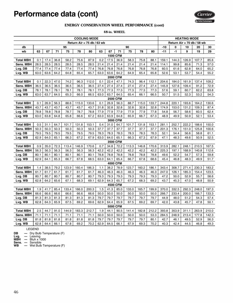
46
ENERGY CONSERVATION WHEEL PERFORMANCE (cont)
48-in. WHEEL
LEGEND
COOLING MODE HEATING MODE Return Air = 75 db / 63 wb Return Air = 70 db / 58 wb
db 95 90 -10 0 10 20 30 wb 63 67 71 75 78 80 63 67 71 75 78 80 -11 -1 9 19 29
1500 CFM Total MBH 0.1 17.4 36.8 58.2 75.6 87.9 0.2 17.5 36.9 58.3 75.8 88.1 159.1 144.3 126.9 107.7 85.6 Sens. MBH 28.5 28.5 28.5 28.5 28.5 28.5 21.4 21.4 21.4 21.4 21.4 21.4 114.1 99.8 85.6 71.3 57.0 Lvg. DB 77.4 77.4 77.4 77.4 77.4 77.4 76.8 76.8 76.8 76.8 76.8 76.8 60.5 61.6 62.8 64.0 65.2 Lvg. WB 63.0 63.6 64.2 64.8 65.4 65.7 63.0 63.6 64.2 64.9 65.4 65.8 52.6 53.1 53.7 54.4 55.2
2000 CFM Total MBH 0.1 22.3 47.0 74.2 96.3 112.0 0.1 22.4 47.1 74.3 96.4 112.1 204.6 184.0 161.9 137.4 109.2 Sens. MBH 36.5 36.5 36.5 36.5 36.5 36.5 27.4 27.4 27.4 27.4 27.4 27.4 145.9 127.6 109.4 91.2 72.9 Lvg. DB 78.1 78.1 78.1 78.1 78.1 78.1 77.3 77.3 77.3 77.3 77.3 77.3 57.6 59.1 60.7 62.2 63.8 Lvg. WB 63.0 63.7 64.5 65.3 66.0 66.5 63.0 63.7 64.5 65.4 66.1 66.5 50.7 51.5 52.3 53.2 54.3
2500 CFM Total MBH 0.1 26.9 56.3 88.6 115.0 133.6 0.1 26.9 56.3 88.7 115.0 133.7 244.8 220.1 193.6 164.2 130.6 Sens. MBH 43.7 43.7 43.7 43.7 43.7 43.7 31.8 32.8 32.8 32.8 32.8 32.8 174.9 153.0 131.2 109.3 87.4 Lvg. DB 78.8 78.8 78.8 78.7 78.7 78.8 77.9 77.9 77.9 77.9 77.9 77.8 54.8 56.7 58.6 60.5 62.4 Lvg. WB 63.0 63.8 64.8 65.8 66.6 67.2 63.0 63.9 64.8 65.9 66.7 67.3 48.9 49.9 50.9 52.1 53.4
3000 CFM Total MBH 0.5 31.1 64.7 101.7 131.8 153.1 0.4 31.0 64.7 101.7 131.8 153.1 281.1 252.7 222.2 188.6 150.0 Sens. MBH 50.3 50.3 50.3 50.3 50.3 50.3 37.7 37.7 37.7 37.7 37.7 37.7 201.3 176.1 151.0 125.8 100.6 Lvg. DB 79.5 79.5 79.5 79.5 79.5 79.5 78.3 78.3 78.3 78.3 78.3 78.3 52.1 54.4 56.6 58.8 61.1 Lvg. WB 62.9 64.0 65.1 66.3 67.2 67.9 63.0 64.0 65.1 66.3 67.3 67.9 47.1 48.3 49.6 50.9 52.5
3500 CFM Total MBH 0.9 35.0 72.3 113.4 146.9 170.6 0.7 34.8 72.2 113.3 146.8 170.6 313.9 282.1 248.1 210.5 167.5 Sens. MBH 56.3 56.3 56.3 56.3 56.3 56.3 42.2 42.2 42.2 42.2 42.2 42.2 225.3 197.1 168.9 140.8 112.6 Lvg. DB 80.1 80.1 80.1 80.1 80.1 80.1 78.8 78.8 78.8 78.8 78.8 78.8 49.6 52.2 54.7 57.3 59.8 Lvg. WB 62.9 64.1 65.3 66.7 67.8 68.5 63.0 64.1 65.4 66.7 67.8 68.6 45.4 46.8 48.3 49.9 51.7
4000 CFM Total MBH 1.4 38.5 79.2 123.9 160.4 186.3 1.1 38.2 78.9 123.7 160.2 186.1 343.4 308.7 271.4 230.3 183.2 Sens. MBH 61.7 61.7 61.7 61.7 61.7 61.7 46.3 46.3 46.3 46.3 46.3 46.3 247.0 126.1 185.3 154.4 123.5 Lvg. DB 80.7 80.7 80.7 80.7 80.7 80.7 79.3 79.3 79.3 79.3 79.3 79.3 47.2 50.0 52.9 55.7 58.6 Lvg. WB 62.8 64.2 65.6 67.1 68.3 69.1 62.9 64.3 65.7 67.2 68.3 69.2 43.7 45.3 47.0 48.8 50.9
4500 CFM Total MBH 1.9 41.7 85.4 133.4 166.0 200.3 1.5 41.3 85.0 133.0 165.7 199.9 370.0 332.5 292.3 248.0 197.3 Sens. MBH 66.6 66.6 66.6 66.6 66.6 66.6 50.0 50.0 50.0 50.0 50.0 50.0 266.7 233.4 200.0 166.7 133.3 Lvg. DB 81.3 81.3 81.3 81.3 81.3 81.3 79.7 79.7 79.7 79.7 79.7 79.7 44.9 48.0 51.2 54.3 57.4 Lvg. WB 62.8 64.3 65.9 67.5 69.2 69.6 62.9 64.4 65.9 67.5 69.2 69.7 42.0 43.8 45.7 47.8 50.1
5000 CFM Total MBH 2.5 44.7 91.0 144.9 183.3 212.7 1.9 44.1 90.5 141.4 182.8 212.2 393.8 353.9 311.1 263.9 210.0 Sens. MBH 71.1 71.1 71.1 71.1 71.1 71.1 50.0 50.0 50.0 50.0 50.0 53.3 284.5 248.9 213.4 177.8 142.3 Lvg. DB 81.8 81.8 81.8 81.8 81.8 81.8 79.7 79.7 79.7 79.7 79.7 80.1 42.7 46.1 49.5 52.9 56.3 Lvg. WB 62.8 64.4 66.1 67.8 69.2 70.2 62.9 64.5 66.1 67.9 69.3 70.2 40.3 42.4 44.5 46.8 49.3
DB — Dry Bulb Temperature (F)Lvg. — LeavingMBH — Btuh x 1000Sens. — SensibleWB — Wet Bulb Temperature (F)
Performance data (cont)
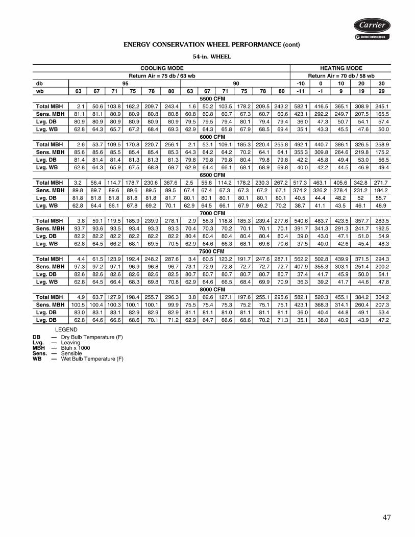
47
ENERGY CONSERVATION WHEEL PERFORMANCE (cont)
54-in. WHEEL
LEGEND
COOLING MODE HEATING MODE Return Air = 75 db / 63 wb Return Air = 70 db / 58 wb
db 95 90 -10 0 10 20 30 wb 63 67 71 75 78 80 63 67 71 75 78 80 -11 -1 9 19 29
5500 CFM Total MBH 2.1 50.6 103.8 162.2 209.7 243.4 1.6 50.2 103.5 178.2 209.5 243.2 582.1 416.5 365.1 308.9 245.1 Sens. MBH 81.1 81.1 80.9 80.9 80.8 80.8 60.8 60.8 60.7 67.3 60.7 60.6 423.1 292.2 249.7 207.5 165.5 Lvg. DB 80.9 80.9 80.9 80.9 80.9 80.9 79.5 79.5 79.4 80.1 79.4 79.4 36.0 47.3 50.7 54.1 57.4 Lvg. WB 62.8 64.3 65.7 67.2 68.4 69.3 62.9 64.3 65.8 67.9 68.5 69.4 35.1 43.3 45.5 47.6 50.0
6000 CFM Total MBH 2.6 53.7 109.5 170.8 220.7 256.1 2.1 53.1 109.1 185.3 220.4 255.8 492.1 440.7 386.1 326.5 258.9 Sens. MBH 85.6 85.6 85.5 85.4 85.4 85.3 64.3 64.2 64.2 70.2 64.1 64.1 355.3 309.8 264.6 219.8 175.2 Lvg. DB 81.4 81.4 81.4 81.3 81.3 81.3 79.8 79.8 79.8 80.4 79.8 79.8 42.2 45.8 49.4 53.0 56.5 Lvg. WB 62.8 64.3 65.9 67.5 68.8 69.7 62.9 64.4 66.1 68.1 68.9 69.8 40.0 42.2 44.5 46.9 49.4
6500 CFM Total MBH 3.2 56.4 114.7 178.7 230.6 367.6 2.5 55.8 114.2 178.2 230.3 267.2 517.3 463.1 405.6 342.8 271.7 Sens. MBH 89.8 89.7 89.6 89.6 89.5 89.5 67.4 67.4 67.3 67.3 67.2 67.1 374.2 326.2 278.4 231.2 184.2 Lvg. DB 81.8 81.8 81.8 81.8 81.8 81.7 80.1 80.1 80.1 80.1 80.1 80.1 40.5 44.4 48.2 52 55.7 Lvg. WB 62.8 64.4 66.1 67.8 69.2 70.1 62.9 64.5 66.1 67.9 69.2 70.2 38.7 41.1 43.5 46.1 48.9
7000 CFM Total MBH 3.8 59.1 119.5 185.9 239.9 278.1 2.9 58.3 118.8 185.3 239.4 277.6 540.6 483.7 423.5 357.7 283.5 Sens. MBH 93.7 93.6 93.5 93.4 93.3 93.3 70.4 70.3 70.2 70.1 70.1 70.1 391.7 341.3 291.3 241.7 192.5 Lvg. DB 82.2 82.2 82.2 82.2 82.2 82.2 80.4 80.4 80.4 80.4 80.4 80.4 39.0 43.0 47.1 51.0 54.9 Lvg. WB 62.8 64.5 66.2 68.1 69.5 70.5 62.9 64.6 66.3 68.1 69.6 70.6 37.5 40.0 42.6 45.4 48.3
7500 CFM Total MBH 4.4 61.5 123.9 192.4 248.2 287.6 3.4 60.5 123.2 191.7 247.6 287.1 562.2 502.8 439.9 371.5 294.3 Sens. MBH 97.3 97.2 97.1 96.9 96.8 96.7 73.1 72.9 72.8 72.7 72.7 72.7 407.9 355.3 303.1 251.4 200.2 Lvg. DB 82.6 82.6 82.6 82.6 82.6 82.5 80.7 80.7 80.7 80.7 80.7 80.7 37.4 41.7 45.9 50.0 54.1 Lvg. WB 62.8 64.5 66.4 68.3 69.8 70.8 62.9 64.6 66.5 68.4 69.9 70.9 36.3 39.2 41.7 44.6 47.8
8000 CFM Total MBH 4.9 63.7 127.9 198.4 255.7 296.3 3.8 62.6 127.1 197.6 255.1 295.6 582.1 520.3 455.1 384.2 304.2 Sens. MBH 100.5 100.4 100.3 100.1 100.1 99.9 75.5 75.4 75.3 75.2 75.1 75.1 423.1 368.3 314.1 260.4 207.3 Lvg. DB 83.0 83.1 83.1 82.9 82.9 82.9 81.1 81.1 81.0 81.1 81.1 81.1 36.0 40.4 44.8 49.1 53.4 Lvg. DB 62.8 64.6 66.6 68.6 70.1 71.2 62.9 64.7 66.6 68.6 70.2 71.3 35.1 38.0 40.9 43.9 47.2
DB — Dry Bulb Temperature (F)Lvg. — LeavingMBH — Btuh x 1000Sens. — SensibleWB — Wet Bulb Temperature (F)
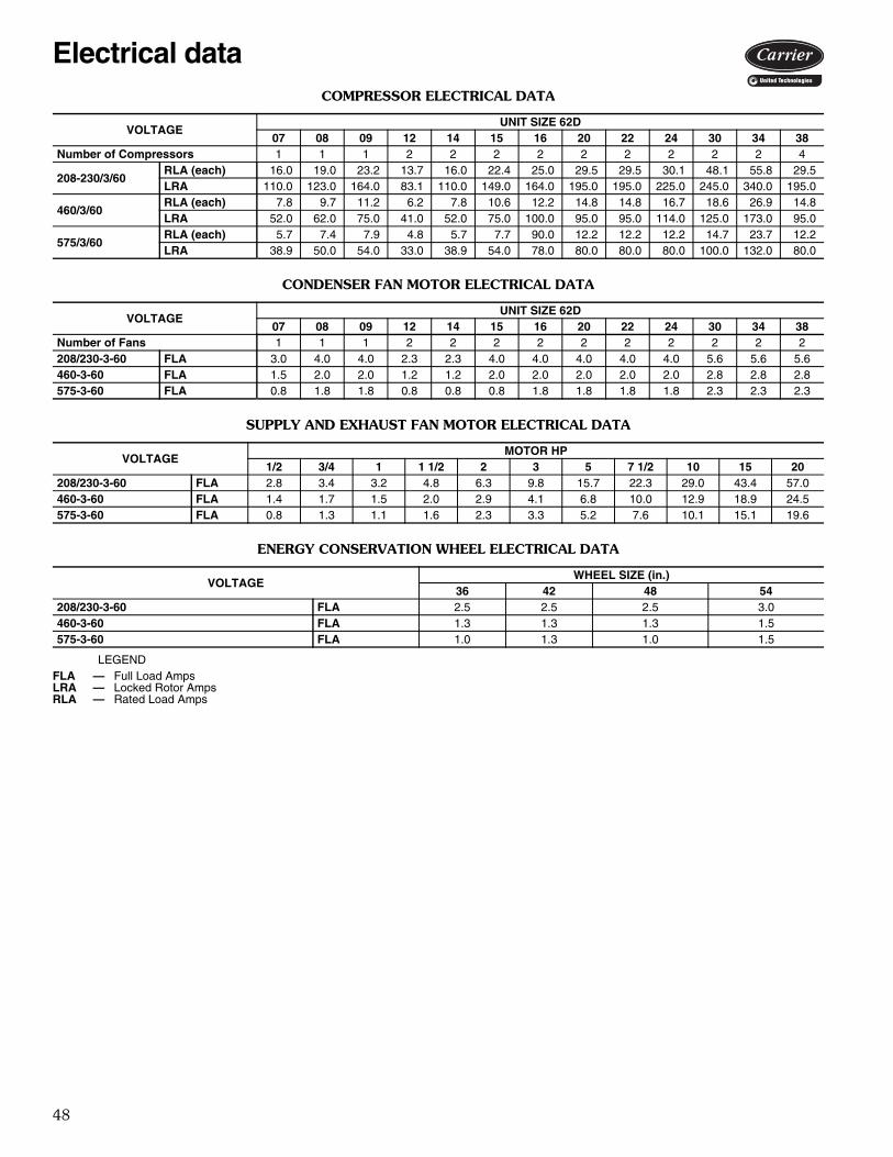
48
COMPRESSOR ELECTRICAL DATA
CONDENSER FAN MOTOR ELECTRICAL DATA
SUPPLY AND EXHAUST FAN MOTOR ELECTRICAL DATA
ENERGY CONSERVATION WHEEL ELECTRICAL DATA
LEGEND
VOLTAGEUNIT SIZE 62D
07 08 09 12 14 15 16 20 22 24 30 34 38Number of Compressors 1 1 1 2 2 2 2 2 2 2 2 2 4
208-230/3/60RLA (each) 16.0 19.0 23.2 13.7 16.0 22.4 25.0 29.5 29.5 30.1 48.1 55.8 29.5LRA 110.0 123.0 164.0 83.1 110.0 149.0 164.0 195.0 195.0 225.0 245.0 340.0 195.0
460/3/60RLA (each) 7.8 9.7 11.2 6.2 7.8 10.6 12.2 14.8 14.8 16.7 18.6 26.9 14.8LRA 52.0 62.0 75.0 41.0 52.0 75.0 100.0 95.0 95.0 114.0 125.0 173.0 95.0
575/3/60RLA (each) 5.7 7.4 7.9 4.8 5.7 7.7 90.0 12.2 12.2 12.2 14.7 23.7 12.2LRA 38.9 50.0 54.0 33.0 38.9 54.0 78.0 80.0 80.0 80.0 100.0 132.0 80.0
VOLTAGEUNIT SIZE 62D
07 08 09 12 14 15 16 20 22 24 30 34 38Number of Fans 1 1 1 2 2 2 2 2 2 2 2 2 2208/230-3-60 FLA 3.0 4.0 4.0 2.3 2.3 4.0 4.0 4.0 4.0 4.0 5.6 5.6 5.6460-3-60 FLA 1.5 2.0 2.0 1.2 1.2 2.0 2.0 2.0 2.0 2.0 2.8 2.8 2.8575-3-60 FLA 0.8 1.8 1.8 0.8 0.8 0.8 1.8 1.8 1.8 1.8 2.3 2.3 2.3
VOLTAGEMOTOR HP
1/2 3/4 1 1 1/2 2 3 5 7 1/2 10 15 20208/230-3-60 FLA 2.8 3.4 3.2 4.8 6.3 9.8 15.7 22.3 29.0 43.4 57.0460-3-60 FLA 1.4 1.7 1.5 2.0 2.9 4.1 6.8 10.0 12.9 18.9 24.5575-3-60 FLA 0.8 1.3 1.1 1.6 2.3 3.3 5.2 7.6 10.1 15.1 19.6
VOLTAGEWHEEL SIZE (in.)
36 42 48 54208/230-3-60 FLA 2.5 2.5 2.5 3.0460-3-60 FLA 1.3 1.3 1.3 1.5575-3-60 FLA 1.0 1.3 1.0 1.5
FLA — Full Load AmpsLRA — Locked Rotor AmpsRLA — Rated Load Amps
Electrical data
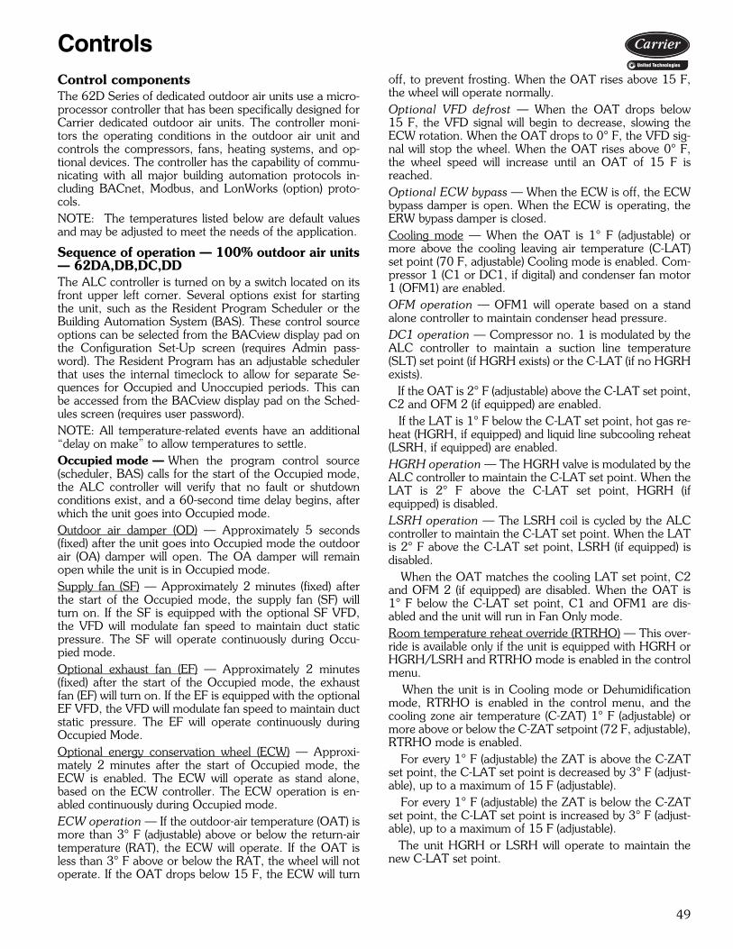
49
ControlsControl componentsThe 62D Series of dedicated outdoor air units use a micro-processor controller that has been specifically designed forCarrier dedicated outdoor air units. The controller moni-tors the operating conditions in the outdoor air unit andcontrols the compressors, fans, heating systems, and op-tional devices. The controller has the capability of commu-nicating with all major building automation protocols in-cluding BACnet, Modbus, and LonWorks (option) proto-cols.NOTE: The temperatures listed below are default valuesand may be adjusted to meet the needs of the application.
Sequence of operation — 100% outdoor air units— 62DA,DB,DC,DDThe ALC controller is turned on by a switch located on itsfront upper left corner. Several options exist for startingthe unit, such as the Resident Program Scheduler or theBuilding Automation System (BAS). These control sourceoptions can be selected from the BACview display pad onthe Configuration Set-Up screen (requires Admin pass-word). The Resident Program has an adjustable schedulerthat uses the internal timeclock to allow for separate Se-quences for Occupied and Unoccupied periods. This canbe accessed from the BACview display pad on the Sched-ules screen (requires user password). NOTE: All temperature-related events have an additional“delay on make” to allow temperatures to settle.Occupied mode — When the program control source(scheduler, BAS) calls for the start of the Occupied mode,the ALC controller will verify that no fault or shutdownconditions exist, and a 60-second time delay begins, afterwhich the unit goes into Occupied mode.Outdoor air damper (OD) — Approximately 5 seconds(fixed) after the unit goes into Occupied mode the outdoorair (OA) damper will open. The OA damper will remainopen while the unit is in Occupied mode.Supply fan (SF) — Approximately 2 minutes (fixed) afterthe start of the Occupied mode, the supply fan (SF) willturn on. If the SF is equipped with the optional SF VFD,the VFD will modulate fan speed to maintain duct staticpressure. The SF will operate continuously during Occu-pied mode.Optional exhaust fan (EF) — Approximately 2 minutes(fixed) after the start of the Occupied mode, the exhaustfan (EF) will turn on. If the EF is equipped with the optionalEF VFD, the VFD will modulate fan speed to maintain ductstatic pressure. The EF will operate continuously duringOccupied Mode.Optional energy conservation wheel (ECW) — Approxi-mately 2 minutes after the start of Occupied mode, theECW is enabled. The ECW will operate as stand alone,based on the ECW controller. The ECW operation is en-abled continuously during Occupied mode.ECW operation — If the outdoor-air temperature (OAT) ismore than 3° F (adjustable) above or below the return-airtemperature (RAT), the ECW will operate. If the OAT isless than 3° F above or below the RAT, the wheel will notoperate. If the OAT drops below 15 F, the ECW will turn
off, to prevent frosting. When the OAT rises above 15 F,the wheel will operate normally.Optional VFD defrost — When the OAT drops below15 F, the VFD signal will begin to decrease, slowing theECW rotation. When the OAT drops to 0° F, the VFD sig-nal will stop the wheel. When the OAT rises above 0° F,the wheel speed will increase until an OAT of 15 F isreached.Optional ECW bypass — When the ECW is off, the ECWbypass damper is open. When the ECW is operating, theERW bypass damper is closed.Cooling mode — When the OAT is 1° F (adjustable) ormore above the cooling leaving air temperature (C-LAT)set point (70 F, adjustable) Cooling mode is enabled. Com-pressor 1 (C1 or DC1, if digital) and condenser fan motor1 (OFM1) are enabled. OFM operation — OFM1 will operate based on a standalone controller to maintain condenser head pressure.DC1 operation — Compressor no. 1 is modulated by theALC controller to maintain a suction line temperature(SLT) set point (if HGRH exists) or the C-LAT (if no HGRHexists). If the OAT is 2° F (adjustable) above the C-LAT set point,C2 and OFM 2 (if equipped) are enabled. If the LAT is 1° F below the C-LAT set point, hot gas re-heat (HGRH, if equipped) and liquid line subcooling reheat(LSRH, if equipped) are enabled.HGRH operation — The HGRH valve is modulated by theALC controller to maintain the C-LAT set point. When theLAT is 2° F above the C-LAT set point, HGRH (ifequipped) is disabled.LSRH operation — The LSRH coil is cycled by the ALCcontroller to maintain the C-LAT set point. When the LATis 2° F above the C-LAT set point, LSRH (if equipped) isdisabled. When the OAT matches the cooling LAT set point, C2and OFM 2 (if equipped) are disabled. When the OAT is1° F below the C-LAT set point, C1 and OFM1 are dis-abled and the unit will run in Fan Only mode.Room temperature reheat override (RTRHO) — This over-ride is available only if the unit is equipped with HGRH orHGRH/LSRH and RTRHO mode is enabled in the controlmenu. When the unit is in Cooling mode or Dehumidificationmode, RTRHO is enabled in the control menu, and thecooling zone air temperature (C-ZAT) 1° F (adjustable) ormore above or below the C-ZAT setpoint (72 F, adjustable),RTRHO mode is enabled. For every 1° F (adjustable) the ZAT is above the C-ZATset point, the C-LAT set point is decreased by 3° F (adjust-able), up to a maximum of 15 F (adjustable). For every 1° F (adjustable) the ZAT is below the C-ZATset point, the C-LAT set point is increased by 3° F (adjust-able), up to a maximum of 15 F (adjustable). The unit HGRH or LSRH will operate to maintain thenew C-LAT set point.
50
When the ZAT equals the C-ZAT set point, RTRHOmode is disabled and Cooling or Dehumidification mode isenabled.Dehumidification mode — Dehumidification is availableonly if the unit is equipped with HGRH or HRGH/LSRHand Dehumidification mode is enabled in the controlsmenu. When OAT is above 60 F (adjustable), and the zone rela-tive humidity (Z-RH) is 1% (adjustable) or more above theZ-RH set point (55% RH, adjustable), and there is no callfor heating, Dehumidification mode is enabled. C1 orDC1, HGRH and LSRH (if equipped), and OFM 1 are en-abled. DC1 operation — Compressor no. 1 is modulated by theALC controller to 100% operation.HGRH operation — HGRH will modulate to maintain theLAT set point.LSRH operation — LSRH will cycle to maintain the LATset point. When the Z-RH is 2% above the Z-RH set point, C2 andOFM 2 (if equipped) are enabled. When Z-RH is 2% below the Z-RH set point, Dehumidi-fication mode is disabled and Cooling, RTRHO or Fanmode is enabled.Heating mode — When the OAT is 1° F (adjustable) ormore above the heat OAT Heating enable set point, Heat-ing Mode is enabled.Staged heat (gas, electric) — The heat source is staged bythe ALC controller based on the difference between theLAT and LAT set point.Modulating heat (gas, electric, steam, hot water) — Theheat source is modulated by the ALC controller to maintainthe LAT set point.
When the OAT is 1° F above the OAT Heating enableset point, Heating Mode is disabled and the unit operatesin Fan Only Mode.Staged heat (gas, electric) — The heat source is staged bythe ALC controller based on the difference between theLAT and LAT set point.
Modulating heat (gas, electric, steam, hot water) — Theheat source is modulated by the ALC controller to maintainthe LAT set point. When the LAT is 1° F above the H-LAT set point, auxil-iary heating is disabled. When the OAT is above the HP-OAT enable set point,Heating mode is disabled.Room temperature reheat override (RTRHO) — When theunit is in Heating mode, RTHO is enabled in the controlmenu, and the heating zone air temperature (H-ZAT) is1° F (adjustable) or more above or below the H-ZAT setpoint (72 F, adjustable) RTHO mode is enabled. For every 1° F (adjustable) the ZAT is above the H-ZATset point, the H-LAT set point is decreased by 3° F (adjust-able), up to a maximum of 15 F (adjustable). For every 1° F (adjustable) the ZAT is below the H-ZATset point, the H-LAT set point is increased by 3° F (adjust-able), up to a maximum of 15 F (adjustable). The unit heat pump or auxiliary heat source will operateto maintain the new H-LAT set point. When the ZAT equals the H-ZAT set point, RTHO modeis disabled and Heating mode is enabled.Fan Only mode — When the OAT is below the C-LAT setpoint, but above the OAT Heating enable set point and De-humidification mode is not enabled, Fan Only mode is en-abled. No cooling or heat source is energized. Only the SF, EF(if equipped) and ECW (if equipped) will operate.Unoccupied mode — When the program control source(Scheduler, BAS) or energy management relay (EMR) callsfor the end of Occupied mode, the unit will enter Unoccu-pied mode. The C1 or DC1 (if equipped), OFM1, C2 and OFM 2 (ifequipped) and auxiliary heat sources will be disabled. The SF and EF will continue to operate for 2 minutes,and then shut off. After the SF and EF shut off, the ERW will shut off. The OA damper will close.
Controls (cont)

51
TYPICAL CONTROLLER INPUTS
TYPICAL CONTROLLER OUTPUTS
LEGEND
NUMBER NAME TYPE SENSOR TYPEUI-01 Outside Air Temperature Analog Type II Thermistor 10k at 77 FUI-02 Outside Air Humidity Analog 0-10 vdcUI-03 Leaving Air Temperature Analog Type II Thermistor 10k at 77 FUI-04 Zone Relative Humidity Analog 0-10 vdcUI-05 Supply Fan Static Pressure Transmitter Analog 0-10 vdcUI-06 Exhaust Fan Static Pressure Transmitter Analog 0-10 vdcUI-07 — — —UI-08 Compressor 2 Suction Line Temperature Binary Type II Thermistor 10k at 77 FUI-09 Compressor 1 Suction Line Temperature Analog Type II Thermistor 10k at 77 FUI-10 Smoke Detector (NC), EMR (NC), LP1 (NO), LP2 (NO) Analog LP1-5k, LP2-10k, SD-20k, EMR-40k
UI-11 Clogged Filter Indicator (NO), C1 Current Sensor (NO), C2 Current Sensor (NO) Analog C1CS-5k, C2CS-10k, CFD-20k
UI-12 ECW Wheel Motion Sensor (NO), SF Air Proving Switch (NO),EF Air Proving Switch (NO) Analog ECWCS-5k, SFAPS-10k, EFAPS-20k
NUMBER NAME OUTPUT TYPEAO-01 Supply Fan VFD Modulation 0-10 vdcAO-02 Exhaust Fan VFD Modulation 0-10 vdcAO-03 Digital Compressor 2 Modulation 0-10 vdcAO-04 Hot Gas Reheat (HGRH)/Discharge Valve Modulation 0-10 vdcAO-05 Digital Compressor 1 Modulation 0-10 vdcAO-06 SCR Heat or Modulating Gas Heat 0-10 vdcBO-01 Supply Fan, Exhaust Fan Relay / Triac OutputBO-02 Compressor (Y1) Relay / Triac OutputBO-03 Compressor (Y2) Relay / Triac OutputBO-04 Hot Gas Reheat Valve (HGRH) Relay / Triac OutputBO-05 Stage 1 Heat (W1) or Heat Pump Heat Relay / Triac OutputBO-06 OA Damper, ECW Motor, ECW Damper, Exhaust Fan Relay / Triac Output
AO — Analog OutputBO — Binary OutputECW — Energy Conservation WheelEF — Exhaust FanEMR — Energy Management RelayHGRH — Hot Gas ReheatLP — Low Pressure SwitchNC — Normally Closed (contact)NO — Normally Open (contact)OA — Outdoor AirSF — Supply FanUI — Universal InputVFD — Variable Frequency Drive
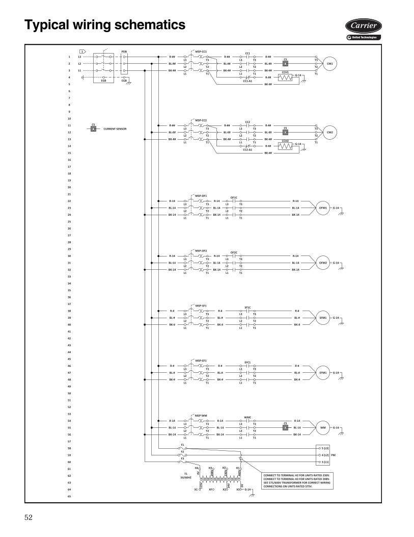
52
PM
CSCS
CS
CS
CCH1G-14
1.
EGB
L3
L2
L1
PDB
EGB
BL-##
BK-##
L3 T3
L2 T2
L1 T1
R-##
BL-##
BK-##
R-##L3
L2
L1
T3
T2
T1
CM1BL-##
BK-##
R-##T3
T2
T1R-##
BK-##
T150/60HZ
0V 208V
230V
460V
115V
24V
0V
H4 H3 H2 H1
X3X2XFX1
MSP-SF1 SF1C
BL-#
BK-#
L3 T3
L2 T2
L1 T1
R-#
BL-#
BK-#
R-#L3
L2
L1
T3
T2
T1
SFM1 G-14BL-#
BK-#
R-#
MSP-EF1 EFC1
BL-#
BK-#
L3 T3
L2 T2
L1 T1
R-#
BL-#
BK-#
R-#L3
L2
L1
T3
T2
T1
EFM1 G-14BL-#
BK-#
R-#
CURRENT SENSOR
G-14
F1
F3
5 (L3)
4 (L2)
3 (L1)
F2
MSP-CC1 CC1
CC1-A1
OF1C
L3
L2
L1
T3
T2
T1
OFM1 G-14
MSP-OF1
BL-14
BK-14
L3 T3
L2 T2
L1 T1
R-14
BL-14
BK-14
R-14
BL-14
BK-14
R-14
OF2C
L3
L2
L1
T3
T2
T1
OFM2 G-14
MSP-OF2
BL-14
BK-14
L3 T3
L2 T2
L1 T1
R-14
BL-14
BK-14
R-14
BL-14
BK-14
R-14
CONNECT TO TERMINAL H2 FOR UNITS RATED 230V.CONNECT TO TERMINAL H3 FOR UNITS RATED 208V.SEE 575/600V TRANSFORMER FOR CORRECT WIRING CONNECTIONS ON UNITS RATED 575V.
MSP-WM WMC
BL-14
BK-14
L3 T3
L2 T2
L1 T1
R-14
BL-14
BK-14
R-14L3
L2
L1
T3
T2
T1
WM G-14BL-14
BK-14
R-14
CCH2G-14
BL-##
BK-##
L3 T3
L2 T2
L1 T1
R-##
BL-##
BK-##
R-##L3
L2
L1
T3
T2
T1
CM2BL-##
BK-##
R-##T3
T2
T1R-##
BK-##
MSP-CC2 CC2
CC2-A1
1
2
3
4
5
6
7
8
9
10
11
12
13
14
15
16
17
18
19
20
21
22
23
24
25
26
27
28
29
30
31
32
33
34
35
36
37
38
39
40
41
42
43
44
45
46
47
48
49
50
51
52
53
54
55
56
57
58
59
60
61
62
63
64
65
a62-708
Typical wiring schematics
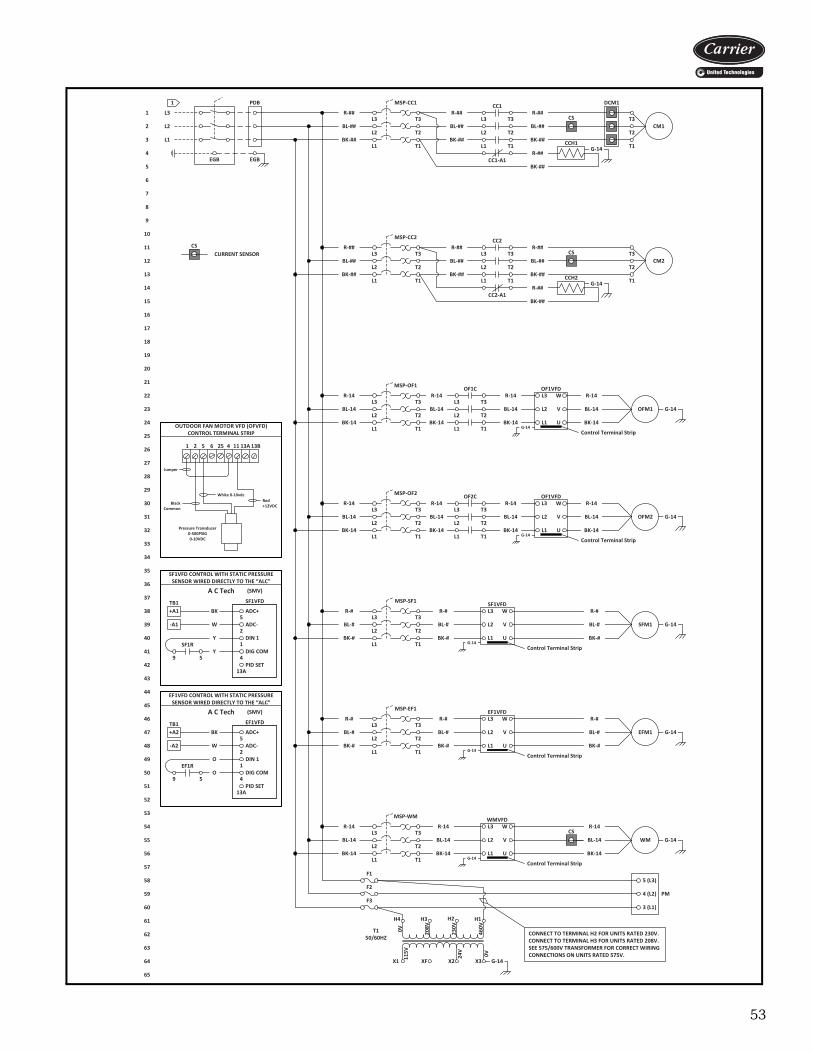
53
TB1
TB1
A C Tech (SMV)
SF1VFD
A C Tech (SMV)
EF1VFD
OF1VFD
OF1VFD
PM
CSCS
DCM1
CS
CS
CCH1G-14
1.
EGB
L3
L2
L1
PDB
EGB
BL-##
BK-##
L3 T3
L2 T2
L1 T1
R-##
BL-##
BK-##
R-##L3
L2
L1
T3
T2
T1
CM1BL-##
BK-##
R-##T3
T2
T1R-##
BK-##
T150/60HZ
0V 208V
230V
460V
115V
24V
0V
H4 H3 H2 H1
X3X2XFX1
MSP-SF1
BL-#
BK-#
L3 T3
L2 T2
L1 T1
R-#
BL-#
BK-#
R-#
SFM1 G-14BL-#
BK-#
R-#
MSP-EF1
BL-#
BK-#
L3 T3
L2 T2
L1 T1
R-#
BL-#
BK-#
R-#
EFM1 G-14BL-#
BK-#
R-#EF1VFD
UL1
VL2
WL3
SF1VFD
UL1
VL2
WL3
CURRENT SENSOR
G-14
F1
F3
Control Terminal StripG-14
Control Terminal StripG-14
5 (L3)
4 (L2)
3 (L1)
F2
MSP-CC1 CC1
CC1-A1
OF1C
L3
L2
L1
T3
T2
T1
OFM1 G-14
MSP-OF1
BL-14
BK-14
L3 T3
L2 T2
L1 T1
R-14
BL-14
BK-14
R-14
BL-14
BK-14
R-14
1 52 6 25 4 11 13A 13B
Pressure Transducer0-500PSIG0-10VDC
Red +12VDC
Black Common
White 0-10vdc
Jumper
SF1VFD CONTROL WITH STATIC PRESSURE SENSOR WIRED DIRECTLY TO THE “ALC”
+A1 BK
SF1R
9 5
DIN 1
ADC+
ADC-2
5
4
1
PID SET13A
DIG COM
-A1 W
Y
Y
EF1VFD CONTROL WITH STATIC PRESSURE SENSOR WIRED DIRECTLY TO THE “ALC”
+A2 BK
EF1R
9 5
DIN 1
ADC+
ADC-2
5
4
1
PID SET13A
DIG COM
-A2 W
O
O
OUTDOOR FAN MOTOR VFD (OFVFD)CONTROL TERMINAL STRIP
UL1
VL2
WL3
Control Terminal StripG-14
BL-14
BK-14
R-14
OF2C
L3
L2
L1
T3
T2
T1
OFM2 G-14
MSP-OF2
BL-14
BK-14
L3 T3
L2 T2
L1 T1
R-14
BL-14
BK-14
R-14
BL-14
BK-14
R-14
UL1
VL2
WL3
Control Terminal StripG-14
BL-14
BK-14
R-14
CONNECT TO TERMINAL H2 FOR UNITS RATED 230V.CONNECT TO TERMINAL H3 FOR UNITS RATED 208V.SEE 575/600V TRANSFORMER FOR CORRECT WIRING CONNECTIONS ON UNITS RATED 575V.
MSP-WM
BL-14
BK-14
L3 T3
L2 T2
L1 T1
R-14
BL-14
BK-14
R-14
WM G-14BL-14
BK-14
R-14WMVFD
UL1
VL2
WL3
Control Terminal StripG-14
CCH2G-14
BL-##
BK-##
L3 T3
L2 T2
L1 T1
R-##
BL-##
BK-##
R-##L3
L2
L1
T3
T2
T1
CM2BL-##
BK-##
R-##T3
T2
T1R-##
BK-##
MSP-CC2 CC2
CC2-A1
1
2
3
4
5
6
7
8
9
10
11
12
13
14
15
16
17
18
19
20
21
22
23
24
25
26
27
28
29
30
31
32
33
34
35
36
37
38
39
40
41
42
43
44
45
46
47
48
49
50
51
52
53
54
55
56
57
58
59
60
61
62
63
64
65
a62-709
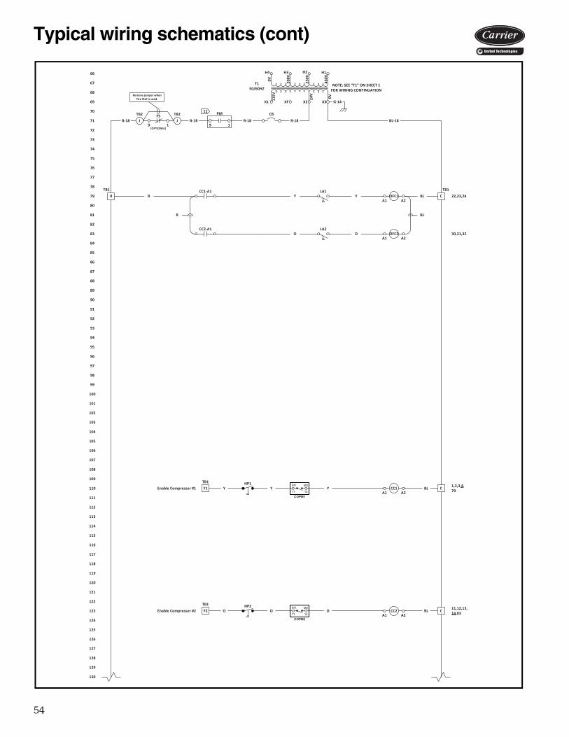
54
TB1
TB1
TB1 TB1
CC2
CC1
BL
OFC2
Enable Compressor #1
Enable Compressor #2
NOTE: SEE “T1” ON SHEET 1 FOR WIRING CONTINUATION
T150/60HZ
0V 208V
230V
460V
115V
24V
0V
H4 H3 H2 H1
X3X2XFX1 G-14
R-18R-18R-18R-18 BL-18
CC1-A1
CC2-A1
R OFC1A2A1
Y
A2A1O
CBLR
HP1Y1 Y
HP2Y2 O
C
C
Y
O
BL
BL
A2A1
A2A1
22,23,24
30,31,32
1,2,3,4, 79
11,12,13,14,83
LA2
LA1Y
O
CB
66
67
68
69
70
71
72
73
74
75
76
77
78
79
80
81
82
83
84
85
86
87
88
89
90
91
92
93
94
95
96
97
98
99
100
101
102
103
104
105
106
107
108
109
110
111
112
113
114
115
116
117
118
119
120
121
122
123
124
125
126
127
128
129
130
R
Y
O
COPM1
M1 M2
11 14
COPM2
M1 M2
11 14
TB2 TB2FS
9 1J J
(OPTIONAL)
Remove jumper when Fire Stat is used.
PM
9 1
11
a62-710
Typical wiring schematics (cont)
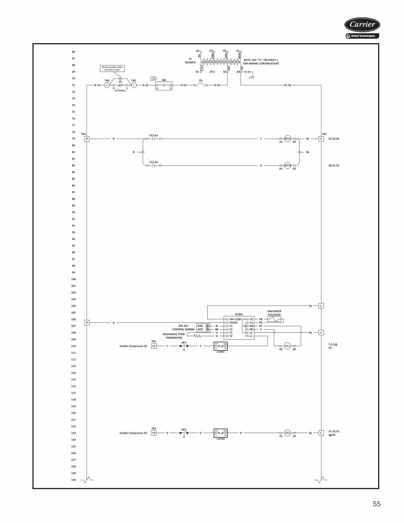
55
TB1
TB1
UNLOADER SOLENOID
SEE ALCCONTROL WIRING
TB1 TB1
CC2
CC1
BL
OFC2
Enable Compressor #1
Enable Compressor #2
DCM1
DISCHARGE TEMP THERMISTOR
AO5
NOTE: SEE “T1” ON SHEET 1 FOR WIRING CONTINUATION
T150/60HZ
0V 208V
230V
460V
115V
24V
0V
H4 H3 H2 H1
X3X2XFX1 G-14
R-18R-18R-18R-18 BL-18
CC1-A1
CC2-A1
R OFC1A2A1
Y
A2A1O
CBLR
C
24VAC
C2
T2
24V COM
C1
T1
U1
M1
L1
U2
M2
L2
PRPKBLY
C
R
BL
BL
GRD WBKOO
HP1Y1 Y Y
HP2Y2 O
R
CO BL
A2A1
A2A1
22,23,24
30,31,32
1,2,3,4, 79
11,12,13,14,83
CB
66
67
68
69
70
71
72
73
74
75
76
77
78
79
80
81
82
83
84
85
86
87
88
89
90
91
92
93
94
95
96
97
98
99
100
101
102
103
104
105
106
107
108
109
110
111
112
113
114
115
116
117
118
119
120
121
122
123
124
125
126
127
128
129
130.
R
Y
O
COPM1
M1 M2
11 14
COPM2
M1 M2
11 14
TB2 TB2FS
9 1J J
(OPTIONAL)
Remove jumper when Fire Stat is used.
PM
9 1
11
a62-711
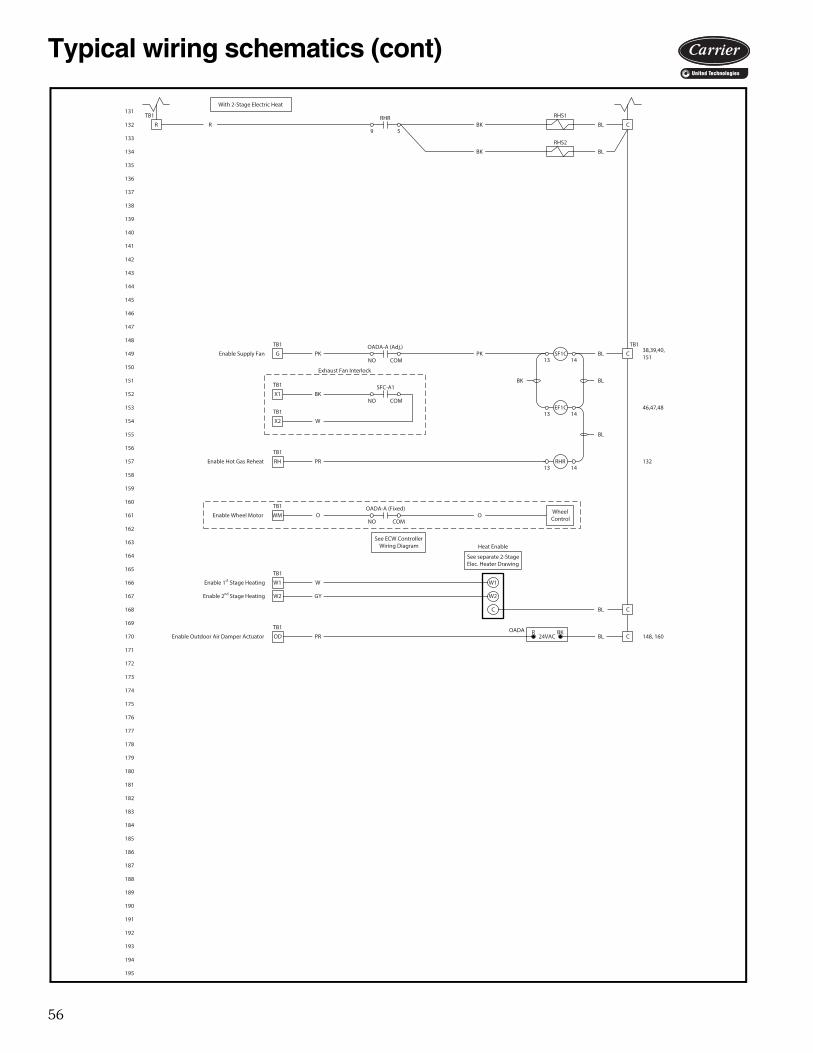
56
TB1
TB1
TB1
TB1
TB1
TB1
TB1
TB1
TB1
R R
Enable Wheel Motor WM
Enable Outdoor Air Damper Actuator OD
OADA-A (Fixed)
NO COMO O
PR COADA BKR
BL 148
Heat Enable
Wheel Control
See ECW Controller Wiring Diagram
Enable 1st Stage Heating
Enable 2nd Stage Heating
W
GY
W1
W2
See separate 2-Stage Elec. Heater Drawing
C BL C
W2
W1
BL
SF1C
EF1C1413
Enable Supply Fan G
Enable Hot Gas Reheat RH
PK
PR
C
BL
38,39,40
46,47,48
OADA-A (Adj.)
NO COMPK
RHR1413
BK
132
13 14
Exhaust Fan Interlock
SFC-A1
NO COMBKX1
WX2
131
132
133
134
135
136
137
138
139
140
141
142
143
144
145
146
147
148
149
150
151
152
153
154
155
156
157
158
159
160
161
162
163
164
165
166
167
168
169
170
171
172
173
174
175
176
177
178
179
180
181
182
183
184
185
186
187
188
189
190
191
192
193
194
195
38,39,40, 151
148, 16024VAC
BOS2RHS2
RHS1
CRHR
9 5BL
BL
BK
BK
BL
With 2-Stage Electric Heat
a62-712
Typical wiring schematics (cont)

57
TB1
TB1
TB1
TB1
TB1
TB1
TB1
TB1
TB1
TB1
WBDA
R R
Enable Wheel Motor WM
Enable Wheel By-Pass Damper Actuator WD
Enable Outdoor Air Damper Actuator OD
OADA-A (Fixed)
NO COM
WMC-A
NC COM
O O
PK PK
PR C
BKR
OADA BKR
BL
BL 148
Wheel Control
See ECW Controller Wiring Diagram
BLEnable 1st Stage Heating CHR1413
See separate 2-Stage Gas Furnace Drawing
Heat Enable
Enable 2nd Stage Heating HF1413
W
GY
W1
W2
BCTLBL
EF1R
SF1R
BL
1413
Enable Supply Fan G
Enable Hot Gas Reheat RH
PK
PR
C
BL
OADA-A (Adj.)
NO COMPK 41,51
50
RHR1413
BK
13 14
Exhaust Fan Interlock
BKX1
WX2
SF1R
12 8
131
132
133
134
135
136
137
138
139
140
141
142
143
144
145
146
147
148
149
150
151
152
153
154
155
156
157
158
159
160
161
162
163
164
165
166
167
168
169
170
171
172
173
174
175
176
177
178
179
180
181
182
183
184
185
186
187
188
189
190
191
192
193
194
195
132, 207, 219132, 136, 207, 219
41,51, 151
148, 160
425
426
24VAC
24VAC
N.C.
N.C.
N.O.
N.O.
LSS2A
10
BOS1
LSS1A
CRHR
BLBK12 8
CBL
BL
Y
O
RHR
R
6
LSS2B
LSS1BY BL
O BL
BL
With 2-Stage Gas Furnace
a62-713
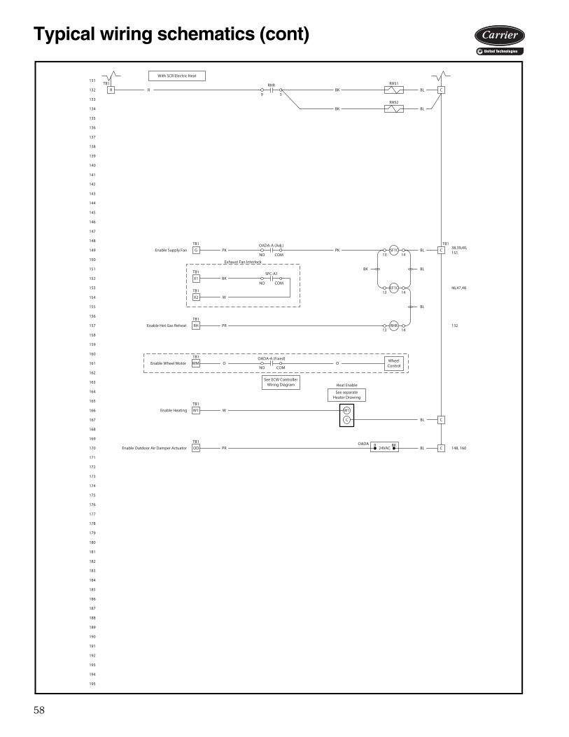
58
TB1
TB1
TB1
TB1
TB1
TB1
TB1
TB1
TB1
R R
Enable Wheel Motor WM
Enable Outdoor Air Damper Actuator OD
OADA-A (Fixed)
NO COMO O
PR COADA BKR
BL 148
See separate Heater Drawing
Heat Enable
BL
Enable Heating
C
Wheel Control
See ECW Controller Wiring Diagram
WW1 W1
C
BL
SF1C
EF1C1413
Enable Supply Fan G
Enable Hot Gas Reheat RH
PK
PR
C
BL
38,39,40
46,47,48
OADA-A (Adj.)
NO COMPK
RHR1413
BK
132
13 14
Exhaust Fan Interlock
SFC-A1
NO COMBKX1
WX2
131
132
133
134
135
136
137
138
139
140
141
142
143
144
145
146
147
148
149
150
151
152
153
154
155
156
157
158
159
160
161
162
163
164
165
166
167
168
169
170
171
172
173
174
175
176
177
178
179
180
181
182
183
184
185
186
187
188
189
190
191
192
193
194
195
38,39,40, 151
148, 16024VAC
BOS2RHS2
RHS1
CRHR
9 5BL
BL
BK
BK
BL
With SCR Electric Heat
a62-714
Typical wiring schematics (cont)
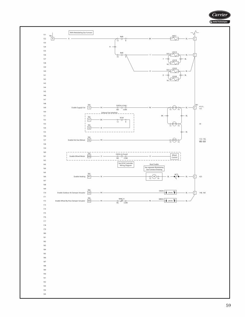
59
TB1
TB1
TB1
TB1
TB1
TB1
TB1
TB1
TB1
TB1
WBDA
R R
Enable Wheel Motor WM
Enable Wheel By-Pass Damper Actuator WD
Enable Outdoor Air Damper Actuator OD
OADA-A (Fixed)
NO COM
WMC-A
NC COM
O O
PK PK
PR C
BKR
OADA BKR
BL
BL 148
Enable Heating
Wheel Control
See ECW Controller Wiring Diagram
BL CHR1413
Heat Enable
WW1BCTL
BL
See separate Modulating Gas Furnace Drawing
EF1R
SF1R
BL
1413
Enable Supply Fan G
Enable Hot Gas Reheat RH
PK
PR
C
BL
OADA-A (Adj.)
NO COMPK 41,51
50
RHR1413
BK
13 14
Exhaust Fan Interlock
BKX1
WX2
SF1R
12 8
131
132
133
134
135
136
137
138
139
140
141
142
143
144
145
146
147
148
149
150
151
152
153
154
155
156
157
158
159
160
161
162
163
164
165
166
167
168
169
170
171
172
173
174
175
176
177
178
179
180
181
182
183
184
185
186
187
188
189
190
191
192
193
194
195
132, 207, 219132, 136, 207, 219
41,51, 151
148, 160
425
24VAC
24VAC
N.C.
N.C.
N.O.
N.O.
LSS2A
10
BOS1
LSS1A
CRHR
BLBK12 8
CBL
BL
Y
O
RHR
R
6
LSS2B
LSS1BY BL
O BL
BL
With Modulating Gas Furnace
a62-715

60
TB1
0-10vdc
TB1
WIRING DIAGRAM FOR 4-STAGE ELECTRIC HEAT
Calibration and Setup- Set the INPUT RANGE jumper to the correct positionfor the signal to be used (0-15 V).- Set the deadband jumper to the desired value (3%). This can be changed at any time with the power on.- Connect the power supply and the input signal to thecorrect terminals.- Turn on the power and the POWER LED will light.- Apply an input signal equal to the R1 setpoint (2.5V).- Adjust the R1 pot clockwise until the RELAY1 LEDgoes out, then slowly adjust the R1 pot counterclockwiseuntil the LED just lights.- Apply an input signal equal to the R2 setpoint (5V) andadjust the R2 pot the same as for R1, watching theRELAY2 LED.- Adjust R3 (7.5V) and R4 (9.5V) using the same method.- Test the operation by increasing the input signal andwatch as R1 to R4 turn on at the selected setpoints.Then decrease the signal and watch as the relays turnoff at the selected setpoints minus the deadband.
SEE UNIT 24V CONTROL TERMINAL BOARD (TB1)
W BK
R
BL
HARM: Heating Analog Relay Module0843P-0602
Set jumper to 3%
AO-6
Gnd
FROM ALC 6126
W
BK
W2
W1
W1
TB1
R
C
TB1
+A6
-A6
BLC C
W3
W4
BR O
SEE ELECTRIC HEATER DRAWING.
196
197
198
199
200
201
202
203
204
205
206
207
208
209
210
211
212
213
214
215
216
217
218
219
220
221
222
223
224
225
226
227
228
229
230
231
232
233
234
235
236
237
238
239
240
241
242
243
244
245
246
247
248
249
250
251
252
253
254
255
256
257
258
259
260
RESISTOR (0843P-0573)
T2
24V
5 24V
40 VACLASS 260 HZ
MRV1
MRC1PID+PID-BLACKWHITE
REDTTL WAVETTL DIRECT.24VAC24VAC
PUMPDOWNPUMPDOWN
TEMP. SENSORTEMP. SENSORNO CONN.24-120 VAC PWM PULSENO CONN.24-120 VAC PWM PULSE
P4
P8P9
P10
P11P12
P2P1
P5
P6
P7
GREEN
WIRING DIAGRAM FOR MODULATING REHEAT, 0-10VDC
TB1
BKW
MODULATING DISCHARGE VALVE CONTROL BOARD
NOTE: BE SURE TO WIRE THE MODULATING DISCHARGE VALVE (MDV) CORRECTLY PER WIRING DIAGRAM. SEE COLOR CODING, THE WHITE WIRE IS CONNECTED TO BLACK AND THE BLACK WIRE IS CONNECTED TO WHITE.
O BR
CIRCUIT # 1
TB1TB1
8
RHR
9 1
PRGY
OBR
R C
+A4
-A4
MDV1
(MDC1)PID+PID-BLACKWHITE
REDTTL WAVETTL DIRECT.24VAC24VAC
PUMPDOWNPUMPDOWN
TEMP. SENSORTEMP. SENSORNO CONN.24-120 VAC PWM PULSENO CONN.24-120 VAC PWM PULSE
P4
P8P9
P10
P11P12
P2P1
P5
P6
P7
GREEN
GY
TB3 K2K1
CIRCUIT # 1
RHR
9 1
PR
W
1K ohms
1K ohms
BK
TB1
+A5
-A5
TB3 K2K1
BKWGR
WBKGR
OBR
8
Set jumper to 0-15V
R
R1 R2 R3 R4
RELAY1 RELAY2 RELAY3 RELAY4
POWER
RELAY 1 RELAY 2 RELAY 3 RELAY 4
0001259
R1
R2
R3
R4
PWR COM IN20V
DEADBAND
INPUT RANGE
1%
3%
5%
0-7.5V
0-15V
0-20mA
a62-716
Typical wiring schematics (cont)
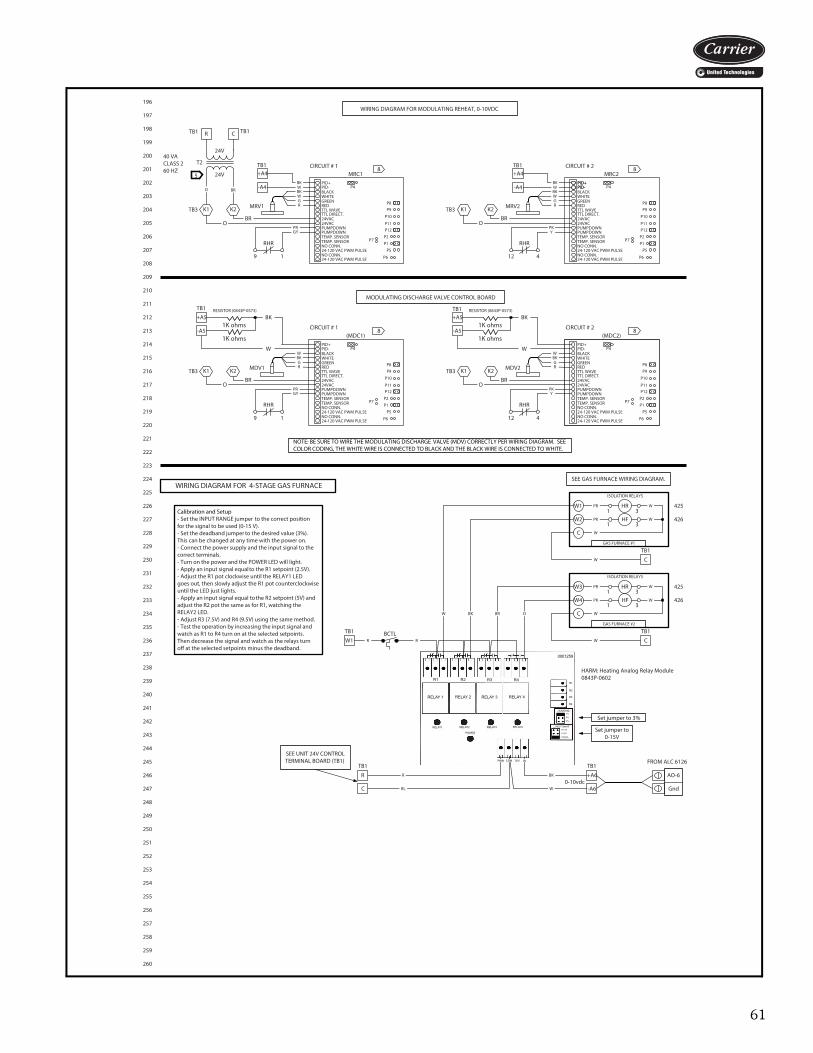
61
TB1
0-10vdc
TB1
WIRING DIAGRAM FOR 4-STAGE GAS FURNACE
Calibration and Setup- Set the INPUT RANGE jumper to the correct positionfor the signal to be used (0-15 V).- Set the deadband jumper to the desired value (3%). This can be changed at any time with the power on.- Connect the power supply and the input signal to thecorrect terminals.- Turn on the power and the POWER LED will light.- Apply an input signal equal to the R1 setpoint (2.5V).- Adjust the R1 pot clockwise until the RELAY1 LEDgoes out, then slowly adjust the R1 pot counterclockwiseuntil the LED just lights.- Apply an input signal equal to the R2 setpoint (5V) andadjust the R2 pot the same as for R1, watching theRELAY2 LED.- Adjust R3 (7.5V) and R4 (9.5V) using the same method.- Test the operation by increasing the input signal andwatch as R1 to R4 turn on at the selected setpoints.Then decrease the signal and watch as the relays turnoff at the selected setpoints minus the deadband.
SEE UNIT 24V CONTROL TERMINAL BOARD (TB1)
W BK
R
BL
HARM: Heating Analog Relay Module0843P-0602
Set jumper to 3%
AO-6
Gnd
FROM ALC 6126
W
BK
SEE GAS FURNACE WIRING DIAGRAM.
ISOLATION RELAYS
PR
PK
W
W
W
HR1 3
HF1 3
C
W2
W1
W1 R
TB1
R
C
TB1
+A6
-A6
W C
BR O
GAS FURNACE #1
TB1
ISOLATION RELAYS
PR
PK
W
W
W
HR1 3
HF1 3
C
W4
W3
W C
GAS FURNACE #2
196
197
198
199
200
201
202
203
204
205
206
207
208
209
210
211
212
213
214
215
216
217
218
219
220
221
222
223
224
225
226
227
228
229
230
231
232
233
234
235
236
237
238
239
240
241
242
243
244
245
246
247
248
249
250
251
252
253
254
255
256
257
258
259
260
426
425
426
425
RESISTOR (0843P-0573)
T2
24V
5 24V
40 VACLASS 260 HZ
MRV1
MRC1PID+PID-BLACKWHITE
REDTTL WAVETTL DIRECT.24VAC24VAC
PUMPDOWNPUMPDOWN
TEMP. SENSORTEMP. SENSORNO CONN.24-120 VAC PWM PULSENO CONN.24-120 VAC PWM PULSE
P4
P8P9
P10
P11P12
P2P1
P5
P6
P7
GREEN
WIRING DIAGRAM FOR MODULATING REHEAT, 0-10VDC
MRV2
MRC2PID+PID-BLACKWHITE
REDTTL WAVETTL DIRECT.24VAC24VAC
PUMPDOWNPUMPDOWN
TEMP. SENSORTEMP. SENSORNO CONN.24-120 VAC PWM PULSENO CONN.24-120 VAC PWM PULSE
P4
P8P9
P10
P11P12
P2P1
P5
P6
P7
GREEN
PKY
TB1
BKW
MODULATING DISCHARGE VALVE CONTROL BOARD
NOTE: BE SURE TO WIRE THE MODULATING DISCHARGE VALVE (MDV) CORRECTLY PER WIRING DIAGRAM. SEE COLOR CODING, THE WHITE WIRE IS CONNECTED TO BLACK AND THE BLACK WIRE IS CONNECTED TO WHITE.
O BR
CIRCUIT # 1 CIRCUIT # 2
TB1TB1
RHR
12 4
8 8
RHR
9 1
PRGY
OBR
R C
+A4
-A4
TB1
BKW
+A4
-A4PID+PID-
MDV1
(MDC1)PID+PID-BLACKWHITE
REDTTL WAVETTL DIRECT.24VAC24VAC
PUMPDOWNPUMPDOWN
TEMP. SENSORTEMP. SENSORNO CONN.24-120 VAC PWM PULSENO CONN.24-120 VAC PWM PULSE
P4
P8P9
P10
P11P12
P2P1
P5
P6
P7
GREENMDV2
(MDC2)PID+PID-BLACKWHITE
REDTTL WAVETTL DIRECT.24VAC24VAC
PUMPDOWNPUMPDOWN
TEMP. SENSORTEMP. SENSORNO CONN.24-120 VAC PWM PULSENO CONN.24-120 VAC PWM PULSE
P4
P8P9
P10
P11P12
P2P1
P5
P6
P7
GREEN
GY
TB3 K2K1TB3 K2K1
CIRCUIT # 1 CIRCUIT # 2
RHR
9 1
PR PKY
RHR
12 4
W
1K ohms
1K ohms
BK
W
1K ohms
1K ohms
BK
TB1
+A5
-A5
TB3 K2K1 TB3 K2K1
RESISTOR (0843P-0573)TB1+A5
-A5
BKWGR
WBKGR
OBR
BKWGR
OBR
WBKGR
OBR
8 8
Set jumper to 0-15V
BCTLR
R1 R2 R3 R4
RELAY1 RELAY2 RELAY3 RELAY4
POWER
RELAY 1 RELAY 2 RELAY 3 RELAY 4
0001259
R1
R2
R3
R4
PWR COM IN20V
DEADBAND
INPUT RANGE
1%
3%
5%
0-7.5V
0-15V
0-20mA
a62-717
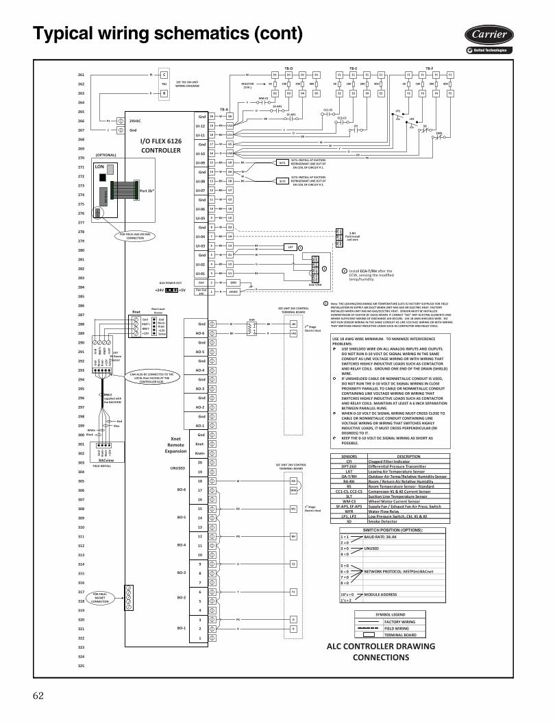
62
Typical wiring schematics (cont)
18
19
20
15
16
17
12
13
14
9
10
11
6
7
8
5
1
2
3
4
W
W
W
W
W
W
W
R
BK
BK
BK
BK
BK
BK
BK
BK
BK
BK
PR
O
Gnd
Gnd
Gnd
Gnd
Gnd
Gnd
Gnd
AO-5
AO-6
AO-4
AO-3
AO-2
AO-1
20
XnetRemote
Expansion
19
2
3
1
5
6
4
8
9
7
11
12
10
14
15
13
17
18
16
BO-1
BO-2
BO-3
BO-4
BO-5
BO-6
UNUSED
Gnd
Xnet-
Xnet+
24VAC
I/O FLEX 6126
Y
P1
C
ALC CONTROLLER DRAWING CONNECTIONS
RnetRnet Local
Access
CONTROLLER
R
O
PR
BK
W
SEE UNIT 24V CONTROL TERMINAL BOARD
SEE TB1 ON UNIT WIRING DIAGRAM
BL
R
ZATRS Room Sensor
SEE UNIT 24V CONTROL TERMINAL BOARD
Gnd
Gnd
Gnd
Gnd
Gnd
Gnd
Gnd
UI-12
UI-11
UI-10
UI-09
UI-08
UI-07
UI-06
UI-05
UI-04
UI-03
UI-02
UI-01
PK
Gnd
RNET+
RNET-
+12V
Gnd
RNET
+
RNET
-
+12V
GndRnet+Rnet-+12VSense
Gnd
Rnet
+Rn
et-
+12V
Sens
e
CAN ALSO BE CONNECTED TO THE LOCAL Rnet ACCESS AT THE
CONTROLLER 6126.
CABLE supplied with the BACVIEW
LON
12
Port 2b*ECHELO
N
(OPTIONAL)
AUX POWER OUT
+24V +5V Pwr Out 24V
Note: THE LEAVING/DISCHARGE AIR TEMPERATURE (LAT) IS FACTORY SUPPLIED FOR FIELD INSTALLATION IN SUPPLY AIR DUCT WHEN UNIT HAS GAS OR ELECTRIC HEAT. FACTORY INSTALLED WHEN UNIT HAS NO GAS/ELECTRIC HEAT. SENSOR MUST BE INSTALLED DOWNSTREAM OF HEATER (IF USED) WHERE IT CANNOT “SEE” ANY HEATING ELEMENTS AND WHERE SUFFICIENT MIXING OF DISCHARGE AIR OCCURS. USE 18 AWG SHIELDED WIRE. DO NOT RUN SENSOR WIRING IN THE SAME CONDUIT AS LINE VOLTAGE WIRING OR WITH WIRING THAT SWITCHES HIGHLY INDUCTIVE LOADS SUCH AS CONTACTOR AND RELAY COILS.
1
FOR FIELD: BACNET
CONNECTION
FOR FIELD: BAS OR EMS CONNECTION
BACview
Gnd
Rnet
+Rn
et-
+12V
FIELD INSTALL
Red
BlueWhite
Black
2
temp
outcom
pwr
W
outpw
rcom Z-RH
Field install and wire
BK
SLT2SLT2: INSTALL AT SUCTION REFRIGERANT LINE OUT OF
DX COIL OF CIRCUIT # 2.
SLT1BK
W
WM-CS
RESISTOR(TYP.)
5K
LP2
O
BK
TB-D
TB1
LATWBK
1
TB-A
SENSORS DESCRIPTIONCFI Clogged Filter Indicator
DPT-260 Differen�al Pressure Transmi�erLAT Leaving Air Temperature Sensor
OA-T/RH Outdoor Air Temp/Rela�ve Humidity SensorRA-RH Room / Return Air Rela�ve Humidity
RS Room Temperature Sensor - StandardCC1-CS, CC2-CS Compressor #1 & #2 Current Sensor
SLT Suc�on Line Temperature SensorWM-CS Wheel Motor Current Sensor
SF-APS, EF-APS Supply Fan / Exhaust Fan Air Press. SwitchWFR Water Flow Relay
LP1, LP2 Low Pressure Switch, Ckt. #1 & #2SD Smoke Detector
FACTORY WIRING
FIELD WIRING
TERMINAL BOARD
SYMBOL LEGEND
1 = 1 BAUD RATE: 38.4K2 = 03 = 0 UNUSED4 = 0
5 = 06 = 0 NETWORK PROTOCOL: MSTP(m) BACnet7 = 08 = 0
10's = 0 MODULE ADDRESS1's = 2
SWITCH POSITION (OPTIONS):
R
2
G
ECA-T/RH
Install ECA-T/RH a�er the ECW, sensing the modified temp/humdity.
CAN ALSO BE CONNECTED TO THE LOCAL Rnet ACCESS AT THE
CONTROLLER 6126.
USE 18 AWG WIRE MINIMUM. TO MINIMIZE INTERFERENCE PROBLEMS:
USE SHIELDED WIRE ON ALL ANALOG INPUTS AND OUPUTS. DO NOT RUN 0-10 VOLT DC SIGNAL WIRING IN THE SAME CONDUIT AS LINE VOLTAGE WIRING OR WITH WIRING THAT SWITCHES HIGHLY INDUCTIVE LOADS SUCH AS CONTACTOR AND RELAY COILS. GROUND ONE END OF THE DRAIN (SHIELD) WIRE.IF UNSHIELDED CABLE OR NONMETALLIC CONDUIT IS USED, DO NOT RUN THE 0-10 VOLT DC SIGNAL WIRING IN CLOSE PROXIMITY PARALLEL TO CABLE OR NONMETALLIC CONDUIT CONTAINING LINE VOLTAGE WIRING OR WIRING THAT SWITCHES HIGHLY INDUCTIVE LOADS SUCH AS CONTACTOR AND RELAY COILS. MAINTAIN AT LEAST A 6 INCH SEPARATION BETWEEN PARALLEL RUNS.WHEN 0-10 VOLT DC SIGNAL WIRING MUST CROSS CLOSE TO CABLE OR NONMETALLIC CONDUIT CONTAINING LINE VOLTAGE WIRING OR WIRING THAT SWITCHES HIGHLY INDUCTIVE LOADS, IT MUST CROSS PERPENDICULAR (90 DEGREES) TO IT.KEEP THE 0-10 VOLT DC SIGNAL WIRING AS SHORT AS POSSIBLE.
R
C
24VDC
GND
U2
U1
G1
G2
U4
U3
G3
U6
U5
G4
U8
U7
G5
U10
U9
G6
U12
U11
BK
W
SLT1: INSTALL AT SUCTION REFRIGERANT LINE OUT OF
DX COIL OF CIRCUIT # 1.
D1
D2
10K
D1
D3
20K
D1
D4
40K
D1
D5
YSF-APS
EF-APS
W
5K
TB-E
E1
E2
10K
E1
E3
20K
E1
E4
40K
E5
5K
TB-F
F1
F2
10K
F1
F3
20K
F1
F4
40K
F1
F5
CC1-CS
CC2-CS
CFI SD
EMR
LP1
WW
BKO
Y
PKBK
OY
OD
E1
WM
W1
RH
Y2
Y1
G
R
261
262
263
264
265
266
267
268
269
270
271
272
273
274
275
276
277
278
279
280
281
282
283
284
285
286
287
288
289
290
291
292
293
294
295
296
297
298
299
300
301
302
303
304
305
306
307
308
309
310
311
312
313
314
315
316
317
318
319
320
321
322
323
324
325
HAR
R
BK
BK
W2nd Stage Electric Heat
-A6
+A6
Hea�ng Enable1st Stage Electric Heat
a62-718
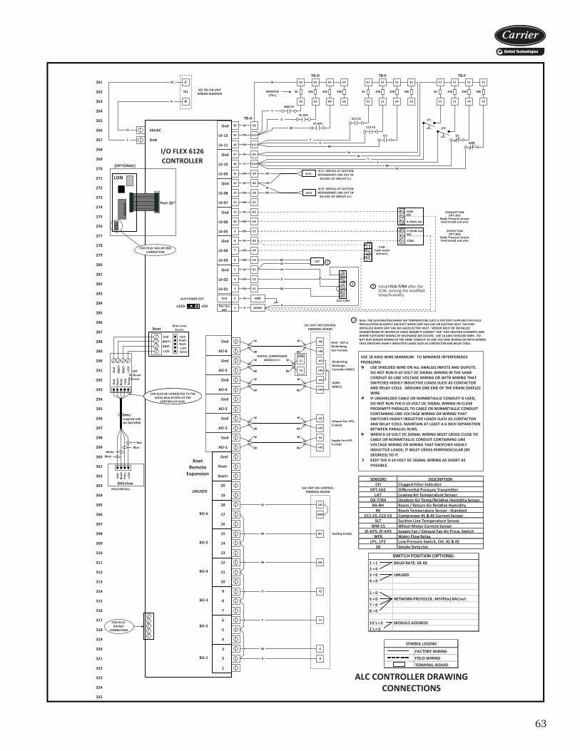
63
BKDCM1
18
19
20
15
16
17
12
13
14
9
10
11
6
7
8
5
1
2
3
4
W
W
W
W
W
W
W
R
BK
BK
BK
BK
BK
BK
BK
BK
BK
BK
PR
O
Gnd
Gnd
Gnd
Gnd
Gnd
Gnd
Gnd
AO-5
AO-6
AO-4
AO-3
AO-2
AO-1
20
XnetRemote
Expansion
19
2
3
1
5
6
4
8
9
7
11
12
10
14
15
13
17
18
16
BO-1
BO-2
BO-3
BO-4
BO-5
BO-6
UNUSED
Gnd
Xnet-
Xnet+
24VAC
I/O FLEX 6126
Y
P1
C
ALC CONTROLLER DRAWING CONNECTIONS
RnetRnet Local
Access
CONTROLLER
R
O
PR
BK
W
SEE UNIT 24V CONTROL TERMINAL BOARD
SEE TB1 ON UNIT WIRING DIAGRAM
BL
R
ZATRS Room Sensor
SEE UNIT 24V CONTROL TERMINAL BOARD
Heat - SCR or Modula�ng Gas Furnace
HGRH(MRC1)
Gnd
Gnd
Gnd
Gnd
Gnd
Gnd
Gnd
UI-12
UI-11
UI-10
UI-09
UI-08
UI-07
UI-06
UI-05
UI-04
UI-03
UI-02
UI-01
PK
Gnd
RNET+
RNET-
+12V
Gnd
RNET
+
RNET
-
+12V
GndRnet+Rnet-+12VSense
Gnd
Rnet
+Rn
et-
+12V
Sens
e
CAN ALSO BE CONNECTED TO THE LOCAL Rnet ACCESS AT THE
CONTROLLER 6126.
CABLE supplied with the BACVIEW
LON
12
Port 2b*ECHELO
N
(OPTIONAL)
AUX POWER OUT
+24V +5V Pwr Out 24V
Note: THE LEAVING/DISCHARGE AIR TEMPERATURE (LAT) IS FACTORY SUPPLIED FOR FIELD INSTALLATION IN SUPPLY AIR DUCT WHEN UNIT HAS GAS OR ELECTRIC HEAT. FACTORY INSTALLED WHEN UNIT HAS NO GAS/ELECTRIC HEAT. SENSOR MUST BE INSTALLED DOWNSTREAM OF HEATER (IF USED) WHERE IT CANNOT “SEE” ANY HEATING ELEMENTS AND WHERE SUFFICIENT MIXING OF DISCHARGE AIR OCCURS. USE 18 AWG SHIELDED WIRE. DO NOT RUN SENSOR WIRING IN THE SAME CONDUIT AS LINE VOLTAGE WIRING OR WITH WIRING THAT SWITCHES HIGHLY INDUCTIVE LOADS SUCH AS CONTACTOR AND RELAY COILS.
1
FOR FIELD: BACNET
CONNECTION
FOR FIELD: BAS OR EMS CONNECTION
DIGITAL COMPRESSOR MODULE # 1
BACview
Gnd
Rnet
+Rn
et-
+12V
FIELD INSTALL
Red
BlueWhite
Black
2
temp
outcom
pwr
W
outpw
rcom Z-RH
Field install and wire
BK
SLT2SLT2: INSTALL AT SUCTION REFRIGERANT LINE OUT OF
DX COIL OF CIRCUIT # 2.
SLT1BK
W
Supply Fan VFD0-10vdc
Modula�ng Discharge Controller (MDC)
EXHAUST FANDPT-26O
Sta�c Pressure SensorField install and wire
WM-CS
RESISTOR(TYP.)
5K
LP2
O
BK
TB-D
TB1
LATWBK
SUPPLY FANDPT-26O
Sta�c Pressure SensorField install and wire
0-10vdc out
COM
EXC
1
Exhaust Fan VFD, 0-10vdc
TB-A
SENSORS DESCRIPTIONCFI Clogged Filter Indicator
DPT-260 Differen�al Pressure Transmi�erLAT Leaving Air Temperature Sensor
OA-T/RH Outdoor Air Temp/Rela�ve Humidity SensorRA-RH Room / Return Air Rela�ve Humidity
RS Room Temperature Sensor - StandardCC1-CS, CC2-CS Compressor #1 & #2 Current Sensor
SLT Suc�on Line Temperature SensorWM-CS Wheel Motor Current Sensor
SF-APS, EF-APS Supply Fan / Exhaust Fan Air Press. SwitchWFR Water Flow Relay
LP1, LP2 Low Pressure Switch, Ckt. #1 & #2SD Smoke Detector
FACTORY WIRING
FIELD WIRING
TERMINAL BOARD
SYMBOL LEGEND
1 = 1 BAUD RATE: 38.4K2 = 03 = 0 UNUSED4 = 0
5 = 06 = 0 NETWORK PROTOCOL: MSTP(m) BACnet7 = 08 = 0
10's = 0 MODULE ADDRESS1's = 2
SWITCH POSITION (OPTIONS):
R
0-10vdc out
COMEXC
2
G
ECA-T/RH
Install ECA-T/RH a�er the ECW, sensing the modified temp/humdity.
CAN ALSO BE CONNECTED TO THE LOCAL Rnet ACCESS AT THE
CONTROLLER 6126.
USE 18 AWG WIRE MINIMUM. TO MINIMIZE INTERFERENCE PROBLEMS:
USE SHIELDED WIRE ON ALL ANALOG INPUTS AND OUPUTS. DO NOT RUN 0-10 VOLT DC SIGNAL WIRING IN THE SAME CONDUIT AS LINE VOLTAGE WIRING OR WITH WIRING THAT SWITCHES HIGHLY INDUCTIVE LOADS SUCH AS CONTACTOR AND RELAY COILS. GROUND ONE END OF THE DRAIN (SHIELD) WIRE.IF UNSHIELDED CABLE OR NONMETALLIC CONDUIT IS USED, DO NOT RUN THE 0-10 VOLT DC SIGNAL WIRING IN CLOSE PROXIMITY PARALLEL TO CABLE OR NONMETALLIC CONDUIT CONTAINING LINE VOLTAGE WIRING OR WIRING THAT SWITCHES HIGHLY INDUCTIVE LOADS SUCH AS CONTACTOR AND RELAY COILS. MAINTAIN AT LEAST A 6 INCH SEPARATION BETWEEN PARALLEL RUNS.WHEN 0-10 VOLT DC SIGNAL WIRING MUST CROSS CLOSE TO CABLE OR NONMETALLIC CONDUIT CONTAINING LINE VOLTAGE WIRING OR WIRING THAT SWITCHES HIGHLY INDUCTIVE LOADS, IT MUST CROSS PERPENDICULAR (90 DEGREES) TO IT.KEEP THE 0-10 VOLT DC SIGNAL WIRING AS SHORT AS POSSIBLE.
R
C
24VDC
GND
U2
U1
G1
G2
U4
U3
G3
U6
U5
G4
U8
U7
G5
U10
U9
G6
U12
U11
BK
W
SLT1: INSTALL AT SUCTION REFRIGERANT LINE OUT OF
DX COIL OF CIRCUIT # 1.
D1
D2
10K
D1
D3
20K
D1
D4
40K
D1
D5
YSF-APS
EF-APS
W
5K
TB-E
E1
E2
10K
E1
E3
20K
E1
E4
40K
E5
5K
TB-F
F1
F2
10K
F1
F3
20K
F1
F4
40K
F1
F5
CC1-CS
CC2-CS
CFI SD
EMR
LP1
WW
BKO
Y
PKBK
OY
-A5
+A5
-A4
+A4
-A2
+A2
-A1
+A1
C1
C2
WW
BK
W
BK BK
W
OD
BK
WW
BK
BK
WW
BK
BK
WW
BK
E1
WM
W1
RH
Y2
Y1
G
R
261
262
263
264
265
266
267
268
269
270
271
272
273
274
275
276
277
278
279
280
281
282
283
284
285
286
287
288
289
290
291
292
293
294
295
296
297
298
299
300
301
302
303
304
305
306
307
308
309
310
311
312
313
314
315
316
317
318
319
320
321
322
323
324
325
-A6
+A6
Hea�ng Enable
a62-719
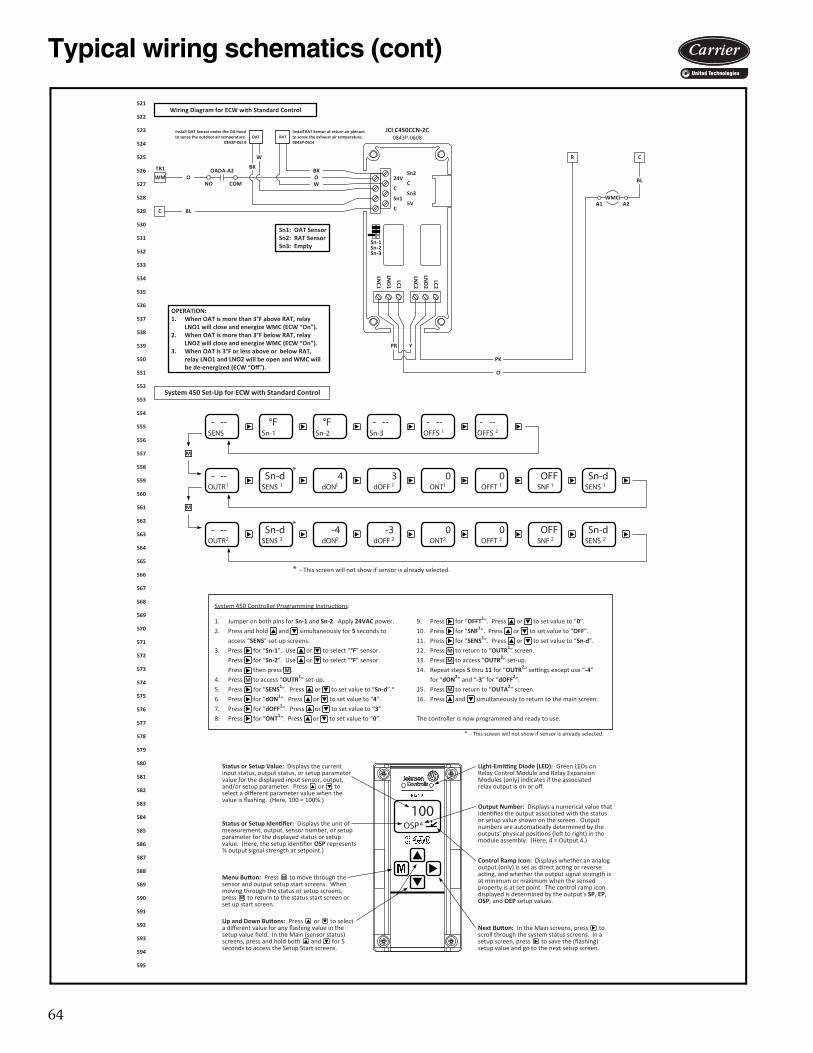
64
Typical wiring schematics (cont)
24V
C
Sn1
C
Sn2
C
Sn3
5V
LNC2
LNO
2
LC2
LNC1
LNO
1
LC1
C
RAT
Sn1: OAT SensorSn2: RAT SensorSn3: Empty
WMCA2A1
PK
BL
BK
W
O
R C
BL
Y
OAT
W
BK
Wiring Diagram for ECW with Standard Control
OPERATION:1. When OAT is more than 3°F above RAT, relay
LNO1 will close and energize WMC (ECW “On”).2. When OAT is more than 3°F below RAT, relay
LNO2 will close and energize WMC (ECW “On”).3. When OAT is 3°F or less above or below RAT,
relay LNO1 and LNO2 will be open and WMC will be de-energized (ECW “Off”).
OADA-A2
NO COMO OWM
PR
System 450 Set-Up for ECW with Standard Control
100OSP4Status or Setup Iden�fier: Displays the unit of
measurement, output, sensor number, or setup parameter for the displayed status or setup value. (Here, the setup iden�fier OSP represents % output signal strength at setpoint.)
Menu Bu�on: Press to move through the sensor and output setup start screens. When moving through the status or setup screens, press to return to the status start screen or set up start screen.
Up and Down Bu�ons: Press or to select a different value for any flashing value in the setup value field. In the Main (sensor status) screens, press and hold both and for 5 seconds to access the Setup Start screens.
Output Number: Displays a numerical value that iden�fies the output associated with the status or setup value shown on the screen. Output numbers are automa�cally determined by the outputs’ physical posi�ons (le� to right) in the module assembly. (Here, 4 = Output 4.)
Control Ramp Icon: Displays whether an analog output (only) is set as direct ac�ng or reverse ac�ng, and whether the output signal strength is at minimum or maximum when the sensed property is at set point. The control ramp icon displayed is determined by the output's SP, EP, OSP, and OEP setup values.
Light-Emi�ng Diode (LED): Green LEDs on Relay Control Module and Relay Expansion Modules (only) indicates if the associated relay output is on or off.
Status or Setup Value: Displays the current input status, output status, or setup parameter value for the displayed input sensor, output, and/or setup parameter. Press or to select a different parameter value when the value is flashing. (Here, 100 = 100%.)
Next Bu�on: In the Main screens, press to scroll through the system status screens. In a setup screen, press to save the (flashing) setup value and go to the next setup screen.
M
M
- --SENS
°FSn-1
°FSn-2
- --Sn-3
- --OUTR1
Sn-dSENS 1
4dON1
3dOFF 1
0ONT1
0OFFT 1
OFFSNF 1
Sn-dSENS 1
- --OFFS 1
- --OFFS 2
*
- --OUTR2
Sn-dSENS 2
-4dON2
-3dOFF 2
0ONT2
0OFFT 2
OFFSNF 2
Sn-dSENS 2
*
M
M
* - This screen will not show if sensor is already selected.
JCI C450CCN-2C0843P-0608
Install OAT Sensor under the OA hood to sense the outdoor air temperature.
0843P-0614
Install RAT Sensor at return air plenum to sense the exhaust air temperature.0843P-0614
TB1
System 450 Controller Programming Instruc�ons:
1. Jumper on both pins for Sn-1 and Sn-2. Apply 24VAC power. 9. Press for “OFFT1”. Press or to set value to “0”.
2. Press and hold and simultaneously for 5 seconds to 10. Press for “SNF1”. Press or to set value to “OFF”.
access “SENS” set-up screens. 11. Press for “SENS1”. Press or to set value to “Sn-d”.
3. Press for “Sn-1”. Use or to select “°F” sensor. 12. Press to return to “OUTR1” screen.
Press for “Sn-2”. Use or to select “°F” sensor. 13. Press to access “OUTR2” set-up.
Press then press . 14. Repeat steps 5 thru 11 for “OUTR2” se�ngs except use “-4”
4. Press to access “OUTR1” set-up. for “dON2” and “-3” for “dOFF2”.
5. Press for “SENS1”. Press or to set value to “Sn-d”.* 15. Press to return to “OUTA2” screen.
6. Press for “dON1”. Press or to set value to “4”. 16. Press and simultaneously to return to the main screen.
7. Press for “dOFF1”. Press or to set value to “3”.
8. Press for “ONT1”. Press or to set value to “0”. The controller is now programmed and ready to use.
M
M
M
M
M
* - This screen will not show if sensor is already selected.
Sn-1Sn-2Sn-3
521
522
523
524
525
526
527
528
529
530
531
532
533
534
535
536
537
538
539
550
551
552
553
554
555
556
557
558
559
560
561
562
563
564
565
566
567
568
569
570
571
572
573
574
575
576
577
578
579
580
581
582
583
584
585
586
587
588
589
590
591
592
593
594
595
a62-720
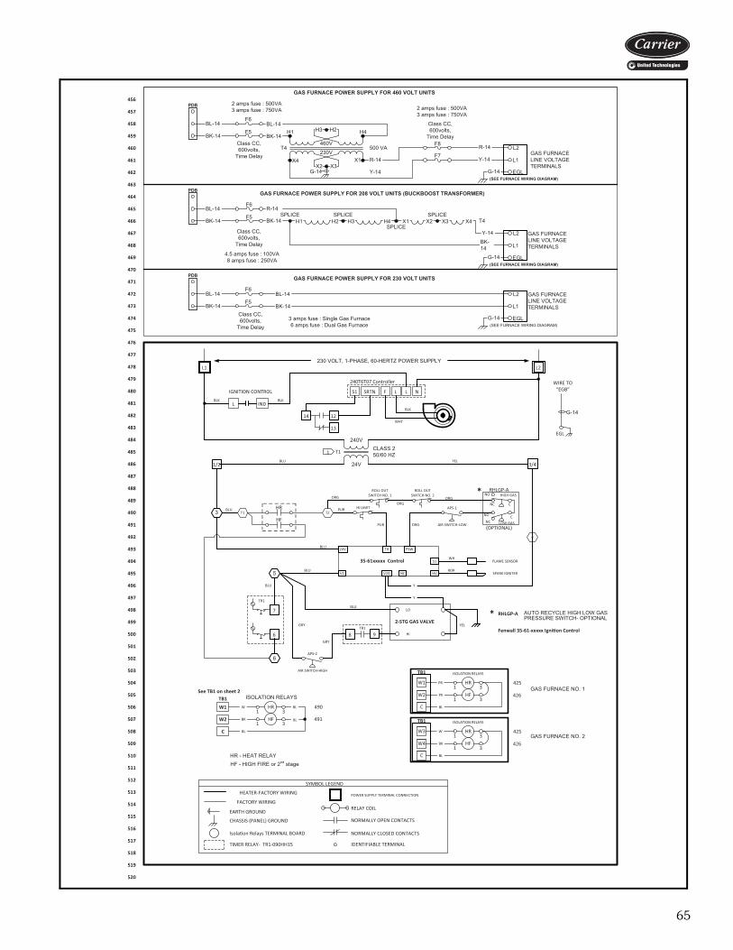
65
EGL
T1
240V
24V
1CLASS 250/60 HZ
HI LIMIT
WIRE TO “EGB”
G-14
RELAY COIL
NORMALLY OPEN CONTACTS
IDENTIFIABLE TERMINAL
NORMALLY CLOSED CONTACTS
HEATER-FACTORY WIRING
EARTH GROUND
CHASSIS (PANEL) GROUND
SYMBOL LEGEND
POWER SUPPLY TERMINAL CONNECTION
TIMER RELAY- TR1-090HH15
BLU YEL
Isola�on Relays TERMINAL BOARD
FACTORY WIRING
3 T1HR
ROLL OUT SWITCH NO. 1
T2
ROLL OUT SWITCH NO. 2
1/2 3/4
APS-1
AIR SWITCH-LOW
PSW
S1
HVV2GV1
FLAME SENSOR
SPARK IGNITER5
6
TR1
7
35-61xxxxx Control
2-STG GAS VALVEYEL
Y
Y
WH
ROR
APS-2
AIR SWITCH-HIGH
GRY
BLU
BLU
BLU
BLU
8 9TR1
GRY
HR1 3
ISOLATION RELAYS
490
ORGORG
ORG
PUR
PUR ORG
LO
HI
6
NO C
NC C
RHLGP-A
NC
NO HIGH GAS
LOW GAS(OPTIONAL)
RHLGP-A AUTO RECYCLE HIGH LOW GAS PRESSURE SWITCH- OPTIONAL
HF
BLU
HF1 3
491
*
*
BL
W
BK
BL
BL
HR - HEAT RELAYHF - HIGH FIRE or 2nd stage
L2
S1 SRTN F L L
240T6T07 Controller
WHT
BLKL IND
BLKBLK
14 12
13
L1
N
TH24V
NC
4
Fenwall 35-61-xxxxx Igni�on Control
IGNITION CONTROL
TB1
W1
W2
C
See TB1 on sheet 2
F6
F5L2
L1
EGL(SEE FURNACE WIRING DIAGRAM)
G-14
GAS FURNACE LINE VOLTAGE TERMINALS
GAS FURNACE POWER SUPPLY FOR 230 VOLT UNITS
BK-14
BL-14
GAS FURNACE POWER SUPPLY FOR 208 VOLT UNITS (BUCKBOOST TRANSFORMER)
L2
L1
EGL(SEE FURNACE WIRING DIAGRAM)
H1SPLICE SPLICE
G-14
GAS FURNACE LINE VOLTAGE TERMINALS
H2 H3SPLICE
H4 X1SPLICE
X2 X3 X4
BK-14
T4
F6
F5BK-14
R-14
F6
F5BK-14
BL-14
460V
230V
H1 H4
X1X4
T4
H2H3
X3X2G-14
L2
L1
EGL(SEE FURNACE WIRING DIAGRAM)
G-14
F8
F7R-14
Y-14R-14
GAS FURNACE POWER SUPPLY FOR 460 VOLT UNITS
500 VA
Y-14
Class CC,600volts,
Time Delay
GAS FURNACE LINE VOLTAGE TERMINALS
PDB
BK-14
BL-14
2 amps fuse : 500VA3 amps fuse : 750VA 2 amps fuse : 500VA
3 amps fuse : 750VA
Class CC,600volts,
Time Delay
BK-14
BL-14
PDB
Y-14Class CC,600volts,
Time Delay
4.5 amps fuse : 100VA8 amps fuse : 250VA
Class CC,600volts,
Time Delay3 amps fuse : Single Gas Furnace6 amps fuse : Dual Gas Furnace
BK-14
BL-14
PDB
230 VOLT, 1-PHASE, 60-HERTZ POWER SUPPLY
HR1 3
ISOLATION RELAYS
425
HF1 3
426
BL
PR
PK
HR1 3
425
HF1 3
426
W
BK
BL
GAS FURNACE NO. 1
GAS FURNACE NO. 2
ISOLATION RELAYS
C
TB1
W1
W2
C
TB1
W3
W4
456
457
458
459
460
461
462
463
464
465
466
467
468
469
470
471
472
473
474
475
476
477
478
479
480
481
482
483
484
485
486
487
488
489
490
491
492
493
494
495
496
497
498
499
500
501
502
503
504
505
506
507
508
509
510
511
512
513
514
515
516
517
518
519
520
a62-715
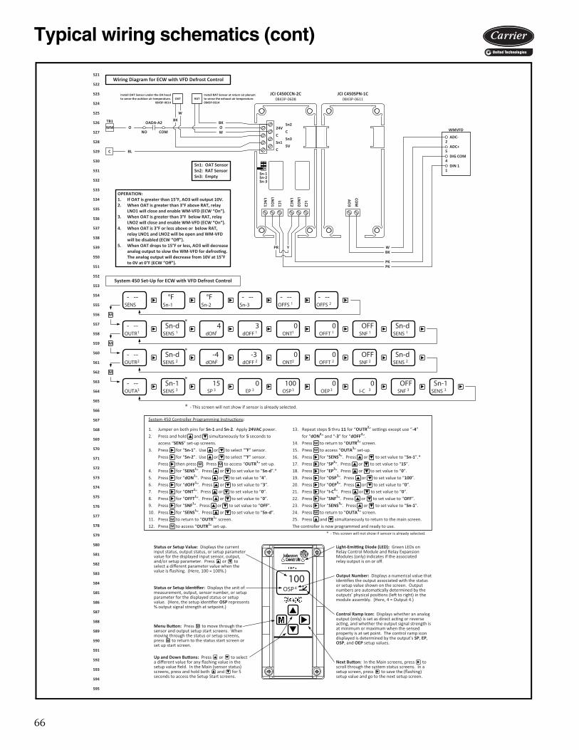
66
Typical wiring schematics (cont)
- --OUTA3
Sn-1SENS 3
15SP 3
0EP 3
100OSP3
0OEP3
0I-C 3
Sn-1SENS 3
* OFFSNF 3
24V
C
Sn1
C
Sn2
C
Sn3
5V
LNC2
LNO
2
LC2
LNC1
LNO
1
LC1
AO
3
COM
WMVFD
ADC-
DIN 1
DIG COM
ADC+
Wiring Diagram for ECW with VFD Defrost Control
C
RAT
1
4
5
2
BK
W
WBK
PKPK
Y
OPERATION:1. If OAT is greater than 15°F, AO3 will output 10V.2. When OAT is greater than 3°F above RAT, relay
LNO1 will close and enable WM-VFD (ECW “On”).3. When OAT is greater than 3°F below RAT, relay
LNO2 will close and enable WM-VFD (ECW “On”).4. When OAT is 3°F or less above or below RAT,
relay LNO1 and LNO2 will be open and WM-VFD will be disabled (ECW “Off”).
5. When OAT drops to 15°F or less, AO3 will decrease analog output to slow the WM-VFD for defros�ng. The analog output will decrease from 10V at 15°F to 0V at 0°F (ECW “Off”).
OAT
W
BKOADA-A2
NO COMOWM
PR
System 450 Set-Up for ECW with VFD Defrost Control
* - This screen will not show if sensor is already selected.
100OSP4Status or Setup Iden�fier: Displays the unit of
measurement, output, sensor number, or setup parameter for the displayed status or setup value. (Here, the setup iden�fier OSP represents % output signal strength at setpoint.)
Menu Bu�on: Press to move through the sensor and output setup start screens. When moving through the status or setup screens, press to return to the status start screen or set up start screen.
Up and Down Bu�ons: Press or to select a different value for any flashing value in the setup value field. In the Main (sensor status) screens, press and hold both and for 5 seconds to access the Setup Start screens.
Output Number: Displays a numerical value that iden�fies the output associated with the status or setup value shown on the screen. Output numbers are automa�cally determined by the outputs’ physical posi�ons (le� to right) in the module assembly. (Here, 4 = Output 4.)
Control Ramp Icon: Displays whether an analog output (only) is set as direct ac�ng or reverse ac�ng, and whether the output signal strength is at minimum or maximum when the sensed property is at set point. The control ramp icon displayed is determined by the output's SP, EP, OSP, and OEP setup values.
Light-Emi�ng Diode (LED): Green LEDs on Relay Control Module and Relay Expansion Modules (only) indicates if the associated relay output is on or off.
Status or Setup Value: Displays the current input status, output status, or setup parameter value for the displayed input sensor, output, and/or setup parameter. Press or to select a different parameter value when the value is flashing. (Here, 100 = 100%.)
Next Bu�on: In the Main screens, press to scroll through the system status screens. In a setup screen, press to save the (flashing) setup value and go to the next setup screen.
M
M
- --SENS
°FSn-1
°FSn-2
- --Sn-3
- --OUTR1
Sn-dSENS 1
4dON1
3dOFF 1
0ONT1
0OFFT 1
OFFSNF 1
Sn-dSENS 1
- --OFFS 1
- --OFFS 2
*
- --OUTR2
Sn-dSENS 2
-4dON2
-3dOFF 2
0ONT2
0OFFT 2
OFFSNF 2
Sn-dSENS 2
*
M
M
M
System 450 Controller Programming Instruc�ons:
1. Jumper on both pins for Sn-1 and Sn-2. Apply 24VAC power. 13. Repeat steps 5 thru 11 for “OUTR2” se�ngs except use “-4”
2. Press and hold and simultaneously for 5 seconds to for “dON2” and “-3” for “dOFF2”.
access “SENS sserP.41.sneercs pu-tes ” to return to “OUTR2” screen.
3. Press for “Sn-1”. Use or to select “°F” sensor. 15. Press to access “OUTA3” set-up.
Press for “Sn-2”. Use or to select “°F” sensor. 16. Press for “SENS3”. Press or to set value to “Sn-1”.*
Press then press . Press to access “OUTR1” set-up. 17. Press for “SP3”. Press or to set value to “15”.
4. Press for “SENS1”. Press or to set value to “Sn-d”.* 18. Press for “EP3”. Press or to set value to “0”.
5. Press for “dON1”. Press or to set value to “4”. 19. Press for “OSP3”. Press or to set value to “100”.
6. Press for “dOFF1”. Press or to set value to “3”. 20. Press for “OEP3”. Press or to set value to “0”.
7. Press for “ONT1”. Press or to set value to “0”. 21. Press for “I-C3”. Press or to set value to “0”.
8. Press for “OFFT1”. Press or to set value to “0”. 22. Press for “SNF3”. Press or to set value to “OFF”.
9. Press for “SNF1”. Press or to set value to “OFF”. 23. Press for “SENS3”. Press or to set value to “Sn-1”.
10. Press for “SENS1”. Press or to set value to “Sn-d”. 24. Press to return to “OUTA3” screen.
11. Press to return to “OUTR1” screen. 25. Press and simultaneously to return to the main screen.
12. Press to access “OUTR2” set-up. The controller is now programmed and ready to use.
MM
M
M
* - This screen will not show if sensor is already selected.
M
M
M
JCI C450CCN-2C0843P-0608
JCI C450SPN-1C0843P-0611
BL
O
Install OAT Sensor under the OA hood to sense the outdoor air temperature.
0843P-0614
Install RAT Sensor at return air plenum to sense the exhaust air temperature.0843P-0614
TB1
Sn1: OAT SensorSn2: RAT SensorSn3: Empty
Sn-1Sn-2Sn-3
521
522
523
524
525
526
527
528
529
530
531
532
533
534
535
536
537
538
539
550
551
552
553
554
555
556
557
558
559
560
561
562
563
564
565
566
567
568
569
570
571
572
573
574
575
576
577
578
579
580
581
582
583
584
585
586
587
588
589
590
591
592
593
594
595
a62-715
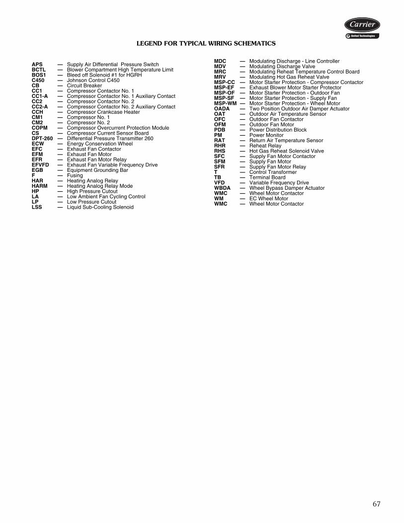
67
LEGEND FOR TYPICAL WIRING SCHEMATICS
APS — Supply Air Differential Pressure SwitchBCTL — Blower Compartment High Temperature LimitBOS1 — Bleed off Solenoid #1 for HGRHC450 — Johnson Control C450CB — Circuit BreakerCC1 — Compressor Contactor No. 1CC1-A — Compressor Contactor No. 1 Auxiliary ContactCC2 — Compressor Contactor No. 2CC2-A — Compressor Contactor No. 2 Auxiliary ContactCCH — Compressor Crankcase HeaterCM1 — Compressor No. 1CM2 — Compressor No. 2COPM — Compressor Overcurrent Protection ModuleCS — Compressor Current Sensor BoardDPT-260 — Differential Pressure Transmitter 260ECW — Energy Conservation WheelEFC — Exhaust Fan ContactorEFM — Exhaust Fan MotorEFR — Exhaust Fan Motor RelayEFVFD — Exhaust Fan Variable Frequency DriveEGB — Equipment Grounding BarF — FusingHAR — Heating Analog RelayHARM — Heating Analog Relay ModeHP — High Pressure CutoutLA — Low Ambient Fan Cycling ControlLP — Low Pressure CutoutLSS — Liquid Sub-Cooling Solenoid
MDC — Modulating Discharge - Line ControllerMDV — Modulating Discharge ValveMRC — Modulating Reheat Temperature Control BoardMRV — Modulating Hot Gas Reheat ValveMSP-CC — Motor Starter Protection - Compressor ContactorMSP-EF — Exhaust Blower Motor Starter ProtectorMSP-OF — Motor Starter Protection - Outdoor FanMSP-SF — Motor Starter Protection - Supply FanMSP-WM — Motor Starter Protection - Wheel MotorOADA — Two Position Outdoor Air Damper ActuatorOAT — Outdoor Air Temperature SensorOFC — Outdoor Fan ContactorOFM — Outdoor Fan MotorPDB — Power Distribution BlockPM — Power MonitorRAT — Return Air Temperature SensorRHR — Reheat Relay RHS — Hot Gas Reheat Solenoid ValveSFC — Supply Fan Motor ContactorSFM — Supply Fan MotorSFR — Supply Fan Motor RelayT — Control TransformerTB — Terminal BoardVFD — Variable Frequency DriveWBDA — Wheel Bypass Damper ActuatorWMC — Wheel Motor ContactorWM — EC Wheel MotorWMC — Wheel Motor Contactor

68
Guide specificationsPackaged Rooftop Cooling Unit and Packaged Rooftop Cooling Unit with HeatHVAC Guide Specifications —Section 62DA,DB,DC,DDSize Range: 6 to 35 Tons Nominal (Cooling)Carrier Model Number: 62DA,DB,DC,DDPart 1 — General1.01 SYSTEM DESCRIPTION:
Outdoor roof curb or slab mounted, electronicallycontrolled, cooling or cooling/heating unit utilizinghermetic scroll compressors with crankcase heatersfor cooling duty and gas combustion or electric heat-ers for heating duty. Units shall discharge supply airvertically or horizontally as shown on contractdrawings.
1.02 QUALITY ASSURANCEA. Unit shall be designed to conform to ANSI/
ASHRAE (American National Standards Institute/American Society of Heating, Refrigerating, andAir-Conditioning Engineers) 15 (latest edition),ASHRAE 62, and UL (Underwriters Laboratories)Standard 1995.
B. Unit shall be listed by ETL and ETL, Canada as atotal package.
C. Gas heat equipped units shall be designed to con-form with ANSI Standard Z21.47 (U.S.A.) / CSA(Canadian Standards Association) Standard 2.3(Canada), Gas-Fired Central Furnaces.
D. Roof curb shall be designed to NRCA (NationalRoofing Contractors Association) criteria per Bulle-tin B-1986.
E. Insulation and adhesive shall meet NFPA (NationalFire Protection Association) 90A requirements forflame spread and smoke generation.
1.03 DELIVERY, STORAGE AND HANDLINGUnit shall be stored and handled per manufacturer’srecommendations.
Part 2 — Products2.01 EQUIPMENT
A. General:Factory-assembled, single-piece heating and coolingunit. Contained within the unit enclosure shall be allfactory wiring, piping, refrigerant charge (R-410A),operating oil charge, single refrigerant circuit (sizes07–09) or dual refrigerant circuits (sizes 12–38),microprocessor based control system and associatedhardware, and all special features required prior tofield start-up.
B. Unit Cabinet:1. Double wall design, constructed of G-90 galva-
nized steel, bonderized and pre-coated with abaked enamel finish.a. Top cover shall be 18-gage sheet metal with
1.0-in. thick, 4.0-lb density, closed cell insula-tion with a 24-gage sheet metal interior liner.
b. Access panels and doors shall be 20-gagesheet metal with 1.0-in. thick, 4.0-lb density,closed cell insulation with a 24-gage sheetmetal interior liner. Access doors shall beequipped with stainless steel hinges andquarter turn, adjustable, cam-action latches.
c. Insulation shall have a minimum thermalresistance rating of R7.
d. Corner and center posts shall be 16-gagegalvanized steel.
e. Basepans shall be 16-gage galvanized steel.All openings through the basepan shall haveupturned flanges at least 0.5 inches in height.
f. Basepans shall be insulated with 0.375-in.thick closed cell foam insulation.
g. Compressor rail shall be 12-gage galvanizedsteel.
h. Condensate pan shall be 16-gage stainlesssteel insulated with closed cell neopreneinsulation.
i. Base rail shall be 14-gage galvanized steel.j. Fan deck (indoor and outdoor section) shall
be 16-gage galvanized steel.k. Roof sections shall be sloped for proper
drainage.2. Unit casing shall be capable of withstanding
500-hour salt spray exposure per ASTM(American Society for Testing and Material)B117 (scribed specimen).
3. Unit shall have insulated hinged access doorsfor easy access to the control box and otherareas requiring servicing. Each door shall sealagainst a rubber gasket to help prevent air andwater leakage and be equipped to permit easeand safety during servicing.
4. Interior cabinet surfaces shall be lined with24 gage galvanized steel.
5. Unit shall have a factory-installed sloped con-densate drain connection fabricated of galva-nized steel.
6. Unit shall be equipped with rigging openings inframe rails to facilitate overhead rigging.
7. Filters shall be accessible through a hingedaccess panel.
8. Unit shall have vinyl-coated security grille toprotect the condenser and compressor section.
9. The outdoor air opening shall have a factory-installed hood with bird screen.
C. Fans:1. Indoor Supply Fans:
a. Fans shall be belt driven with single outletdischarge.
b. Fan shaft bearings shall be of the pillowblock type with positive locking collar and bepermanently lubricated.
69
c. Fans shall be statically and dynamicallybalanced.
d. The fan assembly shall be mounted in rubbervibration isolators.
e. Fan assembly shall be on a slide-out deck thatis removable for maintenance and service.
2. Condenser Fans:a. Fans shall be direct-driven propeller type
only, with corrosion-resistant blades rivetedto corrosion-resistant steel supports.
b. Fans shall discharge air vertically upwardand be protected by PVC coated steel wiresafety guards.
c. Fans shall be statically and dynamicallybalanced.
D. Compressors:1. Fully hermetic, scroll type compressors with
overload protection and short cycle protectionwith minimum on and off timers. Digital com-pressors are available.
2. Factory rubber-in-shear mounted for vibrationisolation.
3. Reverse rotation protection capability.4. Crankcase heaters shall only be activated during
compressor off mode.E. Coils:
1. Standard evaporator coil shall have enhancedsurface aluminum plate fins mechanicallybonded to six rows of seamless internallygrooved copper tubes with all joints brazed.
2. Standard condenser coil shall have enhancedsurface aluminum plate fins mechanicallybonded to seamless internally grooved coppertubes with all joints brazed.
3. Coils shall be pressure tested at 650 psig priorto unit assembly; leak tested at 150 psig andundergo final testing at 475 psig.
4. Optional coil coatings for corrosion protectionshall be available.
F. Refrigeration System Components:1. Unit shall be equipped with single refrigerant
circuit (sizes 07–09) or dual refrigerant circuits(sizes 12–38), with each circuit containing:a. Solid core liquid line filter drier.b. Adjustable thermostatic expansion valve
accumulators.c. Hot gas bypass shall be standard on all non-
digital compressors.d. Gage connection ports.
2. 100% outdoor air units shall be equipped withlow ambient head pressure control to allowoperation down to 35 F.
3. Hot Gas Reheat:A factory-installed hot gas reheat (HGRH) coilshall be available. The HGRH coil shall be
available on the lead circuit only or on bothrefrigerant circuits. Units with HGRH will havevariable speed low ambient head pressure con-trol. Cycling or modulating HGRH shall beavailable.
4. Liquid Subcooling Reheat:A factory-installed liquid subcooling reheat(LSRH) shall be available on all unit circuits andshall have cycling control. LSRH shall be usedin conjunction with lead circuit HGRH.
G. Filter Section:Standard filter section shall be supplied with 2-in.thick MERV-8 fiberglass filters.
H. Controls and Safeties:1. Microprocessor Controls:
a. Unit shall have a factory installed and pro-grammed microprocessor controller withLED indicators and archive capability.
b. Shall include a field-installed space tempera-ture sensor with communication port.
c. Shall be capable of communicating via BAC-net, Modbus, N2 or LonWorks protocols.
d. Shall provide a 5° F temperature differencebetween cooling and heating set points tomeet ASHRAE 90.1, energy standard.
e. Shall provide an alarm indicator and an audiblealarm signal via accessory interface device.
f. Unit shall display current alarms and log 100most recent alarms.
g. Compressor minimum off time (5 minutes)shall be provided.
h. Shall have a service diagnostic mode.i. Unit shall be complete with self-contained
low voltage control circuit.j. Control interface shall be via accessory
device with display and key pad. Accessorycontroller connection shall be at unit control-ler and space temperature sensor.
k. Unit scheduling shall be accomplished bybuilt in scheduling program, occupancyswitch, or external BAS.
2. Safeties:a. Unit shall incorporate a solid-state compres-
sor lockout which provides optional resetcapability at the space thermostat shouldany of the following safety devices trip andshut off compressor:1) Compressor lockout protection provided
for either internal or external overload.2) Low-pressure protection.3) Freeze protection (evaporator coil).4) High-pressure protection.5) Loss of charge protection.
b. Supply-air sensor shall be located in the unitand shall be used for compressor stagecontrol.
70
Guide specifications (cont)c. Unit shall be equipped with a supply fan sta-
tus switch to protect the system in the eventof a fan drive failure.
d. Induced-draft heating section shall be pro-vided with the following minimum protec-tions:1) High-temperature limit switch.2) Differential pressure switch to prove
induced draft.3) Flame rollout switch.4) Flame proving controls.5) Redundant style gas valve.
I. Operating Characteristics:1. Unit shall be capable of starting and running at
115 F ambient outdoor temperature per maxi-mum load criteria of AHRI (Air-Conditioning,Heating, and Refrigeration Institute) Standard340/360.
2. Unit with standard controls will operate in cool-ing down to an outdoor ambient temperature of35 F.
3. Unit shall be equipped with a motorized two-position outdoor air (OA) damper for 100% OAoperation.
4. Unit shall be provided with fan time delay toprevent cold air delivery (gas heat only).
J. Electrical Requirements:All unit power wiring shall enter unit cabinet at a sin-gle location.
K. Motors:1. Compressor motors shall be cooled by refriger-
ant gas passing through motor windings andshall have either internal line break thermal andcurrent overload protection or external currentoverload modules with compressor temperaturesensors.
2. All condenser-fan motors shall be open dripproof with permanently lubricated ball bearings,class F insulation and manual reset overloadprotection.
3. All indoor-fan motors 1 hp and larger shallmeet the minimum efficiency requirements asestablished by the Energy Independence andSecurity Act of 2007 (EISA), effective Decem-ber 20, 2010.
4. All indoor-fan motors shall be open drip proofdesign.
L. Special Features:Not all feature combinations are available. Contactyour local Carrier Sales Office.
1. Energy Recovery:a. The factory-installed enthalpy wheel shall be
certified to meet the requirements of AHRIStandard 1060 and shall be AHRI listed.
b. The enthalpy wheel shall be constructed ofcorrugated synthetic fibrous media with a
desiccant intimately bound and uniformlyand permanently dispersed throughout thematrix structure of the media.
c. The desiccant material shall be molecularsieve, 4 angstrom or smaller.
d. The rotor shall be constructed of alternatinglayers of flat and corrugated media.
e. Wheel construction shall be fluted or formedhoneycomb geometry so as to eliminateinternal wheel bypass.
f. The wheel frames shall be evenly spacedsteel spokes with a galvanized steel outerband and rigid center hub.
g. The wheel seals shall be full contact nylonbrush type.
h. The wheel shall slide out of the cabinet sidefor service.
i. Wheel cassettes shall be constructed of gal-vanized steel. Cassettes shall have integralpurge section.
j. The wheel bearings shall be inboardmounted, permanently sealed roller bearingsor externally flanged bearings.
k. The wheel shall be driven by a fractionalhorsepower AC motor via multilink drivebelts.
l. Energy wheel defrost control and air bypassshall be available.
2. Gas Heating:a. Gas heat shall be induced-draft combustion
type with energy saving direct spark ignitionsystems and redundant main gas valves.
b. The heat exchanger shall be of the tubularsection type constructed of a minimum of20-gage stainless steel.
c. Burners shall be of the in-shot type con-structed of aluminum coated steel.
d. All gas piping shall enter the unit cabinet at asingle location.
e. Induced-Draft Fans:1) Shall be direct-driven, single inlet, for-
ward-curved centrifugal type.2) Shall be statically and dynamically bal-
anced.3) Shall be made from steel with a corro-
sion-resistant finish.f. High-corrosion areas such as flue gas collec-
tion and exhaust areas shall be lined withcorrosion resistant material.
g. Optional 5:1 or 10:1 turndown modulatingfurnace shall be available.
3. Electric Heat:a. Electric resistance heaters shall be factory-
installed, nichrome element type, open wirecoils with 0.375 in. inside diameter, insulatedwith ceramic bushings, and include operating

71
and safety controls. Coil ends shall be stakedand welded to terminal screw slots.
b. Factory-installed electric heat shall havestaged heat control (1, 2, 3, or 4 stages) orSCR (silicon controlled rectifier) control pro-viding infinite capacity adjustment.
4. Hot Water Heat:Unit shall have a 2-row hot water coil, aluminumconstruction, with air vents installed downstreamof the evaporator coil. Coil connection stubs willbe located inside the unit cabinet. Hydronic con-trol valves shall be field furnished.
5. Steam Heat:Unit shall have 1-row, steam distributing type,aluminum fin coil installed downstream of theevaporator coil. Coil connection stubs will belocated inside the unit cabinet. Control valves tobe field furnished.
6. Supply Fan:Supply fan of the backward curve, forwardcurve, airfoil, or backward inclined type shall befactory-installed, mounted on rubber isolation,and installed on a slide-out deck that is remov-able for maintenance and service.
7. Modulating Supply Fan:Package shall include a VFD-controlled supplyfan mounted on rubber vibration isolation andinstalled on a slide-out deck that is removablefor maintenance and service. VFD control shallbe based on duct pressure.
8. Liquid Subcooling Coil:The unit shall be equipped with a factory-installed full face liquid subcooling coil on all cir-cuits.
9. Exhaust Fan:Package shall include an exhaust fan of thebackward curve, forward curve, or airfoil typemounted on rubber vibration isolation withgravity relief damper. The shaft-mounted fanshall be mounted in sealed ball bearings anddriven via an adjustable sheave belt drive.
10. Modulating Exhaust Fan:Package shall include a VFD controlled exhaustfan mounted on rubber vibration isolation withgravity relief damper. The shaft-mounted fan ismounted in sealed ball bearings and driven viaan adjustable sheave belt drive. Control shall bebased on building pressure.
11. Oversize Fan Motors:Oversize fan motors shall be available for bothoptional supply and exhaust fan motors.
12. Liquefied Propane Conversion Kit:Kit shall contain all the necessary hardware andinstructions to convert a standard natural gasunit for use with liquefied propane gas.
13. Convenience Outlet:Shall be factory-installed and internallymounted with an externally accessible 115-v,15 amp GFI, female receptacle with hingedcover. The outlet shall require field-supplied115-v power supply wiring.
14. Fused Disconnect Switch:Shall be factory-installed, internally mounted,and UL approved. Fused switch shall provideunit power shutoff. Shall be accessible from out-side the unit and shall provide power off lockoutcapability.
15. Firestat:A factory-installed, manual-reset firestat shall bemounted in the return-air opening of the unit.The firestat shall be set to open at 135 F.
16. Exhaust Air Smoke Detector:A factory-installed smoke detector shall bemounted in the unit exhaust air intake(62DC,DD).
17. Dirty Filter Status Switch:The manual reset filter status switch shall be apressure differential switch and will indicate adirty filter. The switch shall be factory installed.
18. Fan Status Switch:The unit shall be equipped with a field-adjust-able differential air pressure switch installedacross the filters or supply fan to provide proofof airflow.
19. Phase/Voltage Monitor:A factory-installed under-voltage and phase losssensor shall stop the unit whenever voltage istoo low, phases are out of sequence, or a phaseis dropped. The unit will restart automaticallywithin five minutes after the correct power issupplied.
20. Spring Fan Isolation:Supply fan and power exhaust fan (if equipped)shall be mounted in spring type isolation withseismic restraints.
21. 4-Inch Filters:Optional filter section shall be supplied with4-in. thick MERV-8 or 11 pleated fiberglassfilters.
22. Filter Kits:Accessory filter kits shall be available withMERV-8 or 11 type filters.
23. Digital Compressor:A digital compressor shall be available. The con-trol system shall be capable of unloading thecompressor in an unlimited number of steps from100% capacity down to 10% capacity.
24. Commissioning User Interface:The commissioning keypad/display unit shallhave a numeric keypad, direction keys, and
Manufacturer reserves the right to discontinue, or change at any time, specifications or designs without notice and without incurring obligations.Pg 72 Catalog No. 04-52620017-01 Printed in U.S.A. Form 62D-8PD
Replaces: 62D-7PD
Carrier Corporation • Syracuse, New York 13221 717 1-15
Guide specifications (cont)programmable function keys. The display shallbe a 4-line by 40-character backlit LCDdisplay.
25. Head Pressure Control:Condenser fan cycling or variable speed con-denser fans shall be available for head pres-sure control.
26. LonWorks Communicator:LonWorks communication shall be availablefactory installed.
27. Roof Curb:Curb shall be formed of 14-gage galvanizedsteel with wood nailer strip and shall be capa-ble of supporting entire unit weight.
28. Minimum Load Valve:Unit shall be equipped with factory-installedminimum load valve (hot gas bypass).
29. Harsh Environment Coating:Unit shall be equipped with a factory-applied“Harsh Environment Protection” designed tocombat the corrosive effects of industrial andcommercial atmospheric conditions including:salt air, salt water, acid rain, chlorine and chlo-rides, hydrochloric, nitric, hydrofluoric, sulfu-ric and uric acid fumes, hydrogen sulfide gas,lye, sulfur dioxide, methane gas, hydrocar-bons, chlorinated solvents and aromatic sol-vents. The Harsh Environment Protectionshall include the following features, whereapplicable, to provide extra protection againstcorrosive atmospheric conditions:a. Vinyl-coated condenser fan guards.b. Non-corroding condenser fan motor
mounts.
c. Totally enclosed single-speed three-phasecondenser fan motors.
d. Coated refrigerant to air condenser withcorrosion-resistant coil coating composedof aluminum-impregnated polyurethane,rated for 10,000 hr salt spray.
e. Coated refrigerant to air evaporator withcorrosion-resistant coil coating composedof aluminum-impregnated polyurethane,rated for 10,000 hr salt spray.
f. Coated refrigerant to air hot gas reheat coilwith corrosion-resistant coil coating com-posed of aluminum-impregnated polyure-thane, rated for 10,000 hr salt spray.
g. Coated refrigerant to air subcooling coilwith corrosion-resistant coil coating com-posed of aluminum-impregnated polyure-thane, rated for 10,000 hr salt spray.
h. All interior (un-insulated) cabinet panelscoated with corrosion-resistant cabinetcoating composed of polyurethane, ratedfor 10,000 hr salt spray.
i. All exterior surfaces of the cabinet coatedwith corrosion-resistant cabinet coatingcomposed of polyurethane, rated for10,000 hr salt spray.
j. All compressors, accumulators, factory-installed receivers, control device coversand refrigerant piping coated with corro-sion-resistant cabinet coating composed ofpolyurethane, rated for 10,000 hr saltspray.