Embed Size (px)
Citation preview
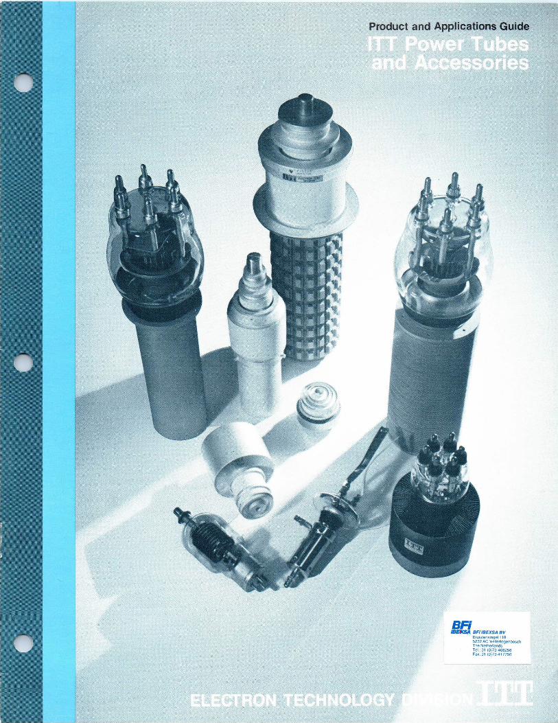
Product and Applications Guide
/BEKSA BFI IBEXSA BV Bruistensingel t 18 5232 AC's-HerlogenbosCh The NetherlanGs Te1.: 31 ~0~73d08256 fax: 31 (O~J3-417750
ITT Electron Tube Division's complete line of external-anode high power vacuum tubes is presented in this quick reference product guide. Tube types, numerically listed in categories of vacuum diodes, pulse triodes, power triodes, and power tetrodes, are cross referenced in order of plate dissipation ratings. Detailed information covering ITT power tube accessories and applications is included.
While the data in this product guide will enable most users to select a tube type for their system, ITT ad-vises that you consult the technical data sheet for the proposed tube prior to final selection.
Your request for tube selection assistance and application engineering service is invited. ITT's Sales Engineering staff welcomes the opportunity to advise you on optimum tube selection and also to counsel you on improved tube performance factors regarding your particular application.
For complete technical data and application assistance, as well as price and delivery information, contact your nearest ITT Sales Engineering office listed on the back of this guide or write to:
ITT Electron Tube Division Box 100, Easton, Pa. 18042 Telephone (215) 252-7331
VACUUM DIODES
Tube Type Cooling Page No.
F-1099 F 3 F-7030 F 3 F-7131 F 3 F-7779 F 3 F-7889 F 3 F-7975 F 3 F-8034 F 3 F-8207) W 3 F-8208 W 3 F-1119 W 3 F-1130 W 3
PULSE TRIODES
Tube Type Cooling
Plate Voltage Vdc
Page No.
F-7C23 F 17,500 3 F-5680 F 17,500 3 F-7012 F 17,500 3 F-6920 F 40,000 3 F-7560 F 50,000 3 F-7560V W 50,000 3 F-1091V W 75,000 3 F-1086 W 75,000 3
•
POWER TRIODES POWER TRIODES (Continued) POWER TETRODES Plate Plate Plate Diss. Page Diss. Page Diss. Page
Tube Type Cooling kW No. Tube Type Cooling Vdc No. Tube Type Cooling kW No.
F-7C25. . F 2.5 4 F-5874A W 25 4 F-1146/4629 F 1.5 4 F-6366 F 3 4 F-5919 F 25 4 F-1183/4665 F 1.5 4 F-6367 F 3 4 F-6804 F 25 4 F-7213 F 1.5 4 F-6925 F 3 4 F-6697A F 35 4 F-7214 F 1.5 4 F-8104R F 3.5 4 F-8494 V 35 4 F-1182/4600A F 1.75 4
F-8104M O 4.0 4 F-6692 W 40 F-7007 4 F 12 4
F-8132 F 5 4 F-1089 F 45 4 F-6399 W 6 4 F-8550 F 45 4 F-6400/6400A W 6 4 F-8146 W 50 4 F-6926 W 6 4 F-6696A W 60 4
F-6926) W 6 4 F-6803 W 70 4 F-8104) W 8 4 F-5918 W 80 4 F-8131 F-5606A F-6801
W W F
8 10 10
4 4 4
F-8386 F-8388 F-7560
W V W
100 100 175
4 4 4
Cooling Code: F W
Forced Air Water
F-SC25A F 12 4 F-7560N W 175 6 V O
Vapor Oil
F-6691 F 17 4 F-7560V V 175 6 F-7207A F 17 4 F-6398 W 225 5 F-6800A W 20 4
~'~ F-8147A F 20 4
2
'vacuum `✓ CHARACTERISTICS MAXIMUM RATINGS -CLASS OF SERVICE
Tube Type Cooling
FILAMENT
Volts Amps Type
RECTIFIER Peak Inverse kW
Peak Amps
Avg. Amps
SHUNT Peak Inverse kW
Peak Amps
Avg. Amps
CHARGING Peak Inverse kW
Peak Amps
RMS or Avg. Amps
LIMITER Peak Inverse kW
Avg. Ampa
F-1099 F 7.0 110 TW 40 25 8
F-7030 F 13 36 TW 25 20 6 30 75* .7* 30 75* .7* avg.
F-7131 F 13 36 TW 40 15 3 40 150* 40 Srms
F-7779 F 13 36 TW 25 20 6 30 75* .7 30 75 .7* avg.
F-7869 F 15 36 TW 56 21 4 65 100* 65 100*
F-7975 F 15 36 TW 46 21 5 55 100 55 100
F-8034 F 7.5 51 TW 25 20 3 25 70* 25 4.5 rms
F-8207) W 15 36 TW 30 12 6 30 100 30 7.5 rms
F-8208 W 22 60 T 45 3
F-1119 W 9 100 T 17.5 4.5
F-1130 W 25 250 T 35 20
*Obtained at elevated filament voltages (-}-5 % )
i'ulse Triode CHARACTERISTICS MAXIMUM RATINGS
TYPICAL OPERATING CONDITIONS
Tube Type Cooling
FILAMENT
Volta Amps Type MU
Class of Service
Plate Volt. Vdc
Pulse Current Amps
Pulse Grid Current Amps
Avg. Plate Diss. kW
Pulse Length Sec.}}
Grid Diss. W
Duty Factor
Plate Volt. Vdc
Plate Currenl Ampa Peak
Grid Current Ampa Peak
Grid Volf. Vdc
Pulse Power Output kW
Plate Output Volt.
F-7C23 F 11 29 TW 25 GP-RF 17,500 20} .2 1.2 90 .005 15,000 60
F-1086 W 12.6 285 TW 25 P-M 75,000 275}} 90 1000 1500 .O1 65,000 160 25 —3200 9,400 59,000 F-1091V{r W 31 970 TW 25 P-M 75,000 2000}} 390 1000 4000 .O1 72,000 1000 225 —4200 58,000 58,000 F-5660 F 13 36 TW 25 GP-RF 17,500 35}} 2.5 .030 15,500 —750 90 F-6920{r F 11
11.9 285 TW
TW 41 41
P-M P-M
40,000 40,000
100} 150}
65 100
10 10
15 15
,002 .002
18 30
90 150
25 50
—1250 —1000
1,485 4,125
16.5 27.5
F-7012 F 15 36 TW 25 GP-RF 17,500 40}} 2.5 .030 15,500 —750 90
F 7560V F-7560N~
~ ** W ~ 14.5 14.5
450 450
TW TW
45 45
P-M PP-RF
50,000 40,000
350} 350}$
175 175
1000 500
3000 3000
.01 .10
50,000 40,000
350 100
80 16
—1800 —1400
15,700 3,000
45,000
t —Cathode; }}—Plate; **Appendage Pump attached; {rNon-emissive grid.
Cooling Code: F Forced Air W Water V Vapor O OI I
Filament Code: T Pure Tungsten TW Thoriated Tungsten MO Matrix Oxide
Class of Service Code: ABt Push/Pull Audio Frequency Modulator (Class AB1) ABt-RF Radio Frequency Linear Amplifier (Class ABl) B-TV Television Service, Grid Driven (Class B) C-P Plate Modulated Radio Frequency Amplifier C-T Telegraphy (Class C) P-M Pulse Modulator GP-RF Grid Pulsed Radio Frequency PP-RF Plate Pulsed Radio Frequency VR Voltage Regulator
3
~owe~ Triodes CHARACTERISTICS
~~
Tube Type Cooling
FILAMENT
Volts Amps Type MU
Class of Service
F-7C25 F 11 28 TW 25 C-T F-8C25A F 7 110 TW 6 A81 F-1089 F 11 285 TW 40 C-T F-5606A W 22 60 T 36 C-T
F-5680 F 13 36 TW 25 C-T
F-5771/356 W 7.5 170 TW 20 C-T
F-5874A W 7 110 TW 6 AB1 F-5918A W 11 265 TW 41 C-T
F-5919 F 11 285 TW 40 C-T
F-6366 F 11 29 TW 25 C-T
F-6367 F 13 36 TW 25 C-T
F-6398 W 15.5 420 TW 21 C-T
F-6399 W 11 29 TW 25 C-T
F-6400/6400A W 13 36 TW 25 C-T
F-6691 F 5 260 TW 21 C-T
F-6692 W 5 260 TW 21 C-T
F-6696A W 13 205 TW 20 C-T
F-6697A F 13 205 TW 20 C-T
F-6800A W 7.5 107 TW 19.5 C-T
F-6801 F 7.5 107 TW 19.5 C-T F-6803 W 11 190
per phase
TW 41 C-T
F-6804 F 11 190 per phase
TW 40 C-T
F-6925 F 13 36 TW 17 C-T
F-6926 W 13 36 TW 17 C-T
F-6926) W 13 36 TW 17 C-T
F-7207A F 7 110 TW 6 ABt F-7560 F-7560N{r F-7560V*
W 14.5 450 TW 45 C-T
F-8045 W 12.6 285 TW 20 C-T
F-8104 F-8104)
W 15 36 TW 25 C-T
F-8104M O 15 36 TW 25 C-T F-8104R F 15 36 TW 25 C-T
F-8131 W 9.5 50 TW 20 C-T
F-8132 F 9.5 50 TW 20 C-T
F-8146A W 11 155 TW 17 B-AF
F-8147A F 11 155 TW 17 C-T
F-8386 W 14.5 330 TW 22 C-T
F-8387 F 14.5 330 TW 22 C-T
F-8388 V 14.5 330 TW 22 C-T
F-8494 V 7 110 TW 6 ABt
F-8550 F 1 190 TW 41 B-AF C-P C-T
-~v~cr Tetrodes CHARACTERISTICS
Tube Type Cooling
FILAMENT
Volts Amps Type
Class of Service
F-7007 F 5.0 180 TW B-TV C-P C-T
F-1146/4629 F 5.5 •17.3 MO P-M
F-1183/4665 F 5.5 17.3 MO PP-RF F-7213 F 5.5 17.3 MO C-T F-7214 F 5.5 17.3 MO GP-RF F-1182/4600A F 5.5 17.3 MO VR
TYPICAL MAXIMUM RATINGS OPERATING CONDITIONS
Plate Plate Grid Power Plate Max. Volt. Current Current Input Diss. Freq. Vdc Adc Adc kW kW MHz
Approx. Plate Grid Plate Grid Driving Power Volt. Volt. Current Current Power Output Vdc Vdc Adc Adc W kW
5,000 1.3 0.15 6.5 2.5 50 4,500 -500 1.2 0.1 110 3.1
8,000 5 30 12 audio 5,000 -900 2.6* 7.4*
17,500 15 1.5 125 4.5 22 14,000 - 800 10 1.4 2000 104
15,000 2 0.4 30 10 1.6 10,000 -1300 1.4 0.24 495 10
6,000 2 0.2 12 2.5 6,000 -800 1.4 0.16 225 6
12,500 6 0.8 60 22.5 25 12,500 - 630 4.8 0.75 1000 44
8,000 5 30 25 audio 5,000 - 900 2.6* 7.4*
17,500 15 1.5 175 80 22 14,000 -1200 12.5 1.45 3300 130
17,500 15 1.5 125 25 22 10,000 -1000 6.4 1.1 1700 50
6,200 1.3 0.15 7 3 30 4,500 - 500 1 0.12 120 3
6,200 2 0.2 12 3 30 6,000 -800 1.4 0.16 225 6
23,000 25 4 370 225 24 16,000 - 2400 21.7 3.5 13,000 250
6,200 1.5 .200 9 6 30 5,000 -600 1.2 0.13 160 4
6,000 2 .200 12 6 30 5,500 - 600 1.7 .19 270 5.9
12,500 6 .8 54 17 30 12,500 -1300 4.25 .500 900 42
12,500 6 .8 75 40 30 12,500 -1300 5.9 .725 1400 58
16,000 11 2 60 40 15,000 -1600 7 .3 600 80
16,000 11 2 35 40 10,000 -1200 10 .81 1500 72
15,000 3.5 .50 45 20 22.5 12,500 -1200 3.5 .45 900 33
15,000 3.5 .5 40 10 22.5 12,500 -1200 3 .43 850 28
17, 500 15 1.5 175 70 22
17,500 15 1.5 125 25 22
14,500 - 2250 8.25 1.5 5000 95
10,000 -1000 6.4 1.1 1700 50
6,500 2 .250 12 3 30 4,000 -800 1.6 .230 300 4.4
6,500 2 .250 12 6 30 4,000 -800 1.6 .230 300 4.4
6,500 2 .250 12 6 30 4,000 - 800 1.6 .230 300 4.4
8,000 5 30 17 audio 7,600 -1400 5* 21*
20,000 35 4 600 175 30 20,000 -1000 29 3.4 6000 440
18,000 17 2 270 90 2 16,000 -1800 13.2 1.25 3250 150
6,000 2.2 .300 12 8 30 5,500 -600 2 .18 230 6.8
6,000 2.5 .3 12 4 30 5,500 -600 1.4 .150 180 5.5
6,000 2.2 .300 12 3.5 30 5,500 -600 1.4 .15 180 5.5
6,500 3 .35 18 8 80 6,000 - 600 2.5 .25 220 11.7
6,200 3 .35 18 5 80 5,000 - 550 2.9 .285 220 10.4
11,000 8 80 40 audio 8,500 - 520 12.8* 110* 70*
11,000 8 .8 80 20 50 7,500 - 800 7.5 .45 545 38
17,000 19 250 100 30 15,500 -1800 17 1.5 3800 175
13,000 19 3.5 190 30 30 12,000 -1500 15.5 1.7 3800 135
17,000 19 3.5 250 100 30 15,500 -1800 17 1.5 3800 175
8,000 5 35 35 audio 7,000 -1400 3.2* 13.75*
19,500 9 14,000 12 17,500 15
45 audio 30 22 45 22
14,000 - 300 16* 1500* 150* 14,000 - 800 10 1.4 2000 104 14,500 - 2250 8.25 1.4 5000 90
"Two tubes; {yNon-emissive grid; **Appendage Pump attached.
TYPICAL MAXIMUM RATINGS OPERATING CONDITIONS
DISSIPATION Plate Plate Max. Volt. Current Plate Screen Grid Freq. VDC ADC kW W W MHz
Plate Screen Plate Driving Power Volt. Volt. Current Power Output VDC VDC ADC W kW
7,500 4 12 400 300 220 5,850 1000 3.20 1000 12
5,000 2 8 220 4,800 800 1.8 100 6
7,500 3 12 400 220 7,000 1000 2.6 80 12
5,000 18*** 1.5 50 30 - 4,000 400 8*** - 28.8*'*
10,000*** 18*** 1.5 50 30 1215 10,000*** 1000*** 18*** 11,000$ 65***
3,000 1.0 1.5 50 30 1215 2,500 500 1.0 75 1.35
5,000 18*** 1.5 50 30 1215 4,500 1000*** 11*** 4,500$ 20***
3,500 1 1.75 50 30 - 3,000 400 .8 - 1.9
* Two Tubes; o Synchronizing Level; *** Pulse Conditions; $ Cathode Drive Conditions.
4
ACCP~SnriP
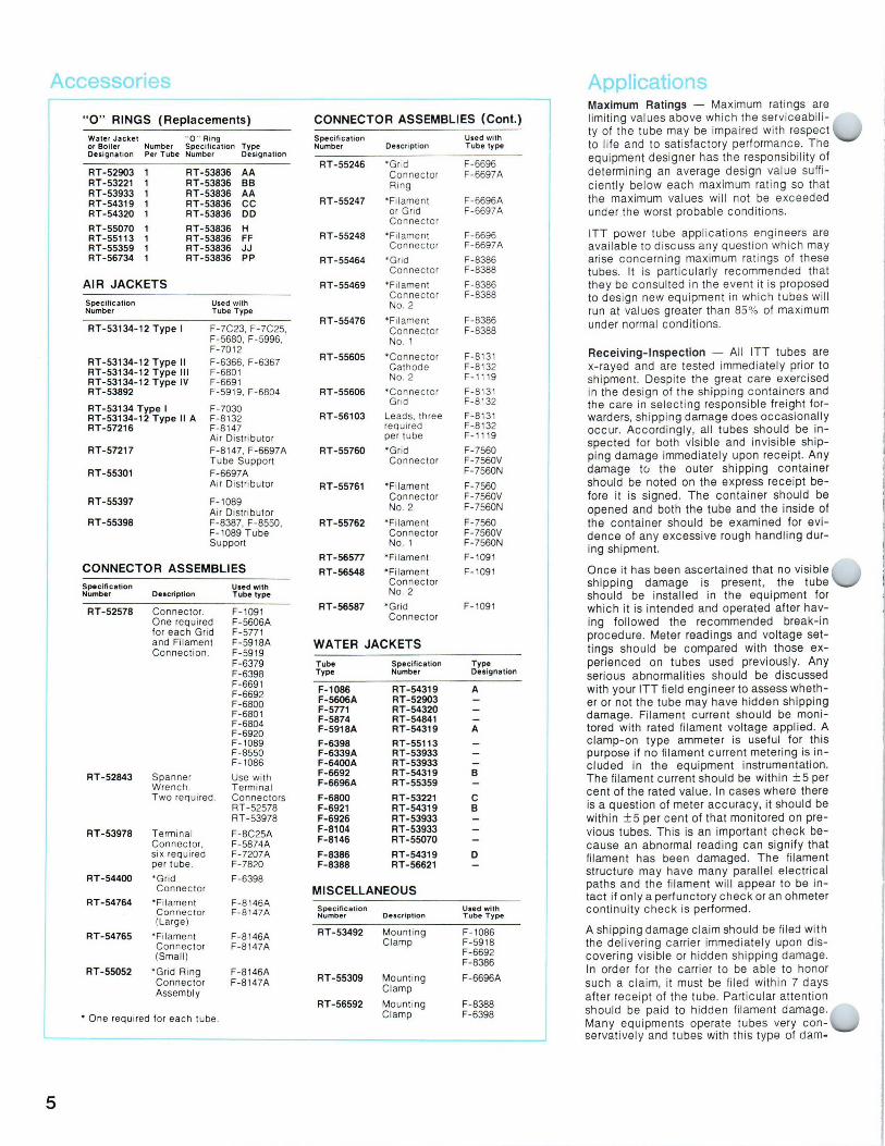
"O" RINGS (Replacements) Water Jacket "O" Ring or Boiler Number Specification Type Designation Per Tube Number Designation
RT-52903 1 RT-53836 AA RT-53221 1 RT-53836 BB RT-53933 1 RT-53836 AA RT-54319 1 RT-53836 CC RT-54320 1 RT-53836 DD RT-55070 1 RT-53836 H R T-55113 1 RT-53836 FF RT-55359 1 RT-53836 JJ RT-56734 1 RT-53836 PP
AIR JACKETS Specification Number
Used with Tube Type
RT-53134-12 Type I
RT-53134-12 Type fl RT-53134-12 Type III RT-53134-12 Type IV R T-53892
RT-53134 Type I RT-53134-12 Type II A RT-57216
RT-57217
RT-55301
RT-55397
RT-55398
F-7C23, F-7C25, F-5680, F-5996, F-7012 F-6366, F-6367 F-6801 F-6691 F-5919, F-6804
F-7030 F-8132 F-8147 Air Distributor F-8147, F-6697A Tube Support F-6697A Air Distributor
F-1089 Air Distributor F-8387, F-8550, F-1089 Tube Support
CONNECTOR ASSEMBLIES Specification Number Description
Used with Tube type
RT-52578 Connector. One required for each Grid and Filament Connection.
RT-52843 Spanner Wrench. Two required.
RT-53978 Terminal Connector, six required per tube.
RT-54400 *Grid Connector
RT-54764 'Filament F-8146A Connector F-8147A (Large)
RT-54765 'Filament F-8146A Connector F-8147A (Small)
RT-55052 "Grid Ring F-8146A Connector F-8147A Assembly
' One required for each tube.
F-1091 F-5606A F-5771 F-5918A F-5919 F-6379 F-6398 F-6691 F-6692 F-6800 F-6801 F-6804 F-6920 F-1089 F-8550 F-1086
Use with Terminal Connectors RT-52578 RT-53978
F-8C25A F-5874A F-7207A F-7820
F-6398
CONNECTOR ASSEMBLIES (Cont.)
Specification Used with Number Description Tube type
RT-55246
RT-55247
R T-55248
R T-55464
R T-55469
R T-55476
RT-55605
RT-55606
`Grid F-6696 Connector F-6697A Ring
*Filament F-6696A or Grid F-6697A Connector
*Filament F-6696 Connector F-6697A
"Grid F-8386 Connector F-8388
`Filament F-8386 Connector F-8388 No. 2
*Filament F-8386 Connector F-8388 No. 1
*Connector Cathode No. 2 *Connector Grid
RT-56103 Leads, three F-8131 required F-.8132 per tube F-1119
RT-55760
RT-55761 *Filament Connector No. 2
RT-55762 *Filament Connector No. 1
RT-56577 *Filament
RT-56548 *Filament Connector No. 2
RT-56587 *Grid Connector
*Grid Connector
WATER JACKETS
Anr~lir~~tit~nc Maximum Ratings —Maximum ratings are limiting values above which the serviceabili-ty of the tube may be impaired with respect `~ to l ife and to satisfactory performance. The equipment designer has the responsibility of determining an average design value suffi-ciently below each maximum rating so that the maximum values will not be exceeded under the worst probable conditions.
ITT power tube applications engineers are available to discuss any question which may arise concerning maximum ratings of these tubes. It is particularly recommended that they be consulted in the event it is proposed to design new equipment in which tubes will run at values greater than 85% of maximum under normal conditions.
F-8131 Receiving-Inspection —All ITT tubes are F-8132 x-rayed and are tested immediately prior to F-1119 shipment. Despite the great care exercised F-8131 in the design of the shipping containers and F-8132 the care in selecting responsible freight for-
warders, shipping damage does occasionally occur. Accordingly, all tubes should be in-spected for both visible and invisible ship-ping damage immediately upon receipt. Any damage to the outer shipping container
F-7560 should be noted on the express receipt be-F-7560V fore it is signed. The container should be F-7560N opened and both the tube and the inside of
the container should be examined for evi-dence of any excessive rough handling dur-ing shipment.
F-1091 Once it has been ascertained that no visible shipping damage is present, the tube `n,e/ should be installed in the equipment for
F-1os1 which it is intended and operated after hav-ing followed the recommended break-in procedure. Meter readings and voltage set-tings should be compared with those ex-perienced on tubes used previously. Any serious abnormalities should be discussed with your ITT field engineer to assess wheth-er or not the tube may have hidden shipping damage. Filament current should be moni-tored with rated filament voltage applied. A clamp-on type ammeter is useful for this purpose if no filament current metering is in-cluded in the equipment instrumentation. The filament current should be within ±5 per cent of the rated value. In cases where there is a question of meter accuracy, it should be within ±5 per cent of that monitored on pre-vious tubes. This is an important check be-cause an abnormal reading can signify that filament has been damaged. The filament structure may have many parallel electrical paths and the filament will appear to be in-tact if only a perfunctory check or an ohmeter continuity check is performed.
A shipping damage claim should be filed with the delivering carrier immediately upon dis-covering visible or hidden shipping damage. In order for the carrier to be able to honor such a claim, it must be filed within 7 days after receipt of the tube. Particular attention should be paid to hidden fi lament damage. Many equipments operate tubes very con-~ servatively and tubes with this type of dam-
F-7560 F-7560V F-7560N
F-7560 F-7560V F-7560N
F-1091
Tube Type
Specification Type Number Designation
F-1086 RT-54319 A F-5606A RT-52903 —F-5771 RT-54320 —F-5874 RT-54841 —F-5918A RT-54319 A
F-6398 RT-55113 —F-6339A RT-53933 —F-6400A RT-53933 —F-6692 RT-54319 B F-6696A RT-55359 —
F-6800 RT-53221 C F-6921 RT-54319 B F-6926 RT-53933 —F-8104 RT-53933 —F-8146 RT-55070 —
F-8386 RT-54319 D F-8388 R T-56621 —
MISCELLANEOUS Specification Number Description
Used with Tube Type
RT-53492 Mounting F-1086 Clamp F-5918
F-6692 F-8386
RT-55309 Mounting F-6696A Clamp
RT-56592 Mounting F-8388 Clamp F-6398
5
r 1
age can often operate satisfactorily in such equipment for several hundred hours. Even-tually, the portion of the filament which re-mained intact fails due to overheating. Many times the overheating causes the filament to bow and touch the grid.
Installation —New equipment should be de-signed with adequate clearance in the cabi-net so that heavy tubes can be handled safely during installation and removal. On occasions where this has not proved prac-tical, many astute manufacturers have pro-vided their customers with special tools to lift particular tubes by the anode to facili-tate safe installation.
Equipment manuals should stress periodic cooling system checks and an especially thorough check when a new tube is installed. Cleanliness of the envelope to insure high voltage holdoff and of connector surfaces to assure good electrical contact should also be emphasized. An undue amount of leverage should be avoided in tightening connectors.
Break-in Procedure —New tubes should be operated at normal rated filament voltage only, for thirty minutes before any other volt-ages are applied. Plate voltage should then be applied at the lowest possible value and increased gradually in steps over a period of an hour until the normal level is reached. This procedure will vary for individual tube types. Experience will determine if it may be shortened for smaller tubes or should be lengthened for larger tubes in a given appli-cation.
Storage —Tubes should be stored in a ver-tical position with the anode end down. They should be protected from extremes of heat and cold as well as from physical abuse. Every three months they should be given the break-in procedure outlined above and then operated at normal plate voltage for one hour.
Filament Care —The cathode of most of the tubes listed in this catalog is a structure of thoriated tungsten wire. Some have a unipo-tential cathode of the oxide coated matrix type and are indicated as such. There are a few older types listed which are still manu-factured using bright tungsten cathodes. For the most part, the latter are made for replace-ment purposes only. Comments here will be confined to thoriated tungsten cathodes. Ali of these cathodes are directly heated thus the cathode is really a filament, and the words filament and cathode are used inter-changeably herein.
When a tube reaches a natural end-of-life condition it is usually because the emitting properties of the cathode have been ex-hausted. The life of this cathode and, there-fore, the life of the tube can be extended many times beyond the normal 1000 hour warranty period if proper care is taken in the design of the equipment and if proper in-structions on tube usage are passed along to the equipment users. Primary considera-tions in this respect are as follows:
1. Filament starting —The ratio of the hot to cold resistance of thoriated tungsten wire is approximately 10 to 1. Therefore, on a typical tube like the F-6696A, the nominal hot resistance would be 63.4 milliohms and the cold resistance would be 6.3 milli-ohms. Ifthe rated voltage of 13 volts is ap-plied to the cold filament without limiting current, the initial surge currents would be approximately 2000 amperes. Excessive starting current may easily warp or break a filament as the mechanical stress on the structure as a result of the magnetic field produced by this current is proportional to It2,
Consequently, current flow through a cold filament should be limited to 150% of the normal operating value for large tubes and 250% for medium types unless otherwise specified on a particular tube data sheet. The three most common methods of limit-ingthis current are a high reactance trans-former, manual control of the filament volt-age either through amulti-tapped trans-former or an auto transformer, or by means of a series of resistances in the filament oircuit which are shorted out one at a time until rated voltage and current are achieved. ITT applications engineers can supply useful details on any of these methods.
2. Maintaining proper voltage — It is essen-tial that the filament voltage on thoriated tungsten filaments be held to within ±5% of the rated value. Operation at high volt-ages will greatly accelerate the decom-position of the layer of tungsten carbide which protects the emitting layer and op-eration at low voltages will destroy the emitting layer itself either by reducing the supply of thoria, or by reducing the space charge and thus subjecting the filament to increased ion bombardment. All trans-mitters or industrial heating equipment should include filament voltage metering. Not quite as essential but highly desirable, are filament current meters. The ability to monitor filament current is useful in per-forming areceiving inspection on new tubes, in performing filament processing when required and in predicting when a tube is approaching end-of-life condition.
3. Filament recovery and processing — Oc-casionally, athoriated tungsten cathode which appears to have lost its emissive capabilities may be reactivated by apply-ing filament voltage only in accordance with one of the following schedules.
A. Apply 110% of rated value of filament voltage for a few hours or over night.
B. If the emission fails to respond after schedule A, run at 30% above normal voltage for 10 minutes, then at 10% above normal for 20 to 30 minutes.
C. in extreme cases, where A and B have failed to give results, and at the risk of
burning out the filament, run at 75% above normal for 3 minutes followed by schedule B.
This procedure is not effective in cases where the protective layer of tungsten carbide formed on the surface of the fila-ment wire during manufacture has been severely depleted. This layer occupies the outer portion of the area cross-section of the wire and is relatively nonconductive. Its depletion is effected by reduction of the tungsten carbide back into tungsten which is a better conductor. Therefore, the conductance of the wire is effectively in-creased by decarburization. Accordingly, filament decarburization is accompanied by a rise in filament current. When filament current at rated filament voltage has risen to a value, 10% above that originally re-corded at rated filament voltage, the tube is at or near end-of-life.
Handling —Tubes should be protected from shock and vibration during handling. Some tubes are quite heavy and require two people or proper materials handling equipment to transport them safely. They should always be handled by the anode and never by the envelope which may put an unreasonable amount of strain on the ceramic to metal or glass to metal seals.
Cleanliness —The equipment users should be encouraged to keep the tubes clean in order to encourage long life. A periodic maintenance check which includes clean-ing the radiator fins on forced air cooled tubes and the anode itself on water or vapor cooled tubes will promote long life through improved heat transfer. Cleaning of non-glazed ceramic envelope areas with or-dinary household cleansers or of glass or glazed ceramic envelopes with carbon tet-rachloride to remove fingerprints and all other foreign matter will improve the insulat-ing properties of these materials. This is ex-tremely important as foreign matter on these surfaces will increase the probability of ex-ternal arcing which could puncture the tube at the seal areas.
Fault Protection —High voltage arcing, whether internal or external, will destroy or impair a high vacuum tube. It is recommen-ded that electronic crowbar circuit protec-tion devices be installed in all high power equipment using these tubes and especially in those applications where such arcing is likely due to conditions of irregular line or load variations. Ball gaps or equivalent de-vices should be used across the tube ter-minals to protect against external arcing. ITT applications engineers can be of valuable assistance in providing information upon any aspect of tube protection.
6
Sales &Applications Assistance s
ITT Electron Tube Division 3100 Charlotte Avenue P.O. Box 100 Easton, Pennsylvania 18042 Phone (215) 252-7331 Field Sales New England
Waltham, MA (617) 893-5579
California Los Angeles (213)362-5680
Canada Downsview, Ontario (416) 630-7971
Facilities located in Easton, Pennsylvania
ELECTRON TECHNOLOGY DIVISION ITT • Printed in U.S:A.


![4th Wireless Transport PoC White Paper · 2017. 6. 4. · representatives, microwave (MW) equipment vendors, integrators and applications providers. It followed the third PoC [WP_3PoC]](https://img.pdfslide.net/doc/110x75/60d837a3200d286f657608fe/4th-wireless-transport-poc-white-paper-2017-6-4-representatives-microwave.jpg)