Embed Size (px)
Citation preview

www.cuedee.com
1
P R O D U C T C A T A L O G U E T E L E C O M / W I N D — C U E D E E ” Y O U R I N N O V A T I V E P A R T N E R ”
Part of Lagercrantz Group Find us on Linked InCUE DEE DEVELOPS AND MARKETS INNOVATIVE
SOLUTIONS COVERING THE WIND AND TELECOM INDUSTRY
PRODUCT CATALOG QUALITY DESIGN AND HIGH TECH SOLUTIONS FOR THE TELECOM AND WIND MEASURMENT INDUSTRIES

www.cuedee.com
” Y O U R I N N O V A T I V E P A R T N E R ” C U E D E E — P R O D U C T C A T A L O G U E T E L E C O M / W I N D
2 3
P R O D U C T C A T A L O G U E T E L E C O M / W I N D — C U E D E E ” Y O U R I N N O V A T I V E P A R T N E R ”
www.cuedee.com
CUE DEE TRIPLE-A RATEDCue Dee has been rated triple-A according to Soliditet, the
leading credit rating company in the Nordic region. Their AAA credit rating system is the Nordic region’s most trusted and
advanced evaluation model.
CUE DEE Sikeå 58 | SE-915 93 ROBERTSFORS | SWEDEN
Telephone: +46 934 153 10 | Fax: +46 934 150 72
[email protected] | www.cuedee.com
DURING 2016 WE HAVE continued to strengthen our sales organization, we now have Cue Dee representatives in both India and U.S.A We did this to improve our global presence and to be able to offer our customers the best service possible.
WE HAVE WORKED with aluminium for more than 20 years and we have always felt that this is the best material for designing and making antenna supports, brackets and any number of mounting solution used in the telecom industry.
With new and effective production methods as well as an increasing part of recycled aluminum used it is also about to qualify as an environmental friendly raw material compa-red too many others. This goes hand in hand with our work to minimize our environmental impact, you can read more about this next to this editor.
DURING 2014 WE BECAME certified according to the EN 1090 standard. It is since mid-2014 a requirement in order to deliver masts and towers within the European Union, but perhaps
CONTENT
39
77
7
23
15
Wind Turbine Supports .................................Page 35Slack Pullers ................................................Page 36Marking/Warning Flags ................................Page 37
SUPPORT & BRACKETSNew Products ..............................................Page 40Antenna Supports ........................................Page 52RRU Supports ..............................................Page 66
ROOFTOP SOLUTIONSFreestanding ................................................ Page 78Fixed ............................................................ Page 88
COMPONENTSAlubra Beams ............................................... Page 92Mounting Tubes ............................................ Page 94Climbing Step .............................................. Page 96Cable Holder ................................................ Page 97
MASTS & TOWERS X-Towers ......................................................Page 8K-Mast/Tower System ..................................Page 10Guyed K-Mast System .................................Page 12Guy Frames .................................................Page 13Guy Wires ....................................................page 14
FOUNDATIONS & GUY ANCHORSMast Foundation for Soil ...............................Page 16Mastbase for Rock .......................................Page 17Guy Discs ....................................................Page 18Guy Foundations ..........................................Page 19Sleeper Fundament ......................................Page 20 Rock Anchors ..............................................Page 21Rock Guy Foundations .................................Page 22
WIND ACCESSORIESWind Measurement Booms ..........................Page 24Top Spires ....................................................Page 27Boom Supports ............................................Page 29 Adapters ......................................................Page 31 Climbing Barriers ..........................................Page 32Lightning Rods .............................................Page 34
www.cuedee.com
PRODUCT CATALOG FOR TELECOM AND WIND MATERIAL
Part of Lagercrantz Group
WELCOME TO 2017 YEARS EDITIONOF THE CUE DEE PRODUCT CATALOGUE
Last year we decided to merge our two product catalogues in to one. This was much appreciated by our customers since it made finding the product a lot easier. This year we have added a number of new products to our two business areas Telecom and Wind.
even more important it is also a requirement in order to deliver and install Rooftop and Bracket solutions. We see this as a further step forward in our process to be a top quality supplier to the telecom industry.
AS FOR NEW PRODUCTS this is a constantly ongoing process within Cue Dee, we have during the year continued to strengthen our R&D department and we are now 7 persons working with development of new products.
SEARCHING FOR SOLUTIONS, please peruse our catalog or feel free to visit our web site where you can find the latest solutions and newly released products that did not make it to the catalog by print time.”
INNOVTATIVE SOLUTIONS made it into this catalog and we are specifically excited about our Chain Bracket that you will find on page 39. This solution offers interchangeable at-tachments covering antennas, radios, filters and other common telecom equipment.
Melker Persson, Marketing Manager
www.cuedee.com
DONT FORGET TO VISIT OUR HOMEPAGE FORUPDATES, DOWNLOADS, NEWS MAGAZINE AND MUCH MORE!
90
NEW PRODUCTS
is a fastening system for installation of telecom equipment or other type of equip-ment on monopoles or round poles.
CHAIN BRACKET
PAGE 40
is designed for instal-lation of one RRU unit on Cue Dee Chain Bracket. It fits Erics-son, Huawei and NSN RRU models.
CHAIN BRACKET RRU HOLDER
PAGE 41
is designed for instal-lation of one NSN Small Cell unit on Cue Dee Chain Bracket to-gether with the Small Cell Bracket.
CHAIN BRACKET SMALL CELL HOLDER
PAGE 42
is designed for installation of 60 mm mounting tubes in 2 levels as an accessory to the Chain Bracket system.
CHAIN BRACKET TUBE HOLDER
PAGE 43
is designed for installation of 60 mm mounting tubes in 2 levels as an accessory to the Chain Bracket system.
CHAIN BRACKET TUBE HOLDER EXT.
PAGE 44
is designed for instal-lation of one RRU unit on mast, towers or other vertical struc-tures.
RRU LIGHT POLE MOUNT
PAGE 45
NEW PRODUCTS
is designed for instal-lation of two RRU units on mast, towers or other vertical struc-tures.
RRU DOUBLE LIGHT POLE MOUNT
PAGE 46
is designed for installation of one antenna together with RRU units on masts, towers or other vertical structures.
OFFSET SUPPORT
PAGE 47
is an aid designed to facilitate lifting Cue Dee Offset Support during installation.
LIFTING DEVICE
PAGE 48
is designed for instal-lation of one NSN Small Cell unit on wall or vertical structures.
SMALL CELL BRACKET
PAGE 49
is designed for easy installation of one Ericsson RRU on wall or vertical structures.
THE SINGLE RADIO MOUNT
PAGE 50
is designed for easy installation of up to three Ericsson RRU’s on wall or vertical structures.
THE MULTI RADIO MOUNT
PAGE 51

www.cuedee.com
” Y O U R I N N O V A T I V E P A R T N E R ” C U E D E E — P R O D U C T C A T A L O G U E T E L E C O M / W I N D
4 5
P R O D U C T C A T A L O G U E T E L E C O M / W I N D — C U E D E E ” Y O U R I N N O V A T I V E P A R T N E R ”
www.cuedee.com
QUALITYCUE DEE IS CERTIFIED ACCORDING TO ISO 9001:2008Our quality management system serves as a guide for Cue Dee’s entire operation and is based on specified custo-mer demands.
THESE INCLUDE: • Reliability • Responsiveness • Speed • Flexibility • Innovation • Cost efficient solutions • Responsibility
Annual customer surveys ensure that we always keep up-to-date with thechanging customer needs and demands.
ENVIRONMENTCUE DEE IS CERTIFIED ACCORDING TO ISO 14001:2004Our environmental management system emanates from the Natural step’sfour conditions to obtain a sustainable society.
THESE ARE: • To prevent increasing concentrations of substances extracted from the earth’s crust into the environment. • To prevent increasing concentrations of substances produced by society into nature. • To avoid intrusion on nature physically. • Not to create obstacles that prevent people from satisfying their needs.
WE HAVE IDENTIFIED THE FOLLOWING MAJOR ENVIRONMENTAL ASPECTS:To minimize the material consumption of steel and aluminium in our products.To minimize emissions in connection with transport.
HEALTH & SAFETY CUE DEE IS CERTIFIED ACCORDING TO OHSAS 18001:2007Cue Dee embraces the principle of continuous improvement and systematic development of the working environment.
In the management of our work environment our aim is to create a workplace that is stimulating for all employees. We achieve this by integrating health and safety standards in all aspects of work undertaken through encouragement of strong leadership that promotes a safe work environment.
We continuously develop competencies and commitment from our employees.Our management system is applied to all aspects of our business and is an active tool in our ambition to achieve more efficient processes, always with our customers, the environment and working conditions in focus.
We annually measure and report the employees’ satisfaction index.
CERTIFICATES
RESPECTAll our actions are based on respect for our customers and suppliers as well as internally. We always focus on the customers specific demands and wishes.
PROFESSIONALISMThe v solutions are ingeniously designed in every aspect, from the smal-lest clamp to overall global logistic solutions. Depending on your demands, we can supply a customised solution based on our flexible standard com-ponents.
THE CUE DEE CORE VALUES
EN 1090-1:2009+A1:2011This certificate attests that all provisions concerning the assessment and verificationof constancy of performance described in annex ZA of the standard EN 1090-1:2009+A1:2011under system 2+ for the performances set out in this certificate are applied and that the factory production control fulfils all the prescribed requirements for these performances.
This certificate was first issued on 2014-11-11 and will remain valid as long as the test methods and/or factory production control requirements included in the harmonised standard, used to assess the performance of the de-clared essential characteristics, do not change, and the construction product, and the manufacturing conditions in the plant are not modified significantly, unless suspended or withdrawn by the product certification body.
Cue Dee’s products are light, flexible and easy to install. The innovative design is the basis for the total cost efficiency throughout the product’s lifetime. Cue Dee has several patented solutions.
RESPONSIBILITYOur ultimate goal is to be your reliable partner. This includes everything from the suggested solution to comprehensive aftermarket service. Our commitment regarding business, quality, technology, environment and deliveries must always be kept in order to maintain our position as your responsible supplier.
We always focus on the customers specific demands and wishes
CUE DEE AB IS NOW CERTIFIED ACCORDING TO EN 1090-1
IN COMPLIANCE WITH REGULATION 305/2011/EU of the European Parliament and of the Council of 9 March 2011, Cue Dee AB has, as of November 2014, been granted the certificate of conformity of the factory production control. Certificate id: 0402 - CPR - SC0642-14
This regulation applies for all structural products of steel and aluminium throughout the European market.
FOR CUE DEE THIS IS A PREFERRED regula-tion which places relevant requirements on this kind of products, although this only applies
to products sold within Europe, Cue Dee products sold out-side Europe will also fulfill these requirements. The EN-1090 regulation is completely in line with Cue Dee’s own require-ments in delivering safe and secure high quality products.
TO ACHIEVE THIS CERTIFICATION we have been working with our suppliers both within and outside Europe. Since we are using a profound supplier base and with our own quality design the effort of achieving this certification has been quite reasonable.
We received our certificate in November and can now CE mark all of our relevant products.
www.cuedee.com
” Y O U R I N N O V A T I V E P A R T N E R ” C U E D E E — P R O D U C T C A T A L O G U E T E L E C O M / W I N D
6 7
P R O D U C T C A T A L O G U E T E L E C O M / W I N D — C U E D E E ” Y O U R I N N O V A T I V E P A R T N E R ”
www.cuedee.com
CUE DEE HAS TWO DIFFERENT TOWER SYSTEMS.THE K-SYSTEM AND THE X-SYSTEM, BOTH ARE MADE OF GALVANIZED STEEL.
MASTSAND TOWERS
ALUMINIUMinfo about
ADVANTAGES OF ALUMINIUMAluminium is the third most common element. About eight percent of the Earth crust consists of aluminium. It is extracted from bauxite, which is mined in open pit mines mainly around the equator. Australia, Brazil and Jamaica are three of the most important countries in the world when it comes to extracting Bauxite, but also in Europe, in e.g. Hungary and in the Balkans bauxite is extracted. The aluminum oxide is produced from bauxite at the oxide plants, these plants are located in close proximity to the open pit mines, the aluminium oxide is then processed at the primary plant where pure aluminium is ex-tracted.
ALUMINIUM PROFILESAlmost every construction problem can have a simple solution: Aluminium can be used instead of steal, copper, plastic or wood.The material is easy to form and the final products has low weight, high strength, high surface finish and with a high corrosion resistance.The tooling costs are reasonable, the technical limitations are few and the possibilities are almost endless.
ABOUT SMELTING PLANTSAbout 50% of the aluminium used in our products comes from recycled aluminium. Our suppliers use both internal and external aluminium scrap to reuse in their own smelting plants.
QUICK REGENERATIONDespite a growing bauxite extraction there is no shortage of raw material since bauxite is formed about 50 times faster than it is extracted.Research has shown a number of benefits using aluminum instead of other materials, this can be an explanation of the rapid market growth.
EASY TO FORMAluminum is a soft material which makes it easy to shape, but through the usage of different alloys aluminium can also provide almost the same strength as many steel structures.The material is easy to work with and can be welded, soldered and glued, it has great corrosion resistance and also a high surface finish.
LIGHT WEIGHTWith a weight of 2.7 kg/dm3, aluminium weighs only a third of steel. The interest and the usage of aluminium is growing, not least in the car- and transport industry which strives for lighter designs to reduce fuel consump-tion.
REDUCED ENERGY CONSUMPTIONIt’s true that relatively high energy consumption is needed in the primary production of aluminium, around 16 000 kWh/ton. This problem is mana-geable however since the primary production plants are located in regions with a surplus of energy. However, new production methods has shown that it is possible to reduce the energy consumption in the primary production to around 10 000 kWh/ton.
RECYCLABLE Today the recycling of aluminium is well developed and the remelting of aluminium requires only 5% of the energy consumption compared to pri-mary production of aluminium.The recycling of aluminium can be done as many times as you need, wit-hout deteriorating the quality of the material.

www.cuedee.com
” Y O U R I N N O V A T I V E P A R T N E R ” C U E D E E — P R O D U C T C A T A L O G U E T E L E C O M / W I N D
8 9
P R O D U C T C A T A L O G U E T E L E C O M / W I N D — C U E D E E ” Y O U R I N N O V A T I V E P A R T N E R ”
www.cuedee.com
X-TOWER SYSTEM
X-TOWER SYSTEM Consists of 4 m (13,1 ft) high standard sections and the straight sections
are 4 and 2 meters. The side of the sections range from 750 mm (29,5 in) to
4350 mm (171 in) bottom width. The tower has solid rod tower legs which
create low windload on the structure. Therefore the tower can use a smaller
footprint and foundation.
FLEXIBILITY The X-Tower is designed to be easy to erect without the need of a crane or
a helicopter. The transport volume is kept small thanks to the 4 m (13,1 ft)
section length and the handling of the components is easy.
QUALITY The tower is CE marked and manufactured according to EN-1090. The frame
legs are solid rod steel members and the bracing members are channel pro-
files. All members are hot-dip galvanized. As the members are solid, the risk
of corrosion on the inside of hollow members is eliminated.
ACCESSORIESClimbing barriers, lightning rods, booms, top spires, fall arrest system, ob-
struction lights, brackets, etc. are available on request. It is possible to attach
a number of antennas using the Cue Dee universal clamps.
Stra
ight
X S
ectio
n.Ta
pere
d X
Sect
ions
.
OPTIMAL HEIGHT: 20-60 m (65,6-197 ft)
DESIGN STANDARDS: TIA 222-G, Eurocode 3, part 1-1, part 1-8 and part 3-1, DIN V 4131
MATERIALS: LEGS: S355, Braces: S355.
CONNECTIONS: Bolts, nuts and washers class 10.9
ANTI CORROSION: All steel elements are hot-dip galvanised (ISO 1461) Optional painting (red/white).
LADDER: Open or caged ladder (inside or outside). Safety climbing rail and cable support are optional.
ANCHORING: Anchor bolts grade 8 according to EN ISO 898-1:1999 Positioning template.
ACCESSORIES: Work and rest platforms, antenna supports, anti-climb guard, obstruction light, lightning protection kit, door opening on bottom section.
DOCUMENTATION: Detailed packing list, installation manual, foundation design.
NOTE! Please contact our sales or design department for configuration and optimizing of your X-Tower.
TECHNICAL DETAILS
2 an
d 4
met
er. (
6,5
ft an
d 1
3 ft)
4 m
eter
. (13
ft)
0,75 meter
(2,5 ft)
STRAIGHT X SECTION:
TAPERED X SECTIONS:
U 40 x 35 x 4 (Ø1,6 x 1,4 x 0,16 in) bracing member.
Ø50, 55, 60, 65, 70, 75 mm(Ø2,0, 2,16, 2,36, 2,56, 2,75, 2,95 in) solid rod frame leg depending on tower configuration.
SECTION WIDTH:
0,75 m(2,5 ft)
0,75 m(2,5 ft)
1,05 m(3,5 ft)
1,35 m(4,5 ft)
1,65 m(5,5 ft)
1,95 m(6,5 ft)
2,25 m(7,4 ft)
2,55 m(8,4 ft)
2,85 m(9,4 ft)
3,15 m(10,3 ft)
3,45 m(11,3 ft)
4,05 m(13,3 ft)
3,75 m(12,3 ft)
4,35 m(14,3 ft)
X-1
X-2
X-3
X-4
X-5
X-6
X-7
X-8
X-9
X-10
X-11
X-12
X-13
SECTION TYPE:
Ø40-Ø50 mm (Ø1,6-2,0 in) solid rod frame leg.
U 40 x 35 x 4 (Ø1,6 x 1,4 x 0,16 in) bracing member.
Max 4,35 meter (14,3 ft)
MA
STS
& T
OW
ERS
MA
STS
& TO
WER
S

www.cuedee.com
” Y O U R I N N O V A T I V E P A R T N E R ” C U E D E E — P R O D U C T C A T A L O G U E T E L E C O M / W I N D
10 11
P R O D U C T C A T A L O G U E T E L E C O M / W I N D — C U E D E E ” Y O U R I N N O V A T I V E P A R T N E R ”
www.cuedee.com
TECHNICAL DETAILS
OPTIMAL HEIGHT: 2-40 m (6,6-131 ft)
DESIGN STANDARDS: TIA 222-G, Eurocode 3, part 1-1, part 1-8 and part 3-1 DIN V 4131
MATERIALS: LEGS: S355, S460 Braces: S355
CONNECTIONS: Bolts, nuts and washers class 10.9
ANTI CORROSION: All steel elements are hot-dip galvanised (ISO 1461) Optional pain- ting (red/white).
LADDER: Open or caged ladder (inside or outside). Safety climbing rail and cable support are optional.
ANCHORING: Anchor bolts grade 8 according to EN ISO 898-1:1999 Positioning template.
ACCESSORIES: Work and rest platforms, antenna supports, anti-climb guard, ob- struction light, lightning protection kit.
DOCUMENTATION: Detailed packing list, installation manual, foundation design.
K-MAST/TOWER SYSTEM
THE MODULAR K -SYSTEMconsists of square 2 m (6,6 ft) high sections. The side of the sections range
from 600 mm (23,6 in) to 1050 mm (41,3 in). Tapered sections are used to
connect two different section sizes.
FLEXIBILITYThe towers can be built at any height up to 40 m (131 ft) and the masts up to
200 m (656 ft). There is no need for an external ladder since the towers are
climbable on the inside and/or outside. It is possible to assemble the tower
by using gin pole, crane or helicopter.
QUALITYThe tower sections are robot welded and CE-marked according to EN-1090.
The mast sections consist of solid rod galvanized steel components. This
gives the system excellent corrosion resistance and a long life. Since the
frame legs are made from solid steel rods there is no risk of inside corrosion.
ACCESSORIESClimbing barriers, lightning rods, booms, top spires, fall arrest system, ob-
struction lights, brackets, etc. are available on request.
K600
CONI
CAL
SECT
ION
K900
-K60
0
K900
NOTE! Please contact our sales or design department for configuration and optimising of your K-mast/tower system.
PRODUCT NO: 4911 / 4933 / 4939 / 4938
K600
PRODUCT NO: 4911 DRAWING NO: CD 431100
SECTION SIDE: 600 mm (23,6 in) SECTION HEIGHT: 2000 mm (78,7 in)
FRAME LEG DIAMETER: Ø25 mm (1,0 in) WEIGHT / SECTION: 70 kg (154 lb)
K900
PRODUCT NO: 4938 DRAWING NO: CD 441150
SECTION SIDE: 900 mm (35,4 in) SECTION HEIGHT: 2000 mm (78,7 in)
FRAME LEG DIAMETER: Ø35 mm (1,4 in) WEIGHT / SECTION: 140 kg (308 lb)
CONICAL SECTION / K900-K600
PRODUCT NO: 4939 DRAWING NO: CD 431160
SECTION SIDE: 900/600 mm (35,4/23,6 in) SECTION HEIGHT: 2000 mm (78,7 in)
FRAME LEG DIAMETER: Ø25 mm (1,0 in) WEIGHT / SECTION: 110 kg (243 lb)
K600 STRONG
PRODUCT NO: 4933 DRAWING NO: CD 431170
SECTION SIDE: 600 mm (23,6 in) SECTION HEIGHT: 2000 mm (78,7 in)
FRAME LEG DIAMETER: Ø30 mm (1,2 in) WEIGHT / SECTION: 75 kg (166 lb)
MA
STS
& T
OW
ERS
MA
STS
& TO
WER
S
www.cuedee.com
” Y O U R I N N O V A T I V E P A R T N E R ” C U E D E E — P R O D U C T C A T A L O G U E T E L E C O M / W I N D
12 13
P R O D U C T C A T A L O G U E T E L E C O M / W I N D — C U E D E E ” Y O U R I N N O V A T I V E P A R T N E R ”
www.cuedee.com
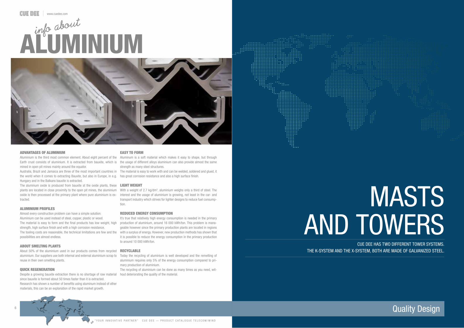
THE MODULAR K-SYSTEMconsists of square 2 m (6,6 ft) high sections. The
side of the sections range from 600 to 1050 mm
(23,6 to 41,3 in). Tapered sections are used to
connect two different section sizes. To support the
mast, guy wires are used at multiple levels depen-
ding on the height of the mast.
FLEXIBILITYWe have a number of standard green field masts
of different heights designed for specific antenna
loads and wind speeds. If none of our standard
masts suit your needs the masts can of course be
built according to your specifications. Just let us
know what you are looking for and we will design
a mast to suit your needs! There is no need for an
GUYED K-MAST SYSTEM
external ladder since the masts are climbable on
the inside and/or outside. The mast is possible to
assemble by using gin pole, crane or helicopter.
QUALITYThe mast sections are made of galvanized steel
components. This gives the system excellent
cor¬rosion resistance and a long life. All sections
are an all welded design. All masts are CE-marked
and manufactured according to EN-1090.
ACCESSORIESClimbing barriers, lightning rods, booms, top spi-
res, fall arrest system, obstruction lights, brackets,
etc. are available on request.
PRODUCT NO: 1581 / 4933 / 1577 / 5343 / 5342
FUNCTION DESCRIPTION: The modular standard K-system consists of square modules, ranging from 600 mm (23,6 in) sides to 1050 mm (41,5 in) sides, that can be combined into guyed masts of desired height. Tapered sections creates a smooth transition between different sizes of straight modules. All modules, straight and tapered, are 2 meters high.
PRODUCT NAME: K600 K600 STRONG K900 K1050 K1050 STRONGPROD. NO: 1581 4933 1577 5343 5342DRAWING NO: CD 431100 CD 431170 CD 441150 CD 455030 CD455020
MECHANICAL DATA:
SECTION SIDE: 600 mm (23,6 in) 600 mm (23,6 in) 900 mm (29,5 in) 1050 mm (41,4 in) 1050 mm (41,4 in)
SECTION HEIGHT: 2000 mm (78,7 in) 2000 mm (78,7 in) 2000 mm (78,7 in) 2000 mm (78,7 in) 2000 mm (78,7 in)
FRAME LEG DIAMETER: Ø25 mm (0,98 in) Ø30 mm (1,18 in) Ø35 mm (1,37 in) Ø50 mm (1,94 in) Ø60 mm (2,36 in)
WEIGHT/SECTION: 70 kg (154 lb) 75,4 kg (166 lb) 140 kg (309 lb) 300 kg (661 lb) 312 kg (688 lb))
ORDER AND TECHNICAL INFORMATION
NOTE! Please contact our sales or design department for configuration and optimizing of your K-mast system.
GUY FRAMES
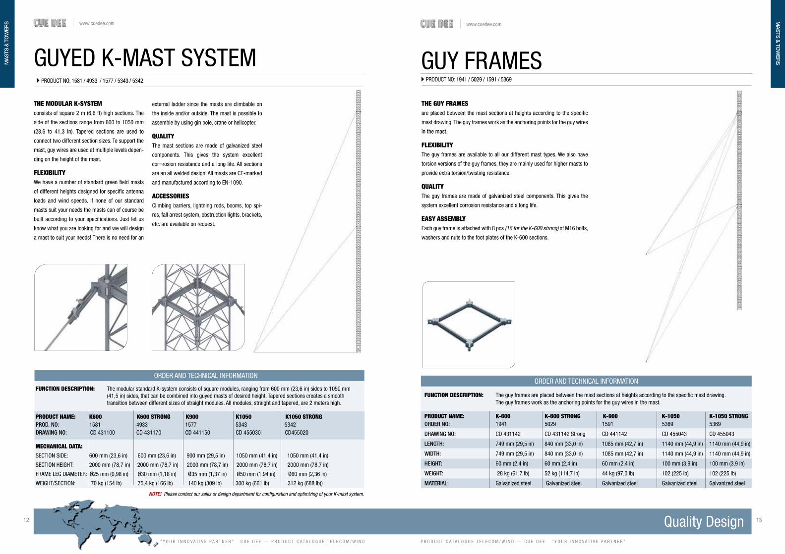
THE GUY FRAMESare placed between the mast sections at heights according to the specific
mast drawing. The guy frames work as the anchoring points for the guy wires
in the mast.
FLEXIBILITYThe guy frames are available to all our different mast types. We also have
torsion versions of the guy frames, they are mainly used for higher masts to
provide extra torsion/twisting resistance.
QUALITYThe guy frames are made of galvanized steel components. This gives the
system excellent corrosion resistance and a long life.
EASY ASSEMBLYEach guy frame is attached with 8 pcs (16 for the K-600 strong) of M16 bolts,
washers and nuts to the foot plates of the K-600 sections.
ORDER AND TECHNICAL INFORMATION
FUNCTION DESCRIPTION: The guy frames are placed between the mast sections at heights according to the specific mast drawing. The guy frames work as the anchoring points for the guy wires in the mast.
PRODUCT NAME: K-600 K-600 STRONG K-900 K-1050 K-1050 STRONGORDER NO: 1941 5029 1591 5369 5369
DRAWING NO: CD 431142 CD 431142 Strong CD 441142 CD 455043 CD 455043
LENGTH: 749 mm (29,5 in) 840 mm (33,0 in) 1085 mm (42,7 in) 1140 mm (44,9 in) 1140 mm (44,9 in)
WIDTH: 749 mm (29,5 in) 840 mm (33,0 in) 1085 mm (42,7 in) 1140 mm (44,9 in) 1140 mm (44,9 in)
HEIGHT: 60 mm (2,4 in) 60 mm (2,4 in) 60 mm (2,4 in) 100 mm (3,9 in) 100 mm (3,9 in)
WEIGHT: 28 kg (61,7 lb) 52 kg (114,7 lb) 44 kg (97,0 lb) 102 (225 lb) 102 (225 lb)
MATERIAL: Galvanized steel Galvanized steel Galvanized steel Galvanized steel Galvanized steel
PRODUCT NO: 1941 / 5029 / 1591 / 5369
MA
STS
& T
OW
ERS
MA
STS
& TO
WER
S

www.cuedee.com
” Y O U R I N N O V A T I V E P A R T N E R ” C U E D E E — P R O D U C T C A T A L O G U E T E L E C O M / W I N D
14 15
P R O D U C T C A T A L O G U E T E L E C O M / W I N D — C U E D E E ” Y O U R I N N O V A T I V E P A R T N E R ”
www.cuedee.com
GUY WIRES
ORDER AND TECHNICAL INFORMATION
FUNCTION DESCRIPTION: Guy wires are needed to give the mast rigidity and torsion resistance. Different guy wire dimensions are available depending on mast height, location and load.
ORDER NO: STRANDS: Ø mm: WEIGHT/m: MIN BREAKING LOAD:
52 mm² (2,0 in) 1758 7 9,2 mm (0,36 in) 410 grams (0,90 lb) 68kN
68 mm² (2,7 in) 1757 7 10,6 mm (0,41 in) 535 grams (1,17 lb) 89kN
89 mm² (2,0 in) 4915 7 12,1mm (0,47 in) 698 grams (1,53 lb) 116kN
105 mm² (4,1 in) 1759 7 13,1mm (0,51in) 821 grams (1,80 lb) 136kN
135 mm² (5,3 in) 5372 19 15 mm (0,59 in) 1060 grams (2,33 lb) 175kN
142 mm² (5,6 in) 5163 19 15,4 mm (0,60 in) 1120 grams (2,46 lb) 184kN
185 mm² (7,3 in) 5373 19 17,6 mm (0,69 in) 1470 grams (3,24 lb) 241kN
THE GUY WIRESare available in many different dimensions depending on mast height and
load. We always supply you with the correct guy wires to your mast.
FLEXIBILITYThe guy wires are available in 7 or 19 strand versions. Thicker guy wires can
be hard to work with if you have fewer strands as they become very stiff, it
might then be advantageous to use the 19 strand version.
QUALITYThe guy wires are made of galvanized steel. This gives the system excellent
corrosion resistance and a long life. The guy wires are usually shipped to the
mast site uncut on wire drums. The guy wires are then measured and cut at
site to ensure correct length depending on terrain variations. 10% extra wire
is always included in the mast delivery.
EASY ASSEMBLYEach guy wire is attached to the mast and to the anchoring point in the
ground with a slack puller.
PRODUCT NO: 1758 / 1757 / 4915 / 1759 / 5372 / 5163 / 5373
FOUNDATIONSAND GUY ANCHORS
MAST FOUNDATIONS FOR BOTH ROCK AND SOIL CONDITIONS.WE CAN ALSO PROVIDE YOU WITH DIFFERENT TYPES OF GUY ANCHORS.
MA
STS
& T
OW
ERS

www.cuedee.com
” Y O U R I N N O V A T I V E P A R T N E R ” C U E D E E — P R O D U C T C A T A L O G U E T E L E C O M / W I N D
16 17
P R O D U C T C A T A L O G U E T E L E C O M / W I N D — C U E D E E ” Y O U R I N N O V A T I V E P A R T N E R ”
www.cuedee.com
K-600 MAST FOUNDATIONPRODUCT NO: 3143
K-600 STRONG MAST FOUNDATIONPRODUCT NO: 5521
K-900 MAST FOUNDATIONPRODUCT NO: 3142
FOUNDATIONS (SOIL)WE SUPPLY TAILOR MADE MAST FOUNDATIONS TO ALL OUR MASTS
K-600 CONCRETE MAST FOUNDATIONis a concrete slab 1700 x 1700 x 400 mm (67 x 67 x 15,7 in)used when installing the K-600 mast on soil.
K-600 STRONG CONCRETE MAST FOUNDATIONConsists of two concrete slabs 2200 x 2200 x 250 mm (87 x 87 x 9,9 in) and1700 x 1700 x 400 mm (67 x 67 x 15,7 in) it is used when installing the K-600 Strong mast on soil.
K-900 MAST FOUNDATIONis a concrete slab 1700 x 1700 x 400 mm (67 x 67 x 15,7 in) used when installing the K-900 mast on soil.
ORDER AND TECHNICAL INFORMATION
DRAWING NO: FSK600-6021 KIT
PACKAGE DIMENSIONS: LENGTH: WIDTH: HEIGHT: WEIGHT: 1,7 m (67 in) 1,7 m (67 in) 400 mm (15,7 in) 2700 kg (5952 lb)
ORDER AND TECHNICAL INFORMATION
DRAWING NO: FSK600-6033
PACKAGE DIMENSIONS: LENGTH: WIDTH: HEIGHT: WEIGHT: 2,2 m (87 in) 2,2 m (87 in) 650 mm (25,6 in) 5700 kg (2700 x 2) (12566 lb)
ORDER AND TECHNICAL INFORMATION
DRAWING NO: FSK900-6010
PACKAGE DIMENSIONS: LENGTH: WIDTH: HEIGHT: WEIGHT: 1,7 m (67 in) 1,7 m (67 in) 400 mm (15,7 in) 2700 kg (5952 lb)
K-600/K-600 STRONG MAST BASEPRODUCT NO: 5162
K-900 MAST BASEPRODUCT NO: 3013
ORDER AND TECHNICAL INFORMATION
DRAWING NO: CD 431153-300
PACKAGE DIMENSIONS: LENGTH: WIDTH: HEIGHT: WEIGHT: 883 mm (34,8 in) 883 mm (34,8 in) 140 mm (5,5 in) 59 kg (130 lb)
ORDER AND TECHNICAL INFORMATION
DRAWING NO: CD 441156
PACKAGE DIMENSIONS: LENGTH: WIDTH: HEIGHT: WEIGHT: 1167 mm (46 in) 1167 mm (46 in) 195 mm (7,7 in) 111 kg (245 lb)
MAST BASE (ROCK)
K-600/K-600 STRONG MAST BASEis a steel cross 883 x 883 mm (34,8 x 34,8 in) used when installing the K-600/K-600 strong mast on rock.
K-900 MASTBASEis a steel cross 1167 x 1167 mm (46 x 46 in) used when installing the K-900 mast on rock.
K-600/K-600 STRONG AND K-900 STEEL MAST BASEare steel mast bases used when installing our K-masts on bed rock.
FLEXIBILITYThe foundation is delivered complete with threaded rods, washers and nuts.
QUALITYThe steel mast base is made out of a HEB 100 steel beam for maximum
strength and durability. We have also added extra reinforcement plates to in-
crease the strength even more. The threaded rods, nuts and washers are all
galvanized for maximum corrosion resistance. A minimum or maintenance is
required thanks to the corrosion resistance of the mast base.
FOU
ND
ATIO
NS
& G
UY
AN
CH
OR
SFO
UN
DATIO
NS
& G
UY
AN
CH
OR
S

www.cuedee.com
” Y O U R I N N O V A T I V E P A R T N E R ” C U E D E E — P R O D U C T C A T A L O G U E T E L E C O M / W I N D
18 19
P R O D U C T C A T A L O G U E T E L E C O M / W I N D — C U E D E E ” Y O U R I N N O V A T I V E P A R T N E R ”
www.cuedee.com
PRODUCT NO: 5544
GUY DISCS
GUY DISC
ORDER AND TECHNICAL INFORMATION
DRAWING NO: GPS50-1010
FUNCTION DESCRIPTION: The guy disc is used as an anchor point for a single guy wire when installing the mast on soil. The guy disc is made of galvanized steel.
PACKAGE DIMENSIONS: LENGTH: DISC SIZE: MAX GUY WIRE AREA: WEIGHT: 2200 mm (86,5 in) 750 x 750 mm (29,5 x 29,5 in) 68 mm² (0,10 sq in) 76 kg (168 lb)
GUY DISC SQUAREPRODUCT NO: 4738
GUY DISCSare used as anchors for single guy wires, they are used when in-
stalling a mast on soil. They are available in many different versions
depending on guy wire dimension. We always supply you with the
correct guy disc for your Cue Dee mast. The guy discs are light weight
and therefore easy to transport to remote sites.
FLEXIBILITYThe guy discs are available from Ø620 mm (24,5 in) up to the square
disc 750 x 750 mm. (29,5 x 29,5 in)
ORDER AND TECHNICAL INFORMATION
FUNCTION DESCRIPTION: The guy disc is used as an anchor point for a single guy wire when installing the mast on soil. The guy disc is made of galvanized steel.
PACKAGE DIMENSIONS: LENGTH: DIAMETER: MAX GUY WIRE AREA: WEIGHT: 2200 mm (86,5 in) 620 mm (24,5 in) 68 mm² (0,10 sq in) 17 kg (37,5 lb)
QUALITYThe guy discs are made of galvanized steel. This gives the system excellent
corrosion resistance and a long life.
EASY ASSEMBLYThe guy discs are light weight and easy to handle manually. Each guy disc is
attached with a slack puller to the guy wire.
GUY FOUNDATIONS
ORDER AND TECHNICAL INFORMATION
DRAWING NO: GP170-2011
FUNCTION DESCRIPTION: The guy foundation is used when the mast is installed on soil. It is possible to attach 1-6 guy wires to the guy foundation as long as the total guy force does not exceed 170kN.
MECHANICAL DATA: MAXIMUM GUY FORCE: WEIGHT: 170 kN 1230 kg (2712 lb)
PACKAGE DIMENSIONS: LENGTH: WIDTH: HEIGHT: WEIGHT: 2200 mm (86,5 in) 1400 mm (55 in) 220 mm (8,7 in) 1230 kg (2712 lb)
PRODUCT NO: 5905
THE GUY FOUNDATIONSare used as anchors for multiple guy wires, they are used when installing a
mast on soil. We always supply you with the correct guy foundation for your
Cue Dee mast.
FLEXIBILITYIt is possible to fit anywhere from 1 to 6 guy wires to the same guy founda-
tion depending on guy wire dimension.
QUALITYThe guy foundations are made of reinforced concrete and galvanized steel.
This gives the system excellent corrosion resistance and a long life.
EASY ASSEMBLYThe guy foundation comes complete with extension rods to connect to the
slack puller and guy wire.
FOU
ND
ATIO
NS
& G
UY
AN
CH
OR
SFO
UN
DATIO
NS
& G
UY
AN
CH
OR
S

www.cuedee.com
” Y O U R I N N O V A T I V E P A R T N E R ” C U E D E E — P R O D U C T C A T A L O G U E T E L E C O M / W I N D
20 21
P R O D U C T C A T A L O G U E T E L E C O M / W I N D — C U E D E E ” Y O U R I N N O V A T I V E P A R T N E R ”
www.cuedee.com
THE SLEEPER GUY ANCHOR
ORDER AND TECHNICAL INFORMATION
PROD. NO: 6907
FUNCTION DESCRIPTION: The Sleepers guy anchor is used when you have soil conditions on site. It has a higher capacity then the guy disc (5544) but is no quite as strong as the concreate foundation (5905)
MECHANICAL DATA: MAXIMUM GUY FORCE: SLIPER WEIGHT: 99 kN 70 kg (154 lbs)
PACKAGE DIMENSIONS: LENGTH: WIDTH: HEIGHT: WEIGHT: 2600 mm (86,5 in) 210 mm (55 in) 200 mm (7,9 in) 94 kg (207 lbs)
PRODUCT NO: 6907
THE SLEEPERS ANCHORIs used as a guy anchor when you have soil conditions on site. It has a higher
capacity then the guy disc (5544) but is no quite as strong as the concreate
foundation (5905)
FLEXIBILITYDepending on installation depth different guywires can be used up to a maxi-
mum of 142mm². When using the adapter plate (7434) multiple guy wires
can be attached to the same guy anchor as long as the maximum guy force
is not exceeded (99 kN).
QUALITYThe sleeper is made of slow growing pine wood and is impregnated with
salt to achieve the longest lifespan possible and to be environment friendly.
EASY ASSEMBLYSince the sleepers are made of wood they are light and easy to handle and
transport.
Optional 7434MUTLIPLE GUY ADAPTER PLATE
ROCK ANCHORSAre used as anchors for single guy wires, they are used when installing a mast on bedrockRock anchors are available in many different dimensions depending on guy wire and bedrock quality.
ORDER AND TECHNICAL INFORMATION
MECHANICAL DATA: Forged steel. Fulfills SS-EN 50423 MAX GUY WIRE AREA: WEIGHT: 52 mm² (0,08 sq in) 2,7 kg (6 lb)
PACKAGE DIMENSIONS: LENGTH: DIAMETER: WEIGHT: 500 mm (19,7 in) 25 mm (1,0 in) 2,7 kg (6 lb)
ORDER AND TECHNICAL INFORMATION
MECHANICAL DATA: Forged steel. Fulfills SS-EN 50423 MAX GUY WIRE AREA: WEIGHT: 142 mm² (0,22 sq in) 6,7 kg (14,8 lb)
PACKAGE DIMENSIONS: LENGTH: DIAMETER: WEIGHT: 1500 mm (59 in) 25 mm (1,0 in) 6,7 kg (14,8 lb)
ORDER AND TECHNICAL INFORMATION
MECHANICAL DATA: Forged steel. Fulfills SS-EN 50423 MAX GUY WIRE AREA: WEIGHT: 185 mm² (0,29 sq in) 11,3 kg (25 lb)
PACKAGE DIMENSIONS: LENGTH: DIAMETER: WEIGHT: 1500 mm (59 in) 32 mm (1,3 in) 11,3 kg (25 lb)
ROCK ANCHOR/WEDGE 500 mm PRODUCT NO: 1811
ROCK ANCHOR Ø25 L1500 mmPRODUCT NO: 3018
ROCK ANCHOR Ø32 L1500 mmPRODUCT NO: 4186
FOU
ND
ATIO
NS
& G
UY
AN
CH
OR
SFO
UN
DATIO
NS
& G
UY
AN
CH
OR
S

www.cuedee.com
” Y O U R I N N O V A T I V E P A R T N E R ” C U E D E E — P R O D U C T C A T A L O G U E T E L E C O M / W I N D
22 23
P R O D U C T C A T A L O G U E T E L E C O M / W I N D — C U E D E E ” Y O U R I N N O V A T I V E P A R T N E R ”
www.cuedee.com
ROCK GUY FOUNDATIONare used as anchors for multiple guy wires, they are used when installing a
mast on bedrock. We always supply you with the correct rock anchor for your
Cue Dee mast. Including 2 pcs of 1 m (3,3 ft) threaded rods.
FLEXIBILITY It is possible to fit anywhere from 1 to 6 guy wires to the same guy founda-
tion depending on guy wire dimension.
QUALITY The guy foundations are made of galvanized steel. This gives the system
excellent corrosion resistance and a long life.
EASY ASSEMBLYDrill 2 holes Ø50 mm (2,0 in) wide and approximately 1000 mm (39 in) deep,
fill the holes with grout and insert the threaded rods. Extension rods are
available if the bedrock should be below ground level.
ORDER AND TECHNICAL INFORMATION
DRAWING NO: CD 30505023
FUNCTION DESCRIPTION: The rock guy foundation is used when the mast is installed on bedrock. It is possible to attach 1-6 guy wires to the rock guy foundation as long as the total guy force does not exceed 350 kN if the bedrock is of good quality.
MECHANICAL DATA: MAXIMUM GUY FORCE: WEIGHT: 350 kN 24 kg (53 lb)
PACKAGE DIMENSIONS: LENGTH: WIDTH: HEIGHT: WEIGHT: 270 mm (10,5 in) 160 mm (6,3 in) 1000 mm (39 in) 24 kg (53 lb)
ROCK GUY FOUNDATIONPRODUCT NO: 4081
WINDACCESSORIES
WE CAN SUPPLY YOU WITH VARIOUS ACCESSORIES FOR YOUR WIND MEASUREMENT MAST SUCH AS CLIMBING BARRIERS AND LIGHTNING RODS.
FOU
ND
ATIO
NS
& G
UY
AN
CH
OR
S

www.cuedee.com
” Y O U R I N N O V A T I V E P A R T N E R ” C U E D E E — P R O D U C T C A T A L O G U E T E L E C O M / W I N D
24 25
P R O D U C T C A T A L O G U E T E L E C O M / W I N D — C U E D E E ” Y O U R I N N O V A T I V E P A R T N E R ”
www.cuedee.com
WIND MEASUREMENT BOOM3.7m (TILTABLE)
ORDER AND TECHNICAL INFORMATION
THE TILTABLE BOOMis designed for meteorological applications to study air quality and wind
profiles. Frame leg clamping range Ø25-90 mm (1,0-3,5 in). Measurement
instrumentation is clamped at the end of the boom, clamping range Ø25-
Ø40 mm (1,0-1,6 in). For easy access to the measurement instrument it is
possible to tilt the boom into a vertical position. Designed according to IEC
61400-12-1.
FLEXIBILITYThe boom can be tilted up or down to gain access to the measurement
equipment. Optional support wire (5194) or support legs (5411) to add extra
rigidity.
QUALITYAll components are made of anodized aluminium and stainless steel which
gives the tiltable boom excellent corrosion resistance and a long life.
EASY ASSEMBLYThe choice of materials makes the product very light which makes handling
and installation very easy.
DRAWING NO: CD 990314
FUNCTION DESCRIPTION: The tiltable boom is designed for meteorological applications to study air quality and wind profiles. Frame leg clamping range Ø25-90 mm (1,0-3,5 in). Measurement instrumentation is clamped at the end of the boom, clamping range Ø25-Ø40 mm. (1,0-1,6 in)
MECHANICAL DATA: PROTRUDING FROM MAST: WIND AREA: CLAMPING RANGE: WEIGHT: 3,7 m (12,1 ft) 0,4 m² (4,3 sq ft) Ø25-90 mm (1,0-3,5 in) 18 kg (39,7 lb)
PRODUCT NO: 4329
DRAWING NO: CD 990282
FUNCTION DESCRIPTION: The Wind measurement Boom 5,1m (16,7 ft) is designed for meteorological applications to study air quality and wind profiles. Frame leg clamping range Ø25-120 mm. (1,0-4,7 in). Measurement instrumentation is clamped at the end of the boom, clamping range depends on choice of clamp. Clamp needs to be ordered separately (order no 1818, 1837, 5431 depending on clamp size).
MECHANICAL DATA: PROTRUDING FROM MAST: WIND AREA: CLAMPING RANGE: WEIGHT: 5,1 m (16,7 ft) 1,1 m² (11,8 sq ft) Ø25-120 mm (1,0-4,7 in) 40,3 kg (88,8 lb)
THE WIND MEASUREMENT BOOM 5,1Mis designed for meteorological applications to carry measurement equip-
ment. Frameleg clamping range Ø25-120 mm (1,0-4,7 in). Measurement
instrumentation is clamped at the end of the boom, clamping range depends
on choice of clamp. Clamp needs to be ordered separately (order no 1818,
1837, 5431 depending on clamp size).
FLEXIBILITYThe wind measurement boom 5,1 m (16,7 ft) is designed to be installed on
masts and towers with a side no greater then 900 mm (35,5 in). The wind
measurement boom 5,1 m (16,7 ft) comes complete with a steel wire guy
kit for extra rigidity.
QUALITYAll components are made of anodized aluminium and stainless steel which
gives the Wind measurement boom 5,1 m (16,7 ft) excellent corrosion resis-
tance and a long life.
EASY ASSEMBLYThe choice of materials makes the product very light which makes handling
and installation very easy.
ORDER AND TECHNICAL INFORMATION
WIND MEASUREMENT BOOM5,1m
PRODUCT NO: 1923
WIN
D A
CC
ESS
OR
IES
WIN
D A
CC
ESS
OR
IES

www.cuedee.com
” Y O U R I N N O V A T I V E P A R T N E R ” C U E D E E — P R O D U C T C A T A L O G U E T E L E C O M / W I N D
26 27
P R O D U C T C A T A L O G U E T E L E C O M / W I N D — C U E D E E ” Y O U R I N N O V A T I V E P A R T N E R ”
www.cuedee.com
THE WIND MEASUREMENT BOOM 6Mis designed for meteorological applications to study air quality and wind pro-
files. Frame leg clamping range depends on choice of clamp and needs to be
ordered separetely (order no 1818, 1837, 5431). Measurement instrumenta-
tion is clamped at the end of the boom, clamping range Ø25-Ø40 mm (1,0-
1,6 in). Clamp needs to be ordered separately (order no 3072).
FLEXIBILITYThe wind measurement boom 6 m (19,7 ft) is designed to be installed on
masts and towers with a side greater then 900 mm (35,5 in).
QUALITYAll components are made of anodized aluminium and stainless steel which
gives The wind measurement boom 6 m (19,7 ft) excellent corrosion resis-
tance and a long life.
EASY ASSEMBLYThe choice of materials makes the product very light which makes handling
and installation very easy.
WIND MEASUREMENT BOOM 6m
DRAWING NO: CD 990269
FUNCTION DESCRIPTION: The Wind measurement boom 6 m (19,7 ft) is designed for meteorological applications to study air quality and wind profiles. Frame leg clamping range depends on choice of clamp and needs to be ordered separately (order no 1818, 1837, 5431). Measurement instrumentation is clamped at the end of the boom, clamping range Ø25-Ø40 mm (1,0-1,6 in). Clamp needs to be ordered separately (order no 3072).
MECHANICAL DATA: PROTRUDING FROM MAST: WIND AREA: CLAMPING RANGE: WEIGHT:
6 m (19,7 ft) 0,9 m² (9,7 sq ft) Ø25-120mm (1,0-4,7 in) 52,8 kg (116 lb)
ORDER AND TECHNICAL INFORMATION
PRODUCT NO: 2976
TOP SPIRE K-600WITH LIGHTNING ROD IEC
ORDER AND TECHNICAL INFORMATION
DRAWING NO: CD 990997
FUNCTION DESCRIPTION: The Top Spire is especially designed for meteorological applications to study air quality and wind profiles. It is meant to be used together with Cue Dee’s K-Mast system. This model is designed to comply the new coming IEC norm.
MECHANICAL DATA: HEIGTH ABOVE MAST: WIND AREA: CLAMPING RANGE: WEIGHT: 3,65 m (12 ft) 1,12 m2 Ø25-90 mm (1,0-3,5 in) 51,9 kg (114 lb)
PRODUCT NO: 7487
THE TOP SPIRE is designed for meteorological applications to study air quality and wind pro-
files. It is designed to fullfill the requirements of the coming 2016 revision of
the IEC-61400-12-1. Frame leg clamping range Ø25-90 mm (1,0-3,5 in). It
is possible to clamp measurement instrumentation at both ends of the beam,
clamping range Ø25-Ø40 mm (1,0-1,6 in). Cup height 4,9 m above the mast
top to achived the IEC 1:11 cone. Distance between anemometers 2,5 m.
FLEXIBILITY The Top spire can be installed on masts with a side width of 600 mm (23,5
in), it comes with a built in safety hook system and follows the latest IEC
standard. Top spires for other mast sizes are available on request.
QUALITY All components are made of anodized aluminum and stainless steel which
gives the Top spire excellent corrosion resistance and a long life.
EASY ASSEMBLY The choice of materials makes the product very light which makes handling
and installation very easy. The top spire should be installed diagonally in the
mast. If a manhole section is used in the bottom of the mast and as the sec-
tion below the top section, the mast can be climbed on the inside.
WIN
D A
CC
ESS
OR
IES
WIN
D A
CC
ESS
OR
IES

www.cuedee.com
” Y O U R I N N O V A T I V E P A R T N E R ” C U E D E E — P R O D U C T C A T A L O G U E T E L E C O M / W I N D
28 29
P R O D U C T C A T A L O G U E T E L E C O M / W I N D — C U E D E E ” Y O U R I N N O V A T I V E P A R T N E R ”
www.cuedee.com
TOP SPIRE K-600WITH LIGHTNING ROD
PRODUCT NO: 7021
ORDER AND TECHNICAL INFORMATION
DRAWING NO: CD 990916
FUNCTION DESCRIPTION: The top spire is designed for meteorological applications to study air quality and wind profiles. It is possible to clamp measurement instrumentation at both ends of the beam, clamping range Ø25-Ø40 mm (1,0-1,6 in). Frame leg clam- ping range Ø25-90 mm (1,0-3,5 in).
MECHANICAL DATA: HEIGTH ABOVE MAST: WIND AREA: CLAMPING RANGE: WEIGHT: 3,16 m (10,4 ft) 1,0 m2 Ø25-90 mm (1,0-3,5 in) 44,1 kg (97 lb)
THE TOP SPIRE is designed for meteorological applications to study air quality and wind pro-
files. It is designed to fullfill the requirements of the coming 2016 revision of
the IEC-61400-12-1. Frame leg clamping range Ø25-90 mm (1,0-3,5 in). It
is possible to clamp measurement instrumentation at both ends of the beam,
clamping range Ø25-Ø40 mm (1,0-1,6 in). A lightning rod is placed in the
center reaching 2,47 meters (8,1 ft) above the horizontal boom to protect the
instruments from lightning strikes.
FLEXIBILITY The Top spire can be installed on masts with a side width of 600 mm (23,5
in), it comes with a built in safety hook system and follows the latest IEC
standard. Top spires for other mast sizes are available on request.
QUALITY All components are made of anodized aluminum and stainless steel which
gives the Top spire excellent corrosion resistance and a long life.
EASY ASSEMBLY The choice of materials makes the product very light which makes handling
and installation very easy. The top spire should be installed diagonally in the
mast. If a manhole section is used in the bottom of the mast and as the sec-
tion below the top section, the mast can be climbed on the inside.
THE 2 WAY BOOM SUPPORTis designed to add extra rigidity to our 3.7m tiltable wind measurement boom
(4329). We recommend using the boom support when there is risk a of
heavy icing.
FLEXIBILITYThe 2 way boom support is designed to be installed on the K-600 mast, to
easily level the boom anenometer the vertical support strutt is equipped with
a turnbuckle.
QUALITYAll components are made of anodized aluminium and stainless steel which
gives the 2 way boom support excellent corrosion resistance and a long life.
EASY ASSEMBLYThe choice of materials makes the product very light which makes handling
and installation easy.
2 WAY BOOM SUPPORTPRODUCT NO: 5411
ORDER AND TECHNICAL INFORMATION
DRAWING NO: CD 990555
FUNCTION DESCRIPTION: The 2 way boom support consists of 2 aluminium tubes that are clamped to the wind boom and mast. The support adds extra rigidity and bending resistance to the boom.
MECHANICAL DATA: HEIGHT: WIND AREA: CLAMPING RANGE: WEIGHT: 2,5 m (8,2 ft) 0,27 m² (2,9 sq ft) Ø25-60 mm (1,0-2,4 in) 8,9 kg (19,6 lb)
WIN
D A
CC
ESS
OR
IES
WIN
D A
CC
ESS
OR
IES
www.cuedee.com
” Y O U R I N N O V A T I V E P A R T N E R ” C U E D E E — P R O D U C T C A T A L O G U E T E L E C O M / W I N D
30 31
P R O D U C T C A T A L O G U E T E L E C O M / W I N D — C U E D E E ” Y O U R I N N O V A T I V E P A R T N E R ”
www.cuedee.com
BOOM WIRE SUPPORTPRODUCT NO: 5194
ORDER AND TECHNICAL INFORMATION
DRAWING NO: CD 990314-90
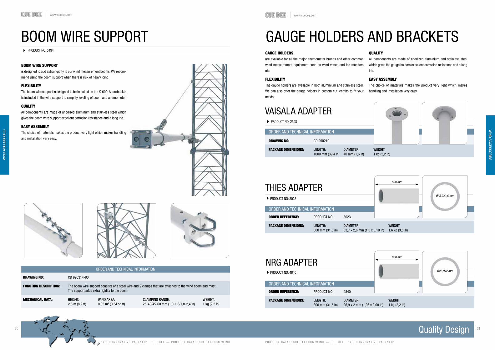
FUNCTION DESCRIPTION: The boom wire support consists of a steel wire and 2 clamps that are attached to the wind boom and mast. The support adds extra rigidity to the boom.
MECHANICAL DATA: HEIGHT: WIND AREA: CLAMPING RANGE: WEIGHT: 2,5 m (8,2 ft) 0,05 m² (0,54 sq ft) 25-40/45-60 mm (1,0-1,6/1,8-2,4 in) 1 kg (2,2 lb)
BOOM WIRE SUPPORTis designed to add extra rigidity to our wind measurement booms. We recom-
mend using the boom support when there is risk of heavy icing.
FLEXIBILITYThe boom wire support is designed to be installed on the K-600. A turnbuckle
is included in the wire support to simplify leveling of boom and anemometer.
QUALITYAll components are made of anodized aluminum and stainless steel which
gives the boom wire support excellent corrosion resistance and a long life.
EASY ASSEMBLYThe choice of materials makes the product very light which makes handling
and installation very easy.
VAISALA ADAPTERPRODUCT NO: 2598
ORDER AND TECHNICAL INFORMATION
DRAWING NO: CD 990219
PACKAGE DIMENSIONS: LENGTH: DIAMETER : WEIGHT: 1000 mm (39,4 in) 40 mm (1,6 in) 1 kg (2,2 lb)
PRODUCT NO: 3023
PRODUCT NO: 4840
THIES ADAPTER
NRG ADAPTER
GAUGE HOLDERS AND BRACKETSGAUGE HOLDERSare available for all the major anemometer brands and other common
wind measurement equipment such as wind vanes and ice monitors
etc.
FLEXIBILITYThe gauge holders are available in both aluminium and stainless steel.
We can also offer the gauge holders in custom cut lengths to fit your
needs.
ORDER AND TECHNICAL INFORMATION
ORDER REFERENCE: PRODUCT NO: 3023
PACKAGE DIMENSIONS: LENGTH: DIAMETER : WEIGHT: 800 mm (31,5 in) 33,7 x 2,6 mm (1,3 x 0,10 in) 1,6 kg (3,5 lb)
ORDER AND TECHNICAL INFORMATION
ORDER REFERENCE: PRODUCT NO: 4840
PACKAGE DIMENSIONS: LENGTH: DIAMETER : WEIGHT: 800 mm (31,5 in) 26,9 x 2 mm (1,06 x 0,08 in) 1 kg (2,2 lb)
QUALITYAll components are made of anodized aluminium and stainless steel
which gives the gauge holders excellent corrosion resistance and a long
life.
EASY ASSEMBLYThe choice of materials makes the product very light which makes
handling and installation very easy.
800 mm
Ø33,7x2,6 mm
800 mm
Ø26,9x2 mm
WIN
D A
CC
ESS
OR
IES
WIN
D A
CC
ESS
OR
IES

www.cuedee.com
” Y O U R I N N O V A T I V E P A R T N E R ” C U E D E E — P R O D U C T C A T A L O G U E T E L E C O M / W I N D
32 33
P R O D U C T C A T A L O G U E T E L E C O M / W I N D — C U E D E E ” Y O U R I N N O V A T I V E P A R T N E R ”
www.cuedee.com
ORDER AND TECHNICAL INFORMATION
DRAWING NO: CD 431135
FUNCTION DESCRIPTION: The Climbing barrier is a galvanized steel obstacle consisting of four sides and one center piece. It is designed to keep unauthorized personnel from gaining access to the mast.
MECHANICAL DATA: PROTRUDING FROM MAST: CLAMPING RANGE: WEIGHT: 485 mm (19 in) Ø25-40 mm (1,0-1,6 in) 23 kg (51 lb)
PACKAGE DIMENSIONS: LENGTH: WIDTH: HEIGHT: WEIGHT: 1245 mm (49 in) 500 mm (19,7 in) 250 mm (10 in) 23 kg (51 lb)
THE CLIMBING BARRIERis designed to prevent unauthorized personnel from gaining access to the
mast and causing damage to the installed equipment or from injuring them-
selves.
FLEXIBILITYThe Climbing Barrier is available for the K-600 and K-900 masts. Barriers for
other mast sizes are available on request.
QUALITYAll components are made of galvanized and stainless steel which gives the
Climbing Barrier high strength and excellent corrosion resistance.
EASY ASSEMBLYThe gate in the barrier is designed for fast and easy assembly/disassembly
for full access to the mast.
CLIMBING BARRIER K-600PRODUCT NO: 1583
CLIMBING BARRIER K-900PRODUCT NO: 1709
ORDER AND TECHNICAL INFORMATION
DRAWING NO: CD 441135
FUNCTION DESCRIPTION: The Climbing barrier is a galvanized steel obstacle consisting of four sides and one center piece. It is designed to keep unauthorized personnel from gaining access to the mast.
MECHANICAL DATA: PROTRUDING FROM MAST: CLAMPING RANGE: WEIGHT: 485 mm (19 in) Ø25-40 mm (1,0-1,6 in) 30,4 kg (67 lb)
PACKAGE DIMENSIONS: LENGTH: WIDTH: HEIGHT: WEIGHT: 1497 mm (59 in) 798 mm (31,5 in) 250 mm (10 in) 30,4 kg (67 lb)
THE CLIMBING BARRIERis designed to prevent unauthorized personnel from gaining access to the
mast and causing damage to the installed equipment or from injuring them-
selves.
FLEXIBILITYThe Climbing Barrier is available for the K-600 and K-900 masts. Barriers for
other mast sizes are available on request.
QUALITYAll components are made of galvanized and stainless steel which gives the
Climbing Barrier high strength and excellent corrosion resistance.
EASY ASSEMBLYThe gate in the barrier is designed for fast and easy assembly/disassembly
for full access to the mast.
WIN
D A
CC
ESS
OR
IES
WIN
D A
CC
ESS
OR
IES

www.cuedee.com
” Y O U R I N N O V A T I V E P A R T N E R ” C U E D E E — P R O D U C T C A T A L O G U E T E L E C O M / W I N D
34 35
P R O D U C T C A T A L O G U E T E L E C O M / W I N D — C U E D E E ” Y O U R I N N O V A T I V E P A R T N E R ”
www.cuedee.com
LIGHTNING RODS
ORDER AND TECHNICAL INFORMATION
ORDER REFERENCE: PRODUCT NO: K-600 1574 PRODUCT NO: K-900 1574 PRODUCT NO: ALMA 1574 DRAWING NO: CD 339000 DRAWING NO: CD 339000 DRAWING NO: CD 990293
FUNCTION DESCRIPTION: Lightning rods are installed to protect your instruments from lightning strikes. They should be installed at the very top of the mast, bolted to the foot plate of the top mast section with 2 bolts either clamped to the frame leg or clamped to the foot plate of the section.
MECHANICAL DATA: LENGTH: WIND AREA: WEIGHT: 2 m (6,5 ft) 0,06 m² (0,65 sq ft) 2 kg (4,5 in)
LIGHTNING RODSare designed to protect your instruments from lightning strikes.
FLEXIBILITYLightning rods are available for the K-600 and K-900 masts as well as the
Alma mast. The lightning rods are available in heights from 2-4,5 m (6,5-
14,8 ft). However our standard lightning rod is 2 m (6,5 ft), other heights are
available upon request.
QUALITYAll components are made of galvanized and stainless steel which gives the
lightning rods excellent corrosion resistance.
EASY ASSEMBLYThe lightning rods should be installed at the very top of the mast, either
clamped to the frame leg or clamped to the foot plate of the section.
PRODUCT NO: 1574
WIND TURBINE SUPPORTSare used to attach small wind turbines to the mast, with a solution like this
you always have access to electricity on the site.
FLEXIBILITYWind turbine supports are available for the K-600 and K-900 masts.: Turbine
adapter tube Ø60 mm (2,4 in). Turbine supports for larger turbines and other
adapter diameters are available upon request.
QUALITYAll components are made of aluminium and stainless steel which gives the
wind turbine supports excellent corrosion resistance.
EASY ASSEMBLYThe wind turbine supports are clamped to the frame legs of the mast using
our universal clamp for a fast and easy assembly.
WIND TURBINE SUPPORTS
WIND TURBINE HOLDER K-600PRODUCT NO: 3056
WIND TURBINE HOLDER K-900PRODUCT NO: 3065
ORDER AND TECHNICAL INFORMATION
DRAWING NO: CD 990642
FUNCTION DESCRIPTION: A support designed to hold a small wind turbine.
MECHANICAL DATA: LENGTH: WIND AREA: WEIGHT: 2,5 m (8,2 ft) 0,4 m² (4,3 sq in) 19,7 kg (43,5 lb)
PACKAGE DIMENSIONS: LENGTH: WIDTH: HEIGHT: WEIGHT: Package 1 2500 mm (8,2 ft) 75 mm (3,0 in) 135 mm (5,5 in) 13 kg (28,7 lb)Package 2 290 mm (11,5 in) 95 mm (3,8 in) 95 mm (3,8 in) 6,7 kg (14,8 lb)
ORDER AND TECHNICAL INFORMATION
DRAWING NO: CD 990492
FUNCTION DESCRIPTION: A support designed to hold a small wind turbine.
MECHANICAL DATA: LENGTH: WIND AREA: WEIGHT: 2 m (79 in) 0,34 m² (3,7 sq ft) 17,4 kg (38,5 lb)
PACKAGE DIMENSIONS: LENGTH: WIDTH: HEIGHT: WEIGHT: Package 1 2000 mm (79 in) 75 mm (3,0 in) 135 mm (5,5 in) 10,7 kg (23,6 lb)Package 2 290 mm (11,5 in) 95 mm (3,7 in) 95 mm (3,7 in) 6,7 kg (14,8 lb)
WIN
D A
CC
ESS
OR
IES
WIN
D A
CC
ESS
OR
IES

www.cuedee.com
” Y O U R I N N O V A T I V E P A R T N E R ” C U E D E E — P R O D U C T C A T A L O G U E T E L E C O M / W I N D
36 37
P R O D U C T C A T A L O G U E T E L E C O M / W I N D — C U E D E E ” Y O U R I N N O V A T I V E P A R T N E R ”
www.cuedee.com
SLACK PULLERS
ORDER AND TECHNICAL INFORMATION
SLACK PULLERSlack pullers are used to attach the guy wires to the mast and to the guy
foundation.
FLEXIBILITY Slack pullers are available in many different versions and sizes. We can pro-
vide you with slack pullers suitable from 25 mm² (0,04 sq in) up to 284 mm²
(0,44 sq in) guy wires.
QUALITY The slack puller wedge and wedge housing are made of nodular cast iron,
the U-bolt is made of steel. All parts are galvanized, this gives them excellent
corrosion resistance and a long life.
EASY ASSEMBLYFollow the steps in the installation manual.
FUNCTION DESCRIPTION: Slack pullers are used to fasten the guy wires to the mast and guy foundations. Different slack puller sizes are available depending on guy wire dimension.
MECHANICAL DATA: PROD NO: SIZE: FITS GUY WIRES: LENGTH: REC MAX GUY FORCE:
1471 M16 25-68 mm² (0,04-0,10 sq in) * 300 mm (12,0 in) 47 kN
4276 M16 25-68 mm² (0,04-0,10 sq in) * 800 mm (31,5 in) 47 kN
1472 M20 68-105 mm² (0,10-0,16 sq in) ** 350 mm (13,8 in) 72 kN
5436 M20 68-105 mm² (0,10-0,16 sq in) ** 800 mm (31,5 in) 72 kN
2182 M24 105-142 mm² (0,16-0,22 sq in) 425 mm (16,7 in) 100 kN
5437 M24 105-142 mm² (0,16-0,22 sq in) 800 mm (31,5 in) 100 kN
5358 M27 185-284 mm² (0,29-0,44 sq in) 425 mm (16,7 in) 200 kN
PRODUCT NO: 1471 / 4276 / 1472 / 5436 / 2182 / 5437 / 5358
* Cue Dee recommend using the larger M20 Slack Puller for the 68 mm2 wire for easier installation.** Cue Dee recommend using the larger M24 Slack Puller for the 105 mm2 wire for easier installation.
GUY WIRE MARKINGPRODUCT NO: 3022
PRODUCT NO: 1980
WARNING FLAGS
ORDER AND TECHNICAL INFORMATION
ORDER REFERENCE: PRODUCT NO: 3022
FUNCTION DESCRIPTION: Guy wire markings are fitted to the guy wires to increase their visibility at ground level. The markings are plastic tubes in two colors: black and yellow. Each kit contains 8 markers (4 of each color) L=200 mm (7,9 in)
ORDER AND TECHNICAL INFORMATION
ORDER REFERENCE: PRODUCT NO: 1980
FUNCTION DESCRIPTION: The warning flags are fitted to the guy wires to increase their visibility. The warning flags are bright red in colour and 400 x 100 mm. (15,7 x 4,0 in)
WIN
D A
CC
ESS
OR
IES
WIN
D A
CC
ESS
OR
IES

www.cuedee.com
” Y O U R I N N O V A T I V E P A R T N E R ” C U E D E E — P R O D U C T C A T A L O G U E T E L E C O M / W I N D
38 39
P R O D U C T C A T A L O G U E T E L E C O M / W I N D — C U E D E E ” Y O U R I N N O V A T I V E P A R T N E R ”
www.cuedee.com
SUPPORTAND BRACKETS
CUE DEE HAS A NUMBER OF DIFFERENT SUPPORTS AND BRACKETS. TO NAME A FEW WE HAVE ANTENNA AND MICROWAVE LINK SUPPORTS, RRU SUPPORTS, WALL SUPPORTS, FLEXI SUPPORTS ETC.

www.cuedee.com
” Y O U R I N N O V A T I V E P A R T N E R ” C U E D E E — P R O D U C T C A T A L O G U E T E L E C O M / W I N D
40 41
P R O D U C T C A T A L O G U E T E L E C O M / W I N D — C U E D E E ” Y O U R I N N O V A T I V E P A R T N E R ”
www.cuedee.com
CHAIN BRACKETis a fastening system for installation of telecom equipment or other type of equipment on monopoles or round poles.
FLEXIBILITY The Chain Bracket can be installed on any pole from Ø110 mm up to Ø1070 mm. A wide range of accessory mounts are available for mounting tubes, RRU:s, filters etc. even for compensation of inclination when installing on conical monopoles.
QUALITYAll components are made of anodized aluminum and acid proof stain less steel which gives the support excellent corrosion resistance.
EASY ASSEMBLYHandling and installation is very easy because of its light weight but also thanks to the pre-assembled kit system and the facile tightening process.
CHAIN BRACKETPRODUCT NO: 7685, 7706, 7664, 7707
DRAWING NO: CD 991019
FUNCTION DESCRIPTION: The chain bracket is an innovative mounting solution for large poles, chimneys etc. with a diameter over Ø110 mm. It comes with a full range of accessories such as brackets for RRU’s, antennas, filters etc.
MECHANICAL DATALink and tensioner profiles: Aluminum, nature anodized 20μm Link plates and fasteners: Acid proof stainless steel
PERFORMANCE FOR ONE LEVEL OPERATIONAL WIND SPEED MAX SIDE WIND AREA * MAX LOAD WEIGHT ** km/h m/s mph m2 ft2 kg lb 240 67 150 0,4 4,3 330 730 210 58 130 0,5 5,5 330 730 180 50 112 0,7 7,5 330 730 150 42 93 1,0 11 330 730 120 33 75 1,5 16 330 730*) Max side wind area for each mounted equipment and for each level **) Max load weight for each level
PACKAGE DIMENSIONS LENGTH WIDTH HEIGHT WEIGHTArt.No Description mm (in) mm (in) mm (in) kg (lb)
7685 Link Set (1 link) 110 (4,3) 60 (2,4) 85 (3,3) 0,35 (0,8) 7706 Basic Set #1 (3 links) 250 (9,8) 110 (4,3) 85 (3,3) 2,0 (4,4)7664 Basic Set #2 (6 links) 400 (15,7) 100 (4,0) 85 (3,3) 3,0 (6,6)7707 Basic Set #3 (9 links) 400 (15,7) 150 (5,9) 85 (3,3) 4,0 (8,8)
ORDER AND TECHNICAL INFORMATION
CHAIN BRACKET RRU HOLDER PRODUCT NO: 7798
CHAIN BRACKET RRU HOLDER is designed for installation of one RRU unit on Cue Dee Chain Bracket. It fits Ericsson, Huawei and NSN RRU models.
FLEXIBILITY Together with the Cue Dee Chain Bracket the RRU Holder can be in stalled on any pole from Ø110 mm up to Ø1070 mm.By orienting the plates either inwards or outwards the RRU Holder can fit either Erics-son, Huawei or NSN RRU units.
Since Chain Bracket is designed with several profile elements around the pole You can easily hook on additional RRU units around the pole in the same level by just adding RRU Holders.
QUALITY All components are made of acid proof stainless steel which gives the support excel-lent corrosion resistance.
EASY ASSEMBLEY Installation is very easy thanks to the hook-on design and the cup head square neck bolts which give you a free hand when tightening the nuts.
ORDER AND TECHNICAL INFORMATION
DRAWING NO: 991087
FUNCTION DESCRIPTION: RRU Holder for installation of one Ericsson, Huawei or NSN RRU unit on Cue Dee Chain Bracket. Together with the Cue Dee Chain Bracket it can be mounted on large poles, monopoles, chimneys etc. with a diameter over Ø110mm
MECHANICAL DATA: Plates: Acid proof stainless steel Fasteners: Acid proof stainless steel
PERFORMANCE MAX WIND SPEED km/h m/s mphWith RRU unit 240 67 150
PACKAGE DIMENSIONS LENGTH WIDTH HEIGHT WEIGHT 290 mm (11,4 in) 80 mm (3,6 in) 85 mm (3,3 in) 1,5 kg (3,3 lb)
SU
PP
OR
TS &
BR
AC
KET
SS
UP
PO
RTS
& B
RA
CK
ETS

www.cuedee.com
” Y O U R I N N O V A T I V E P A R T N E R ” C U E D E E — P R O D U C T C A T A L O G U E T E L E C O M / W I N D
42 43
P R O D U C T C A T A L O G U E T E L E C O M / W I N D — C U E D E E ” Y O U R I N N O V A T I V E P A R T N E R ”
www.cuedee.com
CHAIN BRACKETSMALL CELL HOLDER
PRODUCT NO: 7689
CHAIN BRACKET SMALL CELL HOLDER is designed for installation of one NSN Small Cell unit on Cue Dee Chain Bracket together with the Small Cell Bracket.
FLEXIBILITY Together with the Cue Dee Chain Bracket the Small Cell Hol-der can be installed on any pole from Ø110 mm up to Ø1070 mm.
Since Chain Bracket is designed with several profile elements around the pole You can easily hook on additional Small Cell units around the pole in the same level by just adding Small Cell Holders.
QUALITY All components are made of acid proof stainless steel which gives the support excellent corrosion resistance.
ORDER AND TECHNICAL INFORMATION
DRAWING NO: 991075
FUNCTION DESCRIPTION: Small Cell Holder for installation of one NSN Small Cell unit on Cue Dee Chain Bracket. Together with the Cue Dee Chain Bracket it can be mounted on large poles, monopoles, chimneys etc. with a diameter over Ø110 mm.
MECHANICAL DATA: Plates: Acid proof stainless steel Fasteners: Acid proof stainless steel
PERFORMANCE MAX WIND SPEED km/h m/s mphWith RRU unit 240 67 150
PACKAGE DIMENSIONS LENGTH WIDTH HEIGHT WEIGHT 85 mm (3,4 in) 55 mm (2,2 in) 35 mm (1,4 in) 0,5 kg (1,1 lb)
ACCESSORIES P/N 7685 Chain Bracket, Link Set (1 link) 7706 Chain Bracket, Basic Set #1 (3 links) 7664 Chain Bracket, Basic Set #2 (6 links) 7707 Chain Bracket, Basic Set #3 (9 links) 7611 Small Cell Bracket
DRAWING NO: CD 991072
FUNCTION DESCRIPTION: Tube holder for Chain Bracket in 2 levels for installing 60 mm mounting tubes on any pole or monopole larger than Ø110 mm.
MECHANICAL DATAPlates: Acid proof stainless steel Fasteners: Acid proof stainless steel
PERFORMANCE OPERATIONAL WIND SPEED MAX SIDE WIND AREA MAX LOAD WEIGHT km/h m/s mph m2 ft2 kg lb 240 67 150 0,8 8,6 100 220 210 58 130 1,0 11 100 220 180 50 112 1,4 15 100 220 150 42 93 2,0 22 100 220 120 33 75 3,0 32 100 220
PACKAGE DIMENSIONS LENGTH WIDTH HEIGHT WEIGHT 250 mm (9,8 in) 110 mm (4,3 in) 85 mm (3,3 in) 2,0 kg (4,4 lb)
ORDER AND TECHNICAL INFORMATION
CHAIN BRACKET TUBE HOLDERCHAIN BRACKET TUBE HOLDERis designed for installation of 60 mm mounting tubes in 2 levels as an ac-cessory to the Chain Bracket system.
FLEXIBILITY Together with the Cue Dee Chain Bracket the Tube Holder can be installed on any pole from Ø110 mm up to Ø1070 mm. The Tube Holder is delivered as a set with 1pc upper holder and 1pc lower holder. The upper holder is designed with oblong holes in both horizontal directions to allow an exact vertical mounting of the mounting tube even when instal-ling on conical monopoles.Since Chain Bracket is designed with several profile elements around the pole You can easily install 2 or 3 antennas around the pole in the same level by just adding Tube Holders.
QUALITY All components are made of acid proof stainless steel which gives the sup-port excellent corrosion resistance.
EASY ASSEMBLEY Installation is very easy thanks to its flexible design and the cup head square neck bolts which gives you a free hand when tightening the bolts.
Upper Lower
PRODUCT NO: 7682
SU
PP
OR
TS &
BR
AC
KET
SS
UP
PO
RTS
& B
RA
CK
ETS

www.cuedee.com
” Y O U R I N N O V A T I V E P A R T N E R ” C U E D E E — P R O D U C T C A T A L O G U E T E L E C O M / W I N D
44 45
P R O D U C T C A T A L O G U E T E L E C O M / W I N D — C U E D E E ” Y O U R I N N O V A T I V E P A R T N E R ”
www.cuedee.com
CHAIN BRACKET TUBE HOLDER EXT.CHAIN BRACKET TUBE HOLDERis designed for installation of 60 mm mounting tubes in 2 levels as an ac-cessory to the Chain Bracket system.
FLEXIBILITY Together with the Cue Dee Chain Bracket the Tube Holder can be installed on any pole from Ø110 mm up to Ø1070 mm. The Tube Holder is delivered as a set with 1pc upper holder and 1pc lower holder. The upper holder is designed with oblong holes in both horizontal directions to allow an exact vertical mounting of the mounting tube even when instal-ling on conical monopoles.Since Chain Bracket is designed with several profile elements around the pole You can easily install 2 or 3 antennas around the pole in the same level by just adding Tube Holders.
QUALITY All components are made of acid proof stainless steel which gives the sup-port excellent corrosion resistance.
EASY ASSEMBLEY Installation is very easy thanks to its flexible design and the cup head square neck bolts which gives you a free hand when tightening the bolts.
DRAWING NO: CD 991073
FUNCTION DESCRIPTION: Tube holder for Chain Bracket in 2 levels for installing 60 mm mounting tubes on any pole or monopole larger than Ø110 mm.
MECHANICAL DATAPlates: Acid proof stainless steel Fasteners: Acid proof stainless steel
PERFORMANCE OPERATIONAL WIND SPEED MAX SIDE WIND AREA MAX LOAD WEIGHT km/h m/s mph m2 ft2 kg lb 240 67 150 0,3 3,4 70 150 210 58 130 0,4 4,4 70 150 180 50 112 0,55 6,0 70 150 150 42 93 0,8 8,8 70 150 120 33 75 1,2 13 70 150
PACKAGE DIMENSIONS LENGTH WIDTH HEIGHT WEIGHT 400 mm (15,7 in) 150 mm (5,9 in) 85 mm (3,3 in) 3,4 kg (7,5 lb)
ORDER AND TECHNICAL INFORMATION
PRODUCT NO: 7684
RRU LIGHT POLE MOUNTis designed for installation of one RRU unit on mast, towers or other vertical structures.
FLEXIBILITYThe support can be installed on a wide range of all common vertical structu-res such as round, square, angle etc.
QUALITYAll components are made of anodized aluminum and acid proof stainless steel which gives the support excellent corrosion resistance.
EASY ASSEMBLYHandling and installation is very easy thanks to its light weight but also thanks to its clever design with elongated opening holes allowing the clamp to be opened and closed without any loose parts which rapidly speeds up the installation.
RRU LIGHT POLE MOUNTPRODUCT NO: 7360
DRAWING NO: CD 990990
FUNCTION DESCRIPTION: RRU Light Pole Mount for installation on mast, tower or other vertical structures. Fits all common RRU:s in Ericsson RRU family and other units with horizontal distance c/c 146 mm (5 ¾”) of the attachment points M10 on the back- side of the unit such as RBS, PBC, GPE etc.
MECHANICAL DATALink and tensioner profiles: Aluminum, nature anodized 20μm Link plates and fasteners: Acid proof stainless steel
MOUNTING SPAN: TUBES: SQUARE PROFILES: 90˚ ANGLE: 60˚ ANGLE:
Minimum Ø25 mm (1,0 in) 35 x 35 (1,4 x 1,4 in) 35 x 35 (1,4 x 1,4 in) 40 mm (1,6 in) openingMaximum Ø120 mm (4,7 in) 90 x 90 mm (3,5 x 3,5 in) 90 x 90 mm (3,5 x 3,5 in) 100 mm (4,0 in) opening
PACKAGE DIMENSIONS LENGTH WIDTH HEIGHT WEIGHT 375 mm (14,8 in) 95 mm (3,8 in) 47 mm (1,9 in) 2,0 kg (4,4 lb)
ORDER AND TECHNICAL INFORMATION SU
PP
OR
TS &
BR
AC
KET
SM
AS
TS &
TOW
ERS
FOU
ND
ATION
S &
GU
Y A
NC
HO
RS
WIN
D A
CC
ESS
OR
IESS
UP
PO
RTS
& B
RA
CK
ETS

www.cuedee.com
” Y O U R I N N O V A T I V E P A R T N E R ” C U E D E E — P R O D U C T C A T A L O G U E T E L E C O M / W I N D
46 47
P R O D U C T C A T A L O G U E T E L E C O M / W I N D — C U E D E E ” Y O U R I N N O V A T I V E P A R T N E R ”
www.cuedee.com
RRU DOUBLE LIGHT POLE MOUNT
RRU DOUBLE LIGHT POLE MOUNTis designed for installation of two RRU units on mast, towers or other vertical structures.
FLEXIBILITYThe support can be installed on a wide range of all common vertical struc-tures such as round, square, angle etc.
QUALITYAll components are made of anodized aluminum and acid proof stainless steel which gives the support excellent corrosion resistance.
EASY ASSEMBLYHandling and installation is very easy thanks to its light weight but also thanks to its clever design with elongated opening holes allowing the clamp to be opened and closed without any loose parts which rapidly speeds up the installation.
PRODUCT NO: 7483
DRAWING NO: CD 991007
FUNCTION DESCRIPTION: RRU Double Light Pole Mount for installation on mast, tower or other vertical structures. Fits all common RRU:s in Ericsson RRU family and other units with horizontal distance c/c 146 mm (5 ¾”) of the attach- ment points M10 on the backside of the unit such as RBS, PBC, GPE etc. (RRU not included)
MOUNTING SPAN: TUBES: SQUARE PROFILES: 90˚ ANGLE 60˚ ANGLE
Minimum Ø25 mm (1,0 in) 35 x 35 mm (1,4 x 1,4 in) 35 x 35 mm (1,4 x 1,4 in) 40 mm (1,6 in) openingMaximum Ø120 mm (4,7 in) 90 x 90 mm (3,5 x 3,5 in) 90 x 90 mm (3,5 x 3,5 in) 100 mm (4,0 in) opening
PACKAGE DIMENSIONS: LENGTH: WIDTH: HEIGHT: WEIGHT: 300 mm (11,8 in) 95 mm (3,7 in) 95 mm (3,7 in) 3,0 kg (6,6 lb)
ORDER AND TECHNICAL INFORMATION
NOTE! RRU is not included.
OFFSET SUPPORTPRODUCT NO: 7530
DRAWING NO: CD 991022
FUNCTION DESCRIPTION: Offset Support for installation of one antenna together with RRU units on masts, towers or other vertical structures.
MECHANICAL DATAClamp profiles: Aluminium, nature anodized 20μm Beams: Aluminium, nature anodized 20μm Fasteners: Acid proof stainless steel
MOUNTING SPAN: TUBES: SQUARE PROFILES: 90˚ ANGLE: 60˚ ANGLE:
Minimum: Ø30 mm (1,2 in) 35 x 35 (1,4 x 1,4 in) 35 x 35 (1,4 x 1,4 in) 40 mm (1,6 in) openingMaximum: Ø155 mm (6,0 in) 110 x 110 mm (4,3 x 4,3 in) 110 x 110 mm (4,3 x 4,3 in) 140 mm (5,5 in) opening
PACKAGE DIMENSIONS LENGTH WIDTH HEIGHT WEIGHT 800 mm (31,5 in) 300 mm (11,8 in) 100 mm (3,9 in) 31 kg (69 lb)
ACCESSORIES P/N 1994 Mounting tube AL Ø75 x 5, L=3000 *2009 Mounting tube AL Ø90 x 5, L=3000 *7200 Safety stop Ø757563 Safety stop Ø907741-30 Double side strut, L=3000 *,**
ORDER AND TECHNICAL INFORMATION
OFFSET SUPPORTis designed for installation of one antenna together with RRU units on masts, towers or other vertical structures.
FLEXIBILITY The support can be installed on a wide range of all common vertical structures such as round, square, angle etc. It can be adjusted and complemented with accessories in order to get a perfect adaption to the site.
QUALITYAll components are made of anodized aluminum and acid proof stainless steel which gives the support excellent corrosion resistance.
EASY ASSEMBLY Handling and installation is very easy thanks to its light weight but also thanks to its clever design allowing the clamp to be opened and closed without any loose parts which significantly speeds up the installation.
*) Mounting tubes and double side strut are available in other lengths.
**) Double side strut is recommended if: 1) Frame leg dimension is smaller than L70x70mm / Ø30mm. 2) Load weight is above 110 kg.
SU
PP
OR
TS &
BR
AC
KET
SM
AS
TS &
TOW
ERS
FOU
ND
ATION
S &
GU
Y A
NC
HO
RS
WIN
D A
CC
ESS
OR
IESS
UP
PO
RTS
& B
RA
CK
ETS
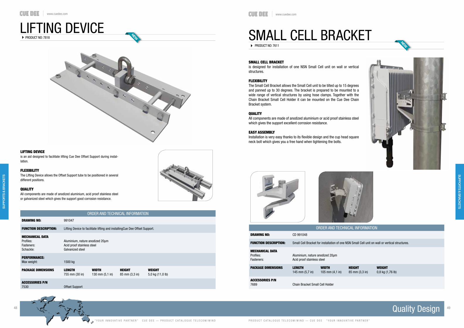
www.cuedee.com
” Y O U R I N N O V A T I V E P A R T N E R ” C U E D E E — P R O D U C T C A T A L O G U E T E L E C O M / W I N D
48 49
P R O D U C T C A T A L O G U E T E L E C O M / W I N D — C U E D E E ” Y O U R I N N O V A T I V E P A R T N E R ”
www.cuedee.com
LIFTING DEVICEPRODUCT NO: 7818
DRAWING NO: 991047
FUNCTION DESCRIPTION: Lifting Device to facilitate lifting and installingCue Dee Offset Support.
MECHANICAL DATAProfiles: Aluminium, nature anodized 20μmFasteners: Acid proof stainless steelSchackle: Galvanized steel
PERFORMANCE:Max weight: 1500 kg
PACKAGE DIMENSIONS LENGTH WIDTH HEIGHT WEIGHT 755 mm (30 in) 130 mm (5,1 in) 85 mm (3,3 in) 5,0 kg (11,0 lb)
ACCESSORIES P/N 7530 Offset Support
ORDER AND TECHNICAL INFORMATION
LIFTING DEVICEis an aid designed to facilitate lifting Cue Dee Offset Support during instal-lation.
FLEXIBILITYThe Lifting Device allows the Offset Support tube to be positioned in several different positions.
QUALITYAll components are made of anodized aluminium, acid proof stain less steel or galvanized steel which gives the support good corrosion resistance.
SMALL CELL BRACKETPRODUCT NO: 7611
DRAWING NO: CD 991048
FUNCTION DESCRIPTION: Small Cell Bracket for installation of one NSN Small Cell unit on wall or vertical structures.
MECHANICAL DATAProfiles: Aluminium, nature anodized 20μm Fasteners: Acid proof stainless steel
PACKAGE DIMENSIONS LENGTH WIDTH HEIGHT WEIGHT 145 mm (5,7 in) 105 mm (4,1 in) 85 mm (3,3 in) 0,8 kg (1,76 lb)
ACCESSORIES P/N 7689 Chain Bracket Small Cell Holder
ORDER AND TECHNICAL INFORMATION
SMALL CELL BRACKETis designed for installation of one NSN Small Cell unit on wall or vertical structures.
FLEXIBILITYThe Small Cell Bracket allows the Small Cell unit to be tilted up to 15 degrees and panned up to 30 degrees. The bracket is prepared to be mounted to a wide range of vertical structures by using hose clamps. Together with the Chain Bracket Small Cell Holder it can be mounted on the Cue Dee Chain Bracket system.
QUALITYAll components are made of anodized aluminium or acid proof stainless steel which gives the support excellent corrosion resistance.
EASY ASSEMBLYInstallation is very easy thanks to its flexible design and the cup head square neck bolt which gives you a free hand when tightening the bolts.
SU
PP
OR
TS &
BR
AC
KET
SS
UP
PO
RTS
& B
RA
CK
ETS

www.cuedee.com
” Y O U R I N N O V A T I V E P A R T N E R ” C U E D E E — P R O D U C T C A T A L O G U E T E L E C O M / W I N D
50 51
P R O D U C T C A T A L O G U E T E L E C O M / W I N D — C U E D E E ” Y O U R I N N O V A T I V E P A R T N E R ”
www.cuedee.com
THE SINGLE RADIO MOUNTIs designed for installation of one Ericsson radio unit on vertical structures.
FLEXIBILITY The Single Radio Mount fits all common units in Ericssons radio family and other units that have the hole pattern shown here below. Thanks to its design the Single Radio Mount can handle a wide range of all common frame leg designs, round, square, angle etc.
QUALITYAll components are made of anodized aluminium or acid proof stainless steel which gives the support excellent corrosion resistance.
EASY ASSEMBLY Handling and installation is extremely easy thanks to its design with “hook on” attachments and also due to the light weight of material.
SINGLE RADIO MOUNTPRODUCT NO: 7773
DRAWING NO: CD 991098
FUNCTION DESCRIPTION: Single Radio Mount for installation of one Ericsson RRU on vertical structures. Fits all common units in Ericssons radio family and other units that utilizes the same hole pattern.
MOUNTING SPAN TUBES SQUARE PROFILES 90˚ ANGLE 60˚ ANGLE
Minimum: Ø25 mm (1,0 in) 35 x 35 mm (1,4 x 1,4 in) 35 x 35 mm (1,4 x 1,4 in) 40 mm opening (1,6 in opening)Maximum: Ø120 mm (4,7 in) 90 x 90 mm (3,5 x 3,5 in) 90 x 90 mm (3,5 x 3,5 in) 100 mm opening (4,0 in opening)
MECHANICAL DATAClamp profiles: Aluminum, nature anodized 20μm Fasteners: Acid proof stainless steel
PACKAGE DIMENSIONS LENGTH WIDTH HEIGHT WEIGHT 180 mm (7,1 in) 100 mm (4,0 in) 90 mm (3,6 in) 1,1 kg (2,4 lb)
ORDER AND TECHNICAL INFORMATION
NOTE! 4 pcs of M8 bolts for one RRU is included in the Single Radio Mount.
THE MULTI RADIO MOUNTIs designed for installation of up to three Ericsson rru’s on wall or vertical structures.
FLEXIBILITYThe Multi radio Mount fits all common units in Ericssons radio family and other units that have the hole pattern shown below. Due to its design the Multi Radio Mount has mounting options on 3 sides, just like the radio unit has. This gives a tremendous number of installation possibilities which can be good in case there is lack of space.
QUALITYAll components are made of anodized aluminum or acid proof stainless steel which gives the support excellent corrosion resistance.
EASY ASSEMBLYHandling and installation is extremely easy thanks to its design with “hook on” attachments and also due to the light weight of material. The attached drill template further simplifies installation.
MULTI RADIO MOUNTPRODUCT NO: 7700
DRAWING NO: CD 991090
FUNCTION DESCRIPTION: Multi Radio Mount for installation of up to three Ericsson RRU’s on wall or vertical structures. Fits all common units in Ericsson radio family and other units that utilizes the same hole patterns.
MOUNTING SPAN TUBES SQUARE PROFILES 90˚ ANGLE 60˚ ANGLE
Minimum: Ø25 mm (1,0 in) 35 x 35 mm (1,4 x 1,4 in) 35 x 35 mm (1,4 x 1,4 in) 40 mm opening (1,6 in opening)Maximum: Ø120 mm (4,7 in) 90 x 90 mm (3,5 x 3,5 in) 90 x 90 mm (3,5 x 3,5 in) 100 mm opening (4,0 in opening)
MECHANICAL DATAClamp profiles: Aluminum, nature anodized 20μm Fasteners: Acid proof stainless steel
PACKAGE DIMENSIONS LENGTH WIDTH HEIGHT WEIGHT 286 mm (11,2 in) 188 mm (7,4 in) 80 mm (3,1 in) 1,8 kg (4,0 lb)
ORDER AND TECHNICAL INFORMATION
NOTE! 4 pcs of M8 bolts for one RRU is included in the Multi Radio Mount. When installing 2 or 3 units extra bolt kit needs to be ordered seperately.
SU
PP
OR
TS &
BR
AC
KET
SS
UP
PO
RTS
& B
RA
CK
ETS

www.cuedee.com
” Y O U R I N N O V A T I V E P A R T N E R ” C U E D E E — P R O D U C T C A T A L O G U E T E L E C O M / W I N D
52 53
P R O D U C T C A T A L O G U E T E L E C O M / W I N D — C U E D E E ” Y O U R I N N O V A T I V E P A R T N E R ”
www.cuedee.com
ORDER AND TECHNICAL INFORMATION
THE HALF PIPE ENCLOSUREis a mounting system used when you want to conceal a small cell site, foliate the radome to make the site blend in to the surroundings. It is possible to mount on almost any structure such as walls, traffic lights, flag poles etc.
FLEXIBILITYThe Half Pipe Enclosure is the perfect installation base for Nokia Flexi Lite BTS, Nokia Flexi Zone outdoor Micro & Pico BTS, Nokia Nano BBU, Nokia Harmony Lite and many other Nokia solutions.
QUALITYAll components are made of anodized aluminium and acid proof stainless steel which gives the enclosure excellent corrosion resistance. The plastic radome is made by UV-stabilized ABS plastic.
EASY ASSEMBLYInstallation is done on the ground, the entire enclosure is then lifted in place for easy installation.
HALF PIPE ENCLOSURE700/1000 mm
PRODUCT NO: 7113-700, 7113-1000
DRAWING NO: CD 990952-70 / CD 990952-100
FUNCTION DESCRIPTION: A mounting system used to conceal a small cell site on almost any structure such as walls, traffic lights, flag poles etc.
MOUNTING SPAN: TUBES SQUARE PROFILES 90˚ ANGLE 60˚ ANGLE
Minimum Ø25 (1,0 in) 35 x 35 (1,4 x 1,4 in) 35 x 35 (1,4 x 1,4 in) 40 mm (1,6 in) openingMaximum Ø120 (4,7 in) 90 x 90 (3,5 x 3,5 in) 90 x 90 (3,5 x 3,5 in) 100 mm (4,0 in) opening
PACKAGE DIMENSIONS LENGTH WIDTH HEIGHT WEIGHT7113-700 Half Pipe Enclosure 700 mm 700 mm (27,5 in) 460 mm (18,1 in) 360 mm (14,2 in) 13 kg (28,5 lb)7113-1000 Half Pipe Enclosure 1000 mm 1000 mm (39,4 in) 460 mm (18,1 in) 360 mm (14,2 in) 16 kg (35 lb)
ONLY FITS NOKIA EQUIPMENT
DRAWING NO: CD 990657
FUNCTION DESCRIPTION: AIR antenna support in two levels for installation of one AIR unit or other common panel antennas on the market. For installation directly on tower leg or other vertical structures of various size and shape. Mounting tube not needed. Including features such as compensation for inclined tower legs, turnable azimuth and mechanical tilt.
MOUNTING SPAN: TUBES: SQUARE PROFILES: 90˚ ANGLE: 60˚ ANGLE:
Minimum Ø25 mm (1,0 in) 35 x 35 (1,4 x 1,4 in) 35 x 35 (1,4 x 1,4 in) 40 mm (1,6 in) openingMaximum Ø120 mm (4,7 in) 90 x 90 mm (3,5 x 3,5 in) 90 x 90 mm (3,5 x 3,5 in) 100 mm (4,0 in) openingMounting tubes Ø60-90 mm (2,4-3,5 in)
PACKAGE DIMENSIONS: LENGTH: WIDTH: HEIGHT: WEIGHT: 285 mm (11,2 in) 190 mm (7,5 in) 150 mm (5,9 in) 8 kg (17,6 lb)
AIR ANTENNA SUPPORTis designed for installation of one AIR unit (antenna integrated radio) or other common panel antennas on the market.
FLEXIBILITY - All functions included! The AIR antenna support can handle a wide range of all common tower leg designs, round, square, angle etc. Thanks to the unique design You can install the AIR unit directly towards the frame leg without mounting tube and still rotate the azimuth +/- 60 degrees. Further features included are compensa-tion for inclined tower legs and mechanical tilt function.
QUALITYAll components are made of anodized aluminium and acid proof stainless steel which gives the support corrosion resistance.
EASY ASSEMBLEYHandling and installation is very easy due to the choice of materials and design, but also because the support is partly preassembled at delivery.
AIR ANTENNA SUPPORT
ORDER AND TECHNICAL INFORMATION
Example of support installed oncommon panel antenna.
PRODUCT NO: 5861
MA
STS
& T
OW
ERS
FOU
ND
ATIO
NS
& G
UY
AN
CH
OR
SW
IND
AC
CES
SO
RIE
SS
UP
PO
RTS
& B
RA
CK
ETS
SU
PP
OR
TS &
BR
AC
KETS
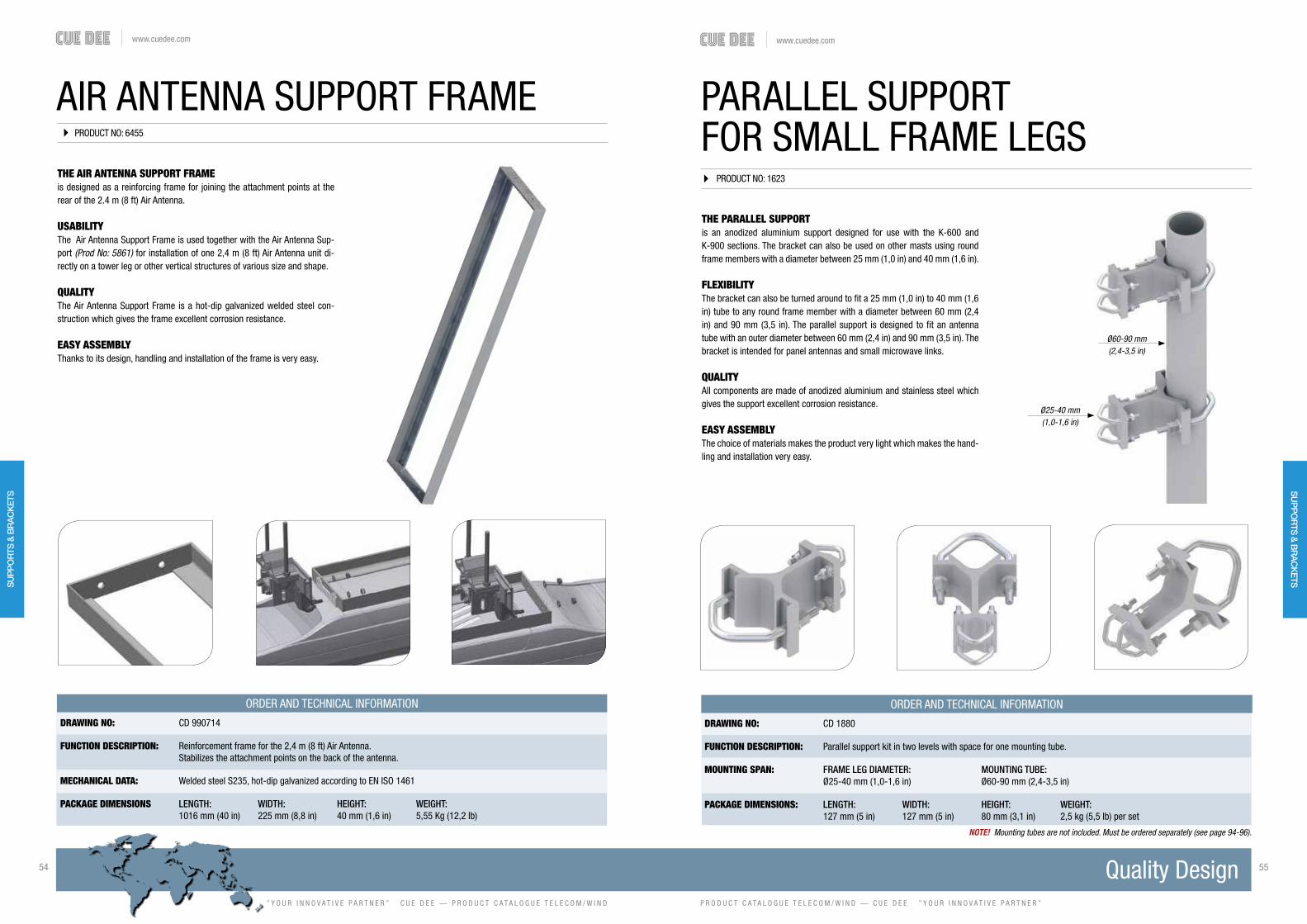
www.cuedee.com
” Y O U R I N N O V A T I V E P A R T N E R ” C U E D E E — P R O D U C T C A T A L O G U E T E L E C O M / W I N D
54 55
P R O D U C T C A T A L O G U E T E L E C O M / W I N D — C U E D E E ” Y O U R I N N O V A T I V E P A R T N E R ”
www.cuedee.com
AIR ANTENNA SUPPORT FRAME
DRAWING NO: CD 990714
FUNCTION DESCRIPTION: Reinforcement frame for the 2,4 m (8 ft) Air Antenna. Stabilizes the attachment points on the back of the antenna.
MECHANICAL DATA: Welded steel S235, hot-dip galvanized according to EN ISO 1461
PACKAGE DIMENSIONS LENGTH: WIDTH: HEIGHT: WEIGHT: 1016 mm (40 in) 225 mm (8,8 in) 40 mm (1,6 in) 5,55 Kg (12,2 lb)
THE AIR ANTENNA SUPPORT FRAMEis designed as a reinforcing frame for joining the attachment points at the rear of the 2.4 m (8 ft) Air Antenna.
USABILITYThe Air Antenna Support Frame is used together with the Air Antenna Sup-port (Prod No: 5861) for installation of one 2,4 m (8 ft) Air Antenna unit di-rectly on a tower leg or other vertical structures of various size and shape.
QUALITYThe Air Antenna Support Frame is a hot-dip galvanized welded steel con-struction which gives the frame excellent corrosion resistance.
EASY ASSEMBLY Thanks to its design, handling and installation of the frame is very easy.
ORDER AND TECHNICAL INFORMATION
PRODUCT NO: 6455
THE PARALLEL SUPPORTis an anodized aluminium support designed for use with the K-600 and K-900 sections. The bracket can also be used on other masts using round frame members with a diameter between 25 mm (1,0 in) and 40 mm (1,6 in).
FLEXIBILITY The bracket can also be turned around to fit a 25 mm (1,0 in) to 40 mm (1,6 in) tube to any round frame member with a diameter between 60 mm (2,4 in) and 90 mm (3,5 in). The parallel support is designed to fit an antenna tube with an outer diameter between 60 mm (2,4 in) and 90 mm (3,5 in). The bracket is intended for panel antennas and small microwave links.
QUALITYAll components are made of anodized aluminium and stainless steel which gives the support excellent corrosion resistance.
EASY ASSEMBLYThe choice of materials makes the product very light which makes the hand-ling and installation very easy.
DRAWING NO: CD 1880
FUNCTION DESCRIPTION: Parallel support kit in two levels with space for one mounting tube.
MOUNTING SPAN: FRAME LEG DIAMETER: MOUNTING TUBE: Ø25-40 mm (1,0-1,6 in) Ø60-90 mm (2,4-3,5 in)
PACKAGE DIMENSIONS: LENGTH: WIDTH: HEIGHT: WEIGHT: 127 mm (5 in) 127 mm (5 in) 80 mm (3,1 in) 2,5 kg (5,5 lb) per set
PARALLEL SUPPORTFOR SMALL FRAME LEGS
Ø25-40 mm(1,0-1,6 in)
Ø60-90 mm(2,4-3,5 in)
NOTE! Mounting tubes are not included. Must be ordered separately (see page 94-96).
ORDER AND TECHNICAL INFORMATION
PRODUCT NO: 1623
SU
PP
OR
TS &
BR
AC
KET
SS
UP
PO
RTS
& B
RA
CK
ETS

www.cuedee.com
” Y O U R I N N O V A T I V E P A R T N E R ” C U E D E E — P R O D U C T C A T A L O G U E T E L E C O M / W I N D
56 57
P R O D U C T C A T A L O G U E T E L E C O M / W I N D — C U E D E E ” Y O U R I N N O V A T I V E P A R T N E R ”
www.cuedee.com
DRAWING NO: CD 2770
FUNCTION DESCRIPTION: Universal clamp kit in two levels with space for one mounting tube. Typical for installation of panel antennas, radio links or other common telecom equipment.
MOUNTING SPAN: TUBES: SQUARE PROFILES: 90˚ ANGLE: 60˚ ANGLE:
Minimum Ø25 mm (1,0 in) 25 x 25 mm (1,0 x 1,0 in) 35 x 35 mm (1,4 x 1,4 in) 95 mm (3,7 in) openingMaximum Ø210 mm (8,3 in) 150 x 150 mm (5,9 x 5,9 in) 150 x 150 mm (5,9 x 5,9 in) 210 mm ( 8,3 in) openingMounting tubes Ø60-90 mm (2,4-3,5 in)
PACKAGE DIMENSIONS: LENGTH: WIDTH: HEIGHT: WEIGHT: 285 mm (11,2 in) 190 mm (7,5 in) 150 mm (5,9 in) 8 kg (17,64 lb)
THE ANTENNA SUPPORTis designed for installation of any kind of panel antennas, radio links up to Ø1,2 (3,9 ft) meters with strut support or other common telecom equipment. It can be installed on masts as well as conical towers.
FLEXIBILITYThe Antenna support can handle a wide range of all common frame leg de-signs, round, square, angular etc. When the included extensions on the upper support are used it will compensate for the inclination of towers.
QUALITYAll components are made of anodized aluminium and stainless steel which gives the support excellent corrosion resistance.
EASY ASSEMBLYThe choice of materials makes the product very light which makes the handling and installation very easy.
ANTENNA SUPPORT
NOTE! Mounting tubes are not included. Must be ordered separately (see page 94-96).
ORDER AND TECHNICAL INFORMATION
PRODUCT NO: 1763
FLEXIBLE ALD MOUNTING SUPPORT
FLEXIBLE ALD MOUNTING SUPPORTis designed for installation of 1-3 antenna line
device units such as TMA, filters etc. By adding
expansion for ALD mounting support it is possible
to install up to 6 units of antenna line device.
FLEXIBILITY The flexible ALD mounting support can handle
a wide range of all common frame leg designs,
round, square, angle etc. Thanks to the unique de-
sign. You can choose the position of the included
mounting tube. This can be done by turning the
tube holder in reverse position or mount the tube
DRAWING NO: CD 990664 / CD 990665
FUNCTION DESCRIPTION: 5891: Flexible ALD mounting support in one level for installation of 1-3 antenna line device units. For Installa- tion directly on tower leg or other vertical structures of various size and shape. 3 pc of mounting tubes are included.
5896: Expansion for ALD mounting support to be added on the flexible ALD mounting support. Containing 1pc tube holder and 1pc mounting tube.
MOUNTING SPAN: TUBES: SQUARE PROFILES: 90˚ ANGLE: 60˚ ANGLE:
Minimum Ø25 mm (1,0 in) 35 x 35 mm (1,4 x 1,4 in) 35 x 35 mm (1,4 x 1,4 in) 40 mm (1,6 in) openingMaximum Ø120 mm (4,7 in) 90 x 90 mm (3,5 x 3,5 in) 90 x 90 mm (3,5 x 3,5 in) 100 mm 4,0 in) openingMounting tubes Ø60 x 3 L=400 mm (2,4 x 3 L=15,7 in)
PACKAGE DIMENSIONS: LENGTH: WIDTH: HEIGHT: WEIGHT: 5891: 405 mm (15,9 in) 136 mm (5,3 in) 136 mm (5,3 in) 4,8 kg (10,6 lb) 5896: 550 mm (21,6 in) 95 mm (3,7 in) 95 mm (3,7 in) 1,5 kg (3,2 lb)
ORDER AND TECHNICAL INFORMATION
PRODUCT NO: 5891 / 5896
holder on the inside or the outside of the clamp.
These options makes the support very flexible and
easy to optimize for your type of installation.
QUALITYAll components are made of anodized aluminium
and acid proof stainless steel which gives the sup-
port excellent corrosion resistance.
EASY ASSEMBLEYThe choice of materials and design makes the
product very light which makes the handling and
installation very easy.
PRODUCT NO: 5896 PRODUCT NO: 5891
SU
PP
OR
TS &
BR
AC
KET
SS
UP
PO
RTS
& B
RA
CK
ETS
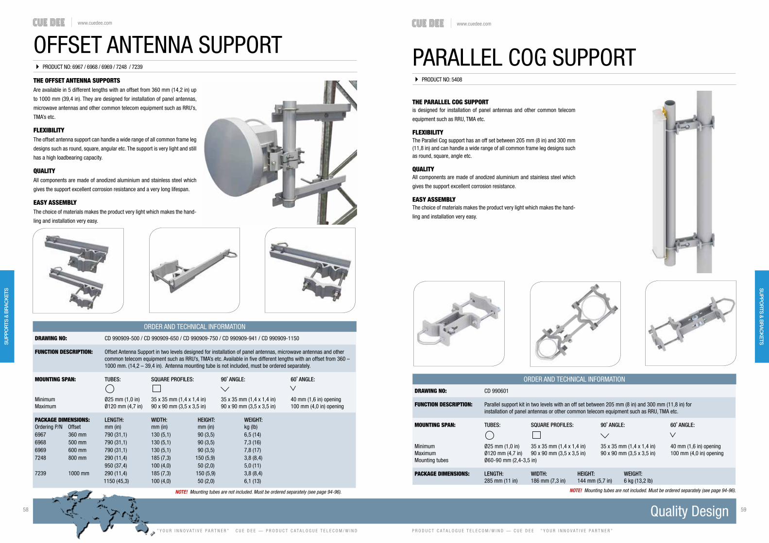
www.cuedee.com
” Y O U R I N N O V A T I V E P A R T N E R ” C U E D E E — P R O D U C T C A T A L O G U E T E L E C O M / W I N D
58 59
P R O D U C T C A T A L O G U E T E L E C O M / W I N D — C U E D E E ” Y O U R I N N O V A T I V E P A R T N E R ”
www.cuedee.com
OFFSET ANTENNA SUPPORTPRODUCT NO: 6967 / 6968 / 6969 / 7248 / 7239
THE OFFSET ANTENNA SUPPORTS Are available in 5 different lengths with an offset from 360 mm (14,2 in) up
to 1000 mm (39,4 in). They are designed for installation of panel antennas,
microwave antennas and other common telecom equipment such as RRU’s,
TMA’s etc.
FLEXIBILITY
The offset antenna support can handle a wide range of all common frame leg
designs such as round, square, angular etc. The support is very light and still
has a high loadbearing capacity.
QUALITY All components are made of anodized aluminium and stainless steel which
gives the support excellent corrosion resistance and a very long lifespan.
EASY ASSEMBLY The choice of materials makes the product very light which makes the hand-
ling and installation very easy.
DRAWING NO: CD 990909-500 / CD 990909-650 / CD 990909-750 / CD 990909-941 / CD 990909-1150
FUNCTION DESCRIPTION: Offset Antenna Support in two levels designed for installation of panel antennas, microwave antennas and other common telecom equipment such as RRU’s, TMA’s etc. Available in five different lengths with an offset from 360 – 1000 mm. (14,2 – 39,4 in). Antenna mounting tube is not included, must be ordered separately.
MOUNTING SPAN: TUBES: SQUARE PROFILES: 90˚ ANGLE: 60˚ ANGLE:
Minimum Ø25 mm (1,0 in) 35 x 35 mm (1,4 x 1,4 in) 35 x 35 mm (1,4 x 1,4 in) 40 mm (1,6 in) openingMaximum Ø120 mm (4,7 in) 90 x 90 mm (3,5 x 3,5 in) 90 x 90 mm (3,5 x 3,5 in) 100 mm (4,0 in) opening
PACKAGE DIMENSIONS: LENGTH: WIDTH: HEIGHT: WEIGHT:Ordering P/N Offset mm (in) mm (in) mm (in) kg (lb)6967 360 mm 790 (31,1) 130 (5,1) 90 (3,5) 6,5 (14)6968 500 mm 790 (31,1) 130 (5,1) 90 (3,5) 7,3 (16)6969 600 mm 790 (31,1) 130 (5,1) 90 (3,5) 7,8 (17)7248 800 mm 290 (11,4) 185 (7,3) 150 (5,9) 3,8 (8,4) 950 (37,4) 100 (4,0) 50 (2,0) 5,0 (11)7239 1000 mm 290 (11,4) 185 (7,3) 150 (5,9) 3,8 (8,4) 1150 (45,3) 100 (4,0) 50 (2,0) 6,1 (13)
NOTE! Mounting tubes are not included. Must be ordered separately (see page 94-96).
ORDER AND TECHNICAL INFORMATION
THE PARALLEL COG SUPPORTis designed for installation of panel antennas and other common telecom
equipment such as RRU, TMA etc.
FLEXIBILITYThe Parallel Cog support has an off set between 205 mm (8 in) and 300 mm (11,8 in) and can handle a wide range of all common frame leg designs such as round, square, angle etc.
QUALITYAll components are made of anodized aluminium and stainless steel which
gives the support excellent corrosion resistance.
EASY ASSEMBLYThe choice of materials makes the product very light which makes the hand-
ling and installation very easy.
PARALLEL COG SUPPORT
DRAWING NO: CD 990601
FUNCTION DESCRIPTION: Parallel support kit in two levels with an off set between 205 mm (8 in) and 300 mm (11,8 in) for installation of panel antennas or other common telecom equipment such as RRU, TMA etc.
MOUNTING SPAN: TUBES: SQUARE PROFILES: 90˚ ANGLE: 60˚ ANGLE:
Minimum Ø25 mm (1,0 in) 35 x 35 mm (1,4 x 1,4 in) 35 x 35 mm (1,4 x 1,4 in) 40 mm (1,6 in) openingMaximum Ø120 mm (4,7 in) 90 x 90 mm (3,5 x 3,5 in) 90 x 90 mm (3,5 x 3,5 in) 100 mm (4,0 in) openingMounting tubes Ø60-90 mm (2,4-3,5 in)
PACKAGE DIMENSIONS: LENGTH: WIDTH: HEIGHT: WEIGHT: 285 mm (11 in) 186 mm (7,3 in) 144 mm (5,7 in) 6 kg (13,2 lb)
NOTE! Mounting tubes are not included. Must be ordered separately (see page 94-96).
ORDER AND TECHNICAL INFORMATION
PRODUCT NO: 5408
SU
PP
OR
TS &
BR
AC
KET
SM
AS
TS &
TOW
ERS
FOU
ND
ATION
S &
GU
Y A
NC
HO
RS
WIN
D A
CC
ESS
OR
IESS
UP
PO
RTS
& B
RA
CK
ETS

www.cuedee.com
” Y O U R I N N O V A T I V E P A R T N E R ” C U E D E E — P R O D U C T C A T A L O G U E T E L E C O M / W I N D
60 61
P R O D U C T C A T A L O G U E T E L E C O M / W I N D — C U E D E E ” Y O U R I N N O V A T I V E P A R T N E R ”
www.cuedee.com
DOUBLE ANTENNA SUPPORT
THE DOUBLE ANTENNA SUPPORTis designed for installation of 2 panel antennas or small radio links or other common telecom equipment.
FLEXIBILITYThe support is assembled to a tower or mast frame member via 2 clamps. This clamp can handle all common frame leg designs such as round, square,
angle etc.
QUALITYAll components are made of anodized aluminium and stainless steel which
gives the support excellent corrosion resistance.
EASY ASSEMBLYThe choice of materials makes the product very light which makes the hand-ling and installation very easy.
DRAWING NO: CD 990517
FUNCTION DESCRIPTION: Clamp kit in two levels, with horizontal beams, and space for two mounting tubes. Typical for installation of panel antennas, radio links or other common telecom equipment.
MOUNTING SPAN: TUBES: SQUARE PROFILES: 90˚ ANGLE: 60˚ ANGLE:
Minimum Ø25 mm (1,0 in) 30 x 30 mm (1,2 x 1,2 in) 35 x 35 mm (1,4 x 1,4 in) 35 mm (1,4 in) openingMaximum Ø120 mm (4,7 in) 90 x 90 mm (3,5 x 3,5 in) 90 x 90 mm (3,5 x 3,5 in) 130 mm (5,1 in) openingMounting tubes Ø60-90 (2,4-3,5 in)
PACKAGE DIMENSIONS: LENGTH: WIDTH: HEIGHT: WEIGHT: 790 mm (31 in) 130 mm (5,1 in) 90 mm (3,6 in) 10,4 kg (22,9 lb)
c/c 466 mm (18,3 in)
NOTE! Mounting tubes are not included. Must be ordered separately (see page 94-96).
ORDER AND TECHNICAL INFORMATION
PRODUCT NO: 4984
3-SECTOR FRAME
DRAWING NO: CD 990904-1150 / CD 990904-1750
FUNCTION DESCRIPTION: 3-Sector frame for installation of three panel antennas or microwave antennas on one frameleg.
MOUNTING SPAN: TUBES: SQUARE PROFILES: 90˚ ANGLE 60˚ ANGLE:
Minimum: Ø25 mm (1,0 in) 25 x 25 mm (1,0 x 1,0 in) 35 x 35 mm (1,4 x 1,4 in) 95 mm (3,7 in) openingMaximum: Ø210 mm (8,3 in) 150 x 150 mm (5,9 x 5,9 in) 150 x 150 mm (5,9 x 5,9 in) 210 mm (8,3 in) opening
PACKAGE DIMENSIONS P/N: LENGTH: WIDTH: HEIGHT: WEIGHT:7080-xx: Package 1 (2 pcs) 370 mm (15 in) 340 mm (13 in) 160 mm (6,3 in) 17 kg (37 lb)7080-12: Package 2 1150 mm (45 in) 150 mm (6,0 in) 75 mm (3,0 in) 11 kg (24 lb)7080-18: Package 2 1750 mm (69 in) 150 mm (6,0 in) 75 mm (3,0 in) 16 kg (35 lb)
ORDER AND TECHNICAL INFORMATION
PRODUCT NO: 7080-12 / 7080-18
THE 3-SECTOR FRAMEIs a two level support designed for installation of three panel antennas on the same bracket. The c/c distance between the antennas is 500 mm (20 in).
FLEXIBILITYThe support can be mounted to basically any type of frame leg for example round, square, 60° angle as well as 90° thanks to the very flexible bracket.
QUALITYAll components are made of anodized aluminium and stainless steel which gives the support excellent corrosion resistance.
EASY ASSEMBLYThe choice of materials makes the product very light which makes the hand-ling and installation very easy.
NOTE! Mounting tubes are not included. Must be ordered separately (see page 94-96).
SU
PP
OR
TS &
BR
AC
KET
SS
UP
PO
RTS
& B
RA
CK
ETS

www.cuedee.com
” Y O U R I N N O V A T I V E P A R T N E R ” C U E D E E — P R O D U C T C A T A L O G U E T E L E C O M / W I N D
62 63
P R O D U C T C A T A L O G U E T E L E C O M / W I N D — C U E D E E ” Y O U R I N N O V A T I V E P A R T N E R ”
www.cuedee.com
THE DOUBLE SPLIT SUPPORTis designed for installation of 2 panel antennas up to 2,6 m (8,5 ft).
FLEXIBILITYThe support is mounted to a centre tube with dimension Ø75 to 120 mm (3,0 to 4,7 in). The antenna mounting tube can be Ø45-60 mm (1,8 to 2,4 in).
QUALITYAll components are made of anodized aluminium and stainless steel which gives the support excellent corrosion resistance.
EASY ASSEMBLYThe choice of materials makes the product very light which makes the hand-ling and installation very easy.
DRAWING NO: CD 189023 CD 189123
MOUNTING SPAN: MOUNTING TUBE: CENTRE TUBES: MOUNTING TUBE: CENTRE TUBES: Ø45-60 mm Ø75-100 mm Ø45-60 mm Ø100-120 mm (1,8 to 2,4 in) (3,0 to 4,0 in) (1,8 to 2,4 in) (4,0 to 4,7 in)
FUNCTION DESCRIPTION: Antenna support kit in two levels with space for 2 mounting tubes on 1 centre tube. Typical for installation of panel antennas.
PACKAGE DIMENSIONS: LENGTH: WIDTH: HEIGHT: WEIGHT:1624 285 mm (11 in) 190 mm (7,5 in) 150 mm (5,9 in) 4,2 kg (9,3 lb)1626 285 mm (11 in) 190 mm (7,5 in) 150 mm (5,9 in) 4,4 kg (9,7 lb)
NOTE! Mounting tubes are not included. Must be ordered separately (see page 94-96).
ORDER AND TECHNICAL INFORMATION
PRODUCT NO: 1624 / 1626
DOUBLE SPLIT SUPPORT
THE TRIPLE SPLIT SUPPORT is designed for installation of three panel antennas up to 2,6 m (8,5 ft).
FLEXIBILITYThe support is mounted to a centre tube with dimension Ø75 to 100 mm, (3,0 to 4,0 in) or Ø100 to 120 mm, (4,0 to 4,7 in) The antenna mounting tube can be Ø45-60 mm, (1,8 to 2,4 in).
QUALITYAll components are made of anodized aluminium and stainless steel which gives the support excellent corrosion resistance.
EASY ASSEMBLYThe choice of materials makes the product very light which makes the hand-ling and installation very easy.
PRODUCT NO: 1625 / 1627
TRIPLE SPLIT SUPPORT
DRAWING NO: Prod.Nr 1625, CD 189060 Prod.Nr 1627, CD 189160
MOUNTING SPAN: MOUNTING TUBE: CENTRE TUBES: MOUNTING TUBE: CENTRE TUBES: Ø45-60 mm Ø75-100 mm Ø45-60 mm Ø100-120 mm (1,8 to 2,4 in) (3,0 to 4,0 in) (1,8 to 2,4 in) (4,0 to 4,7 in)
FUNCTION DESCRIPTION: Antenna support kit in two levels with space for 3 mounting tubes on 1 centre tube. Typical for installation of panel antennas.
PACKAGE DIMENSIONS: LENGTH: WIDTH: HEIGHT: WEIGHT:1625 285 mm (11,2 in) 190 mm (7,5 in) 150 mm (5,9 in) 5,1 kg (11,24 lb)1627 285 mm (11,2 in) 190 mm (7,5 in) 150 mm (5,9 in) 5,2 kg (11,46 lb)
NOTE! Mounting tubes are not included. Must be ordered separately (see page 94-96).
ORDER AND TECHNICAL INFORMATION
SU
PP
OR
TS &
BR
AC
KET
SM
AS
TS &
TOW
ERS
FOU
ND
ATION
S &
GU
Y A
NC
HO
RS
WIN
D A
CC
ESS
OR
IESS
UP
PO
RTS
& B
RA
CK
ETS

www.cuedee.com
” Y O U R I N N O V A T I V E P A R T N E R ” C U E D E E — P R O D U C T C A T A L O G U E T E L E C O M / W I N D
64 65
P R O D U C T C A T A L O G U E T E L E C O M / W I N D — C U E D E E ” Y O U R I N N O V A T I V E P A R T N E R ”
www.cuedee.com
DRAWING NO: CD 184224
FUNCTION DESCRIPTION: Clamp kit in two levels, with space for 1 mounting tube. Typical for installation of large radio links or several small ones or other common telecom equipment.
MOUNTING SPAN: TUBES: SQUARE PROFILES: 90˚ ANGLE : 60˚ ANGLE:
Minimum Ø25 mm (1,0 in) 60 x 60 mm (2,4 x 2,4 in) 60 x 60 mm (2,4 x 2,4 in) 65 mm (2,6 in) openingMaximum Ø270 mm (10,6 in) 210 x 210 mm (8,3 x 8,3 in) 220 x 220 mm (8,7 x 8,7 in) 310 mm (12,2 in) openingMounting tube Ø25-120 (1,0-4,7 in) (Recommended Ø114 mm (4,5 in), see page 92-93).
PACKAGE DIMENSIONS: LENGTH: WIDTH: HEIGHT: WEIGHT: 540 mm (21 in) 175 mm (6,9 in) 180 mm (7,1 in) 23 kg (51 lb)
1-L LINK SUPPORT
THE 1-L LINK SUPPORTis designed for installation of several small radio links or one large link up to Ø3,0 m (10 ft) with strut support. The 1-L link support can be installed on masts as well as conical towers.
FLEXIBILITYThe 1-Leg link support can handle a wide range of all common frame leg designs, round, square, angular, etc. Thanks to the flexibility of the Cue Dee clamp 270. The oblong holes on the upper extension arms allow the support to compensate for inclined towers.
QUALITYAll components are made of anodized aluminium and stainless steel which gives the support excellent corrosion resistance.
EASY ASSEMBLYThe choice of materials makes the product very light which makes the hand-ling and installation very easy.
UPPER LOWER
NOTE! Mounting tubes are not included. Must be ordered separately (see page 94-96).
ORDER AND TECHNICAL INFORMATION
PRODUCT NO: 1981
THE TOP SPIRE 2-Lis designed as an extension kit for towers and masts and is suitable to install 3 panel antennas up to 2,3 m (7,5 ft). (Other versions are available up on request).The centre aluminium pole Ø120 mm (4,7 in) is 4,8 m (15,7 ft) long and equipped with split supports to carry the included Ø60 mm (2,4 in) mounting tubes.
FLEXIBILITYThe support has 1,5 m (5 ft) alubra bars at two levels to distribute the load on two frame legs. The support can be installed on top of towers and masts with all common frame leg designs, round, square, angle etc, thanks to the Cue Dee clamp.
QUALITYAll components are made of anodized aluminium and stainless steel which gives the support excellent corrosion resistance.
EASY ASSEMBLYThe choice of materials makes the product very light which in turn makes the handling and installation very easy.
DRAWING NO: CD 189648-4
FUNCTION DESCRIPTION: Top Spire support kit in 2 levels with alubra bars which distribute the load on frame legs. For installation of 3 panel antennas up to 2,3 m (7,5 ft).
MOUNTING SPAN: TUBES: SQUARE PROFILES: 90˚ ANGLE 60˚ ANGLE:
Minimum Ø25 mm (1,0 in) 30 x 30 mm (1,2 x 1,2 in) 35 x 35 mm (1,4 x 1,4 in) 35 mm (1,4 in) openingMaximum Ø120 mm (4,7 in) 90 x 90 mm (3,5 x 3,5 in) 90 x 90 mm (3,5 x 3,5 in) 60 mm (2,4 in) opening
PACKAGE DIMENSIONS: LENGTH: WIDTH: HEIGHT: WEIGHT: 4800 mm (189 in) 300 mm (11,8 in) 300 mm (11,8 in) 65 kg (143 lb)
TOP SPIRE 2-L
ORDER AND TECHNICAL INFORMATION
PRODUCT NO: 5215
SU
PP
OR
TS &
BR
AC
KET
SS
UP
PO
RTS
& B
RA
CK
ETS

www.cuedee.com
” Y O U R I N N O V A T I V E P A R T N E R ” C U E D E E — P R O D U C T C A T A L O G U E T E L E C O M / W I N D
66 67
P R O D U C T C A T A L O G U E T E L E C O M / W I N D — C U E D E E ” Y O U R I N N O V A T I V E P A R T N E R ”
www.cuedee.com
mUNIT BASE MOUNTPRODUCT NO: 6127
THE mUNIT BASE MOUNTis designed as a base component in a building system for mUnit products. By only using the mUnit Base Mount it`s possible to install one mRRU or mRBS on wall. Along with additional accessories (Pole Clamp, Hose Plate etc.) it is also possible to install on masts, towers or other vertical / horizontal structures.
FLEXIBILITYThe mUnit Base Mount can either be installed in vertical position used for tilt function or horizontal position used for azimuth function. If needed it´s pos-sible to combine both features by using two Base Mount units mounted cross wise to achieve both azimuth and tilt function. A degree scale on one of the link arms helps the installer to reach exact orientation.
QUALITYAll components are made of anodized aluminium or acid proof stainless steel which gives the support excellent corrosion resistance.
EASY ASSEMBLYHandling and installation is very easy thanks to the light weight material of the product.
ONLY FITS ERICSSON EQUIPMENT
DRAWING NO: CD 990705
FUNCTION DESCRIPTION: mUnit Pole Clamp for attachment of mUnit Base Mount on mast, towers or other vertical/horizontal structures.
MECHANICAL DATA: Mounting Plates: Aluminium, nature anodized 20myDrill template for wall: Included, square c/c 140 mm (5,5 in) screw dimension M10 Link arms: Blast acid proof stainless steelTilt function: On wall max down tilt: 23 degree Azimuth function: On wall max +/- 45 degreeFasteners: Acid proof stainless steel
PACKAGE DIMENSIONS: LENGTH: WIDTH: HEIGHT: WEIGHT: 260 mm (10,2 in) 240 mm (9,5 in) 40 mm (1,6 in) 2.5 kg (5,5 lb)
ORDER AND TECHNICAL INFORMATION
NOTE! RRU is not included.
mUNIT POLE CLAMPPRODUCT NO: 6120
THE mUNIT POLE CLAMPis a part of building system for mUnit products and designed for attach-ment of mUnit Base Mount towards mast, towers or other vertical / horizontal structures.
FLEXIBILITYThe mUnit Pole Clamp can handle a wide range of all common tower leg designs, round, square, angle etc. The Pole Clamp also has elongated slotted holes which means that the installer can unhook one half during installation and do not need to handle any loose parts.
QUALITYAll components are made of anodized aluminium or acid proof stainless steel which gives the support excellent corrosion resistance.
EASY ASSEMBLYHandling and installation is very easy thanks to the light weight material of the product.
ONLY FITS ERICSSON EQUIPMENT
ORDER AND TECHNICAL INFORMATION
DRAWING NO: CD 990703
FUNCTION DESCRIPTION: mUnit Pole Clamp for attachment of mUnit Base Mount towards mast, towers or other vertical/horizontal structures.
MECHANICAL DATA: Clamp profiles: Aluminium, nature anodized 20μmFasteners: Acid proof stainless steel M10 x 185 mm (7,3 in)
MOUNTING SPAN: TUBES: SQUARE PROFILES: 90˚ ANGLE 60˚ ANGLE:
Minimum: Ø25 mm (1,0 in) 35 x 35 mm (1,4 x 1,4 in) 35 x 35 mm (1,4 x 1,4 in) 40 mm (1,6 in) openingMaximum: Ø120 mm (4,7 in) 90 x 90 mm (3,5 x 3,5 in) 90 x 90 mm (3,5 x 3,5 in) 100 mm (4,0 in) opening)
PACKAGE DIMENSIONS: LENGTH: WIDTH: HEIGHT: WEIGHT: 210 mm (8,3 in) 235 mm (9,2 in) 45 mm (1,8 in) 1,5 kg (4 lb)
NOTE! RRU is not included.
SU
PP
OR
TS &
BR
AC
KET
SS
UP
PO
RTS
& B
RA
CK
ETS

www.cuedee.com
” Y O U R I N N O V A T I V E P A R T N E R ” C U E D E E — P R O D U C T C A T A L O G U E T E L E C O M / W I N D
68 69
P R O D U C T C A T A L O G U E T E L E C O M / W I N D — C U E D E E ” Y O U R I N N O V A T I V E P A R T N E R ”
www.cuedee.com
mUNIT OMNI SUPPORTPRODUCT NO: 6129
THE mUNIT OMNI SUPPORTis designed for installation of two small omni antennas on one mRRU or one mRBS unit.
FLEXIBILITYThanks to the design of the mUnit Omni Support it allows the omni antennas to be mounted either in a vertical or a horizontal position on the mRRU/mRBS unit. For wall, pole, mast and tower installation the mUnit Omni Support is always mounted together with the mUnit Base Mount.
QUALITYAll components are made of acid proof stainless steel which gives the sup-port excellent corrosion resistance.
EASY ASSEMBLYHandling and installation is very easy thanks to the light weight material of the product.
ONLY FITS ERICSSON EQUIPMENT
ORDER AND TECHNICAL INFORMATION
DRAWING NO: CD 990706
FUNCTION DESCRIPTION: mUnit Omni Support for installation of two small omni antennas on one mRRU or one mRBS unit.
MECHANICAL DATA: Omni Support: Acid proof stainless steel 3 mm (0,118 in)Fasteners: Acid proof stainless steel
PACKAGE DIMENSIONS: LENGTH: WIDTH: HEIGHT: WEIGHT: 310 mm (12,2 in) 160 mm (6,3 in) 95 mm (3,7 in) 0,7 Kg (1,5 lb)
ACCESSORIES P/N:6127 mUnit Base Mount
NOTE! RRU is not included.
ORDER AND TECHNICAL INFORMATION
mUNIT HOSE PLATEPRODUCT NO: 6193
THE mUNIT HOSE PLATEis a part of a building system for mUnit products and designed for attachment of mUnit Base Mount towards round structures.
FLEXIBILITYThe mUnit Hose Plate allows installation of a wide range of round structures depending on the choice of Hose Clamp as accessories.
QUALITYAll components are made of acid proof stainless steel which gives the sup-port excellent corrosion resistance.
EASY ASSEMBLYHandling and installation is very easy thanks to the light weight material of the product.
ONLY FITS ERICSSON EQUIPMENT
DRAWING NO: CD 990709
FUNCTION DESCRIPTION: mUnit Hose Plate for attachment of mUnit Base Mount on round structures.
MECHANICAL DATA: Hose Plate: Acid proof stainless steel 2 mm (0,08 in)Fasteners: Acid proof stainless steel
PACKAGE DIMENSIONS: LENGTH: WIDTH: HEIGHT: WEIGHT: 210 mm (8,3 in) 235 mm (9,3 in) 45 mm (1,8 in) 0,75 Kg (1,65 lb)
ACCESSORIES P/N:6127 mUnit Base Mount 6371 Hose Clamp
NOTE! Hose Clamps not included, RRU is not included.
SU
PP
OR
TS &
BR
AC
KET
SS
UP
PO
RTS
& B
RA
CK
ETS
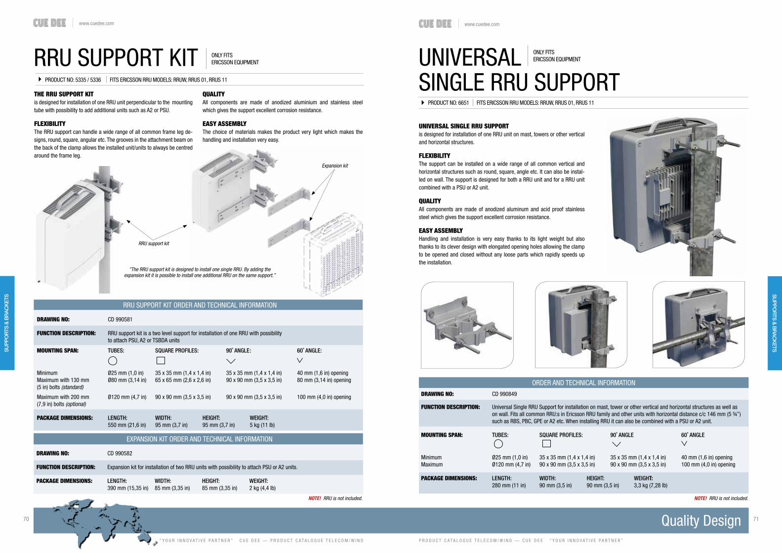
www.cuedee.com
” Y O U R I N N O V A T I V E P A R T N E R ” C U E D E E — P R O D U C T C A T A L O G U E T E L E C O M / W I N D
70 71
P R O D U C T C A T A L O G U E T E L E C O M / W I N D — C U E D E E ” Y O U R I N N O V A T I V E P A R T N E R ”
www.cuedee.com
RRU SUPPORT KITTHE RRU SUPPORT KITis designed for installation of one RRU unit perpendicular to the mounting tube with possibility to add additional units such as A2 or PSU.
FLEXIBILITYThe RRU support can handle a wide range of all common frame leg de-signs, round, square, angular etc. The grooves in the attachment beam on the back of the clamp allows the installed unit/units to always be centred around the frame leg.
ONLY FITS ERICSSON EQUIPMENT
QUALITYAll components are made of anodized aluminium and stainless steel which gives the support excellent corrosion resistance.
EASY ASSEMBLYThe choice of materials makes the product very light which makes the handling and installation very easy.
EXPANSION KIT ORDER AND TECHNICAL INFORMATION
DRAWING NO: CD 990582
FUNCTION DESCRIPTION: Expansion kit for installation of two RRU units with possibility to attach PSU or A2 units.
PACKAGE DIMENSIONS: LENGTH: WIDTH: HEIGHT: WEIGHT: 390 mm (15,35 in) 85 mm (3,35 in) 85 mm (3,35 in) 2 kg (4,4 lb)
RRU support kit
Expansion kit
”The RRU support kit is designed to install one single RRU. By adding the expansion kit it is possible to install one additional RRU on the same support.”
NOTE! RRU is not included.
PRODUCT NO: 5335 / 5336 FITS ERICSSON RRU MODELS: RRUW, RRUS 01, RRUS 11
RRU SUPPORT KIT ORDER AND TECHNICAL INFORMATION
DRAWING NO: CD 990581
FUNCTION DESCRIPTION: RRU support kit is a two level support for installation of one RRU with possibility to attach PSU, A2 or TSBDA units
MOUNTING SPAN: TUBES: SQUARE PROFILES: 90˚ ANGLE : 60˚ ANGLE:
Minimum Ø25 mm (1,0 in) 35 x 35 mm (1,4 x 1,4 in) 35 x 35 mm (1,4 x 1,4 in) 40 mm (1,6 in) openingMaximum with 130 mm Ø80 mm (3,14 in) 65 x 65 mm (2,6 x 2,6 in) 90 x 90 mm (3,5 x 3,5 in) 80 mm (3,14 in) opening(5 in) bolts (standard)
Maximum with 200 mm Ø120 mm (4,7 in) 90 x 90 mm (3,5 x 3,5 in) 90 x 90 mm (3,5 x 3,5 in) 100 mm (4,0 in) opening(7,9 in) bolts (optional)
PACKAGE DIMENSIONS: LENGTH: WIDTH: HEIGHT: WEIGHT: 550 mm (21,6 in) 95 mm (3,7 in) 95 mm (3,7 in) 5 kg (11 lb)
UNIVERSAL SINGLE RRU SUPPORTis designed for installation of one RRU unit on mast, towers or other vertical and horizontal structures.
FLEXIBILITYThe support can be installed on a wide range of all common vertical and horizontal structures such as round, square, angle etc. It can also be instal-led on wall. The support is designed for both a RRU unit and for a RRU unit combined with a PSU or A2 unit.
QUALITYAll components are made of anodized aluminum and acid proof stainless steel which gives the support excellent corrosion resistance.
EASY ASSEMBLYHandling and installation is very easy thanks to its light weight but also thanks to its clever design with elongated opening holes allowing the clamp to be opened and closed without any loose parts which rapidly speeds up the installation.
UNIVERSALSINGLE RRU SUPPORT
DRAWING NO: CD 990849
FUNCTION DESCRIPTION: Universal Single RRU Support for installation on mast, tower or other vertical and horizontal structures as well as on wall. Fits all common RRU:s in Ericsson RRU family and other units with horizontal distance c/c 146 mm (5 ¾”) such as RBS, PBC, GPE or A2 etc. When installing RRU it can also be combined with a PSU or A2 unit.
MOUNTING SPAN: TUBES: SQUARE PROFILES: 90˚ ANGLE 60˚ ANGLE
Minimum Ø25 mm (1,0 in) 35 x 35 mm (1,4 x 1,4 in) 35 x 35 mm (1,4 x 1,4 in) 40 mm (1,6 in) openingMaximum Ø120 mm (4,7 in) 90 x 90 mm (3,5 x 3,5 in) 90 x 90 mm (3,5 x 3,5 in) 100 mm (4,0 in) opening
PACKAGE DIMENSIONS: LENGTH: WIDTH: HEIGHT: WEIGHT: 280 mm (11 in) 90 mm (3,5 in) 90 mm (3,5 in) 3,3 kg (7,28 lb)
NOTE! RRU is not included.
ORDER AND TECHNICAL INFORMATION
PRODUCT NO: 6651 FITS ERICSSON RRU MODELS: RRUW, RRUS 01, RRUS 11
ONLY FITS ERICSSON EQUIPMENT
SU
PP
OR
TS &
BR
AC
KET
SS
UP
PO
RTS
& B
RA
CK
ETS

www.cuedee.com
” Y O U R I N N O V A T I V E P A R T N E R ” C U E D E E — P R O D U C T C A T A L O G U E T E L E C O M / W I N D
72 73
P R O D U C T C A T A L O G U E T E L E C O M / W I N D — C U E D E E ” Y O U R I N N O V A T I V E P A R T N E R ”
www.cuedee.com
DRAWING NO: CD 990787
FUNCTION DESCRIPTION: Double RRU support for installation of 2 RRU units with possibility to attach a PSU on the back.
MOUNTING SPAN: TUBES: SQUARE PROFILES: 90˚ ANGLE 60˚ ANGLE
Minimum Ø25 mm (1,0 in) 35 x 35 mm (1,4 x 1,4 in) 35 x 35 mm (1,4 x 1,4 in) 40 mm (1,6 in) openingMaximum Ø120 mm (4,7 in) 90 x 90 mm (3,5 x 3,5 in) 90 x 90 mm (3,5 x 3,5 in) 100 mm (4,0 in) opening
PACKAGE DIMENSIONS: LENGTH: WIDTH: HEIGHT: WEIGHT: 290 mm (11,4 in) 124 mm (4,88 in) 122 mm (4,80 in) 5,1 kg (11,24 lb)
THE DOUBLE RRU SUPPORTis designed for installation of 2 RRU units with possibility to attach a PSU on the back.
FLEXIBILITYThe RRU support can handle a wide range of all common frame leg designs such as round, square, angular, etc.
QUALITYAll components are made of anodized aluminium and stainless steel which gives the support excellent corrosion resistance.
EASY ASSEMBLYThe choice of materials makes the product very light which makes the hand-ling and installation very easy.
DOUBLE RRU SUPPORT
NOTE! RRU is not included.
ORDER AND TECHNICAL INFORMATION
PRODUCT NO: 6400 FITS ERICSSON RRU MODELS: RRUW, RRUS 01, RRUS 11
ONLY FITS ERICSSON EQUIPMENT
DRAWING NO: CD 990986
FUNCTION DESCRIPTION: Triple RRU support in aluminium for installation of three RRU units with possibility to attach a PSU on the back. (RRU not included)
MOUNTING SPAN: TUBES: SQUARE PROFILES: 90˚ ANGLE 60˚ ANGLE
Minimum Ø25 mm (1,0 in) 35 x 35 mm (1,4 x 1,4 in) 35 x 35 mm (1,4 x 1,4 in) 40 mm (1,6 in) openingMaximum Ø120 mm (4,7 in) 90 x 90 mm (3,5 x 3,5 in) 90 x 90 mm (3,5 x 3,5 in) 100 mm (4,0 in) opening
PACKAGE DIMENSIONS: LENGTH: WIDTH: HEIGHT: WEIGHT: 485 mm (19,1 in) 350 mm (13,8 in) 285 mm (11,2 in) 11.9 kg (26,2 lb)
THE TRIPLE RRU SUPPORT KITis designed for installation of three RRU units with possibility toattach a PSU on the back.
FLEXIBILITYThe RRU support can handle a wide range of all common frame leg designs such as round, square, angular, etc.
QUALITYAll components are made of anodized aluminium and acid proof stainless steel which gives the support excellent corrosion resistance.
EASY ASSEMBLYThe support is installed on only one level which makes installation very fast.
TRIPLE RRU SUPPORT
ORDER AND TECHNICAL INFORMATION
PRODUCT NO: 7294 FITS ERICSSON RRU MODELS: RRUW, RRUS 01, RRUS 11
NOTE! RRU is not included.
ONLY FITS ERICSSON EQUIPMENT
SU
PP
OR
TS &
BR
AC
KET
SS
UP
PO
RTS
& B
RA
CK
ETS

www.cuedee.com
” Y O U R I N N O V A T I V E P A R T N E R ” C U E D E E — P R O D U C T C A T A L O G U E T E L E C O M / W I N D
74 75
P R O D U C T C A T A L O G U E T E L E C O M / W I N D — C U E D E E ” Y O U R I N N O V A T I V E P A R T N E R ”
www.cuedee.com
RRU LIGHT WALL SUPPORT
DRAWING NO: CD 990658
FUNCTION DESCRIPTION: A two level support for installation of 1 RRU or 1 RBS 6302 on any wall. Containing 2 sets of angle brackets with different length sides which make it possible to choose distance from the wall and also fit a PSU when needed.
MECHANICAL DATA:Angle profiles: Aluminium, Nature anodized 20μmFasteners: Acid proof stainless steel. (Note! Fasternes for wall are not included). Distance from wall: Short = 84 mm (3,3 in) Long = 125 mm (4,9 in)
PACKAGE DIMENSIONS: LENGTH: WIDTH: HEIGHT: WEIGHT: 200 mm (11 in) 90 mm (3,5 in) 90 mm (3,5 in) 2,5 kg (5,5 lb)
ORDER AND TECHNICAL INFORMATION
RRU LIGHT WALL SUPPORTis designed for installation of one RRU unit or 1 RBS 6302 unit on wall.
FLEXIBILITYThe support is easy to install towards the wall. A template for drilling is in-cluded. The fixing angles have 2 flanges with different length which makes it possible to choose long or short distance from wall. The long distance makes it possible to fit a PSU on the backside of the RRU when needed.
QUALITYAll components are made of anodized aluminium and acid proof stainless steel which gives the support excellent corrosion resistance.
EASY ASSEMBLYHandling and installation is very easy thanks to the light weight material of the product.
PRODUCT NO: 5865 FITS ERICSSON RRU MODELS: RRUW, RRUS 01, RRUS 11
NOTE! RRU is not included.
ONLY FITS ERICSSON EQUIPMENT
THE RRU WALL SUPPORTis designed for installation of 1 RRU with the possibility to attach a PSU or A2 unit on the back. Fastening kits can be supplied depending on wall quality.
FLEXIBILITYThe support fits the Ericsson RRU models RRUW 01, RRUS 01, RRUS 11 & RRUS 12.
QUALITYAll components are made of anodized aluminium and stainless steel which gives the support excellent corrosion resistance.
EASY ASSEMBLYThe choice of materials makes the product very light which makes the handling and installation very easy.
RRU WALL SUPPORT
DRAWING NO: CD 990608
FUNCTION DESCRIPTION: Wall support kit with space for 1 RRU mounted perpendicular on the wall.
MECHANICAL DATA: WALL INSTALLATION: ANGLES AND SUPPORTS: Threaded M12 Rods or expander bolts Aluminium, Nature anodized 20μm
PACKAGE DIMENSIONS: LENGTH: WIDTH: HEIGHT: WEIGHT: 390 mm (15,3 in) 85 mm (3,3 in) 85 mm (3,3 in) 2,5 kg (5,5 lb)
ORDER AND TECHNICAL INFORMATION
PRODUCT NO: 5553 FITS ERICSSON RRU MODELS: RRUW, RRUS 01, RRUS 11
NOTE! RRU is not included.
ONLY FITS ERICSSON EQUIPMENT
SU
PP
OR
TS &
BR
AC
KET
SS
UP
PO
RTS
& B
RA
CK
ETS

www.cuedee.com
” Y O U R I N N O V A T I V E P A R T N E R ” C U E D E E — P R O D U C T C A T A L O G U E T E L E C O M / W I N D
76 77
P R O D U C T C A T A L O G U E T E L E C O M / W I N D — C U E D E E ” Y O U R I N N O V A T I V E P A R T N E R ”
www.cuedee.com
ROOFTOPSOLUTIONS
CUE DEE CAN SUPPLY YOU WITH VARIOUS TYPES OF ROOFTOP SOLUTIONS. WE HAVE NON-PENETRATINGBALLAST SOLUTIONS AS WELL AS DIPODS, BOTH ARE AVAILABLE IN A LARGE NUMBER OF VERSIONS.

www.cuedee.com
” Y O U R I N N O V A T I V E P A R T N E R ” C U E D E E — P R O D U C T C A T A L O G U E T E L E C O M / W I N D
78 79
P R O D U C T C A T A L O G U E T E L E C O M / W I N D — C U E D E E ” Y O U R I N N O V A T I V E P A R T N E R ”
www.cuedee.com
BALLAST SYSTEM 1460THE BALLAST SYSTEM 1460is a free standing rooftop solution designed for installation of any kind of panel antenna, small radio link or other common telecom equipment.The mounting tube height is 1.5, 2, 2.5 or 3 m (5, 7, 8, or 10 ft).
FLEXIBILITYThe ballast system is a non-penetrating rooftop system. The antenna moun-ting tube is fitted to one of the corners of the ballast frame which makes it possible to place the antenna close to the edge of the building. This increases coverage and may reduce the required height of the installation.
QUALITYThe mounting tube and support tubes with brackets are made of anodized aluminium. The ballast frame is made of galvanized steel components. This gives the system excellent corrosion resistance and a long life. A 3 mm (0,12 in) EPDM rubber sheet is included and should be placed under the ballast frame to protect the roof.
EASY ASSEMBLYThe light weight aluminium components makes the assembly extremely fast and easy.
ORDER AND TECHNICAL INFORMATION
PRODUCT NO: 6408 / 6409 / 6411 / 6412
DRAWING NO: CD 990773-1500 / CD 990773-2000 / CD 990773-2500 / CD 990773-3000
FUNCTION DESCRIPTION: Freestanding non-penetrating rooftop. Typical for installation of panel antennas, radio links or other common telecom equipment. (Ballast not included)
MECHANICAL DATA: Tubes: Aluminium, Nature anodized 20μmBrackets: Aluminium, Nature anodized 20μmBallast frame: Galvanized steelU-bolts: Acid proof stainless steelFasteners: Acid proof stainless steel
PACKAGE DIMENSIONS P/N: LENGTH: WIDTH: HEIGHT: WEIGHT:6408 1600 mm (63 in) 400 mm (16 in) 200 mm (7,9 in) 105 kg (231 lb)6409 2000 mm (79 in) 400 mm (16 in) 200 mm (7,9 in) 108 kg (238 lb)6411 2500 mm (98 in) 400 mm (16 in) 200 mm (7,9 in) 110 kg (243 lb)6412 3000 mm (118 in) 400 mm (16 in) 200 mm (7,9 in) 113 kg (249 lb)
BALLAST: Concrete slab 400 x 400 x 40 mm (15,7 x 15,7 x 1,6 in), Product number: 5621
NOTE! Ballast not included.
BALLAST SYSTEM 1890
THE BALLAST SYSTEM 1890is a free standing rooftop solution designed for installation of any kind of panel antenna, small radio link or other common telecom equipment.The mounting tube height is 2.5 or 3 m (8 or 10 ft).
FLEXIBILITYThe ballast system is a non-penetrating rooftop system. The antenna moun-ting tube is fitted to one of the corners of the ballast frame which makes it possible to place the antenna close to the edge of the building. This increases coverage and may reduce the required height of the installation.
QUALITYThe mounting tube and support tubes with brackets are made of anodized aluminium. The ballast frame is made of galvanized steel components. This gives the system excellent corrosion resistance and a long life. A 3 mm (0,12 in) EPDM rubber sheet is included and should be placed under the ballast frame to protect the roof.
EASY ASSEMBLYThe light weight aluminium components makes the assembly extremely fast and easy.
ORDER AND TECHNICAL INFORMATION
PRODUCT NO: 6414 / 6415
DRAWING NO: CD 990774-2500 / CD 990774-3000
FUNCTION DESCRIPTION: Freestanding non-penetrating rooftop. Typical for installation of panel antennas, radio links or other common telecom equipment. (Ballast not included)
MECHANICAL DATA: Tubes: Aluminium, Nature anodized 20μmBrackets: Aluminium, Nature anodized 20μmBallast frame: Galvanized steelU-bolts: Acid proof stainless steelFasteners: Acid proof stainless steel
PACKAGE DIMENSIONS P/N: LENGTH: WIDTH: HEIGHT: WEIGHT:6414 2500 mm (98 in) 400 mm (16 in) 200 mm (7,9 in) 154 kg (340 lb)6415 3000 mm (118 in) 400 mm (16 in) 200 mm (7,9 in) 157 kg (346 lb)
BALLAST: Concrete slab 400 x 400 x 40 mm (15,7 x 15,7 x 1,6 in), Product number: 5621
NOTE! Ballast not included.
RO
OFT
OP
SO
LUTI
ON
S RO
OFTO
P S
OLU
TION
S

www.cuedee.com
” Y O U R I N N O V A T I V E P A R T N E R ” C U E D E E — P R O D U C T C A T A L O G U E T E L E C O M / W I N D
80 81
P R O D U C T C A T A L O G U E T E L E C O M / W I N D — C U E D E E ” Y O U R I N N O V A T I V E P A R T N E R ”
www.cuedee.com
BALLAST SYSTEM 2320
ORDER AND TECHNICAL INFORMATION
PRODUCT NO: 6416 / 6418 / 6550
THE BALLAST SYSTEM 2320is a free standing rooftop solution designed for installation of any kind of panel antenna, small radio link or other common telecom equipment.The mounting tube height is 3, 4 or 5 m (10, 13 or 16 ft).
FLEXIBILITYThe ballast system is a non-penetrating rooftop system. The antenna moun-ting tube is fitted to one of the corners of the ballast frame which makes it possible to place the antenna close to the edge of the building. This increases coverage and may reduce the required height of the installation.
QUALITYThe mounting tube and support tubes with brackets are made of anodized aluminium. The ballast frame is made of galvanized steel components. This gives the system excellent corrosion resistance and a long life. A 3 mm (0,12 in) EPDM rubber sheet is included and should be placed under the ballast frame to protect the roof.
EASY ASSEMBLYThe light weight aluminium components makes the assembly extremely fast and easy.
DRAWING NO: CD 990775-3000 / CD 990776-4000 / CD 990776-5000
FUNCTION DESCRIPTION: Freestanding non-penetrating rooftop. Typical for installation of panel antennas, radio links or other common telecom equipment. (Ballast not included)
MECHANICAL DATA: Tubes: Aluminium, Nature anodized 20μmBrackets: Aluminium, Nature anodized 20μmBallast frame: Galvanized steelU-bolts: Acid proof stainless steelFasteners: Acid proof stainless steel
PACKAGE DIMENSIONS P/N: LENGTH: WIDTH: HEIGHT: WEIGHT:6416 3000 mm (118 in) 500 mm (20 in) 200 mm (7,9 in) 207 kg (456 lb) 6418 4000 mm (158 in) 500 mm (20 in) 200 mm (7,9 in) 216 kg (476 lb) 6550 5000 mm (197 in) 500 mm (20 in) 200 mm (7,9 in) 222 kg (489 lb)
BALLAST: Concrete slab 400 x 400 x 40 mm (15,7 x 15,7 x 1,6 in), Product number: 5621
NOTE! Ballast not included.
BALLAST SYSTEM 2750THE BALLAST SYSTEM 2750is a free standing rooftop solution designed for installation of any kind of panel antenna, small radio link or other common telecom equipment.The mounting tube height is 4, 5 or 6 m (13, 16 or 20 ft).
FLEXIBILITYThe ballast system is a non-penetrating rooftop system. The antenna moun-ting tube is fitted to one of the corners of the ballast frame which makes it possible to place the antenna close to the edge of the building. This increases coverage and may reduce the required height of the installation.
QUALITYThe mounting tube and support tubes with brackets are made of anodized aluminium. The ballast frame is made of galvanized steel components. This gives the system excellent corrosion resistance and a long life. A 3 mm (0,12 in) EPDM rubber sheet is included and should be placed under the ballast frame to protect the roof.
EASY ASSEMBLYThe light weight aluminium components makes the assembly extremely fast and easy.
ORDER AND TECHNICAL INFORMATION
PRODUCT NO: 6420 / 6421 / 6423
DRAWING NO: CD 990777-4000 / CD 990777-5000 / CD 990777-6000
FUNCTION DESCRIPTION: Freestanding non-penetrating rooftop. Typical for installation of panel antennas, radio links or other common telecom equipment. (Ballast not included)
MECHANICAL DATA: Tubes: Aluminium, Nature anodized 20μmBrackets: Aluminium, Nature anodized 20μmBallast frame: Galvanized steelU-bolts: Acid proof stainless steelFasteners: Acid proof stainless steel
PACKAGE DIMENSIONS P/N: LENGTH: WIDTH: HEIGHT: WEIGHT:6420 4000 mm (158 in) 500 mm (20 in) 200 mm (7,9 in) 280,3 kg (618 lb)6421 5000 mm (197 in) 500 mm (20 in) 200 mm (7,9 in) 286,7 kg (632,1 lb)6423 6000 mm (287 in) 400 mm (16 in) 200 mm (7,9 in) 294,3 kg (648,8 lb)
BALLAST: Concrete slab 400 x 400 x 40 mm (15,7 x 15,7 x 1,6 in), Product number: 5621
NOTE! Ballast not included.
RO
OFT
OP
SO
LUTI
ON
S RO
OFTO
P S
OLU
TION
S

www.cuedee.com
” Y O U R I N N O V A T I V E P A R T N E R ” C U E D E E — P R O D U C T C A T A L O G U E T E L E C O M / W I N D
82 83
P R O D U C T C A T A L O G U E T E L E C O M / W I N D — C U E D E E ” Y O U R I N N O V A T I V E P A R T N E R ”
www.cuedee.com
BALLAST BOX SYSTEM 2M
THE 4 BALLAST BOX SYSTEMis a 2 m (7 ft) high freestanding rooftop solution designed for installation of any kind of panel antenna, small radio link or other common telecom equip-ment. Other antenna mounting tube dimensions are available on request.
FLEXIBILITYThe ballast box system is a non-penetrating rooftop system. The antenna mounting tube is fitted to one of the corners of the joined modules which makes it possible to place the antenna close to the edge of the building. This increases coverage and may reduce the required height of the installation.
QUALITYThe mounting tube and support tubes with brackets are made of anodized aluminium. The ballast box modules are made of galvanized steel compo-nents. This gives the system excellent corrosion resistance and a long life. As an option a 3 mm (0,12 in) EPDM rubber sheet is placed under the ballast boxes to protect the roof.
EASY ASSEMBLYThe module based ballast box system together with light weight aluminium components makes the assembly extremely fast and easy.
NOTE! Ballast not included.
ORDER AND TECHNICAL INFORMATION
PRODUCT NO: BALLAST BOX SYSTEM: 1902, EPDM RUBBER SHEET: 2795
BALLAST BOX SYSTEM: DRAWING NO: CD 82391204 EPDM RUBBER SHEET: DIMENSION: 1,05 x 1,05 m (3,4 x 3,4 ft)
FUNCTION DESCRIPTION: Freestanding non-penetrating rooftop. Typical for installation of panel antennas, radio links or other common telecom equipment.
MECHANICAL DATA: MOUNTING TUBE: SUPPORT TUBES: Ø90, L=2000 (Ø3,5 in, L=78,7 in) (Other dimensions available on request). Ø75, L=1500 (Ø3,0, L=59 in)
PACKAGE DIMENSIONS: LENGTH: WIDTH: HEIGHT: WEIGHT:PACKAGE 1 2000 mm (78,7 in) 150 mm (5,9 in) 160 mm (6,3 in) 13,6 kg (30 lb)PACKAGE 2 1200 mm (47,2 in) 800 mm (31,5 in) 350 mm (13,8 in) 125 kg (275 lb)
BALLAST: Concrete slab 400 x 400 x 40 mm (15,7 x 15,7 x 1,6 in), Product number: 5621
BALLAST BOX SYSTEM 3M
THE 8 BALLAST BOX SYSTEMis a 3 m (10 ft) high freestanding rooftop solution designed for installation of any kind of panel antenna, small radio link or other common telecom equip-ment. Other antenna mounting tube dimensions are available on request.
FLEXIBILITYThe ballast box system is a non-penetrating rooftop system. The antenna mounting tube is fitted to one of the corners of the joined modules which makes it possible to place the antenna close to the edge of the building. This increases coverage and may reduce the required height of the installation.
QUALITYThe mounting tube and support tubes with brackets are made of anodized aluminium. The ballast box modules are made of galvanized steel compo-nents. This gives the system excellent corrosion resistance and a long life. As an option a 3 mm (0,12 in) EPDM rubber sheet is placed under the ballast boxes to protect the roof.
EASY ASSEMBLYThe module based ballast box system together with light weight aluminium components makes the assembly extremely fast and easy.
ORDER AND TECHNICAL INFORMATION
PRODUCT NO: BALLAST BOX SYSTEM: 1782, EPDM RUBBER SHEET: 1962
BALLAST BOX SYSTEM: DRAWING NO: CD 82391408 EPDM RUBBER SHEET: DIMENSION: 1,6 x 1,6 m (5,2 x 5,2 ft)
FUNCTION DESCRIPTION: Freestanding non-penetrating rooftop. Typical for installation of panel antennas, radio links or other common telecom equipment.
MECHANICAL DATA: MOUNTING TUBE: SUPPORT TUBES: Ø90, L=3000 (Ø3,5 in, L=118 in) (Other dimensions available on request) Ø75, L=2000 (Ø3,0, L=79 in)
PACKAGE DIMENSIONS: LENGTH: WIDTH: HEIGHT: WEIGHT:PACKAGE 1 3000 mm (118 in) 150 mm (5,9 in) 160 mm (6,3 in) 19,4 kg (42,76 lb)PACKAGE 2 1200 mm (47,2 in) 800 mm (31,5 in) 550 mm (21,6 in) 225 kg (496 lb)
BALLAST: Concrete slab 400 x 400 x 40 mm (15,7 x 15,7 x 1,6 in), Product number: 5621
NOTE! Ballast not included.
RO
OFT
OP
SO
LUTI
ON
SFO
UN
DATIO
NS
& G
UY
AN
CH
OR
SW
IND
AC
CES
SO
RIES
SU
PP
OR
TS &
BR
AC
KETS
RO
OFTO
P S
OLU
TION
S

www.cuedee.com
” Y O U R I N N O V A T I V E P A R T N E R ” C U E D E E — P R O D U C T C A T A L O G U E T E L E C O M / W I N D
84 85
P R O D U C T C A T A L O G U E T E L E C O M / W I N D — C U E D E E ” Y O U R I N N O V A T I V E P A R T N E R ”
www.cuedee.com
THE 14 BALLAST BOX SYSTEMis a 4 m (13 ft) high freestanding rooftop solution designed for installation of any kind of panel antenna, small radio link or other common telecom equip-ment. Other antenna mounting tube dimensions are available on request.
FLEXIBILITYThe ballast box system is a non-penetrating rooftop system. The antenna mounting tube is fitted to one of the corners of the joined modules which makes it possible to place the antenna close to the edge of the building. This increases coverage and may reduce the required height of the installation.
QUALITYThe mounting tube and support tubes with brackets are made of anodized aluminium. The ballast box modules are made of galvanized steel compo-nents. This gives the system excellent corrosion resistance and a long life. As an option a 3 mm (0,12 in) EPDM rubber sheet is placed under the ballast boxes to protect the roof.
EASY ASSEMBLYThe module based ballast box system together with light weight aluminium components makes the assembly extremely fast and easy.
BALLAST BOX SYSTEM 4M
BALLAST BOX SYSTEM DRAWING NO: CD 82392614 EPDM RUBBER SHEET: DIMENSION: 2,05 x 2,05 m (80,7 x 80,7 in)
FUNCTION DESCRIPTION: Freestanding non-penetrating rooftop. Typical for installation of panel antennas, radio links or other common telecom equipment.
MECHANICAL DATA: MOUNTING TUBE: SUPPORT TUBES: Ø114, L = 4000 (Ø4,5 in, L=157,5 in) (Other dimensions available on request). Ø75, L = 3000 (Ø3,0, L=118 in)
PACKAGE DIMENSIONS: LENGTH: WIDTH: HEIGHT: WEIGHT:PACKAGE 1 4000 mm (157,5 in) 150 mm (5,9 in) 160 mm (6,3 in) 31,3 kg (69 lb)PACKAGE 2 1200 mm (47,2 in) 800 mm (31,5 in) 740 mm (29 in) 371 kg (818 lb)
BALLAST: Concrete slab 400 x 400 x 40 mm (15,7 x 15,7 x 1,6 in), Product number: 5621
NOTE! Ballast not included.
ORDER AND TECHNICAL INFORMATION
PRODUCT NO: BALLAST BOX SYSTEM: 1816, EPDM RUBBER SHEET: 1969
BALLAST BOX SYSTEM 5M
THE 21 BALLAST BOX SYSTEMis a 5 m (16 ft) high freestanding rooftop solution designed for installation of any kind of panel antenna, small radio link or other common telecom equip-ment. Other antenna mounting tube dimensions are available on request.
FLEXIBILITYThe ballast box system is a non-penetrating rooftop system. The antenna mounting tube is fitted to one of the corners of the joined modules which makes it possible to place the antenna close to the edge of the building. This increases coverage and may reduce the required height of the installation.
QUALITYThe mounting tube and support tubes with brackets are made of anodized aluminium. The ballast box modules are made of galvanized steel compo-nents. This gives the system excellent corrosion resistance and a long life. As an option a 3 mm (0,12 in) EPDM rubber sheet is placed under the ballast boxes to protect the roof.
EASY ASSEMBLYThe module based ballast box system together with light weight aluminium components makes the assembly extremely fast and easy.
BALLAST BOX SYSTEM DRAWING NO: CD 82392821 EPDM RUBBER SHEET: DIMENSION: 2,76 x 2,60 m (109 x 102 in)
FUNCTION DESCRIPTION: Freestanding non-penetrating rooftop. Typical for installation of panel antennas, radio links or other common telecom equipment.
MECHANICAL DATA: MOUNTING TUBE: SUPPORT TUBES: Ø114, L = 5000 (Ø4,5 in, L=197 in) (Other dimensions available on request) Ø75, L = 3900 (Ø3,0 in, L=153,5 in)
PACKAGE DIMENSIONS: LENGTH: WIDTH: HEIGHT: WEIGHT:PACKAGE 1 5000 mm (197 in) 150 mm (5,9 in) 180 mm (7 in) 39,8 kg (87,8 lb)PACKAGE 2 1200 mm (47,2 in) 800 mm (31,5 in) 910 mm (36 in) 540 kg (1190 lb)
BALLAST: Concrete slab 400 x 400 x 40 mm (15,7 x 15,7 x 1,6 in), Product number: 5621
NOTE! Ballast not included.
ORDER AND TECHNICAL INFORMATION
PRODUCT NO: BALLAST BOX SYSTEM: 1821, EPDM RUBBER SHEET: 3089
RO
OFT
OP
SO
LUTI
ON
S RO
OFTO
P S
OLU
TION
S

www.cuedee.com
” Y O U R I N N O V A T I V E P A R T N E R ” C U E D E E — P R O D U C T C A T A L O G U E T E L E C O M / W I N D
86 87
P R O D U C T C A T A L O G U E T E L E C O M / W I N D — C U E D E E ” Y O U R I N N O V A T I V E P A R T N E R ”
www.cuedee.com
BALLAST BOX SYSTEM 6M
THE 21 BALLAST BOX SYSTEMis a 6 m (20 ft) high freestanding rooftop solution designed for installation of any kind of panel antenna, small radio link or other common telecom equip-ment. Other antenna mounting tube dimensions are available on request.
FLEXIBILITYThe ballast box system is a non-penetrating roof top system. The antenna mounting tube is fitted to one of the corners of the joined modules which makes it possible to place the antenna close to the edge of the building. This increases coverage and may reduce the required height of the installation.
QUALITYThe mounting tube and support tubes with brackets are made of anodized aluminium. The ballast box modules are made of galvanized steel compo-nents. This gives the system excellent corrosion resistance and a long life. As an option A 3 mm (0,12 in) EPDM rubber sheet is placed under the ballast boxes to protect the roof.
EASY ASSEMBLYThe module based ballast box system together with light weight aluminium components makes the assembly extremely fast and easy.
NOTE! Ballast not included.
ORDER AND TECHNICAL INFORMATION
PRODUCT NO: BALLAST BOX SYSTEM: 1823, EPDM RUBBER SHEET: 3089
BALLAST BOX SYSTEM: DRAWING NO: CD 82393021 EPDM RUBBER SHEET: DIMENSION: 2,76 x 2,60 m (109 x 102 in)
FUNCTION DESCRIPTION: Freestanding non-penetrating rooftop. Typical for installation of panel antennas, radio links or other common telecom equipment.
MECHANICAL DATA: MOUNTING TUBE: SUPPORT TUBES: Ø114, L = 6000 mm (Ø4,5 in, L=236 in) Ø75, L = 4900 mm (Ø3,0 in, L=193 in)
PACKAGE DIMENSIONS: LENGTH: WIDTH: HEIGHT: WEIGHT:PACKAGE 1 6000 mm (236 in) 150 mm (5,9 in) 180 mm (7 in) 47 kg (103,6 lb)PACKAGE 2 1200 mm (47,2 in) 800 mm (31,5 in) 910 mm (35,8 in) 540 kg (1190 lb)
BALLAST: Concrete slab 400 x 400 x 40 mm (15,7 x 15,7 x 1,6 in), Product number: 5621
THE LIGHT DIPOD ROOFTOP SYSTEMis a 3 m (10 ft) high fixed rooftop solution designed for installation of small panel antennas, small radio links or other common telecom equipment. This version is optimized for low weight and cost.
FLEXIBILITYThe dipodsystem is a system with the capability of handling all possible roof inclinations. The supports are attached to the roof to ensure a firm anchoring. The antenna mounting tube is supported by two stays to ensure stability.
QUALITYThe mounting tube and support tubes with brackets are made of anodized aluminium. This gives the system excellent corrosion resistance and a long life. A 3 mm (0,12 in) EPDM rubber sheet is placed under the supports to protect the roof.
EASY ASSEMBLYThe choice of materials makes the product very light which makes the hand-ling and installation very easy.
DIPOD 3M LIGHT
DRAWING NO: CD 823174
FUNCTION DESCRIPTION: Fixed mounted roof top, typical for installation of panel antennas, radio links or other common telecom equipment.
MECHANICAL DATA:MOUNTING TUBE: SUPPORT TUBES: TUBES AND BRACKETS U-BOLTS AND FASTENERS:Ø75, L = 3000 (Ø3,0 in, L=118 in) Ø40, L = 2600 (Ø1,6 in, L=102 in) Aluminium, Nature anodized 20μm Acid proof stainless steel
PACKAGE DIMENSIONS: LENGTH: WIDTH: HEIGHT: WEIGHT:PACKAGE 1 460 mm (18,1 in) 150 mm (5,9 in) 180 mm (7 in) 8,2 kg (18 lb)PACKAGE 2 3000 mm (118 in) 100 mm (3,9 in) 150 mm (5,9 in) 11,8 kg (26 lb)
NOTE! Roof attachment bolts are not included.
ORDER AND TECHNICAL INFORMATION
PRODUCT NO: 2699
RO
OFT
OP
SO
LUTI
ON
S RO
OFTO
P S
OLU
TION
S

www.cuedee.com
” Y O U R I N N O V A T I V E P A R T N E R ” C U E D E E — P R O D U C T C A T A L O G U E T E L E C O M / W I N D
88 89
P R O D U C T C A T A L O G U E T E L E C O M / W I N D — C U E D E E ” Y O U R I N N O V A T I V E P A R T N E R ”
www.cuedee.com
DIPOD 3M
DRAWING NO: CD 823177
FUNCTION DESCRIPTION: Fixed mounted rooftop, typical for installation of panel antennas, radio links or other common telecom equipment.
MECHANICAL DATA:MOUNTING TUBE: SUPPORT TUBES: TUBES AND BRACKETS U-BOLTS AND FASTENERS:Ø75, L = 3000 (Ø3,0 in, L=118 in) Ø75, L = 2600 (Ø3,0 in, L=102 in) Aluminium, Nature anodized 20μm Acid proof stainless steel
PACKAGE DIMENSIONS: LENGTH: WIDTH: HEIGHT: WEIGHT:PACKAGE 1 460 mm (18,1 in) 150 mm (5,9 in) 180 mm (7,1 in) 9,2 kg (20,3 lb)PACKAGE 2 3000 mm (118 in) 150 mm (5,9 in) 150 mm (5,9 in) 19 kg (41,9 lb)
THE DIPOD ROOFTOP SYSTEMis a 3 m (10 ft) high fixed rooftop solution designed for installation of any kind of panel antenna, small radio link or other common telecom equipment. This version is optimized for high stability.
FLEXIBILITYThe dipodsystem is a system with the capability of handling all possible roof inclinations. The supports are bolted through the roof to ensure a firm an-choring. The antenna mounting tube is supported by two stays to ensure stability.
QUALITYThe mounting tube and support tubes with brackets are made of anodized aluminium. This gives the system excellent corrosion resistance and a long life. A 3 mm (0,12 in) EPDM rubber sheet is placed under the Supports to protect the roof.
EASY ASSEMBLYThe choice of materials makes the product very light which makes the hand-ling and installation very easy.
NOTE! Roof attachment bolts are not included.
ORDER AND TECHNICAL INFORMATION
PRODUCT NO: 1827
THE DIPOD ROOFTOP SYSTEMis a 4 m (13 ft) high fixed rooftop solution designed for installation of any kind of panel antenna, small radio link or other common telecom equipment.
FLEXIBILITYThe dipodsystem is a system with the capability of handling all possible roof inclinations. The supports are bolted through the roof to ensure a firm an-choring. The antenna mounting tube is supported by two stays to ensure stability.
QUALITYThe mounting tube and support tubes with brackets are made of anodized aluminium. This gives the system excellent corrosion resistance and a long life. A 3 mm (0,12 in) EPDM rubber sheet is placed under the Supports to protect the roof.
EASY ASSEMBLYThe choice of materials makes the product very light which makes the hand-ling and installation very easy.
DIPOD 4M
DRAWING NO: CD 823197
FUNCTION DESCRIPTION: Fixed mounted roof top, typical for installation of panel antennas, radio links or other common telecom equipment.
MECHANICAL DATA:MOUNTING TUBE: SUPPORT TUBES: TUBES AND BRACKETS: U-BOLTS AND FASTENERS: Ø90, L=4000 (Ø3,5 in, L=157 in) Ø75, L = 3000 (Ø3,0 in, L=118 in) Aluminium, Nature anodized 20μm Acid proof stainless steel
PACKAGE DIMENSIONS: LENGTH: WIDTH: HEIGHT: WEIGHT:PACKAGE 1 460 mm (18,1 in) 150 mm (5,9 in) 180 mm (7,1 in) 11,5 kg (25,3 lb)PACKAGE 2 4000 mm (157 in) 150 mm (5,9 in) 200 mm (7,9 in) 29 kg (64 lb)
NOTE! Roof attachment bolts are not included.
ORDER AND TECHNICAL INFORMATION
PRODUCT NO: 1831
RO
OFT
OP
SO
LUTI
ON
S RO
OFTO
P S
OLU
TION
S

www.cuedee.com
” Y O U R I N N O V A T I V E P A R T N E R ” C U E D E E — P R O D U C T C A T A L O G U E T E L E C O M / W I N D
90 91
P R O D U C T C A T A L O G U E T E L E C O M / W I N D — C U E D E E ” Y O U R I N N O V A T I V E P A R T N E R ”
www.cuedee.com
THE DIPOD ROOFTOP SYSTEMis a 5 m (16 ft) high fixed rooftop solution designed for installation of any kind of panel antenna, small radio link or other common telecom equipment.
FLEXIBILITYThe dipodsystem is a system with the capability of handling all possible roof inclinations. The supports are bolted through the roof to ensure a firm an-choring. The antenna mounting tube is supported by two stays to ensure stability.
QUALITYThe mounting tube and support tubes with brackets are made of anodized aluminium. This gives the system excellent corrosion resistance and a long life. A 3 mm (0,12 in) EPDM rubber sheet is placed under the Supports to protect the roof.
EASY ASSEMBLYThe choice of materials makes the product very light which makes the hand-ling and installation very easy.
DIPOD 5M
DRAWING NO: CD 823117 5MS
FUNCTION DESCRIPTION: Fixed mounted rooftop, typical for installation of panel antennas, radio links or other common telecom equipment.
MECHANICAL DATA:MOUNTING TUBE: SUPPORT TUBES: TUBES AND BRACKETS: U-BOLTS AND FASTENERS: Ø114, L=5000 (Ø4,5 in, L=197 in) Ø75, L=3900 (Ø3,0 in, L=153,5 in) Aluminium, Nature anodized 20μm Acid proof stainless steel
PACKAGE DIMENSIONS: LENGTH: WIDTH: HEIGHT: WEIGHT:PACKAGE 1 460 mm (18,1 in) 150 mm (5,9 in) 180 mm (7 in) 11,5 kg (25,3 lb)PACKAGE 2 5000 mm (197 in) 150 mm (5,9 in) 250 mm (9,8 in) 46,5 kg (102,5 lb)
NOTE! Roof attachment bolts are not included.
ORDER AND TECHNICAL INFORMATION
PRODUCT NO: 3193
THE DIPOD ROOFTOP SYSTEMis a 6 m (20 ft) high fixed rooftop solution designed for installation of any kind of panel antenna, small radio link or other common telecom equipment.
FLEXIBILITYThe dipodsystem is a system with thecapability of handling all possible roof inclinations. The supports are bolted through the roof to ensure a firm an-choring. The antenna mounting tube is supported by two stays to ensure stability.
QUALITYThe mounting tube and support tubes with brackets are made of anodized aluminium. This gives the system excellent corrosion resistance and a long life. A 3 mm (0,12 in) EPDM rubber sheet is placed under the Supports to protect the roof.
EASY ASSEMBLYThe choice of materials makes the product very light which makes the hand-ling and installation very easy.
DIPOD 6M
DRAWING NO: CD 823117 6M
FUNCTION DESCRIPTION: Fixed mounted rooftop, typical for installation of panel antennas, radio links or other common telecom equipment.
MECHANICAL DATA:MOUNTING TUBE: SUPPORT TUBES: TUBES AND BRACKETS: U-BOLTS AND FASTENERS: Ø114, L=6000 (Ø4,5 in, L=236 in) Ø75, L=4900 (Ø3,0 in, L=193 in) Aluminium, Nature anodized 20μm Acid proof stainless steel
PACKAGE DIMENSIONS: LENGTH: WIDTH: HEIGHT: WEIGHT:PACKAGE 1 460 mm (18,1 in) 150 mm (5,9 in) 180 mm (7 in) 11,5 kg (25,3 lb)PACKAGE 2 6000 mm (236 in) 150 mm (5,9 in) 250 mm (9,8 in) 54 kg (119 lb)
NOTE! Roof attachment bolts are not included.
ORDER AND TECHNICAL INFORMATION
PRODUCT NO: 1834
RO
OFT
OP
SO
LUTI
ON
S RO
OFTO
P S
OLU
TION
S

www.cuedee.com
” Y O U R I N N O V A T I V E P A R T N E R ” C U E D E E — P R O D U C T C A T A L O G U E T E L E C O M / W I N D
92 93
P R O D U C T C A T A L O G U E T E L E C O M / W I N D — C U E D E E ” Y O U R I N N O V A T I V E P A R T N E R ”
www.cuedee.com
ALUBRA BEAMS
THE ALUBRA BEAMSare the basic components of several light weight constructions. There are four different beams available,100 mm (4,0 in) side with 4 grooves, 75 mm (3,0 in) side with 2 or 4 grooves and 50 mm (2,0 in) side with 4 grooves.
QUALITYThe ALUBRA beams are made of age hardened anodized aluminium which gives the beams excellent corrosion resistance and strength.
EASY ASSEMBLYThe choice of material makes the product very light which makes the hand-ling and installation very easy.
FLEXIBILITYThe grooves on the side of the beam fits an M12 bolt with washer, that ena-bles easy assembly to clamps, angles or brackets of almost any kind.
75/2 75/4 100/4
”Example of application with Alubra bars”
50/4
PRODUCT NAME:75/2
DRAWING NO:CD 8400
FUNCTION DESCRIPTION: 75 x 75 mm, 2 grooves(3,0 x 3,0 in)
WEIGHT PER METER:3,3 kg (7,3 lb)
ORDER AND TECHNICAL INFORMATION
PRODUCT NAME:75/4
DRAWING NO:CD 8700
FUNCTION DESCRIPTION: 75 x 75 mm, 4 grooves(3,0 x 3,0 in)
WEIGHT PER METER:4,6 kg (10,1 lb)
PRODUCT NAME:100/4
DRAWING NO:CD 8100
FUNCTION DESCRIPTION: 100 x 100 mm, 4 grooves(4,0 x 4,0 in)
WEIGHT PER METER:5,5 kg (12,1 lb)
PRODUCT NAME:50/4
DRAWING NO:CD 8500
FUNCTION DESCRIPTION: 50 x 50 mm, 4 grooves(2,0 x 2,0 in)
WEIGHT PER METER:2,5 kg (5,5 lb)
PRODUCT NO: LENGTH: mm (in) DRAWING NO:
2042 L=500 (20 in) CD 840005
1961 L=1000 (39 in) CD 840010
2011 L=1500 (59 in) CD 840015
4810 L=2000 (79 in) CD 840020
2221 L=2500 (98 in) CD 840025
2014 L=3000 (118 in) CD 840030
5736 L=3500 (138 in) CD 840035
5737 L=4000 (157,5 in) CD 840040
5738 L=4500 (177 in) CD 840045
5739 L=5000 (197 in) CD 840050
5740 L=5500 (216,5 in) CD 840055
5741 L=6000 (236 in) CD 840060
ALUBRA 75-2
ALUBRA 75-4
PRODUCT NO: LENGTH: mm (in) DRAWING NO:
1968 L=500 (20 in) CD 870005
2202 L=1000 (39 in) CD 870010
2532 L=1500 (59 in) CD 870015
2088 L=2000 (79 in) CD 870020
2573 L=2500 (98 in) CD 870025
5078 L=3000 (118 in) CD 870030
2956 L=3500 (138 in) CD 870035
5742 L=4000 (157,5 in) CD 870040
5743 L=4500 (177 in) CD 870045
5744 L=5000 (197 in) CD 870050
5745 L=5500 (216,5 in) CD 870055
5746 L=6000 (236 in) CD 870060
ALUBRA 100-4
PRODUCT NO: LENGTH: mm (in) DRAWING NO:
5747 L=500 (20 in) CD 810005
5748 L=1000 (39 in) CD 810010
5749 L=1500 (59 in) CD 810015
5750 L=2000 (79 in) CD 810020
5751 L=2500 (98 in) CD 810025
5752 L=3000 (118 in) CD 810030
5753 L=3500 (138 in) CD 810035
2099 L=4000 (157,5 in) CD 810040
5754 L=4500 (177 in) CD 810045
5755 L=5000 (197 in) CD 810050
5756 L=5500 (216,5 in) CD 810055
5757 L=6000 (236 in) CD 810060
ALUBRA 50-4
PRODUCT NO: LENGTH: mm (in) DRAWING NO:
7101 L=500 (20 in) CD 850005
7102 L=1000 (39 in) CD 850010
7103 L=1500 (59 in) CD 850015
7104 L=2000 (79 in) CD 850020
7105 L=2500 (98 in) CD 850025
7106 L=3000 (118 in) CD 850030
7107 L=3500 (138 in) CD 850035
7108 L=4000 (157,5 in) CD 850040
7109 L=4500 (177 in) CD 850045
7110 L=5000 (197 in) CD 850050
7111 L=5500 (216,5 in) CD 850055
7112 L=6000 (236 in) CD 850060
CO
MP
ON
ENTS
CO
MP
ON
ENTS

www.cuedee.com
” Y O U R I N N O V A T I V E P A R T N E R ” C U E D E E — P R O D U C T C A T A L O G U E T E L E C O M / W I N D
94 95
P R O D U C T C A T A L O G U E T E L E C O M / W I N D — C U E D E E ” Y O U R I N N O V A T I V E P A R T N E R ”
www.cuedee.com
MOUNTING TUBES
IDENTIFICATION: MOUNTING TUBE: TYPICAL APPLICATION: Ø mm (in) T mm (in) WEIGHT: kg/m (lb)
CD 7040 Ø40 x 3 mm (Ø1,6 x 0,12 in) Small antennas and telecom equipment 40 (1,6) 3 (0,12) 0,94 (2)
CD 7041 Ø40 x 5 mm (Ø1,6 x 0,20 in) Small antennas and telecom equipment 40 (1,6) 5 (0,20) 1,4 (3,1)
CD 7050 Ø50 x 3 mm (Ø2,0 x 0,12 in) Small antennas and telecom equipment 50 (2,0) 3 (0,12) 1,2 (2,6)
CD 7051 Ø50 x 5 mm (Ø2,0 x 0,20 in) Small antennas and telecom equipment 50 (2,0) 5 (0,20) 1,91 (4,2)
CD 7060 Ø60 x 3 mm (Ø2,4 x 0,12 in) Panel antennas, small radio links etc. 60 (2,4) 3 (0,12) 1,45 (3,2)
CD 7075 Ø75 x 3,5 mm (Ø3,0 x 0,14 in) Panel antennas, small radio links etc. 75 (3,0) 3,5 (0,14) 2,12 (4,7)
CD 7076 Ø75 x 5 mm (Ø3,0 x 0,20 in) Panel antennas, small radio links etc. 75 (3,0) 5 (0,20) 2,97 (6,5)
CD 7090 Ø90 x 5 mm (Ø3,5 x 0,20 in) Panel antennas, radio links etc. 90 (3,5) 5 (0,20) 3,61 (8)
CD 7114 Ø114 x 5 mm (Ø4,5 x 0,20 in) Panel antennas, radio links etc. 114 (4,5) 5 (0,20) 4,62 (10,2)
CD 7120 Ø120 x 6 mm (Ø4,7 x 0,24 in) Rooftops/Monopoles 120 (4,7) 6 (0,24) 5,8 (12,8)
CD 7150 Ø150 x 5 mm (Ø5,9 x 0,20 in) Rooftops/Monopoles 150 (5,9) 5 (0,20) 6,15 (13,5)
CD 7200 Ø202 x 4 mm (7,95 x 0,16 in) Rooftops/Monopoles 202 (7,95) 4 (0,16) 8,92 (19,7)
THE MOUNTING TUBEScan be used as a support for panel antennas, small radio links or other com-mon telecom equipment. And also as an extension of existing tubes.
QUALITYThe mounting tubes are made of age hardened anodized aluminium which gives the tubes excellent corrosion resistance and strength.
EASY ASSEMBLYThe choice of material makes the product very light which makes the hand-ling and installation very easy.
FLEXIBILITYMounting tubes are available in diameters between Ø40 mm (Ø1,6 in) and Ø114 mm (Ø4,5 in) at custom lengths up to 6000 mm (236 in).
ORDER AND TECHNICAL INFORMATION
P/N: TUBE: mm (in) LENGTH: m (ft)
5672 Ø40 x 3 (Ø1,6 x 0,12) 1 (3,3)
5673 Ø40 x 3 (Ø1,6 x 0,12) 1,5 (4,9)
5674 Ø40 x 3 (Ø1,6 x 0,12) 2 (6,6)
5675 Ø40 x 3 (Ø1,6 x 0,12) 2,5 (8,2)
5676 Ø40 x 3 (Ø1,6 x 0,12) 3 (9,8)
5677 Ø40 x 3 (Ø1,6 x 0,12) 3,5 (11,5)
5678 Ø40 x 3 (Ø1,6 x 0,12) 4 (13,1)
5679 Ø40 x 3 (Ø1,6 x 0,12) 4,5 (14,8)
5680 Ø40 x 3 (Ø1,6 x 0,12) 5 (16,4)
5681 Ø40 x 3 (Ø1,6 x 0,12) 5,5 (18,0)
5682 Ø40 x 3 (Ø1,6 x 0,12) 6 (19,7)
P/N: TUBE: mm (in) LENGTH: m (ft)
5683 Ø40 x 5 (Ø1,6 x 0,20) 1 (3,3)
5684 Ø40 x 5 (Ø1,6 x 0,20) 1,5 (4,9)
5685 Ø40 x 5 (Ø1,6 x 0,20) 2 (6,6)
5686 Ø40 x 5 (Ø1,6 x 0,20) 2,5 (8,2)
5687 Ø40 x 5 (Ø1,6 x 0,20) 3 (9,8)
5688 Ø40 x 5 (Ø1,6 x 0,20) 3,5 (11,5)
5689 Ø40 x 5 (Ø1,6 x 0,20) 4 (13,1)
5690 Ø40 x 5 (Ø1,6 x 0,20) 4,5 (14,8)
5691 Ø40 x 5 (Ø1,6 x 0,20) 5 (16,4)
5692 Ø40 x 5 (Ø1,6 x 0,20) 5,5 (18,0)
5693 Ø40 x 5 (Ø1,6 x 0,20) 6 (19,7)
P/N: TUBE: mm (in) LENGTH: (ft)
5694 Ø50 x 3 (Ø2,0 x 0,12) 1 (3,3)
5695 Ø50 x 3 (Ø2,0 x 0,12) 1,5 (4,9)
5696 Ø50 x 3 (Ø2,0 x 0,12) 2 (6,6)
5697 Ø50 x 3 (Ø2,0 x 0,12) 2,5 (8,2)
5698 Ø50 x 3 (Ø2,0 x 0,12) 3 (9,8)
5699 Ø50 x 3 (Ø2,0 x 0,12) 3,5 (11,5)
5700 Ø50 x 3 (Ø2,0 x 0,12) 4 (13,1)
5701 Ø50 x 3 (Ø2,0 x 0,12) 4,5 (14,8)
5702 Ø50 x 3 (Ø2,0 x 0,12) 5 (16,4)
5703 Ø50 x 3 (Ø2,0 x 0,12) 5,5 (18,0)
5704 Ø50 x 3 (Ø2,0 x 0,12) 6 (19,7)
P/N: TUBE: mm (in) LENGTH: m (ft)
5705 Ø50 x 5 (Ø2,0 x 0,20) 1 (3,3)
5706 Ø50 x 5 (Ø2,0 x 0,20) 1,5 (4,9)
5707 Ø50 x 5 (Ø2,0 x 0,20) 2 (6,6)
5708 Ø50 x 5 (Ø2,0 x 0,20) 2,5 (8,2)
5709 Ø50 x 5 (Ø2,0 x 0,20) 3 (9,8)
5710 Ø50 x 5 (Ø2,0 x 0,20) 3,5 (11,5)
5711 Ø50 x 5 (Ø2,0 x 0,20) 4 (13,1)
5712 Ø50 x 5 (Ø2,0 x 0,20) 4,5 (14,8)
5713 Ø50 x 5 (Ø2,0 x 0,20) 5 (16,4)
5714 Ø50 x 5 (Ø2,0 x 0,20) 5,5 (18,0)
5715 Ø50 x 5 (Ø2,0 x 0,20) 6 (19,7)
P/N: TUBE: mm (in) LENGTH: m (ft)
2002 Ø60 x 3 (Ø2,4 x 0,12) 1 (3,3)
1949 Ø60 x 3 (Ø2,4 x 0,12) 1,5 (4,9)
1948 Ø60 x 3 (Ø2,4 x 0,12) 2 (6,6)
1967 Ø60 x 3 (Ø2,4 x 0,12) 2,5 (8,2)
2003 Ø60 x 3 (Ø2,4 x 0,12) 3 (9,8)
5716 Ø60 x 3 (Ø2,4 x 0,12) 3,5 (11,5)
5717 Ø60 x 3 (Ø2,4 x 0,12) 4 (13,1)
5718 Ø60 x 3 (Ø2,4 x 0,12) 4,5 (14,8)
5719 Ø60 x 3 (Ø2,4 x 0,12) 5 (16,4)
5720 Ø60 x 3 (Ø2,4 x 0,12) 5,5 (18,0)
5721 Ø60 x 3 (Ø2,4 x 0,12) 6 (19,7)
P/N: TUBE: mm (in) LENGTH: m (ft)
2004 Ø75 x 3,5 (Ø3,0 x 0,14) 1 (3,3)
1956 Ø75 x 3,5 (Ø3,0 x 0,14) 1,5 (4,9)
1950 Ø75 x 3,5 (Ø3,0 x 0,14) 2 (6,6)
1958 Ø75 x 3,5 (Ø3,0 x 0,14) 2,5 (8,2)
1919 Ø75 x 3,5 (Ø3,0 x 0,14) 3 (9,8)
3309 Ø75 x 3,5 (Ø3,0 x 0,14) 3,5 (11,5)
1920 Ø75 x 3,5 (Ø3,0 x 0,14) 4 (13,1)
5722 Ø75 x 3,5 (Ø3,0 x 0,14) 4,5 (14,8)
5723 Ø75 x 3,5 (Ø3,0 x 0,14) 5 (16,4)
5724 Ø75 x 3,5 (Ø3,0 x 0,14) 5,5 (18,0)
4585 Ø75 x 3,5 (Ø3,0 x 0,14) 6 (19,7)
P/N: TUBE: mm (in) LENGTH: m (ft)
2108 Ø75 x 5 (Ø3,0 x 0,20) 1 (3,3)
5594 Ø75 x 5 (Ø3,0 x 0,20) 1,5 (4,9)
2220 Ø75 x 5 (Ø3,0 x 0,20) 2 (6,6)
5595 Ø75 x 5 (Ø3,0 x 0,20) 2,5 (8,2)
1994 Ø75 x 5 (Ø3,0 x 0,20) 3 (9,8)
5725 Ø75 x 5 (Ø3,0 x 0,20) 3,5 (11,5)
1218 Ø75 x 5 (Ø3,0 x 0,20) 4 (13,1)
5726 Ø75 x 5 (Ø3,0 x 0,20) 4,5 (14,8)
5727 Ø75 x 5 (Ø3,0 x 0,20) 5 (16,4)
5728 Ø75 x 5 (Ø3,0 x 0,20) 5,5 (18,0)
5729 Ø75 x 5 (Ø3,0 x 0,20) 6 (19,7)
P/N: TUBE: mm (in) LENGTH: m (ft)
3011 Ø90 x 5 (Ø3,5x 0,20) 1 (3,3)
2006 Ø90 x 5 (Ø3,5 x 0,20) 1,5 (4,9)
2007 Ø90 x 5 (Ø3,5 x 0,20) 2 (6,6)
2008 Ø90 x 5 (Ø3,5 x 0,20) 2,5 (8,2)
2009 Ø90 x 5 (Ø3,5 x 0,20) 3 (9,8)
3540 Ø90 x 5 (Ø3,5 x 0,20) 3,5 (11,5)
2410 Ø90 x 5 (Ø3,5 x 0,20) 4 (13,1)
3847 Ø90 x 5 (Ø3,5 x 0,20) 4,5 (14,8)
5730 Ø90 x 5 (Ø3,5 x 0,20) 5 (16,4)
5731 Ø90 x 5 (Ø3,5 x 0,20) 5,5 (18,0)
3952 Ø90 x 5 (Ø3,5 x 0,20) 6 (19,7)
P/N: TUBE: mm (in) LENGTH: m (ft)
5732 Ø114 x 5 (Ø4,5 x 0,20) 1 (3,3)
2041 Ø114 x 5 (Ø4,5 x 0,20) 1,5 (4,9)
2096 Ø114 x 5 (Ø4,5 x 0,20) 2 (6,6)
1978 Ø114 x 5 (Ø4,5 x 0,20) 2,5 (8,2)
1959 Ø114 x 5 (Ø4,5 x 0,20) 3 (9,8)
5733 Ø114 x 5 (Ø4,5 x 0,20) 3,5 (11,5)
1922 Ø114 x 5 (Ø4,5 x 0,20) 4 (13,1)
5734 Ø114 x 5 (Ø4,5 x 0,20) 4,5 (14,8)
2411 Ø114 x 5 (Ø4,5 x 0,20) 5 (16,4)
5735 Ø114 x 5 (Ø4,5 x 0,20) 5,5 (18,0)
1921 Ø114 x 5 (Ø4,5 x 0,20) 6 (19,7)
ORDER AND TECHNICAL INFORMATION
CO
MP
ON
ENTS
CO
MP
ON
ENTS

www.cuedee.com
” Y O U R I N N O V A T I V E P A R T N E R ” C U E D E E — P R O D U C T C A T A L O G U E T E L E C O M / W I N D
96 97
P R O D U C T C A T A L O G U E T E L E C O M / W I N D — C U E D E E ” Y O U R I N N O V A T I V E P A R T N E R ”
www.cuedee.com
ORDER AND TECHNICAL INFORMATION
DRAWING NO: CD 735012
FUNCTION DESCRIPTION: Climbing Step for mounting on any tube with diameter between Ø90-114 mm (3,5-4,5 in).
MECHANICAL DATA: Climbing step Hot-dip galvanized steelFasteners Acid proof stainless steel
PACKAGE DIMENSIONS: LENGTH: WIDTH: HEIGHT: WEIGHT: 300 mm (12 in) 150 mm (6,0 in) 50 mm (2,0 in) 1,7 kg (3,7 lb)
THE CLIMBING STEPis suitable for any tube with diameter between Ø90-114 mm (3,5-4,5 in).
Each climbing step has a connection point to ensure safe climbing.
FLEXIBILITYFits any tube with an outer diameter between Ø90-114 mm (3,5-4,5 in).
QUALITYThe climbing steps are made from galvanized steel and the fasteners from
stainless steel. This gives the product excellent corrosion resistance.
EASY ASSEMBLYThe U-Bolts and nuts are pre waxed upon delivery to ensure a smooth and
easy installation.
CLIMBING STEPPRODUCT NO: 3099
CABLE HOLDERPRODUCT NO: 2622 / 2621 / 1614
ORDER AND TECHNICAL INFORMATION
DRAWING NO: CD 101936 (Ø25-40 mm) / CD 101937 (Ø40-60 mm) / CD 101938 (Ø60-76 mm)
FUNCTION DESCRIPTION: Galvanized cable holder, fits round frame legs Ø25-76 mm (1,0-3,0 in). It is possible to install a number of feeder cables together with this bracket.
MECHANICAL DATA: PROTRUDING FROM MAST: CLAMPING RANGE: WEIGHT: 230 mm (9 in) Ø25-76 mm (1,0-3,0 in) 1,2 kg (2,6 lb)
THE CABLE HOLDER is designed to be an attachment point for any type of cable that is installed
on a site, mast or tower.
FLEXIBILITY
The Cable Holders have a total mounting span of 25-76 mm (1,0-3,0 in),
there are other sizes available upon request.
QUALITY
All components are made of galvanized and stainless steel which gives the
Cable Holder high strength and excellent corrosion resistance.
EASY ASSEMBLY Installation of the Cable Holder is very easy, attach the U-Bolt to the frame leg
and tighten the nuts then attach the cables.
CO
MP
ON
ENTS
CO
MP
ON
ENTS

www.cuedee.com
” Y O U R I N N O V A T I V E P A R T N E R ” C U E D E E — P R O D U C T C A T A L O G U E T E L E C O M / W I N D
98 99
P R O D U C T C A T A L O G U E T E L E C O M / W I N D — C U E D E E ” Y O U R I N N O V A T I V E P A R T N E R ”
www.cuedee.com
WARRANTY TERMS AND CONDITIONS Cue Dee AB provides 24 months warranty on material, design and fabrication defaults for brackets and components and 12 months warranty
for masts. The terms and conditions of the warranty require that Cue Dee AB’s products are used in accordance with all safety and operation
procedures recommended by Cue Dee AB in the written instructions and installation manuals issued by Cue Dee AB.
All mast and tower installations must unconditionally be strength calculated by Cue Dee AB for the specific site location where the mast or
tower will be erected. Cue Dee AB provides under no circumstances guarantees on the actual construction of the mast or tower, this is the
responsibility of the installer. All of the above is also applicable for all other installations that require a strength calculation.
WARRANTY CONDITIONS FOR SECONDARY INSTALLATIONS
Cue Dee AB’s masts and towers are designed for long durability, but it is of vital importance that the masts and towers are strength calculated
by Cue Dee AB even at secondary installations. Under no circumstances does Cue Dee AB provide warranty on secondary installations unless
an additional strength calculation is carried out by Cue Dee AB for the new site location and a visual inspection is made of the mast or tower
sections and fittings. Cue Dee AB can offer written extended warranty up to 12 months on secondary installations. This is subject to a new
visual inspection and a strength calculation being carried out by Cue Dee AB. Cost for this will be charged separately.
DISPUTES
Disputes arising from purchases will ultimately be settled by arbitration in accordance with Stockholm’s Chamber of Commerce’s rules of
arbitration. Not with standing this, Cue Dee AB is free to pursue claims on overdue payments at any court of competent jurisdiction.
GÖRAN ALM, CEO, CUE DEE
2 YEARS FOR BRACKETS AND COMPONENTS
1 YEAR FOR MASTS
WARRANTY

” Y O U R I N N O V A T I V E P A R T N E R ” C U E D E E — P R O D U C T C A T A L O G U E T E L E C O M / W I N D
100
www.cuedee.com
WELCOME TO CONTACT USHEAD QUARTERS: CUE DEE AB, SIKEÅ 58, SE-915 93 ROBERTSFORS, SWEDEN
TEL: +46 934 153 10
FAX: +46 934 150 72
OVERALL E-MAIL ADRESS: [email protected]
SALES E-MAIL ADRESS: [email protected]
ORDER E-MAIL ADRESS: [email protected]
PERSONNEL: [email protected]
WEB: www.cuedee.com
PROD
UCTI
ON B
Y: C
UE D
EE 2
017
©
COP
YRIG
HT C
UE D
EE
INDIA
Paresh Gupta / Business Head- India region & MEA
Mobile: +91 9810175844/ +91 9910429690
E-mail: [email protected]
Cue Dee India Private Limited
Plot# 77B, Sector 5, IMT Manesar
Gurgaon 122050, Haryana, India
U.S.A
Hakan Andersson / Head of the Americas
Mobile: +1 (601) 212-3462
E-mail: [email protected]
294 Surrey Crossing Ridgeland, MS 39157
CHINA
Anne Qiu / Sales Manager – APAC region
Mobile: +86 139 0515 7159
E-mail: [email protected]
Cue Dee (Suzhou) Trading Co., Ltd
Room 422, Century Financial Tower
No. 1 Suzhou Da Dao West
Part of Lagercrantz Group Find us on Linked InCUE DEE DEVELOPS AND MARKETS INNOVATIVE
SOLUTIONS COVERING THE WIND AND TELECOM INDUSTRY