Embed Size (px)
Citation preview

T E C Q U I P M E N T . C O M
p r o d u c t c a t a l o g u e 2 0 1 8E n g i n e e r i n g E x c e l l e n c e i n E d u c a t i o n
T e c Q u i p m e n t h e r i t a g e
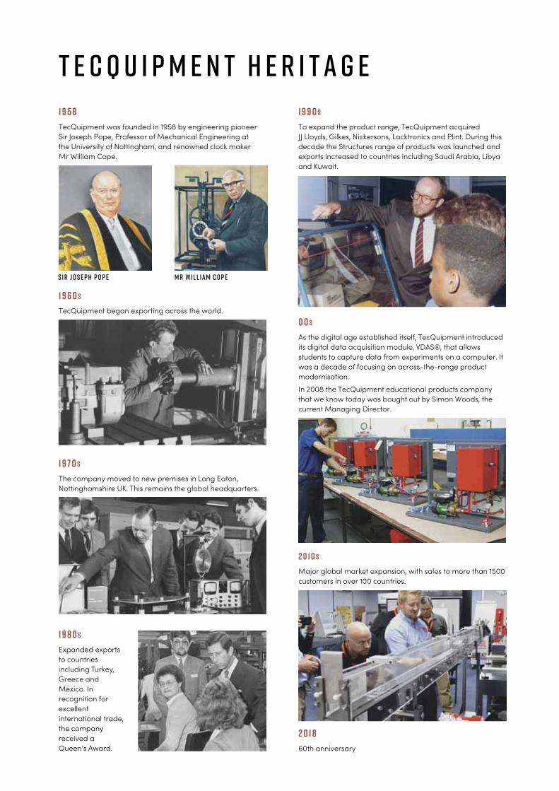
1958
TecQuipment was founded in 1958 by engineering pioneer
Sir Joseph Pope, Professor of Mechanical Engineering at
the University of Nottingham, and renowned clock maker
Mr William Cope.
1960s
TecQuipment began exporting across the world.
1970s
The company moved to new premises in Long Eaton,
Nottinghamshire UK. This remains the global headquarters.
1980s
Expanded exports
to countries
including Turkey,
Greece and
Mexico. In
recognition for
excellent
international trade,
the company
received a
Queen’s Award.
1990s
To expand the product range, TecQuipment acquired
JJ Lloyds, Gilkes, Nickersons, Locktronics and Plint. During this
decade the Structures range of products was launched and
exports increased to countries including Saudi Arabia, Libya
and Kuwait.
00s
As the digital age established itself, TecQuipment introduced
its digital data acquisition module, VDAS®, that allows
students to capture data from experiments on a computer. It
was a decade of focusing on across-the-range product
modernisation.
In 2008 the TecQuipment educational products company
that we know today was bought out by Simon Woods, the
current Managing Director.
2010s
Major global market expansion, with sales to more than 1500
customers in over 100 countries.
2018
60th anniversary
S i r J o s e p h P o p e M r W i l l i a m c o p e
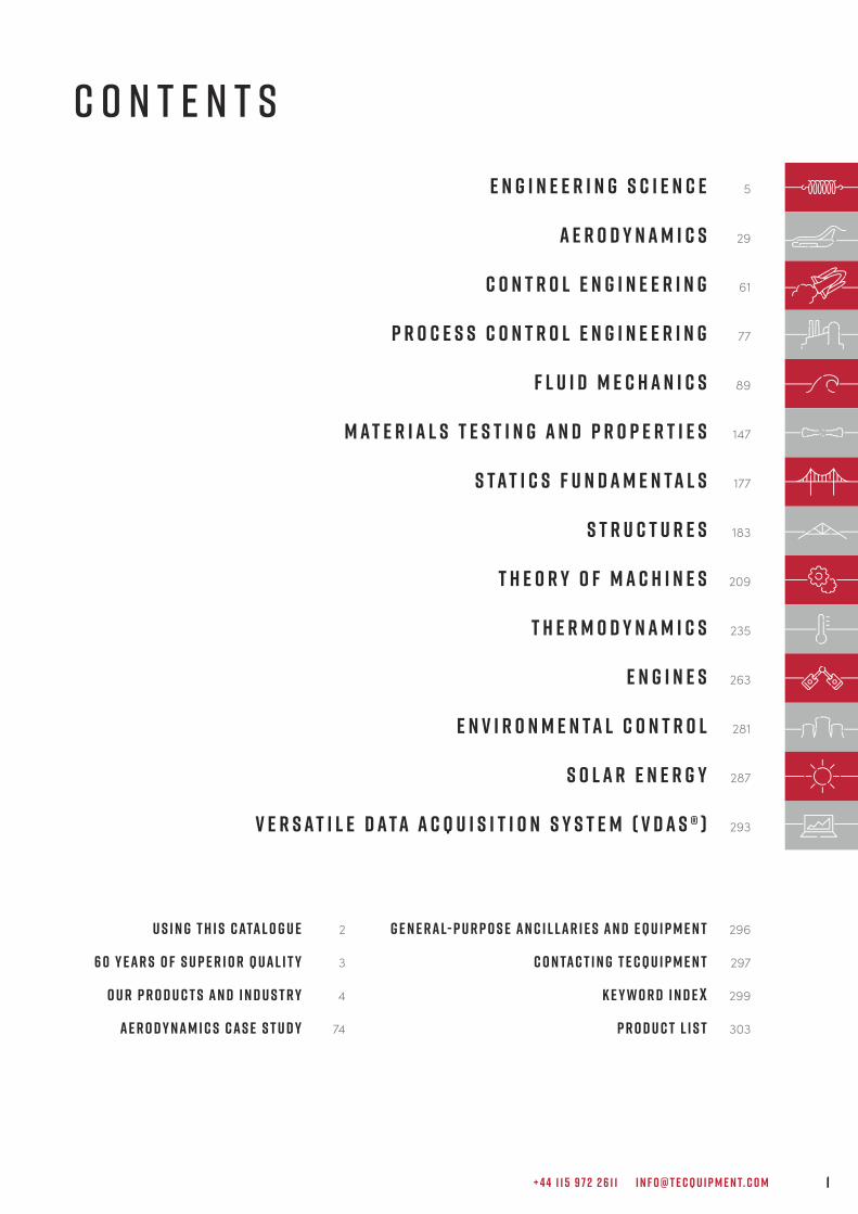
G e n e r a l- P u r p o s e A n c i l l a r i e s a n d E q u i p m e n t 296
C o n ta c t i n g T e c Q u i p m e n t 297
K e y w o r d I n d e x 299
P r o d u c t L i s t 303
+ 4 4 1 1 5 9 7 2 2 6 1 1 I N F O @ T E C Q U I P M E N T. C O M 1
C O N T E N T S
E N G I N E E R I N G S C I E N C E 5
A E R O D Y N A M I C S 29
C O N T R O L E N G I N E E R I N G 61
P R O C E S S C O N T R O L E N G I N E E R I N G 77
F L U I D M E C H A N I C S 89
M A T E R I A L S T E S T I N G A N D P R O P E R T I E S 147
S T A T I C S F U N D A M E N T A L S 177
S T R U C T U R E S 183
T H E O R Y O F M A C H I N E S 209
T H E R M O D Y N A M I C S 235
E N G I N E S 263
e n v i r o n m e n t a l c o n t r o l 281
s o l a r e n e r g y 287
V e r s a t i l e D a t a A c q u i s i t i o n S y s t e m ( V D A S ® ) 293
U s i n g t h i s c ata l o g u e 2
6 0 Y e a r s o f S u p e r i o r Q u a l i t y 3
O u r p r o d u c t s a n d i n d u s t r y 4
A e r o d y n a m i c s c a s e s t u d y 74
T E C Q U I P M E N T. C O M2
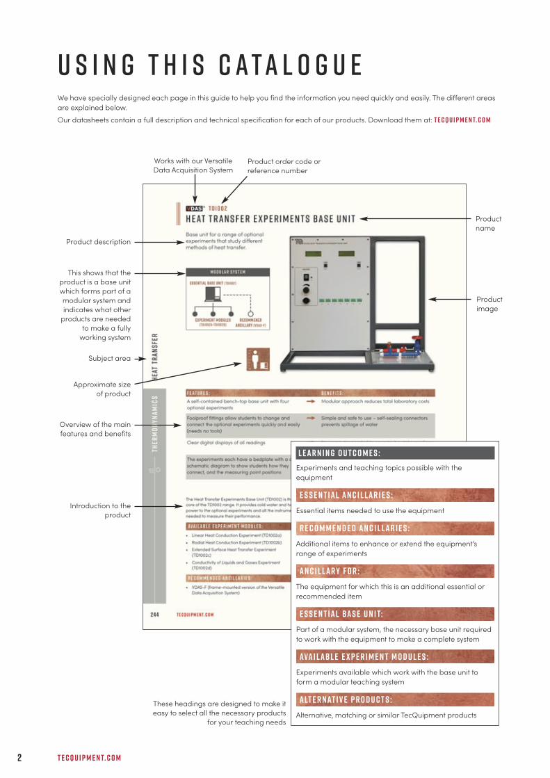
u s i n g t h i s c a t a l o g u eWe have specially designed each page in this guide to help you find the information you need quickly and easily. The different areas
are explained below.
Our datasheets contain a full description and technical specification for each of our products. Download them at: t e c q u i p m e n t. c o m
Product order code or
reference number
Product
image
Works with our Versatile
Data Acquisition System
Subject area
Product description
These headings are designed to make it
easy to select all the necessary products
for your teaching needs
Overview of the main
features and benefits
Product
name
Approximate size
of product
This shows that the
product is a base unit
which forms part of a
modular system and
indicates what other
products are needed
to make a fully
working system
l e a r n i n g o u t c o m e s :
Experiments and teaching topics possible with the
equipment
Essential items needed to use the equipment
Additional items to enhance or extend the equipment’s
range of experiments
The equipment for which this is an additional essential or
recommended item
Part of a modular system, the necessary base unit required
to work with the equipment to make a complete system
Experiments available which work with the base unit to
form a modular teaching system
Alternative, matching or similar TecQuipment products
E S S E N T IAL AN C I L LAR I E S :
R E C O M M E N D E D AN C I L LAR I E S :
AN C I L LAR Y F O R :
e s s e n t ial bas e u n i t:
ava i lab l e e x p e r i m e n t m o d u l e s :
alt e r nat i v e p r o d u c t s :
Introduction to the
product
+ 4 4 1 1 5 9 7 2 2 6 1 1 I N F O @ T E C Q U I P M E N T. C O M 3
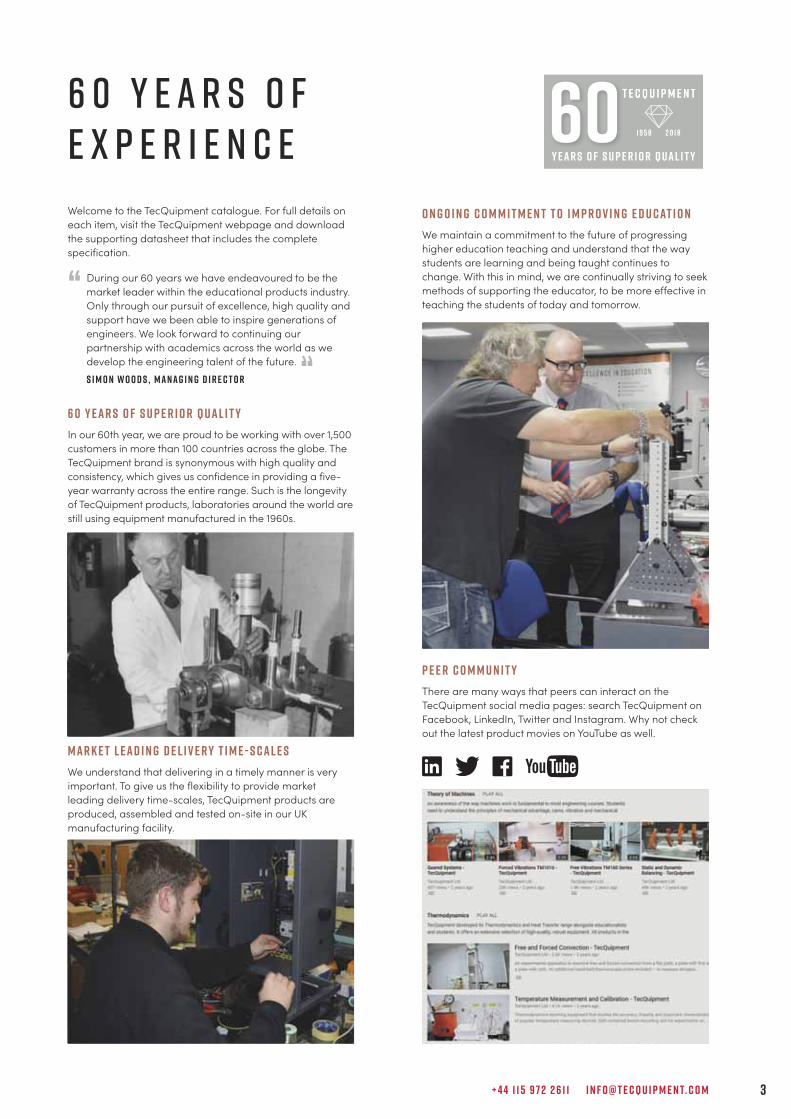
6 0 y e a r s o fe x p e r i e n c e
Welcome to the TecQuipment catalogue. For full details on
each item, visit the TecQuipment webpage and download
the supporting datasheet that includes the complete
specification.
During our 60 years we have endeavoured to be the
market leader within the educational products industry.
Only through our pursuit of excellence, high quality and
support have we been able to inspire generations of
engineers. We look forward to continuing our
partnership with academics across the world as we
develop the engineering talent of the future.
S i m o n W o o d s , M a n a g i n g D i r e c t o r
6 0 Y e a r s o f S u p e r i o r Q u a l i t y
In our 60th year, we are proud to be working with over 1,500
customers in more than 100 countries across the globe. The
TecQuipment brand is synonymous with high quality and
consistency, which gives us confidence in providing a five-
year warranty across the entire range. Such is the longevity
of TecQuipment products, laboratories around the world are
still using equipment manufactured in the 1960s.
M a r k e t L e a d i n g D e l i v e r y T i m e - S c a l e s
We understand that delivering in a timely manner is very
important. To give us the flexibility to provide market
leading delivery time-scales, TecQuipment products are
produced, assembled and tested on-site in our UK
manufacturing facility.
O n g o i n g C o m m i t m e n t t o I m p r o v i n g E d u c at i o n
We maintain a commitment to the future of progressing
higher education teaching and understand that the way
students are learning and being taught continues to
change. With this in mind, we are continually striving to seek
methods of supporting the educator, to be more effective in
teaching the students of today and tomorrow.
P e e r C o m m u n i t y
There are many ways that peers can interact on the
TecQuipment social media pages: search TecQuipment on
Facebook, LinkedIn, Twitter and Instagram. Why not check
out the latest product movies on YouTube as well.
“
“
T E C Q U I P M E N T. C O M4
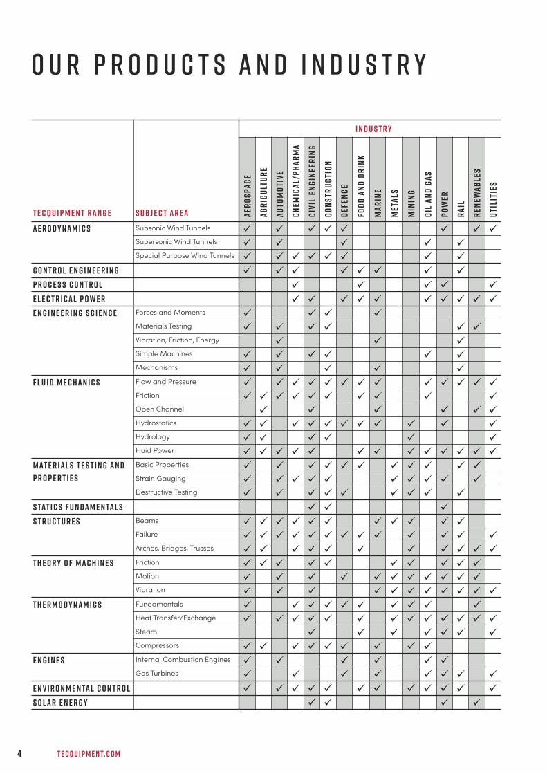
o u r p r o d u c t s a n d i n d u s t r y
I N D U S T R Y
Uti
liti
es
ü
ü
ü
ü
ü
ü
ü
ü
ü
ü
ü
ü
ü
ü
ü
ü
Ren
ewab
les
ü
ü
ü
ü
ü
ü
ü
ü
ü
ü
ü
ü
ü
ü
ü
Ra
il
ü
ü
ü
ü
ü
ü
ü
ü
ü
ü
ü
ü
ü
ü
ü
ü
ü
ü
ü
ü
ü
ü
Po
wer
ü
ü
ü
ü
ü
ü
ü
ü
ü
ü
ü
ü
ü
ü
ü
ü
ü
ü
ü
ü
ü
Oil
an
d G
as
ü
ü
ü
ü
ü
ü
ü
ü
ü
ü
ü
ü
ü
ü
ü
ü
ü
ü
ü
ü
ü
Min
ing
ü
ü
ü
ü
ü
ü
ü
ü
ü
ü
ü
ü
ü
ü
ü
ü
Met
als
ü
ü
ü
ü
ü
ü
ü
ü
ü
ü
Ma
rin
e
ü
ü
ü
ü
ü
ü
ü
ü
ü
ü
ü
ü
ü
ü
ü
ü
ü
ü
Foo
d a
nd
Dr
ink
ü
ü
ü
ü
ü
ü
ü
ü
ü
ü
ü
ü
ü
ü
Def
enc
e
ü
ü
ü
ü
ü
ü
ü
ü
ü
ü
ü
ü
ü
ü
ü
Co
ns
tru
cti
on
ü
ü
ü
ü
ü
ü
ü
ü
ü
ü
ü
ü
ü
ü
ü
ü
ü
ü
ü
ü
ü
ü
ü
Civ
il E
ng
inee
rin
g
ü
ü
ü
ü
ü
ü
ü
ü
ü
ü
ü
ü
ü
ü
ü
ü
ü
ü
ü
ü
ü
ü
ü
ü
ü
ü
ü
ü
Ch
emic
al/
Ph
ar
ma
ü
ü
ü
ü
ü
ü
ü
ü
ü
ü
ü
ü
ü
ü
ü
ü
ü
Au
tom
oti
ve
ü
ü
ü
ü
ü
ü
ü
ü
ü
ü
ü
ü
ü
ü
ü
ü
ü
ü
ü
ü
ü
ü
Ag
ric
ult
ur
e
ü
ü
ü
ü
ü
ü
ü
ü
ü
ü
aer
os
pa
ce
ü
ü
ü
ü
ü
ü
ü
ü
ü
ü
ü
ü
ü
ü
ü
ü
ü
ü
ü
ü
ü
ü
ü
ü
ü
ü
ü
ü
S U B J E C T A R E A
Subsonic Wind Tunnels
Supersonic Wind Tunnels
Special Purpose Wind Tunnels
Forces and Moments
Materials Testing
Vibration, Friction, Energy
Simple Machines
Mechanisms
Flow and Pressure
Friction
Open Channel
Hydrostatics
Hydrology
Fluid Power
Basic Properties
Strain Gauging
Destructive Testing
Beams
Failure
Arches, Bridges, Trusses
Friction
Motion
Vibration
Fundamentals
Heat Transfer/Exchange
Steam
Compressors
Internal Combustion Engines
Gas Turbines
t e c q u i p m e n t R A N G E
A e r o d y n a m i c s
C o n t r o l E n g i n e e r i n g
P r o c e s s C o n t r o l
e l e c t r i c a l p o w e r
E n g i n e e r i n g S c i e n c e
F l u i d M e c h a n i c s
M at e r i a l s T e s t i n g a n d
P r o p e r t i e s
S tat i c s F u n d a m e n ta l s
S t r u c t u r e s
T h e o r y o f M a c h i n e s
T h e r m o d y n a m i c s
E n g i n e s
e n v i r o n m e n ta l c o n t r o l
S o l a r E n e r g y
+ 4 4 1 1 5 9 7 2 2 6 1 1 I N F O @ T E C Q U I P M E N T. C O M 5
Eng
ineer
ing
Sc
ienc
e
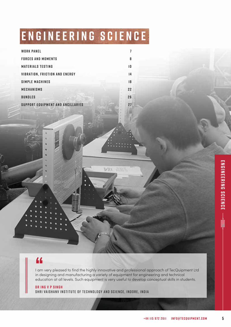
E n g i n e e r i n g S c i e n c e
“I am very pleased to find the highly innovative and professional approach of TecQuipment Ltdin designing and manufacturing a variety of equipment for engineering and technicaleducation at all levels. Such equipment is very useful to develop conceptual skills in students.
D r I n g V P S i n g hS h r i Va i s h a n v I n s t i t u t e o f T e c h n o l o g y a n d S c i e n c e , I n d o r e , I n d i a
W o r k Pa n e l 7
f o r c e s a n d m o m e n t s 8
m at e r i a l s t e s t i n g 1 0
v i b r at i o n , f r i c t i o n a n d e n e r g y 1 4
s i m p l e m a c h i n e s 1 8
m e c h a n i s m s 2 2
B u n d l e s 2 6
S u p p o r t E q u i p m e n t a n d A n c i l l a r i e s 2 7
T E C Q U I P M E N T. C O M6
eng
inee
rin
g s
cie
nc
e
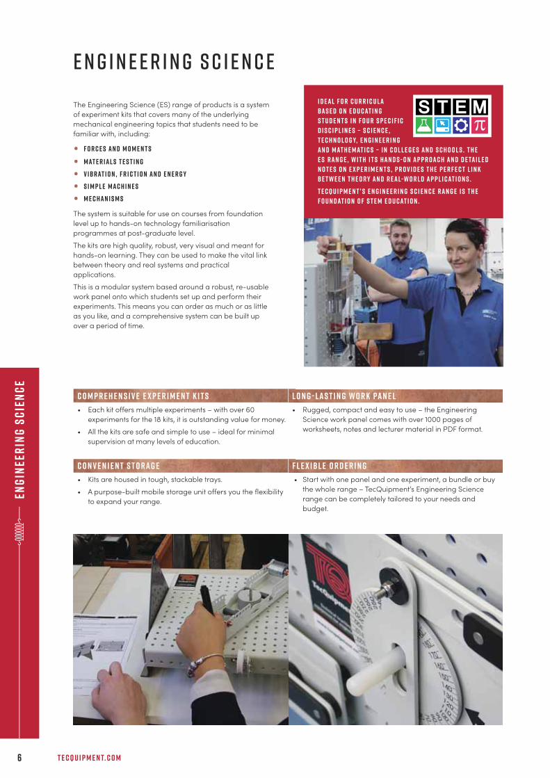
The Engineering Science (ES) range of products is a system
of experiment kits that covers many of the underlying
mechanical engineering topics that students need to be
familiar with, including:
• F o r c e s a n d m o m e n t s
• M at e r i a l s t e s t i n g
• V i b r at i o n , F r i c t i o n a n d E n e r g y
• S i m p l e m a c h i n e s
• M e c h a n i s m s
The system is suitable for use on courses from foundation
level up to hands-on technology familiarisation
programmes at post-graduate level.
The kits are high quality, robust, very visual and meant for
hands-on learning. They can be used to make the vital link
between theory and real systems and practical
applications.
This is a modular system based around a robust, re-usable
work panel onto which students set up and perform their
experiments. This means you can order as much or as little
as you like, and a comprehensive system can be built up
over a period of time.
I d e a l f o r c u r r i c u l a
b a s e d o n e d u c at i n g
s t u d e n t s i n f o u r s p e c i f i c
d i s c i p l i n e s – s c i e n c e ,
t e c h n o l o g y, e n g i n e e r i n g
a n d m at h e m at i c s – i n c o l l e g e s a n d s c h o o l s . T h e
E S r a n g e , w i t h i t s h a n d s - o n a p p r o a c h a n d d e ta i l e d
n o t e s o n e x p e r i m e n t s , p r o v i d e s t h e p e r f e c t l i n k
b e t w e e n t h e o r y a n d r e a l- w o r l d a p p l i c at i o n s .
T e c Q u i p m e n t ’ s E n g i n e e r i n g S c i e n c e r a n g e i s t h e
f o u n d at i o n o f S T E M e d u c at i o n .
C o m p r e h e n s i v e e x p e r i m e n t k i t s L o n g - l a s t i n g w o r k pa n e l
• Each kit offers multiple experiments – with over 60
experiments for the 18 kits, it is outstanding value for money.
• All the kits are safe and simple to use – ideal for minimal
supervision at many levels of education.
• Rugged, compact and easy to use – the Engineering
Science work panel comes with over 1000 pages of
worksheets, notes and lecturer material in PDF format.
C o n v e n i e n t s t o r a g e F l e x i b l e o r d e r i n g
• Kits are housed in tough, stackable trays.
• A purpose-built mobile storage unit offers you the flexibility
to expand your range.
• Start with one panel and one experiment, a bundle or buy
the whole range – TecQuipment’s Engineering Science
range can be completely tailored to your needs and
budget.
E n g i n e e r i n g S c i e n c e
+ 4 4 1 1 5 9 7 2 2 6 1 1 I N F O @ T E C Q U I P M E N T. C O M 7
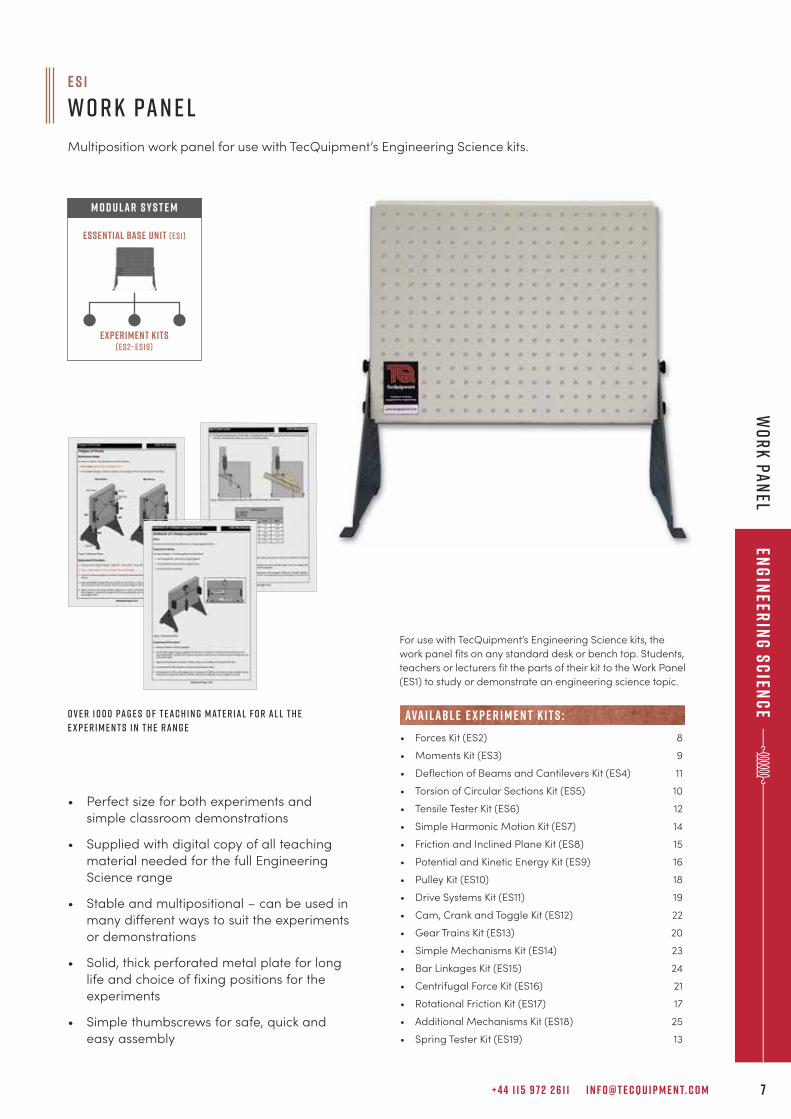
E S 1
W O R K PA N E L
Multiposition work panel for use with TecQuipment’s Engineering Science kits.
• Forces Kit (ES2) 8
• Moments Kit (ES3) 9
• Deflection of Beams and Cantilevers Kit (ES4) 11
• Torsion of Circular Sections Kit (ES5) 10
• Tensile Tester Kit (ES6) 12
• Simple Harmonic Motion Kit (ES7) 14
• Friction and Inclined Plane Kit (ES8) 15
• Potential and Kinetic Energy Kit (ES9) 16
• Pulley Kit (ES10) 18
• Drive Systems Kit (ES11) 19
• Cam, Crank and Toggle Kit (ES12) 22
• Gear Trains Kit (ES13) 20
• Simple Mechanisms Kit (ES14) 23
• Bar Linkages Kit (ES15) 24
• Centrifugal Force Kit (ES16) 21
• Rotational Friction Kit (ES17) 17
• Additional Mechanisms Kit (ES18) 25
• Spring Tester Kit (ES19) 13
ava i labl e e x p e r i m e n t k i t s :
Experiment Kits(ES2–ES19)
Essential Base Unit (ES1)
M O D U LAR S Y S T E M
For use with TecQuipment’s Engineering Science kits, the
work panel fits on any standard desk or bench top. Students,
teachers or lecturers fit the parts of their kit to the Work Panel
(ES1) to study or demonstrate an engineering science topic.
• Perfect size for both experiments and
simple classroom demonstrations
• Supplied with digital copy of all teaching
material needed for the full Engineering
Science range
• Stable and multipositional – can be used in
many different ways to suit the experiments
or demonstrations
• Solid, thick perforated metal plate for long
life and choice of fixing positions for the
experiments
• Simple thumbscrews for safe, quick and
easy assembly
o v e r 1 0 0 0 pa g e s o f T e a c h i n g m at e r i a l f o r a l l t h e
e x p e r i m e n t s i n t h e r a n g e
Eng
ineer
ing
Sc
ienc
ew
or
k p
an
el
T E C Q U I P M E N T. C O M8
eng
inee
rin
g s
cie
nc
eFo
rc
es a
nd
mo
men
ts
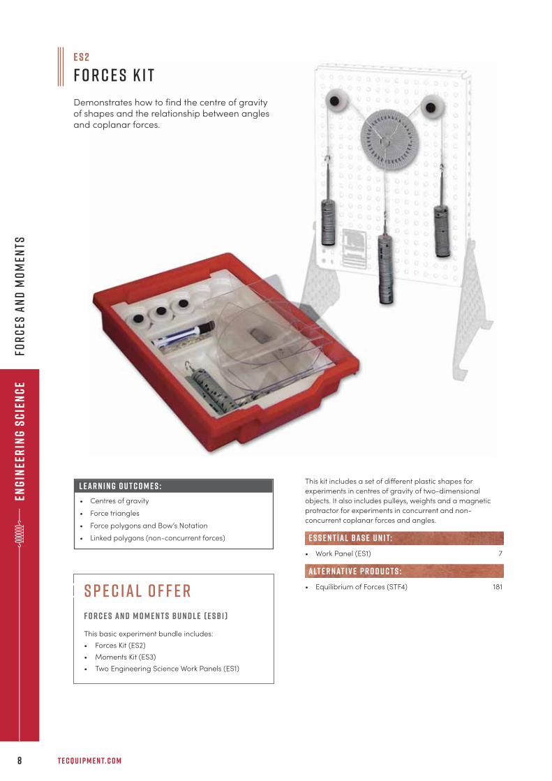
This kit includes a set of different plastic shapes for
experiments in centres of gravity of two-dimensional
objects. It also includes pulleys, weights and a magnetic
protractor for experiments in concurrent and non-
concurrent coplanar forces and angles.
• Work Panel (ES1) 7
• Equilibrium of Forces (STF4) 181
e s s e n t ial bas e u n i t:
alt e r nat i v e p r o d u c t s :
E S 2
F O R C E S K I T
Demonstrates how to find the centre of gravityof shapes and the relationship between anglesand coplanar forces.
L E A R N I N G O U T C O M E S :
• Centres of gravity
• Force triangles
• Force polygons and Bow’s Notation
• Linked polygons (non-concurrent forces)
s p e c ial o f f e r
F o r c e s an d M o m e n t s Bu n d l e ( E SB 1 )
This basic experiment bundle includes:
• Forces Kit (ES2)
• Moments Kit (ES3)
• Two Engineering Science Work Panels (ES1)
+ 4 4 1 1 5 9 7 2 2 6 1 1 I N F O @ T E C Q U I P M E N T. C O M 9
Eng
ineer
ing
Sc
ienc
eFo
rc
es a
nd
mo
men
ts
e s 3
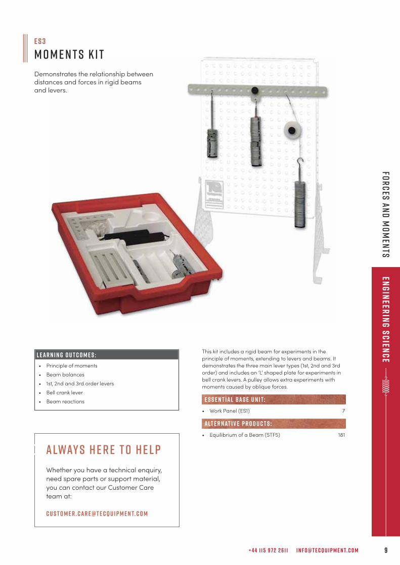
M o m e n t s K i t
Demonstrates the relationship betweendistances and forces in rigid beamsand levers.
L E A R N I N G O U T C O M E S :
• Principle of moments
• Beam balances
• 1st, 2nd and 3rd order levers
• Bell crank lever
• Beam reactions
This kit includes a rigid beam for experiments in the
principle of moments, extending to levers and beams. It
demonstrates the three main lever types (1st, 2nd and 3rd
order) and includes an ‘L’ shaped plate for experiments in
bell crank levers. A pulley allows extra experiments with
moments caused by oblique forces.
• Work Panel (ES1) 7
• Equilibrium of a Beam (STF5) 181
e s s e n t ial bas e u n i t:
alt e r nat i v e p r o d u c t s :
alway s h e r e t o h e l p
Whether you have a technical enquiry,
need spare parts or support material,
you can contact our Customer Care
team at:
c u s t o m e r . car e@t e cqu i p m e n t. c o m
T E C Q U I P M E N T. C O M1 0
eng
inee
rin
g s
cie
nc
eM
ater
ials
tes
tin
g
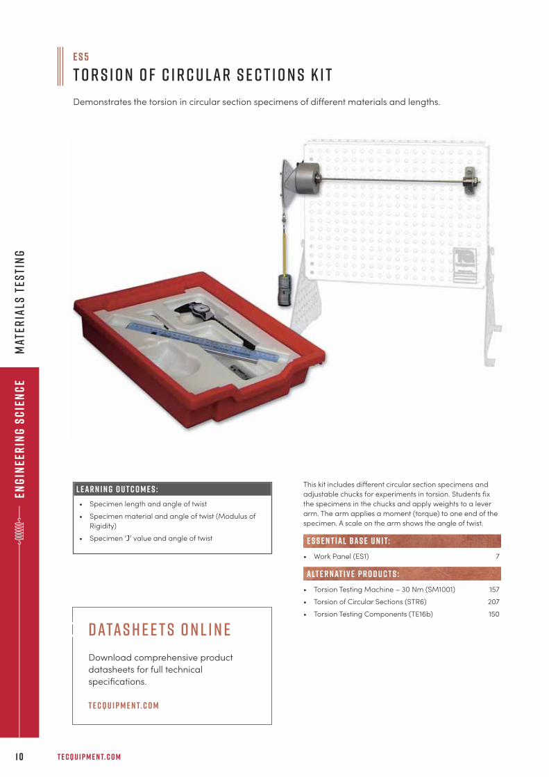
This kit includes different circular section specimens and
adjustable chucks for experiments in torsion. Students fix
the specimens in the chucks and apply weights to a lever
arm. The arm applies a moment (torque) to one end of the
specimen. A scale on the arm shows the angle of twist.
• Work Panel (ES1) 7
• Torsion Testing Machine – 30 Nm (SM1001) 157
• Torsion of Circular Sections (STR6) 207
• Torsion Testing Components (TE16b) 150
e s s e n t ial bas e u n i t:
alt e r nat i v e p r o d u c t s :
e s 5
T o r s i o n o f C i r c u l a r S e c t i o n s K i t
Demonstrates the torsion in circular section specimens of different materials and lengths.
L E A R N I N G O U T C O M E S :
• Specimen length and angle of twist
• Specimen material and angle of twist (Modulus of
Rigidity)
• Specimen ‘J’ value and angle of twist
datas h e e t s o n l i n e
Download comprehensive product
datasheets for full technical
specifications.
t e cqu i p m e n t. c o m
+ 4 4 1 1 5 9 7 2 2 6 1 1 I N F O @ T E C Q U I P M E N T. C O M 1 1
Eng
ineer
ing
Sc
ienc
em
ateria
ls tes
ting
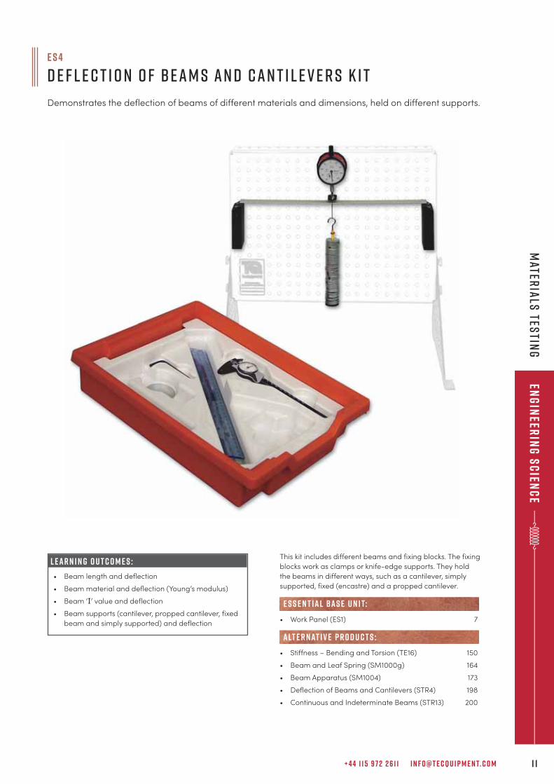
e s 4
D e f l e c t i o n o f B e a m s a n d C a n t i l e v e r s K i t
Demonstrates the deflection of beams of different materials and dimensions, held on different supports.
This kit includes different beams and fixing blocks. The fixing
blocks work as clamps or knife-edge supports. They hold
the beams in different ways, such as a cantilever, simply
supported, fixed (encastre) and a propped cantilever.
• Work Panel (ES1) 7
• Stiffness – Bending and Torsion (TE16) 150
• Beam and Leaf Spring (SM1000g) 164
• Beam Apparatus (SM1004) 173
• Deflection of Beams and Cantilevers (STR4) 198
• Continuous and Indeterminate Beams (STR13) 200
e s s e n t ial bas e u n i t:
alt e r nat i v e p r o d u c t s :
L E A R N I N G O U T C O M E S :
• Beam length and deflection
• Beam material and deflection (Young’s modulus)
• Beam ‘I’ value and deflection
• Beam supports (cantilever, propped cantilever, fixed
beam and simply supported) and deflection
T E C Q U I P M E N T. C O M1 2
eng
inee
rin
g s
cie
nc
em
ater
ials
tes
tin
g
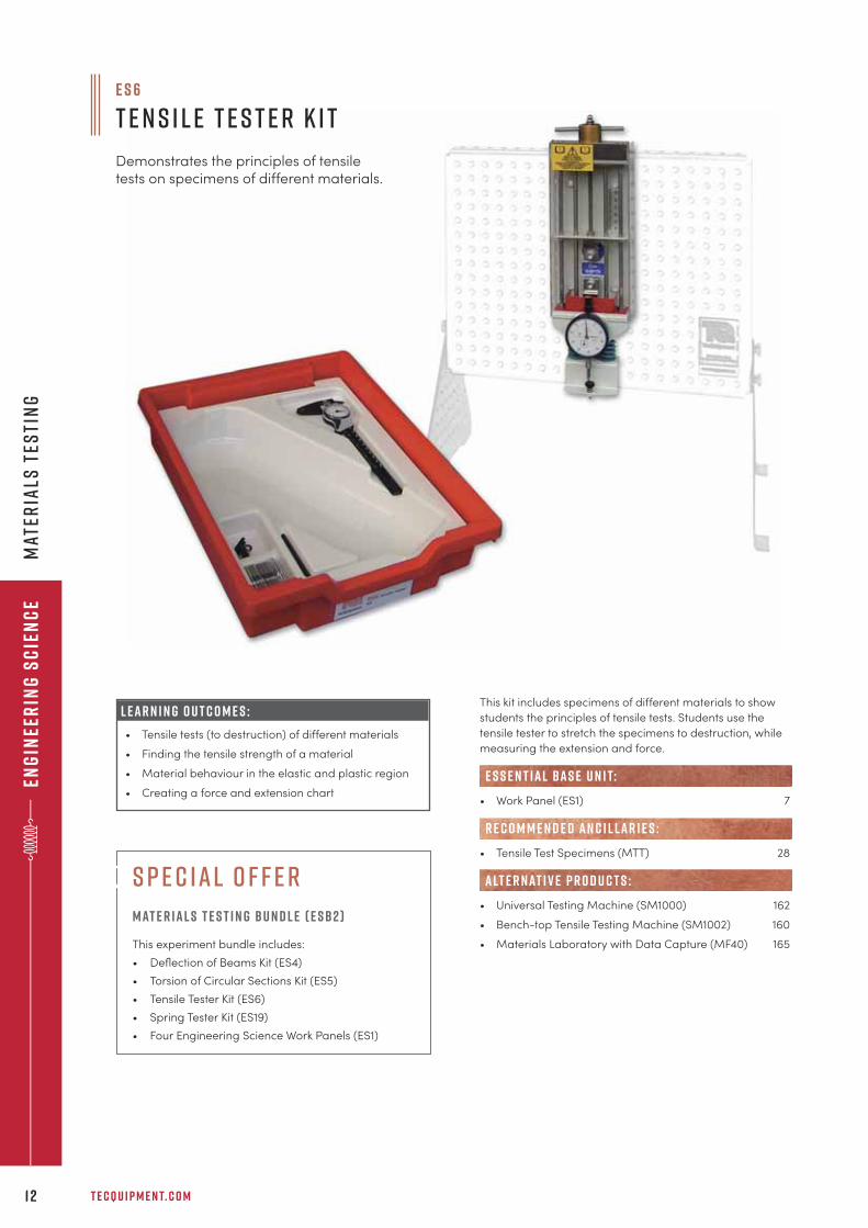
This kit includes specimens of different materials to show
students the principles of tensile tests. Students use the
tensile tester to stretch the specimens to destruction, while
measuring the extension and force.
• Work Panel (ES1) 7
• Tensile Test Specimens (MTT) 28
• Universal Testing Machine (SM1000) 162
• Bench-top Tensile Testing Machine (SM1002) 160
• Materials Laboratory with Data Capture (MF40) 165
R E C O M M E N D E D AN C I L LAR I E S :
e s s e n t ial bas e u n i t:
alt e r nat i v e p r o d u c t s :
L E A R N I N G O U T C O M E S :
• Tensile tests (to destruction) of different materials
• Finding the tensile strength of a material
• Material behaviour in the elastic and plastic region
• Creating a force and extension chart
e s 6
T e n s i l e T e s t e r K i t
Demonstrates the principles of tensiletests on specimens of different materials.
s p e c ial o f f e r
Mat e r ial s T e s t i n g Bu n d l e ( E SB2 )
This experiment bundle includes:
• Deflection of Beams Kit (ES4)
• Torsion of Circular Sections Kit (ES5)
• Tensile Tester Kit (ES6)
• Spring Tester Kit (ES19)
• Four Engineering Science Work Panels (ES1)
+ 4 4 1 1 5 9 7 2 2 6 1 1 I N F O @ T E C Q U I P M E N T. C O M 1 3
Eng
ineer
ing
Sc
ienc
em
ateria
ls Tes
ting
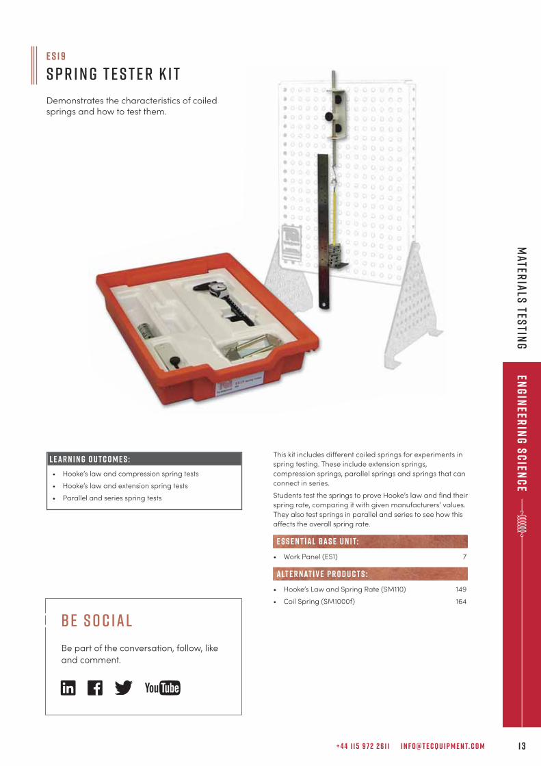
L E A R N I N G O U T C O M E S :
• Hooke’s law and compression spring tests
• Hooke’s law and extension spring tests
• Parallel and series spring tests
This kit includes different coiled springs for experiments in
spring testing. These include extension springs,
compression springs, parallel springs and springs that can
connect in series.
Students test the springs to prove Hooke’s law and find their
spring rate, comparing it with given manufacturers’ values.
They also test springs in parallel and series to see how this
affects the overall spring rate.
• Work Panel (ES1) 7
• Hooke’s Law and Spring Rate (SM110) 149
• Coil Spring (SM1000f) 164
e s s e n t ial bas e u n i t:
alt e r nat i v e p r o d u c t s :
e s 1 9
S p r i n g T e s t e r K i t
Demonstrates the characteristics of coiledsprings and how to test them.
b e s o c ial
Be part of the conversation, follow, like
and comment.
T E C Q U I P M E N T. C O M1 4
eng
inee
rin
g s
cie
nc
eV
ibr
atio
n,
fric
tio
n a
nd
en
erg
y
e s 7
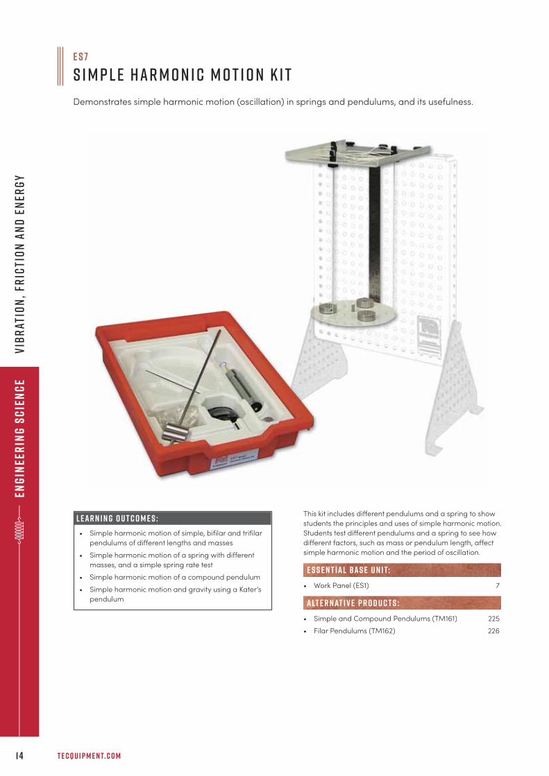
S i m p l e H a r m o n i c M o t i o n K i t
Demonstrates simple harmonic motion (oscillation) in springs and pendulums, and its usefulness.
This kit includes different pendulums and a spring to show
students the principles and uses of simple harmonic motion.
Students test different pendulums and a spring to see how
different factors, such as mass or pendulum length, affect
simple harmonic motion and the period of oscillation.
• Work Panel (ES1) 7
• Simple and Compound Pendulums (TM161) 225
• Filar Pendulums (TM162) 226
e s s e n t ial bas e u n i t:
alt e r nat i v e p r o d u c t s :
L E A R N I N G O U T C O M E S :
• Simple harmonic motion of simple, bifilar and trifilar
pendulums of different lengths and masses
• Simple harmonic motion of a spring with different
masses, and a simple spring rate test
• Simple harmonic motion of a compound pendulum
• Simple harmonic motion and gravity using a Kater’s
pendulum
+ 4 4 1 1 5 9 7 2 2 6 1 1 I N F O @ T E C Q U I P M E N T. C O M 1 5
Eng
ineer
ing
Sc
ienc
eV
ibr
ation
, fric
tion
an
d en
erg
y
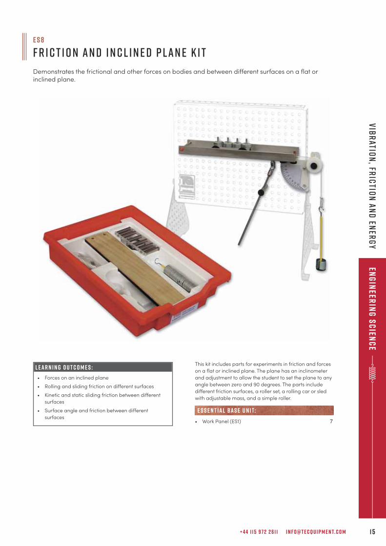
L E A R N I N G O U T C O M E S :
• Forces on an inclined plane
• Rolling and sliding friction on different surfaces
• Kinetic and static sliding friction between different
surfaces
• Surface angle and friction between different
surfaces
e s 8
F r i c t i o n a n d I n c l i n e d P l a n e K i t
Demonstrates the frictional and other forces on bodies and between different surfaces on a flat orinclined plane.
This kit includes parts for experiments in friction and forces
on a flat or inclined plane. The plane has an inclinometer
and adjustment to allow the student to set the plane to any
angle between zero and 90 degrees. The parts include
different friction surfaces, a roller set, a rolling car or sled
with adjustable mass, and a simple roller.
• Work Panel (ES1) 7
e s s e n t ial bas e u n i t:
T E C Q U I P M E N T. C O M1 6
eng
inee
rin
g s
cie
nc
eV
ibr
atio
n,
fric
tio
n a
nd
en
erg
y
L E A R N I N G O U T C O M E S :
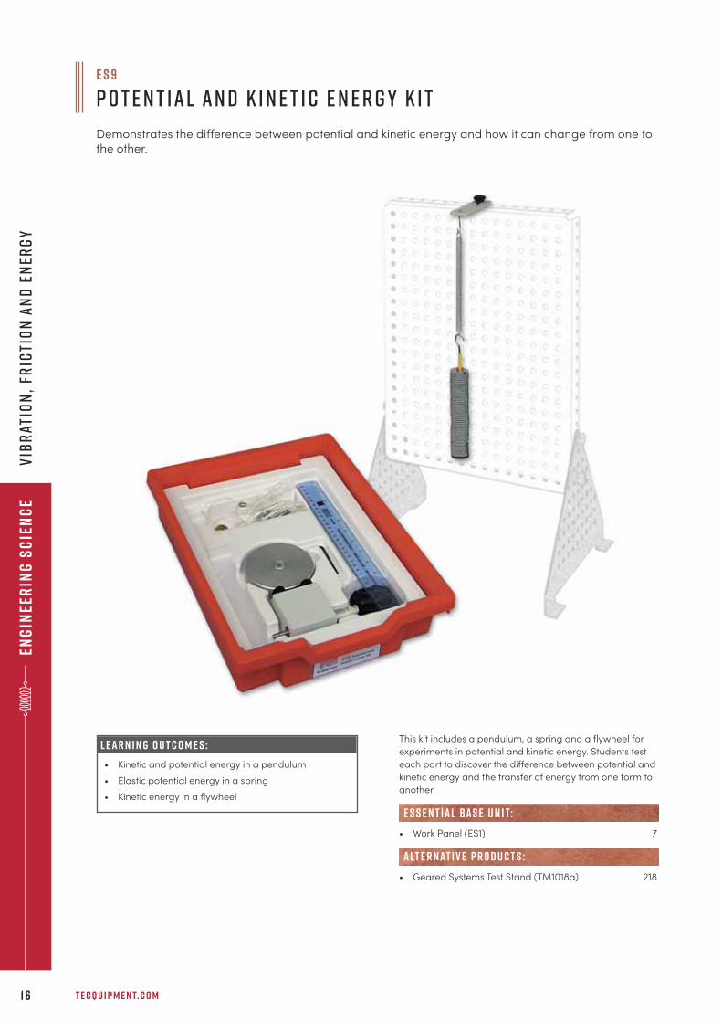
• Kinetic and potential energy in a pendulum
• Elastic potential energy in a spring
• Kinetic energy in a flywheel
e s 9
P o t e n t i a l a n d K i n e t i c E n e r g y K i t
Demonstrates the difference between potential and kinetic energy and how it can change from one tothe other.
This kit includes a pendulum, a spring and a flywheel for
experiments in potential and kinetic energy. Students test
each part to discover the difference between potential and
kinetic energy and the transfer of energy from one form to
another.
• Work Panel (ES1) 7
• Geared Systems Test Stand (TM1018a) 218
e s s e n t ial bas e u n i t:
alt e r nat i v e p r o d u c t s :
+ 4 4 1 1 5 9 7 2 2 6 1 1 I N F O @ T E C Q U I P M E N T. C O M 1 7
Eng
ineer
ing
Sc
ienc
eV
ibr
ation
, fric
tion
an
d en
erg
y
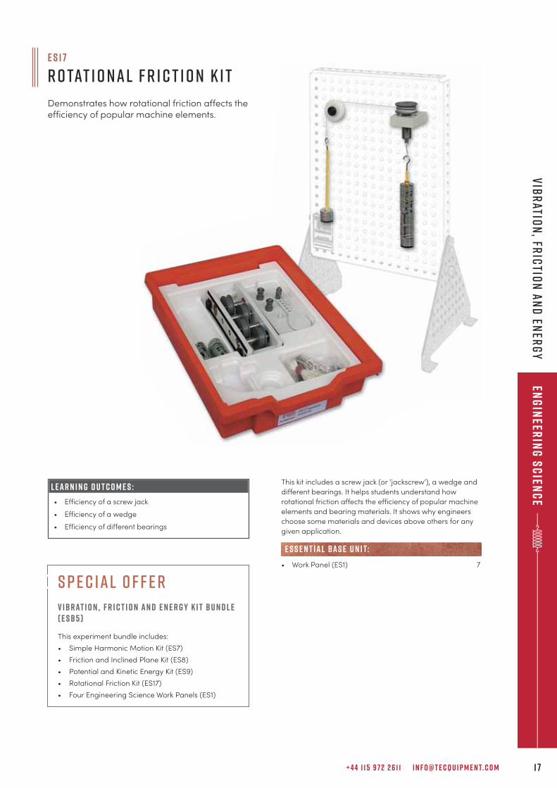
L E A R N I N G O U T C O M E S :
• Efficiency of a screw jack
• Efficiency of a wedge
• Efficiency of different bearings
This kit includes a screw jack (or ‘jackscrew’), a wedge and
different bearings. It helps students understand how
rotational friction affects the efficiency of popular machine
elements and bearing materials. It shows why engineers
choose some materials and devices above others for any
given application.
• Work Panel (ES1) 7
e s s e n t ial bas e u n i t:
e s 1 7
R o tat i o n a l F r i c t i o n K i t
Demonstrates how rotational friction affects theefficiency of popular machine elements.
s p e c ial o f f e r
V ibrat i o n , F r i c t i o n an d E n e r g y K i t Bu n d l e( E SB5 )
This experiment bundle includes:
• Simple Harmonic Motion Kit (ES7)
• Friction and Inclined Plane Kit (ES8)
• Potential and Kinetic Energy Kit (ES9)
• Rotational Friction Kit (ES17)
• Four Engineering Science Work Panels (ES1)
T E C Q U I P M E N T. C O M1 8
eng
inee
rin
g s
cie
nc
eS
imp
le M
ac
hin
es
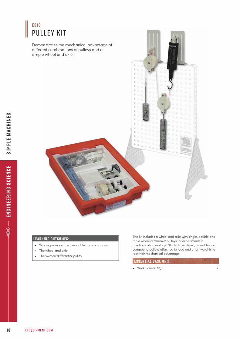
This kit includes a wheel and axle with single, double and
triple wheel or ‘sheave’ pulleys for experiments in
mechanical advantage. Students test fixed, movable and
compound pulleys attached to load and effort weights to
test their mechanical advantage.
• Work Panel (ES1) 7
e s s e n t ial bas e u n i t:
e s 1 0
P u l l e y K i t
Demonstrates the mechanical advantage ofdifferent combinations of pulleys and asimple wheel and axle.
L E A R N I N G O U T C O M E S :
• Simple pulleys – fixed, movable and compound
• The wheel and axle
• The Weston differential pulley
+ 4 4 1 1 5 9 7 2 2 6 1 1 I N F O @ T E C Q U I P M E N T. C O M 1 9
Eng
ineer
ing
Sc
ienc
eS
imp
le Ma
ch
ines
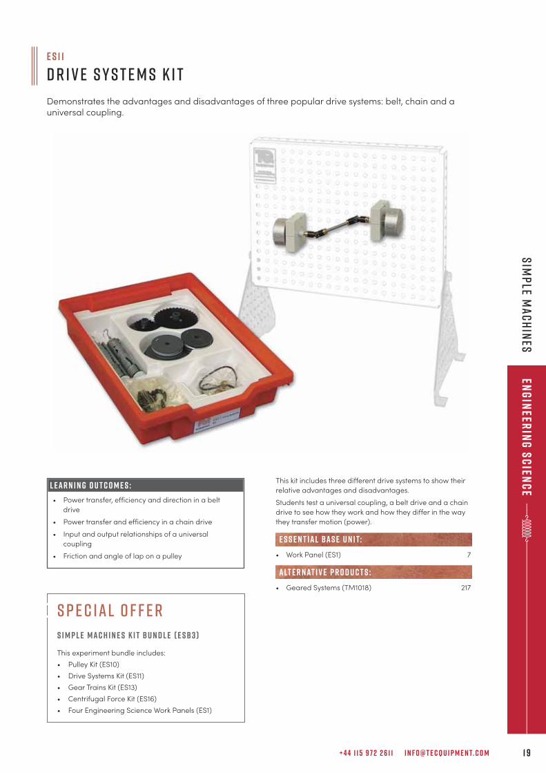
This kit includes three different drive systems to show their
relative advantages and disadvantages.
Students test a universal coupling, a belt drive and a chain
drive to see how they work and how they differ in the way
they transfer motion (power).
• Work Panel (ES1) 7
• Geared Systems (TM1018) 217
e s s e n t ial bas e u n i t:
alt e r nat i v e p r o d u c t s :
e s 1 1
D r i v e S y s t e m s K i t
Demonstrates the advantages and disadvantages of three popular drive systems: belt, chain and auniversal coupling.
L E A R N I N G O U T C O M E S :
• Power transfer, efficiency and direction in a belt
drive
• Power transfer and efficiency in a chain drive
• Input and output relationships of a universal
coupling
• Friction and angle of lap on a pulley
s p e c ial o f f e r
s i m p l e mac h i n e s k i t bu n d l e ( E SB3 )
This experiment bundle includes:
• Pulley Kit (ES10)
• Drive Systems Kit (ES11)
• Gear Trains Kit (ES13)
• Centrifugal Force Kit (ES16)
• Four Engineering Science Work Panels (ES1)
T E C Q U I P M E N T. C O M2 0
eng
inee
rin
g s
cie
nc
eS
imp
le M
ac
hin
es
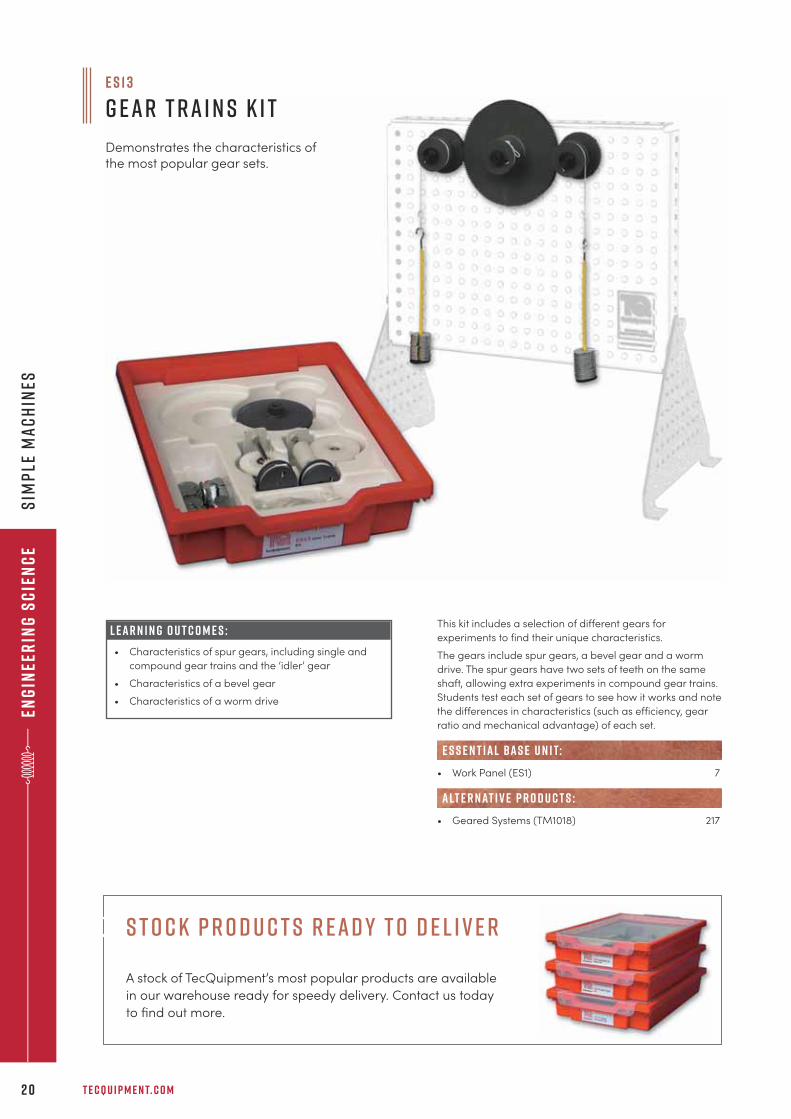
L E A R N I N G O U T C O M E S :
• Characteristics of spur gears, including single and
compound gear trains and the ‘idler’ gear
• Characteristics of a bevel gear
• Characteristics of a worm drive
This kit includes a selection of different gears for
experiments to find their unique characteristics.
The gears include spur gears, a bevel gear and a worm
drive. The spur gears have two sets of teeth on the same
shaft, allowing extra experiments in compound gear trains.
Students test each set of gears to see how it works and note
the differences in characteristics (such as efficiency, gear
ratio and mechanical advantage) of each set.
• Work Panel (ES1) 7
• Geared Systems (TM1018) 217
e s s e n t ial bas e u n i t:
alt e r nat i v e p r o d u c t s :
e s 1 3
G e a r T r a i n s K i t
Demonstrates the characteristics ofthe most popular gear sets.
S t o c k P r o d u c t s R ead y t o D e l i v e r
A stock of TecQuipment’s most popular products are available
in our warehouse ready for speedy delivery. Contact us today
to find out more.
+ 4 4 1 1 5 9 7 2 2 6 1 1 I N F O @ T E C Q U I P M E N T. C O M 2 1
Eng
ineer
ing
Sc
ienc
eS
imp
le ma
ch
ines
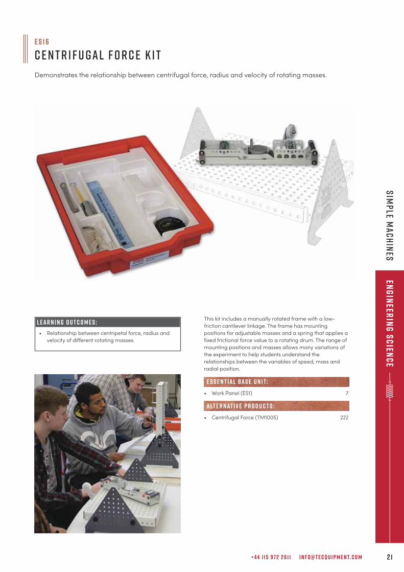
L E A R N I N G O U T C O M E S :
• Relationship between centripetal force, radius and
velocity of different rotating masses.
This kit includes a manually rotated frame with a low-
friction cantilever linkage. The frame has mounting
positions for adjustable masses and a spring that applies a
fixed frictional force value to a rotating drum. The range of
mounting positions and masses allows many variations of
the experiment to help students understand the
relationships between the variables of speed, mass and
radial position.
• Work Panel (ES1) 7
• Centrifugal Force (TM1005) 222
e s s e n t ial bas e u n i t:
alt e r nat i v e p r o d u c t s :
e s 1 6
C e n t r i f u g a l F o r c e K i t
Demonstrates the relationship between centrifugal force, radius and velocity of rotating masses.
T E C Q U I P M E N T. C O M2 2
eng
inee
rin
g s
cie
nc
eM
ech
an
ism
s
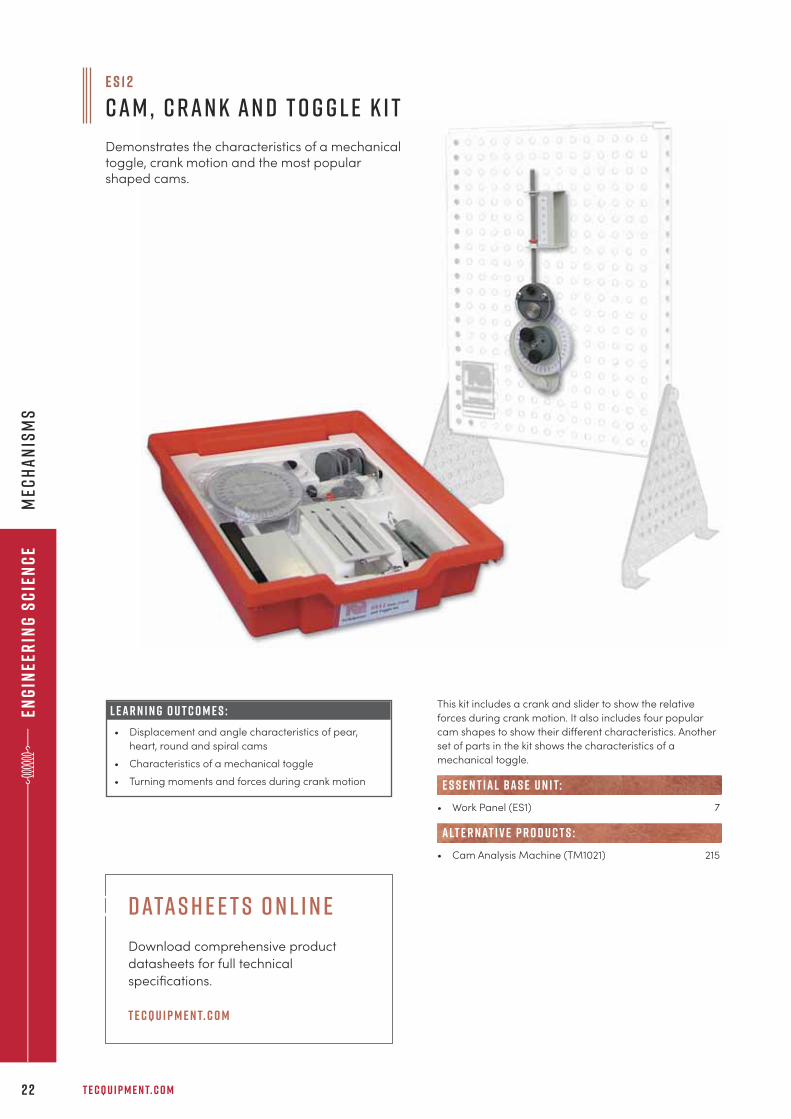
L E A R N I N G O U T C O M E S :
• Displacement and angle characteristics of pear,
heart, round and spiral cams
• Characteristics of a mechanical toggle
• Turning moments and forces during crank motion
This kit includes a crank and slider to show the relative
forces during crank motion. It also includes four popular
cam shapes to show their different characteristics. Another
set of parts in the kit shows the characteristics of a
mechanical toggle.
• Work Panel (ES1) 7
• Cam Analysis Machine (TM1021) 215
e s s e n t ial bas e u n i t:
alt e r nat i v e p r o d u c t s :
E S 1 2
C a m , C r a n k a n d T o g g l e K i t
Demonstrates the characteristics of a mechanicaltoggle, crank motion and the most popularshaped cams.
datas h e e t s o n l i n e
Download comprehensive product
datasheets for full technical
specifications.
t e cqu i p m e n t. c o m
+ 4 4 1 1 5 9 7 2 2 6 1 1 I N F O @ T E C Q U I P M E N T. C O M 2 3
Eng
ineer
ing
Sc
ienc
eM
ech
an
ism
s
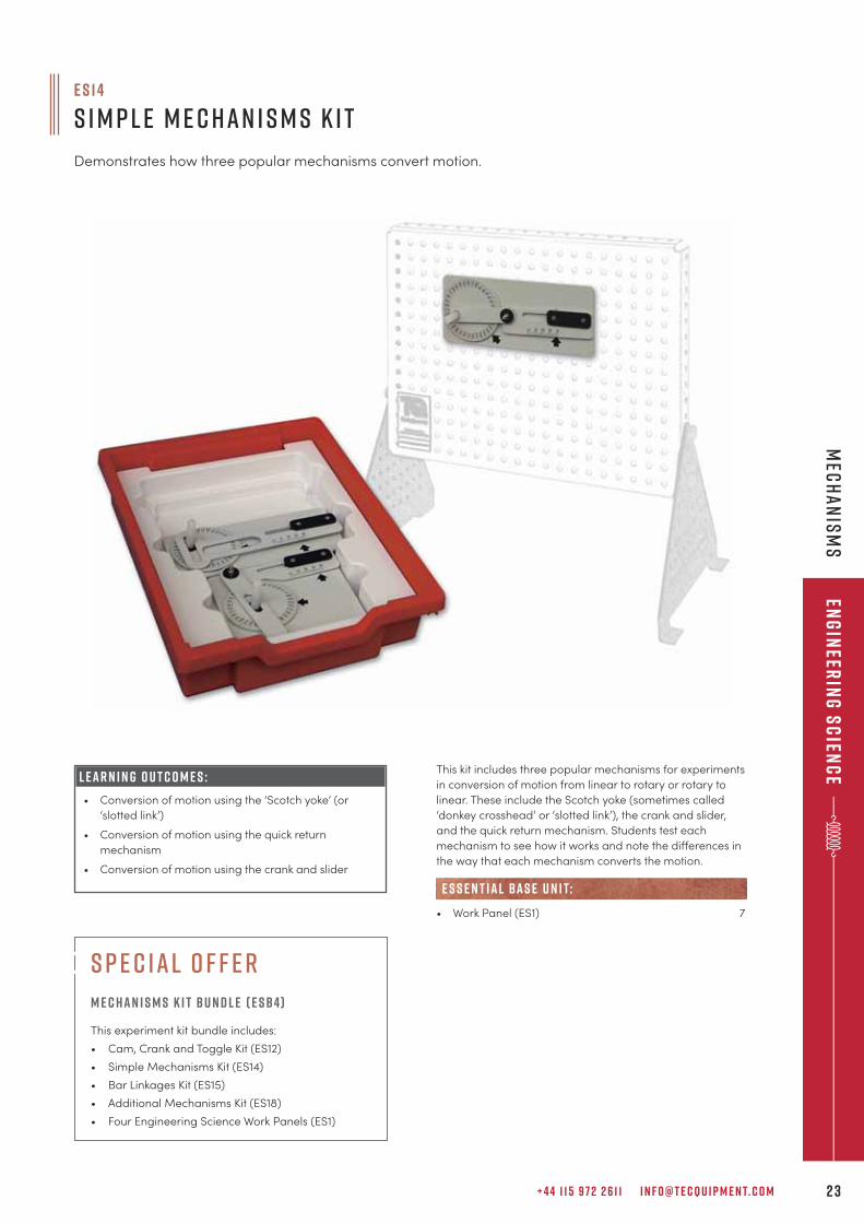
This kit includes three popular mechanisms for experiments
in conversion of motion from linear to rotary or rotary to
linear. These include the Scotch yoke (sometimes called
‘donkey crosshead’ or ‘slotted link’), the crank and slider,
and the quick return mechanism. Students test each
mechanism to see how it works and note the differences in
the way that each mechanism converts the motion.
• Work Panel (ES1) 7
e s s e n t ial bas e u n i t:
e s 1 4
S i m p l e M e c h a n i s m s K i t
Demonstrates how three popular mechanisms convert motion.
L E A R N I N G O U T C O M E S :
• Conversion of motion using the ‘Scotch yoke’ (or
‘slotted link’)
• Conversion of motion using the quick return
mechanism
• Conversion of motion using the crank and slider
s p e c ial o f f e r
m e c han i s m s k i t Bu n d l e ( E SB4)
This experiment kit bundle includes:
• Cam, Crank and Toggle Kit (ES12)
• Simple Mechanisms Kit (ES14)
• Bar Linkages Kit (ES15)
• Additional Mechanisms Kit (ES18)
• Four Engineering Science Work Panels (ES1)
T E C Q U I P M E N T. C O M2 4
eng
inee
rin
g s
cie
nc
eM
ech
an
ism
s
L E A R N I N G O U T C O M E S :
• Four-bar linkages – crank rocker, double rocker,
draglink and parallelogram
• Straight line linkages – Watt’s straight line,
Chebyshev, Peaucellier-Lipkin, Hart’s inversor,
Robert’s and Hoeken’s
• Pantograph
• Ackermann steering
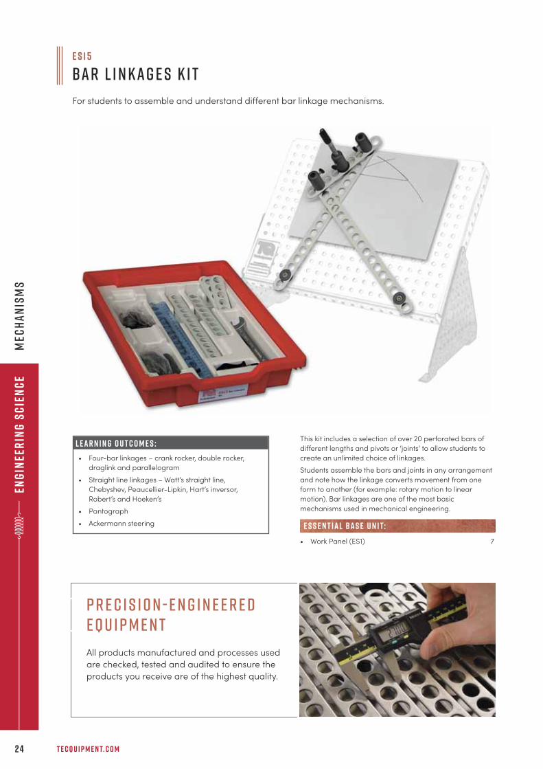
This kit includes a selection of over 20 perforated bars of
different lengths and pivots or ‘joints’ to allow students to
create an unlimited choice of linkages.
Students assemble the bars and joints in any arrangement
and note how the linkage converts movement from one
form to another (for example: rotary motion to linear
motion). Bar linkages are one of the most basic
mechanisms used in mechanical engineering.
• Work Panel (ES1) 7
e s s e n t ial bas e u n i t:
e s 1 5
B a r L i n k a g e s K i t
For students to assemble and understand different bar linkage mechanisms.
p r e c i s i o n - e n g i n e e r e d e q u i p m e n t
All products manufactured and processes used
are checked, tested and audited to ensure the
products you receive are of the highest quality.
+ 4 4 1 1 5 9 7 2 2 6 1 1 I N F O @ T E C Q U I P M E N T. C O M 2 5
Eng
ineer
ing
Sc
ienc
eM
ech
an
ism
s
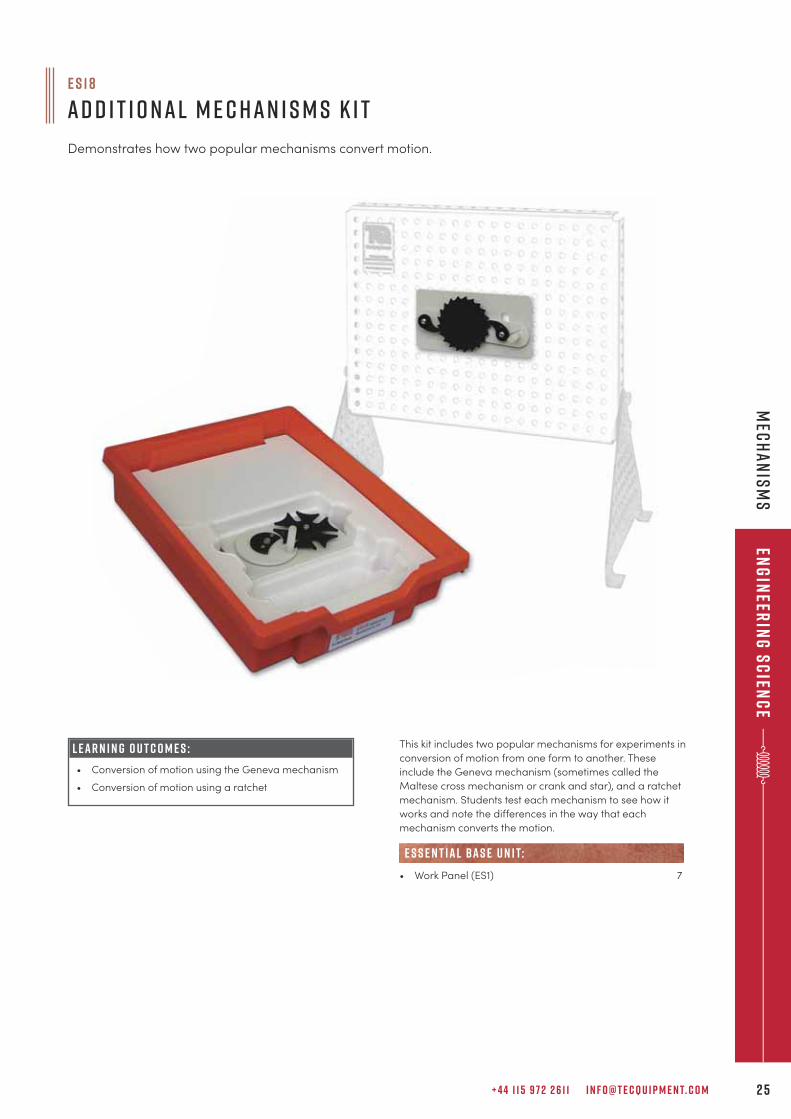
This kit includes two popular mechanisms for experiments in
conversion of motion from one form to another. These
include the Geneva mechanism (sometimes called the
Maltese cross mechanism or crank and star), and a ratchet
mechanism. Students test each mechanism to see how it
works and note the differences in the way that each
mechanism converts the motion.
• Work Panel (ES1) 7
e s s e n t ial bas e u n i t:
L E A R N I N G O U T C O M E S :
• Conversion of motion using the Geneva mechanism
• Conversion of motion using a ratchet
e s 1 8
A d d i t i o n a l M e c h a n i s m s K i t
Demonstrates how two popular mechanisms convert motion.
T E C Q U I P M E N T. C O M2 6
eng
inee
rin
g s
cie
nc
eB
un
dle
s
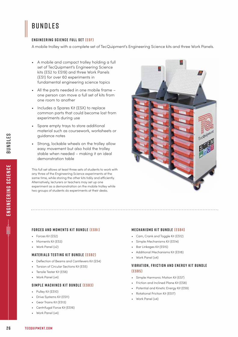
• A mobile and compact trolley holding a full
set of TecQuipment’s Engineering Science
kits (ES2 to ES19) and three Work Panels
(ES1) for over 60 experiments in
fundamental engineering science topics
• All the parts needed in one mobile frame –
one person can move a full set of kits from
one room to another
• Includes a Spares Kit (ESX) to replace
common parts that could become lost from
experiments during use
• Spare empty trays to store additional
material such as coursework, worksheets or
guidance notes
• Strong, lockable wheels on the trolley allow
easy movement but also hold the trolley
stable when needed – making it an ideal
demonstration table
This full set allows at least three sets of students to work with
any three of the Engineering Science experiments at the
same time, while storing the other kits tidily and efficiently.
Alternatively, lecturers or teachers may set up one
experiment as a demonstration on the mobile trolley while
two groups of students do experiments at their desks.
B u n d l e s
E n g i n e e r i n g S c i e n c e F u l l S e t ( E S F )
A mobile trolley with a complete set of TecQuipment’s Engineering Science kits and three Work Panels.
F o r c e s a n d m o m e n t s k i t B u n d l e ( e s B 1 )
• Forces Kit (ES2)
• Moments Kit (ES3)
• Work Panel (x2)
M AT E R I A L S T E S T I N G K I T B u n d l e ( E S B 2 )
• Deflection of Beams and Cantilevers Kit (ES4)
• Torsion of Circular Sections Kit (ES5)
• Tensile Tester Kit (ES6)
• Work Panel (x4)
S I M P L E M A C H I N E S K I T B u n d l e ( E S B 3 )
• Pulley Kit (ES10)
• Drive Systems Kit (ES11)
• Gear Trains Kit (ES13)
• Centrifugal Force Kit (ES16)
• Work Panel (x4)
M E C H A N I S M S K I T B u n d l e ( E S B 4)
• Cam, Crank and Toggle Kit (ES12)
• Simple Mechanisms Kit (ES14)
• Bar Linkages Kit (ES15)
• Additional Mechanisms Kit (ES18)
• Work Panel (x4)
V I B R AT I O N , F R I C T I O N A N D E N E R G Y K I T B u n d l e
( E S B 5 )
• Simple Harmonic Motion Kit (ES7)
• Friction and Inclined Plane Kit (ES8)
• Potential and Kinetic Energy Kit (ES9)
• Rotational Friction Kit (ES17)
• Work Panel (x4)
+ 4 4 1 1 5 9 7 2 2 6 1 1 I N F O @ T E C Q U I P M E N T. C O M 2 7
Eng
ineer
ing
Sc
ienc
eS
up
po
rt eq
uip
men
t an
d a
nc
illar
ies
S u p p o r t Equ i p m e n t
Support equipment for use with TecQuipment’s Engineering Science range.
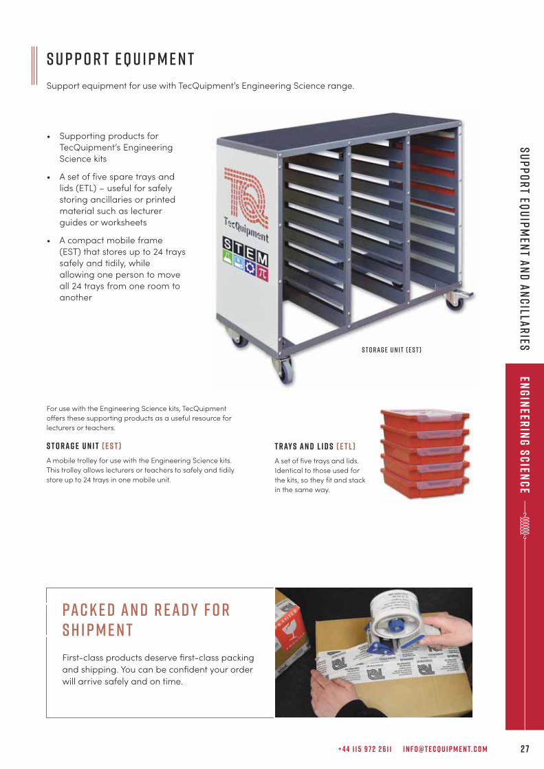
• Supporting products for
TecQuipment’s Engineering
Science kits
• A set of five spare trays and
lids (ETL) – useful for safely
storing ancillaries or printed
material such as lecturer
guides or worksheets
• A compact mobile frame
(EST) that stores up to 24 trays
safely and tidily, while
allowing one person to move
all 24 trays from one room to
another
For use with the Engineering Science kits, TecQuipment
offers these supporting products as a useful resource for
lecturers or teachers.
S t o r a g e U n i t ( E S T )
A mobile trolley for use with the Engineering Science kits.
This trolley allows lecturers or teachers to safely and tidily
store up to 24 trays in one mobile unit.
S t o r a g e U n i t ( E S T )
T r ay s a n d L i d s ( E T L )
A set of five trays and lids.
Identical to those used for
the kits, so they fit and stack
in the same way.
pac k e d an d r ead y f o r s h i p m e n t
First-class products deserve first-class packing
and shipping. You can be confident your order
will arrive safely and on time.
T E C Q U I P M E N T. C O M2 8
eng
inee
rin
g s
cie
nc
eS
up
po
rt
equ
ipm
ent
an
d a
nc
illa
rie
s
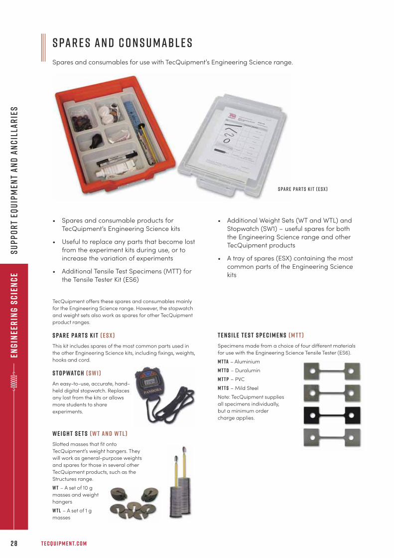
S pa r e s a n d C o n s u m abl e s
Spares and consumables for use with TecQuipment’s Engineering Science range.
• Spares and consumable products for
TecQuipment’s Engineering Science kits
• Useful to replace any parts that become lost
from the experiment kits during use, or to
increase the variation of experiments
• Additional Tensile Test Specimens (MTT) for
the Tensile Tester Kit (ES6)
TecQuipment offers these spares and consumables mainly
for the Engineering Science range. However, the stopwatch
and weight sets also work as spares for other TecQuipment
product ranges.
S pa r e Pa r t s K i t ( E S X )
This kit includes spares of the most common parts used in
the other Engineering Science kits, including fixings, weights,
hooks and cord.
S t o p wat c h ( S W 1 )
An easy-to-use, accurate, hand-
held digital stopwatch. Replaces
any lost from the kits or allows
more students to share
experiments.
W e i g h t S e t s ( W T a n d W T L )
Slotted masses that fit onto
TecQuipment’s weight hangers. They
will work as general-purpose weights
and spares for those in several other
TecQuipment products, such as the
Structures range.
W T – A set of 10 g
masses and weight
hangers
W T L – A set of 1 g
masses
T e n s i l e T e s t S p e c i m e n s ( M T T )
Specimens made from a choice of four different materials
for use with the Engineering Science Tensile Tester (ES6).
M T TA – Aluminium
M T T D – Duralumin
M T T P – PVC
M T T S – Mild Steel
Note: TecQuipment supplies
all specimens individually,
but a minimum order
charge applies.
S pa r e Pa r t s K i t ( E S X )
• Additional Weight Sets (WT and WTL) and
Stopwatch (SW1) – useful spares for both
the Engineering Science range and other
TecQuipment products
• A tray of spares (ESX) containing the most
common parts of the Engineering Science
kits
+ 4 4 1 1 5 9 7 2 2 6 1 1 I N F O @ T E C Q U I P M E N T. C O M 2 9
aER
OD
YN
AM
ICS
A E R O D Y N A M I C S
“We believe that your visit to make our wind tunnel ready to train our students and staff was agreat success and we thank you for the great effort you did for us. It was very effective anduseful work that raised the spirits of all the Aeronautical Engineering Department staff as wellas the College Administration.
D r a h m e d i b r a h i m a h m e dd e a n , c o l l e g e o f e n g i n e e r i n g , s u d a n u n i v e r s i t y o f s c i e n c e a n d t e c h n o l o g y
S u b s o n i c W i n d T u n n e l s 3 1
S u b s o n i c W i n d T u n n e l I n s t r u m e n t s a n d A c c e s s o r i e s 5 0
S p e c i a l P u r p o s e W i n d T u n n e l s 5 2
S u p e r s o n i c N o z z l e 5 5
S u p e r s o n i c W i n d T u n n e l s 5 7
T E C Q U I P M E N T. C O M3 0
aER
OD
YN
AM
ICS
a e r o d y n a m i c s
M a d e f o r e d u c at i o n a n d t r a i n i n g
The Aerodynamics range is used by educators worldwide
for research projects or teaching through first principles to
advanced theories. Our wind tunnels are small enough to fit
in most laboratories, while still producing results that can be
scaled to match those of full size wind tunnels. The subsonic
and special-purpose wind tunnels are mobile to help with
laboratory layouts.
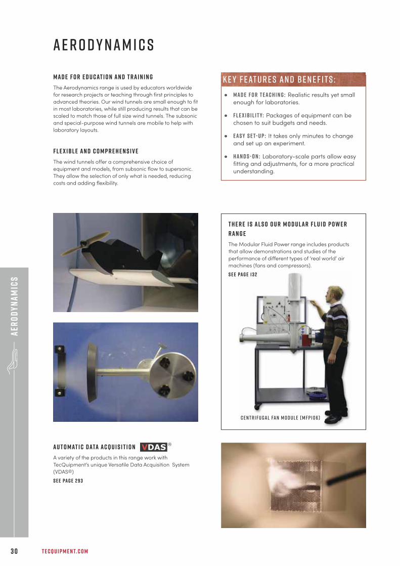
T h e r e i s a l s o o u r M o d u l a r F l u i d P o w e r
r a n g e
The Modular Fluid Power range includes products
that allow demonstrations and studies of the
performance of different types of ‘real world’ air
machines (fans and compressors).
S e e pa g e 1 3 2
C e n t r i f u g a l Fa n M o d u l e ( M F P 1 0 6 )
F l e x i b l e a n d c o m p r e h e n s i v e
The wind tunnels offer a comprehensive choice of
equipment and models, from subsonic flow to supersonic.
They allow the selection of only what is needed, reducing
costs and adding flexibility.
A u t o m at i c d ata a c q u i s i t i o n
A variety of the products in this range work with
TecQuipment’s unique Versatile Data Acquisition System
(VDAS®)
S e e pa g e 2 9 3
• M a d e f o r t e a c h i n g : Realistic results yet small
enough for laboratories.
• F l e x i b i l i t y: Packages of equipment can be
chosen to suit budgets and needs.
• E a s y s e t- u p : It takes only minutes to change
and set up an experiment.
• H a n d s - o n : Laboratory-scale parts allow easy
fitting and adjustments, for a more practical
understanding.
k e y f eat u r e s an d b e n e f i t s :
+ 4 4 1 1 5 9 7 2 2 6 1 1 I N F O @ T E C Q U I P M E N T. C O M 3 1
aER
OD
YN
AM
ICS
sUBSON
IC WIN
D tUN
NELS
F E AT U R E S : B E N E F I T S :
Supports and supplies a controllable air flow to its
optional experiment modules
Modular design saves space and reduces costs
Eight different optional experiment modules Covers all aspects of a basic aerodynamics
curriculum
Compact, mobile and easy to install Simplifies laboratory layout
Easy set-up – just minutes to remove and fit
experiment modules
Maximises experiment time and requires minimal
supervision
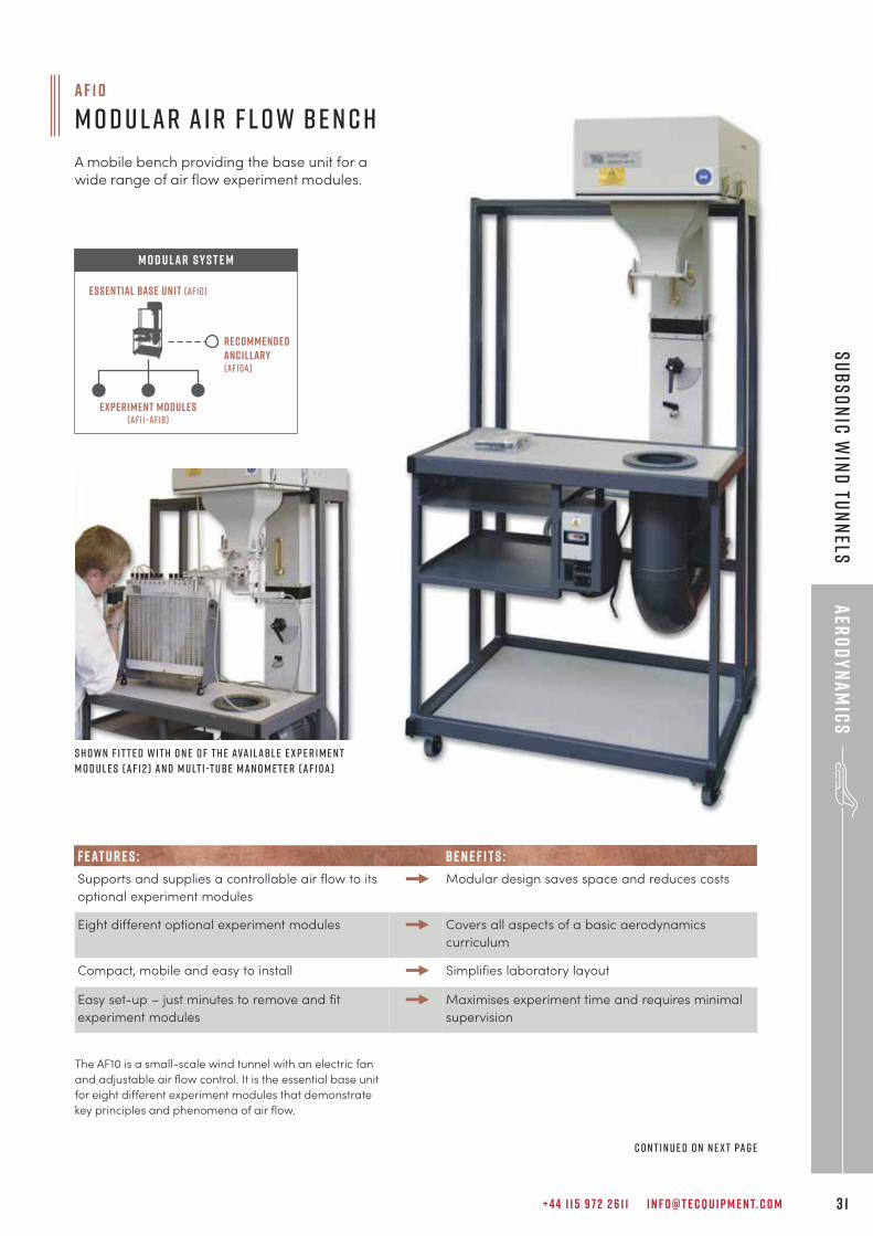
a f 1 0
M o d u l a r A i r F l o w B e n c h
A mobile bench providing the base unit for awide range of air flow experiment modules.
S h o w n f i t t e d w i t h o n e o f t h e ava i l abl e e x p e r i m e n tm o d u l e s ( A F 1 2 ) a n d M u lt i -t ube M a n o m e t e r ( A F 1 0 a )
recommendedancillary (af10a)
Experiment modules(af11–af18)
Essential Base Unit (af10)
M O D U LAR S Y S T E M
The AF10 is a small-scale wind tunnel with an electric fan
and adjustable air flow control. It is the essential base unit
for eight different experiment modules that demonstrate
key principles and phenomena of air flow.
C o n t i n u e d o n n e x t pa g e
T E C Q U I P M E N T. C O M3 2
aER
OD
YN
AM
ICS
sUBS
ON
IC W
IND
tUN
NEL
S
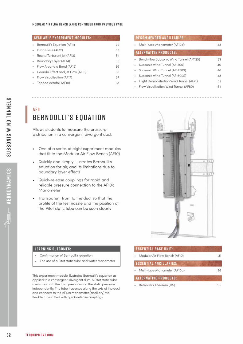
This experiment module illustrates Bernoulli’s equation as
applied to a convergent-divergent duct. A Pitot static tube
measures both the total pressure and the static pressure
independently. The tube traverses along the axis of the duct
and connects to the AF10a manometer (ancillary) via
flexible tubes fitted with quick-release couplings.
• One of a series of eight experiment modules
that fit to the Modular Air Flow Bench (AF10)
• Quickly and simply illustrates Bernoulli’s
equation for air, and its limitations due to
boundary layer effects
• Quick-release couplings for rapid and
reliable pressure connection to the AF10a
Manometer
• Transparent front to the duct so that the
profile of the test nozzle and the position of
the Pitot static tube can be seen clearly
M o d u l a r A i r F l o w B e n c h ( A F 1 0 ) C o n t i n u e d f r o m p r e v i o u s pa g e
• Bernoulli’s Equation (AF11) 32
• Drag Force (AF12) 33
• Round Turbulent Jet (AF13) 34
• Boundary Layer (AF14) 35
• Flow Around a Bend (AF15) 36
• Coandă Effect and Jet Flow (AF16) 36
• Flow Visualisation (AF17) 37
• Tapped Aerofoil (AF18) 38
ava i labl e e x p e r i m e n t m o d u l e s :
• Multi-tube Manometer (AF10a) 38
• Bench-Top Subsonic Wind Tunnel (AF1125) 39
• Subsonic Wind Tunnel (AF1300) 40
• Subsonic Wind Tunnel (AF1450S) 46
• Subsonic Wind Tunnel (AF1600S) 48
• Flight Demonstration Wind Tunnel (AF41) 52
• Flow Visualisation Wind Tunnel (AF80) 54
R E C O M M E N D E D AN C I L LAR I E S :
alt e r nat i v e p r o d u c t s :
a f 1 1
B e r n o u l l i ’ s E q u at i o n
Allows students to measure the pressuredistribution in a convergent-divergent duct.
L E A R N I N G O U T C O M E S :
• Confirmation of Bernoulli’s equation
• The use of a Pitot static tube and water manometer
• Modular Air Flow Bench (AF10) 31
• Multi-tube Manometer (AF10a) 38
• Bernoulli’s Theorem (H5) 95
e s s e n t ial bas e u n i t:
E S S E N T IAL AN C I L LAR I E S :
alt e r nat i v e p r o d u c t s :
+ 4 4 1 1 5 9 7 2 2 6 1 1 I N F O @ T E C Q U I P M E N T. C O M 3 3
aER
OD
YN
AM
ICS
sUBSON
IC WIN
D tUN
NELS
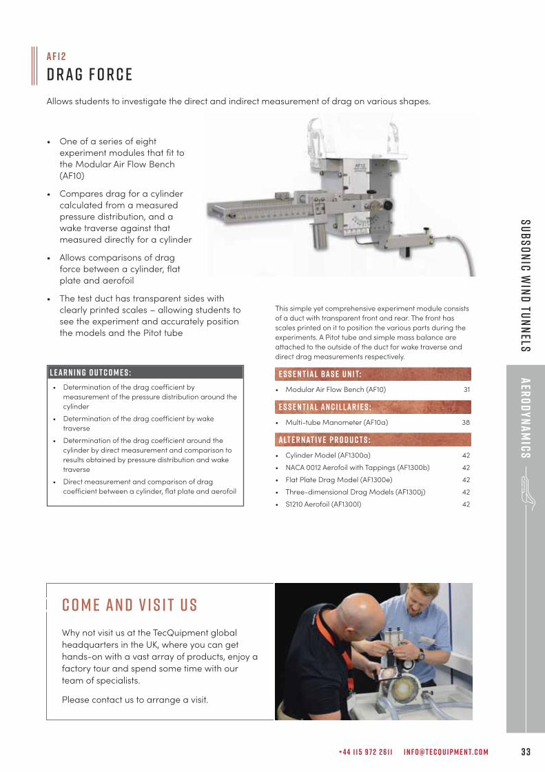
• One of a series of eight
experiment modules that fit to
the Modular Air Flow Bench
(AF10)
• Compares drag for a cylinder
calculated from a measured
pressure distribution, and a
wake traverse against that
measured directly for a cylinder
• Allows comparisons of drag
force between a cylinder, flat
plate and aerofoil
• The test duct has transparent sides with
clearly printed scales – allowing students to
see the experiment and accurately position
the models and the Pitot tube
This simple yet comprehensive experiment module consists
of a duct with transparent front and rear. The front has
scales printed on it to position the various parts during the
experiments. A Pitot tube and simple mass balance are
attached to the outside of the duct for wake traverse and
direct drag measurements respectively.
• Modular Air Flow Bench (AF10) 31
• Multi-tube Manometer (AF10a) 38
• Cylinder Model (AF1300a) 42
• NACA 0012 Aerofoil with Tappings (AF1300b) 42
• Flat Plate Drag Model (AF1300e) 42
• Three-dimensional Drag Models (AF1300j) 42
• S1210 Aerofoil (AF1300l) 42
e s s e n t ial bas e u n i t:
E S S E N T IAL AN C I L LAR I E S :
alt e r nat i v e p r o d u c t s :
L E A R N I N G O U T C O M E S :
• Determination of the drag coefficient by
measurement of the pressure distribution around the
cylinder
• Determination of the drag coefficient by wake
traverse
• Determination of the drag coefficient around the
cylinder by direct measurement and comparison to
results obtained by pressure distribution and wake
traverse
• Direct measurement and comparison of drag
coefficient between a cylinder, flat plate and aerofoil
a f 1 2
D r a g F o r c e
Allows students to investigate the direct and indirect measurement of drag on various shapes.
c o m e an d v i s i t u s
Why not visit us at the TecQuipment global
headquarters in the UK, where you can get
hands-on with a vast array of products, enjoy a
factory tour and spend some time with our
team of specialists.
Please contact us to arrange a visit.
T E C Q U I P M E N T. C O M3 4
aER
OD
YN
AM
ICS
sUBS
ON
IC W
IND
tUN
NEL
S
a f 1 3
R o u n d T u rbu l e n t J e t
Allows students to investigate a jet of air as itemerges from the end of a tube.
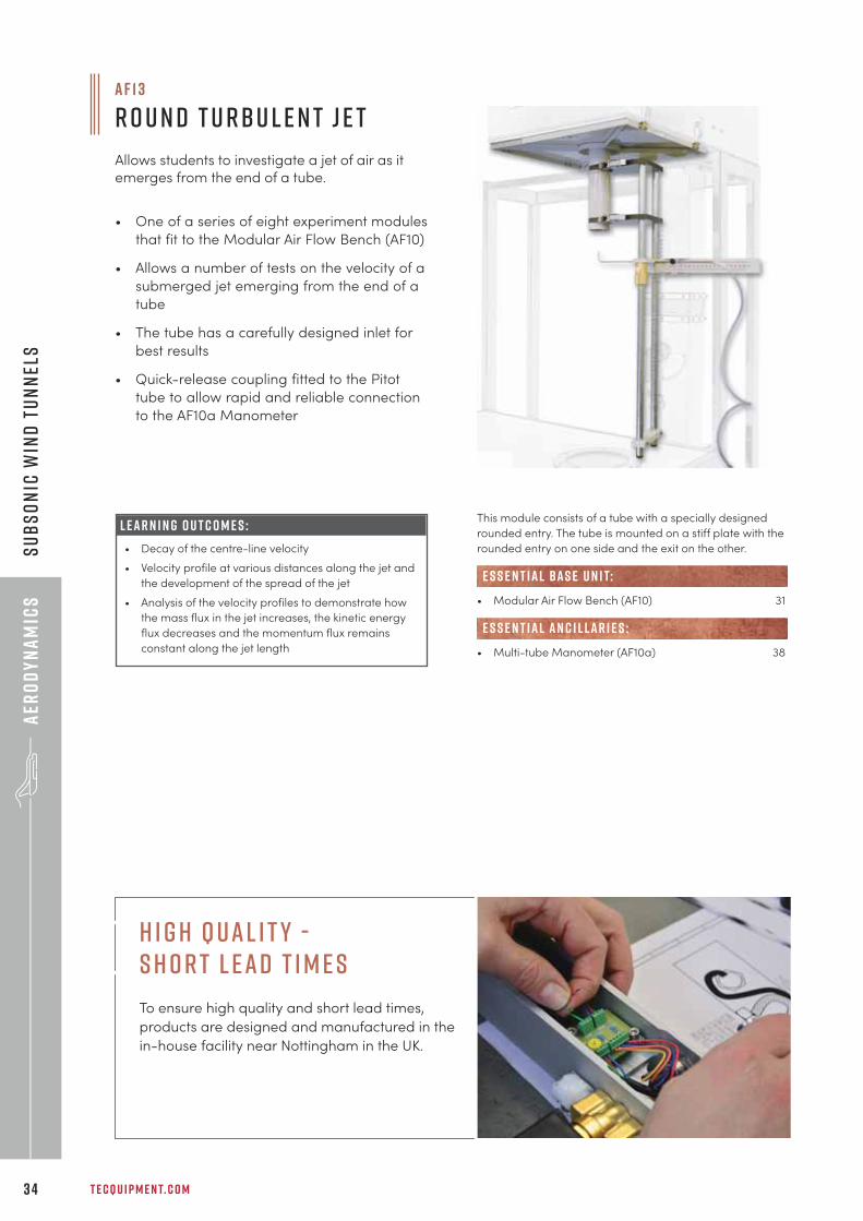
This module consists of a tube with a specially designed
rounded entry. The tube is mounted on a stiff plate with the
rounded entry on one side and the exit on the other.
• Modular Air Flow Bench (AF10) 31
• Multi-tube Manometer (AF10a) 38
e s s e n t ial bas e u n i t:
E S S E N T IAL AN C I L LAR I E S :
• One of a series of eight experiment modules
that fit to the Modular Air Flow Bench (AF10)
• Allows a number of tests on the velocity of a
submerged jet emerging from the end of a
tube
• The tube has a carefully designed inlet for
best results
• Quick-release coupling fitted to the Pitot
tube to allow rapid and reliable connection
to the AF10a Manometer
L E A R N I N G O U T C O M E S :
• Decay of the centre-line velocity
• Velocity profile at various distances along the jet and
the development of the spread of the jet
• Analysis of the velocity profiles to demonstrate how
the mass flux in the jet increases, the kinetic energy
flux decreases and the momentum flux remains
constant along the jet length
H i g h Q ual i t y - S h o r t L ead T i m e s
To ensure high quality and short lead times,
products are designed and manufactured in the
in-house facility near Nottingham in the UK.
+ 4 4 1 1 5 9 7 2 2 6 1 1 I N F O @ T E C Q U I P M E N T. C O M 3 5
aER
OD
YN
AM
ICS
sUBSON
IC WIN
D tUN
NELS
a f 1 4
B o u n d a r y L ay e r
Allows students to investigate the boundary layeron a flat plate.
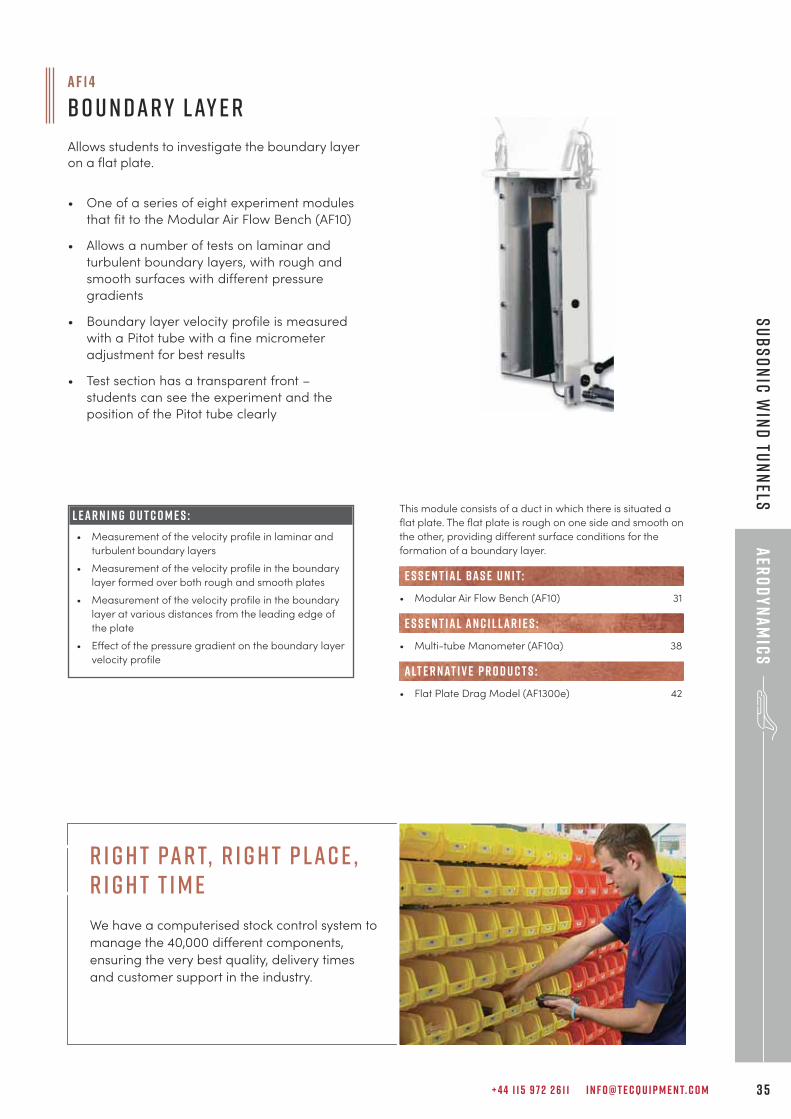
This module consists of a duct in which there is situated a
flat plate. The flat plate is rough on one side and smooth on
the other, providing different surface conditions for the
formation of a boundary layer.
• Modular Air Flow Bench (AF10) 31
• Multi-tube Manometer (AF10a) 38
• Flat Plate Drag Model (AF1300e) 42
e s s e n t ial bas e u n i t:
E S S E N T IAL AN C I L LAR I E S :
alt e r nat i v e p r o d u c t s :
• One of a series of eight experiment modules
that fit to the Modular Air Flow Bench (AF10)
• Allows a number of tests on laminar and
turbulent boundary layers, with rough and
smooth surfaces with different pressure
gradients
• Boundary layer velocity profile is measured
with a Pitot tube with a fine micrometer
adjustment for best results
• Test section has a transparent front –
students can see the experiment and the
position of the Pitot tube clearly
L E A R N I N G O U T C O M E S :
• Measurement of the velocity profile in laminar and
turbulent boundary layers
• Measurement of the velocity profile in the boundary
layer formed over both rough and smooth plates
• Measurement of the velocity profile in the boundary
layer at various distances from the leading edge of
the plate
• Effect of the pressure gradient on the boundary layer
velocity profile
r i g h t par t, r i g h t p lac e , r i g h t t i m e
We have a computerised stock control system to
manage the 40,000 di�erent components,
ensuring the very best quality, delivery times
and customer support in the industry.
T E C Q U I P M E N T. C O M3 6
aER
OD
YN
AM
ICS
sUBS
ON
IC W
IND
tUN
NEL
S
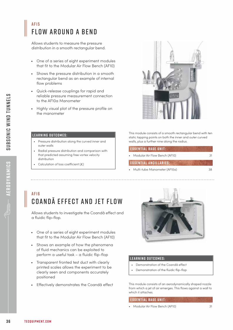
a f 1 5
F l o w A r o u n d a B e n d
Allows students to measure the pressuredistribution in a smooth rectangular bend.
a f 1 6
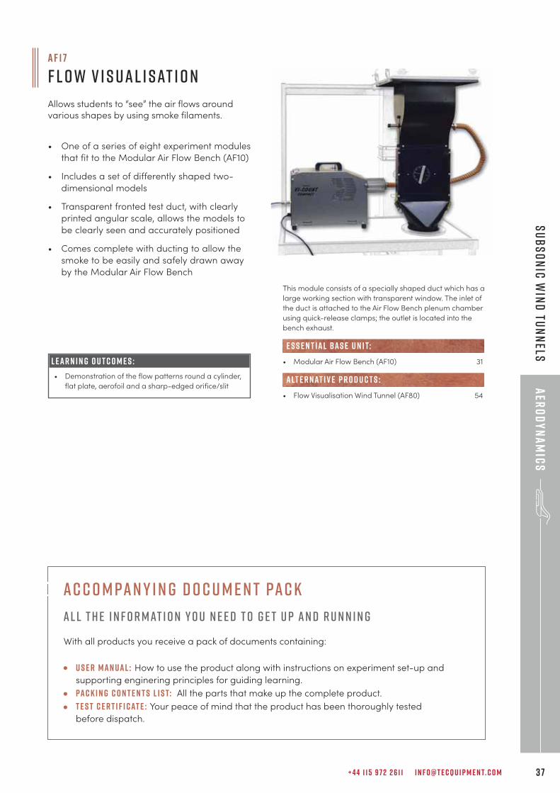
C o a n d ă E f f e c t a n d J e t F l o w
Allows students to investigate the Coandă effect anda fluidic flip-flop.
This module consists of a smooth rectangular bend with ten
static tapping points on both the inner and outer curved
walls, plus a further nine along the radius.
• Modular Air Flow Bench (AF10) 31
• Multi-tube Manometer (AF10a) 38
e s s e n t ial bas e u n i t:
E S S E N T IAL AN C I L LAR I E S :
• One of a series of eight experiment modules
that fit to the Modular Air Flow Bench (AF10)
• Shows the pressure distribution in a smooth
rectangular bend as an example of internal
flow problems
• Quick-release couplings for rapid and
reliable pressure measurement connection
to the AF10a Manometer
• Highly visual plot of the pressure profile on
the manometer
L E A R N I N G O U T C O M E S :
• Pressure distribution along the curved inner and
outer walls
• Radial pressure distribution and comparison with
that predicted assuming free vortex velocity
distribution
• Calculation of loss coefficient (K)
This module consists of an aerodynamically shaped nozzle
from which a jet of air emerges. This flows against a wall to
which it attaches.
• Modular Air Flow Bench (AF10) 31
e s s e n t ial bas e u n i t:
• One of a series of eight experiment modules
that fit to the Modular Air Flow Bench (AF10)
• Shows an example of how the phenomena
of fluid mechanics can be exploited to
perform a useful task – a fluidic flip-flop
• Transparent fronted test duct with clearly
printed scales allows the experiment to be
clearly seen and components accurately
positioned
• Effectively demonstrates the Coandă effect
L E A R N I N G O U T C O M E S :
• Demonstration of the Coandă effect
• Demonstration of the fluidic flip-flop
+ 4 4 1 1 5 9 7 2 2 6 1 1 I N F O @ T E C Q U I P M E N T. C O M 3 7
aER
OD
YN
AM
ICS
sUBSON
IC WIN
D tUN
NELS
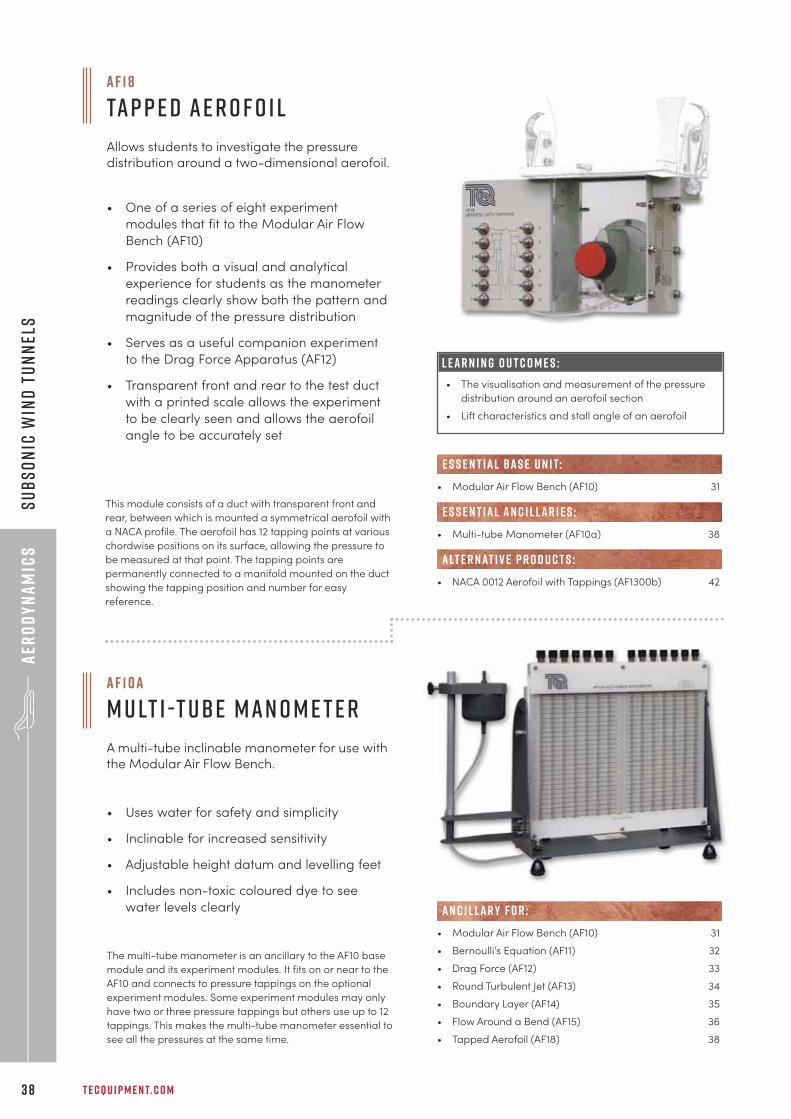
a f 1 7
F l o w V i s u a l i s at i o n
Allows students to “see” the air flows aroundvarious shapes by using smoke filaments.
This module consists of a specially shaped duct which has a
large working section with transparent window. The inlet of
the duct is attached to the Air Flow Bench plenum chamber
using quick-release clamps; the outlet is located into the
bench exhaust.
• Modular Air Flow Bench (AF10) 31
• Flow Visualisation Wind Tunnel (AF80) 54
e s s e n t ial bas e u n i t:
alt e r nat i v e p r o d u c t s :
• One of a series of eight experiment modules
that fit to the Modular Air Flow Bench (AF10)
• Includes a set of differently shaped two-
dimensional models
• Transparent fronted test duct, with clearly
printed angular scale, allows the models to
be clearly seen and accurately positioned
• Comes complete with ducting to allow the
smoke to be easily and safely drawn away
by the Modular Air Flow Bench
L E A R N I N G O U T C O M E S :
• Demonstration of the flow patterns round a cylinder,
flat plate, aerofoil and a sharp-edged orifice/slit
Ac c o m pan y i n g d o c u m e n t pac k
Al l t h e i n f o r mat i o n y o u n e e d t o g e t u p an d r u n n i n g
With all products you receive a pack of documents containing:
U s e r Man ual : How to use the product along with instructions on experiment set-up and
supporting enginering principles for guiding learning.
Pac k i n g c o n t e n t s l i s t: All the parts that make up the complete product.
T e s t c e r t i f i cat e : Your peace of mind that the product has been thoroughly tested
before dispatch.
T E C Q U I P M E N T. C O M3 8
aER
OD
YN
AM
ICS
sUBS
ON
IC W
IND
tUN
NEL
S
a f 1 8
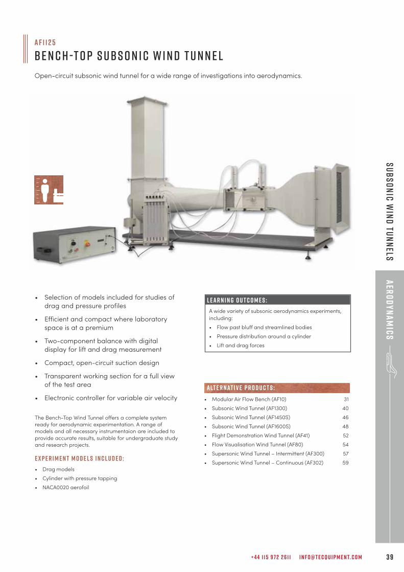
Ta p p e d A e r o f o i l
Allows students to investigate the pressuredistribution around a two-dimensional aerofoil.
a f 1 0 a
m u lt i -t ube m a n o m e t e r
A multi-tube inclinable manometer for use withthe Modular Air Flow Bench.
This module consists of a duct with transparent front and
rear, between which is mounted a symmetrical aerofoil with
a NACA profile. The aerofoil has 12 tapping points at various
chordwise positions on its surface, allowing the pressure to
be measured at that point. The tapping points are
permanently connected to a manifold mounted on the duct
showing the tapping position and number for easy
reference.
• One of a series of eight experiment
modules that fit to the Modular Air Flow
Bench (AF10)
• Provides both a visual and analytical
experience for students as the manometer
readings clearly show both the pattern and
magnitude of the pressure distribution
• Serves as a useful companion experiment
to the Drag Force Apparatus (AF12)
• Transparent front and rear to the test duct
with a printed scale allows the experiment
to be clearly seen and allows the aerofoil
angle to be accurately set
L E A R N I N G O U T C O M E S :
• The visualisation and measurement of the pressure
distribution around an aerofoil section
• Lift characteristics and stall angle of an aerofoil
The multi-tube manometer is an ancillary to the AF10 base
module and its experiment modules. It fits on or near to the
AF10 and connects to pressure tappings on the optional
experiment modules. Some experiment modules may only
have two or three pressure tappings but others use up to 12
tappings. This makes the multi-tube manometer essential to
see all the pressures at the same time.
• Uses water for safety and simplicity
• Inclinable for increased sensitivity
• Adjustable height datum and levelling feet
• Includes non-toxic coloured dye to see
water levels clearly
• Modular Air Flow Bench (AF10) 31
• Bernoulli’s Equation (AF11) 32
• Drag Force (AF12) 33
• Round Turbulent Jet (AF13) 34
• Boundary Layer (AF14) 35
• Flow Around a Bend (AF15) 36
• Tapped Aerofoil (AF18) 38
AN C I L LAR Y F O R :
• Modular Air Flow Bench (AF10) 31
• Multi-tube Manometer (AF10a) 38
• NACA 0012 Aerofoil with Tappings (AF1300b) 42
e s s e n t ial bas e u n i t:
E S S E N T IAL AN C I L LAR I E S :
alt e r nat i v e p r o d u c t s :
+ 4 4 1 1 5 9 7 2 2 6 1 1 I N F O @ T E C Q U I P M E N T. C O M 3 9
aER
OD
YN
AM
ICS
sUBSON
IC WIN
D tUN
NELS
• Selection of models included for studies of
drag and pressure profiles
• Efficient and compact where laboratory
space is at a premium
• Two-component balance with digital
display for lift and drag measurement
• Compact, open-circuit suction design
• Transparent working section for a full view
of the test area
• Electronic controller for variable air velocity
a f 1 1 2 5
be n c h -t o p S ubs o n i c W i n d T u n n e l
Open-circuit subsonic wind tunnel for a wide range of investigations into aerodynamics.
The Bench-Top Wind Tunnel offers a complete system
ready for aerodynamic experimentation. A range of
models and all necessary instrumentaion are included to
provide accurate results, suitable for undergraduate study
and research projects.
E X P E R I M E N T M O D E L S I N C L U D E D :
• Drag models
• Cylinder with pressure tapping
• NACA0020 aerofoil
L E A R N I N G O U T C O M E S :
A wide variety of subsonic aerodynamics experiments,
including:
• Flow past bluff and streamlined bodies
• Pressure distribution around a cylinder
• Lift and drag forces
• Modular Air Flow Bench (AF10) 31
• Subsonic Wind Tunnel (AF1300) 40
• Subsonic Wind Tunnel (AF1450S) 46
• Subsonic Wind Tunnel (AF1600S) 48
• Flight Demonstration Wind Tunnel (AF41) 52
• Flow Visualisation Wind Tunnel (AF80) 54
• Supersonic Wind Tunnel – Intermittent (AF300) 57
• Supersonic Wind Tunnel – Continuous (AF302) 59
alt e r nat i v e p r o d u c t s :
T E C Q U I P M E N T. C O M4 0
aER
OD
YN
AM
ICS
sUBS
ON
IC W
IND
tUN
NEL
S
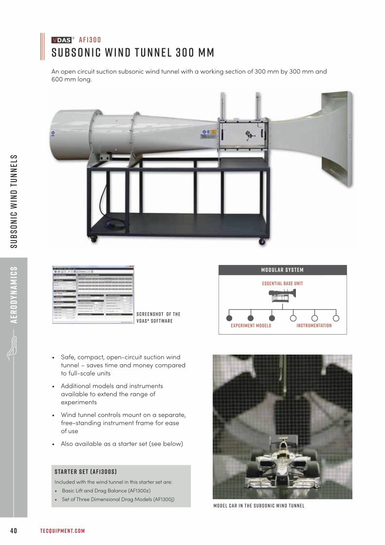
a f 1 3 0 0
S ubs o n i c W i n d T u n n e l 3 0 0 m m
An open circuit suction subsonic wind tunnel with a working section of 300 mm by 300 mm and
600 mm long.
S c r e e n s h o t o f t h eV D A S ® s o f t wa r e
Essential Base Unit
M O D U LAR S Y S T E M
instrumentationExperiment models
M o d e l c a r i n t h e s ubs o n i c w i n d t u n n e l
• Safe, compact, open-circuit suction wind
tunnel – saves time and money compared
to full-scale units
• Additional models and instruments
available to extend the range of
experiments
• Wind tunnel controls mount on a separate,
free-standing instrument frame for ease
of use
• Also available as a starter set (see below)
s ta r t e r s e t ( A F 1 3 0 0 S )
Included with the wind tunnel in this starter set are:
• Basic Lift and Drag Balance (AF1300z)
• Set of Three Dimensional Drag Models (AF1300j)
+ 4 4 1 1 5 9 7 2 2 6 1 1 I N F O @ T E C Q U I P M E N T. C O M 4 1
aER
OD
YN
AM
ICS
sUBSON
IC WIN
D tUN
NELS
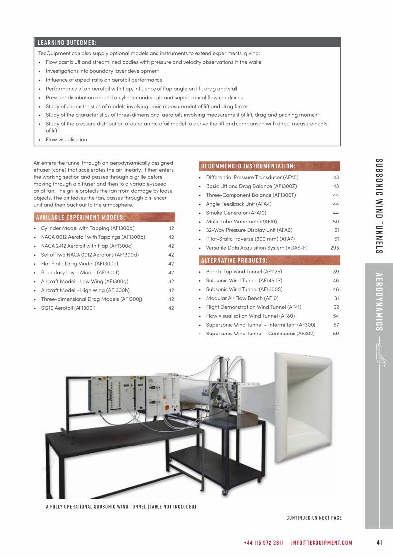
Air enters the tunnel through an aerodynamically designed
effuser (cone) that accelerates the air linearly. It then enters
the working section and passes through a grille before
moving through a diffuser and then to a variable-speed
axial fan. The grille protects the fan from damage by loose
objects. The air leaves the fan, passes through a silencer
unit and then back out to the atmosphere.
• Cylinder Model with Tapping (AF1300a) 42
• NACA 0012 Aerofoil with Tappings (AF1300b) 42
• NACA 2412 Aerofoil with Flap (AF1300c) 42
• Set of Two NACA 0012 Aerofoils (AF1300d) 42
• Flat Plate Drag Model (AF1300e) 42
• Boundary Layer Model (AF1300f) 42
• Aircraft Model - Low Wing (AF1300g) 42
• Aircraft Model - High Wing (AF1300h) 42
• Three-dimensional Drag Models (AF1300j) 42
• S1210 Aerofoil (AF1300l) 42
ava i labl e e x p e r i m e n t m o d e l s :
• Differential Pressure Transducer (AFA5) 43
• Basic Lift and Drag Balance (AF1300Z) 43
• Three-Component Balance (AF1300T) 44
• Angle Feedback Unit (AFA4) 44
• Smoke Generator (AFA10) 44
• Multi-Tube Manometer (AFA1) 50
• 32-Way Pressure Display Unit (AFA6) 51
• Pitot-Static Traverse (300 mm) (AFA7) 51
• Versatile Data Acquisition System (VDAS-F) 293
• Bench-Top Wind Tunnel (AF1125) 39
• Subsonic Wind Tunnel (AF1450S) 46
• Subsonic Wind Tunnel (AF1600S) 48
• Modular Air Flow Bench (AF10) 31
• Flight Demonstration Wind Tunnel (AF41) 52
• Flow Visualisation Wind Tunnel (AF80) 54
• Supersonic Wind Tunnel – Intermittent (AF300) 57
• Supersonic Wind Tunnel – Continuous (AF302) 59
alt e r nat i v e p r o d u c t s :
r e c o m m e n d e d i n s t r u m e n tat i o n :
L E A R N I N G O U T C O M E S :
TecQuipment can also supply optional models and instruments to extend experiments, giving:
• Flow past bluff and streamlined bodies with pressure and velocity observations in the wake
• Investigations into boundary layer development
• Influence of aspect ratio on aerofoil performance
• Performance of an aerofoil with flap, influence of flap angle on lift, drag and stall
• Pressure distribution around a cylinder under sub and super-critical flow conditions
• Study of characteristics of models involving basic measurement of lift and drag forces
• Study of the characteristics of three-dimensional aerofoils involving measurement of lift, drag and pitching moment
• Study of the pressure distribution around an aerofoil model to derive the lift and comparison with direct measurements
of lift
• Flow visualisation
A f u l ly o p e r at i o n a l S ubs o n i c W i n d T u n n e l ( Tabl e n o t i n c l u d e d )
c o n t i n u e d o n n e x t pa g e
T E C Q U I P M E N T. C O M4 2
aER
OD
YN
AM
ICS
sUBS
ON
IC W
IND
tUN
NEL
S
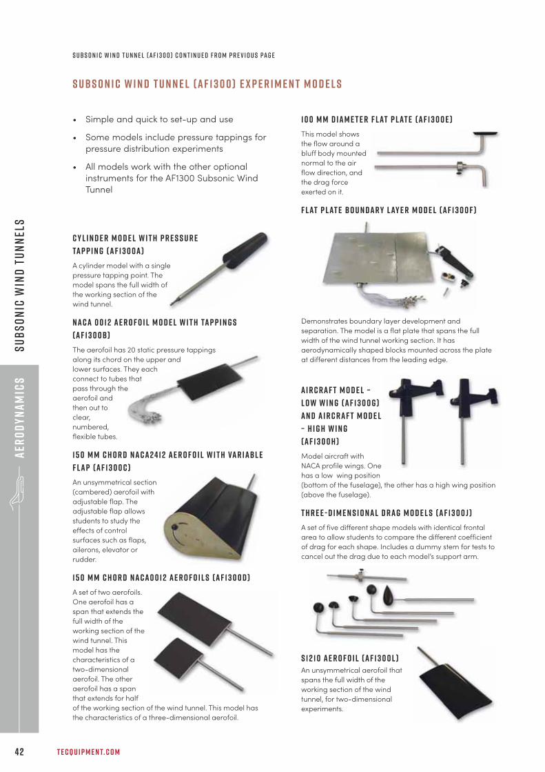
S u b s o n i c W i n d T u n n e l ( A F 1 3 0 0 ) E x p e r i m e n t m o d e l s
• Simple and quick to set-up and use
• Some models include pressure tappings for
pressure distribution experiments
• All models work with the other optional
instruments for the AF1300 Subsonic Wind
Tunnel
C y l i n d e r M o d e l w i t h p r e s s u r e
ta p p i n g ( A F 1 3 0 0 a )
A cylinder model with a single
pressure tapping point. The
model spans the full width of
the working section of the
wind tunnel.
N A C A 0 0 1 2 A E R O F O I L M O D E L W I T H TA P P I N G S
( A F 1 3 0 0 B )
The aerofoil has 20 static pressure tappings
along its chord on the upper and
lower surfaces. They each
connect to tubes that
pass through the
aerofoil and
then out to
clear,
numbered,
flexible tubes.
1 5 0 m m c h o r d N A C A 2 4 1 2 a e r o f o i l w i t h Va r i a b l e
F l a p ( A F 1 3 0 0 C )
An unsymmetrical section
(cambered) aerofoil with
adjustable flap. The
adjustable flap allows
students to study the
effects of control
surfaces such as flaps,
ailerons, elevator or
rudder.
1 5 0 m m C h o r d N A C A 0 0 1 2 A e r o f o i l s ( A F 1 3 0 0 D )
A set of two aerofoils.
One aerofoil has a
span that extends the
full width of the
working section of the
wind tunnel. This
model has the
characteristics of a
two-dimensional
aerofoil. The other
aerofoil has a span
that extends for half
of the working section of the wind tunnel. This model has
the characteristics of a three-dimensional aerofoil.
1 0 0 m m D i a m e t e r F l at P l at e ( A F 1 3 0 0 E )
This model shows
the flow around a
bluff body mounted
normal to the air
flow direction, and
the drag force
exerted on it.
F l at P l at e B o u n d a r y L ay e r M o d e l ( A F 1 3 0 0 f )
Demonstrates boundary layer development and
separation. The model is a flat plate that spans the full
width of the wind tunnel working section. It has
aerodynamically shaped blocks mounted across the plate
at different distances from the leading edge.
A i r c r a f t M o d e l –
L o w W i n g ( A F 1 3 0 0 g )
a n d A i r c r a f t M o d e l
– H i g h W i n g
( A F 1 3 0 0 h )
Model aircraft with
NACA profile wings. One
has a low wing position
(bottom of the fuselage), the other has a high wing position
(above the fuselage).
T H R E E - D I M E N S I O N A L D R A G M O D E L S ( A F 1 3 0 0 J )
A set of five different shape models with identical frontal
area to allow students to compare the different coefficient
of drag for each shape. Includes a dummy stem for tests to
cancel out the drag due to each model’s support arm.
S 1 2 1 0 A e r o f o i l ( A F 1 3 0 0 L )An unsymmetrical aerofoil that
spans the full width of the
working section of the wind
tunnel, for two-dimensional
experiments.
s ubs o n i c w i n d t u n n e l ( A F 1 3 0 0 ) C o n t i n u e d f r o m p r e v i o u s pa g e
+ 4 4 1 1 5 9 7 2 2 6 1 1 I N F O @ T E C Q U I P M E N T. C O M 4 3
aER
OD
YN
AM
ICS
sUBSON
IC WIN
D tUN
NELS
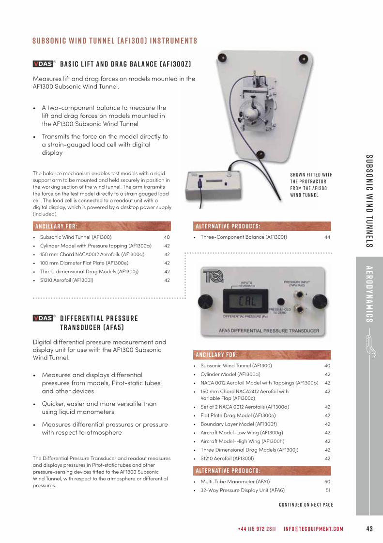
• A two-component balance to measure the
lift and drag forces on models mounted in
the AF1300 Subsonic Wind Tunnel
• Transmits the force on the model directly to
a strain-gauged load cell with digital
display
The balance mechanism enables test models with a rigid
support arm to be mounted and held securely in position in
the working section of the wind tunnel. The arm transmits
the force on the test model directly to a strain gauged load
cell. The load cell is connected to a readout unit with a
digital display, which is powered by a desktop power supply
(included).
• Subsonic Wind Tunnel (AF1300) 40
• Cylinder Model with Pressure tapping (AF1300a) 42
• 150 mm Chord NACA0012 Aerofoils (AF1300d) 42
• 100 mm Diameter Flat Plate (AF1300e) 42
• Three-dimensional Drag Models (AF1300j) 42
• S1210 Aerofoil (AF1300l) 42
AN C I L LAR Y F O R :
B a s i c L i f t a n d D r a g B a l a n c e ( A F 1 3 0 0 z )
Measures lift and drag forces on models mounted in theAF1300 Subsonic Wind Tunnel.
S h o w n f i t t e d w i t ht h e p r o t r a c t o rf r o m t h e A F 1 3 0 0W i n d T u n n e l
c o n t i n u e d o n n e x t pa g e
S u b s o n i c w i n d t u n n e l ( A F 1 3 0 0 ) i n s t r u m e n t s
D i f f e r e n t i a l P r e s s u r e T r a n s d u c e r ( A FA 5 )
Digital differential pressure measurement anddisplay unit for use with the AF1300 SubsonicWind Tunnel.
• Measures and displays differential
pressures from models, Pitot-static tubes
and other devices
• Quicker, easier and more versatile than
using liquid manometers
• Measures differential pressures or pressure
with respect to atmosphere
The Differential Pressure Transducer and readout measures
and displays pressures in Pitot-static tubes and other
pressure-sensing devices fitted to the AF1300 Subsonic
Wind Tunnel, with respect to the atmosphere or differential
pressures.
• Subsonic Wind Tunnel (AF1300) 40
• Cylinder Model (AF1300a) 42
• NACA 0012 Aerofoil Model with Tappings (AF1300b) 42
• 150 mm Chord NACA2412 Aerofoil with 42
Variable Flap (AF1300c)
• Set of 2 NACA 0012 Aerofoils (AF1300d) 42
• Flat Plate Drag Model (AF1300e) 42
• Boundary Layer Model (AF1300f) 42
• Aircraft Model-Low Wing (AF1300g) 42
• Aircraft Model-High Wing (AF1300h) 42
• Three Dimensional Drag Models (AF1300j) 42
• S1210 Aerofoil (AF1300l) 42
• Multi-Tube Manometer (AFA1) 50
• 32-Way Pressure Display Unit (AFA6) 51
alt e r nat i v e p r o d u c t s :
AN C I L LAR Y F O R :
• Three-Component Balance (AF1300t) 44
alt e r nat i v e p r o d u c t s :
T E C Q U I P M E N T. C O M4 4
aER
OD
YN
AM
ICS
sUBS
ON
IC W
IND
tUN
NEL
s
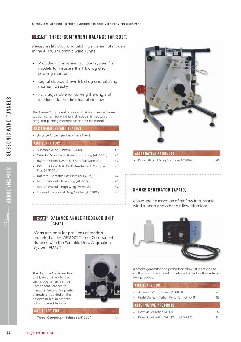
T h r e e - C o m p o n e n t B a l a n c e ( A F 1 3 0 0 t )
Measures lift, drag and pitching moment of modelsin the AF1300 Subsonic Wind Tunnel.
• Provides a convenient support system for
models to measure the lift, drag and
pitching moment
• Digital display shows lift, drag and pitching
moment directly
• Fully adjustable for varying the angle of
incidence to the direction of air flow
The Three-Component Balance provides an easy-to-use
support system for wind tunnel models. It measures lift,
drag and pitching moment exerted on the model.
• Balance Angle Feedback Unit (AFA4) 44
• Subsonic Wind Tunnel (AF1300) 40
• Cylinder Model with Pressure Tapping (AF1300a) 42
• 150 mm Chord NACA0012 Aerofoils (AF1300b) 42
• 150 mm Chord NACA2412 Aerofoil with Variable 42
Flap (AF1300c)
• 100 mm Diameter Flat Plate (AF1300e) 42
• Aircraft Model - Low Wing (AF1300g) 42
• Aircraft Model - High Wing (AF1300h) 42
• Three-dimensional Drag Models (AF1300j) 42
R E C O M M E N D E D AN C I L LAR I E S :
AN C I L LAR Y F O R :
• Basic Lift and Drag Balance (AF1300z) 43
alt e r nat i v e p r o d u c t s :
S m o k e G e n e r at o r ( A FA 1 0 )
Allows the observation of air flow in subsonicwind tunnels and other air flow situations.
A smoke generator and probe that allows students to see
air flow in subsonic wind tunnels and other low flow rate air
flow products.
• Subsonic Wind Tunnel (AF1300) 40
• Flight Demonstration Wind Tunnel (AF41) 52
• Flow Visualisation (AF17) 37
• Flow Visualisation Wind Tunnel (AF80) 54
AN C I L LAR Y F O R :
alt e r nat i v e p r o d u c t s :
s ubs o n i c w i n d t u n n e l ( A F 1 3 0 0 ) I n s t r u m e n t s C o n t i n u e d f r o m p r e v i o u s pa g e
b a l a n c e a n g l e f e e d b a c k u n i t ( A FA 4 )
Measures angular positions of modelsmounted on the AF1300T Three-ComponentBalance with the Versatile Data AcquisitionSystem (VDAS®).
The Balance Angle Feedback
Unit is an ancillary for use
with TecQuipment’s Three-
Component Balance to
measure the angular position
of models mounted on the
balance in TecQuipment’s
Subsonic Wind Tunnels.
• Three-Component Balance (AF1300t) 44
AN C I L LAR Y F O R :
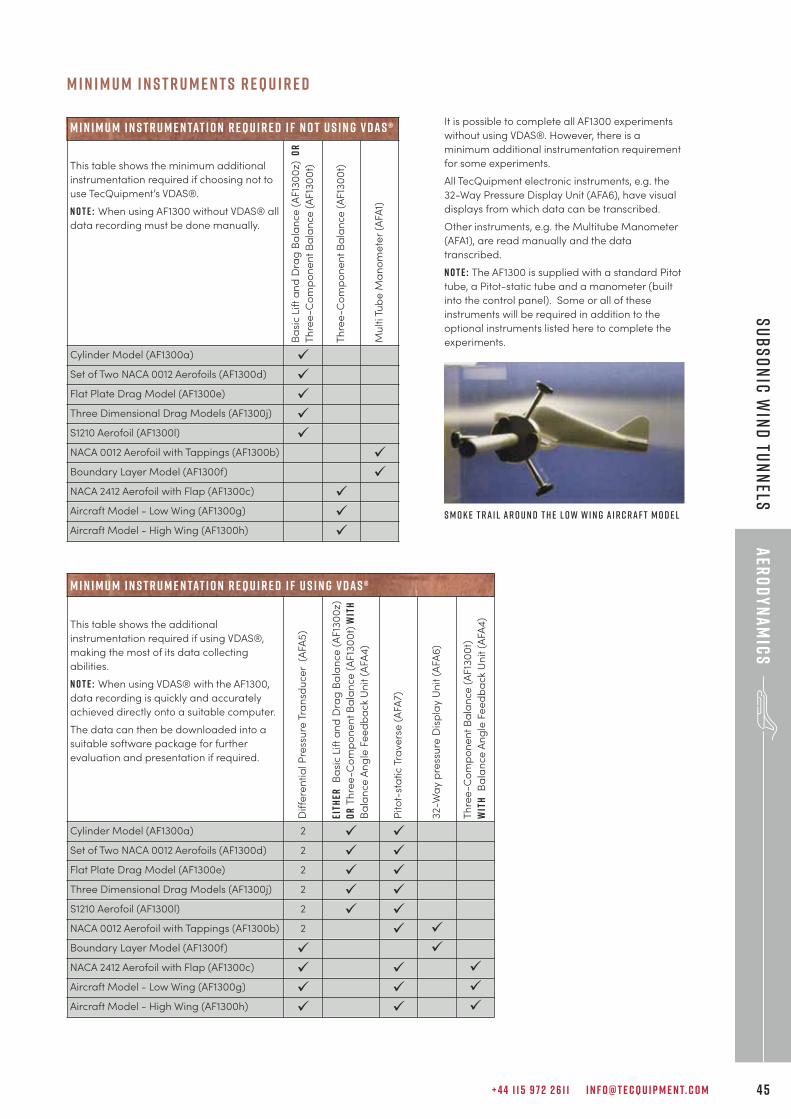
+ 4 4 1 1 5 9 7 2 2 6 1 1 I N F O @ T E C Q U I P M E N T. C O M 4 5
aER
OD
YN
AM
ICS
sUBSON
IC WIN
D tUN
NEls
It is possible to complete all AF1300 experiments
without using VDAS®. However, there is a
minimum additional instrumentation requirement
for some experiments.
All TecQuipment electronic instruments, e.g. the
32-Way Pressure Display Unit (AFA6), have visual
displays from which data can be transcribed.
Other instruments, e.g. the Multitube Manometer
(AFA1), are read manually and the data
transcribed.
N o t e : The AF1300 is supplied with a standard Pitot
tube, a Pitot-static tube and a manometer (built
into the control panel). Some or all of these
instruments will be required in addition to the
optional instruments listed here to complete the
experiments.
M i n i m u m i n s t r u m e n tat i o n r e q u i r e d i f n o t u s i n g v d a s ®
This table shows the minimum additional
instrumentation required if choosing not to
use TecQuipment’s VDAS®.
N o t e : When using AF1300 without VDAS® all
data recording must be done manually.
Ba
sic L
ift
an
d D
rag
Ba
lan
ce
(A
F13
00
z)
OR
Th
ree
-Co
mp
on
en
t B
ala
nce
(A
F13
00
t)
Th
ree
-Co
mp
on
en
t B
ala
nce
(A
F13
00
t)
Mu
lti T
ub
e M
an
om
ete
r (A
FA1)
Cylinder Model (AF1300a) ü
Set of Two NACA 0012 Aerofoils (AF1300d) ü
Flat Plate Drag Model (AF1300e) ü
Three Dimensional Drag Models (AF1300j) ü
S1210 Aerofoil (AF1300l) ü
NACA 0012 Aerofoil with Tappings (AF1300b) ü
Boundary Layer Model (AF1300f) ü
NACA 2412 Aerofoil with Flap (AF1300c) ü
Aircraft Model - Low Wing (AF1300g) ü
Aircraft Model - High Wing (AF1300h) ü
M i n i m u m i n s t r u m e n tat i o n r e q u i r e d i f u s i n g v d a s ®
This table shows the additional
instrumentation required if using VDAS®,
making the most of its data collecting
abilities.
N o t e : When using VDAS® with the AF1300,
data recording is quickly and accurately
achieved directly onto a suitable computer.
The data can then be downloaded into a
suitable software package for further
evaluation and presentation if required.
Dif
fere
nti
al P
ress
ure
Tra
nsd
uce
r (
AFA
5)
EITH
ERB
asi
c L
ift
an
d D
rag
Ba
lan
ce
(A
F13
00
z)
OR
Th
ree
-Co
mp
on
en
t B
ala
nce
(A
F13
00
t) W
ITH
Ba
lan
ce
An
gle
Fe
ed
ba
ck
Un
it (
AFA
4)
Pito
t-st
ati
c T
rave
rse
(A
FA7)
32-W
ay p
ress
ure
Dis
pla
y U
nit (
AFA
6)
Th
ree
-Co
mp
on
en
t B
ala
nce
(A
F13
00
t)
WIT
HB
ala
nce
An
gle
Fe
ed
ba
ck
Un
it (
AFA
4)
Cylinder Model (AF1300a) 2 ü ü
Set of Two NACA 0012 Aerofoils (AF1300d) 2 ü ü
Flat Plate Drag Model (AF1300e) 2 ü ü
Three Dimensional Drag Models (AF1300j) 2 ü ü
S1210 Aerofoil (AF1300l) 2 ü ü
NACA 0012 Aerofoil with Tappings (AF1300b) 2 ü ü
Boundary Layer Model (AF1300f) ü ü
NACA 2412 Aerofoil with Flap (AF1300c) ü ü ü
Aircraft Model - Low Wing (AF1300g) ü ü ü
Aircraft Model - High Wing (AF1300h) ü ü ü
S m o k e t r a i l a r o u n d t h e L o w W i n g A i r c r a f t M o d e l
M i n i m u m i n s t r u m e n t s r e q u i r e d
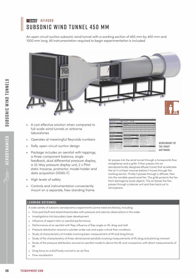
T E C Q U I P M E N T. C O M4 6
aER
OD
YN
AM
ICS
sUBS
ON
IC W
IND
tUN
NEL
s
L E A R N I N G O U T C O M E S :
A wide variety of subsonic aerodynamics experiments (some need ancillaries), including:
• Flow past bluff and streamlined bodies with pressure and velocity observations in the wake
• Investigations into boundary layer development
• Influence of aspect ratio on aerofoil performance
• Performance of an aerofoil with flap, influence of flap angle on lift, drag and stall
• Pressure distribution around a cylinder under sub and super-critical flow conditions
• Study of characteristics of models involving basic measurement of lift and drag forces
• Study of the characteristics of three-dimensional aerofoils involving measurements of lift, drag and pitching moment
• Study of the pressure distribution around an aerofoil model to derive the lift, and comparison with direct measurements of
lift
• Drag force on a bluff body normal to an air flow
• Flow visualisation
a f 1 4 5 0 S
S ubs o n i c W i n d T u n n e l 4 5 0 m m
An open circuit suction subsonic wind tunnel with a working section of 450 mm by 450 mm and
1000 mm long. All instrumentation required to begin experimentation is included.
• A cost effective solution when compared to
full-scale wind tunnels or airborne
laboratories
• Operates at meaningful Reynolds numbers
• Safe, open-circuit suction design
• Package includes an aerofoil with tappings,
a three-component balance, angle
feedback, dual differential pressure display,
a 32-Way pressure display unit, 2 x Pitot
static traverse, protractor, model holder and
data acquisition (VDAS-F)
• High levels of safety
• Controls and instrumentation conveniently
mount on a separate, free-standing frame
Air passes into the wind tunnel through a honeycomb flow
straightener and a grille. It then passes into an
aerodynamically designed effuser (cone) that accelerates
the air in a linear manner before it moves through the
working section. Finally it passes through a diffuser, then
into the variable speed axial fan. The grille protects the fan
from damage by loose objects. The air leaves the fan,
passes through a silencer unit and then back out to
atmosphere.
S c r e e n s h o t o ft h e V D A S ®s o f t wa r e
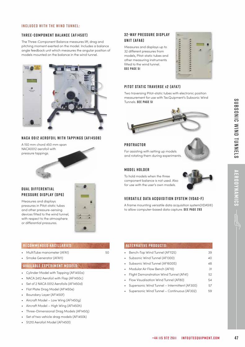
+ 4 4 1 1 5 9 7 2 2 6 1 1 I N F O @ T E C Q U I P M E N T. C O M 47
aER
OD
YN
AM
ICS
sUBSON
IC WIN
D tUN
NELs
I n c l u d e d w i t h t h e w i n d t u n n e l :
T h r e e - C o m p o n e n t B a l a n c e ( A F 1 4 5 0 T )
The Three-Component Balance measures lift, drag and
pitching moment exerted on the model. Includes a balance
angle feedback unit which measures the angular position of
models mounted on the balance in the wind tunnel.
N A C A 0 0 1 2 A e r o f o i l w i t h Ta p p i n g s ( A F 1 4 5 0 B )
A 150 mm chord 450 mm span
NACA0012 aerofoil with
pressure tappings.
D u a l d i f f e r e n t i a l
P r e s s u r e D i s p l ay ( d p 6 )
Measures and displays
pressures in Pitot-static tubes
and other pressure-sensing
devices fitted to the wind tunnel,
with respect to the atmosphere
or differential pressures.
• MultiTube manometer (AFA1) 50
• Smoke Generator (AFA11)
• Cylinder Model with Tapping (AF1450a)
• NACA 2412 Aerofoil with Flap (AF1450c)
• Set of 2 NACA 0012 Aerofoils (AF1450d)
• Flat Plate Drag Model (AF1450e)
• Boundary Layer (AF1450f)
• Aircraft Model – Low Wing (AF1450g)
• Aircraft Model – High Wing (AF1450h)
• Three-Dimensional Drag Models (AF1450j)
• Set of two vehicle drag models (AF1450k)
• S1210 Aerofoil Model (AF1450l)
R E C O M M E N D E D AN C I L LAR I E S :
ava i labl e e x p e r i m e n t m o d e l s :
• Bench-Top Wind Tunnel (AF1125) 39
• Subsonic Wind Tunnel (AF1300) 40
• Subsonic Wind Tunnel (AF1600S) 48
• Modular Air Flow Bench (AF10) 31
• Flight Demonstration Wind Tunnel (AF41) 52
• Flow Visualisation Wind Tunnel (AF80) 54
• Supersonic Wind Tunnel – Intermittent (AF300) 57
• Supersonic Wind Tunnel – Continuous (AF302) 59
alt e r nat i v e p r o d u c t s :
3 2 - Way P r e s s u r e D i s p l ay
U n i t ( A FA 6 )
Measures and displays up to
32 different pressures from
models, Pitot-static tubes and
other measuring instruments
fitted to the wind tunnel.
S e e pa g e 5 1
P i t o t S tat i c T r av e r s e x 2 ( A FA7 )
Two traversing Pitot-static tubes with electronic position
measurement for use with TecQuipment’s Subsonic Wind
Tunnels. S e e pa g e 5 1
P r o t r a c t o r
For assisting with setting up models
and rotating them during experiments.
M o d e l h o l d e r
To hold models when the three
component balance is not used. Also
for use with the user’s own models.
V e r s at i l e D ata A c q u i s i t i o n S y s t e m ( V D A S - F )
A frame mounting versatile data acquisition system(VDAS®)
to allow computer-based data capture. S e e pa g e 2 9 3
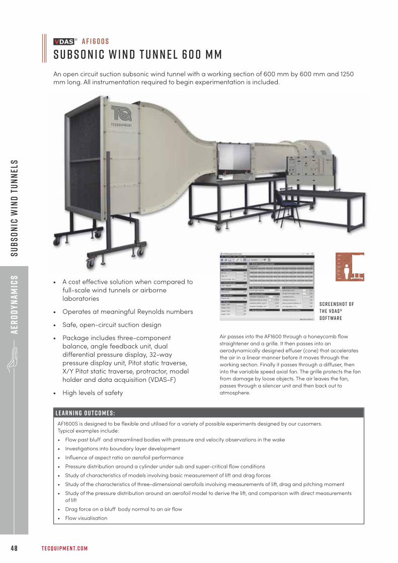
T E C Q U I P M E N T. C O M4 8
aER
OD
YN
AM
ICS
sUBS
ON
IC W
IND
tUN
NEL
s
L E A R N I N G O U T C O M E S :
AF1600S is designed to be flexible and utilised for a variety of possible experiments designed by our cusomers.
Typical examples include:
• Flow past bluff and streamlined bodies with pressure and velocity observations in the wake
• Investigations into boundary layer development
• Influence of aspect ratio on aerofoil performance
• Pressure distribution around a cylinder under sub and super-critical flow conditions
• Study of characteristics of models involving basic measurement of lift and drag forces
• Study of the characteristics of three-dimensional aerofoils involving measurements of lift, drag and pitching moment
• Study of the pressure distribution around an aerofoil model to derive the lift, and comparison with direct measurements
of lift
• Drag force on a bluff body normal to an air flow
• Flow visualisation
a f 1 6 0 0 S
S ubs o n i c W i n d T u n n e l 6 0 0 m m
An open circuit suction subsonic wind tunnel with a working section of 600 mm by 600 mm and 1250
mm long. All instrumentation required to begin experimentation is included.
• A cost effective solution when compared to
full-scale wind tunnels or airborne
laboratories
• Operates at meaningful Reynolds numbers
• Safe, open-circuit suction design
• Package includes three-component
balance, angle feedback unit, dual
differential pressure display, 32-way
pressure display unit, Pitot static traverse,
X/Y Pitot static traverse, protractor, model
holder and data acquisition (VDAS-F)
• High levels of safety
Air passes into the AF1600 through a honeycomb flow
straightener and a grille. It then passes into an
aerodynamically designed effuser (cone) that accelerates
the air in a linear manner before it moves through the
working section. Finally it passes through a diffuser, then
into the variable speed axial fan. The grille protects the fan
from damage by loose objects. The air leaves the fan,
passes through a silencer unit and then back out to
atmosphere.
S c r e e n s h o t o ft h e V D A S ®s o f t wa r e
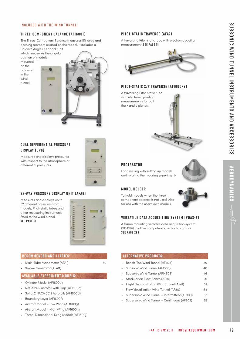
+ 4 4 1 1 5 9 7 2 2 6 1 1 I N F O @ T E C Q U I P M E N T. C O M 4 9
aER
OD
YN
AM
ICS
sUBSON
IC WIN
D tUN
NEL IN
STRUM
ENTS AN
D ACCESSO
RIES
• Multi-Tube Manometer (AFA1) 50
• Smoke Generator (AFA11)
• Cylinder Model (AF1600a)
• NACA 2412 Aerofoil with Flap (AF1600c)
• Set of 2 NACA 0012 Aerofoils (AF1600d)
• Boundary Layer (AF1600f)
• Aircraft Model – Low Wing (AF1600g)
• Aircraft Model – High Wing (AF1600h)
• Three-Dimensional Drag Models (AF1600j)
R E C O M M E N D E D AN C I L LAR I E S :
ava i labl e e x p e r i m e n t m o d e l s :
• Bench-Top Wind Tunnel (AF1125) 39
• Subsonic Wind Tunnel (AF1300) 40
• Subsonic Wind Tunnel (AF1450S) 46
• Modular Air Flow Bench (AF10) 31
• Flight Demonstration Wind Tunnel (AF41) 52
• Flow Visualisation Wind Tunnel (AF80) 54
• Supersonic Wind Tunnel – Intermittent (AF300) 57
• Supersonic Wind Tunnel – Continuous (AF302) 59
alt e r nat i v e p r o d u c t s :
I n c l u d e d w i t h t h e w i n d t u n n e l :
T h r e e - C o m p o n e n t B a l a n c e ( A F 1 6 0 0 T )
The Three-Component Balance measures lift, drag and
pitching moment exerted on the model. It includes a
Balance Angle Feedback Unit
which measures the angular
position of models
mounted
on the
balance
in the
wind
tunnel.
D u a l d i f f e r e n t i a l P r e s s u r e
D i s p l ay ( D P 6 )
Measures and displays pressures
with respect to the atmosphere or
differential pressures.
3 2 - Way P r e s s u r e D i s p l ay U n i t ( A FA 6 )
Measures and displays up to
32 different pressures from
models, Pitot-static tubes and
other measuring instruments
fitted to the wind tunnel.
S e e pa g e 5 1
P i t o t- S tat i c T r av e r s e ( A FA7 )
A traversing Pitot-static tube with electronic position
measurement. S e e pa g e 5 1
P i t o t- s tat i c x / y t r av e r s e ( A F 1 6 0 0 x y )
A traversing Pitot-static tube
with electronic position
measurements for both
the x and y planes.
P r o t r a c t o r
For assisting with setting up models
and rotating them during experiments.
M o d e l h o l d e r
To hold models when the three
component balance is not used. Also
for use with the user’s own models.
V e r s at i l e D ata A c q u i s i t i o n S y s t e m ( V D A S - F )
A frame mounting versatile data acquisition system
(VDAS®) to allow computer-based data capture.
S e e pa g e 2 9 3
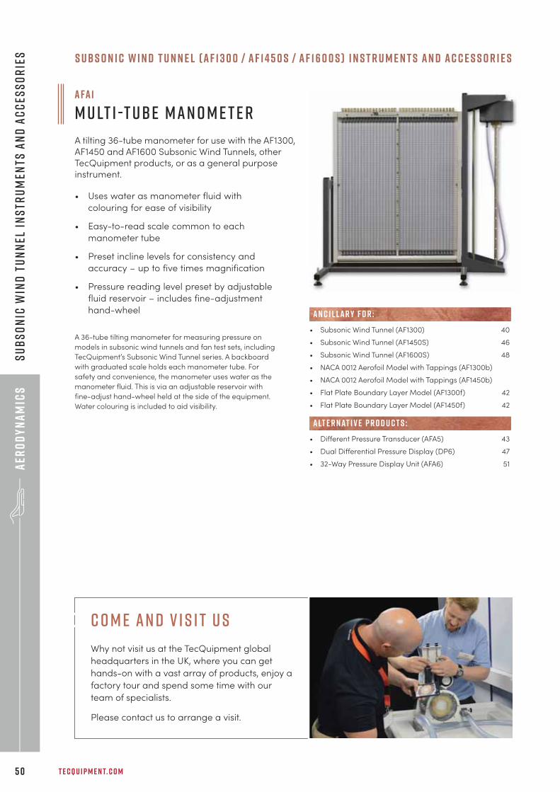
T E C Q U I P M E N T. C O M5 0
aER
OD
YN
AM
ICS
sUBS
ON
IC W
IND
tUN
NEL
IN
STR
UMEN
TS A
ND
ACC
ESSO
RIE
S
A FA 1
M u lt i -T ube M a n o m e t e r
A tilting 36-tube manometer for use with the AF1300,AF1450 and AF1600 Subsonic Wind Tunnels, otherTecQuipment products, or as a general purposeinstrument.
• Uses water as manometer fluid with
colouring for ease of visibility
• Easy-to-read scale common to each
manometer tube
• Preset incline levels for consistency and
accuracy – up to five times magnification
• Pressure reading level preset by adjustable
fluid reservoir – includes fine-adjustment
hand-wheel
A 36-tube tilting manometer for measuring pressure on
models in subsonic wind tunnels and fan test sets, including
TecQuipment’s Subsonic Wind Tunnel series. A backboard
with graduated scale holds each manometer tube. For
safety and convenience, the manometer uses water as the
manometer fluid. This is via an adjustable reservoir with
fine-adjust hand-wheel held at the side of the equipment.
Water colouring is included to aid visibility.
• Subsonic Wind Tunnel (AF1300) 40
• Subsonic Wind Tunnel (AF1450S) 46
• Subsonic Wind Tunnel (AF1600S) 48
• NACA 0012 Aerofoil Model with Tappings (AF1300b)
• NACA 0012 Aerofoil Model with Tappings (AF1450b)
• Flat Plate Boundary Layer Model (AF1300f) 42
• Flat Plate Boundary Layer Model (AF1450f) 42
• Different Pressure Transducer (AFA5) 43
• Dual Differential Pressure Display (DP6) 47
• 32-Way Pressure Display Unit (AFA6) 51
AN C I L LAR Y F O R :
alt e r nat i v e p r o d u c t s :
S u b s o n i c W i n d T u n n e l ( A F 1 3 0 0 / A F 1 4 5 0 S / A F 1 6 0 0 s ) I n s t r u m e n t s a n d a c c e s s o r i e s
c o m e an d v i s i t u s
Why not visit us at the TecQuipment global
headquarters in the UK, where you can get
hands-on with a vast array of products, enjoy a
factory tour and spend some time with our
team of specialists.
Please contact us to arrange a visit.
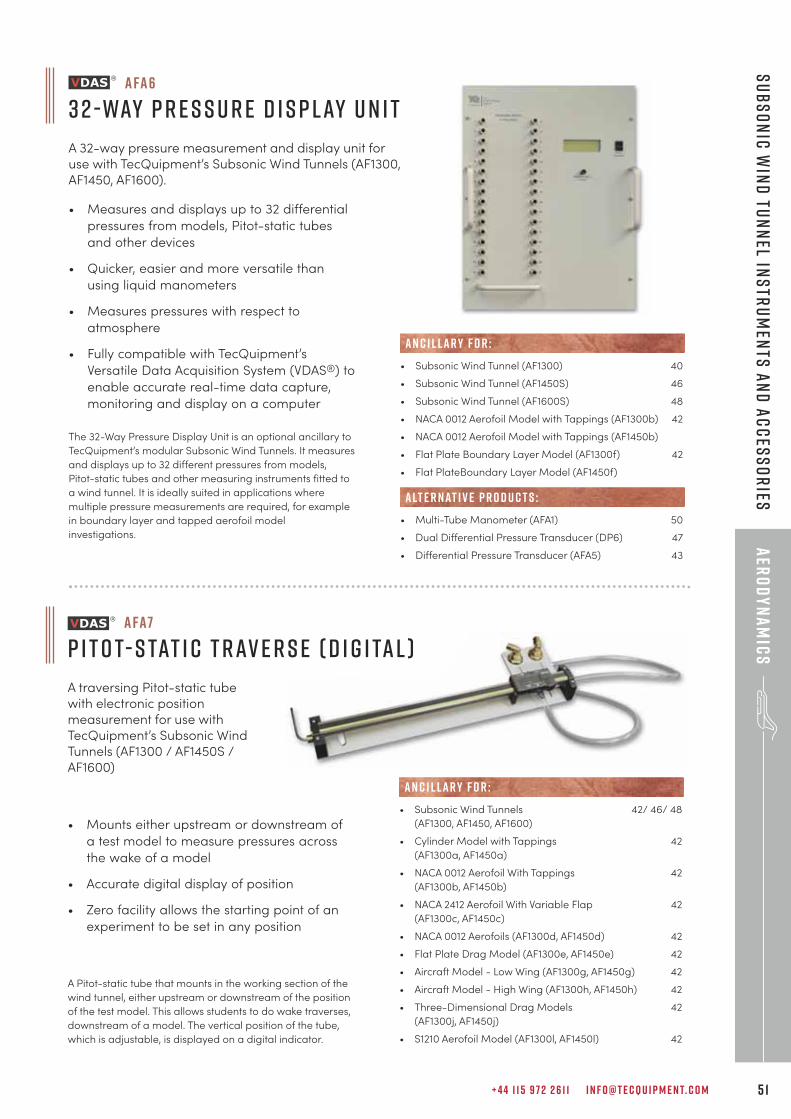
+ 4 4 1 1 5 9 7 2 2 6 1 1 I N F O @ T E C Q U I P M E N T. C O M 5 1
aER
OD
YN
AM
ICS
sUBSON
IC WIN
D tUN
NEL IN
STRUM
ENTS AN
D ACCESSO
RIES
A FA 6
3 2 - Way P r e s s u r e D i s p l ay U n i t
A 32-way pressure measurement and display unit foruse with TecQuipment’s Subsonic Wind Tunnels (AF1300,AF1450, AF1600).
• Measures and displays up to 32 differential
pressures from models, Pitot-static tubes
and other devices
• Quicker, easier and more versatile than
using liquid manometers
• Measures pressures with respect to
atmosphere
• Fully compatible with TecQuipment’s
Versatile Data Acquisition System (VDAS®) to
enable accurate real-time data capture,
monitoring and display on a computer
The 32-Way Pressure Display Unit is an optional ancillary to
TecQuipment’s modular Subsonic Wind Tunnels. It measures
and displays up to 32 different pressures from models,
Pitot-static tubes and other measuring instruments fitted to
a wind tunnel. It is ideally suited in applications where
multiple pressure measurements are required, for example
in boundary layer and tapped aerofoil model
investigations.
• Subsonic Wind Tunnel (AF1300) 40
• Subsonic Wind Tunnel (AF1450S) 46
• Subsonic Wind Tunnel (AF1600S) 48
• NACA 0012 Aerofoil Model with Tappings (AF1300b) 42
• NACA 0012 Aerofoil Model with Tappings (AF1450b)
• Flat Plate Boundary Layer Model (AF1300f) 42
• Flat PlateBoundary Layer Model (AF1450f)
• Multi-Tube Manometer (AFA1) 50
• Dual Differential Pressure Transducer (DP6) 47
• Differential Pressure Transducer (AFA5) 43
AN C I L LAR Y F O R :
alt e r nat i v e p r o d u c t s :
• Mounts either upstream or downstream of
a test model to measure pressures across
the wake of a model
• Accurate digital display of position
• Zero facility allows the starting point of an
experiment to be set in any position
A Pitot-static tube that mounts in the working section of the
wind tunnel, either upstream or downstream of the position
of the test model. This allows students to do wake traverses,
downstream of a model. The vertical position of the tube,
which is adjustable, is displayed on a digital indicator.
A FA7
P i t o t- S tat i c T r av e r s e ( d i g i ta l )
A traversing Pitot-static tubewith electronic positionmeasurement for use withTecQuipment’s Subsonic WindTunnels (AF1300 / AF1450S /AF1600)
• Subsonic Wind Tunnels 42/ 46/ 48
(AF1300, AF1450, AF1600)
• Cylinder Model with Tappings 42
(AF1300a, AF1450a)
• NACA 0012 Aerofoil With Tappings 42
(AF1300b, AF1450b)
• NACA 2412 Aerofoil With Variable Flap 42
(AF1300c, AF1450c)
• NACA 0012 Aerofoils (AF1300d, AF1450d) 42
• Flat Plate Drag Model (AF1300e, AF1450e) 42
• Aircraft Model - Low Wing (AF1300g, AF1450g) 42
• Aircraft Model - High Wing (AF1300h, AF1450h) 42
• Three-Dimensional Drag Models 42
(AF1300j, AF1450j)
• S1210 Aerofoil Model (AF1300l, AF1450l) 42
AN C I L LAR Y F O R :
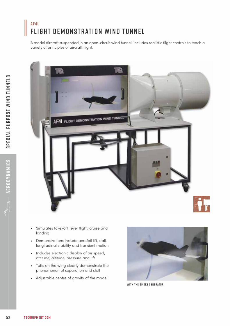
T E C Q U I P M E N T. C O M5 2
aER
OD
YN
AM
ICS
sPEC
IAL
PUR
POSE
WIN
D t
UNN
ELS
a f 4 1
F l i g h t D e m o n s t r at i o n W i n d T u n n e l
A model aircraft suspended in an open-circuit wind tunnel. Includes realistic flight controls to teach avariety of principles of aircraft flight.
• Simulates take-off, level flight, cruise and
landing
• Demonstrations include aerofoil lift, stall,
longitudinal stability and transient motion
• Includes electronic display of air speed,
attitude, altitude, pressure and lift
• Tufts on the wing clearly demonstrate the
phenomenon of separation and stall
• Adjustable centre of gravity of the model
W i t h t h e S m o k e G e n e r at o r
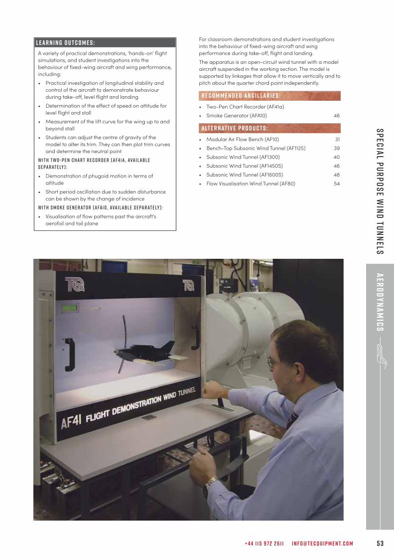
+ 4 4 1 1 5 9 7 2 2 6 1 1 I N F O @ T E C Q U I P M E N T. C O M 5 3
aER
OD
YN
AM
ICS
sPECIAL PURPO
SE WIN
D tUN
NELS
For classroom demonstrations and student investigations
into the behaviour of fixed-wing aircraft and wing
performance during take-off, flight and landing.
The apparatus is an open-circuit wind tunnel with a model
aircraft suspended in the working section. The model is
supported by linkages that allow it to move vertically and to
pitch about the quarter chord point independently.
• Two-Pen Chart Recorder (AF41a)
• Smoke Generator (AFA10) 46
• Modular Air Flow Bench (AF10) 31
• Bench-Top Subsonic Wind Tunnel (AF1125) 39
• Subsonic Wind Tunnel (AF1300) 40
• Subsonic Wind Tunnel (AF1450S) 46
• Subsonic Wind Tunnel (AF1600S) 48
• Flow Visualisation Wind Tunnel (AF80) 54
R E C O M M E N D E D AN C I L LAR I E S :
alt e r nat i v e p r o d u c t s :
L E A R N I N G O U T C O M E S :
A variety of practical demonstrations, ‘hands-on’ flight
simulations, and student investigations into the
behaviour of fixed-wing aircraft and wing performance,
including:
• Practical investigation of longitudinal stability and
control of the aircraft to demonstrate behaviour
during take-off, level flight and landing
• Determination of the effect of speed on attitude for
level flight and stall
• Measurement of the lift curve for the wing up to and
beyond stall
• Students can adjust the centre of gravity of the
model to alter its trim. They can then plot trim curves
and determine the neutral point
W i t h T w o - P e n C h a r t R e c o r d e r ( A F 4 1 a , ava i l abl es e pa r at e ly ) :
• Demonstration of phugoid motion in terms of
altitude
• Short period oscillation due to sudden disturbance
can be shown by the change of incidence
W i t h S m o k e G e n e r at o r ( A FA 1 0 , ava i l abl e s e pa r at e ly ) :
• Visualisation of flow patterns past the aircraft’s
aerofoil and tail plane
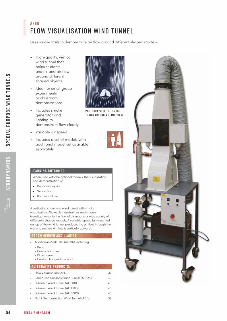
T E C Q U I P M E N T. C O M5 4
aER
OD
YN
AM
ICS
sPEC
IAL
PUR
POSE
WIN
D t
UNN
ELS
• High-quality, vertical
wind tunnel that
helps students
understand air flow
around different
shaped objects
• Ideal for small group
experiments
or classroom
demonstrations
• Includes smoke
generator and
lighting to
demonstrate flow clearly
• Variable air speed
• Includes a set of models with
additional model set available
separately
A vertical, suction-type wind tunnel with smoke
visualisation. Allows demonstrations and student
investigations into the flow of air around a wide variety of
differently shaped models. A variable-speed fan mounted
on top of the wind tunnel produces the air flow through the
working section. Air flow is vertically upwards.
• Additional Model Set (AF80b), including:
– Bend
– Cascade corner
– Plain corner
– Heat exchanger tube bank
• Flow Visualisation (AF17) 37
• Bench-Top Subsonic Wind Tunnel (AF1125) 39
• Subsonic Wind Tunnel (AF1300) 40
• Subsonic Wind Tunnel (AF1450S) 46
• Subsonic Wind Tunnel (AF1600S) 48
• Flight Demonstration Wind Tunnel (AF41) 52
R E C O M M E N D E D AN C I L LAR I E S :
alt e r nat i v e p r o d u c t s :
P h o t o g r a p h o f t h e s m o k et r a i l s a r o u n d a h e m i s p h e r e
a f 8 0
F l o w V i s u a l i s at i o n W i n d T u n n e l
Uses smoke trails to demonstrate air flow around different shaped models.
L e a r n i n g o u t c o m e s :
When used with the optional models, the visualisation
and demonstration of:
• Boundary layers
• Separation
• Rotational flow
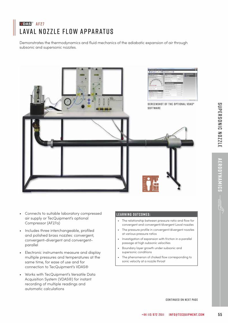
+ 4 4 1 1 5 9 7 2 2 6 1 1 I N F O @ T E C Q U I P M E N T. C O M 5 5
aER
OD
YN
AM
ICS
sUPERSO
NIC n
OZZLE
a f 2 7
L ava l N o z z l e F l o w A p pa r at u s
Demonstrates the thermodynamics and fluid mechanics of the adiabatic expansion of air throughsubsonic and supersonic nozzles.
• Connects to suitable laboratory compressed
air supply or TecQuipment’s optional
Compressor (AF27a)
• Includes three interchangeable, profiled
and polished brass nozzles: convergent,
convergent-divergent and convergent-
parallel
• Electronic instruments measure and display
multiple pressures and temperatures at the
same time, for ease of use and for
connection to TecQuipment’s VDAS®
• Works with TecQuipment’s Versatile Data
Acquisition System (VDAS®) for instant
recording of multiple readings and
automatic calculations
S c r e e n s h o t o f t h e o p t i o n a l V D A S ®s o f t wa r e
L E A R N I N G O U T C O M E S :
• The relationship between pressure ratio and flow for
convergent and convergent/divergent Laval nozzles
• The pressure profile in convergent/divergent nozzles
at various pressure ratios
• Investigation of expansion with friction in a parallel
passage at high subsonic velocities
• Boundary layer growth under subsonic and
supersonic conditions
• The phenomenon of choked flow corresponding to
sonic velocity at a nozzle throat
c o n t i n u e d o n n e x t pa g e
T E C Q U I P M E N T. C O M5 6
aER
OD
YN
AM
ICS
sUUP
ERSO
NIC
nOZ
ZLE
• Compressor (AF27a)
• Versatile Data Acquisition System – 293
Frame-mounted version (VDAS-F)
• Supersonic Wind Tunnel – Intermittent (AF300) 57
• Supersonic Wind Tunnel – Continuous (AF302) 59
alt e r nat i v e p r o d u c t s :
R E C O M M E N D E D AN C I L LAR I E S :
E S S E N T IAL AN C I L LAR I E S :The apparatus connects to TecQuipment’s optional
Compressor (AF27a) or a suitable laboratory supply of dry,
clean compressed air.
It demonstrates the thermodynamic and fluid properties of
the adiabatic expansion of subsonic and supersonic air flow
through nozzles.
L ava l N o z z l e F l o w A p pa r at u s ( A F 2 7 ) c o n t i n u e d f r o m p r e v i o u s pa g e
wat c h equ i p m e n t i n ac t i o n
Visit our YouTube channel to see demonstrations and promotional videos:
y o u t ube . c o m / c / t e cqu i p m e n t
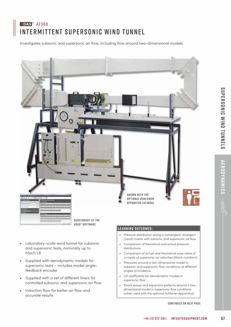
+ 4 4 1 1 5 9 7 2 2 6 1 1 I N F O @ T E C Q U I P M E N T. C O M 5 7
aER
OD
YN
AM
ICS
sUPERSO
NIC W
IND
tUNN
ELS
L E A R N I N G O U T C O M E S :
• Pressure distribution along a convergent/ divergent
(Laval) nozzle with subsonic and supersonic air flow
• Comparison of theoretical and actual pressure
distributions
• Comparison of actual and theoretical area ratios of
a nozzle at supersonic air velocities (Mach numbers)
• Pressures around a two-dimensional model in
subsonic and supersonic flow conditions, at different
angles of incidence
• Lift coefficients for aerodynamic models in
supersonic flow
• Shock waves and expansion patterns around a two-
dimensional model in supersonic flow conditions
(when used with the optional Schlieren Apparatus)
a f 3 0 0
I n t e r m i t t e n t S u p e r s o n i c W i n d T u n n e l
Investigates subsonic and supersonic air flow, including flow around two-dimensional models.
• Laboratory-scale wind tunnel for subsonic
and supersonic tests, nominally up to
Mach 1.8
• Supplied with aerodynamic models for
supersonic tests – includes model angle-
feedback encoder
• Supplied with a set of different liners for
controlled subsonic and supersonic air flow
• Induction flow for better air flow and
accurate results
S c r e e n s h o t o f t h eV D A S ® s o f t wa r e
S h o w n w i t h t h eo p t i o n a l S c h l i e r e nA p pa r at u s ( A F 3 0 0 a )
c o n t i n u e d o n n e x t pa g e
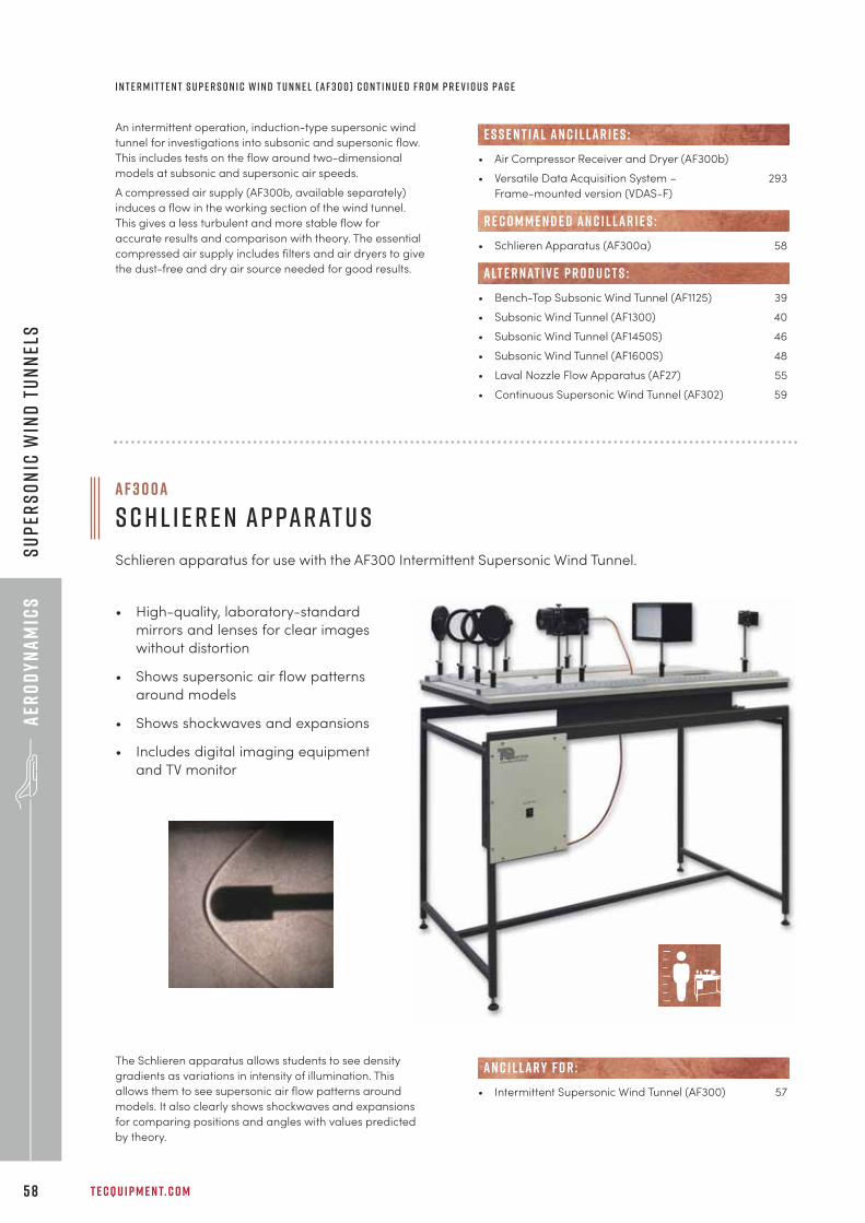
T E C Q U I P M E N T. C O M5 8
aER
OD
YN
AM
ICS
sUPE
RSO
NIC
WIN
D t
UNN
ELS
• Air Compressor Receiver and Dryer (AF300b)
• Versatile Data Acquisition System – 293
Frame-mounted version (VDAS-F)
• Schlieren Apparatus (AF300a) 58
• Bench-Top Subsonic Wind Tunnel (AF1125) 39
• Subsonic Wind Tunnel (AF1300) 40
• Subsonic Wind Tunnel (AF1450S) 46
• Subsonic Wind Tunnel (AF1600S) 48
• Laval Nozzle Flow Apparatus (AF27) 55
• Continuous Supersonic Wind Tunnel (AF302) 59
E S S E N T IAL AN C I L LAR I E S :
R E C O M M E N D E D AN C I L LAR I E S :
alt e r nat i v e p r o d u c t s :
a f 3 0 0 a
s c h l i e r e n a p pa r at u s
Schlieren apparatus for use with the AF300 Intermittent Supersonic Wind Tunnel.
An intermittent operation, induction-type supersonic wind
tunnel for investigations into subsonic and supersonic flow.
This includes tests on the flow around two-dimensional
models at subsonic and supersonic air speeds.
A compressed air supply (AF300b, available separately)
induces a flow in the working section of the wind tunnel.
This gives a less turbulent and more stable flow for
accurate results and comparison with theory. The essential
compressed air supply includes filters and air dryers to give
the dust-free and dry air source needed for good results.
• High-quality, laboratory-standard
mirrors and lenses for clear images
without distortion
• Shows supersonic air flow patterns
around models
• Shows shockwaves and expansions
• Includes digital imaging equipment
and TV monitor
The Schlieren apparatus allows students to see density
gradients as variations in intensity of illumination. This
allows them to see supersonic air flow patterns around
models. It also clearly shows shockwaves and expansions
for comparing positions and angles with values predicted
by theory.
i n t e r m i t t e n t s u p e r s o n i c w i n d t u n n e l ( A F 3 0 0 ) c o n t i n u e d f r o m p r e v i o u s pa g e
• Intermittent Supersonic Wind Tunnel (AF300) 57
AN C I L LAR Y F O R :
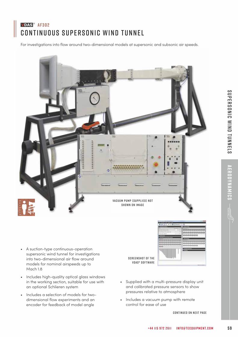
+ 4 4 1 1 5 9 7 2 2 6 1 1 I N F O @ T E C Q U I P M E N T. C O M 5 9
aER
OD
YN
AM
ICS
sUPERSO
NIC W
IND
tUNN
ELS
a f 3 0 2
C o n t i n u o u s S u p e r s o n i c W i n d T u n n e l
For investigations into flow around two-dimensional models at supersonic and subsonic air speeds.
• A suction-type continuous-operation
supersonic wind tunnel for investigations
into two-dimensional air flow around
models for nominal airspeeds up to
Mach 1.8
• Includes high-quality optical glass windows
in the working section, suitable for use with
an optional Schlieren system
• Includes a selection of models for two-
dimensional flow experiments and an
encoder for feedback of model angle
• Supplied with a multi-pressure display unit
and calibrated pressure sensors to show
pressures relative to atmosphere
• Includes a vacuum pump with remote
control for ease of use
Va c u u m p u m p ( s u p p l i e d ) n o ts h o w n o n i m a g e
c o n t i n u e d o n n e x t pa g e
S c r e e n s h o t o f t h eV D A S ® s o f t wa r e
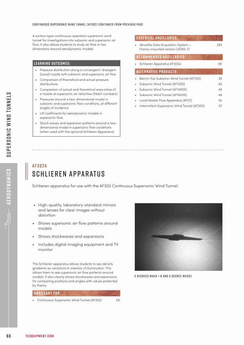
T E C Q U I P M E N T. C O M6 0
aER
OD
YN
AM
ICS
sUPE
RSO
NIC
WIN
D t
UNN
ELS
A suction-type continuous-operation supersonic wind
tunnel for investigations into subsonic and supersonic air
flow. It also allows students to study air flow in two
dimensions around aerodynamic models.
• Versatile Data Acquisition System – 293
Frame-mounted version (VDAS-F)
• Schlieren Apparatus AF302a 60
• Bench-Top Subsonic Wind Tunnel (AF1125) 39
• Subsonic Wind Tunnel (AF1300) 40
• Subsonic Wind Tunnel (AF1450S) 46
• Subsonic Wind Tunnel (AF1600S) 48
• Laval Nozzle Flow Apparatus (AF27) 55
• Intermittent Supersonic Wind Tunnel (AF300) 57
R E C O M M E N D E D AN C I L LAR I E S :
alt e r nat i v e p r o d u c t s :
E S S E N T IAL AN C I L LAR I E S :
• High-quality, laboratory-standard mirrors
and lenses for clear images without
distortion
• Shows supersonic air flow patterns around
models
• Shows shockwaves and expansions
• Includes digital imaging equipment and TV
monitor
The Schlieren apparatus allows students to see density
gradients as variations in intensity of illumination. This
allows them to see supersonic air flow patterns around
models. It also clearly shows shockwaves and expansions
for comparing positions and angles with values predicted
by theory.
• Continuous Supersonic Wind Tunnel (AF302) 59
AN C I L LAR Y F O R :
a f 3 0 2 a
s c h l i e r e n a p pa r at u s
Schlieren apparatus for use with the AF302 Continuous Supersonic Wind Tunnel.
c o n t i n u o u s s u p e r s o n i c w i n d t u n n e l ( A F 3 0 2 ) c o n t i n u e d f r o m p r e v i o u s pa g e
L e a r n i n g o u t c o m e s :
• Pressure distribution along a convergent/ divergent
(Laval) nozzle with subsonic and supersonic air flow
• Comparison of theoretical and actual pressure
distributions
• Comparison of actual and theoretical area ratios of
a nozzle at supersonic air velocities (Mach numbers)
• Pressures around a two-dimensional model in
subsonic and supersonic flow conditions, at different
angles of incidence
• Lift coefficients for aerodynamic models in
supersonic flow
• Shock waves and expansion patterns around a two-
dimensional model in supersonic flow conditions
(when used with the optional Schlieren Apparatus)
5 d e g r e e s m a c h 1 - 8 a n d 5 d e g r e e w e d g e
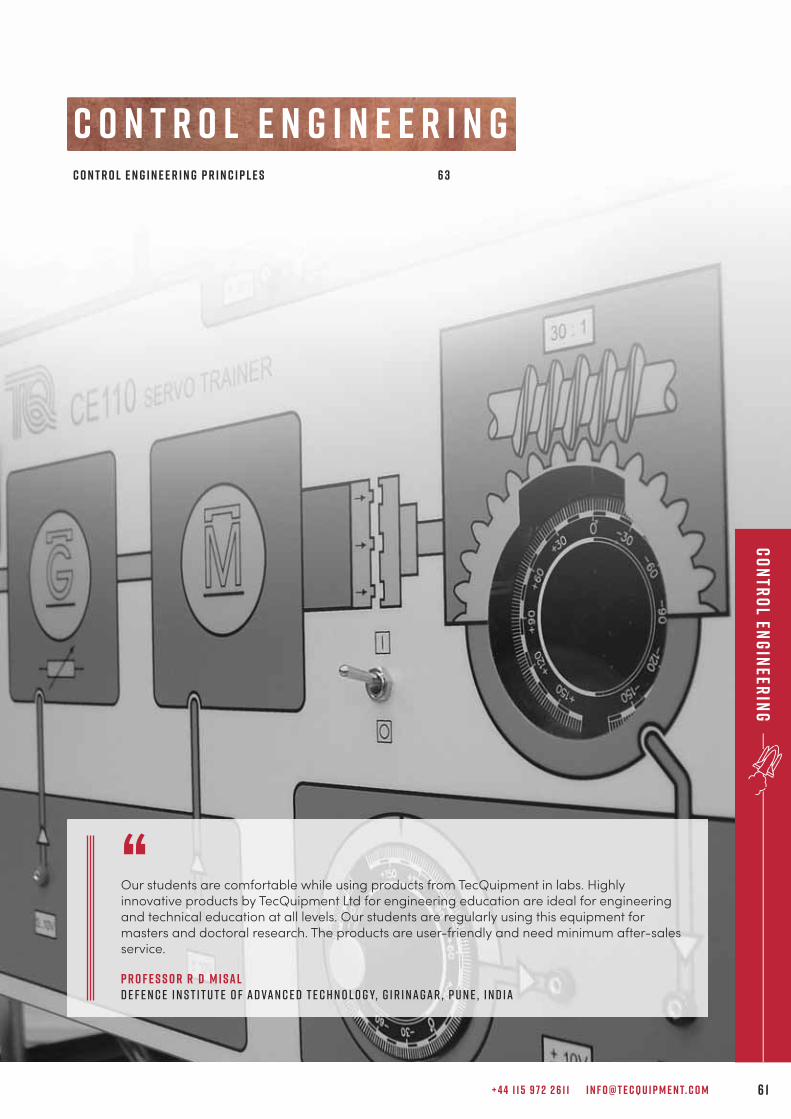
+ 4 4 1 1 5 9 7 2 2 6 1 1 I N F O @ T E C Q U I P M E N T. C O M 6 1
Co
ntr
ol En
gin
eerin
g
c o n t r o l e n g i n e e r i n g
“Our students are comfortable while using products from TecQuipment in labs. Highlyinnovative products by TecQuipment Ltd for engineering education are ideal for engineeringand technical education at all levels. Our students are regularly using this equipment formasters and doctoral research. The products are user-friendly and need minimum after-salesservice.
P r o f e s s o r R D M i s a lD e f e n c e I n s t i t u t e o f A d va n c e d T e c h n o l o g y, G i r i n a g a r , P u n e , I n d i a
C o n t r o l E n g i n e e r i n g P r i n c i p l e s 6 3
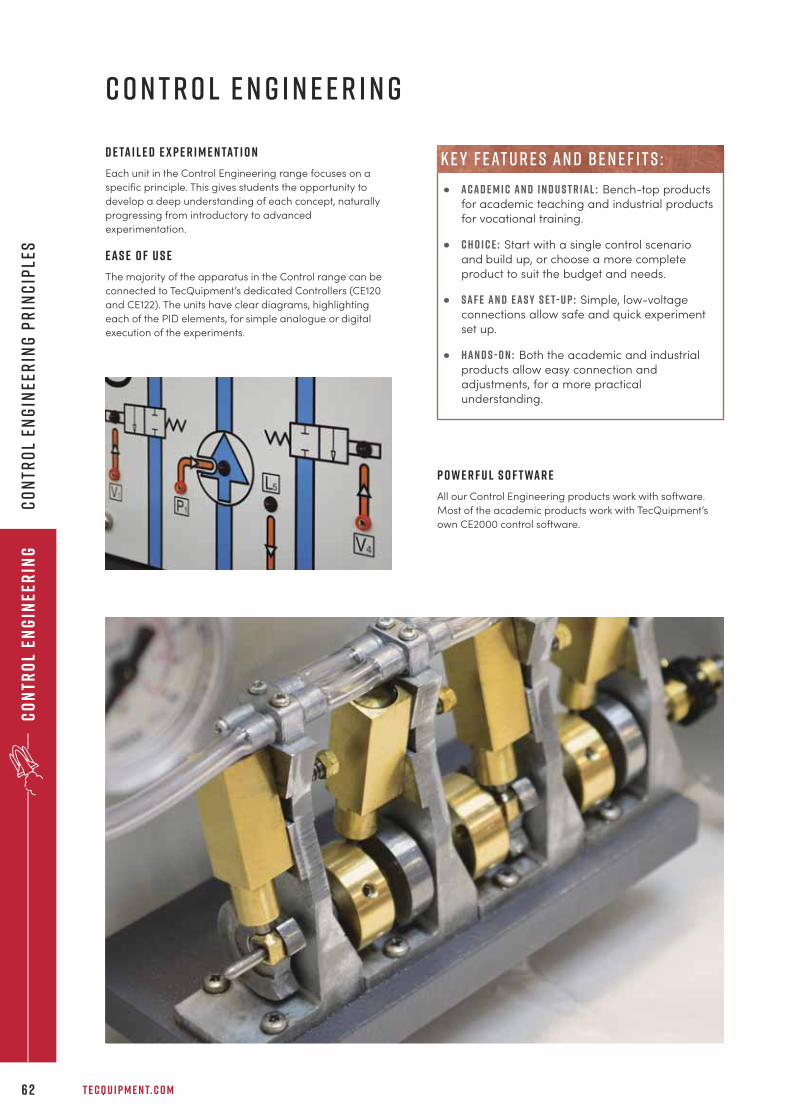
T E C Q U I P M E N T. C O M6 2
Co
ntr
ol
Eng
inee
rin
gC
on
tro
l En
gin
eer
ing
Pr
inc
iple
s
c o n t r o l e n g i n e e r i n g
D e ta i l e d e x p e r i m e n tat i o n
Each unit in the Control Engineering range focuses on a
specific principle. This gives students the opportunity to
develop a deep understanding of each concept, naturally
progressing from introductory to advanced
experimentation.
E a s e o f u s e
The majority of the apparatus in the Control range can be
connected to TecQuipment’s dedicated Controllers (CE120
and CE122). The units have clear diagrams, highlighting
each of the PID elements, for simple analogue or digital
execution of the experiments.
P o w e r f u l S o f t wa r e
All our Control Engineering products work with software.
Most of the academic products work with TecQuipment’s
own CE2000 control software.
• A c a d e m i c a n d i n d u s t r i a l : Bench-top products
for academic teaching and industrial products
for vocational training.
• c h o i c e : Start with a single control scenario
and build up, or choose a more complete
product to suit the budget and needs.
• s a f e a n d e a s y s e t- u p : Simple, low-voltage
connections allow safe and quick experiment
set up.
• H a n d s - o n : Both the academic and industrial
products allow easy connection and
adjustments, for a more practical
understanding.
k e y f eat u r e s an d b e n e f i t s :
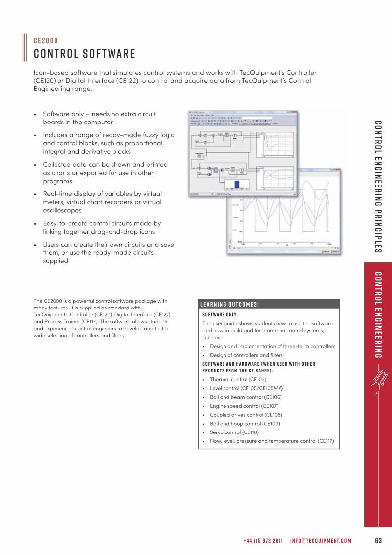
+ 4 4 1 1 5 9 7 2 2 6 1 1 I N F O @ T E C Q U I P M E N T. C O M 6 3
Co
ntr
ol En
gin
eerin
gC
on
tro
l Eng
ineer
ing
Pr
inc
iples
c e 2 0 0 0
C o n t r o l S o f t wa r e
Icon-based software that simulates control systems and works with TecQuipment’s Controller(CE120) or Digital Interface (CE122) to control and acquire data from TecQuipment’s ControlEngineering range.
L E A R N I N G O U T C O M E S :
S o f t wa r e o n ly:
The user guide shows students how to use the software
and how to build and test common control systems,
such as:
• Design and implementation of three-term controllers
• Design of controllers and filters
S o f t wa r e a n d h a r d wa r e ( w h e n u s e d w i t h o t h e r
p r o d u c t s f r o m t h e C E r a n g e ) :
• Thermal control (CE103)
• Level control (CE105/CE105MV)
• Ball and beam control (CE106)
• Engine speed control (CE107)
• Coupled drives control (CE108)
• Ball and hoop control (CE109)
• Servo control (CE110)
• Flow, level, pressure and temperature control (CE117)
The CE2000 is a powerful control software package with
many features. It is supplied as standard with
TecQuipment’s Controller (CE120), Digital Interface (CE122)
and Process Trainer (CE117). The software allows students
and experienced control engineers to develop and test a
wide selection of controllers and filters.
• Software only – needs no extra circuit
boards in the computer
• Includes a range of ready-made fuzzy logic
and control blocks, such as proportional,
integral and derivative blocks
• Collected data can be shown and printed
as charts or exported for use in other
programs
• Real-time display of variables by virtual
meters, virtual chart recorders or virtual
oscilloscopes
• Easy-to-create control circuits made by
linking together drag-and-drop icons
• Users can create their own circuits and save
them, or use the ready-made circuits
supplied
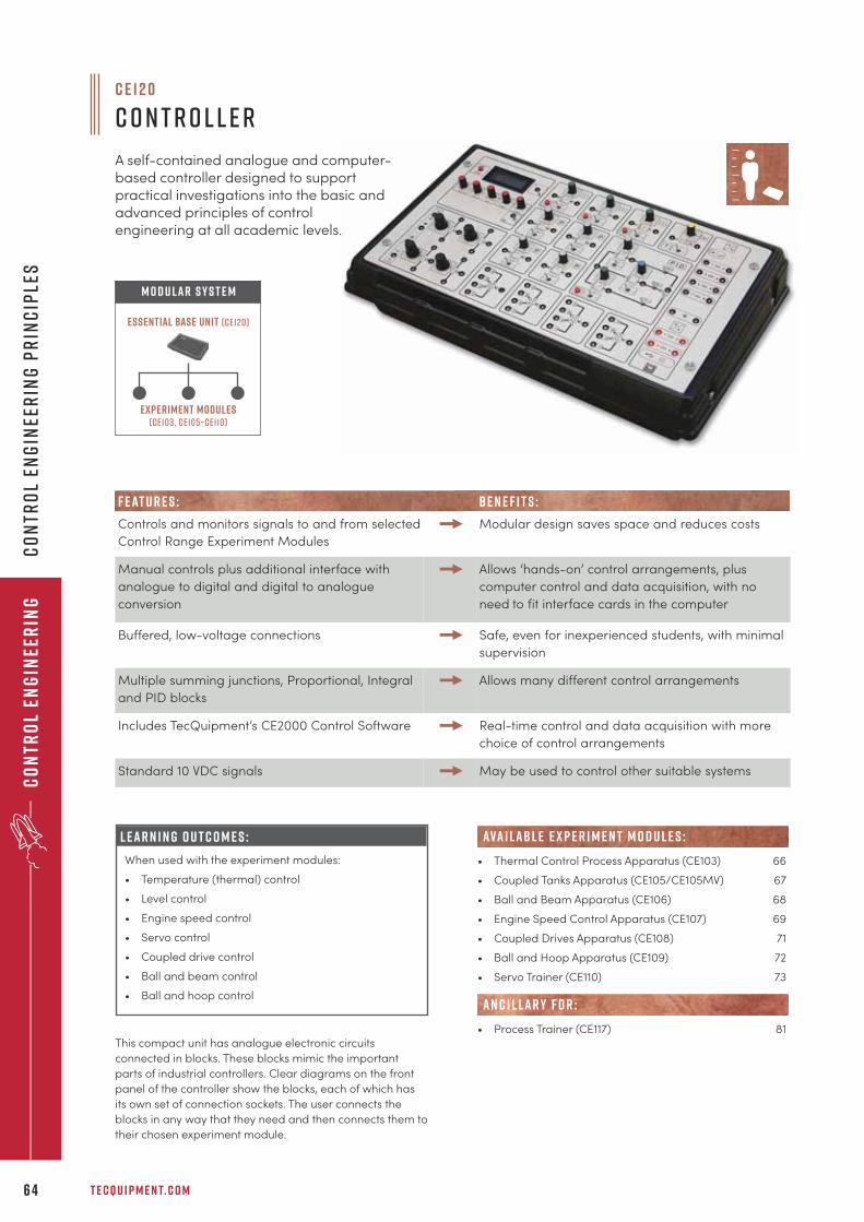
T E C Q U I P M E N T. C O M6 4
Co
ntr
ol
Eng
inee
rin
gC
on
tro
l En
gin
eer
ing
Pr
inc
iple
s
This compact unit has analogue electronic circuits
connected in blocks. These blocks mimic the important
parts of industrial controllers. Clear diagrams on the front
panel of the controller show the blocks, each of which has
its own set of connection sockets. The user connects the
blocks in any way that they need and then connects them to
their chosen experiment module.
c e 1 2 0
C o n t r o l l e r
A self-contained analogue and computer-based controller designed to supportpractical investigations into the basic andadvanced principles of control engineering at all academic levels.
Experiment modules(ce103, ce105–ce110)
Essential Base Unit (ce120)
M O D U LAR S Y S T E M
• Thermal Control Process Apparatus (CE103) 66
• Coupled Tanks Apparatus (CE105/CE105MV) 67
• Ball and Beam Apparatus (CE106) 68
• Engine Speed Control Apparatus (CE107) 69
• Coupled Drives Apparatus (CE108) 71
• Ball and Hoop Apparatus (CE109) 72
• Servo Trainer (CE110) 73
• Process Trainer (CE117) 81
ava i lab l e e x p e r i m e n t m o d u l e s :
AN C I L LAR Y F O R :
F E AT U R E S : BE N E F I T S :
Controls and monitors signals to and from selected
Control Range Experiment Modules
Modular design saves space and reduces costs
Manual controls plus additional interface with
analogue to digital and digital to analogue
conversion
Allows ‘hands-on’ control arrangements, plus
computer control and data acquisition, with no
need to fit interface cards in the computer
Buffered, low-voltage connections Safe, even for inexperienced students, with minimal
supervision
Multiple summing junctions, Proportional, Integral
and PID blocks
Allows many different control arrangements
Includes TecQuipment’s CE2000 Control Software Real-time control and data acquisition with more
choice of control arrangements
Standard 10 VDC signals May be used to control other suitable systems
L E A R N I N G O U T C O M E S :
When used with the experiment modules:
• Temperature (thermal) control
• Level control
• Engine speed control
• Servo control
• Coupled drive control
• Ball and beam control
• Ball and hoop control
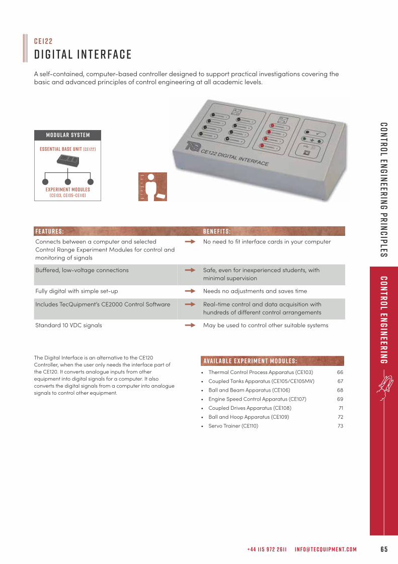
+ 4 4 1 1 5 9 7 2 2 6 1 1 I N F O @ T E C Q U I P M E N T. C O M 6 5
Co
ntr
ol En
gin
eerin
gC
on
tro
l Eng
ineer
ing
Pr
inc
iples
F E AT U R E S : BE N E F I T S :
Connects between a computer and selected
Control Range Experiment Modules for control and
monitoring of signals
No need to fit interface cards in your computer
Buffered, low-voltage connections Safe, even for inexperienced students, with
minimal supervision
Fully digital with simple set-up Needs no adjustments and saves time
Includes TecQuipment’s CE2000 Control Software Real-time control and data acquisition with
hundreds of different control arrangements
Standard 10 VDC signals May be used to control other suitable systems
c e 1 2 2
D i g i ta l I n t e r fa c e
A self-contained, computer-based controller designed to support practical investigations covering thebasic and advanced principles of control engineering at all academic levels.
The Digital Interface is an alternative to the CE120
Controller, when the user only needs the interface part of
the CE120. It converts analogue inputs from other
equipment into digital signals for a computer. It also
converts the digital signals from a computer into analogue
signals to control other equipment.
Experiment modules(ce103, ce105–ce110)
Essential Base Unit (ce122)
M O D U LAR S Y S T E M
• Thermal Control Process Apparatus (CE103) 66
• Coupled Tanks Apparatus (CE105/CE105MV) 67
• Ball and Beam Apparatus (CE106) 68
• Engine Speed Control Apparatus (CE107) 69
• Coupled Drives Apparatus (CE108) 71
• Ball and Hoop Apparatus (CE109) 72
• Servo Trainer (CE110) 73
Ancillaries
ava i lab l e e x p e r i m e n t m o d u l e s :
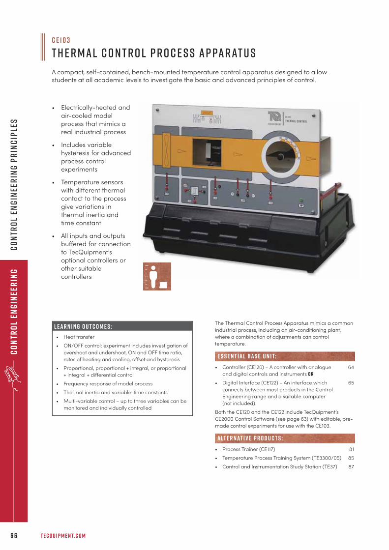
T E C Q U I P M E N T. C O M6 6
Co
ntr
ol
Eng
inee
rin
gC
on
tro
l En
gin
eer
ing
Pr
inc
iple
s
The Thermal Control Process Apparatus mimics a common
industrial process, including an air-conditioning plant,
where a combination of adjustments can control
temperature.
• Controller (CE120) – A controller with analogue 64
and digital controls and instruments o r
• Digital Interface (CE122) – An interface which 65
connects between most products in the Control
Engineering range and a suitable computer
(not included)
Both the CE120 and the CE122 include TecQuipment’s
CE2000 Control Software (see page 63) with editable, pre-
made control experiments for use with the CE103.
• Process Trainer (CE117) 81
• Temperature Process Training System (TE3300/05) 85
• Control and Instrumentation Study Station (TE37) 87
e s s e n t ial bas e u n i t:
alt e r nat i v e p r o d u c t s :
• Electrically-heated and
air-cooled model
process that mimics a
real industrial process
• Includes variable
hysteresis for advanced
process control
experiments
• Temperature sensors
with different thermal
contact to the process
give variations in
thermal inertia and
time constant
• All inputs and outputs
buffered for connection
to TecQuipment’s
optional controllers or
other suitable
controllers
L E A R N I N G O U T C O M E S :
• Heat transfer
• ON/OFF control: experiment includes investigation of
overshoot and undershoot, ON and OFF time ratio,
rates of heating and cooling, offset and hysteresis
• Proportional, proportional + integral, or proportional
+ integral + differential control
• Frequency response of model process
• Thermal inertia and variable-time constants
• Multi-variable control – up to three variables can be
monitored and individually controlled
c e 1 0 3
T h e r m a l C o n t r o l P r o c e s s A p pa r at u s
A compact, self-contained, bench-mounted temperature control apparatus designed to allowstudents at all academic levels to investigate the basic and advanced principles of control.
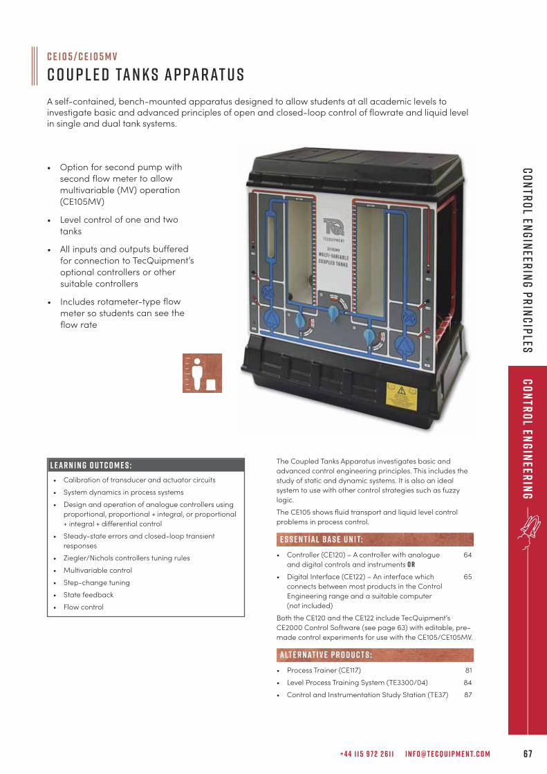
+ 4 4 1 1 5 9 7 2 2 6 1 1 I N F O @ T E C Q U I P M E N T. C O M 6 7
Co
ntr
ol En
gin
eerin
gC
on
tro
l Eng
ineer
ing
Pr
inc
iples
The Coupled Tanks Apparatus investigates basic and
advanced control engineering principles. This includes the
study of static and dynamic systems. It is also an ideal
system to use with other control strategies such as fuzzy
logic.
The CE105 shows fluid transport and liquid level control
problems in process control.
• Controller (CE120) – A controller with analogue 64
and digital controls and instruments o r
• Digital Interface (CE122) – An interface which 65
connects between most products in the Control
Engineering range and a suitable computer
(not included)
Both the CE120 and the CE122 include TecQuipment’s
CE2000 Control Software (see page 63) with editable, pre-
made control experiments for use with the CE105/CE105MV.
• Process Trainer (CE117) 81
• Level Process Training System (TE3300/04) 84
• Control and Instrumentation Study Station (TE37) 87
alt e r nat i v e p r o d u c t s :
e s s e n t ial bas e u n i t:
L E A R N I N G O U T C O M E S :
• Calibration of transducer and actuator circuits
• System dynamics in process systems
• Design and operation of analogue controllers using
proportional, proportional + integral, or proportional
+ integral + differential control
• Steady-state errors and closed-loop transient
responses
• Ziegler/Nichols controllers tuning rules
• Multivariable control
• Step-change tuning
• State feedback
• Flow control
C E 1 0 5 / C E 1 0 5 M V
C o u p l e d Ta n k s A p pa r at u s
A self-contained, bench-mounted apparatus designed to allow students at all academic levels toinvestigate basic and advanced principles of open and closed-loop control of flowrate and liquid levelin single and dual tank systems.
• Option for second pump with
second flow meter to allow
multivariable (MV) operation
(CE105MV)
• Level control of one and two
tanks
• All inputs and outputs buffered
for connection to TecQuipment’s
optional controllers or other
suitable controllers
• Includes rotameter-type flow
meter so students can see the
flow rate
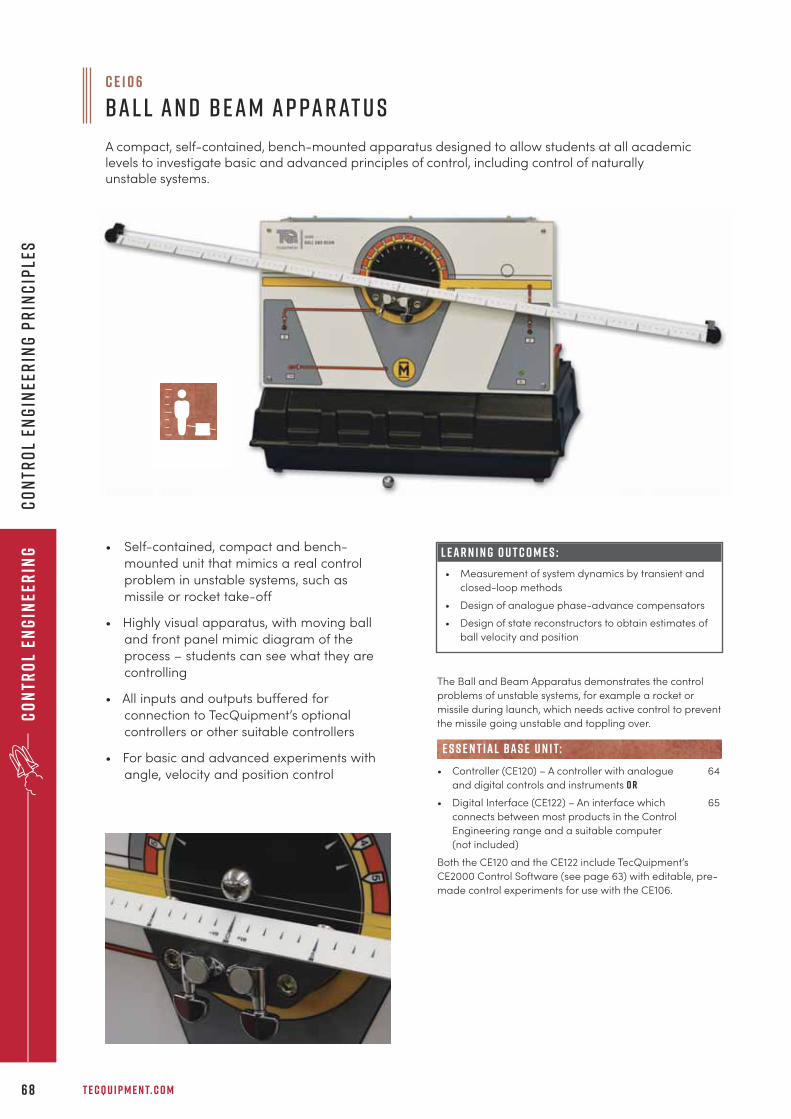
T E C Q U I P M E N T. C O M6 8
Co
ntr
ol
Eng
inee
rin
gC
on
tro
l En
gin
eer
ing
Pr
inc
iple
s
c e 1 0 6
B a l l a n d B e a m A p pa r at u s
A compact, self-contained, bench-mounted apparatus designed to allow students at all academiclevels to investigate basic and advanced principles of control, including control of naturallyunstable systems.
The Ball and Beam Apparatus demonstrates the control
problems of unstable systems, for example a rocket or
missile during launch, which needs active control to prevent
the missile going unstable and toppling over.
• Controller (CE120) – A controller with analogue 64
and digital controls and instruments o r
• Digital Interface (CE122) – An interface which 65
connects between most products in the Control
Engineering range and a suitable computer
(not included)
Both the CE120 and the CE122 include TecQuipment’s
CE2000 Control Software (see page 63) with editable, pre-
made control experiments for use with the CE106.
e s s e n t ial bas e u n i t:
L E A R N I N G O U T C O M E S :
• Measurement of system dynamics by transient and
closed-loop methods
• Design of analogue phase-advance compensators
• Design of state reconstructors to obtain estimates of
ball velocity and position
• Self-contained, compact and bench-
mounted unit that mimics a real control
problem in unstable systems, such as
missile or rocket take-off
• Highly visual apparatus, with moving ball
and front panel mimic diagram of the
process – students can see what they are
controlling
• All inputs and outputs buffered for
connection to TecQuipment’s optional
controllers or other suitable controllers
• For basic and advanced experiments with
angle, velocity and position control
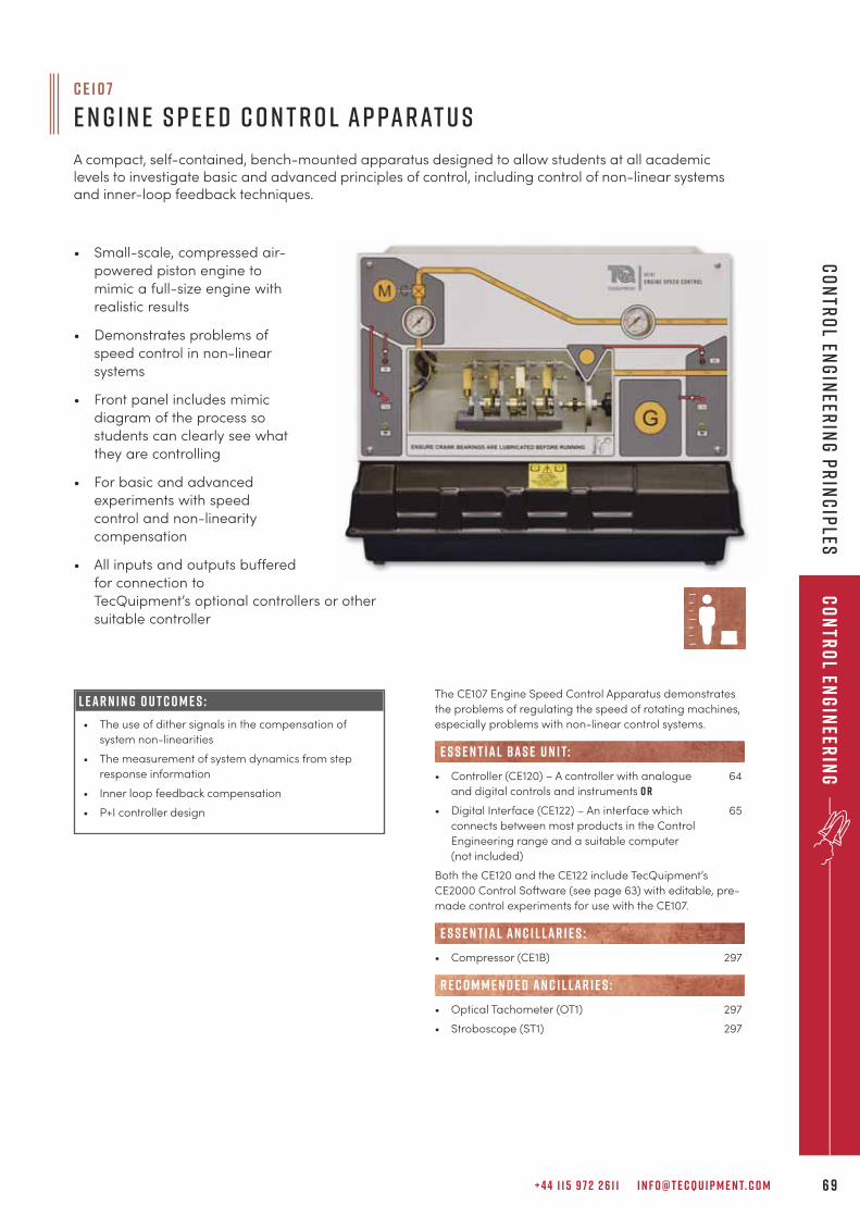
+ 4 4 1 1 5 9 7 2 2 6 1 1 I N F O @ T E C Q U I P M E N T. C O M 6 9
Co
ntr
ol En
gin
eerin
gC
on
tro
l Eng
ineer
ing
Pr
inc
iples
The CE107 Engine Speed Control Apparatus demonstrates
the problems of regulating the speed of rotating machines,
especially problems with non-linear control systems.
• Controller (CE120) – A controller with analogue 64
and digital controls and instruments o r
• Digital Interface (CE122) – An interface which 65
connects between most products in the Control
Engineering range and a suitable computer
(not included)
Both the CE120 and the CE122 include TecQuipment’s
CE2000 Control Software (see page 63) with editable, pre-
made control experiments for use with the CE107.
• Compressor (CE1B) 297
• Optical Tachometer (OT1) 297
• Stroboscope (ST1) 297
e s s e n t ial bas e u n i t:
E S S E N T IAL AN C I L LAR I E S :
R E C O M M E N D E D AN C I L LAR I E S :
L E A R N I N G O U T C O M E S :
• The use of dither signals in the compensation of
system non-linearities
• The measurement of system dynamics from step
response information
• Inner loop feedback compensation
• P+I controller design
• Small-scale, compressed air-
powered piston engine to
mimic a full-size engine with
realistic results
• Demonstrates problems of
speed control in non-linear
systems
• Front panel includes mimic
diagram of the process so
students can clearly see what
they are controlling
• For basic and advanced
experiments with speed
control and non-linearity
compensation
• All inputs and outputs buffered
for connection to
TecQuipment’s optional controllers or other
suitable controller
c e 1 0 7
E n g i n e S p e e d C o n t r o l A p pa r at u s
A compact, self-contained, bench-mounted apparatus designed to allow students at all academiclevels to investigate basic and advanced principles of control, including control of non-linear systemsand inner-loop feedback techniques.
7 0
T e c Q u i p m e n t c o n t i n u e s
t o i n v e s t h e av i ly i n o u r
i n - h o u s e m a n u fa c t u r i n g
fa c i l i t i e s
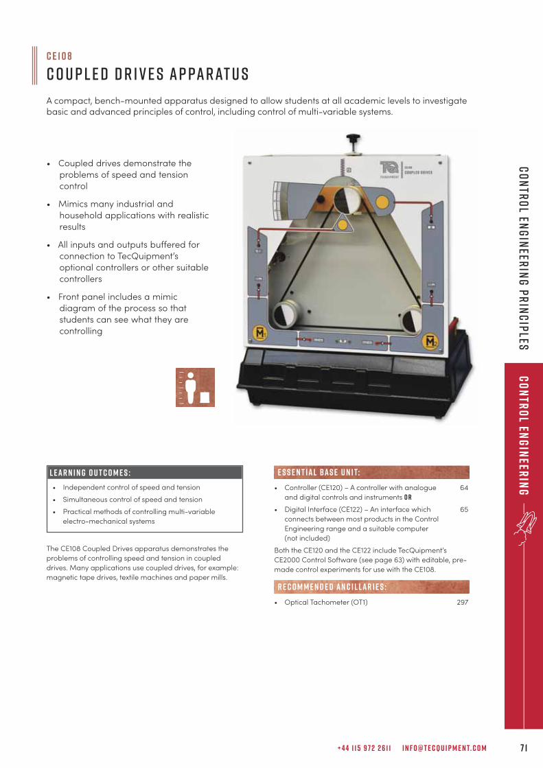
+ 4 4 1 1 5 9 7 2 2 6 1 1 I N F O @ T E C Q U I P M E N T. C O M 7 1
Co
ntr
ol En
gin
eerin
gC
on
tro
l Eng
ineer
ing
Pr
inc
iples
The CE108 Coupled Drives apparatus demonstrates the
problems of controlling speed and tension in coupled
drives. Many applications use coupled drives, for example:
magnetic tape drives, textile machines and paper mills.
L E A R N I N G O U T C O M E S :
• Independent control of speed and tension
• Simultaneous control of speed and tension
• Practical methods of controlling multi-variable
electro-mechanical systems
• Coupled drives demonstrate the
problems of speed and tension
control
• Mimics many industrial and
household applications with realistic
results
• All inputs and outputs buffered for
connection to TecQuipment’s
optional controllers or other suitable
controllers
• Front panel includes a mimic
diagram of the process so that
students can see what they are
controlling
• Controller (CE120) – A controller with analogue 64
and digital controls and instruments o r
• Digital Interface (CE122) – An interface which 65
connects between most products in the Control
Engineering range and a suitable computer
(not included)
Both the CE120 and the CE122 include TecQuipment’s
CE2000 Control Software (see page 63) with editable, pre-
made control experiments for use with the CE108.
• Optical Tachometer (OT1) 297
e s s e n t ial bas e u n i t:
R E C O M M E N D E D AN C I L LAR I E S :
c e 1 0 8
C o u p l e d D r i v e s A p pa r at u s
A compact, bench-mounted apparatus designed to allow students at all academic levels to investigatebasic and advanced principles of control, including control of multi-variable systems.
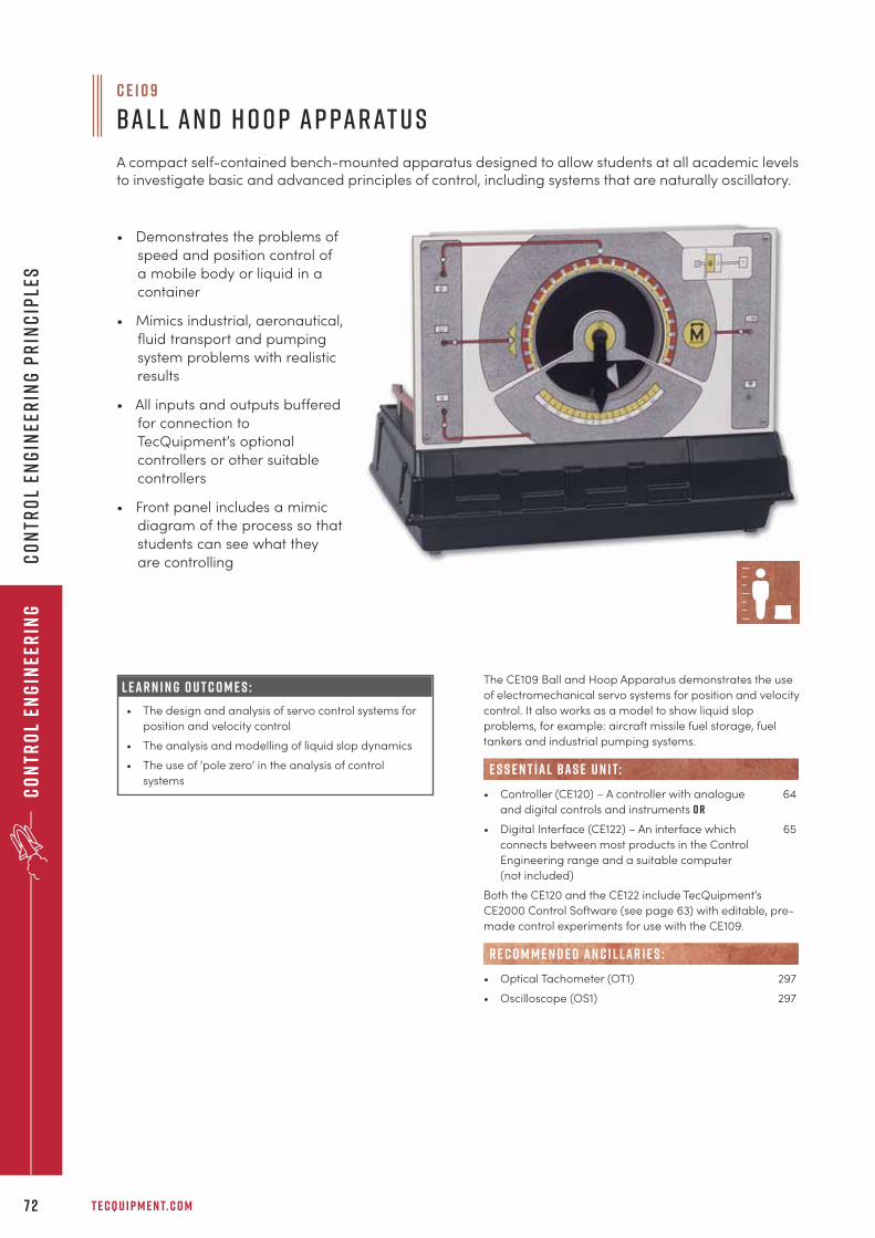
T E C Q U I P M E N T. C O M7 2
Co
ntr
ol
Eng
inee
rin
gC
on
tro
l En
gin
eer
ing
Pr
inc
iple
s
c e 1 0 9
B a l l a n d H o o p A p pa r at u s
A compact self-contained bench-mounted apparatus designed to allow students at all academic levelsto investigate basic and advanced principles of control, including systems that are naturally oscillatory.
The CE109 Ball and Hoop Apparatus demonstrates the use
of electromechanical servo systems for position and velocity
control. It also works as a model to show liquid slop
problems, for example: aircraft missile fuel storage, fuel
tankers and industrial pumping systems.
• Controller (CE120) – A controller with analogue 64
and digital controls and instruments o r
• Digital Interface (CE122) – An interface which 65
connects between most products in the Control
Engineering range and a suitable computer
(not included)
Both the CE120 and the CE122 include TecQuipment’s
CE2000 Control Software (see page 63) with editable, pre-
made control experiments for use with the CE109.
• Optical Tachometer (OT1) 297
• Oscilloscope (OS1) 297
e s s e n t ial bas e u n i t:
R E C O M M E N D E D AN C I L LAR I E S :
L E A R N I N G O U T C O M E S :
• The design and analysis of servo control systems for
position and velocity control
• The analysis and modelling of liquid slop dynamics
• The use of ‘pole zero’ in the analysis of control
systems
• Demonstrates the problems of
speed and position control of
a mobile body or liquid in a
container
• Mimics industrial, aeronautical,
fluid transport and pumping
system problems with realistic
results
• All inputs and outputs buffered
for connection to
TecQuipment’s optional
controllers or other suitable
controllers
• Front panel includes a mimic
diagram of the process so that
students can see what they
are controlling
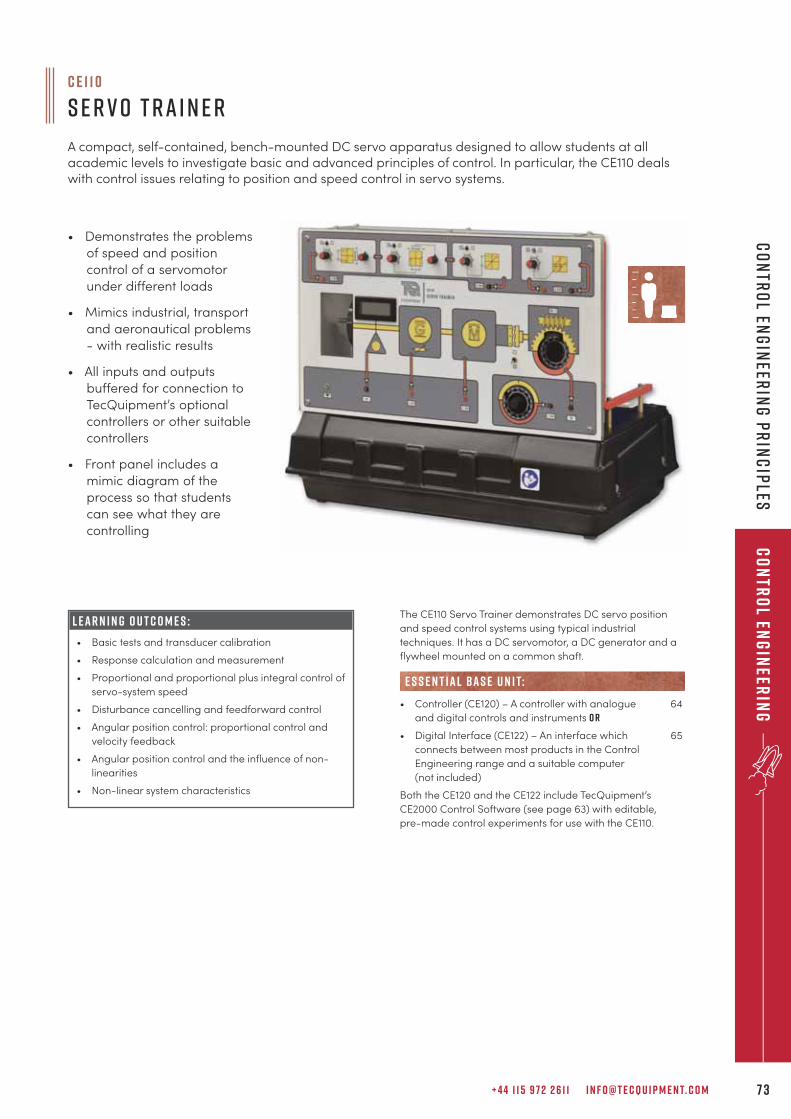
+ 4 4 1 1 5 9 7 2 2 6 1 1 I N F O @ T E C Q U I P M E N T. C O M 7 3
Co
ntr
ol En
gin
eerin
gC
on
tro
l Eng
ineer
ing
Pr
inc
iples
• Demonstrates the problems
of speed and position
control of a servomotor
under different loads
• Mimics industrial, transport
and aeronautical problems
- with realistic results
• All inputs and outputs
buffered for connection to
TecQuipment’s optional
controllers or other suitable
controllers
• Front panel includes a
mimic diagram of the
process so that students
can see what they are
controlling
The CE110 Servo Trainer demonstrates DC servo position
and speed control systems using typical industrial
techniques. It has a DC servomotor, a DC generator and a
flywheel mounted on a common shaft.
• Controller (CE120) – A controller with analogue 64
and digital controls and instruments o r
• Digital Interface (CE122) – An interface which 65
connects between most products in the Control
Engineering range and a suitable computer
(not included)
Both the CE120 and the CE122 include TecQuipment’s
CE2000 Control Software (see page 63) with editable,
pre-made control experiments for use with the CE110.
e s s e n t ial bas e u n i t:
L E A R N I N G O U T C O M E S :
• Basic tests and transducer calibration
• Response calculation and measurement
• Proportional and proportional plus integral control of
servo-system speed
• Disturbance cancelling and feedforward control
• Angular position control: proportional control and
velocity feedback
• Angular position control and the influence of non-
linearities
• Non-linear system characteristics
c e 1 1 0
S e r v o T r a i n e r
A compact, self-contained, bench-mounted DC servo apparatus designed to allow students at allacademic levels to investigate basic and advanced principles of control. In particular, the CE110 dealswith control issues relating to position and speed control in servo systems.
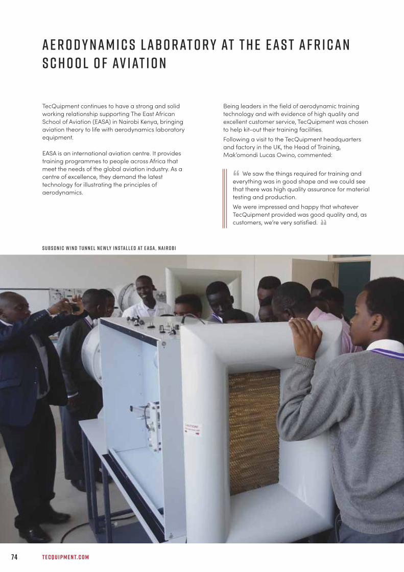
T E C Q U I P M E N T. C O M74
A e r o d y n a m i c s L abo r at o r y at t h e E a s t A f r i c a nS c h o o l o f Av i at i o n
TecQuipment continues to have a strong and solid
working relationship supporting The East African
School of Aviation (EASA) in Nairobi Kenya, bringing
aviation theory to life with aerodynamics laboratory
equipment.
EASA is an international aviation centre. It provides
training programmes to people across Africa that
meet the needs of the global aviation industry. As a
centre of excellence, they demand the latest
technology for illustrating the principles of
aerodynamics.
Being leaders in the field of aerodynamic training
technology and with evidence of high quality and
excellent customer service, TecQuipment was chosen
to help kit-out their training facilities.
Following a visit to the TecQuipment headquarters
and factory in the UK, the Head of Training,
Mak’omondi Lucas Owino, commented:
We saw the things required for training and
everything was in good shape and we could see
that there was high quality assurance for material
testing and production.
We were impressed and happy that whatever
TecQuipment provided was good quality and, as
customers, we’re very satisfied.
“
“s ubs o n i c w i n d t u n n e l n e w ly i n s ta l l e d at E A S A , N a i r ob i
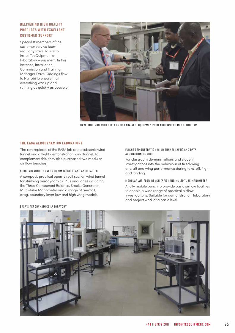
+ 4 4 1 1 5 9 7 2 2 6 1 1 I N F O @ T E C Q U I P M E N T. C O M 7 5
D e l i v e r i n g H i g h Q u a l i t y
P r o d u c t s w i t h E x c e l l e n t
C u s t o m e r S u p p o r t
Specialist members of the
customer service team
regularly travel to site to
install TecQuipment’s
laboratory equipment. In this
instance, Installation,
Commission and Training
Manager Dave Giddings flew
to Nairobi to ensure that
everything was up and
running as quickly as possible.
T h e E A S A A e r o d y n a m i c s L abo r at o r y
The centrepieces of the EASA lab are a subsonic wind
tunnel and a flight demonstration wind tunnel. To
complement this, they also purchased two modular
air flow benches.
S ubs o n i c W i n d T u n n e l 3 0 0 m m ( A F 1 3 0 0 ) a n d A n c i l l a r i e s
A compact, practical open-circuit suction wind tunnel
for studying aerodynamics. Plus ancillaries including
the Three Component Balance, Smoke Generator,
Multi-tube Manometer and a range of aerofoil,
drag, boundary layer low and high wing models.
F l i g h t D e m o n s t r at i o n W i n d T u n n e l ( A F 4 1 ) a n d D ata
A c q u i s i t i o n M o d u l e
For classroom demonstrations and student
investigations into the behaviour of fixed-wing
aircraft and wing performance during take-off, flight
and landing.
M o d u l a r A i r F l o w B e n c h ( A F 1 0 ) a n d M u lt i -t ube M a n o m e t e r
A fully mobile bench to provide basic airflow facilities
to enable a wide range of practical airflow
investigations. Suitable for demonstration, laboratory
and project work at a basic level.
D av e g i d d i n g s w i t h s ta f f f r o m E A S a at t e c q u i p m e n t ’ s h e a d q u a r t e r s i n n o t t i n g h a m
E A S A’ s a e r o d y n a m i c s l abo r at o r y
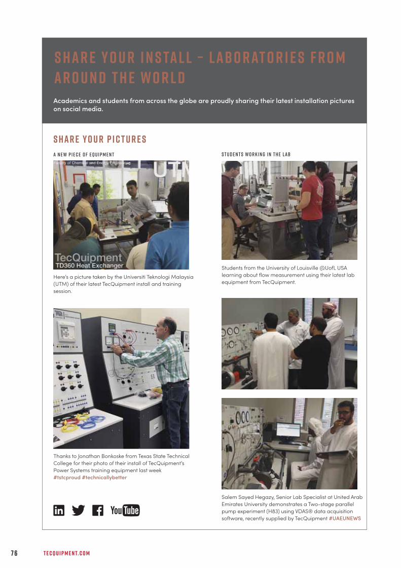
S h a r e Y o u r I n s ta l l – L abo r at o r i e s F r o mA r o u n d t h e W o r l d
T E C Q U I P M E N T. C O M7 6
Academics and students from across the globe are proudly sharing their latest installation pictures
on social media.
Here’s a picture taken by the Universiti Teknologi Malaysia
(UTM) of their latest TecQuipment install and training
session.
Thanks to Jonathan Bonkoske from Texas State Technical
College for their photo of their install of TecQuipment’s
Power Systems training equipment last week
#tstcproud #technicallybetter
Salem Sayed Hegazy, Senior Lab Specialist at United Arab
Emirates University demonstrates a Two-stage parallel
pump experiment (H83) using VDAS® data acquisition
software, recently supplied by TecQuipment #UAEUNEWS
S t u d e n t s w o r k i n g i n t h e l ab
S h a r e Y o u r P i c t u r e s
A n e w p i e c e o f e q u i p m e n t
Students from the University of Louisville @UofL USA
learning about flow measurement using their latest lab
equipment from TecQuipment.

+ 4 4 1 1 5 9 7 2 2 6 1 1 I N F O @ T E C Q U I P M E N T. C O M 7 7
Pr
oc
ess
Co
ntr
ol En
gin
eerin
g
p r o c e s s c o n t r o l e n g i n e e r i n g
“Just wanted to say what a great guy Dave Giddings (TecQuipment’s ICT Manager) is. Thankyou for sending him. I was very impressed with his work ethic and expertise. Also, he is verygood interacting with the customer. You probably know all this already but I just wanted tosay it!
C a r y S t o v e rb u c k e y e e d u c at i o n a l s y s t e m s
e n g i n e e r i n gD i g i ta l C o n t r o l 7 9
P r o c e s s C o n t r o l 8 1
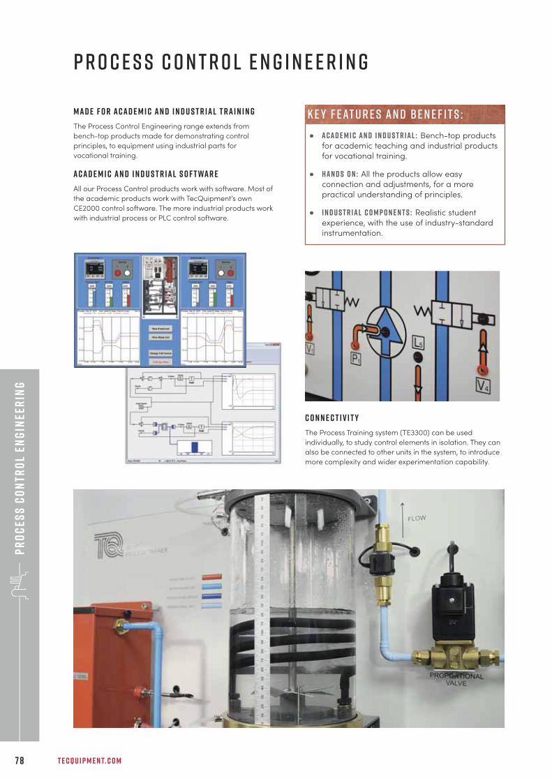
Pr
oc
ess
Co
ntr
ol
Eng
inee
rin
g
T E C Q U I P M E N T. C O M7 8
p r o c e s s c o n t r o l e n g i n e e r i n g
M a d e f o r a c a d e m i c a n d i n d u s t r i a l t r a i n i n g
The Process Control Engineering range extends from
bench-top products made for demonstrating control
principles, to equipment using industrial parts for
vocational training.
A c a d e m i c a n d i n d u s t r i a l s o f t wa r e
All our Process Control products work with software. Most of
the academic products work with TecQuipment’s own
CE2000 control software. The more industrial products work
with industrial process or PLC control software.
C o n n e c t i v i t y
The Process Training system (TE3300) can be used
individually, to study control elements in isolation. They can
also be connected to other units in the system, to introduce
more complexity and wider experimentation capability.
• A c a d e m i c a n d i n d u s t r i a l : Bench-top products
for academic teaching and industrial products
for vocational training.
• h a n d s o n : All the products allow easy
connection and adjustments, for a more
practical understanding of principles.
• i n d u s t r i a l c o m p o n e n t s : Realistic student
experience, with the use of industry-standard
instrumentation.
k e y f eat u r e s an d be n e f i t s :
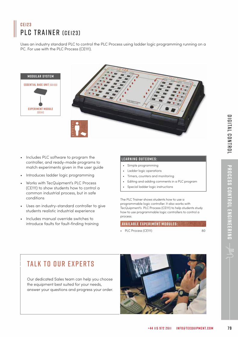
+ 4 4 1 1 5 9 7 2 2 6 1 1 I N F O @ T E C Q U I P M E N T. C O M 7 9
Pr
oc
ess
Co
ntr
ol En
gin
eerin
gD
igita
l Co
ntr
ol
c e 1 2 3
P L C T r a i n e r ( C E 1 2 3 )
Uses an industry standard PLC to control the PLC Process using ladder logic programming running on aPC. For use with the PLC Process (CE111).
• Includes PLC software to program the
controller, and ready-made programs to
match experiments given in the user guide
• Introduces ladder logic programming
• Works with TecQuipment’s PLC Process
(CE111) to show students how to control a
common industrial process, but in safe
conditions
• Uses an industry-standard controller to give
students realistic industrial experience
• Includes manual override switches to
introduce faults for fault-finding training
L E A R N I N G O U T C O M E S :
• Simple programming
• Ladder logic operations
• Timers, counters and monitoring
• Editing and adding comments in a PLC program
• Special ladder logic instructions
The PLC Trainer shows students how to use a
programmable logic controller. It also works with
TecQuipment’s PLC Process (CE111) to help students study
how to use programmable logic controllers to control a
process.
• PLC Process (CE111) 80
ava i lab l e e x p e r i m e n t m o d u l e s :
Experiment module(ce111)
Essential Base Unit (ce123)
M O D U LAR S Y S T E M
tal k t o o u r e x p e r t s
Our dedicated Sales team can help you choose
the equipment best suited for your needs,
answer your questions and progress your order.
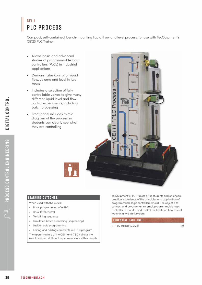
Pr
oc
ess
Co
ntr
ol
Eng
inee
rin
g
T E C Q U I P M E N T. C O M8 0
Dig
ita
l C
on
tro
l
TecQuipment’s PLC Process gives students and engineers
practical experience of the principles and application of
programmable logic controllers (PLCs). The object is to
connect and program an external, programmable logic
controller to monitor and control the level and flow rate of
water in a two-tank system.
• PLC Trainer (CE123) 79
e s s e n t ial bas e u n i t:
• Allows basic and advanced
studies of programmable logic
controllers (PLCs) in industrial
applications
• Demonstrates control of liquid
flow, volume and level in two
tanks
• Includes a selection of fully
controllable valves to give many
different liquid level and flow
control experiments, including
batch processing
• Front panel includes mimic
diagram of the process so
students can clearly see what
they are controlling
L E A R N I N G O U T C O M E S :
When used with the CE123:
• Basic programming of a PLC
• Basic level control
• Tank filling sequence
• Simulated batch processing (sequencing)
• Ladder logic programming
• Editing and adding comments in a PLC program
The open structure of the CE111 and CE123 allows the
user to create additional experiments to suit their needs.
c e 1 1 1
P L C P r o c e s s
Compact, self-contained, bench-mounting liquid fl ow and level process, for use with TecQuipment’sCE123 PLC Trainer.
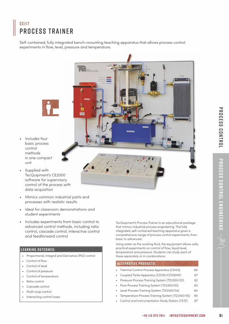
c e 1 1 7
P r o c e s s T r a i n e r
Self-contained, fully integrated bench-mounting teaching apparatus that allows process controlexperiments in flow, level, pressure and temperature.
+ 4 4 1 1 5 9 7 2 2 6 1 1 I N F O @ T E C Q U I P M E N T. C O M 8 1
Pr
oc
ess
Co
ntr
ol En
gin
eerin
gP
ro
ces
s C
on
tro
l
• Includes four
basic process
control
methods
in one compact
unit
• Supplied with
TecQuipment’s CE2000
software for supervisory
control of the process with
data acquisition
• Mimics common industrial parts and
processes with realistic results
• Ideal for classroom demonstrations and
student experiments
• Includes experiments from basic control to
advanced control methods, including ratio
control, cascade control, interactive control
and feedforward control
TecQuipment’s Process Trainer is an educational package
that mimics industrial process engineering. The fully
integrated, self-contained teaching apparatus gives a
comprehensive range of process control experiments, from
basic to advanced.
Using water as the working fluid, the equipment allows safe,
practical experiments on control of flow, liquid level,
temperature and pressure. Students can study each of
these separately or in combinations.
• Thermal Control Process Apparatus (CE103) 66
• Coupled Tanks Apparatus (CE105/CE105MV) 67
• Pressure Process Training System (TE3300/02) 82
• Flow Process Training System (TE3300/03) 83
• Level Process Training System (TE3300/04) 84
• Temperature Process Training System (TE3300/05) 85
• Control and Instrumentation Study Station (TE37) 87
alt e r nat i v e p r o d u c t s :
L E A R N I N G O U T C O M E S :
• Proportional, Integral and Derivative (PID) control
• Control of flow
• Control of level
• Control of pressure
• Control of temperature
• Ratio control
• Cascade control
• Multi-loop control
• Interacting control loops
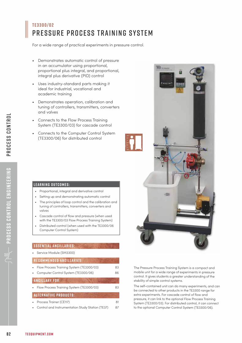
Pr
oc
ess
Co
ntr
ol
Eng
inee
rin
g
T E C Q U I P M E N T. C O M8 2
Pr
oc
ess
Co
ntr
ol
T E 3 3 0 0 / 0 2
P r e s s u r e P r o c e s s T r a i n i n g S y s t e m
For a wide range of practical experiments in pressure control.
• Demonstrates automatic control of pressure
in an accumulator using proportional,
proportional plus integral, and proportional,
integral plus derivative (PID) control
• Uses industry-standard parts making it
ideal for industrial, vocational and
academic training
• Demonstrates operation, calibration and
tuning of controllers, transmitters, converters
and valves
• Connects to the Flow Process Training
System (TE3300/03) for cascade control
• Connects to the Computer Control System
(TE3300/06) for distributed control
• Service Module (SM3300)
• Flow Process Training System (TE3300/03) 83
• Computer Control System (TE3300/06) 86
• Flow Process Training System (TE3300/03) 83
• Process Trainer (CE117) 81
• Control and Instrumentation Study Station (TE37) 87
E S S E N T IAL AN C I L LAR I E S :
R E C O M M E N D E D AN C I L LAR I E S :
AN C I L LAR Y F O R :
alt e r nat i v e p r o d u c t s :
L E A R N I N G O U T C O M E S :
• Proportional, integral and derivative control
• Setting up and demonstrating automatic control
• The principles of loop control and the calibration and
tuning of controllers, transmitters, converters and
valves
• Cascade control of flow and pressure (when used
with the TE3300/03 Flow Process Training System)
• Distributed control (when used with the TE3300/06
Computer Control System)
The Pressure Process Training System is a compact and
mobile unit for a wide range of experiments in pressure
control. It gives students a greater understanding of the
stability of simple control systems.
The self-contained unit can do many experiments, and can
be connected to other products in the TE3300 range for
extra experiments. For cascade control of flow and
pressure, it can link to the optional Flow Process Training
System (TE3300/03). For distributed control, it can connect
to the optional Computer Control System (TE3300/06).
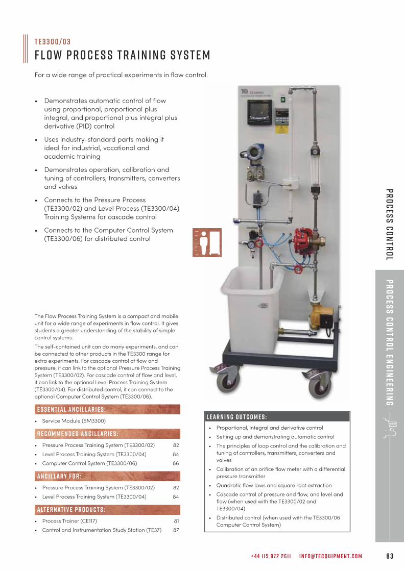
+ 4 4 1 1 5 9 7 2 2 6 1 1 I N F O @ T E C Q U I P M E N T. C O M 8 3
Pr
oc
ess
Co
ntr
ol En
gin
eerin
gP
ro
ces
s C
on
tro
l
The Flow Process Training System is a compact and mobile
unit for a wide range of experiments in flow control. It gives
students a greater understanding of the stability of simple
control systems.
The self-contained unit can do many experiments, and can
be connected to other products in the TE3300 range for
extra experiments. For cascade control of flow and
pressure, it can link to the optional Pressure Process Training
System (TE3300/02). For cascade control of flow and level,
it can link to the optional Level Process Training System
(TE3300/04). For distributed control, it can connect to the
optional Computer Control System (TE3300/06).
• Service Module (SM3300)
• Pressure Process Training System (TE3300/02) 82
• Level Process Training System (TE3300/04) 84
• Computer Control System (TE3300/06) 86
• Pressure Process Training System (TE3300/02) 82
• Level Process Training System (TE3300/04) 84
• Process Trainer (CE117) 81
• Control and Instrumentation Study Station (TE37) 87
E S S E N T IAL AN C I L LAR I E S :
R E C O M M E N D E D AN C I L LAR I E S :
alt e r nat i v e p r o d u c t s :
AN C I L LAR Y F O R :
L E A R N I N G O U T C O M E S :
• Proportional, integral and derivative control
• Setting up and demonstrating automatic control
• The principles of loop control and the calibration and
tuning of controllers, transmitters, converters and
valves
• Calibration of an orifice flow meter with a differential
pressure transmitter
• Quadratic flow laws and square root extraction
• Cascade control of pressure and flow, and level and
flow (when used with the TE3300/02 and
TE3300/04)
• Distributed control (when used with the TE3300/06
Computer Control System)
T E 3 3 0 0 / 0 3
F l o w P r o c e s s T r a i n i n g S y s t e m
For a wide range of practical experiments in flow control.
• Demonstrates automatic control of flow
using proportional, proportional plus
integral, and proportional plus integral plus
derivative (PID) control
• Uses industry-standard parts making it
ideal for industrial, vocational and
academic training
• Demonstrates operation, calibration and
tuning of controllers, transmitters, converters
and valves
• Connects to the Pressure Process
(TE3300/02) and Level Process (TE3300/04)
Training Systems for cascade control
• Connects to the Computer Control System
(TE3300/06) for distributed control
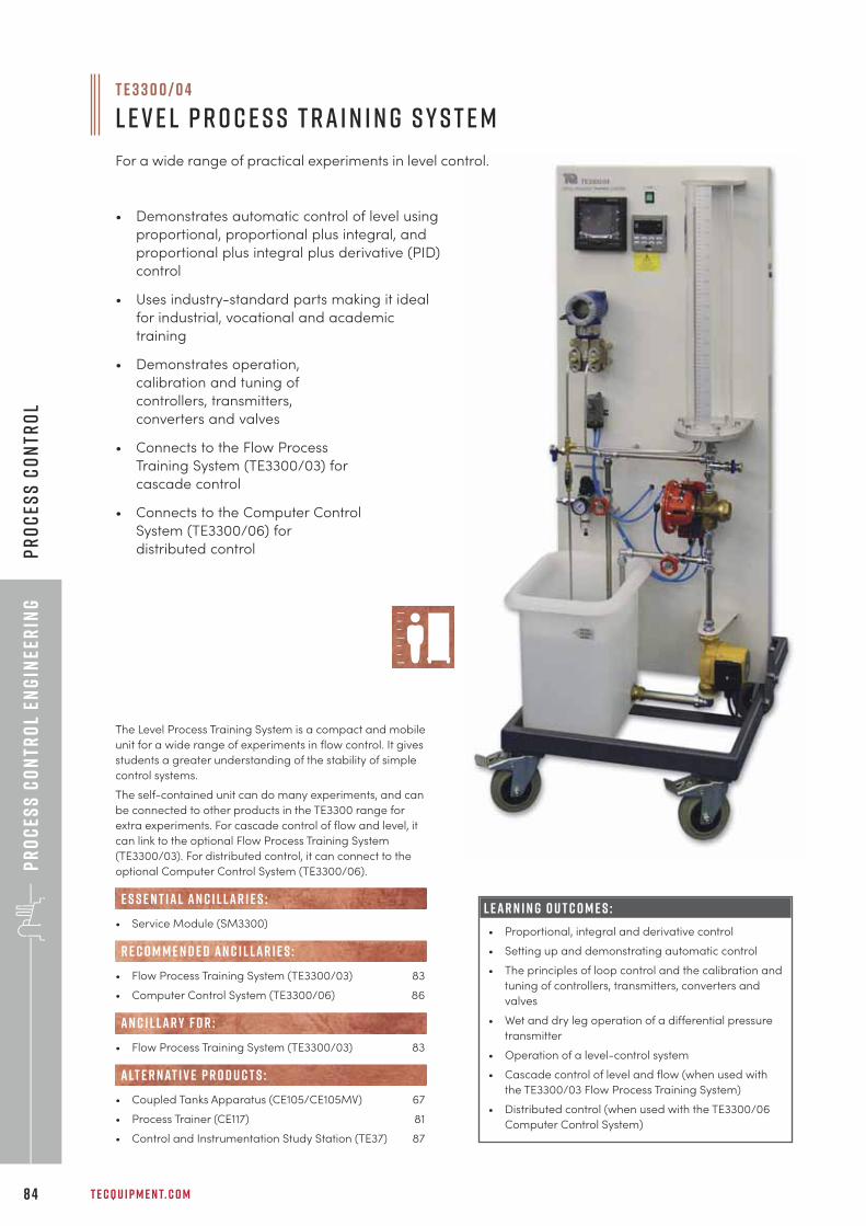
Pr
oc
ess
Co
ntr
ol
Eng
inee
rin
g
T E C Q U I P M E N T. C O M8 4
Pr
oc
ess
Co
ntr
ol
The Level Process Training System is a compact and mobile
unit for a wide range of experiments in flow control. It gives
students a greater understanding of the stability of simple
control systems.
The self-contained unit can do many experiments, and can
be connected to other products in the TE3300 range for
extra experiments. For cascade control of flow and level, it
can link to the optional Flow Process Training System
(TE3300/03). For distributed control, it can connect to the
optional Computer Control System (TE3300/06).
• Service Module (SM3300)
• Flow Process Training System (TE3300/03) 83
• Computer Control System (TE3300/06) 86
• Flow Process Training System (TE3300/03) 83
• Coupled Tanks Apparatus (CE105/CE105MV) 67
• Process Trainer (CE117) 81
• Control and Instrumentation Study Station (TE37) 87
E S S E N T IAL AN C I L LAR I E S :
R E C O M M E N D E D AN C I L LAR I E S :
AN C I L LAR Y F O R :
alt e r nat i v e p r o d u c t s :
L E A R N I N G O U T C O M E S :
• Proportional, integral and derivative control
• Setting up and demonstrating automatic control
• The principles of loop control and the calibration and
tuning of controllers, transmitters, converters and
valves
• Wet and dry leg operation of a differential pressure
transmitter
• Operation of a level-control system
• Cascade control of level and flow (when used with
the TE3300/03 Flow Process Training System)
• Distributed control (when used with the TE3300/06
Computer Control System)
T E 3 3 0 0 / 0 4
L e v e l P r o c e s s T r a i n i n g S y s t e m
For a wide range of practical experiments in level control.
• Demonstrates automatic control of level using
proportional, proportional plus integral, and
proportional plus integral plus derivative (PID)
control
• Uses industry-standard parts making it ideal
for industrial, vocational and academic
training
• Demonstrates operation,
calibration and tuning of
controllers, transmitters,
converters and valves
• Connects to the Flow Process
Training System (TE3300/03) for
cascade control
• Connects to the Computer Control
System (TE3300/06) for
distributed control
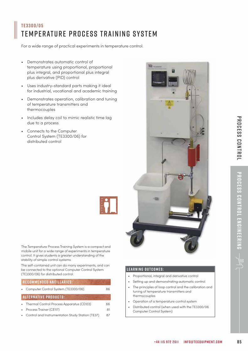
+ 4 4 1 1 5 9 7 2 2 6 1 1 I N F O @ T E C Q U I P M E N T. C O M 8 5
Pr
oc
ess
Co
ntr
ol En
gin
eerin
gP
ro
ces
s C
on
tro
l
The Temperature Process Training System is a compact and
mobile unit for a wide range of experiments in temperature
control. It gives students a greater understanding of the
stability of simple control systems.
The self-contained unit can do many experiments, and can
be connected to the optional Computer Control System
(TE3300/06) for distributed control.
• Computer Control System (TE3300/06) 86
• Thermal Control Process Apparatus (CE103) 66
• Process Trainer (CE117) 81
• Control and Instrumentation Study Station (TE37) 87
R E C O M M E N D E D AN C I L LAR I E S :
alt e r nat i v e p r o d u c t s :
T E 3 3 0 0 / 0 5
T e m p e r at u r e P r o c e s s T r a i n i n g S y s t e m
For a wide range of practical experiments in temperature control.
• Demonstrates automatic control of
temperature using proportional, proportional
plus integral, and proportional plus integral
plus derivative (PID) control
• Uses industry-standard parts making it ideal
for industrial, vocational and academic training
• Demonstrates operation, calibration and tuning
of temperature transmitters and
thermocouples
• Includes delay coil to mimic realistic time lag
due to a process
• Connects to the Computer
Control System (TE3300/06) for
distributed control
L E A R N I N G O U T C O M E S :
• Proportional, integral and derivative control
• Setting up and demonstrating automatic control
• The principles of loop control and the calibration and
tuning of temperature transmitters and
thermocouples
• Operation of a temperature control system
• Distributed control (when used with the TE3300/06
Computer Control System)
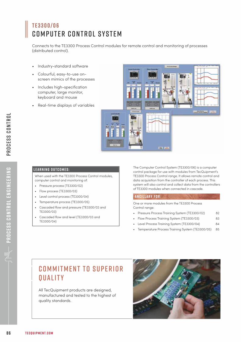
Pr
oc
ess
Co
ntr
ol
Eng
inee
rin
g
T E C Q U I P M E N T. C O M8 6
Pr
oc
ess
Co
ntr
ol
T E 3 3 0 0 / 0 6
C o m p u t e r C o n t r o l S y s t e m
Connects to the TE3300 Process Control modules for remote control and monitoring of processes(distributed control).
• Industry-standard software
• Colourful, easy-to-use on-
screen mimics of the processes
• Includes high-specification
computer, large monitor,
keyboard and mouse
• Real-time displays of variables
The Computer Control System (TE3300/06) is a computer
control package for use with modules from TecQuipment’s
TE3300 Process Control range. It allows remote control and
data acquisition from the controller of each process. This
system will also control and collect data from the controllers
of TE3300 modules when connected in cascade.
One or more modules from the TE3300 Process
Control range:
• Pressure Process Training System (TE3300/02) 82
• Flow Process Training System (TE3300/03) 83
• Level Process Training System (TE3300/04) 84
• Temperature Process Training System (TE3300/05) 85
AN C I L LAR Y F O R :
L E A R N I N G O U T C O M E S :
When used with the TE3300 Process Control modules,
computer control and monitoring of:
• Pressure process (TE3300/02)
• Flow process (TE3300/03)
• Level control process (TE3300/04)
• Temperature process (TE3300/05)
• Cascaded flow and pressure (TE3300/02 and
TE3300/03)
• Cascaded flow and level (TE3300/03 and
TE3300/04)
C o m m i t m e n t t o S u p e r i o r Q ual i t y
All TecQuipment products are designed,
manufactured and tested to the highest of
quality standards.
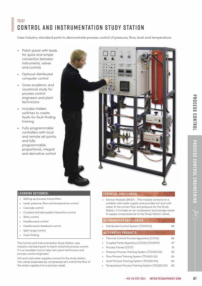
+ 4 4 1 1 5 9 7 2 2 6 1 1 I N F O @ T E C Q U I P M E N T. C O M 8 7
Pr
oc
ess
Co
ntr
ol En
gin
eerin
gP
ro
ces
s C
on
tro
l
The Control and Instrumentation Study Station uses
industry-standard parts to teach industrial process control.
It is an excellent tool to help train plant technicians and
process control engineers.
Hot and cold water supplies connect to the study station.
Two valves (operated by compressed air) control the flow of
the water supplies into a process vessel.
T E 3 7
C o n t r o l a n d I n s t r u m e n tat i o n S t u d y S tat i o n
Uses industry-standard parts to demonstrate process control of pressure, flow, level and temperature.
• Patch panel with leads
for quick and simple
connection between
instruments, valves
and controls
• Optional distributed
computer control
• Gives academic and
vocational study for
process control
engineers and plant
technicians
• Includes hidden
switches to create
faults for fault-finding
training
• Fully programmable
controllers with local
and remote set points,
and fully
programmable
proportional, integral
and derivative control
• Service Module (SM37) – This module connects to a
suitable cold-water supply and provides hot and cold
water at the correct flow and pressure for the Study
Station. It includes an air compressor and storage vessel
to supply compressed air to the Study Station valves.
• Distributed Control System (TE37DCS) 88
• Thermal Control Process Apparatus (CE103) 66
• Coupled Tanks Apparatus (CE105/CE105MV) 67
• Process Trainer (CE117) 81
• Pressure Process Training System (TE3300/02) 82
• Flow Process Training System (TE3300/03) 83
• Level Process Training System (TE3300/04) 84
• Temperature Process Training System (TE3300/05) 85
E S S E N T IAL AN C I L LAR I E S :
R E C O M M E N D E D AN C I L LAR I E S :
alt e r nat i v e p r o d u c t s :
L E A R N I N G O U T C O M E S :
• Setting up process transmitters
• Level, pressure, flow and temperature control
• Cascade control
• Coupled and decoupled interactive control
• Ratio control
• Feedforward control
• Feedforward-feedback control
• Split range control
• Fault-finding
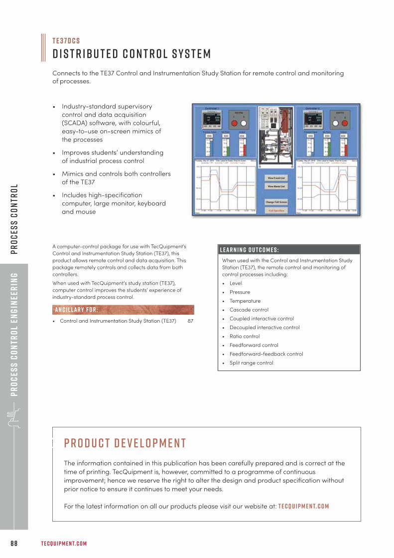
Pr
oc
ess
Co
ntr
ol
Eng
inee
rin
g
T E C Q U I P M E N T. C O M8 8
Pr
oc
ess
Co
ntr
ol
T E 3 7 D C S
D i s t r i b u t e d C o n t r o l S y s t e m
Connects to the TE37 Control and Instrumentation Study Station for remote control and monitoringof processes.
• Industry-standard supervisory
control and data acquisition
(SCADA) software, with colourful,
easy-to-use on-screen mimics of
the processes
• Improves students’ understanding
of industrial process control
• Mimics and controls both controllers
of the TE37
• Includes high-specification
computer, large monitor, keyboard
and mouse
A computer-control package for use with TecQuipment’s
Control and Instrumentation Study Station (TE37), this
product allows remote control and data acquisition. This
package remotely controls and collects data from both
controllers.
When used with TecQuipment’s study station (TE37),
computer control improves the students’ experience of
industry-standard process control.
• Control and Instrumentation Study Station (TE37) 87
AN C I L LAR Y F O R :
L E A R N I N G O U T C O M E S :
When used with the Control and Instrumentation Study
Station (TE37), the remote control and monitoring of
control processes including:
• Level
• Pressure
• Temperature
• Cascade control
• Coupled interactive control
• Decoupled interactive control
• Ratio control
• Feedforward control
• Feedforward-feedback control
• Split range control
p r o d u c t d e v e l o p m e n t
The information contained in this publication has been carefully prepared and is correct at the
time of printing. TecQuipment is, however, committed to a programme of continuous
improvement; hence we reserve the right to alter the design and product specification without
prior notice to ensure it continues to meet your needs.
For the latest information on all our products please visit our website at: t e c q u i p m e n t. c o m
+ 4 4 1 1 5 9 7 2 2 6 1 1 I N F O @ T E C Q U I P M E N T. C O M 8 9
Fluid
Mec
ha
nic
s
“We are extremely satisfied with the TecQuipment Fluids and Thermodynamics equipment: it iswell presented, works well and the students are able to operate it easily. The best feature isthat the user guides are of a very high quality, with excellent theory sections and experimentguides. The support from TecQuipment introducing the equipment and installing it has beenexcellent too.
r i c h a r d a l b a n y- wa r ds c h o o l o f s c i e n c e a n d t e c h n o l o g y, u n i v e r s i t y o f n o r t h a m p t o n
f l u i d m e c h a n i c sd i g i ta l H y d r a u l i c B e n c h 9 1
F l o w a n d P r e s s u r e M e a s u r e m e n t 9 2
P i p e F r i c t i o n a n d E n e r g y L o s s 1 0 0
L a m i n a r a n d T u r b u l e n t F l o w 1 0 4
N o z z l e s a n d J e t s 1 0 5
V o r t i c e s a n d C av i tat i o n 1 0 8
F l o w V i s u a l i s at i o n 1 1 0
P i p e S u r g e a n d Wat e r H a m m e r 1 1 1
O p e n C h a n n e l F l o w 1 1 3
H y d r o s tat i c s a n d P r o p e r t i e s o f F l u i d s 1 1 8
H y d r o l o g y 1 2 2
P u m p s a n d T u r b i n e s 1 2 5
M o d u l a r F l u i d P o w e r ( P u m p s , T u r b i n e s 1 3 2
a n d C o m p r e s s o r s )
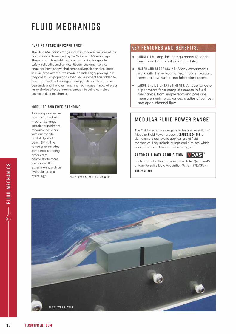
Flu
id M
ech
an
ics
T E C Q U I P M E N T. C O M9 0
f l u i d m e c h a n i c s
O v e r 6 0 y e a r s o f e x p e r i e n c e
The Fluid Mechanics range includes modern versions of the
first products developed by TecQuipment 60 years ago.
These products established our reputation for quality,
safety, reliability and service. Recent customer service
enquiries have shown that some universities and colleges
still use products that we made decades ago, proving that
they are still as popular as ever. TecQuipment has added to
and improved on the original range, in line with customer
demands and the latest teaching techniques. It now offers a
large choice of experiments, enough to suit a complete
course in fluid mechanics.
M o d u l a r a n d f r e e - s ta n d i n g
To save space, water
and costs, the Fluid
Mechanics range
includes experiment
modules that work
with our mobile
Digital Hydraulic
Bench (H1F). The
range also includes
some free-standing
products to
demonstrate more
specialised fluid
experiments, such as
hydrostatics and
hydrology.
M o d u l a r F l u i d P o w e r r a n g e
The Fluid Mechanics range includes a sub-section of
Modular Fluid Power products ( pa g e s 1 3 2 – 1 4 6 ) to
demonstrate real-world applications of fluid
mechanics. They include pumps and turbines, which
also provide a link to renewable energy.
A u t o m at i c D ata A c q u i s i t i o n
Each product in this range works with TecQuipment’s
unique Versatile Data Acquisition System (VDAS®).
S e e pa g e 2 9 3
• l o n g e v i t y: Long-lasting equipment to teach
principles that do not go out of date.
• wat e r a n d s pa c e s av i n g : Many experiments
work with the self-contained, mobile hydraulic
bench to save water and laboratory space.
• l a r g e c h o i c e o f e x p e r i m e n t s : A huge range of
experiments for a complete course in fluid
mechanics, from simple flow and pressure
measurements to advanced studies of vortices
and open-channel flow.
k e y f eat u r e s an d b e n e f i t s :
F l o w o v e r a ‘ V e e ’ n o t c h w e i r
F l o w o v e r a w e i r
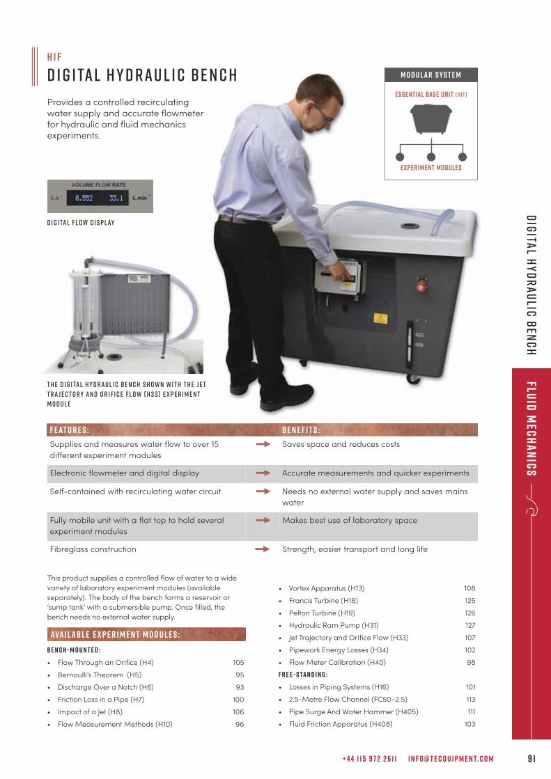
+ 4 4 1 1 5 9 7 2 2 6 1 1 I N F O @ T E C Q U I P M E N T. C O M 9 1
Fluid
Mec
ha
nic
sD
igita
l Hy
dr
au
lic B
enc
h
This product supplies a controlled flow of water to a wide
variety of laboratory experiment modules (available
separately). The body of the bench forms a reservoir or
‘sump tank’ with a submersible pump. Once filled, the
bench needs no external water supply.
B e n c h - m o u n t e d :
• Flow Through an Orifice (H4) 105
• Bernoulli’s Theorem (H5) 95
• Discharge Over a Notch (H6) 93
• Friction Loss in a Pipe (H7) 100
• Impact of a Jet (H8) 106
• Flow Measurement Methods (H10) 96
ava i labl e e x p e r i m e n t m o d u l e s :
• Vortex Apparatus (H13) 108
• Francis Turbine (H18) 125
• Pelton Turbine (H19) 126
• Hydraulic Ram Pump (H31) 127
• Jet Trajectory and Orifice Flow (H33) 107
• Pipework Energy Losses (H34) 102
• Flow Meter Calibration (H40) 98
F r e e - s ta n d i n g :
• Losses in Piping Systems (H16) 101
• 2.5-Metre Flow Channel (FC50–2.5) 113
• Pipe Surge And Water Hammer (H405) 111
• Fluid Friction Apparatus (H408) 103
Experiment modules
Essential Base Unit (h1f)
M O D U LAR S Y S T E M
T h e D i g i ta l H y d r a u l i c B e n c h s h o w n w i t h t h e J e t
T r a j e c t o r y a n d O r i f i c e F l o w ( H 3 3 ) e x p e r i m e n t
m o d u l e
D i g i ta l f l o w d i s p l ay
h 1 f
D i g i ta l H y d r a u l i c B e n c h
Provides a controlled recirculating water supply and accurate flowmeter for hydraulic and fluid mechanics experiments.
F E AT U R E S : B E N E F I T S :
Supplies and measures water flow to over 15
different experiment modules
Saves space and reduces costs
Electronic flowmeter and digital display Accurate measurements and quicker experiments
Self-contained with recirculating water circuit Needs no external water supply and saves mains
water
Fully mobile unit with a flat top to hold several
experiment modules
Makes best use of laboratory space
Fibreglass construction Strength, easier transport and long life
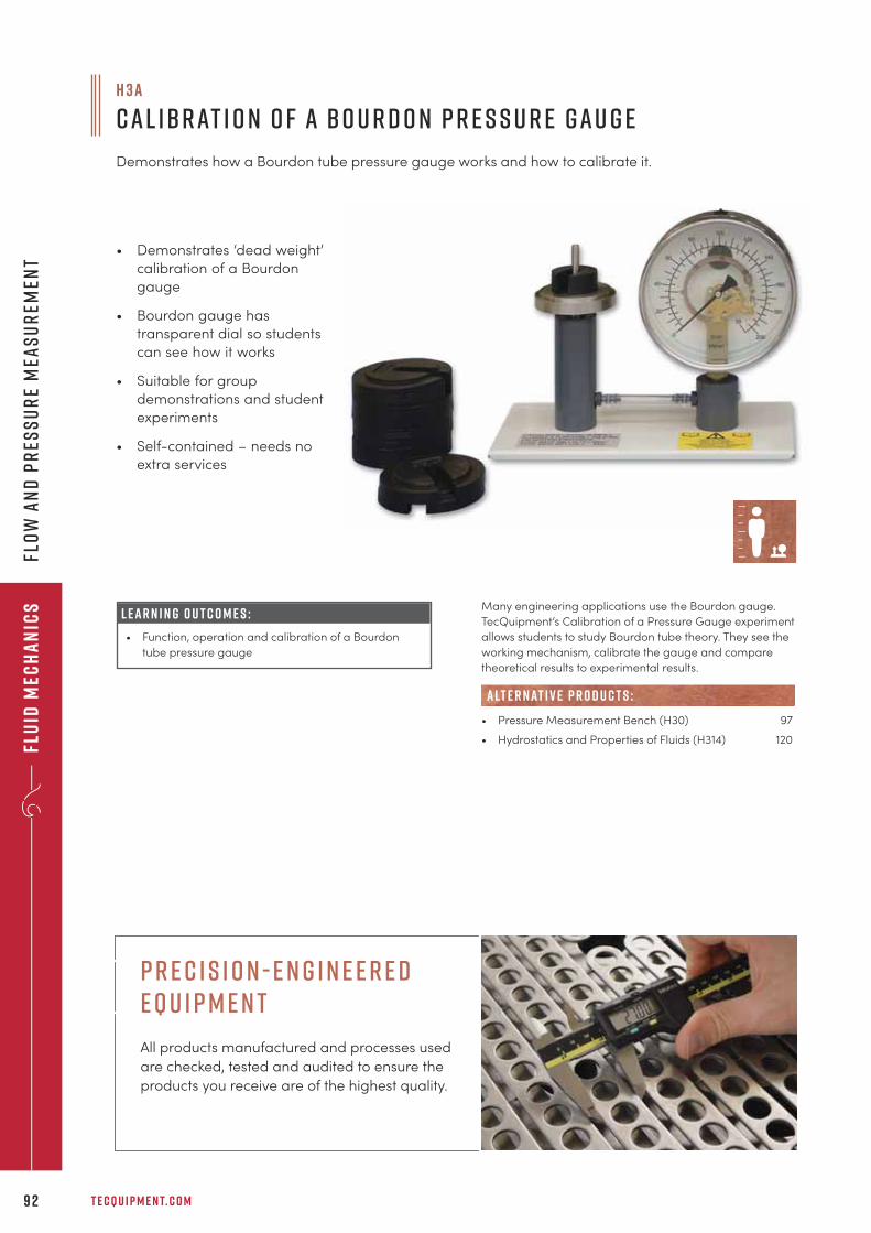
Flu
id M
ech
an
ics
T E C Q U I P M E N T. C O M9 2
Flo
w a
nd
Pr
ess
ur
e M
eas
ur
emen
t
H 3 a
C a l ibr at i o n o f a B o u r d o n P r e s s u r e G a u g e
Demonstrates how a Bourdon tube pressure gauge works and how to calibrate it.
• Demonstrates ‘dead weight’
calibration of a Bourdon
gauge
• Bourdon gauge has
transparent dial so students
can see how it works
• Suitable for group
demonstrations and student
experiments
• Self-contained – needs no
extra services
L E A R N I N G O U T C O M E S :
• Function, operation and calibration of a Bourdon
tube pressure gauge
Many engineering applications use the Bourdon gauge.
TecQuipment’s Calibration of a Pressure Gauge experiment
allows students to study Bourdon tube theory. They see the
working mechanism, calibrate the gauge and compare
theoretical results to experimental results.
• Pressure Measurement Bench (H30) 97
• Hydrostatics and Properties of Fluids (H314) 120
alt e r nat i v e p r o d u c t s :
p r e c i s i o n - e n g i n e e r e d e q u i p m e n t
All products manufactured and processes used
are checked, tested and audited to ensure the
products you receive are of the highest quality.
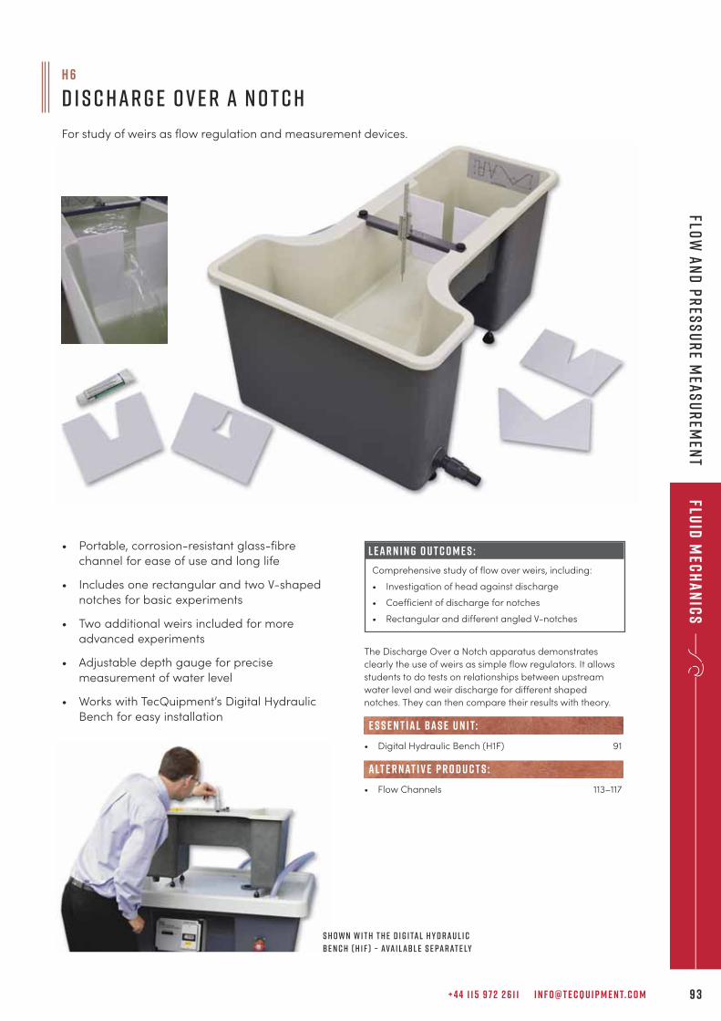
+ 4 4 1 1 5 9 7 2 2 6 1 1 I N F O @ T E C Q U I P M E N T. C O M 9 3
Fluid
Mec
ha
nic
sFlo
w a
nd
Pr
ess
ur
e Mea
su
rem
ent
The Discharge Over a Notch apparatus demonstrates
clearly the use of weirs as simple flow regulators. It allows
students to do tests on relationships between upstream
water level and weir discharge for different shaped
notches. They can then compare their results with theory.
• Digital Hydraulic Bench (H1F) 91
• Flow Channels 113–117
e s s e n t ial bas e u n i t:
alt e r nat i v e p r o d u c t s :
h 6
D i s c h a r g e o v e r a N o t c h
For study of weirs as flow regulation and measurement devices.
• Portable, corrosion-resistant glass-fibre
channel for ease of use and long life
• Includes one rectangular and two V-shaped
notches for basic experiments
• Two additional weirs included for more
advanced experiments
• Adjustable depth gauge for precise
measurement of water level
• Works with TecQuipment’s Digital Hydraulic
Bench for easy installation
L E A R N I N G O U T C O M E S :
Comprehensive study of flow over weirs, including:
• Investigation of head against discharge
• Coefficient of discharge for notches
• Rectangular and different angled V-notches
S h o w n w i t h t h e D i g i ta l H y d r a u l i c
B e n c h ( H 1 F ) – ava i l abl e s e pa r at e ly
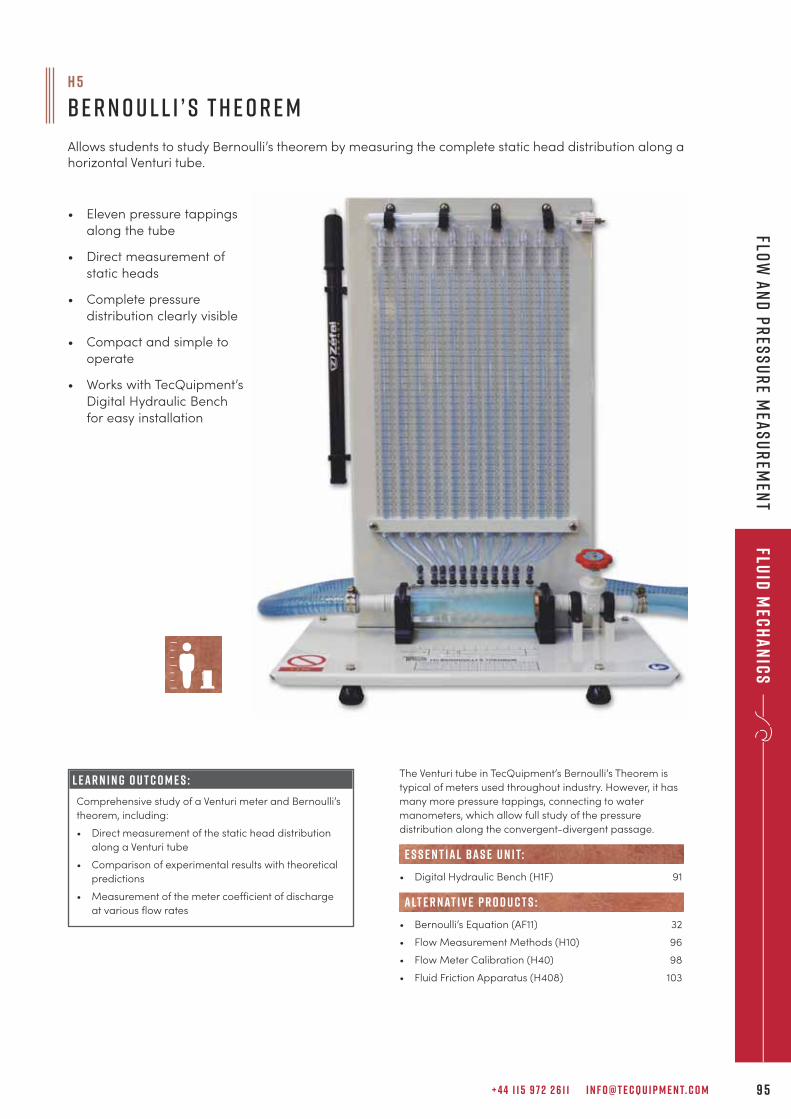
+ 4 4 1 1 5 9 7 2 2 6 1 1 I N F O @ T E C Q U I P M E N T. C O M 9 5
Fluid
Mec
ha
nic
sFlo
w a
nd
Pr
ess
ur
e Mea
su
rem
ent
The Venturi tube in TecQuipment’s Bernoulli’s Theorem is
typical of meters used throughout industry. However, it has
many more pressure tappings, connecting to water
manometers, which allow full study of the pressure
distribution along the convergent-divergent passage.
• Digital Hydraulic Bench (H1F) 91
• Bernoulli’s Equation (AF11) 32
• Flow Measurement Methods (H10) 96
• Flow Meter Calibration (H40) 98
• Fluid Friction Apparatus (H408) 103
alt e r nat i v e p r o d u c t s :
e s s e n t ial bas e u n i t:
h 5
B e r n o u l l i ’ s T h e o r e m
Allows students to study Bernoulli’s theorem by measuring the complete static head distribution along ahorizontal Venturi tube.
L E A R N I N G O U T C O M E S :
Comprehensive study of a Venturi meter and Bernoulli’s
theorem, including:
• Direct measurement of the static head distribution
along a Venturi tube
• Comparison of experimental results with theoretical
predictions
• Measurement of the meter coefficient of discharge
at various flow rates
• Eleven pressure tappings
along the tube
• Direct measurement of
static heads
• Complete pressure
distribution clearly visible
• Compact and simple to
operate
• Works with TecQuipment’s
Digital Hydraulic Bench
for easy installation
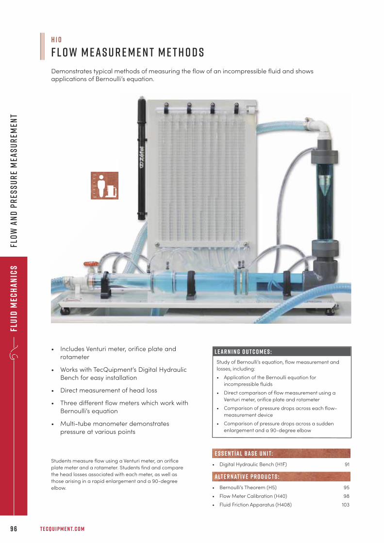
Flu
id M
ech
an
ics
T E C Q U I P M E N T. C O M9 6
Flo
w a
nd
Pr
ess
ur
e M
eas
ur
emen
t
Students measure flow using a Venturi meter, an orifice
plate meter and a rotameter. Students find and compare
the head losses associated with each meter, as well as
those arising in a rapid enlargement and a 90-degree
elbow.
H 1 0
F l o w M e a s u r e m e n t M e t h o d s
Demonstrates typical methods of measuring the flow of an incompressible fluid and showsapplications of Bernoulli’s equation.
L E A R N I N G O U T C O M E S :
Study of Bernoulli’s equation, flow measurement and
losses, including:
• Application of the Bernoulli equation for
incompressible fluids
• Direct comparison of flow measurement using a
Venturi meter, orifice plate and rotameter
• Comparison of pressure drops across each flow-
measurement device
• Comparison of pressure drops across a sudden
enlargement and a 90-degree elbow
• Includes Venturi meter, orifice plate and
rotameter
• Works with TecQuipment’s Digital Hydraulic
Bench for easy installation
• Direct measurement of head loss
• Three different flow meters which work with
Bernoulli’s equation
• Multi-tube manometer demonstrates
pressure at various points
• Digital Hydraulic Bench (H1F) 91
• Bernoulli’s Theorem (H5) 95
• Flow Meter Calibration (H40) 98
• Fluid Friction Apparatus (H408) 103
e s s e n t ial bas e u n i t:
alt e r nat i v e p r o d u c t s :

+ 4 4 1 1 5 9 7 2 2 6 1 1 I N F O @ T E C Q U I P M E N T. C O M 9 7
Fluid
Mec
ha
nic
sFlo
w a
nd
Pr
ess
ur
e Mea
su
rem
ent
TecQuipment’s Pressure Measurement Bench enables
students to fully investigate and compare the operation and
characteristics of inclined and U-tube manometers, and
Bourdon-type vacuum and pressure gauges.
• Calibration of a Bourdon Pressure Gauge (H3a) 92
• Hydrostatics and Properties of Fluids (H314) 120
alt e r nat i v e p r o d u c t s :
H 3 0
P r e s s u r e M e a s u r e m e n t B e n c h
Enables a range of practical investigations into manometer and Bourdon gauge pressuremeasurement techniques.
• Provides practical investigations for
pressure measurement using inclined and
U-tube manometers, and Bourdon-type
vacuum and pressure gauges
• Enables instant comparison of
measurement methods
• Includes separate Bourdon gauge with
dead-weight calibration apparatus, and
Bourdon tube mechanism clearly visible
• Fully self-contained, bench-top apparatus
• Suitable for group demonstrations and
individual student experiments
L E A R N I N G O U T C O M E S :
A range of investigations into common pressure-
measurement techniques, including:
• Comparison of pressure measurement by
manometer and Bourdon gauge
• Calibration of a pressure gauge
• Determination of gauge errors as a function of true
pressure
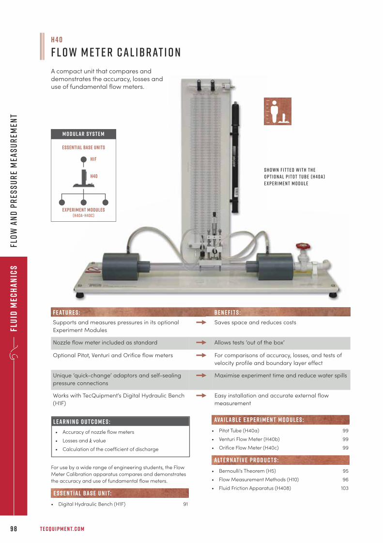
Flu
id M
ech
an
ics
T E C Q U I P M E N T. C O M9 8
Flo
w a
nd
Pr
ess
ur
e M
eas
ur
emen
t
For use by a wide range of engineering students, the Flow
Meter Calibration apparatus compares and demonstrates
the accuracy and use of fundamental flow meters.
• Digital Hydraulic Bench (H1F) 91
e s s e n t ial bas e u n i t:
H 4 0
F l o w M e t e r C a l ibr at i o n
A compact unit that compares anddemonstrates the accuracy, losses anduse of fundamental flow meters.
L E A R N I N G O U T C O M E S :
• Accuracy of nozzle flow meters
• Losses and k value
• Calculation of the coefficient of discharge
S h o w n f i t t e d w i t h t h e
o p t i o n a l P i t o t T ube ( H 4 0 a )
e x p e r i m e n t m o d u l e
Experiment modules(H40a–h40c)
Essential Base Units
M O D U LAR S Y S T E M
H40
H1F
F E AT U R E S : b e n e f i t s :
Supports and measures pressures in its optional
Experiment Modules
Saves space and reduces costs
Nozzle flow meter included as standard Allows tests ‘out of the box’
Optional Pitot, Venturi and Orifice flow meters For comparisons of accuracy, losses, and tests of
velocity profile and boundary layer effect
Unique ‘quick-change’ adaptors and self-sealing
pressure connections
Maximise experiment time and reduce water spills
Works with TecQuipment’s Digital Hydraulic Bench
(H1F)
Easy installation and accurate external flow
measurement
• Pitot Tube (H40a) 99
• Venturi Flow Meter (H40b) 99
• Orifice Flow Meter (H40c) 99
• Bernoulli’s Theorem (H5) 95
• Flow Measurement Methods (H10) 96
• Fluid Friction Apparatus (H408) 103
alt e r nat i v e p r o d u c t s :
ava i labl e e x p e r i m e n t m o d u l e s :
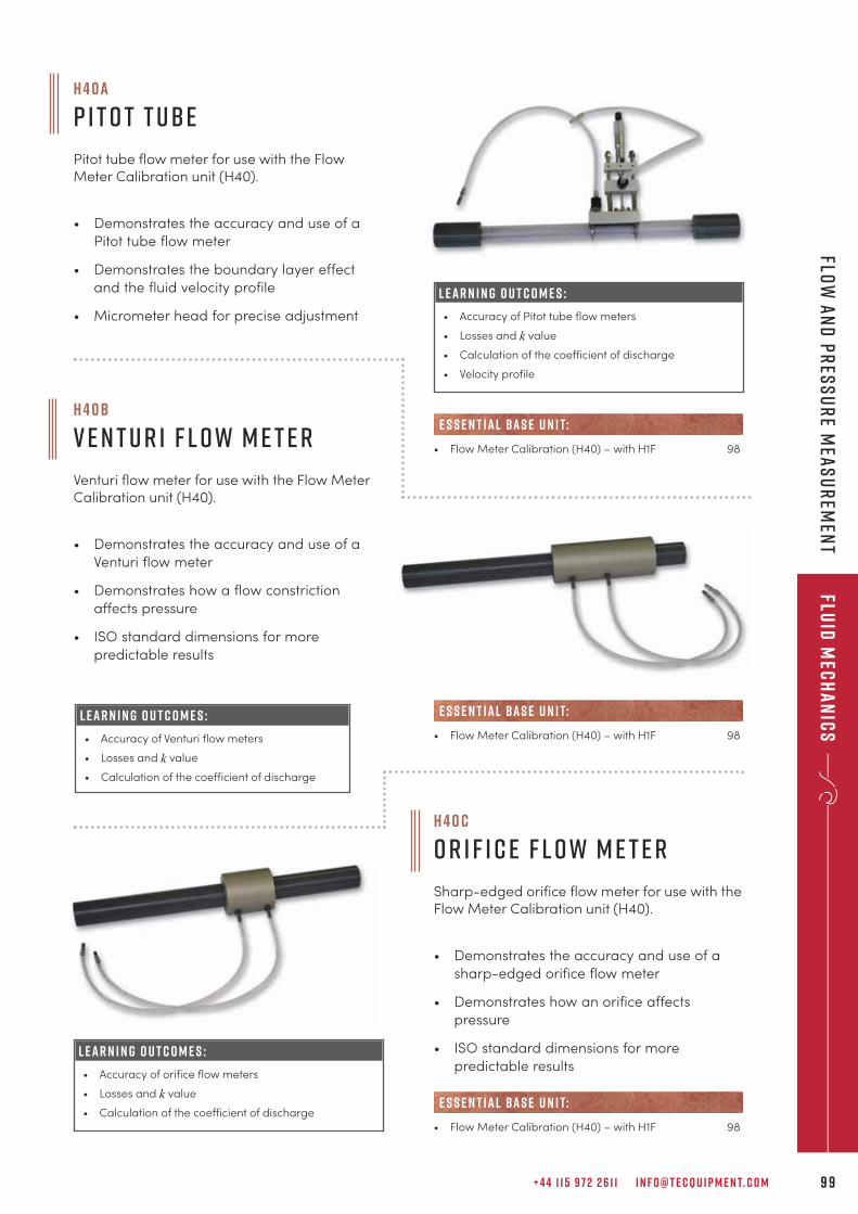
H 4 0 b
V e n t u r i F l o w M e t e r
Venturi flow meter for use with the Flow MeterCalibration unit (H40).
• Demonstrates the accuracy and use of a
Venturi flow meter
• Demonstrates how a flow constriction
affects pressure
• ISO standard dimensions for more
predictable results
+ 4 4 1 1 5 9 7 2 2 6 1 1 I N F O @ T E C Q U I P M E N T. C O M 9 9
Fluid
Mec
ha
nic
sFlo
w a
nd
Pr
ess
ur
e Mea
su
rem
ent
• Flow Meter Calibration (H40) – with H1F 98
e s s e n t ial bas e u n i t:
H 4 0 a
P i t o t T ube
Pitot tube flow meter for use with the FlowMeter Calibration unit (H40).
• Demonstrates the accuracy and use of a
Pitot tube flow meter
• Demonstrates the boundary layer effect
and the fluid velocity profile
• Micrometer head for precise adjustment
L E A R N I N G O U T C O M E S :
• Accuracy of Pitot tube flow meters
• Losses and k value
• Calculation of the coefficient of discharge
• Velocity profile
• Flow Meter Calibration (H40) – with H1F 98
e s s e n t ial bas e u n i t:L E A R N I N G O U T C O M E S :
• Accuracy of Venturi flow meters
• Losses and k value
• Calculation of the coefficient of discharge
• Flow Meter Calibration (H40) – with H1F 98
e s s e n t ial bas e u n i t:
H 4 0 c
O r i f i c e F l o w M e t e r
Sharp-edged orifice flow meter for use with theFlow Meter Calibration unit (H40).
• Demonstrates the accuracy and use of a
sharp-edged orifice flow meter
• Demonstrates how an orifice affects
pressure
• ISO standard dimensions for more
predictable resultsL E A R N I N G O U T C O M E S :
• Accuracy of orifice flow meters
• Losses and k value
• Calculation of the coefficient of discharge
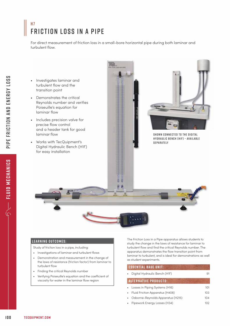
Flu
id M
ech
an
ics
T E C Q U I P M E N T. C O M1 0 0
Pip
e fr
icti
on
an
d e
ner
gy
lo
ss
The Friction Loss in a Pipe apparatus allows students to
study the change in the laws of resistance for laminar to
turbulent flow and find the critical Reynolds number. The
apparatus demonstrates the flow transition point from
laminar to turbulent, and is ideal for demonstrations as well
as student experiments.
• Digital Hydraulic Bench (H1F) 91
• Losses in Piping Systems (H16) 101
• Fluid Friction Apparatus (H408) 103
• Osborne-Reynolds Apparatus (H215) 104
• Pipework Energy Losses (H34) 102
e s s e n t ial bas e u n i t:
alt e r nat i v e p r o d u c t s :
• Investigates laminar and
turbulent flow and the
transition point
• Demonstrates the critical
Reynolds number and verifies
Poiseuille’s equation for
laminar flow
• Includes precision valve for
precise flow control
and a header tank for good
laminar flow
• Works with TecQuipment’s
Digital Hydraulic Bench (H1F)
for easy installation
L E A R N I N G O U T C O M E S :
Study of friction loss in a pipe, including:
• Investigations of laminar and turbulent flows
• Demonstration and measurement in the change of
the laws of resistance (friction factor) from laminar to
turbulent flow
• Finding the critical Reynolds number
• Verifying Poiseuille’s equation and the coefficient of
viscosity for water in the laminar flow region
S h o w n c o n n e c t e d t o t h e D i g i ta l
H y d r a u l i c B e n c h ( H 1 F ) – ava i l abl e
s e pa r at e ly
H 7
F r i c t i o n L o s s i n a P i p e
For direct measurement of friction loss in a small-bore horizontal pipe during both laminar andturbulent flow.
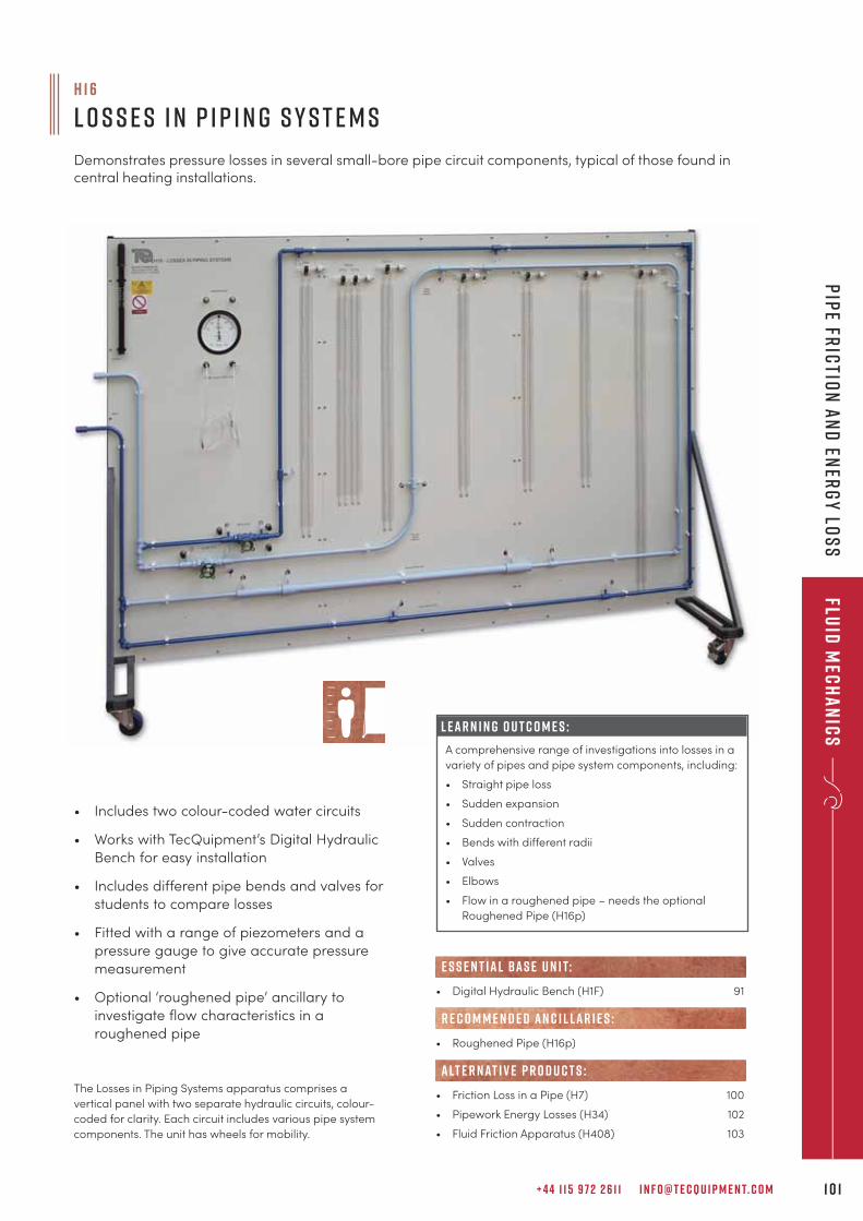
+ 4 4 1 1 5 9 7 2 2 6 1 1 I N F O @ T E C Q U I P M E N T. C O M 1 0 1
Fluid
Mec
ha
nic
sP
ipe Fr
ictio
n a
nd
ener
gy
los
s
H 1 6
L o s s e s i n P i p i n g S y s t e m s
Demonstrates pressure losses in several small-bore pipe circuit components, typical of those found incentral heating installations.
• Includes two colour-coded water circuits
• Works with TecQuipment’s Digital Hydraulic
Bench for easy installation
• Includes different pipe bends and valves for
students to compare losses
• Fitted with a range of piezometers and a
pressure gauge to give accurate pressure
measurement
• Optional ‘roughened pipe’ ancillary to
investigate flow characteristics in a
roughened pipe
The Losses in Piping Systems apparatus comprises a
vertical panel with two separate hydraulic circuits, colour-
coded for clarity. Each circuit includes various pipe system
components. The unit has wheels for mobility.
L E A R N I N G O U T C O M E S :
A comprehensive range of investigations into losses in a
variety of pipes and pipe system components, including:
• Straight pipe loss
• Sudden expansion
• Sudden contraction
• Bends with different radii
• Valves
• Elbows
• Flow in a roughened pipe – needs the optional
Roughened Pipe (H16p)
• Digital Hydraulic Bench (H1F) 91
• Roughened Pipe (H16p)
• Friction Loss in a Pipe (H7) 100
• Pipework Energy Losses (H34) 102
• Fluid Friction Apparatus (H408) 103
e s s e n t ial bas e u n i t:
alt e r nat i v e p r o d u c t s :
R E C O M M E N D E D AN C I L LAR I E S :
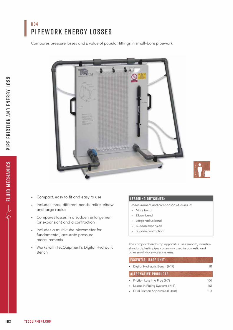
Flu
id M
ech
an
ics
T E C Q U I P M E N T. C O M1 0 2
Pip
e fr
icti
on
an
d e
ner
gy
lo
ss
This compact bench-top apparatus uses smooth, industry-
standard plastic pipe, commonly used in domestic and
other small-bore water systems.
• Digital Hydraulic Bench (H1F) 91
• Friction Loss in a Pipe (H7) 100
• Losses in Piping Systems (H16) 101
• Fluid Friction Apparatus (H408) 103
e s s e n t ial bas e u n i t:
alt e r nat i v e p r o d u c t s :
H 3 4
P i p e w o r k E n e r g y L o s s e s
Compares pressure losses and k value of popular fittings in small-bore pipework.
• Compact, easy to fit and easy to use
• Includes three different bends: mitre, elbow
and large radius
• Compares losses in a sudden enlargement
(or expansion) and a contraction
• Includes a multi-tube piezometer for
fundamental, accurate pressure
measurements
• Works with TecQuipment’s Digital Hydraulic
Bench
L E A R N I N G O U T C O M E S :
Measurement and comparison of losses in:
• Mitre bend
• Elbow bend
• Large radius bend
• Sudden expansion
• Sudden contraction
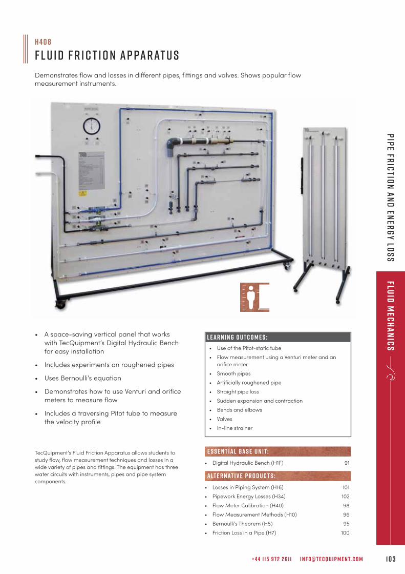
+ 4 4 1 1 5 9 7 2 2 6 1 1 I N F O @ T E C Q U I P M E N T. C O M 1 0 3
Fluid
Mec
ha
nic
sP
ipe fr
ictio
n a
nd
ener
gy
los
s
H 4 0 8
F l u i d F r i c t i o n A p pa r at u s
Demonstrates flow and losses in different pipes, fittings and valves. Shows popular flowmeasurement instruments.
• A space-saving vertical panel that works
with TecQuipment’s Digital Hydraulic Bench
for easy installation
• Includes experiments on roughened pipes
• Uses Bernoulli’s equation
• Demonstrates how to use Venturi and orifice
meters to measure flow
• Includes a traversing Pitot tube to measure
the velocity profile
L E A R N I N G O U T C O M E S :
• Use of the Pitot-static tube
• Flow measurement using a Venturi meter and an
orifice meter
• Smooth pipes
• Artificially roughened pipe
• Straight pipe loss
• Sudden expansion and contraction
• Bends and elbows
• Valves
• In-line strainer
TecQuipment’s Fluid Friction Apparatus allows students to
study flow, flow measurement techniques and losses in a
wide variety of pipes and fittings. The equipment has three
water circuits with instruments, pipes and pipe system
components.
• Digital Hydraulic Bench (H1F) 91
• Losses in Piping System (H16) 101
• Pipework Energy Losses (H34) 102
• Flow Meter Calibration (H40) 98
• Flow Measurement Methods (H10) 96
• Bernoulli’s Theorem (H5) 95
• Friction Loss in a Pipe (H7) 100
e s s e n t ial bas e u n i t:
alt e r nat i v e p r o d u c t s :
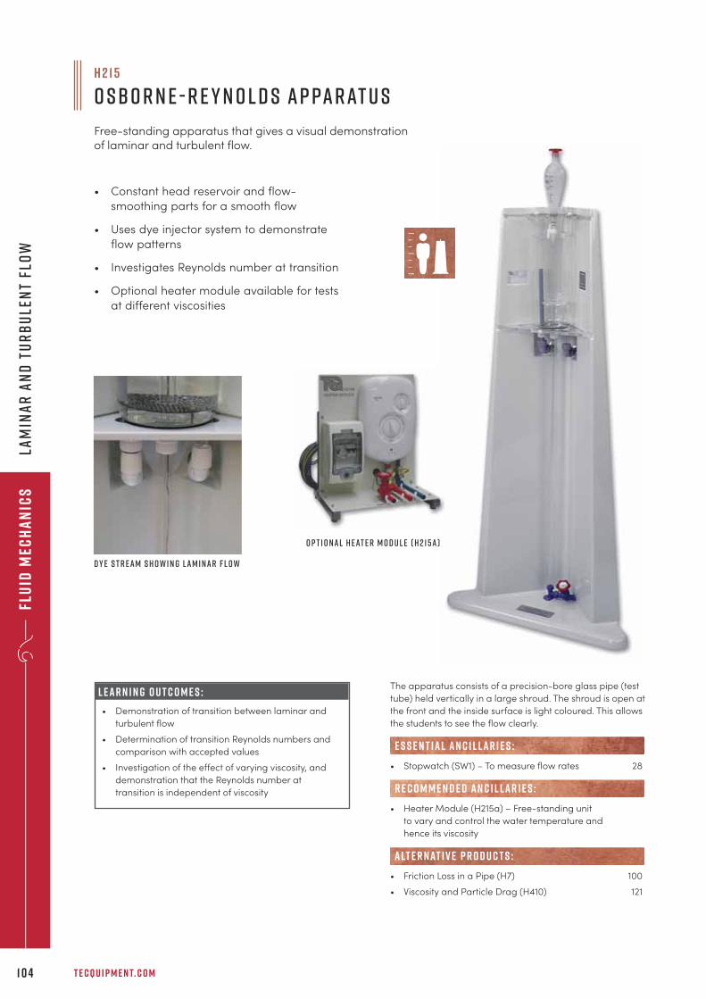
Flu
id M
ech
an
ics
T E C Q U I P M E N T. C O M1 0 4
Lam
ina
r a
nd
Tu
rb
ule
nt
Flo
w
The apparatus consists of a precision-bore glass pipe (test
tube) held vertically in a large shroud. The shroud is open at
the front and the inside surface is light coloured. This allows
the students to see the flow clearly.
• Stopwatch (SW1) – To measure flow rates 28
• Heater Module (H215a) – Free-standing unit
to vary and control the water temperature and
hence its viscosity
• Friction Loss in a Pipe (H7) 100
• Viscosity and Particle Drag (H410) 121
alt e r nat i v e p r o d u c t s :
R E C O M M E N D E D AN C I L LAR I E S :
E S S E N T IAL AN C I L LAR I E S :
L E A R N I N G O U T C O M E S :
• Demonstration of transition between laminar and
turbulent flow
• Determination of transition Reynolds numbers and
comparison with accepted values
• Investigation of the effect of varying viscosity, and
demonstration that the Reynolds number at
transition is independent of viscosity
• Constant head reservoir and flow-
smoothing parts for a smooth flow
• Uses dye injector system to demonstrate
flow patterns
• Investigates Reynolds number at transition
• Optional heater module available for tests
at different viscosities
H 2 1 5
O sbo r n e - R e y n o l d s A p pa r at u s
Free-standing apparatus that gives a visual demonstrationof laminar and turbulent flow.
O p t i o n a l H e at e r M o d u l e ( H 2 1 5 a )
D y e S t r e a m S h o w i n g L a m i n a r F l o w
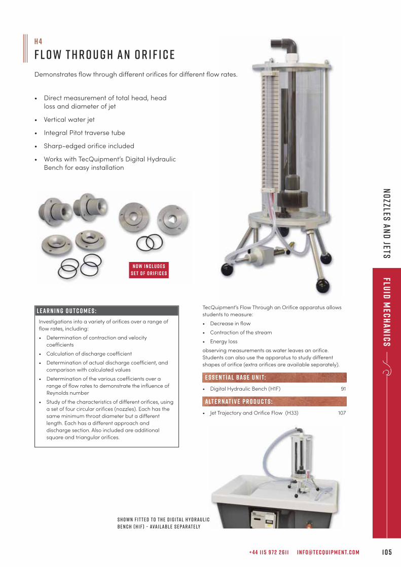
+ 4 4 1 1 5 9 7 2 2 6 1 1 I N F O @ T E C Q U I P M E N T. C O M 1 0 5
Fluid
Mec
ha
nic
sN
ozzles
an
d jets
• Direct measurement of total head, head
loss and diameter of jet
• Vertical water jet
• Integral Pitot traverse tube
• Sharp-edged orifice included
• Works with TecQuipment’s Digital Hydraulic
Bench for easy installation
TecQuipment’s Flow Through an Orifice apparatus allows
students to measure:
• Decrease in flow
• Contraction of the stream
• Energy loss
observing measurements as water leaves an orifice.
Students can also use the apparatus to study different
shapes of orifice (extra orifices are available separately).
• Digital Hydraulic Bench (H1F) 91
• Jet Trajectory and Orifice Flow (H33) 107
e s s e n t ial bas e u n i t:
alt e r nat i v e p r o d u c t s :
S h o w n f i t t e d t o t h e D i g i ta l H y d r a u l i c
B e n c h ( H 1 F ) – ava i l abl e s e pa r at e ly
L E A R N I N G O U T C O M E S :
Investigations into a variety of orifices over a range of
flow rates, including:
• Determination of contraction and velocity
coefficients
• Calculation of discharge coefficient
• Determination of actual discharge coefficient, and
comparison with calculated values
• Determination of the various coefficients over a
range of flow rates to demonstrate the influence of
Reynolds number
• Study of the characteristics of different orifices, using
a set of four circular orifices (nozzles). Each has the
same minimum throat diameter but a different
length. Each has a different approach and
discharge section. Also included are additional
square and triangular orifices.
N o w I n c l u d e s
s e t o f o r i f i c e s
h 4
F l o w T h r o u g h a n O r i f i c e
Demonstrates flow through different orifices for different flow rates.
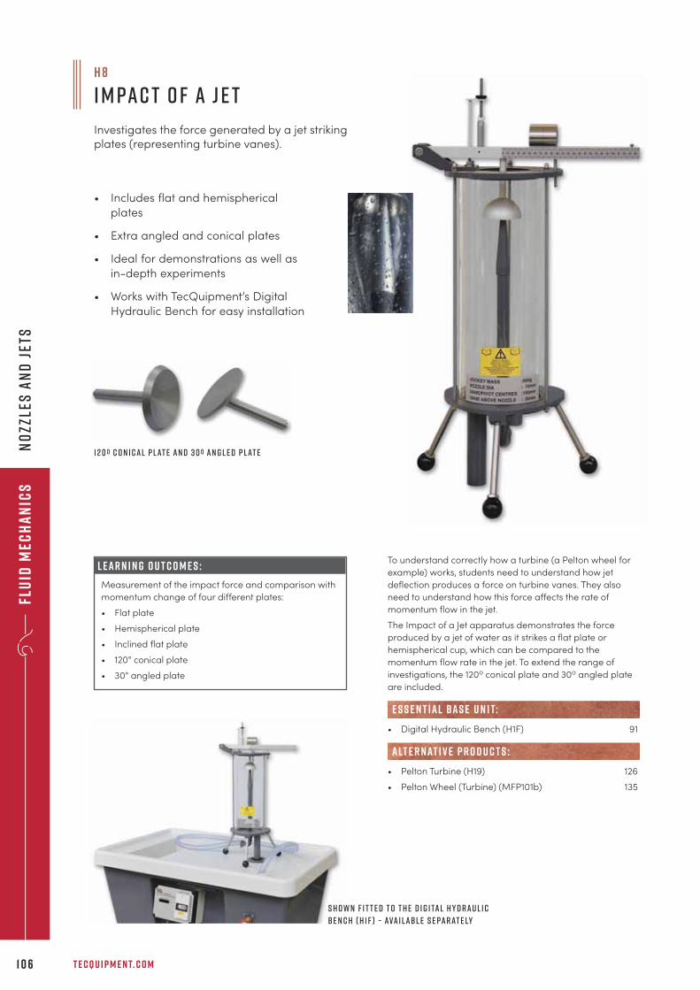
Flu
id M
ech
an
ics
T E C Q U I P M E N T. C O M1 0 6
No
zzle
s a
nd
Jet
s
To understand correctly how a turbine (a Pelton wheel for
example) works, students need to understand how jet
deflection produces a force on turbine vanes. They also
need to understand how this force affects the rate of
momentum flow in the jet.
The Impact of a Jet apparatus demonstrates the force
produced by a jet of water as it strikes a flat plate or
hemispherical cup, which can be compared to the
momentum flow rate in the jet. To extend the range of
investigations, the 120o conical plate and 30o angled plate
are included.
• Digital Hydraulic Bench (H1F) 91
• Pelton Turbine (H19) 126
• Pelton Wheel (Turbine) (MFP101b) 135
e s s e n t ial bas e u n i t:
alt e r nat i v e p r o d u c t s :
H 8
I m pa c t o f a J e t
Investigates the force generated by a jet strikingplates (representing turbine vanes).
• Includes flat and hemispherical
plates
• Extra angled and conical plates
• Ideal for demonstrations as well as
in-depth experiments
• Works with TecQuipment’s Digital
Hydraulic Bench for easy installation
L E A R N I N G O U T C O M E S :
Measurement of the impact force and comparison with
momentum change of four different plates:
• Flat plate
• Hemispherical plate
• Inclined flat plate
• 120° conical plate
• 30° angled plate
1 2 0 0 C o n i c a l P l at e a n d 3 0 0 A n g l e d P l at e
S h o w n f i t t e d t o t h e D i g i ta l H y d r a u l i c
B e n c h ( H 1 F ) – ava i l abl e s e pa r at e ly
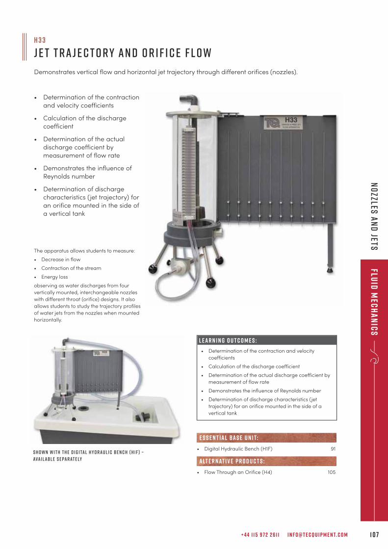
+ 4 4 1 1 5 9 7 2 2 6 1 1 I N F O @ T E C Q U I P M E N T. C O M 1 0 7
Fluid
Mec
ha
nic
sN
ozzles
an
d Jets
• Determination of the contraction
and velocity coefficients
• Calculation of the discharge
coefficient
• Determination of the actual
discharge coefficient by
measurement of flow rate
• Demonstrates the influence of
Reynolds number
• Determination of discharge
characteristics (jet trajectory) for
an orifice mounted in the side of
a vertical tank
H 3 3
J e t T r a j e c t o r y a n d O r i f i c e F l o w
Demonstrates vertical flow and horizontal jet trajectory through different orifices (nozzles).
S h o w n w i t h t h e D i g i ta l H y d r a u l i c B e n c h ( H 1 F ) –
ava i l abl e s e pa r at e ly
The apparatus allows students to measure:
• Decrease in flow
• Contraction of the stream
• Energy loss
observing as water discharges from four
vertically mounted, interchangeable nozzles
with different throat (orifice) designs. It also
allows students to study the trajectory profiles
of water jets from the nozzles when mounted
horizontally.
L E A R N I N G O U T C O M E S :
• Determination of the contraction and velocity
coefficients
• Calculation of the discharge coefficient
• Determination of the actual discharge coefficient by
measurement of flow rate
• Demonstrates the influence of Reynolds number
• Determination of discharge characteristics (jet
trajectory) for an orifice mounted in the side of a
vertical tank
• Digital Hydraulic Bench (H1F) 91
• Flow Through an Orifice (H4) 105
e s s e n t ial bas e u n i t:
alt e r nat i v e p r o d u c t s :
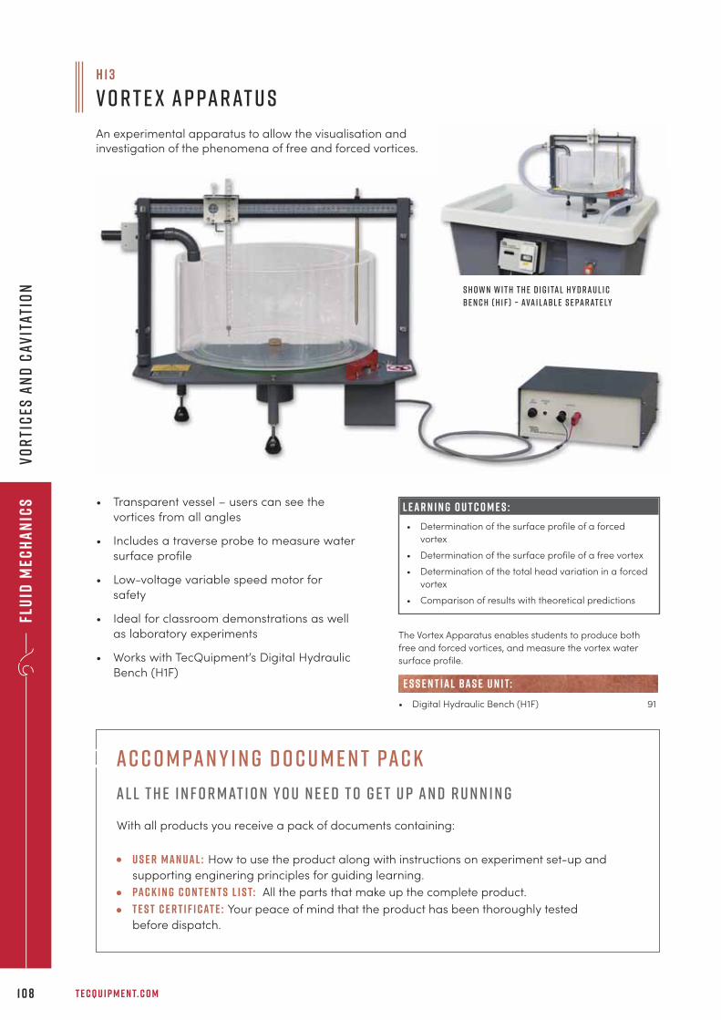
Flu
id M
ech
an
ics
T E C Q U I P M E N T. C O M1 0 8
Vo
rti
ces
an
d C
avit
atio
n
The Vortex Apparatus enables students to produce both
free and forced vortices, and measure the vortex water
surface profile.
• Digital Hydraulic Bench (H1F) 91
e s s e n t ial bas e u n i t:
H 1 3
V o r t e x A p pa r at u s
An experimental apparatus to allow the visualisation andinvestigation of the phenomena of free and forced vortices.
• Transparent vessel – users can see the
vortices from all angles
• Includes a traverse probe to measure water
surface profile
• Low-voltage variable speed motor for
safety
• Ideal for classroom demonstrations as well
as laboratory experiments
• Works with TecQuipment’s Digital Hydraulic
Bench (H1F)
L E A R N I N G O U T C O M E S :
• Determination of the surface profile of a forced
vortex
• Determination of the surface profile of a free vortex
• Determination of the total head variation in a forced
vortex
• Comparison of results with theoretical predictions
S h o w n w i t h t h e D i g i ta l H y d r a u l i c
B e n c h ( H 1 F ) – ava i l abl e s e pa r at e ly
Ac c o m pan y i n g d o c u m e n t pac k
Al l t h e i n f o r mat i o n y o u n e e d t o g e t u p an d r u n n i n g
With all products you receive a pack of documents containing:
U s e r Man ual : How to use the product along with instructions on experiment set-up and
supporting enginering principles for guiding learning.
Pac k i n g c o n t e n t s l i s t: All the parts that make up the complete product.
T e s t c e r t i f i cat e : Your peace of mind that the product has been thoroughly tested
before dispatch.
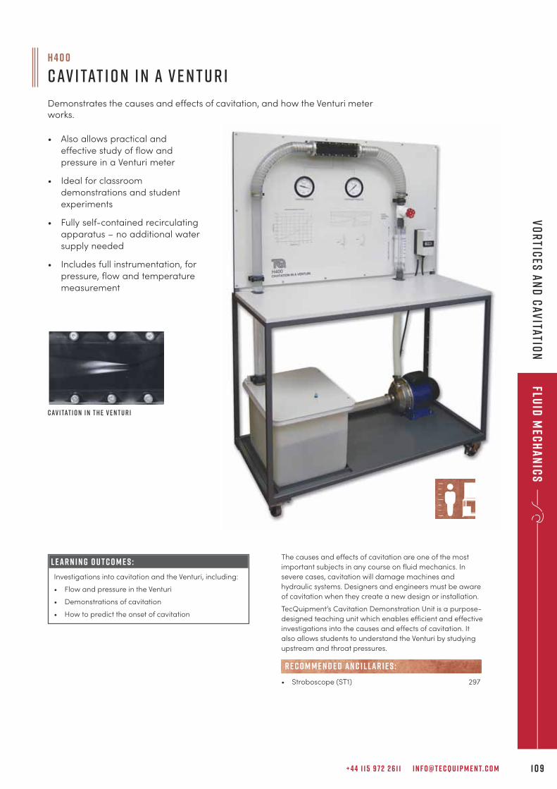
+ 4 4 1 1 5 9 7 2 2 6 1 1 I N F O @ T E C Q U I P M E N T. C O M 1 0 9
Fluid
Mec
ha
nic
sV
or
tices
an
d C
avitatio
n
• Also allows practical and
effective study of flow and
pressure in a Venturi meter
• Ideal for classroom
demonstrations and student
experiments
• Fully self-contained recirculating
apparatus – no additional water
supply needed
• Includes full instrumentation, for
pressure, flow and temperature
measurement
H 4 0 0
C av i tat i o n i n a V e n t u r i
Demonstrates the causes and effects of cavitation, and how the Venturi meterworks.
C av i tat i o n i n t h e V e n t u r i
The causes and effects of cavitation are one of the most
important subjects in any course on fluid mechanics. In
severe cases, cavitation will damage machines and
hydraulic systems. Designers and engineers must be aware
of cavitation when they create a new design or installation.
TecQuipment’s Cavitation Demonstration Unit is a purpose-
designed teaching unit which enables efficient and effective
investigations into the causes and effects of cavitation. It
also allows students to understand the Venturi by studying
upstream and throat pressures.
• Stroboscope (ST1) 297
R E C O M M E N D E D AN C I L LAR I E S :
L E A R N I N G O U T C O M E S :
Investigations into cavitation and the Venturi, including:
• Flow and pressure in the Venturi
• Demonstrations of cavitation
• How to predict the onset of cavitation
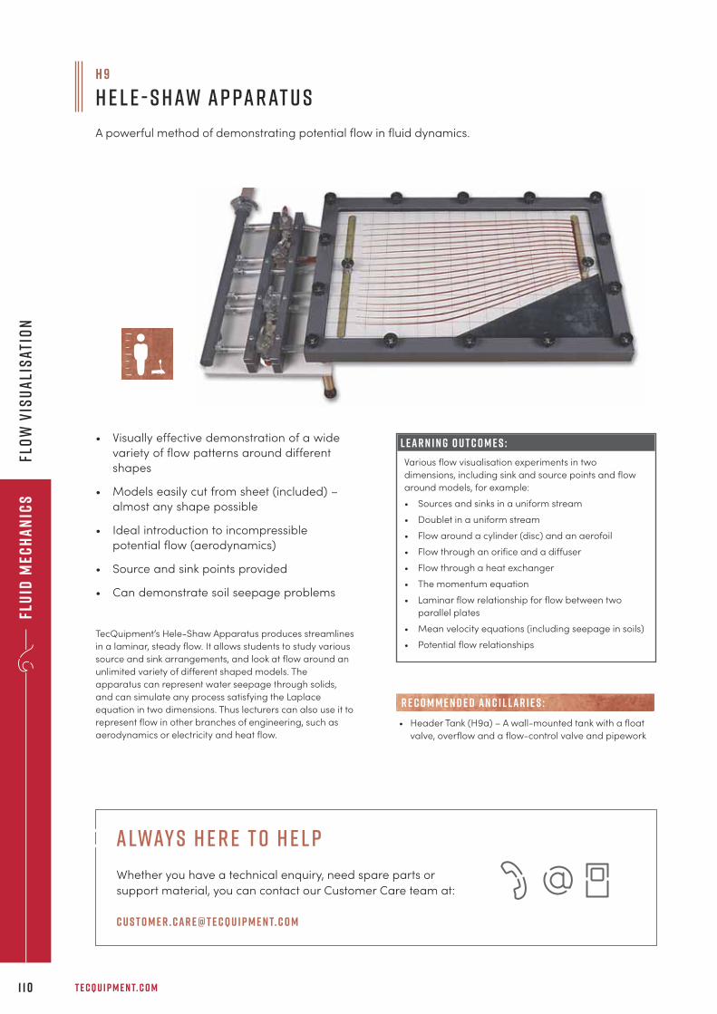
Flu
id M
ech
an
ics
T E C Q U I P M E N T. C O M1 1 0
Flo
w V
isu
ali
sat
ion
TecQuipment’s Hele-Shaw Apparatus produces streamlines
in a laminar, steady flow. It allows students to study various
source and sink arrangements, and look at flow around an
unlimited variety of different shaped models. The
apparatus can represent water seepage through solids,
and can simulate any process satisfying the Laplace
equation in two dimensions. Thus lecturers can also use it to
represent flow in other branches of engineering, such as
aerodynamics or electricity and heat flow.
H 9
H e l e - S h aw A p pa r at u s
A powerful method of demonstrating potential flow in fluid dynamics.
• Visually effective demonstration of a wide
variety of flow patterns around different
shapes
• Models easily cut from sheet (included) –
almost any shape possible
• Ideal introduction to incompressible
potential flow (aerodynamics)
• Source and sink points provided
• Can demonstrate soil seepage problems
L E A R N I N G O U T C O M E S :
Various flow visualisation experiments in two
dimensions, including sink and source points and flow
around models, for example:
• Sources and sinks in a uniform stream
• Doublet in a uniform stream
• Flow around a cylinder (disc) and an aerofoil
• Flow through an orifice and a diffuser
• Flow through a heat exchanger
• The momentum equation
• Laminar flow relationship for flow between two
parallel plates
• Mean velocity equations (including seepage in soils)
• Potential flow relationships
• Header Tank (H9a) – A wall-mounted tank with a float
valve, overflow and a flow-control valve and pipework
R E C O M M E N D E D AN C I L LAR I E S :
alway s h e r e t o h e l p
Whether you have a technical enquiry, need spare parts or
support material, you can contact our Customer Care team at:
c u s t o m e r . car e@t e cqu i p m e n t. c o m
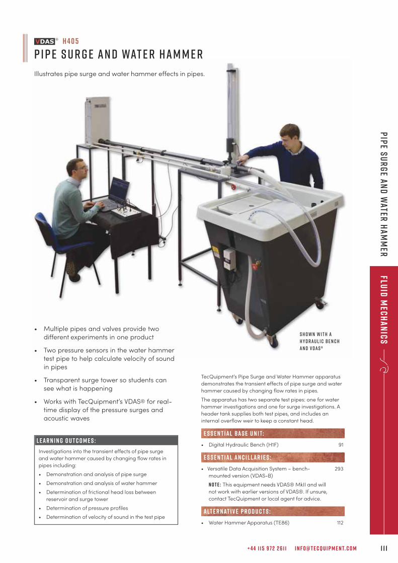
+ 4 4 1 1 5 9 7 2 2 6 1 1 I N F O @ T E C Q U I P M E N T. C O M 1 1 1
Fluid
Mec
ha
nic
sP
ipe S
ur
ge a
nd
Water
Ha
mm
er
TecQuipment’s Pipe Surge and Water Hammer apparatus
demonstrates the transient effects of pipe surge and water
hammer caused by changing flow rates in pipes.
The apparatus has two separate test pipes: one for water
hammer investigations and one for surge investigations. A
header tank supplies both test pipes, and includes an
internal overflow weir to keep a constant head.
• Digital Hydraulic Bench (H1F) 91
• Versatile Data Acquisition System – bench- 293
mounted version (VDAS-B)
N O T E : This equipment needs VDAS® MkII and will
not work with earlier versions of VDAS®. If unsure,
contact TecQuipment or local agent for advice.
• Water Hammer Apparatus (TE86) 112
alt e r nat i v e p r o d u c t s :
E S S E N T IAL AN C I L LAR I E S :
e s s e n t ial bas e u n i t:
h 4 0 5
P i p e S u r g e a n d Wat e r H a m m e r
Illustrates pipe surge and water hammer effects in pipes.
L E A R N I N G O U T C O M E S :
Investigations into the transient effects of pipe surge
and water hammer caused by changing flow rates in
pipes including:
• Demonstration and analysis of pipe surge
• Demonstration and analysis of water hammer
• Determination of frictional head loss between
reservoir and surge tower
• Determination of pressure profiles
• Determination of velocity of sound in the test pipe
S h o w n w i t h a
H y d r a u l i c B e n c h
a n d V D A S ®
• Multiple pipes and valves provide two
different experiments in one product
• Two pressure sensors in the water hammer
test pipe to help calculate velocity of sound
in pipes
• Transparent surge tower so students can
see what is happening
• Works with TecQuipment’s VDAS® for real-
time display of the pressure surges and
acoustic waves
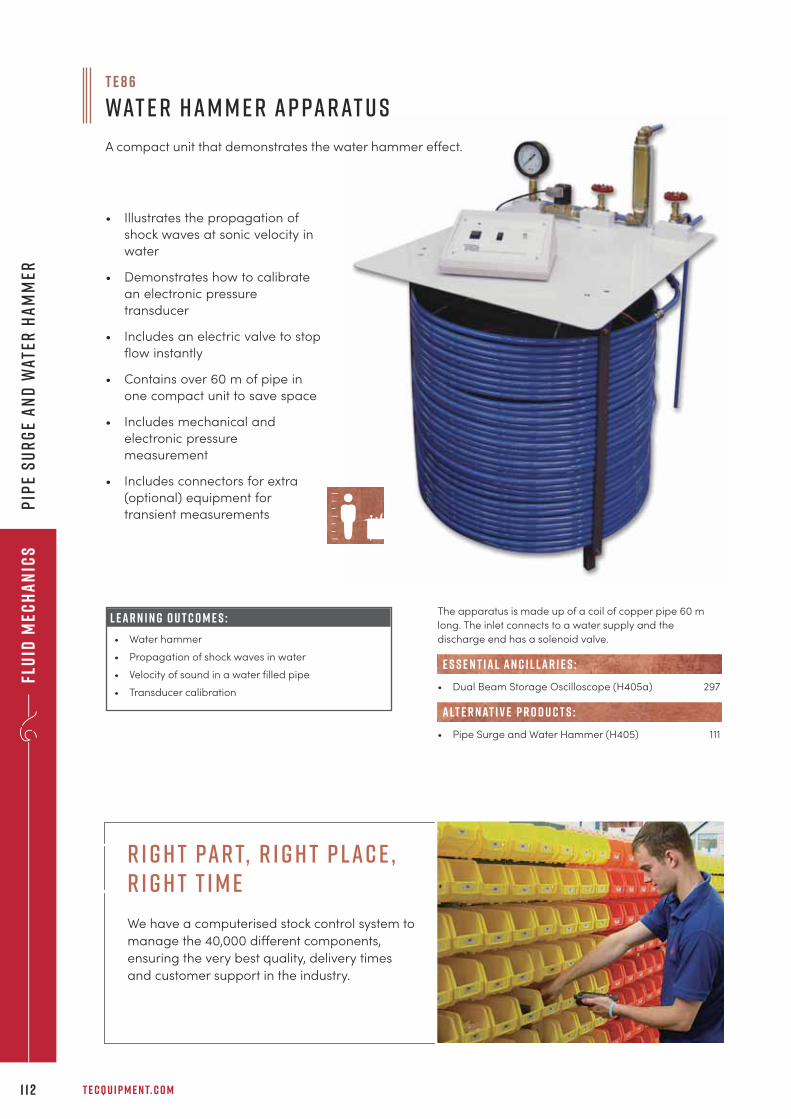
Flu
id M
ech
an
ics
T E C Q U I P M E N T. C O M1 1 2
Pip
e S
ur
ge
an
d W
ater
Ha
mm
er
The apparatus is made up of a coil of copper pipe 60 m
long. The inlet connects to a water supply and the
discharge end has a solenoid valve.
• Dual Beam Storage Oscilloscope (H405a) 297
• Pipe Surge and Water Hammer (H405) 111
E S S E N T IAL AN C I L LAR I E S :
alt e r nat i v e p r o d u c t s :
• Illustrates the propagation of
shock waves at sonic velocity in
water
• Demonstrates how to calibrate
an electronic pressure
transducer
• Includes an electric valve to stop
flow instantly
• Contains over 60 m of pipe in
one compact unit to save space
• Includes mechanical and
electronic pressure
measurement
• Includes connectors for extra
(optional) equipment for
transient measurements
L E A R N I N G O U T C O M E S :
• Water hammer
• Propagation of shock waves in water
• Velocity of sound in a water filled pipe
• Transducer calibration
T E 8 6
Wat e r H a m m e r A p pa r at u s
A compact unit that demonstrates the water hammer effect.
r i g h t par t, r i g h t p lac e , r i g h t t i m e
We have a computerised stock control system to
manage the 40,000 di�erent components,
ensuring the very best quality, delivery times
and customer support in the industry.
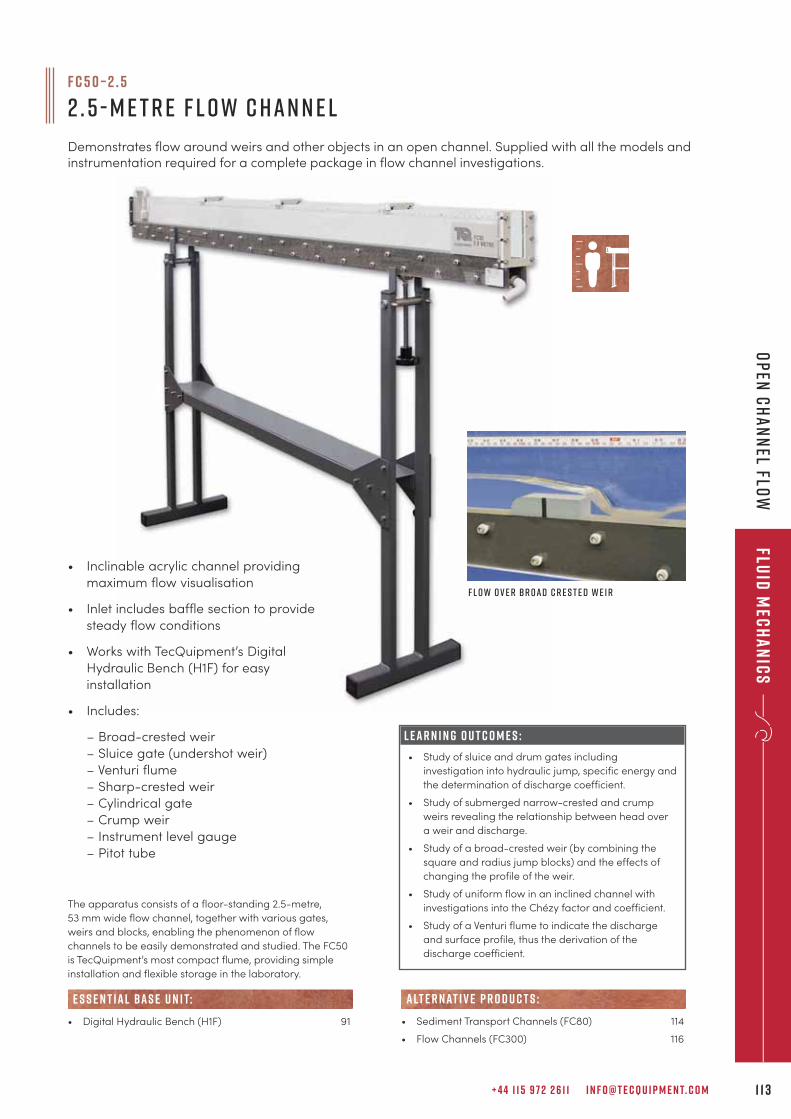
+ 4 4 1 1 5 9 7 2 2 6 1 1 I N F O @ T E C Q U I P M E N T. C O M 1 1 3
Fluid
Mec
ha
nic
sO
pen
Ch
an
nel Flo
w
F C 5 0 – 2 . 5
2 . 5 - M e t r e F l o w C h a n n e l
Demonstrates flow around weirs and other objects in an open channel. Supplied with all the models andinstrumentation required for a complete package in flow channel investigations.
The apparatus consists of a floor-standing 2.5-metre,
53 mm wide flow channel, together with various gates,
weirs and blocks, enabling the phenomenon of flow
channels to be easily demonstrated and studied. The FC50
is TecQuipment’s most compact flume, providing simple
installation and flexible storage in the laboratory.
• Digital Hydraulic Bench (H1F) 91
e s s e n t ial bas e u n i t:
• Sediment Transport Channels (FC80) 114
• Flow Channels (FC300) 116
alt e r nat i v e p r o d u c t s :
• Inclinable acrylic channel providing
maximum flow visualisation
• Inlet includes baffle section to provide
steady flow conditions
• Works with TecQuipment’s Digital
Hydraulic Bench (H1F) for easy
installation
• Includes:
– Broad-crested weir
– Sluice gate (undershot weir)
– Venturi flume
– Sharp-crested weir
– Cylindrical gate
– Crump weir
– Instrument level gauge
– Pitot tube
L E A R N I N G O U T C O M E S :
• Study of sluice and drum gates including
investigation into hydraulic jump, specific energy and
the determination of discharge coefficient.
• Study of submerged narrow-crested and crump
weirs revealing the relationship between head over
a weir and discharge.
• Study of a broad-crested weir (by combining the
square and radius jump blocks) and the effects of
changing the profile of the weir.
• Study of uniform flow in an inclined channel with
investigations into the Chézy factor and coefficient.
• Study of a Venturi flume to indicate the discharge
and surface profile, thus the derivation of the
discharge coefficient.
F l o w o v e r B r o a d C r e s t e d W e i r
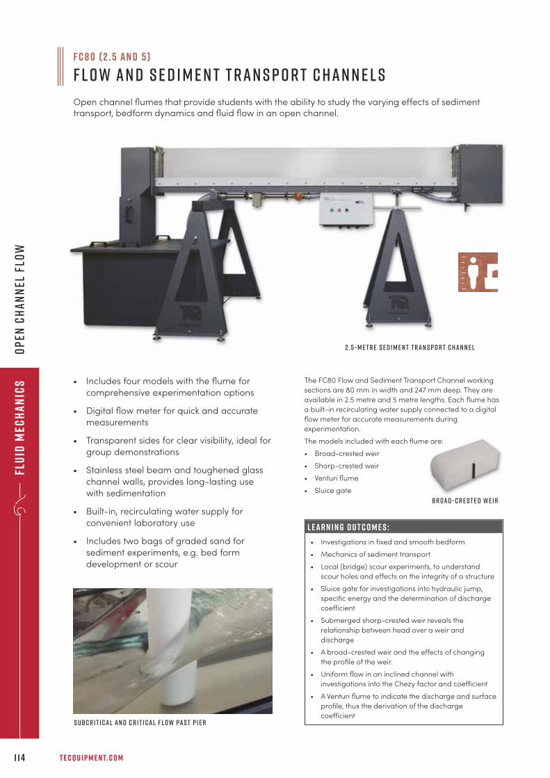
B r o a d - c r e s t e d w e i r
Flu
id M
ech
an
ics
T E C Q U I P M E N T. C O M1 1 4
Op
en C
ha
nn
el F
low
F C 8 0 ( 2 . 5 a n d 5 )
F l o w a n d S e d i m e n t T r a n s p o r t C h a n n e l s
Open channel flumes that provide students with the ability to study the varying effects of sedimenttransport, bedform dynamics and fluid flow in an open channel.
L E A R N I N G O U T C O M E S :
• Investigations in fixed and smooth bedform
• Mechanics of sediment transport
• Local (bridge) scour experiments, to understand
scour holes and effects on the integrity of a structure
• Sluice gate for investigations into hydraulic jump,
specific energy and the determination of discharge
coefficient
• Submerged sharp-crested weir reveals the
relationship between head over a weir and
discharge
• A broad-crested weir and the effects of changing
the profile of the weir.
• Uniform flow in an inclined channel with
investigations into the Chezy factor and coefficient
• A Venturi flume to indicate the discharge and surface
profile, thus the derivation of the discharge
coefficient
The FC80 Flow and Sediment Transport Channel working
sections are 80 mm in width and 247 mm deep. They are
available in 2.5 metre and 5 metre lengths. Each flume has
a built-in recirculating water supply connected to a digital
flow meter for accurate measurements during
experimentation.
The models included with each flume are:
• Broad-crested weir
• Sharp-crested weir
• Venturi flume
• Sluice gate
• Includes four models with the flume for
comprehensive experimentation options
• Digital flow meter for quick and accurate
measurements
• Transparent sides for clear visibility, ideal for
group demonstrations
• Stainless steel beam and toughened glass
channel walls, provides long-lasting use
with sedimentation
• Built-in, recirculating water supply for
convenient laboratory use
• Includes two bags of graded sand for
sediment experiments, e.g. bed form
development or scour
S ubc r i t i c a l a n d c r i t i c a l f l o w pa s t p i e r
2 . 5 - m e t r e S e d i m e n t T r a n s p o r t C h a n n e l
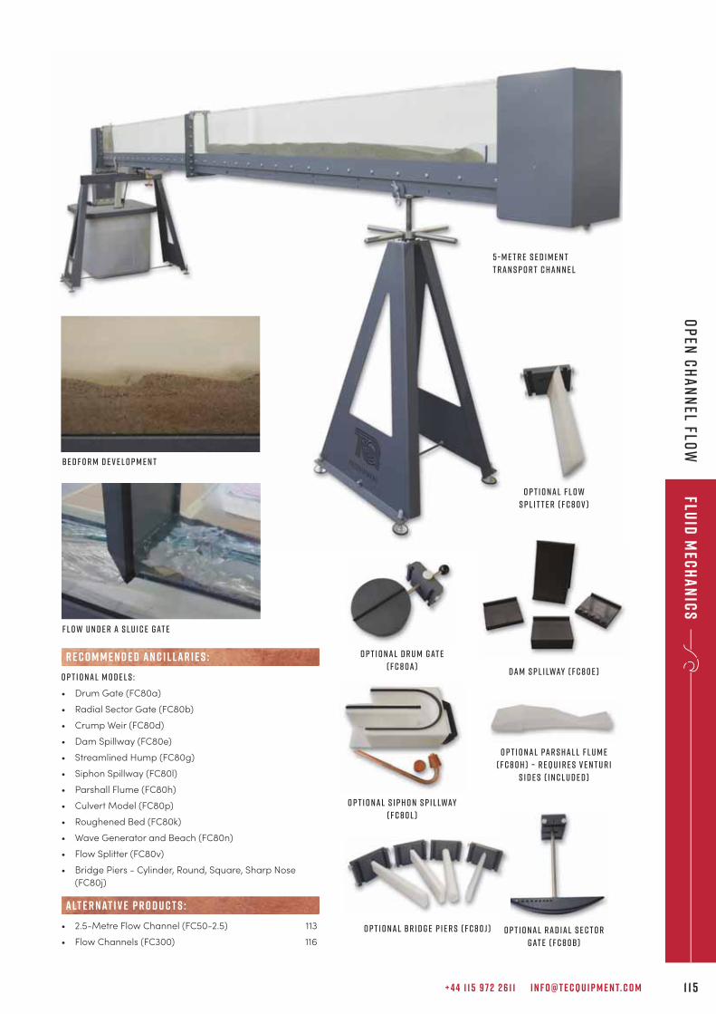
+ 4 4 1 1 5 9 7 2 2 6 1 1 I N F O @ T E C Q U I P M E N T. C O M 1 1 5
Fluid
Mec
ha
nic
sO
pen
Ch
an
nel Flo
w
D a m s p l i lway ( F C 8 0 e )
o p t i o n a l S i p h o n S p i l lway
( f c 8 0 l )
o p t i o n a l R a d i a l s e c t o r
G at e ( f c 8 0b )
o p t i o n a l D r u m G at e
( f c 8 0 a )
o p t i o n a l F l o w
s p l i t t e r ( f c 8 0 v )
o p t i o n a l B r i d g e p i e r s ( f c 8 0 j )
B e d f o r m D e v e l o p m e n t
o p t i o n a l pa r s h a l l f l u m e
( f c 8 0 h ) – r equ i r e s V e n t u r i
s i d e s ( i n c l u d e d )
5 - m e t r e S e d i m e n t
T r a n s p o r t C h a n n e l
F l o w U n d e r a S l u i c e G at e
O p t i o n a l m o d e l s :
• Drum Gate (FC80a)
• Radial Sector Gate (FC80b)
• Crump Weir (FC80d)
• Dam Spillway (FC80e)
• Streamlined Hump (FC80g)
• Siphon Spillway (FC80l)
• Parshall Flume (FC80h)
• Culvert Model (FC80p)
• Roughened Bed (FC80k)
• Wave Generator and Beach (FC80n)
• Flow Splitter (FC80v)
• Bridge Piers - Cylinder, Round, Square, Sharp Nose
(FC80j)
• 2.5-Metre Flow Channel (FC50-2.5) 113
• Flow Channels (FC300) 116
alt e r nat i v e p r o d u c t s :
R E C O M M E N D E D AN C I L LAR I E S :
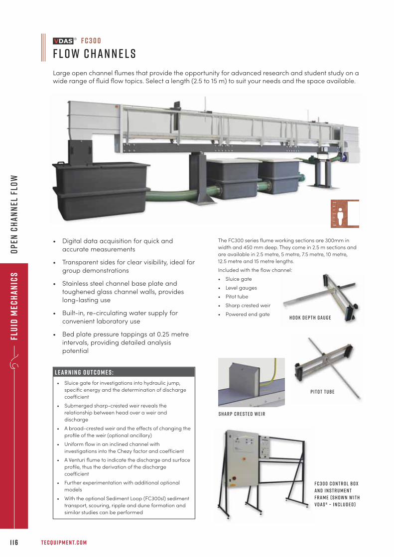
Flu
id M
ech
an
ics
T E C Q U I P M E N T. C O M1 1 6
Op
en C
ha
nn
el F
low
F C 3 0 0
f l o w C h a n n e l s
Large open channel flumes that provide the opportunity for advanced research and student study on awide range of fluid flow topics. Select a length (2.5 to 15 m) to suit your needs and the space available.
The FC300 series flume working sections are 300mm in
width and 450 mm deep. They come in 2.5 m sections and
are available in 2.5 metre, 5 metre, 7.5 metre, 10 metre,
12.5 metre and 15 metre lengths.
Included with the flow channel:
• Sluice gate
• Level gauges
• Pitot tube
• Sharp crested weir
• Powered end gate
• Digital data acquisition for quick and
accurate measurements
• Transparent sides for clear visibility, ideal for
group demonstrations
• Stainless steel channel base plate and
toughened glass channel walls, provides
long-lasting use
• Built-in, re-circulating water supply for
convenient laboratory use
• Bed plate pressure tappings at 0.25 metre
intervals, providing detailed analysis
potential
F C 3 0 0 C o n t r o l B o x
a n d I n s t r u m e n t
F r a m e ( s h o w n w i t h
V D A S ® – i n c l u d e d )
H o o k d e p t h g a u g e
P i t o t t ube
L E A R N I N G O U T C O M E S :
• Sluice gate for investigations into hydraulic jump,
specific energy and the determination of discharge
coefficient
• Submerged sharp-crested weir reveals the
relationship between head over a weir and
discharge
• A broad-crested weir and the effects of changing the
profile of the weir (optional ancillary)
• Uniform flow in an inclined channel with
investigations into the Chezy factor and coefficient
• A Venturi flume to indicate the discharge and surface
profile, thus the derivation of the discharge
coefficient
• Further experimentation with additional optional
models
• With the optional Sediment Loop (FC300sl) sediment
transport, scouring, ripple and dune formation and
similar studies can be performed
S h a r p c r e s t e d W e i r
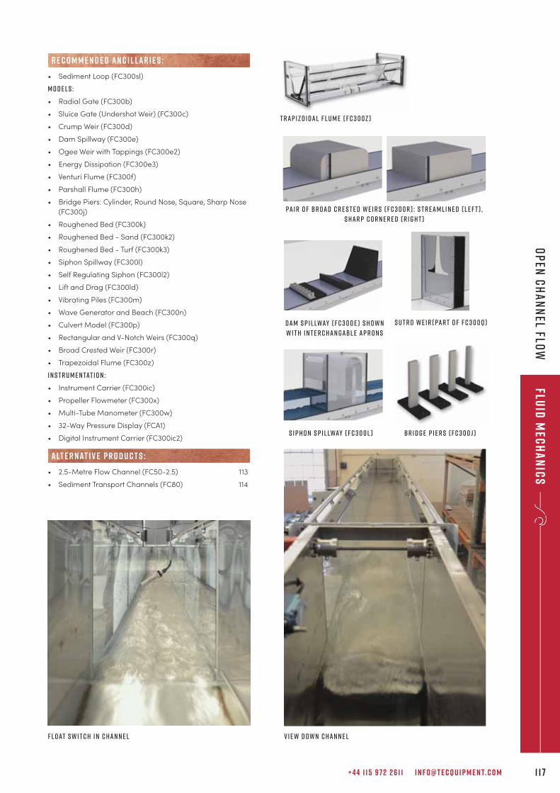
B r i d g e p i e r s ( F C 3 0 0 j )
+ 4 4 1 1 5 9 7 2 2 6 1 1 I N F O @ T E C Q U I P M E N T. C O M 1 1 7
Fluid
Mec
ha
nic
sO
pen
Ch
an
nel Flo
w
• Sediment Loop (FC300sl)
m o d e l s :
• Radial Gate (FC300b)
• Sluice Gate (Undershot Weir) (FC300c)
• Crump Weir (FC300d)
• Dam Spillway (FC300e)
• Ogee Weir with Tappings (FC300e2)
• Energy Dissipation (FC300e3)
• Venturi Flume (FC300f)
• Parshall Flume (FC300h)
• Bridge Piers: Cylinder, Round Nose, Square, Sharp Nose
(FC300j)
• Roughened Bed (FC300k)
• Roughened Bed - Sand (FC300k2)
• Roughened Bed - Turf (FC300k3)
• Siphon Spillway (FC300l)
• Self Regulating Siphon (FC300l2)
• Lift and Drag (FC300ld)
• Vibrating Piles (FC300m)
• Wave Generator and Beach (FC300n)
• Culvert Model (FC300p)
• Rectangular and V-Notch Weirs (FC300q)
• Broad Crested Weir (FC300r)
• Trapezoidal Flume (FC300z)
I n s t r u m e n tat i o n :
• Instrument Carrier (FC300ic)
• Propeller Flowmeter (FC300x)
• Multi-Tube Manometer (FC300w)
• 32-Way Pressure Display (FCA1)
• Digital Instrument Carrier (FC300ic2)
• 2.5-Metre Flow Channel (FC50-2.5) 113
• Sediment Transport Channels (FC80) 114
alt e r nat i v e p r o d u c t s :
R E C O M M E N D E D AN C I L LAR I E S :
Pa i r o f B r o a d C r e s t e d W e i r s ( F C 3 0 0 r ) : S t r e a m l i n e d ( l e f t ) ,
s h a r p c o r n e r e d ( r i g h t )
T r a p i z o i d a l F l u m e ( F C 3 0 0 z )
S i p h o n s p i l lway ( F C 3 0 0 l )
d a m s p i l lway ( F C 3 0 0 e ) S h o w n
w i t h i n t e r c h a n g abl e a p r o n s
F l o at s w i t c h i n c h a n n e l V i e w d o w n c h a n n e l
S u t r o W e i r ( pa r t o f F C 3 0 0q )
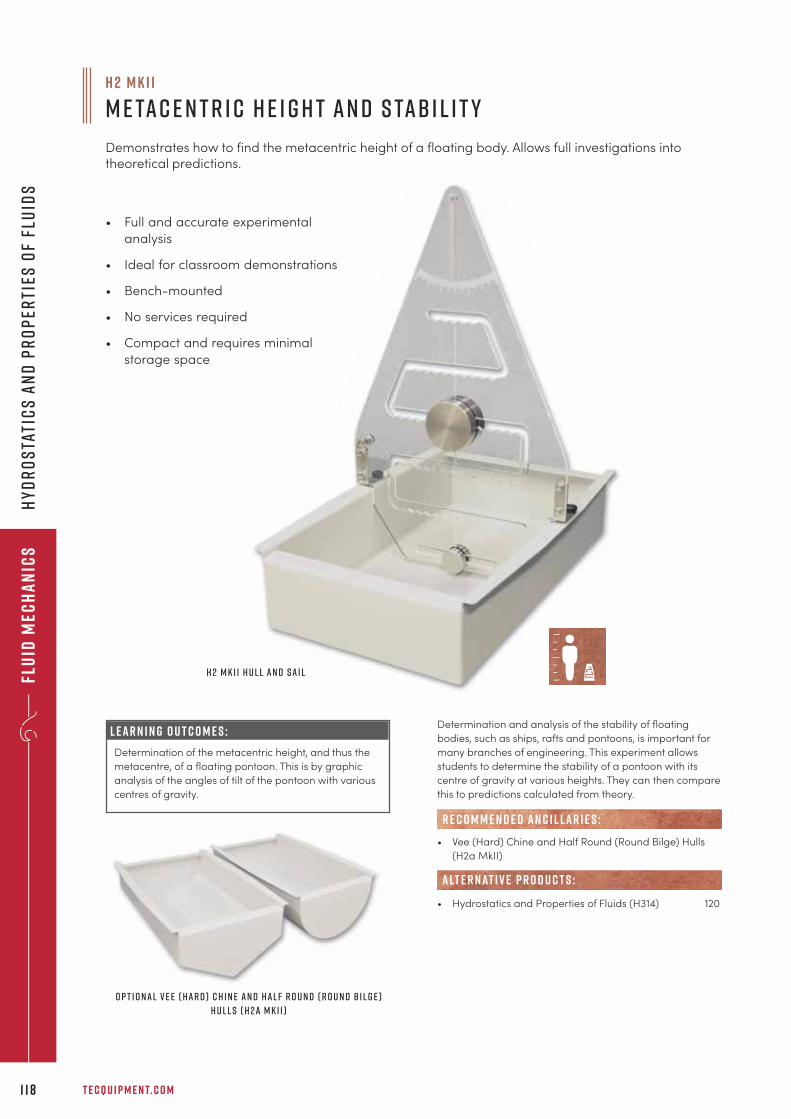
Flu
id M
ech
an
ics
T E C Q U I P M E N T. C O M1 1 8
Hy
dr
os
tati
cs
an
d p
ro
per
ties
of
flu
ids
• Full and accurate experimental
analysis
• Ideal for classroom demonstrations
• Bench-mounted
• No services required
• Compact and requires minimal
storage space
L E A R N I N G O U T C O M E S :
Determination of the metacentric height, and thus the
metacentre, of a floating pontoon. This is by graphic
analysis of the angles of tilt of the pontoon with various
centres of gravity.
Determination and analysis of the stability of floating
bodies, such as ships, rafts and pontoons, is important for
many branches of engineering. This experiment allows
students to determine the stability of a pontoon with its
centre of gravity at various heights. They can then compare
this to predictions calculated from theory.
• Vee (Hard) Chine and Half Round (Round Bilge) Hulls
(H2a MkII)
• Hydrostatics and Properties of Fluids (H314) 120
alt e r nat i v e p r o d u c t s :
R E C O M M E N D E D AN C I L LAR I E S :
h 2 M K I I
M e ta c e n t r i c H e i g h t a n d S tab i l i t y
Demonstrates how to find the metacentric height of a floating body. Allows full investigations intotheoretical predictions.
O p t i o n a l V e e ( H a r d ) C h i n e a n d H a l f R o u n d ( R o u n d B i l g e )
H u l l s ( H 2 a M k I I )
H 2 M k I I H u l l a n d S a i l
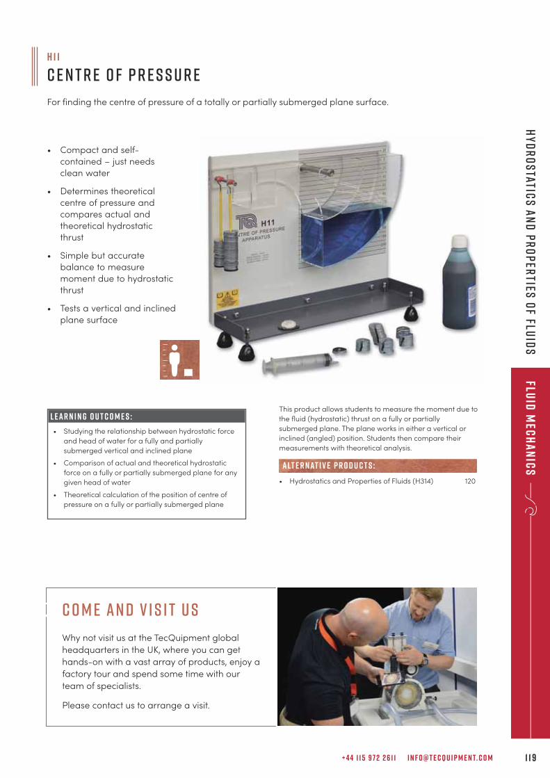
+ 4 4 1 1 5 9 7 2 2 6 1 1 I N F O @ T E C Q U I P M E N T. C O M 1 1 9
Fluid
Mec
ha
nic
sH
yd
ro
static
s a
nd
pr
op
erties
of flu
ids
This product allows students to measure the moment due to
the fluid (hydrostatic) thrust on a fully or partially
submerged plane. The plane works in either a vertical or
inclined (angled) position. Students then compare their
measurements with theoretical analysis.
• Hydrostatics and Properties of Fluids (H314) 120
alt e r nat i v e p r o d u c t s :
h 1 1
C e n t r e o f P r e s s u r e
For finding the centre of pressure of a totally or partially submerged plane surface.
• Compact and self-
contained – just needs
clean water
• Determines theoretical
centre of pressure and
compares actual and
theoretical hydrostatic
thrust
• Simple but accurate
balance to measure
moment due to hydrostatic
thrust
• Tests a vertical and inclined
plane surface
L E A R N I N G O U T C O M E S :
• Studying the relationship between hydrostatic force
and head of water for a fully and partially
submerged vertical and inclined plane
• Comparison of actual and theoretical hydrostatic
force on a fully or partially submerged plane for any
given head of water
• Theoretical calculation of the position of centre of
pressure on a fully or partially submerged plane
c o m e an d v i s i t u s
Why not visit us at the TecQuipment global
headquarters in the UK, where you can get
hands-on with a vast array of products, enjoy a
factory tour and spend some time with our
team of specialists.
Please contact us to arrange a visit.
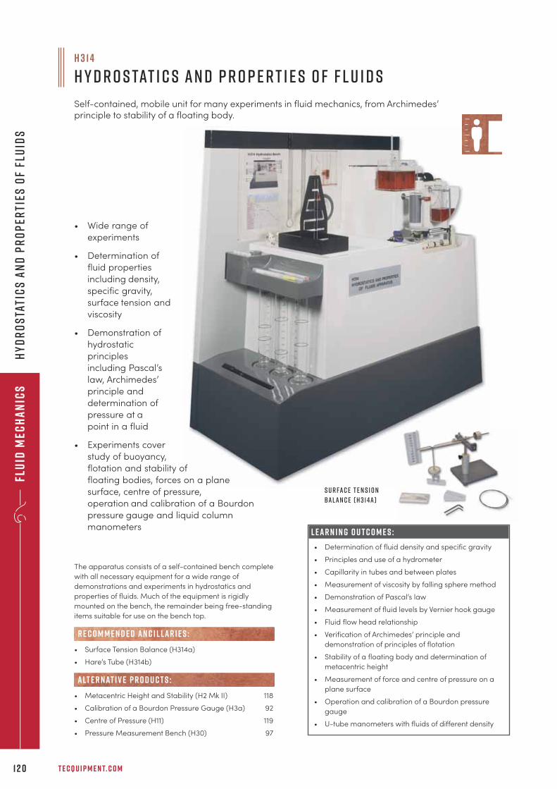
h 3 1 4
H y d r o s tat i c s a n d P r o p e r t i e s o f F l u i d s
Self-contained, mobile unit for many experiments in fluid mechanics, from Archimedes’principle to stability of a floating body.
Flu
id M
ech
an
ics
T E C Q U I P M E N T. C O M1 2 0
Hy
dr
os
tati
cs
an
d p
ro
per
ties
of
flu
ids
• Wide range of
experiments
• Determination of
fluid properties
including density,
specific gravity,
surface tension and
viscosity
• Demonstration of
hydrostatic
principles
including Pascal’s
law, Archimedes’
principle and
determination of
pressure at a
point in a fluid
• Experiments cover
study of buoyancy,
flotation and stability of
floating bodies, forces on a plane
surface, centre of pressure,
operation and calibration of a Bourdon
pressure gauge and liquid column
manometers
The apparatus consists of a self-contained bench complete
with all necessary equipment for a wide range of
demonstrations and experiments in hydrostatics and
properties of fluids. Much of the equipment is rigidly
mounted on the bench, the remainder being free-standing
items suitable for use on the bench top.
• Surface Tension Balance (H314a)
• Hare’s Tube (H314b)
• Metacentric Height and Stability (H2 Mk II) 118
• Calibration of a Bourdon Pressure Gauge (H3a) 92
• Centre of Pressure (H11) 119
• Pressure Measurement Bench (H30) 97
R E C O M M E N D E D AN C I L LAR I E S :
alt e r nat i v e p r o d u c t s :
L E A R N I N G O U T C O M E S :
• Determination of fluid density and specific gravity
• Principles and use of a hydrometer
• Capillarity in tubes and between plates
• Measurement of viscosity by falling sphere method
• Demonstration of Pascal’s law
• Measurement of fluid levels by Vernier hook gauge
• Fluid flow head relationship
• Verification of Archimedes’ principle and
demonstration of principles of flotation
• Stability of a floating body and determination of
metacentric height
• Measurement of force and centre of pressure on a
plane surface
• Operation and calibration of a Bourdon pressure
gauge
• U-tube manometers with fluids of different density
S u r fa c e T e n s i o n
B a l a n c e ( H 3 1 4 a )
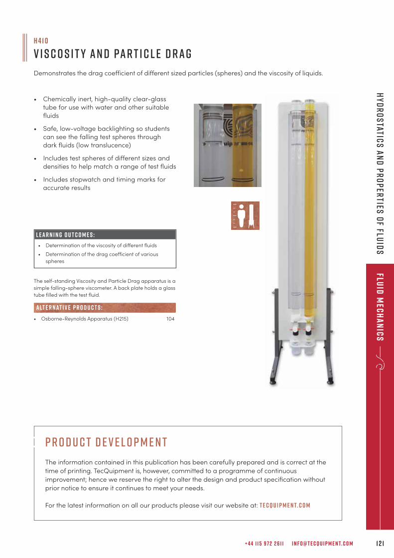
+ 4 4 1 1 5 9 7 2 2 6 1 1 I N F O @ T E C Q U I P M E N T. C O M 1 2 1
Fluid
Mec
ha
nic
sH
yd
ro
static
s a
nd
pr
op
erties
of flu
ids
The self-standing Viscosity and Particle Drag apparatus is a
simple falling-sphere viscometer. A back plate holds a glass
tube filled with the test fluid.
• Osborne-Reynolds Apparatus (H215) 104
alt e r nat i v e p r o d u c t s :
h 4 1 0
V i s c o s i t y a n d Pa r t i c l e D r a g
Demonstrates the drag coefficient of different sized particles (spheres) and the viscosity of liquids.
• Chemically inert, high-quality clear-glass
tube for use with water and other suitable
fluids
• Safe, low-voltage backlighting so students
can see the falling test spheres through
dark fluids (low translucence)
• Includes test spheres of different sizes and
densities to help match a range of test fluids
• Includes stopwatch and timing marks for
accurate results
L E A R N I N G O U T C O M E S :
• Determination of the viscosity of different fluids
• Determination of the drag coefficient of various
spheres
p r o d u c t d e v e l o p m e n t
The information contained in this publication has been carefully prepared and is correct at the
time of printing. TecQuipment is, however, committed to a programme of continuous
improvement; hence we reserve the right to alter the design and product specification without
prior notice to ensure it continues to meet your needs.
For the latest information on all our products please visit our website at: t e cqu i p m e n t. c o m
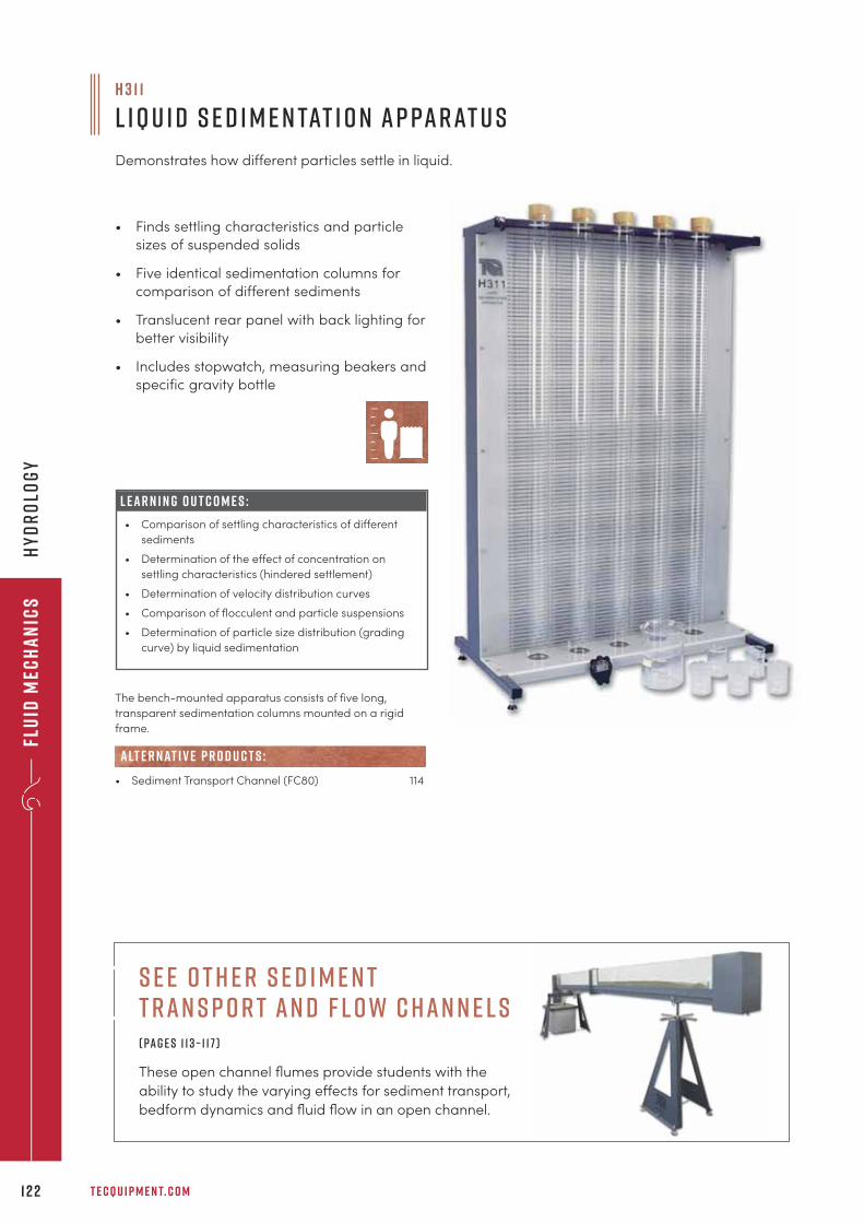
Flu
id M
ech
an
ics
T E C Q U I P M E N T. C O M1 2 2
Hy
dr
olo
gy
The bench-mounted apparatus consists of five long,
transparent sedimentation columns mounted on a rigid
frame.
• Sediment Transport Channel (FC80) 114
alt e r nat i v e p r o d u c t s :
h 3 1 1
L iqu i d S e d i m e n tat i o n A p pa r at u s
Demonstrates how different particles settle in liquid.
• Finds settling characteristics and particle
sizes of suspended solids
• Five identical sedimentation columns for
comparison of different sediments
• Translucent rear panel with back lighting for
better visibility
• Includes stopwatch, measuring beakers and
specific gravity bottle
L E A R N I N G O U T C O M E S :
• Comparison of settling characteristics of different
sediments
• Determination of the effect of concentration on
settling characteristics (hindered settlement)
• Determination of velocity distribution curves
• Comparison of flocculent and particle suspensions
• Determination of particle size distribution (grading
curve) by liquid sedimentation
s e e o t h e r s e d i m e n t t ran s p o r t an d f l ow c han n e l s ( pag e s 1 1 3 – 1 1 7 )
These open channel flumes provide students with the
ability to study the varying e�ects for sediment transport,
bedform dynamics and fluid flow in an open channel.
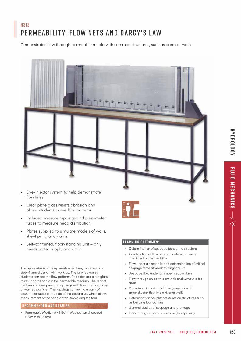
+ 4 4 1 1 5 9 7 2 2 6 1 1 I N F O @ T E C Q U I P M E N T. C O M 1 2 3
The apparatus is a transparent-sided tank, mounted on a
steel-framed bench with worktop. The tank is clear so
students can see the flow patterns. The sides are plate glass
to resist abrasion from the permeable medium. The rear of
the tank contains pressure tappings with filters that stop any
unwanted particles. The tappings connect to a bank of
piezometer tubes at the side of the apparatus, which allows
measurement of the head distribution along the tank.
• Permeable Medium (H312a) – Washed sand, graded
0.5 mm to 1.5 mm
R E C O M M E N D E D AN C I L LAR I E S :
h 3 1 2
P e r m e ab i l i t y, F l o w N e t s a n d D a r c y ’ s L aw
Demonstrates flow through permeable media with common structures, such as dams or walls.
L E A R N I N G O U T C O M E S :
• Determination of seepage beneath a structure
• Construction of flow nets and determination of
coefficient of permeability
• Flow under a sheet pile and determination of critical
seepage force at which ‘piping’ occurs
• Seepage flow under an impermeable dam
• Flow through an earth dam with and without a toe
drain
• Drawdown in horizontal flow (simulation of
groundwater flow into a river or well)
• Determination of uplift pressures on structures such
as building foundations
• General studies of seepage and drainage
• Flow through a porous medium (Darcy’s law)
• Dye-injector system to help demonstrate
flow lines
• Clear plate glass resists abrasion and
allows students to see flow patterns
• Includes pressure tappings and piezometer
tubes to measure head distribution
• Plates supplied to simulate models of walls,
sheet piling and dams
• Self-contained, floor-standing unit – only
needs water supply and drain
Fluid
Mec
ha
nic
sH
yd
ro
log
y
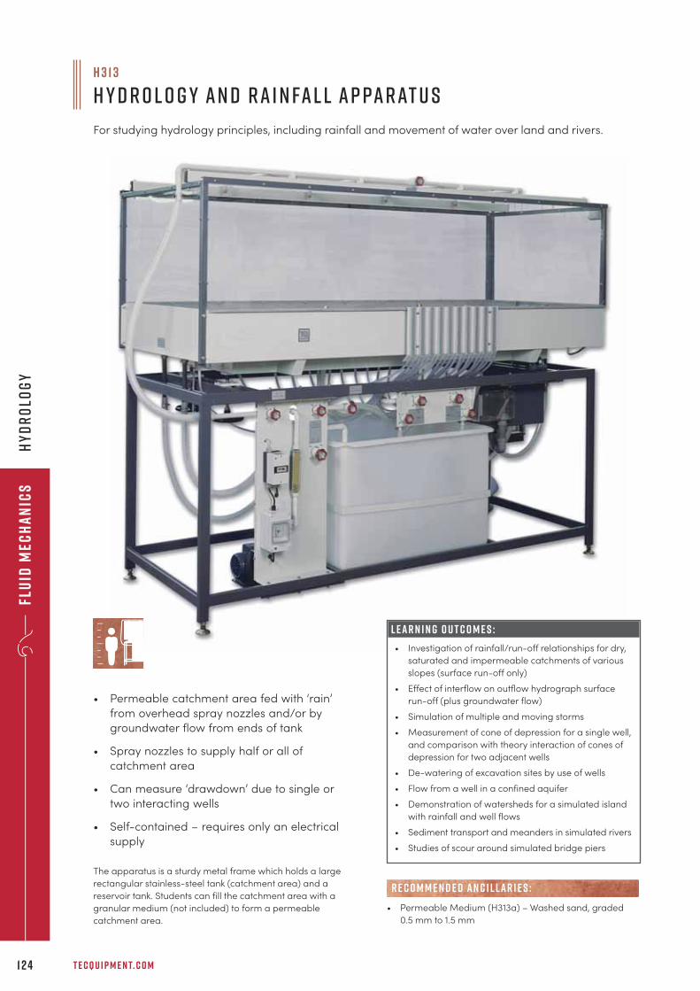
Flu
id M
ech
an
ics
T E C Q U I P M E N T. C O M1 2 4
Hy
dr
olo
gy
The apparatus is a sturdy metal frame which holds a large
rectangular stainless-steel tank (catchment area) and a
reservoir tank. Students can fill the catchment area with a
granular medium (not included) to form a permeable
catchment area.
H 3 1 3
H y d r o l o g y a n d R a i n fa l l A p pa r at u s
For studying hydrology principles, including rainfall and movement of water over land and rivers.
• Permeable catchment area fed with ‘rain’
from overhead spray nozzles and/or by
groundwater flow from ends of tank
• Spray nozzles to supply half or all of
catchment area
• Can measure ‘drawdown’ due to single or
two interacting wells
• Self-contained – requires only an electrical
supply
L E A R N I N G O U T C O M E S :
• Investigation of rainfall/run-off relationships for dry,
saturated and impermeable catchments of various
slopes (surface run-off only)
• Effect of interflow on outflow hydrograph surface
run-off (plus groundwater flow)
• Simulation of multiple and moving storms
• Measurement of cone of depression for a single well,
and comparison with theory interaction of cones of
depression for two adjacent wells
• De-watering of excavation sites by use of wells
• Flow from a well in a confined aquifer
• Demonstration of watersheds for a simulated island
with rainfall and well flows
• Sediment transport and meanders in simulated rivers
• Studies of scour around simulated bridge piers
• Permeable Medium (H313a) – Washed sand, graded
0.5 mm to 1.5 mm
R E C O M M E N D E D AN C I L LAR I E S :
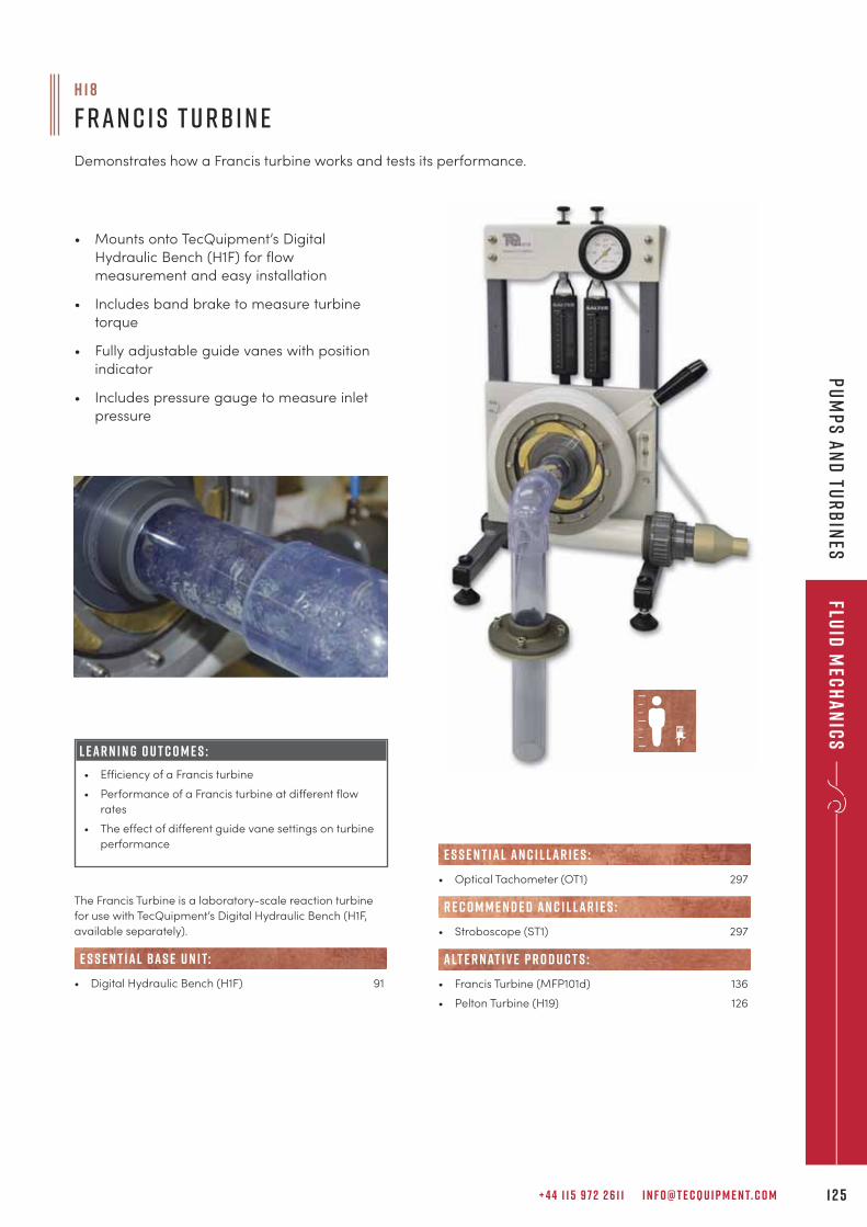
+ 4 4 1 1 5 9 7 2 2 6 1 1 I N F O @ T E C Q U I P M E N T. C O M 1 2 5
Fluid
Mec
ha
nic
sP
um
ps
an
d tu
rb
ines
The Francis Turbine is a laboratory-scale reaction turbine
for use with TecQuipment’s Digital Hydraulic Bench (H1F,
available separately).
• Digital Hydraulic Bench (H1F) 91
e s s e n t ial bas e u n i t:
H 1 8
F r a n c i s T u rb i n e
Demonstrates how a Francis turbine works and tests its performance.
• Mounts onto TecQuipment’s Digital
Hydraulic Bench (H1F) for flow
measurement and easy installation
• Includes band brake to measure turbine
torque
• Fully adjustable guide vanes with position
indicator
• Includes pressure gauge to measure inlet
pressure
L E A R N I N G O U T C O M E S :
• Efficiency of a Francis turbine
• Performance of a Francis turbine at different flow
rates
• The effect of different guide vane settings on turbine
performance
• Optical Tachometer (OT1) 297
• Stroboscope (ST1) 297
• Francis Turbine (MFP101d) 136
• Pelton Turbine (H19) 126
R E C O M M E N D E D AN C I L LAR I E S :
alt e r nat i v e p r o d u c t s :
E S S E N T IAL AN C I L LAR I E S :
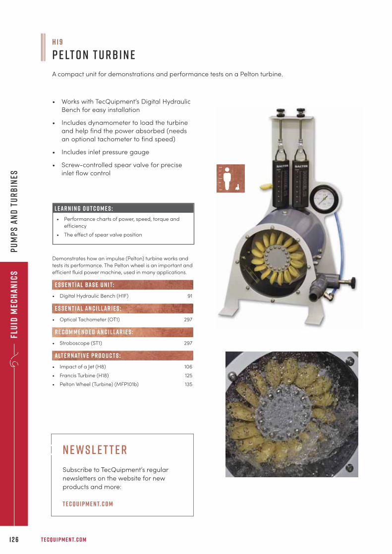
Flu
id M
ech
an
ics
T E C Q U I P M E N T. C O M1 2 6
Pu
mp
s a
nd
Tu
rb
ines
Demonstrates how an impulse (Pelton) turbine works and
tests its performance. The Pelton wheel is an important and
efficient fluid power machine, used in many applications.
• Digital Hydraulic Bench (H1F) 91
• Optical Tachometer (OT1) 297
• Stroboscope (ST1) 297
• Impact of a Jet (H8) 106
• Francis Turbine (H18) 125
• Pelton Wheel (Turbine) (MFP101b) 135
e s s e n t ial bas e u n i t:
E S S E N T IAL AN C I L LAR I E S :
R E C O M M E N D E D AN C I L LAR I E S :
alt e r nat i v e p r o d u c t s :
H 1 9
P e lt o n T u rb i n e
A compact unit for demonstrations and performance tests on a Pelton turbine.
• Works with TecQuipment’s Digital Hydraulic
Bench for easy installation
• Includes dynamometer to load the turbine
and help find the power absorbed (needs
an optional tachometer to find speed)
• Includes inlet pressure gauge
• Screw-controlled spear valve for precise
inlet flow control
L E A R N I N G O U T C O M E S :
• Performance charts of power, speed, torque and
efficiency
• The effect of spear valve position
N ews l e t t e r
Subscribe to TecQuipment’s regular
newsletters on the website for new
products and more:
t e cqu i p m e n t. c o m
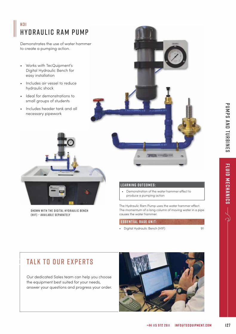
S h o w n w i t h t h e D i g i ta l H y d r a u l i c B e n c h
( H 1 F ) – ava i l abl e s e pa r at e ly
+ 4 4 1 1 5 9 7 2 2 6 1 1 I N F O @ T E C Q U I P M E N T. C O M 1 2 7
Fluid
Mec
ha
nic
sP
um
ps
an
d Tu
rb
ines
The Hydraulic Ram Pump uses the water hammer effect.
The momentum of a long column of moving water in a pipe
causes the water hammer.
• Digital Hydraulic Bench (H1F) 91
e s s e n t ial bas e u n i t:
H 3 1
H y d r a u l i c R a m P u m p
Demonstrates the use of water hammerto create a pumping action.
L E A R N I N G O U T C O M E S :
• Demonstration of the water hammer effect to
produce a pumping action
• Works with TecQuipment’s
Digital Hydraulic Bench for
easy installation
• Includes air vessel to reduce
hydraulic shock
• Ideal for demonstrations to
small groups of students
• Includes header tank and all
necessary pipework
tal k t o o u r e x p e r t s
Our dedicated Sales team can help you choose
the equipment best suited for your needs,
answer your questions and progress your order.
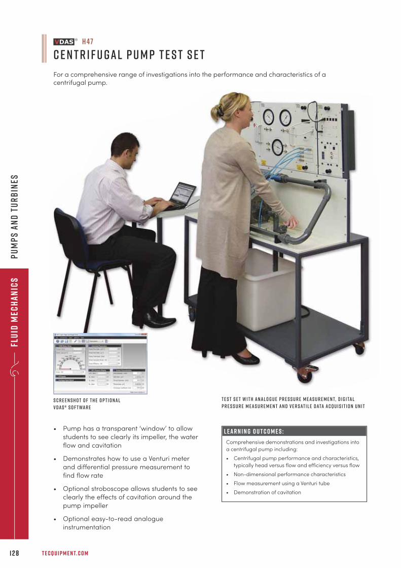
Flu
id M
ech
an
ics
T E C Q U I P M E N T. C O M1 2 8
Pu
mp
s a
nd
tu
rb
ines
• Pump has a transparent ‘window’ to allow
students to see clearly its impeller, the water
flow and cavitation
• Demonstrates how to use a Venturi meter
and differential pressure measurement to
find flow rate
• Optional stroboscope allows students to see
clearly the effects of cavitation around the
pump impeller
• Optional easy-to-read analogue
instrumentation
L E A R N I N G O U T C O M E S :
Comprehensive demonstrations and investigations into
a centrifugal pump including:
• Centrifugal pump performance and characteristics,
typically head versus flow and efficiency versus flow
• Non-dimensional performance characteristics
• Flow measurement using a Venturi tube
• Demonstration of cavitation
S c r e e n s h o t o f t h e o p t i o n a l
V D A S ® s o f t wa r e
T e s t S e t w i t h a n a l o g u e p r e s s u r e m e a s u r e m e n t, d i g i ta l
p r e s s u r e m e a s u r e m e n t a n d V e r s at i l e D ata A cqu i s i t i o n U n i t
H 4 7
C e n t r i f u g a l P u m p T e s t S e t
For a comprehensive range of investigations into the performance and characteristics of acentrifugal pump.
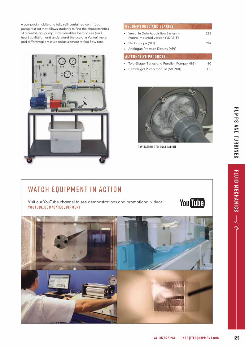
+ 4 4 1 1 5 9 7 2 2 6 1 1 I N F O @ T E C Q U I P M E N T. C O M 1 2 9
• Versatile Data Acquisition System – 293
Frame-mounted version (VDAS-F)
• Stroboscope (ST1) 297
• Analogue Pressure Display (AP1)
• Two-Stage (Series and Parallel) Pumps (H83) 130
• Centrifugal Pump Module (MFP101) 133
R E C O M M E N D E D AN C I L LAR I E S :
alt e r nat i v e p r o d u c t s :
A compact, mobile and fully self-contained centrifugal
pump test set that allows students to find the characteristics
of a centrifugal pump. It also enables them to see (and
hear) cavitation and understand the use of a Venturi meter
and differential pressure measurement to find flow rate.
C av i tat i o n d e m o n s t r at i o n
Fluid
Mec
ha
nic
sP
um
ps
an
d Tu
rb
ines
wat c h e q u i p m e n t i n ac t i o n
Visit our YouTube channel to see demonstrations and promotional videos:
y o u t ube . c o m / c / t e cqu i p m e n t
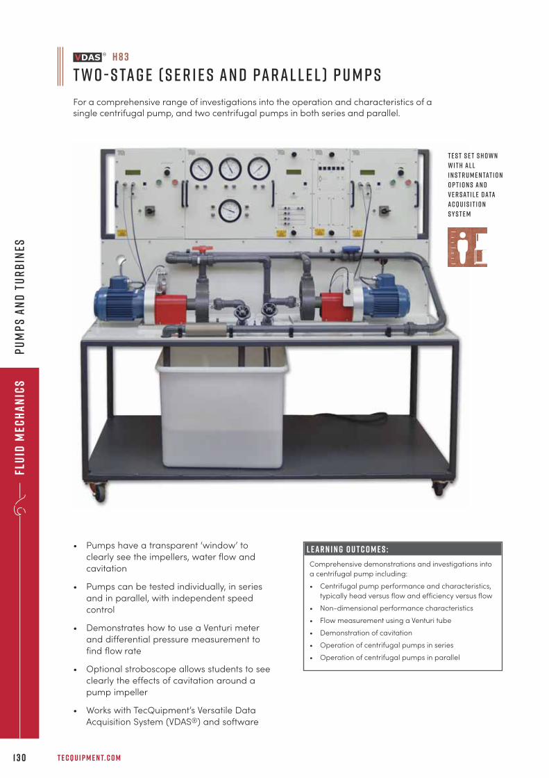
Flu
id M
ech
an
ics
T E C Q U I P M E N T. C O M1 3 0
Pu
mp
s a
nd
Tu
rb
ines
L E A R N I N G O U T C O M E S :
Comprehensive demonstrations and investigations into
a centrifugal pump including:
• Centrifugal pump performance and characteristics,
typically head versus flow and efficiency versus flow
• Non-dimensional performance characteristics
• Flow measurement using a Venturi tube
• Demonstration of cavitation
• Operation of centrifugal pumps in series
• Operation of centrifugal pumps in parallel
• Pumps have a transparent ‘window’ to
clearly see the impellers, water flow and
cavitation
• Pumps can be tested individually, in series
and in parallel, with independent speed
control
• Demonstrates how to use a Venturi meter
and differential pressure measurement to
find flow rate
• Optional stroboscope allows students to see
clearly the effects of cavitation around a
pump impeller
• Works with TecQuipment’s Versatile Data
Acquisition System (VDAS®) and software
H 8 3
T w o - S ta g e ( S e r i e s a n d Pa r a l l e l ) P u m p s
For a comprehensive range of investigations into the operation and characteristics of asingle centrifugal pump, and two centrifugal pumps in both series and parallel.
T e s t s e t s h o w n
w i t h a l l
i n s t r u m e n tat i o n
o p t i o n s a n d
V e r s at i l e D ata
A cqu i s i t i o n
S y s t e m
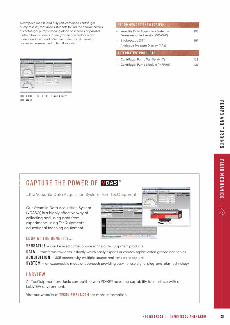
+ 4 4 1 1 5 9 7 2 2 6 1 1 I N F O @ T E C Q U I P M E N T. C O M 1 3 1
Fluid
Mec
ha
nic
sP
um
ps
an
d Tu
rb
ines
S c r e e n s h o t o f t h e o p t i o n a l V D A S ®
s o f t wa r e
A compact, mobile and fully self-contained centrifugal
pump test set, that allows students to find the characteristics
of centrifugal pumps working alone or in series or parallel.
It also allows students to see (and hear) cavitation and
understand the use of a Venturi meter and differential
pressure measurement to find flow rate.
• Versatile Data Acquisition System – 293
Frame-mounted version (VDAS-F)
• Stroboscope (ST1) 297
• Analogue Pressure Display (AP2)
• Centrifugal Pump Test Set (H47) 128
• Centrifugal Pump Module (MFP101) 133
R E C O M M E N D E D AN C I L LAR I E S :
alt e r nat i v e p r o d u c t s :
cap t u r e t h e p owe r o f
...the Versatile Data Acquisition System from TecQuipment
Our Versatile Data Acquisition System
(VDAS®) is a highly e�ective way of
collecting and using data from
experiments using TecQuipment’s
educational teaching equipment.
L O O K AT T H E BE N E F I T S . . .
v e r sat i l e – can be used across a wide range of TecQuipment products
data – transforms raw data instantly which easily exports or creates sophisticated graphs and tables
acqu i s i t i o n – USB connectivity, multiple-source real-time data capture
s y s t e m – an expandable modular approach providing easy-to-use digital plug-and-play technology
labv i e wAll TecQuipment products compatible with VDAS® have the capability to interface with a
LabVIEW environment.
Visit our website at t e cqu i p m e n t. c o m for more information.
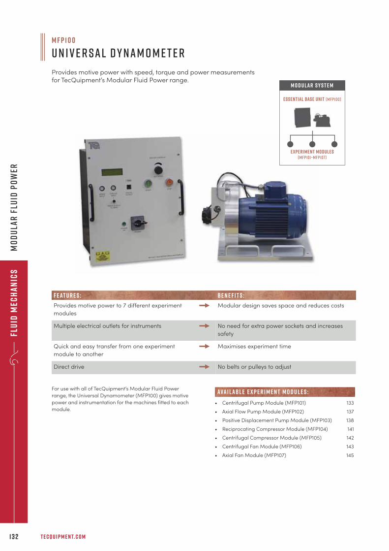
Flu
id M
ech
an
ics
T E C Q U I P M E N T. C O M1 3 2
Mo
du
lar
Flu
id P
ow
er
For use with all of TecQuipment’s Modular Fluid Power
range, the Universal Dynamometer (MFP100) gives motive
power and instrumentation for the machines fitted to each
module.
M F P 1 0 0
U n i v e r s a l D y n a m o m e t e r
Provides motive power with speed, torque and power measurementsfor TecQuipment’s Modular Fluid Power range.
Experiment modules(mfp101–mfp107)
Essential Base Unit (mfp100)
M O D U LAR S Y S T E M
• Centrifugal Pump Module (MFP101) 133
• Axial Flow Pump Module (MFP102) 137
• Positive Displacement Pump Module (MFP103) 138
• Reciprocating Compressor Module (MFP104) 141
• Centrifugal Compressor Module (MFP105) 142
• Centrifugal Fan Module (MFP106) 143
• Axial Fan Module (MFP107) 145
ava i labl e e x p e r i m e n t m o d u l e s :
F E AT U R E S : B E N E F I T S :
Provides motive power to 7 different experiment
modules
Modular design saves space and reduces costs
Multiple electrical outlets for instruments No need for extra power sockets and increases
safety
Quick and easy transfer from one experiment
module to another
Maximises experiment time
Direct drive No belts or pulleys to adjust
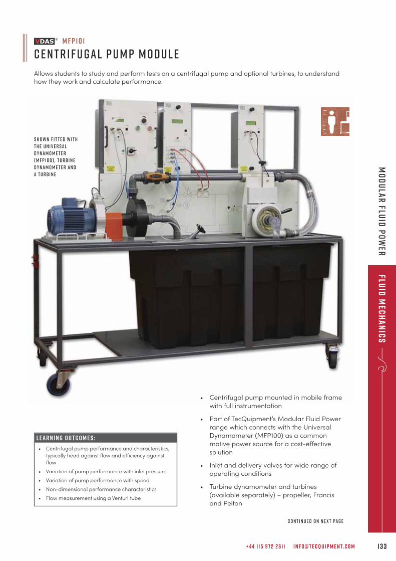
+ 4 4 1 1 5 9 7 2 2 6 1 1 I N F O @ T E C Q U I P M E N T. C O M 1 3 3
Fluid
Mec
ha
nic
sM
od
ula
r Flu
id P
ow
er
L E A R N I N G O U T C O M E S :
• Centrifugal pump performance and characteristics,
typically head against flow and efficiency against
flow
• Variation of pump performance with inlet pressure
• Variation of pump performance with speed
• Non-dimensional performance characteristics
• Flow measurement using a Venturi tube
M F P 1 0 1
C e n t r i f u g a l P u m p M o d u l e
Allows students to study and perform tests on a centrifugal pump and optional turbines, to understandhow they work and calculate performance.
S h o w n f i t t e d w i t h
t h e U n i v e r s a l
D y n a m o m e t e r
( M F P 1 0 0 ) , t u rb i n e
d y n a m o m e t e r a n d
a t u rb i n e
• Centrifugal pump mounted in mobile frame
with full instrumentation
• Part of TecQuipment’s Modular Fluid Power
range which connects with the Universal
Dynamometer (MFP100) as a common
motive power source for a cost-effective
solution
• Inlet and delivery valves for wide range of
operating conditions
• Turbine dynamometer and turbines
(available separately) – propeller, Francis
and Pelton
C o n t i n u e d o n n e x t pa g e
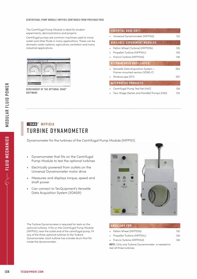
Flu
id M
ech
an
ics
T E C Q U I P M E N T. C O M1 3 4
Mo
du
lar
Flu
id P
ow
er
S c r e e n s h o t o f t h e o p t i o n a l V D A S ®
s o f t wa r e
The Centrifugal Pump Module is ideal for student
experiments, demonstrations and projects.
Centrifugal pumps are common machines used to move
water and other fluids in many applications. These can be
domestic water systems, agriculture, sanitation and many
industrial applications.
• Universal Dynamometer (MFP100) 132
• Pelton Wheel (Turbine) (MFP101b) 135
• Propeller Turbine (MFP101c) 136
• Francis Turbine (MFP101d) 136
• Versatile Data Acquisition System – 293
Frame-mounted version (VDAS-F)
• Stroboscope (ST1) 297
• Centrifugal Pump Test Set (H47) 128
• Two-Stage (Series and Parallel) Pumps (H83) 130
ava i labl e e x p e r i m e n t m o d u l e s :
R E C O M M E N D E D AN C I L LAR I E S :
alt e r nat i v e p r o d u c t s :
e s s e n t ial bas e u n i t:
M F P 1 0 1 a
T u rb i n e D y n a m o m e t e r
Dynamometer for the turbines of the Centrifugal Pump Module (MFP101).
• Dynamometer that fits on the Centrifugal
Pump Module to test the optional turbines
• Electrically powered from outlets on the
Universal Dynamometer motor drive
• Measures and displays torque, speed and
shaft power
• Can connect to TecQuipment’s Versatile
Data Acquisition System (VDAS®)
The Turbine Dynamometer is required for tests on the
optional turbines. It fits on the Centrifugal Pump Module
(MFP101), near the outlet end of the centrifugal pump. Fit
any of the three optional turbines to the Turbine
Dynamometer. Each turbine has a brake drum that fits
inside the dynamometer.
• Pelton Wheel (MFP101b) 135
• Propeller Turbine (MFP101c) 136
• Francis Turbine (MFP101d) 136
N o t e : Only one Turbine Dynamometer is needed to
test all three turbines.
AN C I L LAR Y F O R :
c e n t r i f u g a l p u m p m o d u l e ( M F P 1 0 1 ) c o n t i n u e d f r o m p r e v i o u s pa g e
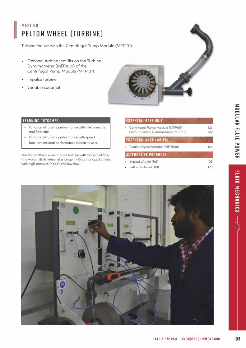
+ 4 4 1 1 5 9 7 2 2 6 1 1 I N F O @ T E C Q U I P M E N T. C O M 1 3 5
Fluid
Mec
ha
nic
sM
od
ula
r Flu
id P
ow
er
M F P 1 0 1 b
P e lt o n W h e e l ( T u rb i n e )
Turbine for use with the Centrifugal Pump Module (MFP101).
• Optional turbine that fits on the Turbine
Dynamometer (MFP101a) of the
Centrifugal Pump Module (MFP101)
• Impulse turbine
• Variable spear jet
L E A R N I N G O U T C O M E S :
• Variation of turbine performance with inlet pressure
and flow rate
• Variation of turbine performance with speed
• Non-dimensional performance characteristics
The Pelton Wheel is an impulse turbine with tangential flow
(the water hits its wheel at a tangent). Good for applications
with high pressure (head) and low flow.
• Centrifugal Pump Module (MFP101) 133
(with Universal Dynamometer MFP100) 132
• Turbine Dynamometer (MFP101a) 134
• Impact of a Jet (H8) 106
• Pelton Turbine (H19) 126
e s s e n t ial bas e u n i t:
E S S E N T IAL AN C I L LAR I E S :
alt e r nat i v e p r o d u c t s :
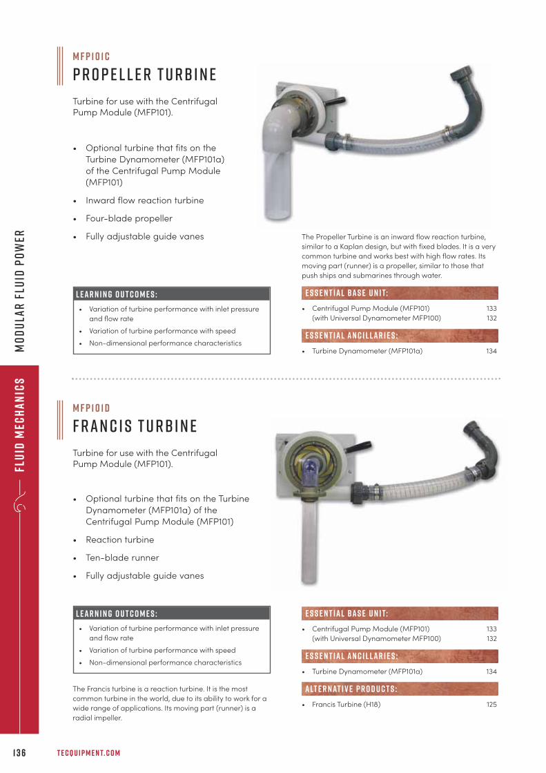
Flu
id M
ech
an
ics
T E C Q U I P M E N T. C O M1 3 6
Mo
du
lar
Flu
id P
ow
er
M F P 1 0 1 d
F r a n c i s T u rb i n e
Turbine for use with the CentrifugalPump Module (MFP101).
• Optional turbine that fits on the Turbine
Dynamometer (MFP101a) of the
Centrifugal Pump Module (MFP101)
• Reaction turbine
• Ten-blade runner
• Fully adjustable guide vanes
The Francis turbine is a reaction turbine. It is the most
common turbine in the world, due to its ability to work for a
wide range of applications. Its moving part (runner) is a
radial impeller.
• Centrifugal Pump Module (MFP101) 133
(with Universal Dynamometer MFP100) 132
• Turbine Dynamometer (MFP101a) 134
• Francis Turbine (H18) 125
e s s e n t ial bas e u n i t:
E S S E N T IAL AN C I L LAR I E S :
alt e r nat i v e p r o d u c t s :
L E A R N I N G O U T C O M E S :
• Variation of turbine performance with inlet pressure
and flow rate
• Variation of turbine performance with speed
• Non-dimensional performance characteristics
M F P 1 0 1 c
P r o p e l l e r T u rb i n e
Turbine for use with the CentrifugalPump Module (MFP101).
• Optional turbine that fits on the
Turbine Dynamometer (MFP101a)
of the Centrifugal Pump Module
(MFP101)
• Inward flow reaction turbine
• Four-blade propeller
• Fully adjustable guide vanes The Propeller Turbine is an inward flow reaction turbine,
similar to a Kaplan design, but with fixed blades. It is a very
common turbine and works best with high flow rates. Its
moving part (runner) is a propeller, similar to those that
push ships and submarines through water.
• Centrifugal Pump Module (MFP101) 133
(with Universal Dynamometer MFP100) 132
• Turbine Dynamometer (MFP101a) 134
e s s e n t ial bas e u n i t:
E S S E N T IAL AN C I L LAR I E S :
L E A R N I N G O U T C O M E S :
• Variation of turbine performance with inlet pressure
and flow rate
• Variation of turbine performance with speed
• Non-dimensional performance characteristics
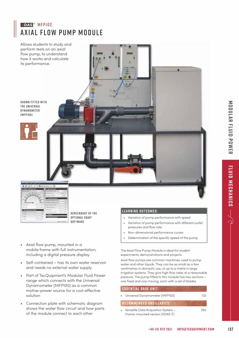
+ 4 4 1 1 5 9 7 2 2 6 1 1 I N F O @ T E C Q U I P M E N T. C O M 1 3 7
Fluid
Mec
ha
nic
sM
od
ula
r Flu
id P
ow
er
The Axial Flow Pump Module is ideal for student
experiments, demonstrations and projects.
Axial flow pumps are common machines, used to pump
water and other liquids. They can be as small as a few
centimetres in domestic use, or up to a metre in large
irrigation systems. They give high flow rates at a reasonable
pressure. The pump fitted to this module has two sections –
one fixed and one moving, each with a set of blades.
• Universal Dynamometer (MFP100) 132
• Versatile Data Acquisition System – 293
Frame-mounted version (VDAS-F)
e s s e n t ial bas e u n i t:
R E C O M M E N D E D AN C I L LAR I E S :
• Axial flow pump, mounted in a
mobile frame with full instrumentation,
including a digital pressure display
• Self-contained – has its own water reservoir
and needs no external water supply
• Part of TecQuipment’s Modular Fluid Power
range which connects with the Universal
Dynamometer (MFP100) as a common
motive-power source for a cost-effective
solution
• Connection plate with schematic diagram
shows the water flow circuit and how parts
of the module connect to each other
M F P 1 0 2
A x i a l F l o w P u m p M o d u l e
Allows students to study andperform tests on an axialflow pump, to understandhow it works and calculateits performance.
S c r e e n s h o t o f t h e
o p t i o n a l V D A S ®
s o f t wa r e
S h o w n f i t t e d w i t h
t h e U n i v e r s a l
D y n a m o m e t e r
( M F P 1 0 0 )
L E A R N I N G O U T C O M E S :
• Variation of pump performance with speed
• Variation of pump performance with different outlet
pressures and flow rate
• Non-dimensional performance curves
• Determination of the specific speed of the pump
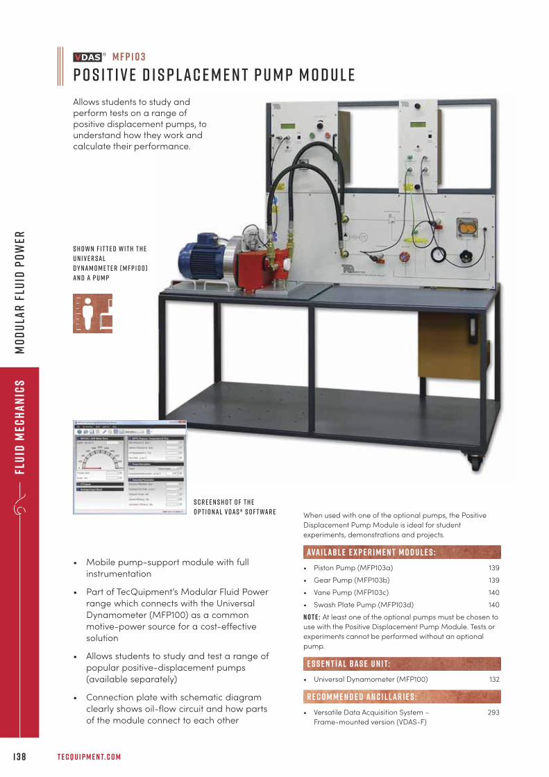
Flu
id M
ech
an
ics
T E C Q U I P M E N T. C O M1 3 8
Mo
du
lar
Flu
id P
ow
er
• Mobile pump-support module with full
instrumentation
• Part of TecQuipment’s Modular Fluid Power
range which connects with the Universal
Dynamometer (MFP100) as a common
motive-power source for a cost-effective
solution
• Allows students to study and test a range of
popular positive-displacement pumps
(available separately)
• Connection plate with schematic diagram
clearly shows oil-flow circuit and how parts
of the module connect to each other
When used with one of the optional pumps, the Positive
Displacement Pump Module is ideal for student
experiments, demonstrations and projects.
• Piston Pump (MFP103a) 139
• Gear Pump (MFP103b) 139
• Vane Pump (MFP103c) 140
• Swash Plate Pump (MFP103d) 140
N o t e : At least one of the optional pumps must be chosen to
use with the Positive Displacement Pump Module. Tests or
experiments cannot be performed without an optional
pump.
• Universal Dynamometer (MFP100) 132
• Versatile Data Acquisition System – 293
Frame-mounted version (VDAS-F)
e s s e n t ial bas e u n i t:
R E C O M M E N D E D AN C I L LAR I E S :
ava i labl e e x p e r i m e n t m o d u l e s :
M F P 1 0 3
P o s i t i v e D i s p l a c e m e n t P u m p M o d u l e
Allows students to study andperform tests on a range ofpositive displacement pumps, tounderstand how they work andcalculate their performance.
S c r e e n s h o t o f t h e
o p t i o n a l V D A S ® s o f t wa r e
S h o w n f i t t e d w i t h t h e
U n i v e r s a l
D y n a m o m e t e r ( M F P 1 0 0 )
a n d a p u m p
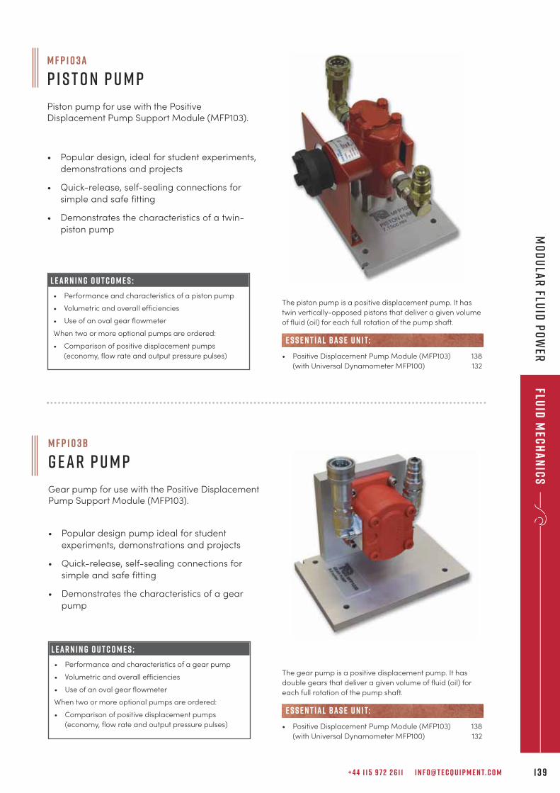
+ 4 4 1 1 5 9 7 2 2 6 1 1 I N F O @ T E C Q U I P M E N T. C O M 1 3 9
Fluid
Mec
ha
nic
sM
od
ula
r Flu
id P
ow
er
M F P 1 0 3 a
P i s t o n P u m p
Piston pump for use with the PositiveDisplacement Pump Support Module (MFP103).
• Popular design, ideal for student experiments,
demonstrations and projects
• Quick-release, self-sealing connections for
simple and safe fitting
• Demonstrates the characteristics of a twin-
piston pump
L E A R N I N G O U T C O M E S :
• Performance and characteristics of a piston pump
• Volumetric and overall efficiencies
• Use of an oval gear flowmeter
When two or more optional pumps are ordered:
• Comparison of positive displacement pumps
(economy, flow rate and output pressure pulses)
The piston pump is a positive displacement pump. It has
twin vertically-opposed pistons that deliver a given volume
of fluid (oil) for each full rotation of the pump shaft.
• Positive Displacement Pump Module (MFP103) 138
(with Universal Dynamometer MFP100) 132
e s s e n t ial bas e u n i t:
M F P 1 0 3 b
G e a r P u m p
Gear pump for use with the Positive DisplacementPump Support Module (MFP103).
• Popular design pump ideal for student
experiments, demonstrations and projects
• Quick-release, self-sealing connections for
simple and safe fitting
• Demonstrates the characteristics of a gear
pump
L E A R N I N G O U T C O M E S :
• Performance and characteristics of a gear pump
• Volumetric and overall efficiencies
• Use of an oval gear flowmeter
When two or more optional pumps are ordered:
• Comparison of positive displacement pumps
(economy, flow rate and output pressure pulses)
The gear pump is a positive displacement pump. It has
double gears that deliver a given volume of fluid (oil) for
each full rotation of the pump shaft.
• Positive Displacement Pump Module (MFP103) 138
(with Universal Dynamometer MFP100) 132
e s s e n t ial bas e u n i t:
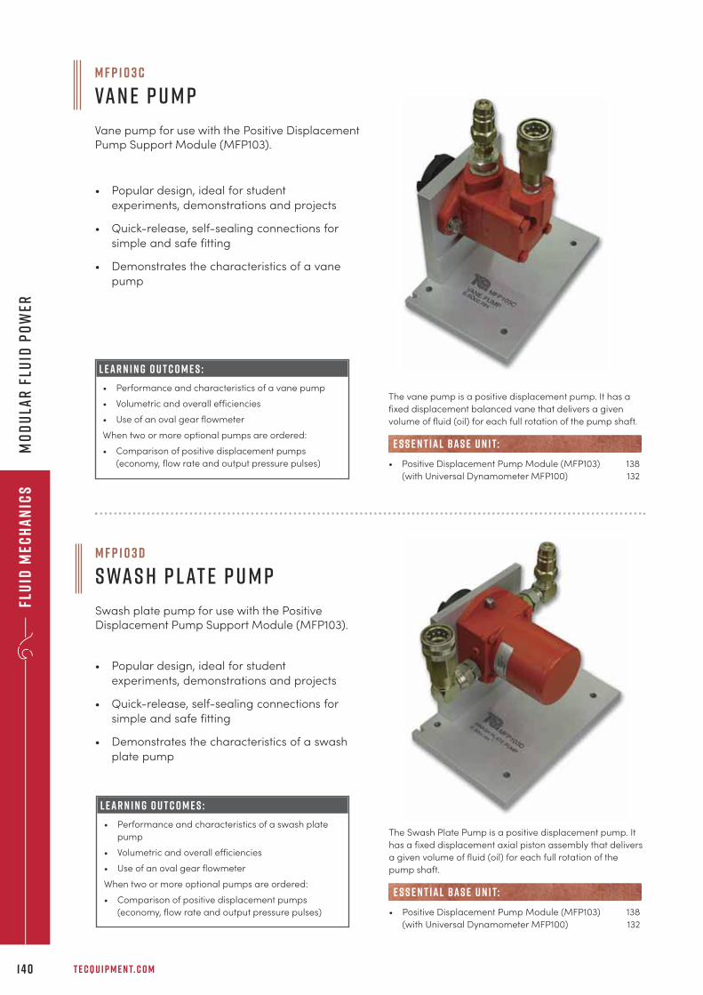
M F P 1 0 3 c
Va n e P u m p
Vane pump for use with the Positive DisplacementPump Support Module (MFP103).
• Popular design, ideal for student
experiments, demonstrations and projects
• Quick-release, self-sealing connections for
simple and safe fitting
• Demonstrates the characteristics of a vane
pump
L E A R N I N G O U T C O M E S :
• Performance and characteristics of a vane pump
• Volumetric and overall efficiencies
• Use of an oval gear flowmeter
When two or more optional pumps are ordered:
• Comparison of positive displacement pumps
(economy, flow rate and output pressure pulses)
The vane pump is a positive displacement pump. It has a
fixed displacement balanced vane that delivers a given
volume of fluid (oil) for each full rotation of the pump shaft.
• Positive Displacement Pump Module (MFP103) 138
(with Universal Dynamometer MFP100) 132
e s s e n t ial bas e u n i t:
• Popular design, ideal for student
experiments, demonstrations and projects
• Quick-release, self-sealing connections for
simple and safe fitting
• Demonstrates the characteristics of a swash
plate pump
L E A R N I N G O U T C O M E S :
• Performance and characteristics of a swash plate
pump
• Volumetric and overall efficiencies
• Use of an oval gear flowmeter
When two or more optional pumps are ordered:
• Comparison of positive displacement pumps
(economy, flow rate and output pressure pulses)
The Swash Plate Pump is a positive displacement pump. It
has a fixed displacement axial piston assembly that delivers
a given volume of fluid (oil) for each full rotation of the
pump shaft.
• Positive Displacement Pump Module (MFP103) 138
(with Universal Dynamometer MFP100) 132
e s s e n t ial bas e u n i t:
Flu
id M
ech
an
ics
T E C Q U I P M E N T. C O M1 4 0
Mo
du
lar
Flu
id P
ow
er
M F P 1 0 3 d
s wa s h p l at e P u m p
Swash plate pump for use with the PositiveDisplacement Pump Support Module (MFP103).
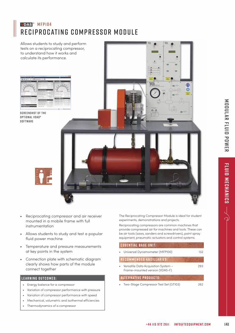
+ 4 4 1 1 5 9 7 2 2 6 1 1 I N F O @ T E C Q U I P M E N T. C O M 1 4 1
Fluid
Mec
ha
nic
sM
od
ula
r Flu
id P
ow
er
• Reciprocating compressor and air receiver
mounted in a mobile frame with full
instrumentation
• Allows students to study and test a popular
fluid power machine
• Temperature and pressure measurements
at key points in the system
• Connection plate with schematic diagram
clearly shows how parts of the module
connect together
L E A R N I N G O U T C O M E S :
• Energy balance for a compressor
• Variation of compressor performance with pressure
• Variation of compressor performance with speed
• Mechanical, volumetric and isothermal efficiencies
• Thermodynamics of a compressor
M F P 1 0 4
R e c i p r o c at i n g C o m p r e s s o r M o d u l e
Allows students to study and performtests on a reciprocating compressor,to understand how it works andcalculate its performance.
S c r e e n s h o t o f t h e
o p t i o n a l V D A S ®
s o f t wa r e
The Reciprocating Compressor Module is ideal for student
experiments, demonstrations and projects.
Reciprocating compressors are common machines that
provide compressed air for machines and tools. These can
be air tools (saws, sanders and screwdrivers), paint spray
equipment, pneumatic actuators and control systems.
• Universal Dynamometer (MFP100) 132
• Versatile Data Acquisition System – 293
Frame-mounted version (VDAS-F)
• Two-Stage Compressor Test Set (GT103) 262
e s s e n t ial bas e u n i t:
R E C O M M E N D E D AN C I L LAR I E S :
alt e r nat i v e p r o d u c t s :
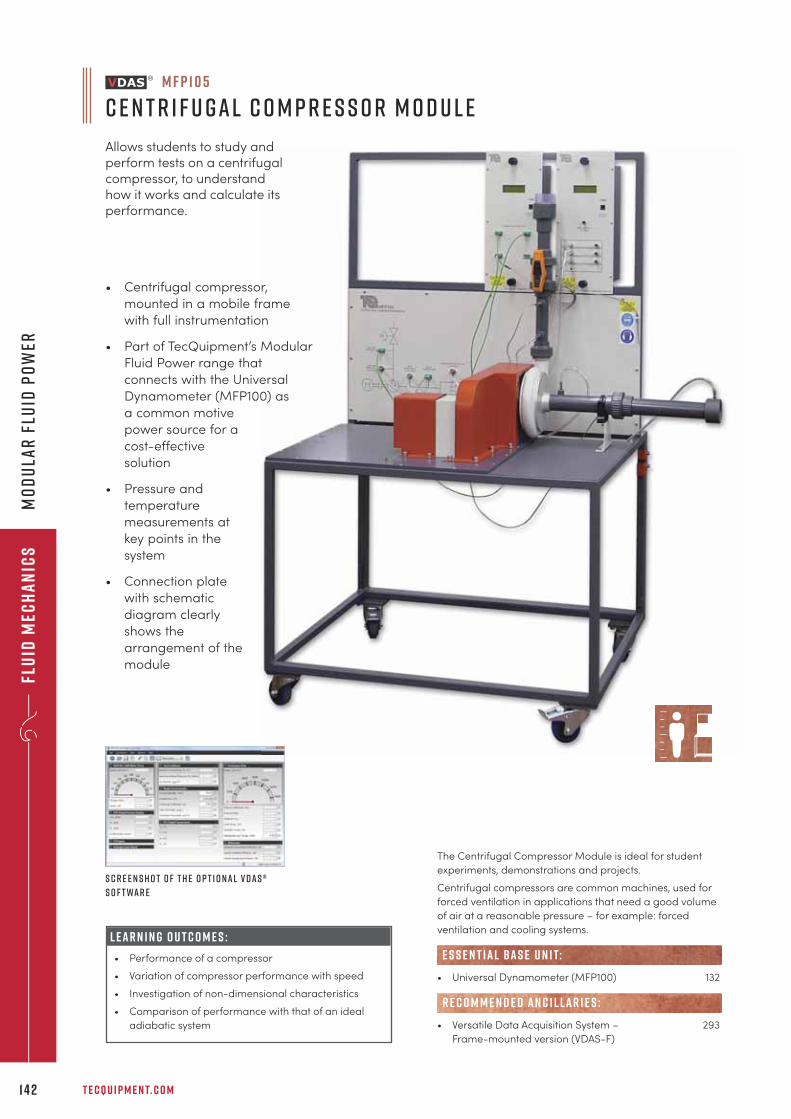
Flu
id M
ech
an
ics
T E C Q U I P M E N T. C O M1 4 2
Mo
du
lar
Flu
id P
ow
er
• Centrifugal compressor,
mounted in a mobile frame
with full instrumentation
• Part of TecQuipment’s Modular
Fluid Power range that
connects with the Universal
Dynamometer (MFP100) as
a common motive
power source for a
cost-effective
solution
• Pressure and
temperature
measurements at
key points in the
system
• Connection plate
with schematic
diagram clearly
shows the
arrangement of the
module
M F P 1 0 5
C e n t r i f u g a l C o m p r e s s o r M o d u l e
Allows students to study andperform tests on a centrifugalcompressor, to understandhow it works and calculate itsperformance.
S c r e e n s h o t o f t h e o p t i o n a l V D A S ®
s o f t wa r e
The Centrifugal Compressor Module is ideal for student
experiments, demonstrations and projects.
Centrifugal compressors are common machines, used for
forced ventilation in applications that need a good volume
of air at a reasonable pressure – for example: forced
ventilation and cooling systems.
• Universal Dynamometer (MFP100) 132
• Versatile Data Acquisition System – 293
Frame-mounted version (VDAS-F)
R E C O M M E N D E D AN C I L LAR I E S :
e s s e n t ial bas e u n i t:
L E A R N I N G O U T C O M E S :
• Performance of a compressor
• Variation of compressor performance with speed
• Investigation of non-dimensional characteristics
• Comparison of performance with that of an ideal
adiabatic system
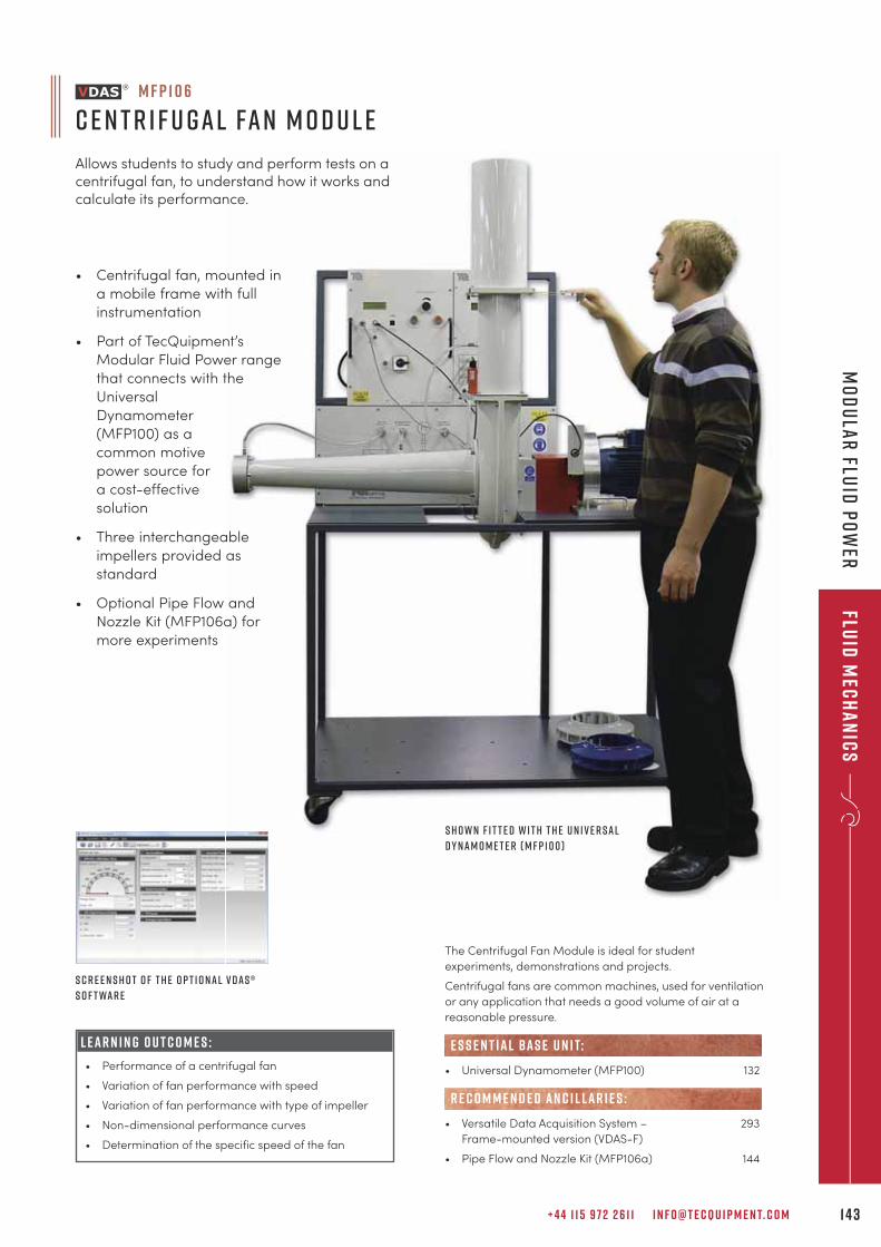
+ 4 4 1 1 5 9 7 2 2 6 1 1 I N F O @ T E C Q U I P M E N T. C O M 1 4 3
Fluid
Mec
ha
nic
sM
od
ula
r Flu
id P
ow
er
L E A R N I N G O U T C O M E S :
• Performance of a centrifugal fan
• Variation of fan performance with speed
• Variation of fan performance with type of impeller
• Non-dimensional performance curves
• Determination of the specific speed of the fan
M F P 1 0 6
C e n t r i f u g a l Fa n M o d u l e
Allows students to study and perform tests on acentrifugal fan, to understand how it works andcalculate its performance.
The Centrifugal Fan Module is ideal for student
experiments, demonstrations and projects.
Centrifugal fans are common machines, used for ventilation
or any application that needs a good volume of air at a
reasonable pressure.
• Universal Dynamometer (MFP100) 132
• Versatile Data Acquisition System – 293
Frame-mounted version (VDAS-F)
• Pipe Flow and Nozzle Kit (MFP106a) 144
R E C O M M E N D E D AN C I L LAR I E S :
e s s e n t ial bas e u n i t:
• Centrifugal fan, mounted in
a mobile frame with full
instrumentation
• Part of TecQuipment’s
Modular Fluid Power range
that connects with the
Universal
Dynamometer
(MFP100) as a
common motive
power source for
a cost-effective
solution
• Three interchangeable
impellers provided as
standard
• Optional Pipe Flow and
Nozzle Kit (MFP106a) for
more experiments
S h o w n f i t t e d w i t h t h e U n i v e r s a l
D y n a m o m e t e r ( M F P 1 0 0 )
S c r e e n s h o t o f t h e o p t i o n a l V D A S ®
s o f t wa r e
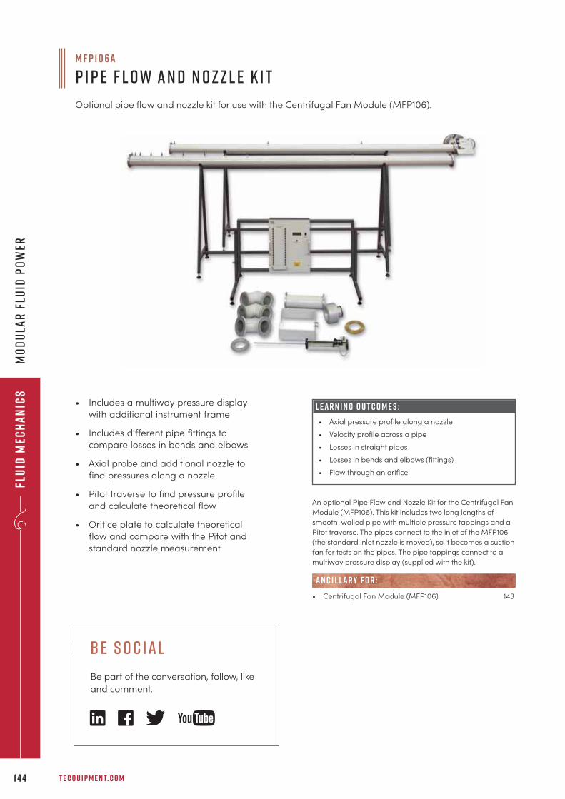
Flu
id M
ech
an
ics
T E C Q U I P M E N T. C O M1 4 4
Mo
du
lar
Flu
id P
ow
er
• Includes a multiway pressure display
with additional instrument frame
• Includes different pipe fittings to
compare losses in bends and elbows
• Axial probe and additional nozzle to
find pressures along a nozzle
• Pitot traverse to find pressure profile
and calculate theoretical flow
• Orifice plate to calculate theoretical
flow and compare with the Pitot and
standard nozzle measurement
L E A R N I N G O U T C O M E S :
• Axial pressure profile along a nozzle
• Velocity profile across a pipe
• Losses in straight pipes
• Losses in bends and elbows (fittings)
• Flow through an orifice
An optional Pipe Flow and Nozzle Kit for the Centrifugal Fan
Module (MFP106). This kit includes two long lengths of
smooth-walled pipe with multiple pressure tappings and a
Pitot traverse. The pipes connect to the inlet of the MFP106
(the standard inlet nozzle is moved), so it becomes a suction
fan for tests on the pipes. The pipe tappings connect to a
multiway pressure display (supplied with the kit).
• Centrifugal Fan Module (MFP106) 143
AN C I L LAR Y F O R :
M F P 1 0 6 a
P i p e F l o w a n d N o z z l e K i t
Optional pipe flow and nozzle kit for use with the Centrifugal Fan Module (MFP106).
b e s o c ial
Be part of the conversation, follow, like
and comment.
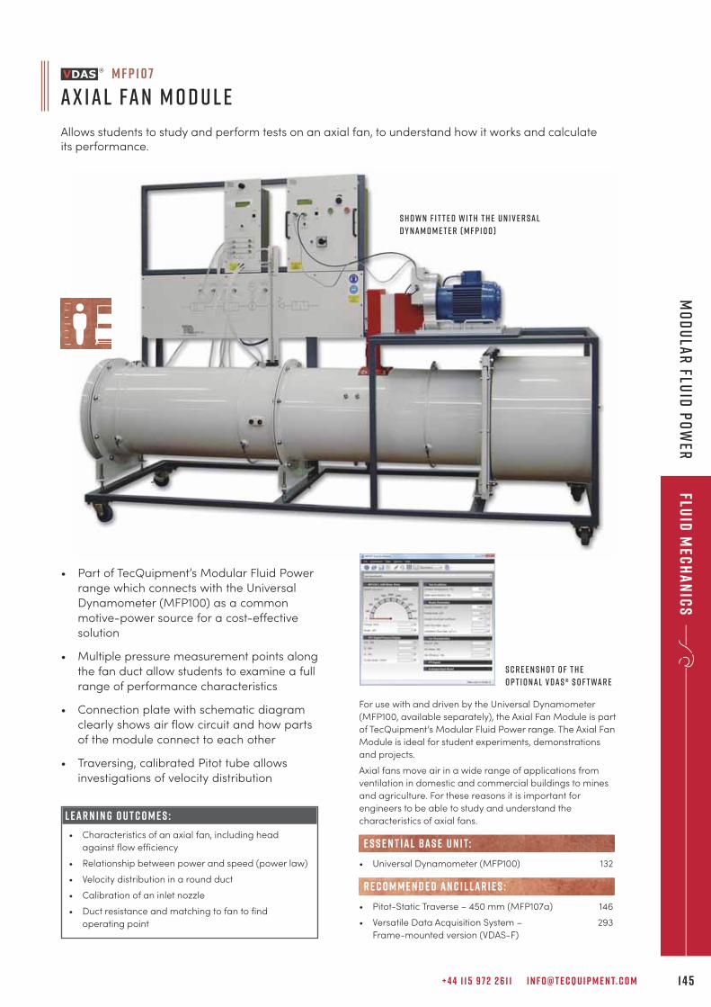
+ 4 4 1 1 5 9 7 2 2 6 1 1 I N F O @ T E C Q U I P M E N T. C O M 1 4 5
Fluid
Mec
ha
nic
sM
od
ula
r Flu
id P
ow
er
L E A R N I N G O U T C O M E S :
• Characteristics of an axial fan, including head
against flow efficiency
• Relationship between power and speed (power law)
• Velocity distribution in a round duct
• Calibration of an inlet nozzle
• Duct resistance and matching to fan to find
operating point
M F P 1 0 7
A x i a l Fa n M o d u l e
Allows students to study and perform tests on an axial fan, to understand how it works and calculateits performance.
S c r e e n s h o t o f t h e
o p t i o n a l V D A S ® s o f t wa r e
For use with and driven by the Universal Dynamometer
(MFP100, available separately), the Axial Fan Module is part
of TecQuipment’s Modular Fluid Power range. The Axial Fan
Module is ideal for student experiments, demonstrations
and projects.
Axial fans move air in a wide range of applications from
ventilation in domestic and commercial buildings to mines
and agriculture. For these reasons it is important for
engineers to be able to study and understand the
characteristics of axial fans.
• Universal Dynamometer (MFP100) 132
• Pitot-Static Traverse – 450 mm (MFP107a) 146
• Versatile Data Acquisition System – 293
Frame-mounted version (VDAS-F)
e s s e n t ial bas e u n i t:
R E C O M M E N D E D AN C I L LAR I E S :
S h o w n f i t t e d w i t h t h e U n i v e r s a l
D y n a m o m e t e r ( M F P 1 0 0 )
• Part of TecQuipment’s Modular Fluid Power
range which connects with the Universal
Dynamometer (MFP100) as a common
motive-power source for a cost-effective
solution
• Multiple pressure measurement points along
the fan duct allow students to examine a full
range of performance characteristics
• Connection plate with schematic diagram
clearly shows air flow circuit and how parts
of the module connect to each other
• Traversing, calibrated Pitot tube allows
investigations of velocity distribution
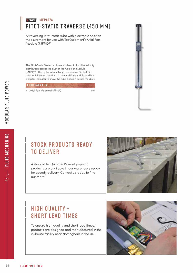
Flu
id M
ech
an
ics
T E C Q U I P M E N T. C O M1 4 6
Mo
du
lar
Flu
id P
ow
er
The Pitot-Static Traverse allows students to find the velocity
distribution across the duct of the Axial Fan Module
(MFP107). This optional ancillary comprises a Pitot-static
tube which fits on the duct of the Axial Fan Module and has
a digital indicator to show the tube position across the duct.
• Axial Fan Module (MFP107) 145
AN C I L LAR Y F O R :
M F P 1 0 7a
P i t o t- S tat i c T r av e r s e (4 5 0 m m )
A traversing Pitot-static tube with electronic positionmeasurement for use with TecQuipment’s Axial FanModule (MFP107)
H i g h Q ual i t y - S h o r t L ead T i m e s
To ensure high quality and short lead times,
products are designed and manufactured in the
in-house facility near Nottingham in the UK.
S t o c k P r o d u c t s R ead y t o D e l i v e r
A stock of TecQuipment's most popular
products are available in our warehouse ready
for speedy delivery. Contact us today to find
out more.
+ 4 4 1 1 5 9 7 2 2 6 1 1 I N F O @ T E C Q U I P M E N T. C O M 1 47
Mater
ials
testin
g a
nd
pr
op
erties
“The university community has been deriving optimal educational benefits from the use ofTecQuipment teaching aids. Latest technology of high quality with robustness, durability,environment-friendly and diverse experiment facilities, the TecQuipment products play asignificant role in ensuring ‘ease of transfer of technology’.
p r o f e s s o r m a l i m u l l a h m i ya ni n t e r n at i o n a l u n i v e r s i t y o f b u s i n e s s a g r i c u lt u r e a n d t e c h n o l o g y, b a n g l a d e s h
m a t e r i a l s t e s t i n g
a n d p r o p e r t i e sb a s i c e l a s t i c p r o p e r t i e s 1 4 9
s t r e s s a n d s t r a i n a n a ly s i s 1 5 1
t o r s i o n t e s t i n g 1 5 7
fat i g u e t e s t i n g 1 5 8
c r e e p t e s t i n g 1 5 9
t e n s i l e a n d u n i v e r s a l t e s t i n g m a c h i n e s 1 6 0
i m pa c t t e s t i n g 1 6 6
i n d u s t r i a l h a r d n e s s t e s t e r s 1 6 7
t e s t s p e c i m e n s 1 7 0
f r e e - s ta n d i n g s t r u c t u r e s e x p e r i m e n t s 1 7 2
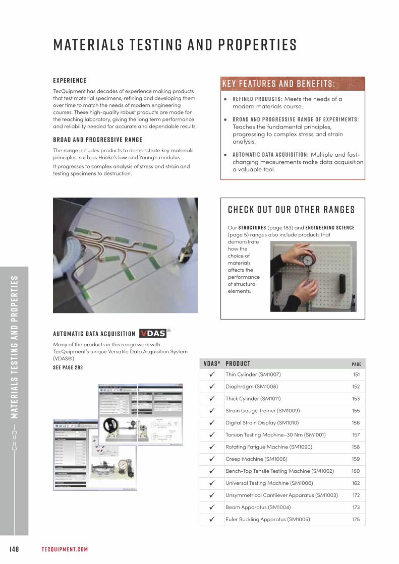
Mat
eria
ls t
esti
ng
an
d p
ro
per
ties
T E C Q U I P M E N T. C O M1 4 8
m at e r i a l s t e s t i n g a n d p r o p e r t i e s
e x p e r i e n c e
TecQuipment has decades of experience making products
that test material specimens, refining and developing them
over time to match the needs of modern engineering
courses. These high-quality robust products are made for
the teaching laboratory, giving the long term performance
and reliability needed for accurate and dependable results.
b r o a d a n d p r o g r e s s i v e r a n g e
The range includes products to demonstrate key materials
principles, such as Hooke’s law and Young’s modulus.
It progresses to complex analysis of stress and strain and
testing specimens to destruction.
c h e c k o u t o u r o t h e r r a n g e s
Our S t r u c t u r e s (page 183) and E n g i n e e r i n g S c i e n c e
(page 5) ranges also include products that
demonstrate
how the
choice of
materials
affects the
performance
of structural
elements.
P r o d u c t Pa g e
Thin Cylinder (SM1007) 151
Diaphragm (SM1008) 152
Thick Cylinder (SM1011) 153
Strain Gauge Trainer (SM1009) 155
Digital Strain Display (SM1010) 156
Torsion Testing Machine–30 Nm (SM1001) 157
Rotating Fatigue Machine (SM1090) 158
Creep Machine (SM1006) 159
Bench-Top Tensile Testing Machine (SM1002) 160
Universal Testing Machine (SM1000) 162
Unsymmetrical Cantilever Apparatus (SM1003) 172
Beam Apparatus (SM1004) 173
Euler Buckling Apparatus (SM1005) 175
V D A S ®
ü
ü
ü
ü
ü
ü
ü
ü
ü
ü
ü
ü
ü
A u t o m at i c d ata a c q u i s i t i o n
Many of the products in this range work with
TecQuipment’s unique Versatile Data Acquisition System
(VDAS®).
S e e pa g e 2 9 3
• r e f i n e d p r o d u c t s : Meets the needs of a
modern materials course..
• b r o a d a n d p r o g r e s s i v e r a n g e o f e x p e r i m e n t s :Teaches the fundamental principles,
progressing to complex stress and strain
analysis.
• a u t o m at i c d ata a c q u i s i t i o n : Multiple and fast-
changing measurements make data acquisition
a valuable tool.
k e y f eat u r e s an d be n e f i t s :
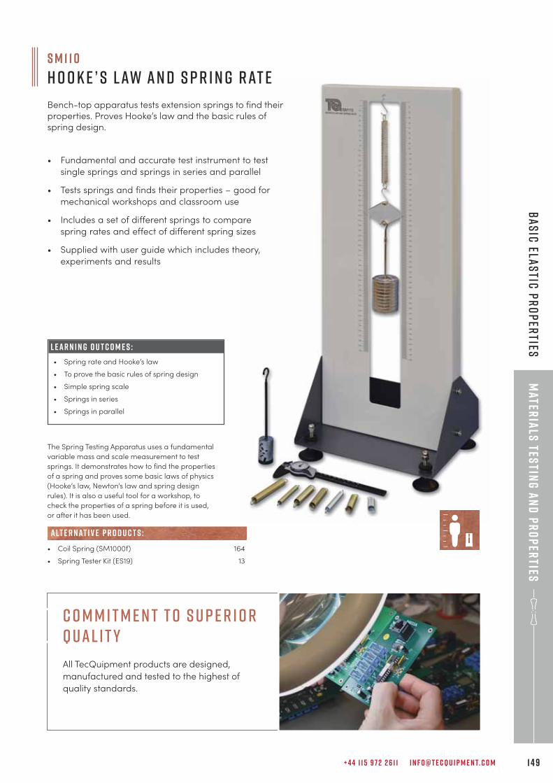
+ 4 4 1 1 5 9 7 2 2 6 1 1 I N F O @ T E C Q U I P M E N T. C O M 1 4 9
Mater
ials
testin
g a
nd
pr
op
erties
Ba
sic
elas
tic p
ro
per
ties
S M 1 1 0
H o o k e ’ s L aw a n d S p r i n g R at e
Bench-top apparatus tests extension springs to find theirproperties. Proves Hooke’s law and the basic rules ofspring design.
L E A R N I N G O U T C O M E S :
• Spring rate and Hooke’s law
• To prove the basic rules of spring design
• Simple spring scale
• Springs in series
• Springs in parallel
The Spring Testing Apparatus uses a fundamental
variable mass and scale measurement to test
springs. It demonstrates how to find the properties
of a spring and proves some basic laws of physics
(Hooke’s law, Newton’s law and spring design
rules). It is also a useful tool for a workshop, to
check the properties of a spring before it is used,
or after it has been used.
• Coil Spring (SM1000f) 164
• Spring Tester Kit (ES19) 13
alt e r nat i v e p r o d u c t s :
• Fundamental and accurate test instrument to test
single springs and springs in series and parallel
• Tests springs and finds their properties – good for
mechanical workshops and classroom use
• Includes a set of different springs to compare
spring rates and effect of different spring sizes
• Supplied with user guide which includes theory,
experiments and results
C o m m i t m e n t t o S u p e r i o r Q ual i t y
All TecQuipment products are designed,
manufactured and tested to the highest of
quality standards.
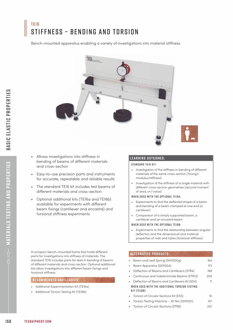
Mat
eria
ls t
esti
ng
an
d p
ro
per
ties
T E C Q U I P M E N T. C O M1 5 0
Ba
sic
ela
sti
c p
ro
per
ties
L E A R N I N G O U T C O M E S :
S ta n d a r d T E 1 6 k i t:
• Investigation of the stiffness in bending of different
materials of the same cross-section (Young’s
modulus/stiffness)
• Investigation of the stiffness of a single material with
different cross-section geometries (second moment
of area, or I value)
W h e n u s e d w i t h t h e o p t i o n a l T E 1 6 a :
• Experiments to find the deflected shape of a beam
and bending of a beam clamped at one end (a
cantilever)
• Comparison of a simply supported beam, a
cantilever and an encastré beam
W h e n u s e d w i t h t h e o p t i o n a l T E 1 6 b :
• Experiments to find the relationship between angular
deflection and the dimensional and material
properties of rods and tubes (torsional stiffness)
T E 1 6
S t i f f n e s s – B e n d i n g a n d T o r s i o n
Bench-mounted apparatus enabling a variety of investigations into material stiffness.
A compact, bench-mounted frame that holds different
parts for investigations into stiffness of materials. The
standard TE16 includes parts for tests in bending of beams
of different materials and cross-section. Optional additional
kits allow investigations into different beam fixings and
torsional stiffness.
• Additional Experimentation Kit (TE16a)
• Additional Torsion Testing Kit (TE16b)
R E C O M M E N D E D AN C I L LAR I E S :
• Beam and Leaf Spring (SM1000g) 164
• Beam Apparatus (SM1004) 173
• Deflection of Beams and Cantilevers (STR4) 198
• Continuous and Indeterminate Beams (STR13) 200
• Deflection of Beams and Cantilevers Kit (ES4) 11
W h e n u s e d w i t h t h e A d d i t i o n a l T o r s i o n T e s t i n g
K i t ( T E 1 6 b ) :
• Torsion of Circular Sections Kit (ES5) 10
• Torsion Testing Machine – 30 Nm (SM1001) 157
• Torsion of Circular Sections (STR6) 207
alt e r nat i v e p r o d u c t s :
• Allows investigations into stiffness in
bending of beams of different materials
and cross-section
• Easy-to-use precision parts and instruments
for accurate, repeatable and reliable results
• The standard TE16 kit includes test beams of
different materials and cross-section
• Optional additional kits (TE16a and TE16b)
available for experiments with different
beam fixings (cantilever and encastré) and
torsional stiffness experiments
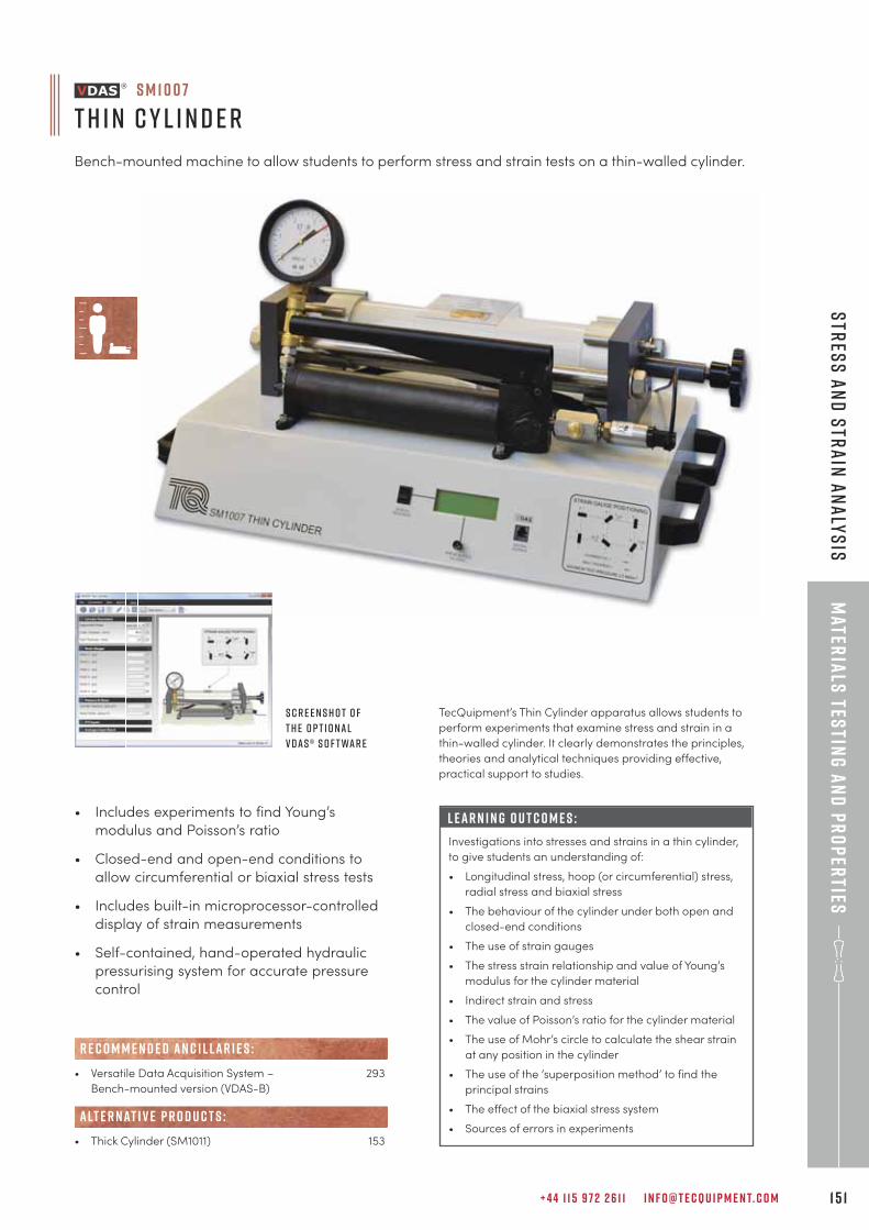
+ 4 4 1 1 5 9 7 2 2 6 1 1 I N F O @ T E C Q U I P M E N T. C O M 1 5 1
Mater
ials
testin
g a
nd
pr
op
erties
Str
ess
an
d s
tra
in a
na
lys
is
• Includes experiments to find Young’s
modulus and Poisson’s ratio
• Closed-end and open-end conditions to
allow circumferential or biaxial stress tests
• Includes built-in microprocessor-controlled
display of strain measurements
• Self-contained, hand-operated hydraulic
pressurising system for accurate pressure
control
L E A R N I N G O U T C O M E S :
Investigations into stresses and strains in a thin cylinder,
to give students an understanding of:
• Longitudinal stress, hoop (or circumferential) stress,
radial stress and biaxial stress
• The behaviour of the cylinder under both open and
closed-end conditions
• The use of strain gauges
• The stress strain relationship and value of Young’s
modulus for the cylinder material
• Indirect strain and stress
• The value of Poisson’s ratio for the cylinder material
• The use of Mohr’s circle to calculate the shear strain
at any position in the cylinder
• The use of the ‘superposition method’ to find the
principal strains
• The effect of the biaxial stress system
• Sources of errors in experiments
S M 1 0 0 7
T h i n C y l i n d e r
Bench-mounted machine to allow students to perform stress and strain tests on a thin-walled cylinder.
S c r e e n s h o t o f
t h e o p t i o n a l
V D A S ® s o f t wa r e
TecQuipment’s Thin Cylinder apparatus allows students to
perform experiments that examine stress and strain in a
thin-walled cylinder. It clearly demonstrates the principles,
theories and analytical techniques providing effective,
practical support to studies.
• Versatile Data Acquisition System – 293
Bench-mounted version (VDAS-B)
• Thick Cylinder (SM1011) 153
alt e r nat i v e p r o d u c t s :
R E C O M M E N D E D AN C I L LAR I E S :
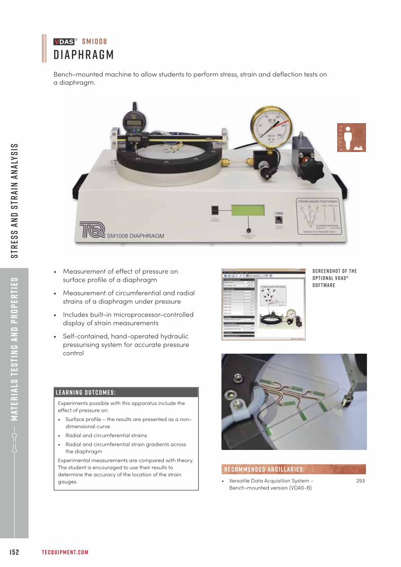
Mat
eria
ls t
esti
ng
an
d p
ro
per
ties
T E C Q U I P M E N T. C O M1 5 2
Str
ess
an
d S
tra
in A
na
lys
is
L E A R N I N G O U T C O M E S :
Experiments possible with this apparatus include the
effect of pressure on:
• Surface profile – the results are presented as a non-
dimensional curve
• Radial and circumferential strains
• Radial and circumferential strain gradients across
the diaphragm
Experimental measurements are compared with theory.
The student is encouraged to use their results to
determine the accuracy of the location of the strain
gauges.
• Measurement of effect of pressure on
surface profile of a diaphragm
• Measurement of circumferential and radial
strains of a diaphragm under pressure
• Includes built-in microprocessor-controlled
display of strain measurements
• Self-contained, hand-operated hydraulic
pressurising system for accurate pressure
control
• Versatile Data Acquisition System – 293
Bench-mounted version (VDAS-B)
R E C O M M E N D E D AN C I L LAR I E S :
S M 1 0 0 8
D i a p h r a g m
Bench-mounted machine to allow students to perform stress, strain and deflection tests ona diaphragm.
S c r e e n s h o t o f t h e
o p t i o n a l V D A S ®
s o f t wa r e
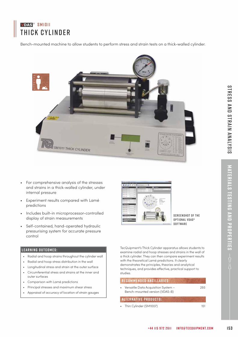
+ 4 4 1 1 5 9 7 2 2 6 1 1 I N F O @ T E C Q U I P M E N T. C O M 1 5 3
Mater
ials
testin
g a
nd
pr
op
erties
Str
ess
an
d S
tra
in A
na
lys
is
• For comprehensive analysis of the stresses
and strains in a thick-walled cylinder, under
internal pressure
• Experiment results compared with Lamé
predictions
• Includes built-in microprocessor-controlled
display of strain measurements
• Self-contained, hand-operated hydraulic
pressurising system for accurate pressure
control
L E A R N I N G O U T C O M E S :
• Radial and hoop strains throughout the cylinder wall
• Radial and hoop stress distribution in the wall
• Longitudinal stress and strain at the outer surface
• Circumferential stress and strains at the inner and
outer surfaces
• Comparison with Lamé predictions
• Principal stresses and maximum shear stress
• Appraisal of accuracy of location of strain gauges
S M 1 0 1 1
T h i c k C y l i n d e r
Bench-mounted machine to allow students to perform stress and strain tests on a thick-walled cylinder.
TecQuipment’s Thick Cylinder apparatus allows students to
examine radial and hoop stresses and strains in the wall of
a thick cylinder. They can then compare experiment results
with the theoretical Lamé predictions. It clearly
demonstrates the principles, theories and analytical
techniques, and provides effective, practical support to
studies.
• Versatile Data Acquisition System – 293
Bench-mounted version (VDAS-B)
• Thin Cylinder (SM1007) 151
R E C O M M E N D E D AN C I L LAR I E S :
alt e r nat i v e p r o d u c t s :
S c r e e n s h o t o f t h e
o p t i o n a l V D A S ®
s o f t wa r e
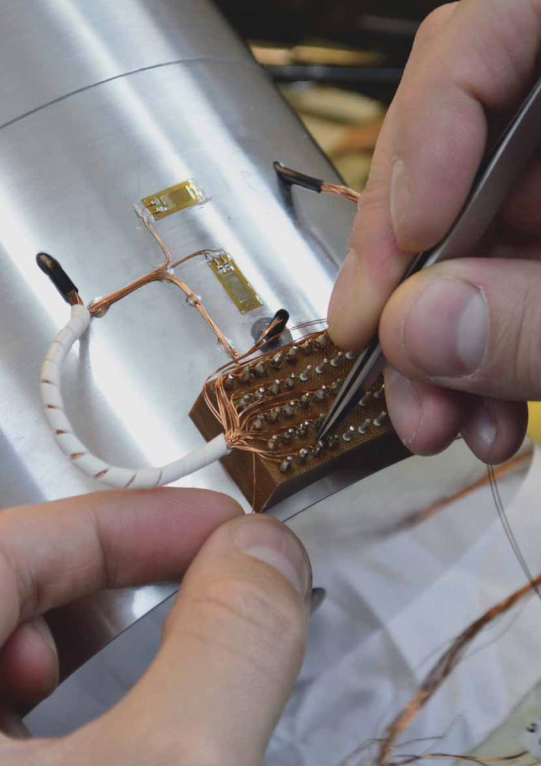
Mat
eria
ls t
esti
ng
an
d p
ro
per
ties
T E C Q U I P M E N T. C O M1 5 4
su
bje
ct
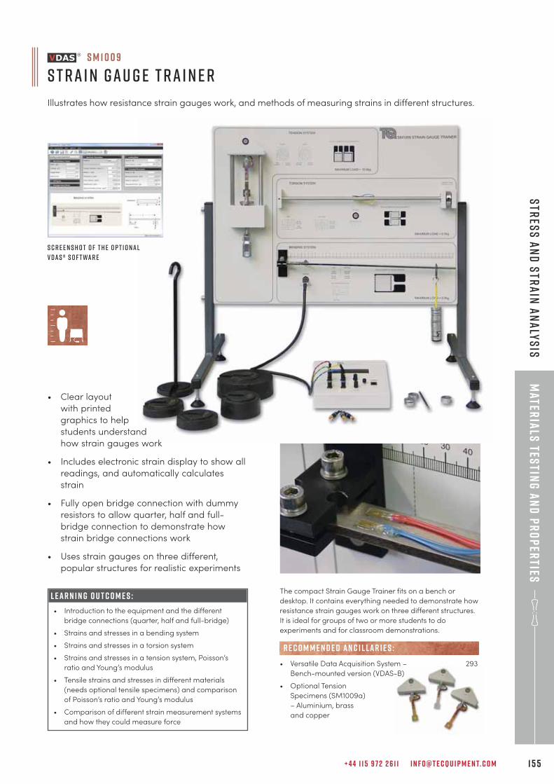
+ 4 4 1 1 5 9 7 2 2 6 1 1 I N F O @ T E C Q U I P M E N T. C O M 1 5 5
Mater
ials
testin
g a
nd
pr
op
erties
Str
ess
an
d S
tra
in A
na
lys
is
• Clear layout
with printed
graphics to help
students understand
how strain gauges work
• Includes electronic strain display to show all
readings, and automatically calculates
strain
• Fully open bridge connection with dummy
resistors to allow quarter, half and full-
bridge connection to demonstrate how
strain bridge connections work
• Uses strain gauges on three different,
popular structures for realistic experiments
L E A R N I N G O U T C O M E S :
• Introduction to the equipment and the different
bridge connections (quarter, half and full-bridge)
• Strains and stresses in a bending system
• Strains and stresses in a torsion system
• Strains and stresses in a tension system, Poisson’s
ratio and Young’s modulus
• Tensile strains and stresses in different materials
(needs optional tensile specimens) and comparison
of Poisson’s ratio and Young’s modulus
• Comparison of different strain measurement systems
and how they could measure force
S M 1 0 0 9
S t r a i n G a u g e T r a i n e r
Illustrates how resistance strain gauges work, and methods of measuring strains in different structures.
The compact Strain Gauge Trainer fits on a bench or
desktop. It contains everything needed to demonstrate how
resistance strain gauges work on three different structures.
It is ideal for groups of two or more students to do
experiments and for classroom demonstrations.
• Versatile Data Acquisition System – 293
Bench-mounted version (VDAS-B)
• Optional Tension
Specimens (SM1009a)
– Aluminium, brass
and copper
R E C O M M E N D E D AN C I L LAR I E S :
S c r e e n s h o t o f t h e o p t i o n a l
V D A S ® s o f t wa r e
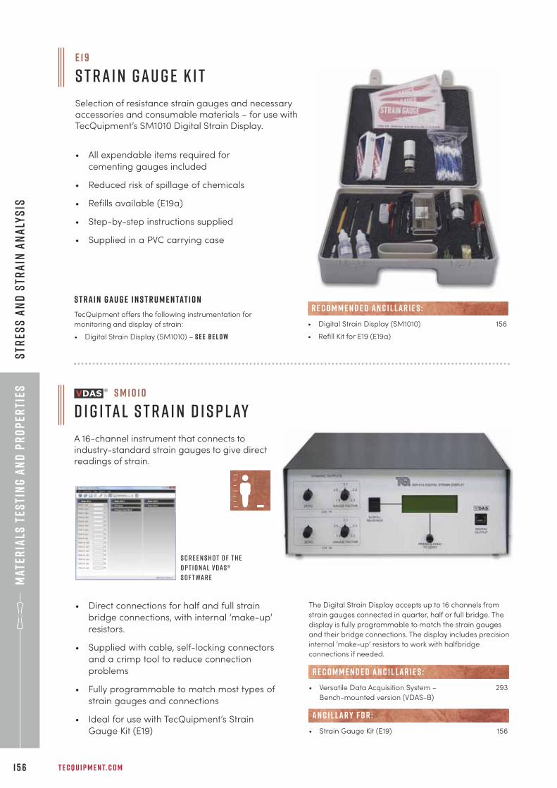
Mat
eria
ls t
esti
ng
an
d p
ro
per
ties
T E C Q U I P M E N T. C O M1 5 6
Str
ess
an
d S
tra
in A
na
lys
is
• All expendable items required for
cementing gauges included
• Reduced risk of spillage of chemicals
• Refills available (E19a)
• Step-by-step instructions supplied
• Supplied in a PVC carrying case
S t r a i n G a u g e I n s t r u m e n tat i o n
TecQuipment offers the following instrumentation for
monitoring and display of strain:
• Digital Strain Display (SM1010) – s e e b e l o w
E 1 9
S t r a i n G a u g e K i t
Selection of resistance strain gauges and necessaryaccessories and consumable materials – for use withTecQuipment’s SM1010 Digital Strain Display.
• Direct connections for half and full strain
bridge connections, with internal ‘make-up’
resistors.
• Supplied with cable, self-locking connectors
and a crimp tool to reduce connection
problems
• Fully programmable to match most types of
strain gauges and connections
• Ideal for use with TecQuipment’s Strain
Gauge Kit (E19)
S M 1 0 1 0
D i g i ta l S t r a i n D i s p l ay
A 16-channel instrument that connects toindustry-standard strain gauges to give directreadings of strain.
S c r e e n s h o t o f t h e
o p t i o n a l V D A S ®
s o f t wa r e
The Digital Strain Display accepts up to 16 channels from
strain gauges connected in quarter, half or full bridge. The
display is fully programmable to match the strain gauges
and their bridge connections. The display includes precision
internal ‘make-up’ resistors to work with halfbridge
connections if needed.
• Versatile Data Acquisition System – 293
Bench-mounted version (VDAS-B)
• Strain Gauge Kit (E19) 156
R E C O M M E N D E D AN C I L LAR I E S :
AN C I L LAR Y F O R :
• Digital Strain Display (SM1010) 156
• Refill Kit for E19 (E19a)
R E C O M M E N D E D AN C I L LAR I E S :
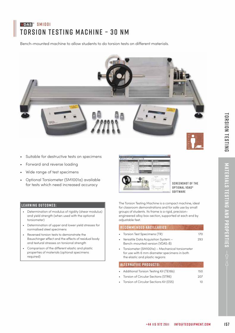
+ 4 4 1 1 5 9 7 2 2 6 1 1 I N F O @ T E C Q U I P M E N T. C O M 1 5 7
Mater
ials
testin
g a
nd
pr
op
erties
Tor
sio
n Tes
ting
S M 1 0 0 1
T o r s i o n T e s t i n g M a c h i n e – 3 0 N m
Bench-mounted machine to allow students to do torsion tests on different materials.
L E A R N I N G O U T C O M E S :
• Determination of modulus of rigidity (shear modulus)
and yield strength (when used with the optional
torsiometer)
• Determination of upper and lower yield stresses for
normalised steel specimens
• Reversed torsion tests to demonstrate the
Bauschinger effect and the effects of residual body
and textural stresses on torsional strength
• Comparison of the different elastic and plastic
properties of materials (optional specimens
required)
• Suitable for destructive tests on specimens
• Forward and reverse loading
• Wide range of test specimens
• Optional Torsiometer (SM1001a) available
for tests which need increased accuracy
The Torsion Testing Machine is a compact machine, ideal
for classroom demonstrations and for safe use by small
groups of students. Its frame is a rigid, precision-
engineered alloy box-section, supported at each end by
adjustable feet.
• Torsion Test Specimens (TR) 170
• Versatile Data Acquisition System – 293
Bench-mounted version (VDAS-B)
• Torsiometer (SM1001a) – Mechanical torsiometer
for use with 6 mm diameter specimens in both
the elastic and plastic regions
• Additional Torsion Testing Kit (TE16b) 150
• Torsion of Circular Sections (STR6) 207
• Torsion of Circular Sections Kit (ES5) 10
R E C O M M E N D E D AN C I L LAR I E S :
alt e r nat i v e p r o d u c t s :
S c r e e n s h o t o f t h e
o p t i o n a l V D A S ®
s o f t wa r e
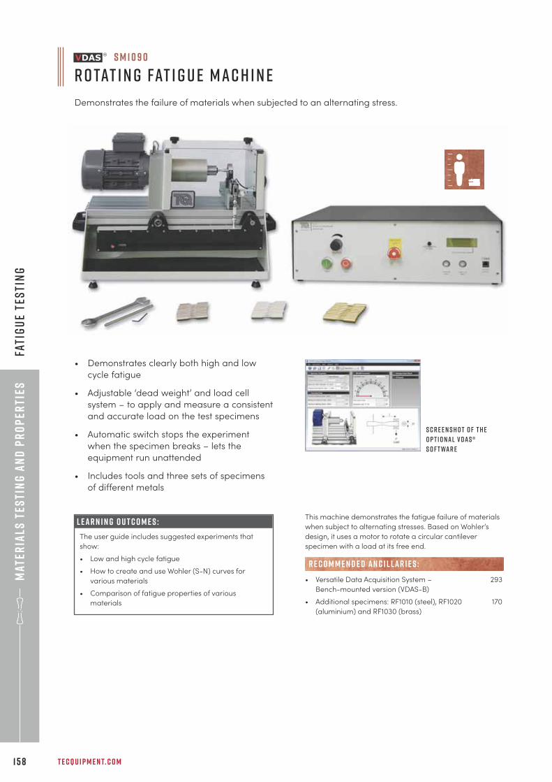
Mat
eria
ls t
esti
ng
an
d p
ro
per
ties
T E C Q U I P M E N T. C O M1 5 8
S M 1 0 9 0
R o tat i n g Fat i g u e M a c h i n e
Demonstrates the failure of materials when subjected to an alternating stress.
S c r e e n s h o t o f t h e
o p t i o n a l V D A S ®
s o f t wa r e
• Demonstrates clearly both high and low
cycle fatigue
• Adjustable ‘dead weight’ and load cell
system – to apply and measure a consistent
and accurate load on the test specimens
• Automatic switch stops the experiment
when the specimen breaks – lets the
equipment run unattended
• Includes tools and three sets of specimens
of different metals
L E A R N I N G O U T C O M E S :
The user guide includes suggested experiments that
show:
• Low and high cycle fatigue
• How to create and use Wohler (S-N) curves for
various materials
• Comparison of fatigue properties of various
materials
This machine demonstrates the fatigue failure of materials
when subject to alternating stresses. Based on Wohler’s
design, it uses a motor to rotate a circular cantilever
specimen with a load at its free end.
• Versatile Data Acquisition System – 293
Bench-mounted version (VDAS-B)
• Additional specimens: RF1010 (steel), RF1020 170
(aluminium) and RF1030 (brass)
R E C O M M E N D E D AN C I L LAR I E S :
Fati
gu
e te
sti
ng
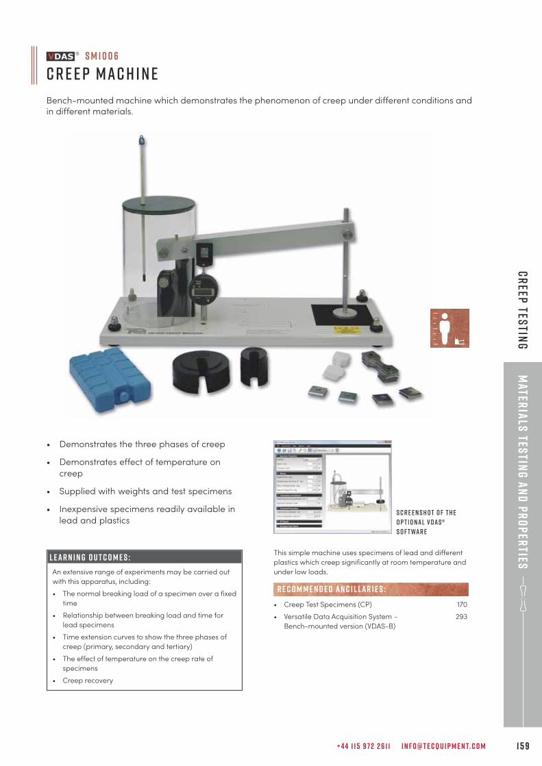
+ 4 4 1 1 5 9 7 2 2 6 1 1 I N F O @ T E C Q U I P M E N T. C O M 1 5 9
• Demonstrates the three phases of creep
• Demonstrates effect of temperature on
creep
• Supplied with weights and test specimens
• Inexpensive specimens readily available in
lead and plastics
L E A R N I N G O U T C O M E S :
An extensive range of experiments may be carried out
with this apparatus, including:
• The normal breaking load of a specimen over a fixed
time
• Relationship between breaking load and time for
lead specimens
• Time extension curves to show the three phases of
creep (primary, secondary and tertiary)
• The effect of temperature on the creep rate of
specimens
• Creep recovery
This simple machine uses specimens of lead and different
plastics which creep significantly at room temperature and
under low loads.
• Creep Test Specimens (CP) 170
• Versatile Data Acquisition System – 293
Bench-mounted version (VDAS-B)
R E C O M M E N D E D AN C I L LAR I E S :
S c r e e n s h o t o f t h e
o p t i o n a l V D A S ®
s o f t wa r e
S M 1 0 0 6
C r e e p M a c h i n e
Bench-mounted machine which demonstrates the phenomenon of creep under different conditions andin different materials.
Mater
ials
testin
g a
nd
pr
op
erties
Cr
eep tes
ting
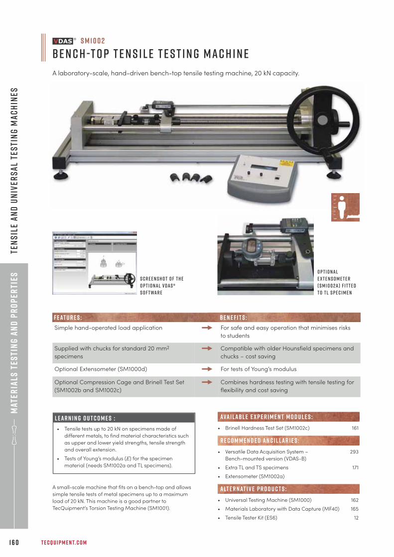
Mat
eria
ls t
esti
ng
an
d p
ro
per
ties
T E C Q U I P M E N T. C O M1 6 0
Ten
sil
e a
nd
Un
iver
sa
l Te
sti
ng
Ma
ch
ines
S M 1 0 0 2
B e n c h -T o p T e n s i l e T e s t i n g M a c h i n e
A laboratory-scale, hand-driven bench-top tensile testing machine, 20 kN capacity.
S c r e e n s h o t o f t h e
o p t i o n a l V D A S ®
s o f t wa r e
O p t i o n a l
E x t e n s o m e t e r
( S M 1 0 0 2 a ) f i t t e d
t o T L s p e c i m e n
L E A R N I N G O U T C O M E S :
• Tensile tests up to 20 kN on specimens made of
different metals, to find material characteristics such
as upper and lower yield strengths, tensile strength
and overall extension.
• Tests of Young’s modulus (E) for the specimen
material (needs SM1002a and TL specimens).
A small-scale machine that fits on a bench-top and allows
simple tensile tests of metal specimens up to a maximum
load of 20 kN. This machine is a good partner to
TecQuipment’s Torsion Testing Machine (SM1001).
F e at u r e s : b e n e f i t s :
Simple hand-operated load application For safe and easy operation that minimises risks
to students
Supplied with chucks for standard 20 mm2
specimens
Compatible with older Hounsfield specimens and
chucks – cost saving
Optional Extensometer (SM1000d) For tests of Young’s modulus
Optional Compression Cage and Brinell Test Set
(SM1002b and SM1002c)
Combines hardness testing with tensile testing for
flexibility and cost saving
• Brinell Hardness Test Set (SM1002c) 161
• Versatile Data Acquisition System – 293
Bench-mounted version (VDAS-B)
• Extra TL and TS specimens 171
• Extensometer (SM1002a)
• Universal Testing Machine (SM1000) 162
• Materials Laboratory with Data Capture (MF40) 165
• Tensile Tester Kit (ES6) 12
R E C O M M E N D E D AN C I L LAR I E S :
ava i labl e e x p e r i m e n t m o d u l e s :
alt e r nat i v e p r o d u c t s :
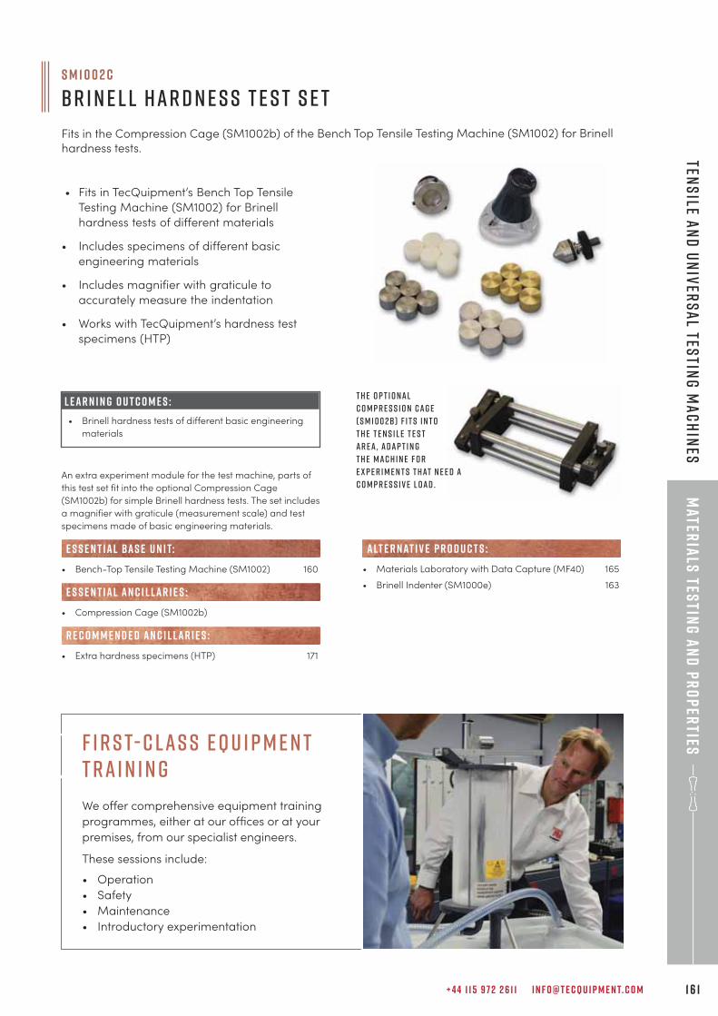
+ 4 4 1 1 5 9 7 2 2 6 1 1 I N F O @ T E C Q U I P M E N T. C O M 1 6 1
Mater
ials
testin
g a
nd
pr
op
erties
Tens
ile an
d U
niv
ers
al Tes
ting
Ma
ch
ines
S M 1 0 0 2 c
B r i n e l l H a r d n e s s T e s t S e t
Fits in the Compression Cage (SM1002b) of the Bench Top Tensile Testing Machine (SM1002) for Brinell
hardness tests.
• Fits in TecQuipment’s Bench Top Tensile
Testing Machine (SM1002) for Brinell
hardness tests of different materials
• Includes specimens of different basic
engineering materials
• Includes magnifier with graticule to
accurately measure the indentation
• Works with TecQuipment’s hardness test
specimens (HTP)
An extra experiment module for the test machine, parts of
this test set fit into the optional Compression Cage
(SM1002b) for simple Brinell hardness tests. The set includes
a magnifier with graticule (measurement scale) and test
specimens made of basic engineering materials.
• Bench-Top Tensile Testing Machine (SM1002) 160
• Compression Cage (SM1002b)
• Extra hardness specimens (HTP) 171
e s s e n t ial bas e u n i t:
E S S E N T IAL AN C I L LAR I E S :
R E C O M M E N D E D AN C I L LAR I E S :
• Materials Laboratory with Data Capture (MF40) 165
• Brinell Indenter (SM1000e) 163
alt e r nat i v e p r o d u c t s :
T h e o p t i o n a l
C o m p r e s s i o n C a g e
( S M 1 0 0 2 b ) f i t s i n t o
t h e t e n s i l e t e s t
a r e a , a d a p t i n g
t h e m a c h i n e f o r
e x p e r i m e n t s t h at n e e d a
c o m p r e s s i v e l o a d .
L E A R N I N G O U T C O M E S :
• Brinell hardness tests of different basic engineering
materials
F i r s t- c las s e q u i p m e n t t ra i n i n g
We offer comprehensive equipment training
programmes, either at our o�ces or at your
premises, from our specialist engineers.
These sessions include:
• Operation
• Safety
• Maintenance
• Introductory experimentation
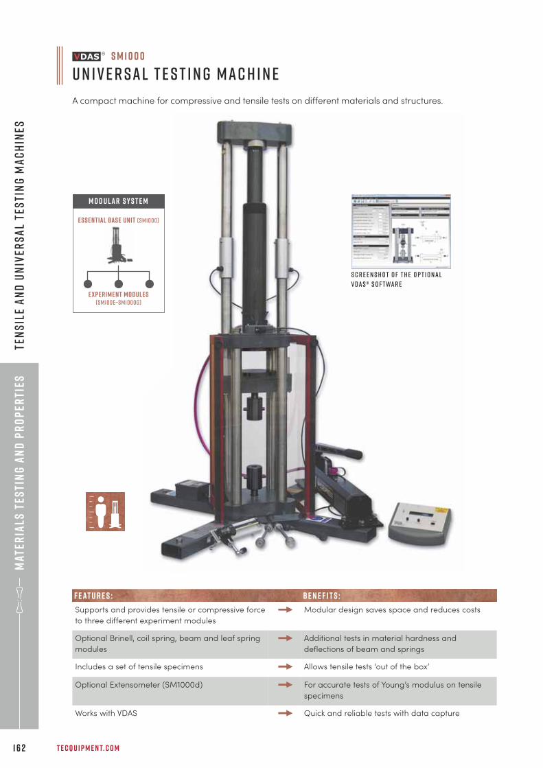
Mat
eria
ls t
esti
ng
an
d p
ro
per
ties
T E C Q U I P M E N T. C O M1 6 2
Ten
sil
e a
nd
Un
iver
sa
l Te
sti
ng
Ma
ch
ines
Experiment modules(sm100e–sm1000g)
Essential Base Unit (sm1000)
M O D U LAR S Y S T E M
S c r e e n s h o t o f t h e o p t i o n a l
V D A S ® s o f t wa r e
S M 1 0 0 0
U n i v e r s a l T e s t i n g M a c h i n e
A compact machine for compressive and tensile tests on different materials and structures.
F E AT U R E S : BE N E F I T S :
Supports and provides tensile or compressive force
to three different experiment modules
Modular design saves space and reduces costs
Optional Brinell, coil spring, beam and leaf spring
modules
Additional tests in material hardness and
deflections of beam and springs
Includes a set of tensile specimens Allows tensile tests ‘out of the box’
Optional Extensometer (SM1000d) For accurate tests of Young’s modulus on tensile
specimens
Works with VDAS Quick and reliable tests with data capture
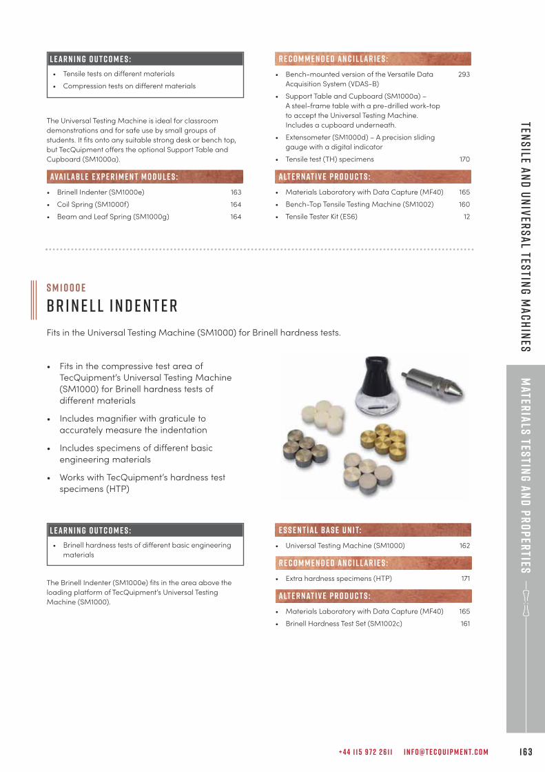
+ 4 4 1 1 5 9 7 2 2 6 1 1 I N F O @ T E C Q U I P M E N T. C O M 1 6 3
Mater
ials
testin
g a
nd
pr
op
erties
Tens
ile an
d U
niv
ers
al Tes
ting
Ma
ch
ines
The Universal Testing Machine is ideal for classroom
demonstrations and for safe use by small groups of
students. It fits onto any suitable strong desk or bench top,
but TecQuipment offers the optional Support Table and
Cupboard (SM1000a).
• Brinell Indenter (SM1000e) 163
• Coil Spring (SM1000f) 164
• Beam and Leaf Spring (SM1000g) 164
ava i labl e e x p e r i m e n t m o d u l e s :
L E A R N I N G O U T C O M E S :
• Tensile tests on different materials
• Compression tests on different materials
• Fits in the compressive test area of
TecQuipment’s Universal Testing Machine
(SM1000) for Brinell hardness tests of
different materials
• Includes magnifier with graticule to
accurately measure the indentation
• Includes specimens of different basic
engineering materials
• Works with TecQuipment’s hardness test
specimens (HTP)
S M 1 0 0 0 e
B r i n e l l I n d e n t e r
Fits in the Universal Testing Machine (SM1000) for Brinell hardness tests.
L E A R N I N G O U T C O M E S :
• Brinell hardness tests of different basic engineering
materials
The Brinell Indenter (SM1000e) fits in the area above the
loading platform of TecQuipment’s Universal Testing
Machine (SM1000).
• Bench-mounted version of the Versatile Data 293
Acquisition System (VDAS-B)
• Support Table and Cupboard (SM1000a) –
A steel-frame table with a pre-drilled work-top
to accept the Universal Testing Machine.
Includes a cupboard underneath.
• Extensometer (SM1000d) – A precision sliding
gauge with a digital indicator
• Tensile test (TH) specimens 170
• Materials Laboratory with Data Capture (MF40) 165
• Bench-Top Tensile Testing Machine (SM1002) 160
• Tensile Tester Kit (ES6) 12
alt e r nat i v e p r o d u c t s :
R E C O M M E N D E D AN C I L LAR I E S :
• Universal Testing Machine (SM1000) 162
• Extra hardness specimens (HTP) 171
• Materials Laboratory with Data Capture (MF40) 165
• Brinell Hardness Test Set (SM1002c) 161
R E C O M M E N D E D AN C I L LAR I E S :
alt e r nat i v e p r o d u c t s :
e s s e n t ial bas e u n i t:
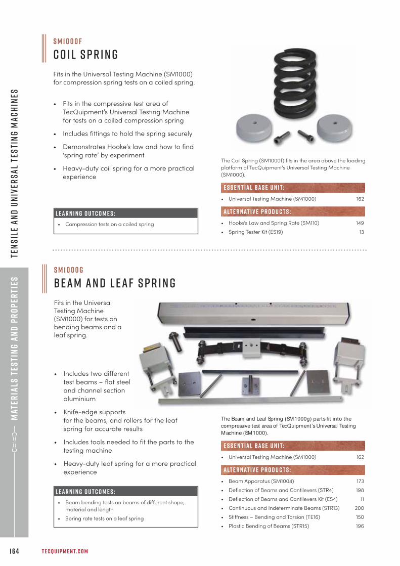
Mat
eria
ls t
esti
ng
an
d p
ro
per
ties
T E C Q U I P M E N T. C O M1 6 4
Ten
sil
e a
nd
Un
iver
sa
l Te
sti
ng
Ma
ch
ines
• Fits in the compressive test area of
TecQuipment’s Universal Testing Machine
for tests on a coiled compression spring
• Includes fittings to hold the spring securely
• Demonstrates Hooke’s law and how to find
‘spring rate’ by experiment
• Heavy-duty coil spring for a more practical
experience
S M 1 0 0 0 f
C o i l S p r i n g
Fits in the Universal Testing Machine (SM1000)for compression spring tests on a coiled spring.
The Coil Spring (SM1000f) fits in the area above the loading
platform of TecQuipment’s Universal Testing Machine
(SM1000).
• Universal Testing Machine (SM1000) 162
• Hooke’s Law and Spring Rate (SM110) 149
• Spring Tester Kit (ES19) 13
e s s e n t ial bas e u n i t:
alt e r nat i v e p r o d u c t s :L E A R N I N G O U T C O M E S :
• Compression tests on a coiled spring
• Includes two different
test beams – flat steel
and channel section
aluminium
• Knife-edge supports
for the beams, and rollers for the leaf
spring for accurate results
• Includes tools needed to fit the parts to the
testing machine
• Heavy-duty leaf spring for a more practical
experience
S M 1 0 0 0 g
B e a m a n d L e a f S p r i n g
Fits in the UniversalTesting Machine(SM1000) for tests onbending beams and aleaf spring.
L E A R N I N G O U T C O M E S :
• Beam bending tests on beams of different shape,
material and length
• Spring rate tests on a leaf spring
The Beam and Leaf Spring (SM1000g) parts fit into the
compressive test area of TecQuipment’s Universal Testing
Machine (SM1000).
• Universal Testing Machine (SM1000) 162
• Beam Apparatus (SM1004) 173
• Deflection of Beams and Cantilevers (STR4) 198
• Deflection of Beams and Cantilevers Kit (ES4) 11
• Continuous and Indeterminate Beams (STR13) 200
• Stiffness – Bending and Torsion (TE16) 150
• Plastic Bending of Beams (STR15) 196
e s s e n t ial bas e u n i t:
alt e r nat i v e p r o d u c t s :
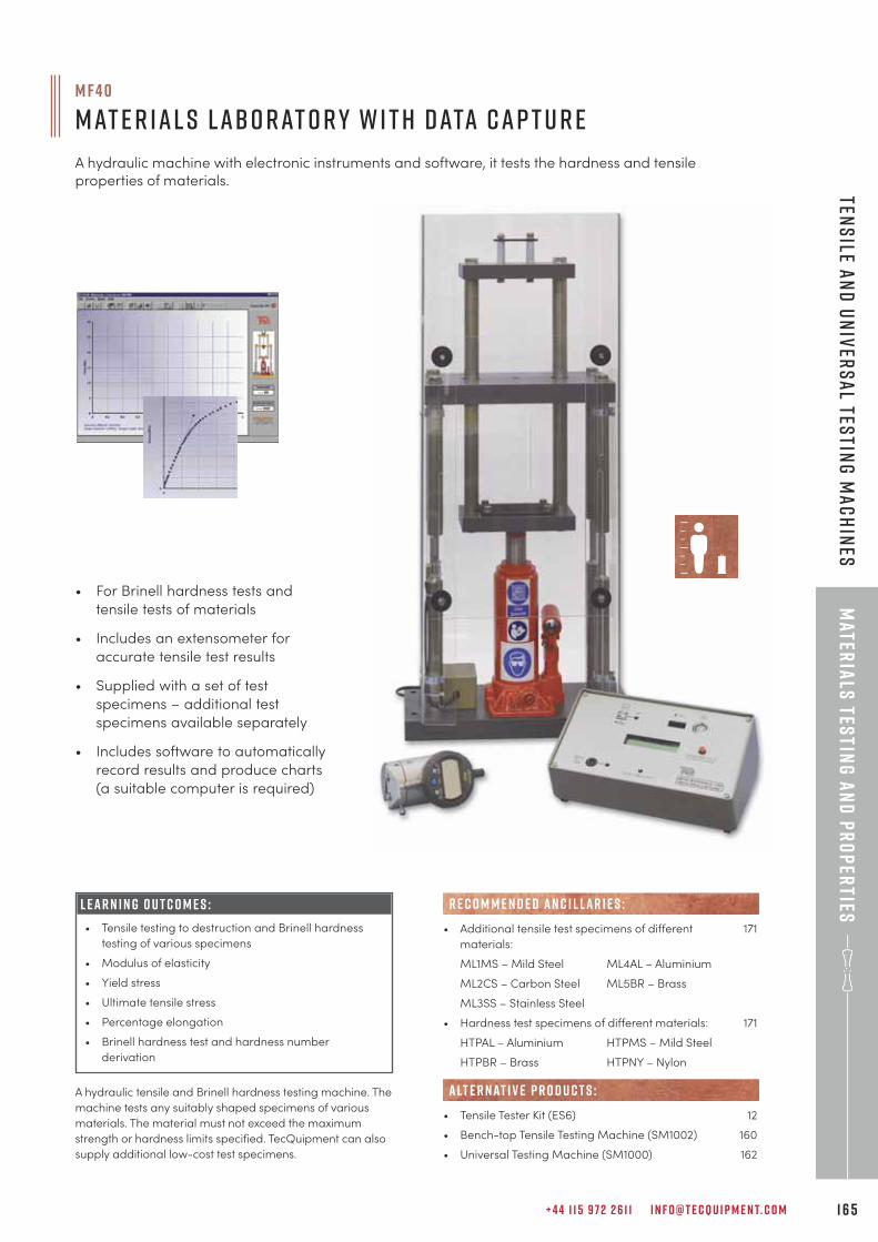
+ 4 4 1 1 5 9 7 2 2 6 1 1 I N F O @ T E C Q U I P M E N T. C O M 1 6 5
Mater
ials
testin
g a
nd
pr
op
erties
Tens
ile an
d U
niv
ers
al Tes
ting
Ma
ch
ines
A hydraulic tensile and Brinell hardness testing machine. The
machine tests any suitably shaped specimens of various
materials. The material must not exceed the maximum
strength or hardness limits specified. TecQuipment can also
supply additional low-cost test specimens.
• For Brinell hardness tests and
tensile tests of materials
• Includes an extensometer for
accurate tensile test results
• Supplied with a set of test
specimens – additional test
specimens available separately
• Includes software to automatically
record results and produce charts
(a suitable computer is required)
• Additional tensile test specimens of different 171
materials:
ML1MS – Mild Steel ML4AL – Aluminium
ML2CS – Carbon Steel ML5BR – Brass
ML3SS – Stainless Steel
• Hardness test specimens of different materials: 171
HTPAL – Aluminium HTPMS – Mild Steel
HTPBR – Brass HTPNY – Nylon
• Tensile Tester Kit (ES6) 12
• Bench-top Tensile Testing Machine (SM1002) 160
• Universal Testing Machine (SM1000) 162
alt e r nat i v e p r o d u c t s :
R E C O M M E N D E D AN C I L LAR I E S :
M F 4 0
M at e r i a l s L a b o r at o r y w i t h D ata C a p t u r e
A hydraulic machine with electronic instruments and software, it tests the hardness and tensileproperties of materials.
L E A R N I N G O U T C O M E S :
• Tensile testing to destruction and Brinell hardness
testing of various specimens
• Modulus of elasticity
• Yield stress
• Ultimate tensile stress
• Percentage elongation
• Brinell hardness test and hardness number
derivation
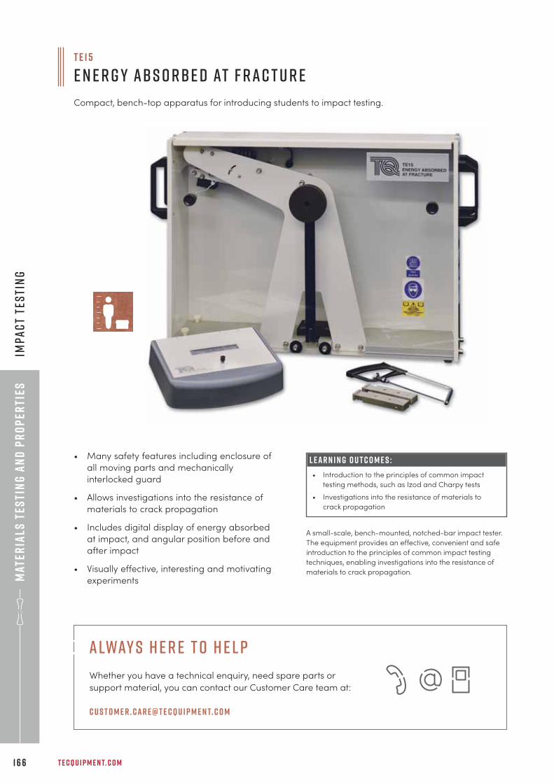
Mat
eria
ls t
esti
ng
an
d p
ro
per
ties
T E C Q U I P M E N T. C O M1 6 6
Imp
ac
t te
sti
ng
• Many safety features including enclosure of
all moving parts and mechanically
interlocked guard
• Allows investigations into the resistance of
materials to crack propagation
• Includes digital display of energy absorbed
at impact, and angular position before and
after impact
• Visually effective, interesting and motivating
experiments
T E 1 5
E n e r g y A b s o r b e d at F r a c t u r e
Compact, bench-top apparatus for introducing students to impact testing.
L E A R N I N G O U T C O M E S :
• Introduction to the principles of common impact
testing methods, such as Izod and Charpy tests
• Investigations into the resistance of materials to
crack propagation
A small-scale, bench-mounted, notched-bar impact tester.
The equipment provides an effective, convenient and safe
introduction to the principles of common impact testing
techniques, enabling investigations into the resistance of
materials to crack propagation.
alway s h e r e t o h e l p
Whether you have a technical enquiry, need spare parts or
support material, you can contact our Customer Care team at:
c u s t o m e r . car e@t e cqu i p m e n t. c o m
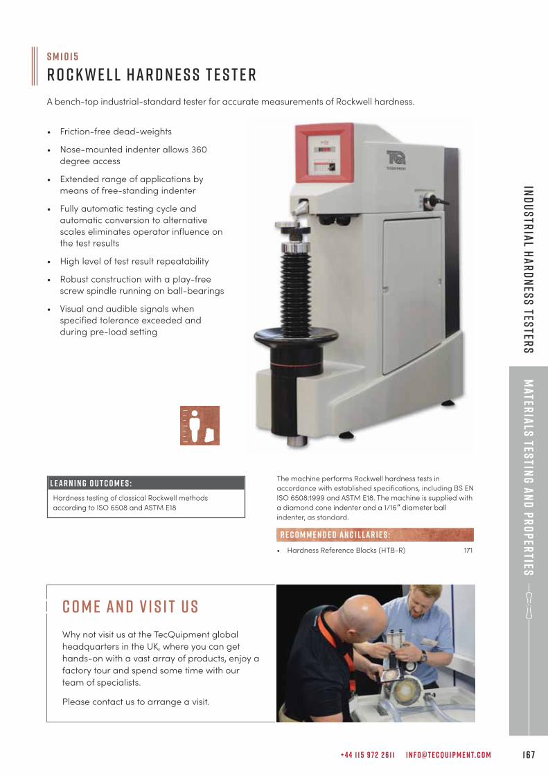
+ 4 4 1 1 5 9 7 2 2 6 1 1 I N F O @ T E C Q U I P M E N T. C O M 1 6 7
Mater
ials
testin
g a
nd
pr
op
erties
Ind
us
tria
l ha
rd
nes
s tes
ters
• Friction-free dead-weights
• Nose-mounted indenter allows 360
degree access
• Extended range of applications by
means of free-standing indenter
• Fully automatic testing cycle and
automatic conversion to alternative
scales eliminates operator influence on
the test results
• High level of test result repeatability
• Robust construction with a play-free
screw spindle running on ball-bearings
• Visual and audible signals when
specified tolerance exceeded and
during pre-load setting
S M 1 0 1 5
R o c k w e l l H a r d n e s s T e s t e r
A bench-top industrial-standard tester for accurate measurements of Rockwell hardness.
L E A R N I N G O U T C O M E S :
Hardness testing of classical Rockwell methods
according to ISO 6508 and ASTM E18
The machine performs Rockwell hardness tests in
accordance with established specifications, including BS EN
ISO 6508:1999 and ASTM E18. The machine is supplied with
a diamond cone indenter and a 1/16” diameter ball
indenter, as standard.
• Hardness Reference Blocks (HTB-R) 171
R E C O M M E N D E D AN C I L LAR I E S :
c o m e an d v i s i t u s
Why not visit us at the TecQuipment global
headquarters in the UK, where you can get
hands-on with a vast array of products, enjoy a
factory tour and spend some time with our
team of specialists.
Please contact us to arrange a visit.
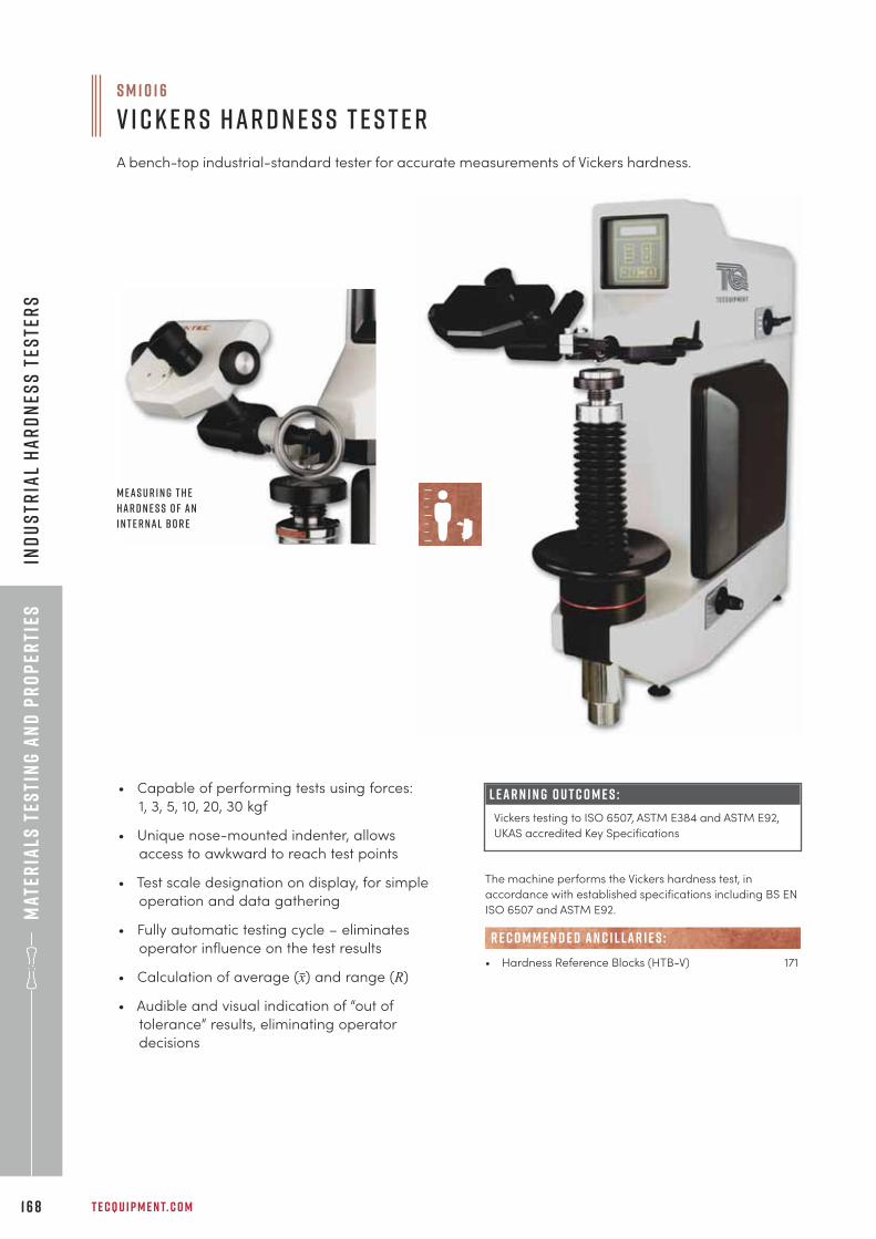
Mat
eria
ls t
esti
ng
an
d p
ro
per
ties
T E C Q U I P M E N T. C O M1 6 8
Ind
us
tria
l h
ar
dn
ess
tes
ter
s
• Capable of performing tests using forces:
1, 3, 5, 10, 20, 30 kgf
• Unique nose-mounted indenter, allows
access to awkward to reach test points
• Test scale designation on display, for simple
operation and data gathering
• Fully automatic testing cycle – eliminates
operator influence on the test results
• Calculation of average (x) and range (R)
• Audible and visual indication of “out of
tolerance” results, eliminating operator
decisions
S M 1 0 1 6
V i c k e r s H a r d n e s s T e s t e r
A bench-top industrial-standard tester for accurate measurements of Vickers hardness.
L E A R N I N G O U T C O M E S :
Vickers testing to ISO 6507, ASTM E384 and ASTM E92,
UKAS accredited Key Specifications
The machine performs the Vickers hardness test, in
accordance with established specifications including BS EN
ISO 6507 and ASTM E92.
• Hardness Reference Blocks (HTB-V) 171
R E C O M M E N D E D AN C I L LAR I E S :
M e a s u r i n g t h e
h a r d n e s s o f a n
i n t e r n a l b o r e
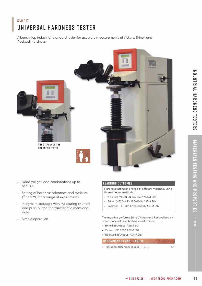
+ 4 4 1 1 5 9 7 2 2 6 1 1 I N F O @ T E C Q U I P M E N T. C O M 1 6 9
Mater
ials
testin
g a
nd
pr
op
erties
Ind
us
tria
l ha
rd
nes
s tes
ters
L E A R N I N G O U T C O M E S :
Hardness testing of a range of different materials, using
three different methods:
• Vickers (HV) DIN EN ISO 6507, ASTM E92
• Brinell (HB) DIN EN ISO 6506, ASTM E10
• Rockwell (HR) DIN EN ISO 6508, ASTM E18
• Dead weight load combinations up to
187.5 kg
• Setting of hardness tolerance and statistics
(x and R), for a range of experiments
• Integral microscope with measuring shutters
and push button for transfer of dimensional
data
• Simple operation
S M 1 0 1 7
U n i v e r s a l H a r d n e s s T e s t e r
A bench-top industrial-standard tester for accurate measurements of Vickers, Brinell andRockwell hardness.
The machine performs Brinell, Vickers and Rockwell tests in
accordance with established specifications:
• Brinell: ISO 6506, ASTM E10
• Vickers: ISO 6507, ASTM E92
• Rockwell: ISO 6508, ASTM E18
• Hardness Reference Blocks (HTB-B) 171
R E C O M M E N D E D AN C I L LAR I E S :
T h e d i s p l ay o f t h e
h a r d n e s s t e s t e r
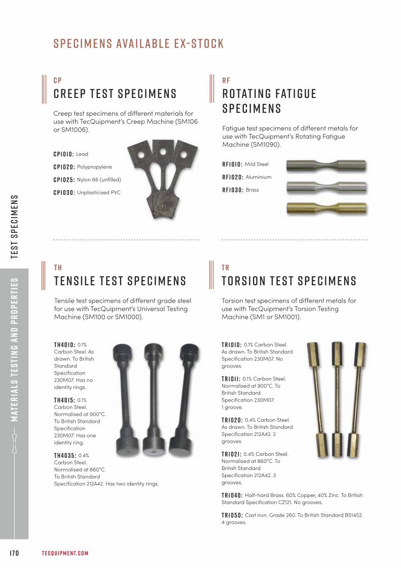
Mat
eria
ls t
esti
ng
an
d p
ro
per
ties
T E C Q U I P M E N T. C O M1 7 0
Tes
t s
pec
imen
s
C P 1 0 1 0 : Lead
C P 1 0 2 0 : Polypropylene
C P 1 0 2 5 : Nylon 66 (unfilled)
C P 1 0 3 0 : Unplasticised PVC
T H 4 0 1 0 : 0.1%
Carbon Steel. As
drawn. To British
Standard
Specification
230M07. Has no
identity rings.
T H 4 0 1 5 : 0.1%
Carbon Steel.
Normalised at 900°C.
To British Standard
Specification
230M07. Has one
identity ring.
T H 4 0 3 5 : 0.4%
Carbon Steel.
Normalised at 860°C.
To British Standard
Specification 212A42. Has two identity rings.
t h
T e n s i l e T e s t S p e c i m e n s
Tensile test specimens of different grade steelfor use with TecQuipment’s Universal TestingMachine (SM100 or SM1000).
T R 1 0 1 0 : 0.1% Carbon Steel.
As drawn. To British Standard
Specification 230M07. No
grooves.
T R 1 0 1 1 : 0.1% Carbon Steel.
Normalised at 900°C. To
British Standard
Specification 230M07.
1 groove.
T R 1 0 2 0 : 0.4% Carbon Steel.
As drawn. To British Standard
Specification 212A42. 2
grooves.
T R 1 0 2 1 : 0.4% Carbon Steel.
Normalised at 860°C. To
British Standard
Specification 212A42. 3
grooves.
T R 1 0 4 0 : Half-hard Brass. 60% Copper, 40% Zinc. To British
Standard Specification CZ121. No grooves.
T R 1 0 5 0 : Cast iron. Grade 260. To British Standard BS1452.
4 grooves.
T R
T o r s i o n T e s t S p e c i m e n s
Torsion test specimens of different metals foruse with TecQuipment’s Torsion TestingMachine (SM1 or SM1001).
C P
C r e e p T e s t S p e c i m e n s
Creep test specimens of different materials foruse with TecQuipment’s Creep Machine (SM106or SM1006).
R F
R o tat i n g Fat i g u eS p e c i m e n s
Fatigue test specimens of different metals foruse with TecQuipment’s Rotating FatigueMachine (SM1090).
R F 1 0 1 0 : Mild Steel
R F 1 0 2 0 : Aluminium
R F 1 0 3 0 : Brass
s p e c i m e n s ava i l a b l e e x- s t o c k
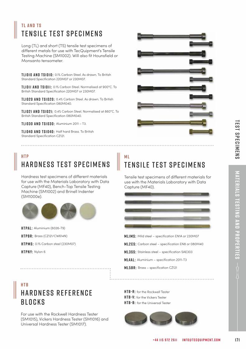
+ 4 4 1 1 5 9 7 2 2 6 1 1 I N F O @ T E C Q U I P M E N T. C O M 1 7 1
Mater
ials
testin
g a
nd
pr
op
erties
Test s
pec
imen
sH T P
H a r d n e s s T e s t S p e c i m e n s
Hardness test specimens of different materialsfor use with the Materials Laboratory with DataCapture (MF40), Bench-Top Tensile TestingMachine (SM1002) and Brinell Indenter(SM1000e).
H T PA L : Aluminium (6026-T9)
H T PBR : Brass (CZ121/CW614N)
H T P M S : 0.1% Carbon steel (230M07)
H T P N Y: Nylon 6
H TB
H a r d n e s s r e f e r e n c e b l o c k s
For use with the Rockwell Hardness Tester(SM1015), Vickers Hardness Tester (SM1016) andUniversal Hardness Tester (SM1017).
M L
T e n s i l e T e s t S p e c i m e n s
Tensile test specimens of different materials foruse with the Materials Laboratory with DataCapture (MF40).
M L1 M S : Mild steel – specification EN1A or 230M07
M L 2 C S : Carbon steel – specification EN8 or 080M40
M L 3 S S : Stainless steel – specification SAE303
M L4 A L : Aluminium – specification 2011-T3
M L 5BR : Brass – specification CZ121
T L a n d T S
T e n s i l e T e s t S p e c i m e n s
Long (TL) and short (TS) tensile test specimens ofdifferent metals for use with TecQuipment’s TensileTesting Machine (SM1002). Will also fit Hounsfield orMonsanto tensometer.
T L1 0 1 0 a n d T S 1 0 1 0 : 0.1% Carbon Steel. As drawn. To British
Standard Specification 220M07 or 230M07.
T L1 0 1 1 a n d T S 1 0 1 1 : 0.1% Carbon Steel. Normalised at 900°C. To
British Standard Specification 220M07 or 230M07.
T L1 0 2 0 a n d T S 1 0 2 0 : 0.4% Carbon Steel. As drawn. To British
Standard Specification 080M040.
T L1 0 2 1 a n d T S 1 0 2 1 : 0.4% Carbon Steel. Normalised at 860°C. To
British Standard Specification 080M040.
T L1 0 3 0 a n d T S 1 0 3 0 : Aluminium 2011 – T3.
T L1 0 4 0 a n d T S 1 0 4 0 : Half hard Brass. To British
Standard Specification CZ121.
H TB - R : for the Rockwell Tester
H TB - V : for the Vickers Tester
H TB -B : for the Universal Tester
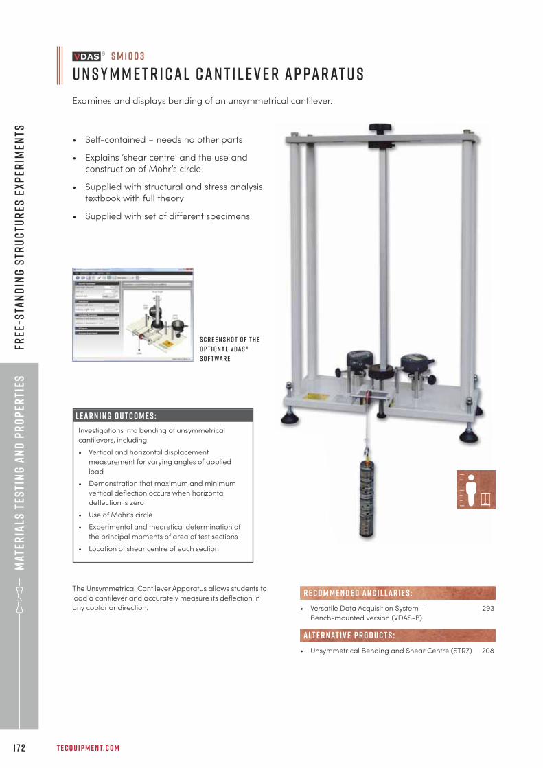
• Self-contained – needs no other parts
• Explains ‘shear centre’ and the use and
construction of Mohr’s circle
• Supplied with structural and stress analysis
textbook with full theory
• Supplied with set of different specimens
Mat
eria
ls t
esti
ng
an
d p
ro
per
ties
T E C Q U I P M E N T. C O M1 7 2
Free
-sta
nd
ing
str
uc
tur
es e
xp
erim
ents
L E A R N I N G O U T C O M E S :
Investigations into bending of unsymmetrical
cantilevers, including:
• Vertical and horizontal displacement
measurement for varying angles of applied
load
• Demonstration that maximum and minimum
vertical deflection occurs when horizontal
deflection is zero
• Use of Mohr’s circle
• Experimental and theoretical determination of
the principal moments of area of test sections
• Location of shear centre of each section
The Unsymmetrical Cantilever Apparatus allows students to
load a cantilever and accurately measure its deflection in
any coplanar direction.
S c r e e n s h o t o f t h e
o p t i o n a l V D A S ®
s o f t wa r e
S M 1 0 0 3
U n s y m m e t r i c a l C a n t i l e v e r A p pa r at u s
Examines and displays bending of an unsymmetrical cantilever.
• Versatile Data Acquisition System – 293
Bench-mounted version (VDAS-B)
• Unsymmetrical Bending and Shear Centre (STR7) 208
R E C O M M E N D E D AN C I L LAR I E S :
alt e r nat i v e p r o d u c t s :
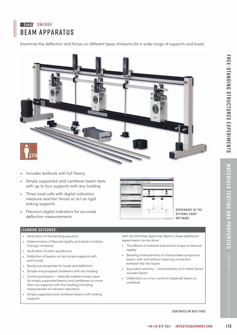
L E A R N I N G O U T C O M E S :
• Verification of the bending equation
• Determination of flexural rigidity and elastic modulus
(Young’s modulus)
• Verification of static equilibrium
• Deflection of beams on two simple supports with
point loads
• Reciprocal properties for loads and deflection
• Simple and propped cantilevers with any loading
• Continuous beams – statically indeterminate cases
for simply supported beams and cantilevers on more
than two supports with any loading (including
measurement of unknown reactions)
• Simply supported and cantilever beams with sinking
supports
+ 4 4 1 1 5 9 7 2 2 6 1 1 I N F O @ T E C Q U I P M E N T. C O M 1 7 3
Mater
ials
testin
g a
nd
pr
op
erties
Free-s
tan
din
g s
tru
ctu
res
exp
erim
ents
• Includes textbook with full theory
• Simply supported and cantilever beam tests
with up to four supports with any loading
• Three load cells with digital indicators
measure reaction forces or act as rigid
sinking supports
• Precision digital indicators for accurate
deflection measurements
S c r e e n s h o t o f t h e
o p t i o n a l V D A S ®
s o f t wa r e
c o n t i n u e d o n n e x t pa g e
S M 1 0 0 4
B e a m A p pa r at u s
Examines the deflection and forces on different types of beams for a wide range of supports and loads.
With the SM1004a Specimen Beams, these additional
experiments can be done:
• The effects of material and section shape on flexural
rigidity
• Bending characteristics of a brass/steel compound
beam, with and without shearing connection
between the two layers
• Equivalent sections – characteristics of a metal-faced
wooden beam
• Deflections on a non-uniform (tapered) beam or
cantilever
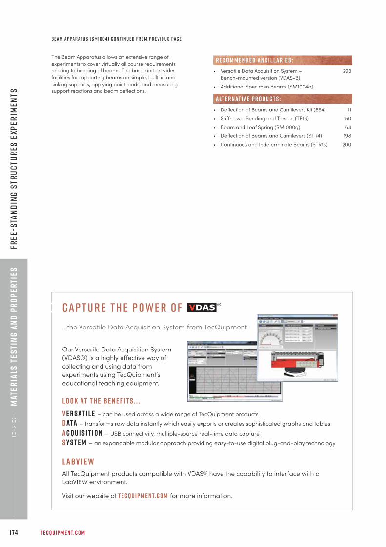
Mat
eria
ls t
esti
ng
an
d p
ro
per
ties
T E C Q U I P M E N T. C O M1 74
Free
-sta
nd
ing
str
uc
tur
es e
xp
erim
ents
The Beam Apparatus allows an extensive range of
experiments to cover virtually all course requirements
relating to bending of beams. The basic unit provides
facilities for supporting beams on simple, built-in and
sinking supports, applying point loads, and measuring
support reactions and beam deflections.
• Versatile Data Acquisition System – 293
Bench-mounted version (VDAS-B)
• Additional Specimen Beams (SM1004a)
• Deflection of Beams and Cantilevers Kit (ES4) 11
• Stiffness – Bending and Torsion (TE16) 150
• Beam and Leaf Spring (SM1000g) 164
• Deflection of Beams and Cantilevers (STR4) 198
• Continuous and Indeterminate Beams (STR13) 200
alt e r nat i v e p r o d u c t s :
R E C O M M E N D E D AN C I L LAR I E S :
B e a m A p pa r at u s ( S M 1 0 0 4 ) C o n t i n u e d f r o m p r e v i o u s pa g e
cap t u r e t h e p owe r o f
...the Versatile Data Acquisition System from TecQuipment
Our Versatile Data Acquisition System
(VDAS®) is a highly effective way of
collecting and using data from
experiments using TecQuipment’s
educational teaching equipment.
L O O K AT T H E B E N E F I T S . . .
v e r sat i l e – can be used across a wide range of TecQuipment products
data – transforms raw data instantly which easily exports or creates sophisticated graphs and tables
acqu i s i t i o n – USB connectivity, multiple-source real-time data capture
s y s t e m – an expandable modular approach providing easy-to-use digital plug-and-play technology
labv i e wAll TecQuipment products compatible with VDAS® have the capability to interface with a
LabVIEW environment.
Visit our website at t e cqu i p m e n t. c o m for more information.
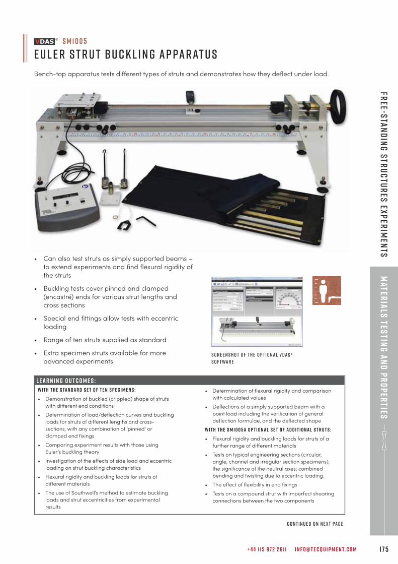
+ 4 4 1 1 5 9 7 2 2 6 1 1 I N F O @ T E C Q U I P M E N T. C O M 1 7 5
Mater
ials
testin
g a
nd
pr
op
erties
Free-s
tan
din
g s
tru
ctu
res
exp
erim
ents
S M 1 0 0 5
E u l e r s t r u t B u c k l i n g A p pa r at u s
Bench-top apparatus tests different types of struts and demonstrates how they deflect under load.
LEARNING OUTCOMES:
W i t h t h e s ta n d a r d s e t o f t e n s p e c i m e n s :
• Demonstration of buckled (crippled) shape of struts
with different end conditions
• Determination of load/deflection curves and buckling
loads for struts of different lengths and cross-
sections, with any combination of ‘pinned’ or
clamped end fixings
• Comparing experiment results with those using
Euler’s buckling theory
• Investigation of the effects of side load and eccentric
loading on strut buckling characteristics
• Flexural rigidity and buckling loads for struts of
different materials
• The use of Southwell’s method to estimate buckling
loads and strut eccentricities from experimental
results
• Can also test struts as simply supported beams –
to extend experiments and find flexural rigidity of
the struts
• Buckling tests cover pinned and clamped
(encastré) ends for various strut lengths and
cross sections
• Special end fittings allow tests with eccentric
loading
• Range of ten struts supplied as standard
• Extra specimen struts available for more
advanced experiments
• Determination of flexural rigidity and comparison
with calculated values
• Deflections of a simply supported beam with a
point load including the verification of general
deflection formulae, and the deflected shape
W i t h t h e S M 1 0 0 5 a o p t i o n a l s e t o f a d d i t i o n a l s t r u t s :
• Flexural rigidity and buckling loads for struts of a
further range of different materials
• Tests on typical engineering sections (circular,
angle, channel and irregular section specimens);
the significance of the neutral axes; combined
bending and twisting due to eccentric loading.
• The effect of flexibility in end fixings
• Tests on a compound strut with imperfect shearing
connections between the two components
S c r e e n s h o t o f t h e o p t i o n a l V D A S ®
s o f t wa r e
C o n t i n u e d o n n e x t pa g e
L E A R N I N G O U T C O M E S :
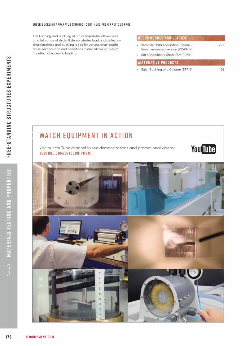
Mat
eria
ls t
esti
ng
an
d p
ro
per
ties
T E C Q U I P M E N T. C O M1 7 6
Free
-sta
nd
ing
str
uc
tur
es e
xp
erim
ents
The Loading and Buckling of Struts apparatus allows tests
on a full range of struts. It demonstrates load and deflection
characteristics and buckling loads for various strut lengths,
cross-sections and end conditions. It also allows studies of
the effect of eccentric loading.
• Versatile Data Acquisition System – 293
Bench-mounted version (VDAS-B)
• Set of Additional Struts (SM1005a)
• Euler Buckling of a Column (STR12) 195
R E C O M M E N D E D AN C I L LAR I E S :
alt e r nat i v e p r o d u c t s :
E u l e r B u c k l i n g A p pa r at u s ( S M 1 0 0 5 ) C o n t i n u e d f r o m p r e v i o u s pa g e
wat c h e q u i p m e n t i n ac t i o n
Visit our YouTube channel to see demonstrations and promotional videos:
y o u t ube . c o m / c / t e cqu i p m e n t
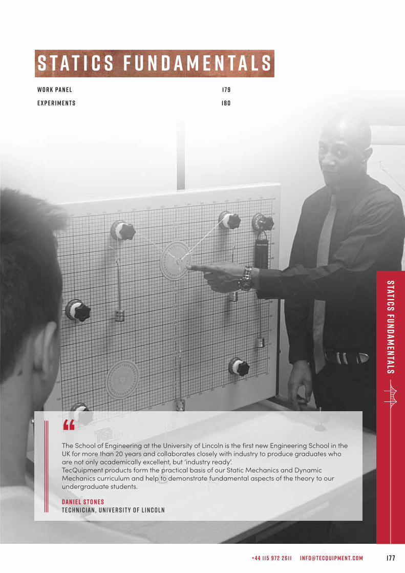
+ 4 4 1 1 5 9 7 2 2 6 1 1 I N F O @ T E C Q U I P M E N T. C O M 1 7 7
Static
s fu
nd
am
enta
ls
s t a t i c s f u n d a m e n t a l sw o r k pa n e l 1 7 9
e x p e r i m e n t s 1 8 0
“The School of Engineering at the University of Lincoln is the first new Engineering School in theUK for more than 20 years and collaborates closely with industry to produce graduates whoare not only academically excellent, but ‘industry ready’.TecQuipment products form the practical basis of our Static Mechanics and DynamicMechanics curriculum and help to demonstrate fundamental aspects of the theory to ourundergraduate students.
d a n i e l s t o n e st e c h n i c i a n , u n i v e r s i t y o f l i n c o l n
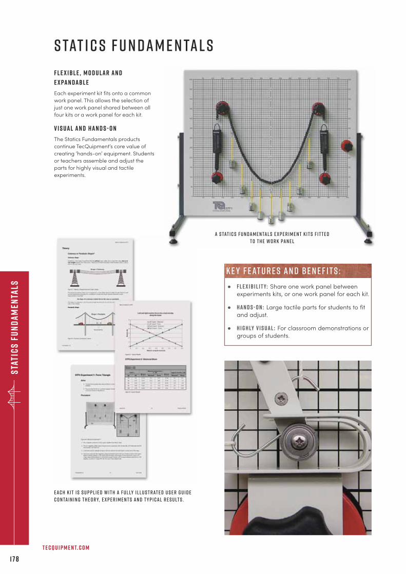
E a c h k i t i s s u p p l i e d w i t h a f u l ly i l l u s t r at e d u s e r g u i d e
c o n ta i n i n g t h e o r y, e x p e r i m e n t s a n d t y p i c a l r e s u lt s .
Sta
tic
s f
un
da
men
tals
T E C Q U I P M E N T. C O M
1 7 8
s tat i c s f u n d a m e n ta l s
a S tat i c s F u n d a m e n ta l s e x p e r i m e n t k i t s f i t t e d
t o t h e w o r k pa n e l
F l e x i b l e , m o d u l a r a n d
e x pa n d a b l e
Each experiment kit fits onto a common
work panel. This allows the selection of
just one work panel shared between all
four kits or a work panel for each kit.
V i s u a l a n d h a n d s - o n
The Statics Fundamentals products
continue TecQuipment’s core value of
creating ‘hands-on’ equipment. Students
or teachers assemble and adjust the
parts for highly visual and tactile
experiments.
• f l e x i b i l i t y: Share one work panel between
experiments kits, or one work panel for each kit.
• h a n d s - o n : Large tactile parts for students to fit
and adjust.
• h i g h ly v i s u a l : For classroom demonstrations or
groups of students.
k e y f eat u r e s an d b e n e f i t s :
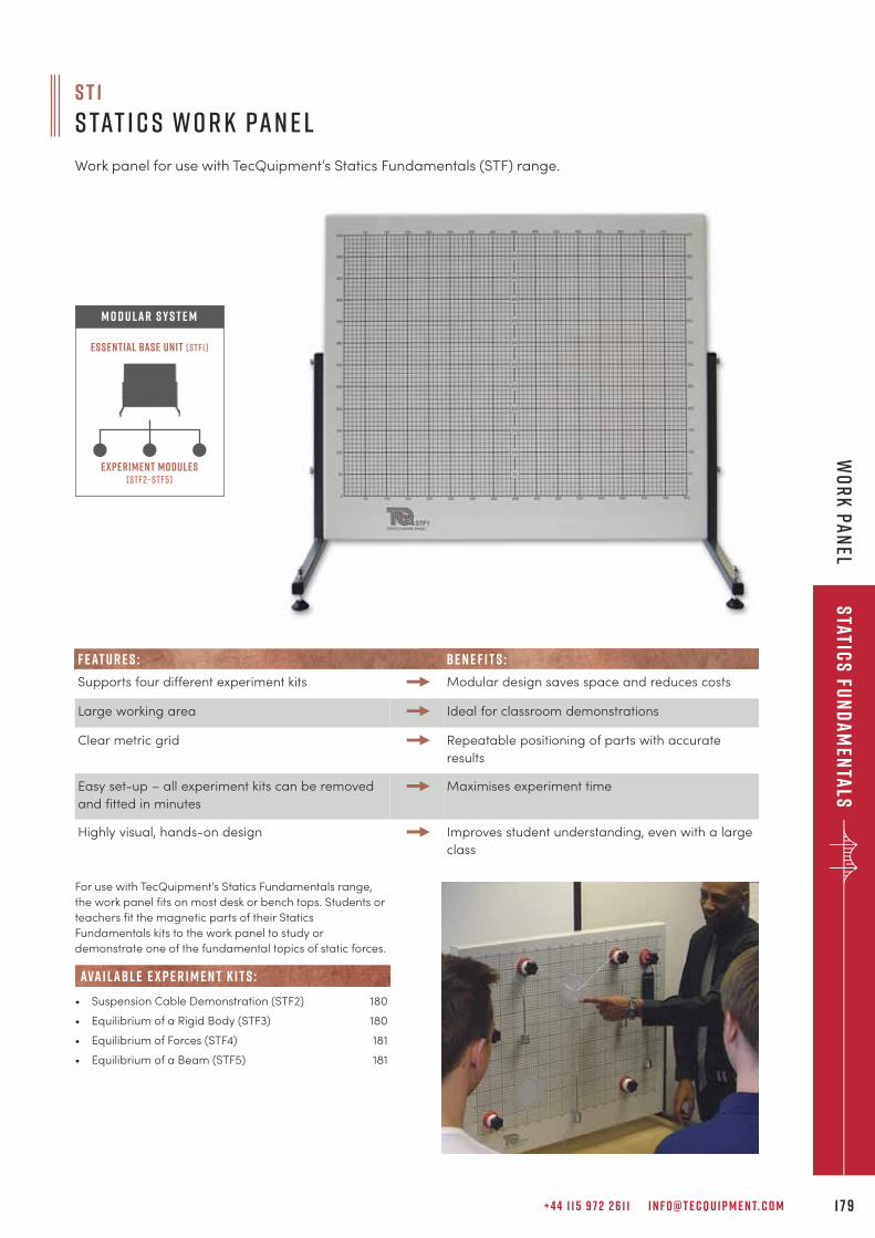
+ 4 4 1 1 5 9 7 2 2 6 1 1 I N F O @ T E C Q U I P M E N T. C O M 1 7 9
Static
s fu
nd
am
enta
lsW
or
k p
an
el
For use with TecQuipment’s Statics Fundamentals range,
the work panel fits on most desk or bench tops. Students or
teachers fit the magnetic parts of their Statics
Fundamentals kits to the work panel to study or
demonstrate one of the fundamental topics of static forces.
• Suspension Cable Demonstration (STF2) 180
• Equilibrium of a Rigid Body (STF3) 180
• Equilibrium of Forces (STF4) 181
• Equilibrium of a Beam (STF5) 181
ava i labl e e x p e r i m e n t k i t s :
Experiment modules(stf2–stf5)
Essential Base Unit (STF1)
M O D U L A R S Y S T E M
F EAT U R E S : BE N E F I T S :
Supports four different experiment kits Modular design saves space and reduces costs
Large working area Ideal for classroom demonstrations
Clear metric grid Repeatable positioning of parts with accurate
results
Easy set-up – all experiment kits can be removed
and fitted in minutes
Maximises experiment time
Highly visual, hands-on design Improves student understanding, even with a large
class
s t 1
s tat i c s w o r k pa n e l
Work panel for use with TecQuipment’s Statics Fundamentals (STF) range.
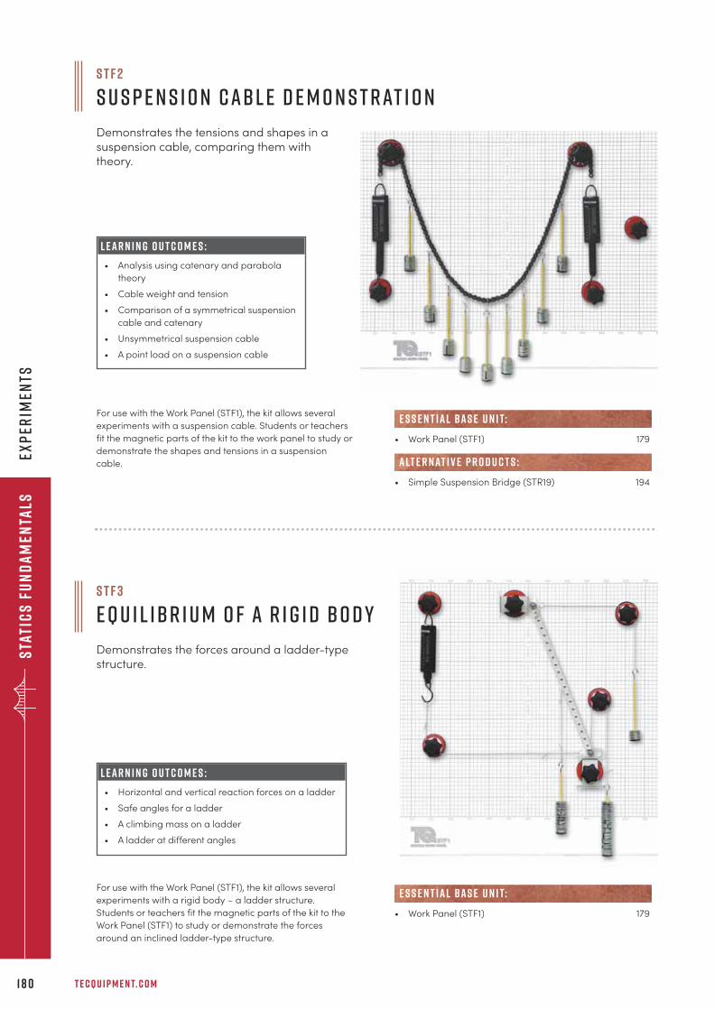
Sta
tic
s f
un
da
men
tals
Exp
erim
ents
T E C Q U I P M E N T. C O M1 8 0
S T F 2
S u s p e n s i o n C abl e D e m o n s t r at i o n
Demonstrates the tensions and shapes in asuspension cable, comparing them withtheory.
L e a r n i n g o u t c o m e s :
• Analysis using catenary and parabola
theory
• Cable weight and tension
• Comparison of a symmetrical suspension
cable and catenary
• Unsymmetrical suspension cable
• A point load on a suspension cable
For use with the Work Panel (STF1), the kit allows several
experiments with a suspension cable. Students or teachers
fit the magnetic parts of the kit to the work panel to study or
demonstrate the shapes and tensions in a suspension
cable.
S T F 3
E q u i l ibr i u m o f a R i g i d B o d y
Demonstrates the forces around a ladder-typestructure.
For use with the Work Panel (STF1), the kit allows several
experiments with a rigid body – a ladder structure.
Students or teachers fit the magnetic parts of the kit to the
Work Panel (STF1) to study or demonstrate the forces
around an inclined ladder-type structure.
• Work Panel (STF1) 179
e s s e n t ial bas e u n i t:
• Work Panel (STF1) 179
• Simple Suspension Bridge (STR19) 194
e s s e n t ial bas e u n i t:
alt e r nat i v e p r o d u c t s :
L e a r n i n g o u t c o m e s :
• Horizontal and vertical reaction forces on a ladder
• Safe angles for a ladder
• A climbing mass on a ladder
• A ladder at different angles
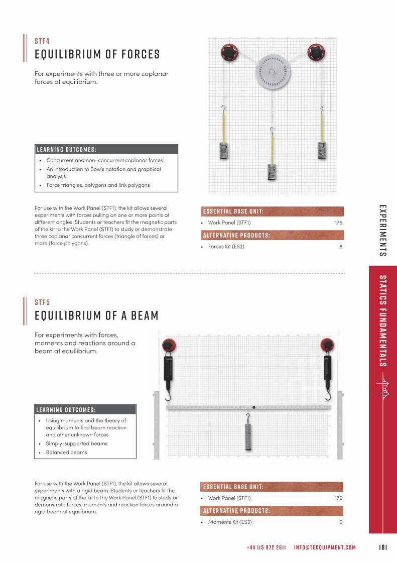
+ 4 4 1 1 5 9 7 2 2 6 1 1 I N F O @ T E C Q U I P M E N T. C O M 1 8 1
Static
s fu
nd
am
enta
lsEx
per
imen
ts
S T F 4
E q u i l ibr i u m o f F o r c e s
For experiments with three or more coplanarforces at equilibrium.
For use with the Work Panel (STF1), the kit allows several
experiments with forces pulling on one or more points at
different angles. Students or teachers fit the magnetic parts
of the kit to the Work Panel (STF1) to study or demonstrate
three coplanar concurrent forces (triangle of forces) or
more (force polygons).
• Work Panel (STF1) 179
• Forces Kit (ES2) 8
e s s e n t ial bas e u n i t:
alt e r nat i v e p r o d u c t s :
S T F 5
E q u i l ibr i u m o f a B e a m
For experiments with forces,moments and reactions around abeam at equilibrium.
For use with the Work Panel (STF1), the kit allows several
experiments with a rigid beam. Students or teachers fit the
magnetic parts of the kit to the Work Panel (STF1) to study or
demonstrate forces, moments and reaction forces around a
rigid beam at equilibrium.
• Work Panel (STF1) 179
• Moments Kit (ES3) 9
e s s e n t ial bas e u n i t:
alt e r nat i v e p r o d u c t s :
L e a r n i n g o u t c o m e s :
• Concurrent and non–concurrent coplanar forces
• An introduction to Bow’s notation and graphical
analysis
• Force triangles, polygons and link polygons
L e a r n i n g o u t c o m e s :
• Using moments and the theory of
equilibrium to find beam reaction
and other unknown forces
• Simply-supported beams
• Balanced beams
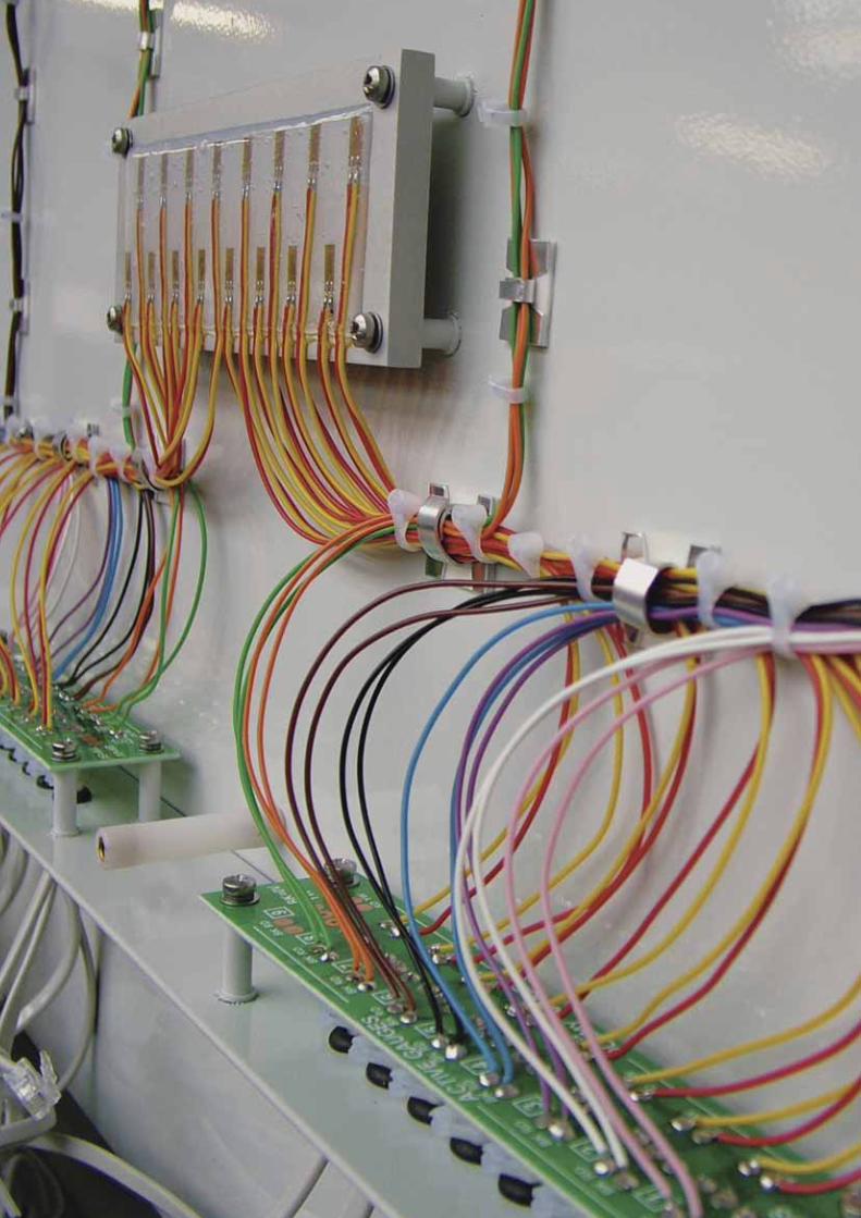
Sta
tic
s f
un
da
men
tals
Sta
tic
s f
un
da
men
tals
T E C Q U I P M E N T. C O M1 8 2
+ 4 4 1 1 5 9 7 2 2 6 1 1 I N F O @ T E C Q U I P M E N T. C O M 1 8 3
Str
uc
tur
es
s t r u c t u r e ss u p p o r t e q u i p m e n t a n d a n c i l l a r i e s 1 8 6
s o f t wa r e 1 8 8
A r c h e s , B r i d g e s a n d T r u s s e s 1 8 9
Fa i l u r e 1 9 5
d e f l e c t i o n s a n d s t r e s s 1 9 8
m o m e n t s 2 0 4
T o r s i o n 2 0 7
“Tecquipment’s Structures line was chosen to enhance the learning experience of ourengineering students. The products were delivered in a timely manner and were easy to set up.After-sales support has been very accommodating, allowing us to modify the experimentmanuals as we saw fit, giving us flexibility in learning objectives. Students have shown greatinterest and have found operating the units to be easy and simple.
R i a d R a j a by o r k u n i v e r s i t y, o n ta r i o , c a n a d a
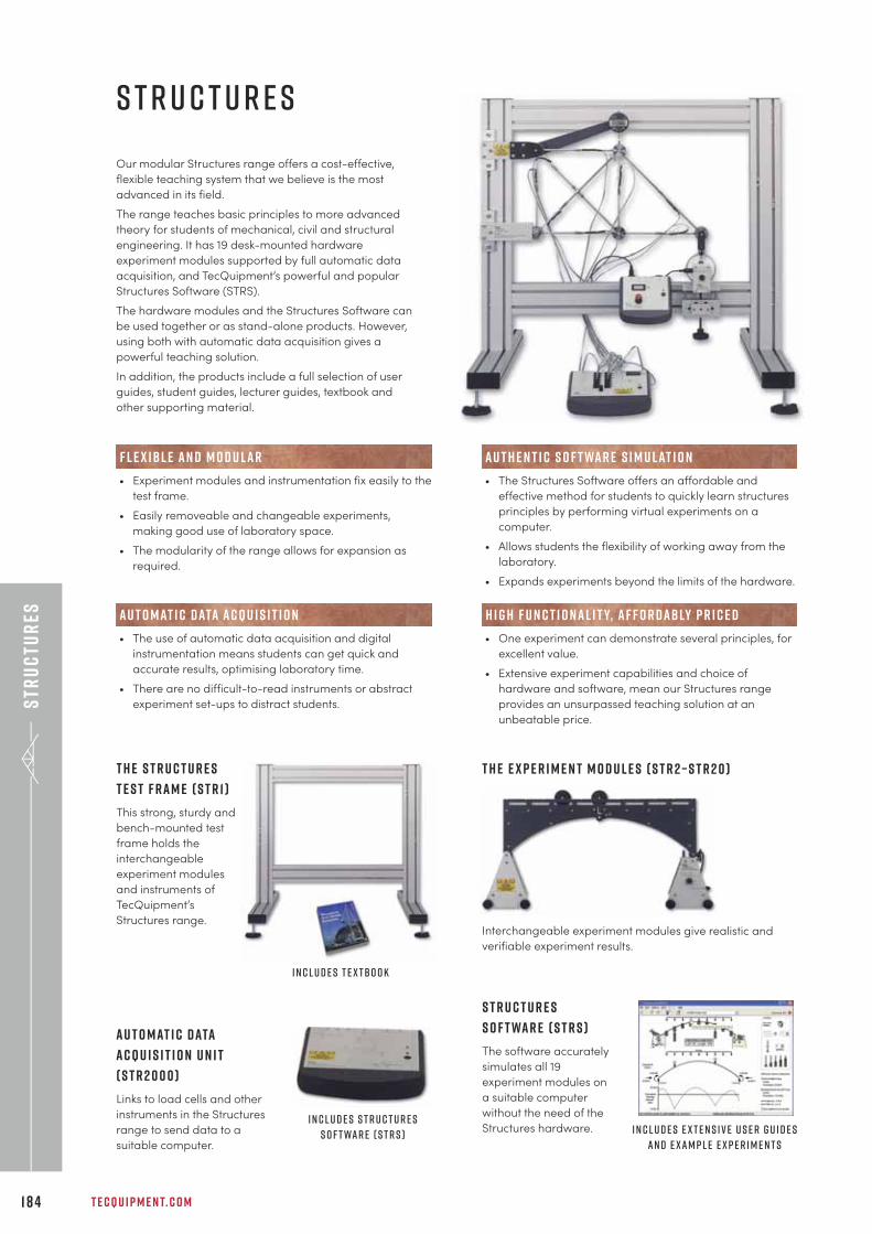
Str
uc
tur
es
T E C Q U I P M E N T. C O M1 8 4
Our modular Structures range offers a cost-effective,
flexible teaching system that we believe is the most
advanced in its field.
The range teaches basic principles to more advanced
theory for students of mechanical, civil and structural
engineering. It has 19 desk-mounted hardware
experiment modules supported by full automatic data
acquisition, and TecQuipment’s powerful and popular
Structures Software (STRS).
The hardware modules and the Structures Software can
be used together or as stand-alone products. However,
using both with automatic data acquisition gives a
powerful teaching solution.
In addition, the products include a full selection of user
guides, student guides, lecturer guides, textbook and
other supporting material.
F l e x i b l e a n d m o d u l a r
• Experiment modules and instrumentation fix easily to the
test frame.
• Easily removeable and changeable experiments,
making good use of laboratory space.
• The modularity of the range allows for expansion as
required.
A u t h e n t i c s o f t wa r e s i m u l at i o n
• The Structures Software offers an affordable and
effective method for students to quickly learn structures
principles by performing virtual experiments on a
computer.
• Allows students the flexibility of working away from the
laboratory.
• Expands experiments beyond the limits of the hardware.
T h e S t r u c t u r e s
T e s t F r a m e ( S T R 1 )
This strong, sturdy and
bench-mounted test
frame holds the
interchangeable
experiment modules
and instruments of
TecQuipment’s
Structures range.
A u t o m at i c D ata
A c q u i s i t i o n U n i t
( S T R 2 0 0 0 )
Links to load cells and other
instruments in the Structures
range to send data to a
suitable computer.
S t r u c t u r e s
S o f t wa r e ( S T R S )
The software accurately
simulates all 19
experiment modules on
a suitable computer
without the need of the
Structures hardware.
T h e E x p e r i m e n t M o d u l e s ( S T R 2 – S T R 2 0 )
Interchangeable experiment modules give realistic and
verifiable experiment results.
H i g h f u n c t i o n a l i t y, a f f o r d a b ly p r i c e d
• One experiment can demonstrate several principles, for
excellent value.
• Extensive experiment capabilities and choice of
hardware and software, mean our Structures range
provides an unsurpassed teaching solution at an
unbeatable price.
I n c l u d e s t e x t b o o k
I n c l u d e s S t r u c t u r e s
S o f t wa r e ( S T R S ) I n c l u d e s e x t e n s i v e u s e r g u i d e s
a n d e x a m p l e e x p e r i m e n t s
s t r u c t u r e s
A u t o m at i c d ata a c q u i s i t i o n
• The use of automatic data acquisition and digital
instrumentation means students can get quick and
accurate results, optimising laboratory time.
• There are no difficult-to-read instruments or abstract
experiment set-ups to distract students.
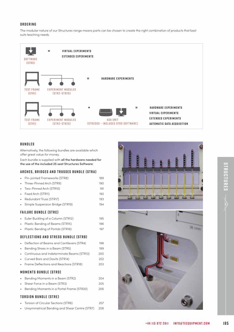
+ 4 4 1 1 5 9 7 2 2 6 1 1 I N F O @ T E C Q U I P M E N T. C O M 1 8 5
Str
uc
tur
es
= V I R T UAL E X P E R I M E N T S
e x t e n d e d e x p e r i m e n t sS o f twar e
( S T R S )
= HAR D WAR E E X P E R I M E N T S
E x p e r i m e n t M o d u l e s( S T R 2 – S T R 2 0 )
T e s t F ram e( S T R 1 )
+
A D A U n i t( S T R 2 0 0 0 – i n c l u d e s S T R S S o f twar e )
= HAR D WAR E E X P E R I M E N T S
V I R T UAL E X P E R I M E N T S
e x t e n d e d e x p e r i m e n t s
AU T O MAT I C DATA ACQU I S I T I O NE x p e r i m e n t M o d u l e s
( S T R 2 – S T R 2 0 )T e s t F ram e
( S T R 1 )
O r d e r i n g
The modular nature of our Structures range means parts can be chosen to create the right combination of products that best
suits teaching needs.
B u n d l e s
Alternatively, the following bundles are available which
offer great value for money.
Each bundle is supplied with all the hardware needed for
the use of the included 25 seat Structures Software:
A R C H E S , B R I D G E S A N D T R U S S E S b u n d l e ( S T R A )
• Pin-jointed Frameworks (STR8) 189
• Three-Pinned Arch (STR9) 190
• Two-Pinned Arch (STR10) 191
• Fixed Arch (STR11) 192
• Redundant Truss (STR17) 193
• Simple Suspension Bridge (STR19) 194
FA I L U R E b u n d l e ( S T R C )
• Euler Buckling of a Column (STR12) 195
• Plastic Bending of Beams (STR15) 196
• Plastic Bending of Portals (STR16) 197
D E F L E C T I O N S A N D S T R E S S b u n d l e ( S T R B )
• Deflection of Beams and Cantilevers (STR4) 198
• Bending Stress in a Beam (STR5) 199
• Continuous and Indeterminate Beams (STR13) 200
• Curved Bars and Davits (STR14) 202
• Frame Deflections and Reactions (STR18) 203
M O M E N T S b u n d l e ( S T R D )
• Bending Moments in a Beam (STR2) 204
• Shear Force in a Beam (STR3) 205
• Bending Moments in a Portal Frame (STR20) 206
T O R S I O N b u n d l e ( S T R E )
• Torsion of Circular Sections (STR6) 207
• Unsymmetrical Bending and Shear Centre (STR7) 208
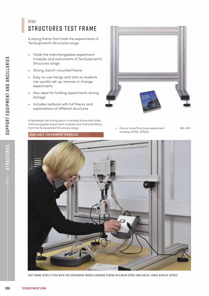
Str
uc
tur
es
T E C Q U I P M E N T. C O M1 8 6
Su
pp
or
t eq
uip
men
t a
nd
an
cil
lar
ies
A lightweight yet strong bench-mounted frame that holds
interchangeable experiment modules and instrumentation
from the TecQuipment Structures range.
• Holds the interchangeable experiment
modules and instruments of TecQuipment’s
Structures range
• Strong, bench-mounted frame
• Easy-to-use fixings and slots so students
can quickly set up, remove or change
experiments
• Also ideal for holding experiments during
storage
• Includes textbook with full theory and
explanations of different structures
• One or more Structures experiment 189–208
modules (STR2–STR20)ava i labl e e x p e r i m e n t m o d u l e s :
T e s t F r a m e ( S T R 1 ) f i t t e d w i t h t h e e x p e r i m e n t m o d u l e B e n d i n g S t r e s s i n a B e a m ( S T R 5 ) a n d D i g i ta l F o r c e D i s p l ay ( S T R 1 a )
S T R 1
S t r u c t u r e s T e s t F r a m e
A strong frame that holds the experiments ofTecQuipment’s Structures range.
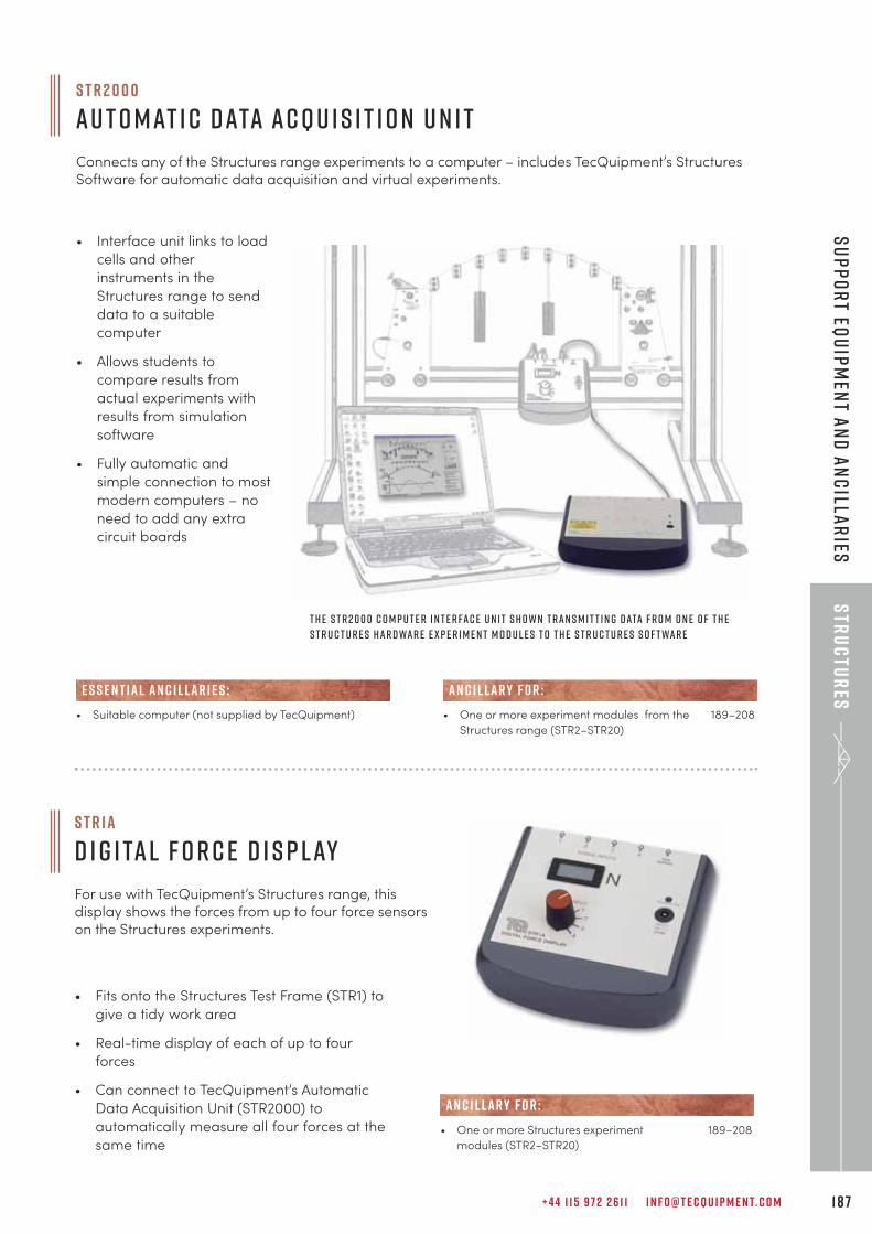
+ 4 4 1 1 5 9 7 2 2 6 1 1 I N F O @ T E C Q U I P M E N T. C O M 1 8 7
Str
uc
tur
esS
up
po
rt eq
uip
men
t an
d a
nc
illar
ies
S T R 2 0 0 0
Au t o m at i c D ata Ac q u i s i t i o n U n i t
Connects any of the Structures range experiments to a computer – includes TecQuipment’s StructuresSoftware for automatic data acquisition and virtual experiments.
• Suitable computer (not supplied by TecQuipment)
E S S E N T IAL AN C I L LAR I E S :
• Interface unit links to load
cells and other
instruments in the
Structures range to send
data to a suitable
computer
• Allows students to
compare results from
actual experiments with
results from simulation
software
• Fully automatic and
simple connection to most
modern computers – no
need to add any extra
circuit boards
T h e S T R 2 0 0 0 c o m p u t e r i n t e r fa c e u n i t s h o w n t r a n s m i t t i n g d ata f r o m o n e o f t h e
S t r u c t u r e s h a r d wa r e e x p e r i m e n t m o d u l e s t o t h e S t r u c t u r e s S o f t wa r e
S T R 1 a
D i g i ta l F o r c e D i s p l ay
For use with TecQuipment’s Structures range, thisdisplay shows the forces from up to four force sensorson the Structures experiments.
• One or more Structures experiment 189–208
modules (STR2–STR20)
AN C I L LAR Y F O R :
• Fits onto the Structures Test Frame (STR1) to
give a tidy work area
• Real-time display of each of up to four
forces
• Can connect to TecQuipment’s Automatic
Data Acquisition Unit (STR2000) to
automatically measure all four forces at the
same time
• One or more experiment modules from the 189–208
Structures range (STR2–STR20)
AN C I L LAR Y F O R :
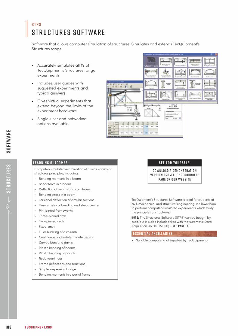
Str
uc
tur
es
T E C Q U I P M E N T. C O M1 8 8
So
ftw
ar
e
• Accurately simulates all 19 of
TecQuipment’s Structures range
experiments
• Includes user guides with
suggested experiments and
typical answers
• Gives virtual experiments that
extend beyond the limits of the
experiment hardware
• Single-user and networked
options available
TecQuipment’s Structures Software is ideal for students of
civil, mechanical and structural engineering. It allows them
to perform computer-simulated experiments which study
the principles of structures.
N o t e : The Structures Software (STRS) can be bought by
itself, but it is also included free with the Automatic Data
Acquisition Unit (STR2000) – s e e pa g e 1 8 7 .
• Suitable computer (not supplied by TecQuipment)
E S S E N T IAL AN C I L LAR I E S :
S T R S
S t r u c t u r e s S o f t wa r e
Software that allows computer simulation of structures. Simulates and extends TecQuipment’sStructures range.
L e a r n i n g o u t c o m e s :
Computer-simulated examination of a wide variety of
structures principles, including:
• Bending moments in a beam
• Shear force in a beam
• Deflection of beams and cantilevers
• Bending stress in a beam
• Torsional deflection of circular sections
• Unsymmetrical bending and shear centre
• Pin-jointed frameworks
• Three-pinned arch
• Two-pinned arch
• Fixed-arch
• Euler buckling of a column
• Continuous and indeterminate beams
• Curved bars and davits
• Plastic bending of beams
• Plastic bending of portals
• Redundant truss
• Frame deflections and reactions
• Simple suspension bridge
• Bending moments in a portal frame
S E E F O R Y O U R S E L F !
D O W N L OAD A D E M O N S T RAT I O NV E R S I O N F R O M T H E “ R E S O U R C E S ”
PAG E O F O U R W E B S I T E
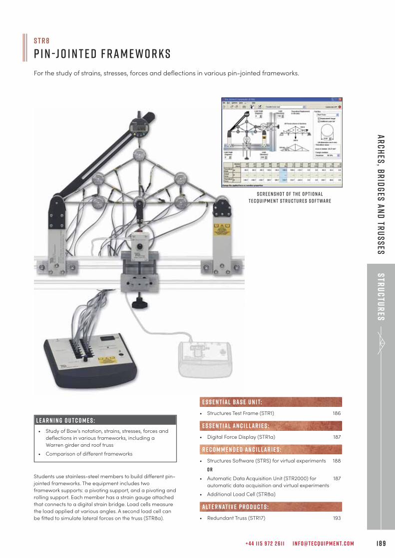
+ 4 4 1 1 5 9 7 2 2 6 1 1 I N F O @ T E C Q U I P M E N T. C O M 1 8 9
Str
uc
tur
esA
rc
hes
, br
idg
es a
nd
tru
ss
es
Students use stainless-steel members to build different pin-
jointed frameworks. The equipment includes two
framework supports: a pivoting support, and a pivoting and
rolling support. Each member has a strain gauge attached
that connects to a digital strain bridge. Load cells measure
the load applied at various angles. A second load cell can
be fitted to simulate lateral forces on the truss (STR8a).
S T R 8
P i n -J o i n t e d F r a m e w o r k s
For the study of strains, stresses, forces and deflections in various pin-jointed frameworks.
S c r e e n s h o t o f t h e o p t i o n a l
T e c Q u i p m e n t S t r u c t u r e s S o f t wa r e
L E A R N I N G O U T C O M E S :
• Study of Bow’s notation, strains, stresses, forces and
deflections in various frameworks, including a
Warren girder and roof truss
• Comparison of different frameworks
• Structures Test Frame (STR1) 186
• Digital Force Display (STR1a) 187
• Structures Software (STRS) for virtual experiments 188
o r
• Automatic Data Acquisition Unit (STR2000) for 187
automatic data acquisition and virtual experiments
• Additional Load Cell (STR8a)
• Redundant Truss (STR17) 193
alt e r nat i v e p r o d u c t s :
e s s e n t ial bas e u n i t:
E S S E N T IAL AN C I L LAR I E S :
R E C O M M E N D E D AN C I L LAR I E S :
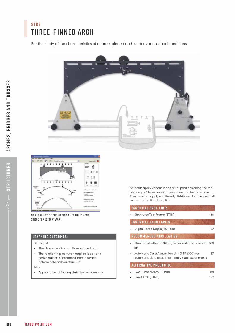
Str
uc
tur
es
T E C Q U I P M E N T. C O M1 9 0
Ar
ch
es,
br
idg
es a
nd
tr
us
ses
Students apply various loads at set positions along the top
of a simple ‘determinate’ three-pinned arched structure.
They can also apply a uniformly distributed load. A load cell
measures the thrust reaction.
• Structures Test Frame (STR1) 186
• Digital Force Display (STR1a) 187
• Structures Software (STRS) for virtual experiments 188
o r
• Automatic Data Acquisition Unit (STR2000) for 187
automatic data acquisition and virtual experiments
• Two-Pinned Arch (STR10) 191
• Fixed Arch (STR11) 192
alt e r nat i v e p r o d u c t s :
e s s e n t ial bas e u n i t:
E S S E N T IAL AN C I L LAR I E S :
R E C O M M E N D E D AN C I L LAR I E S :
S c r e e n s h o t o f t h e o p t i o n a l T e c Q u i p m e n t
S t r u c t u r e s S o f t wa r e
L E A R N I N G O U T C O M E S :
Studies of:
• The characteristics of a three-pinned arch
• The relationship between applied loads and
horizontal thrust produced from a simple
determinate arched structure
Also:
• Appreciation of footing stability and economy.
S T R 9
T h r e e - P i n n e d Ar c h
For the study of the characteristics of a three-pinned arch under various load conditions.
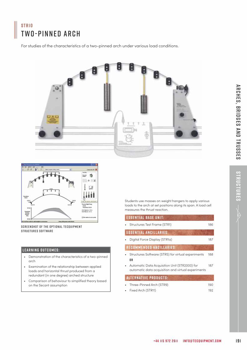
+ 4 4 1 1 5 9 7 2 2 6 1 1 I N F O @ T E C Q U I P M E N T. C O M 1 9 1
Str
uc
tur
esA
rc
hes
, br
idg
es a
nd
tru
ss
es
Students use masses on weight hangers to apply various
loads to the arch at set positions along its span. A load cell
measures the thrust reaction.
• Structures Test Frame (STR1) 186
• Digital Force Display (STR1a) 187
• Structures Software (STRS) for virtual experiments 188
o r
• Automatic Data Acquisition Unit (STR2000) for 187
automatic data acquisition and virtual experiments
• Three-Pinned Arch (STR9) 190
• Fixed Arch (STR11) 192
alt e r nat i v e p r o d u c t s :
e s s e n t ial bas e u n i t:
E S S E N T IAL AN C I L LAR I E S :
R E C O M M E N D E D AN C I L LAR I E S :L E A R N I N G O U T C O M E S :
• Demonstration of the characteristics of a two-pinned
arch
• Examination of the relationship between applied
loads and horizontal thrust produced from a
redundant (in one degree) arched structure
• Comparison of behaviour to simplified theory based
on the Secant assumption
S c r e e n s h o t o f t h e o p t i o n a l T e c Q u i p m e n t
S t r u c t u r e s S o f t wa r e
S T R 1 0
T w o - P i n n e d Ar c h
For studies of the characteristics of a two-pinned arch under various load conditions.
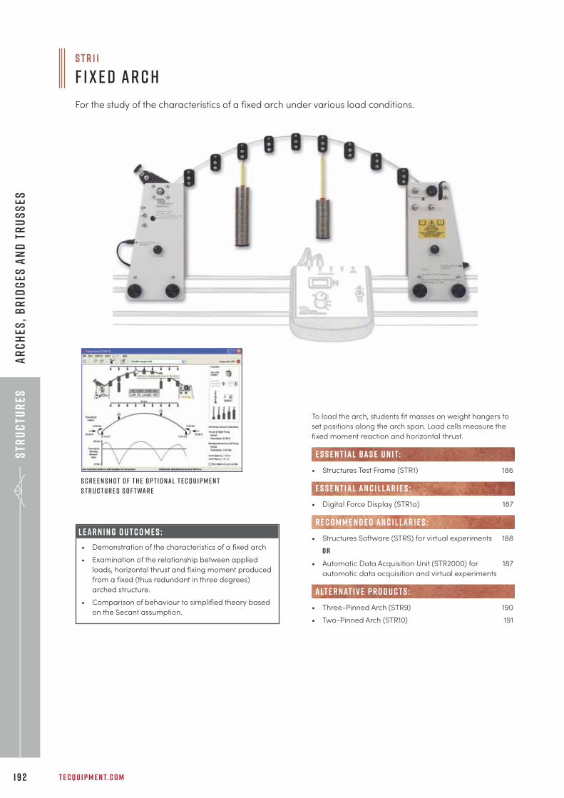
Str
uc
tur
es
T E C Q U I P M E N T. C O M1 9 2
Ar
ch
es,
br
idg
es a
nd
tr
us
ses
L E A R N I N G O U T C O M E S :
• Demonstration of the characteristics of a fixed arch
• Examination of the relationship between applied
loads, horizontal thrust and fixing moment produced
from a fixed (thus redundant in three degrees)
arched structure.
• Comparison of behaviour to simplified theory based
on the Secant assumption.
To load the arch, students fit masses on weight hangers to
set positions along the arch span. Load cells measure the
fixed moment reaction and horizontal thrust.
• Structures Test Frame (STR1) 186
• Digital Force Display (STR1a) 187
• Structures Software (STRS) for virtual experiments 188
o r
• Automatic Data Acquisition Unit (STR2000) for 187
automatic data acquisition and virtual experiments
• Three-Pinned Arch (STR9) 190
• Two-Pinned Arch (STR10) 191
alt e r nat i v e p r o d u c t s :
e s s e n t ial bas e u n i t:
E S S E N T IAL AN C I L LAR I E S :
R E C O M M E N D E D AN C I L LAR I E S :
S c r e e n s h o t o f t h e o p t i o n a l T e c Q u i p m e n t
S t r u c t u r e s S o f t wa r e
S T R 1 1
F i x e d Ar c h
For the study of the characteristics of a fixed arch under various load conditions.
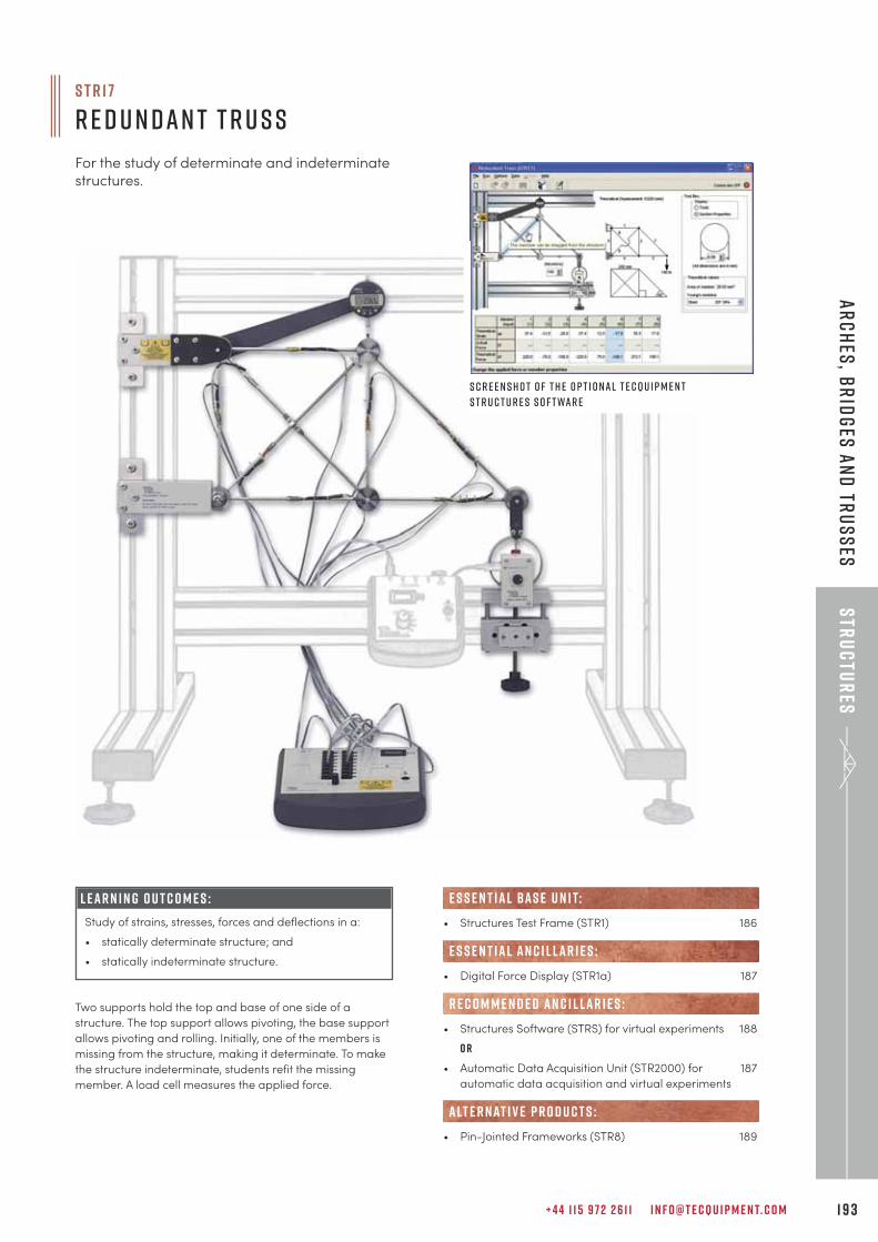
+ 4 4 1 1 5 9 7 2 2 6 1 1 I N F O @ T E C Q U I P M E N T. C O M 1 9 3
Str
uc
tur
esA
rc
hes
, br
idg
es a
nd
tru
ss
es
L E A R N I N G O U T C O M E S :
Study of strains, stresses, forces and deflections in a:
• statically determinate structure; and
• statically indeterminate structure.
S T R 1 7
R e d u n d a n t T r u s s
For the study of determinate and indeterminatestructures.
Two supports hold the top and base of one side of a
structure. The top support allows pivoting, the base support
allows pivoting and rolling. Initially, one of the members is
missing from the structure, making it determinate. To make
the structure indeterminate, students refit the missing
member. A load cell measures the applied force.
• Structures Test Frame (STR1) 186
• Digital Force Display (STR1a) 187
• Structures Software (STRS) for virtual experiments 188
o r
• Automatic Data Acquisition Unit (STR2000) for 187
automatic data acquisition and virtual experiments
• Pin-Jointed Frameworks (STR8) 189
alt e r nat i v e p r o d u c t s :
e s s e n t ial bas e u n i t:
E S S E N T IAL AN C I L LAR I E S :
R E C O M M E N D E D AN C I L LAR I E S :
S c r e e n s h o t o f t h e o p t i o n a l T e c Q u i p m e n t
S t r u c t u r e s S o f t wa r e
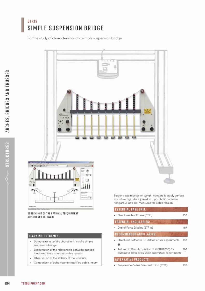
Str
uc
tur
es
T E C Q U I P M E N T. C O M1 9 4
Ar
ch
es,
br
idg
es a
nd
tr
us
ses
L E A R N I N G O U T C O M E S :
• Demonstration of the characteristics of a simple
suspension bridge
• Examination of the relationship between applied
loads and the suspension cable tension
• Observation of the stability of the structure
• Comparison of behaviour to simplified cable theory
S c r e e n s h o t o f t h e o p t i o n a l T e c Q u i p m e n t
S t r u c t u r e s S o f t wa r e
s t r 1 9
S i m p l e S u s p e n s i o n B r i d g e
For the study of characteristics of a simple suspension bridge.
Students use masses on weight hangers to apply various
loads to a rigid deck, joined to a parabolic cable via
hangers. A load cell measures the cable tension.
• Structures Test Frame (STR1) 186
• Digital Force Display (STR1a) 187
• Structures Software (STRS) for virtual experiments 188
o r
• Automatic Data Acquisition Unit (STR2000) for 187
automatic data acquisition and virtual experiments
• Suspension Cable Demonstration (STF2) 180
alt e r nat i v e p r o d u c t s :
e s s e n t ial bas e u n i t:
E S S E N T IAL AN C I L LAR I E S :
R E C O M M E N D E D AN C I L LAR I E S :
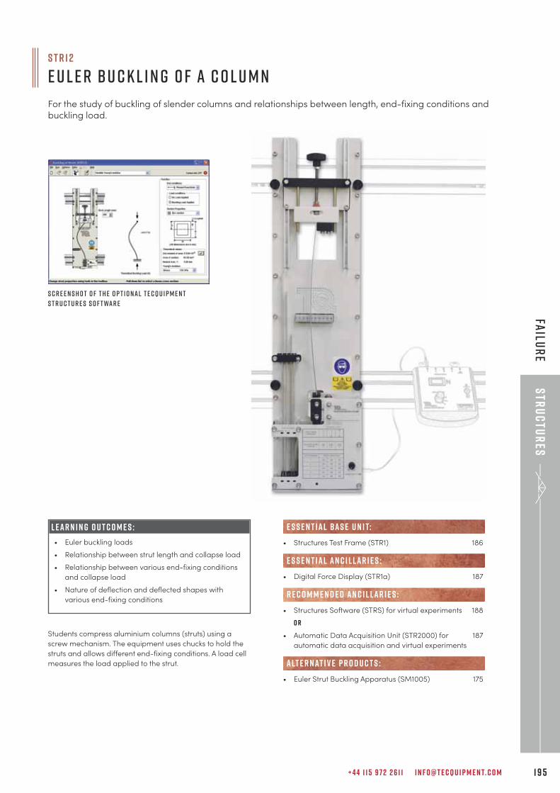
+ 4 4 1 1 5 9 7 2 2 6 1 1 I N F O @ T E C Q U I P M E N T. C O M 1 9 5
Str
uc
tur
esFa
ilur
e
L E A R N I N G O U T C O M E S :
• Euler buckling loads
• Relationship between strut length and collapse load
• Relationship between various end-fixing conditions
and collapse load
• Nature of deflection and deflected shapes with
various end-fixing conditions
Students compress aluminium columns (struts) using a
screw mechanism. The equipment uses chucks to hold the
struts and allows different end-fixing conditions. A load cell
measures the load applied to the strut.
S c r e e n s h o t o f t h e o p t i o n a l T e c Q u i p m e n t
S t r u c t u r e s S o f t wa r e
S T R 1 2
E u l e r B u c k l i n g o f a C o l u m n
For the study of buckling of slender columns and relationships between length, end-fixing conditions andbuckling load.
• Structures Test Frame (STR1) 186
• Digital Force Display (STR1a) 187
• Structures Software (STRS) for virtual experiments 188
o r
• Automatic Data Acquisition Unit (STR2000) for 187
automatic data acquisition and virtual experiments
• Euler Strut Buckling Apparatus (SM1005) 175
alt e r nat i v e p r o d u c t s :
e s s e n t ial bas e u n i t:
E S S E N T IAL AN C I L LAR I E S :
R E C O M M E N D E D AN C I L LAR I E S :
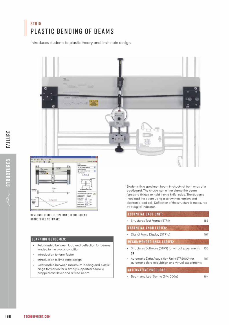
Str
uc
tur
es
T E C Q U I P M E N T. C O M1 9 6
Fail
ur
e
Students fix a specimen beam in chucks at both ends of a
backboard. The chucks can either clamp the beam
(encastré fixing), or hold it on a knife-edge. The students
then load the beam using a screw mechanism and
electronic load cell. Deflection of the structure is measured
by a digital indicator.
• Structures Test Frame (STR1) 186
• Digital Force Display (STR1a) 187
• Structures Software (STRS) for virtual experiments 188
o r
• Automatic Data Acquisition Unit (STR2000) for 187
automatic data acquisition and virtual experiments
• Beam and Leaf Spring (SM1000g) 164
alt e r nat i v e p r o d u c t s :
e s s e n t ial bas e u n i t:
E S S E N T IAL AN C I L LAR I E S :
R E C O M M E N D E D AN C I L LAR I E S :
S c r e e n s h o t o f t h e o p t i o n a l T e c Q u i p m e n t
S t r u c t u r e s S o f t wa r e
S T R 1 5
P l a s t i c B e n d i n g o f B e a m s
Introduces students to plastic theory and limit state design.
L E A R N I N G O U T C O M E S :
• Relationship between load and deflection for beams
loaded to the plastic condition
• Introduction to form factor
• Introduction to limit state design
• Relationship between maximum loading and plastic
hinge formation for a simply supported beam, a
propped cantilever and a fixed beam
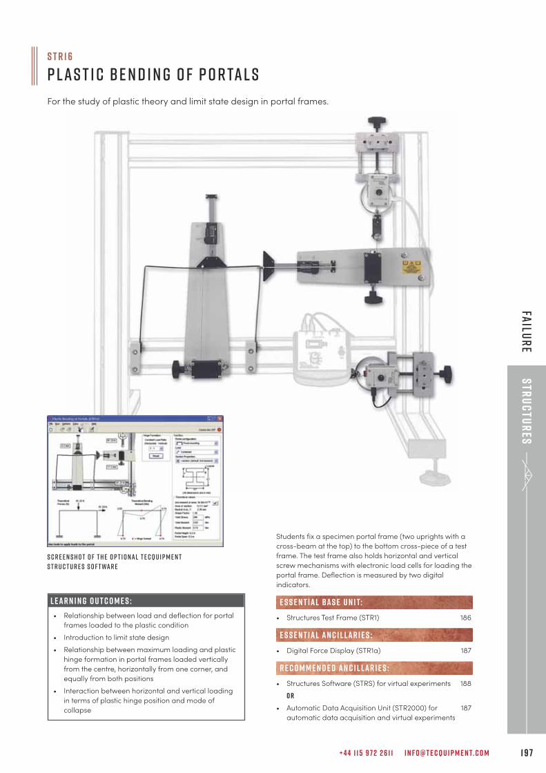
+ 4 4 1 1 5 9 7 2 2 6 1 1 I N F O @ T E C Q U I P M E N T. C O M 1 9 7
Str
uc
tur
esFa
ilur
e
S c r e e n s h o t o f t h e o p t i o n a l T e c Q u i p m e n t
S t r u c t u r e s S o f t wa r e
S T R 1 6
P l a s t i c B e n d i n g o f P o r ta l s
For the study of plastic theory and limit state design in portal frames.
L E A R N I N G O U T C O M E S :
• Relationship between load and deflection for portal
frames loaded to the plastic condition
• Introduction to limit state design
• Relationship between maximum loading and plastic
hinge formation in portal frames loaded vertically
from the centre, horizontally from one corner, and
equally from both positions
• Interaction between horizontal and vertical loading
in terms of plastic hinge position and mode of
collapse
Students fix a specimen portal frame (two uprights with a
cross-beam at the top) to the bottom cross-piece of a test
frame. The test frame also holds horizontal and vertical
screw mechanisms with electronic load cells for loading the
portal frame. Deflection is measured by two digital
indicators.
• Structures Test Frame (STR1) 186
• Digital Force Display (STR1a) 187
• Structures Software (STRS) for virtual experiments 188
o r
• Automatic Data Acquisition Unit (STR2000) for 187
automatic data acquisition and virtual experiments
e s s e n t ial bas e u n i t:
E S S E N T IAL AN C I L LAR I E S :
R E C O M M E N D E D AN C I L LAR I E S :
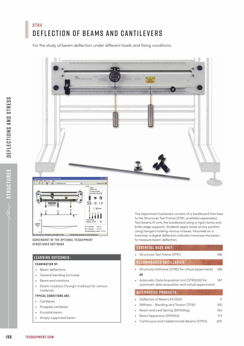
Str
uc
tur
es
T E C Q U I P M E N T. C O M1 9 8
Def
lec
tio
ns
an
d S
tres
s
L E A R N I N G O U T C O M E S :
E x a m i n at i o n o f :
• Beam deflections
• General bending formulae
• Beam end rotations
• Elastic modulus (Young’s modulus) for various
materials
T y p i c a l c o n d i t i o n s a r e :
• Cantilever
• Propped cantilever
• Encastré beam
• Simply supported beam
The experiment hardware consists of a backboard that fixes
to the Structures Test Frame (STR1, available separately).
Test beams fit onto the backboard using a rigid clamp and
knife-edge supports. Students apply loads at any position
using hangers holding various masses. Mounted on a
trammel, a digital deflection indicator traverses the beam
to measure beam deflection.
• Structures Test Frame (STR1) 186
• Structures Software (STRS) for virtual experiments 188
o r
• Automatic Data Acquisition Unit (STR2000) for 187
automatic data acquisition and virtual experiments
• Deflection of Beams Kit (ES4) 11
• Stiffness – Bending and Torsion (TE16) 150
• Beam and Leaf Spring (SM1000g) 164
• Beam Apparatus (SM1004) 173
• Continuous and Indeterminate Beams (STR13) 200
e s s e n t ial bas e u n i t:
R E C O M M E N D E D AN C I L LAR I E S :
alt e r nat i v e p r o d u c t s :
S c r e e n s h o t o f t h e o p t i o n a l T e c Q u i p m e n t
S t r u c t u r e s S o f t wa r e
S T R 4
D e f l e c t i o n o f B e a m s a n d C a n t i l e v e r s
For the study of beam deflection under different loads and fixing conditions.
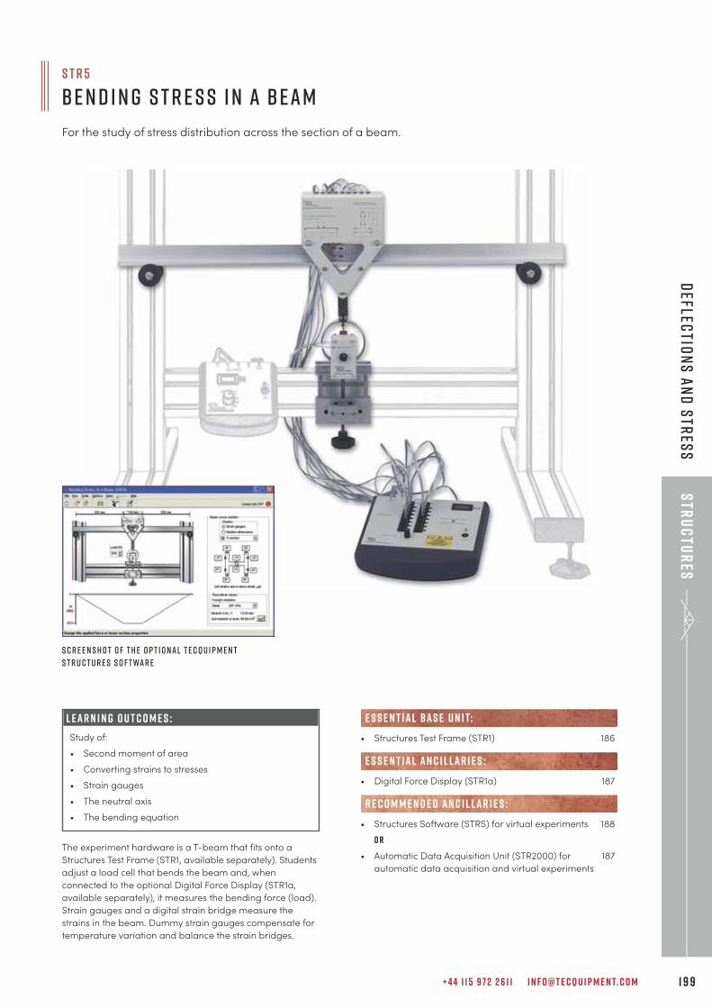
+ 4 4 1 1 5 9 7 2 2 6 1 1 I N F O @ T E C Q U I P M E N T. C O M 1 9 9
Str
uc
tur
esD
eflectio
ns
an
d S
tres
s
L E A R N I N G O U T C O M E S :
Study of:
• Second moment of area
• Converting strains to stresses
• Strain gauges
• The neutral axis
• The bending equation
The experiment hardware is a T-beam that fits onto a
Structures Test Frame (STR1, available separately). Students
adjust a load cell that bends the beam and, when
connected to the optional Digital Force Display (STR1a,
available separately), it measures the bending force (load).
Strain gauges and a digital strain bridge measure the
strains in the beam. Dummy strain gauges compensate for
temperature variation and balance the strain bridges.
S c r e e n s h o t o f t h e o p t i o n a l T e c Q u i p m e n t
S t r u c t u r e s S o f t wa r e
S T R 5
B e n d i n g S t r e s s i n a B e a m
For the study of stress distribution across the section of a beam.
• Structures Test Frame (STR1) 186
• Digital Force Display (STR1a) 187
• Structures Software (STRS) for virtual experiments 188
o r
• Automatic Data Acquisition Unit (STR2000) for 187
automatic data acquisition and virtual experiments
e s s e n t ial bas e u n i t:
E S S E N T IAL AN C I L LAR I E S :
R E C O M M E N D E D AN C I L LAR I E S :
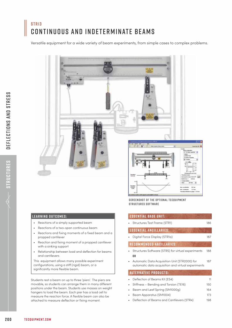
Str
uc
tur
es
T E C Q U I P M E N T. C O M2 0 0
Def
lec
tio
ns
an
d S
tres
s
• Structures Test Frame (STR1) 186
• Digital Force Display (STR1a) 187
• Structures Software (STRS) for virtual experiments 188
o r
• Automatic Data Acquisition Unit (STR2000) for 187
automatic data acquisition and virtual experiments
• Deflection of Beams Kit (ES4) 11
• Stiffness – Bending and Torsion (TE16) 150
• Beam and Leaf Spring (SM1000g) 164
• Beam Apparatus (SM1004) 173
• Deflection of Beams and Cantilevers (STR4) 198
alt e r nat i v e p r o d u c t s :
e s s e n t ial bas e u n i t:
E S S E N T IAL AN C I L LAR I E S :
R E C O M M E N D E D AN C I L LAR I E S :
S c r e e n s h o t o f t h e o p t i o n a l T e c Q u i p m e n t
S t r u c t u r e s S o f t wa r e
S T R 1 3
C o n t i n u o u s a n d I n d e t e r m i n at e B e a m s
Versatile equipment for a wide variety of beam experiments, from simple cases to complex problems.
Students rest a beam on up to three ‘piers’. The piers are
movable, so students can arrange them in many different
positions under the beam. Students use masses on weight
hangers to load the beam. Each pier has a load cell to
measure the reaction force. A flexible beam can also be
attached to measure deflection or fixing moment.
L E A R N I N G O U T C O M E S :
• Reactions of a simply supported beam
• Reactions of a two-span continuous beam
• Reactions and fixing moments of a fixed beam and a
propped cantilever
• Reaction and fixing moment of a propped cantilever
with a sinking support
• Relationship between load and deflection for beams
and cantilevers
This equipment allows many possible experiment
configurations, using a stiff (rigid) beam, or a
significantly more flexible beam.

+ 4 4 1 1 5 9 7 2 2 6 1 1 I N F O @ T E C Q U I P M E N T. C O M 2 0 1
O u r M at e r i a l s T e s t i n g a n d P r o p e r t i e s r a n g e a l s o e x t e n d s i n t o t h e a r e a o f s t r u c t u r e s a n d s t r u c t u r a l
e l e m e n t s a n d i n c l u d e s t h e f o l l o w i n g f r e e - s ta n d i n g p r o d u c t s :
U n s y m m e t r i c a l C a n t i l e v e r A p pa r at u s (SM1003) – Pa g e 1 7 2
Examines and displays bending of an unsymmetrical cantilever
B e a m A p pa r at u s (SM1004) – Pa g e 1 7 3
Examines the deflection and forces on different types of beams for a
wide range of supports and loads
e u l e r S t r u t b u c k l i n g a p pa r at u s (SM1005) – Pa g e 1 7 5
Tests different types of struts and demonstrates how they deflect under load
H av e y o u a l s o s e e n o u r M at e r i a l s T e s t i n g r a n g e ?
The above equipment is compatible with TecQuipment’s Versatile Data Acquisition system
(VDAS®). This gives accurate real-time data capture, monitoring and display, calculation
and charting of all important readings on a computer – pa g e 2 9 3 .
E u l e r s t r u t b u c k l i n g a p pa r at s ( S M 1 0 0 5 )
S M 1 0 0 3 V DAS ® S c r e e n s h o t
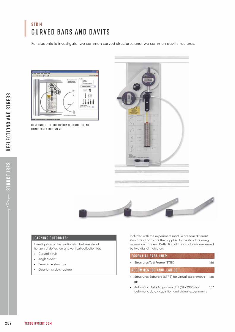
Str
uc
tur
es
T E C Q U I P M E N T. C O M2 0 2
Def
lec
tio
ns
an
d S
tres
s
L E A R N I N G O U T C O M E S :
Investigation of the relationship between load,
horizontal deflection and vertical deflection for:
• Curved davit
• Angled davit
• Semicircle structure
• Quarter-circle structure
Included with the experiment module are four different
structures. Loads are then applied to the structure using
masses on hangers. Deflection of the structure is measured
by two digital indicators.
• Structures Test Frame (STR1) 186
• Structures Software (STRS) for virtual experiments 188
o r
• Automatic Data Acquisition Unit (STR2000) for 187
automatic data acquisition and virtual experiments
e s s e n t ial bas e u n i t:
R E C O M M E N D E D AN C I L LAR I E S :
S c r e e n s h o t o f t h e o p t i o n a l T e c Q u i p m e n t
S t r u c t u r e s S o f t wa r e
S T R 1 4
C u r v e d B a r s a n d D av i t s
For students to investigate two common curved structures and two common davit structures.
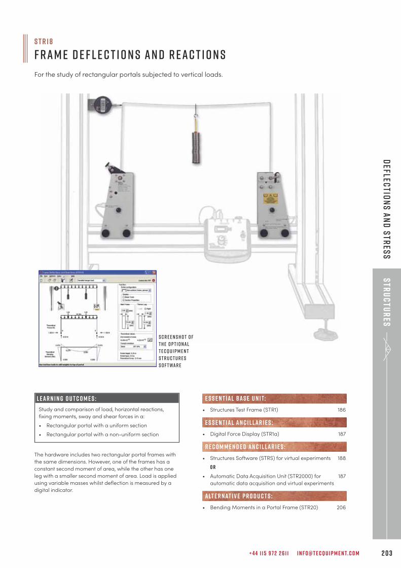
+ 4 4 1 1 5 9 7 2 2 6 1 1 I N F O @ T E C Q U I P M E N T. C O M 2 0 3
Str
uc
tur
esD
eflectio
ns
an
d s
tres
s
L E A R N I N G O U T C O M E S :
Study and comparison of load, horizontal reactions,
fixing moments, sway and shear forces in a:
• Rectangular portal with a uniform section
• Rectangular portal with a non-uniform section
The hardware includes two rectangular portal frames with
the same dimensions. However, one of the frames has a
constant second moment of area, while the other has one
leg with a smaller second moment of area. Load is applied
using variable masses whilst deflection is measured by a
digital indicator.
S T R 1 8
F r a m e D e f l e c t i o n s a n d R e a c t i o n s
For the study of rectangular portals subjected to vertical loads.
S c r e e n s h o t o f
t h e o p t i o n a l
T e c Q u i p m e n t
S t r u c t u r e s
S o f t wa r e
• Structures Test Frame (STR1) 186
• Digital Force Display (STR1a) 187
• Structures Software (STRS) for virtual experiments 188
o r
• Automatic Data Acquisition Unit (STR2000) for 187
automatic data acquisition and virtual experiments
• Bending Moments in a Portal Frame (STR20) 206
alt e r nat i v e p r o d u c t s :
e s s e n t ial bas e u n i t:
E S S E N T IAL AN C I L LAR I E S :
R E C O M M E N D E D AN C I L LAR I E S :
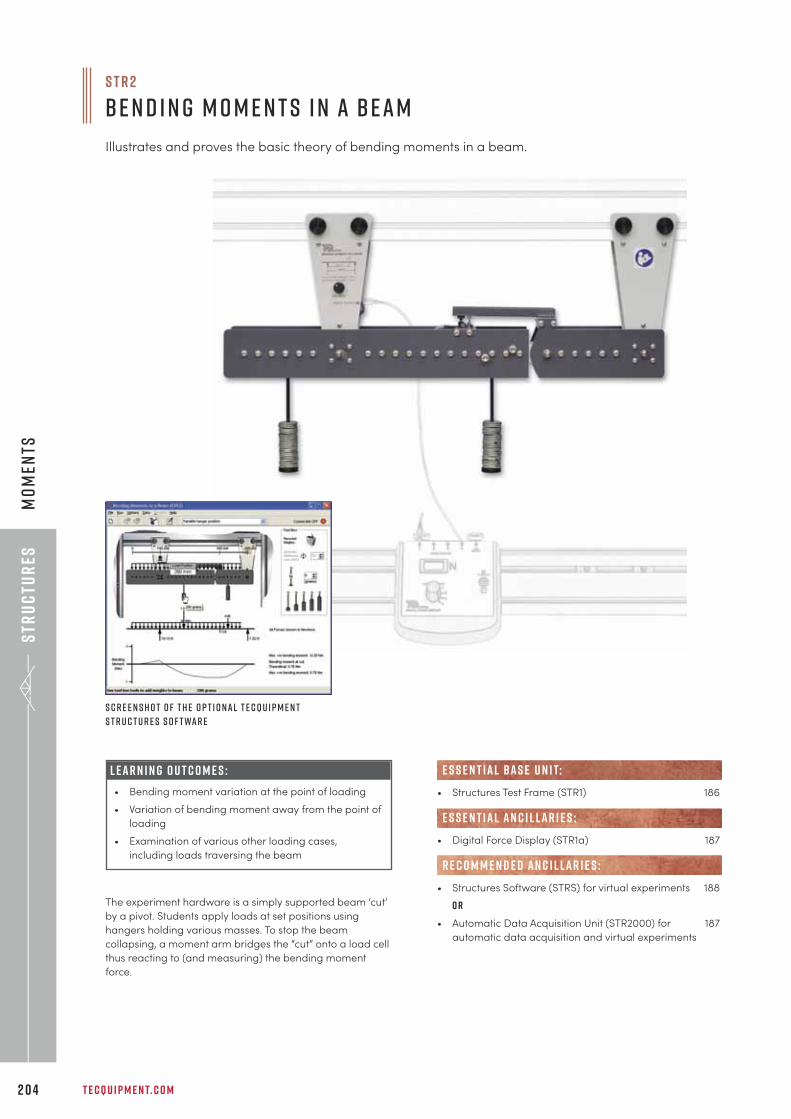
Str
uc
tur
es
T E C Q U I P M E N T. C O M2 0 4
Mo
men
ts
S T R 2
B e n d i n g M o m e n t s i n a B e a m
Illustrates and proves the basic theory of bending moments in a beam.
The experiment hardware is a simply supported beam ‘cut’
by a pivot. Students apply loads at set positions using
hangers holding various masses. To stop the beam
collapsing, a moment arm bridges the “cut” onto a load cell
thus reacting to (and measuring) the bending moment
force.
• Structures Test Frame (STR1) 186
• Digital Force Display (STR1a) 187
• Structures Software (STRS) for virtual experiments 188
o r
• Automatic Data Acquisition Unit (STR2000) for 187
automatic data acquisition and virtual experiments
R E C O M M E N D E D AN C I L LAR I E S :
E S S E N T IAL AN C I L LAR I E S :
e s s e n t ial bas e u n i t:
S c r e e n s h o t o f t h e o p t i o n a l T e c Q u i p m e n t
S t r u c t u r e s S o f t wa r e
L E A R N I N G O U T C O M E S :
• Bending moment variation at the point of loading
• Variation of bending moment away from the point of
loading
• Examination of various other loading cases,
including loads traversing the beam
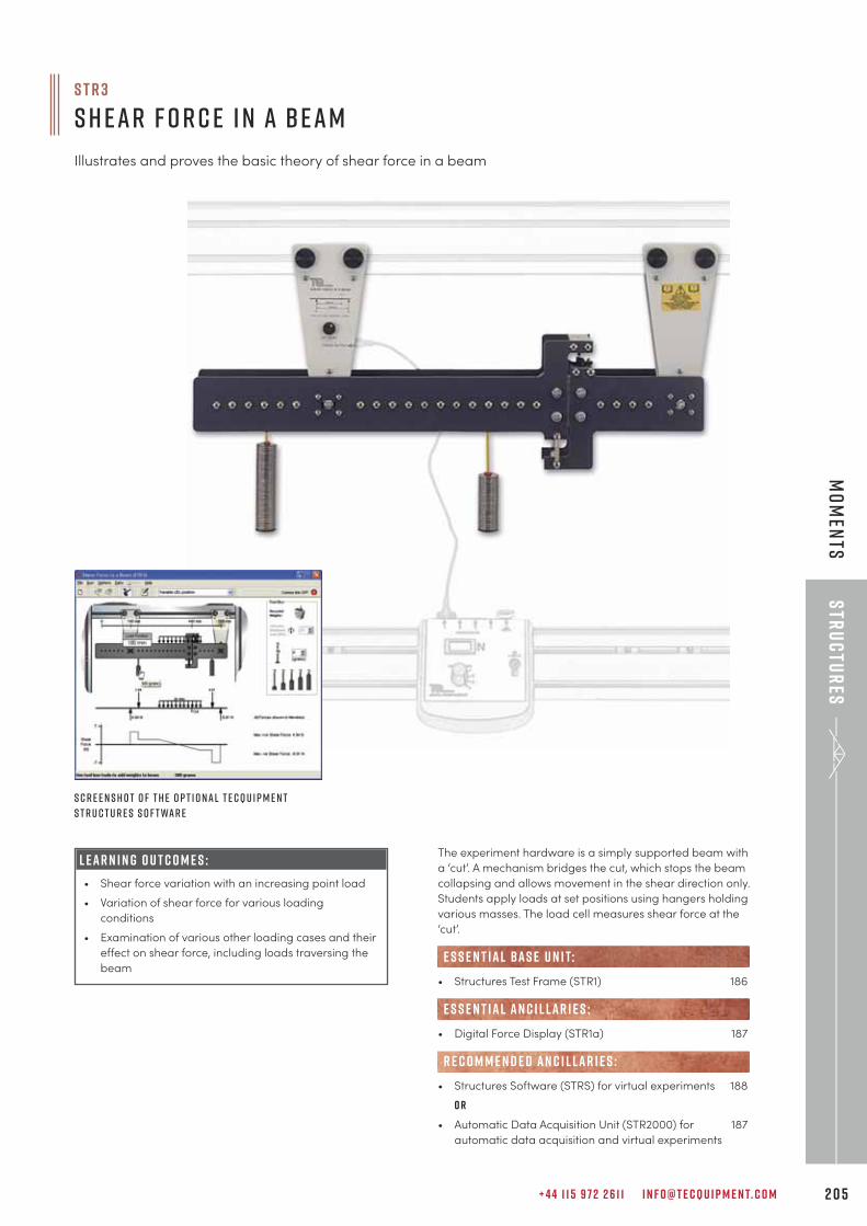
+ 4 4 1 1 5 9 7 2 2 6 1 1 I N F O @ T E C Q U I P M E N T. C O M 2 0 5
Str
uc
tur
esM
om
ents
S T R 3
S h e a r F o r c e i n a B e a m
Illustrates and proves the basic theory of shear force in a beam
The experiment hardware is a simply supported beam with
a ‘cut’. A mechanism bridges the cut, which stops the beam
collapsing and allows movement in the shear direction only.
Students apply loads at set positions using hangers holding
various masses. The load cell measures shear force at the
‘cut’.
• Structures Test Frame (STR1) 186
• Digital Force Display (STR1a) 187
• Structures Software (STRS) for virtual experiments 188
o r
• Automatic Data Acquisition Unit (STR2000) for 187
automatic data acquisition and virtual experiments
e s s e n t ial bas e u n i t:
E S S E N T IAL AN C I L LAR I E S :
R E C O M M E N D E D AN C I L LAR I E S :
S c r e e n s h o t o f t h e o p t i o n a l T e c Q u i p m e n t
S t r u c t u r e s S o f t wa r e
L E A R N I N G O U T C O M E S :
• Shear force variation with an increasing point load
• Variation of shear force for various loading
conditions
• Examination of various other loading cases and their
effect on shear force, including loads traversing the
beam
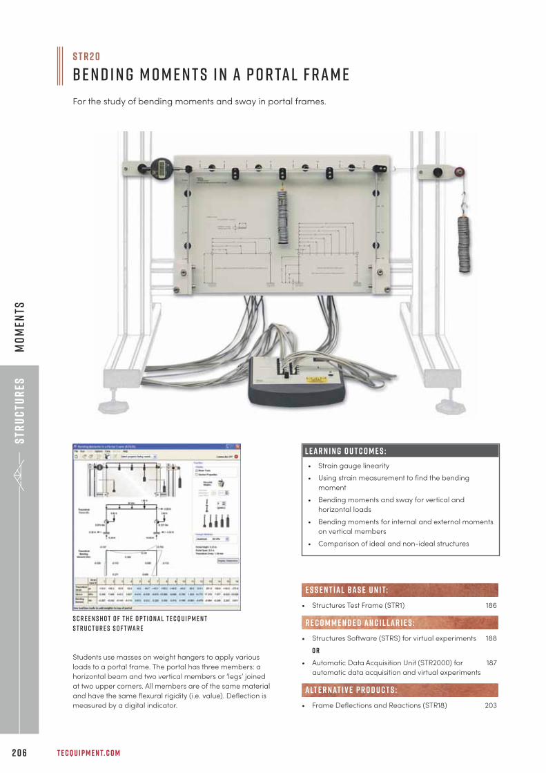
Str
uc
tur
es
T E C Q U I P M E N T. C O M2 0 6
Mo
men
ts
L E A R N I N G O U T C O M E S :
• Strain gauge linearity
• Using strain measurement to find the bending
moment
• Bending moments and sway for vertical and
horizontal loads
• Bending moments for internal and external moments
on vertical members
• Comparison of ideal and non-ideal structures
S T R 2 0
B e n d i n g M o m e n t s i n a P o r ta l F r a m e
For the study of bending moments and sway in portal frames.
S c r e e n s h o t o f t h e o p t i o n a l T e c Q u i p m e n t
S t r u c t u r e s S o f t wa r e
Students use masses on weight hangers to apply various
loads to a portal frame. The portal has three members: a
horizontal beam and two vertical members or ‘legs’ joined
at two upper corners. All members are of the same material
and have the same flexural rigidity (i.e. value). Deflection is
measured by a digital indicator.
• Structures Test Frame (STR1) 186
• Structures Software (STRS) for virtual experiments 188
o r
• Automatic Data Acquisition Unit (STR2000) for 187
automatic data acquisition and virtual experiments
• Frame Deflections and Reactions (STR18) 203
e s s e n t ial bas e u n i t:
R E C O M M E N D E D AN C I L LAR I E S :
alt e r nat i v e p r o d u c t s :
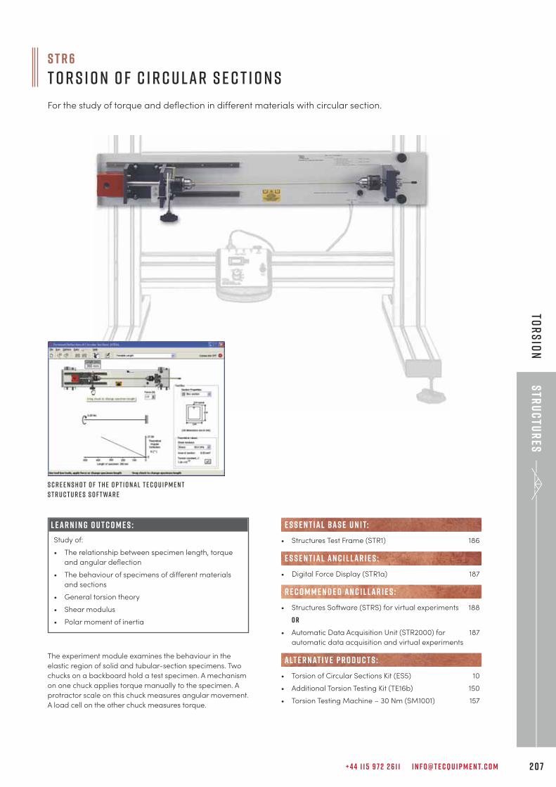
+ 4 4 1 1 5 9 7 2 2 6 1 1 I N F O @ T E C Q U I P M E N T. C O M 2 0 7
Str
uc
tur
esTo
rs
ion
The experiment module examines the behaviour in the
elastic region of solid and tubular-section specimens. Two
chucks on a backboard hold a test specimen. A mechanism
on one chuck applies torque manually to the specimen. A
protractor scale on this chuck measures angular movement.
A load cell on the other chuck measures torque.
• Structures Test Frame (STR1) 186
• Digital Force Display (STR1a) 187
• Structures Software (STRS) for virtual experiments 188
o r
• Automatic Data Acquisition Unit (STR2000) for 187
automatic data acquisition and virtual experiments
• Torsion of Circular Sections Kit (ES5) 10
• Additional Torsion Testing Kit (TE16b) 150
• Torsion Testing Machine – 30 Nm (SM1001) 157
e s s e n t ial bas e u n i t:
E S S E N T IAL AN C I L LAR I E S :
R E C O M M E N D E D AN C I L LAR I E S :
alt e r nat i v e p r o d u c t s :
S c r e e n s h o t o f t h e o p t i o n a l T e c Q u i p m e n t
S t r u c t u r e s S o f t wa r e
S T R 6
T o r s i o n o f C i r c u l a r S e c t i o n s
For the study of torque and deflection in different materials with circular section.
L E A R N I N G O U T C O M E S :
Study of:
• The relationship between specimen length, torque
and angular deflection
• The behaviour of specimens of different materials
and sections
• General torsion theory
• Shear modulus
• Polar moment of inertia
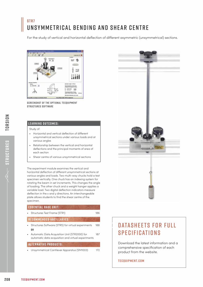
Str
uc
tur
es
T E C Q U I P M E N T. C O M2 0 8
Tor
sio
n
S T R 7
U n s y m m e t r i c a l B e n d i n g a n d S h e a r C e n t r e
For the study of vertical and horizontal deflection of different asymmetric (unsymmetrical) sections.
The experiment module examines the vertical and
horizontal deflection of different unsymmetrical sections at
various angles and loads. Two multi-way chucks hold a test
specimen vertically. One chuck has an indexing system for
rotating the beam in set increments. This changes the angle
of loading. The other chuck and a weight hanger applies a
variable load. Two digital deflection indicators measure
deflection in the x and y directions. An interchangeable
plate allows students to find the shear centre of the
specimen.
• Structures Test Frame (STR1) 186
• Structures Software (STRS) for virtual experiments 188
o r
• Automatic Data Acquisition Unit (STR2000) for 187
automatic data acquisition and virtual experiments
• Unsymmetrical Cantilever Apparatus (SM1003) 172
e s s e n t ial bas e u n i t:
R E C O M M E N D E D AN C I L LAR I E S :
alt e r nat i v e p r o d u c t s :
S c r e e n s h o t o f t h e o p t i o n a l T e c Q u i p m e n t
S t r u c t u r e s S o f t wa r e
L E A R N I N G O U T C O M E S :
Study of:
• Horizontal and vertical deflection of different
unsymmetrical sections under various loads and at
various angles
• Relationship between the vertical and horizontal
deflections and the principal moments of area of
each section
• Shear centre of various unsymmetrical sections
Datas h e e t s f o r F u l l S p e c i f i cat i o n s
Download the latest information and a
comprehensive specification of each
product from the website.
t e cqu i p m e n t. c o m
+ 4 4 1 1 5 9 7 2 2 6 1 1 I N F O @ T E C Q U I P M E N T. C O M 2 0 9
Theo
ry
of M
ac
hin
es
“I have the pleasure to express my full satisfaction with the smooth functioning of theTecQuipment laboratory educational equipment supplied to IUBAT Departments ofMechanical and Civil Engineering. I particularly appreciate TecQuipment’s local agent forassisting IUBAT with free installation, commissioning, testing along with comprehensive training.
P R O F E S S O R M A L I M U L L A H M I YA NI N T E R N AT I O N A L U N I V E R S I T Y O F B U S I N E S S A G R I C U LT U R E A N D T E C H N O L O G Y, B A N G L A D E S H
T H E O R Y O F M A C H I N E SF R I C T I O N 2 1 1
M O T I O N 2 1 5
V I B R AT I O N 2 2 4
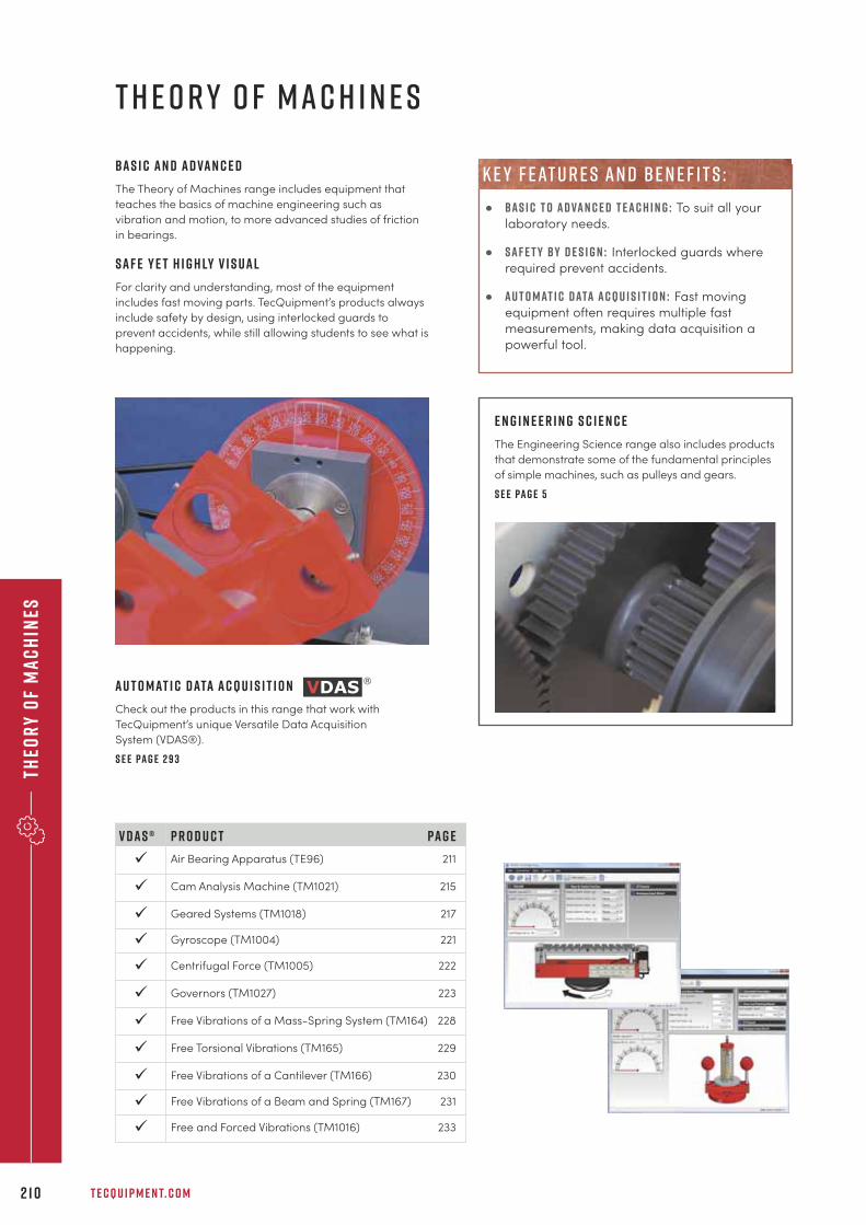
Theo
ry
of
Ma
ch
ines
T E C Q U I P M E N T. C O M2 1 0
B a s i c a n d a d va n c e d
The Theory of Machines range includes equipment that
teaches the basics of machine engineering such as
vibration and motion, to more advanced studies of friction
in bearings.
S a f e y e t h i g h ly v i s u a l
For clarity and understanding, most of the equipment
includes fast moving parts. TecQuipment’s products always
include safety by design, using interlocked guards to
prevent accidents, while still allowing students to see what is
happening.
T H E O R Y O F M A C H I N E S
E n g i n e e r i n g S c i e n c e
The Engineering Science range also includes products
that demonstrate some of the fundamental principles
of simple machines, such as pulleys and gears.
S e e pa g e 5
P r o d u c t Pa g e
Air Bearing Apparatus (TE96) 211
Cam Analysis Machine (TM1021) 215
Geared Systems (TM1018) 217
Gyroscope (TM1004) 221
Centrifugal Force (TM1005) 222
Governors (TM1027) 223
Free Vibrations of a Mass-Spring System (TM164) 228
Free Torsional Vibrations (TM165) 229
Free Vibrations of a Cantilever (TM166) 230
Free Vibrations of a Beam and Spring (TM167) 231
Free and Forced Vibrations (TM1016) 233
V D A S ®
ü
ü
ü
ü
ü
ü
ü
ü
ü
ü
ü
A u t o m at i c d ata a c q u i s i t i o n
Check out the products in this range that work with
TecQuipment’s unique Versatile Data Acquisition
System (VDAS®).
S e e pa g e 2 9 3
• B A S I C T O A D VA N C E D T E A C H I N G : To suit all your
laboratory needs.
• s a f e t y b y d e s i g n : Interlocked guards where
required prevent accidents.
• a u t o m at i c d ata a c q u i s i t i o n : Fast moving
equipment often requires multiple fast
measurements, making data acquisition a
powerful tool.
k e y f e at u r e s a n d b e n e f i t s :
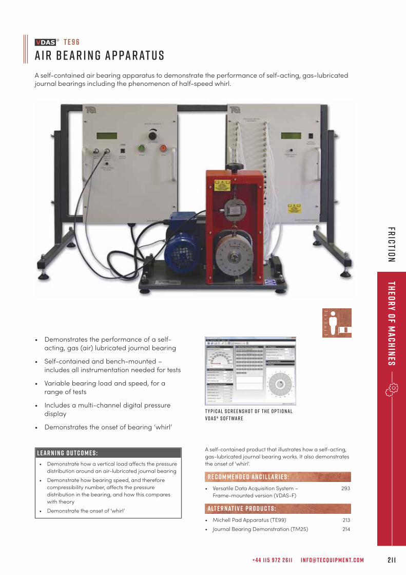
+ 4 4 1 1 5 9 7 2 2 6 1 1 I N F O @ T E C Q U I P M E N T. C O M 2 1 1
Theo
ry
of M
ac
hin
esFr
ictio
n
T E 9 6
A i r B ear i n g A p parat u s
A self-contained air bearing apparatus to demonstrate the performance of self-acting, gas-lubricatedjournal bearings including the phenomenon of half-speed whirl.
• Demonstrates the performance of a self-
acting, gas (air) lubricated journal bearing
• Self-contained and bench-mounted –
includes all instrumentation needed for tests
• Variable bearing load and speed, for a
range of tests
• Includes a multi-channel digital pressure
display
• Demonstrates the onset of bearing ‘whirl’
L E A R N I N G O U T C O M E S :
• Demonstrate how a vertical load affects the pressure
distribution around an air-lubricated journal bearing
• Demonstrate how bearing speed, and therefore
compressibility number, affects the pressure
distribution in the bearing, and how this compares
with theory
• Demonstrate the onset of ‘whirl’
T y p i cal s c r e e n s h o t o f t h e o p t i o nal
V D A S ® s o f t war e
A self-contained product that illustrates how a self-acting,
gas-lubricated journal bearing works. It also demonstrates
the onset of ‘whirl’.
• Versatile Data Acquisition System – 293
Frame-mounted version (VDAS-F)
• Michell Pad Apparatus (TE99) 213
• Journal Bearing Demonstration (TM25) 214
R E C O M M E N D E D AN C I L LAR I E S :
alt e r nat i v e p r o d u c t s :
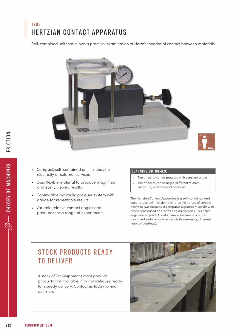
Theo
ry
of
Ma
ch
ines
T E C Q U I P M E N T. C O M2 1 2
Fric
tio
n
T E 9 8
H e r t z ian C o n tac t A p parat u s
Self-contained unit that allows a practical examination of Hertz’s theories of contact between materials.
L E A R N I N G O U T C O M E S :
• The effect of varied pressure with constant angle
• The effect of varied angle (different relative
curvature) with constant pressure
• Compact, self-contained unit – needs no
electricity or external services
• Uses flexible material to produce magnified
and easily viewed results
• Controllable hydraulic pressure system with
gauge for repeatable results
• Variable relative contact angles and
pressures for a range of experiments
The Hertzian Contact Apparatus is a self-contained and
easy-to-use unit that demonstrates the nature of contact
between two surfaces. It compares experiment results with
predictions based on Hertz’s original theories. This helps
engineers to predict contact areas between common
machined surfaces and materials (for example, different
types of bearings).
S t o c k P r o d u c t s R e a d y t o D e l i v e r
A stock of TecQuipment's most popular
products are available in our warehouse ready
for speedy delivery. Contact us today to find
out more.
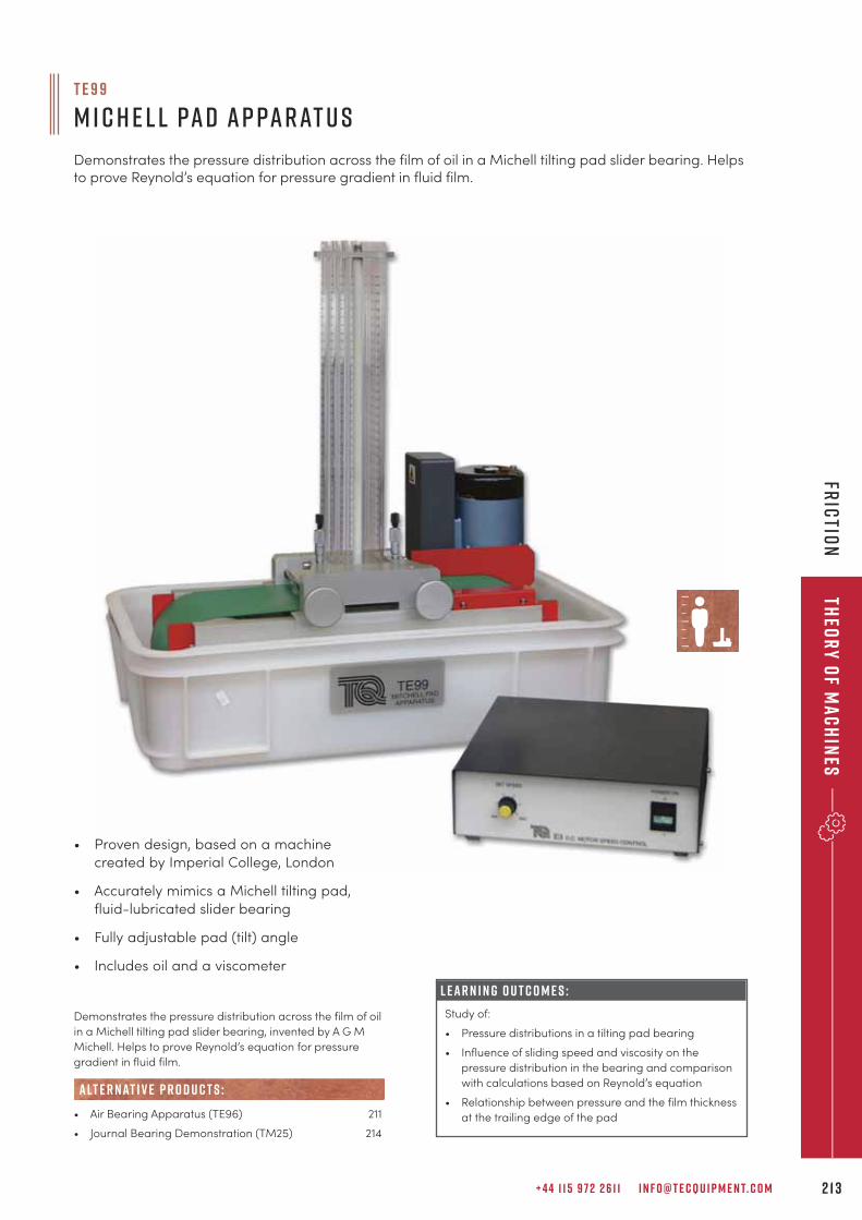
+ 4 4 1 1 5 9 7 2 2 6 1 1 I N F O @ T E C Q U I P M E N T. C O M 2 1 3
Theo
ry
of M
ac
hin
esFr
ictio
n
L E A R N I N G O U T C O M E S :
Study of:
• Pressure distributions in a tilting pad bearing
• Influence of sliding speed and viscosity on the
pressure distribution in the bearing and comparison
with calculations based on Reynold’s equation
• Relationship between pressure and the film thickness
at the trailing edge of the pad
T E 9 9
M i c h e l l Pad A p parat u s
Demonstrates the pressure distribution across the film of oil in a Michell tilting pad slider bearing. Helpsto prove Reynold’s equation for pressure gradient in fluid film.
Demonstrates the pressure distribution across the film of oil
in a Michell tilting pad slider bearing, invented by A G M
Michell. Helps to prove Reynold’s equation for pressure
gradient in fluid film.
• Air Bearing Apparatus (TE96) 211
• Journal Bearing Demonstration (TM25) 214
alt e r nat i v e p r o d u c t s :
• Proven design, based on a machine
created by Imperial College, London
• Accurately mimics a Michell tilting pad,
fluid-lubricated slider bearing
• Fully adjustable pad (tilt) angle
• Includes oil and a viscometer
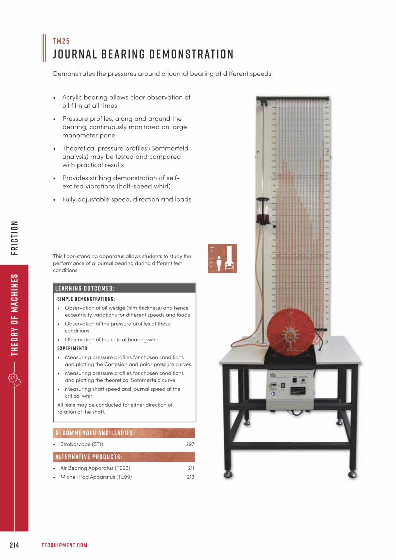
Theo
ry
of
Ma
ch
ines
T E C Q U I P M E N T. C O M2 1 4
Fric
tio
n
T M 2 5
J o u r nal B ear i n g D e m o n s t rat i o n
Demonstrates the pressures around a journal bearing at different speeds.
L E A R N I N G O U T C O M E S :
S i m p l e d e m o n s t r at i o n s :
• Observation of oil wedge (film thickness) and hence
eccentricity variations for different speeds and loads
• Observation of the pressure profiles at these
conditions
• Observation of the critical bearing whirl
E x p e r i m e n t s :
• Measuring pressure profiles for chosen conditions
and plotting the Cartesian and polar pressure curves
• Measuring pressure profiles for chosen conditions
and plotting the theoretical Sommerfeld curve
• Measuring shaft speed and journal speed at the
critical whirl
All tests may be conducted for either direction of
rotation of the shaft.
• Acrylic bearing allows clear observation of
oil film at all times
• Pressure profiles, along and around the
bearing, continuously monitored on large
manometer panel
• Theoretical pressure profiles (Sommerfeld
analysis) may be tested and compared
with practical results
• Provides striking demonstration of self-
excited vibrations (half-speed whirl)
• Fully adjustable speed, direction and loads
This floor-standing apparatus allows students to study the
performance of a journal bearing during different test
conditions.
• Stroboscope (ST1) 297
• Air Bearing Apparatus (TE96) 211
• Michell Pad Apparatus (TE99) 213
alt e r nat i v e p r o d u c t s :
R E C O M M E N D E D AN C I L LAR I E S :
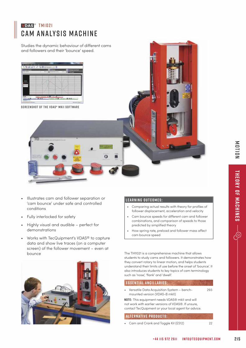
+ 4 4 1 1 5 9 7 2 2 6 1 1 I N F O @ T E C Q U I P M E N T. C O M 2 1 5
Theo
ry
of M
ac
hin
esM
otio
n
• Illustrates cam and follower separation or
‘cam bounce’ under safe and controlled
conditions
• Fully interlocked for safety
• Highly visual and audible – perfect for
demonstrations
• Works with TecQuipment’s VDAS® to capture
data and show live traces (on a computer
screen) of the follower movement – even at
bounce
L E A R N I N G O U T C O M E S :
• Comparing actual results with theory for profiles of
follower displacement, acceleration and velocity
• Cam bounce speeds for different cam and follower
combinations, and comparison of speeds to those
predicted by simplified theory
• How spring rate, preload and follower mass affect
cam bounce speed
T M 1 0 2 1
Cam A naly s i s Mac h i n e
Studies the dynamic behaviour of different camsand followers and their ‘bounce’ speed.
S c r e e n s h o t o f t h e V D A S ® m k I I s o f t war e
The TM1021 is a comprehensive machine that allows
students to study cams and followers. It demonstrates how
they convert rotary to linear motion, and helps students
understand their limits of use before the onset of ‘bounce’. It
also introduces students to key topics of cam terminology
such as ‘nose’, ‘flank’ and ‘dwell’.
• Versatile Data Acquisition System – bench- 293
mounted version (VDAS-B mkII)
N o t e : This equipment needs VDAS® mkII and will
not work with earlier versions of VDAS®. If unsure,
contact TecQuipment or your local agent for advice.
• Cam and Crank and Toggle Kit (ES12) 22
alt e r nat i v e p r o d u c t s :
E S S E N T IAL AN C I L LAR I E S :
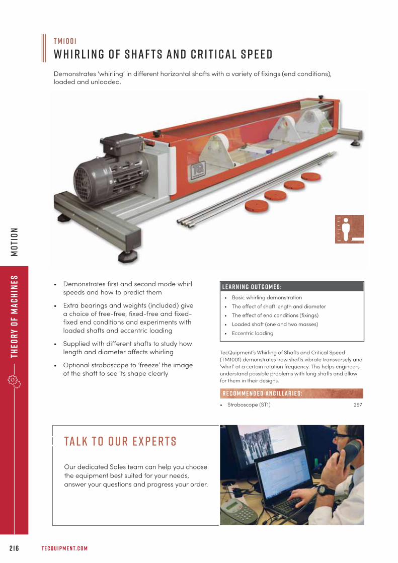
Theo
ry
of
Ma
ch
ines
T E C Q U I P M E N T. C O M2 1 6
Mo
tio
n
• Demonstrates first and second mode whirl
speeds and how to predict them
• Extra bearings and weights (included) give
a choice of free-free, fixed-free and fixed-
fixed end conditions and experiments with
loaded shafts and eccentric loading
• Supplied with different shafts to study how
length and diameter affects whirling
• Optional stroboscope to ‘freeze’ the image
of the shaft to see its shape clearly
L E A R N I N G O U T C O M E S :
• Basic whirling demonstration
• The effect of shaft length and diameter
• The effect of end conditions (fixings)
• Loaded shaft (one and two masses)
• Eccentric loading
T M 1 0 0 1
W h i r l i n g o f S haf t s an d C r i t i cal S p e e d
Demonstrates ‘whirling’ in different horizontal shafts with a variety of fixings (end conditions),loaded and unloaded.
TecQuipment’s Whirling of Shafts and Critical Speed
(TM1001) demonstrates how shafts vibrate transversely and
‘whirl’ at a certain rotation frequency. This helps engineers
understand possible problems with long shafts and allow
for them in their designs.
• Stroboscope (ST1) 297
R E C O M M E N D E D AN C I L LAR I E S :
ta l k t o o u r e x p e r t s
Our dedicated Sales team can help you choose
the equipment best suited for your needs,
answer your questions and progress your order.
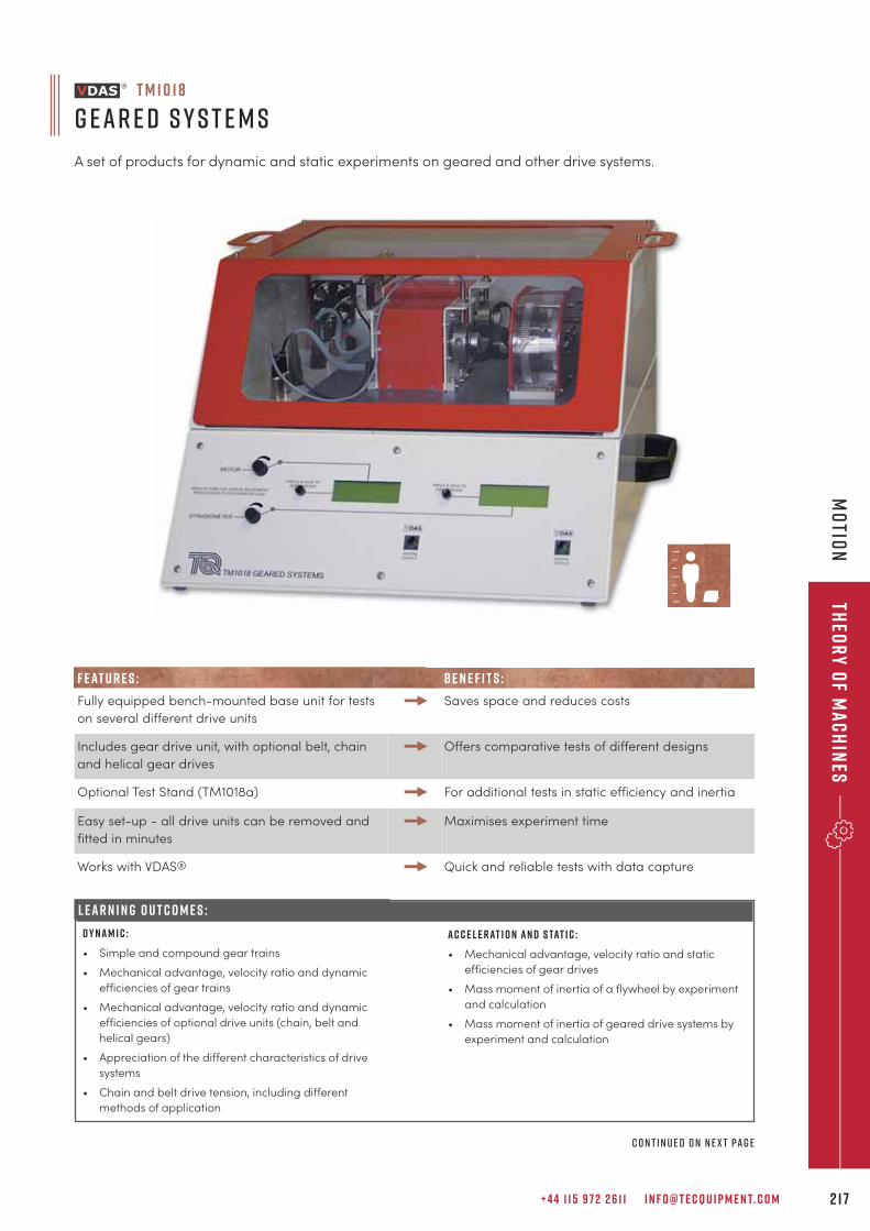
+ 4 4 1 1 5 9 7 2 2 6 1 1 I N F O @ T E C Q U I P M E N T. C O M 2 1 7
Theo
ry
of M
ac
hin
esM
otio
n
L E A R N I N G O U T C O M E S :
T M 1 0 1 8
G ear e d S y s t e m s
A set of products for dynamic and static experiments on geared and other drive systems.
L E A R N I N G O U T C O M E S :
D y n a m i c :
• Simple and compound gear trains
• Mechanical advantage, velocity ratio and dynamic
efficiencies of gear trains
• Mechanical advantage, velocity ratio and dynamic
efficiencies of optional drive units (chain, belt and
helical gears)
• Appreciation of the different characteristics of drive
systems
• Chain and belt drive tension, including different
methods of application
F E AT U R E S : B E N E F I T S :
Fully equipped bench-mounted base unit for tests
on several different drive units
Saves space and reduces costs
Includes gear drive unit, with optional belt, chain
and helical gear drives
Offers comparative tests of different designs
Optional Test Stand (TM1018a) For additional tests in static efficiency and inertia
Easy set-up - all drive units can be removed and
fitted in minutes
Maximises experiment time
Works with VDAS® Quick and reliable tests with data capture
A c c e l e r at i o n a n d s tat i c :
• Mechanical advantage, velocity ratio and static
efficiencies of gear drives
• Mass moment of inertia of a flywheel by experiment
and calculation
• Mass moment of inertia of geared drive systems by
experiment and calculation
c o n t i n u e d o n n e x t pag e
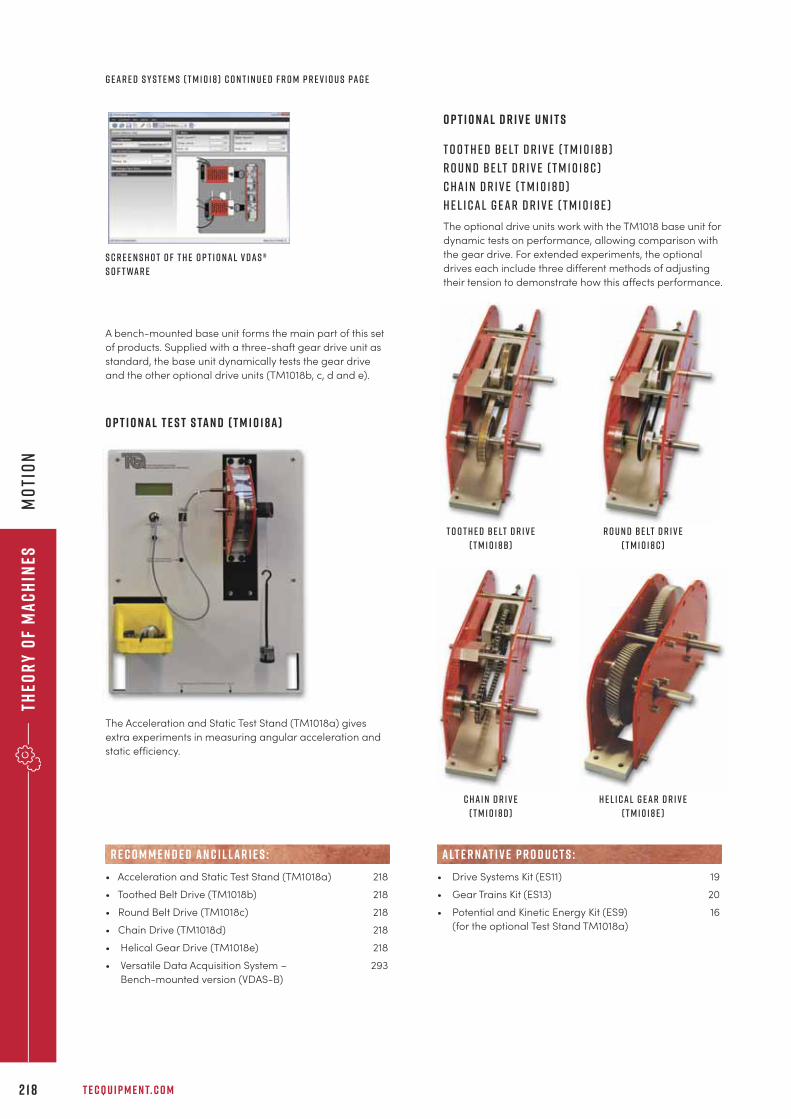
Theo
ry
of
Ma
ch
ines
T E C Q U I P M E N T. C O M2 1 8
Mo
tio
n
O p t i o n a l D r i v e U n i t s
T o o t h e d B e lt D r i v e ( T M 1 0 1 8b )
R o u n d B e lt D r i v e ( T M 1 0 1 8 c )
C ha i n D r i v e ( T M 1 0 1 8 d )
h e l i cal g ear d r i v e ( t m 1 0 1 8 e )
The optional drive units work with the TM1018 base unit for
dynamic tests on performance, allowing comparison with
the gear drive. For extended experiments, the optional
drives each include three different methods of adjusting
their tension to demonstrate how this affects performance.
O p t i o n a l T e s t S ta n d ( T M 1 0 1 8 a )
The Acceleration and Static Test Stand (TM1018a) gives
extra experiments in measuring angular acceleration and
static efficiency.
S c r e e n s h o t o f t h e o p t i o nal V D A S ®
s o f t war e
• Acceleration and Static Test Stand (TM1018a) 218
• Toothed Belt Drive (TM1018b) 218
• Round Belt Drive (TM1018c) 218
• Chain Drive (TM1018d) 218
• Helical Gear Drive (TM1018e) 218
• Versatile Data Acquisition System – 293
Bench-mounted version (VDAS-B)
R E C O M M E N D E D AN C I L LAR I E S :
A bench-mounted base unit forms the main part of this set
of products. Supplied with a three-shaft gear drive unit as
standard, the base unit dynamically tests the gear drive
and the other optional drive units (TM1018b, c, d and e).
g ear e d s y s t e m s ( t m 1 0 1 8 ) c o n t i n u e d f r o m p r e v i o u s pag e
• Drive Systems Kit (ES11) 19
• Gear Trains Kit (ES13) 20
• Potential and Kinetic Energy Kit (ES9) 16
(for the optional Test Stand TM1018a)
alt e r nat i v e p r o d u c t s :
T o o t h e d B e lt D r i v e
( T M 1 0 1 8b )
R o u n d B e lt D r i v e
( T M 1 0 1 8 c )
C ha i n D r i v e
( T M 1 0 1 8 d )
h e l i cal g ear d r i v e
( t m 1 0 1 8 e )
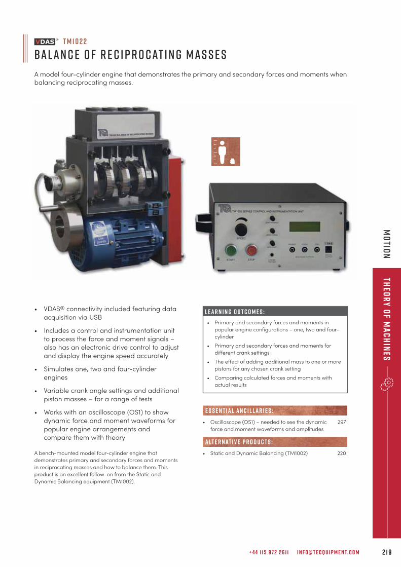
+ 4 4 1 1 5 9 7 2 2 6 1 1 I N F O @ T E C Q U I P M E N T. C O M 2 1 9
Theo
ry
of M
ac
hin
esM
otio
n
T M 1 0 2 2
Balan c e o f R e c i p r o cat i n g Mas s e s
A model four-cylinder engine that demonstrates the primary and secondary forces and moments whenbalancing reciprocating masses.
L E A R N I N G O U T C O M E S :
• Primary and secondary forces and moments in
popular engine configurations – one, two and four-
cylinder
• Primary and secondary forces and moments for
different crank settings
• The effect of adding additional mass to one or more
pistons for any chosen crank setting
• Comparing calculated forces and moments with
actual results
• VDAS® connectivity included featuring data
acquisition via USB
• Includes a control and instrumentation unit
to process the force and moment signals –
also has an electronic drive control to adjust
and display the engine speed accurately
• Simulates one, two and four-cylinder
engines
• Variable crank angle settings and additional
piston masses – for a range of tests
• Works with an oscilloscope (OS1) to show
dynamic force and moment waveforms for
popular engine arrangements and
compare them with theory
A bench-mounted model four-cylinder engine that
demonstrates primary and secondary forces and moments
in reciprocating masses and how to balance them. This
product is an excellent follow-on from the Static and
Dynamic Balancing equipment (TM1002).
• Oscilloscope (OS1) – needed to see the dynamic 297
force and moment waveforms and amplitudes
• Static and Dynamic Balancing (TM1002) 220
alt e r nat i v e p r o d u c t s :
E S S E N T IAL AN C I L LAR I E S :
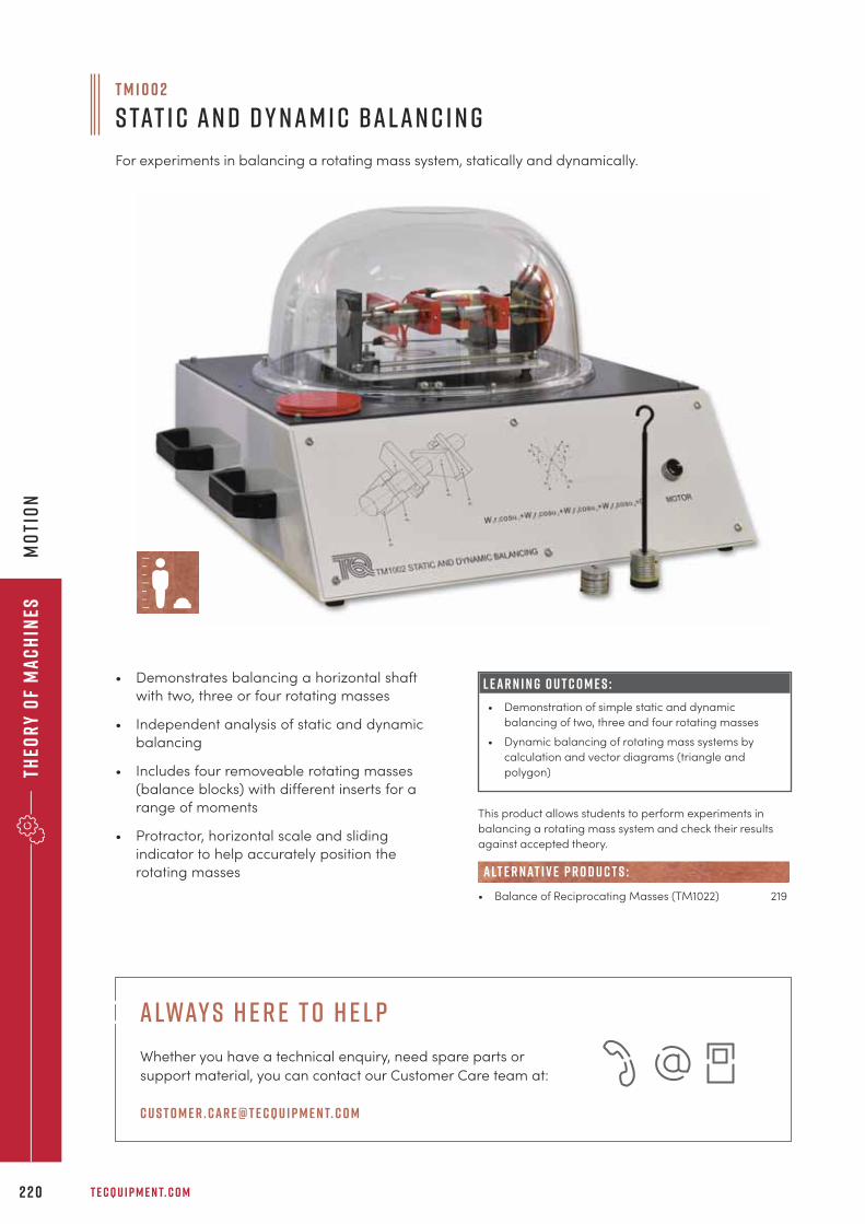
Theo
ry
of
Ma
ch
ines
T E C Q U I P M E N T. C O M2 2 0
mo
tio
n
• Demonstrates balancing a horizontal shaft
with two, three or four rotating masses
• Independent analysis of static and dynamic
balancing
• Includes four removeable rotating masses
(balance blocks) with different inserts for a
range of moments
• Protractor, horizontal scale and sliding
indicator to help accurately position the
rotating masses
L E A R N I N G O U T C O M E S :
• Demonstration of simple static and dynamic
balancing of two, three and four rotating masses
• Dynamic balancing of rotating mass systems by
calculation and vector diagrams (triangle and
polygon)
T M 1 0 0 2
S tat i c an d D y nam i c Balan c i n g
For experiments in balancing a rotating mass system, statically and dynamically.
This product allows students to perform experiments in
balancing a rotating mass system and check their results
against accepted theory.
• Balance of Reciprocating Masses (TM1022) 219
alt e r nat i v e p r o d u c t s :
a lway s h e r e t o h e l p
Whether you have a technical enquiry, need spare parts or
support material, you can contact our Customer Care team at:
c u s t o m e r . car e@t e cqu i p m e n t. c o m
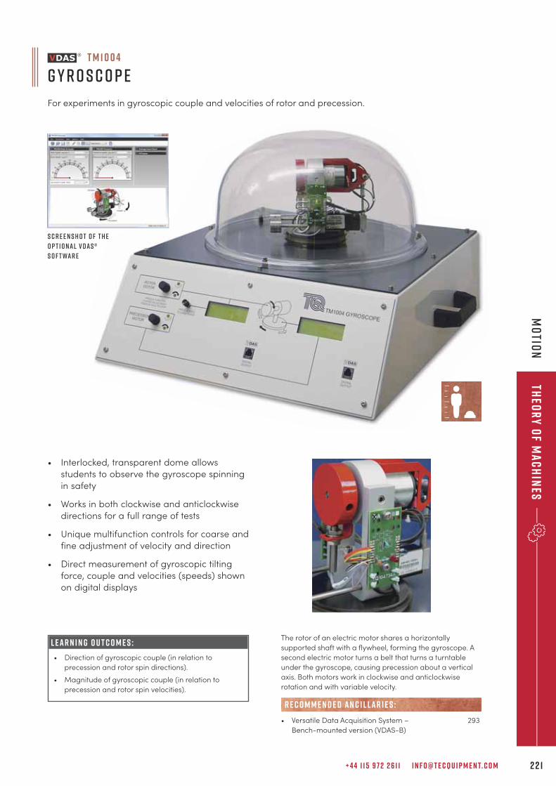
+ 4 4 1 1 5 9 7 2 2 6 1 1 I N F O @ T E C Q U I P M E N T. C O M 2 2 1
Theo
ry
of M
ac
hin
esm
otio
n
• Interlocked, transparent dome allows
students to observe the gyroscope spinning
in safety
• Works in both clockwise and anticlockwise
directions for a full range of tests
• Unique multifunction controls for coarse and
fine adjustment of velocity and direction
• Direct measurement of gyroscopic tilting
force, couple and velocities (speeds) shown
on digital displays
L E A R N I N G O U T C O M E S :
• Direction of gyroscopic couple (in relation to
precession and rotor spin directions).
• Magnitude of gyroscopic couple (in relation to
precession and rotor spin velocities).
The rotor of an electric motor shares a horizontally
supported shaft with a flywheel, forming the gyroscope. A
second electric motor turns a belt that turns a turntable
under the gyroscope, causing precession about a vertical
axis. Both motors work in clockwise and anticlockwise
rotation and with variable velocity.
• Versatile Data Acquisition System – 293
Bench-mounted version (VDAS-B)
R E C O M M E N D E D AN C I L LAR I E S :
S c r e e n s h o t o f t h e
o p t i o nal V D A S ®
s o f t war e
T M 1 0 0 4
G y r o s c o p e
For experiments in gyroscopic couple and velocities of rotor and precession.
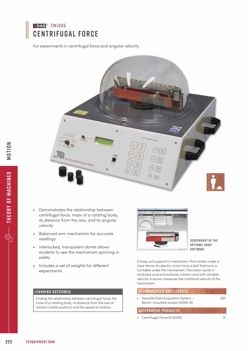
Theo
ry
of
Ma
ch
ines
T E C Q U I P M E N T. C O M2 2 2
mo
tio
n
• Demonstrates the relationship between
centrifugal force, mass of a rotating body,
its distance from the axis, and its angular
velocity
• Balanced arm mechanism for accurate
readings
• Interlocked, transparent dome allows
students to see the mechanism spinning in
safety
• Includes a set of weights for different
experiments
L E A R N I N G O U T C O M E S :
Finding the relationship between centrifugal force, the
mass of a rotating body, its distance from the axis of
rotation (radial position) and the speed of rotation.
S c r e e n s h o t o f t h e
o p t i o nal V D A S ®
s o f t war e
T M 1 0 0 5
C e n t r i f u gal F o r c e
For experiments in centrifugal force and angular velocity.
A base unit supports a mechanism that rotates under a
clear dome. An electric motor turns a belt that turns a
turntable under the mechanism. The motor works in
clockwise and anticlockwise rotation and with variable
velocity. A sensor measures the rotational velocity of the
mechanism.
• Versatile Data Acquisition System – 293
Bench-mounted version (VDAS-B)
• Centrifugal Force Kit (ES16) 21
R E C O M M E N D E D AN C I L LAR I E S :
alt e r nat i v e p r o d u c t s :
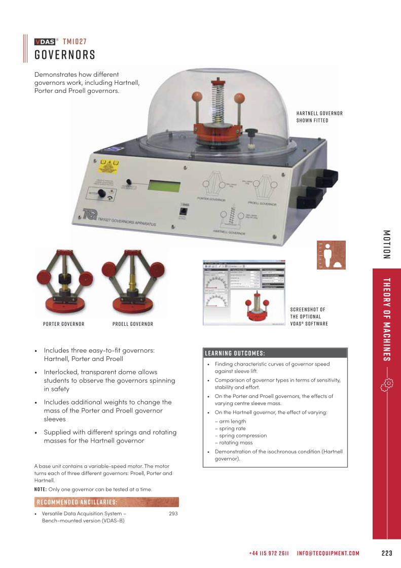
+ 4 4 1 1 5 9 7 2 2 6 1 1 I N F O @ T E C Q U I P M E N T. C O M 2 2 3
Theo
ry
of M
ac
hin
esm
otio
n
L E A R N I N G O U T C O M E S :
• Finding characteristic curves of governor speed
against sleeve lift.
• Comparison of governor types in terms of sensitivity,
stability and effort.
• On the Porter and Proell governors, the effects of
varying centre sleeve mass.
• On the Hartnell governor, the effect of varying:
– arm length
– spring rate
– spring compression
– rotating mass
• Demonstration of the isochronous condition (Hartnell
governor).
A base unit contains a variable-speed motor. The motor
turns each of three different governors: Proell, Porter and
Hartnell.
N o t e : Only one governor can be tested at a time.
• Versatile Data Acquisition System – 293
Bench-mounted version (VDAS-B)
R E C O M M E N D E D AN C I L LAR I E S :
• Includes three easy-to-fit governors:
Hartnell, Porter and Proell
• Interlocked, transparent dome allows
students to observe the governors spinning
in safety
• Includes additional weights to change the
mass of the Porter and Proell governor
sleeves
• Supplied with different springs and rotating
masses for the Hartnell governor
Har t n e l l g o v e r n o r
s h o w n f i t t e d
S c r e e n s h o t o f
t h e o p t i o nal
V D A S ® s o f t war e
T M 1 0 2 7
G o v e r n o r s
Demonstrates how differentgovernors work, including Hartnell,Porter and Proell governors.
p o r t e r g o v e r n o r P r o e l l g o v e r n o r
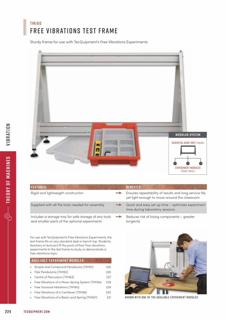
Theo
ry
of
Ma
ch
ines
T E C Q U I P M E N T. C O M2 2 4
Vib
rat
ion
F E AT U R E S : B E N E F I T S :
Rigid and lightweight construction Ensures repeatability of results and long service life,
yet light enough to move around the classroom
Supplied with all the tools needed for assembly Quick and easy set up time – optimises experiment
time during laboratory sessions
Includes a storage tray for safe storage of any tools
and smaller parts of the optional experiments
Reduces risk of losing components – greater
longevity
For use with TecQuipment’s Free Vibrations Experiments, the
test frame fits on any standard desk or bench top. Students,
teachers or lecturers fit the parts of their free vibrations
experiments to the test frame to study or demonstrate a
free vibrations topic.
• Simple and Compound Pendulums (TM161) 225
• Filar Pendulums (TM162) 226
• Centre of Percussion (TM163) 227
• Free Vibrations of a Mass-Spring System (TM164) 228
• Free Torsional Vibrations (TM165) 229
• Free Vibrations of a Cantilever (TM166) 230
• Free Vibrations of a Beam and Spring (TM167) 231
ava i labl e e x p e r i m e n t m o d u l e s :
T M 1 6 0
F r e e V ibrat i o n s T e s t F ram e
Sturdy frame for use with TecQuipment’s Free Vibrations Experiments.
Experiment modules(tm161–tm167)
Essential Base Unit (tm160)
M O D U LAR S Y S T E M
S h o w n w i t h o n e o f t h e ava i labl e e x p e r i m e n t m o d u l e s
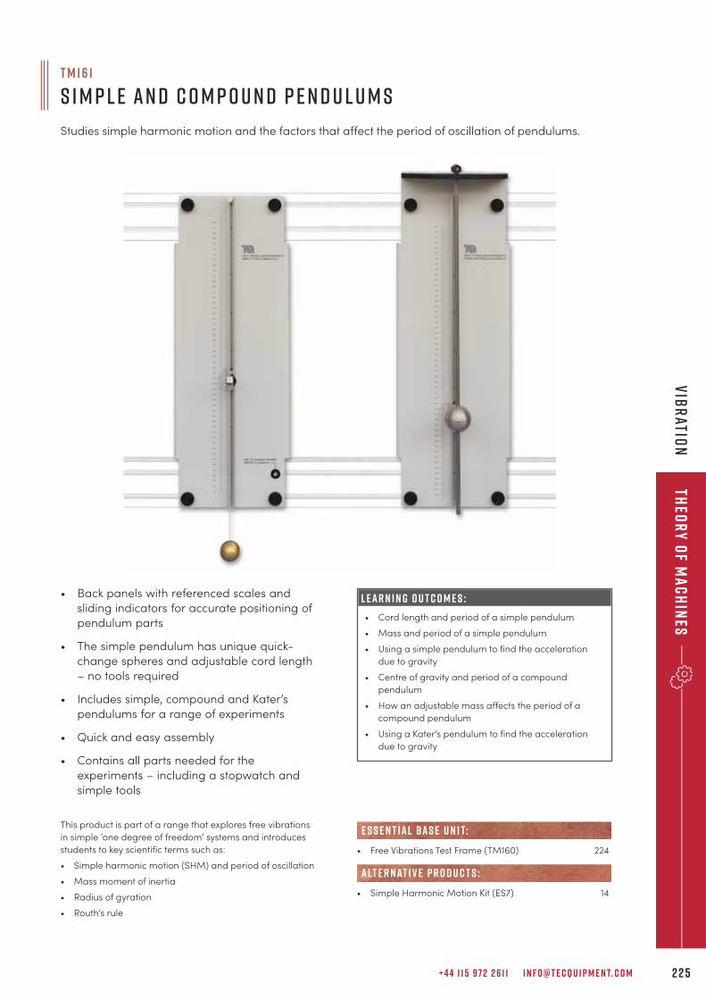
+ 4 4 1 1 5 9 7 2 2 6 1 1 I N F O @ T E C Q U I P M E N T. C O M 2 2 5
Theo
ry
of M
ac
hin
esv
IBRatio
n
This product is part of a range that explores free vibrations
in simple ‘one degree of freedom’ systems and introduces
students to key scientific terms such as:
• Simple harmonic motion (SHM) and period of oscillation
• Mass moment of inertia
• Radius of gyration
• Routh’s rule
T M 1 6 1
S i m p l e an d C o m p o u n d P e n d u l u m s
Studies simple harmonic motion and the factors that affect the period of oscillation of pendulums.
• Back panels with referenced scales and
sliding indicators for accurate positioning of
pendulum parts
• The simple pendulum has unique quick-
change spheres and adjustable cord length
– no tools required
• Includes simple, compound and Kater’s
pendulums for a range of experiments
• Quick and easy assembly
• Contains all parts needed for the
experiments – including a stopwatch and
simple tools
L E A R N I N G O U T C O M E S :
• Cord length and period of a simple pendulum
• Mass and period of a simple pendulum
• Using a simple pendulum to find the acceleration
due to gravity
• Centre of gravity and period of a compound
pendulum
• How an adjustable mass affects the period of a
compound pendulum
• Using a Kater’s pendulum to find the acceleration
due to gravity
• Free Vibrations Test Frame (TM160) 224
• Simple Harmonic Motion Kit (ES7) 14
alt e r nat i v e p r o d u c t s :
e s s e n t ial bas e u n i t:
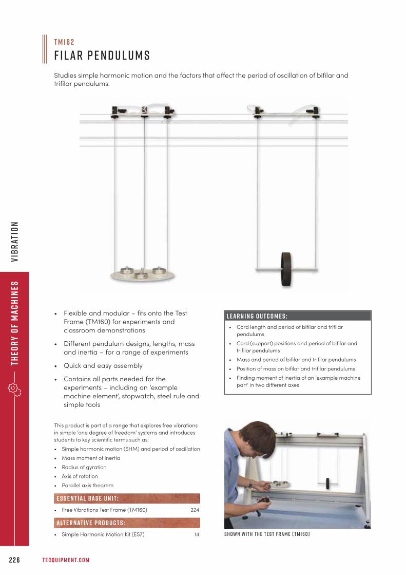
Theo
ry
of
Ma
ch
ines
T E C Q U I P M E N T. C O M2 2 6
Vib
rAT
ION
This product is part of a range that explores free vibrations
in simple ‘one degree of freedom’ systems and introduces
students to key scientific terms such as:
• Simple harmonic motion (SHM) and period of oscillation
• Mass moment of inertia
• Radius of gyration
• Axis of rotation
• Parallel axis theorem
• Free Vibrations Test Frame (TM160) 224
• Simple Harmonic Motion Kit (ES7) 14
alt e r nat i v e p r o d u c t s :
e s s e n t ial bas e u n i t:
• Flexible and modular – fits onto the Test
Frame (TM160) for experiments and
classroom demonstrations
• Different pendulum designs, lengths, mass
and inertia – for a range of experiments
• Quick and easy assembly
• Contains all parts needed for the
experiments – including an ‘example
machine element’, stopwatch, steel rule and
simple tools
L E A R N I N G O U T C O M E S :
• Cord length and period of bifilar and trifilar
pendulums
• Cord (support) positions and period of bifilar and
trifilar pendulums
• Mass and period of bifilar and trifilar pendulums
• Position of mass on bifilar and trifilar pendulums
• Finding moment of inertia of an ‘example machine
part’ in two different axes
T M 1 6 2
F i lar P e n d u l u m s
Studies simple harmonic motion and the factors that affect the period of oscillation of bifilar andtrifilar pendulums.
S h o w n w i t h t h e T e s t F ram e ( T M 160 )
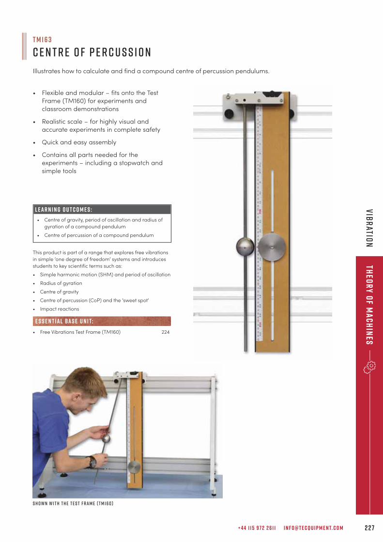
+ 4 4 1 1 5 9 7 2 2 6 1 1 I N F O @ T E C Q U I P M E N T. C O M 2 2 7
Theo
ry
of M
ac
hin
esv
IBR
ATION
This product is part of a range that explores free vibrations
in simple ‘one degree of freedom’ systems and introduces
students to key scientific terms such as:
• Simple harmonic motion (SHM) and period of oscillation
• Radius of gyration
• Centre of gravity
• Centre of percussion (CoP) and the ‘sweet spot’
• Impact reactions
• Free Vibrations Test Frame (TM160) 224
e s s e n t ial bas e u n i t:
• Flexible and modular – fits onto the Test
Frame (TM160) for experiments and
classroom demonstrations
• Realistic scale – for highly visual and
accurate experiments in complete safety
• Quick and easy assembly
• Contains all parts needed for the
experiments – including a stopwatch and
simple tools
L E A R N I N G O U T C O M E S :
• Centre of gravity, period of oscillation and radius of
gyration of a compound pendulum
• Centre of percussion of a compound pendulum
T M 1 6 3
C e n t r e o f P e r c u s s i o n
Illustrates how to calculate and find a compound centre of percussion pendulums.
S h o w n w i t h t h e T e s t F ram e ( T M 160 )
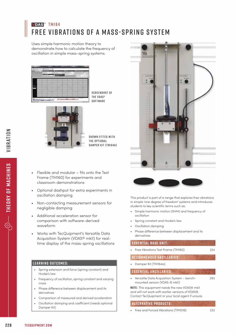
Theo
ry
of
Ma
ch
ines
T E C Q U I P M E N T. C O M2 2 8
vIB
RAT
ION
• Flexible and modular – fits onto the Test
Frame (TM160) for experiments and
classroom demonstrations
• Optional dashpot for extra experiments in
oscillation damping
• Non-contacting measurement sensors for
negligible damping
• Additional acceleration sensor for
comparison with software-derived
waveform
• Works with TecQuipment’s Versatile Data
Acquisition System (VDAS® mkII) for real-
time display of the mass-spring oscillations
L E A R N I N G O U T C O M E S :
• Spring extension and force (spring constant) and
Hooke’s law
• Frequency of oscillation, spring constant and varying
mass
• Phase difference between displacement and its
derivatives
• Comparison of measured and derived acceleration
• Oscillation damping and coefficient (needs optional
Damper Kit)
T M 1 6 4
F r e e V ibrat i o n s o f a Mas s - S p r i n g S y s t e m
Uses simple harmonic motion theory todemonstrate how to calculate the frequency ofoscillation in simple mass-spring systems.
S c r e e n s h o t o f
t h e V D A S ®
s o f t war e
S h o w n f i t t e d w i t h
t h e o p t i o nal
Dam p e r K i t ( T M 164a )
This product is part of a range that explores free vibrations
in simple ‘one degree of freedom’ systems and introduces
students to key scientific terms such as:
• Simple harmonic motion (SHM) and frequency of
oscillation
• Spring constant and Hooke’s law
• Oscillation damping
• Phase difference between displacement and its
derivatives
• Free Vibrations Test Frame (TM160) 224
• Damper Kit (TM164a)
• Versatile Data Acquisition System – bench- 293
mounted version (VDAS-B mkII)
N o t e : This equipment needs the new VDAS® mkII
and will not work with earlier versions of VDAS®.
Contact TecQuipment or your local agent if unsure.
• Free and Forced Vibrations (TM1016) 233
R E C O M M E N D E D AN C I L LAR I E S :
alt e r nat i v e p r o d u c t s :
e s s e n t ial bas e u n i t:
E S S E N T IAL AN C I L LAR I E S :
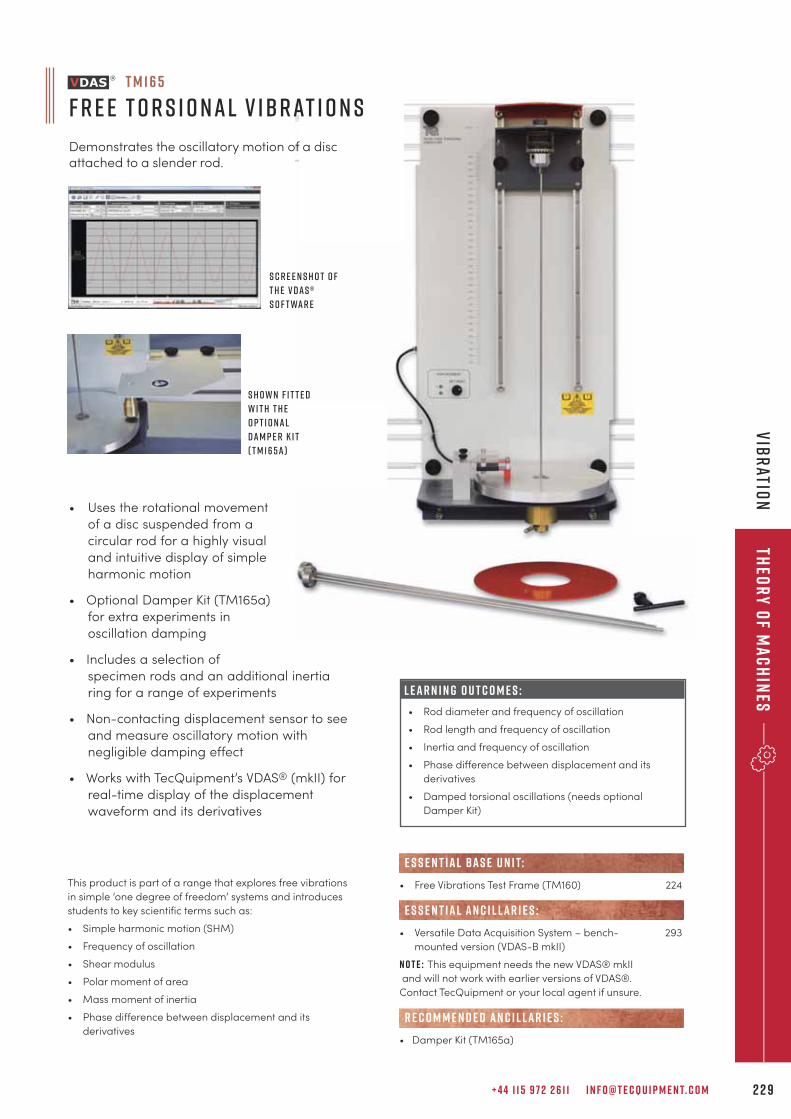
• Uses the rotational movement
of a disc suspended from a
circular rod for a highly visual
and intuitive display of simple
harmonic motion
• Optional Damper Kit (TM165a)
for extra experiments in
oscillation damping
• Includes a selection of
specimen rods and an additional inertia
ring for a range of experiments
• Non-contacting displacement sensor to see
and measure oscillatory motion with
negligible damping effect
• Works with TecQuipment’s VDAS® (mkII) for
real-time display of the displacement
waveform and its derivatives
+ 4 4 1 1 5 9 7 2 2 6 1 1 I N F O @ T E C Q U I P M E N T. C O M 2 2 9
Theo
ry
of M
ac
hin
esv
IBR
ATION
• Free Vibrations Test Frame (TM160) 224
• Versatile Data Acquisition System – bench- 293
mounted version (VDAS-B mkII)
N o t e : This equipment needs the new VDAS® mkII
and will not work with earlier versions of VDAS®.
Contact TecQuipment or your local agent if unsure.
• Damper Kit (TM165a)
R E C O M M E N D E D AN C I L LAR I E S :
e s s e n t ial bas e u n i t:
E S S E N T IAL AN C I L LAR I E S :
S h o w n f i t t e d
w i t h t h e
o p t i o nal
Dam p e r K i t
( T M 165a )
T M 1 6 5
F r e e T o r s i o nal V ibrat i o n s
Demonstrates the oscillatory motion of a discattached to a slender rod.
S c r e e n s h o t o f
t h e V D A S ®
s o f t war e
This product is part of a range that explores free vibrations
in simple ‘one degree of freedom’ systems and introduces
students to key scientific terms such as:
• Simple harmonic motion (SHM)
• Frequency of oscillation
• Shear modulus
• Polar moment of area
• Mass moment of inertia
• Phase difference between displacement and its
derivatives
L E A R N I N G O U T C O M E S :
• Rod diameter and frequency of oscillation
• Rod length and frequency of oscillation
• Inertia and frequency of oscillation
• Phase difference between displacement and its
derivatives
• Damped torsional oscillations (needs optional
Damper Kit)
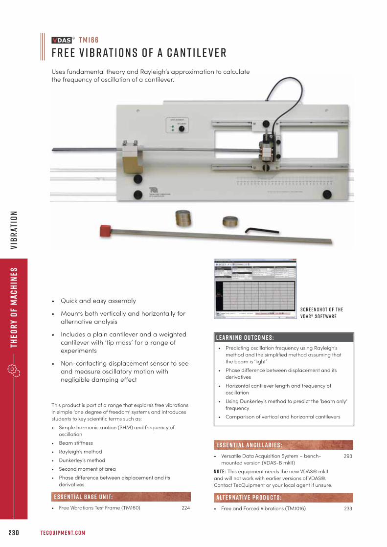
Theo
ry
of
Ma
ch
ines
T E C Q U I P M E N T. C O M2 3 0
vIB
RAT
ION
This product is part of a range that explores free vibrations
in simple ‘one degree of freedom’ systems and introduces
students to key scientific terms such as:
• Simple harmonic motion (SHM) and frequency of
oscillation
• Beam stiffness
• Rayleigh’s method
• Dunkerley’s method
• Second moment of area
• Phase difference between displacement and its
derivatives
• Free Vibrations Test Frame (TM160) 224
e s s e n t ial bas e u n i t:
L E A R N I N G O U T C O M E S :
• Predicting oscillation frequency using Rayleigh’s
method and the simplified method assuming that
the beam is ‘light’
• Phase difference between displacement and its
derivatives
• Horizontal cantilever length and frequency of
oscillation
• Using Dunkerley’s method to predict the ‘beam only’
frequency
• Comparison of vertical and horizontal cantilevers
T M 1 6 6
F r e e V ibrat i o n s o f a Can t i l e v e r
Uses fundamental theory and Rayleigh’s approximation to calculate the frequency of oscillation of a cantilever.
S c r e e n s h o t o f t h e
V D A S ® s o f t war e
• Quick and easy assembly
• Mounts both vertically and horizontally for
alternative analysis
• Includes a plain cantilever and a weighted
cantilever with ‘tip mass’ for a range of
experiments
• Non-contacting displacement sensor to see
and measure oscillatory motion with
negligible damping effect
• Versatile Data Acquisition System – bench- 293
mounted version (VDAS-B mkII)
N o t e : This equipment needs the new VDAS® mkII
and will not work with earlier versions of VDAS®.
Contact TecQuipment or your local agent if unsure.
• Free and Forced Vibrations (TM1016) 233
alt e r nat i v e p r o d u c t s :
E S S E N T IAL AN C I L LAR I E S :
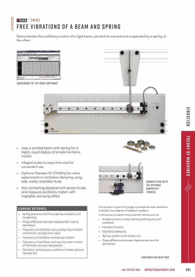
+ 4 4 1 1 5 9 7 2 2 6 1 1 I N F O @ T E C Q U I P M E N T. C O M 2 3 1
Theo
ry
of M
ac
hin
esv
IBR
ATION
This product is part of a range that explores free vibrations
in simple ‘one degree of freedom’ systems.
It introduces students to key scientific terms such as:
• Simple harmonic motion (SHM) and frequency of
oscillation
• Moment of inertia
• Oscillation damping
• Spring constant and Hooke’s law
• Phase difference between displacement and its
derivatives
S c r e e n s h o t o f t h e V D A S ® s o f t war e
S h o w n f i t t e d w i t h
t h e o p t i o nal
Dam p e r K i t
( T M 167a )
L E A R N I N G O U T C O M E S :
• Spring extension and force (spring constant), and
Hooke’s law
• Phase difference between displacement and its
derivatives
• Frequency of oscillation and varying mass moment
of inertia by varying mass value
• Frequency of oscillation and spring constant
• Frequency of oscillation and varying mass moment
of inertia by varying mass position
• Oscillation damping and coefficient (needs optional
Damper Kit)
• Uses a pivoted beam with spring for a
highly visual display of simple harmonic
motion
• Integral scales to save time and for
convenient use
• Optional Damper Kit (TM167a) for extra
experiments in oscillation damping using
safe, easily-available fluids
• Non-contacting displacement sensor to see
and measure oscillatory motion with
negligible damping effect
C o n t i n u e d o n n e x t pag e
T M 1 6 7
F r e e V ibrat i o n s o f a B eam an d S p r i n g
Demonstrates the oscillatory motion of a rigid beam, pivoted at one end and suspended by a spring atthe other.
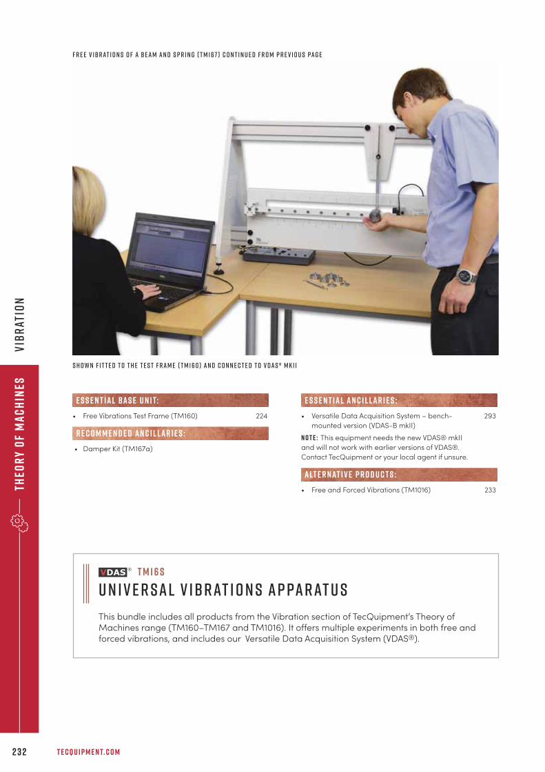
Theo
ry
of
Ma
ch
ines
T E C Q U I P M E N T. C O M2 3 2
vIB
RAT
ION
• Versatile Data Acquisition System – bench- 293
mounted version (VDAS-B mkII)
N o t e : This equipment needs the new VDAS® mkII
and will not work with earlier versions of VDAS®.
Contact TecQuipment or your local agent if unsure.
• Free and Forced Vibrations (TM1016) 233
alt e r nat i v e p r o d u c t s :
E S S E N T IAL AN C I L LAR I E S :
S h o w n f i t t e d t o t h e T e s t F ram e ( T M 160 ) an d c o n n e c t e d t o V D A S ® m k I I
• Free Vibrations Test Frame (TM160) 224
• Damper Kit (TM167a)
R E C O M M E N D E D AN C I L LAR I E S :
e s s e n t ial bas e u n i t:
F r e e V ibrat i o n s o f a B eam an d S p r i n g ( T M 167 ) C o n t i n u e d f r o m p r e v i o u s pag e
T M 1 6 s
u n i v e r sal v ibrat i o n s ap parat u s
This bundle includes all products from the Vibration section of TecQuipment’s Theory ofMachines range (TM160–TM167 and TM1016). It offers multiple experiments in both free andforced vibrations, and includes our Versatile Data Acquisition System (VDAS®).
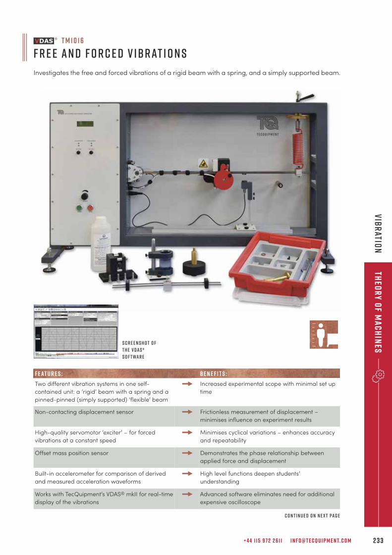
+ 4 4 1 1 5 9 7 2 2 6 1 1 I N F O @ T E C Q U I P M E N T. C O M 2 3 3
Theo
ry
of M
ac
hin
esv
IBR
ATION
T M 1 0 1 6
F r e e an d F o r c e d V ibrat i o n s
Investigates the free and forced vibrations of a rigid beam with a spring, and a simply supported beam.
S c r e e n s h o t o f
t h e V D A S ®
s o f t war e
F E AT U R E S : B E N E F I T S :
Two different vibration systems in one self-
contained unit: a ‘rigid’ beam with a spring and a
pinned-pinned (simply supported) ‘flexible’ beam
Increased experimental scope with minimal set up
time
Non-contacting displacement sensor Frictionless measurement of displacement –
minimises influence on experiment results
High-quality servomotor ‘exciter’ – for forced
vibrations at a constant speed
Minimises cyclical variations – enhances accuracy
and repeatability
Offset mass position sensor Demonstrates the phase relationship between
applied force and displacement
Built-in accelerometer for comparison of derived
and measured acceleration waveforms
High level functions deepen students’
understanding
Works with TecQuipment’s VDAS® mkII for real-time
display of the vibrations
Advanced software eliminates need for additional
expensive oscilloscope
C o n t i n u e d o n n e x t pag e
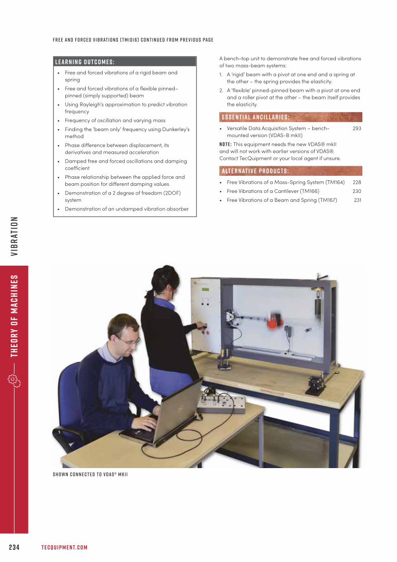
Theo
ry
of
Ma
ch
ines
T E C Q U I P M E N T. C O M2 3 4
vIB
RAT
ION
F r e e an d F o r c e d V ibrat i o n s ( T M 1 0 16 ) C o n t i n u e d f r o m p r e v i o u s pag e
S h o w n c o n n e c t e d t o V D A S ® m k I I
L E A R N I N G O U T C O M E S :
• Free and forced vibrations of a rigid beam and
spring
• Free and forced vibrations of a flexible pinned–
pinned (simply supported) beam
• Using Rayleigh’s approximation to predict vibration
frequency
• Frequency of oscillation and varying mass
• Finding the ‘beam only’ frequency using Dunkerley’s
method
• Phase difference between displacement, its
derivatives and measured acceleration
• Damped free and forced oscillations and damping
coefficient
• Phase relationship between the applied force and
beam position for different damping values
• Demonstration of a 2 degree of freedom (2DOF)
system
• Demonstration of an undamped vibration absorber
A bench-top unit to demonstrate free and forced vibrations
of two mass-beam systems:
1. A ‘rigid’ beam with a pivot at one end and a spring at
the other – the spring provides the elasticity.
2. A ‘flexible’ pinned-pinned beam with a pivot at one end
and a roller pivot at the other – the beam itself provides
the elasticity.
• Versatile Data Acquisition System – bench- 293
mounted version (VDAS-B mkII)
N o t e : This equipment needs the new VDAS® mkII
and will not work with earlier versions of VDAS®.
Contact TecQuipment or your local agent if unsure.
• Free Vibrations of a Mass-Spring System (TM164) 228
• Free Vibrations of a Cantilever (TM166) 230
• Free Vibrations of a Beam and Spring (TM167) 231
alt e r nat i v e p r o d u c t s :
E S S E N T IAL AN C I L LAR I E S :
+ 4 4 1 1 5 9 7 2 2 6 1 1 I N F O @ T E C Q U I P M E N T. C O M 2 3 5
Ther
mo
dy
na
mic
s
“BAE Systems Defence Information, Training and Services have recently used TecQuipment tosupport training activities in the Kingdom of Saudi Arabia through the procurement of two gasturbine trainers. Throughout the procurement, manufacturing and installation periodTecQuipment have performed well and supported extra requirements such as product safetyjustification reports. The experience and expertise of their commissioning engineer was firstclass and in-country activities went well.
N C H E R R YT R A I N I N G P R O C U R E M E N T WA R T O N , B A E S Y S T E M S ( O P E R AT I O N S ) L I M I T E D
t h e r m o d y n a m i c sT H E R M O D Y N A M I C P R I N C I P L E S 2 3 7
H E AT T R A N S F E R 2 4 0
T E M P E R AT U R E 2 6 0
S T E A M 2 6 1
C O M P R E S S O R S 2 6 2
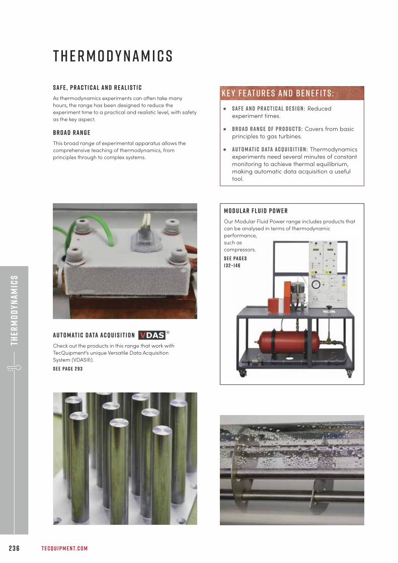
Ther
mo
dy
na
mic
s
T E C Q U I P M E N T. C O M2 3 6
S a f e , p r a c t i c a l a n d r e a l i s t i c
As thermodynamics experiments can often take many
hours, the range has been designed to reduce the
experiment time to a practical and realistic level, with safety
as the key aspect.
B r o a d r a n g e
This broad range of experimental apparatus allows the
comprehensive teaching of thermodynamics, from
principles through to complex systems.
T H E R M O D Y N A M I C S
A u t o m at i c d ata a c q u i s i t i o n
Check out the products in this range that work with
TecQuipment’s unique Versatile Data Acquisition
System (VDAS®).
S e e pa g e 2 9 3
M o d u l a r f l u i d p o w e r
Our Modular Fluid Power range includes products that
can be analysed in terms of thermodynamic
performance,
such as
compressors.
S e e pa g e s
1 3 2 – 1 4 6
• s a f e a n d p r a c t i c a l d e s i g n : Reduced
experiment times.
• b r o a d r a n g e o f p r o d u c t s : Covers from basic
principles to gas turbines.
• a u t o m at i c d ata a c q u i s i t i o n : Thermodynamics
experiments need several minutes of constant
monitoring to achieve thermal equilibrium,
making automatic data acquisition a useful
tool.
k e y f e at u r e s a n d b e n e f i t s :
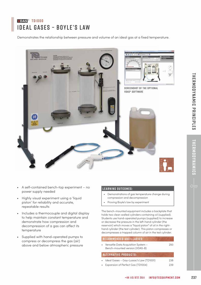
+ 4 4 1 1 5 9 7 2 2 6 1 1 I N F O @ T E C Q U I P M E N T. C O M 2 3 7
Ther
mo
dy
na
mic
sTh
erm
od
yna
mic
pr
inc
iples
• A self-contained bench-top experiment – no
power supply needed
• Highly visual experiment using a ‘liquid
piston’ for reliability and accurate,
repeatable results
• Includes a thermocouple and digital display
to help maintain constant temperature and
demonstrate how compression and
decompression of a gas can affect its
temperature
• Supplied with hand-operated pumps to
compress or decompress the gas (air)
above and below atmospheric pressure
L E A R N I N G O U T C O M E S :
• Demonstrations of gas temperature change during
compression and decompression
• Proving Boyle’s law by experiment
T D 1 0 0 0
I d eal Gas e s – B o y l e ’ s Law
Demonstrates the relationship between pressure and volume of an ideal gas at a fixed temperature.
S c r e e n s h o t o f t h e o p t i o nal
V D A S ® s o f t war e
The bench-mounted equipment includes a backplate that
holds two clear-walled cylinders containing oil (supplied).
Students use hand-operated pumps (supplied) to increase
or decrease the pressure in the left-hand cylinder (the
reservoir) which moves a “liquid piston” of oil in the right-
hand cylinder (the test cylinder). This piston compresses or
decompresses a trapped column of air in the test cylinder.
• Versatile Data Acquisition System – 293
Bench-mounted version (VDAS-B)
• Ideal Gases – Gay-Lussac’s Law (TD1001) 238
• Expansion of Perfect Gas (TD1004) 239
R E C O M M E N D E D AN C I L LAR I E S :
alt e r nat i v e p r o d u c t s :
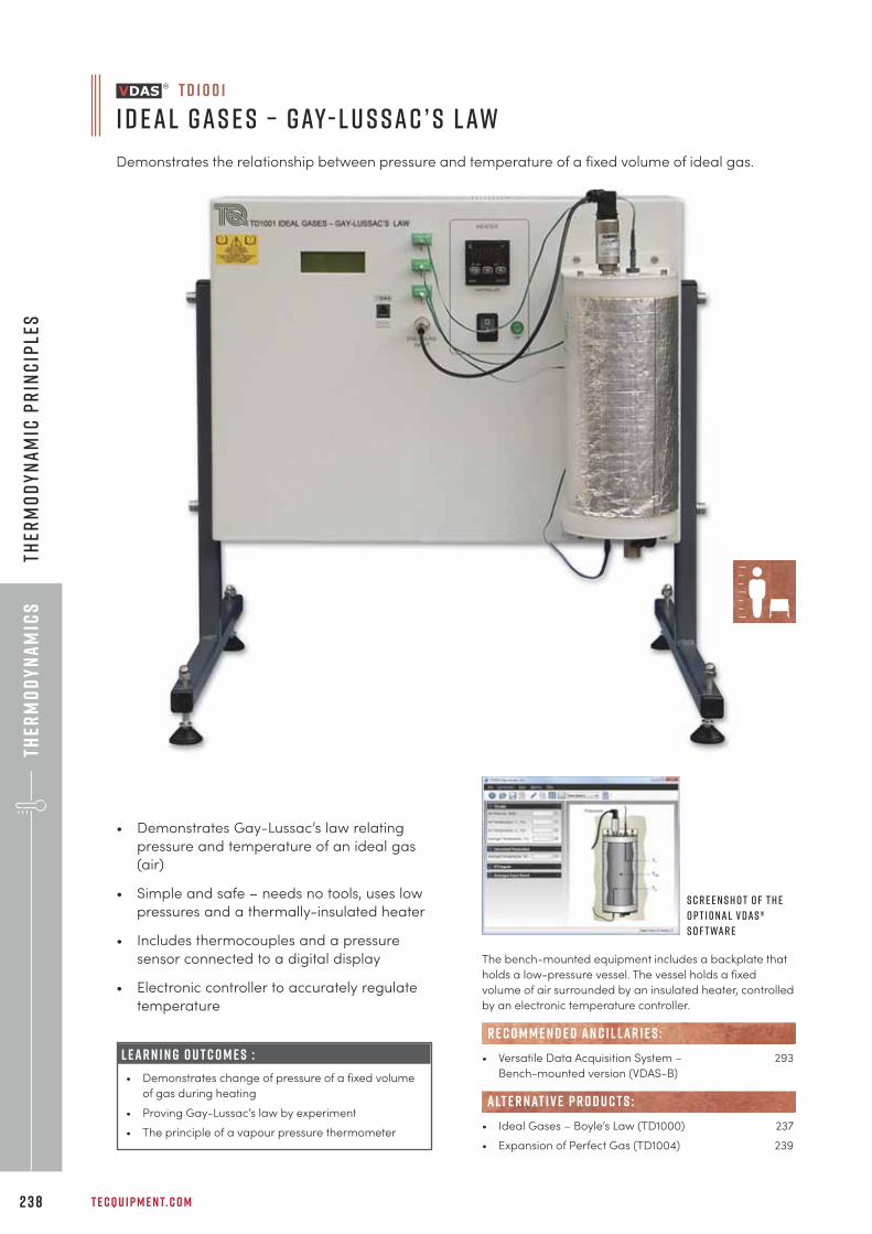
Ther
mo
dy
na
mic
s
T E C Q U I P M E N T. C O M2 3 8
Ther
mo
dy
na
mic
pr
inc
iple
s
• Demonstrates Gay-Lussac’s law relating
pressure and temperature of an ideal gas
(air)
• Simple and safe – needs no tools, uses low
pressures and a thermally-insulated heater
• Includes thermocouples and a pressure
sensor connected to a digital display
• Electronic controller to accurately regulate
temperature
L E A R N I N G O U T C O M E S :
• Demonstrates change of pressure of a fixed volume
of gas during heating
• Proving Gay-Lussac’s law by experiment
• The principle of a vapour pressure thermometer
T D 1 0 0 1
I d eal Gas e s – Gay- L u s sac ’ s Law
Demonstrates the relationship between pressure and temperature of a fixed volume of ideal gas.
S c r e e n s h o t o f t h e
o p t i o nal V D A S ®
s o f t war e
The bench-mounted equipment includes a backplate that
holds a low-pressure vessel. The vessel holds a fixed
volume of air surrounded by an insulated heater, controlled
by an electronic temperature controller.
• Versatile Data Acquisition System – 293
Bench-mounted version (VDAS-B)
• Ideal Gases – Boyle’s Law (TD1000) 237
• Expansion of Perfect Gas (TD1004) 239
R E C O M M E N D E D AN C I L LAR I E S :
alt e r nat i v e p r o d u c t s :
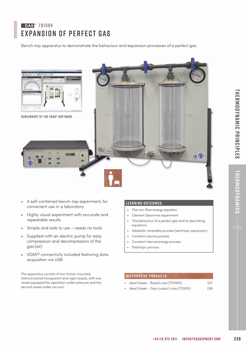
+ 4 4 1 1 5 9 7 2 2 6 1 1 I N F O @ T E C Q U I P M E N T. C O M 2 3 9
Ther
mo
dy
na
mic
sTh
erm
od
yna
mic
Pr
inc
iples
T D 1 0 0 4
e x pan s i o n o f p e r f e c t gas
Bench-top apparatus to demonstrate the behaviour and expansion processes of a perfect gas.
• A self-contained bench-top experiment, for
convenient use in a laboratory
• Highly visual experiment with accurate and
repeatable results
• Simple and safe to use – needs no tools
• Supplied with an electric pump for easy
compression and decompression of the
gas (air)
• VDAS® connectivity included featuring data
acquisition via USB
The apparatus consists of two frame-mounted,
interconnected transparent and rigid vessels, with one
vessel equipped for operation under pressure and the
second vessel under vacuum.
L E A R N I N G O U T C O M E S :
• The non-flow energy equation
• Clément Desormes experiment
• The behaviour of a perfect gas and its describing
equations
• Adiabatic reversible process (isentropic expansion)
• Constant volume process
• Constant internal energy process
• Polytropic process
S c r e e n s h o t o f t h e V D A S ® s o f t war e
• Ideal Gases – Boyle’s Law (TD1000) 237
• Ideal Gases – Gay-Lussac’s Law (TD1001) 238
alt e r nat i v e p r o d u c t s :
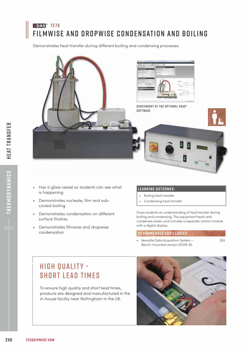
Ther
mo
dy
na
mic
s
T E C Q U I P M E N T. C O M2 4 0
Hea
t Tr
an
sfe
r
• Has a glass vessel so students can see what
is happening
• Demonstrates nucleate, film and sub-
cooled boiling
• Demonstrates condensation on different
surface finishes
• Demonstrates filmwise and dropwise
condensation
L E A R N I N G O U T C O M E S :
• Boiling heat transfer
• Condensing heat transfer
S c r e e n s h o t o f t h e o p t i o nal V D A S ®
s o f t war e
Gives students an understanding of heat transfer during
boiling and condensing. The equipment heats and
condenses water, and includes a separate control module
with a digital display.
• Versatile Data Acquisition System – 293
Bench-mounted version (VDAS-B)
R E C O M M E N D E D AN C I L LAR I E S :
T E 7 8
F i l m w i s e an d D r o p w i s e C o n d e n sat i o n an d B o i l i n g
Demonstrates heat transfer during different boiling and condensing processes.
H i g h Q u a l i t y - S h o r t L e a d T i m e s
To ensure high quality and short lead times,
products are designed and manufactured in the
in-house facility near Nottingham in the UK.
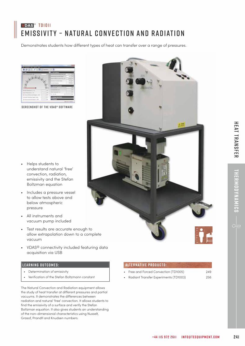
+ 4 4 1 1 5 9 7 2 2 6 1 1 I N F O @ T E C Q U I P M E N T. C O M 2 4 1
Ther
mo
dy
na
mic
sH
eat Tra
ns
fer
• Helps students to
understand natural ‘free’
convection, radiation,
emissivity and the Stefan
Boltzman equation
• Includes a pressure vessel
to allow tests above and
below atmospheric
pressure
• All instruments and
vacuum pump included
• Test results are accurate enough to
allow extrapolation down to a complete
vacuum
• VDAS® connectivity included featuring data
acquisition via USB
S c r e e n s h o t o f t h e V D A S ® s o f t war e
The Natural Convection and Radiation equipment allows
the study of heat transfer at different pressures and partial
vacuums. It demonstrates the differences between
radiation and natural ‘free’ convection. It allows students to
find the emissivity of a surface and verify the Stefan
Boltzman equation. It also gives students an understanding
of the non-dimensional characteristics using Nusselt,
Grasof, Prandtl and Knudsen numbers.
• Free and Forced Convection (TD1005) 249
• Radiant Transfer Experiments (TD1003) 256
alt e r nat i v e p r o d u c t s :
T D 1 0 1 1
E m i s s i v i t y – Nat u ral C o n v e c t i o n an d Rad iat i o n
Demonstrates students how different types of heat can transfer over a range of pressures.
L E A R N I N G O U T C O M E S :
• Determination of emissivity
• Verification of the Stefan Boltzmann constant
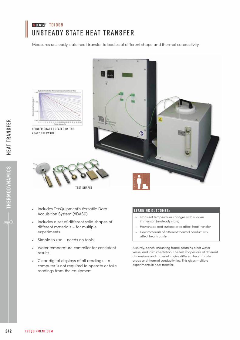
Ther
mo
dy
na
mic
s
T E C Q U I P M E N T. C O M2 4 2
Hea
t Tr
an
sfe
r
L E A R N I N G O U T C O M E S :
• Transient temperature changes with sudden
immersion (unsteady state)
• How shape and surface area affect heat transfer
• How materials of different thermal conductivity
affect heat transfer
• Includes TecQuipment’s Versatile Data
Acquisition System (VDAS®)
• Includes a set of different solid shapes of
different materials – for multiple
experiments
• Simple to use – needs no tools
• Water temperature controller for consistent
results
• Clear digital displays of all readings – a
computer is not required to operate or take
readings from the equipment
T D 1 0 0 9
U n s t ead y S tat e H eat T ran s f e r
Measures unsteady state heat transfer to bodies of different shape and thermal conductivity.
H e i s l e r c har t c r eat e d by t h e
V D A S ® s o f t war e
T e s t s hap e s
A sturdy, bench-mounting frame contains a hot water
vessel and instrumentation. The test shapes are of different
dimensions and material to give different heat transfer
areas and thermal conductivities. This gives multiple
experiments in heat transfer.
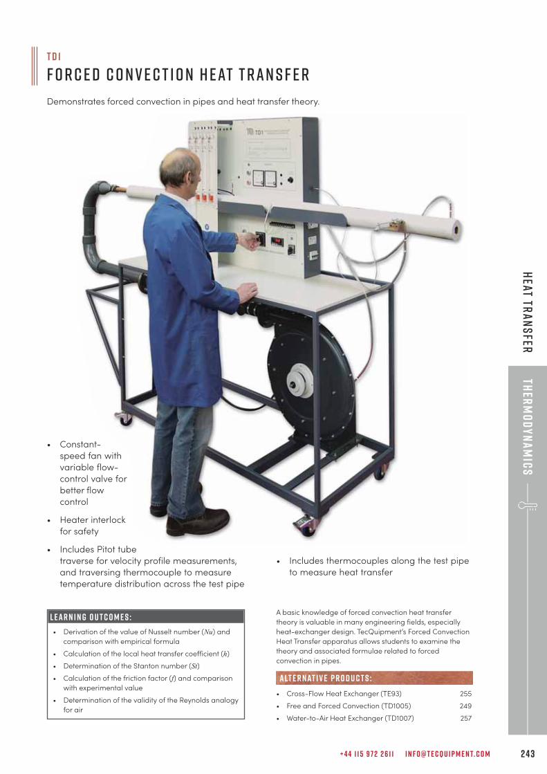
+ 4 4 1 1 5 9 7 2 2 6 1 1 I N F O @ T E C Q U I P M E N T. C O M 2 4 3
Ther
mo
dy
na
mic
sH
eat Tra
ns
fer
T D 1
F o r c e d C o n v e c t i o n H eat T ran s f e r
Demonstrates forced convection in pipes and heat transfer theory.
• Constant-
speed fan with
variable flow-
control valve for
better flow
control
• Heater interlock
for safety
• Includes Pitot tube
traverse for velocity profile measurements,
and traversing thermocouple to measure
temperature distribution across the test pipe
A basic knowledge of forced convection heat transfer
theory is valuable in many engineering fields, especially
heat-exchanger design. TecQuipment’s Forced Convection
Heat Transfer apparatus allows students to examine the
theory and associated formulae related to forced
convection in pipes.
• Cross-Flow Heat Exchanger (TE93) 255
• Free and Forced Convection (TD1005) 249
• Water-to-Air Heat Exchanger (TD1007) 257
alt e r nat i v e p r o d u c t s :
L E A R N I N G O U T C O M E S :
• Derivation of the value of Nusselt number (Nu) and
comparison with empirical formula
• Calculation of the local heat transfer coefficient (h)
• Determination of the Stanton number (St)
• Calculation of the friction factor (f) and comparison
with experimental value
• Determination of the validity of the Reynolds analogy
for air
• Includes thermocouples along the test pipe
to measure heat transfer
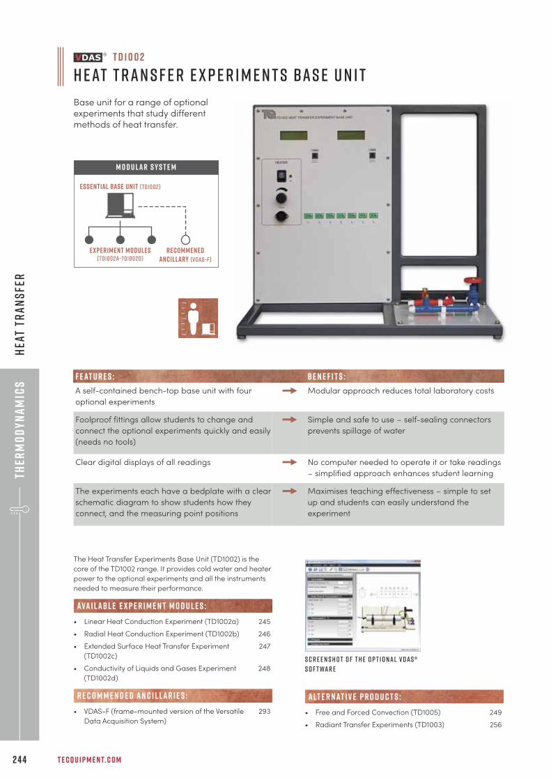
Ther
mo
dy
na
mic
s
T E C Q U I P M E N T. C O M2 4 4
Hea
t Tr
an
sfe
r
T D 1 0 0 2
H eat T ran s f e r E x p e r i m e n t s Bas e U n i t
Base unit for a range of optionalexperiments that study differentmethods of heat transfer.
S c r e e n s h o t o f t h e o p t i o nal V D A S ®
s o f t war e
The Heat Transfer Experiments Base Unit (TD1002) is the
core of the TD1002 range. It provides cold water and heater
power to the optional experiments and all the instruments
needed to measure their performance.
• Linear Heat Conduction Experiment (TD1002a) 245
• Radial Heat Conduction Experiment (TD1002b) 246
• Extended Surface Heat Transfer Experiment 247
(TD1002c)
• Conductivity of Liquids and Gases Experiment 248
(TD1002d)
• VDAS-F (frame-mounted version of the Versatile 293
Data Acquisition System)
R E C O M M E N D E D AN C I L LAR I E S :
ava i labl e e x p e r i m e n t m o d u l e s :
• Free and Forced Convection (TD1005) 249
• Radiant Transfer Experiments (TD1003) 256
alt e r nat i v e p r o d u c t s :
Experiment modules(td1002a–td1002d)
recommenedancillary (vdas-f)
Essential Base Unit (TD1002)
M O D U LAR S Y S T E M
F E AT U R E S : B E N E F I T S :
A self-contained bench-top base unit with four
optional experiments
Modular approach reduces total laboratory costs
Foolproof fittings allow students to change and
connect the optional experiments quickly and easily
(needs no tools)
Simple and safe to use – self-sealing connectors
prevents spillage of water
Clear digital displays of all readings No computer needed to operate it or take readings
– simplified approach enhances student learning
The experiments each have a bedplate with a clear
schematic diagram to show students how they
connect, and the measuring point positions
Maximises teaching effectiveness – simple to set
up and students can easily understand the
experiment
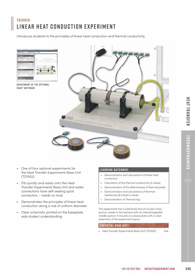
+ 4 4 1 1 5 9 7 2 2 6 1 1 I N F O @ T E C Q U I P M E N T. C O M 2 4 5
Ther
mo
dy
na
mic
sH
eat Tra
ns
fer
• One of four optional experiments for
the Heat Transfer Experiments Base Unit
(TD1002)
• Fits quickly and easily onto the Heat
Transfer Experiments Base Unit and water
connections have self-sealing quick
connectors – needs no tools
• Demonstrates the principles of linear heat
conduction along a rod of uniform diameter
• Clear schematic printed on the baseplate
aids student understanding
L E A R N I N G O U T C O M E S :
• Demonstration and calculations of linear heat
conduction
• Calculation of the thermal conductivity (k value)
• Demonstration of the effectiveness of thermal paste
• Demonstration and calculations of thermal
resistances (R value) in series
• Demonstration of ‘thermal lag’
This experiment has a solid brass bar of circular cross-
section, made in two sections with an interchangeable
middle section. It mounts on a base plate with a clear
schematic of the experiment layout.
• Heat Transfer Experiments Base Unit (TD1002) 244
e s s e n t ial bas e u n i t:
S c r e e n s h o t o f t h e o p t i o nal
V D A S ® s o f t war e
T D 1 0 0 2 a
L i n ear H eat C o n d u c t i o n E x p e r i m e n t
Introduces students to the principles of linear heat conduction and thermal conductivity.
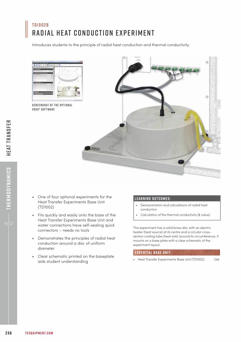
Ther
mo
dy
na
mic
s
T E C Q U I P M E N T. C O M2 4 6
Hea
t Tr
an
sfe
r
• One of four optional experiments for the
Heat Transfer Experiments Base Unit
(TD1002)
• Fits quickly and easily onto the base of the
Heat Transfer Experiments Base Unit and
water connections have self-sealing quick
connectors – needs no tools
• Demonstrates the principles of radial heat
conduction around a disc of uniform
diameter
• Clear schematic printed on the baseplate
aids student understanding
L E A R N I N G O U T C O M E S :
• Demonstration and calculations of radial heat
conduction
• Calculation of the thermal conductivity (k value)
This experiment has a solid brass disc with an electric
heater (heat source) at its centre and a circular cross-
section cooling tube (heat sink) around its circumference. It
mounts on a base plate with a clear schematic of the
experiment layout.
• Heat Transfer Experiments Base Unit (TD1002) 244
e s s e n t ial bas e u n i t:
S c r e e n s h o t o f t h e o p t i o nal
V D A S ® s o f t war e
T D 1 0 0 2 b
Rad ial H eat C o n d u c t i o n E x p e r i m e n t
Introduces students to the principle of radial heat conduction and thermal conductivity.

+ 4 4 1 1 5 9 7 2 2 6 1 1 I N F O @ T E C Q U I P M E N T. C O M 2 4 7
Ther
mo
dy
na
mic
sH
eat Tra
ns
fer
• One of four optional experiments for the
Heat Transfer Experiments base unit
(TD1002)
• Fits quickly and easily onto the Heat
Transfer Experiments Base Unit and water
connections have self-sealing quick
connectors – needs no tools
• Demonstrates how a long thin rod conducts
heat along it and how heat is lost due to
radiation and convection
• Clear schematic printed on the baseplate
aids student understanding
L E A R N I N G O U T C O M E S :
• To demonstrate how heat transfers from the surface
of a solid bar or rod.
• To demonstrate the temperatures on, and heat flow
through, the solid bar to its surroundings.
S c r e e n s h o t o f t h e o p t i o nal
V D A S ® s o f t war e
This experiment has a thin solid bar with an electric heater
(heat source) at one end. It mounts on a base plate with a
clear schematic of the experiment layout.
• Heat Transfer Experiments Base Unit (TD1002) 244
e s s e n t ial bas e u n i t:
T D 1 0 0 2 c
E x t e n d e d S u r fac e H eat C o n d u c t i o n E x p e r i m e n t
Demonstrates an example of conduction combined with losses due to radiation and convection.
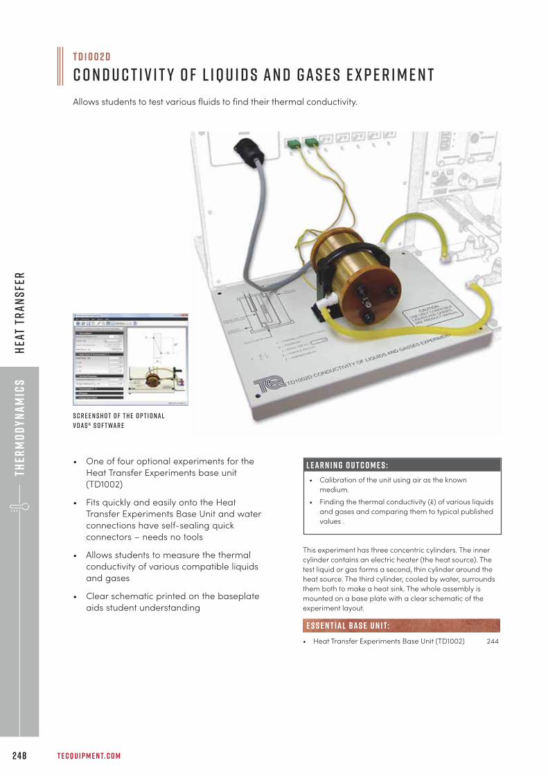
Ther
mo
dy
na
mic
s
T E C Q U I P M E N T. C O M2 4 8
Hea
t Tr
an
sfe
r
T D 1 0 0 2 d
C o n d u c t i v i t y o f L i q u i d s an d Gas e s E x p e r i m e n t
Allows students to test various fluids to find their thermal conductivity.
• One of four optional experiments for the
Heat Transfer Experiments base unit
(TD1002)
• Fits quickly and easily onto the Heat
Transfer Experiments Base Unit and water
connections have self-sealing quick
connectors – needs no tools
• Allows students to measure the thermal
conductivity of various compatible liquids
and gases
• Clear schematic printed on the baseplate
aids student understanding
L E A R N I N G O U T C O M E S :
• Calibration of the unit using air as the known
medium.
• Finding the thermal conductivity (k) of various liquids
and gases and comparing them to typical published
values .
This experiment has three concentric cylinders. The inner
cylinder contains an electric heater (the heat source). The
test liquid or gas forms a second, thin cylinder around the
heat source. The third cylinder, cooled by water, surrounds
them both to make a heat sink. The whole assembly is
mounted on a base plate with a clear schematic of the
experiment layout.
• Heat Transfer Experiments Base Unit (TD1002) 244
e s s e n t ial bas e u n i t:
S c r e e n s h o t o f t h e o p t i o nal
V D A S ® s o f t war e
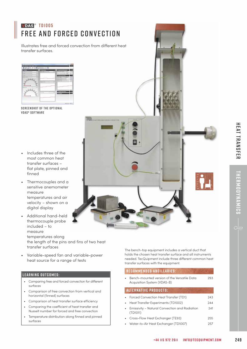
+ 4 4 1 1 5 9 7 2 2 6 1 1 I N F O @ T E C Q U I P M E N T. C O M 2 4 9
Ther
mo
dy
na
mic
sH
eat Tra
ns
fer• Includes three of the
most common heat
transfer surfaces –
flat plate, pinned and
finned
• Thermocouples and a
sensitive anemometer
measure
temperatures and air
velocity – shown on a
digital display
• Additional hand-held
thermocouple probe
included – to
measure
temperatures along
the length of the pins and fins of two heat
transfer surfaces
• Variable-speed fan and variable-power
heat source for a range of tests
T D 1 0 0 5
F r e e an d F o r c e d C o n v e c t i o n
Illustrates free and forced convection from different heattransfer surfaces.
S c r e e n s h o t o f t h e o p t i o nal
V D A S ® s o f t war e
L E A R N I N G O U T C O M E S :
• Comparing free and forced convection for different
surfaces
• Comparison of free convection from vertical and
horizontal (finned) surfaces
• Comparison of heat transfer surface efficiency
• Comparing the coefficient of heat transfer and
Nusselt number for forced and free convection
• Temperature distribution along finned and pinned
surfaces
The bench-top equipment includes a vertical duct that
holds the chosen heat transfer surface and all instruments
needed. TecQuipment include three different common heat
transfer surfaces with the equipment.
• Bench-mounted version of the Versatile Data 293
Acquisition System (VDAS-B)
• Forced Convection Heat Transfer (TD1) 243
• Heat Transfer Experiments (TD1002) 244
• Emissivity – Natural Convection and Radiation 241
(TD1011)
• Cross-Flow Heat Exchanger (TE93) 255
• Water-to-Air Heat Exchanger (TD1007) 257
R E C O M M E N D E D AN C I L LAR I E S :
alt e r nat i v e p r o d u c t s :
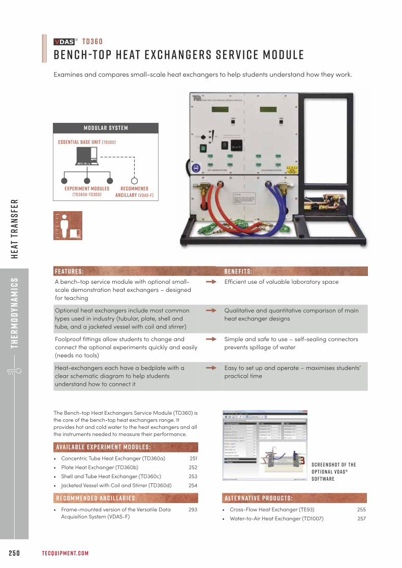
Ther
mo
dy
na
mic
s
T E C Q U I P M E N T. C O M2 5 0
Hea
t Tr
an
sfe
r
The Bench-top Heat Exchangers Service Module (TD360) is
the core of the bench-top heat exchangers range. It
provides hot and cold water to the heat exchangers and all
the instruments needed to measure their performance.
• Concentric Tube Heat Exchanger (TD360a) 251
• Plate Heat Exchanger (TD360b) 252
• Shell and Tube Heat Exchanger (TD360c) 253
• Jacketed Vessel with Coil and Stirrer (TD360d) 254
• Frame-mounted version of the Versatile Data 293
Acquisition System (VDAS-F)
R E C O M M E N D E D AN C I L LAR I E S :
ava i labl e e x p e r i m e n t m o d u l e s :
S c r e e n s h o t o f t h e
o p t i o nal V D A S ®
s o f t war e
T D 3 6 0
B e n c h -t o p H eat E x c han g e r s S e r v i c e M o d u l e
Examines and compares small-scale heat exchangers to help students understand how they work.
Experiment modules(td360a–td30d)
recommenedancillary (vdas-f)
Essential Base Unit (TD360)
M O D U LAR S Y S T E M
F E AT U R E S : B E N E F I T S :
A bench-top service module with optional small-
scale demonstration heat exchangers – designed
for teaching
Efficient use of valuable laboratory space
Optional heat exchangers include most common
types used in industry (tubular, plate, shell and
tube, and a jacketed vessel with coil and stirrer)
Qualitative and quantitative comparison of main
heat exchanger designs
Foolproof fittings allow students to change and
connect the optional experiments quickly and easily
(needs no tools)
Simple and safe to use – self-sealing connectors
prevents spillage of water
Heat-exchangers each have a bedplate with a
clear schematic diagram to help students
understand how to connect it
Easy to set up and operate – maximises students’
practical time
• Cross-Flow Heat Exchanger (TE93) 255
• Water-to-Air Heat Exchanger (TD1007) 257
alt e r nat i v e p r o d u c t s :
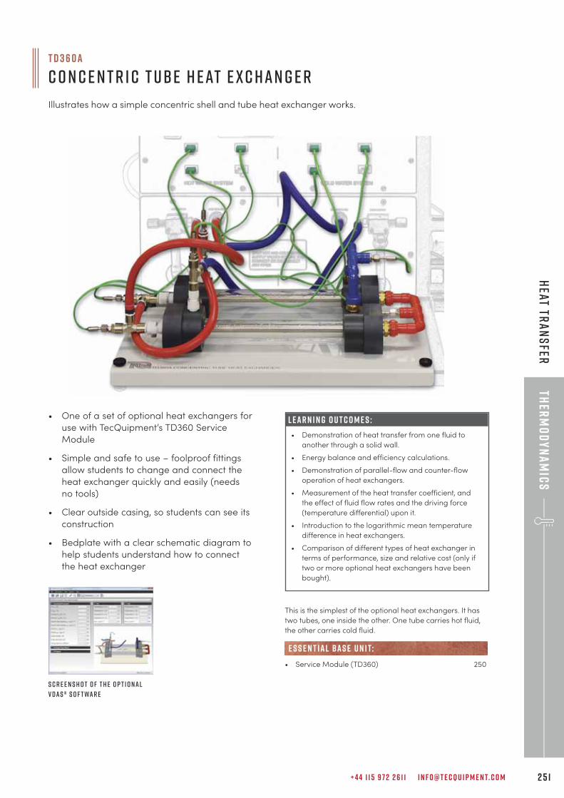
+ 4 4 1 1 5 9 7 2 2 6 1 1 I N F O @ T E C Q U I P M E N T. C O M 2 5 1
Ther
mo
dy
na
mic
sH
eat Tra
ns
fer
L E A R N I N G O U T C O M E S :
• Demonstration of heat transfer from one fluid to
another through a solid wall.
• Energy balance and efficiency calculations.
• Demonstration of parallel-flow and counter-flow
operation of heat exchangers.
• Measurement of the heat transfer coefficient, and
the effect of fluid flow rates and the driving force
(temperature differential) upon it.
• Introduction to the logarithmic mean temperature
difference in heat exchangers.
• Comparison of different types of heat exchanger in
terms of performance, size and relative cost (only if
two or more optional heat exchangers have been
bought).
This is the simplest of the optional heat exchangers. It has
two tubes, one inside the other. One tube carries hot fluid,
the other carries cold fluid.
• Service Module (TD360) 250
e s s e n t ial bas e u n i t:
S c r e e n s h o t o f t h e o p t i o nal
V D A S ® s o f t war e
• One of a set of optional heat exchangers for
use with TecQuipment’s TD360 Service
Module
• Simple and safe to use – foolproof fittings
allow students to change and connect the
heat exchanger quickly and easily (needs
no tools)
• Clear outside casing, so students can see its
construction
• Bedplate with a clear schematic diagram to
help students understand how to connect
the heat exchanger
T D 3 6 0 a
C o n c e n t r i c T ube H eat E x c han g e r
Illustrates how a simple concentric shell and tube heat exchanger works.
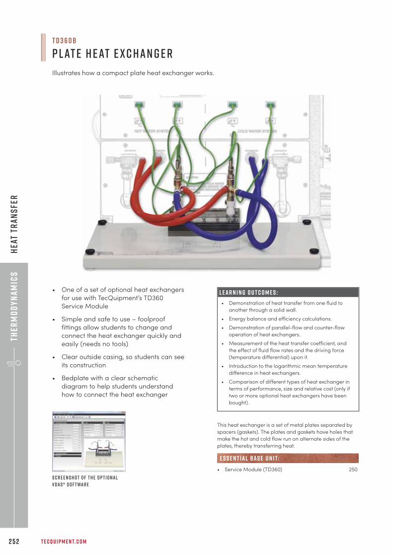
Ther
mo
dy
na
mic
s
T E C Q U I P M E N T. C O M2 5 2
Hea
t Tr
an
sfe
r
• One of a set of optional heat exchangers
for use with TecQuipment’s TD360
Service Module
• Simple and safe to use – foolproof
fittings allow students to change and
connect the heat exchanger quickly and
easily (needs no tools)
• Clear outside casing, so students can see
its construction
• Bedplate with a clear schematic
diagram to help students understand
how to connect the heat exchanger
L E A R N I N G O U T C O M E S :
• Demonstration of heat transfer from one fluid to
another through a solid wall.
• Energy balance and efficiency calculations.
• Demonstration of parallel-flow and counter-flow
operation of heat exchangers.
• Measurement of the heat transfer coefficient, and
the effect of fluid flow rates and the driving force
(temperature differential) upon it.
• Introduction to the logarithmic mean temperature
difference in heat exchangers.
• Comparison of different types of heat exchanger in
terms of performance, size and relative cost (only if
two or more optional heat exchangers have been
bought).
This heat exchanger is a set of metal plates separated by
spacers (gaskets). The plates and gaskets have holes that
make the hot and cold flow run on alternate sides of the
plates, thereby transferring heat.
• Service Module (TD360) 250
e s s e n t ial bas e u n i t:
S c r e e n s h o t o f t h e o p t i o nal
V D A S ® s o f t war e
T D 3 6 0 b
P lat e H eat E x c han g e r
Illustrates how a compact plate heat exchanger works.
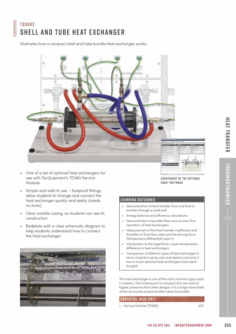
+ 4 4 1 1 5 9 7 2 2 6 1 1 I N F O @ T E C Q U I P M E N T. C O M 2 5 3
Ther
mo
dy
na
mic
sH
eat Tra
ns
fer
T D 3 6 0 c
S h e l l an d T ube H eat E x c han g e r
Illustrates how a compact shell and tube bundle heat exchanger works.
• One of a set of optional heat exchangers for
use with TecQuipment’s TD360 Service
Module
• Simple and safe to use – foolproof fittings
allow students to change and connect the
heat exchanger quickly and easily (needs
no tools)
• Clear outside casing, so students can see its
construction
• Bedplate with a clear schematic diagram to
help students understand how to connect
the heat exchanger
L E A R N I N G O U T C O M E S :
• Demonstration of heat transfer from one fluid to
another through a solid wall.
• Energy balance and efficiency calculations.
• Demonstration of parallel-flow and counter-flow
operation of heat exchangers.
• Measurement of the heat transfer coefficient, and
the effect of fluid flow rates and the driving force
(temperature differential) upon it.
• Introduction to the logarithmic mean temperature
difference in heat exchangers.
• Comparison of different types of heat exchanger in
terms of performance, size and relative cost (only if
two or more optional heat exchangers have been
bought).
This heat exchanger is one of the most common types used
in industry. This is because it is compact, but can work at
higher pressures than other designs. It is a large tube (shell)
which surrounds several smaller tubes (a bundle).
• Service Module (TD360) 250
e s s e n t ial bas e u n i t:
S c r e e n s h o t o f t h e o p t i o nal
V D A S ® s o f t war e
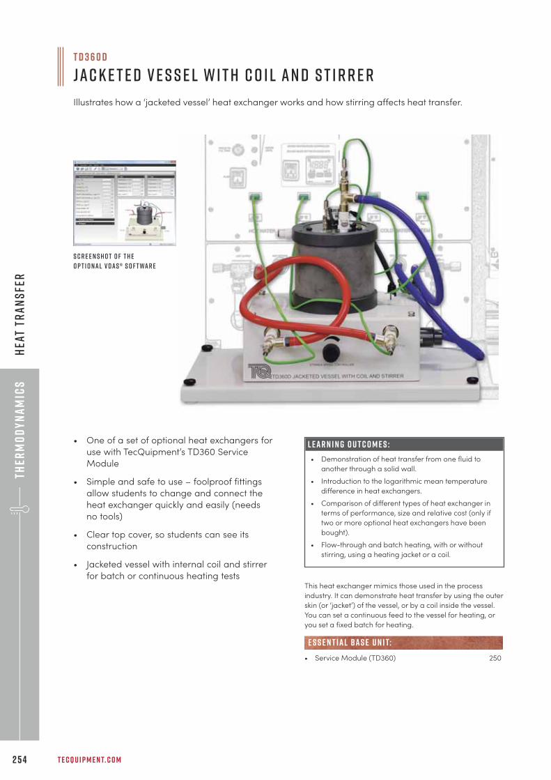
Ther
mo
dy
na
mic
s
T E C Q U I P M E N T. C O M2 5 4
Hea
t Tr
an
sfe
r
T D 3 6 0 d
Jac k e t e d V e s s e l w i t h C o i l an d S t i r r e r
Illustrates how a ‘jacketed vessel’ heat exchanger works and how stirring affects heat transfer.
• One of a set of optional heat exchangers for
use with TecQuipment’s TD360 Service
Module
• Simple and safe to use – foolproof fittings
allow students to change and connect the
heat exchanger quickly and easily (needs
no tools)
• Clear top cover, so students can see its
construction
• Jacketed vessel with internal coil and stirrer
for batch or continuous heating tests
L E A R N I N G O U T C O M E S :
• Demonstration of heat transfer from one fluid to
another through a solid wall.
• Introduction to the logarithmic mean temperature
difference in heat exchangers.
• Comparison of different types of heat exchanger in
terms of performance, size and relative cost (only if
two or more optional heat exchangers have been
bought).
• Flow-through and batch heating, with or without
stirring, using a heating jacket or a coil.
This heat exchanger mimics those used in the process
industry. It can demonstrate heat transfer by using the outer
skin (or ‘jacket’) of the vessel, or by a coil inside the vessel.
You can set a continuous feed to the vessel for heating, or
you set a fixed batch for heating.
• Service Module (TD360) 250
e s s e n t ial bas e u n i t:
S c r e e n s h o t o f t h e
o p t i o nal V D A S ® s o f t war e
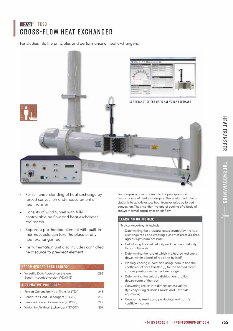
+ 4 4 1 1 5 9 7 2 2 6 1 1 I N F O @ T E C Q U I P M E N T. C O M 2 5 5
Ther
mo
dy
na
mic
sH
eat Tra
ns
fer
• For full understanding of heat exchange by
forced convection and measurement of
heat transfer
• Consists of wind tunnel with fully
controllable air flow and heat exchanger
rod matrix
• Separate pre-heated element with built-in
thermocouple can take the place of any
heat exchanger rod
• Instrumentation unit also includes controlled
heat source to pre-heat element
L E A R N I N G O U T C O M E S :
Typical experiments include:
• Determining the pressure losses created by the heat
exchange rods and creating a chart of pressure drop
against upstream pressure.
• Calculating the inlet velocity and the mean velocity
through the rods.
• Determining the rate at which the heated rod cools
down, within a bank of rods and by itself.
• Plotting ‘cooling curves’ and using them to find the
coefficient of heat transfer (h) for the heated rod at
various positions in the heat exchanger.
• Determining the velocity distribution (profile)
downstream of the rods.
• Converting results into dimensionless values
(typically using Nusselt, Prandtl and Reynolds
equations).
• Comparing results and producing heat transfer
coefficient curves.
For comprehensive studies into the principles and
performance of heat exchangers. The equipment allows
students to quickly assess heat transfer rates by forced
convection. They monitor the rate of cooling of a body of
known thermal capacity in an air flow.
T E 9 3
C r o s s - F l o w H eat E x c han g e r
For studies into the principles and performance of heat exchangers.
• Versatile Data Acquisition System – 293
Bench-mounted version (VDAS-B)
• Forced Convection Heat Transfer (TD1) 243
• Bench-top Heat Exchangers (TD360) 250
• Free and Forced Convection (TD1005) 249
• Water-to-Air Heat Exchanger (TD1007) 257
R E C O M M E N D E D AN C I L LAR I E S :
alt e r nat i v e p r o d u c t s :
S c r e e n s h o t o f t h e o p t i o nal V D A S ® s o f t war e
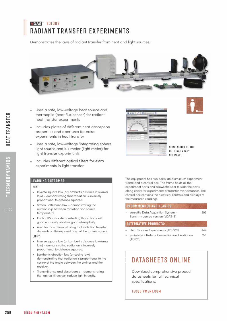
Ther
mo
dy
na
mic
s
T E C Q U I P M E N T. C O M2 5 6
Hea
t Tr
an
sfe
r
• Uses a safe, low-voltage heat source and
thermopile (heat flux sensor) for radiant
heat transfer experiments
• Includes plates of different heat absorption
properties and apertures for extra
experiments in heat transfer
• Uses a safe, low-voltage ‘integrating sphere’
light source and lux meter (light meter) for
light transfer experiments
• Includes different optical filters for extra
experiments in light transfer
L E A R N I N G O U T C O M E S :
H e at:
• Inverse square law (or Lambert's distance law/area
law) – demonstrating that radiation is inversely
proportional to distance squared.
• Stefan Boltzmann law – demonstrating the
relationship between radiation and source
temperature.
• Kirchhoff's law – demonstrating that a body with
good emissivity also has good absorptivity.
• Area factor – demonstrating that radiation transfer
depends on the exposed area of the radiant source.
L i g h t:
• Inverse square law (or Lambert's distance law/area
law) – demonstrating radiation is inversely
proportional to distance squared.
• Lambert's direction law (or cosine law) –
demonstrating that radiation is proportional to the
cosine of the angle between the emitter and the
receiver.
• Transmittance and absorbance – demonstrating
that optical filters can reduce light intensity.
T D 1 0 0 3
Rad ian t T ran s f e r E x p e r i m e n t s
Demonstrates the laws of radiant transfer from heat and light sources.
S c r e e n s h o t o f t h e
o p t i o nal V D A S ®
s o f t war e
The equipment has two parts: an aluminium experiment
frame and a control box. The frame holds all the
experiment parts and allows the user to slide the parts
along easily for experiments of transfer over distances. The
control box contains the electrical controls and displays of
the measured readings.
• Versatile Data Acquisition System – 293
Bench-mounted version (VDAS-B)
• Heat Transfer Experiments (TD1002) 244
• Emissivity – Natural Convection and Radiation 241
(TD1011)
R E C O M M E N D E D AN C I L LAR I E S :
alt e r nat i v e p r o d u c t s :
d ata s h e e t s o n l i n e
Download comprehensive product
datasheets for full technical
specifications.
t e cqu i p m e n t. c o m
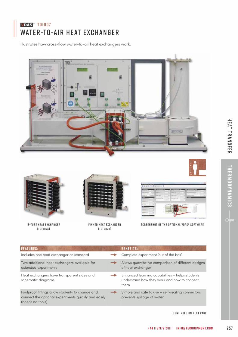
+ 4 4 1 1 5 9 7 2 2 6 1 1 I N F O @ T E C Q U I P M E N T. C O M 2 5 7
Ther
mo
dy
na
mic
sH
eat Tra
ns
fer
F E AT U R E S : B E N E F I T S :
Includes one heat exchanger as standard Complete experiment ‘out of the box’
Two additional heat exchangers available for
extended experiments
Allows quantitative comparison of different designs
of heat exchanger
Heat exchangers have transparent sides and
schematic diagrams
Enhanced learning capabilities – helps students
understand how they work and how to connect
them
Foolproof fittings allow students to change and
connect the optional experiments quickly and easily
(needs no tools)
Simple and safe to use – self-sealing connectors
prevents spillage of water
T D 1 0 0 7
Wat e r -t o - A i r H eat E x c han g e r
Illustrates how cross-flow water-to-air heat exchangers work.
S c r e e n s h o t o f t h e o p t i o nal V D A S ® s o f t war e16 -T ube H eat E x c han g e r
( T D 1 0 0 7a )
F i n n e d H eat E x c han g e r
( T D 1 0 0 7b )
c o n t i n u e d o n n e x t pag e

Ther
mo
dy
na
mic
s
T E C Q U I P M E N T. C O M2 5 8
Hea
t Tr
an
sfe
r
L E A R N I N G O U T C O M E S :
• Heat transfer between fluids through a solid wall
• Energy balance and efficiency
• Finding the heat transfer coefficient and Log Mean
Temperature Difference (LMTD)
• Effect of water temperature (the ‘driving force’)
• Comparison of heat exchangers of different
construction and heat transfer area (needs optional
TD1007a and TD1007b)
Many thermodynamic applications use water-to-air heat
exchangers. Examples include using circulated water to
heat or cool air in an HVAC installation, or to cool hot water
using a flow of air, as in the radiator of a combustion
engine.
The TecQuipment Water-to-Air Heat Exchanger mirrors air
heating and water cooling applications. It fits on a bench
top and includes a hot water supply, a cooling air duct and
all instruments needed for tests on cross-flow heat
exchangers. The heat output of the design produces good
results without greatly affecting the temperature of a
reasonably-sized classroom or laboratory.
• 16-Tube Heat Exchanger (TD1007a)
• 16-Tube Finned Heat Exchanger (TD1007b)
• VDAS-F (frame-mounted version of the Versatile 293
Data Acquisition System)
• Bench-Top Heat Exchangers (TD360) 250
• Cross-Flow Heat Exchanger (TE93) 255
• Free and Forced Convection (TD1005) 249
• Forced Convection Heat Transfer (TD1) 243
R E C O M M E N D E D AN C I L LAR I E S :
alt e r nat i v e p r o d u c t s :
wat e r -t o -a i r h eat e x c han g e r ( t d 1 0 0 7 ) c o n t i n u e d f r o m p r e v i o u s pag e
e l e c t r i c a l p owe r s y s t e m s r a n g e
The TecQuipment Electrical Power Systems
range is the most advanced and
comprehensive educational range for power
systems in the industry, covering all elements of
a power system including:
• Generation • Utilisation
• Transmission • Protection
• Transformation • Distribution
Visit h t t p s : // i n d u s t r ial .t e cqu i p m e n t. c o m
for more information.
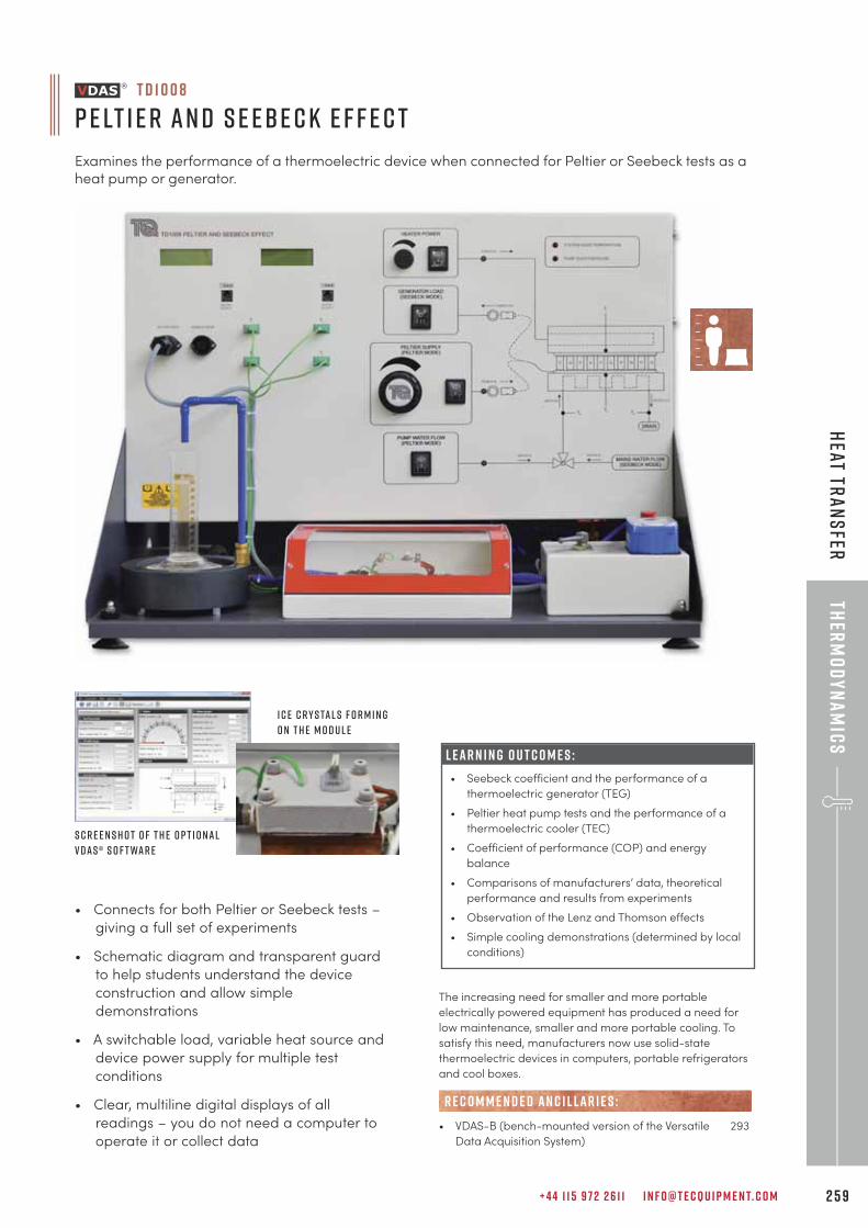
+ 4 4 1 1 5 9 7 2 2 6 1 1 I N F O @ T E C Q U I P M E N T. C O M 2 5 9
Ther
mo
dy
na
mic
sH
eat Tra
ns
fer
• Connects for both Peltier or Seebeck tests –
giving a full set of experiments
• Schematic diagram and transparent guard
to help students understand the device
construction and allow simple
demonstrations
• A switchable load, variable heat source and
device power supply for multiple test
conditions
• Clear, multiline digital displays of all
readings – you do not need a computer to
operate it or collect data
L E A R N I N G O U T C O M E S :
• Seebeck coefficient and the performance of a
thermoelectric generator (TEG)
• Peltier heat pump tests and the performance of a
thermoelectric cooler (TEC)
• Coefficient of performance (COP) and energy
balance
• Comparisons of manufacturers’ data, theoretical
performance and results from experiments
• Observation of the Lenz and Thomson effects
• Simple cooling demonstrations (determined by local
conditions)
T D 1 0 0 8
P e lt i e r an d S e ebe c k E f f e c t
Examines the performance of a thermoelectric device when connected for Peltier or Seebeck tests as aheat pump or generator.
S c r e e n s h o t o f t h e o p t i o nal
V D A S ® s o f t war e
I c e c r y s tal s f o r m i n g
o n t h e m o d u l e
The increasing need for smaller and more portable
electrically powered equipment has produced a need for
low maintenance, smaller and more portable cooling. To
satisfy this need, manufacturers now use solid-state
thermoelectric devices in computers, portable refrigerators
and cool boxes.
• VDAS-B (bench-mounted version of the Versatile 293
Data Acquisition System)
R E C O M M E N D E D AN C I L LAR I E S :
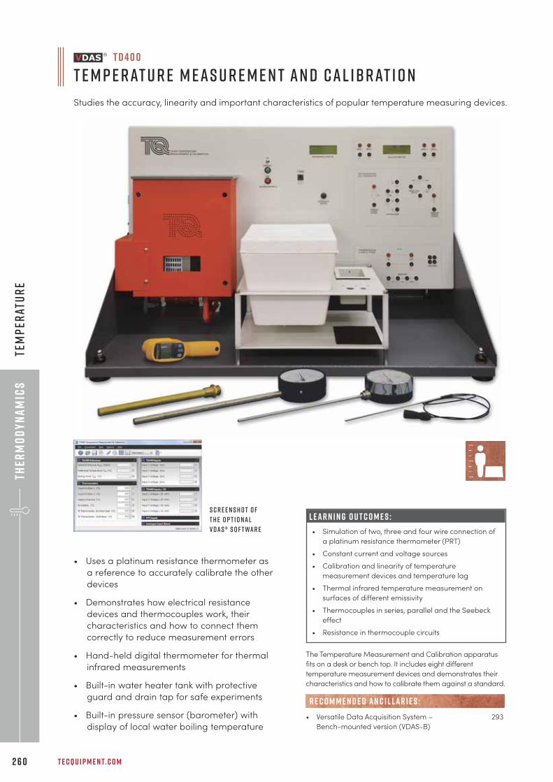
Ther
mo
dy
na
mic
s
T E C Q U I P M E N T. C O M2 6 0
Tem
per
atu
re
L E A R N I N G O U T C O M E S :
• Simulation of two, three and four wire connection of
a platinum resistance thermometer (PRT)
• Constant current and voltage sources
• Calibration and linearity of temperature
measurement devices and temperature lag
• Thermal infrared temperature measurement on
surfaces of different emissivity
• Thermocouples in series, parallel and the Seebeck
effect
• Resistance in thermocouple circuits
T D 4 0 0
T e m p e rat u r e M eas u r e m e n t an d Cal ibrat i o n
Studies the accuracy, linearity and important characteristics of popular temperature measuring devices.
S c r e e n s h o t o f
t h e o p t i o nal
V D A S ® s o f t war e
• Uses a platinum resistance thermometer as
a reference to accurately calibrate the other
devices
• Demonstrates how electrical resistance
devices and thermocouples work, their
characteristics and how to connect them
correctly to reduce measurement errors
• Hand-held digital thermometer for thermal
infrared measurements
• Built-in water heater tank with protective
guard and drain tap for safe experiments
• Built-in pressure sensor (barometer) with
display of local water boiling temperature
The Temperature Measurement and Calibration apparatus
fits on a desk or bench top. It includes eight different
temperature measurement devices and demonstrates their
characteristics and how to calibrate them against a standard.
• Versatile Data Acquisition System – 293
Bench-mounted version (VDAS-B)
R E C O M M E N D E D AN C I L LAR I E S :
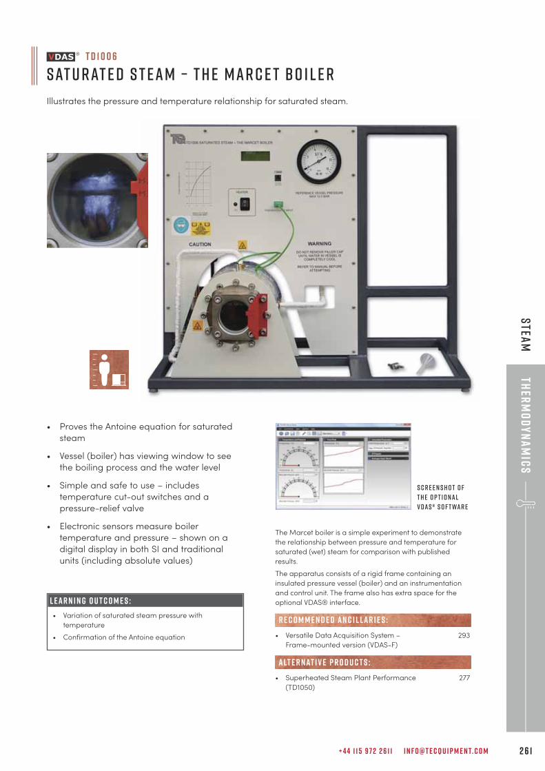
+ 4 4 1 1 5 9 7 2 2 6 1 1 I N F O @ T E C Q U I P M E N T. C O M 2 6 1
L E A R N I N G O U T C O M E S :
• Variation of saturated steam pressure with
temperature
• Confirmation of the Antoine equation
• Proves the Antoine equation for saturated
steam
• Vessel (boiler) has viewing window to see
the boiling process and the water level
• Simple and safe to use – includes
temperature cut-out switches and a
pressure-relief valve
• Electronic sensors measure boiler
temperature and pressure – shown on a
digital display in both SI and traditional
units (including absolute values)
The Marcet boiler is a simple experiment to demonstrate
the relationship between pressure and temperature for
saturated (wet) steam for comparison with published
results.
The apparatus consists of a rigid frame containing an
insulated pressure vessel (boiler) and an instrumentation
and control unit. The frame also has extra space for the
optional VDAS® interface.
• Versatile Data Acquisition System – 293
Frame-mounted version (VDAS-F)
• Superheated Steam Plant Performance 277
(TD1050)
R E C O M M E N D E D AN C I L LAR I E S :
alt e r nat i v e p r o d u c t s :
T D 1 0 0 6
Sat u rat e d S t eam – T h e Mar c e t B o i l e r
Illustrates the pressure and temperature relationship for saturated steam.
S c r e e n s h o t o f
t h e o p t i o nal
V D A S ® s o f t war e
Ther
mo
dy
na
mic
sS
team
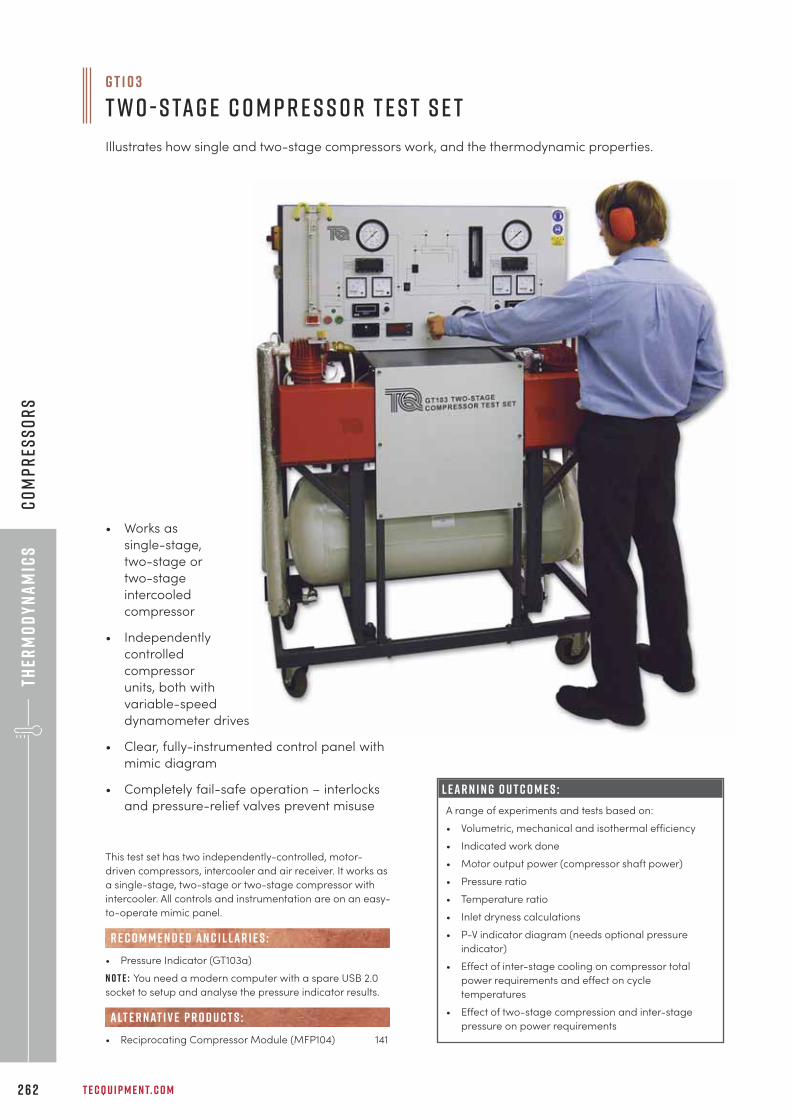
Ther
mo
dy
na
mic
s
G T 1 0 3
T w o - S tag e C o m p r e s s o r T e s t S e t
Illustrates how single and two-stage compressors work, and the thermodynamic properties.
T E C Q U I P M E N T. C O M2 6 2
Co
mp
res
so
rs
L E A R N I N G O U T C O M E S :
A range of experiments and tests based on:
• Volumetric, mechanical and isothermal efficiency
• Indicated work done
• Motor output power (compressor shaft power)
• Pressure ratio
• Temperature ratio
• Inlet dryness calculations
• P-V indicator diagram (needs optional pressure
indicator)
• Effect of inter-stage cooling on compressor total
power requirements and effect on cycle
temperatures
• Effect of two-stage compression and inter-stage
pressure on power requirements
This test set has two independently-controlled, motor-
driven compressors, intercooler and air receiver. It works as
a single-stage, two-stage or two-stage compressor with
intercooler. All controls and instrumentation are on an easy-
to-operate mimic panel.
• Pressure Indicator (GT103a)
N o t e : You need a modern computer with a spare USB 2.0
socket to setup and analyse the pressure indicator results.
• Reciprocating Compressor Module (MFP104) 141
R E C O M M E N D E D AN C I L LAR I E S :
alt e r nat i v e p r o d u c t s :
• Works as
single-stage,
two-stage or
two-stage
intercooled
compressor
• Independently
controlled
compressor
units, both with
variable-speed
dynamometer drives
• Clear, fully-instrumented control panel with
mimic diagram
• Completely fail-safe operation – interlocks
and pressure-relief valves prevent misuse
+ 4 4 1 1 5 9 7 2 2 6 1 1 I N F O @ T E C Q U I P M E N T. C O M 2 6 3
Eng
ines
e n g i n e si n t e r n a l c o m b u s t i o n e n g i n e t e s t s e t s 2 6 5
s t e a m 2 7 7
g a s t u r b i n e s 2 7 8
“For a number of years we have procured laboratory-based teaching resources fromTecQuipment. Operation of this equipment, coupled with the robust build quality, provides ourstudents with a clear understanding of the intrinsic features behind thermo-fluids andmechanical principles. This instills confidence for a safe, hands-on experience demonstratingthese principles in practice. Furthermore, the build quality of TecQuipment products also givesassurance that the investment made satisfies our ongoing teaching needs well into the future.
g r a h a m p r e e c efa c u lt y o f c o m p u t i n g , e n g i n e e r i n g a n d s c i e n c e s , s ta f f o r d s h i r e u n i v e r s i t y
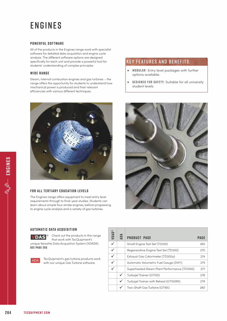
Eng
ines
T E C Q U I P M E N T. C O M2 6 4
P o w e r f u l s o f t wa r e
All of the products in the Engines range work with specialist
software for detailed data acquisition and engine cycle
analysis. The different software options are designed
specifically for each unit and provide a powerful tool for
students’ understanding of complex principles.
W i d e r a n g e
Steam, internal combustion engines and gas turbines – the
range offers the opportunity for students to understand how
mechanical power is produced and their relevant
efficiencies with various different techniques.
e n g i n e s
P r o d u c t Pa g e Pa g e
Small Engine Test Set (TD200) 265
Regenerative Engine Test Set (TD300) 270
Exhaust Gas Calorimeter (TD300a) 274
Automatic Volumetric Fuel Gauge (DVF1) 275
Superheated Steam Plant Performance (TD1050) 277
Turbojet Trainer (GT100) 278
Turbojet Trainer with Reheat (GT100RS) 279
Two-Shaft Gas Turbine (GT185) 280
AD
A
ü
ü
ü
VD
AS
®
ü
ü
ü
ü
ü
A u t o m at i c D ata A c q u i s i t i o n
Check out the products in this range
that work with TecQuipment’s
unique Versatile Data Acquisition System (VDAS®).
S e e pa g e 2 9 3
TecQuipment’s gas turbine products work
with our unique Gas Turbine software.
F o r a l l t e r t i a r y e d u c at i o n l e v e l s
The Engines range offers equipment to meet entry level
requirements through to final-year studies. Students can
learn about simple four-stroke engines, before progressing
to engine cycle analysis and a variety of gas turbines.
• m o d u l a r : Entry level packages with further
options available.
• d e s i g n e d f o r s a f e t y: Suitable for all university
student levels.
k e y f eat u r e s an d b e n e f i t s :
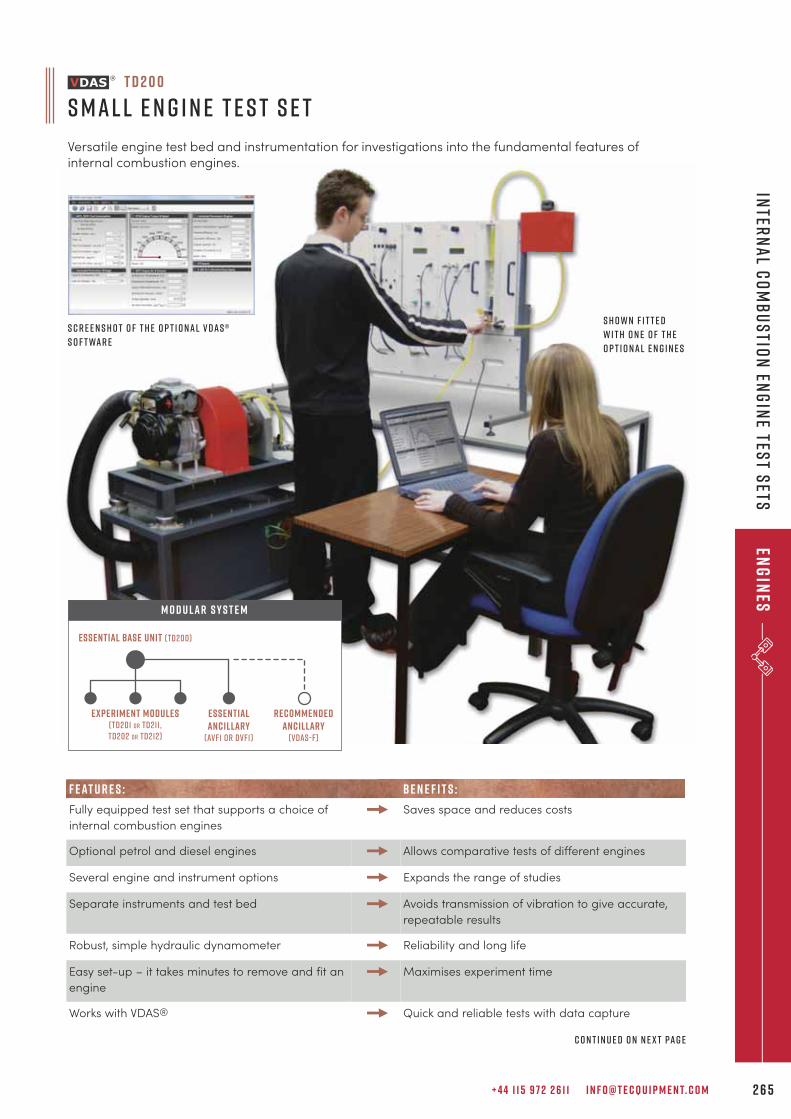
+ 4 4 1 1 5 9 7 2 2 6 1 1 I N F O @ T E C Q U I P M E N T. C O M 2 6 5
Inter
na
l Co
mb
us
tion
Eng
ine tes
t sets
Eng
ines
S c r e e n s h o t o f t h e o p t i o n a l V D A S ®
s o f t wa r e
C o n t i n u e d o n n e x t pa g e
Experiment modules(TD201 or TD211,TD202 or td212)
essentialancillary
(avf1 or dvf1)
recommendedancillary
(vdas-f)
Essential Base Unit (TD200)
M O D U LAR S Y S T E M
S h o w n f i t t e d
w i t h o n e o f t h e
o p t i o n a l e n g i n e s
F E AT U R E S : BE N E F I T S :
Fully equipped test set that supports a choice of
internal combustion engines
Saves space and reduces costs
Optional petrol and diesel engines Allows comparative tests of different engines
Several engine and instrument options Expands the range of studies
Separate instruments and test bed Avoids transmission of vibration to give accurate,
repeatable results
Robust, simple hydraulic dynamometer Reliability and long life
Easy set-up – it takes minutes to remove and fit an
engine
Maximises experiment time
Works with VDAS® Quick and reliable tests with data capture
T D 2 0 0
S m a l l E n g i n e T e s t S e t
Versatile engine test bed and instrumentation for investigations into the fundamental features ofinternal combustion engines.
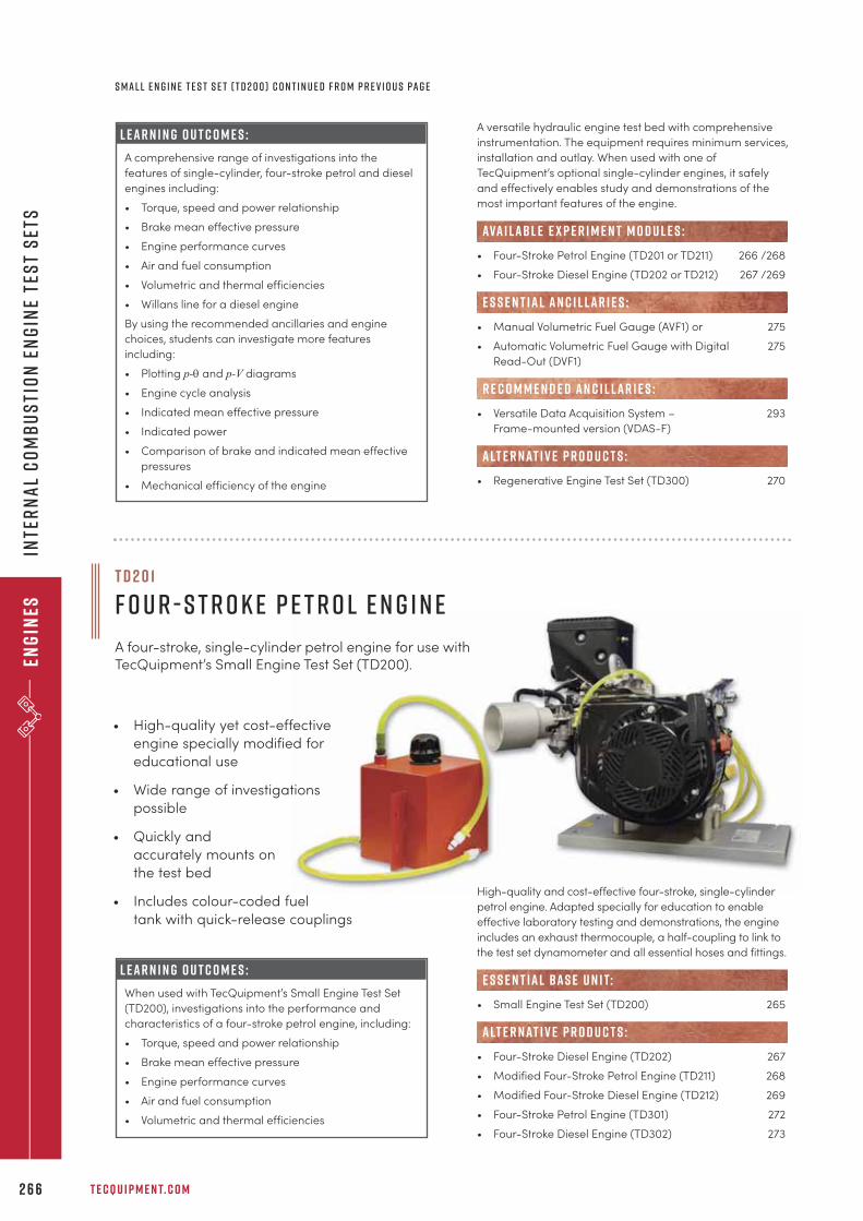
Eng
ines
T E C Q U I P M E N T. C O M2 6 6
L e a r n i n g o u t c o m e s :
A comprehensive range of investigations into the
features of single-cylinder, four-stroke petrol and diesel
engines including:
• Torque, speed and power relationship
• Brake mean effective pressure
• Engine performance curves
• Air and fuel consumption
• Volumetric and thermal efficiencies
• Willans line for a diesel engine
By using the recommended ancillaries and engine
choices, students can investigate more features
including:
• Plotting p-q and p-V diagrams
• Engine cycle analysis
• Indicated mean effective pressure
• Indicated power
• Comparison of brake and indicated mean effective
pressures
• Mechanical efficiency of the engine
A versatile hydraulic engine test bed with comprehensive
instrumentation. The equipment requires minimum services,
installation and outlay. When used with one of
TecQuipment’s optional single-cylinder engines, it safely
and effectively enables study and demonstrations of the
most important features of the engine.
• Four-Stroke Petrol Engine (TD201 or TD211) 266 /268
• Four-Stroke Diesel Engine (TD202 or TD212) 267 /269
• Manual Volumetric Fuel Gauge (AVF1) or 275
• Automatic Volumetric Fuel Gauge with Digital 275
Read-Out (DVF1)
• Versatile Data Acquisition System – 293
Frame-mounted version (VDAS-F)
• Regenerative Engine Test Set (TD300) 270
R E C O M M E N D E D AN C I L LAR I E S :
alt e r nat i v e p r o d u c t s :
ava i labl e e x p e r i m e n t m o d u l e s :
E S S E N T IAL AN C I L LAR I E S :
S m a l l E n g i n e T e s t S e t ( T D 2 0 0 ) C o n t i n u e d f r o m p r e v i o u s pa g e
L e a r n i n g o u t c o m e s :
When used with TecQuipment’s Small Engine Test Set
(TD200), investigations into the performance and
characteristics of a four-stroke petrol engine, including:
• Torque, speed and power relationship
• Brake mean effective pressure
• Engine performance curves
• Air and fuel consumption
• Volumetric and thermal efficiencies
High-quality and cost-effective four-stroke, single-cylinder
petrol engine. Adapted specially for education to enable
effective laboratory testing and demonstrations, the engine
includes an exhaust thermocouple, a half-coupling to link to
the test set dynamometer and all essential hoses and fittings.
• Small Engine Test Set (TD200) 265
• Four-Stroke Diesel Engine (TD202) 267
• Modified Four-Stroke Petrol Engine (TD211) 268
• Modified Four-Stroke Diesel Engine (TD212) 269
• Four-Stroke Petrol Engine (TD301) 272
• Four-Stroke Diesel Engine (TD302) 273
alt e r nat i v e p r o d u c t s :
e s s e n t ial bas e u n i t:
T D 2 0 1
F o u r - S t r o k e P e t r o l E n g i n e
A four-stroke, single-cylinder petrol engine for use withTecQuipment’s Small Engine Test Set (TD200).
• High-quality yet cost-effective
engine specially modified for
educational use
• Wide range of investigations
possible
• Quickly and
accurately mounts on
the test bed
• Includes colour-coded fuel
tank with quick-release couplings
Inte
rn
al
Co
mb
us
tio
n E
ng
ine
tes
t s
ets
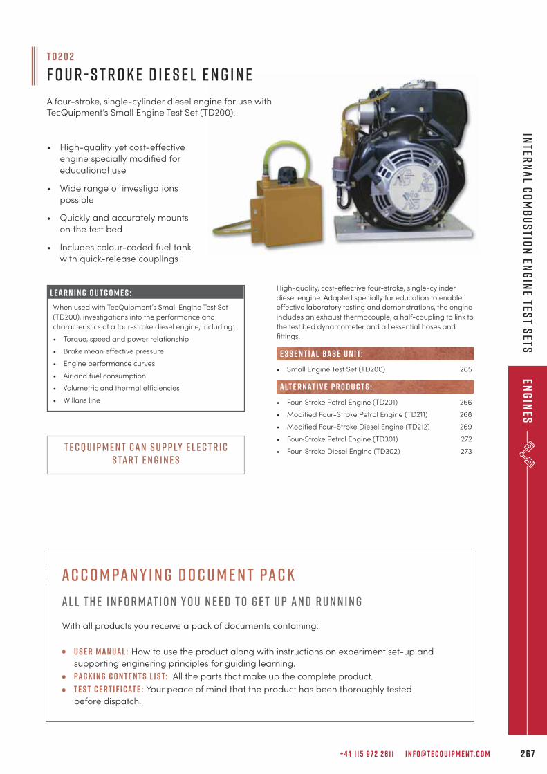
+ 4 4 1 1 5 9 7 2 2 6 1 1 I N F O @ T E C Q U I P M E N T. C O M 2 6 7
L e a r n i n g o u t c o m e s :
When used with TecQuipment’s Small Engine Test Set
(TD200), investigations into the performance and
characteristics of a four-stroke diesel engine, including:
• Torque, speed and power relationship
• Brake mean effective pressure
• Engine performance curves
• Air and fuel consumption
• Volumetric and thermal efficiencies
• Willans line
High-quality, cost-effective four-stroke, single-cylinder
diesel engine. Adapted specially for education to enable
effective laboratory testing and demonstrations, the engine
includes an exhaust thermocouple, a half-coupling to link to
the test bed dynamometer and all essential hoses and
fittings.
• Small Engine Test Set (TD200) 265
• Four-Stroke Petrol Engine (TD201) 266
• Modified Four-Stroke Petrol Engine (TD211) 268
• Modified Four-Stroke Diesel Engine (TD212) 269
• Four-Stroke Petrol Engine (TD301) 272
• Four-Stroke Diesel Engine (TD302) 273
alt e r nat i v e p r o d u c t s :
e s s e n t ial bas e u n i t:
T D 2 0 2
F o u r - S t r o k e D i e s e l E n g i n e
A four-stroke, single-cylinder diesel engine for use withTecQuipment’s Small Engine Test Set (TD200).
• High-quality yet cost-effective
engine specially modified for
educational use
• Wide range of investigations
possible
• Quickly and accurately mounts
on the test bed
• Includes colour-coded fuel tank
with quick-release couplings
Inter
na
l Co
mb
us
tion
Eng
ine tes
t sets
Eng
ines
T e c Q u i p m e n t c a n s u p p ly e l e c t r i cs ta r t e n g i n e s
Ac c o m pan y i n g d o c u m e n t pac k
Al l t h e i n f o r mat i o n y o u n e e d t o g e t u p an d r u n n i n g
With all products you receive a pack of documents containing:
U s e r Man ual : How to use the product along with instructions on experiment set-up and
supporting enginering principles for guiding learning.
Pac k i n g c o n t e n t s l i s t: All the parts that make up the complete product.
T e s t c e r t i f i cat e : Your peace of mind that the product has been thoroughly tested
before dispatch.
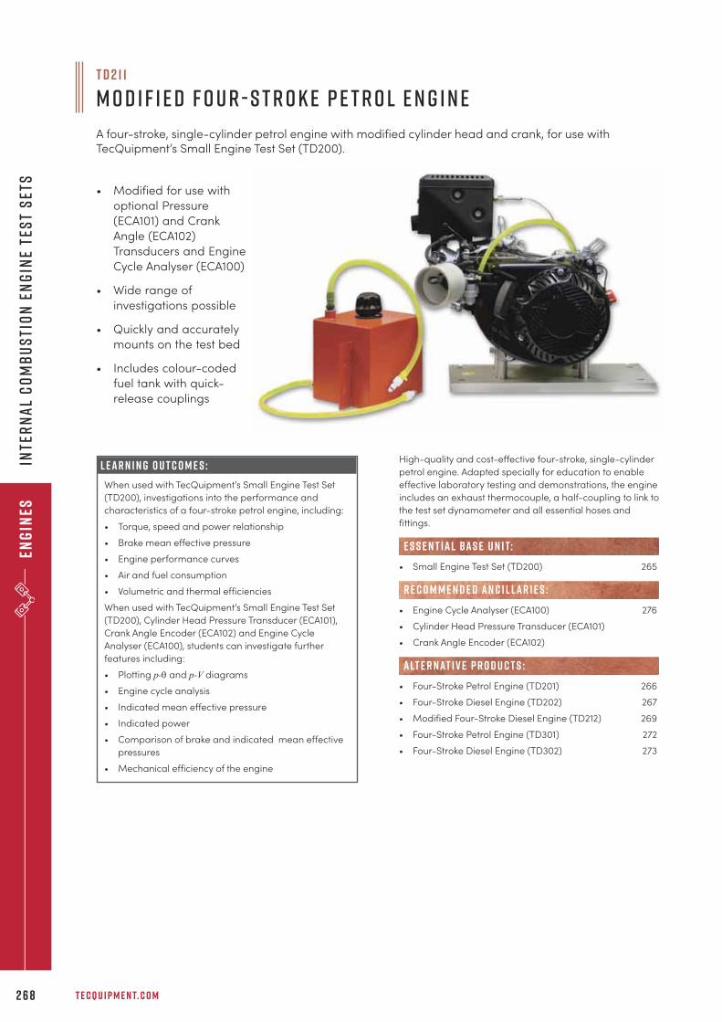
Eng
ines
T E C Q U I P M E N T. C O M2 6 8
• Modified for use with
optional Pressure
(ECA101) and Crank
Angle (ECA102)
Transducers and Engine
Cycle Analyser (ECA100)
• Wide range of
investigations possible
• Quickly and accurately
mounts on the test bed
• Includes colour-coded
fuel tank with quick-
release couplings
L e a r n i n g o u t c o m e s :
When used with TecQuipment’s Small Engine Test Set
(TD200), investigations into the performance and
characteristics of a four-stroke petrol engine, including:
• Torque, speed and power relationship
• Brake mean effective pressure
• Engine performance curves
• Air and fuel consumption
• Volumetric and thermal efficiencies
When used with TecQuipment’s Small Engine Test Set
(TD200), Cylinder Head Pressure Transducer (ECA101),
Crank Angle Encoder (ECA102) and Engine Cycle
Analyser (ECA100), students can investigate further
features including:
• Plotting p-q and p-V diagrams
• Engine cycle analysis
• Indicated mean effective pressure
• Indicated power
• Comparison of brake and indicated mean effective
pressures
• Mechanical efficiency of the engine
High-quality and cost-effective four-stroke, single-cylinder
petrol engine. Adapted specially for education to enable
effective laboratory testing and demonstrations, the engine
includes an exhaust thermocouple, a half-coupling to link to
the test set dynamometer and all essential hoses and
fittings.
• Small Engine Test Set (TD200) 265
• Engine Cycle Analyser (ECA100) 276
• Cylinder Head Pressure Transducer (ECA101)
• Crank Angle Encoder (ECA102)
• Four-Stroke Petrol Engine (TD201) 266
• Four-Stroke Diesel Engine (TD202) 267
• Modified Four-Stroke Diesel Engine (TD212) 269
• Four-Stroke Petrol Engine (TD301) 272
• Four-Stroke Diesel Engine (TD302) 273
R E C O M M E N D E D AN C I L LAR I E S :
alt e r nat i v e p r o d u c t s :
e s s e n t ial bas e u n i t:
T D 2 1 1
M o d i f i e d F o u r - S t r o k e P e t r o l E n g i n e
A four-stroke, single-cylinder petrol engine with modified cylinder head and crank, for use withTecQuipment’s Small Engine Test Set (TD200).
Inte
rn
al
Co
mb
us
tio
n E
ng
ine
tes
t s
ets
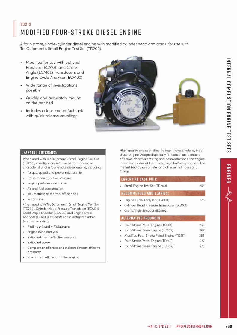
+ 4 4 1 1 5 9 7 2 2 6 1 1 I N F O @ T E C Q U I P M E N T. C O M 2 6 9
T D 2 1 2
M o d i f i e d F o u r - S t r o k e D i e s e l E n g i n e
A four-stroke, single-cylinder diesel engine with modified cylinder head and crank, for use withTecQuipment’s Small Engine Test Set (TD200).
• Modified for use with optional
Pressure (ECA101) and Crank
Angle (ECA102) Transducers and
Engine Cycle Analyser (ECA100)
• Wide range of investigations
possible
• Quickly and accurately mounts
on the test bed
• Includes colour-coded fuel tank
with quick-release couplings
L e a r n i n g o u t c o m e s :
When used with TecQuipment’s Small Engine Test Set
(TD200), investigations into the performance and
characteristics of a four-stroke diesel engine, including:
• Torque, speed and power relationship
• Brake mean effective pressure
• Engine performance curves
• Air and fuel consumption
• Volumetric and thermal efficiencies
• Willans line
When used with TecQuipment’s Small Engine Test Set
(TD200), Cylinder Head Pressure Transducer (ECA101),
Crank Angle Encoder (ECA102) and Engine Cycle
Analyser (ECA100), students can investigate further
features including:
• Plotting p-q and p-V diagrams
• Engine cycle analysis
• Indicated mean effective pressure
• Indicated power
• Comparison of brake and indicated mean effective
pressures
• Mechanical efficiency of the engine
High-quality and cost-effective four-stroke, single-cylinder
diesel engine. Adapted specially for education to enable
effective laboratory testing and demonstrations, the engine
includes an exhaust thermocouple, a half-coupling to link to
the test bed dynamometer and all essential hoses and
fittings.
• Small Engine Test Set (TD200) 265
• Engine Cycle Analyser (ECA100) 276
• Cylinder Head Pressure Transducer (ECA101)
• Crank Angle Encoder (ECA102)
• Four-Stroke Petrol Engine (TD201) 266
• Four-Stroke Diesel Engine (TD202) 267
• Modified Four-Stroke Petrol Engine (TD211) 268
• Four-Stroke Petrol Engine (TD301) 272
• Four-Stroke Diesel Engine (TD302) 273
R E C O M M E N D E D AN C I L LAR I E S :
alt e r nat i v e p r o d u c t s :
e s s e n t ial bas e u n i t:
Inter
na
l Co
mb
us
tion
Eng
ine tes
t sets
Eng
ines
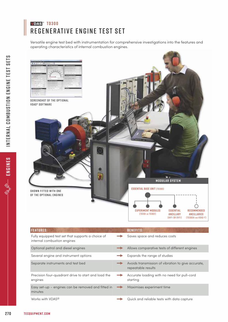
Eng
ines
T E C Q U I P M E N T. C O M2 7 0
Inte
rn
al
Co
mb
us
tio
n E
ng
ine
tes
t s
ets
Experiment modules(TD301 or TD302)
essentialancillary
(avf1 or dvf1)
recommendedancillaries
(TD300a and vdas-f)
Essential Base Unit (TD300)
M O D U LAR S Y S T E M
T D 3 0 0
R e g e n e r at i v e E n g i n e T e s t S e t
Versatile engine test bed with instrumentation for comprehensive investigations into the features andoperating characteristics of internal combustion engines.
S c r e e n s h o t o f t h e o p t i o n a l
V D A S ® s o f t wa r e
S h o w n f i t t e d w i t h o n e
o f t h e o p t i o n a l e n g i n e s
F E AT U R E S : BE N E F I T S :
Fully equipped test set that supports a choice of
internal combustion engines
Saves space and reduces costs
Optional petrol and diesel engines Allows comparative tests of different engines
Several engine and instrument options Expands the range of studies
Separate instruments and test bed Avoids transmission of vibration to give accurate,
repeatable results
Precision four-quadrant drive to start and load the
engines
Accurate loading with no need for pull-cord
starting
Easy set-up – engines can be removed and fitted in
minutes
Maximises experiment time
Works with VDAS® Quick and reliable tests with data capture
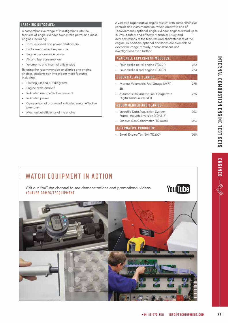
+ 4 4 1 1 5 9 7 2 2 6 1 1 I N F O @ T E C Q U I P M E N T. C O M 2 7 1
Inter
na
l Co
mb
us
tion
Eng
ine tes
t sets
Eng
ines
L e a r n i n g o u t c o m e s :
A comprehensive range of investigations into the
features of single-cylinder, four-stroke petrol and diesel
engines including:
• Torque, speed and power relationship
• Brake mean effective pressure
• Engine performance curves
• Air and fuel consumption
• Volumetric and thermal efficiencies
By using the recommended ancillaries and engine
choices, students can investigate more features
including:
• Plotting p-q and p-V diagrams
• Engine cycle analysis
• Indicated mean effective pressure
• Indicated power
• Comparison of brake and indicated mean effective
pressures
• Mechanical efficiency of the engine
A versatile regenerative engine test set with comprehensive
controls and instrumentation. When used with one of
TecQuipment’s optional single-cylinder engines (rated up to
10 kW), it safely and effectively enables study and
demonstrations of the features and characteristics of the
engine. In addition, optional ancillaries are available to
extend the range of study, demonstrations and
investigations even further.
• Four-stroke petrol engine (TD301) 272
• Four-stroke diesel engine (TD302) 273
• Manual Volumetric Fuel Gauge (AVF1) 275
o r
• Automatic Volumetric Fuel Gauge with 275
Digital Read-out (DVF1)
• Versatile Data Acquisition System – 293
Frame-mounted version (VDAS-F)
• Exhaust Gas Calorimeter (TD300a) 274
• Small Engine Test Set (TD200) 265
R E C O M M E N D E D AN C I L LAR I E S :
alt e r nat i v e p r o d u c t s :
ava i labl e e x p e r i m e n t m o d u l e s :
E S S E N T IAL AN C I L LAR I E S :
wat c h e q u i p m e n t i n ac t i o n
Visit our YouTube channel to see demonstrations and promotional videos:
y o u t ube . c o m / c / t e cqu i p m e n t
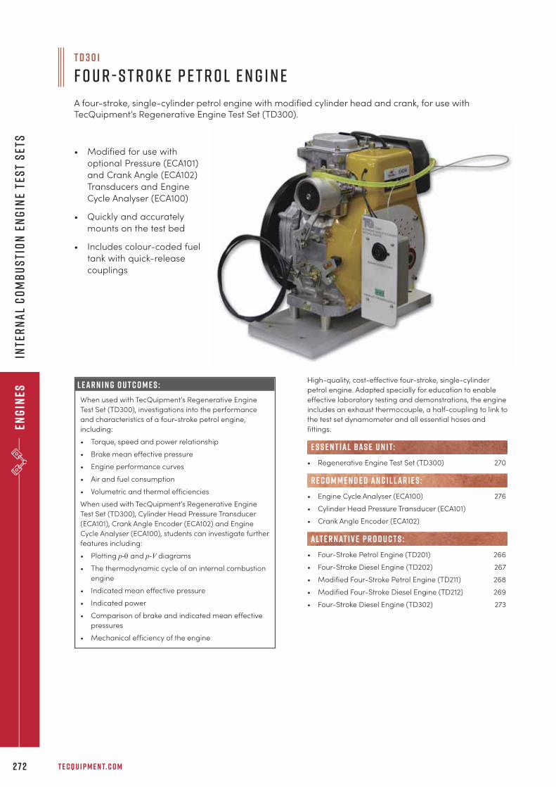
Eng
ines
T E C Q U I P M E N T. C O M2 7 2
Inte
rn
al
Co
mb
us
tio
n E
ng
ine
tes
t s
ets
• Modified for use with
optional Pressure (ECA101)
and Crank Angle (ECA102)
Transducers and Engine
Cycle Analyser (ECA100)
• Quickly and accurately
mounts on the test bed
• Includes colour-coded fuel
tank with quick-release
couplings
L e a r n i n g o u t c o m e s :
When used with TecQuipment’s Regenerative Engine
Test Set (TD300), investigations into the performance
and characteristics of a four-stroke petrol engine,
including:
• Torque, speed and power relationship
• Brake mean effective pressure
• Engine performance curves
• Air and fuel consumption
• Volumetric and thermal efficiencies
When used with TecQuipment’s Regenerative Engine
Test Set (TD300), Cylinder Head Pressure Transducer
(ECA101), Crank Angle Encoder (ECA102) and Engine
Cycle Analyser (ECA100), students can investigate further
features including:
• Plotting p-q and p-V diagrams
• The thermodynamic cycle of an internal combustion
engine
• Indicated mean effective pressure
• Indicated power
• Comparison of brake and indicated mean effective
pressures
• Mechanical efficiency of the engine
High-quality, cost-effective four-stroke, single-cylinder
petrol engine. Adapted specially for education to enable
effective laboratory testing and demonstrations, the engine
includes an exhaust thermocouple, a half-coupling to link to
the test set dynamometer and all essential hoses and
fittings.
• Regenerative Engine Test Set (TD300) 270
• Engine Cycle Analyser (ECA100) 276
• Cylinder Head Pressure Transducer (ECA101)
• Crank Angle Encoder (ECA102)
• Four-Stroke Petrol Engine (TD201) 266
• Four-Stroke Diesel Engine (TD202) 267
• Modified Four-Stroke Petrol Engine (TD211) 268
• Modified Four-Stroke Diesel Engine (TD212) 269
• Four-Stroke Diesel Engine (TD302) 273
R E C O M M E N D E D AN C I L LAR I E S :
alt e r nat i v e p r o d u c t s :
e s s e n t ial bas e u n i t:
T D 3 0 1
F o u r - S t r o k e P e t r o l E n g i n e
A four-stroke, single-cylinder petrol engine with modified cylinder head and crank, for use withTecQuipment’s Regenerative Engine Test Set (TD300).
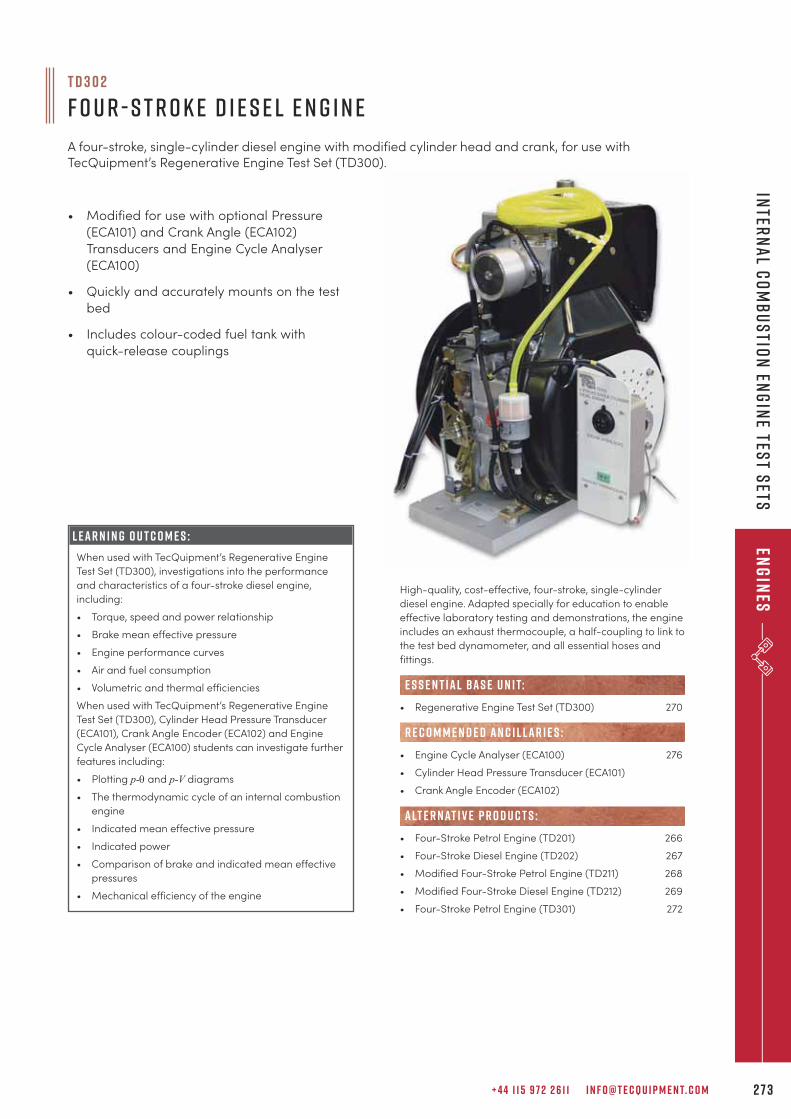
+ 4 4 1 1 5 9 7 2 2 6 1 1 I N F O @ T E C Q U I P M E N T. C O M 2 7 3
Inter
na
l Co
mb
us
tion
Eng
ine tes
t sets
Eng
ines
• Modified for use with optional Pressure
(ECA101) and Crank Angle (ECA102)
Transducers and Engine Cycle Analyser
(ECA100)
• Quickly and accurately mounts on the test
bed
• Includes colour-coded fuel tank with
quick-release couplings
L e a r n i n g O u t c o m e s :
When used with TecQuipment’s Regenerative Engine
Test Set (TD300), investigations into the performance
and characteristics of a four-stroke diesel engine,
including:
• Torque, speed and power relationship
• Brake mean effective pressure
• Engine performance curves
• Air and fuel consumption
• Volumetric and thermal efficiencies
When used with TecQuipment’s Regenerative Engine
Test Set (TD300), Cylinder Head Pressure Transducer
(ECA101), Crank Angle Encoder (ECA102) and Engine
Cycle Analyser (ECA100) students can investigate further
features including:
• Plotting p-q and p-V diagrams
• The thermodynamic cycle of an internal combustion
engine
• Indicated mean effective pressure
• Indicated power
• Comparison of brake and indicated mean effective
pressures
• Mechanical efficiency of the engine
High-quality, cost-effective, four-stroke, single-cylinder
diesel engine. Adapted specially for education to enable
effective laboratory testing and demonstrations, the engine
includes an exhaust thermocouple, a half-coupling to link to
the test bed dynamometer, and all essential hoses and
fittings.
• Regenerative Engine Test Set (TD300) 270
• Engine Cycle Analyser (ECA100) 276
• Cylinder Head Pressure Transducer (ECA101)
• Crank Angle Encoder (ECA102)
• Four-Stroke Petrol Engine (TD201) 266
• Four-Stroke Diesel Engine (TD202) 267
• Modified Four-Stroke Petrol Engine (TD211) 268
• Modified Four-Stroke Diesel Engine (TD212) 269
• Four-Stroke Petrol Engine (TD301) 272
R E C O M M E N D E D AN C I L LAR I E S :
alt e r nat i v e p r o d u c t s :
e s s e n t ial bas e u n i t:
T D 3 0 2
F o u r - S t r o k e D i e s e l E n g i n e
A four-stroke, single-cylinder diesel engine with modified cylinder head and crank, for use withTecQuipment’s Regenerative Engine Test Set (TD300).
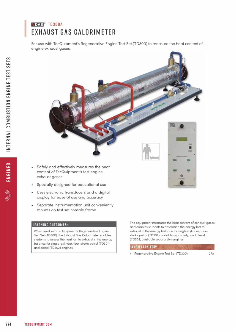
Eng
ines
T E C Q U I P M E N T. C O M2 74
Inte
rn
al
Co
mb
us
tio
n E
ng
ine
tes
t s
ets
L e a r n i n g o u t c o m e s :
When used with TecQuipment’s Regenerative Engine
Test Set (TD300), the Exhaust Gas Calorimeter enables
students to assess the heat lost to exhaust in the energy
balance for single-cylinder, four-stroke petrol (TD301)
and diesel (TD302) engines.
The equipment measures the heat content of exhaust gases
and enables students to determine the energy lost to
exhaust in the energy balance for single-cylinder, four-
stroke petrol (TD301, available separately) and diesel
(TD302, available separately) engines.
• Regenerative Engine Test Set (TD300) 270
AN C I L LAR Y F O R :
T D 3 0 0 a
E x h a u s t G a s C a l o r i m e t e r
For use with TecQuipment’s Regenerative Engine Test Set (TD300) to measure the heat content ofengine exhaust gases.
• Safely and effectively measures the heat
content of TecQuipment’s test engine
exhaust gases
• Specially designed for educational use
• Uses electronic transducers and a digital
display for ease of use and accuracy
• Separate instrumentation unit conveniently
mounts on test set console frame
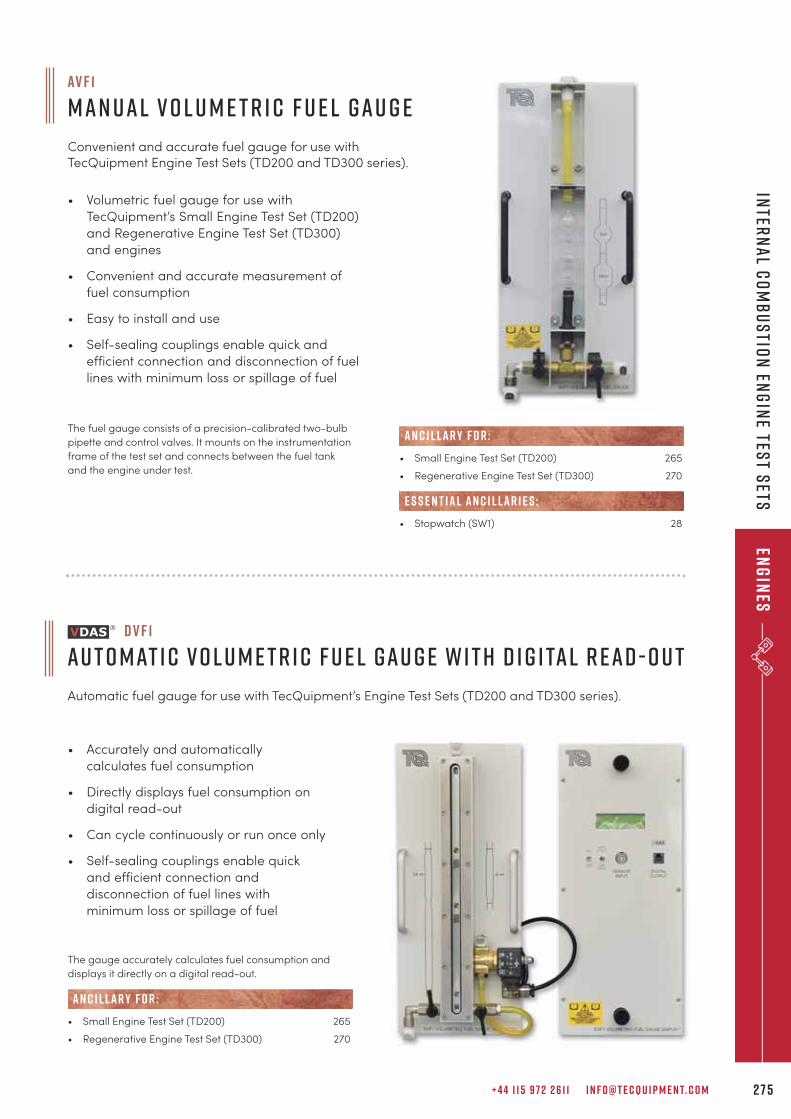
+ 4 4 1 1 5 9 7 2 2 6 1 1 I N F O @ T E C Q U I P M E N T. C O M 2 7 5
Inter
na
l Co
mb
us
tion
Eng
ine tes
t sets
Eng
ines
• Accurately and automatically
calculates fuel consumption
• Directly displays fuel consumption on
digital read-out
• Can cycle continuously or run once only
• Self-sealing couplings enable quick
and efficient connection and
disconnection of fuel lines with
minimum loss or spillage of fuel
D V F 1
A u t o m at i c V o l u m e t r i c F u e l G a u g e w i t h D i g i ta l R e a d - O u t
Automatic fuel gauge for use with TecQuipment’s Engine Test Sets (TD200 and TD300 series).
• Volumetric fuel gauge for use with
TecQuipment’s Small Engine Test Set (TD200)
and Regenerative Engine Test Set (TD300)
and engines
• Convenient and accurate measurement of
fuel consumption
• Easy to install and use
• Self-sealing couplings enable quick and
efficient connection and disconnection of fuel
lines with minimum loss or spillage of fuel
The fuel gauge consists of a precision-calibrated two-bulb
pipette and control valves. It mounts on the instrumentation
frame of the test set and connects between the fuel tank
and the engine under test.
AV F 1
M a n u a l V o l u m e t r i c F u e l G a u g e
Convenient and accurate fuel gauge for use withTecQuipment Engine Test Sets (TD200 and TD300 series).
• Small Engine Test Set (TD200) 265
• Regenerative Engine Test Set (TD300) 270
• Stopwatch (SW1) 28
E S S E N T IAL AN C I L LAR I E S :
AN C I L LAR Y F O R :
The gauge accurately calculates fuel consumption and
displays it directly on a digital read-out.
• Small Engine Test Set (TD200) 265
• Regenerative Engine Test Set (TD300) 270
AN C I L LAR Y F O R :
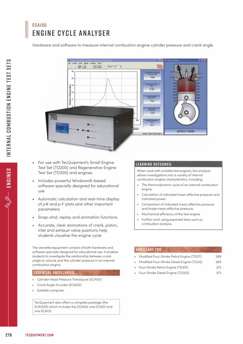
Eng
ines
T E C Q U I P M E N T. C O M2 7 6
Inte
rn
al
Co
mb
us
tio
n E
ng
ine
tes
t s
ets
• For use with TecQuipment’s Small Engine
Test Set (TD200) and Regenerative Engine
Test Set (TD300) and engines
• Includes powerful Windows®-based
software specially designed for educational
use
• Automatic calculation and real-time display
of p-q and p-V plots and other important
parameters
• Snap-shot, replay and animation functions
• Accurate, clear animations of crank, piston,
inlet and exhaust valve positions help
students visualise the engine cycle
L e a r n i n g o u t c o m e s :
When used with suitable test engines, the analyser
allows investigations into a variety of internal
combustion engine characteristics, including:
• The thermodynamic cycle of an internal combustion
engine.
• Calculation of indicated mean effective pressure and
indicated power.
• Comparison of indicated mean effective pressure
and brake mean effective pressure.
• Mechanical efficiency of the test engine.
• Further work using exported data such as
combustion analysis.
The versatile equipment consists of both hardware and
software specially designed for educational use. It enables
students to investigate the relationship between crank
angle or volume and the cylinder pressure in an internal
combustion engine.
• Cylinder Head Pressure Transducer (ECA101)
• Crank Angle Encoder (ECA102)
• Suitable computer
E S S E N T IAL AN C I L LAR I E S :
E C A1 0 0
E n g i n e C y c l e A n a ly s e r
Hardware and software to measure internal combustion engine cylinder pressure and crank angle.
• Modified Four-Stroke Petrol Engine (TD211) 268
• Modified Four-Stroke Diesel Engine (TD212) 269
• Four-Stroke Petrol Engine (TD301) 272
• Four-Stroke Diesel Engine (TD302) 273
AN C I L LAR Y F O R :
TecQuipment also offers a complete package (the
ECA100S) which includes the ECA100, one ECA101 and
one ECA102.
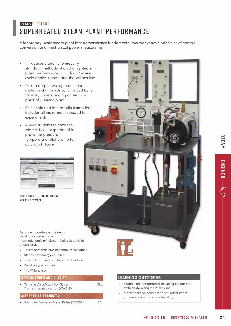
A mobile laboratory-scale steam
plant for experiments in
thermodynamic principles. It helps students to
understand:
• Thermodynamic laws of energy conservation
• Steady flow energy equation
• Thermal efficiency and the control surface
• Rankine cycle analysis
• The Willans line
• Versatile Data Acquisition System – 293
Frame-mounted version (VDAS-F)
• Saturated Steam – Marcet Boiler (TD1006) 261
R E C O M M E N D E D AN C I L LAR I E S :
alt e r nat i v e p r o d u c t s :
T D 1 0 5 0
S u p e r h e at e d S t e a m P l a n t P e r f o r m a n c e
A laboratory-scale steam plant that demonstrates fundamental thermodynamic principles of energyconversion and mechanical power measurement.
+ 4 4 1 1 5 9 7 2 2 6 1 1 I N F O @ T E C Q U I P M E N T. C O M 2 7 7
Stea
mEn
gin
es
LEARNING OUTCOM ES:
• Steam plant performance, including the Rankine
cycle analysis and the Willans line
• Marcet boiler experiment on saturated steam
(pressure temperature relationship)
• Introduces students to industry-
standard methods of analysing steam
plant performance, including Rankine
cycle analysis and using the Willans line
• Uses a simple two-cylinder steam
motor and an electrically heated boiler
for easy understanding of the main
parts of a steam plant
• Self-contained in a mobile frame that
includes all instruments needed for
experiments
• Allows students to copy the
Marcet boiler experiment to
prove the pressure-
temperature relationship for
saturated steam
S c r e e n s h o t o f t h e o p t i o n a l
V D A S ® s o f t wa r e
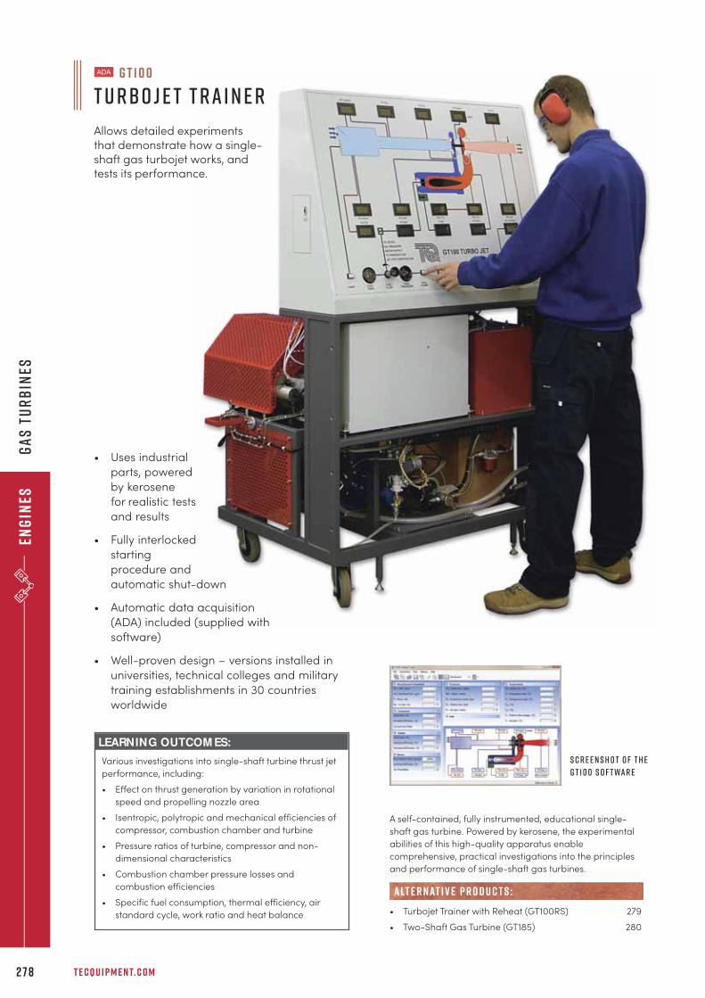
Eng
ines
T E C Q U I P M E N T. C O M2 7 8
Ga
s T
urb
ines
LEARNING OUTCOM ES:
Various investigations into single-shaft turbine thrust jet
performance, including:
• Effect on thrust generation by variation in rotational
speed and propelling nozzle area
• Isentropic, polytropic and mechanical efficiencies of
compressor, combustion chamber and turbine
• Pressure ratios of turbine, compressor and non-
dimensional characteristics
• Combustion chamber pressure losses and
combustion efficiencies
• Specific fuel consumption, thermal efficiency, air
standard cycle, work ratio and heat balance
A self-contained, fully instrumented, educational single-
shaft gas turbine. Powered by kerosene, the experimental
abilities of this high-quality apparatus enable
comprehensive, practical investigations into the principles
and performance of single-shaft gas turbines.
• Turbojet Trainer with Reheat (GT100RS) 279
• Two-Shaft Gas Turbine (GT185) 280
alt e r nat i v e p r o d u c t s :
G T 1 0 0
T u rbo j e t T r a i n e r
Allows detailed experimentsthat demonstrate how a single-shaft gas turbojet works, andtests its performance.
• Uses industrial
parts, powered
by kerosene
for realistic tests
and results
• Fully interlocked
starting
procedure and
automatic shut-down
• Automatic data acquisition
(ADA) included (supplied with
software)
• Well-proven design – versions installed in
universities, technical colleges and military
training establishments in 30 countries
worldwide
S c r e e n s h o t o f t h e
G T 1 0 0 s o f t wa r e
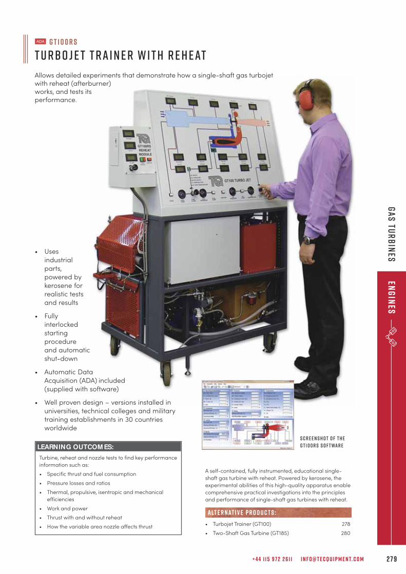
+ 4 4 1 1 5 9 7 2 2 6 1 1 I N F O @ T E C Q U I P M E N T. C O M 2 7 9
Ga
s Tu
rb
ines
Eng
ines
LEARNING OUTCOM ES:
Turbine, reheat and nozzle tests to find key performance
information such as:
• Specific thrust and fuel consumption
• Pressure losses and ratios
• Thermal, propulsive, isentropic and mechanical
efficiencies
• Work and power
• Thrust with and without reheat
• How the variable area nozzle affects thrust
A self-contained, fully instrumented, educational single-
shaft gas turbine with reheat. Powered by kerosene, the
experimental abilities of this high-quality apparatus enable
comprehensive practical investigations into the principles
and performance of single-shaft gas turbines with reheat.
• Turbojet Trainer (GT100) 278
• Two-Shaft Gas Turbine (GT185) 280
alt e r nat i v e p r o d u c t s :
S c r e e n s h o t o f t h e
G T 1 0 0 R S s o f t wa r e
G T 1 0 0 R S
T u rbo j e t T r a i n e r w i t h R e h e at
Allows detailed experiments that demonstrate how a single-shaft gas turbojetwith reheat (afterburner)works, and tests itsperformance.
• Uses
industrial
parts,
powered by
kerosene for
realistic tests
and results
• Fully
interlocked
starting
procedure
and automatic
shut-down
• Automatic Data
Acquisition (ADA) included
(supplied with software)
• Well proven design – versions installed in
universities, technical colleges and military
training establishments in 30 countries
worldwide
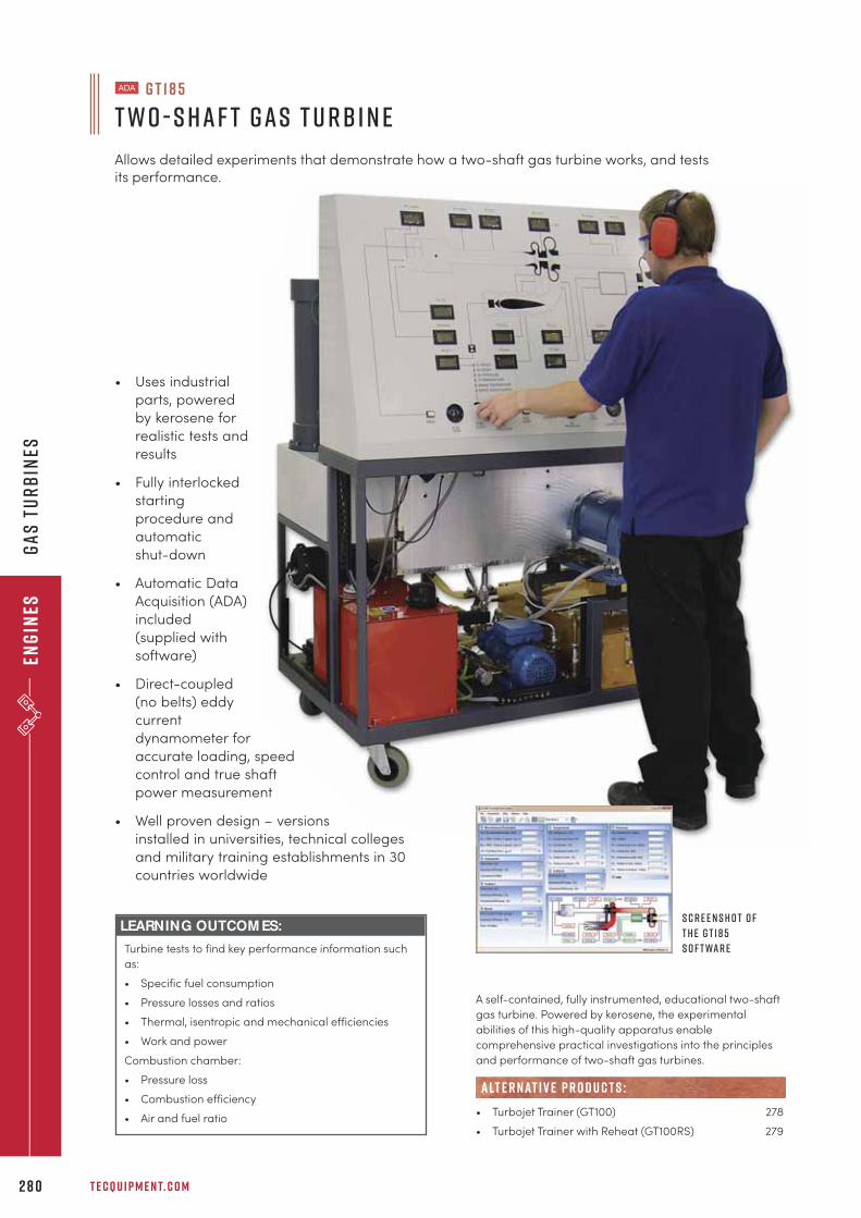
Eng
ines
T E C Q U I P M E N T. C O M2 8 0
Ga
s T
urb
ines
• Uses industrial
parts, powered
by kerosene for
realistic tests and
results
• Fully interlocked
starting
procedure and
automatic
shut-down
• Automatic Data
Acquisition (ADA)
included
(supplied with
software)
• Direct-coupled
(no belts) eddy
current
dynamometer for
accurate loading, speed
control and true shaft
power measurement
• Well proven design – versions
installed in universities, technical colleges
and military training establishments in 30
countries worldwide
LEARNING OUTCOM ES:
Turbine tests to find key performance information such
as:
• Specific fuel consumption
• Pressure losses and ratios
• Thermal, isentropic and mechanical efficiencies
• Work and power
Combustion chamber:
• Pressure loss
• Combustion efficiency
• Air and fuel ratio
A self-contained, fully instrumented, educational two-shaft
gas turbine. Powered by kerosene, the experimental
abilities of this high-quality apparatus enable
comprehensive practical investigations into the principles
and performance of two-shaft gas turbines.
• Turbojet Trainer (GT100) 278
• Turbojet Trainer with Reheat (GT100RS) 279
alt e r nat i v e p r o d u c t s :
G T 1 8 5
T w o - S h a f t G a s T u rb i n e
Allows detailed experiments that demonstrate how a two-shaft gas turbine works, and testsits performance.
S c r e e n s h o t o f
t h e G T 1 8 5
s o f t wa r e

+ 4 4 1 1 5 9 7 2 2 6 1 1 I N F O @ T E C Q U I P M E N T. C O M 2 8 1
Env
iro
nm
enta
l Co
ntr
ol
“It is gratifying indeed to work with a company with exemplary customer service such as yours.Thank you on behalf of the entire Department of Civil Engineering at Oregon Tech.
Pat r i c k K i l eO r e g o n i n s t i t u t e o f T e c h n o l o g y
e n v i r o n m e n t a l c o n t r o lc o o l i n g 2 8 3
R e f r i g e r at i o n 2 8 4
A i r C o n d i t i o n i n g 2 8 5
h u m i d i t y 2 8 6
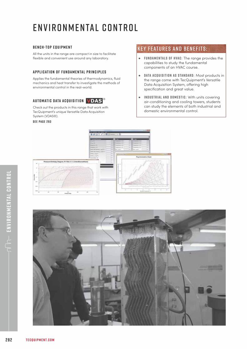
• F u n d a m e n ta l s o f H VA C : The range provides the
capabilities to study the fundamental
components of an HVAC course.
• D ata A c q u i s i t i o n a s s ta n d a r d : Most products in
the range come with TecQuipment’s Versatile
Data Acquisition System, offering high
specification and great value.
• I n d u s t r i a l a n d D o m e s t i c : With units covering
air-conditioning and cooling towers, students
can study the elements of both industrial and
domestic environmental control.
Env
iro
nm
enta
l C
on
tro
l
T E C Q U I P M E N T. C O M2 8 2
B e n c h -T o p E q u i p m e n t
All the units in the range are compact in size to facilitate
flexible and convenient use around any laboratory.
A p p l i c at i o n o f F u n d a m e n ta l P r i n c i p l e s
Applies the fundamental theories of thermodynamics, fluid
mechanics and heat transfer to investigate the methods of
environmental control in the real-world.
e n v i r o n m e n ta l c o n t r o l
k e y f eat u r e s an d b e n e f i t s :
A u t o m at i c d ata a c q u i s i t i o n
Check out the products in this range that work with
TecQuipment’s unique Versatile Data Acquisition
System (VDAS®).
S e e pa g e 2 9 3
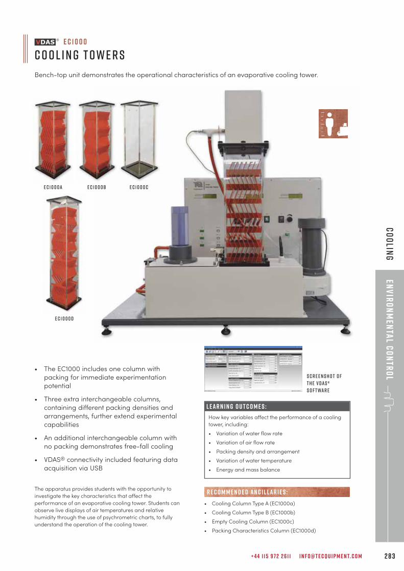
+ 4 4 1 1 5 9 7 2 2 6 1 1 I N F O @ T E C Q U I P M E N T. C O M 2 8 3
Env
iro
nm
enta
l Co
ntr
ol
Co
olin
g
L E A R N I N G O U T C O M E S :
How key variables affect the performance of a cooling
tower, including:
• Variation of water flow rate
• Variation of air flow rate
• Packing density and arrangement
• Variation of water temperature
• Energy and mass balance
• The EC1000 includes one column with
packing for immediate experimentation
potential
• Three extra interchangeable columns,
containing different packing densities and
arrangements, further extend experimental
capabilities
• An additional interchangeable column with
no packing demonstrates free-fall cooling
• VDAS® connectivity included featuring data
acquisition via USB
The apparatus provides students with the opportunity to
investigate the key characteristics that affect the
performance of an evaporative cooling tower. Students can
observe live displays of air temperatures and relative
humidity through the use of psychrometric charts, to fully
understand the operation of the cooling tower.
E C 1 0 0 0 d
• Cooling Column Type A (EC1000a)
• Cooling Column Type B (EC1000b)
• Empty Cooling Column (EC1000c)
• Packing Characteristics Column (EC1000d)
R E C O M M E N D E D AN C I L LAR I E S :
E C 1 0 0 0 a E C 1 0 0 0b E C 1 0 0 0 c
e c 1 0 0 0
C o o l i n g T o w e r s
Bench-top unit demonstrates the operational characteristics of an evaporative cooling tower.
S c r e e n s h o t o f
t h e V D A S ®
s o f t wa r e
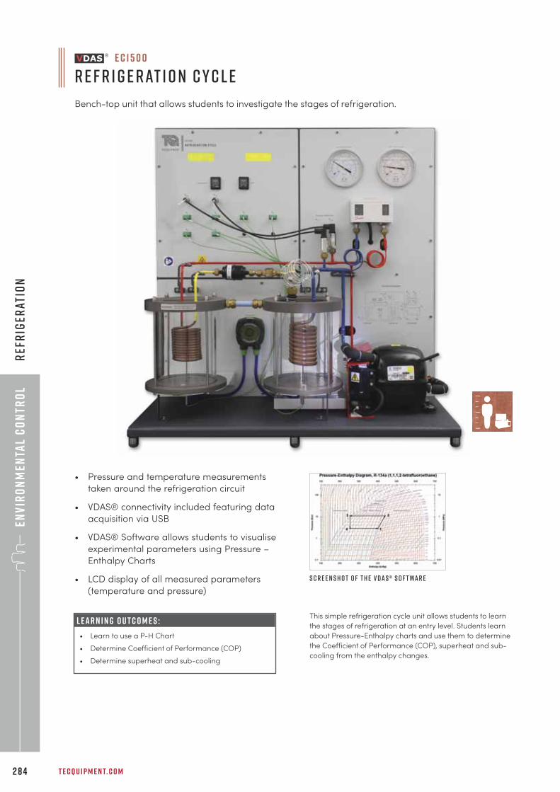
Env
iro
nm
enta
l C
on
tro
lR
efr
iger
atio
n
T E C Q U I P M E N T. C O M2 8 4
e c 1 5 0 0
r e f r i g e r at i o n c y c l e
Bench-top unit that allows students to investigate the stages of refrigeration.
L E A R N I N G O U T C O M E S :
• Learn to use a P-H Chart
• Determine Coefficient of Performance (COP)
• Determine superheat and sub-cooling
• Pressure and temperature measurements
taken around the refrigeration circuit
• VDAS® connectivity included featuring data
acquisition via USB
• VDAS® Software allows students to visualise
experimental parameters using Pressure –
Enthalpy Charts
• LCD display of all measured parameters
(temperature and pressure)
This simple refrigeration cycle unit allows students to learn
the stages of refrigeration at an entry level. Students learn
about Pressure-Enthalpy charts and use them to determine
the Coefficient of Performance (COP), superheat and sub-
cooling from the enthalpy changes.
S c r e e n s h o t o f t h e V D A S ® s o f t wa r e
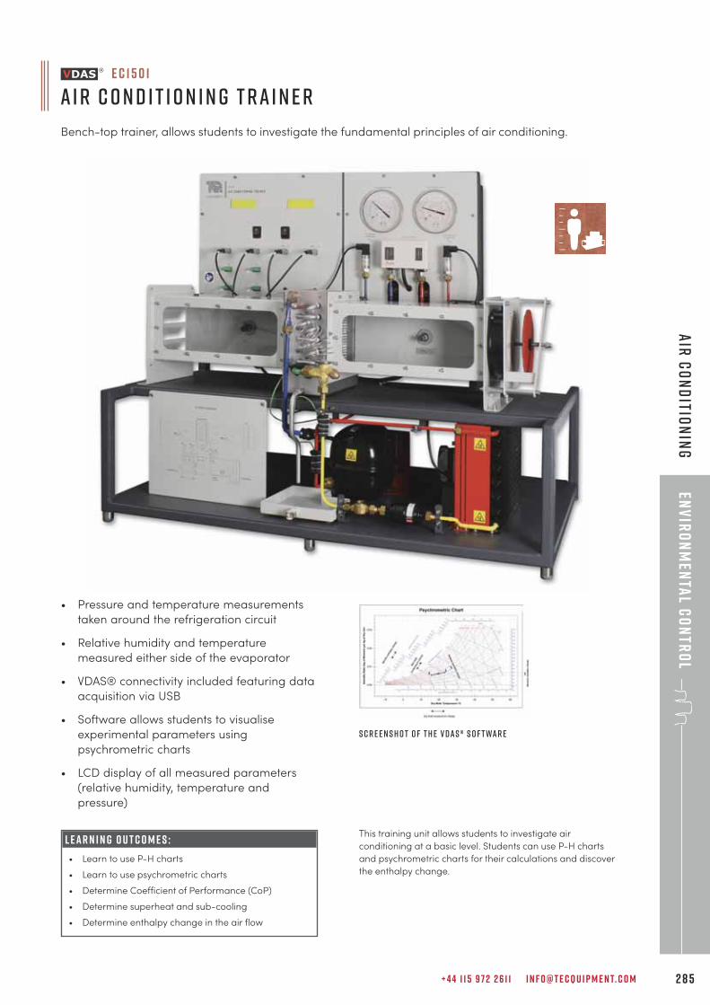
+ 4 4 1 1 5 9 7 2 2 6 1 1 I N F O @ T E C Q U I P M E N T. C O M 2 8 5
Env
iro
nm
enta
l Co
ntr
ol
Air
Co
nd
ition
ing
e c 1 5 0 1
a i r c o n d i t i o n i n g t r a i n e r
Bench-top trainer, allows students to investigate the fundamental principles of air conditioning.
L E A R N I N G O U T C O M E S :
• Learn to use P-H charts
• Learn to use psychrometric charts
• Determine Coefficient of Performance (CoP)
• Determine superheat and sub-cooling
• Determine enthalpy change in the air flow
• Pressure and temperature measurements
taken around the refrigeration circuit
• Relative humidity and temperature
measured either side of the evaporator
• VDAS® connectivity included featuring data
acquisition via USB
• Software allows students to visualise
experimental parameters using
psychrometric charts
• LCD display of all measured parameters
(relative humidity, temperature and
pressure)
This training unit allows students to investigate air
conditioning at a basic level. Students can use P-H charts
and psychrometric charts for their calculations and discover
the enthalpy change.
S c r e e n s h o t o f t h e V D A S ® s o f t wa r e
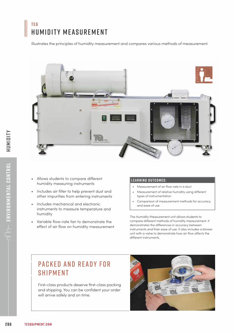
Env
iro
nm
enta
l C
on
tro
lH
um
idit
y
T E C Q U I P M E N T. C O M2 8 6
L E A R N I N G O U T C O M E S :
• Measurement of air flow rate in a duct
• Measurement of relative humidity using different
types of instrumentation
• Comparison of measurement methods for accuracy
and ease of use
• Allows students to compare different
humidity measuring instruments
• Includes air filter to help prevent dust and
other impurities from entering instruments
• Includes mechanical and electronic
instruments to measure temperature and
humidity
• Variable flow-rate fan to demonstrate the
effect of air flow on humidity measurement
The Humidity Measurement unit allows students to
compare different methods of humidity measurement. It
demonstrates the differences in accuracy between
instruments and their ease of use. It also includes a blower
unit with a valve to demonstrate how air flow affects the
different instruments.
T E 6
H u m i d i t y M e a s u r e m e n t
Illustrates the principles of humidity measurement and compares various methods of measurement.
pac k e d an d r ead y f o r s h i p m e n t
First-class products deserve first-class packing
and shipping. You can be confident your order
will arrive safely and on time.

+ 4 4 1 1 5 9 7 2 2 6 1 1 I N F O @ T E C Q U I P M E N T. C O M 2 8 7
Solar
Energ
y
“The TecQuipment teaching solutions and scalable teaching equipment has allowed theThermal Engineering and Energy Department to provide training up to Masters degree levelwith continuous and undeniable quality.
p r o f e s s o r j e a n - n o Ë l b l a n c h a r di u t o r l e a n s , f r a n c e
s o l a r e n e r g ys o l a r p h o t o v o lta i c 2 8 9
s o l a r t h e r m a l 2 9 0
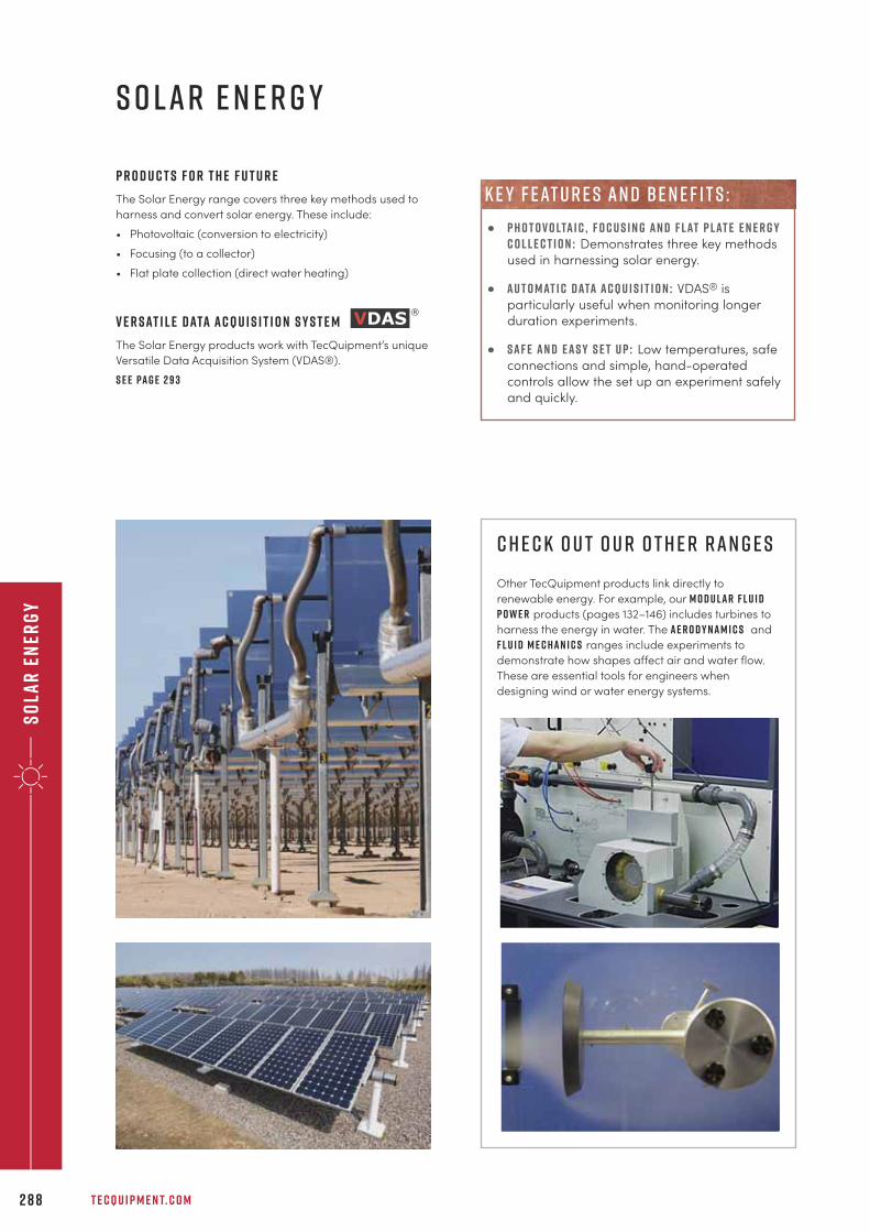
Sola
r E
ner
gy
T E C Q U I P M E N T. C O M2 8 8
s o l a r e n e r g y
p r o d u c t s f o r t h e f u t u r e
The Solar Energy range covers three key methods used to
harness and convert solar energy. These include:
• Photovoltaic (conversion to electricity)
• Focusing (to a collector)
• Flat plate collection (direct water heating)
V e r s at i l e d ata a c q u i s i t i o n S y s t e m
The Solar Energy products work with TecQuipment’s unique
Versatile Data Acquisition System (VDAS®).
S e e pa g e 2 9 3
c h e c k o u t o u r o t h e r r a n g e s
Other TecQuipment products link directly to
renewable energy. For example, our M o d u l a r F l u i dP o w e r products (pages 132–146) includes turbines to
harness the energy in water. The A e r o d y n a m i c s and
F l u i d M e c h a n i c s ranges include experiments to
demonstrate how shapes affect air and water flow.
These are essential tools for engineers when
designing wind or water energy systems.
• P h o t o v o lta i c , f o c u s i n g a n d f l at p l at e e n e r g yc o l l e c t i o n : Demonstrates three key methods
used in harnessing solar energy.
• a u t o m at i c d ata a c q u i s i t i o n : VDAS® is
particularly useful when monitoring longer
duration experiments.
• s a f e a n d e a s y s e t u p : Low temperatures, safe
connections and simple, hand-operated
controls allow the set up an experiment safely
and quickly.
k e y f eat u r e s an d b e n e f i t s :
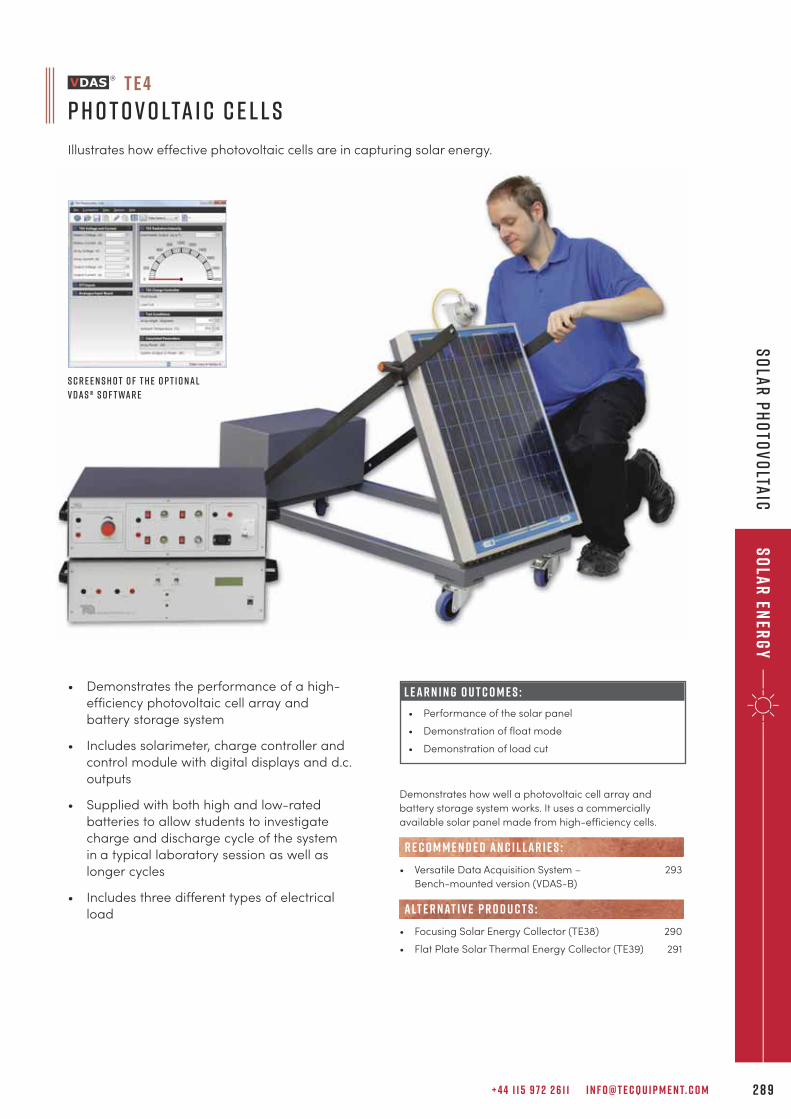
• Demonstrates the performance of a high-
efficiency photovoltaic cell array and
battery storage system
• Includes solarimeter, charge controller and
control module with digital displays and d.c.
outputs
• Supplied with both high and low-rated
batteries to allow students to investigate
charge and discharge cycle of the system
in a typical laboratory session as well as
longer cycles
• Includes three different types of electrical
load
L E A R N I N G O U T C O M E S :
• Performance of the solar panel
• Demonstration of float mode
• Demonstration of load cut
Demonstrates how well a photovoltaic cell array and
battery storage system works. It uses a commercially
available solar panel made from high-efficiency cells.
• Versatile Data Acquisition System – 293
Bench-mounted version (VDAS-B)
• Focusing Solar Energy Collector (TE38) 290
• Flat Plate Solar Thermal Energy Collector (TE39) 291
alt e r nat i v e p r o d u c t s :
R E C O M M E N D E D AN C I L LAR I E S :
S c r e e n s h o t o f t h e o p t i o n a l
V D A S ® s o f t wa r e
+ 4 4 1 1 5 9 7 2 2 6 1 1 I N F O @ T E C Q U I P M E N T. C O M 2 8 9
Solar
Energ
yS
ola
r P
ho
tov
olta
ic
t e 4
p h o t o v o lta i c c e l l s
Illustrates how effective photovoltaic cells are in capturing solar energy.
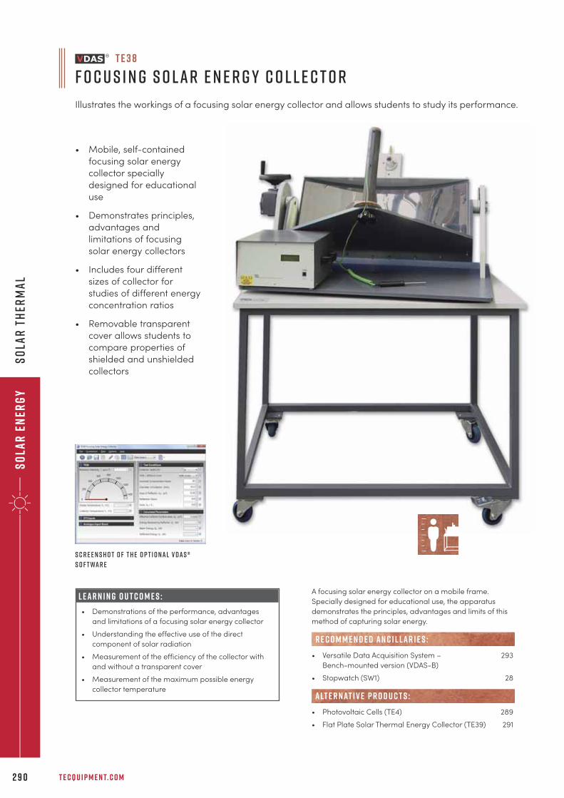
Sola
r E
ner
gy
So
lar
th
erm
al
T E C Q U I P M E N T. C O M2 9 0
• Mobile, self-contained
focusing solar energy
collector specially
designed for educational
use
• Demonstrates principles,
advantages and
limitations of focusing
solar energy collectors
• Includes four different
sizes of collector for
studies of different energy
concentration ratios
• Removable transparent
cover allows students to
compare properties of
shielded and unshielded
collectors
L E A R N I N G O U T C O M E S :
• Demonstrations of the performance, advantages
and limitations of a focusing solar energy collector
• Understanding the effective use of the direct
component of solar radiation
• Measurement of the efficiency of the collector with
and without a transparent cover
• Measurement of the maximum possible energy
collector temperature
A focusing solar energy collector on a mobile frame.
Specially designed for educational use, the apparatus
demonstrates the principles, advantages and limits of this
method of capturing solar energy.
• Versatile Data Acquisition System – 293
Bench-mounted version (VDAS-B)
• Stopwatch (SW1) 28
• Photovoltaic Cells (TE4) 289
• Flat Plate Solar Thermal Energy Collector (TE39) 291
R E C O M M E N D E D AN C I L LAR I E S :
alt e r nat i v e p r o d u c t s :
T E 3 8
F o c u s i n g S o l a r E n e r g y C o l l e c t o r
Illustrates the workings of a focusing solar energy collector and allows students to study its performance.
S c r e e n s h o t o f t h e o p t i o n a l V D A S ®
s o f t wa r e
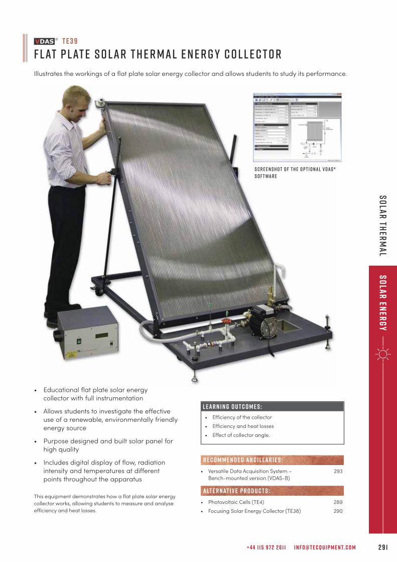
+ 4 4 1 1 5 9 7 2 2 6 1 1 I N F O @ T E C Q U I P M E N T. C O M 2 9 1
Solar
Energ
yS
ola
r th
erm
al
L E A R N I N G O U T C O M E S :
• Efficiency of the collector
• Efficiency and heat losses
• Effect of collector angle.
• Versatile Data Acquisition System – 293
Bench-mounted version (VDAS-B)
• Photovoltaic Cells (TE4) 289
• Focusing Solar Energy Collector (TE38) 290
R E C O M M E N D E D AN C I L LAR I E S :
alt e r nat i v e p r o d u c t s :
T E 3 9
F l at P l at e S o l a r T h e r m a l E n e r g y C o l l e c t o r
Illustrates the workings of a flat plate solar energy collector and allows students to study its performance.
S c r e e n s h o t o f t h e o p t i o n a l V D A S ®
s o f t wa r e
This equipment demonstrates how a flat plate solar energy
collector works, allowing students to measure and analyse
efficiency and heat losses.
• Educational flat plate solar energy
collector with full instrumentation
• Allows students to investigate the effective
use of a renewable, environmentally friendly
energy source
• Purpose designed and built solar panel for
high quality
• Includes digital display of flow, radiation
intensity and temperatures at different
points throughout the apparatus
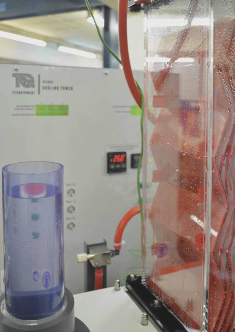
Sola
r E
ner
gy
So
lar
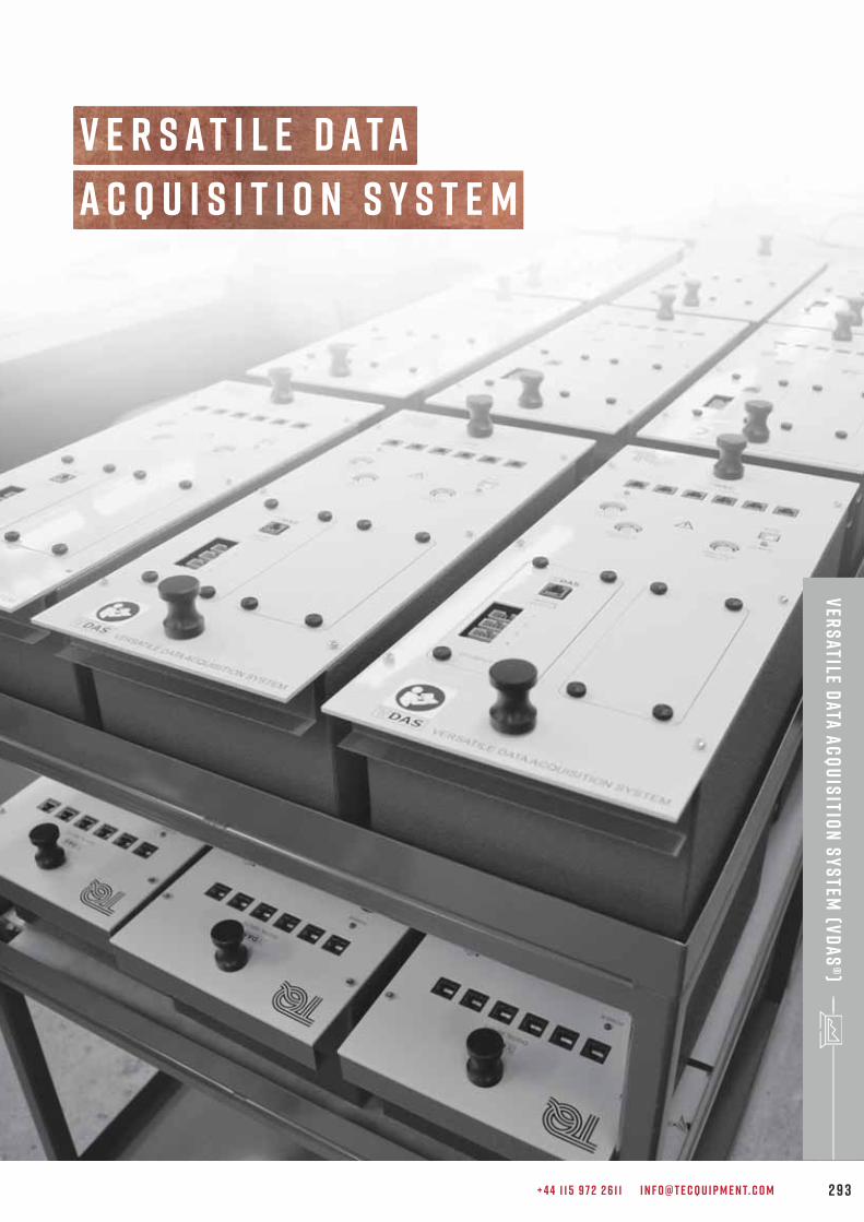
+ 4 4 1 1 5 9 7 2 2 6 1 1 I N F O @ T E C Q U I P M E N T. C O M 2 9 3
Ver
satile D
ata A
cq
uis
ition
Sy
stem
(VD
AS
®)
A c q u i s i t i o n S y s t e m
V e r s a t i l e d a t a
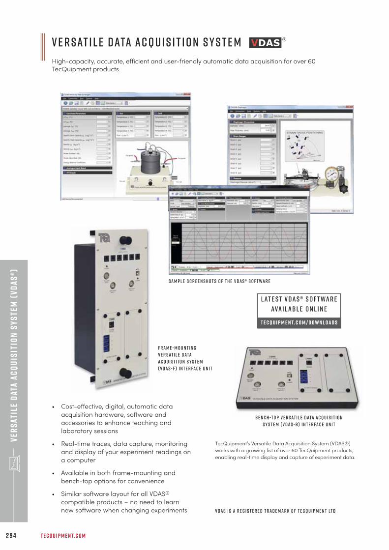
V e r s at i l e D ata A c q u i s i t i o n S y s t e m
High-capacity, accurate, efficient and user-friendly automatic data acquisition for over 60TecQuipment products.
T E C Q U I P M E N T. C O M2 9 4
Ver
sat
ile
Dat
a A
cq
uis
itio
n S
ys
tem
(V
DA
S®)
TecQuipment’s Versatile Data Acquisition System (VDAS®)
works with a growing list of over 60 TecQuipment products,
enabling real-time display and capture of experiment data.
B e n c h -t o p V e r s at i l e D ata A c q u i s i t i o n
S y s t e m ( V D A S - B ) i n t e r fa c e u n i t
S a m p l e s c r e e n s h o t s o f t h e V D A S ® s o f t wa r e
V D A S i s a r e g i s t e r e d t r a d e m a r k o f T e c Q u i p m e n t Lt d
• Cost-effective, digital, automatic data
acquisition hardware, software and
accessories to enhance teaching and
laboratory sessions
• Real-time traces, data capture, monitoring
and display of your experiment readings on
a computer
• Available in both frame-mounting and
bench-top options for convenience
• Similar software layout for all VDAS®
compatible products – no need to learn
new software when changing experiments
F r a m e - m o u n t i n g
V e r s at i l e D ata
A c q u i s i t i o n S y s t e m
( V D A S - F ) i n t e r fa c e u n i t
L at e s t V D A S ® s o f t wa r e
ava i l a b l e o n l i n e
t e c q u i p m e n t. c o m / d o w n l o a d s
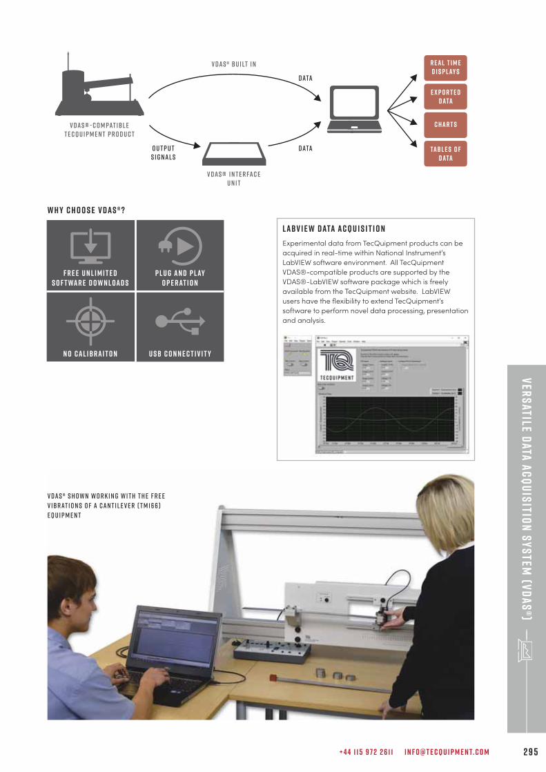
+ 4 4 1 1 5 9 7 2 2 6 1 1 I N F O @ T E C Q U I P M E N T. C O M 2 9 5
Ver
satile D
ata A
cq
uis
ition
Sy
stem
(VD
AS
®)
V DAS ® - c o m pat ibl eT e cQu i p m e n t p r o d u c t
V DAS® i n t e r fac eu n i t
V DAS® bu i lt i n
O u t p u ts i g nal s
Data
Data
E x p o r t e dData
R eal T i m eD i s p lay s
C har t s
Tab l e s o fdata
V D A S ® s h o w n w o r k i n g w i t h t h e F r e e
V i b r at i o n s o f a C a n t i l e v e r ( T M 1 6 6 )
e q u i p m e n t
L abV I E W D ata A c q u i s i t i o n
Experimental data from TecQuipment products can be
acquired in real-time within National Instrument’s
LabVIEW software environment. All TecQuipment
VDAS®-compatible products are supported by the
VDAS®-LabVIEW software package which is freely
available from the TecQuipment website. LabVIEW
users have the flexibility to extend TecQuipment’s
software to perform novel data processing, presentation
and analysis.
F r e e U n l i m i t e dS o f t war e D o w n l oad s
P l u g an d p layo p e rat i o n
n o cal i b ra i t o n u s b c o n n e c t i v i t y
W h y c h o o s e V D A S ® ?
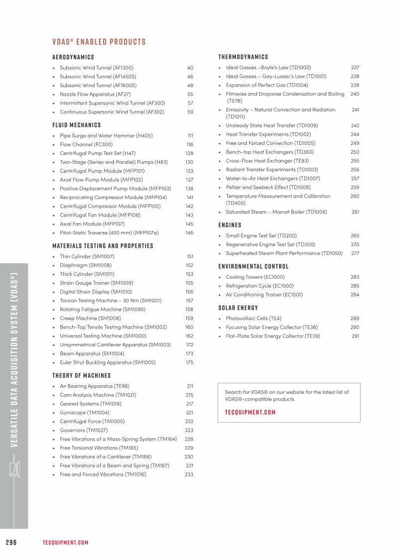
T E C Q U I P M E N T. C O M2 9 6
Ver
sat
ile
Dat
a A
cq
uis
itio
n S
ys
tem
(V
DA
S®)
V D A S ® e n abl e d p r o d u c t s
A e r o d y n a m i c s
• Subsonic Wind Tunnel (AF1300) 40
• Subsonic Wind Tunnel (AF1450S) 46
• Subsonic Wind Tunnel (AF1600S) 48
• Nozzle Flow Apparatus (AF27) 55
• Intermittent Supersonic Wind Tunnel (AF300) 57
• Continuous Supersonic Wind Tunnel (AF302) 59
F l u i d M e c h a n i c s
• Pipe Surge and Water Hammer (H405) 111
• Flow Channel (FC300) 116
• Centrifugal Pump Test Set (H47) 128
• Two-Stage (Series and Parallel) Pumps (H83) 130
• Centrifugal Pump Module (MFP101) 133
• Axial Flow Pump Module (MFP102) 137
• Positive Displacement Pump Module (MFP103) 138
• Reciprocating Compressor Module (MFP104) 141
• Centrifugal Compressor Module (MFP105) 142
• Centrifugal Fan Module (MFP106) 143
• Axial Fan Module (MFP107) 145
• Pitot-Static Traverse (450 mm) (MFP107a) 146
M at e r i a l s T e s t i n g a n d P r o p e r t i e s
• Thin Cylinder (SM1007) 151
• Diaphragm (SM1008) 152
• Thick Cylinder (SM1011) 153
• Strain Gauge Trainer (SM1009) 155
• Digital Strain Display (SM1010) 156
• Torsion Testing Machine – 30 Nm (SM1001) 157
• Rotating Fatigue Machine (SM1090) 158
• Creep Machine (SM1006) 159
• Bench-Top Tensile Testing Machine (SM1002) 160
• Universal Testing Machine (SM1000) 162
• Unsymmetrical Cantilever Apparatus (SM1003) 172
• Beam Apparatus (SM1004) 173
• Euler Strut Buckling Apparatus (SM1005) 175
T h e o r y o f M a c h i n e s
• Air Bearing Apparatus (TE96) 211
• Cam Analysis Machine (TM1021) 215
• Geared Systems (TM1018) 217
• Gyroscope (TM1004) 221
• Centrifugal Force (TM1005) 222
• Governors (TM1027) 223
• Free Vibrations of a Mass-Spring System (TM164) 228
• Free Torsional Vibrations (TM165) 229
• Free Vibrations of a Cantilever (TM166) 230
• Free Vibrations of a Beam and Spring (TM167) 231
• Free and Forced Vibrations (TM1016) 233
T h e r m o d y n a m i c s
• Ideal Gasses –Boyle’s Law (TD1000) 237
• Ideal Gasses – Gay-Lussac’s Law (TD1001) 238
• Expansion of Perfect Gas (TD1004) 239
• Filmwise and Dropwise Condensation and Boiling 240
(TE78)
• Emissivity – Natural Convection and Radiation 241
(TD1011)
• Unsteady State Heat Transfer (TD1009) 242
• Heat Transfer Experiments (TD1002) 244
• Free and Forced Convection (TD1005) 249
• Bench-top Heat Exchangers (TD360) 250
• Cross-Flow Heat Exchanger (TE93) 255
• Radiant Transfer Experiments (TD1003) 256
• Water-to-Air Heat Exchangers (TD1007) 257
• Peltier and Seebeck Effect (TD1008) 259
• Temperature Measurement and Calibration 260
(TD400)
• Saturated Steam – Marcet Boiler (TD1006) 261
e n g i n e s
• Small Engine Test Set (TD200) 265
• Regenerative Engine Test Set (TD300) 270
• Superheated Steam Plant Performance (TD1050) 277
e n v i r o n m e n ta l c o n t r o l
• Cooling Towers (EC1000) 283
• Refrigeration Cycle (EC1500) 285
• Air Conditioning Trainer (EC1501) 284
s o l a r E n e r g y
• Photovoltaic Cells (TE4) 289
• Focusing Solar Energy Collector (TE38) 290
• Flat-Plate Solar Energy Collector (TE39) 291
Search for VDAS® on our website for the latest list of
VDAS®-compatible products.
t e c q u i p m e n t. c o m
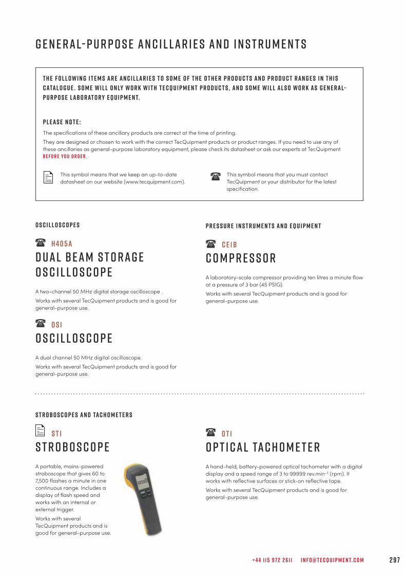
+ 4 4 1 1 5 9 7 2 2 6 1 1 I N F O @ T E C Q U I P M E N T. C O M 2 9 7
T h e f o l l o w i n g i t e m s a r e a n c i l l a r i e s t o s o m e o f t h e o t h e r p r o d u c t s a n d p r o d u c t r a n g e s i n t h i s
c ata l o g u e . S o m e w i l l o n ly w o r k w i t h T e c Q u i p m e n t p r o d u c t s , a n d s o m e w i l l a l s o w o r k a s g e n e r a l-
p u r p o s e l a b o r at o r y e q u i p m e n t.
P l e a s e n o t e :
The specifications of these ancillary products are correct at the time of printing.
They are designed or chosen to work with the correct TecQuipment products or product ranges. If you need to use any of
these ancillaries as general-purpose laboratory equipment, please check its datasheet or ask our experts at TecQuipment
b e f o r e y o u o r d e r .
This symbol means that we keep an up-to-date This symbol means that you must contact
datasheet on our website (www.tecquipment.com). TecQuipment or your distributor for the latest
specification.
P r e s s u r e I n s t r u m e n t s a n d E q u i p m e n t
C E 1 B
C o m p r e s s o r
A laboratory-scale compressor providing ten litres a minute flow
at a pressure of 3 bar (45 PSIG).
Works with several TecQuipment products and is good for
general-purpose use.
O s c i l l o s c o p e s
H 4 0 5 a
D u a l B e a m S t o r a g eO s c i l l o s c o p e
A two-channel 50 MHz digital storage oscilloscope .
Works with several TecQuipment products and is good for
general-purpose use.
O S 1
O s c i l l o s c o p e
A dual channel 50 MHz digital oscilloscope.
Works with several TecQuipment products and is good for
general-purpose use.
O T 1
O p t i c a l Ta c h o m e t e r
A hand-held, battery-powered optical tachometer with a digital
display and a speed range of 3 to 99999 rev.min–1 (rpm). It
works with reflective surfaces or stick-on reflective tape.
Works with several TecQuipment products and is good for
general-purpose use.
S t r o b o s c o p e s a n d Ta c h o m e t e r s
S T 1
S t r o b o s c o p e
A portable, mains-powered
stroboscope that gives 60 to
7,500 flashes a minute in one
continuous range. Includes a
display of flash speed and
works with an internal or
external trigger.
Works with several
TecQuipment products and is
good for general-purpose use.
g e n e r a l- p u r p o s e a n c i l l a r i e s a n d i n s t r u m e n t s
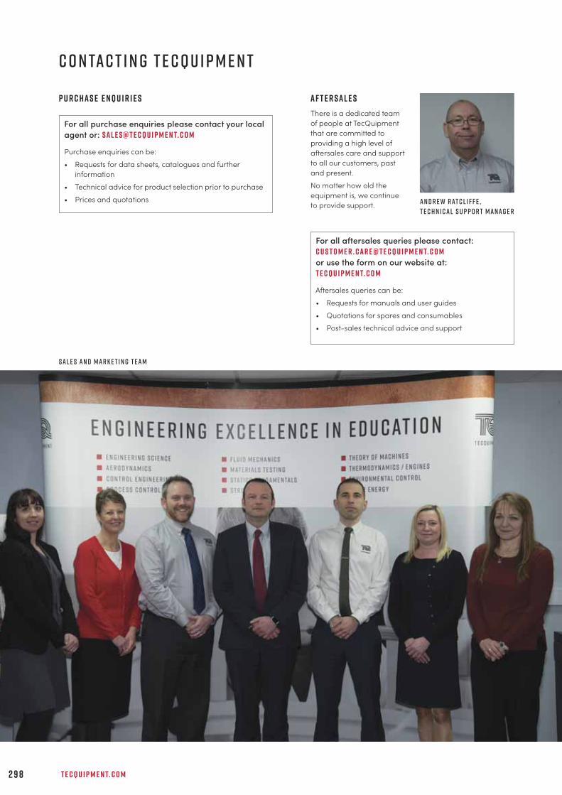
T E C Q U I P M E N T. C O M2 9 8
C o n ta c t i n g T e c Q u i p m e n t
A f t e r s a l e s
There is a dedicated team
of people at TecQuipment
that are committed to
providing a high level of
aftersales care and support
to all our customers, past
and present.
No matter how old the
equipment is, we continue
to provide support.
P u r c h a s e e n q u i r i e s
For all purchase enquiries please contact your local
agent or: s a l e s @ t e c q u i p m e n t. c o m
Purchase enquiries can be:
• Requests for data sheets, catalogues and further
information
• Technical advice for product selection prior to purchase
• Prices and quotations
For all aftersales queries please contact:
c u s t o m e r . c a r e @ t e c q u i p m e n t. c o m
or use the form on our website at:
t e c q u i p m e n t. c o m
Aftersales queries can be:
• Requests for manuals and user guides
• Quotations for spares and consumables
• Post-sales technical advice and support
S a l e s a n d m a r k e t i n g t e a m
A n d r e w r at c l i f f e ,
t e c h n i c a l s u p p o r t m a n a g e r
+ 4 4 1 1 5 9 7 2 2 6 1 1 I N F O @ T E C Q U I P M E N T. C O M 2 9 9
k e y w o r d i n d e x
AAerodynamics 2 9Aerofoil
150 mm chord NACA0012 (AF1300d) 4 4 150 mm chord NACA2412 (AF1300c) 4 4 S1210 (AF1300l) 4 5 tapped (AF18) 3 8Aeroplane (AF41) 5 2Afterburner (reheat) (GT100RS) 2 7 9Air bearing (TE96) 2 1 1Air conditioning (EC1501) 2 8 5Aircraft model 4 5Air flow (AF10–18) 3 1 around a bend (AF15) 3 6 visualisation (AF17) 3 7 , (AF80) 5 4Angle feedback (wind tunnel models) (AFA4) 4 4 , 4 5 , 4 6 , 47 , 4 8 , 4 9Antoine Equation (TD1006) 2 6 1Arch
fixed (STR11) 1 9 2 three-pinned (STR9) 1 9 0 two-pinned (STR10) 1 9 1Archimedes Principle (H314) 1 2 0Aspect ratio (AF1125–AF1600) 3 9 – 4 9Automatic data acquisition (STR2000) 1 8 7 , (VDAS®) 2 9 3
BBalance
of reciprocating masses (TM1022) 2 1 9 static and dynamic (TM1002) 2 2 0Ball and beam (CE106) 6 8Ball and hoop (CE109) 7 2Bar linkage mechanisms (ES15) 2 4Batch processing (CE111) 8 0Bauschinger effect (SM1001) 1 5 7Beams (SM1004) 1 7 3Beam
balance (ES3) 9 bending (STR4) 1 9 8 , (SM1000g) 1 6 4 , (TE16) 1 5 0 continuous and indeterminate (STR13) 2 0 0 deflection (ES4) 1 1 equilibrium of forces (STF5) 1 8 1 plastic bending (STR15) 1 9 6 reactions (ES3) 9 stresses (STR5) 1 9 9Bearings (ES17) 1 7 , (TM25) 2 1 4 , (TE96) 2 1 1Bending
moment (STR2) 2 0 4 , (STR20) 2 0 6 plastic (STR15) 1 9 6 , (STR16) 1 9 7 stress (STR5) 1 9 9 unsymmetrical (STR7) 2 0 8 , (SM1003) 1 7 2Bernoulli’s equation (AF11) 3 2 , (H5) 9 5 , (H10) 9 6Boiling (TE78) 2 4 0 , (TD1006) 2 6 1Boltzmann (TD1003) 2 5 6 , (TD1011) 2 4 1Boundary layer (AF14) 3 2 , 3 5 , 3 8Bourdon gauge (H3a) 9 2 , (H30) 9 7Bow’s Notation (ES2) 8 , (STF4) 1 8 1 , (STR8) 1 8 9 , (STR17) 1 9 3Boyle’s Law (TD1000) 2 3 7Brinell hardness tests (SM1000e) 1 6 3 , (SM1002c) 1 6 1 , (SM1017) 1 6 9 , (MF40) 1 6 5Buckling of struts (STR12) 1 9 5 , (SM1005) 1 7 5Buoyancy (H2 MkII) 1 1 8 , (H314) 1 2 0
CCalibration
temperature (TD400) 2 6 0 pressure (H3a) 9 2 , (H30) 9 7 flow (H40) 9 8Cams (ES12) 2 2 , (TM1021) 2 1 5Cantilever (ES4) 1 1 , (STR4) 1 9 8 , (SM1004) 1 7 3 , (SM1009) 1 5 5 ,
(TE16a) 1 5 0 unsymmetrical (SM1003) 1 7 2 , (STR7) 2 0 8Catenary (STF2) 1 8 0 , (STR19) 1 9 4Cavitation (H47) 1 2 8 , (MFP101) 1 3 3 , (H400) 1 0 9Centres of gravity (ES2) 8 ,(H2 MkII) 1 1 8Centrifugal force (ES16) 2 1 , (TM1005) 2 2 2Centripetal force (ES16) 2 1 , (TM1005) 2 2 2Chain drive (ES11) 1 9 , (TM1018) 2 1 7Chezy factor (FC50) 1 1 3 , (FC80) 1 1 4 , (FC300) 1 1 6Choked flow (AF27) 5 5Coandă effect (AF16) 3 6Compressor
centrifugal (MFP105) 1 4 2 laboratory (CE1B) 2 9 7 reciprocating (MFP104) 1 4 1 two-stage (GT103) 2 6 2Computer control system (TE3300/06) 8 6 , (TE37DCS) 8 8 ,
(CE2000) 6 3Compression
of a gas (TD1000) 2 3 7 tests (SM1000) 1 6 2 of springs (ES19) 1 3Condensing (TE78) 2 4 0Conduction (thermal) (TD1002) 2 4 4Control
cascade (CE117) 8 1 coupled drives (CE108) 7 1 coupled tanks (CE105/CE105MV) 6 7 digital (CE111) 8 0 , (CE123) 7 9 distributed (TE3300/06) 8 6 , (TE37DCS) 8 8 engineering 6 1 engine speed (CE107) 6 9 flow (TE3300/03) 8 3 , (TE37) 8 7 , (CE117) 8 1 level (TE3300/04) 8 4 , (TE37) 8 7 , (CE117) 8 1 multi-loop (CE117) 8 1 multivariable (CE105MV) 6 7 , (CE108) 7 1 naturally unstable (CE106) 6 8 position (CE109) 7 2 , (CE106) 6 8 pressure (TE3300/02) 8 2 , (TE37) 8 7 , (CE117) 8 1 process (CE117) 8 1 , (TE37) 8 7 , (TE3300 series) 8 2 ratio (TE37) 8 7 servomotor (CE110) 7 3 software (CE2000) 6 3 split range (TE37) 8 7 temperature (TE3300/05) 8 5 , (TE37) 8 7 , (CE117) 8 1 thermal (CE103) 6 6 velocity (CE106) 6 8 , (CE109) 7 2Controller (CE120) 6 4Convection (thermal) (TD1002) 2 4 4 , (TD1011) 2 4 1 forced (TD1) 2 4 3 , (TE93) 2 5 5 , (TD1005) 2 4 9 free (TD1005) 2 4 9Cooling (EC1000) 2 8 3Coupled drives (CE108) 7 1Coupled tanks (CE105/CE105MV) 6 7
P l e a s e n o t e : For ease of use we have only shown the main TecQuipment products relating to the keywords in this index. However, there may
be other similar products that are also suitable for your needs. These are listed as alternative products in the main pages of this guide.
T E C Q U I P M E N T. C O M3 0 0
Coupling (universal) (ES11) 1 9Crank motion (ES12) 2 2 , (ES14) 2 3Crank angle encoder (ECA102) 2 7 6Creep (SM1006) 1 5 9Critical whirl speed (TM1001) 2 1 6Curved bars (STR14) 2 0 2Cylinder
head transducer (ECA101) 2 7 6 thick (SM1011) 1 5 3 thin (SM1007) 1 5 1 wind tunnel models 4 2
DDarcy’s Law (H312) 1 2 3Davits (STR14) 2 0 2Diaphragm (SM1008) 1 5 2Differential pressure transducer (DP6) 4 7– 5 1Digital
control (CE111) 8 0 , (CE123) 7 9 interface (CE122) 6 5Discharge
coefficient (H4) 1 0 5 , (H33) 1 0 7 , (Flumes) 1 1 3 – 1 1 7 ,
(H5) 9 5 , (H6) 9 3 , (H40) 9 8 over a notch (H6) 9 3Distributed control (TE3300/06) 8 6 , (TE37DCS) 8 8 (CE2000) 6 3Drag (air) (AF12) 3 1 , 3 2 , 3 3 , 3 8Drag coefficient (H410) 1 2 1Drive systems (TM1018) 2 1 7 , (ES11) 1 9Dropwise condensation (TE78) 2 4 0Dunkerley (TM1016) 2 3 3 , (TM1001) 2 1 6Dynamometer
hydraulic (TD200) 2 6 5 regenerative (TD300) 2 7 0 turbine (MFP101a) 1 3 4 universal (MFP100) 1 3 2
EElastic properties (ES19) 1 3 , (SM110) 1 4 9 , (SM1002) 1 6 0 , (TE16) 1 5 0Emissivity (TD1003) 2 5 6 , (TD1011) 2 4 1Energy
conversion (TD1050) 2 7 7 losses in pipes (H34) 1 0 2 potential and kinetic (ES9) 1 6
renewable (TE4) 2 8 9 , (TE38) 2 9 0 , (TE39) 2 9 1Engine
cycle analyser (ECA100) 2 7 6 diesel (four-stroke) (TD202) 2 6 7 , (TD212) 2 6 9 , (TD302) 2 7 3 petrol (four-stroke) (TD201) 2 6 6 , (TD211) 2 6 8 , (TD301) 2 7 2 speed control (CE107) 6 9 steam (TD1050) 2 7 7 test set (regenerative) (TD300) 2 7 0 test set (small) (TD200) 2 6 5Engineering science 5Equilibrium (rigid body, forces, beam) (STF) 1 8 0 – 1 8 1Euler buckling (STR12) 1 9 5 , (SM1005) 1 7 5Exhaust gas calorimeter (TD300a) 2 74Extensometer (SM1000d) 1 6 3 , (SM1002a) 1 6 0 , (MF40) 1 6 5
FFan
axial (MFP107) 1 4 5 centrifugal (MFP106) 1 4 3Fatigue (SM1090) 1 5 8Flat plate
boundary layer (AF14) 3 5 , 4 5 wind tunnel model 4 5 impact of a jet (H8) 1 0 6Flow
channel (FC50) 1 1 3 , (FC80) 1 1 4 , (FC300) 1 1 6
control (TE3300/03) 8 3 , (TE37) 8 7 , (CE117) 8 1 counter (TD360) 2 5 0 laminar and turbulent (H7) 1 0 0 , (H215) 1 0 4 measurement (H10) 9 6 , (H408) 1 0 3 , (H40) 9 8 , (H5) 9 5 meter calibration (H40) 9 8 orifice (through) (H4) 1 0 5 , (H33) 1 0 7 , (H40) 9 8 parallel (TD360) 2 5 0 permeable media (through) (H312) 1 2 3 transitional (H215) 1 0 4 visualisation (AF17) 3 7 , (AF80) 5 4 , (H9) 1 1 0Flywheel (TM1018a) 2 1 8 , (ES9) 1 6Fluid mechanics 8 9Flumes (FC50) 1 1 3 , (FC80) 1 1 4 , (FC300) 1 1 6Force display (digital) (STR1a) 1 8 7Forces
concurrent, coplanar (STF4) 1 8 1 , (ES2) 8 equilibrium of (ES2) 8 , (ES3) 9 , (STF range) 1 7 7 non-concurrent (ES2) 8 , (STF4) 1 8 1 polygons (ES2) 8 , (STF4) 1 8 1 primary (TM1022) 2 1 9 secondary (TM1022) 2 1 9 triangles (ES2) 8 , (STF4) 1 8 1Fracture (energy) (TE15) 1 6 6Frame (portals) (STR16) 1 9 7 , (STR18) 2 0 3 , (STR20) 2 0 6Framework, indeterminate (STR17) 1 9 3Friction (ES8) 1 5 , (TE96) 2 1 1 , (TE98) 2 1 2 ,
(TE99) 2 1 3 , (TM25) 2 1 4 angle of lap (ES11) 1 9 fluid (H7) 1 0 0 , (H16) 1 0 1 , (H34) 1 0 2 , (H408) 1 0 3 pipe (H7) 1 0 0 , (H16) 1 0 1 , (H34) 1 0 2 , (H408) 1 0 3 rotational (ES17) 1 7 sliding (ES8) 1 5Froude Number (FC50) 1 1 3 , (FC80) 1 1 4 , (FC300) 1 1 6Fuel gauge
automatic volumetric (DVF1) 2 7 5 manual volumetric (AVF1) 2 7 5Fuzzy logic (CE2000) 6 3
GGases
ideal (TD1000) 2 3 7 , (TD1001) 2 3 8 perfect (TD1004) 2 3 9Gas generator (GT100) 2 7 8 , (GT100RS) 2 7 9 , (GT185) 2 8 0Gas turbine
single-shaft (GT100) 2 7 8 , (GT100RS) 2 7 9
two-shaft (GT185) 2 8 0Gay-Lussac’s Law (TD1001) 2 3 8Gears (ES13) 2 0 , (TM1018) 2 1 7Geneva mechanism (ES18) 2 5Governors (TM1027) 2 2 3Gyroscope (TM1004) 2 2 1
HHardness
Brinell (MF40) 1 6 5 , (SM1000e) 1 6 3 , (SM1002c) 1 6 1 , (SM1017) 1 6 9 Rockwell (SM1015) 1 6 7 , (SM1017) 1 6 9 Vickers (SM1016) 1 6 8 , (SM1017) 1 6 9Hare’s tube (H314b) 1 2 0Heat exchangers
cross-flow (TE93) 2 5 5 liquid to liquid (TD360) 2 5 0 water to air (TD1007) 2 5 7Heat pump (TD1008) 2 5 9Heat transfer 2 4 0 – 2 5 8Hele-shaw (H9) 1 1 0Hertzian contact (TE98) 2 1 2Hooke’s Law (ES19) 1 3 , (SM1000f) 1 6 4 , (SM110) 1 4 9Humidity measurement (TE6) 2 8 6Hydraulic bench (H1F) 9 1Hydraulic ram pump (H31) 1 2 7
+ 4 4 1 1 5 9 7 2 2 6 1 1 I N F O @ T E C Q U I P M E N T. C O M 3 0 1
Hydrology (H311) 1 2 2 , (H312) 1 2 3 , (H313) 1 2 4Hydrostatics (H314) 1 2 0
IImpact tests (TE15) 1 6 6Inclined plane (ES8) 1 5Internal combustion engine test sets (TD200) 2 6 5 , (TD300) 2 7 0
JJet (air) attachment (AF16) 3 6Jet (water)
impact of (H8) 1 0 6 trajectory (H33) 1 0 7Journal bearing (TM25) 2 1 4
LLadder logic (CE111) 8 0Laplace equation (H9) 1 1 0Level control (TE3300/04) 8 4 , (TE37) 8 7 , (CE117) 8 1Levers (ES3) 9Lift
balance (AF1300z) 4 3 , (AF1300z) 4 4 , (AF1450t) 47 , (AF1600t) 4 9Liquid slop (CE109) 7 2LMTD (logarithmic mean temperature difference) (TD360) 2 5 0
MMach number (AF27) 5 5 , (AF300) 5 7 , (AF302) 5 9Manometer
multi-tube (AF10a) 3 8 , (AFA1) 5 0Marcet boiler (TD1006) 2 6 1Mass flux (AF13) 3 4Materials testing and properties 1 47Mechanisms (ES14) 2 3 , (ES18) 2 5Metacentric height (H2 MkII) 1 1 8Michell pad (TE99) 2 1 3Modulus of Rigidity (ES5) 1 0 , (SM1001) 1 5 7Moments
primary (TM1022) 2 1 9 principle of (ES3) 9 , (STF5) 1 8 1 secondary (TM1022) 2 1 9Momentum flux (AF13) 3 4Motion (TM1018) 2 1 7 , (TM1021) 2 1 5 , (TM1022) 2 1 9 ,
(TM1002) 2 2 0 , (TM1004) 2 2 1 , (TM1005) 2 2 2 ,
(TM1027) 2 2 3 , (TM1001) 2 1 6
NNozzle
calibration (H40) 9 8 flow (supersonic) (AF27) 5 5 , (AF300) 5 7 , (AF302) 5 9 flow through (H4) 1 0 5 , (H33) 1 0 7 , (H40) 9 8
OOscillations (ES7) 1 4 , (TM161) 2 2 5 , (TM162) 2 2 6 ,
(TM164) 2 2 8 , (TM165) 2 2 9 , (TM166) 2 3 0 ,
(TM167) 2 3 1 , (TM1016) 2 3 3Oscilloscope (OS1) 2 9 7 , (H405a) 2 9 7
PParabolic (STF2) 1 8 0 , (STR9) 1 9 0 , (STR10) 1 9 1 , (STR11) 1 9 2 , (STR19) 1 9 4Parallelogram of forces (ES2) 8 , (STF4) 1 8 1Peltier (TD1008) 2 5 9Pendulum (ES7) 1 4 , (TM161) 2 2 5 , (TM162) 2 2 6 , (TM163) 2 2 7Permeability tank (H312) 1 2 3Photovoltaic cells (TE4) 2 8 9Phugoid (AF41) 5 2Pin-jointed framework (STR8) 1 8 9 , (STR17) 1 9 3
Pipe
friction (H7) 1 0 0 pressure loss (H16) 1 0 1 , (H34) 1 0 2 , (H408) 1 0 3 surge (H405) 1 1 1Pitching moment 4 1 , 4 4 , 4 6 , 47 , 4 8 , 4 9Pitot-static traverse 5 1 , (MFP107a) 1 4 6Pitot tube flow meter (H40a) 9 9Poisson’s Ratio (SM1007) 1 5 1 , (SM1009) 1 5 5Polygon of forces (ES2) 8 , (STF4) 1 8 1Portal frames (STR16) 1 9 7 , (STR18) 2 0 3 , (STR20) 2 0 6Potential flow (H9) 1 1 0Pressure
centre of (H11) 1 1 9 , (H314) 1 2 0 control (TE3300/02) 8 2 , (TE37) 8 7 , (CE117) 8 1 display (H47) 1 2 8 , (H83) 1 3 0 display (32-way) (AFA1) 5 0 distribution (AF15) 3 6 , (AF18) 3 8 , (AF1125–AF1600) 3 9 – 4 9gauge (calibration of) (H3a) 9 2 , (H30) 9 7 , (H314) 1 2 0 loss (in pipes) (H16) 1 0 1 , (H408) 1 0 3 , (H34) 1 0 2 measurement (H30) 9 7 of a gas (TD1000) 2 3 7 , (TD1001) 2 3 8Process trainer (CE117) 8 1Programmable logic controller (PLC) (CE123) 7 9 process (CE111) 8 0Pulleys (ES10) 1 8Pump
axial (MFP102) 1 3 7 centrifugal (H47) 1 2 8 , (H83) 1 3 0 , (MFP101) 1 3 3 gear (MFP103b) 1 3 9 hydraulic ram (H31) 1 2 7 piston (MFP103a) 1 3 9 positive displacement (MFP103) 1 3 8 series and parallel (H83) 1 3 0 swash (MFP103d) 1 4 0 vane (MFP103c) 1 4 0
QQuick return mechanism (ES14) 2 3
RRadiant transfer (TD1003) 2 5 6Radiation (thermal) (TD1003) 2 5 6 , (TD1011) 2 4 1Ratchet mechanism (ES18) 2 5Reciprocating masses (balance of) (TM1022) 2 1 9Refrigeration (EC1500) 2 8 4Renewable energy 9 0 , 2 8 8Reynolds number (H215) 1 0 4Rockwell hardness tests (SM1015) 1 6 7 , (SM1017) 1 6 9Rotating fatigue (SM1090) 1 5 8Round turbulent jet (AF13) 3 4
SSchlieren (AF300a) 5 8 , (AF302a) 6 0Scotch yoke (ES14) 2 3Screw jack (ES17) 1 7Sediment (FC80) 1 1 4 , (FC300) 1 1 6 , (H311) 1 2 2Seebeck (TD400) 2 6 0 , (TD1008) 2 5 9Servo trainer (CE110) 7 3Shear
centre (STR7) 2 0 8 , (SM1003) 1 7 2 force (STR3) 2 0 5 modulus (SM1001) 1 5 7Shock waves (AF300) 5 7 , (AF302) 5 9 , (TE86) 1 1 2Simple harmonic motion (ES7) 1 4 , (TM161–TM167) 2 2 5 – 2 3 2Smoke generator (AFa10) 4 4 , (AF17) 3 7 , (AF80) 5 4S-N curve (SM1090) 1 5 8Solar energy 2 8 7 focusing (TE38) 2 9 0 flat-plate (TE39) 2 9 1 photovoltaic (TE4) 2 8 9
T E C Q U I P M E N T. C O M3 0 2
Specific energy (FC50) 1 1 3 , (FC80) 1 1 4 , (FC300) 1 1 6Specimens (MTT) 2 8 , (CP, RF, TH, TR) 1 7 0 (TL/TS, HTP, ML, HTB) 1 7 1Spring
coil (SM1000f) 1 6 4 elastic potential energy (ES9) 1 6 leaf (SM1000g) 1 6 4 testing (ES19) 1 3 , (SM110) 1 4 9Stability of a floating body (H2 MkII) 1 1 8 , (H314) 1 2 0Statics (STF) 1 7 7Steam
motor (TD1050) 2 7 7 saturated (TD1006) 2 6 1Strain
analysis (SM1007) 1 5 1 , (SM1008) 1 5 2 , (SM1009) 1 5 5 ,
(SM1011) 1 5 3 display (SM1010) 1 5 6 gauge kit (E19) 1 5 6 gauge trainer (SM1009) 1 5 5Stiffness of materials and structures (TE16) 1 5 0Stirred vessel (CE117) 8 1 , (TD360d) 2 5 4Stress analysis (SM1007) 1 5 1 , (SM1008) 1 5 2 , (SM1009) 1 5 5 ,
(SM1011) 1 5 3Stroboscope (ST1) 2 9 7Structures 1 8 3 software (STRS) 1 8 8 statically determinate (STR8) 1 8 9 , (STR9) 1 9 0 statically indeterminate (STR17) 1 9 3 test frame (STR1) 1 8 6Struts (SM1005) 1 7 5 , (STR12) 1 9 5Surface tension (H314a) 1 2 0Suspension
bridge (STR19) 1 9 4 cable (STF2) 1 8 0Sway (STR18) 2 0 3 , (STR20) 2 0 6
TTachometer
optical (OT1) 2 9 7Tapped aerofoil (AF18) 3 8 , 4 4Temperature
control (CE117) 8 1 , (TE3300/05) 8 5 , (TE37) 8 7 measurement and calibration (TD400) 2 6 0Tensile tests (ES6) 1 2 , (MF40) 1 6 5 , (SM1000) 1 6 2 ,
(SM1002) 1 6 0
Test specimens (MTT) 2 8 , (CP, RF, TH, TR) 1 7 0 (TL/TS, HTP, ML, HTB) 1 7 1Theory of machines 2 0 9Thermal control (CE103) 6 6 , (CE117) 8 1 , (TE3300/05) 8 5Thermodynamics 2 3 5Thermoelectric (TD1008) 2 5 9Thermometer (TD400) 2 6 0Toggle (ES12) 2 2Torsiometer (SM1001a) 1 5 7Torsion (ES5) 1 0 , (TE16b) 1 5 0 , (SM1001) 1 5 7 , (STR6) 2 0 7Triangle of forces (STF4) 1 8 1 , (ES2) 8Truss (redundant) (STR17) 1 9 3
Turbines
Francis (H18) 1 2 5 , (MFP101d) 1 3 6 gas (GT100) 2 7 8 , (GT100RS) 2 7 9 , (GT185) 2 8 0 Pelton (H19) 1 2 6 , (MFP101b) 1 3 5 propeller (MFP101c) 1 3 6Turbojet trainer (GT100) 2 7 8 with afterburner (GT100RS) 2 7 9Turbulent jet (AF13) 3 4
UUnsteady state heat transfer (TD1009) 2 4 2
VVelocity
coefficients (H33) 1 0 7 of sound (H405) 1 1 1 , (TE86) 1 1 2profile (AF13) 3 4 , (AF14) 3 5 , (H40a) 9 9Venturi
flume (FC50) 1 1 3 , (FC80) 1 1 4 , (FC300) 1 1 6 meter (H5) 9 5 , (H10) 9 6 , (H40b) 9 9Versatile data acquisition system (VDAS®) 2 9 3Vibration (TM160) 2 2 4 , (TM1016) 2 3 3Vickers hardness tests (SM1016) 1 6 8 , (SM1017) 1 6 9Viscosity (H314) 1 2 0 , (H410) 1 2 1Vortex (H13) 1 0 8
WWater hammer (TE86) 1 1 2 , (H31) 1 2 7 , (H405) 1 1 1Wave generator (FC80) 1 1 4 , (FC300) 1 1 6Wedge (ES17) 1 7Weight set (WT) 2 8 , (WTL) 2 8Weirs (H6) 9 3 , (FC50) 1 1 3 , (FC80) 1 1 4 , (FC300) 1 1 6Weston differential pulley (ES10) 1 8Wheel and axle (ES10) 1 8Whirling of shafts (TM1001) 2 1 6Wind tunnel
flight demonstration (AF41) 5 2 flow visualisation (AF17) 3 7 , (AF80) 5 4 modular (AF10–AF18) 3 1 –3 8 subsonic (AF1125 / AF1300 / AF1450S / AF1600S) 3 9 – 4 8 subsonic models 4 2 – 4 5 , 47 , 4 9 supersonic (continuous) (AF302) 5 9 supersonic (intermittent) (AF300) 5 7Worm drive (ES13) 2 0Wohler (SM1090) 1 5 8
YYoung’s Modulus (ES4) 1 1 , (SM1000d) 1 6 3 , (SM1002a) 1 6 0 ,
(SM1004) 1 7 3 , (SM1007) 1 5 1 , (SM1009) 1 5 5 ,
(TE16) 1 5 0 , (STR4) 1 9 8
ZZiegler/Nichols (CE105/MV) 6 7
+ 4 4 1 1 5 9 7 2 2 6 1 1 I N F O @ T E C Q U I P M E N T. C O M 3 0 3
p r o d u c t l i s t
AA F 1 0 Modular Air Flow Bench 31
A F 1 1 Bernoulli’s Equation 32
A F 1 2 Drag Force 33
A F 1 3 Round Turbulent Jet 34
A F 1 4 Boundary Layer 35
A F 1 5 Flow Around a Bend 36
A F 1 6 Coandă Effect and Jet Flow 36
A F 1 7 Flow Visualisation 37
A F 1 8 Tapped Aerofoil 38
A F 2 7 Laval Nozzle Flow Apparatus 55
A F 4 1 Flight Demonstration Wind Tunnel 52
A F 8 0 Flow Visualisation Wind Tunnel 54
A F 1 1 2 5 Bench-Top Subsonic Wind Tunnel 39
A F 1 3 0 0 Subsonic Wind Tunnel 40
A F 1 4 5 0 S Subsonic Wind Tunnel 46
A F 1 6 0 0 S Subsonic Wind Tunnel 48
A F 3 0 0 Intermittent Supersonic Wind Tunnel 57
A F 3 0 0 a Schlieren Apparatus 58
A F 3 0 2 Continuous Supersonic Wind Tunnel 59
A F 3 0 2 a Schlieren Apparatus 60
AV F 1 Manual Volumetric Fuel Gauge 275
CC E 1 B Compressor 297
C E 1 0 3 Thermal Control Process Apparatus 66
C E 1 0 5 / M V Coupled Tanks Apparatus 67
C E 1 0 6 Ball and Beam Apparatus 68
C E 1 0 7 Engine Speed Control Apparatus 69
C E 1 0 8 Coupled Drives Apparatus 71
C E 1 0 9 Ball and Hoop Apparatus 72
C E 1 1 0 Servo Trainer 73
C E 1 1 1 PLC Process 80
C E 1 1 7 Process Trainer 81
C E 1 2 0 Controller 64
C E 1 2 2 Digital Interface 65
C E 1 2 3 PLC Trainer 79
C E 2 0 0 0 Control Software 63
DD V F 1 Automatic Volumetric Fuel Gauge 275
EE 1 9 Strain Gauge Kit 156
E C 1 0 0 0 Cooling Towers 283
E C 1 5 0 0 Refrigeration Cycle 284
E C 1 5 0 1 Air Conditioning Trainer 285
E C A1 0 0 Engine Cycle Analyser 276
E S 1 Work Panel 7
E S 2 Forces Kit 8
E S 3 Moments Kit 9
E S 4 Deflection of Beams and Cantilevers Kit 11
E S 5 Torsion of Circular Sections Kit 10
E S 6 Tensile Tester Kit 12
E S 7 Simple Harmonic Motion Kit 14
E S 8 Friction and Inclined Plane Kit 15
E S 9 Potential and Kinetic Energy Kit 16
E S 1 0 Pulley Kit 18
E S 1 1 Drive System Kit 19
E S 1 2 Cam, Crank and Toggle Kit 22
E S 1 3 Gear Trains Kit 20
E S 1 4 Simple Mechanisms Kit 23
E S 1 5 Bar Linkages Kit 24
E S 1 6 Centrifugal Force Kit 21
E S 1 7 Rotational Friction Kit 17
E S 1 8 Additional Mechanisms Kit 25
E S 1 9 Spring Tester Kit 13
E S F Engineering Science Full Set 26
E T L Trays and Lids 27
E S T Storage Unit 27
E S X Spare Parts Kit 28
fF C 5 0 2.5 Metre Flow Channel 113
F C 8 0 Sediment Transport Channels 114
F C 3 0 0 Flow Channels 116
GG T 1 0 0 Turbojet Trainer 278
G T 1 0 0 R S Turbojet Trainer with Reheat 279
G T 1 0 3 Two-Stage Compressor Test Set 262
G T 1 8 5 Two-Shaft Gas Turbine 280
HH 1 F Digital Hydraulic Bench 91
H 2 M K I I Metacentric Height and Stability 118
H 3 a Calibration of a Bourdon Pressure Gauge 92
H 4 Flow Through an Orifice 105
H 5 Bernoulli’s Theorem 95
H 6 Discharge over a Notch 93
H 7 Friction Loss in a Pipe 100
H 8 Impact of a Jet 106
H 9 Hele-Shaw Apparatus 110
H 1 0 Flow Measurement Methods 96
H 1 1 Centre of Pressure 119
H 1 3 Vortex Apparatus 108
H 1 6 Losses in Piping Systems 101
H 1 8 Francis Turbine 125
H 1 9 Pelton Turbine 126
H 3 0 Pressure Measurement Bench 97
H 3 1 Hydraulic Ram Pump 127
H 3 3 Jet Trajectory and Orifice Flow 107
H 3 4 Pipework Energy Losses 102
H 4 0 Flow Meter Calibration 98
H 4 0 a Pitot Tube 99
H 4 0 b Venturi Flow Meter 99
H 4 0 c Orifice Flow Meter 99
H 47 Centrifugal Pump Test Set 128
H 8 3 Two-Stage (Series and Parallel) Pumps 130
H 2 1 5 Osborne-Reynolds Apparatus 104
H 3 1 1 Liquid Sedimentation Apparatus 122
H 3 1 2 Permeability, Flow Nets and Darcy’s Law 123
H 3 1 3 Hydrology and Rainfall Apparatus 124
H 3 1 4 Hydrostatics and Properties of Fluids 120
H 4 0 0 Cavitation in a Venturi 109
H 4 0 5 Pipe Surge and Water Hammer 111
H 4 0 5 a Dual Beam Storage Oscilloscope 297
H 4 0 8 Fluid Friction Apparatus 103
H 4 1 0 Viscosity and Particle Drag 121
MM F 4 0 Materials Laboratory with Data Capture 165
M F P 1 0 0 Universal Dynamometer 132
M F P 1 0 1 Centrifugal Pump Module 133
M F P 1 0 1 a Turbine Dynamometer 134
M F P 1 0 1 b Pelton Wheel (Turbine) 135
M F P 1 0 1 c Propeller Turbine 136
M F P 1 0 1 d Francis Turbine 136
M F P 1 0 2 Axial Flow Pump Module 137
M F P 1 0 3 Positive Displacement Pump Module 138
M F P 1 0 3 a Piston Pump 139
M F P 1 0 3 b Gear Pump 139
This is a list of our main line items so some ancillary products may not appear. Please refer to the main line item to find any ancillaries
(for example, to find AF80a look at AF80). Alternatively, check our website (t e c q u i p m e n t. c o m) or contact our expert Sales team.
T E C Q U I P M E N T. C O M3 0 4
M F P 1 0 3 c Vane Pump 140
M F P 1 0 3 d Swash Plate Pump 140
M F P 1 0 4 Reciprocating Compressor Module 141
M F P 1 0 5 Centrifugal Compressor Module 142
M F P 1 0 6 Centrifugal Fan Module 143
M F P 1 0 6 a Pipe Flow and Nozzle Kit 144
M F P 1 0 7 Axial Fan Module 145
M F P 1 0 7a Pitot-Static Traverse (450 mm) 146
OO S 1 Oscilloscope 297
O T 1 Optical Tachometer 297
SS M 1 1 0 Hooke’s Law and Spring Rate 149
S M 1 0 0 0 Universal Testing Machine 162
S M 1 0 0 0 e Brinell Indenter 163
S M 1 0 0 0 f Coil Spring 164
S M 1 0 0 0 g Beam and Leaf Spring 164
S M 1 0 0 1 Torsion Testing Machine – 30 Nm 157
S M 1 0 0 2 Bench-Top Tensile Testing Machine 160
S M 1 0 0 2 c Brinell Hardness Test Set 161
S M 1 0 0 3 Unsymmetrical Cantilever Apparatus 172
S M 1 0 0 4 Beam Apparatus 173
S M 1 0 0 5 Euler Strut Buckling Apparatus 175
S M 1 0 0 6 Creep Machine 159
S M 1 0 0 7 Thin Cylinder 151
S M 1 0 0 8 Diaphragm 152
S M 1 0 0 9 Strain Gauge Trainer 155
S M 1 0 1 0 Digital Strain Display 156
S M 1 0 1 1 Thick Cylinder 153
S M 1 0 1 5 Rockwell Hardness Tester 167
S M 1 0 1 6 Vickers Hardness Tester 168
S M 1 0 1 7 Universal Hardness Tester 169
S M 1 0 9 0 Rotating Fatigue Machine 158
S T 1 Stroboscope 297
S T F 1 Statics Work Panel 179
S T F 2 Suspension Cable Demonstration 180
S T F 3 Equilibrium of a Rigid Body 180
S T F 4 Equilibrium of Forces 181
S T F 5 Equilibrium of a Beam 181
S T R 1 Structures Test Frame 186
S T R 1 a Digital Force Display 187
S T R 2 Bending Moments in a Beam 204
S T R 3 Shear Force in a Beam 205
S T R 4 Deflection of Beams and Cantilevers 198
S T R 5 Bending Stress in a Beam 199
S T R 6 Torsion of Circular Sections 207
S T R 7 Unsymmetrical Bending and Shear Centre 208
S T R 8 Pin-Jointed Frameworks 189
S T R 9 Three-Pinned Arch 190
S T R 1 0 Two-Pinned Arch 191
S T R 1 1 Fixed Arch 192
S T R 1 2 Euler Buckling of a Column 195
S T R 1 3 Continuous and Indeterminate Beams 200
S T R 1 4 Curved Bars and Davits 202
S T R 1 5 Plastic Bending of Beams 196
S T R 1 6 Plastic Bending of Portals 197
S T R 1 7 Redundant Truss 193
S T R 1 8 Frame Deflections and Reactions 203
S T R 1 9 Simple Suspension Bridge 194
S T R 2 0 Bending Moments in a Portal Frame 206
S T R 2 0 0 0 Automatic Data Acquisition Unit 187
S T R S Structures Software 188
TT D 1 Forced Convection Heat Transfer 243
T D 2 0 0 Small Engine Test Set 265
T D 2 0 1 Four-Stroke Petrol Engine 266
T D 2 0 2 Four-Stroke Diesel Engine 267
T D 2 1 1 Modified Four-Stroke Petrol Engine 268
T D 2 1 2 Modified Four-Stroke Diesel Engine 269
T D 3 0 0 Regenerative Engine Test Set 270
T D 3 0 0 a Exhaust Gas Calorimeter 274
T D 3 0 1 Four-Stroke Petrol Engine 272
T D 3 0 2 Four-Stroke Diesel Engine 273
T D 3 6 0 Bench-top Heat Exchangers Service Module 250
T D 3 6 0 a Concentric Tube Heat Exchanger 251
T D 3 6 0 b Plate Heat Exchanger 252
T D 3 6 0 c Shell and Tube Heat Exchanger 253
T D 3 6 0 d Jacketed Vessel with Coil and Stirrer 254
T D 4 0 0 Temperature Measurement and Calibration 260
T D 1 0 0 0 Ideal Gases – Boyle’s Law 237
T D 1 0 0 1 Ideal Gases – Gay Lussac’s Law 238
T D 1 0 0 2 Heat Transfer Experiments Base Unit 244
T D 1 0 0 2 a Linear Heat Conduction Experiment 245
T D 1 0 0 2 b Radial Heat Conduction Experiment 246
T D 1 0 0 2 c Extended Surface Heat Conduction Exp 247
T D 1 0 0 2 d Conductivity of Liquids and Gases Exp 248
T D 1 0 0 3 Radiant Transfer Experiments 256
T D 1 0 0 4 Expansion of Perfect Gas 239
T D 1 0 0 5 Free and Forced Convection 249
T D 1 0 0 6 Saturated Steam – Marcet Boiler 261
T D 1 0 0 7 Water-to-Air Heat Exchanger 257
T D 1 0 0 8 Peltier and Seebeck Effect 259
T D 1 0 0 9 Unsteady State Heat Transfer 242
T D 1 0 1 1 Emissivity – Natural Convection and Radiation 241
T D 1 0 5 0 Superheated Steam Plant Performance 277
T E 4 Photovoltaic Cells 289
T E 6 Humidity Measurement 286
T E 1 5 Energy Absorbed at Fracture 166
T E 1 6 Stiffness – Bending and Torsion 150
T E 3 7 Control and Instrumentation Study Station 87
T E 3 7 D C S Distributed Control System 88
T E 3 8 Focusing Solar Energy Collector 290
T E 3 9 Flat-Plate Solar Thermal Energy Collector 291
T E 3 3 0 0 / 0 2 Pressure Process Training System 82
T E 3 3 0 0 / 0 3 Flow Process Training System 83
T E 3 3 0 0 / 0 4 Level Process Training System 84
T E 3 3 0 0 / 0 5 Temperature Process Training System 85
T E 3 3 0 0 / 0 6 Computer Control System 86
T E 7 8 Filmwise and Dropwise Condensation and 240
Boiling
T E 8 6 Water Hammer Apparatus 112
T E 9 3 Cross-Flow Heat Exchanger 255
T E 9 6 Air Bearing Apparatus 211
T E 9 8 Hertzian Contact Apparatus 212
T E 9 9 Michell Pad Apparatus 213
T M 2 5 Journal Bearing Demonstration 214
T M 1 6 0 Free Vibrations Test Frame 224
T M 1 6 1 Simple and Compound Pendulums 225
T M 1 6 2 Filar Pendulums 226
T M 1 6 3 Centre of Percussion 227
T M 1 6 4 Free Vibrations of a Mass-Spring System 228
T M 1 6 5 Free Torsional Vibrations 229
T M 1 6 6 Free Vibrations of a Cantilever 230
T M 1 6 7 Free Vibrations of a Beam and Spring 231
T M 1 0 0 1 Whirling of Shafts and Critical Speed 216
T M 1 0 0 2 Static and Dynamic Balancing 220
T M 1 0 0 4 Gyroscope 221
T M 1 0 0 5 Centrifugal Force 222
T M 1 0 1 6 Free and Forced Vibrations 233
T M 1 0 1 8 Geared Systems 217
T M 1 0 2 1 Cam Analysis Machine 215
T M 1 0 2 2 Balance of Reciprocating Masses 219
T M 1 0 2 7 Governors 223
VV D A S Versatile Data Acquisition System 293
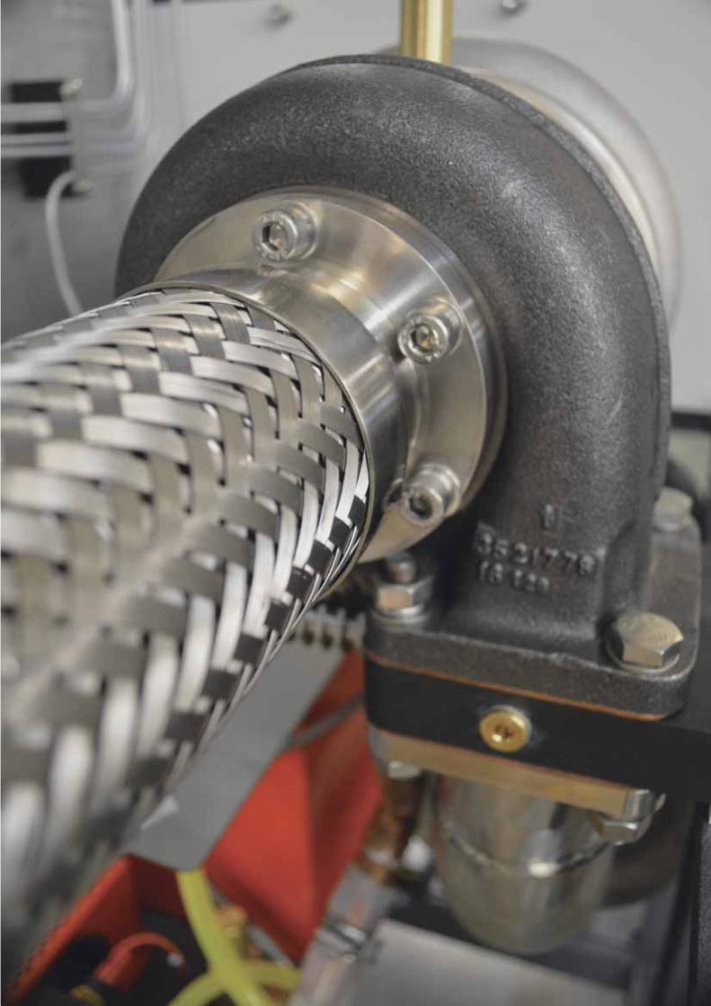
TecQuipment Ltd, Bonsall Street, Long Eaton, Nottingham NG10 2AN, UK
Pr
od
uc
t Ca
talo
gu
e 2018