Embed Size (px)
Citation preview
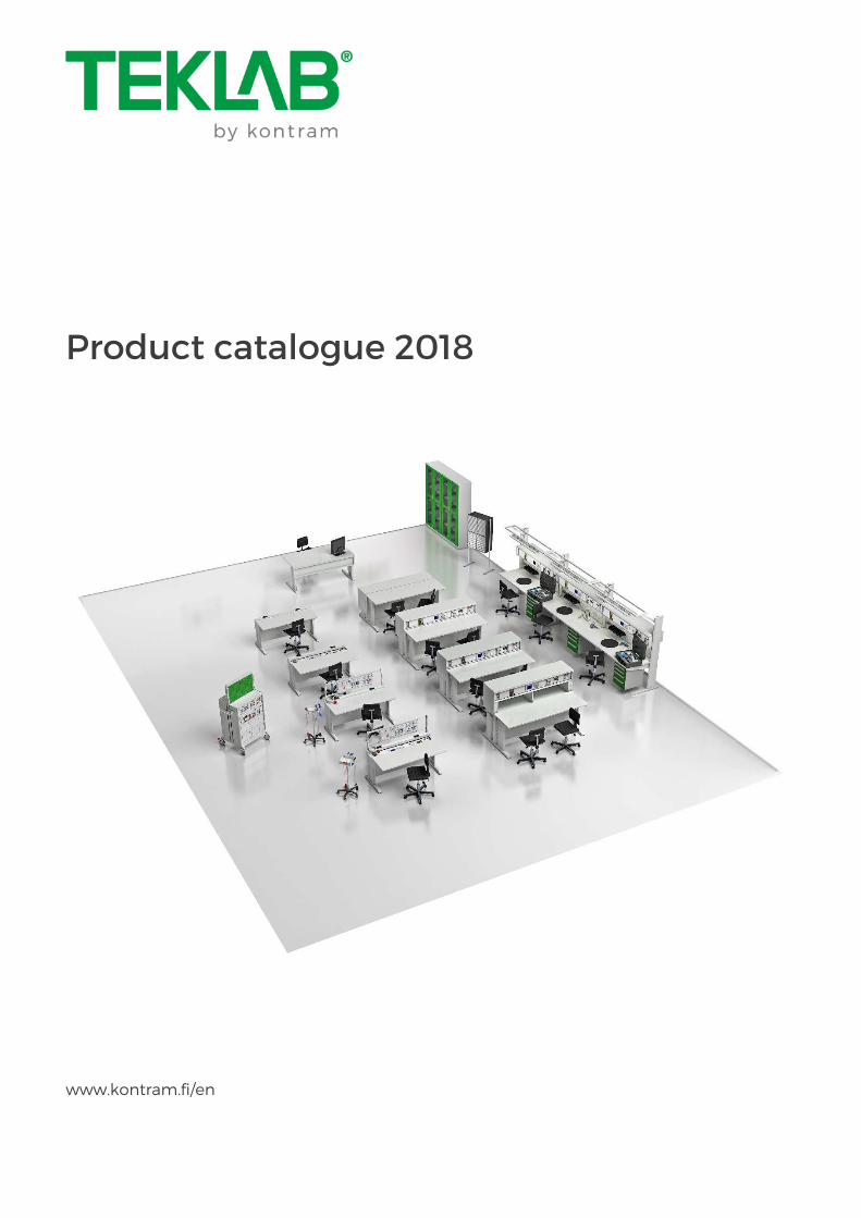
Product catalogue 2018
www.kontram.fi/en

Copyright: TEKLAB® 1
Copyright: TEKLAB® 2
Kontram’s TEKLAB group specializes in providing modular and multipurpose electric workstations and laboratories for education and industry.
TEKLAB solutions are used for example in following areas:
EDUCATIONAL
Electronics laboratories Electrical engineering laboratories Physics laboratories Calibration laboratories ICT laboratories Aviation laboratories Automotive laboratories Industrial training centres
INDUSTRIAL
Electrical industry Electronics industry Process industry Defence Pharmaceutical Marine Food & beverage
More than 20 000 TEKLAB workstations have been delivered to more than 100 countries during our 35 years of existence. Thus, our experience provides us leading knowledge of customer requirements in demanding industrial and educational environments.
TEKLAB is world widely well known as a reliable partner with longlife quality products. We are committed to support our customers and partners by providing industry-leading expertise with complete service all the way from product development to turn-key delivery.
All specifications in the catalogue are subject to change without notice.

Copyright: TEKLAB® 3
TABLE OF CONTENTSTABLE OF CONTENTSTABLE OF CONTENTSTABLE OF CONTENTS
Laboratory examples ................................................................................................................................................................................................. 4
Laboratory products ................................................................................................................................................................................................... 6
Workstations ................................................................................................................................................................................................................... 13
Accessories and fittings… ...................................................................................................................................................................................... 21
Supply units..................................................................................................................................................................................................................... 31
Variable DC power supplies ............................................................................................................................................................................... 33
Fixed DC power supplies ...................................................................................................................................................................................... 36
1 phase AC power supplies .................................................................................................................................................................................. 37
3 phase AC power supplies ................................................................................................................................................................................ 40
1 phase AC connections ....................................................................................................................................................................................... 42
3 phase AC connections ........................................................................................................................................................................................ 43
Connections .................................................................................................................................................................................................................. 44
Multimeters .................................................................................................................................................................................................................... 47
LCR meters ..................................................................................................................................................................................................................... 50
Function generators ..................................................................................................................................................................................................51
Oscilloscopes ................................................................................................................................................................................................................. 53
Power analyzers ......................................................................................................................................................................................................... 56
RF equipment.............................................................................................................................................................................................................. 58
Calibration equipment ......................................................................................................................................................................................... 59
Test equipment .......................................................................................................................................................................................................... 65
Biomedical test equipment .............................................................................................................................................................................. 68
Soldering equipment ............................................................................................................................................................................................... 71
Laboratory examples
Copyright: TEKLAB® 4
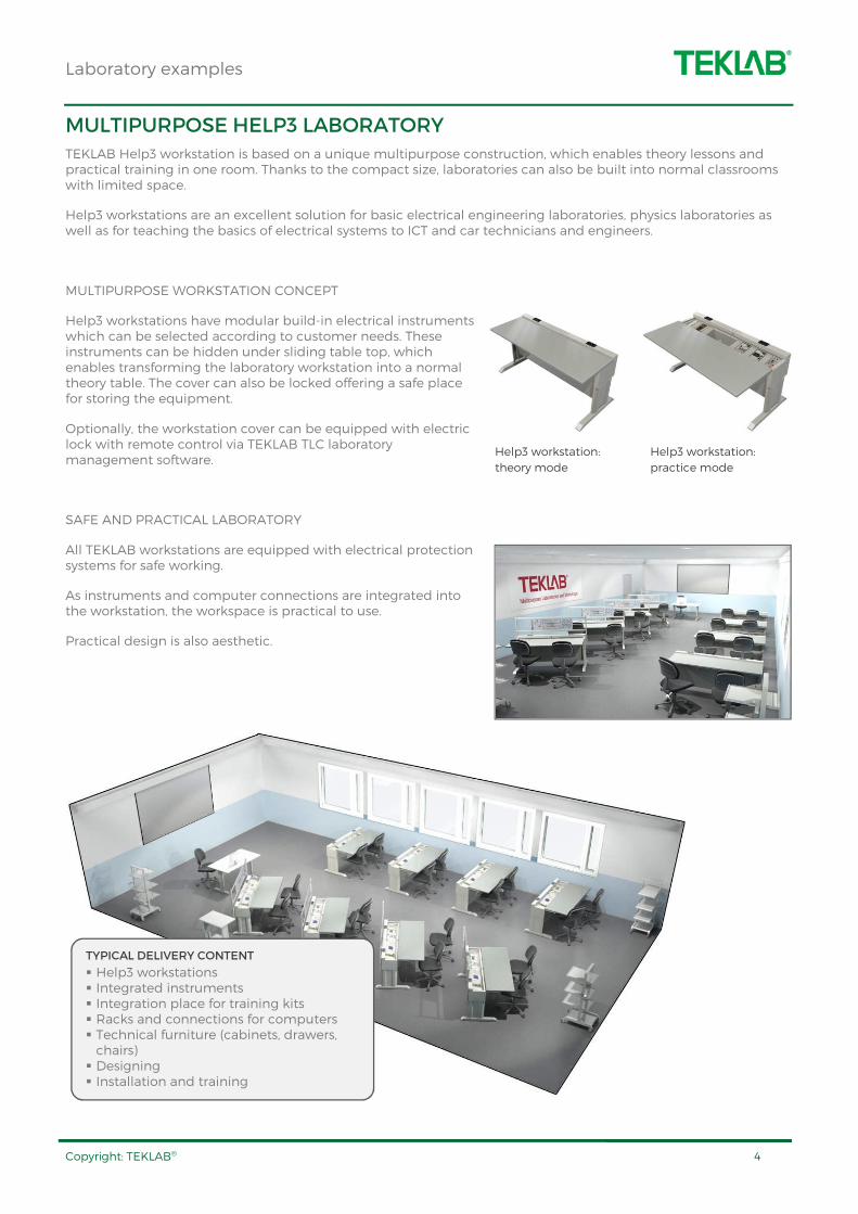
MULTIPURPOSE HELP3 LABORATORY
TEKLAB Help3 workstation is based on a unique multipurpose construction, which enables theory lessons and practical training in one room. Thanks to the compact size, laboratories can also be built into normal classrooms with limited space.
Help3 workstations are an excellent solution for basic electrical engineering laboratories, physics laboratories as well as for teaching the basics of electrical systems to ICT and car technicians and engineers.
MULTIPURPOSE WORKSTATION CONCEPT
Help3 workstations have modular build-in electrical instruments which can be selected according to customer needs. These instruments can be hidden under sliding table top, which enables transforming the laboratory workstation into a normal theory table. The cover can also be locked offering a safe place for storing the equipment.
Optionally, the workstation cover can be equipped with electric lock with remote control via TEKLAB TLC laboratory management software.
SAFE AND PRACTICAL LABORATORY
All TEKLAB workstations are equipped with electrical protection systems for safe working.
As instruments and computer connections are integrated into the workstation, the workspace is practical to use.
Practical design is also aesthetic.
TYPICAL DELIVERY CONTENT
Help3 workstations Integrated instruments Integration place for training kits Racks and connections for computers Technical furniture (cabinets, drawers, chairs) Designing Installation and training
Help3 workstation:
theory mode
Help3 workstation:
practice mode

Laboratory examples
Copyright: TEKLAB® 5
MULTIPURPOSE HELP5 LABORATORY
Help5 motorised multipurpose workstations offer great flexibility for technical laboratories: motorised panels can be driven up and down to transform a theory classroom into a technical laboratory - and vice versa. Considerable savings are achieved thanks to the possibility to modify classrooms for different purposes.
TRAINING AREAS
Help5 motorised workstations are the right choice e.g. for electronics and telecommunication training laboratories. Together with TLC laboratory control software, Help5 workstations convert the laboratory into a multifunctional room.
INTEGRATED CONSTRUCTION
Help5 workstation is equipped with a modular instrument panel for electrical instruments such as power supplies and measuring equipment. Integration releases more space on tabletop providing an ergonomic workplace.
Help5 workstation includes also an integrated storage space. This storage space is suitable for storing training sets, learning materials and accessories. When the panels are driven down and locked, the equipment is practically stored in a safe place.
The multipurpose concept brings savings in both space and time because all laboratory equipment and components are always easily available in the workstation.
UNIQUE FUNCTIONALITY
Help5 laboratory can be controlled via TEKLAB TLC software on the teacher’s computers.
Centralized software control converts the laboratory into a theory classroom in just 30 seconds. Besides this, the teacher can for example:
Control of the students' motorised workstations (UP / DOWN / LOCK) Control of the electricity in the students’ workstations (ON / OFF) Limit the output voltage and current on power supplies Supervise and lock students' computers Students can control the instruments via TEKLAB Client software. In addition, datalogging features are available for saving measurement results.
WHY LABORATORY BASED ON HELP5
WORKSTATIONS?
2 in 1 concept: laboratory work and theory lessons in one room All instruments and training equipment available by a press of a button Suitable for different types of laboratories:
• Electrical • Electronics • Automation etc.
Help5 workstation
Help5 laboratory in theory teaching mode. All equipment is
safely stored inside the workstations.
Help5 laboratory in practice mode. All equipment is
practically available.

Laboratory products
Copyright: TEKLAB® 6
TLC
TEKLAB Laboratory Control software
TEKLAB Laboratory Control (TLC) software is especially designed for educational laboratories. With TLC software, teacher is able to supervise and control the whole laboratory easily.
TEKLAB multifunction workstations and devices, together with TEKLAB Laboratory Control software, turn the work premises into a genuine multipurpose laboratory.
TLC software enables teacher to control workstations and devices from a single computer. Versatile group control functions with preset values make the software an efficient and convenient tool for the teacher.
There are three versions of the software available, TLCLITE, TLCBASIC and TLCPRO.
TLCLITE controls motorized workstations in the laboratory:
Lifting / lowering motorized panels in Help5 workstations Workstation locking in Help5 workstations
TLCBASIC includes TLCLITE features adding the following:
Connection permission for electricity Electricity off -control Electricity on -status information Emergency switch -status information Call button -status information Centralized safety test for RCDs
TLCPRO includes all features listed above, adding the following:
Group control of student power supplies: settings, limitations and locking Group control of student devices: settings, two-way communication Real time supervision / locking of student computers Limitation of internet access / application access of student computers Display sharing for whole classroom
Software Description TLCLITE TEKLAB Laboratory
Control, lite TLCBASIC TEKLAB Laboratory
Control, basic TLCPRO TEKLAB Laboratory
Control, large
Local Area Network (LAN)
Teacher’s laboratory
control software
Student workstations
Laboratory products
Copyright: TEKLAB® 7
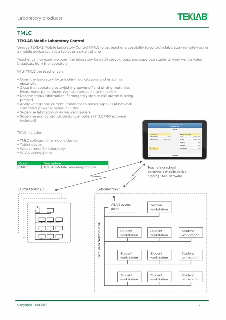
TMLC
TEKLAB Mobile Laboratory Control
Unique TEKLAB Mobile Laboratory Control (TMLC) gives teacher a possibility to control a laboratory remotely using a mobile device such as a tablet or a smart phone.
Teacher can for example open the laboratory for small study groups and supervise students' work via live video broadcast from the laboratory.
With TMLC the teacher can:
Open the laboratory by unlocking workstations and enabling electricity Close the laboratory by switching power off and driving motorised instruments panel down. Workstations can also be locked. Receive status information if emergency stop or call button is being pressed Apply voltage and current limitations to power supplies (if network controlled power supplies included) Supervise laboratory work via web camera Supervise and control students´ computers (if TLCPRO software included)
TMLC includes:
TMLC software for a mobile device Tablet device Web camera for laboratory WLAN access point
Code Description TMLC TEKLAB Mobile Laboratory Control
S SS
S SS
S SS
T
LABORATORY 1 LABORATORY 2, 3….
Teacher’s or school
personnel’s mobile device
running TMLC software
Local Area Network (LAN)
Student
workstation
Student
workstation
Student
workstation
Student
workstation
Student
workstation
Student
workstation
Student
workstation
Student
workstation
Student
workstation
Teacher
workstation
WLAN access
point
Laboratory products
Copyright: TEKLAB® 8
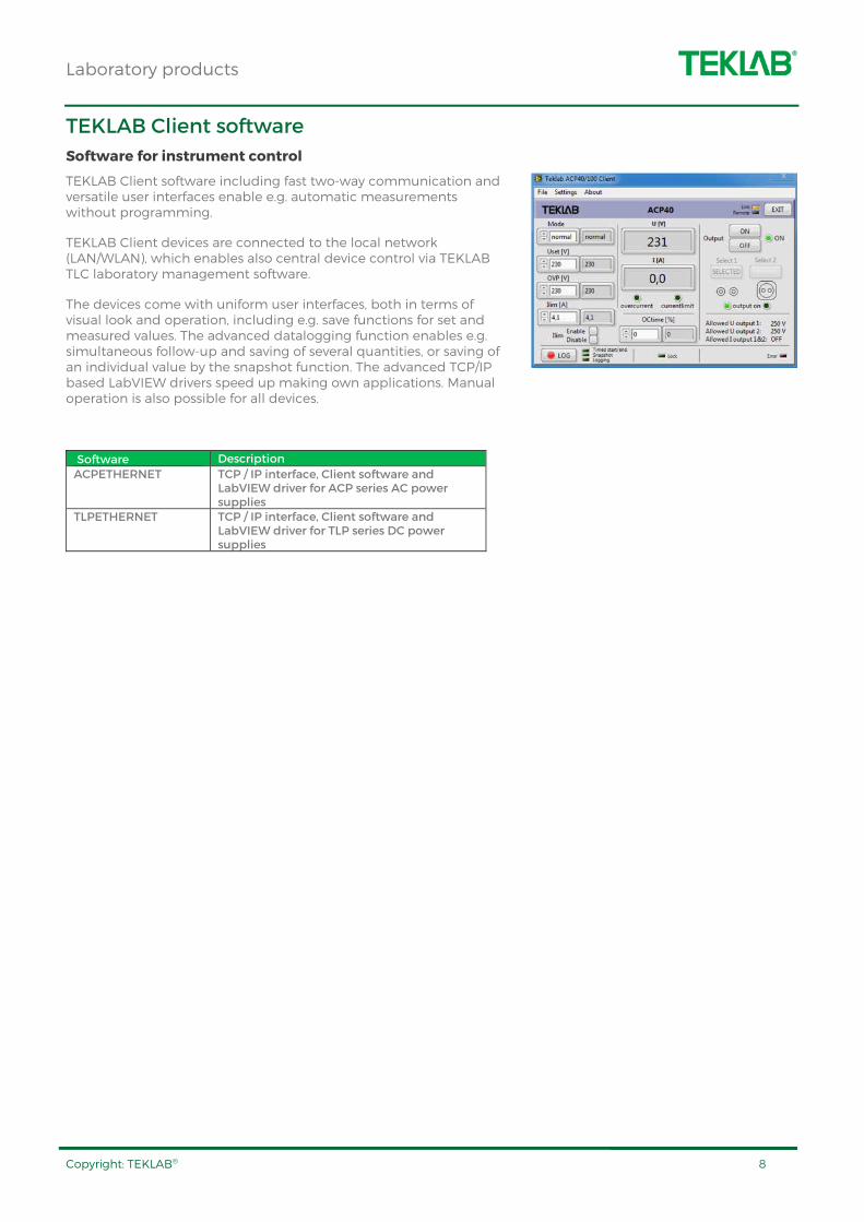
TEKLAB Client software
Software for instrument control
TEKLAB Client software including fast two-way communication and versatile user interfaces enable e.g. automatic measurements without programming.
TEKLAB Client devices are connected to the local network (LAN/WLAN), which enables also central device control via TEKLAB TLC laboratory management software.
The devices come with uniform user interfaces, both in terms of visual look and operation, including e.g. save functions for set and measured values. The advanced datalogging function enables e.g. simultaneous follow-up and saving of several quantities, or saving of an individual value by the snapshot function. The advanced TCP/IP based LabVIEW drivers speed up making own applications. Manual operation is also possible for all devices.
Software Description
ACPETHERNET TCP / IP interface, Client software and LabVIEW driver for ACP series AC power supplies
TLPETHERNET TCP / IP interface, Client software and LabVIEW driver for TLP series DC power supplies
Laboratory products
Copyright: TEKLAB® 9
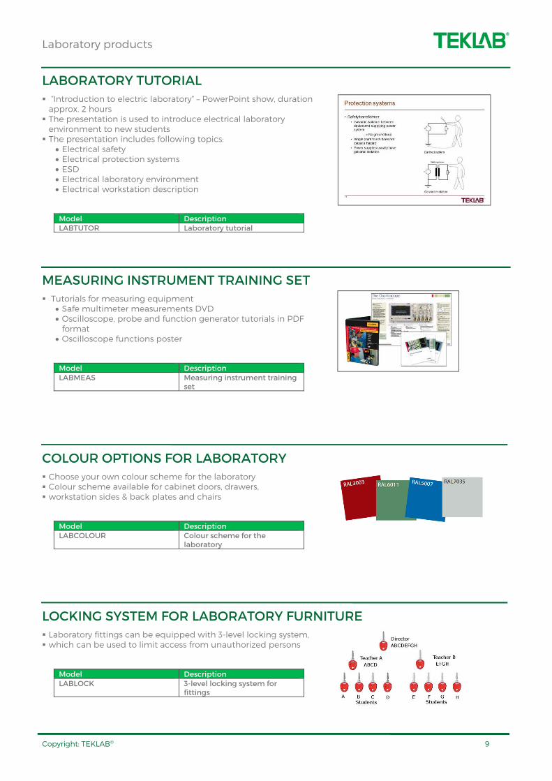
LABORATORY TUTORIAL
“Introduction to electric laboratory” – PowerPoint show, duration approx. 2 hours The presentation is used to introduce electrical laboratory environment to new students The presentation includes following topics:
• Electrical safety • Electrical protection systems • ESD • Electrical laboratory environment • Electrical workstation description
Model Description LABTUTOR Laboratory tutorial
MEASURING INSTRUMENT TRAINING SET
Tutorials for measuring equipment • Safe multimeter measurements DVD • Oscilloscope, probe and function generator tutorials in PDF format
• Oscilloscope functions poster
Model Description LABMEAS Measuring instrument training
set
COLOUR OPTIONS FOR LABORATORY
Choose your own colour scheme for the laboratory Colour scheme available for cabinet doors, drawers, workstation sides & back plates and chairs
Model Description LABCOLOUR Colour scheme for the
laboratory
LOCKING SYSTEM FOR LABORATORY FURNITURE
Laboratory fittings can be equipped with 3-level locking system, which can be used to limit access from unauthorized persons
Model Description LABLOCK 3-level locking system for
fittings
Laboratory products
Copyright: TEKLAB® 10
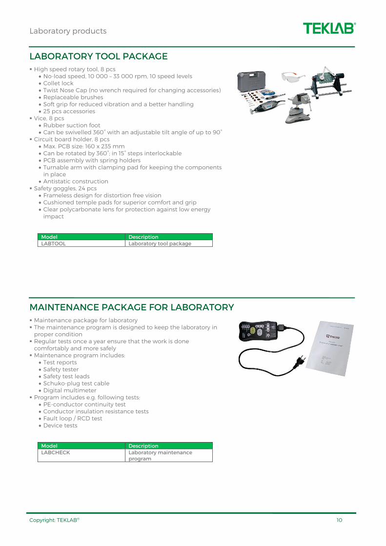
LABORATORY TOOL PACKAGE
High speed rotary tool, 8 pcs • No-load speed, 10 000 – 33 000 rpm, 10 speed levels • Collet lock • Twist Nose Cap (no wrench required for changing accessories) • Replaceable brushes • Soft grip for reduced vibration and a better handling • 25 pcs accessories
Vice, 8 pcs • Rubber suction foot • Can be swivelled 360° with an adjustable tilt angle of up to 90°
Circuit board holder, 8 pcs • Max. PCB size: 160 x 235 mm • Can be rotated by 360°; in 15° steps interlockable • PCB assembly with spring holders • Turnable arm with clamping pad for keeping the components in place
• Antistatic construction Safety goggles, 24 pcs
• Frameless design for distortion free vision • Cushioned temple pads for superior comfort and grip • Clear polycarbonate lens for protection against low energy impact
Model Description LABTOOL Laboratory tool package
MAINTENANCE PACKAGE FOR LABORATORY
Maintenance package for laboratory The maintenance program is designed to keep the laboratory in proper condition Regular tests once a year ensure that the work is done comfortably and more safely Maintenance program includes:
• Test reports • Safety tester • Safety test leads • Schuko-plug test cable • Digital multimeter
Program includes e.g. following tests: • PE-conductor continuity test • Conductor insulation resistance tests • Fault loop / RCD test • Device tests
Model Description LABCHECK Laboratory maintenance
program
Laboratory products
Copyright: TEKLAB® 11
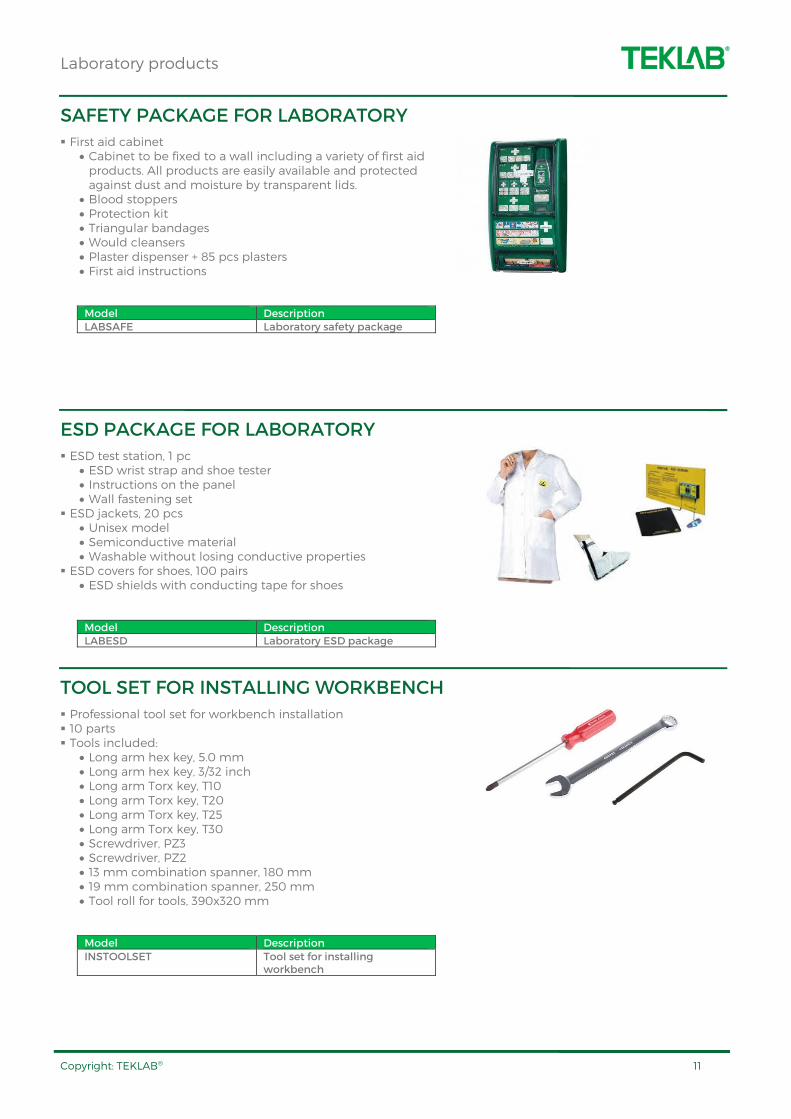
SAFETY PACKAGE FOR LABORATORY
First aid cabinet • Cabinet to be fixed to a wall including a variety of first aid products. All products are easily available and protected against dust and moisture by transparent lids.
• Blood stoppers • Protection kit • Triangular bandages • Would cleansers • Plaster dispenser + 85 pcs plasters • First aid instructions
Model Description LABSAFE Laboratory safety package
ESD PACKAGE FOR LABORATORY
ESD test station, 1 pc • ESD wrist strap and shoe tester • Instructions on the panel • Wall fastening set
ESD jackets, 20 pcs • Unisex model • Semiconductive material • Washable without losing conductive properties
ESD covers for shoes, 100 pairs • ESD shields with conducting tape for shoes
Model Description LABESD Laboratory ESD package
TOOL SET FOR INSTALLING WORKBENCH
Professional tool set for workbench installation 10 parts Tools included:
• Long arm hex key, 5.0 mm • Long arm hex key, 3/32 inch • Long arm Torx key, T10 • Long arm Torx key, T20 • Long arm Torx key, T25 • Long arm Torx key, T30 • Screwdriver, PZ3 • Screwdriver, PZ2 • 13 mm combination spanner, 180 mm • 19 mm combination spanner, 250 mm • Tool roll for tools, 390x320 mm
Model Description INSTOOLSET Tool set for installing
workbench
Laboratory products
Copyright: TEKLAB® 12
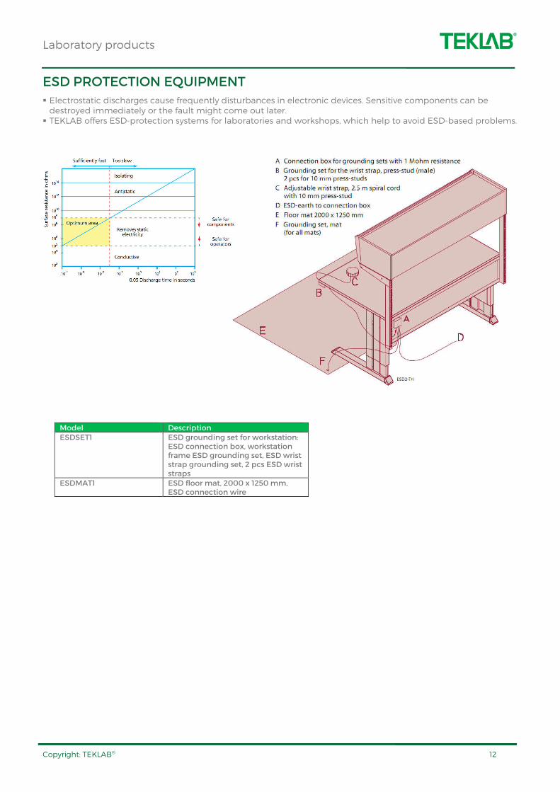
ESD PROTECTION EQUIPMENT
Electrostatic discharges cause frequently disturbances in electronic devices. Sensitive components can be destroyed immediately or the fault might come out later. TEKLAB offers ESD-protection systems for laboratories and workshops, which help to avoid ESD-based problems.
Model Description ESDSET1 ESD grounding set for workstation:
ESD connection box, workstation frame ESD grounding set, ESD wrist strap grounding set, 2 pcs ESD wrist straps
ESDMAT1 ESD floor mat, 2000 x 1250 mm, ESD connection wire
Workstations
Copyright: TEKLAB® 13
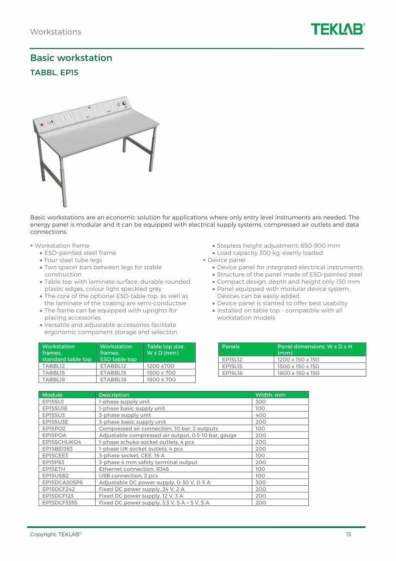
Basic workstation
TABBL, EP15
Basic workstations are an economic solution for applications where only entry level instruments are needed. The energy panel is modular and it can be equipped with electrical supply systems, compressed air outlets and data connections.
Workstation frame • ESD-painted steel frame • Four steel tube legs • Two spacer bars between legs for stable construction
• Table top with laminate surface, durable rounded plastic edges, colour light speckled grey
• The core of the optional ESD-table top, as well as the laminate of the coating are semi-conductive
• The frame can be equipped with uprights for placing accessories
• Versatile and adjustable accessories facilitate ergonomic component storage and selection
• Stepless height adjustment: 650-900 mm • Load capacity 300 kg, evenly loaded
Device panel • Device panel for integrated electrical instruments • Structure of the panel made of ESD-painted steel • Compact design, depth and height only 150 mm • Panel equipped with modular device system: Devices can be easily added
• Device panel is slanted to offer best usability • Installed on table top - compatible with all workstation models
Workstation frames, standard table top
Workstation frames, ESD table top
Table top size, W x D (mm)
TABBL12 ETABBL12 1200 x700 TABBL15 ETABBL15 1500 x 700 TABBL18 ETABBL18 1800 x 700
Panels Panel dimensions, W x D x H (mm)
EP15L12 1200 x 150 x 150 EP15L15 1500 x 150 x 150 EP15L18 1800 x 150 x 150
Module Description Width, mm EP15SU1 1-phase supply unit 300 EP15SU1E 1-phase basic supply unit 100 EP15SU3 3-phase supply unit 400 EP15SU3E 3-phase basic supply unit 200 EP15PO2 Compressed air connection, 10 bar, 2 outputs 100 EP15POA Adjustable compressed air output, 0.5-10 bar, gauge 200 EP15SCHUKO4 1-phase schuko socket outlets, 4 pcs 200 EP15BS1363 1-phase UK socket outlets, 4 pcs 200 EP15CEE3 3-phase socket, CEE, 16 A 100 EP15PS3 3-phase 4 mm safety terminal output 200 EP15ETH Ethernet connection, RJ45 100 EP15USB2 USB connection, 2 pcs 100 EP15DCA305PS Adjustable DC power supply, 0-30 V, 0-5 A 300 EP15DCF242 Fixed DC power supply, 24 V, 2 A 200 EP15DCF123 Fixed DC power supply, 12 V, 3 A 200 EP15DCF3355 Fixed DC power supply, 3.3 V, 5 A + 5 V, 5 A 200

Workstations
Copyright: TEKLAB® 14
Multipurpose workstation
HELP3
TEKLAB Help3 workstation is based on a unique multipurpose construction, which enables theory lessons and practical training in one room.
Help3 workstations are an excellent solution for basic electrical engineering laboratories, physics laboratories as well as for teaching the basics of electrical systems to ICT and car technicians and engineers.
Help3 multifunction workstation is a cost-effective solution for training laboratories. Thanks to the compact size, the laboratory can be built into rooms with limited space.
Multipurpose construction: electric workstation and theory desk in one solution Built-in instrument panel for integrated electrical instruments, instrument panel located under a sliding table top Sliding table top movable forwards and backwards to enable / hide the instrument panel Sliding table top can be locked to prevent access to the instrument panel Modular instrument panel:
• Devices can be added afterwards • Instrument panel is slanted to achieve best possible usability
• Integrated modules are covered with polyester film to ensure long lifetime for the markings in the front panel
Workstation frame and instrument panel made of ESD powder painted steel L-shaped ergonomic legs for more space under workstation Adjustable height 710-780 mm Adjustment screws under the workstation to eliminate the roughness of the floor Table top with laminate coating, durable plastic edges, colour light grey 4 pcs sockets in the energy channel located at the rear part of the workstations. Sockets are available also when the table top is in closed position. Can be equipped with upright tubes for fixing accessories such as shelves, display holders or frames for training panels
Workstation frames Table top size, W x D (mm) Full modules max. HELP3L12 1210 x 580-810 4 ½ HELP3L15 1460 x 580-810 5 ½ HELP3L17 1710 x 580-810 6 ½
Options for Help3 workstations LOCK3M Manual lock for cover LOCK3NET LAN-controlled electric lock for cover, power on/off control WKS820717 Mini cabinet under the table top, lockable, dimensions:
255(W) x 330(D) x 189(H) mm HELP3SOCKEU 4 pcs schuko sockets under the workstation HELP3SOCKUK 4 pcs UK sockets under the workstation HELP3SOCKUS 4 pcs US sockets under the workstation
Workstations
Copyright: TEKLAB® 15
Multipurpose workstation
HELP5
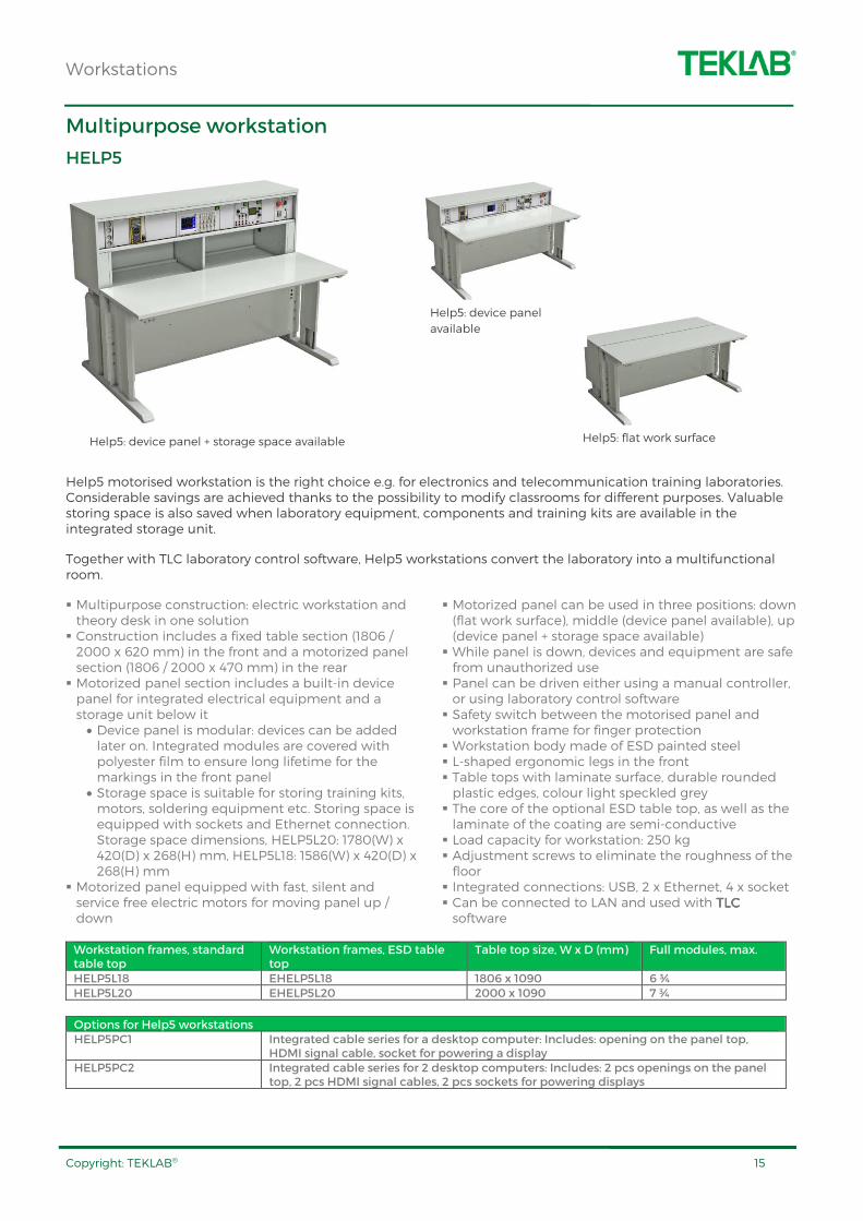
Help5 motorised workstation is the right choice e.g. for electronics and telecommunication training laboratories. Considerable savings are achieved thanks to the possibility to modify classrooms for different purposes. Valuable storing space is also saved when laboratory equipment, components and training kits are available in the integrated storage unit.
Together with TLC laboratory control software, Help5 workstations convert the laboratory into a multifunctional room.
Multipurpose construction: electric workstation and theory desk in one solution Construction includes a fixed table section (1806 / 2000 x 620 mm) in the front and a motorized panel section (1806 / 2000 x 470 mm) in the rear Motorized panel section includes a built-in device panel for integrated electrical equipment and a storage unit below it
• Device panel is modular: devices can be added later on. Integrated modules are covered with polyester film to ensure long lifetime for the markings in the front panel
• Storage space is suitable for storing training kits, motors, soldering equipment etc. Storing space is equipped with sockets and Ethernet connection. Storage space dimensions, HELP5L20: 1780(W) x 420(D) x 268(H) mm, HELP5L18: 1586(W) x 420(D) x 268(H) mm
Motorized panel equipped with fast, silent and service free electric motors for moving panel up / down
Motorized panel can be used in three positions: down (flat work surface), middle (device panel available), up (device panel + storage space available) While panel is down, devices and equipment are safe from unauthorized use Panel can be driven either using a manual controller, or using laboratory control software Safety switch between the motorised panel and workstation frame for finger protection Workstation body made of ESD painted steel L-shaped ergonomic legs in the front Table tops with laminate surface, durable rounded plastic edges, colour light speckled grey The core of the optional ESD table top, as well as the laminate of the coating are semi-conductive Load capacity for workstation: 250 kg Adjustment screws to eliminate the roughness of the floor Integrated connections: USB, 2 x Ethernet, 4 x socket Can be connected to LAN and used with TLC TLC TLC TLC software
Workstation frames, standard table top
Workstation frames, ESD table top
Table top size, W x D (mm) Full modules, max.
HELP5L18 EHELP5L18 1806 x 1090 6 ¾ HELP5L20 EHELP5L20 2000 x 1090 7 ¾
Options for Help5 workstations HELP5PC1 Integrated cable series for a desktop computer: Includes: opening on the panel top,
HDMI signal cable, socket for powering a display HELP5PC2 Integrated cable series for 2 desktop computers: Includes: 2 pcs openings on the panel
top, 2 pcs HDMI signal cables, 2 pcs sockets for powering displays
Help5: device panel + storage space available Help5: flat work surface
Help5: device panel
available
Workstations
Copyright: TEKLAB® 16
TowerLine workstation
TABTL, PANTL
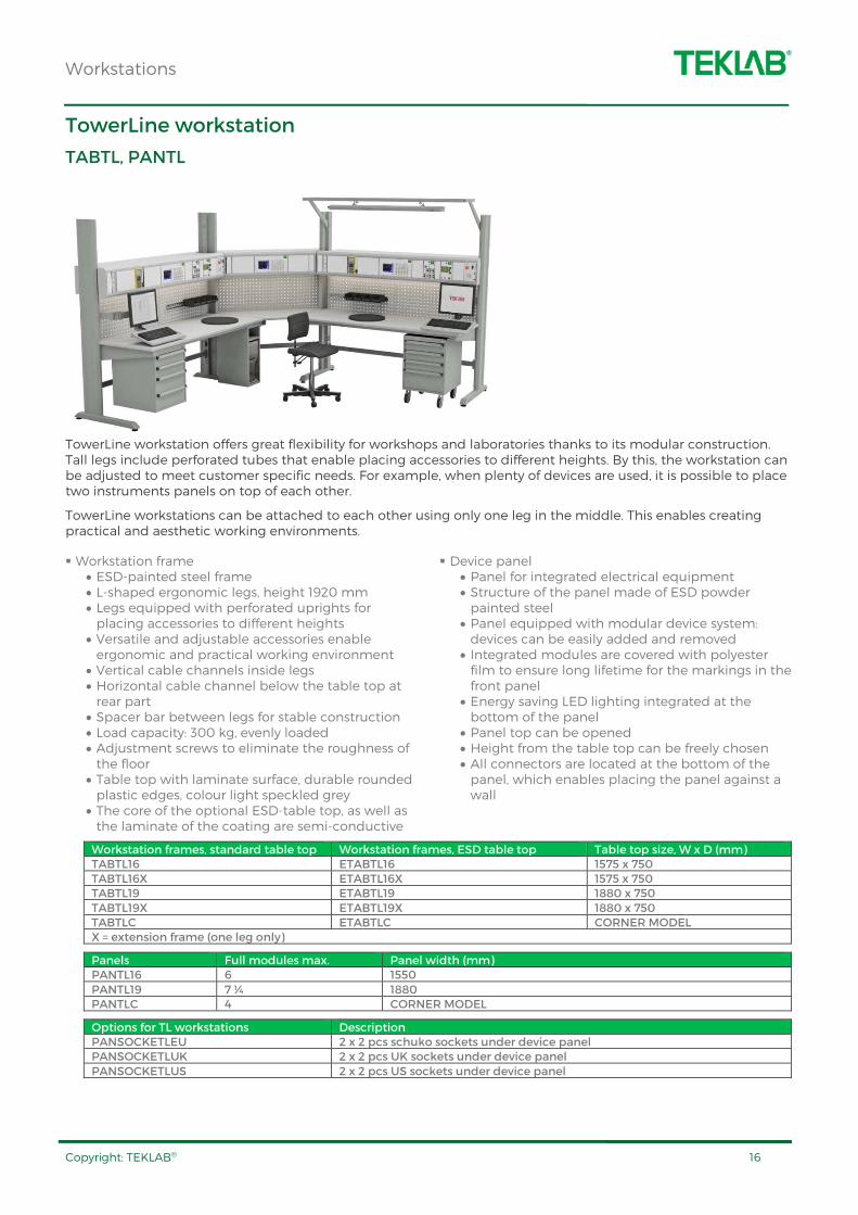
TowerLine workstation offers great flexibility for workshops and laboratories thanks to its modular construction. Tall legs include perforated tubes that enable placing accessories to different heights. By this, the workstation can be adjusted to meet customer specific needs. For example, when plenty of devices are used, it is possible to place two instruments panels on top of each other.
TowerLine workstations can be attached to each other using only one leg in the middle. This enables creating practical and aesthetic working environments.
Workstation frame • ESD-painted steel frame • L-shaped ergonomic legs, height 1920 mm • Legs equipped with perforated uprights for placing accessories to different heights
• Versatile and adjustable accessories enable ergonomic and practical working environment
• Vertical cable channels inside legs • Horizontal cable channel below the table top at rear part
• Spacer bar between legs for stable construction • Load capacity: 300 kg, evenly loaded • Adjustment screws to eliminate the roughness of the floor
• Table top with laminate surface, durable rounded plastic edges, colour light speckled grey
• The core of the optional ESD-table top, as well as the laminate of the coating are semi-conductive
Device panel • Panel for integrated electrical equipment • Structure of the panel made of ESD powder painted steel
• Panel equipped with modular device system: devices can be easily added and removed
• Integrated modules are covered with polyester film to ensure long lifetime for the markings in the front panel
• Energy saving LED lighting integrated at the bottom of the panel
• Panel top can be opened • Height from the table top can be freely chosen • All connectors are located at the bottom of the panel, which enables placing the panel against a wall
Workstation frames, standard table top Workstation frames, ESD table top Table top size, W x D (mm) TABTL16 ETABTL16 1575 x 750 TABTL16X ETABTL16X 1575 x 750 TABTL19 ETABTL19 1880 x 750 TABTL19X ETABTL19X 1880 x 750 TABTLC ETABTLC CORNER MODEL X = extension frame (one leg only)
Panels Full modules max. Panel width (mm) PANTL16 6 1550 PANTL19 7 ¼ 1880 PANTLC 4 CORNER MODEL
Options for TL workstations Description PANSOCKETLEU 2 x 2 pcs schuko sockets under device panel PANSOCKETLUK 2 x 2 pcs UK sockets under device panel PANSOCKETLUS 2 x 2 pcs US sockets under device panel

Workstations
Copyright: TEKLAB® 17
Concept workstation
TABSYSL, PANSYSL
Concept workstation is a good solution for rooms where it is preferred to have a direct view forward, or to allow natural light to enter the space. The top of the panel can be used as a practical plane surface.
Workstation frame • ESD powder painted steel frame • L-shaped ergonomic legs • Table top with laminate surface, durable rounded plastic edges, colour light speckled grey
• Core of the ESD-table top, as well as the laminate of the coating are semi-conductive
• Adjustable height: 670 – 1120 mm • Adjustment screws to eliminate the roughness of the floor
• Load capacity 500 kg, evenly loaded
Device panel • Panel for integrated electrical equipment • Installed on the table top • Structure of the panel made of ESD powder painted steel
• Panel equipped with modular device system: devices can be easily added and removed
• Integrated modules are covered with polyester film to ensure long lifetime for the markings in the front panel
• Panel top can be opened • All connectors are located at the bottom of the panel which enables placing the panel against a wall
Workstation frames, standard table top Workstation frames, ESD table top Table top size, W x D (mm) TABSYSL15 ETABSYSL15 1500 x 900 TABSYSL18 ETABSYSL18 1800 x 900 TABSYSL20 ETABSYSL20 2000 x 900
Panels Full modules max. Panel length (mm) PANSYSL15 5 ¾ 1500 PANSYSL18 7 1805 PANSYSL20 7 ¾ 2000
Workstations
Copyright: TEKLAB® 18
Heavy duty workstation
TABHEAVYH, PANSYSH
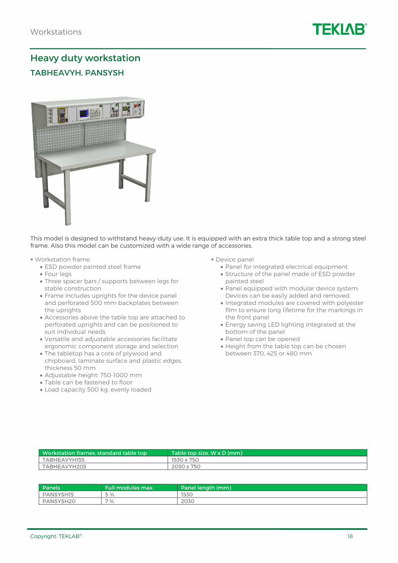
This model is designed to withstand heavy-duty use. It is equipped with an extra thick table top and a strong steel frame. Also this model can be customized with a wide range of accessories.
Workstation frame • ESD powder painted steel frame • Four legs • Three spacer bars / supports between legs for stable construction
• Frame includes uprights for the device panel and perforated 500 mm backplates between the uprights
• Accessories above the table top are attached to perforated uprights and can be positioned to suit individual needs
• Versatile and adjustable accessories facilitate ergonomic component storage and selection
• The tabletop has a core of plywood and chipboard, laminate surface and plastic edges, thickness 50 mm
• Adjustable height: 750-1000 mm • Table can be fastened to floor • Load capacity 500 kg, evenly loaded
Device panel • Panel for integrated electrical equipment • Structure of the panel made of ESD powder painted steel
• Panel equipped with modular device system: Devices can be easily added and removed
• Integrated modules are covered with polyester film to ensure long lifetime for the markings in the front panel
• Energy saving LED lighting integrated at the bottom of the panel
• Panel top can be opened • Height from the table top can be chosen between 370, 425 or 480 mm
Workstation frames, standard table top Table top size, W x D (mm) TABHEAVYH155 1530 x 750 TABHEAVYH205 2030 x 750
Panels Full modules max. Panel length (mm) PANSYSH15 5 ¾ 1530 PANSYSH20 7 ¾ 2030
Workstations
Copyright: TEKLAB® 19
Electrically / manually adjustable Concept workstation
TABSYSHE/M, PANSYSH
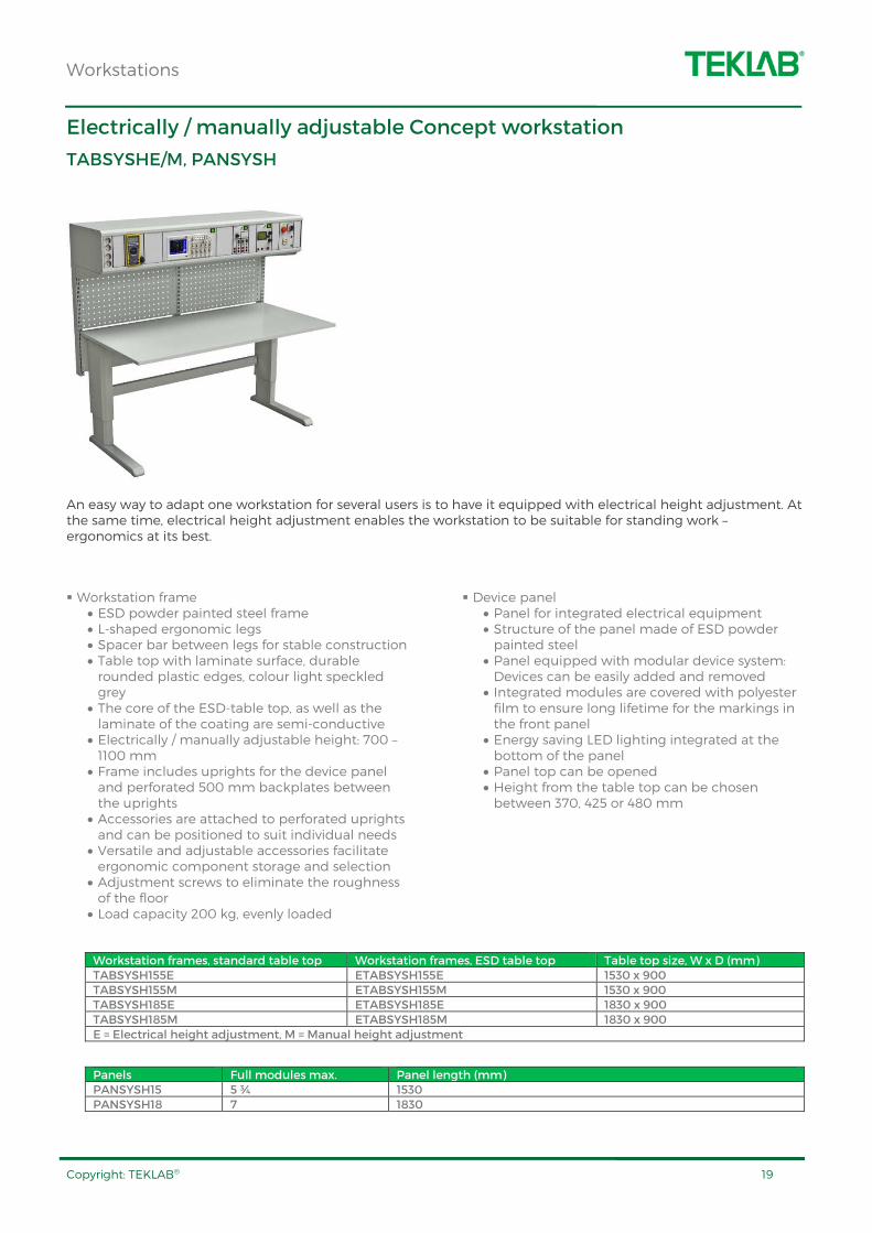
An easy way to adapt one workstation for several users is to have it equipped with electrical height adjustment. At the same time, electrical height adjustment enables the workstation to be suitable for standing work – ergonomics at its best.
Workstation frame • ESD powder painted steel frame • L-shaped ergonomic legs • Spacer bar between legs for stable construction • Table top with laminate surface, durable rounded plastic edges, colour light speckled grey
• The core of the ESD-table top, as well as the laminate of the coating are semi-conductive
• Electrically / manually adjustable height: 700 – 1100 mm
• Frame includes uprights for the device panel and perforated 500 mm backplates between the uprights
• Accessories are attached to perforated uprights and can be positioned to suit individual needs
• Versatile and adjustable accessories facilitate ergonomic component storage and selection
• Adjustment screws to eliminate the roughness of the floor
• Load capacity 200 kg, evenly loaded
Device panel • Panel for integrated electrical equipment • Structure of the panel made of ESD powder painted steel
• Panel equipped with modular device system: Devices can be easily added and removed
• Integrated modules are covered with polyester film to ensure long lifetime for the markings in the front panel
• Energy saving LED lighting integrated at the bottom of the panel
• Panel top can be opened • Height from the table top can be chosen between 370, 425 or 480 mm
Workstation frames, standard table top Workstation frames, ESD table top Table top size, W x D (mm) TABSYSH155E ETABSYSH155E 1530 x 900 TABSYSH155M ETABSYSH155M 1530 x 900 TABSYSH185E ETABSYSH185E 1830 x 900 TABSYSH185M ETABSYSH185M 1830 x 900 E = Electrical height adjustment, M = Manual height adjustment
Panels Full modules max. Panel length (mm) PANSYSH15 5 ¾ 1530 PANSYSH18 7 1830
Workstations
Copyright: TEKLAB® 20
Trolleys
MOBILELAB
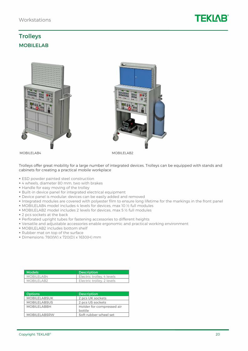
Trolleys offer great mobility for a large number of integrated devices. Trolleys can be equipped with stands and cabinets for creating a practical mobile workplace
ESD powder painted steel construction 4 wheels, diameter 80 mm, two with brakes Handle for easy moving of the trolley Built-in device panel for integrated electrical equipment Device panel is modular: devices can be easily added and removed Integrated modules are covered with polyester film to ensure long lifetime for the markings in the front panel MOBILELAB4 model includes 4 levels for devices, max 10 ½ full modules MOBILELAB2 model includes 2 levels for devices, max 5 ½ full modules 2 pcs sockets at the back Perforated upright tubes for fastening accessories to different heights Versatile and adjustable accessories enable ergonomic and practical working environment MOBILELAB2 includes bottom shelf Rubber mat on top of the surface Dimensions: 780(W) x 720(D) x 1630(H) mm
Models Description MOBILELAB4 Electric trolley, 4 levels MOBILELAB2 Electric trolley, 2 levels
Options Description MOBILELABSUK 2 pcs UK sockets MOBILELABSUS 2 pcs US sockets MOBILELABBH Holder for compressed air
bottle MOBILELABSRW Soft rubber wheel set
MOBILELAB2 MOBILELAB4
Accessories and fittings
Copyright: TEKLAB® 21
ACCESSORIES
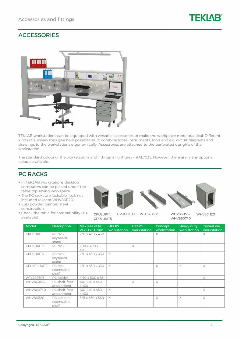
TEKLAB workstations can be equipped with versatile accessories to make the workplace more practical. Different kinds of auxiliary tops give new possibilities to combine loose instruments, tools and e.g. circuit diagrams and drawings to the workstations ergonomically. Accessories are attached to the perforated uprights of the workstation.
The standard colour of the workstations and fittings is light grey – RAL7035. However, there are many optional colours available.
PC RACKS
In TEKLAB workstations desktop computers can be placed under the table top saving workspace The PC racks are lockable, lock not included (except WHV861120) ESD powder painted steel construction Check the table for compatibility (X = available)
Model Description Max size of PC W x D x H, mm
HELP5 workstation
HELP3 workstation
Concept workstation
Heavy duty workstation
TowerLine workstation
CPULUKIT PC rack, keyboard stand
230 x 430 x 430 X X X
CPULUKIT3 PC rack 200 x 400 x 380
X
CPULUKIT5 PC rack, keyboard stand
230 x 430 x 430 X
CPUVTLUKITT PC rack, extendable shelf
230 x 430 x 430 X X X X
WTL820303 PC holder >150 x 500 x 85 X WHV860552 PC shelf, foot
attachment 100-240 x 450 x 430
X X
WHV860740 PC shelf, foot attachment
100-240 x 450 x 430
X X
WHV861120 PC cabinet, extendable shelf
325 x 550 x 560 X X X X
CPULUKIT,
CPULUKIT5
WHV861120 WHV860552,
WHV860740
WTL820303 CPULUKIT3

Accessories and fittings
Copyright: TEKLAB® 22
DISPLAY HOLDERS
Fixing a display to a separate holder gives more workspace on the table top Adjustable display holder improves work ergonomics
Models Description WSA93035002 Display holder
WTL93035002 Display holder for TL workstation
WSA93035003 Display holder with keyboard and mouse stand
WTL93035003 Display holder with keyboard and mouse stand for TL workstation
LCDKANL Display holder to be attached to horizontal surface
KEYBOARD TRAY
Keyboard tray is fastened under the table top
Model Size, W x D, mm Max load, kg WHV92535001 630 x 400 10
DRAWER UNITS 45
Select from two models: drawer trolley or drawer to be fixed under the table top Drawers equipped with ball-rails and central locking, load capacity 30 kg / drawer Drawers open 75 %, also 100 % models are available In trolley model four swivel wheels, two with brakes, diameter 100 mm ESD-painted steel frame, trolley model equipped with ESD-mat and wheels Standard colour light grey – RAL7035, optional colours available for drawer fronts, see page 19 Dimensions: 450(W) x 520(D) x 560(H) mm
Drawer to be fixed under table top
Trolley model Drawers
WKL60635001 WEV60635021 5 x 100 mm WKL60635002 WEV60635022 2 x 100 mm, 2 x 150 mm WKL60635003 WEV60635023 3 x 100 mm, 1 x 200 mm WKL60635004 WEV60635024 1 x 100 mm, 2 x 200 mm WKL60635007 WEV60635027 2 x 150 mm, 1 x 200 mm
WKL60635001 WEV60635023
WSA93035002 WSA93035003 LCDKANL

Accessories and fittings
Copyright: TEKLAB® 23
DRAWER UNITS 30
ESD-painted steel frame To be fixed under table top. Drawer units can also be fixed one below other Small drawers for tools etc. Drawers equipped with a lock Drawer opening 80% Internal drawer dimensions: 253(W) x 429(D) x 130(H) mm
Model Size, W x D x H, mm Max load, kg
WKS859330 300 x 454 x 150, 1 drawer 10 WKS859340 300 x 454 x 222, 2 drawers 20 WKS860972 350 x 450 x 470, cabinet 25 WKS860918 350 x 450 x 555, cabinet,
wheels 25
UPRIGHT TUBES
Perforated upright tubes for fastening accessories to workstations Made of ESD painted steel, 30(W) x 60(D) mm Removable
Model Height WPE860024 1359 mm WPE860142 800 mm
SHELVES
Structure made of ESD painted steel
Model Size, W x D, mm Max load kg WHT860804 490 x 300 50 WHT860805 490 x 400 50 WTL854480 1167 x 300 80 WTL854481 1467 x 300 80 WTL854484 1467 x 400 80 WTL854482 1773 x 300 80 WTL854485 1773 x 400 80 WTL820471 600 x 200, fixed to perforated
back panel 7
WTL854479 CORNER MODEL FOR TL WORKSTATION
80
PERFORATED BACK PANELS
Structure made of ESD painted steel Can be used to attach accessories such as hooks or suspension rails Standard colour, RAL7035, optional colours available
Model Dimensions (W) x (H) WPT861501 468 x 389 mm WPT861511 718 x 389 mm WPT861516 871 x 389 mm WTL861526 1474 x 389 mm WTL861531 1774 x 389 mm WTL890411 CORNER MODEL FOR TL WORKSTATION
WKS859330 WKS860918
Accessories and fittings
Copyright: TEKLAB® 24
SUSPENSION RAILS AND PICK-UP BOXES
Structure made of ESD painted steel
Model Description Max load WHL859150 Suspension rail, 492(W) x 100(H) mm 50 kg WTL859154 Suspension rail, 1493(W) x 100(H) mm 50 kg WTL859155 Suspension rail, 1799(W) x 100(H) mm 50 kg WTL839086 Suspension rail, 634(W) mm, fixed to
perforated back panel 10 kg
WEL806207 Pick-up box, 105(W) x 165(D) x 75(H) mm
2 kg
TRAINING PANEL FRAMES
Frame for A4 training panels Easily fastening and removing of panels
Model Description A4FRAME12(D) Training panel frame, width 1200 mm, one
row A4FRAME15(D) Training panel frame, width 1500 mm, one
row A4FRAME18(D) Training panel frame, width 1800 mm, one
row * D model includes two rows
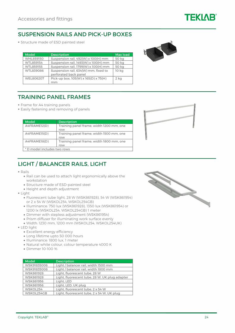
LIGHT / BALANCER RAILS, LIGHT
Rails • Rail can be used to attach light ergonomically above the workstation
• Structure made of ESD-painted steel • Height and depth adjustment
Light • Fluorescent tube light, 28 W (WSK861928), 54 W (WSK861954) or 2 x 54 W (WSKOL254, WSKOL254GB)
• Illuminance: 750 lux (WSK861928), 1350 lux (WSK861954) or 1200 lx (WSKOL254, WSKOL254GB) 1 meter
• Dimmer with stepless adjustment (WSK861954) • Prism diffuser for illuminating work surface evenly • Width: 1230 mm, 1200 mm (WSKOL254, WSKOL254UK)
LED light • Excellent energy efficiency • Long lifetime upto 50 000 hours • Illuminance: 1800 lux, 1 meter • Natural white colour, colour temperature 4000 K • Dimmer 10-100 %
Model Description WSK91835006 Light / balancer rail, width 1500 mm WSK91835008 Light / balancer rail, width 1800 mm WSK861928 Light, fluorescent tube, 28 W WSK861928 Light, fluorescent tube, 28 W, UK plug adapter WSK861956 Light, LED WSK861956 Light, LED, UK plug WSKOL254 Light, fluorescent tube, 2 x 54 W WSKOL254GB Light, fluorescent tube, 2 x 54 W, UK plug
Accessories and fittings
Copyright: TEKLAB® 25
CABLE TROUGHS
Horizontal cable trough efficiently hides cables without preventing maintenance access Structure made of ESD painted steel
Model Description WTL854556 Cable trough, 1487(W) x 97(D) x 45(H)
mm WTL854557 Cable trough, 1793(W) x 97(D) x 45(H)
mm
DOCUMENT HOLDER
Documents and drawings can be easily placed on the document holder with two magnets included Structure made of ESD painted steel
Model Size, W x D, mm Max load, kg WSI92835008 290 x 330 5 WTL92835008 Document holder for TL workstation
TOOL PANEL
Perforated tool panel, includes 6 pcs hooks Structure made of ESD painted steel
Model Size, W x D, mm Max load, kg WST92835010 267 x 305 5 WTL92835010 Tool panel for TL workstation
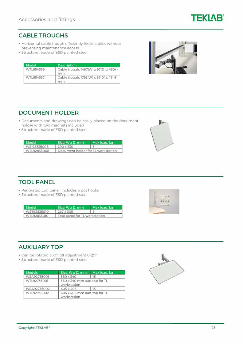
AUXILIARY TOP
Can be rotated 360º, tilt adjustment 0-25º Structure made of ESD painted steel
Models Size, W x D, mm Max load, kg WSA92735001 560 x 340 15 WTL92735001 560 x 340 mm aux. top for TL
workstation WSA92735002 605 x 405 15 WTL92735002 605 x 405 mm aux. top for TL
workstation
Accessories and fittings
Copyright: TEKLAB® 26
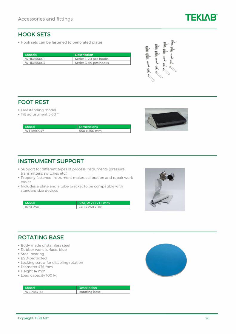
HOOK SETS
Hook sets can be fastened to perforated plates
Models Description WHR855001 Series 1, 20 pcs hooks WHR855003 Series 3, 69 pcs hooks
FOOT REST
Freestanding model Tilt adjustment 5-30 º
Model Dimensions WTT860947 550 x 350 mm
INSTRUMENT SUPPORT
Support for different types of process instruments (pressure transmitters, switches etc.) Properly fastened instrument makes calibration and repair work easier Includes a plate and a tube bracket to be compatible with standard size devices
Model Size, W x D x H, mm INSTRSU 240 x 260 x 318
ROTATING BASE
Body made of stainless steel Rubber work surface, blue Steel bearing ESD-protected Locking screw for disabling rotation Diameter 475 mm Height 14 mm Load capacity 100 kg
Model Description WEP847145 Rotating base

Accessories and fittings
Copyright: TEKLAB® 27
WHEELS FOR WORKSTATIONS
Diameter of wheels 100 mm, two wheels with brakes
Model Description WPP834734 Standard WEP860429 ESD
TRANSPORT SKATES FOR WORKSTATIONS
With transport skates, one person can easily move the workstation
Model Description TRSK 1 pair transport skates

Accessories and fittings
Copyright: TEKLAB® 28
CABINETS
Cabinets bring tidiness, order and efficiency to the work environment Cabinets are made of ESD-painted steel Available are practical accessories such as extendable shelves and drawers with ball-race rails, steel shelves, perforated plates for doors and side walls etc.
Model Description Dimensions, W x D x H, mm
TKCABIN1 Tool cabinet, two shelves, perforated panels, hook series 60 pcs
1024 x 500 x 2000
TKSARJA5 Tool set to be attached to TKCABIN1 cabinet, 60 tools
TKCABIN2 General purpose cabinet, two shelves
800 x 400 x 1000
TKCABIN5 Training kit cabinet, acrylic glass doors, four shelves
1024 x 500 x 2000
WVK821465 Perforated tool cabinet 720 x 255 x 300
WRL820800 Perforated tool cabinet 720 x 255 x 400 WRL836273 Shelf for the perforated
cabinet 715 x 175 x 15
TKCABIN1 + TKSARJA5
TKCABIN5
TKCABIN2
WVK821465, WRL820800
Accessories and fittings
Copyright: TEKLAB® 29
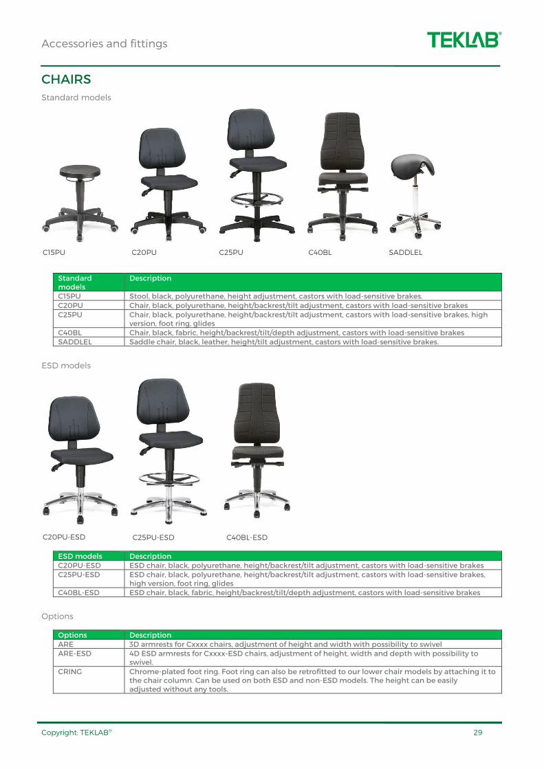
CHAIRS
Standard models
Standard models
Description
C15PU Stool, black, polyurethane, height adjustment, castors with load-sensitive brakes. C20PU Chair, black, polyurethane, height/backrest/tilt adjustment, castors with load-sensitive brakes C25PU Chair, black, polyurethane, height/backrest/tilt adjustment, castors with load-sensitive brakes, high
version, foot ring, glides C40BL Chair, black, fabric, height/backrest/tilt/depth adjustment, castors with load-sensitive brakes SADDLEL Saddle chair, black, leather, height/tilt adjustment, castors with load-sensitive brakes.
ESD models
ESD models Description C20PU-ESD ESD chair, black, polyurethane, height/backrest/tilt adjustment, castors with load-sensitive brakes C25PU-ESD ESD chair, black, polyurethane, height/backrest/tilt adjustment, castors with load-sensitive brakes,
high version, foot ring, glides C40BL-ESD ESD chair, black, fabric, height/backrest/tilt/depth adjustment, castors with load-sensitive brakes
Options
Options Description ARE 3D armrests for Cxxxx chairs, adjustment of height and width with possibility to swivel ARE-ESD 4D ESD armrests for Cxxxx-ESD chairs, adjustment of height, width and depth with possibility to
swivel. CRING Chrome-plated foot ring. Foot ring can also be retrofitted to our lower chair models by attaching it to
the chair column. Can be used on both ESD and non-ESD models. The height can be easily adjusted without any tools.
C15PU C20PU C25PU C40BL SADDLEL
C20PU-ESD C25PU-ESD C40BL-ESD
Accessories and fittings
Copyright: TEKLAB® 30
WORKSTOP TROLLEY
All wheels, diameter 100 mm, with swivel, two with brakes Includes a lower surface Height adjustable between 650 - 900 mm Loading capacity: 150 kg
Model Dimensions, W x D x H, mm WESSAP507 700 x 500 x 650-900 WESSAP507ESD 700 x 500 x 650-900, ESD
ERGO TROLLEY
All wheels, diameter 100 mm, with swivel, two with brakes ESD-protected Height adjustable between 650 - 900 mm Loading capacity: 150 kg
Model Dimensions, W x D x H, mm WES860422 750 x 500 x 650-900
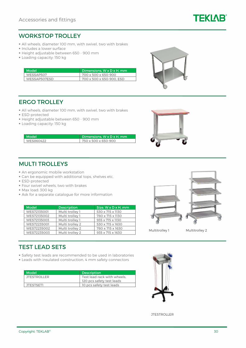
MULTI TROLLEYS
An ergonomic mobile workstation Can be equipped with additional tops, shelves etc. ESD-protected Four swivel wheels, two with brakes Max load: 300 kg Ask for a separate catalogue for more information
Model Description Size, W x D x H, mm WES72135001 Multi trolley 1 530 x 715 x 1130 WES72135002 Multi trolley 1 780 x 715 x 1130 WES72135003 Multi trolley 1 935 x 715 x 1130 WES72235001 Multi trolley 2 530 x 715 x 1630 WES72235002 Multi trolley 2 780 x 715 x 1630 WES72235003 Multi trolley 2 935 x 715 x 1630
TEST LEAD SETS
Safety test leads are recommended to be used in laboratories Leads with insulated construction, 4 mm safety connectors
Model Description JTESTROLLER Test lead rack with wheels,
120 pcs safety test leads JTESTSET1 10 pcs safety test leads
Multitrolley 1 Multitrolley 2
JTESTROLLER

Supply units
Copyright: TEKLAB® 31
SU1
1 phase supply unit
Main switch for the workstation with START-position Green indicator light Integrated emergency switch, reset from the main switch Automatic restart prevention system e.g. after power failure 16 A thermal overload protector Fault current protection 0.03 A for all devices connected to the supply unit Earth terminal screw Outlets for the device modules Dimensions: ½-module, 125(W) x 200(H) mm
SU3
3 phase supply unit
Main switch for the workstation with START-position Green indicators Integrated emergency switch, reset from the operating switch Automatic restart prevention system e.g. after power failure Protection circuit for missing phase / wrong phase order 16A thermal overload protector for each phase Fault current protection 0.03 A for all devices connected to the supply unit Earth terminal screw Connector for 3-phase (3L+N+PE) device module Outlets for the device modules Dimensions: ½-module, 125(W) x 200(H) mm
SU332
3 phase supply unit
Main switch for the workstation Green indicator light Emergency switch Automatic restart prevention system eg. after power failure Protection circuit for missing phase/wrong phase order 32 A and 16 A circuit breakers Fault current protection 0.03 A for all devices 3-phase 32 A socket at the front panel Earth terminal screw Outlets for the device modules in the workstation Dimensions: 1 ½-module, 375(W) x 200(H) mm
Supply units
Copyright: TEKLAB® 32
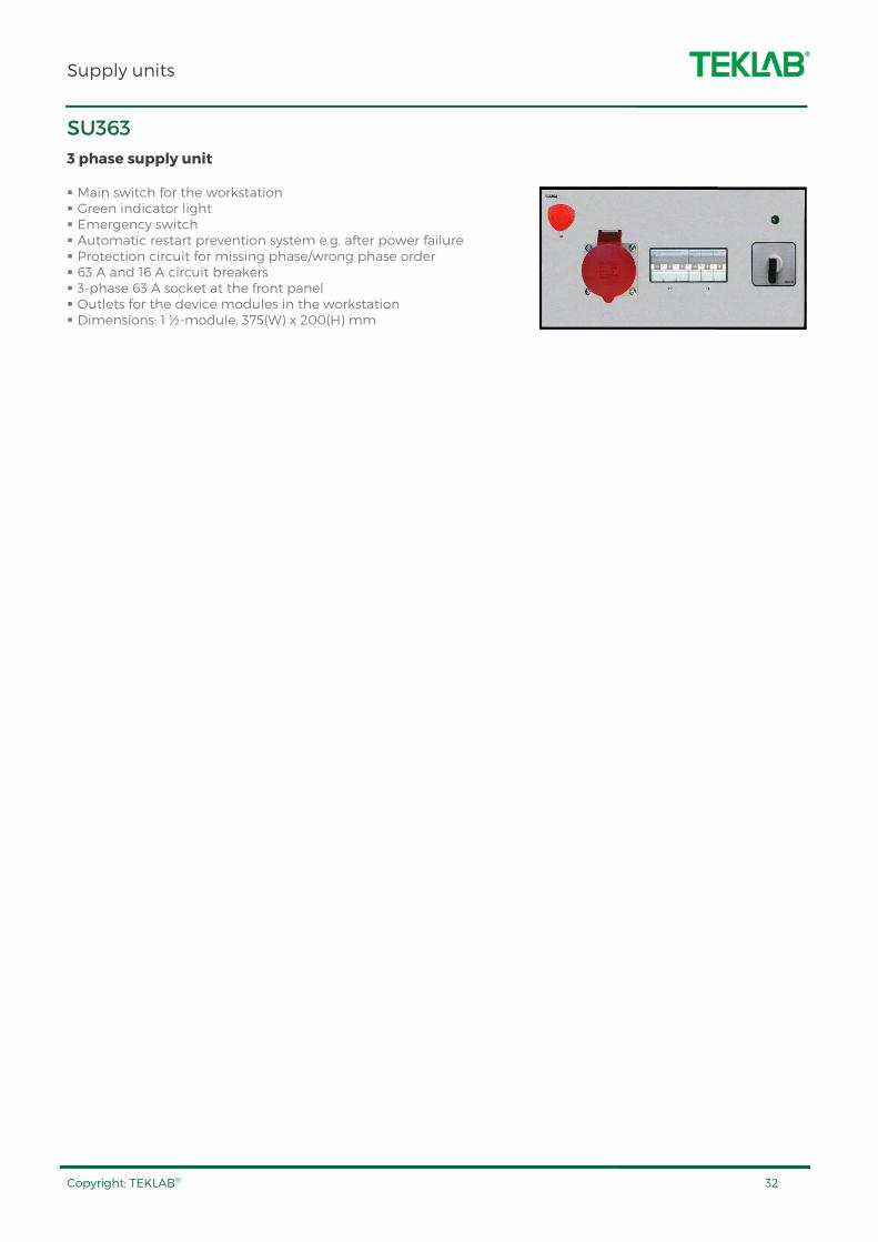
SU363
3 phase supply unit
Main switch for the workstation Green indicator light Emergency switch Automatic restart prevention system e.g. after power failure Protection circuit for missing phase/wrong phase order 63 A and 16 A circuit breakers 3-phase 63 A socket at the front panel Outlets for the device modules in the workstation Dimensions: 1 ½-module, 375(W) x 200(H) mm
Variable DC power supplies
Copyright: TEKLAB® 33
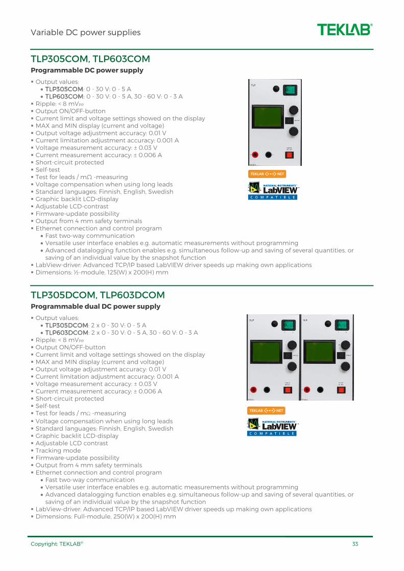
TLP305COM, TLP603COM Programmable DC power supply
Output values: • TLP305TLP305TLP305TLP305COMCOMCOMCOM: 0 - 30 V: 0 - 5 A • TLP603TLP603TLP603TLP603COMCOMCOMCOM: 0 - 30 V: 0 - 5 A, 30 - 60 V: 0 - 3 A
Ripple: < 8 mVPP Output ON/OFF-button Current limit and voltage settings showed on the display MAX and MIN display (current and voltage) Output voltage adjustment accuracy: 0.01 V Current limitation adjustment accuracy: 0.001 A Voltage measurement accuracy: ± 0.03 V Current measurement accuracy: ± 0.006 A Short-circuit protected Self-test Test for leads / mΩ -measuring Voltage compensation when using long leads Standard languages: Finnish, English, Swedish Graphic backlit LCD-display Adjustable LCD-contrast Firmware-update possibility Output from 4 mm safety terminals Ethernet connection and control program
• Fast two-way communication • Versatile user interface enables e.g. automatic measurements without programming • Advanced datalogging function enables e.g. simultaneous follow-up and saving of several quantities, or saving of an individual value by the snapshot function
LabView-driver: Advanced TCP/IP based LabVIEW driver speeds up making own applications Dimensions: ½-module, 125(W) x 200(H) mm
TLP305DCOM, TLP603DCOM Programmable dual DC power supply
Output values: • TLP305DTLP305DTLP305DTLP305DCOMCOMCOMCOM: 2 x 0 - 30 V: 0 - 5 A • TLP603DTLP603DTLP603DTLP603DCOMCOMCOMCOM: 2 x 0 - 30 V: 0 - 5 A, 30 - 60 V: 0 - 3 A
Ripple: < 8 mVPP Output ON/OFF-button Current limit and voltage settings showed on the display MAX and MIN display (current and voltage) Output voltage adjustment accuracy: 0.01 V Current limitation adjustment accuracy: 0.001 A Voltage measurement accuracy: ± 0.03 V Current measurement accuracy: ± 0.006 A Short-circuit protected Self-test Test for leads / mΩ -measuring
Voltage compensation when using long leads Standard languages: Finnish, English, Swedish Graphic backlit LCD-display Adjustable LCD contrast Tracking mode Firmware-update possibility Output from 4 mm safety terminals Ethernet connection and control program
• Fast two-way communication • Versatile user interface enables e.g. automatic measurements without programming • Advanced datalogging function enables e.g. simultaneous follow-up and saving of several quantities, or saving of an individual value by the snapshot function
LabView-driver: Advanced TCP/IP based LabVIEW driver speeds up making own applications Dimensions: Full-module, 250(W) x 200(H) mm
Variable DC power supplies
Copyright: TEKLAB® 34
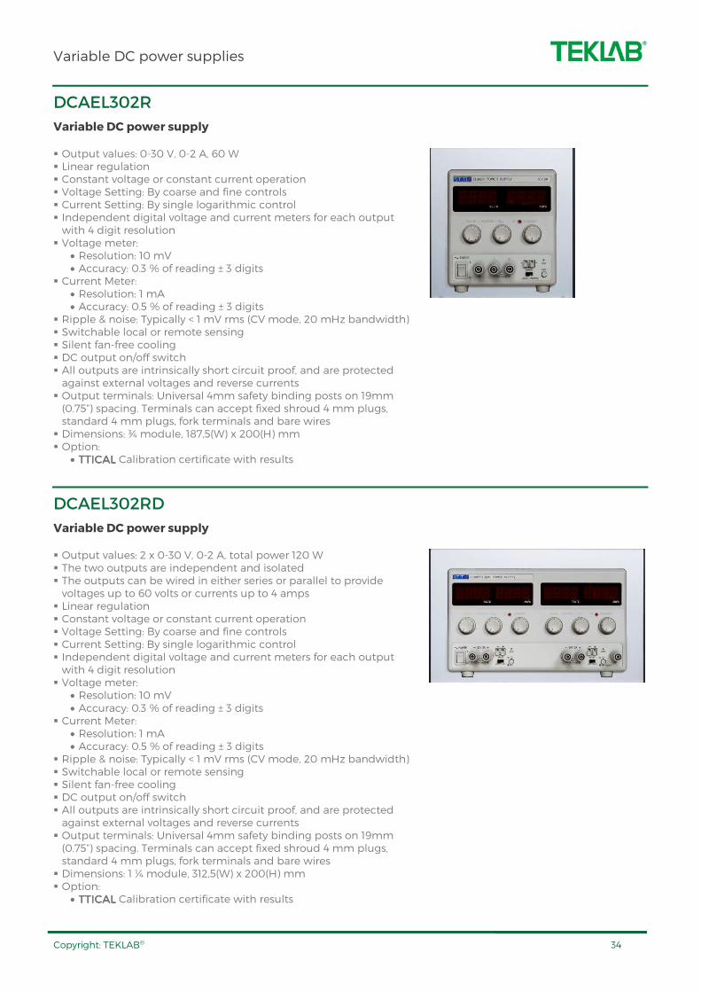
DCAEL302R
Variable DC power supply
Output values: 0-30 V, 0-2 A, 60 W Linear regulation Constant voltage or constant current operation Voltage Setting: By coarse and fine controls Current Setting: By single logarithmic control Independent digital voltage and current meters for each output with 4 digit resolution Voltage meter:
• Resolution: 10 mV • Accuracy: 0.3 % of reading ± 3 digits
Current Meter: • Resolution: 1 mA • Accuracy: 0.5 % of reading ± 3 digits
Ripple & noise: Typically < 1 mV rms (CV mode, 20 mHz bandwidth) Switchable local or remote sensing Silent fan-free cooling DC output on/off switch All outputs are intrinsically short circuit proof, and are protected against external voltages and reverse currents Output terminals: Universal 4mm safety binding posts on 19mm (0.75”) spacing. Terminals can accept fixed shroud 4 mm plugs, standard 4 mm plugs, fork terminals and bare wires Dimensions: ¾ module, 187,5(W) x 200(H) mm Option:
• TTICALTTICALTTICALTTICAL Calibration certificate with results
DCAEL302RD
Variable DC power supply
Output values: 2 x 0-30 V, 0-2 A, total power 120 W The two outputs are independent and isolated The outputs can be wired in either series or parallel to provide voltages up to 60 volts or currents up to 4 amps Linear regulation Constant voltage or constant current operation Voltage Setting: By coarse and fine controls Current Setting: By single logarithmic control Independent digital voltage and current meters for each output with 4 digit resolution Voltage meter:
• Resolution: 10 mV • Accuracy: 0.3 % of reading ± 3 digits
Current Meter: • Resolution: 1 mA • Accuracy: 0.5 % of reading ± 3 digits
Ripple & noise: Typically < 1 mV rms (CV mode, 20 mHz bandwidth) Switchable local or remote sensing Silent fan-free cooling DC output on/off switch All outputs are intrinsically short circuit proof, and are protected against external voltages and reverse currents Output terminals: Universal 4mm safety binding posts on 19mm (0.75”) spacing. Terminals can accept fixed shroud 4 mm plugs, standard 4 mm plugs, fork terminals and bare wires Dimensions: 1 ¼ module, 312,5(W) x 200(H) mm Option:
• TTICALTTICALTTICALTTICAL Calibration certificate with results

Variable DC power supplies
Copyright: TEKLAB® 35
DCAEX355R
Variable DC power supply
Output values: 0-35 V, 0-5 A, 175 W Mixed-mode regulation Constant voltage or constant current operation Voltage Setting: By coarse and fine controls Current Setting: By single logarithmic control Independent digital voltage and current meters for each output with 4 digit resolution Voltage meter:
• Resolution: 10 mV • Accuracy: 0.3 % of reading ± 3 digits
Current Meter: • Resolution: 1 mA • Accuracy: 0.5 % of reading ± 3 digits
Ripple & noise: Typically < 1 mV rms (CV mode, 20 mHz bandwidth) Switchable local or remote sensing Silent fan-free cooling DC output on/off switch All outputs are intrinsically short circuit proof, and are protected against external voltages and reverse currents Output terminals: Universal 4mm safety binding posts on 19mm (0.75”) spacing. Terminals can accept fixed shroud 4 mm plugs, standard 4 mm plugs, fork terminals and bare wires Dimensions: ¾-module, 187,5(W) x 200(H) mm Option: TTICALTTICALTTICALTTICAL Calibration certificate with results
DCACPX400S
Variable DC power supply
Output values: 0-60 V, 0-20 A, 420 W PowerFlex design gives variable voltage and current combinations within a maximum power range PowerFlex or fixed-range operation plus custom limits Constant voltage or constant current operation Variable OVP trips True analogue controls Voltage Setting: By coarse and fine controls Current Setting: By single logarithmic control Settings locking Independent digital voltage and current meters for each output with 4 digit resolution Voltage meter:
• Resolution: 10 mV • Accuracy: 0.1 % of reading ± 2 digits
Current Meter: • Resolution: 10 mA • Accuracy: 0.3 % of reading ± 20 mA
Ripple & noise: Typically < 3 mV rms (CV mode) Switchable local or remote sensing View Settings LED indication of Output On, V/I Limits, CV, CI, Power Limit Silent fan-free cooling DC output on/off switch All outputs are intrinsically short circuit proof Output terminals can accept fixed shroud 4 mm plugs, standard 4 mm plugs, fork terminals and bare wires Dimensions: ½ module, 125(W) x 200(H) mm Option: TTICALTTICALTTICALTTICAL Calibration certificate with results

Variable DC power supplies
Copyright: TEKLAB® 36
DCACPX400D
Variable DC power supply
Output values: 2 x 0-60 V, 0-20 A, 840 W PowerFlex design gives variable voltage and current combinations within a maximum power range PowerFlex or fixed-range operation plus custom limits Constant voltage or constant current operation Independent outputs or isolated voltage tracking Outputs can be wired in series or parallel for 120 V or 40 A Variable OVP trips True analogue controls Voltage Setting: By coarse and fine controls Current Setting: By single logarithmic control Settings locking Independent digital voltage and current meters for each output with 4 digit resolution Voltage meter:
• Resolution: 10 mV • Accuracy: 0.1 % of reading ± 2 digits
Current Meter: • Resolution: 10 mA • Accuracy: 0.3 % of reading ± 20 mA
Ripple & noise: Typically < 3 mV rms (CV mode) Switchable local or remote sensing View Settings LED indication of Output On, V/I Limits, CV, CI, Power Limit Silent fan-free cooling DC output on/off switch All outputs are intrinsically short circuit proof Output can accept fixed shroud 4 mm plugs, standard 4 mm plugs, fork terminals and bare wires Dimensions: 1 module, 250(W) x 200(H) mm Option: TTICALTTICALTTICALTTICAL Calibration certificate with results

Fixed DC power supplies
Copyright: TEKLAB® 37
TLMB12
Fixed DC power supply
Linear power supply 4 outputs, floating with respect to each other Outputs can be connected in series or in parallel Output values:
• Output 1: 1.5 V / 3 V / 4.5 V / 5 V / 6 V / 9 V, 1 A • Output 2: 5 V / 3.3 V, 3 A • Output 3: 12 V / 15 V, 1 A • Output 4: 12 V / 15 V, 1 A
Current limitation indicated by a LED Ripple: < 10 mVPP All outputs are short-circuit protected Voltage accuracy better than 100 mV Output from 4 mm safety terminals Dimensions: ½-module, 125(W) x 200(H) mm
DCF series
Fixed DC power supply
Output values: • DCF1212: 12 V, 12 A DC • DCF242: 2 x 24 V, 2 A DC • DCF242R: 24 V, 2 A DC, 250 ohm series resistor
Ripple: • DCF1212: < 120 mVPP • DCF242: < 50 mVPP • DCF242R: < 50 mVPP
Output floating, can be connected in series or in parallel Overcurrent limiter, indicated by a LED Outputs from 4 mm safety terminals Dimensions: ¼-module, 62.5(W) x 200(H) mm
1 phase AC power supplies
Copyright: TEKLAB® 38
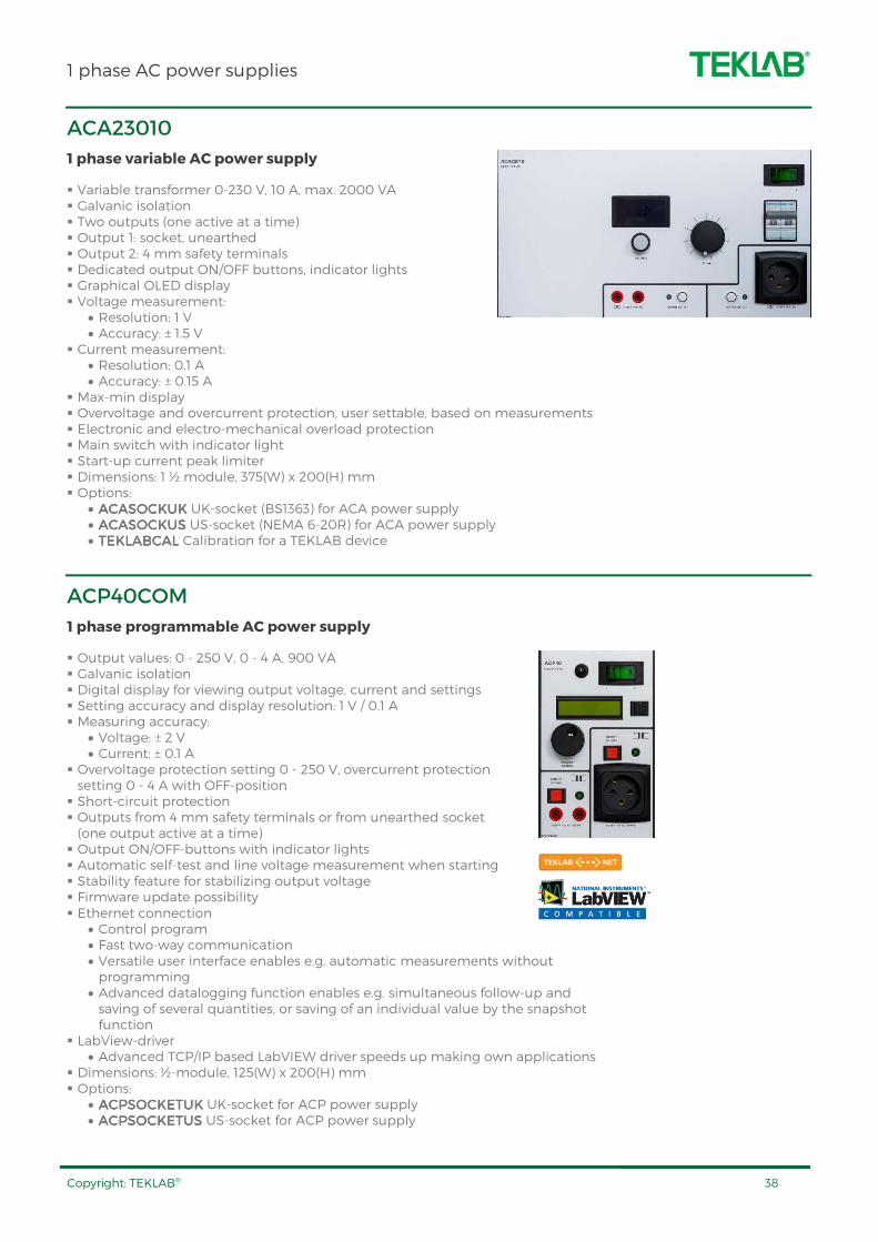
ACA23010
1 phase variable AC power supply
Variable transformer 0-230 V, 10 A, max. 2000 VA Galvanic isolation Two outputs (one active at a time) Output 1: socket, unearthed Output 2: 4 mm safety terminals Dedicated output ON/OFF buttons, indicator lights Graphical OLED display Voltage measurement:
• Resolution: 1 V • Accuracy: ± 1.5 V
Current measurement: • Resolution: 0.1 A • Accuracy: ± 0.15 A
Max-min display Overvoltage and overcurrent protection, user settable, based on measurements Electronic and electro-mechanical overload protection Main switch with indicator light Start-up current peak limiter Dimensions: 1 ½ module, 375(W) x 200(H) mm Options:
• ACASOCKUKACASOCKUKACASOCKUKACASOCKUK UK-socket (BS1363) for ACA power supply • ACASOCKUSACASOCKUSACASOCKUSACASOCKUS US-socket (NEMA 6-20R) for ACA power supply • TEKLABCAL TEKLABCAL TEKLABCAL TEKLABCAL Calibration for a TEKLAB device
ACP40COM
1 phase programmable AC power supply
Output values: 0 - 250 V, 0 - 4 A, 900 VA Galvanic isolation Digital display for viewing output voltage, current and settings Setting accuracy and display resolution: 1 V / 0.1 A Measuring accuracy:
• Voltage: ± 2 V • Current: ± 0.1 A
Overvoltage protection setting 0 - 250 V, overcurrent protection setting 0 - 4 A with OFF-position Short-circuit protection Outputs from 4 mm safety terminals or from unearthed socket (one output active at a time) Output ON/OFF-buttons with indicator lights Automatic self-test and line voltage measurement when starting Stability feature for stabilizing output voltage Firmware update possibility Ethernet connection
• Control program • Fast two-way communication • Versatile user interface enables e.g. automatic measurements without programming
• Advanced datalogging function enables e.g. simultaneous follow-up and saving of several quantities, or saving of an individual value by the snapshot function
LabView-driver • Advanced TCP/IP based LabVIEW driver speeds up making own applications
Dimensions: ½-module, 125(W) x 200(H) mm Options:
• ACPSOCKETUKACPSOCKETUKACPSOCKETUKACPSOCKETUK UK-socket for ACP power supply • ACPSOCKETUSACPSOCKETUSACPSOCKETUSACPSOCKETUS US-socket for ACP power supply

1 phase AC power supplies
Copyright: TEKLAB® 39
ACP100COM
1 phase programmable AC power supply
Output values: 0 - 250 V, 0 - 10 A, 2000 VA Galvanic isolation Digital display for viewing output voltage, current and settings Setting accuracy and display resolution: 1 V / 0.1 A Measuring accuracy:
• Voltage: ± 2 V • Current: ± 0.1 A
Overvoltage protection setting 0 - 250 V, overcurrent protection setting 0 - 10 A with OFF –position Short-circuit protected Outputs from 4 mm safety terminals or from unearthed socket (one output active at a time) Output ON/OFF-buttons with indicator lights Automatic self-test and line voltage measurement when starting Stability feature for stabilizing output voltage Firmware update possibility Dimensions: Full-module, 250(W) x 200(H) mm Ethernet connection
• Control program • Fast two-way communication • Versatile user interface enables e.g. automatic measurements without programming
• Advanced datalogging function enables e.g. simultaneous follow-up and saving of several quantities, or saving of an individual value by the snapshot function
LabView-driver • Advanced TCP/IP based LabVIEW driver speeds up making own applications
Options: • ACPSOCKETUKACPSOCKETUKACPSOCKETUKACPSOCKETUK UK-socket for ACP power supply • ACPSOCKETUSACPSOCKETUSACPSOCKETUSACPSOCKETUS US-socket for ACP power supply

3 phase AC power supplies
Copyright: TEKLAB® 40
ACA40016
3 phase AC power supply
A push-button to control variable transformer Galvanic isolation Output values:
• Output 1: 0-400 V, 16 A (unearthed socket) • Output 2: 0-400 V, 16 A (4 mm safety terminals)
Output selection switch, one output active at a time Analog voltage measurement (L1-N) Thermal / magnetic circuit breaker Transformers are placed in separate floor-standing housing Dimensions: Full-module, 250(W) x 200(H) mm Options:
• ACMACMACMACM3VVA3VVA3VVA3VVA analogue voltage meters 0 - 400 V • ACMACMACMACM3V160AA3V160AA3V160AA3V160AA analogue current meters 0 - 16 A
MT63
3 phase power supply for motor testing
Test unit for electric motors based on AC-drive technology For electric motors with operating voltage range of 380-480 V AC Output current max. 63 A Control / measurement unit Measurements with 3 parameters on display at a time: voltage, current, speed, power, run time, output frequency, Kwh counter, reserve Output ON/OFF buttons 4 programmable buttons for test ramps Software for loading motor parameters Output connectors for motor test cables 16 A and 63 A Requires SU363 supply unit Dimensions: Full-module, 250(W) x 200(H) mm Standard accessories
• Motor test cable 16 A, 5 m • Motor test cable 63 A, 5 m • Alarm light unit

3 phase AC power supplies
Copyright: TEKLAB® 41
RB3
Rectifier
3-phase diode rectifier bridge, no filtration Can be used also as 1-phase rectifier Maximum input voltage 700 V AC Maximum output current: 20 A Dimensions: ¼-module, 62.5(W) x 200(H) mm
ACM3VVA, ACM3V160AA
Measuring accessory
Measuring accessory for,ACA40016 3 phase AC power supply 3 pcs analog voltmeters, 0-400 V, L1-L2, L2-L3 and L3-L1 (ACM3VVA) 3 pcs analog ammeters 0-16 A, L1, L2 and L3 (ACM3V160AA) Accuracy. ± 1.5 % Dimensions: ¼-module, 62.5(W) x 200(H) mm
1 phase AC connections
Copyright: TEKLAB® 42
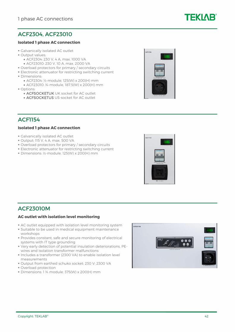
ACF2304, ACF23010
Isolated 1 phase AC connection
Galvanically isolated AC outlet Output values:
• ACF2304: 230 V, 4 A, max. 1000 VA • ACF23010: 230 V, 10 A, max. 2000 VA
Overload protectors for primary / secondary circuits Electronic attenuator for restricting switching current Dimensions:
• ACF2304: ½-module, 125(W) x 200(H) mm • ACF23010: ¾-module, 187.5(W) x 200(H) mm
Options: • ACFACFACFACFSOCKETUKSOCKETUKSOCKETUKSOCKETUK UK socket for AC outlet • ACFACFACFACFSOCKETUSSOCKETUSSOCKETUSSOCKETUS US-socket for AC outlet
ACF1154
Isolated 1 phase AC connection
Galvanically isolated AC outlet Output: 115 V, 4 A, max. 500 VA Overload protectors for primary / secondary circuits Electronic attenuator for restricting switching current Dimensions: ½-module, 125(W) x 200(H) mm
ACF23010M
AC outlet with isolation level monitoring
AC outlet equipped with isolation level monitoring system Suitable to be used in medical equipment maintenance workshops Provides constant, safe and secure monitoring of electrical systems with IT type grounding Very early detection of potential insulation deteriorations, PE-wires and isolation transformer malfunctions Includes a transformer (2300 VA) to enable isolation level measurements Output from earthed schuko socket: 230 V: 2300 VA Overload protection Dimensions: 1 ¾ module, 375(W) x 200(H) mm
3 phase AC connections
Copyright: TEKLAB® 43
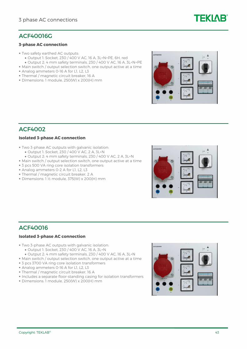
ACF40016G
3-phase AC connection
Two safety earthed AC outputs: • Output 1: Socket, 230 / 400 V AC, 16 A, 3L+N+PE, 6H, red • Output 2: 4 mm safety terminals, 230 / 400 V AC, 16 A, 3L+N+PE
Main switch / output selection switch, one output active at a time Analog ammeters 0-16 A for L1, L2, L3 Thermal / magnetic circuit breaker, 16 A Dimensions: 1 module, 250(W) x 200(H) mm
ACF4002
Isolated 3-phase AC connection
Two 3-phase AC outputs with galvanic isolation: • Output 1: Socket, 230 / 400 V AC, 2 A, 3L+N • Output 2: 4 mm safety terminals, 230 / 400 V AC, 2 A, 3L+N
Main switch / output selection switch, one output active at a time 3 pcs 500 VA ring core isolation transformers Analog ammeters 0-2 A for L1, L2, L3 Thermal / magnetic circuit breaker, 2 A Dimensions: 1 ½ module, 375(W) x 200(H) mm
ACF40016
Isolated 3-phase AC connection
Two 3-phase AC outputs with galvanic isolation: • Output 1: Socket, 230 / 400 V AC, 16 A, 3L+N • Output 2: 4 mm safety terminals, 230 / 400 V AC, 16 A, 3L+N
Main switch / output selection switch, one output active at a time 3 pcs 3700 VA ring core isolation transformers Analog ammeters 0-16 A for L1, L2, L3 Thermal / magnetic circuit breaker, 16 A Includes a separate floor-standing casing for isolation transformers Dimensions: 1 module, 250(W) x 200(H) mm

Connections
Copyright: TEKLAB® 44
ELPSLxx
1 phase socket outlets
Standard models: • ELPSL3ELPSL3ELPSL3ELPSL3 3 x schuko sockets • EPLSL2USB EPLSL2USB EPLSL2USB EPLSL2USB 2 x sssschuko sockets + 2 x USB charger • ELPSL3GBELPSL3GBELPSL3GBELPSL3GB 3 x UK-sockets • ELPSL3GBELPSL3GBELPSL3GBELPSL3GB 2 x UK-sockets + 2 x USB charger • ELPSL3USELPSL3USELPSL3USELPSL3US 3 x US-sockets • EPLSL2US EPLSL2US EPLSL2US EPLSL2US 2 x US-sockets + 2 x USB charger
Other socket models also available Dimensions: ¼-module, 62.5(W) x 200(H) mm
ELPSL3V
3 phase socket outlet
3 phase extra socket 5-pole 16 A CEE socket Dimensions: ½-module, 125(W) x 200(H) mm
STO40016
Safety terminal outlets
AC outlets from 4 mm safety terminals 3L+N+PE, 400 V, 16 A Dimensions: ¼-module, 62.5(W) x 200(H) mm
Connections
Copyright: TEKLAB® 45
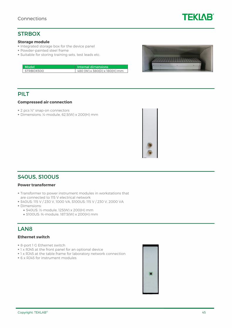
STRBOX
Storage module Integrated storage box for the device panel Powder-painted steel frame Suitable for storing training sets, test leads etc.
Model Internal dimensions STRBOX500 480 (W) x 380(D) x 180(H) mm
PILT
Compressed air connection
2 pcs ½" snap-on connectors Dimensions: ¼-module, 62.5(W) x 200(H) mm
S40US, S100US
Power transformer
Transformer to power instrument modules in workstations that are connected to 115 V electrical network S40US: 115 V / 230 V, 1000 VA, S100US: 115 V / 230 V, 2000 VA Dimensions:
• S40US: ½-module, 125(W) x 200(H) mm • S100US: ¾-module, 187.5(W) x 200(H) mm
LAN8
Ethernet switch
8-port 1 G Ethernet switch 1 x RJ45 at the front panel for an optional device 1 x RJ45 at the table frame for laboratory network connection 6 x RJ45 for instrument modules
Connections
Copyright: TEKLAB® 46
LANWBRIDGE
Wireless LAN bridge
A wireless link between a workstation and laboratory Wireless Access Point Available also for a single device control Antenna mounted in the workstation 802.11 a/b/g/n/ac standard
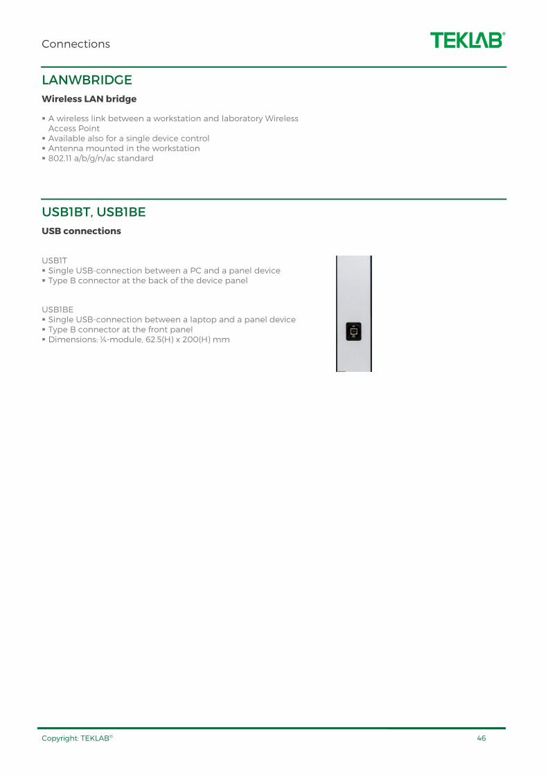
USB1BT, USB1BE
USB connections
USB1T Single USB-connection between a PC and a panel device Type B connector at the back of the device panel
USB1BE Single USB-connection between a laptop and a panel device Type B connector at the front panel Dimensions: ¼-module, 62.5(H) x 200(H) mm
Multimeters
Copyright: TEKLAB® 47
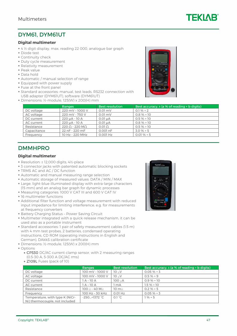
DYM61, DYM61UT
Digital multimeter
4 ½ digit display, max. reading 22 000, analogue bar graph Diode test Continuity check Duty cycle measurement Relativity measurement Peak value Data hold Automatic / manual selection of range Equipped with power supply Fuse at the front panel Standard accessories: manual, test leads, RS232 connection with USB adapter (DYM61UT), software (DYM61UT) Dimensions: ½-module, 125(W) x 200(H) mm
Ranges Best resolution Best accuracy, ± (a % of reading + b digits) DC voltage 220 mV – 1000 V 0.01 mV 0.1 % + 2 AC voltage 220 mV - 750 V 0.01 mV 0.8 % + 10 DC current 220 µA - 10 A 0.01 µA 0.5 % + 10 AC current 220 µA - 10 A 0.01 µA 0.8 % + 10 Resistance 220 Ω - 220 MΩ 0.01 Ω 0.5 % + 10 Capacitance 22 nF - 220 mF 0.001 nF 3.0 % + 5 Frequency 10 Hz - 220 MHz 0.001 Hz 0.01 % + 5
DMMHPRO
Digital multimeter
Resolution: ± 12,000 digits, 4½-place 3 connector jacks with patented automatic blocking sockets TRMS AC and AC / DC function Automatic and manual measuring range selection Automatic storage of measured values: DATA / MIN / MAX Large, light-blue illuminated display with extra-large characters (15 mm) and an analog bar graph for dynamic processes Measuring categories: 1000 V CAT III and 600 V CAT IV 16 multimeter functions Additional filter function and voltage measurement with reduced input impedance for limiting interference, e.g. for measurements at frequency converters Battery Charging Status – Power Saving Circuit Multimeter integrated with a quick-release mechanism, it can be used also as a portable instrument Standard accessories: 1 pair of safety measurement cables (1.5 m) with 4 mm test probes, 2 batteries, condensed operating instructions, CD ROM (operating instructions in English and German), DAkkS calibration certificate Dimensions: ½-module, 125(W) x 200(H) mm Options
• CP330 CP330 CP330 CP330 DC/AC current clamp sensor, with 2 measuring ranges (0.5-30 A, 5-300 A DC/AC rms)
• Z109L Z109L Z109L Z109L Fuses (pack of 10)
Ranges Best resolution Best accuracy, ± (a % of reading + b digits) DC voltage 100 mV – 1000 V 10 μV 0.05 % + 3
AC voltage 100 mV – 1000 V 10 μV 0.5 % + 9
DC current 1 A – 10 A 100 μA 0.9 % + 10
AC current 1 A – 10 A 1 mA 1.5 % + 10 Resistance 100 Ω – 40 MΩ 10 mΩ 0.2 % + 5
Frequency 100 Hz – 30 kHz 0.01 Hz 0.05 % + 3 Temperature, with type K (NiCr-Ni) thermocouple, not included
-250…+1372 °C 0.1 °C 1 % + 5

Multimeters
Copyright: TEKLAB® 48
DMMHULT
Digital multimeter
Triple display with a resolution of ±310,000 digits Intrinsic error: ± (0.02% rdg. + 20 digits) Measuring functions:
• 1 µV to 600 VDC and 10 µV to 600 VAC/AC+DC TRMS (bandwidth: 15 Hz to 100 kHz),
• 1 nA to 10 ADC and 10 nA to 10 AAC/AC+DC TRMS (bandwidth: 15 Hz to 10 kHz)
• Resistance, frequency, capacitance and temperature measurement: 1 mΩ to 30 MΩ, 0.001 Hz to 1 MHz, 1 pF to 3
mF, °C/°F • dB measuring function • Fast Acoustic Continuity Test
Automatic range selection and battery cutoff Min-Max measured value storage Integrated 2 MByte measurement data memory for approx. 300,000 measured values, sampling rate: 10 ms to 9 hrs. CAT IV @ 300 V or CAT III @ 600 V per IEC 61010-1 1 kHz / -3 dB low-pass filter can be activated in the alternating voltage measuring ranges Instrument can be remote controlled and measurement data saved via Bluetooth and IR interfaces (optional adapter and METRAwin10 software needed) 3 connector jacks with patented automatic blocking sockets Adjustable clamp factor for measurement with current clamp sensors and transformers Automatic and manual measuring range selection Separate battery and fuse compartments Battery Charging Status – Power Saving Circuit Multimeter integrated with a quick-release mechanism, it can be used also as a portable instrument Standard accessories: KS17-2 cable set, 2 batteries, condensed operating instructions, CD ROM (operating instructions in English and German), DAkkS calibration certificate Dimensions: ½-module, 125(W) x 200(H) mm Options
• USBUSBUSBUSB----PACKPACKPACKPACK Software for data logging, recording, visualizing and documenting. Includes IR-USB bidirectional interface adapter
• Z3409Z3409Z3409Z3409 Pt100 temperature sensor for surface and immersion measurement, -40 to +600 °C
• CP330 CP330 CP330 CP330 DC/AC current clamp sensor, with 2 measuring ranges (0.5-30 A, 5-300 A DC/AC rms)
• Z109L Z109L Z109L Z109L Fuses (pack of 10)
Ranges Best resolution Best accuracy, ± (a % of reading + b digits) DC voltage 300 mV – 600 V 1 μV 0.02 % + 0.005 % +5 (% rdg + % MR + d)
AC voltage 300 mV – 600 V 10 μV 0.2 % + 30
DC current 300 µA – 10 A 1 nA 0.02 % + 0.01 % +5 (% rdg + % MR + d) AC current 300 µA – 10 A 10 nA 0.5 % + 30 Resistance 300 Ω – 30 MΩ 1 mΩ 0.05 % + 0.01 % +5 (% rdg + % MR + d)
Frequency 300 Hz – 1 MHz 0.001 Hz 0.05 % + 8 Capacitance 3 nF – 3 mF 1 pF 1 % + 6 Temperature (MHZ3409 probe)
-40…+600 °C 0.1 °C 0.3 % + 10

Multimeters
Copyright: TEKLAB® 49
TEK4050C
Digital multimeter
6.5 Digit Resolution, dual display, graphics Basic VDC Accuracy of up to 0.0024% (1 yr.) 100 mV to 1000 V Voltage Range, with up to 100 nV Resolution 100 μA to 10 A Current Range, with up to 100 pA Resolution 10 Ω to 1 GΩ Range, with up to 10 μΩ Resolution CAT I 1000 V, CAT II 600 V Volts, Ohms, and Amps Measurements True RMS (AC, AC + DC) Measurements Diode and Continuity Testing Frequency and Period Measurements Temperature and Capacitance Measurements Math Functions: Zero, dBm, dB, MX+B, Offset, DCV ratio and TrendPlot, Histogram, Statistics (min/max/average/standard deviation), and Limit Test 2×4 Ohms 4-wire Measurement Technique TrendPlot™ Paperless Data Recorder Mode Measurement Statistics Histogram Mode USB Host Port on Front Panel for Easy Storage of Measurement Data and Instrument Settings RS-232, LAN, and GPIB Ports on Rear Panel for Quick PC Connectivity (requires optional connection cable) Standard accessories: TL710 Test Leads, Calibration Certificate, Calibration Data Report, Safety and Installation Instructions including Warranty Statement, CD-ROM with User Manual and Connectivity Information, RS-232 to USB Adapter Cable, National Instruments LabVIEW SignalExpress™ Tektronix Edition Limited Edition Software. Dimensions: full module, 250(W) x 200(H) mm Options
• TEKTP750TEKTP750TEKTP750TEKTP750 100 Ω RTD Temperature Probe • TEKTL705 TEKTL705 TEKTL705 TEKTL705 2×4 Wire Ohm 1000 V Precision Test Lead • USB1BT USB1BT USB1BT USB1BT USB connection for instrument panel
Ranges Best resolution Best accuracy, ± (a % of reading + b % of range) DC voltage 100 mV – 1000 V 100 nV 0.0024 % + 0.0005 % AC voltage 100 mV – 1000 V 100 nV 0.06 % + 0.03 % DC current 100 μA – 10 A 100 pA 0.05 % + 0.005 %
AC current 100 μA – 10 100 pA 0.1 % + 0.04
Resistance (2x4 wire) 10 Ω – 1 GΩ 10 μΩ 0.01 % + 0.001 %
Frequency 3 Hz – 1 MHz 0.1 μHz 0.01 % of measurement
Capacitance 1 nF – 100 mF 1 pF 1 % + 0.5 % Temperature - 200°C - + 600°C 0.001 °C ± 0.06 °C
LCR meters
Copyright: TEKLAB® 50
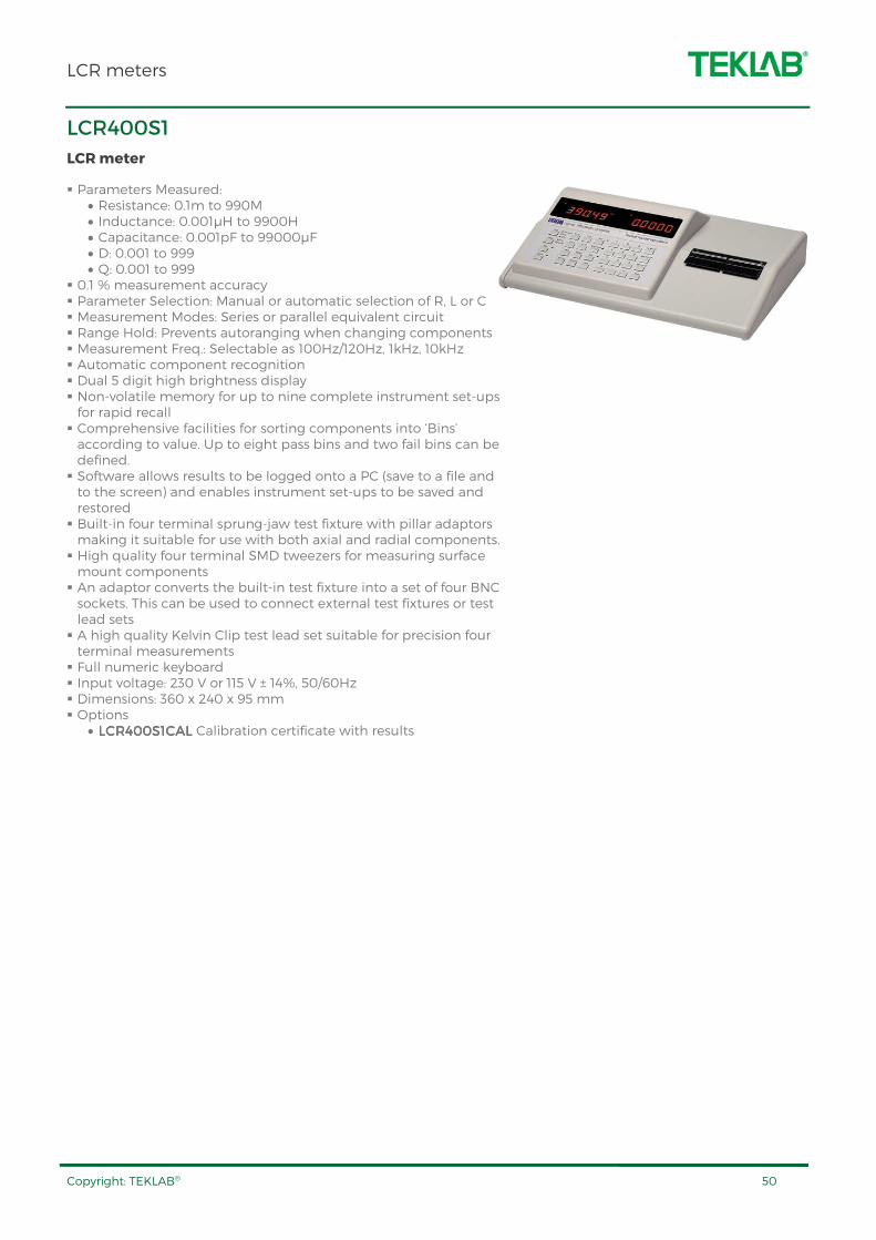
LCR400S1
LCR meter
Parameters Measured: • Resistance: 0.1m to 990M • Inductance: 0.001µH to 9900H • Capacitance: 0.001pF to 99000µF • D: 0.001 to 999 • Q: 0.001 to 999
0.1 % measurement accuracy Parameter Selection: Manual or automatic selection of R, L or C Measurement Modes: Series or parallel equivalent circuit Range Hold: Prevents autoranging when changing components Measurement Freq.: Selectable as 100Hz/120Hz, 1kHz, 10kHz Automatic component recognition Dual 5 digit high brightness display Non-volatile memory for up to nine complete instrument set-ups for rapid recall Comprehensive facilities for sorting components into ‘Bins’ according to value. Up to eight pass bins and two fail bins can be defined. Software allows results to be logged onto a PC (save to a file and to the screen) and enables instrument set-ups to be saved and restored Built-in four terminal sprung-jaw test fixture with pillar adaptors making it suitable for use with both axial and radial components. High quality four terminal SMD tweezers for measuring surface mount components An adaptor converts the built-in test fixture into a set of four BNC sockets. This can be used to connect external test fixtures or test lead sets A high quality Kelvin Clip test lead set suitable for precision four terminal measurements Full numeric keyboard Input voltage: 230 V or 115 V ± 14%, 50/60Hz Dimensions: 360 x 240 x 95 mm Options
• LCR400S1CALLCR400S1CALLCR400S1CALLCR400S1CAL Calibration certificate with results
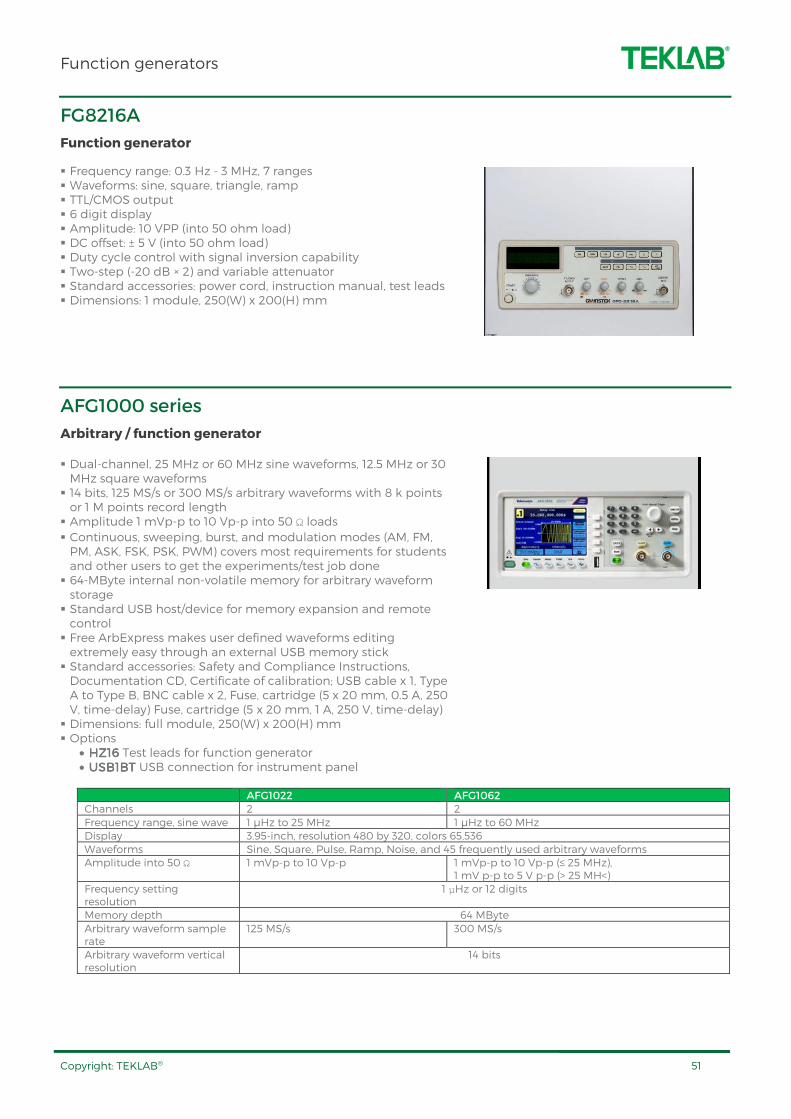
Function generators
Copyright: TEKLAB® 51
FG8216A
Function generator
Frequency range: 0.3 Hz - 3 MHz, 7 ranges Waveforms: sine, square, triangle, ramp TTL/CMOS output 6 digit display Amplitude: 10 VPP (into 50 ohm load) DC offset: ± 5 V (into 50 ohm load) Duty cycle control with signal inversion capability Two-step (-20 dB × 2) and variable attenuator Standard accessories: power cord, instruction manual, test leads Dimensions: 1 module, 250(W) x 200(H) mm
AFG1000 series
Arbitrary / function generator
Dual-channel, 25 MHz or 60 MHz sine waveforms, 12.5 MHz or 30 MHz square waveforms 14 bits, 125 MS/s or 300 MS/s arbitrary waveforms with 8 k points or 1 M points record length Amplitude 1 mVp-p to 10 Vp-p into 50 Ω loads Continuous, sweeping, burst, and modulation modes (AM, FM, PM, ASK, FSK, PSK, PWM) covers most requirements for students and other users to get the experiments/test job done 64-MByte internal non-volatile memory for arbitrary waveform storage Standard USB host/device for memory expansion and remote control Free ArbExpress makes user defined waveforms editing extremely easy through an external USB memory stick Standard accessories: Safety and Compliance Instructions, Documentation CD, Certificate of calibration; USB cable x 1, Type A to Type B, BNC cable x 2, Fuse, cartridge (5 x 20 mm, 0.5 A, 250 V, time-delay) Fuse, cartridge (5 x 20 mm, 1 A, 250 V, time-delay) Dimensions: full module, 250(W) x 200(H) mm Options
• HZ16HZ16HZ16HZ16 Test leads for function generator • USB1BT USB1BT USB1BT USB1BT USB connection for instrument panel
AFG1022 AFG1062 Channels 2 2 Frequency range, sine wave 1 µHz to 25 MHz 1 µHz to 60 MHz Display 3.95-inch, resolution 480 by 320, colors 65,536 Waveforms Sine, Square, Pulse, Ramp, Noise, and 45 frequently used arbitrary waveforms Amplitude into 50 Ω 1 mVp-p to 10 Vp-p 1 mVp-p to 10 Vp-p (≤ 25 MHz),
1 mV p-p to 5 V p-p (> 25 MH<) Frequency setting resolution
1 μHz or 12 digits
Memory depth 64 MByte Arbitrary waveform sample rate
125 MS/s 300 MS/s
Arbitrary waveform vertical resolution
14 bits

Function generators
Copyright: TEKLAB® 52
AFG3000C series
Arbitrary / function generator
Today’s designs are often complex, demanding a variety of stimulus signals during test. With 12 standard waveforms, arbitrary waveform capability, and signal impairment options, the AFG3000C Series supports a wide range of application needs with one instrument.
Best-in-class performance ensures signals are accurately reproduced.
A large display and 25 shortcut keys make the AFG3000C Series both easy to learn and easy to use.
5.6” color display for full confidence in settings and waveform shape Multi-language and intuitive operation saves set-up time AM, FM, PM, FSK, PWM Sweep and burst Pulse waveform with variable edge times 128 k memory for arbitrary waveforms Time base with only ± 1 ppm drift per year Dual channel models save cost and bench space USB connector on front panel for waveform storage on memory device USB, GPIB and Ethernet Standard accessories: manuals, ArbExpress™ software, NIST-traceable calibration certificate Dimensions: 1½-module, 375(W) x 200(H) mm Options
• HZ16HZ16HZ16HZ16 Test leads for function generator • USB1BTUSB1BTUSB1BTUSB1BT USB connection
AFG3011C AFG3021C AFG3052C AFG3101C AFG3252C Channels 1 1 2 1 2 Frequency range
1 μH - 10 MHz 1 μH - 25 MHz 1 μH - 50 MHz 1 μH - 100 MHz 1 μH - 240 MHz
Display 5.6” color LCD Waveforms Sine, Square, Pulse, Ramp, Triangle, Sin(x)/x, Exponential Rise & Decay, Gaussian, Lorentz, Haversine, DC,
Noise Amplitude into 50 Ω
20 mVPP – 20 VPP 10 mVPP – 10 VPP 10 mVPP – 10 VPP 20 mVPP – 10 VPP 50 mVPP – 5 VPP
Frequency setting resolution
1 μHz or 12 digits
Memory depth
128 k
Arbitrary waveform sample rate
250 MS / s 250 MS / s 1 GS / s 1 GS / s 2 GS / s
Arbitrary waveform vertical resolution
14 bits

Oscilloscopes
Copyright: TEKLAB® 53
TBS1000B, TBS1000BEDU series
Digital storage oscilloscopes
The TBS1000BEDU digital storage oscilloscope series is designed specifically to meet the needs of today's schools and universities. It's the first oscilloscope to use an innovative new Courseware system that enables educators to seamlessly integrate teaching materials onto TBS1000BEDU oscilloscopes.
The Courseware information is presented directly on the oscilloscope display and can be used to provide; step by step instructions, background theory, hints and tips or an efficient way for students to document their lab work.
The TBS1000B series is designed to industrial users including similar design compared TBS1000BEDU series. In addition, TBS1000B models are equipped with Built-in waveform limit and TrendPlot™ testing.
7 inch WVGA (800X480) Active TFT Color Display 34 automated measurements Dual window FFT, simultaneously monitors both the time and frequency domains Integrated Courseware feature: Lab content can be loaded directly onto the oscilloscope, Students can review lab content, perform step-by-step instructions, record lab results and create lab reports all on the scope (TBS1000BEDU only) Built-in waveform limit and TrendPlot™ testing (TBS1000B only) Automated, extended data logging feature (TBS1000B only) Dual channel frequency counter Zoom Function Advanced triggers including pulse and line-selectable video triggers Autoset and signal auto-ranging Autoset enable/disable feature with password protection (TBS1000BEDU only) USB 2.0 host port on the front panel for quick and easy data storage USB 2.0 device port on rear panel for easy connection to a PC Multiple language user interface Dimensions: 1¾-module, 437.5(W) x 200(H) mm Standard accessories
• Passive probes (one per channel) • OpenChoice Software • LabVIEW driver • CD including: Courseware Editor software, Example Courseware labs, oscilloscope tutorials (TBS1000BEDU)
• Traceable certificate of calibration – NIM/NIST Recommended accessories
• USB1BTUSB1BTUSB1BTUSB1BT USB connection
TBS1052BEDU TBS1102BEDU TBS1102B TBS1202B Channels 2 2 2 2 Bandwidth 50 MHz 100 MHz 100 MHz 200 MHz Sample rate (each channel)
1 GS/s 2 GS/s 2 GS/s 2 GS/s
Record length (each channel)
2500 2500 2500 2500
Vertical resolution
8 bits 8 bits 8 bits 8 bits
Vertical sensitivity
2 mV – 5 V / DIV 2 mV – 5 V / DIV 2 mV – 5 V / DIV 2 mV – 5 V / DIV
Time base range (s/div)
2.5 ns – 50 s 2.5 ns – 50 s 2.5 ns – 50 s 2.5 ns – 50 s

Oscilloscopes
Copyright: TEKLAB® 54
TPS2000B series
Digital storage oscilloscopes
As an engineer or technician, you must often make floating, or differential, measurements. And you may need to develop and test designs in a variety of challenging environments that demand versatility.
You can quickly tackle these tough challenges to speed the design, troubleshooting, installation, and maintenance of components and systems with the TPS2000 Series oscilloscopes.
Fully isolated and floating channels, plus isolated external trigger Optional power application software offers the broadest range of power measurements at its price point FFT standard on all models Advanced triggers to quickly capture the event of interest Easily operate the oscilloscope with traditional, analog-style knobs and multi-language user interface Simplify setup and operation with autoset menu, autorange, waveform and setup memories, and built-in, context-sensitive help Adjust the oscilloscope to your operating environment with backlit menu buttons/display and brightness/contrast controls 11 automatic measurements Connectivity: RS-232 (USB adapter), Centronics, CompactFlash Dimensions: 1½-module, 375(W) x 200(H) mm Standard accessories
• P2220 - 200 MHz, 10x/1x switchable passive probes (one per channel)
• User manual • OpenChoice PC communication software • Traceable certificate of calibration – NIM/NIS
Recommended accessories • TPS2PBNDTPS2PBNDTPS2PBNDTPS2PBND2222 Power bundle for TPS2000 series oscilloscopes. Includes (4) P5120 passive, high-voltage probes and TPS2PWR1 power measurement and analysis software
• TPS2PWR1TPS2PWR1TPS2PWR1TPS2PWR1 - Power measurements application package. Instantaneous power waveform analysis, waveform analysis, harmonic analysis, switching loss, phase angles, dv/dt and di/dt cursor
TPS2012B TPS2014B TPS2024B Channels 2 4 4 Bandwidth 100 MHz 100 MHz 200 MHz Sample rate (each channel)
1.0 GS/s 1.0 GS/s 2.0 GS/s
Record length (each channel)
2500 2500 2500
Vertical resolution
8 bits 8 bits 8 bits
Vertical sensitivity
2 mV to 5 V/div 2 mV to 5 V/div 2 mV to 5 V/div
Time base range (s/div)
5 ns to 50 s/div 5 ns to 50 s/div 2.5 ns to 50 s/div
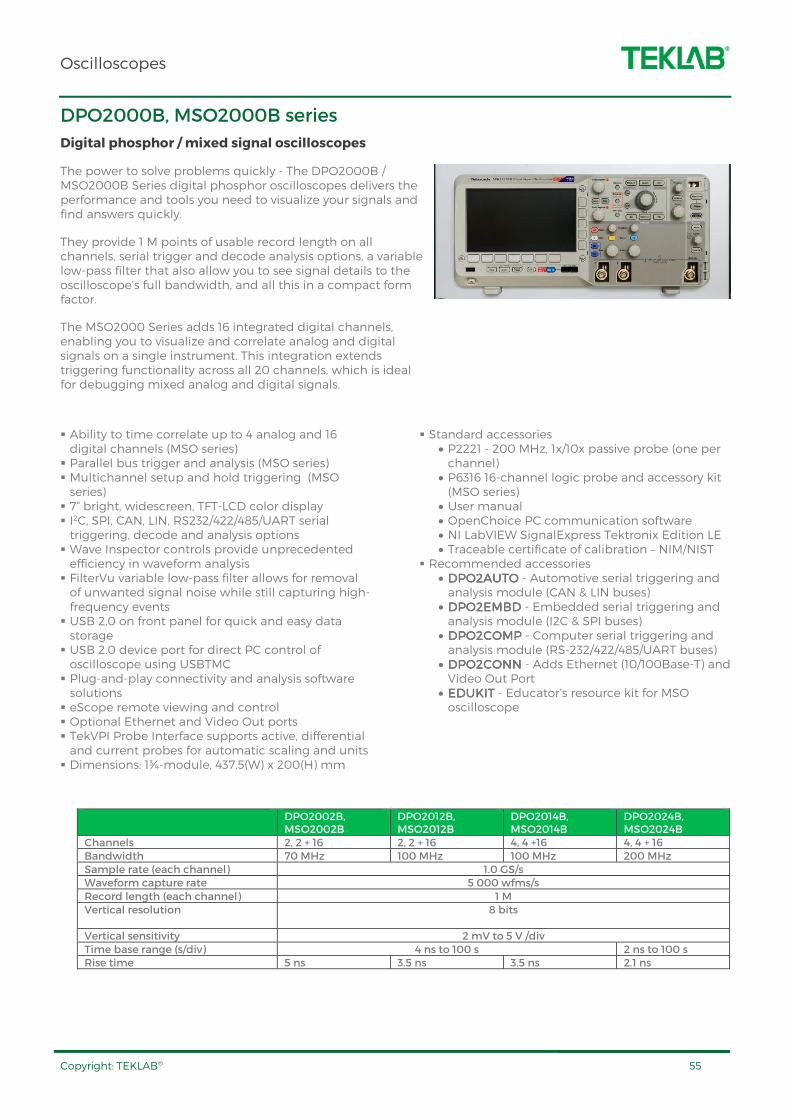
Oscilloscopes
Copyright: TEKLAB® 55
DPO2000B, MSO2000B series
Digital phosphor / mixed signal oscilloscopes
The power to solve problems quickly - The DPO2000B / MSO2000B Series digital phosphor oscilloscopes delivers the performance and tools you need to visualize your signals and find answers quickly.
They provide 1 M points of usable record length on all channels, serial trigger and decode analysis options, a variable low-pass filter that also allow you to see signal details to the oscilloscope’s full bandwidth, and all this in a compact form factor.
The MSO2000 Series adds 16 integrated digital channels, enabling you to visualize and correlate analog and digital signals on a single instrument. This integration extends triggering functionality across all 20 channels, which is ideal for debugging mixed analog and digital signals.
Ability to time correlate up to 4 analog and 16 digital channels (MSO series) Parallel bus trigger and analysis (MSO series) Multichannel setup and hold triggering (MSO series) 7“ bright, widescreen, TFT-LCD color display I2C, SPI, CAN, LIN, RS232/422/485/UART serial triggering, decode and analysis options Wave Inspector controls provide unprecedented efficiency in waveform analysis FilterVu variable low-pass filter allows for removal of unwanted signal noise while still capturing high-frequency events USB 2.0 on front panel for quick and easy data storage USB 2.0 device port for direct PC control of oscilloscope using USBTMC Plug-and-play connectivity and analysis software solutions eScope remote viewing and control Optional Ethernet and Video Out ports TekVPI Probe Interface supports active, differential and current probes for automatic scaling and units Dimensions: 1¾-module, 437.5(W) x 200(H) mm
Standard accessories • P2221 - 200 MHz, 1x/10x passive probe (one per channel)
• P6316 16-channel logic probe and accessory kit (MSO series)
• User manual • OpenChoice PC communication software • NI LabVIEW SignalExpress Tektronix Edition LE • Traceable certificate of calibration – NIM/NIST
Recommended accessories • DPO2AUTODPO2AUTODPO2AUTODPO2AUTO - Automotive serial triggering and analysis module (CAN & LIN buses)
• DPO2EMBDDPO2EMBDDPO2EMBDDPO2EMBD - Embedded serial triggering and analysis module (I2C & SPI buses)
• DPO2COMPDPO2COMPDPO2COMPDPO2COMP - Computer serial triggering and analysis module (RS-232/422/485/UART buses)
• DPO2CONNDPO2CONNDPO2CONNDPO2CONN - Adds Ethernet (10/100Base-T) and Video Out Port
• EDUKITEDUKITEDUKITEDUKIT - Educator’s resource kit for MSO oscilloscope
DPO2002B, MSO2002B
DPO2012B, MSO2012B
DPO2014B, MSO2014B
DPO2024B, MSO2024B
Channels 2, 2 + 16 2, 2 + 16 4, 4 +16 4, 4 + 16 Bandwidth 70 MHz 100 MHz 100 MHz 200 MHz Sample rate (each channel) 1.0 GS/s Waveform capture rate 5 000 wfms/s Record length (each channel) 1 M Vertical resolution 8 bits
Vertical sensitivity 2 mV to 5 V /div Time base range (s/div) 4 ns to 100 s 2 ns to 100 s Rise time 5 ns 3.5 ns 3.5 ns 2.1 ns
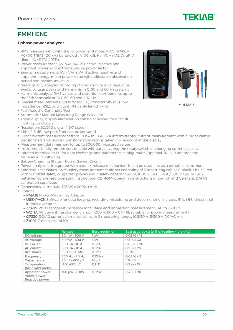
Power analyzers
Copyright: TEKLAB® 56
PMMHENE
1 phase power analyzer
RMS measurement with the following and more: V AC TRMS, V AC+DC TRMS 100 kHz bandwidth, V DC, dB, Hz (V), Hz (A), Ω, µF, V diode, °C / F (TC / RTD) Power measurement: (W, VAr, VA, PF): active, reactive and apparent power with extreme values, power factor Energy measurement: (Wh, VArh, VAh) active, reactive and apparent energy, mean power value with adjustable observation period and maximum value Mains quality analysis: recording of over and undervoltage, dips, swells, voltage peaks and transients in 0, 50 and 60 Hz systems Harmonic analysis: RMS values and distortion components up to the 15thharmonic at 16.7, 50, 60 and 400 Hz Special measurements: Crest factor (CF), conductivity (nS), low impedance (RSL), duty cycle (%), cable length (km) Fast Acoustic Continuity Test Automatic / Manual Measuring Range Selection Triple display, display illumination can be activated for difficult lighting conditions Resolution: 60,000 digits (4 6/7 place) 1 kHz / -3 dB low-pass filter can be activated Direct current measurement from 10 nA to 10 A, 16 A intermittently, current measurement with current clamp transformers and sensors, transformation ratio is taken into account at the display Measurement data memory for up to 300,000 measured values Instrument is fully remote controllable without activating the rotary switch or changing current sockets Infrared interface to PC for data exchange and parameters configuration (optional: IR-USB adapter and METRAwin10 software) Battery Charging Status – Power Saving Circuit Power analyser is integrated with a quick-release mechanism, it can be used also as a portable instrument Standard accessories: KS29 safety measurement cable set consisting of 3 measuring cables (1 black, 1 blue, 1 red) with 90° offset safety plugs, test probes and 3 safety caps for CAT IV, 1000 V CAT II 16 A / 600 V CAT IV 1 A, 2 batteries, condensed operating instructions, CD ROM (operating instructions in English and German), DAkkS calibration certificate Dimensions: ½-module, 125(W) x 200(H) mm Options
• PMA16PMA16PMA16PMA16 Power Measuring Adapter • USUSUSUSBBBB----PACKPACKPACKPACK Software for data logging, recording, visualizing and documenting. Includes IR-USB bidirectional interface adapter
• Z3409Z3409Z3409Z3409 Pt100 temperature sensor for surface and immersion measurement, -40 to +600 °C • WZ11AWZ11AWZ11AWZ11A AC current transformer clamp, 1-200 A, 600 V CAT III, suitable for power measurements • CP330 CP330 CP330 CP330 DC/AC current clamp sensor, with 2 measuring ranges (0.5-30 A, 5-300 A DC/AC rms) • Z109L Z109L Z109L Z109L Fuses (pack of 10)
Ranges Best resolution Best accuracy, ± (a % of reading + b digits) DC voltage 60 mV – 600 V 1 μV 0.02 % + 15
AC voltage 60 mV – 600 V 1 μV 0.2 % + 30
DC current 600 µA – 10 A 10 nA 0.05 % + 20 AC current 600 µA – 10 A 10 nA 0.5 % + 25 Resistance 600 Ω – 60 MΩ 10 mΩ 0.1 % + 5
Frequency 600 Hz – 1 MHz 0.01 Hz 0.05 % + 5 Capacitance 60 nF – 600 µF 10 pF 1 % + 6 Temperature (MHZ3409 probe)
-40…+600 °C 0.1 °C 0.3 % + 15
Apparent power Active power Reactive power
360 µW – 6 kW
10 nW 0.4 % + 20
MHPMA16

Power analyzers
Copyright: TEKLAB® 57
PM3
3 phase power analyser
Multi-measurement • Currents:
• instantaneous: I1, I2, I3, Isystem • average/maximum average: I1, I2, I3
• Voltages & frequency: • instantaneous: V1, V2, V3, U12, U23, U31, F, Vsystem, Usystem
• average/maximum average: V1, V2, V3, U12, U23, U31, F • Power:
• instantaneous: 3P, ΣP, 3Q, ΣQ, 3S, ΣS • maximum average: ΣP, ΣQ, ΣS • predictive: (ΣP), (ΣQ), (ΣS)
• Power factors: • instantaneous: 3PF, ΣPF • average/maximum average: ΣPF
Metering: • Active energy: +/- kWh • Reactive energy: +/- kvarh • Apparent power: kVAh • Hours
Harmonic analysis • Total harmonic distortion
• Currents: thd I1, thd I2, thd I3 • Phase-to-neutral voltage: thd V1, thd V2, thd V3 • Phase-to-phase voltage: thd U12, thd U23, thd U31
TRMS Large backlit LCD display Multiple viewing screens with direct pushbutton access Connections with 4 mm safety terminals (L1, L2, L3, N) Dimensions: ¾-module, 187.5(W) x 200(H) mm
Ranges Best resolution Best accuracy, a % of reading AC voltage 50 - 700 V (phase-to-phase) 0.01 V 0.2 % + 1 AC current 0-25 A 1 mA 1 % + 1 Power NA NA 1 % Power factor NA NA 1 % Frequency 45-65 Hz NA 0.1 % Energy, active NA NA Class 0.5 S Energy reactive NA NA Class 2

RF equipment
Copyright: TEKLAB® 58
FSC3, FSC6
Spectrum analyzers
FSC is a compact, cost-efficient solution that offers all essential features of a professional spectrum analyzer. It covers a wide range of applications from simple development tasks to production, or can be used for training RF professionals.
Moreover, it is ideal for applications in service or maintenance. A wide selection of accessories is available to suit your application.
Frequency range 9 kHz to 3 GHz (FSC3) or 6 GHz (FSC6) Resolution bandwidths 10 Hz to 3 MHz High sensitivity (< –141 dBm (1 Hz), with optional preamplifier < –161 dBm (1 Hz ) Low measurement uncertainty (< 1 dB) Frequency counter with 0.1 Hz resolution Limit line monitoring (pass/fail function) for indicating whether the DUT complies with defined limits Measurement of harmonics and total harmonic distortion Storage of measurement results on USB stick LAN and USB interface for remote control and transfer of measurement data FSCView software for simple documentation of measurement results Easy operation via keyboard and a rotary knob Low power consumption (12 W) Dimensions: 1 ¼-module, 312.5(W) x 200(H) mm
SMC100AB101, SMC100AB103
Signal generators
The analog SMC100AB101/103 sets standards for attractively-priced signal generators. It has the smallest size and the best price/performance ratio in its class.
The flexible and versatile instrument is suited for use in service and maintenance labs. Due to its small dimensions and lightweight design, the SMC100AB101/103 is also the perfect choice for field applications or training and education environments.
A wide selection of accessories is available to suit your application.
Frequency range • 9 kHz to 1.1 GHz (SMC100AB101) • 9 kHz to 3.2 GHz (SMC100AB103)
Typical maximum level of above +17 dBm Analog modulation modes (AM/FM/φM/pulse modulation)
integrated as standard Remote control compatibility with other signal generators Integrated overvoltage protection Wear-free electronic attenuator Simplified error diagnostics through built-in selftests Low SSB phase noise of typ. –111dBc Wideband noise of typ. –148 dBc Nonharmonics of typ. –72 dBc Level uncertainty <0.9 dB Frequency and level setting times <5 ms Dimensions: 1 ¼ module, 312.5(W) x 200(H) mm
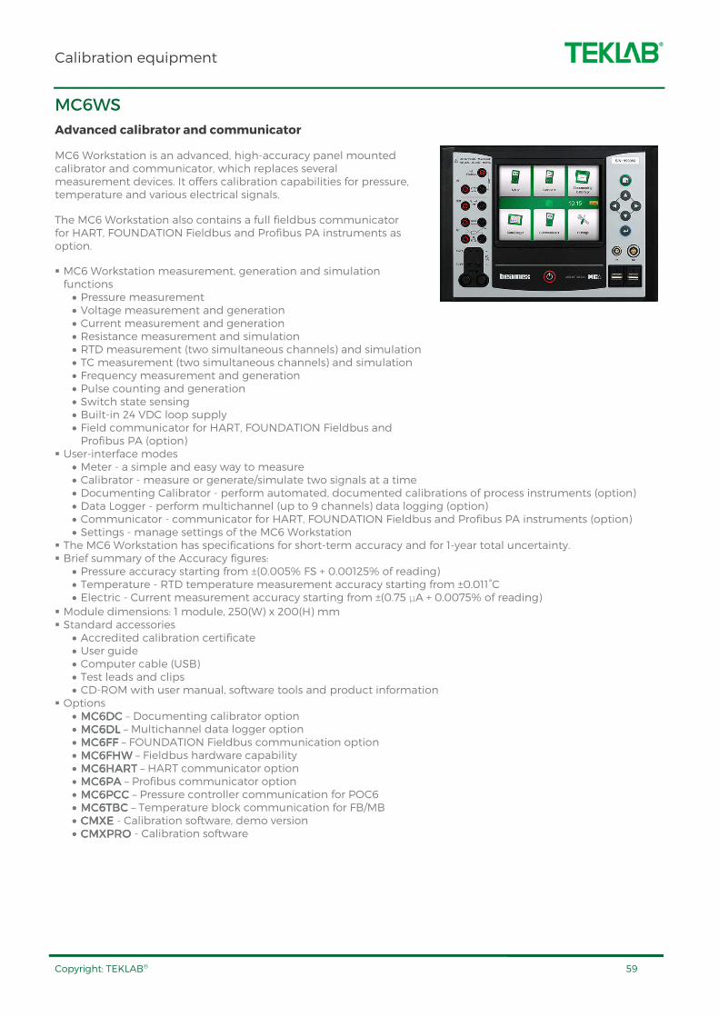
Calibration equipment
Copyright: TEKLAB® 59
MC6WS
Advanced calibrator and communicator
MC6 Workstation is an advanced, high-accuracy panel mounted calibrator and communicator, which replaces several measurement devices. It offers calibration capabilities for pressure, temperature and various electrical signals.
The MC6 Workstation also contains a full fieldbus communicator for HART, FOUNDATION Fieldbus and Profibus PA instruments as option.
MC6 Workstation measurement, generation and simulation functions
• Pressure measurement • Voltage measurement and generation • Current measurement and generation • Resistance measurement and simulation • RTD measurement (two simultaneous channels) and simulation • TC measurement (two simultaneous channels) and simulation • Frequency measurement and generation • Pulse counting and generation • Switch state sensing • Built-in 24 VDC loop supply • Field communicator for HART, FOUNDATION Fieldbus and Profibus PA (option)
User-interface modes • Meter - a simple and easy way to measure • Calibrator - measure or generate/simulate two signals at a time • Documenting Calibrator - perform automated, documented calibrations of process instruments (option) • Data Logger - perform multichannel (up to 9 channels) data logging (option) • Communicator - communicator for HART, FOUNDATION Fieldbus and Profibus PA instruments (option) • Settings - manage settings of the MC6 Workstation
The MC6 Workstation has specifications for short-term accuracy and for 1-year total uncertainty. Brief summary of the Accuracy figures:
• Pressure accuracy starting from ±(0.005% FS + 0.00125% of reading) • Temperature - RTD temperature measurement accuracy starting from ±0.011°C • Electric - Current measurement accuracy starting from ±(0.75 μA + 0.0075% of reading)
Module dimensions: 1 module, 250(W) x 200(H) mm Standard accessories
• Accredited calibration certificate • User guide • Computer cable (USB) • Test leads and clips • CD-ROM with user manual, software tools and product information
Options • MC6DCMC6DCMC6DCMC6DC – Documenting calibrator option • MC6DLMC6DLMC6DLMC6DL – Multichannel data logger option • MC6FFMC6FFMC6FFMC6FF – FOUNDATION Fieldbus communication option • MC6FHWMC6FHWMC6FHWMC6FHW – Fieldbus hardware capability • MC6HARTMC6HARTMC6HARTMC6HART – HART communicator option • MC6PAMC6PAMC6PAMC6PA – Profibus communicator option • MC6PCCMC6PCCMC6PCCMC6PCC – Pressure controller communication for POC6 • MC6TBCMC6TBCMC6TBCMC6TBC – Temperature block communication for FB/MB • CMXCMXCMXCMXEEEE - Calibration software, demo version • CMXPROCMXPROCMXPROCMXPRO - Calibration software
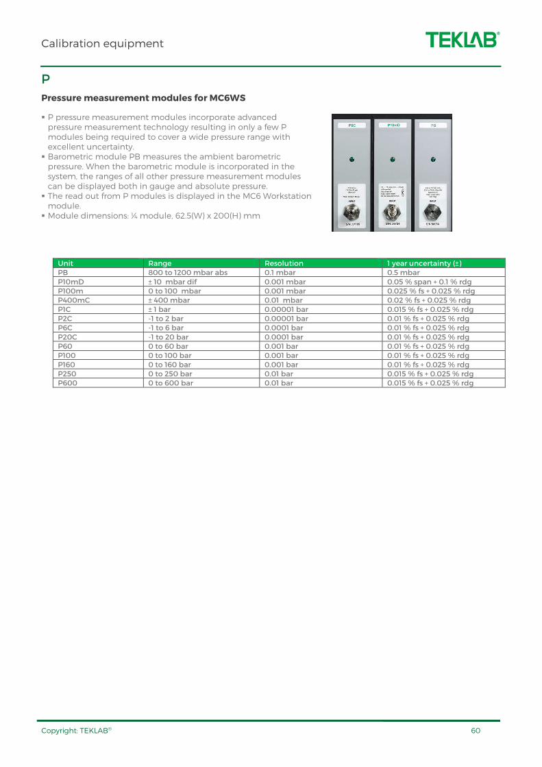
Calibration equipment
Copyright: TEKLAB® 60
P
Pressure measurement modules for MC6WS
P pressure measurement modules incorporate advanced pressure measurement technology resulting in only a few P modules being required to cover a wide pressure range with excellent uncertainty. Barometric module PB measures the ambient barometric pressure. When the barometric module is incorporated in the system, the ranges of all other pressure measurement modules can be displayed both in gauge and absolute pressure. The read out from P modules is displayed in the MC6 Workstation module. Module dimensions: ¼ module, 62.5(W) x 200(H) mm
Unit Range Resolution 1 year uncertainty (±) PB 800 to 1200 mbar abs 0.1 mbar 0.5 mbar P10mD ± 10 mbar dif 0.001 mbar 0.05 % span + 0.1 % rdg P100m 0 to 100 mbar 0.001 mbar 0.025 % fs + 0.025 % rdg P400mC ± 400 mbar 0.01 mbar 0.02 % fs + 0.025 % rdg P1C ± 1 bar 0.00001 bar 0.015 % fs + 0.025 % rdg P2C -1 to 2 bar 0.00001 bar 0.01 % fs + 0.025 % rdg P6C -1 to 6 bar 0.0001 bar 0.01 % fs + 0.025 % rdg P20C -1 to 20 bar 0.0001 bar 0.01 % fs + 0.025 % rdg P60 0 to 60 bar 0.001 bar 0.01 % fs + 0.025 % rdg P100 0 to 100 bar 0.001 bar 0.01 % fs + 0.025 % rdg P160 0 to 160 bar 0.001 bar 0.01 % fs + 0.025 % rdg P250 0 to 250 bar 0.01 bar 0.015 % fs + 0.025 % rdg P600 0 to 600 bar 0.01 bar 0.015 % fs + 0.025 % rdg
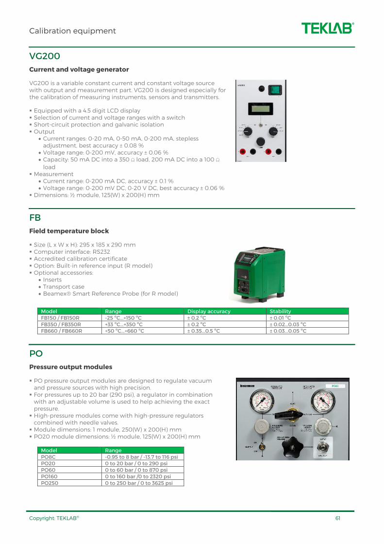
Calibration equipment
Copyright: TEKLAB® 61
VG200
Current and voltage generator
VG200 is a variable constant current and constant voltage source with output and measurement part. VG200 is designed especially for the calibration of measuring instruments, sensors and transmitters.
Equipped with a 4.5 digit LCD display Selection of current and voltage ranges with a switch Short-circuit protection and galvanic isolation Output
• Current ranges: 0-20 mA, 0-50 mA, 0-200 mA, stepless adjustment, best accuracy ± 0.08 %
• Voltage range: 0-200 mV, accuracy ± 0.06 % • Capacity: 50 mA DC into a 350 Ω load, 200 mA DC into a 100 Ω load
Measurement • Current range: 0-200 mA DC, accuracy ± 0.1 % • Voltage range: 0-200 mV DC, 0-20 V DC, best accuracy ± 0.06 %
Dimensions: ½ module, 125(W) x 200(H) mm
FB
Field temperature block
Size (L x W x H): 295 x 185 x 290 mm Computer interface: RS232 Accredited calibration certificate Option: Built-in reference input (R model) Optional accessories:
• Inserts • Transport case • Beamex® Smart Reference Probe (for R model)
Model Range Display accuracy Stability FB150 / FB150R -25 ºC...+150 ºC ± 0.2 ºC ± 0.01 ºC FB350 / FB350R +33 ºC...+350 ºC ± 0.2 ºC ± 0.02…0.03 ºC FB660 / FB660R +50 ºC...+660 ºC ± 0.35...0.5 ºC ± 0.03...0.05 ºC
PO
Pressure output modules
PO pressure output modules are designed to regulate vacuum and pressure sources with high precision. For pressures up to 20 bar (290 psi), a regulator in combination with an adjustable volume is used to help achieving the exact pressure. High-pressure modules come with high-pressure regulators combined with needle valves. Module dimensions: 1 module, 250(W) x 200(H) mm PO20 module dimensions: ½ module, 125(W) x 200(H) mm
Model Range PO8C -0.95 to 8 bar / -13.7 to 116 psi PO20 0 to 20 bar / 0 to 290 psi PO60 0 to 60 bar / 0 to 870 psi PO160 0 to 160 bar /0 to 2320 psi PO250 0 to 250 bar / 0 to 3625 psi
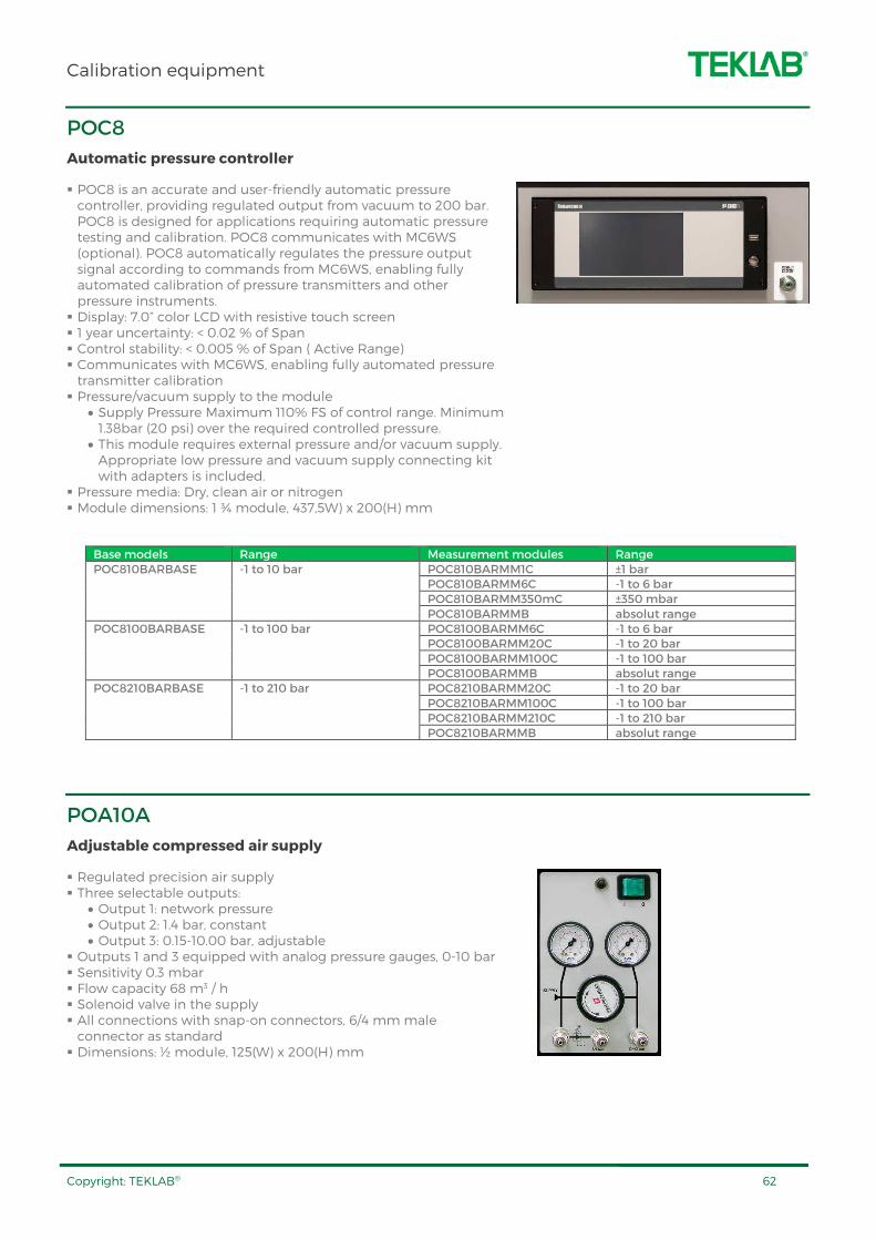
Calibration equipment
Copyright: TEKLAB® 62
POC8
Automatic pressure controller
POC8 is an accurate and user-friendly automatic pressure controller, providing regulated output from vacuum to 200 bar. POC8 is designed for applications requiring automatic pressure testing and calibration. POC8 communicates with MC6WS (optional). POC8 automatically regulates the pressure output signal according to commands from MC6WS, enabling fully automated calibration of pressure transmitters and other pressure instruments. Display: 7.0” color LCD with resistive touch screen 1 year uncertainty: < 0.02 % of Span Control stability: < 0.005 % of Span ( Active Range) Communicates with MC6WS, enabling fully automated pressure transmitter calibration Pressure/vacuum supply to the module
• Supply Pressure Maximum 110% FS of control range. Minimum 1.38bar (20 psi) over the required controlled pressure.
• This module requires external pressure and/or vacuum supply. Appropriate low pressure and vacuum supply connecting kit with adapters is included.
Pressure media: Dry, clean air or nitrogen Module dimensions: 1 ¾ module, 437,5W) x 200(H) mm
Base models Range Measurement modules Range POC810BARBASE -1 to 10 bar POC810BARMM1C ±1 bar
POC810BARMM6C -1 to 6 bar POC810BARMM350mC ±350 mbar POC810BARMMB absolut range
POC8100BARBASE -1 to 100 bar POC8100BARMM6C -1 to 6 bar POC8100BARMM20C -1 to 20 bar POC8100BARMM100C -1 to 100 bar POC8100BARMMB absolut range
POC8210BARBASE -1 to 210 bar POC8210BARMM20C -1 to 20 bar POC8210BARMM100C -1 to 100 bar POC8210BARMM210C -1 to 210 bar POC8210BARMMB absolut range
POA10A
Adjustable compressed air supply
Regulated precision air supply Three selectable outputs:
• Output 1: network pressure • Output 2: 1.4 bar, constant • Output 3: 0.15-10.00 bar, adjustable
Outputs 1 and 3 equipped with analog pressure gauges, 0-10 bar Sensitivity 0.3 mbar Flow capacity 68 m3 / h Solenoid valve in the supply All connections with snap-on connectors, 6/4 mm male connector as standard Dimensions: ½ module, 125(W) x 200(H) mm

Calibration equipment
Copyright: TEKLAB® 63
PG
Calibration pumps
PG series includes hand-held, lightweight pressure and vacuum sources for field use.
PG series of hand pumps are ideal pressure/vacuum generators to be used as accessories for pressure and vacuum calibration.
PGV PGV PGV PGV ---- Pressure Generator Vacuum Pressure Generator Vacuum Pressure Generator Vacuum Pressure Generator Vacuum Output pressure: 0...-0.95 bar / 0...-13.7 psi Pressure media: air Outlet connector: G 1/8” male 60° int. cone Dimensions: diameter: 35 mm, length: min 230 mm, max 322 mm, weight: 340 g
PGPGPGPGLLLL ---- Pressure Pressure Pressure Pressure Generator Generator Generator Generator LowLowLowLow Output pressure: -400...400 mbar / -160...160 psi Pressure media: air Output threads: 1 x G 1/8" female Standard accessories:
• Output connectors: G 1/8” / 60 - G 1/8” installed in the pump; Nipple for 4 mm ID hose
• Small bag (about 10 pcs) of o-rings in size and type: 10.1 mm x 1.6 mm NBR 70
PGM PGM PGM PGM ---- Pressure Generator Medium Pressure Generator Medium Pressure Generator Medium Pressure Generator Medium Output pressure: 0...20 bar / 0...300 psi Pressure media: air Outlet connector: G 1/8” male 60° int. cone Dimensions: 223 mm x 96 mm x 38 mm, weight: 400 g
PGPGPGPGPPPPH H H H ---- Pressure Generator Pressure Generator Pressure Generator Pressure Generator Pneumatic HighPneumatic HighPneumatic HighPneumatic High Output pressure: -0.95...140 bar / -13.7...2000 psi Pressure media: air Output threads: 2 x G 1/4" female Standard accessories:
• Output connectors: G 1/4" (Male) Plug x 1 • Small bag (about 20 pcs) of o-rings (sealing rings) type NBR70 (size 6x2)
PGXH PGXH PGXH PGXH ---- Pressure Generator Extra High Pressure Generator Extra High Pressure Generator Extra High Pressure Generator Extra High Output pressure: 0 ...700 bar / 0 ...10000 psi Pressure media: distilled water or mineral based hydraulic oil Fine adjustment: with adjustable volume control PGXH is delivered with:
• Carrying case • Pressure Measurement Hose (1 meter) • Filling bottle • 3/8" plug and 3/8" to 1/4" BSP female adapter • BSP male / 1215 connector • NPT male / 1215 connector
PB0004B
Electrical vacuum pump
Mains supply: 230 V 50 Hz (p/n 9427230), 110 V 60 Hz (p/n 9427110) Nominal motor rating: 0.1 kW Nominal motor speed: 2700 min-1 (50 Hz), 3200 min-1 (60Hz) Ultimate vacuum: 7 mbar Nominal displacement: 4 m3/h Sound level (DIN 45635): 59 dB (A) Oil filling: 0.06 l Oil: standard hydraulic oil, viscosity 32 (ISO) Weight: 5.1 kg Dimensions: 133(W) x 141(H) x 230(D) mm (230 V 50 Hz), 148(W) x 141(H) x 230(D) mm (110 V 60 Hz) Mains lead: without plug (to be added depending on the installation) Options
• VACUUMPSWVACUUMPSWVACUUMPSWVACUUMPSW Switch module for vacuum pump • VACUUMPUMPJVACUUMPUMPJVACUUMPUMPJVACUUMPUMPJ Bracket for pump in Concept workstation • WHV820472 WHV820472 WHV820472 WHV820472 Bracket for pump in TowerLine workstation

Calibration equipment
Copyright: TEKLAB® 64
CALABTRK
Process instrument kit for calibration training
Process instrument kit is apProcess instrument kit is apProcess instrument kit is apProcess instrument kit is applicable plicable plicable plicable for following for following for following for following training areastraining areastraining areastraining areas
Calibration of process instruments such as • Pressure transmitters, switches and gauges • Electrical converters, frequency meters • Temperature transmitters, thermocouples, RTDs
HART, FOUNDATION Fieldbus, Profibus PA Automatic pressure and temperature calibration Documenting and management of calibrations ContentsContentsContentsContents
Case Background material about calibration, does not include training exercises Pressure transmitters:
• HART® type: 0-10 bar, 4-20 mA. Including pressure connector to MC5P hose set
Temperature transmitter with Pt100 sensor • HART® type: 0-800 °C, 4-20 mA, PT100 (385) • Pt100 (385) sensor, 6 mm
Temperature transmitter • Foundation Fieldbus type (OPTION)
Pressure switch • Pressure switch, adjustable switch set point 3-7 bar gauge. • Including pressure connector to MC5P hose set
Thermocouple: • K-element, 3 mm, including K-element connector
DB
Decade boxes
DBRS, DBLS and DBLC series include decades for resistance, inductance and capacitance.
Direct reading — No fumbling with multiple slide or rotary switches The IET family of digital substituters uses convenient side-by-side thumbwheel switches. Simply dial in the desired values and use For easy value readings, ranges are separated by color coded switches and numbers. Accuracies of 0.1%, 1.0 % and 2.0 %
Product Description Range Resolution Accuracy Dimensions DBRS201W Resistance decade 0 – 100 MΩ 0.1 Ω ± (0.1 % + 36 mΩ) ¾-module, 187.5(W) x 200(H) mm
DBRSB8WC Resistance decade 0 – 1 MΩ 0.01 Ω ± 0.1 % ¾-module, 187.5(W) x 200(H) mm
DBLS400 Inductance decade 0 – 10 H 1 mH ± (2 % + 0.5 µH) ¾-module, 187.5(W) x 200(H) mm DBCS301 Capacitance decade 0 – 100 µF 100 pF ± (1 % + 3 pF) ¾-module, 187.5(W) x 200(H) mm DBCS301L Capacitance decade 0 – 10 µF 1 pF ± (1 % + 3 pF) ¾-module, 187.5(W) x 200(H) mm
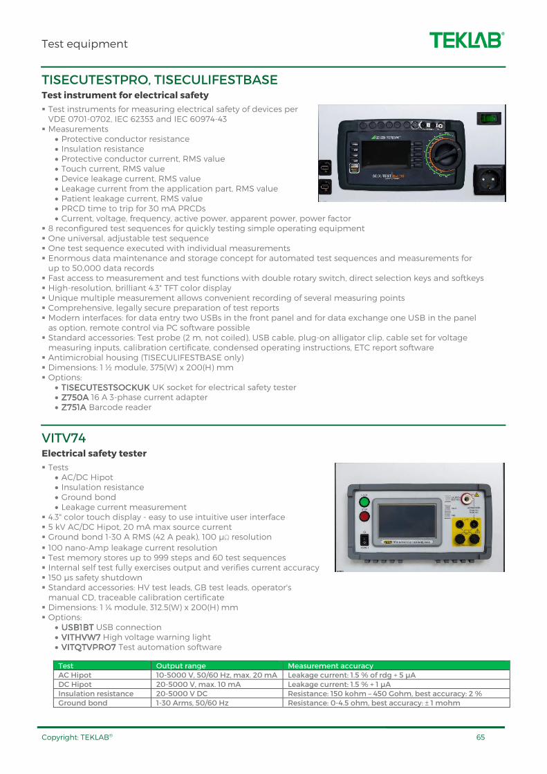
Test equipment
Copyright: TEKLAB® 65
TISECUTESTPRO, TISECULIFESTBASE Test instrument for electrical safety
Test instruments for measuring electrical safety of devices per VDE 0701-0702, IEC 62353 and IEC 60974-43 Measurements
• Protective conductor resistance • Insulation resistance • Protective conductor current, RMS value • Touch current, RMS value • Device leakage current, RMS value • Leakage current from the application part, RMS value • Patient leakage current, RMS value • PRCD time to trip for 30 mA PRCDs • Current, voltage, frequency, active power, apparent power, power factor
8 reconfigured test sequences for quickly testing simple operating equipment One universal, adjustable test sequence One test sequence executed with individual measurements Enormous data maintenance and storage concept for automated test sequences and measurements for up to 50,000 data records Fast access to measurement and test functions with double rotary switch, direct selection keys and softkeys High-resolution, brilliant 4.3" TFT color display Unique multiple measurement allows convenient recording of several measuring points Comprehensive, legally secure preparation of test reports Modern interfaces: for data entry two USBs in the front panel and for data exchange one USB in the panel as option, remote control via PC software possible Standard accessories: Test probe (2 m, not coiled), USB cable, plug-on alligator clip, cable set for voltage measuring inputs, calibration certificate, condensed operating instructions, ETC report software Antimicrobial housing (TISECULIFESTBASE only) Dimensions: 1 ½ module, 375(W) x 200(H) mm Options:
• TISECUTESTSOCKUK TISECUTESTSOCKUK TISECUTESTSOCKUK TISECUTESTSOCKUK UK socket for electrical safety tester • Z750Z750Z750Z750AAAA 16 A 3-phase current adapter • Z751A Z751A Z751A Z751A Barcode reader
VITV74 Electrical safety tester
Tests • AC/DC Hipot • Insulation resistance • Ground bond • Leakage current measurement
4.3" color touch display - easy to use intuitive user interface 5 kV AC/DC Hipot, 20 mA max source current Ground bond 1-30 A RMS (42 A peak), 100 µΩ resolution 100 nano-Amp leakage current resolution Test memory stores up to 999 steps and 60 test sequences Internal self test fully exercises output and verifies current accuracy 150 µs safety shutdown Standard accessories: HV test leads, GB test leads, operator's manual CD, traceable calibration certificate Dimensions: 1 ¼ module, 312.5(W) x 200(H) mm Options:
• USB1BTUSB1BTUSB1BTUSB1BT USB connection • VITHVW7VITHVW7VITHVW7VITHVW7 High voltage warning light • VITQTVPRO7 VITQTVPRO7 VITQTVPRO7 VITQTVPRO7 Test automation software
Test Output range Measurement accuracy AC Hipot 10-5000 V, 50/60 Hz, max. 20 mA Leakage current: 1.5 % of rdg + 5 µA DC Hipot 20-5000 V, max. 10 mA Leakage current: 1.5 % + 1 µA Insulation resistance 20-5000 V DC Resistance: 150 kohm – 450 Gohm, best accuracy: 2 % Ground bond 1-30 Arms, 50/60 Hz Resistance: 0-4.5 ohm, best accuracy: ± 1 mohm

Test equipment
Copyright: TEKLAB® 66
AMTACH20
Tachometer
Measures rotational and surface speed Built-in memory Digital display Auto power off function Easy to select units and mode functions Contact and non-contact measurement Select rpm using infrared beam or adapter: m/min, m/sec, ft/min, ft/sec, in/min, m, ft, and in Measuring range:
• Optical: 1- 99 999 1/min • Mechanical: 1- 19 999 1/min
Optical sensing distance: max. 600 mm Accuracy: ± 0.02 % of rdg + 1 digit Dimensions: 60(W) x 28(D) x 175(H) mm Includes 6 adapters, carrying case, reflective tapes, batteries and user manual
FLUKE805
Vibration meter
Four-level scale for indicating severity of problems for overall vibration and bearing condition Exportable data via USB Trending in Microsoft® Excel using built-in templates Overall vibration measurement (10 Hz to 1,000 Hz) for acceleration, velocity and displacement units of measurement for a wide variety of machines Crest Factor+ technology provides reliable bearing assessment using direct sensor tip measurements between 4,000 Hz and 20,000 Hz Colored lighting system (green, red) and on-screen comments indicate how much pressure needs to be applied to take measurements Infrared temperature sensor On-board memory for 3,500 measurements Audio output for listening to bearing tones directly External accelerometer support for hard to reach locations Flashlight Dimensions: 71(W) x 58(D) x 241(H) mm
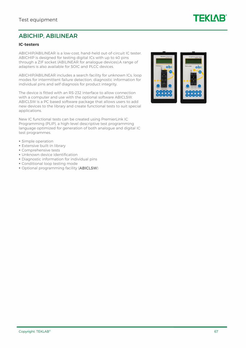
Test equipment
Copyright: TEKLAB® 67
ABICHIP, ABILINEAR
IC-testers
ABICHIP/ABILINEAR is a low-cost, hand-held out-of-circuit IC tester. ABICHIP is designed for testing digital ICs with up to 40 pins through a ZIF socket (ABILINEAR for analogue devices).A range of adapters is also available for SOIC and PLCC devices.
ABICHIP/ABILINEAR includes a search facility for unknown ICs, loop modes for intermittent failure detection, diagnostic information for individual pins and self diagnosis for product integrity.
The device is fitted with an RS-232 interface to allow connection with a computer and use with the optional software ABICLSW. ABICLSW is a PC based software package that allows users to add new devices to the library and create functional tests to suit special applications.
New IC functional tests can be created using PremierLink IC Programming (PLIP), a high-level descriptive test programming language optimized for generation of both analogue and digital IC test programmes.
Simple operation Extensive built-in library Comprehensive tests Unknown device identification Diagnostic information for individual pins Conditional loop testing mode Optional programming facility (ABICLSWABICLSWABICLSWABICLSW)
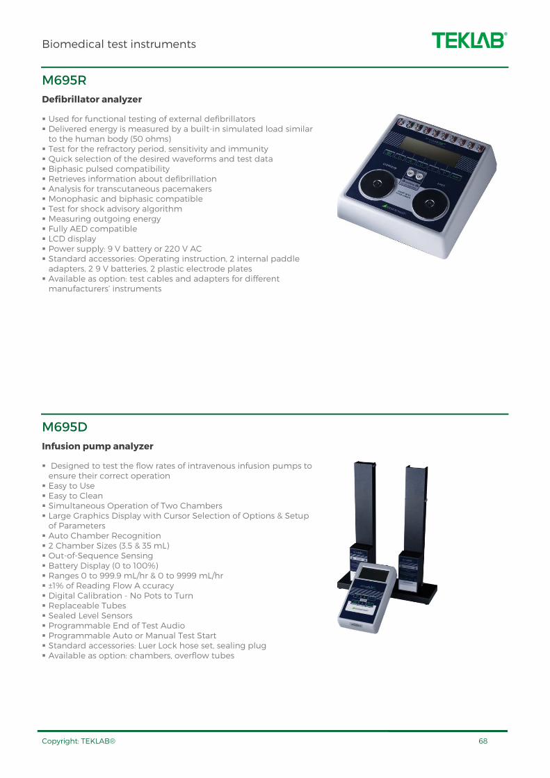
Biomedical test instruments
Copyright: TEKLAB® 68
M695R
Defibrillator analyzer
Used for functional testing of external defibrillators Delivered energy is measured by a built-in simulated load similar to the human body (50 ohms) Test for the refractory period, sensitivity and immunity Quick selection of the desired waveforms and test data Biphasic pulsed compatibility Retrieves information about defibrillation Analysis for transcutaneous pacemakers Monophasic and biphasic compatible Test for shock advisory algorithm Measuring outgoing energy Fully AED compatible LCD display Power supply: 9 V battery or 220 V AC Standard accessories: Operating instruction, 2 internal paddle adapters, 2 9 V batteries, 2 plastic electrode plates Available as option: test cables and adapters for different manufacturers’ instruments
M695D
Infusion pump analyzer
Designed to test the flow rates of intravenous infusion pumps to ensure their correct operation Easy to Use Easy to Clean Simultaneous Operation of Two Chambers Large Graphics Display with Cursor Selection of Options & Setup of Parameters Auto Chamber Recognition 2 Chamber Sizes (3.5 & 35 mL) Out-of-Sequence Sensing Battery Display (0 to 100%) Ranges 0 to 999.9 mL/hr & 0 to 9999 mL/hr ±1% of Reading Flow A ccuracy Digital Calibration - No Pots to Turn Replaceable Tubes Sealed Level Sensors Programmable End of Test Audio Programmable Auto or Manual Test Start Standard accessories: Luer Lock hose set, sealing plug Available as option: chambers, overflow tubes
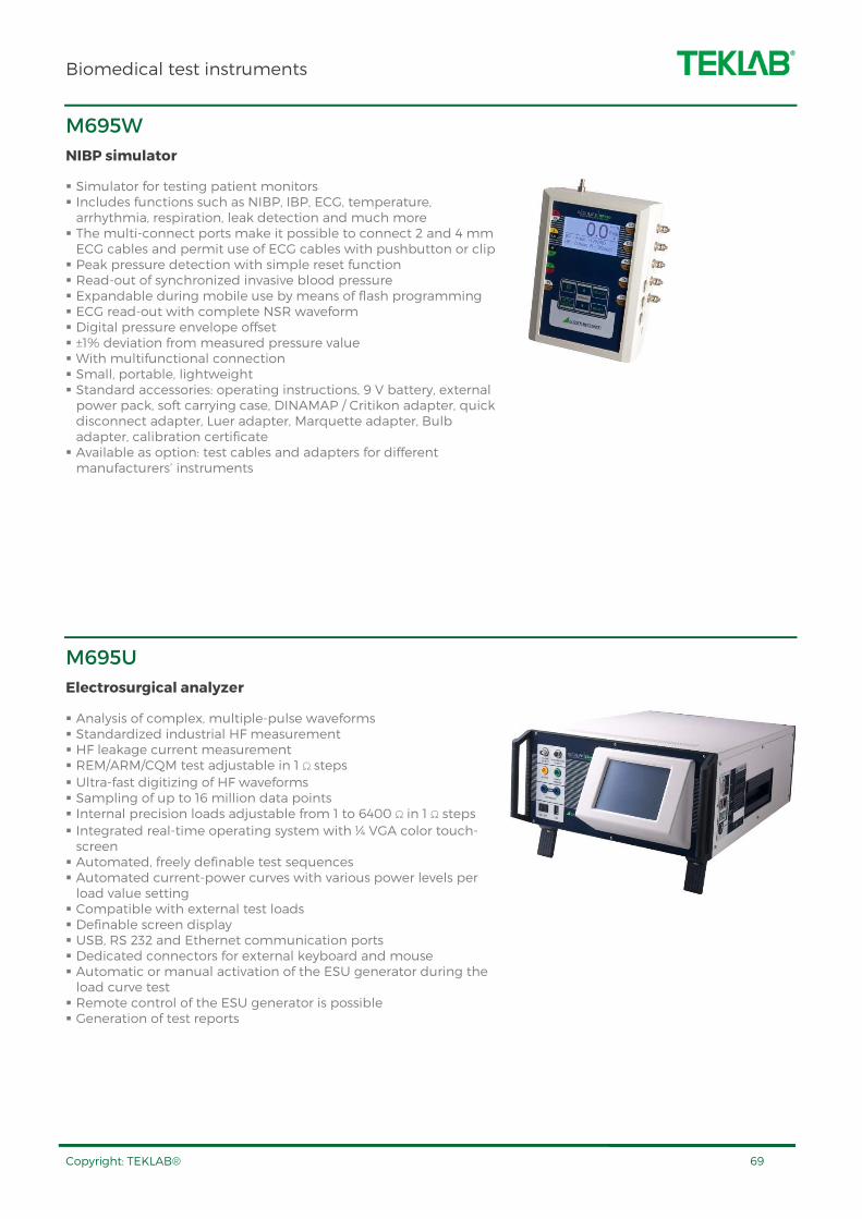
Biomedical test instruments
Copyright: TEKLAB® 69
M695W
NIBP simulator
Simulator for testing patient monitors Includes functions such as NIBP, IBP, ECG, temperature, arrhythmia, respiration, leak detection and much more The multi-connect ports make it possible to connect 2 and 4 mm ECG cables and permit use of ECG cables with pushbutton or clip Peak pressure detection with simple reset function Read-out of synchronized invasive blood pressure Expandable during mobile use by means of flash programming ECG read-out with complete NSR waveform Digital pressure envelope offset ±1% deviation from measured pressure value With multifunctional connection Small, portable, lightweight Standard accessories: operating instructions, 9 V battery, external power pack, soft carrying case, DINAMAP / Critikon adapter, quick disconnect adapter, Luer adapter, Marquette adapter, Bulb adapter, calibration certificate Available as option: test cables and adapters for different manufacturers’ instruments
M695U
Electrosurgical analyzer
Analysis of complex, multiple-pulse waveforms Standardized industrial HF measurement HF leakage current measurement REM/ARM/CQM test adjustable in 1 Ω steps Ultra-fast digitizing of HF waveforms Sampling of up to 16 million data points Internal precision loads adjustable from 1 to 6400 Ω in 1 Ω steps Integrated real-time operating system with ¼ VGA color touch-screen Automated, freely definable test sequences Automated current-power curves with various power levels per load value setting Compatible with external test loads Definable screen display USB, RS 232 and Ethernet communication ports Dedicated connectors for external keyboard and mouse Automatic or manual activation of the ESU generator during the load curve test Remote control of the ESU generator is possible Generation of test reports
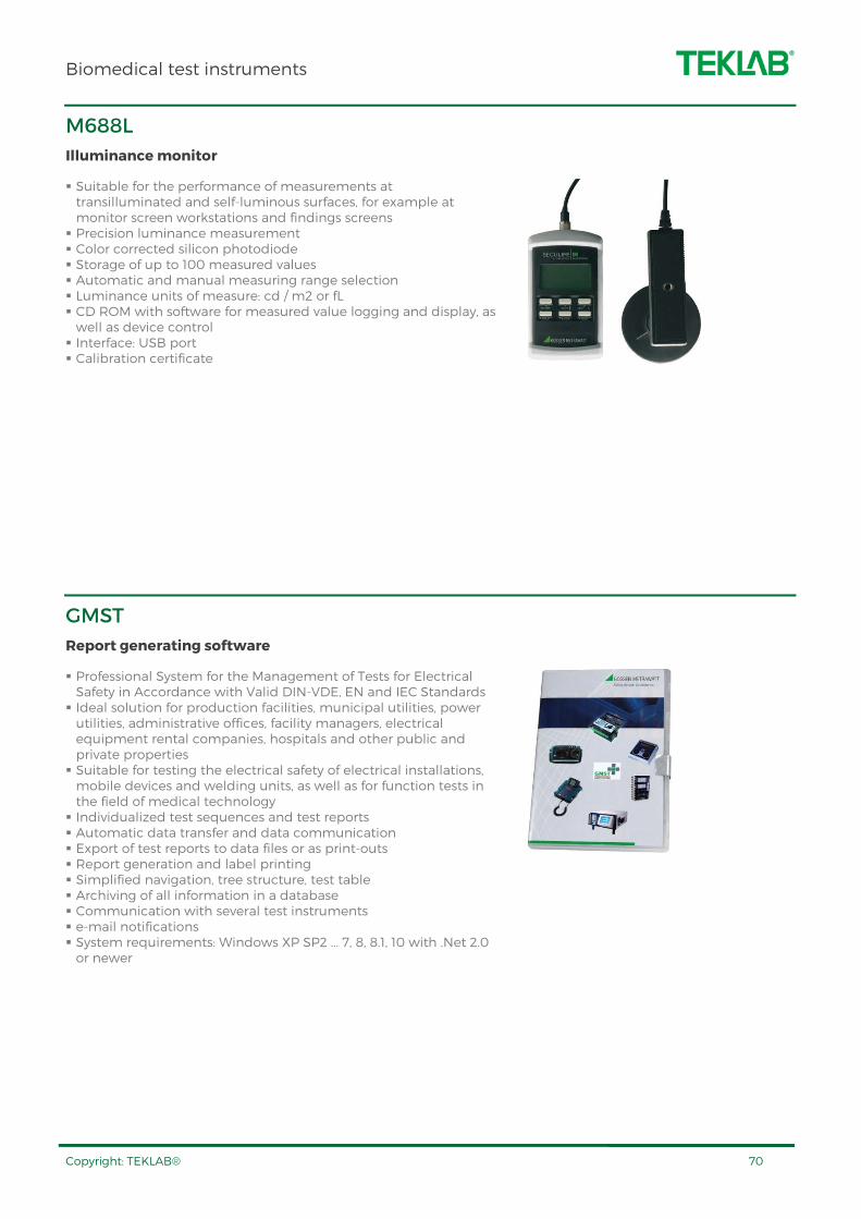
Biomedical test instruments
Copyright: TEKLAB® 70
M688L
Illuminance monitor
Suitable for the performance of measurements at transilluminated and self-luminous surfaces, for example at monitor screen workstations and findings screens Precision luminance measurement Color corrected silicon photodiode Storage of up to 100 measured values Automatic and manual measuring range selection Luminance units of measure: cd / m2 or fL CD ROM with software for measured value logging and display, as well as device control Interface: USB port Calibration certificate
GMST
Report generating software
Professional System for the Management of Tests for Electrical Safety in Accordance with Valid DIN-VDE, EN and IEC Standards Ideal solution for production facilities, municipal utilities, power utilities, administrative offices, facility managers, electrical equipment rental companies, hospitals and other public and private properties Suitable for testing the electrical safety of electrical installations, mobile devices and welding units, as well as for function tests in the field of medical technology Individualized test sequences and test reports Automatic data transfer and data communication Export of test reports to data files or as print-outs Report generation and label printing Simplified navigation, tree structure, test table Archiving of all information in a database Communication with several test instruments e-mail notifications System requirements: Windows XP SP2 ... 7, 8, 8.1, 10 with .Net 2.0 or newer

Soldering equipment
Copyright: TEKLAB® 71
SSWT1010SET
Soldering station
Power: 90 W Channels: 1 Temperature range: 100-450 ºC Temperature accuracy: ± 9 ºC Temperature stability: ± 2 ºC Graphical backlit LC-Display Automatic standby of tool thanks to integrated acceleration sensor in the tool Soldering iron:
• 90 W, 24 V with Power Response Heating Technology • Heat-up time (ca) in seconds (50-350°C): 7
ESD safe Includes: power unit, soldering iron, safety rest and cleaning sponge for soldering iron, soldering tip (2.4 mm) Operating voltage: 230 V, 50/60 Hz Dimensions: ¾ module, 187.5(W) x 200(H) mm Options:
• XNTXNTXNTXNT----KIT KIT KIT KIT Soldering tip kit, 5 pcs • WTAWTAWTAWTA----50 50 50 50 Desoldering tweezers • SDWTSRJSDWTSRJSDWTSRJSDWTSRJ Tip set for desoldering tweezers, 4 pairs • SSWTCTRLSSWTCTRLSSWTCTRLSSWTCTRL Fume extractor control option
SSWT1012SET
Soldering station
Power: 80 W Channels: 1 Temperature range: 50-450 ºC Temperature accuracy: ± 9 ºC Temperature stability: ± 2 ºC Graphical backlit LC-Display Soldering iron:
• 80 W, 24 V • Heat-up time (ca) in seconds (50-350°C): 10
ESD safe Includes: power unit, soldering iron, safety rest and cleaning sponge for soldering iron, soldering tip (2.4 mm) Operating voltage: 230 V, 50/60 Hz Dimensions: ¾ module, 187.5(W) x 200(H) mm Options:
• LTLTLTLT----KIT KIT KIT KIT Soldering tip kit, 5 pcs • WTAWTAWTAWTA----50 50 50 50 Desoldering tweezers • SDWTSRJSDWTSRJSDWTSRJSDWTSRJ Tip set for desoldering tweezers, 4 pairs
XNT-KIT
LT-KIT
WTA-50
WTA-50 SDWTSRJ
SDWTSRJ

Soldering equipment
Copyright: TEKLAB® 72
SDWR2002
Soldering / desoldering station
Combo unit with soldering and desoldering functions Integrated vacuum pump, no need for compressed air connection Power: 250 W Temperature range: 50-450 ºC (soldering and desoldering) Temperature stability: ± 2 ºC LCD display Automatic tool recognition for safe operation with different soldering tools 2 independent channels for simultaneous operation with different tools ESD safe Sleep mode when unit not used Includes soldering iron, desoldering iron, stands and cleaning sponges for soldering tools, cleaning tool series, soldering tip (2.4 mm), 3 pcs desoldering nozzles (1.0/2.3 mm, 1.2/2.5 mm, 1.2/2.5 mm thick) Dimensions: 1 ¼ module: 312.5(W) x 200(H) mm Options:
• LTLTLTLT----KIT KIT KIT KIT Soldering tip kit, 5 pcs • SDDXSRJSDDXSRJSDDXSRJSDDXSRJ Desoldering nozzle set, 6 pcs • WTAWTAWTAWTA----50 50 50 50 Desoldering tweezers • SDWTSRJSDWTSRJSDWTSRJSDWTSRJ Tip set for desoldering tweezers, 4 pairs • SDHGPSETSDHGPSETSDHGPSETSDHGPSET Hot air pencil • SDRSDRSDRSDR----06060606 Optional tip for hot air pencil
LT-KIT
WTA-50 SDWTSRJ
SDDXSRJ
SDHGPSET

Soldering equipment
Copyright: TEKLAB® 73
ELTOOLSET
Electronics tool set
Professional electronics tool set 30 parts ESD protected design Tools included:
• Side cutter - oval head • Needle nose pliers • Tip cutter - angled wide head • Ergonomic precision tweezers with straight, strong tips • Ergonomic precision tweezers with straight, very pointed tips for gripping fine wires
• Ergonomic precision tweezers with straight, flat and rounded tips for simple gripping jobs
• Screwdriver set, precision, ESD, slotted, Phillips, 6 pcs • Screwdriver set, precision, ESD, hexagon, 6 pcs • Screwdriver set, precision, ESD, hexagon nut driver, 6 pcs • Screwdriver set, precision, ESD, TORX, 6 pcs
SOLDERSET
Soldering consumables set
Contents: • Solder dispenser, 1 roll • Cleaner flux • Soldering tip cleaner • Solder wick, 1.5 mm • Solder wick, 2.2 mm • Solder wick, 2.7 mm • Flux pen • Flux-gel • Lead-free solder • Desoldering pump
SDMICRO
Digital microscope
This high-quality microscope with digital camera and USB interface is a professional solution for tasks with diverse magnification requirements. It is designed to be used in quality control or educational purposes.
The image of the object can be transmitted as a digital photo or video to a PC via the USB cable and displayed in exceptional detail.
Resolution: 1280 x 1024 Magnification: 20X - 90X Sensor: 1/3" Color CMOS Video frame rate: up to 30 Fps Illumination: 8 build-in Hightech LEDs ESD safe Metal stand for microscope, adjustable in all directions Software features: picture and video capturing (jpg, bmp, avi), editing and measuring pictures, LED control Contents: Microscope with digital camera and USB interface, adjustable work stand and application software
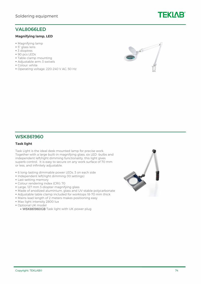
Soldering equipment
Copyright: TEKLAB® 74
VAL8066LED
Magnifying lamp, LED
Magnifying lamp 5” glass lens 3 dioptres 90 pcs LEDs Table clamp mounting Adjustable arm: 3 swivels Colour: white Operating voltage: 220-240 V AC, 50 Hz
WSK861960
Task light
Task Light is the ideal desk-mounted lamp for precise work. Together with a large built-in magnifying glass, six LED -bulbs and independent left/right dimming functionality, this light gives superb control. It is easy to secure on any work surface of 70 mm or less, and infinitely adjustable.
6 long-lasting dimmable power LEDs, 3 on each side Independent left/right dimming (10 settings) Last-setting memory Colour rendering index (CRI): 70 Large, 127 mm 3-diopter magnifying glass Made of anodized aluminium, glass and UV-stable polycarbonate Adjustable table clamp included for worktops 18-70 mm thick Mains lead length of 2 meters makes positioning easy Max light intensity 2800 lux Optional UK model
• WSK861960GBWSK861960GBWSK861960GBWSK861960GB Task light with UK power plug

Soldering equipment
Copyright: TEKLAB® 75
FT91015699
Fume extractor
Fume extraction unit for 1 workplace Fine dust pre-filter can be separately changed without having to change the main filter Active carbon foam for effective gas filtration Portable fume extraction unit, for placement under or next to the bench Quick and easy filter replacement Longer service life due to exceptionally large filter surface of 2,4m² Variable speed setting Automated filter change notification system Exceptionally long service life due to maintenance free brushless EC turbine Quick, simple and user-friendly installation with Easy-Click System ESD safe Low noise level: max 50 dB(A) at 1 m Suction capacity: 190 m3/h Voltage: 220-240 V (50/60 Hz) Dimensions: 355(W) x 333(D) x 455(H) mm Includes filter unit, stop valve with bench mounting brackets, 3 m extraction hose (ø 60 mm), 1 m extraction arm (ø 60 mm), funnel nose Options:
• FT3411FT3411FT3411FT3411 Additional extractor arm • 58762858587628585876285858762858 Gas filter and fine dust filter (10 pcs)
STKIT
Soldering training kit
Suitable for practicing basic and advanced soldering techniques Includes three different type of soldering training kits
• Soldering training kit “Dice”:16 pcs through-hole components • Soldering training kit “SMD ruler”, 80 pcs SMD components • Soldering training kit “Running light”: 30 pcs SMD components
Assembly instructions included in all training kits

Copyright: TEKLAB®
CONTACT
Kontram has trusted partners for TEKLAB products all around the world. Please contact us to find your nearest distributor.
Telephone: +358 9 8866 4500
Postal Address: Kontram Oy, P.O.Box 741, (Tuupakantie 32a), FI-01741 Vantaa, Finland
E-mail: [email protected]
Website www.kontram.fi/en