Embed Size (px)
Citation preview

PTR Messtechnik GmbH & Co. KG · Gewerbehof 38 · 59368 Werne · Germany Phone: +49 (0)2389/7988-0 · Fax: +49 (0)2389/798888 e-mail: [email protected] · www.ptr.eu
Represented worldwide in more than 50 countries.
Terminal Blocks and M
ulti Connector Systems
Terminal Blocks and Multi Connector Systems
Cover_AK_ENGL_ok.indd 1 18.10.2010 10:28:40 Uhr

We combine precision, innovation and reliability for your benefit.
Areas of Operation f PCB terminal blocks and multi-connector systems fDIN rail terminal blocks f Test probes for PCB and cable test
Field of ActivitiesPTR is responding to the globalisation of markets with an expanded distribution network. In over 50 countries worldwide, qualified personnel ensure that our products and services are always available to customers.
PTR Terminal Blocks and Multi Connector Systems 3
Introduction
PTR has always produced quality. Since 1979, the name of PTR has stood for excellence and innovation in the field of terminal and testing technology. Thanks to our steadily expand-ing product portfolio, over the years we have acquired a significant share of the worldwide market for electromechanical components. Our merger with the Swiss firm of Phoenix Mecano in 1989 strengthened our worldwide presence.
For our customers, the excellent functional-ity, efficiency, precision and reliability of our products are the most important advantages. In addition, we set international standards by using German engineering, high-quality materi-als, flexible production processes and intelligent logistics. As a member of the Phoenix Mecano group, which operates worldwide, and through our other distribution partners, PTR terminal blocks and multi connector systems are always available in more than 50 countries.
Our customers use PTR terminal blocks and multi connector systems for a wide range of applications, including automation technology, safety technology, telecommunications and building automation.
A company which offers first-class products and services cannot leave anything to chance. All PTR terminal blocks and multi connector systems are VDE and UL approved, or the ap-proval is pending. A modern quality manage-ment system is essential, and we have been certified according to EN ISO 9001 for many years.
We believe that a successful enterprise must also demonstrate social responsibility. This is why environmental responsibility is one of the cornerstones of our corporate philosophy, and we document this with certification accord-ing to DIN EN ISO 14001. Of course, we also comply with all relevant EU directives, for example EU-RoHS2 (2011/65/EU) and REACH (1907/2006/EC) in their current versions. Adherence to additional laws and guidelines – some of which only apply locally – for example section 1502 of the US American Dodd Frank Act, which deals with the topic of conflict minerals, is checked on a regular basis and con-firmed when the preconditions are present.
We offer our customers a wide range of value-added products and services in the terminal block sector. These include customised terminal blocks and multi connector systems, for example special soldering pin lengths, various colours, partially-assembled terminal blocks, both inkjet and tampon printing and laser marking, and terminal blocks and pin strips in tape-on-reel, tube or tray packaging. We are happy to work closely with our customers and to create individual products for them. Our product range also includes assemblies, fully-populated circuit boards, or pre-assembled wiring. One new feature in the range of products is PTR’s own integrated clamp technology, which can be used in a large number of very different housings. And of course, in addition to our standard articles, we can meet customers’ special requirements.
Interface pin blocks are also new , as standard, single row/double row, or if with special dimen-sions, as data interfaces or for a power supply for mobile consumers (battery probes).
All the information in this catalogue was compiled to the best of our knowledge and was correct at the time of printing. For the latest information, please visit our website at www.ptr.eu.
4
Content
Introduction ......................................... 3Content ................................................ 4PTR – Phoenix Mecano ........................ 8Integrated Connection System ............ 10Interface Pin Blocks .............................. 11Your Benefits ........................................ 12Clamp Types ......................................... 14Automated Assembly of PCBs Tape-on-Reel, Tubes, Trays ................. 16Soldering Wave and Reflow ................ 18Printing Processes Tampon, Inkjet, Laser .......................................... 20Article Designation .............................. 21PTR Website ......................................... 22
I. Terminal Blocks ............................. 24 Screw Terminal Blocks Wire Guard Type Spacing 3.5 mm AK550-V ................................. 26 AK550-H ................................ 27 Spacing 5.0 mm/ 5.08 mm AK100-V ................................ 28 AKZ120-V .............................. 29 AK100-V-BL ........................... 30 AK100-H ................................ 31 AKZ120-H .............................. 32 AK100-H-BL .......................... 33 AK104-V ................................ 34 AK500-V ................................ 35 AKZ500-V .............................. 35 AK500-V-BL .......................... 36 AK500-H ............................... 37 AKZ500-H ............................ 37 AK500-H-BL .......................... 38 AK590 ..................................... 39 Spacing 7.0 mm AK550-V ................................ 40 AK550-H ................................ 41 Spacing 7.5 mm AK110-V ................................. 42 AK110-H ................................ 43 AK114-V ................................. 44 Spacing 10.0 mm/ 10.16 mm AK100-V . ............................... 45 AKZ120-V .............................. 46 AK100-V-BL ........................... 47 AK100-H . ............................... 48 AKZ120-H .............................. 49 AK100-H-BL .......................... 50 AK500-V ................................ 51 AKZ500-V .............................. 51 AK500-V-BL ...........................52 AK500-H ............................... 53 AKZ500-H ............................. 53 AK500-H-BL .......................... 54
Lift Type Spacing 2.54 mm AKZ692-V .............................. 55 Spacing 3.5 mm/ 3.81 mm AK601-V .................................56 AKZ601-V ...............................56 AKZ602-V .............................. 57 Spacing 5.0 mm/ 5.08 mm AKZ250-V ............................. 58 AK300 .................................... 59 AKZ300 ................................. 59 AK340-OL ............................. 60 AK340-OR ............................. 61 AK350-V ............................... 62 AKZ350-V ............................. 62 AK350-V-HC .......................... 63 NEW AKZ350-V-HC ......................... 63 NEW AK350-V-BR ......................... 64 AKZ350-V-P3.5-HT ................. 65 NEW AKZ350-V-P3.5-FP-HT ............ 66 NEW AK350-H ................................ 67 AKZ350-H ............................. 67 AK350-H-HC ......................... 62 NEW AKZ350-H-HC ........................ 68 NEW AK370-V ................................ 69 AK370-V-HC ...........................70 NEW AK700-V ................................ 71 AKZ700-V .............................. 71 AK700-V-BR .......................... 72 AK700-H ................................ 73 AKZ700-H ............................. 73 AK750-V .................................74 AKZ750-V ...............................74 AKZ770-V .............................. 75 AK790-V ................................ 76 AK793-V ................................ 77 Spacing 6.35 mm AKZ840-V .............................. 78 Spacing 7.5 mm/ 7.62 mm AK360-V ................................ 79 AK360-V-HC ......................... 80 NEW AK360-H ............................... 81 AK360-H-HC ........................ 82 NEW AK710-V ............................... 83 AKZ710-V ............................. 83 Spacing 9.52 mm AKZ841-V ............................. 84 Spacing 10.0 mm/ 10.16 mm AKZ250-V ............................. 85 AK350-V ................................ 86 AKZ350-V .............................. 86 AK350-V-HC .......................... 87 NEW AKZ350-V-HC ........................ 87 NEW AK350-H ............................... 88 AKZ350-H ............................ 88 AK350-H-HC ........................ 89 NEW AKZ350-H-HC ...................... 89 NEW
Excenter Type Spacing 5.0 mm AK2200-V ............................ 90 AK2200-H ............................ 91 Spacing 7.5 mm AK2200-V ............................. 92 AK2200-H ............................ 93 Spacing 10.0 mm AK2200-V ............................ 94 AK2200-H ........................... 95 Spring Terminal Blocks Push-In Type Spacing 2.5 mm/ 2.54 mm AK4191/..KD ........................ 96 AK4191/..KDVP ..................... 97 AKZ4791/..KD-V .................. 98 AKZ4791/..KD-H ................. 99 Spacing 3.5 mm/ 3.81 mm AK4291/..KD ..................... 100 AK4291/..KDVP .................. 101 AKZ4701/..KD-V ................. 102 AKZ4701/..KD-H ................ 103 Spacing 4.0 mm AK4091/..KD ...................... 104 NEW Spacing 5.0 mm/ 5.08 mm AK4100 .............................. 105 AK4101/..KD ........................ 106 AK4200-V ........................... 107 NEW AK4200-H .......................... 108 NEW AKZ4301/..KD ...................... 109 Spacing 6.35 mm AKZ4801-V .......................... 110 AKZ4841/..KD-OL ............... 111 AKZ4841/..KD-OR ................112 Spacing 7.5 mm AK4200-V ............................ 113 NEW AK4200-H .............................114 NEW AK4210-V ............................ 115 NEW AK4210/..VP-V ......................116 NEW AK4210-H ............................ 117 NEW AK4210/..VP-H ..................... 118 NEW Spacing 11.5 mm AK4210-V ............................ 119 NEW AK4210-H ............................ 120 NEW Tension Spring Type Spacing 2.5 mm/ 2.54 mm AK3191 ................................. 121 AKZ3191 ............................... 121 AK3191/..KD ........................ 122 AKZ3191/..KD ...................... 122 Spacing 5.0 mm/ 5.08 mm AK3000 ............................... 123 AK3001/..KD ........................ 124 AK3001/..FD ........................ 125 AK3001/..WD ....................... 126 NEW AK3100 ................................ 127
PTR Terminal Blocks and Multi Connector Systems 5
AK3101/..KD ........................ 128 NEW AK3101/..WD ....................... 129 AK3750 ................................ 130 AKZ3750 .............................. 130 AK3750-PD10.16 ................. 131 AKZ3750-PD10.16 ................ 131 AK3750/..VP ........................ 132 AKZ3750/..VP .......................132 Spacing 7.5 mm AK3010 ................................ 133 AK3011/..KD ........................ 134 AK3011/..FD ......................... 135 AK3011/..WD ....................... 136 NEW Spacing 10.0 mm AK3000 ............................... 137 AK3001/..KD ........................ 138 AK3001/..FD ........................ 139 AK3001/..WD ....................... 140 NEW
II. Multi Connector Systems ........ 142 Screw Terminal Blocks Wire Guard Type Spacing 3.5 mm AK1350 ................................. 145 AK1350-CP .......................... 146 Spacing 5.0 mm/ 5.08 mm AK130 .................................. 147 AK130-BR ............................ 148 NEW AK130-BL ............................. 149 AKZ130-BL .......................... 149 AK133 .................................. 150 Spacing 10.0 mm/ 10.16 mm AK130 .................................. 151 AK130-BL ............................. 152 AKZ130-BL .......................... 152 Lift Type Spacing 3.5 mm/ 3.81 mm AK1550 ................................ 153 AKZ1550 .............................. 153 AK1550/..F ........................... 154 AKZ1550/..F ......................... 154 AK1700 ................................ 155 AKZ1700 .............................. 155 AK1700/..F ........................... 156 AKZ1700/..F ......................... 156 AK1710 ................................ 157 AKZ1710 .............................. 157 AK1710/..F ............................ 158 AKZ1710/..F ......................... 158 Spacing 5.0 mm/ 5.08 mm AK950 .................................. 159 AKZ950 ................................ 159 AK950-HC ........................... 160 AKZ950-HC ......................... 160 AK950/..F ............................. 161 AKZ950/..F ........................... 161
AK950/..F-HC ....................... 162 AKZ950/..F-HC ..................... 162 AK955 .................................. 163 AKZ955 ................................ 163 AKZ950-INV ........................ 164 AK1100 ................................ 165 AKZ1100 .............................. 165 AKZ1100/..FS ....................... 166 AK1110 ................................. 167 AKZ1110 .............................. 167 AKZ1110/..FS ........................ 168 AKZS950/..G ........................ 169 AKZS950/..F ......................... 170 AKZS950/..GMB ................... 171 Spacing 7.62 mm AKZ960 ............................... 172 AKZ965/..F ........................... 173 Excenter Type Spacing 5.0 mm/ 5.08 mm AK1200 ................................. 174 NEW AKZ1200 ............................. 174 AK1200/..F ............................ 175 NEW AKZ1200/..F ......................... 175 Spring Terminal Blocks Push-In Type Spacing 3.5 mm / 3.81 mm AK4350/..G .......................... 176 AK4551/..KD ........................ 177 AKZ4551/..KD ...................... 177 AK4551/..FKD ...................... 178 AKZ4551/..FKD .................... 178 AK4561/..KD ........................ 179 AKZ4561/..KD ..................... 179 AK4561/..FKD .................... 180 AKZ4561/..FKD .................. 180 Spacing 5.0 mm/ 5.08 mm AK4951/..KD ........................ 181 AKZ4951/..KD ...................... 181 AK4951/..FKD ...................... 182 AKZ4951/..FKD .................... 182 Tension Spring Type Spacing 5.0 mm AK3950 ................................ 183 Pin Strips Spacing 3.5 mm/ 3.81 mm STL1350-V ........................... 184 STL1350-V-P3.5-BK-HT ....... 185 STL1350-V-P3.5-BK-HT ....... 186 NEW STL1350-H ........................... 187 STL1350-H-HT ..................... 188 STL1550/..G-V ...................... 189 STLZ1550/..G-V .................... 189 STLZ1550/..G-V-P1.4-HT ....... 190 STLZ1550/..G-V-P1.4-HT ....... 191 NEW STL1550/..F-V ........................192 STLZ1550/..F-V ..................... 192
STLZ1550/..F-V-P1.4-HT ...... 193 STLZ1550/..F-V-P1.4-HT ...... 194 NEW STL1550/..G-H ...................... 195 STLZ1550/..G-H .................... 195 STLZ1550/..G-H-P1.4-HT ..... 196 STLZ1550/..G-H-P1.4-HT ......197 NEW STL1550/..F-H ....................... 198 STLZ1550/..F-H .................... 198 STLZ1550/..F-H-P1.4-HT ...... 199 STLZ1550/..F-H-P1.4-HT ..... 200 NEW STLZ1570/..G-V .................... 201 STLZ1570/..G-H .................... 202 STLZ1570/..F-V ..................... 203 STLZ1570/..F-H ................... 204 STLZ1590/..G ....................... 205 Spacing 5.0 mm/ 5.08 mm STL130-V ............................. 206 STLZ130-V .......................... 206 STL130-V-P3.5-HT ............... 207 STL130-V-P3.5-HT ............... 208 NEW STL132-V ............................. 209 STL132-V-P3.3-HT ............... 210 STL132-V-P3.3-HT ............... 211 NEW STL133-V ...............................212 STL133-V-P3.5-HT ................213 NEW STL136-V .............................. 214 NEW STL136-V-P3.5-HT ................215 NEW STL140-H ............................. 216 STL140-H-HT ....................... 217 STL950-V ............................. 218 STLZ950-V ........................... 218 STL950-V-P2.6-HT ................ 219 NEW STLZ950-V-P2.6-HT.............. 219 NEW STL950-V-P2.6-HT ............... 220 NEW STLZ950-V-P2.6-HT............. 220 NEW STL950-V-HC ....................... 221 STLZ950-V-HC ..................... 221 STL950-V-P2.6-HC-HT ........ 222 NEW STLZ950-V-P2.6-HC-HT ...... 222 NEW STL950-V-P2.6-HC-HT ........ 223 NEW STLZ950-V-P2.6-HC-HT ...... 223 NEW STL950/..G-V ........................ 224 STLZ950/..G-V ...................... 224 STL950/..G-V-P2.6-HT .......... 225 NEW STLZ950/..G-V-P2.6-HT ........ 225 NEW STL950/..G-V-P2.6-HT ...........226 NEW STLZ950/..G-V-P2.6-HT .........226 NEW STL950/..G-V-HC .................. 227 STLZ950/..G-V-HC ................ 227 STL950/..G-V-P2.6-HC-HT ... 228 NEW STLZ950/..G-V-P2.6-HC-HT ... 228 NEW STL950/..G-V-P2.6-HC-HT .... 229 NEW STLZ950/..G-V-P2.6-HC-HT .... 229 NEW STL950/..F-V ........................ 230 STLZ950/..F-V ..................... 230 STL950/..F-V-P2.6-HT ........... 231 NEW
6
STLZ950/..F-V-P2.6-HT ........... 231 NEW STL950/..F-V-P2.6-HT ............ 232 NEW STLZ950/..F-V-P2.6-HT ........... 232 NEW STL950/..F-V-HC .................. 233 STLZ950/..F-V-HC ................ 233 STL950/..F-V-P2.6-HC-HT .... 234 NEW STLZ950/..F-V-P2.6-HC-HT .... 234 NEW STL950/..F-V-P2.6-HC-HT ..... 235 NEW STLZ950/..F-V-P2.6-HC-HT ..... 235 NEW STLZ950-V-INV ................... 236 STL950-H ..............................237 STLZ950-H ............................237 STL950-H-P2.6-HT ............. 238 NEW STLZ950-H-P2.6-HT ............. 238 NEW STL950-H-P2.6-HT ............... 239 NEW STLZ950-H-P2.6-HT .............. 239 NEW STL950-H-HC ...................... 240 STLZ950-H-HC ................... 240 STL950-H-P2.6-HC-HT ........ 241 NEW STLZ950-H-P2.6-HC-HT ........ 241 NEW STL950-H-P2.6-HC-HT ......... 242 NEW STLZ950-H-P2.6-HC-HT .........242 NEW STL950/..G-H ....................... 243 STLZ950/..G-H ..................... 243 STL950/..G-H-P2.6-HT ........ 244 NEW STLZ950/..G-H-P2.6-HT ........ 244 NEW STL950/..G-H-P2.6-HT .......... 245 NEW STLZ950/..G-H-P2.6-HT ..........245 NEW STL950/..G-H-HC ................ 246 STLZ950/..G-H-HC .............. 246 STL950/..G-H-P2.6-HC-HT .... 247 NEW STLZ950/..G-H-P2.6-HC-HT .... 247 NEW STL950/..G-H-P2.6-HC-HT .... 248 NEW STLZ950/..G-H-P2.6-HC-HT .... 248 NEW STL950/..F-H .........................249 STLZ950/..F-H .......................249 STL950/..F-H-P2.6-HT ......... 250 NEW STLZ950/..F-H-P2.6-HT ......... 250 NEW STL950/..F-H-P2.6-HT ........... 251 NEW STLZ950/..F-H-P2.6-HT ...........251 NEW STL950/..F-H-HC .................. 252 STLZ950/..F-H-HC ................ 252 STL950/..F-H-P2.6-HC-HT .... 253 NEW STLZ950/..F-H-P2.6-HC-HT .... 253 NEW STL950/..F-H-P2.6-HC-HT ..... 254 NEW STLZ950/..F-H-P2.6-HC-HT .... 254 NEW STLZ950-H-INV ................... 255 STL955- OL .......................... 256 STL955-OR .......................... 257 STLZ970-V .......................... 258 STLZ970-H ........................... 259 STLZ970/..G-V ..................... 260 STLZ970/..G-H ..................... 261 STLZ970/..F-V ....................... 262 STLZ970/..F-H ...................... 263 STL975/..G-V ....................... 264 STL975/..G-H .........................265
STLZ990 .............................. 266 STLZ990/..G ......................... 267 Spacing 7.62 mm STLZ960-V .......................... 268 STLZ960/..G-V .......................269 STLZ960-H ............................270 STLZ960/..G-H ......................271 STLZ965/..F-V ...................... 272 STLZ965/..F-H .......................273 Spacing 10.0 mm/ 10.16 mm STL130-V ...............................274 STLZ130-V ............................274 STL130-V-HT ........................ 275 STL132-V .............................. 276 STL132-V-HT ........................ 277
III. Interface Pin Blocks ................. 278 Series 5322 .......................... 281 NEW
IV. Accessories ................................. 282
V. Technical Information ............. 286 Order Number Index ..................... 300 Order Number Index - Tape-on-Reel Products ............... 302 Type Index ...................................... 303 Type Index - Tape-on-Reel Products ............... 305 PTR Worldwide ............................. 306 PTR Germany ................................ 308 Distributors with Stock in Germany ................................... 309
Imprint ........................................... 311

PTR Terminal Blocks and Multi Connector Systems 7

8
Phoenix Mecano AG
The Group Phoenix Mecano is a global player in the enclosures and industrial components segments, has a streamlined operating structure and is a leader in many markets. Geared towards the professional and cost-effective manufacture of niche products, it helps to ensure the smooth operation of processes and connections in the
EnclosuresStandardised and customised enclosures made of aluminium, plastic and glass-fibre reinforced polyester and stainless steel, machine control panels and suspension systems protect sensitive electrical equipment and electronics in mechani-cal engineering and measurement and control technology applications. High-quality sandwich keyboards offer a reliable human/machine inter-face, even under extreme conditions.
Phoenix Mecano Group locations around the world
North | South AmericaUSA: Houston, Texas Springfield, OhioShannon, MississippiFrederick, MarylandOntario, CaliforniaBrazil: Barueri
Europe | AfricaGreat Britain: AylesburySpain: ZaragozaFrance: Fontenay-sous-BoisBenelux: Deinze, BelgiumDoetinchem, NetherlandsKD Almelo, NetherlandsScandinavia:Odense, DenmarkIngelstad, SwedenGermany: Alsdorf, Baiersdorf, Bünde,Burscheid, Grävenwiesbach, Kirchlengern, Langenhagen, Minden, Muggensturm, Porta
Westfalica, Salem-Neufrach, Stuttgart, Villingen-Schwenningen, Werne, Wendel, Wutha-Farnroda Switzerland: Stein am RheinTunisia: Ben Arous, Borj-Cedria,Djebel El Quest-Zaghouan Marocco: TétouanItaly: InzagoAustria: ViennaHungary: KecskemétRomania: Sibiu
AsiaTurkey: AnkaraRussia: MoscowUnited Arab Emirates: SharjahIndia: PuneThailand: BangkokSingapore: SingaporePeople’s Republic of China:Dongguan, Kwun Tong (Hong Kong), Jiaxing, Shenzhen, Schanghai, TaicangTaiwan: TaipeiSouth Korea: Busanjin-gu, BusanVietnam: Ho Chi Minh City
AustraliaAustralia: Victoria
ELCOM/EMSIntelligent concepts provide solutions for increasingly complex tasks associated with cod-ing switches, inductive components and plug connectors, backplanes, transformers and power supply systems, circuit board equipment and the development of customised electronic applica-tions right down to complete subsystems.
Mechanical ComponentsAluminium profiles, pipe connection systems, linear drives and conveyor components enable sophisticated systems for use in machine and equipment construction. Reliable, high-perform-ance linear actuators and drive units for use in the home and care sector offer users a high level of comfort.
machine industry and industrial electronics. Its products are used in the mechanical engineer-ing, measurement and control technology, al-ternative energy, medical technology, aerospace technology and home and hospital care sectors, amongst others.
Phoenix Mecano Group fGross sales approx. 500,6 million EUR fApprox. 5,800 employees
The numbers relate to 2013.
You can find current figures on our Website:
www.phoenix-mecano.com
PTR Terminal Blocks and Multi Connector Systems 9
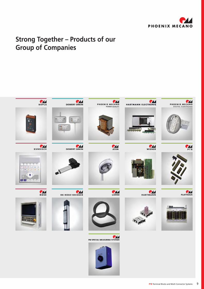
Strong Together – Products of our Group of Companies
10
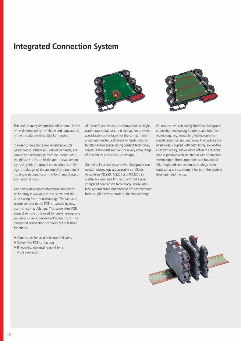
Integrated Connection System
The look of many assemblies and product lines is often determined by the shape and appearance of the included terminal blocks’ housing.
In order to be able to implement products which match customers’ individual needs, the connection technology must be integrated in the plastic enclosure of the appropriate assem-bly. Using this integrated connection technol-ogy, the design of the assembly/ product line is no longer depending on the form and shape of any terminal block.
The newly-developed integrated connection technology is available in the screw and the time-saving Push-In technology. The fast andsecure contact to the PCB is realized by easy push-on contact/clamps. This solder-free PCB contact removes the need for costly, errorprone soldering or an expensive soldering robot. The integrated connection technology fulfils three functions:
fConnection for solid and stranded wires f Solder-free PCB contacting f If required, connecting point for a cross connector
All these functions are concentrated on a single continuous metal part, and this system provides considerable advantages for the contact resist-ances and mechanical reliability. Such a highly functional and space-saving contact technology creates a standard solution for a very wide range of assemblies and enclosure designs.
Complete interface systems with integrated con-nection technology are available as follows:Assemblies INS250, INS260 and INM260 in widths 6.2 mm and 17.5 mm, with 5-12 pole integrated connection technology. These inter-face systems stand out because of their compact form coupled with a modern, functional design.
On request, we can supply individual integrated connection technology solutions and interface technology, e.g. contacting technologies or specific electrical requirements. The wide range of services, coupled with costsaving, solder-free PCB contacting, allows more efficient solutions than is possible with traditional wire connection technologies. Both ergonomic and functional this integrated connection technology repre-sents a major improvement for both the product developer and the user.
PTR Terminal Blocks and Multi Connector Systems 11
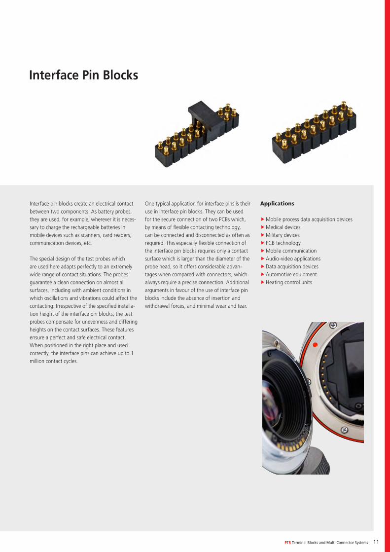
Interface Pin Blocks
Interface pin blocks create an electrical contact between two components. As battery probes, they are used, for example, wherever it is neces-sary to charge the rechargeable batteries in mobile devices such as scanners, card readers, communication devices, etc. The special design of the test probes which are used here adapts perfectly to an extremely wide range of contact situations. The probes guarantee a clean connection on almost all surfaces, including with ambient conditions in which oscillations and vibrations could affect the contacting. Irrespective of the specified installa-tion height of the interface pin blocks, the test probes compensate for unevenness and differing heights on the contact surfaces. These features ensure a perfect and safe electrical contact. When positioned in the right place and used correctly, the interface pins can achieve up to 1 million contact cycles.
One typical application for interface pins is their use in interface pin blocks. They can be used for the secure connection of two PCBs which, by means of flexible contacting technology, can be connected and disconnected as often as required. This especially flexible connection of the interface pin blocks requires only a contact surface which is larger than the diameter of the probe head, so it offers considerable advan-tages when compared with connectors, which always require a precise connection. Additional arguments in favour of the use of interface pin blocks include the absence of insertion and withdrawal forces, and minimal wear and tear.
Applications
fMobile process data acquisition devices fMedical devices fMilitary devices f PCB technology fMobile communication fAudio-video applications fData acquisition devices fAutomotive equipment fHeating control units
12
Your Benefits
Quality and reliability are more important today than ever before. This is
of utmost importance especially when it comes to terminal blocks and multi-
connector systems.
Ever-new directions must be met and strict international standards adhered to.
Along with constant quality checks and delivery deadlines, PTR maintains excel-
lent reliability, quality and service.
The focus is on the customer, who is not only offered a high-quality product
but in addition tremendous value and service.
With an innovative R&D Department (specialising in custom-made products),
a flexible production facility and a well-thought-out logistic process, PTR offers
prompt service and cost-effective products.
PTR offers a great package of value and service when it comes to
terminal blocks and multi-connector systems. Customer-specific requests are
welcome accepted and fulfilled using our in-house capabilities.
PTR Terminal Blocks and Multi Connector Systems 13
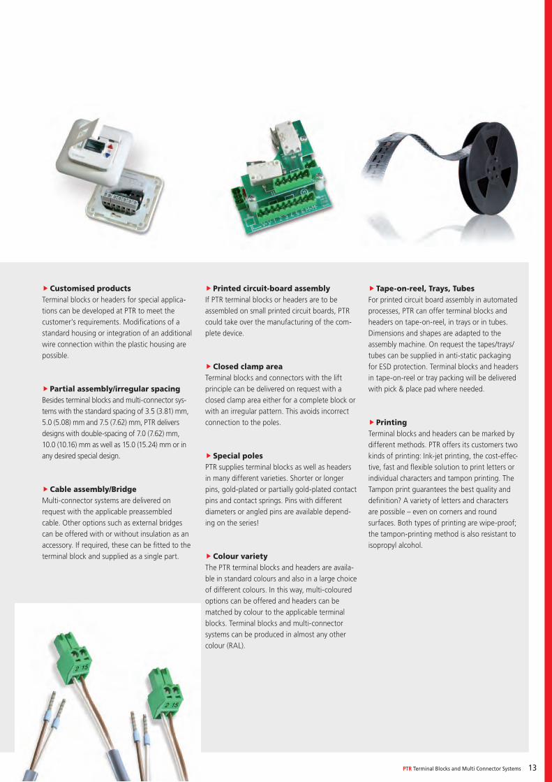
fCustomised productsTerminal blocks or headers for special applica-tions can be developed at PTR to meet the customer’s requirements. Modifications of a standard housing or integration of an additional wire connection within the plastic housing are possible.
f Partial assembly/irregular spacingBesides terminal blocks and multi-connector sys-tems with the standard spacing of 3.5 (3.81) mm, 5.0 (5.08) mm and 7.5 (7.62) mm, PTR delivers designs with double-spacing of 7.0 (7.62) mm, 10.0 (10.16) mm as well as 15.0 (15.24) mm or in any desired special design.
fCable assembly/BridgeMulti-connector systems are delivered on request with the applicable preassembled cable. Other options such as external bridges can be offered with or without insulation as an accessory. If required, these can be fitted to the terminal block and supplied as a single part.
f Printed circuit-board assemblyIf PTR terminal blocks or headers are to be assembled on small printed circuit boards, PTR could take over the manufacturing of the com-plete device.
fClosed clamp areaTerminal blocks and connectors with the lift principle can be delivered on request with a closed clamp area either for a complete block or with an irregular pattern. This avoids incorrect connection to the poles.
f Special polesPTR supplies terminal blocks as well as headers in many different varieties. Shorter or longer pins, gold-plated or partially gold-plated contact pins and contact springs. Pins with different diameters or angled pins are available depend-ing on the series!
fColour varietyThe PTR terminal blocks and headers are availa-ble in standard colours and also in a large choice of different colours. In this way, multi-coloured options can be offered and headers can be matched by colour to the applicable terminal blocks. Terminal blocks and multi-connector systems can be produced in almost any other colour (RAL).
f Tape-on-reel, Trays, TubesFor printed circuit board assembly in automated processes, PTR can offer terminal blocks and headers on tape-on-reel, in trays or in tubes. Dimensions and shapes are adapted to the assembly machine. On request the tapes/trays/tubes can be supplied in anti-static packaging for ESD protection. Terminal blocks and headers in tape-on-reel or tray packing will be delivered with pick & place pad where needed.
f PrintingTerminal blocks and headers can be marked by different methods. PTR offers its customers two kinds of printing: Ink-jet printing, the cost-effec-tive, fast and flexible solution to print letters or individual characters and tampon printing. The Tampon print guarantees the best quality and definition? A variety of letters and characters are possible – even on corners and round surfaces. Both types of printing are wipe-proof; the tampon-printing method is also resistant to isopropyl alcohol.
14
Clamp Types
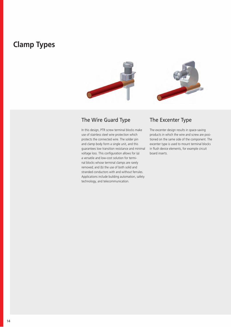
The Wire Guard Type
In this design, PTR screw terminal blocks make use of stainless steel wire protection which protects the connected wire. The solder pin and clamp body form a single unit, and this guarantees low transition resistance and minimal voltage loss. This configuration allows for (a) a versatile and low-cost solution for termi-nal blocks whose terminal clamps are rarely removed; and (b) the use of both solid and stranded conductors with and without ferrules. Applications include building automation, safety technology, and telecommunication.
The Excenter Type
The excenter design results in space-saving products in which the wire and screw are posi-tioned on the same side of the component. The excenter type is used to mount terminal blocks in flush device elements, for example circuit board inserts.
PTR Terminal Blocks and Multi Connector Systems 15
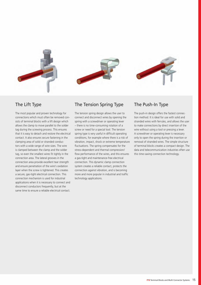
The Tension Spring Type
The tension spring design allows the user to connect and disconnect wires by opening the spring with a screwdriver or operating lever – there is no time-consuming rotation of a screw or need for a special tool. The tension spring type is very useful in difficult operating conditions, for example where there is a risk of vibration, impact, shock or extreme temperature fluctuations. The spring compensates for the stress-dependent and thermal compression/flow performance of the wires, and this ensures a gas-tight and maintenance-free electrical connection. This dynamic clamp connection system creates a reliable contact, protects the connection against vibration, and is becoming more and more popular in industrial and traffic technology applications.
The Push-In Type
The push-in design offers the fastest connec-tion method. It is ideal for use with solid and stranded wires with ferrules, and allows the user to make connections by direct insertion of the wire without using a tool or pressing a lever. A screwdriver or operating lever is necessary only to open the spring during the insertion or removal of stranded wires. The simple structure of terminal blocks creates a compact design. The data and telecommunication industries often use this time-saving connection technology.
The Lift Type
The most popular and proven technology for connections which must often be removed con-sists of terminal blocks with a lift design which allows the clamp to move parallel to the solder tag during the screwing process. This ensures that it is easy to detach and restore the electrical contact. It also ensures secure fastening in the clamping area of solid or stranded conduc-tors with a wide range of wire sizes. The wire is clamped between the clamp and the solder tag, so even the smallest wires fit tightly in the connection area. The lateral grooves in the connection area provide excellent tear strength and ensure penetration of the wire’s oxidation layer when the screw is tightened. This creates a secure, gas-tight electrical connection. This connection mechanism is used for industrial applications when it is necessary to connect and disconnect conductors frequently, but at the same time to ensure a reliable electrical contact.
16
Automated Assembly of PCBs
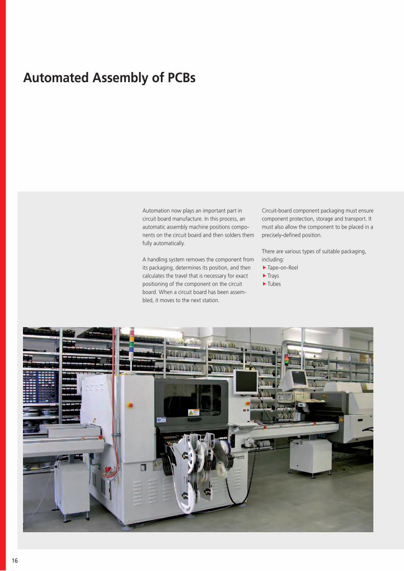
Automation now plays an important part in circuit board manufacture. In this process, an automatic assembly machine positions compo-nents on the circuit board and then solders them fully automatically.
A handling system removes the component from its packaging, determines its position, and then calculates the travel that is necessary for exact positioning of the component on the circuit board. When a circuit board has been assem-bled, it moves to the next station.
Circuit-board component packaging must ensure component protection, storage and transport. It must also allow the component to be placed in a precisely-defined position.
There are various types of suitable packaging, including:
f Tape-on-Reel f Trays f Tubes
PTR Terminal Blocks and Multi Connector Systems 17
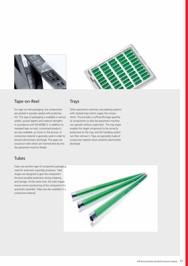
Tape-on-Reel
For tape-on-reel packaging, the components are packed in pockets sealed with protective foil. This type of packaging is available in various widths, pocket depths and material strengths in accordance with EN 60286-3. In addition to standard tape-on-reel, customized products are also available, as shown in the picture. A conductive material is generally used in order to prevent electrostatic discharge. The tapes are wound on reels which are inserted directly into the placement machine feeder.
Tubes
Tubes are another type of component packaging used for automatic assembly processes. Tube shapes are designed to give the component the best possible protection during shipping and storage. At the same time, the tube shapes ensure correct positioning of the component for automatic assembly. Tubes are also available in a conductive material.
Trays
Other placement machines use palleting systems with stacked trays which supply the compo-nents. This provides a sufficiently large quantity of components so that the placement machine can operate without supervision. The tray shape enables the target component to be correctly positioned on the tray, and the handling system can then remove it. Trays are generally made of conductive material which prevents electrostatic discharge.
18
Soldering
Wave or reflow soldering is used for the fully-automatic or semi-automatic soldering of com-ponents to circuit boards and flat modules.
In wave soldering, after the circuit board has been assembled, it is heated and then passed over a solder wave. In this process, hot fluid solder is pumped through a gap (chip and delta wave) or, for example, through holes in a perforated plate (Wörthmann wave). The com-ponent’s solder pins take up the solder, which results in a perfect solder connection after the solder has cooled.
In reflow soldering, soldering paste is applied under pressure to the circuit board. As the ap-plied solder has adhesive properties, the circuit board can be assembled without any further fixation, and can then pass through the furnace. After a pre-heating phase, the solder is heated to fusion temperature during the soldering phase. At this temperature, the solder becomes liquid, and this creates a bond between the component and circuit board. The result is a fault-free solder connection after the solder has cooled.
As a rule of thumb for solderable PTR terminal blocks and pin strips a PCB hole diameter should be used which is 0.3 mm larger than the pin diameter from the soldered component.
As preferred the information of the respective product page is valid. A solder pad has to have a minimum ring thickness of 0.2 mm to ensure a correct shaped soldering cone and therefore a good soldering joint.
The soldering process consists of the following four main phases:
1. Preparation: In the wave soldering process, first the components are mounted on the circuit board. In reflow soldering, by contrast, first the soldering paste is applied, and then the compo-nents are mounted.
2. Preheating: During this phase, the as-sembled circuit boards are brought to a preheat temperature – there are different processes for this purpose. The preheating method prevents deformation of the circuit board or its compo-nents and other damage.
3. Soldering: In wave soldering, the preheated circuit board passes over a solder wave. In reflow soldering, the entire circuit board is heated to the soldering temperature. The soldering time must be carefully selected to ensure that there is no damage to the circuit board or its heat-sensitive components.
4. Cooling: The circuit board components should be cooled under supervision immediately after soldering. This minimises thermal stress on the circuit board and its components.
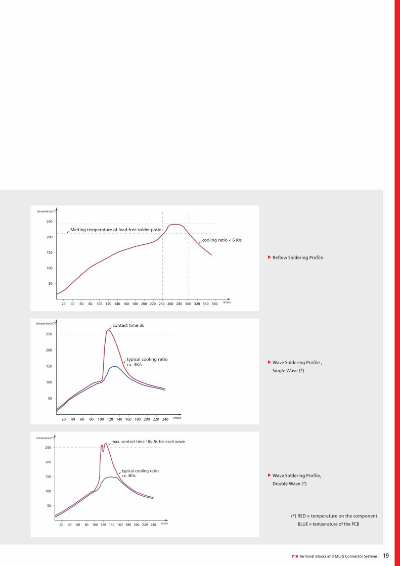
On the right there are examples of soldering temperature profiles for various soldering proc-esses used with through-hole products, based on EN 61760-1 for SMD products.
The actual soldering process depends on various factors, including PCB design, solder paste used, number, type and size of the components used. This means that the profiles illustrated can only be seen as recommendations.
It is not possible to make generally binding statements about the various processes, PCBs and components. Any decision about the profile which ensures your best soldering result must be taken on a case-by-case basis. The aim is to carry out work at the lower maximum load for the components used, so in general the maxi-mum temperatures used are lower than those shown in the soldering profiles on the right.
PTR Terminal Blocks and Multi Connector Systems 19
f Reflow Soldering Profile
fWave Soldering Profile ,
Single Wave (*)
fWave Soldering Profile,
Double Wave (*)
(*) RED = temperature on the component
BLUE = temperature of the PCB
temperature/°C
time/s
50
100
150
200
250
20 40 60 80 100 120 140 160 180 200 220 240
contact time 3s
typical cooling ratioca. 3K/s
temperature/°C
time/s
50
100
150
200
250
20 40 60 80 100 120 140 160 180 200 220 240
max. contact time 10s, 5s for each wave
typical cooling ratioca. 3K/s
50
100
150
200
250
20 40 60 80 100 120 140 160 180 200 220 240 260 280 300 320 340 360
cooling ratio < 6 K/s
Melting temperature of lead-free solder paste
temperature/°C
time/s
20
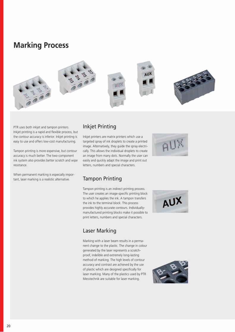
Marking Process
PTR uses both inkjet and tampon printers. Inkjet printing is a rapid and flexible process, but the contour accuracy is inferior. Inkjet printing is easy to use and offers low-cost manufacturing.
Tampon printing is more expensive, but contour accuracy is much better. The two-component ink system also provides better scratch and wipe resistance.
When permanent marking is especially impor-tant, laser marking is a realistic alternative.
Inkjet Printing
Inkjet printers are matrix printers which use a targeted spray of ink droplets to create a printed image. Alternatively, they guide the spray electri-cally. This allows the individual droplets to create an image from many dots. Normally the user can easily and quickly adapt the image and print out letters, numbers and special characters.
Tampon Printing
Tampon printing is an indirect printing process. The user creates an image-specific printing block to which he applies the ink. A tampon transfers the ink to the terminal block. This process provides highly accurate contours. Individually-manufactured printing blocks make it possible to print letters, numbers and special characters.
Laser Marking
Marking with a laser beam results in a perma-nent change to the plastic. The change in colour generated by the laser represents a scratch-proof, indelible and extremely long-lasting method of marking. The high levels of contour accuracy and contrast are achieved by the use of plastic which are designed specifically for laser marking. Many of the plastics used by PTR Messtechnik are suitable for laser marking.
PTR Terminal Blocks and Multi Connector Systems 21
1
2
3
5
4
6
7
8
9
Article Designation for Standard Terminal Blocks
Series NameAK/ STL metric versionAKZ/ STLZ inch version
Number of Poles
CC with coding cover DS with wire guard F with flange FD with finger releaseG with side walls, enclosed housingGMB assembly block versionKD with screw leverL with pull relief LG with locking guides SE with separating element(s)VP with alternating pinsWD with angle lever
Spacing in mm
H solderable terminal blocks: horizontal screw-in direction pin strips: horizontal plug-in direction of pluggable terminal blockV solderable terminal blocks: vertical screw-in direction pin strips: vertical plug-in direction of pluggable terminal blockOL orthogonal design, pins point left OR orthogonal design, pins point right
PX.X pin length, solder sidePTX.X pin length, plug side
with Printing
Housing Colour be spelled out completely for example: GREENor on the basis of DIN IEC 60757 for example: GN
AU gold-plated contactsBL solid block BR with internal bridging CP with coding pin(s) FP with fixing pin(s)HC high-current version HT reflow enabled INV inverted mating facePD Pin distance from front row to back rowSMD surface mounted device
1 2 3 4 5 6 7 8 9
STL950 / 6 (G) – 5.0 – (V) – (P2.6) – (B) – GREEN – (AU)

22
www.ptr.eu
6
1
4
6
2 3 5
Products Product search with individual search criteria Product data sheets with technical drawings and zoomable photos PDF generation Terminal blocks Test probes - product configurator Sample order Cross-reference from stock
Know How Background knowledge and more detailed information on our products
Downloads Catalogues Certificates Statements of conformity Brochures Press releases
Cross-Reference Recoding of competitor article designations to PTR designations
Login Area Premium service for registered customers
fDownload 3D-files
Contact Your contacts worldwide
4
5
1 2
3

PTR Terminal Blocks and Multi Connector Systems 23
24
PTR Terminal Blocks and Multi Connector Systems 25
Terminal Blocks
PCB terminal blocks are divided into two groups: a) screw terminal blocks,
and b) spring terminal blocks. Three connection types are available for
the screw terminal blocks: the wire guard, the lift, and the excenter
type.
Normally, screw terminal blocks are manufactured either as modular con-
structions, as two-pole and three-pole terminals, and can be flexi-
bly connected to each other to make larger terminals by means of the so-called
dovetail connection. Individual series are also available in blocks. Screw ter-
minal blocks using the different connection designs are available with spacing
from 2.54 mm to 15.24 mm, metric or inch, and in various colours.
The group of spring terminal blocks is divided into terminal blocks
using the push-in design (leg spring technology) and the tension spring
design. Spring terminal blocks are normally manufactured in layers which
can be combined to create the required number of poles. In addition, different
colours can be combined within a terminal block.
Spring terminal blocks using both connection types are available with spacing
from 2.5 mm to 11.5 mm, metric or inches.
Wire SizesSolid minSolid maxStranded (flexible) minStranded (flexible) maxStranded with Ferrule minStranded with Ferrule maxDimensions Stripped Length
PCB Hole DiameterMaterials
Insulating Material MaterialFlammability ClassTemperaturesOperating TemperatureWave Soldering ProcessSoldering Temperature,recommendedPeak Soldering Time,recommendedReflow ProcessSoldering Temperature,recommended
Peak Soldering Time,recommended
Technical Data
Ratings
26
Colours Colours
AccessoriesFigure Designation Article Number
Order Data (Spacing 3.5 mm)Poles Width (mm) Article Designation Article Number PU
See pages 282 ff for detail and general accessoriesand see pages 12/13 concerning services.
Colours according to RAL, there may be variations on colour due to production conditions. Special colours on request.
Bridge, 2-pole, insulated, BRI/2-7.0/7.62-L7.5-LIGHT GREY
50000000018
Bridge, 2-pole, angled, BR/2-3.5/3.81-H-L7.5
50000000029
Bridge, 2-pole, BR/2-3.5/3.81-L7.5 50000000015
Bridge, 3-pole, BR/3-3.5/3.81-L7.5 50000000016
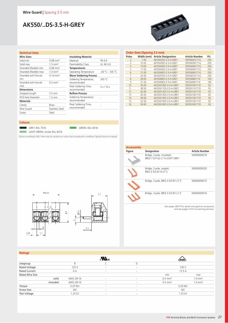
Wire Guard | Spacing 3.5 mm
AK550/..DS-3.5-V-GREY
2 7.00 AK550/2DS-3.5-V-GREY 50550020121G 2503 10.50 AK550/3DS-3.5-V-GREY 50550030121G 2504 14.00 AK550/4DS-3.5-V-GREY 50550040121G 2505 17.50 AK550/5DS-3.5-V-GREY 50550050121G 2506 21.00 AK550/6DS-3.5-V-GREY 50550060121G 2507 24.50 AK550/7DS-3.5-V-GREY 50550070121G 2508 28.00 AK550/8DS-3.5-V-GREY 50550080121E 1009 31.50 AK550/9DS-3.5-V-GREY 50550090121E 100
10 35.00 AK550/10DS-3.5-V-GREY 50550100121D 5011 38.50 AK550/11DS-3.5-V-GREY 50550110121D 5012 42.00 AK550/12DS-3.5-V-GREY 50550120121D 5013 45.50 AK550/13DS-3.5-V-GREY 50550130121D 5014 49.00 AK550/14DS-3.5-V-GREY 50550140121D 5015 52.50 AK550/15DS-3.5-V-GREY 50550150121D 5016 56.00 AK550/16DS-3.5-V-GREY 50550160121D 50
Usegroup B C DRated Voltage 125 V - - 130 VRated Current 6 A - - 13.5 ARated Wire Size min max
solid AWG 28-16 - - 0.5 mm² 1.0 mm²stranded AWG 28-16 - - 0.5 mm² 1.0 mm²
Torque 0.25 Nm - - 0.20 NmScrew Size M2 - - M2Test Voltage 1.25 kV - - 1.25 kV
GREY, RAL 7016 PEBBLE GREY, RAL 7032
GREEN, RAL 6018 LIGHT GREEN, similar RAL 6018
PA 6.6UL 94 V-0
-30 °C - 105 °C
265 °C
3 s / 10 s
-
-
0.08 mm²1.5 mm²0.08 mm²1.0 mm²0.14 mm²
0.5 mm²
5.5 mm
1.2 mm
Clamp BrassWire Guard Stainless SteelScrew Steel
Wire SizesSolid minSolid maxStranded (flexible) minStranded (flexible) maxStranded with Ferrule minStranded with Ferrule maxDimensions Stripped Length
PCB Hole DiameterMaterials
Insulating Material MaterialFlammability ClassTemperaturesOperating TemperatureWave Soldering ProcessSoldering Temperature,recommendedPeak Soldering Time,recommendedReflow ProcessSoldering Temperature,recommended
Peak Soldering Time,recommended
Technical Data
Ratings
Colours
PTR Terminal Blocks and Multi Connector Systems 27
AccessoriesFigure Designation Article Number
Order Data (Spacing 3.5 mm)Poles Width (mm) Article Designation Article Number PU
See pages 282 ff for detail and general accessoriesand see pages 12/13 concerning services.
Colours according to RAL, there may be variations on colour due to production conditions. Special colours on request.
Wire Guard | Spacing 3.5 mm
AK550/..DS-3.5-H-GREY
2 7.00 AK550/2DS-3.5-H-GREY 50550020171G 2503 10.50 AK550/3DS-3.5-H-GREY 50550030171G 2504 14.00 AK550/4DS-3.5-H-GREY 50550040171G 2505 17.50 AK550/5DS-3.5-H-GREY 50550050171G 2506 21.00 AK550/6DS-3.5-H-GREY 50550060171G 2507 24.50 AK550/7DS-3.5-H-GREY 50550070171G 2508 28.00 AK550/8DS-3.5-H-GREY 50550080171E 1009 31.50 AK550/9DS-3.5-H-GREY 50550090171E 100
10 35.00 AK550/10DS-3.5-H-GREY 50550100171D 5011 38.50 AK550/11DS-3.5-H-GREY 50550110171D 5012 42.00 AK550/12DS-3.5-H-GREY 50550120171D 5013 45.50 AK550/13DS-3.5-H-GREY 50550130171D 5014 49.00 AK550/14DS-3.5-H-GREY 50550140171D 5015 52.50 AK550/15DS-3.5-H-GREY 50550150171D 5016 56.00 AK550/16DS-3.5-H-GREY 50550160171D 50
Usegroup B C DRated Voltage 125 V - - 130 VRated Current 6 A - - 13.5 ARated Wire Size min max
solid AWG 28-16 - - 0.5 mm² 1.0 mm²stranded AWG 28-16 - - 0.5 mm² 1.0 mm²
Torque 0.25 Nm - - 0.20 NmScrew Size M2 - - M2Test Voltage 1.25 kV - - 1.25 kV
GREY, RAL 7016 GREEN, RAL 6018
LIGHT GREEN, similar RAL 6018
Bridge, 2-pole, insulated, BRI/2-7.0/7.62-L7.5-LIGHT GREY
50000000018
Bridge, 2-pole, angled, BR/2-3.5/3.81-H-L7.5
50000000029
Bridge, 2-pole, BR/2-3.5/3.81-L7.5 50000000015
Bridge, 3-pole, BR/3-3.5/3.81-L7.5 50000000016
PA 6.6UL 94 V-0
-30 °C - 105 °C
265 °C
3 s / 10 s
-
-
0.08 mm²1.5 mm²0.08 mm²1.0 mm²0.14 mm²
0.5 mm²
5.5 mm
1.2 mm
Clamp BrassWire Guard Stainless SteelScrew Steel
Wire SizesSolid minSolid maxStranded (flexible) minStranded (flexible) maxStranded with Ferrule minStranded with Ferrule maxDimensions Stripped Length
PCB Hole DiameterMaterials
Insulating Material MaterialFlammability ClassTemperaturesOperating TemperatureWave Soldering ProcessSoldering Temperature,recommendedPeak Soldering Time,recommendedReflow ProcessSoldering Temperature,recommended
Peak Soldering Time,recommended
Technical Data
Ratings
Accessories Figure Designation Article Number
28
Colours
Order Data (Spacing 5.0 mm)Poles Width (mm) Article Designation Article Number PU
See pages 282 ff for detail and general accessoriesand see pages 12/13 concerning services.
Colours according to RAL, there may be variations on colour due to production conditions. Special colours on request.
Wire Guard | Spacing 5.0 mm
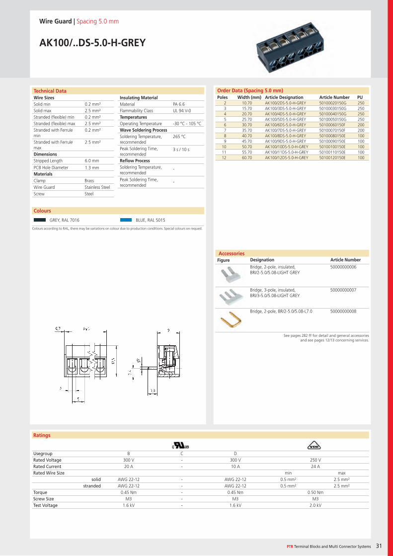
AK100/..DS-5.0-V-GREY
2 10.70 AK100/2DS-5.0-V-GREY 50100020121G 2503 15.70 AK100/3DS-5.0-V-GREY 50100030121G 2504 20.70 AK100/4DS-5.0-V-GREY 50100040121G 2505 25.70 AK100/5DS-5.0-V-GREY 50100050121G 2506 30.70 AK100/6DS-5.0-V-GREY 50100060121F 2007 35.70 AK100/7DS-5.0-V-GREY 50100070121F 2008 40.70 AK100/8DS-5.0-V-GREY 50100080121E 1009 45.70 AK100/9DS-5.0-V-GREY 50100090121E 100
10 50.70 AK100/10DS-5.0-V-GREY 50100100121E 10011 55.70 AK100/11DS-5.0-V-GREY 50100110121E 10012 60.70 AK100/12DS-5.0-V-GREY 50100120121E 100
Usegroup B C DRated Voltage 300 V - 300 V 250 VRated Current 20 A - 10 A 24 ARated Wire Size min max
solid AWG 22-12 - AWG 22-12 0.5 mm² 2.5 mm²stranded AWG 22-12 - AWG 22-12 0.5 mm² 2.5 mm²
Torque 0.45 Nm - 0.45 Nm 0.50 NmScrew Size M3 - M3 M3Test Voltage 1.6 kV - 1.6 kV 2.0 kV
GREY, RAL 7016 BLACK, RAL 9011
BLUE, RAL 5015
Bridge, 2-pole, insulated, BRI/2-5.0/5.08-LIGHT GREY
50000000006
Bridge, 3-pole, insulated, BRI/3-5.0/5.08-LIGHT GREY
50000000007
Bridge, 2-pole, BR/2-5.0/5.08-L7.0 50000000008
PA 6.6UL 94 V-0
-30 °C - 105 °C
265 °C
3 s / 10 s
-
-
0.2 mm²2.5 mm²0.2 mm²2.5 mm²0.2 mm²
2.5 mm²
7.0 mm
1.3 mm
Clamp BrassWire Guard Stainless SteelScrew Steel
Wire SizesSolid minSolid maxStranded (flexible) minStranded (flexible) maxStranded with Ferrule minStranded with Ferrule maxDimensions Stripped Length
PCB Hole DiameterMaterials
Insulating Material MaterialFlammability ClassTemperaturesOperating TemperatureWave Soldering ProcessSoldering Temperature,recommendedPeak Soldering Time,recommendedReflow ProcessSoldering Temperature,recommended
Peak Soldering Time,recommended
Technical Data
Ratings
Accessories Figure Designation Article Number
Order Data (Spacing 5.08 mm)Poles Width (mm) Article Designation Article Number PU
Colours
PTR Terminal Blocks and Multi Connector Systems 29
See pages 282 ff for detail and general accessoriesand see pages 12/13 concerning services.
Colours according to RAL, there may be variations on colour due to production conditions. Special colours on request.
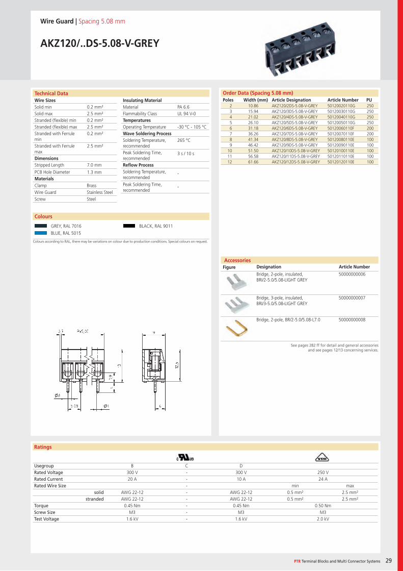
Wire Guard | Spacing 5.08 mm
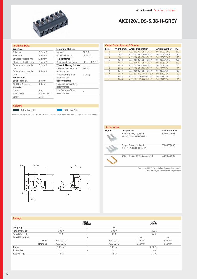
AKZ120/..DS-5.08-V-GREY
2 10.86 AKZ120/2DS-5.08-V-GREY 50120020110G 2503 15.94 AKZ120/3DS-5.08-V-GREY 50120030110G 2504 21.02 AKZ120/4DS-5.08-V-GREY 50120040110G 2505 26.10 AKZ120/5DS-5.08-V-GREY 50120050110G 2506 31.18 AKZ120/6DS-5.08-V-GREY 50120060110F 2007 36.26 AKZ120/7DS-5.08-V-GREY 50120070110F 2008 41.34 AKZ120/8DS-5.08-V-GREY 50120080110E 1009 46.42 AKZ120/9DS-5.08-V-GREY 50120090110E 100
10 51.50 AKZ120/10DS-5.08-V-GREY 50120100110E 10011 56.58 AKZ120/11DS-5.08-V-GREY 50120110110E 10012 61.66 AKZ120/12DS-5.08-V-GREY 50120120110E 100
Usegroup B C DRated Voltage 300 V - 300 V 250 VRated Current 20 A - 10 A 24 ARated Wire Size - min max
solid AWG 22-12 - AWG 22-12 0.5 mm² 2.5 mm²stranded AWG 22-12 - AWG 22-12 0.5 mm² 2.5 mm²
Torque 0.45 Nm - 0.45 Nm 0.50 NmScrew Size M3 - M3 M3Test Voltage 1.6 kV - 1.6 kV 2.0 kV
GREY, RAL 7016 BLACK, RAL 9011
BLUE, RAL 5015
Bridge, 2-pole, insulated, BRI/2-5.0/5.08-LIGHT GREY
50000000006
Bridge, 3-pole, insulated, BRI/3-5.0/5.08-LIGHT GREY
50000000007
Bridge, 2-pole, BR/2-5.0/5.08-L7.0 50000000008
PA 6.6UL 94 V-0
-30 °C - 105 °C
265 °C
3 s / 10 s
-
-
0.2 mm²2.5 mm²0.2 mm²2.5 mm²0.2 mm²
2.5 mm²
7.0 mm
1.3 mm
Clamp BrassWire Guard Stainless SteelScrew Steel
Wire SizesSolid minSolid maxStranded (flexible) minStranded (flexible) maxStranded with Ferrule minStranded with Ferrule maxDimensions Stripped Length
PCB Hole DiameterMaterials
Insulating Material MaterialFlammability ClassTemperaturesOperating TemperatureWave Soldering ProcessSoldering Temperature,recommendedPeak Soldering Time,recommendedReflow ProcessSoldering Temperature,recommended
Peak Soldering Time,recommended
Technical Data
Ratings
Accessories Figure Designation Article Number
30
Colours
Order Data (Spacing 5.0 mm)Poles Width (mm) Article Designation Article Number PU
See pages 282 ff for detail and general accessoriesand see pages 12/13 concerning services.
Colours according to RAL, there may be variations on colour due to production conditions. Special colours on request.
Wire Guard | Spacing 5.0 mm
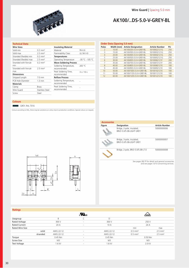
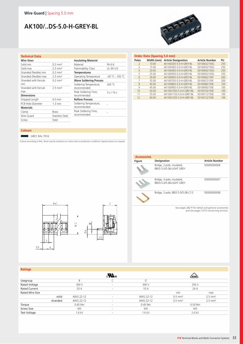
AK100/..DS-5.0-V-GREY-BL
2 10.00 AK100/2DS-5.0-V-GREY-BL 50100022121G 2503 15.00 AK100/3DS-5.0-V-GREY-BL 50100032121G 2504 20.00 AK100/4DS-5.0-V-GREY-BL 50100042121G 2505 25.00 AK100/5DS-5.0-V-GREY-BL 50100052121G 2506 30.00 AK100/6DS-5.0-V-GREY-BL 50100062121F 2007 35.00 AK100/7DS-5.0-V-GREY-BL 50100072121F 2008 40.00 AK100/8DS-5.0-V-GREY-BL 50100082121E 1009 45.00 AK100/9DS-5.0-V-GREY-BL 50100092121E 100
10 50.00 AK100/10DS-5.0-V-GREY-BL 50100102121E 10011 55.00 AK100/11DS-5.0-V-GREY-BL 50100112121E 10012 60.00 AK100/12DS-5.0-V-GREY-BL 50100122121E 100
Usegroup B C DRated Voltage 300 V - 300 V 250 VRated Current 20 A - 10 A 24 ARated Wire Size min max
solid AWG 22-12 - AWG 22-12 0.5 mm² 2.5 mm²stranded AWG 22-12 - AWG 22-12 0.5 mm² 2.5 mm²
Torque 0.45 Nm - 0.45 Nm 0.50 NmScrew Size M3 - M3 M3Test Voltage 1.6 kV - 1.6 kV 2.0 kV
GREY, RAL 7016
Bridge, 2-pole, insulated, BRI/2-5.0/5.08-LIGHT GREY
50000000006
Bridge, 3-pole, insulated, BRI/3-5.0/5.08-LIGHT GREY
50000000007
Bridge, 2-pole, BR/2-5.0/5.08-L7.0 50000000008
PA 6.6UL 94 V-0
-30 °C - 105 °C
265 °C
3 s / 10 s
-
-
0.2 mm²2.5 mm²0.2 mm²2.5 mm²0.2 mm²
2.5 mm²
7.0 mm
1.3 mm
Clamp BrassWire Guard Stainless SteelScrew Steel
Wire SizesSolid minSolid maxStranded (flexible) minStranded (flexible) maxStranded with Ferrule minStranded with Ferrule maxDimensions Stripped Length
PCB Hole DiameterMaterials
Insulating Material MaterialFlammability ClassTemperaturesOperating TemperatureWave Soldering ProcessSoldering Temperature,recommendedPeak Soldering Time,recommendedReflow ProcessSoldering Temperature,recommended
Peak Soldering Time,recommended
Technical Data
Ratings
Accessories Figure Designation Article Number
Colours
PTR Terminal Blocks and Multi Connector Systems 31
Order Data (Spacing 5.0 mm)Poles Width (mm) Article Designation Article Number PU
See pages 282 ff for detail and general accessoriesand see pages 12/13 concerning services.
Colours according to RAL, there may be variations on colour due to production conditions. Special colours on request.
Wire Guard | Spacing 5.0 mm
AK100/..DS-5.0-H-GREY
2 10.70 AK100/2DS-5.0-H-GREY 50100020150G 2503 15.70 AK100/3DS-5.0-H-GREY 50100030150G 2504 20.70 AK100/4DS-5.0-H-GREY 50100040150G 2505 25.70 AK100/5DS-5.0-H-GREY 50100050150G 2506 30.70 AK100/6DS-5.0-H-GREY 50100060150F 2007 35.70 AK100/7DS-5.0-H-GREY 50100070150F 2008 40.70 AK100/8DS-5.0-H-GREY 50100080150E 1009 45.70 AK100/9DS-5.0-H-GREY 50100090150E 100
10 50.70 AK100/10DS-5.0-H-GREY 50100100150E 10011 55.70 AK100/11DS-5.0-H-GREY 50100110150E 10012 60.70 AK100/12DS-5.0-H-GREY 50100120150E 100
Usegroup B C DRated Voltage 300 V - 300 V 250 VRated Current 20 A - 10 A 24 ARated Wire Size min max
solid AWG 22-12 - AWG 22-12 0.5 mm² 2.5 mm²stranded AWG 22-12 - AWG 22-12 0.5 mm² 2.5 mm²
Torque 0.45 Nm - 0.45 Nm 0.50 NmScrew Size M3 - M3 M3Test Voltage 1.6 kV - 1.6 kV 2.0 kV
GREY, RAL 7016 BLUE, RAL 5015
Bridge, 2-pole, insulated, BRI/2-5.0/5.08-LIGHT GREY
50000000006
Bridge, 3-pole, insulated, BRI/3-5.0/5.08-LIGHT GREY
50000000007
Bridge, 2-pole, BR/2-5.0/5.08-L7.0 50000000008
PA 6.6UL 94 V-0
-30 °C - 105 °C
265 °C
3 s / 10 s
-
-
0.2 mm²2.5 mm²0.2 mm²2.5 mm²0.2 mm²
2.5 mm²
6.0 mm
1.3 mm
Clamp BrassWire Guard Stainless SteelScrew Steel
Wire SizesSolid minSolid maxStranded (flexible) minStranded (flexible) maxStranded with Ferrule minStranded with Ferrule maxDimensions Stripped Length
PCB Hole DiameterMaterials
Insulating Material MaterialFlammability ClassTemperaturesOperating TemperatureWave Soldering ProcessSoldering Temperature,recommendedPeak Soldering Time,recommendedReflow ProcessSoldering Temperature,recommended
Peak Soldering Time,recommended
Technical Data
Ratings
Accessories Figure Designation Article Number
32
Colours
Order Data (Spacing 5.08 mm)Poles Width (mm) Article Designation Article Number PU
See pages 282 ff for detail and general accessoriesand see pages 12/13 concerning services.
Colours according to RAL, there may be variations on colour due to production conditions. Special colours on request.
Wire Guard | Spacing 5.08 mm
AKZ120/..DS-5.08-H-GREY
2 10.86 AKZ120/2DS-5.08-H-GREY 50120020130G 2503 15.94 AKZ120/3DS-5.08-H-GREY 50120030130G 2504 21.02 AKZ120/4DS-5.08-H-GREY 50120040130G 2505 26.10 AKZ120/5DS-5.08-H-GREY 50120050130G 2506 31.18 AKZ120/6DS-5.08-H-GREY 50120060130F 2007 36.26 AKZ120/7DS-5.08-H-GREY 50120070130F 2008 41.34 AKZ120/8DS-5.08-H-GREY 50120080130E 1009 46.42 AKZ120/9DS-5.08-H-GREY 50120090130E 100
10 51.50 AKZ120/10DS-5.08-H-GREY 50120100130E 10011 56.58 AKZ120/11DS-5.08-H-GREY 50120110130E 10012 61.66 AKZ120/12DS-5.08-H-GREY 50120120130E 100
Usegroup B C DRated Voltage 300 V - 300 V 250 VRated Current 20 A - 10 A 24 ARated Wire Size - min max
solid AWG 22-12 - AWG 22-12 0.5 mm² 2.5 mm²stranded AWG 22-12 - AWG 22-12 0.5 mm² 2.5 mm²
Torque 0.45 Nm - 0.45 Nm 0.50 NmScrew Size M3 - M3 M3Test Voltage 1.6 kV - 1.6 kV 2.0 kV
GREY, RAL 7016 BLUE, RAL 5015
Bridge, 2-pole, insulated, BRI/2-5.0/5.08-LIGHT GREY
50000000006
Bridge, 3-pole, insulated, BRI/3-5.0/5.08-LIGHT GREY
50000000007
Bridge, 2-pole, BR/2-5.0/5.08-L7.0 50000000008
PA 6.6UL 94 V-0
-30 °C - 105 °C
265 °C
3 s / 10 s
-
-
0.2 mm²2.5 mm²0.2 mm²2.5 mm²0.2 mm²
2.5 mm²
6.0 mm
1.3 mm
Clamp BrassWire Guard Stainless SteelScrew Steel
Wire SizesSolid minSolid maxStranded (flexible) minStranded (flexible) maxStranded with Ferrule minStranded with Ferrule maxDimensions Stripped Length
PCB Hole DiameterMaterials
Insulating Material MaterialFlammability ClassTemperaturesOperating TemperatureWave Soldering ProcessSoldering Temperature,recommendedPeak Soldering Time,recommendedReflow ProcessSoldering Temperature,recommended
Peak Soldering Time,recommended
Technical Data
Ratings
Accessories Figure Designation Article Number
Colours
PTR Terminal Blocks and Multi Connector Systems 33
Order Data (Spacing 5.0 mm)Poles Width (mm) Article Designation Article Number PU
See pages 282 ff for detail and general accessoriesand see pages 12/13 concerning services.
Colours according to RAL, there may be variations on colour due to production conditions. Special colours on request.
Wire Guard | Spacing 5.0 mm
AK100/..DS-5.0-H-GREY-BL
2 10.00 AK100/2DS-5.0-H-GREY-BL 50100022150G 2503 15.00 AK100/3DS-5.0-H-GREY-BL 50100032150G 2504 20.00 AK100/4DS-5.0-H-GREY-BL 50100042150G 2505 25.00 AK100/5DS-5.0-H-GREY-BL 50100052150G 2506 30.00 AK100/6DS-5.0-H-GREY-BL 50100062150F 2007 35.00 AK100/7DS-5.0-H-GREY-BL 50100072150F 2008 40.00 AK100/8DS-5.0-H-GREY-BL 50100082150E 1009 45.00 AK100/9DS-5.0-H-GREY-BL 50100092150E 100
10 50.00 AK100/10DS-5.0-H-GREY-BL 50100102150E 10011 55.00 AK100/11DS-5.0-H-GREY-BL 50100112150E 10012 60.00 AK100/12DS-5.0-H-GREY-BL 50100122150E 100
Usegroup B C DRated Voltage 300 V - 300 V 250 VRated Current 20 A - 10 A 24 ARated Wire Size min max
solid AWG 22-12 - AWG 22-12 0.5 mm² 2.5 mm²stranded AWG 22-12 - AWG 22-12 0.5 mm² 2.5 mm²
Torque 0.45 Nm - 0.45 Nm 0.50 NmScrew Size M3 - M3 M3Test Voltage 1.6 kV - 1.6 kV 2.0 kV
GREY, RAL 7016
Bridge, 2-pole, insulated, BRI/2-5.0/5.08-LIGHT GREY
50000000006
Bridge, 3-pole, insulated, BRI/3-5.0/5.08-LIGHT GREY
50000000007
Bridge, 2-pole, BR/2-5.0/5.08-L7.0 50000000008
PA 6.6UL 94 V-0
-30 °C - 105 °C
265 °C
3 s / 10 s
-
-
0.2 mm²2.5 mm²0.2 mm²2.5 mm²0.2 mm²
2.5 mm²
6.0 mm
1.3 mm
Clamp BrassWire Guard Stainless SteelScrew Steel
Wire SizesSolid minSolid maxStranded (flexible) minStranded (flexible) maxStranded with Ferrule minStranded with Ferrule maxDimensions Stripped Length
PCB Hole DiameterMaterials
Insulating Material MaterialFlammability ClassTemperaturesOperating TemperatureWave Soldering ProcessSoldering Temperature,recommendedPeak Soldering Time,recommendedReflow ProcessSoldering Temperature,recommended
Peak Soldering Time,recommended
Technical Data
Ratings
Accessories Figure Designation Article Number
34
Colours
Order Data (Spacing 5.0 mm)Poles Width (mm) Article Designation Article Number PU
See pages 282 ff for detail and general accessoriesand see pages 12/13 concerning services.
Colours according to RAL, there may be variations on colour due to production conditions. Special colours on request.
Wire Guard | Spacing 5.0 mm
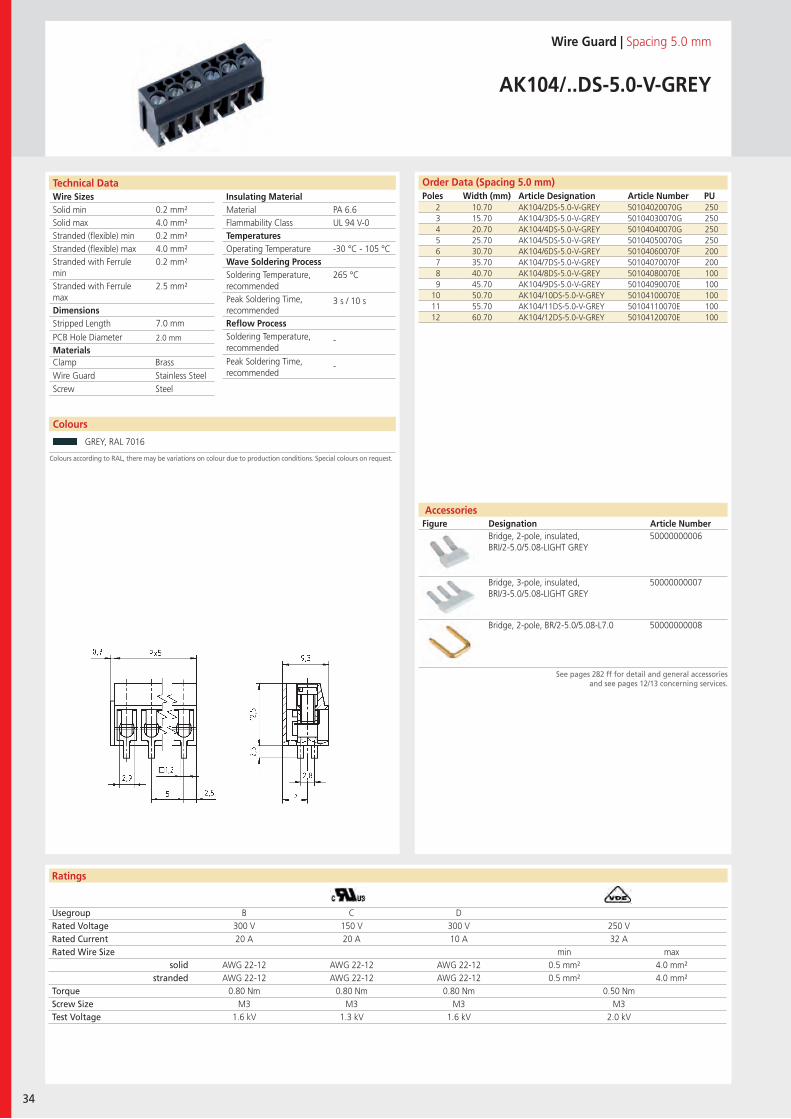
AK104/..DS-5.0-V-GREY
2 10.70 AK104/2DS-5.0-V-GREY 50104020070G 2503 15.70 AK104/3DS-5.0-V-GREY 50104030070G 2504 20.70 AK104/4DS-5.0-V-GREY 50104040070G 2505 25.70 AK104/5DS-5.0-V-GREY 50104050070G 2506 30.70 AK104/6DS-5.0-V-GREY 50104060070F 2007 35.70 AK104/7DS-5.0-V-GREY 50104070070F 2008 40.70 AK104/8DS-5.0-V-GREY 50104080070E 1009 45.70 AK104/9DS-5.0-V-GREY 50104090070E 100
10 50.70 AK104/10DS-5.0-V-GREY 50104100070E 10011 55.70 AK104/11DS-5.0-V-GREY 50104110070E 10012 60.70 AK104/12DS-5.0-V-GREY 50104120070E 100
Usegroup B C DRated Voltage 300 V 150 V 300 V 250 VRated Current 20 A 20 A 10 A 32 ARated Wire Size min max
solid AWG 22-12 AWG 22-12 AWG 22-12 0.5 mm² 4.0 mm²stranded AWG 22-12 AWG 22-12 AWG 22-12 0.5 mm² 4.0 mm²
Torque 0.80 Nm 0.80 Nm 0.80 Nm 0.50 NmScrew Size M3 M3 M3 M3Test Voltage 1.6 kV 1.3 kV 1.6 kV 2.0 kV
GREY, RAL 7016
Bridge, 2-pole, insulated, BRI/2-5.0/5.08-LIGHT GREY
50000000006
Bridge, 3-pole, insulated, BRI/3-5.0/5.08-LIGHT GREY
50000000007
Bridge, 2-pole, BR/2-5.0/5.08-L7.0 50000000008
PA 6.6UL 94 V-0
-30 °C - 105 °C
265 °C
3 s / 10 s
-
-
0.2 mm²4.0 mm²0.2 mm²4.0 mm²0.2 mm²
2.5 mm²
7.0 mm
2.0 mm
Clamp BrassWire Guard Stainless SteelScrew Steel
Wire SizesSolid minSolid maxStranded (flexible) minStranded (flexible) maxStranded with Ferrule minStranded with Ferrule maxDimensions Stripped Length
PCB Hole DiameterMaterials
Insulating Material MaterialFlammability ClassTemperaturesOperating TemperatureWave Soldering ProcessSoldering Temperature,recommendedPeak Soldering Time,recommendedReflow ProcessSoldering Temperature,recommended
Peak Soldering Time,recommended
Technical Data
Ratings
Accessories Figure Designation Article Number
Colours
PTR Terminal Blocks and Multi Connector Systems 35
Order Data (Spacing 5.08 mm)Poles Width (mm) Article Designation Article Number PU
Order Data (Spacing 5.0 mm)Poles Width (mm) Article Designation Article Number PU
See pages 282 ff for detail and general accessoriesand see pages 12/13 concerning services.
Colours according to RAL, there may be variations on colour due to production conditions. Special colours on request.
Wire Guard | Spacing 5.0 mm / 5.08 mm
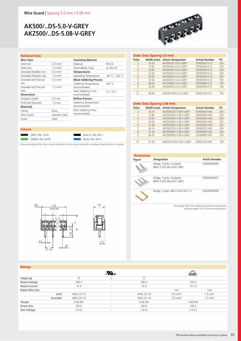
AK500/..DS-5.0-V-GREYAKZ500/..DS-5.08-V-GREY
2 10.60 AK500/2DS-5.0-V-GREY 50500020121G 2503 15.60 AK500/3DS-5.0-V-GREY 50500030121G 2504 20.60 AK500/4DS-5.0-V-GREY 50500040121G 2505 25.60 AK500/5DS-5.0-V-GREY 50500050121G 2506 30.60 AK500/6DS-5.0-V-GREY 50500060121G 2507 35.60 AK500/7DS-5.0-V-GREY 50500070121G 2508 40.60 AK500/8DS-5.0-V-GREY 50500080121E 1009 45.60 AK500/9DS-5.0-V-GREY 50500090121E 100... ... ... ... ...12 60.60 AK500/12DS-5.0-V-GREY 50500120121E 100
Usegroup B C DRated Voltage 300 V - 300 V 250 VRated Current 15 A - 10 A 17.5 ARated Wire Size min max
solid AWG 22-14 - AWG 22-14 0.5 mm² 1.5 mm²stranded AWG 22-14 - AWG 22-14 0.5 mm² 1.5 mm²
Torque 0.40 Nm - 0.40 Nm 0.40 NmScrew Size M2.6 - M2.6 M2.6Test Voltage 1.6 kV - 1.6 kV 2.0 kV
GREY, RAL 7016 BLACK, RAL 9011
GREEN, RAL 6018 BLUE, RAL 5015
Bridge, 2-pole, insulated, BRI/2-5.0/5.08-LIGHT GREY
50000000006
Bridge, 3-pole, insulated, BRI/3-5.0/5.08-LIGHT GREY
50000000007
Bridge, 2-pole, BR/2-5.0/5.08-L7.0 50000000008
PA 6.6UL 94 V-0
-30 °C - 105 °C
265 °C
3 s / 10 s
-
-
0.2 mm²1.5 mm²0.2 mm²1.5 mm²0.2 mm²
1.5 mm²
6.0 mm
1.3 mm
2 10.76 AKZ500/2DS-5.08-V-GREY 50500020134G 2503 15.84 AKZ500/3DS-5.08-V-GREY 50500030134G 2504 20.92 AKZ500/4DS-5.08-V-GREY 50500040134G 2505 26.00 AKZ500/5DS-5.08-V-GREY 50500050134G 2506 31.08 AKZ500/6DS-5.08-V-GREY 50500060134G 2507 36.16 AKZ500/7DS-5.08-V-GREY 50500070134G 2508 41.24 AKZ500/8DS-5.08-V-GREY 50500080134E 1009 46.32 AKZ500/9DS-5.08-V-GREY 50500090134E 100... ... ... ... ...12 61.56 AKZ500/12DS-5.08-V-GREY 50500120134E 100
Clamp BrassWire Guard Stainless SteelScrew Steel
Wire SizesSolid minSolid maxStranded (flexible) minStranded (flexible) maxStranded with Ferrule minStranded with Ferrule maxDimensions Stripped Length
PCB Hole DiameterMaterials
Insulating Material MaterialFlammability ClassTemperaturesOperating TemperatureWave Soldering ProcessSoldering Temperature,recommendedPeak Soldering Time,recommendedReflow ProcessSoldering Temperature,recommended
Peak Soldering Time,recommended
Technical Data
Ratings
Accessories Figure Designation Article Number
36
Colours
Order Data (Spacing 5.0 mm)Poles Width (mm) Article Designation Article Number PU
See pages 282 ff for detail and general accessoriesand see pages 12/13 concerning services.
Colours according to RAL, there may be variations on colour due to production conditions. Special colours on request.
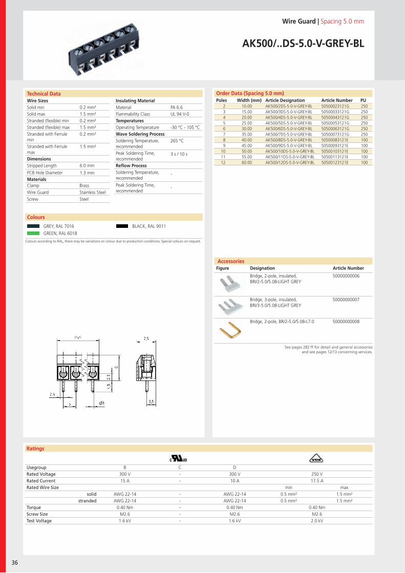
Wire Guard | Spacing 5.0 mm
AK500/..DS-5.0-V-GREY-BL
2 10.00 AK500/2DS-5.0-V-GREY-BL 50500023121G 2503 15.00 AK500/3DS-5.0-V-GREY-BL 50500033121G 2504 20.00 AK500/4DS-5.0-V-GREY-BL 50500043121G 2505 25.00 AK500/5DS-5.0-V-GREY-BL 50500053121G 2506 30.00 AK500/6DS-5.0-V-GREY-BL 50500063121G 2507 35.00 AK500/7DS-5.0-V-GREY-BL 50500073121G 2508 40.00 AK500/8DS-5.0-V-GREY-BL 50500083121E 1009 45.00 AK500/9DS-5.0-V-GREY-BL 50500093121E 100
10 50.00 AK500/10DS-5.0-V-GREY-BL 50500103121E 10011 55.00 AK500/11DS-5.0-V-GREY-BL 50500113121E 10012 60.00 AK500/12DS-5.0-V-GREY-BL 50500123121E 100
Usegroup B C DRated Voltage 300 V - 300 V 250 VRated Current 15 A - 10 A 17.5 ARated Wire Size min max
solid AWG 22-14 - AWG 22-14 0.5 mm² 1.5 mm²stranded AWG 22-14 - AWG 22-14 0.5 mm² 1.5 mm²
Torque 0.40 Nm - 0.40 Nm 0.40 NmScrew Size M2.6 - M2.6 M2.6Test Voltage 1.6 kV - 1.6 kV 2.0 kV
GREY, RAL 7016 BLACK, RAL 9011
GREEN, RAL 6018
Bridge, 2-pole, insulated, BRI/2-5.0/5.08-LIGHT GREY
50000000006
Bridge, 3-pole, insulated, BRI/3-5.0/5.08-LIGHT GREY
50000000007
Bridge, 2-pole, BR/2-5.0/5.08-L7.0 50000000008
PA 6.6UL 94 V-0
-30 °C - 105 °C
265 °C
3 s / 10 s
-
-
0.2 mm²1.5 mm²0.2 mm²1.5 mm²0.2 mm²
1.5 mm²
6.0 mm
1.3 mm
Clamp BrassWire Guard Stainless SteelScrew Steel
Wire SizesSolid minSolid maxStranded (flexible) minStranded (flexible) maxStranded with Ferrule minStranded with Ferrule maxDimensions Stripped Length
PCB Hole DiameterMaterials
Insulating Material MaterialFlammability ClassTemperaturesOperating TemperatureWave Soldering ProcessSoldering Temperature,recommendedPeak Soldering Time,recommendedReflow ProcessSoldering Temperature,recommended
Peak Soldering Time,recommended
Technical Data
Ratings
Accessories Figure Designation Article Number
Colours
PTR Terminal Blocks and Multi Connector Systems 37
Order Data (Spacing 5.08 mm)Poles Width (mm) Article Designation Article Number PU
Order Data (Spacing 5.0 mm)Poles Width (mm) Article Designation Article Number PU
See pages 282 ff for detail and general accessoriesand see pages 12/13 concerning services.
Colours according to RAL, there may be variations on colour due to production conditions. Special colours on request.
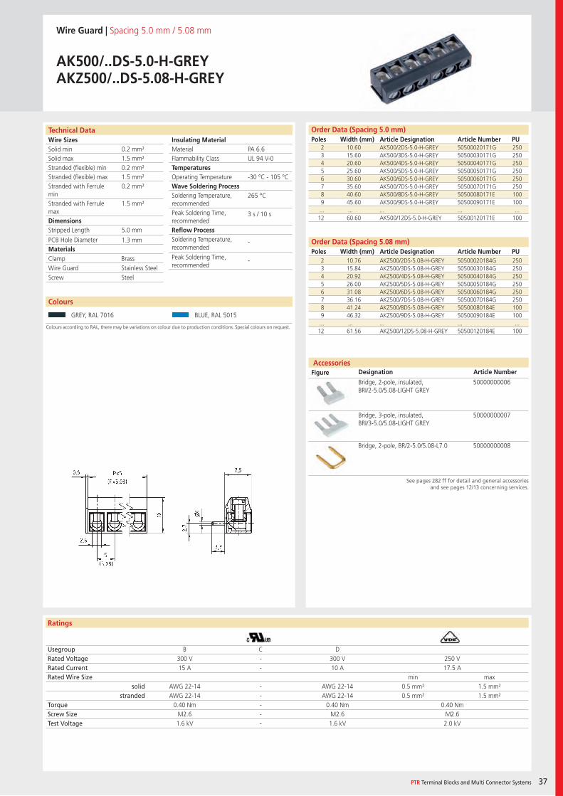
Wire Guard | Spacing 5.0 mm / 5.08 mm
AK500/..DS-5.0-H-GREYAKZ500/..DS-5.08-H-GREY
2 10.60 AK500/2DS-5.0-H-GREY 50500020171G 2503 15.60 AK500/3DS-5.0-H-GREY 50500030171G 2504 20.60 AK500/4DS-5.0-H-GREY 50500040171G 2505 25.60 AK500/5DS-5.0-H-GREY 50500050171G 2506 30.60 AK500/6DS-5.0-H-GREY 50500060171G 2507 35.60 AK500/7DS-5.0-H-GREY 50500070171G 2508 40.60 AK500/8DS-5.0-H-GREY 50500080171E 1009 45.60 AK500/9DS-5.0-H-GREY 50500090171E 100... ... ... ... ...12 60.60 AK500/12DS-5.0-H-GREY 50500120171E 100
Usegroup B C DRated Voltage 300 V - 300 V 250 VRated Current 15 A - 10 A 17.5 ARated Wire Size min max
solid AWG 22-14 - AWG 22-14 0.5 mm² 1.5 mm²stranded AWG 22-14 - AWG 22-14 0.5 mm² 1.5 mm²
Torque 0.40 Nm - 0.40 Nm 0.40 NmScrew Size M2.6 - M2.6 M2.6Test Voltage 1.6 kV - 1.6 kV 2.0 kV
GREY, RAL 7016 BLUE, RAL 5015
Bridge, 2-pole, insulated, BRI/2-5.0/5.08-LIGHT GREY
50000000006
Bridge, 3-pole, insulated, BRI/3-5.0/5.08-LIGHT GREY
50000000007
Bridge, 2-pole, BR/2-5.0/5.08-L7.0 50000000008
PA 6.6UL 94 V-0
-30 °C - 105 °C
265 °C
3 s / 10 s
-
-
0.2 mm²1.5 mm²0.2 mm²1.5 mm²0.2 mm²
1.5 mm²
5.0 mm
1.3 mm
2 10.76 AKZ500/2DS-5.08-H-GREY 50500020184G 2503 15.84 AKZ500/3DS-5.08-H-GREY 50500030184G 2504 20.92 AKZ500/4DS-5.08-H-GREY 50500040184G 2505 26.00 AKZ500/5DS-5.08-H-GREY 50500050184G 2506 31.08 AKZ500/6DS-5.08-H-GREY 50500060184G 2507 36.16 AKZ500/7DS-5.08-H-GREY 50500070184G 2508 41.24 AKZ500/8DS-5.08-H-GREY 50500080184E 1009 46.32 AKZ500/9DS-5.08-H-GREY 50500090184E 100... ... ... ... ...12 61.56 AKZ500/12DS-5.08-H-GREY 50500120184E 100
Clamp BrassWire Guard Stainless SteelScrew Steel
Wire SizesSolid minSolid maxStranded (flexible) minStranded (flexible) maxStranded with Ferrule minStranded with Ferrule maxDimensions Stripped Length
PCB Hole DiameterMaterials
Insulating Material MaterialFlammability ClassTemperaturesOperating TemperatureWave Soldering ProcessSoldering Temperature,recommendedPeak Soldering Time,recommendedReflow ProcessSoldering Temperature,recommended
Peak Soldering Time,recommended
Technical Data
Ratings
Accessories Figure Designation Article Number
38
Colours
Order Data (Spacing 5.0 mm)Poles Width (mm) Article Designation Article Number PU
See pages 282 ff for detail and general accessoriesand see pages 12/13 concerning services.
Colours according to RAL, there may be variations on colour due to production conditions. Special colours on request.
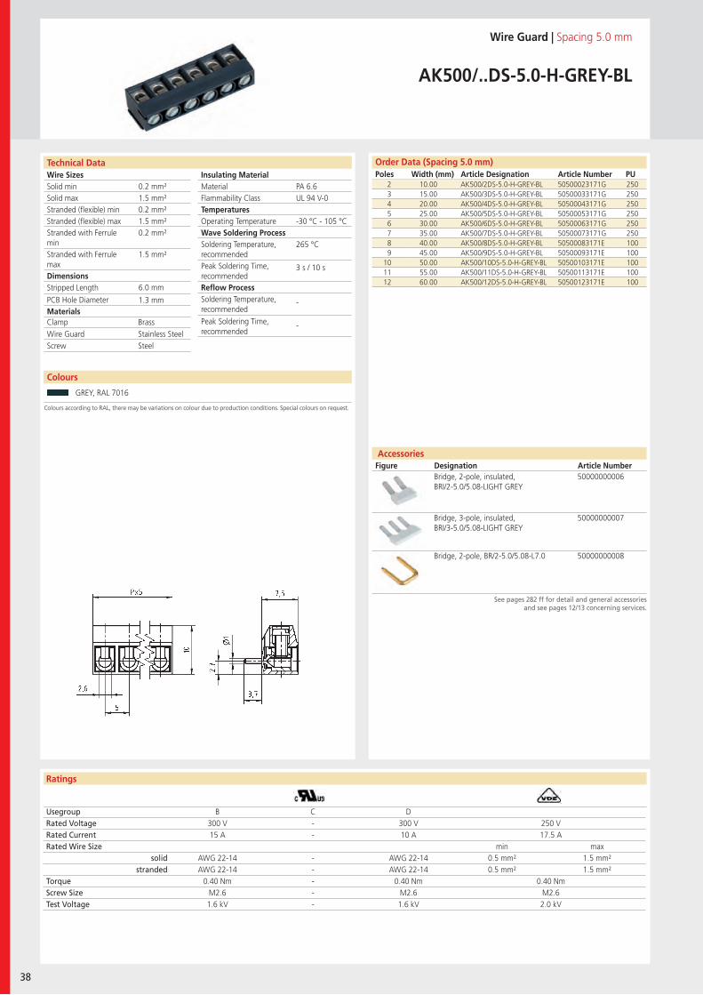
Wire Guard | Spacing 5.0 mm
AK500/..DS-5.0-H-GREY-BL
2 10.00 AK500/2DS-5.0-H-GREY-BL 50500023171G 2503 15.00 AK500/3DS-5.0-H-GREY-BL 50500033171G 2504 20.00 AK500/4DS-5.0-H-GREY-BL 50500043171G 2505 25.00 AK500/5DS-5.0-H-GREY-BL 50500053171G 2506 30.00 AK500/6DS-5.0-H-GREY-BL 50500063171G 2507 35.00 AK500/7DS-5.0-H-GREY-BL 50500073171G 2508 40.00 AK500/8DS-5.0-H-GREY-BL 50500083171E 1009 45.00 AK500/9DS-5.0-H-GREY-BL 50500093171E 100
10 50.00 AK500/10DS-5.0-H-GREY-BL 50500103171E 10011 55.00 AK500/11DS-5.0-H-GREY-BL 50500113171E 10012 60.00 AK500/12DS-5.0-H-GREY-BL 50500123171E 100
Usegroup B C DRated Voltage 300 V - 300 V 250 VRated Current 15 A - 10 A 17.5 ARated Wire Size min max
solid AWG 22-14 - AWG 22-14 0.5 mm² 1.5 mm²stranded AWG 22-14 - AWG 22-14 0.5 mm² 1.5 mm²
Torque 0.40 Nm - 0.40 Nm 0.40 NmScrew Size M2.6 - M2.6 M2.6Test Voltage 1.6 kV - 1.6 kV 2.0 kV
GREY, RAL 7016
Bridge, 2-pole, insulated, BRI/2-5.0/5.08-LIGHT GREY
50000000006
Bridge, 3-pole, insulated, BRI/3-5.0/5.08-LIGHT GREY
50000000007
Bridge, 2-pole, BR/2-5.0/5.08-L7.0 50000000008
PA 6.6UL 94 V-0
-30 °C - 105 °C
265 °C
3 s / 10 s
-
-
0.2 mm²1.5 mm²0.2 mm²1.5 mm²0.2 mm²
1.5 mm²
6.0 mm
1.3 mm
Clamp BrassWire Guard Stainless SteelScrew Steel
Wire SizesSolid minSolid maxStranded (flexible) minStranded (flexible) maxStranded with Ferrule minStranded with Ferrule maxDimensions Stripped Length
PCB Hole DiameterMaterials
Insulating Material MaterialFlammability ClassTemperaturesOperating TemperatureWave Soldering ProcessSoldering Temperature,recommendedPeak Soldering Time,recommendedReflow ProcessSoldering Temperature,recommended
Peak Soldering Time,recommended
Technical Data
Ratings
Accessories Figure Designation Article Number
Colours
PTR Terminal Blocks and Multi Connector Systems 39
Order Data (Spacing 5.0 mm)Poles Width (mm) Article Designation Article Number PU
See pages 282 ff for detail and general accessoriesand see pages 12/13 concerning services.
Colours according to RAL, there may be variations on colour due to production conditions. Special colours on request.
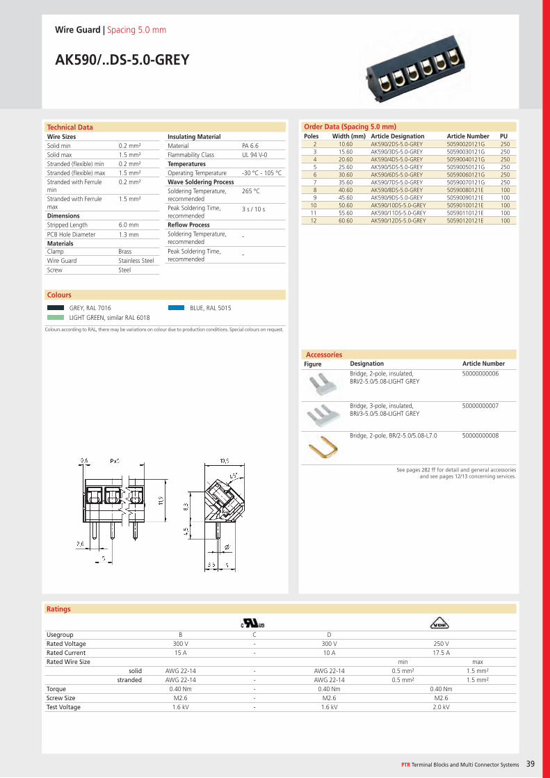
Wire Guard | Spacing 5.0 mm
AK590/..DS-5.0-GREY
2 10.60 AK590/2DS-5.0-GREY 50590020121G 2503 15.60 AK590/3DS-5.0-GREY 50590030121G 2504 20.60 AK590/4DS-5.0-GREY 50590040121G 2505 25.60 AK590/5DS-5.0-GREY 50590050121G 2506 30.60 AK590/6DS-5.0-GREY 50590060121G 2507 35.60 AK590/7DS-5.0-GREY 50590070121G 2508 40.60 AK590/8DS-5.0-GREY 50590080121E 1009 45.60 AK590/9DS-5.0-GREY 50590090121E 100
10 50.60 AK590/10DS-5.0-GREY 50590100121E 10011 55.60 AK590/11DS-5.0-GREY 50590110121E 10012 60.60 AK590/12DS-5.0-GREY 50590120121E 100
Usegroup B C DRated Voltage 300 V - 300 V 250 VRated Current 15 A - 10 A 17.5 ARated Wire Size min max
solid AWG 22-14 - AWG 22-14 0.5 mm² 1.5 mm²stranded AWG 22-14 - AWG 22-14 0.5 mm² 1.5 mm²
Torque 0.40 Nm - 0.40 Nm 0.40 NmScrew Size M2.6 - M2.6 M2.6Test Voltage 1.6 kV - 1.6 kV 2.0 kV
GREY, RAL 7016 BLUE, RAL 5015
LIGHT GREEN, similar RAL 6018
Bridge, 2-pole, insulated, BRI/2-5.0/5.08-LIGHT GREY
50000000006
Bridge, 3-pole, insulated, BRI/3-5.0/5.08-LIGHT GREY
50000000007
Bridge, 2-pole, BR/2-5.0/5.08-L7.0 50000000008
PA 6.6UL 94 V-0
-30 °C - 105 °C
265 °C
3 s / 10 s
-
-
0.2 mm²1.5 mm²0.2 mm²1.5 mm²0.2 mm²
1.5 mm²
6.0 mm
1.3 mm
Clamp BrassWire Guard Stainless SteelScrew Steel
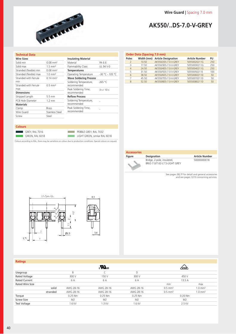
Wire SizesSolid minSolid maxStranded (flexible) minStranded (flexible) maxStranded with Ferrule minStranded with Ferrule maxDimensions Stripped Length
PCB Hole DiameterMaterials
Insulating Material MaterialFlammability ClassTemperaturesOperating TemperatureWave Soldering ProcessSoldering Temperature,recommendedPeak Soldering Time,recommendedReflow ProcessSoldering Temperature,recommended
Peak Soldering Time,recommended
Technical Data
Ratings
40
Colours
Order Data (Spacing 7.0 mm)Poles Width (mm) Article Designation Article Number PU
Colours according to RAL, there may be variations on colour due to production conditions. Special colours on request.
AccessoriesFigure Designation Article Number
See pages 282 ff for detail and general accessoriesand see pages 12/13 concerning services.
Wire Guard | Spacing 7.0 mm
AK550/..DS-7.0-V-GREY
2 10.50 AK550/2DS-7.0-V-GREY 50550020211G 2503 17.50 AK550/3DS-7.0-V-GREY 50550030211G 2504 24.50 AK550/4DS-7.0-V-GREY 50550040211G 2505 31.50 AK550/5DS-7.0-V-GREY 50550050211E 1006 38.50 AK550/6DS-7.0-V-GREY 50550060211D 507 45.50 AK550/7DS-7.0-V-GREY 50550070211D 508 52.50 AK550/8DS-7.0-V-GREY 50550080211D 50
Usegroup B C DRated Voltage 300 V 150 V 300 V 450 VRated Current 6 A 6 A 6 A 13.5 ARated Wire Size min max
solid AWG 28-16 AWG 28-16 AWG 28-16 0.5 mm² 1.0 mm²stranded AWG 28-16 AWG 28-16 AWG 28-16 0.5 mm² 1.0 mm²
Torque 0.25 Nm 0.25 Nm 0.25 Nm 0.20 NmScrew Size M2 M2 M2 M2Test Voltage 1.6 kV 1.3 kV 1.6 kV 2.5 kV
GREY, RAL 7016 PEBBLE GREY, RAL 7032
GREEN, RAL 6018 LIGHT GREEN, similar RAL 6018
PA 6.6UL 94 V-0
-30 °C - 105 °C
265 °C
3 s / 10 s
-
-
0.08 mm²1.5 mm²0.08 mm²1.0 mm²0.14 mm²
0.5 mm²
5.5 mm
1.2 mm
Clamp BrassWire Guard Stainless SteelScrew Steel
Bridge, 2-pole, insulated, BRI/2-7.0/7.62-L7.5-LIGHT GREY
50000000018

Wire SizesSolid minSolid maxStranded (flexible) minStranded (flexible) maxStranded with Ferrule minStranded with Ferrule maxDimensions Stripped Length
PCB Hole DiameterMaterials
Insulating Material MaterialFlammability ClassTemperaturesOperating TemperatureWave Soldering ProcessSoldering Temperature,recommendedPeak Soldering Time,recommendedReflow ProcessSoldering Temperature,recommended
Peak Soldering Time,recommended
Technical Data
Ratings
Colours
PTR Terminal Blocks and Multi Connector Systems 41
Order Data (Spacing 7.0 mm)Poles Width (mm) Article Designation Article Number PU
Colours according to RAL, there may be variations on colour due to production conditions. Special colours on request.
Wire Guard | Spacing 7.0 mm
AK550/..DS-7.0-H-GREY
2 10.50 AK550/2DS-7.0-H-GREY 50550020240G 2503 17.50 AK550/3DS-7.0-H-GREY 50550030240G 2504 24.50 AK550/4DS-7.0-H-GREY 50550040240G 2505 31.50 AK550/5DS-7.0-H-GREY 50550050240E 1006 38.50 AK550/6DS-7.0-H-GREY 50550060240D 507 45.50 AK550/7DS-7.0-H-GREY 50550070240D 508 52.50 AK550/8DS-7.0-H-GREY 50550080240D 50
Usegroup B C DRated Voltage 300 V 150 V 300 V 450 VRated Current 6 A 6 A 6 A 13.5 ARated Wire Size min max
solid AWG 28-16 AWG 28-16 AWG 28-16 0.5 mm² 1.0 mm²stranded AWG 28-16 AWG 28-16 AWG 28-16 0.5 mm² 1.0 mm²
Torque 0.25 Nm 0.25 Nm 0.25 Nm 0.20 NmScrew Size M2 M2 M2 M2Test Voltage 1.6 kV 1.3 kV 1.6 kV 2.5 kV
GREY, RAL 7016 GREEN, RAL 6018
LIGHT GREEN, similar RAL 6018
PA 6.6UL 94 V-0
-30 °C - 105 °C
265 °C
3 s / 10 s
-
-
0.08 mm²1.5 mm²0.08 mm²1.0 mm²0.14 mm²
0.5 mm²
5.5 mm
1.2 mm
Clamp BrassWire Guard Stainless SteelScrew Steel
AccessoriesFigure Designation Article Number
See pages 282 ff for detail and general accessoriesand see pages 12/13 concerning services.
Bridge, 2-pole, insulated, BRI/2-7.0/7.62-L7.5-LIGHT GREY
50000000018
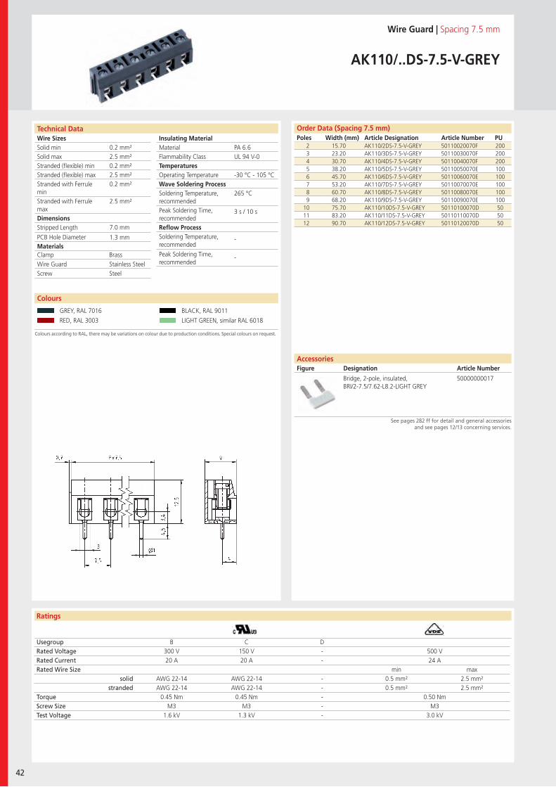
Wire SizesSolid minSolid maxStranded (flexible) minStranded (flexible) maxStranded with Ferrule minStranded with Ferrule maxDimensions Stripped Length
PCB Hole DiameterMaterials
Insulating Material MaterialFlammability ClassTemperaturesOperating TemperatureWave Soldering ProcessSoldering Temperature,recommendedPeak Soldering Time,recommendedReflow ProcessSoldering Temperature,recommended
Peak Soldering Time,recommended
Technical Data
Ratings
42
Colours
Order Data (Spacing 7.5 mm)Poles Width (mm) Article Designation Article Number PU
Colours according to RAL, there may be variations on colour due to production conditions. Special colours on request.
AccessoriesFigure Designation Article Number
See pages 282 ff for detail and general accessoriesand see pages 12/13 concerning services.
Wire Guard | Spacing 7.5 mm
AK110/..DS-7.5-V-GREY
2 15.70 AK110/2DS-7.5-V-GREY 50110020070F 2003 23.20 AK110/3DS-7.5-V-GREY 50110030070F 2004 30.70 AK110/4DS-7.5-V-GREY 50110040070F 2005 38.20 AK110/5DS-7.5-V-GREY 50110050070E 1006 45.70 AK110/6DS-7.5-V-GREY 50110060070E 1007 53.20 AK110/7DS-7.5-V-GREY 50110070070E 1008 60.70 AK110/8DS-7.5-V-GREY 50110080070E 1009 68.20 AK110/9DS-7.5-V-GREY 50110090070E 100
10 75.70 AK110/10DS-7.5-V-GREY 50110100070D 5011 83.20 AK110/11DS-7.5-V-GREY 50110110070D 5012 90.70 AK110/12DS-7.5-V-GREY 50110120070D 50
Usegroup B C DRated Voltage 300 V 150 V - 500 VRated Current 20 A 20 A - 24 ARated Wire Size min max
solid AWG 22-14 AWG 22-14 - 0.5 mm² 2.5 mm²stranded AWG 22-14 AWG 22-14 - 0.5 mm² 2.5 mm²
Torque 0.45 Nm 0.45 Nm - 0.50 NmScrew Size M3 M3 - M3Test Voltage 1.6 kV 1.3 kV - 3.0 kV
GREY, RAL 7016 BLACK, RAL 9011
RED, RAL 3003 LIGHT GREEN, similar RAL 6018
Bridge, 2-pole, insulated, BRI/2-7.5/7.62-L8.2-LIGHT GREY
50000000017
PA 6.6UL 94 V-0
-30 °C - 105 °C
265 °C
3 s / 10 s
-
-
0.2 mm²2.5 mm²0.2 mm²2.5 mm²0.2 mm²
2.5 mm²
7.0 mm
1.3 mm
Clamp BrassWire Guard Stainless SteelScrew Steel
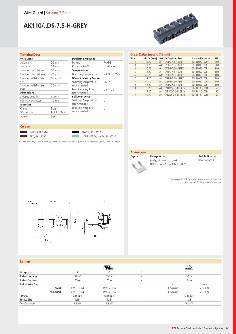
Wire SizesSolid minSolid maxStranded (flexible) minStranded (flexible) maxStranded with Ferrule minStranded with Ferrule maxDimensions Stripped Length
PCB Hole DiameterMaterials
Insulating Material MaterialFlammability ClassTemperaturesOperating TemperatureWave Soldering ProcessSoldering Temperature,recommendedPeak Soldering Time,recommendedReflow ProcessSoldering Temperature,recommended
Peak Soldering Time,recommended
Technical Data
Ratings
Colours
PTR Terminal Blocks and Multi Connector Systems 43
Order Data (Spacing 7.5 mm)Poles Width (mm) Article Designation Article Number PU
Colours according to RAL, there may be variations on colour due to production conditions. Special colours on request.
AccessoriesFigure Designation Article Number
See pages 282 ff for detail and general accessoriesand see pages 12/13 concerning services.
Wire Guard | Spacing 7.5 mm
AK110/..DS-7.5-H-GREY
2 15.70 AK110/2DS-7.5-H-GREY 50110020100F 2003 23.20 AK110/3DS-7.5-H-GREY 50110030100F 2004 30.70 AK110/4DS-7.5-H-GREY 50110040100F 2005 38.20 AK110/5DS-7.5-H-GREY 50110050100E 1006 45.70 AK110/6DS-7.5-H-GREY 50110060100E 1007 53.20 AK110/7DS-7.5-H-GREY 50110070100E 1008 60.70 AK110/8DS-7.5-H-GREY 50110080100E 1009 68.20 AK110/9DS-7.5-H-GREY 50110090100E 100
10 75.70 AK110/10DS-7.5-H-GREY 50110100100D 5011 83.20 AK110/11DS-7.5-H-GREY 50110110100D 5012 90.70 AK110/12DS-7.5-H-GREY 50110120100D 50
Usegroup B C DRated Voltage 300 V 150 V - 500 VRated Current 20 A 20 A - 24 ARated Wire Size min max
solid AWG 22-14 AWG 22-14 - 0.5 mm² 2.5 mm²stranded AWG 22-14 AWG 22-14 - 0.5 mm² 2.5 mm²
Torque 0.45 Nm 0.45 Nm - 0.50 NmScrew Size M3 M3 - M3Test Voltage 1.6 kV 1.3 kV - 3.0 kV
GREY, RAL 7016 BLACK, RAL 9011
RED, RAL 3003 LIGHT GREEN, similar RAL 6018
Bridge, 2-pole, insulated, BRI/2-7.5/7.62-L8.2-LIGHT GREY
50000000017
PA 6.6UL 94 V-0
-30 °C - 105 °C
265 °C
3 s / 10 s
-
-
0.2 mm²2.5 mm²0.2 mm²2.5 mm²0.2 mm²
2.5 mm²
6.0 mm
1.3 mm
Clamp BrassWire Guard Stainless SteelScrew Steel
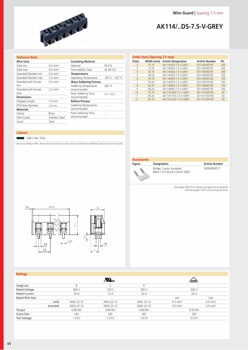
Wire SizesSolid minSolid maxStranded (flexible) minStranded (flexible) maxStranded with Ferrule minStranded with Ferrule maxDimensions Stripped Length
PCB Hole DiameterMaterials
Insulating Material MaterialFlammability ClassTemperaturesOperating TemperatureWave Soldering ProcessSoldering Temperature,recommendedPeak Soldering Time,recommendedReflow ProcessSoldering Temperature,recommended
Peak Soldering Time,recommended
Technical Data
Ratings
44
Colours
Order Data (Spacing 7.5 mm)Poles Width (mm) Article Designation Article Number PU
Colours according to RAL, there may be variations on colour due to production conditions. Special colours on request.
AccessoriesFigure Designation Article Number
See pages 282 ff for detail and general accessoriesand see pages 12/13 concerning services.
Wire Guard | Spacing 7.5 mm
AK114/..DS-7.5-V-GREY
2 15.70 AK114/2DS-7.5-V-GREY 50114020070F 2003 23.20 AK114/3DS-7.5-V-GREY 50114030070F 2004 30.70 AK114/4DS-7.5-V-GREY 50114040070F 2005 38.20 AK114/5DS-7.5-V-GREY 50114050070E 1006 45.70 AK114/6DS-7.5-V-GREY 50114060070E 1007 53.20 AK114/7DS-7.5-V-GREY 50114070070E 1008 60.70 AK114/8DS-7.5-V-GREY 50114080070E 1009 68.20 AK114/9DS-7.5-V-GREY 50114090070E 100
10 75.70 AK114/10DS-7.5-V-GREY 50114100070D 5011 83.20 AK114/11DS-7.5-V-GREY 50114110070D 5012 90.70 AK114/12DS-7.5-V-GREY 50114120070D 50
Usegroup B C DRated Voltage 300 V 150 V 300 V 500 VRated Current 20 A 10 A 20 A 32 ARated Wire Size min max
solid AWG 22-12 AWG 22-12 AWG 22-12 0.5 mm² 4.0 mm²stranded AWG 22-12 AWG 22-12 AWG 22-12 0.5 mm² 4.0 mm²
Torque 0.80 Nm 0.80 Nm 0.80 Nm 0.50 NmScrew Size M3 M3 M3 M3Test Voltage 1.6 kV 1.3 kV 1.6 kV 3.0 kV
GREY, RAL 7016
Bridge, 2-pole, insulated, BRI/2-7.5/7.62-L8.2-LIGHT GREY
50000000017
PA 6.6UL 94 V-0
-30 °C - 105 °C
265 °C
3 s / 10 s
-
-
0.2 mm²4.0 mm²0.2 mm²2.5 mm²0.2 mm²
2.5 mm²
7.0 mm
2.0 mm
Clamp BrassWire Guard Stainless SteelScrew Steel
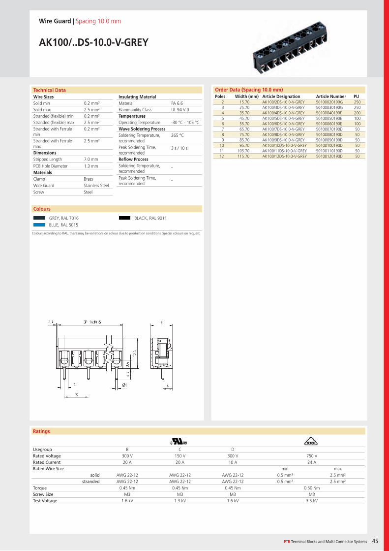
Wire SizesSolid minSolid maxStranded (flexible) minStranded (flexible) maxStranded with Ferrule minStranded with Ferrule maxDimensions Stripped Length
PCB Hole DiameterMaterials
Insulating Material MaterialFlammability ClassTemperaturesOperating TemperatureWave Soldering ProcessSoldering Temperature,recommendedPeak Soldering Time,recommendedReflow ProcessSoldering Temperature,recommended
Peak Soldering Time,recommended
Technical Data
Ratings
Colours
PTR Terminal Blocks and Multi Connector Systems 45
Order Data (Spacing 10.0 mm)Poles Width (mm) Article Designation Article Number PU
Colours according to RAL, there may be variations on colour due to production conditions. Special colours on request.
Wire Guard | Spacing 10.0 mm
AK100/..DS-10.0-V-GREY
2 15.70 AK100/2DS-10.0-V-GREY 50100020190G 2503 25.70 AK100/3DS-10.0-V-GREY 50100030190G 2504 35.70 AK100/4DS-10.0-V-GREY 50100040190F 2005 45.70 AK100/5DS-10.0-V-GREY 50100050190E 1006 55.70 AK100/6DS-10.0-V-GREY 50100060190E 1007 65.70 AK100/7DS-10.0-V-GREY 50100070190D 508 75.70 AK100/8DS-10.0-V-GREY 50100080190D 509 85.70 AK100/9DS-10.0-V-GREY 50100090190D 50
10 95.70 AK100/10DS-10.0-V-GREY 50100100190D 5011 105.70 AK100/11DS-10.0-V-GREY 50100110190D 5012 115.70 AK100/12DS-10.0-V-GREY 50100120190D 50
Usegroup B C DRated Voltage 300 V 150 V 300 V 750 VRated Current 20 A 20 A 10 A 24 ARated Wire Size min max
solid AWG 22-12 AWG 22-12 AWG 22-12 0.5 mm² 2.5 mm²stranded AWG 22-12 AWG 22-12 AWG 22-12 0.5 mm² 2.5 mm²
Torque 0.45 Nm 0.45 Nm 0.45 Nm 0.50 NmScrew Size M3 M3 M3 M3Test Voltage 1.6 kV 1.3 kV 1.6 kV 3.5 kV
GREY, RAL 7016 BLACK, RAL 9011
BLUE, RAL 5015
PA 6.6UL 94 V-0
-30 °C - 105 °C
265 °C
3 s / 10 s
-
-
0.2 mm²2.5 mm²0.2 mm²2.5 mm²0.2 mm²
2.5 mm²
7.0 mm
1.3 mm
Clamp BrassWire Guard Stainless SteelScrew Steel
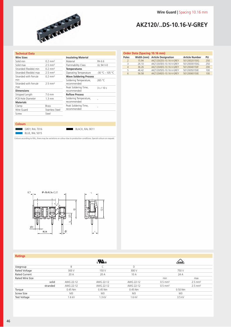
Wire SizesSolid minSolid maxStranded (flexible) minStranded (flexible) maxStranded with Ferrule minStranded with Ferrule maxDimensions Stripped Length
PCB Hole DiameterMaterials
Insulating Material MaterialFlammability ClassTemperaturesOperating TemperatureWave Soldering ProcessSoldering Temperature,recommendedPeak Soldering Time,recommendedReflow ProcessSoldering Temperature,recommended
Peak Soldering Time,recommended
Technical Data
Ratings
46
Colours
Order Data (Spacing 10.16 mm)Poles Width (mm) Article Designation Article Number PU
Colours according to RAL, there may be variations on colour due to production conditions. Special colours on request.
Wire Guard | Spacing 10.16 mm
AKZ120/..DS-10.16-V-GREY
2 15.94 AKZ120/2DS-10.16-V-GREY 50120020150G 2503 26.10 AKZ120/3DS-10.16-V-GREY 50120030150G 2504 36.26 AKZ120/4DS-10.16-V-GREY 50120040150F 2005 46.42 AKZ120/5DS-10.16-V-GREY 50120050150E 1006 56.58 AKZ120/6DS-10.16-V-GREY 50120060150E 100
Usegroup B C DRated Voltage 300 V 150 V 300 V 750 VRated Current 20 A 20 A 10 A 24 ARated Wire Size min max
solid AWG 22-12 AWG 22-12 AWG 22-12 0.5 mm² 2.5 mm²stranded AWG 22-12 AWG 22-12 AWG 22-12 0.5 mm² 2.5 mm²
Torque 0.45 Nm 0.45 Nm 0.45 Nm 0.50 NmScrew Size M3 M3 M3 M3Test Voltage 1.6 kV 1.3 kV 1.6 kV 3.5 kV
GREY, RAL 7016 BLACK, RAL 9011
BLUE, RAL 5015
PA 6.6UL 94 V-0
-30 °C - 105 °C
265 °C
3 s / 10 s
-
-
0.2 mm²2.5 mm²0.2 mm²2.5 mm²0.2 mm²
2.5 mm²
7.0 mm
1.3 mm
Clamp BrassWire Guard Stainless SteelScrew Steel
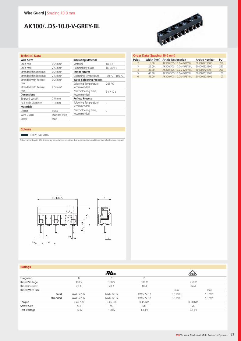
Wire SizesSolid minSolid maxStranded (flexible) minStranded (flexible) maxStranded with Ferrule minStranded with Ferrule maxDimensions Stripped Length
PCB Hole DiameterMaterials
Insulating Material MaterialFlammability ClassTemperaturesOperating TemperatureWave Soldering ProcessSoldering Temperature,recommendedPeak Soldering Time,recommendedReflow ProcessSoldering Temperature,recommended
Peak Soldering Time,recommended
Technical Data
Ratings
Colours
PTR Terminal Blocks and Multi Connector Systems 47
Order Data (Spacing 10.0 mm)Poles Width (mm) Article Designation Article Number PU
Colours according to RAL, there may be variations on colour due to production conditions. Special colours on request.
Wire Guard | Spacing 10.0 mm
AK100/..DS-10.0-V-GREY-BL
2 15.00 AK100/2DS-10.0-V-GREY-BL 50100022190G 2503 25.00 AK100/3DS-10.0-V-GREY-BL 50100032190G 2504 35.00 AK100/4DS-10.0-V-GREY-BL 50100042190F 2005 45.00 AK100/5DS-10.0-V-GREY-BL 50100052190E 1006 55.00 AK100/6DS-10.0-V-GREY-BL 50100062190E 100
Usegroup B C DRated Voltage 300 V 150 V 300 V 750 VRated Current 20 A 20 A 10 A 24 ARated Wire Size min max
solid AWG 22-12 AWG 22-12 AWG 22-12 0.5 mm² 2.5 mm²stranded AWG 22-12 AWG 22-12 AWG 22-12 0.5 mm² 2.5 mm²
Torque 0.45 Nm 0.45 Nm 0.45 Nm 0.50 NmScrew Size M3 M3 M3 M3Test Voltage 1.6 kV 1.3 kV 1.6 kV 3.5 kV
GREY, RAL 7016
PA 6.6UL 94 V-0
-30 °C - 105 °C
265 °C
3 s / 10 s
-
-
0.2 mm²2.5 mm²0.2 mm²2.5 mm²0.2 mm²
2.5 mm²
7.0 mm
1.3 mm
Clamp BrassWire Guard Stainless SteelScrew Steel
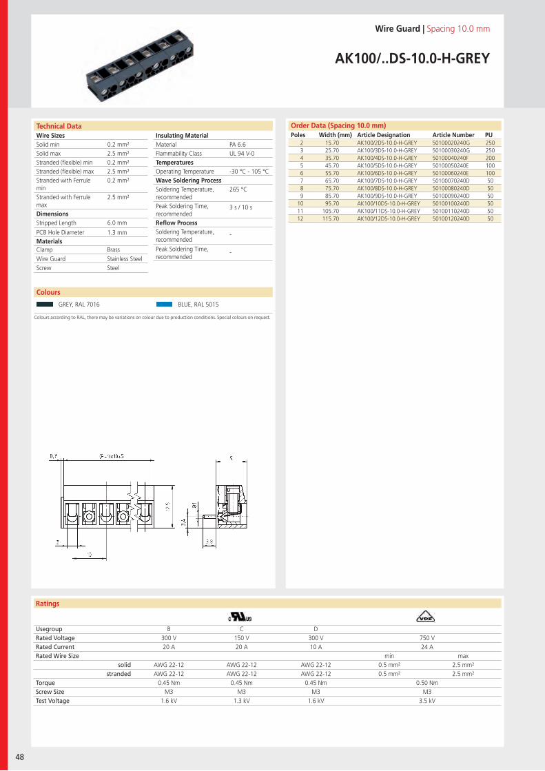
Wire SizesSolid minSolid maxStranded (flexible) minStranded (flexible) maxStranded with Ferrule minStranded with Ferrule maxDimensions Stripped Length
PCB Hole DiameterMaterials
Insulating Material MaterialFlammability ClassTemperaturesOperating TemperatureWave Soldering ProcessSoldering Temperature,recommendedPeak Soldering Time,recommendedReflow ProcessSoldering Temperature,recommended
Peak Soldering Time,recommended
Technical Data
Ratings
48
Colours
Order Data (Spacing 10.0 mm)Poles Width (mm) Article Designation Article Number PU
Colours according to RAL, there may be variations on colour due to production conditions. Special colours on request.
Wire Guard | Spacing 10.0 mm
AK100/..DS-10.0-H-GREY
2 15.70 AK100/2DS-10.0-H-GREY 50100020240G 2503 25.70 AK100/3DS-10.0-H-GREY 50100030240G 2504 35.70 AK100/4DS-10.0-H-GREY 50100040240F 2005 45.70 AK100/5DS-10.0-H-GREY 50100050240E 1006 55.70 AK100/6DS-10.0-H-GREY 50100060240E 1007 65.70 AK100/7DS-10.0-H-GREY 50100070240D 508 75.70 AK100/8DS-10.0-H-GREY 50100080240D 509 85.70 AK100/9DS-10.0-H-GREY 50100090240D 50
10 95.70 AK100/10DS-10.0-H-GREY 50100100240D 5011 105.70 AK100/11DS-10.0-H-GREY 50100110240D 5012 115.70 AK100/12DS-10.0-H-GREY 50100120240D 50
Usegroup B C DRated Voltage 300 V 150 V 300 V 750 VRated Current 20 A 20 A 10 A 24 ARated Wire Size min max
solid AWG 22-12 AWG 22-12 AWG 22-12 0.5 mm² 2.5 mm²stranded AWG 22-12 AWG 22-12 AWG 22-12 0.5 mm² 2.5 mm²
Torque 0.45 Nm 0.45 Nm 0.45 Nm 0.50 NmScrew Size M3 M3 M3 M3Test Voltage 1.6 kV 1.3 kV 1.6 kV 3.5 kV
GREY, RAL 7016 BLUE, RAL 5015
PA 6.6UL 94 V-0
-30 °C - 105 °C
265 °C
3 s / 10 s
-
-
0.2 mm²2.5 mm²0.2 mm²2.5 mm²0.2 mm²
2.5 mm²
6.0 mm
1.3 mm
Clamp BrassWire Guard Stainless SteelScrew Steel
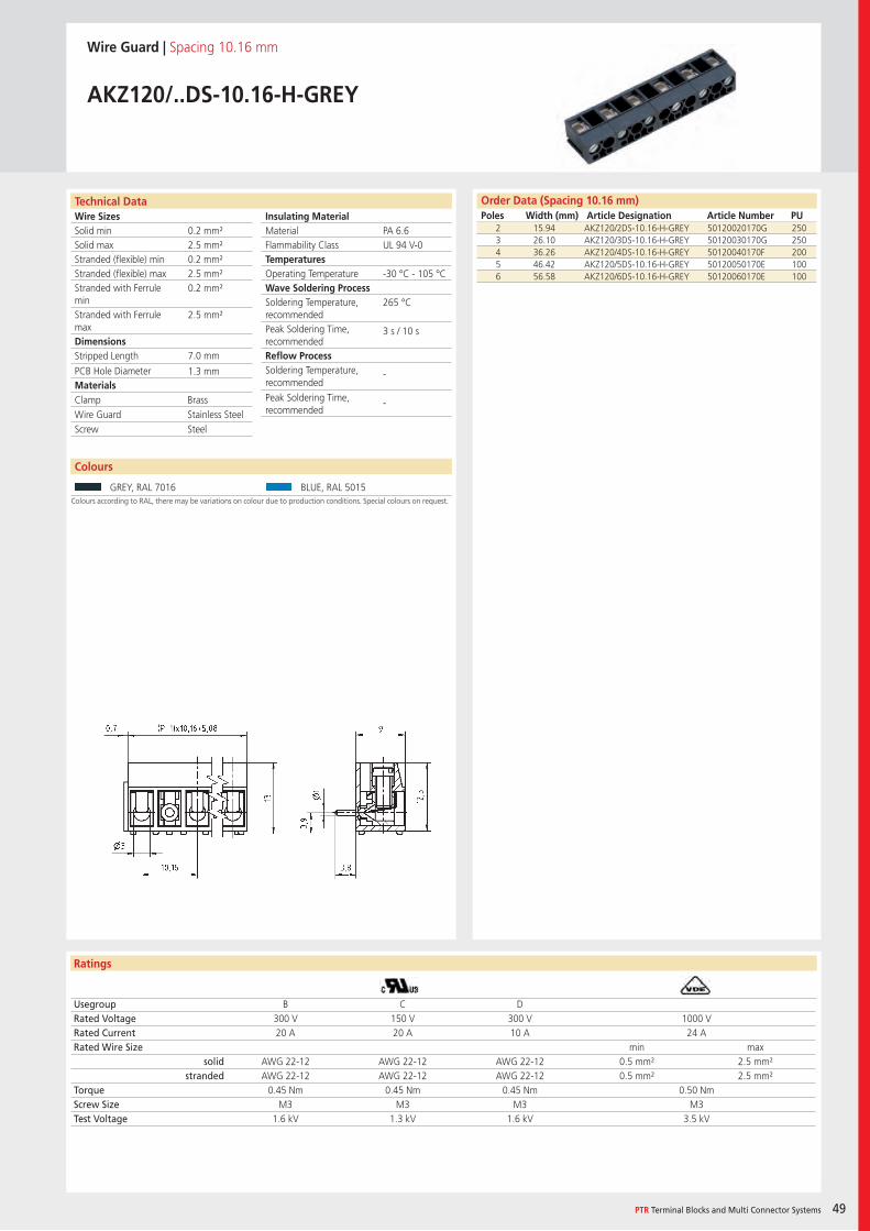
Wire SizesSolid minSolid maxStranded (flexible) minStranded (flexible) maxStranded with Ferrule minStranded with Ferrule maxDimensions Stripped Length
PCB Hole DiameterMaterials
Insulating Material MaterialFlammability ClassTemperaturesOperating TemperatureWave Soldering ProcessSoldering Temperature,recommendedPeak Soldering Time,recommendedReflow ProcessSoldering Temperature,recommended
Peak Soldering Time,recommended
Technical Data
Ratings
Colours
PTR Terminal Blocks and Multi Connector Systems 49
Order Data (Spacing 10.16 mm)Poles Width (mm) Article Designation Article Number PU
Colours according to RAL, there may be variations on colour due to production conditions. Special colours on request.
Wire Guard | Spacing 10.16 mm
AKZ120/..DS-10.16-H-GREY
2 15.94 AKZ120/2DS-10.16-H-GREY 50120020170G 2503 26.10 AKZ120/3DS-10.16-H-GREY 50120030170G 2504 36.26 AKZ120/4DS-10.16-H-GREY 50120040170F 2005 46.42 AKZ120/5DS-10.16-H-GREY 50120050170E 1006 56.58 AKZ120/6DS-10.16-H-GREY 50120060170E 100
Usegroup B C DRated Voltage 300 V 150 V 300 V 1000 VRated Current 20 A 20 A 10 A 24 ARated Wire Size min max
solid AWG 22-12 AWG 22-12 AWG 22-12 0.5 mm² 2.5 mm²stranded AWG 22-12 AWG 22-12 AWG 22-12 0.5 mm² 2.5 mm²
Torque 0.45 Nm 0.45 Nm 0.45 Nm 0.50 NmScrew Size M3 M3 M3 M3Test Voltage 1.6 kV 1.3 kV 1.6 kV 3.5 kV
GREY, RAL 7016 BLUE, RAL 5015
PA 6.6UL 94 V-0
-30 °C - 105 °C
265 °C
3 s / 10 s
-
-
0.2 mm²2.5 mm²0.2 mm²2.5 mm²0.2 mm²
2.5 mm²
7.0 mm
1.3 mm
Clamp BrassWire Guard Stainless SteelScrew Steel

Wire SizesSolid minSolid maxStranded (flexible) minStranded (flexible) maxStranded with Ferrule minStranded with Ferrule maxDimensions Stripped Length
PCB Hole DiameterMaterials
Insulating Material MaterialFlammability ClassTemperaturesOperating TemperatureWave Soldering ProcessSoldering Temperature,recommendedPeak Soldering Time,recommendedReflow ProcessSoldering Temperature,recommended
Peak Soldering Time,recommended
Technical Data
Ratings
50
Colours
Order Data (Spacing 10.0 mm)Poles Width (mm) Article Designation Article Number PU
Colours according to RAL, there may be variations on colour due to production conditions. Special colours on request.
Wire Guard | Spacing 10.0 mm
AK100/..DS-10.0-H-GREY-BL
2 15.00 AK100/2DS-10.0-H-GREY-BL 50100022240G 2503 25.00 AK100/3DS-10.0-H-GREY-BL 50100032240G 2504 35.00 AK100/4DS-10.0-H-GREY-BL 50100042240F 2005 45.00 AK100/5DS-10.0-H-GREY-BL 50100052240E 1006 55.00 AK100/6DS-10.0-H-GREY-BL 50100062240E 100
Usegroup B C DRated Voltage 300 V 150 V 300 V 750 VRated Current 20 A 20 A 10 A 24 ARated Wire Size min max
solid AWG 22-12 AWG 22-12 AWG 22-12 0.5 mm² 2.5 mm²stranded AWG 22-12 AWG 22-12 AWG 22-12 0.5 mm² 2.5 mm²
Torque 0.45 Nm 0.45 Nm 0.45 Nm 0.50 NmScrew Size M3 M3 M3 M3Test Voltage 1.6 kV 1.3 kV 1.6 kV 3.5 kV
GREY, RAL 7016
PA 6.6UL 94 V-0
-30 °C - 105 °C
265 °C
3 s / 10 s
-
-
0.2 mm²2.5 mm²0.2 mm²2.5 mm²0.2 mm²
2.5 mm²
6.0 mm
1.3 mm
Clamp BrassWire Guard Stainless SteelScrew Steel
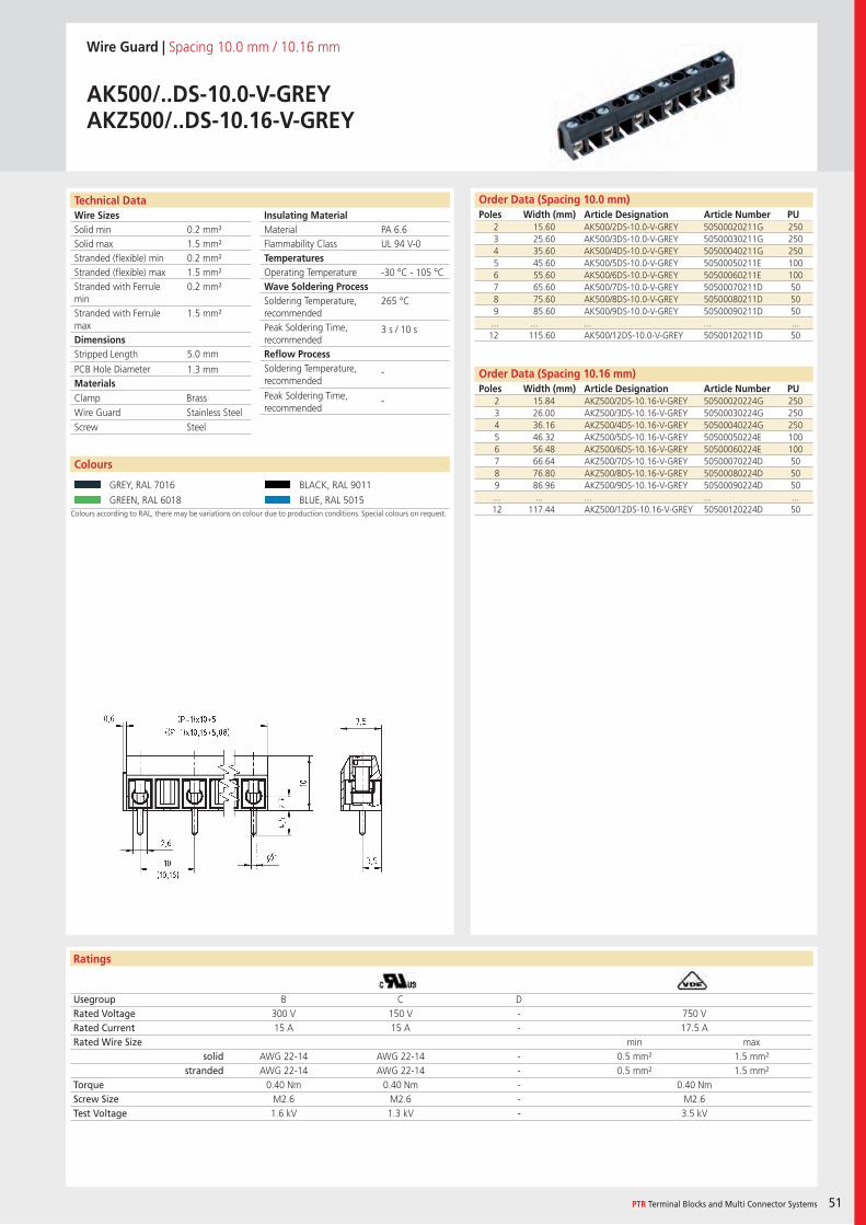
Wire SizesSolid minSolid maxStranded (flexible) minStranded (flexible) maxStranded with Ferrule minStranded with Ferrule maxDimensions Stripped Length
PCB Hole DiameterMaterials
Insulating Material MaterialFlammability ClassTemperaturesOperating TemperatureWave Soldering ProcessSoldering Temperature,recommendedPeak Soldering Time,recommendedReflow ProcessSoldering Temperature,recommended
Peak Soldering Time,recommended
Technical Data
Ratings
Colours
PTR Terminal Blocks and Multi Connector Systems 51
Order Data (Spacing 10.0 mm)Poles Width (mm) Article Designation Article Number PU
Colours according to RAL, there may be variations on colour due to production conditions. Special colours on request.
Wire Guard | Spacing 10.0 mm / 10.16 mm
AK500/..DS-10.0-V-GREYAKZ500/..DS-10.16-V-GREY
2 15.60 AK500/2DS-10.0-V-GREY 50500020211G 2503 25.60 AK500/3DS-10.0-V-GREY 50500030211G 2504 35.60 AK500/4DS-10.0-V-GREY 50500040211G 2505 45.60 AK500/5DS-10.0-V-GREY 50500050211E 1006 55.60 AK500/6DS-10.0-V-GREY 50500060211E 1007 65.60 AK500/7DS-10.0-V-GREY 50500070211D 508 75.60 AK500/8DS-10.0-V-GREY 50500080211D 509 85.60 AK500/9DS-10.0-V-GREY 50500090211D 50... ... ... ... ...12 115.60 AK500/12DS-10.0-V-GREY 50500120211D 50
Usegroup B C DRated Voltage 300 V 150 V - 750 VRated Current 15 A 15 A - 17.5 ARated Wire Size min max
solid AWG 22-14 AWG 22-14 - 0.5 mm² 1.5 mm²stranded AWG 22-14 AWG 22-14 - 0.5 mm² 1.5 mm²
Torque 0.40 Nm 0.40 Nm - 0.40 NmScrew Size M2.6 M2.6 - M2.6Test Voltage 1.6 kV 1.3 kV - 3.5 kV
GREY, RAL 7016 BLACK, RAL 9011
GREEN, RAL 6018 BLUE, RAL 5015
PA 6.6UL 94 V-0
-30 °C - 105 °C
265 °C
3 s / 10 s
-
-
0.2 mm²1.5 mm²0.2 mm²1.5 mm²0.2 mm²
1.5 mm²
5.0 mm
1.3 mm
2 15.84 AKZ500/2DS-10.16-V-GREY 50500020224G 2503 26.00 AKZ500/3DS-10.16-V-GREY 50500030224G 2504 36.16 AKZ500/4DS-10.16-V-GREY 50500040224G 2505 46.32 AKZ500/5DS-10.16-V-GREY 50500050224E 1006 56.48 AKZ500/6DS-10.16-V-GREY 50500060224E 1007 66.64 AKZ500/7DS-10.16-V-GREY 50500070224D 508 76.80 AKZ500/8DS-10.16-V-GREY 50500080224D 509 86.96 AKZ500/9DS-10.16-V-GREY 50500090224D 50... ... ... ... ...12 117.44 AKZ500/12DS-10.16-V-GREY 50500120224D 50
Clamp BrassWire Guard Stainless SteelScrew Steel
Order Data (Spacing 10.16 mm)Poles Width (mm) Article Designation Article Number PU

Wire SizesSolid minSolid maxStranded (flexible) minStranded (flexible) maxStranded with Ferrule minStranded with Ferrule maxDimensions Stripped Length
PCB Hole DiameterMaterials
Insulating Material MaterialFlammability ClassTemperaturesOperating TemperatureWave Soldering ProcessSoldering Temperature,recommendedPeak Soldering Time,recommendedReflow ProcessSoldering Temperature,recommended
Peak Soldering Time,recommended
Technical Data
Ratings
52
Colours
Order Data (Spacing 10.0 mm)Poles Width (mm) Article Designation Article Number PU
Colours according to RAL, there may be variations on colour due to production conditions. Special colours on request.
Wire Guard | Spacing 10.0 mm
AK500/..DS-10.0-V-GREY-BL
2 15.00 AK500/2DS-10.0-V-GREY-BL 50500023211G 2503 25.00 AK500/3DS-10.0-V-GREY-BL 50500033211G 2504 35.00 AK500/4DS-10.0-V-GREY-BL 50500043211G 2505 45.00 AK500/5DS-10.0-V-GREY-BL 50500053211E 1006 55.00 AK500/6DS-10.0-V-GREY-BL 50500063211E 100
Usegroup B C DRated Voltage 300 V 150 V 300 V 750 VRated Current 15 A 15 A 10 A 17.5 ARated Wire Size min max
solid AWG 22-14 AWG 22-14 AWG 22-14 0.5 mm² 1.5 mm²stranded AWG 22-14 AWG 22-14 AWG 22-14 0.5 mm² 1.5 mm²
Torque 0.40 Nm 0.40 Nm 0.40 Nm 0.40 NmScrew Size M2.6 M2.6 M2.6 M2.6Test Voltage 1.6 kV 1.3 kV 1.6 kV 3.5 kV
GREY, RAL 7016 BLACK, RAL 9011
GREEN, RAL 6018
PA 6.6UL 94 V-0
-30 °C - 105 °C
265 °C
3 s / 10 s
-
-
0.2 mm²1.5 mm²0.2 mm²1.5 mm²0.2 mm²
1.5 mm²
5.0 mm
1.3 mm
Clamp BrassWire Guard Stainless SteelScrew Steel
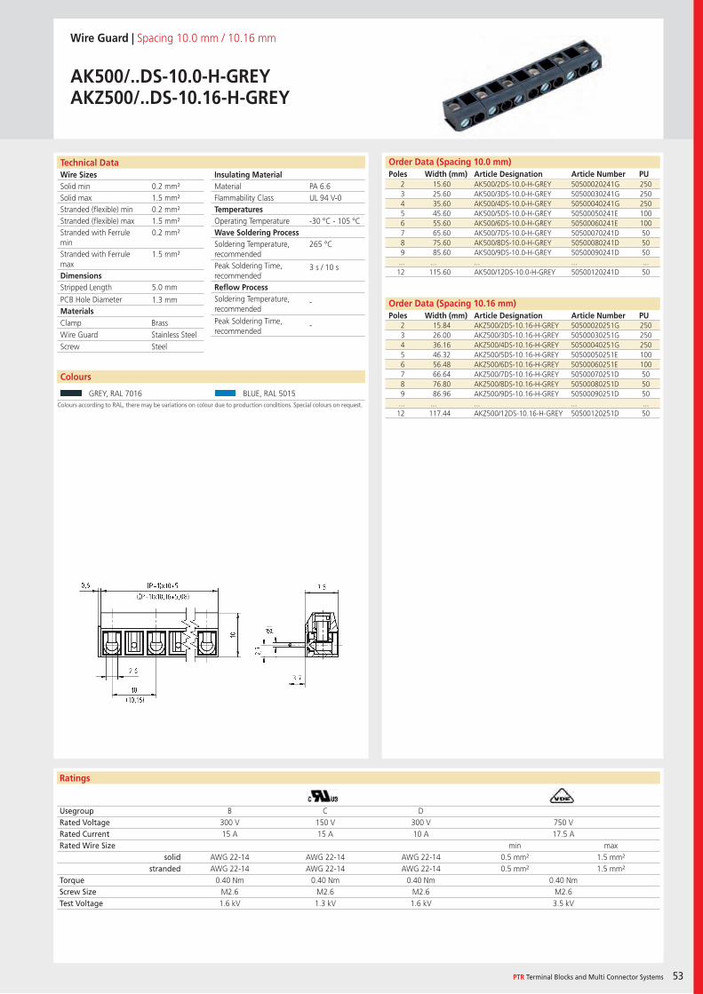
Wire SizesSolid minSolid maxStranded (flexible) minStranded (flexible) maxStranded with Ferrule minStranded with Ferrule maxDimensions Stripped Length
PCB Hole DiameterMaterials
Insulating Material MaterialFlammability ClassTemperaturesOperating TemperatureWave Soldering ProcessSoldering Temperature,recommendedPeak Soldering Time,recommendedReflow ProcessSoldering Temperature,recommended
Peak Soldering Time,recommended
Technical Data
Ratings
Colours
PTR Terminal Blocks and Multi Connector Systems 53
Order Data (Spacing 10.0 mm)Poles Width (mm) Article Designation Article Number PU
Colours according to RAL, there may be variations on colour due to production conditions. Special colours on request.
Wire Guard | Spacing 10.0 mm / 10.16 mm
AK500/..DS-10.0-H-GREYAKZ500/..DS-10.16-H-GREY
2 15.60 AK500/2DS-10.0-H-GREY 50500020241G 2503 25.60 AK500/3DS-10.0-H-GREY 50500030241G 2504 35.60 AK500/4DS-10.0-H-GREY 50500040241G 2505 45.60 AK500/5DS-10.0-H-GREY 50500050241E 1006 55.60 AK500/6DS-10.0-H-GREY 50500060241E 1007 65.60 AK500/7DS-10.0-H-GREY 50500070241D 508 75.60 AK500/8DS-10.0-H-GREY 50500080241D 509 85.60 AK500/9DS-10.0-H-GREY 50500090241D 50... ... ... ... ...12 115.60 AK500/12DS-10.0-H-GREY 50500120241D 50
Usegroup B C DRated Voltage 300 V 150 V 300 V 750 VRated Current 15 A 15 A 10 A 17.5 ARated Wire Size min max
solid AWG 22-14 AWG 22-14 AWG 22-14 0.5 mm² 1.5 mm²stranded AWG 22-14 AWG 22-14 AWG 22-14 0.5 mm² 1.5 mm²
Torque 0.40 Nm 0.40 Nm 0.40 Nm 0.40 NmScrew Size M2.6 M2.6 M2.6 M2.6Test Voltage 1.6 kV 1.3 kV 1.6 kV 3.5 kV
GREY, RAL 7016 BLUE, RAL 5015
PA 6.6UL 94 V-0
-30 °C - 105 °C
265 °C
3 s / 10 s
-
-
0.2 mm²1.5 mm²0.2 mm²1.5 mm²0.2 mm²
1.5 mm²
5.0 mm
1.3 mm
2 15.84 AKZ500/2DS-10.16-H-GREY 50500020251G 2503 26.00 AKZ500/3DS-10.16-H-GREY 50500030251G 2504 36.16 AKZ500/4DS-10.16-H-GREY 50500040251G 2505 46.32 AKZ500/5DS-10.16-H-GREY 50500050251E 1006 56.48 AKZ500/6DS-10.16-H-GREY 50500060251E 1007 66.64 AKZ500/7DS-10.16-H-GREY 50500070251D 508 76.80 AKZ500/8DS-10.16-H-GREY 50500080251D 509 86.96 AKZ500/9DS-10.16-H-GREY 50500090251D 50
... ... ... ... ...12 117.44 AKZ500/12DS-10.16-H-GREY 50500120251D 50
Clamp BrassWire Guard Stainless SteelScrew Steel
Order Data (Spacing 10.16 mm)Poles Width (mm) Article Designation Article Number PU
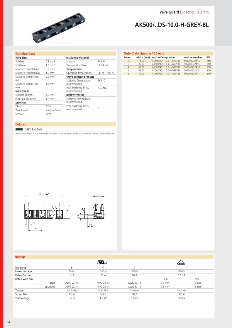
Wire SizesSolid minSolid maxStranded (flexible) minStranded (flexible) maxStranded with Ferrule minStranded with Ferrule maxDimensions Stripped Length
PCB Hole DiameterMaterials
Insulating Material MaterialFlammability ClassTemperaturesOperating TemperatureWave Soldering ProcessSoldering Temperature,recommendedPeak Soldering Time,recommendedReflow ProcessSoldering Temperature,recommended
Peak Soldering Time,recommended
Technical Data
Ratings
54
Colours
Order Data (Spacing 10.0 mm)Poles Width (mm) Article Designation Article Number PU
Colours according to RAL, there may be variations on colour due to production conditions. Special colours on request.
Wire Guard | Spacing 10.0 mm
AK500/..DS-10.0-H-GREY-BL
2 15.00 AK500/2DS-10.0-H-GREY-BL 50500023241G 2503 25.00 AK500/3DS-10.0-H-GREY-BL 50500033241G 2504 35.00 AK500/4DS-10.0-H-GREY-BL 50500043241G 2505 45.00 AK500/5DS-10.0-H-GREY-BL 50500053241E 1006 55.00 AK500/6DS-10.0-H-GREY-BL 50500063241E 100
Usegroup B C DRated Voltage 300 V 150 V 300 V 750 VRated Current 15 A 15 A 10 A 17.5 ARated Wire Size min max
solid AWG 22-14 AWG 22-14 AWG 22-14 0.5 mm² 1.5 mm²stranded AWG 22-14 AWG 22-14 AWG 22-14 0.5 mm² 1.5 mm²
Torque 0.40 Nm 0.40 Nm 0.40 Nm 0.40 NmScrew Size M2.6 M2.6 M2.6 M2.6Test Voltage 1.6 kV 1.3 kV 1.6 kV 3.5 kV
GREY, RAL 7016
PA 6.6UL 94 V-0
-30 °C - 105 °C
265 °C
3 s / 10 s
-
-
0.2 mm²1.5 mm²0.2 mm²1.5 mm²0.2 mm²
1.5 mm²
5.0 mm
1.3 mm
Clamp BrassWire Guard Stainless SteelScrew Steel
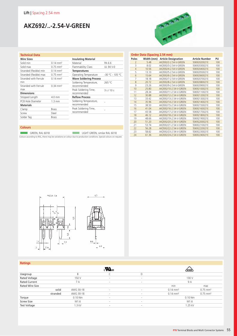
Wire SizesSolid minSolid maxStranded (flexible) minStranded (flexible) maxStranded with Ferrule minStranded with Ferrule maxDimensions Stripped Length
PCB Hole DiameterMaterials
Insulating Material MaterialFlammability ClassTemperaturesOperating TemperatureWave Soldering ProcessSoldering Temperature,recommendedPeak Soldering Time,recommendedReflow ProcessSoldering Temperature,recommended
Peak Soldering Time,recommended
Technical Data
Ratings
Colours
PTR Terminal Blocks and Multi Connector Systems 55
Order Data (Spacing 2.54 mm)Poles Width (mm) Article Designation Article Number PU
Colours according to RAL, there may be variations on colour due to production conditions. Special colours on request.
Lift | Spacing 2.54 mm
AKZ692/..-2.54-V-GREEN
2 5.48 AKZ692/2-2.54-V-GREEN 50692020021E 1003 8.02 AKZ692/3-2.54-V-GREEN 50692030021E 1004 10.56 AKZ692/4-2.54-V-GREEN 50692040021E 1005 13.10 AKZ692/5-2.54-V-GREEN 50692050021E 1006 15.64 AKZ692/6-2.54-V-GREEN 50692060021E 1007 18.18 AKZ692/7-2.54-V-GREEN 50692070021E 1008 20.72 AKZ692/8-2.54-V-GREEN 50692080021E 1009 23.26 AKZ692/9-2.54-V-GREEN 50692090021E 100
10 25.80 AKZ692/10-2.54-V-GREEN 50692100021E 10011 28.34 AKZ692/11-2.54-V-GREEN 50692110021E 10012 30.88 AKZ692/12-2.54-V-GREEN 50692120021E 10013 33.42 AKZ692/13-2.54-V-GREEN 50692130021E 10014 35.96 AKZ692/14-2.54-V-GREEN 50692140021E 10015 38.50 AKZ692/15-2.54-V-GREEN 50692150021E 10016 41.04 AKZ692/16-2.54-V-GREEN 50692160021E 10017 43.58 AKZ692/17-2.54-V-GREEN 50692170021E 10018 46.12 AKZ692/18-2.54-V-GREEN 50692180021E 10019 48.66 AKZ692/19-2.54-V-GREEN 50692190021E 10020 51.20 AKZ692/20-2.54-V-GREEN 50692200021E 10021 53.74 AKZ692/21-2.54-V-GREEN 50692210021E 10022 56.28 AKZ692/22-2.54-V-GREEN 50692220021E 10023 58.82 AKZ692/23-2.54-V-GREEN 50692230021E 10024 61.36 AKZ692/24-2.54-V-GREEN 50692240021E 100
Usegroup B C DRated Voltage 150 V - - 130 VRated Current 7 A - - 9 ARated Wire Size min max
solid AWG 30-18 - - 0.14 mm² 0.75 mm²stranded AWG 30-18 - - 0.14 mm² 0.75 mm²
Torque 0.10 Nm - - 0.10 NmScrew Size M1.6 - - M1.6Test Voltage 1.3 kV - - 1.25 kV
GREEN, RAL 6018 LIGHT GREEN, similar RAL 6018
PA 6.6UL 94 V-0
-30 °C - 105 °C
265 °C
3 s / 10 s
-
-
0.14 mm²0.75 mm²0.14 mm²0.75 mm²0.14 mm²
0.34 mm²
4.0 mm
1.3 mm
Clamp BrassScrew SteelSolder Tag Brass
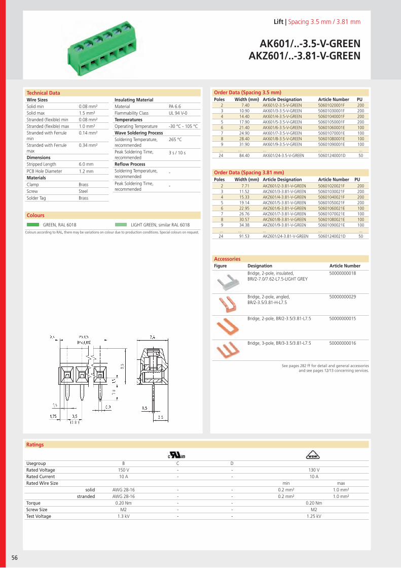
Wire SizesSolid minSolid maxStranded (flexible) minStranded (flexible) maxStranded with Ferrule minStranded with Ferrule maxDimensions Stripped Length
PCB Hole DiameterMaterials
Insulating Material MaterialFlammability ClassTemperaturesOperating TemperatureWave Soldering ProcessSoldering Temperature,recommendedPeak Soldering Time,recommendedReflow ProcessSoldering Temperature,recommended
Peak Soldering Time,recommended
Technical Data
Ratings
56
Colours
AccessoriesFigure Designation Article Number
Order Data (Spacing 3.81 mm)Poles Width (mm) Article Designation Article Number PU
Order Data (Spacing 3.5 mm)Poles Width (mm) Article Designation Article Number PU
See pages 282 ff for detail and general accessoriesand see pages 12/13 concerning services.
Colours according to RAL, there may be variations on colour due to production conditions. Special colours on request.
Lift | Spacing 3.5 mm / 3.81 mm
AK601/..-3.5-V-GREENAKZ601/..-3.81-V-GREEN
2 7.40 AK601/2-3.5-V-GREEN 50601020001F 2003 10.90 AK601/3-3.5-V-GREEN 50601030001F 2004 14.40 AK601/4-3.5-V-GREEN 50601040001F 2005 17.90 AK601/5-3.5-V-GREEN 50601050001F 2006 21.40 AK601/6-3.5-V-GREEN 50601060001E 1007 24.90 AK601/7-3.5-V-GREEN 50601070001E 1008 28.40 AK601/8-3.5-V-GREEN 50601080001E 1009 31.90 AK601/9-3.5-V-GREEN 50601090001E 100... ... ... ... ...24 84.40 AK601/24-3.5-V-GREEN 50601240001D 50
Usegroup B C DRated Voltage 150 V - - 130 VRated Current 10 A - - 10 ARated Wire Size min max
solid AWG 28-16 - - 0.2 mm² 1.0 mm²stranded AWG 28-16 - - 0.2 mm² 1.0 mm²
Torque 0.20 Nm - - 0.20 NmScrew Size M2 - - M2Test Voltage 1.3 kV - - 1.25 kV
GREEN, RAL 6018 LIGHT GREEN, similar RAL 6018
Bridge, 2-pole, insulated, BRI/2-7.0/7.62-L7.5-LIGHT GREY
50000000018
Bridge, 2-pole, angled, BR/2-3.5/3.81-H-L7.5
50000000029
Bridge, 2-pole, BR/2-3.5/3.81-L7.5 50000000015
Bridge, 3-pole, BR/3-3.5/3.81-L7.5 50000000016
PA 6.6UL 94 V-0
-30 °C - 105 °C
265 °C
3 s / 10 s
-
-
0.08 mm²1.5 mm²0.08 mm²1.0 mm²0.14 mm²
0.34 mm²
6.0 mm
1.2 mm
2 7.71 AKZ601/2-3.81-V-GREEN 50601020021F 2003 11.52 AKZ601/3-3.81-V-GREEN 50601030021F 2004 15.33 AKZ601/4-3.81-V-GREEN 50601040021F 2005 19.14 AKZ601/5-3.81-V-GREEN 50601050021F 2006 22.95 AKZ601/6-3.81-V-GREEN 50601060021E 1007 26.76 AKZ601/7-3.81-V-GREEN 50601070021E 1008 30.57 AKZ601/8-3.81-V-GREEN 50601080021E 1009 34.38 AKZ601/9-3.81-V-GREEN 50601090021E 100... ... ... ... ...24 91.53 AKZ601/24-3.81-V-GREEN 50601240021D 50
Clamp BrassScrew SteelSolder Tag Brass
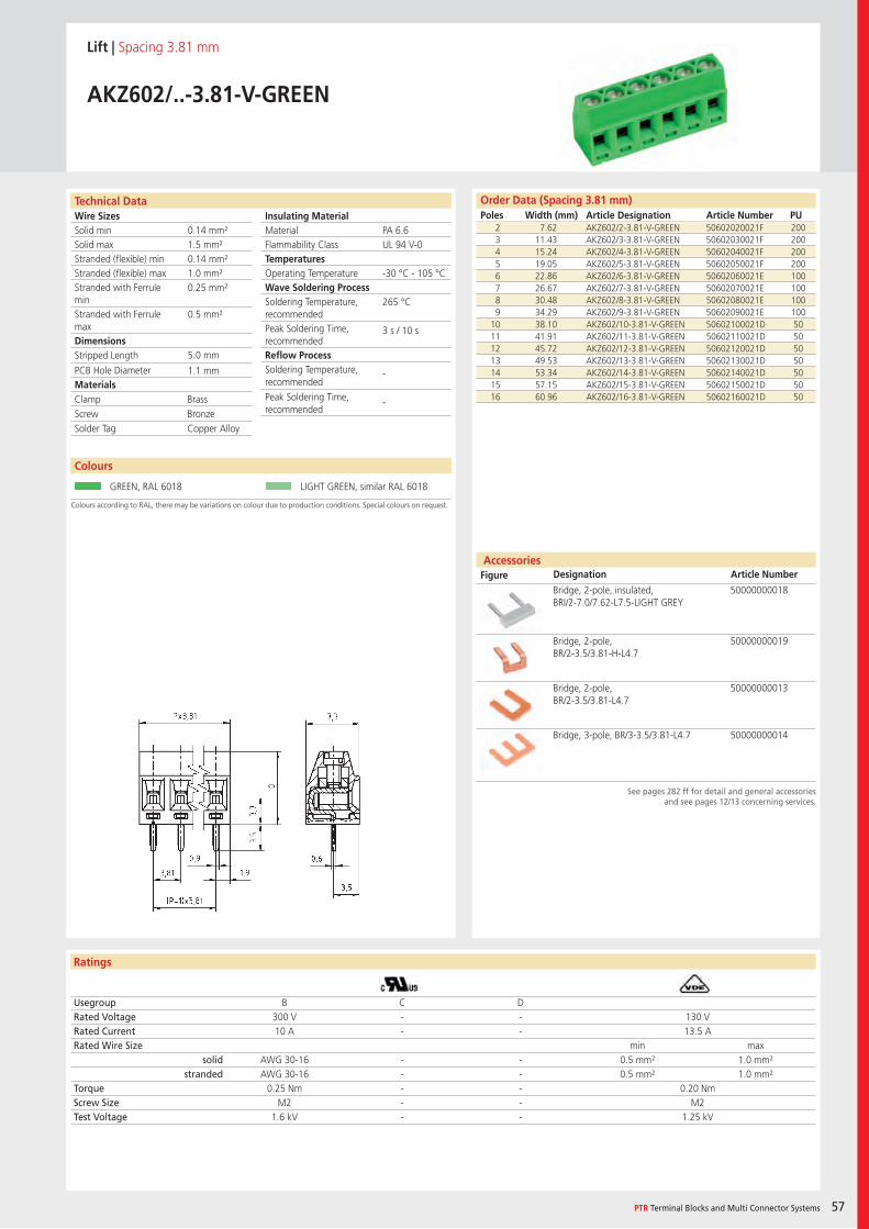
Wire SizesSolid minSolid maxStranded (flexible) minStranded (flexible) maxStranded with Ferrule minStranded with Ferrule maxDimensions Stripped Length
PCB Hole DiameterMaterials
Insulating Material MaterialFlammability ClassTemperaturesOperating TemperatureWave Soldering ProcessSoldering Temperature,recommendedPeak Soldering Time,recommendedReflow ProcessSoldering Temperature,recommended
Peak Soldering Time,recommended
Technical Data
Ratings
Accessories Figure Designation Article Number
Colours
PTR Terminal Blocks and Multi Connector Systems 57
Order Data (Spacing 3.81 mm)Poles Width (mm) Article Designation Article Number PU
See pages 282 ff for detail and general accessoriesand see pages 12/13 concerning services.
Colours according to RAL, there may be variations on colour due to production conditions. Special colours on request.
Lift | Spacing 3.81 mm
AKZ602/..-3.81-V-GREEN
2 7.62 AKZ602/2-3.81-V-GREEN 50602020021F 2003 11.43 AKZ602/3-3.81-V-GREEN 50602030021F 2004 15.24 AKZ602/4-3.81-V-GREEN 50602040021F 2005 19.05 AKZ602/5-3.81-V-GREEN 50602050021F 2006 22.86 AKZ602/6-3.81-V-GREEN 50602060021E 1007 26.67 AKZ602/7-3.81-V-GREEN 50602070021E 1008 30.48 AKZ602/8-3.81-V-GREEN 50602080021E 1009 34.29 AKZ602/9-3.81-V-GREEN 50602090021E 100
10 38.10 AKZ602/10-3.81-V-GREEN 50602100021D 5011 41.91 AKZ602/11-3.81-V-GREEN 50602110021D 5012 45.72 AKZ602/12-3.81-V-GREEN 50602120021D 5013 49.53 AKZ602/13-3.81-V-GREEN 50602130021D 5014 53.34 AKZ602/14-3.81-V-GREEN 50602140021D 5015 57.15 AKZ602/15-3.81-V-GREEN 50602150021D 5016 60.96 AKZ602/16-3.81-V-GREEN 50602160021D 50
Usegroup B C DRated Voltage 300 V - - 130 VRated Current 10 A - - 13.5 ARated Wire Size min max
solid AWG 30-16 - - 0.5 mm² 1.0 mm²stranded AWG 30-16 - - 0.5 mm² 1.0 mm²
Torque 0.25 Nm - - 0.20 NmScrew Size M2 - - M2Test Voltage 1.6 kV - - 1.25 kV
GREEN, RAL 6018 LIGHT GREEN, similar RAL 6018
Bridge, 2-pole, insulated, BRI/2-7.0/7.62-L7.5-LIGHT GREY
50000000018
Bridge, 2-pole, BR/2-3.5/3.81-H-L4.7
50000000019
Bridge, 2-pole, BR/2-3.5/3.81-L4.7
50000000013
Bridge, 3-pole, BR/3-3.5/3.81-L4.7 50000000014
PA 6.6UL 94 V-0
-30 °C - 105 °C
265 °C
3 s / 10 s
-
-
0.14 mm²1.5 mm²0.14 mm²1.0 mm²0.25 mm²
0.5 mm²
5.0 mm
1.1 mm
Clamp BrassScrew BronzeSolder Tag Copper Alloy
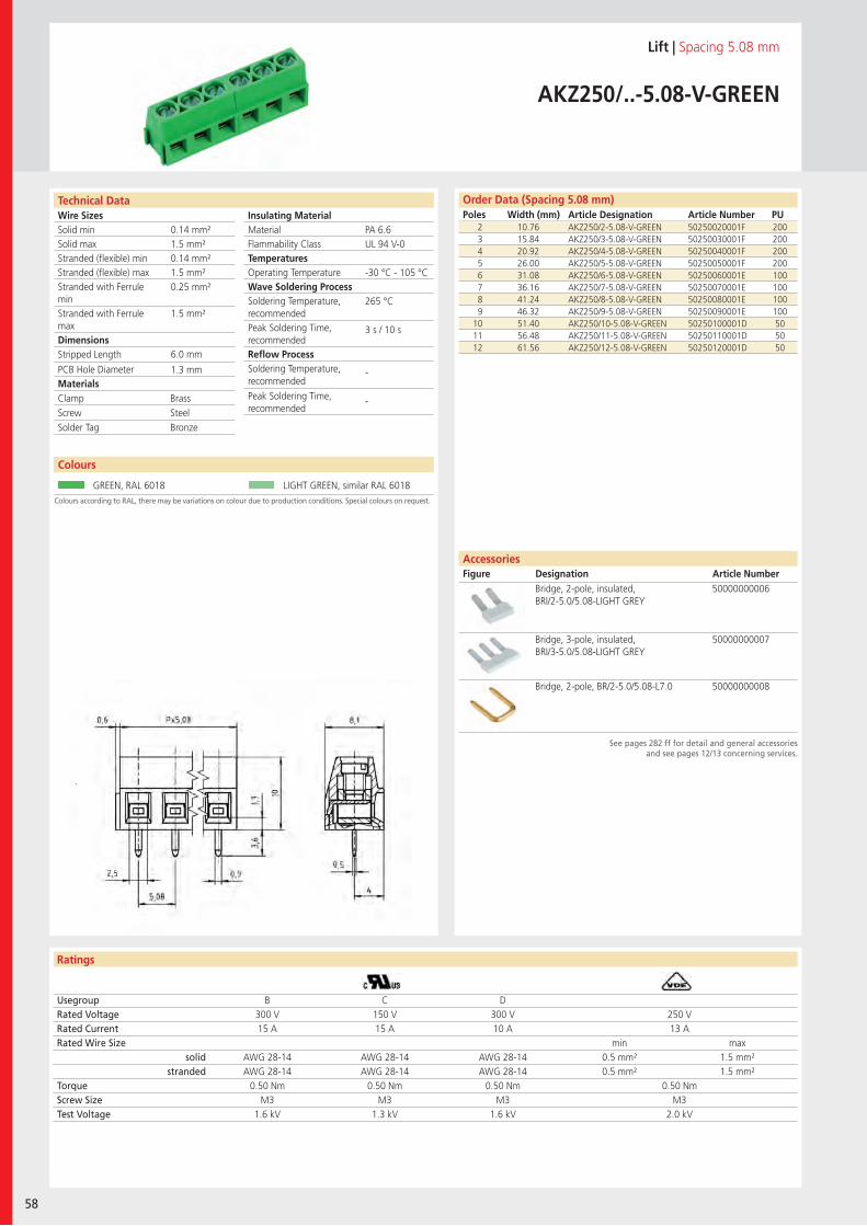
Wire SizesSolid minSolid maxStranded (flexible) minStranded (flexible) maxStranded with Ferrule minStranded with Ferrule maxDimensions Stripped Length
PCB Hole DiameterMaterials
Insulating Material MaterialFlammability ClassTemperaturesOperating TemperatureWave Soldering ProcessSoldering Temperature,recommendedPeak Soldering Time,recommendedReflow ProcessSoldering Temperature,recommended
Peak Soldering Time,recommended
Technical Data
Ratings
58
Colours
Order Data (Spacing 5.08 mm)Poles Width (mm) Article Designation Article Number PU
AccessoriesFigure Designation Article Number
See pages 282 ff for detail and general accessoriesand see pages 12/13 concerning services.
Colours according to RAL, there may be variations on colour due to production conditions. Special colours on request.
Lift | Spacing 5.08 mm
AKZ250/..-5.08-V-GREEN
2 10.76 AKZ250/2-5.08-V-GREEN 50250020001F 2003 15.84 AKZ250/3-5.08-V-GREEN 50250030001F 2004 20.92 AKZ250/4-5.08-V-GREEN 50250040001F 2005 26.00 AKZ250/5-5.08-V-GREEN 50250050001F 2006 31.08 AKZ250/6-5.08-V-GREEN 50250060001E 1007 36.16 AKZ250/7-5.08-V-GREEN 50250070001E 1008 41.24 AKZ250/8-5.08-V-GREEN 50250080001E 1009 46.32 AKZ250/9-5.08-V-GREEN 50250090001E 100
10 51.40 AKZ250/10-5.08-V-GREEN 50250100001D 5011 56.48 AKZ250/11-5.08-V-GREEN 50250110001D 5012 61.56 AKZ250/12-5.08-V-GREEN 50250120001D 50
Usegroup B C DRated Voltage 300 V 150 V 300 V 250 VRated Current 15 A 15 A 10 A 13 ARated Wire Size min max
solid AWG 28-14 AWG 28-14 AWG 28-14 0.5 mm² 1.5 mm²stranded AWG 28-14 AWG 28-14 AWG 28-14 0.5 mm² 1.5 mm²
Torque 0.50 Nm 0.50 Nm 0.50 Nm 0.50 NmScrew Size M3 M3 M3 M3Test Voltage 1.6 kV 1.3 kV 1.6 kV 2.0 kV
GREEN, RAL 6018 LIGHT GREEN, similar RAL 6018
Bridge, 2-pole, insulated, BRI/2-5.0/5.08-LIGHT GREY
50000000006
Bridge, 3-pole, insulated, BRI/3-5.0/5.08-LIGHT GREY
50000000007
Bridge, 2-pole, BR/2-5.0/5.08-L7.0 50000000008
PA 6.6UL 94 V-0
-30 °C - 105 °C
265 °C
3 s / 10 s
-
-
0.14 mm²1.5 mm²0.14 mm²1.5 mm²0.25 mm²
1.5 mm²
6.0 mm
1.3 mm
Clamp BrassScrew SteelSolder Tag Bronze
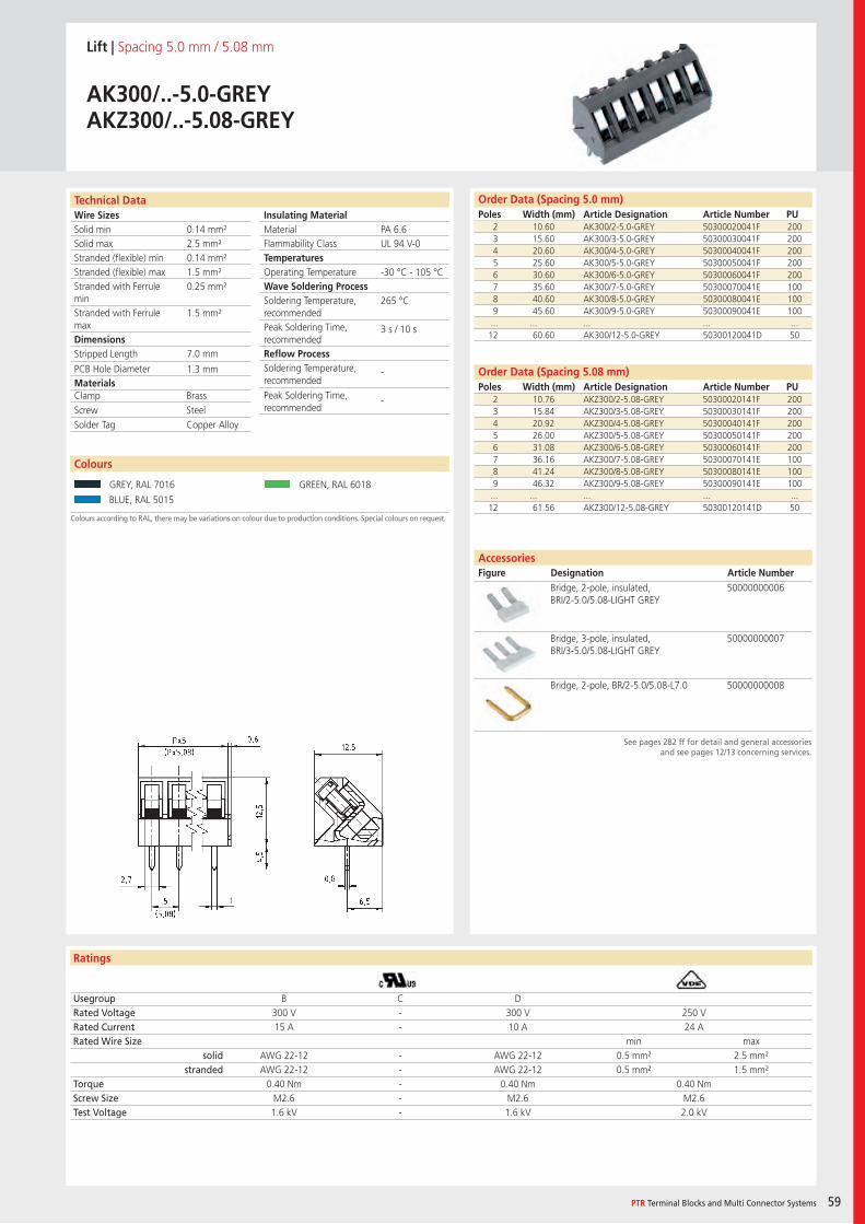
Wire SizesSolid minSolid maxStranded (flexible) minStranded (flexible) maxStranded with Ferrule minStranded with Ferrule maxDimensions Stripped Length
PCB Hole DiameterMaterials
Insulating Material MaterialFlammability ClassTemperaturesOperating TemperatureWave Soldering ProcessSoldering Temperature,recommendedPeak Soldering Time,recommendedReflow ProcessSoldering Temperature,recommended
Peak Soldering Time,recommended
Technical Data
Ratings
Colours
PTR Terminal Blocks and Multi Connector Systems 59
Order Data (Spacing 5.0 mm)Poles Width (mm) Article Designation Article Number PU
See pages 282 ff for detail and general accessoriesand see pages 12/13 concerning services.
Colours according to RAL, there may be variations on colour due to production conditions. Special colours on request.
Lift | Spacing 5.0 mm / 5.08 mm
AK300/..-5.0-GREYAKZ300/..-5.08-GREY
2 10.60 AK300/2-5.0-GREY 50300020041F 2003 15.60 AK300/3-5.0-GREY 50300030041F 2004 20.60 AK300/4-5.0-GREY 50300040041F 2005 25.60 AK300/5-5.0-GREY 50300050041F 2006 30.60 AK300/6-5.0-GREY 50300060041F 2007 35.60 AK300/7-5.0-GREY 50300070041E 1008 40.60 AK300/8-5.0-GREY 50300080041E 1009 45.60 AK300/9-5.0-GREY 50300090041E 100... ... ... ... ...12 60.60 AK300/12-5.0-GREY 50300120041D 50
Usegroup B C DRated Voltage 300 V - 300 V 250 VRated Current 15 A - 10 A 24 ARated Wire Size min max
solid AWG 22-12 - AWG 22-12 0.5 mm² 2.5 mm²stranded AWG 22-12 - AWG 22-12 0.5 mm² 1.5 mm²
Torque 0.40 Nm - 0.40 Nm 0.40 NmScrew Size M2.6 - M2.6 M2.6Test Voltage 1.6 kV - 1.6 kV 2.0 kV
GREY, RAL 7016 GREEN, RAL 6018
BLUE, RAL 5015
AccessoriesFigure Designation Article Number
Bridge, 2-pole, insulated, BRI/2-5.0/5.08-LIGHT GREY
50000000006
Bridge, 3-pole, insulated, BRI/3-5.0/5.08-LIGHT GREY
50000000007
Bridge, 2-pole, BR/2-5.0/5.08-L7.0 50000000008
PA 6.6UL 94 V-0
-30 °C - 105 °C
265 °C
3 s / 10 s
-
-
0.14 mm²2.5 mm²0.14 mm²1.5 mm²0.25 mm²
1.5 mm²
7.0 mm
1.3 mm
2 10.76 AKZ300/2-5.08-GREY 50300020141F 2003 15.84 AKZ300/3-5.08-GREY 50300030141F 2004 20.92 AKZ300/4-5.08-GREY 50300040141F 2005 26.00 AKZ300/5-5.08-GREY 50300050141F 2006 31.08 AKZ300/6-5.08-GREY 50300060141F 2007 36.16 AKZ300/7-5.08-GREY 50300070141E 1008 41.24 AKZ300/8-5.08-GREY 50300080141E 1009 46.32 AKZ300/9-5.08-GREY 50300090141E 100... ... ... ... ...12 61.56 AKZ300/12-5.08-GREY 50300120141D 50
Clamp BrassScrew SteelSolder Tag Copper Alloy
Order Data (Spacing 5.08 mm)Poles Width (mm) Article Designation Article Number PU
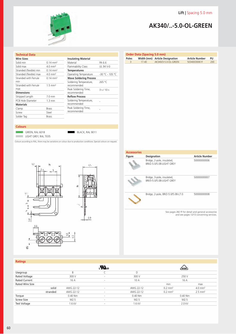
Wire SizesSolid minSolid maxStranded (flexible) minStranded (flexible) maxStranded with Ferrule minStranded with Ferrule maxDimensions Stripped Length
PCB Hole DiameterMaterials
Insulating Material MaterialFlammability ClassTemperaturesOperating TemperatureWave Soldering ProcessSoldering Temperature,recommendedPeak Soldering Time,recommendedReflow ProcessSoldering Temperature,recommended
Peak Soldering Time,recommended
Technical Data
Ratings
60
Colours
AccessoriesFigure Designation Article Number
Order Data (Spacing 5.0 mm)Poles Width (mm) Article Designation Article Number PU
Colours according to RAL, there may be variations on colour due to production conditions. Special colours on request.
See pages 282 ff for detail and general accessoriesand see pages 12/13 concerning services.
Lift | Spacing 5.0 mm
AK340/..-5.0-OL-GREEN
3 17.40 AK340/3-5.0-OL-GREEN 50340030061F 200
Usegroup B C DRated Voltage 300 V - 300 V 250 VRated Current 16 A - 10 A 16 ARated Wire Size min max
solid AWG 22-12 - AWG 22-12 0.2 mm² 4.0 mm²stranded AWG 22-12 - AWG 22-12 0.2 mm² 2.5 mm²
Torque 0.40 Nm - 0.40 Nm 0.40 NmScrew Size M2.5 - M2.5 M2.5Test Voltage 1.6 kV - 1.6 kV 2.0 kV
GREEN, RAL 6018 BLACK, RAL 9011
LIGHT GREY, RAL 7035
Bridge, 2-pole, insulated, BRI/2-5.0/5.08-LIGHT GREY
50000000006
Bridge, 3-pole, insulated, BRI/3-5.0/5.08-LIGHT GREY
50000000007
Bridge, 2-pole, BR/2-5.0/5.08-L7.0 50000000008
PA 6.6UL 94 V-0
-30 °C - 105 °C
265 °C
3 s / 10 s
-
-
0.14 mm²4.0 mm²0.14 mm²4.0 mm²0.14 mm²
1.5 mm²
7.0 mm
1.3 mm
Clamp BrassScrew SteelSolder Tag Brass
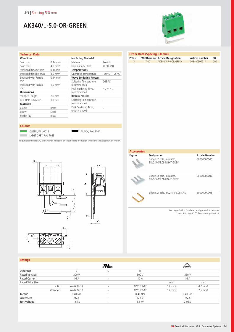
Wire SizesSolid minSolid maxStranded (flexible) minStranded (flexible) maxStranded with Ferrule minStranded with Ferrule maxDimensions Stripped Length
PCB Hole DiameterMaterials
Insulating Material MaterialFlammability ClassTemperaturesOperating TemperatureWave Soldering ProcessSoldering Temperature,recommendedPeak Soldering Time,recommendedReflow ProcessSoldering Temperature,recommended
Peak Soldering Time,recommended
Technical Data
Ratings
Colours
PTR Terminal Blocks and Multi Connector Systems 61
AccessoriesFigure Designation Article Number
Order Data (Spacing 5.0 mm)Poles Width (mm) Article Designation Article Number PU
Colours according to RAL, there may be variations on colour due to production conditions. Special colours on request.
See pages 282 ff for detail and general accessoriesand see pages 12/13 concerning services.
Lift | Spacing 5.0 mm
AK340/..-5.0-OR-GREEN
3 17.40 AK340/3-5.0-OR-GREEN 50340030071F 200
Usegroup B C DRated Voltage 300 V - 300 V 250 VRated Current 16 A - 10 A 16 ARated Wire Size min max
solid AWG 22-12 - AWG 22-12 0.2 mm² 4.0 mm²stranded AWG 22-12 - AWG 22-12 0.2 mm² 2.5 mm²
Torque 0.40 Nm - 0.40 Nm 0.40 NmScrew Size M2.5 - M2.5 M2.5Test Voltage 1.6 kV - 1.6 kV 2.0 kV
GREEN, RAL 6018 BLACK, RAL 9011
LIGHT GREY, RAL 7035
Bridge, 2-pole, insulated, BRI/2-5.0/5.08-LIGHT GREY
50000000006
Bridge, 3-pole, insulated, BRI/3-5.0/5.08-LIGHT GREY
50000000007
Bridge, 2-pole, BR/2-5.0/5.08-L7.0 50000000008
PA 6.6UL 94 V-0
-30 °C - 105 °C
265 °C
3 s / 10 s
-
-
0.14 mm²4.0 mm²0.14 mm²4.0 mm²0.14 mm²
1.5 mm²
7.0 mm
1.3 mm
Clamp BrassScrew SteelSolder Tag Brass
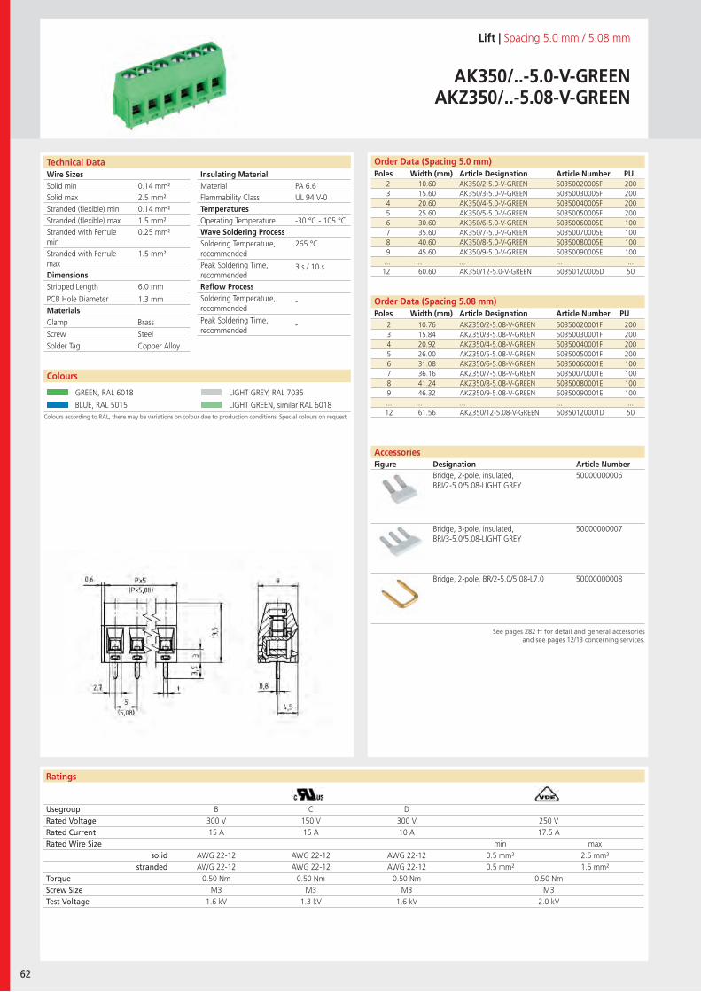
Wire SizesSolid minSolid maxStranded (flexible) minStranded (flexible) maxStranded with Ferrule minStranded with Ferrule maxDimensions Stripped Length
PCB Hole DiameterMaterials
Insulating Material MaterialFlammability ClassTemperaturesOperating TemperatureWave Soldering ProcessSoldering Temperature,recommendedPeak Soldering Time,recommendedReflow ProcessSoldering Temperature,recommended
Peak Soldering Time,recommended
Technical Data
Ratings
62
Colours
Order Data (Spacing 5.08 mm)Poles Width (mm) Article Designation Article Number PU
Order Data (Spacing 5.0 mm)Poles Width (mm) Article Designation Article Number PU
See pages 282 ff for detail and general accessoriesand see pages 12/13 concerning services.
AccessoriesFigure Designation Article Number
Colours according to RAL, there may be variations on colour due to production conditions. Special colours on request.
Lift | Spacing 5.0 mm / 5.08 mm
AK350/..-5.0-V-GREENAKZ350/..-5.08-V-GREEN
2 10.60 AK350/2-5.0-V-GREEN 50350020005F 2003 15.60 AK350/3-5.0-V-GREEN 50350030005F 2004 20.60 AK350/4-5.0-V-GREEN 50350040005F 2005 25.60 AK350/5-5.0-V-GREEN 50350050005F 2006 30.60 AK350/6-5.0-V-GREEN 50350060005E 1007 35.60 AK350/7-5.0-V-GREEN 50350070005E 1008 40.60 AK350/8-5.0-V-GREEN 50350080005E 1009 45.60 AK350/9-5.0-V-GREEN 50350090005E 100... ... ... ... ...12 60.60 AK350/12-5.0-V-GREEN 50350120005D 50
Usegroup B C DRated Voltage 300 V 150 V 300 V 250 VRated Current 15 A 15 A 10 A 17.5 ARated Wire Size min max
solid AWG 22-12 AWG 22-12 AWG 22-12 0.5 mm² 2.5 mm²stranded AWG 22-12 AWG 22-12 AWG 22-12 0.5 mm² 1.5 mm²
Torque 0.50 Nm 0.50 Nm 0.50 Nm 0.50 NmScrew Size M3 M3 M3 M3Test Voltage 1.6 kV 1.3 kV 1.6 kV 2.0 kV
GREEN, RAL 6018 LIGHT GREY, RAL 7035
BLUE, RAL 5015 LIGHT GREEN, similar RAL 6018
Bridge, 2-pole, insulated, BRI/2-5.0/5.08-LIGHT GREY
50000000006
Bridge, 3-pole, insulated, BRI/3-5.0/5.08-LIGHT GREY
50000000007
Bridge, 2-pole, BR/2-5.0/5.08-L7.0 50000000008
PA 6.6UL 94 V-0
-30 °C - 105 °C
265 °C
3 s / 10 s
-
-
0.14 mm²2.5 mm²0.14 mm²1.5 mm²0.25 mm²
1.5 mm²
6.0 mm
1.3 mm
2 10.76 AKZ350/2-5.08-V-GREEN 50350020001F 2003 15.84 AKZ350/3-5.08-V-GREEN 50350030001F 2004 20.92 AKZ350/4-5.08-V-GREEN 50350040001F 2005 26.00 AKZ350/5-5.08-V-GREEN 50350050001F 2006 31.08 AKZ350/6-5.08-V-GREEN 50350060001E 1007 36.16 AKZ350/7-5.08-V-GREEN 50350070001E 1008 41.24 AKZ350/8-5.08-V-GREEN 50350080001E 1009 46.32 AKZ350/9-5.08-V-GREEN 50350090001E 100... ... ... ... ...12 61.56 AKZ350/12-5.08-V-GREEN 50350120001D 50
Clamp BrassScrew SteelSolder Tag Copper Alloy
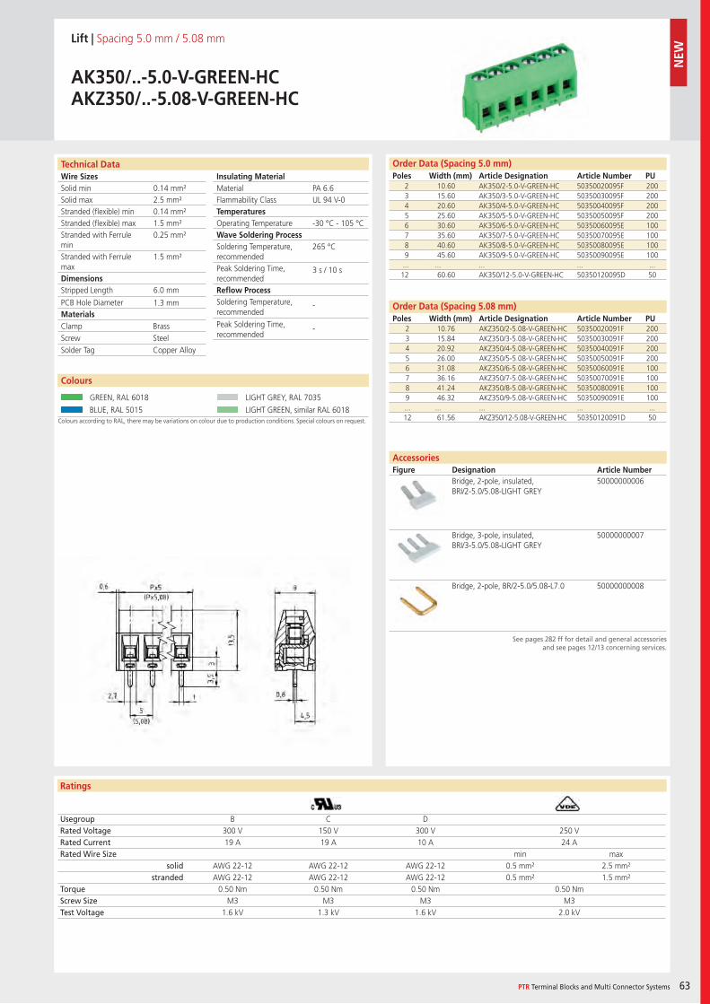
Wire SizesSolid minSolid maxStranded (flexible) minStranded (flexible) maxStranded with Ferrule minStranded with Ferrule maxDimensions Stripped Length
PCB Hole DiameterMaterials
Insulating Material MaterialFlammability ClassTemperaturesOperating TemperatureWave Soldering ProcessSoldering Temperature,recommendedPeak Soldering Time,recommendedReflow ProcessSoldering Temperature,recommended
Peak Soldering Time,recommended
Technical Data
Ratings
Colours
PTR Terminal Blocks and Multi Connector Systems 63
See pages 282 ff for detail and general accessoriesand see pages 12/13 concerning services.
AccessoriesFigure Designation Article Number
Order Data (Spacing 5.0 mm)Poles Width (mm) Article Designation Article Number PU
Colours according to RAL, there may be variations on colour due to production conditions. Special colours on request.
Lift | Spacing 5.0 mm / 5.08 mm
AK350/..-5.0-V-GREEN-HCAKZ350/..-5.08-V-GREEN-HC
2 10.60 AK350/2-5.0-V-GREEN-HC 50350020095F 2003 15.60 AK350/3-5.0-V-GREEN-HC 50350030095F 2004 20.60 AK350/4-5.0-V-GREEN-HC 50350040095F 2005 25.60 AK350/5-5.0-V-GREEN-HC 50350050095F 2006 30.60 AK350/6-5.0-V-GREEN-HC 50350060095E 1007 35.60 AK350/7-5.0-V-GREEN-HC 50350070095E 1008 40.60 AK350/8-5.0-V-GREEN-HC 50350080095E 1009 45.60 AK350/9-5.0-V-GREEN-HC 50350090095E 100... ... ... ... ...12 60.60 AK350/12-5.0-V-GREEN-HC 50350120095D 50
Usegroup B C DRated Voltage 300 V 150 V 300 V 250 VRated Current 19 A 19 A 10 A 24 ARated Wire Size min max
solid AWG 22-12 AWG 22-12 AWG 22-12 0.5 mm² 2.5 mm²stranded AWG 22-12 AWG 22-12 AWG 22-12 0.5 mm² 1.5 mm²
Torque 0.50 Nm 0.50 Nm 0.50 Nm 0.50 NmScrew Size M3 M3 M3 M3Test Voltage 1.6 kV 1.3 kV 1.6 kV 2.0 kV
GREEN, RAL 6018 LIGHT GREY, RAL 7035
BLUE, RAL 5015 LIGHT GREEN, similar RAL 6018
Bridge, 2-pole, insulated, BRI/2-5.0/5.08-LIGHT GREY
50000000006
Bridge, 3-pole, insulated, BRI/3-5.0/5.08-LIGHT GREY
50000000007
Bridge, 2-pole, BR/2-5.0/5.08-L7.0 50000000008
PA 6.6UL 94 V-0
-30 °C - 105 °C
265 °C
3 s / 10 s
- -
0.14 mm²2.5 mm²0.14 mm²1.5 mm²0.25 mm²
1.5 mm²
6.0 mm
1.3 mm
2 10.76 AKZ350/2-5.08-V-GREEN-HC 50350020091F 2003 15.84 AKZ350/3-5.08-V-GREEN-HC 50350030091F 2004 20.92 AKZ350/4-5.08-V-GREEN-HC 50350040091F 2005 26.00 AKZ350/5-5.08-V-GREEN-HC 50350050091F 2006 31.08 AKZ350/6-5.08-V-GREEN-HC 50350060091E 1007 36.16 AKZ350/7-5.08-V-GREEN-HC 50350070091E 1008 41.24 AKZ350/8-5.08-V-GREEN-HC 50350080091E 1009 46.32 AKZ350/9-5.08-V-GREEN-HC 50350090091E 100... ... ... ... ...12 61.56 AKZ350/12-5.08-V-GREEN-HC 50350120091D 50
Clamp BrassScrew SteelSolder Tag Copper Alloy
Order Data (Spacing 5.08 mm)Poles Width (mm) Article Designation Article Number PU
NEW
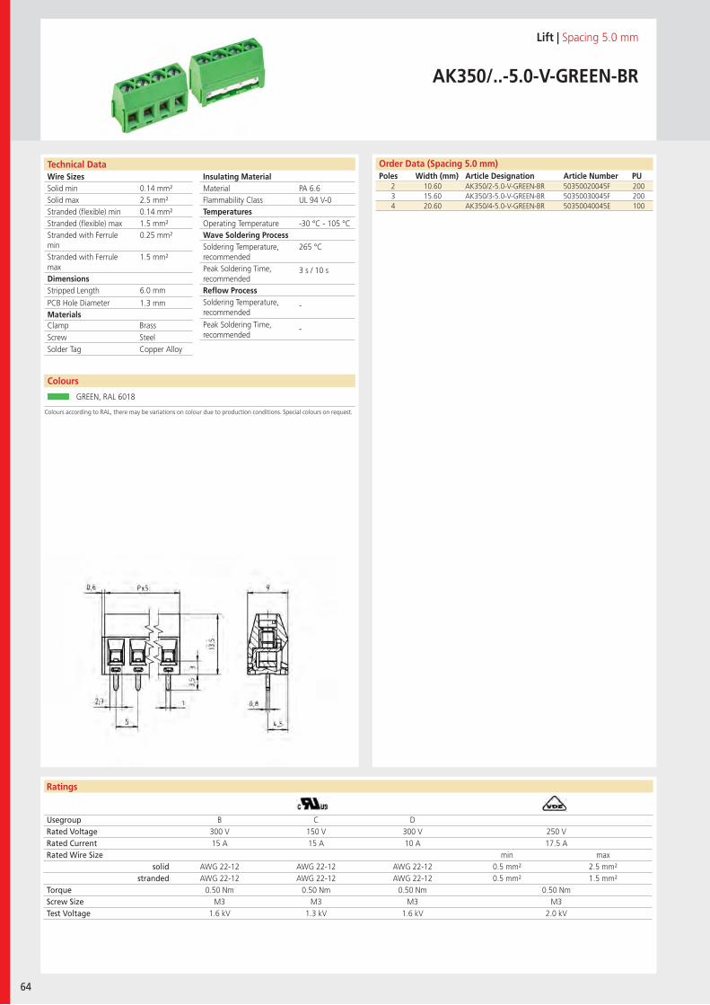
Wire SizesSolid minSolid maxStranded (flexible) minStranded (flexible) maxStranded with Ferrule minStranded with Ferrule maxDimensions Stripped Length
PCB Hole DiameterMaterials
Insulating Material MaterialFlammability ClassTemperaturesOperating TemperatureWave Soldering ProcessSoldering Temperature,recommendedPeak Soldering Time,recommendedReflow ProcessSoldering Temperature,recommended
Peak Soldering Time,recommended
Technical Data
Ratings
64
Colours
Order Data (Spacing 5.0 mm)Poles Width (mm) Article Designation Article Number PU
Colours according to RAL, there may be variations on colour due to production conditions. Special colours on request.
Lift | Spacing 5.0 mm
AK350/..-5.0-V-GREEN-BR
2 10.60 AK350/2-5.0-V-GREEN-BR 50350020045F 2003 15.60 AK350/3-5.0-V-GREEN-BR 50350030045F 2004 20.60 AK350/4-5.0-V-GREEN-BR 50350040045E 100
Usegroup B C DRated Voltage 300 V 150 V 300 V 250 VRated Current 15 A 15 A 10 A 17.5 ARated Wire Size min max
solid AWG 22-12 AWG 22-12 AWG 22-12 0.5 mm² 2.5 mm²stranded AWG 22-12 AWG 22-12 AWG 22-12 0.5 mm² 1.5 mm²
Torque 0.50 Nm 0.50 Nm 0.50 Nm 0.50 NmScrew Size M3 M3 M3 M3Test Voltage 1.6 kV 1.3 kV 1.6 kV 2.0 kV
GREEN, RAL 6018
PA 6.6UL 94 V-0
-30 °C - 105 °C
265 °C
3 s / 10 s
-
-
0.14 mm²2.5 mm²0.14 mm²1.5 mm²0.25 mm²
1.5 mm²
6.0 mm
1.3 mm
Clamp BrassScrew SteelSolder Tag Copper Alloy
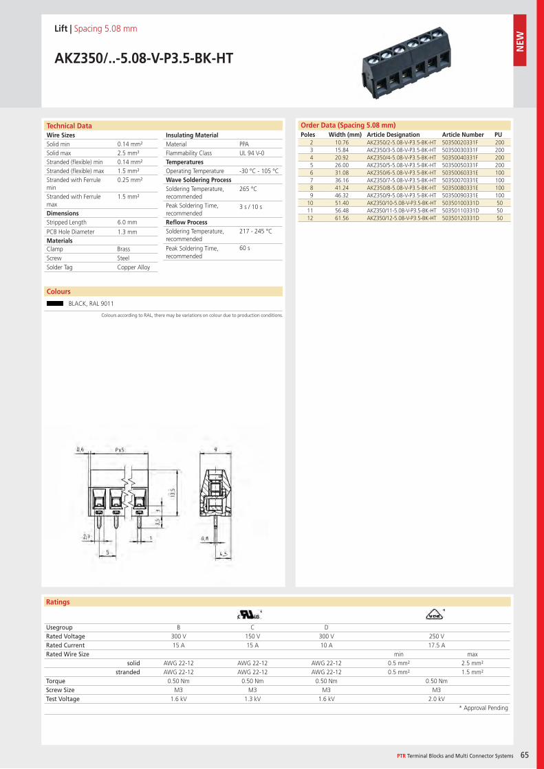
Wire SizesSolid minSolid maxStranded (flexible) minStranded (flexible) maxStranded with Ferrule minStranded with Ferrule maxDimensions Stripped Length
PCB Hole DiameterMaterials
Insulating Material MaterialFlammability ClassTemperaturesOperating TemperatureWave Soldering ProcessSoldering Temperature,recommendedPeak Soldering Time,recommendedReflow ProcessSoldering Temperature,recommended
Peak Soldering Time,recommended
Technical Data
Ratings
Colours
PTR Terminal Blocks and Multi Connector Systems 65
Order Data (Spacing 5.08 mm)Poles Width (mm) Article Designation Article Number PU
Colours according to RAL, there may be variations on colour due to production conditions.
Lift | Spacing 5.08 mm
AKZ350/..-5.08-V-P3.5-BK-HT
2 10.76 AKZ350/2-5.08-V-P3.5-BK-HT 50350020331F 2003 15.84 AKZ350/3-5.08-V-P3.5-BK-HT 50350030331F 2004 20.92 AKZ350/4-5.08-V-P3.5-BK-HT 50350040331F 2005 26.00 AKZ350/5-5.08-V-P3.5-BK-HT 50350050331F 2006 31.08 AKZ350/6-5.08-V-P3.5-BK-HT 50350060331E 1007 36.16 AKZ350/7-5.08-V-P3.5-BK-HT 50350070331E 1008 41.24 AKZ350/8-5.08-V-P3.5-BK-HT 50350080331E 1009 46.32 AKZ350/9-5.08-V-P3.5-BK-HT 50350090331E 100
10 51.40 AKZ350/10-5.08-V-P3.5-BK-HT 50350100331D 5011 56.48 AKZ350/11-5.08-V-P3.5-BK-HT 50350110331D 5012 61.56 AKZ350/12-5.08-V-P3.5-BK-HT 50350120331D 50
Usegroup B C DRated Voltage 300 V 150 V 300 V 250 VRated Current 15 A 15 A 10 A 17.5 ARated Wire Size min max
solid AWG 22-12 AWG 22-12 AWG 22-12 0.5 mm² 2.5 mm²stranded AWG 22-12 AWG 22-12 AWG 22-12 0.5 mm² 1.5 mm²
Torque 0.50 Nm 0.50 Nm 0.50 Nm 0.50 NmScrew Size M3 M3 M3 M3Test Voltage 1.6 kV 1.3 kV 1.6 kV 2.0 kV
* Approval Pending
BLACK, RAL 9011
PPAUL 94 V-0
-30 °C - 105 °C
265 °C
3 s / 10 s
217 - 245 °C
60 s
0.14 mm²2.5 mm²0.14 mm²1.5 mm²0.25 mm²
1.5 mm²
6.0 mm
1.3 mm
Clamp BrassScrew SteelSolder Tag Copper Alloy
NEW
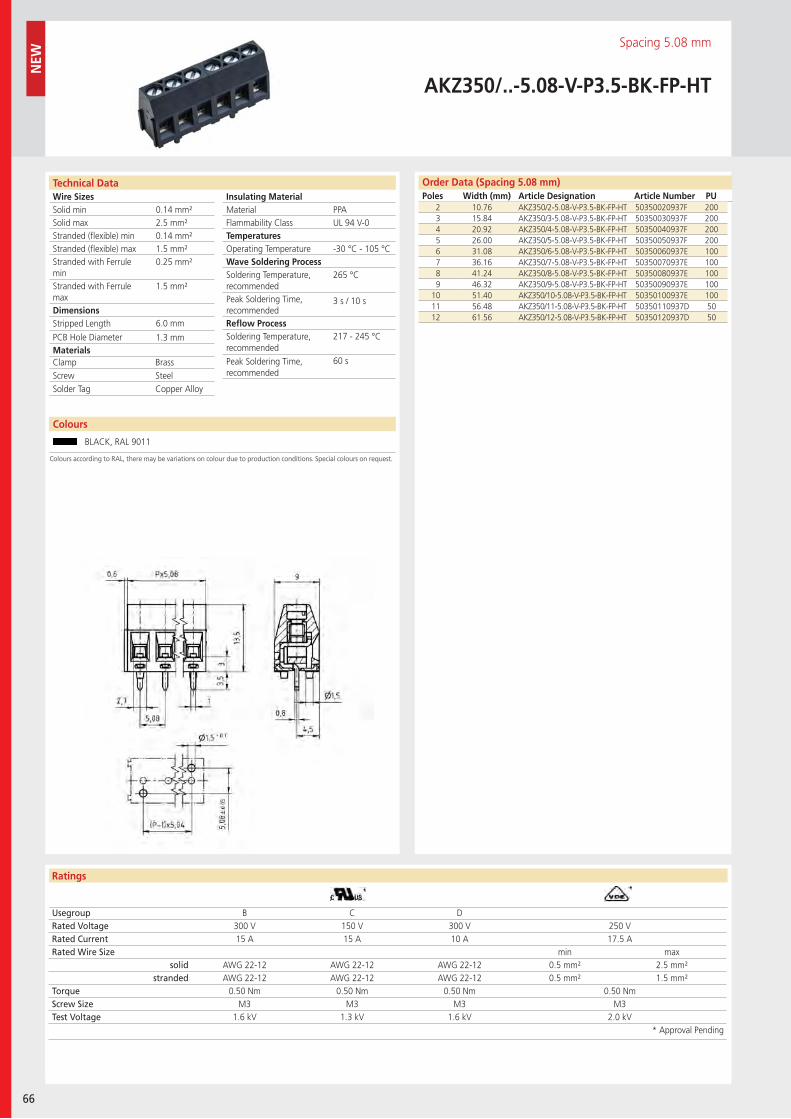
Wire SizesSolid minSolid maxStranded (flexible) minStranded (flexible) maxStranded with Ferrule minStranded with Ferrule maxDimensions Stripped Length
PCB Hole DiameterMaterials
Insulating Material MaterialFlammability ClassTemperaturesOperating TemperatureWave Soldering ProcessSoldering Temperature,recommendedPeak Soldering Time,recommendedReflow ProcessSoldering Temperature,recommended
Peak Soldering Time,recommended
Technical Data
Ratings
66
Colours
Order Data (Spacing 5.08 mm)Poles Width (mm) Article Designation Article Number PU
NEW
Colours according to RAL, there may be variations on colour due to production conditions. Special colours on request.
LIFT | Spacing 5.08 mm
AKZ350/..-5.08-V-P3.5-BK-FP-HT
2 10.76 AKZ350/2-5.08-V-P3.5-BK-FP-HT 50350020937F 2003 15.84 AKZ350/3-5.08-V-P3.5-BK-FP-HT 50350030937F 2004 20.92 AKZ350/4-5.08-V-P3.5-BK-FP-HT 50350040937F 2005 26.00 AKZ350/5-5.08-V-P3.5-BK-FP-HT 50350050937F 2006 31.08 AKZ350/6-5.08-V-P3.5-BK-FP-HT 50350060937E 1007 36.16 AKZ350/7-5.08-V-P3.5-BK-FP-HT 50350070937E 1008 41.24 AKZ350/8-5.08-V-P3.5-BK-FP-HT 50350080937E 1009 46.32 AKZ350/9-5.08-V-P3.5-BK-FP-HT 50350090937E 100
10 51.40 AKZ350/10-5.08-V-P3.5-BK-FP-HT 50350100937E 10011 56.48 AKZ350/11-5.08-V-P3.5-BK-FP-HT 50350110937D 5012 61.56 AKZ350/12-5.08-V-P3.5-BK-FP-HT 50350120937D 50
Usegroup B C DRated Voltage 300 V 150 V 300 V 250 VRated Current 15 A 15 A 10 A 17.5 ARated Wire Size min max
solid AWG 22-12 AWG 22-12 AWG 22-12 0.5 mm² 2.5 mm²stranded AWG 22-12 AWG 22-12 AWG 22-12 0.5 mm² 1.5 mm²
Torque 0.50 Nm 0.50 Nm 0.50 Nm 0.50 NmScrew Size M3 M3 M3 M3Test Voltage 1.6 kV 1.3 kV 1.6 kV 2.0 kV
* Approval Pending
BLACK, RAL 9011
PPAUL 94 V-0
-30 °C - 105 °C
265 °C
3 s / 10 s
217 - 245 °C
60 s
0.14 mm²2.5 mm²0.14 mm²1.5 mm²0.25 mm²
1.5 mm²
6.0 mm
1.3 mm
Clamp BrassScrew SteelSolder Tag Copper Alloy
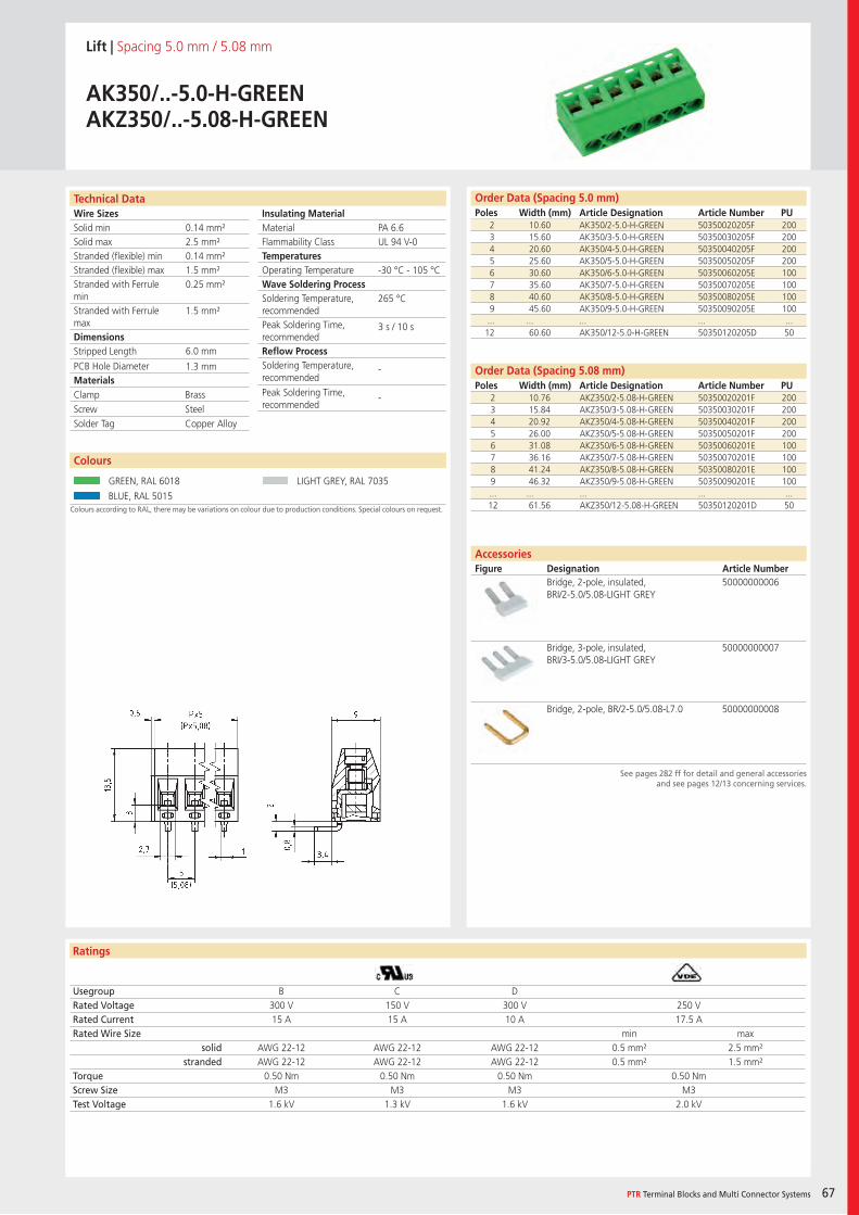
Wire SizesSolid minSolid maxStranded (flexible) minStranded (flexible) maxStranded with Ferrule minStranded with Ferrule maxDimensions Stripped Length
PCB Hole DiameterMaterials
Insulating Material MaterialFlammability ClassTemperaturesOperating TemperatureWave Soldering ProcessSoldering Temperature,recommendedPeak Soldering Time,recommendedReflow ProcessSoldering Temperature,recommended
Peak Soldering Time,recommended
Technical Data
Ratings
Colours
PTR Terminal Blocks and Multi Connector Systems 67
See pages 282 ff for detail and general accessoriesand see pages 12/13 concerning services.
AccessoriesFigure Designation Article Number
Order Data (Spacing 5.0 mm)Poles Width (mm) Article Designation Article Number PU
Colours according to RAL, there may be variations on colour due to production conditions. Special colours on request.
Lift | Spacing 5.0 mm / 5.08 mm
AK350/..-5.0-H-GREENAKZ350/..-5.08-H-GREEN
2 10.60 AK350/2-5.0-H-GREEN 50350020205F 2003 15.60 AK350/3-5.0-H-GREEN 50350030205F 2004 20.60 AK350/4-5.0-H-GREEN 50350040205F 2005 25.60 AK350/5-5.0-H-GREEN 50350050205F 2006 30.60 AK350/6-5.0-H-GREEN 50350060205E 1007 35.60 AK350/7-5.0-H-GREEN 50350070205E 1008 40.60 AK350/8-5.0-H-GREEN 50350080205E 1009 45.60 AK350/9-5.0-H-GREEN 50350090205E 100... ... ... ... ...12 60.60 AK350/12-5.0-H-GREEN 50350120205D 50
Usegroup B C DRated Voltage 300 V 150 V 300 V 250 VRated Current 15 A 15 A 10 A 17.5 ARated Wire Size min max
solid AWG 22-12 AWG 22-12 AWG 22-12 0.5 mm² 2.5 mm²stranded AWG 22-12 AWG 22-12 AWG 22-12 0.5 mm² 1.5 mm²
Torque 0.50 Nm 0.50 Nm 0.50 Nm 0.50 NmScrew Size M3 M3 M3 M3Test Voltage 1.6 kV 1.3 kV 1.6 kV 2.0 kV
GREEN, RAL 6018 LIGHT GREY, RAL 7035
BLUE, RAL 5015
Bridge, 2-pole, insulated, BRI/2-5.0/5.08-LIGHT GREY
50000000006
Bridge, 3-pole, insulated, BRI/3-5.0/5.08-LIGHT GREY
50000000007
Bridge, 2-pole, BR/2-5.0/5.08-L7.0 50000000008
PA 6.6UL 94 V-0
-30 °C - 105 °C
265 °C
3 s / 10 s
-
-
0.14 mm²2.5 mm²0.14 mm²1.5 mm²0.25 mm²
1.5 mm²
6.0 mm
1.3 mm
2 10.76 AKZ350/2-5.08-H-GREEN 50350020201F 2003 15.84 AKZ350/3-5.08-H-GREEN 50350030201F 2004 20.92 AKZ350/4-5.08-H-GREEN 50350040201F 2005 26.00 AKZ350/5-5.08-H-GREEN 50350050201F 2006 31.08 AKZ350/6-5.08-H-GREEN 50350060201E 1007 36.16 AKZ350/7-5.08-H-GREEN 50350070201E 1008 41.24 AKZ350/8-5.08-H-GREEN 50350080201E 1009 46.32 AKZ350/9-5.08-H-GREEN 50350090201E 100... ... ... ... ...12 61.56 AKZ350/12-5.08-H-GREEN 50350120201D 50
Clamp BrassScrew SteelSolder Tag Copper Alloy
Order Data (Spacing 5.08 mm)Poles Width (mm) Article Designation Article Number PU
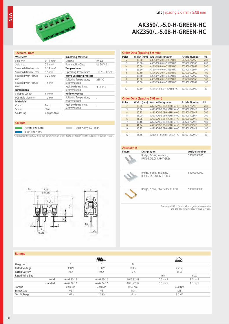
Wire SizesSolid minSolid maxStranded (flexible) minStranded (flexible) maxStranded with Ferrule minStranded with Ferrule maxDimensions Stripped Length
PCB Hole DiameterMaterials
Insulating Material MaterialFlammability ClassTemperaturesOperating TemperatureWave Soldering ProcessSoldering Temperature,recommendedPeak Soldering Time,recommendedReflow ProcessSoldering Temperature,recommended
Peak Soldering Time,recommended
Technical Data
Ratings
68
Colours
Order Data (Spacing 5.08 mm)Poles Width (mm) Article Designation Article Number PU
Order Data (Spacing 5.0 mm)Poles Width (mm) Article Designation Article Number PU
N
EW
See pages 282 ff for detail and general accessoriesand see pages 12/13 concerning services.
AccessoriesFigure Designation Article Number
Colours according to RAL, there may be variations on colour due to production conditions. Special colours on request.
Lift | Spacing 5.0 mm / 5.08 mm
AK350/..-5.0-H-GREEN-HCAKZ350/..-5.08-H-GREEN-HC
2 10.60 AK350/2-5.0-H-GREEN-HC 50350020295F 2003 15.60 AK350/3-5.0-H-GREEN-HC 50350030295F 2004 20.60 AK350/4-5.0-H-GREEN-HC 50350040295F 2005 25.60 AK350/5-5.0-H-GREEN-HC 50350050295F 2006 30.60 AK350/6-5.0-H-GREEN-HC 50350060295E 1007 35.60 AK350/7-5.0-H-GREEN-HC 50350070295E 1008 40.60 AK350/8-5.0-H-GREEN-HC 50350080295E 1009 45.60 AK350/9-5.0-H-GREEN-HC 50350090295E 100... ... ... ... ...12 60.60 AK350/12-5.0-H-GREEN-HC 50350120295D 50
Usegroup B C DRated Voltage 300 V 150 V 300 V 250 VRated Current 19 A 19 A 10 A 24 ARated Wire Size min max
solid AWG 22-12 AWG 22-12 AWG 22-12 0.5 mm² 2.5 mm²stranded AWG 22-12 AWG 22-12 AWG 22-12 0.5 mm² 1.5 mm²
Torque 0.50 Nm 0.50 Nm 0.50 Nm 0.50 NmScrew Size M3 M3 M3 M3Test Voltage 1.6 kV 1.3 kV 1.6 kV 2.0 kV
GREEN, RAL 6018 LIGHT GREY, RAL 7035
BLUE, RAL 5015
Bridge, 2-pole, insulated, BRI/2-5.0/5.08-LIGHT GREY
50000000006
Bridge, 3-pole, insulated, BRI/3-5.0/5.08-LIGHT GREY
50000000007
Bridge, 2-pole, BR/2-5.0/5.08-L7.0 50000000008
PA 6.6UL 94 V-0
-30 °C - 105 °C
265 °C
3 s / 10 s
-
-
0.14 mm²2.5 mm²0.14 mm²1.5 mm²0.25 mm²
1.5 mm²
6.0 mm
1.3 mm
2 10.76 AKZ350/2-5.08-H-GREEN-HC 50350020291F 2003 15.84 AKZ350/3-5.08-H-GREEN-HC 50350030291F 2004 20.92 AKZ350/4-5.08-H-GREEN-HC 50350040291F 2005 26.00 AKZ350/5-5.08-H-GREEN-HC 50350050291F 2006 31.08 AKZ350/6-5.08-H-GREEN-HC 50350060291E 1007 36.16 AKZ350/7-5.08-H-GREEN-HC 50350070291E 1008 41.24 AKZ350/8-5.08-H-GREEN-HC 50350080291E 1009 46.32 AKZ350/9-5.08-H-GREEN-HC 50350090291E 100... ... ... ... ...12 61.56 AKZ350/12-5.08-H-GREEN-HC 50350120291D 50
Clamp BrassScrew SteelSolder Tag Copper Alloy
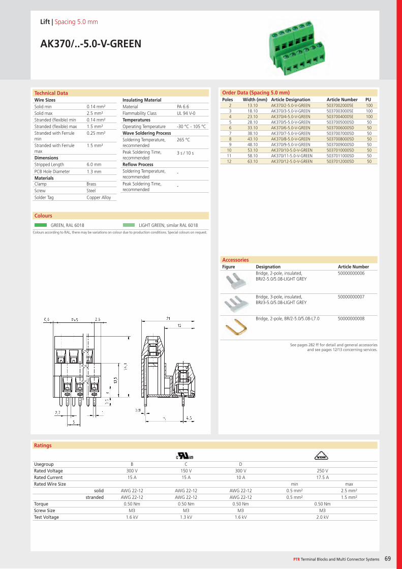
Wire SizesSolid minSolid maxStranded (flexible) minStranded (flexible) maxStranded with Ferrule minStranded with Ferrule maxDimensions Stripped Length
PCB Hole DiameterMaterials
Insulating Material MaterialFlammability ClassTemperaturesOperating TemperatureWave Soldering ProcessSoldering Temperature,recommendedPeak Soldering Time,recommendedReflow ProcessSoldering Temperature,recommended
Peak Soldering Time,recommended
Technical Data
Ratings
Colours
PTR Terminal Blocks and Multi Connector Systems 69
Order Data (Spacing 5.0 mm)Poles Width (mm) Article Designation Article Number PU
See pages 282 ff for detail and general accessoriesand see pages 12/13 concerning services.
Colours according to RAL, there may be variations on colour due to production conditions. Special colours on request.
AccessoriesFigure Designation Article Number
Lift | Spacing 5.0 mm
AK370/..-5.0-V-GREEN
2 13.10 AK370/2-5.0-V-GREEN 50370020005E 1003 18.10 AK370/3-5.0-V-GREEN 50370030005E 1004 23.10 AK370/4-5.0-V-GREEN 50370040005E 1005 28.10 AK370/5-5.0-V-GREEN 50370050005D 506 33.10 AK370/6-5.0-V-GREEN 50370060005D 507 38.10 AK370/7-5.0-V-GREEN 50370070005D 508 43.10 AK370/8-5.0-V-GREEN 50370080005D 509 48.10 AK370/9-5.0-V-GREEN 50370090005D 50
10 53.10 AK370/10-5.0-V-GREEN 50370100005D 5011 58.10 AK370/11-5.0-V-GREEN 50370110005D 5012 63.10 AK370/12-5.0-V-GREEN 50370120005D 50
Usegroup B C DRated Voltage 300 V 150 V 300 V 250 VRated Current 15 A 15 A 10 A 17.5 ARated Wire Size min max
solid AWG 22-12 AWG 22-12 AWG 22-12 0.5 mm² 2.5 mm²stranded AWG 22-12 AWG 22-12 AWG 22-12 0.5 mm² 1.5 mm²
Torque 0.50 Nm 0.50 Nm 0.50 Nm 0.50 NmScrew Size M3 M3 M3 M3Test Voltage 1.6 kV 1.3 kV 1.6 kV 2.0 kV
GREEN, RAL 6018 LIGHT GREEN, similar RAL 6018
Bridge, 2-pole, insulated, BRI/2-5.0/5.08-LIGHT GREY
50000000006
Bridge, 3-pole, insulated, BRI/3-5.0/5.08-LIGHT GREY
50000000007
Bridge, 2-pole, BR/2-5.0/5.08-L7.0 50000000008
PA 6.6UL 94 V-0
-30 °C - 105 °C
265 °C
3 s / 10 s
-
-
0.14 mm²2.5 mm²0.14 mm²1.5 mm²0.25 mm²
1.5 mm²
6.0 mm
1.3 mm
Clamp BrassScrew SteelSolder Tag Copper Alloy
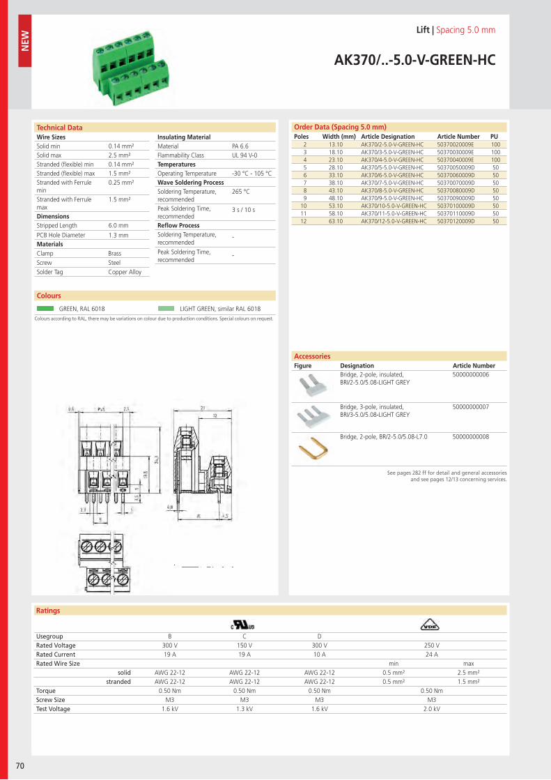
Wire SizesSolid minSolid maxStranded (flexible) minStranded (flexible) maxStranded with Ferrule minStranded with Ferrule maxDimensions Stripped Length
PCB Hole DiameterMaterials
Insulating Material MaterialFlammability ClassTemperaturesOperating TemperatureWave Soldering ProcessSoldering Temperature,recommendedPeak Soldering Time,recommendedReflow ProcessSoldering Temperature,recommended
Peak Soldering Time,recommended
Technical Data
Ratings
70
Colours
Order Data (Spacing 5.0 mm)Poles Width (mm) Article Designation Article Number PU
N
EW
See pages 282 ff for detail and general accessoriesand see pages 12/13 concerning services.
Colours according to RAL, there may be variations on colour due to production conditions. Special colours on request.
Lift | Spacing 5.0 mm
AK370/..-5.0-V-GREEN-HC
2 13.10 AK370/2-5.0-V-GREEN-HC 50370020009E 1003 18.10 AK370/3-5.0-V-GREEN-HC 50370030009E 1004 23.10 AK370/4-5.0-V-GREEN-HC 50370040009E 1005 28.10 AK370/5-5.0-V-GREEN-HC 50370050009D 506 33.10 AK370/6-5.0-V-GREEN-HC 50370060009D 507 38.10 AK370/7-5.0-V-GREEN-HC 50370070009D 508 43.10 AK370/8-5.0-V-GREEN-HC 50370080009D 509 48.10 AK370/9-5.0-V-GREEN-HC 50370090009D 50
10 53.10 AK370/10-5.0-V-GREEN-HC 50370100009D 5011 58.10 AK370/11-5.0-V-GREEN-HC 50370110009D 5012 63.10 AK370/12-5.0-V-GREEN-HC 50370120009D 50
Usegroup B C DRated Voltage 300 V 150 V 300 V 250 VRated Current 19 A 19 A 10 A 24 ARated Wire Size min max
solid AWG 22-12 AWG 22-12 AWG 22-12 0.5 mm² 2.5 mm²stranded AWG 22-12 AWG 22-12 AWG 22-12 0.5 mm² 1.5 mm²
Torque 0.50 Nm 0.50 Nm 0.50 Nm 0.50 NmScrew Size M3 M3 M3 M3Test Voltage 1.6 kV 1.3 kV 1.6 kV 2.0 kV
GREEN, RAL 6018 LIGHT GREEN, similar RAL 6018
Bridge, 2-pole, insulated, BRI/2-5.0/5.08-LIGHT GREY
50000000006
Bridge, 3-pole, insulated, BRI/3-5.0/5.08-LIGHT GREY
50000000007
Bridge, 2-pole, BR/2-5.0/5.08-L7.0 50000000008
PA 6.6UL 94 V-0
-30 °C - 105 °C
265 °C
3 s / 10 s
-
-
0.14 mm²2.5 mm²0.14 mm²1.5 mm²0.25 mm²
1.5 mm²
6.0 mm
1.3 mm
Clamp BrassScrew SteelSolder Tag Copper Alloy
AccessoriesFigure Designation Article Number
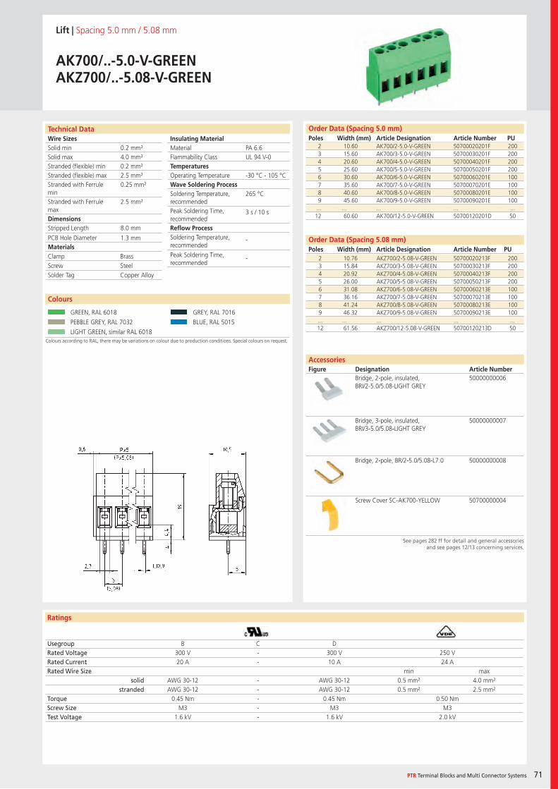
Wire SizesSolid minSolid maxStranded (flexible) minStranded (flexible) maxStranded with Ferrule minStranded with Ferrule maxDimensions Stripped Length
PCB Hole DiameterMaterials
Insulating Material MaterialFlammability ClassTemperaturesOperating TemperatureWave Soldering ProcessSoldering Temperature,recommendedPeak Soldering Time,recommendedReflow ProcessSoldering Temperature,recommended
Peak Soldering Time,recommended
Technical Data
Ratings
Colours
PTR Terminal Blocks and Multi Connector Systems 71
Order Data (Spacing 5.08 mm)Poles Width (mm) Article Designation Article Number PU
Order Data (Spacing 5.0 mm)Poles Width (mm) Article Designation Article Number PU
See pages 282 ff for detail and general accessoriesand see pages 12/13 concerning services.
AccessoriesFigure Designation Article Number
Colours according to RAL, there may be variations on colour due to production conditions. Special colours on request.
Lift | Spacing 5.0 mm / 5.08 mm
AK700/..-5.0-V-GREENAKZ700/..-5.08-V-GREEN
2 10.60 AK700/2-5.0-V-GREEN 50700020201F 2003 15.60 AK700/3-5.0-V-GREEN 50700030201F 2004 20.60 AK700/4-5.0-V-GREEN 50700040201F 2005 25.60 AK700/5-5.0-V-GREEN 50700050201F 2006 30.60 AK700/6-5.0-V-GREEN 50700060201E 1007 35.60 AK700/7-5.0-V-GREEN 50700070201E 1008 40.60 AK700/8-5.0-V-GREEN 50700080201E 1009 45.60 AK700/9-5.0-V-GREEN 50700090201E 100... ... ... ... ...12 60.60 AK700/12-5.0-V-GREEN 50700120201D 50
Usegroup B C DRated Voltage 300 V - 300 V 250 VRated Current 20 A - 10 A 24 ARated Wire Size min max
solid AWG 30-12 - AWG 30-12 0.5 mm² 4.0 mm²stranded AWG 30-12 - AWG 30-12 0.5 mm² 2.5 mm²
Torque 0.45 Nm - 0.45 Nm 0.50 NmScrew Size M3 - M3 M3Test Voltage 1.6 kV - 1.6 kV 2.0 kV
GREEN, RAL 6018 GREY, RAL 7016
PEBBLE GREY, RAL 7032 BLUE, RAL 5015
LIGHT GREEN, similar RAL 6018
Bridge, 2-pole, insulated, BRI/2-5.0/5.08-LIGHT GREY
50000000006
Bridge, 3-pole, insulated, BRI/3-5.0/5.08-LIGHT GREY
50000000007
Bridge, 2-pole, BR/2-5.0/5.08-L7.0 50000000008
Screw Cover SC-AK700-YELLOW 50700000004
PA 6.6UL 94 V-0
-30 °C - 105 °C
265 °C
3 s / 10 s
-
-
0.2 mm²4.0 mm²0.2 mm²2.5 mm²0.25 mm²
2.5 mm²
8.0 mm
1.3 mm
2 10.76 AKZ700/2-5.08-V-GREEN 50700020213F 2003 15.84 AKZ700/3-5.08-V-GREEN 50700030213F 2004 20.92 AKZ700/4-5.08-V-GREEN 50700040213F 2005 26.00 AKZ700/5-5.08-V-GREEN 50700050213F 2006 31.08 AKZ700/6-5.08-V-GREEN 50700060213E 1007 36.16 AKZ700/7-5.08-V-GREEN 50700070213E 1008 41.24 AKZ700/8-5.08-V-GREEN 50700080213E 1009 46.32 AKZ700/9-5.08-V-GREEN 50700090213E 100... ... ... ... ...12 61.56 AKZ700/12-5.08-V-GREEN 50700120213D 50
Clamp BrassScrew SteelSolder Tag Copper Alloy
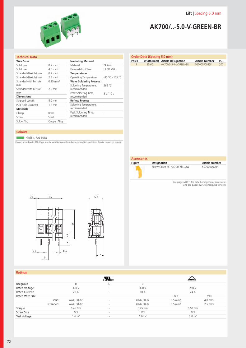
Wire SizesSolid minSolid maxStranded (flexible) minStranded (flexible) maxStranded with Ferrule minStranded with Ferrule maxDimensions Stripped Length
PCB Hole DiameterMaterials
Insulating Material MaterialFlammability ClassTemperaturesOperating TemperatureWave Soldering ProcessSoldering Temperature,recommendedPeak Soldering Time,recommendedReflow ProcessSoldering Temperature,recommended
Peak Soldering Time,recommended
Technical Data
Ratings
Order Data (Spacing 5.08 mm)Poles Width (mm) Article Designation Article Number PU
72
Colours
Order Data (Spacing 5.0 mm)Poles Width (mm) Article Designation Article Number PU
See pages 282 ff for detail and general accessoriesand see pages 12/13 concerning services.
Colours according to RAL, there may be variations on colour due to production conditions. Special colours on request.
Lift | Spacing 5.0 mm
AK700/..-5.0-V-GREEN-BR
3 15.60 AK700/3-5.0-V-GREEN-BR 50700030045F 200
Usegroup B C DRated Voltage 300 V - 300 V 250 VRated Current 20 A - 10 A 24 ARated Wire Size min max
solid AWG 30-12 - AWG 30-12 0.5 mm² 4.0 mm²stranded AWG 30-12 - AWG 30-12 0.5 mm² 2.5 mm²
Torque 0.45 Nm - 0.45 Nm 0.50 NmScrew Size M3 - M3 M3Test Voltage 1.6 kV - 1.6 kV 2.0 kV
GREEN, RAL 6018
Screw Cover SC-AK700-YELLOW 50700000004
PA 6.6UL 94 V-0
-30 °C - 105 °C
265 °C
3 s / 10 s
-
-
0.2 mm²4.0 mm²0.2 mm²2.5 mm²0.25 mm²
2.5 mm²
8.0 mm
1.3 mm
Clamp BrassScrew SteelSolder Tag Copper Alloy
AccessoriesFigure Designation Article Number
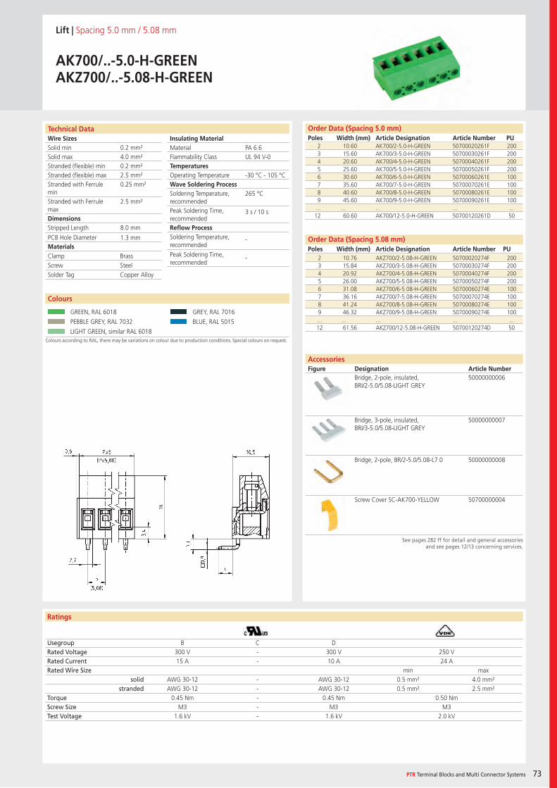
Wire SizesSolid minSolid maxStranded (flexible) minStranded (flexible) maxStranded with Ferrule minStranded with Ferrule maxDimensions Stripped Length
PCB Hole DiameterMaterials
Insulating Material MaterialFlammability ClassTemperaturesOperating TemperatureWave Soldering ProcessSoldering Temperature,recommendedPeak Soldering Time,recommendedReflow ProcessSoldering Temperature,recommended
Peak Soldering Time,recommended
Technical Data
Ratings
Colours
PTR Terminal Blocks and Multi Connector Systems 73
Order Data (Spacing 5.08 mm)Poles Width (mm) Article Designation Article Number PU
Order Data (Spacing 5.0 mm)Poles Width (mm) Article Designation Article Number PU
See pages 282 ff for detail and general accessoriesand see pages 12/13 concerning services.
AccessoriesFigure Designation Article Number
Colours according to RAL, there may be variations on colour due to production conditions. Special colours on request.
Lift | Spacing 5.0 mm / 5.08 mm
AK700/..-5.0-H-GREENAKZ700/..-5.08-H-GREEN
2 10.60 AK700/2-5.0-H-GREEN 50700020261F 2003 15.60 AK700/3-5.0-H-GREEN 50700030261F 2004 20.60 AK700/4-5.0-H-GREEN 50700040261F 2005 25.60 AK700/5-5.0-H-GREEN 50700050261F 2006 30.60 AK700/6-5.0-H-GREEN 50700060261E 1007 35.60 AK700/7-5.0-H-GREEN 50700070261E 1008 40.60 AK700/8-5.0-H-GREEN 50700080261E 1009 45.60 AK700/9-5.0-H-GREEN 50700090261E 100... ... ... ... ...12 60.60 AK700/12-5.0-H-GREEN 50700120261D 50
Usegroup B C DRated Voltage 300 V - 300 V 250 VRated Current 15 A - 10 A 24 ARated Wire Size min max
solid AWG 30-12 - AWG 30-12 0.5 mm² 4.0 mm²stranded AWG 30-12 - AWG 30-12 0.5 mm² 2.5 mm²
Torque 0.45 Nm - 0.45 Nm 0.50 NmScrew Size M3 - M3 M3Test Voltage 1.6 kV - 1.6 kV 2.0 kV
GREEN, RAL 6018 GREY, RAL 7016
PEBBLE GREY, RAL 7032 BLUE, RAL 5015
LIGHT GREEN, similar RAL 6018
Bridge, 2-pole, insulated, BRI/2-5.0/5.08-LIGHT GREY
50000000006
Bridge, 3-pole, insulated, BRI/3-5.0/5.08-LIGHT GREY
50000000007
Bridge, 2-pole, BR/2-5.0/5.08-L7.0 50000000008
Screw Cover SC-AK700-YELLOW 50700000004
PA 6.6UL 94 V-0
-30 °C - 105 °C
265 °C
3 s / 10 s
-
-
0.2 mm²4.0 mm²0.2 mm²2.5 mm²0.25 mm²
2.5 mm²
8.0 mm
1.3 mm
2 10.76 AKZ700/2-5.08-H-GREEN 50700020274F 2003 15.84 AKZ700/3-5.08-H-GREEN 50700030274F 2004 20.92 AKZ700/4-5.08-H-GREEN 50700040274F 2005 26.00 AKZ700/5-5.08-H-GREEN 50700050274F 2006 31.08 AKZ700/6-5.08-H-GREEN 50700060274E 1007 36.16 AKZ700/7-5.08-H-GREEN 50700070274E 1008 41.24 AKZ700/8-5.08-H-GREEN 50700080274E 1009 46.32 AKZ700/9-5.08-H-GREEN 50700090274E 100... ... ... ... ...12 61.56 AKZ700/12-5.08-H-GREEN 50700120274D 50
Clamp BrassScrew SteelSolder Tag Copper Alloy
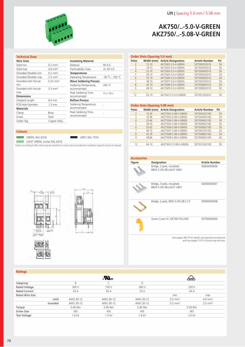
Wire SizesSolid minSolid maxStranded (flexible) minStranded (flexible) maxStranded with Ferrule minStranded with Ferrule maxDimensions Stripped Length
PCB Hole DiameterMaterials
Insulating Material MaterialFlammability ClassTemperaturesOperating TemperatureWave Soldering ProcessSoldering Temperature,recommendedPeak Soldering Time,recommendedReflow ProcessSoldering Temperature,recommended
Peak Soldering Time,recommended
Technical Data
Ratings
74
Colours
Order Data (Spacing 5.08 mm)Poles Width (mm) Article Designation Article Number PU
Order Data (Spacing 5.0 mm)Poles Width (mm) Article Designation Article Number PU
See pages 282 ff for detail and general accessoriesand see pages 12/13 concerning services.
AccessoriesFigure Designation Article Number
Colours according to RAL, there may be variations on colour due to production conditions. Special colours on request.
Lift | Spacing 5.0 mm / 5.08 mm
AK750/..-5.0-V-GREENAKZ750/..-5.08-V-GREEN
2 13.10 AK750/2-5.0-V-GREEN 50750020201D 503 18.10 AK750/3-5.0-V-GREEN 50750030201D 504 23.10 AK750/4-5.0-V-GREEN 50750040201D 505 28.10 AK750/5-5.0-V-GREEN 50750050201D 506 33.10 AK750/6-5.0-V-GREEN 50750060201D 507 38.10 AK750/7-5.0-V-GREEN 50750070201D 508 43.10 AK750/8-5.0-V-GREEN 50750080201D 509 48.10 AK750/9-5.0-V-GREEN 50750090201D 50... ... ... ... ...12 63.10 AK750/12-5.0-V-GREEN 50750120201D 50
Usegroup B C DRated Voltage 300 V 150 V 300 V 250 VRated Current 20 A 20 A 10 A 24 ARated Wire Size min max
solid AWG 30-12 AWG 30-12 AWG 30-12 0.5 mm² 4.0 mm²stranded AWG 30-12 AWG 30-12 AWG 30-12 0.5 mm² 2.5 mm²
Torque 0.45 Nm 0.45 Nm 0.45 Nm 0.50 NmScrew Size M3 M3 M3 M3Test Voltage 1.6 kV 1.3 kV 1.6 kV 2.0 kV
GREEN, RAL 6018 GREY, RAL 7016
LIGHT GREEN, similar RAL 6018
Bridge, 2-pole, insulated, BRI/2-5.0/5.08-LIGHT GREY
50000000006
Bridge, 3-pole, insulated, BRI/3-5.0/5.08-LIGHT GREY
50000000007
Bridge, 2-pole, BR/2-5.0/5.08-L7.0 50000000008
Screw Cover SC-AK700-YELLOW 50700000004
PA 6.6UL 94 V-0
-30 °C - 105 °C
265 °C
3 s / 10 s
-
-
0.2 mm²4.0 mm²0.2 mm²2.5 mm²0.25 mm²
2.5 mm²
8.0 mm
1.3 mm
2 13.30 AKZ750/2-5.08-V-GREEN 50750020210D 503 18.38 AKZ750/3-5.08-V-GREEN 50750030210D 504 23.46 AKZ750/4-5.08-V-GREEN 50750040210D 505 28.54 AKZ750/5-5.08-V-GREEN 50750050210D 506 33.62 AKZ750/6-5.08-V-GREEN 50750060210D 507 38.70 AKZ750/7-5.08-V-GREEN 50750070210D 508 43.78 AKZ750/8-5.08-V-GREEN 50750080210D 509 48.86 AKZ750/9-5.08-V-GREEN 50750090210D 50... ... ... ... ...12 64.10 AKZ750/12-5.08-V-GREEN 50750120210D 50
Clamp BrassScrew SteelSolder Tag Copper Alloy
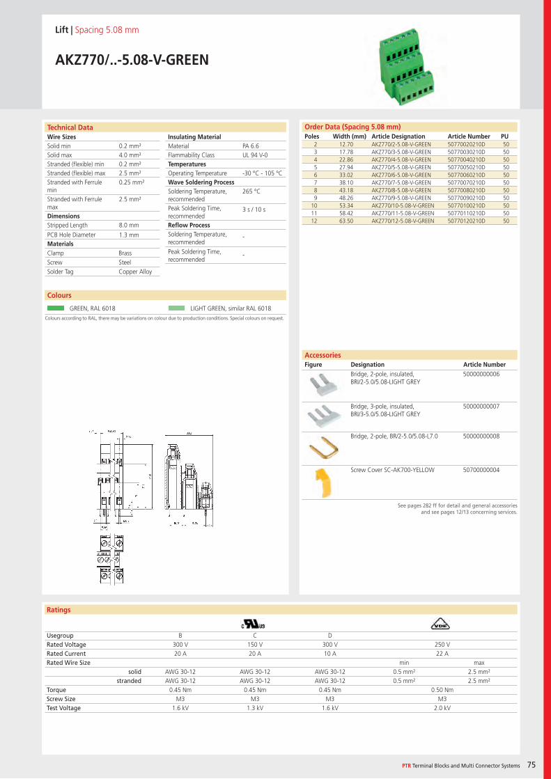
Wire SizesSolid minSolid maxStranded (flexible) minStranded (flexible) maxStranded with Ferrule minStranded with Ferrule maxDimensions Stripped Length
PCB Hole DiameterMaterials
Insulating Material MaterialFlammability ClassTemperaturesOperating TemperatureWave Soldering ProcessSoldering Temperature,recommendedPeak Soldering Time,recommendedReflow ProcessSoldering Temperature,recommended
Peak Soldering Time,recommended
Technical Data
Ratings
Colours
PTR Terminal Blocks and Multi Connector Systems 75
AccessoriesFigure Designation Article Number
Order Data (Spacing 5.08 mm)Poles Width (mm) Article Designation Article Number PU
See pages 282 ff for detail and general accessoriesand see pages 12/13 concerning services.
Colours according to RAL, there may be variations on colour due to production conditions. Special colours on request.
Lift | Spacing 5.08 mm
AKZ770/..-5.08-V-GREEN
2 12.70 AKZ770/2-5.08-V-GREEN 50770020210D 503 17.78 AKZ770/3-5.08-V-GREEN 50770030210D 504 22.86 AKZ770/4-5.08-V-GREEN 50770040210D 505 27.94 AKZ770/5-5.08-V-GREEN 50770050210D 506 33.02 AKZ770/6-5.08-V-GREEN 50770060210D 507 38.10 AKZ770/7-5.08-V-GREEN 50770070210D 508 43.18 AKZ770/8-5.08-V-GREEN 50770080210D 509 48.26 AKZ770/9-5.08-V-GREEN 50770090210D 50
10 53.34 AKZ770/10-5.08-V-GREEN 50770100210D 5011 58.42 AKZ770/11-5.08-V-GREEN 50770110210D 5012 63.50 AKZ770/12-5.08-V-GREEN 50770120210D 50
Usegroup B C DRated Voltage 300 V 150 V 300 V 250 VRated Current 20 A 20 A 10 A 22 ARated Wire Size min max
solid AWG 30-12 AWG 30-12 AWG 30-12 0.5 mm² 2.5 mm²stranded AWG 30-12 AWG 30-12 AWG 30-12 0.5 mm² 2.5 mm²
Torque 0.45 Nm 0.45 Nm 0.45 Nm 0.50 NmScrew Size M3 M3 M3 M3Test Voltage 1.6 kV 1.3 kV 1.6 kV 2.0 kV
GREEN, RAL 6018 LIGHT GREEN, similar RAL 6018
Bridge, 2-pole, insulated, BRI/2-5.0/5.08-LIGHT GREY
50000000006
Bridge, 3-pole, insulated, BRI/3-5.0/5.08-LIGHT GREY
50000000007
Bridge, 2-pole, BR/2-5.0/5.08-L7.0 50000000008
Screw Cover SC-AK700-YELLOW 50700000004
PA 6.6UL 94 V-0
-30 °C - 105 °C
265 °C
3 s / 10 s
-
-
0.2 mm²4.0 mm²0.2 mm²2.5 mm²0.25 mm²
2.5 mm²
8.0 mm
1.3 mm
Clamp BrassScrew SteelSolder Tag Copper Alloy
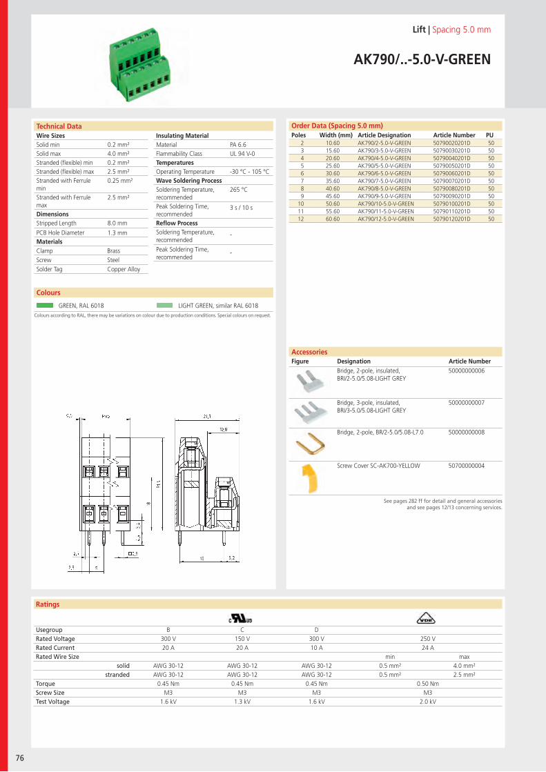
Wire SizesSolid minSolid maxStranded (flexible) minStranded (flexible) maxStranded with Ferrule minStranded with Ferrule maxDimensions Stripped Length
PCB Hole DiameterMaterials
Insulating Material MaterialFlammability ClassTemperaturesOperating TemperatureWave Soldering ProcessSoldering Temperature,recommendedPeak Soldering Time,recommendedReflow ProcessSoldering Temperature,recommended
Peak Soldering Time,recommended
Technical Data
Ratings
76
Colours
Order Data (Spacing 5.0 mm)Poles Width (mm) Article Designation Article Number PU
AccessoriesFigure Designation Article Number
See pages 282 ff for detail and general accessoriesand see pages 12/13 concerning services.
Colours according to RAL, there may be variations on colour due to production conditions. Special colours on request.
Lift | Spacing 5.0 mm
AK790/..-5.0-V-GREEN
2 10.60 AK790/2-5.0-V-GREEN 50790020201D 503 15.60 AK790/3-5.0-V-GREEN 50790030201D 504 20.60 AK790/4-5.0-V-GREEN 50790040201D 505 25.60 AK790/5-5.0-V-GREEN 50790050201D 506 30.60 AK790/6-5.0-V-GREEN 50790060201D 507 35.60 AK790/7-5.0-V-GREEN 50790070201D 508 40.60 AK790/8-5.0-V-GREEN 50790080201D 509 45.60 AK790/9-5.0-V-GREEN 50790090201D 50
10 50.60 AK790/10-5.0-V-GREEN 50790100201D 5011 55.60 AK790/11-5.0-V-GREEN 50790110201D 5012 60.60 AK790/12-5.0-V-GREEN 50790120201D 50
Usegroup B C DRated Voltage 300 V 150 V 300 V 250 VRated Current 20 A 20 A 10 A 24 ARated Wire Size min max
solid AWG 30-12 AWG 30-12 AWG 30-12 0.5 mm² 4.0 mm²stranded AWG 30-12 AWG 30-12 AWG 30-12 0.5 mm² 2.5 mm²
Torque 0.45 Nm 0.45 Nm 0.45 Nm 0.50 NmScrew Size M3 M3 M3 M3Test Voltage 1.6 kV 1.3 kV 1.6 kV 2.0 kV
GREEN, RAL 6018 LIGHT GREEN, similar RAL 6018
Bridge, 2-pole, insulated, BRI/2-5.0/5.08-LIGHT GREY
50000000006
Bridge, 3-pole, insulated, BRI/3-5.0/5.08-LIGHT GREY
50000000007
Bridge, 2-pole, BR/2-5.0/5.08-L7.0 50000000008
Screw Cover SC-AK700-YELLOW 50700000004
PA 6.6UL 94 V-0
-30 °C - 105 °C
265 °C
3 s / 10 s
-
-
0.2 mm²4.0 mm²0.2 mm²2.5 mm²0.25 mm²
2.5 mm²
8.0 mm
1.3 mm
Clamp BrassScrew SteelSolder Tag Copper Alloy
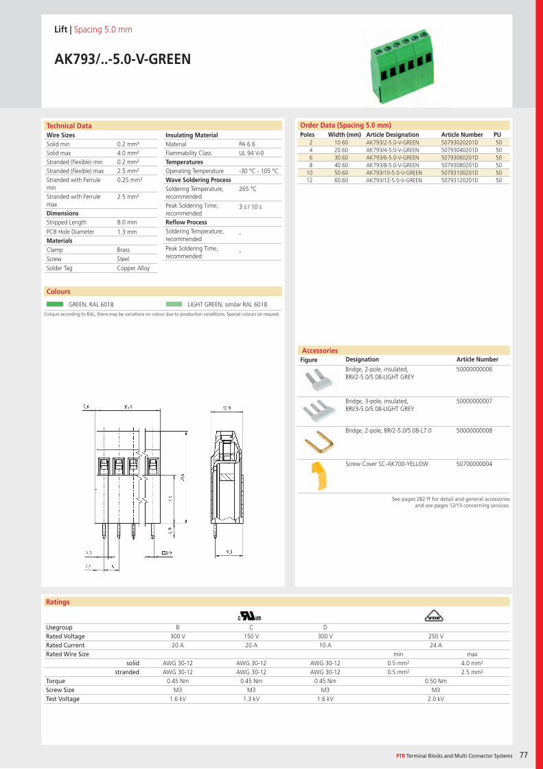
Wire SizesSolid minSolid maxStranded (flexible) minStranded (flexible) maxStranded with Ferrule minStranded with Ferrule maxDimensions Stripped Length
PCB Hole DiameterMaterials
Insulating Material MaterialFlammability ClassTemperaturesOperating TemperatureWave Soldering ProcessSoldering Temperature,recommendedPeak Soldering Time,recommendedReflow ProcessSoldering Temperature,recommended
Peak Soldering Time,recommended
Technical Data
Ratings
Accessories Figure Designation Article Number
Colours
PTR Terminal Blocks and Multi Connector Systems 77
Order Data (Spacing 5.0 mm)Poles Width (mm) Article Designation Article Number PU
See pages 282 ff for detail and general accessoriesand see pages 12/13 concerning services.
Colours according to RAL, there may be variations on colour due to production conditions. Special colours on request.
Lift | Spacing 5.0 mm
AK793/..-5.0-V-GREEN
2 10.60 AK793/2-5.0-V-GREEN 50793020201D 504 20.60 AK793/4-5.0-V-GREEN 50793040201D 506 30.60 AK793/6-5.0-V-GREEN 50793060201D 508 40.60 AK793/8-5.0-V-GREEN 50793080201D 50
10 50.60 AK793/10-5.0-V-GREEN 50793100201D 5012 60.60 AK793/12-5.0-V-GREEN 50793120201D 50
Usegroup B C DRated Voltage 300 V 150 V 300 V 250 VRated Current 20 A 20 A 10 A 24 ARated Wire Size min max
solid AWG 30-12 AWG 30-12 AWG 30-12 0.5 mm² 4.0 mm²stranded AWG 30-12 AWG 30-12 AWG 30-12 0.5 mm² 2.5 mm²
Torque 0.45 Nm 0.45 Nm 0.45 Nm 0.50 NmScrew Size M3 M3 M3 M3Test Voltage 1.6 kV 1.3 kV 1.6 kV 2.0 kV
GREEN, RAL 6018 LIGHT GREEN, similar RAL 6018
Bridge, 2-pole, insulated, BRI/2-5.0/5.08-LIGHT GREY
50000000006
Bridge, 3-pole, insulated, BRI/3-5.0/5.08-LIGHT GREY
50000000007
Bridge, 2-pole, BR/2-5.0/5.08-L7.0 50000000008
Screw Cover SC-AK700-YELLOW 50700000004
PA 6.6UL 94 V-0
-30 °C - 105 °C
265 °C
3 s / 10 s
-
-
0.2 mm²4.0 mm²0.2 mm²2.5 mm²0.25 mm²
2.5 mm²
8.0 mm
1.3 mm
Clamp BrassScrew SteelSolder Tag Copper Alloy
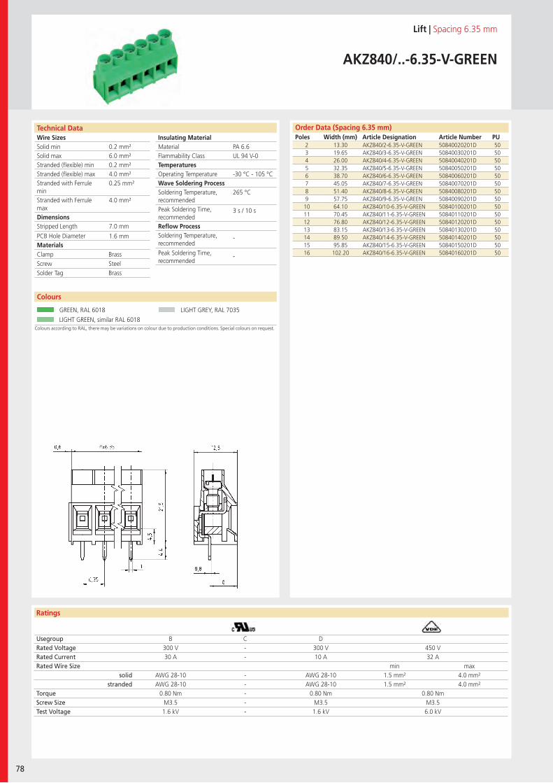
Wire SizesSolid minSolid maxStranded (flexible) minStranded (flexible) maxStranded with Ferrule minStranded with Ferrule maxDimensions Stripped Length
PCB Hole DiameterMaterials
Insulating Material MaterialFlammability ClassTemperaturesOperating TemperatureWave Soldering ProcessSoldering Temperature,recommendedPeak Soldering Time,recommendedReflow ProcessSoldering Temperature,recommended
Peak Soldering Time,recommended
Technical Data
Ratings
78
Colours
Order Data (Spacing 6.35 mm)Poles Width (mm) Article Designation Article Number PU
Colours according to RAL, there may be variations on colour due to production conditions. Special colours on request.
Lift | Spacing 6.35 mm
AKZ840/..-6.35-V-GREEN
2 13.30 AKZ840/2-6.35-V-GREEN 50840020201D 503 19.65 AKZ840/3-6.35-V-GREEN 50840030201D 504 26.00 AKZ840/4-6.35-V-GREEN 50840040201D 505 32.35 AKZ840/5-6.35-V-GREEN 50840050201D 506 38.70 AKZ840/6-6.35-V-GREEN 50840060201D 507 45.05 AKZ840/7-6.35-V-GREEN 50840070201D 508 51.40 AKZ840/8-6.35-V-GREEN 50840080201D 509 57.75 AKZ840/9-6.35-V-GREEN 50840090201D 5010 64.10 AKZ840/10-6.35-V-GREEN 50840100201D 5011 70.45 AKZ840/11-6.35-V-GREEN 50840110201D 5012 76.80 AKZ840/12-6.35-V-GREEN 50840120201D 5013 83.15 AKZ840/13-6.35-V-GREEN 50840130201D 5014 89.50 AKZ840/14-6.35-V-GREEN 50840140201D 5015 95.85 AKZ840/15-6.35-V-GREEN 50840150201D 5016 102.20 AKZ840/16-6.35-V-GREEN 50840160201D 50
Usegroup B C DRated Voltage 300 V - 300 V 450 VRated Current 30 A - 10 A 32 ARated Wire Size min max
solid AWG 28-10 - AWG 28-10 1.5 mm² 4.0 mm²stranded AWG 28-10 - AWG 28-10 1.5 mm² 4.0 mm²
Torque 0.80 Nm - 0.80 Nm 0.80 NmScrew Size M3.5 - M3.5 M3.5Test Voltage 1.6 kV - 1.6 kV 6.0 kV
GREEN, RAL 6018 LIGHT GREY, RAL 7035
LIGHT GREEN, similar RAL 6018
PA 6.6UL 94 V-0
-30 °C - 105 °C
265 °C
3 s / 10 s
-
-
0.2 mm²6.0 mm²0.2 mm²4.0 mm²0.25 mm²
4.0 mm²
7.0 mm
1.6 mm
Clamp BrassScrew SteelSolder Tag Brass
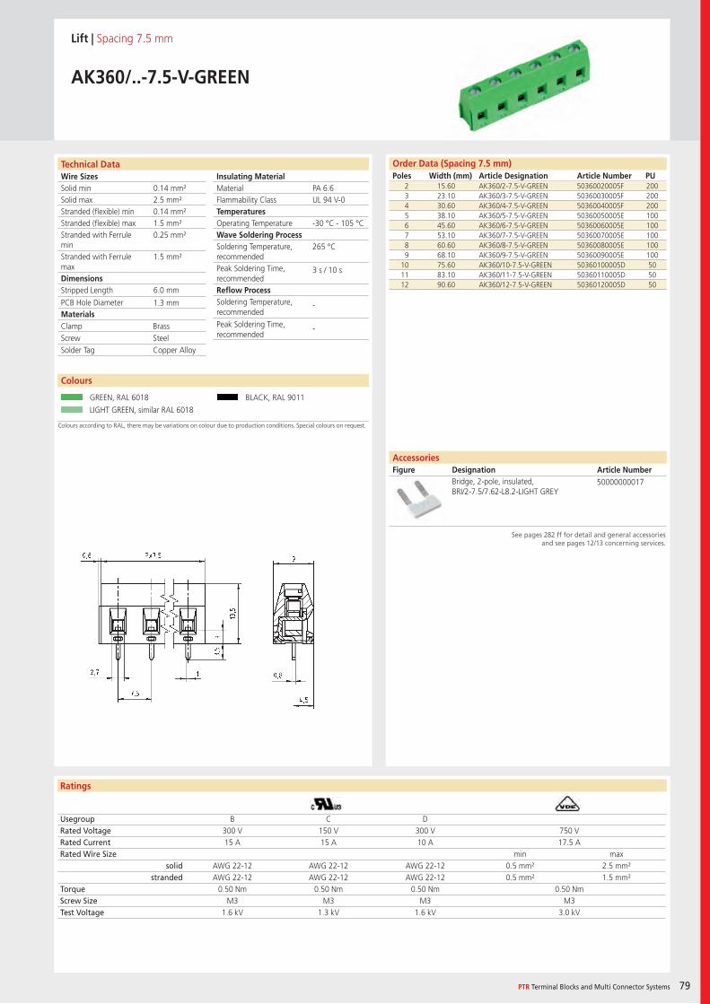
Wire SizesSolid minSolid maxStranded (flexible) minStranded (flexible) maxStranded with Ferrule minStranded with Ferrule maxDimensions Stripped Length
PCB Hole DiameterMaterials
Insulating Material MaterialFlammability ClassTemperaturesOperating TemperatureWave Soldering ProcessSoldering Temperature,recommendedPeak Soldering Time,recommendedReflow ProcessSoldering Temperature,recommended
Peak Soldering Time,recommended
Technical Data
Ratings
Colours
PTR Terminal Blocks and Multi Connector Systems 79
AccessoriesFigure Designation Article Number
Order Data (Spacing 7.5 mm)Poles Width (mm) Article Designation Article Number PU
Colours according to RAL, there may be variations on colour due to production conditions. Special colours on request.
See pages 282 ff for detail and general accessoriesand see pages 12/13 concerning services.
Lift | Spacing 7.5 mm
AK360/..-7.5-V-GREEN
2 15.60 AK360/2-7.5-V-GREEN 50360020005F 2003 23.10 AK360/3-7.5-V-GREEN 50360030005F 2004 30.60 AK360/4-7.5-V-GREEN 50360040005F 2005 38.10 AK360/5-7.5-V-GREEN 50360050005E 1006 45.60 AK360/6-7.5-V-GREEN 50360060005E 1007 53.10 AK360/7-7.5-V-GREEN 50360070005E 1008 60.60 AK360/8-7.5-V-GREEN 50360080005E 1009 68.10 AK360/9-7.5-V-GREEN 50360090005E 100
10 75.60 AK360/10-7.5-V-GREEN 50360100005D 5011 83.10 AK360/11-7.5-V-GREEN 50360110005D 5012 90.60 AK360/12-7.5-V-GREEN 50360120005D 50
Usegroup B C DRated Voltage 300 V 150 V 300 V 750 VRated Current 15 A 15 A 10 A 17.5 ARated Wire Size min max
solid AWG 22-12 AWG 22-12 AWG 22-12 0.5 mm² 2.5 mm²stranded AWG 22-12 AWG 22-12 AWG 22-12 0.5 mm² 1.5 mm²
Torque 0.50 Nm 0.50 Nm 0.50 Nm 0.50 NmScrew Size M3 M3 M3 M3Test Voltage 1.6 kV 1.3 kV 1.6 kV 3.0 kV
GREEN, RAL 6018 BLACK, RAL 9011
LIGHT GREEN, similar RAL 6018
Bridge, 2-pole, insulated, BRI/2-7.5/7.62-L8.2-LIGHT GREY
50000000017
PA 6.6UL 94 V-0
-30 °C - 105 °C
265 °C
3 s / 10 s
-
-
0.14 mm²2.5 mm²0.14 mm²1.5 mm²0.25 mm²
1.5 mm²
6.0 mm
1.3 mm
Clamp BrassScrew SteelSolder Tag Copper Alloy
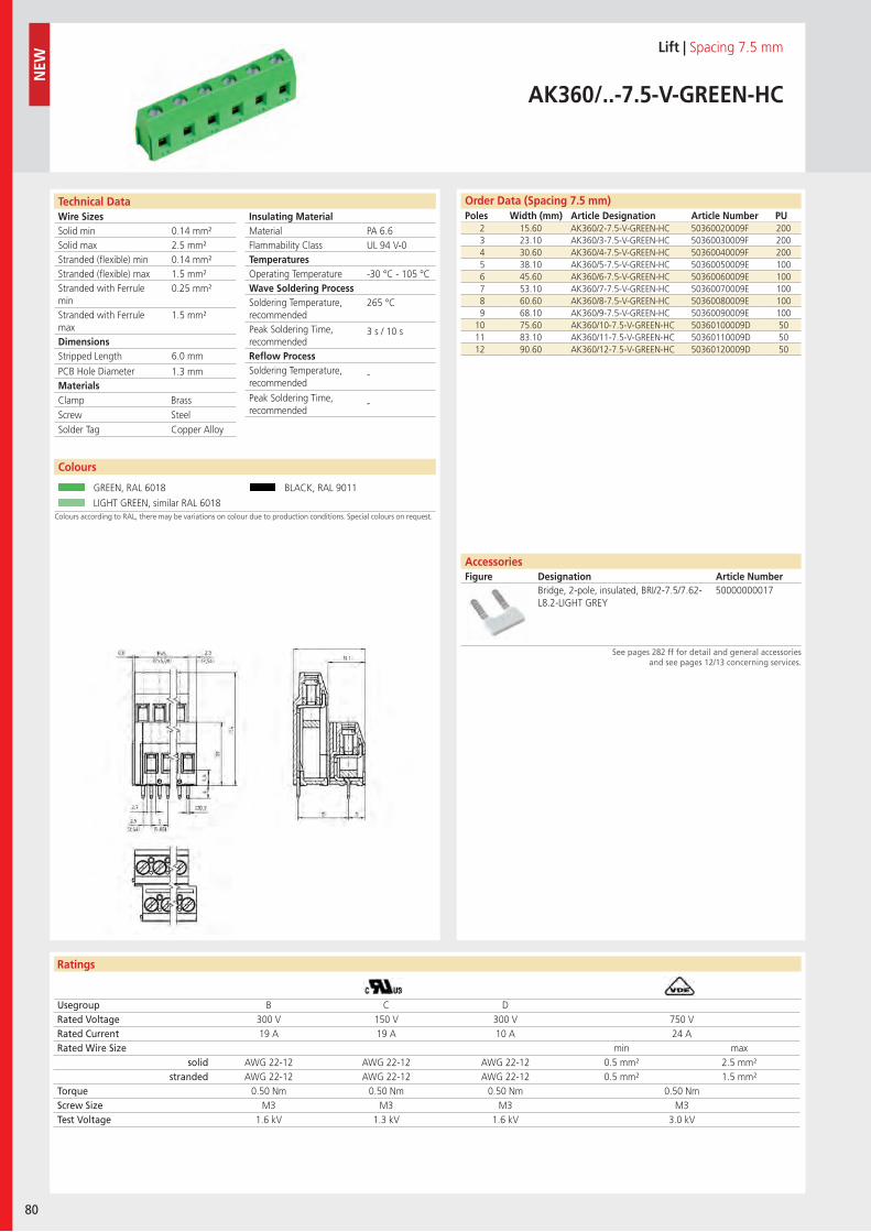
Wire SizesSolid minSolid maxStranded (flexible) minStranded (flexible) maxStranded with Ferrule minStranded with Ferrule maxDimensions Stripped Length
PCB Hole DiameterMaterials
Insulating Material MaterialFlammability ClassTemperaturesOperating TemperatureWave Soldering ProcessSoldering Temperature,recommendedPeak Soldering Time,recommendedReflow ProcessSoldering Temperature,recommended
Peak Soldering Time,recommended
Technical Data
Ratings
80
Colours
Order Data (Spacing 7.5 mm)Poles Width (mm) Article Designation Article Number PU
See pages 282 ff for detail and general accessoriesand see pages 12/13 concerning services.
AccessoriesFigure Designation Article Number
Colours according to RAL, there may be variations on colour due to production conditions. Special colours on request.
Lift | Spacing 7.5 mm
AK360/..-7.5-V-GREEN-HC
2 15.60 AK360/2-7.5-V-GREEN-HC 50360020009F 2003 23.10 AK360/3-7.5-V-GREEN-HC 50360030009F 2004 30.60 AK360/4-7.5-V-GREEN-HC 50360040009F 2005 38.10 AK360/5-7.5-V-GREEN-HC 50360050009E 1006 45.60 AK360/6-7.5-V-GREEN-HC 50360060009E 1007 53.10 AK360/7-7.5-V-GREEN-HC 50360070009E 1008 60.60 AK360/8-7.5-V-GREEN-HC 50360080009E 1009 68.10 AK360/9-7.5-V-GREEN-HC 50360090009E 100
10 75.60 AK360/10-7.5-V-GREEN-HC 50360100009D 5011 83.10 AK360/11-7.5-V-GREEN-HC 50360110009D 5012 90.60 AK360/12-7.5-V-GREEN-HC 50360120009D 50
Usegroup B C DRated Voltage 300 V 150 V 300 V 750 VRated Current 19 A 19 A 10 A 24 ARated Wire Size min max
solid AWG 22-12 AWG 22-12 AWG 22-12 0.5 mm² 2.5 mm²stranded AWG 22-12 AWG 22-12 AWG 22-12 0.5 mm² 1.5 mm²
Torque 0.50 Nm 0.50 Nm 0.50 Nm 0.50 NmScrew Size M3 M3 M3 M3Test Voltage 1.6 kV 1.3 kV 1.6 kV 3.0 kV
GREEN, RAL 6018 BLACK, RAL 9011
LIGHT GREEN, similar RAL 6018
Bridge, 2-pole, insulated, BRI/2-7.5/7.62-L8.2-LIGHT GREY
50000000017
PA 6.6UL 94 V-0
-30 °C - 105 °C
265 °C
3 s / 10 s
-
-
0.14 mm²2.5 mm²0.14 mm²1.5 mm²0.25 mm²
1.5 mm²
6.0 mm
1.3 mm
Clamp BrassScrew SteelSolder Tag Copper Alloy
NEW
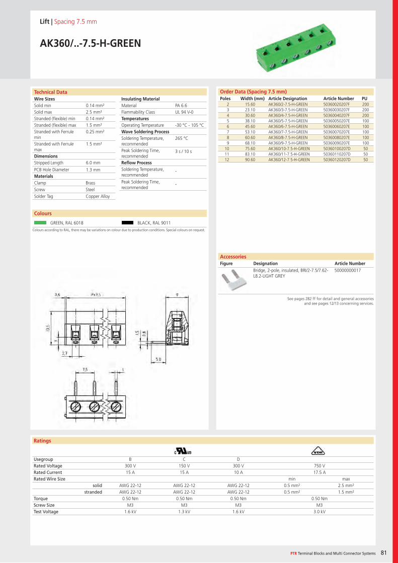
Wire SizesSolid minSolid maxStranded (flexible) minStranded (flexible) maxStranded with Ferrule minStranded with Ferrule maxDimensions Stripped Length
PCB Hole DiameterMaterials
Insulating Material MaterialFlammability ClassTemperaturesOperating TemperatureWave Soldering ProcessSoldering Temperature,recommendedPeak Soldering Time,recommendedReflow ProcessSoldering Temperature,recommended
Peak Soldering Time,recommended
Technical Data
Ratings
Colours
PTR Terminal Blocks and Multi Connector Systems 81
AccessoriesFigure Designation Article Number
Order Data (Spacing 7.5 mm)Poles Width (mm) Article Designation Article Number PU
See pages 282 ff for detail and general accessoriesand see pages 12/13 concerning services.
Colours according to RAL, there may be variations on colour due to production conditions. Special colours on request.
Lift | Spacing 7.5 mm
AK360/..-7.5-H-GREEN
2 15.60 AK360/2-7.5-H-GREEN 50360020207F 2003 23.10 AK360/3-7.5-H-GREEN 50360030207F 2004 30.60 AK360/4-7.5-H-GREEN 50360040207F 2005 38.10 AK360/5-7.5-H-GREEN 50360050207E 1006 45.60 AK360/6-7.5-H-GREEN 50360060207E 1007 53.10 AK360/7-7.5-H-GREEN 50360070207E 1008 60.60 AK360/8-7.5-H-GREEN 50360080207E 1009 68.10 AK360/9-7.5-H-GREEN 50360090207E 100
10 75.60 AK360/10-7.5-H-GREEN 50360100207D 5011 83.10 AK360/11-7.5-H-GREEN 50360110207D 5012 90.60 AK360/12-7.5-H-GREEN 50360120207D 50
Usegroup B C DRated Voltage 300 V 150 V 300 V 750 VRated Current 15 A 15 A 10 A 17.5 ARated Wire Size min max
solid AWG 22-12 AWG 22-12 AWG 22-12 0.5 mm² 2.5 mm²stranded AWG 22-12 AWG 22-12 AWG 22-12 0.5 mm² 1.5 mm²
Torque 0.50 Nm 0.50 Nm 0.50 Nm 0.50 NmScrew Size M3 M3 M3 M3Test Voltage 1.6 kV 1.3 kV 1.6 kV 3.0 kV
GREEN, RAL 6018 BLACK, RAL 9011
Bridge, 2-pole, insulated, BRI/2-7.5/7.62-L8.2-LIGHT GREY
50000000017
PA 6.6UL 94 V-0
-30 °C - 105 °C
265 °C
3 s / 10 s
-
-
0.14 mm²2.5 mm²0.14 mm²1.5 mm²0.25 mm²
1.5 mm²
6.0 mm
1.3 mm
Clamp BrassScrew SteelSolder Tag Copper Alloy
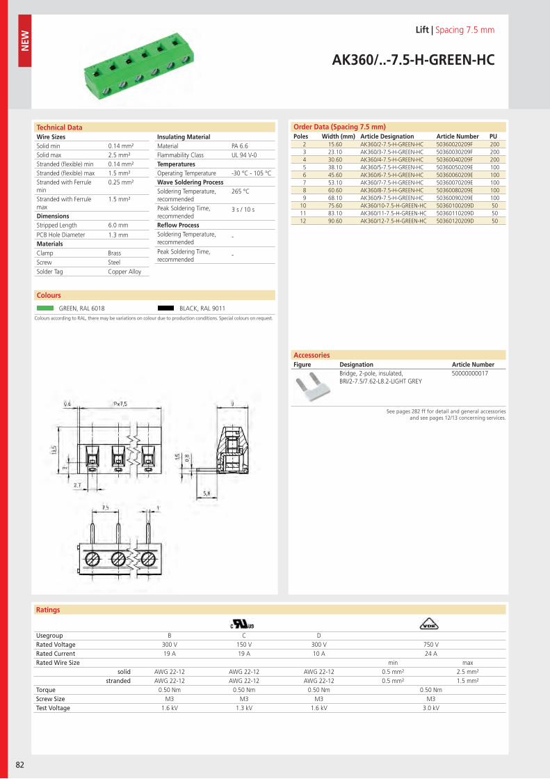
Wire SizesSolid minSolid maxStranded (flexible) minStranded (flexible) maxStranded with Ferrule minStranded with Ferrule maxDimensions Stripped Length
PCB Hole DiameterMaterials
Insulating Material MaterialFlammability ClassTemperaturesOperating TemperatureWave Soldering ProcessSoldering Temperature,recommendedPeak Soldering Time,recommendedReflow ProcessSoldering Temperature,recommended
Peak Soldering Time,recommended
Technical Data
Ratings
Order Data (Spacing 5.08 mm)Poles Width (mm) Article Designation Article Number PU
82
Colours
N
EW
Order Data (Spacing 7.5 mm)Poles Width (mm) Article Designation Article Number PU
See pages 282 ff for detail and general accessoriesand see pages 12/13 concerning services.
Colours according to RAL, there may be variations on colour due to production conditions. Special colours on request.
Lift | Spacing 7.5 mm
AK360/..-7.5-H-GREEN-HC
2 15.60 AK360/2-7.5-H-GREEN-HC 50360020209F 2003 23.10 AK360/3-7.5-H-GREEN-HC 50360030209F 2004 30.60 AK360/4-7.5-H-GREEN-HC 50360040209F 2005 38.10 AK360/5-7.5-H-GREEN-HC 50360050209E 1006 45.60 AK360/6-7.5-H-GREEN-HC 50360060209E 1007 53.10 AK360/7-7.5-H-GREEN-HC 50360070209E 1008 60.60 AK360/8-7.5-H-GREEN-HC 50360080209E 1009 68.10 AK360/9-7.5-H-GREEN-HC 50360090209E 100
10 75.60 AK360/10-7.5-H-GREEN-HC 50360100209D 5011 83.10 AK360/11-7.5-H-GREEN-HC 50360110209D 5012 90.60 AK360/12-7.5-H-GREEN-HC 50360120209D 50
Usegroup B C DRated Voltage 300 V 150 V 300 V 750 VRated Current 19 A 19 A 10 A 24 ARated Wire Size min max
solid AWG 22-12 AWG 22-12 AWG 22-12 0.5 mm² 2.5 mm²stranded AWG 22-12 AWG 22-12 AWG 22-12 0.5 mm² 1.5 mm²
Torque 0.50 Nm 0.50 Nm 0.50 Nm 0.50 NmScrew Size M3 M3 M3 M3Test Voltage 1.6 kV 1.3 kV 1.6 kV 3.0 kV
GREEN, RAL 6018 BLACK, RAL 9011
Bridge, 2-pole, insulated, BRI/2-7.5/7.62-L8.2-LIGHT GREY
50000000017
PA 6.6UL 94 V-0
-30 °C - 105 °C
265 °C
3 s / 10 s
-
-
0.14 mm²2.5 mm²0.14 mm²1.5 mm²0.25 mm²
1.5 mm²
6.0 mm
1.3 mm
Clamp BrassScrew SteelSolder Tag Copper Alloy
AccessoriesFigure Designation Article Number
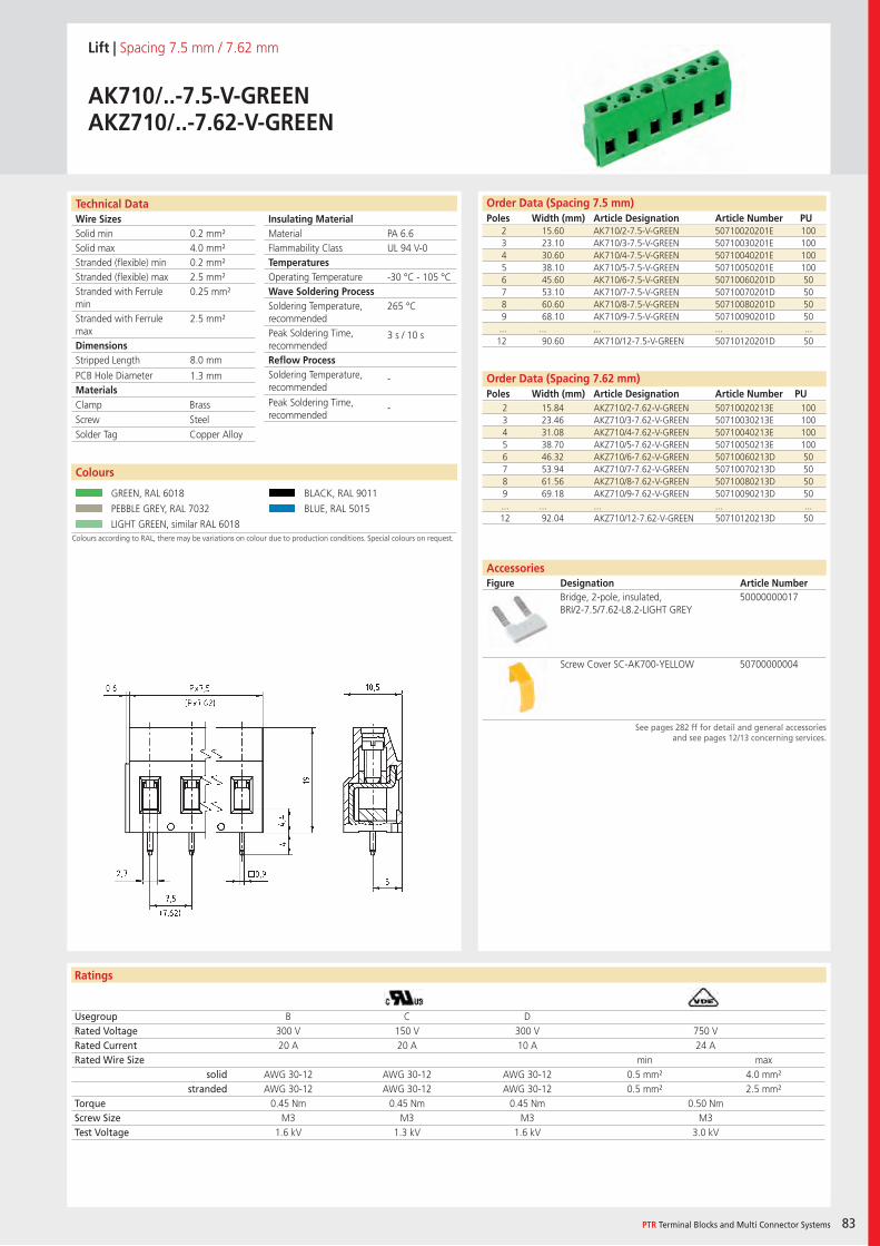
Wire SizesSolid minSolid maxStranded (flexible) minStranded (flexible) maxStranded with Ferrule minStranded with Ferrule maxDimensions Stripped Length
PCB Hole DiameterMaterials
Insulating Material MaterialFlammability ClassTemperaturesOperating TemperatureWave Soldering ProcessSoldering Temperature,recommendedPeak Soldering Time,recommendedReflow ProcessSoldering Temperature,recommended
Peak Soldering Time,recommended
Technical Data
Ratings
Colours
PTR Terminal Blocks and Multi Connector Systems 83
Colours
Order Data (Spacing 7.62 mm)Poles Width (mm) Article Designation Article Number PU
Order Data (Spacing 7.5 mm)Poles Width (mm) Article Designation Article Number PU
See pages 282 ff for detail and general accessoriesand see pages 12/13 concerning services.
AccessoriesFigure Designation Article Number
Colours according to RAL, there may be variations on colour due to production conditions. Special colours on request.
Lift | Spacing 7.5 mm / 7.62 mm
AK710/..-7.5-V-GREENAKZ710/..-7.62-V-GREEN
2 15.60 AK710/2-7.5-V-GREEN 50710020201E 1003 23.10 AK710/3-7.5-V-GREEN 50710030201E 1004 30.60 AK710/4-7.5-V-GREEN 50710040201E 1005 38.10 AK710/5-7.5-V-GREEN 50710050201E 1006 45.60 AK710/6-7.5-V-GREEN 50710060201D 507 53.10 AK710/7-7.5-V-GREEN 50710070201D 508 60.60 AK710/8-7.5-V-GREEN 50710080201D 509 68.10 AK710/9-7.5-V-GREEN 50710090201D 50... ... ... ... ...12 90.60 AK710/12-7.5-V-GREEN 50710120201D 50
Usegroup B C DRated Voltage 300 V 150 V 300 V 750 VRated Current 20 A 20 A 10 A 24 ARated Wire Size min max
solid AWG 30-12 AWG 30-12 AWG 30-12 0.5 mm² 4.0 mm²stranded AWG 30-12 AWG 30-12 AWG 30-12 0.5 mm² 2.5 mm²
Torque 0.45 Nm 0.45 Nm 0.45 Nm 0.50 NmScrew Size M3 M3 M3 M3Test Voltage 1.6 kV 1.3 kV 1.6 kV 3.0 kV
GREEN, RAL 6018 BLACK, RAL 9011
PEBBLE GREY, RAL 7032 BLUE, RAL 5015
LIGHT GREEN, similar RAL 6018
Bridge, 2-pole, insulated, BRI/2-7.5/7.62-L8.2-LIGHT GREY
50000000017
Screw Cover SC-AK700-YELLOW 50700000004
PA 6.6UL 94 V-0
-30 °C - 105 °C
265 °C
3 s / 10 s
-
-
0.2 mm²4.0 mm²0.2 mm²2.5 mm²0.25 mm²
2.5 mm²
8.0 mm
1.3 mm
2 15.84 AKZ710/2-7.62-V-GREEN 50710020213E 1003 23.46 AKZ710/3-7.62-V-GREEN 50710030213E 1004 31.08 AKZ710/4-7.62-V-GREEN 50710040213E 1005 38.70 AKZ710/5-7.62-V-GREEN 50710050213E 1006 46.32 AKZ710/6-7.62-V-GREEN 50710060213D 507 53.94 AKZ710/7-7.62-V-GREEN 50710070213D 508 61.56 AKZ710/8-7.62-V-GREEN 50710080213D 509 69.18 AKZ710/9-7.62-V-GREEN 50710090213D 50... ... ... ... ...12 92.04 AKZ710/12-7.62-V-GREEN 50710120213D 50
Clamp BrassScrew SteelSolder Tag Copper Alloy
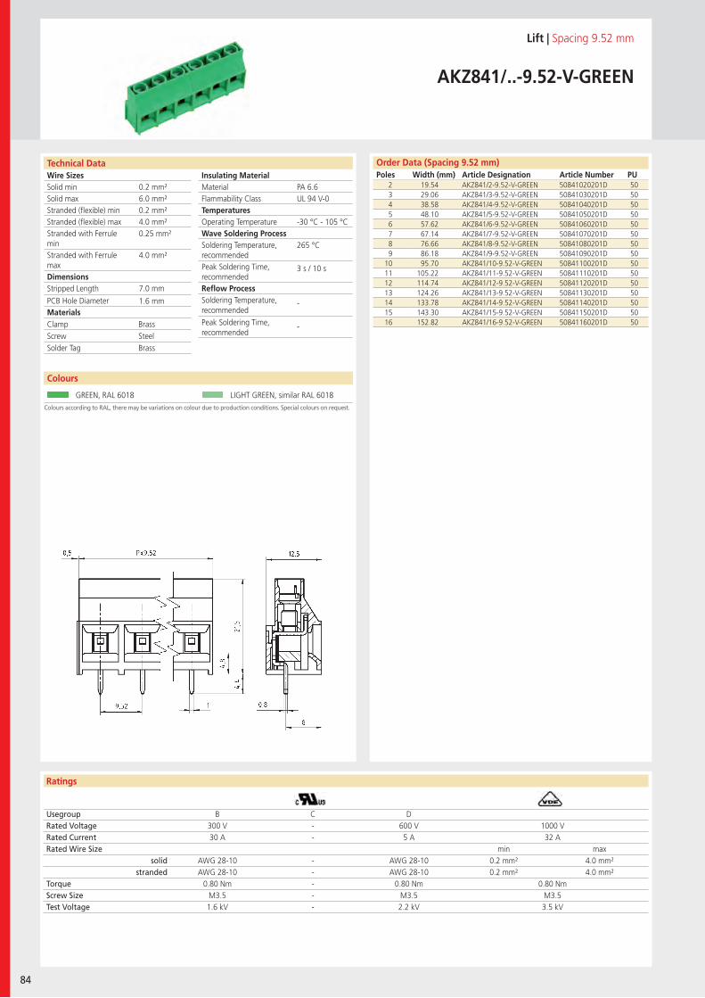
Wire SizesSolid minSolid maxStranded (flexible) minStranded (flexible) maxStranded with Ferrule minStranded with Ferrule maxDimensions Stripped Length
PCB Hole DiameterMaterials
Insulating Material MaterialFlammability ClassTemperaturesOperating TemperatureWave Soldering ProcessSoldering Temperature,recommendedPeak Soldering Time,recommendedReflow ProcessSoldering Temperature,recommended
Peak Soldering Time,recommended
Technical Data
Ratings
84
Colours
Order Data (Spacing 9.52 mm)Poles Width (mm) Article Designation Article Number PU
Colours
Colours according to RAL, there may be variations on colour due to production conditions. Special colours on request.
Lift | Spacing 9.52 mm
AKZ841/..-9.52-V-GREEN
2 19.54 AKZ841/2-9.52-V-GREEN 50841020201D 503 29.06 AKZ841/3-9.52-V-GREEN 50841030201D 504 38.58 AKZ841/4-9.52-V-GREEN 50841040201D 505 48.10 AKZ841/5-9.52-V-GREEN 50841050201D 506 57.62 AKZ841/6-9.52-V-GREEN 50841060201D 507 67.14 AKZ841/7-9.52-V-GREEN 50841070201D 508 76.66 AKZ841/8-9.52-V-GREEN 50841080201D 509 86.18 AKZ841/9-9.52-V-GREEN 50841090201D 50
10 95.70 AKZ841/10-9.52-V-GREEN 50841100201D 5011 105.22 AKZ841/11-9.52-V-GREEN 50841110201D 5012 114.74 AKZ841/12-9.52-V-GREEN 50841120201D 5013 124.26 AKZ841/13-9.52-V-GREEN 50841130201D 5014 133.78 AKZ841/14-9.52-V-GREEN 50841140201D 5015 143.30 AKZ841/15-9.52-V-GREEN 50841150201D 5016 152.82 AKZ841/16-9.52-V-GREEN 50841160201D 50
Usegroup B C DRated Voltage 300 V - 600 V 1000 VRated Current 30 A - 5 A 32 ARated Wire Size min max
solid AWG 28-10 - AWG 28-10 0.2 mm² 4.0 mm²stranded AWG 28-10 - AWG 28-10 0.2 mm² 4.0 mm²
Torque 0.80 Nm - 0.80 Nm 0.80 NmScrew Size M3.5 - M3.5 M3.5Test Voltage 1.6 kV - 2.2 kV 3.5 kV
GREEN, RAL 6018 LIGHT GREEN, similar RAL 6018
PA 6.6UL 94 V-0
-30 °C - 105 °C
265 °C
3 s / 10 s
-
-
0.2 mm²6.0 mm²0.2 mm²4.0 mm²0.25 mm²
4.0 mm²
7.0 mm
1.6 mm
Clamp BrassScrew SteelSolder Tag Brass
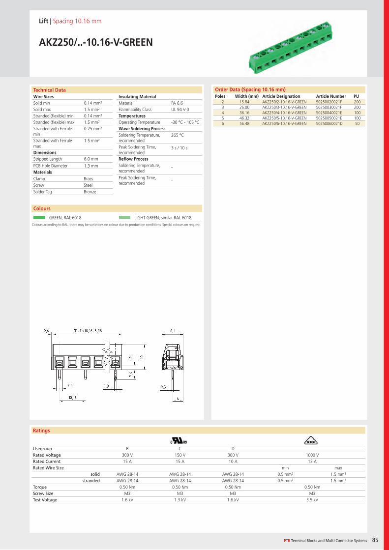
Wire SizesSolid minSolid maxStranded (flexible) minStranded (flexible) maxStranded with Ferrule minStranded with Ferrule maxDimensions Stripped Length
PCB Hole DiameterMaterials
Insulating Material MaterialFlammability ClassTemperaturesOperating TemperatureWave Soldering ProcessSoldering Temperature,recommendedPeak Soldering Time,recommendedReflow ProcessSoldering Temperature,recommended
Peak Soldering Time,recommended
Technical Data
Ratings
Colours
PTR Terminal Blocks and Multi Connector Systems 85
Colours
Order Data (Spacing 10.16 mm)Poles Width (mm) Article Designation Article Number PU
Colours according to RAL, there may be variations on colour due to production conditions. Special colours on request.
Lift | Spacing 10.16 mm
AKZ250/..-10.16-V-GREEN
2 15.84 AKZ250/2-10.16-V-GREEN 50250020021F 2003 26.00 AKZ250/3-10.16-V-GREEN 50250030021F 2004 36.16 AKZ250/4-10.16-V-GREEN 50250040021E 1005 46.32 AKZ250/5-10.16-V-GREEN 50250050021E 1006 56.48 AKZ250/6-10.16-V-GREEN 50250060021D 50
Usegroup B C DRated Voltage 300 V 150 V 300 V 1000 VRated Current 15 A 15 A 10 A 13 ARated Wire Size min max
solid AWG 28-14 AWG 28-14 AWG 28-14 0.5 mm² 1.5 mm²stranded AWG 28-14 AWG 28-14 AWG 28-14 0.5 mm² 1.5 mm²
Torque 0.50 Nm 0.50 Nm 0.50 Nm 0.50 NmScrew Size M3 M3 M3 M3Test Voltage 1.6 kV 1.3 kV 1.6 kV 3.5 kV
GREEN, RAL 6018 LIGHT GREEN, similar RAL 6018
PA 6.6UL 94 V-0
-30 °C - 105 °C
265 °C
3 s / 10 s
-
-
0.14 mm²1.5 mm²0.14 mm²1.5 mm²0.25 mm²
1.5 mm²
6.0 mm
1.3 mm
Clamp BrassScrew SteelSolder Tag Bronze
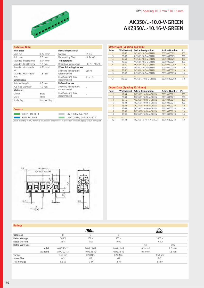
Wire SizesSolid minSolid maxStranded (flexible) minStranded (flexible) maxStranded with Ferrule minStranded with Ferrule maxDimensions Stripped Length
PCB Hole DiameterMaterials
Insulating Material MaterialFlammability ClassTemperaturesOperating TemperatureWave Soldering ProcessSoldering Temperature,recommendedPeak Soldering Time,recommendedReflow ProcessSoldering Temperature,recommended
Peak Soldering Time,recommended
Technical Data
Ratings
86
Colours Colours
Order Data (Spacing 10.16 mm)Poles Width (mm) Article Designation Article Number PU
Order Data (Spacing 10.0 mm)Poles Width (mm) Article Designation Article Number PU
Colours according to RAL, there may be variations on colour due to production conditions. Special colours on request.
Lift | Spacing 10.0 mm / 10.16 mm
AK350/..-10.0-V-GREENAKZ350/..-10.16-V-GREEN
2 15.60 AK350/2-10.0-V-GREEN 50350020025F 2003 25.60 AK350/3-10.0-V-GREEN 50350030025F 2004 35.60 AK350/4-10.0-V-GREEN 50350040025E 1005 45.60 AK350/5-10.0-V-GREEN 50350050025E 1006 55.60 AK350/6-10.0-V-GREEN 50350060025D 507 65.60 AK350/7-10.0-V-GREEN 50350070025D 508 75.60 AK350/8-10.0-V-GREEN 50350080025D 509 85.60 AK350/9-10.0-V-GREEN 50350090025D 50... ... ... ... ...12 115.60 AK350/12-10.0-V-GREEN 50350120025D 50
Usegroup B C DRated Voltage 300 V 150 V 300 V 1000 VRated Current 15 A 15 A 10 A 17.5 ARated Wire Size min max
solid AWG 22-12 AWG 22-12 AWG 22-12 0.5 mm² 2.5 mm²stranded AWG 22-12 AWG 22-12 AWG 22-12 0.5 mm² 1.5 mm²
Torque 0.50 Nm 0.50 Nm 0.50 Nm 0.50 NmScrew Size M3 M3 M3 M3Test Voltage 1.6 kV 1.3 kV 1.6 kV 3.5 kV
GREEN, RAL 6018 LIGHT GREY, RAL 7035
BLUE, RAL 5015 LIGHT GREEN, similar RAL 6018
PA 6.6UL 94 V-0
-30 °C - 105 °C
265 °C
3 s / 10 s
-
-
0.14 mm²2.5 mm²0.14 mm²1.5 mm²0.25 mm²
1.5 mm²
6.0 mm
1.3 mm
2 15.84 AKZ350/2-10.16-V-GREEN 50350020021F 2003 26.00 AKZ350/3-10.16-V-GREEN 50350030021F 2004 36.16 AKZ350/4-10.16-V-GREEN 50350040021E 1005 46.32 AKZ350/5-10.16-V-GREEN 50350050021E 1006 56.48 AKZ350/6-10.16-V-GREEN 50350060021D 507 66.64 AKZ350/7-10.16-V-GREEN 50350070021D 508 76.80 AKZ350/8-10.16-V-GREEN 50350080021D 509 86.96 AKZ350/9-10.16-V-GREEN 50350090021D 50... ... ... ... ...12 117.44 AKZ350/12-10.16-V-GREEN 50350120021D 50
Clamp BrassScrew SteelSolder Tag Copper Alloy
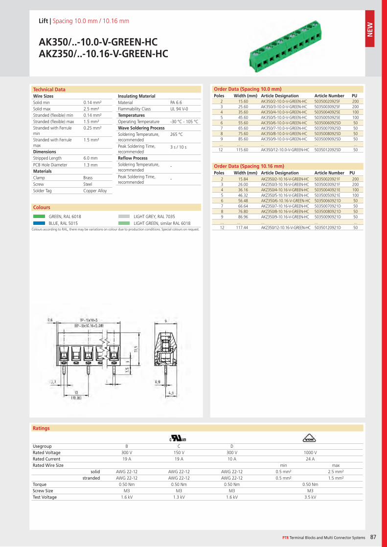
Wire SizesSolid minSolid maxStranded (flexible) minStranded (flexible) maxStranded with Ferrule minStranded with Ferrule maxDimensions Stripped Length
PCB Hole DiameterMaterials
Insulating Material MaterialFlammability ClassTemperaturesOperating TemperatureWave Soldering ProcessSoldering Temperature,recommendedPeak Soldering Time,recommendedReflow ProcessSoldering Temperature,recommended
Peak Soldering Time,recommended
Technical Data
Ratings
Colours
PTR Terminal Blocks and Multi Connector Systems 87
Order Data (Spacing 10.16 mm)Poles Width (mm) Article Designation Article Number PU
Order Data (Spacing 10.0 mm)Poles Width (mm) Article Designation Article Number PU
Colours according to RAL, there may be variations on colour due to production conditions. Special colours on request.
Lift | Spacing 10.0 mm / 10.16 mm
AK350/..-10.0-V-GREEN-HCAKZ350/..-10.16-V-GREEN-HC
2 15.60 AK350/2-10.0-V-GREEN-HC 50350020925F 2003 25.60 AK350/3-10.0-V-GREEN-HC 50350030925F 2004 35.60 AK350/4-10.0-V-GREEN-HC 50350040925E 1005 45.60 AK350/5-10.0-V-GREEN-HC 50350050925E 1006 55.60 AK350/6-10.0-V-GREEN-HC 50350060925D 507 65.60 AK350/7-10.0-V-GREEN-HC 50350070925D 508 75.60 AK350/8-10.0-V-GREEN-HC 50350080925D 509 85.60 AK350/9-10.0-V-GREEN-HC 50350090925D 50... ... ... ... ...12 115.60 AK350/12-10.0-V-GREEN-HC 50350120925D 50
Usegroup B C DRated Voltage 300 V 150 V 300 V 1000 VRated Current 19 A 19 A 10 A 24 ARated Wire Size min max
solid AWG 22-12 AWG 22-12 AWG 22-12 0.5 mm² 2.5 mm²stranded AWG 22-12 AWG 22-12 AWG 22-12 0.5 mm² 1.5 mm²
Torque 0.50 Nm 0.50 Nm 0.50 Nm 0.50 NmScrew Size M3 M3 M3 M3Test Voltage 1.6 kV 1.3 kV 1.6 kV 3.5 kV
GREEN, RAL 6018 LIGHT GREY, RAL 7035
BLUE, RAL 5015 LIGHT GREEN, similar RAL 6018
PA 6.6UL 94 V-0
-30 °C - 105 °C
265 °C
3 s / 10 s
-
-
0.14 mm²2.5 mm²0.14 mm²1.5 mm²0.25 mm²
1.5 mm²
6.0 mm
1.3 mm
2 15.84 AKZ350/2-10.16-V-GREEN-HC 50350020921F 2003 26.00 AKZ350/3-10.16-V-GREEN-HC 50350030921F 2004 36.16 AKZ350/4-10.16-V-GREEN-HC 50350040921E 1005 46.32 AKZ350/5-10.16-V-GREEN-HC 50350050921E 1006 56.48 AKZ350/6-10.16-V-GREEN-HC 50350060921D 507 66.64 AKZ350/7-10.16-V-GREEN-HC 50350070921D 508 76.80 AKZ350/8-10.16-V-GREEN-HC 50350080921D 509 86.96 AKZ350/9-10.16-V-GREEN-HC 50350090921D 50... ... ... ... ...12 117.44 AKZ350/12-10.16-V-GREEN-HC 50350120921D 50
Clamp BrassScrew SteelSolder Tag Copper Alloy
NEW
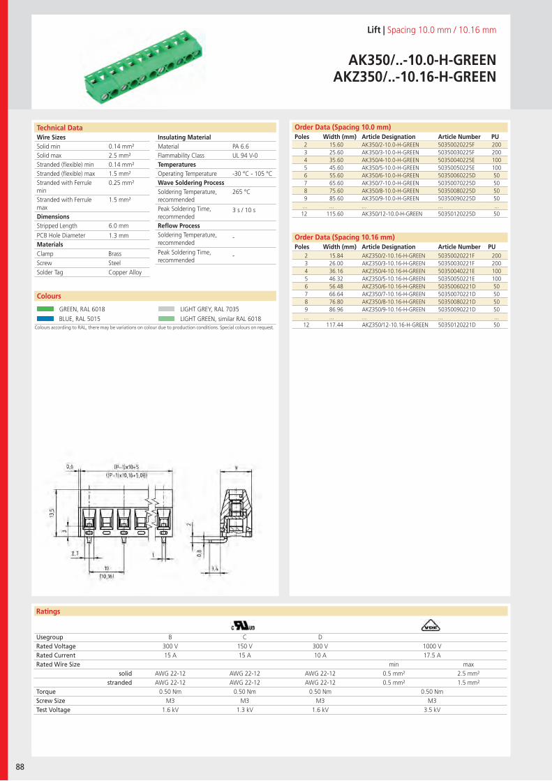
Wire SizesSolid minSolid maxStranded (flexible) minStranded (flexible) maxStranded with Ferrule minStranded with Ferrule maxDimensions Stripped Length
PCB Hole DiameterMaterials
Insulating Material MaterialFlammability ClassTemperaturesOperating TemperatureWave Soldering ProcessSoldering Temperature,recommendedPeak Soldering Time,recommendedReflow ProcessSoldering Temperature,recommended
Peak Soldering Time,recommended
Technical Data
Ratings
88
Colours
Order Data (Spacing 10.16 mm)Poles Width (mm) Article Designation Article Number PU
Order Data (Spacing 10.0 mm)Poles Width (mm) Article Designation Article Number PU
Colours according to RAL, there may be variations on colour due to production conditions. Special colours on request.
Lift | Spacing 10.0 mm / 10.16 mm
AK350/..-10.0-H-GREENAKZ350/..-10.16-H-GREEN
2 15.60 AK350/2-10.0-H-GREEN 50350020225F 2003 25.60 AK350/3-10.0-H-GREEN 50350030225F 2004 35.60 AK350/4-10.0-H-GREEN 50350040225E 1005 45.60 AK350/5-10.0-H-GREEN 50350050225E 1006 55.60 AK350/6-10.0-H-GREEN 50350060225D 507 65.60 AK350/7-10.0-H-GREEN 50350070225D 508 75.60 AK350/8-10.0-H-GREEN 50350080225D 509 85.60 AK350/9-10.0-H-GREEN 50350090225D 50... ... ... ... ...12 115.60 AK350/12-10.0-H-GREEN 50350120225D 50
Usegroup B C DRated Voltage 300 V 150 V 300 V 1000 VRated Current 15 A 15 A 10 A 17.5 ARated Wire Size min max
solid AWG 22-12 AWG 22-12 AWG 22-12 0.5 mm² 2.5 mm²stranded AWG 22-12 AWG 22-12 AWG 22-12 0.5 mm² 1.5 mm²
Torque 0.50 Nm 0.50 Nm 0.50 Nm 0.50 NmScrew Size M3 M3 M3 M3Test Voltage 1.6 kV 1.3 kV 1.6 kV 3.5 kV
GREEN, RAL 6018 LIGHT GREY, RAL 7035
BLUE, RAL 5015 LIGHT GREEN, similar RAL 6018
PA 6.6UL 94 V-0
-30 °C - 105 °C
265 °C
3 s / 10 s
-
-
0.14 mm²2.5 mm²0.14 mm²1.5 mm²0.25 mm²
1.5 mm²
6.0 mm
1.3 mm
2 15.84 AKZ350/2-10.16-H-GREEN 50350020221F 2003 26.00 AKZ350/3-10.16-H-GREEN 50350030221F 2004 36.16 AKZ350/4-10.16-H-GREEN 50350040221E 1005 46.32 AKZ350/5-10.16-H-GREEN 50350050221E 1006 56.48 AKZ350/6-10.16-H-GREEN 50350060221D 507 66.64 AKZ350/7-10.16-H-GREEN 50350070221D 508 76.80 AKZ350/8-10.16-H-GREEN 50350080221D 509 86.96 AKZ350/9-10.16-H-GREEN 50350090221D 50... ... ... ... ...12 117.44 AKZ350/12-10.16-H-GREEN 50350120221D 50
Clamp BrassScrew SteelSolder Tag Copper Alloy
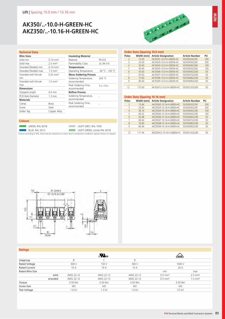
Wire SizesSolid minSolid maxStranded (flexible) minStranded (flexible) maxStranded with Ferrule minStranded with Ferrule maxDimensions Stripped Length
PCB Hole DiameterMaterials
Insulating Material MaterialFlammability ClassTemperaturesOperating TemperatureWave Soldering ProcessSoldering Temperature,recommendedPeak Soldering Time,recommendedReflow ProcessSoldering Temperature,recommended
Peak Soldering Time,recommended
Technical Data
Ratings
Colours
PTR Terminal Blocks and Multi Connector Systems 89
Order Data (Spacing 10.16 mm)Poles Width (mm) Article Designation Article Number PU
Order Data (Spacing 10.0 mm)Poles Width (mm) Article Designation Article Number PU
Lift | Spacing 10.0 mm / 10.16 mm
AK350/..-10.0-H-GREEN-HCAKZ350/..-10.16-H-GREEN-HC
2 15.60 AK350/2-10.0-H-GREEN-HC 50350020226F 2003 25.60 AK350/3-10.0-H-GREEN-HC 50350030226F 2004 35.60 AK350/4-10.0-H-GREEN-HC 50350040226E 1005 45.60 AK350/5-10.0-H-GREEN-HC 50350050226E 1006 55.60 AK350/6-10.0-H-GREEN-HC 50350060226D 507 65.60 AK350/7-10.0-H-GREEN-HC 50350070226D 508 75.60 AK350/8-10.0-H-GREEN-HC 50350080226D 509 85.60 AK350/9-10.0-H-GREEN-HC 50350090226D 50... ... ... ... ...12 115.60 AK350/12-10.0-H-GREEN-HC 50350120226D 50
Usegroup B C DRated Voltage 300 V 150 V 300 V 1000 VRated Current 19 A 19 A 10 A 24 ARated Wire Size min max
solid AWG 22-12 AWG 22-12 AWG 22-12 0.5 mm² 2.5 mm²stranded AWG 22-12 AWG 22-12 AWG 22-12 0.5 mm² 1.5 mm²
Torque 0.50 Nm 0.50 Nm 0.50 Nm 0.50 NmScrew Size M3 M3 M3 M3Test Voltage 1.6 kV 1.3 kV 1.6 kV 3.5 kV
Colours
Colours according to RAL, there may be variations on colour due to production conditions. Special colours on request.
GREEN, RAL 6018 LIGHT GREY, RAL 7035
BLUE, RAL 5015 LIGHT GREEN, similar RAL 6018
PA 6.6UL 94 V-0
-30 °C - 105 °C
265 °C
3 s / 10 s
-
-
0.14 mm²2.5 mm²0.14 mm²1.5 mm²0.25 mm²
1.5 mm²
6.0 mm
1.3 mm
2 15.84 AKZ350/2-10.16-H-GREEN-HC 50350020229F 2003 26.00 AKZ350/3-10.16-H-GREEN-HC 50350030229F 2004 36.16 AKZ350/4-10.16-H-GREEN-HC 50350040229E 1005 46.32 AKZ350/5-10.16-H-GREEN-HC 50350050229E 1006 56.48 AKZ350/6-10.16-H-GREEN-HC 50350060229D 507 66.64 AKZ350/7-10.16-H-GREEN-HC 50350070229D 508 76.80 AKZ350/8-10.16-H-GREEN-HC 50350080229D 509 86.96 AKZ350/9-10.16-H-GREEN-HC 50350090229D 50... ... ... ... ...12 117.44 AKZ350/12-10.16-H-GREEN-HC 50350120229D 50
Clamp BrassScrew SteelSolder Tag Copper Alloy
NEW
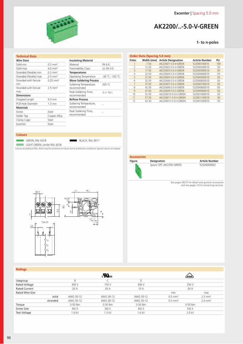
Wire SizesSolid minSolid maxStranded (flexible) minStranded (flexible) maxStranded with Ferrule minStranded with Ferrule maxDimensions Stripped Length
PCB Hole DiameterMaterials
Insulating Material MaterialFlammability ClassTemperaturesOperating TemperatureWave Soldering ProcessSoldering Temperature,recommendedPeak Soldering Time,recommendedReflow ProcessSoldering Temperature,recommended
Peak Soldering Time,recommended
Technical Data
Ratings
90
Order Data (Spacing 5.0 mm)Poles Width (mm) Article Designation Article Number PU
See pages 282 ff for detail and general accessoriesand see pages 12/13 concerning services.
AccessoriesFigure Designation Article Number
Excenter | Spacing 5.0 mm
AK2200/..-5.0-V-GREEN
1- to n-poles
1 7.50 AK2200/1-5.0-V-GREEN 52200010001E 1002 12.50 AK2200/2-5.0-V-GREEN 52200020001D 503 17.50 AK2200/3-5.0-V-GREEN 52200030001D 504 22.50 AK2200/4-5.0-V-GREEN 52200040001D 505 27.50 AK2200/5-5.0-V-GREEN 52200050001D 506 32.50 AK2200/6-5.0-V-GREEN 52200060001D 507 37.50 AK2200/7-5.0-V-GREEN 52200070001D 508 42.50 AK2200/8-5.0-V-GREEN 52200080001D 509 47.50 AK2200/9-5.0-V-GREEN 52200090001D 50
10 52.50 AK2200/10-5.0-V-GREEN 52200100001D 5011 57.50 AK2200/11-5.0-V-GREEN 52200110001D 5012 62.50 AK2200/12-5.0-V-GREEN 52200120001D 50
Usegroup B C DRated Voltage 300 V 150 V 300 V 250 VRated Current 20 A 20 A 10 A 24 ARated Wire Size min max
solid AWG 30-12 AWG 30-12 AWG 30-12 0.5 mm² 2.5 mm²stranded AWG 30-12 AWG 30-12 AWG 30-12 0.5 mm² 2.5 mm²
Torque 0.50 Nm 0.50 Nm 0.50 Nm 0.50 NmScrew Size M2.5 M2.5 M2.5 M2.5Test Voltage 1.6 kV 1.3 kV 1.6 kV 2.0 kV
Colours
Colours according to RAL, there may be variations on colour due to production conditions. Special colours on request.
GREEN, RAL 6018 BLACK, RAL 9011
LIGHT GREEN, similar RAL 6018
Spacer SPC-AK2200-GREEN 52200000002
PA 6.6UL 94 V-0
-30 °C - 105 °C
265 °C
3 s / 10 s
-
-
0.2 mm²4.0 mm²0.2 mm²2.5 mm²0.25 mm²
2.5 mm²
9.0 mm
1.3 mm
Screw SteelSolder Tag Copper AlloyClamp Cage SteelExcenter Steel
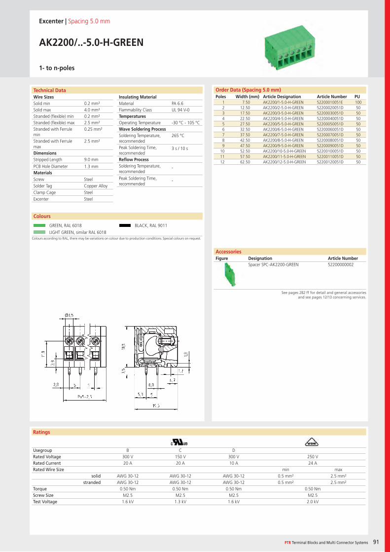
Wire SizesSolid minSolid maxStranded (flexible) minStranded (flexible) maxStranded with Ferrule minStranded with Ferrule maxDimensions Stripped Length
PCB Hole DiameterMaterials
Insulating Material MaterialFlammability ClassTemperaturesOperating TemperatureWave Soldering ProcessSoldering Temperature,recommendedPeak Soldering Time,recommendedReflow ProcessSoldering Temperature,recommended
Peak Soldering Time,recommended
Technical Data
Ratings
PTR Terminal Blocks and Multi Connector Systems 91
Order Data (Spacing 5.0 mm)Poles Width (mm) Article Designation Article Number PU
See pages 282 ff for detail and general accessoriesand see pages 12/13 concerning services.
AccessoriesFigure Designation Article Number
Excenter | Spacing 5.0 mm
AK2200/..-5.0-H-GREEN
1- to n-poles
1 7.50 AK2200/1-5.0-H-GREEN 52200010051E 1002 12.50 AK2200/2-5.0-H-GREEN 52200020051D 503 17.50 AK2200/3-5.0-H-GREEN 52200030051D 504 22.50 AK2200/4-5.0-H-GREEN 52200040051D 505 27.50 AK2200/5-5.0-H-GREEN 52200050051D 506 32.50 AK2200/6-5.0-H-GREEN 52200060051D 507 37.50 AK2200/7-5.0-H-GREEN 52200070051D 508 42.50 AK2200/8-5.0-H-GREEN 52200080051D 509 47.50 AK2200/9-5.0-H-GREEN 52200090051D 50
10 52.50 AK2200/10-5.0-H-GREEN 52200100051D 5011 57.50 AK2200/11-5.0-H-GREEN 52200110051D 5012 62.50 AK2200/12-5.0-H-GREEN 52200120051D 50
Usegroup B C DRated Voltage 300 V 150 V 300 V 250 VRated Current 20 A 20 A 10 A 24 ARated Wire Size min max
solid AWG 30-12 AWG 30-12 AWG 30-12 0.5 mm² 2.5 mm²stranded AWG 30-12 AWG 30-12 AWG 30-12 0.5 mm² 2.5 mm²
Torque 0.50 Nm 0.50 Nm 0.50 Nm 0.50 NmScrew Size M2.5 M2.5 M2.5 M2.5Test Voltage 1.6 kV 1.3 kV 1.6 kV 2.0 kV
Colours
Colours according to RAL, there may be variations on colour due to production conditions. Special colours on request.
GREEN, RAL 6018 BLACK, RAL 9011
LIGHT GREEN, similar RAL 6018
Spacer SPC-AK2200-GREEN 52200000002
PA 6.6UL 94 V-0
-30 °C - 105 °C
265 °C
3 s / 10 s
-
-
0.2 mm²4.0 mm²0.2 mm²2.5 mm²0.25 mm²
2.5 mm²
9.0 mm
1.3 mm
Screw SteelSolder Tag Copper AlloyClamp Cage SteelExcenter Steel
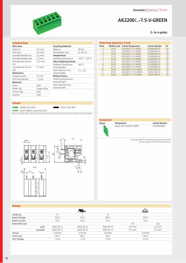
Wire SizesSolid minSolid maxStranded (flexible) minStranded (flexible) maxStranded with Ferrule minStranded with Ferrule maxDimensions Stripped Length
PCB Hole DiameterMaterials
Insulating Material MaterialFlammability ClassTemperaturesOperating TemperatureWave Soldering ProcessSoldering Temperature,recommendedPeak Soldering Time,recommendedReflow ProcessSoldering Temperature,recommended
Peak Soldering Time,recommended
Technical Data
Ratings
92
See pages 282 ff for detail and general accessoriesand see pages 12/13 concerning services.
AccessoriesFigure Designation Article Number
Order Data (Spacing 7.5 mm)Poles Width (mm) Article Designation Article Number PU
Excenter | Spacing 7.5 mm
AK2200/..-7.5-V-GREEN
2- to n-poles
2 15.00 AK2200/2-7.5-V-GREEN 52200020021D 503 22.50 AK2200/3-7.5-V-GREEN 52200030021D 504 30.00 AK2200/4-7.5-V-GREEN 52200040021D 505 37.50 AK2200/5-7.5-V-GREEN 52200050021D 506 45.00 AK2200/6-7.5-V-GREEN 52200060021D 507 52.50 AK2200/7-7.5-V-GREEN 52200070021D 508 60.00 AK2200/8-7.5-V-GREEN 52200080021D 509 67.50 AK2200/9-7.5-V-GREEN 52200090021D 50
10 75.00 AK2200/10-7.5-V-GREEN 52200100021D 5011 82.50 AK2200/11-7.5-V-GREEN 52200110021D 5012 90.00 AK2200/12-7.5-V-GREEN 52200120021D 50
Usegroup B C DRated Voltage 300 V 150 V 300 V 450 VRated Current 20 A 20 A 10 A 24 ARated Wire Size min max
solid AWG 30-12 AWG 30-12 AWG 30-12 0.5 mm² 2.5 mm²stranded AWG 30-12 AWG 30-12 AWG 30-12 0.5 mm² 2.5 mm²
Torque 0.50 Nm 0.50 Nm 0.50 Nm 0.50 NmScrew Size M2.5 M2.5 M2.5 M2.5Test Voltage 1.6 kV 1.3 kV 1.6 kV 2.5 kV
Colours
Colours according to RAL, there may be variations on colour due to production conditions. Special colours on request.
GREEN, RAL 6018 BLACK, RAL 9011
LIGHT GREEN, similar RAL 6018
Spacer SPC-AK2200-GREEN 52200000002
PA 6.6UL 94 V-0
-30 °C - 105 °C
265 °C
3 s / 10 s
-
-
0.2 mm²4.0 mm²0.2 mm²2.5 mm²0.25 mm²
2.5 mm²
9.0 mm
1.3 mm
Screw SteelSolder Tag Copper AlloyClamp Cage SteelExcenter Steel
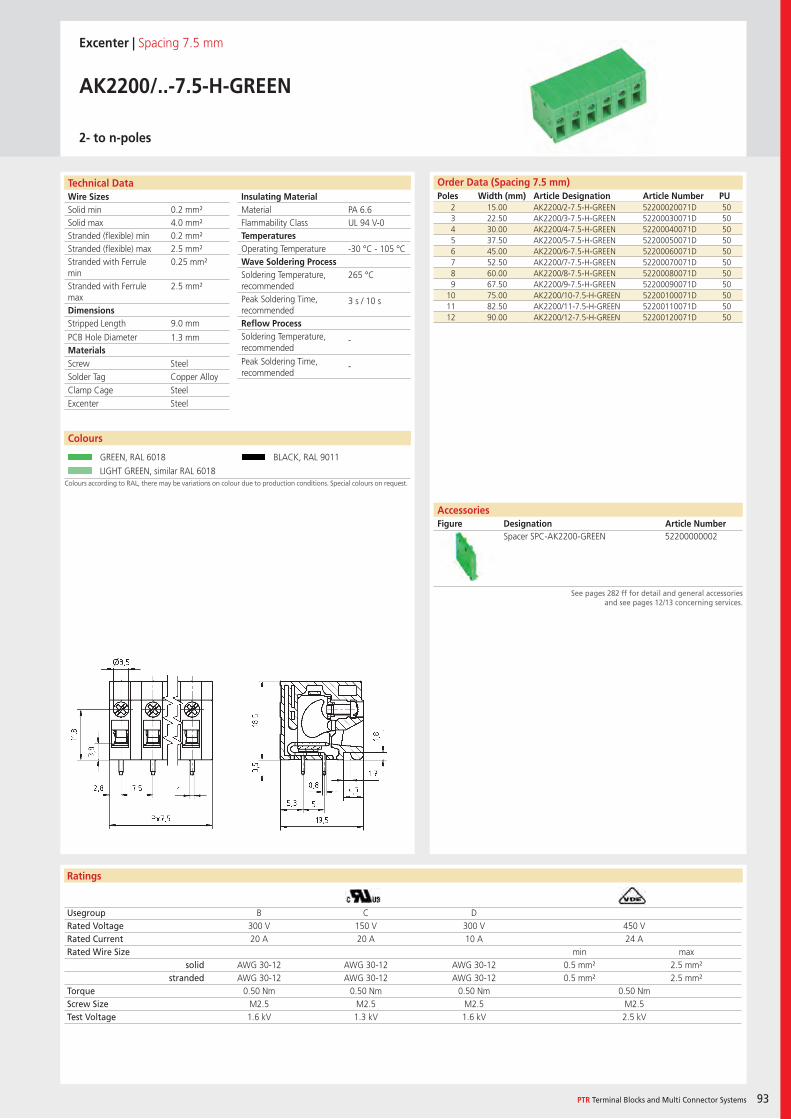
Wire SizesSolid minSolid maxStranded (flexible) minStranded (flexible) maxStranded with Ferrule minStranded with Ferrule maxDimensions Stripped Length
PCB Hole DiameterMaterials
Insulating Material MaterialFlammability ClassTemperaturesOperating TemperatureWave Soldering ProcessSoldering Temperature,recommendedPeak Soldering Time,recommendedReflow ProcessSoldering Temperature,recommended
Peak Soldering Time,recommended
Technical Data
Ratings
PTR Terminal Blocks and Multi Connector Systems 93
Order Data (Spacing 7.5 mm)Poles Width (mm) Article Designation Article Number PU
See pages 282 ff for detail and general accessoriesand see pages 12/13 concerning services.
AccessoriesFigure Designation Article Number
Excenter | Spacing 7.5 mm
AK2200/..-7.5-H-GREEN
2- to n-poles
2 15.00 AK2200/2-7.5-H-GREEN 52200020071D 503 22.50 AK2200/3-7.5-H-GREEN 52200030071D 504 30.00 AK2200/4-7.5-H-GREEN 52200040071D 505 37.50 AK2200/5-7.5-H-GREEN 52200050071D 506 45.00 AK2200/6-7.5-H-GREEN 52200060071D 507 52.50 AK2200/7-7.5-H-GREEN 52200070071D 508 60.00 AK2200/8-7.5-H-GREEN 52200080071D 509 67.50 AK2200/9-7.5-H-GREEN 52200090071D 50
10 75.00 AK2200/10-7.5-H-GREEN 52200100071D 5011 82.50 AK2200/11-7.5-H-GREEN 52200110071D 5012 90.00 AK2200/12-7.5-H-GREEN 52200120071D 50
Usegroup B C DRated Voltage 300 V 150 V 300 V 450 VRated Current 20 A 20 A 10 A 24 ARated Wire Size min max
solid AWG 30-12 AWG 30-12 AWG 30-12 0.5 mm² 2.5 mm²stranded AWG 30-12 AWG 30-12 AWG 30-12 0.5 mm² 2.5 mm²
Torque 0.50 Nm 0.50 Nm 0.50 Nm 0.50 NmScrew Size M2.5 M2.5 M2.5 M2.5Test Voltage 1.6 kV 1.3 kV 1.6 kV 2.5 kV
Colours
Colours according to RAL, there may be variations on colour due to production conditions. Special colours on request.
GREEN, RAL 6018 BLACK, RAL 9011
LIGHT GREEN, similar RAL 6018
Spacer SPC-AK2200-GREEN 52200000002
PA 6.6UL 94 V-0
-30 °C - 105 °C
265 °C
3 s / 10 s
-
-
0.2 mm²4.0 mm²0.2 mm²2.5 mm²0.25 mm²
2.5 mm²
9.0 mm
1.3 mm
Screw SteelSolder Tag Copper AlloyClamp Cage SteelExcenter Steel
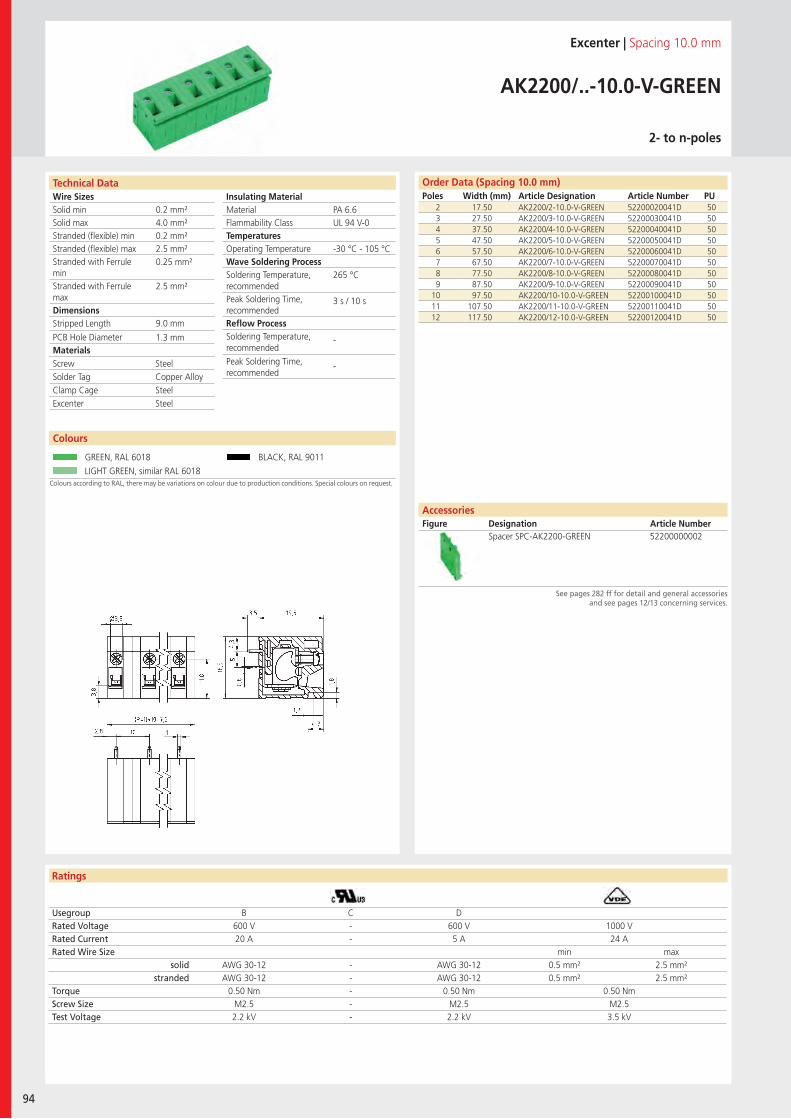
Wire SizesSolid minSolid maxStranded (flexible) minStranded (flexible) maxStranded with Ferrule minStranded with Ferrule maxDimensions Stripped Length
PCB Hole DiameterMaterials
Insulating Material MaterialFlammability ClassTemperaturesOperating TemperatureWave Soldering ProcessSoldering Temperature,recommendedPeak Soldering Time,recommendedReflow ProcessSoldering Temperature,recommended
Peak Soldering Time,recommended
Technical Data
Ratings
94
Colours
Order Data (Spacing 10.0 mm)Poles Width (mm) Article Designation Article Number PU
See pages 282 ff for detail and general accessoriesand see pages 12/13 concerning services.
AccessoriesFigure Designation Article Number
Colours according to RAL, there may be variations on colour due to production conditions. Special colours on request.
Excenter | Spacing 10.0 mm
AK2200/..-10.0-V-GREEN
2- to n-poles
2 17.50 AK2200/2-10.0-V-GREEN 52200020041D 503 27.50 AK2200/3-10.0-V-GREEN 52200030041D 504 37.50 AK2200/4-10.0-V-GREEN 52200040041D 505 47.50 AK2200/5-10.0-V-GREEN 52200050041D 506 57.50 AK2200/6-10.0-V-GREEN 52200060041D 507 67.50 AK2200/7-10.0-V-GREEN 52200070041D 508 77.50 AK2200/8-10.0-V-GREEN 52200080041D 509 87.50 AK2200/9-10.0-V-GREEN 52200090041D 50
10 97.50 AK2200/10-10.0-V-GREEN 52200100041D 5011 107.50 AK2200/11-10.0-V-GREEN 52200110041D 5012 117.50 AK2200/12-10.0-V-GREEN 52200120041D 50
Usegroup B C DRated Voltage 600 V - 600 V 1000 VRated Current 20 A - 5 A 24 ARated Wire Size min max
solid AWG 30-12 - AWG 30-12 0.5 mm² 2.5 mm²stranded AWG 30-12 - AWG 30-12 0.5 mm² 2.5 mm²
Torque 0.50 Nm - 0.50 Nm 0.50 NmScrew Size M2.5 - M2.5 M2.5Test Voltage 2.2 kV - 2.2 kV 3.5 kV
GREEN, RAL 6018 BLACK, RAL 9011
LIGHT GREEN, similar RAL 6018
Spacer SPC-AK2200-GREEN 52200000002
PA 6.6UL 94 V-0
-30 °C - 105 °C
265 °C
3 s / 10 s
-
-
0.2 mm²4.0 mm²0.2 mm²2.5 mm²0.25 mm²
2.5 mm²
9.0 mm
1.3 mm
Screw SteelSolder Tag Copper AlloyClamp Cage SteelExcenter Steel
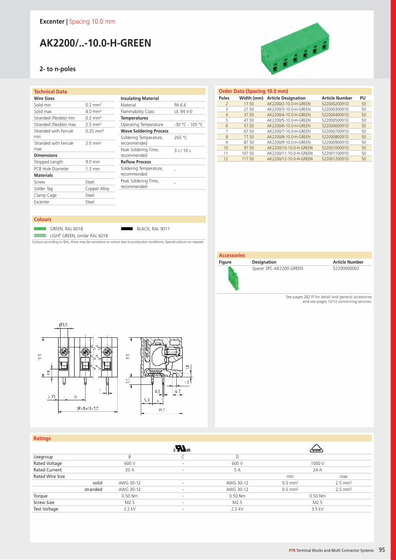
Wire SizesSolid minSolid maxStranded (flexible) minStranded (flexible) maxStranded with Ferrule minStranded with Ferrule maxDimensions Stripped Length
PCB Hole DiameterMaterials
Insulating Material MaterialFlammability ClassTemperaturesOperating TemperatureWave Soldering ProcessSoldering Temperature,recommendedPeak Soldering Time,recommendedReflow ProcessSoldering Temperature,recommended
Peak Soldering Time,recommended
Technical Data
Ratings
PTR Terminal Blocks and Multi Connector Systems 95
Colours
Order Data (Spacing 10.0 mm)Poles Width (mm) Article Designation Article Number PU
See pages 282 ff for detail and general accessoriesand see pages 12/13 concerning services.
AccessoriesFigure Designation Article Number
Colours according to RAL, there may be variations on colour due to production conditions. Special colours on request.
Excenter | Spacing 10.0 mm
AK2200/..-10.0-H-GREEN
2- to n-poles
2 17.50 AK2200/2-10.0-H-GREEN 52200020091D 503 27.50 AK2200/3-10.0-H-GREEN 52200030091D 504 37.50 AK2200/4-10.0-H-GREEN 52200040091D 505 47.50 AK2200/5-10.0-H-GREEN 52200050091D 506 57.50 AK2200/6-10.0-H-GREEN 52200060091D 507 67.50 AK2200/7-10.0-H-GREEN 52200070091D 508 77.50 AK2200/8-10.0-H-GREEN 52200080091D 509 87.50 AK2200/9-10.0-H-GREEN 52200090091D 50
10 97.50 AK2200/10-10.0-H-GREEN 52200100091D 5011 107.50 AK2200/11-10.0-H-GREEN 52200110091D 5012 117.50 AK2200/12-10.0-H-GREEN 52200120091D 50
Usegroup B C DRated Voltage 600 V - 600 V 1000 VRated Current 20 A - 5 A 24 ARated Wire Size min max
solid AWG 30-12 - AWG 30-12 0.5 mm² 2.5 mm²stranded AWG 30-12 - AWG 30-12 0.5 mm² 2.5 mm²
Torque 0.50 Nm - 0.50 Nm 0.50 NmScrew Size M2.5 - M2.5 M2.5Test Voltage 2.2 kV - 2.2 kV 3.5 kV
GREEN, RAL 6018 BLACK, RAL 9011
LIGHT GREEN, similar RAL 6018
Spacer SPC-AK2200-GREEN 52200000002
PA 6.6UL 94 V-0
-30 °C - 105 °C
265 °C
3 s / 10 s
-
-
0.2 mm²4.0 mm²0.2 mm²2.5 mm²0.25 mm²
2.5 mm²
9.0 mm
1.3 mm
Screw SteelSolder Tag Copper AlloyClamp Cage SteelExcenter Steel
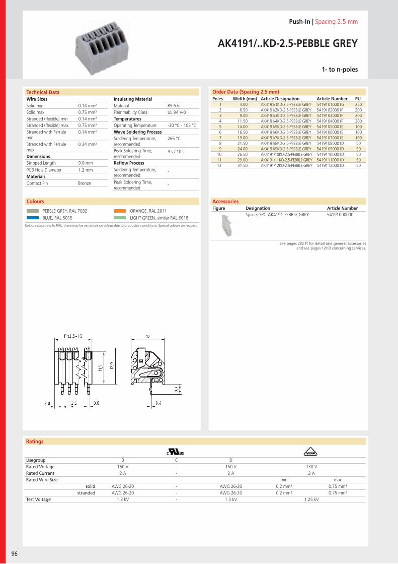
Wire SizesSolid minSolid maxStranded (flexible) minStranded (flexible) maxStranded with Ferrule minStranded with Ferrule maxDimensions Stripped Length
PCB Hole DiameterMaterials
Ratings
96
Insulating Material MaterialFlammability ClassTemperaturesOperating TemperatureWave Soldering ProcessSoldering Temperature,recommendedPeak Soldering Time,recommendedReflow ProcessSoldering Temperature,recommended
Peak Soldering Time,recommended
Technical Data Order Data (Spacing 2.5 mm)Poles Width (mm) Article Designation Article Number PU
Colours
Push-In | Spacing 2.5 mm
AK4191/..KD-2.5-PEBBLE GREY
1- to n-poles
1 4.00 AK4191/1KD-2.5-PEBBLE GREY 54191010001G 2502 6.50 AK4191/2KD-2.5-PEBBLE GREY 54191020001F 2003 9.00 AK4191/3KD-2.5-PEBBLE GREY 54191030001F 2004 11.50 AK4191/4KD-2.5-PEBBLE GREY 54191040001F 2005 14.00 AK4191/5KD-2.5-PEBBLE GREY 54191050001E 1006 16.50 AK4191/6KD-2.5-PEBBLE GREY 54191060001E 1007 19.00 AK4191/7KD-2.5-PEBBLE GREY 54191070001E 1008 21.50 AK4191/8KD-2.5-PEBBLE GREY 54191080001D 509 24.00 AK4191/9KD-2.5-PEBBLE GREY 54191090001D 50
10 26.50 AK4191/10KD-2.5-PEBBLE GREY 54191100001D 5011 29.00 AK4191/11KD-2.5-PEBBLE GREY 54191110001D 5012 31.50 AK4191/12KD-2.5-PEBBLE GREY 54191120001D 50
Usegroup B C DRated Voltage 150 V - 150 V 130 VRated Current 2 A - 2 A 2 ARated Wire Size min max
solid AWG 26-20 - AWG 26-20 0.2 mm² 0.75 mm²stranded AWG 26-20 - AWG 26-20 0.2 mm² 0.75 mm²
Test Voltage 1.3 kV - 1.3 kV 1.25 kV
PEBBLE GREY, RAL 7032 ORANGE, RAL 2011
BLUE, RAL 5015 LIGHT GREEN, similar RAL 6018
AccessoriesFigure Designation Article Number
See pages 282 ff for detail and general accessoriesand see pages 12/13 concerning services.
Spacer SPC-AK4191-PEBBLE GREY 54191000000
PA 6.6UL 94 V-0
-30 °C - 105 °C
265 °C
3 s / 10 s
-
-
0.14 mm²0.75 mm²0.14 mm²0.75 mm²0.14 mm²
0.34 mm²
9.0 mm
1.2 mm
Contact Pin Bronze
Colours according to RAL, there may be variations on colour due to production conditions. Special colours on request.
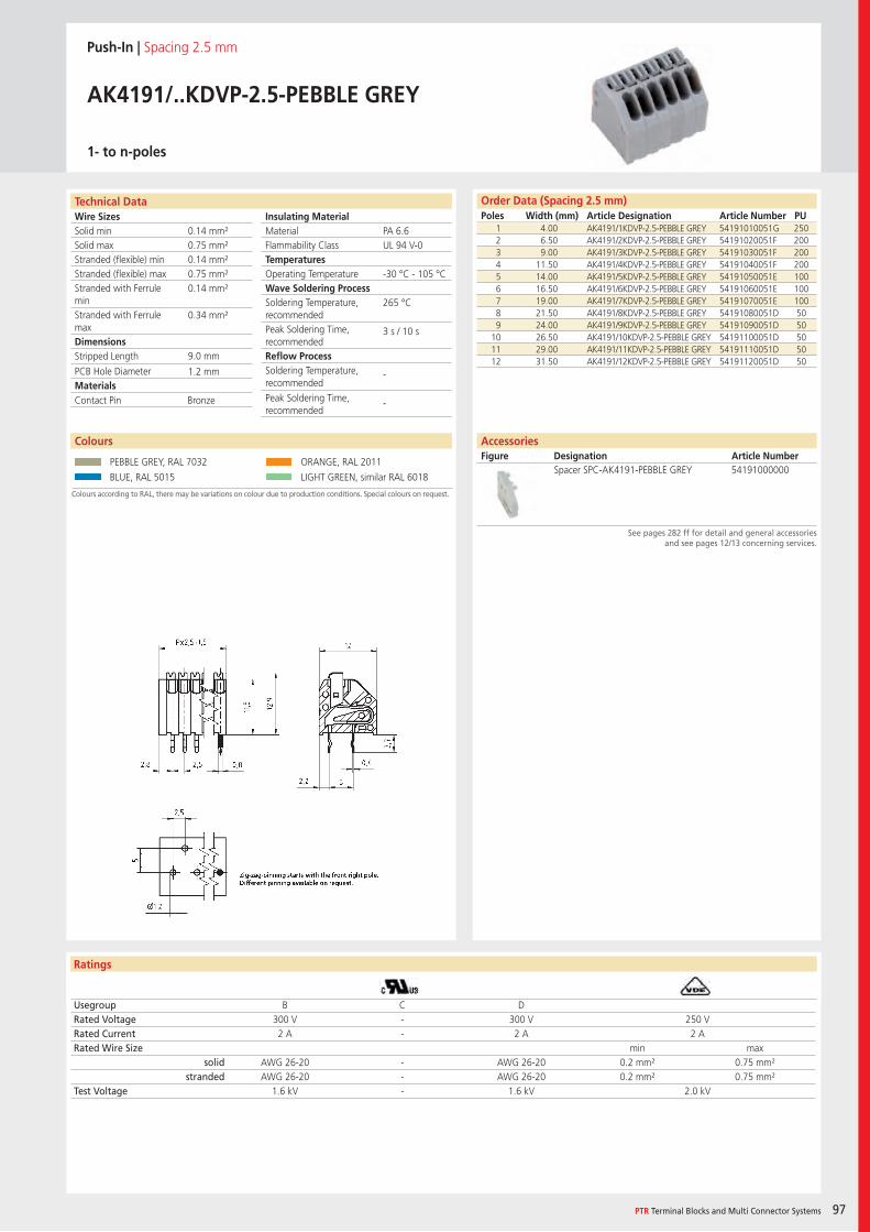
Wire SizesSolid minSolid maxStranded (flexible) minStranded (flexible) maxStranded with Ferrule minStranded with Ferrule maxDimensions Stripped Length
PCB Hole DiameterMaterials
PTR Terminal Blocks and Multi Connector Systems 97
Insulating Material MaterialFlammability ClassTemperaturesOperating TemperatureWave Soldering ProcessSoldering Temperature,recommendedPeak Soldering Time,recommendedReflow ProcessSoldering Temperature,recommended
Peak Soldering Time,recommended
Technical Data
Ratings
Order Data (Spacing 2.5 mm)Poles Width (mm) Article Designation Article Number PU
Push-In | Spacing 2.5 mm
AK4191/..KDVP-2.5-PEBBLE GREY
1- to n-poles
1 4.00 AK4191/1KDVP-2.5-PEBBLE GREY 54191010051G 2502 6.50 AK4191/2KDVP-2.5-PEBBLE GREY 54191020051F 2003 9.00 AK4191/3KDVP-2.5-PEBBLE GREY 54191030051F 2004 11.50 AK4191/4KDVP-2.5-PEBBLE GREY 54191040051F 2005 14.00 AK4191/5KDVP-2.5-PEBBLE GREY 54191050051E 1006 16.50 AK4191/6KDVP-2.5-PEBBLE GREY 54191060051E 1007 19.00 AK4191/7KDVP-2.5-PEBBLE GREY 54191070051E 1008 21.50 AK4191/8KDVP-2.5-PEBBLE GREY 54191080051D 509 24.00 AK4191/9KDVP-2.5-PEBBLE GREY 54191090051D 50
10 26.50 AK4191/10KDVP-2.5-PEBBLE GREY 54191100051D 5011 29.00 AK4191/11KDVP-2.5-PEBBLE GREY 54191110051D 5012 31.50 AK4191/12KDVP-2.5-PEBBLE GREY 54191120051D 50
Usegroup B C DRated Voltage 300 V - 300 V 250 VRated Current 2 A - 2 A 2 ARated Wire Size min max
solid AWG 26-20 - AWG 26-20 0.2 mm² 0.75 mm²stranded AWG 26-20 - AWG 26-20 0.2 mm² 0.75 mm²
Test Voltage 1.6 kV - 1.6 kV 2.0 kV
Colours
PEBBLE GREY, RAL 7032 ORANGE, RAL 2011
BLUE, RAL 5015 LIGHT GREEN, similar RAL 6018
AccessoriesFigure Designation Article Number
See pages 282 ff for detail and general accessoriesand see pages 12/13 concerning services.
Spacer SPC-AK4191-PEBBLE GREY 54191000000
PA 6.6UL 94 V-0
-30 °C - 105 °C
265 °C
3 s / 10 s
-
-
0.14 mm²0.75 mm²0.14 mm²0.75 mm²0.14 mm²
0.34 mm²
9.0 mm
1.2 mm
Contact Pin Bronze
Colours according to RAL, there may be variations on colour due to production conditions. Special colours on request.
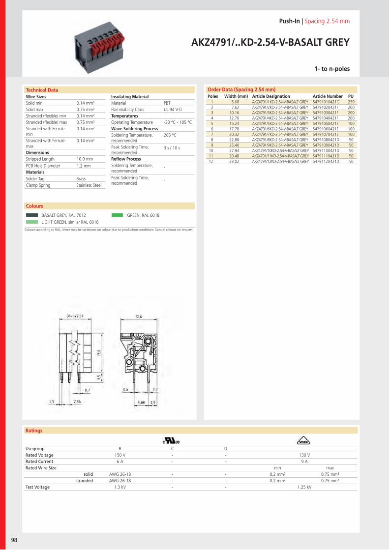
Wire SizesSolid minSolid maxStranded (flexible) minStranded (flexible) maxStranded with Ferrule minStranded with Ferrule maxDimensions Stripped Length
PCB Hole DiameterMaterials
Ratings
98
Insulating Material MaterialFlammability ClassTemperaturesOperating TemperatureWave Soldering ProcessSoldering Temperature,recommendedPeak Soldering Time,recommendedReflow ProcessSoldering Temperature,recommended
Peak Soldering Time,recommended
Technical Data Order Data (Spacing 2.54 mm)Poles Width (mm) Article Designation Article Number PU
Push-In | Spacing 2.54 mm
AKZ4791/..KD-2.54-V-BASALT GREY
1- to n-poles
1 5.08 AKZ4791/1KD-2.54-V-BASALT GREY 54791010421G 2502 7.62 AKZ4791/2KD-2.54-V-BASALT GREY 54791020421F 2003 10.16 AKZ4791/3KD-2.54-V-BASALT GREY 54791030421F 2004 12.70 AKZ4791/4KD-2.54-V-BASALT GREY 54791040421F 2005 15.24 AKZ4791/5KD-2.54-V-BASALT GREY 54791050421E 1006 17.78 AKZ4791/6KD-2.54-V-BASALT GREY 54791060421E 1007 20.32 AKZ4791/7KD-2.54-V-BASALT GREY 54791070421E 1008 22.86 AKZ4791/8KD-2.54-V-BASALT GREY 54791080421D 509 25.40 AKZ4791/9KD-2.54-V-BASALT GREY 54791090421D 50
10 27.94 AKZ4791/10KD-2.54-V-BASALT GREY 54791100421D 5011 30.48 AKZ4791/11KD-2.54-V-BASALT GREY 54791110421D 5012 33.02 AKZ4791/12KD-2.54-V-BASALT GREY 54791120421D 50
Usegroup B C DRated Voltage 150 V - - 130 VRated Current 6 A - - 9 ARated Wire Size min max
solid AWG 26-18 - - 0.2 mm² 0.75 mm²stranded AWG 26-18 - - 0.2 mm² 0.75 mm²
Test Voltage 1.3 kV - - 1.25 kV
Colours according to RAL, there may be variations on colour due to production conditions. Special colours on request.
Colours
BASALT GREY, RAL 7012 GREEN, RAL 6018
LIGHT GREEN, similar RAL 6018
PBTUL 94 V-0
-30 °C - 105 °C
265 °C
3 s / 10 s
-
-
0.14 mm²0.75 mm²0.14 mm²0.75 mm²0.14 mm²
0.14 mm²
10.0 mm
1.2 mm
Solder Tag BrassClamp Spring Stainless Steel
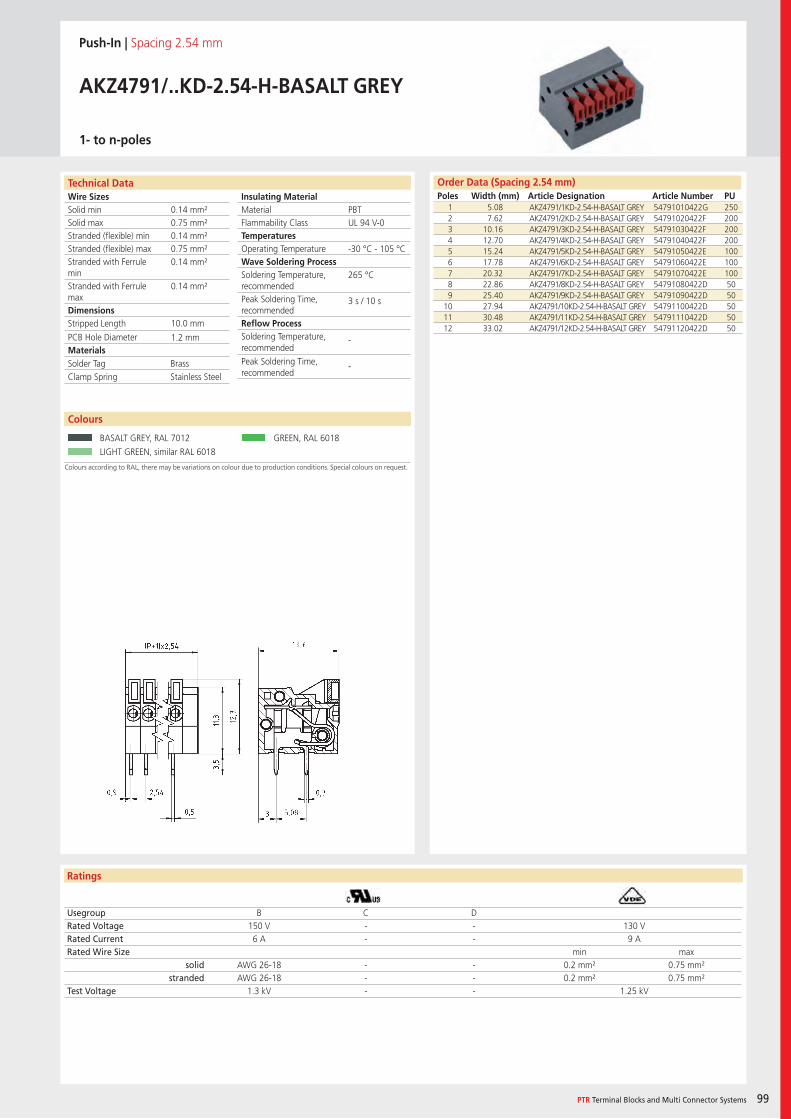
Wire SizesSolid minSolid maxStranded (flexible) minStranded (flexible) maxStranded with Ferrule minStranded with Ferrule maxDimensions Stripped Length
PCB Hole DiameterMaterials
Ratings
PTR Terminal Blocks and Multi Connector Systems 99
Insulating Material MaterialFlammability ClassTemperaturesOperating TemperatureWave Soldering ProcessSoldering Temperature,recommendedPeak Soldering Time,recommendedReflow ProcessSoldering Temperature,recommended
Peak Soldering Time,recommended
Order Data (Spacing 2.54 mm)Poles Width (mm) Article Designation Article Number PU
Colours according to RAL, there may be variations on colour due to production conditions. Special colours on request.
Push-In | Spacing 2.54 mm
AKZ4791/..KD-2.54-H-BASALT GREY
1- to n-poles
1 5.08 AKZ4791/1KD-2.54-H-BASALT GREY 54791010422G 2502 7.62 AKZ4791/2KD-2.54-H-BASALT GREY 54791020422F 2003 10.16 AKZ4791/3KD-2.54-H-BASALT GREY 54791030422F 2004 12.70 AKZ4791/4KD-2.54-H-BASALT GREY 54791040422F 2005 15.24 AKZ4791/5KD-2.54-H-BASALT GREY 54791050422E 1006 17.78 AKZ4791/6KD-2.54-H-BASALT GREY 54791060422E 1007 20.32 AKZ4791/7KD-2.54-H-BASALT GREY 54791070422E 1008 22.86 AKZ4791/8KD-2.54-H-BASALT GREY 54791080422D 509 25.40 AKZ4791/9KD-2.54-H-BASALT GREY 54791090422D 50
10 27.94 AKZ4791/10KD-2.54-H-BASALT GREY 54791100422D 5011 30.48 AKZ4791/11KD-2.54-H-BASALT GREY 54791110422D 5012 33.02 AKZ4791/12KD-2.54-H-BASALT GREY 54791120422D 50
Usegroup B C DRated Voltage 150 V - - 130 VRated Current 6 A - - 9 ARated Wire Size min max
solid AWG 26-18 - - 0.2 mm² 0.75 mm²stranded AWG 26-18 - - 0.2 mm² 0.75 mm²
Test Voltage 1.3 kV - - 1.25 kV
Colours
BASALT GREY, RAL 7012 GREEN, RAL 6018
LIGHT GREEN, similar RAL 6018
PBTUL 94 V-0
-30 °C - 105 °C
265 °C
3 s / 10 s
-
-
0.14 mm²0.75 mm²0.14 mm²0.75 mm²0.14 mm²
0.14 mm²
10.0 mm
1.2 mm
Solder Tag BrassClamp Spring Stainless Steel
Technical Data
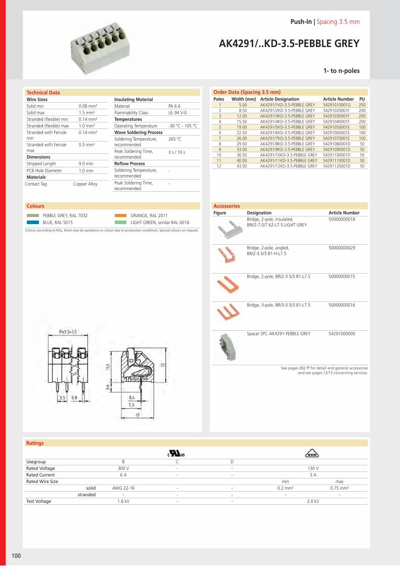
Wire SizesSolid minSolid maxStranded (flexible) minStranded (flexible) maxStranded with Ferrule minStranded with Ferrule maxDimensions Stripped Length
PCB Hole DiameterMaterials
Ratings
100
Insulating Material MaterialFlammability ClassTemperaturesOperating TemperatureWave Soldering ProcessSoldering Temperature,recommendedPeak Soldering Time,recommendedReflow ProcessSoldering Temperature,recommended
Peak Soldering Time,recommended
Technical Data Order Data (Spacing 3.5 mm)Poles Width (mm) Article Designation Article Number PU
Push-In | Spacing 3.5 mm
AK4291/..KD-3.5-PEBBLE GREY
1- to n-poles
1 5.00 AK4291/1KD-3.5-PEBBLE GREY 54291010001G 2502 8.50 AK4291/2KD-3.5-PEBBLE GREY 54291020001F 2003 12.00 AK4291/3KD-3.5-PEBBLE GREY 54291030001F 2004 15.50 AK4291/4KD-3.5-PEBBLE GREY 54291040001F 2005 19.00 AK4291/5KD-3.5-PEBBLE GREY 54291050001E 1006 22.50 AK4291/6KD-3.5-PEBBLE GREY 54291060001E 1007 26.00 AK4291/7KD-3.5-PEBBLE GREY 54291070001E 1008 29.50 AK4291/8KD-3.5-PEBBLE GREY 54291080001D 509 33.00 AK4291/9KD-3.5-PEBBLE GREY 54291090001D 50
10 36.50 AK4291/10KD-3.5-PEBBLE GREY 54291100001D 5011 40.00 AK4291/11KD-3.5-PEBBLE GREY 54291110001D 5012 43.50 AK4291/12KD-3.5-PEBBLE GREY 54291120001D 50
Usegroup B C DRated Voltage 300 V - - 130 VRated Current 6 A - - 3 ARated Wire Size min max
solid AWG 22-16 - - 0.2 mm² 0.75 mm²stranded - - - - -
Test Voltage 1.6 kV - - 2.0 kV
Colours according to RAL, there may be variations on colour due to production conditions. Special colours on request.
Colours
PEBBLE GREY, RAL 7032 ORANGE, RAL 2011
BLUE, RAL 5015 LIGHT GREEN, similar RAL 6018
PA 6.6UL 94 V-0
-30 °C - 105 °C
265 °C
3 s / 10 s
-
-
0.08 mm²1.5 mm²0.14 mm²1.0 mm²0.14 mm²
0.5 mm²
9.0 mm
1.0 mm
Contact Tag Copper Alloy
AccessoriesFigure Designation Article Number
Bridge, 2-pole, insulated, BRI/2-7.0/7.62-L7.5-LIGHT GREY
50000000018
Bridge, 2-pole, angled, BR/2-3.5/3.81-H-L7.5
50000000029
Bridge, 2-pole, BR/2-3.5/3.81-L7.5 50000000015
Bridge, 3-pole, BR/3-3.5/3.81-L7.5 50000000016
Spacer SPC-AK4291-PEBBLE GREY 54291000000
See pages 282 ff for detail and general accessoriesand see pages 12/13 concerning services.
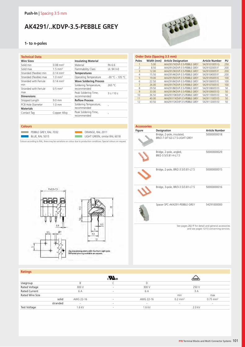
Wire SizesSolid minSolid maxStranded (flexible) minStranded (flexible) maxStranded with Ferrule minStranded with Ferrule maxDimensions Stripped Length
PCB Hole DiameterMaterials
Ratings
PTR Terminal Blocks and Multi Connector Systems 101
Insulating Material MaterialFlammability ClassTemperaturesOperating TemperatureWave Soldering ProcessSoldering Temperature,recommendedPeak Soldering Time,recommendedReflow ProcessSoldering Temperature,recommended
Peak Soldering Time,recommended
Order Data (Spacing 3.5 mm)Poles Width (mm) Article Designation Article Number PU
Push-In | Spacing 3.5 mm
AK4291/..KDVP-3.5-PEBBLE GREY
1- to n-poles
1 5.00 AK4291/1KDVP-3.5-PEBBLE GREY 54291010051G 2502 8.50 AK4291/2KDVP-3.5-PEBBLE GREY 54291020051F 2003 12.00 AK4291/3KDVP-3.5-PEBBLE GREY 54291030051F 2004 15.50 AK4291/4KDVP-3.5-PEBBLE GREY 54291040051F 2005 19.00 AK4291/5KDVP-3.5-PEBBLE GREY 54291050051E 1006 22.50 AK4291/6KDVP-3.5-PEBBLE GREY 54291060051E 1007 26.00 AK4291/7KDVP-3.5-PEBBLE GREY 54291070051E 1008 29.50 AK4291/8KDVP-3.5-PEBBLE GREY 54291080051D 509 33.00 AK4291/9KDVP-3.5-PEBBLE GREY 54291090051D 50
10 36.50 AK4291/10KDVP-3.5-PEBBLE GREY 54291100051D 5011 40.00 AK4291/11KDVP-3.5-PEBBLE GREY 54291110051D 5012 43.50 AK4291/12KDVP-3.5-PEBBLE GREY 54291120051D 50
Usegroup B C DRated Voltage 300 V - 300 V 250 VRated Current 6 A - 6 A 3 ARated Wire Size min max
solid AWG 22-16 - AWG 22-16 0.2 mm² 0.75 mm²stranded - - - - -
Test Voltage 1.6 kV - 1.6 kV 2.0 kV
Colours according to RAL, there may be variations on colour due to production conditions. Special colours on request.
Colours
PEBBLE GREY, RAL 7032 ORANGE, RAL 2011
BLUE, RAL 5015 LIGHT GREEN, similar RAL 6018
See pages 282 ff for detail and general accessoriesand see pages 12/13 concerning services.
AccessoriesFigure Designation Article Number
Bridge, 2-pole, insulated, BRI/2-7.0/7.62-L7.5-LIGHT GREY
50000000018
Bridge, 2-pole, angled, BR/2-3.5/3.81-H-L7.5
50000000029
Bridge, 2-pole, BR/2-3.5/3.81-L7.5 50000000015
Bridge, 3-pole, BR/3-3.5/3.81-L7.5 50000000016
Spacer SPC-AK4291-PEBBLE GREY 54291000000
PA 6.6UL 94 V-0
-30 °C - 105 °C
265 °C
3 s / 10 s
-
-
0.08 mm²1.5 mm²0.14 mm²1.0 mm²0.14 mm²
0.5 mm²
9.0 mm
1.0 mm
Contact Tag Copper Alloy
Technical Data
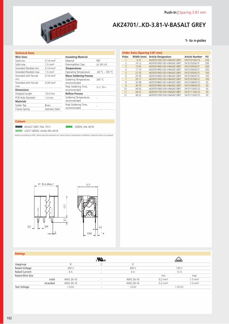
Wire SizesSolid minSolid maxStranded (flexible) minStranded (flexible) maxStranded with Ferrule minStranded with Ferrule maxDimensions Stripped Length
PCB Hole DiameterMaterials
Technical Data
Ratings
102
Insulating Material MaterialFlammability ClassTemperaturesOperating TemperatureWave Soldering ProcessSoldering Temperature,recommendedPeak Soldering Time,recommendedReflow ProcessSoldering Temperature,recommended
Peak Soldering Time,recommended
Order Data (Spacing 3.81 mm)Poles Width (mm) Article Designation Article Number PU
Technical Data
Push-In | Spacing 3.81 mm
AKZ4701/..KD-3.81-V-BASALT GREY
1- to n-poles
1 6.31 AKZ4701/1KD-3.81-V-BASALT GREY 54701010421G 2502 10.12 AKZ4701/2KD-3.81-V-BASALT GREY 54701020421F 2003 13.93 AKZ4701/3KD-3.81-V-BASALT GREY 54701030421F 2004 17.74 AKZ4701/4KD-3.81-V-BASALT GREY 54701040421F 2005 21.55 AKZ4701/5KD-3.81-V-BASALT GREY 54701050421E 1006 25.36 AKZ4701/6KD-3.81-V-BASALT GREY 54701060421E 1007 29.17 AKZ4701/7KD-3.81-V-BASALT GREY 54701070421E 1008 32.98 AKZ4701/8KD-3.81-V-BASALT GREY 54701080421D 509 36.79 AKZ4701/9KD-3.81-V-BASALT GREY 54701090421D 50
10 40.60 AKZ4701/10KD-3.81-V-BASALT GREY 54701100421D 5011 44.41 AKZ4701/11KD-3.81-V-BASALT GREY 54701110421D 5012 48.22 AKZ4701/12KD-3.81-V-BASALT GREY 54701120421D 50
Usegroup B C DRated Voltage 300 V - 300 V 130 VRated Current 6 A - 6 A 12 ARated Wire Size min max
solid AWG 26-16 - AWG 26-16 0.2 mm² 1.5 mm²stranded AWG 26-16 - AWG 26-16 0.2 mm² 1.5 mm²
Test Voltage 1.6 kV - 1.6 kV 1.25 kV
Colours
BASALT GREY, RAL 7012 GREEN, RAL 6018
LIGHT GREEN, similar RAL 6018
PBTUL 94 V-0
-30 °C - 105 °C
265 °C
3 s / 10 s
-
-
0.14 mm²1.5 mm²0.14 mm²1.5 mm²0.14 mm²
0.34 mm²
10.0 mm
1.4 mm
Solder Tag BrassClamp Spring Stainless Steel
Colours according to RAL, there may be variations on colour due to production conditions. Special colours on request.
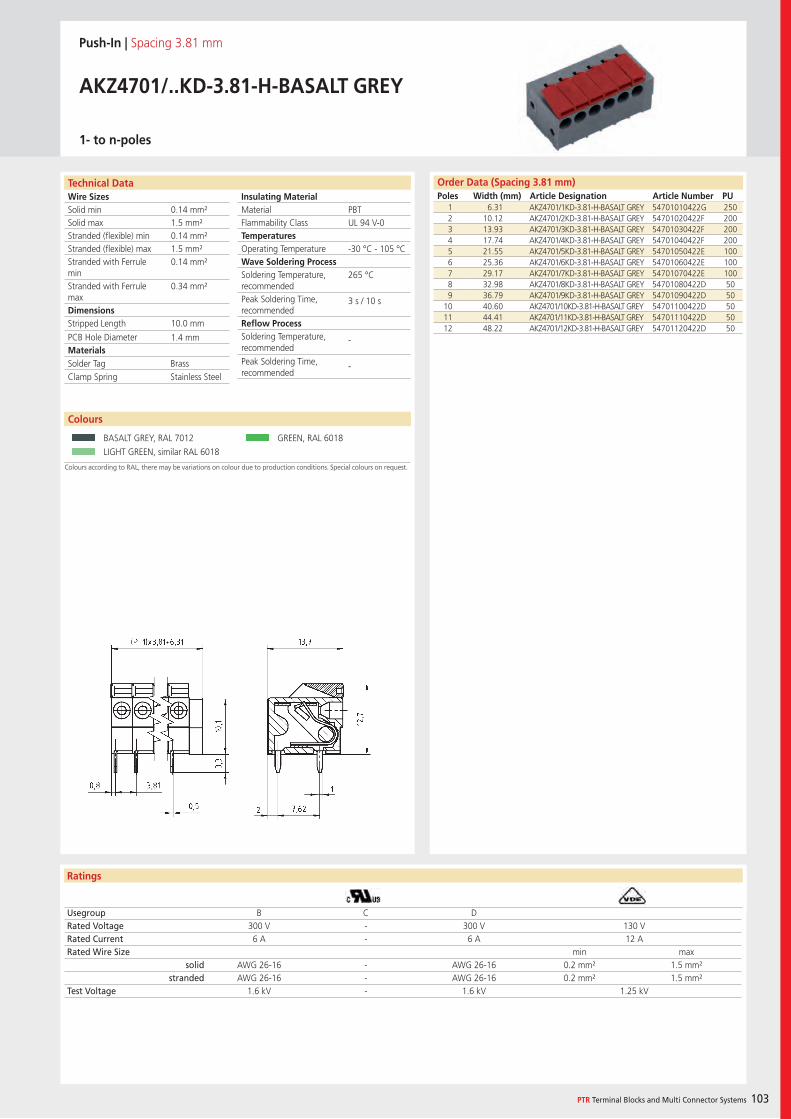
Wire SizesSolid minSolid maxStranded (flexible) minStranded (flexible) maxStranded with Ferrule minStranded with Ferrule maxDimensions Stripped Length
PCB Hole DiameterMaterials
Ratings
PTR Terminal Blocks and Multi Connector Systems 103
Insulating Material MaterialFlammability ClassTemperaturesOperating TemperatureWave Soldering ProcessSoldering Temperature,recommendedPeak Soldering Time,recommendedReflow ProcessSoldering Temperature,recommended
Peak Soldering Time,recommended
Ratings
Order Data (Spacing 3.81 mm)Poles Width (mm) Article Designation Article Number PU
Push-In | Spacing 3.81 mm
AKZ4701/..KD-3.81-H-BASALT GREY
1- to n-poles
1 6.31 AKZ4701/1KD-3.81-H-BASALT GREY 54701010422G 2502 10.12 AKZ4701/2KD-3.81-H-BASALT GREY 54701020422F 2003 13.93 AKZ4701/3KD-3.81-H-BASALT GREY 54701030422F 2004 17.74 AKZ4701/4KD-3.81-H-BASALT GREY 54701040422F 2005 21.55 AKZ4701/5KD-3.81-H-BASALT GREY 54701050422E 1006 25.36 AKZ4701/6KD-3.81-H-BASALT GREY 54701060422E 1007 29.17 AKZ4701/7KD-3.81-H-BASALT GREY 54701070422E 1008 32.98 AKZ4701/8KD-3.81-H-BASALT GREY 54701080422D 509 36.79 AKZ4701/9KD-3.81-H-BASALT GREY 54701090422D 50
10 40.60 AKZ4701/10KD-3.81-H-BASALT GREY 54701100422D 5011 44.41 AKZ4701/11KD-3.81-H-BASALT GREY 54701110422D 5012 48.22 AKZ4701/12KD-3.81-H-BASALT GREY 54701120422D 50
Usegroup B C DRated Voltage 300 V - 300 V 130 VRated Current 6 A - 6 A 12 ARated Wire Size min max
solid AWG 26-16 - AWG 26-16 0.2 mm² 1.5 mm²stranded AWG 26-16 - AWG 26-16 0.2 mm² 1.5 mm²
Test Voltage 1.6 kV - 1.6 kV 1.25 kV
Colours
BASALT GREY, RAL 7012 GREEN, RAL 6018
LIGHT GREEN, similar RAL 6018
PBTUL 94 V-0
-30 °C - 105 °C
265 °C
3 s / 10 s
-
-
0.14 mm²1.5 mm²0.14 mm²1.5 mm²0.14 mm²
0.34 mm²
10.0 mm
1.4 mm
Solder Tag BrassClamp Spring Stainless Steel
Technical Data
Colours according to RAL, there may be variations on colour due to production conditions. Special colours on request.
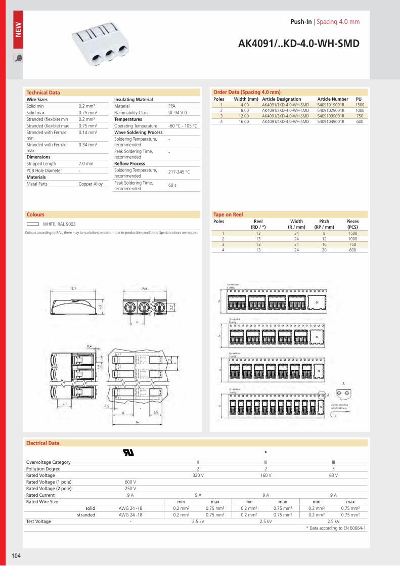
Wire SizesSolid minSolid maxStranded (flexible) minStranded (flexible) maxStranded with Ferrule minStranded with Ferrule maxDimensions Stripped Length
PCB Hole DiameterMaterials
Technical Data
104
Insulating Material MaterialFlammability ClassTemperaturesOperating TemperatureWave Soldering ProcessSoldering Temperature,recommendedPeak Soldering Time,recommendedReflow ProcessSoldering Temperature,recommended
Peak Soldering Time,recommended
Electrical Data
Colours
Order Data (Spacing 4.0 mm)Poles Width (mm) Article Designation Article Number PU
Technical Data
N
EW
Colours according to RAL, there may be variations on colour due to production conditions. Special colours on request.
Push-In | Spacing 4.0 mm
AK4091/..KD-4.0-WH-SMD
1 4.00 AK4091/1KD-4.0-WH-SMD 54091019001R 15002 8.00 AK4091/2KD-4.0-WH-SMD 54091029001R 10003 12.00 AK4091/3KD-4.0-WH-SMD 54091039001R 7504 16.00 AK4091/4KD-4.0-WH-SMD 54091049001R 600
WHITE, RAL 9003
PPAUL 94 V-0
-60 °C - 105 °C
-
-
217-245 °C
60 s
0.2 mm²0.75 mm²0.2 mm²0.75 mm²0.14 mm²
0.34 mm²
7.0 mm
-
Metal Parts Copper Alloy
1 13 24 8 15002 13 24 12 10003 13 24 16 7504 13 24 20 600
Tape on ReelPoles Reel
(RD / “)Width
(R / mm)Pitch
(RP / mm)Pieces (PCS)
Overvoltage Category II III IIIPollution Degree 2 2 3Rated Voltage 320 V 160 V 63 VRated Voltage (1 pole) 600 VRated Voltage (2 pole) 250 VRated Current 9 A 9 A 9 A 9 ARated Wire Size min max min max min max
solid AWG 24 -18 0.2 mm² 0.75 mm² 0.2 mm² 0.75 mm² 0.2 mm² 0.75 mm²stranded AWG 24 -18 0.2 mm² 0.75 mm² 0.2 mm² 0.75 mm² 0.2 mm² 0.75 mm²
Test Voltage - 2.5 kV 2.5 kV 2.5 kV* Data according to EN 60664-1
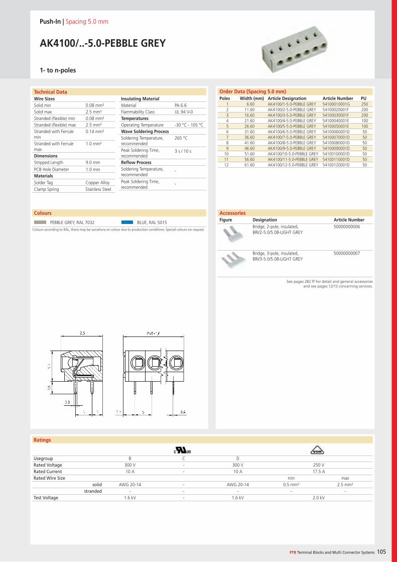
Wire SizesSolid minSolid maxStranded (flexible) minStranded (flexible) maxStranded with Ferrule minStranded with Ferrule maxDimensions Stripped Length
PCB Hole DiameterMaterials
Ratings
PTR Terminal Blocks and Multi Connector Systems 105
Insulating Material MaterialFlammability ClassTemperaturesOperating TemperatureWave Soldering ProcessSoldering Temperature,recommendedPeak Soldering Time,recommendedReflow ProcessSoldering Temperature,recommended
Peak Soldering Time,recommended
Order Data (Spacing 5.0 mm)Poles Width (mm) Article Designation Article Number PU
Technical Data
Push-In | Spacing 5.0 mm
AK4100/..-5.0-PEBBLE GREY
1- to n-poles
1 6.60 AK4100/1-5.0-PEBBLE GREY 54100010001G 2502 11.60 AK4100/2-5.0-PEBBLE GREY 54100020001F 2003 16.60 AK4100/3-5.0-PEBBLE GREY 54100030001F 2004 21.60 AK4100/4-5.0-PEBBLE GREY 54100040001E 1005 26.60 AK4100/5-5.0-PEBBLE GREY 54100050001E 1006 31.60 AK4100/6-5.0-PEBBLE GREY 54100060001D 507 36.60 AK4100/7-5.0-PEBBLE GREY 54100070001D 508 41.60 AK4100/8-5.0-PEBBLE GREY 54100080001D 509 46.60 AK4100/9-5.0-PEBBLE GREY 54100090001D 50
10 51.60 AK4100/10-5.0-PEBBLE GREY 54100100001D 5011 56.60 AK4100/11-5.0-PEBBLE GREY 54100110001D 5012 61.60 AK4100/12-5.0-PEBBLE GREY 54100120001D 50
Usegroup B C DRated Voltage 300 V - 300 V 250 VRated Current 10 A - 10 A 17.5 ARated Wire Size min max
solid AWG 20-14 - AWG 20-14 0.5 mm² 2.5 mm²stranded - - - - -
Test Voltage 1.6 kV - 1.6 kV 2.0 kV
Colours
Colours according to RAL, there may be variations on colour due to production conditions. Special colours on request.
PEBBLE GREY, RAL 7032 BLUE, RAL 5015
AccessoriesFigure Designation Article Number
See pages 282 ff for detail and general accessoriesand see pages 12/13 concerning services.
Bridge, 2-pole, insulated, BRI/2-5.0/5.08-LIGHT GREY
50000000006
Bridge, 3-pole, insulated, BRI/3-5.0/5.08-LIGHT GREY
50000000007
PA 6.6UL 94 V-0
-30 °C - 105 °C
265 °C
3 s / 10 s
-
-
0.08 mm²2.5 mm²0.08 mm²2.5 mm²0.14 mm²
1.0 mm²
9.0 mm
1.0 mm
Solder Tag Copper AlloyClamp Spring Stainless Steel
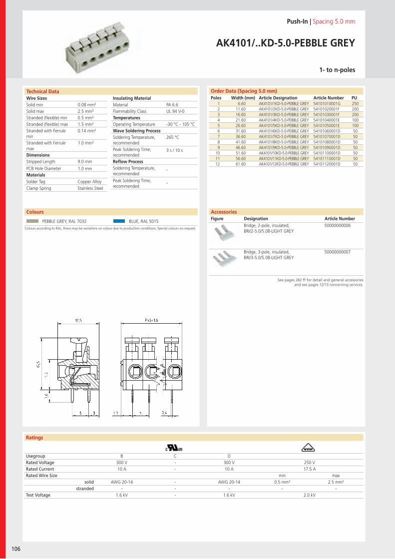
Wire SizesSolid minSolid maxStranded (flexible) minStranded (flexible) maxStranded with Ferrule minStranded with Ferrule maxDimensions Stripped Length
PCB Hole DiameterMaterials
Technical Data
Ratings
106
Insulating Material MaterialFlammability ClassTemperaturesOperating TemperatureWave Soldering ProcessSoldering Temperature,recommendedPeak Soldering Time,recommendedReflow ProcessSoldering Temperature,recommended
Peak Soldering Time,recommended
Colours
Order Data (Spacing 5.0 mm)Poles Width (mm) Article Designation Article Number PU
Colours according to RAL, there may be variations on colour due to production conditions. Special colours on request.
Push-In | Spacing 5.0 mm
AK4101/..KD-5.0-PEBBLE GREY
1- to n-poles
1 6.60 AK4101/1KD-5.0-PEBBLE GREY 54101010001G 2502 11.60 AK4101/2KD-5.0-PEBBLE GREY 54101020001F 2003 16.60 AK4101/3KD-5.0-PEBBLE GREY 54101030001F 2004 21.60 AK4101/4KD-5.0-PEBBLE GREY 54101040001E 1005 26.60 AK4101/5KD-5.0-PEBBLE GREY 54101050001E 1006 31.60 AK4101/6KD-5.0-PEBBLE GREY 54101060001D 507 36.60 AK4101/7KD-5.0-PEBBLE GREY 54101070001D 508 41.60 AK4101/8KD-5.0-PEBBLE GREY 54101080001D 509 46.60 AK4101/9KD-5.0-PEBBLE GREY 54101090001D 50
10 51.60 AK4101/10KD-5.0-PEBBLE GREY 54101100001D 5011 56.60 AK4101/11KD-5.0-PEBBLE GREY 54101110001D 5012 61.60 AK4101/12KD-5.0-PEBBLE GREY 54101120001D 50
Usegroup B C DRated Voltage 300 V - 300 V 250 VRated Current 10 A - 10 A 17.5 ARated Wire Size min max
solid AWG 20-14 - AWG 20-14 0.5 mm² 2.5 mm²stranded - - - - -
Test Voltage 1.6 kV - 1.6 kV 2.0 kV
PEBBLE GREY, RAL 7032 BLUE, RAL 5015
AccessoriesFigure Designation Article Number
See pages 282 ff for detail and general accessoriesand see pages 12/13 concerning services.
Bridge, 2-pole, insulated, BRI/2-5.0/5.08-LIGHT GREY
50000000006
Bridge, 3-pole, insulated, BRI/3-5.0/5.08-LIGHT GREY
50000000007
PA 6.6UL 94 V-0
-30 °C - 105 °C
265 °C
3 s / 10 s
-
-
0.08 mm²2.5 mm²0.5 mm²1.5 mm²0.14 mm²
1.0 mm²
9.0 mm
1.0 mm
Solder Tag Copper AlloyClamp Spring Stainless Steel
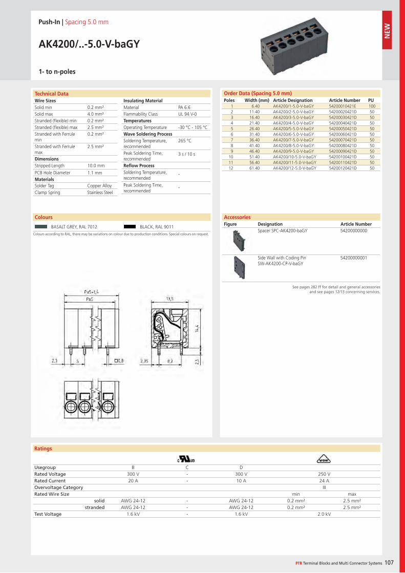
Wire SizesSolid minSolid maxStranded (flexible) minStranded (flexible) maxStranded with Ferrule minStranded with Ferrule maxDimensions Stripped Length
PCB Hole DiameterMaterials
Technical Data
Ratings
Colours
PTR Terminal Blocks and Multi Connector Systems 107
Insulating Material MaterialFlammability ClassTemperaturesOperating TemperatureWave Soldering ProcessSoldering Temperature,recommendedPeak Soldering Time,recommendedReflow ProcessSoldering Temperature,recommended
Peak Soldering Time,recommended
Order Data (Spacing 5.0 mm)Poles Width (mm) Article Designation Article Number PU
Colours
Colours according to RAL, there may be variations on colour due to production conditions. Special colours on request.
Push-In | Spacing 5.0 mm
AK4200/..-5.0-V-baGY
1- to n-poles
1 6.40 AK4200/1-5.0-V-baGY 54200010421E 1002 11.40 AK4200/2-5.0-V-baGY 54200020421D 503 16.40 AK4200/3-5.0-V-baGY 54200030421D 504 21.40 AK4200/4-5.0-V-baGY 54200040421D 505 26.40 AK4200/5-5.0-V-baGY 54200050421D 506 31.40 AK4200/6-5.0-V-baGY 54200060421D 507 36.40 AK4200/7-5.0-V-baGY 54200070421D 508 41.40 AK4200/8-5.0-V-baGY 54200080421D 509 46.40 AK4200/9-5.0-V-baGY 54200090421D 50
10 51.40 AK4200/10-5.0-V-baGY 54200100421D 5011 56.40 AK4200/11-5.0-V-baGY 54200110421D 5012 61.40 AK4200/12-5.0-V-baGY 54200120421D 50
Usegroup B C DRated Voltage 300 V - 300 V 250 VRated Current 20 A - 10 A 24 AOvervoltage Category IIIRated Wire Size min max
solid AWG 24-12 - AWG 24-12 0.2 mm² 2.5 mm²stranded AWG 24-12 - AWG 24-12 0.2 mm² 2.5 mm²
Test Voltage 1.6 kV - 1.6 kV 2.0 kV
BASALT GREY, RAL 7012 BLACK, RAL 9011
AccessoriesFigure Designation Article Number
See pages 282 ff for detail and general accessoriesand see pages 12/13 concerning services.
Spacer SPC-AK4200-baGY 54200000000
Side Wall with Coding Pin SW-AK4200-CP-V-baGY
54200000001
PA 6.6UL 94 V-0
-30 °C - 105 °C
265 °C
3 s / 10 s
-
-
0.2 mm²4.0 mm²0.2 mm²2.5 mm²0.2 mm²
2.5 mm²
10.0 mm
1.1 mm
Solder Tag Copper AlloyClamp Spring Stainless Steel
NEW
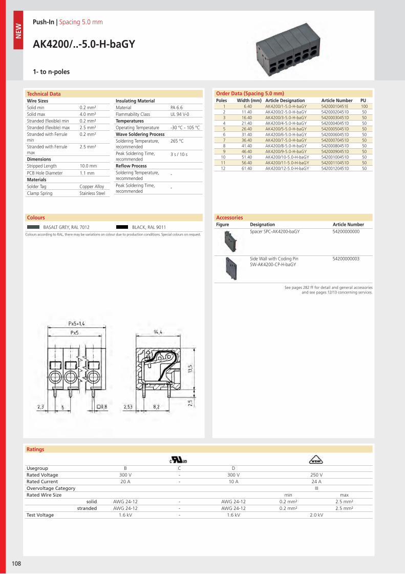
Wire SizesSolid minSolid maxStranded (flexible) minStranded (flexible) maxStranded with Ferrule minStranded with Ferrule maxDimensions Stripped Length
PCB Hole DiameterMaterials
Technical Data
Ratings
108
Insulating Material MaterialFlammability ClassTemperaturesOperating TemperatureWave Soldering ProcessSoldering Temperature,recommendedPeak Soldering Time,recommendedReflow ProcessSoldering Temperature,recommended
Peak Soldering Time,recommended
Technical Data
Colours
Order Data (Spacing 5.0 mm)Poles Width (mm) Article Designation Article Number PU
Colours according to RAL, there may be variations on colour due to production conditions. Special colours on request.
Push-In | Spacing 5.0 mm
AK4200/..-5.0-H-baGY
1- to n-poles
1 6.40 AK4200/1-5.0-H-baGY 54200010451E 1002 11.40 AK4200/2-5.0-H-baGY 54200020451D 503 16.40 AK4200/3-5.0-H-baGY 54200030451D 504 21.40 AK4200/4-5.0-H-baGY 54200040451D 505 26.40 AK4200/5-5.0-H-baGY 54200050451D 506 31.40 AK4200/6-5.0-H-baGY 54200060451D 507 36.40 AK4200/7-5.0-H-baGY 54200070451D 508 41.40 AK4200/8-5.0-H-baGY 54200080451D 509 46.40 AK4200/9-5.0-H-baGY 54200090451D 50
10 51.40 AK4200/10-5.0-H-baGY 54200100451D 5011 56.40 AK4200/11-5.0-H-baGY 54200110451D 5012 61.40 AK4200/12-5.0-H-baGY 54200120451D 50
Usegroup B C DRated Voltage 300 V - 300 V 250 VRated Current 20 A - 10 A 24 AOvervoltage Category IIIRated Wire Size min max
solid AWG 24-12 - AWG 24-12 0.2 mm² 2.5 mm²stranded AWG 24-12 - AWG 24-12 0.2 mm² 2.5 mm²
Test Voltage 1.6 kV - 1.6 kV 2.0 kV
BASALT GREY, RAL 7012 BLACK, RAL 9011
AccessoriesFigure Designation Article Number
See pages 282 ff for detail and general accessoriesand see pages 12/13 concerning services.
Spacer SPC-AK4200-baGY 54200000000
Side Wall with Coding PinSW-AK4200-CP-H-baGY
54200000003
PA 6.6UL 94 V-0
-30 °C - 105 °C
265 °C
3 s / 10 s
-
-
0.2 mm²4.0 mm²0.2 mm²2.5 mm²0.2 mm²
2.5 mm²
10.0 mm
1.1 mm
Solder Tag Copper AlloyClamp Spring Stainless Steel
NEW
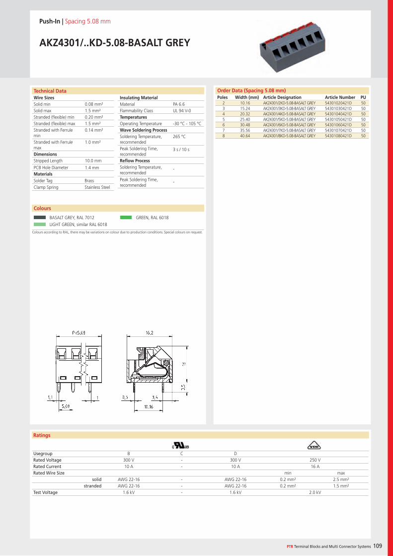
Wire SizesSolid minSolid maxStranded (flexible) minStranded (flexible) maxStranded with Ferrule minStranded with Ferrule maxDimensions Stripped Length
PCB Hole DiameterMaterials
Ratings
PTR Terminal Blocks and Multi Connector Systems 109
Insulating Material MaterialFlammability ClassTemperaturesOperating TemperatureWave Soldering ProcessSoldering Temperature,recommendedPeak Soldering Time,recommendedReflow ProcessSoldering Temperature,recommended
Peak Soldering Time,recommended
Technical Data
Colours according to RAL, there may be variations on colour due to production conditions. Special colours on request.
Order Data (Spacing 5.08 mm)Poles Width (mm) Article Designation Article Number PU
Push-In | Spacing 5.08 mm
AKZ4301/..KD-5.08-BASALT GREY
2 10.16 AKZ4301/2KD-5.08-BASALT GREY 54301020421D 503 15.24 AKZ4301/3KD-5.08-BASALT GREY 54301030421D 504 20.32 AKZ4301/4KD-5.08-BASALT GREY 54301040421D 505 25.40 AKZ4301/5KD-5.08-BASALT GREY 54301050421D 506 30.48 AKZ4301/6KD-5.08-BASALT GREY 54301060421D 507 35.56 AKZ4301/7KD-5.08-BASALT GREY 54301070421D 508 40.64 AKZ4301/8KD-5.08-BASALT GREY 54301080421D 50
Usegroup B C DRated Voltage 300 V - 300 V 250 VRated Current 10 A - 10 A 16 ARated Wire Size min max
solid AWG 22-16 - AWG 22-16 0.2 mm² 2.5 mm²stranded AWG 22-16 - AWG 22-16 0.2 mm² 1.5 mm²
Test Voltage 1.6 kV - 1.6 kV 2.0 kV
Colours
BASALT GREY, RAL 7012 GREEN, RAL 6018
LIGHT GREEN, similar RAL 6018
PA 6.6UL 94 V-0
-30 °C - 105 °C
265 °C
3 s / 10 s
-
-
0.08 mm²1.5 mm²0.20 mm²1.5 mm²0.14 mm²
1.0 mm²
10.0 mm
1.4 mm
Solder Tag BrassClamp Spring Stainless Steel
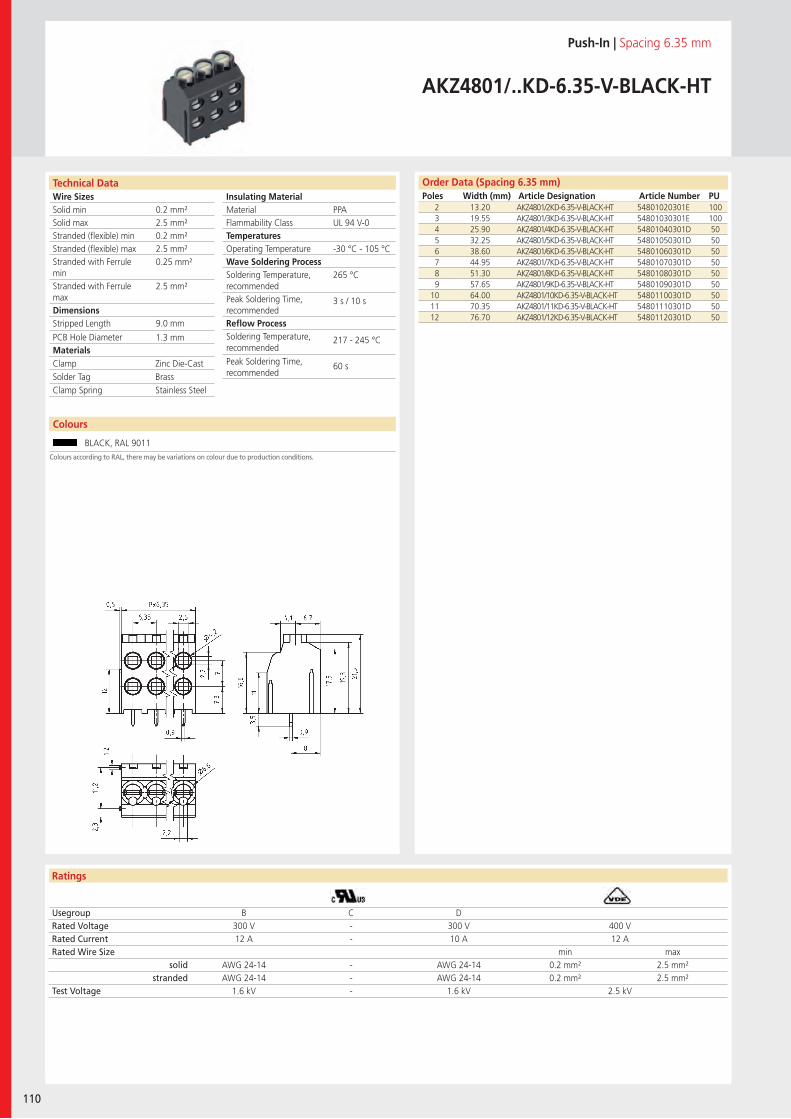
Wire SizesSolid minSolid maxStranded (flexible) minStranded (flexible) maxStranded with Ferrule minStranded with Ferrule maxDimensions Stripped Length
PCB Hole DiameterMaterials
Technical Data
Ratings
110
Colours
Insulating Material MaterialFlammability ClassTemperaturesOperating TemperatureWave Soldering ProcessSoldering Temperature,recommendedPeak Soldering Time,recommendedReflow ProcessSoldering Temperature,recommended
Peak Soldering Time,recommended
Order Data (Spacing 6.35 mm)Poles Width (mm) Article Designation Article Number PU
Colours according to RAL, there may be variations on colour due to production conditions.
Push-In | Spacing 6.35 mm
AKZ4801/..KD-6.35-V-BLACK-HT
2 13.20 AKZ4801/2KD-6.35-V-BLACK-HT 54801020301E 1003 19.55 AKZ4801/3KD-6.35-V-BLACK-HT 54801030301E 1004 25.90 AKZ4801/4KD-6.35-V-BLACK-HT 54801040301D 505 32.25 AKZ4801/5KD-6.35-V-BLACK-HT 54801050301D 506 38.60 AKZ4801/6KD-6.35-V-BLACK-HT 54801060301D 507 44.95 AKZ4801/7KD-6.35-V-BLACK-HT 54801070301D 508 51.30 AKZ4801/8KD-6.35-V-BLACK-HT 54801080301D 509 57.65 AKZ4801/9KD-6.35-V-BLACK-HT 54801090301D 50
10 64.00 AKZ4801/10KD-6.35-V-BLACK-HT 54801100301D 5011 70.35 AKZ4801/11KD-6.35-V-BLACK-HT 54801110301D 5012 76.70 AKZ4801/12KD-6.35-V-BLACK-HT 54801120301D 50
Usegroup B C DRated Voltage 300 V - 300 V 400 VRated Current 12 A - 10 A 12 ARated Wire Size min max
solid AWG 24-14 - AWG 24-14 0.2 mm² 2.5 mm²stranded AWG 24-14 - AWG 24-14 0.2 mm² 2.5 mm²
Test Voltage 1.6 kV - 1.6 kV 2.5 kV
BLACK, RAL 9011
PPAUL 94 V-0
-30 °C - 105 °C
265 °C
3 s / 10 s
217 - 245 °C
60 s
0.2 mm²2.5 mm²0.2 mm²2.5 mm²0.25 mm²
2.5 mm²
9.0 mm
1.3 mm
Clamp Zinc Die-CastSolder Tag BrassClamp Spring Stainless Steel
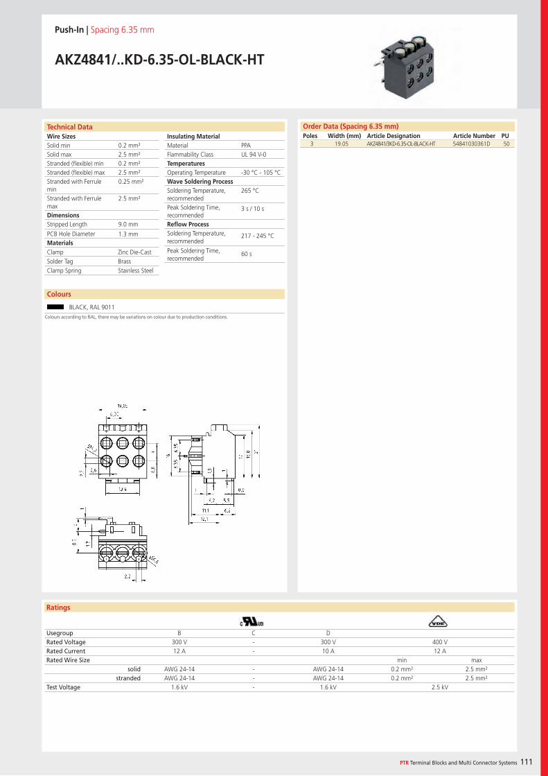
Wire SizesSolid minSolid maxStranded (flexible) minStranded (flexible) maxStranded with Ferrule minStranded with Ferrule maxDimensions Stripped Length
PCB Hole DiameterMaterials
Technical Data
Ratings
Colours
PTR Terminal Blocks and Multi Connector Systems 111
Insulating Material MaterialFlammability ClassTemperaturesOperating TemperatureWave Soldering ProcessSoldering Temperature,recommendedPeak Soldering Time,recommendedReflow ProcessSoldering Temperature,recommended
Peak Soldering Time,recommended
Order Data (Spacing 6.35 mm)Poles Width (mm) Article Designation Article Number PU
Colours according to RAL, there may be variations on colour due to production conditions.
Push-In | Spacing 6.35 mm
AKZ4841/..KD-6.35-OL-BLACK-HT
3 19.05 AKZ4841/3KD-6.35-OL-BLACK-HT 54841030361D 50
Usegroup B C DRated Voltage 300 V - 300 V 400 VRated Current 12 A - 10 A 12 ARated Wire Size min max
solid AWG 24-14 - AWG 24-14 0.2 mm² 2.5 mm²stranded AWG 24-14 - AWG 24-14 0.2 mm² 2.5 mm²
Test Voltage 1.6 kV - 1.6 kV 2.5 kV
BLACK, RAL 9011
PPAUL 94 V-0
-30 °C - 105 °C
265 °C
3 s / 10 s
217 - 245 °C
60 s
0.2 mm²2.5 mm²0.2 mm²2.5 mm²0.25 mm²
2.5 mm²
9.0 mm
1.3 mm
Clamp Zinc Die-CastSolder Tag BrassClamp Spring Stainless Steel
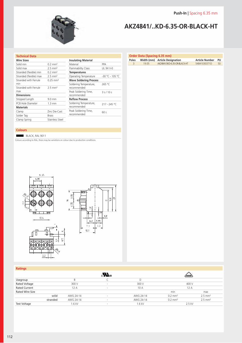
Wire SizesSolid minSolid maxStranded (flexible) minStranded (flexible) maxStranded with Ferrule minStranded with Ferrule maxDimensions Stripped Length
PCB Hole DiameterMaterials
Technical Data
Ratings
112
Colours
Insulating Material MaterialFlammability ClassTemperaturesOperating TemperatureWave Soldering ProcessSoldering Temperature,recommendedPeak Soldering Time,recommendedReflow ProcessSoldering Temperature,recommended
Peak Soldering Time,recommended
Order Data (Spacing 6.35 mm)Poles Width (mm) Article Designation Article Number PU
Colours according to RAL, there may be variations on colour due to production conditions.
Push-In | Spacing 6.35 mm
AKZ4841/..KD-6.35-OR-BLACK-HT
Usegroup B C DRated Voltage 300 V - 300 V 400 VRated Current 12 A - 10 A 12 ARated Wire Size min max
solid AWG 24-14 - AWG 24-14 0.2 mm² 2.5 mm²stranded AWG 24-14 - AWG 24-14 0.2 mm² 2.5 mm²
Test Voltage 1.6 kV - 1.6 kV 2.5 kV
BLACK, RAL 9011
PPAUL 94 V-0
-30 °C - 105 °C
265 °C
3 s / 10 s
217 - 245 °C
60 s
0.2 mm²2.5 mm²0.2 mm²2.5 mm²0.25 mm²
2.5 mm²
9.0 mm
1.3 mm
Clamp Zinc Die-CastSolder Tag BrassClamp Spring Stainless Steel
3 19.05 AKZ4841/3KD-6.35-OR-BLACK-HT 54841030371D 50
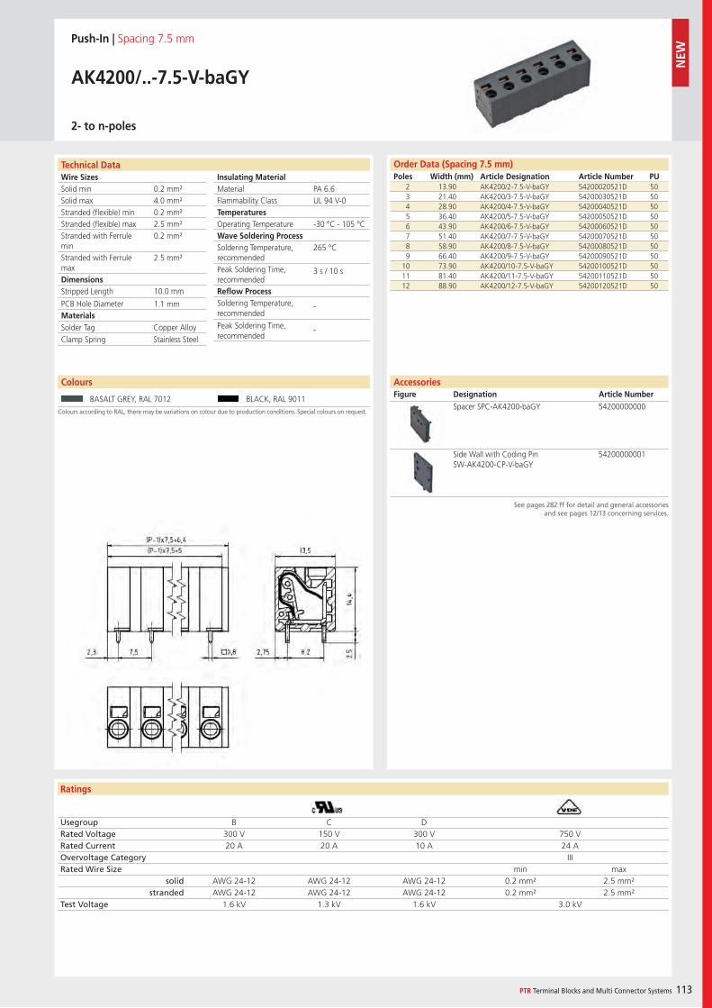
Wire SizesSolid minSolid maxStranded (flexible) minStranded (flexible) maxStranded with Ferrule minStranded with Ferrule maxDimensions Stripped Length
PCB Hole DiameterMaterials
Technical Data
Ratings
PTR Terminal Blocks and Multi Connector Systems 113
Insulating Material MaterialFlammability ClassTemperaturesOperating TemperatureWave Soldering ProcessSoldering Temperature,recommendedPeak Soldering Time,recommendedReflow ProcessSoldering Temperature,recommended
Peak Soldering Time,recommended
Colours
Order Data (Spacing 7.5 mm)Poles Width (mm) Article Designation Article Number PU
Colours according to RAL, there may be variations on colour due to production conditions. Special colours on request.
Push-In | Spacing 7.5 mm
AK4200/..-7.5-V-baGY
2- to n-poles
2 13.90 AK4200/2-7.5-V-baGY 54200020521D 503 21.40 AK4200/3-7.5-V-baGY 54200030521D 504 28.90 AK4200/4-7.5-V-baGY 54200040521D 505 36.40 AK4200/5-7.5-V-baGY 54200050521D 506 43.90 AK4200/6-7.5-V-baGY 54200060521D 507 51.40 AK4200/7-7.5-V-baGY 54200070521D 508 58.90 AK4200/8-7.5-V-baGY 54200080521D 509 66.40 AK4200/9-7.5-V-baGY 54200090521D 50
10 73.90 AK4200/10-7.5-V-baGY 54200100521D 5011 81.40 AK4200/11-7.5-V-baGY 54200110521D 5012 88.90 AK4200/12-7.5-V-baGY 54200120521D 50
BASALT GREY, RAL 7012 BLACK, RAL 9011
AccessoriesFigure Designation Article Number
See pages 282 ff for detail and general accessoriesand see pages 12/13 concerning services.
Spacer SPC-AK4200-baGY 54200000000
Side Wall with Coding PinSW-AK4200-CP-V-baGY
54200000001
PA 6.6UL 94 V-0
-30 °C - 105 °C
265 °C
3 s / 10 s
-
-
0.2 mm²4.0 mm²0.2 mm²2.5 mm²0.2 mm²
2.5 mm²
10.0 mm
1.1 mm
Solder Tag Copper AlloyClamp Spring Stainless Steel
Usegroup B C DRated Voltage 300 V 150 V 300 V 750 VRated Current 20 A 20 A 10 A 24 AOvervoltage Category IIIRated Wire Size min max
solid AWG 24-12 AWG 24-12 AWG 24-12 0.2 mm² 2.5 mm²stranded AWG 24-12 AWG 24-12 AWG 24-12 0.2 mm² 2.5 mm²
Test Voltage 1.6 kV 1.3 kV 1.6 kV 3.0 kV
NEW
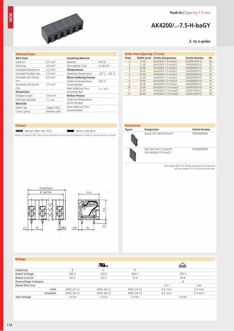
Wire SizesSolid minSolid maxStranded (flexible) minStranded (flexible) maxStranded with Ferrule minStranded with Ferrule maxDimensions Stripped Length
PCB Hole DiameterMaterials
Technical Data
Ratings
114
Colours
Insulating Material MaterialFlammability ClassTemperaturesOperating TemperatureWave Soldering ProcessSoldering Temperature,recommendedPeak Soldering Time,recommendedReflow ProcessSoldering Temperature,recommended
Peak Soldering Time,recommended
Order Data (Spacing 7.5 mm)Poles Width (mm) Article Designation Article Number PU
NEW
Colours according to RAL, there may be variations on colour due to production conditions. Special colours on request.
Push-In | Spacing 7.5 mm
AK4200/..-7.5-H-baGY
2- to n-poles
2 13.90 AK4200/2-7.5-H-baGY 54200020551D 503 21.40 AK4200/3-7.5-H-baGY 54200030551D 504 28.90 AK4200/4-7.5-H-baGY 54200040551D 505 36.40 AK4200/5-7.5-H-baGY 54200050551D 506 43.90 AK4200/6-7.5-H-baGY 54200060551D 507 51.40 AK4200/7-7.5-H-baGY 54200070551D 508 58.90 AK4200/8-7.5-H-baGY 54200080551D 509 66.40 AK4200/9-7.5-H-baGY 54200090551D 50
10 73.90 AK4200/10-7.5-H-baGY 54200100551D 5011 81.40 AK4200/11-7.5-H-baGY 54200110551D 5012 88.90 AK4200/12-7.5-H-baGY 54200120551D 50
Usegroup B C DRated Voltage 300 V 150 V 300 V 750 VRated Current 20 A 20 A 10 A 24 AOvervoltage Category IIIRated Wire Size min max
solid AWG 24-12 AWG 24-12 AWG 24-12 0.2 mm² 2.5 mm²stranded AWG 24-12 AWG 24-12 AWG 24-12 0.2 mm² 2.5 mm²
Test Voltage 1.6 kV 1.3 kV 1.6 kV 3.0 kV
BASALT GREY, RAL 7012 BLACK, RAL 9011
See pages 282 ff for detail and general accessoriesand see pages 12/13 concerning services.
Spacer SPC-AK4200-baGY 54200000000
Side Wall with Coding PinSW-AK4200-CP-H-baGY
54200000003
PA 6.6UL 94 V-0
-30 °C - 105 °C
265 °C
3 s / 10 s
-
-
0.2 mm²4.0 mm²0.2 mm²2.5 mm²0.2 mm²
2.5 mm²
10.0 mm
1.1 mm
Solder Tag Copper AlloyClamp Spring Stainless Steel
AccessoriesFigure Designation Article Number

Wire SizesSolid minSolid maxStranded (flexible) minStranded (flexible) maxStranded with Ferrule minStranded with Ferrule maxDimensions Stripped Length
PCB Hole DiameterMaterials
Technical Data
Ratings
Colours
PTR Terminal Blocks and Multi Connector Systems 115
Insulating Material MaterialFlammability ClassTemperaturesOperating TemperatureWave Soldering ProcessSoldering Temperature,recommendedPeak Soldering Time,recommendedReflow ProcessSoldering Temperature,recommended
Peak Soldering Time,recommended
Order Data (Spacing 7.5 mm)Poles Width (mm) Article Designation Article Number PU
Colours according to RAL, there may be variations on colour due to production conditions. Special colours on request.
Push-In | Spacing 7.5 mm
AK4210/..-7.5-V-baGY
1- to n-poles
1 9.25 AK4210/1-7.5-V-baGY 54210010521E 1002 16.75 AK4210/2-7.5-V-baGY 54210020521D 503 24.25 AK4210/3-7.5-V-baGY 54210030521D 504 31.75 AK4210/4-7.5-V-baGY 54210040521D 505 39.25 AK4210/5-7.5-V-baGY 54210050521D 506 46.75 AK4210/6-7.5-V-baGY 54210060521D 507 54.25 AK4210/7-7.5-V-baGY 54210070521D 508 61.75 AK4210/8-7.5-V-baGY 54210080521D 509 69.25 AK4210/9-7.5-V-baGY 54210090521D 50
10 76.75 AK4210/10-7.5-V-baGY 54210100521D 5011 84.25 AK4210/11-7.5-V-baGY 54210110521D 5012 91.75 AK4210/12-7.5-V-baGY 54210120521D 50
BASALT GREY, RAL 7012 BLACK, RAL 9011
See pages 282 ff for detail and general accessoriesand see pages 12/13 concerning services.
Spacer SPC-AK4210-V-baGY 54210000001
PA 6.6UL 94 V-0
-30 °C - 105 °C
265 °C
3 s / 10 s
-
-
0.2 mm²10.0 mm²0.2 mm²6.0 mm²0.25 mm²
6.0 mm²
15.0 mm
2.1 mm
Solder Tag Copper AlloyClamp Spring Stainless Steel
Usegroup B C DRated Voltage 300 V 150 V 300 V 450 VRated Current 35 A 35 A 10 A 41 AOvervoltage Category IIIRated Wire Size min max
solid AWG 24-8 AWG 24-8 AWG 24-8 0.2 mm² 10.0 mm²stranded AWG 24-8 AWG 24-8 AWG 24-8 0.2 mm² 6.0 mm²
Test Voltage 1.6 kV 1.3 kV 1.6 kV 2.5 kV
AccessoriesFigure Designation Article Number
NEW
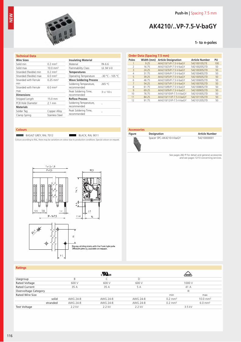
Wire SizesSolid minSolid maxStranded (flexible) minStranded (flexible) maxStranded with Ferrule minStranded with Ferrule maxDimensions Stripped Length
PCB Hole DiameterMaterials
Technical Data
Ratings
116
Insulating Material MaterialFlammability ClassTemperaturesOperating TemperatureWave Soldering ProcessSoldering Temperature,recommendedPeak Soldering Time,recommendedReflow ProcessSoldering Temperature,recommended
Peak Soldering Time,recommended
Colours
Order Data (Spacing 7.5 mm)Poles Width (mm) Article Designation Article Number PU
NEW
Colours according to RAL, there may be variations on colour due to production conditions. Special colours on request.
Push-In | Spacing 7.5 mm
AK4210/..VP-7.5-V-baGY
1- to n-poles
1 9.25 AK4210/1VP-7.5-V-baGY 54210010527E 1002 16.75 AK4210/2VP-7.5-V-baGY 54210020527D 503 24.25 AK4210/3VP-7.5-V-baGY 54210030527D 504 31.75 AK4210/4VP-7.5-V-baGY 54210040527D 505 39.25 AK4210/5VP-7.5-V-baGY 54210050527D 506 46.75 AK4210/6VP-7.5-V-baGY 54210060527D 507 54.25 AK4210/7VP-7.5-V-baGY 54210070527D 508 61.75 AK4210/8VP-7.5-V-baGY 54210080527D 509 69.25 AK4210/9VP-7.5-V-baGY 54210090527D 50
10 76.75 AK4210/10VP-7.5-V-baGY 54210100527D 5011 84.25 AK4210/11VP-7.5-V-baGY 54210110527D 5012 91.75 AK4210/12VP-7.5-V-baGY 54210120527D 50
BASALT GREY, RAL 7012 BLACK, RAL 9011
AccessoriesFigure Designation Article Number
See pages 282 ff for detail and general accessoriesand see pages 12/13 concerning services.
Spacer SPC-AK4210-V-baGY 54210000001
PA 6.6UL 94 V-0
-30 °C - 105 °C
265 °C
3 s / 10 s
-
-
0.2 mm²10.0 mm²0.2 mm²6.0 mm²0.25 mm²
6.0 mm²
15.0 mm
2.1 mm
Solder Tag Copper AlloyClamp Spring Stainless Steel
Usegroup B C DRated Voltage 600 V 600 V 600 V 1000 VRated Current 35 A 35 A 5 A 41 AOvervoltage Category IIIRated Wire Size min max
solid AWG 24-8 AWG 24-8 AWG 24-8 0.2 mm² 10.0 mm²stranded AWG 24-8 AWG 24-8 AWG 24-8 0.2 mm² 6.0 mm²
Test Voltage 2.2 kV 2.2 kV 2.2 kV 3.5 kV
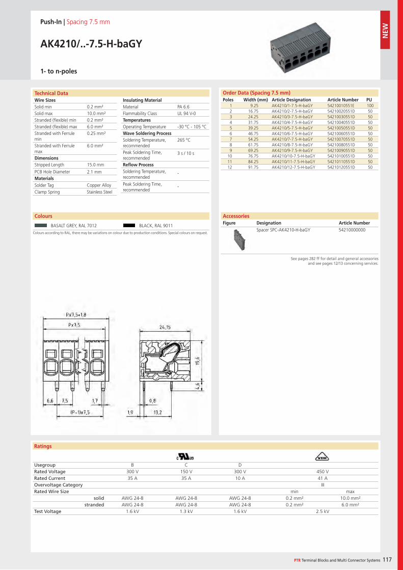
Wire SizesSolid minSolid maxStranded (flexible) minStranded (flexible) maxStranded with Ferrule minStranded with Ferrule maxDimensions Stripped Length
PCB Hole DiameterMaterials
Technical Data
Ratings
PTR Terminal Blocks and Multi Connector Systems 117
Insulating Material MaterialFlammability ClassTemperaturesOperating TemperatureWave Soldering ProcessSoldering Temperature,recommendedPeak Soldering Time,recommendedReflow ProcessSoldering Temperature,recommended
Peak Soldering Time,recommended
Colours
Order Data (Spacing 7.5 mm)Poles Width (mm) Article Designation Article Number PU
Colours according to RAL, there may be variations on colour due to production conditions. Special colours on request.
Push-In | Spacing 7.5 mm
AK4210/..-7.5-H-baGY
1- to n-poles
1 9.25 AK4210/1-7.5-H-baGY 54210010551E 1002 16.75 AK4210/2-7.5-H-baGY 54210020551D 503 24.25 AK4210/3-7.5-H-baGY 54210030551D 504 31.75 AK4210/4-7.5-H-baGY 54210040551D 505 39.25 AK4210/5-7.5-H-baGY 54210050551D 506 46.75 AK4210/6-7.5-H-baGY 54210060551D 507 54.25 AK4210/7-7.5-H-baGY 54210070551D 508 61.75 AK4210/8-7.5-H-baGY 54210080551D 509 69.25 AK4210/9-7.5-H-baGY 54210090551D 50
10 76.75 AK4210/10-7.5-H-baGY 54210100551D 5011 84.25 AK4210/11-7.5-H-baGY 54210110551D 5012 91.75 AK4210/12-7.5-H-baGY 54210120551D 50
Usegroup B C DRated Voltage 300 V 150 V 300 V 450 VRated Current 35 A 35 A 10 A 41 AOvervoltage Category IIIRated Wire Size min max
solid AWG 24-8 AWG 24-8 AWG 24-8 0.2 mm² 10.0 mm²stranded AWG 24-8 AWG 24-8 AWG 24-8 0.2 mm² 6.0 mm²
Test Voltage 1.6 kV 1.3 kV 1.6 kV 2.5 kV
BASALT GREY, RAL 7012 BLACK, RAL 9011
AccessoriesFigure Designation Article Number
See pages 282 ff for detail and general accessoriesand see pages 12/13 concerning services.
Spacer SPC-AK4210-H-baGY 54210000000
PA 6.6UL 94 V-0
-30 °C - 105 °C
265 °C
3 s / 10 s
-
-
0.2 mm²10.0 mm²0.2 mm²6.0 mm²0.25 mm²
6.0 mm²
15.0 mm
2.1 mm
Solder Tag Copper AlloyClamp Spring Stainless Steel
NEW
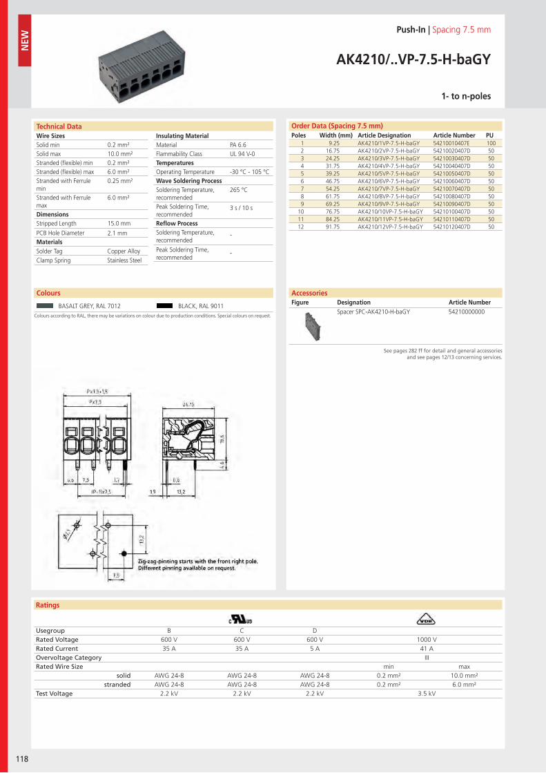
Wire SizesSolid minSolid maxStranded (flexible) minStranded (flexible) maxStranded with Ferrule minStranded with Ferrule maxDimensions Stripped Length
PCB Hole DiameterMaterials
Technical Data
Ratings
118
Insulating Material MaterialFlammability ClassTemperaturesOperating TemperatureWave Soldering ProcessSoldering Temperature,recommendedPeak Soldering Time,recommendedReflow ProcessSoldering Temperature,recommended
Peak Soldering Time,recommended
Colours
Order Data (Spacing 7.5 mm)Poles Width (mm) Article Designation Article Number PU
NEW
Colours according to RAL, there may be variations on colour due to production conditions. Special colours on request.
Push-In | Spacing 7.5 mm
AK4210/..VP-7.5-H-baGY
1- to n-poles
1 9.25 AK4210/1VP-7.5-H-baGY 54210010407E 1002 16.75 AK4210/2VP-7.5-H-baGY 54210020407D 503 24.25 AK4210/3VP-7.5-H-baGY 54210030407D 504 31.75 AK4210/4VP-7.5-H-baGY 54210040407D 505 39.25 AK4210/5VP-7.5-H-baGY 54210050407D 506 46.75 AK4210/6VP-7.5-H-baGY 54210060407D 507 54.25 AK4210/7VP-7.5-H-baGY 54210070407D 508 61.75 AK4210/8VP-7.5-H-baGY 54210080407D 509 69.25 AK4210/9VP-7.5-H-baGY 54210090407D 50
10 76.75 AK4210/10VP-7.5-H-baGY 54210100407D 5011 84.25 AK4210/11VP-7.5-H-baGY 54210110407D 5012 91.75 AK4210/12VP-7.5-H-baGY 54210120407D 50
BASALT GREY, RAL 7012 BLACK, RAL 9011
AccessoriesFigure Designation Article Number
See pages 282 ff for detail and general accessoriesand see pages 12/13 concerning services.
Spacer SPC-AK4210-H-baGY 54210000000
PA 6.6UL 94 V-0
-30 °C - 105 °C
265 °C
3 s / 10 s
-
-
0.2 mm²10.0 mm²0.2 mm²6.0 mm²0.25 mm²
6.0 mm²
15.0 mm
2.1 mm
Solder Tag Copper AlloyClamp Spring Stainless Steel
Usegroup B C DRated Voltage 600 V 600 V 600 V 1000 VRated Current 35 A 35 A 5 A 41 AOvervoltage Category IIIRated Wire Size min max
solid AWG 24-8 AWG 24-8 AWG 24-8 0.2 mm² 10.0 mm²stranded AWG 24-8 AWG 24-8 AWG 24-8 0.2 mm² 6.0 mm²
Test Voltage 2.2 kV 2.2 kV 2.2 kV 3.5 kV
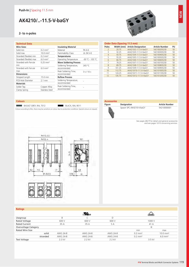
Wire SizesSolid minSolid maxStranded (flexible) minStranded (flexible) maxStranded with Ferrule minStranded with Ferrule maxDimensions Stripped Length
PCB Hole DiameterMaterials
Technical Data
Ratings
PTR Terminal Blocks and Multi Connector Systems 119
Insulating Material MaterialFlammability ClassTemperaturesOperating TemperatureWave Soldering ProcessSoldering Temperature,recommendedPeak Soldering Time,recommendedReflow ProcessSoldering Temperature,recommended
Peak Soldering Time,recommended
Colours
Order Data (Spacing 11.5 mm)Poles Width (mm) Article Designation Article Number PU
Colours according to RAL, there may be variations on colour due to production conditions. Special colours on request.
Push-In | Spacing 11.5 mm
AK4210/..-11.5-V-baGY
2- to n-poles
2 20.75 AK4210/2-11.5-V-baGY 54210020523D 503 32.25 AK4210/3-11.5-V-baGY 54210030523D 504 43.75 AK4210/4-11.5-V-baGY 54210040523D 505 55.25 AK4210/5-11.5-V-baGY 54210050523D 506 66.75 AK4210/6-11.5-V-baGY 54210060523D 507 78.25 AK4210/7-11.5-V-baGY 54210070523D 508 89.75 AK4210/8-11.5-V-baGY 54210080523D 509 101.25 AK4210/9-11.5-V-baGY 54210090523D 50
10 112.75 AK4210/10-11.5-V-baGY 54210100523D 5011 124.25 AK4210/11-11.5-V-baGY 54210110523D 5012 135.75 AK4210/12-11.5-V-baGY 54210120523D 50
BASALT GREY, RAL 7012 BLACK, RAL 9011
AccessoriesFigure Designation Article Number
See pages 282 ff for detail and general accessoriesand see pages 12/13 concerning services.
Spacer SPC-AK4210-V-baGY 54210000001
PA 6.6UL 94 V-0
-30 °C - 105 °C
265 °C
3 s / 10 s
-
-
0.2 mm²10.0 mm²0.2 mm²6.0 mm²0.25 mm²
6.0 mm²
15.0 mm
2.1 mm
Solder Tag Copper AlloyClamp Spring Stainless Steel
Usegroup B C DRated Voltage 600 V 600 V 600 V 1000 VRated Current 35 A 35 A 5 A 41 AOvervoltage Category IIIRated Wire Size min max
solid AWG 24-8 AWG 24-8 AWG 24-8 0.2 mm² 10.0 mm²stranded AWG 24-8 AWG 24-8 AWG 24-8 0.2 mm² 6.0 mm²
Test Voltage 2.2 kV 2.2 kV 2.2 kV 3.5 kV
NEW
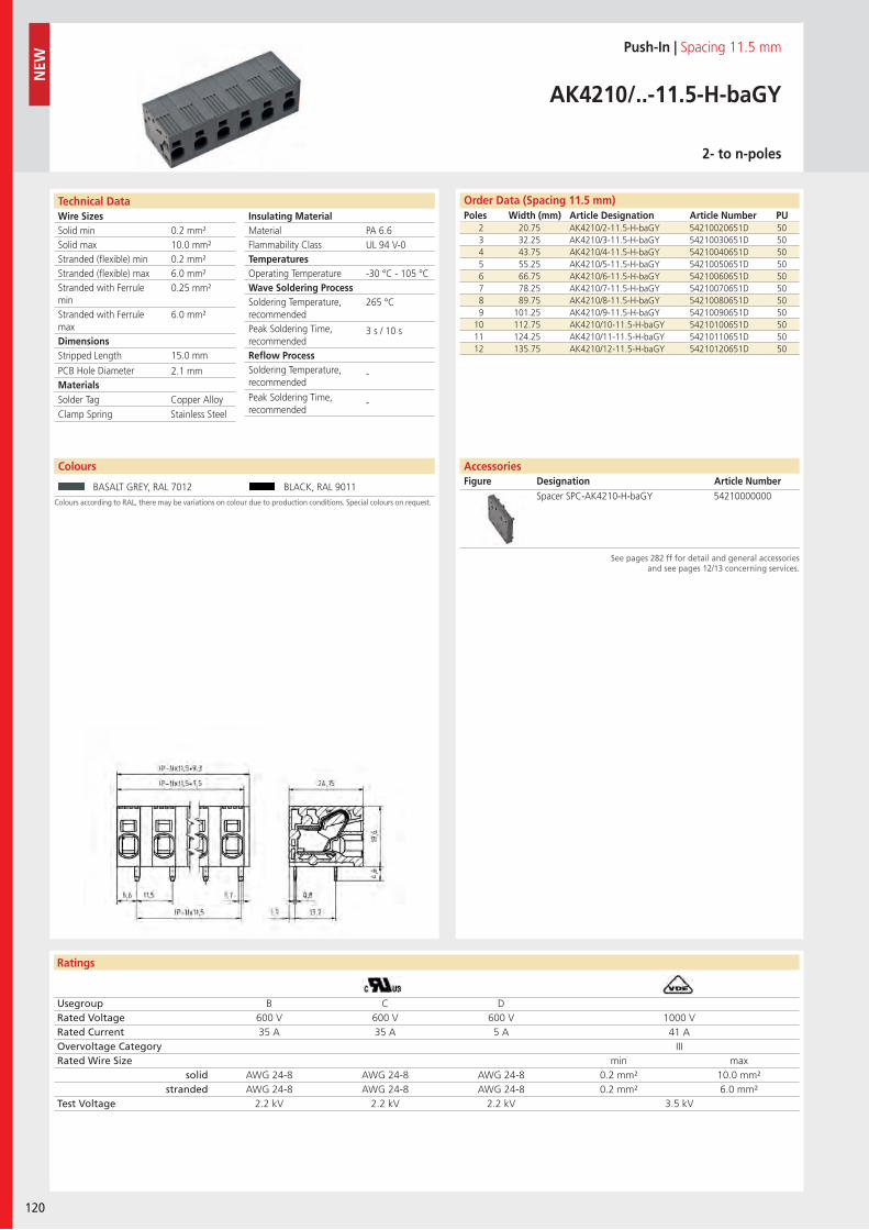
Wire SizesSolid minSolid maxStranded (flexible) minStranded (flexible) maxStranded with Ferrule minStranded with Ferrule maxDimensions Stripped Length
PCB Hole DiameterMaterials
Technical Data
Ratings
120
Insulating Material MaterialFlammability ClassTemperaturesOperating TemperatureWave Soldering ProcessSoldering Temperature,recommendedPeak Soldering Time,recommendedReflow ProcessSoldering Temperature,recommended
Peak Soldering Time,recommended
Colours
Order Data (Spacing 11.5 mm)Poles Width (mm) Article Designation Article Number PU
NEW
Colours according to RAL, there may be variations on colour due to production conditions. Special colours on request.
Push-In | Spacing 11.5 mm
AK4210/..-11.5-H-baGY
2- to n-poles
2 20.75 AK4210/2-11.5-H-baGY 54210020651D 503 32.25 AK4210/3-11.5-H-baGY 54210030651D 504 43.75 AK4210/4-11.5-H-baGY 54210040651D 505 55.25 AK4210/5-11.5-H-baGY 54210050651D 506 66.75 AK4210/6-11.5-H-baGY 54210060651D 507 78.25 AK4210/7-11.5-H-baGY 54210070651D 508 89.75 AK4210/8-11.5-H-baGY 54210080651D 509 101.25 AK4210/9-11.5-H-baGY 54210090651D 50
10 112.75 AK4210/10-11.5-H-baGY 54210100651D 5011 124.25 AK4210/11-11.5-H-baGY 54210110651D 5012 135.75 AK4210/12-11.5-H-baGY 54210120651D 50
BASALT GREY, RAL 7012 BLACK, RAL 9011
AccessoriesFigure Designation Article Number
See pages 282 ff for detail and general accessoriesand see pages 12/13 concerning services.
Spacer SPC-AK4210-H-baGY 54210000000
PA 6.6UL 94 V-0
-30 °C - 105 °C
265 °C
3 s / 10 s
-
-
0.2 mm²10.0 mm²0.2 mm²6.0 mm²0.25 mm²
6.0 mm²
15.0 mm
2.1 mm
Solder Tag Copper AlloyClamp Spring Stainless Steel
Usegroup B C DRated Voltage 600 V 600 V 600 V 1000 VRated Current 35 A 35 A 5 A 41 AOvervoltage Category IIIRated Wire Size min max
solid AWG 24-8 AWG 24-8 AWG 24-8 0.2 mm² 10.0 mm²stranded AWG 24-8 AWG 24-8 AWG 24-8 0.2 mm² 6.0 mm²
Test Voltage 2.2 kV 2.2 kV 2.2 kV 3.5 kV
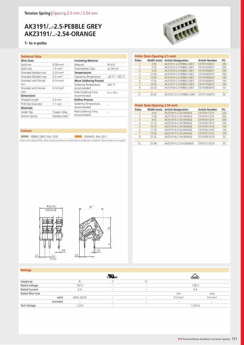
Wire SizesSolid minSolid maxStranded (flexible) minStranded (flexible) maxStranded with Ferrule minStranded with Ferrule maxDimensions Stripped Length
PCB Hole DiameterMaterials
Technical Data
Ratings
PTR Terminal Blocks and Multi Connector Systems 121
Insulating Material MaterialFlammability ClassTemperaturesOperating TemperatureWave Soldering ProcessSoldering Temperature,recommendedPeak Soldering Time,recommendedReflow ProcessSoldering Temperature,recommended
Peak Soldering Time,recommended
Colours
Order Data (Spacing 2.5 mm)Poles Width (mm) Article Designation Article Number PU
Colours according to RAL, there may be variations on colour due to production conditions. Special colours on request.
1 4.50 AK3191/1-2.5-PEBBLE GREY 53191010001F 2002 7.00 AK3191/2-2.5-PEBBLE GREY 53191020001F 2003 9.50 AK3191/3-2.5-PEBBLE GREY 53191030001F 2004 12.00 AK3191/4-2.5-PEBBLE GREY 53191040001F 2005 14.50 AK3191/5-2.5-PEBBLE GREY 53191050001E 1006 17.00 AK3191/6-2.5-PEBBLE GREY 53191060001E 1007 19.50 AK3191/7-2.5-PEBBLE GREY 53191070001E 1008 22.00 AK3191/8-2.5-PEBBLE GREY 53191080001D 50... ... ... ... ...12 32.00 AK3191/12-2.5-PEBBLE GREY 53191120001D 50
Usegroup B C DRated Voltage 150 V - - 130 VRated Current 4 A - - 9 ARated Wire Size min max
solid AWG 28-20 - - 0.2 mm² 0.5 mm²stranded - - - - -
Test Voltage 1.3 kV - - 1.25 kV
PEBBLE GREY, RAL 7032 ORANGE, RAL 2011
PA 6.6UL 94 V-0
-30 °C - 105 °C
265 °C
3 s / 10 s
-
-
0.08 mm²1.0 mm²0.14 mm²0.5 mm²0.14 mm²
0.14 mm²
5.0 mm
1.1 mm
1 4.54 AKZ3191/1-2.54-ORANGE 53191011321F 2002 7.08 AKZ3191/2-2.54-ORANGE 53191021321F 2003 9.62 AKZ3191/3-2.54-ORANGE 53191031321F 2004 12.16 AKZ3191/4-2.54-ORANGE 53191041321F 2005 14.70 AKZ3191/5-2.54-ORANGE 53191051321E 1006 17.24 AKZ3191/6-2.54-ORANGE 53191061321E 1007 19.78 AKZ3191/7-2.54-ORANGE 53191071321E 1008 22.32 AKZ3191/8-2.54-ORANGE 53191081321D 50
... ... ... ... ...12 32.48 AKZ3191/12-2.54-ORANGE 53191121321D 50
Solder Tag Copper AlloyTension Spring Stainless Steel
Order Data (Spacing 2.54 mm)Poles Width (mm) Article Designation Article Number PU
Tension Spring | Spacing 2.5 mm / 2.54 mm
AK3191/..-2.5-PEBBLE GREYAKZ3191/..-2.54-ORANGE1- to n-poles
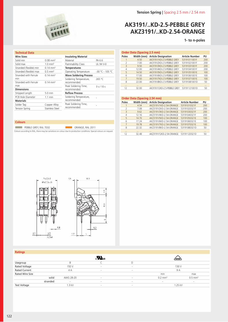
Wire SizesSolid minSolid maxStranded (flexible) minStranded (flexible) maxStranded with Ferrule minStranded with Ferrule maxDimensions Stripped Length
PCB Hole DiameterMaterials
Technical Data
Ratings
122
Insulating Material MaterialFlammability ClassTemperaturesOperating TemperatureWave Soldering ProcessSoldering Temperature,recommendedPeak Soldering Time,recommendedReflow ProcessSoldering Temperature,recommended
Peak Soldering Time,recommended
Colours
Order Data (Spacing 2.5 mm)Poles Width (mm) Article Designation Article Number PU
Colours according to RAL, there may be variations on colour due to production conditions. Special colours on request.
1 4.50 AK3191/1KD-2.5-PEBBLE GREY 53191011001F 2002 7.00 AK3191/2KD-2.5-PEBBLE GREY 53191021001F 2003 9.50 AK3191/3KD-2.5-PEBBLE GREY 53191031001F 2004 12.00 AK3191/4KD-2.5-PEBBLE GREY 53191041001F 2005 14.50 AK3191/5KD-2.5-PEBBLE GREY 53191051001E 1006 17.00 AK3191/6KD-2.5-PEBBLE GREY 53191061001E 1007 19.50 AK3191/7KD-2.5-PEBBLE GREY 53191071001E 1008 22.00 AK3191/8KD-2.5-PEBBLE GREY 53191081001D 50... ... ... ... ...12 32.00 AK3191/12KD-2.5-PEBBLE GREY 53191121001D 50
Usegroup B C DRated Voltage 150 V - - 130 VRated Current 4 A - - 9 ARated Wire Size min max
solid AWG 28-20 - - 0.2 mm² 0.5 mm²stranded - - - - -
Test Voltage 1.3 kV - - 1.25 kV
PEBBLE GREY, RAL 7032 ORANGE, RAL 2011
PA 6.6UL 94 V-0
-30 °C - 105 °C
265 °C
3 s / 10 s
-
-
0.08 mm²1.0 mm²0.14 mm²0.5 mm²0.14 mm²
0.14 mm²
5.0 mm
1.1 mm
1 4.54 AKZ3191/1KD-2.54-ORANGE 53191010321F 2002 7.08 AKZ3191/2KD-2.54-ORANGE 53191020321F 2003 9.62 AKZ3191/3KD-2.54-ORANGE 53191030321F 2004 12.16 AKZ3191/4KD-2.54-ORANGE 53191040321F 2005 14.70 AKZ3191/5KD-2.54-ORANGE 53191050321E 1006 17.24 AKZ3191/6KD-2.54-ORANGE 53191060321E 1007 19.78 AKZ3191/7KD-2.54-ORANGE 53191070321E 1008 22.32 AKZ3191/8KD-2.54-ORANGE 53191080321D 50
... ... ... ... ...12 32.48 AKZ3191/12KD-2.54-ORANGE 53191120321D 50
Solder Tag Copper AlloyTension Spring Stainless Steel
Order Data (Spacing 2.54 mm)Poles Width (mm) Article Designation Article Number PU
Tension Spring | Spacing 2.5 mm / 2.54 mm
AK3191/..KD-2.5-PEBBLE GREYAKZ3191/..KD-2.54-ORANGE
1- to n-poles
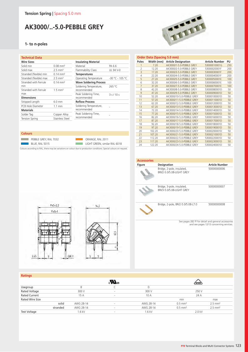
Wire SizesSolid minSolid maxStranded (flexible) minStranded (flexible) maxStranded with Ferrule minStranded with Ferrule maxDimensions Stripped Length
PCB Hole DiameterMaterials
Ratings
PTR Terminal Blocks and Multi Connector Systems 123
Insulating Material MaterialFlammability ClassTemperaturesOperating TemperatureWave Soldering ProcessSoldering Temperature,recommendedPeak Soldering Time,recommendedReflow ProcessSoldering Temperature,recommended
Peak Soldering Time,recommended
Order Data (Spacing 5.0 mm)Poles Width (mm) Article Designation Article Number PU
Technical Data
Colours
Tension Spring | Spacing 5.0 mm
AK3000/..-5.0-PEBBLE GREY
1- to n-poles
1 7.20 AK3000/1-5.0-PEBBLE GREY 53000010001G 2502 12.20 AK3000/2-5.0-PEBBLE GREY 53000020001F 2003 17.20 AK3000/3-5.0-PEBBLE GREY 53000030001F 2004 22.20 AK3000/4-5.0-PEBBLE GREY 53000040001F 2005 27.20 AK3000/5-5.0-PEBBLE GREY 53000050001E 1006 32.20 AK3000/6-5.0-PEBBLE GREY 53000060001E 1007 37.20 AK3000/7-5.0-PEBBLE GREY 53000070001E 1008 42.20 AK3000/8-5.0-PEBBLE GREY 53000080001D 509 47.20 AK3000/9-5.0-PEBBLE GREY 53000090001D 50
10 52.20 AK3000/10-5.0-PEBBLE GREY 53000100001D 5011 57.20 AK3000/11-5.0-PEBBLE GREY 53000110001D 5012 62.20 AK3000/12-5.0-PEBBLE GREY 53000120001D 5013 67.20 AK3000/13-5.0-PEBBLE GREY 53000130001D 5014 72.20 AK3000/14-5.0-PEBBLE GREY 53000140001D 5015 77.20 AK3000/15-5.0-PEBBLE GREY 53000150001D 5016 82.20 AK3000/16-5.0-PEBBLE GREY 53000160001D 5017 87.20 AK3000/17-5.0-PEBBLE GREY 53000170001D 5018 92.20 AK3000/18-5.0-PEBBLE GREY 53000180001D 5019 97.20 AK3000/19-5.0-PEBBLE GREY 53000190001D 5020 102.20 AK3000/20-5.0-PEBBLE GREY 53000200001D 5021 107.20 AK3000/21-5.0-PEBBLE GREY 53000210001D 5022 112.20 AK3000/22-5.0-PEBBLE GREY 53000220001D 5023 117.20 AK3000/23-5.0-PEBBLE GREY 53000230001D 5024 122.20 AK3000/24-5.0-PEBBLE GREY 53000240001D 50
Usegroup B C DRated Voltage 300 V - 300 V 250 VRated Current 15 A - 10 A 24 ARated Wire Size min max
solid AWG 28-14 - AWG 28-14 0.5 mm² 2.5 mm²stranded AWG 28-14 - AWG 28-14 0.5 mm² 2.5 mm²
Test Voltage 1.6 kV - 1.6 kV 2.0 kV
Colours according to RAL, there may be variations on colour due to production conditions. Special colours on request.
PEBBLE GREY, RAL 7032 ORANGE, RAL 2011
BLUE, RAL 5015 LIGHT GREEN, similar RAL 6018
Bridge, 2-pole, insulated, BRI/2-5.0/5.08-LIGHT GREY
50000000006
Bridge, 3-pole, insulated, BRI/3-5.0/5.08-LIGHT GREY
50000000007
Bridge, 2-pole, BR/2-5.0/5.08-L7.0 50000000008
PA 6.6UL 94 V-0
-30 °C - 105 °C
265 °C
3 s / 10 s
-
-
0.08 mm²2.5 mm²0.14 mm²2.5 mm²0.14 mm²
1.5 mm²
6.0 mm
1.1 mm
Solder Tag Copper AlloyTension Spring Stainless Steel
See pages 282 ff for detail and general accessoriesand see pages 12/13 concerning services.
AccessoriesFigure Designation Article Number
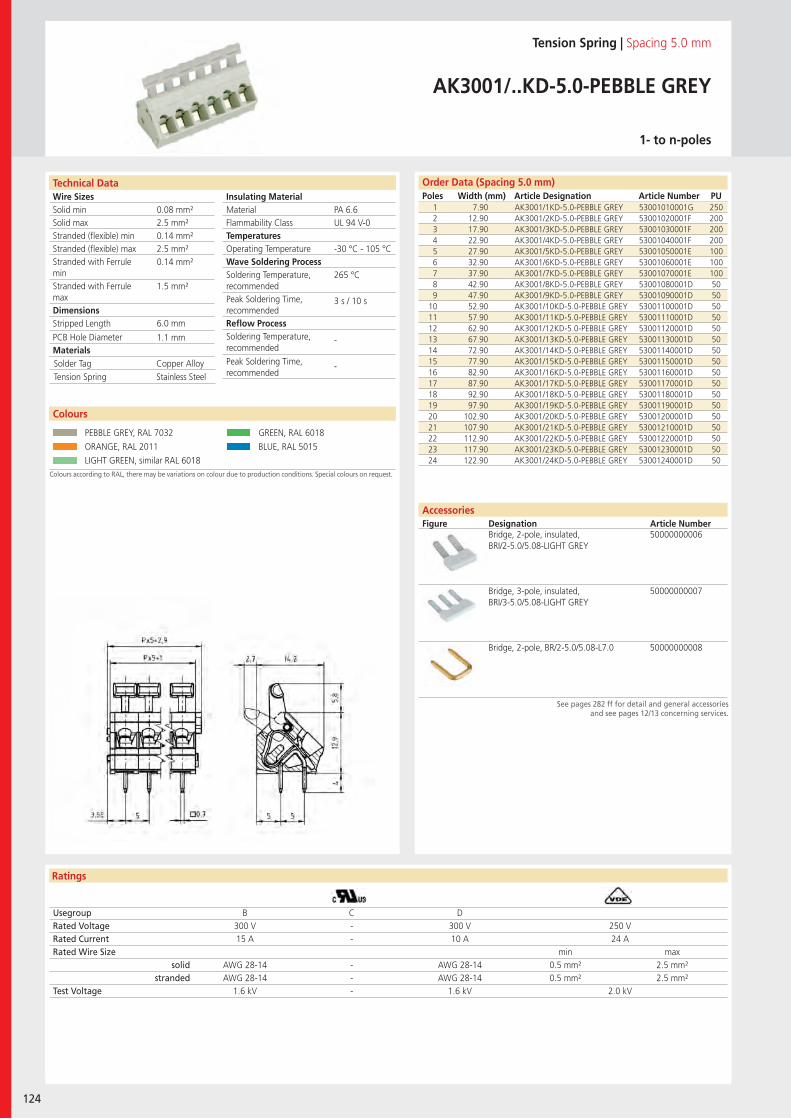
Wire SizesSolid minSolid maxStranded (flexible) minStranded (flexible) maxStranded with Ferrule minStranded with Ferrule maxDimensions Stripped Length
PCB Hole DiameterMaterials
Technical Data
Ratings
124
Insulating Material MaterialFlammability ClassTemperaturesOperating TemperatureWave Soldering ProcessSoldering Temperature,recommendedPeak Soldering Time,recommendedReflow ProcessSoldering Temperature,recommended
Peak Soldering Time,recommended
AccessoriesFigure Designation Article Number
Technical Data Order Data (Spacing 5.0 mm)Poles Width (mm) Article Designation Article Number PU
Tension Spring | Spacing 5.0 mm
AK3001/..KD-5.0-PEBBLE GREY
1- to n-poles
1 7.90 AK3001/1KD-5.0-PEBBLE GREY 53001010001G 2502 12.90 AK3001/2KD-5.0-PEBBLE GREY 53001020001F 2003 17.90 AK3001/3KD-5.0-PEBBLE GREY 53001030001F 2004 22.90 AK3001/4KD-5.0-PEBBLE GREY 53001040001F 2005 27.90 AK3001/5KD-5.0-PEBBLE GREY 53001050001E 1006 32.90 AK3001/6KD-5.0-PEBBLE GREY 53001060001E 1007 37.90 AK3001/7KD-5.0-PEBBLE GREY 53001070001E 1008 42.90 AK3001/8KD-5.0-PEBBLE GREY 53001080001D 509 47.90 AK3001/9KD-5.0-PEBBLE GREY 53001090001D 50
10 52.90 AK3001/10KD-5.0-PEBBLE GREY 53001100001D 5011 57.90 AK3001/11KD-5.0-PEBBLE GREY 53001110001D 5012 62.90 AK3001/12KD-5.0-PEBBLE GREY 53001120001D 5013 67.90 AK3001/13KD-5.0-PEBBLE GREY 53001130001D 5014 72.90 AK3001/14KD-5.0-PEBBLE GREY 53001140001D 5015 77.90 AK3001/15KD-5.0-PEBBLE GREY 53001150001D 5016 82.90 AK3001/16KD-5.0-PEBBLE GREY 53001160001D 5017 87.90 AK3001/17KD-5.0-PEBBLE GREY 53001170001D 5018 92.90 AK3001/18KD-5.0-PEBBLE GREY 53001180001D 5019 97.90 AK3001/19KD-5.0-PEBBLE GREY 53001190001D 5020 102.90 AK3001/20KD-5.0-PEBBLE GREY 53001200001D 5021 107.90 AK3001/21KD-5.0-PEBBLE GREY 53001210001D 5022 112.90 AK3001/22KD-5.0-PEBBLE GREY 53001220001D 5023 117.90 AK3001/23KD-5.0-PEBBLE GREY 53001230001D 5024 122.90 AK3001/24KD-5.0-PEBBLE GREY 53001240001D 50
Usegroup B C DRated Voltage 300 V - 300 V 250 VRated Current 15 A - 10 A 24 ARated Wire Size min max
solid AWG 28-14 - AWG 28-14 0.5 mm² 2.5 mm²stranded AWG 28-14 - AWG 28-14 0.5 mm² 2.5 mm²
Test Voltage 1.6 kV - 1.6 kV 2.0 kV
Colours according to RAL, there may be variations on colour due to production conditions. Special colours on request.
Colours
PEBBLE GREY, RAL 7032 GREEN, RAL 6018
ORANGE, RAL 2011 BLUE, RAL 5015
LIGHT GREEN, similar RAL 6018
Bridge, 2-pole, insulated, BRI/2-5.0/5.08-LIGHT GREY
50000000006
Bridge, 3-pole, insulated, BRI/3-5.0/5.08-LIGHT GREY
50000000007
Bridge, 2-pole, BR/2-5.0/5.08-L7.0 50000000008
PA 6.6UL 94 V-0
-30 °C - 105 °C
265 °C
3 s / 10 s
-
-
0.08 mm²2.5 mm²0.14 mm²2.5 mm²0.14 mm²
1.5 mm²
6.0 mm
1.1 mm
Solder Tag Copper AlloyTension Spring Stainless Steel
See pages 282 ff for detail and general accessoriesand see pages 12/13 concerning services.
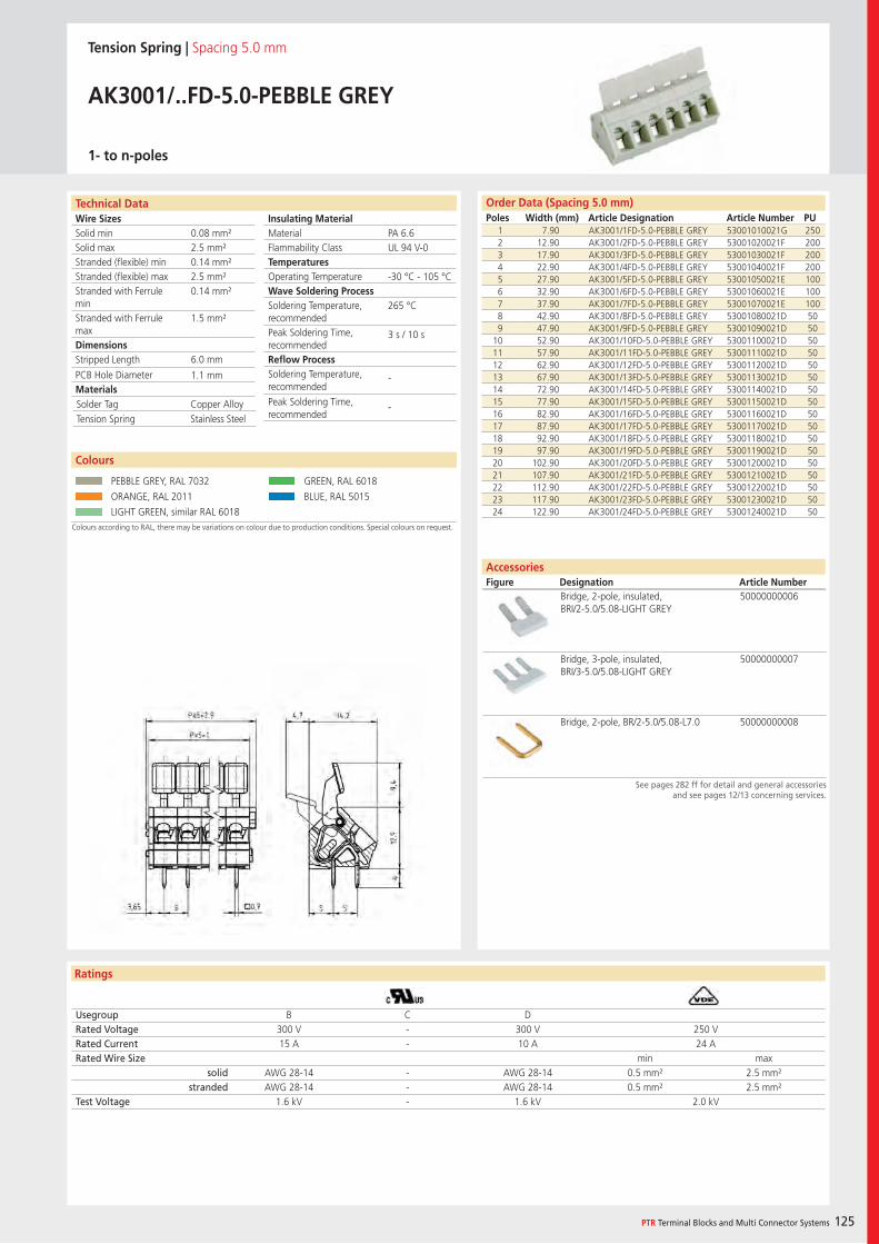
Wire SizesSolid minSolid maxStranded (flexible) minStranded (flexible) maxStranded with Ferrule minStranded with Ferrule maxDimensions Stripped Length
PCB Hole DiameterMaterials
Ratings
PTR Terminal Blocks and Multi Connector Systems 125
Insulating Material MaterialFlammability ClassTemperaturesOperating TemperatureWave Soldering ProcessSoldering Temperature,recommendedPeak Soldering Time,recommendedReflow ProcessSoldering Temperature,recommended
Peak Soldering Time,recommended
Order Data (Spacing 5.0 mm)Poles Width (mm) Article Designation Article Number PU
Tension Spring | Spacing 5.0 mm
AK3001/..FD-5.0-PEBBLE GREY
1- to n-poles
1 7.90 AK3001/1FD-5.0-PEBBLE GREY 53001010021G 2502 12.90 AK3001/2FD-5.0-PEBBLE GREY 53001020021F 2003 17.90 AK3001/3FD-5.0-PEBBLE GREY 53001030021F 2004 22.90 AK3001/4FD-5.0-PEBBLE GREY 53001040021F 2005 27.90 AK3001/5FD-5.0-PEBBLE GREY 53001050021E 1006 32.90 AK3001/6FD-5.0-PEBBLE GREY 53001060021E 1007 37.90 AK3001/7FD-5.0-PEBBLE GREY 53001070021E 1008 42.90 AK3001/8FD-5.0-PEBBLE GREY 53001080021D 509 47.90 AK3001/9FD-5.0-PEBBLE GREY 53001090021D 50
10 52.90 AK3001/10FD-5.0-PEBBLE GREY 53001100021D 5011 57.90 AK3001/11FD-5.0-PEBBLE GREY 53001110021D 5012 62.90 AK3001/12FD-5.0-PEBBLE GREY 53001120021D 5013 67.90 AK3001/13FD-5.0-PEBBLE GREY 53001130021D 5014 72.90 AK3001/14FD-5.0-PEBBLE GREY 53001140021D 5015 77.90 AK3001/15FD-5.0-PEBBLE GREY 53001150021D 5016 82.90 AK3001/16FD-5.0-PEBBLE GREY 53001160021D 5017 87.90 AK3001/17FD-5.0-PEBBLE GREY 53001170021D 5018 92.90 AK3001/18FD-5.0-PEBBLE GREY 53001180021D 5019 97.90 AK3001/19FD-5.0-PEBBLE GREY 53001190021D 5020 102.90 AK3001/20FD-5.0-PEBBLE GREY 53001200021D 5021 107.90 AK3001/21FD-5.0-PEBBLE GREY 53001210021D 5022 112.90 AK3001/22FD-5.0-PEBBLE GREY 53001220021D 5023 117.90 AK3001/23FD-5.0-PEBBLE GREY 53001230021D 5024 122.90 AK3001/24FD-5.0-PEBBLE GREY 53001240021D 50
Usegroup B C DRated Voltage 300 V - 300 V 250 VRated Current 15 A - 10 A 24 ARated Wire Size min max
solid AWG 28-14 - AWG 28-14 0.5 mm² 2.5 mm²stranded AWG 28-14 - AWG 28-14 0.5 mm² 2.5 mm²
Test Voltage 1.6 kV - 1.6 kV 2.0 kV
Colours according to RAL, there may be variations on colour due to production conditions. Special colours on request.
Colours
PEBBLE GREY, RAL 7032 GREEN, RAL 6018
ORANGE, RAL 2011 BLUE, RAL 5015
LIGHT GREEN, similar RAL 6018
Bridge, 2-pole, insulated, BRI/2-5.0/5.08-LIGHT GREY
50000000006
Bridge, 3-pole, insulated, BRI/3-5.0/5.08-LIGHT GREY
50000000007
Bridge, 2-pole, BR/2-5.0/5.08-L7.0 50000000008
PA 6.6UL 94 V-0
-30 °C - 105 °C
265 °C
3 s / 10 s
-
-
0.08 mm²2.5 mm²0.14 mm²2.5 mm²0.14 mm²
1.5 mm²
6.0 mm
1.1 mm
Solder Tag Copper AlloyTension Spring Stainless Steel
See pages 282 ff for detail and general accessoriesand see pages 12/13 concerning services.
Technical Data
AccessoriesFigure Designation Article Number
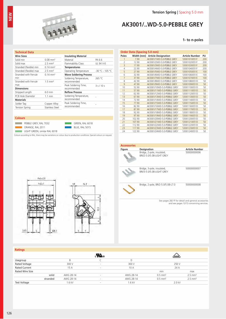
Wire SizesSolid minSolid maxStranded (flexible) minStranded (flexible) maxStranded with Ferrule minStranded with Ferrule maxDimensions Stripped Length
PCB Hole DiameterMaterials
Technical Data
Ratings
126
Insulating Material MaterialFlammability ClassTemperaturesOperating TemperatureWave Soldering ProcessSoldering Temperature,recommendedPeak Soldering Time,recommendedReflow ProcessSoldering Temperature,recommended
Peak Soldering Time,recommended
AccessoriesFigure Designation Article Number
Order Data (Spacing 5.0 mm)Poles Width (mm) Article Designation Article Number PU
Technical Data
NEW
Tension Spring | Spacing 5.0 mm
AK3001/..WD-5.0-PEBBLE GREY
1- to n-poles
1 7.90 AK3001/1WD-5.0-PEBBLE GREY 53001010051F 2002 12.90 AK3001/2WD-5.0-PEBBLE GREY 53001020051F 2003 17.90 AK3001/3WD-5.0-PEBBLE GREY 53001030051F 2004 22.90 AK3001/4WD-5.0-PEBBLE GREY 53001040051F 2005 27.90 AK3001/5WD-5.0-PEBBLE GREY 53001050051E 1006 32.90 AK3001/6WD-5.0-PEBBLE GREY 53001060051E 1007 37.90 AK3001/7WD-5.0-PEBBLE GREY 53001070051E 1008 42.90 AK3001/8WD-5.0-PEBBLE GREY 53001080051D 509 47.90 AK3001/9WD-5.0-PEBBLE GREY 53001090051D 50
10 52.90 AK3001/10WD-5.0-PEBBLE GREY 53001100051D 5011 57.90 AK3001/11WD-5.0-PEBBLE GREY 53001110051D 5012 62.90 AK3001/12WD-5.0-PEBBLE GREY 53001120051D 5013 67.90 AK3001/13WD-5.0-PEBBLE GREY 53001130051D 5014 72.90 AK3001/14WD-5.0-PEBBLE GREY 53001140051D 5015 77.90 AK3001/15WD-5.0-PEBBLE GREY 53001150051D 5016 82.90 AK3001/16WD-5.0-PEBBLE GREY 53001160051D 5017 87.90 AK3001/17WD-5.0-PEBBLE GREY 53001170051D 5018 92.90 AK3001/18WD-5.0-PEBBLE GREY 53001180051D 5019 97.90 AK3001/19WD-5.0-PEBBLE GREY 53001190051D 5020 102.90 AK3001/20WD-5.0-PEBBLE GREY 53001200051D 5021 107.90 AK3001/21WD-5.0-PEBBLE GREY 53001210051D 5022 112.90 AK3001/22WD-5.0-PEBBLE GREY 53001220051D 5023 117.90 AK3001/23WD-5.0-PEBBLE GREY 53001230051D 5024 122.90 AK3001/24WD-5.0-PEBBLE GREY 53001240051D 50
Usegroup B C DRated Voltage 300 V - 300 V 250 VRated Current 15 A - 10 A 24 ARated Wire Size min max
solid AWG 28-14 - AWG 28-14 0.5 mm² 2.5 mm²stranded AWG 28-14 - AWG 28-14 0.5 mm² 2.5 mm²
Test Voltage 1.6 kV - 1.6 kV 2.0 kV
Colours according to RAL, there may be variations on colour due to production conditions. Special colours on request.
Colours
PEBBLE GREY, RAL 7032 GREEN, RAL 6018
ORANGE, RAL 2011 BLUE, RAL 5015
LIGHT GREEN, similar RAL 6018
Bridge, 2-pole, insulated, BRI/2-5.0/5.08-LIGHT GREY
50000000006
Bridge, 3-pole, insulated, BRI/3-5.0/5.08-LIGHT GREY
50000000007
Bridge, 2-pole, BR/2-5.0/5.08-L7.0 50000000008
PA 6.6UL 94 V-0
-30 °C - 105 °C
265 °C
3 s / 10 s
-
-
0.08 mm²2.5 mm²0.14 mm²2.5 mm²0.14 mm²
1.5 mm²
6.0 mm
1.1 mm
Solder Tag Copper AlloyTension Spring Stainless Steel
See pages 282 ff for detail and general accessoriesand see pages 12/13 concerning services.
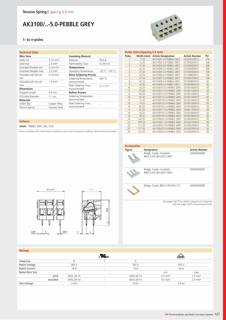
Wire SizesSolid minSolid maxStranded (flexible) minStranded (flexible) maxStranded with Ferrule minStranded with Ferrule maxDimensions Stripped Length
PCB Hole DiameterMaterials
Technical Data
Ratings
Colours
PTR Terminal Blocks and Multi Connector Systems 127
Insulating Material MaterialFlammability ClassTemperaturesOperating TemperatureWave Soldering ProcessSoldering Temperature,recommendedPeak Soldering Time,recommendedReflow ProcessSoldering Temperature,recommended
Peak Soldering Time,recommended
Order Data (Spacing 5.0 mm)Poles Width (mm) Article Designation Article Number PU
Colours according to RAL, there may be variations on colour due to production conditions. Special colours on request.
AccessoriesFigure Designation Article Number
See pages 282 ff for detail and general accessoriesand see pages 12/13 concerning services.
Tension Spring | Spacing 5.0 mm
AK3100/..-5.0-PEBBLE GREY
1- to n-poles
1 7.20 AK3100/1-5.0-PEBBLE GREY 53100010001G 2502 12.20 AK3100/2-5.0-PEBBLE GREY 53100020001F 2003 17.20 AK3100/3-5.0-PEBBLE GREY 53100030001F 2004 22.20 AK3100/4-5.0-PEBBLE GREY 53100040001F 2005 27.20 AK3100/5-5.0-PEBBLE GREY 53100050001E 1006 32.20 AK3100/6-5.0-PEBBLE GREY 53100060001E 1007 37.20 AK3100/7-5.0-PEBBLE GREY 53100070001E 1008 42.20 AK3100/8-5.0-PEBBLE GREY 53100080001D 509 47.20 AK3100/9-5.0-PEBBLE GREY 53100090001D 50
10 52.20 AK3100/10-5.0-PEBBLE GREY 53100100001D 5011 57.20 AK3100/11-5.0-PEBBLE GREY 53100110001D 5012 62.20 AK3100/12-5.0-PEBBLE GREY 53100120001D 5013 67.20 AK3100/13-5.0-PEBBLE GREY 53100130001D 5014 72.20 AK3100/14-5.0-PEBBLE GREY 53100140001D 5015 77.20 AK3100/15-5.0-PEBBLE GREY 53100150001D 5016 82.20 AK3100/16-5.0-PEBBLE GREY 53100160001D 5017 87.20 AK3100/17-5.0-PEBBLE GREY 53100170001D 5018 92.20 AK3100/18-5.0-PEBBLE GREY 53100180001D 5019 97.20 AK3100/19-5.0-PEBBLE GREY 53100190001D 5020 102.20 AK3100/20-5.0-PEBBLE GREY 53100200001D 5021 107.20 AK3100/21-5.0-PEBBLE GREY 53100210001D 5022 112.20 AK3100/22-5.0-PEBBLE GREY 53100220001D 5023 117.20 AK3100/23-5.0-PEBBLE GREY 53100230001D 5024 122.20 AK3100/24-5.0-PEBBLE GREY 53100240001D 50
Usegroup B C DRated Voltage 300 V - 300 V 250 VRated Current 16 A - 10 A 24 ARated Wire Size min max
solid AWG 28-14 - AWG 28-14 0.5 mm² 2.5 mm²stranded AWG 28-14 - AWG 28-14 0.5 mm² 2.5 mm²
Test Voltage 1.6 kV - 1.6 kV 2.0 kV
PEBBLE GREY, RAL 7032
Bridge, 2-pole, insulated, BRI/2-5.0/5.08-LIGHT GREY
50000000006
Bridge, 3-pole, insulated, BRI/3-5.0/5.08-LIGHT GREY
50000000007
Bridge, 2-pole, BR/2-5.0/5.08-L7.0 50000000008
PA 6.6UL 94 V-0
-30 °C - 105 °C
265 °C
3 s / 10 s
-
-
0.14 mm²2.5 mm²0.14 mm²2.5 mm²0.14 mm²
1.5 mm²
6.0 mm
1.1 mm
Solder Tag Copper AlloyTension Spring Stainless Steel
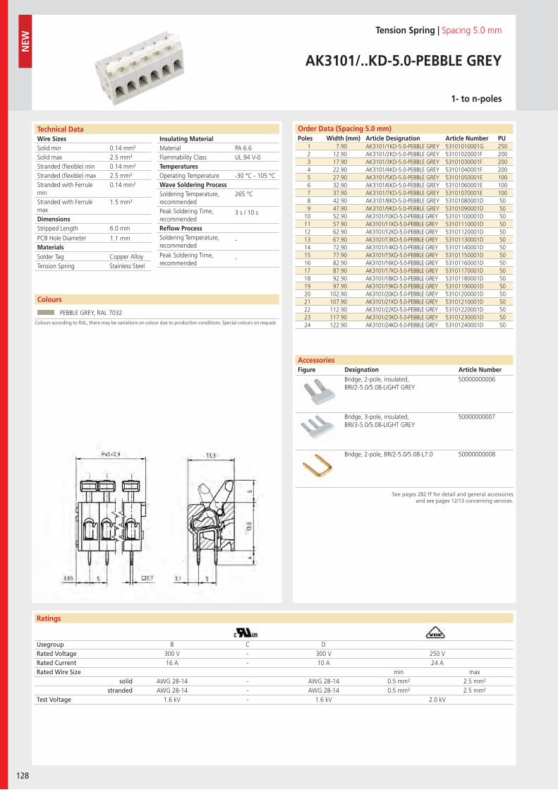
Wire SizesSolid minSolid maxStranded (flexible) minStranded (flexible) maxStranded with Ferrule minStranded with Ferrule maxDimensions Stripped Length
PCB Hole DiameterMaterials
Technical Data
Ratings
AccessoriesFigure Designation Article Number
128
Colours
Insulating Material MaterialFlammability ClassTemperaturesOperating TemperatureWave Soldering ProcessSoldering Temperature,recommendedPeak Soldering Time,recommendedReflow ProcessSoldering Temperature,recommended
Peak Soldering Time,recommended
Order Data (Spacing 5.0 mm)Poles Width (mm) Article Designation Article Number PU
NEW
See pages 282 ff for detail and general accessoriesand see pages 12/13 concerning services.
Colours according to RAL, there may be variations on colour due to production conditions. Special colours on request.
Tension Spring | Spacing 5.0 mm
AK3101/..KD-5.0-PEBBLE GREY
1- to n-poles
1 7.90 AK3101/1KD-5.0-PEBBLE GREY 53101010001G 2502 12.90 AK3101/2KD-5.0-PEBBLE GREY 53101020001F 2003 17.90 AK3101/3KD-5.0-PEBBLE GREY 53101030001F 2004 22.90 AK3101/4KD-5.0-PEBBLE GREY 53101040001F 2005 27.90 AK3101/5KD-5.0-PEBBLE GREY 53101050001E 1006 32.90 AK3101/6KD-5.0-PEBBLE GREY 53101060001E 1007 37.90 AK3101/7KD-5.0-PEBBLE GREY 53101070001E 1008 42.90 AK3101/8KD-5.0-PEBBLE GREY 53101080001D 509 47.90 AK3101/9KD-5.0-PEBBLE GREY 53101090001D 50
10 52.90 AK3101/10KD-5.0-PEBBLE GREY 53101100001D 5011 57.90 AK3101/11KD-5.0-PEBBLE GREY 53101110001D 5012 62.90 AK3101/12KD-5.0-PEBBLE GREY 53101120001D 5013 67.90 AK3101/13KD-5.0-PEBBLE GREY 53101130001D 5014 72.90 AK3101/14KD-5.0-PEBBLE GREY 53101140001D 5015 77.90 AK3101/15KD-5.0-PEBBLE GREY 53101150001D 5016 82.90 AK3101/16KD-5.0-PEBBLE GREY 53101160001D 5017 87.90 AK3101/17KD-5.0-PEBBLE GREY 53101170001D 5018 92.90 AK3101/18KD-5.0-PEBBLE GREY 53101180001D 5019 97.90 AK3101/19KD-5.0-PEBBLE GREY 53101190001D 5020 102.90 AK3101/20KD-5.0-PEBBLE GREY 53101200001D 5021 107.90 AK3101/21KD-5.0-PEBBLE GREY 53101210001D 5022 112.90 AK3101/22KD-5.0-PEBBLE GREY 53101220001D 5023 117.90 AK3101/23KD-5.0-PEBBLE GREY 53101230001D 5024 122.90 AK3101/24KD-5.0-PEBBLE GREY 53101240001D 50
Usegroup B C DRated Voltage 300 V - 300 V 250 VRated Current 16 A - 10 A 24 ARated Wire Size min max
solid AWG 28-14 - AWG 28-14 0.5 mm² 2.5 mm²stranded AWG 28-14 - AWG 28-14 0.5 mm² 2.5 mm²
Test Voltage 1.6 kV - 1.6 kV 2.0 kV
PEBBLE GREY, RAL 7032
Bridge, 2-pole, insulated, BRI/2-5.0/5.08-LIGHT GREY
50000000006
Bridge, 3-pole, insulated, BRI/3-5.0/5.08-LIGHT GREY
50000000007
Bridge, 2-pole, BR/2-5.0/5.08-L7.0 50000000008
PA 6.6UL 94 V-0
-30 °C - 105 °C
265 °C
3 s / 10 s
-
-
0.14 mm²2.5 mm²0.14 mm²2.5 mm²0.14 mm²
1.5 mm²
6.0 mm
1.1 mm
Solder Tag Copper AlloyTension Spring Stainless Steel
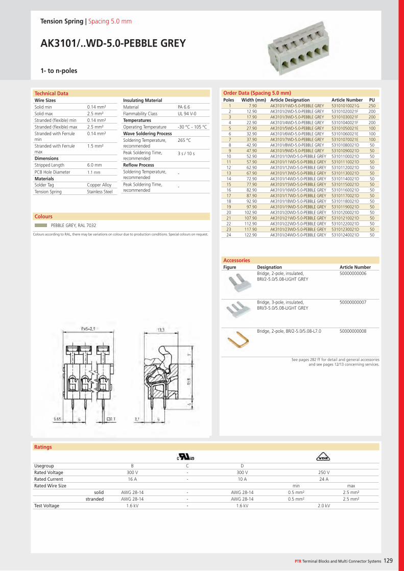
Wire SizesSolid minSolid maxStranded (flexible) minStranded (flexible) maxStranded with Ferrule minStranded with Ferrule maxDimensions Stripped Length
PCB Hole DiameterMaterials
Technical Data
Ratings
Colours
PTR Terminal Blocks and Multi Connector Systems 129
Insulating Material MaterialFlammability ClassTemperaturesOperating TemperatureWave Soldering ProcessSoldering Temperature,recommendedPeak Soldering Time,recommendedReflow ProcessSoldering Temperature,recommended
Peak Soldering Time,recommended
Order Data (Spacing 5.0 mm)Poles Width (mm) Article Designation Article Number PU
Colours according to RAL, there may be variations on colour due to production conditions. Special colours on request.
AccessoriesFigure Designation Article Number
See pages 282 ff for detail and general accessoriesand see pages 12/13 concerning services.
Tension Spring | Spacing 5.0 mm
AK3101/..WD-5.0-PEBBLE GREY
1- to n-poles
1 7.90 AK3101/1WD-5.0-PEBBLE GREY 53101010021G 2502 12.90 AK3101/2WD-5.0-PEBBLE GREY 53101020021F 2003 17.90 AK3101/3WD-5.0-PEBBLE GREY 53101030021F 2004 22.90 AK3101/4WD-5.0-PEBBLE GREY 53101040021F 2005 27.90 AK3101/5WD-5.0-PEBBLE GREY 53101050021E 1006 32.90 AK3101/6WD-5.0-PEBBLE GREY 53101060021E 1007 37.90 AK3101/7WD-5.0-PEBBLE GREY 53101070021E 1008 42.90 AK3101/8WD-5.0-PEBBLE GREY 53101080021D 509 47.90 AK3101/9WD-5.0-PEBBLE GREY 53101090021D 50
10 52.90 AK3101/10WD-5.0-PEBBLE GREY 53101100021D 5011 57.90 AK3101/11WD-5.0-PEBBLE GREY 53101110021D 5012 62.90 AK3101/12WD-5.0-PEBBLE GREY 53101120021D 5013 67.90 AK3101/13WD-5.0-PEBBLE GREY 53101130021D 5014 72.90 AK3101/14WD-5.0-PEBBLE GREY 53101140021D 5015 77.90 AK3101/15WD-5.0-PEBBLE GREY 53101150021D 5016 82.90 AK3101/16WD-5.0-PEBBLE GREY 53101160021D 5017 87.90 AK3101/17WD-5.0-PEBBLE GREY 53101170021D 5018 92.90 AK3101/18WD-5.0-PEBBLE GREY 53101180021D 5019 97.90 AK3101/19WD-5.0-PEBBLE GREY 53101190021D 5020 102.90 AK3101/20WD-5.0-PEBBLE GREY 53101200021D 5021 107.90 AK3101/21WD-5.0-PEBBLE GREY 53101210021D 5022 112.90 AK3101/22WD-5.0-PEBBLE GREY 53101220021D 5023 117.90 AK3101/23WD-5.0-PEBBLE GREY 53101230021D 5024 122.90 AK3101/24WD-5.0-PEBBLE GREY 53101240021D 50
Usegroup B C DRated Voltage 300 V - 300 V 250 VRated Current 16 A - 10 A 24 ARated Wire Size min max
solid AWG 28-14 - AWG 28-14 0.5 mm² 2.5 mm²stranded AWG 28-14 - AWG 28-14 0.5 mm² 2.5 mm²
Test Voltage 1.6 kV - 1.6 kV 2.0 kV
PEBBLE GREY, RAL 7032
Bridge, 2-pole, insulated, BRI/2-5.0/5.08-LIGHT GREY
50000000006
Bridge, 3-pole, insulated, BRI/3-5.0/5.08-LIGHT GREY
50000000007
Bridge, 2-pole, BR/2-5.0/5.08-L7.0 50000000008
PA 6.6UL 94 V-0
-30 °C - 105 °C
265 °C
3 s / 10 s
-
-
0.14 mm²2.5 mm²0.14 mm²2.5 mm²0.14 mm²
1.5 mm²
6.0 mm
1.1 mm
Solder Tag Copper AlloyTension Spring Stainless Steel
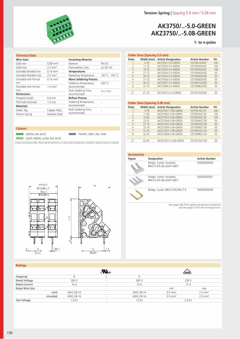
Wire SizesSolid minSolid maxStranded (flexible) minStranded (flexible) maxStranded with Ferrule minStranded with Ferrule maxDimensions Stripped Length
PCB Hole DiameterMaterials
Technical Data
Ratings
130
Insulating Material MaterialFlammability ClassTemperaturesOperating TemperatureWave Soldering ProcessSoldering Temperature,recommendedPeak Soldering Time,recommendedReflow ProcessSoldering Temperature,recommended
Peak Soldering Time,recommended
AccessoriesFigure Designation Article Number
Colours
Order Data (Spacing 5.08 mm)Poles Width (mm) Article Designation Article Number PU
Order Data (Spacing 5.0 mm)Poles Width (mm) Article Designation Article Number PU
Colours according to RAL, there may be variations on colour due to production conditions. Special colours on request.
Tension Spring | Spacing 5.0 mm / 5.08 mm
AK3750/..-5.0-GREENAKZ3750/..-5.08-GREEN
1- to n-poles
1 6.70 AK3750/1-5.0-GREEN 53750010203F 2002 11.70 AK3750/2-5.0-GREEN 53750020203E 1003 16.70 AK3750/3-5.0-GREEN 53750030203E 1004 21.70 AK3750/4-5.0-GREEN 53750040203D 505 26.70 AK3750/5-5.0-GREEN 53750050203D 506 31.70 AK3750/6-5.0-GREEN 53750060203D 507 36.70 AK3750/7-5.0-GREEN 53750070203D 508 41.70 AK3750/8-5.0-GREEN 53750080203D 50... ... ... ... ...12 61.70 AK3750/12-5.0-GREEN 53750120203D 50
Usegroup B C DRated Voltage 300 V - 300 V 250 VRated Current 16 A - 10 A 12 ARated Wire Size min max
solid AWG 28-14 - AWG 28-14 0.5 mm² 2.5 mm²stranded AWG 28-14 - AWG 28-14 0.5 mm² 2.5 mm²
Test Voltage 1.6 kV - 1.6 kV 2.0 kV
GREEN, RAL 6018 TRAFFIC GREY, RAL 7042
LIGHT GREEN, similar RAL 6018
Bridge, 2-pole, insulated, BRI/2-5.0/5.08-LIGHT GREY
50000000006
Bridge, 3-pole, insulated, BRI/3-5.0/5.08-LIGHT GREY
50000000007
Bridge, 2-pole, BR/2-5.0/5.08-L7.0 50000000008
PA 6.6UL 94 V-0
-30 °C - 105 °C
265 °C
3 s / 10 s
-
-
0.08 mm²2.5 mm²0.14 mm²2.5 mm²0.14 mm²
1.5 mm²
6.0 mm
1.3 mm
1 6.78 AKZ3750/1-5.08-GREEN 53750010213F 2002 11.86 AKZ3750/2-5.08-GREEN 53750020213E 1003 16.94 AKZ3750/3-5.08-GREEN 53750030213E 1004 22.02 AKZ3750/4-5.08-GREEN 53750040213D 505 27.10 AKZ3750/5-5.08-GREEN 53750050213D 506 32.18 AKZ3750/6-5.08-GREEN 53750060213D 507 37.26 AKZ3750/7-5.08-GREEN 53750070213D 508 42.34 AKZ3750/8-5.08-GREEN 53750080213D 50... ... ... ... ...12 62.66 AKZ3750/12-5.08-GREEN 53750120213D 50
Solder Tag Copper AlloyTension Spring Stainless Steel
See pages 282 ff for detail and general accessoriesand see pages 12/13 concerning services.
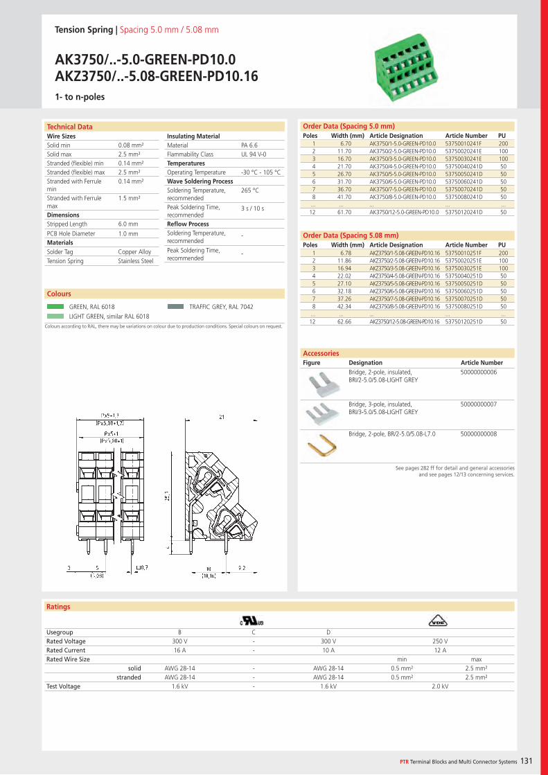
Wire SizesSolid minSolid maxStranded (flexible) minStranded (flexible) maxStranded with Ferrule minStranded with Ferrule maxDimensions Stripped Length
PCB Hole DiameterMaterials
Technical Data
Ratings
PTR Terminal Blocks and Multi Connector Systems 131
Insulating Material MaterialFlammability ClassTemperaturesOperating TemperatureWave Soldering ProcessSoldering Temperature,recommendedPeak Soldering Time,recommendedReflow ProcessSoldering Temperature,recommended
Peak Soldering Time,recommended
Colours
Order Data (Spacing 5.08 mm)Poles Width (mm) Article Designation Article Number PU
Order Data (Spacing 5.0 mm)Poles Width (mm) Article Designation Article Number PU
See pages 282 ff for detail and general accessoriesand see pages 12/13 concerning services.
Colours according to RAL, there may be variations on colour due to production conditions. Special colours on request.
Tension Spring | Spacing 5.0 mm / 5.08 mm
AK3750/..-5.0-GREEN-PD10.0AKZ3750/..-5.08-GREEN-PD10.161- to n-poles
1 6.70 AK3750/1-5.0-GREEN-PD10.0 53750010241F 2002 11.70 AK3750/2-5.0-GREEN-PD10.0 53750020241E 1003 16.70 AK3750/3-5.0-GREEN-PD10.0 53750030241E 1004 21.70 AK3750/4-5.0-GREEN-PD10.0 53750040241D 505 26.70 AK3750/5-5.0-GREEN-PD10.0 53750050241D 506 31.70 AK3750/6-5.0-GREEN-PD10.0 53750060241D 507 36.70 AK3750/7-5.0-GREEN-PD10.0 53750070241D 508 41.70 AK3750/8-5.0-GREEN-PD10.0 53750080241D 50... ... ... ... ...12 61.70 AK3750/12-5.0-GREEN-PD10.0 53750120241D 50
Usegroup B C DRated Voltage 300 V - 300 V 250 VRated Current 16 A - 10 A 12 ARated Wire Size min max
solid AWG 28-14 - AWG 28-14 0.5 mm² 2.5 mm²stranded AWG 28-14 - AWG 28-14 0.5 mm² 2.5 mm²
Test Voltage 1.6 kV - 1.6 kV 2.0 kV
GREEN, RAL 6018 TRAFFIC GREY, RAL 7042
LIGHT GREEN, similar RAL 6018
Bridge, 2-pole, insulated, BRI/2-5.0/5.08-LIGHT GREY
50000000006
Bridge, 3-pole, insulated, BRI/3-5.0/5.08-LIGHT GREY
50000000007
Bridge, 2-pole, BR/2-5.0/5.08-L7.0 50000000008
PA 6.6UL 94 V-0
-30 °C - 105 °C
265 °C
3 s / 10 s
-
-
0.08 mm²2.5 mm²0.14 mm²2.5 mm²0.14 mm²
1.5 mm²
6.0 mm
1.0 mm
1 6.78 AKZ3750/1-5.08-GREEN-PD10.16 53750010251F 2002 11.86 AKZ3750/2-5.08-GREEN-PD10.16 53750020251E 1003 16.94 AKZ3750/3-5.08-GREEN-PD10.16 53750030251E 1004 22.02 AKZ3750/4-5.08-GREEN-PD10.16 53750040251D 505 27.10 AKZ3750/5-5.08-GREEN-PD10.16 53750050251D 506 32.18 AKZ3750/6-5.08-GREEN-PD10.16 53750060251D 507 37.26 AKZ3750/7-5.08-GREEN-PD10.16 53750070251D 508 42.34 AKZ3750/8-5.08-GREEN-PD10.16 53750080251D 50... ... ... ... ...12 62.66 AKZ3750/12-5.08-GREEN-PD10.16 53750120251D 50
Solder Tag Copper AlloyTension Spring Stainless Steel
AccessoriesFigure Designation Article Number
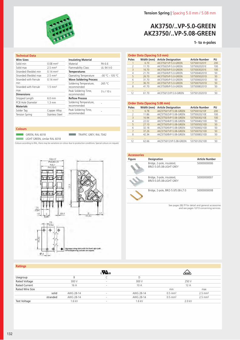
Wire SizesSolid minSolid maxStranded (flexible) minStranded (flexible) maxStranded with Ferrule minStranded with Ferrule maxDimensions Stripped Length
PCB Hole DiameterMaterials
Technical Data
Ratings
AccessoriesFigure Designation Article Number
132
Colours
Insulating Material MaterialFlammability ClassTemperaturesOperating TemperatureWave Soldering ProcessSoldering Temperature,recommendedPeak Soldering Time,recommendedReflow ProcessSoldering Temperature,recommended
Peak Soldering Time,recommended
Order Data (Spacing 5.08 mm)Poles Width (mm) Article Designation Article Number PU
Order Data (Spacing 5.0 mm)Poles Width (mm) Article Designation Article Number PU
See pages 282 ff for detail and general accessoriesand see pages 12/13 concerning services.
Colours according to RAL, there may be variations on colour due to production conditions. Special colours on request.
Tension Spring | Spacing 5.0 mm / 5.08 mm
AK3750/..VP-5.0-GREENAKZ3750/..VP-5.08-GREEN
1- to n-poles
1 6.70 AK3750/1VP-5.0-GREEN 53750010201F 2002 11.70 AK3750/2VP-5.0-GREEN 53750020201E 1003 16.70 AK3750/3VP-5.0-GREEN 53750030201E 1004 21.70 AK3750/4VP-5.0-GREEN 53750040201D 505 26.70 AK3750/5VP-5.0-GREEN 53750050201D 506 31.70 AK3750/6VP-5.0-GREEN 53750060201D 507 36.70 AK3750/7VP-5.0-GREEN 53750070201D 508 41.70 AK3750/8VP-5.0-GREEN 53750080201D 50... ... ... ... ...12 61.70 AK3750/12VP-5.0-GREEN 53750120201D 50
Usegroup B C DRated Voltage 300 V - 300 V 250 VRated Current 16 A - 10 A 12 ARated Wire Size min max
solid AWG 28-14 - AWG 28-14 0.5 mm² 2.5 mm²stranded AWG 28-14 - AWG 28-14 0.5 mm² 2.5 mm²
Test Voltage 1.6 kV - 1.6 kV 2.0 kV
GREEN, RAL 6018 TRAFFIC GREY, RAL 7042
LIGHT GREEN, similar RAL 6018
Bridge, 2-pole, insulated, BRI/2-5.0/5.08-LIGHT GREY
50000000006
Bridge, 3-pole, insulated, BRI/3-5.0/5.08-LIGHT GREY
50000000007
Bridge, 2-pole, BR/2-5.0/5.08-L7.0 50000000008
PA 6.6UL 94 V-0
-30 °C - 105 °C
265 °C
3 s / 10 s
-
-
0.08 mm²2.5 mm²0.14 mm²2.5 mm²0.14 mm²
1.5 mm²
6.0 mm
1.3 mm
1 6.78 AKZ3750/1VP-5.08-GREEN 53750010210F 2002 11.86 AKZ3750/2VP-5.08-GREEN 53750020210E 1003 16.94 AKZ3750/3VP-5.08-GREEN 53750030210E 1004 22.02 AKZ3750/4VP-5.08-GREEN 53750040210D 505 27.10 AKZ3750/5VP-5.08-GREEN 53750050210D 506 32.18 AKZ3750/6VP-5.08-GREEN 53750060210D 507 37.26 AKZ3750/7VP-5.08-GREEN 53750070210D 508 42.34 AKZ3750/8VP-5.08-GREEN 53750080210D 50... ... ... ... ...12 62.66 AKZ3750/12VP-5.08-GREEN 53750120210D 50
Solder Tag Copper AlloyTension Spring Stainless Steel
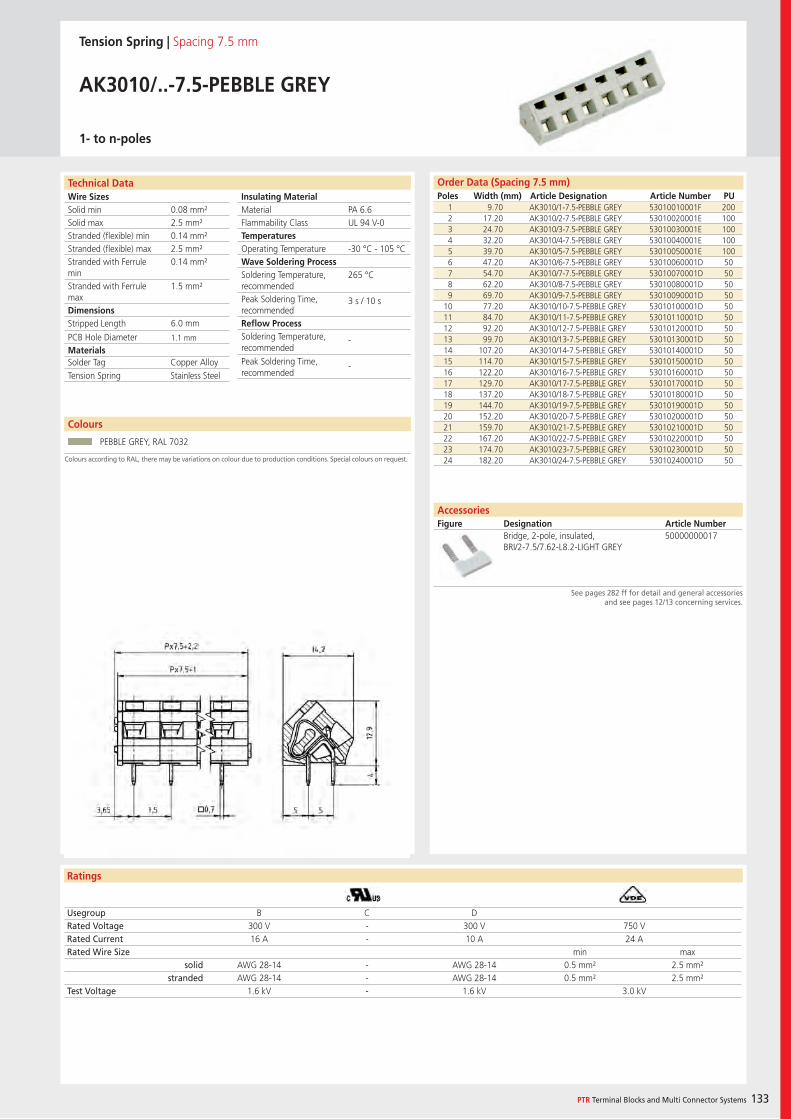
Wire SizesSolid minSolid maxStranded (flexible) minStranded (flexible) maxStranded with Ferrule minStranded with Ferrule maxDimensions Stripped Length
PCB Hole DiameterMaterials
Technical Data
Ratings
Colours
PTR Terminal Blocks and Multi Connector Systems 133
Insulating Material MaterialFlammability ClassTemperaturesOperating TemperatureWave Soldering ProcessSoldering Temperature,recommendedPeak Soldering Time,recommendedReflow ProcessSoldering Temperature,recommended
Peak Soldering Time,recommended
Order Data (Spacing 7.5 mm)Poles Width (mm) Article Designation Article Number PU
Colours according to RAL, there may be variations on colour due to production conditions. Special colours on request.
AccessoriesFigure Designation Article Number
See pages 282 ff for detail and general accessoriesand see pages 12/13 concerning services.
Tension Spring | Spacing 7.5 mm
AK3010/..-7.5-PEBBLE GREY
1- to n-poles
1 9.70 AK3010/1-7.5-PEBBLE GREY 53010010001F 2002 17.20 AK3010/2-7.5-PEBBLE GREY 53010020001E 1003 24.70 AK3010/3-7.5-PEBBLE GREY 53010030001E 1004 32.20 AK3010/4-7.5-PEBBLE GREY 53010040001E 1005 39.70 AK3010/5-7.5-PEBBLE GREY 53010050001E 1006 47.20 AK3010/6-7.5-PEBBLE GREY 53010060001D 507 54.70 AK3010/7-7.5-PEBBLE GREY 53010070001D 508 62.20 AK3010/8-7.5-PEBBLE GREY 53010080001D 509 69.70 AK3010/9-7.5-PEBBLE GREY 53010090001D 50
10 77.20 AK3010/10-7.5-PEBBLE GREY 53010100001D 5011 84.70 AK3010/11-7.5-PEBBLE GREY 53010110001D 5012 92.20 AK3010/12-7.5-PEBBLE GREY 53010120001D 5013 99.70 AK3010/13-7.5-PEBBLE GREY 53010130001D 5014 107.20 AK3010/14-7.5-PEBBLE GREY 53010140001D 5015 114.70 AK3010/15-7.5-PEBBLE GREY 53010150001D 5016 122.20 AK3010/16-7.5-PEBBLE GREY 53010160001D 5017 129.70 AK3010/17-7.5-PEBBLE GREY 53010170001D 5018 137.20 AK3010/18-7.5-PEBBLE GREY 53010180001D 5019 144.70 AK3010/19-7.5-PEBBLE GREY 53010190001D 5020 152.20 AK3010/20-7.5-PEBBLE GREY 53010200001D 5021 159.70 AK3010/21-7.5-PEBBLE GREY 53010210001D 5022 167.20 AK3010/22-7.5-PEBBLE GREY 53010220001D 5023 174.70 AK3010/23-7.5-PEBBLE GREY 53010230001D 5024 182.20 AK3010/24-7.5-PEBBLE GREY 53010240001D 50
Usegroup B C DRated Voltage 300 V - 300 V 750 VRated Current 16 A - 10 A 24 ARated Wire Size min max
solid AWG 28-14 - AWG 28-14 0.5 mm² 2.5 mm²stranded AWG 28-14 - AWG 28-14 0.5 mm² 2.5 mm²
Test Voltage 1.6 kV - 1.6 kV 3.0 kV
PEBBLE GREY, RAL 7032
Bridge, 2-pole, insulated, BRI/2-7.5/7.62-L8.2-LIGHT GREY
50000000017
PA 6.6UL 94 V-0
-30 °C - 105 °C
265 °C
3 s / 10 s
-
-
0.08 mm²2.5 mm²0.14 mm²2.5 mm²0.14 mm²
1.5 mm²
6.0 mm
1.1 mm
Solder Tag Copper AlloyTension Spring Stainless Steel
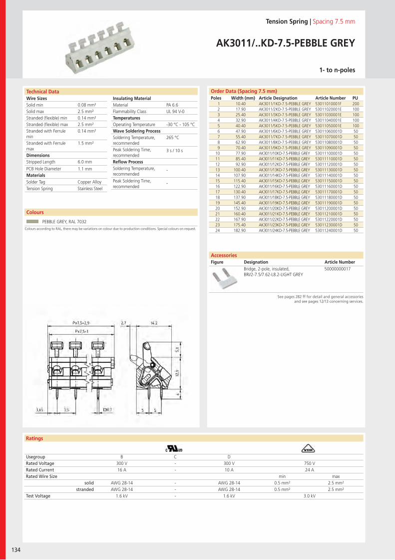
Wire SizesSolid minSolid maxStranded (flexible) minStranded (flexible) maxStranded with Ferrule minStranded with Ferrule maxDimensions Stripped Length
PCB Hole DiameterMaterials
Technical Data
Ratings
134
Insulating Material MaterialFlammability ClassTemperaturesOperating TemperatureWave Soldering ProcessSoldering Temperature,recommendedPeak Soldering Time,recommendedReflow ProcessSoldering Temperature,recommended
Peak Soldering Time,recommended
Colours
Order Data (Spacing 7.5 mm)Poles Width (mm) Article Designation Article Number PU
Colours according to RAL, there may be variations on colour due to production conditions. Special colours on request.
Tension Spring | Spacing 7.5 mm
AK3011/..KD-7.5-PEBBLE GREY
1- to n-poles
1 10.40 AK3011/1KD-7.5-PEBBLE GREY 53011010001F 2002 17.90 AK3011/2KD-7.5-PEBBLE GREY 53011020001E 1003 25.40 AK3011/3KD-7.5-PEBBLE GREY 53011030001E 1004 32.90 AK3011/4KD-7.5-PEBBLE GREY 53011040001E 1005 40.40 AK3011/5KD-7.5-PEBBLE GREY 53011050001E 1006 47.90 AK3011/6KD-7.5-PEBBLE GREY 53011060001D 507 55.40 AK3011/7KD-7.5-PEBBLE GREY 53011070001D 508 62.90 AK3011/8KD-7.5-PEBBLE GREY 53011080001D 509 70.40 AK3011/9KD-7.5-PEBBLE GREY 53011090001D 50
10 77.90 AK3011/10KD-7.5-PEBBLE GREY 53011100001D 5011 85.40 AK3011/11KD-7.5-PEBBLE GREY 53011110001D 5012 92.90 AK3011/12KD-7.5-PEBBLE GREY 53011120001D 5013 100.40 AK3011/13KD-7.5-PEBBLE GREY 53011130001D 5014 107.90 AK3011/14KD-7.5-PEBBLE GREY 53011140001D 5015 115.40 AK3011/15KD-7.5-PEBBLE GREY 53011150001D 5016 122.90 AK3011/16KD-7.5-PEBBLE GREY 53011160001D 5017 130.40 AK3011/17KD-7.5-PEBBLE GREY 53011170001D 5018 137.90 AK3011/18KD-7.5-PEBBLE GREY 53011180001D 5019 145.40 AK3011/19KD-7.5-PEBBLE GREY 53011190001D 5020 152.90 AK3011/20KD-7.5-PEBBLE GREY 53011200001D 5021 160.40 AK3011/21KD-7.5-PEBBLE GREY 53011210001D 5022 167.90 AK3011/22KD-7.5-PEBBLE GREY 53011220001D 5023 175.40 AK3011/23KD-7.5-PEBBLE GREY 53011230001D 5024 182.90 AK3011/24KD-7.5-PEBBLE GREY 53011240001D 50
Usegroup B C DRated Voltage 300 V - 300 V 750 VRated Current 16 A - 10 A 24 ARated Wire Size min max
solid AWG 28-14 - AWG 28-14 0.5 mm² 2.5 mm²stranded AWG 28-14 - AWG 28-14 0.5 mm² 2.5 mm²
Test Voltage 1.6 kV - 1.6 kV 3.0 kV
PEBBLE GREY, RAL 7032
AccessoriesFigure Designation Article Number
See pages 282 ff for detail and general accessoriesand see pages 12/13 concerning services.
Bridge, 2-pole, insulated, BRI/2-7.5/7.62-L8.2-LIGHT GREY
50000000017
PA 6.6UL 94 V-0
-30 °C - 105 °C
265 °C
3 s / 10 s
-
-
0.08 mm²2.5 mm²0.14 mm²2.5 mm²0.14 mm²
1.5 mm²
6.0 mm
1.1 mm
Solder Tag Copper AlloyTension Spring Stainless Steel
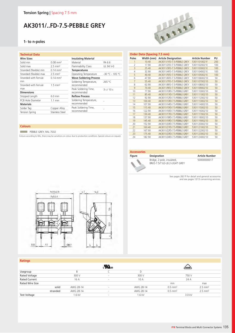
Wire SizesSolid minSolid maxStranded (flexible) minStranded (flexible) maxStranded with Ferrule minStranded with Ferrule maxDimensions Stripped Length
PCB Hole DiameterMaterials
Ratings
PTR Terminal Blocks and Multi Connector Systems 135
Insulating Material MaterialFlammability ClassTemperaturesOperating TemperatureWave Soldering ProcessSoldering Temperature,recommendedPeak Soldering Time,recommendedReflow ProcessSoldering Temperature,recommended
Peak Soldering Time,recommended
Technical Data
Colours
AccessoriesFigure Designation Article Number
Order Data (Spacing 7.5 mm)Poles Width (mm) Article Designation Article Number PU
See pages 282 ff for detail and general accessoriesand see pages 12/13 concerning services.
Colours according to RAL, there may be variations on colour due to production conditions. Special colours on request.
Tension Spring | Spacing 7.5 mm
AK3011/..FD-7.5-PEBBLE GREY
1- to n-poles
1 10.40 AK3011/1FD-7.5-PEBBLE GREY 53011010021F 2002 17.90 AK3011/2FD-7.5-PEBBLE GREY 53011020021E 1003 25.40 AK3011/3FD-7.5-PEBBLE GREY 53011030021E 1004 32.90 AK3011/4FD-7.5-PEBBLE GREY 53011040021E 1005 40.40 AK3011/5FD-7.5-PEBBLE GREY 53011050021E 1006 47.90 AK3011/6FD-7.5-PEBBLE GREY 53011060021D 507 55.40 AK3011/7FD-7.5-PEBBLE GREY 53011070021D 508 62.90 AK3011/8FD-7.5-PEBBLE GREY 53011080021D 509 70.40 AK3011/9FD-7.5-PEBBLE GREY 53011090021D 50
10 77.90 AK3011/10FD-7.5-PEBBLE GREY 53011100021D 5011 85.40 AK3011/11FD-7.5-PEBBLE GREY 53011110021D 5012 92.90 AK3011/12FD-7.5-PEBBLE GREY 53011120021D 5013 100.40 AK3011/13FD-7.5-PEBBLE GREY 53011130021D 5014 107.90 AK3011/14FD-7.5-PEBBLE GREY 53011140021D 5015 115.40 AK3011/15FD-7.5-PEBBLE GREY 53011150021D 5016 122.90 AK3011/16FD-7.5-PEBBLE GREY 53011160021D 5017 130.40 AK3011/17FD-7.5-PEBBLE GREY 53011170021D 5018 137.90 AK3011/18FD-7.5-PEBBLE GREY 53011180021D 5019 145.40 AK3011/19FD-7.5-PEBBLE GREY 53011190021D 5020 152.90 AK3011/20FD-7.5-PEBBLE GREY 53011200021D 5021 160.40 AK3011/21FD-7.5-PEBBLE GREY 53011210021D 5022 167.90 AK3011/22FD-7.5-PEBBLE GREY 53011220021D 5023 175.40 AK3011/23FD-7.5-PEBBLE GREY 53011230021D 5024 182.90 AK3011/24FD-7.5-PEBBLE GREY 53011240021D 50
Usegroup B C DRated Voltage 300 V - 300 V 750 VRated Current 16 A - 10 A 24 ARated Wire Size min max
solid AWG 28-14 - AWG 28-14 0.5 mm² 2.5 mm²stranded AWG 28-14 - AWG 28-14 0.5 mm² 2.5 mm²
Test Voltage 1.6 kV - 1.6 kV 3.0 kV
PEBBLE GREY, RAL 7032
Bridge, 2-pole, insulated, BRI/2-7.5/7.62-L8.2-LIGHT GREY
50000000017
PA 6.6UL 94 V-0
-30 °C - 105 °C
265 °C
3 s / 10 s
-
-
0.08 mm²2.5 mm²0.14 mm²2.5 mm²0.14 mm²
1.5 mm²
6.0 mm
1.1 mm
Solder Tag Copper AlloyTension Spring Stainless Steel
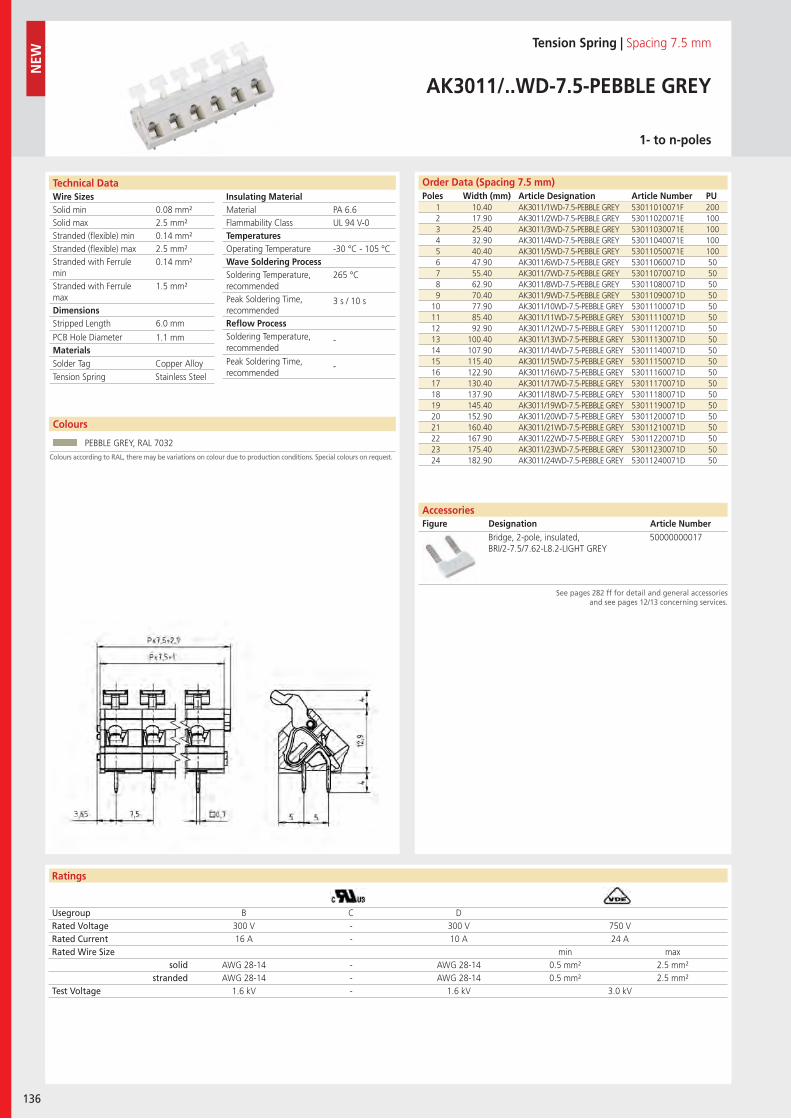
Wire SizesSolid minSolid maxStranded (flexible) minStranded (flexible) maxStranded with Ferrule minStranded with Ferrule maxDimensions Stripped Length
PCB Hole DiameterMaterials
Technical Data
Ratings
AccessoriesFigure Designation Article Number
136
Colours
Insulating Material MaterialFlammability ClassTemperaturesOperating TemperatureWave Soldering ProcessSoldering Temperature,recommendedPeak Soldering Time,recommendedReflow ProcessSoldering Temperature,recommended
Peak Soldering Time,recommended
Order Data (Spacing 7.5 mm)Poles Width (mm) Article Designation Article Number PU
NEW
See pages 282 ff for detail and general accessoriesand see pages 12/13 concerning services.
Colours according to RAL, there may be variations on colour due to production conditions. Special colours on request.
Tension Spring | Spacing 7.5 mm
AK3011/..WD-7.5-PEBBLE GREY
1- to n-poles
1 10.40 AK3011/1WD-7.5-PEBBLE GREY 53011010071F 2002 17.90 AK3011/2WD-7.5-PEBBLE GREY 53011020071E 1003 25.40 AK3011/3WD-7.5-PEBBLE GREY 53011030071E 1004 32.90 AK3011/4WD-7.5-PEBBLE GREY 53011040071E 1005 40.40 AK3011/5WD-7.5-PEBBLE GREY 53011050071E 1006 47.90 AK3011/6WD-7.5-PEBBLE GREY 53011060071D 507 55.40 AK3011/7WD-7.5-PEBBLE GREY 53011070071D 508 62.90 AK3011/8WD-7.5-PEBBLE GREY 53011080071D 509 70.40 AK3011/9WD-7.5-PEBBLE GREY 53011090071D 50
10 77.90 AK3011/10WD-7.5-PEBBLE GREY 53011100071D 5011 85.40 AK3011/11WD-7.5-PEBBLE GREY 53011110071D 5012 92.90 AK3011/12WD-7.5-PEBBLE GREY 53011120071D 5013 100.40 AK3011/13WD-7.5-PEBBLE GREY 53011130071D 5014 107.90 AK3011/14WD-7.5-PEBBLE GREY 53011140071D 5015 115.40 AK3011/15WD-7.5-PEBBLE GREY 53011150071D 5016 122.90 AK3011/16WD-7.5-PEBBLE GREY 53011160071D 5017 130.40 AK3011/17WD-7.5-PEBBLE GREY 53011170071D 5018 137.90 AK3011/18WD-7.5-PEBBLE GREY 53011180071D 5019 145.40 AK3011/19WD-7.5-PEBBLE GREY 53011190071D 5020 152.90 AK3011/20WD-7.5-PEBBLE GREY 53011200071D 5021 160.40 AK3011/21WD-7.5-PEBBLE GREY 53011210071D 5022 167.90 AK3011/22WD-7.5-PEBBLE GREY 53011220071D 5023 175.40 AK3011/23WD-7.5-PEBBLE GREY 53011230071D 5024 182.90 AK3011/24WD-7.5-PEBBLE GREY 53011240071D 50
Usegroup B C DRated Voltage 300 V - 300 V 750 VRated Current 16 A - 10 A 24 ARated Wire Size min max
solid AWG 28-14 - AWG 28-14 0.5 mm² 2.5 mm²stranded AWG 28-14 - AWG 28-14 0.5 mm² 2.5 mm²
Test Voltage 1.6 kV - 1.6 kV 3.0 kV
PEBBLE GREY, RAL 7032
Bridge, 2-pole, insulated, BRI/2-7.5/7.62-L8.2-LIGHT GREY
50000000017
PA 6.6UL 94 V-0
-30 °C - 105 °C
265 °C
3 s / 10 s
-
-
0.08 mm²2.5 mm²0.14 mm²2.5 mm²0.14 mm²
1.5 mm²
6.0 mm
1.1 mm
Solder Tag Copper AlloyTension Spring Stainless Steel
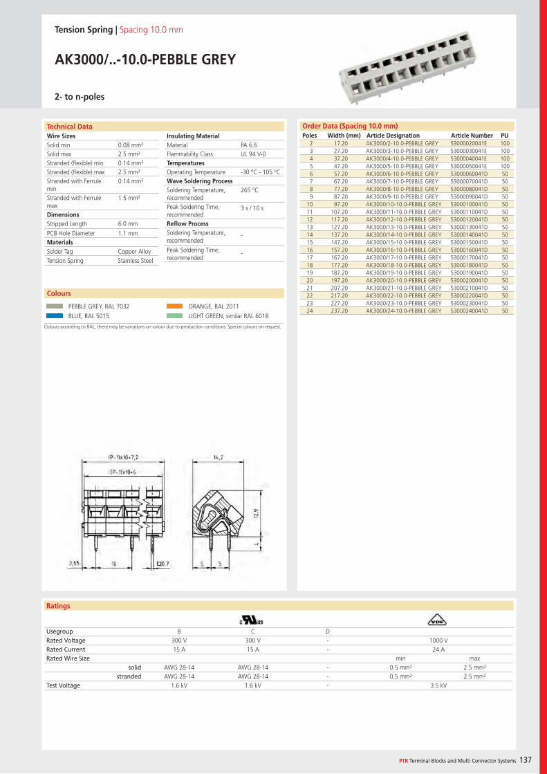
Wire SizesSolid minSolid maxStranded (flexible) minStranded (flexible) maxStranded with Ferrule minStranded with Ferrule maxDimensions Stripped Length
PCB Hole DiameterMaterials
Ratings
PTR Terminal Blocks and Multi Connector Systems 137
Insulating Material MaterialFlammability ClassTemperaturesOperating TemperatureWave Soldering ProcessSoldering Temperature,recommendedPeak Soldering Time,recommendedReflow ProcessSoldering Temperature,recommended
Peak Soldering Time,recommended
Order Data (Spacing 10.0 mm)Poles Width (mm) Article Designation Article Number PU
Colours
Technical Data
Tension Spring | Spacing 10.0 mm
AK3000/..-10.0-PEBBLE GREY
2- to n-poles
2 17.20 AK3000/2-10.0-PEBBLE GREY 53000020041E 1003 27.20 AK3000/3-10.0-PEBBLE GREY 53000030041E 1004 37.20 AK3000/4-10.0-PEBBLE GREY 53000040041E 1005 47.20 AK3000/5-10.0-PEBBLE GREY 53000050041E 1006 57.20 AK3000/6-10.0-PEBBLE GREY 53000060041D 507 67.20 AK3000/7-10.0-PEBBLE GREY 53000070041D 508 77.20 AK3000/8-10.0-PEBBLE GREY 53000080041D 509 87.20 AK3000/9-10.0-PEBBLE GREY 53000090041D 50
10 97.20 AK3000/10-10.0-PEBBLE GREY 53000100041D 5011 107.20 AK3000/11-10.0-PEBBLE GREY 53000110041D 5012 117.20 AK3000/12-10.0-PEBBLE GREY 53000120041D 5013 127.20 AK3000/13-10.0-PEBBLE GREY 53000130041D 5014 137.20 AK3000/14-10.0-PEBBLE GREY 53000140041D 5015 147.20 AK3000/15-10.0-PEBBLE GREY 53000150041D 5016 157.20 AK3000/16-10.0-PEBBLE GREY 53000160041D 5017 167.20 AK3000/17-10.0-PEBBLE GREY 53000170041D 5018 177.20 AK3000/18-10.0-PEBBLE GREY 53000180041D 5019 187.20 AK3000/19-10.0-PEBBLE GREY 53000190041D 5020 197.20 AK3000/20-10.0-PEBBLE GREY 53000200041D 5021 207.20 AK3000/21-10.0-PEBBLE GREY 53000210041D 5022 217.20 AK3000/22-10.0-PEBBLE GREY 53000220041D 5023 227.20 AK3000/23-10.0-PEBBLE GREY 53000230041D 5024 237.20 AK3000/24-10.0-PEBBLE GREY 53000240041D 50
Usegroup B C DRated Voltage 300 V 300 V - 1000 VRated Current 15 A 15 A - 24 ARated Wire Size min max
solid AWG 28-14 AWG 28-14 - 0.5 mm² 2.5 mm²stranded AWG 28-14 AWG 28-14 - 0.5 mm² 2.5 mm²
Test Voltage 1.6 kV 1.6 kV - 3.5 kV
Colours according to RAL, there may be variations on colour due to production conditions. Special colours on request.
PEBBLE GREY, RAL 7032 ORANGE, RAL 2011
BLUE, RAL 5015 LIGHT GREEN, similar RAL 6018
PA 6.6UL 94 V-0
-30 °C - 105 °C
265 °C
3 s / 10 s
-
-
0.08 mm²2.5 mm²0.14 mm²2.5 mm²0.14 mm²
1.5 mm²
6.0 mm
1.1 mm
Solder Tag Copper AlloyTension Spring Stainless Steel
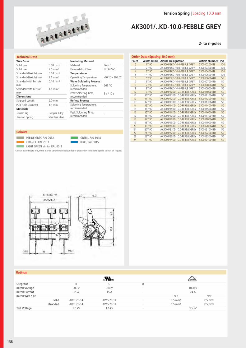
Wire SizesSolid minSolid maxStranded (flexible) minStranded (flexible) maxStranded with Ferrule minStranded with Ferrule maxDimensions Stripped Length
PCB Hole DiameterMaterials
Ratings
138
Insulating Material MaterialFlammability ClassTemperaturesOperating TemperatureWave Soldering ProcessSoldering Temperature,recommendedPeak Soldering Time,recommendedReflow ProcessSoldering Temperature,recommended
Peak Soldering Time,recommended
Technical Data Order Data (Spacing 10.0 mm)Poles Width (mm) Article Designation Article Number PU
Tension Spring | Spacing 10.0 mm
AK3001/..KD-10.0-PEBBLE GREY
2- to n-poles
2 17.90 AK3001/2KD-10.0-PEBBLE GREY 53001020041E 1003 27.90 AK3001/3KD-10.0-PEBBLE GREY 53001030041E 1004 37.90 AK3001/4KD-10.0-PEBBLE GREY 53001040041E 1005 47.90 AK3001/5KD-10.0-PEBBLE GREY 53001050041E 1006 57.90 AK3001/6KD-10.0-PEBBLE GREY 53001060041D 507 67.90 AK3001/7KD-10.0-PEBBLE GREY 53001070041D 508 77.90 AK3001/8KD-10.0-PEBBLE GREY 53001080041D 509 87.90 AK3001/9KD-10.0-PEBBLE GREY 53001090041D 50
10 97.90 AK3001/10KD-10.0-PEBBLE GREY 53001100041D 5011 107.90 AK3001/11KD-10.0-PEBBLE GREY 53001110041D 5012 117.90 AK3001/12KD-10.0-PEBBLE GREY 53001120041D 5013 127.90 AK3001/13KD-10.0-PEBBLE GREY 53001130041D 5014 137.90 AK3001/14KD-10.0-PEBBLE GREY 53001140041D 5015 147.90 AK3001/15KD-10.0-PEBBLE GREY 53001150041D 5016 157.90 AK3001/16KD-10.0-PEBBLE GREY 53001160041D 5017 167.90 AK3001/17KD-10.0-PEBBLE GREY 53001170041D 5018 177.90 AK3001/18KD-10.0-PEBBLE GREY 53001180041D 5019 187.90 AK3001/19KD-10.0-PEBBLE GREY 53001190041D 5020 197.90 AK3001/20KD-10.0-PEBBLE GREY 53001200041D 5021 207.90 AK3001/21KD-10.0-PEBBLE GREY 53001210041D 5022 217.90 AK3001/22KD-10.0-PEBBLE GREY 53001220041D 5023 227.90 AK3001/23KD-10.0-PEBBLE GREY 53001230041D 5024 237.90 AK3001/24KD-10.0-PEBBLE GREY 53001240041D 50
Usegroup B C DRated Voltage 300 V 300 V - 1000 VRated Current 15 A 15 A - 24 ARated Wire Size min max
solid AWG 28-14 AWG 28-14 - 0.5 mm² 2.5 mm²stranded AWG 28-14 AWG 28-14 - 0.5 mm² 2.5 mm²
Test Voltage 1.6 kV 1.6 kV - 3.5 kV
Colours according to RAL, there may be variations on colour due to production conditions. Special colours on request.
Colours
PEBBLE GREY, RAL 7032 GREEN, RAL 6018
ORANGE, RAL 2011 BLUE, RAL 5015
LIGHT GREEN, similar RAL 6018
PA 6.6UL 94 V-0
-30 °C - 105 °C
265 °C
3 s / 10 s
-
-
0.08 mm²2.5 mm²0.14 mm²2.5 mm²0.14 mm²
1.5 mm²
6.0 mm
1.1 mm
Solder Tag Copper AlloyTension Spring Stainless Steel
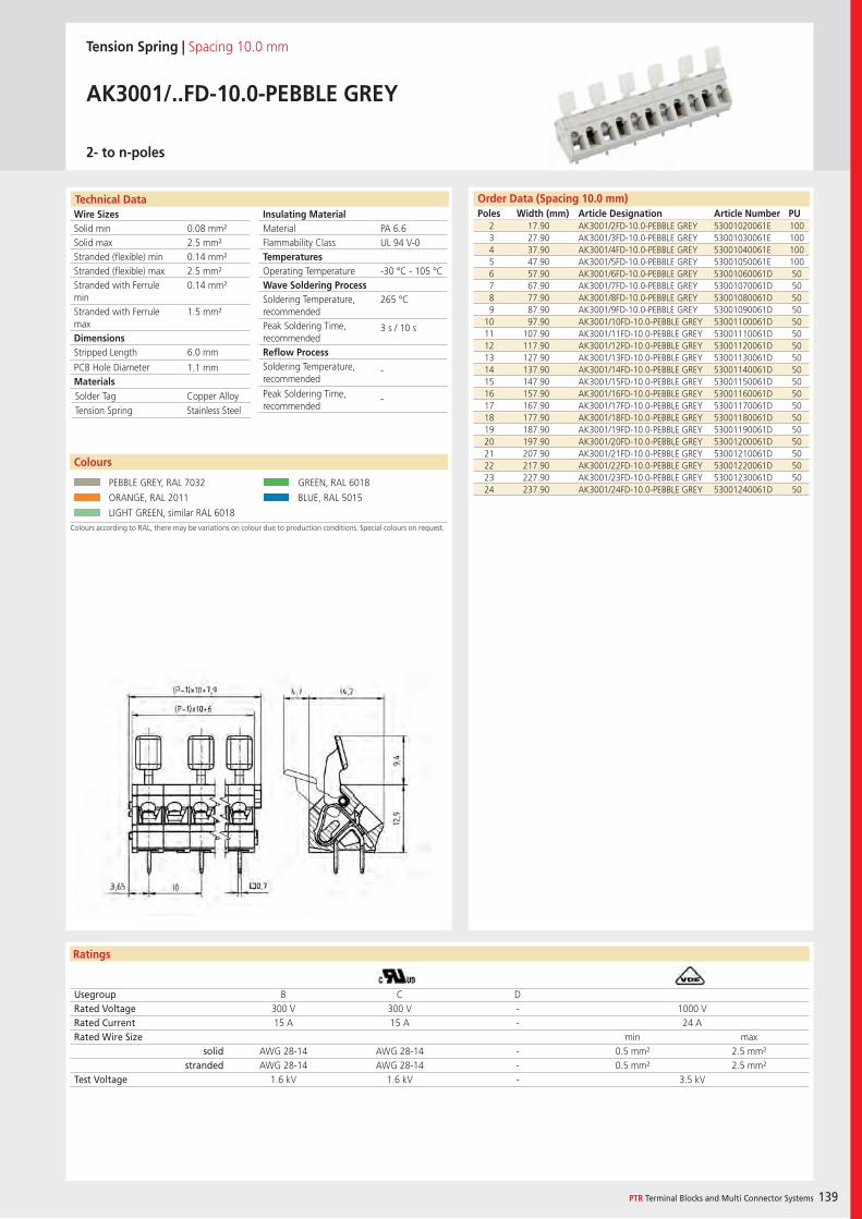
Wire SizesSolid minSolid maxStranded (flexible) minStranded (flexible) maxStranded with Ferrule minStranded with Ferrule maxDimensions Stripped Length
PCB Hole DiameterMaterials
Ratings
PTR Terminal Blocks and Multi Connector Systems 139
Insulating Material MaterialFlammability ClassTemperaturesOperating TemperatureWave Soldering ProcessSoldering Temperature,recommendedPeak Soldering Time,recommendedReflow ProcessSoldering Temperature,recommended
Peak Soldering Time,recommended
Technical Data Order Data (Spacing 10.0 mm)Poles Width (mm) Article Designation Article Number PU
Tension Spring | Spacing 10.0 mm
AK3001/..FD-10.0-PEBBLE GREY
2- to n-poles
2 17.90 AK3001/2FD-10.0-PEBBLE GREY 53001020061E 1003 27.90 AK3001/3FD-10.0-PEBBLE GREY 53001030061E 1004 37.90 AK3001/4FD-10.0-PEBBLE GREY 53001040061E 1005 47.90 AK3001/5FD-10.0-PEBBLE GREY 53001050061E 1006 57.90 AK3001/6FD-10.0-PEBBLE GREY 53001060061D 507 67.90 AK3001/7FD-10.0-PEBBLE GREY 53001070061D 508 77.90 AK3001/8FD-10.0-PEBBLE GREY 53001080061D 509 87.90 AK3001/9FD-10.0-PEBBLE GREY 53001090061D 50
10 97.90 AK3001/10FD-10.0-PEBBLE GREY 53001100061D 5011 107.90 AK3001/11FD-10.0-PEBBLE GREY 53001110061D 5012 117.90 AK3001/12FD-10.0-PEBBLE GREY 53001120061D 5013 127.90 AK3001/13FD-10.0-PEBBLE GREY 53001130061D 5014 137.90 AK3001/14FD-10.0-PEBBLE GREY 53001140061D 5015 147.90 AK3001/15FD-10.0-PEBBLE GREY 53001150061D 5016 157.90 AK3001/16FD-10.0-PEBBLE GREY 53001160061D 5017 167.90 AK3001/17FD-10.0-PEBBLE GREY 53001170061D 5018 177.90 AK3001/18FD-10.0-PEBBLE GREY 53001180061D 5019 187.90 AK3001/19FD-10.0-PEBBLE GREY 53001190061D 5020 197.90 AK3001/20FD-10.0-PEBBLE GREY 53001200061D 5021 207.90 AK3001/21FD-10.0-PEBBLE GREY 53001210061D 5022 217.90 AK3001/22FD-10.0-PEBBLE GREY 53001220061D 5023 227.90 AK3001/23FD-10.0-PEBBLE GREY 53001230061D 5024 237.90 AK3001/24FD-10.0-PEBBLE GREY 53001240061D 50
Usegroup B C DRated Voltage 300 V 300 V - 1000 VRated Current 15 A 15 A - 24 ARated Wire Size min max
solid AWG 28-14 AWG 28-14 - 0.5 mm² 2.5 mm²stranded AWG 28-14 AWG 28-14 - 0.5 mm² 2.5 mm²
Test Voltage 1.6 kV 1.6 kV - 3.5 kV
Colours according to RAL, there may be variations on colour due to production conditions. Special colours on request.
Colours
PEBBLE GREY, RAL 7032 GREEN, RAL 6018
ORANGE, RAL 2011 BLUE, RAL 5015
LIGHT GREEN, similar RAL 6018
PA 6.6UL 94 V-0
-30 °C - 105 °C
265 °C
3 s / 10 s
-
-
0.08 mm²2.5 mm²0.14 mm²2.5 mm²0.14 mm²
1.5 mm²
6.0 mm
1.1 mm
Solder Tag Copper AlloyTension Spring Stainless Steel
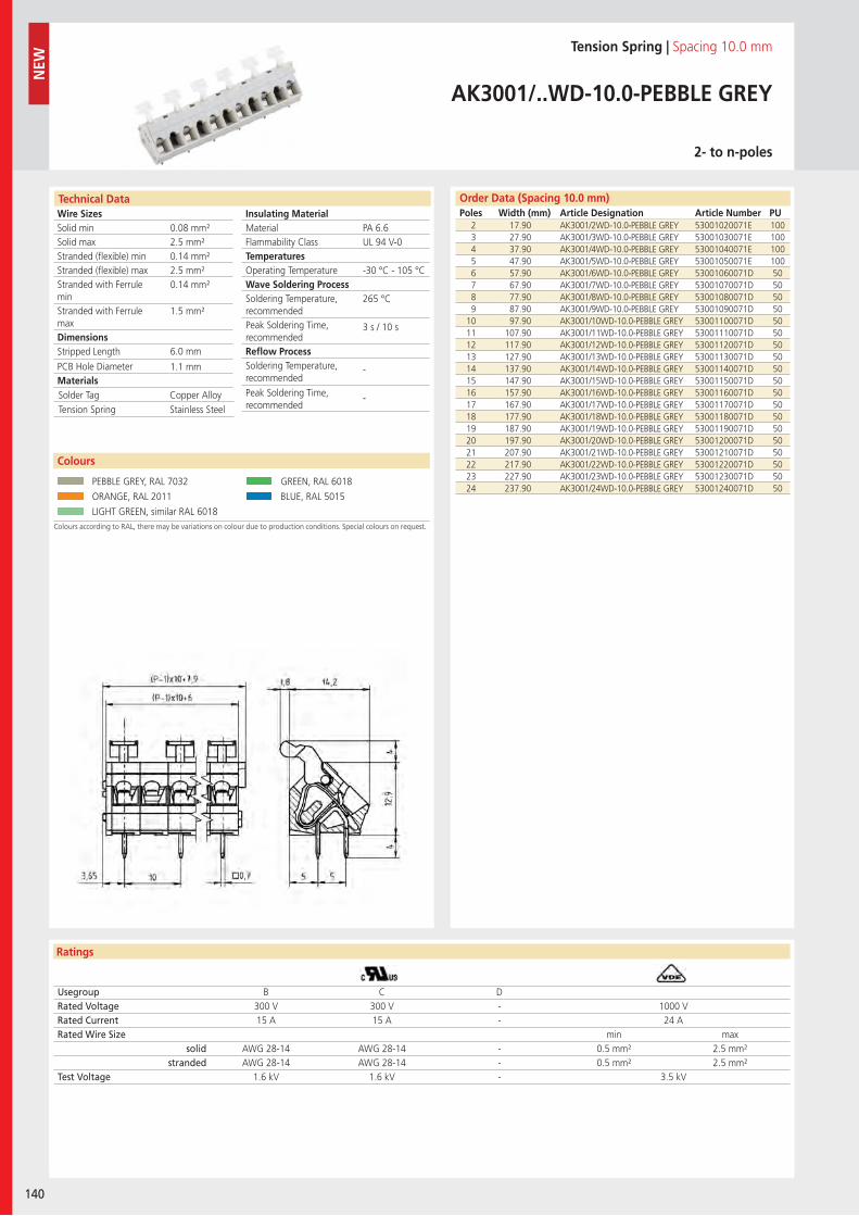
Wire SizesSolid minSolid maxStranded (flexible) minStranded (flexible) maxStranded with Ferrule minStranded with Ferrule maxDimensions Stripped Length
PCB Hole DiameterMaterials
Ratings
140
Insulating Material MaterialFlammability ClassTemperaturesOperating TemperatureWave Soldering ProcessSoldering Temperature,recommendedPeak Soldering Time,recommendedReflow ProcessSoldering Temperature,recommended
Peak Soldering Time,recommended
NEW
Technical Data Order Data (Spacing 10.0 mm)Poles Width (mm) Article Designation Article Number PU
Tension Spring | Spacing 10.0 mm
AK3001/..WD-10.0-PEBBLE GREY
2- to n-poles
2 17.90 AK3001/2WD-10.0-PEBBLE GREY 53001020071E 1003 27.90 AK3001/3WD-10.0-PEBBLE GREY 53001030071E 1004 37.90 AK3001/4WD-10.0-PEBBLE GREY 53001040071E 1005 47.90 AK3001/5WD-10.0-PEBBLE GREY 53001050071E 1006 57.90 AK3001/6WD-10.0-PEBBLE GREY 53001060071D 507 67.90 AK3001/7WD-10.0-PEBBLE GREY 53001070071D 508 77.90 AK3001/8WD-10.0-PEBBLE GREY 53001080071D 509 87.90 AK3001/9WD-10.0-PEBBLE GREY 53001090071D 50
10 97.90 AK3001/10WD-10.0-PEBBLE GREY 53001100071D 5011 107.90 AK3001/11WD-10.0-PEBBLE GREY 53001110071D 5012 117.90 AK3001/12WD-10.0-PEBBLE GREY 53001120071D 5013 127.90 AK3001/13WD-10.0-PEBBLE GREY 53001130071D 5014 137.90 AK3001/14WD-10.0-PEBBLE GREY 53001140071D 5015 147.90 AK3001/15WD-10.0-PEBBLE GREY 53001150071D 5016 157.90 AK3001/16WD-10.0-PEBBLE GREY 53001160071D 5017 167.90 AK3001/17WD-10.0-PEBBLE GREY 53001170071D 5018 177.90 AK3001/18WD-10.0-PEBBLE GREY 53001180071D 5019 187.90 AK3001/19WD-10.0-PEBBLE GREY 53001190071D 5020 197.90 AK3001/20WD-10.0-PEBBLE GREY 53001200071D 5021 207.90 AK3001/21WD-10.0-PEBBLE GREY 53001210071D 5022 217.90 AK3001/22WD-10.0-PEBBLE GREY 53001220071D 5023 227.90 AK3001/23WD-10.0-PEBBLE GREY 53001230071D 5024 237.90 AK3001/24WD-10.0-PEBBLE GREY 53001240071D 50
Usegroup B C DRated Voltage 300 V 300 V - 1000 VRated Current 15 A 15 A - 24 ARated Wire Size min max
solid AWG 28-14 AWG 28-14 - 0.5 mm² 2.5 mm²stranded AWG 28-14 AWG 28-14 - 0.5 mm² 2.5 mm²
Test Voltage 1.6 kV 1.6 kV - 3.5 kV
Colours according to RAL, there may be variations on colour due to production conditions. Special colours on request.
Colours
PEBBLE GREY, RAL 7032 GREEN, RAL 6018
ORANGE, RAL 2011 BLUE, RAL 5015
LIGHT GREEN, similar RAL 6018
PA 6.6UL 94 V-0
-30 °C - 105 °C
265 °C
3 s / 10 s
-
-
0.08 mm²2.5 mm²0.14 mm²2.5 mm²0.14 mm²
1.5 mm²
6.0 mm
1.1 mm
Solder Tag Copper AlloyTension Spring Stainless Steel

142
PTR Terminal Blocks and Multi Connector Systems 143
Multi Connector Systems
A multi-connector system consists of a pin strip which is fastened onto the PCB
and the relevant terminal block (also known as a socket terminal strip or con-
nector). The terminal blocks are divided into two groups: a) screw terminal
blocks, and b) spring terminal blocks.
Three connection types are available for the screw terminal blocks – the
wire guard, the lift, and the excenter type. Normally, screw terminal
blocks for multi-connector systems are manufactured as a block design and
are available using the different connection types with spacing from 3.5 mm to
15.24 mm, metric or inches, and in various colours.
The group of spring terminal blocks is divided into terminal blocks us-
ing the push-in design (leg spring technology) and the tension spring
design. Terminal blocks which use the push-in design are manufactured in
blocks, and the terminal blocks which use the tension spring design are man-
ufactured in layers. Spring terminal blocks using both connection types are
available with spacing from 3.5 mm to 5.08 mm, metric or inches. Many series
in the multi-connector systems are available in different colours.
All multi-connector systems are multi-connectors without break-
ing capacity (COC), and when used as intended, must not be connected
or disconnected when under load or live. Wiring has to be done when multi-
connectors are unplugged. If there are combinations with different ratings, the
lower value is valid.

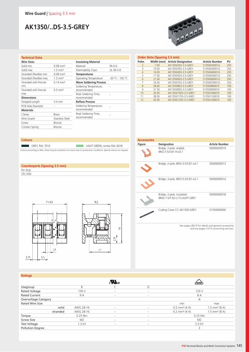
Wire SizesSolid minSolid maxStranded (flexible) minStranded (flexible) maxStranded with Ferrule minStranded with Ferrule maxDimensions Stripped Length
PCB Hole DiameterMaterials
Insulating Material MaterialFlammability ClassTemperaturesOperating TemperatureWave Soldering ProcessSoldering Temperature,recommendedPeak Soldering Time,recommendedReflow ProcessSoldering Temperature,recommended
Peak Soldering Time,recommended
Ratings
PTR Terminal Blocks and Multi Connector Systems 145
Counterparts (Spacing 3.5 mm)Pin Strip
Technical Data
Colours according to RAL, there may be variations on colour due to production conditions. Special colours on request.
Order Data (Spacing 3.5 mm)Poles Width (mm) Article Designation Article Number PU
Colours
Wire Guard | Spacing 3.5 mm
AK1350/..DS-3.5-GREY
2 7.00 AK1350/2DS-3.5-GREY 51350020001G 2503 10.50 AK1350/3DS-3.5-GREY 51350030001G 2504 14.00 AK1350/4DS-3.5-GREY 51350040001G 2505 17.50 AK1350/5DS-3.5-GREY 51350050001G 2506 21.00 AK1350/6DS-3.5-GREY 51350060001G 2507 24.50 AK1350/7DS-3.5-GREY 51350070001G 2508 28.00 AK1350/8DS-3.5-GREY 51350080001E 1009 31.50 AK1350/9DS-3.5-GREY 51350090001E 100
10 35.00 AK1350/10DS-3.5-GREY 51350100001E 10011 38.50 AK1350/11DS-3.5-GREY 51350110001E 10012 42.00 AK1350/12DS-3.5-GREY 51350120001E 100
GREY, RAL 7016 LIGHT GREEN, similar RAL 6018
AccessoriesFigure Designation Article Number
See pages 282 ff for detail and general accessoriesand see pages 12/13 concerning services.
Bridge, 2-pole, angled, BR/2-3.5/3.81-H-L4.7
50000000019
Bridge, 2-pole, BR/2-3.5/3.81-L4.7 50000000013
Bridge, 3-pole, BR/3-3.5/3.81-L4.7 50000000014
Bridge, 2-pole, insulated, BRI/2-7.0/7.62-L7.5-LIGHT GREY
50000000018
Coding Cover CC-AK1350-GREY 51350000000
PA 6.6UL 94 V-0
-30 °C - 105 °C
-
-
-
-
0.08 mm²1.5 mm²0.08 mm²1.5 mm²0.14 mm²
0.5 mm²
5.0 mm
-
STL1350
Clamp BrassWire Guard Stainless SteelScrew BronzeContact Spring Bronze
Usegroup B C DRated Voltage 150 V - - 125 VRated Current 9 A - - 8 AOvervoltage Category IIIRated Wire Size min max
solid AWG 28-16 - - 0.2 mm² (4 A) 1.5 mm² (8 A)stranded AWG 28-16 - - 0.2 mm² (4 A) 1.5 mm² (8 A)
Torque 0.25 Nm - - 0.25 NmScrew Size M2 - - M2Test Voltage 1.3 kV - - 2.5 kVPollution Degree 3
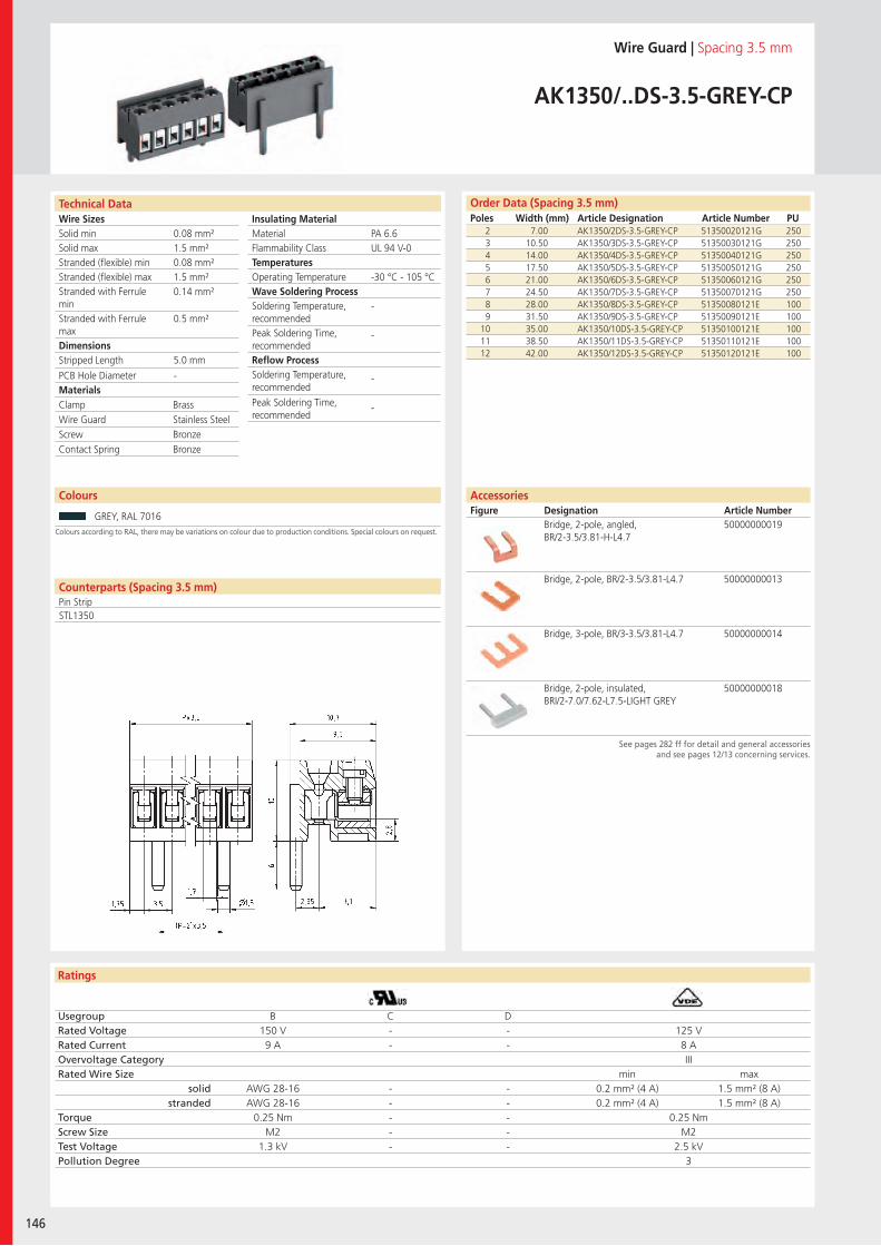
Wire SizesSolid minSolid maxStranded (flexible) minStranded (flexible) maxStranded with Ferrule minStranded with Ferrule maxDimensions Stripped Length
PCB Hole DiameterMaterials
Insulating Material MaterialFlammability ClassTemperaturesOperating TemperatureWave Soldering ProcessSoldering Temperature,recommendedPeak Soldering Time,recommendedReflow ProcessSoldering Temperature,recommended
Peak Soldering Time,recommended
Technical Data
Ratings
146
Order Data (Spacing 3.5 mm)Poles Width (mm) Article Designation Article Number PU
Counterparts (Spacing 3.5 mm)Pin Strip
Technical Data
Wire Guard | Spacing 3.5 mm
AK1350/..DS-3.5-GREY-CP
2 7.00 AK1350/2DS-3.5-GREY-CP 51350020121G 2503 10.50 AK1350/3DS-3.5-GREY-CP 51350030121G 2504 14.00 AK1350/4DS-3.5-GREY-CP 51350040121G 2505 17.50 AK1350/5DS-3.5-GREY-CP 51350050121G 2506 21.00 AK1350/6DS-3.5-GREY-CP 51350060121G 2507 24.50 AK1350/7DS-3.5-GREY-CP 51350070121G 2508 28.00 AK1350/8DS-3.5-GREY-CP 51350080121E 1009 31.50 AK1350/9DS-3.5-GREY-CP 51350090121E 100
10 35.00 AK1350/10DS-3.5-GREY-CP 51350100121E 10011 38.50 AK1350/11DS-3.5-GREY-CP 51350110121E 10012 42.00 AK1350/12DS-3.5-GREY-CP 51350120121E 100
See pages 282 ff for detail and general accessoriesand see pages 12/13 concerning services.
AccessoriesFigure Designation Article Number
Bridge, 2-pole, angled, BR/2-3.5/3.81-H-L4.7
50000000019
Bridge, 2-pole, BR/2-3.5/3.81-L4.7 50000000013
Bridge, 3-pole, BR/3-3.5/3.81-L4.7 50000000014
Bridge, 2-pole, insulated, BRI/2-7.0/7.62-L7.5-LIGHT GREY
50000000018
PA 6.6UL 94 V-0
-30 °C - 105 °C
-
-
-
-
0.08 mm²1.5 mm²0.08 mm²1.5 mm²0.14 mm²
0.5 mm²
5.0 mm
-
Colours according to RAL, there may be variations on colour due to production conditions. Special colours on request.
Colours
GREY, RAL 7016
STL1350
Clamp BrassWire Guard Stainless SteelScrew BronzeContact Spring Bronze
Usegroup B C DRated Voltage 150 V - - 125 VRated Current 9 A - - 8 AOvervoltage Category IIIRated Wire Size min max
solid AWG 28-16 - - 0.2 mm² (4 A) 1.5 mm² (8 A)stranded AWG 28-16 - - 0.2 mm² (4 A) 1.5 mm² (8 A)
Torque 0.25 Nm - - 0.25 NmScrew Size M2 - - M2Test Voltage 1.3 kV - - 2.5 kVPollution Degree 3
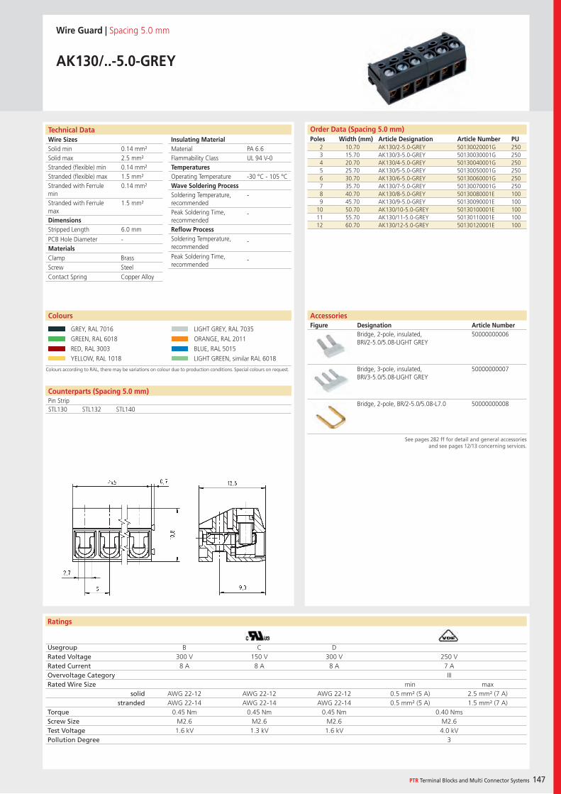
Wire SizesSolid minSolid maxStranded (flexible) minStranded (flexible) maxStranded with Ferrule minStranded with Ferrule maxDimensions Stripped Length
PCB Hole DiameterMaterials
Insulating Material MaterialFlammability ClassTemperaturesOperating TemperatureWave Soldering ProcessSoldering Temperature,recommendedPeak Soldering Time,recommendedReflow ProcessSoldering Temperature,recommended
Peak Soldering Time,recommended
Ratings
PTR Terminal Blocks and Multi Connector Systems 147
Counterparts (Spacing 5.0 mm)Pin Strip
Technical Data
Colours according to RAL, there may be variations on colour due to production conditions. Special colours on request.
Order Data (Spacing 5.0 mm)Poles Width (mm) Article Designation Article Number PU
Colours
Wire Guard | Spacing 5.0 mm
AK130/..-5.0-GREY
2 10.70 AK130/2-5.0-GREY 50130020001G 2503 15.70 AK130/3-5.0-GREY 50130030001G 2504 20.70 AK130/4-5.0-GREY 50130040001G 2505 25.70 AK130/5-5.0-GREY 50130050001G 2506 30.70 AK130/6-5.0-GREY 50130060001G 2507 35.70 AK130/7-5.0-GREY 50130070001G 2508 40.70 AK130/8-5.0-GREY 50130080001E 1009 45.70 AK130/9-5.0-GREY 50130090001E 100
10 50.70 AK130/10-5.0-GREY 50130100001E 10011 55.70 AK130/11-5.0-GREY 50130110001E 10012 60.70 AK130/12-5.0-GREY 50130120001E 100
GREY, RAL 7016 LIGHT GREY, RAL 7035
GREEN, RAL 6018 ORANGE, RAL 2011
RED, RAL 3003 BLUE, RAL 5015
YELLOW, RAL 1018 LIGHT GREEN, similar RAL 6018
AccessoriesFigure Designation Article Number
See pages 282 ff for detail and general accessoriesand see pages 12/13 concerning services.
Bridge, 2-pole, insulated, BRI/2-5.0/5.08-LIGHT GREY
50000000006
Bridge, 3-pole, insulated, BRI/3-5.0/5.08-LIGHT GREY
50000000007
Bridge, 2-pole, BR/2-5.0/5.08-L7.0 50000000008
PA 6.6UL 94 V-0
-30 °C - 105 °C
-
-
-
-
0.14 mm²2.5 mm²0.14 mm²1.5 mm²0.14 mm²
1.5 mm²
6.0 mm
-
STL130 STL132 STL140
Clamp BrassScrew SteelContact Spring Copper Alloy
Usegroup B C DRated Voltage 300 V 150 V 300 V 250 VRated Current 8 A 8 A 8 A 7 AOvervoltage Category IIIRated Wire Size min max
solid AWG 22-12 AWG 22-12 AWG 22-12 0.5 mm² (5 A) 2.5 mm² (7 A)stranded AWG 22-14 AWG 22-14 AWG 22-14 0.5 mm² (5 A) 1.5 mm² (7 A)
Torque 0.45 Nm 0.45 Nm 0.45 Nm 0.40 NmsScrew Size M2.6 M2.6 M2.6 M2.6Test Voltage 1.6 kV 1.3 kV 1.6 kV 4.0 kVPollution Degree 3
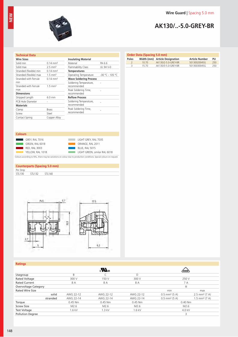
Wire SizesSolid minSolid maxStranded (flexible) minStranded (flexible) maxStranded with Ferrule minStranded with Ferrule maxDimensions Stripped Length
PCB Hole DiameterMaterials
Insulating Material MaterialFlammability ClassTemperaturesOperating TemperatureWave Soldering ProcessSoldering Temperature,recommendedPeak Soldering Time,recommendedReflow ProcessSoldering Temperature,recommended
Peak Soldering Time,recommended
Ratings
148
NEW
Counterparts (Spacing 5.0 mm)Pin Strip
Technical Data
Colours according to RAL, there may be variations on colour due to production conditions. Special colours on request.
Order Data (Spacing 5.0 mm)Poles Width (mm) Article Designation Article Number PU
Colours
Wire Guard | Spacing 5.0 mm
AK130/..-5.0-GREY-BR
2 10.70 AK130/2-5.0-GREY-BR 50130020045G 2503 15.70 AK130/3-5.0-GREY-BR 50130030045G 250
GREY, RAL 7016 LIGHT GREY, RAL 7035
GREEN, RAL 6018 ORANGE, RAL 2011
RED, RAL 3003 BLUE, RAL 5015
YELLOW, RAL 1018 LIGHT GREEN, similar RAL 6018
PA 6.6UL 94 V-0
-30 °C - 105 °C
-
-
-
-
0.14 mm²2.5 mm²0.14 mm²1.5 mm²0.14 mm²
1.5 mm²
6.0 mm
-
STL130 STL132 STL140
Clamp BrassScrew SteelContact Spring Copper Alloy
Usegroup B C DRated Voltage 300 V 150 V 300 V 250 VRated Current 8 A 8 A 8 A 7 AOvervoltage Category IIIRated Wire Size min max
solid AWG 22-12 AWG 22-12 AWG 22-12 0.5 mm² (5 A) 2.5 mm² (7 A)stranded AWG 22-14 AWG 22-14 AWG 22-14 0.5 mm² (5 A) 1.5 mm² (7 A)
Torque 0.45 Nm 0.45 Nm 0.45 Nm 0.40 NmScrew Size M2.6 M2.6 M2.6 M2.6Test Voltage 1.6 kV 1.3 kV 1.6 kV 4.0 kVPollution Degree 3
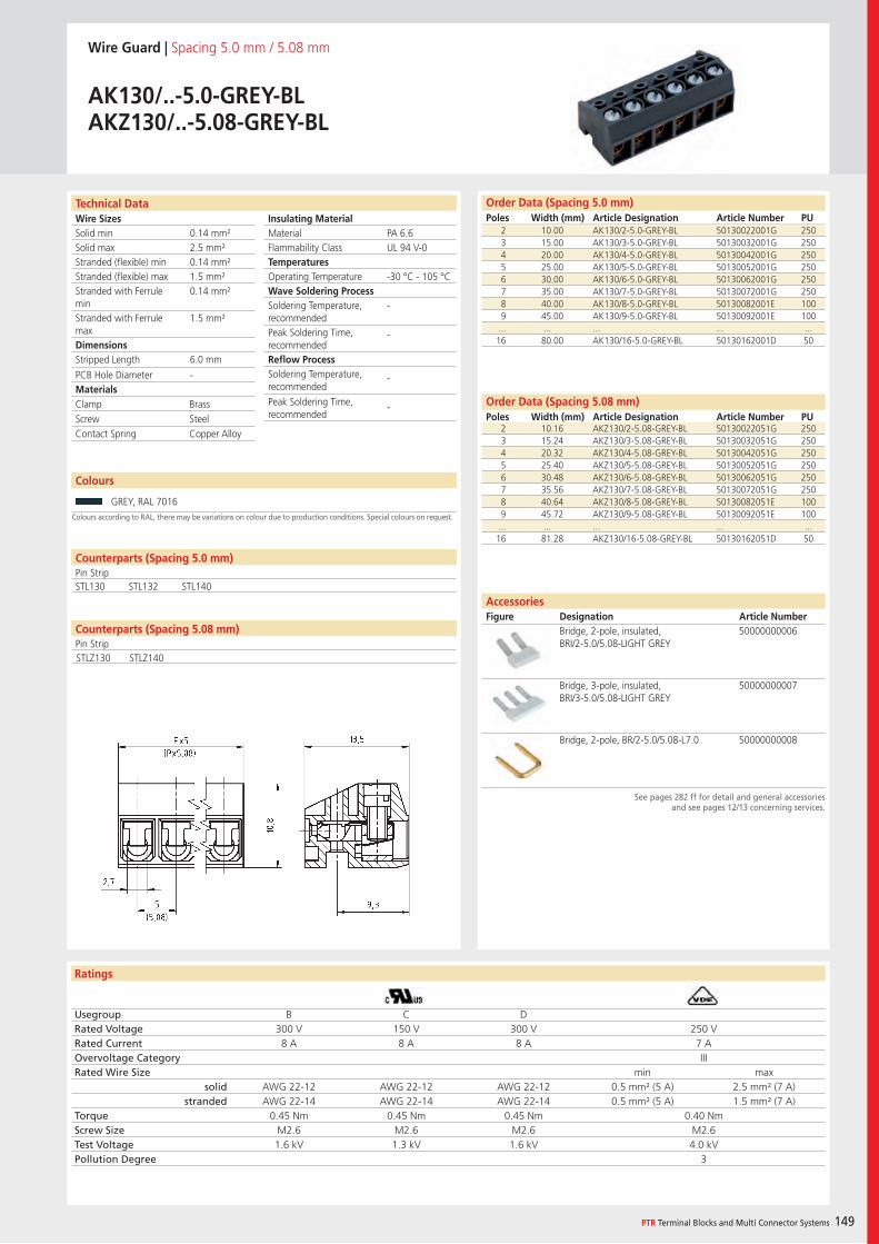
Wire SizesSolid minSolid maxStranded (flexible) minStranded (flexible) maxStranded with Ferrule minStranded with Ferrule maxDimensions Stripped Length
PCB Hole DiameterMaterials
Insulating Material MaterialFlammability ClassTemperaturesOperating TemperatureWave Soldering ProcessSoldering Temperature,recommendedPeak Soldering Time,recommendedReflow ProcessSoldering Temperature,recommended
Peak Soldering Time,recommended
Ratings
PTR Terminal Blocks and Multi Connector Systems 149
Technical Data Order Data (Spacing 5.0 mm)Poles Width (mm) Article Designation Article Number PU
Order Data (Spacing 5.08 mm)Poles Width (mm) Article Designation Article Number PU
Wire Guard | Spacing 5.0 mm / 5.08 mm
AK130/..-5.0-GREY-BLAKZ130/..-5.08-GREY-BL
2 10.00 AK130/2-5.0-GREY-BL 50130022001G 2503 15.00 AK130/3-5.0-GREY-BL 50130032001G 2504 20.00 AK130/4-5.0-GREY-BL 50130042001G 2505 25.00 AK130/5-5.0-GREY-BL 50130052001G 2506 30.00 AK130/6-5.0-GREY-BL 50130062001G 2507 35.00 AK130/7-5.0-GREY-BL 50130072001G 2508 40.00 AK130/8-5.0-GREY-BL 50130082001E 1009 45.00 AK130/9-5.0-GREY-BL 50130092001E 100
... ... ... ... ...16 80.00 AK130/16-5.0-GREY-BL 50130162001D 50
Colours according to RAL, there may be variations on colour due to production conditions. Special colours on request.
Colours
GREY, RAL 7016
AccessoriesFigure Designation Article Number
See pages 282 ff for detail and general accessoriesand see pages 12/13 concerning services.
2 10.16 AKZ130/2-5.08-GREY-BL 50130022051G 2503 15.24 AKZ130/3-5.08-GREY-BL 50130032051G 2504 20.32 AKZ130/4-5.08-GREY-BL 50130042051G 2505 25.40 AKZ130/5-5.08-GREY-BL 50130052051G 2506 30.48 AKZ130/6-5.08-GREY-BL 50130062051G 2507 35.56 AKZ130/7-5.08-GREY-BL 50130072051G 2508 40.64 AKZ130/8-5.08-GREY-BL 50130082051E 1009 45.72 AKZ130/9-5.08-GREY-BL 50130092051E 100
... ... ... ... ...16 81.28 AKZ130/16-5.08-GREY-BL 50130162051D 50
PA 6.6UL 94 V-0
-30 °C - 105 °C
-
-
-
-
0.14 mm²2.5 mm²0.14 mm²1.5 mm²0.14 mm²
1.5 mm²
6.0 mm
-
Counterparts (Spacing 5.0 mm)Pin StripSTL130 STL132 STL140
Clamp BrassScrew SteelContact Spring Copper Alloy
Usegroup B C DRated Voltage 300 V 150 V 300 V 250 VRated Current 8 A 8 A 8 A 7 AOvervoltage Category IIIRated Wire Size min max
solid AWG 22-12 AWG 22-12 AWG 22-12 0.5 mm² (5 A) 2.5 mm² (7 A)stranded AWG 22-14 AWG 22-14 AWG 22-14 0.5 mm² (5 A) 1.5 mm² (7 A)
Torque 0.45 Nm 0.45 Nm 0.45 Nm 0.40 NmScrew Size M2.6 M2.6 M2.6 M2.6Test Voltage 1.6 kV 1.3 kV 1.6 kV 4.0 kVPollution Degree 3
Bridge, 2-pole, insulated, BRI/2-5.0/5.08-LIGHT GREY
50000000006
Bridge, 3-pole, insulated, BRI/3-5.0/5.08-LIGHT GREY
50000000007
Bridge, 2-pole, BR/2-5.0/5.08-L7.0 50000000008
Counterparts (Spacing 5.08 mm)Pin StripSTLZ130 STLZ140
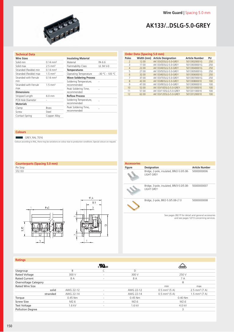
Wire SizesSolid minSolid maxStranded (flexible) minStranded (flexible) maxStranded with Ferrule minStranded with Ferrule maxDimensions Stripped Length
PCB Hole DiameterMaterials
Insulating Material MaterialFlammability ClassTemperaturesOperating TemperatureWave Soldering ProcessSoldering Temperature,recommendedPeak Soldering Time,recommendedReflow ProcessSoldering Temperature,recommended
Peak Soldering Time,recommended
Technical Data
Ratings
150
Order Data (Spacing 5.0 mm)Poles Width (mm) Article Designation Article Number PU
Technical Data
Wire Guard | Spacing 5.0 mm
AK133/..DSLG-5.0-GREY
2 12.00 AK133/2DSLG-5.0-GREY 50133020001G 2503 17.00 AK133/3DSLG-5.0-GREY 50133030001G 2504 22.00 AK133/4DSLG-5.0-GREY 50133040001G 2505 27.00 AK133/5DSLG-5.0-GREY 50133050001G 2506 32.00 AK133/6DSLG-5.0-GREY 50133060001G 2507 37.00 AK133/7DSLG-5.0-GREY 50133070001G 2508 42.00 AK133/8DSLG-5.0-GREY 50133080001E 1009 47.00 AK133/9DSLG-5.0-GREY 50133090001E 100
10 52.00 AK133/10DSLG-5.0-GREY 50133100001E 10011 57.00 AK133/11DSLG-5.0-GREY 50133110001E 10012 62.00 AK133/12DSLG-5.0-GREY 50133120001E 100
PA 6.6UL 94 V-0
-30 °C - 105 °C
-
-
-
-
0.14 mm²2.5 mm²0.14 mm²1.5 mm²0.14 mm²
1.5 mm²
6.0 mm
-
Colours according to RAL, there may be variations on colour due to production conditions. Special colours on request.
Colours
GREY, RAL 7016
See pages 282 ff for detail and general accessoriesand see pages 12/13 concerning services.
AccessoriesFigure Designation Article Number
Bridge, 2-pole, insulated, BRI/2-5.0/5.08-LIGHT GREY
50000000006
Bridge, 3-pole, insulated, BRI/3-5.0/5.08-LIGHT GREY
50000000007
Bridge, 2-pole, BR/2-5.0/5.08-L7.0 50000000008
Counterparts (Spacing 5.0 mm)Pin StripSTL133
Clamp BrassScrew SteelContact Spring Copper Alloy
Usegroup B C DRated Voltage 300 V - 300 V 250 VRated Current 8 A - 8 A 7 AOvervoltage Category IIIRated Wire Size min max
solid AWG 22-12 - AWG 22-12 0.5 mm² (5 A) 2.5 mm² (7 A)stranded AWG 22-14 - AWG 22-14 0.5 mm² (5 A) 1.5 mm² (7 A)
Torque 0.45 Nm - 0.45 Nm 0.40 NmScrew Size M2.6 - M2.6 M2.6Test Voltage 1.6 kV - 1.6 kV 4.0 kVPollution Degree 3
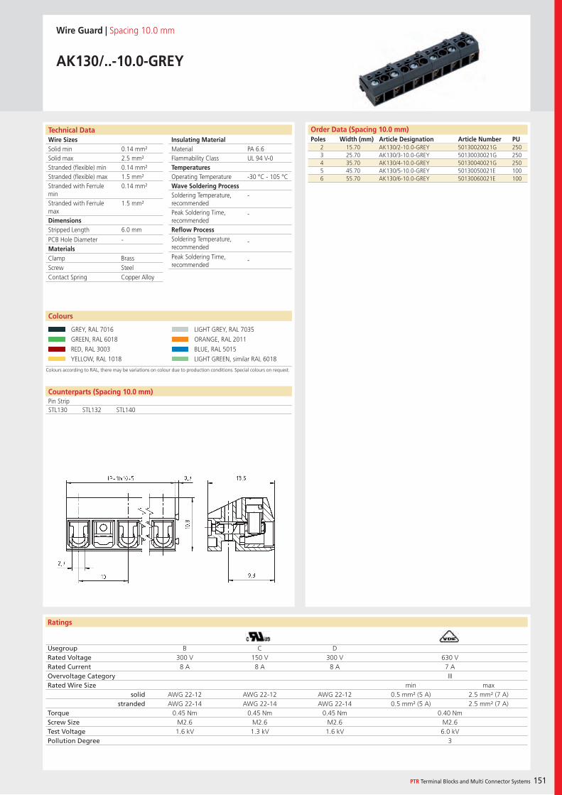
Wire SizesSolid minSolid maxStranded (flexible) minStranded (flexible) maxStranded with Ferrule minStranded with Ferrule maxDimensions Stripped Length
PCB Hole DiameterMaterials
Insulating Material MaterialFlammability ClassTemperaturesOperating TemperatureWave Soldering ProcessSoldering Temperature,recommendedPeak Soldering Time,recommendedReflow ProcessSoldering Temperature,recommended
Peak Soldering Time,recommended
Ratings
PTR Terminal Blocks and Multi Connector Systems 151
Counterparts (Spacing 10.0 mm)Pin Strip
Technical Data
Colours according to RAL, there may be variations on colour due to production conditions. Special colours on request.
Order Data (Spacing 10.0 mm)Poles Width (mm) Article Designation Article Number PU
Colours
Wire Guard | Spacing 10.0 mm
AK130/..-10.0-GREY
2 15.70 AK130/2-10.0-GREY 50130020021G 2503 25.70 AK130/3-10.0-GREY 50130030021G 2504 35.70 AK130/4-10.0-GREY 50130040021G 2505 45.70 AK130/5-10.0-GREY 50130050021E 1006 55.70 AK130/6-10.0-GREY 50130060021E 100
GREY, RAL 7016 LIGHT GREY, RAL 7035
GREEN, RAL 6018 ORANGE, RAL 2011
RED, RAL 3003 BLUE, RAL 5015
YELLOW, RAL 1018 LIGHT GREEN, similar RAL 6018
PA 6.6UL 94 V-0
-30 °C - 105 °C
-
-
-
-
0.14 mm²2.5 mm²0.14 mm²1.5 mm²0.14 mm²
1.5 mm²
6.0 mm
-
STL130 STL132 STL140
Clamp BrassScrew SteelContact Spring Copper Alloy
Usegroup B C DRated Voltage 300 V 150 V 300 V 630 VRated Current 8 A 8 A 8 A 7 AOvervoltage Category IIIRated Wire Size min max
solid AWG 22-12 AWG 22-12 AWG 22-12 0.5 mm² (5 A) 2.5 mm² (7 A)stranded AWG 22-14 AWG 22-14 AWG 22-14 0.5 mm² (5 A) 2.5 mm² (7 A)
Torque 0.45 Nm 0.45 Nm 0.45 Nm 0.40 NmScrew Size M2.6 M2.6 M2.6 M2.6Test Voltage 1.6 kV 1.3 kV 1.6 kV 6.0 kVPollution Degree 3
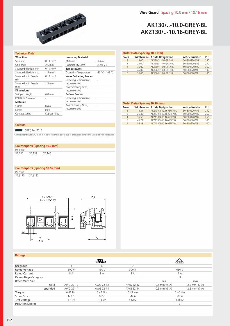
Wire SizesSolid minSolid maxStranded (flexible) minStranded (flexible) maxStranded with Ferrule minStranded with Ferrule maxDimensions Stripped Length
PCB Hole DiameterMaterials
Insulating Material MaterialFlammability ClassTemperaturesOperating TemperatureWave Soldering ProcessSoldering Temperature,recommendedPeak Soldering Time,recommendedReflow ProcessSoldering Temperature,recommended
Peak Soldering Time,recommended
Ratings
152
Technical Data Order Data (Spacing 10.0 mm)Poles Width (mm) Article Designation Article Number PU
Technical Data
Wire Guard | Spacing 10.0 mm / 10.16 mm
AK130/..-10.0-GREY-BLAKZ130/..-10.16-GREY-BL
2 15.00 AK130/2-10.0-GREY-BL 50130022021G 2503 25.00 AK130/3-10.0-GREY-BL 50130032021G 2504 35.00 AK130/4-10.0-GREY-BL 50130042021G 2505 45.00 AK130/5-10.0-GREY-BL 50130052021E 1006 55.00 AK130/6-10.0-GREY-BL 50130062021E 100
Colours
Colours according to RAL, there may be variations on colour due to production conditions. Special colours on request.
GREY, RAL 7016
2 15.24 AKZ130/2-10.16-GREY-BL 50130022071G 2503 25.40 AKZ130/3-10.16-GREY-BL 50130032071G 2504 35.56 AKZ130/4-10.16-GREY-BL 50130042071G 2505 45.72 AKZ130/5-10.16-GREY-BL 50130052071E 1006 55.88 AKZ130/6-10.16-GREY-BL 50130062071E 100
PA 6.6UL 94 V-0
-30 °C - 105 °C
-
-
-
-
0.14 mm²2.5 mm²0.14 mm²1.5 mm²0.14 mm²
1.5 mm²
6.0 mm
-
Counterparts (Spacing 10.16 mm)Pin Strip
Counterparts (Spacing 10.0 mm)Pin StripSTL130 STL132 STL140
Clamp BrassScrew SteelContact Spring Copper Alloy
Usegroup B C DRated Voltage 300 V 150 V 300 V 630 VRated Current 8 A 8 A 8 A 7 AOvervoltage Category IIIRated Wire Size min max
solid AWG 22-12 AWG 22-12 AWG 22-12 0.5 mm² (5 A) 2.5 mm² (7 A)stranded AWG 22-14 AWG 22-14 AWG 22-14 0.5 mm² (5 A) 2.5 mm² (7 A)
Torque 0.45 Nm 0.45 Nm 0.45 Nm 0.40 NmScrew Size M2.6 M2.6 M2.6 M2.6Test Voltage 1.6 kV 1.3 kV 1.6 kV 6.0 kVPollution Degree 3
Order Data (Spacing 10.16 mm)Poles Width (mm) Article Designation Article Number PU
STLZ130 STLZ140
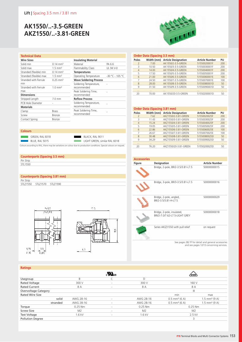
Wire SizesSolid minSolid maxStranded (flexible) minStranded (flexible) maxStranded with Ferrule minStranded with Ferrule maxDimensions Stripped Length
PCB Hole DiameterMaterials
Insulating Material MaterialFlammability ClassTemperaturesOperating TemperatureWave Soldering ProcessSoldering Temperature,recommendedPeak Soldering Time,recommendedReflow ProcessSoldering Temperature,recommended
Peak Soldering Time,recommended
Ratings
PTR Terminal Blocks and Multi Connector Systems 153
Technical Data Order Data (Spacing 3.5 mm)Poles Width (mm) Article Designation Article Number PU
Order Data (Spacing 3.81 mm)Poles Width (mm) Article Designation Article Number PU
Lift | Spacing 3.5 mm / 3.81 mm
AK1550/..-3.5-GREENAKZ1550/..-3.81-GREEN
2 7.00 AK1550/2-3.5-GREEN 51550020001F 2003 10.50 AK1550/3-3.5-GREEN 51550030001F 2004 14.00 AK1550/4-3.5-GREEN 51550040001F 2005 17.50 AK1550/5-3.5-GREEN 51550050001F 2006 21.00 AK1550/6-3.5-GREEN 51550060001E 1007 24.50 AK1550/7-3.5-GREEN 51550070001E 1008 28.00 AK1550/8-3.5-GREEN 51550080001D 509 31.50 AK1550/9-3.5-GREEN 51550090001D 50
... ... ... ... ...20 70.00 AK1550/20-3.5-GREEN 51550200001D 50
Colours according to RAL, there may be variations on colour due to production conditions. Special colours on request.
Colours
GREEN, RAL 6018 BLACK, RAL 9011
BLUE, RAL 5015 LIGHT GREEN, similar RAL 6018
AccessoriesFigure Designation Article Number
See pages 282 ff for detail and general accessoriesand see pages 12/13 concerning services.
2 7.62 AKZ1550/2-3.81-GREEN 51550020025F 2003 11.43 AKZ1550/3-3.81-GREEN 51550030025F 2004 15.24 AKZ1550/4-3.81-GREEN 51550040025F 2005 19.05 AKZ1550/5-3.81-GREEN 51550050025F 2006 22.86 AKZ1550/6-3.81-GREEN 51550060025E 1007 26.67 AKZ1550/7-3.81-GREEN 51550070025E 1008 30.48 AKZ1550/8-3.81-GREEN 51550080025D 509 34.29 AKZ1550/9-3.81-GREEN 51550090025D 50
... ... ... ... ...20 76.20 AKZ1550/20-3.81-GREEN 51550200025D 50
PA 6.6UL 94 V-0
-30 °C - 105 °C
-
-
-
-
0.14 mm²1.5 mm²0.14 mm²1.5 mm²0.25 mm²
1.0 mm²
7.0 mm
-
Counterparts (Spacing 3.5 mm)Pin StripSTL1550
Clamp BrassScrew BronzeContact Spring Bronze
Usegroup B C DRated Voltage 300 V - 300 V 160 VRated Current 8 A - 8 A 8 AOvervoltage Category IIIRated Wire Size min max
solid AWG 28-16 - AWG 28-16 0.5 mm² (6 A) 1.5 mm² (9 A)stranded AWG 28-16 - AWG 28-16 0.5 mm² (6 A) 1.5 mm² (9 A)
Torque 0.25 Nm - 0.25 Nm 0.25 NmScrew Size M2 - M2 M2Test Voltage 1.6 kV - 1.6 kV 2.5 kVPollution Degree 3
Bridge, 2-pole, BR/2-3.5/3.81-L7.5 50000000015
Bridge, 3-pole, BR/3-3.5/3.81-L7.5 50000000016
Bridge, 2-pole, angled, BR/2-3.5/3.81-H-L7.5
50000000029
Bridge, 2-pole, insulated, BRI/2-7.0/7.62-L7.5-LIGHT GREY
50000000018
Series AK(Z)1550 with pull relief on request
Counterparts (Spacing 3.81 mm)Pin StripSTLZ1550 STLZ1570 STLZ1590
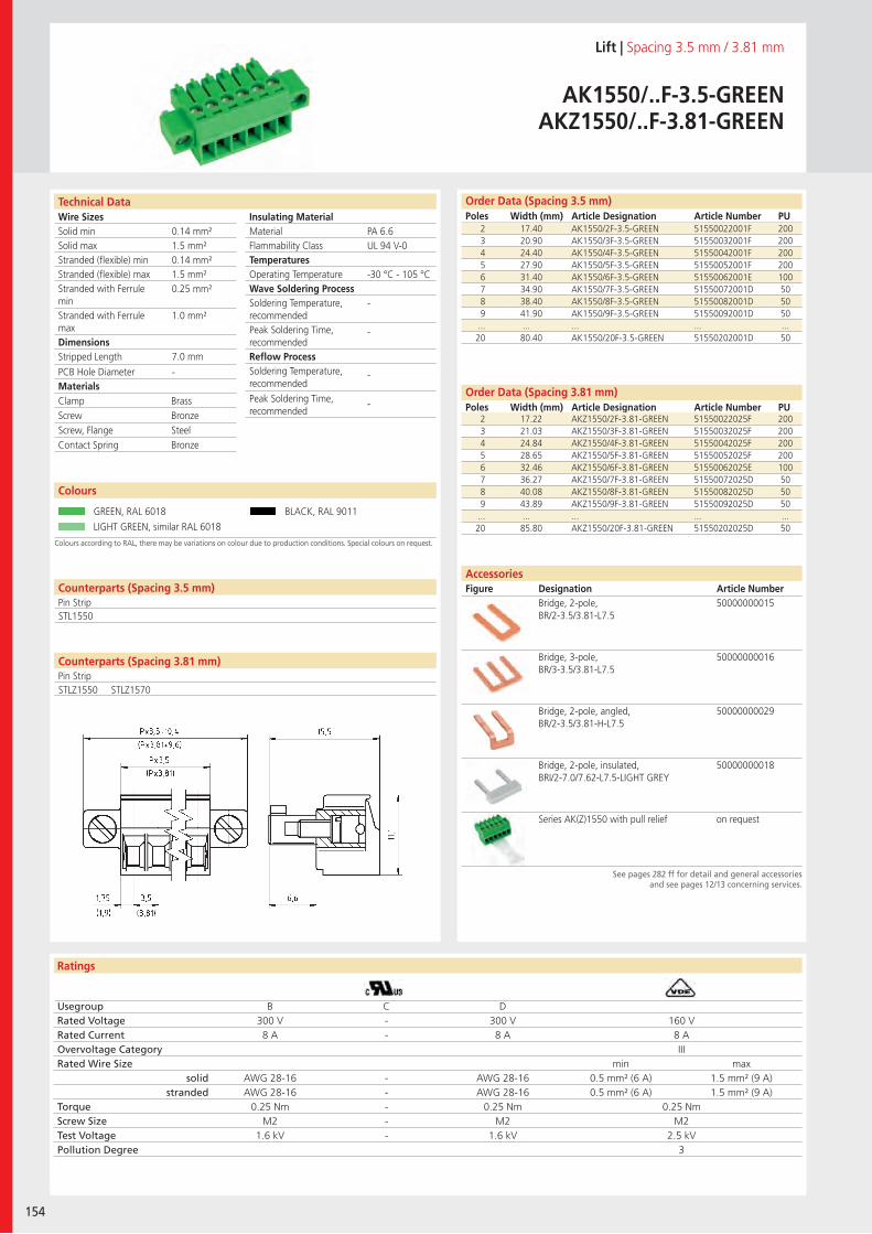
Wire SizesSolid minSolid maxStranded (flexible) minStranded (flexible) maxStranded with Ferrule minStranded with Ferrule maxDimensions Stripped Length
PCB Hole DiameterMaterials
Insulating Material MaterialFlammability ClassTemperaturesOperating TemperatureWave Soldering ProcessSoldering Temperature,recommendedPeak Soldering Time,recommendedReflow ProcessSoldering Temperature,recommended
Peak Soldering Time,recommended
Ratings
154
Technical Data
Colours according to RAL, there may be variations on colour due to production conditions. Special colours on request.
Order Data (Spacing 3.5 mm)Poles Width (mm) Article Designation Article Number PU
Order Data (Spacing 3.81 mm)Poles Width (mm) Article Designation Article Number PU
Colours
Lift | Spacing 3.5 mm / 3.81 mm
AK1550/..F-3.5-GREENAKZ1550/..F-3.81-GREEN
2 17.40 AK1550/2F-3.5-GREEN 51550022001F 2003 20.90 AK1550/3F-3.5-GREEN 51550032001F 2004 24.40 AK1550/4F-3.5-GREEN 51550042001F 2005 27.90 AK1550/5F-3.5-GREEN 51550052001F 2006 31.40 AK1550/6F-3.5-GREEN 51550062001E 1007 34.90 AK1550/7F-3.5-GREEN 51550072001D 508 38.40 AK1550/8F-3.5-GREEN 51550082001D 509 41.90 AK1550/9F-3.5-GREEN 51550092001D 50
... ... ... ... ...20 80.40 AK1550/20F-3.5-GREEN 51550202001D 50
GREEN, RAL 6018 BLACK, RAL 9011
LIGHT GREEN, similar RAL 6018
AccessoriesFigure Designation Article Number
See pages 282 ff for detail and general accessoriesand see pages 12/13 concerning services.
2 17.22 AKZ1550/2F-3.81-GREEN 51550022025F 2003 21.03 AKZ1550/3F-3.81-GREEN 51550032025F 2004 24.84 AKZ1550/4F-3.81-GREEN 51550042025F 2005 28.65 AKZ1550/5F-3.81-GREEN 51550052025F 2006 32.46 AKZ1550/6F-3.81-GREEN 51550062025E 1007 36.27 AKZ1550/7F-3.81-GREEN 51550072025D 508 40.08 AKZ1550/8F-3.81-GREEN 51550082025D 509 43.89 AKZ1550/9F-3.81-GREEN 51550092025D 50
... ... ... ... ...20 85.80 AKZ1550/20F-3.81-GREEN 51550202025D 50
PA 6.6UL 94 V-0
-30 °C - 105 °C
-
-
-
-
0.14 mm²1.5 mm²0.14 mm²1.5 mm²0.25 mm²
1.0 mm²
7.0 mm
-
Counterparts (Spacing 3.5 mm)Pin Strip
Counterparts (Spacing 3.81 mm)Pin Strip
STL1550
Clamp BrassScrew BronzeScrew, Flange SteelContact Spring Bronze
Usegroup B C DRated Voltage 300 V - 300 V 160 VRated Current 8 A - 8 A 8 AOvervoltage Category IIIRated Wire Size min max
solid AWG 28-16 - AWG 28-16 0.5 mm² (6 A) 1.5 mm² (9 A)stranded AWG 28-16 - AWG 28-16 0.5 mm² (6 A) 1.5 mm² (9 A)
Torque 0.25 Nm - 0.25 Nm 0.25 NmScrew Size M2 - M2 M2Test Voltage 1.6 kV - 1.6 kV 2.5 kVPollution Degree 3
Bridge, 2-pole, BR/2-3.5/3.81-L7.5
50000000015
Bridge, 3-pole, BR/3-3.5/3.81-L7.5
50000000016
Bridge, 2-pole, angled, BR/2-3.5/3.81-H-L7.5
50000000029
Bridge, 2-pole, insulated, BRI/2-7.0/7.62-L7.5-LIGHT GREY
50000000018
Series AK(Z)1550 with pull relief on request
STLZ1550 STLZ1570
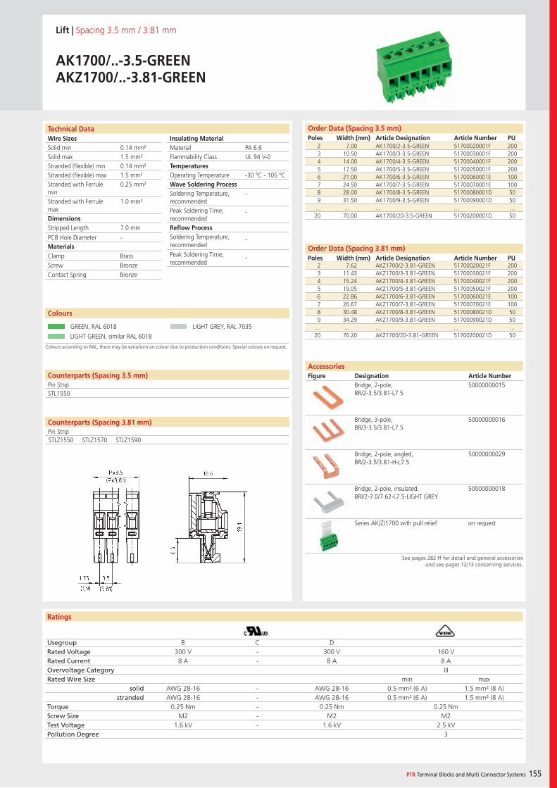
Wire SizesSolid minSolid maxStranded (flexible) minStranded (flexible) maxStranded with Ferrule minStranded with Ferrule maxDimensions Stripped Length
PCB Hole DiameterMaterials
Insulating Material MaterialFlammability ClassTemperaturesOperating TemperatureWave Soldering ProcessSoldering Temperature,recommendedPeak Soldering Time,recommendedReflow ProcessSoldering Temperature,recommended
Peak Soldering Time,recommended
Ratings
PTR Terminal Blocks and Multi Connector Systems 155
Technical Data
Colours according to RAL, there may be variations on colour due to production conditions. Special colours on request.
Order Data (Spacing 3.5 mm)Poles Width (mm) Article Designation Article Number PU
Order Data (Spacing 3.81 mm)Poles Width (mm) Article Designation Article Number PU
Colours
Lift | Spacing 3.5 mm / 3.81 mm
AK1700/..-3.5-GREENAKZ1700/..-3.81-GREEN
2 7.00 AK1700/2-3.5-GREEN 51700020001F 2003 10.50 AK1700/3-3.5-GREEN 51700030001F 2004 14.00 AK1700/4-3.5-GREEN 51700040001F 2005 17.50 AK1700/5-3.5-GREEN 51700050001F 2006 21.00 AK1700/6-3.5-GREEN 51700060001E 1007 24.50 AK1700/7-3.5-GREEN 51700070001E 1008 28.00 AK1700/8-3.5-GREEN 51700080001D 509 31.50 AK1700/9-3.5-GREEN 51700090001D 50
... ... ... ... ...20 70.00 AK1700/20-3.5-GREEN 51700200001D 50
GREEN, RAL 6018 LIGHT GREY, RAL 7035
LIGHT GREEN, similar RAL 6018
AccessoriesFigure Designation Article Number
See pages 282 ff for detail and general accessoriesand see pages 12/13 concerning services.
2 7.62 AKZ1700/2-3.81-GREEN 51700020021F 2003 11.43 AKZ1700/3-3.81-GREEN 51700030021F 2004 15.24 AKZ1700/4-3.81-GREEN 51700040021F 2005 19.05 AKZ1700/5-3.81-GREEN 51700050021F 2006 22.86 AKZ1700/6-3.81-GREEN 51700060021E 1007 26.67 AKZ1700/7-3.81-GREEN 51700070021E 1008 30.48 AKZ1700/8-3.81-GREEN 51700080021D 509 34.29 AKZ1700/9-3.81-GREEN 51700090021D 50
... ... ... ... ...20 76.20 AKZ1700/20-3.81-GREEN 51700200021D 50
PA 6.6UL 94 V-0
-30 °C - 105 °C
-
-
-
-
0.14 mm²1.5 mm²0.14 mm²1.5 mm²0.25 mm²
1.0 mm²
7.0 mm
-
Counterparts (Spacing 3.5 mm)Pin StripSTL1550
Clamp BrassScrew BronzeContact Spring Bronze
Usegroup B C DRated Voltage 300 V - 300 V 160 VRated Current 8 A - 8 A 8 AOvervoltage Category IIIRated Wire Size min max
solid AWG 28-16 - AWG 28-16 0.5 mm² (6 A) 1.5 mm² (8 A)stranded AWG 28-16 - AWG 28-16 0.5 mm² (6 A) 1.5 mm² (8 A)
Torque 0.25 Nm - 0.25 Nm 0.25 NmScrew Size M2 - M2 M2Test Voltage 1.6 kV - 1.6 kV 2.5 kVPollution Degree 3
Bridge, 2-pole, BR/2-3.5/3.81-L7.5
50000000015
Bridge, 3-pole, BR/3-3.5/3.81-L7.5
50000000016
Bridge, 2-pole, angled, BR/2-3.5/3.81-H-L7.5
50000000029
Bridge, 2-pole, insulated, BRI/2-7.0/7.62-L7.5-LIGHT GREY
50000000018
Series AK(Z)1700 with pull relief on request
Counterparts (Spacing 3.81 mm)Pin StripSTLZ1550 STLZ1570 STLZ1590
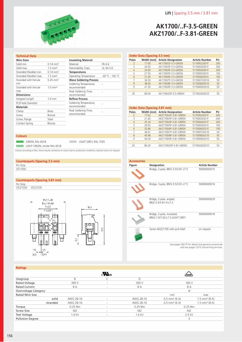
Wire SizesSolid minSolid maxStranded (flexible) minStranded (flexible) maxStranded with Ferrule minStranded with Ferrule maxDimensions Stripped Length
PCB Hole DiameterMaterials
Insulating Material MaterialFlammability ClassTemperaturesOperating TemperatureWave Soldering ProcessSoldering Temperature,recommendedPeak Soldering Time,recommendedReflow ProcessSoldering Temperature,recommended
Peak Soldering Time,recommended
Ratings
156
Technical Data
Colours according to RAL, there may be variations on colour due to production conditions. Special colours on request.
Order Data (Spacing 3.5 mm)Poles Width (mm) Article Designation Article Number PU
Order Data (Spacing 3.81 mm)Poles Width (mm) Article Designation Article Number PU
Colours
Lift | Spacing 3.5 mm / 3.81 mm
AK1700/..F-3.5-GREENAKZ1700/..F-3.81-GREEN
2 17.00 AK1700/2F-3.5-GREEN 51700022001F 2003 20.50 AK1700/3F-3.5-GREEN 51700032001F 2004 24.00 AK1700/4F-3.5-GREEN 51700042001F 2005 27.50 AK1700/5F-3.5-GREEN 51700052001E 1006 31.00 AK1700/6F-3.5-GREEN 51700062001E 1007 34.50 AK1700/7F-3.5-GREEN 51700072001D 508 38.00 AK1700/8F-3.5-GREEN 51700082001D 509 41.50 AK1700/9F-3.5-GREEN 51700092001D 50
... ... ... ... ...20 80.00 AK1700/20F-3.5-GREEN 51700202001D 50
GREEN, RAL 6018 LIGHT GREY, RAL 7035
LIGHT GREEN, similar RAL 6018
2 17.62 AKZ1700/2F-3.81-GREEN 51700022021F 2003 21.43 AKZ1700/3F-3.81-GREEN 51700032021F 2004 25.24 AKZ1700/4F-3.81-GREEN 51700042021F 2005 29.05 AKZ1700/5F-3.81-GREEN 51700052021E 1006 32.86 AKZ1700/6F-3.81-GREEN 51700062021E 1007 36.67 AKZ1700/7F-3.81-GREEN 51700072021D 508 40.48 AKZ1700/8F-3.81-GREEN 51700082021D 509 44.29 AKZ1700/9F-3.81-GREEN 51700092021D 50
... ... ... ... ...20 86.20 AKZ1700/20F-3.81-GREEN 51700202021D 50
PA 6.6UL 94 V-0
-30 °C - 105 °C
-
-
-
-
0.14 mm²1.5 mm²0.14 mm²1.5 mm²0.25 mm²
1.0 mm²
7.0 mm
-
Counterparts (Spacing 3.5 mm)Pin StripSTL1550
Clamp BrassScrew BronzeScrew, Flange SteelContact Spring Bronze
Usegroup B C DRated Voltage 300 V - 300 V 160 VRated Current 8 A - 8 A 8 AOvervoltage Category IIIRated Wire Size min max
solid AWG 28-16 - AWG 28-16 0.5 mm² (6 A) 1.5 mm² (8 A)stranded AWG 28-16 - AWG 28-16 0.5 mm² (6 A) 1.5 mm² (8 A)
Torque 0.25 Nm - 0.25 Nm 0.25 NmScrew Size M2 - M2 M2Test Voltage 1.6 kV - 1.6 kV 2.5 kVPollution Degree 3
AccessoriesFigure Designation Article Number
See pages 282 ff for detail and general accessoriesand see pages 12/13 concerning services.
Bridge, 2-pole, BR/2-3.5/3.81-L7.5 50000000015
Bridge, 3-pole, BR/3-3.5/3.81-L7.5 50000000016
Bridge, 2-pole, angled, BR/2-3.5/3.81-H-L7.5
50000000029
Bridge, 2-pole, insulated, BRI/2-7.0/7.62-L7.5-LIGHT GREY
50000000018
Series AK(Z)1700 with pull relief on request
Counterparts (Spacing 3.81 mm)Pin StripSTLZ1550 STLZ1570
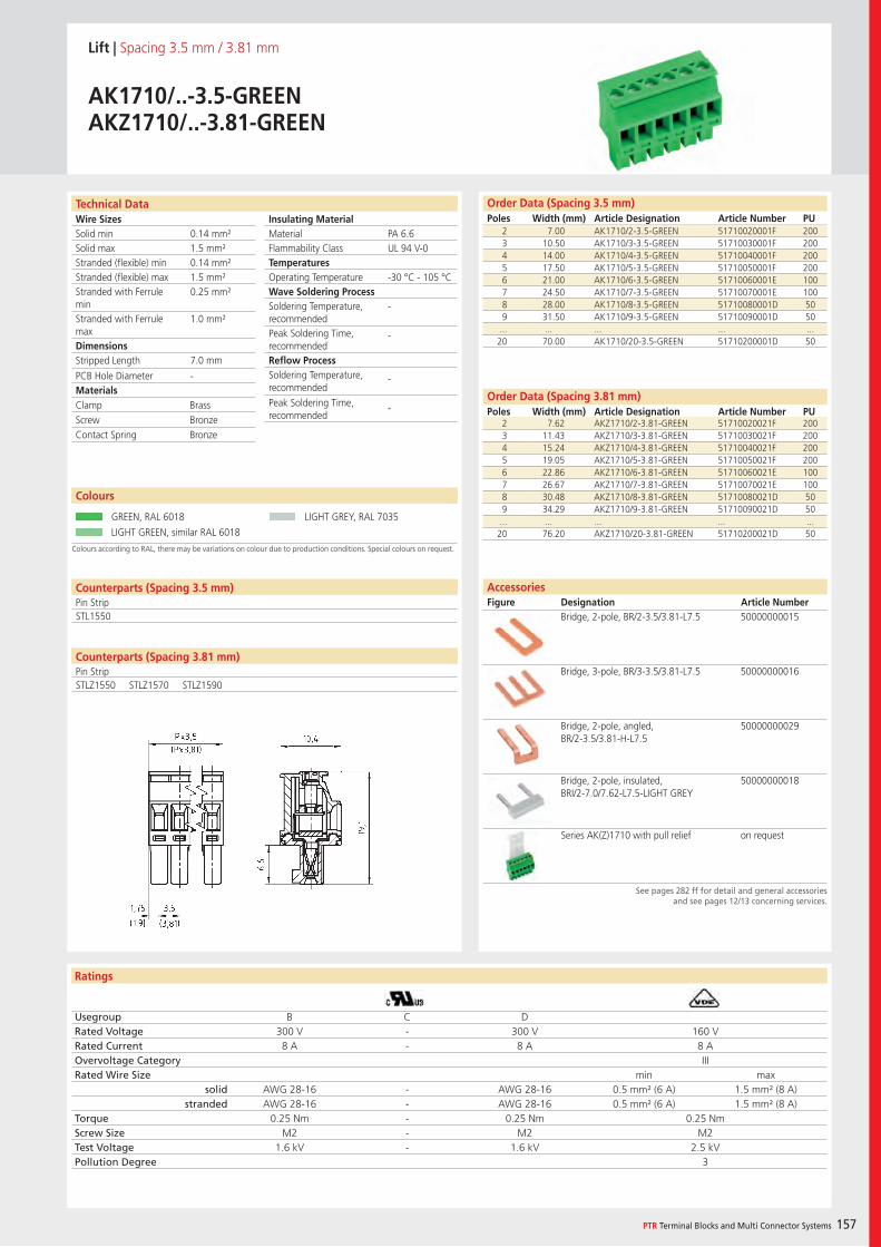
Wire SizesSolid minSolid maxStranded (flexible) minStranded (flexible) maxStranded with Ferrule minStranded with Ferrule maxDimensions Stripped Length
PCB Hole DiameterMaterials
Insulating Material MaterialFlammability ClassTemperaturesOperating TemperatureWave Soldering ProcessSoldering Temperature,recommendedPeak Soldering Time,recommendedReflow ProcessSoldering Temperature,recommended
Peak Soldering Time,recommended
Ratings
PTR Terminal Blocks and Multi Connector Systems 157
Technical Data
Colours according to RAL, there may be variations on colour due to production conditions. Special colours on request.
Order Data (Spacing 3.5 mm)Poles Width (mm) Article Designation Article Number PU
Order Data (Spacing 3.81 mm)Poles Width (mm) Article Designation Article Number PU
Colours
Lift | Spacing 3.5 mm / 3.81 mm
AK1710/..-3.5-GREENAKZ1710/..-3.81-GREEN
2 7.00 AK1710/2-3.5-GREEN 51710020001F 2003 10.50 AK1710/3-3.5-GREEN 51710030001F 2004 14.00 AK1710/4-3.5-GREEN 51710040001F 2005 17.50 AK1710/5-3.5-GREEN 51710050001F 2006 21.00 AK1710/6-3.5-GREEN 51710060001E 1007 24.50 AK1710/7-3.5-GREEN 51710070001E 1008 28.00 AK1710/8-3.5-GREEN 51710080001D 509 31.50 AK1710/9-3.5-GREEN 51710090001D 50
... ... ... ... ...20 70.00 AK1710/20-3.5-GREEN 51710200001D 50
GREEN, RAL 6018 LIGHT GREY, RAL 7035
LIGHT GREEN, similar RAL 6018
2 7.62 AKZ1710/2-3.81-GREEN 51710020021F 2003 11.43 AKZ1710/3-3.81-GREEN 51710030021F 2004 15.24 AKZ1710/4-3.81-GREEN 51710040021F 2005 19.05 AKZ1710/5-3.81-GREEN 51710050021F 2006 22.86 AKZ1710/6-3.81-GREEN 51710060021E 1007 26.67 AKZ1710/7-3.81-GREEN 51710070021E 1008 30.48 AKZ1710/8-3.81-GREEN 51710080021D 509 34.29 AKZ1710/9-3.81-GREEN 51710090021D 50
... ... ... ... ...20 76.20 AKZ1710/20-3.81-GREEN 51710200021D 50
PA 6.6UL 94 V-0
-30 °C - 105 °C
-
-
-
-
0.14 mm²1.5 mm²0.14 mm²1.5 mm²0.25 mm²
1.0 mm²
7.0 mm
-
Counterparts (Spacing 3.5 mm)Pin StripSTL1550
Clamp BrassScrew BronzeContact Spring Bronze
Usegroup B C DRated Voltage 300 V - 300 V 160 VRated Current 8 A - 8 A 8 AOvervoltage Category IIIRated Wire Size min max
solid AWG 28-16 - AWG 28-16 0.5 mm² (6 A) 1.5 mm² (8 A)stranded AWG 28-16 - AWG 28-16 0.5 mm² (6 A) 1.5 mm² (8 A)
Torque 0.25 Nm - 0.25 Nm 0.25 NmScrew Size M2 - M2 M2Test Voltage 1.6 kV - 1.6 kV 2.5 kVPollution Degree 3
AccessoriesFigure Designation Article Number
See pages 282 ff for detail and general accessoriesand see pages 12/13 concerning services.
Bridge, 2-pole, BR/2-3.5/3.81-L7.5 50000000015
Bridge, 3-pole, BR/3-3.5/3.81-L7.5 50000000016
Bridge, 2-pole, angled, BR/2-3.5/3.81-H-L7.5
50000000029
Bridge, 2-pole, insulated, BRI/2-7.0/7.62-L7.5-LIGHT GREY
50000000018
Series AK(Z)1710 with pull relief on request
Counterparts (Spacing 3.81 mm)Pin StripSTLZ1550 STLZ1570 STLZ1590
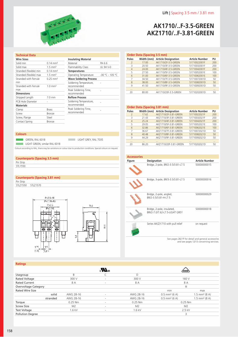
Wire SizesSolid minSolid maxStranded (flexible) minStranded (flexible) maxStranded with Ferrule minStranded with Ferrule maxDimensions Stripped Length
PCB Hole DiameterMaterials
Insulating Material MaterialFlammability ClassTemperaturesOperating TemperatureWave Soldering ProcessSoldering Temperature,recommendedPeak Soldering Time,recommendedReflow ProcessSoldering Temperature,recommended
Peak Soldering Time,recommended
Ratings
158
Technical Data
Colours according to RAL, there may be variations on colour due to production conditions. Special colours on request.
Order Data (Spacing 3.5 mm)Poles Width (mm) Article Designation Article Number PU
Order Data (Spacing 3.81 mm)Poles Width (mm) Article Designation Article Number PU
Colours
Lift | Spacing 3.5 mm / 3.81 mm
AK1710/..F-3.5-GREENAKZ1710/..F-3.81-GREEN
2 17.00 AK1710/2F-3.5-GREEN 51710022001F 2003 20.50 AK1710/3F-3.5-GREEN 51710032001F 2004 24.00 AK1710/4F-3.5-GREEN 51710042001F 2005 27.50 AK1710/5F-3.5-GREEN 51710052001E 1006 31.00 AK1710/6F-3.5-GREEN 51710062001E 1007 34.50 AK1710/7F-3.5-GREEN 51710072001D 508 38.00 AK1710/8F-3.5-GREEN 51710082001D 509 41.50 AK1710/9F-3.5-GREEN 51710092001D 50
... ... ... ... ...20 80.00 AK1710/20F-3.5-GREEN 51710202001D 50
GREEN, RAL 6018 LIGHT GREY, RAL 7035
LIGHT GREEN, similar RAL 6018
AccessoriesFigure Designation Article Number
See pages 282 ff for detail and general accessoriesand see pages 12/13 concerning services.
2 17.62 AKZ1710/2F-3.81-GREEN 51710022021F 2003 21.43 AKZ1710/3F-3.81-GREEN 51710032021F 2004 25.24 AKZ1710/4F-3.81-GREEN 51710042021F 2005 29.05 AKZ1710/5F-3.81-GREEN 51710052021E 1006 32.86 AKZ1710/6F-3.81-GREEN 51710062021E 1007 36.67 AKZ1710/7F-3.81-GREEN 51710072021D 508 40.48 AKZ1710/8F-3.81-GREEN 51710082021D 509 44.29 AKZ1710/9F-3.81-GREEN 51710092021D 50
... ... ... ... ...20 86.20 AKZ1710/20F-3.81-GREEN 51710202021D 50
PA 6.6UL 94 V-0
-30 °C - 105 °C
-
-
-
-
0.14 mm²1.5 mm²0.14 mm²1.5 mm²0.25 mm²
1.0 mm²
7.0 mm
-
Counterparts (Spacing 3.5 mm)Pin Strip
Counterparts (Spacing 3.81 mm)Pin Strip
STL1550
Clamp BrassScrew BronzeScrew, Flange SteelContact Spring Bronze
Usegroup B C DRated Voltage 300 V - 300 V 160 VRated Current 8 A - 8 A 8 AOvervoltage Category IIIRated Wire Size min max
solid AWG 28-16 - AWG 28-16 0.5 mm² (6 A) 1.5 mm² (8 A)stranded AWG 28-16 - AWG 28-16 0.5 mm² (6 A) 1.5 mm² (8 A)
Torque 0.25 Nm - 0.25 Nm 0.25 NmScrew Size M2 - M2 M2Test Voltage 1.6 kV - 1.6 kV 2.5 kVPollution Degree 3
Bridge, 2-pole, BR/2-3.5/3.81-L7.5 50000000015
Bridge, 3-pole, BR/3-3.5/3.81-L7.5 50000000016
Bridge, 2-pole, angled, BR/2-3.5/3.81-H-L7.5
50000000029
Bridge, 2-pole, insulated, BRI/2-7.0/7.62-L7.5-LIGHT GREY
50000000018
Series AK(Z)1710 with pull relief on request
STLZ1550 STLZ1570
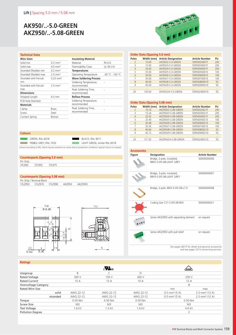
Wire SizesSolid minSolid maxStranded (flexible) minStranded (flexible) maxStranded with Ferrule minStranded with Ferrule maxDimensions Stripped Length
PCB Hole DiameterMaterials
Insulating Material MaterialFlammability ClassTemperaturesOperating TemperatureWave Soldering ProcessSoldering Temperature,recommendedPeak Soldering Time,recommendedReflow ProcessSoldering Temperature,recommended
Peak Soldering Time,recommended
Ratings
PTR Terminal Blocks and Multi Connector Systems 159
Technical Data Order Data (Spacing 5.0 mm)Poles Width (mm) Article Designation Article Number PU
Order Data (Spacing 5.08 mm)Poles Width (mm) Article Designation Article Number PU
Lift | Spacing 5.0 mm / 5.08 mm
AK950/..-5.0-GREENAKZ950/..-5.08-GREEN
2 10.00 AK950/2-5.0-GREEN 50950020001F 2003 15.00 AK950/3-5.0-GREEN 50950030001F 2004 20.00 AK950/4-5.0-GREEN 50950040001F 2005 25.00 AK950/5-5.0-GREEN 50950050001E 1006 30.00 AK950/6-5.0-GREEN 50950060001E 1007 35.00 AK950/7-5.0-GREEN 50950070001E 1008 40.00 AK950/8-5.0-GREEN 50950080001D 509 45.00 AK950/9-5.0-GREEN 50950090001D 50
... ... ... ... ...24 120.00 AK950/24-5.0-GREEN 50950240001D 50
Colours according to RAL, there may be variations on colour due to production conditions. Special colours on request.
Colours
GREEN, RAL 6018 BLACK, RAL 9011
PEBBLE GREY, RAL 7032 LIGHT GREEN, similar RAL 6018
2 10.16 AKZ950/2-5.08-GREEN 50950020021F 2003 15.24 AKZ950/3-5.08-GREEN 50950030021F 2004 20.32 AKZ950/4-5.08-GREEN 50950040021F 2005 25.40 AKZ950/5-5.08-GREEN 50950050021E 1006 30.48 AKZ950/6-5.08-GREEN 50950060021E 1007 35.56 AKZ950/7-5.08-GREEN 50950070021E 1008 40.64 AKZ950/8-5.08-GREEN 50950080021D 509 45.72 AKZ950/9-5.08-GREEN 50950090021D 50
... ... ... ... ...24 121.92 AKZ950/24-5.08-GREEN 50950240021D 50
PA 6.6UL 94 V-0
-30 °C - 105 °C
-
-
-
-
0.2 mm²4.0 mm²0.2 mm²2.5 mm²0.25 mm²
2.5 mm²
6.0 mm
-
Counterparts (Spacing 5.0 mm)Pin StripSTL950 STL955 STL975
Clamp BrassScrew SteelContact Spring Bronze
Usegroup B C DRated Voltage 300 V 150 V 300 V 250 VRated Current 15 A 15 A 10 A 12 AOvervoltage Category IIIRated Wire Size min max
solid AWG 22-12 AWG 22-12 AWG 22-12 0.5 mm² (5 A) 2.5 mm² (12 A)stranded AWG 22-12 AWG 22-12 AWG 22-12 0.5 mm² (5 A) 2.5 mm² (12 A)
Torque 0.50 Nm 0.50 Nm 0.50 Nm 0.50 NmScrew Size M3 M3 M3 M3Test Voltage 1.6 kV 1.3 kV 1.6 kV 4.0 kVPollution Degree 3
AccessoriesFigure Designation Article Number
See pages 282 ff for detail and general accessoriesand see pages 12/13 concerning services.
Bridge, 2-pole, insulated, BRI/2-5.0/5.08-LIGHT GREY
50000000006
Bridge, 3-pole, insulated, BRI/3-5.0/5.08-LIGHT GREY
50000000007
Bridge, 2-pole, BR/2-5.0/5.08-L7.0 50000000008
Coding Star CS1-5.0/5.08-RED 50000000021
Series AK(Z)950 with separating element on request
Series AK(Z)950 with pull relief on request
Counterparts (Spacing 5.08 mm)Pin Strip / Terminal BlockSTLZ950 STLZ970 STLZ990 AKZ950 AKZS950
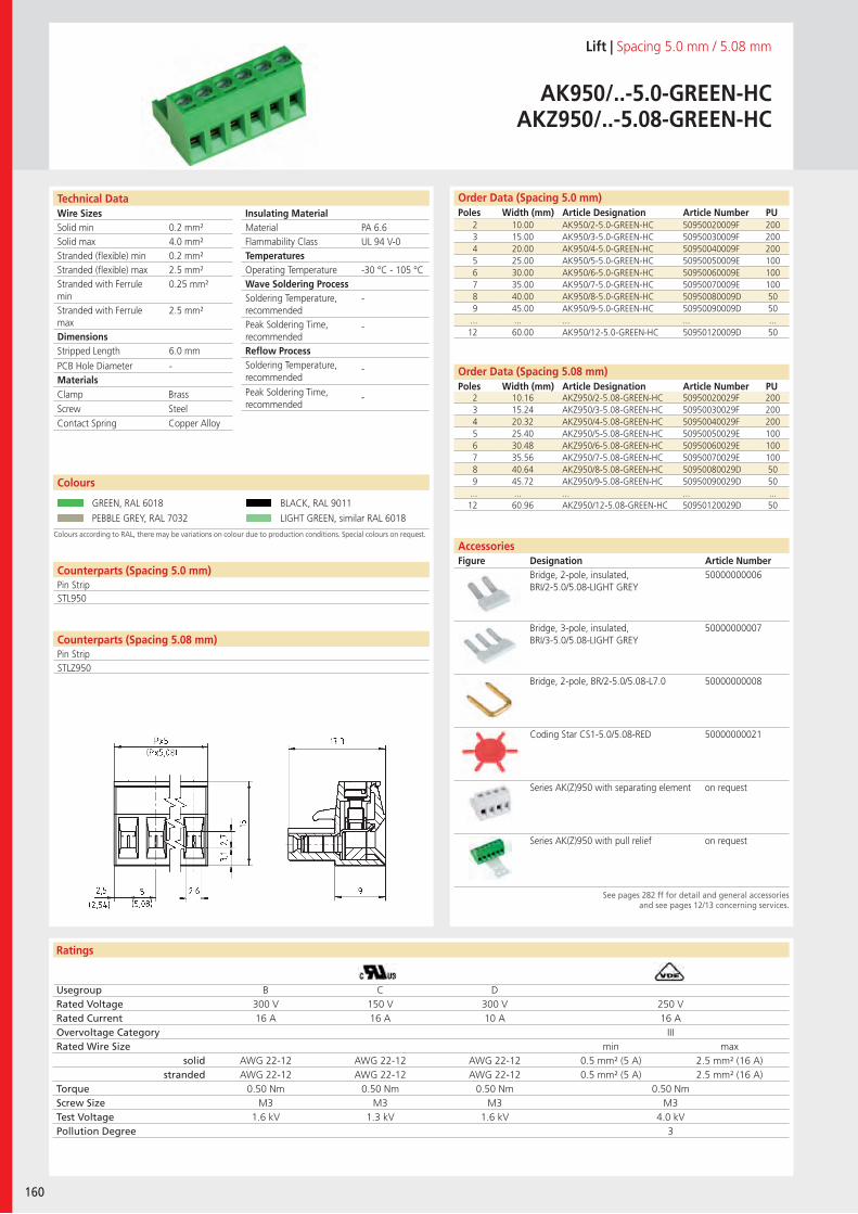
Wire SizesSolid minSolid maxStranded (flexible) minStranded (flexible) maxStranded with Ferrule minStranded with Ferrule maxDimensions Stripped Length
PCB Hole DiameterMaterials
Insulating Material MaterialFlammability ClassTemperaturesOperating TemperatureWave Soldering ProcessSoldering Temperature,recommendedPeak Soldering Time,recommendedReflow ProcessSoldering Temperature,recommended
Peak Soldering Time,recommended
Ratings
160
Technical Data
Colours according to RAL, there may be variations on colour due to production conditions. Special colours on request.
Order Data (Spacing 5.0 mm)Poles Width (mm) Article Designation Article Number PU
Colours
Lift | Spacing 5.0 mm / 5.08 mm
AK950/..-5.0-GREEN-HCAKZ950/..-5.08-GREEN-HC
2 10.00 AK950/2-5.0-GREEN-HC 50950020009F 2003 15.00 AK950/3-5.0-GREEN-HC 50950030009F 2004 20.00 AK950/4-5.0-GREEN-HC 50950040009F 2005 25.00 AK950/5-5.0-GREEN-HC 50950050009E 1006 30.00 AK950/6-5.0-GREEN-HC 50950060009E 1007 35.00 AK950/7-5.0-GREEN-HC 50950070009E 1008 40.00 AK950/8-5.0-GREEN-HC 50950080009D 509 45.00 AK950/9-5.0-GREEN-HC 50950090009D 50
... ... ... ... ...12 60.00 AK950/12-5.0-GREEN-HC 50950120009D 50
GREEN, RAL 6018 BLACK, RAL 9011
PEBBLE GREY, RAL 7032 LIGHT GREEN, similar RAL 6018
See pages 282 ff for detail and general accessoriesand see pages 12/13 concerning services.
Order Data (Spacing 5.08 mm)Poles Width (mm) Article Designation Article Number PU
2 10.16 AKZ950/2-5.08-GREEN-HC 50950020029F 2003 15.24 AKZ950/3-5.08-GREEN-HC 50950030029F 2004 20.32 AKZ950/4-5.08-GREEN-HC 50950040029F 2005 25.40 AKZ950/5-5.08-GREEN-HC 50950050029E 1006 30.48 AKZ950/6-5.08-GREEN-HC 50950060029E 1007 35.56 AKZ950/7-5.08-GREEN-HC 50950070029E 1008 40.64 AKZ950/8-5.08-GREEN-HC 50950080029D 509 45.72 AKZ950/9-5.08-GREEN-HC 50950090029D 50
... ... ... ... ...12 60.96 AKZ950/12-5.08-GREEN-HC 50950120029D 50
PA 6.6UL 94 V-0
-30 °C - 105 °C
-
-
-
-
0.2 mm²4.0 mm²0.2 mm²2.5 mm²0.25 mm²
2.5 mm²
6.0 mm
-
Counterparts (Spacing 5.0 mm)Pin StripSTL950
Clamp BrassScrew SteelContact Spring Copper Alloy
Usegroup B C DRated Voltage 300 V 150 V 300 V 250 VRated Current 16 A 16 A 10 A 16 AOvervoltage Category IIIRated Wire Size min max
solid AWG 22-12 AWG 22-12 AWG 22-12 0.5 mm² (5 A) 2.5 mm² (16 A)stranded AWG 22-12 AWG 22-12 AWG 22-12 0.5 mm² (5 A) 2.5 mm² (16 A)
Torque 0.50 Nm 0.50 Nm 0.50 Nm 0.50 NmScrew Size M3 M3 M3 M3Test Voltage 1.6 kV 1.3 kV 1.6 kV 4.0 kVPollution Degree 3
AccessoriesFigure Designation Article Number
Bridge, 2-pole, insulated, BRI/2-5.0/5.08-LIGHT GREY
50000000006
Bridge, 3-pole, insulated, BRI/3-5.0/5.08-LIGHT GREY
50000000007
Bridge, 2-pole, BR/2-5.0/5.08-L7.0 50000000008
Coding Star CS1-5.0/5.08-RED 50000000021
Series AK(Z)950 with separating element on request
Series AK(Z)950 with pull relief on request
Counterparts (Spacing 5.08 mm)Pin StripSTLZ950
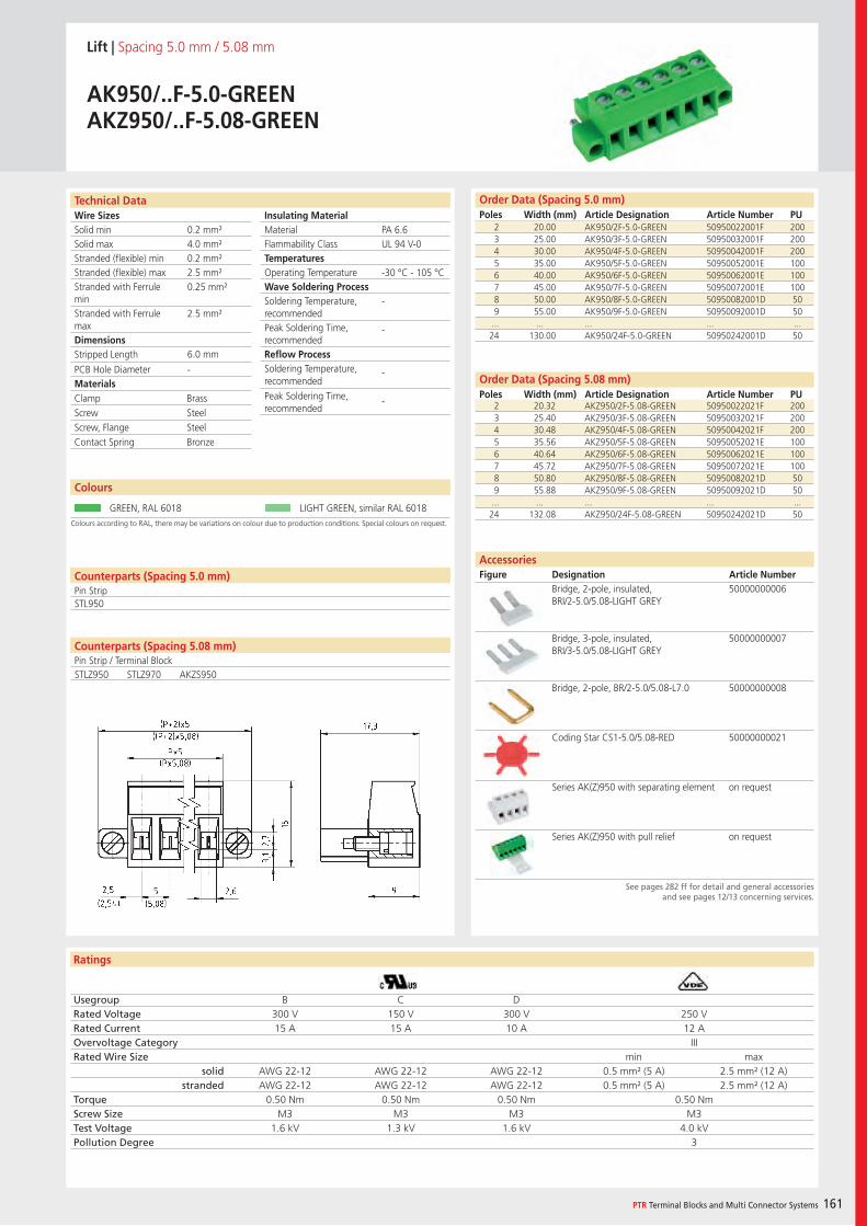
Wire SizesSolid minSolid maxStranded (flexible) minStranded (flexible) maxStranded with Ferrule minStranded with Ferrule maxDimensions Stripped Length
PCB Hole DiameterMaterials
Insulating Material MaterialFlammability ClassTemperaturesOperating TemperatureWave Soldering ProcessSoldering Temperature,recommendedPeak Soldering Time,recommendedReflow ProcessSoldering Temperature,recommended
Peak Soldering Time,recommended
Ratings
PTR Terminal Blocks and Multi Connector Systems 161
Technical Data
Colours according to RAL, there may be variations on colour due to production conditions. Special colours on request.
Order Data (Spacing 5.0 mm)Poles Width (mm) Article Designation Article Number PU
Colours
Lift | Spacing 5.0 mm / 5.08 mm
AK950/..F-5.0-GREENAKZ950/..F-5.08-GREEN
2 20.00 AK950/2F-5.0-GREEN 50950022001F 2003 25.00 AK950/3F-5.0-GREEN 50950032001F 2004 30.00 AK950/4F-5.0-GREEN 50950042001F 2005 35.00 AK950/5F-5.0-GREEN 50950052001E 1006 40.00 AK950/6F-5.0-GREEN 50950062001E 1007 45.00 AK950/7F-5.0-GREEN 50950072001E 1008 50.00 AK950/8F-5.0-GREEN 50950082001D 509 55.00 AK950/9F-5.0-GREEN 50950092001D 50
... ... ... ... ...24 130.00 AK950/24F-5.0-GREEN 50950242001D 50
GREEN, RAL 6018 LIGHT GREEN, similar RAL 6018
See pages 282 ff for detail and general accessoriesand see pages 12/13 concerning services.
PA 6.6UL 94 V-0
-30 °C - 105 °C
-
-
-
-
0.2 mm²4.0 mm²0.2 mm²2.5 mm²0.25 mm²
2.5 mm²
6.0 mm
-
Counterparts (Spacing 5.0 mm)Pin StripSTL950
Clamp BrassScrew SteelScrew, Flange SteelContact Spring Bronze
Usegroup B C DRated Voltage 300 V 150 V 300 V 250 VRated Current 15 A 15 A 10 A 12 AOvervoltage Category IIIRated Wire Size min max
solid AWG 22-12 AWG 22-12 AWG 22-12 0.5 mm² (5 A) 2.5 mm² (12 A)stranded AWG 22-12 AWG 22-12 AWG 22-12 0.5 mm² (5 A) 2.5 mm² (12 A)
Torque 0.50 Nm 0.50 Nm 0.50 Nm 0.50 NmScrew Size M3 M3 M3 M3Test Voltage 1.6 kV 1.3 kV 1.6 kV 4.0 kVPollution Degree 3
Order Data (Spacing 5.08 mm)Poles Width (mm) Article Designation Article Number PU
AccessoriesFigure Designation Article Number
2 20.32 AKZ950/2F-5.08-GREEN 50950022021F 2003 25.40 AKZ950/3F-5.08-GREEN 50950032021F 2004 30.48 AKZ950/4F-5.08-GREEN 50950042021F 2005 35.56 AKZ950/5F-5.08-GREEN 50950052021E 1006 40.64 AKZ950/6F-5.08-GREEN 50950062021E 1007 45.72 AKZ950/7F-5.08-GREEN 50950072021E 1008 50.80 AKZ950/8F-5.08-GREEN 50950082021D 509 55.88 AKZ950/9F-5.08-GREEN 50950092021D 50
... ... ... ... ...24 132.08 AKZ950/24F-5.08-GREEN 50950242021D 50
Bridge, 2-pole, insulated, BRI/2-5.0/5.08-LIGHT GREY
50000000006
Bridge, 3-pole, insulated, BRI/3-5.0/5.08-LIGHT GREY
50000000007
Bridge, 2-pole, BR/2-5.0/5.08-L7.0 50000000008
Coding Star CS1-5.0/5.08-RED 50000000021
Series AK(Z)950 with separating element on request
Series AK(Z)950 with pull relief on request
Counterparts (Spacing 5.08 mm)Pin Strip / Terminal BlockSTLZ950 STLZ970 AKZS950
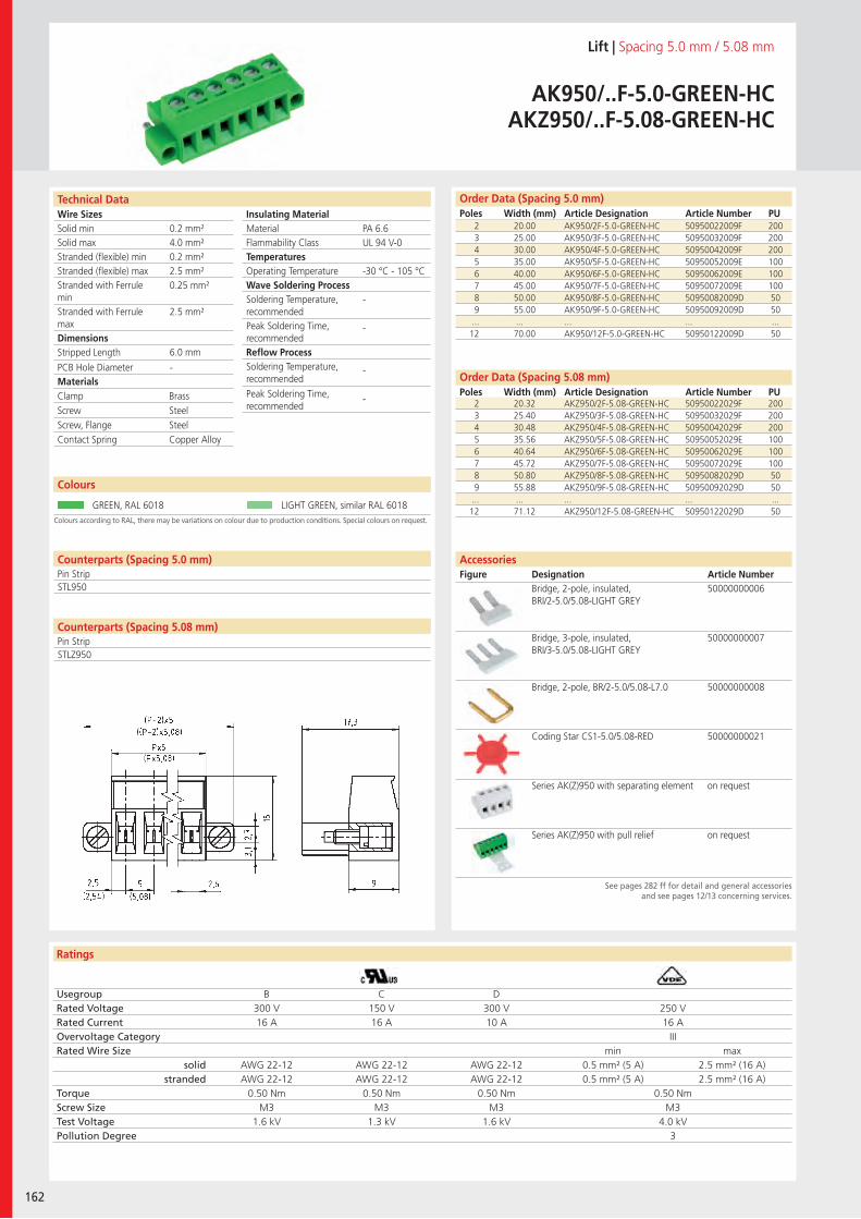
Wire SizesSolid minSolid maxStranded (flexible) minStranded (flexible) maxStranded with Ferrule minStranded with Ferrule maxDimensions Stripped Length
PCB Hole DiameterMaterials
Insulating Material MaterialFlammability ClassTemperaturesOperating TemperatureWave Soldering ProcessSoldering Temperature,recommendedPeak Soldering Time,recommendedReflow ProcessSoldering Temperature,recommended
Peak Soldering Time,recommended
Ratings
162
Technical Data
Colours according to RAL, there may be variations on colour due to production conditions. Special colours on request.
Order Data (Spacing 5.0 mm)Poles Width (mm) Article Designation Article Number PU
Colours
Lift | Spacing 5.0 mm / 5.08 mm
AK950/..F-5.0-GREEN-HCAKZ950/..F-5.08-GREEN-HC
2 20.00 AK950/2F-5.0-GREEN-HC 50950022009F 2003 25.00 AK950/3F-5.0-GREEN-HC 50950032009F 2004 30.00 AK950/4F-5.0-GREEN-HC 50950042009F 2005 35.00 AK950/5F-5.0-GREEN-HC 50950052009E 1006 40.00 AK950/6F-5.0-GREEN-HC 50950062009E 1007 45.00 AK950/7F-5.0-GREEN-HC 50950072009E 1008 50.00 AK950/8F-5.0-GREEN-HC 50950082009D 509 55.00 AK950/9F-5.0-GREEN-HC 50950092009D 50
... ... ... ... ...12 70.00 AK950/12F-5.0-GREEN-HC 50950122009D 50
GREEN, RAL 6018 LIGHT GREEN, similar RAL 6018
See pages 282 ff for detail and general accessoriesand see pages 12/13 concerning services.
Order Data (Spacing 5.08 mm)Poles Width (mm) Article Designation Article Number PU
2 20.32 AKZ950/2F-5.08-GREEN-HC 50950022029F 2003 25.40 AKZ950/3F-5.08-GREEN-HC 50950032029F 2004 30.48 AKZ950/4F-5.08-GREEN-HC 50950042029F 2005 35.56 AKZ950/5F-5.08-GREEN-HC 50950052029E 1006 40.64 AKZ950/6F-5.08-GREEN-HC 50950062029E 1007 45.72 AKZ950/7F-5.08-GREEN-HC 50950072029E 1008 50.80 AKZ950/8F-5.08-GREEN-HC 50950082029D 509 55.88 AKZ950/9F-5.08-GREEN-HC 50950092029D 50
... ... ... ... ...12 71.12 AKZ950/12F-5.08-GREEN-HC 50950122029D 50
PA 6.6UL 94 V-0
-30 °C - 105 °C
-
-
-
-
0.2 mm²4.0 mm²0.2 mm²2.5 mm²0.25 mm²
2.5 mm²
6.0 mm
-
Clamp BrassScrew SteelScrew, Flange SteelContact Spring Copper Alloy
Usegroup B C DRated Voltage 300 V 150 V 300 V 250 VRated Current 16 A 16 A 10 A 16 AOvervoltage Category IIIRated Wire Size min max
solid AWG 22-12 AWG 22-12 AWG 22-12 0.5 mm² (5 A) 2.5 mm² (16 A)stranded AWG 22-12 AWG 22-12 AWG 22-12 0.5 mm² (5 A) 2.5 mm² (16 A)
Torque 0.50 Nm 0.50 Nm 0.50 Nm 0.50 NmScrew Size M3 M3 M3 M3Test Voltage 1.6 kV 1.3 kV 1.6 kV 4.0 kVPollution Degree 3
AccessoriesFigure Designation Article Number
Bridge, 2-pole, insulated,BRI/2-5.0/5.08-LIGHT GREY
50000000006
Bridge, 3-pole, insulated, BRI/3-5.0/5.08-LIGHT GREY
50000000007
Bridge, 2-pole, BR/2-5.0/5.08-L7.0 50000000008
Coding Star CS1-5.0/5.08-RED 50000000021
Series AK(Z)950 with separating element on request
Series AK(Z)950 with pull relief on request
Counterparts (Spacing 5.0 mm)Pin Strip
Counterparts (Spacing 5.08 mm)Pin Strip
STL950
STLZ950
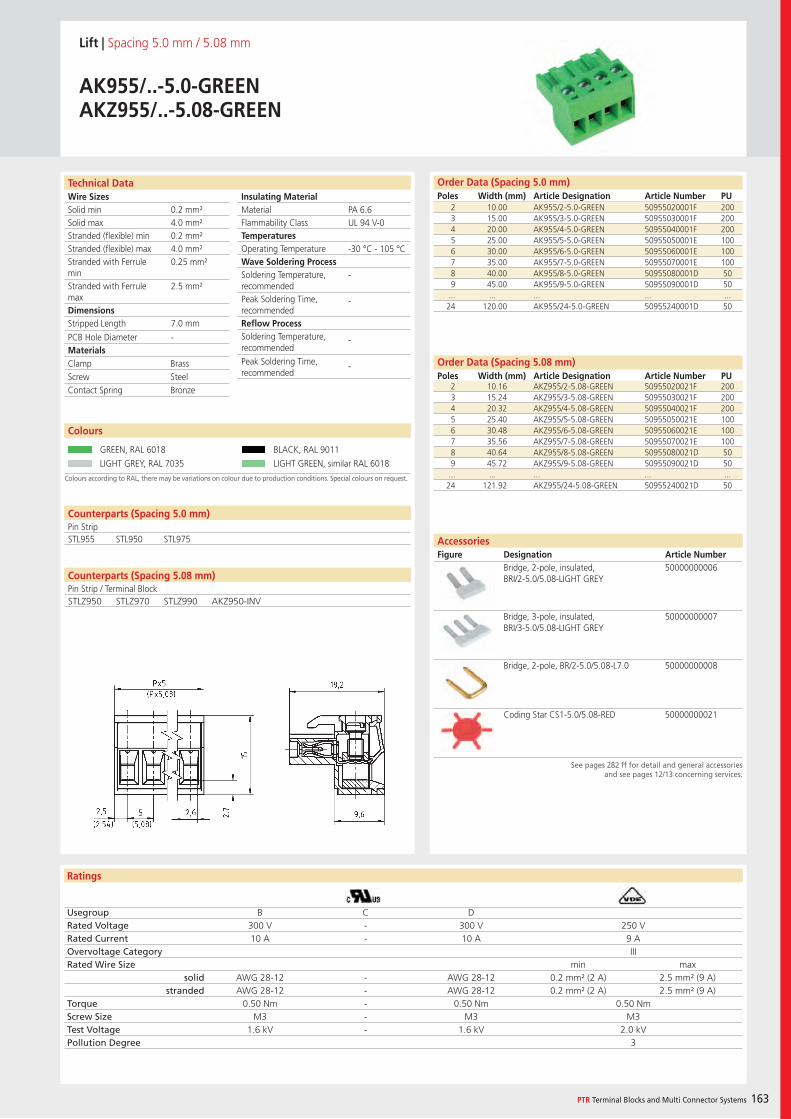
Wire SizesSolid minSolid maxStranded (flexible) minStranded (flexible) maxStranded with Ferrule minStranded with Ferrule maxDimensions Stripped Length
PCB Hole DiameterMaterials
Insulating Material MaterialFlammability ClassTemperaturesOperating TemperatureWave Soldering ProcessSoldering Temperature,recommendedPeak Soldering Time,recommendedReflow ProcessSoldering Temperature,recommended
Peak Soldering Time,recommended
Ratings
PTR Terminal Blocks and Multi Connector Systems 163
Technical Data
Colours according to RAL, there may be variations on colour due to production conditions. Special colours on request.
Order Data (Spacing 5.0 mm)Poles Width (mm) Article Designation Article Number PU
Order Data (Spacing 5.08 mm)Poles Width (mm) Article Designation Article Number PU
Colours
Lift | Spacing 5.0 mm / 5.08 mm
AK955/..-5.0-GREENAKZ955/..-5.08-GREEN
2 10.00 AK955/2-5.0-GREEN 50955020001F 2003 15.00 AK955/3-5.0-GREEN 50955030001F 2004 20.00 AK955/4-5.0-GREEN 50955040001F 2005 25.00 AK955/5-5.0-GREEN 50955050001E 1006 30.00 AK955/6-5.0-GREEN 50955060001E 1007 35.00 AK955/7-5.0-GREEN 50955070001E 1008 40.00 AK955/8-5.0-GREEN 50955080001D 509 45.00 AK955/9-5.0-GREEN 50955090001D 50
... ... ... ... ...24 120.00 AK955/24-5.0-GREEN 50955240001D 50
GREEN, RAL 6018 BLACK, RAL 9011
LIGHT GREY, RAL 7035 LIGHT GREEN, similar RAL 6018
2 10.16 AKZ955/2-5.08-GREEN 50955020021F 2003 15.24 AKZ955/3-5.08-GREEN 50955030021F 2004 20.32 AKZ955/4-5.08-GREEN 50955040021F 2005 25.40 AKZ955/5-5.08-GREEN 50955050021E 1006 30.48 AKZ955/6-5.08-GREEN 50955060021E 1007 35.56 AKZ955/7-5.08-GREEN 50955070021E 1008 40.64 AKZ955/8-5.08-GREEN 50955080021D 509 45.72 AKZ955/9-5.08-GREEN 50955090021D 50
... ... ... ... ...24 121.92 AKZ955/24-5.08-GREEN 50955240021D 50
PA 6.6UL 94 V-0
-30 °C - 105 °C
-
-
-
-
0.2 mm²4.0 mm²0.2 mm²4.0 mm²0.25 mm²
2.5 mm²
7.0 mm
-
Counterparts (Spacing 5.0 mm)Pin StripSTL955 STL950 STL975
Clamp BrassScrew SteelContact Spring Bronze
Usegroup B C DRated Voltage 300 V - 300 V 250 VRated Current 10 A - 10 A 9 AOvervoltage Category IIIRated Wire Size min max
solid AWG 28-12 - AWG 28-12 0.2 mm² (2 A) 2.5 mm² (9 A)stranded AWG 28-12 - AWG 28-12 0.2 mm² (2 A) 2.5 mm² (9 A)
Torque 0.50 Nm - 0.50 Nm 0.50 NmScrew Size M3 - M3 M3Test Voltage 1.6 kV - 1.6 kV 2.0 kVPollution Degree 3
AccessoriesFigure Designation Article Number
See pages 282 ff for detail and general accessoriesand see pages 12/13 concerning services.
Bridge, 2-pole, insulated, BRI/2-5.0/5.08-LIGHT GREY
50000000006
Bridge, 3-pole, insulated, BRI/3-5.0/5.08-LIGHT GREY
50000000007
Bridge, 2-pole, BR/2-5.0/5.08-L7.0 50000000008
Coding Star CS1-5.0/5.08-RED 50000000021
Counterparts (Spacing 5.08 mm)Pin Strip / Terminal BlockSTLZ950 STLZ970 STLZ990 AKZ950-INV
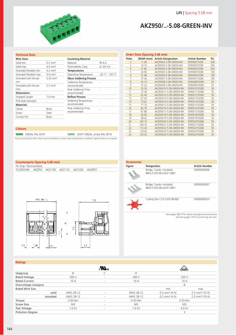
Wire SizesSolid minSolid maxStranded (flexible) minStranded (flexible) maxStranded with Ferrule minStranded with Ferrule maxDimensions Stripped Length
PCB Hole DiameterMaterials
Insulating Material MaterialFlammability ClassTemperaturesOperating TemperatureWave Soldering ProcessSoldering Temperature,recommendedPeak Soldering Time,recommendedReflow ProcessSoldering Temperature,recommended
Peak Soldering Time,recommended
Technical Data
Ratings
164
Order Data (Spacing 5.08 mm)Poles Width (mm) Article Designation Article Number PU
Counterparts (Spacing 5.08 mm)Pin Strip / Terminal Block
Technical Data
Lift | Spacing 5.08 mm
AKZ950/..-5.08-GREEN-INV
2 11.66 AKZ950/2-5.08-GREEN-INV 50950027028F 2003 16.74 AKZ950/3-5.08-GREEN-INV 50950037028F 2004 21.82 AKZ950/4-5.08-GREEN-INV 50950047028F 2005 26.90 AKZ950/5-5.08-GREEN-INV 50950057028E 1006 31.98 AKZ950/6-5.08-GREEN-INV 50950067028E 1007 37.06 AKZ950/7-5.08-GREEN-INV 50950077028E 1008 42.14 AKZ950/8-5.08-GREEN-INV 50950087028D 509 47.22 AKZ950/9-5.08-GREEN-INV 50950097028D 50
10 52.30 AKZ950/10-5.08-GREEN-INV 50950107028D 5011 57.38 AKZ950/11-5.08-GREEN-INV 50950117028D 5012 62.46 AKZ950/12-5.08-GREEN-INV 50950127028D 5013 67.54 AKZ950/13-5.08-GREEN-INV 50950137028D 5014 72.62 AKZ950/14-5.08-GREEN-INV 50950147028D 5015 77.70 AKZ950/15-5.08-GREEN-INV 50950157028D 5016 82.78 AKZ950/16-5.08-GREEN-INV 50950167028D 5017 87.86 AKZ950/17-5.08-GREEN-INV 50950177028D 5018 92.94 AKZ950/18-5.08-GREEN-INV 50950187028D 5019 98.02 AKZ950/19-5.08-GREEN-INV 50950197028D 5020 103.10 AKZ950/20-5.08-GREEN-INV 50950207028D 5021 108.18 AKZ950/21-5.08-GREEN-INV 50950217028D 5022 113.26 AKZ950/22-5.08-GREEN-INV 50950227028D 5023 118.34 AKZ950/23-5.08-GREEN-INV 50950237028D 5024 123.42 AKZ950/24-5.08-GREEN-INV 50950247028D 50
See pages 282 ff for detail and general accessoriesand see pages 12/13 concerning services.
AccessoriesFigure Designation Article Number
Bridge, 2-pole, insulated, BRI/2-5.0/5.08-LIGHT GREY
50000000006
Bridge, 3-pole, insulated, BRI/3-5.0/5.08-LIGHT GREY
50000000007
Coding Star CS3-5.0/5.08-RED 50000000025
PA 6.6UL 94 V-0
-30 °C - 105 °C
-
-
-
-
0.2 mm²4.0 mm²0.2 mm²4.0 mm²0.25 mm²
2.5 mm²
7.0 mm
-
Colours according to RAL, there may be variations on colour due to production conditions. Special colours on request.
Colours
GREEN, RAL 6018 LIGHT GREEN, similar RAL 6018
STLZ950-INV AKZ950 AKZ1100 AKZ1110 AKZ1200 AKZ4951
Clamp BrassScrew SteelContact Pin Brass
Usegroup B C DRated Voltage 300 V - 300 V 250 VRated Current 10 A - 10 A 10 AOvervoltage Category IIIRated Wire Size min max
solid AWG 28-12 - AWG 28-12 0.2 mm² (4 A) 2.5 mm² (10 A)stranded AWG 28-12 - AWG 28-12 0.2 mm² (4 A) 2.5 mm² (10 A)
Torque 0.50 Nm - 0.50 Nm 0.50 NmScrew Size M3 - M3 M3Test Voltage 1.6 kV - 1.6 kV 4.0 kVPollution Degree 3

Wire SizesSolid minSolid maxStranded (flexible) minStranded (flexible) maxStranded with Ferrule minStranded with Ferrule maxDimensions Stripped Length
PCB Hole DiameterMaterials
Insulating Material MaterialFlammability ClassTemperaturesOperating TemperatureWave Soldering ProcessSoldering Temperature,recommendedPeak Soldering Time,recommendedReflow ProcessSoldering Temperature,recommended
Peak Soldering Time,recommended
Ratings
PTR Terminal Blocks and Multi Connector Systems 165
Technical Data Order Data (Spacing 5.0 mm)Poles Width (mm) Article Designation Article Number PU
Order Data (Spacing 5.08 mm)Poles Width (mm) Article Designation Article Number PU
Lift | Spacing 5.0 mm / 5.08 mm
AK1100/..-5.0-GREENAKZ1100/..-5.08-GREEN
2 10.00 AK1100/2-5.0-GREEN 51100020021F 2003 15.00 AK1100/3-5.0-GREEN 51100030021F 2004 20.00 AK1100/4-5.0-GREEN 51100040021E 1005 25.00 AK1100/5-5.0-GREEN 51100050021E 1006 30.00 AK1100/6-5.0-GREEN 51100060021E 1007 35.00 AK1100/7-5.0-GREEN 51100070021E 1008 40.00 AK1100/8-5.0-GREEN 51100080021D 509 45.00 AK1100/9-5.0-GREEN 51100090021D 50
... ... ... ... ...20 100.00 AK1100/20-5.0-GREEN 51100200021D 50
Colours according to RAL, there may be variations on colour due to production conditions. Special colours on request.
Colours
GREEN, RAL 6018 LIGHT GREY, RAL 7035
LIGHT GREEN, similar RAL 6018
2 10.16 AKZ1100/2-5.08-GREEN 51100020001F 2003 15.24 AKZ1100/3-5.08-GREEN 51100030001F 2004 20.32 AKZ1100/4-5.08-GREEN 51100040001E 1005 25.40 AKZ1100/5-5.08-GREEN 51100050001E 1006 30.48 AKZ1100/6-5.08-GREEN 51100060001E 1007 35.56 AKZ1100/7-5.08-GREEN 51100070001E 1008 40.64 AKZ1100/8-5.08-GREEN 51100080001D 509 45.72 AKZ1100/9-5.08-GREEN 51100090001D 50
... ... ... ... ...16 81.28 AKZ1100/16-5.08-GREEN 51100160001D 50
PA 6.6UL 94 V-0
-30 °C - 105 °C
-
-
-
-
0.2 mm²4.0 mm²0.2 mm²2.5 mm²0.25 mm²
2.5 mm²
7.0 mm
-
Counterparts (Spacing 5.0 mm)Pin StripSTL950 STL955 STL975
Clamp BrassScrew SteelContact Spring Bronze
Usegroup B C DRated Voltage 300 V 150 V 300 V 250 VRated Current 15 A 15 A 10 A 10 AOvervoltage Category IIIRated Wire Size min max
solid AWG 22-10 AWG 22-10 AWG 22-10 0.5 mm² (6 A) 2.5 mm² (10 A)stranded AWG 22-10 AWG 22-10 AWG 22-10 0.5 mm² (6 A) 2.5 mm² (10 A)
Torque 0.50 Nm 0.50 Nm 0.50 Nm 0.50 NmScrew Size M3 M3 M3 M3Test Voltage 1.6 kV 1.3 kV 1.6 kV 4.0 kVPollution Degree 3
AccessoriesFigure Designation Article Number
See pages 282 ff for detail and general accessoriesand see pages 12/13 concerning services.
Bridge, 2-pole, insulated, BRI/2-5.0/5.08-LIGHT GREY
50000000006
Bridge, 3-pole, insulated, BRI/3-5.0/5.08-LIGHT GREY
50000000007
Bridge, 2-pole, BR/2-5.0/5.08-L7.0 50000000008
Coding Star CS1-5.0/5.08-RED 50000000021
Series AK(Z)1100 with separating element
on request
Series AK(Z)1100 with pull relief on request
Counterparts (Spacing 5.08 mm)Pin Strip / Terminal BlockSTLZ950 STLZ970 STLZ990 AKZ950 AKZS950
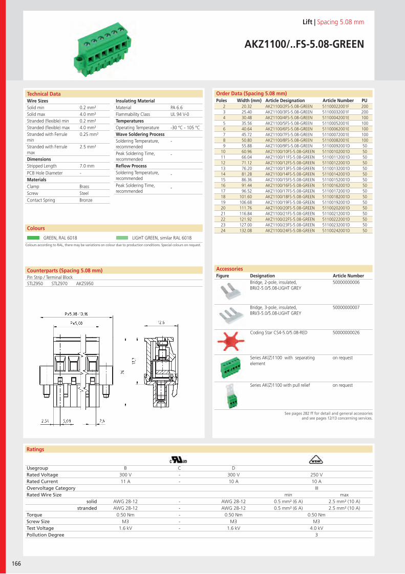
Wire SizesSolid minSolid maxStranded (flexible) minStranded (flexible) maxStranded with Ferrule minStranded with Ferrule maxDimensions Stripped Length
PCB Hole DiameterMaterials
Insulating Material MaterialFlammability ClassTemperaturesOperating TemperatureWave Soldering ProcessSoldering Temperature,recommendedPeak Soldering Time,recommendedReflow ProcessSoldering Temperature,recommended
Peak Soldering Time,recommended
Technical Data
Ratings
166
Order Data (Spacing 5.08 mm)Poles Width (mm) Article Designation Article Number PU
Counterparts (Spacing 5.08 mm)Pin Strip / Terminal Block
Technical Data
Lift | Spacing 5.08 mm
AKZ1100/..FS-5.08-GREEN
2 20.32 AKZ1100/2FS-5.08-GREEN 51100022001F 2003 25.40 AKZ1100/3FS-5.08-GREEN 51100032001F 2004 30.48 AKZ1100/4FS-5.08-GREEN 51100042001E 1005 35.56 AKZ1100/5FS-5.08-GREEN 51100052001E 1006 40.64 AKZ1100/6FS-5.08-GREEN 51100062001E 1007 45.72 AKZ1100/7FS-5.08-GREEN 51100072001E 1008 50.80 AKZ1100/8FS-5.08-GREEN 51100082001E 1009 55.88 AKZ1100/9FS-5.08-GREEN 51100092001D 50
10 60.96 AKZ1100/10FS-5.08-GREEN 51100102001D 5011 66.04 AKZ1100/11FS-5.08-GREEN 51100112001D 5012 71.12 AKZ1100/12FS-5.08-GREEN 51100122001D 5013 76.20 AKZ1100/13FS-5.08-GREEN 51100132001D 5014 81.28 AKZ1100/14FS-5.08-GREEN 51100142001D 5015 86.36 AKZ1100/15FS-5.08-GREEN 51100152001D 5016 91.44 AKZ1100/16FS-5.08-GREEN 51100162001D 5017 96.52 AKZ1100/17FS-5.08-GREEN 51100172001D 5018 101.60 AKZ1100/18FS-5.08-GREEN 51100182001D 5019 106.68 AKZ1100/19FS-5.08-GREEN 51100192001D 5020 111.76 AKZ1100/20FS-5.08-GREEN 51100202001D 5021 116.84 AKZ1100/21FS-5.08-GREEN 51100212001D 5022 121.92 AKZ1100/22FS-5.08-GREEN 51100222001D 5023 127.00 AKZ1100/23FS-5.08-GREEN 51100232001D 5024 132.08 AKZ1100/24FS-5.08-GREEN 51100242001D 50
See pages 282 ff for detail and general accessoriesand see pages 12/13 concerning services.
AccessoriesFigure Designation Article Number
Bridge, 2-pole, insulated, BRI/2-5.0/5.08-LIGHT GREY
50000000006
Bridge, 3-pole, insulated, BRI/3-5.0/5.08-LIGHT GREY
50000000007
Coding Star CS4-5.0/5.08-RED 50000000026
Series AK(Z)1100 with separating element
on request
Series AK(Z)1100 with pull relief on request
PA 6.6UL 94 V-0
-30 °C - 105 °C
-
-
-
-
0.2 mm²4.0 mm²0.2 mm²4.0 mm²0.25 mm²
2.5 mm²
7.0 mm
-
Colours according to RAL, there may be variations on colour due to production conditions. Special colours on request.
Colours
GREEN, RAL 6018 LIGHT GREEN, similar RAL 6018
STLZ950 STLZ970 AKZS950
Clamp BrassScrew SteelContact Spring Bronze
Usegroup B C DRated Voltage 300 V - 300 V 250 VRated Current 11 A - 10 A 10 AOvervoltage Category IIIRated Wire Size min max
solid AWG 28-12 - AWG 28-12 0.5 mm² (6 A) 2.5 mm² (10 A)stranded AWG 28-12 - AWG 28-12 0.5 mm² (6 A) 2.5 mm² (10 A)
Torque 0.50 Nm - 0.50 Nm 0.50 NmScrew Size M3 - M3 M3Test Voltage 1.6 kV - 1.6 kV 4.0 kVPollution Degree 3
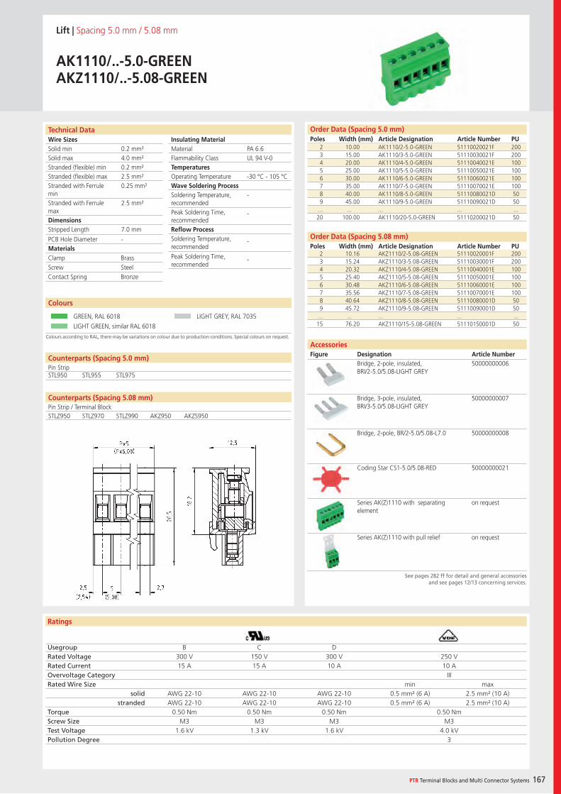
Wire SizesSolid minSolid maxStranded (flexible) minStranded (flexible) maxStranded with Ferrule minStranded with Ferrule maxDimensions Stripped Length
PCB Hole DiameterMaterials
Insulating Material MaterialFlammability ClassTemperaturesOperating TemperatureWave Soldering ProcessSoldering Temperature,recommendedPeak Soldering Time,recommendedReflow ProcessSoldering Temperature,recommended
Peak Soldering Time,recommended
Ratings
PTR Terminal Blocks and Multi Connector Systems 167
Technical Data
Colours according to RAL, there may be variations on colour due to production conditions. Special colours on request.
Order Data (Spacing 5.0 mm)Poles Width (mm) Article Designation Article Number PU
Order Data (Spacing 5.08 mm)Poles Width (mm) Article Designation Article Number PU
Colours
Lift | Spacing 5.0 mm / 5.08 mm
AK1110/..-5.0-GREENAKZ1110/..-5.08-GREEN
2 10.00 AK1110/2-5.0-GREEN 51110020021F 2003 15.00 AK1110/3-5.0-GREEN 51110030021F 2004 20.00 AK1110/4-5.0-GREEN 51110040021E 1005 25.00 AK1110/5-5.0-GREEN 51110050021E 1006 30.00 AK1110/6-5.0-GREEN 51110060021E 1007 35.00 AK1110/7-5.0-GREEN 51110070021E 1008 40.00 AK1110/8-5.0-GREEN 51110080021D 509 45.00 AK1110/9-5.0-GREEN 51110090021D 50
... ... ... ... ...20 100.00 AK1110/20-5.0-GREEN 51110200021D 50
GREEN, RAL 6018 LIGHT GREY, RAL 7035
LIGHT GREEN, similar RAL 6018
2 10.16 AKZ1110/2-5.08-GREEN 51110020001F 2003 15.24 AKZ1110/3-5.08-GREEN 51110030001F 2004 20.32 AKZ1110/4-5.08-GREEN 51110040001E 1005 25.40 AKZ1110/5-5.08-GREEN 51110050001E 1006 30.48 AKZ1110/6-5.08-GREEN 51110060001E 1007 35.56 AKZ1110/7-5.08-GREEN 51110070001E 1008 40.64 AKZ1110/8-5.08-GREEN 51110080001D 509 45.72 AKZ1110/9-5.08-GREEN 51110090001D 50
... ... ... ... ...15 76.20 AKZ1110/15-5.08-GREEN 51110150001D 50
PA 6.6UL 94 V-0
-30 °C - 105 °C
-
-
-
-
0.2 mm²4.0 mm²0.2 mm²2.5 mm²0.25 mm²
2.5 mm²
7.0 mm
-
Counterparts (Spacing 5.0 mm)Pin StripSTL950 STL955 STL975
Clamp BrassScrew SteelContact Spring Bronze
Usegroup B C DRated Voltage 300 V 150 V 300 V 250 VRated Current 15 A 15 A 10 A 10 AOvervoltage Category IIIRated Wire Size min max
solid AWG 22-10 AWG 22-10 AWG 22-10 0.5 mm² (6 A) 2.5 mm² (10 A)stranded AWG 22-10 AWG 22-10 AWG 22-10 0.5 mm² (6 A) 2.5 mm² (10 A)
Torque 0.50 Nm 0.50 Nm 0.50 Nm 0.50 NmScrew Size M3 M3 M3 M3Test Voltage 1.6 kV 1.3 kV 1.6 kV 4.0 kVPollution Degree 3
AccessoriesFigure Designation Article Number
See pages 282 ff for detail and general accessoriesand see pages 12/13 concerning services.
Bridge, 2-pole, insulated, BRI/2-5.0/5.08-LIGHT GREY
50000000006
Bridge, 3-pole, insulated, BRI/3-5.0/5.08-LIGHT GREY
50000000007
Bridge, 2-pole, BR/2-5.0/5.08-L7.0 50000000008
Coding Star CS1-5.0/5.08-RED 50000000021
Series AK(Z)1110 with separating element
on request
Series AK(Z)1110 with pull relief on request
Counterparts (Spacing 5.08 mm)Pin Strip / Terminal BlockSTLZ950 STLZ970 STLZ990 AKZ950 AKZS950
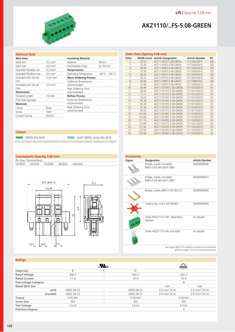
Wire SizesSolid minSolid maxStranded (flexible) minStranded (flexible) maxStranded with Ferrule minStranded with Ferrule maxDimensions Stripped Length
PCB Hole DiameterMaterials
Insulating Material MaterialFlammability ClassTemperaturesOperating TemperatureWave Soldering ProcessSoldering Temperature,recommendedPeak Soldering Time,recommendedReflow ProcessSoldering Temperature,recommended
Peak Soldering Time,recommended
Technical Data
Ratings
168
Order Data (Spacing 5.08 mm)Poles Width (mm) Article Designation Article Number PU
Counterparts (Spacing 5.08 mm)Pin Strip / Terminal Block
Technical Data
Lift | Spacing 5.08 mm
AKZ1110/..FS-5.08-GREEN
2 20.32 AKZ1110/2FS-5.08-GREEN 51110022001F 2003 25.40 AKZ1110/3FS-5.08-GREEN 51110032001F 2004 30.48 AKZ1110/4FS-5.08-GREEN 51110042001E 1005 35.56 AKZ1110/5FS-5.08-GREEN 51110052001E 1006 40.64 AKZ1110/6FS-5.08-GREEN 51110062001E 1007 45.72 AKZ1110/7FS-5.08-GREEN 51110072001E 1008 50.80 AKZ1110/8FS-5.08-GREEN 51110082001E 1009 55.88 AKZ1110/9FS-5.08-GREEN 51110092001D 50
10 60.96 AKZ1110/10FS-5.08-GREEN 51110102001D 5011 66.04 AKZ1110/11FS-5.08-GREEN 51110112001D 5012 71.12 AKZ1110/12FS-5.08-GREEN 51110122001D 5013 76.20 AKZ1110/13FS-5.08-GREEN 51110132001D 5014 81.28 AKZ1110/14FS-5.08-GREEN 51110142001D 5015 86.36 AKZ1110/15FS-5.08-GREEN 51110152001D 5016 91.44 AKZ1110/16FS-5.08-GREEN 51110162001D 5017 96.52 AKZ1110/17FS-5.08-GREEN 51110172001D 5018 101.60 AKZ1110/18FS-5.08-GREEN 51110182001D 5019 106.68 AKZ1110/19FS-5.08-GREEN 51110192001D 5020 111.76 AKZ1110/20FS-5.08-GREEN 51110202001D 5021 116.84 AKZ1110/21FS-5.08-GREEN 51110212001D 5022 121.92 AKZ1110/22FS-5.08-GREEN 51110222001D 5023 127.00 AKZ1110/23FS-5.08-GREEN 51110232001D 5024 132.08 AKZ1110/24FS-5.08-GREEN 51110242001D 50
See pages 282 ff for detail and general accessoriesand see pages 12/13 concerning services.
AccessoriesFigure Designation Article Number
Bridge, 2-pole, insulated, BRI/2-5.0/5.08-LIGHT GREY
50000000006
Bridge, 3-pole, insulated, BRI/3-5.0/5.08-LIGHT GREY
50000000007
Bridge, 2-pole, BR/2-5.0/5.08-L7.0 50000000008
Coding Star CS4-5.0/5.08-RED 50000000026
Series AK(Z)1110 with separating element
on request
Series AK(Z)1110 with pull relief on request
PA 6.6UL 94 V-0
-30 °C - 105 °C
-
-
-
-
0.2 mm²4.0 mm²0.2 mm²4.0 mm²0.25 mm²
2.5 mm²
7.0 mm
-
Colours according to RAL, there may be variations on colour due to production conditions. Special colours on request.
Colours
GREEN, RAL 6018 LIGHT GREEN, similar RAL 6018
STLZ950 STLZ970 STLZ990 AKZ950 AKZS950
Clamp BrassScrew SteelContact Spring Bronze
Usegroup B C DRated Voltage 300 V - 300 V 250 VRated Current 11 A - 10 A 10 AOvervoltage Category IIIRated Wire Size min max
solid AWG 28-12 - AWG 28-12 0.5 mm² (6 A) 2.5 mm² (10 A)stranded AWG 28-12 - AWG 28-12 0.5 mm² (6 A) 2.5 mm² (10 A)
Torque 0.50 Nm - 0.50 Nm 0.50 NmScrew Size M3 - M3 M3Test Voltage 1.6 kV - 1.6 kV 4.0 kVPollution Degree 3
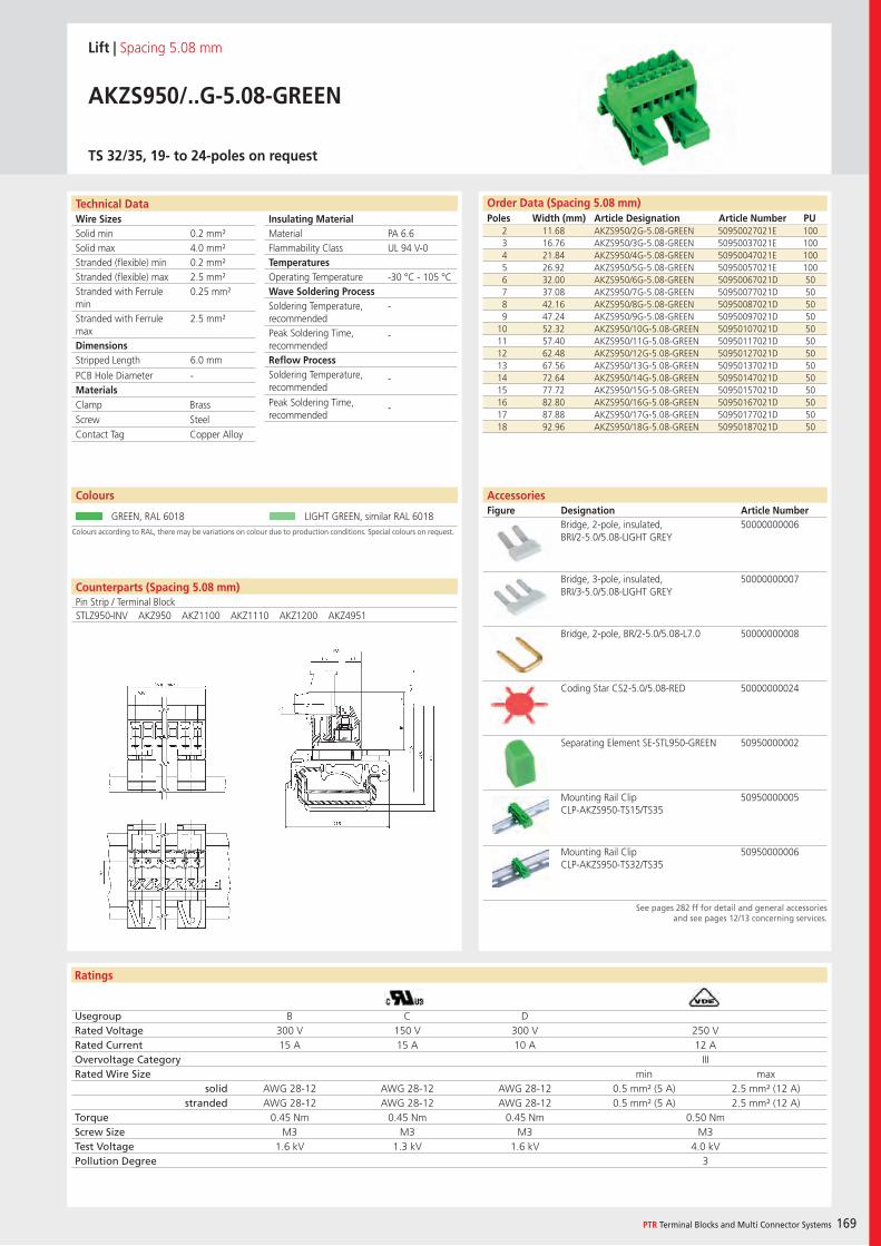
Wire SizesSolid minSolid maxStranded (flexible) minStranded (flexible) maxStranded with Ferrule minStranded with Ferrule maxDimensions Stripped Length
PCB Hole DiameterMaterials
Insulating Material MaterialFlammability ClassTemperaturesOperating TemperatureWave Soldering ProcessSoldering Temperature,recommendedPeak Soldering Time,recommendedReflow ProcessSoldering Temperature,recommended
Peak Soldering Time,recommended
Ratings
PTR Terminal Blocks and Multi Connector Systems 169
Order Data (Spacing 5.08 mm)Poles Width (mm) Article Designation Article Number PU
Counterparts (Spacing 5.08 mm)Pin Strip / Terminal Block
Technical Data
Lift | Spacing 5.08 mm
AKZS950/..G-5.08-GREEN
TS 32/35, 19- to 24-poles on request
2 11.68 AKZS950/2G-5.08-GREEN 50950027021E 1003 16.76 AKZS950/3G-5.08-GREEN 50950037021E 1004 21.84 AKZS950/4G-5.08-GREEN 50950047021E 1005 26.92 AKZS950/5G-5.08-GREEN 50950057021E 1006 32.00 AKZS950/6G-5.08-GREEN 50950067021D 507 37.08 AKZS950/7G-5.08-GREEN 50950077021D 508 42.16 AKZS950/8G-5.08-GREEN 50950087021D 509 47.24 AKZS950/9G-5.08-GREEN 50950097021D 50
10 52.32 AKZS950/10G-5.08-GREEN 50950107021D 5011 57.40 AKZS950/11G-5.08-GREEN 50950117021D 5012 62.48 AKZS950/12G-5.08-GREEN 50950127021D 5013 67.56 AKZS950/13G-5.08-GREEN 50950137021D 5014 72.64 AKZS950/14G-5.08-GREEN 50950147021D 5015 77.72 AKZS950/15G-5.08-GREEN 50950157021D 5016 82.80 AKZS950/16G-5.08-GREEN 50950167021D 5017 87.88 AKZS950/17G-5.08-GREEN 50950177021D 5018 92.96 AKZS950/18G-5.08-GREEN 50950187021D 50
See pages 282 ff for detail and general accessoriesand see pages 12/13 concerning services.
AccessoriesFigure Designation Article Number
Bridge, 2-pole, insulated, BRI/2-5.0/5.08-LIGHT GREY
50000000006
Bridge, 3-pole, insulated, BRI/3-5.0/5.08-LIGHT GREY
50000000007
Bridge, 2-pole, BR/2-5.0/5.08-L7.0 50000000008
Coding Star CS2-5.0/5.08-RED 50000000024
Separating Element SE-STL950-GREEN 50950000002
Mounting Rail Clip CLP-AKZS950-TS15/TS35
50950000005
Mounting Rail Clip CLP-AKZS950-TS32/TS35
50950000006
PA 6.6UL 94 V-0
-30 °C - 105 °C
-
-
-
-
0.2 mm²4.0 mm²0.2 mm²2.5 mm²0.25 mm²
2.5 mm²
6.0 mm
-
Colours according to RAL, there may be variations on colour due to production conditions. Special colours on request.
Colours
GREEN, RAL 6018 LIGHT GREEN, similar RAL 6018
STLZ950-INV AKZ950 AKZ1100 AKZ1110 AKZ1200 AKZ4951
Clamp BrassScrew SteelContact Tag Copper Alloy
Usegroup B C DRated Voltage 300 V 150 V 300 V 250 VRated Current 15 A 15 A 10 A 12 AOvervoltage Category IIIRated Wire Size min max
solid AWG 28-12 AWG 28-12 AWG 28-12 0.5 mm² (5 A) 2.5 mm² (12 A)stranded AWG 28-12 AWG 28-12 AWG 28-12 0.5 mm² (5 A) 2.5 mm² (12 A)
Torque 0.45 Nm 0.45 Nm 0.45 Nm 0.50 NmScrew Size M3 M3 M3 M3Test Voltage 1.6 kV 1.3 kV 1.6 kV 4.0 kVPollution Degree 3
Wire SizesSolid minSolid maxStranded (flexible) minStranded (flexible) maxStranded with Ferrule minStranded with Ferrule maxDimensions Stripped Length
PCB Hole DiameterMaterials
Insulating Material MaterialFlammability ClassTemperaturesOperating TemperatureWave Soldering ProcessSoldering Temperature,recommendedPeak Soldering Time,recommendedReflow ProcessSoldering Temperature,recommended
Peak Soldering Time,recommended
Technical Data
Ratings
170
Order Data (Spacing 5.08 mm)Poles Width (mm) Article Designation Article Number PU
Counterparts (Spacing 5.08 mm)Terminal Block
Technical Data
Lift | Spacing 5.08 mm
AKZS950/..F-5.08-GREEN
TS 32/35, 19- to 24-poles on request
2 21.48 AKZS950/2F-5.08-GREEN 50950027022E 1003 26.56 AKZS950/3F-5.08-GREEN 50950037022E 1004 31.64 AKZS950/4F-5.08-GREEN 50950047022E 1005 36.72 AKZS950/5F-5.08-GREEN 50950057022E 1006 41.80 AKZS950/6F-5.08-GREEN 50950067022D 507 46.88 AKZS950/7F-5.08-GREEN 50950077022D 508 51.96 AKZS950/8F-5.08-GREEN 50950087022D 509 57.04 AKZS950/9F-5.08-GREEN 50950097022D 50
10 62.12 AKZS950/10F-5.08-GREEN 50950107022D 5011 67.20 AKZS950/11F-5.08-GREEN 50950117022D 5012 72.28 AKZS950/12F-5.08-GREEN 50950127022D 5013 77.36 AKZS950/13F-5.08-GREEN 50950137022D 5014 82.44 AKZS950/14F-5.08-GREEN 50950147022D 5015 87.52 AKZS950/15F-5.08-GREEN 50950157022D 5016 92.60 AKZS950/16F-5.08-GREEN 50950167022D 5017 97.68 AKZS950/17F-5.08-GREEN 50950177022D 5018 102.76 AKZS950/18F-5.08-GREEN 50950187022D 50
See pages 282 ff for detail and general accessoriesand see pages 12/13 concerning services.
AccessoriesFigure Designation Article Number
Bridge, 2-pole, insulated, BRI/2-5.0/5.08-LIGHT GREY
50000000006
Bridge, 3-pole, insulated, BRI/3-5.0/5.08-LIGHT GREY
50000000007
Bridge, 2-pole, BR/2-5.0/5.08-L7.0 50000000008
Coding Star CS2-5.0/5.08-RED 50000000024
Separating Element SE-STL950-GREEN 50950000002
Mounting Rail Clip CLP-AKZS950-TS15/TS35
50950000005
Mounting Rail Clip CLP-AKZS950-TS32/TS35
50950000006
PA 6.6UL 94 V-0
-30 °C - 105 °C
-
-
-
-
0.2 mm²4.0 mm²0.2 mm²2.5 mm²0.25 mm²
2.5 mm²
6.0 mm
-
Colours according to RAL, there may be variations on colour due to production conditions. Special colours on request.
Colours
GREEN, RAL 6018 LIGHT GREEN, similar RAL 6018
AKZ950 AKZ1100 AKZ1110 AKZ4951
Clamp BrassScrew SteelThread Insert, Flange BrassContact Tag Copper Alloy
Usegroup B C DRated Voltage 300 V 150 V 300 V 250 VRated Current 15 A 15 A 10 A 12 AOvervoltage Category IIIRated Wire Size min max
solid AWG 28-12 AWG 28-12 AWG 28-12 0.5 mm² (5 A) 2.5 mm² (12 A)stranded AWG 28-12 AWG 28-12 AWG 28-12 0.5 mm² (5 A) 2.5 mm² (12 A)
Torque 0.45 Nm 0.45 Nm 0.45 Nm 0.50 NmScrew Size M3 M3 M3 M3Test Voltage 1.6 kV 1.3 kV 1.6 kV 4.0 kVPollution Degree 3
Wire SizesSolid minSolid maxStranded (flexible) minStranded (flexible) maxStranded with Ferrule minStranded with Ferrule maxDimensions Stripped Length
PCB Hole DiameterMaterials
Insulating Material MaterialFlammability ClassTemperaturesOperating TemperatureWave Soldering ProcessSoldering Temperature,recommendedPeak Soldering Time,recommendedReflow ProcessSoldering Temperature,recommended
Peak Soldering Time,recommended
Ratings
PTR Terminal Blocks and Multi Connector Systems 171
Order Data (Spacing 5.08 mm)Poles Width (mm) Article Designation Article Number PU
Counterparts (Spacing 5.08 mm)Pin Strip / Terminal Block
Technical Data
Lift | Spacing 5.08 mm
AKZS950/..GMB-5.08-GREEN
13- to 24-poles on request
2 21.48 AKZS950/2GMB-5.08-GREEN 50950027041D 503 26.56 AKZS950/3GMB-5.08-GREEN 50950037041D 504 31.64 AKZS950/4GMB-5.08-GREEN 50950047041D 505 36.72 AKZS950/5GMB-5.08-GREEN 50950057041D 506 41.80 AKZS950/6GMB-5.08-GREEN 50950067041D 507 46.88 AKZS950/7GMB-5.08-GREEN 50950077041D 508 51.96 AKZS950/8GMB-5.08-GREEN 50950087041D 509 57.04 AKZS950/9GMB-5.08-GREEN 50950097041D 50
10 62.12 AKZS950/10GMB-5.08-GREEN 50950107041D 5011 67.20 AKZS950/11GMB-5.08-GREEN 50950117041D 5012 72.28 AKZS950/12GMB-5.08-GREEN 50950127041D 50
See pages 282 ff for detail and general accessoriesand see pages 12/13 concerning services.
AccessoriesFigure Designation Article Number
Bridge, 2-pole, insulated, BRI/2-5.0/5.08-LIGHT GREY
50000000006
Bridge, 3-pole, insulated, BRI/3-5.0/5.08-LIGHT GREY
50000000007
Bridge, 2-pole, BR/2-5.0/5.08-L7.0 50000000008
Separating Element SE-STL950-GREEN 50950000002
Coding Star CS2-5.0/5.08-RED 50000000024
PA 6.6UL 94 V-0
-30 °C - 105 °C
-
-
-
-
0.2 mm²4.0 mm²0.2 mm²2.5 mm²0.25 mm²
2.5 mm²
6.0 mm
-
Colours according to RAL, there may be variations on colour due to production conditions. Special colours on request.
Colours
GREEN, RAL 6018 LIGHT GREEN, similar RAL 6018
STLZ950-INV AKZ950 AKZ1100 AKZ1110 AKZ1200 AKZ4951
Clamp BrassScrew SteelContact Tag Copper Alloy
Usegroup B C DRated Voltage 300 V 150 V 300 V 250 VRated Current 15 A 15 A 10 A 12 AOvervoltage Category IIIRated Wire Size min max
solid AWG 28-12 AWG 28-12 AWG 28-12 0.5 mm² (5 A) 2.5 mm² (12 A)stranded AWG 28-12 AWG 28-12 AWG 28-12 0.5 mm² (5 A) 2.5 mm² (12 A)
Torque 0.45 Nm 0.45 Nm 0.45 Nm 0.50 NmScrew Size M3 M3 M3 M3Test Voltage 1.6 kV 1.3 kV 1.6 kV 4.0 kVPollution Degree 3
Wire SizesSolid minSolid maxStranded (flexible) minStranded (flexible) maxStranded with Ferrule minStranded with Ferrule maxDimensions Stripped Length
PCB Hole DiameterMaterials
Insulating Material MaterialFlammability ClassTemperaturesOperating TemperatureWave Soldering ProcessSoldering Temperature,recommendedPeak Soldering Time,recommendedReflow ProcessSoldering Temperature,recommended
Peak Soldering Time,recommended
Technical Data
Ratings
172
Order Data (Spacing 7.62 mm)Poles Width (mm) Article Designation Article Number PU
Counterparts (Spacing 7.62 mm)Pin Strip
Technical Data
Lift | Spacing 7.62 mm
AKZ960/..-7.62-GREEN
2 13.24 AKZ960/2-7.62-GREEN 50960020021E 1003 20.86 AKZ960/3-7.62-GREEN 50960030021E 1004 28.48 AKZ960/4-7.62-GREEN 50960040021E 1005 36.10 AKZ960/5-7.62-GREEN 50960050021E 1006 43.72 AKZ960/6-7.62-GREEN 50960060021D 507 51.34 AKZ960/7-7.62-GREEN 50960070021D 508 58.96 AKZ960/8-7.62-GREEN 50960080021D 509 66.58 AKZ960/9-7.62-GREEN 50960090021D 50
10 74.20 AKZ960/10-7.62-GREEN 50960100021D 5011 81.82 AKZ960/11-7.62-GREEN 50960110021D 5012 89.44 AKZ960/12-7.62-GREEN 50960120021D 5013 97.06 AKZ960/13-7.62-GREEN 50960130021D 5014 104.68 AKZ960/14-7.62-GREEN 50960140021D 5015 112.30 AKZ960/15-7.62-GREEN 50960150021D 5016 119.92 AKZ960/16-7.62-GREEN 50960160021D 50
See pages 282 ff for detail and general accessoriesand see pages 12/13 concerning services.
AccessoriesFigure Designation Article Number
Bridge, 2-pole, insulated, BRI/2-7.5/7.62-L8.2-LIGHT GREY
50000000017
Coding Star CS1-5.0/5.08-RED 50000000021
Series AK(Z)960 with separating element on request
Series AKZ960 with pull relief on request
PA 6.6UL 94 V-0
-30 °C - 105 °C
-
-
-
-
0.2 mm²4.0 mm²0.2 mm²2.5 mm²0.25 mm²
2.5 mm²
6.0 mm
-
Colours according to RAL, there may be variations on colour due to production conditions. Special colours on request.
Colours
GREEN, RAL 6018 LIGHT GREY, RAL 7035
LIGHT GREEN, similar RAL 6018
STLZ960
Clamp BrassScrew SteelContact Spring Bronze
Usegroup B C DRated Voltage 300 V 150 V 300 V 400 VRated Current 15 A 15 A 10 A 12 AOvervoltage Category IIIRated Wire Size min max
solid AWG 22-12 AWG 22-12 AWG 22-12 0.5 mm² (5 A) 2.5 mm² (12 A)stranded AWG 22-12 AWG 22-12 AWG 22-12 0.5 mm² (5 A) 2.5 mm² (12 A)
Torque 0.50 Nm 0.50 Nm 0.50 Nm 0.50 NmScrew Size M3 M3 M3 M3Test Voltage 1.6 kV 1.3 kV 1.6 kV 6.0 kVPollution Degree 3
Wire SizesSolid minSolid maxStranded (flexible) minStranded (flexible) maxStranded with Ferrule minStranded with Ferrule maxDimensions Stripped Length
PCB Hole DiameterMaterials
Insulating Material MaterialFlammability ClassTemperaturesOperating TemperatureWave Soldering ProcessSoldering Temperature,recommendedPeak Soldering Time,recommendedReflow ProcessSoldering Temperature,recommended
Peak Soldering Time,recommended
Ratings
PTR Terminal Blocks and Multi Connector Systems 173
Order Data (Spacing 7.62 mm)Poles Width (mm) Article Designation Article Number PU
Counterparts (Spacing 7.62 mm)Pin Strip
Technical Data
Lift | Spacing 7.62 mm
AKZ965/..F-7.62-GREEN
2 25.54 AKZ965/2F-7.62-GREEN 50965022021E 1003 33.16 AKZ965/3F-7.62-GREEN 50965032021E 1004 40.78 AKZ965/4F-7.62-GREEN 50965042021D 505 48.40 AKZ965/5F-7.62-GREEN 50965052021D 506 56.02 AKZ965/6F-7.62-GREEN 50965062021D 507 63.64 AKZ965/7F-7.62-GREEN 50965072021D 508 71.26 AKZ965/8F-7.62-GREEN 50965082021D 509 78.88 AKZ965/9F-7.62-GREEN 50965092021D 50
10 86.50 AKZ965/10F-7.62-GREEN 50965102021D 5011 94.12 AKZ965/11F-7.62-GREEN 50965112021D 5012 101.74 AKZ965/12F-7.62-GREEN 50965122021D 5013 109.36 AKZ965/13F-7.62-GREEN 50965132021D 5014 116.98 AKZ965/14F-7.62-GREEN 50965142021D 5015 124.60 AKZ965/15F-7.62-GREEN 50965152021D 5016 132.22 AKZ965/16F-7.62-GREEN 50965162021D 50
See pages 282 ff for detail and general accessoriesand see pages 12/13 concerning services.
AccessoriesFigure Designation Article Number
Bridge, 2-pole, insulated, BRI/2-7.5/7.62-L8.2-LIGHT GREY
50000000017
Coding Star CS4-5.0/5.08-RED 50000000026
Series AKZ965 with pull relief on request
PA 6.6UL 94 V-0
-30 °C - 105 °C
-
-
-
-
0.08 mm²4.0 mm²0.08 mm²4.0 mm²0.25 mm²
2.5 mm²
7.0 mm
-
Colours according to RAL, there may be variations on colour due to production conditions. Special colours on request.
Colours
GREEN, RAL 6018 LIGHT GREEN, similar RAL 6018
STLZ965
Clamp BrassScrew SteelContact Spring Bronze
Usegroup B C DRated Voltage 300 V - 300 V 400 VRated Current 10 A - 10 A 12 AOvervoltage Category IIIRated Wire Size min max
solid AWG 28-12 - AWG 28-12 0.2 mm² (4 A) 2.5 mm² (12 A)stranded AWG 28-12 - AWG 28-12 0.2 mm² (4 A) 2.5 mm² (12 A)
Torque 0.50 Nm - 0.50 Nm 0.50 NmScrew Size M3 - M3 M3Test Voltage 1.6 kV - 1.6 kV 6.0 kVPollution Degree 3
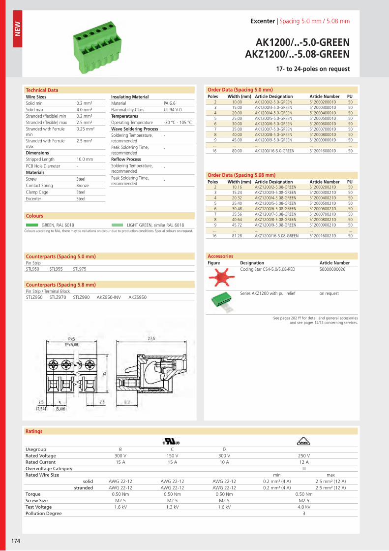
Wire SizesSolid minSolid maxStranded (flexible) minStranded (flexible) maxStranded with Ferrule minStranded with Ferrule maxDimensions Stripped Length
PCB Hole DiameterMaterials
Insulating Material MaterialFlammability ClassTemperaturesOperating TemperatureWave Soldering ProcessSoldering Temperature,recommendedPeak Soldering Time,recommendedReflow ProcessSoldering Temperature,recommended
Peak Soldering Time,recommended
Ratings
174
NEW
Technical Data
Colours according to RAL, there may be variations on colour due to production conditions. Special colours on request.
Order Data (Spacing 5.0 mm)Poles Width (mm) Article Designation Article Number PU
Order Data (Spacing 5.08 mm)Poles Width (mm) Article Designation Article Number PU
Colours
Excenter | Spacing 5.0 mm / 5.08 mm
AK1200/..-5.0-GREENAKZ1200/..-5.08-GREEN
17- to 24-poles on request
2 10.00 AK1200/2-5.0-GREEN 51200020001D 503 15.00 AK1200/3-5.0-GREEN 51200030001D 504 20.00 AK1200/4-5.0-GREEN 51200040001D 505 25.00 AK1200/5-5.0-GREEN 51200050001D 506 30.00 AK1200/6-5.0-GREEN 51200060001D 507 35.00 AK1200/7-5.0-GREEN 51200070001D 508 40.00 AK1200/8-5.0-GREEN 51200080001D 509 45.00 AK1200/9-5.0-GREEN 51200090001D 50
... ... ... ... ...16 80.00 AK1200/16-5.0-GREEN 51200160001D 50
GREEN, RAL 6018 LIGHT GREEN, similar RAL 6018
AccessoriesFigure Designation Article Number
See pages 282 ff for detail and general accessoriesand see pages 12/13 concerning services.
2 10.16 AKZ1200/2-5.08-GREEN 51200020021D 503 15.24 AKZ1200/3-5.08-GREEN 51200030021D 504 20.32 AKZ1200/4-5.08-GREEN 51200040021D 505 25.40 AKZ1200/5-5.08-GREEN 51200050021D 506 30.48 AKZ1200/6-5.08-GREEN 51200060021D 507 35.56 AKZ1200/7-5.08-GREEN 51200070021D 508 40.64 AKZ1200/8-5.08-GREEN 51200080021D 509 45.72 AKZ1200/9-5.08-GREEN 51200090021D 50
... ... ... ... ...16 81.28 AKZ1200/16-5.08-GREEN 51200160021D 50
PA 6.6UL 94 V-0
-30 °C - 105 °C
-
-
-
-
0.2 mm²4.0 mm²0.2 mm²2.5 mm²0.25 mm²
2.5 mm²
10.0 mm
-
Screw SteelContact Spring BronzeClamp Cage SteelExcenter Steel
Usegroup B C DRated Voltage 300 V 150 V 300 V 250 VRated Current 15 A 15 A 10 A 12 AOvervoltage Category IIIRated Wire Size min max
solid AWG 22-12 AWG 22-12 AWG 22-12 0.2 mm² (4 A) 2.5 mm² (12 A)stranded AWG 22-12 AWG 22-12 AWG 22-12 0.2 mm² (4 A) 2.5 mm² (12 A)
Torque 0.50 Nm 0.50 Nm 0.50 Nm 0.50 NmScrew Size M2.5 M2.5 M2.5 M2.5Test Voltage 1.6 kV 1.3 kV 1.6 kV 4.0 kVPollution Degree 3
Coding Star CS4-5.0/5.08-RED 50000000026
Series AKZ1200 with pull relief on request
Counterparts (Spacing 5.0 mm)Pin Strip
Counterparts (Spacing 5.8 mm)Pin Strip / Terminal Block
STL950 STL955 STL975
STLZ950 STLZ970 STLZ990 AKZ950-INV AKZS950
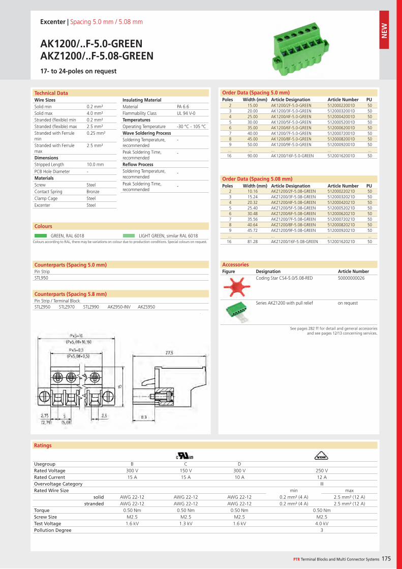
Wire SizesSolid minSolid maxStranded (flexible) minStranded (flexible) maxStranded with Ferrule minStranded with Ferrule maxDimensions Stripped Length
PCB Hole DiameterMaterials
Insulating Material MaterialFlammability ClassTemperaturesOperating TemperatureWave Soldering ProcessSoldering Temperature,recommendedPeak Soldering Time,recommendedReflow ProcessSoldering Temperature,recommended
Peak Soldering Time,recommended
Ratings
PTR Terminal Blocks and Multi Connector Systems 175
Technical Data
Colours according to RAL, there may be variations on colour due to production conditions. Special colours on request.
Order Data (Spacing 5.0 mm)Poles Width (mm) Article Designation Article Number PU
Colours
Excenter | Spacing 5.0 mm / 5.08 mm
AK1200/..F-5.0-GREENAKZ1200/..F-5.08-GREEN17- to 24-poles on request
2 15.00 AK1200/2F-5.0-GREEN 51200022001D 503 20.00 AK1200/3F-5.0-GREEN 51200032001D 504 25.00 AK1200/4F-5.0-GREEN 51200042001D 505 30.00 AK1200/5F-5.0-GREEN 51200052001D 506 35.00 AK1200/6F-5.0-GREEN 51200062001D 507 40.00 AK1200/7F-5.0-GREEN 51200072001D 508 45.00 AK1200/8F-5.0-GREEN 51200082001D 509 50.00 AK1200/9F-5.0-GREEN 51200092001D 50
... ... ... ... ...16 90.00 AK1200/16F-5.0-GREEN 51200162001D 50
GREEN, RAL 6018 LIGHT GREEN, similar RAL 6018
Order Data (Spacing 5.08 mm)Poles Width (mm) Article Designation Article Number PU
2 10.16 AKZ1200/2F-5.08-GREEN 51200022021D 503 15.24 AKZ1200/3F-5.08-GREEN 51200032021D 504 20.32 AKZ1200/4F-5.08-GREEN 51200042021D 505 25.40 AKZ1200/5F-5.08-GREEN 51200052021D 506 30.48 AKZ1200/6F-5.08-GREEN 51200062021D 507 35.56 AKZ1200/7F-5.08-GREEN 51200072021D 508 40.64 AKZ1200/8F-5.08-GREEN 51200082021D 509 45.72 AKZ1200/9F-5.08-GREEN 51200092021D 50
... ... ... ... ...16 81.28 AKZ1200/16F-5.08-GREEN 51200162021D 50
PA 6.6UL 94 V-0
-30 °C - 105 °C
-
-
-
-
0.2 mm²4.0 mm²0.2 mm²2.5 mm²0.25 mm²
2.5 mm²
10.0 mm
-
Counterparts (Spacing 5.0 mm)Pin StripSTL950
Screw SteelContact Spring BronzeClamp Cage SteelExcenter Steel
Usegroup B C DRated Voltage 300 V 150 V 300 V 250 VRated Current 15 A 15 A 10 A 12 AOvervoltage Category IIIRated Wire Size min max
solid AWG 22-12 AWG 22-12 AWG 22-12 0.2 mm² (4 A) 2.5 mm² (12 A)stranded AWG 22-12 AWG 22-12 AWG 22-12 0.2 mm² (4 A) 2.5 mm² (12 A)
Torque 0.50 Nm 0.50 Nm 0.50 Nm 0.50 NmScrew Size M2.5 M2.5 M2.5 M2.5Test Voltage 1.6 kV 1.3 kV 1.6 kV 4.0 kVPollution Degree 3
AccessoriesFigure Designation Article Number
See pages 282 ff for detail and general accessoriesand see pages 12/13 concerning services.
Coding Star CS4-5.0/5.08-RED 50000000026
Series AKZ1200 with pull relief on request
Counterparts (Spacing 5.8 mm)Pin Strip / Terminal BlockSTLZ950 STLZ970 STLZ990 AKZ950-INV AKZS950
NEW
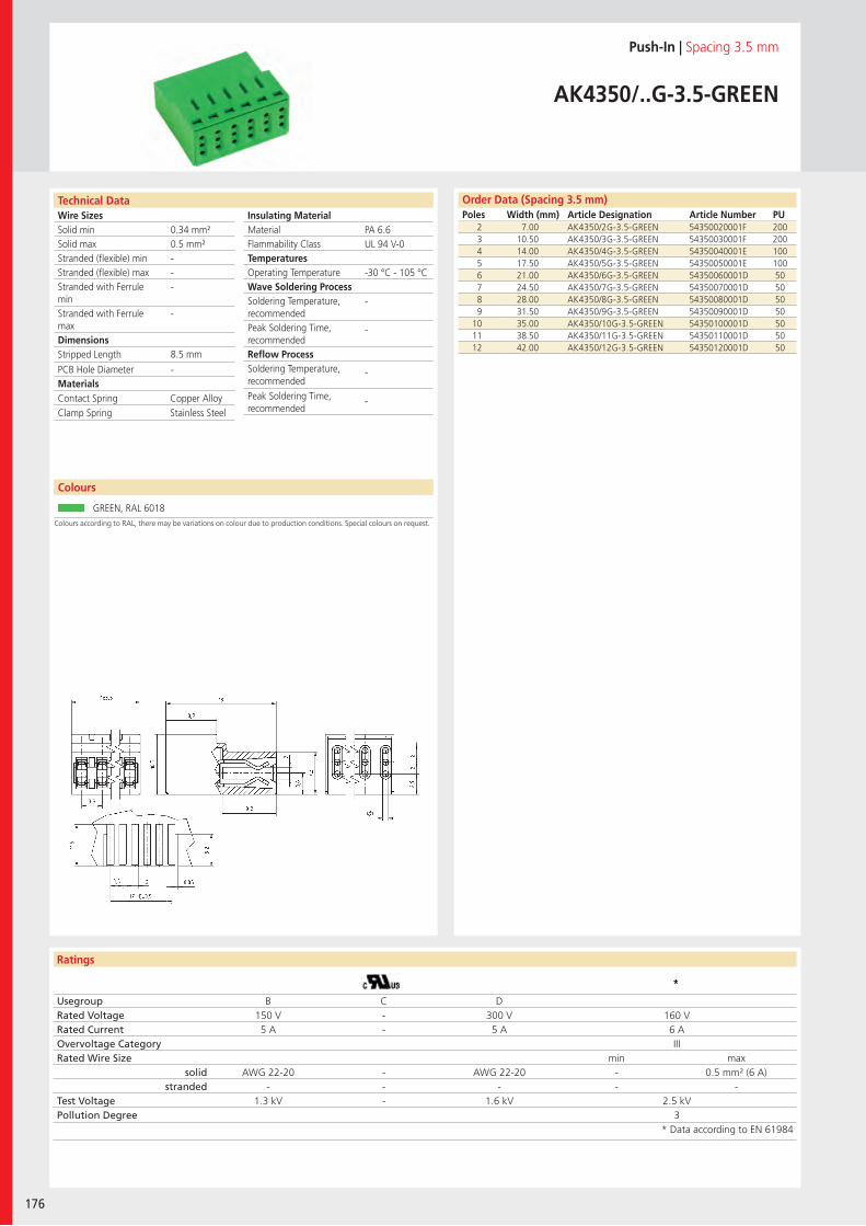
Wire SizesSolid minSolid maxStranded (flexible) minStranded (flexible) maxStranded with Ferrule minStranded with Ferrule maxDimensions Stripped Length
PCB Hole DiameterMaterials
Insulating Material MaterialFlammability ClassTemperaturesOperating TemperatureWave Soldering ProcessSoldering Temperature,recommendedPeak Soldering Time,recommendedReflow ProcessSoldering Temperature,recommended
Peak Soldering Time,recommended
Ratings
176
Technical Data
Colours according to RAL, there may be variations on colour due to production conditions. Special colours on request.
Order Data (Spacing 3.5 mm)Poles Width (mm) Article Designation Article Number PU
Colours
Push-In | Spacing 3.5 mm
AK4350/..G-3.5-GREEN
2 7.00 AK4350/2G-3.5-GREEN 54350020001F 2003 10.50 AK4350/3G-3.5-GREEN 54350030001F 2004 14.00 AK4350/4G-3.5-GREEN 54350040001E 1005 17.50 AK4350/5G-3.5-GREEN 54350050001E 1006 21.00 AK4350/6G-3.5-GREEN 54350060001D 507 24.50 AK4350/7G-3.5-GREEN 54350070001D 508 28.00 AK4350/8G-3.5-GREEN 54350080001D 509 31.50 AK4350/9G-3.5-GREEN 54350090001D 50
10 35.00 AK4350/10G-3.5-GREEN 54350100001D 5011 38.50 AK4350/11G-3.5-GREEN 54350110001D 5012 42.00 AK4350/12G-3.5-GREEN 54350120001D 50
GREEN, RAL 6018
PA 6.6UL 94 V-0
-30 °C - 105 °C
-
-
-
-
0.34 mm²0.5 mm²---
-
8.5 mm
-
Contact Spring Copper AlloyClamp Spring Stainless Steel
Usegroup B C DRated Voltage 150 V - 300 V 160 VRated Current 5 A - 5 A 6 AOvervoltage Category IIIRated Wire Size min max
solid AWG 22-20 - AWG 22-20 - 0.5 mm² (6 A)stranded - - - - -
Test Voltage 1.3 kV - 1.6 kV 2.5 kVPollution Degree 3
* Data according to EN 61984
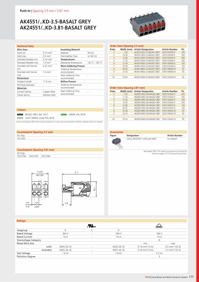
Wire SizesSolid minSolid maxStranded (flexible) minStranded (flexible) maxStranded with Ferrule minStranded with Ferrule maxDimensions Stripped Length
PCB Hole DiameterMaterials
Insulating Material MaterialFlammability ClassTemperaturenOperating TemperatureWave Soldering ProcessSoldering Temperature,recommendedPeak Soldering Time,recommendedReflow ProcessSoldering Temperature,recommended
Peak Soldering Time,recommended
Ratings
PTR Terminal Blocks and Multi Connector Systems 177
Technical Data Order Data (Spacing 3.5 mm)Poles Width (mm) Article Designation Article Number PU
Order Data (Spacing 3.81 mm)Poles Width (mm) Article Designation Article Number PU
Push-In | Spacing 3.5 mm / 3.81 mm
AK4551/..KD-3.5-BASALT GREYAKZ4551/..KD-3.81-BASALT GREY
2 7.00 AK4551/2KD-3.5-BASALT GREY 54551020401F 2003 10.50 AK4551/3KD-3.5-BASALT GREY 54551030401F 2004 14.00 AK4551/4KD-3.5-BASALT GREY 54551040401F 2005 17.50 AK4551/5KD-3.5-BASALT GREY 54551050401F 2006 21.00 AK4551/6KD-3.5-BASALT GREY 54551060401E 1007 24.50 AK4551/7KD-3.5-BASALT GREY 54551070401E 1008 28.00 AK4551/8KD-3.5-BASALT GREY 54551080401D 509 31.50 AK4551/9KD-3.5-BASALT GREY 54551090401D 50
... ... ... ... ...20 70.00 AK4551/20KD-3.5-BASALT GREY 54551200401D 50
AccessoriesFigure Designation Article Number
See pages 282 ff for detail and general accessoriesand see pages 12/13 concerning services.
2 7.62 AKZ4551/2KD-3.81-BASALT GREY 54551020421F 2003 11.43 AKZ4551/3KD-3.81-BASALT GREY 54551030421F 2004 15.24 AKZ4551/4KD-3.81-BASALT GREY 54551040421F 2005 19.05 AKZ4551/5KD-3.81-BASALT GREY 54551050421F 2006 22.86 AKZ4551/6KD-3.81-BASALT GREY 54551060421E 1007 26.67 AKZ4551/7KD-3.81-BASALT GREY 54551070421E 1008 30.48 AKZ4551/8KD-3.81-BASALT GREY 54551080421D 509 34.29 AKZ4551/9KD-3.81-BASALT GREY 54551090421D 50
... ... ... ... ...20 76.20 AKZ4551/20KD-3.81-BASALT GREY 54551200421D 50
PA 6.6UL 94 V-0
-30 °C - 105 °C
-
-
-
-
0.14 mm²2.5 mm²0.14 mm²1.5 mm²0.25 mm²
1.0 mm²
11.0 mm
-
Contact Spring Copper AlloyClamp Spring Stainless Steel
Usegroup B C DRated Voltage 300 V - 300 V 160 VRated Current 10 A - 10 A 10 AOvervoltage Category IIIRated Wire Size min max
solid AWG 26-16 - AWG 26-16 0.14 mm² (3 A) 2.5 mm² (10 A)stranded AWG 26-16 - AWG 26-16 0.14 mm² (3 A) 1.5 mm² (10 A)
Test Voltage 1.6 kV - 1.6 kV 2.5 kVPollution Degree 3
Series AK(Z)4551 with pull relief on request
Colours according to RAL, there may be variations on colour due to production conditions. Special colours on request.
Colours
BASALT GREY, RAL 7012 GREEN, RAL 6018
LIGHT GREEN, similar RAL 6018
Counterparts (Spacing 3.5 mm)Pin Strip
Counterparts (Spacing 3.81 mm)Pin Strip
STL1550
STLZ1550 STLZ1570 STLZ1590
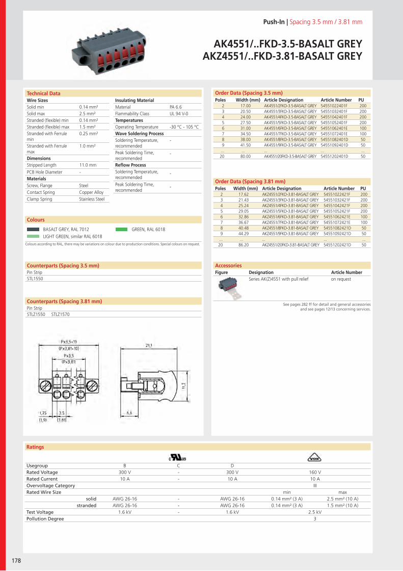
Wire SizesSolid minSolid maxStranded (flexible) minStranded (flexible) maxStranded with Ferrule minStranded with Ferrule maxDimensions Stripped Length
PCB Hole DiameterMaterials
Insulating Material MaterialFlammability ClassTemperaturesOperating TemperatureWave Soldering ProcessSoldering Temperature,recommendedPeak Soldering Time,recommendedReflow ProcessSoldering Temperature,recommended
Peak Soldering Time,recommended
Ratings
178
Technical Data
Colours according to RAL, there may be variations on colour due to production conditions. Special colours on request.
Order Data (Spacing 3.5 mm)Poles Width (mm) Article Designation Article Number PU
Order Data (Spacing 3.81 mm)Poles Width (mm) Article Designation Article Number PU
Colours
Push-In | Spacing 3.5 mm / 3.81 mm
AK4551/..FKD-3.5-BASALT GREYAKZ4551/..FKD-3.81-BASALT GREY
2 17.00 AK4551/2FKD-3.5-BASALT GREY 54551022401F 2003 20.50 AK4551/3FKD-3.5-BASALT GREY 54551032401F 2004 24.00 AK4551/4FKD-3.5-BASALT GREY 54551042401F 2005 27.50 AK4551/5FKD-3.5-BASALT GREY 54551052401F 2006 31.00 AK4551/6FKD-3.5-BASALT GREY 54551062401E 1007 34.50 AK4551/7FKD-3.5-BASALT GREY 54551072401E 1008 38.00 AK4551/8FKD-3.5-BASALT GREY 54551082401D 509 41.50 AK4551/9FKD-3.5-BASALT GREY 54551092401D 50
... ... ... ... ...20 80.00 AK4551/20FKD-3.5-BASALT GREY 54551202401D 50
BASALT GREY, RAL 7012 GREEN, RAL 6018
LIGHT GREEN, similar RAL 6018
AccessoriesFigure Designation Article Number
See pages 282 ff for detail and general accessoriesand see pages 12/13 concerning services.
2 17.62 AKZ4551/2FKD-3.81-BASALT GREY 54551022421F 2003 21.43 AKZ4551/3FKD-3.81-BASALT GREY 54551032421F 2004 25.24 AKZ4551/4FKD-3.81-BASALT GREY 54551042421F 2005 29.05 AKZ4551/5FKD-3.81-BASALT GREY 54551052421F 2006 32.86 AKZ4551/6FKD-3.81-BASALT GREY 54551062421E 1007 36.67 AKZ4551/7FKD-3.81-BASALT GREY 54551072421E 1008 40.48 AKZ4551/8FKD-3.81-BASALT GREY 54551082421D 509 44.29 AKZ4551/9FKD-3.81-BASALT GREY 54551092421D 50
... ... ... ... ...20 86.20 AKZ4551/20FKD-3.81-BASALT GREY 54551202421D 50
PA 6.6UL 94 V-0
-30 °C - 105 °C
-
-
-
-
0.14 mm²2.5 mm²0.14 mm²1.5 mm²0.25 mm²
1.0 mm²
11.0 mm
-
Counterparts (Spacing 3.5 mm)Pin Strip
Counterparts (Spacing 3.81 mm)Pin Strip
STL1550
Screw, Flange SteelContact Spring Copper AlloyClamp Spring Stainless Steel
Usegroup B C DRated Voltage 300 V - 300 V 160 VRated Current 10 A - 10 A 10 AOvervoltage Category IIIRated Wire Size min max
solid AWG 26-16 - AWG 26-16 0.14 mm² (3 A) 2.5 mm² (10 A)stranded AWG 26-16 - AWG 26-16 0.14 mm² (3 A) 1.5 mm² (10 A)
Test Voltage 1.6 kV - 1.6 kV 2.5 kVPollution Degree 3
Series AK(Z)4551 with pull relief on request
STLZ1550 STLZ1570
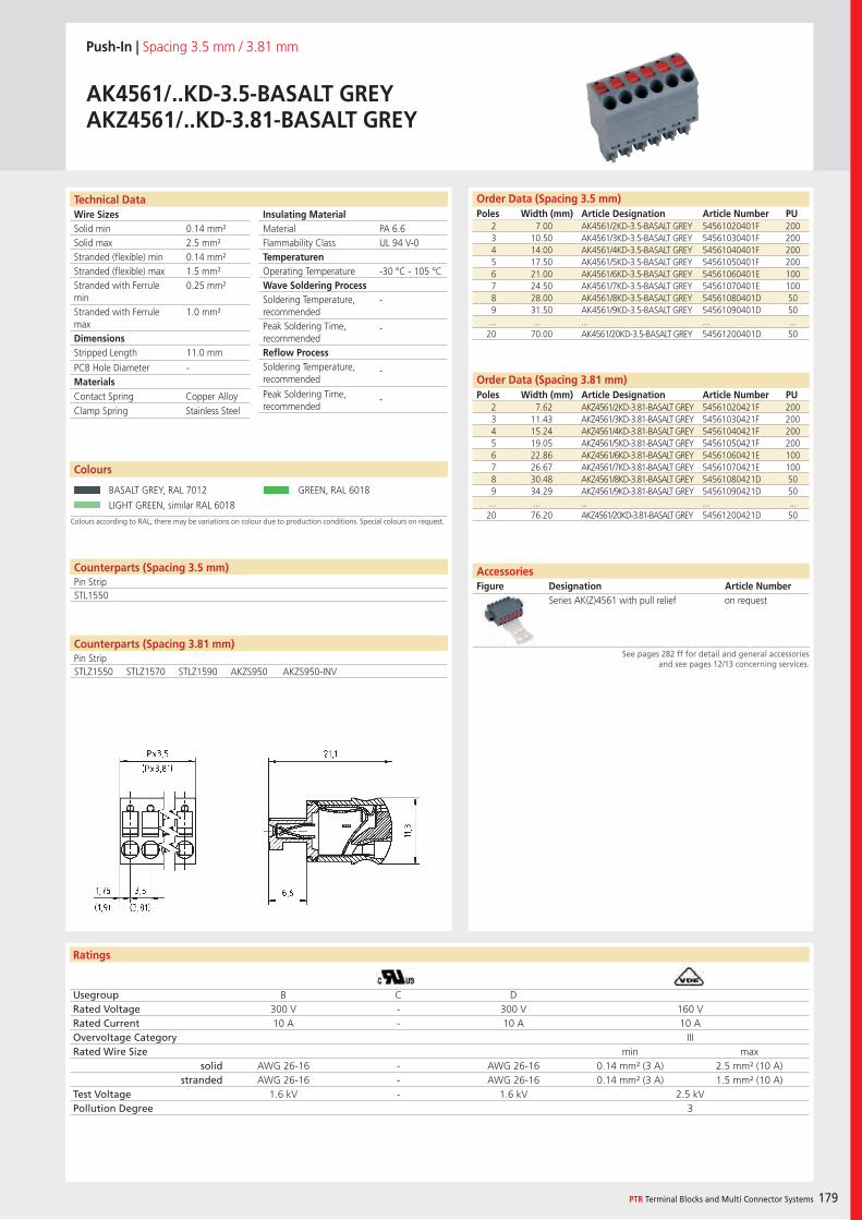
Wire SizesSolid minSolid maxStranded (flexible) minStranded (flexible) maxStranded with Ferrule minStranded with Ferrule maxDimensions Stripped Length
PCB Hole DiameterMaterials
Insulating Material MaterialFlammability ClassTemperaturenOperating TemperatureWave Soldering ProcessSoldering Temperature,recommendedPeak Soldering Time,recommendedReflow ProcessSoldering Temperature,recommended
Peak Soldering Time,recommended
Ratings
PTR Terminal Blocks and Multi Connector Systems 179
Counterparts (Spacing 3.81 mm)Pin Strip
Technical Data Order Data (Spacing 3.5 mm)Poles Width (mm) Article Designation Article Number PU
Order Data (Spacing 3.81 mm)Poles Width (mm) Article Designation Article Number PU
Push-In | Spacing 3.5 mm / 3.81 mm
AK4561/..KD-3.5-BASALT GREYAKZ4561/..KD-3.81-BASALT GREY
2 7.00 AK4561/2KD-3.5-BASALT GREY 54561020401F 2003 10.50 AK4561/3KD-3.5-BASALT GREY 54561030401F 2004 14.00 AK4561/4KD-3.5-BASALT GREY 54561040401F 2005 17.50 AK4561/5KD-3.5-BASALT GREY 54561050401F 2006 21.00 AK4561/6KD-3.5-BASALT GREY 54561060401E 1007 24.50 AK4561/7KD-3.5-BASALT GREY 54561070401E 1008 28.00 AK4561/8KD-3.5-BASALT GREY 54561080401D 509 31.50 AK4561/9KD-3.5-BASALT GREY 54561090401D 50
... ... ... ... ...20 70.00 AK4561/20KD-3.5-BASALT GREY 54561200401D 50
Colours according to RAL, there may be variations on colour due to production conditions. Special colours on request.
Colours
BASALT GREY, RAL 7012 GREEN, RAL 6018
LIGHT GREEN, similar RAL 6018
AccessoriesFigure Designation Article Number
See pages 282 ff for detail and general accessoriesand see pages 12/13 concerning services.
2 7.62 AKZ4561/2KD-3.81-BASALT GREY 54561020421F 2003 11.43 AKZ4561/3KD-3.81-BASALT GREY 54561030421F 2004 15.24 AKZ4561/4KD-3.81-BASALT GREY 54561040421F 2005 19.05 AKZ4561/5KD-3.81-BASALT GREY 54561050421F 2006 22.86 AKZ4561/6KD-3.81-BASALT GREY 54561060421E 1007 26.67 AKZ4561/7KD-3.81-BASALT GREY 54561070421E 1008 30.48 AKZ4561/8KD-3.81-BASALT GREY 54561080421D 509 34.29 AKZ4561/9KD-3.81-BASALT GREY 54561090421D 50
... ... ... ... ...20 76.20 AKZ4561/20KD-3.81-BASALT GREY 54561200421D 50
PA 6.6UL 94 V-0
-30 °C - 105 °C
-
-
-
-
0.14 mm²2.5 mm²0.14 mm²1.5 mm²0.25 mm²
1.0 mm²
11.0 mm
-
Counterparts (Spacing 3.5 mm)Pin StripSTL1550
Contact Spring Copper AlloyClamp Spring Stainless Steel
Usegroup B C DRated Voltage 300 V - 300 V 160 VRated Current 10 A - 10 A 10 AOvervoltage Category IIIRated Wire Size min max
solid AWG 26-16 - AWG 26-16 0.14 mm² (3 A) 2.5 mm² (10 A)stranded AWG 26-16 - AWG 26-16 0.14 mm² (3 A) 1.5 mm² (10 A)
Test Voltage 1.6 kV - 1.6 kV 2.5 kVPollution Degree 3
Series AK(Z)4561 with pull relief on request
STLZ1550 STLZ1570 STLZ1590 AKZS950 AKZS950-INV
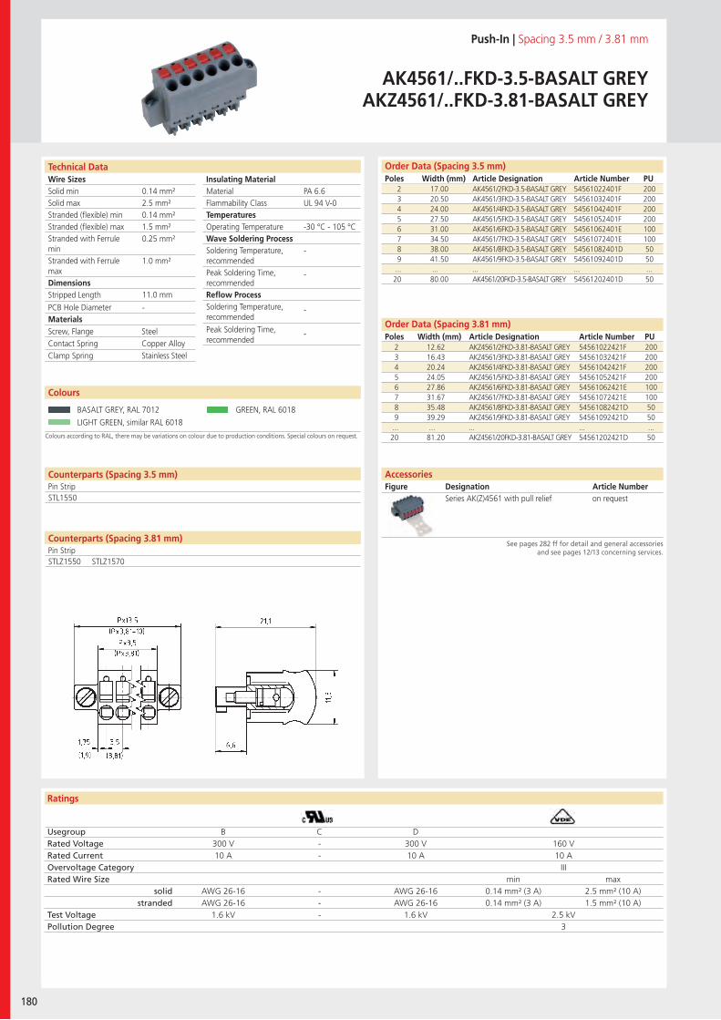
Wire SizesSolid minSolid maxStranded (flexible) minStranded (flexible) maxStranded with Ferrule minStranded with Ferrule maxDimensions Stripped Length
PCB Hole DiameterMaterials
Insulating Material MaterialFlammability ClassTemperaturesOperating TemperatureWave Soldering ProcessSoldering Temperature,recommendedPeak Soldering Time,recommendedReflow ProcessSoldering Temperature,recommended
Peak Soldering Time,recommended
Ratings
180
Technical Data Order Data (Spacing 3.5 mm)Poles Width (mm) Article Designation Article Number PU
Order Data (Spacing 3.81 mm)Poles Width (mm) Article Designation Article Number PU
Push-In | Spacing 3.5 mm / 3.81 mm
AK4561/..FKD-3.5-BASALT GREYAKZ4561/..FKD-3.81-BASALT GREY
2 17.00 AK4561/2FKD-3.5-BASALT GREY 54561022401F 2003 20.50 AK4561/3FKD-3.5-BASALT GREY 54561032401F 2004 24.00 AK4561/4FKD-3.5-BASALT GREY 54561042401F 2005 27.50 AK4561/5FKD-3.5-BASALT GREY 54561052401F 2006 31.00 AK4561/6FKD-3.5-BASALT GREY 54561062401E 1007 34.50 AK4561/7FKD-3.5-BASALT GREY 54561072401E 1008 38.00 AK4561/8FKD-3.5-BASALT GREY 54561082401D 509 41.50 AK4561/9FKD-3.5-BASALT GREY 54561092401D 50
... ... ... ... ...20 80.00 AK4561/20FKD-3.5-BASALT GREY 54561202401D 50
Colours according to RAL, there may be variations on colour due to production conditions. Special colours on request.
Colours
BASALT GREY, RAL 7012 GREEN, RAL 6018
LIGHT GREEN, similar RAL 6018
AccessoriesFigure Designation Article Number
See pages 282 ff for detail and general accessoriesand see pages 12/13 concerning services.
2 12.62 AKZ4561/2FKD-3.81-BASALT GREY 54561022421F 2003 16.43 AKZ4561/3FKD-3.81-BASALT GREY 54561032421F 2004 20.24 AKZ4561/4FKD-3.81-BASALT GREY 54561042421F 2005 24.05 AKZ4561/5FKD-3.81-BASALT GREY 54561052421F 2006 27.86 AKZ4561/6FKD-3.81-BASALT GREY 54561062421E 1007 31.67 AKZ4561/7FKD-3.81-BASALT GREY 54561072421E 1008 35.48 AKZ4561/8FKD-3.81-BASALT GREY 54561082421D 509 39.29 AKZ4561/9FKD-3.81-BASALT GREY 54561092421D 50
... ... ... ... ...20 81.20 AKZ4561/20FKD-3.81-BASALT GREY 54561202421D 50
PA 6.6UL 94 V-0
-30 °C - 105 °C
-
-
-
-
0.14 mm²2.5 mm²0.14 mm²1.5 mm²0.25 mm²
1.0 mm²
11.0 mm
-
Counterparts (Spacing 3.5 mm)Pin StripSTL1550
Screw, Flange SteelContact Spring Copper AlloyClamp Spring Stainless Steel
Usegroup B C DRated Voltage 300 V - 300 V 160 VRated Current 10 A - 10 A 10 AOvervoltage Category IIIRated Wire Size min max
solid AWG 26-16 - AWG 26-16 0.14 mm² (3 A) 2.5 mm² (10 A)stranded AWG 26-16 - AWG 26-16 0.14 mm² (3 A) 1.5 mm² (10 A)
Test Voltage 1.6 kV - 1.6 kV 2.5 kVPollution Degree 3
Series AK(Z)4561 with pull relief on request
Counterparts (Spacing 3.81 mm)Pin StripSTLZ1550 STLZ1570
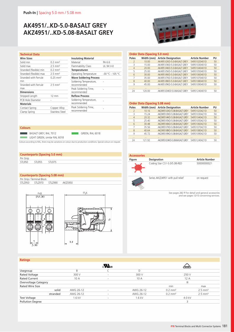
Wire SizesSolid minSolid maxStranded (flexible) minStranded (flexible) maxStranded with Ferrule minStranded with Ferrule maxDimensions Stripped Length
PCB Hole DiameterMaterials
Insulating Material MaterialFlammability ClassTemperaturenOperating TemperatureWave Soldering ProcessSoldering Temperature,recommendedPeak Soldering Time,recommendedReflow ProcessSoldering Temperature,recommended
Peak Soldering Time,recommended
Ratings
PTR Terminal Blocks and Multi Connector Systems 181
Technical Data Order Data (Spacing 5.0 mm)Poles Width (mm) Article Designation Article Number PU
Order Data (Spacing 5.08 mm)Poles Width (mm) Article Designation Article Number PU
Push-In | Spacing 5.0 mm / 5.08 mm
AK4951/..KD-5.0-BASALT GREYAKZ4951/..KD-5.08-BASALT GREY
2 10.00 AK4951/2KD-5.0-BASALT GREY 54951020401D 503 15.00 AK4951/3KD-5.0-BASALT GREY 54951030401D 504 20.00 AK4951/4KD-5.0-BASALT GREY 54951040401D 505 25.00 AK4951/5KD-5.0-BASALT GREY 54951050401D 506 30.00 AK4951/6KD-5.0-BASALT GREY 54951060401D 507 35.00 AK4951/7KD-5.0-BASALT GREY 54951070401D 508 40.00 AK4951/8KD-5.0-BASALT GREY 54951080401D 509 45.00 AK4951/9KD-5.0-BASALT GREY 54951090401D 50
... ... ... ... ...24 120.00 AK4951/24KD-5.0-BASALT GREY 54951240401D 50
Colours according to RAL, there may be variations on colour due to production conditions. Special colours on request.
Colours
BASALT GREY, RAL 7012 GREEN, RAL 6018
LIGHT GREEN, similar RAL 6018
AccessoriesFigure Designation Article Number
See pages 282 ff for detail and general accessoriesand see pages 12/13 concerning services.
2 10.16 AKZ4951/2KD-5.08-BASALT GREY 54951020421D 503 15.24 AKZ4951/3KD-5.08-BASALT GREY 54951030421D 504 20.32 AKZ4951/4KD-5.08-BASALT GREY 54951040421D 505 25.40 AKZ4951/5KD-5.08-BASALT GREY 54951050421D 506 30.48 AKZ4951/6KD-5.08-BASALT GREY 54951060421D 507 35.56 AKZ4951/7KD-5.08-BASALT GREY 54951070421D 508 40.64 AKZ4951/8KD-5.08-BASALT GREY 54951080421D 509 45.72 AKZ4951/9KD-5.08-BASALT GREY 54951090421D 50
... ... ... ... ...24 121.92 AKZ4951/24KD-5.08-BASALT GREY 54951240421D 50
PA 6.6UL 94 V-0
-30 °C - 105 °C
-
-
-
-
0.2 mm²2.5 mm²0.2 mm²2.5 mm²0.25 mm²
2.5 mm²
12 mm
-
Counterparts (Spacing 5.0 mm)Pin StripSTL950 STL955 STL975
Contact Spring Copper AlloyClamp Spring Stainless Steel
Usegroup B C DRated Voltage 300 V - 300 V 250 VRated Current 10 A - 10 A 12 AOvervoltage Category IIIRated Wire Size min max
solid AWG 26-12 - AWG 26-12 0.2 mm² 2.5 mm²stranded AWG 26-12 - AWG 26-12 0.2 mm² 2.5 mm²
Test Voltage 1.6 kV - 1.6 kV 4.0 kVPollution Degree 3
Coding Star CS1-5.0/5.08-RED 50000000021
Series AK(Z)4951 with pull relief on requestCounterparts (Spacing 5.08 mm)Pin Strip / Terminal BlockSTLZ950 STLZ970 STLZ990 AKZS950
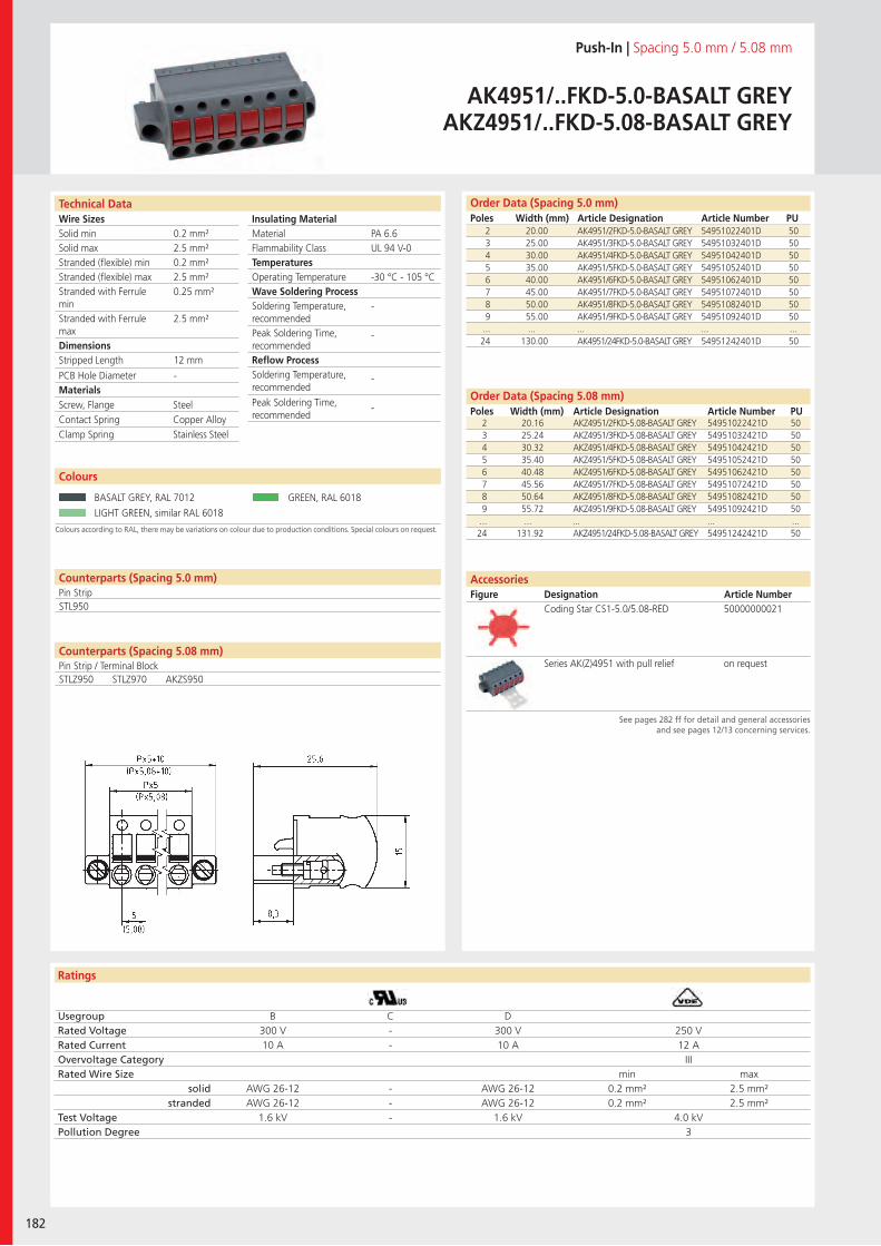
Wire SizesSolid minSolid maxStranded (flexible) minStranded (flexible) maxStranded with Ferrule minStranded with Ferrule maxDimensions Stripped Length
PCB Hole DiameterMaterials
Insulating Material MaterialFlammability ClassTemperaturesOperating TemperatureWave Soldering ProcessSoldering Temperature,recommendedPeak Soldering Time,recommendedReflow ProcessSoldering Temperature,recommended
Peak Soldering Time,recommended
Ratings
182
Technical Data Order Data (Spacing 5.0 mm)Poles Width (mm) Article Designation Article Number PU
Order Data (Spacing 5.08 mm)Poles Width (mm) Article Designation Article Number PU
Push-In | Spacing 5.0 mm / 5.08 mm
AK4951/..FKD-5.0-BASALT GREYAKZ4951/..FKD-5.08-BASALT GREY
2 20.00 AK4951/2FKD-5.0-BASALT GREY 54951022401D 503 25.00 AK4951/3FKD-5.0-BASALT GREY 54951032401D 504 30.00 AK4951/4FKD-5.0-BASALT GREY 54951042401D 505 35.00 AK4951/5FKD-5.0-BASALT GREY 54951052401D 506 40.00 AK4951/6FKD-5.0-BASALT GREY 54951062401D 507 45.00 AK4951/7FKD-5.0-BASALT GREY 54951072401D 508 50.00 AK4951/8FKD-5.0-BASALT GREY 54951082401D 509 55.00 AK4951/9FKD-5.0-BASALT GREY 54951092401D 50
... ... ... ... ...24 130.00 AK4951/24FKD-5.0-BASALT GREY 54951242401D 50
Colours according to RAL, there may be variations on colour due to production conditions. Special colours on request.
Colours
BASALT GREY, RAL 7012 GREEN, RAL 6018
LIGHT GREEN, similar RAL 6018
AccessoriesFigure Designation Article Number
See pages 282 ff for detail and general accessoriesand see pages 12/13 concerning services.
2 20.16 AKZ4951/2FKD-5.08-BASALT GREY 54951022421D 503 25.24 AKZ4951/3FKD-5.08-BASALT GREY 54951032421D 504 30.32 AKZ4951/4FKD-5.08-BASALT GREY 54951042421D 505 35.40 AKZ4951/5FKD-5.08-BASALT GREY 54951052421D 506 40.48 AKZ4951/6FKD-5.08-BASALT GREY 54951062421D 507 45.56 AKZ4951/7FKD-5.08-BASALT GREY 54951072421D 508 50.64 AKZ4951/8FKD-5.08-BASALT GREY 54951082421D 509 55.72 AKZ4951/9FKD-5.08-BASALT GREY 54951092421D 50
... ... ... ... ...24 131.92 AKZ4951/24FKD-5.08-BASALT GREY 54951242421D 50
PA 6.6UL 94 V-0
-30 °C - 105 °C
-
-
-
-
0.2 mm²2.5 mm²0.2 mm²2.5 mm²0.25 mm²
2.5 mm²
12 mm
-
Counterparts (Spacing 5.0 mm)Pin StripSTL950
Screw, Flange SteelContact Spring Copper AlloyClamp Spring Stainless Steel
Usegroup B C DRated Voltage 300 V - 300 V 250 VRated Current 10 A - 10 A 12 AOvervoltage Category IIIRated Wire Size min max
solid AWG 26-12 - AWG 26-12 0.2 mm² 2.5 mm²stranded AWG 26-12 - AWG 26-12 0.2 mm² 2.5 mm²
Test Voltage 1.6 kV - 1.6 kV 4.0 kVPollution Degree 3
Coding Star CS1-5.0/5.08-RED 50000000021
Series AK(Z)4951 with pull relief on requestCounterparts (Spacing 5.08 mm)Pin Strip / Terminal BlockSTLZ950 STLZ970 AKZS950
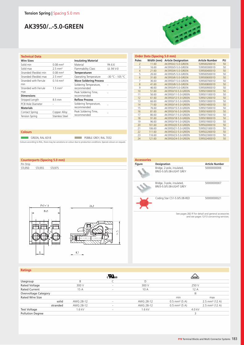
Wire SizesSolid minSolid maxStranded (flexible) minStranded (flexible) maxStranded with Ferrule minStranded with Ferrule maxDimensions Stripped Length
PCB Hole DiameterMaterials
Insulating Material MaterialFlammability ClassTemperaturenOperating TemperatureWave Soldering ProcessSoldering Temperature,recommendedPeak Soldering Time,recommendedReflow ProcessSoldering Temperature,recommended
Peak Soldering Time,recommended
Ratings
PTR Terminal Blocks and Multi Connector Systems 183
Order Data (Spacing 5.0 mm)Poles Width (mm) Article Designation Article Number PU
Technical Data
Tension Spring | Spacing 5.0 mm
AK3950/..-5.0-GREEN
2 11.60 AK3950/2-5.0-GREEN 53950020001D 503 16.60 AK3950/3-5.0-GREEN 53950030001D 504 21.60 AK3950/4-5.0-GREEN 53950040001D 505 26.60 AK3950/5-5.0-GREEN 53950050001D 506 31.60 AK3950/6-5.0-GREEN 53950060001D 507 36.60 AK3950/7-5.0-GREEN 53950070001D 508 41.60 AK3950/8-5.0-GREEN 53950080001D 509 46.60 AK3950/9-5.0-GREEN 53950090001D 50
10 51.60 AK3950/10-5.0-GREEN 53950100001D 5011 56.60 AK3950/11-5.0-GREEN 53950110001D 5012 61.60 AK3950/12-5.0-GREEN 53950120001D 5013 66.60 AK3950/13-5.0-GREEN 53950130001D 5014 71.60 AK3950/14-5.0-GREEN 53950140001D 5015 76.60 AK3950/15-5.0-GREEN 53950150001D 5016 81.60 AK3950/16-5.0-GREEN 53950160001D 5017 86.60 AK3950/17-5.0-GREEN 53950170001D 5018 91.60 AK3950/18-5.0-GREEN 53950180001D 5019 96.60 AK3950/19-5.0-GREEN 53950190001D 5020 101.60 AK3950/20-5.0-GREEN 53950200001D 5021 106.60 AK3950/21-5.0-GREEN 53950210001D 5022 111.60 AK3950/22-5.0-GREEN 53950220001D 5023 116.60 AK3950/23-5.0-GREEN 53950230001D 5024 121.60 AK3950/24-5.0-GREEN 53950240001D 50
See pages 282 ff for detail and general accessoriesand see pages 12/13 concerning services.
AccessoriesFigure Designation Article Number
Bridge, 2-pole, insulated, BRI/2-5.0/5.08-LIGHT GREY
50000000006
Bridge, 3-pole, insulated, BRI/3-5.0/5.08-LIGHT GREY
50000000007
Coding Star CS1-5.0/5.08-RED 50000000021
PA 6.6UL 94 V-0
-30 °C - 105 °C
-
-
-
-
0.08 mm²2.5 mm²0.08 mm²2.5 mm²0.14 mm²
1.5 mm²
8.5 mm
-
Colours according to RAL, there may be variations on colour due to production conditions. Special colours on request.
Colours
GREEN, RAL 6018 PEBBLE GREY, RAL 7032
Counterparts (Spacing 5.0 mm)Pin Strip STL950 STL955 STL975
Contact Spring Copper AlloyTension Spring Stainless Steel
Usegroup B C DRated Voltage 300 V - 300 V 250 VRated Current 15 A - 10 A 12 AOvervoltage Category IIIRated Wire Size min max
solid AWG 28-12 - AWG 28-12 0.5 mm² (5 A) 2.5 mm² (12 A)stranded AWG 28-12 - AWG 28-12 0.5 mm² (5 A) 2.5 mm² (12 A)
Test Voltage 1.6 kV - 1.6 kV 4.0 kVPollution Degree 3
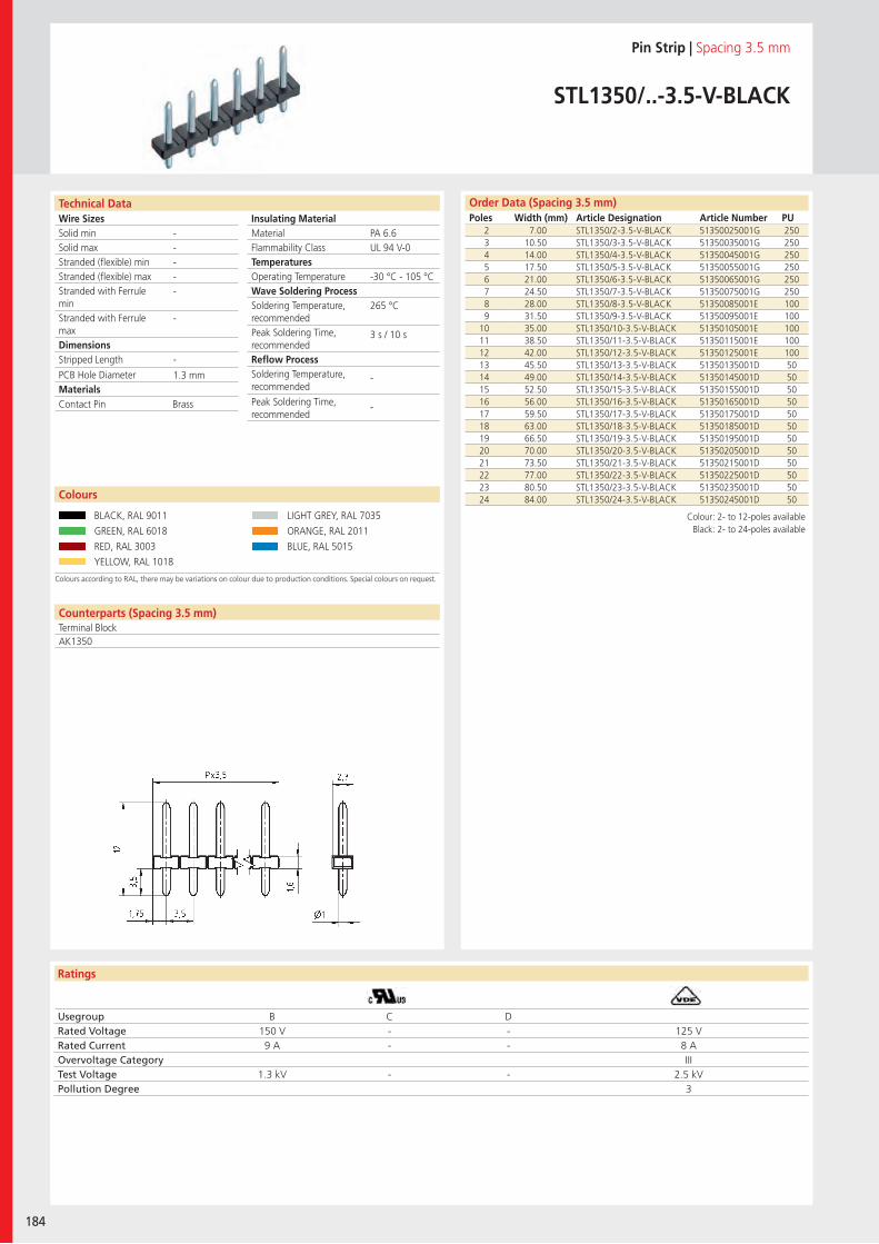
Wire SizesSolid minSolid maxStranded (flexible) minStranded (flexible) maxStranded with Ferrule minStranded with Ferrule maxDimensions Stripped Length
PCB Hole DiameterMaterials
Ratings
184
Insulating Material MaterialFlammability ClassTemperaturesOperating TemperatureWave Soldering ProcessSoldering Temperature,recommendedPeak Soldering Time,recommendedReflow ProcessSoldering Temperature,recommended
Peak Soldering Time,recommended
Counterparts (Spacing 3.5 mm)Terminal Block
Technical Data
Colours according to RAL, there may be variations on colour due to production conditions. Special colours on request.
Order Data (Spacing 3.5 mm)Poles Width (mm) Article Designation Article Number PU
Colours
Pin Strip | Spacing 3.5 mm
STL1350/..-3.5-V-BLACK
2 7.00 STL1350/2-3.5-V-BLACK 51350025001G 2503 10.50 STL1350/3-3.5-V-BLACK 51350035001G 2504 14.00 STL1350/4-3.5-V-BLACK 51350045001G 2505 17.50 STL1350/5-3.5-V-BLACK 51350055001G 2506 21.00 STL1350/6-3.5-V-BLACK 51350065001G 2507 24.50 STL1350/7-3.5-V-BLACK 51350075001G 2508 28.00 STL1350/8-3.5-V-BLACK 51350085001E 1009 31.50 STL1350/9-3.5-V-BLACK 51350095001E 100
10 35.00 STL1350/10-3.5-V-BLACK 51350105001E 10011 38.50 STL1350/11-3.5-V-BLACK 51350115001E 10012 42.00 STL1350/12-3.5-V-BLACK 51350125001E 10013 45.50 STL1350/13-3.5-V-BLACK 51350135001D 5014 49.00 STL1350/14-3.5-V-BLACK 51350145001D 5015 52.50 STL1350/15-3.5-V-BLACK 51350155001D 5016 56.00 STL1350/16-3.5-V-BLACK 51350165001D 5017 59.50 STL1350/17-3.5-V-BLACK 51350175001D 5018 63.00 STL1350/18-3.5-V-BLACK 51350185001D 5019 66.50 STL1350/19-3.5-V-BLACK 51350195001D 5020 70.00 STL1350/20-3.5-V-BLACK 51350205001D 5021 73.50 STL1350/21-3.5-V-BLACK 51350215001D 5022 77.00 STL1350/22-3.5-V-BLACK 51350225001D 5023 80.50 STL1350/23-3.5-V-BLACK 51350235001D 5024 84.00 STL1350/24-3.5-V-BLACK 51350245001D 50
BLACK, RAL 9011 LIGHT GREY, RAL 7035
GREEN, RAL 6018 ORANGE, RAL 2011
RED, RAL 3003 BLUE, RAL 5015
YELLOW, RAL 1018
PA 6.6UL 94 V-0
-30 °C - 105 °C
265 °C
3 s / 10 s
-
-
-----
-
-
1.3 mm
AK1350
Contact Pin Brass
Usegroup B C DRated Voltage 150 V - - 125 VRated Current 9 A - - 8 AOvervoltage Category IIITest Voltage 1.3 kV - - 2.5 kVPollution Degree 3
Colour: 2- to 12-poles availableBlack: 2- to 24-poles available
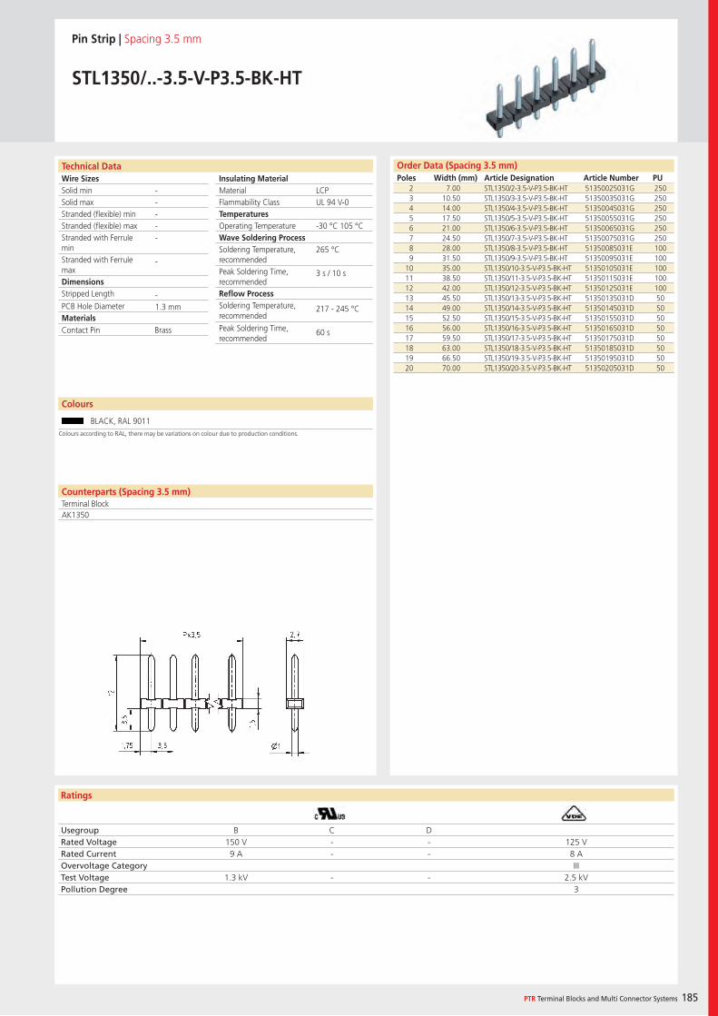
Wire SizesSolid minSolid maxStranded (flexible) minStranded (flexible) maxStranded with Ferrule minStranded with Ferrule maxDimensions Stripped Length
PCB Hole DiameterMaterials
Ratings
PTR Terminal Blocks and Multi Connector Systems 185
Insulating Material MaterialFlammability ClassTemperaturesOperating TemperatureWave Soldering ProcessSoldering Temperature,recommendedPeak Soldering Time,recommendedReflow ProcessSoldering Temperature,recommended
Peak Soldering Time,recommended
Order Data (Spacing 3.5 mm)Poles Width (mm) Article Designation Article Number PU
Technical Data
Pin Strip | Spacing 3.5 mm
STL1350/..-3.5-V-P3.5-BK-HT
2 7.00 STL1350/2-3.5-V-P3.5-BK-HT 51350025031G 2503 10.50 STL1350/3-3.5-V-P3.5-BK-HT 51350035031G 2504 14.00 STL1350/4-3.5-V-P3.5-BK-HT 51350045031G 2505 17.50 STL1350/5-3.5-V-P3.5-BK-HT 51350055031G 2506 21.00 STL1350/6-3.5-V-P3.5-BK-HT 51350065031G 2507 24.50 STL1350/7-3.5-V-P3.5-BK-HT 51350075031G 2508 28.00 STL1350/8-3.5-V-P3.5-BK-HT 51350085031E 1009 31.50 STL1350/9-3.5-V-P3.5-BK-HT 51350095031E 100
10 35.00 STL1350/10-3.5-V-P3.5-BK-HT 51350105031E 10011 38.50 STL1350/11-3.5-V-P3.5-BK-HT 51350115031E 10012 42.00 STL1350/12-3.5-V-P3.5-BK-HT 51350125031E 10013 45.50 STL1350/13-3.5-V-P3.5-BK-HT 51350135031D 5014 49.00 STL1350/14-3.5-V-P3.5-BK-HT 51350145031D 5015 52.50 STL1350/15-3.5-V-P3.5-BK-HT 51350155031D 5016 56.00 STL1350/16-3.5-V-P3.5-BK-HT 51350165031D 5017 59.50 STL1350/17-3.5-V-P3.5-BK-HT 51350175031D 5018 63.00 STL1350/18-3.5-V-P3.5-BK-HT 51350185031D 5019 66.50 STL1350/19-3.5-V-P3.5-BK-HT 51350195031D 5020 70.00 STL1350/20-3.5-V-P3.5-BK-HT 51350205031D 50
LCPUL 94 V-0
-30 °C 105 °C
265 °C
3 s / 10 s
217 - 245 °C
60 s
-----
-
-1.3 mm
Colours
BLACK, RAL 9011
Counterparts (Spacing 3.5 mm)Terminal BlockAK1350
Contact Pin Brass
Usegroup B C DRated Voltage 150 V - - 125 VRated Current 9 A - - 8 AOvervoltage Category IIITest Voltage 1.3 kV - - 2.5 kVPollution Degree 3
Colours according to RAL, there may be variations on colour due to production conditions.
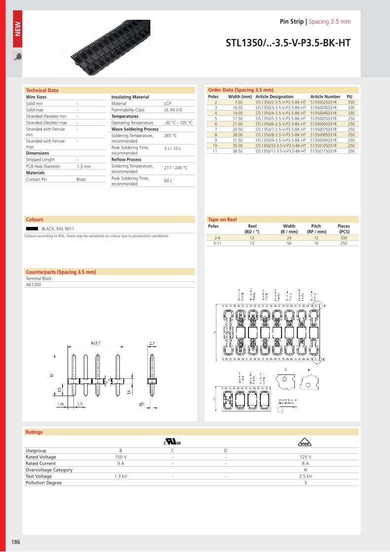
Wire SizesSolid minSolid maxStranded (flexible) minStranded (flexible) maxStranded with Ferrule minStranded with Ferrule maxDimensions Stripped Length
PCB Hole DiameterMaterials
Ratings
186
Insulating Material MaterialFlammability ClassTemperaturesOperating TemperatureWave Soldering ProcessSoldering Temperature,recommendedPeak Soldering Time,recommendedReflow ProcessSoldering Temperature,recommended
Peak Soldering Time,recommended
Usegroup B C DRated Voltage 150 V - - 125 VRated Current 9 A - - 8 AOvervoltage Category IIITest Voltage 1.3 kV - - 2.5 kVPollution Degree 3
NEW
Counterparts (Spacing 3.5 mm)Terminal Block
Technical Data Order Data (Spacing 3.5 mm)Poles Width (mm) Article Designation Article Number PU
Colours
Pin Strip | Spacing 3.5 mm
STL1350/..-3.5-V-P3.5-BK-HT
2 7.00 STL1350/2-3.5-V-P3.5-BK-HT 51350025031R 3303 10.50 STL1350/3-3.5-V-P3.5-BK-HT 51350035031R 3304 14.00 STL1350/4-3.5-V-P3.5-BK-HT 51350045031R 3305 17.50 STL1350/5-3.5-V-P3.5-BK-HT 51350055031R 2506 21.00 STL1350/6-3.5-V-P3.5-BK-HT 51350065031R 2507 24.50 STL1350/7-3.5-V-P3.5-BK-HT 51350075031R 2508 28.00 STL1350/8-3.5-V-P3.5-BK-HT 51350085031R 2509 31.50 STL1350/9-3.5-V-P3.5-BK-HT 51350095031R 250
10 35.00 STL1350/10-3.5-V-P3.5-BK-HT 51350105031R 25011 38.50 STL1350/11-3.5-V-P3.5-BK-HT 51350115031R 250
BLACK, RAL 9011
LCPUL 94 V-0
-30 °C - 105 °C
265 °C
3 s / 10 s
217 - 245 °C
60 s
-----
-
-
1.3 mm
AK1350
Contact Pin Brass
Tape on ReelPoles Reel
(RD / “)Width
(R / mm)Pitch
(RP / mm)Pieces (PCS)
2-4 13 24 12 3305-11 13 56 16 250
Colours according to RAL, there may be variations on colour due to production conditions.
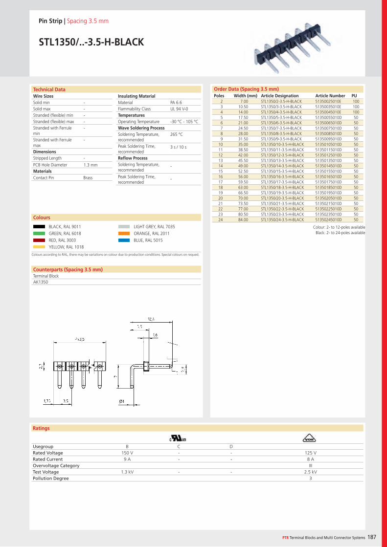
Wire SizesSolid minSolid maxStranded (flexible) minStranded (flexible) maxStranded with Ferrule minStranded with Ferrule maxDimensions Stripped Length
PCB Hole DiameterMaterials
Ratings
PTR Terminal Blocks and Multi Connector Systems 187
Insulating Material MaterialFlammability ClassTemperaturesOperating TemperatureWave Soldering ProcessSoldering Temperature,recommendedPeak Soldering Time,recommendedReflow ProcessSoldering Temperature,recommended
Peak Soldering Time,recommended
Counterparts (Spacing 3.5 mm)Terminal Block
Technical Data
Colours according to RAL, there may be variations on colour due to production conditions. Special colours on request.
Order Data (Spacing 3.5 mm)Poles Width (mm) Article Designation Article Number PU
Colours
Pin Strip | Spacing 3.5 mm
STL1350/..-3.5-H-BLACK
2 7.00 STL1350/2-3.5-H-BLACK 51350025010E 1003 10.50 STL1350/3-3.5-H-BLACK 51350035010E 1004 14.00 STL1350/4-3.5-H-BLACK 51350045010E 1005 17.50 STL1350/5-3.5-H-BLACK 51350055010D 506 21.00 STL1350/6-3.5-H-BLACK 51350065010D 507 24.50 STL1350/7-3.5-H-BLACK 51350075010D 508 28.00 STL1350/8-3.5-H-BLACK 51350085010D 509 31.50 STL1350/9-3.5-H-BLACK 51350095010D 50
10 35.00 STL1350/10-3.5-H-BLACK 51350105010D 5011 38.50 STL1350/11-3.5-H-BLACK 51350115010D 5012 42.00 STL1350/12-3.5-H-BLACK 51350125010D 5013 45.50 STL1350/13-3.5-H-BLACK 51350135010D 5014 49.00 STL1350/14-3.5-H-BLACK 51350145010D 5015 52.50 STL1350/15-3.5-H-BLACK 51350155010D 5016 56.00 STL1350/16-3.5-H-BLACK 51350165010D 5017 59.50 STL1350/17-3.5-H-BLACK 51350175010D 5018 63.00 STL1350/18-3.5-H-BLACK 51350185010D 5019 66.50 STL1350/19-3.5-H-BLACK 51350195010D 5020 70.00 STL1350/20-3.5-H-BLACK 51350205010D 5021 73.50 STL1350/21-3.5-H-BLACK 51350215010D 5022 77.00 STL1350/22-3.5-H-BLACK 51350225010D 5023 80.50 STL1350/23-3.5-H-BLACK 51350235010D 5024 84.00 STL1350/24-3.5-H-BLACK 51350245010D 50
BLACK, RAL 9011 LIGHT GREY, RAL 7035
GREEN, RAL 6018 ORANGE, RAL 2011
RED, RAL 3003 BLUE, RAL 5015
YELLOW, RAL 1018
PA 6.6UL 94 V-0
-30 °C - 105 °C
265 °C
3 s / 10 s
-
-
-----
-
-
1.3 mm
AK1350
Contact Pin Brass
Usegroup B C DRated Voltage 150 V - - 125 VRated Current 9 A - - 8 AOvervoltage Category IIITest Voltage 1.3 kV - - 2.5 kVPollution Degree 3
Colour: 2- to 12-poles availableBlack: 2- to 24-poles available
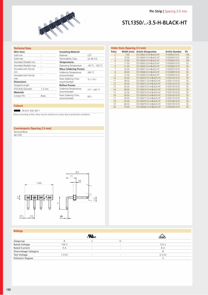
Wire SizesSolid minSolid maxStranded (flexible) minStranded (flexible) maxStranded with Ferrule minStranded with Ferrule maxDimensions Stripped Length
PCB Hole DiameterMaterials
Ratings
188
Insulating Material MaterialFlammability ClassTemperaturesOperating TemperatureWave Soldering ProcessSoldering Temperature,recommendedPeak Soldering Time,recommendedReflow ProcessSoldering Temperature,recommended
Peak Soldering Time,recommended
Technical Data Order Data (Spacing 3.5 mm)Poles Width (mm) Article Designation Article Number PU
Pin Strip | Spacing 3.5 mm
STL1350/..-3.5-H-BLACK-HT
2 7.00 STL1350/2-3.5-H-BLACK-HT 51350025101E 1003 10.50 STL1350/3-3.5-H-BLACK-HT 51350035101E 1004 14.00 STL1350/4-3.5-H-BLACK-HT 51350045101E 1005 17.50 STL1350/5-3.5-H-BLACK-HT 51350055101D 506 21.00 STL1350/6-3.5-H-BLACK-HT 51350065101D 507 24.50 STL1350/7-3.5-H-BLACK-HT 51350075101D 508 28.00 STL1350/8-3.5-H-BLACK-HT 51350085101D 509 31.50 STL1350/9-3.5-H-BLACK-HT 51350095101D 50
10 35.00 STL1350/10-3.5-H-BLACK-HT 51350105101D 5011 38.50 STL1350/11-3.5-H-BLACK-HT 51350115101D 5012 42.00 STL1350/12-3.5-H-BLACK-HT 51350125101D 5013 45.50 STL1350/13-3.5-H-BLACK-HT 51350135101D 5014 49.00 STL1350/14-3.5-H-BLACK-HT 51350145101D 5015 52.50 STL1350/15-3.5-H-BLACK-HT 51350155101D 5016 56.00 STL1350/16-3.5-H-BLACK-HT 51350165101D 5017 59.50 STL1350/17-3.5-H-BLACK-HT 51350175101D 5018 63.00 STL1350/18-3.5-H-BLACK-HT 51350185101D 5019 66.50 STL1350/19-3.5-H-BLACK-HT 51350195101D 5020 70.00 STL1350/20-3.5-H-BLACK-HT 51350205101D 50
LCPUL 94 V-0
-30 °C - 105 °C
265 °C
3 s / 10 s
217 - 245 °C
60 s
-----
-
-
1.3 mm
Counterparts (Spacing 3.5 mm)Terminal BlockAK1350
Contact Pin Brass
Usegroup B C DRated Voltage 150 V - - 125 VRated Current 9 A - - 8 AOvervoltage Category IIITest Voltage 1.3 kV - - 2.5 kVPollution Degree 3
Colours
BLACK, RAL 9011
Colours according to RAL, there may be variations on colour due to production conditions.
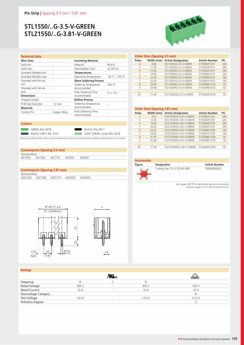
Wire SizesSolid minSolid maxStranded (flexible) minStranded (flexible) maxStranded with Ferrule minStranded with Ferrule maxDimensions Stripped Length
PCB Hole DiameterMaterials
Ratings
PTR Terminal Blocks and Multi Connector Systems 189
Insulating Material MaterialFlammability ClassTemperaturesOperating TemperatureWave Soldering ProcessSoldering Temperature,recommendedPeak Soldering Time,recommendedReflow ProcessSoldering Temperature,recommended
Peak Soldering Time,recommended
Technical Data Order Data (Spacing 3.5 mm)Poles Width (mm) Article Designation Article Number PU
Order Data (Spacing 3.81 mm)Poles Width (mm) Article Designation Article Number PU
Pin Strip | Spacing 3.5 mm / 3.81 mm
STL1550/..G-3.5-V-GREENSTLZ1550/..G-3.81-V-GREEN
2 8.40 STL1550/2G-3.5-V-GREEN 51550025101F 2003 11.90 STL1550/3G-3.5-V-GREEN 51550035101F 2004 15.40 STL1550/4G-3.5-V-GREEN 51550045101F 2005 18.90 STL1550/5G-3.5-V-GREEN 51550055101F 2006 22.40 STL1550/6G-3.5-V-GREEN 51550065101E 1007 25.90 STL1550/7G-3.5-V-GREEN 51550075101E 1008 29.40 STL1550/8G-3.5-V-GREEN 51550085101D 509 32.90 STL1550/9G-3.5-V-GREEN 51550095101D 50
... ... ... ... ...20 71.40 STL1550/20G-3.5-V-GREEN 51550205101D 50
Colours according to RAL, there may be variations on colour due to production conditions. Special colours on request.
Colours
GREEN, RAL 6018 BLACK, RAL 9011
BASALT GREY, RAL 7012 LIGHT GREEN, similar RAL 6018
AccessoriesFigure Designation Article Number
See pages 282 ff for detail and general accessories and see pages 12/13 concerning services.
2 9.01 STLZ1550/2G-3.81-V-GREEN 51550025125F 2003 12.82 STLZ1550/3G-3.81-V-GREEN 51550035125F 2004 16.63 STLZ1550/4G-3.81-V-GREEN 51550045125F 2005 20.44 STLZ1550/5G-3.81-V-GREEN 51550055125F 2006 24.25 STLZ1550/6G-3.81-V-GREEN 51550065125E 1007 28.06 STLZ1550/7G-3.81-V-GREEN 51550075125E 1008 31.87 STLZ1550/8G-3.81-V-GREEN 51550085125D 509 35.68 STLZ1550/9G-3.81-V-GREEN 51550095125D 50
... ... ... ... ...20 77.59 STLZ1550/20G-3.81-V-GREEN 51550205125D 50
PA 6.6UL 94 V-0
-30 °C - 105 °C
265 °C
3 s / 10 s
-
-
-----
-
-
1.2 mm
Counterparts (Spacing 3.5 mm)Terminal BlockAK1550 AK1700 AK1710 AK4551 AK4561
Contact Pin Copper Alloy
Usegroup B C DRated Voltage 300 V - 300 V 160 VRated Current 10 A - 10 A 10 AOvervoltage Category IIITest Voltage 1.6 kV - 1.6 kV 2.5 kVPollution Degree 3
Coding Star CS1-3.5/3.81-RED 50000000023Counterparts (Spacing 3.81 mm)Terminal BlockAKZ1550 AKZ1700 AKZ1710 AKZ4551 AKZ4561
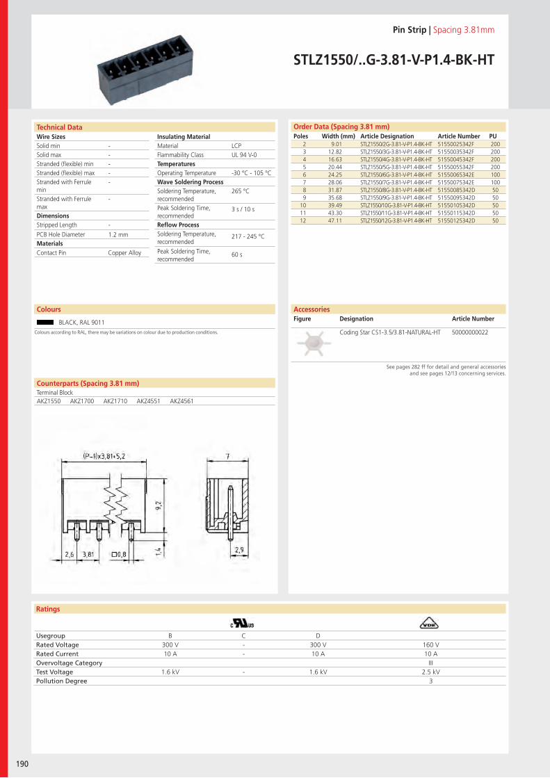
Wire SizesSolid minSolid maxStranded (flexible) minStranded (flexible) maxStranded with Ferrule minStranded with Ferrule maxDimensions Stripped Length
PCB Hole DiameterMaterials
Ratings
190
Insulating Material MaterialFlammability ClassTemperaturesOperating TemperatureWave Soldering ProcessSoldering Temperature,recommendedPeak Soldering Time,recommendedReflow ProcessSoldering Temperature,recommended
Peak Soldering Time,recommended
Counterparts (Spacing 3.81 mm)Terminal Block
Technical Data Order Data (Spacing 3.81 mm)Poles Width (mm) Article Designation Article Number PU
Colours
Pin Strip | Spacing 3.81mm
STLZ1550/..G-3.81-V-P1.4-BK-HT
2 9.01 STLZ1550/2G-3.81-V-P1.4-BK-HT 51550025342F 2003 12.82 STLZ1550/3G-3.81-V-P1.4-BK-HT 51550035342F 2004 16.63 STLZ1550/4G-3.81-V-P1.4-BK-HT 51550045342F 2005 20.44 STLZ1550/5G-3.81-V-P1.4-BK-HT 51550055342F 2006 24.25 STLZ1550/6G-3.81-V-P1.4-BK-HT 51550065342E 1007 28.06 STLZ1550/7G-3.81-V-P1.4-BK-HT 51550075342E 1008 31.87 STLZ1550/8G-3.81-V-P1.4-BK-HT 51550085342D 509 35.68 STLZ1550/9G-3.81-V-P1.4-BK-HT 51550095342D 50
10 39.49 STLZ1550/10G-3.81-V-P1.4-BK-HT 51550105342D 5011 43.30 STLZ1550/11G-3.81-V-P1.4-BK-HT 51550115342D 5012 47.11 STLZ1550/12G-3.81-V-P1.4-BK-HT 51550125342D 50
BLACK, RAL 9011
LCPUL 94 V-0
-30 °C - 105 °C
265 °C
3 s / 10 s
217 - 245 °C
60 s
-----
-
-
1.2 mm
AKZ1550 AKZ1700 AKZ1710 AKZ4551 AKZ4561
Contact Pin Copper Alloy
Usegroup B C DRated Voltage 300 V - 300 V 160 VRated Current 10 A - 10 A 10 AOvervoltage Category IIITest Voltage 1.6 kV - 1.6 kV 2.5 kVPollution Degree 3
Coding Star CS1-3.5/3.81-NATURAL-HT 50000000022
AccessoriesFigure Designation Article Number
See pages 282 ff for detail and general accessories and see pages 12/13 concerning services.
Colours according to RAL, there may be variations on colour due to production conditions.
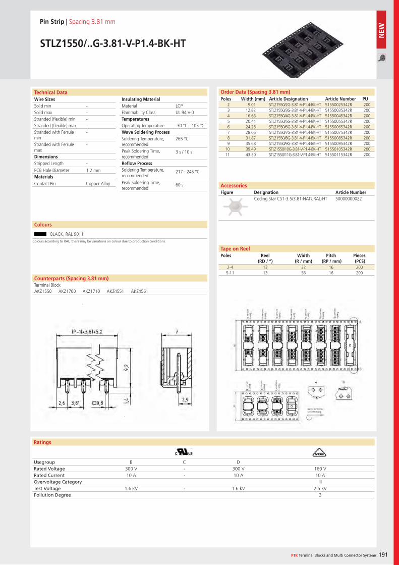
Wire SizesSolid minSolid maxStranded (flexible) minStranded (flexible) maxStranded with Ferrule minStranded with Ferrule maxDimensions Stripped Length
PCB Hole DiameterMaterials
Ratings
PTR Terminal Blocks and Multi Connector Systems 191
Insulating Material MaterialFlammability ClassTemperaturesOperating TemperatureWave Soldering ProcessSoldering Temperature,recommendedPeak Soldering Time,recommendedReflow ProcessSoldering Temperature,recommended
Peak Soldering Time,recommended
Usegroup B C DRated Voltage 300 V - 300 V 160 VRated Current 10 A - 10 A 10 AOvervoltage Category IIITest Voltage 1.6 kV - 1.6 kV 2.5 kVPollution Degree 3
Counterparts (Spacing 3.81 mm)Terminal Block
Technical Data Order Data (Spacing 3.81 mm)Poles Width (mm) Article Designation Article Number PU
Colours
Pin Strip | Spacing 3.81 mm
STLZ1550/..G-3.81-V-P1.4-BK-HT
2 9.01 STLZ1550/2G-3.81-V-P1.4-BK-HT 51550025342R 2003 12.82 STLZ1550/3G-3.81-V-P1.4-BK-HT 51550035342R 2004 16.63 STLZ1550/4G-3.81-V-P1.4-BK-HT 51550045342R 2005 20.44 STLZ1550/5G-3.81-V-P1.4-BK-HT 51550055342R 2006 24.25 STLZ1550/6G-3.81-V-P1.4-BK-HT 51550065342R 2007 28.06 STLZ1550/7G-3.81-V-P1.4-BK-HT 51550075342R 2008 31.87 STLZ1550/8G-3.81-V-P1.4-BK-HT 51550085342R 2009 35.68 STLZ1550/9G-3.81-V-P1.4-BK-HT 51550095342R 200
10 39.49 STLZ1550/10G-3.81-V-P1.4-BK-HT 51550105342R 20011 43.30 STLZ1550/11G-3.81-V-P1.4-BK-HT 51550115342R 200
BLACK, RAL 9011
LCPUL 94 V-0
-30 °C - 105 °C
265 °C
3 s / 10 s
217 - 245 °C
60 s
-----
-
-
1.2 mm
AKZ1550 AKZ1700 AKZ1710 AKZ4551 AKZ4561
Contact Pin Copper Alloy
Coding Star CS1-3.5/3.81-NATURAL-HT 50000000022
2-4 13 32 16 2005-11 13 56 16 200
AccessoriesFigure Designation Article Number
Tape on ReelPoles Reel
(RD / “)Width
(R / mm)Pitch
(RP / mm)Pieces (PCS)
Colours according to RAL, there may be variations on colour due to production conditions.
NEW
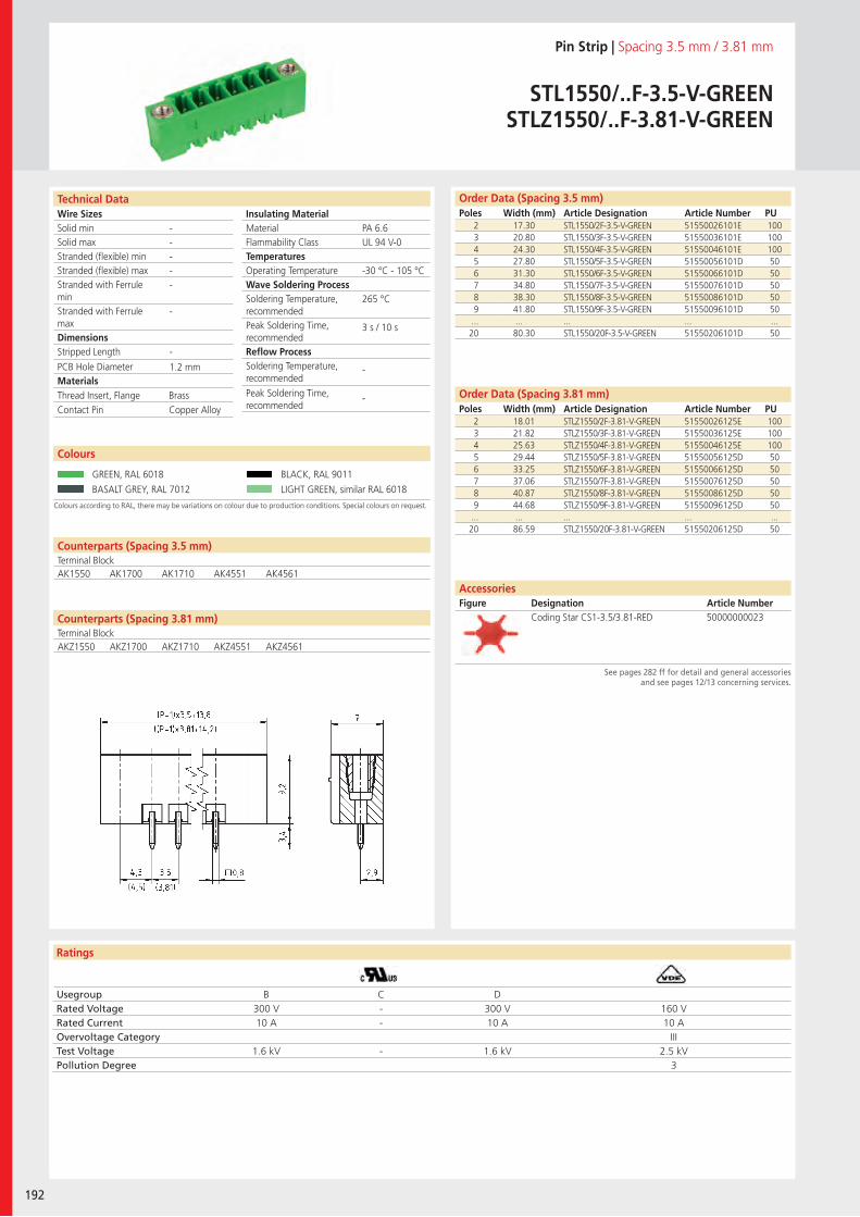
Wire SizesSolid minSolid maxStranded (flexible) minStranded (flexible) maxStranded with Ferrule minStranded with Ferrule maxDimensions Stripped Length
PCB Hole DiameterMaterials
Ratings
192
Insulating Material MaterialFlammability ClassTemperaturesOperating TemperatureWave Soldering ProcessSoldering Temperature,recommendedPeak Soldering Time,recommendedReflow ProcessSoldering Temperature,recommended
Peak Soldering Time,recommended
Technical Data
Colours according to RAL, there may be variations on colour due to production conditions. Special colours on request.
Order Data (Spacing 3.5 mm)Poles Width (mm) Article Designation Article Number PU
Order Data (Spacing 3.81 mm)Poles Width (mm) Article Designation Article Number PU
Colours
Pin Strip | Spacing 3.5 mm / 3.81 mm
STL1550/..F-3.5-V-GREENSTLZ1550/..F-3.81-V-GREEN
2 17.30 STL1550/2F-3.5-V-GREEN 51550026101E 1003 20.80 STL1550/3F-3.5-V-GREEN 51550036101E 1004 24.30 STL1550/4F-3.5-V-GREEN 51550046101E 1005 27.80 STL1550/5F-3.5-V-GREEN 51550056101D 506 31.30 STL1550/6F-3.5-V-GREEN 51550066101D 507 34.80 STL1550/7F-3.5-V-GREEN 51550076101D 508 38.30 STL1550/8F-3.5-V-GREEN 51550086101D 509 41.80 STL1550/9F-3.5-V-GREEN 51550096101D 50
... ... ... ... ...20 80.30 STL1550/20F-3.5-V-GREEN 51550206101D 50
GREEN, RAL 6018 BLACK, RAL 9011
BASALT GREY, RAL 7012 LIGHT GREEN, similar RAL 6018
2 18.01 STLZ1550/2F-3.81-V-GREEN 51550026125E 1003 21.82 STLZ1550/3F-3.81-V-GREEN 51550036125E 1004 25.63 STLZ1550/4F-3.81-V-GREEN 51550046125E 1005 29.44 STLZ1550/5F-3.81-V-GREEN 51550056125D 506 33.25 STLZ1550/6F-3.81-V-GREEN 51550066125D 507 37.06 STLZ1550/7F-3.81-V-GREEN 51550076125D 508 40.87 STLZ1550/8F-3.81-V-GREEN 51550086125D 509 44.68 STLZ1550/9F-3.81-V-GREEN 51550096125D 50
... ... ... ... ...20 86.59 STLZ1550/20F-3.81-V-GREEN 51550206125D 50
PA 6.6UL 94 V-0
-30 °C - 105 °C
265 °C
3 s / 10 s
-
-
-----
-
-
1.2 mm
Counterparts (Spacing 3.5 mm)Terminal Block
Counterparts (Spacing 3.81 mm)Terminal Block
AK1550 AK1700 AK1710 AK4551 AK4561
Thread Insert, Flange BrassContact Pin Copper Alloy
Usegroup B C DRated Voltage 300 V - 300 V 160 VRated Current 10 A - 10 A 10 AOvervoltage Category IIITest Voltage 1.6 kV - 1.6 kV 2.5 kVPollution Degree 3
AccessoriesFigure Designation Article Number
See pages 282 ff for detail and general accessories and see pages 12/13 concerning services.
Coding Star CS1-3.5/3.81-RED 50000000023
AKZ1550 AKZ1700 AKZ1710 AKZ4551 AKZ4561
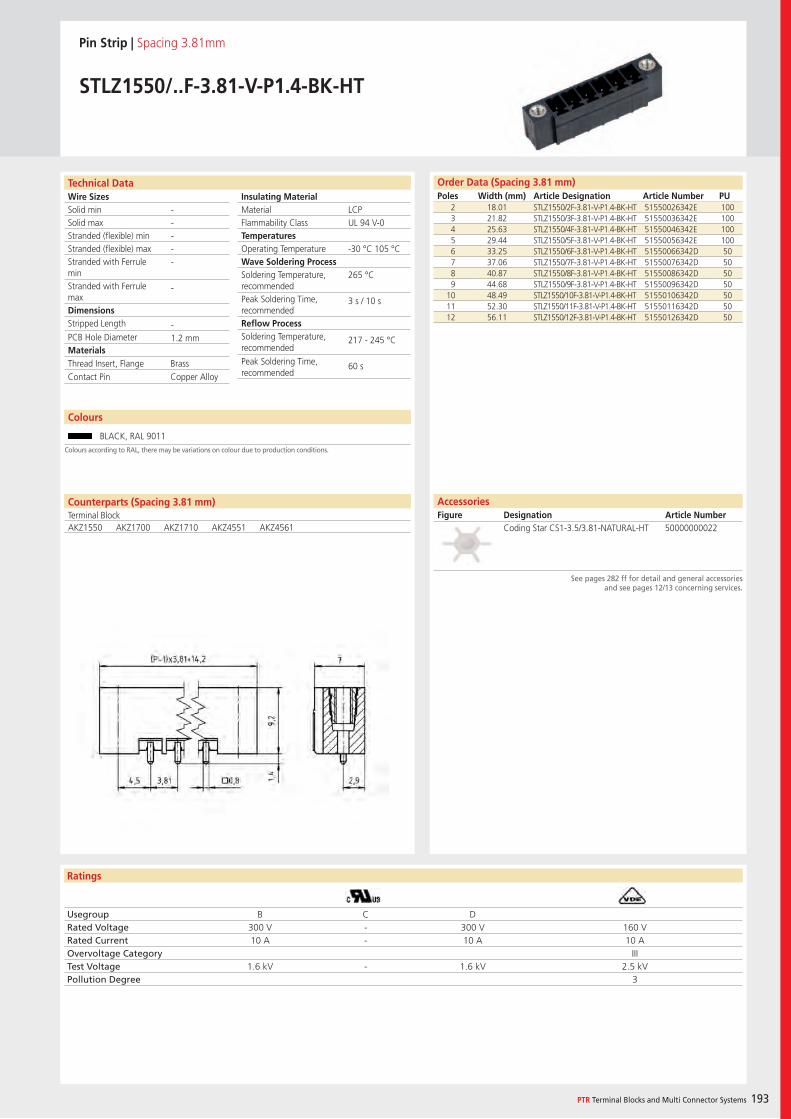
Wire SizesSolid minSolid maxStranded (flexible) minStranded (flexible) maxStranded with Ferrule minStranded with Ferrule maxDimensions Stripped Length
PCB Hole DiameterMaterials
Ratings
PTR Terminal Blocks and Multi Connector Systems 193
Insulating Material MaterialFlammability ClassTemperaturesOperating TemperatureWave Soldering ProcessSoldering Temperature,recommendedPeak Soldering Time,recommendedReflow ProcessSoldering Temperature,recommended
Peak Soldering Time,recommended
Order Data (Spacing 3.81 mm)Poles Width (mm) Article Designation Article Number PU
Technical Data
Pin Strip | Spacing 3.81mm
STLZ1550/..F-3.81-V-P1.4-BK-HT
2 18.01 STLZ1550/2F-3.81-V-P1.4-BK-HT 51550026342E 1003 21.82 STLZ1550/3F-3.81-V-P1.4-BK-HT 51550036342E 1004 25.63 STLZ1550/4F-3.81-V-P1.4-BK-HT 51550046342E 1005 29.44 STLZ1550/5F-3.81-V-P1.4-BK-HT 51550056342E 1006 33.25 STLZ1550/6F-3.81-V-P1.4-BK-HT 51550066342D 507 37.06 STLZ1550/7F-3.81-V-P1.4-BK-HT 51550076342D 508 40.87 STLZ1550/8F-3.81-V-P1.4-BK-HT 51550086342D 509 44.68 STLZ1550/9F-3.81-V-P1.4-BK-HT 51550096342D 50
10 48.49 STLZ1550/10F-3.81-V-P1.4-BK-HT 51550106342D 5011 52.30 STLZ1550/11F-3.81-V-P1.4-BK-HT 51550116342D 5012 56.11 STLZ1550/12F-3.81-V-P1.4-BK-HT 51550126342D 50
LCPUL 94 V-0
-30 °C 105 °C
265 °C
3 s / 10 s
217 - 245 °C
60 s
-----
-
-1.2 mm
Counterparts (Spacing 3.81 mm)Terminal BlockAKZ1550 AKZ1700 AKZ1710 AKZ4551 AKZ4561
Thread Insert, Flange BrassContact Pin Copper Alloy
Usegroup B C DRated Voltage 300 V - 300 V 160 VRated Current 10 A - 10 A 10 AOvervoltage Category IIITest Voltage 1.6 kV - 1.6 kV 2.5 kVPollution Degree 3
AccessoriesFigure Designation Article Number
Coding Star CS1-3.5/3.81-NATURAL-HT 50000000022
See pages 282 ff for detail and general accessories and see pages 12/13 concerning services.
Colours
BLACK, RAL 9011
Colours according to RAL, there may be variations on colour due to production conditions.
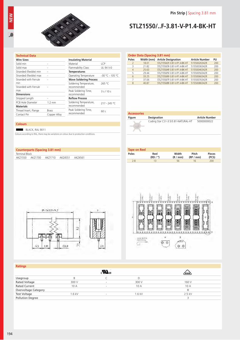
Wire SizesSolid minSolid maxStranded (flexible) minStranded (flexible) maxStranded with Ferrule minStranded with Ferrule maxDimensions Stripped Length
PCB Hole DiameterMaterials
Ratings
194
Insulating Material MaterialFlammability ClassTemperaturesOperating TemperatureWave Soldering ProcessSoldering Temperature,recommendedPeak Soldering Time,recommendedReflow ProcessSoldering Temperature,recommended
Peak Soldering Time,recommended
Usegroup B C DRated Voltage 300 V - 300 V 160 VRated Current 10 A - 10 A 10 AOvervoltage Category IIITest Voltage 1.6 kV - 1.6 kV 2.5 kVPollution Degree 3
Technical Data Order Data (Spacing 3.81 mm)Poles Width (mm) Article Designation Article Number PU
Pin Strip | Spacing 3.81 mm
STLZ1550/..F-3.81-V-P1.4-BK-HT
2 18.01 STLZ1550/2F-3.81-V-P1.4-BK-HT 51550026342R 2003 21.82 STLZ1550/3F-3.81-V-P1.4-BK-HT 51550036342R 2004 25.63 STLZ1550/4F-3.81-V-P1.4-BK-HT 51550046342R 2005 29.44 STLZ1550/5F-3.81-V-P1.4-BK-HT 51550056342R 2006 33.25 STLZ1550/6F-3.81-V-P1.4-BK-HT 51550066342R 2007 37.06 STLZ1550/7F-3.81-V-P1.4-BK-HT 51550076342R 2008 40.87 STLZ1550/8F-3.81-V-P1.4-BK-HT 51550086342R 200
LCPUL 94 V-0
-30 °C - 105 °C
265 °C
3 s / 10 s
217 - 245 °C
60 s
-----
-
-
1.2 mm
Counterparts (Spacing 3.81 mm)Terminal BlockAKZ1550 AKZ1700 AKZ1710 AKZ4551 AKZ4561
Thread Insert, Flange BrassContact Pin Copper Alloy
2-8 13 56 16 200
Coding Star CS1-3.5/3.81-NATURAL-HT 50000000022
AccessoriesFigure Designation Article Number
Tape on ReelPoles Reel
(RD / “)Width
(R / mm)Pitch
(RP / mm)Pieces (PCS)
NEW
Colours
BLACK, RAL 9011Colours according to RAL, there may be variations on colour due to production conditions.
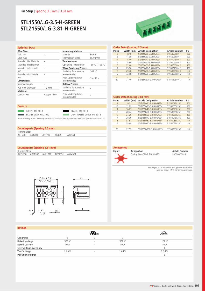
Wire SizesSolid minSolid maxStranded (flexible) minStranded (flexible) maxStranded with Ferrule minStranded with Ferrule maxDimensions Stripped Length
PCB Hole DiameterMaterials
Ratings
PTR Terminal Blocks and Multi Connector Systems 195
Insulating Material MaterialFlammability ClassTemperaturesOperating TemperatureWave Soldering ProcessSoldering Temperature,recommendedPeak Soldering Time,recommendedReflow ProcessSoldering Temperature,recommended
Peak Soldering Time,recommended
Technical Data
Colours according to RAL, there may be variations on colour due to production conditions. Special colours on request.
Order Data (Spacing 3.5 mm)Poles Width (mm) Article Designation Article Number PU
Order Data (Spacing 3.81 mm)Poles Width (mm) Article Designation Article Number PU
Colours
Pin Strip | Spacing 3.5 mm / 3.81 mm
STL1550/..G-3.5-H-GREENSTLZ1550/..G-3.81-H-GREEN
2 8.40 STL1550/2G-3.5-H-GREEN 51550025001F 2003 11.90 STL1550/3G-3.5-H-GREEN 51550035001F 2004 15.40 STL1550/4G-3.5-H-GREEN 51550045001F 2005 18.90 STL1550/5G-3.5-H-GREEN 51550055001F 2006 22.40 STL1550/6G-3.5-H-GREEN 51550065001E 1007 25.90 STL1550/7G-3.5-H-GREEN 51550075001E 1008 29.40 STL1550/8G-3.5-H-GREEN 51550085001D 509 32.90 STL1550/9G-3.5-H-GREEN 51550095001D 50
... ... ... ... ...20 71.40 STL1550/20G-3.5-H-GREEN 51550205001D 50
GREEN, RAL 6018 BLACK, RAL 9011
BASALT GREY, RAL 7012 LIGHT GREEN, similar RAL 6018
2 9.01 STLZ1550/2G-3.81-H-GREEN 51550025025F 2003 12.82 STLZ1550/3G-3.81-H-GREEN 51550035025F 2004 16.63 STLZ1550/4G-3.81-H-GREEN 51550045025F 2005 20.44 STLZ1550/5G-3.81-H-GREEN 51550055025F 2006 24.25 STLZ1550/6G-3.81-H-GREEN 51550065025E 1007 28.06 STLZ1550/7G-3.81-H-GREEN 51550075025E 1008 31.87 STLZ1550/8G-3.81-H-GREEN 51550085025D 509 35.68 STLZ1550/9G-3.81-H-GREEN 51550095025D 50
... ... ... ... ...20 77.59 STLZ1550/20G-3.81-H-GREEN 51550205025D 50
PA 6.6UL 94 V-0
-30 °C - 105 °C
265 °C
3 s / 10 s
-
-
-----
-
-
1.2 mm
Counterparts (Spacing 3.5 mm)Terminal BlockAK1550 AK1700 AK1710 AK4551 AK4561
Counterparts (Spacing 3.81 mm)Terminal Block
Contact Pin Copper Alloy
Usegroup B C DRated Voltage 300 V - 300 V 160 VRated Current 10 A - 10 A 10 AOvervoltage Category IIITest Voltage 1.6 kV - 1.6 kV 2.5 kVPollution Degree 3
AccessoriesFigure Designation Article Number
See pages 282 ff for detail and general accessories and see pages 12/13 concerning services.
Coding Star CS1-3.5/3.81-RED 50000000023AKZ1550 AKZ1700 AKZ1710 AKZ4551 AKZ4561
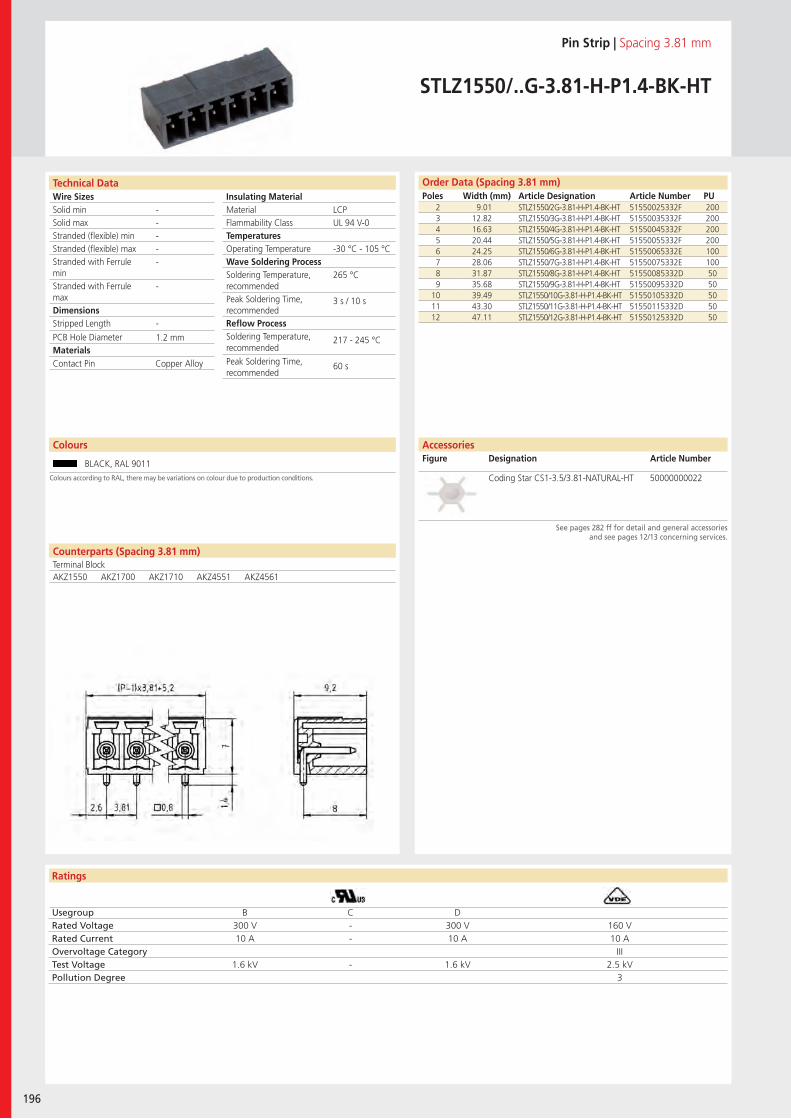
Wire SizesSolid minSolid maxStranded (flexible) minStranded (flexible) maxStranded with Ferrule minStranded with Ferrule maxDimensions Stripped Length
PCB Hole DiameterMaterials
Ratings
196
Insulating Material MaterialFlammability ClassTemperaturesOperating TemperatureWave Soldering ProcessSoldering Temperature,recommendedPeak Soldering Time,recommendedReflow ProcessSoldering Temperature,recommended
Peak Soldering Time,recommended
Counterparts (Spacing 3.81 mm)Terminal Block
Technical Data Order Data (Spacing 3.81 mm)Poles Width (mm) Article Designation Article Number PU
Colours
Pin Strip | Spacing 3.81 mm
STLZ1550/..G-3.81-H-P1.4-BK-HT
2 9.01 STLZ1550/2G-3.81-H-P1.4-BK-HT 51550025332F 2003 12.82 STLZ1550/3G-3.81-H-P1.4-BK-HT 51550035332F 2004 16.63 STLZ1550/4G-3.81-H-P1.4-BK-HT 51550045332F 2005 20.44 STLZ1550/5G-3.81-H-P1.4-BK-HT 51550055332F 2006 24.25 STLZ1550/6G-3.81-H-P1.4-BK-HT 51550065332E 1007 28.06 STLZ1550/7G-3.81-H-P1.4-BK-HT 51550075332E 1008 31.87 STLZ1550/8G-3.81-H-P1.4-BK-HT 51550085332D 509 35.68 STLZ1550/9G-3.81-H-P1.4-BK-HT 51550095332D 50
10 39.49 STLZ1550/10G-3.81-H-P1.4-BK-HT 51550105332D 5011 43.30 STLZ1550/11G-3.81-H-P1.4-BK-HT 51550115332D 5012 47.11 STLZ1550/12G-3.81-H-P1.4-BK-HT 51550125332D 50
BLACK, RAL 9011
LCPUL 94 V-0
-30 °C - 105 °C
265 °C
3 s / 10 s
217 - 245 °C
60 s
-----
-
-
1.2 mm
AKZ1550 AKZ1700 AKZ1710 AKZ4551 AKZ4561
Contact Pin Copper Alloy
Usegroup B C DRated Voltage 300 V - 300 V 160 VRated Current 10 A - 10 A 10 AOvervoltage Category IIITest Voltage 1.6 kV - 1.6 kV 2.5 kVPollution Degree 3
Coding Star CS1-3.5/3.81-NATURAL-HT 50000000022
AccessoriesFigure Designation Article Number
See pages 282 ff for detail and general accessories and see pages 12/13 concerning services.
Colours according to RAL, there may be variations on colour due to production conditions.
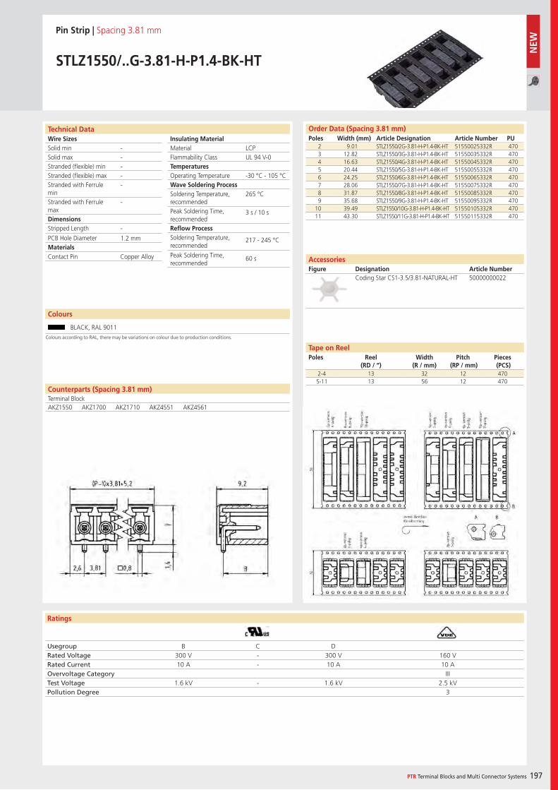
Wire SizesSolid minSolid maxStranded (flexible) minStranded (flexible) maxStranded with Ferrule minStranded with Ferrule maxDimensions Stripped Length
PCB Hole DiameterMaterials
Ratings
PTR Terminal Blocks and Multi Connector Systems 197
Insulating Material MaterialFlammability ClassTemperaturesOperating TemperatureWave Soldering ProcessSoldering Temperature,recommendedPeak Soldering Time,recommendedReflow ProcessSoldering Temperature,recommended
Peak Soldering Time,recommended
Usegroup B C DRated Voltage 300 V - 300 V 160 VRated Current 10 A - 10 A 10 AOvervoltage Category IIITest Voltage 1.6 kV - 1.6 kV 2.5 kVPollution Degree 3
Counterparts (Spacing 3.81 mm)Terminal Block
Technical Data Order Data (Spacing 3.81 mm)Poles Width (mm) Article Designation Article Number PU
Colours
Pin Strip | Spacing 3.81 mm
STLZ1550/..G-3.81-H-P1.4-BK-HT
2 9.01 STLZ1550/2G-3.81-H-P1.4-BK-HT 51550025332R 4703 12.82 STLZ1550/3G-3.81-H-P1.4-BK-HT 51550035332R 4704 16.63 STLZ1550/4G-3.81-H-P1.4-BK-HT 51550045332R 4705 20.44 STLZ1550/5G-3.81-H-P1.4-BK-HT 51550055332R 4706 24.25 STLZ1550/6G-3.81-H-P1.4-BK-HT 51550065332R 4707 28.06 STLZ1550/7G-3.81-H-P1.4-BK-HT 51550075332R 4708 31.87 STLZ1550/8G-3.81-H-P1.4-BK-HT 51550085332R 4709 35.68 STLZ1550/9G-3.81-H-P1.4-BK-HT 51550095332R 470
10 39.49 STLZ1550/10G-3.81-H-P1.4-BK-HT 51550105332R 47011 43.30 STLZ1550/11G-3.81-H-P1.4-BK-HT 51550115332R 470
BLACK, RAL 9011
LCPUL 94 V-0
-30 °C - 105 °C
265 °C
3 s / 10 s
217 - 245 °C
60 s
-----
-
-
1.2 mm
AKZ1550 AKZ1700 AKZ1710 AKZ4551 AKZ4561
Contact Pin Copper Alloy
Coding Star CS1-3.5/3.81-NATURAL-HT 50000000022
2-4 13 32 12 4705-11 13 56 12 470
AccessoriesFigure Designation Article Number
Tape on ReelPoles Reel
(RD / “)Width
(R / mm)Pitch
(RP / mm)Pieces (PCS)
Colours according to RAL, there may be variations on colour due to production conditions.
NEW
Wire SizesSolid minSolid maxStranded (flexible) minStranded (flexible) maxStranded with Ferrule minStranded with Ferrule maxDimensions Stripped Length
PCB Hole DiameterMaterials
Ratings
198
Insulating Material MaterialFlammability ClassTemperaturesOperating TemperatureWave Soldering ProcessSoldering Temperature,recommendedPeak Soldering Time,recommendedReflow ProcessSoldering Temperature,recommended
Peak Soldering Time,recommended
Technical Data Order Data (Spacing 3.5 mm)Poles Width (mm) Article Designation Article Number PU
Pin Strip | Spacing 3.5 mm / 3.81 mm
STL1550/..F-3.5-H-GREENSTLZ1550/..F-3.81-H-GREEN
2 17.30 STL1550/2F-3.5-H-GREEN 51550026001E 1003 20.80 STL1550/3F-3.5-H-GREEN 51550036001E 1004 24.30 STL1550/4F-3.5-H-GREEN 51550046001E 1005 27.80 STL1550/5F-3.5-H-GREEN 51550056001D 506 31.30 STL1550/6F-3.5-H-GREEN 51550066001D 507 34.80 STL1550/7F-3.5-H-GREEN 51550076001D 508 38.30 STL1550/8F-3.5-H-GREEN 51550086001D 509 41.80 STL1550/9F-3.5-H-GREEN 51550096001D 50
... ... ... ... ...20 80.30 STL1550/20F-3.5-H-GREEN 51550206001D 50
Colours according to RAL, there may be variations on colour due to production conditions. Special colours on request.
Colours
GREEN, RAL 6018 BLACK, RAL 9011
BASALT GREY, RAL 7012 LIGHT GREEN, similar RAL 6018
Order Data (Spacing 3.81 mm)Poles Width (mm) Article Designation Article Number PU
2 18.01 STLZ1550/2F-3.81-H-GREEN 51550026025E 1003 21.82 STLZ1550/3F-3.81-H-GREEN 51550036025E 1004 25.63 STLZ1550/4F-3.81-H-GREEN 51550046025E 1005 29.44 STLZ1550/5F-3.81-H-GREEN 51550056025D 506 33.25 STLZ1550/6F-3.81-H-GREEN 51550066025D 507 37.06 STLZ1550/7F-3.81-H-GREEN 51550076025D 508 40.87 STLZ1550/8F-3.81-H-GREEN 51550086025D 509 44.68 STLZ1550/9F-3.81-H-GREEN 51550096025D 50
... ... ... ... ...20 86.59 STLZ1550/20F-3.81-H-GREEN 51550206025D 50
PA 6.6UL 94 V-0
-30 °C - 105 °C
265 °C
3 s / 10 s
-
-
-----
-
-
1.2 mm
Counterparts (Spacing 3.5 mm)Terminal BlockAK1550 AK1700 AK1710 AK4551 AK4561
Thread Insert, Flange BrassContact Pin Copper Alloy
Usegroup B C DRated Voltage 300 V - 300 V 160 VRated Current 10 A - 10 A 10 AOvervoltage Category IIITest Voltage 1.6 kV - 1.6 kV 2.5 kVPollution Degree 3
AccessoriesFigure Designation Article Number
See pages 282 ff for detail and general accessories and see pages 12/13 concerning services.
Coding Star CS1-3.5/3.81-RED 50000000023Counterparts (Spacing 3.81 mm)Terminal BlockAKZ1550 AKZ1700 AKZ1710 AKZ4551 AKZ4561
Wire SizesSolid minSolid maxStranded (flexible) minStranded (flexible) maxStranded with Ferrule minStranded with Ferrule maxDimensions Stripped Length
PCB Hole DiameterMaterials
Ratings
PTR Terminal Blocks and Multi Connector Systems 199
Insulating Material MaterialFlammability ClassTemperaturesOperating TemperatureWave Soldering ProcessSoldering Temperature,recommendedPeak Soldering Time,recommendedReflow ProcessSoldering Temperature,recommended
Peak Soldering Time,recommended
Order Data (Spacing 3.81 mm)Poles Width (mm) Article Designation Article Number PU
Technical Data
Pin Strip | Spacing 3.81 mm
STLZ1550/..F-3.81-H-P1.4-BK-HT
2 18.01 STLZ1550/2F-3.81-H-P1.4-BK-HT 51550026332E 1003 21.82 STLZ1550/3F-3.81-H-P1.4-BK-HT 51550036332E 1004 25.63 STLZ1550/4F-3.81-H-P1.4-BK-HT 51550046332E 1005 29.44 STLZ1550/5F-3.81-H-P1.4-BK-HT 51550056332E 1006 33.25 STLZ1550/6F-3.81-H-P1.4-BK-HT 51550066332D 507 37.06 STLZ1550/7F-3.81-H-P1.4-BK-HT 51550076332D 508 40.87 STLZ1550/8F-3.81-H-P1.4-BK-HT 51550086332D 509 44.68 STLZ1550/9F-3.81-H-P1.4-BK-HT 51550096332D 50
10 48.49 STLZ1550/10F-3.81-H-P1.4-BK-HT 51550106332D 5011 52.30 STLZ1550/11F-3.81-H-P1.4-BK-HT 51550116332D 5012 56.11 STLZ1550/12F-3.81-H-P1.4-BK-HT 51550126332D 50
LCPUL 94 V-0
-30 °C 105 °C
265 °C
3 s / 10 s
217 - 245 °C
60 s
-----
-
-1.2 mm
Counterparts (Spacing 3.81 mm)Terminal BlockAKZ1550 AKZ1700 AKZ1710 AKZ4551 AKZ4561
Thread Insert, Flange BrassContact Pin Copper Alloy
Usegroup B C DRated Voltage 300 V - 300 V 160 VRated Current 10 A - 10 A 10 AOvervoltage Category IIITest Voltage 1.6 kV - 1.6 kV 2.5 kVPollution Degree 3
AccessoriesFigure Designation Article Number
Coding Star CS1-3.5/3.81-NATURAL-HT 50000000022
See pages 282 ff for detail and general accessories and see pages 12/13 concerning services.
Colours
BLACK, RAL 9011
Colours according to RAL, there may be variations on colour due to production conditions.
Wire SizesSolid minSolid maxStranded (flexible) minStranded (flexible) maxStranded with Ferrule minStranded with Ferrule maxDimensions Stripped Length
PCB Hole DiameterMaterials
Ratings
200
Insulating Material MaterialFlammability ClassTemperaturesOperating TemperatureWave Soldering ProcessSoldering Temperature,recommendedPeak Soldering Time,recommendedReflow ProcessSoldering Temperature,recommended
Peak Soldering Time,recommended
Usegroup B C DRated Voltage 300 V - 300 V 160 VRated Current 10 A - 10 A 10 AOvervoltage Category IIITest Voltage 1.6 kV - 1.6 kV 2.5 kVPollution Degree 3
Technical Data Order Data (Spacing 3.81 mm)Poles Width (mm) Article Designation Article Number PU
Colours
Pin Strip | Spacing 3.81 mm
STLZ1550/..F-3.81-H-P1.4-BK-HT
2 18.01 STLZ1550/2F-3.81-H-P1.4-BK-HT 51550026332R 4703 21.82 STLZ1550/3F-3.81-H-P1.4-BK-HT 51550036332R 4704 25.63 STLZ1550/4F-3.81-H-P1.4-BK-HT 51550046332R 4705 29.44 STLZ1550/5F-3.81-H-P1.4-BK-HT 51550056332R 4706 33.25 STLZ1550/6F-3.81-H-P1.4-BK-HT 51550066332R 4707 37.06 STLZ1550/7F-3.81-H-P1.4-BK-HT 51550076332R 4708 40.87 STLZ1550/8F-3.81-H-P1.4-BK-HT 51550086332R 4709 44.68 STLZ1550/9F-3.81-H-P1.4-BK-HT 51550096332R 470
BLACK, RAL 9011
LCPUL 94 V-0
-30 °C - 105 °C
265 °C
3 s / 10 s
217 - 245 °C
60 s
-----
-
-
1.2 mm
Counterparts (Spacing 3.81 mm)Terminal BlockAKZ1550 AKZ1700 AKZ1710 AKZ4551 AKZ4561
Thread Insert, Flange BrassContact Pin Copper Alloy
Coding Star CS1-3.5/3.81-NATURAL-HT 50000000022
AccessoriesFigure Designation Article Number
2-9 13 56 12 470
Tape on ReelPoles Reel
(RD / “)Width
(R / mm)Pitch
(RP / mm)Pieces (PCS)
NEW
See pages 282 ff for detail and general accessories and see pages 12/13 concerning services.
Colours according to RAL, there may be variations on colour due to production conditions.
Wire SizesSolid minSolid maxStranded (flexible) minStranded (flexible) maxStranded with Ferrule minStranded with Ferrule maxDimensions Stripped Length
PCB Hole DiameterMaterials
Ratings
PTR Terminal Blocks and Multi Connector Systems 201
Insulating Material MaterialFlammability ClassTemperaturesOperating TemperatureWave Soldering ProcessSoldering Temperature,recommendedPeak Soldering Time,recommendedReflow ProcessSoldering Temperature,recommended
Peak Soldering Time,recommended
Order Data (Spacing 3.81 mm)Poles Width (mm) Article Designation Article Number PU
Technical Data
Pin Strip | Spacing 3.81 mm
STLZ1570/..G-3.81-V-GREEN
2 9.01 STLZ1570/2G-3.81-V-GREEN 51570025121E 1003 12.82 STLZ1570/3G-3.81-V-GREEN 51570035121E 1004 16.63 STLZ1570/4G-3.81-V-GREEN 51570045121E 1005 20.44 STLZ1570/5G-3.81-V-GREEN 51570055121E 1006 24.25 STLZ1570/6G-3.81-V-GREEN 51570065121E 1007 28.06 STLZ1570/7G-3.81-V-GREEN 51570075121D 508 31.87 STLZ1570/8G-3.81-V-GREEN 51570085121D 509 35.68 STLZ1570/9G-3.81-V-GREEN 51570095121D 50
10 39.49 STLZ1570/10G-3.81-V-GREEN 51570105121D 5011 43.30 STLZ1570/11G-3.81-V-GREEN 51570115121D 5012 47.11 STLZ1570/12G-3.81-V-GREEN 51570125121D 5013 50.92 STLZ1570/13G-3.81-V-GREEN 51570135121D 5014 54.73 STLZ1570/14G-3.81-V-GREEN 51570145121D 5015 58.54 STLZ1570/15G-3.81-V-GREEN 51570155121D 5016 62.35 STLZ1570/16G-3.81-V-GREEN 51570165121D 5017 66.16 STLZ1570/17G-3.81-V-GREEN 51570175121D 5018 69.97 STLZ1570/18G-3.81-V-GREEN 51570185121D 5019 73.78 STLZ1570/19G-3.81-V-GREEN 51570195121D 5020 77.59 STLZ1570/20G-3.81-V-GREEN 51570205121D 50
PBTUL 94 V-0
-30 °C 105 °C
265 °C
3 s / 10 s
-
-
-----
-
-1.2 mm
Colours according to RAL, there may be variations on colour due to production conditions. Special colours on request.
Colours
GREEN, RAL 6018 LIGHT GREEN, similar RAL 6018
Counterparts (Spacing 3.81 mm)Terminal BlockAKZ1550 AKZ1700 AKZ1710 AKZ4551 AKZ4561
Contact Pin Copper Alloy
Usegroup B C DRated Voltage 300 V - 300 V 160 VRated Current 10 A - 10 A 10 AOvervoltage Category IIITest Voltage 1.6 kV - 1.6 kV 2.5 kVPollution Degree 3
AccessoriesFigure Designation Article Number
Coding Star CS1-3.5/3.81-RED 50000000023
See pages 282 ff for detail and general accessories and see pages 12/13 concerning services.
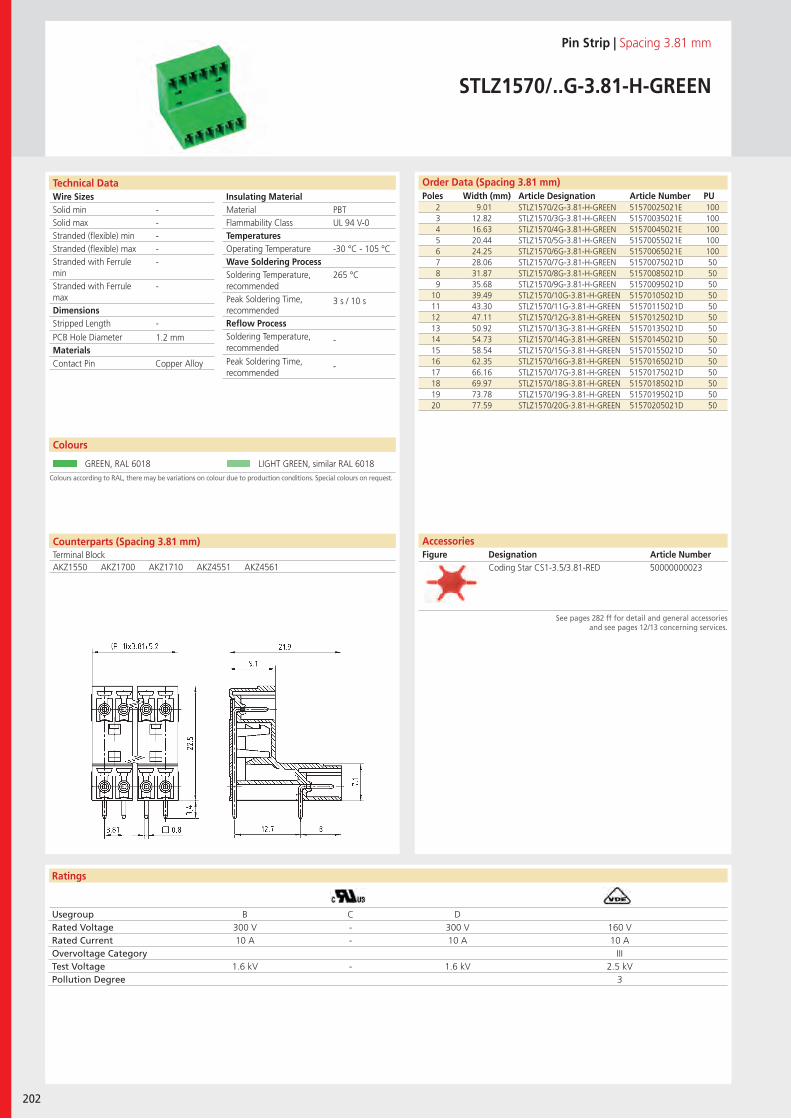
Wire SizesSolid minSolid maxStranded (flexible) minStranded (flexible) maxStranded with Ferrule minStranded with Ferrule maxDimensions Stripped Length
PCB Hole DiameterMaterials
Ratings
202
Insulating Material MaterialFlammability ClassTemperaturesOperating TemperatureWave Soldering ProcessSoldering Temperature,recommendedPeak Soldering Time,recommendedReflow ProcessSoldering Temperature,recommended
Peak Soldering Time,recommended
Technical Data
Colours according to RAL, there may be variations on colour due to production conditions. Special colours on request.
Order Data (Spacing 3.81 mm)Poles Width (mm) Article Designation Article Number PU
Colours
Pin Strip | Spacing 3.81 mm
STLZ1570/..G-3.81-H-GREEN
2 9.01 STLZ1570/2G-3.81-H-GREEN 51570025021E 1003 12.82 STLZ1570/3G-3.81-H-GREEN 51570035021E 1004 16.63 STLZ1570/4G-3.81-H-GREEN 51570045021E 1005 20.44 STLZ1570/5G-3.81-H-GREEN 51570055021E 1006 24.25 STLZ1570/6G-3.81-H-GREEN 51570065021E 1007 28.06 STLZ1570/7G-3.81-H-GREEN 51570075021D 508 31.87 STLZ1570/8G-3.81-H-GREEN 51570085021D 509 35.68 STLZ1570/9G-3.81-H-GREEN 51570095021D 50
10 39.49 STLZ1570/10G-3.81-H-GREEN 51570105021D 5011 43.30 STLZ1570/11G-3.81-H-GREEN 51570115021D 5012 47.11 STLZ1570/12G-3.81-H-GREEN 51570125021D 5013 50.92 STLZ1570/13G-3.81-H-GREEN 51570135021D 5014 54.73 STLZ1570/14G-3.81-H-GREEN 51570145021D 5015 58.54 STLZ1570/15G-3.81-H-GREEN 51570155021D 5016 62.35 STLZ1570/16G-3.81-H-GREEN 51570165021D 5017 66.16 STLZ1570/17G-3.81-H-GREEN 51570175021D 5018 69.97 STLZ1570/18G-3.81-H-GREEN 51570185021D 5019 73.78 STLZ1570/19G-3.81-H-GREEN 51570195021D 5020 77.59 STLZ1570/20G-3.81-H-GREEN 51570205021D 50
GREEN, RAL 6018 LIGHT GREEN, similar RAL 6018
PBTUL 94 V-0
-30 °C - 105 °C
265 °C
3 s / 10 s
-
-
-----
-
-
1.2 mm
Counterparts (Spacing 3.81 mm)Terminal BlockAKZ1550 AKZ1700 AKZ1710 AKZ4551 AKZ4561
Contact Pin Copper Alloy
Usegroup B C DRated Voltage 300 V - 300 V 160 VRated Current 10 A - 10 A 10 AOvervoltage Category IIITest Voltage 1.6 kV - 1.6 kV 2.5 kVPollution Degree 3
Coding Star CS1-3.5/3.81-RED 50000000023
AccessoriesFigure Designation Article Number
See pages 282 ff for detail and general accessories and see pages 12/13 concerning services.
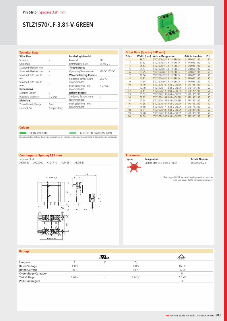
Wire SizesSolid minSolid maxStranded (flexible) minStranded (flexible) maxStranded with Ferrule minStranded with Ferrule maxDimensions Stripped Length
PCB Hole DiameterMaterials
Ratings
PTR Terminal Blocks and Multi Connector Systems 203
Insulating Material MaterialFlammability ClassTemperaturesOperating TemperatureWave Soldering ProcessSoldering Temperature,recommendedPeak Soldering Time,recommendedReflow ProcessSoldering Temperature,recommended
Peak Soldering Time,recommended
Order Data (Spacing 3.81 mm)Poles Width (mm) Article Designation Article Number PU
Technical Data
Pin Strip | Spacing 3.81 mm
STLZ1570/..F-3.81-V-GREEN
2 18.01 STLZ1570/2F-3.81-V-GREEN 51570026121D 503 21.82 STLZ1570/3F-3.81-V-GREEN 51570036121D 504 25.63 STLZ1570/4F-3.81-V-GREEN 51570046121D 505 29.44 STLZ1570/5F-3.81-V-GREEN 51570056121D 506 33.25 STLZ1570/6F-3.81-V-GREEN 51570066121D 507 37.06 STLZ1570/7F-3.81-V-GREEN 51570076121D 508 40.87 STLZ1570/8F-3.81-V-GREEN 51570086121D 509 44.68 STLZ1570/9F-3.81-V-GREEN 51570096121D 50
10 48.49 STLZ1570/10F-3.81-V-GREEN 51570106121D 5011 52.30 STLZ1570/11F-3.81-V-GREEN 51570116121D 5012 56.11 STLZ1570/12F-3.81-V-GREEN 51570126121D 5013 59.92 STLZ1570/13F-3.81-V-GREEN 51570136121D 5014 63.73 STLZ1570/14F-3.81-V-GREEN 51570146121D 5015 67.54 STLZ1570/15F-3.81-V-GREEN 51570156121D 5016 71.35 STLZ1570/16F-3.81-V-GREEN 51570166121D 5017 75.16 STLZ1570/17F-3.81-V-GREEN 51570176121D 5018 78.97 STLZ1570/18F-3.81-V-GREEN 51570186121D 5019 82.78 STLZ1570/19F-3.81-V-GREEN 51570196121D 5020 86.59 STLZ1570/20F-3.81-V-GREEN 51570206121D 50
PBTUL 94 V-0
-30 °C 105 °C
265 °C
3 s / 10 s
-
-
-----
-
-1.2 mm
Colours according to RAL, there may be variations on colour due to production conditions. Special colours on request.
Colours
GREEN, RAL 6018 LIGHT GREEN, similar RAL 6018
Counterparts (Spacing 3.81 mm)Terminal BlockAKZ1550 AKZ1700 AKZ1710 AKZ4551 AKZ4561
Thread Insert, Flange BrassContact Pin Copper Alloy
Usegroup B C DRated Voltage 300 V - 300 V 160 VRated Current 10 A - 10 A 10 AOvervoltage Category IIITest Voltage 1.6 kV - 1.6 kV 2.5 kVPollution Degree 3
AccessoriesFigure Designation Article Number
Coding Star CS1-3.5/3.81-RED 50000000023
See pages 282 ff for detail and general accessories and see pages 12/13 concerning services.
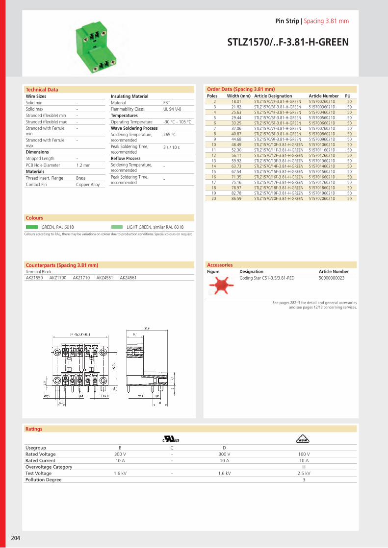
Wire SizesSolid minSolid maxStranded (flexible) minStranded (flexible) maxStranded with Ferrule minStranded with Ferrule maxDimensions Stripped Length
PCB Hole DiameterMaterials
Ratings
204
Insulating Material MaterialFlammability ClassTemperaturesOperating TemperatureWave Soldering ProcessSoldering Temperature,recommendedPeak Soldering Time,recommendedReflow ProcessSoldering Temperature,recommended
Peak Soldering Time,recommended
Technical Data
Colours according to RAL, there may be variations on colour due to production conditions. Special colours on request.
Order Data (Spacing 3.81 mm)Poles Width (mm) Article Designation Article Number PU
Colours
Pin Strip | Spacing 3.81 mm
STLZ1570/..F-3.81-H-GREEN
2 18.01 STLZ1570/2F-3.81-H-GREEN 51570026021D 503 21.82 STLZ1570/3F-3.81-H-GREEN 51570036021D 504 25.63 STLZ1570/4F-3.81-H-GREEN 51570046021D 505 29.44 STLZ1570/5F-3.81-H-GREEN 51570056021D 506 33.25 STLZ1570/6F-3.81-H-GREEN 51570066021D 507 37.06 STLZ1570/7F-3.81-H-GREEN 51570076021D 508 40.87 STLZ1570/8F-3.81-H-GREEN 51570086021D 509 44.68 STLZ1570/9F-3.81-H-GREEN 51570096021D 50
10 48.49 STLZ1570/10F-3.81-H-GREEN 51570106021D 5011 52.30 STLZ1570/11F-3.81-H-GREEN 51570116021D 5012 56.11 STLZ1570/12F-3.81-H-GREEN 51570126021D 5013 59.92 STLZ1570/13F-3.81-H-GREEN 51570136021D 5014 63.73 STLZ1570/14F-3.81-H-GREEN 51570146021D 5015 67.54 STLZ1570/15F-3.81-H-GREEN 51570156021D 5016 71.35 STLZ1570/16F-3.81-H-GREEN 51570166021D 5017 75.16 STLZ1570/17F-3.81-H-GREEN 51570176021D 5018 78.97 STLZ1570/18F-3.81-H-GREEN 51570186021D 5019 82.78 STLZ1570/19F-3.81-H-GREEN 51570196021D 5020 86.59 STLZ1570/20F-3.81-H-GREEN 51570206021D 50
GREEN, RAL 6018 LIGHT GREEN, similar RAL 6018
PBTUL 94 V-0
-30 °C - 105 °C
265 °C
3 s / 10 s
-
-
-----
-
-
1.2 mm
Counterparts (Spacing 3.81 mm)Terminal BlockAKZ1550 AKZ1700 AKZ1710 AKZ4551 AKZ4561
Thread Insert, Flange BrassContact Pin Copper Alloy
Usegroup B C DRated Voltage 300 V - 300 V 160 VRated Current 10 A - 10 A 10 AOvervoltage Category IIITest Voltage 1.6 kV - 1.6 kV 2.5 kVPollution Degree 3
Coding Star CS1-3.5/3.81-RED 50000000023
AccessoriesFigure Designation Article Number
See pages 282 ff for detail and general accessories and see pages 12/13 concerning services.
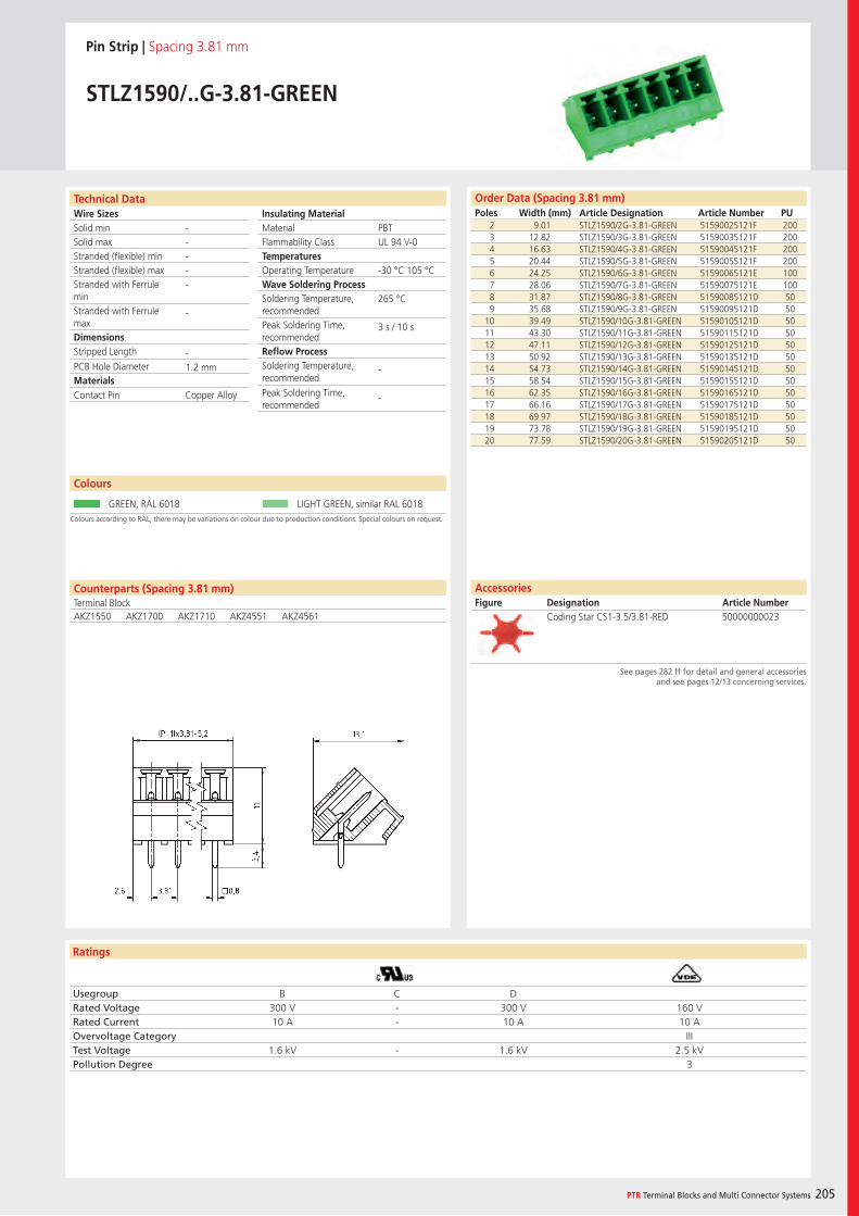
Wire SizesSolid minSolid maxStranded (flexible) minStranded (flexible) maxStranded with Ferrule minStranded with Ferrule maxDimensions Stripped Length
PCB Hole DiameterMaterials
Ratings
PTR Terminal Blocks and Multi Connector Systems 205
Insulating Material MaterialFlammability ClassTemperaturesOperating TemperatureWave Soldering ProcessSoldering Temperature,recommendedPeak Soldering Time,recommendedReflow ProcessSoldering Temperature,recommended
Peak Soldering Time,recommended
Order Data (Spacing 3.81 mm)Poles Width (mm) Article Designation Article Number PU
Technical Data
Pin Strip | Spacing 3.81 mm
STLZ1590/..G-3.81-GREEN
2 9.01 STLZ1590/2G-3.81-GREEN 51590025121F 2003 12.82 STLZ1590/3G-3.81-GREEN 51590035121F 2004 16.63 STLZ1590/4G-3.81-GREEN 51590045121F 2005 20.44 STLZ1590/5G-3.81-GREEN 51590055121F 2006 24.25 STLZ1590/6G-3.81-GREEN 51590065121E 1007 28.06 STLZ1590/7G-3.81-GREEN 51590075121E 1008 31.87 STLZ1590/8G-3.81-GREEN 51590085121D 509 35.68 STLZ1590/9G-3.81-GREEN 51590095121D 50
10 39.49 STLZ1590/10G-3.81-GREEN 51590105121D 5011 43.30 STLZ1590/11G-3.81-GREEN 51590115121D 5012 47.11 STLZ1590/12G-3.81-GREEN 51590125121D 5013 50.92 STLZ1590/13G-3.81-GREEN 51590135121D 5014 54.73 STLZ1590/14G-3.81-GREEN 51590145121D 5015 58.54 STLZ1590/15G-3.81-GREEN 51590155121D 5016 62.35 STLZ1590/16G-3.81-GREEN 51590165121D 5017 66.16 STLZ1590/17G-3.81-GREEN 51590175121D 5018 69.97 STLZ1590/18G-3.81-GREEN 51590185121D 5019 73.78 STLZ1590/19G-3.81-GREEN 51590195121D 5020 77.59 STLZ1590/20G-3.81-GREEN 51590205121D 50
PBTUL 94 V-0
-30 °C 105 °C
265 °C
3 s / 10 s
-
-
-----
-
-1.2 mm
Colours according to RAL, there may be variations on colour due to production conditions. Special colours on request.
Colours
GREEN, RAL 6018 LIGHT GREEN, similar RAL 6018
Counterparts (Spacing 3.81 mm)Terminal BlockAKZ1550 AKZ1700 AKZ1710 AKZ4551 AKZ4561
Contact Pin Copper Alloy
Usegroup B C DRated Voltage 300 V - 300 V 160 VRated Current 10 A - 10 A 10 AOvervoltage Category IIITest Voltage 1.6 kV - 1.6 kV 2.5 kVPollution Degree 3
AccessoriesFigure Designation Article Number
Coding Star CS1-3.5/3.81-RED 50000000023
See pages 282 ff for detail and general accessories and see pages 12/13 concerning services.
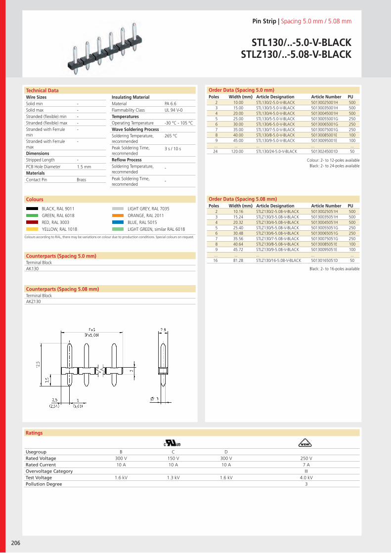
Wire SizesSolid minSolid maxStranded (flexible) minStranded (flexible) maxStranded with Ferrule minStranded with Ferrule maxDimensions Stripped Length
PCB Hole DiameterMaterials
Ratings
206
Insulating Material MaterialFlammability ClassTemperaturesOperating TemperatureWave Soldering ProcessSoldering Temperature,recommendedPeak Soldering Time,recommendedReflow ProcessSoldering Temperature,recommended
Peak Soldering Time,recommended
Technical Data Order Data (Spacing 5.0 mm)Poles Width (mm) Article Designation Article Number PU
Pin Strip | Spacing 5.0 mm / 5.08 mm
STL130/..-5.0-V-BLACKSTLZ130/..-5.08-V-BLACK
2 10.00 STL130/2-5.0-V-BLACK 50130025001H 5003 15.00 STL130/3-5.0-V-BLACK 50130035001H 5004 20.00 STL130/4-5.0-V-BLACK 50130045001H 5005 25.00 STL130/5-5.0-V-BLACK 50130055001G 2506 30.00 STL130/6-5.0-V-BLACK 50130065001G 2507 35.00 STL130/7-5.0-V-BLACK 50130075001G 2508 40.00 STL130/8-5.0-V-BLACK 50130085001E 1009 45.00 STL130/9-5.0-V-BLACK 50130095001E 100
... ... ... ... ...24 120.00 STL130/24-5.0-V-BLACK 50130245001D 50
Colours according to RAL, there may be variations on colour due to production conditions. Special colours on request.
Colours
BLACK, RAL 9011 LIGHT GREY, RAL 7035
GREEN, RAL 6018 ORANGE, RAL 2011
RED, RAL 3003 BLUE, RAL 5015
YELLOW, RAL 1018 LIGHT GREEN, similar RAL 6018
PA 6.6UL 94 V-0
-30 °C - 105 °C
265 °C
3 s / 10 s
-
-
-----
-
-
1.5 mm
Counterparts (Spacing 5.0 mm)Terminal BlockAK130
Counterparts (Spacing 5.08 mm)Terminal Block
Contact Pin Brass
Usegroup B C DRated Voltage 300 V 150 V 300 V 250 VRated Current 10 A 10 A 10 A 7 AOvervoltage Category IIITest Voltage 1.6 kV 1.3 kV 1.6 kV 4.0 kVPollution Degree 3
2 10.16 STLZ130/2-5.08-V-BLACK 50130025051H 5003 15.24 STLZ130/3-5.08-V-BLACK 50130035051H 5004 20.32 STLZ130/4-5.08-V-BLACK 50130045051H 5005 25.40 STLZ130/5-5.08-V-BLACK 50130055051G 2506 30.48 STLZ130/6-5.08-V-BLACK 50130065051G 2507 35.56 STLZ130/7-5.08-V-BLACK 50130075051G 2508 40.64 STLZ130/8-5.08-V-BLACK 50130085051E 1009 45.72 STLZ130/9-5.08-V-BLACK 50130095051E 100
... ... ... ... ...16 81.28 STLZ130/16-5.08-V-BLACK 50130165051D 50
Order Data (Spacing 5.08 mm)Poles Width (mm) Article Designation Article Number PU
AKZ130
Colour: 2- to 12-poles availableBlack: 2- to 24-poles available
Black: 2- to 16-poles available
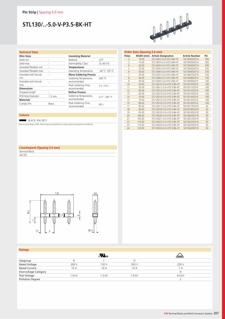
Wire SizesSolid minSolid maxStranded (flexible) minStranded (flexible) maxStranded with Ferrule minStranded with Ferrule maxDimensions Stripped Length
PCB Hole DiameterMaterials
Ratings
PTR Terminal Blocks and Multi Connector Systems 207
Insulating Material MaterialFlammability ClassTemperaturesOperating TemperatureWave Soldering ProcessSoldering Temperature,recommendedPeak Soldering Time,recommendedReflow ProcessSoldering Temperature,recommended
Peak Soldering Time,recommended
Order Data (Spacing 5.0 mm)Poles Width (mm) Article Designation Article Number PU
Technical Data
Pin Strip | Spacing 5.0 mm
STL130/..-5.0-V-P3.5-BK-HT
2 10.00 STL130/2-5.0-V-P3.5-BK-HT 50130025031H 5003 15.00 STL130/3-5.0-V-P3.5-BK-HT 50130035031H 5004 20.00 STL130/4-5.0-V-P3.5-BK-HT 50130045031H 5005 25.00 STL130/5-5.0-V-P3.5-BK-HT 50130055031G 2506 30.00 STL130/6-5.0-V-P3.5-BK-HT 50130065031G 2507 35.00 STL130/7-5.0-V-P3.5-BK-HT 50130075031G 2508 40.00 STL130/8-5.0-V-P3.5-BK-HT 50130085031E 1009 45.00 STL130/9-5.0-V-P3.5-BK-HT 50130095031E 100
10 50.00 STL130/10-5.0-V-P3.5-BK-HT 50130105031E 10011 55.00 STL130/11-5.0-V-P3.5-BK-HT 50130115031E 10012 60.00 STL130/12-5.0-V-P3.5-BK-HT 50130125031E 10013 65.00 STL130/13-5.0-V-P3.5-BK-HT 50130135031E 10014 70.00 STL130/14-5.0-V-P3.5-BK-HT 50130145031E 10015 75.00 STL130/15-5.0-V-P3.5-BK-HT 50130155031E 10016 80.00 STL130/16-5.0-V-P3.5-BK-HT 50130165031E 10017 85.00 STL130/17-5.0-V-P3.5-BK-HT 50130175031D 5018 90.00 STL130/18-5.0-V-P3.5-BK-HT 50130185031D 5019 95.00 STL130/19-5.0-V-P3.5-BK-HT 50130195031D 5020 100.00 STL130/20-5.0-V-P3.5-BK-HT 50130205031D 5021 105.00 STL130/21-5.0-V-P3.5-BK-HT 50130215031D 5022 110.00 STL130/22-5.0-V-P3.5-BK-HT 50130225031D 5023 115.00 STL130/23-5.0-V-P3.5-BK-HT 50130235031D 5024 120.00 STL130/24-5.0-V-P3.5-BK-HT 50130245031D 50
LCPUL 94 V-0
-30 °C 105 °C
265 °C
3 s / 10 s
217 - 245 °C
60 s
-----
-
-1.5 mm
Counterparts (Spacing 5.0 mm)Terminal BlockAK130
Contact Pin Brass
Usegroup B C DRated Voltage 300 V 150 V 300 V 250 VRated Current 10 A 10 A 10 A 7 AOvervoltage Category IIITest Voltage 1.6 kV 1.3 kV 1.6 kV 4.0 kVPollution Degree 2
Colours
BLACK, RAL 9011
Colours according to RAL, there may be variations on colour due to production conditions.
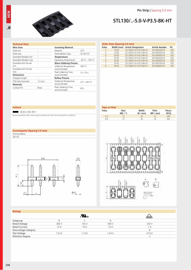
Wire SizesSolid minSolid maxStranded (flexible) minStranded (flexible) maxStranded with Ferrule minStranded with Ferrule maxDimensions Stripped Length
PCB Hole DiameterMaterials
Ratings
208
Insulating Material MaterialFlammability ClassTemperaturesOperating TemperatureWave Soldering ProcessSoldering Temperature,recommendedPeak Soldering Time,recommendedReflow ProcessSoldering Temperature,recommended
Peak Soldering Time,recommended
Usegroup B C DRated Voltage 300 V 150 V 300 V 250 VRated Current 10 A 10 A 10 A 7 AOvervoltage Category IIITest Voltage 1.6 kV 1.3 kV 1.6 kV 4.0 kVPollution Degree 2
Technical Data Order Data (Spacing 5.0 mm)Poles Width (mm) Article Designation Article Number PU
Colours
Pin Strip | Spacing 5.0 mm
STL130/..-5.0-V-P3.5-BK-HT
2 10.00 STL130/2-5.0-V-P3.5-BK-HT 50130025031R 3303 15.00 STL130/3-5.0-V-P3.5-BK-HT 50130035031R 3304 20.00 STL130/4-5.0-V-P3.5-BK-HT 50130045031R 2505 25.00 STL130/5-5.0-V-P3.5-BK-HT 50130055031R 2506 30.00 STL130/6-5.0-V-P3.5-BK-HT 50130065031R 2507 35.00 STL130/7-5.0-V-P3.5-BK-HT 50130075031R 2508 40.00 STL130/8-5.0-V-P3.5-BK-HT 50130085031R 250
BLACK, RAL 9011
LCPUL 94 V-0
-30 °C - 105 °C
265 °C
3 s / 10 s
217 - 245 °C
60 s
-----
-
-
1.5 mm
Counterparts (Spacing 5.0 mm)Terminal BlockAK130
Contact Pin Brass
NEW
2-3 13 24 12 3304-8 13 56 16 250
Tape on ReelPoles Reel
(RD / “)Width
(R / mm)Pitch
(RP / mm)Pieces (PCS)
Colours according to RAL, there may be variations on colour due to production conditions.
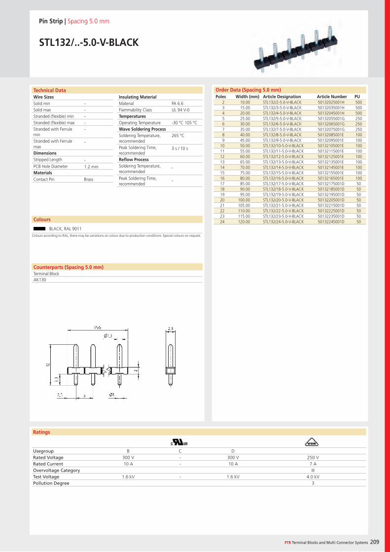
Wire SizesSolid minSolid maxStranded (flexible) minStranded (flexible) maxStranded with Ferrule minStranded with Ferrule maxDimensions Stripped Length
PCB Hole DiameterMaterials
Ratings
PTR Terminal Blocks and Multi Connector Systems 209
Insulating Material MaterialFlammability ClassTemperaturesOperating TemperatureWave Soldering ProcessSoldering Temperature,recommendedPeak Soldering Time,recommendedReflow ProcessSoldering Temperature,recommended
Peak Soldering Time,recommended
Order Data (Spacing 5.0 mm)Poles Width (mm) Article Designation Article Number PU
Technical Data
Pin Strip | Spacing 5.0 mm
STL132/..-5.0-V-BLACK
2 10.00 STL132/2-5.0-V-BLACK 50132025001H 5003 15.00 STL132/3-5.0-V-BLACK 50132035001H 5004 20.00 STL132/4-5.0-V-BLACK 50132045001H 5005 25.00 STL132/5-5.0-V-BLACK 50132055001G 2506 30.00 STL132/6-5.0-V-BLACK 50132065001G 2507 35.00 STL132/7-5.0-V-BLACK 50132075001G 2508 40.00 STL132/8-5.0-V-BLACK 50132085001E 1009 45.00 STL132/9-5.0-V-BLACK 50132095001E 100
10 50.00 STL132/10-5.0-V-BLACK 50132105001E 10011 55.00 STL132/11-5.0-V-BLACK 50132115001E 10012 60.00 STL132/12-5.0-V-BLACK 50132125001E 10013 65.00 STL132/13-5.0-V-BLACK 50132135001E 10014 70.00 STL132/14-5.0-V-BLACK 50132145001E 10015 75.00 STL132/15-5.0-V-BLACK 50132155001E 10016 80.00 STL132/16-5.0-V-BLACK 50132165001E 10017 85.00 STL132/17-5.0-V-BLACK 50132175001D 5018 90.00 STL132/18-5.0-V-BLACK 50132185001D 5019 95.00 STL132/19-5.0-V-BLACK 50132195001D 5020 100.00 STL132/20-5.0-V-BLACK 50132205001D 5021 105.00 STL132/21-5.0-V-BLACK 50132215001D 5022 110.00 STL132/22-5.0-V-BLACK 50132225001D 5023 115.00 STL132/23-5.0-V-BLACK 50132235001D 5024 120.00 STL132/24-5.0-V-BLACK 50132245001D 50
PA 6.6UL 94 V-0
-30 °C 105 °C
265 °C
3 s / 10 s
-
-
-----
-
-1.2 mm
Colours according to RAL, there may be variations on colour due to production conditions. Special colours on request.
Colours
BLACK, RAL 9011
Counterparts (Spacing 5.0 mm)Terminal BlockAK130
Contact Pin Brass
Usegroup B C DRated Voltage 300 V - 300 V 250 VRated Current 10 A - 10 A 7 AOvervoltage Category IIITest Voltage 1.6 kV - 1.6 kV 4.0 kVPollution Degree 3
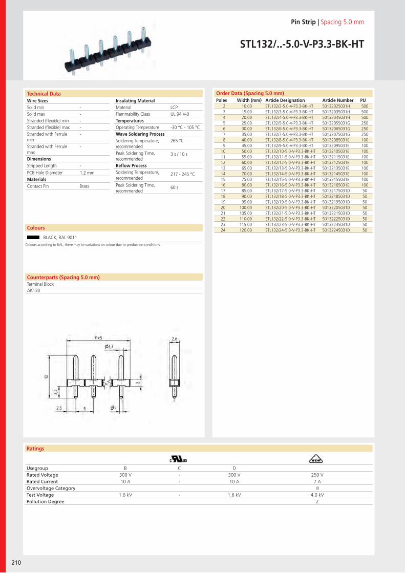
Wire SizesSolid minSolid maxStranded (flexible) minStranded (flexible) maxStranded with Ferrule minStranded with Ferrule maxDimensions Stripped Length
PCB Hole DiameterMaterials
Ratings
210
Insulating Material MaterialFlammability ClassTemperaturesOperating TemperatureWave Soldering ProcessSoldering Temperature,recommendedPeak Soldering Time,recommendedReflow ProcessSoldering Temperature,recommended
Peak Soldering Time,recommended
Technical Data Order Data (Spacing 5.0 mm)Poles Width (mm) Article Designation Article Number PU
Colours
Pin Strip | Spacing 5.0 mm
STL132/..-5.0-V-P3.3-BK-HT
2 10.00 STL132/2-5.0-V-P3.3-BK-HT 50132025031H 5003 15.00 STL132/3-5.0-V-P3.3-BK-HT 50132035031H 5004 20.00 STL132/4-5.0-V-P3.3-BK-HT 50132045031H 5005 25.00 STL132/5-5.0-V-P3.3-BK-HT 50132055031G 2506 30.00 STL132/6-5.0-V-P3.3-BK-HT 50132065031G 2507 35.00 STL132/7-5.0-V-P3.3-BK-HT 50132075031G 2508 40.00 STL132/8-5.0-V-P3.3-BK-HT 50132085031E 1009 45.00 STL132/9-5.0-V-P3.3-BK-HT 50132095031E 100
10 50.00 STL132/10-5.0-V-P3.3-BK-HT 50132105031E 10011 55.00 STL132/11-5.0-V-P3.3-BK-HT 50132115031E 10012 60.00 STL132/12-5.0-V-P3.3-BK-HT 50132125031E 10013 65.00 STL132/13-5.0-V-P3.3-BK-HT 50132135031E 10014 70.00 STL132/14-5.0-V-P3.3-BK-HT 50132145031E 10015 75.00 STL132/15-5.0-V-P3.3-BK-HT 50132155031E 10016 80.00 STL132/16-5.0-V-P3.3-BK-HT 50132165031E 10017 85.00 STL132/17-5.0-V-P3.3-BK-HT 50132175031D 5018 90.00 STL132/18-5.0-V-P3.3-BK-HT 50132185031D 5019 95.00 STL132/19-5.0-V-P3.3-BK-HT 50132195031D 5020 100.00 STL132/20-5.0-V-P3.3-BK-HT 50132205031D 5021 105.00 STL132/21-5.0-V-P3.3-BK-HT 50132215031D 5022 110.00 STL132/22-5.0-V-P3.3-BK-HT 50132225031D 5023 115.00 STL132/23-5.0-V-P3.3-BK-HT 50132235031D 5024 120.00 STL132/24-5.0-V-P3.3-BK-HT 50132245031D 50
BLACK, RAL 9011
LCPUL 94 V-0
-30 °C - 105 °C
265 °C
3 s / 10 s
217 - 245 °C
60 s
-----
-
-
1.2 mm
Counterparts (Spacing 5.0 mm)Terminal BlockAK130
Contact Pin Brass
Usegroup B C DRated Voltage 300 V - 300 V 250 VRated Current 10 A - 10 A 7 AOvervoltage Category IIITest Voltage 1.6 kV - 1.6 kV 4.0 kVPollution Degree 2
Colours according to RAL, there may be variations on colour due to production conditions.
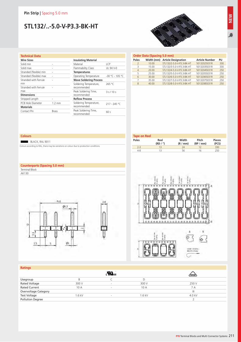
Wire SizesSolid minSolid maxStranded (flexible) minStranded (flexible) maxStranded with Ferrule minStranded with Ferrule maxDimensions Stripped Length
PCB Hole DiameterMaterials
Ratings
PTR Terminal Blocks and Multi Connector Systems 211
Insulating Material MaterialFlammability ClassTemperaturesOperating TemperatureWave Soldering ProcessSoldering Temperature,recommendedPeak Soldering Time,recommendedReflow ProcessSoldering Temperature,recommended
Peak Soldering Time,recommended
Usegroup B C DRated Voltage 300 V - 300 V 250 VRated Current 10 A - 10 A 7 AOvervoltage Category IIITest Voltage 1.6 kV - 1.6 kV 4.0 kVPollution Degree 2
Technical Data Order Data (Spacing 5.0 mm)Poles Width (mm) Article Designation Article Number PU
Pin Strip | Spacing 5.0 mm
STL132/..-5.0-V-P3.3-BK-HT
2 10.00 STL132/2-5.0-V-P3.3-BK-HT 50132025031R 3303 15.00 STL132/3-5.0-V-P3.3-BK-HT 50132035031R 3304 20.00 STL132/4-5.0-V-P3.3-BK-HT 50132045031R 2505 25.00 STL132/5-5.0-V-P3.3-BK-HT 50132055031R 2506 30.00 STL132/6-5.0-V-P3.3-BK-HT 50132065031R 2507 35.00 STL132/7-5.0-V-P3.3-BK-HT 50132075031R 2508 40.00 STL132/8-5.0-V-P3.3-BK-HT 50132085031R 250
LCPUL 94 V-0
-30 °C - 105 °C
265 °C
3 s / 10 s
217 - 245 °C
60 s
-----
-
-
1.2 mm
Counterparts (Spacing 5.0 mm)Terminal BlockAK130
Contact Pin Brass
2-3 13 24 12 3304-8 13 56 16 250
Tape on ReelPoles Reel
(RD / “)Width
(R / mm)Pitch
(RP / mm)Pieces (PCS)
Colours
BLACK, RAL 9011Colours according to RAL, there may be variations on colour due to production conditions.
NEW
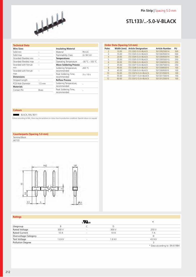
Wire SizesSolid minSolid maxStranded (flexible) minStranded (flexible) maxStranded with Ferrule minStranded with Ferrule maxDimensions Stripped Length
PCB Hole DiameterMaterials
Ratings
212
Insulating Material MaterialFlammability ClassTemperaturesOperating TemperatureWave Soldering ProcessSoldering Temperature,recommendedPeak Soldering Time,recommendedReflow ProcessSoldering Temperature,recommended
Peak Soldering Time,recommended
Technical Data
Colours according to RAL, there may be variations on colour due to production conditions. Special colours on request.
Order Data (Spacing 5.0 mm)Poles Width (mm) Article Designation Article Number PU
Colours
Pin Strip | Spacing 5.0 mm
STL133/..-5.0-V-BLACK
2 10.00 STL133/2-5.0-V-BLACK 50133025001H 5003 15.00 STL133/3-5.0-V-BLACK 50133035001H 5004 20.00 STL133/4-5.0-V-BLACK 50133045001H 5005 25.00 STL133/5-5.0-V-BLACK 50133055001G 2506 30.00 STL133/6-5.0-V-BLACK 50133065001G 2507 35.00 STL133/7-5.0-V-BLACK 50133075001G 2508 40.00 STL133/8-5.0-V-BLACK 50133085001E 1009 45.00 STL133/9-5.0-V-BLACK 50133095001E 100
10 50.00 STL133/10-5.0-V-BLACK 50133105001E 10011 55.00 STL133/11-5.0-V-BLACK 50133115001E 10012 60.00 STL133/12-5.0-V-BLACK 50133125001E 100
BLACK, RAL 9011
PA 6.6UL 94 V-0
-30 °C - 105 °C
265 °C
3 s / 10 s
-
-
-----
-
-
1.5 mm
Counterparts (Spacing 5.0 mm)Terminal BlockAK133
Contact Pin Brass
Usegroup B C DRated Voltage 300 V - 300 V 250 VRated Current 10 A - 10 A 7 AOvervoltage Category IIITest Voltage 1.6 kV - 1.6 kV 4.0 kVPollution Degree 3
* Data according to EN 61984
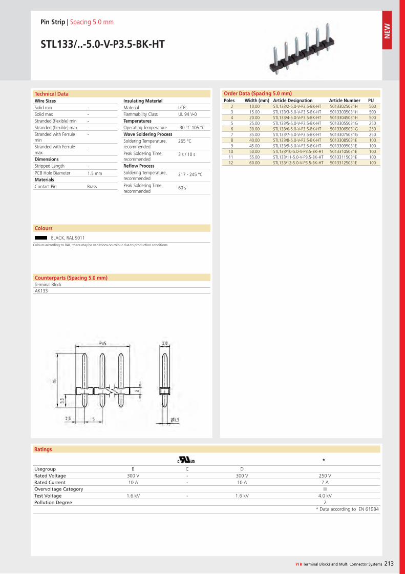
Wire SizesSolid minSolid maxStranded (flexible) minStranded (flexible) maxStranded with Ferrule minStranded with Ferrule maxDimensions Stripped Length
PCB Hole DiameterMaterials
Ratings
PTR Terminal Blocks and Multi Connector Systems 213
Insulating Material MaterialFlammability ClassTemperaturesOperating TemperatureWave Soldering ProcessSoldering Temperature,recommendedPeak Soldering Time,recommendedReflow ProcessSoldering Temperature,recommended
Peak Soldering Time,recommended
Order Data (Spacing 5.0 mm)Poles Width (mm) Article Designation Article Number PU
Technical Data
Pin Strip | Spacing 5.0 mm
STL133/..-5.0-V-P3.5-BK-HT
2 10.00 STL133/2-5.0-V-P3.5-BK-HT 50133025031H 5003 15.00 STL133/3-5.0-V-P3.5-BK-HT 50133035031H 5004 20.00 STL133/4-5.0-V-P3.5-BK-HT 50133045031H 5005 25.00 STL133/5-5.0-V-P3.5-BK-HT 50133055031G 2506 30.00 STL133/6-5.0-V-P3.5-BK-HT 50133065031G 2507 35.00 STL133/7-5.0-V-P3.5-BK-HT 50133075031G 2508 40.00 STL133/8-5.0-V-P3.5-BK-HT 50133085031E 1009 45.00 STL133/9-5.0-V-P3.5-BK-HT 50133095031E 100
10 50.00 STL133/10-5.0-V-P3.5-BK-HT 50133105031E 10011 55.00 STL133/11-5.0-V-P3.5-BK-HT 50133115031E 10012 60.00 STL133/12-5.0-V-P3.5-BK-HT 50133125031E 100
LCPUL 94 V-0
-30 °C 105 °C
265 °C
3 s / 10 s
217 - 245 °C
60 s
-----
-
-1.5 mm
Colours
BLACK, RAL 9011
Counterparts (Spacing 5.0 mm)Terminal BlockAK133
Contact Pin Brass
Usegroup B C DRated Voltage 300 V - 300 V 250 VRated Current 10 A - 10 A 7 AOvervoltage Category IIITest Voltage 1.6 kV - 1.6 kV 4.0 kVPollution Degree 2
* Data according to EN 61984
Colours according to RAL, there may be variations on colour due to production conditions.
NEW
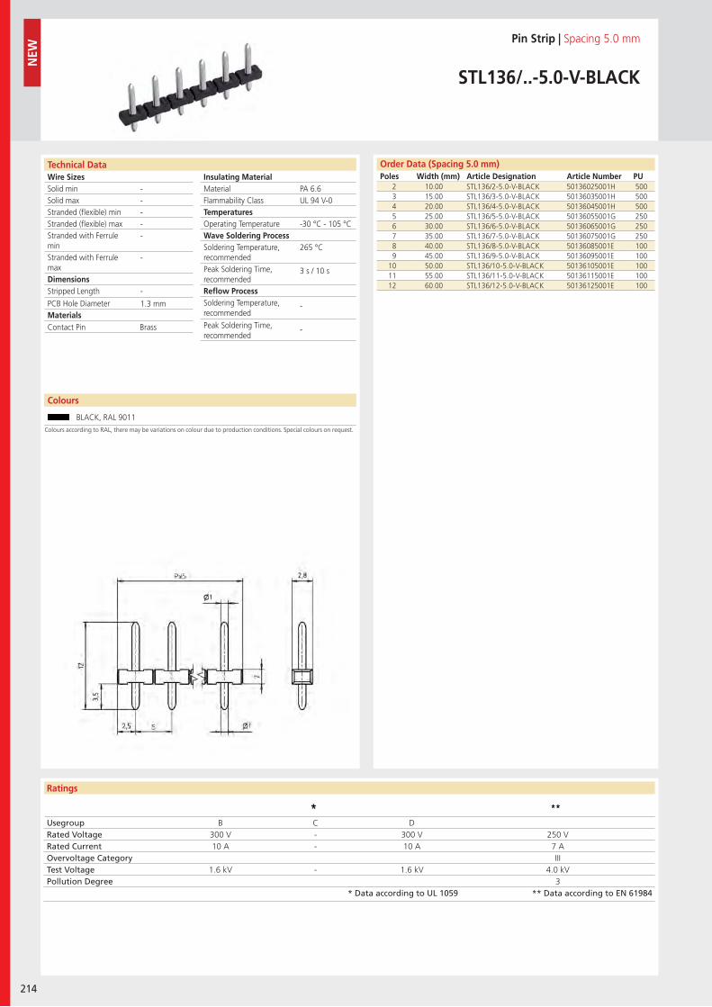
Wire SizesSolid minSolid maxStranded (flexible) minStranded (flexible) maxStranded with Ferrule minStranded with Ferrule maxDimensions Stripped Length
PCB Hole DiameterMaterials
Ratings
214
Insulating Material MaterialFlammability ClassTemperaturesOperating TemperatureWave Soldering ProcessSoldering Temperature,recommendedPeak Soldering Time,recommendedReflow ProcessSoldering Temperature,recommended
Peak Soldering Time,recommended
NEW
Technical Data
Colours according to RAL, there may be variations on colour due to production conditions. Special colours on request.
Order Data (Spacing 5.0 mm)Poles Width (mm) Article Designation Article Number PU
Colours
Pin Strip | Spacing 5.0 mm
STL136/..-5.0-V-BLACK
2 10.00 STL136/2-5.0-V-BLACK 50136025001H 5003 15.00 STL136/3-5.0-V-BLACK 50136035001H 5004 20.00 STL136/4-5.0-V-BLACK 50136045001H 5005 25.00 STL136/5-5.0-V-BLACK 50136055001G 2506 30.00 STL136/6-5.0-V-BLACK 50136065001G 2507 35.00 STL136/7-5.0-V-BLACK 50136075001G 2508 40.00 STL136/8-5.0-V-BLACK 50136085001E 1009 45.00 STL136/9-5.0-V-BLACK 50136095001E 100
10 50.00 STL136/10-5.0-V-BLACK 50136105001E 10011 55.00 STL136/11-5.0-V-BLACK 50136115001E 10012 60.00 STL136/12-5.0-V-BLACK 50136125001E 100
BLACK, RAL 9011
PA 6.6UL 94 V-0
-30 °C - 105 °C
265 °C
3 s / 10 s
-
-
-----
-
-
1.3 mm
Contact Pin Brass
Usegroup B C DRated Voltage 300 V - 300 V 250 VRated Current 10 A - 10 A 7 AOvervoltage Category IIITest Voltage 1.6 kV - 1.6 kV 4.0 kVPollution Degree 3
* Data according to UL 1059 ** Data according to EN 61984
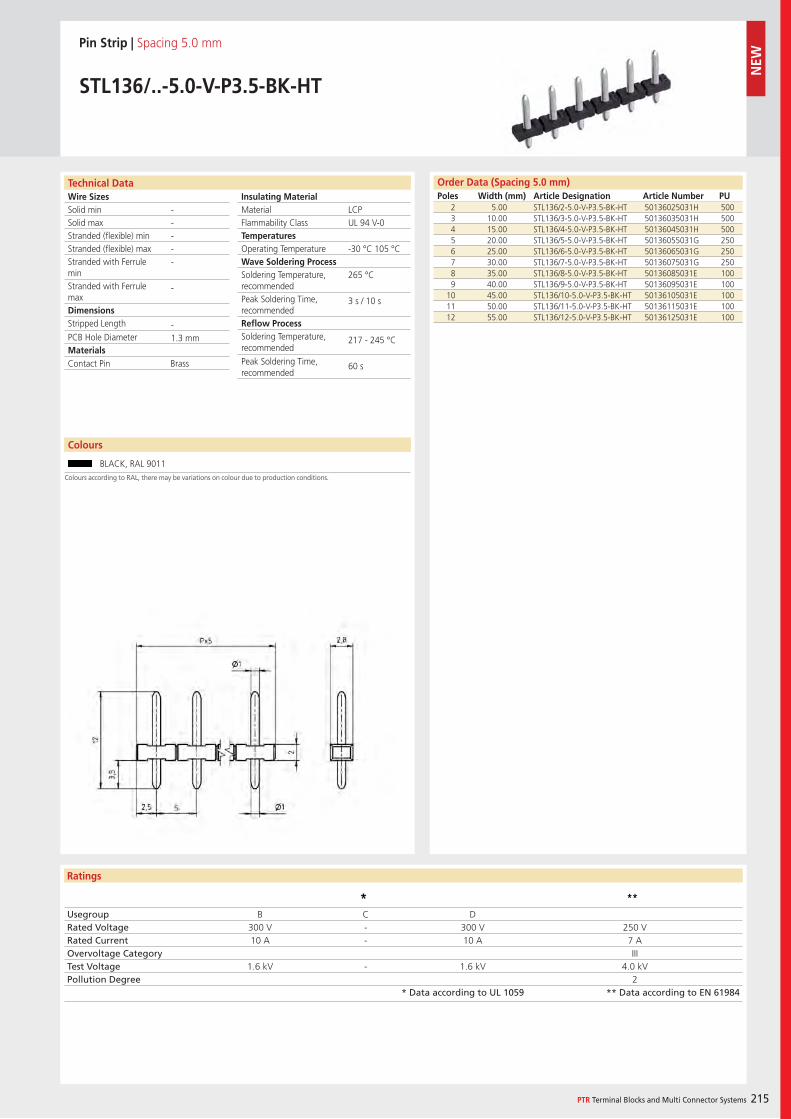
Wire SizesSolid minSolid maxStranded (flexible) minStranded (flexible) maxStranded with Ferrule minStranded with Ferrule maxDimensions Stripped Length
PCB Hole DiameterMaterials
Ratings
PTR Terminal Blocks and Multi Connector Systems 215
Insulating Material MaterialFlammability ClassTemperaturesOperating TemperatureWave Soldering ProcessSoldering Temperature,recommendedPeak Soldering Time,recommendedReflow ProcessSoldering Temperature,recommended
Peak Soldering Time,recommended
Order Data (Spacing 5.0 mm)Poles Width (mm) Article Designation Article Number PU
Technical Data
Pin Strip | Spacing 5.0 mm
STL136/..-5.0-V-P3.5-BK-HT
2 5.00 STL136/2-5.0-V-P3.5-BK-HT 50136025031H 5003 10.00 STL136/3-5.0-V-P3.5-BK-HT 50136035031H 5004 15.00 STL136/4-5.0-V-P3.5-BK-HT 50136045031H 5005 20.00 STL136/5-5.0-V-P3.5-BK-HT 50136055031G 2506 25.00 STL136/6-5.0-V-P3.5-BK-HT 50136065031G 2507 30.00 STL136/7-5.0-V-P3.5-BK-HT 50136075031G 2508 35.00 STL136/8-5.0-V-P3.5-BK-HT 50136085031E 1009 40.00 STL136/9-5.0-V-P3.5-BK-HT 50136095031E 100
10 45.00 STL136/10-5.0-V-P3.5-BK-HT 50136105031E 10011 50.00 STL136/11-5.0-V-P3.5-BK-HT 50136115031E 10012 55.00 STL136/12-5.0-V-P3.5-BK-HT 50136125031E 100
LCPUL 94 V-0
-30 °C 105 °C
265 °C
3 s / 10 s
217 - 245 °C
60 s
-----
-
-1.3 mm
Colours
BLACK, RAL 9011
Contact Pin Brass
Usegroup B C DRated Voltage 300 V - 300 V 250 VRated Current 10 A - 10 A 7 AOvervoltage Category IIITest Voltage 1.6 kV - 1.6 kV 4.0 kVPollution Degree 2
* Data according to UL 1059 ** Data according to EN 61984
Colours according to RAL, there may be variations on colour due to production conditions.
NEW
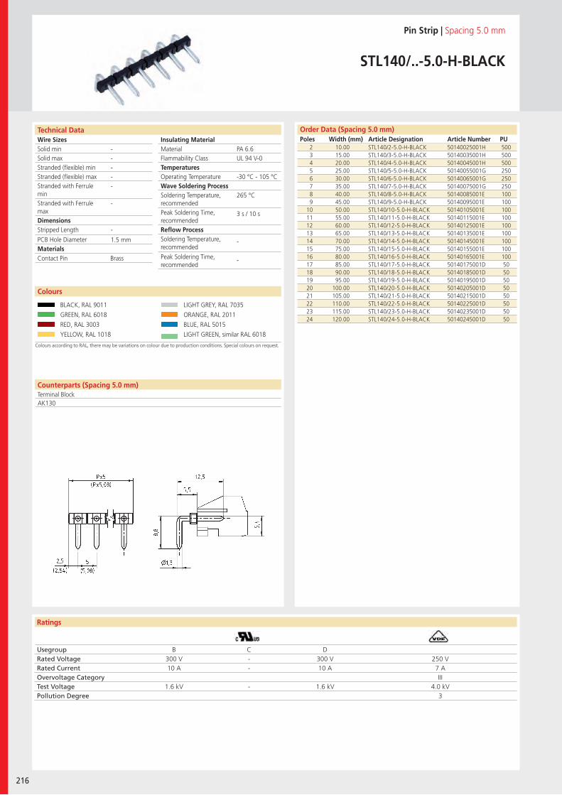
Wire SizesSolid minSolid maxStranded (flexible) minStranded (flexible) maxStranded with Ferrule minStranded with Ferrule maxDimensions Stripped Length
PCB Hole DiameterMaterials
Ratings
216
Insulating Material MaterialFlammability ClassTemperaturesOperating TemperatureWave Soldering ProcessSoldering Temperature,recommendedPeak Soldering Time,recommendedReflow ProcessSoldering Temperature,recommended
Peak Soldering Time,recommended
Counterparts (Spacing 5.0 mm)Terminal Block
Technical Data Order Data (Spacing 5.0 mm)Poles Width (mm) Article Designation Article Number PU
Pin Strip | Spacing 5.0 mm
STL140/..-5.0-H-BLACK
2 10.00 STL140/2-5.0-H-BLACK 50140025001H 5003 15.00 STL140/3-5.0-H-BLACK 50140035001H 5004 20.00 STL140/4-5.0-H-BLACK 50140045001H 5005 25.00 STL140/5-5.0-H-BLACK 50140055001G 2506 30.00 STL140/6-5.0-H-BLACK 50140065001G 2507 35.00 STL140/7-5.0-H-BLACK 50140075001G 2508 40.00 STL140/8-5.0-H-BLACK 50140085001E 1009 45.00 STL140/9-5.0-H-BLACK 50140095001E 100
10 50.00 STL140/10-5.0-H-BLACK 50140105001E 10011 55.00 STL140/11-5.0-H-BLACK 50140115001E 10012 60.00 STL140/12-5.0-H-BLACK 50140125001E 10013 65.00 STL140/13-5.0-H-BLACK 50140135001E 10014 70.00 STL140/14-5.0-H-BLACK 50140145001E 10015 75.00 STL140/15-5.0-H-BLACK 50140155001E 10016 80.00 STL140/16-5.0-H-BLACK 50140165001E 10017 85.00 STL140/17-5.0-H-BLACK 50140175001D 5018 90.00 STL140/18-5.0-H-BLACK 50140185001D 5019 95.00 STL140/19-5.0-H-BLACK 50140195001D 5020 100.00 STL140/20-5.0-H-BLACK 50140205001D 5021 105.00 STL140/21-5.0-H-BLACK 50140215001D 5022 110.00 STL140/22-5.0-H-BLACK 50140225001D 5023 115.00 STL140/23-5.0-H-BLACK 50140235001D 5024 120.00 STL140/24-5.0-H-BLACK 50140245001D 50
Colours according to RAL, there may be variations on colour due to production conditions. Special colours on request.
Colours
BLACK, RAL 9011 LIGHT GREY, RAL 7035
GREEN, RAL 6018 ORANGE, RAL 2011
RED, RAL 3003 BLUE, RAL 5015
YELLOW, RAL 1018 LIGHT GREEN, similar RAL 6018
PA 6.6UL 94 V-0
-30 °C - 105 °C
265 °C
3 s / 10 s
-
-
-----
-
-
1.5 mm
AK130
Contact Pin Brass
Usegroup B C DRated Voltage 300 V - 300 V 250 VRated Current 10 A - 10 A 7 AOvervoltage Category IIITest Voltage 1.6 kV - 1.6 kV 4.0 kVPollution Degree 3
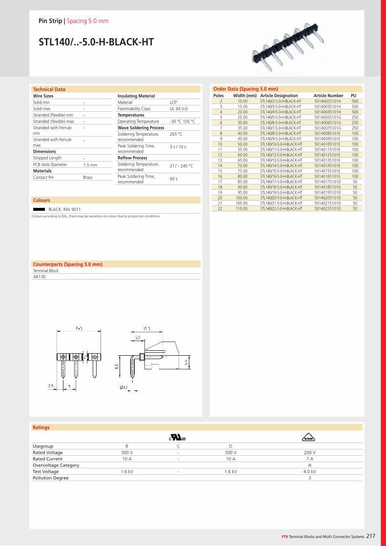
Wire SizesSolid minSolid maxStranded (flexible) minStranded (flexible) maxStranded with Ferrule minStranded with Ferrule maxDimensions Stripped Length
PCB Hole DiameterMaterials
Ratings
PTR Terminal Blocks and Multi Connector Systems 217
Insulating Material MaterialFlammability ClassTemperaturesOperating TemperatureWave Soldering ProcessSoldering Temperature,recommendedPeak Soldering Time,recommendedReflow ProcessSoldering Temperature,recommended
Peak Soldering Time,recommended
Order Data (Spacing 5.0 mm)Poles Width (mm) Article Designation Article Number PU
Technical Data
Pin Strip | Spacing 5.0 mm
STL140/..-5.0-H-BLACK-HT
2 10.00 STL140/2-5.0-H-BLACK-HT 50140025101H 5003 15.00 STL140/3-5.0-H-BLACK-HT 50140035101H 5004 20.00 STL140/4-5.0-H-BLACK-HT 50140045101H 5005 25.00 STL140/5-5.0-H-BLACK-HT 50140055101G 2506 30.00 STL140/6-5.0-H-BLACK-HT 50140065101G 2507 35.00 STL140/7-5.0-H-BLACK-HT 50140075101G 2508 40.00 STL140/8-5.0-H-BLACK-HT 50140085101E 1009 45.00 STL140/9-5.0-H-BLACK-HT 50140095101E 100
10 50.00 STL140/10-5.0-H-BLACK-HT 50140105101E 10011 55.00 STL140/11-5.0-H-BLACK-HT 50140115101E 10012 60.00 STL140/12-5.0-H-BLACK-HT 50140125101E 10013 65.00 STL140/13-5.0-H-BLACK-HT 50140135101E 10014 70.00 STL140/14-5.0-H-BLACK-HT 50140145101E 10015 75.00 STL140/15-5.0-H-BLACK-HT 50140155101E 10016 80.00 STL140/16-5.0-H-BLACK-HT 50140165101E 10017 85.00 STL140/17-5.0-H-BLACK-HT 50140175101D 5018 90.00 STL140/18-5.0-H-BLACK-HT 50140185101D 5019 95.00 STL140/19-5.0-H-BLACK-HT 50140195101D 5020 100.00 STL140/20-5.0-H-BLACK-HT 50140205101D 5021 105.00 STL140/21-5.0-H-BLACK-HT 50140215101D 5022 110.00 STL140/22-5.0-H-BLACK-HT 50140225101D 50
LCPUL 94 V-0
-30 °C 105 °C
265 °C
3 s / 10 s
217 - 245 °C
60 s
-----
-
-1.5 mm
Counterparts (Spacing 5.0 mm)Terminal BlockAK130
Contact Pin Brass
Usegroup B C DRated Voltage 300 V - 300 V 200 VRated Current 10 A - 10 A 7 AOvervoltage Category IIITest Voltage 1.6 kV - 1.6 kV 4.0 kVPollution Degree 3
Colours
BLACK, RAL 9011
Colours according to RAL, there may be variations on colour due to production conditions.
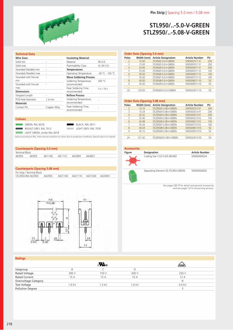
Wire SizesSolid minSolid maxStranded (flexible) minStranded (flexible) maxStranded with Ferrule minStranded with Ferrule maxDimensions Stripped Length
PCB Hole DiameterMaterials
Ratings
218
Insulating Material MaterialFlammability ClassTemperaturesOperating TemperatureWave Soldering ProcessSoldering Temperature,recommendedPeak Soldering Time,recommendedReflow ProcessSoldering Temperature,recommended
Peak Soldering Time,recommended
Technical Data
Colours according to RAL, there may be variations on colour due to production conditions. Special colours on request.
Order Data (Spacing 5.0 mm)Poles Width (mm) Article Designation Article Number PU
Colours
Pin Strip | Spacing 5.0 mm / 5.08 mm
STL950/..-5.0-V-GREENSTLZ950/..-5.08-V-GREEN
2 10.00 STL950/2-5.0-V-GREEN 50950025111F 2003 15.00 STL950/3-5.0-V-GREEN 50950035111F 2004 20.00 STL950/4-5.0-V-GREEN 50950045111F 2005 25.00 STL950/5-5.0-V-GREEN 50950055111E 1006 30.00 STL950/6-5.0-V-GREEN 50950065111E 1007 35.00 STL950/7-5.0-V-GREEN 50950075111E 1008 40.00 STL950/8-5.0-V-GREEN 50950085111D 509 45.00 STL950/9-5.0-V-GREEN 50950095111D 50
... ... ... ... ...24 120.00 STL950/24-5.0-V-GREEN 50950245111D 50
GREEN, RAL 6018 BLACK, RAL 9011
BASALT GREY, RAL 7012 LIGHT GREY, RAL 7035
LIGHT GREEN, similar RAL 6018
2 10.16 STLZ950/2-5.08-V-GREEN 50950025131F 2003 15.24 STLZ950/3-5.08-V-GREEN 50950035131F 2004 20.32 STLZ950/4-5.08-V-GREEN 50950045131F 2005 25.40 STLZ950/5-5.08-V-GREEN 50950055131E 1006 30.48 STLZ950/6-5.08-V-GREEN 50950065131E 1007 35.56 STLZ950/7-5.08-V-GREEN 50950075131E 1008 40.64 STLZ950/8-5.08-V-GREEN 50950085131D 509 45.72 STLZ950/9-5.08-V-GREEN 50950095131D 50
... ... ... ... ...24 121.92 STLZ950/24-5.08-V-GREEN 50950245131D 50
PA 6.6UL 94 V-0
-30 °C - 105 °C
265 °C
3 s / 10 s
-
-
-----
-
-
1.4 mm
Counterparts (Spacing 5.0 mm)Terminal Block
Counterparts (Spacing 5.08 mm)Pin Strip / Terminal Block
AK950 AK955 AK1100 AK1110 AK3950 AK4951
Contact Pin Copper Alloy
Usegroup B C DRated Voltage 300 V 150 V 300 V 250 VRated Current 15 A 15 A 10 A 12 AOvervoltage Category IIITest Voltage 1.6 kV 1.3 kV 1.6 kV 4.0 kVPollution Degree 3
Order Data (Spacing 5.08 mm)Poles Width (mm) Article Designation Article Number PU
Coding Star CS2-5.0/5.08-RED 50000000024
Separating Element SE-STL950-GREEN 50950000002
AccessoriesFigure Designation Article Number
See pages 282 ff for detail and general accessories and see pages 12/13 concerning services.
STLZ950-INV AKZ950 AKZ955 AKZ1100 AKZ1110 AKZ1200 AKZ4951
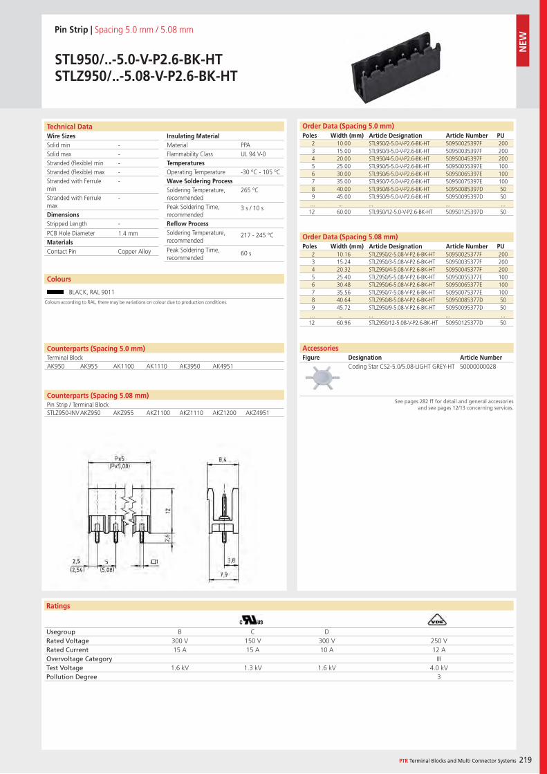
Wire SizesSolid minSolid maxStranded (flexible) minStranded (flexible) maxStranded with Ferrule minStranded with Ferrule maxDimensions Stripped Length
PCB Hole DiameterMaterials
Ratings
PTR Terminal Blocks and Multi Connector Systems 219
Insulating Material MaterialFlammability ClassTemperaturesOperating TemperatureWave Soldering ProcessSoldering Temperature,recommendedPeak Soldering Time,recommendedReflow ProcessSoldering Temperature,recommended
Peak Soldering Time,recommended
Counterparts (Spacing 5.08 mm)Pin Strip / Terminal Block
Technical Data Order Data (Spacing 5.0 mm)Poles Width (mm) Article Designation Article Number PU
Pin Strip | Spacing 5.0 mm / 5.08 mm
STL950/..-5.0-V-P2.6-BK-HTSTLZ950/..-5.08-V-P2.6-BK-HT
2 10.00 STL950/2-5.0-V-P2.6-BK-HT 50950025397F 2003 15.00 STL950/3-5.0-V-P2.6-BK-HT 50950035397F 2004 20.00 STL950/4-5.0-V-P2.6-BK-HT 50950045397F 2005 25.00 STL950/5-5.0-V-P2.6-BK-HT 50950055397E 1006 30.00 STL950/6-5.0-V-P2.6-BK-HT 50950065397E 1007 35.00 STL950/7-5.0-V-P2.6-BK-HT 50950075397E 1008 40.00 STL950/8-5.0-V-P2.6-BK-HT 50950085397D 509 45.00 STL950/9-5.0-V-P2.6-BK-HT 50950095397D 50
... ... ... ... ...12 60.00 STL950/12-5.0-V-P2.6-BK-HT 50950125397D 50
Order Data (Spacing 5.08 mm)Poles Width (mm) Article Designation Article Number PU
2 10.16 STLZ950/2-5.08-V-P2.6-BK-HT 50950025377F 2003 15.24 STLZ950/3-5.08-V-P2.6-BK-HT 50950035377F 2004 20.32 STLZ950/4-5.08-V-P2.6-BK-HT 50950045377F 2005 25.40 STLZ950/5-5.08-V-P2.6-BK-HT 50950055377E 1006 30.48 STLZ950/6-5.08-V-P2.6-BK-HT 50950065377E 1007 35.56 STLZ950/7-5.08-V-P2.6-BK-HT 50950075377E 1008 40.64 STLZ950/8-5.08-V-P2.6-BK-HT 50950085377D 509 45.72 STLZ950/9-5.08-V-P2.6-BK-HT 50950095377D 50
... ... ... ... ...12 60.96 STLZ950/12-5.08-V-P2.6-BK-HT 50950125377D 50
PPAUL 94 V-0
-30 °C - 105 °C
265 °C
3 s / 10 s
217 - 245 °C
60 s
-----
-
-
1.4 mm
Counterparts (Spacing 5.0 mm)Terminal BlockAK950 AK955 AK1100 AK1110 AK3950 AK4951
Contact Pin Copper Alloy
Usegroup B C DRated Voltage 300 V 150 V 300 V 250 VRated Current 15 A 15 A 10 A 12 AOvervoltage Category IIITest Voltage 1.6 kV 1.3 kV 1.6 kV 4.0 kVPollution Degree 3
AccessoriesFigure Designation Article Number
See pages 282 ff for detail and general accessories and see pages 12/13 concerning services.
Coding Star CS2-5.0/5.08-LIGHT GREY-HT 50000000028
Colours
BLACK, RAL 9011
Colours according to RAL, there may be variations on colour due to production conditions.
STLZ950-INV AKZ950 AKZ955 AKZ1100 AKZ1110 AKZ1200 AKZ4951
NEW
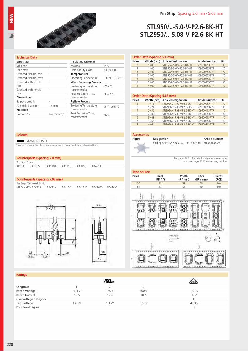
Wire SizesSolid minSolid maxStranded (flexible) minStranded (flexible) maxStranded with Ferrule minStranded with Ferrule maxDimensions Stripped Length
PCB Hole DiameterMaterials
Ratings
220
Insulating Material MaterialFlammability ClassTemperaturesOperating TemperatureWave Soldering ProcessSoldering Temperature,recommendedPeak Soldering Time,recommendedReflow ProcessSoldering Temperature,recommended
Peak Soldering Time,recommended
Technical Data Order Data (Spacing 5.0 mm)Poles Width (mm) Article Designation Article Number PU
Pin Strip | Spacing 5.0 mm / 5.08 mm
STL950/..-5.0-V-P2.6-BK-HTSTLZ950/..-5.08-V-P2.6-BK-HT
2 10.00 STL950/2-5.0-V-P2.6-BK-HT 50950025397R 1403 15.00 STL950/3-5.0-V-P2.6-BK-HT 50950035397R 1404 20.00 STL950/4-5.0-V-P2.6-BK-HT 50950045397R 1405 25.00 STL950/5-5.0-V-P2.6-BK-HT 50950055397R 1406 30.00 STL950/6-5.0-V-P2.6-BK-HT 50950065397R 1407 35.00 STL950/7-5.0-V-P2.6-BK-HT 50950075397R 1408 40.00 STL950/8-5.0-V-P2.6-BK-HT 50950085397R 140
PPAUL 94 V-0
-30 °C - 105 °C
265 °C
3 s / 10 s
217 - 245 °C
60 s
-----
-
-
1.4 mm
Counterparts (Spacing 5.0 mm)Terminal BlockAK950 AK955 AK1100 AK1110 AK3950 AK4951
Contact Pin Copper Alloy
2 10.16 STLZ950/2-5.08-V-P2.6-BK-HT 50950025377R 1403 15.24 STLZ950/3-5.08-V-P2.6-BK-HT 50950035377R 1404 20.32 STLZ950/4-5.08-V-P2.6-BK-HT 50950045377R 1405 25.40 STLZ950/5-5.08-V-P2.6-BK-HT 50950055377R 1406 30.48 STLZ950/6-5.08-V-P2.6-BK-HT 50950065377R 1407 35.56 STLZ950/7-5.08-V-P2.6-BK-HT 50950075377R 1408 40.64 STLZ950/8-5.08-V-P2.6-BK-HT 50950085377R 140
Order Data (Spacing 5.08 mm)Poles Width (mm) Article Designation Article Number PU
Coding Star CS2-5.0/5.08-LIGHT GREY-HT 50000000028
AccessoriesFigure Designation Article Number
See pages 282 ff for detail and general accessories and see pages 12/13 concerning services.
NEW
Usegroup B C DRated Voltage 300 V 150 V 300 V 250 VRated Current 15 A 15 A 10 A 12 AOvervoltage Category IIITest Voltage 1.6 kV 1.3 kV 1.6 kV 4.0 kVPollution Degree 3
2-3 13 32 20 1404-8 13 56 20 140
Tape on ReelPoles Reel
(RD / “)Width
(R / mm)Pitch
(RP / mm)Pieces (PCS)
Colours
BLACK, RAL 9011Colours according to RAL, there may be variations on colour due to production conditions.
Counterparts (Spacing 5.08 mm)Pin Strip / Terminal BlockSTLZ950-INV AKZ950 AKZ955 AKZ1100 AKZ1110 AKZ1200 AKZ4951
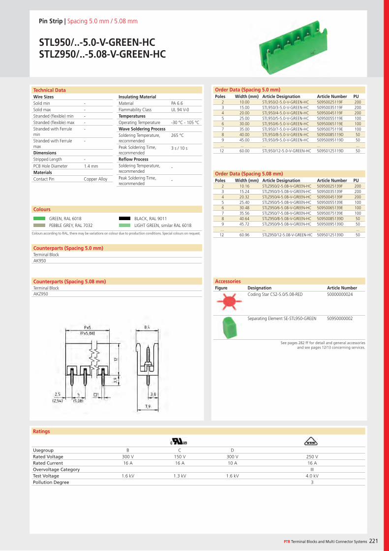
Wire SizesSolid minSolid maxStranded (flexible) minStranded (flexible) maxStranded with Ferrule minStranded with Ferrule maxDimensions Stripped Length
PCB Hole DiameterMaterials
Ratings
PTR Terminal Blocks and Multi Connector Systems 221
Insulating Material MaterialFlammability ClassTemperaturesOperating TemperatureWave Soldering ProcessSoldering Temperature,recommendedPeak Soldering Time,recommendedReflow ProcessSoldering Temperature,recommended
Peak Soldering Time,recommended
Technical Data Order Data (Spacing 5.0 mm)Poles Width (mm) Article Designation Article Number PU
Pin Strip | Spacing 5.0 mm / 5.08 mm
STL950/..-5.0-V-GREEN-HCSTLZ950/..-5.08-V-GREEN-HC
2 10.00 STL950/2-5.0-V-GREEN-HC 50950025119F 2003 15.00 STL950/3-5.0-V-GREEN-HC 50950035119F 2004 20.00 STL950/4-5.0-V-GREEN-HC 50950045119F 2005 25.00 STL950/5-5.0-V-GREEN-HC 50950055119E 1006 30.00 STL950/6-5.0-V-GREEN-HC 50950065119E 1007 35.00 STL950/7-5.0-V-GREEN-HC 50950075119E 1008 40.00 STL950/8-5.0-V-GREEN-HC 50950085119D 509 45.00 STL950/9-5.0-V-GREEN-HC 50950095119D 50
... ... ... ... ...12 60.00 STL950/12-5.0-V-GREEN-HC 50950125119D 50
Colours according to RAL, there may be variations on colour due to production conditions. Special colours on request.
Colours
GREEN, RAL 6018 BLACK, RAL 9011
PEBBLE GREY, RAL 7032 LIGHT GREEN, similar RAL 6018
Order Data (Spacing 5.08 mm)Poles Width (mm) Article Designation Article Number PU
2 10.16 STLZ950/2-5.08-V-GREEN-HC 50950025139F 2003 15.24 STLZ950/3-5.08-V-GREEN-HC 50950035139F 2004 20.32 STLZ950/4-5.08-V-GREEN-HC 50950045139F 2005 25.40 STLZ950/5-5.08-V-GREEN-HC 50950055139E 1006 30.48 STLZ950/6-5.08-V-GREEN-HC 50950065139E 1007 35.56 STLZ950/7-5.08-V-GREEN-HC 50950075139E 1008 40.64 STLZ950/8-5.08-V-GREEN-HC 50950085139D 509 45.72 STLZ950/9-5.08-V-GREEN-HC 50950095139D 50
... ... ... ... ...12 60.96 STLZ950/12-5.08-V-GREEN-HC 50950125139D 50
PA 6.6UL 94 V-0
-30 °C - 105 °C
265 °C
3 s / 10 s
-
-
-----
-
-
1.4 mm
Counterparts (Spacing 5.0 mm)Terminal BlockAK950
Contact Pin Copper Alloy
Usegroup B C DRated Voltage 300 V 150 V 300 V 250 VRated Current 16 A 16 A 10 A 16 AOvervoltage Category IIITest Voltage 1.6 kV 1.3 kV 1.6 kV 4.0 kVPollution Degree 3
AccessoriesFigure Designation Article Number
See pages 282 ff for detail and general accessories and see pages 12/13 concerning services.
Coding Star CS2-5.0/5.08-RED 50000000024
Separating Element SE-STL950-GREEN 50950000002
Counterparts (Spacing 5.08 mm)Terminal BlockAKZ950
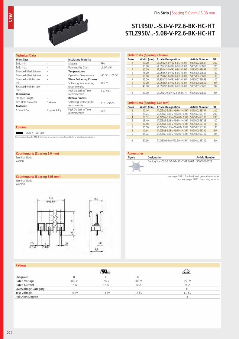
Wire SizesSolid minSolid maxStranded (flexible) minStranded (flexible) maxStranded with Ferrule minStranded with Ferrule maxDimensions Stripped Length
PCB Hole DiameterMaterials
Ratings
222
Insulating Material MaterialFlammability ClassTemperaturesOperating TemperatureWave Soldering ProcessSoldering Temperature,recommendedPeak Soldering Time,recommendedReflow ProcessSoldering Temperature,recommended
Peak Soldering Time,recommended
Technical Data Order Data (Spacing 5.0 mm)Poles Width (mm) Article Designation Article Number PU
Colours
Pin Strip | Spacing 5.0 mm / 5.08 mm
STL950/..-5.0-V-P2.6-BK-HC-HTSTLZ950/..-5.08-V-P2.6-BK-HC-HT
2 10.00 STL950/2-5.0-V-P2.6-BK-HC-HT 50950025389F 2003 15.00 STL950/3-5.0-V-P2.6-BK-HC-HT 50950035389F 2004 20.00 STL950/4-5.0-V-P2.6-BK-HC-HT 50950045389F 2005 25.00 STL950/5-5.0-V-P2.6-BK-HC-HT 50950055389E 1006 30.00 STL950/6-5.0-V-P2.6-BK-HC-HT 50950065389E 1007 35.00 STL950/7-5.0-V-P2.6-BK-HC-HT 50950075389E 1008 40.00 STL950/8-5.0-V-P2.6-BK-HC-HT 50950085389D 509 45.00 STL950/9-5.0-V-P2.6-BK-HC-HT 50950095389D 50
... ... ... ... ...12 60.00 STL950/12-5.0-V-P2.6-BK-HC-HT 50950125389D 50
BLACK, RAL 9011
2 10.16 STLZ950/2-5.08-V-P2.6-BK-HC-HT 50950025379F 2003 15.24 STLZ950/3-5.08-V-P2.6-BK-HC-HT 50950035379F 2004 20.32 STLZ950/4-5.08-V-P2.6-BK-HC-HT 50950045379F 2005 25.40 STLZ950/5-5.08-V-P2.6-BK-HC-HT 50950055379E 1006 30.48 STLZ950/6-5.08-V-P2.6-BK-HC-HT 50950065379E 1007 35.56 STLZ950/7-5.08-V-P2.6-BK-HC-HT 50950075379E 1008 40.64 STLZ950/8-5.08-V-P2.6-BK-HC-HT 50950085379D 509 45.72 STLZ950/9-5.08-V-P2.6-BK-HC-HT 50950095379D 50
... ... ... ... ...12 60.96 STLZ950/12-5.08-V-P2.6-BK-HC-HT 50950125379D 50
PPAUL 94 V-0
-30 °C - 105 °C
265 °C
3 s / 10 s
217 - 245 °C
60 s
-----
-
-
1.4 mm
Counterparts (Spacing 5.0 mm)Terminal BlockAK950
Contact Pin Copper Alloy
Usegroup B C DRated Voltage 300 V 150 V 300 V 250 VRated Current 16 A 16 A 10 A 16 AOvervoltage Category IIITest Voltage 1.6 kV 1.3 kV 1.6 kV 4.0 kVPollution Degree 3
Coding Star CS2-5.0/5.08-LIGHT GREY-HT 50000000028
Order Data (Spacing 5.08 mm)Poles Width (mm) Article Designation Article Number PU
AccessoriesFigure Designation Article Number
See pages 282 ff for detail and general accessories and see pages 12/13 concerning services.
NEW
Colours according to RAL, there may be variations on colour due to production conditions.
Counterparts (Spacing 5.08 mm)Terminal BlockAKZ950
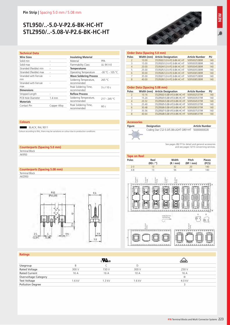
Wire SizesSolid minSolid maxStranded (flexible) minStranded (flexible) maxStranded with Ferrule minStranded with Ferrule maxDimensions Stripped Length
PCB Hole DiameterMaterials
Ratings
PTR Terminal Blocks and Multi Connector Systems 223
Insulating Material MaterialFlammability ClassTemperaturesOperating TemperatureWave Soldering ProcessSoldering Temperature,recommendedPeak Soldering Time,recommendedReflow ProcessSoldering Temperature,recommended
Peak Soldering Time,recommended
Technical Data Order Data (Spacing 5.0 mm)Poles Width (mm) Article Designation Article Number PU
Colours
Pin Strip | Spacing 5.0 mm / 5.08 mm
STL950/..-5.0-V-P2.6-BK-HC-HTSTLZ950/..-5.08-V-P2.6-BK-HC-HT
2 10.00 STL950/2-5.0-V-P2.6-BK-HC-HT 50950025389R 1403 15.00 STL950/3-5.0-V-P2.6-BK-HC-HT 50950035389R 1404 20.00 STL950/4-5.0-V-P2.6-BK-HC-HT 50950045389R 1405 25.00 STL950/5-5.0-V-P2.6-BK-HC-HT 50950055389R 1406 30.00 STL950/6-5.0-V-P2.6-BK-HC-HT 50950065389R 1407 35.00 STL950/7-5.0-V-P2.6-BK-HC-HT 50950075389R 1408 40.00 STL950/8-5.0-V-P2.6-BK-HC-HT 50950085389R 140
BLACK, RAL 9011
PPAUL 94 V-0
-30 °C - 105 °C
265 °C
3 s / 10 s
217 - 245 °C
60 s
-----
-
-
1.4 mm
Counterparts (Spacing 5.0 mm)Terminal BlockAK950
Contact Pin Copper Alloy
Usegroup B C DRated Voltage 300 V 150 V 300 V 250 VRated Current 16 A 16 A 10 A 16 AOvervoltage Category IIITest Voltage 1.6 kV 1.3 kV 1.6 kV 4.0 kVPollution Degree 3
2 10.16 STLZ950/2-5.08-V-P2.6-BK-HC-HT 50950025379R 1403 15.24 STLZ950/3-5.08-V-P2.6-BK-HC-HT 50950035379R 1404 20.32 STLZ950/4-5.08-V-P2.6-BK-HC-HT 50950045379R 1405 25.40 STLZ950/5-5.08-V-P2.6-BK-HC-HT 50950055379R 1406 30.48 STLZ950/6-5.08-V-P2.6-BK-HC-HT 50950065379R 1407 35.56 STLZ950/7-5.08-V-P2.6-BK-HC-HT 50950075379R 1408 40.64 STLZ950/8-5.08-V-P2.6-BK-HC-HT 50950085379R 140
Order Data (Spacing 5.08 mm)Poles Width (mm) Article Designation Article Number PU
Coding Star CS2-5.0/5.08-LIGHT GREY-HT 50000000028
AccessoriesFigure Designation Article Number
See pages 282 ff for detail and general accessories and see pages 12/13 concerning services.
2-3 13 32 20 1404-8 13 56 20 140
Tape on ReelPoles Reel
(RD / “)Width
(R / mm)Pitch
(RP / mm)Pieces (PCS)
Colours according to RAL, there may be variations on colour due to production conditions.
Counterparts (Spacing 5.08 mm)Terminal BlockAKZ950
NEW
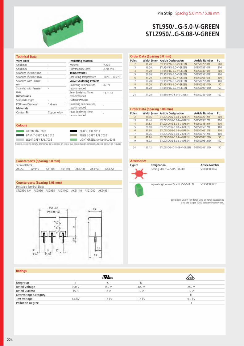
Wire SizesSolid minSolid maxStranded (flexible) minStranded (flexible) maxStranded with Ferrule minStranded with Ferrule maxDimensions Stripped Length
PCB Hole DiameterMaterials
Ratings
224
Insulating Material MaterialFlammability ClassTemperaturesOperating TemperatureWave Soldering ProcessSoldering Temperature,recommendedPeak Soldering Time,recommendedReflow ProcessSoldering Temperature,recommended
Peak Soldering Time,recommended
Technical Data Order Data (Spacing 5.0 mm)Poles Width (mm) Article Designation Article Number PU
Pin Strip | Spacing 5.0 mm / 5.08 mm
STL950/..G-5.0-V-GREENSTLZ950/..G-5.08-V-GREEN
2 11.20 STL950/2G-5.0-V-GREEN 50950025101F 2003 16.20 STL950/3G-5.0-V-GREEN 50950035101F 2004 21.20 STL950/4G-5.0-V-GREEN 50950045101F 2005 26.20 STL950/5G-5.0-V-GREEN 50950055101E 1006 31.20 STL950/6G-5.0-V-GREEN 50950065101E 1007 36.20 STL950/7G-5.0-V-GREEN 50950075101E 1008 41.20 STL950/8G-5.0-V-GREEN 50950085101D 509 46.20 STL950/9G-5.0-V-GREEN 50950095101D 50
... ... ... ... ...24 121.20 STL950/24G-5.0-V-GREEN 50950245101D 50
Colours according to RAL, there may be variations on colour due to production conditions. Special colours on request.
Colours
GREEN, RAL 6018 BLACK, RAL 9011
BASALT GREY, RAL 7012 PEBBLE GREY, RAL 7032
LIGHT GREY, RAL 7035 LIGHT GREEN, similar RAL 6018
2 11.36 STLZ950/2G-5.08-V-GREEN 50950025121F 2003 16.44 STLZ950/3G-5.08-V-GREEN 50950035121F 2004 21.52 STLZ950/4G-5.08-V-GREEN 50950045121F 2005 26.60 STLZ950/5G-5.08-V-GREEN 50950055121E 1006 31.68 STLZ950/6G-5.08-V-GREEN 50950065121E 1007 36.76 STLZ950/7G-5.08-V-GREEN 50950075121E 1008 41.84 STLZ950/8G-5.08-V-GREEN 50950085121D 509 46.92 STLZ950/9G-5.08-V-GREEN 50950095121D 50
... ... ... ... ...24 123.12 STLZ950/24G-5.08-V-GREEN 50950245121D 50
PA 6.6UL 94 V-0
-30 °C - 105 °C
265 °C
3 s / 10 s
-
-
-----
-
-
1.4 mm
Counterparts (Spacing 5.0 mm)Terminal BlockAK950 AK955 AK1100 AK1110 AK1200 AK3950 AK4951
Counterparts (Spacing 5.08 mm)Pin Strip / Terminal Block
Contact Pin Copper Alloy
Usegroup B C DRated Voltage 300 V 150 V 300 V 250 VRated Current 15 A 15 A 10 A 12 AOvervoltage Category IIITest Voltage 1.6 kV 1.3 kV 1.6 kV 4.0 kVPollution Degree 3
Coding Star CS2-5.0/5.08-RED 50000000024
Separating Element SE-STL950-GREEN 50950000002
Order Data (Spacing 5.08 mm)Poles Width (mm) Article Designation Article Number PU
AccessoriesFigure Designation Article Number
See pages 282 ff for detail and general accessories and see pages 12/13 concerning services.
STLZ950-INV AKZ950 AKZ955 AKZ1100 AKZ1110 AKZ1200 AKZ4951
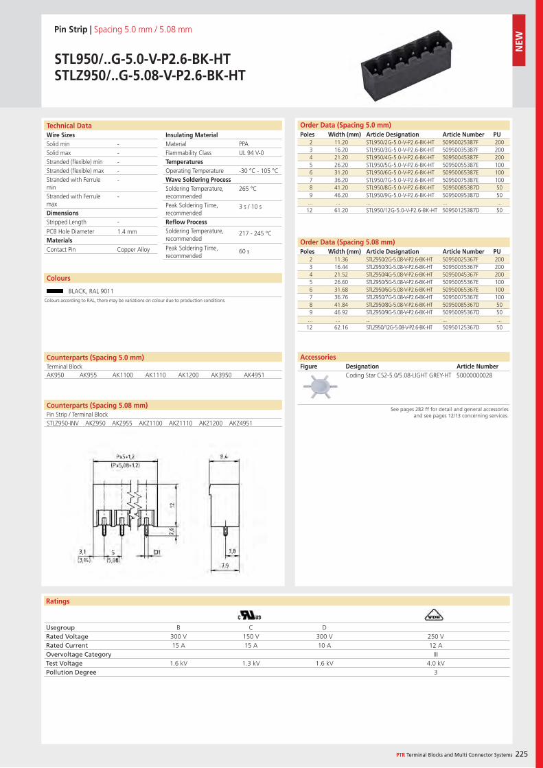
Wire SizesSolid minSolid maxStranded (flexible) minStranded (flexible) maxStranded with Ferrule minStranded with Ferrule maxDimensions Stripped Length
PCB Hole DiameterMaterials
Ratings
PTR Terminal Blocks and Multi Connector Systems 225
Insulating Material MaterialFlammability ClassTemperaturesOperating TemperatureWave Soldering ProcessSoldering Temperature,recommendedPeak Soldering Time,recommendedReflow ProcessSoldering Temperature,recommended
Peak Soldering Time,recommended
Counterparts (Spacing 5.08 mm)Pin Strip / Terminal Block
Technical Data Order Data (Spacing 5.0 mm)Poles Width (mm) Article Designation Article Number PU
Pin Strip | Spacing 5.0 mm / 5.08 mm
STL950/..G-5.0-V-P2.6-BK-HTSTLZ950/..G-5.08-V-P2.6-BK-HT
2 11.20 STL950/2G-5.0-V-P2.6-BK-HT 50950025387F 2003 16.20 STL950/3G-5.0-V-P2.6-BK-HT 50950035387F 2004 21.20 STL950/4G-5.0-V-P2.6-BK-HT 50950045387F 2005 26.20 STL950/5G-5.0-V-P2.6-BK-HT 50950055387E 1006 31.20 STL950/6G-5.0-V-P2.6-BK-HT 50950065387E 1007 36.20 STL950/7G-5.0-V-P2.6-BK-HT 50950075387E 1008 41.20 STL950/8G-5.0-V-P2.6-BK-HT 50950085387D 509 46.20 STL950/9G-5.0-V-P2.6-BK-HT 50950095387D 50
... ... ... ... ...12 61.20 STL950/12G-5.0-V-P2.6-BK-HT 50950125387D 50
PPAUL 94 V-0
-30 °C - 105 °C
265 °C
3 s / 10 s
217 - 245 °C
60 s
-----
-
-
1.4 mm
Counterparts (Spacing 5.0 mm)Terminal BlockAK950 AK955 AK1100 AK1110 AK1200 AK3950 AK4951
Contact Pin Copper Alloy
Usegroup B C DRated Voltage 300 V 150 V 300 V 250 VRated Current 15 A 15 A 10 A 12 AOvervoltage Category IIITest Voltage 1.6 kV 1.3 kV 1.6 kV 4.0 kVPollution Degree 3
2 11.36 STLZ950/2G-5.08-V-P2.6-BK-HT 50950025367F 2003 16.44 STLZ950/3G-5.08-V-P2.6-BK-HT 50950035367F 2004 21.52 STLZ950/4G-5.08-V-P2.6-BK-HT 50950045367F 2005 26.60 STLZ950/5G-5.08-V-P2.6-BK-HT 50950055367E 1006 31.68 STLZ950/6G-5.08-V-P2.6-BK-HT 50950065367E 1007 36.76 STLZ950/7G-5.08-V-P2.6-BK-HT 50950075367E 1008 41.84 STLZ950/8G-5.08-V-P2.6-BK-HT 50950085367D 509 46.92 STLZ950/9G-5.08-V-P2.6-BK-HT 50950095367D 50
... ... ... ... ...12 62.16 STLZ950/12G-5.08-V-P2.6-BK-HT 50950125367D 50
Order Data (Spacing 5.08 mm)Poles Width (mm) Article Designation Article Number PU
Coding Star CS2-5.0/5.08-LIGHT GREY-HT 50000000028
AccessoriesFigure Designation Article Number
See pages 282 ff for detail and general accessories and see pages 12/13 concerning services.
Colours
BLACK, RAL 9011Colours according to RAL, there may be variations on colour due to production conditions.
STLZ950-INV AKZ950 AKZ955 AKZ1100 AKZ1110 AKZ1200 AKZ4951
NEW
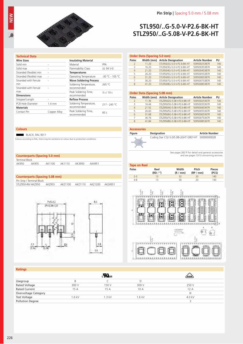
Wire SizesSolid minSolid maxStranded (flexible) minStranded (flexible) maxStranded with Ferrule minStranded with Ferrule maxDimensions Stripped Length
PCB Hole DiameterMaterials
Ratings
226
Insulating Material MaterialFlammability ClassTemperaturesOperating TemperatureWave Soldering ProcessSoldering Temperature,recommendedPeak Soldering Time,recommendedReflow ProcessSoldering Temperature,recommended
Peak Soldering Time,recommended
Technical Data Order Data (Spacing 5.0 mm)Poles Width (mm) Article Designation Article Number PU
Colours
Pin Strip | Spacing 5.0 mm / 5.08 mm
STL950/..G-5.0-V-P2.6-BK-HTSTLZ950/..G-5.08-V-P2.6-BK-HT
2 11.20 STL950/2G-5.0-V-P2.6-BK-HT 50950025387R 1403 16.20 STL950/3G-5.0-V-P2.6-BK-HT 50950035387R 1404 21.20 STL950/4G-5.0-V-P2.6-BK-HT 50950045387R 1405 26.20 STL950/5G-5.0-V-P2.6-BK-HT 50950055387R 1406 31.20 STL950/6G-5.0-V-P2.6-BK-HT 50950065387R 1407 36.20 STL950/7G-5.0-V-P2.6-BK-HT 50950075387R 1408 41.20 STL950/8G-5.0-V-P2.6-BK-HT 50950085387R 140
BLACK, RAL 9011
PPAUL 94 V-0
-30 °C - 105 °C
265 °C
3 s / 10 s
217 - 245 °C
60 s
-----
-
-
1.4 mm
Counterparts (Spacing 5.0 mm)Terminal BlockAK950 AK955 AK1100 AK1110 AK3950 AK4951
Contact Pin Copper Alloy
Usegroup B C DRated Voltage 300 V 150 V 300 V 250 VRated Current 15 A 15 A 10 A 12 AOvervoltage Category IIITest Voltage 1.6 kV 1.3 kV 1.6 kV 4.0 kVPollution Degree 3
2 11.36 STLZ950/2G-5.08-V-P2.6-BK-HT 50950025367R 1403 16.44 STLZ950/3G-5.08-V-P2.6-BK-HT 50950035367R 1404 21.52 STLZ950/4G-5.08-V-P2.6-BK-HT 50950045367R 1405 26.60 STLZ950/5G-5.08-V-P2.6-BK-HT 50950055367R 1406 31.68 STLZ950/6G-5.08-V-P2.6-BK-HT 50950065367R 1407 36.76 STLZ950/7G-5.08-V-P2.6-BK-HT 50950075367R 1408 41.84 STLZ950/8G-5.08-V-P2.6-BK-HT 50950085367R 140
Order Data (Spacing 5.08 mm)Poles Width (mm) Article Designation Article Number PU
Coding Star CS2-5.0/5.08-LIGHT GREY-HT 50000000028
AccessoriesFigure Designation Article Number
See pages 282 ff for detail and general accessories and see pages 12/13 concerning services.
2-3 13 32 20 1404-8 13 56 20 140
NEW
Tape on ReelPoles Reel
(RD / “)Width
(R / mm)Pitch
(RP / mm)Pieces (PCS)
Colours according to RAL, there may be variations on colour due to production conditions.
Counterparts (Spacing 5.08 mm)Pin Strip / Terminal BlockSTLZ950-INV AKZ950 AKZ955 AKZ1100 AKZ1110 AKZ1200 AKZ4951
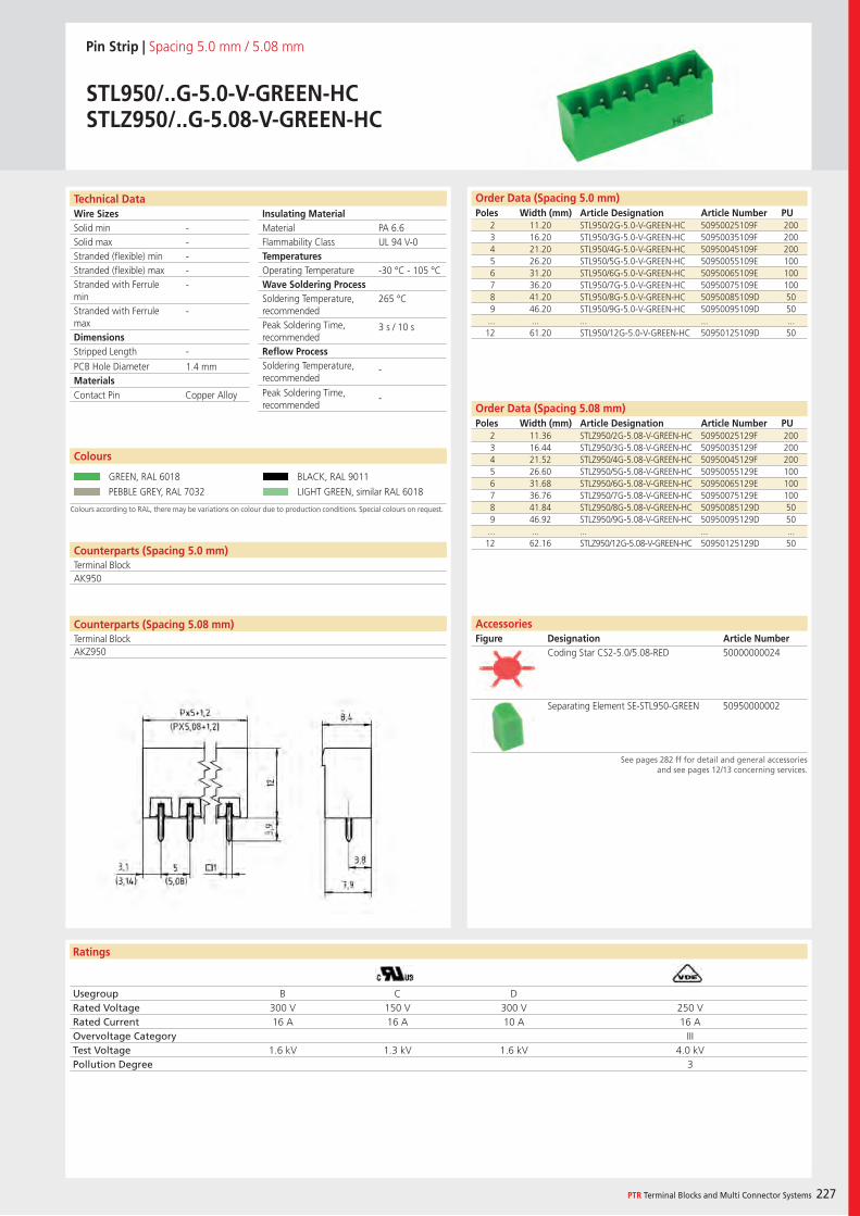
Wire SizesSolid minSolid maxStranded (flexible) minStranded (flexible) maxStranded with Ferrule minStranded with Ferrule maxDimensions Stripped Length
PCB Hole DiameterMaterials
Ratings
PTR Terminal Blocks and Multi Connector Systems 227
Insulating Material MaterialFlammability ClassTemperaturesOperating TemperatureWave Soldering ProcessSoldering Temperature,recommendedPeak Soldering Time,recommendedReflow ProcessSoldering Temperature,recommended
Peak Soldering Time,recommended
Technical Data Order Data (Spacing 5.0 mm)Poles Width (mm) Article Designation Article Number PU
Pin Strip | Spacing 5.0 mm / 5.08 mm
STL950/..G-5.0-V-GREEN-HCSTLZ950/..G-5.08-V-GREEN-HC
2 11.20 STL950/2G-5.0-V-GREEN-HC 50950025109F 2003 16.20 STL950/3G-5.0-V-GREEN-HC 50950035109F 2004 21.20 STL950/4G-5.0-V-GREEN-HC 50950045109F 2005 26.20 STL950/5G-5.0-V-GREEN-HC 50950055109E 1006 31.20 STL950/6G-5.0-V-GREEN-HC 50950065109E 1007 36.20 STL950/7G-5.0-V-GREEN-HC 50950075109E 1008 41.20 STL950/8G-5.0-V-GREEN-HC 50950085109D 509 46.20 STL950/9G-5.0-V-GREEN-HC 50950095109D 50
... ... ... ... ...12 61.20 STL950/12G-5.0-V-GREEN-HC 50950125109D 50
Colours according to RAL, there may be variations on colour due to production conditions. Special colours on request.
Colours
GREEN, RAL 6018 BLACK, RAL 9011
PEBBLE GREY, RAL 7032 LIGHT GREEN, similar RAL 6018
Order Data (Spacing 5.08 mm)Poles Width (mm) Article Designation Article Number PU
2 11.36 STLZ950/2G-5.08-V-GREEN-HC 50950025129F 2003 16.44 STLZ950/3G-5.08-V-GREEN-HC 50950035129F 2004 21.52 STLZ950/4G-5.08-V-GREEN-HC 50950045129F 2005 26.60 STLZ950/5G-5.08-V-GREEN-HC 50950055129E 1006 31.68 STLZ950/6G-5.08-V-GREEN-HC 50950065129E 1007 36.76 STLZ950/7G-5.08-V-GREEN-HC 50950075129E 1008 41.84 STLZ950/8G-5.08-V-GREEN-HC 50950085129D 509 46.92 STLZ950/9G-5.08-V-GREEN-HC 50950095129D 50
... ... ... ... ...12 62.16 STLZ950/12G-5.08-V-GREEN-HC 50950125129D 50
PA 6.6UL 94 V-0
-30 °C - 105 °C
265 °C
3 s / 10 s
-
-
-----
-
-
1.4 mm
Counterparts (Spacing 5.0 mm)Terminal BlockAK950
Contact Pin Copper Alloy
Usegroup B C DRated Voltage 300 V 150 V 300 V 250 VRated Current 16 A 16 A 10 A 16 AOvervoltage Category IIITest Voltage 1.6 kV 1.3 kV 1.6 kV 4.0 kVPollution Degree 3
AccessoriesFigure Designation Article Number
See pages 282 ff for detail and general accessories and see pages 12/13 concerning services.
Coding Star CS2-5.0/5.08-RED 50000000024
Separating Element SE-STL950-GREEN 50950000002
Counterparts (Spacing 5.08 mm)Terminal BlockAKZ950
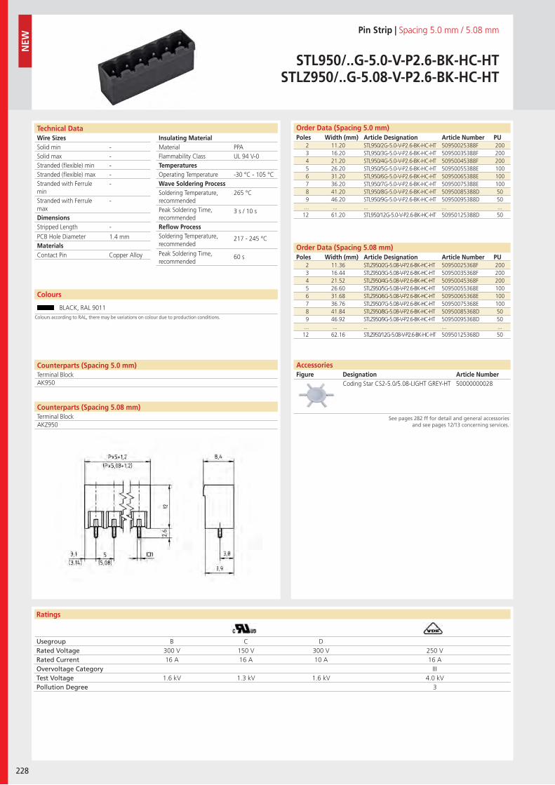
Wire SizesSolid minSolid maxStranded (flexible) minStranded (flexible) maxStranded with Ferrule minStranded with Ferrule maxDimensions Stripped Length
PCB Hole DiameterMaterials
Ratings
228
Insulating Material MaterialFlammability ClassTemperaturesOperating TemperatureWave Soldering ProcessSoldering Temperature,recommendedPeak Soldering Time,recommendedReflow ProcessSoldering Temperature,recommended
Peak Soldering Time,recommended
Technical Data Order Data (Spacing 5.0 mm)Poles Width (mm) Article Designation Article Number PU
Colours
Pin Strip | Spacing 5.0 mm / 5.08 mm
STL950/..G-5.0-V-P2.6-BK-HC-HTSTLZ950/..G-5.08-V-P2.6-BK-HC-HT
2 11.20 STL950/2G-5.0-V-P2.6-BK-HC-HT 50950025388F 2003 16.20 STL950/3G-5.0-V-P2.6-BK-HC-HT 50950035388F 2004 21.20 STL950/4G-5.0-V-P2.6-BK-HC-HT 50950045388F 2005 26.20 STL950/5G-5.0-V-P2.6-BK-HC-HT 50950055388E 1006 31.20 STL950/6G-5.0-V-P2.6-BK-HC-HT 50950065388E 1007 36.20 STL950/7G-5.0-V-P2.6-BK-HC-HT 50950075388E 1008 41.20 STL950/8G-5.0-V-P2.6-BK-HC-HT 50950085388D 509 46.20 STL950/9G-5.0-V-P2.6-BK-HC-HT 50950095388D 50
... ... ... ... ...12 61.20 STL950/12G-5.0-V-P2.6-BK-HC-HT 50950125388D 50
BLACK, RAL 9011
2 11.36 STLZ950/2G-5.08-V-P2.6-BK-HC-HT 50950025368F 2003 16.44 STLZ950/3G-5.08-V-P2.6-BK-HC-HT 50950035368F 2004 21.52 STLZ950/4G-5.08-V-P2.6-BK-HC-HT 50950045368F 2005 26.60 STLZ950/5G-5.08-V-P2.6-BK-HC-HT 50950055368E 1006 31.68 STLZ950/6G-5.08-V-P2.6-BK-HC-HT 50950065368E 1007 36.76 STLZ950/7G-5.08-V-P2.6-BK-HC-HT 50950075368E 1008 41.84 STLZ950/8G-5.08-V-P2.6-BK-HC-HT 50950085368D 509 46.92 STLZ950/9G-5.08-V-P2.6-BK-HC-HT 50950095368D 50
... ... ... ... ...12 62.16 STLZ950/12G-5.08-V-P2.6-BK-HC-HT 50950125368D 50
PPAUL 94 V-0
-30 °C - 105 °C
265 °C
3 s / 10 s
217 - 245 °C
60 s
-----
-
-
1.4 mm
Counterparts (Spacing 5.0 mm)Terminal Block
Counterparts (Spacing 5.08 mm)Terminal Block
AK950
Contact Pin Copper Alloy
Usegroup B C DRated Voltage 300 V 150 V 300 V 250 VRated Current 16 A 16 A 10 A 16 AOvervoltage Category IIITest Voltage 1.6 kV 1.3 kV 1.6 kV 4.0 kVPollution Degree 3
Coding Star CS2-5.0/5.08-LIGHT GREY-HT 50000000028
Order Data (Spacing 5.08 mm)Poles Width (mm) Article Designation Article Number PU
AccessoriesFigure Designation Article Number
See pages 282 ff for detail and general accessories and see pages 12/13 concerning services.
NEW
Colours according to RAL, there may be variations on colour due to production conditions.
AKZ950
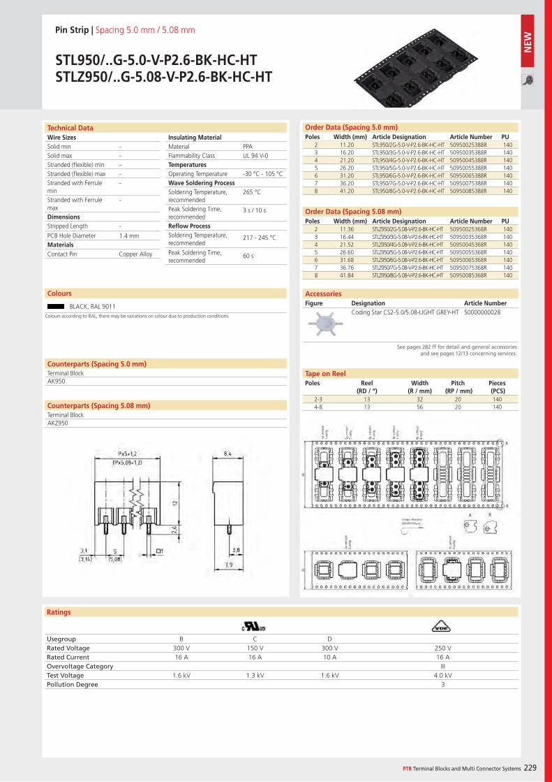
Wire SizesSolid minSolid maxStranded (flexible) minStranded (flexible) maxStranded with Ferrule minStranded with Ferrule maxDimensions Stripped Length
PCB Hole DiameterMaterials
Ratings
PTR Terminal Blocks and Multi Connector Systems 229
Insulating Material MaterialFlammability ClassTemperaturesOperating TemperatureWave Soldering ProcessSoldering Temperature,recommendedPeak Soldering Time,recommendedReflow ProcessSoldering Temperature,recommended
Peak Soldering Time,recommended
Counterparts (Spacing 5.08 mm)Terminal Block
Technical Data Order Data (Spacing 5.0 mm)Poles Width (mm) Article Designation Article Number PU
Colours
Pin Strip | Spacing 5.0 mm / 5.08 mm
STL950/..G-5.0-V-P2.6-BK-HC-HTSTLZ950/..G-5.08-V-P2.6-BK-HC-HT
2 11.20 STL950/2G-5.0-V-P2.6-BK-HC-HT 50950025388R 1403 16.20 STL950/3G-5.0-V-P2.6-BK-HC-HT 50950035388R 1404 21.20 STL950/4G-5.0-V-P2.6-BK-HC-HT 50950045388R 1405 26.20 STL950/5G-5.0-V-P2.6-BK-HC-HT 50950055388R 1406 31.20 STL950/6G-5.0-V-P2.6-BK-HC-HT 50950065388R 1407 36.20 STL950/7G-5.0-V-P2.6-BK-HC-HT 50950075388R 1408 41.20 STL950/8G-5.0-V-P2.6-BK-HC-HT 50950085388R 140
BLACK, RAL 9011
PPAUL 94 V-0
-30 °C - 105 °C
265 °C
3 s / 10 s
217 - 245 °C
60 s
-----
-
-
1.4 mm
Counterparts (Spacing 5.0 mm)Terminal BlockAK950
Contact Pin Copper Alloy
Usegroup B C DRated Voltage 300 V 150 V 300 V 250 VRated Current 16 A 16 A 10 A 16 AOvervoltage Category IIITest Voltage 1.6 kV 1.3 kV 1.6 kV 4.0 kVPollution Degree 3
2 11.36 STLZ950/2G-5.08-V-P2.6-BK-HC-HT 50950025368R 1403 16.44 STLZ950/3G-5.08-V-P2.6-BK-HC-HT 50950035368R 1404 21.52 STLZ950/4G-5.08-V-P2.6-BK-HC-HT 50950045368R 1405 26.60 STLZ950/5G-5.08-V-P2.6-BK-HC-HT 50950055368R 1406 31.68 STLZ950/6G-5.08-V-P2.6-BK-HC-HT 50950065368R 1407 36.76 STLZ950/7G-5.08-V-P2.6-BK-HC-HT 50950075368R 1408 41.84 STLZ950/8G-5.08-V-P2.6-BK-HC-HT 50950085368R 140
Order Data (Spacing 5.08 mm)Poles Width (mm) Article Designation Article Number PU
Coding Star CS2-5.0/5.08-LIGHT GREY-HT 50000000028
AccessoriesFigure Designation Article Number
See pages 282 ff for detail and general accessories and see pages 12/13 concerning services.
2-3 13 32 20 1404-8 13 56 20 140
Tape on ReelPoles Reel
(RD / “)Width
(R / mm)Pitch
(RP / mm)Pieces (PCS)
Colours according to RAL, there may be variations on colour due to production conditions.
AKZ950
NEW
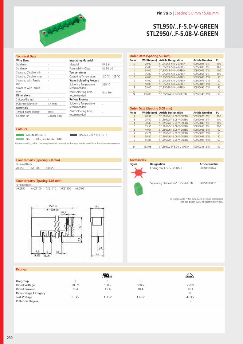
Wire SizesSolid minSolid maxStranded (flexible) minStranded (flexible) maxStranded with Ferrule minStranded with Ferrule maxDimensions Stripped Length
PCB Hole DiameterMaterials
Ratings
230
Insulating Material MaterialFlammability ClassTemperaturesOperating TemperatureWave Soldering ProcessSoldering Temperature,recommendedPeak Soldering Time,recommendedReflow ProcessSoldering Temperature,recommended
Peak Soldering Time,recommended
Technical Data
Colours according to RAL, there may be variations on colour due to production conditions. Special colours on request.
Order Data (Spacing 5.0 mm)Poles Width (mm) Article Designation Article Number PU
Colours
Pin Strip | Spacing 5.0 mm / 5.08 mm
STL950/..F-5.0-V-GREENSTLZ950/..F-5.08-V-GREEN
2 20.00 STL950/2F-5.0-V-GREEN 50950026101E 1003 25.00 STL950/3F-5.0-V-GREEN 50950036101E 1004 30.00 STL950/4F-5.0-V-GREEN 50950046101E 1005 35.00 STL950/5F-5.0-V-GREEN 50950056101E 1006 40.00 STL950/6F-5.0-V-GREEN 50950066101D 507 45.00 STL950/7F-5.0-V-GREEN 50950076101D 508 50.00 STL950/8F-5.0-V-GREEN 50950086101D 509 55.00 STL950/9F-5.0-V-GREEN 50950096101D 50
... ... ... ... ...24 130.00 STL950/24F-5.0-V-GREEN 50950246101D 50
GREEN, RAL 6018 BASALT GREY, RAL 7012
LIGHT GREEN, similar RAL 6018
2 20.32 STLZ950/2F-5.08-V-GREEN 50950026121E 1003 25.40 STLZ950/3F-5.08-V-GREEN 50950036121E 1004 30.48 STLZ950/4F-5.08-V-GREEN 50950046121E 1005 35.56 STLZ950/5F-5.08-V-GREEN 50950056121E 1006 40.64 STLZ950/6F-5.08-V-GREEN 50950066121D 507 45.72 STLZ950/7F-5.08-V-GREEN 50950076121D 508 50.80 STLZ950/8F-5.08-V-GREEN 50950086121D 509 55.88 STLZ950/9F-5.08-V-GREEN 50950096121D 50
... ... ... ... ...24 132.08 STLZ950/24F-5.08-V-GREEN 50950246121D 50
PA 6.6UL 94 V-0
-30 °C - 105 °C
265 °C
3 s / 10 s
-
-
-----
-
-
1.4 mm
Counterparts (Spacing 5.0 mm)Terminal Block
Counterparts (Spacing 5.08 mm)Terminal Block
AK950 AK1200 AK4951
Thread Insert, Flange BrassContact Pin Copper Alloy
Usegroup B C DRated Voltage 300 V 150 V 300 V 250 VRated Current 15 A 15 A 10 A 12 AOvervoltage Category IIITest Voltage 1.6 kV 1.3 kV 1.6 kV 4.0 kVPollution Degree 3
Coding Star CS2-5.0/5.08-RED 50000000024
Separating Element SE-STL950-GREEN 50950000002
Order Data (Spacing 5.08 mm)Poles Width (mm) Article Designation Article Number PU
AccessoriesFigure Designation Article Number
See pages 282 ff for detail and general accessories and see pages 12/13 concerning services.
AKZ950 AKZ1100 AKZ1110 AKZ1200 AKZ4951
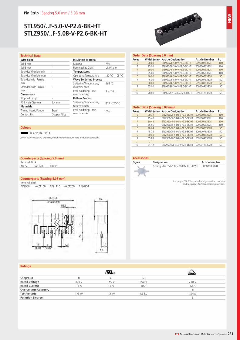
Wire SizesSolid minSolid maxStranded (flexible) minStranded (flexible) maxStranded with Ferrule minStranded with Ferrule maxDimensions Stripped Length
PCB Hole DiameterMaterials
Ratings
PTR Terminal Blocks and Multi Connector Systems 231
Insulating Material MaterialFlammability ClassTemperaturesOperating TemperatureWave Soldering ProcessSoldering Temperature,recommendedPeak Soldering Time,recommendedReflow ProcessSoldering Temperature,recommended
Peak Soldering Time,recommended
Counterparts (Spacing 5.08 mm)Terminal Block
Technical Data Order Data (Spacing 5.0 mm)Poles Width (mm) Article Designation Article Number PU
Colours
Pin Strip | Spacing 5.0 mm / 5.08 mm
STL950/..F-5.0-V-P2.6-BK-HTSTLZ950/..F-5.08-V-P2.6-BK-HT
2 20.00 STL950/2F-5.0-V-P2.6-BK-HT 50950026387E 1003 25.00 STL950/3F-5.0-V-P2.6-BK-HT 50950036387E 1004 30.00 STL950/4F-5.0-V-P2.6-BK-HT 50950046387E 1005 35.00 STL950/5F-5.0-V-P2.6-BK-HT 50950056387E 1006 40.00 STL950/6F-5.0-V-P2.6-BK-HT 50950066387D 507 45.00 STL950/7F-5.0-V-P2.6-BK-HT 50950076387D 508 50.00 STL950/8F-5.0-V-P2.6-BK-HT 50950086387D 509 55.00 STL950/9F-5.0-V-P2.6-BK-HT 50950096387D 50
... ... ... ... ...12 70.00 STL950/12F-5.0-V-P2.6-BK-HT 50950126387D 50
BLACK, RAL 9011
PPAUL 94 V-0
-30 °C - 105 °C
265 °C
3 s / 10 s
217 - 245 °C
60 s
-----
-
-
1.4 mm
Counterparts (Spacing 5.0 mm)Terminal BlockAK950 AK1200 AK4951
Thread Insert, Flange BrassContact Pin Copper Alloy
Usegroup B C DRated Voltage 300 V 150 V 300 V 250 VRated Current 15 A 15 A 10 A 12 AOvervoltage Category IIITest Voltage 1.6 kV 1.3 kV 1.6 kV 4.0 kVPollution Degree 3
2 20.32 STLZ950/2F-5.08-V-P2.6-BK-HT 50950026367E 1003 25.40 STLZ950/3F-5.08-V-P2.6-BK-HT 50950036367E 1004 30.48 STLZ950/4F-5.08-V-P2.6-BK-HT 50950046367E 1005 35.56 STLZ950/5F-5.08-V-P2.6-BK-HT 50950056367E 1006 40.64 STLZ950/6F-5.08-V-P2.6-BK-HT 50950066367D 507 45.72 STLZ950/7F-5.08-V-P2.6-BK-HT 50950076367D 508 50.80 STLZ950/8F-5.08-V-P2.6-BK-HT 50950086367D 509 55.88 STLZ950/9F-5.08-V-P2.6-BK-HT 50950096367D 50
... ... ... ... ...12 71.12 STLZ950/12F-5.08-V-P2.6-BK-HT 50950126367D 50
Order Data (Spacing 5.08 mm)Poles Width (mm) Article Designation Article Number PU
Coding Star CS2-5.0/5.08-LIGHT GREY-HT 50000000028
AccessoriesFigure Designation Article Number
See pages 282 ff for detail and general accessories and see pages 12/13 concerning services.
Colours according to RAL, there may be variations on colour due to production conditions.
AKZ950 AKZ1100 AKZ1110 AKZ1200 AKZ4951
NEW
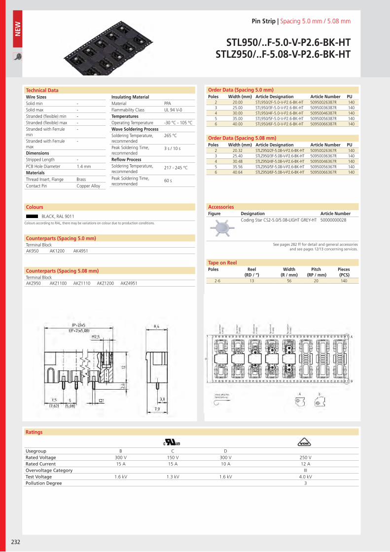
Wire SizesSolid minSolid maxStranded (flexible) minStranded (flexible) maxStranded with Ferrule minStranded with Ferrule maxDimensions Stripped Length
PCB Hole DiameterMaterials
Ratings
232
Insulating Material MaterialFlammability ClassTemperaturesOperating TemperatureWave Soldering ProcessSoldering Temperature,recommendedPeak Soldering Time,recommendedReflow ProcessSoldering Temperature,recommended
Peak Soldering Time,recommended
Technical Data Order Data (Spacing 5.0 mm)Poles Width (mm) Article Designation Article Number PU
Pin Strip | Spacing 5.0 mm / 5.08 mm
STL950/..F-5.0-V-P2.6-BK-HTSTLZ950/..F-5.08-V-P2.6-BK-HT
2 20.00 STL950/2F-5.0-V-P2.6-BK-HT 50950026387R 1403 25.00 STL950/3F-5.0-V-P2.6-BK-HT 50950036387R 1404 30.00 STL950/4F-5.0-V-P2.6-BK-HT 50950046387R 1405 35.00 STL950/5F-5.0-V-P2.6-BK-HT 50950056387R 1406 40.00 STL950/6F-5.0-V-P2.6-BK-HT 50950066387R 140
PPAUL 94 V-0
-30 °C - 105 °C
265 °C
3 s / 10 s
217 - 245 °C
60 s
-----
-
-
1.4 mm
Counterparts (Spacing 5.08 mm)Terminal Block
Counterparts (Spacing 5.0 mm)Terminal BlockAK950 AK1200 AK4951
Thread Insert, Flange BrassContact Pin Copper Alloy
Usegroup B C DRated Voltage 300 V 150 V 300 V 250 VRated Current 15 A 15 A 10 A 12 AOvervoltage Category IIITest Voltage 1.6 kV 1.3 kV 1.6 kV 4.0 kVPollution Degree 3
2 20.32 STLZ950/2F-5.08-V-P2.6-BK-HT 50950026367R 1403 25.40 STLZ950/3F-5.08-V-P2.6-BK-HT 50950036367R 1404 30.48 STLZ950/4F-5.08-V-P2.6-BK-HT 50950046367R 1405 35.56 STLZ950/5F-5.08-V-P2.6-BK-HT 50950056367R 1406 40.64 STLZ950/6F-5.08-V-P2.6-BK-HT 50950066367R 140
Order Data (Spacing 5.08 mm)Poles Width (mm) Article Designation Article Number PU
Coding Star CS2-5.0/5.08-LIGHT GREY-HT 50000000028
AccessoriesFigure Designation Article Number
See pages 282 ff for detail and general accessories and see pages 12/13 concerning services.
2-6 13 56 20 140
NEW
Tape on ReelPoles Reel
(RD / “)Width
(R / mm)Pitch
(RP / mm)Pieces (PCS)
Colours
BLACK, RAL 9011Colours according to RAL, there may be variations on colour due to production conditions.
AKZ950 AKZ1100 AKZ1110 AKZ1200 AKZ4951
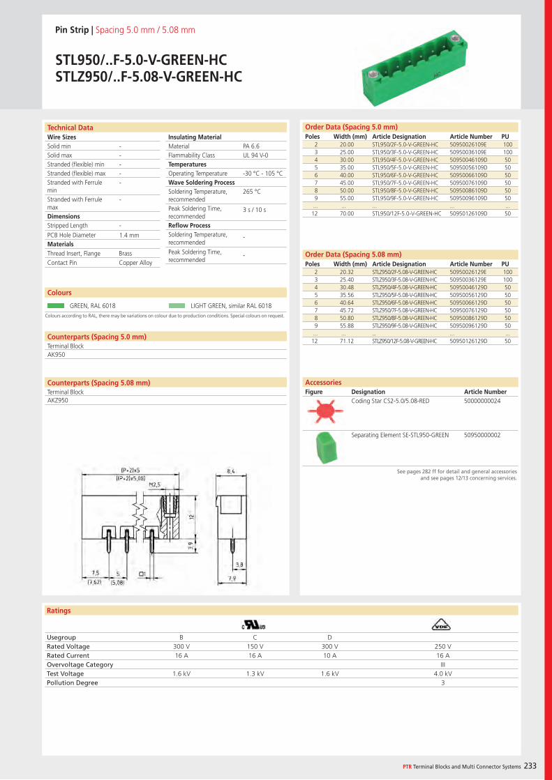
Wire SizesSolid minSolid maxStranded (flexible) minStranded (flexible) maxStranded with Ferrule minStranded with Ferrule maxDimensions Stripped Length
PCB Hole DiameterMaterials
Ratings
PTR Terminal Blocks and Multi Connector Systems 233
Insulating Material MaterialFlammability ClassTemperaturesOperating TemperatureWave Soldering ProcessSoldering Temperature,recommendedPeak Soldering Time,recommendedReflow ProcessSoldering Temperature,recommended
Peak Soldering Time,recommended
Counterparts (Spacing 5.08 mm)Terminal Block
Technical Data Order Data (Spacing 5.0 mm)Poles Width (mm) Article Designation Article Number PU
Pin Strip | Spacing 5.0 mm / 5.08 mm
STL950/..F-5.0-V-GREEN-HCSTLZ950/..F-5.08-V-GREEN-HC
2 20.00 STL950/2F-5.0-V-GREEN-HC 50950026109E 1003 25.00 STL950/3F-5.0-V-GREEN-HC 50950036109E 1004 30.00 STL950/4F-5.0-V-GREEN-HC 50950046109D 505 35.00 STL950/5F-5.0-V-GREEN-HC 50950056109D 506 40.00 STL950/6F-5.0-V-GREEN-HC 50950066109D 507 45.00 STL950/7F-5.0-V-GREEN-HC 50950076109D 508 50.00 STL950/8F-5.0-V-GREEN-HC 50950086109D 509 55.00 STL950/9F-5.0-V-GREEN-HC 50950096109D 50
... ... ... ... ...12 70.00 STL950/12F-5.0-V-GREEN-HC 50950126109D 50
Colours according to RAL, there may be variations on colour due to production conditions. Special colours on request.
Colours
GREEN, RAL 6018 LIGHT GREEN, similar RAL 6018
PA 6.6UL 94 V-0
-30 °C - 105 °C
265 °C
3 s / 10 s
-
-
-----
-
-
1.4 mm
Counterparts (Spacing 5.0 mm)Terminal BlockAK950
Thread Insert, Flange BrassContact Pin Copper Alloy
Usegroup B C DRated Voltage 300 V 150 V 300 V 250 VRated Current 16 A 16 A 10 A 16 AOvervoltage Category IIITest Voltage 1.6 kV 1.3 kV 1.6 kV 4.0 kVPollution Degree 3
2 20.32 STLZ950/2F-5.08-V-GREEN-HC 50950026129E 1003 25.40 STLZ950/3F-5.08-V-GREEN-HC 50950036129E 1004 30.48 STLZ950/4F-5.08-V-GREEN-HC 50950046129D 505 35.56 STLZ950/5F-5.08-V-GREEN-HC 50950056129D 506 40.64 STLZ950/6F-5.08-V-GREEN-HC 50950066129D 507 45.72 STLZ950/7F-5.08-V-GREEN-HC 50950076129D 508 50.80 STLZ950/8F-5.08-V-GREEN-HC 50950086129D 509 55.88 STLZ950/9F-5.08-V-GREEN-HC 50950096129D 50
... ... ... ... ...12 71.12 STLZ950/12F-5.08-V-GREEN-HC 50950126129D 50
Order Data (Spacing 5.08 mm)Poles Width (mm) Article Designation Article Number PU
Coding Star CS2-5.0/5.08-RED 50000000024
Separating Element SE-STL950-GREEN 50950000002
AccessoriesFigure Designation Article Number
See pages 282 ff for detail and general accessories and see pages 12/13 concerning services.
AKZ950
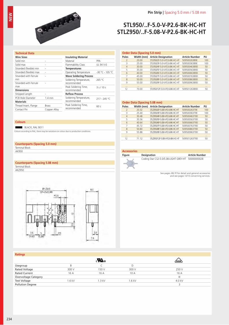
Wire SizesSolid minSolid maxStranded (flexible) minStranded (flexible) maxStranded with Ferrule minStranded with Ferrule maxDimensions Stripped Length
PCB Hole DiameterMaterials
Ratings
234
Insulating Material MaterialFlammability ClassTemperaturesOperating TemperatureWave Soldering ProcessSoldering Temperature,recommendedPeak Soldering Time,recommendedReflow ProcessSoldering Temperature,recommended
Peak Soldering Time,recommended
Technical Data Order Data (Spacing 5.0 mm)Poles Width (mm) Article Designation Article Number PU
Colours
Pin Strip | Spacing 5.0 mm / 5.08 mm
STL950/..F-5.0-V-P2.6-BK-HC-HTSTLZ950/..F-5.08-V-P2.6-BK-HC-HT
2 20.00 STL950/2F-5.0-V-P2.6-BK-HC-HT 50950026389E 1003 25.00 STL950/3F-5.0-V-P2.6-BK-HC-HT 50950036389E 1004 30.00 STL950/4F-5.0-V-P2.6-BK-HC-HT 50950046389D 505 35.00 STL950/5F-5.0-V-P2.6-BK-HC-HT 50950056389D 506 40.00 STL950/6F-5.0-V-P2.6-BK-HC-HT 50950066389D 507 45.00 STL950/7F-5.0-V-P2.6-BK-HC-HT 50950076389D 508 50.00 STL950/8F-5.0-V-P2.6-BK-HC-HT 50950086389D 509 55.00 STL950/9F-5.0-V-P2.6-BK-HC-HT 50950096389D 50
... ... ... ... ...12 70.00 STL950/12F-5.0-V-P2.6-BK-HC-HT 50950126389D 50
BLACK, RAL 9011
2 20.32 STLZ950/2F-5.08-V-P2.6-BK-HC-HT 50950026379E 1003 25.40 STLZ950/3F-5.08-V-P2.6-BK-HC-HT 50950036379E 1004 30.48 STLZ950/4F-5.08-V-P2.6-BK-HC-HT 50950046379D 505 35.56 STLZ950/5F-5.08-V-P2.6-BK-HC-HT 50950056379D 506 40.64 STLZ950/6F-5.08-V-P2.6-BK-HC-HT 50950066379D 507 45.72 STLZ950/7F-5.08-V-P2.6-BK-HC-HT 50950076379D 508 50.80 STLZ950/8F-5.08-V-P2.6-BK-HC-HT 50950086379D 509 55.88 STLZ950/9F-5.08-V-P2.6-BK-HC-HT 50950096379D 50
... ... ... ... ...12 71.12 STLZ950/12F-5.08-V-P2.6-BK-HC-HT 50950126379D 50
PPAUL 94 V-0
-30 °C - 105 °C
265 °C
3 s / 10 s
217 - 245 °C
60 s
-----
-
-
1.4 mm
Counterparts (Spacing 5.0 mm)Terminal Block
Counterparts (Spacing 5.08 mm)Terminal Block
AK950
Thread Insert, Flange BrassContact Pin Copper Alloy
Usegroup B C DRated Voltage 300 V 150 V 300 V 250 VRated Current 16 A 16 A 10 A 16 AOvervoltage Category IIITest Voltage 1.6 kV 1.3 kV 1.6 kV 4.0 kVPollution Degree 3
Coding Star CS2-5.0/5.08-LIGHT GREY-HT 50000000028
Order Data (Spacing 5.08 mm)Poles Width (mm) Article Designation Article Number PU
AccessoriesFigure Designation Article Number
See pages 282 ff for detail and general accessories and see pages 12/13 concerning services.
NEW
Colours according to RAL, there may be variations on colour due to production conditions.
AKZ950
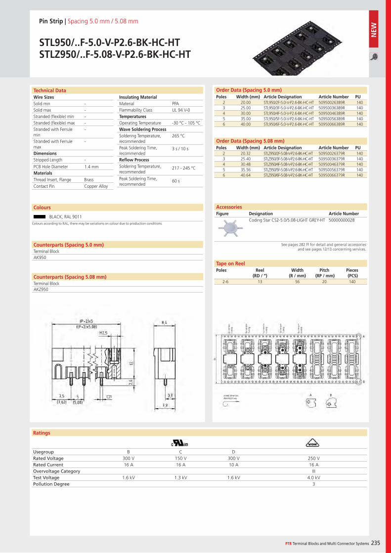
Wire SizesSolid minSolid maxStranded (flexible) minStranded (flexible) maxStranded with Ferrule minStranded with Ferrule maxDimensions Stripped Length
PCB Hole DiameterMaterials
Ratings
PTR Terminal Blocks and Multi Connector Systems 235
Insulating Material MaterialFlammability ClassTemperaturesOperating TemperatureWave Soldering ProcessSoldering Temperature,recommendedPeak Soldering Time,recommendedReflow ProcessSoldering Temperature,recommended
Peak Soldering Time,recommended
Counterparts (Spacing 5.08 mm)Terminal Block
Technical Data Order Data (Spacing 5.0 mm)Poles Width (mm) Article Designation Article Number PU
Colours
Pin Strip | Spacing 5.0 mm / 5.08 mm
STL950/..F-5.0-V-P2.6-BK-HC-HTSTLZ950/..F-5.08-V-P2.6-BK-HC-HT
2 20.00 STL950/2F-5.0-V-P2.6-BK-HC-HT 50950026389R 1403 25.00 STL950/3F-5.0-V-P2.6-BK-HC-HT 50950036389R 1404 30.00 STL950/4F-5.0-V-P2.6-BK-HC-HT 50950046389R 1405 35.00 STL950/5F-5.0-V-P2.6-BK-HC-HT 50950056389R 1406 40.00 STL950/6F-5.0-V-P2.6-BK-HC-HT 50950066389R 140
BLACK, RAL 9011
PPAUL 94 V-0
-30 °C - 105 °C
265 °C
3 s / 10 s
217 - 245 °C
60 s
-----
-
-
1.4 mm
Counterparts (Spacing 5.0 mm)Terminal BlockAK950
Thread Insert, Flange BrassContact Pin Copper Alloy
Usegroup B C DRated Voltage 300 V 150 V 300 V 250 VRated Current 16 A 16 A 10 A 16 AOvervoltage Category IIITest Voltage 1.6 kV 1.3 kV 1.6 kV 4.0 kVPollution Degree 3
2 20.32 STLZ950/2F-5.08-V-P2.6-BK-HC-HT 50950026379R 1403 25.40 STLZ950/3F-5.08-V-P2.6-BK-HC-HT 50950036379R 1404 30.48 STLZ950/4F-5.08-V-P2.6-BK-HC-HT 50950046379R 1405 35.56 STLZ950/5F-5.08-V-P2.6-BK-HC-HT 50950056379R 1406 40.64 STLZ950/6F-5.08-V-P2.6-BK-HC-HT 50950066379R 140
Order Data (Spacing 5.08 mm)Poles Width (mm) Article Designation Article Number PU
Coding Star CS2-5.0/5.08-LIGHT GREY-HT 50000000028
AccessoriesFigure Designation Article Number
See pages 282 ff for detail and general accessories and see pages 12/13 concerning services.
2-6 13 56 20 140
Tape on ReelPoles Reel
(RD / “)Width
(R / mm)Pitch
(RP / mm)Pieces (PCS)
Colours according to RAL, there may be variations on colour due to production conditions.
AKZ950
NEW
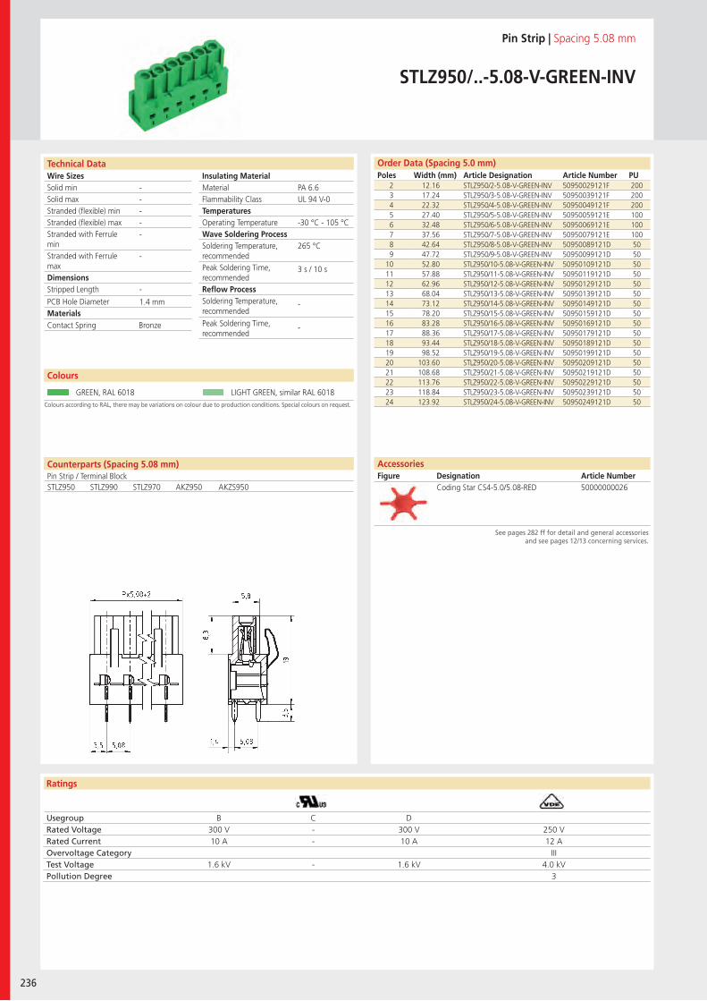
Wire SizesSolid minSolid maxStranded (flexible) minStranded (flexible) maxStranded with Ferrule minStranded with Ferrule maxDimensions Stripped Length
PCB Hole DiameterMaterials
Ratings
236
Insulating Material MaterialFlammability ClassTemperaturesOperating TemperatureWave Soldering ProcessSoldering Temperature,recommendedPeak Soldering Time,recommendedReflow ProcessSoldering Temperature,recommended
Peak Soldering Time,recommended
Technical Data Order Data (Spacing 5.0 mm)Poles Width (mm) Article Designation Article Number PU
Pin Strip | Spacing 5.08 mm
STLZ950/..-5.08-V-GREEN-INV
2 12.16 STLZ950/2-5.08-V-GREEN-INV 50950029121F 2003 17.24 STLZ950/3-5.08-V-GREEN-INV 50950039121F 2004 22.32 STLZ950/4-5.08-V-GREEN-INV 50950049121F 2005 27.40 STLZ950/5-5.08-V-GREEN-INV 50950059121E 1006 32.48 STLZ950/6-5.08-V-GREEN-INV 50950069121E 1007 37.56 STLZ950/7-5.08-V-GREEN-INV 50950079121E 1008 42.64 STLZ950/8-5.08-V-GREEN-INV 50950089121D 509 47.72 STLZ950/9-5.08-V-GREEN-INV 50950099121D 50
10 52.80 STLZ950/10-5.08-V-GREEN-INV 50950109121D 5011 57.88 STLZ950/11-5.08-V-GREEN-INV 50950119121D 5012 62.96 STLZ950/12-5.08-V-GREEN-INV 50950129121D 5013 68.04 STLZ950/13-5.08-V-GREEN-INV 50950139121D 5014 73.12 STLZ950/14-5.08-V-GREEN-INV 50950149121D 5015 78.20 STLZ950/15-5.08-V-GREEN-INV 50950159121D 5016 83.28 STLZ950/16-5.08-V-GREEN-INV 50950169121D 5017 88.36 STLZ950/17-5.08-V-GREEN-INV 50950179121D 5018 93.44 STLZ950/18-5.08-V-GREEN-INV 50950189121D 5019 98.52 STLZ950/19-5.08-V-GREEN-INV 50950199121D 5020 103.60 STLZ950/20-5.08-V-GREEN-INV 50950209121D 5021 108.68 STLZ950/21-5.08-V-GREEN-INV 50950219121D 5022 113.76 STLZ950/22-5.08-V-GREEN-INV 50950229121D 5023 118.84 STLZ950/23-5.08-V-GREEN-INV 50950239121D 5024 123.92 STLZ950/24-5.08-V-GREEN-INV 50950249121D 50Colours according to RAL, there may be variations on colour due to production conditions. Special colours on request.
Colours
GREEN, RAL 6018 LIGHT GREEN, similar RAL 6018
PA 6.6UL 94 V-0
-30 °C - 105 °C
265 °C
3 s / 10 s
-
-
-----
-
-
1.4 mm
Counterparts (Spacing 5.08 mm)Pin Strip / Terminal BlockSTLZ950 STLZ990 STLZ970 AKZ950 AKZS950
Contact Spring Bronze
Usegroup B C DRated Voltage 300 V - 300 V 250 VRated Current 10 A - 10 A 12 AOvervoltage Category IIITest Voltage 1.6 kV - 1.6 kV 4.0 kVPollution Degree 3
AccessoriesFigure Designation Article Number
Coding Star CS4-5.0/5.08-RED 50000000026
See pages 282 ff for detail and general accessories and see pages 12/13 concerning services.
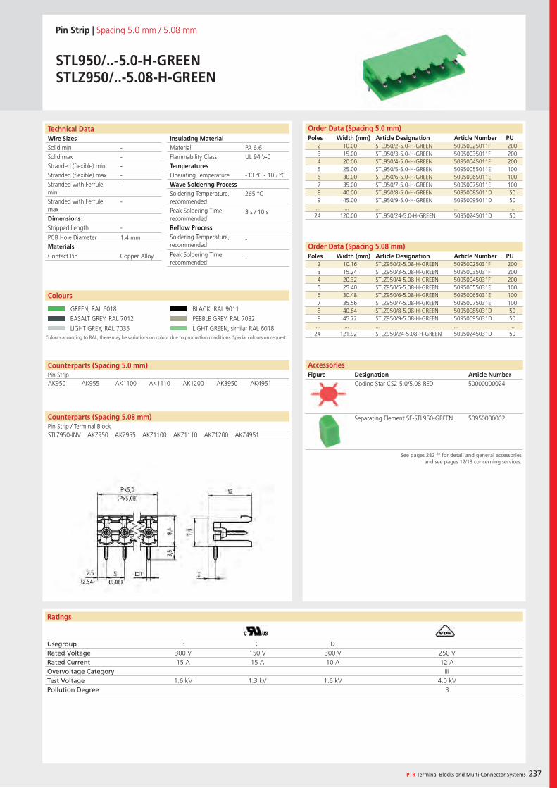
Wire SizesSolid minSolid maxStranded (flexible) minStranded (flexible) maxStranded with Ferrule minStranded with Ferrule maxDimensions Stripped Length
PCB Hole DiameterMaterials
Ratings
PTR Terminal Blocks and Multi Connector Systems 237
Insulating Material MaterialFlammability ClassTemperaturesOperating TemperatureWave Soldering ProcessSoldering Temperature,recommendedPeak Soldering Time,recommendedReflow ProcessSoldering Temperature,recommended
Peak Soldering Time,recommended
Technical Data
Colours according to RAL, there may be variations on colour due to production conditions. Special colours on request.
Order Data (Spacing 5.0 mm)Poles Width (mm) Article Designation Article Number PU
Colours
Pin Strip | Spacing 5.0 mm / 5.08 mm
STL950/..-5.0-H-GREENSTLZ950/..-5.08-H-GREEN
2 10.00 STL950/2-5.0-H-GREEN 50950025011F 2003 15.00 STL950/3-5.0-H-GREEN 50950035011F 2004 20.00 STL950/4-5.0-H-GREEN 50950045011F 2005 25.00 STL950/5-5.0-H-GREEN 50950055011E 1006 30.00 STL950/6-5.0-H-GREEN 50950065011E 1007 35.00 STL950/7-5.0-H-GREEN 50950075011E 1008 40.00 STL950/8-5.0-H-GREEN 50950085011D 509 45.00 STL950/9-5.0-H-GREEN 50950095011D 50
... ... ... ... ...24 120.00 STL950/24-5.0-H-GREEN 50950245011D 50
GREEN, RAL 6018 BLACK, RAL 9011
BASALT GREY, RAL 7012 PEBBLE GREY, RAL 7032
LIGHT GREY, RAL 7035 LIGHT GREEN, similar RAL 6018
PA 6.6UL 94 V-0
-30 °C - 105 °C
265 °C
3 s / 10 s
-
-
-----
-
-
1.4 mm
Counterparts (Spacing 5.0 mm)Pin Strip
Counterparts (Spacing 5.08 mm)Pin Strip / Terminal Block
AK950 AK955 AK1100 AK1110 AK1200 AK3950 AK4951
Contact Pin Copper Alloy
Usegroup B C DRated Voltage 300 V 150 V 300 V 250 VRated Current 15 A 15 A 10 A 12 AOvervoltage Category IIITest Voltage 1.6 kV 1.3 kV 1.6 kV 4.0 kVPollution Degree 3
2 10.16 STLZ950/2-5.08-H-GREEN 50950025031F 2003 15.24 STLZ950/3-5.08-H-GREEN 50950035031F 2004 20.32 STLZ950/4-5.08-H-GREEN 50950045031F 2005 25.40 STLZ950/5-5.08-H-GREEN 50950055031E 1006 30.48 STLZ950/6-5.08-H-GREEN 50950065031E 1007 35.56 STLZ950/7-5.08-H-GREEN 50950075031E 1008 40.64 STLZ950/8-5.08-H-GREEN 50950085031D 509 45.72 STLZ950/9-5.08-H-GREEN 50950095031D 50
... ... ... ... ...24 121.92 STLZ950/24-5.08-H-GREEN 50950245031D 50
Order Data (Spacing 5.08 mm)Poles Width (mm) Article Designation Article Number PU
Coding Star CS2-5.0/5.08-RED 50000000024
Separating Element SE-STL950-GREEN 50950000002
AccessoriesFigure Designation Article Number
See pages 282 ff for detail and general accessories and see pages 12/13 concerning services.
STLZ950-INV AKZ950 AKZ955 AKZ1100 AKZ1110 AKZ1200 AKZ4951
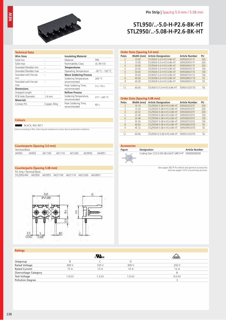
Wire SizesSolid minSolid maxStranded (flexible) minStranded (flexible) maxStranded with Ferrule minStranded with Ferrule maxDimensions Stripped Length
PCB Hole DiameterMaterials
Ratings
238
Insulating Material MaterialFlammability ClassTemperaturesOperating TemperatureWave Soldering ProcessSoldering Temperature,recommendedPeak Soldering Time,recommendedReflow ProcessSoldering Temperature,recommended
Peak Soldering Time,recommended
Technical Data Order Data (Spacing 5.0 mm)Poles Width (mm) Article Designation Article Number PU
Colours
Pin Strip | Spacing 5.0 mm / 5.08 mm
STL950/..-5.0-H-P2.6-BK-HTSTLZ950/..-5.08-H-P2.6-BK-HT
2 10.00 STL950/2-5.0-H-P2.6-BK-HT 50950025317F 2003 15.00 STL950/3-5.0-H-P2.6-BK-HT 50950035317F 2004 20.00 STL950/4-5.0-H-P2.6-BK-HT 50950045317F 2005 25.00 STL950/5-5.0-H-P2.6-BK-HT 50950055317E 1006 30.00 STL950/6-5.0-H-P2.6-BK-HT 50950065317E 1007 35.00 STL950/7-5.0-H-P2.6-BK-HT 50950075317E 1008 40.00 STL950/8-5.0-H-P2.6-BK-HT 50950085317D 509 45.00 STL950/9-5.0-H-P2.6-BK-HT 50950095317D 50
... ... ... ... ...12 60.00 STL950/12-5.0-H-P2.6-BK-HT 50950125317D 50
BLACK, RAL 9011
2 10.16 STLZ950/2-5.08-H-P2.6-BK-HT 50950025337F 2003 15.24 STLZ950/3-5.08-H-P2.6-BK-HT 50950035337F 2004 20.32 STLZ950/4-5.08-H-P2.6-BK-HT 50950045337F 2005 25.40 STLZ950/5-5.08-H-P2.6-BK-HT 50950055337E 1006 30.48 STLZ950/6-5.08-H-P2.6-BK-HT 50950065337E 1007 35.56 STLZ950/7-5.08-H-P2.6-BK-HT 50950075337E 1008 40.64 STLZ950/8-5.08-H-P2.6-BK-HT 50950085337D 509 45.72 STLZ950/9-5.08-H-P2.6-BK-HT 50950095337D 50
... ... ... ... ...12 60.96 STLZ950/12-5.08-H-P2.6-BK-HT 50950125337D 50
PPAUL 94 V-0
-30 °C - 105 °C
265 °C
3 s / 10 s
217 - 245 °C
60 s
-----
-
-
1.4 mm
Contact Pin Copper Alloy
Usegroup B C DRated Voltage 300 V 150 V 300 V 250 VRated Current 15 A 15 A 10 A 12 AOvervoltage Category IIITest Voltage 1.6 kV 1.3 kV 1.6 kV 4.0 kVPollution Degree 3
Coding Star CS2-5.0/5.08-LIGHT GREY-HT 50000000028
Order Data (Spacing 5.08 mm)Poles Width (mm) Article Designation Article Number PU
AccessoriesFigure Designation Article Number
See pages 282 ff for detail and general accessories and see pages 12/13 concerning services.
NEW
Colours according to RAL, there may be variations on colour due to production conditions.
Counterparts (Spacing 5.0 mm)Terminal Block
Counterparts (Spacing 5.08 mm)Pin Strip / Terminal Block
AK950 AK955 AK1100 AK1110 AK1200 AK3950 AK4951
STLZ950-INV AKZ950 AKZ955 AKZ1100 AKZ1110 AKZ1200 AKZ4951
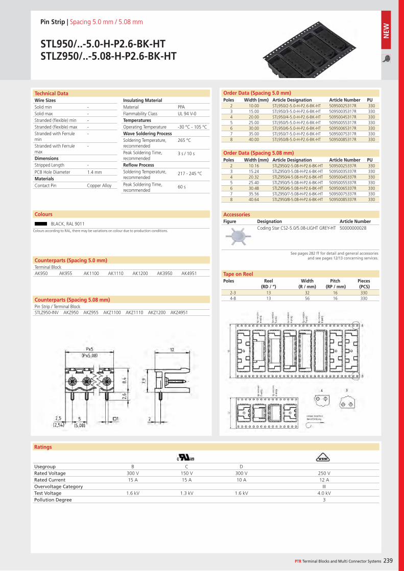
Wire SizesSolid minSolid maxStranded (flexible) minStranded (flexible) maxStranded with Ferrule minStranded with Ferrule maxDimensions Stripped Length
PCB Hole DiameterMaterials
Ratings
PTR Terminal Blocks and Multi Connector Systems 239
Insulating Material MaterialFlammability ClassTemperaturesOperating TemperatureWave Soldering ProcessSoldering Temperature,recommendedPeak Soldering Time,recommendedReflow ProcessSoldering Temperature,recommended
Peak Soldering Time,recommended
Technical Data
Colours according to RAL, there may be variations on colour due to production conditions.
Order Data (Spacing 5.0 mm)Poles Width (mm) Article Designation Article Number PU
Colours
Pin Strip | Spacing 5.0 mm / 5.08 mm
STL950/..-5.0-H-P2.6-BK-HTSTLZ950/..-5.08-H-P2.6-BK-HT
2 10.00 STL950/2-5.0-H-P2.6-BK-HT 50950025317R 3303 15.00 STL950/3-5.0-H-P2.6-BK-HT 50950035317R 3304 20.00 STL950/4-5.0-H-P2.6-BK-HT 50950045317R 3305 25.00 STL950/5-5.0-H-P2.6-BK-HT 50950055317R 3306 30.00 STL950/6-5.0-H-P2.6-BK-HT 50950065317R 3307 35.00 STL950/7-5.0-H-P2.6-BK-HT 50950075317R 3308 40.00 STL950/8-5.0-H-P2.6-BK-HT 50950085317R 330
BLACK, RAL 9011
PPAUL 94 V-0
-30 °C - 105 °C
265 °C
3 s / 10 s
217 - 245 °C
60 s
-----
-
-
1.4 mm
Contact Pin Copper Alloy
Usegroup B C DRated Voltage 300 V 150 V 300 V 250 VRated Current 15 A 15 A 10 A 12 AOvervoltage Category IIITest Voltage 1.6 kV 1.3 kV 1.6 kV 4.0 kVPollution Degree 3
2 10.16 STLZ950/2-5.08-H-P2.6-BK-HT 50950025337R 3303 15.24 STLZ950/3-5.08-H-P2.6-BK-HT 50950035337R 3304 20.32 STLZ950/4-5.08-H-P2.6-BK-HT 50950045337R 3305 25.40 STLZ950/5-5.08-H-P2.6-BK-HT 50950055337R 3306 30.48 STLZ950/6-5.08-H-P2.6-BK-HT 50950065337R 3307 35.56 STLZ950/7-5.08-H-P2.6-BK-HT 50950075337R 3308 40.64 STLZ950/8-5.08-H-P2.6-BK-HT 50950085337R 330
Order Data (Spacing 5.08 mm)Poles Width (mm) Article Designation Article Number PU
Coding Star CS2-5.0/5.08-LIGHT GREY-HT 50000000028
AccessoriesFigure Designation Article Number
See pages 282 ff for detail and general accessories and see pages 12/13 concerning services.
2-3 13 32 16 3304-8 13 56 16 330
Tape on ReelPoles Reel
(RD / “)Width
(R / mm)Pitch
(RP / mm)Pieces (PCS)
Counterparts (Spacing 5.08 mm)Pin Strip / Terminal Block
Counterparts (Spacing 5.0 mm)Terminal BlockAK950 AK955 AK1100 AK1110 AK1200 AK3950 AK4951
STLZ950-INV AKZ950 AKZ955 AKZ1100 AKZ1110 AKZ1200 AKZ4951
NEW
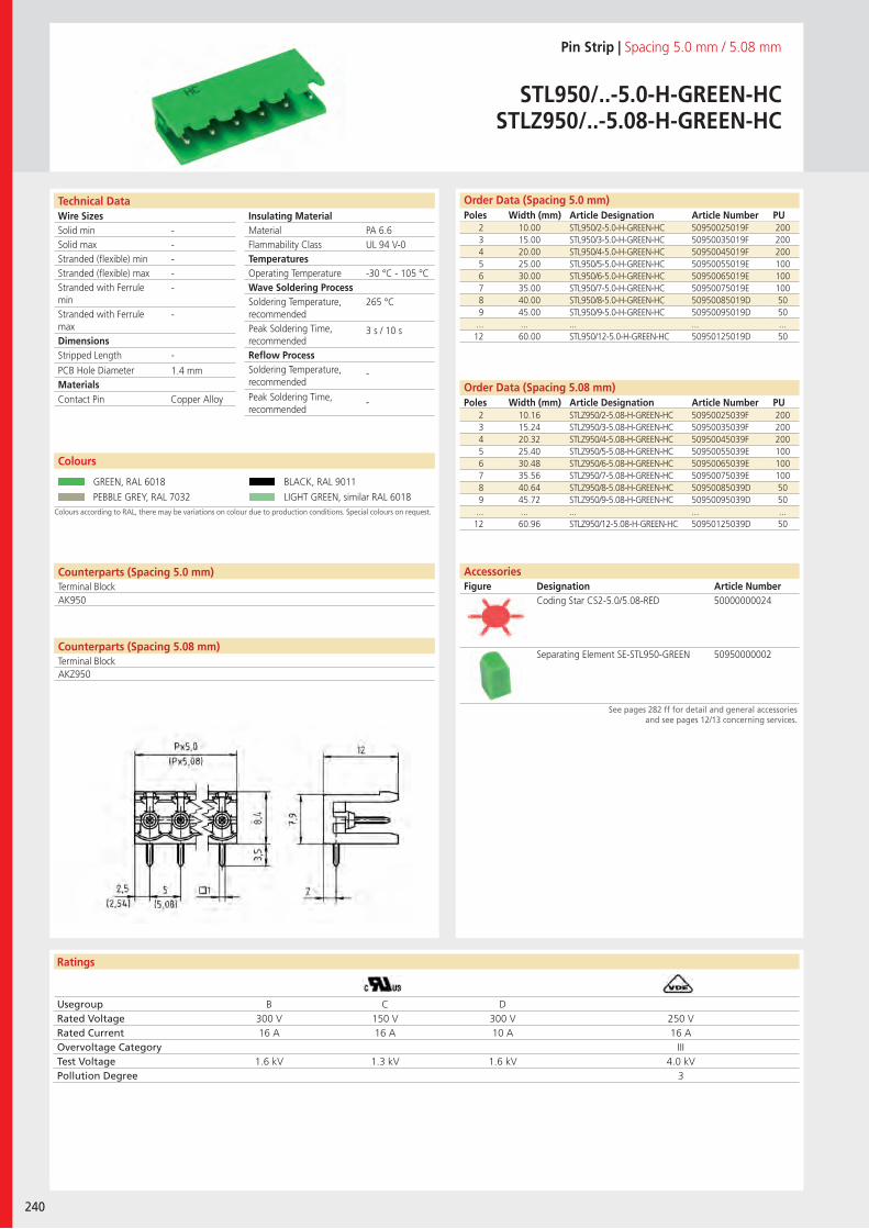
Wire SizesSolid minSolid maxStranded (flexible) minStranded (flexible) maxStranded with Ferrule minStranded with Ferrule maxDimensions Stripped Length
PCB Hole DiameterMaterials
Ratings
240
Insulating Material MaterialFlammability ClassTemperaturesOperating TemperatureWave Soldering ProcessSoldering Temperature,recommendedPeak Soldering Time,recommendedReflow ProcessSoldering Temperature,recommended
Peak Soldering Time,recommended
Technical Data
Colours according to RAL, there may be variations on colour due to production conditions. Special colours on request.
Order Data (Spacing 5.0 mm)Poles Width (mm) Article Designation Article Number PU
Colours
Pin Strip | Spacing 5.0 mm / 5.08 mm
STL950/..-5.0-H-GREEN-HCSTLZ950/..-5.08-H-GREEN-HC
2 10.00 STL950/2-5.0-H-GREEN-HC 50950025019F 2003 15.00 STL950/3-5.0-H-GREEN-HC 50950035019F 2004 20.00 STL950/4-5.0-H-GREEN-HC 50950045019F 2005 25.00 STL950/5-5.0-H-GREEN-HC 50950055019E 1006 30.00 STL950/6-5.0-H-GREEN-HC 50950065019E 1007 35.00 STL950/7-5.0-H-GREEN-HC 50950075019E 1008 40.00 STL950/8-5.0-H-GREEN-HC 50950085019D 509 45.00 STL950/9-5.0-H-GREEN-HC 50950095019D 50
... ... ... ... ...12 60.00 STL950/12-5.0-H-GREEN-HC 50950125019D 50
GREEN, RAL 6018 BLACK, RAL 9011
PEBBLE GREY, RAL 7032 LIGHT GREEN, similar RAL 6018
2 10.16 STLZ950/2-5.08-H-GREEN-HC 50950025039F 2003 15.24 STLZ950/3-5.08-H-GREEN-HC 50950035039F 2004 20.32 STLZ950/4-5.08-H-GREEN-HC 50950045039F 2005 25.40 STLZ950/5-5.08-H-GREEN-HC 50950055039E 1006 30.48 STLZ950/6-5.08-H-GREEN-HC 50950065039E 1007 35.56 STLZ950/7-5.08-H-GREEN-HC 50950075039E 1008 40.64 STLZ950/8-5.08-H-GREEN-HC 50950085039D 509 45.72 STLZ950/9-5.08-H-GREEN-HC 50950095039D 50
... ... ... ... ...12 60.96 STLZ950/12-5.08-H-GREEN-HC 50950125039D 50
PA 6.6UL 94 V-0
-30 °C - 105 °C
265 °C
3 s / 10 s
-
-
-----
-
-
1.4 mm
Counterparts (Spacing 5.0 mm)Terminal Block
Counterparts (Spacing 5.08 mm)Terminal Block
AK950
Contact Pin Copper Alloy
Usegroup B C DRated Voltage 300 V 150 V 300 V 250 VRated Current 16 A 16 A 10 A 16 AOvervoltage Category IIITest Voltage 1.6 kV 1.3 kV 1.6 kV 4.0 kVPollution Degree 3
Coding Star CS2-5.0/5.08-RED 50000000024
Separating Element SE-STL950-GREEN 50950000002
Order Data (Spacing 5.08 mm)Poles Width (mm) Article Designation Article Number PU
AccessoriesFigure Designation Article Number
See pages 282 ff for detail and general accessories and see pages 12/13 concerning services.
AKZ950
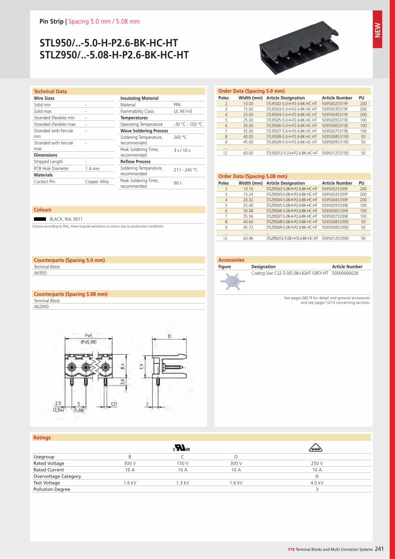
Wire SizesSolid minSolid maxStranded (flexible) minStranded (flexible) maxStranded with Ferrule minStranded with Ferrule maxDimensions Stripped Length
PCB Hole DiameterMaterials
Ratings
PTR Terminal Blocks and Multi Connector Systems 241
Insulating Material MaterialFlammability ClassTemperaturesOperating TemperatureWave Soldering ProcessSoldering Temperature,recommendedPeak Soldering Time,recommendedReflow ProcessSoldering Temperature,recommended
Peak Soldering Time,recommended
Technical Data Order Data (Spacing 5.0 mm)Poles Width (mm) Article Designation Article Number PU
Colours
Pin Strip | Spacing 5.0 mm / 5.08 mm
STL950/..-5.0-H-P2.6-BK-HC-HTSTLZ950/..-5.08-H-P2.6-BK-HC-HT
2 10.00 STL950/2-5.0-H-P2.6-BK-HC-HT 50950025319F 2003 15.00 STL950/3-5.0-H-P2.6-BK-HC-HT 50950035319F 2004 20.00 STL950/4-5.0-H-P2.6-BK-HC-HT 50950045319F 2005 25.00 STL950/5-5.0-H-P2.6-BK-HC-HT 50950055319E 1006 30.00 STL950/6-5.0-H-P2.6-BK-HC-HT 50950065319E 1007 35.00 STL950/7-5.0-H-P2.6-BK-HC-HT 50950075319E 1008 40.00 STL950/8-5.0-H-P2.6-BK-HC-HT 50950085319D 509 45.00 STL950/9-5.0-H-P2.6-BK-HC-HT 50950095319D 50
... ... ... ... ...12 60.00 STL950/12-5.0-H-P2.6-BK-HC-HT 50950125319D 50
BLACK, RAL 9011
PPAUL 94 V-0
-30 °C - 105 °C
265 °C
3 s / 10 s
217 - 245 °C
60 s
-----
-
-
1.4 mm
Counterparts (Spacing 5.0 mm)Terminal Block
Counterparts (Spacing 5.08 mm)Terminal Block
AK950
Contact Pin Copper Alloy
Usegroup B C DRated Voltage 300 V 150 V 300 V 250 VRated Current 16 A 16 A 10 A 16 AOvervoltage Category IIITest Voltage 1.6 kV 1.3 kV 1.6 kV 4.0 kVPollution Degree 3
2 10.16 STLZ950/2-5.08-H-P2.6-BK-HC-HT 50950025339F 2003 15.24 STLZ950/3-5.08-H-P2.6-BK-HC-HT 50950035339F 2004 20.32 STLZ950/4-5.08-H-P2.6-BK-HC-HT 50950045339F 2005 25.40 STLZ950/5-5.08-H-P2.6-BK-HC-HT 50950055339E 1006 30.48 STLZ950/6-5.08-H-P2.6-BK-HC-HT 50950065339E 1007 35.56 STLZ950/7-5.08-H-P2.6-BK-HC-HT 50950075339E 1008 40.64 STLZ950/8-5.08-H-P2.6-BK-HC-HT 50950085339D 509 45.72 STLZ950/9-5.08-H-P2.6-BK-HC-HT 50950095339D 50
... ... ... ... ...12 60.96 STLZ950/12-5.08-H-P2.6-BK-HC-HT 50950125339D 50
Order Data (Spacing 5.08 mm)Poles Width (mm) Article Designation Article Number PU
Coding Star CS2-5.0/5.08-LIGHT GREY-HT 50000000028
AccessoriesFigure Designation Article Number
See pages 282 ff for detail and general accessories and see pages 12/13 concerning services.
Colours according to RAL, there may be variations on colour due to production conditions.
AKZ950
NEW
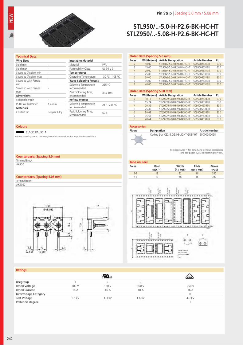
Wire SizesSolid minSolid maxStranded (flexible) minStranded (flexible) maxStranded with Ferrule minStranded with Ferrule maxDimensions Stripped Length
PCB Hole DiameterMaterials
Ratings
242
Insulating Material MaterialFlammability ClassTemperaturesOperating TemperatureWave Soldering ProcessSoldering Temperature,recommendedPeak Soldering Time,recommendedReflow ProcessSoldering Temperature,recommended
Peak Soldering Time,recommended
Technical Data Order Data (Spacing 5.0 mm)Poles Width (mm) Article Designation Article Number PU
Pin Strip | Spacing 5.0 mm / 5.08 mm
STL950/..-5.0-H-P2.6-BK-HC-HTSTLZ950/..-5.08-H-P2.6-BK-HC-HT
2 10.00 STL950/2-5.0-H-P2.6-BK-HC-HT 50950025319R 3303 15.00 STL950/3-5.0-H-P2.6-BK-HC-HT 50950035319R 3304 20.00 STL950/4-5.0-H-P2.6-BK-HC-HT 50950045319R 3305 25.00 STL950/5-5.0-H-P2.6-BK-HC-HT 50950055319R 3306 30.00 STL950/6-5.0-H-P2.6-BK-HC-HT 50950065319R 3307 35.00 STL950/7-5.0-H-P2.6-BK-HC-HT 50950075319R 3308 40.00 STL950/8-5.0-H-P2.6-BK-HC-HT 50950085319R 330
PPAUL 94 V-0
-30 °C - 105 °C
265 °C
3 s / 10 s
217 - 245 °C
60 s
-----
-
-
1.4 mm
Counterparts (Spacing 5.0 mm)Terminal Block
Counterparts (Spacing 5.08 mm)Terminal Block
AK950
Contact Pin Copper Alloy
Usegroup B C DRated Voltage 300 V 150 V 300 V 250 VRated Current 16 A 16 A 10 A 16 AOvervoltage Category IIITest Voltage 1.6 kV 1.3 kV 1.6 kV 4.0 kVPollution Degree 3
2 10.16 STLZ950/2-5.08-H-P2.6-BK-HC-HT 50950025339R 3303 15.24 STLZ950/3-5.08-H-P2.6-BK-HC-HT 50950035339R 3304 20.32 STLZ950/4-5.08-H-P2.6-BK-HC-HT 50950045339R 3305 25.40 STLZ950/5-5.08-H-P2.6-BK-HC-HT 50950055339R 3306 30.48 STLZ950/6-5.08-H-P2.6-BK-HC-HT 50950065339R 3307 35.56 STLZ950/7-5.08-H-P2.6-BK-HC-HT 50950075339R 3308 40.64 STLZ950/8-5.08-H-P2.6-BK-HC-HT 50950085339R 330
Order Data (Spacing 5.08 mm)Poles Width (mm) Article Designation Article Number PU
Coding Star CS2-5.0/5.08-LIGHT GREY-HT 50000000028
AccessoriesFigure Designation Article Number
See pages 282 ff for detail and general accessories and see pages 12/13 concerning services.
2-3 13 32 16 3304-8 13 56 16 330
NEW
Tape on ReelPoles Reel
(RD / “)Width
(R / mm)Pitch
(RP / mm)Pieces (PCS)
Colours
BLACK, RAL 9011Colours according to RAL, there may be variations on colour due to production conditions.
AKZ950
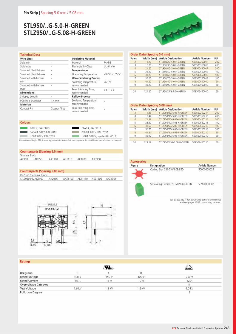
Wire SizesSolid minSolid maxStranded (flexible) minStranded (flexible) maxStranded with Ferrule minStranded with Ferrule maxDimensions Stripped Length
PCB Hole DiameterMaterials
Ratings
PTR Terminal Blocks and Multi Connector Systems 243
Insulating Material MaterialFlammability ClassTemperaturesOperating TemperatureWave Soldering ProcessSoldering Temperature,recommendedPeak Soldering Time,recommendedReflow ProcessSoldering Temperature,recommended
Peak Soldering Time,recommended
Counterparts (Spacing 5.08 mm)Pin Strip / Terminal Block
Technical Data Order Data (Spacing 5.0 mm)Poles Width (mm) Article Designation Article Number PU
Pin Strip | Spacing 5.0 mm / 5.08 mm
STL950/..G-5.0-H-GREENSTLZ950/..G-5.08-H-GREEN
2 11.20 STL950/2G-5.0-H-GREEN 50950025001F 2003 16.20 STL950/3G-5.0-H-GREEN 50950035001F 2004 21.20 STL950/4G-5.0-H-GREEN 50950045001F 2005 26.20 STL950/5G-5.0-H-GREEN 50950055001E 1006 31.20 STL950/6G-5.0-H-GREEN 50950065001E 1007 36.20 STL950/7G-5.0-H-GREEN 50950075001E 1008 41.20 STL950/8G-5.0-H-GREEN 50950085001D 509 46.20 STL950/9G-5.0-H-GREEN 50950095001D 50
... ... ... ... ...24 121.20 STL950/24G-5.0-H-GREEN 50950245001D 50
Colours according to RAL, there may be variations on colour due to production conditions. Special colours on request.
Colours
GREEN, RAL 6018 BLACK, RAL 9011
BASALT GREY, RAL 7012 PEBBLE GREY, RAL 7032
LIGHT GREY, RAL 7035 LIGHT GREEN, similar RAL 6018
PA 6.6UL 94 V-0
-30 °C - 105 °C
265 °C
3 s / 10 s
-
-
-----
-
-
1.4 mm
Counterparts (Spacing 5.0 mm)Terminal BlockAK950 AK955 AK1100 AK1110 AK1200 AK3950
Contact Pin Copper Alloy
Usegroup B C DRated Voltage 300 V 150 V 300 V 250 VRated Current 15 A 15 A 10 A 12 AOvervoltage Category IIITest Voltage 1.6 kV 1.3 kV 1.6 kV 4.0 kVPollution Degree 3
2 11.36 STLZ950/2G-5.08-H-GREEN 50950025021F 2003 16.44 STLZ950/3G-5.08-H-GREEN 50950035021F 2004 21.52 STLZ950/4G-5.08-H-GREEN 50950045021F 2005 26.60 STLZ950/5G-5.08-H-GREEN 50950055021E 1006 31.68 STLZ950/6G-5.08-H-GREEN 50950065021E 1007 36.76 STLZ950/7G-5.08-H-GREEN 50950075021E 1008 41.84 STLZ950/8G-5.08-H-GREEN 50950085021D 509 46.92 STLZ950/9G-5.08-H-GREEN 50950095021D 50
... ... ... ... ...24 123.12 STLZ950/24G-5.08-H-GREEN 50950245021D 50
Order Data (Spacing 5.08 mm)Poles Width (mm) Article Designation Article Number PU
Coding Star CS2-5.0/5.08-RED 50000000024
Separating Element SE-STL950-GREEN 50950000002
AccessoriesFigure Designation Article Number
See pages 282 ff for detail and general accessories and see pages 12/13 concerning services.
STLZ950-INV AKZ950 AKZ955 AKZ1100 AKZ1110 AKZ1200 AKZ4951
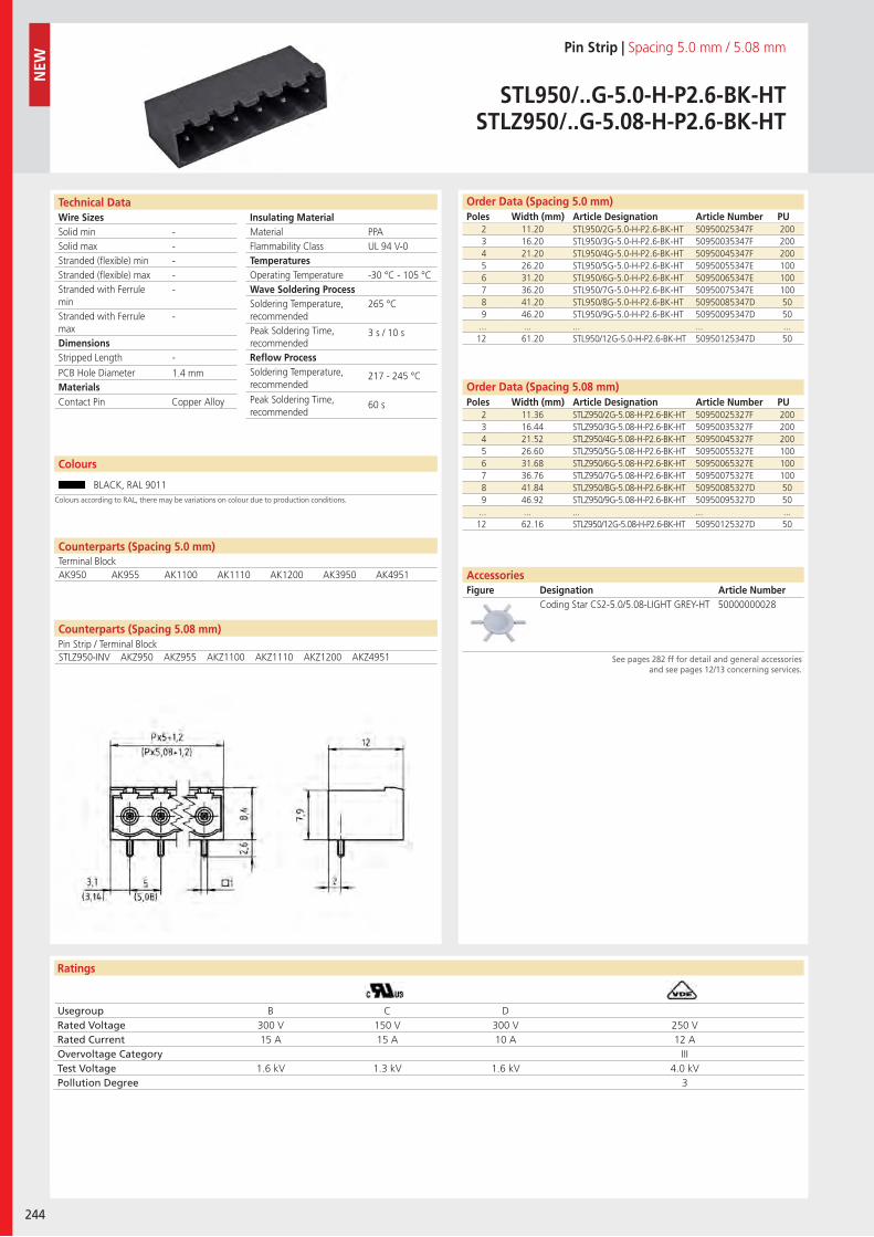
Wire SizesSolid minSolid maxStranded (flexible) minStranded (flexible) maxStranded with Ferrule minStranded with Ferrule maxDimensions Stripped Length
PCB Hole DiameterMaterials
Ratings
244
Insulating Material MaterialFlammability ClassTemperaturesOperating TemperatureWave Soldering ProcessSoldering Temperature,recommendedPeak Soldering Time,recommendedReflow ProcessSoldering Temperature,recommended
Peak Soldering Time,recommended
Technical Data Order Data (Spacing 5.0 mm)Poles Width (mm) Article Designation Article Number PU
Colours
Pin Strip | Spacing 5.0 mm / 5.08 mm
STL950/..G-5.0-H-P2.6-BK-HTSTLZ950/..G-5.08-H-P2.6-BK-HT
2 11.20 STL950/2G-5.0-H-P2.6-BK-HT 50950025347F 2003 16.20 STL950/3G-5.0-H-P2.6-BK-HT 50950035347F 2004 21.20 STL950/4G-5.0-H-P2.6-BK-HT 50950045347F 2005 26.20 STL950/5G-5.0-H-P2.6-BK-HT 50950055347E 1006 31.20 STL950/6G-5.0-H-P2.6-BK-HT 50950065347E 1007 36.20 STL950/7G-5.0-H-P2.6-BK-HT 50950075347E 1008 41.20 STL950/8G-5.0-H-P2.6-BK-HT 50950085347D 509 46.20 STL950/9G-5.0-H-P2.6-BK-HT 50950095347D 50
... ... ... ... ...12 61.20 STL950/12G-5.0-H-P2.6-BK-HT 50950125347D 50
BLACK, RAL 9011
2 11.36 STLZ950/2G-5.08-H-P2.6-BK-HT 50950025327F 2003 16.44 STLZ950/3G-5.08-H-P2.6-BK-HT 50950035327F 2004 21.52 STLZ950/4G-5.08-H-P2.6-BK-HT 50950045327F 2005 26.60 STLZ950/5G-5.08-H-P2.6-BK-HT 50950055327E 1006 31.68 STLZ950/6G-5.08-H-P2.6-BK-HT 50950065327E 1007 36.76 STLZ950/7G-5.08-H-P2.6-BK-HT 50950075327E 1008 41.84 STLZ950/8G-5.08-H-P2.6-BK-HT 50950085327D 509 46.92 STLZ950/9G-5.08-H-P2.6-BK-HT 50950095327D 50
... ... ... ... ...12 62.16 STLZ950/12G-5.08-H-P2.6-BK-HT 50950125327D 50
PPAUL 94 V-0
-30 °C - 105 °C
265 °C
3 s / 10 s
217 - 245 °C
60 s
-----
-
-
1.4 mm
Counterparts (Spacing 5.0 mm)Terminal Block
Counterparts (Spacing 5.08 mm)Pin Strip / Terminal Block
AK950 AK955 AK1100 AK1110 AK1200 AK3950 AK4951
Contact Pin Copper Alloy
Usegroup B C DRated Voltage 300 V 150 V 300 V 250 VRated Current 15 A 15 A 10 A 12 AOvervoltage Category IIITest Voltage 1.6 kV 1.3 kV 1.6 kV 4.0 kVPollution Degree 3
Coding Star CS2-5.0/5.08-LIGHT GREY-HT 50000000028
Order Data (Spacing 5.08 mm)Poles Width (mm) Article Designation Article Number PU
AccessoriesFigure Designation Article Number
See pages 282 ff for detail and general accessories and see pages 12/13 concerning services.
NEW
Colours according to RAL, there may be variations on colour due to production conditions.
STLZ950-INV AKZ950 AKZ955 AKZ1100 AKZ1110 AKZ1200 AKZ4951
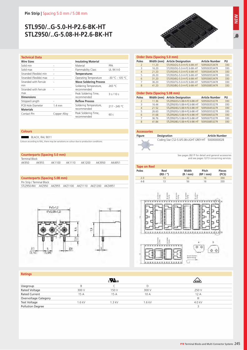
Wire SizesSolid minSolid maxStranded (flexible) minStranded (flexible) maxStranded with Ferrule minStranded with Ferrule maxDimensions Stripped Length
PCB Hole DiameterMaterials
Ratings
PTR Terminal Blocks and Multi Connector Systems 245
Insulating Material MaterialFlammability ClassTemperaturesOperating TemperatureWave Soldering ProcessSoldering Temperature,recommendedPeak Soldering Time,recommendedReflow ProcessSoldering Temperature,recommended
Peak Soldering Time,recommended
Counterparts (Spacing 5.08 mm)Pin Strip / Terminal Block
Technical Data Order Data (Spacing 5.0 mm)Poles Width (mm) Article Designation Article Number PU
Colours
Pin Strip | Spacing 5.0 mm / 5.08 mm
STL950/..G-5.0-H-P2.6-BK-HTSTLZ950/..G-5.08-H-P2.6-BK-HT
2 11.20 STL950/2G-5.0-H-P2.6-BK-HT 50950025347R 3303 16.20 STL950/3G-5.0-H-P2.6-BK-HT 50950035347R 3304 21.20 STL950/4G-5.0-H-P2.6-BK-HT 50950045347R 3305 26.20 STL950/5G-5.0-H-P2.6-BK-HT 50950055347R 3306 31.20 STL950/6G-5.0-H-P2.6-BK-HT 50950065347R 3307 36.20 STL950/7G-5.0-H-P2.6-BK-HT 50950075347R 3308 41.20 STL950/8G-5.0-H-P2.6-BK-HT 50950085347R 330
BLACK, RAL 9011
PPAUL 94 V-0
-30 °C - 105 °C
265 °C
3 s / 10 s
217 - 245 °C
60 s
-----
-
-
1.4 mm
Counterparts (Spacing 5.0 mm)Terminal BlockAK950 AK955 AK1100 AK1110 AK1200 AK3950 AK4951
Contact Pin Copper Alloy
Usegroup B C DRated Voltage 300 V 150 V 300 V 250 VRated Current 15 A 15 A 10 A 12 AOvervoltage Category IIITest Voltage 1.6 kV 1.3 kV 1.6 kV 4.0 kVPollution Degree 3
2 11.36 STLZ950/2G-5.08-H-P2.6-BK-HT 50950025327R 3303 16.44 STLZ950/3G-5.08-H-P2.6-BK-HT 50950035327R 3304 21.52 STLZ950/4G-5.08-H-P2.6-BK-HT 50950045327R 3305 26.60 STLZ950/5G-5.08-H-P2.6-BK-HT 50950055327R 3306 31.68 STLZ950/6G-5.08-H-P2.6-BK-HT 50950065327R 3307 36.76 STLZ950/7G-5.08-H-P2.6-BK-HT 50950075327R 3308 41.84 STLZ950/8G-5.08-H-P2.6-BK-HT 50950085327R 330
Order Data (Spacing 5.08 mm)Poles Width (mm) Article Designation Article Number PU
Coding Star CS2-5.0/5.08-LIGHT GREY-HT 50000000028
AccessoriesFigure Designation Article Number
See pages 282 ff for detail and general accessories and see pages 12/13 concerning services.
2-3 13 32 16 3304-8 13 56 16 330
Tape on ReelPoles Reel
(RD / “)Width
(R / mm)Pitch
(RP / mm)Pieces (PCS)
Colours according to RAL, there may be variations on colour due to production conditions.
STLZ950-INV AKZ950 AKZ955 AKZ1100 AKZ1110 AKZ1200 AKZ4951
NEW
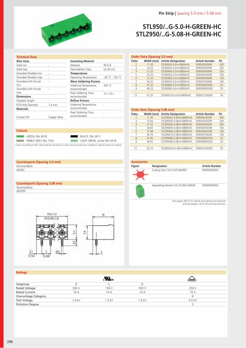
Wire SizesSolid minSolid maxStranded (flexible) minStranded (flexible) maxStranded with Ferrule minStranded with Ferrule maxDimensions Stripped Length
PCB Hole DiameterMaterials
Ratings
246
Insulating Material MaterialFlammability ClassTemperaturesOperating TemperatureWave Soldering ProcessSoldering Temperature,recommendedPeak Soldering Time,recommendedReflow ProcessSoldering Temperature,recommended
Peak Soldering Time,recommended
Technical Data
Colours according to RAL, there may be variations on colour due to production conditions. Special colours on request.
Order Data (Spacing 5.0 mm)Poles Width (mm) Article Designation Article Number PU
Colours
Pin Strip | Spacing 5.0 mm / 5.08 mm
STL950/..G-5.0-H-GREEN-HCSTLZ950/..G-5.08-H-GREEN-HC
2 11.20 STL950/2G-5.0-H-GREEN-HC 50950025009F 2003 16.20 STL950/3G-5.0-H-GREEN-HC 50950035009F 2004 21.20 STL950/4G-5.0-H-GREEN-HC 50950045009F 2005 26.20 STL950/5G-5.0-H-GREEN-HC 50950055009E 1006 31.20 STL950/6G-5.0-H-GREEN-HC 50950065009E 1007 36.20 STL950/7G-5.0-H-GREEN-HC 50950075009E 1008 41.20 STL950/8G-5.0-H-GREEN-HC 50950085009D 509 46.20 STL950/9G-5.0-H-GREEN-HC 50950095009D 50
... ... ... ... ...12 61.20 STL950/12G-5.0-H-GREEN-HC 50950125009D 50
GREEN, RAL 6018 BLACK, RAL 9011
PEBBLE GREY, RAL 7032 LIGHT GREEN, similar RAL 6018
2 11.36 STLZ950/2G-5.08-H-GREEN-HC 50950025029F 2003 16.44 STLZ950/3G-5.08-H-GREEN-HC 50950035029F 2004 21.52 STLZ950/4G-5.08-H-GREEN-HC 50950045029F 2005 26.60 STLZ950/5G-5.08-H-GREEN-HC 50950055029E 1006 31.68 STLZ950/6G-5.08-H-GREEN-HC 50950065029E 1007 36.76 STLZ950/7G-5.08-H-GREEN-HC 50950075029E 1008 41.84 STLZ950/8G-5.08-H-GREEN-HC 50950085029D 509 46.92 STLZ950/9G-5.08-H-GREEN-HC 50950095029D 50
... ... ... ... ...12 62.16 STLZ950/12G-5.08-H-GREEN-HC 50950125029D 50
PA 6.6UL 94 V-0
-30 °C - 105 °C
265 °C
3 s / 10 s
-
-
-----
-
-
1.4 mm
Counterparts (Spacing 5.0 mm)Terminal Block
Counterparts (Spacing 5.08 mm)Terminal Block
AK950
Contact Pin Copper Alloy
Usegroup B C DRated Voltage 300 V 150 V 300 V 250 VRated Current 16 A 16 A 10 A 16 AOvervoltage Category IIITest Voltage 1.6 kV 1.3 kV 1.6 kV 4.0 kVPollution Degree 3
Coding Star CS2-5.0/5.08-RED 50000000024
Separating Element SE-STL950-GREEN 50950000002
Order Data (Spacing 5.08 mm)Poles Width (mm) Article Designation Article Number PU
AccessoriesFigure Designation Article Number
See pages 282 ff for detail and general accessories and see pages 12/13 concerning services.
AKZ950
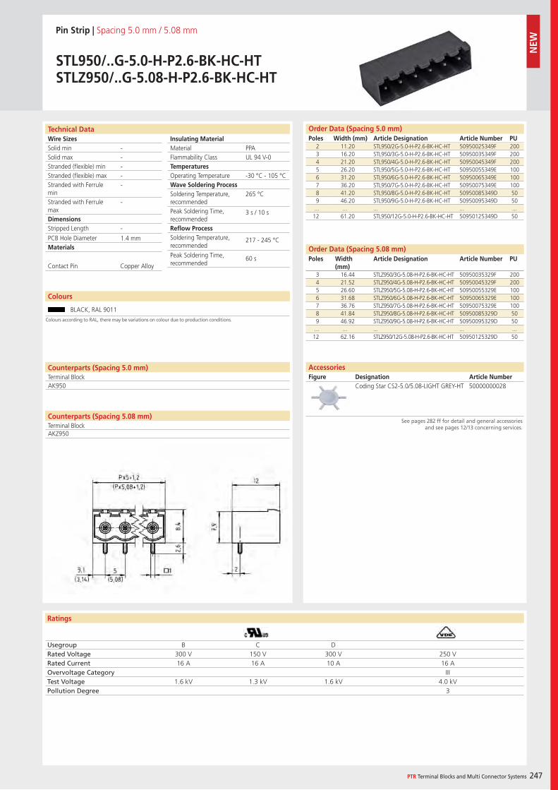
Wire SizesSolid minSolid maxStranded (flexible) minStranded (flexible) maxStranded with Ferrule minStranded with Ferrule maxDimensions Stripped Length
PCB Hole DiameterMaterials
Ratings
PTR Terminal Blocks and Multi Connector Systems 247
Insulating Material MaterialFlammability ClassTemperaturesOperating TemperatureWave Soldering ProcessSoldering Temperature,recommendedPeak Soldering Time,recommendedReflow ProcessSoldering Temperature,recommended
Peak Soldering Time,recommended
Counterparts (Spacing 5.08 mm)Terminal Block
Technical Data Order Data (Spacing 5.0 mm)Poles Width (mm) Article Designation Article Number PU
Colours
Pin Strip | Spacing 5.0 mm / 5.08 mm
STL950/..G-5.0-H-P2.6-BK-HC-HTSTLZ950/..G-5.08-H-P2.6-BK-HC-HT
2 11.20 STL950/2G-5.0-H-P2.6-BK-HC-HT 50950025349F 2003 16.20 STL950/3G-5.0-H-P2.6-BK-HC-HT 50950035349F 2004 21.20 STL950/4G-5.0-H-P2.6-BK-HC-HT 50950045349F 2005 26.20 STL950/5G-5.0-H-P2.6-BK-HC-HT 50950055349E 1006 31.20 STL950/6G-5.0-H-P2.6-BK-HC-HT 50950065349E 1007 36.20 STL950/7G-5.0-H-P2.6-BK-HC-HT 50950075349E 1008 41.20 STL950/8G-5.0-H-P2.6-BK-HC-HT 50950085349D 509 46.20 STL950/9G-5.0-H-P2.6-BK-HC-HT 50950095349D 50
... ... ... ... ...12 61.20 STL950/12G-5.0-H-P2.6-BK-HC-HT 50950125349D 50
BLACK, RAL 9011
PPAUL 94 V-0
-30 °C - 105 °C
265 °C
3 s / 10 s
217 - 245 °C
60 s
-----
-
-
1.4 mm
Counterparts (Spacing 5.0 mm)Terminal BlockAK950
Contact Pin Copper Alloy
Usegroup B C DRated Voltage 300 V 150 V 300 V 250 VRated Current 16 A 16 A 10 A 16 AOvervoltage Category IIITest Voltage 1.6 kV 1.3 kV 1.6 kV 4.0 kVPollution Degree 3
2 11.36 STLZ950/2G-5.08-H-P2.6-BK-HC-HT 50950025329F 2003 16.44 STLZ950/3G-5.08-H-P2.6-BK-HC-HT 50950035329F 2004 21.52 STLZ950/4G-5.08-H-P2.6-BK-HC-HT 50950045329F 2005 26.60 STLZ950/5G-5.08-H-P2.6-BK-HC-HT 50950055329E 1006 31.68 STLZ950/6G-5.08-H-P2.6-BK-HC-HT 50950065329E 1007 36.76 STLZ950/7G-5.08-H-P2.6-BK-HC-HT 50950075329E 1008 41.84 STLZ950/8G-5.08-H-P2.6-BK-HC-HT 50950085329D 509 46.92 STLZ950/9G-5.08-H-P2.6-BK-HC-HT 50950095329D 50
... ... ... ... ...12 62.16 STLZ950/12G-5.08-H-P2.6-BK-HC-HT 50950125329D 50
Order Data (Spacing 5.08 mm)Poles Width
(mm) Article Designation Article Number PU
Coding Star CS2-5.0/5.08-LIGHT GREY-HT 50000000028
AccessoriesFigure Designation Article Number
See pages 282 ff for detail and general accessories and see pages 12/13 concerning services.
Colours according to RAL, there may be variations on colour due to production conditions.
AKZ950
NEW
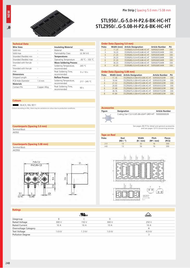
Wire SizesSolid minSolid maxStranded (flexible) minStranded (flexible) maxStranded with Ferrule minStranded with Ferrule maxDimensions Stripped Length
PCB Hole DiameterMaterials
Ratings
248
Insulating Material MaterialFlammability ClassTemperaturesOperating TemperatureWave Soldering ProcessSoldering Temperature,recommendedPeak Soldering Time,recommendedReflow ProcessSoldering Temperature,recommended
Peak Soldering Time,recommended
Technical Data
Colours
Pin Strip | Spacing 5.0 mm / 5.08 mm
STL950/..G-5.0-H-P2.6-BK-HC-HTSTLZ950/..G-5.08-H-P2.6-BK-HC-HT
Order Data (Spacing 5.0 mm)Poles Width (mm) Article Designation Article Number PU
2 11.20 STL950/2G-5.0-H-P2.6-BK-HC-HT 50950025349R 3303 16.20 STL950/3G-5.0-H-P2.6-BK-HC-HT 50950035349R 3304 21.20 STL950/4G-5.0-H-P2.6-BK-HC-HT 50950045349R 3305 26.20 STL950/5G-5.0-H-P2.6-BK-HC-HT 50950055349R 3306 31.20 STL950/6G-5.0-H-P2.6-BK-HC-HT 50950065349R 3307 36.20 STL950/7G-5.0-H-P2.6-BK-HC-HT 50950075349R 3308 41.20 STL950/8G-5.0-H-P2.6-BK-HC-HT 50950085349R 330
BLACK, RAL 9011
PPAUL 94 V-0
-30 °C - 105 °C
265 °C
3 s / 10 s
217 - 245 °C
60 s
-----
-
-
1.4 mm
Counterparts (Spacing 5.0 mm)Terminal Block
Counterparts (Spacing 5.08 mm)Terminal Block
AK950
Contact Pin Copper Alloy
Usegroup B C DRated Voltage 300 V 150 V 300 V 250 VRated Current 16 A 16 A 10 A 16 AOvervoltage Category IIITest Voltage 1.6 kV 1.3 kV 1.6 kV 4.0 kVPollution Degree 3
2 11.36 STLZ950/2G-5.08-H-P2.6-BK-HC-HT 50950025329R 3303 16.44 STLZ950/3G-5.08-H-P2.6-BK-HC-HT 50950035329R 3304 21.52 STLZ950/4G-5.08-H-P2.6-BK-HC-HT 50950045329R 3305 26.60 STLZ950/5G-5.08-H-P2.6-BK-HC-HT 50950055329R 3306 31.68 STLZ950/6G-5.08-H-P2.6-BK-HC-HT 50950065329R 3307 36.76 STLZ950/7G-5.08-H-P2.6-BK-HC-HT 50950075329R 3308 41.84 STLZ950/8G-5.08-H-P2.6-BK-HC-HT 50950085329R 330
Order Data (Spacing 5.08 mm)Poles Width (mm) Article Designation Article Number PU
Coding Star CS2-5.0/5.08-LIGHT GREY-HT 50000000028
AccessoriesFigure Designation Article Number
See pages 282 ff for detail and general accessories and see pages 12/13 concerning services.
NEW
2-3 13 32 16 3304-8 13 56 16 330
Tape on ReelPoles Reel
(RD / “)Width
(R / mm)Pitch
(RP / mm)Pieces (PCS)
Colours according to RAL, there may be variations on colour due to production conditions.
AKZ950
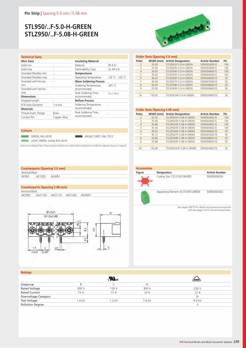
Wire SizesSolid minSolid maxStranded (flexible) minStranded (flexible) maxStranded with Ferrule minStranded with Ferrule maxDimensions Stripped Length
PCB Hole DiameterMaterials
Ratings
PTR Terminal Blocks and Multi Connector Systems 249
Insulating Material MaterialFlammability ClassTemperaturesOperating TemperatureWave Soldering ProcessSoldering Temperature,recommendedPeak Soldering Time,recommendedReflow ProcessSoldering Temperature,recommended
Peak Soldering Time,recommended
Counterparts (Spacing 5.08 mm)Terminal Block
Technical Data Order Data (Spacing 5.0 mm)Poles Width (mm) Article Designation Article Number PU
Pin Strip | Spacing 5.0 mm / 5.08 mm
STL950/..F-5.0-H-GREENSTLZ950/..F-5.08-H-GREEN
2 20.00 STL950/2F-5.0-H-GREEN 50950026001E 1003 25.00 STL950/3F-5.0-H-GREEN 50950036001E 1004 30.00 STL950/4F-5.0-H-GREEN 50950046001E 1005 35.00 STL950/5F-5.0-H-GREEN 50950056001E 1006 40.00 STL950/6F-5.0-H-GREEN 50950066001D 507 45.00 STL950/7F-5.0-H-GREEN 50950076001D 508 50.00 STL950/8F-5.0-H-GREEN 50950086001D 509 55.00 STL950/9F-5.0-H-GREEN 50950096001D 50
... ... ... ... ...24 130.00 STL950/24F-5.0-H-GREEN 50950246001D 50
Colours according to RAL, there may be variations on colour due to production conditions. Special colours on request.
Colours
GREEN, RAL 6018 BASALT GREY, RAL 7012
LIGHT GREEN, similar RAL 6018
Order Data (Spacing 5.08 mm)Poles Width (mm) Article Designation Article Number PU
2 20.32 STLZ950/2F-5.08-H-GREEN 50950026021E 1003 25.40 STLZ950/3F-5.08-H-GREEN 50950036021E 1004 30.48 STLZ950/4F-5.08-H-GREEN 50950046021E 1005 35.56 STLZ950/5F-5.08-H-GREEN 50950056021E 1006 40.64 STLZ950/6F-5.08-H-GREEN 50950066021D 507 45.72 STLZ950/7F-5.08-H-GREEN 50950076021D 508 50.80 STLZ950/8F-5.08-H-GREEN 50950086021D 509 55.88 STLZ950/9F-5.08-H-GREEN 50950096021D 50
... ... ... ... ...24 132.08 STLZ950/24F-5.08-H-GREEN 50950246021D 50
PA 6.6UL 94 V-0
-30 °C - 105 °C
265 °C
3 s / 10 s
-
-
-----
-
-
1.4 mm
Counterparts (Spacing 5.0 mm)Terminal BlockAK950 AK1200 AK4951
Thread Insert, Flange BrassContact Pin Copper Alloy
Usegroup B C DRated Voltage 300 V 150 V 300 V 250 VRated Current 15 A 15 A 10 A 12 AOvervoltage Category IIITest Voltage 1.6 kV 1.3 kV 1.6 kV 4.0 kVPollution Degree 3
AccessoriesFigure Designation Article Number
See pages 282 ff for detail and general accessories and see pages 12/13 concerning services.
Coding Star CS2-5.0/5.08-RED 50000000024
Separating Element SE-STL950-GREEN 50950000002AKZ950 AKZ1100 AKZ1110 AKZ1200 AKZ4951
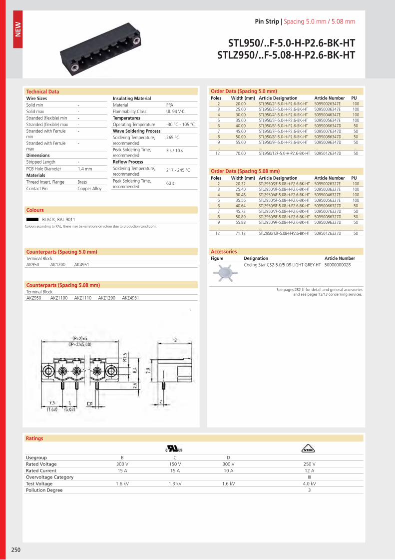
Wire SizesSolid minSolid maxStranded (flexible) minStranded (flexible) maxStranded with Ferrule minStranded with Ferrule maxDimensions Stripped Length
PCB Hole DiameterMaterials
Ratings
250
Insulating Material MaterialFlammability ClassTemperaturesOperating TemperatureWave Soldering ProcessSoldering Temperature,recommendedPeak Soldering Time,recommendedReflow ProcessSoldering Temperature,recommended
Peak Soldering Time,recommended
Technical Data Order Data (Spacing 5.0 mm)Poles Width (mm) Article Designation Article Number PU
Colours
Pin Strip | Spacing 5.0 mm / 5.08 mm
STL950/..F-5.0-H-P2.6-BK-HTSTLZ950/..F-5.08-H-P2.6-BK-HT
2 20.00 STL950/2F-5.0-H-P2.6-BK-HT 50950026347E 1003 25.00 STL950/3F-5.0-H-P2.6-BK-HT 50950036347E 1004 30.00 STL950/4F-5.0-H-P2.6-BK-HT 50950046347E 1005 35.00 STL950/5F-5.0-H-P2.6-BK-HT 50950056347E 1006 40.00 STL950/6F-5.0-H-P2.6-BK-HT 50950066347D 507 45.00 STL950/7F-5.0-H-P2.6-BK-HT 50950076347D 508 50.00 STL950/8F-5.0-H-P2.6-BK-HT 50950086347D 509 55.00 STL950/9F-5.0-H-P2.6-BK-HT 50950096347D 50
... ... ... ... ...12 70.00 STL950/12F-5.0-H-P2.6-BK-HT 50950126347D 50
BLACK, RAL 9011
2 20.32 STLZ950/2F-5.08-H-P2.6-BK-HT 50950026327E 1003 25.40 STLZ950/3F-5.08-H-P2.6-BK-HT 50950036327E 1004 30.48 STLZ950/4F-5.08-H-P2.6-BK-HT 50950046327E 1005 35.56 STLZ950/5F-5.08-H-P2.6-BK-HT 50950056327E 1006 40.64 STLZ950/6F-5.08-H-P2.6-BK-HT 50950066327D 507 45.72 STLZ950/7F-5.08-H-P2.6-BK-HT 50950076327D 508 50.80 STLZ950/8F-5.08-H-P2.6-BK-HT 50950086327D 509 55.88 STLZ950/9F-5.08-H-P2.6-BK-HT 50950096327D 50
... ... ... ... ...12 71.12 STLZ950/12F-5.08-H-P2.6-BK-HT 50950126327D 50
PPAUL 94 V-0
-30 °C - 105 °C
265 °C
3 s / 10 s
217 - 245 °C
60 s
-----
-
-
1.4 mm
Counterparts (Spacing 5.0 mm)Terminal BlockAK950 AK1200 AK4951
Thread Insert, Flange BrassContact Pin Copper Alloy
Usegroup B C DRated Voltage 300 V 150 V 300 V 250 VRated Current 15 A 15 A 10 A 12 AOvervoltage Category IIITest Voltage 1.6 kV 1.3 kV 1.6 kV 4.0 kVPollution Degree 3
Order Data (Spacing 5.08 mm)Poles Width (mm) Article Designation Article Number PU
Coding Star CS2-5.0/5.08-LIGHT GREY-HT 50000000028
AccessoriesFigure Designation Article Number
See pages 282 ff for detail and general accessories and see pages 12/13 concerning services.
NEW
Colours according to RAL, there may be variations on colour due to production conditions.
Counterparts (Spacing 5.08 mm)Terminal BlockAKZ950 AKZ1100 AKZ1110 AKZ1200 AKZ4951
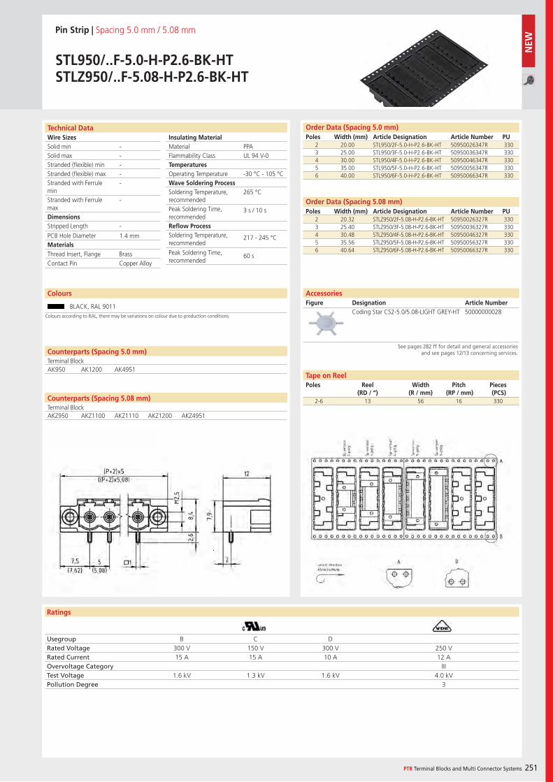
Wire SizesSolid minSolid maxStranded (flexible) minStranded (flexible) maxStranded with Ferrule minStranded with Ferrule maxDimensions Stripped Length
PCB Hole DiameterMaterials
Ratings
PTR Terminal Blocks and Multi Connector Systems 251
Insulating Material MaterialFlammability ClassTemperaturesOperating TemperatureWave Soldering ProcessSoldering Temperature,recommendedPeak Soldering Time,recommendedReflow ProcessSoldering Temperature,recommended
Peak Soldering Time,recommended
Counterparts (Spacing 5.08 mm)Terminal Block
Technical Data Order Data (Spacing 5.0 mm)Poles Width (mm) Article Designation Article Number PU
Colours
Pin Strip | Spacing 5.0 mm / 5.08 mm
STL950/..F-5.0-H-P2.6-BK-HTSTLZ950/..F-5.08-H-P2.6-BK-HT
2 20.00 STL950/2F-5.0-H-P2.6-BK-HT 50950026347R 3303 25.00 STL950/3F-5.0-H-P2.6-BK-HT 50950036347R 3304 30.00 STL950/4F-5.0-H-P2.6-BK-HT 50950046347R 3305 35.00 STL950/5F-5.0-H-P2.6-BK-HT 50950056347R 3306 40.00 STL950/6F-5.0-H-P2.6-BK-HT 50950066347R 330
BLACK, RAL 9011
PPAUL 94 V-0
-30 °C - 105 °C
265 °C
3 s / 10 s
217 - 245 °C
60 s
-----
-
-
1.4 mm
Counterparts (Spacing 5.0 mm)Terminal BlockAK950 AK1200 AK4951
Thread Insert, Flange BrassContact Pin Copper Alloy
Usegroup B C DRated Voltage 300 V 150 V 300 V 250 VRated Current 15 A 15 A 10 A 12 AOvervoltage Category IIITest Voltage 1.6 kV 1.3 kV 1.6 kV 4.0 kVPollution Degree 3
2 20.32 STLZ950/2F-5.08-H-P2.6-BK-HT 50950026327R 3303 25.40 STLZ950/3F-5.08-H-P2.6-BK-HT 50950036327R 3304 30.48 STLZ950/4F-5.08-H-P2.6-BK-HT 50950046327R 3305 35.56 STLZ950/5F-5.08-H-P2.6-BK-HT 50950056327R 3306 40.64 STLZ950/6F-5.08-H-P2.6-BK-HT 50950066327R 330
Order Data (Spacing 5.08 mm)Poles Width (mm) Article Designation Article Number PU
Coding Star CS2-5.0/5.08-LIGHT GREY-HT 50000000028
AccessoriesFigure Designation Article Number
See pages 282 ff for detail and general accessories and see pages 12/13 concerning services.
2-6 13 56 16 330
Tape on ReelPoles Reel
(RD / “)Width
(R / mm)Pitch
(RP / mm)Pieces (PCS)
Colours according to RAL, there may be variations on colour due to production conditions.
AKZ950 AKZ1100 AKZ1110 AKZ1200 AKZ4951
NEW
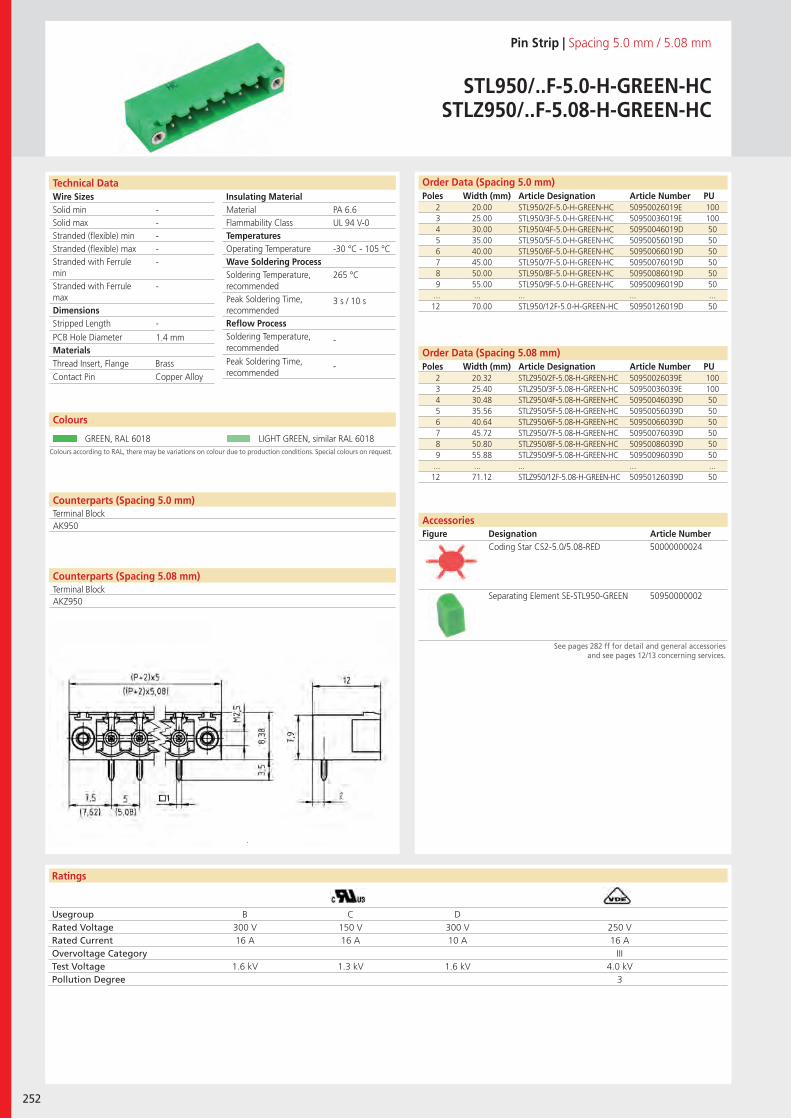
Wire SizesSolid minSolid maxStranded (flexible) minStranded (flexible) maxStranded with Ferrule minStranded with Ferrule maxDimensions Stripped Length
PCB Hole DiameterMaterials
Ratings
252
Insulating Material MaterialFlammability ClassTemperaturesOperating TemperatureWave Soldering ProcessSoldering Temperature,recommendedPeak Soldering Time,recommendedReflow ProcessSoldering Temperature,recommended
Peak Soldering Time,recommended
Technical Data
Colours according to RAL, there may be variations on colour due to production conditions. Special colours on request.
Order Data (Spacing 5.0 mm)Poles Width (mm) Article Designation Article Number PU
Colours
Pin Strip | Spacing 5.0 mm / 5.08 mm
STL950/..F-5.0-H-GREEN-HCSTLZ950/..F-5.08-H-GREEN-HC
2 20.00 STL950/2F-5.0-H-GREEN-HC 50950026019E 1003 25.00 STL950/3F-5.0-H-GREEN-HC 50950036019E 1004 30.00 STL950/4F-5.0-H-GREEN-HC 50950046019D 505 35.00 STL950/5F-5.0-H-GREEN-HC 50950056019D 506 40.00 STL950/6F-5.0-H-GREEN-HC 50950066019D 507 45.00 STL950/7F-5.0-H-GREEN-HC 50950076019D 508 50.00 STL950/8F-5.0-H-GREEN-HC 50950086019D 509 55.00 STL950/9F-5.0-H-GREEN-HC 50950096019D 50
... ... ... ... ...12 70.00 STL950/12F-5.0-H-GREEN-HC 50950126019D 50
GREEN, RAL 6018 LIGHT GREEN, similar RAL 6018
2 20.32 STLZ950/2F-5.08-H-GREEN-HC 50950026039E 1003 25.40 STLZ950/3F-5.08-H-GREEN-HC 50950036039E 1004 30.48 STLZ950/4F-5.08-H-GREEN-HC 50950046039D 505 35.56 STLZ950/5F-5.08-H-GREEN-HC 50950056039D 506 40.64 STLZ950/6F-5.08-H-GREEN-HC 50950066039D 507 45.72 STLZ950/7F-5.08-H-GREEN-HC 50950076039D 508 50.80 STLZ950/8F-5.08-H-GREEN-HC 50950086039D 509 55.88 STLZ950/9F-5.08-H-GREEN-HC 50950096039D 50
... ... ... ... ...12 71.12 STLZ950/12F-5.08-H-GREEN-HC 50950126039D 50
PA 6.6UL 94 V-0
-30 °C - 105 °C
265 °C
3 s / 10 s
-
-
-----
-
-
1.4 mm
Counterparts (Spacing 5.0 mm)Terminal Block
Counterparts (Spacing 5.08 mm)Terminal Block
AK950
Thread Insert, Flange Brass Contact Pin Copper Alloy
Usegroup B C DRated Voltage 300 V 150 V 300 V 250 VRated Current 16 A 16 A 10 A 16 AOvervoltage Category IIITest Voltage 1.6 kV 1.3 kV 1.6 kV 4.0 kVPollution Degree 3
Coding Star CS2-5.0/5.08-RED 50000000024
Separating Element SE-STL950-GREEN 50950000002
Order Data (Spacing 5.08 mm)Poles Width (mm) Article Designation Article Number PU
AccessoriesFigure Designation Article Number
See pages 282 ff for detail and general accessories and see pages 12/13 concerning services.
AKZ950
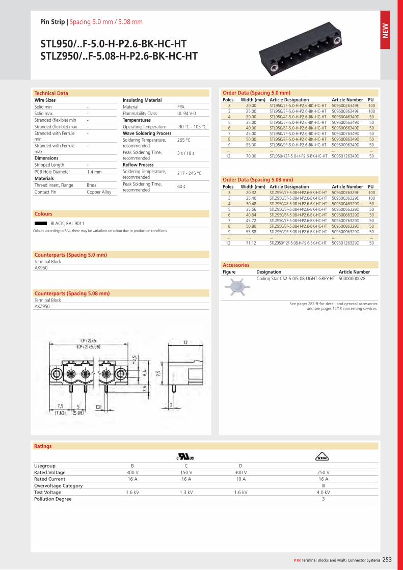
Wire SizesSolid minSolid maxStranded (flexible) minStranded (flexible) maxStranded with Ferrule minStranded with Ferrule maxDimensions Stripped Length
PCB Hole DiameterMaterials
Ratings
PTR Terminal Blocks and Multi Connector Systems 253
Insulating Material MaterialFlammability ClassTemperaturesOperating TemperatureWave Soldering ProcessSoldering Temperature,recommendedPeak Soldering Time,recommendedReflow ProcessSoldering Temperature,recommended
Peak Soldering Time,recommended
Counterparts (Spacing 5.08 mm)Terminal Block
Technical Data Order Data (Spacing 5.0 mm)Poles Width (mm) Article Designation Article Number PU
Colours
Pin Strip | Spacing 5.0 mm / 5.08 mm
STL950/..F-5.0-H-P2.6-BK-HC-HTSTLZ950/..F-5.08-H-P2.6-BK-HC-HT
2 20.00 STL950/2F-5.0-H-P2.6-BK-HC-HT 50950026349E 1003 25.00 STL950/3F-5.0-H-P2.6-BK-HC-HT 50950036349E 1004 30.00 STL950/4F-5.0-H-P2.6-BK-HC-HT 50950046349D 505 35.00 STL950/5F-5.0-H-P2.6-BK-HC-HT 50950056349D 506 40.00 STL950/6F-5.0-H-P2.6-BK-HC-HT 50950066349D 507 45.00 STL950/7F-5.0-H-P2.6-BK-HC-HT 50950076349D 508 50.00 STL950/8F-5.0-H-P2.6-BK-HC-HT 50950086349D 509 55.00 STL950/9F-5.0-H-P2.6-BK-HC-HT 50950096349D 50
... ... ... ... ...12 70.00 STL950/12F-5.0-H-P2.6-BK-HC-HT 50950126349D 50
BLACK, RAL 9011
PPAUL 94 V-0
-30 °C - 105 °C
265 °C
3 s / 10 s
217 - 245 °C
60 s
-----
-
-
1.4 mm
Counterparts (Spacing 5.0 mm)Terminal BlockAK950
Thread Insert, Flange BrassContact Pin Copper Alloy
Usegroup B C DRated Voltage 300 V 150 V 300 V 250 VRated Current 16 A 16 A 10 A 16 AOvervoltage Category IIITest Voltage 1.6 kV 1.3 kV 1.6 kV 4.0 kVPollution Degree 3
2 20.32 STLZ950/2F-5.08-H-P2.6-BK-HC-HT 50950026329E 1003 25.40 STLZ950/3F-5.08-H-P2.6-BK-HC-HT 50950036329E 1004 30.48 STLZ950/4F-5.08-H-P2.6-BK-HC-HT 50950046329D 505 35.56 STLZ950/5F-5.08-H-P2.6-BK-HC-HT 50950056329D 506 40.64 STLZ950/6F-5.08-H-P2.6-BK-HC-HT 50950066329D 507 45.72 STLZ950/7F-5.08-H-P2.6-BK-HC-HT 50950076329D 508 50.80 STLZ950/8F-5.08-H-P2.6-BK-HC-HT 50950086329D 509 55.88 STLZ950/9F-5.08-H-P2.6-BK-HC-HT 50950096329D 50
... ... ... ... ...12 71.12 STLZ950/12F-5.08-H-P2.6-BK-HC-HT 50950126329D 50
Order Data (Spacing 5.08 mm)Poles Width (mm) Article Designation Article Number PU
Coding Star CS2-5.0/5.08-LIGHT GREY-HT 50000000028
AccessoriesFigure Designation Article Number
See pages 282 ff for detail and general accessories and see pages 12/13 concerning services.
Colours according to RAL, there may be variations on colour due to production conditions.
AKZ950
NEW
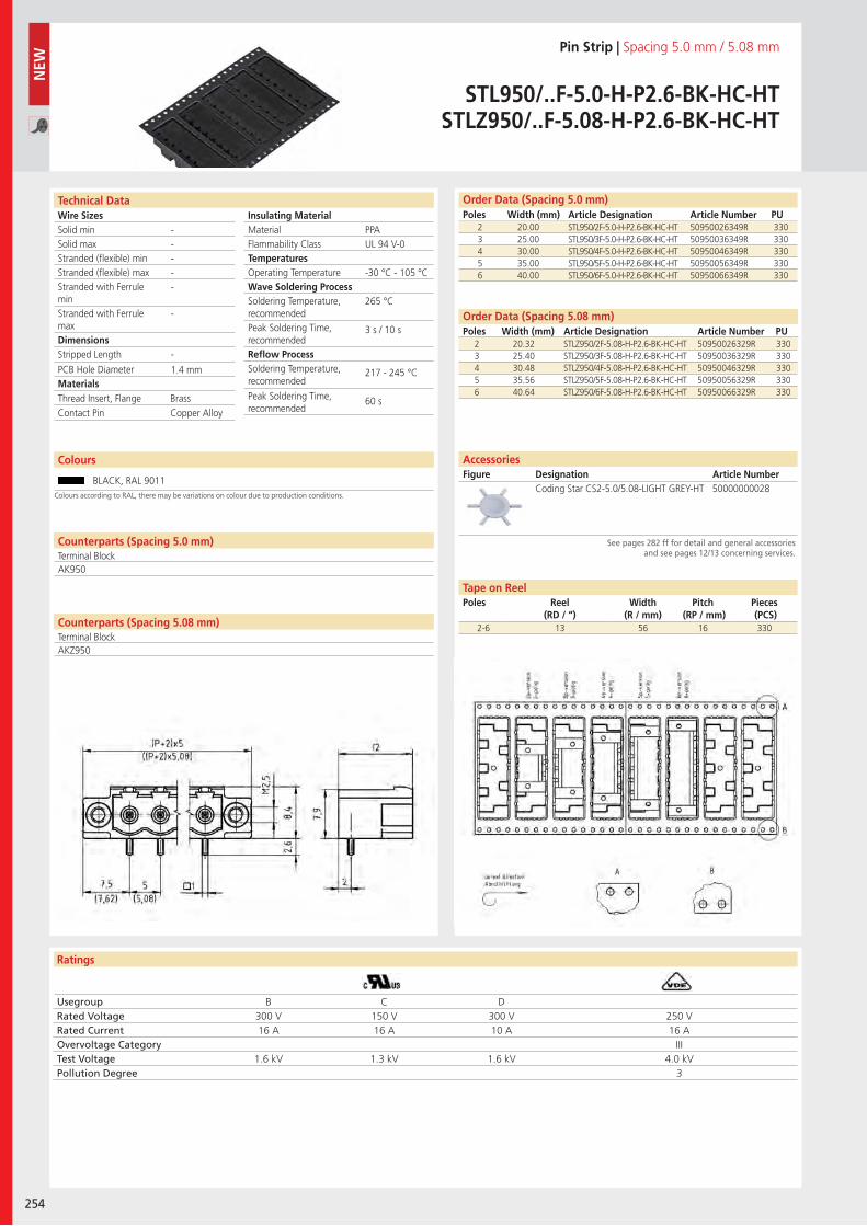
Wire SizesSolid minSolid maxStranded (flexible) minStranded (flexible) maxStranded with Ferrule minStranded with Ferrule maxDimensions Stripped Length
PCB Hole DiameterMaterials
Ratings
254
Insulating Material MaterialFlammability ClassTemperaturesOperating TemperatureWave Soldering ProcessSoldering Temperature,recommendedPeak Soldering Time,recommendedReflow ProcessSoldering Temperature,recommended
Peak Soldering Time,recommended
Technical Data Order Data (Spacing 5.0 mm)Poles Width (mm) Article Designation Article Number PU
Colours
Pin Strip | Spacing 5.0 mm / 5.08 mm
STL950/..F-5.0-H-P2.6-BK-HC-HTSTLZ950/..F-5.08-H-P2.6-BK-HC-HT
2 20.00 STL950/2F-5.0-H-P2.6-BK-HC-HT 50950026349R 3303 25.00 STL950/3F-5.0-H-P2.6-BK-HC-HT 50950036349R 3304 30.00 STL950/4F-5.0-H-P2.6-BK-HC-HT 50950046349R 3305 35.00 STL950/5F-5.0-H-P2.6-BK-HC-HT 50950056349R 3306 40.00 STL950/6F-5.0-H-P2.6-BK-HC-HT 50950066349R 330
BLACK, RAL 9011
PPAUL 94 V-0
-30 °C - 105 °C
265 °C
3 s / 10 s
217 - 245 °C
60 s
-----
-
-
1.4 mm
Counterparts (Spacing 5.0 mm)Terminal BlockAK950
Thread Insert, Flange BrassContact Pin Copper Alloy
Usegroup B C DRated Voltage 300 V 150 V 300 V 250 VRated Current 16 A 16 A 10 A 16 AOvervoltage Category IIITest Voltage 1.6 kV 1.3 kV 1.6 kV 4.0 kVPollution Degree 3
2 20.32 STLZ950/2F-5.08-H-P2.6-BK-HC-HT 50950026329R 3303 25.40 STLZ950/3F-5.08-H-P2.6-BK-HC-HT 50950036329R 3304 30.48 STLZ950/4F-5.08-H-P2.6-BK-HC-HT 50950046329R 3305 35.56 STLZ950/5F-5.08-H-P2.6-BK-HC-HT 50950056329R 3306 40.64 STLZ950/6F-5.08-H-P2.6-BK-HC-HT 50950066329R 330
Order Data (Spacing 5.08 mm)Poles Width (mm) Article Designation Article Number PU
Coding Star CS2-5.0/5.08-LIGHT GREY-HT 50000000028
AccessoriesFigure Designation Article Number
See pages 282 ff for detail and general accessories and see pages 12/13 concerning services.
NEW
2-6 13 56 16 330
Tape on ReelPoles Reel
(RD / “)Width
(R / mm)Pitch
(RP / mm)Pieces (PCS)
Colours according to RAL, there may be variations on colour due to production conditions.
Counterparts (Spacing 5.08 mm)Terminal BlockAKZ950
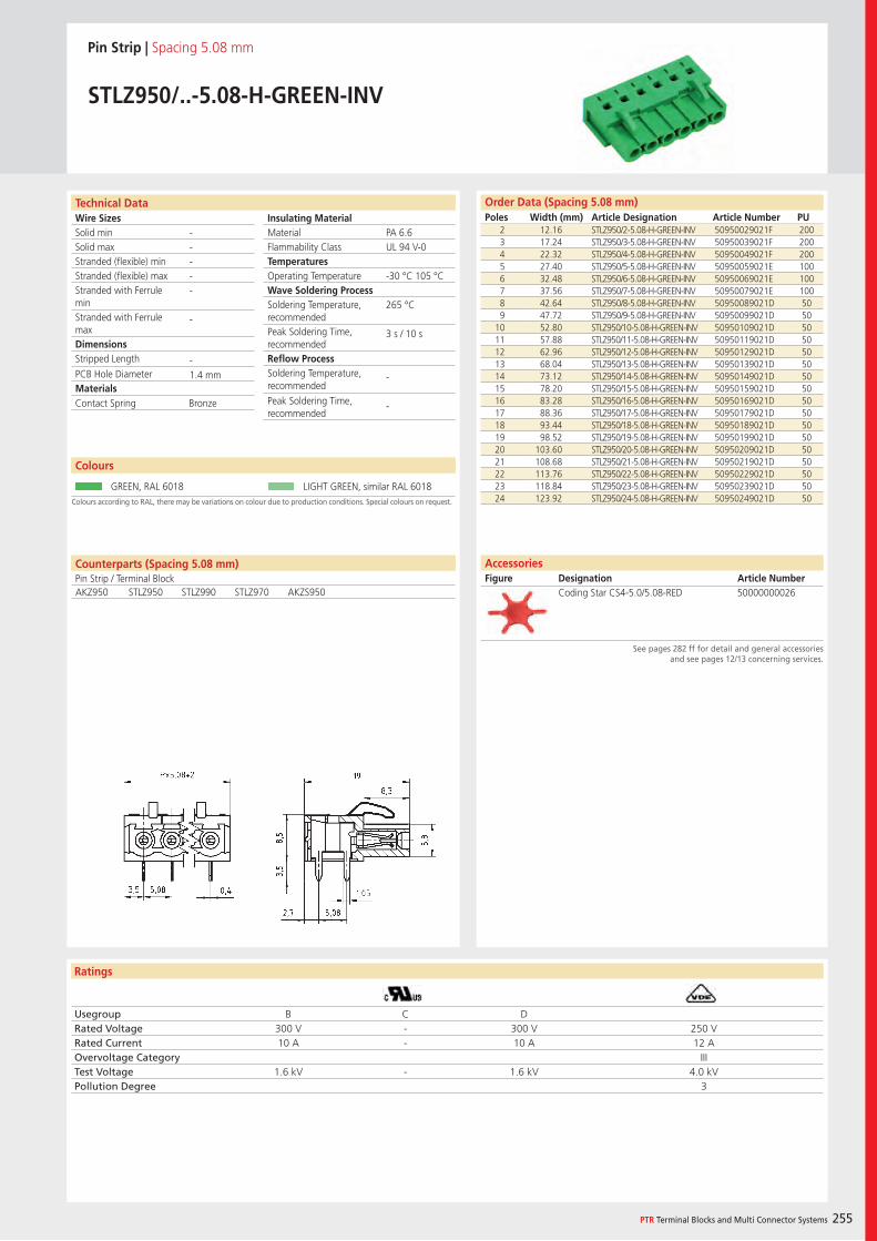
Wire SizesSolid minSolid maxStranded (flexible) minStranded (flexible) maxStranded with Ferrule minStranded with Ferrule maxDimensions Stripped Length
PCB Hole DiameterMaterials
Ratings
PTR Terminal Blocks and Multi Connector Systems 255
Insulating Material MaterialFlammability ClassTemperaturesOperating TemperatureWave Soldering ProcessSoldering Temperature,recommendedPeak Soldering Time,recommendedReflow ProcessSoldering Temperature,recommended
Peak Soldering Time,recommended
Order Data (Spacing 5.08 mm)Poles Width (mm) Article Designation Article Number PU
Technical Data
Pin Strip | Spacing 5.08 mm
STLZ950/..-5.08-H-GREEN-INV
2 12.16 STLZ950/2-5.08-H-GREEN-INV 50950029021F 2003 17.24 STLZ950/3-5.08-H-GREEN-INV 50950039021F 2004 22.32 STLZ950/4-5.08-H-GREEN-INV 50950049021F 2005 27.40 STLZ950/5-5.08-H-GREEN-INV 50950059021E 1006 32.48 STLZ950/6-5.08-H-GREEN-INV 50950069021E 1007 37.56 STLZ950/7-5.08-H-GREEN-INV 50950079021E 1008 42.64 STLZ950/8-5.08-H-GREEN-INV 50950089021D 509 47.72 STLZ950/9-5.08-H-GREEN-INV 50950099021D 50
10 52.80 STLZ950/10-5.08-H-GREEN-INV 50950109021D 5011 57.88 STLZ950/11-5.08-H-GREEN-INV 50950119021D 5012 62.96 STLZ950/12-5.08-H-GREEN-INV 50950129021D 5013 68.04 STLZ950/13-5.08-H-GREEN-INV 50950139021D 5014 73.12 STLZ950/14-5.08-H-GREEN-INV 50950149021D 5015 78.20 STLZ950/15-5.08-H-GREEN-INV 50950159021D 5016 83.28 STLZ950/16-5.08-H-GREEN-INV 50950169021D 5017 88.36 STLZ950/17-5.08-H-GREEN-INV 50950179021D 5018 93.44 STLZ950/18-5.08-H-GREEN-INV 50950189021D 5019 98.52 STLZ950/19-5.08-H-GREEN-INV 50950199021D 5020 103.60 STLZ950/20-5.08-H-GREEN-INV 50950209021D 5021 108.68 STLZ950/21-5.08-H-GREEN-INV 50950219021D 5022 113.76 STLZ950/22-5.08-H-GREEN-INV 50950229021D 5023 118.84 STLZ950/23-5.08-H-GREEN-INV 50950239021D 5024 123.92 STLZ950/24-5.08-H-GREEN-INV 50950249021D 50
PA 6.6UL 94 V-0
-30 °C 105 °C
265 °C
3 s / 10 s
-
-
-----
-
-1.4 mm
Colours according to RAL, there may be variations on colour due to production conditions. Special colours on request.
Colours
GREEN, RAL 6018 LIGHT GREEN, similar RAL 6018
Counterparts (Spacing 5.08 mm)Pin Strip / Terminal BlockAKZ950 STLZ950 STLZ990 STLZ970 AKZS950
Contact Spring Bronze
Usegroup B C DRated Voltage 300 V - 300 V 250 VRated Current 10 A - 10 A 12 AOvervoltage Category IIITest Voltage 1.6 kV - 1.6 kV 4.0 kVPollution Degree 3
AccessoriesFigure Designation Article Number
Coding Star CS4-5.0/5.08-RED 50000000026
See pages 282 ff for detail and general accessories and see pages 12/13 concerning services.
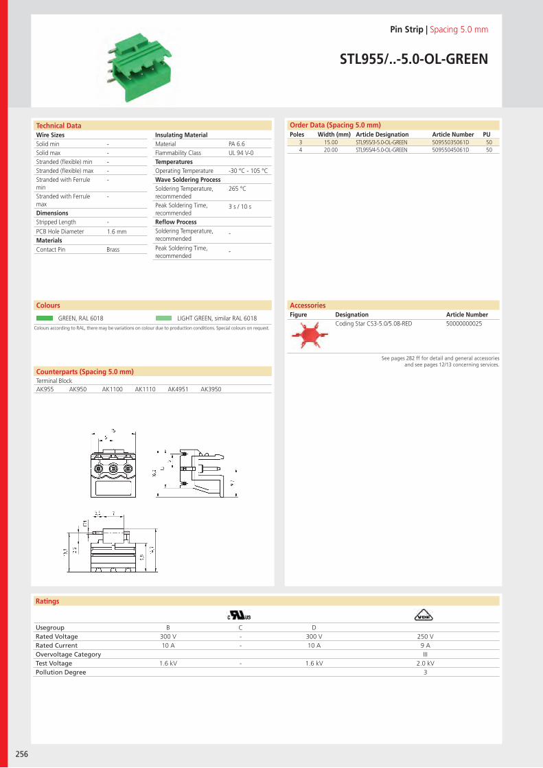
Wire SizesSolid minSolid maxStranded (flexible) minStranded (flexible) maxStranded with Ferrule minStranded with Ferrule maxDimensions Stripped Length
PCB Hole DiameterMaterials
Ratings
256
Insulating Material MaterialFlammability ClassTemperaturesOperating TemperatureWave Soldering ProcessSoldering Temperature,recommendedPeak Soldering Time,recommendedReflow ProcessSoldering Temperature,recommended
Peak Soldering Time,recommended
Technical Data
Colours according to RAL, there may be variations on colour due to production conditions. Special colours on request.
Order Data (Spacing 5.0 mm)Poles Width (mm) Article Designation Article Number PU
Colours
Pin Strip | Spacing 5.0 mm
STL955/..-5.0-OL-GREEN
3 15.00 STL955/3-5.0-OL-GREEN 50955035061D 504 20.00 STL955/4-5.0-OL-GREEN 50955045061D 50
GREEN, RAL 6018 LIGHT GREEN, similar RAL 6018
PA 6.6UL 94 V-0
-30 °C - 105 °C
265 °C
3 s / 10 s
-
-
-----
-
-
1.6 mm
Counterparts (Spacing 5.0 mm)Terminal BlockAK955 AK950 AK1100 AK1110 AK4951 AK3950
Contact Pin Brass
Usegroup B C DRated Voltage 300 V - 300 V 250 VRated Current 10 A - 10 A 9 AOvervoltage Category IIITest Voltage 1.6 kV - 1.6 kV 2.0 kVPollution Degree 3
Coding Star CS3-5.0/5.08-RED 50000000025
AccessoriesFigure Designation Article Number
See pages 282 ff for detail and general accessories and see pages 12/13 concerning services.
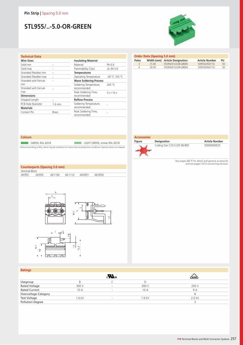
Wire SizesSolid minSolid maxStranded (flexible) minStranded (flexible) maxStranded with Ferrule minStranded with Ferrule maxDimensions Stripped Length
PCB Hole DiameterMaterials
Ratings
PTR Terminal Blocks and Multi Connector Systems 257
Insulating Material MaterialFlammability ClassTemperaturesOperating TemperatureWave Soldering ProcessSoldering Temperature,recommendedPeak Soldering Time,recommendedReflow ProcessSoldering Temperature,recommended
Peak Soldering Time,recommended
Order Data (Spacing 5.0 mm)Poles Width (mm) Article Designation Article Number PU
Technical Data
Pin Strip | Spacing 5.0 mm
STL955/..-5.0-OR-GREEN
3 15.00 STL955/3-5.0-OR-GREEN 50955035071D 504 20.00 STL955/4-5.0-OR-GREEN 50955045071D 50
PA 6.6UL 94 V-0
-30 °C 105 °C
265 °C
3 s / 10 s
-
-
-----
-
-1.6 mm
Colours according to RAL, there may be variations on colour due to production conditions. Special colours on request.
Colours
GREEN, RAL 6018 LIGHT GREEN, similar RAL 6018
Counterparts (Spacing 5.0 mm)Terminal BlockAK955 AK950 AK1100 AK1110 AK4951 AK3950
Contact Pin Brass
Usegroup B C DRated Voltage 300 V - 300 V 250 VRated Current 10 A - 10 A 9 AOvervoltage Category IIITest Voltage 1.6 kV - 1.6 kV 2.0 kVPollution Degree 3
AccessoriesFigure Designation Article Number
Coding Star CS3-5.0/5.08-RED 50000000025
See pages 282 ff for detail and general accessories and see pages 12/13 concerning services.
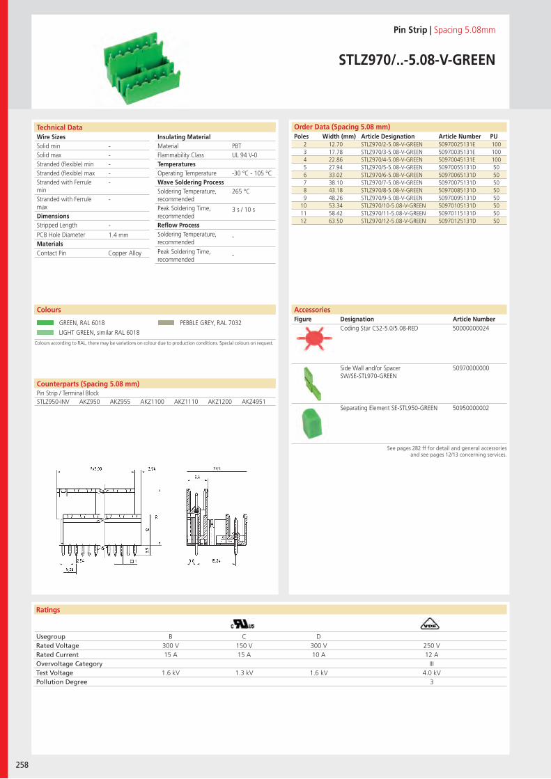
Wire SizesSolid minSolid maxStranded (flexible) minStranded (flexible) maxStranded with Ferrule minStranded with Ferrule maxDimensions Stripped Length
PCB Hole DiameterMaterials
Ratings
258
Insulating Material MaterialFlammability ClassTemperaturesOperating TemperatureWave Soldering ProcessSoldering Temperature,recommendedPeak Soldering Time,recommendedReflow ProcessSoldering Temperature,recommended
Peak Soldering Time,recommended
Counterparts (Spacing 5.08 mm)Pin Strip / Terminal Block
Technical Data Order Data (Spacing 5.08 mm)Poles Width (mm) Article Designation Article Number PU
Colours
Pin Strip | Spacing 5.08mm
STLZ970/..-5.08-V-GREEN
2 12.70 STLZ970/2-5.08-V-GREEN 50970025131E 1003 17.78 STLZ970/3-5.08-V-GREEN 50970035131E 1004 22.86 STLZ970/4-5.08-V-GREEN 50970045131E 1005 27.94 STLZ970/5-5.08-V-GREEN 50970055131D 506 33.02 STLZ970/6-5.08-V-GREEN 50970065131D 507 38.10 STLZ970/7-5.08-V-GREEN 50970075131D 508 43.18 STLZ970/8-5.08-V-GREEN 50970085131D 509 48.26 STLZ970/9-5.08-V-GREEN 50970095131D 50
10 53.34 STLZ970/10-5.08-V-GREEN 50970105131D 5011 58.42 STLZ970/11-5.08-V-GREEN 50970115131D 5012 63.50 STLZ970/12-5.08-V-GREEN 50970125131D 50
GREEN, RAL 6018 PEBBLE GREY, RAL 7032
LIGHT GREEN, similar RAL 6018
PBTUL 94 V-0
-30 °C - 105 °C
265 °C
3 s / 10 s
-
-
-----
-
-
1.4 mm
STLZ950-INV AKZ950 AKZ955 AKZ1100 AKZ1110 AKZ1200 AKZ4951
Contact Pin Copper Alloy
Usegroup B C DRated Voltage 300 V 150 V 300 V 250 VRated Current 15 A 15 A 10 A 12 AOvervoltage Category IIITest Voltage 1.6 kV 1.3 kV 1.6 kV 4.0 kVPollution Degree 3
Coding Star CS2-5.0/5.08-RED 50000000024
Side Wall and/or Spacer SW/SE-STL970-GREEN
50970000000
Separating Element SE-STL950-GREEN 50950000002
AccessoriesFigure Designation Article Number
See pages 282 ff for detail and general accessories and see pages 12/13 concerning services.
Colours according to RAL, there may be variations on colour due to production conditions. Special colours on request.
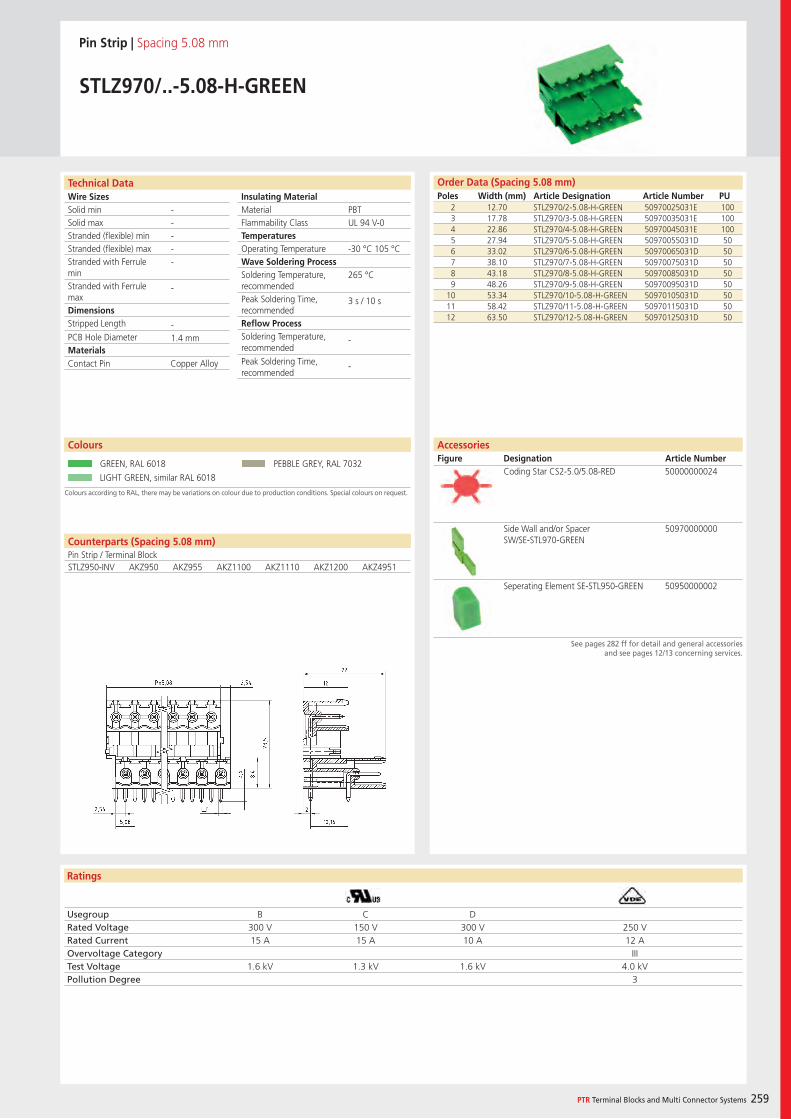
Wire SizesSolid minSolid maxStranded (flexible) minStranded (flexible) maxStranded with Ferrule minStranded with Ferrule maxDimensions Stripped Length
PCB Hole DiameterMaterials
Ratings
PTR Terminal Blocks and Multi Connector Systems 259
Insulating Material MaterialFlammability ClassTemperaturesOperating TemperatureWave Soldering ProcessSoldering Temperature,recommendedPeak Soldering Time,recommendedReflow ProcessSoldering Temperature,recommended
Peak Soldering Time,recommended
Order Data (Spacing 5.08 mm)Poles Width (mm) Article Designation Article Number PU
Technical Data
Pin Strip | Spacing 5.08 mm
STLZ970/..-5.08-H-GREEN
2 12.70 STLZ970/2-5.08-H-GREEN 50970025031E 1003 17.78 STLZ970/3-5.08-H-GREEN 50970035031E 1004 22.86 STLZ970/4-5.08-H-GREEN 50970045031E 1005 27.94 STLZ970/5-5.08-H-GREEN 50970055031D 506 33.02 STLZ970/6-5.08-H-GREEN 50970065031D 507 38.10 STLZ970/7-5.08-H-GREEN 50970075031D 508 43.18 STLZ970/8-5.08-H-GREEN 50970085031D 509 48.26 STLZ970/9-5.08-H-GREEN 50970095031D 50
10 53.34 STLZ970/10-5.08-H-GREEN 50970105031D 5011 58.42 STLZ970/11-5.08-H-GREEN 50970115031D 5012 63.50 STLZ970/12-5.08-H-GREEN 50970125031D 50
PBTUL 94 V-0
-30 °C 105 °C
265 °C
3 s / 10 s
-
-
-----
-
-1.4 mm
Colours according to RAL, there may be variations on colour due to production conditions. Special colours on request.
Colours
GREEN, RAL 6018 PEBBLE GREY, RAL 7032
LIGHT GREEN, similar RAL 6018
Counterparts (Spacing 5.08 mm)Pin Strip / Terminal BlockSTLZ950-INV AKZ950 AKZ955 AKZ1100 AKZ1110 AKZ1200 AKZ4951
Contact Pin Copper Alloy
Usegroup B C DRated Voltage 300 V 150 V 300 V 250 VRated Current 15 A 15 A 10 A 12 AOvervoltage Category IIITest Voltage 1.6 kV 1.3 kV 1.6 kV 4.0 kVPollution Degree 3
AccessoriesFigure Designation Article Number
Coding Star CS2-5.0/5.08-RED 50000000024
Side Wall and/or Spacer SW/SE-STL970-GREEN
50970000000
Seperating Element SE-STL950-GREEN 50950000002
See pages 282 ff for detail and general accessories and see pages 12/13 concerning services.

Wire SizesSolid minSolid maxStranded (flexible) minStranded (flexible) maxStranded with Ferrule minStranded with Ferrule maxDimensions Stripped Length
PCB Hole DiameterMaterials
Ratings
260
Insulating Material MaterialFlammability ClassTemperaturesOperating TemperatureWave Soldering ProcessSoldering Temperature,recommendedPeak Soldering Time,recommendedReflow ProcessSoldering Temperature,recommended
Peak Soldering Time,recommended
Counterparts (Spacing 5.08 mm)Pin Strip / Terminal Block
Technical Data Order Data (Spacing 5.08 mm)Poles Width (mm) Article Designation Article Number PU
Colours
Pin Strip | Spacing 5.08mm
STLZ970/..G-5.08-V-GREEN
2 17.78 STLZ970/2G-5.08-V-GREEN 50970025121E 1003 22.86 STLZ970/3G-5.08-V-GREEN 50970035121E 1004 27.94 STLZ970/4G-5.08-V-GREEN 50970045121E 1005 33.02 STLZ970/5G-5.08-V-GREEN 50970055121D 506 38.10 STLZ970/6G-5.08-V-GREEN 50970065121D 507 43.18 STLZ970/7G-5.08-V-GREEN 50970075121D 508 48.26 STLZ970/8G-5.08-V-GREEN 50970085121D 509 53.34 STLZ970/9G-5.08-V-GREEN 50970095121D 50
10 58.42 STLZ970/10G-5.08-V-GREEN 50970105121D 5011 63.50 STLZ970/11G-5.08-V-GREEN 50970115121D 5012 68.58 STLZ970/12G-5.08-V-GREEN 50970125121D 50
GREEN, RAL 6018 PEBBLE GREY, RAL 7032
LIGHT GREEN, similar RAL 6018
PBTUL 94 V-0
-30 °C - 105 °C
265 °C
3 s / 10 s
-
-
-----
-
-
1.4 mm
STLZ950-INV AKZ950 AKZ955 AKZ1100 AKZ1110 AKZ1200 AKZ4951
Contact Pin Copper Alloy
Usegroup B C DRated Voltage 300 V 150 V 300 V 250 VRated Current 15 A 15 A 10 A 12 AOvervoltage Category IIITest Voltage 1.6 kV 1.3 kV 1.6 kV 4.0 kVPollution Degree 3
AccessoriesFigure Designation Article Number
Coding Star CS2-5.0/5.08-RED 50000000024
Side Wall and/or Spacer SW/SE-STL970-GREEN
50970000000
Separating Element SE-STL950-GREEN 50950000002
See pages 282 ff for detail and general accessories and see pages 12/13 concerning services.
Colours according to RAL, there may be variations on colour due to production conditions. Special colours on request.
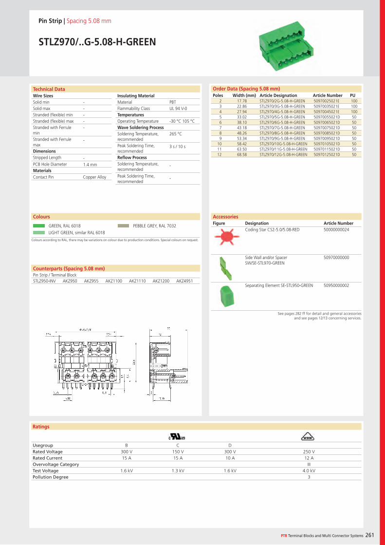
Wire SizesSolid minSolid maxStranded (flexible) minStranded (flexible) maxStranded with Ferrule minStranded with Ferrule maxDimensions Stripped Length
PCB Hole DiameterMaterials
Ratings
PTR Terminal Blocks and Multi Connector Systems 261
Insulating Material MaterialFlammability ClassTemperaturesOperating TemperatureWave Soldering ProcessSoldering Temperature,recommendedPeak Soldering Time,recommendedReflow ProcessSoldering Temperature,recommended
Peak Soldering Time,recommended
Order Data (Spacing 5.08 mm)Poles Width (mm) Article Designation Article Number PU
Technical Data
Pin Strip | Spacing 5.08 mm
STLZ970/..G-5.08-H-GREEN
2 17.78 STLZ970/2G-5.08-H-GREEN 50970025021E 1003 22.86 STLZ970/3G-5.08-H-GREEN 50970035021E 1004 27.94 STLZ970/4G-5.08-H-GREEN 50970045021E 1005 33.02 STLZ970/5G-5.08-H-GREEN 50970055021D 506 38.10 STLZ970/6G-5.08-H-GREEN 50970065021D 507 43.18 STLZ970/7G-5.08-H-GREEN 50970075021D 508 48.26 STLZ970/8G-5.08-H-GREEN 50970085021D 509 53.34 STLZ970/9G-5.08-H-GREEN 50970095021D 50
10 58.42 STLZ970/10G-5.08-H-GREEN 50970105021D 5011 63.50 STLZ970/11G-5.08-H-GREEN 50970115021D 5012 68.58 STLZ970/12G-5.08-H-GREEN 50970125021D 50
PBTUL 94 V-0
-30 °C 105 °C
265 °C
3 s / 10 s
-
-
-----
-
-1.4 mm
Colours according to RAL, there may be variations on colour due to production conditions. Special colours on request.
Colours
GREEN, RAL 6018 PEBBLE GREY, RAL 7032
LIGHT GREEN, similar RAL 6018
Counterparts (Spacing 5.08 mm)Pin Strip / Terminal BlockSTLZ950-INV AKZ950 AKZ955 AKZ1100 AKZ1110 AKZ1200 AKZ4951
Contact Pin Copper Alloy
Usegroup B C DRated Voltage 300 V 150 V 300 V 250 VRated Current 15 A 15 A 10 A 12 AOvervoltage Category IIITest Voltage 1.6 kV 1.3 kV 1.6 kV 4.0 kVPollution Degree 3
AccessoriesFigure Designation Article Number
Coding Star CS2-5.0/5.08-RED 50000000024
Side Wall and/or Spacer SW/SE-STL970-GREEN
50970000000
Separating Element SE-STL950-GREEN 50950000002
See pages 282 ff for detail and general accessories and see pages 12/13 concerning services.
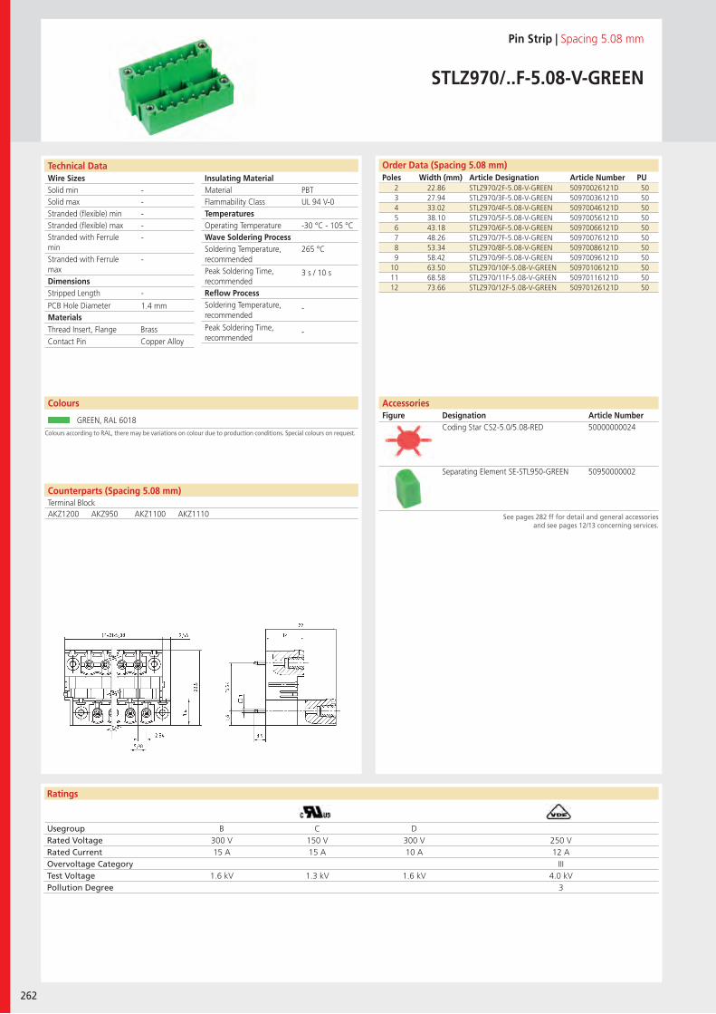
Wire SizesSolid minSolid maxStranded (flexible) minStranded (flexible) maxStranded with Ferrule minStranded with Ferrule maxDimensions Stripped Length
PCB Hole DiameterMaterials
Ratings
262
Insulating Material MaterialFlammability ClassTemperaturesOperating TemperatureWave Soldering ProcessSoldering Temperature,recommendedPeak Soldering Time,recommendedReflow ProcessSoldering Temperature,recommended
Peak Soldering Time,recommended
Technical Data
Colours according to RAL, there may be variations on colour due to production conditions. Special colours on request.
Order Data (Spacing 5.08 mm)Poles Width (mm) Article Designation Article Number PU
Colours
Pin Strip | Spacing 5.08 mm
STLZ970/..F-5.08-V-GREEN
2 22.86 STLZ970/2F-5.08-V-GREEN 50970026121D 503 27.94 STLZ970/3F-5.08-V-GREEN 50970036121D 504 33.02 STLZ970/4F-5.08-V-GREEN 50970046121D 505 38.10 STLZ970/5F-5.08-V-GREEN 50970056121D 506 43.18 STLZ970/6F-5.08-V-GREEN 50970066121D 507 48.26 STLZ970/7F-5.08-V-GREEN 50970076121D 508 53.34 STLZ970/8F-5.08-V-GREEN 50970086121D 509 58.42 STLZ970/9F-5.08-V-GREEN 50970096121D 50
10 63.50 STLZ970/10F-5.08-V-GREEN 50970106121D 5011 68.58 STLZ970/11F-5.08-V-GREEN 50970116121D 5012 73.66 STLZ970/12F-5.08-V-GREEN 50970126121D 50
GREEN, RAL 6018
PBTUL 94 V-0
-30 °C - 105 °C
265 °C
3 s / 10 s
-
-
-----
-
-
1.4 mm
Counterparts (Spacing 5.08 mm)Terminal BlockAKZ1200 AKZ950 AKZ1100 AKZ1110
Thread Insert, Flange BrassContact Pin Copper Alloy
Usegroup B C DRated Voltage 300 V 150 V 300 V 250 VRated Current 15 A 15 A 10 A 12 AOvervoltage Category IIITest Voltage 1.6 kV 1.3 kV 1.6 kV 4.0 kVPollution Degree 3
Coding Star CS2-5.0/5.08-RED 50000000024
Separating Element SE-STL950-GREEN 50950000002
AccessoriesFigure Designation Article Number
See pages 282 ff for detail and general accessories and see pages 12/13 concerning services.
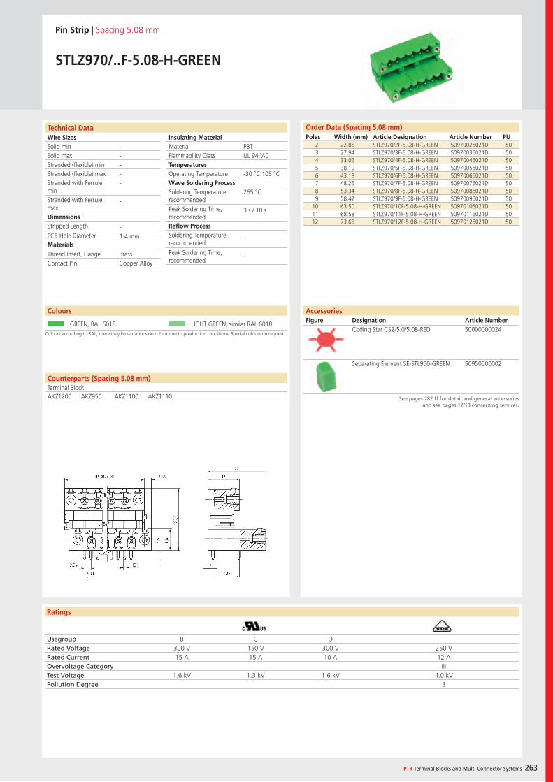
Wire SizesSolid minSolid maxStranded (flexible) minStranded (flexible) maxStranded with Ferrule minStranded with Ferrule maxDimensions Stripped Length
PCB Hole DiameterMaterials
Ratings
PTR Terminal Blocks and Multi Connector Systems 263
Insulating Material MaterialFlammability ClassTemperaturesOperating TemperatureWave Soldering ProcessSoldering Temperature,recommendedPeak Soldering Time,recommendedReflow ProcessSoldering Temperature,recommended
Peak Soldering Time,recommended
Order Data (Spacing 5.08 mm)Poles Width (mm) Article Designation Article Number PU
Technical Data
Pin Strip | Spacing 5.08 mm
STLZ970/..F-5.08-H-GREEN
2 22.86 STLZ970/2F-5.08-H-GREEN 50970026021D 503 27.94 STLZ970/3F-5.08-H-GREEN 50970036021D 504 33.02 STLZ970/4F-5.08-H-GREEN 50970046021D 505 38.10 STLZ970/5F-5.08-H-GREEN 50970056021D 506 43.18 STLZ970/6F-5.08-H-GREEN 50970066021D 507 48.26 STLZ970/7F-5.08-H-GREEN 50970076021D 508 53.34 STLZ970/8F-5.08-H-GREEN 50970086021D 509 58.42 STLZ970/9F-5.08-H-GREEN 50970096021D 50
10 63.50 STLZ970/10F-5.08-H-GREEN 50970106021D 5011 68.58 STLZ970/11F-5.08-H-GREEN 50970116021D 5012 73.66 STLZ970/12F-5.08-H-GREEN 50970126021D 50
PBTUL 94 V-0
-30 °C 105 °C
265 °C
3 s / 10 s
-
-
-----
-
-1.4 mm
Colours according to RAL, there may be variations on colour due to production conditions. Special colours on request.
Colours
GREEN, RAL 6018 LIGHT GREEN, similar RAL 6018
Counterparts (Spacing 5.08 mm)Terminal BlockAKZ1200 AKZ950 AKZ1100 AKZ1110
Thread Insert, Flange BrassContact Pin Copper Alloy
Usegroup B C DRated Voltage 300 V 150 V 300 V 250 VRated Current 15 A 15 A 10 A 12 AOvervoltage Category IIITest Voltage 1.6 kV 1.3 kV 1.6 kV 4.0 kVPollution Degree 3
AccessoriesFigure Designation Article Number
Coding Star CS2-5.0/5.08-RED 50000000024
Separating Element SE-STL950-GREEN 50950000002
See pages 282 ff for detail and general accessories and see pages 12/13 concerning services.
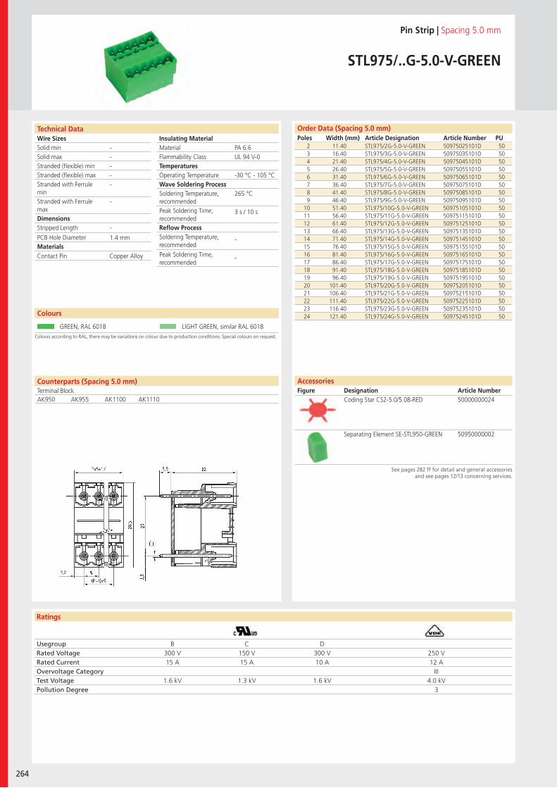
Wire SizesSolid minSolid maxStranded (flexible) minStranded (flexible) maxStranded with Ferrule minStranded with Ferrule maxDimensions Stripped Length
PCB Hole DiameterMaterials
Ratings
264
Insulating Material MaterialFlammability ClassTemperaturesOperating TemperatureWave Soldering ProcessSoldering Temperature,recommendedPeak Soldering Time,recommendedReflow ProcessSoldering Temperature,recommended
Peak Soldering Time,recommended
Technical Data
Colours according to RAL, there may be variations on colour due to production conditions. Special colours on request.
Order Data (Spacing 5.0 mm)Poles Width (mm) Article Designation Article Number PU
Colours
Pin Strip | Spacing 5.0 mm
STL975/..G-5.0-V-GREEN
2 11.40 STL975/2G-5.0-V-GREEN 50975025101D 503 16.40 STL975/3G-5.0-V-GREEN 50975035101D 504 21.40 STL975/4G-5.0-V-GREEN 50975045101D 505 26.40 STL975/5G-5.0-V-GREEN 50975055101D 506 31.40 STL975/6G-5.0-V-GREEN 50975065101D 507 36.40 STL975/7G-5.0-V-GREEN 50975075101D 508 41.40 STL975/8G-5.0-V-GREEN 50975085101D 509 46.40 STL975/9G-5.0-V-GREEN 50975095101D 50
10 51.40 STL975/10G-5.0-V-GREEN 50975105101D 5011 56.40 STL975/11G-5.0-V-GREEN 50975115101D 5012 61.40 STL975/12G-5.0-V-GREEN 50975125101D 5013 66.40 STL975/13G-5.0-V-GREEN 50975135101D 5014 71.40 STL975/14G-5.0-V-GREEN 50975145101D 5015 76.40 STL975/15G-5.0-V-GREEN 50975155101D 5016 81.40 STL975/16G-5.0-V-GREEN 50975165101D 5017 86.40 STL975/17G-5.0-V-GREEN 50975175101D 5018 91.40 STL975/18G-5.0-V-GREEN 50975185101D 5019 96.40 STL975/19G-5.0-V-GREEN 50975195101D 5020 101.40 STL975/20G-5.0-V-GREEN 50975205101D 5021 106.40 STL975/21G-5.0-V-GREEN 50975215101D 5022 111.40 STL975/22G-5.0-V-GREEN 50975225101D 5023 116.40 STL975/23G-5.0-V-GREEN 50975235101D 5024 121.40 STL975/24G-5.0-V-GREEN 50975245101D 50
GREEN, RAL 6018 LIGHT GREEN, similar RAL 6018
PA 6.6UL 94 V-0
-30 °C - 105 °C
265 °C
3 s / 10 s
-
-
-----
-
-
1.4 mm
Counterparts (Spacing 5.0 mm)Terminal BlockAK950 AK955 AK1100 AK1110
Contact Pin Copper Alloy
Usegroup B C DRated Voltage 300 V 150 V 300 V 250 VRated Current 15 A 15 A 10 A 12 AOvervoltage Category IIITest Voltage 1.6 kV 1.3 kV 1.6 kV 4.0 kVPollution Degree 3
Coding Star CS2-5.0/5.08-RED 50000000024
Separating Element SE-STL950-GREEN 50950000002
AccessoriesFigure Designation Article Number
See pages 282 ff for detail and general accessories and see pages 12/13 concerning services.
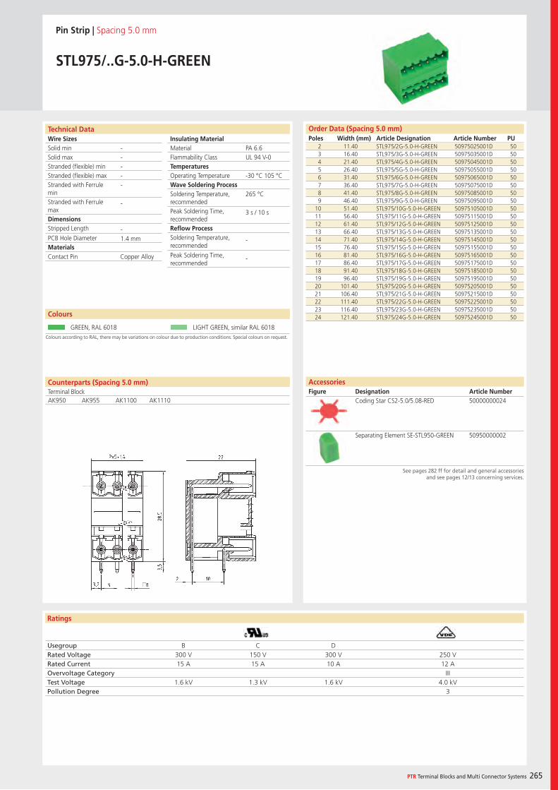
Wire SizesSolid minSolid maxStranded (flexible) minStranded (flexible) maxStranded with Ferrule minStranded with Ferrule maxDimensions Stripped Length
PCB Hole DiameterMaterials
Ratings
PTR Terminal Blocks and Multi Connector Systems 265
Insulating Material MaterialFlammability ClassTemperaturesOperating TemperatureWave Soldering ProcessSoldering Temperature,recommendedPeak Soldering Time,recommendedReflow ProcessSoldering Temperature,recommended
Peak Soldering Time,recommended
Order Data (Spacing 5.0 mm)Poles Width (mm) Article Designation Article Number PU
Technical Data
Pin Strip | Spacing 5.0 mm
STL975/..G-5.0-H-GREEN
2 11.40 STL975/2G-5.0-H-GREEN 50975025001D 503 16.40 STL975/3G-5.0-H-GREEN 50975035001D 504 21.40 STL975/4G-5.0-H-GREEN 50975045001D 505 26.40 STL975/5G-5.0-H-GREEN 50975055001D 506 31.40 STL975/6G-5.0-H-GREEN 50975065001D 507 36.40 STL975/7G-5.0-H-GREEN 50975075001D 508 41.40 STL975/8G-5.0-H-GREEN 50975085001D 509 46.40 STL975/9G-5.0-H-GREEN 50975095001D 50
10 51.40 STL975/10G-5.0-H-GREEN 50975105001D 5011 56.40 STL975/11G-5.0-H-GREEN 50975115001D 5012 61.40 STL975/12G-5.0-H-GREEN 50975125001D 5013 66.40 STL975/13G-5.0-H-GREEN 50975135001D 5014 71.40 STL975/14G-5.0-H-GREEN 50975145001D 5015 76.40 STL975/15G-5.0-H-GREEN 50975155001D 5016 81.40 STL975/16G-5.0-H-GREEN 50975165001D 5017 86.40 STL975/17G-5.0-H-GREEN 50975175001D 5018 91.40 STL975/18G-5.0-H-GREEN 50975185001D 5019 96.40 STL975/19G-5.0-H-GREEN 50975195001D 5020 101.40 STL975/20G-5.0-H-GREEN 50975205001D 5021 106.40 STL975/21G-5.0-H-GREEN 50975215001D 5022 111.40 STL975/22G-5.0-H-GREEN 50975225001D 5023 116.40 STL975/23G-5.0-H-GREEN 50975235001D 5024 121.40 STL975/24G-5.0-H-GREEN 50975245001D 50
PA 6.6UL 94 V-0
-30 °C 105 °C
265 °C
3 s / 10 s
-
-
-----
-
-1.4 mm
Colours according to RAL, there may be variations on colour due to production conditions. Special colours on request.
Colours
GREEN, RAL 6018 LIGHT GREEN, similar RAL 6018
Counterparts (Spacing 5.0 mm)Terminal BlockAK950 AK955 AK1100 AK1110
Contact Pin Copper Alloy
Usegroup B C DRated Voltage 300 V 150 V 300 V 250 VRated Current 15 A 15 A 10 A 12 AOvervoltage Category IIITest Voltage 1.6 kV 1.3 kV 1.6 kV 4.0 kVPollution Degree 3
AccessoriesFigure Designation Article Number
Coding Star CS2-5.0/5.08-RED 50000000024
Separating Element SE-STL950-GREEN 50950000002
See pages 282 ff for detail and general accessories and see pages 12/13 concerning services.
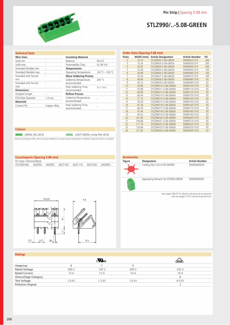
Wire SizesSolid minSolid maxStranded (flexible) minStranded (flexible) maxStranded with Ferrule minStranded with Ferrule maxDimensions Stripped Length
PCB Hole DiameterMaterials
Ratings
266
Insulating Material MaterialFlammability ClassTemperaturesOperating TemperatureWave Soldering ProcessSoldering Temperature,recommendedPeak Soldering Time,recommendedReflow ProcessSoldering Temperature,recommended
Peak Soldering Time,recommended
Technical Data
Colours according to RAL, there may be variations on colour due to production conditions. Special colours on request.
Order Data (Spacing 5.08 mm)Poles Width (mm) Article Designation Article Number PU
Colours
Pin Strip | Spacing 5.08 mm
STLZ990/..-5.08-GREEN
2 10.16 STLZ990/2-5.08-GREEN 50990025131F 2003 15.24 STLZ990/3-5.08-GREEN 50990035131F 2004 20.32 STLZ990/4-5.08-GREEN 50990045131F 2005 25.40 STLZ990/5-5.08-GREEN 50990055131E 1006 30.48 STLZ990/6-5.08-GREEN 50990065131E 1007 35.56 STLZ990/7-5.08-GREEN 50990075131E 1008 40.64 STLZ990/8-5.08-GREEN 50990085131D 509 45.72 STLZ990/9-5.08-GREEN 50990095131D 50
10 50.80 STLZ990/10-5.08-GREEN 50990105131D 5011 55.88 STLZ990/11-5.08-GREEN 50990115131D 5012 60.96 STLZ990/12-5.08-GREEN 50990125131D 5013 66.04 STLZ990/13-5.08-GREEN 50990135131D 5014 71.12 STLZ990/14-5.08-GREEN 50990145131D 5015 76.20 STLZ990/15-5.08-GREEN 50990155131D 5016 81.28 STLZ990/16-5.08-GREEN 50990165131D 5017 86.36 STLZ990/17-5.08-GREEN 50990175131D 5018 91.44 STLZ990/18-5.08-GREEN 50990185131D 5019 96.52 STLZ990/19-5.08-GREEN 50990195131D 5020 101.60 STLZ990/20-5.08-GREEN 50990205131D 5021 106.68 STLZ990/21-5.08-GREEN 50990215131D 5022 111.76 STLZ990/22-5.08-GREEN 50990225131D 5023 116.84 STLZ990/23-5.08-GREEN 50990235131D 5024 121.92 STLZ990/24-5.08-GREEN 50990245131D 50
GREEN, RAL 6018 LIGHT GREEN, similar RAL 6018
PA 6.6UL 94 V-0
-30 °C - 105 °C
265 °C
3 s / 10 s
-
-
-----
-
-
1.4 mm
Counterparts (Spacing 5.08 mm)Pin Strip / Terminal BlockSTLZ950-INV AKZ950 AKZ955 AKZ1100 AKZ1110 AKZ1200 AKZ4951
Contact Pin Copper Alloy
Usegroup B C DRated Voltage 300 V 150 V 300 V 250 VRated Current 15 A 15 A 10 A 10 AOvervoltage Category IIITest Voltage 1.6 kV 1.3 kV 1.6 kV 4.0 kVPollution Degree 3
Coding Star CS2-5.0/5.08-RED 50000000024
Separating Element SE-STL950-GREEN 50950000002
AccessoriesFigure Designation Article Number
See pages 282 ff for detail and general accessories and see pages 12/13 concerning services.
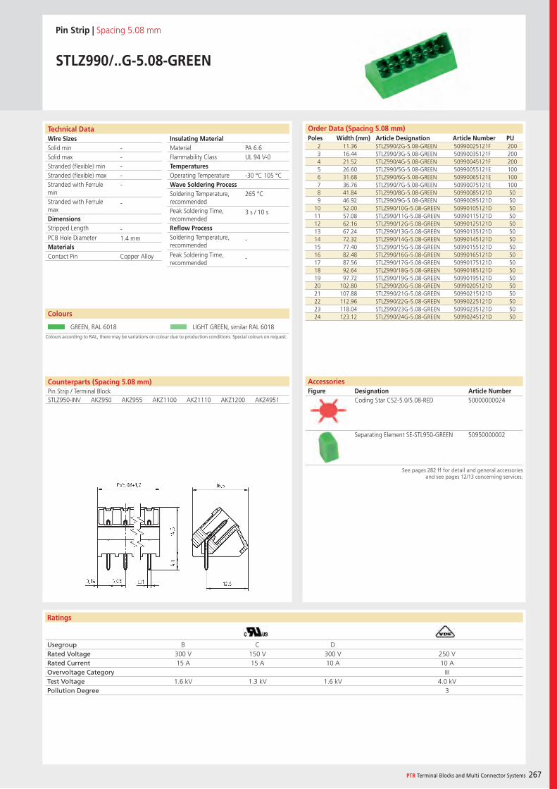
Wire SizesSolid minSolid maxStranded (flexible) minStranded (flexible) maxStranded with Ferrule minStranded with Ferrule maxDimensions Stripped Length
PCB Hole DiameterMaterials
Ratings
PTR Terminal Blocks and Multi Connector Systems 267
Insulating Material MaterialFlammability ClassTemperaturesOperating TemperatureWave Soldering ProcessSoldering Temperature,recommendedPeak Soldering Time,recommendedReflow ProcessSoldering Temperature,recommended
Peak Soldering Time,recommended
Order Data (Spacing 5.08 mm)Poles Width (mm) Article Designation Article Number PU
Technical Data
Pin Strip | Spacing 5.08 mm
STLZ990/..G-5.08-GREEN
2 11.36 STLZ990/2G-5.08-GREEN 50990025121F 2003 16.44 STLZ990/3G-5.08-GREEN 50990035121F 2004 21.52 STLZ990/4G-5.08-GREEN 50990045121F 2005 26.60 STLZ990/5G-5.08-GREEN 50990055121E 1006 31.68 STLZ990/6G-5.08-GREEN 50990065121E 1007 36.76 STLZ990/7G-5.08-GREEN 50990075121E 1008 41.84 STLZ990/8G-5.08-GREEN 50990085121D 509 46.92 STLZ990/9G-5.08-GREEN 50990095121D 50
10 52.00 STLZ990/10G-5.08-GREEN 50990105121D 5011 57.08 STLZ990/11G-5.08-GREEN 50990115121D 5012 62.16 STLZ990/12G-5.08-GREEN 50990125121D 5013 67.24 STLZ990/13G-5.08-GREEN 50990135121D 5014 72.32 STLZ990/14G-5.08-GREEN 50990145121D 5015 77.40 STLZ990/15G-5.08-GREEN 50990155121D 5016 82.48 STLZ990/16G-5.08-GREEN 50990165121D 5017 87.56 STLZ990/17G-5.08-GREEN 50990175121D 5018 92.64 STLZ990/18G-5.08-GREEN 50990185121D 5019 97.72 STLZ990/19G-5.08-GREEN 50990195121D 5020 102.80 STLZ990/20G-5.08-GREEN 50990205121D 5021 107.88 STLZ990/21G-5.08-GREEN 50990215121D 5022 112.96 STLZ990/22G-5.08-GREEN 50990225121D 5023 118.04 STLZ990/23G-5.08-GREEN 50990235121D 5024 123.12 STLZ990/24G-5.08-GREEN 50990245121D 50
PA 6.6UL 94 V-0
-30 °C 105 °C
265 °C
3 s / 10 s
-
-
-----
-
-1.4 mm
Colours according to RAL, there may be variations on colour due to production conditions. Special colours on request.
Colours
GREEN, RAL 6018 LIGHT GREEN, similar RAL 6018
Counterparts (Spacing 5.08 mm)Pin Strip / Terminal BlockSTLZ950-INV AKZ950 AKZ955 AKZ1100 AKZ1110 AKZ1200 AKZ4951
Contact Pin Copper Alloy
Usegroup B C DRated Voltage 300 V 150 V 300 V 250 VRated Current 15 A 15 A 10 A 10 AOvervoltage Category IIITest Voltage 1.6 kV 1.3 kV 1.6 kV 4.0 kVPollution Degree 3
AccessoriesFigure Designation Article Number
Coding Star CS2-5.0/5.08-RED 50000000024
Separating Element SE-STL950-GREEN 50950000002
See pages 282 ff for detail and general accessories and see pages 12/13 concerning services.
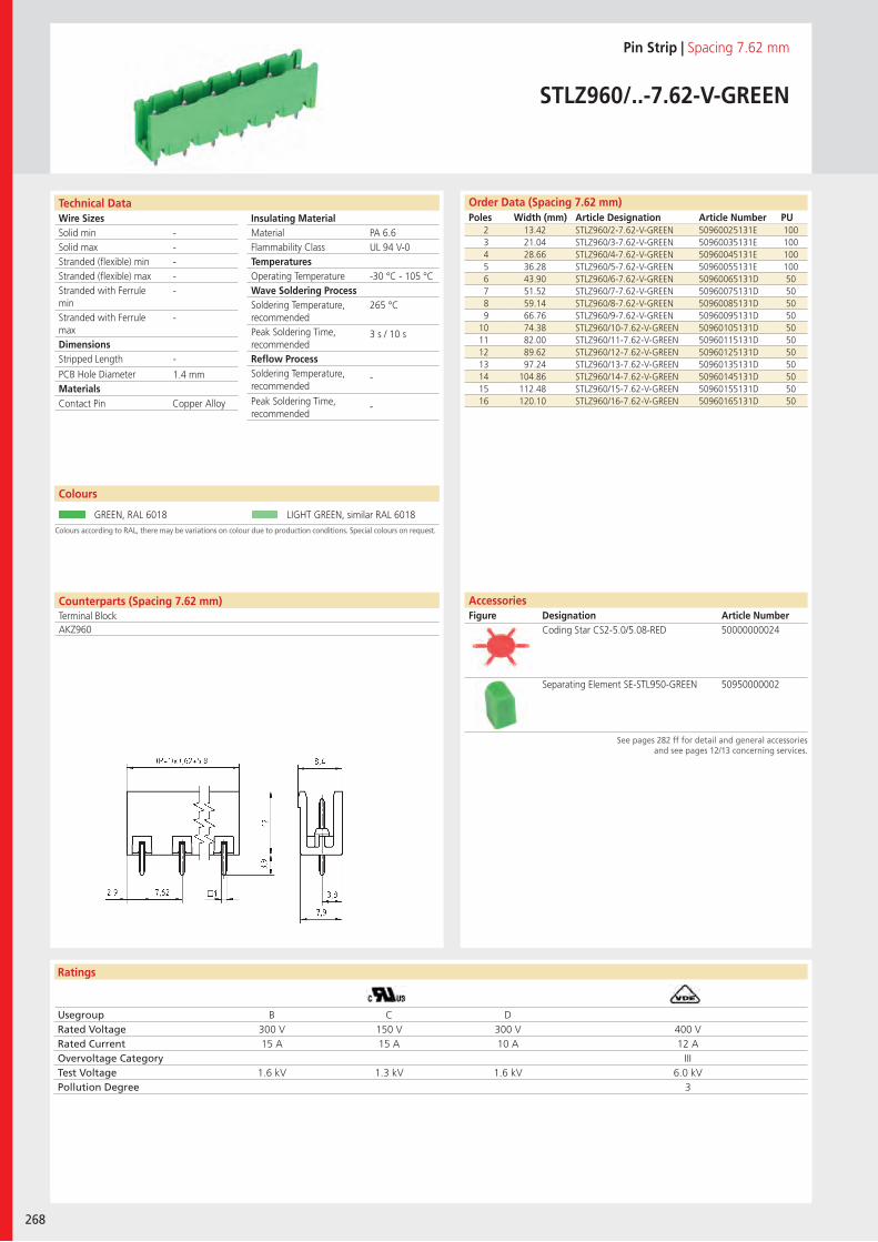
Wire SizesSolid minSolid maxStranded (flexible) minStranded (flexible) maxStranded with Ferrule minStranded with Ferrule maxDimensions Stripped Length
PCB Hole DiameterMaterials
Ratings
268
Insulating Material MaterialFlammability ClassTemperaturesOperating TemperatureWave Soldering ProcessSoldering Temperature,recommendedPeak Soldering Time,recommendedReflow ProcessSoldering Temperature,recommended
Peak Soldering Time,recommended
Technical Data
Colours according to RAL, there may be variations on colour due to production conditions. Special colours on request.
Order Data (Spacing 7.62 mm)Poles Width (mm) Article Designation Article Number PU
Colours
Pin Strip | Spacing 7.62 mm
STLZ960/..-7.62-V-GREEN
2 13.42 STLZ960/2-7.62-V-GREEN 50960025131E 1003 21.04 STLZ960/3-7.62-V-GREEN 50960035131E 1004 28.66 STLZ960/4-7.62-V-GREEN 50960045131E 1005 36.28 STLZ960/5-7.62-V-GREEN 50960055131E 1006 43.90 STLZ960/6-7.62-V-GREEN 50960065131D 507 51.52 STLZ960/7-7.62-V-GREEN 50960075131D 508 59.14 STLZ960/8-7.62-V-GREEN 50960085131D 509 66.76 STLZ960/9-7.62-V-GREEN 50960095131D 50
10 74.38 STLZ960/10-7.62-V-GREEN 50960105131D 5011 82.00 STLZ960/11-7.62-V-GREEN 50960115131D 5012 89.62 STLZ960/12-7.62-V-GREEN 50960125131D 5013 97.24 STLZ960/13-7.62-V-GREEN 50960135131D 5014 104.86 STLZ960/14-7.62-V-GREEN 50960145131D 5015 112.48 STLZ960/15-7.62-V-GREEN 50960155131D 5016 120.10 STLZ960/16-7.62-V-GREEN 50960165131D 50
GREEN, RAL 6018 LIGHT GREEN, similar RAL 6018
PA 6.6UL 94 V-0
-30 °C - 105 °C
265 °C
3 s / 10 s
-
-
-----
-
-
1.4 mm
Counterparts (Spacing 7.62 mm)Terminal BlockAKZ960
Contact Pin Copper Alloy
Usegroup B C DRated Voltage 300 V 150 V 300 V 400 VRated Current 15 A 15 A 10 A 12 AOvervoltage Category IIITest Voltage 1.6 kV 1.3 kV 1.6 kV 6.0 kVPollution Degree 3
Coding Star CS2-5.0/5.08-RED 50000000024
Separating Element SE-STL950-GREEN 50950000002
AccessoriesFigure Designation Article Number
See pages 282 ff for detail and general accessories and see pages 12/13 concerning services.
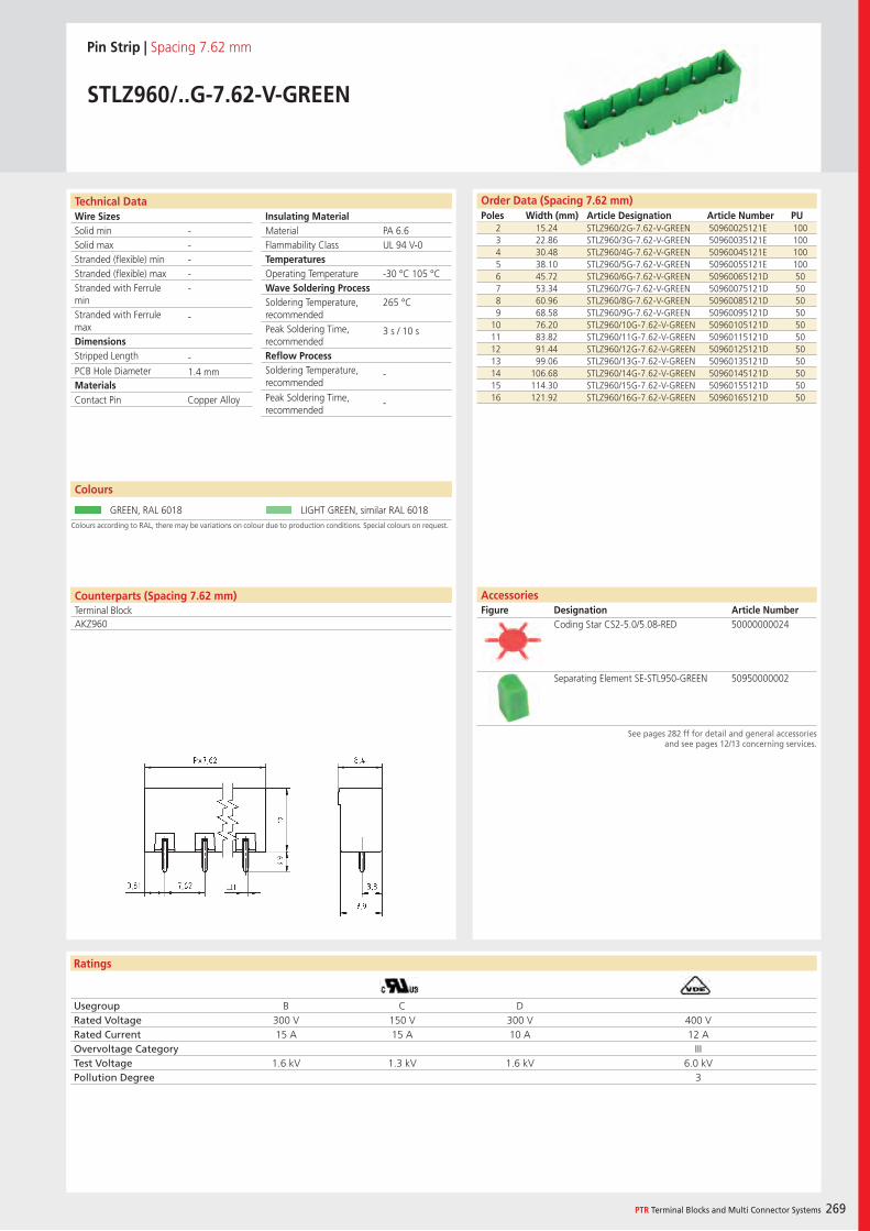
Wire SizesSolid minSolid maxStranded (flexible) minStranded (flexible) maxStranded with Ferrule minStranded with Ferrule maxDimensions Stripped Length
PCB Hole DiameterMaterials
Ratings
PTR Terminal Blocks and Multi Connector Systems 269
Insulating Material MaterialFlammability ClassTemperaturesOperating TemperatureWave Soldering ProcessSoldering Temperature,recommendedPeak Soldering Time,recommendedReflow ProcessSoldering Temperature,recommended
Peak Soldering Time,recommended
Order Data (Spacing 7.62 mm)Poles Width (mm) Article Designation Article Number PU
Technical Data
Pin Strip | Spacing 7.62 mm
STLZ960/..G-7.62-V-GREEN
2 15.24 STLZ960/2G-7.62-V-GREEN 50960025121E 1003 22.86 STLZ960/3G-7.62-V-GREEN 50960035121E 1004 30.48 STLZ960/4G-7.62-V-GREEN 50960045121E 1005 38.10 STLZ960/5G-7.62-V-GREEN 50960055121E 1006 45.72 STLZ960/6G-7.62-V-GREEN 50960065121D 507 53.34 STLZ960/7G-7.62-V-GREEN 50960075121D 508 60.96 STLZ960/8G-7.62-V-GREEN 50960085121D 509 68.58 STLZ960/9G-7.62-V-GREEN 50960095121D 50
10 76.20 STLZ960/10G-7.62-V-GREEN 50960105121D 5011 83.82 STLZ960/11G-7.62-V-GREEN 50960115121D 5012 91.44 STLZ960/12G-7.62-V-GREEN 50960125121D 5013 99.06 STLZ960/13G-7.62-V-GREEN 50960135121D 5014 106.68 STLZ960/14G-7.62-V-GREEN 50960145121D 5015 114.30 STLZ960/15G-7.62-V-GREEN 50960155121D 5016 121.92 STLZ960/16G-7.62-V-GREEN 50960165121D 50
PA 6.6UL 94 V-0
-30 °C 105 °C
265 °C
3 s / 10 s
-
-
-----
-
-1.4 mm
Colours according to RAL, there may be variations on colour due to production conditions. Special colours on request.
Colours
GREEN, RAL 6018 LIGHT GREEN, similar RAL 6018
Counterparts (Spacing 7.62 mm)Terminal BlockAKZ960
Contact Pin Copper Alloy
Usegroup B C DRated Voltage 300 V 150 V 300 V 400 VRated Current 15 A 15 A 10 A 12 AOvervoltage Category IIITest Voltage 1.6 kV 1.3 kV 1.6 kV 6.0 kVPollution Degree 3
AccessoriesFigure Designation Article Number
Coding Star CS2-5.0/5.08-RED 50000000024
Separating Element SE-STL950-GREEN 50950000002
See pages 282 ff for detail and general accessories and see pages 12/13 concerning services.
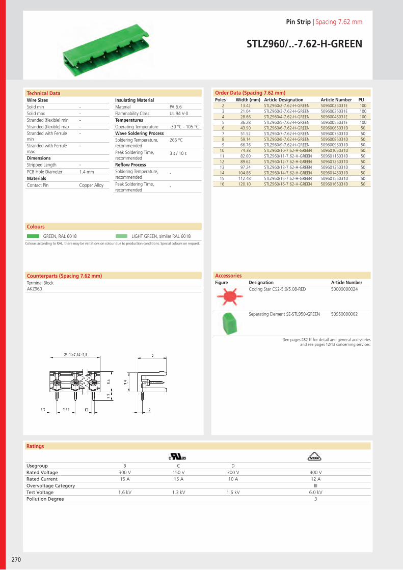
Wire SizesSolid minSolid maxStranded (flexible) minStranded (flexible) maxStranded with Ferrule minStranded with Ferrule maxDimensions Stripped Length
PCB Hole DiameterMaterials
Ratings
270
Insulating Material MaterialFlammability ClassTemperaturesOperating TemperatureWave Soldering ProcessSoldering Temperature,recommendedPeak Soldering Time,recommendedReflow ProcessSoldering Temperature,recommended
Peak Soldering Time,recommended
Technical Data
Colours according to RAL, there may be variations on colour due to production conditions. Special colours on request.
Order Data (Spacing 7.62 mm)Poles Width (mm) Article Designation Article Number PU
Colours
Pin Strip | Spacing 7.62 mm
STLZ960/..-7.62-H-GREEN
2 13.42 STLZ960/2-7.62-H-GREEN 50960025031E 1003 21.04 STLZ960/3-7.62-H-GREEN 50960035031E 1004 28.66 STLZ960/4-7.62-H-GREEN 50960045031E 1005 36.28 STLZ960/5-7.62-H-GREEN 50960055031E 1006 43.90 STLZ960/6-7.62-H-GREEN 50960065031D 507 51.52 STLZ960/7-7.62-H-GREEN 50960075031D 508 59.14 STLZ960/8-7.62-H-GREEN 50960085031D 509 66.76 STLZ960/9-7.62-H-GREEN 50960095031D 50
10 74.38 STLZ960/10-7.62-H-GREEN 50960105031D 5011 82.00 STLZ960/11-7.62-H-GREEN 50960115031D 5012 89.62 STLZ960/12-7.62-H-GREEN 50960125031D 5013 97.24 STLZ960/13-7.62-H-GREEN 50960135031D 5014 104.86 STLZ960/14-7.62-H-GREEN 50960145031D 5015 112.48 STLZ960/15-7.62-H-GREEN 50960155031D 5016 120.10 STLZ960/16-7.62-H-GREEN 50960165031D 50
GREEN, RAL 6018 LIGHT GREEN, similar RAL 6018
PA 6.6UL 94 V-0
-30 °C - 105 °C
265 °C
3 s / 10 s
-
-
-----
-
-
1.4 mm
Counterparts (Spacing 7.62 mm)Terminal BlockAKZ960
Contact Pin Copper Alloy
Usegroup B C DRated Voltage 300 V 150 V 300 V 400 VRated Current 15 A 15 A 10 A 12 AOvervoltage Category IIITest Voltage 1.6 kV 1.3 kV 1.6 kV 6.0 kVPollution Degree 3
Coding Star CS2-5.0/5.08-RED 50000000024
Separating Element SE-STL950-GREEN 50950000002
AccessoriesFigure Designation Article Number
See pages 282 ff for detail and general accessories and see pages 12/13 concerning services.
Wire SizesSolid minSolid maxStranded (flexible) minStranded (flexible) maxStranded with Ferrule minStranded with Ferrule maxDimensions Stripped Length
PCB Hole DiameterMaterials
Ratings
PTR Terminal Blocks and Multi Connector Systems 271
Insulating Material MaterialFlammability ClassTemperaturesOperating TemperatureWave Soldering ProcessSoldering Temperature,recommendedPeak Soldering Time,recommendedReflow ProcessSoldering Temperature,recommended
Peak Soldering Time,recommended
Order Data (Spacing 7.62 mm)Poles Width (mm) Article Designation Article Number PU
Technical Data
Pin Strip | Spacing 7.62 mm
STLZ960/..G-7.62-H-GREEN
2 15.24 STLZ960/2G-7.62-H-GREEN 50960025021E 1003 22.86 STLZ960/3G-7.62-H-GREEN 50960035021E 1004 30.48 STLZ960/4G-7.62-H-GREEN 50960045021E 1005 38.10 STLZ960/5G-7.62-H-GREEN 50960055021E 1006 45.72 STLZ960/6G-7.62-H-GREEN 50960065021D 507 53.34 STLZ960/7G-7.62-H-GREEN 50960075021D 508 60.96 STLZ960/8G-7.62-H-GREEN 50960085021D 509 68.58 STLZ960/9G-7.62-H-GREEN 50960095021D 50
10 76.20 STLZ960/10G-7.62-H-GREEN 50960105021D 5011 83.82 STLZ960/11G-7.62-H-GREEN 50960115021D 5012 91.44 STLZ960/12G-7.62-H-GREEN 50960125021D 5013 99.06 STLZ960/13G-7.62-H-GREEN 50960135021D 5014 106.68 STLZ960/14G-7.62-H-GREEN 50960145021D 5015 114.30 STLZ960/15G-7.62-H-GREEN 50960155021D 5016 121.92 STLZ960/16G-7.62-H-GREEN 50960165021D 50
PA 6.6UL 94 V-0
-30 °C 105 °C
265 °C
3 s / 10 s
-
-
-----
-
-1.4 mm
Colours according to RAL, there may be variations on colour due to production conditions. Special colours on request.
Colours
GREEN, RAL 6018 LIGHT GREEN, similar RAL 6018
Counterparts (Spacing 7.62 mm)Terminal BlockAKZ960
Contact Pin Copper Alloy
Usegroup B C DRated Voltage 300 V 150 V 300 V 400 VRated Current 15 A 15 A 10 A 12 AOvervoltage Category IIITest Voltage 1.6 kV 1.3 kV 1.6 kV 6.0 kVPollution Degree 3
AccessoriesFigure Designation Article Number
Coding Star CS2-5.0/5.08-RED 50000000024
Separating Element SE-STL950-GREEN 50950000002
See pages 282 ff for detail and general accessories and see pages 12/13 concerning services.
Wire SizesSolid minSolid maxStranded (flexible) minStranded (flexible) maxStranded with Ferrule minStranded with Ferrule maxDimensions Stripped Length
PCB Hole DiameterMaterials
Ratings
272
Insulating Material MaterialFlammability ClassTemperaturesOperating TemperatureWave Soldering ProcessSoldering Temperature,recommendedPeak Soldering Time,recommendedReflow ProcessSoldering Temperature,recommended
Peak Soldering Time,recommended
Technical Data
Colours according to RAL, there may be variations on colour due to production conditions. Special colours on request.
Order Data (Spacing 7.62 mm)Poles Width (mm) Article Designation Article Number PU
Colours
Pin Strip | Spacing 7.62 mm
STLZ965/..F-7.62-V-GREEN
2 25.82 STLZ965/2F-7.62-V-GREEN 50965026121E 1003 33.44 STLZ965/3F-7.62-V-GREEN 50965036121E 1004 41.06 STLZ965/4F-7.62-V-GREEN 50965046121D 505 48.68 STLZ965/5F-7.62-V-GREEN 50965056121D 506 56.30 STLZ965/6F-7.62-V-GREEN 50965066121D 507 63.92 STLZ965/7F-7.62-V-GREEN 50965076121D 508 71.54 STLZ965/8F-7.62-V-GREEN 50965086121D 509 79.16 STLZ965/9F-7.62-V-GREEN 50965096121D 50
10 86.78 STLZ965/10F-7.62-V-GREEN 50965106121D 5011 94.40 STLZ965/11F-7.62-V-GREEN 50965116121D 5012 102.02 STLZ965/12F-7.62-V-GREEN 50965126121D 5013 109.64 STLZ965/13F-7.62-V-GREEN 50965136121D 5014 117.26 STLZ965/14F-7.62-V-GREEN 50965146121D 5015 124.88 STLZ965/15F-7.62-V-GREEN 50965156121D 5016 132.50 STLZ965/16F-7.62-V-GREEN 50965166121D 50
GREEN, RAL 6018 LIGHT GREEN, similar RAL 6018
PBTUL 94 V-0
-30 °C - 105 °C
265 °C
3 s / 10 s
-
-
-----
-
-
1.6 mm
Counterparts (Spacing 7.62 mm)Terminal BlockAKZ965
Thread Insert, Flange BrassContact Pin Brass
Usegroup B C DRated Voltage 300 V - 300 V 400 VRated Current 10 A - 10 A 12 AOvervoltage Category IIITest Voltage 1.6 kV - 1.6 kV 6.0 kVPollution Degree 3
Coding Star CS3-5.0/5.08-RED 50000000025
Separating Element SE-STL950-GREEN 50950000002
AccessoriesFigure Designation Article Number
See pages 282 ff for detail and general accessories and see pages 12/13 concerning services.
Wire SizesSolid minSolid maxStranded (flexible) minStranded (flexible) maxStranded with Ferrule minStranded with Ferrule maxDimensions Stripped Length
PCB Hole DiameterMaterials
Ratings
PTR Terminal Blocks and Multi Connector Systems 273
Insulating Material MaterialFlammability ClassTemperaturesOperating TemperatureWave Soldering ProcessSoldering Temperature,recommendedPeak Soldering Time,recommendedReflow ProcessSoldering Temperature,recommended
Peak Soldering Time,recommended
Order Data (Spacing 7.62 mm)Poles Width (mm) Article Designation Article Number PU
Technical Data
Pin Strip | Spacing 7.62 mm
STLZ965/..F-7.62-H-GREEN
2 25.82 STLZ965/2F-7.62-H-GREEN 50965026021E 1003 33.44 STLZ965/3F-7.62-H-GREEN 50965036021E 1004 41.06 STLZ965/4F-7.62-H-GREEN 50965046021D 505 48.68 STLZ965/5F-7.62-H-GREEN 50965056021D 506 56.30 STLZ965/6F-7.62-H-GREEN 50965066021D 507 63.92 STLZ965/7F-7.62-H-GREEN 50965076021D 508 71.54 STLZ965/8F-7.62-H-GREEN 50965086021D 509 79.16 STLZ965/9F-7.62-H-GREEN 50965096021D 50
10 86.78 STLZ965/10F-7.62-H-GREEN 50965106021D 5011 94.40 STLZ965/11F-7.62-H-GREEN 50965116021D 5012 102.02 STLZ965/12F-7.62-H-GREEN 50965126021D 5013 109.64 STLZ965/13F-7.62-H-GREEN 50965136021D 5014 117.26 STLZ965/14F-7.62-H-GREEN 50965146021D 5015 124.88 STLZ965/15F-7.62-H-GREEN 50965156021D 5016 132.50 STLZ965/16F-7.62-H-GREEN 50965166021D 50
PBTUL 94 V-0
-30 °C 105 °C
265 °C
3 s / 10 s
-
-
-----
-
-1.6 mm
Colours according to RAL, there may be variations on colour due to production conditions. Special colours on request.
Colours
GREEN, RAL 6018 LIGHT GREEN, similar RAL 6018
Counterparts (Spacing 7.62 mm)Terminal BlockAKZ965
Thread Insert, Flange BrassContact Pin Brass
Usegroup B C DRated Voltage 300 V - 300 V 400 VRated Current 10 A - 10 A 12 AOvervoltage Category IIITest Voltage 1.6 kV - 1.6 kV 6.0 kVPollution Degree 3
AccessoriesFigure Designation Article Number
Coding Star CS3-5.0/5.08-RED 50000000025
Separating Element SE-STL950-GREEN 50950000002
See pages 282 ff for detail and general accessories and see pages 12/13 concerning services.
Wire SizesSolid minSolid maxStranded (flexible) minStranded (flexible) maxStranded with Ferrule minStranded with Ferrule maxDimensions Stripped Length
PCB Hole DiameterMaterials
Ratings
274
Insulating Material MaterialFlammability ClassTemperaturesOperating TemperatureWave Soldering ProcessSoldering Temperature,recommendedPeak Soldering Time,recommendedReflow ProcessSoldering Temperature,recommended
Peak Soldering Time,recommended
Technical Data Order Data (Spacing 10.0 mm)Poles Width (mm) Article Designation Article Number PU
Pin Strip | Spacing 10.0 mm / 10.16 mm
STL130/..-10.0-V-BLACKSTLZ130/..-10.16-V-BLACK
2 15.00 STL130/2-10.0-V-BLACK 50130025021F 2003 25.00 STL130/3-10.0-V-BLACK 50130035021E 1004 35.00 STL130/4-10.0-V-BLACK 50130045021E 1005 45.00 STL130/5-10.0-V-BLACK 50130055021E 1006 55.00 STL130/6-10.0-V-BLACK 50130065021D 507 65.00 STL130/7-10.0-V-BLACK 50130075021D 508 75.00 STL130/8-10.0-V-BLACK 50130085021D 509 85.00 STL130/9-10.0-V-BLACK 50130095021D 50
... ... ... ... ...12 115.00 STL130/12-10.0-V-BLACK 50130125021D 50
Colours according to RAL, there may be variations on colour due to production conditions. Special colours on request.
Colours
BLACK, RAL 9011 LIGHT GREY, RAL 7035
GREEN, RAL 6018 ORANGE, RAL 2011
RED, RAL 3003 BLUE, RAL 5015
YELLOW, RAL 1018 LIGHT GREEN, similar RAL 6018
PA 6.6UL 94 V-0
-30 °C - 105 °C
265 °C
3 s / 10 s
-
-
-----
-
-
1.5 mm
Counterparts (Spacing 10.0 mm)Terminal Block
Counterparts (Spacing 10.16 mm)Terminal Block
AK130
Contact Pin Brass
Usegroup B C DRated Voltage 300 V 150 V 300 V 630 VRated Current 10 A 10 A 10 A 7 AOvervoltage Category IIITest Voltage 1.6 kV 1.3 kV 1.6 kV 6.0 kVPollution Degree 3
2 15.24 STLZ130/2-10.16-V-BLACK 50130025071F 2003 25.40 STLZ130/3-10.16-V-BLACK 50130035071E 1004 35.56 STLZ130/4-10.16-V-BLACK 50130045071E 1005 45.72 STLZ130/5-10.16-V-BLACK 50130055071E 1006 55.88 STLZ130/6-10.16-V-BLACK 50130065071D 50
Order Data (Spacing 10.16 mm)Poles Width (mm) Article Designation Article Number PU
AKZ130
Black: 2- to 6-poles available
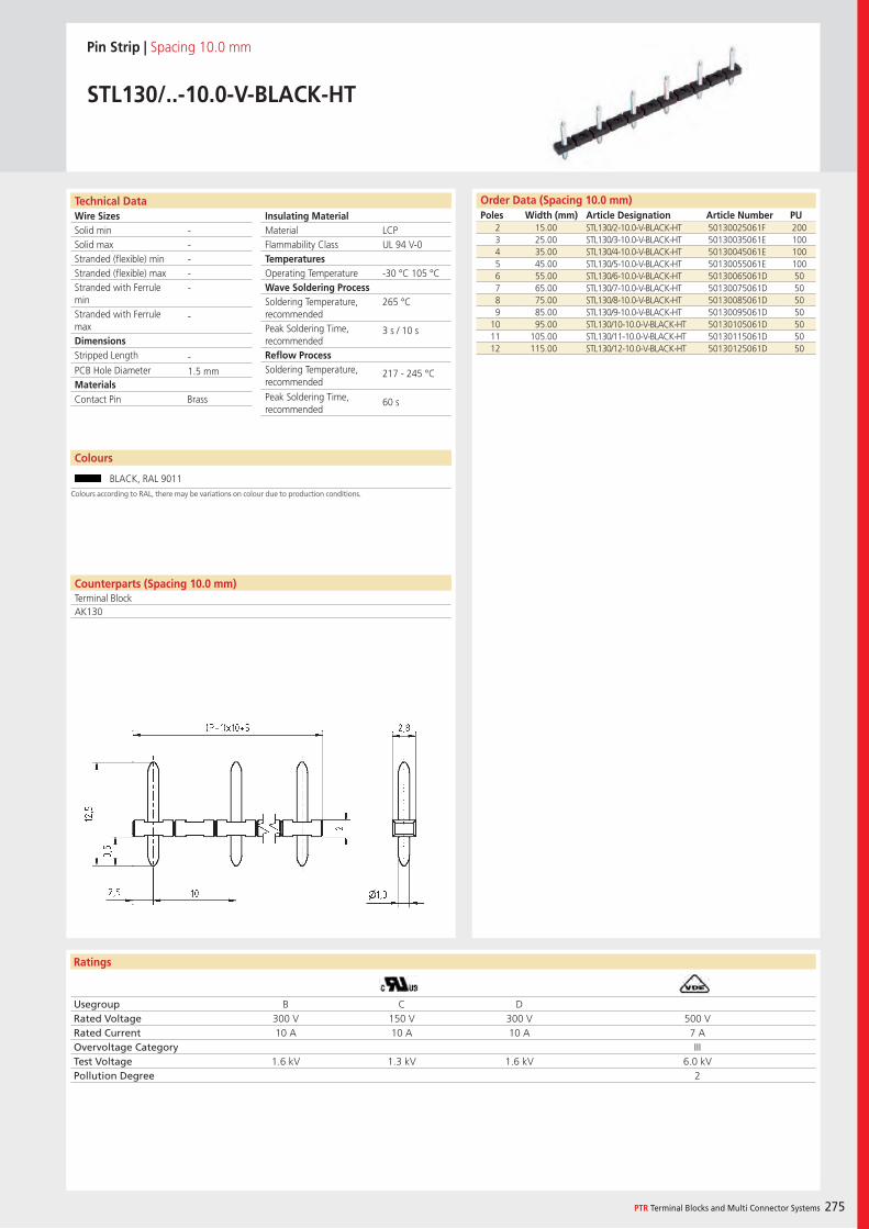
Wire SizesSolid minSolid maxStranded (flexible) minStranded (flexible) maxStranded with Ferrule minStranded with Ferrule maxDimensions Stripped Length
PCB Hole DiameterMaterials
Ratings
PTR Terminal Blocks and Multi Connector Systems 275
Insulating Material MaterialFlammability ClassTemperaturesOperating TemperatureWave Soldering ProcessSoldering Temperature,recommendedPeak Soldering Time,recommendedReflow ProcessSoldering Temperature,recommended
Peak Soldering Time,recommended
Order Data (Spacing 10.0 mm)Poles Width (mm) Article Designation Article Number PU
Technical Data
Pin Strip | Spacing 10.0 mm
STL130/..-10.0-V-BLACK-HT
2 15.00 STL130/2-10.0-V-BLACK-HT 50130025061F 2003 25.00 STL130/3-10.0-V-BLACK-HT 50130035061E 1004 35.00 STL130/4-10.0-V-BLACK-HT 50130045061E 1005 45.00 STL130/5-10.0-V-BLACK-HT 50130055061E 1006 55.00 STL130/6-10.0-V-BLACK-HT 50130065061D 507 65.00 STL130/7-10.0-V-BLACK-HT 50130075061D 508 75.00 STL130/8-10.0-V-BLACK-HT 50130085061D 509 85.00 STL130/9-10.0-V-BLACK-HT 50130095061D 50
10 95.00 STL130/10-10.0-V-BLACK-HT 50130105061D 5011 105.00 STL130/11-10.0-V-BLACK-HT 50130115061D 5012 115.00 STL130/12-10.0-V-BLACK-HT 50130125061D 50
LCPUL 94 V-0
-30 °C 105 °C
265 °C
3 s / 10 s
217 - 245 °C
60 s
-----
-
-1.5 mm
Counterparts (Spacing 10.0 mm)Terminal BlockAK130
Contact Pin Brass
Usegroup B C DRated Voltage 300 V 150 V 300 V 500 VRated Current 10 A 10 A 10 A 7 AOvervoltage Category IIITest Voltage 1.6 kV 1.3 kV 1.6 kV 6.0 kVPollution Degree 2
Colours
BLACK, RAL 9011
Colours according to RAL, there may be variations on colour due to production conditions.
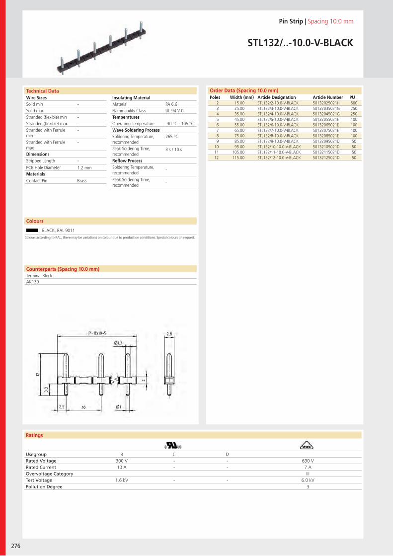
Wire SizesSolid minSolid maxStranded (flexible) minStranded (flexible) maxStranded with Ferrule minStranded with Ferrule maxDimensions Stripped Length
PCB Hole DiameterMaterials
Ratings
276
Insulating Material MaterialFlammability ClassTemperaturesOperating TemperatureWave Soldering ProcessSoldering Temperature,recommendedPeak Soldering Time,recommendedReflow ProcessSoldering Temperature,recommended
Peak Soldering Time,recommended
Technical Data Order Data (Spacing 10.0 mm)Poles Width (mm) Article Designation Article Number PU
Colours
Pin Strip | Spacing 10.0 mm
STL132/..-10.0-V-BLACK
2 15.00 STL132/2-10.0-V-BLACK 50132025021H 5003 25.00 STL132/3-10.0-V-BLACK 50132035021G 2504 35.00 STL132/4-10.0-V-BLACK 50132045021G 2505 45.00 STL132/5-10.0-V-BLACK 50132055021E 1006 55.00 STL132/6-10.0-V-BLACK 50132065021E 1007 65.00 STL132/7-10.0-V-BLACK 50132075021E 1008 75.00 STL132/8-10.0-V-BLACK 50132085021E 1009 85.00 STL132/9-10.0-V-BLACK 50132095021D 50
10 95.00 STL132/10-10.0-V-BLACK 50132105021D 5011 105.00 STL132/11-10.0-V-BLACK 50132115021D 5012 115.00 STL132/12-10.0-V-BLACK 50132125021D 50
BLACK, RAL 9011
PA 6.6UL 94 V-0
-30 °C - 105 °C
265 °C
3 s / 10 s
-
-
-----
-
-
1.2 mm
Counterparts (Spacing 10.0 mm)Terminal BlockAK130
Contact Pin Brass
Usegroup B C DRated Voltage 300 V - - 630 VRated Current 10 A - - 7 AOvervoltage Category IIITest Voltage 1.6 kV - - 6.0 kVPollution Degree 3
Colours according to RAL, there may be variations on colour due to production conditions. Special colours on request.
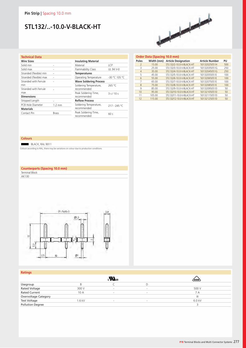
Wire SizesSolid minSolid maxStranded (flexible) minStranded (flexible) maxStranded with Ferrule minStranded with Ferrule maxDimensions Stripped Length
PCB Hole DiameterMaterials
Ratings
PTR Terminal Blocks and Multi Connector Systems 277
Insulating Material MaterialFlammability ClassTemperaturesOperating TemperatureWave Soldering ProcessSoldering Temperature,recommendedPeak Soldering Time,recommendedReflow ProcessSoldering Temperature,recommended
Peak Soldering Time,recommended
Order Data (Spacing 10.0 mm)Poles Width (mm) Article Designation Article Number PU
Technical Data
Pin Strip | Spacing 10.0 mm
STL132/..-10.0-V-BLACK-HT
2 15.00 STL132/2-10.0-V-BLACK-HT 50132025051H 5003 25.00 STL132/3-10.0-V-BLACK-HT 50132035051G 2504 35.00 STL132/4-10.0-V-BLACK-HT 50132045051G 2505 45.00 STL132/5-10.0-V-BLACK-HT 50132055051E 1006 55.00 STL132/6-10.0-V-BLACK-HT 50132065051E 1007 65.00 STL132/7-10.0-V-BLACK-HT 50132075051E 1008 75.00 STL132/8-10.0-V-BLACK-HT 50132085051E 1009 85.00 STL132/9-10.0-V-BLACK-HT 50132095051D 50
10 95.00 STL132/10-10.0-V-BLACK-HT 50132105051D 5011 105.00 STL132/11-10.0-V-BLACK-HT 50132115051D 5012 115.00 STL132/12-10.0-V-BLACK-HT 50132125051D 50
LCPUL 94 V-0
-30 °C 105 °C
265 °C
3 s / 10 s
217 - 245 °C
60 s
-----
-
-1.2 mm
Colours
BLACK, RAL 9011
Counterparts (Spacing 10.0 mm)Terminal BlockAK130
Contact Pin Brass
Usegroup B C DRated Voltage 300 V - - 500 VRated Current 10 A - - 7 AOvervoltage Category IIITest Voltage 1.6 kV - - 6.0 kVPollution Degree 3
Colours according to RAL, there may be variations on colour due to production conditions.

278
PTR Terminal Blocks and Multi Connector Systems 279
Interface Pin Blocks
Interface Pin Blocks – also known as Battery Probes – are used
everywhere it is necessary to charge rechargeable batteries, mobile
equipment such as scanners, card readers, communication devices, etc. In
many cases, they are also used to connect two PCBs.
In addition to many standard products, PTR specialises in customer-specific
solutions. As a result of the company’s considerable experience in the manu-
facturing of injection moulding tools for the connection terminal sector, PTR
offers complete solutions including plastic carriers, tape-and-reel, and “pick &
place” pads. We develop professional solutions together with our customers,
and then implement them precisely.

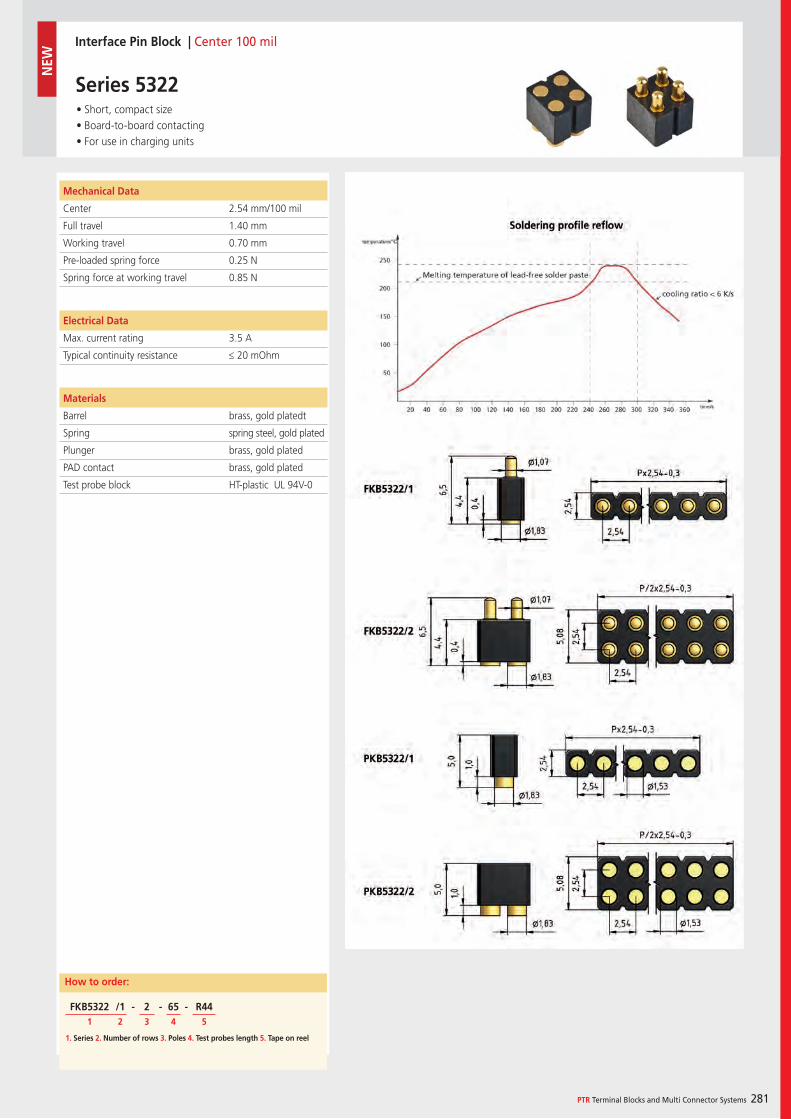
PTR Terminal Blocks and Multi Connector Systems 281
Interface Pin Block | Center 100 mil
Series 5322 • Short, compact size • Board-to-board contacting • For use in charging units
Mechanical Data
Center 2.54 mm/100 mil
Full travel 1.40 mm
Working travel 0.70 mm
Pre-loaded spring force 0.25 N
Spring force at working travel 0.85 N
Electrical Data
Max. current rating 3.5 A
Typical continuity resistance ≤ 20 mOhm
Materials
Barrel brass, gold platedt
Spring spring steel, gold plated
Plunger brass, gold plated
PAD contact brass, gold plated
Test probe block HT-plastic UL 94V-0
How to order:
1. Series 2. Number of rows 3. Poles 4. Test probes length 5. Tape on reel
FKB5322 /1 - 2 - 65 - R441 2 3 4 5
NEW
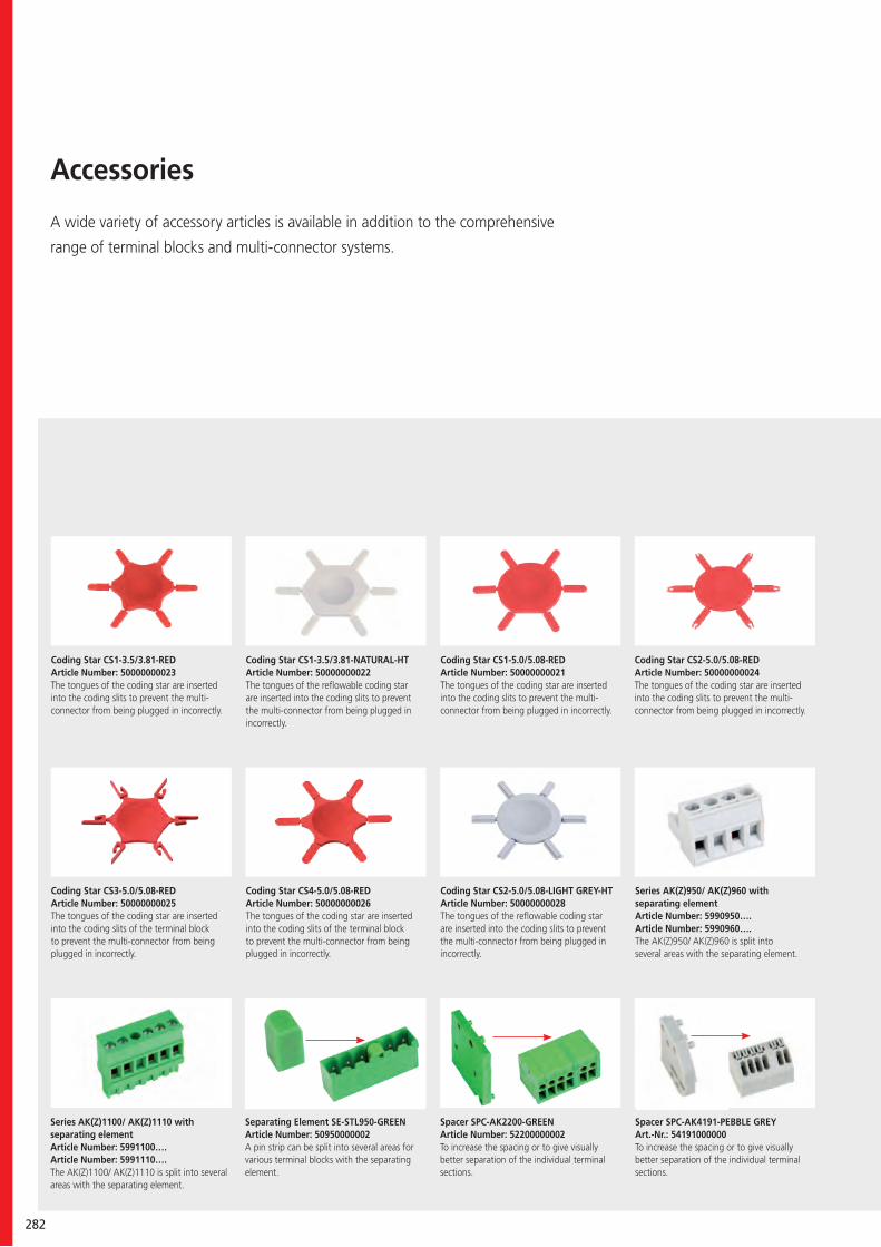
282
Accessories
A wide variety of accessory articles is available in addition to the comprehensive
range of terminal blocks and multi-connector systems.
Coding Star CS3-5.0/5.08-REDArticle Number: 50000000025The tongues of the coding star are inserted into the coding slits of the terminal block to prevent the multi-connector from being plugged in incorrectly.
Coding Star CS4-5.0/5.08-REDArticle Number: 50000000026The tongues of the coding star are inserted into the coding slits of the terminal block to prevent the multi-connector from being plugged in incorrectly.
Coding Star CS2-5.0/5.08-REDArticle Number: 50000000024The tongues of the coding star are inserted into the coding slits to prevent the multi-connector from being plugged in incorrectly.
Coding Star CS1-3.5/3.81-NATURAL-HTArticle Number: 50000000022The tongues of the reflowable coding star are inserted into the coding slits to prevent the multi-connector from being plugged in incorrectly.
Coding Star CS1-5.0/5.08-REDArticle Number: 50000000021The tongues of the coding star are inserted into the coding slits to prevent the multi-connector from being plugged in incorrectly.
Coding Star CS1-3.5/3.81-REDArticle Number: 50000000023The tongues of the coding star are inserted into the coding slits to prevent the multi-connector from being plugged in incorrectly.
Coding Star CS2-5.0/5.08-LIGHT GREY-HTArticle Number: 50000000028The tongues of the reflowable coding star are inserted into the coding slits to prevent the multi-connector from being plugged in incorrectly.
Series AK(Z)950/ AK(Z)960 with separating elementArticle Number: 5990950….Article Number: 5990960….The AK(Z)950/ AK(Z)960 is split into several areas with the separating element.
Series AK(Z)1100/ AK(Z)1110 with separating elementArticle Number: 5991100…. Article Number: 5991110….The AK(Z)1100/ AK(Z)1110 is split into several areas with the separating element.
Separating Element SE-STL950-GREENArticle Number: 50950000002A pin strip can be split into several areas for various terminal blocks with the separating element.
Spacer SPC-AK2200-GREENArticle Number: 52200000002To increase the spacing or to give visually better separation of the individual terminal sections.
Spacer SPC-AK4191-PEBBLE GREYArt.-Nr.: 54191000000To increase the spacing or to give visually better separation of the individual terminal sections.
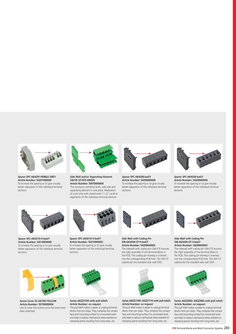
PTR Terminal Blocks and Multi Connector Systems 283
Spacer SPC-AK4291-PEBBLE GREYArticle Number: 54291000000To increase the spacing or to give visually better separation of the individual terminal sections.
Spacer SPC-AK4200-baGYArticle Number: 54200000000To increase the spacing or to give visually better separation of the individual terminal sections.
Spacer SPC-AK4200-baGYArticle Number: 54200000000To increase the spacing or to give visually better separation of the individual terminal sections.
Spacer SPC-AK4210-H-baGYArticle Number: 54210000000To increase the spacing or to give visually better separation of the individual terminal sections.
Screw Cover SC-AK700-YELLOWArticle Number: 50700000004Use to cover the screws once the wires have been attached.
Series AK(Z)1550 with pull reliefsArticle Number: on requestThe pull relief makes it easier to unplug terminal blocks from pin strips. They comprise the contact face and mounting surface for connected wires and help to reduce mechanical stress exerted on clamping points resulting from long wires, etc.
Series AK(Z)1700/ AK(Z)1710 with pull reliefsArticle Number: on requestThe pull relief makes it easier to unplug terminal blocks from pin strips. They comprise the contact face and mounting surface for connected wires and help to reduce mechanical stress exerted on clamping points resulting from long wires, etc.
Series AK(Z)950/ AK(Z)960 with pull reliefsArticle Number: on requestThe pull relief makes it easier to unplug terminal blocks from pin strips. They comprise the contact face and mounting surface for connected wires and help to reduce mechanical stress exerted on clamping points resulting from long wires, etc.
Side Wall with Coding PinSW-AK4200-CP-H-baGYArticle Number: 54200000002The sidewall with coding pin (SW-CP) ensures the right assembly of the terminal block in the PCB. The coding pin thereby is inserted into the corresponding PCB hole. The SW-CP substitutes the standard side wall (SW).
Side Wall with Coding PinSW-AK4200-CP-V-baGY Article Number: 54200000001The sidewall with coding pin (SW-CP) ensures the right assembly of the terminal block in the PCB. The coding pin thereby is inserted into the corresponding PCB hole. The SW-CP substitutes the standard side wall (SW).
Spacer SPC-AK4210-V-baGYArticle Number: 54210000001To increase the spacing or to give visually better separation of the individual terminal sections.
Side Wall and/or Separating Element SW/SE-STL970-GREENArticle Number: 50970000000This accessory combines both, side wall and separating element in one piece: Realization of a pin strip with closed ends (“/..G”) and/ or separation of the individual terminal sections.
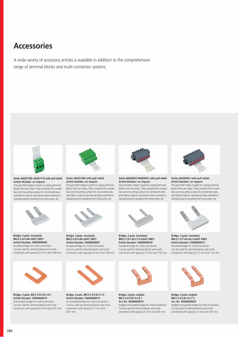
284
Bridge, 2-pole, BR/2-3.5/3.81-L4.7Article Number: 50000000013Uninsulated bridge for multi-connection.Can be used for terminal blocks and multi-connectors with spacing 3.5 mm and 3.81 mm.
Bridge, 2-pole, insulated, BRI/2-5.0/5.08-LIGHT GREYArticle Number: 50000000006Insulated bridge for multi-connection.Can be used for terminal blocks and multi-connectors with spacing 5.0 mm and 5.08 mm.
Bridge, 3-pole, insulated, BRI/3-5.0/5.08-LIGHT GREYArticle Number: 50000000007Insulated bridge for multi-connection.Can be used for terminal blocks and multi-connectors with spacing 5.0 mm and 5.08 mm.
Bridge, 2-pole, insulated, BRI/2-7.0/7.62-L7.5-LIGHT GREYArticle Number: 50000000018Insulated bridge for multi-connection.Can be used for terminal blocks and multi-connectors with spacing 7.0 mm and 7.62 mm.
Bridge, 2-pole, insulated, BRI/2-7.5/7.62-L8.2-LIGHT GREYArticle Number: 50000000017Insulated bridge for multi-connection.Can be used for terminal blocks and multi-connectors with spacing 7.5 mm and 7.62 mm.
Series AK(Z)1200 with pull reliefsArticle Number: on requestThe pull relief makes it easier to unplug terminal blocks from pin strips. They comprise the contact face and mounting surface for connected wires and help to reduce mechanical stress exerted on clamping points resulting from long wires, etc.
Series AK(Z)4551/AK(Z)4551 with pull reliefsArticle Number: on requestThe pull relief makes it easier to unplug terminal blocks from pin strips. They comprise the contact face and mounting surface for connected wires and help to reduce mechanical stress exerted on clamping points resulting from long wires, etc.
Series AK(Z)4951 with pull reliefsArticle Number: on requestThe pull relief makes it easier to unplug terminal blocks from pin strips. They comprise the contact face and mounting surface for connected wires and help to reduce mechanical stress exerted on clamping points resulting from long wires, etc.
Accessories
A wide variety of accessory articles is available in addition to the comprehensive
range of terminal blocks and multi-connector systems.
Bridge, 2-pole, BR/2-3.5/3.81-L7.5Article Number: 50000000015Uninsulated bridge for multi-connection.Can be used for terminal blocks and multi-connectors with spacing 3.5 mm and3.81 mm.
Bridge, 2-pole, angled, BR/2-3.5/3.81-H-L7.5Art.-Nr.: 50000000029Angled uninsulated bridge for multi-connection. Can be used for terminal blocks and multi-connectors with spacing 3.5 mm and 3.81 mm.
Bridge, 2-pole, angled, BR/2-3.5/3.81-H-L4.7Art.-Nr.: 50000000019Angled uninsulated bridge for multi-connection. Can be used for terminal blocks and multi-connectors with spacing 3.5 mm and 3.81 mm.
Series AK(Z)1100/ AK(Z)1110 with pull reliefsArticle Number: on requestThe pull relief makes it easier to unplug terminal blocks from pin strips. They comprise the contact face and mounting surface for connected wires and help to reduce mechanical stress exerted on clamping points resulting from long wires, etc.
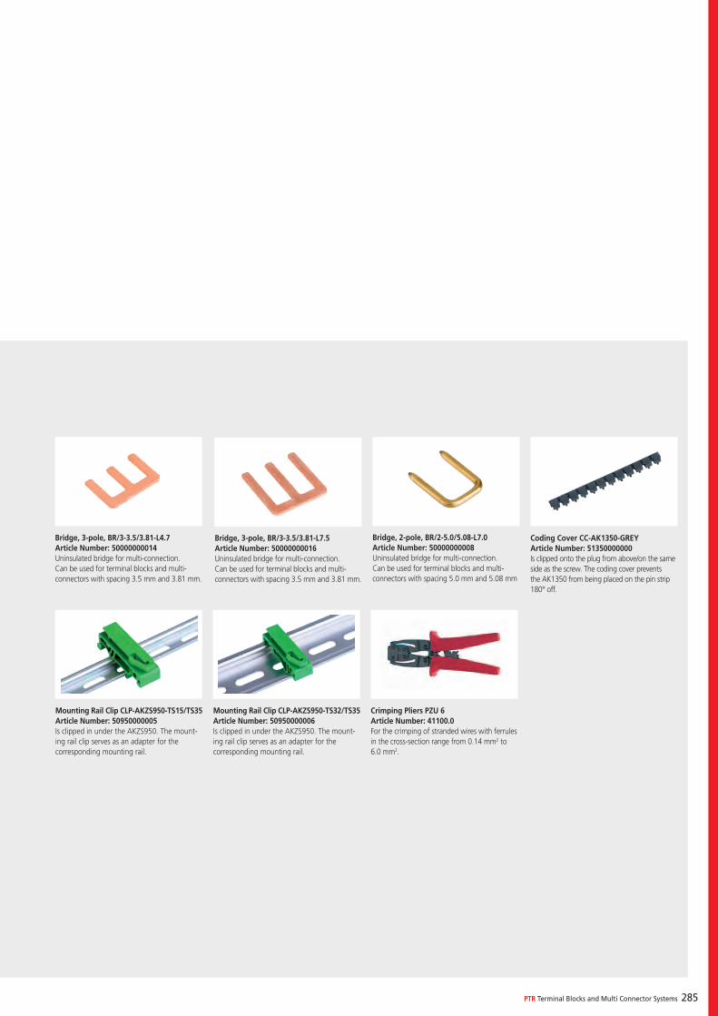
PTR Terminal Blocks and Multi Connector Systems 285
Bridge, 3-pole, BR/3-3.5/3.81-L4.7Article Number: 50000000014Uninsulated bridge for multi-connection.Can be used for terminal blocks and multi-connectors with spacing 3.5 mm and 3.81 mm.
Mounting Rail Clip CLP-AKZS950-TS15/TS35Article Number: 50950000005Is clipped in under the AKZS950. The mount-ing rail clip serves as an adapter for the corresponding mounting rail.
Crimping Pliers PZU 6Article Number: 41100.0For the crimping of stranded wires with ferrules in the cross-section range from 0.14 mm2 to 6.0 mm2.
Mounting Rail Clip CLP-AKZS950-TS32/TS35Article Number: 50950000006Is clipped in under the AKZS950. The mount-ing rail clip serves as an adapter for the corresponding mounting rail.
Bridge, 3-pole, BR/3-3.5/3.81-L7.5Article Number: 50000000016Uninsulated bridge for multi-connection.Can be used for terminal blocks and multi-connectors with spacing 3.5 mm and 3.81 mm.
Bridge, 2-pole, BR/2-5.0/5.08-L7.0Article Number: 50000000008Uninsulated bridge for multi-connection.Can be used for terminal blocks and multi-connectors with spacing 5.0 mm and 5.08 mm
Coding Cover CC-AK1350-GREYArticle Number: 51350000000Is clipped onto the plug from above/on the same side as the screw. The coding cover prevents the AK1350 from being placed on the pin strip 180° off.
286
Directive 2011/65/EU of the European Parliament and of the Council on the Restriction of the Use of Certain Hazardous Substances in Electrical and Electronic Equipment (recast) (RoHS2-Directive).
Regulation No. 1907/2006/EC of the European Parliament and of the Council of 18 December 2006 concerning the Registration, Evaluation, Authorisation and Restriction of Chemicals (REACH), establishing a Euro-pean Chemicals Agency, amending Directive 1999/45/EC and repealing Council Regulation (EEC) No. 793/93 and Commission Regulation (EC) No. 1488/94 as well as Council Direc-tive 76/769/EEC and Commission Directives 91/155/EEC, 93/67/EEC, 93/105/EC and 2000/21/EC (REACH) Directive)
PTR is very aware of its responsibilities towards the environment and mankind. This is why PTR has been certified since 1999 according to DIN EN ISO 14001 (environmental manage-ment standard). New environmental targets are regularly defined, and conformity is confirmed in the annual TÜV audits. Since 2008, PTR has also defined its conformity with and pursuance of environmental goals according to EU directive 1907/2006/EC, generally known as the REACH directive. In accordance with the EU RoHS direc-tive, with whose current ROHS2 version PTR also complies, this extends the goal of environmental friendliness to include the detailed maintenance of human health. This means that the following are excluded from new PTR products as early as the design phase: materials which are harmful to the environment, non-degradable, bioaccumula-tive, toxic, carcinogenic, mutagenic or toxic for reproduction.
A declaration of conformity regarding the latest state of the REACH and ROHS2 guideline can be viewed and downloaded as a PDF file at any time from the PTR website at www.ptr.eu.
In the same way, PTR automatically and im-mediately checks new environmental and health guidelines for conformity, issues the appropriate declarations of conformity, and adapts products when necessary to ensure conformity.
Responsibility Towards the Environment and Mankind
The IEC 60335-1 claims for a better resistance of household and similar electrical appliances against heat and fire amongst others the compli-ance with harder glow wire tests. Due to these tests are not part of the standard terminal blocks certification, PTR Messtechnik offers its terminal blocks and pin strips with special insulating materials which are optimized to this household norm. Further questions regarding to IEC 60335-1 in our products can be answered when con-tacting PTR’s sales department.
Household Appliance
PTR Terminal Blocks and Multi Connector Systems 287
Our terminal blocks and multi connector systems comply with the current versions of all applicable standards and regulations.
The following standards apply to VDE ap-proval of PTR’s screwable and screwless terminal blocks: EN 60998-1, EN 60998-2-1, and EN 60998-2-2.
PTR’s screwable and screwless multi connector systems are approved in accordance with EN 61984.
In addition, EN 60664-1 and VDE 0110-1 are the cornerstones of insulation coordination for equipment used in low-voltage installations. This applies to all equipment that is rated for use up to 2,000 metres above sea level. Above 2,000 metres above sea level, height correction factors come into play.
Approvals and Regulations
cURus approval of PTR terminal blocks and multi connector systems is based on the UL 1059, UL 1977 and CSA 22.2 No. 158 standards.
The cURus mark indicates that our products meet Canadian and U.S. safety standards.
The CE mark, which is a European product safety mark for specific types of products, was created mainly to provide EU consumers with safe products. The CE mark is the manufacturer’s assurance that the product bearing the mark complies with European directives. A product may only be placed on the market in the EU if it meets the requirements of the applicable EU di-rectives, and if it has undergone a conformance procedure in accordance with the applicable EU directives.
The CE mark on PTR’s products indicates that they comply with the following EU directive: Directive 2014/35/EC of the European Parlia-ment and of the Council of 12 December 2006 on the harmonisation of the laws of Member States relating to Electrical Equipment designed for use within certain voltage limits.

288
Overvoltage Categories I-IV (in accordance with EN 60664-1:2007 and VDE 0110-1)
The concept of overvoltage categories is used for equipment energized directly from the low-voltage mains. A similar concept can also be used for equipment connected to other systems, for example telecommunication and data systems.
Equipment of Overvoltage Category I is equipment for connection to circuits in which measures are taken to limit transient overvolt-ages* to an appropriately low level. These measures shall ensure that the temporary over-voltages that could occur are sufficiently limited so that their peak value does not exceed the relevant rated impulse voltage of the following table ”Rated impulse voltage for equipment…”
fApplication: Equipment containing elec-tronic circuits protected to this level. Unless the circuits are designed to take the tempo-rary overvoltages into account, equipment of overvoltage category I cannot be directly connected to the supply mains.
Equipment of Overvoltage Category II is energy-consuming equipment to be supplied from the fixed installation.
fApplication: Appliances, portable tools and other household and similar loads. If such equipment is subjected to special require-ments with regard to reliability and availabil-ity, overvoltage category III applies.
Equipment of Overvoltage Category III is equipment in fixed installations and for cases where the reliability and the availability of the equipment are subject to special requirements.
fApplication: Switches in the fixed instal-lation and equipment for industrial use with permanent connection to the fixed installa-tion.
Equipment of Overvoltage Category IV is for use at the origin of the installation.
fApplication: Electricity meters and primary overcurrent protection equipment.
(*short duration overvoltage of a few milliseconds or less, usually highly damped)
All PTR approval data are based on overvoltage category III.
PTR Terminal Blocks and Multi Connector Systems 289
Clearance is the shortest distance in air be-tween two conductive parts. Clearance shall be dimensioned to withstand the required impulse withstand voltage, in accordance with table “Clearances to withstand transient overvolt-ages”. For equipment directly connected to the low-voltage mains, the required impulse withstand voltage is the rated impulse voltage, and can be found in the table titled “Rated impulse voltage for equipment…,” according to application.
Larger clearances may be required due to me-chanical influences such as vibration or applied forces.
Inasmuch as the values indicated in the afore-mentioned tables are applicable up to 2,000 meters above sea level, clearance for greater heights must be calculated using the multiplica-tion factors in the “Altitude correction factors” table.
Creepage distance means the shortest distance along the surface of a solid insulating material between two conductive parts. The values of table “Creepage distances to avoid failure due to tracking” are based upon existing data and are suitable for the majority of applications.
The basis for the determination of a creepage distance is the long-term r.m.s. value of the volt-age existing across it. This voltage is the working voltage, the rated insulation voltage or the rated voltage.
The influence of the degrees of pollution in the micro-environment on the dimensioning of creepage distances is taken into account in table “Creepage distances to avoid failure due to tracking”. Also keep in mind that different micro-environment conditions can exist within the same equipment.
A creepage distance cannot be less than the as-sociated clearance so that the shortest creepage distance possible is equal to the required clear-ance. However, there is no physical relationship, other than this dimensional limitation, between the minimum clearance in air and the minimum acceptable creepage distance.
Clearance and Creepage Distances (in accordance with EN 60664-1:2007 and VDE 0110-1)
For the purposes of the above-mentioned stand-ards, materials are classified into four groups according to their CTI values. These values are determined in accordance with EN 60112 using solution A. The groups are as follows:
Insulation materials group I 600 ≤ CTI
Insulation materials group II 400 ≤ CTI < 600
Insulation materials group IIIa 175 ≤ CTI < 400
Insulation materials group IIIb 100 ≤ CTI < 175
The proof tracking index (PTI) is used to verify the tracking characteristics of materials. A mate-rial may be included in one of these four groups on the basis that the PTI is not less than the lower value specified for the group.
Insulation Material Groups (in accordance with EN 60664-
1:2007 and VDE 0110-1)

290
The environment determines the effect of pollu-tion on the insulation.
Small clearances can be bridged completely by solid particles, dust and water and therefore minimum clearances are specified, where pollu-tion may be present in the micro-environment.
For the purpose of evaluating creepage distances and clearances, the following four degrees of pollution in the micro-environment are established:
Pollution degree 1No pollution or only dry, non-conductive pollu-tion occurs. The pollution has no influence. Pollution degree 2Only non-conductive pollution occurs except that occasionally a temporary conductivity caused by condensation is to be expected.
Pollution degree 3Conductive pollution occurs or dry non-conduc-tive pollution occurs which becomes conductive due to condensation which is to be expected.
Pollution degree 4Continuous conductivity occurs due to conduc-tive dust, rain or wet conditions.
Pollution Degrees 1 up to 4 (in accordance with EN 60664-1:2007 and VDE 0110-1)
The dimensions for creepage distance cannot be specified where permanently conductive pollu-tion is present (Pollution degree 4). For tempo-rarily conductive pollution (Pollution degree 3), the surface of the insulation may be designed to avoid a continuous path of conductive pollution, e.g. by means of ribs and grooves.
PTR’s approval data are based on pollution degree 3.
PTR Terminal Blocks and Multi Connector Systems 291
PTR Messtechnik’s terminals and connectors are approved according to the underlying EN 60998-1 and 61984-1 standards. Specifica-tion of the rated voltages is on the basis of these standards.
In addition – as requested by many custom-ers – operating voltages and/or clearance and creepage distances for operating voltages can be determined in accordance with the generally applicable EN 60664-1.
For the clearance distances, the required nominal voltage and/or the rated surge voltage – whose definition takes place in accordance with table F.1 – are the decisive factor.
This is shown in table F.2 as a withstand/impulse voltage and – depending on the degree of soil-ing and field conditions – is used to determine the clearance.
For creepage, the rated voltage of the power supply system must be defined according to table F.3a for single-phase systems, or accord-ing to table F.3b for three-phase systems. In combination with the degree of soiling and the insulation material group, the voltage value specified in this way determines the minimum creepage distance according to table F.4.
Determination of Clearance and Creepage Distances (in accordance with EN 60664-1:2007 and VDE 0110-1)
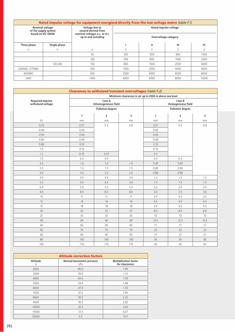
292
Clearances to withstand transient overvoltages (table F.2)Minimum clearances in air up to 2000 m above sea level
Required impulse withstand voltage
Case A lnhomogeneous field
Case B Homogeneous field
Pollution degree Pollution degree
1 2 3 1 2 3
kV mm mm mm mm mm mm
0.33 0.01 0.2 0.8 0.01 0.2 0.8
0.40 0.02 0.02
0.50 0.04 0.04
0.60 0.06 0.06
0.80 0.10 0.10
1.0 0.15 0.15
1.2 0.25 0.25 0.2
1.5 0.5 0.5 0.3 0.3
2.0 1.0 1.0 1.0 0.45 0.45
2.5 1.5 1.5 1.5 0.60 0.60
3.0 2.0 2.0 2.0 0.80 0.80
4.0 3.0 3.0 3.0 1.2 1.2 1.2
5.0 4.0 4.0 4.0 1.5 1.5 1.5
6.0 5.5 5.5 5.5 2.0 2.0 2.0
8.0 8.0 8.0 8.0 3.0 3.0 3.0
10 11 11 11 3.5 3.5 3.5
12 14 14 14 4.5 4.5 4.5
15 18 18 18 5.5 5.5 5.5
20 25 25 25 8.0 8.0 8.0
25 33 33 33 10 10 10
30 40 40 40 12.5 12.5 12.5
40 60 60 60 17 17 17
50 75 75 75 22 22 22
60 90 90 90 27 27 27
80 130 130 130 35 35 35
100 170 170 170 45 45 45
Altitude correction factorsAltitude
mNormal barometric pressure
kPaMultiplication factor
for clearances
2000 80.0 1.00
3000 70.0 1.14
4000 62.0 1.29
5000 54.0 1.48
6000 47.0 1.70
7000 41.0 1.95
8000 35.5 2.25
9000 30.5 2.62
10000 26.5 3.02
15000 12.0 6.67
20000 5.5 14.5
Rated impulse voltage for equipment energized directly from the low-voltage mains (table F.1)Nominal voltage
of the supply system based on IEC 50038
Voltage line to neutral derived from
nominal voltages a.c. or d.c. up to and including
Rated impulse voltage
Overvoltage category
Three phase Single phase I II III IV
V V V V V V V
50 330 500 800 1500
100 500 800 1500 2500
120-240 150 800 1500 2500 4000
230/400 277/480 300 1500 2500 4000 6000
400/690 600 2500 4000 6000 8000
1000 1000 4000 6000 8000 12000
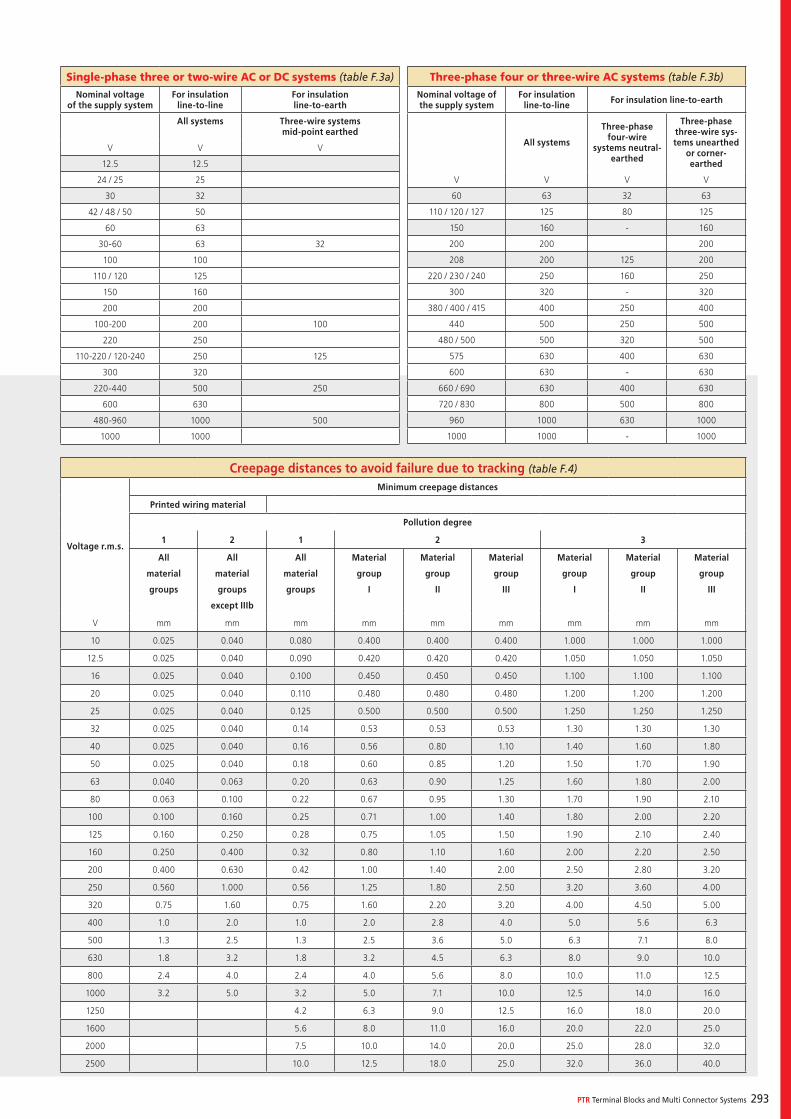
PTR Terminal Blocks and Multi Connector Systems 293
Creepage distances to avoid failure due to tracking (table F.4)
Voltage r.m.s.
Minimum creepage distances
Printed wiring material
Pollution degree
1 2 1 2 3
All
material
groups
All
material
groups
except IIIb
All
material
groups
Material
group
I
Material
group
II
Material
group
III
Material
group
I
Material
group
II
Material
group
III
V mm mm mm mm mm mm mm mm mm
10 0.025 0.040 0.080 0.400 0.400 0.400 1.000 1.000 1.000
12.5 0.025 0.040 0.090 0.420 0.420 0.420 1.050 1.050 1.050
16 0.025 0.040 0.100 0.450 0.450 0.450 1.100 1.100 1.100
20 0.025 0.040 0.110 0.480 0.480 0.480 1.200 1.200 1.200
25 0.025 0.040 0.125 0.500 0.500 0.500 1.250 1.250 1.250
32 0.025 0.040 0.14 0.53 0.53 0.53 1.30 1.30 1.30
40 0.025 0.040 0.16 0.56 0.80 1.10 1.40 1.60 1.80
50 0.025 0.040 0.18 0.60 0.85 1.20 1.50 1.70 1.90
63 0.040 0.063 0.20 0.63 0.90 1.25 1.60 1.80 2.00
80 0.063 0.100 0.22 0.67 0.95 1.30 1.70 1.90 2.10
100 0.100 0.160 0.25 0.71 1.00 1.40 1.80 2.00 2.20
125 0.160 0.250 0.28 0.75 1.05 1.50 1.90 2.10 2.40
160 0.250 0.400 0.32 0.80 1.10 1.60 2.00 2.20 2.50
200 0.400 0.630 0.42 1.00 1.40 2.00 2.50 2.80 3.20
250 0.560 1.000 0.56 1.25 1.80 2.50 3.20 3.60 4.00
320 0.75 1.60 0.75 1.60 2.20 3.20 4.00 4.50 5.00
400 1.0 2.0 1.0 2.0 2.8 4.0 5.0 5.6 6.3
500 1.3 2.5 1.3 2.5 3.6 5.0 6.3 7.1 8.0
630 1.8 3.2 1.8 3.2 4.5 6.3 8.0 9.0 10.0
800 2.4 4.0 2.4 4.0 5.6 8.0 10.0 11.0 12.5
1000 3.2 5.0 3.2 5.0 7.1 10.0 12.5 14.0 16.0
1250 4.2 6.3 9.0 12.5 16.0 18.0 20.0
1600 5.6 8.0 11.0 16.0 20.0 22.0 25.0
2000 7.5 10.0 14.0 20.0 25.0 28.0 32.0
2500 10.0 12.5 18.0 25.0 32.0 36.0 40.0
Single-phase three or two-wire AC or DC systems (table F.3a)
Nominal voltage of the supply system
For insulation line-to-line
For insulation line-to-earth
All systems Three-wire systems mid-point earthed
V V V
12.5 12.5
24 / 25 25
30 32
42 / 48 / 50 50
60 63
30-60 63 32
100 100
110 / 120 125
150 160
200 200
100-200 200 100
220 250
110-220 / 120-240 250 125
300 320
220-440 500 250
600 630
480-960 1000 500
1000 1000
Three-phase four or three-wire AC systems (table F.3b)
Nominal voltage of the supply system
For insulation line-to-line For insulation line-to-earth
All systems
Three-phase four-wire
systems neutral-earthed
Three-phase three-wire sys-tems unearthed
or corner-earthed
V V V V
60 63 32 63
110 / 120 / 127 125 80 125
150 160 - 160
200 200 200
208 200 125 200
220 / 230 / 240 250 160 250
300 320 - 320
380 / 400 / 415 400 250 400
440 500 250 500
480 / 500 500 320 500
575 630 400 630
600 630 - 630
660 / 690 630 400 630
720 / 830 800 500 800
960 1000 630 1000
1000 1000 - 1000
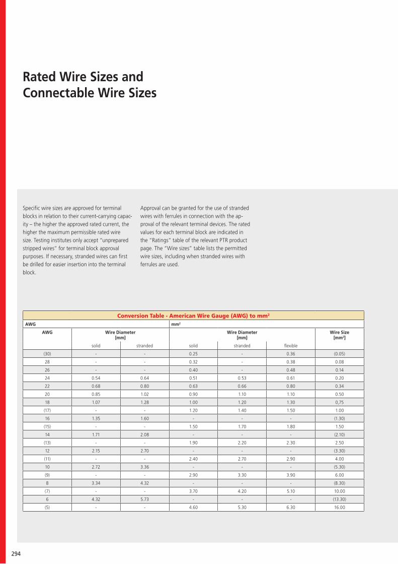
294
Rated Wire Sizes and Connectable Wire Sizes
Conversion Table - American Wire Gauge (AWG) to mm2
AWG mm2
AWG Wire Diameter [mm]
Wire Diameter [mm]
Wire Size [mm2]
solid stranded solid stranded flexible
(30) - - 0.25 - 0.36 (0.05)
28 - - 0.32 - 0.38 0.08
26 - - 0.40 - 0.48 0.14
24 0.54 0.64 0.51 0.53 0.61 0.20
22 0.68 0.80 0.63 0.66 0.80 0.34
20 0.85 1.02 0.90 1.10 1.10 0.50
18 1.07 1.28 1.00 1.20 1.30 0,75
(17) - - 1.20 1.40 1.50 1.00
16 1.35 1.60 - - - (1.30)
(15) - - 1.50 1.70 1.80 1.50
14 1.71 2.08 - - - (2.10)
(13) - - 1.90 2.20 2.30 2.50
12 2.15 2.70 - - - (3.30)
(11) - - 2.40 2.70 2.90 4.00
10 2.72 3.36 - - - (5.30)
(9) - - 2.90 3.30 3.90 6.00
8 3.34 4.32 - - - (8.30)
(7) - - 3.70 4.20 5.10 10.00
6 4.32 5.73 - - - (13.30)
(5) - - 4.60 5.30 6.30 16.00
Specific wire sizes are approved for terminal blocks in relation to their current-carrying capac-ity – the higher the approved rated current, the higher the maximum permissible rated wire size. Testing institutes only accept “unprepared stripped wires” for terminal block approval purposes. If necessary, stranded wires can first be drilled for easier insertion into the terminal block.
Approval can be granted for the use of stranded wires with ferrules in connection with the ap-proval of the relevant terminal devices. The rated values for each terminal block are indicated in the “Ratings” table of the relevant PTR product page. The “Wire sizes” table lists the permitted wire sizes, including when stranded wires with ferrules are used.
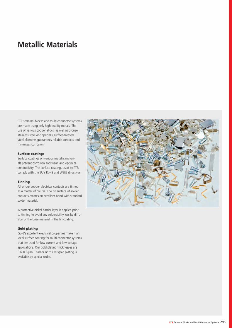
PTR Terminal Blocks and Multi Connector Systems 295
PTR terminal blocks and multi connector systems are made using only high quality metals. The use of various copper alloys, as well as bronze, stainless steel and specially surface-treated steel elements guarantees reliable contacts and minimizes corrosion.
Surface coatings Surface coatings on various metallic materi-als prevent corrosion and wear, and optimize conductivity. The surface coatings used by PTR comply with the EU’s RoHS and WEEE directives.
Tinning All of our copper electrical contacts are tinned as a matter of course. The tin surface of solder contacts creates an excellent bond with standard solder material.
A protective nickel barrier layer is applied prior to tinning to avoid any solderability loss by diffu-sion of the base material in the tin coating.
Gold plating Gold’s excellent electrical properties make it an ideal surface coating for multi connector systems that are used for low current and low voltage applications. Our gold plating thicknesses are 0.6-0.8 µm. Thinner or thicker gold plating is available by special order.
Metallic Materials
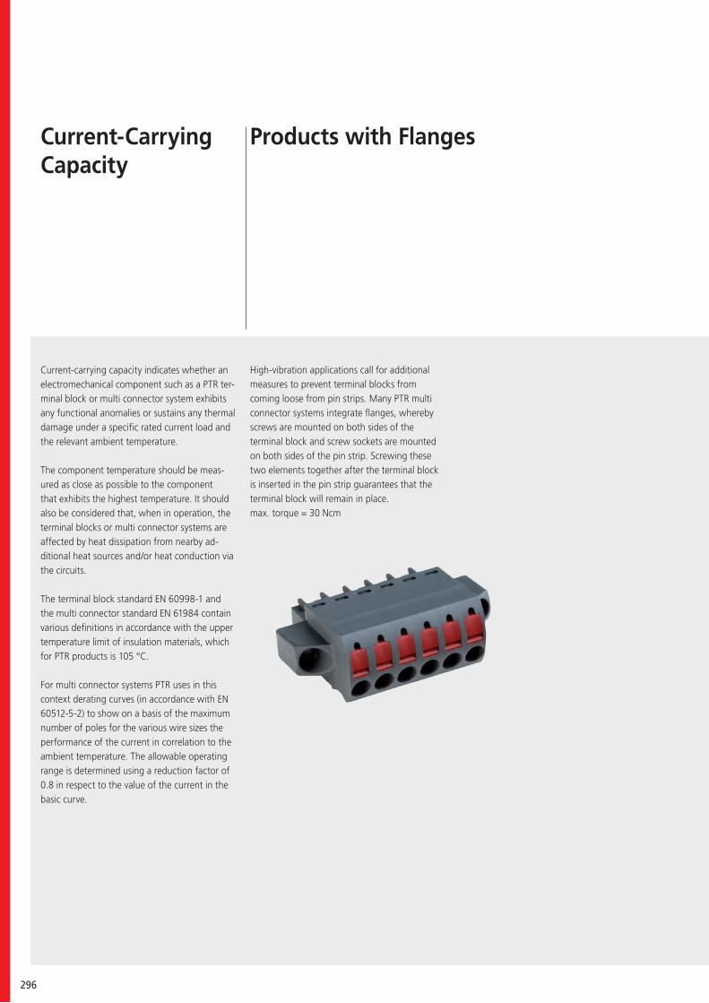
296
Current-carrying capacity indicates whether an electromechanical component such as a PTR ter-minal block or multi connector system exhibits any functional anomalies or sustains any thermal damage under a specific rated current load and the relevant ambient temperature.
The component temperature should be meas-ured as close as possible to the component that exhibits the highest temperature. It should also be considered that, when in operation, the terminal blocks or multi connector systems are affected by heat dissipation from nearby ad-ditional heat sources and/or heat conduction via the circuits.
The terminal block standard EN 60998-1 and the multi connector standard EN 61984 contain various definitions in accordance with the upper temperature limit of insulation materials, which for PTR products is 105 °C.
For multi connector systems PTR uses in this context derating curves (in accordance with EN 60512-5-2) to show on a basis of the maximum number of poles for the various wire sizes the performance of the current in correlation to the ambient temperature. The allowable operating range is determined using a reduction factor of 0.8 in respect to the value of the current in the basic curve.
High-vibration applications call for additional measures to prevent terminal blocks from coming loose from pin strips. Many PTR multi connector systems integrate flanges, whereby screws are mounted on both sides of the terminal block and screw sockets are mounted on both sides of the pin strip. Screwing these two elements together after the terminal block is inserted in the pin strip guarantees that the terminal block will remain in place. max. torque = 30 Ncm
Current-Carrying Capacity
Products with Flanges
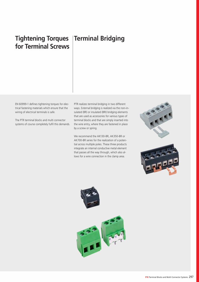
PTR Terminal Blocks and Multi Connector Systems 297
EN 60999-1 defines tightening torques for elec-trical fastening materials which ensure that the wiring of electrical terminals is safe.
The PTR terminal blocks and multi connector systems of course completely fulfil this demands.
Tightening Torques for Terminal Screws
PTR realizes terminal bridging in two different ways. External bridging is realized via the non-in-sulated (BR) or insulated (BRI) bridging elements that are used as accessories for various types of terminal blocks and that are simply inserted into the wire entry, where they are fastened in place by a screw or spring.
We recommend the AK130-BR, AK350-BR or AK700-BR series for the realization of a poten-tial across multiple poles. These three products integrate an internal conductive metal element that passes all the way through, which also al-lows for a wire connection in the clamp area.
Terminal Bridging
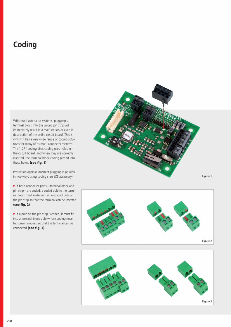
298
With multi connector systems, plugging a terminal block into the wrong pin strip will immediately result in a malfunction or even in destruction of the entire circuit board. This is why PTR has a very wide range of coding solu-tions for many of its multi connector systems. The “-CP” coding pin’s coding uses holes in the circuit board, and when they are correctly inserted, the terminal block coding pins fit into these holes. (see fig. 1)
Protection against incorrect plugging is possible in two ways using coding stars (CS accessory):
if both connector parts – terminal block and pin strip – are coded, a coded pole in the termi-nal block must mate with an uncoded pole on the pin strip so that the terminal can be inserted (see fig. 2)
if a pole on the pin strip is coded, it must fit into a terminal block pole whose coding nose has been removed so that the terminal can be connected (see fig. 3).
Coding
Figure 3
Figure 2
Figure 1
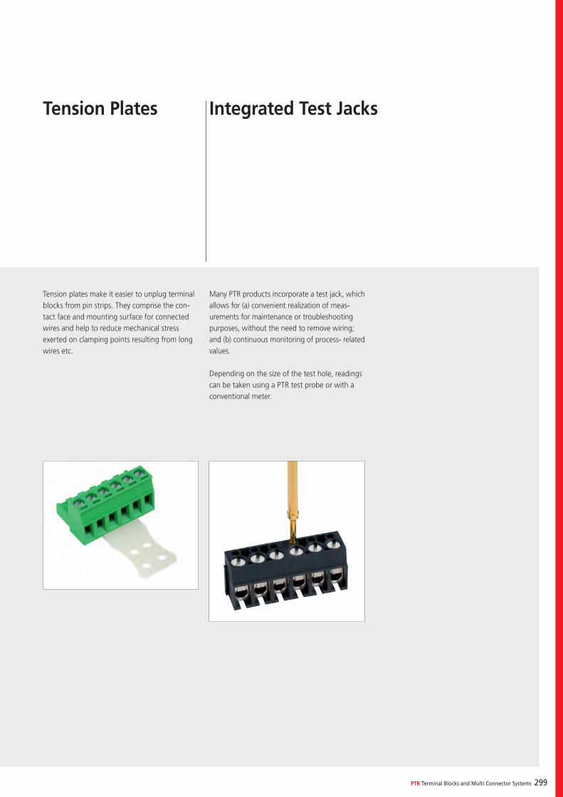
PTR Terminal Blocks and Multi Connector Systems 299
Tension plates make it easier to unplug terminal blocks from pin strips. They comprise the con-tact face and mounting surface for connected wires and help to reduce mechanical stress exerted on clamping points resulting from long wires etc.
Many PTR products incorporate a test jack, which allows for (a) convenient realization of meas-urements for maintenance or troubleshooting purposes, without the need to remove wiring; and (b) continuous monitoring of process- related values.
Depending on the size of the test hole, readings can be taken using a PTR test probe or with a conventional meter.
Tension Plates Integrated Test Jacks
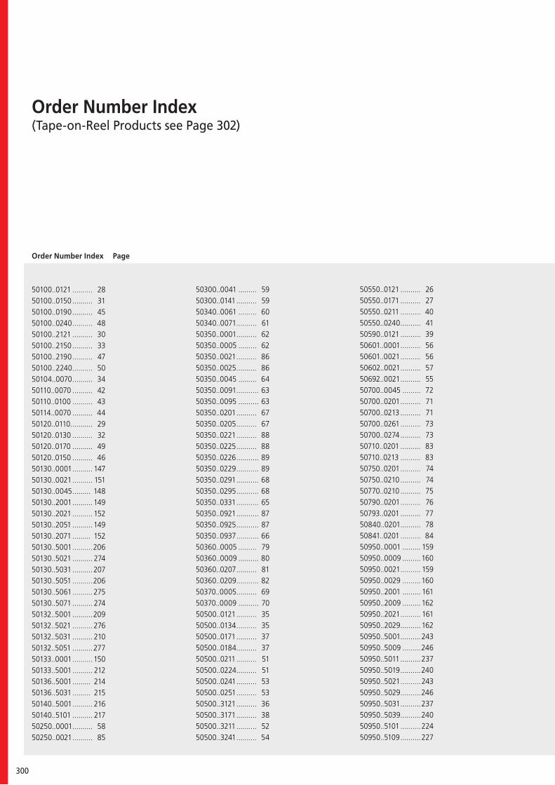
300
Order Number Index(Tape-on-Reel Products see Page 302)
Order Number Index Page
50100..0121 .......... 2850100..0150 .......... 3150100..0190 .......... 4550100..0240 .......... 4850100..2121 .......... 3050100..2150 .......... 3350100..2190 .......... 4750100..2240 .......... 5050104..0070 .......... 3450110..0070 .......... 4250110..0100 .......... 4350114..0070 .......... 4450120..0110 ........... 2950120..0130 .......... 3250120..0170 .......... 4950120..0150 .......... 4650130..0001 .......... 14750130..0021 .......... 15150130..0045 ......... 14850130..2001 .......... 14950130..2021 .......... 15250130..2051 .......... 14950130..2071 ......... 15250130..5001 ..........20650130..5021 .......... 27450130..5031 ..........20750130..5051 ..........20650130..5061 .......... 27550130..5071 .......... 27450132..5001 ..........20950132..5021 .......... 27650132..5031 .......... 21050132..5051 ..........27750133..0001 .......... 15050133..5001 .......... 21250136..5001 ......... 21450136..5031 ......... 21550140..5001 .......... 21650140..5101 .......... 21750250..0001 .......... 5850250..0021 .......... 85
50300..0041 ......... 5950300..0141 .......... 5950340..0061 ......... 6050340..0071 .......... 6150350..0001.......... 6250350..0005 ......... 6250350..0021 .......... 8650350..0025 .......... 8650350..0045 ......... 6450350..0091 ........... 6350350..0095 .......... 6350350..0201 .......... 6750350..0205 .......... 6750350..0221 .......... 8850350..0225 .......... 8850350..0226 ........... 8950350..0229 ........... 8950350..0291 ........... 6850350..0295 ........... 6850350..0331 ........... 6550350..0921 ........... 8750350..0925 ........... 8750350..0937 ........... 6650360..0005 ......... 7950360..0009 .......... 8050360..0207 .......... 8150360..0209 ........... 8250370..0005.......... 6950370..0009 .......... 7050500..0121 .......... 3550500..0134 .......... 3550500..0171 .......... 3750500..0184 .......... 3750500..0211 .......... 5150500..0224 .......... 5150500..0241 .......... 5350500..0251 .......... 5350500..3121 .......... 3650500..3171 .......... 3850500..3211 .......... 5250500..3241 .......... 54
50550..0121 .......... 2650550..0171 .......... 2750550..0211 .......... 4050550..0240 .......... 4150590..0121 .......... 3950601..0001 .......... 5650601..0021 .......... 5650602..0021 .......... 5750692..0021 .......... 5550700..0045 ......... 7250700..0201 .......... 7150700..0213 .......... 7150700..0261 .......... 7350700..0274 .......... 7350710..0201 .......... 8350710..0213 .......... 8350750..0201 .......... 7450750..0210 .......... 7450770..0210 .......... 7550790..0201 .......... 7650793..0201 .......... 7750840..0201.......... 7850841..0201 .......... 8450950..0001 ......... 15950950..0009 .........16050950..0021 .......... 15950950..0029 .........16050950..2001 ......... 16150950..2009 ......... 16250950..2021 .......... 16150950..2029 .......... 16250950..5001..........24350950..5009 .........24650950..5011 ..........23750950..5019 ..........24050950..5021 ..........24350950..5029 ..........24650950..5031 ..........23750950..5039..........24050950..5101 ..........22450950..5109 ..........227
PTR Terminal Blocks and Multi Connector Systems 301
50950..5111 ......... 21850950..5119 ......... 22150950..5121 ......... 22450950..5129 ......... 22750950..5131 ......... 21850950..5139 ......... 22150950..5317 ......... 23850950..5319 ......... 24150950..5327 ......... 24450950..5329 ......... 24750950..5337 ......... 23850950..5339 ......... 24150950..5347 ......... 24450950..5349......... 24750950..5367......... 22550950..5368 ........ 22850950..5377 ......... 21950950..5379 ......... 22250950..5387 ......... 22550950..5388 ........ 22850950..5389 ........ 22250950..5397 ......... 21950950..6001 ........ 24950950..6019 ......... 25250950..6021 ......... 24950950..6039 ........ 25250950..6101 ......... 23050950..6109 ......... 23350950..6121 ......... 23050950..6129 ......... 23350950..6327 ......... 25050950..6329 ......... 25350950..6347 ......... 25050950..6349 ........ 25350950..6367 ........ 23150950..6379 ......... 23450950..6387 ........ 23150950..6389 ........ 23450950..7021 ......... 16950950..7022 ......... 17050950..7028 ......... 164
50950..7041 ......... 17150950..9021 ......... 25550950..9121 ......... 23650955..0001......... 16350955..0021 ......... 16350955..5061 ......... 25650955..5071 ......... 25750960..0021 ........ 17250960..5021 ......... 27150960..5031 ......... 27050960..5121 ......... 26950960..5131 ......... 26850965..2021 ......... 17350965..6021 ......... 27350965..6121 ......... 27250970..5021 ......... 26150970..5031 ......... 25950970..5121 ......... 26050970..5131 ......... 25850970..6021 ......... 26350970..6121 ......... 26250975..5001 ......... 26550975..5101 ......... 26450990..5121 ......... 26750990..5131 ......... 26651100..0001 ......... 16551100..0021 ......... 16551100..2001 ......... 16651110..0001 .......... 16751110..0021 .......... 16751110..2001 .......... 16851200..0001 ......... 17451200..0021 ......... 17451200..2001 ......... 17551200..2021 ......... 17551350..0001 ......... 14551350..0121 .......... 14651350..5001 ......... 18451350..5010 ......... 18751350..5031 ......... 18551350..5101 .......... 188
51550..0001 ......... 15351550..0025 ......... 15351550..2001 ......... 15451550..2025 ......... 15451550..5001 ......... 19551550..5025 ......... 19551550..5101 .......... 18951550..5125 .......... 18951550..5332 ......... 19651550..5342 ......... 19051550..6001 ......... 19851550..6025 ......... 19851550..6101.......... 19251550..6125 .......... 19251550..6332 ......... 19951550..6342 ......... 19351570..5021 ......... 20251570..5121 .......... 20151570..6021 ......... 20451570..6121 .......... 20351590..5121 .......... 20551700..0001 ......... 155 51700..0021 ......... 15551700..2001 ......... 156 51700..2021 ......... 15651710..0001 ......... 157 51710..0021 ......... 157 51710..2001 ......... 15851710..2021.......... 158 52200..0001 ......... 9052200..0021 .......... 9252200..0041 .......... 9452200..0051 .......... 9152200..0071 .......... 9352200..0091 .......... 9553000..0001 ........ 12353000..0041 ........ 13753001..0001 ......... 12453001..0021 ......... 12553001..0041 ......... 13853001..0051 .................... 126
302
53001..0061 .................... 13953001..0071 .................... 14053010..0001 .................... 13353011..0001 .................... 13453011..0021 .................... 13553011..0071 .................... 13653100..0001 .................... 12753101..0001 .................... 12853101..0021 .................... 12953191..0001 .................... 12153191..0321 .................... 12253191..1001 ..................... 12253191..1321 ..................... 12153750..0201 .................... 13253750..0203 .................... 13053750..0210 .................... 13253750..0213 .................... 13053750..0241 .................... 13153750..0251 .................... 13153950..0001.................... 18354100..0001 .................... 10554101..0001 .................... 10654191..0001 ..................... 9654191..0051 ..................... 9754200..0421 .................... 10754200..0451 .................... 10854200..0521 .................... 11354200..0551 .................... 11454210..0407 .................... 11854210..0521 .................... 11554210..0523 .................... 11954210..0527 .................... 11654210..0551 .................... 11754210..0651 .................... 12054291..0001 .................... 10054291..0051 .................... 10154301..0421 .................... 10954350..0001 ................... 17654551..0401 .................... 17754551..0421 .................... 17754551..2401 .................... 178
54551..2421 ..................... 17854561..0401 ..................... 17954561..0421 ..................... 17954561..2401 .....................18054561..2421 .....................18054701..0421 .................... 10254701..0422 .................... 10354791..0421 ..................... 9854791..0422 ..................... 9954801..0301 .................... 11054841..0361 .................... 11154841..0371 .................... 11254951..0401 ..................... 18154951..0421 ..................... 18154951..2401 ..................... 18254951..2421 ..................... 182
Tape-on-Reel Products
50130..5031R .................. 20850132..5031R .................. 21150950..5317R .................. 23950950..5319R .................. 24250950..5327R .................. 24550950..5329R .................. 24850950..5337R .................. 23950950..5339R.................. 24250950..5347R .................. 24550950..5349R ................. 24850950..5367R .................. 22650950..5368R ................. 22950950..5377R .................. 22050950..5379R .................. 22350950..5387R .................. 22650950..5388R ................. 22950950..5389R ................. 22350950..5397R .................. 22050950..6327R .................. 251 50950..6329R.................. 25450950..6347R .................. 25150950..6349R ................. 25450950..6367R.................. 23250950..6379R.................. 23550950..6387R.................. 23250950..6389R ................. 23551350..5031R .................. 18651550..5332R .................. 19751550..5342R .................. 19151550..6332R .................. 20051550..6342R .................. 19454091..9001R .................. 104
Order Number Index Page
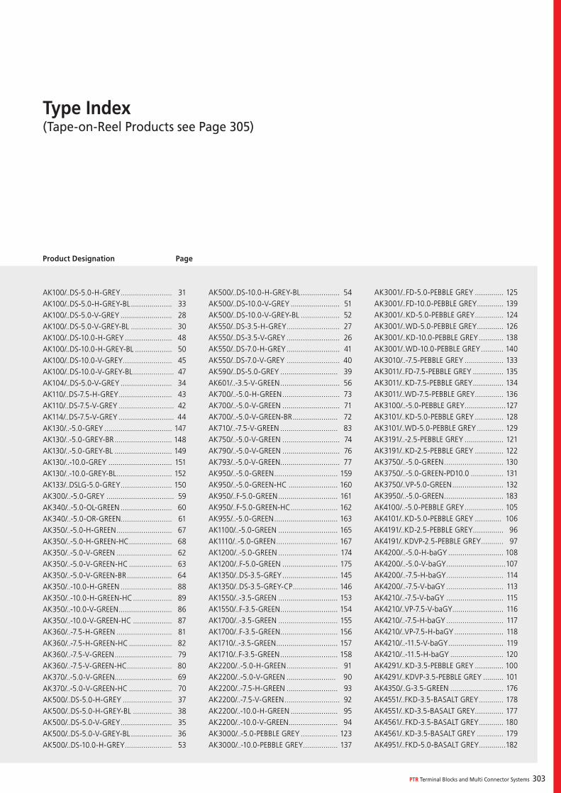
PTR Terminal Blocks and Multi Connector Systems 303
Type Index(Tape-on-Reel Products see Page 305)
Product Designation Page
AK100/..DS-5.0-H-GREY ......................... 31AK100/..DS-5.0-H-GREY-BL .................... 33AK100/..DS-5.0-V-GREY ......................... 28AK100/..DS-5.0-V-GREY-BL .................... 30AK100/..DS-10.0-H-GREY ....................... 48AK100/..DS-10.0-H-GREY-BL .................. 50AK100/..DS-10.0-V-GREY ........................ 45AK100/..DS-10.0-V-GREY-BL .................... 47AK104/..DS-5.0-V-GREY ......................... 34AK110/..DS-7.5-H-GREY .......................... 43AK110/..DS-7.5-V-GREY ........................... 42AK114/..DS-7.5-V-GREY ........................... 44AK130/..-5.0-GREY ................................. 147AK130/..-5.0-GREY-BR ............................ 148AK130/..-5.0-GREY-BL ............................ 149AK130/..-10.0-GREY ............................... 151AK130/..-10.0-GREY-BL ........................... 152AK133/..DSLG-5.0-GREY ......................... 150AK300/..-5.0-GREY ................................. 59AK340/..-5.0-OL-GREEN ......................... 60AK340/..-5.0-OR-GREEN ......................... 61AK350/..-5.0-H-GREEN ........................... 67AK350/..-5.0-H-GREEN-HC ..................... 68AK350/..-5.0-V-GREEN ........................... 62AK350/..-5.0-V-GREEN-HC ..................... 63AK350/..-5.0-V-GREEN-BR ...................... 64AK350/..-10.0-H-GREEN ......................... 88AK350/..-10.0-H-GREEN-HC ................... 89AK350/..-10.0-V-GREEN .......................... 86AK350/..-10.0-V-GREEN-HC ................... 87AK360/..-7.5-H-GREEN ........................... 81AK360/..-7.5-H-GREEN-HC ..................... 82AK360/..-7.5-V-GREEN ............................ 79AK360/..-7.5-V-GREEN-HC...................... 80AK370/..-5.0-V-GREEN............................ 69AK370/..-5.0-V-GREEN-HC ..................... 70AK500/..DS-5.0-H-GREY ........................ 37AK500/..DS-5.0-H-GREY-BL ................... 38AK500/..DS-5.0-V-GREY ......................... 35AK500/..DS-5.0-V-GREY-BL .................... 36AK500/..DS-10.0-H-GREY ....................... 53
AK500/..DS-10.0-H-GREY-BL ................... 54AK500/..DS-10.0-V-GREY ........................ 51AK500/..DS-10.0-V-GREY-BL ................... 52AK550/..DS-3.5-H-GREY .......................... 27AK550/..DS-3.5-V-GREY .......................... 26AK550/..DS-7.0-H-GREY .......................... 41AK550/..DS-7.0-V-GREY .......................... 40AK590/..DS-5.0-GREY ............................ 39AK601/..-3.5-V-GREEN ............................. 56AK700/..-5.0-H-GREEN ............................ 73AK700/..-5.0-V-GREEN ............................ 71AK700/..-5.0-V-GREEN-BR ...................... 72AK710/..-7.5-V-GREEN ............................ 83AK750/..-5.0-V-GREEN ............................ 74AK790/..-5.0-V-GREEN ............................ 76AK793/..-5.0-V-GREEN ............................. 77AK950/..-5.0-GREEN ............................... 159AK950/..-5.0-GREEN-HC ........................ 160AK950/..F-5.0-GREEN ............................. 161AK950/..F-5.0-GREEN-HC ....................... 162AK955/..-5.0-GREEN ............................... 163AK1100/..-5.0-GREEN ............................. 165AK1110/..-5.0-GREEN .............................. 167AK1200/..-5.0-GREEN ............................. 174AK1200/..F-5.0-GREEN ........................... 175AK1350/..DS-3.5-GREY ........................... 145AK1350/..DS-3.5-GREY-CP ...................... 146AK1550/..-3.5-GREEN ............................. 153AK1550/..F-3.5-GREEN ............................ 154AK1700/..-3.5-GREEN ............................. 155AK1700/..F-3.5-GREEN ............................ 156AK1710/..-3.5-GREEN .............................. 157AK1710/..F-3.5-GREEN ............................ 158 AK2200/..-5.0-H-GREEN ......................... 91AK2200/..-5.0-V-GREEN ........................ 90AK2200/..-7.5-H-GREEN ......................... 93AK2200/..-7.5-V-GREEN ........................... 92AK2200/..-10.0-H-GREEN ....................... 95AK2200/..-10.0-V-GREEN ........................ 94AK3000/..-5.0-PEBBLE GREY .................. 123AK3000/..-10.0-PEBBLE GREY................. 137
AK3001/..FD-5.0-PEBBLE GREY .............. 125AK3001/..FD-10.0-PEBBLE GREY ............. 139AK3001/..KD-5.0-PEBBLE GREY .............. 124AK3001/..WD-5.0-PEBBLE GREY ............. 126AK3001/..KD-10.0-PEBBLE GREY ............ 138AK3001/..WD-10.0-PEBBLE GREY ........... 140AK3010/..-7.5-PEBBLE GREY ................... 133AK3011/..FD-7.5-PEBBLE GREY ............... 135AK3011/..KD-7.5-PEBBLE GREY ............... 134AK3011/..WD-7.5-PEBBLE GREY .............. 136AK3100/..-5.0-PEBBLE GREY ....................127AK3101/..KD-5.0-PEBBLE GREY .............. 128AK3101/..WD-5.0-PEBBLE GREY ............. 129AK3191/..-2.5-PEBBLE GREY ................... 121AK3191/..KD-2.5-PEBBLE GREY .............. 122AK3750/..-5.0-GREEN ............................. 130AK3750/..-5.0-GREEN-PD10.0 ................ 131AK3750/..VP-5.0-GREEN ......................... 132AK3950/..-5.0-GREEN ............................. 183AK4100/..-5.0-PEBBLE GREY ................... 105AK4101/..KD-5.0-PEBBLE GREY ............. 106AK4191/..KD-2.5-PEBBLE GREY ............... 96AK4191/..KDVP-2.5-PEBBLE GREY ........... 97AK4200/..-5.0-H-baGY ........................... 108AK4200/..-5.0-V-baGY .............................107AK4200/..-7.5-H-baGY ............................ 114AK4200/..-7.5-V-baGY ............................ 113AK4210/..-7.5-V-baGY ............................ 115AK4210/..VP-7.5-V-baGY......................... 116AK4210/..-7.5-H-baGY ............................ 117AK4210/..VP-7.5-H-baGY ........................ 118AK4210/..-11.5-V-baGY ........................... 119AK4210/..-11.5-H-baGY .......................... 120AK4291/..KD-3.5-PEBBLE GREY .............. 100AK4291/..KDVP-3.5-PEBBLE GREY .......... 101AK4350/..G-3.5-GREEN .......................... 176AK4551/..FKD-3.5-BASALT GREY ............ 178AK4551/..KD-3.5-BASALT GREY.............. 177AK4561/..FKD-3.5-BASALT GREY ............ 180AK4561/..KD-3.5-BASALT GREY ............. 179AK4951/..FKD-5.0-BASALT GREY .............182
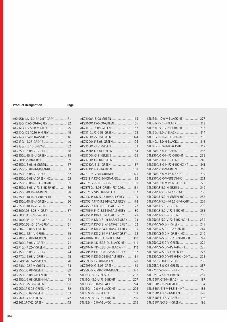
304
Product Designation Page
AK4951/..KD-5.0-BASALT GREY ..............181AKZ120/..DS-5.08-H-GREY ...................... 32AKZ120/..DS-5.08-V-GREY ...................... 29AKZ120/..DS-10.16-H-GREY ..................... 49AKZ120/..DS-10.16-V-GREY ..................... 46AKZ130/..-5.08-GREY-BL ........................ 149AKZ130/..-10.16-GREY-BL ....................... 152AKZ250/..-5.08-V-GREEN ....................... 58AKZ250/..-10.16-V-GREEN ....................... 85AKZ300/..-5.08-GREY ............................. 59AKZ350/..-5.08-H-GREEN ....................... 67AKZ350/..-5.08-H-GREEN-HC ................. 68AKZ350/..-5.08-V-GREEN ........................ 62AKZ350/..-5.08-V-GREEN-HC ................. 63AKZ350/..-5.08-V-P3.5-BK-HT ................. 65AKZ350/..-5.08-V-P3.5-BK-FP-HT ........... 66AKZ350/..-10.16-H-GREEN ...................... 88AKZ350/..-10.16-H-GREEN-HC ............... 89AKZ350/..-10.16-V-GREEN ...................... 86AKZ350/..-10.16-V-GREEN-HC ................ 87AKZ500/..DS-5.08-H-GREY ..................... 37AKZ500/..DS-5.08-V-GREY ...................... 35AKZ500/..DS-10.16-H-GREY ................... 53AKZ500/..DS-10.16-V-GREY .................... 51AKZ602/..-3.81-V-GREEN ........................ 57AKZ692/..-2.54-V-GREEN ........................ 55AKZ700/..-5.08-H-GREEN ....................... 73AKZ700/..-5.08-V-GREEN ....................... 71AKZ710/..-7.62-V-GREEN ........................ 83AKZ750/..-5.08-V-GREEN ....................... 74AKZ770/..-5.08-V-GREEN ....................... 75AKZ840/..-6.35-V-GREEN ....................... 78AKZ841/..-9.52-V-GREEN ........................ 84AKZ950/..-5.08-GREEN ........................... 159AKZ950/..-5.08-GREEN-HC .................... 160AKZ950/..-5.08-GREEN-INV ................... 164AKZ950/..F-5.08-GREEN ......................... 161AKZ950/..F-5.08-GREEN-HC ................... 162AKZ955/..-5.08-GREEN ........................... 163AKZ960/..-7.62-GREEN ........................... 172AKZ965/..F-7.62-GREEN ...........................173
AKZ1100/..-5.08-GREEN ......................... 165AKZ1100/..FS-5.08-GREEN ...................... 166AKZ1110/..-5.08-GREEN .......................... 167AKZ1110/..FS-5.08-GREEN ...................... 168AKZ1200/..-5.08-GREEN ......................... 174AKZ1200/..F-5.08-GREEN ....................... 175AKZ1550/..-3.81-GREEN .......................... 153AKZ1550/..F-3.81-GREEN ........................ 154AKZ1700/..-3.81-GREEN .......................... 155AKZ1700/..F-3.81-GREEN ........................ 156AKZ1710/..-3.81-GREEN .......................... 157AKZ1710/..F-3.81-GREEN ........................ 158AKZ3191/..-2.54-ORANGE ...................... 121AKZ3191/..KD-2.54-ORANGE ................. 122AKZ3750/..-5.08-GREEN ......................... 130AKZ3750/..-5.08-GREEN-PD10.16 ........... 131AKZ3750/..VP-5.08-GREEN ..................... 132AKZ4301/..KD-5.08-BASALT GREY ......... 109AKZ4551/..FKD-3.81-BASALT GREY ........ 178AKZ4551/..KD-3.81-BASALT GREY .......... 177AKZ4561/..FKD-3.81-BASALT GREY ........ 180AKZ4561/..KD-3.81-BASALT GREY .......... 179AKZ4701/..KD-3.81-H-BASALT GREY ...... 103AKZ4701/..KD-3.81-V-BASALT GREY ...... 102AKZ4791/..KD-2.54-H-BASALT GREY...... 99AKZ4791/..KD-2.54-V-BASALT GREY ...... 98AKZ4801/..KD-6.35-V-BLACK-HT ........... 110AKZ4841/..KD-6.35-OL-BLACK-HT ......... 111AKZ4841/..KD-6.35-OR-BLACK-HT ........ 112AKZ4951/..FKD-5.08-BASALT GREY ........ 182AKZ4951/..KD-5.08-BASALT GREY ......... 181AKZS950/..F-5.08-GREEN ....................... 170AKZS950/..G-5.08-GREEN ...................... 169AKZS950/..GMB-5.08-GREEN ................. 171STL130/..-5.0-V-BLACK .......................... 206STL130/..-5.0-V-P3.5-BK-HT .................... 207STL130/..-10.0-V-BLACK.......................... 274STL130/..-10.0-V-BLACK-HT .................... 275STL132/..-5.0-V-BLACK .......................... 209STL132/..-5.0-V-P3.3-BK-HT .................... 210STL132/..-10.0-V-BLACK .......................... 276
STL132/..-10.0-V-BLACK-HT ................... 277STL133/..-5.0-V-BLACK .......................... 212STL133/..-5.0-V-P3.5-BK-HT ................... 213STL136/..-5.0-V-BLACK .......................... 214STL136/..-5.0-V-P3.5-BK-HT ................... 215STL140/..-5.0-H-BLACK .......................... 216STL140/..-5.0-H-BLACK-HT .................... 217STL950/..-5.0-H-GREEN ......................... 237STL950/..-5.0-H-P2.6-BK-HT .................. 238STL950/..-5.0-H-GREEN-HC ................... 240STL950/..-5.0-H-P2.6-BK-HC-HT ............. 241STL950/..-5.0-V-GREEN ........................... 218STL950/..-5.0-V-P2.6-BK-HT ................... 219STL950/..-5.0-V-GREEN-HC ................... 221STL950/..-5.0-V-P2.6-BK-HC-HT ............. 222STL950/..F-5.0-H-GREEN ........................ 249STL950/..F-5.0-H-P2.6-BK-HT ................ 250STL950/..F-5.0-H-GREEN-HC .................. 252STL950/..F-5.0-H-P2.6-BK-HC-HT ........... 253STL950/..F-5.0-V-GREEN ......................... 230STL950/..F-5.0-V-P2.6-BK-HT .................. 231STL950/..F-5.0-V-GREEN-HC ................... 233STL950/..F-5.0-V-P2.6-BK-HC-HT ............ 234STL950/..G-5.0-H-GREEN........................ 243STL950/..G-5.0-H-P2.6-BK-HT ............... 244STL950/..G-5.0-H-GREEN-HC ................ 246STL950/..G-5.0-H-P2.6-BK-HC-HT ........... 247STL950/..G-5.0-V-GREEN ........................ 224STL950/..G-5.0-V-P2.6-BK-HT ................. 225STL950/..G-5.0-V-GREEN-HC .................. 227STL950/..G-5.0-V-P2.6-BK-HC-HT ........... 228STL955/..-5.0-OL-GREEN ......................... 256STL955/..-5.0-OR-GREEN ........................ 257STL975/..G-5.0-H-GREEN ........................ 265STL975/..G-5.0-V-GREEN ....................... 264STL1350/..-3.5-H-BLACK ......................... 187STL1350/..-3.5-V-BLACK ........................ 184STL1350/..-3.5-V-P3.5-BK-HT .................. 185STL1550/..F-3.5-H-GREEN ....................... 198STL1550/..F-3.5-V-GREEN ........................ 192STL1550/..G-3.5-H-GREEN .......................195
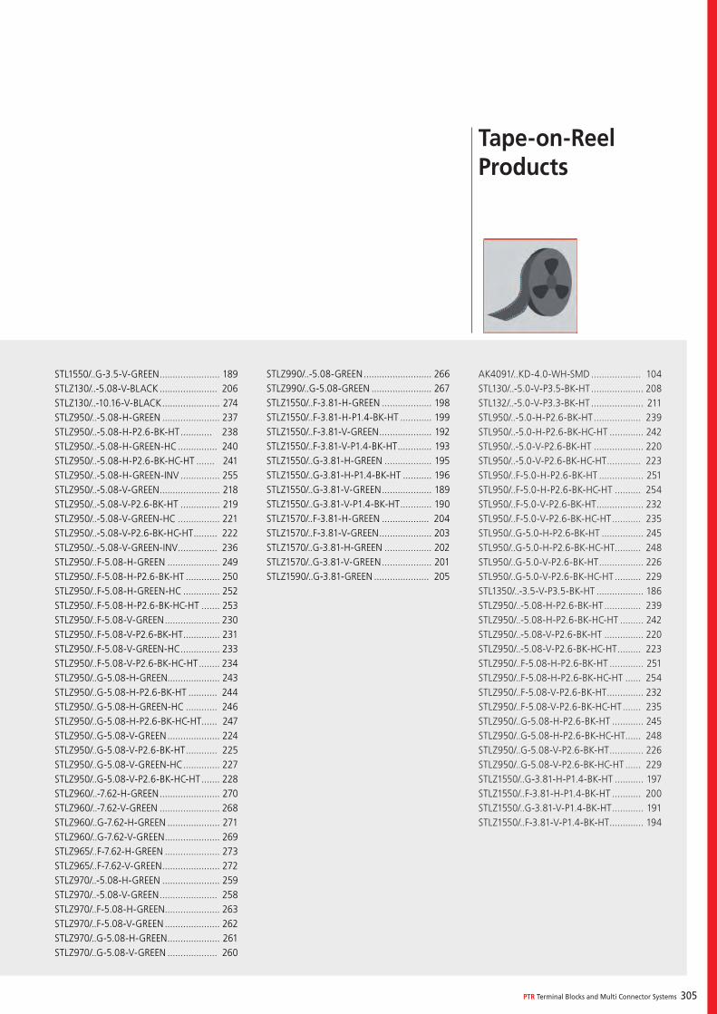
PTR Terminal Blocks and Multi Connector Systems 305
STL1550/..G-3.5-V-GREEN ....................... 189STLZ130/..-5.08-V-BLACK ...................... 206STLZ130/..-10.16-V-BLACK ...................... 274STLZ950/..-5.08-H-GREEN ...................... 237STLZ950/..-5.08-H-P2.6-BK-HT ............ 238STLZ950/..-5.08-H-GREEN-HC ............... 240STLZ950/..-5.08-H-P2.6-BK-HC-HT ....... 241STLZ950/..-5.08-H-GREEN-INV ............... 255STLZ950/..-5.08-V-GREEN ....................... 218STLZ950/..-5.08-V-P2.6-BK-HT ............... 219STLZ950/..-5.08-V-GREEN-HC ................ 221STLZ950/..-5.08-V-P2.6-BK-HC-HT ......... 222STLZ950/..-5.08-V-GREEN-INV ............... 236STLZ950/..F-5.08-H-GREEN .................... 249STLZ950/..F-5.08-H-P2.6-BK-HT ............. 250STLZ950/..F-5.08-H-GREEN-HC .............. 252STLZ950/..F-5.08-H-P2.6-BK-HC-HT ....... 253STLZ950/..F-5.08-V-GREEN ..................... 230STLZ950/..F-5.08-V-P2.6-BK-HT .............. 231STLZ950/..F-5.08-V-GREEN-HC ............... 233STLZ950/..F-5.08-V-P2.6-BK-HC-HT ........ 234STLZ950/..G-5.08-H-GREEN.................... 243STLZ950/..G-5.08-H-P2.6-BK-HT ........... 244STLZ950/..G-5.08-H-GREEN-HC ............ 246STLZ950/..G-5.08-H-P2.6-BK-HC-HT ...... 247STLZ950/..G-5.08-V-GREEN .................... 224STLZ950/..G-5.08-V-P2.6-BK-HT ............ 225STLZ950/..G-5.08-V-GREEN-HC .............. 227STLZ950/..G-5.08-V-P2.6-BK-HC-HT ....... 228STLZ960/..-7.62-H-GREEN ....................... 270STLZ960/..-7.62-V-GREEN ....................... 268STLZ960/..G-7.62-H-GREEN .................... 271STLZ960/..G-7.62-V-GREEN ..................... 269STLZ965/..F-7.62-H-GREEN ..................... 273STLZ965/..F-7.62-V-GREEN ...................... 272STLZ970/..-5.08-H-GREEN ...................... 259STLZ970/..-5.08-V-GREEN ...................... 258STLZ970/..F-5.08-H-GREEN ..................... 263STLZ970/..F-5.08-V-GREEN ..................... 262STLZ970/..G-5.08-H-GREEN .................... 261STLZ970/..G-5.08-V-GREEN ................... 260
STLZ990/..-5.08-GREEN .......................... 266STLZ990/..G-5.08-GREEN ....................... 267STLZ1550/..F-3.81-H-GREEN ................... 198STLZ1550/..F-3.81-H-P1.4-BK-HT ............ 199STLZ1550/..F-3.81-V-GREEN .................... 192STLZ1550/..F-3.81-V-P1.4-BK-HT ............. 193STLZ1550/..G-3.81-H-GREEN .................. 195STLZ1550/..G-3.81-H-P1.4-BK-HT ........... 196STLZ1550/..G-3.81-V-GREEN ................... 189STLZ1550/..G-3.81-V-P1.4-BK-HT ............ 190STLZ1570/..F-3.81-H-GREEN .................. 204STLZ1570/..F-3.81-V-GREEN .................... 203STLZ1570/..G-3.81-H-GREEN .................. 202STLZ1570/..G-3.81-V-GREEN ................... 201STLZ1590/..G-3.81-GREEN ..................... 205
Tape-on-Reel Products
AK4091/..KD-4.0-WH-SMD ................... 104STL130/..-5.0-V-P3.5-BK-HT .................... 208STL132/..-5.0-V-P3.3-BK-HT .................... 211STL950/..-5.0-H-P2.6-BK-HT .................. 239STL950/..-5.0-H-P2.6-BK-HC-HT ............. 242STL950/..-5.0-V-P2.6-BK-HT ................... 220STL950/..-5.0-V-P2.6-BK-HC-HT ............. 223STL950/..F-5.0-H-P2.6-BK-HT ................. 251STL950/..F-5.0-H-P2.6-BK-HC-HT .......... 254STL950/..F-5.0-V-P2.6-BK-HT .................. 232STL950/..F-5.0-V-P2.6-BK-HC-HT ........... 235STL950/..G-5.0-H-P2.6-BK-HT ................ 245STL950/..G-5.0-H-P2.6-BK-HC-HT .......... 248STL950/..G-5.0-V-P2.6-BK-HT ................. 226STL950/..G-5.0-V-P2.6-BK-HC-HT .......... 229STL1350/..-3.5-V-P3.5-BK-HT .................. 186STLZ950/..-5.08-H-P2.6-BK-HT .............. 239STLZ950/..-5.08-H-P2.6-BK-HC-HT ......... 242STLZ950/..-5.08-V-P2.6-BK-HT ............... 220STLZ950/..-5.08-V-P2.6-BK-HC-HT ......... 223STLZ950/..F-5.08-H-P2.6-BK-HT ............. 251STLZ950/..F-5.08-H-P2.6-BK-HC-HT ...... 254STLZ950/..F-5.08-V-P2.6-BK-HT .............. 232STLZ950/..F-5.08-V-P2.6-BK-HC-HT ....... 235STLZ950/..G-5.08-H-P2.6-BK-HT ............ 245STLZ950/..G-5.08-H-P2.6-BK-HC-HT ...... 248STLZ950/..G-5.08-V-P2.6-BK-HT ............. 226STLZ950/..G-5.08-V-P2.6-BK-HC-HT ...... 229STLZ1550/..G-3.81-H-P1.4-BK-HT ........... 197STLZ1550/..F-3.81-H-P1.4-BK-HT ........... 200STLZ1550/..G-3.81-V-P1.4-BK-HT ............ 191STLZ1550/..F-3.81-V-P1.4-BK-HT ............. 194
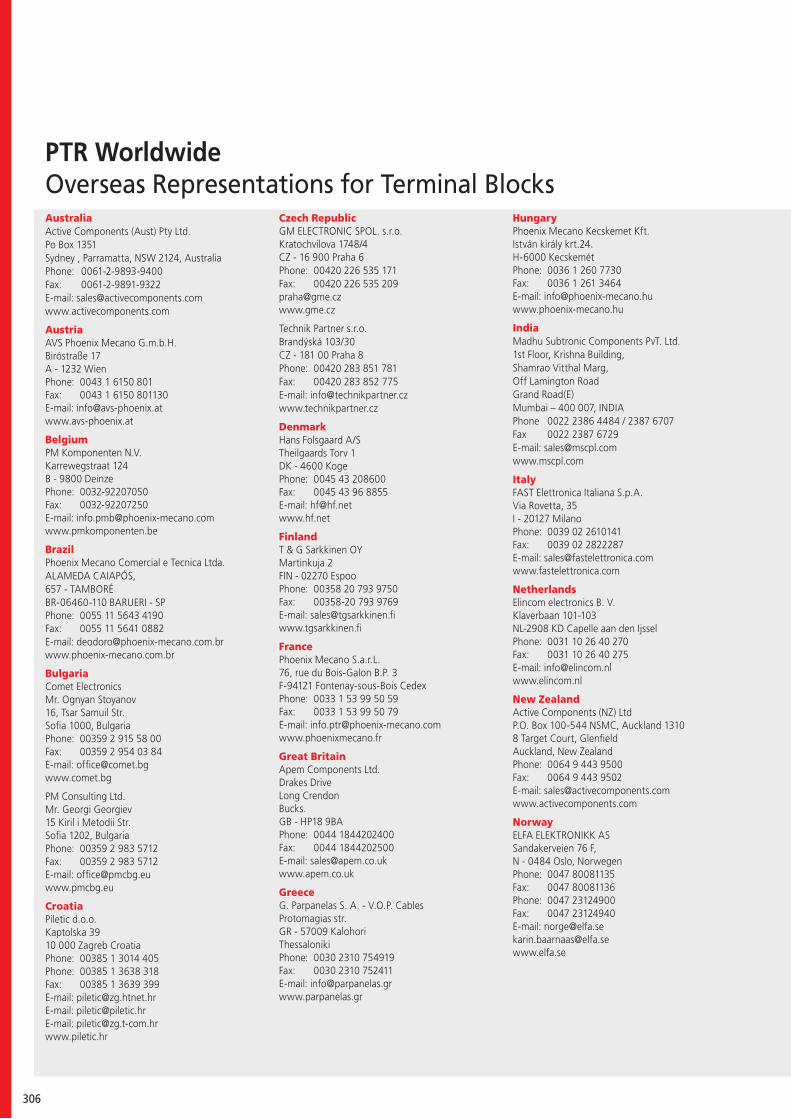
306
PTR WorldwideOverseas Representations for Terminal BlocksAustraliaActive Components (Aust) Pty Ltd.Po Box 1351 Sydney , Parramatta, NSW 2124, AustraliaPhone: 0061-2-9893-9400Fax: 0061-2-9891-9322E-mail: [email protected]
AustriaAVS Phoenix Mecano G.m.b.H.Biróstraße 17A - 1232 WienPhone: 0043 1 6150 801Fax: 0043 1 6150 801130E-mail: [email protected]
BelgiumPM Komponenten N.V.Karrewegstraat 124B - 9800 DeinzePhone: 0032-92207050Fax: 0032-92207250E-mail: [email protected]
BrazilPhoenix Mecano Comercial e Tecnica Ltda.ALAMEDA CAIAPÓS, 657 - TAMBORÉBR-06460-110 BARUERI - SPPhone: 0055 11 5643 4190Fax: 0055 11 5641 0882E-mail: [email protected]
BulgariaComet Electronics Mr. Ognyan Stoyanov16, Tsar Samuil Str.Sofia 1000, BulgariaPhone: 00359 2 915 58 00 Fax: 00359 2 954 03 84 E-mail: [email protected]
PM Consulting Ltd.Mr. Georgi Georgiev15 Kiril i Metodii Str.Sofia 1202, BulgariaPhone: 00359 2 983 5712Fax: 00359 2 983 5712E-mail: [email protected]
CroatiaPiletic d.o.o.Kaptolska 39 10 000 Zagreb CroatiaPhone: 00385 1 3014 405Phone: 00385 1 3638 318Fax: 00385 1 3639 399E-mail: [email protected]: [email protected]: [email protected]
Czech RepublicGM ELECTRONIC SPOL. s.r.o.Kratochvilova 1748/4CZ - 16 900 Praha 6Phone: 00420 226 535 171Fax: 00420 226 535 [email protected]
Technik Partner s.r.o.Brandýská 103/30CZ - 181 00 Praha 8Phone: 00420 283 851 781Fax: 00420 283 852 775E-mail: [email protected]
DenmarkHans Folsgaard A/S Theilgaards Torv 1DK - 4600 KogePhone: 0045 43 208600Fax: 0045 43 96 8855E-mail: [email protected]
FinlandT & G Sarkkinen OYMartinkuja 2FIN - 02270 EspooPhone: 00358 20 793 9750Fax: 00358-20 793 9769E-mail: [email protected]
FrancePhoenix Mecano S.a.r.L.76, rue du Bois-Galon B.P. 3F-94121 Fontenay-sous-Bois CedexPhone: 0033 1 53 99 50 59Fax: 0033 1 53 99 50 79E-mail: [email protected]
Great Britain Apem Components Ltd.Drakes DriveLong CrendonBucks.GB - HP18 9BAPhone: 0044 1844202400Fax: 0044 1844202500E-mail: [email protected]
GreeceG. Parpanelas S. A. - V.O.P. CablesProtomagias str.GR - 57009 KalohoriThessalonikiPhone: 0030 2310 754919Fax: 0030 2310 752411 E-mail: [email protected]
HungaryPhoenix Mecano Kecskemet Kft.István király krt.24.H-6000 KecskemétPhone: 0036 1 260 7730Fax: 0036 1 261 3464E-mail: [email protected]
IndiaMadhu Subtronic Components PvT. Ltd.1st Floor, Krishna Building,Shamrao Vitthal Marg,Off Lamington RoadGrand Road(E)Mumbai – 400 007, INDIAPhone 0022 2386 4484 / 2387 6707Fax 0022 2387 6729E-mail: [email protected]
ItalyFAST Elettronica Italiana S.p.A.Via Rovetta, 35I - 20127 MilanoPhone: 0039 02 2610141Fax: 0039 02 2822287E-mail: [email protected]
NetherlandsElincom electronics B. V.Klaverbaan 101-103NL-2908 KD Capelle aan den IjsselPhone: 0031 10 26 40 270Fax: 0031 10 26 40 275E-mail: [email protected]
New ZealandActive Components (NZ) LtdP.O. Box 100-544 NSMC, Auckland 13108 Target Court, GlenfieldAuckland, New ZealandPhone: 0064 9 443 9500Fax: 0064 9 443 9502E-mail: [email protected]
NorwayELFA ELEKTRONIKK ASSandakerveien 76 F, N - 0484 Oslo, NorwegenPhone: 0047 80081135Fax: 0047 80081136Phone: 0047 23124900Fax: 0047 23124940E-mail: [email protected]@elfa.sewww.elfa.se
PTR Terminal Blocks and Multi Connector Systems 307
People’s Republic of ChinaMecano Components (Shanghai) Co., Ltd. No. 1001, JiaQian RoadNanxiang Hi-tech Park, JiaDing District 201802 Shanghai, China PRC Phone: 0086 21 69176590Fax: 0086 21 69176532E-mail: [email protected]
PolandJacenko Import Exportul. Iganska 11PL - 04-087 WarszawaPhone: 0048 22 8137493Fax: 0048 22 8137467E-mail: [email protected]
Elhurt sp z o.o.Galaktyczna 35 APL - 80-299 GdanskPhone: 0048 585540800Fax: 0048 585540806 E-mail: [email protected]
RomaniaECAS ELECTRO SRLStr. Cornelia nr.7Sector 4RO - 040181 Bucuresti, RomaniaPhone: 0040 21 204 81 00Fax: 0040 21 204 81 30E-mail: [email protected]
RussiaADK ElektronikKutuzov prospect, 36, p.3RUS-125284 MoscowPhone/Fax: +7(495) 276-11-71E-mail: [email protected]
SerbiaComet Electronics d.o.o.Mr. Zoran Petrovic17, Arsenija Carnojevica Blvd.11070 New BelgradPhone: 00381 11 213 61 45Fax: 00381 11 311 39 42E-mail: [email protected]
SingaporePhoenix Mecano S.E. Asia Pte Ltd53 Ubi Ave 3, #04-01Colourscan BuildingSingapore 408863 Phone: 0065 6749 1611 Fax: 0065 6749 6766 / 6749 6749E-mail: [email protected]
SlowakeiGM ELECTRONIC SPOL. s.r.o.Mlynské nivy 58SK - 821 05 BratislavaTel.: 00421 2 20 633 408E-mail: [email protected]
South AfricaWILTRON Agencies CCP.O. Box 854MIDSTREAM ESTATE 1692South AfricaPhone: 0027 12 940 9475Fax: 0027 86 684 7506E-mail: [email protected]
South KoreaPhoenix Mecano Korea Co., Ltd 2020 Ho, Daelim Acrotel, C-Dong, Dogok-dong, 467-6,Kangnam-Gu, Seoul, KoreaPhone: 0082-2-2637-6922Fax: 0082-2-2637-6925E-mail: [email protected]
Phoenix Mecano Korea Co., Ltd 304, Kyungmu Building, 675-5,Jeonpo-Dong, Jin-Gu, Pusan, KoreaPhone: 0082-51-517-6924Fax: 0082-51-517-6925E-mail: [email protected]
SpainPhoenix Mecano Espana S.A.Pol. El Olivar, Naves 15-16Carretera de Logroño, km. 247E - 50011 ZaragozaPhone: 0034 976 786 080Fax: 0034 976 787 088E-mail: [email protected]
SwedenBonab Elektronik ABAröds Industriväg 76S-42243 Hisings BackaPhone: 0046 31 724 24 24Fax: 0046 31 724 24 31E-mail: [email protected]
SwitzerlandPhoenix Mecano Komponenten AGHofwisenstr. 6, CH - 8260 Stein am RheinPhone: 0041 52 742 7500Fax: 0041 52 742 7590E-mail: [email protected]
TaiwanPhoenix Mecano S.E. Asia Pte Ltd - Taiwan Branch Taipei World Trade Center ExhibitionHall Room 4E-12, No. 5, Hsin-yi Road, Sec. 5, Taipei 110, Taiwan Phone: 00886 2 2725 2627 Fax: 00886 2 2725 2575E-mail: [email protected]
ThailandPhoenix Mecano Thailand Representative OfficeB.B. Building, 54 Sukhumvit 21 (Asoke) Road,8th Floor, Unit 3811, Klong Toey Nua, Wattana,Bangkok 10110, ThailandPhone: 0066 2 261 4175 / 261 4176 Fax: 0066 2 261 4177 E-mail: [email protected]
TurkeyENTEK TEKNIKCevizli Mahallesi Tansel Cad. No: 18 Maltepe TR - 34846 IstanbulPhone: 0090/216 - 4598660Fax: 0090/216 - 4577732E-mail: [email protected]
USAO.S.T.On-Shore Technology, Inc.1917 West 3rd StreetUSA - Tempe/Arizona 85281Phone: 001 480 921 30 00Fax: 001 480 968 4444E-mail: [email protected]
Electro-Kinetics Inc.749 Creel DriveUSA - Wood Dale/IL-60191Phone: 001 630 595 6700Fax: 001 630595 7622E-mail: [email protected]
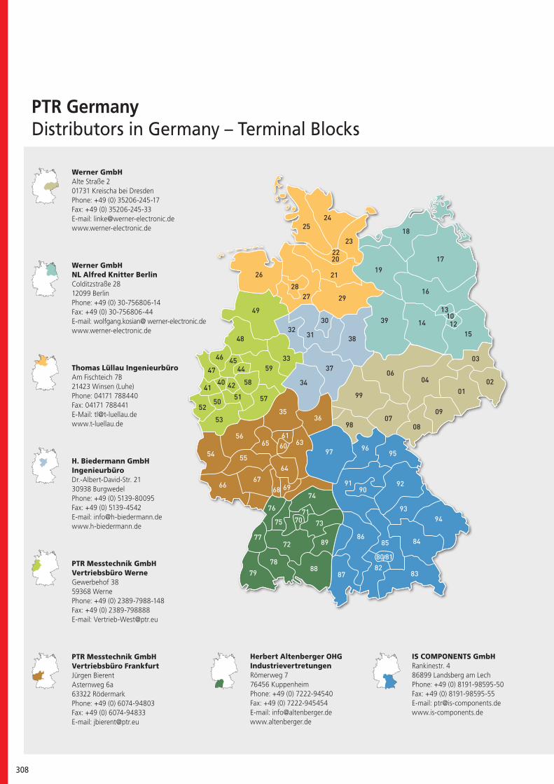
308
PTR GermanyDistributors in Germany – Terminal Blocks
Werner GmbHAlte Straße 201731 Kreischa bei DresdenPhone: +49 (0) 35206-245-17Fax: +49 (0) 35206-245-33E-mail: [email protected]
Werner GmbHNL Alfred Knitter BerlinColditzstraße 2812099 BerlinPhone: +49 (0) 30-756806-14Fax: +49 (0) 30-756806-44E-mail: wolfgang.kosian@ werner-electronic.dewww.werner-electronic.de
Thomas Lüllau IngenieurbüroAm Fischteich 7B21423 Winsen (Luhe)Phone: 04171 788440Fax: 04171 788441E-Mail: [email protected] www.t-luellau.de
H. Biedermann GmbHIngenieurbüroDr.-Albert-David-Str. 2130938 Burgwedel Phone: +49 (0) 5139-80095Fax: +49 (0) 5139-4542E-mail: [email protected]
PTR Messtechnik GmbHVertriebsbüro WerneGewerbehof 3859368 Werne Phone: +49 (0) 2389-7988-148Fax: +49 (0) 2389-798888E-mail: [email protected]
PTR Messtechnik GmbHVertriebsbüro FrankfurtJürgen BierentAsternweg 6a63322 Rödermark Phone: +49 (0) 6074-94803Fax: +49 (0) 6074-94833E-mail: [email protected]
Herbert Altenberger OHGIndustrievertretungenRömerweg 776456 Kuppenheim Phone: +49 (0) 7222-94540Fax: +49 (0) 7222-945454E-mail: [email protected]
IS COMPONENTS GmbHRankinestr. 486899 Landsberg am Lech Phone: +49 (0) 8191-98595-50Fax: +49 (0) 8191-98595-55E-mail: [email protected]
/
PTR Terminal Blocks and Multi Connector Systems 309
Distributors with Stock in Germany
AL-Elektronik Distribution GmbH Christian-Pommer-Straße 3638112 Braunschweig Phone: +49 (0) 531 25669-0Fax: +49 (0) 531 25669-28E-mail: [email protected]
Bürklin GmbH & Co. KGGrünwalder Weg 3082041 OberhachingPhone.: +49 (0) 89 55875-0Fax: +49 (0) 89 55875-421E-mail: [email protected]
Conrad Electronic SE Klaus-Conrad-Straße 2 92533 Wernberg-Köblitz Phone: +49 (0) 9604 408988Fax: +49 (0) 9604 408988E-mail: [email protected]
Distrelec Schuricht GmbH Lise-Meitner-Straße 4 28359 Bremen Phone: +49 (0) 180 5223435Fax: +49 (0) 180 5223436E-mail: [email protected]
EVE GmbH Hollefeldstr.1648282 Emsdetten Phone: +49 (0) 2572 9351-0Fax: +49 (0) 2572 9351-24E-mail: [email protected]
Schukat Electronic Vertriebs GmbH Daimlerstr. 2640789 Monheim am RheinPhone: +49 (0) 2173 950-5Fax: +49 (0) 2173 950-999E-mail: [email protected]
310
FSC® (Forest Stewardship Council®)
The promotion of an environmentally friendly, socially beneficial and economically viable man-agement of forests — this is the Forest Steward-ship Council®’s (FSC®) mission. The FSC’s logo must only be used in conjunction with wood products which come from sustain-able forest use or which conserve the forest’s resources.
In this way, the FSC and its system of certifi-cation actively support sustainability when it comes to dealing responsibly with our natural resources.
PTR Messtechnik GmbH & Co. KG supports this mission, and has printed this catalogue in accordance with the guidelines of the FSC directive.

PTR Terminal Blocks and Multi Connector Systems 311
Imprint:
PTR Messtechnik GmbH & Co. KGGewerbehof 38 · 59368 Werne · Phone: +49 (0)2389-79880 · Fax: +49 (0)2389-798888 · [email protected] · www.ptr.eu
Design: RAFFELT MEDIENDESIGN · Databased-Publishing: CYBOB COMMUNICATION GMBH · Photos: Tim Luhmann, iStockphoto.com · Print: Bruns Druckwelt GmbH & Co. KG
Copyright: PTR GmbH & Co. KG, 10/2014. This catalogue replaces all earlier editions. We reserve the right to make any changes which are in the interest of technical improvement.

PTR Messtechnik GmbH · Gewerbehof 38 · 59368 Werne · Germany Phone: +49 (0)2389/7988-0 · Fax: +49 (0)2389/7988-88 e-mail: [email protected] · www.ptr.eu
Represented worldwide in more than 50 countries.