Embed Size (px)
Citation preview
CABLE CONNECTIONTECHNIQUEScrew Connectors and Screw CableLugs for Low, Medium and HighVoltage
Pro
duct
Cat
alog
ue 1
Your PPartner ffor CConnection TTechnique
Since 1928 the name ARCUS equals quality and reliability in cable connections and safety products. The ARCUS ELEKTROTECHNIK ALOIS SCHIFFMANN GMBH is a highly specialised industrial enterprisein which high-quality products are designed and produced for the worldwide market.
Our product range includes:
• Connectors and tools for underground cables• Overhead line clamps• Earthing and short circuiting devices with cables and bars• Lance earthing devices for outdoor switchgear up to 80 kA/0.5 s and 63 kA/1 s• High voltage detectors for nominal voltages up to 380 kV• Detectors and phase comparators for encapsulated switchgear• Compression material and compression tools• Devices for current tapping and power supply
Always in the centre of our activities:
Our clients. Our top aim is their complete and long-term satisfaction!
Highly qualified and motivated employees in our company in Munich and in our sales offices are the maincondition for a successful conversion of customers' requirements.
During the long history of our company we have always understood some complex requirements of ourcustomers as a challenge to be met.
In many cases the result of technical cooperation with business partners are products with an extraordinaryplace on the world market.
Technical know-how and the latest production techniques insure long term quality and reliability of our pro-ducts and permit to keep the place of our company in Germany.
Availability by phone:
For queries concerning products and delivery time, and to place an order by phone, we are available as follows:
+49 (0)89/436 04-0
Monday - Thursday:8:00 am-12:00 noon and 12:30 pm-16:00 pm
Friday:8:00 am-12:00 noon
Information concerning this catalogue:
All rights reserved for copying of any kind. All dimensions and pictures are not binding. We permanentlystrive to improve products and reserve the right to change design, dimensions or material. Cable cross sections mentioned refer to DIN VDE 0295.
General
Low VVoltage
Medium VVoltage
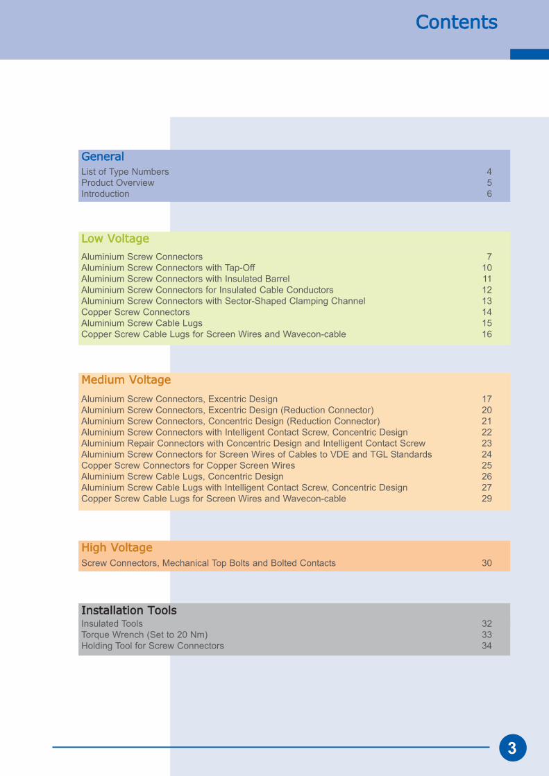
List of Type Numbers 4Product Overview 5Introduction 6
Aluminium Screw Connectors 7Aluminium Screw Connectors with Tap-Off 10Aluminium Screw Connectors with Insulated Barrel 11Aluminium Screw Connectors for Insulated Cable Conductors 12Aluminium Screw Connectors with Sector-Shaped Clamping Channel 13Copper Screw Connectors 14Aluminium Screw Cable Lugs 15Copper Screw Cable Lugs for Screen Wires and Wavecon-cable 16
Aluminium Screw Connectors, Excentric Design 17Aluminium Screw Connectors, Excentric Design (Reduction Connector) 20Aluminium Screw Connectors, Concentric Design (Reduction Connector) 21Aluminium Screw Connectors with Intelligent Contact Screw, Concentric Design 22Aluminium Repair Connectors with Concentric Design and Intelligent Contact Screw 23Aluminium Screw Connectors for Screen Wires of Cables to VDE and TGL Standards 24Copper Screw Connectors for Copper Screen Wires 25Aluminium Screw Cable Lugs, Concentric Design 26Aluminium Screw Cable Lugs with Intelligent Contact Screw, Concentric Design 27Copper Screw Cable Lugs for Screen Wires and Wavecon-cable 29
Contents
Installation TToolsInsulated Tools 32Torque Wrench (Set to 20 Nm) 33Holding Tool for Screw Connectors 34
High VVoltageScrew Connectors, Mechanical Top Bolts and Bolted Contacts 30
3
List oof TType NNumbersG
ener
al
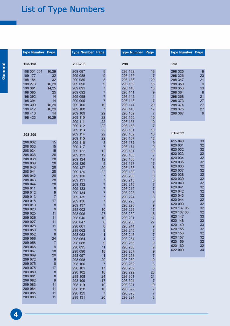
Type Number Page Type Number Page Type Number Page Type Number Page
4
108-198
208-209
108 001 001 16,29109 177 32198 184 32198 273 16,29198 381 14,25198 385 25198 392 14198 394 14198 399 16,29198 412 16,29198 413 14198 423 16,29
208 032 15208 033 15208 034 15208 036 26208 038 28208 039 28208 040 28208 041 28208 042 28208 043 28208 044 28209 011 8209 012 9209 013 7209 018 17209 019 8209 020 9209 025 11209 026 11209 027 11209 028 11209 050 9209 052 8209 056 24209 058 7209 065 9209 067 18209 069 20209 072 9209 075 8209 078 17209 080 8209 081 8209 082 9209 083 11209 084 11209 085 11209 086 11
209 087 8209 088 9209 089 8209 090 9209 091 7209 092 7209 098 7209 099 7209 100 19209 108 7209 109 22209 110 22209 111 22209 112 22209 113 22209 114 22209 115 22209 116 8209 117 7209 122 12209 123 12209 124 12209 126 8209 127 20209 129 22209 130 7209 131 7209 132 7209 133 7209 134 7209 135 7209 136 7209 137 7298 002 10298 006 27298 040 10298 047 8298 061 8298 062 9298 063 11298 064 11298 088 9298 095 11298 096 18298 097 11298 098 20298 100 7298 101 17298 102 18298 108 24298 109 17298 119 10298 128 10298 129 7298 131 20
298 132 18298 135 17298 136 20298 139 15298 140 15298 141 9298 142 11298 143 17298 144 20298 145 17298 152 7298 155 10298 157 10298 158 7298 161 10298 162 10298 167 18298 172 9298 174 9298 181 10298 185 7298 186 17298 187 17298 188 8298 189 9298 200 8298 213 8298 218 7298 219 7298 223 8298 224 8298 225 9298 226 9298 229 17298 230 18298 231 17298 238 27298 244 9298 245 8298 246 7298 254 7298 255 9298 256 9298 257 9298 258 7298 260 10298 262 8298 269 8298 292 23298 301 21298 304 7298 321 19298 322 7298 323 7298 324 8
615 040 33620 031 32620 032 32620 033 32620 034 32620 035 32620 036 32620 037 32620 038 32620 039 32620 040 32620 041 32620 042 32620 043 32620 044 32620 090 32620 137 05 32620 137 06 32620 147 33620 148 33620 149 33620 155 32620 156 32620 157 32620 159 32620 160 32622 009 34
615-622
298
298 325 8298 326 23298 347 21298 350 9298 356 13298 364 8298 368 21298 373 27298 374 27298 375 27298 387 9
209-298 298
Product OOverview
Gen
eral
5
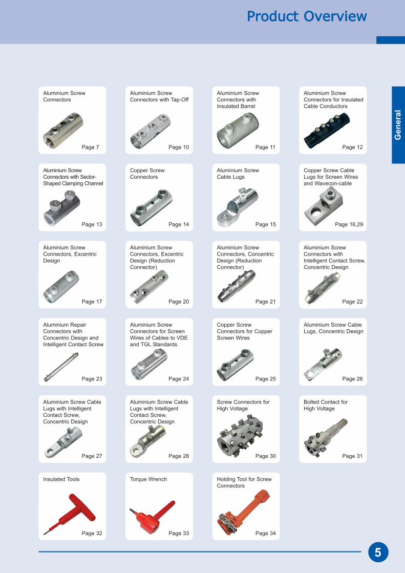
Page 7 Page 10 Page 11 Page 12
Page 13 Page 14 Page 15 Page 16,29
Page 17 Page 20 Page 21 Page 22
Page 23 Page 24 Page 25 Page 26
Page 27 Page 28 Page 30 Page 31
Page 32 Page 33 Page 34
Aluminium ScrewConnectors
Aluminium ScrewConnectors with Tap-Off
Aluminium ScrewConnectors withInsulated Barrel
Aluminium ScrewConnectors for InsulatedCable Conductors
Aluminium ScrewConnectors with Sector-Shaped Clamping Channel
Copper ScrewConnectors
Aluminium ScrewCable Lugs
Copper Screw CableLugs for Screen Wiresand Wavecon-cable
Aluminium ScrewConnectors, ExcentricDesign
Aluminium ScrewConnectors, ExcentricDesign (ReductionConnector)
Aluminium ScrewConnectors, ConcentricDesign (ReductionConnector)
Aluminium ScrewConnectors withIntelligent Contact Screw,Concentric Design
Aluminium RepairConnectors withConcentric Design andIntelligent Contact Screw
Aluminium ScrewConnectors for ScreenWires of Cables to VDEand TGL Standards
Copper ScrewConnectors for CopperScreen Wires
Aluminium Screw CableLugs, Concentric Design
Aluminium Screw CableLugs with IntelligentContact Screw,Concentric Design
Aluminium Screw CableLugs with IntelligentContact Screw,Concentric Design
Screw Connectors forHigh Voltage
Bolted Contact for High Voltage
Insulated Tools Torque Wrench Holding Tool for ScrewConnectors
Gen
eral
Introduction
For many years now screw connectors and screw cable lugs have not only been an alternative to compres-sion systems but even more they offer additional advantages and possibilities.
To install bolted cable connections means to make a connection with mechanic and electric long-term loadproperties. This connection needs to be produced by simple means and even under difficult conditions.The quality of this connection must be high enough to ensure reliability for many years.
Depending on their specific usage, screw connectors and screw cable lugs are provided with various featu-res which lead to a wide variety of types. Those who have to select from this variety need to make a wellinformed choice.
The main criteria are voltage level, type of cable conductor, working method, and joint or termination tech-nology. Apart from the related circumstances there are a number of selection criteria that depend on experienceand personal preferences or philosophies of power suppliers.
An overview of the selection criteria of screw connectors and screw cable lugs with the main features asfollows:
Connector barrel Al or CuConnector barrel uncoated, tin-plated, insulated or greasedConnector barrel with chamfurred or rounded endsConnector barrel optional with branch connection for tap-offConnector barrel with concentric or excentric clamping channelClamping channel round or sector-shapedClamping channel straight-through or with oil-stopClamping channel plain, grooved or serratedOne or more contact screws per connector halfContact screws with spherical pressure foot or with cutting edgesContact screws with or without shear-headShear-head bolts removable or not removable after shear-off Multiple or single shear-head boltsOn cable lugs: type of palm
We will not go into any further detail at this point. There are many different reasons to prefer or reject cer-tain features. For instance an oil stop inside a connector may be considered as a helpful stopper during installation but may also be seen as a hinderance because a push-through movement of the first conductorfor easy installation of the second conductor is impossible.
In ccase yyou wwill nnot ffind tthe rrequired In ccase yyou wwill nnot ffind tthe rrequired product oon tthe ffollowing ppages - product oon tthe ffollowing ppages -
please ccontact uus!please ccontact uus!
6
Low
Vol
tage
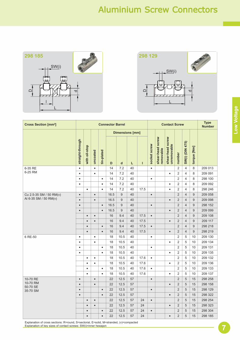
Aluminium SScrew CConnectors
Explanation of cross sections: R=round, S=sectorial, E=solid, M=stranded, (v)=compactedExplanation of key sizes of contact screws: SW(i)=inner hexagon 7
298 185 298 129
SW(i)
L
D dSW(i)
D d
Ll
Cross Section [mm²] Connector Barrel Contact Screw TypeNumber
stra
ight
-thro
ugh
with
oil-
stop
unco
ated
tin-p
late
d
Dimensions [mm]
sock
et s
crew
shea
r-he
ad s
crew
rem
ovab
le
shea
r-he
ad s
crew
unre
mov
able
num
ber
SW(i)
(DIN
475
)
torq
ue [N
m]
D d L l6-35 RE6-25 RM
• • 14 7.2 40 • 2 4 8 209 013• • 14 7.2 40 • 2 4 8 209 091• • 14 7.2 40 • 2 4 8 298 100• • 14 7.2 40 • 2 4 8 209 092
• • 14 7.2 40 17.5 • 2 4 8 298 246
Cu 2.5-35 SM / 50 RM(v)Al 6-35 SM / 50 RM(v)
• • 16.5 9 40 • 2 4 9 209 058• • 16.5 9 40 • 2 4 9 209 098• • 16.5 9 40 • 2 4 9 298 152• • 16.5 9 40 • 2 4 9 209 099
• • 16 9.4 40 17.5 • 2 4 9 209 108• • 16 9.4 40 17.5 • 2 4 9 209 117• • 16 9.4 40 17.5 • 2 4 9 298 218• • 16 9.4 40 17.5 • 2 4 9 298 219
6 RE-50 • • 18 10.5 40 • 2 5 10 209 130• • 18 10.5 40 • 2 5 10 209 134• • 18 10.5 40 • 2 5 10 209 131• • 18 10.5 40 • 2 5 10 209 135
• • 18 10.5 40 17.6 • 2 5 10 209 132• • 18 10.5 40 17.6 • 2 5 10 209 136• • 18 10.5 40 17.6 • 2 5 10 209 133• • 18 10.5 40 17.6 • 2 5 10 209 137
10-70 RE10-70 RM50-70 SE35-70 SM
• • 22 12.5 57 • 2 5 15 298 258• • 22 12.5 57 • 2 5 15 298 158• • 22 12.5 57 • 2 5 15 298 129• • 22 12.5 57 • 2 5 15 298 322
• • 22 12.5 57 24 • 2 5 15 298 254• • 22 12.5 57 24 • 2 5 15 298 323• • 22 12.5 57 24 • 2 5 15 298 304• • 22 12.5 57 24 • 2 5 15 298 185
Low
Vol
tage
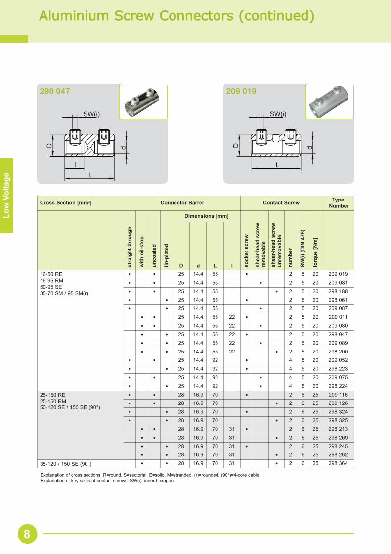
Aluminium SScrew CConnectors ((continued)
Cross Section [mm²] Connector Barrel Contact Screw TypeNumber
stra
ight
-thro
ugh
with
oil-
stop
unco
ated
tin-p
late
d
Dimensions [mm]
sock
et s
crew
shea
r-he
ad s
crew
rem
ovab
le
shea
r-he
ad s
crew
unre
mov
able
num
ber
SW(i)
(DIN
475
)
torq
ue [N
m]
D d L l16-50 RE16-95 RM50-95 SE35-70 SM / 95 SM(r)
• • 25 14.4 55 • 2 5 20 209 019• • 25 14.4 55 • 2 5 20 209 081• • 25 14.4 55 • 2 5 20 298 188• • 25 14.4 55 • 2 5 20 298 061• • 25 14.4 55 • 2 5 20 209 087
• • 25 14.4 55 22 • 2 5 20 209 011• • 25 14.4 55 22 • 2 5 20 209 080• • 25 14.4 55 22 • 2 5 20 298 047• • 25 14.4 55 22 • 2 5 20 209 089• • 25 14.4 55 22 • 2 5 20 298 200
• • 25 14.4 92 • 4 5 20 209 052• • 25 14.4 92 • 4 5 20 298 223• • 25 14.4 92 • 4 5 20 209 075• • 25 14.4 92 • 4 5 20 298 224
25-150 RE25-150 RM50-120 SE / 150 SE (90°)
• • 28 16.9 70 • 2 6 25 209 116• • 28 16.9 70 • 2 6 25 209 126• • 28 16.9 70 • 2 6 25 298 324• • 28 16.9 70 • 2 6 25 298 325
• • 28 16.9 70 31 • 2 6 25 298 213• • 28 16.9 70 31 • 2 6 25 298 269• • 28 16.9 70 31 • 2 6 25 298 245• • 28 16.9 70 31 • 2 6 25 298 262
35-120 / 150 SE (90°) • • 28 16.9 70 31 • 2 6 25 298 364
Explanation of cross sections: R=round, S=sectorial, E=solid, M=stranded, (r)=rounded, (90°)=4-core cableExplanation of key sizes of contact screws: SW(i)=inner hexagon
8
SW(i)
L
D d
l
SW(i)
L
D d
298 047 209 019
Low
Vol
tage
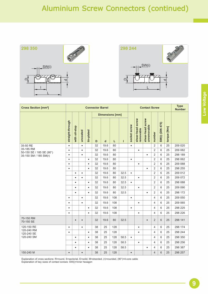
Aluminium SScrew CConnectors ((continued)
Cross Section [mm²] Connector Barrel Contact Screw TypeNumber
stra
ight
-thro
ugh
with
oil-
stop
unco
ated
tin-p
late
d
Dimensions [mm]
sock
et s
crew
shea
r-he
ad s
crew
rem
ovab
le
shea
r-he
ad s
crew
unre
mov
able
num
ber
SW(i)
(DIN
475
)
torq
ue [N
m]
D d L l35-50 RE35-185 RM50-150 SE / 185 SE (90°)35-150 SM / 185 SM(r)
• • 32 19.6 80 • 2 6 25 209 020• • 32 19.6 80 • 2 6 25 209 082• • 32 19.6 80 • 2 6 25 298 189• • 32 19.6 80 • 2 6 25 298 062• • 32 19.6 80 • 2 6 25 209 088• • 32 19.6 80 • 2 6 25 298 255
• • 32 19.6 80 32.5 • 2 6 25 209 012• • 32 19.6 80 32.5 • 2 6 25 209 072
• • 32 19.6 80 32.5 • 2 6 25 298 088
• • 32 19.6 80 32.5 • 2 6 25 209 090
• • 32 19.6 80 32.5 • 2 6 25 298 172
• • 32 19.6 108 • 4 6 25 209 050
• • 32 19.6 108 • 4 6 25 209 065
• • 32 19.6 108 • 4 6 25 298 225
• • 32 19.6 108 • 4 6 25 298 226
70-150 RM70-150 SE • • 32 19.6 80 32.5 • 2 6 25 298 141
120-150 RE120-240 RM120-240 SE120-240 SM
• • 38 25 128 • 4 6 25 298 174
• • 38 25 128 • 4 6 25 298 244
• • 38 25 128 58.5 • 4 6 25 298 350
• • 38 25 128 58.5 • 4 6 25 298 256
• • 38 25 128 58.5 • 4 6 25 298 387
150-240 M • • 38 25 128 • 4 6 25 298 257
Explanation of cross sections: R=round, S=sectorial, E=solid, M=stranded, (r)=rounded, (90°)=4-core cableExplanation of key sizes of contact screws: SW(i)=inner hexagon
9
SW(i)
L
D d
l
SW(i)
L
D d
298 350 298 244
Low
Vol
tage
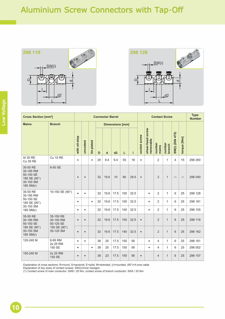
Aluminium SScrew CConnectors wwith TTap-OOff
Explanation of cross sections: R=round, S=sectorial, E=solid, M=stranded, (r)=rounded, (90°)=4-core cableExplanation of key sizes of contact screws: SW(i)=inner hexagon(1) Contact screw of main conductor: SW6 / 25 Nm, contact screw of branch conductor: SW5 / 20 Nm
SW(i)
L
D d
ld2
SW(i)
L
D d
ld2
298 119 298 128
Cross Section [mm²] Connector Barrel Contact Screw TypeNumber
Mains Branch
with
oil-
stop
unco
ated
tin-p
late
d
Dimensions [mm]
sock
et s
crew
shea
r-he
ad s
crew
rem
ovab
le
num
ber
mai
ns
num
ber
bran
ch
SW(i)
(DIN
475
)
torq
ue [N
m]
D d d2 L lAl 35 RECu 35 RE
Cu 10 RE• • 20 9.4 9.4 55 18 • 2 1 4 15 298 260
35-50 RE35-185 RM50-150 SE185 SE (90°)35-150 SM185 SM(r)
6-50 SE
• • 32 19.6 10 80 29.5 • 2 1 (1) (1) 298 040
35-50 RE35-185 RM50-150 SE185 SE (90°)35-150 SM185 SM(r)
10-150 SE (90°) • • 32 19.6 17.5 100 32.5 • 2 1 6 25 298 128
• • 32 19.6 17.5 100 32.5 • 2 1 6 25 298 181
• • 32 19.6 17.5 140 32.5 • 2 1 6 25 298 155
35-50 RE35-185 RM50-150 SE185 SE (90°)35-150 SM185 SM(r)
35-150 RE35-150 RM50-120 SE150 SE (90°)35-120 SM
• • 32 19.6 17.5 100 32.5 • 2 1 6 25 298 119
• • 32 19.6 17.5 140 32.5 • 2 1 6 25 298 162
120-240 M 6-95 RM2x 25 RM150 SE
• • 38 25 17.5 150 56 • 4 1 6 25 298 161
• • 38 25 17.5 150 56 • 4 1 6 25 298 002
150-240 M 2x 25 RM150 SE • • 38 23 17.5 150 56 • 4 1 6 25 298 157
10
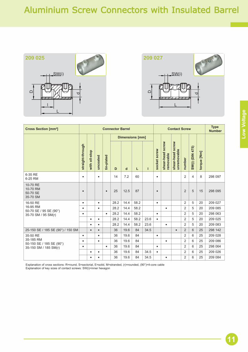
Aluminium SScrew CConnectors wwith IInsulated BBarrel
Low
Vol
tage
Cross Section [mm²] Connector Barrel Contact Screw TypeNumber
stra
ight
-thro
ugh
with
oil-
stop
unco
ated
tin-p
late
d
Dimensions [mm]
sock
et s
crew
shea
r-he
ad s
crew
rem
ovab
le
shea
r-he
ad s
crew
unre
mov
able
num
ber
SW(i)
(DIN
475
)
torq
ue [N
m]
D d L l
6-35 RE6-25 RM • • 14 7.2 60 • 2 4 8 298 097
10-70 RE10-70 RM50-70 SE35-70 SM
• • 25 12.5 87 • 2 5 15 298 095
16-50 RE16-95 RM50-70 SE / 95 SE (90°)35-70 SM / 95 SM(r)
• • 28.2 14.4 58.2 • 2 5 20 209 027• • 28.2 14.4 58.2 • 2 5 20 209 085• • 28.2 14.4 58.2 • 2 5 20 298 063
• • 28.2 14.4 58.2 23.6 • 2 5 20 209 025• • 28.2 14.4 58.2 23.6 • 2 5 20 209 083
25-150 SE / 185 SE (90°) / 150 SM • • 36 19.6 84 34.5 • 2 6 25 298 142
35-50 RE35-185 RM50-150 SE / 185 SE (90°)35-150 SM / 185 SM(r)
• • 36 19.6 84 • 2 6 25 209 028• • 36 19.6 84 • 2 6 25 209 086• • 36 19.6 84 • 2 6 25 298 064
• • 36 19.6 84 34.5 • 2 6 25 209 026• • 36 19.6 84 34.5 • 2 6 25 209 084
Explanation of cross sections: R=round, S=sectorial, E=solid, M=stranded, (r)=rounded, (90°)=4-core cableExplanation of key sizes of contact screws: SW(i)=inner hexagon
SW(i)
L
D d
l
SW(i)
D d
L
209 025 209 027
11
Low
Vol
tage
Cross Section [mm²] Connector Barrel Contact Screw TypeNumber
stra
ight
-thro
ugh
with
oil-
stop
unco
ated
tin-p
late
d
Dimensions [mm]
insu
latio
n-pi
erci
ngsc
rew
num
ber
SW(i)
(DIN
475
)
torq
ue [N
m]
D d L1 H
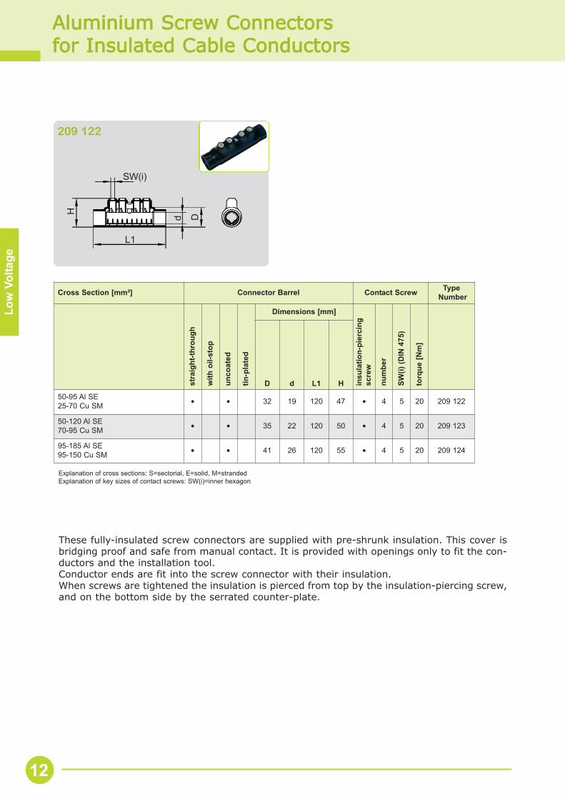
50-95 Al SE25-70 Cu SM • • 32 19 120 47 • 4 5 20 209 122
50-120 Al SE70-95 Cu SM • • 35 22 120 50 • 4 5 20 209 123
95-185 Al SE95-150 Cu SM • • 41 26 120 55 • 4 5 20 209 124
Aluminium SScrew CConnectors for IInsulated CCable CConductors
Explanation of cross sections: S=sectorial, E=solid, M=strandedExplanation of key sizes of contact screws: SW(i)=inner hexagon
SW(i)
L1
H d D
209 122
12
These fully-insulated screw connectors are supplied with pre-shrunk insulation. This cover isbridging proof and safe from manual contact. It is provided with openings only to fit the con-ductors and the installation tool.Conductor ends are fit into the screw connector with their insulation.When screws are tightened the insulation is pierced from top by the insulation-piercing screw,and on the bottom side by the serrated counter-plate.
Low
Vol
tage
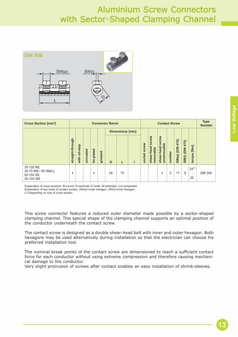
Aluminium SScrew CConnectors with SSector-SShaped CClamping CChannel
Cross Section [mm²] Connector Barrel Contact Screw TypeNumber
stra
ight
-thro
ugh
with
oil-
stop
unco
ated
tin-p
late
d
grea
sed
Dimensions [mm]
sock
et s
crew
shea
r-he
ad s
crew
rem
ovab
lesh
ear-
head
scr
ewun
rem
ovab
le
num
ber
SW(a
) (D
IN 4
75)
SW(i)
(DIN
475
)
torq
ue [N
m]
D L l35-120 RE 35-70 RM / 95 RM(v)50-150 SE35-120 SM
• • 26 70 • 2 17 624(1)
-25
298 356
Explanation of cross sections: R=round, S=sectorial, E=solid, M=stranded, (v)=compactedExplanation of key sizes of contact screws: SW(a)=outer hexagon, SW(i)=inner hexagon(1) Depending on size of cross section
SW(a)
LD
SW(i)
298 356
This screw connector features a reduced outer diameter made possible by a sector-shapedclamping channel. This special shape of the clamping channel supports an optimal position ofthe conductor underneath the contact screw.
The contact screw is designed as a double shear-head bolt with inner and outer hexagon. Both hexagons may be used alternatively during installation so that the electrician can choose hispreferred installation tool.
The nominal break points of the contact screw are dimensioned to reach a sufficient contactforce for each conductor without using extreme compression and therefore causing mechani-cal damage to the conductor.Very slight protrusion of screws after contact enables an easy installation of shrink-sleeves.
13
Low
Vol
tage
Copper SScrew CConnectors
Cross Section [mm²] Connector Barrel Contact Screw TypeNumber
stra
ight
-thro
ugh
with
oil-
stop
unco
ated
tin-p
late
d
Dimensions [mm]
sock
et s
crew
shea
r-he
ad s
crew
rem
ovab
le
shea
r-he
ad s
crew
unre
mov
able
num
ber
SW(i)
(DIN
475
)
torq
ue [N
m]
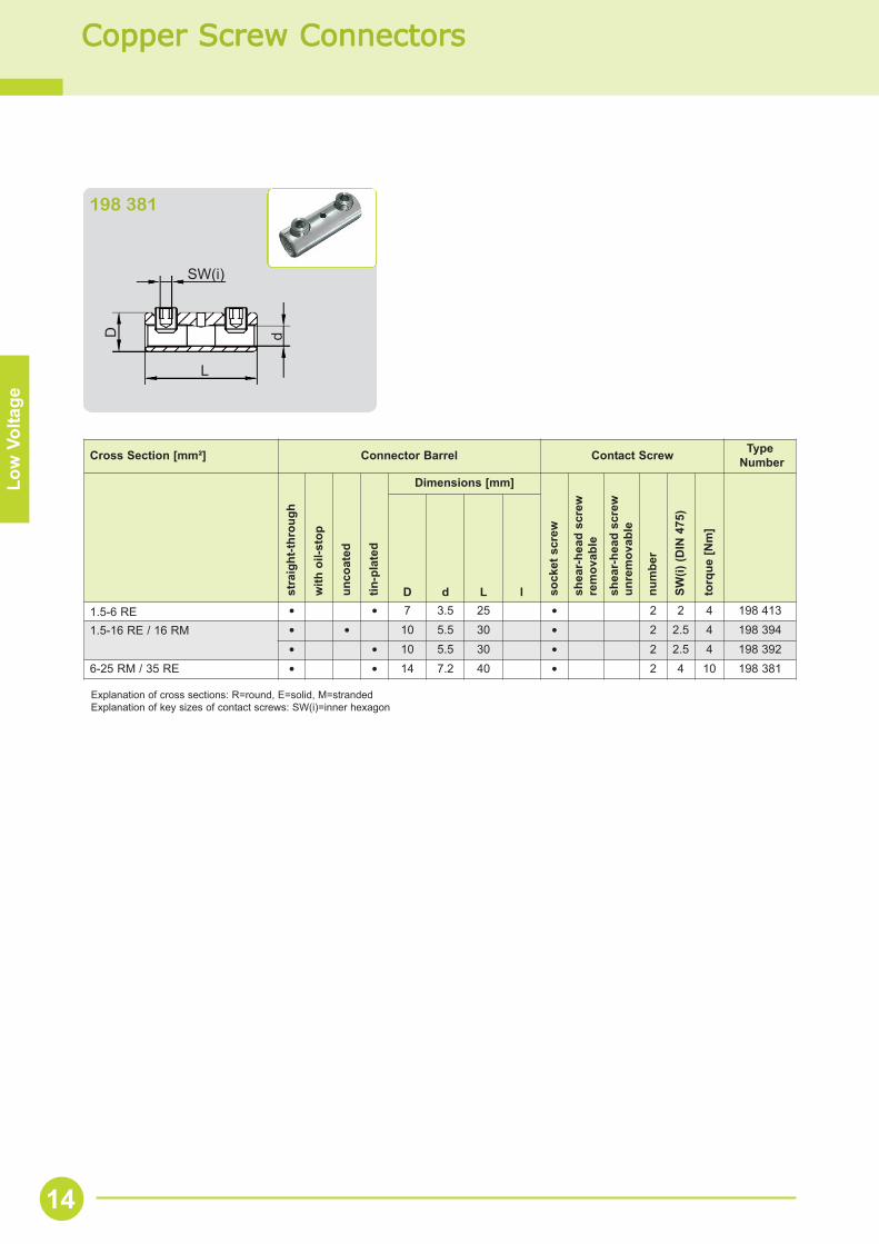
D d L l1.5-6 RE • • 7 3.5 25 • 2 2 4 198 413
1.5-16 RE / 16 RM • • 10 5.5 30 • 2 2.5 4 198 394• • 10 5.5 30 • 2 2.5 4 198 392
6-25 RM / 35 RE • • 14 7.2 40 • 2 4 10 198 381
Explanation of cross sections: R=round, E=solid, M=strandedExplanation of key sizes of contact screws: SW(i)=inner hexagon
SW(i)
L
D d
198 381
14
Aluminium SScrew CCable LLugs
Low
Vol
tage
Cross Section [mm²] Connector Barrel Contact Screw TypeNumber
tin-p
late
d
Dimensions [mm]
shea
r-he
ad s
crew
unre
mov
able
shea
r-he
ad s
crew
rem
ovab
le
num
ber
SW(i)
(DIN
475
)
torq
ue [N
m]
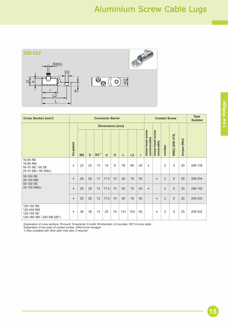
W2 D D2(1) d H L L2 l16-95 RE16-95 RM50-70 SE / 95 SE25-70 SM / 95 SM(r)
• 23 23 13 14 8 78 66 45 • 2 5 20 298 139
35-150 RE35-150 RM50-120 SE35-120 SM(r)
• 28 28 11 17.5 10 92 78 50 • 2 6 25 208 034
• 28 28 13 17.5 10 92 78 50 • 2 6 25 298 140
• 28 28 13 17.5 10 92 78 50 • 2 6 25 208 033
120-150 RE120-240 RM120-185 SE120-185 SM / 240 SM (90°)
• 36 36 13 25 15 121 103 65 • 2 6 25 208 032
Explanation of cross sections: R=round, S=sectorial, E=solid, M=stranded, (r)=rounded, (90°)=4-core cableExplanation of key sizes of contact screws: SW(i)=inner hexagon1) Also available with other palm hole size, if required
SW(i)
L
H
dD
L2l
W2
D2
208 032
15
Copper SScrew CCable LLugs for SScreen WWires aand WWavecon-ccable
Explanation of cross sections: R=round, M=strandedExplanation of key sizes of contact screws: SW(i)=inner hexagon1) Also available with other palm hole size, if required
Low
Vol
tage
SW(i)
L
H
dB
L2l
W2
D2
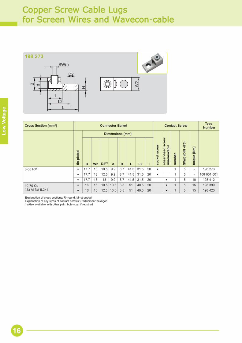
198 273
Cross Section [mm²] Connector Barrel Contact Screw TypeNumber
tin-p
late
d
Dimensions [mm]
sock
et s
crew
shea
r-he
ad s
crew
unre
mov
able
num
ber
SW(i)
(DIN
475
)
torq
ue [N
m]
B W2 D2(1) d H L L2 l6-50 RM • 17.7 18 10.5 9.9 8.7 41.5 31.5 20 • 1 5 - 198 273
• 17.7 18 12.5 9.9 8.7 41.5 31.5 20 • 1 5 - 108 001 001• 17.7 18 13 9.9 8.7 41.5 31.5 20 • 1 5 10 198 412
10-70 Cu13x Al-flat 5.2x1
• 16 16 10.5 10.5 3.5 51 40.5 20 • 1 5 15 198 399• 16 16 12.5 10.5 3.5 51 40.5 20 • 1 5 15 198 423
16
Explanation of cross sections: R=round, S=sectorial, E=solid, M=stranded, (r)=rounded, (90°)=4-core cableExplanation of key sizes of contact screws: SW(i)=inner hexagon
Med
ium
Vol
tage
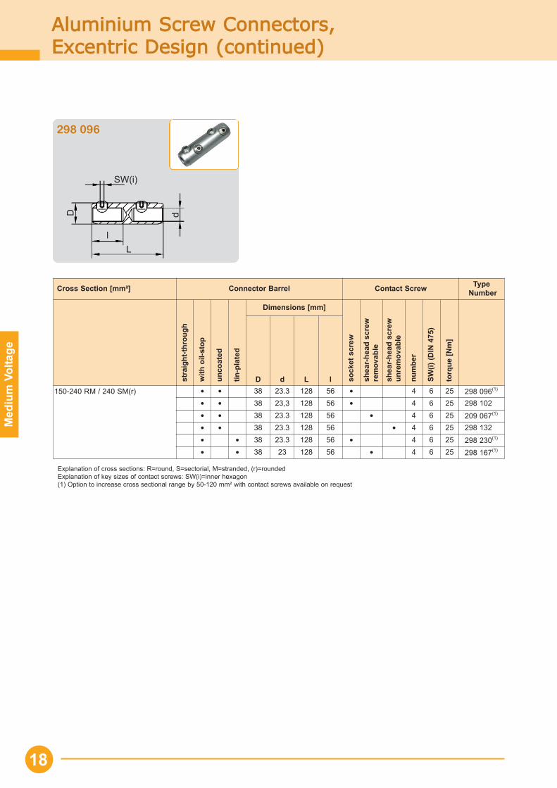
Aluminium SScrew CConnectors, Excentric DDesign
Cross Section [mm²] Connector Barrel Contact Screw TypeNumber
stra
ight
-thro
ugh
with
oil-
stop
unco
ated
tin-p
late
d
Dimensions [mm]
sock
et s
crew
shea
r-he
ad s
crew
rem
ovab
le
shea
r-he
ad s
crew
unre
mov
able
num
ber
SW(i)
(DIN
475
)
torq
ue [N
m]
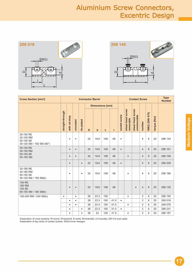
D d L l25-150 RE25-150 RM50-150 SE35-120 SM / 150 SM (90°)
• • 32 19.6 108 48 • 4 6 25 298 143
35-150 RE35-150 RM50-150 SE35-150 SM
• • 32 19.6 108 48 • 4 6 25 298 101
• • 32 19.6 108 48 • 4 6 25 298 109
• • 32 19.6 108 48 • 4 6 25 298 229
35-185 RE35-185 RM50-150 SE35-120 SM / 150 SM(r)
• • 32 19.6 108 48 • 4 6 25 298 186
150 RE185 RM150 SE 95-150 SM / 185 SM(r)
• • 32 19.6 108 48 • 4 6 25 298 135
150-240 RM / 240 SM(r) • • 38 23.3 100 • 2 6 25 298 145• • 38 23.3 100 41.5 • 2 6 25 209 018• • 38 23.3 100 41.5 • 2 6 25 209 078• • 38 23.3 100 41.5 • 2 6 25 298 231• • 38 23 100 41.5 • 2 6 25 298 187
17
SW(i)
L
D d
l
SW(i)
L
D d
209 018 298 145
Med
ium
Vol
tage
Aluminium SScrew CConnectors,Excentric DDesign ((continued)
Cross Section [mm²] Connector Barrel Contact Screw TypeNumber
stra
ight
-thro
ugh
with
oil-
stop
unco
ated
tin-p
late
d
Dimensions [mm]
sock
et s
crew
shea
r-he
ad s
crew
rem
ovab
le
shea
r-he
ad s
crew
unre
mov
able
num
ber
SW(i)
(DIN
475
)
torq
ue [N
m]
D d L l150-240 RM / 240 SM(r) • • 38 23.3 128 56 • 4 6 25 298 096(1)
• • 38 23,3 128 56 • 4 6 25 298 102• • 38 23.3 128 56 • 4 6 25 209 067(1)
• • 38 23.3 128 56 • 4 6 25 298 132• • 38 23.3 128 56 • 4 6 25 298 230(1)
• • 38 23 128 56 • 4 6 25 298 167(1)
Explanation of cross sections: R=round, S=sectorial, M=stranded, (r)=roundedExplanation of key sizes of contact screws: SW(i)=inner hexagon(1) Option to increase cross sectional range by 50-120 mm² with contact screws available on request
18
SW(i)
L
D d
l
298 096
Med
ium
Vol
tage
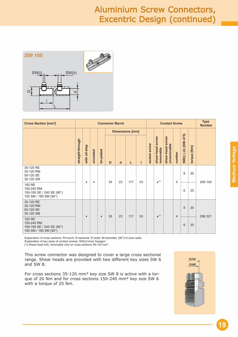
Aluminium SScrew CConnectors,Excentric DDesign ((continued)
Cross Section [mm²] Connector Barrel Contact Screw TypeNumber
stra
ight
-thro
ugh
with
oil-
stop
unco
ated
tin-p
late
d
Dimensions [mm]
sock
et s
crew
shea
r-he
ad s
crew
rem
ovab
le
shea
r-he
ad s
crew
unre
mov
able
num
ber
SW(i)
| (ii
) (D
IN 4
75)
torq
ue [N
m]
D d L l35-120 RE35-120 RM50-120 SE35-120 SM
• • 35 23 117 53 •(1) 4
8 20
209 100150 RE150-240 RM150-185 SE / 240 SE (90°)150 SM / 185 SM (90°)
6 25
35-120 RE35-120 RM50-120 SE35-120 SM
• • 35 23 117 53 •(1) 4
8 20
298 321150 RE150-240 RM150-185 SE / 240 SE (90°)150 SM / 185 SM (90°)
6 25
Explanation of cross sections: R=round, S=sectorial, E=solid, M=stranded, (90°)=4-core cableExplanation of key sizes of contact screws: SW(i)=inner hexagon(1) Shear-head bolt, removable only on cross sections 35-120 mm².
19
SW(i)
L
D d
l
SW(ii)
209 100
This screw connector was designed to cover a large cross sectionalrange. Shear heads are provided with two different key sizes SW 6and SW 8.
For cross sections 35-120 mm² key size SW 8 is active with a tor-que of 20 Nm and for cross sections 150-240 mm² key size SW 6with a torque of 25 Nm.
Med
ium
Vol
tage
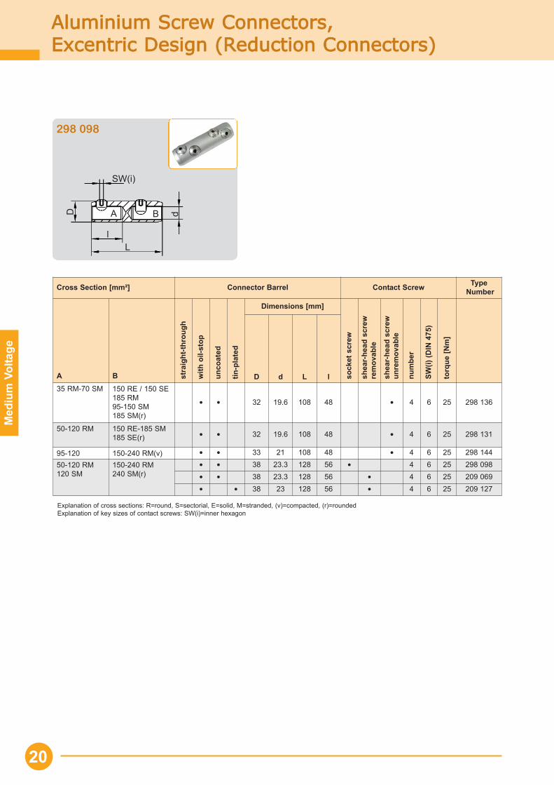
Aluminium SScrew CConnectors,Excentric DDesign ((Reduction CConnectors)
Cross Section [mm²] Connector Barrel Contact Screw TypeNumber
A B stra
ight
-thro
ugh
with
oil-
stop
unco
ated
tin-p
late
d
Dimensions [mm]
sock
et s
crew
shea
r-he
ad s
crew
rem
ovab
le
shea
r-he
ad s
crew
unre
mov
able
num
ber
SW(i)
(DIN
475
)
torq
ue [N
m]
D d L l35 RM-70 SM 150 RE / 150 SE
185 RM95-150 SM185 SM(r)
• • 32 19.6 108 48 • 4 6 25 298 136
50-120 RM 150 RE-185 SM185 SE(r) • • 32 19.6 108 48 • 4 6 25 298 131
95-120 150-240 RM(v) • • 33 21 108 48 • 4 6 25 298 144
50-120 RM120 SM
150-240 RM240 SM(r)
• • 38 23.3 128 56 • 4 6 25 298 098• • 38 23.3 128 56 • 4 6 25 209 069• • 38 23 128 56 • 4 6 25 209 127
Explanation of cross sections: R=round, S=sectorial, E=solid, M=stranded, (v)=compacted, (r)=roundedExplanation of key sizes of contact screws: SW(i)=inner hexagon
20
SW(i)
L
D d
l
298 098
A B
Med
ium
Vol
tage
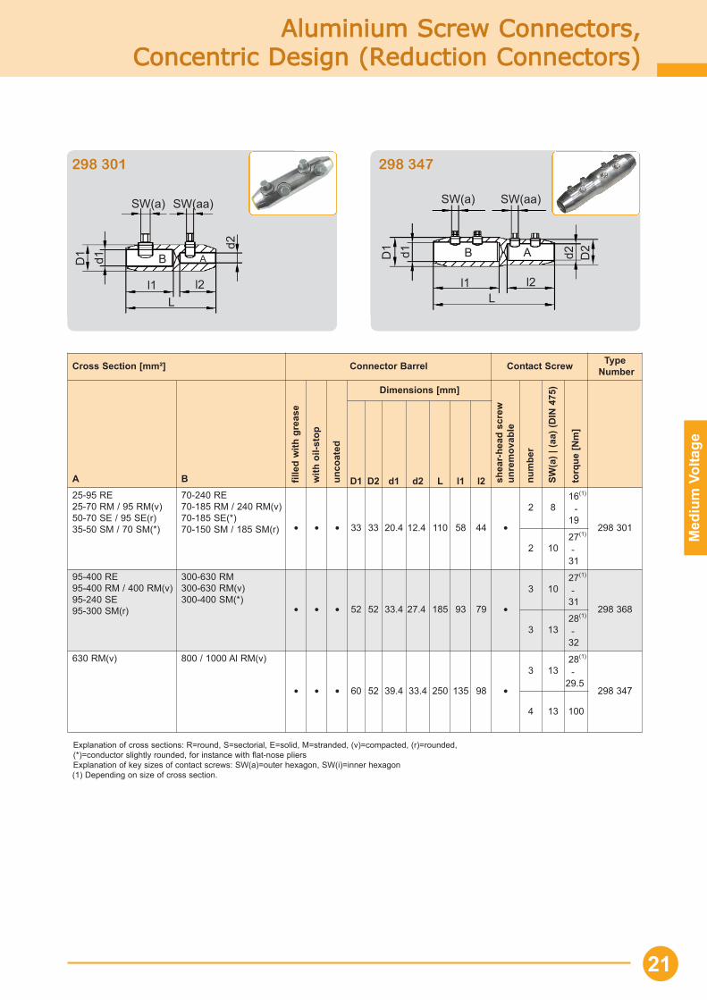
Explanation of cross sections: R=round, S=sectorial, E=solid, M=stranded, (v)=compacted, (r)=rounded, (*)=conductor slightly rounded, for instance with flat-nose pliersExplanation of key sizes of contact screws: SW(a)=outer hexagon, SW(i)=inner hexagon(1) Depending on size of cross section.
Aluminium SScrew CConnectors,Concentric DDesign ((Reduction CConnectors)
Cross Section [mm²] Connector Barrel Contact Screw TypeNumber
A B fille
d w
ith g
reas
e
with
oil-
stop
unco
ated
Dimensions [mm]
shea
r-he
ad s
crew
unre
mov
able
num
ber
SW(a
) | (a
a) (D
IN 4
75)
torq
ue [N
m]
D1 D2 d1 d2 L l1 l225-95 RE25-70 RM / 95 RM(v)50-70 SE / 95 SE(r)35-50 SM / 70 SM(*)
70-240 RE70-185 RM / 240 RM(v)70-185 SE(*)70-150 SM / 185 SM(r) • • • 33 33 20.4 12.4 110 58 44 •
2 816(1)
-19
298 301
2 1027(1)
-31
95-400 RE95-400 RM / 400 RM(v)95-240 SE95-300 SM(r)
300-630 RM300-630 RM(v)300-400 SM(*)
• • • 52 52 33.4 27.4 185 93 79 •
3 1027(1)
-31
298 368
3 1328(1)
-32
630 RM(v) 800 / 1000 Al RM(v)
• • • 60 52 39.4 33.4 250 135 98 •
3 1328(1)
-29.5
298 347
4 13 100
21
SW(a)
L
D1 d1
l2
SW(aa)
d2
l1
SW(a)
L
D1 d1
l2
SW(aa)
d2
l1
D2
298 301 298 347
AB AB
Med
ium
Vol
tage
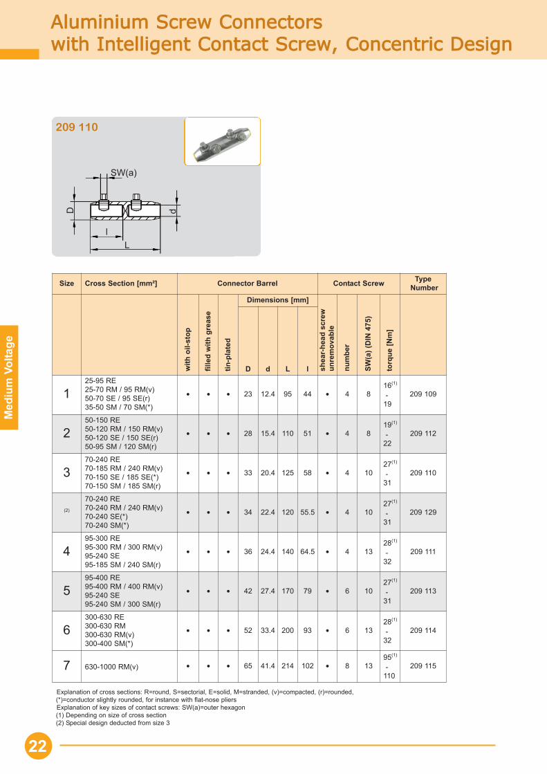
Aluminium SScrew CConnectors with IIntelligent CContact SScrew, CConcentric DDesign
Explanation of cross sections: R=round, S=sectorial, E=solid, M=stranded, (v)=compacted, (r)=rounded, (*)=conductor slightly rounded, for instance with flat-nose pliersExplanation of key sizes of contact screws: SW(a)=outer hexagon(1) Depending on size of cross section(2) Special design deducted from size 3
Size Cross Section [mm²] Connector Barrel Contact Screw TypeNumber
with
oil-
stop
fille
d w
ith g
reas
e
tin-p
late
d
Dimensions [mm]
shea
r-he
ad s
crew
unre
mov
able
num
ber
SW(a
) (D
IN 4
75)
torq
ue [N
m]
D d L l
125-95 RE25-70 RM / 95 RM(v)50-70 SE / 95 SE(r)35-50 SM / 70 SM(*)
• • • 23 12.4 95 44 • 4 816(1)
-19
209 109
250-150 RE50-120 RM / 150 RM(v)50-120 SE / 150 SE(r)50-95 SM / 120 SM(r)
• • • 28 15.4 110 51 • 4 819(1)
-22
209 112
370-240 RE70-185 RM / 240 RM(v)70-150 SE / 185 SE(*)70-150 SM / 185 SM(r)
• • • 33 20.4 125 58 • 4 1027(1)
-31
209 110
(2)
70-240 RE70-240 RM / 240 RM(v)70-240 SE(*)70-240 SM(*)
• • • 34 22.4 120 55.5 • 4 1027(1)
-31
209 129
495-300 RE95-300 RM / 300 RM(v)95-240 SE95-185 SM / 240 SM(r)
• • • 36 24.4 140 64.5 • 4 1328(1)
-32
209 111
595-400 RE95-400 RM / 400 RM(v)95-240 SE95-240 SM / 300 SM(r)
• • • 42 27.4 170 79 • 6 1027(1)
-31
209 113
6300-630 RE300-630 RM300-630 RM(v)300-400 SM(*)
• • • 52 33.4 200 93 • 6 1328(1)
-32
209 114
7 630-1000 RM(v) • • • 65 41.4 214 102 • 8 1395(1)
-110
209 115
22
SW(a)
L
D d
l
209 110
Med
ium
Vol
tage
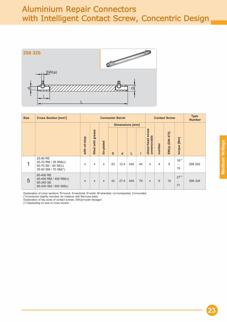
Aluminium RRepair CConnectors with IIntelligent CContact SScrew, CConcentric DDesign
23
Size Cross Section [mm²] Connector Barrel Contact Screw TypeNumber
with
oil-
stop
fille
d w
ith g
reas
e
tin-p
late
d
Dimensions [mm]
shea
r-he
ad s
crew
unre
mov
able
num
ber
SW(a
) (D
IN 4
75)
torq
ue [N
m]
D d L l
125-95 RE25-70 RM / 95 RM(v)50-70 SE / 95 SE(r)35-50 SM / 70 SM(*)
• • • 23 12.4 440 44 • 4 816(1)
-19
298 292
595-400 RE95-400 RM / 400 RM(v)95-240 SE95-240 SM / 300 SM(r)
• • • 42 27.4 440 79 • 6 1027(1)
-31
298 326
Explanation of cross sections: R=round, S=sectorial, E=solid, M=stranded, (v)=compacted, (r)=rounded, (*)=conductor slightly rounded, for instance with flat-nose pliersExplanation of key sizes of contact screws: SW(a)=outer hexagon(1) Depending on size of cross section
SW(a)
L
Dd
l
298 326
Med
ium
Vol
tage
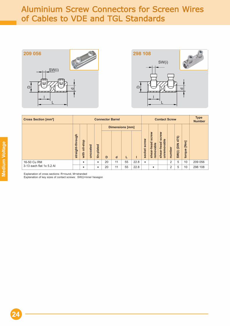
Aluminium SScrew CConnectors ffor SScreen WWires of CCables tto VVDE aand TTGL SStandards
24
Cross Section [mm²] Connector Barrel Contact Screw TypeNumber
stra
ight
-thro
ugh
with
oil-
stop
unco
ated
tin-p
late
d
Dimensions [mm]
sock
et s
crew
shea
r-he
ad s
crew
rem
ovab
le
shea
r-he
ad s
crew
unre
mov
able
num
ber
SW(i)
(DIN
475
)
torq
ue [N
m]
D d L l16-50 Cu RM3-13 each flat 1x 5.2 Al
• • 20 11 55 22.8 • 2 5 10 209 056• • 20 11 55 22.8 • 2 5 10 298 108
Explanation of cross sections: R=round, M=strandedExplanation of key sizes of contact screws: SW(i)=inner hexagon
SW(i)
L
D d
l
SW(i)
L
D d
l
209 056 298 108
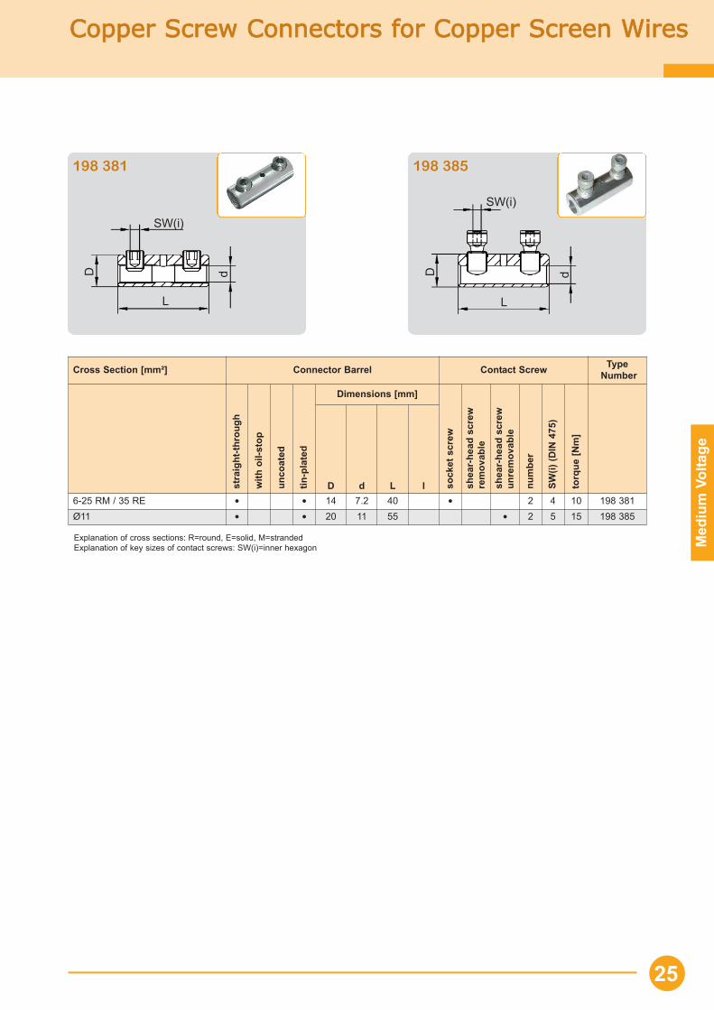
Copper SScrew CConnectors ffor CCopper SScreen WWires
Med
ium
Vol
tage
25
Cross Section [mm²] Connector Barrel Contact Screw TypeNumber
stra
ight
-thro
ugh
with
oil-
stop
unco
ated
tin-p
late
d
Dimensions [mm]
sock
et s
crew
shea
r-he
ad s
crew
rem
ovab
le
shea
r-he
ad s
crew
unre
mov
able
num
ber
SW(i)
(DIN
475
)
torq
ue [N
m]
D d L l6-25 RM / 35 RE • • 14 7.2 40 • 2 4 10 198 381Ø11 • • 20 11 55 • 2 5 15 198 385
Explanation of cross sections: R=round, E=solid, M=strandedExplanation of key sizes of contact screws: SW(i)=inner hexagon
SW(i)
L
D d
SW(i)
L
D d
198 381 198 385
Med
ium
Vol
tage
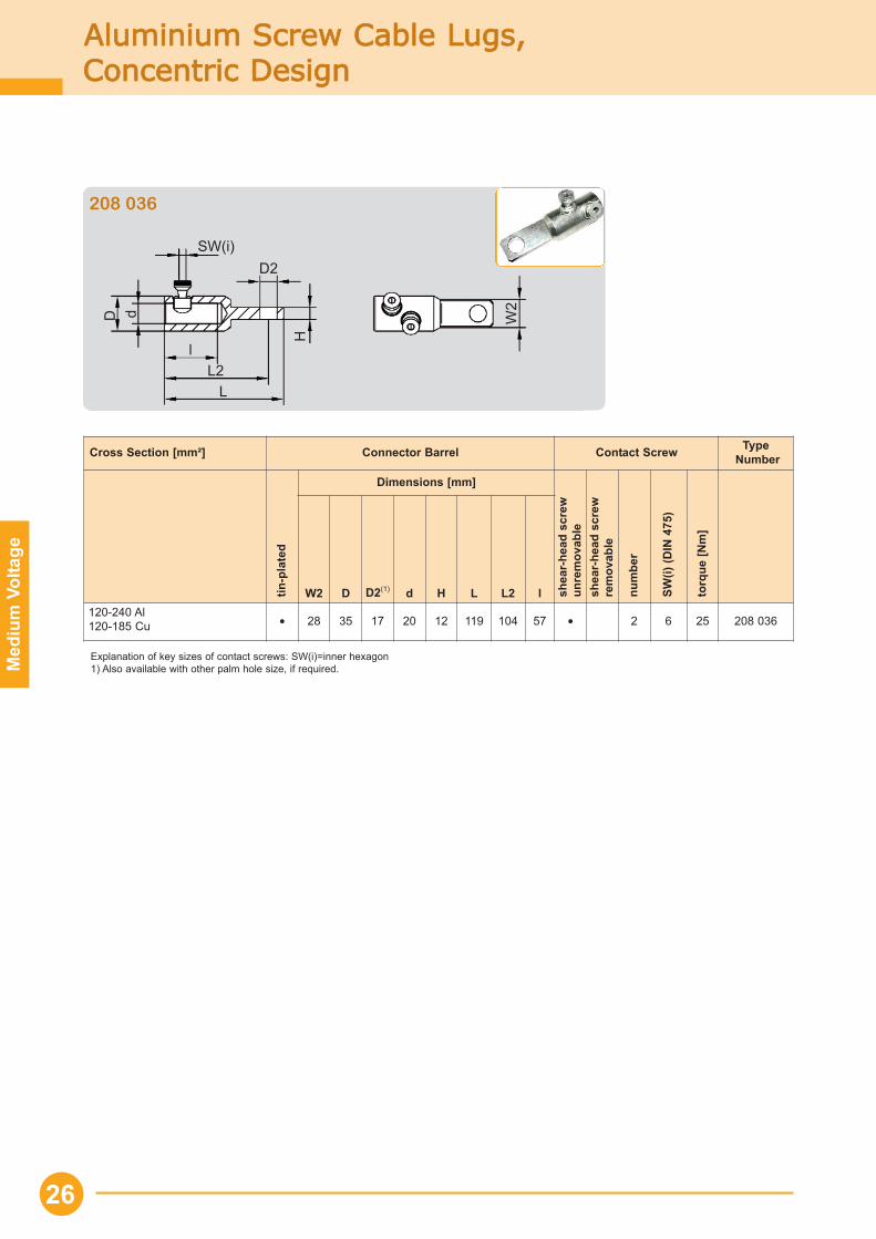
Aluminium SScrew CCable LLugs,Concentric DDesign
26
Explanation of key sizes of contact screws: SW(i)=inner hexagon1) Also available with other palm hole size, if required.
Cross Section [mm²] Connector Barrel Contact Screw TypeNumber
tin-p
late
d
Dimensions [mm]
shea
r-he
ad s
crew
unre
mov
able
shea
r-he
ad s
crew
rem
ovab
le
num
ber
SW(i)
(DIN
475
)
torq
ue [N
m]
W2 D D2(1) d H L L2 l120-240 Al120-185 Cu • 28 35 17 20 12 119 104 57 • 2 6 25 208 036
SW(i)
L2
D
H
l
d
D2
L
W2
208 036
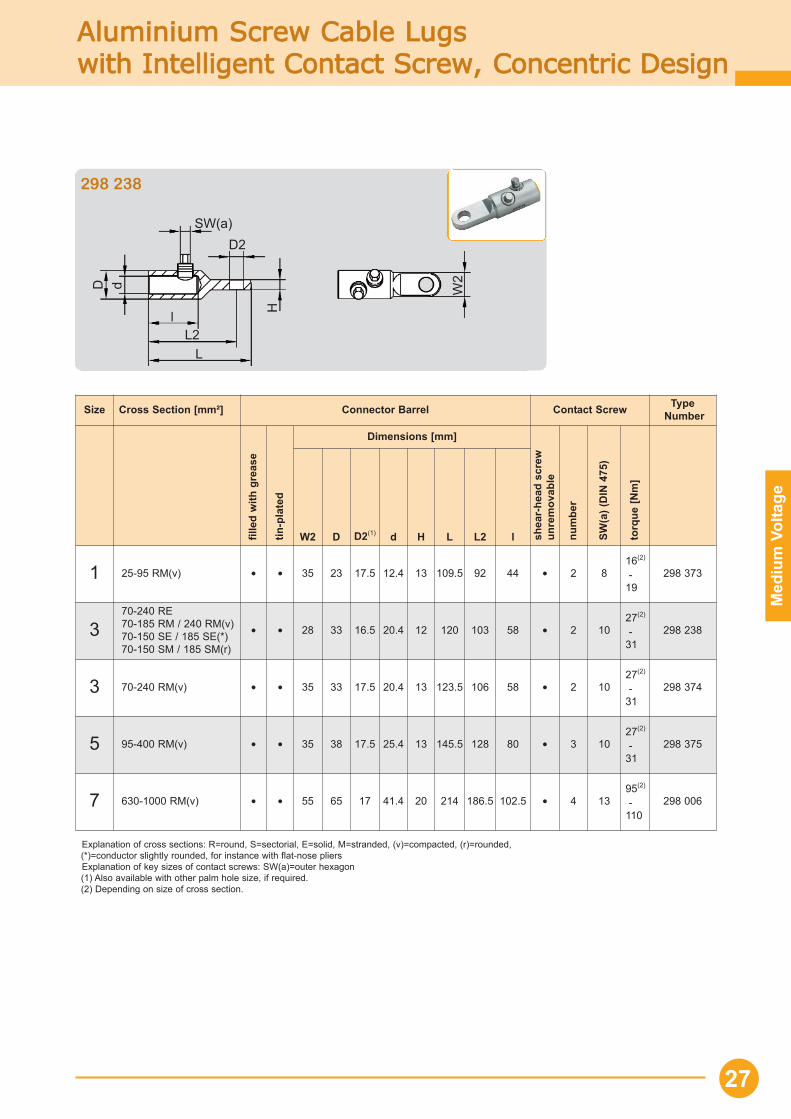
Aluminium SScrew CCable LLugs with IIntelligent CContact SScrew, CConcentric DDesign
Med
ium
Vol
tage
27
Size Cross Section [mm²] Connector Barrel Contact Screw TypeNumber
fille
d w
ith g
reas
e
tin-p
late
d
Dimensions [mm]
shea
r-he
ad s
crew
unre
mov
able
num
ber
SW(a
) (D
IN 4
75)
torq
ue [N
m]
W2 D D2(1) d H L L2 l
1 25-95 RM(v) • • 35 23 17.5 12.4 13 109.5 92 44 • 2 816(2)
-19
298 373
370-240 RE70-185 RM / 240 RM(v)70-150 SE / 185 SE(*)70-150 SM / 185 SM(r)
• • 28 33 16.5 20.4 12 120 103 58 • 2 1027(2)
-31
298 238
3 70-240 RM(v) • • 35 33 17.5 20.4 13 123.5 106 58 • 2 1027(2)
-31
298 374
5 95-400 RM(v) • • 35 38 17.5 25.4 13 145.5 128 80 • 3 1027(2)
-31
298 375
7 630-1000 RM(v) • • 55 65 17 41.4 20 214 186.5 102.5 • 4 1395(2)
-110
298 006
Explanation of cross sections: R=round, S=sectorial, E=solid, M=stranded, (v)=compacted, (r)=rounded, (*)=conductor slightly rounded, for instance with flat-nose pliersExplanation of key sizes of contact screws: SW(a)=outer hexagon(1) Also available with other palm hole size, if required.(2) Depending on size of cross section.
SW(a)
L2
D
Hl
d
D2
L
W2
298 238
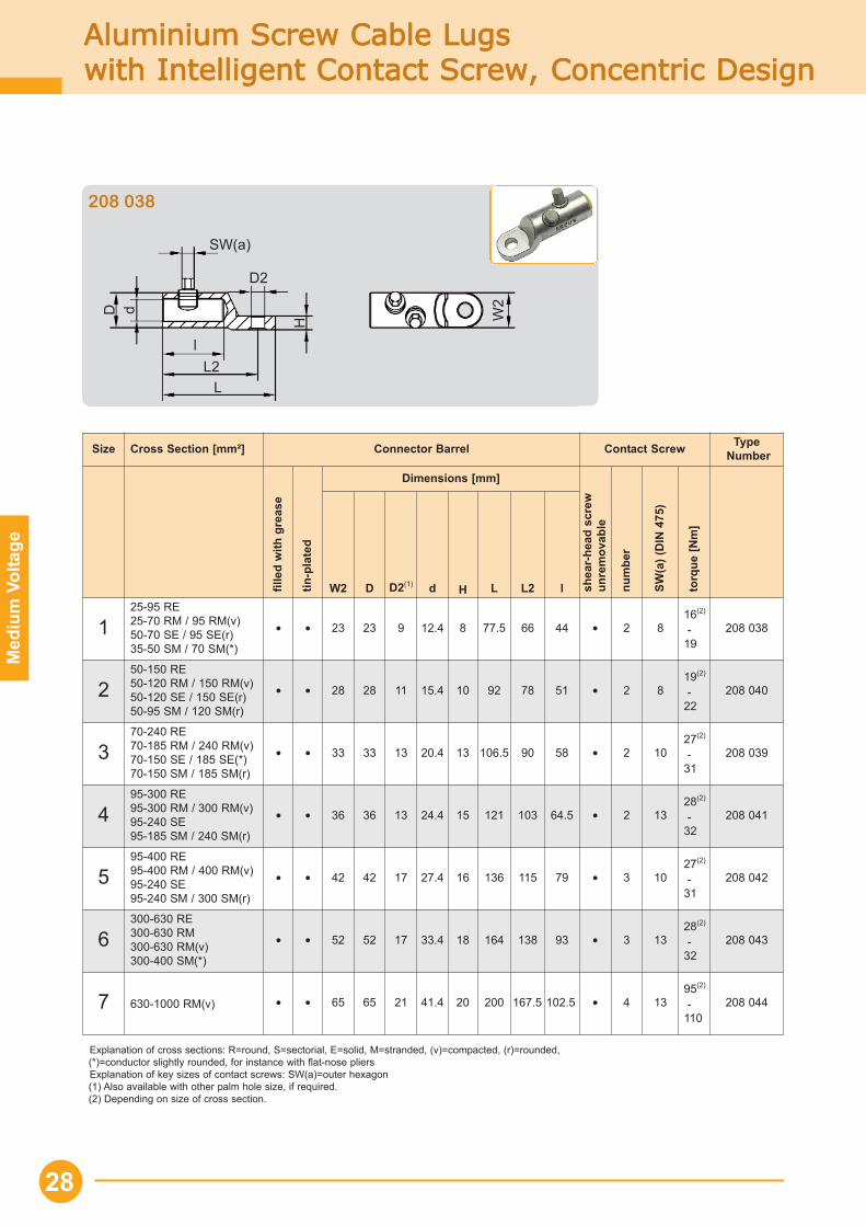
Aluminium SScrew CCable LLugswith IIntelligent CContact SScrew, CConcentric DDesign
Med
ium
Vol
tage
28
Explanation of cross sections: R=round, S=sectorial, E=solid, M=stranded, (v)=compacted, (r)=rounded, (*)=conductor slightly rounded, for instance with flat-nose pliersExplanation of key sizes of contact screws: SW(a)=outer hexagon(1) Also available with other palm hole size, if required.(2) Depending on size of cross section.
Size Cross Section [mm²] Connector Barrel Contact Screw TypeNumber
fille
d w
ith g
reas
e
tin-p
late
d
Dimensions [mm]
shea
r-he
ad s
crew
unre
mov
able
num
ber
SW(a
) (D
IN 4
75)
torq
ue [N
m]
W2 D D2(1) d H L L2 l
125-95 RE25-70 RM / 95 RM(v)50-70 SE / 95 SE(r)35-50 SM / 70 SM(*)
• • 23 23 9 12.4 8 77.5 66 44 • 2 816(2)
-19
208 038
250-150 RE50-120 RM / 150 RM(v)50-120 SE / 150 SE(r)50-95 SM / 120 SM(r)
• • 28 28 11 15.4 10 92 78 51 • 2 819(2)
-22
208 040
370-240 RE70-185 RM / 240 RM(v)70-150 SE / 185 SE(*)70-150 SM / 185 SM(r)
• • 33 33 13 20.4 13 106.5 90 58 • 2 1027(2)
-31
208 039
495-300 RE95-300 RM / 300 RM(v)95-240 SE95-185 SM / 240 SM(r)
• • 36 36 13 24.4 15 121 103 64.5 • 2 1328(2)
-32
208 041
595-400 RE95-400 RM / 400 RM(v)95-240 SE95-240 SM / 300 SM(r)
• • 42 42 17 27.4 16 136 115 79 • 3 1027(2)
-31
208 042
6300-630 RE300-630 RM300-630 RM(v)300-400 SM(*)
• • 52 52 17 33.4 18 164 138 93 • 3 1328(2)
-32
208 043
7 630-1000 RM(v) • • 65 65 21 41.4 20 200 167.5 102.5 • 4 1395(2)
-110
208 044
SW(a)
L
H
dD
L2l
W2
D2
208 038
Explanation of cross sections: R=round, M=strandedExplanation of key sizes of contact screws: SW(i)=inner hexagon1) Also available with other palm hole size, if required.
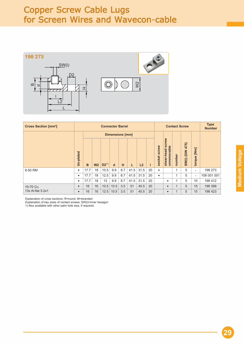
Copper SScrew CCable LLugs for SScreen WWires aand WWavecon-ccable
Med
ium
Vol
tage
Cross Section [mm²] Connector Barrel Contact Screw TypeNumber
tin-p
late
d
Dimensions [mm]
sock
et s
crew
shea
r-he
ad s
crew
unre
mov
able
num
ber
SW(i)
(DIN
475
)
torq
ue [N
m]
B W2 D2(1) d H L L2 l6-50 RM • 17.7 18 10.5 9.9 8.7 41.5 31.5 20 • 1 5 - 198 273
• 17.7 18 12.5 9.9 8.7 41.5 31.5 20 • 1 5 - 108 001 001• 17.7 18 13 9.9 8.7 41.5 31.5 20 • 1 5 10 198 412
10-70 Cu13x Al-flat 5.2x1
• 16 16 10.5 10.5 3.5 51 40.5 20 • 1 5 15 198 399• 16 16 12.5 10.5 3.5 51 40.5 20 • 1 5 15 198 423
SW(i)
L
H
dB
L2l
W2
D2
198 273
29
Screw CConnectors, MMechanical TTop BBolts aand Bolted CContacts
30
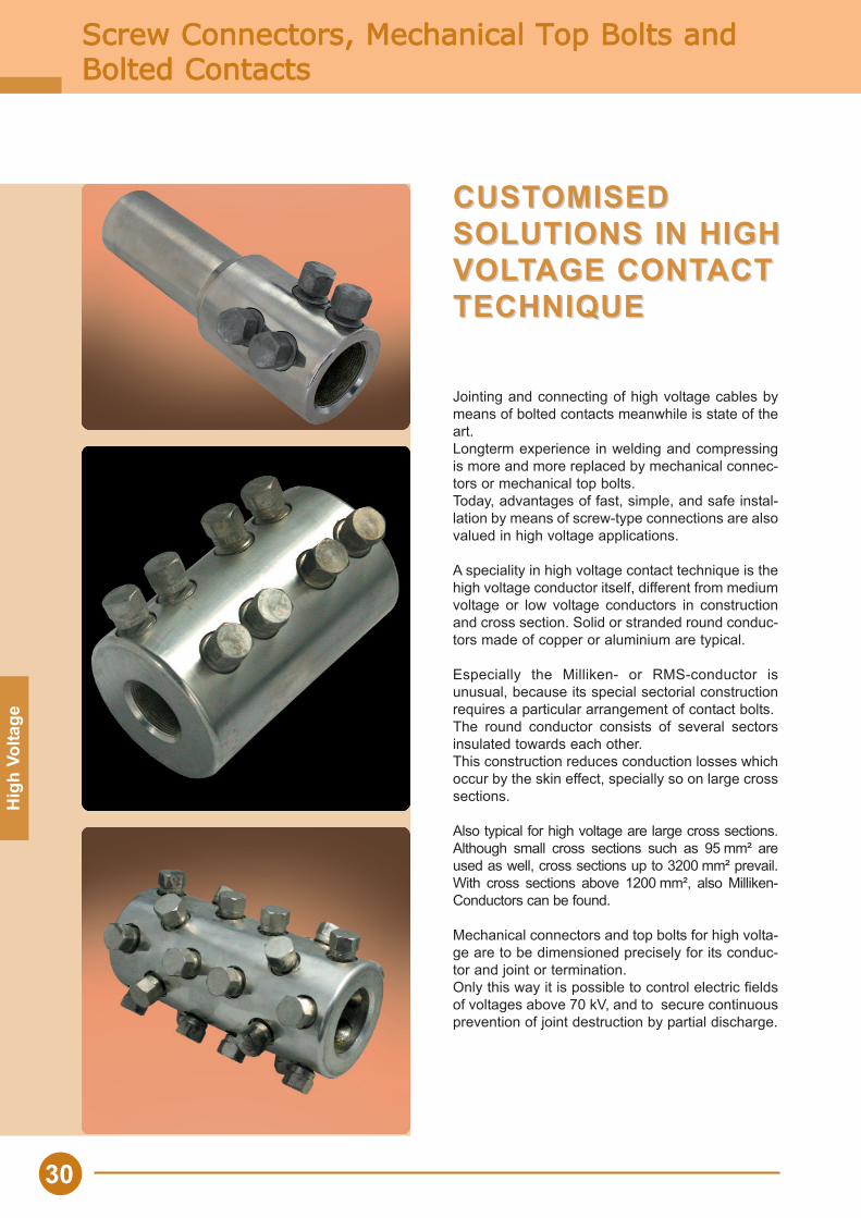
Jointing and connecting of high voltage cables bymeans of bolted contacts meanwhile is state of theart. Longterm experience in welding and compressingis more and more replaced by mechanical connec-tors or mechanical top bolts.Today, advantages of fast, simple, and safe instal-lation by means of screw-type connections are alsovalued in high voltage applications.
A speciality in high voltage contact technique is thehigh voltage conductor itself, different from mediumvoltage or low voltage conductors in constructionand cross section. Solid or stranded round conduc-tors made of copper or aluminium are typical.
Especially the Milliken- or RMS-conductor isunusual, because its special sectorial constructionrequires a particular arrangement of contact bolts.The round conductor consists of several sectorsinsulated towards each other.This construction reduces conduction losses whichoccur by the skin effect, specially so on large crosssections.
Also typical for high voltage are large cross sections.Although small cross sections such as 95 mm² areused as well, cross sections up to 3200 mm² prevail.With cross sections above 1200 mm², also Milliken-Conductors can be found.
Mechanical connectors and top bolts for high volta-ge are to be dimensioned precisely for its conduc-tor and joint or termination.Only this way it is possible to control electric fieldsof voltages above 70 kV, and to secure continuousprevention of joint destruction by partial discharge.
CUSTCUSTOMISED OMISED SOLUTIONS IN HIGHSOLUTIONS IN HIGHVOLVOLTTAGE CONTAGE CONTACTACTTECHNIQUETECHNIQUE
Hig
h Vo
ltage
Screw CConnectors, MMechanical TTop BBolts aand Bolted CContacts
Hig
h Vo
ltage
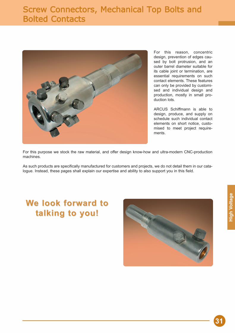
For this reason, concentricdesign, prevention of edges cau-sed by bolt protrusion, and anouter barrel diameter suitable forits cable joint or termination, areessential requirements on suchcontact elements. These featurescan only be provided by customi-sed and individual design andproduction, mostly in small pro-duction lots.
ARCUS Schiffmann is able todesign, produce, and supply onschedule such individual contactelements on short notice, custo-mised to meet project require-ments.
For this purpose we stock the raw material, and offer design know-how and ultra-modern CNC-productionmachines.
As such products are specifically manufactured for customers and projects, we do not detail them in our cata-logue. Instead, these pages shall explain our expertise and ability to also support you in this field.
WWe look forward toe look forward tottalking to you!alking to you!
31
Insulated TToolsIn
stal
latio
n To
ols
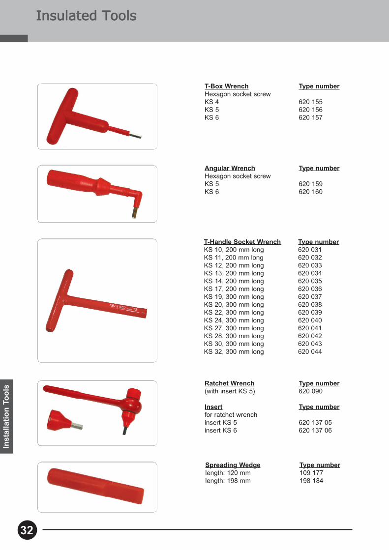
T-Handle Socket Wrench Type numberKS 10, 200 mm long 620 031KS 11, 200 mm long 620 032KS 12, 200 mm long 620 033KS 13, 200 mm long 620 034KS 14, 200 mm long 620 035KS 17, 200 mm long 620 036KS 19, 300 mm long 620 037KS 20, 300 mm long 620 038KS 22, 300 mm long 620 039KS 24, 300 mm long 620 040KS 27, 300 mm long 620 041KS 28, 300 mm long 620 042KS 30, 300 mm long 620 043KS 32, 300 mm long 620 044
Spreading Wedge Type numberlength: 120 mm 109 177length: 198 mm 198 184
Angular Wrench Type numberHexagon socket screwKS 5 620 159KS 6 620 160
Ratchet Wrench Type number(with insert KS 5) 620 090
Insert Type numberfor ratchet wrenchinsert KS 5 620 137 05insert KS 6 620 137 06
T-Box Wrench Type numberHexagon socket screwKS 4 620 155KS 5 620 156KS 6 620 157
32
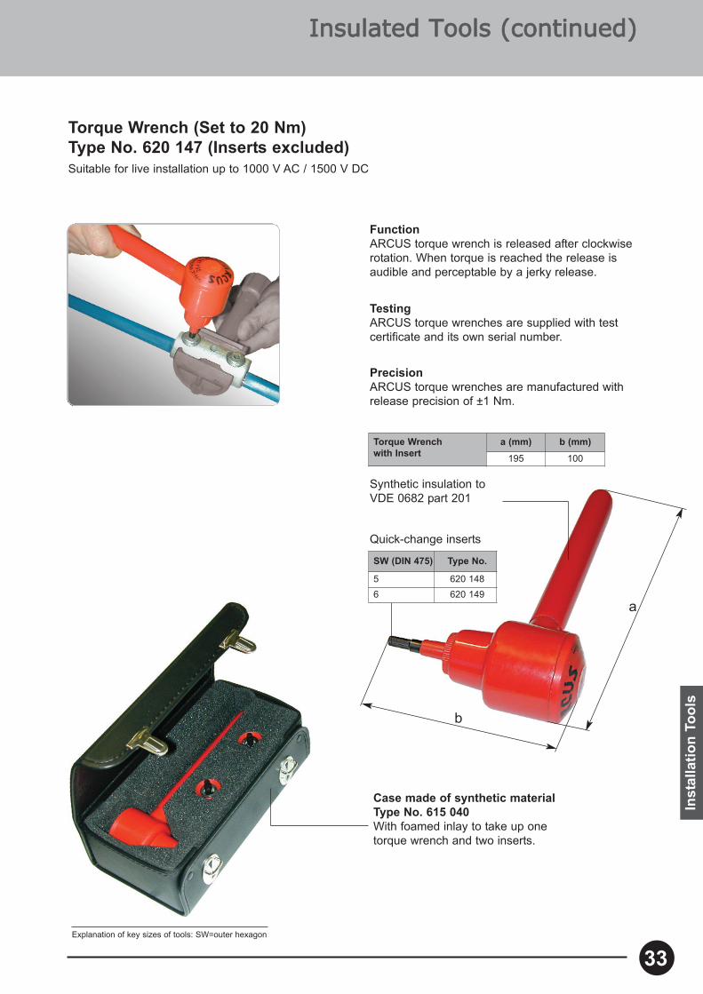
Torque Wrench (Set to 20 Nm) Type No. 620 147 (Inserts excluded)Suitable for live installation up to 1000 V AC / 1500 V DC
Synthetic insulation toVDE 0682 part 201
Quick-change inserts
TestingARCUS torque wrenches are supplied with testcertificate and its own serial number.
PrecisionARCUS torque wrenches are manufactured withrelease precision of ±1 Nm.
SW (DIN 475) Type No.
5 620 1486 620 149
Case made of synthetic materialType No. 615 040With foamed inlay to take up onetorque wrench and two inserts.
FunctionARCUS torque wrench is released after clockwiserotation. When torque is reached the release isaudible and perceptable by a jerky release.
a
b
Torque Wrench with Insert
a (mm) b (mm)
195 100
Explanation of key sizes of tools: SW=outer hexagon
Inst
alla
tion
Tool
s
Insulated TTools ((continued)
33
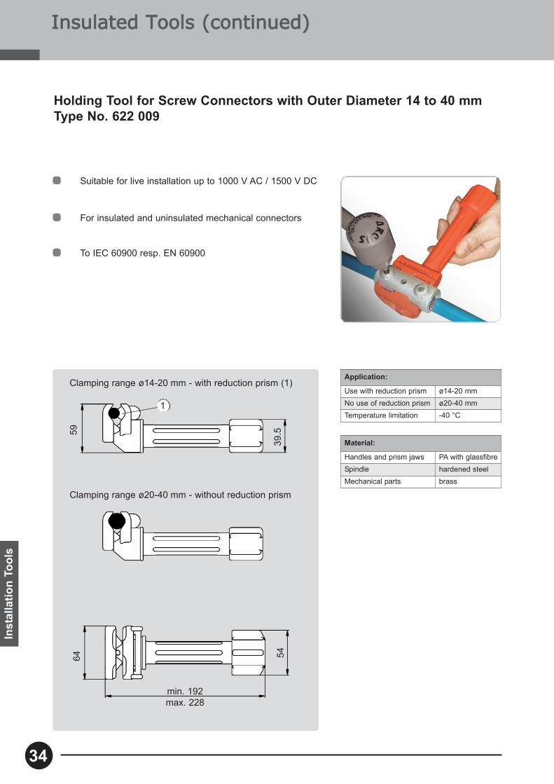
Suitable for live installation up to 1000 V AC / 1500 V DC
For insulated and uninsulated mechanical connectors
To IEC 60900 resp. EN 60900
Application:
Use with reduction prism ø14-20 mmNo use of reduction prism ø20-40 mmTemperature limitation -40 °C
Holding Tool for Screw Connectors with Outer Diameter 14 to 40 mmType No. 622 009
Material:
Handles and prism jaws PA with glassfibreSpindle hardened steelMechanical parts brass
Insulated TTools ((continued)In
stal
latio
n To
ols
34
Clamping range ø14-20 mm - with reduction prism (1)
Clamping range ø20-40 mm - without reduction prism
1
min. 192max. 228
5964 54
39.5

35
Copyright © ARCUS Schiffmann
Layo
ut: M
ario
n R
enz
PhoneGeneral+49 (0) 89 / 4 36 04 - 0
FaxGeneral+49 (0) 89 / 4 31 68 88
FaxSales Department+49 (0) 89 / 4 36 04 - 73
Seat of the CompanyTruderinger Str. 199D-81673 Munich
Edition: 04.2014 Subject to change without notice
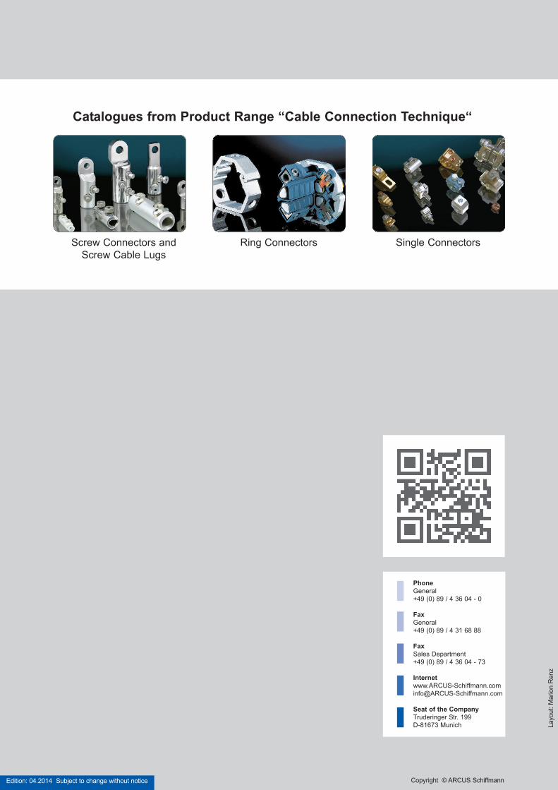
Screw Connectors and Screw Cable Lugs
Single ConnectorsRing Connectors
Catalogues from Product Range “Cable Connection Technique“