Embed Size (px)
Citation preview
1
Product Data
PG96VATTWO--STAGE, 4--WAY MULTIPOISE
VARIABLE--SPEEDCONDENSING GAS FURNACE
A11300
The two--stage gas valve is at the heart of the comfort provided bythis furnace, along with the variable--speed ECM blower motor,and two--speed inducer motor. With an Annual Fuel UtilizationEfficiency (AFUE) up to 96.0%, the two--stage gas furnaceprovides exceptional savings as well when compared to standardgas furnaces. This furnace also features 4--way multipoiseinstallation flexibility, and is available in six model sizes. ThePG96VAT can be vented for direct vent/two--pipe, ventilatedcombustion air, or single--pipe applications. All units meetCalifornia Air Quality Management District emission requirements.All sizes are design certified in Canada.
STANDARD FEATURESS All sizes meet ENERGY STARR Version 4.0 criteria for gas
furnaces: 95+AFUE; AMACF electrical rating; 2% or less
cabinet airflow leakage.
S Ideal height 35” (889 mm) cabinet: short enough for taller coils,
but still allows enough room for service.
S Silicon Nitride Hot Surface Igniter.
S 4--way multipoise design for upflow, downflow or horizontal
installations, with unique vent elbow and optional through--
the--cabinet downflow venting capability.
S Full--featured variable--speed blower motor, two--speed inducer
motor, and two--stage gas valve.
S Self--diagnostics.
S Adjustable blower speed for cooling, continuous fan, and
dehumidification.
S Aluminized--steel primary heat exchanger.
S Stainless--steel condensing secondary heat exchanger.
S Propane convertible (See Accessory list).
S Factory--configured ready for upflow applications.
S Fully--insulated casing including blower section.
S Convenient Air Purifier and Humidifier connections.
S Direct--vent/sealed combustion, single--pipe venting or
ventilated combustion air.
S Installation flexibility: sidewall or vertical vent.
S Certified to leak 2% or less of nominal air conditioning CFM
delivered when pressurized to 1--in. water column with all
present air inlets, air outlets, and condensate drain port(s) sealed.
LIMITED WARRANTY*S 20--year limited warranty on heat exchangers.
S 10 year parts limited warranty to the original purchaser upon
timely registration.
S Limited warranty period is five years for parts if not registered
within 90 days of installation.{
* For owner occupied, residential applications.{Jurisdictions where warranty benefits cannot be conditioned on registra-tion will receive registered limited warranty benefits.
CERTIFIED
Always Ask For
Use of the AHRI Certified TM Mark indicates amanufacturer’s participation in the program. Forverification of certification for individual products,go to www.ahridirectory.org.
2
SAP ORDERING NO.
CASINGDIMENSIONS (IN.)
RATED HEATING OUTPUT{(BTUH) HEATING
COOLINGCFM @ 0.5ESP
MOTOR HP(VARIABLESPEED)
APPROX.SHIP WT.(LB)H D W High Low AFUE
CFM‡(LowHeating)
CFM(HighHeating)
RatedHighHeatingESP
PG96VAT30040AA 35 29.5 14.2 39,000 25,000 96.0% 660 815 0.10 440 - 905 1/2 121PG96VAT42060BA 35 29.5 17.5 58,000 38,000 96.0% 860 1135 0.12 435 - 1475 3/4 142PG96VAT48080BA 35 29.5 17.5 78,000 50,000 96.0% 1160 1505 0.15 555 - 1610 3/4 152PG96VAT60080CA 35 29.5 21.0 78,000 51,000 96.0% 1200 1555 0.15 440 - 2005 1 156PG96VAT60100CA 35 29.5 21.0 97,000 63,000 96.0% 1435 1865 0.20 405 - 2005 1 166PG96VAT66120DA 35 29.5 24.5 117,000 76,000 96.0% 1675 2375 0.20 480 - 2115 1 190{Capacity in accordance with DOE test procedures. Ratings are position dependent. See rating plate.‡Minimum heat CFM when low---heat rise adjustment switch (SW 1---3) and comfort/efficiency adjustment switch (SW1---4) on control center are OFF.ESP --- External Static Pressure
Dual Fuel System Compatibility — This system can providemore control over your monthly energy bills by automaticallyselecting the most economical method of heating. Our systemautomatically switches between the gas furnace and the electricheat pump as outside temperatures change to maintain greaterefficiency and comfort than with any traditional single-sourceheating system. The heat pump also delivers high-efficiencycooling in the summer.
Robust Igniter — Payne’s unique SiN igniter is not onlyphysically robust but it is also electrically robust. It is capable ofrunning at line voltage and does not require complex voltageregulators as do other brands. This unique feature further enhancesthe gas furnace reliability and continues Payne’s tradition oftechnology leadership and innovation in providing a reliable anddurable product.
Reliable Heat Exchanger Design — The aluminized steel,clamshell primary heat exchanger was reengineered to achievegreater efficiency out of a smaller size. The first two passes of theheat exchanger are based on the current 80% product, a designwith more than ten years of field-proven performance and success.These innovations, paired with the continuation of a crimped,no-weld seam create an efficient, robust design for this essentialcomponent.
The condensing heat exchanger, a stainless steel fin and tubedesign, is positioned in the furnace to extract additional heat.Stainless steel coupling box componentry between heat exchangershas exceptional corrosion resistance in both natural gas andpropane applications.
4-Way Multipoise Design — One model for all applications –there is no need to stock special downflow or horizontal modelswhen one unit will do it all. The new heat exchanger design allowsthese units to achieve the certified AFUE in all positions.
Direct or Single-pipe Venting, or Optional VentilatedCombustion Air — This furnace can be installed as a 2-pipe(Direct Vent) furnace, in an optional ventilated combustion airapplication, or in single-pipe, non-direct vent applications. Thisprovides added flexibility to meet diverse installation needs.
Sealed Combustion System — This furnace brings in combustionair from outside the furnace when installed as a direct vent orventilated combustion air venting system, which results inespecially quiet operation. By sealing the entire combustionvestibule, the entire furnace can be made quieter, not just theburners.
Monoport Burners — The burners are specially designed andfinely tuned for smooth, quiet combustion and economicaloperation.
Bottom Closure — Factory--installed for side return; easilyremovable for bottom return. The multi-use bottom closure canalso serve for roll-out protection in horizontal applications, and actas the bottom closure for the optional return air base accessory.
Blower Access Panel Switch — Automatically shuts off 115-vpower to furnace whenever blower access panel is opened.
Quality Registration — Our furnaces are engineered andmanufactured under an ISO 9001 registered quality system.
Certifications — This furnace is CSA (AGA and CGA) designcertified for use with natural and propane gases. The furnace isfactory--shipped for use with natural gas. A CSA listed gasconversion kit is required to convert furnace for use with propanegas. The efficiency is GAMA efficiency rating certified. Thisfurnace meets California Air Quality Management Districtemission requirements.
PG96VAT
3
SPECIFICATIONSHeating Capacity and Efficiency 30040 42060 48080 60080 60100 66120Input High Heat (BTUH) 40,000 60,000 80,000 80,000 100,000 120,000
Low Heat (BTUH) 26,000 39,000 52,000 52,000 65,000 78,000Output High Heat (BTUH) 39,000 58,000 78,000 78,000 97,000 117,000
Low Heat (BTUH) 25,000 38,000 50,000 51,000 63,000 76,000Efficiency AFUE % (ICS) 96.0 96.0 96.0 96.0 96.0 96.0Certified TemperatureRise Range ºF (ºC) High Heat 40 - 70
(22 - 39)40 - 70
(22 - 39)40 - 70
(22 - 39)40 - 70
(22 - 39)40 - 70
(22 - 39)40 - 70
(22 - 39)
Low Heat 30 - 60(17 - 33)
30 - 60(17 - 33)
30 - 60(17 - 33)
30 - 60(17 - 33)
30 - 60(17 - 33)
30 - 60(17 - 33)
Airflow Capacity and Blower Data 30040 42060 48080 60080 60100 66120Certified External StaticPressure (in. w.c.) Heating 0.10 0.12 0.15 0.15 0.20 0.20
Cooling 0.5 0.5 0.5 0.5 0.5 0.5Airflow Delivery @ Rated ESP (CFM) High Heat 815 1135 1505 1555 1865 2375
Low Heat 660 860 1160 1200 1435 1675Cooling 905 1475 1610 2005 2005 2115
Cooling Capacity (tons) @ 400, 350CFM/ton CFM/ton 2 3.5 4 5 5 5
CFM/ton 2.5 4 4.5 5.5 5.5 6Direct-Drive Motor Type Electronically Commutated Motor (ECM)Direct-Drive Motor HP 1/2 3/4 3/4 1 1 1Motor Full Load Amps 6.8 8.4 8.4 10.9 10.9 10.9RPM Range 600 - 1200Speed Selections Variable (PWM)Blower Wheel Dia x Width in. 11 x 7 11 x 8 11 x 8 11 x 10 11 x 10 11 x 11Air Filtration System Field SuppliedFilter Used for Certified Watt Data KGAWF1506UFR
Electrical Data 30040 42060 48080 60080 60100 66120Input Voltage Volts-Hertz-Phase 115-60-1Operating Voltage Range Min-Max 104 - 127Maximum Input Amps Amps 7.5 9.2 9.2 11.7 11.8 11.8Unit Ampacity Amps 10.3 12.4 12.4 15.5 15.6 15.6Minimum Wire Size AWG 14 14 14 12 12 12Maximum Wire Length@ Minimum Wire Size Feet 36 29 29 37 36 36
(M) (11.0) (8.8) (8.8) (11.3) (11.0) (11.0)Maximum Fuse/Ckt Bkr(Time-Delay Type Recommended) Amps 15 15 15 20 20 20
Transformer Capacity (24vac output) 40 VAExternal Control Power Available Heating 24.3 VA
Cooling 34.6 VA
Controls 30040 42060 48080 60080 60100 66120Gas Connection Size 1/2" - NPTBurners (Monoport) 2 3 4 4 5 6Gas Valve (Redundant) Manufacturer White Rogers
Minimum Inlet Gas pressure (in. wc) 4.5Maximum Inlet Gas pressure (in. wc) 13.6
Gas Conversion Kit - Natural to Propane KGANP5201VSPGas Conversion Kit - Propane to Natural KGAPN4401VSPManufactured (Mobile) Home Kit not approved for MH useIgnition Device Silicon NitrideLimit Control 165 180 170 200 180 160Heating Blower Control (Heating Off-Delay) Adjustable: 90, 120, 150, 180 secondsCooling Blower Control (Time Delay Relay) 90 secondsCommunication System Non-communicatingThermostat Connections R, W/W1, W2 Y/Y2, Y1, G, Com 24V, DHUMAccessory Connections EAC (115vac); HUM (24vac); 1-stg AC (via Y/Y2)
PG96VAT
4
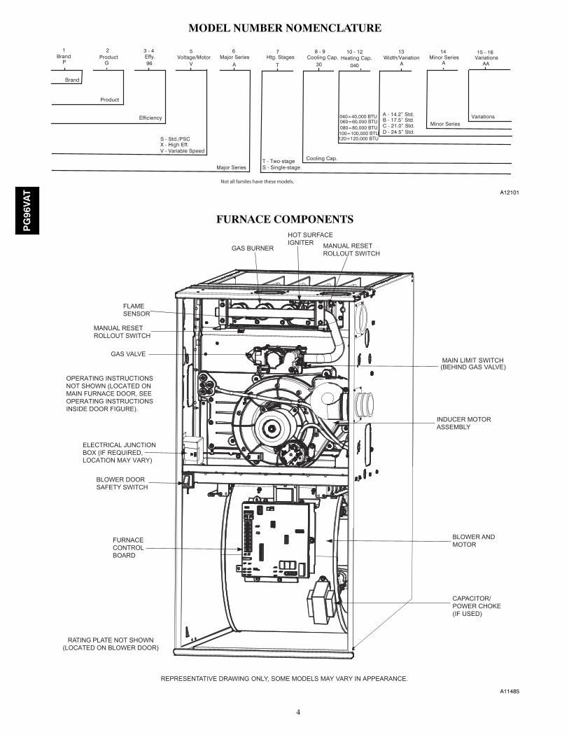
MODEL NUMBER NOMENCLATURE
P 96 V A T 30 040 A A AA
Product
S - Std./PSCX - High Eff.V - Variable Speed
Brand
Major SeriesT - Two-stageS - Single-stage
Minor Series
1Brand
2Product Effy.
3 - 4 5Voltage/Motor
6Major Series Htg. Stages
7Cooling Cap.
8 - 9 10 - 12Heating Cap.
13Width/Variation
14Minor Series Variations
15 - 16
G
EfficiencyA - 14.2” Std.B - 17.5” Std.C - 21.0” Std.D - 24.5” Std.
Variations
Cooling Cap.
040=40,000 BTU 060=60,000 BTU 080=80,000 BTU 100=100,000 BTU 120=120,000 BTU
Not all familes have these models.
A12101
FURNACE COMPONENTS
RATING PLATE NOT SHOWN(LOCATED ON BLOWER DOOR)
GAS VALVEMAIN LIMIT SWITCH(BEHIND GAS VALVE)
REPRESENTATIVE DRAWING ONLY, SOME MODELS MAY VARY IN APPEARANCE.
ELECTRICAL JUNCTIONBOX (IF REQUIRED, LOCATION MAY VARY)
OPERATING INSTRUCTIONSNOT SHOWN (LOCATED ONMAIN FURNACE DOOR, SEE OPERATING INSTRUCTIONS INSIDE DOOR FIGURE).
FURNACECONTROLBOARD
MANUAL RESETROLLOUT SWITCH
FLAMESENSOR
MANUAL RESETROLLOUT SWITCH
GAS BURNER
HOT SURFACEIGNITER
INDUCER MOTORASSEMBLY
BLOWER ANDMOTOR
CAPACITOR/POWER CHOKE(IF USED)
BLOWER DOORSAFETY SWITCH
A11485
PG96VAT
5
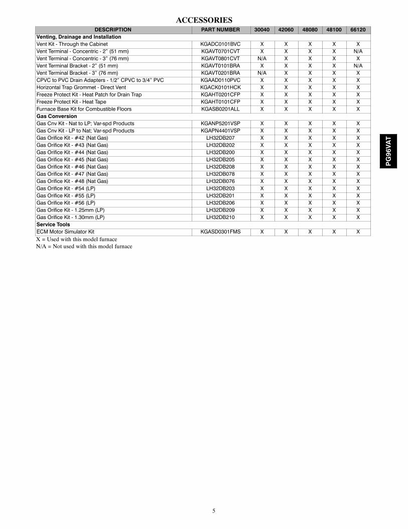
ACCESSORIESDESCRIPTION PART NUMBER 30040 42060 48080 48100 66120
Venting, Drainage and InstallationVent Kit - Through the Cabinet KGADC0101BVC X X X X XVent Terminal - Concentric - 2” (51 mm) KGAVT0701CVT X X X X N/AVent Terminal - Concentric - 3” (76 mm) KGAVT0801CVT N/A X X X XVent Terminal Bracket - 2” (51 mm) KGAVT0101BRA X X X X N/AVent Terminal Bracket - 3” (76 mm) KGAVT0201BRA N/A X X X XCPVC to PVC Drain Adapters - 1/2” CPVC to 3/4” PVC KGAAD0110PVC X X X X XHorizontal Trap Grommet - Direct Vent KGACK0101HCK X X X X XFreeze Protect Kit - Heat Patch for Drain Trap KGAHT0201CFP X X X X XFreeze Protect Kit - Heat Tape KGAHT0101CFP X X X X XFurnace Base Kit for Combustible Floors KGASB0201ALL X X X X XGas ConversionGas Cnv Kit - Nat to LP; Var-spd Products KGANP5201VSP X X X X XGas Cnv Kit - LP to Nat; Var-spd Products KGAPN4401VSP X X X X XGas Orifice Kit - #42 (Nat Gas) LH32DB207 X X X X XGas Orifice Kit - #43 (Nat Gas) LH32DB202 X X X X XGas Orifice Kit - #44 (Nat Gas) LH32DB200 X X X X XGas Orifice Kit - #45 (Nat Gas) LH32DB205 X X X X XGas Orifice Kit - #46 (Nat Gas) LH32DB208 X X X X XGas Orifice Kit - #47 (Nat Gas) LH32DB078 X X X X XGas Orifice Kit - #48 (Nat Gas) LH32DB076 X X X X XGas Orifice Kit - #54 (LP) LH32DB203 X X X X XGas Orifice Kit - #55 (LP) LH32DB201 X X X X XGas Orifice Kit - #56 (LP) LH32DB206 X X X X XGas Orifice Kit - 1.25mm (LP) LH32DB209 X X X X XGas Orifice Kit - 1.30mm (LP) LH32DB210 X X X X XService ToolsECM Motor Simulator Kit KGASD0301FMS X X X X XX = Used with this model furnaceN/A = Not used with this model furnace
PG96VAT
6
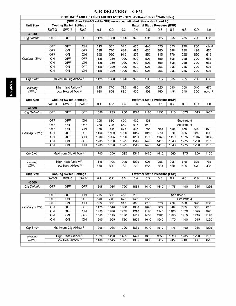
AIR DELIVERY -- CFMCOOLING 4 AND HEATING AIR DELIVERY - CFM (Bottom Return 5 With Filter)(SW1-5 and SW4-3 set to OFF, except as indicated. See notes 1 and 2.)
Unit Size Cooling Switch Settings External Static Pressure (ESP)SW2-3 SW2-2 SW2-1 0.1 0.2 0.3 0.4 0.5 0.6 0.7 0.8 0.9 1.0
30040Clg Default: OFF OFF OFF 1125 1080 1020 970 905 855 805 755 700 635
Cooling (SW2)
OFF OFF ON 615 555 510 475 440 395 355 270 230 note 8OFF ON OFF 785 740 695 665 630 590 565 520 485 450OFF ON ON 990 950 910 875 850 815 770 720 670 615ON OFF OFF 1125 1080 1020 970 905 855 805 755 700 635ON OFF ON 1125 1080 1020 970 905 855 805 755 700 635ON ON OFF 1125 1080 1020 970 905 855 805 755 700 635ON ON ON 1125 1080 1020 970 905 855 805 755 700 635
Clg SW2: Maximum Clg Airflow 2 1125 1080 1020 970 905 855 805 755 700 635
Heating(SW1)
High Heat Airflow 3 815 770 725 695 660 625 595 550 510 475Low Heat Airflow 3 660 605 560 530 495 450 415 340 300 note 7
Unit Size Cooling Switch Settings External Static Pressure (ESP)SW2-3 SW2-2 SW2-1 0.1 0.2 0.3 0.4 0.5 0.6 0.7 0.8 0.9 1.0
42060Clg Default: OFF OFF OFF 1330 1295 1260 1220 1190 1150 1110 1075 1045 1005
Cooling (SW2)
OFF OFF ON 725 660 600 520 435 See note 4OFF ON OFF 780 725 660 615 540 See note 4OFF ON ON 975 925 875 835 785 750 690 655 610 570ON OFF OFF 1160 1120 1090 1045 1010 970 920 885 840 800ON OFF ON 1330 1295 1260 1220 1190 1150 1110 1075 1045 1005ON ON OFF 1705 1650 1595 1545 1475 1415 1340 1275 1200 1105ON ON ON 1705 1650 1595 1545 1475 1415 1340 1275 1200 1105
Clg SW2: Maximum Clg Airflow 2 1705 1650 1595 1545 1475 1415 1340 1275 1200 1105
Heating(SW1)
High Heat Airflow 3 1145 1105 1075 1030 995 955 905 870 825 785Low Heat Airflow 3 870 820 760 720 655 620 560 525 470 435
Unit Size Cooling Switch Settings External Static Pressure (ESP)SW2-3 SW2-2 SW2-1 0.1 0.2 0.3 0.4 0.5 0.6 0.7 0.8 0.9 1.0
48080Clg Default: OFF OFF OFF 1805 1765 1720 1665 1610 1540 1475 1400 1315 1235
Cooling (SW2)
OFF OFF ON 775 635 455 230 See note 8OFF ON OFF 840 740 675 625 555 See note 4OFF ON ON 995 955 910 860 815 770 720 660 620 585ON OFF OFF 1175 1140 1090 1060 1025 980 940 905 855 815ON OFF ON 1325 1280 1245 1210 1180 1140 1105 1070 1025 990ON ON OFF 1545 1515 1480 1445 1410 1380 1350 1315 1245 1175ON ON ON 1805 1765 1720 1665 1610 1540 1475 1400 1315 1235
Clg SW2: Maximum Clg Airflow 2 1805 1765 1720 1665 1610 1540 1475 1400 1315 1235
Heating(SW1)
High Heat Airflow 3 1520 1490 1455 1420 1385 1355 1320 1285 1220 1155Low Heat Airflow 3 1180 1145 1095 1065 1030 985 945 910 860 820
PG96VAT
7
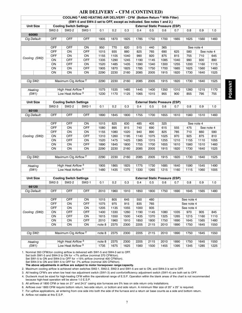
AIR DELIVERY -- CFM (CONTINUED)COOLING 4 AND HEATING AIR DELIVERY - CFM (Bottom Return 5 With Filter)(SW1-5 and SW4-3 set to OFF, except as indicated. See notes 1 and 2.)
Unit Size Cooling Switch Settings External Static Pressure (ESP)SW2-3 SW2-2 SW2-1 0.1 0.2 0.3 0.4 0.5 0.6 0.7 0.8 0.9 1.0
60080Clg Default: OFF OFF OFF 1905 1870 1825 1785 1750 1700 1665 1625 1560 1460
Cooling (SW2)
OFF OFF ON 950 770 620 515 440 365 See note 4OFF ON OFF 1015 935 880 825 765 690 625 580 See note 4OFF ON ON 1155 1105 1040 990 920 875 815 755 710 645ON OFF OFF 1335 1290 1245 1190 1145 1085 1040 990 930 890ON OFF ON 1520 1485 1435 1390 1340 1300 1255 1200 1160 1115ON ON OFF 1905 1870 1825 1785 1750 1700 1665 1625 1560 1460ON ON ON 2290 2230 2160 2085 2005 1915 1820 1730 1640 1525
Clg SW2: Maximum Clg Airflow 2 2290 2230 2160 2085 2005 1915 1820 1730 1640 1525
Heating(SW1)
High Heat Airflow 3 1575 1535 1485 1445 1400 1350 1310 1260 1215 1170Low Heat Airflow 3 1230 1170 1125 1065 1015 955 900 855 795 755
Unit Size Cooling Switch Settings External Static Pressure (ESP)SW2-3 SW2-2 SW2-1 0.1 0.2 0.3 0.4 0.5 0.6 0.7 0.8 0.9 1.0
60100Clg Default: OFF OFF OFF 1890 1845 1800 1755 1700 1655 1610 1560 1510 1460
Cooling (SW2)
OFF OFF ON 1015 825 630 485 405 325 See note 4OFF ON OFF 1080 895 815 740 690 615 555 475 See note 4OFF ON ON 1155 1080 1020 940 890 825 785 710 660 590ON OFF OFF 1310 1260 1195 1140 1075 1025 970 925 875 810ON OFF ON 1520 1475 1425 1365 1315 1255 1210 1155 1110 1055ON ON OFF 1890 1845 1800 1755 1700 1655 1610 1560 1510 1460ON ON ON 2290 2230 2160 2085 2005 1915 1820 1730 1640 1525
Clg SW2: Maximum Clg Airflow 2 2290 2230 2160 2085 2005 1915 1820 1730 1640 1525
Heating(SW1)
High Heat Airflow 3 1905 1865 1825 1775 1730 1685 1640 1590 1545 1490Low Heat Airflow 3 1480 1435 1375 1330 1265 1215 1160 1115 1060 1005
Unit Size Cooling Switch Settings External Static Pressure (ESP)SW2-3 SW2-2 SW2-1 0.1 0.2 0.3 0.4 0.5 0.6 0.7 0.8 0.9 1.0
66120Clg Default: OFF OFF OFF 2010 1960 1910 1850 1800 1750 1690 1645 1565 1480
Cooling (SW2)
OFF OFF ON 1015 805 645 550 480 See note 4OFF ON OFF 1075 975 915 835 765 See note 4OFF ON ON 1205 1135 1055 1000 935 See note 4ON OFF OFF 1400 1330 1260 1190 1145 1080 1035 970 905 845ON OFF ON 1615 1550 1500 1435 1370 1325 1265 1215 1160 1110ON ON OFF 2010 1960 1910 1850 1800 1750 1690 1645 1565 1480ON ON ON note 8 2375 2300 2205 2115 2010 1890 1750 1645 1550
Clg SW2: Maximum Clg Airflow 2 note 8 2375 2300 2205 2115 2010 1890 1750 1645 1550
Heating(SW1)
High Heat Airflow 3 note 8 2375 2300 2205 2115 2010 1890 1750 1645 1550Low Heat Airflow 3 1735 1675 1625 1560 1500 1455 1395 1345 1285 1225
1. Nominal 350 CFM/ton cooling airflow is delivered with SW1-5 and SW4-3 set to OFF.Set both SW1-5 and SW4-3 to ON for +7% airflow (nominal 370 CFM/ton).Set SW1-5 to ON and SW4-3 to OFF for +15% airflow (nominal 400 CFM/ton).Set SW4-3 to ON and SW1-5 to OFF for -7% airflow (nominal 325 CFM/ton).The above adjustments in airflow are subject to motor horsepower range/capacity.
2. Maximum cooling airflow is achieved when switches SW2-1, SW2-2, SW2-3 and SW1-5 are set to ON, and SW4-3 is set to OFF.3. All heating CFM's are when low heat rise adjustment switch (SW1-3) and comfort/efficiency adjustment switch (SW1-4) are both set to OFF.4. Ductwork must be sized for high-heating CFM within the operational range of E.S.P. Operation within the blank areas of the chart is not recommended
because high-heat operation will be above 1.0 E.S.P.5. All airflows of 1800 CFM or less on 21” and 24.5” casing size furnaces are 5% less on side return only installations.6. Airflows over 1800 CFM require bottom return, two-side return, or bottom and side return. A minimum filter size of 20” x 25” is required.7. For upflow applications, air entering from one side into both the side of the furnace and a return air base counts as a side and bottom return.8. Airflow not stable at this E.S.P.
PG96VAT
8
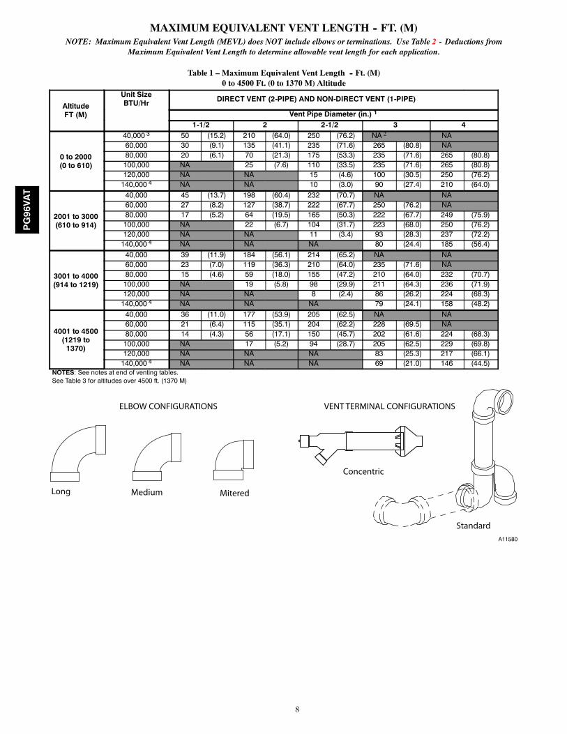
MAXIMUM EQUIVALENT VENT LENGTH -- FT. (M)NOTE: Maximum Equivalent Vent Length (MEVL) does NOT include elbows or terminations. Use Table 2 - Deductions from
Maximum Equivalent Vent Length to determine allowable vent length for each application.
Table 1 – Maximum Equivalent Vent Length -- Ft. (M)0 to 4500 Ft. (0 to 1370 M) Altitude
AltitudeFT (M)
Unit SizeBTU/Hr DIRECT VENT (2-PIPE) AND NON-DIRECT VENT (1-PIPE)
Vent Pipe Diameter (in.) 1
1-1/2 2 2-1/2 3 4
0 to 2000(0 to 610)
40,000 3 50 (15.2) 210 (64.0) 250 (76.2) NA 2 NA60,000 30 (9.1) 135 (41.1) 235 (71.6) 265 (80.8) NA80,000 20 (6.1) 70 (21.3) 175 (53.3) 235 (71.6) 265 (80.8)100,000 NA 25 (7.6) 110 (33.5) 235 (71.6) 265 (80.8)120,000 NA NA 15 (4.6) 100 (30.5) 250 (76.2)140,000 4 NA NA 10 (3.0) 90 (27.4) 210 (64.0)
2001 to 3000(610 to 914)
40,000 45 (13.7) 198 (60.4) 232 (70.7) NA NA60,000 27 (8.2) 127 (38.7) 222 (67.7) 250 (76.2) NA80,000 17 (5.2) 64 (19.5) 165 (50.3) 222 (67.7) 249 (75.9)100,000 NA 22 (6.7) 104 (31.7) 223 (68.0) 250 (76.2)120,000 NA NA 11 (3.4) 93 (28.3) 237 (72.2)140,000 4 NA NA NA 80 (24.4) 185 (56.4)
3001 to 4000(914 to 1219)
40,000 39 (11.9) 184 (56.1) 214 (65.2) NA NA60,000 23 (7.0) 119 (36.3) 210 (64.0) 235 (71.6) NA80,000 15 (4.6) 59 (18.0) 155 (47.2) 210 (64.0) 232 (70.7)100,000 NA 19 (5.8) 98 (29.9) 211 (64.3) 236 (71.9)120,000 NA NA 8 (2.4) 86 (26.2) 224 (68.3)140,000 4 NA NA NA 79 (24.1) 158 (48.2)
4001 to 4500(1219 to1370)
40,000 36 (11.0) 177 (53.9) 205 (62.5) NA NA60,000 21 (6.4) 115 (35.1) 204 (62.2) 228 (69.5) NA80,000 14 (4.3) 56 (17.1) 150 (45.7) 202 (61.6) 224 (68.3)100,000 NA 17 (5.2) 94 (28.7) 205 (62.5) 229 (69.8)120,000 NA NA NA 83 (25.3) 217 (66.1)140,000 4 NA NA NA 69 (21.0) 146 (44.5)
NOTES: See notes at end of venting tables.See Table 3 for altitudes over 4500 ft. (1370 M)
Long Medium Mitered
Concentric
Standard
ELBOW CONFIGURATIONS VENT TERMINAL CONFIGURATIONS
A11580
PG96VAT
9
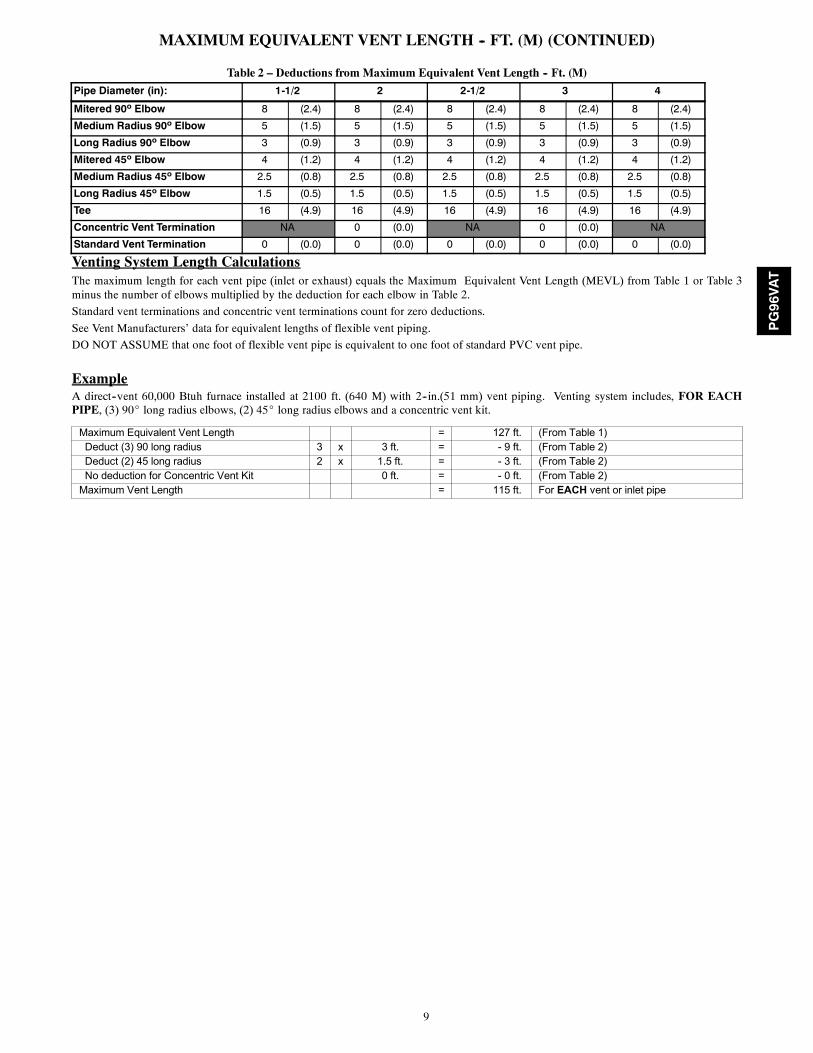
MAXIMUM EQUIVALENT VENT LENGTH -- FT. (M) (CONTINUED)
Table 2 – Deductions from Maximum Equivalent Vent Length -- Ft. (M)
Pipe Diameter (in): 1-1/2 2 2-1/2 3 4
Mitered 90º Elbow 8 (2.4) 8 (2.4) 8 (2.4) 8 (2.4) 8 (2.4)
Medium Radius 90º Elbow 5 (1.5) 5 (1.5) 5 (1.5) 5 (1.5) 5 (1.5)
Long Radius 90º Elbow 3 (0.9) 3 (0.9) 3 (0.9) 3 (0.9) 3 (0.9)
Mitered 45º Elbow 4 (1.2) 4 (1.2) 4 (1.2) 4 (1.2) 4 (1.2)
Medium Radius 45º Elbow 2.5 (0.8) 2.5 (0.8) 2.5 (0.8) 2.5 (0.8) 2.5 (0.8)
Long Radius 45º Elbow 1.5 (0.5) 1.5 (0.5) 1.5 (0.5) 1.5 (0.5) 1.5 (0.5)
Tee 16 (4.9) 16 (4.9) 16 (4.9) 16 (4.9) 16 (4.9)
Concentric Vent Termination NA 0 (0.0) NA 0 (0.0) NA
Standard Vent Termination 0 (0.0) 0 (0.0) 0 (0.0) 0 (0.0) 0 (0.0)
Venting System Length CalculationsThe maximum length for each vent pipe (inlet or exhaust) equals the Maximum Equivalent Vent Length (MEVL) from Table 1 or Table 3minus the number of elbows multiplied by the deduction for each elbow in Table 2.
Standard vent terminations and concentric vent terminations count for zero deductions.
See Vent Manufacturers’ data for equivalent lengths of flexible vent piping.
DO NOT ASSUME that one foot of flexible vent pipe is equivalent to one foot of standard PVC vent pipe.
ExampleA direct--vent 60,000 Btuh furnace installed at 2100 ft. (640 M) with 2--in.(51 mm) vent piping. Venting system includes, FOR EACHPIPE, (3) 90_ long radius elbows, (2) 45_ long radius elbows and a concentric vent kit.
Maximum Equivalent Vent Length = 127 ft. (From Table 1)Deduct (3) 90 long radius 3 x 3 ft. = - 9 ft. (From Table 2)Deduct (2) 45 long radius 2 x 1.5 ft. = - 3 ft. (From Table 2)No deduction for Concentric Vent Kit 0 ft. = - 0 ft. (From Table 2)
Maximum Vent Length = 115 ft. For EACH vent or inlet pipe
PG96VAT
10
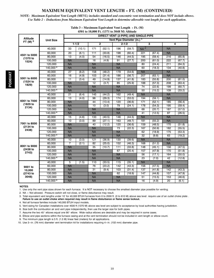
MAXIMUM EQUIVALENT VENT LENGTH -- FT. (M) (CONTINUED)NOTE: Maximum Equivalent Vent Length (MEVL) includes standard and concentric vent termination and does NOT include elbows.
Use Table 2 - Deductions from Maximum Equivalent Vent Length to determine allowable vent length for each application.
Table 3 – Maximum Equivalent Vent Length -- Ft. (M)4501 to 10,000 Ft. (1371 to 3048 M) Altitude
AltitudeFT (M) 5 Unit Size
DIRECT VENT (2-PIPE) AND SINGLE-PIPEVent Pipe Diameter (in.) 1
1-1/2 2 2-1/2 3 4
4501 to 5000(1370 to1524)
40,000 33 (10.1) 171 (52.1) 196 (59.7) NA 2 NA60,000 20 (6.1) 111 (33.8) 198 (60.4) 221 (67.4) NA80,000 13 (4.0) 54 (16.5) 146 (44.5) 195 (59.4) 216 (65.8)100,000 NA 16 (4.9) 91 (27.7) 200 (61.0) 222 (67.7)120,000 NA NA NA 80 (24.4) 211 (64.3)140,000 4 NA NA NA 60 (18.3) 134 (40.8)
5001 to 6000(1524 to1829)
40,000 27 (8.2) 158 (48.2) 179 (54.6) NA NA60,000 16 (4.9) 103 (31.4) 186 (56.7) 207 (63.1) NA80,000 11 (3.4) 49 (14.9) 137 (41.8) 183 (55.8) 200 (61.0)100,000 NA 12 (3.7) 85 (25.9) 188 (57.3) 208 (63.4)120,000 NA NA NA 74 (22.6) 199 (60.7)140,000 4 NA NA NA 50 (15.2) 109 (33.2)
6001 to 7000(1829 to2134)
40,000 21 (6.4) 145 (44.2) 162 (49.4) NA NA60,000 13 (4.0) 96 (29.3) 174 (53.0) 194 (59.1) NA80,000 NA 44 (13.4) 120 (36.6) 171 (52.1) 185 (56.4)100,000 NA 10 (3.0) 79 (24.1) 178 (54.3) 195 (59.4)120,000 NA NA NA 68 (20.7) 187 (57.0)140,000 4 NA NA NA 41 (12.5) 87 (26.5)
7001 to 8000(2134 to2438)
40,000 15 (4.6) 133 (40.5) 146 (44.5) NA NA60,000 10 (3.0) 89 (27.1) 163 (49.7) 181 (55.2) NA80,000 NA 40 (12.2) 120 (36.6) 159 (48.5) 170 (51.8)100,000 NA NA 73 (22.3) 167 (50.9) 182 (55.5)120,000 NA NA NA 62 (18.9) 175 (53.3)140,000 4 NA NA NA 32 (9.8) 63 (19.2)
8001 to 9000(2438 to2743)
40,000 10 (3.0) 121 (36.9) 130 (39.6) NA NA60,000 7 (2.1) 82 (25.0) 152 (46.3) 168 (51.2) NA80,000 NA 35 (10.7) 111 (33.8) 148 (45.1) 156 (47.5)100,000 NA NA 67 (20.4) 157 (47.9) 170 (51.8)120,000 NA NA NA 56 (17.1) 164 (50.0)140,000 4 NA NA NA 23 (7.0) 42 (12.8)
9001 to10,000(2743 to3048)
40,000 5 (1.5) 110 (33.5) 115 (35.1) NA NA60,000 NA 76 (23.2) 142 (43.3) 156 (47.5) NA80,000 NA 31 (9.4) 103 (31.4) 137 (41.8) 142 (43.3)100,000 NA NA 62 (18.9) 147 (44.8) 157 (47.9)120,000 NA NA NA 51 (15.5) 153 (46.6)140,000 4 NA NA NA 16 (4.9) 20 (6.1)
NOTES:1. Use only the vent pipe sizes shown for each furnace. It is NOT necessary to choose the smallest diameter pipe possible for venting.2. NA --- Not allowed. Pressure switch will not close, or flame disturbance may result.3. Total equivalent vent lengths under 10’ for 40,000 BTUH furnaces from 0 to 2000 ft. (0 to 610 M) above sea level require use of an outlet choke plate .Failure to use an outlet choke when required may result in flame disturbance or flame sense lockout.
4. Not all furnace families include 140,000 BTUH input models.5. Vent sizing for Canadian installations over 4500 ft (1370 M) above sea level are subject to acceptance by local authorities having jurisdiction.6. Size both the combustion air and vent pipe independently, then use the larger size for both pipes.7. Assume the two 45_ elbows equal one 90_ elbow. Wide radius elbows are desirable and may be required in some cases.8. Elbow and pipe sections within the furnace casing and at the vent termination should not be included in vent length or elbow count.9. The minimum pipe length is 5 ft. (1.5 M) linear feet (meters) for all applications.10. Use 3---in. (76 mm) diameter vent termination kit for installations requiring 4---in. (102 mm) diameter pipe.
PG96VAT

11
MAXIMUM ALLOWABLE EXPOSED VENT LENGTHS INSULATION TABLE -- FT. (M)
Two StageFurnace HighHeat Input
Winter DesignTemp ° F (° C)
PipeLength inFt. & M
No Insulation 3/8-in. (9.5 mm) 1/2-in. (12.7 mm)
Pipe Diameter-inches (mm) Pipe Diameter-inches (mm) Pipe Diameter-inches (mm)
1.5 2.0 2.5 3.0 4.0 1.5 2.0 2.5 3.0 4.0 1.5 2.0 2.5 3.0 4.0
(38) (51) (64) (76) (102) (38) (51) (64) (76) (102) (38) (51) (64) (76) (102)
40000*
20 (-10)Ft. 40.0 35.0 35.0 N/A N/A 50.0 104.0 94.0 N/A N/A 50.0 122.0 110.0 N/A N/A
M 12.2 10.7 10.7 N/A N/A 15.2 31.7 28.7 N/A N/A 15.2 37.2 33.5 N/A N/A
0 (-20)Ft. 19.0 14.0 12.0 N/A N/A 50.0 61.0 54.0 N/A N/A 50.0 74.0 65.0 N/A N/A
M 5.8 4.3 3.7 N/A N/A 15.2 18.6 16.5 N/A N/A 15.2 22.6 19.8 N/A N/A
-20 (-30)Ft. 9.0 3.0 1.0 N/A N/A 50.0 41.0 35.0 N/A N/A 50.0 51.0 43.0 N/A N/A
M 2.7 0.9 0.3 N/A N/A 15.2 12.5 10.7 N/A N/A 15.2 15.5 13.1 N/A N/A
-40 (-40)Ft. 3.0 0.0 0.0 N/A N/A 39.0 29.0 23.0 N/A N/A 48.0 37.0 30.0 N/A N/A
M 0.9 0.0 0.0 N/A N/A 11.9 8.8 7.0 N/A N/A 14.6 11.3 9.1 N/A N/A
60000
20 (-10)Ft. 30.0 51.0 51.0 45.0 N/A 30.0 135.0 138.0 120.0 N/A 30.0 135.0 162.0 141.0 N/A
M 9.1 15.5 15.5 13.7 N/A 9.1 41.1 42.1 36.6 N/A 9.1 41.1 49.4 43.0 N/A
0 (-20)Ft. 30.0 24.0 23.0 16.0 N/A 30.0 93.0 82.0 69.0 N/A 30.0 111.0 98.0 83.0 N/A
M 9.1 7.3 7.0 4.9 N/A 9.1 28.3 25.0 21.0 N/A 9.1 33.8 29.9 25.3 N/A
-20 (-30)Ft. 18.0 11.0 9.0 1.0 N/A 30.0 65.0 56.0 44.0 N/A 30.0 79.0 68.0 55.0 N/A
M 5.5 3.4 2.7 0.3 N/A 9.1 19.8 17.1 13.4 N/A 9.1 24.1 20.7 16.8 N/A
-40 (-40)Ft. 10.0 3.0 0.0 0.0 N/A 30.0 48.0 40.0 29.0 N/A 30.0 59.0 50.0 38.0 N/A
M 3.0 0.9 0.0 0.0 N/A 9.1 14.6 12.2 8.8 N/A 9.1 18.0 15.2 11.6 N/A
80000
20 (-10)Ft. 20.0 64.0 64.0 56.0 47.0 20.0 70.0 173.0 150.0 125.0 20.0 70.0 175.0 177.0 147.0
M 6.1 19.5 19.5 17.1 14.3 6.1 21.3 52.7 45.7 38.1 6.1 21.3 53.3 53.9 44.8
0 (-20)Ft. 20.0 32.0 30.0 22.0 11.0 20.0 70.0 104.0 87.0 67.0 20.0 70.0 124.0 104.0 82.0
M 6.1 9.8 9.1 6.7 3.4 6.1 21.3 31.7 26.5 20.4 6.1 21.3 37.8 31.7 25.0
-20 (-30)Ft. 20.0 17.0 14.0 6.0 0.0 20.0 70.0 71.0 57.0 40.0 20.0 70.0 86.0 71.0 52.0
M 6.1 5.2 4.3 1.8 0.0 6.1 21.3 21.6 17.4 12.2 6.1 21.3 26.2 21.6 15.8
-40 (-40)Ft. 15.0 7.0 5.0 0.0 0.0 20.0 61.0 52.0 40.0 24.0 20.0 70.0 64.0 50.0 33.0
M 4.6 2.1 1.5 0.0 0.0 6.1 18.6 15.8 12.2 7.3 6.1 21.3 19.5 15.2 10.1
100000
20 (-10)Ft. N/A 25.0 79.0 70.0 59.0 N/A 25.0 110.0 186.0 155.0 25.0 110.0 219.0 182.0
M N/A 7.6 24.1 21.3 18.0 N/A 7.6 33.5 56.7 47.2 7.6 33.5 66.8 55.5
0 (-20)Ft. N/A 25.0 40.0 31.0 19.0 N/A 25.0 110.0 109.0 86.0 25.0 110.0 131.0 104.0
M N/A 7.6 12.2 9.4 5.8 N/A 7.6 33.5 33.2 26.2 7.6 33.5 39.9 31.7
-20 (-30)Ft. N/A 23.0 21.0 13.0 0.0 N/A 25.0 91.0 74.0 54.0 25.0 110.0 90.0 68.0
M N/A 7.0 6.4 4.0 0.0 N/A 7.6 27.7 22.6 16.5 7.6 33.5 27.4 20.7
-40 (-40)Ft. N/A 13.0 10.0 1.0 0.0 N/A 25.0 68.0 53.0 35.0 25.0 83.0 66.0 46.0
M N/A 4.0 3.0 0.3 0.0 N/A 7.6 20.7 16.2 10.7 7.6 25.3 20.1 14.0
120000
20 (-10)Ft. N/A N/A 15.0 85.0 73.0 N/A N/A 15.0 100.0 190.0 N/A N/A 15.0 100.0 224.0
M N/A N/A 4.6 25.9 22.3 N/A N/A 4.6 30.5 57.9 N/A N/A 4.6 30.5 68.3
0 (-20)Ft. N/A N/A 15.0 41.0 29.0 N/A N/A 15.0 100.0 109.0 N/A N/A 15.0 100.0 131.0
M N/A N/A 4.6 12.5 8.8 N/A N/A 4.6 30.5 33.2 N/A N/A 4.6 30.5 39.9
-20 (-30)Ft. N/A N/A 15.0 20.0 7.0 N/A N/A 15.0 94.0 71.0 N/A N/A 15.0 114.0 88.0
M N/A N/A 4.6 6.1 2.1 N/A N/A 4.6 28.7 21.6 N/A N/A 4.6 34.7 26.8
-40 (-40)Ft. N/A N/A 15.0 7.0 0.0 N/A N/A 15.0 69.0 48.0 N/A N/A 15.0 85.0 62.0
M N/A N/A 4.6 2.1 0.0 N/A N/A 4.6 21.0 14.6 N/A N/A 4.6 25.9 18.9* Not all families have these models.* Pipe length (ft) specified for maximum pipe lengths located in unconditioned spaces. Pipes located in unconditioned space cannot exceed total allowable pipelength calculated from Table 1 or 3.
† Insulation thickness based on R value of 3.5 per in.
PG96VAT
12
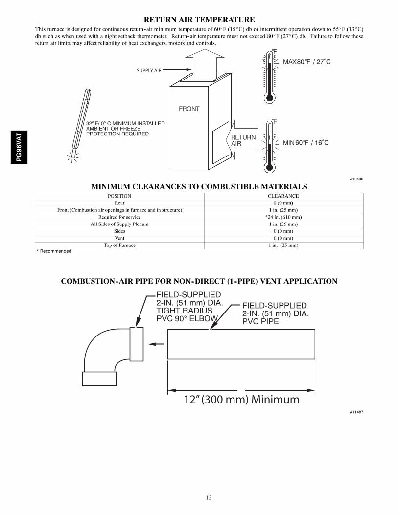
RETURN AIR TEMPERATUREThis furnace is designed for continuous return--air minimum temperature of 60_F (15_C) db or intermittent operation down to 55_F (13_C)db such as when used with a night setback thermometer. Return--air temperature must not exceed 80_F (27_C) db. Failure to follow thesereturn air limits may affect reliability of heat exchangers, motors and controls.
60
80 / 27˚C
/ 16˚C
SUPPLY AIR
A10490
MINIMUM CLEARANCES TO COMBUSTIBLE MATERIALSPOSITION CLEARANCE
Rear 0 (0 mm)Front (Combustion air openings in furnace and in structure) 1 in. (25 mm)
Required for service *24 in. (610 mm)All Sides of Supply Plenum 1 in. (25 mm)
Sides 0 (0 mm)Vent 0 (0 mm)
Top of Furnace 1 in. (25 mm)* Recommended
COMBUSTION--AIR PIPE FOR NON--DIRECT (1--PIPE) VENT APPLICATION
FIELD-SUPPLIED2-IN. (51 mm) DIA.PVC PIPE
FIELD-SUPPLIED2-IN. (51 mm) DIA.TIGHT RADIUSPVC 90° ELBOW
12” (300 mm) MinimumA11487
PG96VAT
13
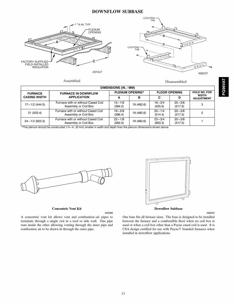
DOWNFLOW SUBBASELOCATING
TAB
LOCATINGTAB
1 2 3 4
4 3 2 1
B
D
C
A
1 1/4-IN. TYP
PLENUMOPENING
FACTORY-SUPPLIEDFIELD-INSTALLED
INSULATION
Assembled Disassembled
A97427 A88207
DIMENSIONS (IN. / MM)
FURNACECASING WIDTH
FURNACE IN DOWNFLOWAPPLICATION
PLENUM OPENING* FLOOR OPENING HOLE NO. FORWIDTH
ADJUSTMENTA B C D
17---1/2 (444.5) Furnace with or without Cased CoilAssembly or Coil Box
15---1/8(384.2) 19 (482.6) 16---3/4
(425.5)20---3/8(517.5) 3
21 (533.4) Furnace with or without Cased CoilAssembly or Coil Box
18---5/8(396.4) 19 (482.6) 20---1/4
(514.4)20---3/8(517.5) 2
24---1/2 (622.3) Furnace with or without Cased CoilAssembly or Coil Box
22---1/8(562.0) 19 (482.6) 23---3/4
(603.3)20---3/8(517.5) 1
*The plenum should be constructed 1/4---in. (6 mm) smaller in width and depth than the plenum dimensions shown above.
Concentric Vent KitA93086
A concentric vent kit allows vent and combustion--air pipes toterminate through a single exit in a roof or side wall. One piperuns inside the other allowing venting through the inner pipe andcombustion air to be drawn in through the outer pipe.
Downflow SubbaseA88202
One base fits all furnace sizes. The base is designed to be installedbetween the furnace and a combustible floor when no coil box isused or when a coil box other than a Payne cased coil is used. It isCSA design certified for use with PayneR branded furnaces wheninstalled in downflow applications.
PG96VAT
14
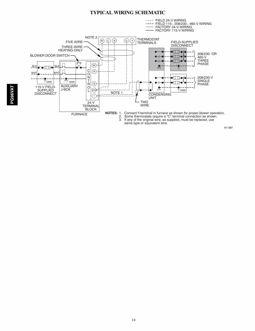
TYPICAL WIRING SCHEMATIC
115-V FIELD-SUPPLIED
DISCONNECT
AUXILIARYJ-BOX
24-VTERMINAL
BLOCK
THREE-WIREHEATING-ONLY
FIVE WIRE
NOTE 1
NOTE 2FIELD-SUPPLIEDDISCONNECT
CONDENSINGUNIT
TWOWIRE
FURNACE
CONTROL
R
G
COM
W C R G Y
GND
GND
FIELD 24-V WIRINGFIELD 115-, 208/230-, 460-V WIRINGFACTORY 24-V WIRINGFACTORY 115-V WIRING
208/230- OR460-VTHREEPHASE
208/230-VSINGLEPHASE
BLOWER DOOR SWITCH
WHT
BLK
WHT
BLK
NOTES: Connect Y-terminal in furnace as shown for proper blower operation.Some thermostats require a "C" terminal connection as shown.If any of the original wire, as supplied, must be replaced, usesame type or equivalent wire.
W
Y
GND
THERMOSTATTERMINALS
1.2.3.
A11387
PG96VAT
15
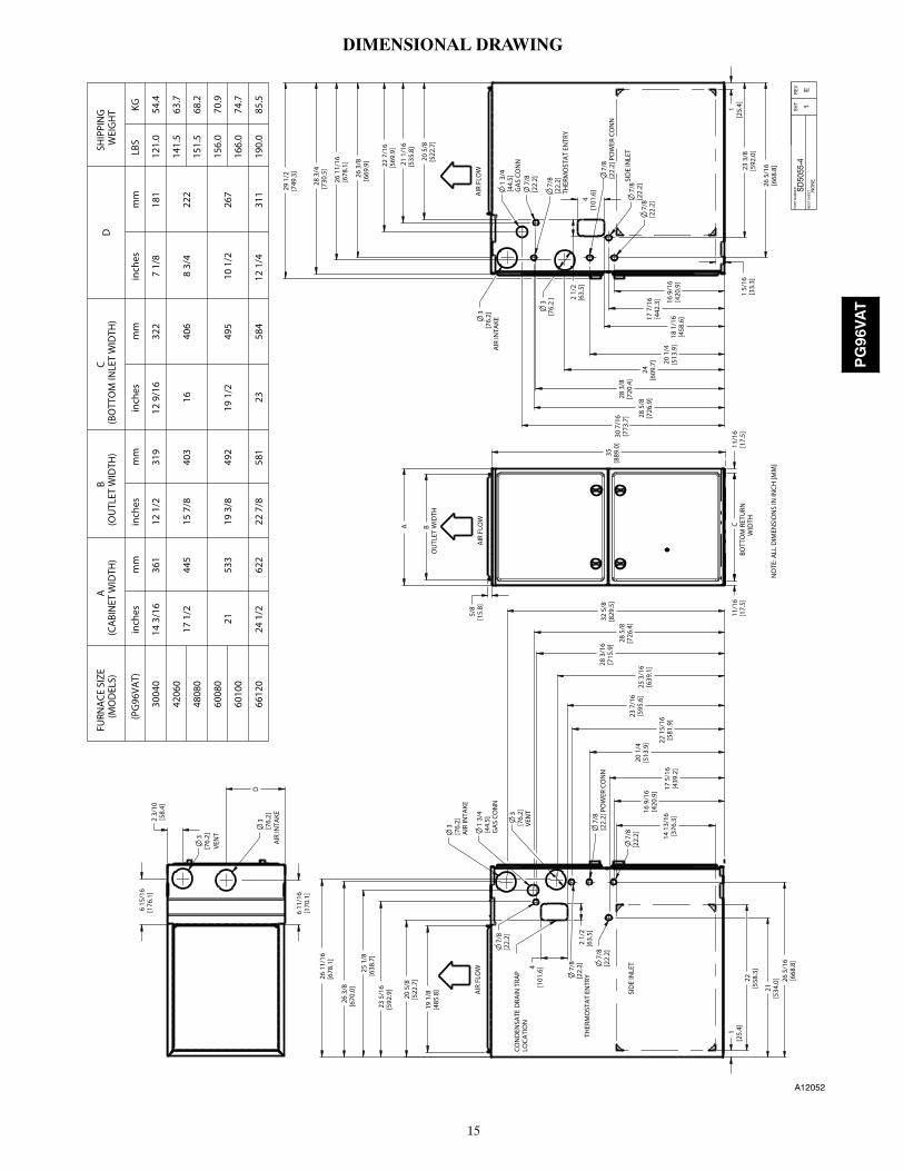
DIMENSIONAL DRAWING
6 15
/16
[176
.1]
3[7
6.2]
3[7
6.2]
6 11
/16
[170
.1]
23 5
/16
[592
.9]
25 1
/8[6
38.7
]
26 3
/8[6
70.0
]
26
11/1
6[6
78.1
]
21[5
34.0
] 26 5
/16
[668
.8]
17 5
/16
[439
.2]
16 9
/16
[420
.9]
20 1
/4[5
13.9
]25
3/1
6[6
39.1
]28 3
/16
[715
.9] 28
5/8
[726
.4]
32 5
/8[8
29.5
]
28 3
/4[7
30.5
]
26 3
/8[6
69.9
]
26 1
1/16
[678
.1] 22
7/1
6[5
69.9
]
21 1
/16
[535
.8]
26 5
/16
[668
.8]
3[7
6.2]
AIR
INTA
KE
1 3/
4[4
4.5]
GA
S CO
NN
7/8
[22.
2]
7/8
[22.
2] P
OW
ER C
ON
N
7/8
[22.
2]
7/8
[22.
2]
3[7
6.2]
AIR
INTA
KE1
3/4
[44.
5]G
AS
CON
N7/
8[2
2.2]
7/8
[22.
2]TH
ERM
OST
AT
ENTR
Y
3[7
6.2
]
7/8
[22.
2]7/
8[2
2.2]
22 1
5/16
[581
.9]
16 9
/16
[420
.9]
17 7
/16
[442
.3]
20 1
/4[5
13.9
]
24[6
09.7
]
28 3
/8[7
20.4
]
28 5
/8[7
26.9
]
30 7
/16
[773
.7]
23 3
/8[5
92.0
]
3[7
6.2]
VEN
T
1[2
5.4]
1[2
5.4]
D
2 3/
10[5
8.4]
CBO
TTO
M R
ETU
RNW
IDTH
11/1
6[1
7.5]
11/1
6[1
7.5]
BO
UTL
ET W
IDTH
A
22[5
58.3
]
14 1
3/16
[376
.3]
35[8
89.0
]
5/8
[15.
8]
1 5/
16[3
3.3]
29 1
/2[7
49.3
]
19 1
/8[4
85.8
]
20 5
/8[5
22.7
]
23 7
/16
[595
.6]
[101
.6]4
[63.
5]2
1/2
18 1
/16
[458
.6]
2 1/
2[6
3.5]
4[1
01.6
]
20 5
/8[5
22.7
]
PAR
T NU
MBE
R
S
D505
5-4
SH
T 1
RE
V E N
EXT
SHEE
T
NO
NE
VEN
T
AIR
INTA
KE
AIR
FLO
WA
IR F
LOW
SID
E IN
LET
SID
E IN
LET
CON
DEN
SATE
DRA
IN T
RAP
LOCA
TIO
N
NO
TE: A
LL D
IMEN
SIO
NS
IN IN
CH [M
M]
THER
MO
STA
T EN
TRY[2
2.2]7/
8
7/8
[22.
2] P
OW
ER C
ON
N
AIR
FLO
W
FURN
ACE
SIZ
E(M
OD
ELS)
A
(CA
BIN
ET W
IDTH
)B
(OU
TLET
WID
TH)
C(B
OTT
OM
INLE
T W
IDTH
)D
SHIP
PIN
G
WEI
GH
T
(PG
96VA
T)in
ches
mm
inch
esm
min
ches
mm
inch
esm
mLB
SKG
3004
014
3/1
636
112
1/2
319
12 9
/16
322
7 1/
818
112
1.0
54.4
4206
017
1/2
445
15 7
/840
316
406
8 3/
422
214
1.5
63.7
4808
015
1.5
68.2
6008
021
533
19 3
/849
219
1/2
495
10 1
/226
715
6.0
70.9
6010
016
6.0
74.7
6612
024
1/2
622
22 7
/858
123
584
12 1
/4
311
190.
085
.5
A12052
PG96VAT
16
GUIDE SPECIFICATIONSGeneralSystem DescriptionFurnish a ______________________ 4--way multipoise gas--firedcondensing furnace for use with natural gas or propane (factory--authorized conversion kit required for propane); furnish cold airreturn plenum.
Quality AssuranceUnit will be designed, tested and constructed to the current ANSI Z21.47/CSA 2.3 design standard for gas--fired central furnaces.
Unit will be third party certified by CSA to the current ANSI Z21.47/CSA 2.3 design standard for gas--fired central furnaces. Unitwill carry the CSA Blue StarR and Blue FlameR labels. Unitefficiency testing will be performed per the current DOE testprocedure as listed in the Federal Register.
Unit will be certified for capacity and efficiency and listed in thelatest AHRI Consumer’s Directory of Certified Efficiency Ratings.
Unit will carry the current Federal Trade Commission EnergyGuide efficiency label.
Delivery, Storage, and HandlingUnit will be shipped as single package only and is stored andhandled per unit manufacturer’s recommendations.
Warranty (for inclusion by specifying engineer)U.S. and Canada only. Warranty certificate available upon request.
EquipmentBlower Wheel and ECM Blower Motor
Galvanized blower wheel shall be centrifugal type, statically anddynamically balanced. Blower motor of ECM type shall bepermanently lubricated with sealed ball bearings, of _______hp,and have infinitely variable speed from 600--1200 RPM operatingonly when motor inputs are provided. Blower motor shall be directdrive and soft mounted to the blower scroll to reduce vibrationtransmission.
Filters
Furnace shall have reusable--type filters. Filter shall be ______ in.(mm) X ________ in. (mm). An accessory highly efficient MediaFilter is available as an option. _____________ Media Filter.
Casing
Casing shall be of .030 in. thickness minimum, pre--paintedgalvanized steel.
Draft Inducer Motor
Draft inducer motor shall be two--speed design.
Primary Heat Exchangers
Primary heat exchangers shall be 3--Pass corrosion-- resistantaluminized steel of fold--and--crimp sectional design and appliedoperating under negative pressure.
Secondary Heat Exchangers
Secondary heat exchangers shall be of a stainless steelflow--through of fin--and--tube design and applied operating undernegative pressure.
Controls
Controls shall include a micro--processor--based integratedelectronic control board with at least 16 service troubleshootingcodes displayed via diagnostic flashing LED light on the control, aself--test feature that checks all major functions of the furnace, anda replaceable automotive--type circuit protection fuse. Multipleoperational settings available, including separate blower speeds forlow heat, high heat, low cooling, high cooling and continuous fan.Continuous fan speed may be adjusted from the thermostat.Cooling airflow will be selectable between 325 and 400 CFM perton of air conditioning. Features will also include temporaryreduced airflow in the cooling mode for improveddehumidification when an Evolution Control or T6--PRH isselected as the thermostat.
Operating CharacteristicsHeating capacity shall be _________________ Btuh input;______________ Btuh output capacity.
Fuel Gas Efficiency shall be________ AFUE.
Air delivery shall be ________________ cfm minimum at 0.50 in.W.C. external static pressure.
Dimensions shall be: depth_________in. (mm); width__________in. (mm); height___________in. (mm) (casing only).Height shall be _________in. (mm) with A/C coil and_________________in. (mm) overall with plenum.
Electrical RequirementsElectrical supply shall be 115 volts, 60 Hz, single--phase (nominal).Minimum wire size shall be ________AWG; maximum fuse sizeof HACR--type designated circuit breaker shall be _________amps.
Special FeaturesRefer to section of the product data identifying accessories anddescriptions for specific features and available enhancements.
E2012 Payne Heating & Cooling Systems D 7310 W. Morris St. D Indianapolis, IN 46231 Printed in U.S.A. Edition Date: 03/12
Manufacturer reserves the right to change, at any time, specifications and designs without notice and without obligations.
Catalog No: SS---PG96VAT---01Replaces: New
PG96VAT