Embed Size (px)
Citation preview

The ENI-ZNT200/UKR/072016 is a complete motive power transmission and control system intended for the ELECTRONTRANS T19102-10 trolleybus. System features: .
propulsion and braking (with regeneration) at high efficiency, dynamic and reliability ratings,24 V and 3 × 400 V power supply for onboard auxiliary systems,DC AC
advanced diagnostic and servicing functionalities,power consumption monitoring.
The precise scope of the design, delivery and installation is adaptable to suit custom project requirements, the following being indicative only. .
Scope of deliverables:electrical design of the power transmission system and the trolleybus unit,software programming of all components,commissioning with assistance in static and dynamic testing; approval,operator and maintenance service training.
The scope of the system deliverables includes the main assemblies:
ENIKA Sp. z o.o. ul. Morgowa 1191-223 Łódź
tel. +48 42 652 15 55, +48 42 652 16 14faks +48 42 652 16 11e-mail: [email protected]
Page 1/6
ENI-ZNT200/UKR/072016 System
Power transmission box ENI-ZNT200/UKR/072016 (x1)Page: 2-4
Trolleybus controller panel ENI-SNT/TB/UKR/072016 (x1)Page: 5
Control panel ETC.2-084 (x1)Page: 6
Product Data Sheet
Page 2/6
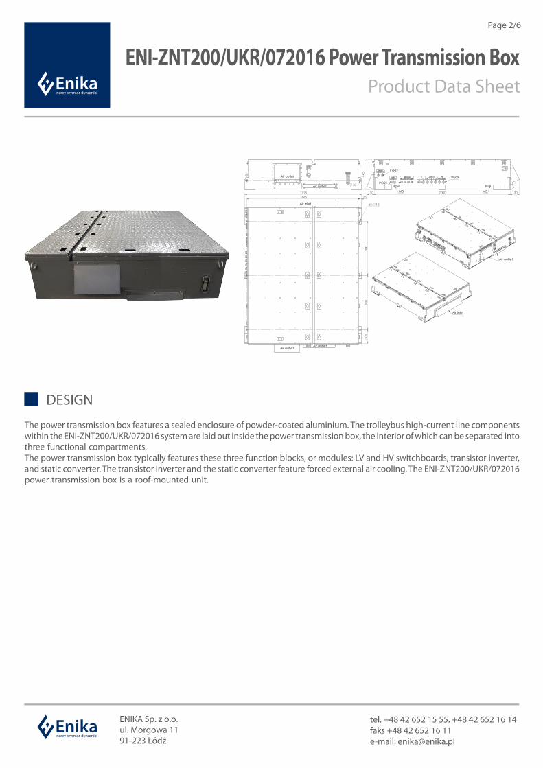
ENI-ZNT200/UKR/072016 Power Transmission BoxProduct Data Sheet
ENIKA Sp. z o.o. ul. Morgowa 1191-223 Łódź
tel. +48 42 652 15 55, +48 42 652 16 14faks +48 42 652 16 11e-mail: [email protected]
DESIGN
The power transmission box features a sealed enclosure of powder-coated aluminium. The trolleybus high-current line components within the ENI-ZNT200/UKR/072016 system are laid out inside the power transmission box, the interior of which can be separated into three functional compartments. .The power transmission box typically features these three function blocks, or modules: LV and HV switchboards, transistor inverter, and static converter. The transistor inverter and the static converter feature forced external air cooling. The ENI-ZNT200/UKR/072016 power transmission box is a roof-mounted unit. .

Page 3/6
ENIKA Sp. z o.o. ul. Morgowa 1191-223 Łódź
tel. +48 42 652 15 55, +48 42 652 16 14faks +48 42 652 16 11e-mail: [email protected]
Rated input voltageSupply voltage variationRated output voltageOutput frequencyRated power outputMaximum power outputMaximum instantaneous current amplitude
550 VDC
400 to 720 V (peak 900 V )DC DC
3 x 400 V, 50 Hz0 to 200 Hz180 kW320 kW660 A
INVERTER
DESIGN AND APPLICATIONThe onboard inverter provides a controlled-frequency AC voltage supply for the asynchronous traction motor. The inverter features a dedicated microprocessor controller supervised by the SNT trolleybus controller, and both communicate with each other via the CAN bus. Current monitoring of both the power transmission system status and vehicle starting parameters is provided through a CAN-connected control panel. The power transmission system enables low-voltage driving at 60 V to 110 VDC (e.g. for passing a drive-through wash). The inverter also enables current filter switching (with the current levels preset in the firmware). The power transmission system prevents the trolleybus starting current from energizing any unwanted resistors and enables braking energy recovery to the contact system at its maximum permissible levels. If the contact system cannot receive the whole energy recovered from braking due to a risk of overvoltage, the trolleybus power transmission system dissipates the surplus energy in a resistor, thus maintaining the maximum permitted voltage over the contact system. A contact system voltage loss, or a dip below the minimum permitted limit, blocks the braking energy recovery to the contact system. The trolleybus controller activates a full resistor braking mode. If the braking energy recovery has not been turned on or it has been interrupted, the controller starts or resumes the process whenever the prerequisites for doing so are met. The power transmission system does not emit any high, onerous noise or squeal under normal operating conditions. The average power consumption of the trolleybus in normal urban traffic conditions with the onboard heating system off is 1.4 kWh/km max. .
The traction inverter comprises:a fully controlled power electronic IGBT reverser,a three-phase IGBT bridge,an electromagnetic braking system based on an IGBT module,a power filter, formed by a bank of C-capacitors and an L-choke,a control system, comprising: an onboard controller power supply unit and a PWM modulator, which outputs transistor switch control signals, .sensor array for monitoring the traction inverter.
SPECIFICATIONS
FUNCTIONAL MODULES
ENI-ZNT200/UKR/072016 Power Transmission BoxProduct Data Sheet
Page 4/6
ENIKA Sp. z o.o. ul. Morgowa 1191-223 Łódź
tel. +48 42 652 15 55, +48 42 652 16 14faks +48 42 652 16 11e-mail: [email protected]
Rated input voltageSupply voltage variation
Rated output voltageDC rated line currentOutput overload capacityStartingBackupProtection systems
Rated output voltageDC rated line currentOutput overload capacityStartingBackupProtection systems
Rated output voltageNominal voltageRated output currentProtection systems
550 VDC
400 to 720 V (peak 900 V )DC DC
3 x 400 V, 50 Hz10A200% in 1 sU/f = const, adjustable time from 1 to 4 sNoOverload and shorting
3 x 400 V, 50 Hz10 A200% in 1 sU/f = const, adjustable time from 1 to 4 s24 VDC source, for 10 seconds of HV outageOverload and shorting
27,8 ± 0,5 V24 VDC
200 AOverload and shorting
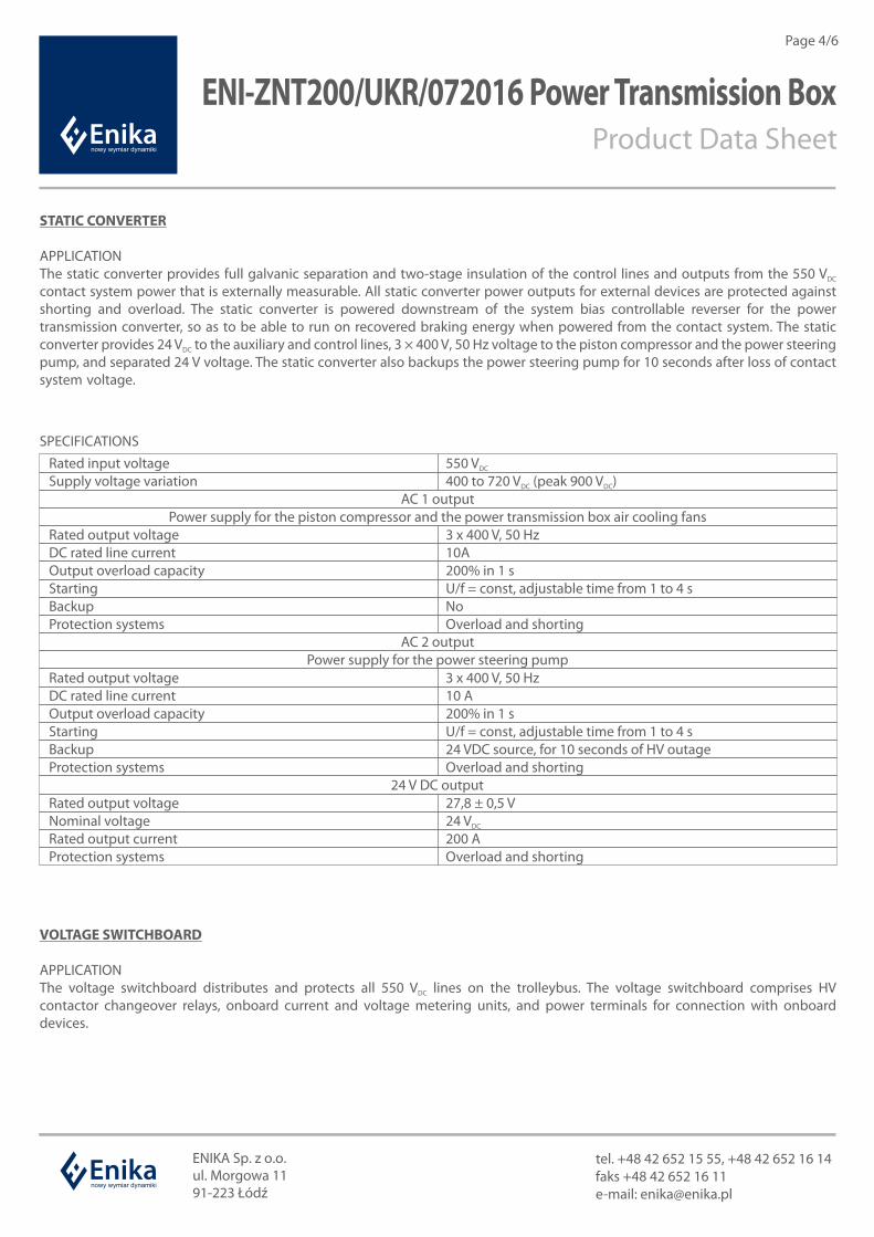
STATIC CONVERTER
APPLICATIONThe static converter provides full galvanic separation and two-stage insulation of the control lines and outputs from the 550 V DC
contact system power that is externally measurable. All static converter power outputs for external devices are protected against shorting and overload. The static converter is powered downstream of the system bias controllable reverser for the power transmission converter, so as to be able to run on recovered braking energy when powered from the contact system. The static converter provides 24 V to the auxiliary and control lines, 3 × 400 V, 50 Hz voltage to the piston compressor and the power steering DC
pump, and separated 24 V voltage. The static converter also backups the power steering pump for 10 seconds after loss of contact system voltage. .
SPECIFICATIONS
AC 1 outputPower supply for the piston compressor and the power transmission box air cooling fans
AC 2 outputPower supply for the power steering pump
24 V DC output
VOLTAGE SWITCHBOARD
APPLICATIONThe voltage switchboard distributes and protects all 550 V lines on the trolleybus. The voltage switchboard comprises HV DC
contactor changeover relays, onboard current and voltage metering units, and power terminals for connection with onboard devices.
ENI-ZNT200/UKR/072016 Power Transmission BoxProduct Data Sheet

Page 5/6
ENI-SNT/TB/UKR/072016 Trolleybus Controller PanelProduct Data Sheet
APPLICATION
The trolleybus controller panel features an integrated PLC and relays to control the power transmission system components. The control is handled by a dedicated algorithm that processes the input states and CAN bus inputs. .
ENIKA Sp. z o.o. ul. Morgowa 1191-223 Łódź
tel. +48 42 652 15 55, +48 42 652 16 14faks +48 42 652 16 11e-mail: [email protected]
Supply voltage 24 VDC
Digital inputs 32 × inputs (modules: 2 × 16 Dl)Digital outputs 32 × 4 A relay outputs (modules: 2 × 16 DO)Analogue inputs 8 × 4 – 20 mA / 0-10 V / PT100DC
Communication interfaces 3 × CAN
SPECIFICATIONS
Page 6/6
ETC.2-084 Control PanelProduct Data Sheet
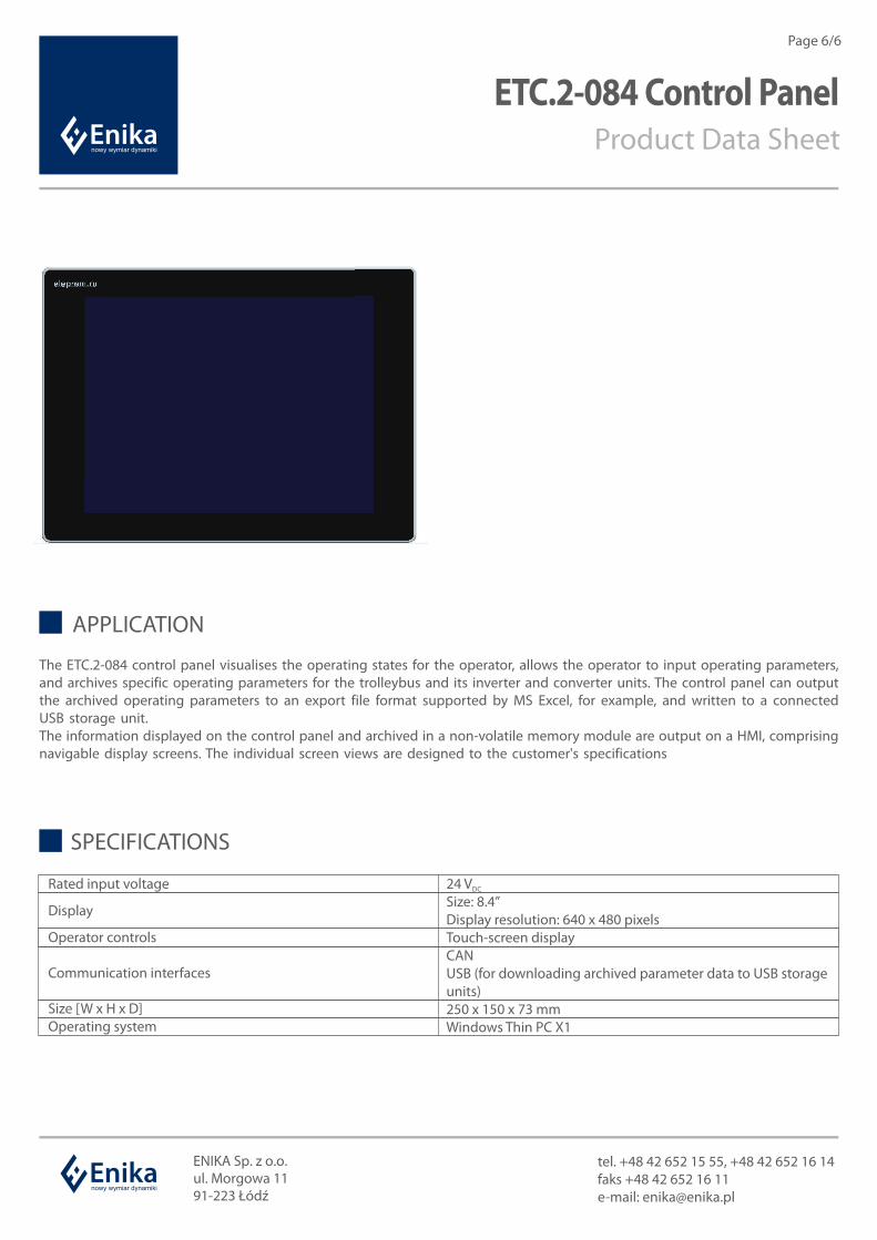
APPLICATION
The ETC.2-084 control panel visualises the operating states for the operator, allows the operator to input operating parameters, and archives specific operating parameters for the trolleybus and its inverter and converter units. The control panel can output the archived operating parameters to an export file format supported by MS Excel, for example, and written to a connected USB storage unit. .The information displayed on the control panel and archived in a non-volatile memory module are output on a HMI, comprising navigable display screens. The individual screen views are designed to the customer's specifications .
ENIKA Sp. z o.o. ul. Morgowa 1191-223 Łódź
tel. +48 42 652 15 55, +48 42 652 16 14faks +48 42 652 16 11e-mail: [email protected]
Rated input voltage
Display
Operator controls
Communication interfaces
Size [W x H x D]Operating system
24 VDC
Size: 8.4”Display resolution: 640 x 480 pixelsTouch-screen displayCANUSB (for downloading archived parameter data to USB storage units)250 x 150 x 73 mmWindows Thin PC X1
SPECIFICATIONS