Embed Size (px)
Citation preview

Product Data SheetOctober 2013
00813-0100-4690, Rev NB
Rosemount 2088 Absolute and Gage Pressure Transmitter
Performance of 0.065% with High Accuracy option
Lightweight, compact design for cost-effective installation
Protocols available include 4-20 mA HART® and 1-5 Vdc HART Low Power
Absolute and gage pressure ranges up to 4,000 psi (276 bar)
Rangeability of 50:1

Rosemount 2088 October 2013
Rosemount 2088 Pressure Transmitter Product Offering
Proven Reliability for Gage and Absolute Applications
Available protocols include 4-20 mA HART® and 1-5 Vdc HART Low Power
Fully Configurable LCD to display process variable, percent of range, and diagnostic messages
Lightweight, compact design enables easy installation
Choice of Stainless Steel or Alloy C-276 wetted materials
Unlock the Value of Devices with the Smart Wireless THUM™ Adapter
Gain access to field intelligence and improve quality, safety, availability, operations, and maintenance costs
Remotely manage devices and monitor health
Enable new wireless measurement points
Utilize existing loop power
Proven, Reliable, and Innovative DP Level Technologies
Connect to virtually any process with a comprehensive offering of process connections, fill fluids, direct mount or capillary connections and materials
Quantify and optimize total system performance with QZ option
Instrument Manifolds – Quality, Convenient, and Easy
Designed and engineered for optimal performance with Rosemount transmitters
Save installation time and money with factory assembly
Offers a variety of styles, materials, and configurations
2 www.rosemount.com
Contents
Rosemount 2088 In-line Pressure Transmitter . . . page 3
Specifications . . . . . . . . . . . . . . . . . . . . . . . . . . . . . . . page 8
Product Certifications . . . . . . . . . . . . . . . . . . . . . . .page 11
Dimensional Drawings . . . . . . . . . . . . . . . . . . . . . . .page 14

Rosemount 2088October 2013
Rosemount 2088 In-line Pressure Transmitter
Ordering Information
Configuration Transmitter Output Code
4-20 mA HART® S
- 2088 with Selectable HART
1-5 Vdc Low PowerN
- 2088 with Selectable HART
Table 1. Rosemount 2088 Pressure Transmitter Ordering Information★ The Standard offering represents the most common options. The starred options (★) should be selected for best delivery.
__The Expanded offering is manufactured after receipt of order and is subject to additional delivery lead time.
Model Product description
Standard Standard2088 Pressure Transmitter ★
Code Measurement Type
Standard Standard
A Absolute ★
G Gage ★
Code Pressure Ranges
Standard Standard
2088G 2088A
1 -14.7 to 30 psi /(-1,01 to 2,1 bar) 0 to 30 psi (0 to 2,1 bar) ★
2 -14.7 to 150 psi (-1,01 to 10,3 bar) 0 to 150 psi (0 to 10,3 bar) ★
3 -14.7 to 800 psi (-1,01 to 55,2 bar) 0 to 800 psi (0 to 55,2 bar) ★
4 -14.7 to 4,000 psi (-1,01 to 275,8 bar) 0 to 4,000 psi (0 to 275,8 bar) ★
Code Transmitter Output
Standard Standard
S(1) 4–20 mA dc/Digital HART® Protocol ★
N(1) 1-5 Vdc Low Power/ Digital HART protocol ★
Additional Information
Specifications : page 8Product Certifications : page 11Dimensional Drawings : page 14
3www.rosemount.com

Rosemount 2088 October 2013
Code Materials of Construction
Standard Standard
Process connection Isolating diaphragm Fill Fluid
22(2) 316L SST 316L SST Silicone ★
33(2) Alloy C-276 Alloy C-276 Silicone ★
Expanded
2B(2) 316L SST 316L SST Inert
Code Process Connection
Standard Standard
A ½–14 NPT Female ★
B(3) DIN 16288 G ½ Male ★
D(3)(4) M20 � 1.5 Male ★
Expanded
C(3)(4) RC ½ Female
Code Conduit Entry
Standard Standard
1 ½–14 NPT ★
2(3) M20 � 1.5 ★
Expanded
4(3) G ½
Options (Include with selected model number)
Diaphragm Seal Assemblies
Standard Standard
S1(5) (6) Assemble to one Rosemount 1199 diaphragm seal ★
Display and Interface
Standard Standard
M4 LCD Display with Local Operator Interface ★
M5 LCD Display, configured for Engineering Units ★
Configuration Buttons
Standard Standard
D4 Analog Zero and Span ★
DZ Digital Zero Trim ★
Mounting Brackets
Standard Standard
B4 SST mounting bracket with SST Bolts ★
Table 1. Rosemount 2088 Pressure Transmitter Ordering Information★ The Standard offering represents the most common options. The starred options (★) should be selected for best delivery.
__The Expanded offering is manufactured after receipt of order and is subject to additional delivery lead time.
4 www.rosemount.com

Rosemount 2088October 2013
Product Certifications
Standard Standard
C6 CSA Explosion-Proof, Intrinsically Safe, and non-Incendive ★
E2 INMETRO Flameproof ★
E3 China Flameproof ★
E4(3)(7) TIIS Flameproof ★
E5 FM Explosion-Proof, Dust Ignition-proof ★
E7 IECEx Flameproof ★
ED ATEX Flameproof ★
I1(3) ATEX Intrinsic Safety ★
I2 INMETRO Intrinsic Safety ★
I3 China Intrinsic Safety ★
I5 FM Intrinsically safe, Division 2 ★
I7 IECEx Intrinsic Safety ★
K1 ATEX Flameproof, Intrinsic Safety, Type n, Dust ★
K2 INMETRO Flameproof, Intrinsic Safety ★
K5 FM Explosion-Proof, Dust Ignition-proof, Intrinsically Safe, Division 2 ★
K6(3) ATEX and CSA Explosion-Proof, Dust Ignition-proof, Intrinsically Safe, Division 2 ★
K7 IECEx Flameproof, Intrinsic Safety, Type n, Dust ★
KB FM and CSA Explosion-Proof, Dust Ignition-proof, Intrinsically Safe, Division 2 ★
KH(3) FM Approvals and ATEX Explosion-Proof and Intrinsically Safe ★
N1(3) ATEX Type n ★
N3 China Type n ★
N7 IECEx Type n ★
ND(3) ATEX Dust ★
NK IECEx Dust ★
Shipboard Approvals
Standard Standard
SBS American Bureau of Shipping (ABS) Type Approval ★
SBV Bureau Veritas (BV) Type Approval ★
SDN Det Norske Veritas (DNV) Type Approval ★
SLL Lloyd's Register (LR) Type Approval ★
Pressure Testing
Expanded
P1 Hydrostatic testing
Terminal Blocks
Standard Standard
T1 Transient protection ★
Special Cleaning
Expanded
P2 Cleaning for special service
Calibration Certificate
Standard Standard
Q4 Calibration certificate ★
Table 1. Rosemount 2088 Pressure Transmitter Ordering Information★ The Standard offering represents the most common options. The starred options (★) should be selected for best delivery.
__The Expanded offering is manufactured after receipt of order and is subject to additional delivery lead time.
5www.rosemount.com

Rosemount 2088 October 2013
Quality Calibration Certificate Traceability Certification
Standard Standard
Q8 Material Traceability Certification per EN 10204 3.1 ★
Q15 Certificate of Compliance to NACE MR0175/ISO 15156 for wetted materials ★
Q25 Certificate of Compliance to NACE MR0103 for wetted materials ★
Digital Signal
Standard Standard
C4(3) NAMUR alarm and saturation levels, high alarm ★
CN(3) NAMUR alarm and saturation levels, low alarm ★
C5 (8)(9) Custom alarm and saturation levels, high alarm, (Requires C9 and Configuration Data Sheet) ★
C7(8)(9) Custom alarm and saturation levels, low alarm (Requires C9 and Configuration Data Sheet) ★
C8(9) Low alarm (Standard Rosemount Alarm and Saturation Levels) ★
Configuration
Standard Standard
C9 Software configuration ★
Manifold Assemblies
Standard Standard
S5(5)(6) Assemble to Rosemount 306 integral manifold ★
Calibration Accuracy
Standard Standard
P8(10) 0.065% accuracy to 10:1 turndown ★
Water Approval
Standard Standard
DW(11) NSF drinking water approval ★
Surface Finish
Standard Standard
Q16 Surface finish certification for sanitary remote seals ★
Toolkit Total System Performance Reports
Standard Standard
QZ Remote Seal System Performance Calculation Report ★
HART Revision Configuration
Standard Standard
HR 5(9)(12) Configured for HART Revision 5 ★
HR7 (9)(13) Configured for HART Revision 7 ★
Typical Model Number: 2088 G 2 S 22 A 1 B4 M5
(1) HART Revision 5 is the default HART output. The 2088 with selectable HART can be factory or field configured to HART Revision 7. To order HART Revision 7 factory configured, add option code HR7.
Table 1. Rosemount 2088 Pressure Transmitter Ordering Information★ The Standard offering represents the most common options. The starred options (★) should be selected for best delivery.
__The Expanded offering is manufactured after receipt of order and is subject to additional delivery lead time.
6 www.rosemount.com
Rosemount 2088October 2013
(2) Materials of Construction comply with recommendations per NACE MR0175/ISO 15156 for sour oil field production environments. Environmental limits apply to certain materials. Consult latest standard for details. Selected materials also conform to NACE MR0103 for sour refining environments.
(3) Not available with low-power Transmitter Output code N.
(4) Not available with Alloy C-276, Material of Construction code 33.
(5) Use 1/2 - 14 NPT Female Process Connection code A.
(6) “Assemble-to” items are specified separately and require a completed model number.
(7) Only available with Conduit Thread code 4.
(8) Only available with 4-20 mA HART Output (Output Code A).
(9) Select Configuration Buttons (option code D4 or DZ) or Local Operator Interface (option code M4) if local configuration buttons are required.
(10) Requires Transmitter Output code S with either Materials of Construction code 22 or 23.
(11) Requires Materials of Construction code 22 with Process Connection code A.
(12) Configures the HART output to HART Revision 5. The device can be field configured to HART Revision 7 if needed.
(13) Configures the HART output to HART Revision 7. The device can be field configured to HART Revision 5 if needed.
7www.rosemount.com

Rosemount 2088 October 2013
Specifications
Performance SpecificationsFor zero-based spans, reference conditions, silicone oil fill, 316L SST isolating diaphragm.
Reference Accuracy±0.075% of calibrated span. Includes combined effects of
linearity, hysteresis, and repeatability±0.065% of calibrated span (high accuracy option - P8)For spans less than 10:1, accuracy =
± % of Span
Ambient Temperature EffectExpressed as a total effect per 50 °F (28 °C)Total effect includes zero and span effects.± (0.15% URL + 0.15% of span)
StabilityRanges 2-4: ±0.10% of URL for 3 yearsRange 1: ±0.10% of URL for 1 year
Vibration EffectLess than ±0.1% of URL when tested per the requirements of IEC60770-1 field or pipeline with high vibration level (10 - 60 Hz 0.21 mm displacement peak amplitude / 60 - 2000 Hz 3g).
Power Supply EffectLess than ±0.005% of calibrated span per volt change in voltage at the transmitter terminals.
Mounting Position EffectZero shifts to ±2.5 inH2O (6,22 mbar), which can be zeroed Span: no effect
Transient ProtectionTested in accordance with IEEE C62.41.2-2002,Location Category B6 kV crest (0.5 s - 100 kHz)3 kA crest (8 x 20 microseconds)6 kV crest (1.2 x 50 microseconds)
General SpecificationsTested to IEC 801-3
Functional Specifications
Table 2. 2088 Range Values
OutputCode S: 4–20 mACode N: 1-5 Vdc, low power(Outputs are directly proportional to the input pressure)
Selectable HARTDigital communications based on HART Revision 5 (default) or Revision 7 (option code HR7) protocol can be selected. The HART revision can be switched in the field using any HART based configuration tool or the optional local operator interface (LOI).
ServiceLiquid, gas, and vapor applications
Power SupplyExternal power supply required. Transmitter operates on 10.5–42.4 Vdc with no load (5.8-28 V for Low Power). Reverse polarity protection is standard.
0.009URL
Span-------------
RangeMinimum
SpanUpper(URL)
Lower (LRL)
Lower(1)
(LRL) (Gage)
(1) Assumes atmospheric pressure of 14.70 psia (1,01 bar-a).
10.60 psi
(41,37 mbar)30.00 psi(2,07 bar)
0 psia(0 bar)
–14.70 psig(–1,01 bar)
23.00 psi
(206,85 mbar)150.00 psi(10,34 bar)
0 psia(0 bar)
–14.70 psig(–1,01 bar)
316.00 psi(1,11 bar)
800.00 psi(55,16 bar)
0 psia(0 bar)
–14.70 psig(–1,01 bar)
480.00 psi(5,52 bar)
4000.00 psi(275,79 bar)
0 psia(0 bar)
–14.70 psig(–1,01 bar)
8 www.rosemount.com

Rosemount 2088October 2013
Load Limitations
Reverse polarity protection is standard. Maximum loop resistance is determined by the power supply voltage as described by the following equations:
Figure 1. Maximum loop resistance
IndicationOptional two line LCD/LOI Display.
Zero and Span Adjustment RequirementsZero and span values can be set anywhere within the range limits stated in Table 2 on page 8. Span must be greater than or equal to the minimum span stated in Table 2 on page 8.
Local Operator InterfaceThe LOI utilizes a 2 button menu with internal and external configuration buttons. Internal buttons are always configured for Local Operator Interface. External Buttons can be configured for either LOI, (option code M4), Analog Zero and Span (option code D4) or Digital Zero Trim (option code DZ) for LOI configuration menu.
Current DrawOutput Code N: 3 mA.
Overpressure LimitsRange 1: 120 psig maxAll other ranges: two times the URL
Burst Pressure11,000 psi for all ranges
Zero Elevation and SuppressionZero can be suppressed between atmosphere for gage transmitters or 0 psia for absolute transmitters and upper range limit, provided the calibrated span is equal to or greater than the minimum span, and the upper range value does not exceed the upper range limit.
Dynamic PerformanceTotal Response Time: 145 millisecondsUpdate rate: 20 times per second minimum
Temperature Limits
Ambient: -40 to 185 °F (–40 to 85 °C)With LCD display(1): -40 to 176 °F (–40 to 80 °C)
Storage(1):
-50 to 230 °F (-46 to 110 °C)With LCD display: –40 to 185 °F (–40 to 85 °C) ProcessSilicone fill sensor: –40 to 250 °F (–40 to 121 °C)(2)
Inert fill sensor: –22 to 250 °F (–30 to 121 °C)(2)
Process temperatures above 185 °F (85 °C) require derating the ambient limits by a 1.5:1 ratio. For example, for process temperature of 195 °F (91 °C), new ambient temperature limit is equal to 170 °F (77 °C). This can be determined as follows: (195 °F - 185 °F) x 1.5 = 15 °F, 185 °F - 15 °F = 170 °F
Humidity Limits0–100% relative humidity
Volumetric DisplacementLess than 0.0005 in3 (0,008 cm3)
DampingAnalog output response time to a step change is user-selectable from 0 to 60 seconds for one time constant. Software damping is in addition to sensor module response time.
Turn-on Time2.0 seconds, no warm-up required
Transmitter SecurityActivating the transmitter security function prevents changes to the transmitter configuration, including local zero and span adjustments. Security is activated by an internal switch.
Failure Mode AlarmIf self-diagnostics detect a sensor or microprocessor failure, the analog signal will be driven either high or low to alert the user. High or low failure mode is user-selectable with a jumper on the transmitter. The values to which the transmitter drives its output in failure mode depend on whether it is factory-configured to standard or NAMUR-compliant operation. The values for each are as follows:
Load
(ohm
s)
Operating Region
Voltage (Vdc)
Max. Loop Resistance = 43.5 (Power Supply Voltage – 10.5)
1387
1000
500
0
10.5 20 30 42.4
The Field communicator requires a minimum loop resistance of 250W for communication.
(1) If storage temperature is above 85 °C, perform a sensor trim prior to installation.
(2) 220 °F (104 °C) limit in vacuum service; 130 °F (54 °C) for pressures below 0.5 psia.
Standard Operation
Output Code Linear Output Fail High Fail Low
S 3.9 I 20.8 I 21.75 mA I 3.75 mAN 0.97 V 5.2 V 5.4 V V 0.95 V
NAMUR-Compliant Operation
Output Code Linear Output Fail High Fail Low
S 3.8 I 20.5 I 22.5 mA I 3.6 mA
9www.rosemount.com

Rosemount 2088 October 2013
Physical Specifications
Electrical Connections1/2–14 NPT, M20 � 1.5 (CM20), or G 1/2 female (PF 1/2 female) conduit entry
Process Connections1/2–14 NPT female, DIN 16288 G 1/2 male, RC 1/2 female(PT 1/2 female), M20 � 1.5 (CM20) male
Process-Wetted Parts
Isolating Diaphragm
316L SST (UNS S31603), Alloy C-276 (UNS N10276)
Process Connector
316L stainless steel CF-3M (Cast version of 316L SST, material per ASTM_A743) or Alloy C-276
Non-Wetted Parts
Electronics Housing
Low-copper aluminum, NEMA 4X, IP65, IP67,CSA enclosure Type 4X
Paint for Aluminum Housing
Polyurethane
Cover O-rings
Buna-N
Fill Fluid
Silicone or inert fill
Weight
Output Code S and N: Approximately 2.44 lb (1, 11 kg)
10 www.rosemount.com

Rosemount 2088October 2013
Product CertificationsApproved Manufacturing LocationsRosemount Inc. — Chanhassen, Minnesota, USAEmerson Process Management GmbH & Co. — Wessling, GermanyEmerson Process Management Asia Pacific Private Limited — SingaporeBeijing Rosemount Far East Instrument Co., LTD — Beijing, China
European Directive InformationThe EC declaration of conformity for all applicable European directives for this product can be found at www.rosemount.com. A hard copy may be obtained by contacting an Emerson Process Management representative.
ATEX Directive (94/9/EC)Emerson Process Management complies with the ATEX Directive.
European Pressure Equipment Directive (PED) (97/23/EC)2088/2090 Pressure Transmitters— Sound Engineering Practice
Electro Magnetic Compatibility (EMC) (2004/108/EC)EN 61326-1:2006
Hazardous Locations Certifications
North American CertificationsFM Approvals
E5 Explosion-proof and Dust Ignition ProofCertificate No.: 1V2A8.AEApplicable Standards: FM Class 3600 - 1998, FM Class 3615 - 1989, FM Class 3810 - 1989Markings: Explosion-proof for Class I, Division 1, Groups B, C, and D. Dust Ignition-Proof for Class II/III, Division 1, Groups E, F and G.Temperature Code: T5 (Ta = -40 °C to + 85 °C) Factory Sealed, Enclosure Type 4X.For input parameters see control drawing 02088-1018.
I5 Intrinsically Safe and Non-IncendiveCertificate No.: 0V9A7.AXApplicable Standards: FM Class 3600 - 1998, FM Class 3610 - 2010, FM Class 3811 - 2004, FM Class 3810 - 1989.Markings: Intrinsically safe for use in Class I, Division 1, Groups A, B, C, D; Class II, Division 1, Groups E, F, and G; and Class III, Division 1 Temperature Code: T4 (Ta = 70 °C) in accordance with Rosemount drawing 02088-1018. Non-incendive for Class I, Division 2, Groups A, B, C, and D. Temperature Code: T4 (Ta = 85 °C), Enclosure Type 4X.For input parameters see control drawing 02088-1018.
Canadian Standards Association (CSA)
All CSA hazardous approved transmitters are certified per ANSI/ISA 12.27.01-2003.
C6 Explosion-Proof, Intrinsically Safe, Dust Ignition-Proof and Class I Division 2Applicable Standards: CAN/CSA Std. C22.2 No. 0-M91, CSA Std. C22.2 No. 25 - 1966, CSA Std. C22.2 No. 30 - M1986, CAN/CSA Std. C22.2 No. 94 - M91, CSA Std. C22.2 No. 142 - M1987, CAN/CSA Std. C22.2 No. 157-92, CSA Std. C22.2 No. 213 - M1987, ANSI/ISA 12.27.01-2003.Markings: Explosion-proof for Class I, Division 1, Groups B, C, and D. Dust-Ignition-Proof for Class II, Division 1, Groups E, F, G, Class III. Suitable for Class I, Division 2, Groups A, B, C, and D.Intrinsically Safe for Class I, Division 1, Groups A, B, C, and D. Temperature Code: T3C. Enclosure Type 4X. Factory sealed. Single Seal. See control drawing 02088-1024.
European CertificationsED ATEX Flameproof
Certification No.: KEMA97ATEX2378X Applicable Standards: EN60079-0:2006, EN60079-1:2007, EN60079-26:2007
Markings: II 1/2 G Ex d IIC T6 (-40 °C Tamb 40 °C); T4 (-40 °C Tamb 80 °C)
1180Vmax = 36 (with Output Code S) Vmax = 14 (with Output Code N)
Special Conditions for Safe Use (x):
1. The cable and conduit entry devices shall be of a certified flameproof type Ex d, suitable for the conditions of use and correctly installed.
2. With the use of conduit entries a sealing device shall be provided immediately on the entrance thereto.
3. Unused apertures shall be closed with suitable Ex d certified blanking elements.
4. Suitable heat-resisting cables shall be used when the ambient temperature at the cable or conduit entries exceed 65 °C.
5. This device contains a thin wall diaphragm. Installation, maintenance, and use shall take into account the environmental conditions to which the diaphragm will be subjected. The manufacturer's instructions for installation and maintenance shall be followed in detail to assure safety during its expected lifetime.
6. For information on the dimensions of the flameproof joints the manufacturer shall be contacted.
11www.rosemount.com

Rosemount 2088 October 2013
12 www.rosemount.com
I1 ATEX Intrinsic SafetyCertificate No.: BAS00ATEX1166XApplicable Standards: EN60079-0:2012, EN60079-11: 2012 Markings: II 1 G Ex ia IIC T5 Ga (–55 °C Tamb 40 °C)Ex ia IIC T4 Ga (–55 °C Tamb 70 °C)
1180
Table 3. Input Parameters
Special Conditions For Safe Use (x): 1. The apparatus is not capable of withstanding the 500V
insulation test required by EN60079-11. This must be taken into account when installing the apparatus.
N1 ATEX Non-incendive/Type n Certification No.: BAS 00ATEX3167X Applicable Standards: EN60079-0:2012, EN60079-15: 2010
Markings: II 3 GEx nA IIC T5 Gc (–40 °C Tamb 70 °C)Ui = 50 Vdc max
1180
1. Special Conditions For Safe Use (x): The apparatus is not capable of withstanding the 500V insulation test required by EN60079-15. This must be taken into account when installing the apparatus.
ND ATEX Dust Certificate No.: BAS01ATEX1427X Applicable Standards: EN60079-0:2012, EN60079-31: 2009
Markings: II 1 DEx t IIIC T50 °C T 500 60 °C DaVmax = 36 Vdc; Ii = 24 mA
1180Special Conditions For Safe Use (x):
1. The user must ensure that the maximum rated voltage and current (36 volts, 24 mA, D.C.) are not exceeded. All connections to other apparatus or associated apparatus shall have control over this voltage and current equivalent to a category “ib” circuit according to EN50020.
2. Cable entries must be used which maintain the ingress protection of the enclosure to at least IP66.
3. Unused cable entries must be filled with suitable blanking plugs which maintain the ingress protection of the enclosure to at least IP66.
4. Cable entries and blanking plugs must be suitable for the ambient range of the apparatus and capable of withstanding a 7J impact test.
5. The 2088/2090 sensor module must be securely screwed in place to maintain the ingress protection of the enclosure.
IECEx Certifications
E7 IECEx FlameproofCertificate No.: IECEx KEM 06.0021X Applicable Standards: IEC60079-0:2004, IEC60079-1:2003, IEC60079-26:2004Markings: Ex d IIC T4 (-20 °C Tamb 80 °C)Ex d IIC T6 (–20 °C Tamb 40 °C)
I7 IECEx Intrinsic SafetyCertificate No.: IECEx BAS 12.0071X Applicable Standards: IEC60079-0:2011, IEC60079-11:2011Markings: Ex ia IIC T5 Ga(-55 °C Tamb +40 °C)Ex ia IIC T4 Ga (–55 °C Tamb +70 °C)
Table 4. Input Parameter
Special Conditions for Safe Use (x):1. The equipment is not capable of withstanding the 500V
insulation test required by EN60079-11. This must be taken into account when installing the equipment.
N7 IECEx Non-incendive/Type n Certificate No.: IECEx BAS 12.0072X Applicable Standards: IEC60079-0:2011, IEC60079-15: 2010Markings: Ex nA IIC T5 Gc (-40 °C Tamb +70 °C)Ui =50 Vdc max
Special Conditions for Safe Use (x):
1. When fitted with a transient suppression terminal block, the Model 2088 is incapable of passing the 500V isolation test. This must be taking into account during installation.
NK IECEx DustCertificate No.: IECEx BAS12.0073XApplicable Standards: IEC60079-0:2011, IEC60079-31: 2008Markings: Ex t IIIC T50 °C T 500 60 °C DaVmax = 36 Vdc; Ii = 24 mA
Special Conditions For Safe Use (x):
1. Cable entries must be used which maintain the ingress protection of the enclosure to at least IP66.
2. Unused cable entries must be filled with suitable blanking plugs which maintain the ingress protection of the enclosure to at least IP66.
3. Cable entries and blanking plugs must be suitable for the ambient range of the apparatus and capable of withstanding a 7J impact.
Ui = 30 VIi = 200 mAPi = 0.9 WCi = 0.012 �F
Ui = 30 VIi = 200 mAPi = 0.9 WCi = 0.012 �F

Rosemount 2088October 2013
Japanese CertificationsE4 TIIS Flameproof
Ex d IIC T6 (Tamb = 85 °C)
Brazil Certifications
I2 INMETRO Intrinsic SafetyCertification No.: UL-BR 13.0246Markings: Ex ia IIC T5/T4 GaT5 (-55 °C Tamb +40 °C); T4 (-55 °C Tamb +70 °C)
Special Conditions For Safe Use (x):
1. When fitted with a transient suppression terminal block, the model 2088 is incapable of passing the 500V isolation test. This must be taken into account during installation.
2. The enclosure may be made of aluminum alloy and given a protective polyurethane paint finish; however, care should be taken to protect it from impact or abrasion if located in a zone 0 environment.
E2 INMETRO Flameproof (2088 Series only)Certification No.: CEPEL 97.0076Markings: Ex d IIC T6/T5 GbT6 (-20 °C Tamb +40 °C); T5 (-20 °C Tamb +60 °C)
China CertificationsI3 China Intrinsic Safety
Certification No.: GYJ111063X (2088 Series); GYJ111065X (2090 Series) Applicable Standards: GB3836.1-2000, GB3836.4-2000Markings: Ex ia IIC T4/T5 T4 (-55 °C Tamb +70 °C);T5 (-55 °C Tamb +40 °C)
Refer to Appendix B of the 2088/2090 Reference Manual (document number 00809-0100-4690) for Special Conditions for Safe Use
E3 China FlameproofCertificate No.: GYJ111062 (2088 Series); GYJ111064 (2090 Series)Applicable Standards: GB3836.1-2000, GB3836.2-2000Markings: Ex d IIC T4/T6T4 (-20 °C Tamb +40 °C); T6 (-20 °C Tamb +80 °C)
Refer to Appendix B of the 2088/2090 Reference Manual (document number 00809-0100-4690) for Special Conditions for Safe Use.
N3 China Type n Non-SparkingCertification No.: GYJ101126X (2088 Series)Applicable Standards: GB3836.1-2000, GB3836. 8-2000Markings: Ex nA nL IIC T5 (-40 °C Tamb +70 °C)
Refer to Appendix B of the 2088/2090 Reference Manual (document number 00809-0100-4690) for Special Conditions for Safe Use.
Combinations of CertificationsStainless steel certification tag is provided when optional approval is
specified. Once a device labeled with multiple approval types is
installed, it should not be reinstalled using any other approval types.
Permanently mark the approval label to distinguish it from unused
approval types.
K1 I1, N1, ED, and ND combination
K2 I2 and E2 combination
K5 E5 and I5 combination
K6 C6, I1, and ED combination
K7 I7, N7, E7, and NK combination
KB K5 and C6 combination
KH K5, ED, and I1 combination
Certificate Description
TC15874 2088 with Alloy C-276 wetted parts (with display)TC15873 2088 with Alloy C-276 wetted parts (no display)TC15872 2088 with SST wetted parts (with display)TC15871 2088 with SST wetted parts (no display)
Table 5. Input ParametersUi = 30 VIi= 200 mAPi= 0.9 WCi = 0.012 �F
13www.rosemount.com
Rosemount 2088 October 2013
14 www.rosemount.com
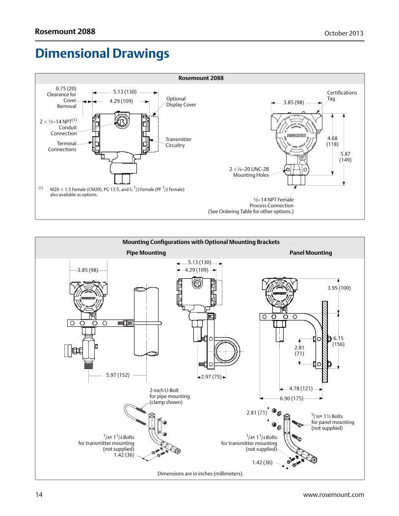
Dimensional Drawings
Rosemount 2088
2 � ½–14 NPT(1)
ConduitConnection
Terminal Connections
5.13 (130)OptionalDisplay Cover
TransmitterCircuitry
4.29 (109)
0.75 (20)Clearance for
CoverRemoval
Certifications Tag
2 �¼–20 UNC-2BMounting Holes
½–14 NPT FemaleProcess Connection
(See Ordering Table for other options.)
3.85 (98)
5.87 (149)
4.68 (118)
(1) M20 � 1.5 Female (CM20), PG 13.5, and G 1/2 Female (PF 1/2 Female) also available as options.
Mounting Configurations with Optional Mounting Brackets
Pipe Mounting Panel Mounting
5.97 (152) 2.97 (75)
3.95 (100)
6.15(156)
2.81(71)
4.78 (121)
6.90 (175)
2-inch U-Boltfor pipe mounting(clamp shown)
1.42 (36)
2.81 (71) 5/16× 1½ Boltsfor panel mounting(not supplied)
1/4× 11/4 Boltsfor transmitter mounting
(not supplied)
Dimensions are in inches (millimeters).
3.85 (98)
5.13 (130)
4.29 (109)
1/4× 11/4 Boltsfor transmitter mounting
(not supplied)1.42 (36)

Rosemount 2088October 2013
Options
Standard ConfigurationUnless otherwise specified, transmitter is shipped as follows:
Custom ConfigurationIf Option Code C9 is ordered, the customer may specify the following data in addition to the standard configuration parameters.
• Output Information
• Transmitter Information
• LCD display Configuration
• Hardware Selectable Information
• Signal SelectionRefer to the “Rosemount 2088 Configuration Data Sheet” document number 00806-0100-4690.
Tagging (3 options available)• Standard SST hardware tag is permanently affixed on transmitter.
Tag character height is 0.125 in. (3,18 mm), 84 characters maximum.
• Tag may be wired to the transmitter nameplate upon request, 85 characters maximum.
• For HART protocols, the tag may be stored in transmitter memory (eight characters maximum). Software tag is left blank unless specified.
• HART Revision 5: 8 characters
• HART Revision 7: 32 characters
Optional Rosemount 306 Integral ManifoldFactory assembled to 2088 transmitters. Refer to Product Data Sheet (document number 00813-0100-4733 for Rosemount 306) for additional information.
Other SealsRefer to Product Data Sheet (document number 00813-0100-4016 or 00813-0201-4016) for additional information.
Output InformationOutput range points must be the same unit of measure. Available units of measure include:
Display and Interface OptionsM4 Digital Display with Local Operator Interface (LOI)
• Available for 4-20 mA HART, 4-20 mA HART Low PowerM5 Digital Meter
• 2-Line, 5-Digit LCD for 4-20 mA HART
• 2-Line, 5-Digit LCD for 1-5 Vdc HART Low Power
• Direct reading of digital data for higher accuracy
• Displays user-defined flow, level, volume, or pressure units
• Displays diagnostic messages for local troubleshooting
• 90-degree rotation capability for easy viewing
Configuration ButtonsRosemount 2088 now offers optional internal and external configuration buttons.
• Choosing option D4 will add external Analog Zero and Span configuration buttons
• Choosing option DZ will add an external Digital Zero Trim configuration button
• Choosing option M4 (LOI) adds both internal and external local configuration buttons.
Certain button options can also be combined as shown below:
Rosemount 2088 Bracket OptionB4 Bracket for 2-in. Pipe or Panel Mounting
• Bracket for mounting of transmitter on 2-in. pipe or panel
• Stainless steel construction with stainless steel bolts
ENGINEERING UNITS psi (all ranges)4 mA (1 Vdc): 0 (engineering units)20 mA (5 Vdc): Upper range limitOutput: LinearFlange type: Specified model code optionFlange material: Specified model code optionO-ring material: Specified model code optionDrain/vent: Specified model code optionLCD Display: Installed or noneAlarm: HighSoftware tag: (Blank)
Pressure Units(1)
(1) Field configurable only, not available for factory calibration or custom configuration (option code C9 “Software configuration”).
torr psf(1) cmH2O@4°C(1)
atm inH2O mH2O@4°C(1)
Pa inH2O@4°C(1) inHg
kPa inH2O@60°F(1) mmHg
MPa(1) ftH2O cmHG@0°C(1)
hPa(1) ftH2O@4°C(1) mHG@0°C(1)
mbar ftH2O@60°F(1) g/cm2
bar mmH2O kg/m2(1)
psi mmH2O@4°C(1) kg/cm2
Button ConfigurationOption Codes Internal External
DZ N/A Digital Zero TrimD4 N/A Analog Zero & TrimM4 LOI LOI
M4 + DZ LOI Digital Zero TrimM4 + D4 LOI Analog Zero & Trim
15www.rosemount.com

Rosemount 208800813-0100-4690, Rev NB
Product Data SheetOctober 2013
Emerson Process ManagementRosemount Inc.8200 Market BoulevardChanhassen, MN 55317 USAT (U.S.) 1-800-999-9307T (International) (952) 906-8888F (952) 906-8889www.rosemount.com
Emerson Process ManagementBlegistrasse 23P.O. Box 1046CH 6341 BaarSwitzerlandT +41 (0) 41 768 6111F +41 (0) 41 768 6300www.rosemount.com
Emerson Process Management Asia Pacific Pte Ltd1 Pandan CrescentSingapore 128461T +65 6777 8211F +65 6777 0947Service Support Hotline: +65 6770 8711Email: [email protected]
Emerson Process Management Latin America1300 Concord Terrace, Suite 400Sunrise Florida 33323 USATel + 1 954 846 5030www.rosemount.com
Standard Terms and Conditions of Sale can be found at www.rosemount.com\terms_of_saleThe Emerson logo is a trade mark and service mark of Emerson Electric Co.Rosemount and the Rosemount logotype are registered trademarks of Rosemount Inc.PlantWeb is a registered trademark of one of the Emerson Process Management group of companies.
HART and WirelessHART are registered trademarks of the HART Communication FoundationModbus is a trademark of Modicon, Inc.All other marks are the property of their respective owners.© 2013 Rosemount Inc. All rights reserved.