Embed Size (px)
Citation preview
Product Data Sheet00813-0100-5901, Rev BA
September 2019
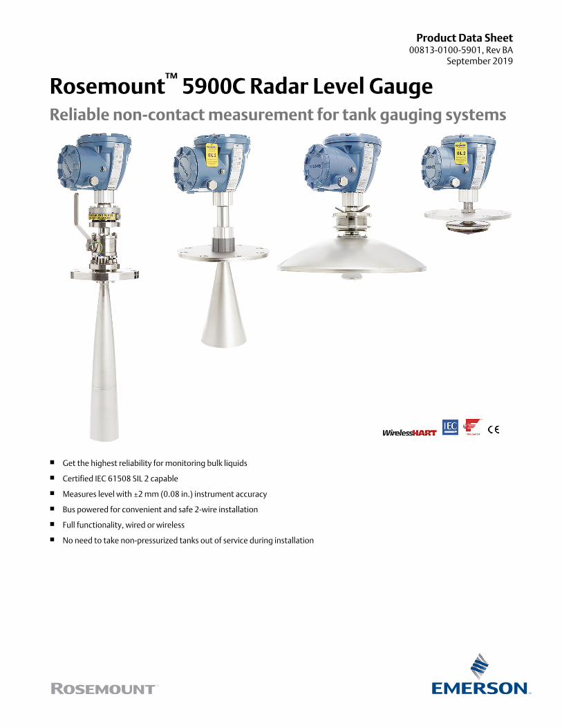
Rosemount™ 5900C Radar Level GaugeReliable non-contact measurement for tank gauging systems
■ Get the highest reliability for monitoring bulk liquids
■ Certified IEC 61508 SIL 2 capable
■ Measures level with ±2 mm (0.08 in.) instrument accuracy
■ Bus powered for convenient and safe 2-wire installation
■ Full functionality, wired or wireless
■ No need to take non-pressurized tanks out of service during installation
Improve plant efficiency and safety
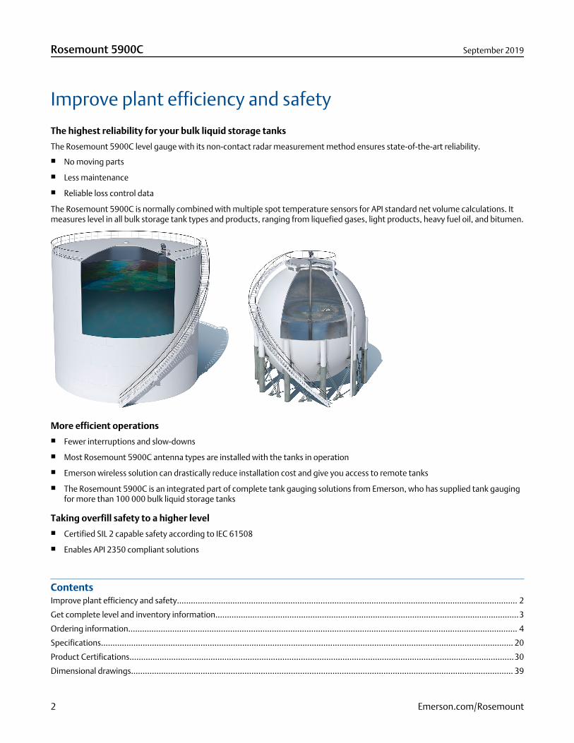
The highest reliability for your bulk liquid storage tanks
The Rosemount 5900C level gauge with its non-contact radar measurement method ensures state-of-the-art reliability.
■ No moving parts
■ Less maintenance
■ Reliable loss control data
The Rosemount 5900C is normally combined with multiple spot temperature sensors for API standard net volume calculations. Itmeasures level in all bulk storage tank types and products, ranging from liquefied gases, light products, heavy fuel oil, and bitumen.
More efficient operations■ Fewer interruptions and slow-downs
■ Most Rosemount 5900C antenna types are installed with the tanks in operation
■ Emerson wireless solution can drastically reduce installation cost and give you access to remote tanks
■ The Rosemount 5900C is an integrated part of complete tank gauging solutions from Emerson, who has supplied tank gaugingfor more than 100 000 bulk liquid storage tanks
Taking overfill safety to a higher level■ Certified SIL 2 capable safety according to IEC 61508
■ Enables API 2350 compliant solutions
ContentsImprove plant efficiency and safety................................................................................................................................................... 2
Get complete level and inventory information...................................................................................................................................3
Ordering information........................................................................................................................................................................ 4
Specifications.................................................................................................................................................................................. 20
Product Certifications......................................................................................................................................................................30
Dimensional drawings..................................................................................................................................................................... 39
Rosemount 5900C September 2019
2 Emerson.com/Rosemount
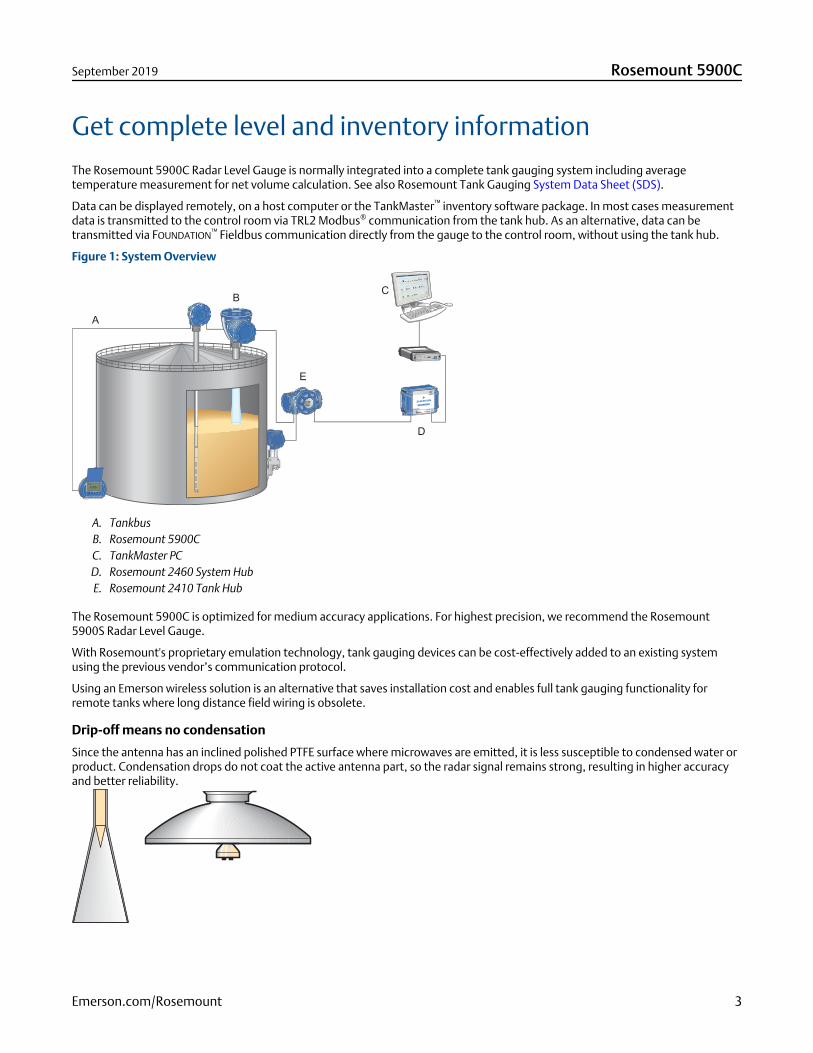
Get complete level and inventory informationThe Rosemount 5900C Radar Level Gauge is normally integrated into a complete tank gauging system including averagetemperature measurement for net volume calculation. See also Rosemount Tank Gauging System Data Sheet (SDS).
Data can be displayed remotely, on a host computer or the TankMaster™ inventory software package. In most cases measurementdata is transmitted to the control room via TRL2 Modbus® communication from the tank hub. As an alternative, data can betransmitted via FOUNDATION™ Fieldbus communication directly from the gauge to the control room, without using the tank hub.
Figure 1: System Overview
Rosemount TankRadar
FBM 2180
Ext.
pw
r
RS
-23
2
US
B
Tx
Rx
Lo - GAIN - Hi On - TERM - Off
A. TankbusB. Rosemount 5900CC. TankMaster PCD. Rosemount 2460 System HubE. Rosemount 2410 Tank Hub
The Rosemount 5900C is optimized for medium accuracy applications. For highest precision, we recommend the Rosemount5900S Radar Level Gauge.
With Rosemount's proprietary emulation technology, tank gauging devices can be cost-effectively added to an existing systemusing the previous vendor’s communication protocol.
Using an Emerson wireless solution is an alternative that saves installation cost and enables full tank gauging functionality forremote tanks where long distance field wiring is obsolete.
Drip-off means no condensation
Since the antenna has an inclined polished PTFE surface where microwaves are emitted, it is less susceptible to condensed water orproduct. Condensation drops do not coat the active antenna part, so the radar signal remains strong, resulting in higher accuracyand better reliability.
September 2019 Rosemount 5900C
Emerson.com/Rosemount 3
Ordering information
Rosemount 5900C Radar Level Gauge with parabolic antenna
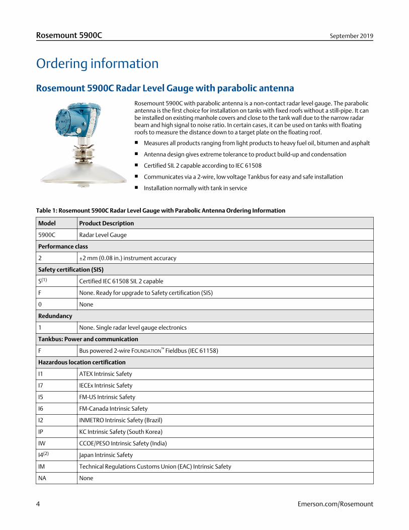
Rosemount 5900C with parabolic antenna is a non-contact radar level gauge. The parabolicantenna is the first choice for installation on tanks with fixed roofs without a still-pipe. It canbe installed on existing manhole covers and close to the tank wall due to the narrow radarbeam and high signal to noise ratio. In certain cases, it can be used on tanks with floatingroofs to measure the distance down to a target plate on the floating roof.
■ Measures all products ranging from light products to heavy fuel oil, bitumen and asphalt
■ Antenna design gives extreme tolerance to product build-up and condensation
■ Certified SIL 2 capable according to IEC 61508
■ Communicates via a 2-wire, low voltage Tankbus for easy and safe installation
■ Installation normally with tank in service
Table 1: Rosemount 5900C Radar Level Gauge with Parabolic Antenna Ordering Information
Model Product Description
5900C Radar Level Gauge
Performance class
2 ±2 mm (0.08 in.) instrument accuracy
Safety certification (SIS)
S(1) Certified IEC 61508 SIL 2 capable
F None. Ready for upgrade to Safety certification (SIS)
0 None
Redundancy
1 None. Single radar level gauge electronics
Tankbus: Power and communication
F Bus powered 2-wire FOUNDATION™ Fieldbus (IEC 61158)
Hazardous location certification
I1 ATEX Intrinsic Safety
I7 IECEx Intrinsic Safety
I5 FM-US Intrinsic Safety
I6 FM-Canada Intrinsic Safety
I2 INMETRO Intrinsic Safety (Brazil)
IP KC Intrinsic Safety (South Korea)
IW CCOE/PESO Intrinsic Safety (India)
I4(2) Japan Intrinsic Safety
IM Technical Regulations Customs Union (EAC) Intrinsic Safety
NA None
Rosemount 5900C September 2019
4 Emerson.com/Rosemount
Table 1: Rosemount 5900C Radar Level Gauge with Parabolic Antenna Ordering Information (continued)
Custody transfer type approval
0 None
Level measurement method
1 10 GHz FMCW radar technology
2 10 GHz FMCW radar technology for US installation
Housing
A Standard enclosure, polyurethane-covered aluminum. IP 66/67
Cable entry/Conduit connections
1 ½ - 14 NPT, female thread. (1 plug included)
2 M20 x 1.5 adapters, female thread. (2 adapters and 1 plug included)
G Metal cable glands (½ - 14 NPT). Minimum temperature -20 °C (-4 °F). ATEX/IECEx Exe approved.
(2 glands and 1 plug included)
E eurofast® male connector (1 plug included)
M minifast® male connector (1 plug included)
Antenna
1P Parabolic antenna
Antenna size
F 20 in./DN 500, Ø=440 mm (17.3 in.)
Antenna material
S SST AISI 316L/EN 1.4436
Tank seal
PF PTFE with FEP fluoropolymer O-ring
PK PTFE with Kalrez® perfluoroelastomer O-ring
Tank connection
WE Welded installation
CL Clamped/threaded installation
Antenna options
0 None
V(3) Proof test verification reflector
Options (include with selected model number)
Safety certificate
QT(4) IEC 61508 certificate and FMEDA-data (printed copy)
Calibration certificate
Q4 Calibration certificate (printed copy)
Material traceability certificate
Q8(5) Antenna material traceability certification per EN 10204 3.1
September 2019 Rosemount 5900C
Emerson.com/Rosemount 5
Table 1: Rosemount 5900C Radar Level Gauge with Parabolic Antenna Ordering Information (continued)
Overfill protection approval
U1(6) TÜV/DIBt WHG approval for overfill protection
U2 SVTI approval for overfill protection (Switzerland)
Tag plate
ST Engraved SST tag plate
Extended warranty
WR3 3-year limited warranty
WR5 5-year limited warranty
Typical Model Number: 5900C 3 2 1 F I5 0 2 A 1 1P F S PF WE 0 Q4
(1) Requires Rosemount 2410 with either Analog output 4-20 mA or Relay output code 1 or 2.(2) Not available with Cable entry/Conduit connections code E or M.(3) Not available with Options code U1.(4) Requires Safety certification (SIS) code S.(5) Not available for transmitter head sparepart.(6) Requires one or more relay outputs in the Rosemount 2410 Tank Hub.
Rosemount 5900C September 2019
6 Emerson.com/Rosemount
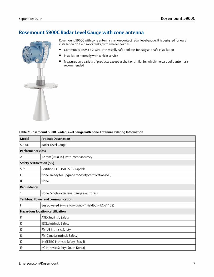
Rosemount 5900C Radar Level Gauge with cone antenna
Rosemount 5900C with cone antenna is a non-contact radar level gauge. It is designed for easyinstallation on fixed roofs tanks, with smaller nozzles.
■ Communicates via a 2-wire, intrinsically safe Tankbus for easy and safe installation
■ Installation normally with tank in service
■ Measures on a variety of products except asphalt or similar for which the parabolic antenna isrecommended
Table 2: Rosemount 5900C Radar Level Gauge with Cone Antenna Ordering Information
Model Product Description
5900C Radar Level Gauge
Performance class
2 ±2 mm (0.08 in.) instrument accuracy
Safety certification (SIS)
S(1) Certified IEC 61508 SIL 2 capable
F None. Ready for upgrade to Safety certification (SIS)
0 None
Redundancy
1 None. Single radar level gauge electronics
Tankbus: Power and communication
F Bus powered 2-wire FOUNDATION™ Fieldbus (IEC 61158)
Hazardous location certification
I1 ATEX Intrinsic Safety
I7 IECEx Intrinsic Safety
I5 FM-US Intrinsic Safety
I6 FM-Canada Intrinsic Safety
I2 INMETRO Intrinsic Safety (Brazil)
IP KC Intrinsic Safety (South Korea)
September 2019 Rosemount 5900C
Emerson.com/Rosemount 7
Table 2: Rosemount 5900C Radar Level Gauge with Cone Antenna Ordering Information (continued)
IW CCOE/PESO Intrinsic Safety (India)
I4(2) Japan Intrinsic Safety
IM Technical Regulations Customs Union (EAC) Intrinsic Safety
NA None
Custody transfer type approval
0 None
Level measurement method
1 10 GHz FMCW radar technology
2 10 GHz FMCW radar technology for US installation
Housing
A Standard enclosure, polyurethane-covered aluminum. IP 66/67
Cable entry/Conduit connections
1 ½ - 14 NPT, female thread. (1 plug included)
2 M20 x 1.5 adapters, female thread. (2 adapters and 1 plug included)
G Metal cable glands (½ - 14 NPT). Minimum temperature -20 °C (-4 °F). ATEX/IECEx Exe approved.
(2 glands and 1 plug included)
E eurofast® male connector (1 plug included)
M minifast® male connector (1 plug included)
Antenna
1C Cone antenna
Antenna size
4 4 in. / DN 100, Ø=93 mm (3.7 in.)
6(3) 6 in. / DN 150, Ø=141 mm (5.6 in.)
8(3) 8 in. / DN 200, Ø=189 mm (7.4 in.)
X Customer-specific, consult factory
Antenna material
S SST AISI 316/316L and SST EN 1.4401/1.4404
X Customer-specific, consult factory
Tank seal
PV PTFE with Viton® fluoroelastomer O-rings
PK PTFE with Kalrez® perfluoroelastomer O-rings
QV Quartz with Viton® fluoroelastomer O-rings
QK Quartz with Kalrez® perfluoroelastomer O-rings
Tank connection
ANSI Hole Pattern (SST AISI 316 L) – Flat Face(4)
6T 6 in. Class 150
Rosemount 5900C September 2019
8 Emerson.com/Rosemount
Table 2: Rosemount 5900C Radar Level Gauge with Cone Antenna Ordering Information (continued)
8T 8 in. Class 150
EN Hole Pattern (SST EN 1.4404) – Flat Face(4)
KT DN 150/PN 16
MT DN 200/PN 10
ANSI flanges (SST AISI 316 L) – Raised Face
4A 4 in. Class 150
4B 4 in. Class 300
6A 6 in. Class 150
6B 8 in. Class 150
EN flanges (SST EN 1.4404) – Flat Face
JA DN 100 PN 16
JB DN 100 PN 40
KA DN 150 PN 16
LA DN 200 PN 16
Other
00 None
XX Customer-specific, consult factory.
Antenna options
0 None
1(5) Extended Cone Antenna, total length 20 in. (500 mm).
X Customer-specific, consult factory.
Options (include with selected model number)
Safety certificate
QT(6) IEC 61508 certificate and FMEDA-data (printed copy)
Calibration certificate
Q4 Calibration certificate (printed copy)
Material traceability certificate
Q8(7) Antenna material traceability certification per EN 10204 3.1
Overfill protection approval
U1(8) TÜV/DIBt WHG approval for overfill protection
U2 SVTI approval for overfill protection (Switzerland)
Tag plate
ST Engraved SST tag plate
Extended warranty
WR3 3-year limited warranty
WR5 5-year limited warranty
September 2019 Rosemount 5900C
Emerson.com/Rosemount 9
Table 2: Rosemount 5900C Radar Level Gauge with Cone Antenna Ordering Information (continued)
Typical Model Number: 5900C 3 0 1 F I5 0 2 A G 1C 8 S PV 8A 0 ST
(1) Requires Rosemount 2410 with either Analog output 4-20 mA or Relay output code 1 or 2.(2) Not available with Cable entry/Conduit connections code E or M.(3) Only for free propagation installations.(4) Thin flange for non-pressurized applications, max pressure 0,2 bar (2.9 psi).(5) Requires Antenna size code 4 or 6.(6) Requires Safety certification (SIS) code S.(7) Not available for transmitter head sparepart.(8) Requires one or more relay outputs in the Rosemount 2410 Tank Hub.
Rosemount 5900C September 2019
10 Emerson.com/Rosemount
Rosemount 5900C Radar Level Gauge with still-pipe array antenna
The Rosemount 5900C with array antenna is a non-contact radar level gauge for still-pipemeasurement. It is available in two versions, fixed and hinged hatch. Typical applications arecrude oil tanks with floating roofs and gasoline/product tanks with or without inner floatingroofs.
■ Suitable for crude oil, gasoline or similar products. For Methanol please consult factory.
■ Certified SIL 2 capable according to IEC 61508
■ Tolerant against rust and product deposits inside the pipe
■ Communicates via a 2-wire, low voltage Tankbus for easy and safe installation
■ Hinged hatch version enables easier product sampling and hand-dips
■ Installation normally with tank in service
Table 3: Rosemount 5900C Radar Level Gauge with Still-Pipe Array Antenna Ordering Information
Model Product Description
5900C Radar Level Gauge
Performance class
2 ±2 mm (0.08 in.) instrument accuracy
Safety certification (SIS)
S(1) Certified IEC 61508 SIL 2 capable
F None. Ready for upgrade to Safety certification (SIS)
0 None
Redundancy
1 None. Single radar level gauge electronics
Tankbus: Power and communication
F Bus powered 2-wire FOUNDATION™ Fieldbus (IEC 61158)
Hazardous location certification
I1 ATEX Intrinsic Safety
I7 IECEx Intrinsic Safety
I5 FM-US Intrinsic Safety
I6 FM-Canada Intrinsic Safety
I2 INMETRO Intrinsic Safety (Brazil)
IP KC Intrinsic Safety (South Korea)
IW CCOE/PESO Intrinsic Safety (India)
I4(2) Japan Intrinsic Safety
IM Technical Regulations Customs Union (EAC) Intrinsic Safety
NA None
Custody transfer type approval
0 None
September 2019 Rosemount 5900C
Emerson.com/Rosemount 11
Table 3: Rosemount 5900C Radar Level Gauge with Still-Pipe Array Antenna Ordering Information (continued)
Level measurement method
1 10 GHz FMCW radar technology
2 10 GHz FMCW radar technology for US installation
Housing
A Standard enclosure, polyurethane-covered aluminum. IP 66/67
Cable entry/Conduit connections
1 ½ - 14 NPT, female thread. (1 plug included)
2 M20 x 1.5 adapters, female thread. (2 adapters and 1 plug included)
G Metal cable glands (½ - 14 NPT). Minimum temperature -20 °C (-4 °F). ATEX/IECEx Exe approved.
(2 glands and 1 plug included)
E eurofast® male connector (1 plug included)
M minifast® male connector (1 plug included)
Antenna
1A Still-pipe array antenna
Antenna size
5 5 in./DN 125, Ø=120 mm (4.7 in.)
6 6 in./DN 150, Ø=145 mm (5.7 in.)
8 8 in./DN 200, Ø=189 mm (7.4 in.)
A 10 in./DN 250, Ø=243 mm (9.8 in.)
B 12 in./DN 300, Ø=293 mm (11.8 in.)
Antenna material
S SST (AISI 316L / EN 1.4404) and PPS (polyphenylene sulfide)
Tank seal
FF Fixed flange installation with fluorosilicone O-ring
HH Integrated hatch installation with fluorosilicone O-ring (direct access to pipe with hand gauge)
Tank connection
ANSI Hole Pattern (SST AISI 316/316 L) – Flat Face
5A 5 in. Class 150
6A 6 in. Class 150
8A 8 in. Class 150
AA 10 in. Class 150
BA 12 in. Class 150
EN Hole Pattern (SST EN 1.4404) – Flat Face
KA DN 150 PN 16
LA DN 200 PN 10
MB DN 250 PN 16
Rosemount 5900C September 2019
12 Emerson.com/Rosemount
Table 3: Rosemount 5900C Radar Level Gauge with Still-Pipe Array Antenna Ordering Information (continued)
Antenna options
0 None
C Clamp flange in galvanized steel (for still-pipes without a flange). Available for 6, 8 , 10, and 12 in. tankconnections.
V(3)(4) Proof test verification reflector (size equal to Tank connection)
Options (include with selected model number)
Safety certificate
QT(5) IEC 61508 certificate and FMEDA-data (printed copy)
Calibration certificate
Q4 Calibration certificate (printed copy)
Material traceability certificate
Q8(6) Antenna material traceability certification per EN 10204 3.1
Overfill protection approval
U1(7) TÜV/DIBt WHG approval for overfill protection
U2 SVTI approval for overfill protection (Switzerland)
Tag plate
ST Engraved SST tag plate
Extended warranty
WR3 3-year limited warranty
WR5 5-year limited warranty
Typical Model Number: 5900C 3 F 1 F I5 0 2 A 1 1A 5 S FF AA C Q4
(1) Requires Rosemount 2410 with either Analog output 4-20 mA or Relay output code 1 or 2.(2) Not available with Cable entry/Conduit connections code E or M.(3) Requires Antenna size 6 or 8.(4) Not available with Options code U1.(5) Requires Safety certification (SIS) code S.(6) Not available for transmitter head sparepart.(7) Requires one or more relay outputs in the Rosemount 2410 Tank Hub.
September 2019 Rosemount 5900C
Emerson.com/Rosemount 13
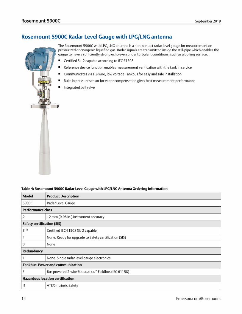
Rosemount 5900C Radar Level Gauge with LPG/LNG antenna
The Rosemount 5900C with LPG/LNG antenna is a non-contact radar level gauge for measurement onpressurized or cryogenic liquefied gas. Radar signals are transmitted inside the still-pipe which enables thegauge to have a sufficiently strong echo even under turbulent conditions, such as a boiling surface.
■ Certified SIL 2 capable according to IEC 61508
■ Reference device function enables measurement verification with the tank in service
■ Communicates via a 2-wire, low voltage Tankbus for easy and safe installation
■ Built-in pressure sensor for vapor compensation gives best measurement performance
■ Integrated ball valve
Table 4: Rosemount 5900C Radar Level Gauge with LPG/LNG Antenna Ordering Information
Model Product Description
5900C Radar Level Gauge
Performance class
2 ±2 mm (0.08 in.) instrument accuracy
Safety certification (SIS)
S(1) Certified IEC 61508 SIL 2 capable
F None. Ready for upgrade to Safety certification (SIS)
0 None
Redundancy
1 None. Single radar level gauge electronics
Tankbus: Power and communication
F Bus powered 2-wire FOUNDATION™ Fieldbus (IEC 61158)
Hazardous location certification
I1 ATEX Intrinsic Safety
Rosemount 5900C September 2019
14 Emerson.com/Rosemount
Table 4: Rosemount 5900C Radar Level Gauge with LPG/LNG Antenna Ordering Information (continued)
I7 IECEx Intrinsic Safety
I5 FM-US Intrinsic Safety
I6 FM-Canada Intrinsic Safety
I2 INMETRO Intrinsic Safety (Brazil)
IP KC Intrinsic Safety (South Korea)
IW CCOE/PESO Intrinsic Safety (India)
I4(2) Japan Intrinsic Safety
IM Technical Regulations Customs Union (EAC) Intrinsic Safety
NA None
Custody transfer type approval
0 None
Level measurement method
1 10 GHz FMCW radar technology
2 10 GHz FMCW radar technology for US installation
Housing
A Standard enclosure, polyurethane-covered aluminum. IP 66/67
Cable entry/Conduit connections
1 ½ - 14 NPT, female thread. (1 plug included)
2 M20 x 1.5 adapters, female thread. (2 adapters and 1 plug included)
G Metal cable glands (½ - 14 NPT). Minimum temperature -20 °C (-4 °F). ATEX/IECEx Exe approved.
(2 glands and 1 plug included)
E eurofast® male connector (1 plug included)
M minifast® male connector (1 plug included)
Antenna
G1 LNG still-pipe antenna (with integrated ball-valve)
G2(3) LPG/LNG still-pipe antenna (with integrated ball-valve and pressure transmitter)
Antenna size
A 4 in. Schedule 10, Ø=107 mm (4.2 in.)
B 4 in. Schedule 40, Ø=101 mm (4.0 in.)
D DN 100, Ø=99 mm (3.9 in.)
Antenna material
S SST AISI 316/316L and SST EN1.4401/1.4404
Tank seal
PT PTFE sealing
Tank connection
ANSI Flanges (SST AISI 316/316 L) – Raised Face
September 2019 Rosemount 5900C
Emerson.com/Rosemount 15
Table 4: Rosemount 5900C Radar Level Gauge with LPG/LNG Antenna Ordering Information (continued)
1B(4) 1.5 in. Class 300
2A(4) 2 in. Class 150
2B(4) 2 in. Class 300
3A(4) 3 in. Class 150
3B(4) 3 in. Class 300
4A 4 in. Class 150
4B 4 in. Class 300
6A 6 in. Class 150
6B 6 in. Class 300
8A 8 in. Class 150
8B 8 in. Class 300
Antenna options
V Measurement verification kit with 1 verification pin and 1 pipe end deflector kit
Options (include with selected model number)
Safety certificate
QT(5) IEC 61508 certificate and FMEDA-data (printed copy)
Calibration certificate
Q4 Calibration certificate (printed copy)
Material traceability certificate
Q8(6) Antenna material traceability certification per EN 10204 3.1
Overfill protection approval
U1(7) TÜV/DIBt WHG approval for overfill protection
U2 SVTI approval for overfill protection (Switzerland)
Tag plate
ST Engraved SST tag plate
Hydrostatic pressure test
P1 Antenna hydrostatic pressure testing
Extended warranty
WR3 3-year limited warranty
WR5 5-year limited warranty
Typical Model Number: 5900C 3 F 1 F I1 0 1 A 2 G1 B S QA 4A V Q4
(1) Requires Rosemount 2410 with either Analog output 4-20 mA or Relay output code 1 or 2.(2) Not available with Cable entry/Conduit connections code E or M.(3) Requires Hazardous location certification code I1, I2, I5, I6, I7, IP, I4 or IM.(4) Requires Antenna size code A.(5) Requires Safety certification (SIS) code S.(6) Not available for transmitter head sparepart.(7) Requires one or more relay outputs in the Rosemount 2410 Tank Hub.
Rosemount 5900C September 2019
16 Emerson.com/Rosemount
Rosemount 5900C Radar Level Gauge with 1- and 2-in. still-pipe antenna
The 1- and 2-in. still-pipe gauges are suitable for clean liquids only and can be delivered complete with still-pipe, deflection plate,and fittings without any need for welding.
Table 5: Rosemount 5900C Radar Level Gauge with 1- and 2-in. Still-Pipe Antennas Ordering Information
Model Product Description
5900C Radar Level Gauge
Performance class
2 ±2 mm (0.08 in.) instrument accuracy
Safety certification (SIS)
S(1) Certified IEC 61508 SIL 2 capable
F None. Ready for upgrade to Safety certification (SIS)
0 None
Redundancy
1 None. Single radar level gauge electronics
Tankbus: Power and communication
F Bus powered 2-wire FOUNDATION™ Fieldbus (IEC 61158)
Hazardous location certification
I1 ATEX Intrinsic Safety
I7 IECEx Intrinsic Safety
I5 FM-US Intrinsic Safety
I6 FM-Canada Intrinsic Safety
I2 INMETRO Intrinsic Safety (Brazil)
IP KC Intrinsic Safety (South Korea)
IW CCOE/PESO Intrinsic Safety (India)
I4(2) Japan Intrinsic Safety
IM Technical Regulations Customs Union (EAC) Intrinsic Safety
NA None
Custody transfer type approval
0 None
Level measurement method
1 10 GHz FMCW radar technology
2 10 GHz FMCW radar technology for US installation
Housing
A Standard enclosure, polyurethane-covered aluminum. IP 66/67
Cable entry/Conduit connections
1 ½ - 14 NPT, female thread. (1 plug included)
September 2019 Rosemount 5900C
Emerson.com/Rosemount 17
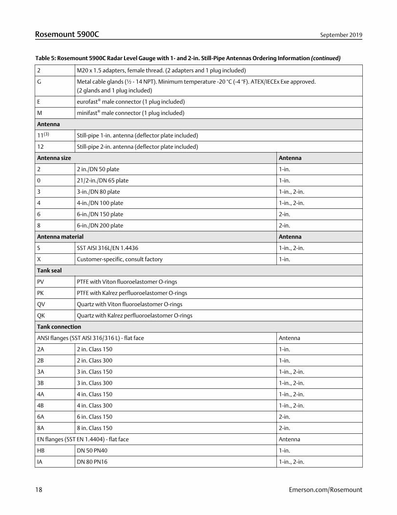
Table 5: Rosemount 5900C Radar Level Gauge with 1- and 2-in. Still-Pipe Antennas Ordering Information (continued)
2 M20 x 1.5 adapters, female thread. (2 adapters and 1 plug included)
G Metal cable glands (½ - 14 NPT). Minimum temperature -20 °C (-4 °F). ATEX/IECEx Exe approved.
(2 glands and 1 plug included)
E eurofast® male connector (1 plug included)
M minifast® male connector (1 plug included)
Antenna
11(3) Still-pipe 1-in. antenna (deflector plate included)
12 Still-pipe 2-in. antenna (deflector plate included)
Antenna size Antenna
2 2 in./DN 50 plate 1-in.
0 21/2-in./DN 65 plate 1-in.
3 3-in./DN 80 plate 1-in., 2-in.
4 4-in./DN 100 plate 1-in., 2-in.
6 6-in./DN 150 plate 2-in.
8 6-in./DN 200 plate 2-in.
Antenna material Antenna
S SST AISI 316L/EN 1.4436 1-in., 2-in.
X Customer-specific, consult factory 1-in.
Tank seal
PV PTFE with Viton fluoroelastomer O-rings
PK PTFE with Kalrez perfluoroelastomer O-rings
QV Quartz with Viton fluoroelastomer O-rings
QK Quartz with Kalrez perfluoroelastomer O-rings
Tank connection
ANSI flanges (SST AISI 316/316 L) - flat face Antenna
2A 2 in. Class 150 1-in.
2B 2 in. Class 300 1-in.
3A 3 in. Class 150 1-in., 2-in.
3B 3 in. Class 300 1-in., 2-in.
4A 4 in. Class 150 1-in., 2-in.
4B 4 in. Class 300 1-in., 2-in.
6A 6 in. Class 150 2-in.
8A 8 in. Class 150 2-in.
EN flanges (SST EN 1.4404) - flat face Antenna
HB DN 50 PN40 1-in.
IA DN 80 PN16 1-in., 2-in.
Rosemount 5900C September 2019
18 Emerson.com/Rosemount
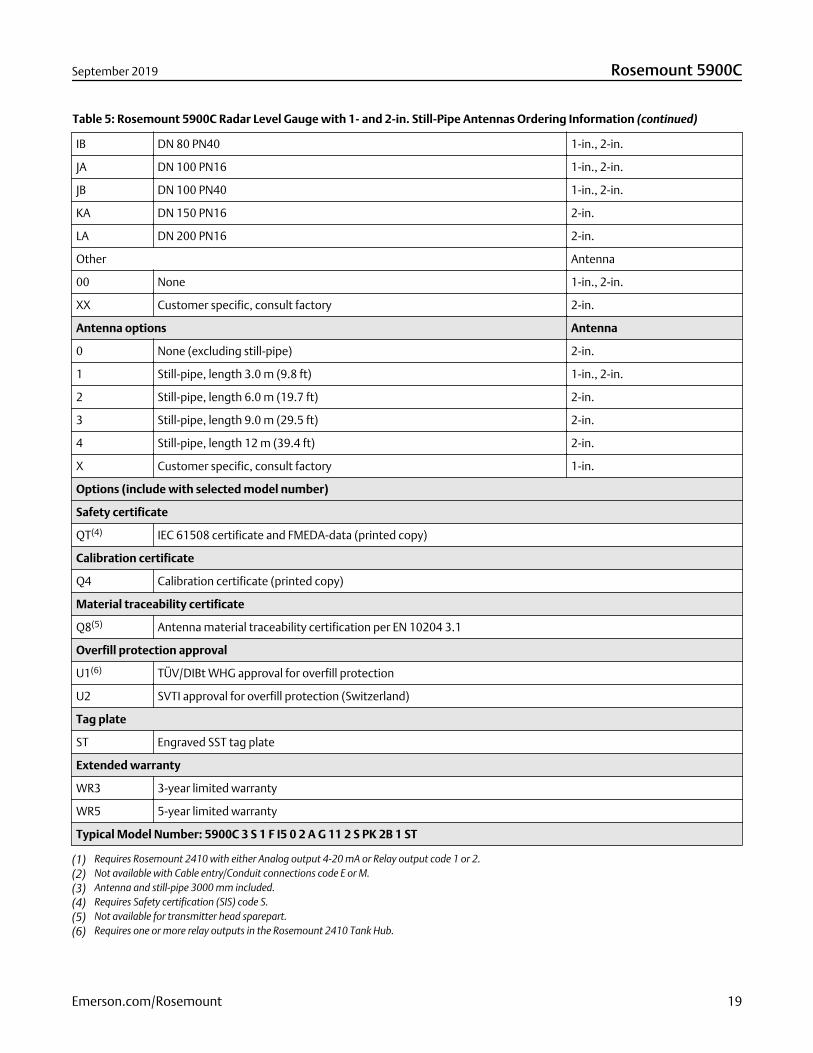
Table 5: Rosemount 5900C Radar Level Gauge with 1- and 2-in. Still-Pipe Antennas Ordering Information (continued)
IB DN 80 PN40 1-in., 2-in.
JA DN 100 PN16 1-in., 2-in.
JB DN 100 PN40 1-in., 2-in.
KA DN 150 PN16 2-in.
LA DN 200 PN16 2-in.
Other Antenna
00 None 1-in., 2-in.
XX Customer specific, consult factory 2-in.
Antenna options Antenna
0 None (excluding still-pipe) 2-in.
1 Still-pipe, length 3.0 m (9.8 ft) 1-in., 2-in.
2 Still-pipe, length 6.0 m (19.7 ft) 2-in.
3 Still-pipe, length 9.0 m (29.5 ft) 2-in.
4 Still-pipe, length 12 m (39.4 ft) 2-in.
X Customer specific, consult factory 1-in.
Options (include with selected model number)
Safety certificate
QT(4) IEC 61508 certificate and FMEDA-data (printed copy)
Calibration certificate
Q4 Calibration certificate (printed copy)
Material traceability certificate
Q8(5) Antenna material traceability certification per EN 10204 3.1
Overfill protection approval
U1(6) TÜV/DIBt WHG approval for overfill protection
U2 SVTI approval for overfill protection (Switzerland)
Tag plate
ST Engraved SST tag plate
Extended warranty
WR3 3-year limited warranty
WR5 5-year limited warranty
Typical Model Number: 5900C 3 S 1 F I5 0 2 A G 11 2 S PK 2B 1 ST
(1) Requires Rosemount 2410 with either Analog output 4-20 mA or Relay output code 1 or 2.(2) Not available with Cable entry/Conduit connections code E or M.(3) Antenna and still-pipe 3000 mm included.(4) Requires Safety certification (SIS) code S.(5) Not available for transmitter head sparepart.(6) Requires one or more relay outputs in the Rosemount 2410 Tank Hub.
September 2019 Rosemount 5900C
Emerson.com/Rosemount 19
Specifications
General
Instrument accuracy± 2.0 mm (0.08 in.)
Instrument accuracy is under reference conditions. Reference conditions are: Measurement in test bench at Rosemount Tank RadarAB in Mölnlycke Sweden. Test bench is calibrated minimum yearly by an accredited laboratory (SP Technical Research Institute ofSweden. Measuring range is up to 30 m (98 ft). Ambient temperature and humidity is close to constant during tests. Totaluncertainty in test bench is below 0.15 mm (0.006 in.).
Temperature stabilityTypically < ± 0.5 mm (0.020 in.) in -40 to +70 °C (-40 to +158 °F)
Fieldbus (standard)FOUNDATION™ Fieldbus FISCO (Tankbus)
Update timeNew measurement every 0.3 s
Repeatability0.2 mm (0.008 in.)
Maximum level rateUp to 200 mm/s
Metrology sealing possibilityYes
Installation considerationsSee Rosemount 5900C Reference Manual
Measurement principleThe FMCW-method (Frequency Modulated Continuous Wave) means that the transmitted radar signal has a linear frequencyvariation around 10 GHz. The reflection from the liquid surface has a slightly different frequency compared with the signaltransmitted from the antenna when the reflection is received. The difference in frequency is directly proportional to the distancebetween the antenna and the liquid surface, and thereby also the liquid level. This technology enables a very accurate and stablemeasured value.
Rosemount 5900C September 2019
20 Emerson.com/Rosemount
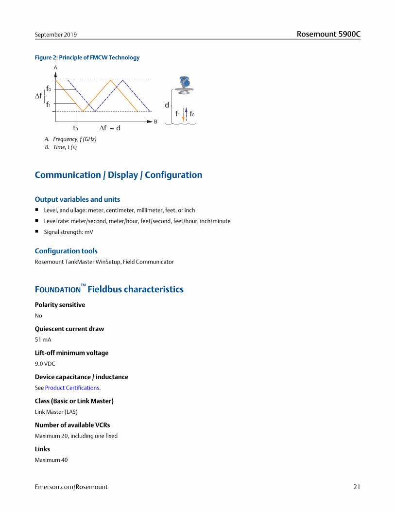
Figure 2: Principle of FMCW Technology
A. Frequency, f (GHz)B. Time, t (s)
Communication / Display / Configuration
Output variables and units■ Level, and ullage: meter, centimeter, millimeter, feet, or inch
■ Level rate: meter/second, meter/hour, feet/second, feet/hour, inch/minute
■ Signal strength: mV
Configuration toolsRosemount TankMaster WinSetup, Field Communicator
FOUNDATION™ Fieldbus characteristics
Polarity sensitive
No
Quiescent current draw
51 mA
Lift-off minimum voltage
9.0 VDC
Device capacitance / inductance
See Product Certifications.
Class (Basic or Link Master)
Link Master (LAS)
Number of available VCRs
Maximum 20, including one fixed
Links
Maximum 40
September 2019 Rosemount 5900C
Emerson.com/Rosemount 21
Minimum slot time / maximum response delay/ minimum intermessage delay
8/5/8
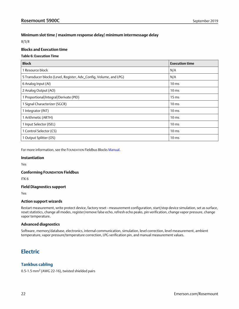
Blocks and Execution time
Table 6: Execution Time
Block Execution time
1 Resource block N/A
5 Transducer blocks (Level, Register, Adv_Config, Volume, and LPG) N/A
6 Analog Input (AI) 10 ms
2 Analog Output (AO) 10 ms
1 Proportional/Integral/Derivate (PID) 15 ms
1 Signal Characterizer (SGCR) 10 ms
1 Integrator (INT) 10 ms
1 Arithmetic (ARTH) 10 ms
1 Input Selector (ISEL) 10 ms
1 Control Selector (CS) 10 ms
1 Output Splitter (OS) 10 ms
For more information, see the FOUNDATION Fieldbus Blocks Manual.
Instantiation
Yes
Conforming FOUNDATION Fieldbus
ITK 6
Field Diagnostics support
Yes
Action support wizards
Restart measurement, write protect device, factory reset - measurement configuration, start/stop device simulation, set as surface,reset statistics, change all modes, register/remove false echo, refresh echo peaks, pin verification, change vapor pressure, changevapor temperature.
Advanced diagnostics
Software, memory/database, electronics, internal communication, simulation, level correction, level measurement, ambienttemperature, vapor pressure/temperature correction, LPG verification pin, and manual measurement values.
Electric
Tankbus cabling0.5-1.5 mm2 (AWG 22-16), twisted shielded pairs
Rosemount 5900C September 2019
22 Emerson.com/Rosemount
Power supplyFISCO: 9.0 - 17.5 VDC polarity insensitive (for example from Rosemount 2410 Tank Hub)
Entity: 9.0 - 30.0 VDC polarity insensitive
Bus current draw50 mA
Microwave output power< 1 mW
Build-in Tankbus terminatorYes (to be connected if required)
Daisy chain possibilityYes
Mechanical
Housing material & surface treatmentPolyurethane-coated die-cast aluminum
Cable entry (connection/glands)Two ½ - 14 NPT entries for cable glands or conduits. One metal plug to seal any unused port is enclosed in the transmitter delivery.
Optional:
■ M20 x 1.5 conduit / cable adapter
■ Cable glands in metal (½ - 14 NPT)
■ 4-pin male eurofast connector or A size Mini 4-pin male minifast connector
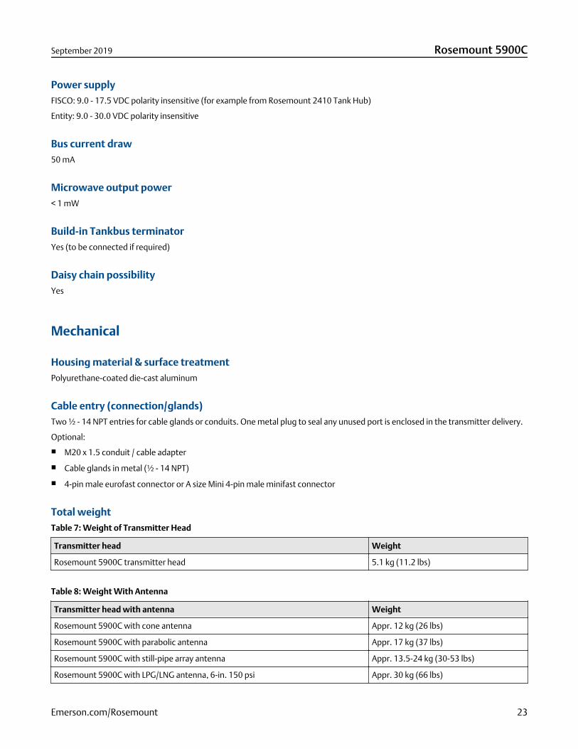
Total weightTable 7: Weight of Transmitter Head
Transmitter head Weight
Rosemount 5900C transmitter head 5.1 kg (11.2 lbs)
Table 8: Weight With Antenna
Transmitter head with antenna Weight
Rosemount 5900C with cone antenna Appr. 12 kg (26 lbs)
Rosemount 5900C with parabolic antenna Appr. 17 kg (37 lbs)
Rosemount 5900C with still-pipe array antenna Appr. 13.5-24 kg (30-53 lbs)
Rosemount 5900C with LPG/LNG antenna, 6-in. 150 psi Appr. 30 kg (66 lbs)
September 2019 Rosemount 5900C
Emerson.com/Rosemount 23
Table 8: Weight With Antenna (continued)
Transmitter head with antenna Weight
Rosemount 5900C with LPG/LNG antenna, 6-in. 300 psi Appr. 40 kg (88 lbs)
AntennasThe Rosemount 5900C antennas have a drip-off design which for some versions also include inclined polished PTFE surfaces.Condensation on the antenna is minimized, and the radar signal remains strong. This results in maintenance free operation, highaccuracy and reliability. There is always a suitable antenna for every tank type, tank opening and application:
■ Parabolic
■ Cone
■ Still-pipe array
■ LPG/LNG
■ 1-in./2-in. still-pipe
Transmitter headThe same transmitter head is used for all Rosemount 5900C antenna types, minimizing spare part requirements:
■ The dual compartment transmitter housing, with electronics and cabling separated, can be replaced without opening the tank
■ It is protected against lightning, moisture/rain, and has a surface protection against sulphur and salt spray atmospheres
■ Electronics consists of one encapsulated units.
■ No need for re-calibration
Environment
Ambient operating temperature-40 to +70 °C (-40 to +158 °F). Minimum start-up temperature is -50 °C (-58 °F)
Storage temperature-50 to +85 °C (-58 to +185 °F)
Humidity0-100% relative humidity
Ingress protectionIP 66/67 and NEMA® 4X
Vibration resistanceIEC 60770-1 level 1 and IACS UR E10 test 7
TelecommunicationCompliance with:
Rosemount 5900C September 2019
24 Emerson.com/Rosemount
■ FCC 15B Class A, and 15C
■ RED (EU directive 2014/53/EU) ETSI EN 302372; EN 50371
■ IC (RSS210-5)
Electromagnetic compatibility■ EMC (EU directive 2014/30/EU) EN 61326-1; EN 61326-3-1
■ OIML R85:2008
Transient / built-in lightning protectionAccording to IEC 61000-4-5, level 2 kV line to ground. Complies with IEEE 587 Category B transient protection and IEEE 472 surgeprotection.
Low Voltage Directive (LVD)LVD (EU directive 2014/35/EU) EN/IEC 61010-1
Rosemount 5900C with parabolic antenna
Operating temperature in tank
Max. +180 °C (+356 °F) with FEP O-ring, or +230 °C (+445 °F) with Kalrez® O-ring
Measuring range
0.8 to 30 m (2.6 to 100 ft) below flange.
Possibility to measure 0.5 to 50 m (1.6 to 164 ft). Accuracy may be reduced. For longer measuring range, consult your localrepresentative.
Pressure range
Clamped/threaded: -0.2 to 0.2 bar (-2.9 to 2.9 psig)
Welded: -0.2 to 10 bar (-2.9 to 145 psig)
Material exposed to tank atmosphere
Antenna: Material corresponds to AISI 316/316L and EN 1.4401 /1.4404
Sealing: PTFE
O-ring: FEP, or Kalrez®
Antenna dimension
440 mm (17 in.)
Manway size and installation
500 mm (20-in.) opening.
The parabolic antenna is installed on the manway cover by using the flange ball. It is designed for easy adjustment of the antennainclination and orientation within the specified limits.
The flexible flange ball can be installed on both horizontal or inclined manways without any special arrangements.
Tank connection
The gauge is clamped in a 96-mm (3.78-in.) diameter hole, or welded in a 117-mm (4.61-in.) diameter hole.
September 2019 Rosemount 5900C
Emerson.com/Rosemount 25
Rosemount 5900C with cone antenna
Operating temperature in tank
Max. +180 °C (+356 °F) with Viton® O-ring, or +230 °C (+445 °F) with Kalrez® O-ring
Measuring range, accuracy, and cone dimensions
When selecting cone antenna dimension, it is generally recommended to use as large antenna diameter as possible.
Standard cone antennas are available for 4-, 6- and 8-in. tank openings. The 4- and 6-in. cones can be extended to fit long tanknozzles.
Level accuracy is up to ±2 mm (0.08 in.) for 8-in. cone antennas. For 4- and 6-in. cone antennas accuracy depends on installationconditions.
Measuring range
8-in. Cone: 0,8 to 20 m (2.6 to 65 ft) below flange. (Possibility to measure 0,4 to 30 m (1.3 to 100 ft). Accuracy may be reduced.)
6-in. Cone: 0.8 to 20 m (2.6 to 65 ft) below flange. (Possibility to measure 0.3 to 25 m (1 to 80 ft). Accuracy may be reduced.)
4-in. Cone: 0.8 to 15 m (2.6 to 50 ft) below flange. (Possibility to measure 0.2 to 20 m (0.7 to 65 ft). Accuracy may be reduced.)
Material exposed to tank atmosphere
Antenna: SST AISI 316L/EN 1.4436
Sealing: PTFE, or Quartz
O-ring: Viton®, or Kalrez®
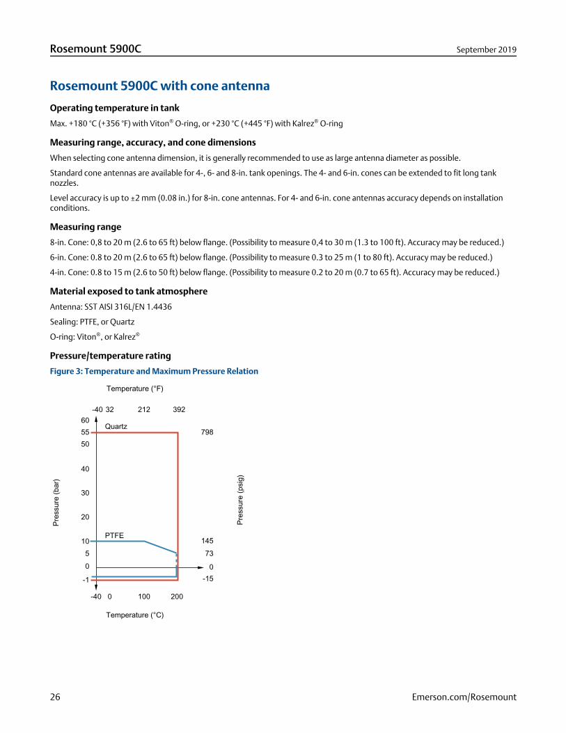
Pressure/temperature rating
Figure 3: Temperature and Maximum Pressure Relation
0-15
39221232-40
-40 0 100 200
605550
40
30
20
1050
-1
Quartz
PTFE
Pres
sure
(psi
g)
Temperature (°F)
Temperature (°C)
Pres
sure
(bar
)
798
14573
Rosemount 5900C September 2019
26 Emerson.com/Rosemount
Rosemount 5900C with still-pipe array antenna
Operating temperature in tank
-40 to 120 °C (-40 to 248 °F)
Measuring range
0.8 to 30 m (2.6 to 100 ft) below flange.
Possibility to measure 0.5 to 40 m (1.6 to130 ft). Accuracy may be reduced. For longer measuring range, consult your localrepresentative.
Pressure range
Fixed version: -0.2 to 2 bar (-2.9 to 29 psig) at 20 °C (68 °F).
Hinged hatch version: -0.2 to 0.5 bar (-2.9 to 7.2 psig) for 5 to 8-in. pipes.
-0.2 to 0.25 bar (-2.9 to 3.6 psig) for 10 and 12-in. pipes.
Material exposed to tank atmosphere
Antenna: Polyphenylenesulphide (PPS)
Sealing: PTFE
O-ring: FMVQ
Flange: Material corresponds to AISI 316/316L and EN 1.4401 /1.4404
Still-pipe dimensions
5-, 6-, 8-, 10- or 12 in.
Tank connection
5 in. hole pattern according to ANSI 5 in. Class 150
6 in. hole pattern according to ANSI 6 in. Class 150 / DN 150 PN 16
8 in. hole pattern according to ANSI 8 in. Class 150 / DN 200 PN 10
10 in. hole pattern according to ANSI 10 in. Class 150 / DN 250 PN 16
12 in. hole pattern according to ANSI 12 in. Class 150
Rosemount 5900C with LPG/LNG antenna
Operating temperature at ball valve
-55 to 90 °C (-67 to 194 °F)
Operating temperature in tank
-170 to 90 °C (-274 to 194 °F)
Measuring range
1.2 to 30 m (3.9 to 100 ft) below flange.
Possibility to measure 0.8 to 60 m (2.6 to 200 ft). Accuracy may be reduced. For longer measuring range, consult your localrepresentative.
Pressure range
-1 to 25 bar (-14.5 to 365 psig).
September 2019 Rosemount 5900C
Emerson.com/Rosemount 27
Note! Flanges may have higher pressure rating than 25 bar, but maximum tank pressure is still 25 bar.
Pressure sensor (option)
Rosemount 2051. It is available with various hazardous location certifications, see Product Certifications.
For more information see the Rosemount 2051 Product Data Sheet.
Material exposed to tank atmosphere
Antenna and flange: Material corresponds to AISI 316/316L and EN 1.4401 /1.4404
Sealing: PTFE
Still-pipe dimension compatibility
Antenna choices for 4-in. sch. 10, 4-in. sch 40, or 100 mm (99 mm inner diameter) still-pipe dimensions
Flange size and rating
4 in. Class 150/300
6 in. Class 150/300
8 in. Class 150/300
Pressure seal
The pressure seal includes a double-block function, consisting of a PTFE seal and a fire-proof ball valve. A pressure sensor enablescorrection due to vapor for best measurement performance.
Verification possibility
A patented reference device function enables measurement verification with the tank in service. A verification pin mounted in astill-pipe hole, and a deflection plate with a verification ring at the lower still-pipe end provide reference echoes at fixed pre-defineddistances.
Rosemount with 1- and 2-in. still-pipe antennas
Operating temperature in tank
Max. +180 °C (+356 °F) with Viton® O-ring, or +230 °C (+445 °F) with Kalrez® O-ring
Measuring range
1-in. still-pipe antenna: 0.2 to 3 m (0.7 to 9.8 ft.) below flange.
2-in. still-pipe antenna: 0.2 to 12 m (0.7 to 39 ft.) below flange.
(Possibility to measure longer ranges. For more information, contact your local Emerson representative.)
Material exposed to tank atmosphere
Antenna: SST 316L
Sealing: PTFE, or Quartz
O-ring: Viton®, or Kalrez®
Rosemount 5900C September 2019
28 Emerson.com/Rosemount
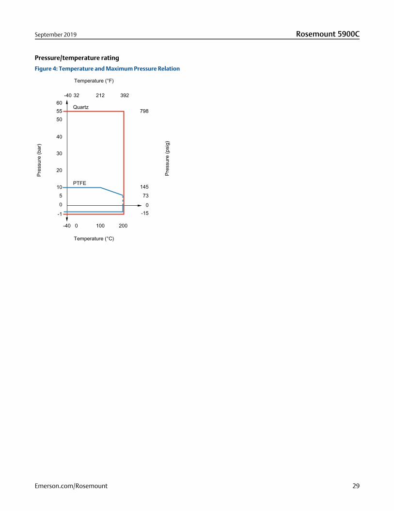
Pressure/temperature rating
Figure 4: Temperature and Maximum Pressure Relation
0-15
39221232-40
-40 0 100 200
605550
40
30
20
1050
-1
Quartz
PTFE
Pres
sure
(psi
g)
Temperature (°F)
Temperature (°C)
Pres
sure
(bar
)
798
14573
September 2019 Rosemount 5900C
Emerson.com/Rosemount 29
Product CertificationsRev 2.9
European directive informationThe most recent revision of the EU Declaration of Conformity can be found at Emerson.com/Rosemount.
Ordinary Location CertificationAs standard, the transmitter has been examined and tested to determine that the design meets the basic electrical, mechanical,and fire protection requirements by a nationally recognized test laboratory (NRTL) as accredited by the Federal Occupational Safetyand Health Administration (OSHA). Complies with FM 3810:2005 and CSA: C22.2 No. 1010.1.
Telecommunication compliance
FCCThis device complies with Part 15C of the FCC Rules. Operation is subject to the following two conditions: (1) This device may notcause interference, and (2) this device must accept any interference received, including interference that may cause undesiredoperation.
Certificate: K8C5900
ICThis device complies with RSS210-7.
Certificate: 2827A-5900
Radio Equipment Directive (RED)This device complies with ETSI EN 302 372 and EN 62479. EU directive 2014/53/EU. The device shall be installed according torequrements ETSI EN 302372.
CE-markThe product complies with applicable EU directives (EMC, ATEX, LVD, and RED). Based on the low emitted effects from the gauges(below 0.1 mW) compared to limits given by the Rec. 1999/519/EC, no additional measures are needed.
Installing Equipment in North AmericaThe US National Electrical Code® (NEC) and the Canadian Electrical Code (CEC) permit the use of Division marked equipment inZones and Zone marked equipment in Divisions.
The markings must be suitable for the area classification, gas, and temperature class. This information is clearly defined in therespective codes.
Rosemount 5900C September 2019
30 Emerson.com/Rosemount
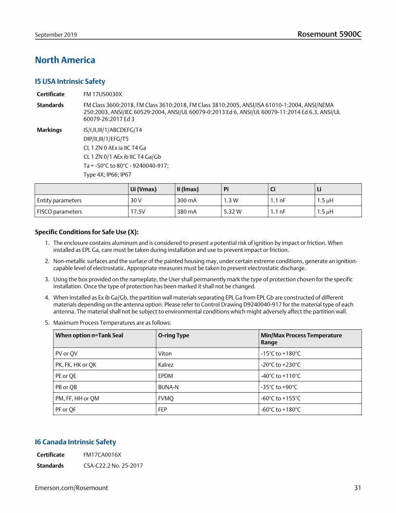
North America
I5 USA Intrinsic Safety
Certificate FM 17US0030X
Standards FM Class 3600:2018, FM Class 3610:2018, FM Class 3810:2005, ANSI/ISA 61010-1:2004, ANSI/NEMA250:2003, ANSI/IEC 60529:2004, ANSI/UL 60079-0:2013 Ed 6, ANSI/UL 60079-11:2014 Ed 6.3, ANSI/UL60079-26:2017 Ed 3
Markings IS/I,II,III/1/ABCDEFG/T4
DIP/II,III/1/EFG/T5
CL 1 ZN 0 AEx ia IIC T4 Ga
CL 1 ZN 0/1 AEx ib IIC T4 Ga/Gb
Ta = -50°C to 80°C - 9240040-917;
Type 4X; IP66; IP67
Ui (Vmax) Ii (lmax) Pi Ci Li
Entity parameters 30 V 300 mA 1.3 W 1.1 nF 1.5 µH
FISCO parameters 17.5V 380 mA 5.32 W 1.1 nF 1.5 µH
Specific Conditions for Safe Use (X):
1. The enclosure contains aluminum and is considered to present a potential risk of ignition by impact or friction. Wheninstalled as EPL Ga, care must be taken during installation and use to prevent impact or friction.
2. Non-metallic surfaces and the surface of the painted housing may, under certain extreme conditions, generate an ignition-capable level of electrostatic. Appropriate measures must be taken to prevent electrostatic discharge.
3. Using the box provided on the nameplate, the User shall permanently mark the type of protection chosen for the specificinstallation. Once the type of protection has been marked it shall not be changed.
4. When installed as Ex ib Ga/Gb, the partition wall materials separating EPL Ga from EPL Gb are constructed of differentmaterials depending on the antenna option. Please refer to Control Drawing D9240040-917 for the material type of eachantenna. The material shall not be subject to environmental conditions which might adversely affect the partition wall.
5. Maximum Process Temperatures are as follows:
When option n=Tank Seal O-ring Type Min/Max Process TemperatureRange
PV or QV Viton -15°C to +180°C
PK, FK, HK or QK Kalrez -20°C to +230°C
PE or QE EPDM -40°C to +110°C
PB or QB BUNA-N -35°C to +90°C
PM, FF, HH or QM FVMQ -60°C to +155°C
PF or QF FEP -60°C to +180°C
I6 Canada Intrinsic Safety
Certificate FM17CA0016X
Standards CSA-C22.2 No. 25-2017
September 2019 Rosemount 5900C
Emerson.com/Rosemount 31
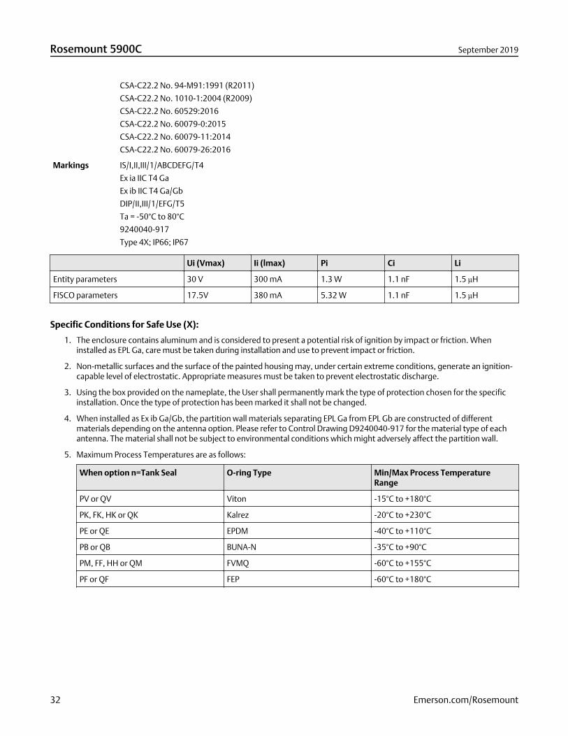
CSA-C22.2 No. 94-M91:1991 (R2011)
CSA-C22.2 No. 1010-1:2004 (R2009)
CSA-C22.2 No. 60529:2016
CSA-C22.2 No. 60079-0:2015
CSA-C22.2 No. 60079-11:2014
CSA-C22.2 No. 60079-26:2016
Markings IS/I,II,III/1/ABCDEFG/T4
Ex ia IIC T4 Ga
Ex ib IIC T4 Ga/Gb
DIP/II,III/1/EFG/T5
Ta = -50°C to 80°C
9240040-917
Type 4X; IP66; IP67
Ui (Vmax) Ii (lmax) Pi Ci Li
Entity parameters 30 V 300 mA 1.3 W 1.1 nF 1.5 µH
FISCO parameters 17.5V 380 mA 5.32 W 1.1 nF 1.5 µH
Specific Conditions for Safe Use (X):
1. The enclosure contains aluminum and is considered to present a potential risk of ignition by impact or friction. Wheninstalled as EPL Ga, care must be taken during installation and use to prevent impact or friction.
2. Non-metallic surfaces and the surface of the painted housing may, under certain extreme conditions, generate an ignition-capable level of electrostatic. Appropriate measures must be taken to prevent electrostatic discharge.
3. Using the box provided on the nameplate, the User shall permanently mark the type of protection chosen for the specificinstallation. Once the type of protection has been marked it shall not be changed.
4. When installed as Ex ib Ga/Gb, the partition wall materials separating EPL Ga from EPL Gb are constructed of differentmaterials depending on the antenna option. Please refer to Control Drawing D9240040-917 for the material type of eachantenna. The material shall not be subject to environmental conditions which might adversely affect the partition wall.
5. Maximum Process Temperatures are as follows:
When option n=Tank Seal O-ring Type Min/Max Process TemperatureRange
PV or QV Viton -15°C to +180°C
PK, FK, HK or QK Kalrez -20°C to +230°C
PE or QE EPDM -40°C to +110°C
PB or QB BUNA-N -35°C to +90°C
PM, FF, HH or QM FVMQ -60°C to +155°C
PF or QF FEP -60°C to +180°C
Rosemount 5900C September 2019
32 Emerson.com/Rosemount
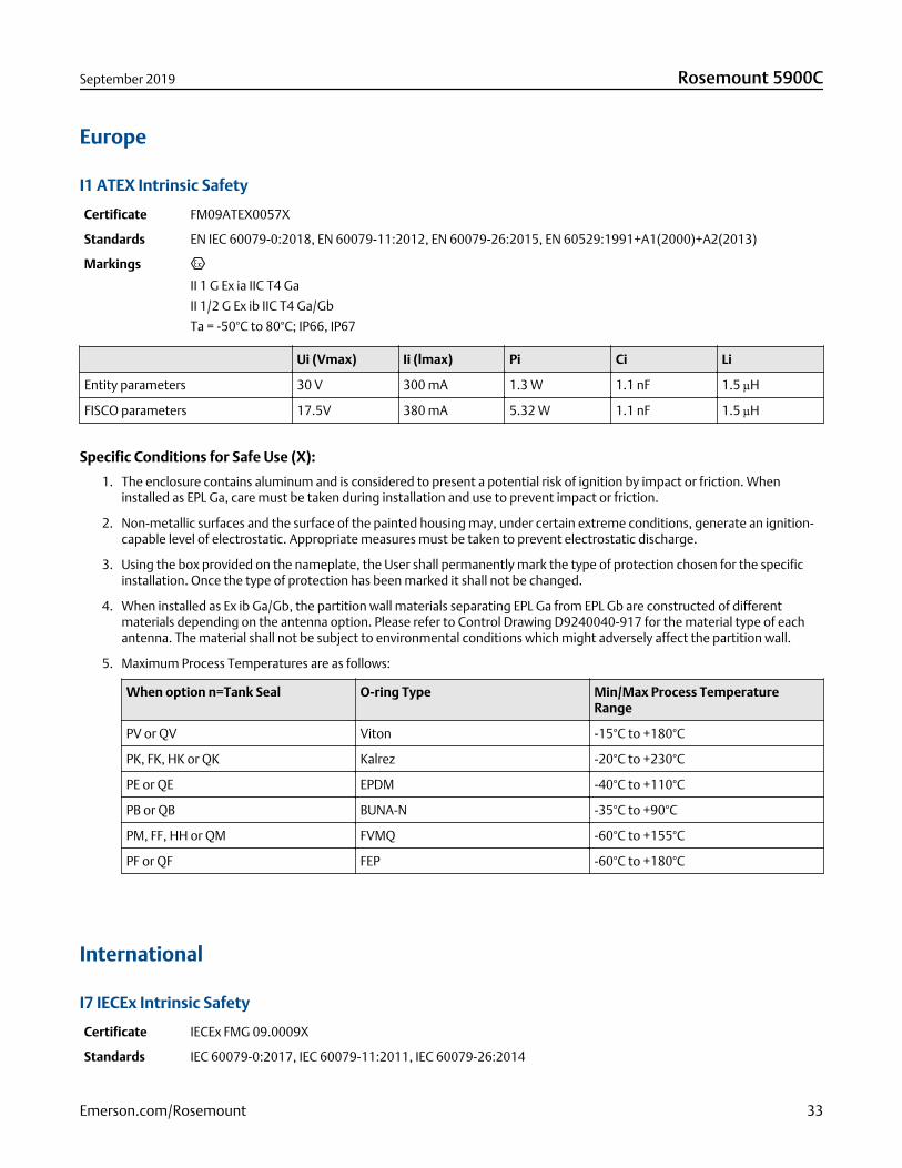
Europe
I1 ATEX Intrinsic Safety
Certificate FM09ATEX0057X
Standards EN IEC 60079-0:2018, EN 60079-11:2012, EN 60079-26:2015, EN 60529:1991+A1(2000)+A2(2013)
Markings
II 1 G Ex ia IIC T4 Ga
II 1/2 G Ex ib IIC T4 Ga/Gb
Ta = -50°C to 80°C; IP66, IP67
Ui (Vmax) Ii (lmax) Pi Ci Li
Entity parameters 30 V 300 mA 1.3 W 1.1 nF 1.5 µH
FISCO parameters 17.5V 380 mA 5.32 W 1.1 nF 1.5 µH
Specific Conditions for Safe Use (X):
1. The enclosure contains aluminum and is considered to present a potential risk of ignition by impact or friction. Wheninstalled as EPL Ga, care must be taken during installation and use to prevent impact or friction.
2. Non-metallic surfaces and the surface of the painted housing may, under certain extreme conditions, generate an ignition-capable level of electrostatic. Appropriate measures must be taken to prevent electrostatic discharge.
3. Using the box provided on the nameplate, the User shall permanently mark the type of protection chosen for the specificinstallation. Once the type of protection has been marked it shall not be changed.
4. When installed as Ex ib Ga/Gb, the partition wall materials separating EPL Ga from EPL Gb are constructed of differentmaterials depending on the antenna option. Please refer to Control Drawing D9240040-917 for the material type of eachantenna. The material shall not be subject to environmental conditions which might adversely affect the partition wall.
5. Maximum Process Temperatures are as follows:
When option n=Tank Seal O-ring Type Min/Max Process TemperatureRange
PV or QV Viton -15°C to +180°C
PK, FK, HK or QK Kalrez -20°C to +230°C
PE or QE EPDM -40°C to +110°C
PB or QB BUNA-N -35°C to +90°C
PM, FF, HH or QM FVMQ -60°C to +155°C
PF or QF FEP -60°C to +180°C
International
I7 IECEx Intrinsic Safety
Certificate IECEx FMG 09.0009X
Standards IEC 60079-0:2017, IEC 60079-11:2011, IEC 60079-26:2014
September 2019 Rosemount 5900C
Emerson.com/Rosemount 33
Markings Ex ia IIC T4 Ga
Ex ib IIC T4 Ga/Gb
Ta = -50°C to +80°C; IP66, IP67
Ui (Vmax) Ii (lmax) Pi Ci Li
Entity parameters 30 V 300 mA 1.3 W 1.1 nF 1.5 µH
FISCO parameters 17.5V 380 mA 5.32 W 1.1 nF 1.5 µH
Specific Conditions for Safe Use (X):
1. The enclosure contains aluminum and is considered to present a potential risk of ignition by impact or friction. Wheninstalled as EPL Ga, care must be taken during installation and use to prevent impact or friction.
2. Non-metallic surfaces and the surface of the painted housing may, under certain extreme conditions, generate an ignition-capable level of electrostatic. Appropriate measures must be taken to prevent electrostatic discharge.
3. Using the box provided on the nameplate, the User shall permanently mark the type of protection chosen for the specificinstallation. Once the type of protection has been marked it shall not be changed.
4. When installed as Ex ib Ga/Gb, the partition wall materials separating EPL Ga from EPL Gb are constructed of differentmaterials depending on the antenna option. Please refer to Control Drawing D9240040-917 for the material type of eachantenna. The material shall not be subject to environmental conditions which might adversely affect the partition wall.
5. Maximum Process Temperatures are as follows:
When option n=Tank Seal O-ring Type Min/Max Process TemperatureRange
PV or QV Viton -15°C to +180°C
PK, FK, HK or QK Kalrez -20°C to +230°C
PE or QE EPDM -40°C to +110°C
PB or QB BUNA-N -35°C to +90°C
PM, FF, HH or QM FVMQ -60°C to +155°C
PF or QF FEP -60°C to +180°C
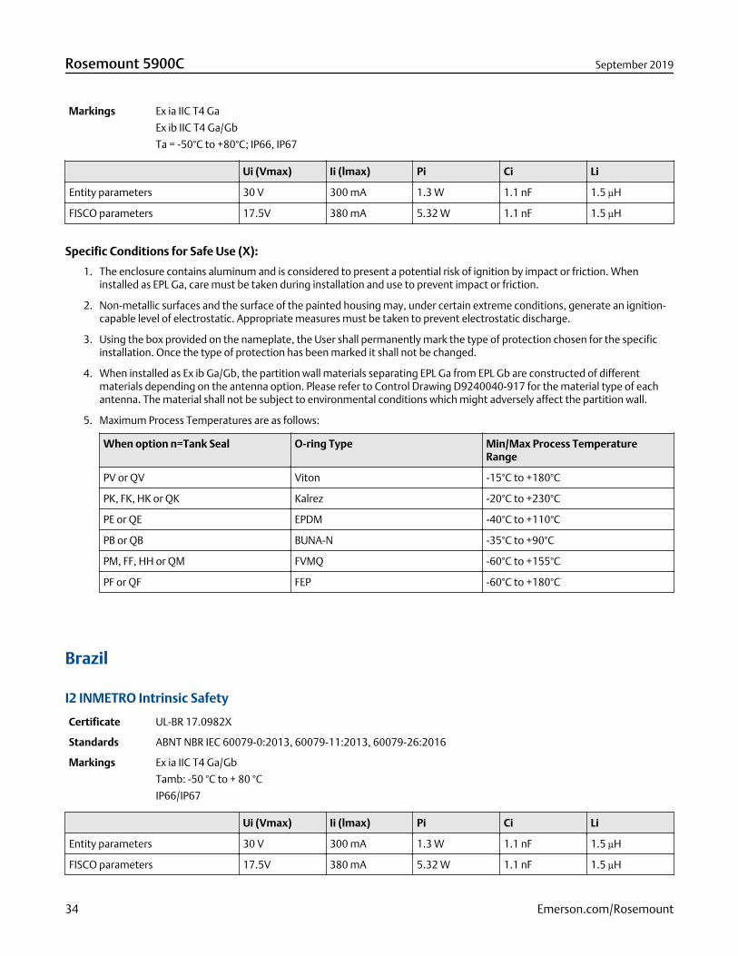
Brazil
I2 INMETRO Intrinsic Safety
Certificate UL-BR 17.0982X
Standards ABNT NBR IEC 60079-0:2013, 60079-11:2013, 60079-26:2016
Markings Ex ia IIC T4 Ga/Gb
Tamb: -50 °C to + 80 °C
IP66/IP67
Ui (Vmax) Ii (lmax) Pi Ci Li
Entity parameters 30 V 300 mA 1.3 W 1.1 nF 1.5 µH
FISCO parameters 17.5V 380 mA 5.32 W 1.1 nF 1.5 µH
Rosemount 5900C September 2019
34 Emerson.com/Rosemount
Special Conditions for Safe Use (X):
1. See certificate for special conditions.
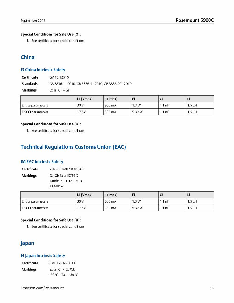
China
I3 China Intrinsic Safety
Certificate GYJ16.1251X
Standards GB 3836.1 - 2010, GB 3836.4 - 2010, GB 3836.20 - 2010
Markings Ex ia IIC T4 Ga
Ui (Vmax) Ii (lmax) Pi Ci Li
Entity parameters 30 V 300 mA 1.3 W 1.1 nF 1.5 µH
FISCO parameters 17.5V 380 mA 5.32 W 1.1 nF 1.5 µH
Special Conditions for Safe Use (X):
1. See certificate for special conditions.
Technical Regulations Customs Union (EAC)
IM EAC Intrinsic Safety
Certificate RU C-SE.AA87.B.00346
Markings Ga/Gb Ex ia IIC T4 X
Tamb: -50 °C to + 80 °C
IP66/IP67
Ui (Vmax) Ii (lmax) Pi Ci Li
Entity parameters 30 V 300 mA 1.3 W 1.1 nF 1.5 µH
FISCO parameters 17.5V 380 mA 5.32 W 1.1 nF 1.5 µH
Special Conditions for Safe Use (X):
1. See certificate for special conditions.
Japan
I4 Japan Intrinsic Safety
Certificate CML 17JPN2301X
Markings Ex ia IIC T4 Ga/Gb
-50 °C ≤ Ta ≤ +80 °C
September 2019 Rosemount 5900C
Emerson.com/Rosemount 35
Ui (Vmax) Ii (lmax) Pi Ci Li
Entity parameters 30 V 300 mA 1.3 W 1.1 nF 1.5 µH
FISCO parameters 17.5V 380 mA 5.32 W 1.1 nF 1.5 µH
Special Conditions for Safe Use (X):
1. See certificate for special conditions.
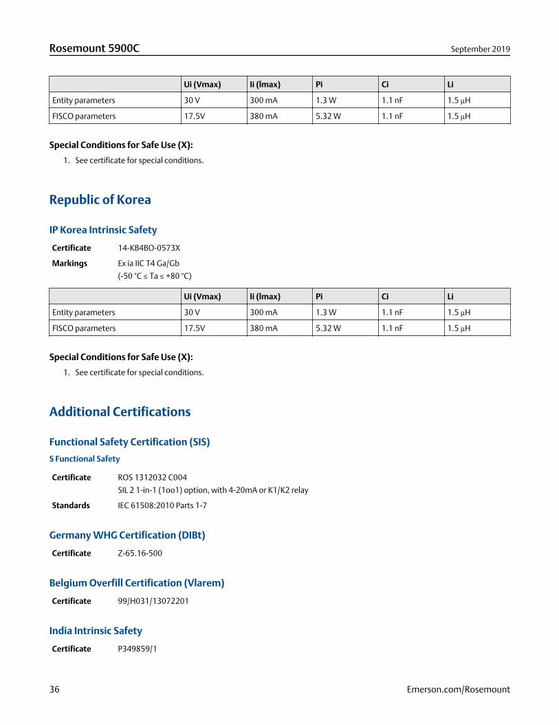
Republic of Korea
IP Korea Intrinsic Safety
Certificate 14-KB4BO-0573X
Markings Ex ia IIC T4 Ga/Gb
(-50 °C ≤ Ta ≤ +80 °C)
Ui (Vmax) Ii (lmax) Pi Ci Li
Entity parameters 30 V 300 mA 1.3 W 1.1 nF 1.5 µH
FISCO parameters 17.5V 380 mA 5.32 W 1.1 nF 1.5 µH
Special Conditions for Safe Use (X):
1. See certificate for special conditions.
Additional Certifications
Functional Safety Certification (SIS)
S Functional Safety
Certificate ROS 1312032 C004
SIL 2 1-in-1 (1oo1) option, with 4-20mA or K1/K2 relay
Standards IEC 61508:2010 Parts 1-7
Germany WHG Certification (DIBt)
Certificate Z-65.16-500
Belgium Overfill Certification (Vlarem)
Certificate 99/H031/13072201
India Intrinsic Safety
Certificate P349859/1
Rosemount 5900C September 2019
36 Emerson.com/Rosemount
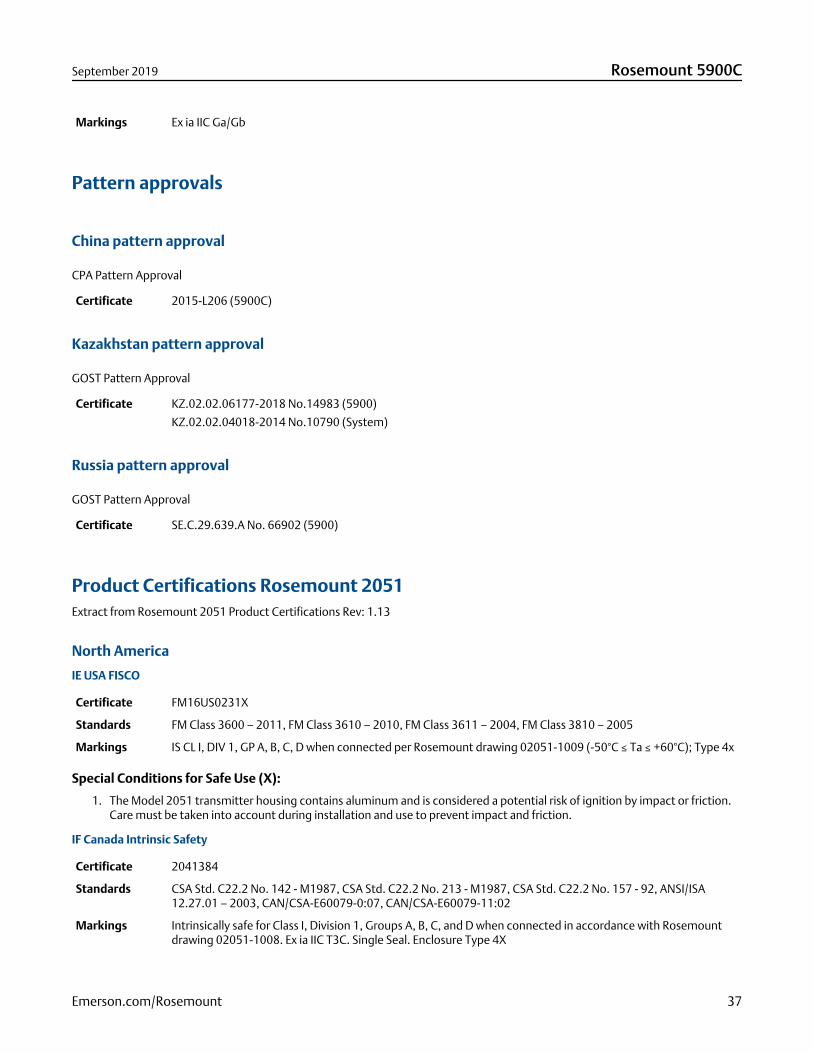
Markings Ex ia IIC Ga/Gb
Pattern approvals
China pattern approval
CPA Pattern Approval
Certificate 2015-L206 (5900C)
Kazakhstan pattern approval
GOST Pattern Approval
Certificate KZ.02.02.06177-2018 No.14983 (5900)
KZ.02.02.04018-2014 No.10790 (System)
Russia pattern approval
GOST Pattern Approval
Certificate SE.C.29.639.A No. 66902 (5900)
Product Certifications Rosemount 2051Extract from Rosemount 2051 Product Certifications Rev: 1.13
North America
IE USA FISCO
Certificate FM16US0231X
Standards FM Class 3600 – 2011, FM Class 3610 – 2010, FM Class 3611 – 2004, FM Class 3810 – 2005
Markings IS CL I, DIV 1, GP A, B, C, D when connected per Rosemount drawing 02051-1009 (-50°C ≤ Ta ≤ +60°C); Type 4x
Special Conditions for Safe Use (X):
1. The Model 2051 transmitter housing contains aluminum and is considered a potential risk of ignition by impact or friction.Care must be taken into account during installation and use to prevent impact and friction.
IF Canada Intrinsic Safety
Certificate 2041384
Standards CSA Std. C22.2 No. 142 - M1987, CSA Std. C22.2 No. 213 - M1987, CSA Std. C22.2 No. 157 - 92, ANSI/ISA12.27.01 – 2003, CAN/CSA-E60079-0:07, CAN/CSA-E60079-11:02
Markings Intrinsically safe for Class I, Division 1, Groups A, B, C, and D when connected in accordance with Rosemountdrawing 02051-1008. Ex ia IIC T3C. Single Seal. Enclosure Type 4X
September 2019 Rosemount 5900C
Emerson.com/Rosemount 37
Europe
IA ATEX FISCO
Certificate Baseefa08ATEX0129X
Standards EN60079-0:2012+A11:2013, EN60079-11:2012
Markings II 1 G Ex ia IIC T4 Ga (-60°C ≤ Ta ≤ +60°C)
Ui Ii Pi Ci Li
FISCO parameters 17.5V 380 mA 5.32 W 0 µF 0 mH
Special Conditions for Safe Use (X):
1. If the equipment is fitted with an optional 90V transient suppressor, it is incapable of withstanding the 500V isolation fromearth test and this must be taken into account during installation.
2. The enclosure may be made of aluminum alloy and given a protective polyurethane paint finish; however care should betaken to protect it from impact and abrasion when located in Zone 0.
International
IG IECEx FISCO
Certificate IECExBAS08.0045X
Standards IEC60079-0:2011, IEC60079-11:2011
Markings Ex ia IIC T4 Ga (-60°C ≤ Ta ≤ +60°C)
Ui Ii Pi Ci Li
FISCO parameters 17.5V 380 mA 5.32 W 0 nF 0 µH
Special Conditions for Safe Use (X):
1. If the equipment is fitted with an optional 90V transient suppressor, it is incapable of withstanding the 500V isolation fromearth test and this must be taken into account during installation.
2. The enclosure may be made of aluminum alloy and given a protective polyurethane paint finish; however care should betaken to protect it from impact and abrasion when located in Zone 0.
3. The equipment contains thin wall diaphragms. The installation, maintenance and use shall take into account theenvironmental conditions to which the diaphragms will be subjected. The manufacturer’s instructions for installation andmaintenance shall be followed in detail to assure safety during its expected lifetime.
Rosemount 5900C September 2019
38 Emerson.com/Rosemount
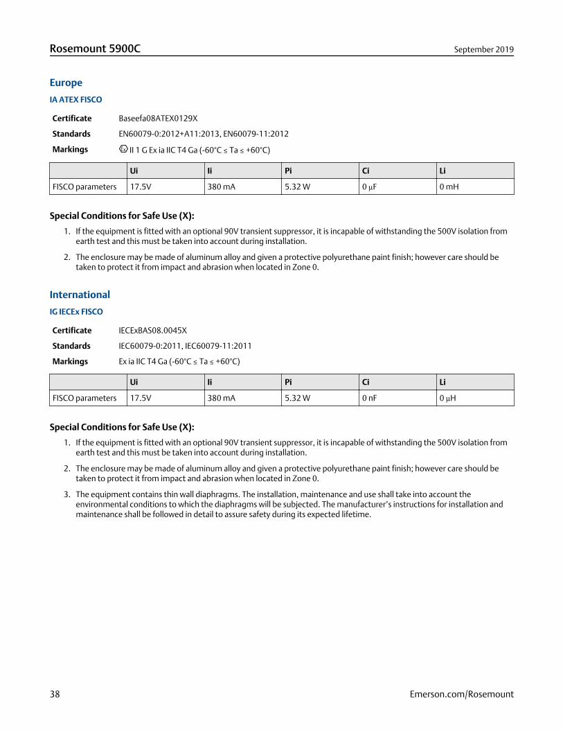
Dimensional drawingsFigure 5: Dimensions of Rosemount 5900C with Parabolic Antenna
226 (8.9) 177 (7.0)
<600 (23.6)
440 (17.3)
17
0 (
6.7
)
27
7 (
10
.9
20
4 (
8.1
Dimensions are in millimeters (inches).
September 2019 Rosemount 5900C
Emerson.com/Rosemount 39
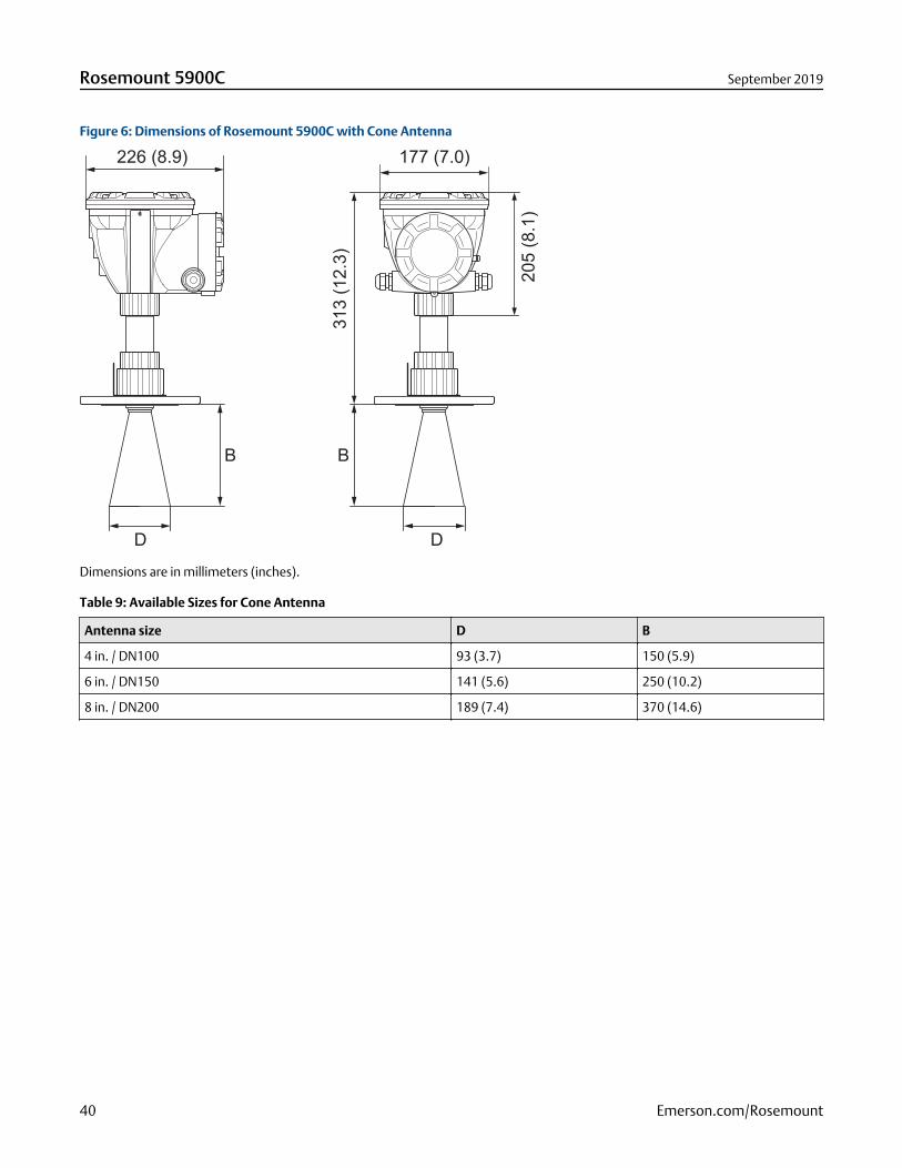
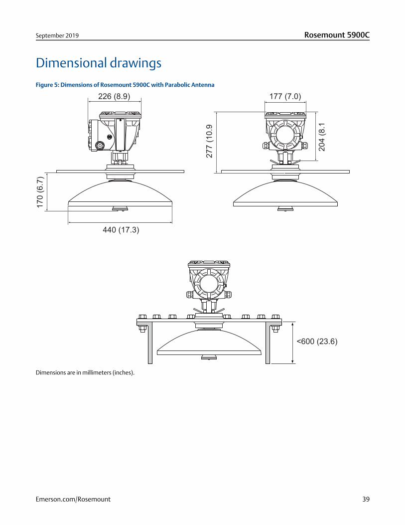
Figure 6: Dimensions of Rosemount 5900C with Cone Antenna
226 (8.9)
B B
D D
177 (7.0)
20
5 (
8.1
)
31
3 (
12
.3)
Dimensions are in millimeters (inches).
Table 9: Available Sizes for Cone Antenna
Antenna size D B
4 in. / DN100 93 (3.7) 150 (5.9)
6 in. / DN150 141 (5.6) 250 (10.2)
8 in. / DN200 189 (7.4) 370 (14.6)
Rosemount 5900C September 2019
40 Emerson.com/Rosemount
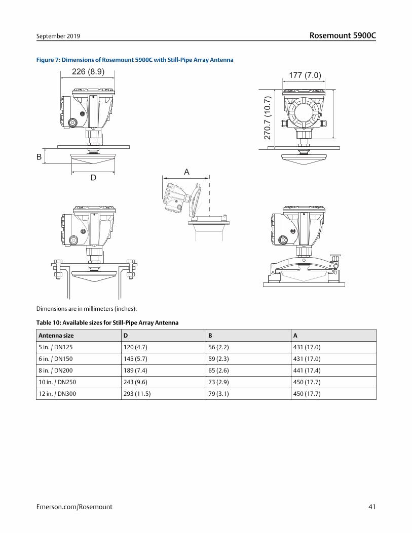
Figure 7: Dimensions of Rosemount 5900C with Still-Pipe Array Antenna
226 (8.9)
D
B
A
177 (7.0)
27
0.7
(1
0.7
)
Dimensions are in millimeters (inches).
Table 10: Available sizes for Still-Pipe Array Antenna
Antenna size D B A
5 in. / DN125 120 (4.7) 56 (2.2) 431 (17.0)
6 in. / DN150 145 (5.7) 59 (2.3) 431 (17.0)
8 in. / DN200 189 (7.4) 65 (2.6) 441 (17.4)
10 in. / DN250 243 (9.6) 73 (2.9) 450 (17.7)
12 in. / DN300 293 (11.5) 79 (3.1) 450 (17.7)
September 2019 Rosemount 5900C
Emerson.com/Rosemount 41
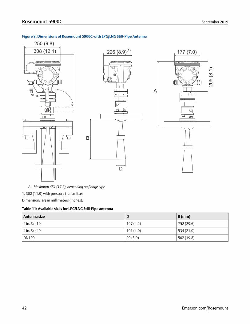
Figure 8: Dimensions of Rosemount 5900C with LPG/LNG Still-Pipe Antenna
226 (8.9)(1)
177 (7.0)
20
5 (
8.1
)
250 (9.8)
308 (12.1)
B
A
D
A. Maximum 451 (17.7), depending on flange type
1. 302 (11.9) with pressure transmitter
Dimensions are in millimeters (inches).
Table 11: Available sizes for LPG/LNG Still-Pipe antenna
Antenna size D B (mm)
4 in. Sch10 107 (4.2) 752 (29.6)
4 in. Sch40 101 (4.0) 534 (21.0)
DN100 99 (3.9) 502 (19.8)
Rosemount 5900C September 2019
42 Emerson.com/Rosemount
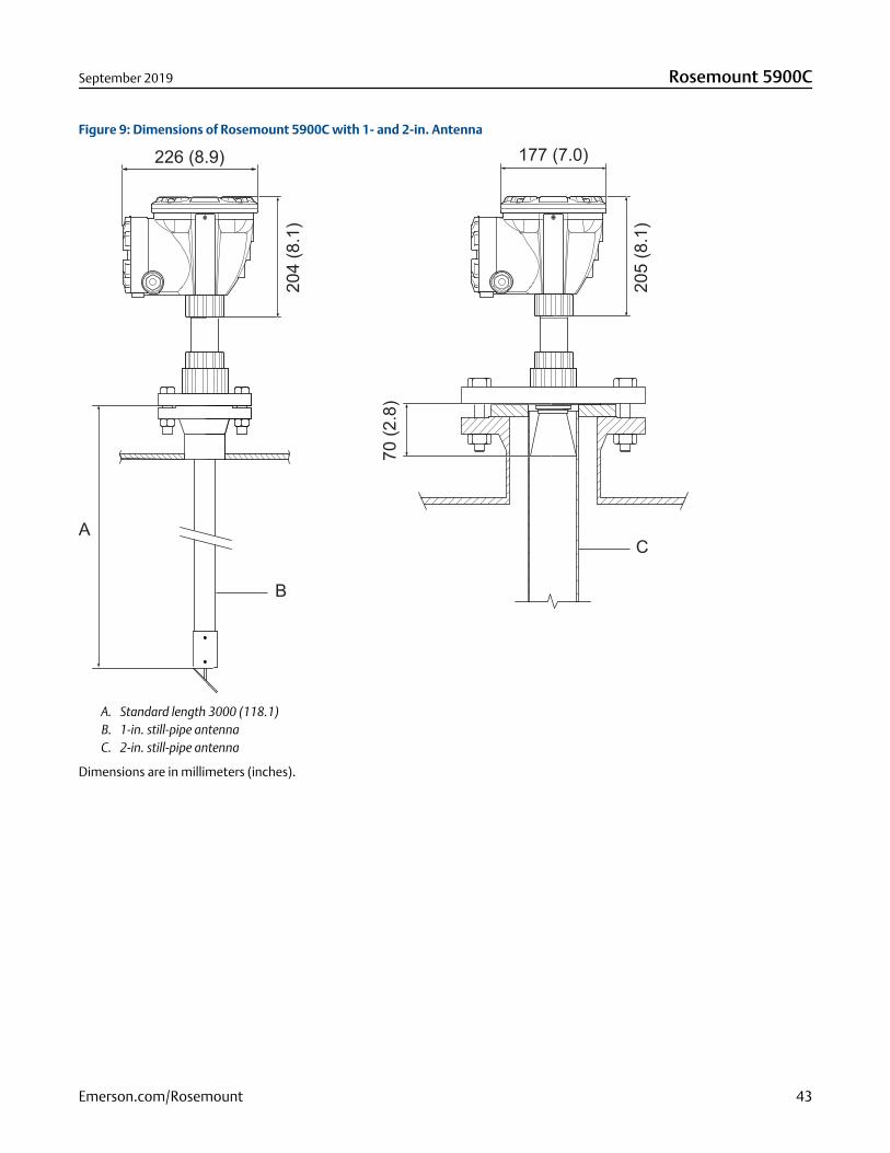
Figure 9: Dimensions of Rosemount 5900C with 1- and 2-in. Antenna
177 (7.0)
A
B
C
70
(2
.8)
20
5 (
8.1
)
20
4 (
8.1
)
226 (8.9)
A. Standard length 3000 (118.1)B. 1-in. still-pipe antennaC. 2-in. still-pipe antenna
Dimensions are in millimeters (inches).
September 2019 Rosemount 5900C
Emerson.com/Rosemount 43
00813-0100-5901Rev. BA
September 2019
Global Headquarters and Europe RegionalOffice Tank GaugingEmerson Automation SolutionsBox 150(Visiting address: Layoutvägen 1)SE-435 23 MölnlyckeSweden
+46 31 337 00 00
+46 31 25 30 22
North America Regional Office TankGaugingEmerson Automation Solutions6005 Rogerdale RoadMail Stop NC 136Houston, TX 77072, USA
+1 281 988 4000 or +1 800 722 2865
Latin America Regional OfficeEmerson Automation Solutions1300 Concord Terrace, Suite 400Sunrise, FL 33323, USA
+1 954 846 5030
+1 954 846 5121
Asia Pacific Regional OfficeEmerson Automation Solutions1 Pandan CrescentSingapore 128461
+65 6777 8211
+65 6777 0947
Middle East and Africa Regional OfficeEmerson Automation SolutionsEmerson FZEP.O. Box 17033Jebel Ali Free Zone - South 2Dubai, United Arab Emirates
+971 4 8118100
+971 4 8865465
Linkedin.com/company/Emerson-Automation-Solutions
Twitter.com/Rosemount_News
Facebook.com/Rosemount
Youtube.com/user/RosemountMeasurement
©2019 Emerson. All rights reserved.
Emerson Terms and Conditions of Sale are available upon request. The Emerson logo is atrademark and service mark of Emerson Electric Co. Rosemount is a mark of one of theEmerson family of companies. All other marks are the property of their respective owners.