Embed Size (px)
Citation preview
PRODUCT: ELECTRONIC ROULETTE MODEL: FUTURA NUMBER OF GAMES: 1 JURISDICTION: DEFAULT VERSION: 1.0 SW VERSION: 6.0.0.0 OPERATING SYSTEM: WINDOWS 8.0 CAB VERSION:
CONFIGURATION: bill validator support: YES tito support: YES coin handling support: YES
online support: YES, SAS 6.02
PROJECT MANAGER:
DOCUMENTATION PREPARED BY: Matej Mihalj
07/2014

2 | P a g e
GOLD CLUB CASINO
PRODUCTION AND DEVELOPMENT OF AMERICAN AVTOMATED ROULETTE
TECHNICAL MANUAL FOR
FUTURA ROULETTE
3 | P a g e
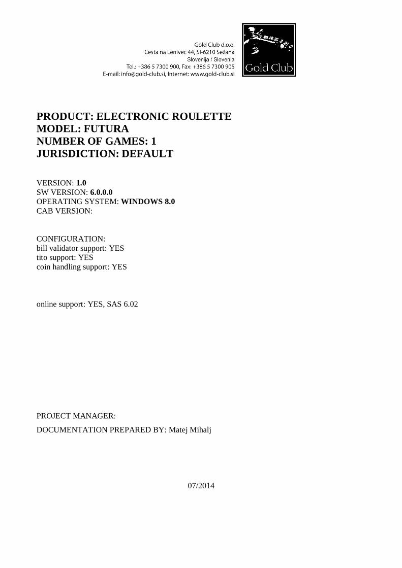
CONTENTS
1. BASIC TECHNICAL DATA FOR THE DEVICE .................................................................... 4
2. DIMENSIONS .......................................................................................................................... 5
3. STRUCTURE OF THE GAMING MACHINE .......................................................................... 6
4. ROULETTE CONNECTION .................................................................................................... 7
5. OPERATING SYSTEM .......................................................................................................... 10
6. GAME DESCRIPTION ........................................................................................................... 13
6.1 MENU .............................................................................................................................. 19
6.2 HELP................................................................................................................................ 21
6.3 CASHOUT ....................................................................................................................... 22
6.4 ADMINISTRATIVE MENU ................................................................................................. 23
7. ACCOUNTING ....................................................................................................................... 28
8. CONFIGURATION................................................................................................................. 29
9. OTHER ELETRONICS COMPONENTS ................................................................................ 59
10. SERVICE MANUAL ........................................................................................................... 70
4 | P a g e
1. BASIC TECHNICAL DATA FOR THE DEVICE Title GAMING MACHINE - AMERICAN ROULETTE Model - Type FUTURA ( Ten play stations ) Manufacturer GOLD CLUB d.o.o. Cesta na Lenivec 44, 6210 Sežana SLOVENIA Identification When communicating with Gold Club Company or with service centre, always give the roulette SERIAL NUMBER, which can be found on the plate located on the cashbox below monitor number 1. Transportation The roulette is normally transported by surface means. Machine is protected with carton and plastic foil. Unloading On receiving the roulette, it is advisable to check its conditions and integrity. Raise the machine with normal lifting equipment. Environmental specifications To ensure that the roulette operates properly, it is advisable to comply with the following limits: Operating temperature: +5°C - 25°C Relative humidity: 15% - 95% Positioning, assembling and maintenance When positioning, assembling and installing the machine the following must be respected: - laws and standards in force regarding the installation of electrical equipment - directives and indications issued by the electrical supply network - local building and fire-prevention laws - accident prevention regulations - ensure antistatic environment
5 | P a g e
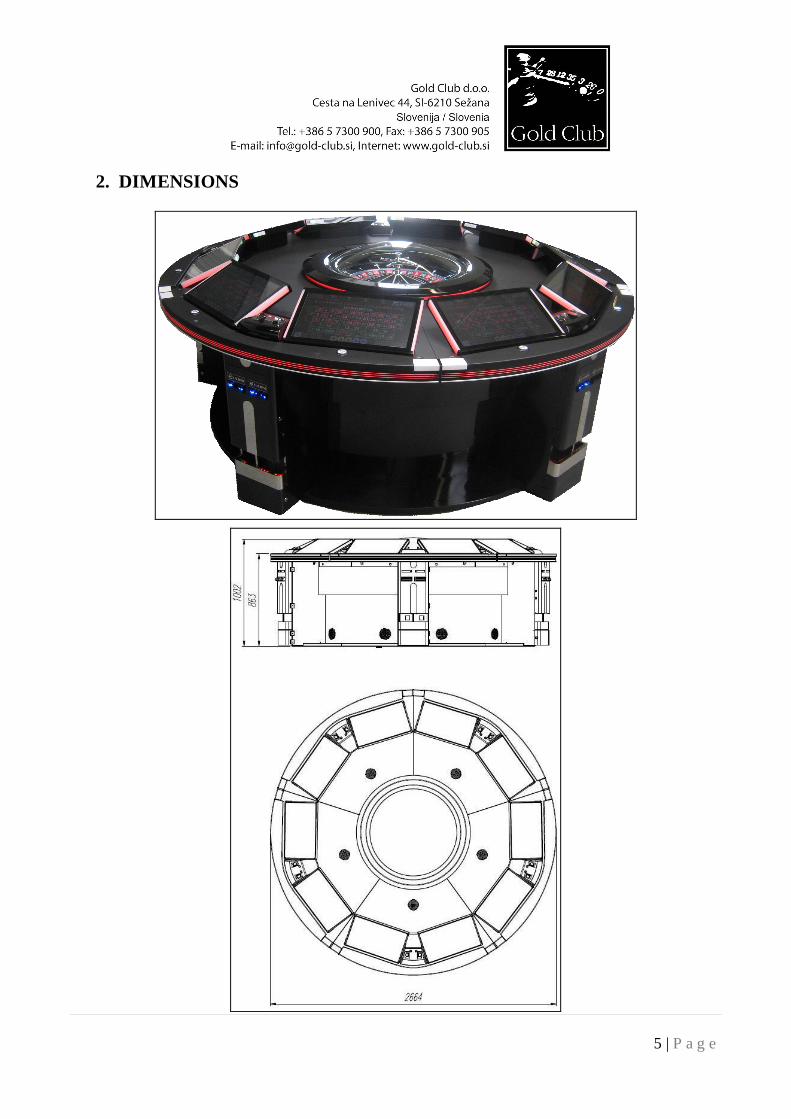
2. DIMENSIONS
6 | P a g e
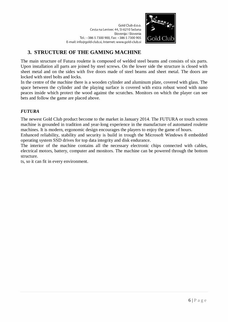
3. STRUCTURE OF THE GAMING MACHINE The main structure of Futura roulette is composed of welded steel beams and consists of six parts. Upon installation all parts are joined by steel screws. On the lower side the structure is closed with sheet metal and on the sides with five doors made of steel beams and sheet metal. The doors are locked with steel bolts and locks. In the centre of the machine there is a wooden cylinder and aluminum plate, covered with glass. The space between the cylinder and the playing surface is covered with extra robust wood with nano peaces inside which protect the wood against the scratches. Monitors on which the player can see bets and follow the game are placed above.
FUTURA
The newest Gold Club product become to the market in January 2014. The FUTURA or touch screen machine is grounded in tradition and year-long experience in the manufacture of automated roulette machines. It is modern, ergonomic design encourages the players to enjoy the game of hours. Enhanced reliability, stability and security is build in trough the Microsoft Windows 8 embedded operating system SSD drives for top data integrity and disk endurance. The interior of the machine contains all the necessary electronic chips connected with cables, electrical motors, battery, computer and monitors. The machine can be powered through the bottom structure. ts, so it can fit in every environment.
7 | P a g e
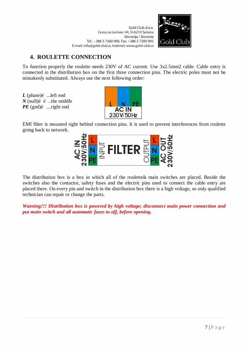
4. ROULETTE CONNECTION To function properly the roulette needs 230V of AC current. Use 3x2.5mm2 cable. Cable entry is connected in the distribution box on the first three connection pins. The electric poles must not be mistakenly substituted. Always use the next following order: L (phase)…...left end N (null)……..the middle PE (gnd)…....right end EMI filter is mounted right behind connection pins. It is used to prevent interferences from roulette going back to network.
The distribution box is a box in which all of the roulette’s main switches are placed. Beside the switches also the contactor, safety fuses and the electric pins used to connect the cable entry are placed there. On every pin and switch in the distribution box there is a high voltage, so only qualified technician can repair or change the parts. Warning!!! Distribution box is powered by high voltage; disconnect main power connection and put main switch and all automatic fuses to off, before opening.
8 | P a g e
THE DISTRIBUTION BOX ELEMENTS
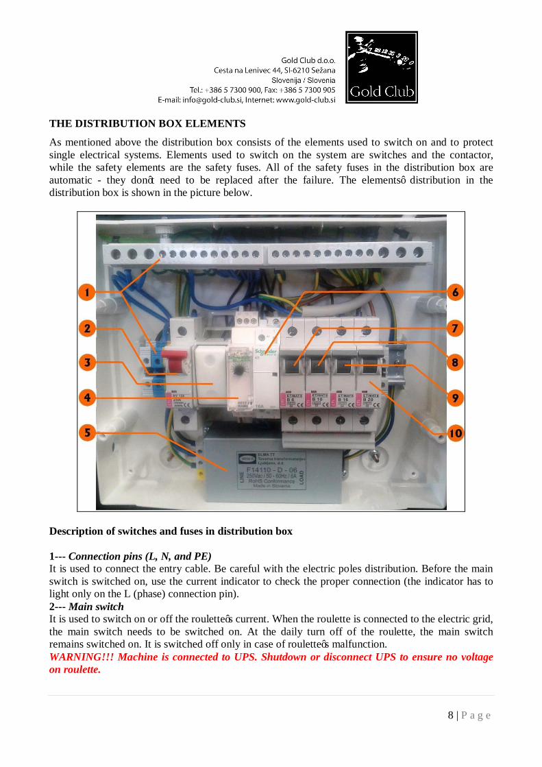
As mentioned above the distribution box consists of the elements used to switch on and to protect single electrical systems. Elements used to switch on the system are switches and the contactor, while the safety elements are the safety fuses. All of the safety fuses in the distribution box are automatic - they don’t need to be replaced after the failure. The elements’ distribution in the distribution box is shown in the picture below.
Description of switches and fuses in distribution box 1--- Connection pins (L, N, and PE) It is used to connect the entry cable. Be careful with the electric poles distribution. Before the main switch is switched on, use the current indicator to check the proper connection (the indicator has to light only on the L (phase) connection pin). 2--- Main switch It is used to switch on or off the roulette’s current. When the roulette is connected to the electric grid, the main switch needs to be switched on. At the daily turn off of the roulette, the main switch remains switched on. It is switched off only in case of roulette’s malfunction. WARNING!!! Machine is connected to UPS. Shutdown or disconnect UPS to ensure no voltage on roulette.
9 | P a g e
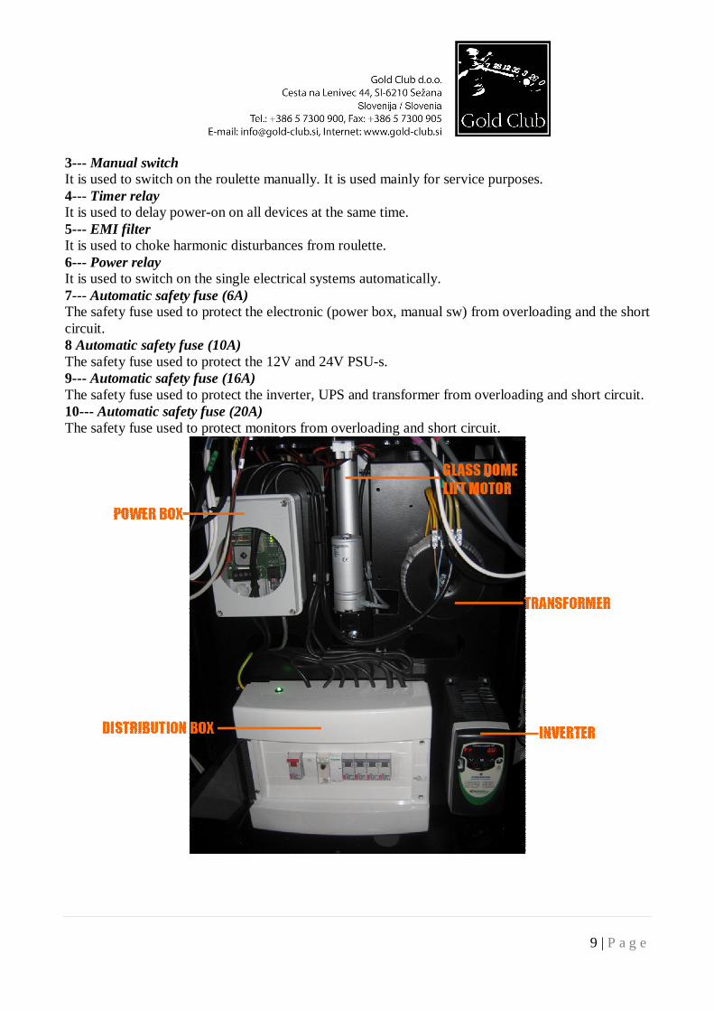
3--- Manual switch It is used to switch on the roulette manually. It is used mainly for service purposes. 4--- Timer relay It is used to delay power-on on all devices at the same time. 5--- EMI filter It is used to choke harmonic disturbances from roulette. 6--- Power relay It is used to switch on the single electrical systems automatically. 7--- Automatic safety fuse (6A) The safety fuse used to protect the electronic (power box, manual sw) from overloading and the short circuit. 8 Automatic safety fuse (10A) The safety fuse used to protect the 12V and 24V PSU-s. 9--- Automatic safety fuse (16A) The safety fuse used to protect the inverter, UPS and transformer from overloading and short circuit. 10--- Automatic safety fuse (20A) The safety fuse used to protect monitors from overloading and short circuit.
10 | P a g e
5. OPERATING SYSTEM Elementary operation of the playing machine is based on the use of the computer. The computer is quite simple in structure, since it does not differ much from a typical home computer. The only difference is that in this case, several graphics cards (multi-monitoring) are used instead of just one. The playing machine uses Windows 8 operating system. SSD disk is used as the data carrier.
COMPUTER ELEMENTS
1 Power supply Seasonic 2 Intel Pentium core2 quad processor 3 RAM Kingston DDR2 4x2Gb 4 Motherboard IEI IMBA XQ354 5 SSD disk GoldClub 60Gb 6 Graphic cards Matrox M9188 and M9120 7 USB read only disk for CRC check
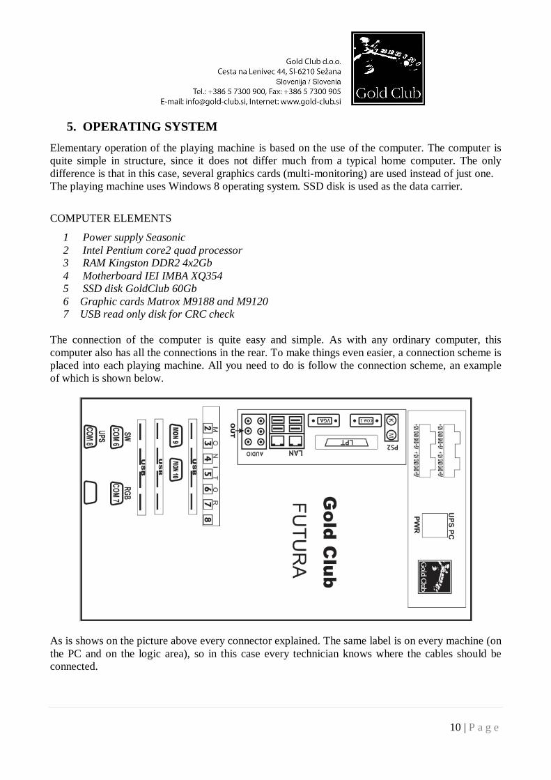
The connection of the computer is quite easy and simple. As with any ordinary computer, this computer also has all the connections in the rear. To make things even easier, a connection scheme is placed into each playing machine. All you need to do is follow the connection scheme, an example of which is shown below.
As is shows on the picture above every connector explained. The same label is on every machine (on the PC and on the logic area), so in this case every technician knows where the cables should be connected.
11 | P a g e
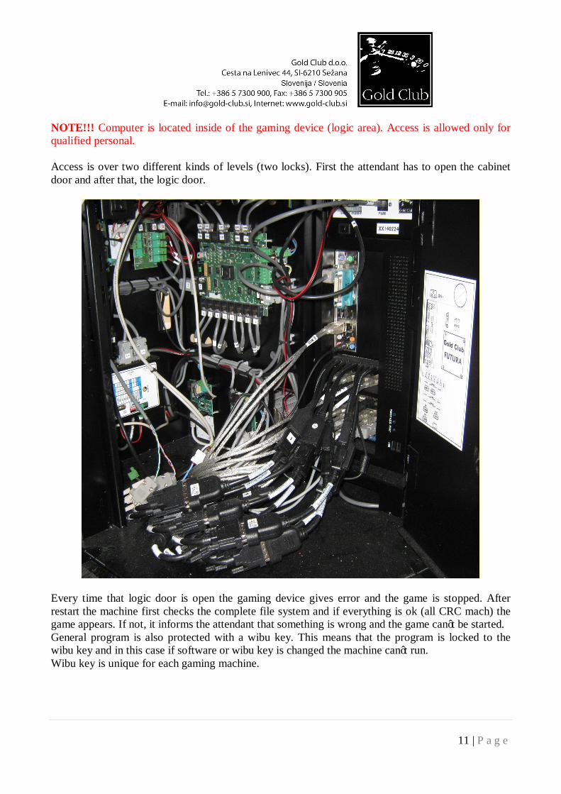
NOTE!!! Computer is located inside of the gaming device (logic area). Access is allowed only for qualified personal. Access is over two different kinds of levels (two locks). First the attendant has to open the cabinet door and after that, the logic door.
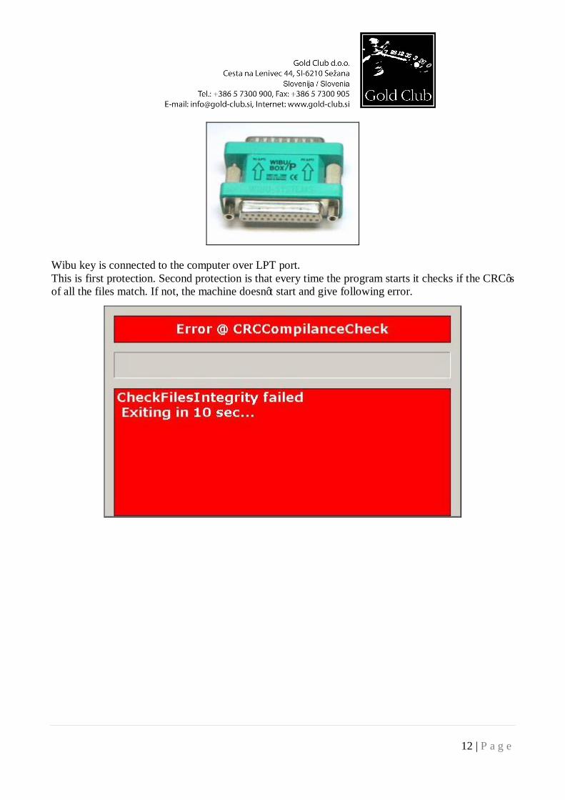
Every time that logic door is open the gaming device gives error and the game is stopped. After restart the machine first checks the complete file system and if everything is ok (all CRC mach) the game appears. If not, it informs the attendant that something is wrong and the game can’t be started. General program is also protected with a wibu key. This means that the program is locked to the wibu key and in this case if software or wibu key is changed the machine can’t run. Wibu key is unique for each gaming machine.
12 | P a g e
Wibu key is connected to the computer over LPT port. This is first protection. Second protection is that every time the program starts it checks if the CRC’s of all the files match. If not, the machine doesn’t start and give following error.
13 | P a g e
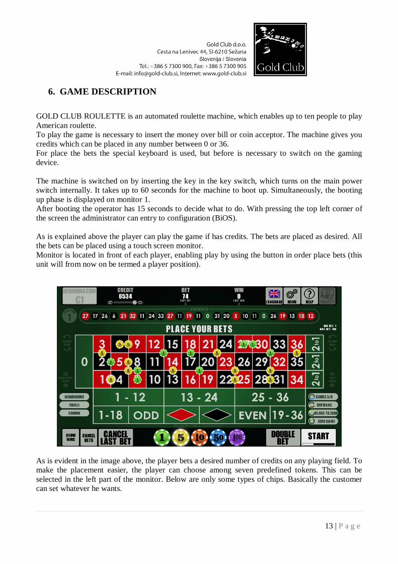
6. GAME DESCRIPTION GOLD CLUB ROULETTE is an automated roulette machine, which enables up to ten people to play American roulette. To play the game is necessary to insert the money over bill or coin acceptor. The machine gives you credits which can be placed in any number between 0 or 36. For place the bets the special keyboard is used, but before is necessary to switch on the gaming device. The machine is switched on by inserting the key in the key switch, which turns on the main power switch internally. It takes up to 60 seconds for the machine to boot up. Simultaneously, the booting up phase is displayed on monitor 1. After booting the operator has 15 seconds to decide what to do. With pressing the top left corner of the screen the administrator can entry to configuration (BiOS). As is explained above the player can play the game if has credits. The bets are placed as desired. All the bets can be placed using a touch screen monitor. Monitor is located in front of each player, enabling play by using the button in order place bets (this unit will from now on be termed a player position).
As is evident in the image above, the player bets a desired number of credits on any playing field. To make the placement easier, the player can choose among seven predefined tokens. This can be selected in the left part of the monitor. Below are only some types of chips. Basically the customer can set whatever he wants.
14 | P a g e
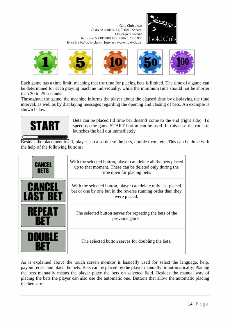
Each game has a time limit, meaning that the time for placing bets is limited. The time of a game can be determined for each playing machine individually, while the minimum time should not be shorter than 20 to 25 seconds. Throughout the game, the machine informs the player about the elapsed time by displaying the time interval, as well as by displaying messages regarding the opening and closing of bets. An example is shown below.
Bets can be placed till time bar doesn’t come to the end (right side). To speed up the game START button can be used. In this case the roulette launches the ball out immediately.
Besides the placement itself, player can also delete the bets, double them, etc. This can be done with the help of the following buttons:
With the selected button, player can delete all the bets placed up to that moment. These can be deleted only during the
time open for placing bets.
With the selected button, player can delete only last placed bet or one by one but in the reverse running order than they
were placed.
The selected button serves for repeating the bets of the previous game.
The selected button serves for doubling the bets.
As is explained above the touch screen monitor is basically used for select the language, help, payout, erase and place the bets. Bets can be placed by the player manually or automatically. Placing the bets manually means the player place the bets on selected field. Besides the manual way of placing the bets the player can also use the automatic one. Buttons that allow the automatic placing the bets are:
15 | P a g e
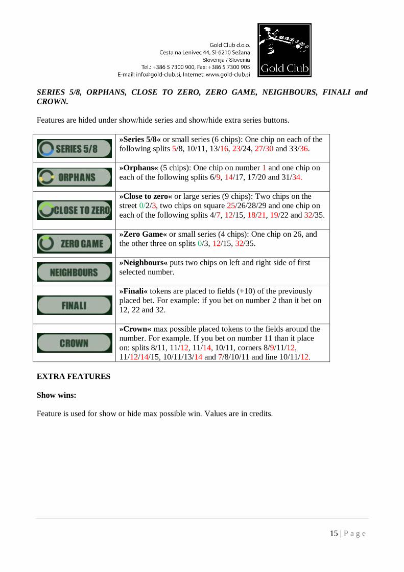
SERIES 5/8, ORPHANS, CLOSE TO ZERO, ZERO GAME, NEIGHBOURS, FINALI and CROWN. Features are hided under show/hide series and show/hide extra series buttons.
»Series 5/8« or small series (6 chips): One chip on each of the following splits 5/8, 10/11, 13/16, 23/24, 27/30 and 33/36.
»Orphans« (5 chips): One chip on number 1 and one chip on each of the following splits 6/9, 14/17, 17/20 and 31/34.
»Close to zero« or large series (9 chips): Two chips on the street 0/2/3, two chips on square 25/26/28/29 and one chip on each of the following splits 4/7, 12/15, 18/21, 19/22 and 32/35.
»Zero Game« or small series (4 chips): One chip on 26, and the other three on splits 0/3, 12/15, 32/35.
»Neighbours« puts two chips on left and right side of first selected number.
»Finali« tokens are placed to fields (+10) of the previously placed bet. For example: if you bet on number 2 than it bet on 12, 22 and 32.
»Crown« max possible placed tokens to the fields around the number. For example. If you bet on number 11 than it place on: splits 8/11, 11/12, 11/14, 10/11, corners 8/9/11/12, 11/12/14/15, 10/11/13/14 and 7/8/10/11 and line 10/11/12.
EXTRA FEATURES Show wins: Feature is used for show or hide max possible win. Values are in credits.
16 | P a g e
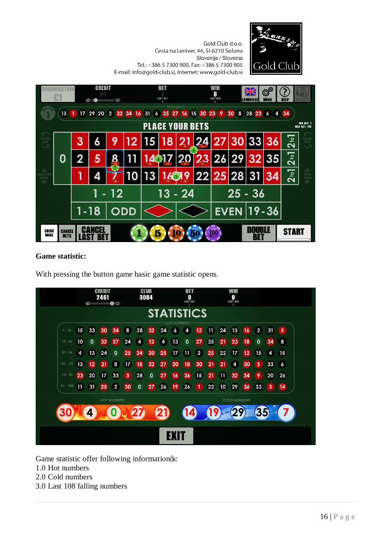
Game statistic: With pressing the button game basic game statistic opens.
Game statistic offer following information’s: 1.0 Hot numbers 2.0 Cold numbers 3.0 Last 108 falling numbers
17 | P a g e
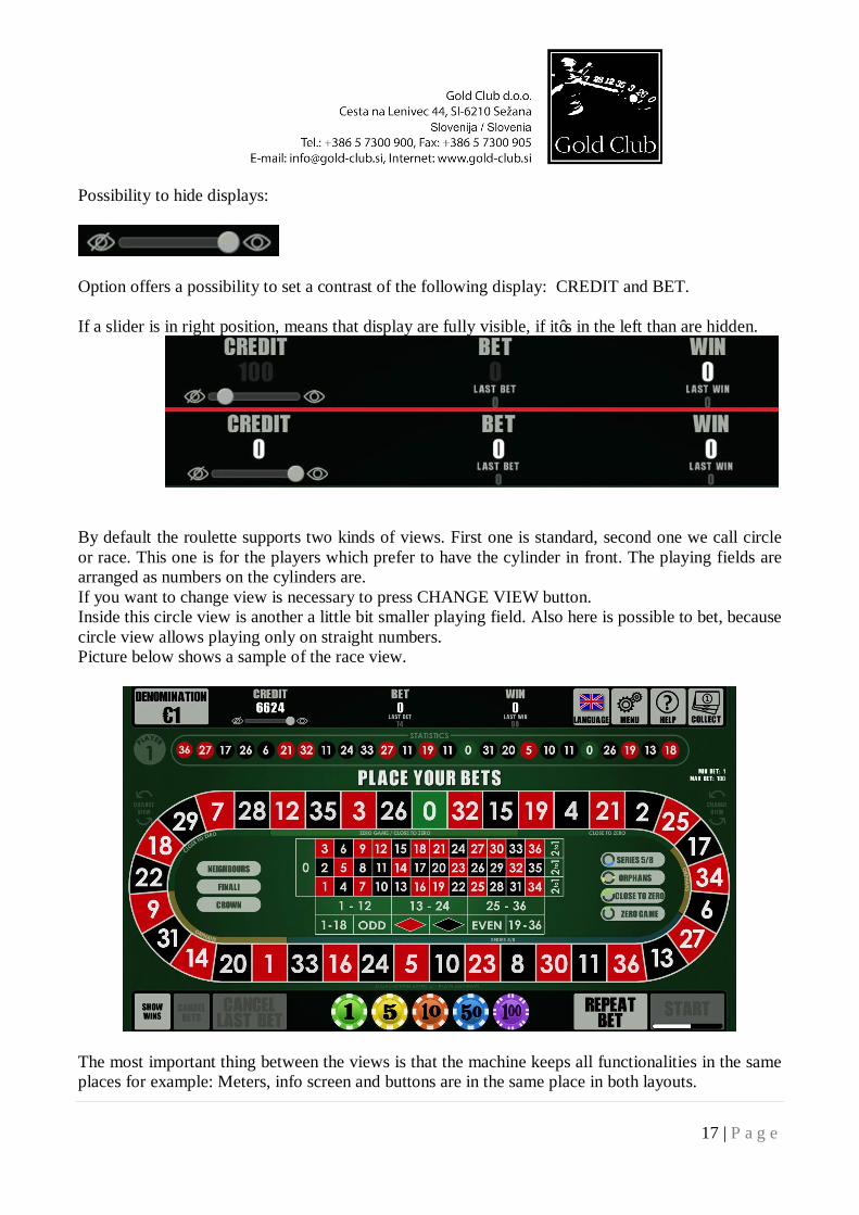
Possibility to hide displays:
Option offers a possibility to set a contrast of the following display: CREDIT and BET. If a slider is in right position, means that display are fully visible, if it’s in the left than are hidden.
By default the roulette supports two kinds of views. First one is standard, second one we call circle or race. This one is for the players which prefer to have the cylinder in front. The playing fields are arranged as numbers on the cylinders are. If you want to change view is necessary to press CHANGE VIEW button. Inside this circle view is another a little bit smaller playing field. Also here is possible to bet, because circle view allows playing only on straight numbers. Picture below shows a sample of the race view.
The most important thing between the views is that the machine keeps all functionalities in the same places for example: Meters, info screen and buttons are in the same place in both layouts.
18 | P a g e
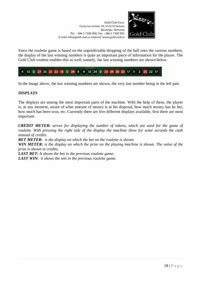
Since the roulette game is based on the unpredictable dropping of the ball onto the various numbers, the display of the last winning numbers is quite an important piece of information for the player. The Gold Club roulette enables this as well; namely, the last winning numbers are shown below.
In the image above, the last winning numbers are shown, the very last number being in the left part. DISPLAYS The displays are among the most important parts of the machine. With the help of these, the player is, at any moment, aware of what amount of money is at his disposal, how much money has he bet, how much has been won, etc. Currently there are five different displays available, first three are most important. CREDIT METER: serves for displaying the number of tokens, which are used for the game of roulette. With pressing the right side of the display the machine show for some seconds the cash instead of credits. BET METER: is the display on which the bet on the roulette is shown. WIN METER: is the display on which the prize on the playing machine is shown. The value of the prize is shown in credits. LAST BET: It shows the bet in the previous roulette game. LAST WIN: it shows the win in the previous roulette game.
19 | P a g e
6.1 MENU
Pressing the MENU button opens a window in which the player can choose among certain smaller settings.
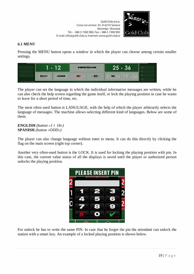
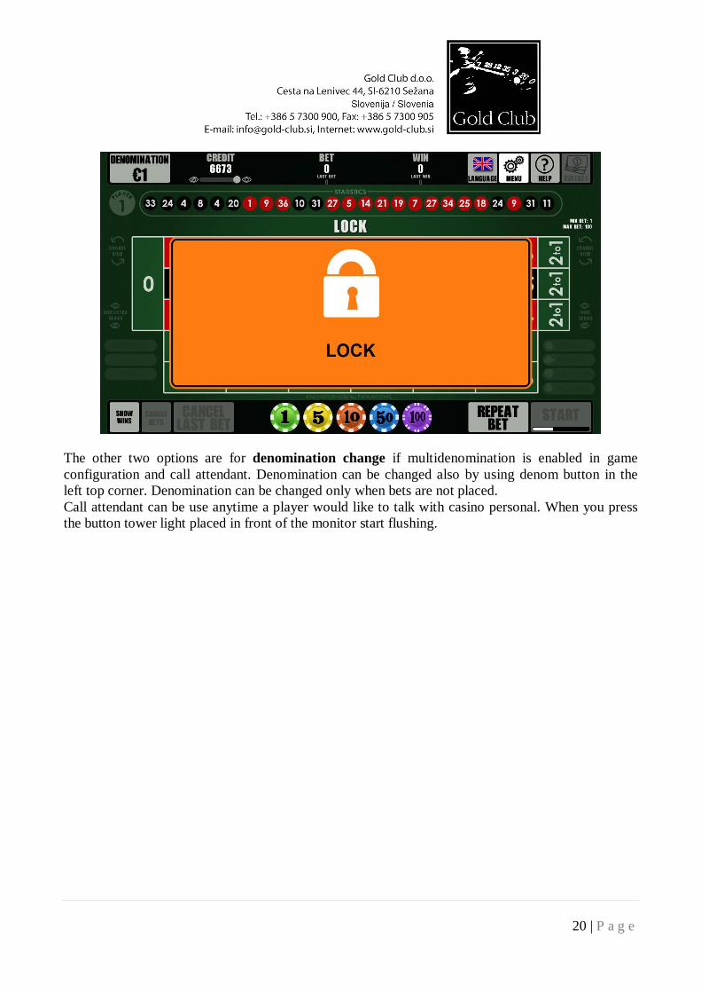
The player can set the language in which the individual informative messages are written, while he can also check the help screen regarding the game itself, or lock the playing position in case he wants to leave for a short period of time, etc. The most often used button is LANGUAGE, with the help of which the player arbitrarily selects the language of messages. The machine allows selecting different kind of languages. Below are some of them. ENGLISH (button »1 – 18«) SPANISH (button »ODD«) The player can also change language without enter to menu. It can do this directly by clicking the flag on the main screen (right top corner). Another very often-used button is the LOCK. It is used for locking the playing position with pin. In this case, the current value status of all the displays is saved until the player or authorized person unlocks the playing position.
For unlock he has to write the same PIN. In case that he forget the pin the attendant can unlock the station with a smart key. An example of a locked playing position is shown below.
20 | P a g e
The other two options are for denomination change if multidenomination is enabled in game configuration and call attendant. Denomination can be changed also by using denom button in the left top corner. Denomination can be changed only when bets are not placed. Call attendant can be use anytime a player would like to talk with casino personal. When you press the button tower light placed in front of the monitor start flushing.
21 | P a g e
6.2 HELP
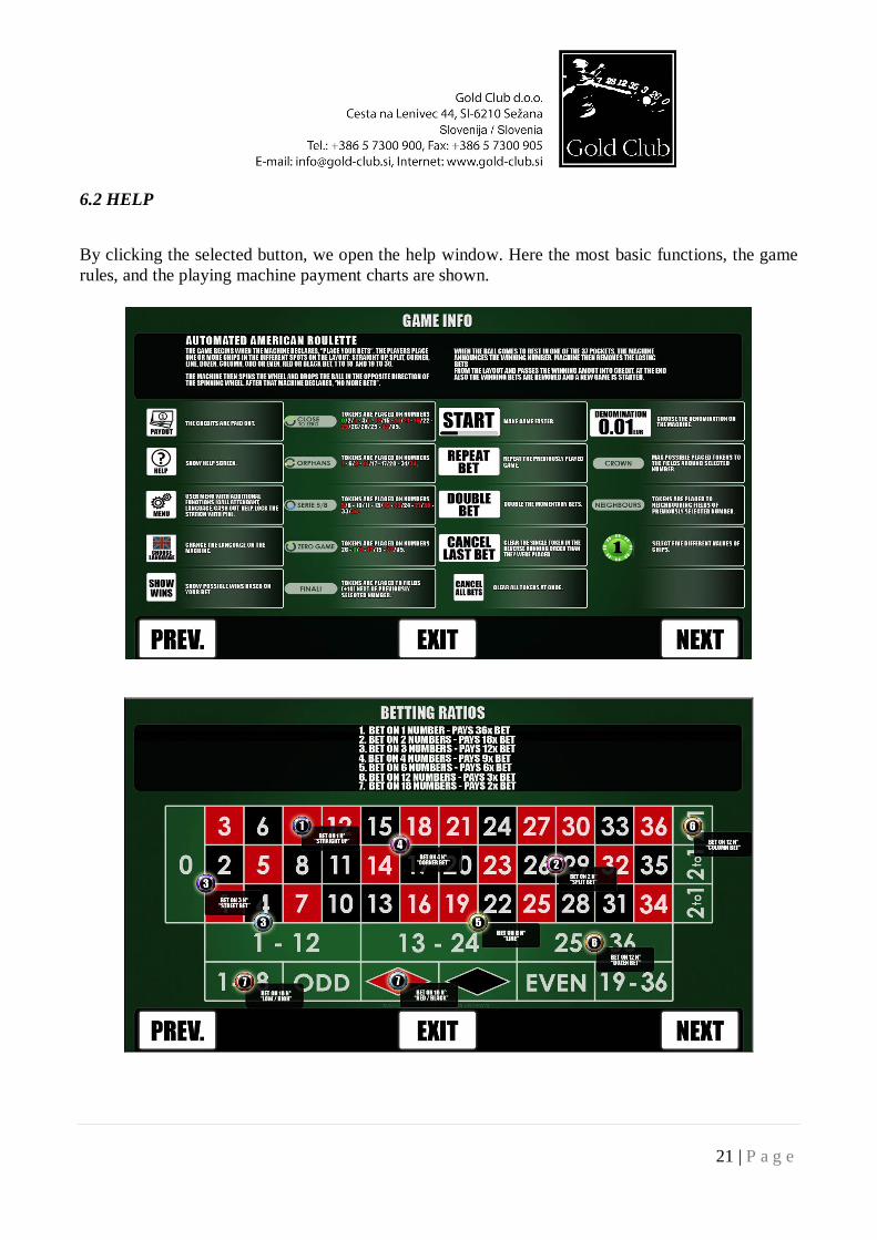
By clicking the selected button, we open the help window. Here the most basic functions, the game rules, and the playing machine payment charts are shown.
22 | P a g e
6.3 CASHOUT
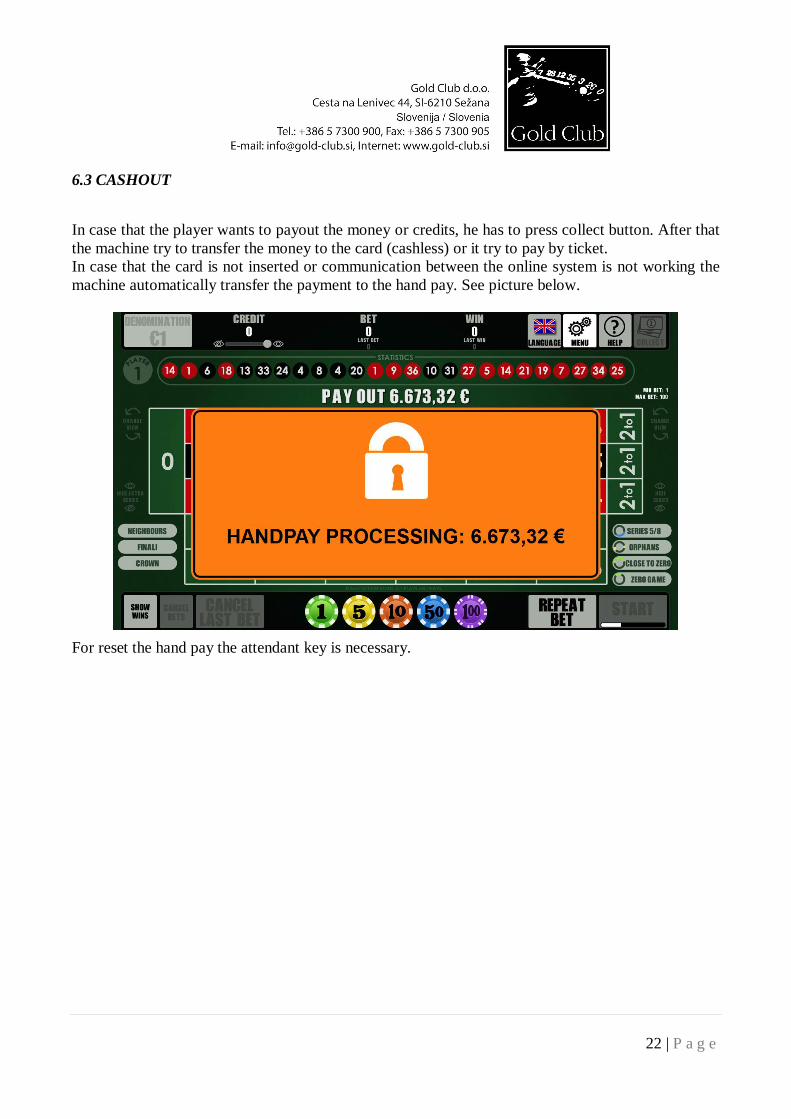
In case that the player wants to payout the money or credits, he has to press collect button. After that the machine try to transfer the money to the card (cashless) or it try to pay by ticket. In case that the card is not inserted or communication between the online system is not working the machine automatically transfer the payment to the hand pay. See picture below.
For reset the hand pay the attendant key is necessary.
23 | P a g e
6.4 ADMINISTRATIVE MENU
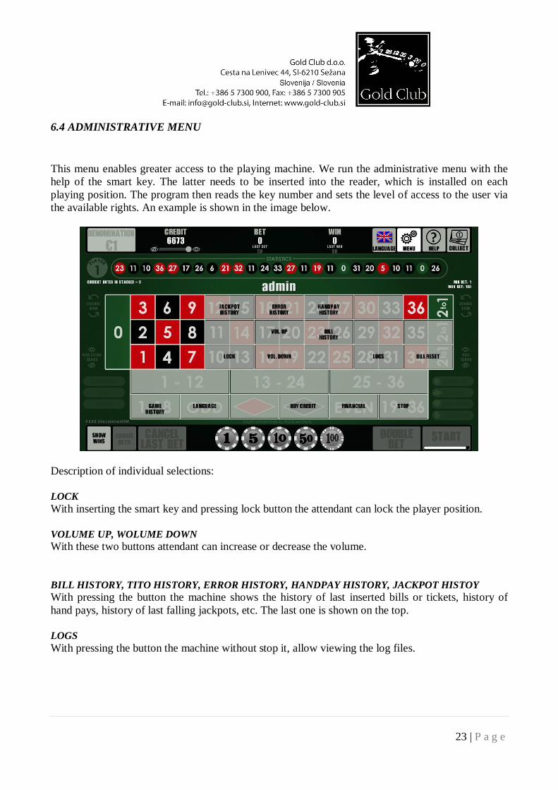
This menu enables greater access to the playing machine. We run the administrative menu with the help of the smart key. The latter needs to be inserted into the reader, which is installed on each playing position. The program then reads the key number and sets the level of access to the user via the available rights. An example is shown in the image below.
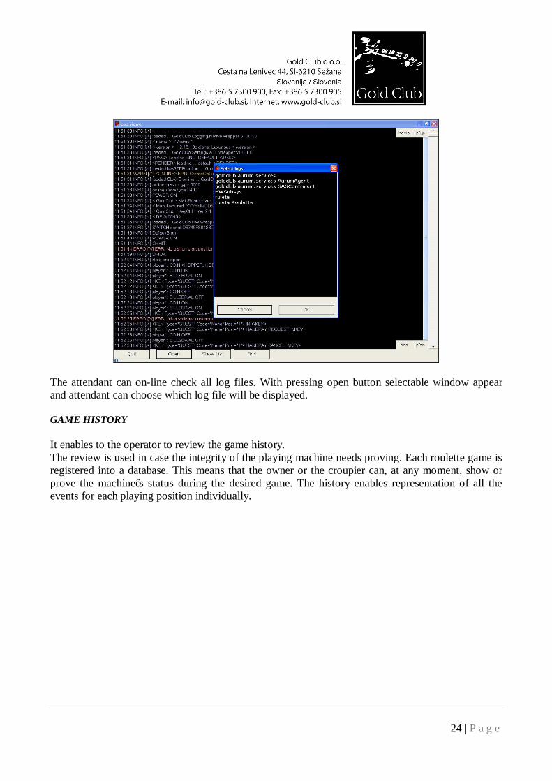
Description of individual selections: LOCK With inserting the smart key and pressing lock button the attendant can lock the player position. VOLUME UP, WOLUME DOWN With these two buttons attendant can increase or decrease the volume. BILL HISTORY, TITO HISTORY, ERROR HISTORY, HANDPAY HISTORY, JACKPOT HISTOY With pressing the button the machine shows the history of last inserted bills or tickets, history of hand pays, history of last falling jackpots, etc. The last one is shown on the top. LOGS With pressing the button the machine without stop it, allow viewing the log files.
24 | P a g e
The attendant can on-line check all log files. With pressing open button selectable window appear and attendant can choose which log file will be displayed. GAME HISTORY It enables to the operator to review the game history. The review is used in case the integrity of the playing machine needs proving. Each roulette game is registered into a database. This means that the owner or the croupier can, at any moment, show or prove the machine’s status during the desired game. The history enables representation of all the events for each playing position individually.
25 | P a g e
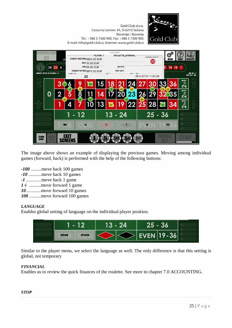
The image above shows an example of displaying the previous games. Moving among individual games (forward, back) is performed with the help of the following buttons: -100 .........move back 100 games -10 ...........move back 10 games -1 .............move back 1 game 1 …..........move forward 1 game 10.............move forward 10 games 100 ..........move forward 100 games LANGUAGE Enables global setting of language on the individual player position.
Similar to the player menu, we select the language as well. The only difference is that this setting is global, not temporary FINANCIAL Enables us to review the quick finances of the roulette. See more in chapter 7.0 ACCOUNTING. STOP
26 | P a g e
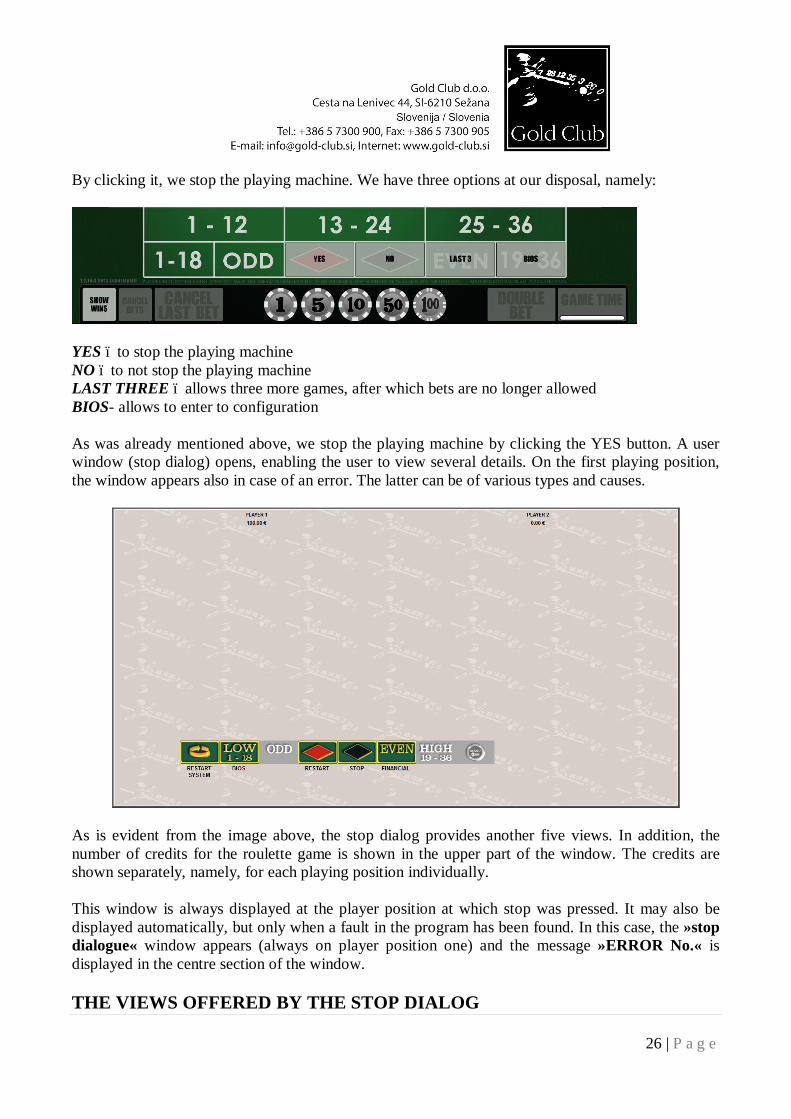
By clicking it, we stop the playing machine. We have three options at our disposal, namely:
YES – to stop the playing machine NO – to not stop the playing machine LAST THREE – allows three more games, after which bets are no longer allowed BIOS- allows to enter to configuration As was already mentioned above, we stop the playing machine by clicking the YES button. A user window (stop dialog) opens, enabling the user to view several details. On the first playing position, the window appears also in case of an error. The latter can be of various types and causes.
As is evident from the image above, the stop dialog provides another five views. In addition, the number of credits for the roulette game is shown in the upper part of the window. The credits are shown separately, namely, for each playing position individually. This window is always displayed at the player position at which stop was pressed. It may also be displayed automatically, but only when a fault in the program has been found. In this case, the »stop dialogue« window appears (always on player position one) and the message »ERROR No.« is displayed in the centre section of the window. THE VIEWS OFFERED BY THE STOP DIALOG
27 | P a g e
SYSTEM RESTART Button is used to completely restart the roulette (OS and the game). BIOS Button is used to enter to configuration. RESTART Button is used to start the game. STOP Button is used to switch off the roulette. FINANCIAL See chapter 7.0.
28 | P a g e
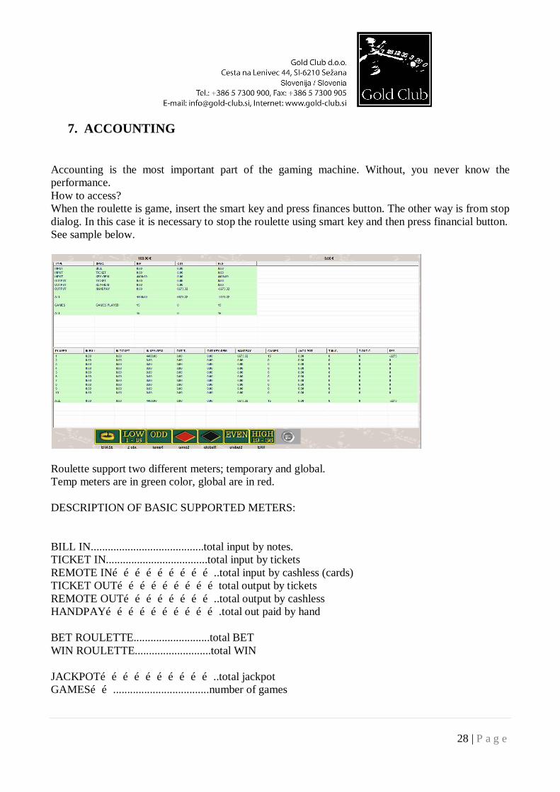
7. ACCOUNTING
Accounting is the most important part of the gaming machine. Without, you never know the performance. How to access? When the roulette is game, insert the smart key and press finances button. The other way is from stop dialog. In this case it is necessary to stop the roulette using smart key and then press financial button. See sample below.
Roulette support two different meters; temporary and global. Temp meters are in green color, global are in red. DESCRIPTION OF BASIC SUPPORTED METERS:
BILL IN........................................total input by notes. TICKET IN....................................total input by tickets REMOTE IN………………………..total input by cashless (cards) TICKET OUT………………………total output by tickets REMOTE OUT……………………..total output by cashless HANDPAY………………………….total out paid by hand BET ROULETTE...........................total BET WIN ROULETTE...........................total WIN JACKPOT…………………………..total jackpot GAMES……..................................number of games
29 | P a g e
8. CONFIGURATION
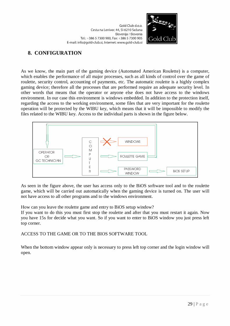
As we know, the main part of the gaming device (Automated American Roulette) is a computer, which enables the performance of all major processes, such as all kinds of control over the game of roulette, security control, accounting of payments, etc. The automatic roulette is a highly complex gaming device; therefore all the processes that are performed require an adequate security level. In other words that means that the operator or anyone else does not have access to the windows environment. In our case this environment is windows embedded. In addition to the protection itself, regarding the access to the working environment, some files that are very important for the roulette operation will be protected by the WIBU key, which means that it will be impossible to modify the files related to the WIBU key. Access to the individual parts is shown in the figure below.
As seen in the figure above, the user has access only to the BiOS software tool and to the roulette game, which will be carried out automatically when the gaming device is turned on. The user will not have access to all other programs and to the windows environment. How can you leave the roulette game and entry to BiOS setup window? If you want to do this you must first stop the roulette and after that you must restart it again. Now you have 15s for decide what you want. So if you want to enter to BiOS window you just press left top corner. ACCESS TO THE GAME OR TO THE BIOS SOFTWARE TOOL
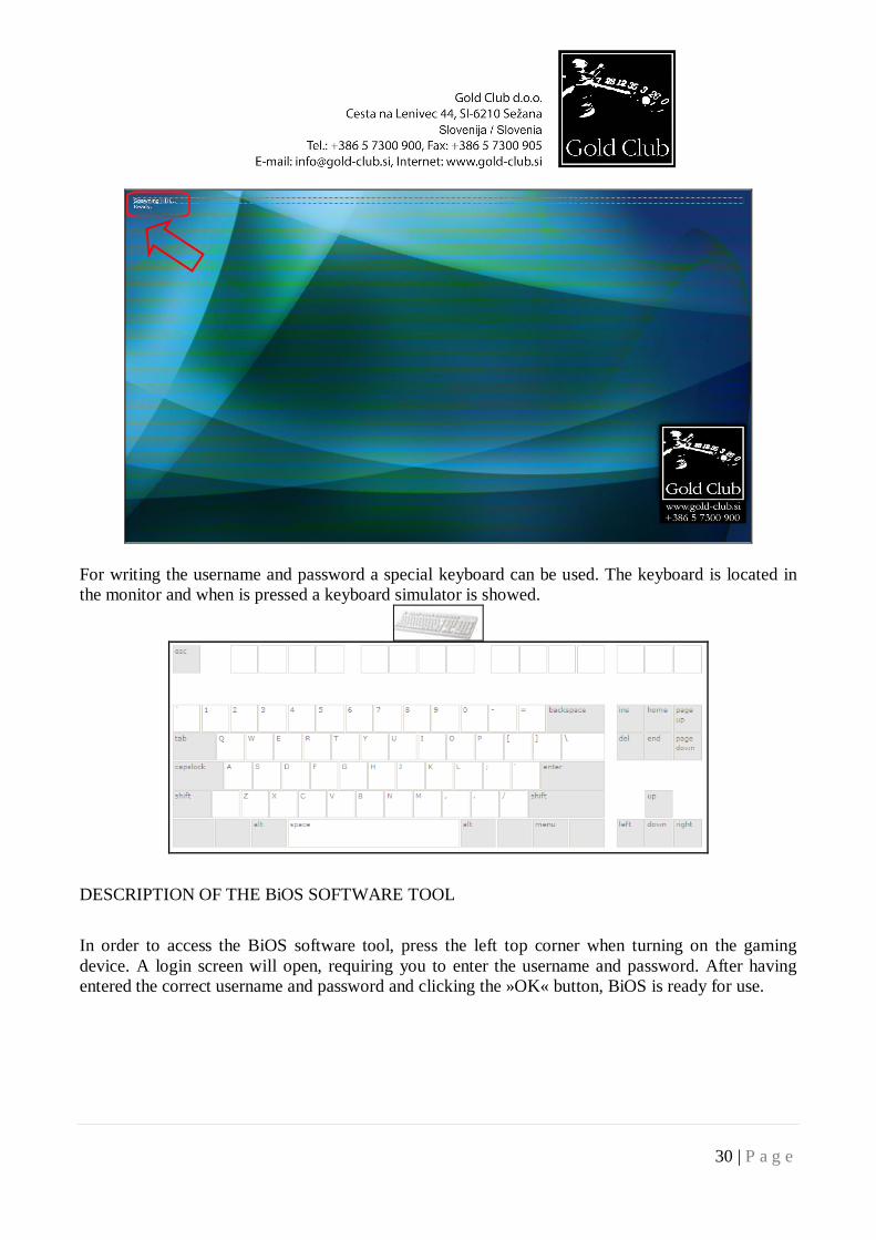
When the bottom window appear only is necessary to press left top corner and the login window will open.
30 | P a g e
For writing the username and password a special keyboard can be used. The keyboard is located in the monitor and when is pressed a keyboard simulator is showed.
DESCRIPTION OF THE BiOS SOFTWARE TOOL
In order to access the BiOS software tool, press the left top corner when turning on the gaming device. A login screen will open, requiring you to enter the username and password. After having entered the correct username and password and clicking the »OK« button, BiOS is ready for use.
31 | P a g e
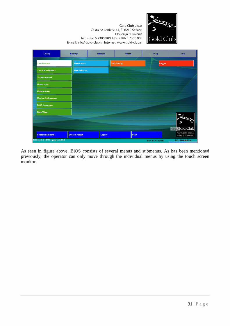
As seen in figure above, BiOS consists of several menus and submenus. As has been mentioned previously, the operator can only move through the individual menus by using the touch screen monitor.
32 | P a g e
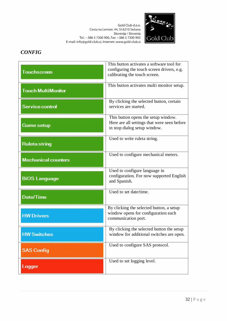
CONFIG
This button activates a software tool for configuring the touch screen drivers, e.g. calibrating the touch screen.
This button activates multi monitor setup.
By clicking the selected button, certain services are started.
This button opens the setup window. Here are all settings that were seen before in stop dialog setup window.
Used to write ruleta string.
Used to configure mechanical meters.
Used to configure language in configuration. For now supported English and Spanish.
Used to set date/time.
By clicking the selected button, a setup window opens for configuration each communication port.
By clicking the selected button the setup window for additional switches are open.
Used to configure SAS protocol.
Used to set logging level.
33 | P a g e
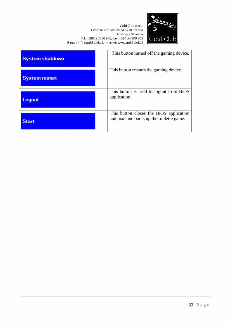
This button turned off the gaming device.
This button restarts the gaming device.
This button is used to logout from BiOS application.
This button closes the BiOS application and machine boots up the roulette game.
34 | P a g e
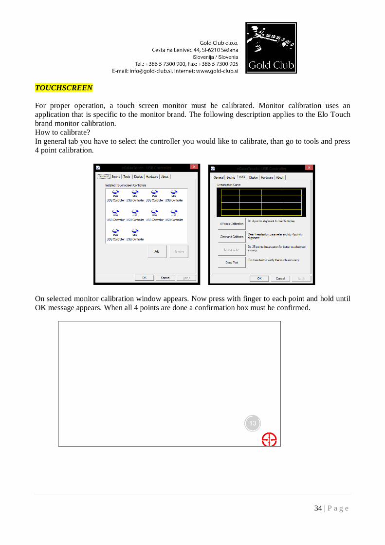
TOUCHSCREEN For proper operation, a touch screen monitor must be calibrated. Monitor calibration uses an application that is specific to the monitor brand. The following description applies to the Elo Touch brand monitor calibration. How to calibrate? In general tab you have to select the controller you would like to calibrate, than go to tools and press 4 point calibration.
On selected monitor calibration window appears. Now press with finger to each point and hold until OK message appears. When all 4 points are done a confirmation box must be confirmed.
35 | P a g e
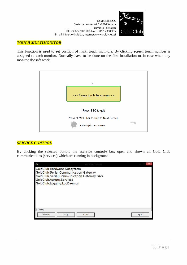
TOUCH MULTIMONITOR This function is used to set position of multi touch monitors. By clicking screen touch number is assigned to each monitor. Normally have to be done on the first installation or in case when any monitor doesn’t work.
SERVICE CONTROL By clicking the selected button, the »service control« box open and shown all Gold Club communications (services) which are running in background.
36 | P a g e
GAME SETUP
Software and hardware configuration.
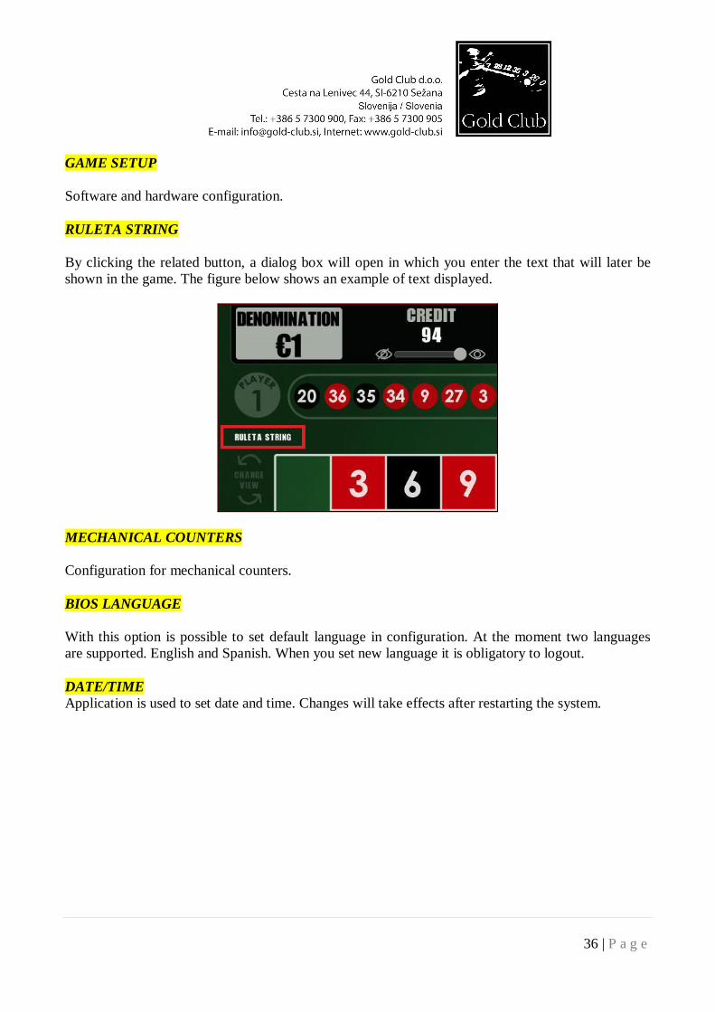
RULETA STRING
By clicking the related button, a dialog box will open in which you enter the text that will later be shown in the game. The figure below shows an example of text displayed.
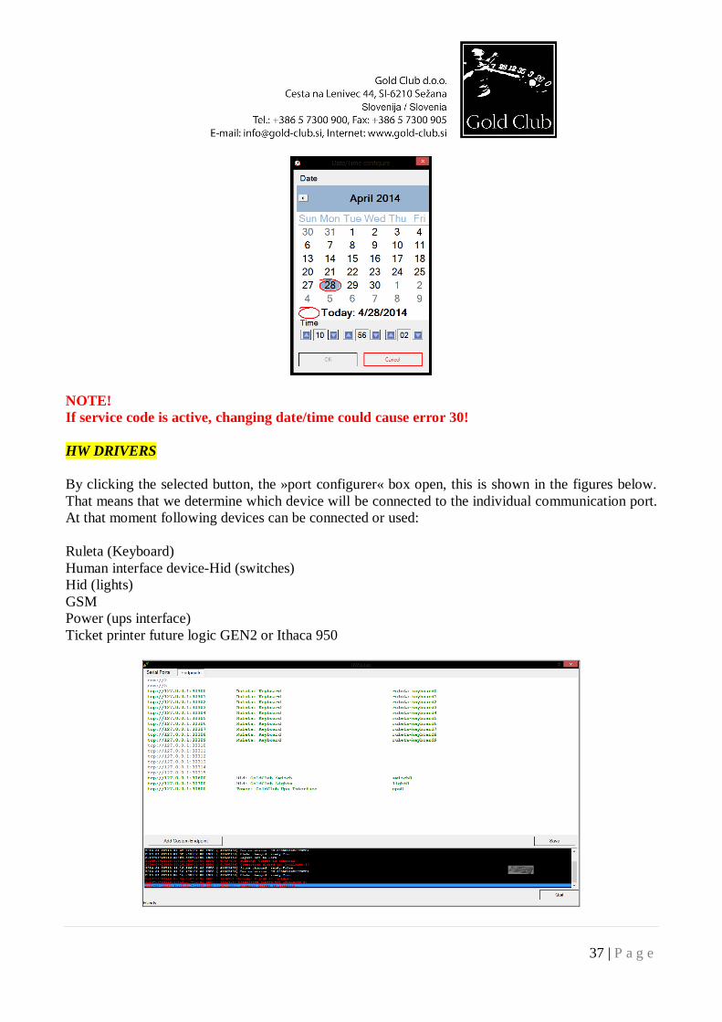
MECHANICAL COUNTERS Configuration for mechanical counters. BIOS LANGUAGE With this option is possible to set default language in configuration. At the moment two languages are supported. English and Spanish. When you set new language it is obligatory to logout. DATE/TIME Application is used to set date and time. Changes will take effects after restarting the system.
37 | P a g e
NOTE! If service code is active, changing date/time could cause error 30!
HW DRIVERS By clicking the selected button, the »port configurer« box open, this is shown in the figures below. That means that we determine which device will be connected to the individual communication port. At that moment following devices can be connected or used: Ruleta (Keyboard) Human interface device-Hid (switches) Hid (lights) GSM Power (ups interface) Ticket printer future logic GEN2 or Ithaca 950
38 | P a g e
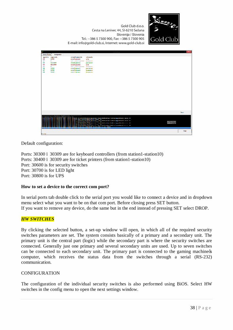
Default configuration: Ports: 30300 – 30309 are for keyboard controllers (from station1-station10) Ports: 30400 – 30309 are for ticket printers (from station1-station10) Port: 30600 is for security switches Port: 30700 is for LED light Port: 30800 is for UPS How to set a device to the correct com port? In serial ports tab double click to the serial port you would like to connect a device and in dropdown menu select what you want to be on that com port. Before closing press SET button. If you want to remove any device, do the same but in the end instead of pressing SET select DROP. HW SWITCHES By clicking the selected button, a set-up window will open, in which all of the required security switches parameters are set. The system consists basically of a primary and a secondary unit. The primary unit is the central part (logic) while the secondary part is where the security switches are connected. Generally just one primary and several secondary units are used. Up to seven switches can be connected to each secondary unit. The primary part is connected to the gaming machine’s computer, which receives the status data from the switches through a serial (RS-232) communication. CONFIGURATION The configuration of the individual security switches is also performed using BiOS. Select HW switches in the config menu to open the next settings window.
39 | P a g e
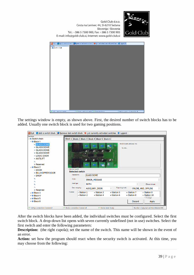
The settings window is empty, as shown above. First, the desired number of switch blocks has to be added. Usually one switch block is used for two gaming positions.
After the switch blocks have been added, the individual switches must be configured. Select the first switch block. A drop-down list opens with seven currently undefined (not in use) switches. Select the first switch and enter the following parameters: Description: (the right cupola); set the name of the switch. This name will be shown in the event of an error. Action: set how the program should react when the security switch is activated. At this time, you may choose from the following:
40 | P a g e
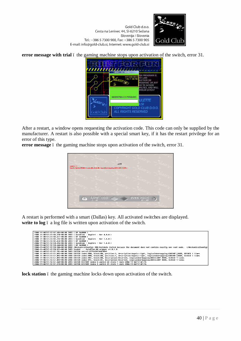
error message with trial – the gaming machine stops upon activation of the switch, error 31.
After a restart, a window opens requesting the activation code. This code can only be supplied by the manufacturer. A restart is also possible with a special smart key, if it has the restart privilege for an error of this type. error message – the gaming machine stops upon activation of the switch, error 31.
A restart is performed with a smart (Dallas) key. All activated switches are displayed. write to log – a log file is written upon activation of the switch.
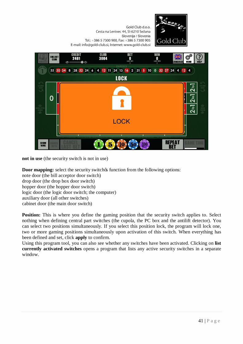
lock station – the gaming machine locks down upon activation of the switch.
41 | P a g e
not in use (the security switch is not in use) Door mapping: select the security switch’s function from the following options: note door (the bill acceptor door switch) drop door (the drop box door switch) hopper door (the hopper door switch) logic door (the logic door switch; the computer) auxiliary door (all other switches) cabinet door (the main door switch) Position: This is where you define the gaming position that the security switch applies to. Select nothing when defining central part switches (the cupola, the PC box and the antilift detector). You can select two positions simultaneously. If you select this position lock, the program will lock one, two or more gaming positions simultaneously upon activation of this switch. When everything has been defined and set, click apply to confirm. Using this program tool, you can also see whether any switches have been activated. Clicking on list currently activated switches opens a program that lists any active security switches in a separate window.
42 | P a g e
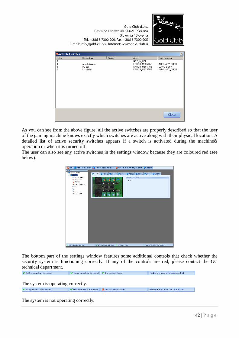
As you can see from the above figure, all the active switches are properly described so that the user of the gaming machine knows exactly which switches are active along with their physical location. A detailed list of active security switches appears if a switch is activated during the machine’s operation or when it is turned off. The user can also see any active switches in the settings window because they are coloured red (see below).
The bottom part of the settings window features some additional controls that check whether the security system is functioning correctly. If any of the controls are red, please contact the GC technical department.
The system is operating correctly.
The system is not operating correctly.
43 | P a g e
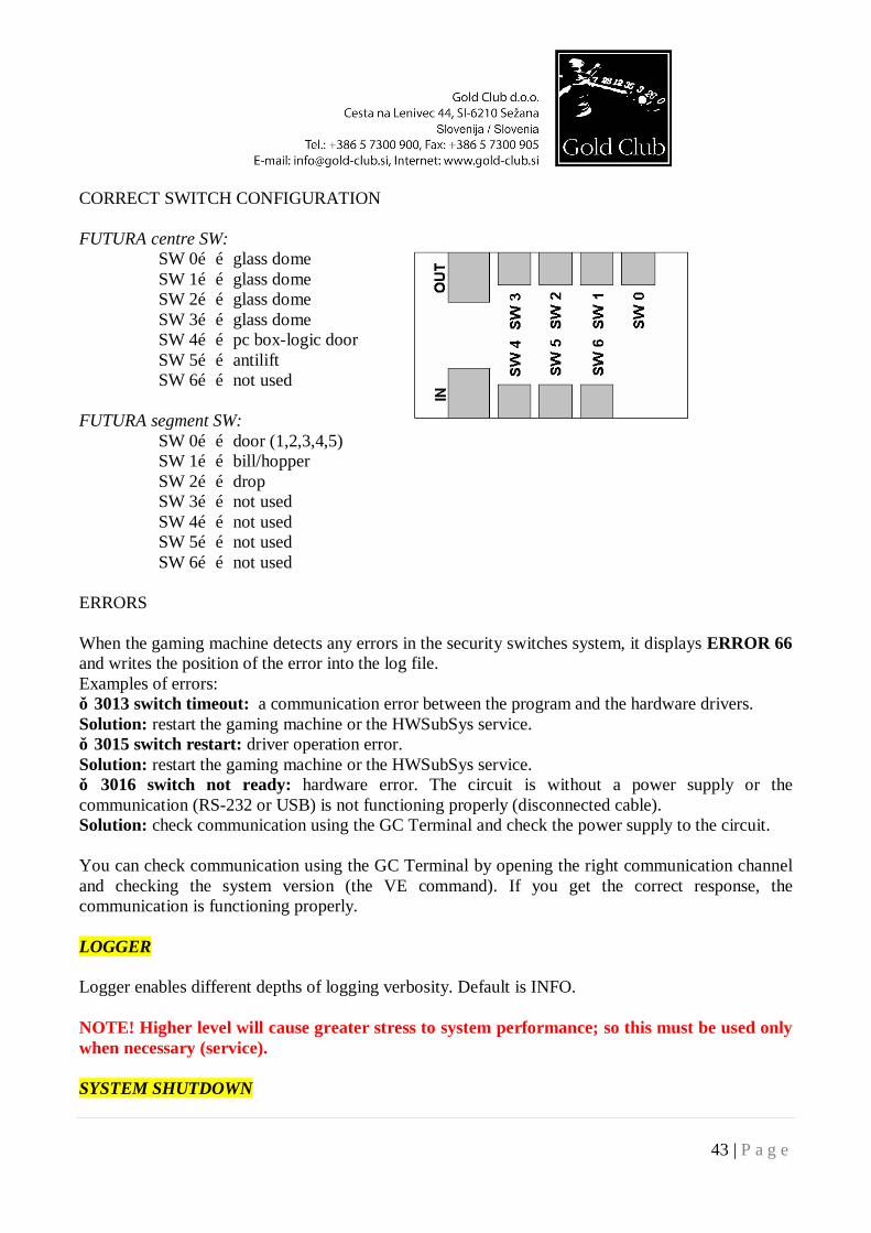
CORRECT SWITCH CONFIGURATION FUTURA centre SW: SW 0……glass dome SW 1……glass dome SW 2……glass dome SW 3……glass dome SW 4……pc box-logic door SW 5……antilift SW 6……not used FUTURA segment SW: SW 0……door (1,2,3,4,5) SW 1……bill/hopper SW 2……drop SW 3……not used SW 4……not used SW 5……not used SW 6……not used ERRORS When the gaming machine detects any errors in the security switches system, it displays ERROR 66 and writes the position of the error into the log file. Examples of errors: ● 3013 switch timeout: a communication error between the program and the hardware drivers. Solution: restart the gaming machine or the HWSubSys service. ● 3015 switch restart: driver operation error. Solution: restart the gaming machine or the HWSubSys service. ● 3016 switch not ready: hardware error. The circuit is without a power supply or the communication (RS-232 or USB) is not functioning properly (disconnected cable). Solution: check communication using the GC Terminal and check the power supply to the circuit. You can check communication using the GC Terminal by opening the right communication channel and checking the system version (the VE command). If you get the correct response, the communication is functioning properly. LOGGER Logger enables different depths of logging verbosity. Default is INFO. NOTE! Higher level will cause greater stress to system performance; so this must be used only when necessary (service). SYSTEM SHUTDOWN
44 | P a g e
Use this key to turn off the gaming machine. SYSTEM RESTART Use this key to restart the gaming device.
LOGOUT Press this button to logout the current user from the GC BiOS application. START Press this button to start the game.
45 | P a g e
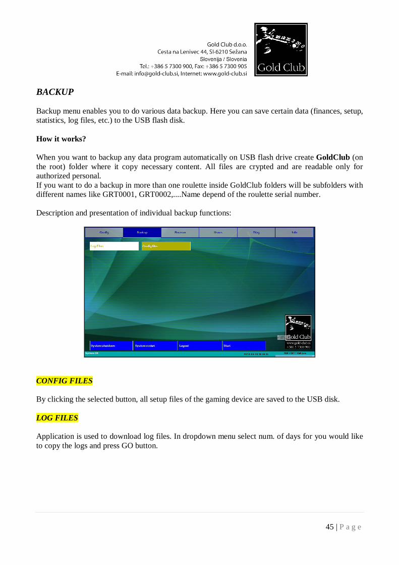
BACKUP Backup menu enables you to do various data backup. Here you can save certain data (finances, setup, statistics, log files, etc.) to the USB flash disk. How it works? When you want to backup any data program automatically on USB flash drive create GoldClub (on the root) folder where it copy necessary content. All files are crypted and are readable only for authorized personal. If you want to do a backup in more than one roulette inside GoldClub folders will be subfolders with different names like GRT0001, GRT0002,....Name depend of the roulette serial number. Description and presentation of individual backup functions:
CONFIG FILES By clicking the selected button, all setup files of the gaming device are saved to the USB disk.
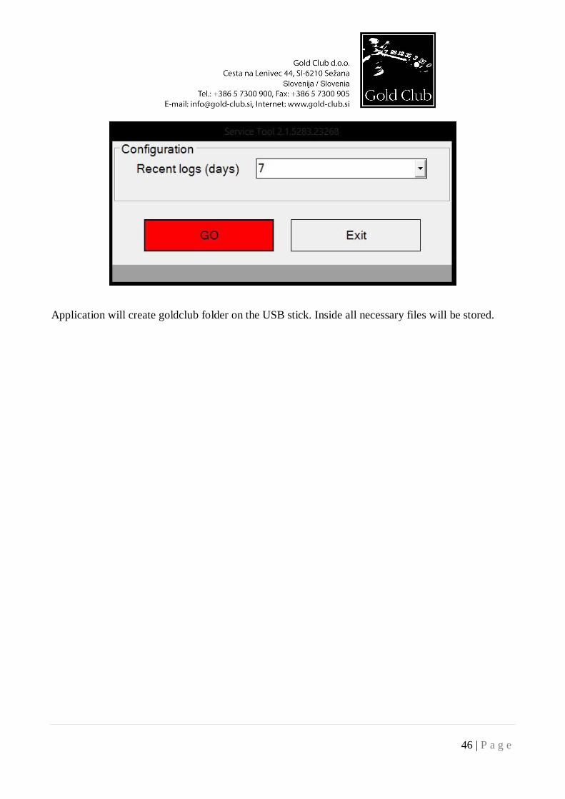
LOG FILES Application is used to download log files. In dropdown menu select num. of days for you would like to copy the logs and press GO button.
46 | P a g e
Application will create goldclub folder on the USB stick. Inside all necessary files will be stored.
47 | P a g e
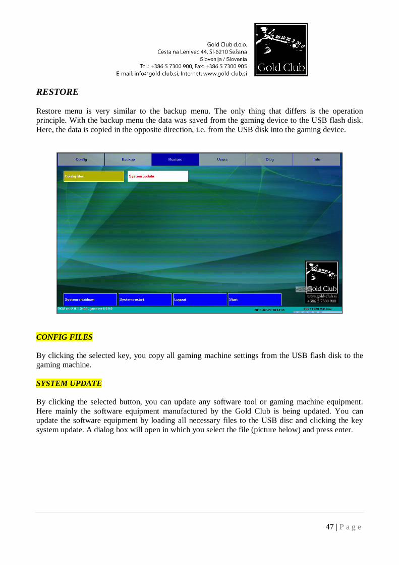
RESTORE Restore menu is very similar to the backup menu. The only thing that differs is the operation principle. With the backup menu the data was saved from the gaming device to the USB flash disk. Here, the data is copied in the opposite direction, i.e. from the USB disk into the gaming device.
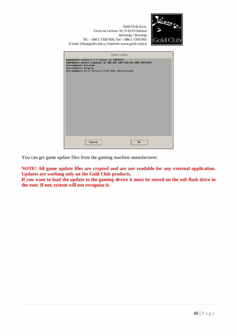
CONFIG FILES By clicking the selected key, you copy all gaming machine settings from the USB flash disk to the gaming machine. SYSTEM UPDATE By clicking the selected button, you can update any software tool or gaming machine equipment. Here mainly the software equipment manufactured by the Gold Club is being updated. You can update the software equipment by loading all necessary files to the USB disc and clicking the key system update. A dialog box will open in which you select the file (picture below) and press enter.
48 | P a g e
You can get game update files from the gaming machine manufacturer. NOTE! All game update files are crypted and are not readable for any external application. Updates are working only on the Gold Club products. If you want to load the update to the gaming device it must be stored on the usb flash drive in the root. If not, system will not recognize it.
49 | P a g e
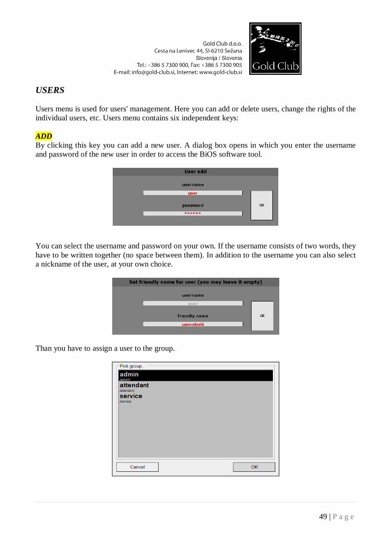
USERS Users menu is used for users' management. Here you can add or delete users, change the rights of the individual users, etc. Users menu contains six independent keys: ADD By clicking this key you can add a new user. A dialog box opens in which you enter the username and password of the new user in order to access the BiOS software tool.
You can select the username and password on your own. If the username consists of two words, they have to be written together (no space between them). In addition to the username you can also select a nickname of the user, at your own choice.
Than you have to assign a user to the group.
50 | P a g e
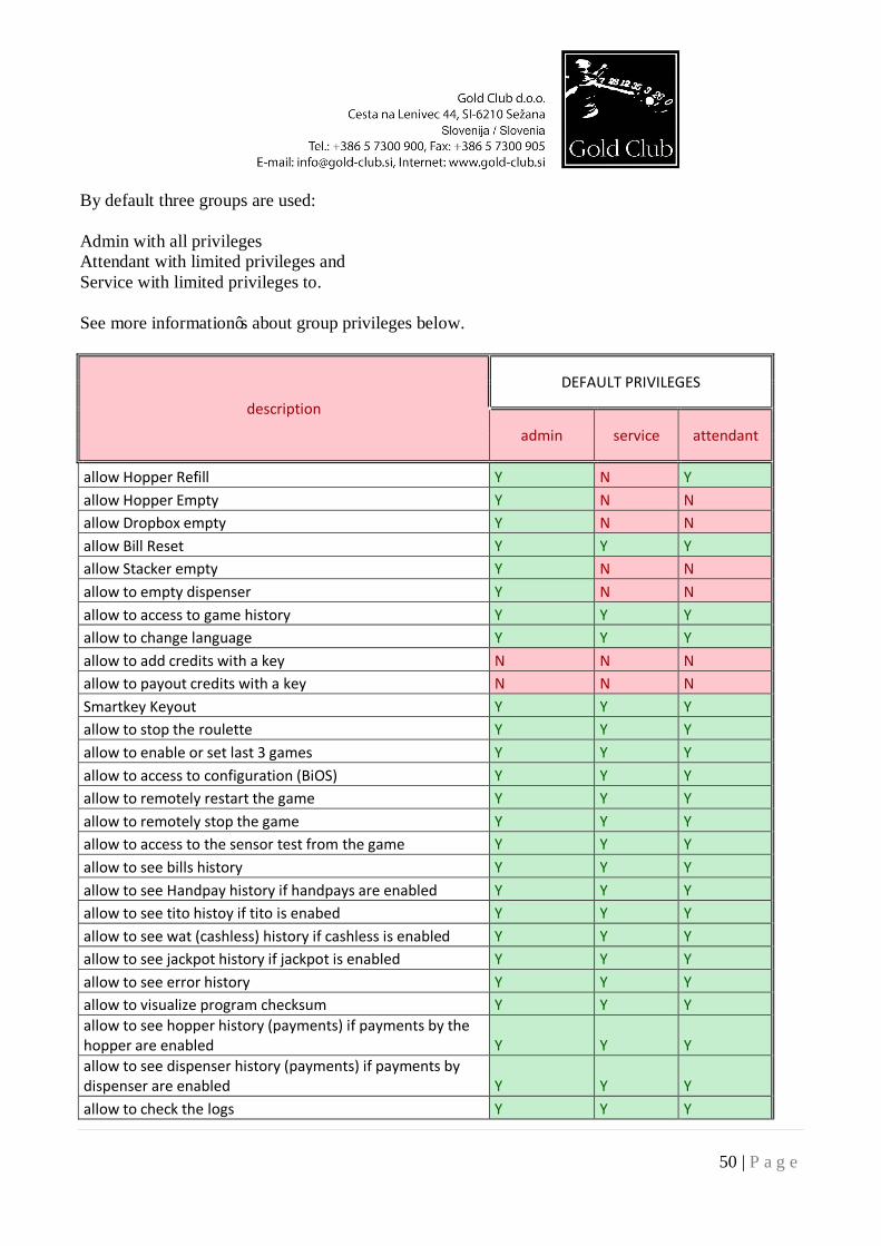
By default three groups are used: Admin with all privileges Attendant with limited privileges and Service with limited privileges to. See more information’s about group privileges below.
description
DEFAULT PRIVILEGES
admin service attendant
allow Hopper Refill Y N Y allow Hopper Empty Y N N allow Dropbox empty Y N N allow Bill Reset Y Y Y allow Stacker empty Y N N allow to empty dispenser Y N N allow to access to game history Y Y Y allow to change language Y Y Y allow to add credits with a key N N N allow to payout credits with a key N N N Smartkey Keyout Y Y Y allow to stop the roulette Y Y Y allow to enable or set last 3 games Y Y Y allow to access to configuration (BiOS) Y Y Y allow to remotely restart the game Y Y Y allow to remotely stop the game Y Y Y allow to access to the sensor test from the game Y Y Y allow to see bills history Y Y Y allow to see Handpay history if handpays are enabled Y Y Y allow to see tito histoy if tito is enabed Y Y Y allow to see wat (cashless) history if cashless is enabled Y Y Y allow to see jackpot history if jackpot is enabled Y Y Y allow to see error history Y Y Y allow to visualize program checksum Y Y Y allow to see hopper history (payments) if payments by the hopper are enabled Y Y Y allow to see dispenser history (payments) if payments by dispenser are enabled Y Y Y allow to check the logs Y Y Y
51 | P a g e
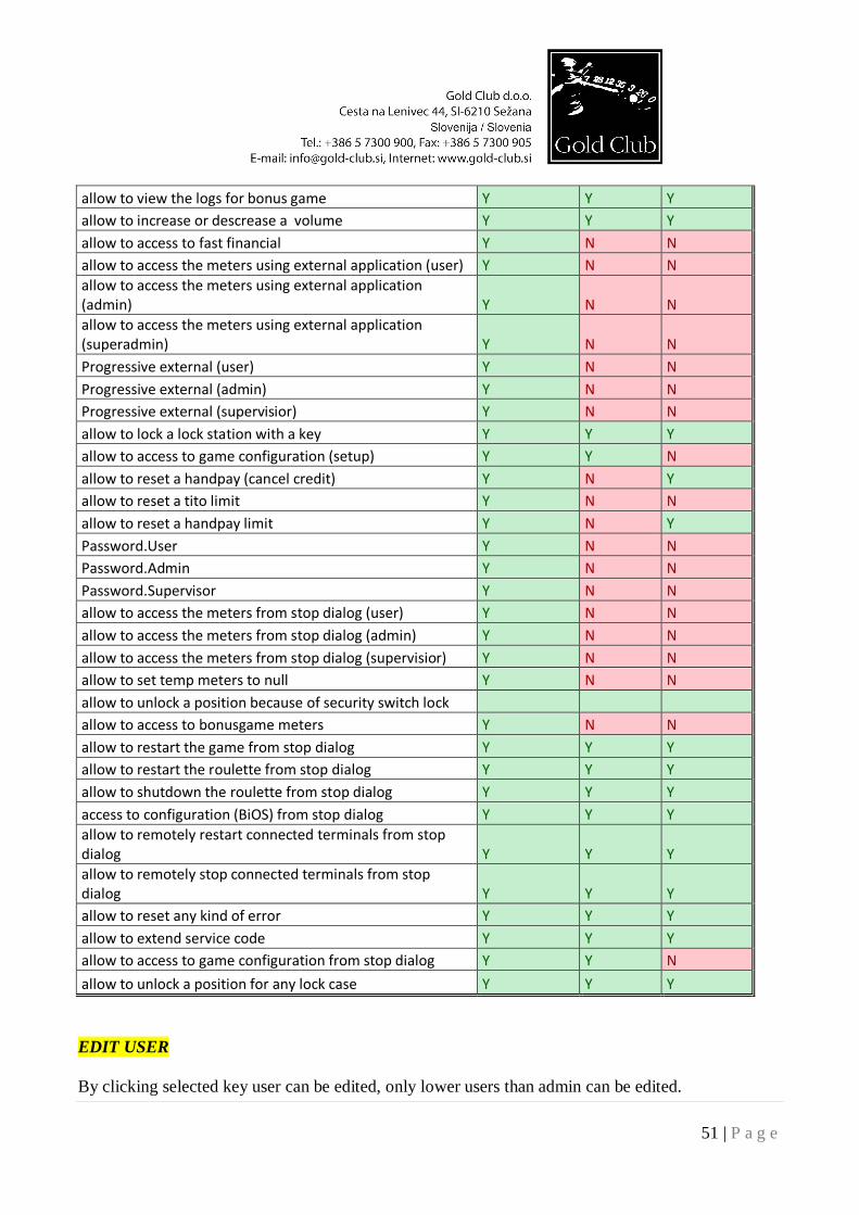
allow to view the logs for bonus game Y Y Y allow to increase or descrease a volume Y Y Y allow to access to fast financial Y N N allow to access the meters using external application (user) Y N N allow to access the meters using external application (admin) Y N N allow to access the meters using external application (superadmin) Y N N Progressive external (user) Y N N Progressive external (admin) Y N N Progressive external (supervisior) Y N N allow to lock a lock station with a key Y Y Y allow to access to game configuration (setup) Y Y N allow to reset a handpay (cancel credit) Y N Y allow to reset a tito limit Y N N allow to reset a handpay limit Y N Y Password.User Y N N Password.Admin Y N N Password.Supervisor Y N N allow to access the meters from stop dialog (user) Y N N allow to access the meters from stop dialog (admin) Y N N allow to access the meters from stop dialog (supervisior) Y N N allow to set temp meters to null Y N N allow to unlock a position because of security switch lock allow to access to bonusgame meters Y N N allow to restart the game from stop dialog Y Y Y allow to restart the roulette from stop dialog Y Y Y allow to shutdown the roulette from stop dialog Y Y Y access to configuration (BiOS) from stop dialog Y Y Y allow to remotely restart connected terminals from stop dialog Y Y Y allow to remotely stop connected terminals from stop dialog Y Y Y allow to reset any kind of error Y Y Y allow to extend service code Y Y Y allow to access to game configuration from stop dialog Y Y N allow to unlock a position for any lock case Y Y Y EDIT USER By clicking selected key user can be edited, only lower users than admin can be edited.
52 | P a g e
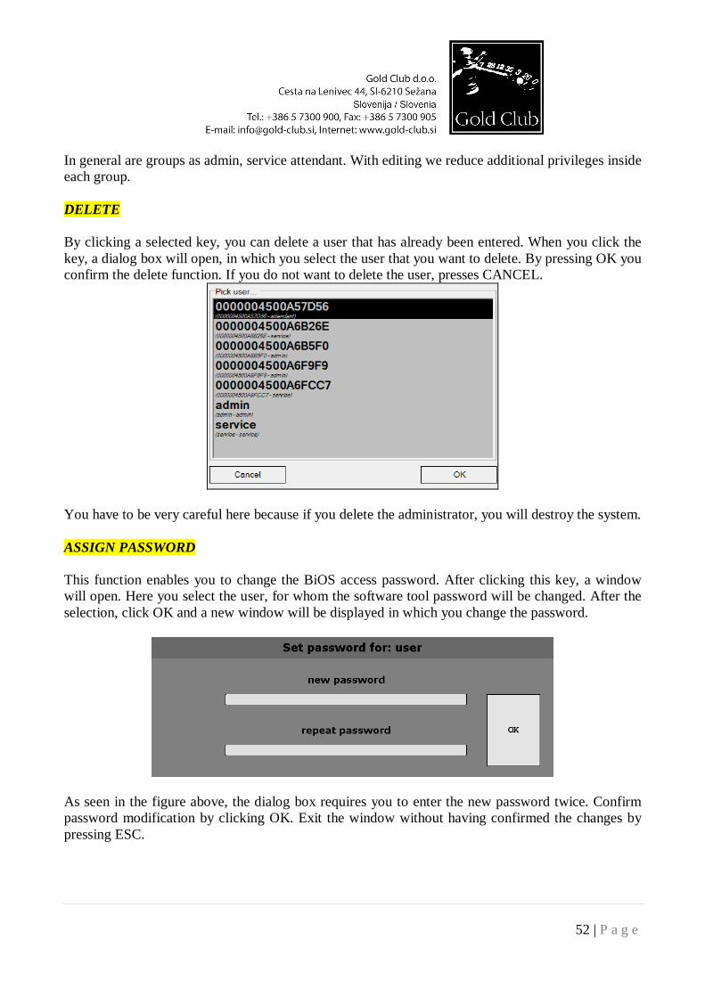
In general are groups as admin, service attendant. With editing we reduce additional privileges inside each group. DELETE By clicking a selected key, you can delete a user that has already been entered. When you click the key, a dialog box will open, in which you select the user that you want to delete. By pressing OK you confirm the delete function. If you do not want to delete the user, presses CANCEL.
You have to be very careful here because if you delete the administrator, you will destroy the system. ASSIGN PASSWORD This function enables you to change the BiOS access password. After clicking this key, a window will open. Here you select the user, for whom the software tool password will be changed. After the selection, click OK and a new window will be displayed in which you change the password.
As seen in the figure above, the dialog box requires you to enter the new password twice. Confirm password modification by clicking OK. Exit the window without having confirmed the changes by pressing ESC.
53 | P a g e
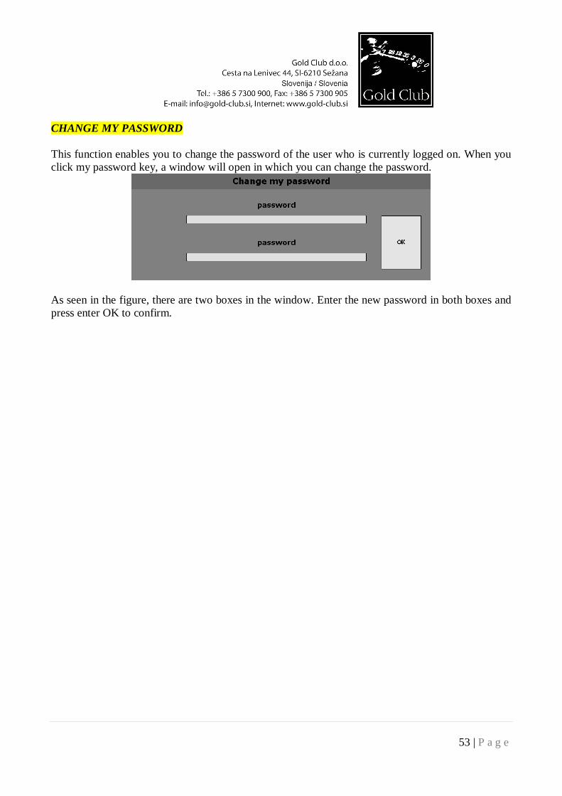
CHANGE MY PASSWORD This function enables you to change the password of the user who is currently logged on. When you click my password key, a window will open in which you can change the password.
As seen in the figure, there are two boxes in the window. Enter the new password in both boxes and press enter OK to confirm.
54 | P a g e
DIAG MENU Diagnostics menu is the menu where technician can check if the roulette hardware works as it should. Following applications are present:
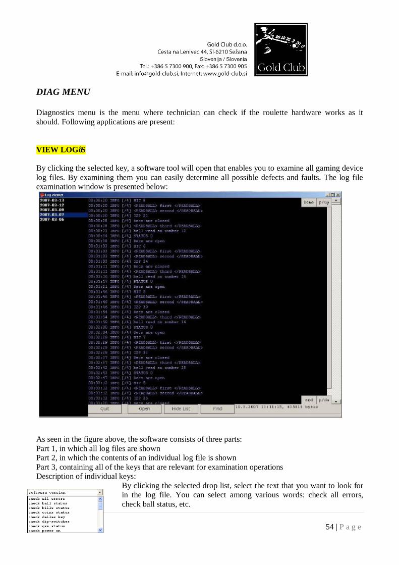
VIEW LOG’S By clicking the selected key, a software tool will open that enables you to examine all gaming device log files. By examining them you can easily determine all possible defects and faults. The log file examination window is presented below:
As seen in the figure above, the software consists of three parts: Part 1, in which all log files are shown Part 2, in which the contents of an individual log file is shown Part 3, containing all of the keys that are relevant for examination operations Description of individual keys:
By clicking the selected drop list, select the text that you want to look for in the log file. You can select among various words: check all errors, check ball status, etc.
55 | P a g e
By clicking the selected button, a new selection box will open, in which you select the log file type. See the example below.
By clicking the selected button, the log viewer program toll will be closed. By clicking the selected button the search window opens.
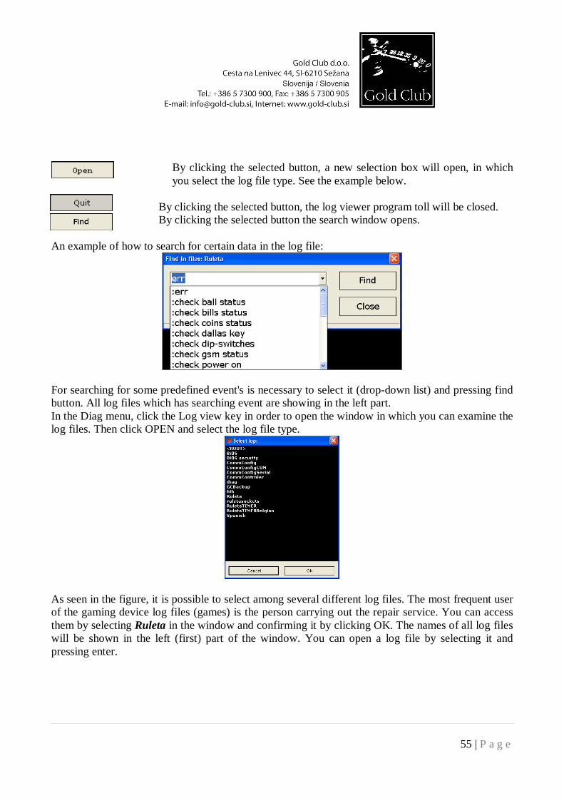
An example of how to search for certain data in the log file:
For searching for some predefined event's is necessary to select it (drop-down list) and pressing find button. All log files which has searching event are showing in the left part. In the Diag menu, click the Log view key in order to open the window in which you can examine the log files. Then click OPEN and select the log file type.
As seen in the figure, it is possible to select among several different log files. The most frequent user of the gaming device log files (games) is the person carrying out the repair service. You can access them by selecting Ruleta in the window and confirming it by clicking OK. The names of all log files will be shown in the left (first) part of the window. You can open a log file by selecting it and pressing enter.
56 | P a g e
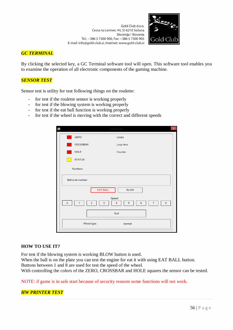
GC TERMINAL By clicking the selected key, a GC Terminal software tool will open. This software tool enables you to examine the operation of all electronic components of the gaming machine. SENSOR TEST Sensor test is utility for test following things on the roulette:
- for test if the roulette sensor is working properly - for test if the blowing system is working properly - for test if the eat ball function is working properly - for test if the wheel is moving with the correct and different speeds
HOW TO USE IT?
For test if the blowing system is working BLOW button is used. When the ball is on the plate you can test the engine for eat it with using EAT BALL button. Buttons between 1 and 8 are used for test the speed of the wheel. With controlling the colors of the ZERO, CROSSBAR and HOLE squares the sensor can be tested. NOTE: if game is in safe start because of security reasons some functions will not work. HW PRINTER TEST
57 | P a g e
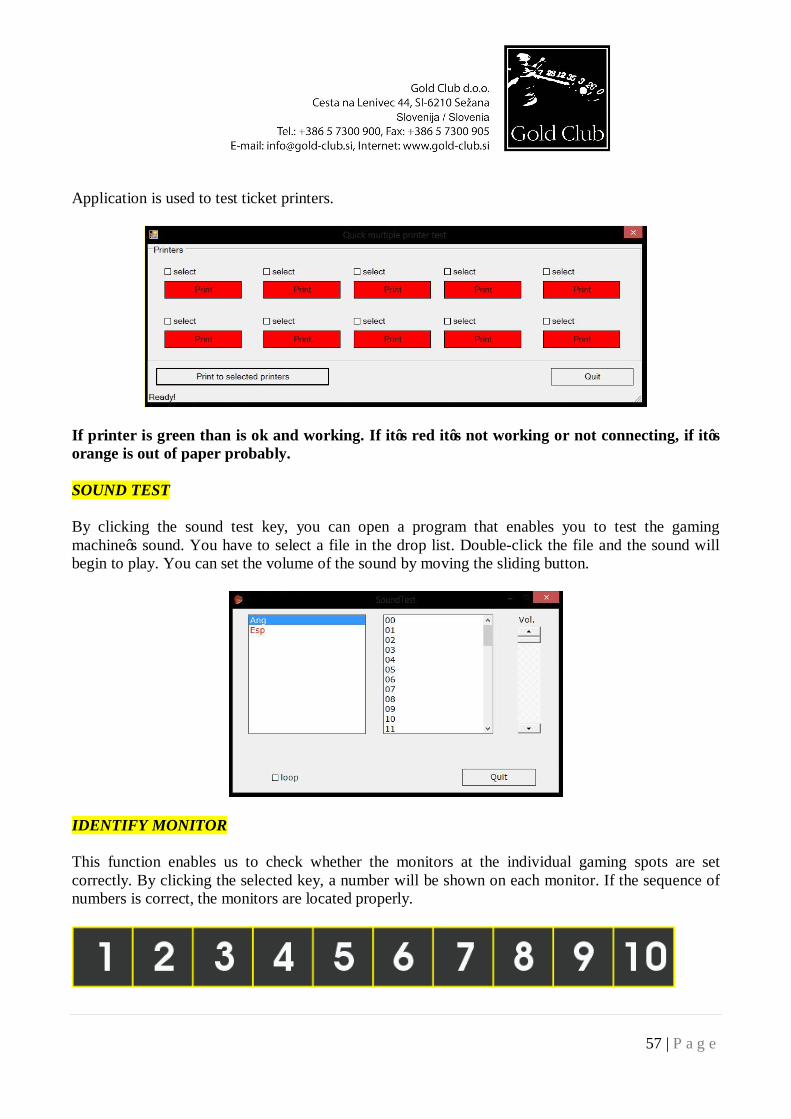
Application is used to test ticket printers.
If printer is green than is ok and working. If it’s red it’s not working or not connecting, if it’s orange is out of paper probably. SOUND TEST By clicking the sound test key, you can open a program that enables you to test the gaming machine’s sound. You have to select a file in the drop list. Double-click the file and the sound will begin to play. You can set the volume of the sound by moving the sliding button.
IDENTIFY MONITOR This function enables us to check whether the monitors at the individual gaming spots are set correctly. By clicking the selected key, a number will be shown on each monitor. If the sequence of numbers is correct, the monitors are located properly.
58 | P a g e
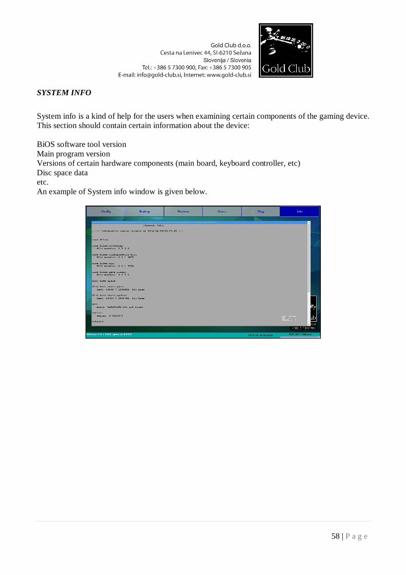
SYSTEM INFO
System info is a kind of help for the users when examining certain components of the gaming device. This section should contain certain information about the device: BiOS software tool version Main program version Versions of certain hardware components (main board, keyboard controller, etc) Disc space data etc. An example of System info window is given below.
59 | P a g e
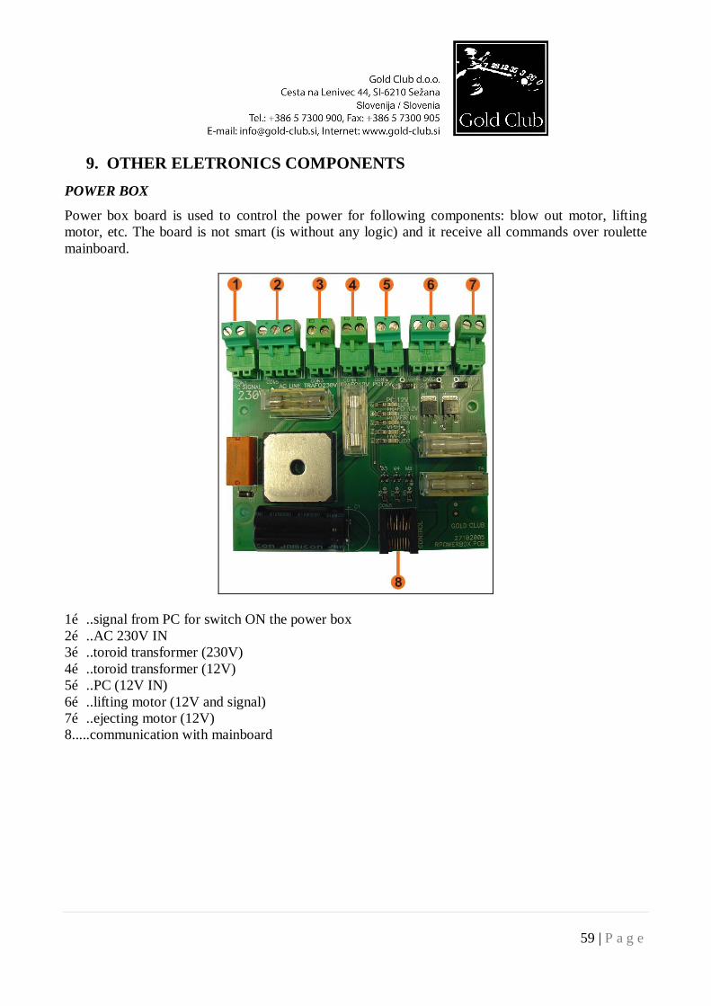
9. OTHER ELETRONICS COMPONENTS POWER BOX
Power box board is used to control the power for following components: blow out motor, lifting motor, etc. The board is not smart (is without any logic) and it receive all commands over roulette mainboard.
1…..signal from PC for switch ON the power box 2…..AC 230V IN 3…..toroid transformer (230V) 4…..toroid transformer (12V) 5…..PC (12V IN) 6…..lifting motor (12V and signal) 7…..ejecting motor (12V) 8.....communication with mainboard
60 | P a g e
MAINBOARD
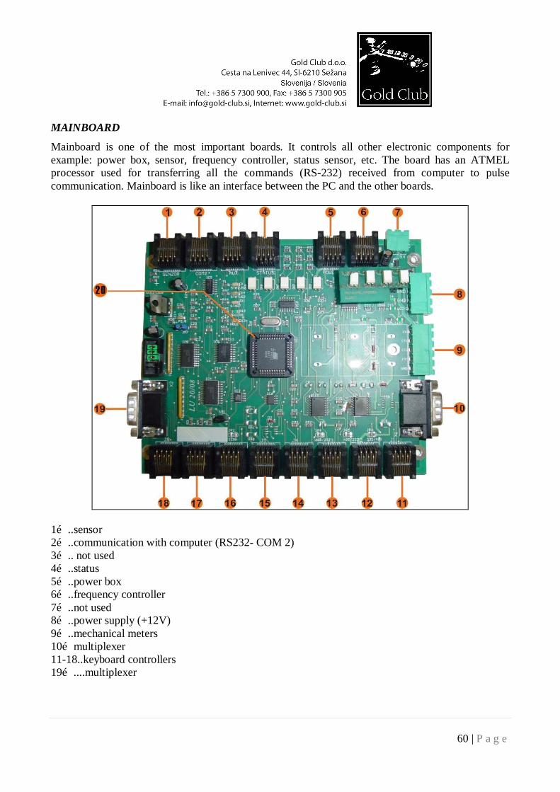
Mainboard is one of the most important boards. It controls all other electronic components for example: power box, sensor, frequency controller, status sensor, etc. The board has an ATMEL processor used for transferring all the commands (RS-232) received from computer to pulse communication. Mainboard is like an interface between the PC and the other boards.
1…..sensor 2…..communication with computer (RS232- COM 2) 3….. not used 4…..status 5…..power box 6…..frequency controller 7…..not used 8…..power supply (+12V) 9…..mechanical meters 10…multiplexer 11-18..keyboard controllers 19…....multiplexer
61 | P a g e
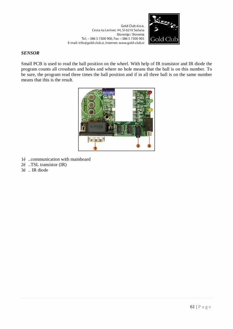
SENSOR Small PCB is used to read the ball position on the wheel. With help of IR transistor and IR diode the program counts all crossbars and holes and where no hole means that the ball is on this number. To be sure, the program read three times the ball position and if in all three ball is on the same number means that this is the result.
1…..communication with mainboard 2…..TSL transistor (IR) 3….. IR diode
62 | P a g e
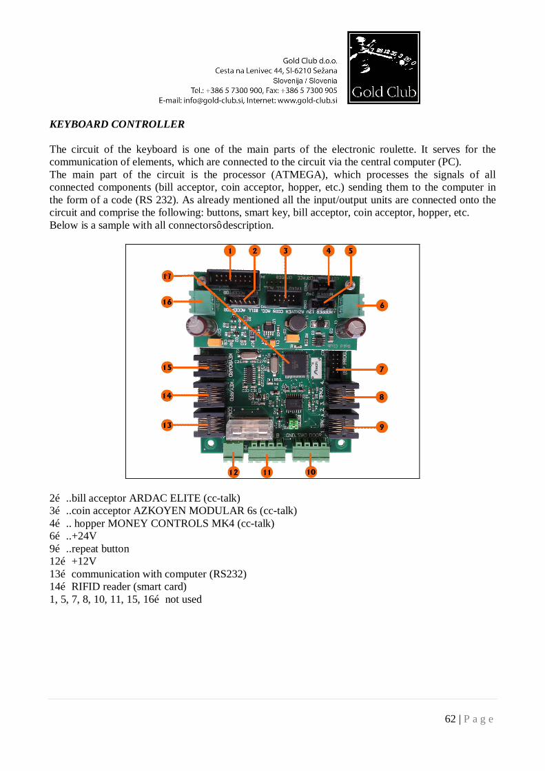
KEYBOARD CONTROLLER The circuit of the keyboard is one of the main parts of the electronic roulette. It serves for the communication of elements, which are connected to the circuit via the central computer (PC). The main part of the circuit is the processor (ATMEGA), which processes the signals of all connected components (bill acceptor, coin acceptor, hopper, etc.) sending them to the computer in the form of a code (RS 232). As already mentioned all the input/output units are connected onto the circuit and comprise the following: buttons, smart key, bill acceptor, coin acceptor, hopper, etc. Below is a sample with all connectors’ description.
2…..bill acceptor ARDAC ELITE (cc-talk) 3…..coin acceptor AZKOYEN MODULAR 6s (cc-talk) 4….. hopper MONEY CONTROLS MK4 (cc-talk) 6…..+24V 9…..repeat button 12…+12V 13…communication with computer (RS232) 14…RIFID reader (smart card) 1, 5, 7, 8, 10, 11, 15, 16…not used
63 | P a g e
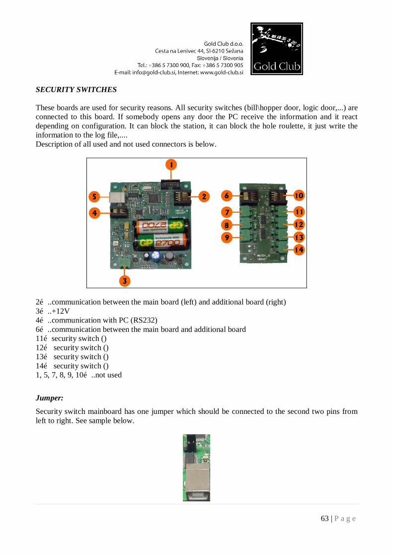
SECURITY SWITCHES These boards are used for security reasons. All security switches (bill\hopper door, logic door,...) are connected to this board. If somebody opens any door the PC receive the information and it react depending on configuration. It can block the station, it can block the hole roulette, it just write the information to the log file,.... Description of all used and not used connectors is below.
2…..communication between the main board (left) and additional board (right) 3…..+12V 4…..communication with PC (RS232) 6…..communication between the main board and additional board 11…security switch () 12… security switch () 13… security switch () 14… security switch () 1, 5, 7, 8, 9, 10…..not used
Jumper:
Security switch mainboard has one jumper which should be connected to the second two pins from left to right. See sample below.
64 | P a g e
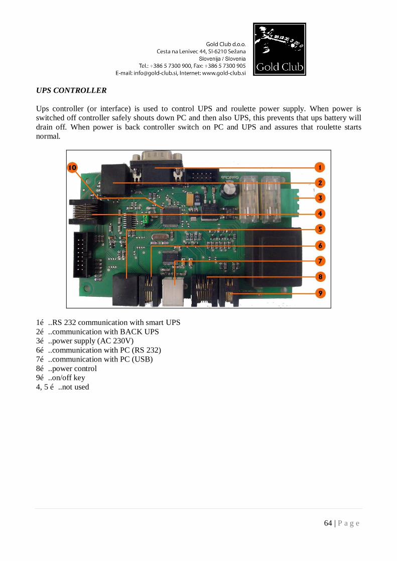
UPS CONTROLLER Ups controller (or interface) is used to control UPS and roulette power supply. When power is switched off controller safely shouts down PC and then also UPS, this prevents that ups battery will drain off. When power is back controller switch on PC and UPS and assures that roulette starts normal.
1…..RS 232 communication with smart UPS 2…..communication with BACK UPS 3…..power supply (AC 230V) 6…..communication with PC (RS 232) 7…..communication with PC (USB) 8…..power control 9…..on/off key 4, 5 …..not used
65 | P a g e
MULTIPLEXER
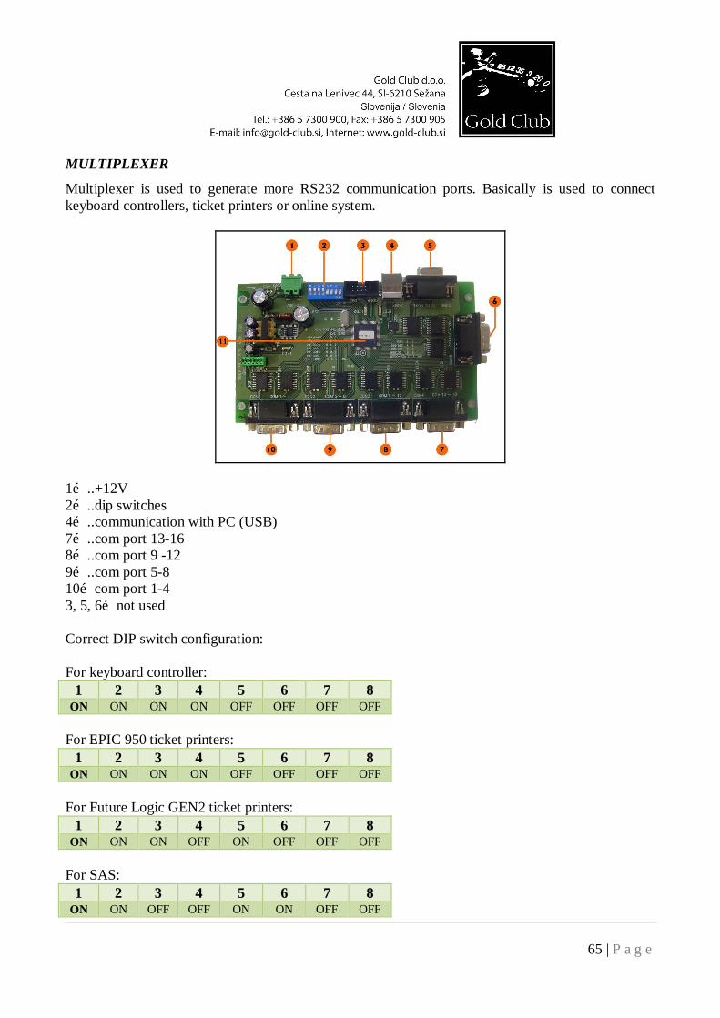
Multiplexer is used to generate more RS232 communication ports. Basically is used to connect keyboard controllers, ticket printers or online system.
1…..+12V 2…..dip switches 4…..communication with PC (USB) 7…..com port 13-16 8…..com port 9 -12 9…..com port 5-8 10…com port 1-4 3, 5, 6…not used Correct DIP switch configuration: For keyboard controller:
1 2 3 4 5 6 7 8 ON ON ON ON OFF OFF OFF OFF
For EPIC 950 ticket printers:
1 2 3 4 5 6 7 8 ON ON ON ON OFF OFF OFF OFF
For Future Logic GEN2 ticket printers:
1 2 3 4 5 6 7 8 ON ON ON OFF ON OFF OFF OFF
For SAS:
1 2 3 4 5 6 7 8 ON ON OFF OFF ON ON OFF OFF
66 | P a g e
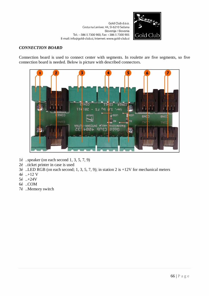
CONNECTION BOARD Connection board is used to connect center with segments. In roulette are five segments, so five connection board is needed. Below is picture with described connectors.
1…..speaker (on each second 1, 3, 5, 7, 9) 2…..ticket printer in case is used 3…..LED RGB (on each second; 1, 3, 5, 7, 9); in station 2 is +12V for mechanical meters 4…..+12 V 5…..+24V 6…..COM 7…..Memory switch
67 | P a g e
LED MAIN BOARD
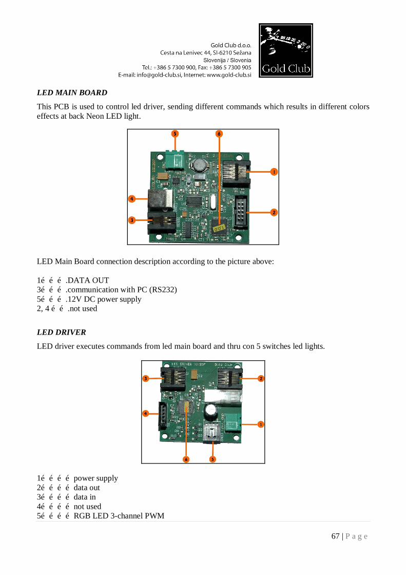
This PCB is used to control led driver, sending different commands which results in different colors effects at back Neon LED light.
LED Main Board connection description according to the picture above: 1……….DATA OUT 3……….communication with PC (RS232) 5……….12V DC power supply 2, 4 …….not used
LED DRIVER
LED driver executes commands from led main board and thru con 5 switches led lights.
1…………power supply 2…………data out 3…………data in 4…………not used 5…………RGB LED 3-channel PWM
68 | P a g e
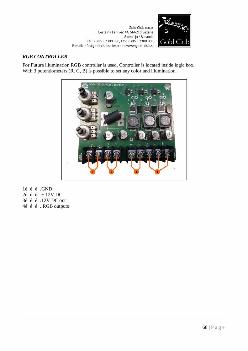
RGB CONTROLLER
For Futura illumination RGB controller is used. Controller is located inside logic box. With 3 potentiometers (R, G, B) is possible to set any color and illumination.
1……….GND 2……….+ 12V DC 3……….12V DC out 4………..RGB outputs
69 | P a g e
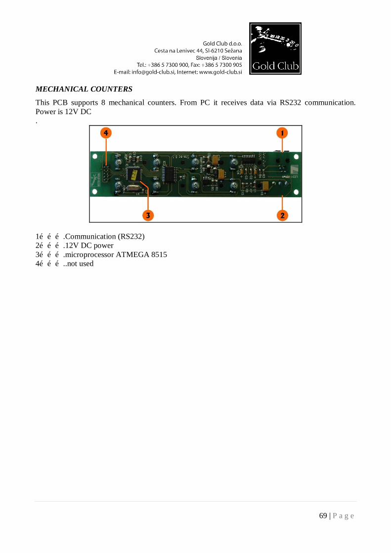
MECHANICAL COUNTERS
This PCB supports 8 mechanical counters. From PC it receives data via RS232 communication. Power is 12V DC .
1……….Communication (RS232) 2……….12V DC power 3……….microprocessor ATMEGA 8515 4………..not used
70 | P a g e
10. SERVICE MANUAL
Debug error list for authorized service personal ONLY 1. Error 1. PC Reset The program was not shut down correctly (incorrect exit from the program). Possible faults:
- PC block - Power supply cable of the PC - UPS fault - Power supply cable of the UPS - Roulette switched off with the POWER key - Program stopped with the PC keyboard
2. Error 2. Communication with COM 2 Fault on the main CPU Possible faults:
- CPU on main PC is not responding - COM 2 on PC is not working - Check PC power supply - Check serial communication cable
3. Error 3. The ball was located on the cylinder during the start-up check During the check of the cylinder and sensors something was detected on the cylinder Possible faults:
- The sensor is not set correctly - There is dirt or dust on the cylinder - Transmitting IR LED is not working or it is dirty - The zero location sensor is not set correctly
4. Error 4. There was a error locating the ball A mistake occurred during the sensor-reading period Possible faults:
- The cylinder sensor is not set correctly - Check the sensor cable and jacks - Check COM 2 cable - Check that the computer is not overloaded
71 | P a g e
5. Error 5. Unable to locate the ball During the blow period the sensor has not located the ball Possible faults:
- Check the ball is not blocked in the blowing tube - If the ball is on the cylinder check that the cylinder sensor is set correctly
6. Error 6. Unable to blow out the ball After the blow the status sensor has found the ball still on the start position Possible faults:
- Check if the blow compressor is working - Check if the status sensor is working - Check there is no dust on start position sensor
7. Error 7. Power failure: Power supply has failed Possible faults:
- Check for mains power - Check the fuses and circuit breakers
8. Error 8. The ball remained on the cylinder The ball has not returned to the start position Possible faults:
- Check the lift motor and the mechanism for correct operation - Check that the ball is not stuck in the drop system or under the cylinder - Check if the status sensor is working
9. Error 10. Error writing to databases An error occurred during the writing of a database Possible faults:
- Check databases - Check that there are no errors on the Hard Disk - Delete lock files and restart
10. Error 12. Maximum location rotations exceeded The cylinder has made the maximum number of turns and has failed to located the ball. Possible faults:
- After the blow out the ball has not arrived on the cylinder - On start-up the program has not located the ball - Check if the sensors are working
72 | P a g e
11. Error 13. On safe start the ball was not located for 2 rotations The program automatically turns to safe start if the ball was not found for 2 rotations Possible faults:
- Check the location of the ball - Check if the sensors are working properly
12. Error 15. Unable to read databases The program was not able to read from the database Possible faults:
- Check there are errors on hard disk 13. Error 16. Opening of the databases During the start the program was unable to open the databases Possible faults:
- Check for errors on hard disk - Check if the databases for corruption
14. Error 19. During opening of COM ports During initialization the program failed to open one or more communication ports Possible faults:
- Check communication cards and ports are working properly - Check if any other program is using the ports
15. Error 20. No response from COM 2 An error occurred on communication between the PC and Com2 Possible faults:
- Check if COM 2 is working properly - Check if CPU is responding
16. Error 21. During closing of COM ports Possible faults: - Check communication cards and cables - Check all programs which are using com ports (commcontroller) 17. Error 22. Registry error A mistake occurred during data transfer to the windows register
73 | P a g e
Possible faults: - Check for errors on hard disk - Check databases are not corrupt - Delete playx.mdb databases using special tool
18. Error 23. Negative values found in databases During data processing a negative value occurred in base Possible faults:
- Errors on hard disk - Delete playx.mdb databases using special tool.
19. Error 24. Registry error on start-up The program was not able to initialize the register Possible faults:
- Errors on hard disk - Check databases are not corrupt in folder - Delete playx.mdb databases using special tool
20. Error 27. Unable to load coded Bitmap screen saver During initialization the program was unable to load BMP screen saver Possible faults:
- Errors on hard disk - Reload BMP screen saver
21. Error 28. Initialization of graphics cards The program during start unable to run all graphics cards Possible faults:
- Check if all the graphic cards are correctly located in the PCI slots - Check if the correct drivers are loaded for graphic cards in use
22. Error 29. Mechanical counter error A fault occurred on communication with the i/o board and the mechanical counters. Possible faults:
- Check if COM1 works correctly - Check if CPU on I/0 counter board is responding - Check communication cable - Check power supply to the I/O board
23. Error 30. Demonstration timer period exceeded
74 | P a g e
Program locks on a predefined date and hour. Program can be restarted with password. 24. Error 31. Tamper switch error Program stops with activation of certain security switches 25. Error 32. Error data initialization A fault can happens during initialization any data for ticket printers or any other peripheral device. Possible faults: - Check if ticket printers are connected properly (to correct com port on mux) 26. Error 33. Time-out error The program has not received enough information from the sensors Possible faults:
- Check if the sensors are properly aligned - Check sensor cables - Check communication cable - Check if the cylinder is spinning at the correct speed
27. Error 34. Timing fault on Banknote acceptors Timing error on banknote impulse Possible faults:
- Control Banknote reader - Control Cable on banknote reader - Control Satellite I/O board under keyboard
28. Error 35. Error opening serial port 1 Unable to initialize COM1 29. Error 36. Status sensor error Fault on status sensor 30. Error 37. Online communication error Online communication has connection errors. 31. Error 38. Timeout of online communications
Timeout of online connection exceeded. Possible faults.
- Check if on-line system is connected to correct com port - Check if the same com port is selected in game setup
32. Error 39. Speed Variations detected on Cylinder
75 | P a g e
Possible faults. - Sensor faulty - FM motor controller - Control zero position sensor
35. Error 61. Sound error Possible faults
- Check if the sound card is working properly 36. Error 62. Finances error
If this error is happen the problem is finances which are used only for roulettes for Spanish market
Possible faults - Check Bonus.dat file - Check BonusTable.dat - Check Lottery.dat - Check configuration (wibu number)
37. Error 63. Power fail
Error is happen only when the main power is lost. If the error is happened a lot of time please check the main fuse or the UPS.
38. Error 64. Power fail It is the same than the error before.
39. Error 65. Difference a cycle time
If the error is happen means that the last game (cycle) is longer or shorter than the average cycle time. Check the deviation in game setup (game settings/additional/ball read/max time diff)
40. Error 66. Error initialization security switch system Check if security switch PCB is connected to the computer (GC Terminal) Check if HWSubsys service is starting (BiOS\config\Services) 41. Error 67. Error initialization tokens Check in game setup if the tokens and chips are set correctly. 42. Error 68. Finances mismatch Solution: RAM clear
76 | P a g e
43. Error 69. UPS error Communication between the roulette and the UPS is missing.
Possible faults. COM cable Wrong COM setting (speed, mapping…) UPS not defined in configuration (HW drivers)
44. Error 70. Language error
Not defined language in configuration. Please call customer support. 45. Error 71. RAM error
Contact Gold Club Company 46. Error 72. UPS on battery; communication problem with satellite (NEON)
Check main power supply. Check communication with satellite. For further information please email us ([email protected]) on or call service department on telephone number +386 57 311 562.