Embed Size (px)
Citation preview

BARTEC GmbH Schulstraße 30 D-94239 Gotteszell Telefon +49 (0) 9929 301-0 Fax 301-112 E-Mail: [email protected] Internet: www.bartec.de
Product information
HYGROPHIL® HCDT Measurement system for the determination of the hydrocarbon dewpoint and the water dewpoint in natural gas

Product information Hygrophil® HCDT PI 070117 08.08/me

Product information Hygrophil® HCDT PI 070117 08.08/me
Table of contents
Contents Page
Product information __________________________ 1
HYGROPHIL® HCDT______________________ 1
1 Introduction ___________________________________________________________ 1
2 Underlying physical principle _____________________________________________ 2
3 Design of the measurement system HYGROPHIL©
HCDT ______________________ 4
4 Sensors _______________________________________________________________ 7
5 Measurement ranges ___________________________________________________ 10
6 Technical data ________________________________________________________ 12
All rights and changes reserved. No part of this document may be reproduced, processed or distributed in any form or by any means without the prior written permission of BARTEC.
Copyright © 2008 by BARTEC Schulstraße 30, D-94239 Gotteszell
Document: PI 070117 valid as from: 01.07 Revision: 18.02.2008 Author/s: Alfred Böhm/Markus Gärber

Produktinformation Hygrophil® HCDT PI 070117 08.08/me

Produktinformation Hygrophil® HCDT PI 070117 08.08/me
1 Introduction The water dewpoint is generally defined as the temperature at which water vapour begins to condense. This phenomenon can be observed on every foggy morning. The air cools down to the dewpoint temperature, water begins to condense and gathers in small drops. Something similar happens to eyeglasses steaming up on a humid day. The cold glass cools the air temperature down below the dewpoint temperature, water condenses on the cold side of the glass. Compared to the hydrocarbon dewpoint, the water dewpoint can be determined quite easily because it is only a one-component system. The hydrocarbon dewpoint (HCDT = Hydro Carbon Dewpoint Temperature) behaves similarly to the water dewpoint, with the difference that this is a multi-component system. Natural gas consists of a multitude of lightweight, gaseous hydrocarbons and some heavy (longer-chained) liquid hydrocarbons. The composition of the gas and consequently also its quality heavily depends on the respective gas production area. First of all, the longer-chained heavy hydrocarbons condense and, in doing so, define the hydrocarbon dewpoint (HCDT) of the gas.
Why is it so important to measure the water and hydrocarbon dewpoint in natural gas? As for the humidity (water dewpoint) in natural gas, the reason for this measurement is evident: Water vapour does not burn. Water vapour reduces the heating value and consequently impairs the quality of the gas. Far more important, however, are the reasons concerning the safety of the equipment. Firstly, too much humidity in natural gas causes corrosion within the pipeline, which inevitably results in leakages. Secondly, water can condense at cold places within the pipeline and, during the winter months, freeze to ice. This results in pipe blockages, cracking and leakages or even more severe damages
of the equipment as well as safety risks. Similar to the water dewpoint, the hydrocarbon dewpoint is primarily a measurement category for the quality of natural gas. The higher the HCDT value, the higher the quantity of heavy (long-chained) hydrocarbons, the poorer the quality. Like water, hydrocarbons can condense in high-pressure lines at low temperatures and can cause the equipment damages and safety risks that have already been mentioned. As hydrocarbons condense at significantly higher temperatures (cf. fig. 1), however, it is especially important to monitor the HCDT value.
The combination of a high humidity content in high-pressure lines with hydrocarbons can cause hydrate formation. This natural gas hydrate (“burning ice“) is extremely bothersome in pipe networks as it blocks the valves and the complete pipeline and causes pressure drops and a reduction of the flowrate. To protect the equipment and to guarantee the failure-free operation of natural gas plants and pipeline networks, it is extremely important for natural gas companies to carry out exact, long-time stable and reproducible measurements of the water dewpoint and the hydrocarbon dewpoint. One of the conventional standard methods used so far is the time-consumimg measurement by means of gravimetric procedures in accordance with BS EN ISO 6570 “Determination of the potential content of condensable hydrocarbons”. From the quantity of condensate measured at constant pressure and at different measurement temperatures, the hydrocarbon dewpoint can be determined. On the other hand, the hydrocarbon dewpoint can also be calculated by means of a gas-chromatographic determination of the exact gas composition in combination with intricate mathematical interrelations.

Produktinformation Hygrophil® HCDT PI 070117 08.08/me
2 Underlying physical principle For the determination of the hydrocarbon dewpoint temperature, the HYGROPHIL
® HCDT made by
BARTEC applies the fundamental and approved standard method of the dewpoint mirror procedure. This principle, which was discovered by Regnault in the 19th century, is based on the cooling of a mirror surface which is flowed around by gas. When the dewpoint temperature has been reached, condensate is deposited on the mirror surface. Fig. 1 roughly illustrates the interrelationship between water dewpoint and hydrocarbon dewpoint Fig. 1
As can be seen in fig. 1, in most of the cases the higher hydrocarbons condense before the water. The phase diagram (HCDT curve in fig. 1) can be calculated from the composition of the natural gas. Fig. 2 shows an exemplary phase diagram. The condensation curve represented there contains two extremums: the cricondentherm point and the cricondenbar point. The cricondentherm point (“critical condensation temperature“) is the maximum temperature at which 2 phases (liquid phase, gas phase) can occur. In other words, at this specific temperature the condensation of the hydrocarbons starts, which corresponds to the hydrocarbon dewpoint. The HCDT sensor 1510-11 measures the hydrocarbon dewpoint exactly at this point, whereas the gas humidity (water dewpoint) is measured under pipeline pressure and by means of the well-proven and long-time stable fiber-optical measurement principle of the L1660 sensor. To create these different measurement conditions, the gas is introduced into a sample system.
Temperature [°C]
Water and liquid hydrocarbons
Liquid hydrocarbons
Gas phase
Pressure [bara]
HC DT
-40 -30 -20 -10 0 +10 0
1
2
3
4
5
6
7
8
H2O DT

Produktinformation Hygrophil® HCDT PI 070117 08.08/me
Erdgas, Beispiel Phasendiagramm
0
10
20
30
40
50
60
70
80
90
100
-70 -60 -50 -40 -30 -20 -10 0 10
Temperature, °C
Pre
ssure
, B
AR
Critical Point Cricondentherm
Cricondenbar
Fig. 2
Natural gas, example phase diagram
Produktinformation Hygrophil® HCDT PI 070117 08.08/me
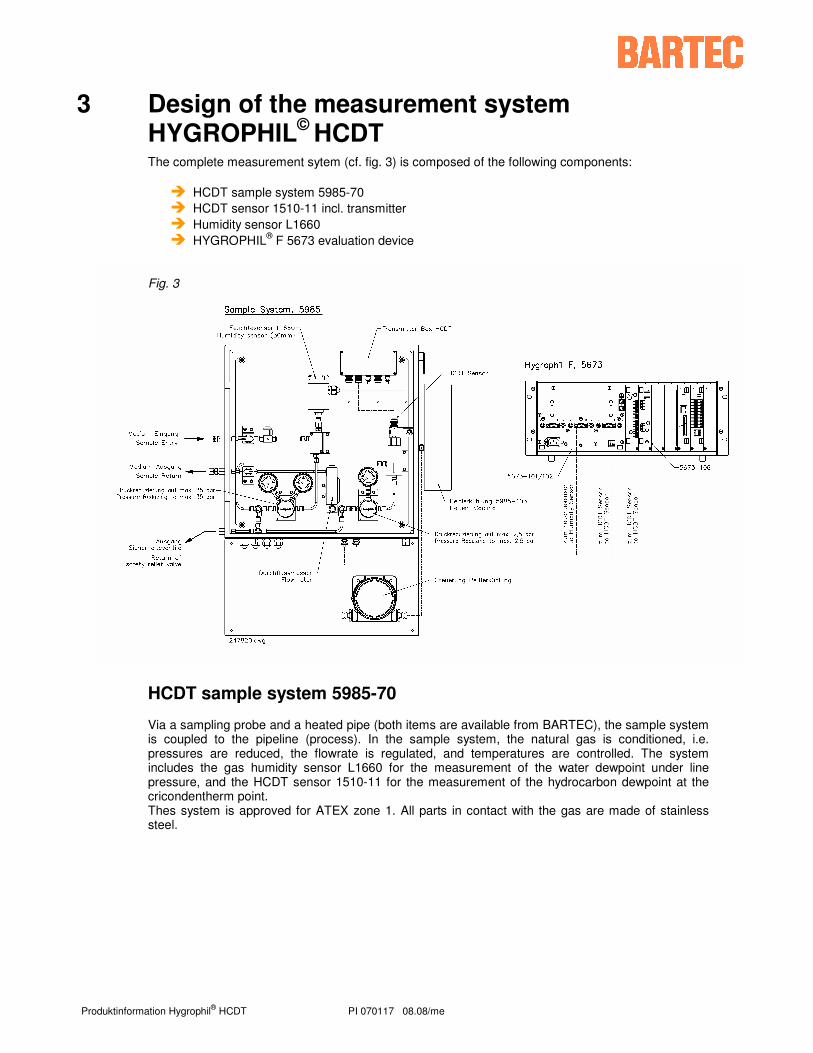
3 Design of the measurement system HYGROPHIL© HCDT The complete measurement sytem (cf. fig. 3) is composed of the following components:
HCDT sample system 5985-70
HCDT sensor 1510-11 incl. transmitter
Humidity sensor L1660
HYGROPHIL® F 5673 evaluation device
Fig. 3
HCDT sample system 5985-70 Via a sampling probe and a heated pipe (both items are available from BARTEC), the sample system is coupled to the pipeline (process). In the sample system, the natural gas is conditioned, i.e. pressures are reduced, the flowrate is regulated, and temperatures are controlled. The system includes the gas humidity sensor L1660 for the measurement of the water dewpoint under line pressure, and the HCDT sensor 1510-11 for the measurement of the hydrocarbon dewpoint at the cricondentherm point. Thes system is approved for ATEX zone 1. All parts in contact with the gas are made of stainless steel.

Produktinformation Hygrophil® HCDT PI 070117 08.08/me
Fig. 4 shows the HCDT sample system Fig. 4
HYGROPHIL® F 5673 In the last 10 years, the measurement system HYGROPHIL
® F 5673 with its fiber-optical sensor
L1660 has established itself very successfully in the field of ”trace humidity measurement in natural gas“. For more detailed information, see product information ”HYGROPHIL
® F 5673“
Via an application-specific software of HYGROPHIL
® F, the complex activation and regulation of the
sensors integrated in the sample system (HCDT sensor 1510-11 and trace humidity sensor L1660) takes place. HYGROPHIL
® F evaluates the sensor data, represents the data graphically and stores
all available data in an integrated data logger. For the data transfer to superordinate conduct systems, not only analog outputs but Modbus, Profibus and USB are available.

Produktinformation Hygrophil® HCDT PI 070117 08.08/me
Fig. 5 shows the evaluation device HYGROPHIL® F 5673
Fig. 5

Produktinformation Hygrophil® HCDT PI 070117 08.08/me
4 Sensors Measurement of the water dewpoint The measurement of the water vapour dewpoint is carried out via Hygrophil
® F and the sensor type
L1660. The humidity sensor type L1660 consists of a robust multilayer of optically high-refractive and low-refractive layers connected to 2 fiber-optical cables. By means of a special thermal coating technique, pores with the diameter of a water molecule (approx. 0.3 nm) are generated on the layer. Due to the equilibrium relative humidity, water is deposited in the layer. Due to the different refraction indexes (air: 1.00 / water: 1.33), this results in a wavelength shift in the layer system in proportion to the humidity prevailing in the medium. This shift (i.e. no intensity! ->path-neutral) is registered by the evaluation unit and assigned to a dewpoint. L1660 measures in a way that is both temperature-compensated (integrated Pt100) as well as pressure-compensated. Hygrophil
© F 5673 works in conjunction with a combination sensor which determines the humidity
content in the medium in a fiber-optical way and the temperature in the medium via a Pt100. Not only the highly robust design of the sensor but also the measurement principle itself offers a number of decisive advantages. Some of the plus factors of this patent-protected measurement principle are:
High measurement safety including precision, reproducibility and low hysteresis
Long-term stability of the sensor
Measurement on high-pressure side is possible (pressure dewpoint!)
Application in explosion-hazardous areas (zone 0 and higher)
Easy installation and retrofitting (Swagelok, Parker, …)
Low-maintenance L1660 has been developed specifically for the natural gas industry and is meanwhile used for the measurement of trace humidity in various gases and liquids. Due to the high-quality materials that are used, the sensor is extremely robust and resistant to almost any medium. For more detailed information, see product information „HYGROPHIL
® F 5673“
Fig. 5 shows humidity sensor L1660
Fig. 5

Produktinformation Hygrophil® HCDT PI 070117 08.08/me
Measurement of the hydrocarbon dewpoint For the measurement of the hydrocarbon dewpoint, the optical dewpoint sensor 1510-11 is integrated into the sample system after the pressure reduction (20 - 30 bar) (p corresponding to the phase diagram). Fig. 6 shows the sensor tip of the HCDT sensor 1510-11, fig. 7 shows the layout with the transmitter
Bild 6
Fig. 7
Condensation range of hydrocarbons (2mm x 1mm)
Produktinformation Hygrophil® HCDT PI 070117 08.08/me
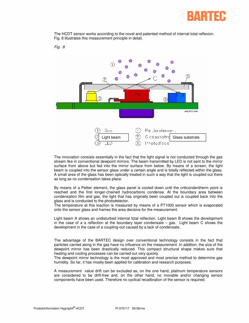
The HCDT sensor works according to the novel and patented method of internal total reflexion. Fig. 8 illustrates this measurement principle in detail. Fig. 8
The innovation consists essentially in the fact that the light signal is not conducted through the gas stream like in conventional dewpoint mirrors. The beam transmitted by LED is not sent to the mirror surface from above but fed into the mirror surface from below. By means of a screen, the light beam is coupled into the sensor glass under a certain angle and is totally reflected within the glass. A small area of the glass has been optically treated in such a way that the light is coupled out there as long as no condensation takes place. By means of a Peltier element, the glass panel is cooled down until the criticondentherm point is reached and the first longer-chained hydrocarbons condense. At the boundary area between condensation film and gas, the light that has originally been coupled out is coupled back into the glass and is conducted to the photodetector. The temperature at this loaction is measured by means of a PT1000 sensor which is evaporated onto the sensor glass and frames the area decisive for the measurement. Light beam A shows an undisturbed internal total reflection. Light beam B shows the development in the case of a a reflection at the boundary layer condensate – gas. Light beam C shows the development in the case of a coupling-out caused by a lack of condensate.. The advantage of the BARTEC design over conventional technology consists in the fact that particles carried along in the gas have no influence on the measurement. In addition, the size of the dewpoint mirror has been drastically reduced. This compact structural shape makes sure that heating and cooling processes can be carried out very quickly. The dewpoint mirror technology is the most approved and most precise method to determine gas humidity. So far, it has mostly been applied for calibration and research purposes. A measurement value drift can be excluded as, on the one hand, platinum temperature sensors are considered to be drift-free and, on the other hand, no movable and/or changing sensor components have been used. Therefore no cyclical recalibration of the sensor is required.
Light beam Glass substrate
Produktinformation Hygrophil® HCDT PI 070117 08.08/me
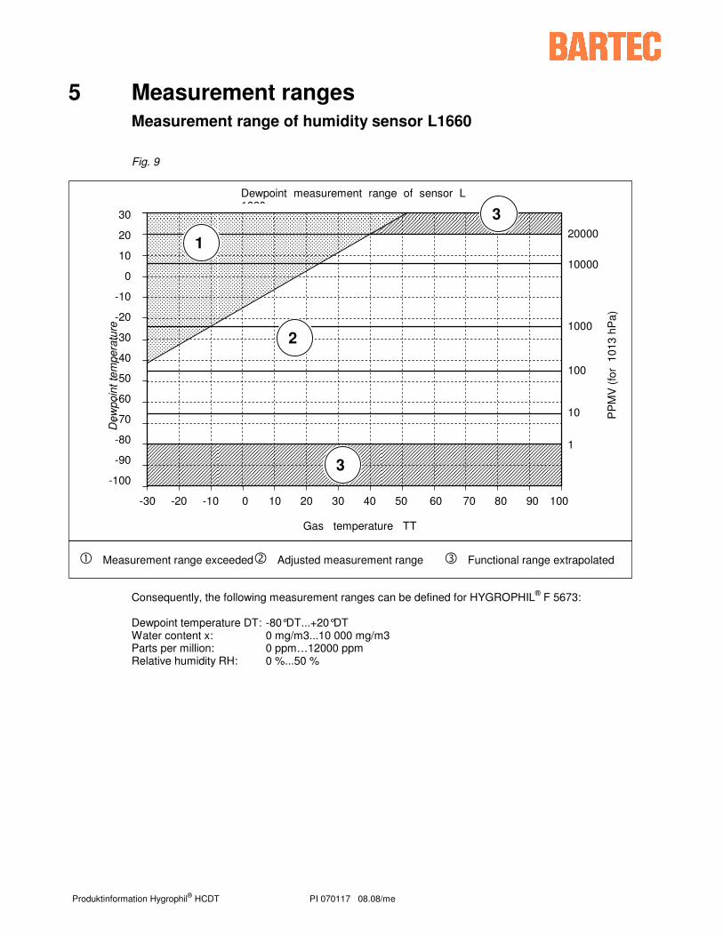
5 Measurement ranges Measurement range of humidity sensor L1660 Fig. 9
Consequently, the following measurement ranges can be defined for HYGROPHIL® F 5673:
Dewpoint temperature DT: -80°DT...+20°DT Water content x: 0 mg/m3...10 000 mg/m3 Parts per million: 0 ppm…12000 ppm Relative humidity RH: 0 %...50 %
30
20
10
0
-10
-20
-30
-40
-50
-60
-70
-80
-90
-100
Dew
poin
t te
mpera
ture
Gas temperature TT [°C]
-30 -20 -10 0 10 20 30 40 50 60 70 80 90 100
3
3
Measurement range exceeded Adjusted measurement range Functional range extrapolated
Dewpoint measurement range of sensor L 1660
20000
10000
1000
100
10
1
1
2
PP
MV
(fo
r 1
013 h
Pa
)

Produktinformation Hygrophil® HCDT PI 070117 08.08/me
Measurement range of HCDT sensor 1510-11 The probe works as a dewpoint sensor with active Peltier cooling. By means of the integrated Peltier cooling and depending on the density (pressure) of the gas, a cooling of 35 to 40 K compared to the sensor ambient temperature (sensor shaft) can be reached. If this is not sufficient, a vortex cooling or Peltier cooling simply flanged to the sensor shaft can achieve an additional cooling of approx. 20 - 30 K. Fig. 10 shows the application range of the sensor, in range A without an additional cooling, and in range B with additional cooling Fig. 10
6
Additional cooling
Example amb. temp. 20 º C
Produktinformation Hygrophil® HCDT PI 070117 08.08/me
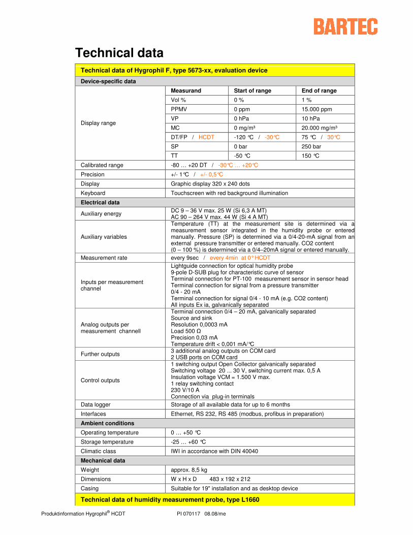
Technical data
Technical data of Hygrophil F, type 5673-xx, evaluation device
Device-specific data
Measurand Start of range End of range
Vol % 0 % 1 %
PPMV 0 ppm 15.000 ppm
VP 0 hPa 10 hPa
MC 0 mg/m³ 20.000 mg/m³
DT/FP / HCDT -120 °C / -30°C 75 °C / 30°C
SP 0 bar 250 bar
Display range
TT -50 °C 150 °C
Calibrated range -80 … +20 DT / -30°C … +20°C
Precision +/- 1°C / +/- 0,5°C
Display Graphic display 320 x 240 dots
Keyboard Touchscreen with red background illumination
Electrical data
Auxiliary energy DC 9 – 36 V max. 25 W (Si 6,3 A MT) AC 90 – 264 V max. 44 W (Si 4 A MT)
Auxiliary variables
Temperature (TT) at the measurement site is determined via a measurement sensor integrated in the humidity probe or entered manually. Pressure (SP) is determined via a 0/4-20-mA signal from an external pressure transmitter or entered manually. CO2 content (0 – 100 %) is determined via a 0/4–20mA signal or entered manually.
Measurement rate every 9sec / every 4min at 0° HCDT
Inputs per measurement channel
Lightguide connection for optical humidity probe 9-pole D-SUB plug for characteristic curve of sensor Terminal connection for PT-100 measurement sensor in sensor head Terminal connection for signal from a pressure transmitter 0/4 - 20 mA Terminal connection for signal 0/4 - 10 mA (e.g. CO2 content) All inputs Ex ia, galvanically separated
Analog outputs per measurement channell
Terminal connection 0/4 – 20 mA, galvanically separated Source and sink Resolution 0,0003 mA Load 500 Ω Precision 0,03 mA Temperature drift < 0,001 mA/°C
Further outputs 3 additional analog outputs on COM card 2 USB ports on COM card
Control outputs
1 switching output Open Collector galvanically separated Switching voltage 20 ... 30 V, switching current max. 0,5 A Insulation voltage VCM = 1.500 V max. 1 relay switching contact 230 V/10 A Connection via plug-in terminals
Data logger Storage of all available data for up to 6 months
Interfaces Ethernet, RS 232, RS 485 (modbus, profibus in preparation)
Ambient conditions
Operating temperature 0 … +50 °C
Storage temperature -25 … +60 °C
Climatic class IWI in accordance with DIN 40040
Mechanical data
Weight approx. 8,5 kg
Dimensions W x H x D 483 x 192 x 212
Casing Suitable for 19" installation and as desktop device
Technical data of humidity measurement probe, type L1660

Produktinformation Hygrophil® HCDT PI 070117 08.08/me
Device-specific data
Integrated Pt100 -50 … + 100 °C, DIN IEC 751, 4 conductor connections
Ambient conditions
Operating temperature -30 … +95 °C (sensor tip)
Storage temperature -30 … +50 °C
Maximal admissible working pressure
100 bar, 200 bar with test certificate
Protection type IP 65 (when built-in)
Mechanical data
Material Shaft: 1.4571 Sensor head: POM
Dimensions of humidity sensor L1660
Technical data of HCDT sensor
Measurement range
Application range of HCDT -40 … +80°C
Maximal cooling compared to shaft temperature (temperature of measurement gas)
60 K (with additional cooling)
Precision of HCDT ± 0,5 °C
Measurement rate approx. 4min ati 0° HCDT
Start-up time approx. 30min
Ambient conditions
Operating temperature of probe -40 … +80°C
Pressure range of probe 0,2 … 40bar
Mechanical data
Material of casing (transmitter box) Aluminium, varnished
Material of probe shaft Copper, nickel-plated 10µ
Protection type of casing IP 65
Dimensions of HCDT sensor 1510-11