Embed Size (px)
Citation preview

quinn-therm.com
1 www.quinn-buildingproducts.com
PRODUCT & INSTALLATION
GUIDE
APRIL 17

2
Product & Installation Guide
WALL
08 Cavity walls: masonry - full fill
10 Cavity walls: masonry - partial fill
12 Cavity walls: timber frame
14 Cavity walls: steel stud frame
16 Cavity walls: masonry - internal dry lining
18 Solid walls: internal dry lining - fixed to battens
20 Solid walls: internal dry lining - fixed by battens
22 Solid walls: internal dry lining - insulated plasterboard fixed by dabs
PITCHED ROOFS
36 Pitched roof: insulated above rafters
38 Pitched roof: insulated above & between rafters
40 Pitched roof: insulated between & below rafters
42 Pitched roof: insulated at ceiling
FLAT ROOFS
44 Flat roof: metal deck
46 Flat roof: concrete deck
48 Flat roof: timber deck
50 Flat roof: timber deck insulated above joists
52 Flat roof: timber deck insulated between & below joists
OTHERS
54 Timber frame wall with weatherboards
56 Wall: room in roof
58 References/Applications
59 Storage & Handling
PRODUCT/APPLICATION SELECTOR
04 Product Range
05 Performance
06 Design considerations
58 Reference / Accreditions
59 Storage & Handling
FLOORS
24 Solid ground floor: insulated below groundbearing slab
26 Solid ground floor: insulated above groundbearing slab
28 Solid ground floor: timber floating floor
30 Suspended beam and block floor
32 Suspended timber ground floor: insulated between timber joists
34 Suspended timber floor other than ground floor: insulated between timber joists
GENERAL INFORMATION
New Build Refurbishment

3
quinn-therm.com
3
EXCELLENT PERFORMANCE
SUSTAINABILITY
QUALITY PRODUCTS
TECHNICAL RESOURCES
FLEXIBLE SOLUTIONS
• Excellent life-long thermal performance
• Helps to achieve low energy building standards
• High compressive strength
• Zero Ozone Depletion Potential (ODP) & Global Warming Potential (GWP) <5
• A+ BRE Green Guide rating
• Environmental Management System certified to ISO 14001
• Exceeding performance criteria of national and European Standards
• Products which are CE marked and have BBA and IAB accreditation
• Daily quality control testing to all relevant European standards
• Online resource library including BIM objects and Accredited Construction Details
• Free U-value & Y-value calculators and online product converter
• Technical support and CPD seminars by highly experienced technical team
• Solutions for new builds & refurbishment
• Suitable for commercial and domestic builds
• Full suite of complimentary building products available
WHY QUINN THERMQuinn Therm offer a range of products that are engineered for Quality and Performance. With
nationwide sales coverage and an In-house team of Technical Experts we are uniquely placed to support
any project.

4
Product & Installation Guide
PRODUCT RANGE
Table 1 Physical characteristics
Board Surface EdgeThicknesses
(mm)Length x width
QF Composite foil
facings
Butt 20 - 150 2400 x 1200mm
QW Composite foil
facings
Butt, T&G 25 - 150 450 x 1200mm
1200 x 2400mm
Isoshield Embossed Foil
Facing
Rebated 72, 97, 122, 147 450 x 1200mm
QL-Kraft Composite kraft
paper facing
adhered to
plasterboard
Butt 26.5*, 29.5, 34.5*,
37.5, 42.5, 50.5,
62.5, 72.5, 82.5,
92.5
1200 x 2400mm
1200 x 2438mm
1200 x 2743mm
QL-Foil Composite foil
facing adhered to
plasterboard
Butt 34.5*, 37.5, 42.5,
52.5, 62.5, 72.5,
82.5, 92.5
1200 x 2400mm
QR Composite foil
facings
Butt 20 - 150 1200 x 2400mm
QRFR-FFR Composite foil
facings
Butt 25 - 150 1200 x 2400mm
QRFR-DPFR Fleece-finished,
bitumen facing on
one side. Mineral
coated, perforated,
glass tissue facing
on other side.
Butt 25 – 150* 600 x 1200mm
QFFR-GFR Mineral coated, perforated, glass
tissue
Butt 25 -150 600 x 1200mm
Plydeck Composite foil
facing adhered to
6mm plywood
Butt 56, 76, 96, 116, 131 1200 x 2400mm
Note: All QL boards thickness include 12.5mm plasterboard except those* which include 9.5mm plasterboard.
Quinn Therm offers an extensive range of PIR insulation products for use in floor, wall and roof
applications in new build and retrofit projects.
Available in range of thicknesses from 20mm to 150mm. All PIR boards achieve a thermal conductivity of
0.022W/mK to 0.026W/mK.

quinn-therm.com
5
Environmental
Quinn Therm has an ozone depletion
potential (ODP) of zero. It has a low Global
Warming Potential (GWP), certified to ISO
14001 - Environmental Management Systems.
All Quinn Therm products, with the exception
of QRFR-GFR and QRFR-DPFR, achieve A+
rating when compared to the BRE Green
Guide. QRFR-GFR and QRFR-DPFR achieve
A rating.
Dimensional stability
When tested to EN 1604 Quinn Therm
achieves level DS(TH)4 to EN 13165.
Durability
Quinn Therm will perform for the service life
of the building.
Fire Properties
Quinn Therm products have been tested to
BS EN 13501-1 to achieve Euro class rating.
Quinn Therm boards also have a Class 1 rating
when tested to BS 476-7.
Thermal performance
Quinn Therm has a thermal conductivity as
low as 0.022W/mK, making it one of the most
effective rigid board insulations available.
The facings have a hemispherical emissivity
(Eη) of 0.07 ± 0.02 (BBA test report no.
2270) which enhances the thermal resistance
of any cavities adjacent to Quinn Therm
boards (see page 6 for more details).
Vapour control
The water vapour resistivity of the core
insulation may be taken as 300MN.s.g-1.m-1
and a resistance value of 4000MN.s.g-1.m-1 for
each foil facing. In some applications the foil
facings may be sealed at the joints on the warm
side with metalised tape which will eliminate
the requirement for an additional
air and vapour control layer (AVCL).
Biological / Chemical
Quinn Therm does not rot and does not
support mould or fungus.
Quinn Therm is chemically inert, and poses no
threat to anyone using it.
Table 2 Performance characteristics
* Values for insulation only
PERFORMANCE
Board Thermal conductivity (W/mK)Core water
vapour resistivity (MNs/gm)
Compressive strength (kPa)
QF 0.022 ≅300 >150
QW 0.022 ≅300 >150
Isoshield 0.022 ≅300 >150
QL-Kraft* 0.022 ≅300 >150
QR 0.022 ≅300 >150
Plydeck* 0.022 ≅300 >150
QRFR-FFR 0.022 ≅300 >150
QRFR-GFR 0.024 - 0.026 ≅300 >150
QRFR-DPFR 0.024 - 0.026 ≅300 >150

6
Product & Installation Guide
DESIGN CONSIDERATIONS
For boards installed above the rafters on
warm pitched roofs consult Annex B of
BS 5534:2003 for guidance on calculation
methods and fixings.
Low emissivity cavities
The rate at which heat travels across a cavity
in the building element is determined by the
direction of heat flow and by the surfaces
which form the cavity. A cavity with at least
one low emissivity surface, such as aluminium
foil, will have a better thermal resistance than
a similar cavity with high emissivity surfaces
such as brick, block or unfaced insulation
board.
The composite aluminium foil facings on
most Quinn Therm boards will form a low
emissivity surface to any adjacent cavity, and
will therefore improve the thermal resistance
of the cavity and reduce the rate of heat loss
through the building element
Fixings
The selection and specification of fixings
are key considerations in achieving efficient
insulation systems with Quinn Therm.
Designers must consider both the thermal
and mechanical performance of the fixings.
U-value calculations to BR 443 must take
account of the additional heat loss caused
when an insulation layer is penetrated
by metal fixings which have high thermal
conductivities. In order to minimise that heat
loss and maintain thermal performance it is
important to select appropriate fixings.
Stainless steel double triangle ties are
recommended for use in cavity wall
constructions. Where Quinn Therm boards
are being fixed internally, for example behind
plasterboard linings or beneath rafters,
stainless steel clout headed nails should
be used to restrain the boards. Specialist
fixing systems designed to minimise thermal
bridging, such as those with plastic shafted
washers, may be used where the required
fixing density will significantly reduce thermal
performance.
Where boards will be subject to wind-uplift
forces, on flat or pitched roofs, the wind loads
should be determined by the calculation
methods in BS EN 1991-1-4 (which replaces
BS 6399-2). The fixing density should then
be determined in consultation with the fixing
manufacturer.
Figures for cavities 25mm wide
Element Thermal resistance (m2K/W)
Normal cavityQuinn Therm cavity
Roof 0.16 0.454
Wall 0.18 0.665
Floor 0.19 0.767

quinn-therm.com
7
Radon
Radon is a colourless, odourless radioactive
gas that occurs naturally in the ground
in parts of Britain and Ireland. Radon is
carcinogenic and exposure to radon is, after
smoking, the main cause of lung cancer.
As radon is released from the ground it
can reach dangerous concentrations within
buildings; the risk is greater in dwellings and
other residential buildings, where people
spend a substantial amount of time.
Where there is a risk of radon being present
in harmful levels protective measures
should be installed. In lower risk areas
typical provision is to install a gas-resistant
membrane across the whole footprint of the
building.
In groundbearing floors the same membrane
can protect against radon and form the
dpm. In suspended floors the gas-resistant
membrane should be installed across the
bottom of the sub-floor void and protected
by a layer of concrete. In all constructions
the gas-resistant membrane must extend
to the outer face of external walls: that may
be achieved by using gas-resistant cavity
trays and dpcs and sealing them to the gas-
resistant membrane.
In higher risk areas a radon sump should be
provided below the gas-resistant membrane
in order to extract radon from beneath a
building and so reduce the likelihood of an
internal build up.
Condensation control
Damaging interstitial condensation can form
within floors, walls and roofs when water
vapour passing through the construction
builds up against a cold impermeable surface.
To prevent condensation it is important to
extract moisture from the building as close
as possible to the source (e.g. bathrooms and
kitchens) and to allow any moisture which
reaches the inside of the construction to pass
safely to atmosphere. That can be achieved
by ensuring the materials to the cold side of
the insulation have a low vapour resistance.
However, some constructions – such as
timber framed walls or warm flat roofs – have
layers with high vapour resistance to the
cold side of the insulation, and consequently
have a high risk of condensation. In such
constructions it is vital to prevent water
vapour entering the construction, therefore
an air and vapour control layer (AVCL)
should be formed as close to the internal
surface as possible.
As the foil facings of Quinn Therm boards
have an extremely high vapour resistance it
is possible in many constructions to form an
AVCL by taping the joints between Quinn
Therm boards with metalised tape. Where
that is not practicable, a separate AVCL must
be provided.
Contact Quinn Technical Services for
further advice on condensation control and
interstitial condensation risk analysis.

8
Product & Installation Guide
CAVITY WALLS: MASONRY - FULL FILL insulated with Quinn Therm Isoshield
Design and Installation
Cavities up to 100mm wide require wall ties
at maximum 900mm horizontal centres and
450mm vertical centres, with additional ties
around openings and at corners. Cavities
wider than 100mm may require ties at
reduced centres. Wall ties must slope down
from the inner leaf in order to shed water into
the cavity.
Wall insulation must extend 150mm below
the upper edge of floor insulation to prevent
thermal bridging at the floor perimeter.
Quinn Therm Isoshield boards should be
fitted tightly against the leading leaf of
masonry supported on the first row of wall
ties. The higher side of the rebated edge
should always be against the inner leaf.
The faces of masonry must be kept clean and
clear of mortar snots and droppings to enable
the Quinn Therm Isoshield boards to be
installed properly. A cavity board should be
used to protect the cavity from droppings.
At corner junctions, the rebated edge should
be carefully removed with a handsaw or knife
to allow a straight butt joint with no gaps.
The corner joint should be staggered and
the exposed edge of the board should be
protected by a vertical DPC of an appropriate
width.
1 External brickwork
Quinn Therm Isoshield
Cavity tray
Internal blockwork
Internal finish
2
3
4
5
1
2
3
45

Benefits
Suitable for new build
Utilizes full cavity width
Achieves lower U-values whilst
maintaining cavity width
Precision cut rebated edge ensures block
lock tightly together, minimises heat loss
and eliminates the passage of moisture
Extremely durable textured aluminium foil
facings
quinn-therm.com
9
U-value results above based upon wall construction shown:
103mm brick outer leaf; Quinn Therm Isoshield full fill cavity wall insulation, 100mm concrete block
(conductivity as shown); 12mm plaster. Brick and block leaves with 10mm nominal mortar joints.
Calculations performed to BS EN ISO 6946, taking account of repeating thermal bridges.
WA
LL
S
Full fill isoshield insulation with plasterboard on dabs
Innerleaf Conductivity
W/m2k
Dense block
1.13
Others
0.45
Others
0.3
Quinn Lite
0.19 0.17 0.12
Thickness(mm) U-value (W/m2K)
72 0.26 0.25 0.24 0.24 0.23 0.22
97 0.20 0.20 0.19 0.19 0.18 0.18
122 0.16 0.16 0.16 0.15 0.15 0.15
147 0.14 0.14 0.13 0.13 0.13 0.13
Inner leaf Conductivity
(W/m2K)
Dense block
1.13
Others
0.45
Others
0.3
Quinn Lite
0.19 0.17 0.12
Thickness (mm) U-value (W/m2K)
72 0.27 0.26 0.25 0.24 0.24 0.23
97 0.21 0.20 0.20 0.19 0.19 0.18
122 0.17 0.16 0.16 0.16 0.16 0.15
147 0.14 0.14 0.14 0.13 0.13 0.13
Full fill isoshield insulation with 12mm plasterfinish
For performance properties, including fire properties, thermal conductivity and compressive strength,
see Page 5.

10
Product & Installation Guide
CAVITY WALLS: MASONRY - PARTIAL FILL insulated with Quinn Therm QW
Design and Installation
Cavities up to 100mm wide require wall ties
at maximum 900mm horizontal centres and
450mm vertical centres, with additional ties
around openings and at corners. Cavities
wider than 100mm may require ties at
reduced centres. Wall ties must slope down
from the inner leaf in order to shed water into
the cavity.
Wall ties can have a significant impact on
the overall U-value of the wall. It is therefore
important to select ties which will minimise
heat loss, such as stainless steel double
triangle ties. Ties should comply with EN
845–1 and PD 6697.
Wall insulation must extend 150mm below
the upper edge of floor insulation to prevent
thermal bridging at the floor perimeter. If the
1
2
3
4 5
1 External brickwork
Quinn Therm QW cavity boards
Cavity tray
Internal blockwork
Internal finish
2
3
4
5
cavity includes a radon barrier the first run
of boards should be supported on the cavity
tray.
Quinn Therm QW boards should be fitted
against the inner leaf of masonry and held
in place by wall-tie clips or collars. Boards
must be butted tightly together at corners to
give a continuous layer of insulation, and cut
neatly to fit tight to the backs of frames, sills,
cavity closers and lintels.
The faces of masonry must be kept clean
and clear of mortar snots and droppings to
enable the Quinn Therm QW boards to be
installed properly. When raising the outer leaf
use a cavity board to protect the cavity from
droppings.

U-value results above based upon wall construction shown:
103mm brick outer leaf; 40 - 50mm low emissivity residual cavity; Quinn Therm QW, 100mm concrete
block (conductivity as shown); 12mm plaster. Brick and block leaves with 10mm nominal mortar joints.
Calculations performed to BS EN ISO 6946, taking account of repeating thermal bridges.
For performance properties, including fire properties, thermal conductivity and compressive strength,
see Page 5.
Required thickness of Quinn Therm QW for different blocksPartial fill QW insulation with internal plasterboard on plaster dabs
Inner leaf Conductivity
(W/m2K)
Dense block
1.13
Others
0.45
Others
0.3
Quinn Lite
0.19 0.17 0.12
Thickness (mm) U-value (W/m2K)
50 0.29 0.28 0.27 0.26 0.26 0.24
60 0.25 0.25 0.24 0.23 0.23 0.22
65 0.24 0.23 0.23 0.22 0.22 0.21
70 0.23 0.22 0.22 0.21 0.21 0.20
75 0.22 0.21 0.21 0.20 0.20 0.19
80 0.21 0.20 0.20 0.19 0.19 0.18
100 0.17 0.17 0.17 0.16 0.16 0.16
110 0.16 0.16 0.15 0.15 0.15 0.15
Partial fill QW insulation with internal wet plaster
Inner leaf Conductivity
(W/m2K)
Dense block
1.13
Others
0.45
Others
0.3
Quinn Lite
0.19 0.17 0.12
Thickness (mm) U-value (W/m2K)
50 0.30 0.29 0.28 0.27 0.26 0.25
60 0.26 0.25 0.25 0.24 0.24 0.23
65 0.25 0.24 0.23 0.23 0.22 0.22
70 0.23 0.23 0.22 0.22 0.21 0.21
75 0.22 0.22 0.21 0.20 0.20 0.20
80 0.21 0.21 0.20 0.20 0.20 0.19
100 0.18 0.17 0.17 0.17 0.17 0.16
110 0.16 0.16 0.16 0.15 0.15 0.15
quinn-therm.com
11
Benefits
Suitable for new build
projects.
Excellent thermal properties
Extremely durable
High thermally resistant cavity due to low
emissivity foil facings
WA
LL
S
12
Product & Installation Guide
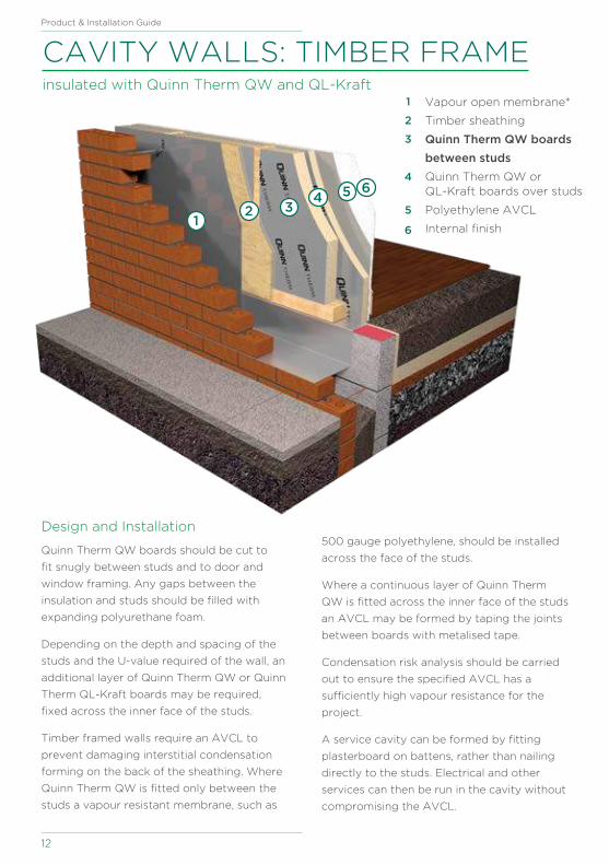
CAVITY WALLS: TIMBER FRAME insulated with Quinn Therm QW and QL-Kraft
Design and Installation
Quinn Therm QW boards should be cut to
fit snugly between studs and to door and
window framing. Any gaps between the
insulation and studs should be filled with
expanding polyurethane foam.
Depending on the depth and spacing of the
studs and the U-value required of the wall, an
additional layer of Quinn Therm QW or Quinn
Therm QL-Kraft boards may be required,
fixed across the inner face of the studs.
Timber framed walls require an AVCL to
prevent damaging interstitial condensation
forming on the back of the sheathing. Where
Quinn Therm QW is fitted only between the
studs a vapour resistant membrane, such as
Vapour open membrane*
Timber sheathing
Quinn Therm QW boards
between studs
Quinn Therm QW or QL-Kraft boards over studs
Polyethylene AVCL
Internal finish
1
2
3
4
5
61
2 34 5 6
500 gauge polyethylene, should be installed
across the face of the studs.
Where a continuous layer of Quinn Therm
QW is fitted across the inner face of the studs
an AVCL may be formed by taping the joints
between boards with metalised tape.
Condensation risk analysis should be carried
out to ensure the specified AVCL has a
sufficiently high vapour resistance for the
project.
A service cavity can be formed by fitting
plasterboard on battens, rather than nailing
directly to the studs. Electrical and other
services can then be run in the cavity without
compromising the AVCL.

Benefits
Suitable for new build
projects.
Excellent thermal properties
Extremely durable
Quinn Therm QW can be easily cut
between studs
Quinn Therm QL across studs eliminate
thermal bridging
quinn-therm.com
13
Required thickness of QW & QL-KraftQuinn Therm QW between studs and Quinn Therm QW or QL-Kraft across studs
Between + Across studs89mm stud
U-Value (W/m2K)
140mm stud
U-Value (W/m2K)
50 + 25 0.26 0.25
60 + 25 0.24 0.24
75 + 25 - 0.22
90 + 25 - 0.20
100 + 25 - 0.19
110 + 25 - 0.18
110 + 40 - 0.16
110 + 50 - 0.15
110 + 65 - 0.13
U-value results above based upon wall construction shown:
103mm brick outer leaf; 40 - 50mm cavity; vapour open membrane*; 12mm plywood sheathing; 89 or
140mm timber studs @ 600mm centres (timber bridging fraction 15%); Quinn Therm QW between
studs; Quinn Therm QW or QL-Kraft over studs; polyethylene AVCL; 12mm plasterboard. Calculations
performed to BS EN ISO 6946, taking account of repeating thermal bridges.
* Note: improved U-values may be achieved using reflective vapour open membranes.
WA
LL
S
For performance properties, including fire properties, thermal conductivity and compressive strength,
see Page 5.

14
Product & Installation Guide
CAVITY WALLS: STEEL STUD FRAME insulated with Quinn Therm QW
Design and Installation
Quinn Therm QW boards should be butted
tightly together to form a continuous layer
of insulation. The boards should be cut to
fit tightly to the back of door and window
framing. Any gaps between the insulation
and framing should be filled with expanding
polyurethane foam.
The Quinn Therm QW boards are restrained
by steel channels which are screwed back
to the studs. The screws must be specified
carefully, to ensure they can withstand
the transmitted loading from the cladding,
while also minimising heat loss where they
penetrate the insulation. U-value calculations
must take account of that additional heat
loss.
1
2
3
4
5
Steel runners with wall ties
Quinn Therm QW boards
Steel studs
Polyethylene AVCL
Internal finish
1
2
3
4
5
Light steel framed walls require an AVCL to
prevent damaging interstitial condensation
forming within the construction. The AVCL
should be installed across the inner face of
the studs, immediately behind the surface
finish.
Condensation risk analysis should be carried
out to ensure the specified AVCL has a
sufficiently high vapour resistance for the
project. The AVCL will also help reduce air
leakage into the stud cavity.
Depending on the depth and spacing of the
studs and the U-value required of the wall, an
additional layer of mineral fibre insulation can
be fitted between the steel studs.

Benefits
Suitable for new build
projects.
Warm frame construction avoids
significant thermal bridging
Excellent thermal properties
Extremely durable
High thermally resistant cavity due to low
emissivity foil facings
quinn-therm.com
15
Required thickness of Quinn Therm QWNo insulation between studs. Quinn Therm QW across studs.
Insulation thickness (mm)
40 50 60 70 75 80 90 100
U-value
(W/m2K) - 0.27 0.24 0.22 0.21 0.20 0.19 0.17
Insulation thickness (mm)
40 50 60 70 75 80 90 100
U-value
(W/m2K) 0.24 0.21 0.20 0.19 0.18 0.17 0.16 0.15
100mm wool insulation between studs (0.044). Quinn Therm QW across studs.
Insulation thickness (mm)
40 50 60 70 75 80 90 100
U-value
(W/m2K)0.20 0.19 0.17 0.16 0.16 0.15 0.14 0.14
150mm wool insulation between studs (0.044). Quinn Therm QW across studs.
U-values based on studs at 400mm centres (3% bridging)
U-value results above based upon wall construction shown:
103mm brick outer leaf; 40 - 50mm low emissivity residual cavity; Quinn Therm QW; steel studs @ 600mm
centres; polyethylene AVCL; 12mm plasterboard. Calculations performed to
BS EN ISO 6946 and BRE Digest 465, taking account of repeating thermal bridges.
WA
LL
S
For performance properties, including fire properties, thermal conductivity and compressive strength,
see Page 5.

16
Product & Installation Guide
123456
123
4
56
CAVITY WALLS: MASONRY - INTERNAL DRY LINING
with Quinn Therm QL-Kraft insulated plasterboard
Design and Installation
Cavities up to 100mm wide require ties at
maximum 900mm horizontal centres and
450mm vertical centres, with additional ties
around openings and at corners. Cavities
wider than 100mm may require ties at
reduced centres.
Cavity wall ties can have a significant impact
on the overall U-value of the wall. It is
therefore important to select ties which will
minimise heat loss, such as stainless steel
double triangle ties. Ties should comply with
EN 845–1 and
PD 6697.
Insulation in the wall cavity must extend
150mm below the upper edge of floor
insulation to prevent thermal bridging.
1
Internal blockwork
Original plaster finish
Dry wall adhesive
Plaster dabs
Quinn Therm
QL-Kraft boards
Internal finish
23456
If the cavity includes a radon barrier the first
run of boards should be supported on the
cavity tray.
Quinn Therm boards should be fitted against
the inner leaf of masonry and held in place
by wall-tie clips or collars. Boards must be
butted tightly together at corners to give a
continuous layer of insulation, and cut neatly
to fit tight to the backs of frames, sills, cavity
closers and lintels.
To minimise air infiltration, a continuous strip
of dry-lining adhesive should be used to seal
the perimeter of the Quinn Thermal QL-Kraft
boards, including around window and door
openings. (For further guidance on installing
Quinn Therm QL-Kraft see page 22.)
1
2
3
4
5
6

123456
U-value results above based upon wall construction shown:
103mm brick outer leaf; 40 - 50mm low emissivity residual cavity; Quinn Therm QW; 100mm concrete
block (conductivity as shown); 12mm plaster with dry wall adhesive; Quinn Therm QL-Kraft insulated
plasterboard on plaster dabs. Calculations performed to BS EN ISO 6946, taking account of repeating
thermal bridges.
Benefits
Suitable for new build projects and
refurbishment projects
Excellent thermal properties
Extremely durable
No additional plasterboard finish requires
Compatible with dot and dab adhesive
Reduced labour costs
quinn-therm.com
17
123456
Required thickness of Quinn Therm QL-KraftCavity wall with internal drylining
Quinn Therm QL-Kraft
Partial fill cavity insulation (mm)
50 60 75 80 100
Thickness (mm) U-value (W/m2K)
37.5 0.22 0.20 0.17 0.17 0.15
42.5 0.21 0.19 0.17 0.16 0.14
50.5 0.19 0.18 0.16 0.15 0.13
62.5 0.17 0.16 0.14 0.14 0.12
72.5 0.16 0.15 0.14 0.13 0.12
82.5 0.15 0.14 0.13 0.12 0.11
92.5 0.14 0.13 0.12 0.12 0.11
WA
LL
S
For performance properties, including fire properties, thermal conductivity and compressive strength,
see Page 5.

18
Product & Installation Guide
SOLID WALLS: INTERNAL DRY LINING insulated with Quinn Therm QW or QL-Foil fixed to battens
Design and Installation
Insulating an existing wall changes the heat
and moisture patterns in the wall, so it is vital
to carry out condensation risk analysis before
undertaking any work on site. To minimise the
risk of condensation the joints between Quinn
Therm QW boards should be taped with
metalised tape to form an AVCL which will
prevent moisture from the building interior
condensing on the cold side of the insulation.
Existing wall surfaces should be prepared by
removing existing skirting, picture rails and
window boards, as well as any wall coverings
with high vapour resistance, such as vinyl
wallpaper or gloss paint.
Solid stone wall
Existing plaster finish
Battens on a strip of DPC
Quinn Therm QW or
QL-Foil boards
Plasterboard
Internal finish
6
Battens should be isolated from the wall
surface by a strip of DPC material and on
uneven walls should be packed out to give a
true surface for installing Quinn Therm QW.
Additional battens should be fixed to support
cupboards, shelves and other fittings.
The screws which fix Quinn Therm QW to
the battens should be selected to minimise
heat loss: U-value calculations for the wall
should account for the additional heat loss
resulting from mechanical fasteners. The
plasterboard lining should also be fixed back
to the battens.
Using Quinn Therm QL-Foil insulated
plasterboard enables the insulation and
internal lining to be applied in one process.
1
2
3
4
56
123
45
6

Benefits
Suitable for new build and refurbishment
projects.
Significantly improves thermal
performance of old uninsulated walls.
Extremely durable
Improves finish on old uneven walls
High thermally resistant cavity due to low
emissivity foil facings
quinn-therm.com
19
6
Required thickness of Quinn Therm QW or QL FoilQW or QL-Foil insulation fixed to timber battens @ 400mm centres
Masonry Type 215mm Brick 500mm Stone 215 Dense Block215mm Quinn Lite
(B5)
Thickness (mm) U-value (W/m2K)
37.5 0.44 0.43 0.47 0.32
42.5 0.41 0.40 0.43 0.30
50.5 0.35 0.34 0.37 0.27
62.5 0.29 0.29 0.30 0.24
72.5 0.26 0.26 0.27 0.21
82.5 0.23 0.23 0.24 0.19
92.5 0.21 0.21 0.22 0.18
102.5 0.19 0.19 0.20 0.17
112.5 0.18 0.17 0.18 0.15
U-value results above based upon wall construction shown:
Masonry (see table); 15mm plaster; 25mm cavity; Quinn Therm QW with 12.5mm
plasterboard or Quinn Therm QL-Foil insulated plasterboard. Calculations performed to BS EN ISO 6946,
taking account of repeating thermal bridges.
WA
LL
S
For performance properties, including fire properties, thermal conductivity and compressive strength,
see Page 5.

20
Product & Installation Guide
SOLID WALLS: INTERNAL DRY LINING insulated with Quinn Therm QW fixed by battens
Design and Installation
Insulating an existing wall changes the heat
and moisture patterns in the wall, so it is vital
to carry out condensation risk analysis before
undertaking any work on site.
To minimise the risk of condensation the
joints between Quinn Therm QW boards
should be taped with metalised tape to form
an AVCL which will prevent moisture from
the building interior condensing on the cold
side of the insulation.
Existing wall surfaces should be prepared by
removing existing skirting, picture rails and
window boards, as well as any wall coverings
with high vapour resistance, such as vinyl
wallpaper or gloss paint.
Solid stone wall
Existing plaster finish
Quinn Therm QW boards
Battens
Internal finish
Additional battens should be fixed to support
cupboards, shelves and other fittings.
Mechanical fixings which penetrate thermal
insulation result in additional heat loss. The
screws which fix the battens and Quinn
Therm QW to the wall should be selected
to minimise the additional heat loss through
Quinn Therm QW.
U-value calculations for the wall should
account for the additional heat loss resulting
from mechanical fasteners.
Fixings for the plasterboard lining should not
penetrate the insulation.
12345
1234
5
5
4
3
2
1

Benefits
Suitable for new build and refurbishment
projects.
Significantly improves thermal
performance of old uninsulated walls.
Creates cavity for services
Improves finish on old uneven walls
High thermally resistant cavity due to low
emissivity foil facings
quinn-therm.com
21
U-value results above based upon wall construction shown:
Masonry (see table); 15mm plaster; Quinn Therm QW; 25mm cavity; 12.5mm plasterboard. Calculations
performed to BS EN ISO 6946, taking account of repeating thermal bridges.
Required thickness of Quinn Therm QWQW insulation fixed by timber battens @ 400mm centres
Masonry Type 215mm Brick 500mm Stone 215 Dense Block215mm Quinn Lite
(B5)
Thickness (mm) U-value (W/m2K)
25 0.44 0.43 0.47 0.32
30 0.41 0.40 0.43 0.30
40 0.35 0.34 0.37 0.27
50 0.29 0.29 0.30 0.24
60 0.26 0.26 0.27 0.21
70 0.23 0.23 0.24 0.19
80 0.21 0.21 0.22 0.18
90 0.19 0.19 0.20 0.17
100 0.18 0.17 0.18 0.15
WA
LL
S
For performance properties, including fire properties, thermal conductivity and compressive strength,
see Page 5.
12345
22
Product & Installation Guide
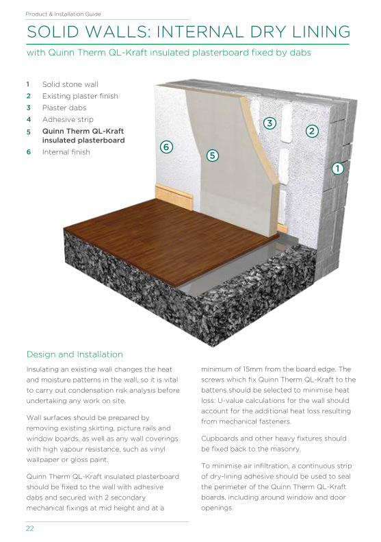
SOLID WALLS: INTERNAL DRY LINING with Quinn Therm QL-Kraft insulated plasterboard fixed by dabs
Design and Installation
Insulating an existing wall changes the heat
and moisture patterns in the wall, so it is vital
to carry out condensation risk analysis before
undertaking any work on site.
Wall surfaces should be prepared by
removing existing skirting, picture rails and
window boards, as well as any wall coverings
with high vapour resistance, such as vinyl
wallpaper or gloss paint.
Quinn Therm QL-Kraft insulated plasterboard
should be fixed to the wall with adhesive
dabs and secured with 2 secondary
mechanical fixings at mid height and at a
4
1
23
56
1 Solid stone wall
Existing plaster finish
Plaster dabs
Adhesive strip
Quinn Therm QL-Kraft insulated plasterboard
Internal finish
2
3
4
5
6
minimum of 15mm from the board edge. The
screws which fix Quinn Therm QL-Kraft to the
battens should be selected to minimise heat
loss: U-value calculations for the wall should
account for the additional heat loss resulting
from mechanical fasteners.
Cupboards and other heavy fixtures should
be fixed back to the masonry.
To minimise air infiltration, a continuous strip
of dry-lining adhesive should be used to seal
the perimeter of the Quinn Therm QL-Kraft
boards, including around window and door
openings.

U-value results above based upon wall construction shown:
Masonry (see table); 15mm plaster; plaster dabs; Quinn Therm QL-Kraft with 12.5mm plasterboard.
Calculations performed to BS EN ISO 6946, taking account of repeating thermal bridges.
Masonry Type 215mm Brick 500mm Stone 215 Dense Block215mm Quinn Lite
(B5)
Thickness (mm) U-value (W/m2K)
37.5 0.55 0.53 0.58 0.38
42.5 0.50 0.48 0.52 0.35
50.5 0.41 0.40 0.43 0.31
62.5 0.34 0.33 0.34 0.27
72.5 0.29 0.29 0.30 0.24
82.5 0.26 0.25 0.27 0.21
92.5 0.23 0.23 0.24 0.20
102.5 0.21 0.21 0.21 0.18
112.5 0.19 0.19 0.20 0.17
Benefits
Suitable for new build and refurbishment
projects.
Significantly improves thermal
performance of old uninsulated walls
Extremely durable
Improves finish on old uneven walls
Compatible with dot and dab adhesive
quinn-therm.com
23
Required thickness of Quinn Therm QL-Kraft WA
LL
S
For performance properties, including fire properties, thermal conductivity and compressive strength,
see Page 5.

24
Product & Installation Guide
SOLID GROUND FLOOR insulated below groundbearing slab with Quinn Therm QF
Design and Installation
Installing thermal insulation below the slab
brings the thermal mass of slab within the
insulated envelope, giving the building a
steady thermal response.
Where radon control measures are required,
a gas-resistant membrane should be specified
for the dpm. The gas-resistant membrane
should extend to the outer faces of all
external walls. Cavity walls will require gas-
resistant cavity trays.
Quinn Therm QF boards should be butted
tightly together, to give a continuous layer
across the whole floor. Boards should be
cut neatly around service penetrations to
minimise heat loss.
To prevent thermal bridging at the perimeter
of the floor a continuous run of Quinn Therm
12
3
45
6
1 Sand blinding and hardcore
Radon barrier / DPM
Quinn Therm QF boards
Quinn Therm edge insulation
Concrete slab on
separating layer
Timber flooring on
polyethylene slip sheet
2
3
4
5
6
QF boards should be fitted vertically against
the perimeter walls, for the whole depth of
the slab. The edge insulation should be at
least 25mm thick and the exposed top edge
should be protected from damage until
covered by the wall finish and/or skirting.
Insulation in perimeter walls should extend
at least 150mm below the top of the floor
insulation.
A polyethylene slip sheet should be laid
across the insulation, to isolate it from the
slab and prevent concrete working down
between boards. The slip sheet will also
function as a VCL, reducing the risk of
condensation forming beneath the insulation.
Quinn Therm QF must be protected from
damage while the concrete slab is being
poured.
Benefits
Suitable for new build and refurbishment
projects
High compressive strength
Excellent thermal properties
Extremely durable
Suitable for domestic and most
commercial applications
Suitable for use with underfloor heating
quinn-therm.com
25
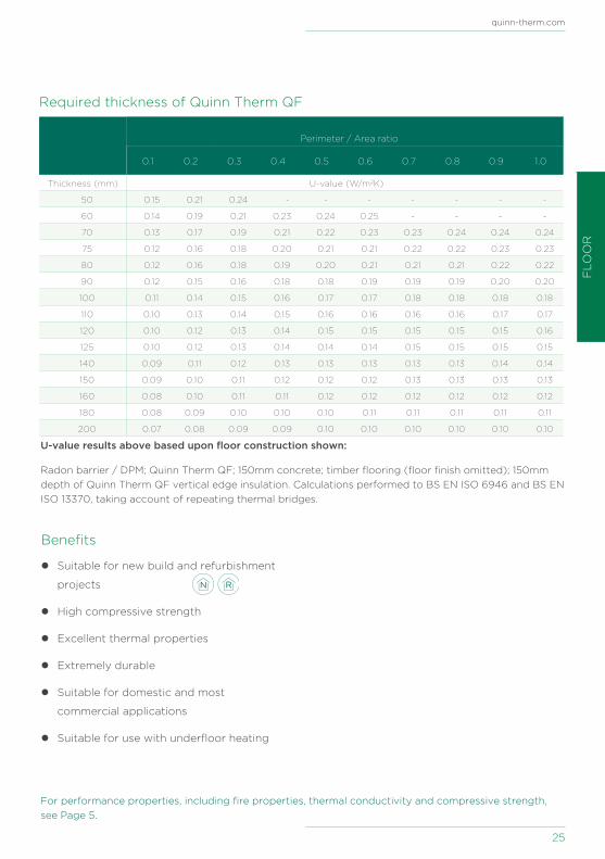
Required thickness of Quinn Therm QF
Perimeter / Area ratio
0.1 0.2 0.3 0.4 0.5 0.6 0.7 0.8 0.9 1.0
Thickness (mm) U-value (W/m2K)
50 0.15 0.21 0.24 - - - - - - -
60 0.14 0.19 0.21 0.23 0.24 0.25 - - - -
70 0.13 0.17 0.19 0.21 0.22 0.23 0.23 0.24 0.24 0.24
75 0.12 0.16 0.18 0.20 0.21 0.21 0.22 0.22 0.23 0.23
80 0.12 0.16 0.18 0.19 0.20 0.21 0.21 0.21 0.22 0.22
90 0.12 0.15 0.16 0.18 0.18 0.19 0.19 0.19 0.20 0.20
100 0.11 0.14 0.15 0.16 0.17 0.17 0.18 0.18 0.18 0.18
110 0.10 0.13 0.14 0.15 0.16 0.16 0.16 0.16 0.17 0.17
120 0.10 0.12 0.13 0.14 0.15 0.15 0.15 0.15 0.15 0.16
125 0.10 0.12 0.13 0.14 0.14 0.14 0.15 0.15 0.15 0.15
140 0.09 0.11 0.12 0.13 0.13 0.13 0.13 0.13 0.14 0.14
150 0.09 0.10 0.11 0.12 0.12 0.12 0.13 0.13 0.13 0.13
160 0.08 0.10 0.11 0.11 0.12 0.12 0.12 0.12 0.12 0.12
180 0.08 0.09 0.10 0.10 0.10 0.11 0.11 0.11 0.11 0.11
200 0.07 0.08 0.09 0.09 0.10 0.10 0.10 0.10 0.10 0.10
U-value results above based upon floor construction shown:
Radon barrier / DPM; Quinn Therm QF; 150mm concrete; timber flooring (floor finish omitted); 150mm
depth of Quinn Therm QF vertical edge insulation. Calculations performed to BS EN ISO 6946 and BS EN
ISO 13370, taking account of repeating thermal bridges.
FL
OO
R
For performance properties, including fire properties, thermal conductivity and compressive strength,
see Page 5.

26
Product & Installation Guide
SOLID GROUND FLOOR insulated above groundbearing slab with Quinn Therm QF
Design and Installation
Installing thermal insulation above the slab
isolates the thermal mass of slab from the
building interior, giving the building a rapid
thermal response. Where heating pipes
are embedded in the screed, insulating
immediately beneath the screed improves the
responsiveness of the heating system.
Where radon control measures are required a
gas-resistant membrane should be specified for
the dpm. The gas-resistant membrane should
be extended to the outer faces of all external
walls. Cavity walls will require gas-resistant
cavity trays.
To reduce thermal bridging at the perimeter
of the floor a continuous run of Quinn Therm
QF boards should be fitted vertically against
the perimeter walls, for the whole depth of the
screed.
1
2
3
456
1 Sand blinding and hardcore
Concrete slab on radon barrier / DPM
Quinn Therm QF boards
Quinn Therm edge insulation
Screed with u/f heating pipes on separating layer
Timber flooring on polyethylene slip sheet
2
3
4
5
6
The edge insulation should be at least 25mm
thick and the exposed top edge should be
protected from damage until covered by
the wall finish and/or skirting. Insulation in
perimeter walls should extend at least 150mm
below the top of the floor insulation.
Quinn Therm QF boards should be butted
tightly together, to give a continuous layer
across the whole floor. Boards should be cut
neatly around service penetrations to minimise
heat loss.
A polyethylene separating layer should be
laid across the insulation, to isolate it from the
screed and prevent concrete working down
between boards. The slip sheet will also function
as a VCL, reducing the risk of condensation
forming beneath the insulation. Quinn Therm
QF must be protected from damage while the
screed is being laid.
Benefits
Suitable for new build and refurbishment
projects
Compatible with underfloor heating
High compressive strength
Excellent thermal properties
Extremely durable
Suitable for domestic and most
commercial applications
Suitable for use with underfloor heating
quinn-therm.com
27
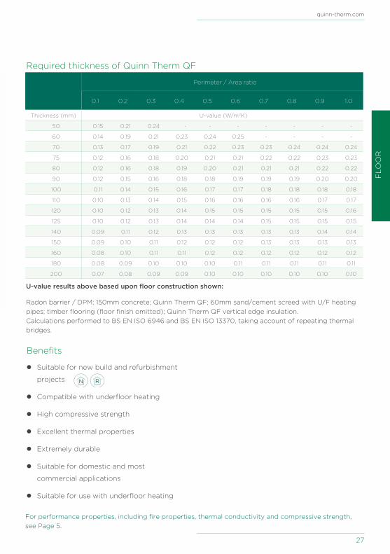
Required thickness of Quinn Therm QF
Perimeter / Area ratio
0.1 0.2 0.3 0.4 0.5 0.6 0.7 0.8 0.9 1.0
Thickness (mm) U-value (W/m2K)
50 0.15 0.21 0.24 - - - - - - -
60 0.14 0.19 0.21 0.23 0.24 0.25 - - - -
70 0.13 0.17 0.19 0.21 0.22 0.23 0.23 0.24 0.24 0.24
75 0.12 0.16 0.18 0.20 0.21 0.21 0.22 0.22 0.23 0.23
80 0.12 0.16 0.18 0.19 0.20 0.21 0.21 0.21 0.22 0.22
90 0.12 0.15 0.16 0.18 0.18 0.19 0.19 0.19 0.20 0.20
100 0.11 0.14 0.15 0.16 0.17 0.17 0.18 0.18 0.18 0.18
110 0.10 0.13 0.14 0.15 0.16 0.16 0.16 0.16 0.17 0.17
120 0.10 0.12 0.13 0.14 0.15 0.15 0.15 0.15 0.15 0.16
125 0.10 0.12 0.13 0.14 0.14 0.14 0.15 0.15 0.15 0.15
140 0.09 0.11 0.12 0.13 0.13 0.13 0.13 0.13 0.14 0.14
150 0.09 0.10 0.11 0.12 0.12 0.12 0.13 0.13 0.13 0.13
160 0.08 0.10 0.11 0.11 0.12 0.12 0.12 0.12 0.12 0.12
180 0.08 0.09 0.10 0.10 0.10 0.11 0.11 0.11 0.11 0.11
200 0.07 0.08 0.09 0.09 0.10 0.10 0.10 0.10 0.10 0.10
U-value results above based upon floor construction shown:
Radon barrier / DPM; 150mm concrete; Quinn Therm QF; 60mm sand/cement screed with U/F heating
pipes; timber flooring (floor finish omitted); Quinn Therm QF vertical edge insulation.
Calculations performed to BS EN ISO 6946 and BS EN ISO 13370, taking account of repeating thermal
bridges.
FL
OO
R
For performance properties, including fire properties, thermal conductivity and compressive strength,
see Page 5.

28
Product & Installation Guide
SOLID GROUND FLOOR: TIMBER FLOATING FLOOR insulated with Quinn Therm QF
Design and Installation
Installing thermal insulation above the slab
isolates the thermal mass of slab from the
building interior, giving the building a rapid
thermal response. It offers a good solution
for upgrading the thermal performance of an
uninsulated concrete floor. When upgrading
an existing floor it is important to consider
the impact of the change of floor levels on
doors and thresholds.
Where radon control measures are required
a gas-resistant membrane should be laid
across the floor slab before Quinn Therm QF
is installed. In new buildings the gas-barrier
should be extended as far as the outer faces
of the external walls.
The surface of the concrete slab should be
1
2
3
4
5
6
1 Sand blinding and hardcore
Concrete slab
Radon barrier / DPM
Quinn Therm QF boards
Timber flooring on
polyethylene slip sheet
Internal finish
2
3
4
5
6
free from projections and level, with no more
than a 5mm deflection over 2m.
Quinn Therm QF boards should be butted
tightly together, to give a continuous layer
across the whole floor, and laid with joints
staggered between rows. Boards should
be cut neatly around service penetrations
to minimise heat loss. Preservative treated
timber battens should be installed where
high point loads are expected, for example at
thresholds.
Timber flooring should be isolated from
the insulation by a polyethylene slip sheet.
Partition walls should be built off the
concrete deck, not off the Quinn Therm QF
boards.

quinn-therm.com
29
U-value results above based upon floor construction shown:
150mm concrete; radon barrier / DPM; Quinn Therm QF; timber flooring (floor finish omitted);
Calculations performed to BS EN ISO 6946 and BS EN ISO 13370, taking account of repeating thermal
bridges.
Required thickness of Quinn Therm QF
Perimeter / Area ratio
0.1 0.2 0.3 0.4 0.5 0.6 0.7 0.8 0.9 1.0
Thickness (mm) U-value (W/m2K)
50 0.15 0.21 0.24 - - - - - - -
60 0.14 0.19 0.21 0.23 0.24 0.25 - - - -
70 0.13 0.17 0.19 0.21 0.22 0.23 0.23 0.24 0.24 0.24
75 0.12 0.16 0.18 0.20 0.21 0.21 0.22 0.22 0.23 0.23
80 0.12 0.16 0.18 0.19 0.20 0.21 0.21 0.21 0.22 0.22
90 0.12 0.15 0.16 0.18 0.18 0.19 0.19 0.19 0.20 0.20
100 0.11 0.14 0.15 0.16 0.17 0.17 0.18 0.18 0.18 0.18
110 0.10 0.13 0.14 0.15 0.16 0.16 0.16 0.16 0.17 0.17
120 0.10 0.12 0.13 0.14 0.15 0.15 0.15 0.15 0.15 0.16
125 0.10 0.12 0.13 0.14 0.14 0.14 0.15 0.15 0.15 0.15
140 0.09 0.11 0.12 0.13 0.13 0.13 0.13 0.13 0.14 0.14
150 0.09 0.10 0.11 0.12 0.12 0.12 0.13 0.13 0.13 0.13
160 0.08 0.10 0.11 0.11 0.12 0.12 0.12 0.12 0.12 0.12
180 0.08 0.09 0.10 0.10 0.10 0.11 0.11 0.11 0.11 0.11
200 0.07 0.08 0.09 0.09 0.10 0.10 0.10 0.10 0.10 0.10
FL
OO
R
Benefits
Suitable for new build and refurbishment
projects
No screed required
Ideal for upgrading existing floors
High compressive strength
Excellent thermal properties
Extremely durable
Suitable for use with underfloor heating
For performance properties, including fire properties, thermal conductivity and compressive strength,
see Page 5.

30
Product & Installation Guide
1 Slip block
Beam and block floor
Radon barrier / DPM on levelling screed
Quinn Therm QF boards
Screed with U/F heating
pipes on separating layer
Timber flooring on
polyethylene slip sheet
2
3
4
5
6
SUSPENDED BEAM AND BLOCK FLOOR insulated with Quinn Therm QF
Design and Installation
Suspended floors are quick to construct and
can be used where site conditions preclude
a ground-bearing construction. Concrete
suspended floors are formed of concrete
beams with infill units. The void beneath the
deck should be vented to prevent problems
with damp.
The surface of the deck should be levelled
with grout or a levelling topping. Where a
radon barrier is required it should be laid over
the grouting layer and extended across the
wall cavity to the outer leaf.
To achieve required energy efficiency
standards, Quinn Therm QF should be
installed between the structural deck and
the screed or finish. Quinn Therm QF boards
should be butted tightly together, to give
123
4
5
6
a continuous layer of insulation across the
whole floor. Boards should be cut neatly
around service penetrations to minimise heat
loss.
Quinn Therm QF should be isolated from
the screed with a polyethylene separating
layer, to prevent moisture from the screed
penetrating board junctions and causing
movement.
Where heating pipes are to be embedded in
the screed a proprietary clip system should
be used to keep flexible piping in place until
the screed has been laid.
Quinn Therm QF must be protected from
damage while the screed is being laid.
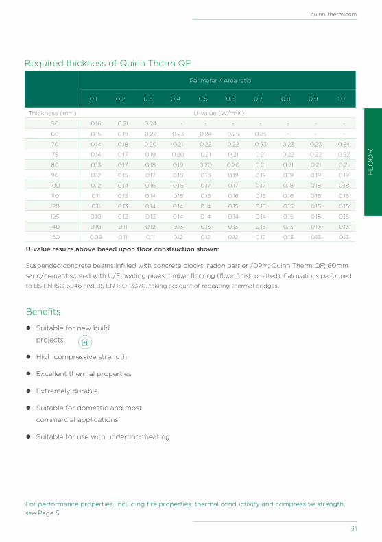
Perimeter / Area ratio
0.1 0.2 0.3 0.4 0.5 0.6 0.7 0.8 0.9 1.0
Thickness (mm) U-value (W/m2K)
50 0.16 0.21 0.24 - - - - - - -
60 0.15 0.19 0.22 0.23 0.24 0.25 0.25 - - -
70 0.14 0.18 0.20 0.21 0.22 0.22 0.23 0.23 0.23 0.24
75 0.14 0.17 0.19 0.20 0.21 0.21 0.21 0.22 0.22 0.22
80 0.13 0.17 0.18 0.19 0.20 0.20 0.21 0.21 0.21 0.21
90 0.12 0.15 0.17 0.18 0.18 0.19 0.19 0.19 0.19 0.19
100 0.12 0.14 0.16 0.16 0.17 0.17 0.17 0.18 0.18 0.18
110 0.11 0.13 0.14 0.15 0.15 0.16 0.16 0.16 0.16 0.16
120 0.11 0.13 0.14 0.14 0.14 0.15 0.15 0.15 0.15 0.15
125 0.10 0.12 0.13 0.14 0.14 0.14 0.14 0.15 0.15 0.15
140 0.10 0.11 0.12 0.13 0.13 0.13 0.13 0.13 0.13 0.13
150 0.09 0.11 0.11 0.12 0.12 0.12 0.12 0.13 0.13 0.13
Required thickness of Quinn Therm QF
Benefits
Suitable for new build
projects.
High compressive strength
Excellent thermal properties
Extremely durable
Suitable for domestic and most
commercial applications
Suitable for use with underfloor heating
quinn-therm.com
31
U-value results above based upon floor construction shown:
Suspended concrete beams infilled with concrete blocks; radon barrier /DPM; Quinn Therm QF; 60mm
sand/cement screed with U/F heating pipes; timber flooring (floor finish omitted). Calculations performed
to BS EN ISO 6946 and BS EN ISO 13370, taking account of repeating thermal bridges.
FL
OO
R
For performance properties, including fire properties, thermal conductivity and compressive strength,
see Page 5.

32
Product & Installation Guide
SUSPENDED TIMBER GROUND FLOOR insulated between timber joists with Quinn Therm QF
Design and Installation
The simplest way of insulating suspended
timber ground floors is to fit Quinn Therm QF
between the joists. As this has no impact on
floor levels it is a good solution for upgrading
the performance of existing timber floors.
For new build, where a radon barrier is
required it should be installed within the
concrete or gravel cover of the sub-floor and
continued through the entire thickness of the
wall.
Quinn Therm QF insulation should be
supported between the joists by either:
• purpose-made saddle clips at 400mm
centres,
• stainless steel nails partially driven into the
joists at 400mm centres,
• or preservative treated timber battens
nailed to the joists.
The supports should be positioned so the
depth of joist above them matches the
thickness of the Quinn Therm QF boards.
1
2
3
4
5
6
1 Radon barrier on sand
Concrete or gravel cover
Joists and support battens
Quinn Therm QF boards
Timber flooring on
polyethylene slip sheet
Internal finish
2
3
4
5
6
Alternatively, the supports can be set lower,
to allow services to be run between the Quinn
Therm QF and the flooring.
The Quinn Therm QF boards should be cut to
fit tightly between the joists then set between
the joists and pressed down until they sit on
the supports.
Strips of Quinn Therm QF should be packed
between the joists and perimeter walls to
reduce thermal bridging. Wall insulation must
extend 150mm below the upper edge of floor
insulation to prevent thermal bridging.
A polyethylene slip sheet may be installed
immediately beneath the flooring to protect
against spills and reduce air leakage.
Ventilation of the sub-floor void is vital
for avoiding problems with damp. When
installing Quinn Therm QF ensure ventilation
paths are maintained.

Benefits
Suitable for new build and
refurbishment projects
Can be easily cut between joists
Excellent thermal properties
Extremely durable
Reduces air infiltration through floor
Suitable for domestic and most
commercial applications
quinn-therm.com
33
Required thickness of Quinn Therm QF
Perimeter / Area ratio
0.1 0.2 0.3 0.4 0.5 0.6 0.7 0.8 0.9 1.0
Thickness (mm) U-value (W/m2K)
50 0.18 0.25 - - - - - - - -
60 0.17 0.23 - - - - - - -
70 0.16 0.22 - - - - - - - -
75 0.16 0.21 0.25 - - - - - - -
80 0.16 0.20 0.23 0.25 - - - - - -
90 0.15 0.19 0.22 0.23 0.24 0.25 0.25 - - -
100 0.14 0.18 0.20 0.22 0.22 0.23 0.25 0.24 0.24 0.25
110 0.14 0.17 0.19 0.20 0.21 0.22 0.22 0.22 0.23 0.23
120 0.13 0.16 0.18 0.19 0.20 0.20 0.21 0.21 0.21 0.21
125 0.13 0.16 0.18 0.19 0.19 0.20 0.20 0.20 0.21 0.21
140 0.12 0.15 0.16 0.17 0.18 0.18 0.18 0.19 0.19 0.19
150 0.12 0.14 0.16 0.16 0.17 0.17 0.18 0.18 0.18 0.18
U-value results above based upon floor construction shown:
Timber joists (150mm x 47mm @ 400mm centres); Quinn Therm QF installed between joists; timber flooring
(floor finish omitted). Calculations performed to BS EN ISO 6946 and BS EN ISO 13370, taking account of
repeating thermal bridges.
FL
OO
R
For performance properties, including fire properties, thermal conductivity and compressive strength,
see Page 5.

34
Product & Installation Guide
SUSPENDED TIMBER FLOOR OTHER THAN GROUND FLOOR
insulated between timber joists with Quinn Therm QF
Design and Installation
The simplest way of insulating suspended
timber floors is to fit Quinn Therm QF
between the joists. As this has no impact on
floor levels it is a good solution for upgrading
the performance of existing timber floors.
Quinn Therm QF insulation should be
supported between the joists by either:
• purpose-made saddle clips at 400mm
centres,
• stainless steel nails partially driven into the
joists at 400mm centres,
• or preservative treated timber battens
nailed to the joists.
The supports should be positioned so the
depth of joist above them matches the
thickness of the Quinn Therm QF boards.
1
2
3
4
5
6
1 Plasterboard
Joists and support battens
Quinn Therm QF boards
Pipework and cables
Timber flooring
Internal finish
2
3
4
5
6
Alternatively, the supports can be set lower
on the joists to provide a service void below
the flooring.
The Quinn Therm QF boards should be cut to
fit tightly between the joists then set between
the joists and pressed down until they sit on
the supports.
Strips of Quinn Therm QF should be packed
between the joists and perimeter walls to
reduce thermal bridging.
A polyethylene slip sheet may be installed
immediately beneath the flooring to protect
against spills and reduce air leakage.
The soffit boarding must have a suitable level
of fire resistance.

Benefits
Suitable for new build and refurbishment
projects
Can be easily cut between joists
Excellent thermal properties
Extremely durable
Reduces air infiltration through floor
Suitable for domestic and most
commercial applications
quinn-therm.com
35
U-value results above based upon floor construction shown:
Plasterboard; timber joists (150mm x 47mm @ 400mm centres); Quinn Therm QF installed between
joists; timber flooring (floor finish omitted). Calculations performed to BS EN ISO 6946 and BS EN ISO
13370, taking account of repeating thermal bridges.
Quinn Therm QF between joists U-value (W/m2K)
100 0.25
110 0.24
120 0.22
125 0.21
140 0.2
150 0.19
160 0.18
175 0.16
200 0.15
Required thickness of Quinn Therm QF
Based on 25mm un-ventilated air gap next to insulation
FL
OO
R
For performance properties, including fire properties, thermal conductivity and compressive strength,
see Page 5.

36
Product & Installation Guide
PITCHED ROOF: INSULATED ABOVE RAFTERS with Quinn Therm QR
Design and Installation
Insulating a pitched roof at rafter line - to
create what is usually known as a warm
roof - makes full use of the building volume
by making the roof space available for
occupation.
Having the insulation at rafter line allows
building services to be located within the
insulated volume.
When installing Quinn Therm QR above the
rafters on warm pitched roofs consult
BS 5534 Code of practice for slating and
1
23
45
6
1 Quinn Therm QR boards
Quinn Therm QR boards
Stop batten
Counterbattens
Vapour open underlay
Roof covering
2
3
4
5
6
tiling (including shingles) - Annex B for
guidance on calculation methods and fixings.
To minimise the risk of interstitial
condensation the roof structure should be
progressively more vapour open from inside
to outside.
An AVCL between the insulation and the
internal finish is essential.
The underlay should be vapour open (vapour
resistance <0.25MNs/g) but water resistant,
to protect against wind-driven rain and snow.

Benefits
Suitable for new build projects and
refurbishment projects
Excellent thermal properties
Extremely durable
High thermally resistant cavity beneath
insulation due to low emissivity foil facings
Eliminates thermal bridging through
rafters
quinn-therm.com
37
Required thickness of Quinn Therm QR
Quinn Therm QR Insulation (mm)
100 110 120 125 130 140 150
U-Value (W/m2K) 0.19 0.17 0.16 0.16 0.15 0.14 0.13
U-value results above based upon pitched roof construction shown:
150mm deep rafters @400mm centres; Quinn Therm QR; vapour open underlay; 38mm cavity formed by
counterbattens; large format concrete tiles. Calculations performed to BS EN ISO 6946, taking account
of repeating thermal bridges.
PIT
CH
ED
RO
OF
S
For performance properties, including fire properties, thermal conductivity and compressive strength,
see Page 5.

38
Product & Installation Guide
1 Quinn Therm QR boards between rafters & supported by battens
Quinn Therm QR boards over rafters
Stop batten
Counterbattens
Vapour open underlay
Roof covering
2
3
4
5
6
PITCHED ROOF: INSULATED ABOVE & BETWEEN RAFTERS with Quinn Therm QR
Design and Installation
Insulating a pitched roof at rafter line - to
create what is usually known as a warm
roof - makes full use of the building volume
by making the roof space available for
occupation. Installing part of the insulation
between the rafters reduces the depth of
insulation required above the rafters, which
reduces the load on fixings and makes
installation easier.
When installing Quinn Therm QR above the
rafters on warm pitched roofs consult
BS 5534 Code of practice for slating and
tiling (including shingles) - Annex B for
guidance on calculation methods and fixings.
3
12
4
5
6
To minimise the risk of interstitial
condensation the roof structure should be
progressively more vapour open from inside
to outside.
An AVCL between the insulation and the
internal finish is essential. The underlay should
be vapour open (vapour resistance
<0.25MNs/g) but water resistant, to protect
against wind-driven rain and snow.
To limit heat loss and prevent problems such
as condensation, mould growth and staining
occurring at cold spots in the construction,
insulation should be continuous at junctions
between the roof and other elements,
particularly the eaves and gable.

Required thickness of Quinn Therm QR
Insulation between rafters
Insulation above rafters (mm)
60 70 80 90 100 110 120 125
Thickness (mm) U-value (W/m2K)
50 0.20 0.18 0.17 0.16 0.15 0.14 0.13 0.13
60 0.19 0.17 0.16 0.15 0.14 0.13 0.13 0.12
70 - 0.16 0.15 0.14 0.13 0.12 0.12 0.12
80 - - 0.14 0.13 0.13 0.12 0.11 0.11
90 - - - 0.13 0.12 0.11 0.11 0.11
100 - - - - 0.12 0.11 0.11 0.10
110 - - - - - 0.11 0.10 0.10
120 - - - - - - 0.10 0.10
Benefits
Suitable for new build and refurbishment
projects.
Excellent thermal properties
Extremely durable
High thermally resistant cavity beneath
insulation due to low emissivity foil facings
Eliminates thermal bridging through
rafters
quinn-therm.com
39
U-value results above based upon pitched roof construction shown:
150mm deep rafters @400mm centres; Quinn Therm QR between rafters; Quinn Therm QR above
rafters; vapour open underlay; 50mm cavity formed by counterbattens; large format concrete tiles.
Calculations performed to BS EN ISO 6946, taking account of repeating thermal bridges.
PIT
CH
ED
RO
OF
S
For performance properties, including fire properties, thermal conductivity and compressive strength,
see Page 5.

40
Product & Installation Guide
PITCHED ROOF: INSULATED BETWEEN & BELOW RAFTERS with Quinn Therm QR & Quinn Therm QL-Kraft
Design and Installation
Insulating a pitched roof at rafter line makes
full use of the building volume by making the
roof space available for occupation. Installing
part of the insulation between the rafters
reduces the depth of insulation required
beneath the rafters, which minimises the loss
of headroom.
To avoid interstitial condensation the roof
structure should be progressively more
vapour open from inside to outside. For new
build, this can be achieved by specifying a
vapour open underlay. In refurbishments
where the roof covering is not being
replaced, 50 mm vented air spaces should
be maintained between the insulation and
underlay.
The foil facing on the rear of Quinn Therm
QL-Kraft has a very high vapour resistance
1
2
3
4
1 Quinn Therm QL-Kraft boards
Quinn Therm QR boards
Underlay
Roof covering
2
3
4
and can be formed into an AVCL by sealing
the joists between boards: set the boards
onto a wide (30mm) bead of vapour resistant
sealant applied to the under surface of all
the joints and cross noggins. Alternatively, a
separate AVCL can be installed.
To limit heat loss and prevent problems such
as condensation, mould growth and staining
occurring at cold spots in the construction,
insulation should be continuous at junctions
between the roof and other elements,
particularly the eaves and gable.
At eaves, wall insulation should be continued
between the rafters until it butts the
underside of the Quinn Therm QR boards.
Where there is a cavity closer at the wall
head the additional wall insulation may be
fixed to the wall plate.

Benefits
Suitable for new build and refurbishment
projects.
Excellent thermal properties
Extremely durable
Quinn Therm QL reduces labour costs
quinn-therm.com
41
U-value results below above upon pitched roof construction shown:
Quinn Therm QL-Kraft insulated plasterboard beneath rafters; 150mm deep rafters @400mm
centres; Quinn Therm QR between rafters (new build); 50mm unvented cavity, vapour open underlay
(refurbishment); 50mm vented cavity; bituminous underlay; large format concrete tiles. Calculations
performed to BS EN ISO 6946, taking account of repeating thermal bridges.
Required thickness of Quinn Therm QRNew build: Quinn Therm QR and Quinn Therm QL-Kraft, unvented cavities
Quinn Therm QL-Kraft
Insulation below rafters
Quinn Therm QR Insulation between rafters (mm)
75 100 125 150 175
Thickness (mm) U-value (W/m2K)
37.5 - 0.20 0.17 0.15 -
42.5 - 0.19 0.17 0.15 0.24
50.5 0.20 0.18 0.15 0.14 0.22
62.5 0.18 0.16 0.14 0.13 0.21
72.5 0.17 0.15 0.13 0.12 0.20
82.5 0.16 0.14 0.12 0.11 0.18
92.5 - 0.13 0.12 0.11 0.17
Quinn Therm QL-Kraft
Insulation below rafters
Quinn Therm QR Insulation between rafters (mm)
75 100 125 150 175
Thickness (mm) U-value (W/m2K)
37.5 - - 0.19 0.16 0.15
42.5 - - 0.18 0.16 0.14
50.5 - 0.19 0.17 0.15 0.13
62.5 0.20 0.17 0.15 0.14 0.12
72.5 0.18 0.16 0.14 0.13 0.12
82.5 0.17 0.15 0.13 0.12 0.11
92.5 - 0.14 0.12 0.11 0.10
Refurbishment: Quinn Therm QR and Quinn Therm QL-Kraft, vented cavities
PIT
CH
ED
RO
OF
S
For performance properties, including fire properties, thermal conductivity and compressive strength,
see Page 5.

42
Product & Installation Guide
PITCHED ROOF: INSULATED AT CEILING with Quinn Therm QR
Design and Installation
Quinn Therm QR should be installed with
joints staggered between rows. All board
ends must be supported on joists. Where
the loft is going to be boarded out it is good
practice to mark the line of joists on the
surface of the boards.
Where the loft is boarded out, the Quinn
Therm insulation boards will be restrained by
the screws used to fix the chipboard, which
should have a minimum 30mm penetration
into the joists. If the insulation is not being
covered then the boards should be fixed by
nailing to the joists, with two nails for each
board at each joist.
1
23
4
5
1 Plasterboard
Mineral wool insulation
Ceiling joists
Quinn Therm QR boards
Timber flooring
2
3
4
5
When upgrading the insulation in an existing
pitched roof, ensure all the pipes and cold
water storage tank are properly insulated to
avoid the risks of freezing.
Installing insulation over electrical cables will
reduce the rate of heat dissipation, which
may result in overheating. This is a particular
risk with cables to showers and immersion
heaters which usually run at a greater
proportion of their capacity.
Cables may need to be de-rated to prevent
overheating. Alternatively, a clear air space
may be left between the top of the fibrous
insulation and the Quinn Therm QR.

Benefits
Suitable for new build and refurbishment
projects.
Excellent thermal properties
High compressive strength
Extremely durable
Utilises valuable attic storage
quinn-therm.com
43
U-value results above based upon pitched roof construction shown:
12.5mm plasterboard; 150mm mineral wool insulation between joists; 150mm deep joists @400mm
centres; Quinn Therm QR; timber flooring. Calculations performed to BS EN ISO 6946, taking account of
repeating thermal bridges.
Required thickness of Quinn Therm QR
Quinn Therm QR above joists (mm) U-value (W/m2K)
60 0.16
70 0.15
80 0.14
90 0.13
100 0.12
120 0.11
140 0.10
150mm x 50mm joists at 400mm centres. 150mm wool insulation between joists - λ 0.040.
PIT
CH
ED
RO
OF
S
For performance properties, including fire properties, thermal conductivity and compressive strength,
see Page 5.

44
Product & Installation Guide
FLAT ROOF: METAL DECK insulated with Quinn Therm QRFR
Design and Installation
When installing Quinn Therm QRFR boards
to a metal deck an AVCL should be laid over
the deck with 150mm sealed laps turned up
at any vertical upstand. The AVCL should
consist of a minimum 1000 gauge (250µm)
polyethylene sheet.
Quinn Therm QRFR boards should be
laid across the troughs of metal decks in
accordance with the minimum thickness of
insulation shown in the table. Boards should
be laid with the long edges at right angles to
the troughs with all joints fully supported.
1
2
3
4
5
61 Lightweight metal deck
Polyethylene AVCL
QRFR boards
Waterproofing layer
QRFR boards
Capping
2
3
4
5
6
Minimum insulation thickness (mm)
Trough opening
25 ≤75
30 76 - 100
35 101 -125
40 126 -150
45 151 - 175
50 176 - 200
The number of fixings required to fix each
board will vary with building location,
geometry and topographical data and should
be assessed in accordance with BS EN 1991-
1–4. As a general rule a minimum of 4 fixings
should be used per 1200 x 600mm board.
Fixings should be placed 50–150mm from the
edges of the board with an additional row of
fixings along the middle of the board.
When calculating U–values to BS EN ISO
6946 the number and type of mechanical
fixings can change the thickness of insulation
required. The tabulated U-values were
calculated based on telescopic tube fasteners
with a thermal conductivity of 1.00W/mK or
less, the effect of which is insignificant.

Benefits
Suitable for new build
projects.
Compatible with most waterproofing
systems
Compatible with concrete, metal and
timber decks
quinn-therm.com
45
U-value results above based upon flat roof construction shown:
Lightweight metal deck; polyethylene AVCL; Quinn Therm QRFR insulation (QRFR-GFR shown for
illustration); waterproofing layer (single ply membrane with 5 fixings per m2 shown). Calculations
performed to BS EN ISO 6946, taking account of repeating thermal bridges.
Required thickness of Quinn Therm* on a flat roof with a metal deck
Quinn Therm
QRFR-FFR
Thickness (mm)
U-value (W/m2K)
90 0.24
100 0.21
110 0.19
120 0.18
125 0.17
130 0.16
140 0.15
150 0.14
80+80 0.13
Quinn Therm
QRFR-GFR
Thickness (mm)
U-value (W/m2K)
100 0.24
110 0.22
120 0.19
125 0.19
130 0.18
140 0.17
150 0.16
80+80 0.15
80+90* 0.14
Quinn Therm
QRFR-DPFR
Thickness (mm)
U-value (W/m2K)
100 0.24
110 0.22
120 0.19
125 0.19
130 0.18
140 0.17
150 0.16
80+80 0.15
80+90* 0.14
*Where different thicknesses of insulation are used, the thicker Quinn Therm board should be placed outermost.
When calculating U-values to BS EN ISO 6946, the type of mechanical fixing used may change the thickness of
insulation required. The U-values in these tables were calculated using telescopic tube fasteners with a thermal
conductivity of 1.00W/m.K or less, the effect of which is insignificant.
Compatability
• Quinn Therm QRFR-FFR: suitable for mechanically fixed single ply membranes.
• Quinn Therm QRFR-GFR: suitable for fully adhered and mechanically fixed single ply
membranes, partially bonded built up felt, mastic asphalt and cold liquid applied waterproofing
systems.
• Quinn Therm QRFR-DPFR: Glass tissue face up - suitable for fully adhered and mechanically
fixed single ply membranes, partially bonded built up felt, mastic asphalt and cold liquid applied
waterproofing systems. Bituminous fleece face up – suitable for hot or cold bonded build-up
bituminous waterproofing systems.
FL
AT
RO
OF
S
For performance properties, including fire properties, thermal conductivity and compressive strength,
see Page 5.
LPCB approval on selected boards
Excellent thermal properties
High compressive strength

46
Product & Installation Guide
FLAT ROOF: CONCRETE DECK insulated with Quinn Therm QRFR
Design and Installation
When installing Quinn Therm QRFR boards to
a concrete deck a bituminous AVCL should
be laid over the deck with 150mm sealed laps
turned up at any vertical upstand and sealed
to the waterproofing layer.
Boards should be laid with joints staggered
between rows.
The number of fixings required to fix each
board will vary with building location,
geometry and topographical data and should
be assessed in accordance with BS EN 1991-
1–4. As a general rule a minimum of 4 fixings
should be used per 1200 x 600mm board.
1
2
34
5
6
7
1 Plasterboard
Concrete deck
Screed
AVCL
QRFR-DPFR boards
Waterproofing layer
QRFR boards
2
3
4
5
6
7
Fixings should be placed 50–150mm from the
edges of the board with an additional row
of fixings along the middle of the board. The
boards can also be fixed using hot bitumen.
When calculating U–values to BS EN ISO
6946 the number and type of mechanical
fixings can change the thickness of insulation
required.
The tabulated U-values were calculated
based on telescopic tube fasteners with a
thermal conductivity of 1.00W/mK or less, the
effect of which is insignificant.

Benefits
Suitable for new build and retrofit
projects
Compatible with most waterproofing
systems
Compatible with concrete, metal and
timber decks
quinn-therm.com
47
U-value results above based upon flat roof construction shown:
Plasterboard on battens, 150mm concrete deck; 50mm sand/cement screed; AVCL bonded to screed with hot
bitumen; Quinn Therm QRFR insulation (QRFR-DPFR shown for illustraton); waterproofing layer (built-up felt
shown). Calculations performed to BS EN ISO 6946, taking account of repeating thermal bridges.
Required thickness of Quinn Therm on a flat roof with a concrete deck
Quinn Therm QRFR-FFR
Thickness (mm)
U-value (W/m2K)
75 0.25
80 0.24
90 0.22
100 0.20
110 0.18
120 0.17
125 0.16
130 0.15
140 0.14
150 0.14
80+80 0.13
80+90* 0.12
*Where different thicknesses of insulation are used, the thicker Quinn Therm board should be placed outermost.
When calculating U-values to BS EN ISO 6946, the type of mechanical fixing used may change the thickness of
insulation required. The U-values in these tables were calculated using telescopic tube fasteners with a thermal
conductivity of 1.00W/m.K or less, the effect of which is insignificant.
Compatability
• Quinn Therm QRFR-FFR: suitable for mechanically fixed single ply membranes.
• Quinn Therm QRFR-GFR: suitable for fully adhered and mechanically fixed single ply membranes,
partially bonded built up felt, mastic asphalt and cold liquid applied waterproofing systems.
• Quinn Therm QRFR-DPFR: Glass tissue face up - suitable for fully adhered and mechanically
fixed single ply membranes, partially bonded built up felt, mastic asphalt and cold liquid applied
waterproofing systems. Bituminous fleece face up – suitable for hot or cold bonded build-up
bituminous waterproofing systems.
Quinn Therm QRFR-GFR
Thickness (mm)
U-value (W/m2K)
90 0.24
100 0.22
110 0.20
120 0.18
125 0.17
130 0.17
140 0.16
150 0.15
80+80 0.14
90+90 0.13
Quinn Therm QRFR-DPFR
Thickness (mm)
U-value (W/m2K)
90 0.24
100 0.22
110 0.20
120 0.18
125 0.17
130 0.17
140 0.16
150 0.15
80+80 0.14
90+90 0.13
FL
AT
RO
OF
S
Excellent thermal properties
High compressive strength
For performance properties, including fire properties, thermal conductivity and compressive strength,
see Page 5.

48
Product & Installation Guide
FLAT ROOF: TIMBER DECK insulated with Quinn Therm QRFR
Design and Installation
When installing Quinn Therm QRFR boards
to a timber deck an AVCL should be laid over
the deck with 150mm sealed laps, turned up
at any vertical upstand. The AVCL should
consist of minimum 1000 gauge (250µm)
polyethylene sheet.
Quinn Therm QRFR boards should be laid
with joints staggered between rows.
The number of fixings required to fix each
board will vary with building location,
geometry and topographical data and should
be assessed in accordance with BS EN 1991-
1–4.
12
3
4
5
6
As a general rule a minimum of 4 fixings
should be used per 1200 x 600mm board.
Fixings should be placed 50–150mm from the
edges of the board with an additional row of
fixings along the middle of the board.
When calculating U–values to BS EN ISO
6946 the number and type of mechanical
fixings can change the thickness of insulation
required.
The tabulated U-values were calculated
based on telescopic tube fasteners with a
thermal conductivity of 1.00W/mK or less, the
effect of which is insignificant.
1 Roof joists
Timber deck
AVCL
QRFR-FFR boards
Waterproofing layer
QRFR boards
2
3
4
5
6

Benefits
Suitable for new build and retrofit
projects
Compatible with most waterproofing
systems
Compatible with concrete, metal and
timber decks
quinn-therm.com
49
U-value results above based upon flat roof construction shown:
12.5mm plasterboard; roof joists; timber deck; AVCL; Quinn Therm QRFR insulation (QRFR-FFR shown
for illustration); waterproofing layer (single ply membrane with 5 fixings per m2 shown).
Calculations performed to BS EN ISO 6946, taking account of repeating thermal bridges.
Required thickness of Quinn Therm on a flat roof with a timber deck
Built-up roofing:
Quinn Therm QRFR-FFR
Thickness (mm)
U-value (W/m2K)
75 0.25
80 0.24
90 0.22
100 0.20
110 0.18
120 0.17
125 0.16
130 0.15
140 0.14
150 0.14
80+80 0.13
80 +90* 0.12
*Where different thicknesses of insulation are used, the thicker Quinn Therm board should be placed outermost.
When calculating U-values to BS EN ISO 6946, the type of mechanical fixing used may change the thickness of
insulation required. The U-values in these tables were calculated using telescopic tube fasteners with a thermal
conductivity of 1.00W/m.K or less, the effect of which is insignificant.
Compatability
• Quinn Therm QRFR-FFR: suitable for mechanically fixed single ply membranes.
• Quinn Therm QRFR-GFR: suitable for fully adhered and mechanically fixed single ply membranes,
partially bonded built up felt, mastic asphalt and cold liquid applied waterproofing systems.
• Quinn Therm QRFR-DPFR: Glass tissue face up - suitable for fully adhered and mechanically
fixed single ply membranes, partially bonded built up felt, mastic asphalt and cold liquid applied
waterproofing systems. Bituminous fleece face up – suitable for hot or cold bonded build-up
bituminous waterproofing systems.
Built-up roofing:
Quinn Therm QRFR-GFR
Thickness (mm)
U-value (W/m2K)
90 0.24
100 0.22
110 0.20
120 0.18
125 0.17
130 0.17
140 0.16
150 0.15
80+80 0.14
90+90 0.13
Built up roofing:
Quinn Therm QRFR-DPFR
Thickness (mm)
U-value (W/m2K)
90 0.24
100 0.22
110 0.20
120 0.18
125 0.17
130 0.17
140 0.16
150 0.15
80+80 0.14
90+90 0.13
FL
AT
RO
OF
S
Excellent thermal properties
High compressive strength
For performance properties, including fire properties, thermal conductivity and compressive strength,
see Page 5.

50
Product & Installation Guide
FLAT ROOF: TIMBER DECK INSULATED ABOVE JOISTS with Quinn Therm Plydeck QRFR-PLY
Design and Installation
The foil facing on the underside of Quinn
Therm QRFR-PLY has a very high vapour
resistance and can be formed into an AVCL
by sealing the joints between boards: set the
boards onto a wide (30mm) bead of vapour
resistant sealant applied to the upper surface
of all the joists and cross noggins.
Quinn Therm QRFR-PLY should be fixed with
low profile headed screws, long enough to
give minimum 35mm embedment into the
timbers. Fixings should be at 200mm centres
around the board edges (300mm centres on
any intermediate timbers) and set at least
10mm from board edges and 50mm from
corners. Fixings for adjacent boards should
be staggered to the same joist or noggin and
screw heads must finish flush with the surface
of the plywood.
1
1
2
3
4
5
6
Timber deck
Vapour resistant sealant strip
Quinn Therm QRFR-PLY boards
Waterproofing layer
QRFR boards
Capping
2
3
4
5
6
To prevent water damage to Quinn Therm
QRFR-PLY the waterproofing system should
be installed as soon as possible. In poor
weather Quinn Therm QRFR-PLY should be
protected by polyethylene sheeting until the
waterproofing system is installed.
Thermal bridging at roof-wall junctions must
be avoided: at eaves and verges the joist
space should be packed with insulation; at
parapets vertical edge insulation should
be applied to the inner face and the wall
insulation carried at least 150mm above the
surface of the Quinn Therm QRFR-PLY.
Access to flat roofs constructed with QRFR-
PLY laminate should be for maintenance and
repair only.

U-value results above upon flat roof construction shown:
Plasterboard; timber deck; Quinn Therm QRFR-PLY plywood laminate on vapour resistant sealant strips
(over joists at 400mm centres); waterproofing layer. Calculations performed to BS EN ISO 6946, taking
account of repeating thermal bridges.
Benefits
Suitable for new build and retrofit
projects
No requirement for additional structural
deck*
Reduces labour costs
Excellent thermal properties
High compressive strength
quinn-therm.com
51
Required thickness of Quinn Therm QRFR-PLY and QR
Quinn Therm QR between joistsQuinn Therm QRFR-PLY above
joists (mm)U-value (W/m2K)
- 76 0.25
- 96 0.21
- 106 0.19
- 116 0.17
- 131 0.15
25 131 0.14
30 131 0.13
50 131 0.12
* Thickness of Quinn Therm QRFR-PLY includes 6mm WPB plywood
Joists at 400mm centres.
FL
AT
RO
OF
S
For performance properties, including fire properties, thermal conductivity and compressive strength,
see Page 5.

52
Product & Installation Guide
FLAT ROOF: TIMBER DECK insulated between & below joists with Quinn Therm QR
Design and Installation
Where the thermal performance of an
existing flat roof needs to be upgraded
without affecting the waterproofing system
Quinn Therm QR insulation can be fitted
between the joists.
To prevent damaging condensation forming
on the underside of the deck, vented
air spaces at least 50mm deep must be
maintained between the deck and the upper
surface of the insulation, with ventilation
openings at each end of every air space. The
openings must be equivalent in area to a
continuous opening of 25mm along each side.
The Quinn Therm QR boards should be cut
to fit tightly between the joists. The boards
should be supported on stainless steel nails
12
34
56
7
1 Plasterboard
AVCL
Quinn Therm QR boards
Roof joists
Vented airspace between
Quinn Therm and timber deck
Timber deck
Waterproofing layer
2
3
4
5
6
7
partially driven into the joists at 400mm
centres, or preservative treated timber
battens nailed to the joists. The distance
from the underside of the deck to the upper
surface of the supports should be a minimum
of the insulation thickness plus 50mm.
The boards should be seated firmly on the
supports.
An AVCL should be fitted to the warm side of
the insulation (between the insulation and the
ceiling). Laps should be sealed and the AVCL
itself sealed to the walls.
It is good practice to avoid penetrations of
the AVCL by fixing battens to the underside
of the joists to form an void in which to run
services.

Benefits
Suitable for retrofit projects
Insulation can be installed form beneath
Excellent thermal properties
quinn-therm.com
53
U-value results above based upon flat roof construction shown:
12.5mm plasterboard; AVCL; Quinn Therm QR; roof joists; Quinn Therm QR between joists @ 400mm
centres; timber deck; waterproofing layer (built-up felt shown). Calculations performed to BS EN ISO
6946, taking account of repeating thermal bridges.
Quinn Therm QR Insulation below joists
Quinn Therm QR Insulation between joists (mm)
75 100 125 150
Thickness (mm) U-value (W/m2K)
25 - - 0.19 0.16
30 - - 0.18 0.16
40 - 0.19 0.17 0.15
50 0.20 0.17 0.15 0.14
60 0.18 0.16 0.14 0.13
Required thickness of Quinn Therm QRQuinn Therm QR insulation between and below joists: Ventilated cold roof
FL
AT
RO
OF
S
For performance properties, including fire properties, thermal conductivity and compressive strength,
see Page 5.
100mm x50mm studs @ 400mm centres. 100mm Quinn Therm between Studs

Weatherboarding
Vapour open membrane
Timber sheathing
Quinn Therm QW boards
between studs
Plasterboard
Quinn Therm boards
across studs
54
Product & Installation Guide
TIMBER FRAME WALL WITH WEATHERBOARDS insulated between studs at dormer cheek with Quinn Therm QW
Design and Installation
Quinn Therm QW boards should be cut to
fit snugly between studs and to window
framing. Any gaps between the insulation
and studs should be filled with expanding
polyurethane foam.
Timber stud dormer checks require an AVCL
to prevent interstitial condensation forming
on the back of the sheathing. Where Quinn
Therm QW is fitted only between the studs
a vapour resistant membrane, such as 500
gauge (125µm) polyethylene, should be
installed across the face of the studs.
Condensation risk analysis should be carried
out to ensure the specified AVCL has a
sufficiently high vapour resistance for the
project. Laps should be sealed and the AVCL
itself sealed to the AVCLs in the adjoining
1
1
2
2
3
3
4
4
56
1
2
3
4
5
6
elements and to the frame of the dormer
window.
Where a continuous layer of Quinn Therm
QW is fitted across the inner face of the studs
an AVCL may be formed by taping the joints
between boards with metalised tape.
The junction between the dormer cheek
and the roof plane should be designed
and constructed so as to minimise thermal
bridging. This is most easily achieved where
both the dormer and the roof plane both
have a layer of insulation drawn over the
internal faces of the studs and rafters. The
insulation on the dormer face can then be
carried down the face of the supporting
rafter to meet the insulation to the underside
of the rafter.

Benefits
Suitable for new build and retrofit
projects.
Excellent thermal properties
Extremely durable
Quinn Therm QW can be easily cut
between studs
quinn-therm.com
55
Required thickness of Quinn Therm QW
Quinn Therm QW between
+ across studs (mm)
89mm stud U-value
(W/m2K)
60+20 0.27
60+25 0.25
60+30 0.24
60+35 0.23
60+40 0.21
60+45 0.20
60+50 0.19
60+60 0.18
Quinn Therm QW between
+ across studs (mm)
100mm stud U-value
(W/m2K)
75+20 0.24
75+25 0.23
75+30 0.21
75+35 0.20
75+40 0.19
75+50 0.18
75+60 0.16
75+70 0.15
Quinn Therm QW between
+ across studs (mm)
140mm stud U-value
(W/m2K)
110+20 0.19
110+25 0.18
110+30 0.17
110+40 0.16
110+45 0.15
110+50 0.15
110+60 0.14
110+70 0.13
89mm x 50mm studs @ 400mm
centres. 60mm Quinn Therm
between studs.
100mm x 50mm studs @ 400mm
centres. 75mm Quinn Therm
between studs.
140mm x 50mm studs @ 400mm
centres. 110mm Quinn Therm
between studs.
Quinn Therm QW between studs and Quinn Therm QW or QL-Kraft across studs
OT
HE
RS
U-value results above based upon wall construction shown:
Weatherboarding; 25mm air cavity formed by battens; vapour open membrane; 12mm plywood
sheathing; Quinn Therm QW between timber studs @ 400mm centres; Quinn Therm QW; AVCL;
plasterboard. Calculations performed to BS EN ISO 6946, taking account of repeating thermal bridges.
For performance properties, including fire properties, thermal conductivity and compressive strength,
see Page 5.

56
Product & Installation Guide
WALL: ROOM IN ROOF insulated stud wall with Quinn Therm QW
Design and Installation
Quinn Therm QW or Quinn Therm QR
boards should be cut to fit tightly between
the timber studs. The boards should be
supported on stainless steel nails partially
driven into the studs at 400mm centres.
Where the required U-value cannot be
obtained by insulating between the studs, an
additional continuous layer of Quinn Therm
insulation should be installed across the face
of the studs.
In order to avoid interstitial condensation
in the remaining unheated roof void an
AVCL is required on the warm side of
the insulation. The AVCL may consist of
minimum 1000 gauge (250µm) polythene
sheet, with all joints lapped and sealed,
1 Quinn Therm QW boards
Timber studs
AVCL
Plasterboard
2
3
4
12
3
4
1
and should be sealed to the AVCL in the
ceiling. Alternatively, an AVCL can be
formed by taping of the joints on the Quinn
Therm boards placed across the studs with
metalised tape.
To avoid thermal bridging, exposed gable
walls may also be insulated, with Quinn
Therm QW fixed by battens or with Quinn
Therm QL-Kraft insulated plasterboard (see
pages 30 to 33 of this brochure).
The insulation in the stud walls must be
continuous with that in the ceiling of the
room in the roof. The insulation should also
meet the insulation laid across the joists in
the remaining roof cavity.

Benefits
Suitable for new build and retrofit projects.
Excellent thermal properties
Extremely durable
Can be easily cut between studs
quinn-therm.com
57
U-value results above based upon wall construction shown:
Plasterboard; timber battens; AVCL; Quinn Therm QW over timber studs; 50mm x 100mm timber studs
@ 400mm centres; Quinn Therm QW between studs; timber battens fixed to studs to secure boards.
Calculations performed to BS EN ISO 6946, taking account of repeating thermal bridges.
Required thickness of Quinn Therm QW or Quinn Therm QR
Quinn Therm QW between & across joists U-value (W/m2K)
100 + 0 0.26
100 + 25 0.20
100 + 35 0.18
100 + 40 0.17
100 + 50 0.16
100 + 60 0.15
100 + 70 0.14
100 + 80 0.13
OT
HE
RS
For performance properties, including fire properties, thermal conductivity and compressive strength,
see Page 5.

58
Product & Installation Guide
BS EN 13165
Thermal insulation products for buildings.
Factory made rigid polyurethane foam (PU)
products. Specification.
BS EN 13172
Thermal insulation products.
Evaluation of conformity.
BS EN 13501-1
Fire classification of construction products
and building elements.
Classification using test data from reaction to
fire tests.
BS EN ISO 13370
Thermal performance of buildings.
Heat transfer via the ground.
Calculation methods.
BS EN ISO 6946
Building components and building
elements. Thermal resistance and thermal
transmittance.
Calculation method.
BS EN ISO 9001
Quality management systems. Requirements.
BRE Digest 465
U-values for light steel-frame construction.
BRE 443
Conventions for U-value calculations. 2006
edition.
BS 476-7
Fire tests on building materials and structures.
Method of test to determine the classification
of the surface spread of flame on products.
BS 5250
Code of practice for control of condensation
in buildings.
BS 5534
Code of practice for slating and tiling
(including shingles).
PD 6697
Recommendations for the design of masonry
structures to BS EN 1996-1-1 and BS EN 1996-2.
BS EN 826
Thermal insulating products for building
applications. Determination of compression
behaviour.
BS EN 845-1
Specification for ancillary components for
masonry. Ties, tension straps, hangers and
brackets.
BS EN 1604
Thermal insulating products for building
applications. Determination of dimensional
stability under specified temperature and
humidity conditions.
BS EN 1991-1-4
Eurocode 1. Actions on structures. General
actions. Wind actions.
REFERENCES / ACCREDITATIONS

STORAGE & HANDLING Health & Safety
quinn-therm.com
59
HEALTH AND SAFETY
DELIVERY AND STORAGE
Quinn Therm boards are shrink-wrapped in
clear polyethylene for delivery to site. Each
pack is labelled with the product description,
product characteristics, manufacturers name
and brand name, quantity per pack, and any
identification marks. For packaging details
please refer to www.quinn-therm.com.
Quinn Therm boards should be stored in a
dry environment, out of direct sunlight. The
boards should preferably be stored indoors.
If they must be stored outdoors the boards
should be stacked on battens clear of the
ground and covered with weatherproof
tarpaulin.
HANDLING
Quinn Therm boards should be handled
carefully. Take care not to knock corners and
edges.
Quinn Therm boards can be cut with a fine
tooth saw or trimming knife.
Protect boards from damage by following
trades after installation.
Please be aware of sharp edges when
handling boards.
Quinn Therm boards are robust, but are not
designed to support the weight of a person.
Do not stand on the boards or use them as
a working platform unless the board is fully
supported by a load bearing surface.

OC
T 2
018
Cert. ENP 481 13Factory
Production Control
Assessed to PN111
JU
LY
19
Rakeelan,
Ballyconnell, Co. Cavan
H14 K765
t: +44 (0)28 6774 8866
www.quinn-buildingproducts.com
TECHNICAL
SALES
Build it better with Quinn
THERM


![Radon and Health - Canadian Nuclear Safety Commission · 2012-06-22 · Radon gas is odourless, tasteless and colourless, and therefore cannot be detected by the human senses [1]](https://img.pdfslide.net/doc/110x75/5f235982aea53a366a24056a/radon-and-health-canadian-nuclear-safety-commission-2012-06-22-radon-gas-is.jpg)