Embed Size (px)
Citation preview
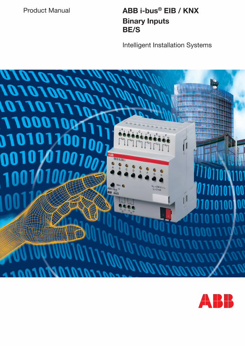
Product Manual ABB i-bus® EIB / KNXBinary InputsBE/S
Intelligent Installation Systems

This manual describes the function of the Binary Inputs BE/S.
Subject to changes and errors excepted.
Exclusion of liability:Despite checking that the contents of this document match the hardware and software, deviations cannot be completely excluded. We therefore cannot accept any liability for this. Any necessary corrections will be inserted in new versions of the manual.Please inform us of any suggested improvements.
Contents
1
Page
1 General 4
1.1 Product and functional overview . . . . . . . . . . . . . . . . . . . . . . . . 5
2 Device technology 6
2.1 Binary Input with with manual operation, 4-fold, 230 V AC/DC, MDRC . . . . . . . . . . . . . . . . . . . . . . . . . . . 62.1.1 Technical data . . . . . . . . . . . . . . . . . . . . . . . . . . . . . . . . . . . . 62.1.2 Circuit diagram . . . . . . . . . . . . . . . . . . . . . . . . . . . . . . . . . . . 72.1.3 Dimension drawing . . . . . . . . . . . . . . . . . . . . . . . . . . . . . . . . 72.1.4 Assembly and installation . . . . . . . . . . . . . . . . . . . . . . . . . . . 82.2 Binary Input with manual operation, 4-fold, 24 V AC/DC, MDRC . . . . . . . . . . . . . . . . . . . . . . . . . . . . 92.2.1 Technical data . . . . . . . . . . . . . . . . . . . . . . . . . . . . . . . . . . . . 92.2.2 Circuit diagram . . . . . . . . . . . . . . . . . . . . . . . . . . . . . . . . . . . 102.2.3 Dimension drawing . . . . . . . . . . . . . . . . . . . . . . . . . . . . . . . . 102.2.4 Assembly and installation . . . . . . . . . . . . . . . . . . . . . . . . . . . 112.3 Binary Input with manual operation, 4-fold, contact scanning, MDRC . . . . . . . . . . . . . . . . . . . . . . . . 122.3.1 Technical data . . . . . . . . . . . . . . . . . . . . . . . . . . . . . . . . . . . . 122.3.2 Circuit diagram . . . . . . . . . . . . . . . . . . . . . . . . . . . . . . . . . . . 132.3.3 Dimension drawing . . . . . . . . . . . . . . . . . . . . . . . . . . . . . . . . 132.3.4 Assembly and installation . . . . . . . . . . . . . . . . . . . . . . . . . . . 142.4 Binary Input with manual operation, 8-fold, 230 V AC/DC, MDRC . . . . . . . . . . . . . . . . . . . . . . . . . . . 152.4.1 Technical data . . . . . . . . . . . . . . . . . . . . . . . . . . . . . . . . . . . . 152.4.2 Circuit diagram . . . . . . . . . . . . . . . . . . . . . . . . . . . . . . . . . . . 162.4.3 Dimension drawing . . . . . . . . . . . . . . . . . . . . . . . . . . . . . . . . 162.4.4 Assembly and installation . . . . . . . . . . . . . . . . . . . . . . . . . . . 172.5 Binary Input with manual operation, 8-fold, 24 V AC/DC, MDRC . . . . . . . . . . . . . . . . . . . . . . . . . . . . 182.5.1 Technical data . . . . . . . . . . . . . . . . . . . . . . . . . . . . . . . . . . . . 182.5.2 Circuit diagram . . . . . . . . . . . . . . . . . . . . . . . . . . . . . . . . . . . 192.5.3 Dimension drawing . . . . . . . . . . . . . . . . . . . . . . . . . . . . . . . . 192.5.4 Assembly and installation . . . . . . . . . . . . . . . . . . . . . . . . . . . 202.6 Binary input with manual operation, 8-fold, contact scanning, MDRC . . . . . . . . . . . . . . . . . . . . . . . . 212.6.1 Technical data . . . . . . . . . . . . . . . . . . . . . . . . . . . . . . . . . . . . 212.6.2 Circuit diagram . . . . . . . . . . . . . . . . . . . . . . . . . . . . . . . . . . . 222.6.3 Dimension drawing . . . . . . . . . . . . . . . . . . . . . . . . . . . . . . . . 222.6.4 Assembly and installation . . . . . . . . . . . . . . . . . . . . . . . . . . . 23
2
Contents
Page
3 Commissioning 24
3.1 Overview . . . . . . . . . . . . . . . . . . . . . . . . . . . . . . . . . . . . . . . . . . 243.2 Parameters . . . . . . . . . . . . . . . . . . . . . . . . . . . . . . . . . . . . . . . . . 253.2.1 General parameters . . . . . . . . . . . . . . . . . . . . . . . . . . . . . . . 253.2.1.1 Parameter window “General” . . . . . . . . . . . . . . . . . . . . . 253.2.1.2 Parameter window “Manual Operation” . . . . . . . . . . . . . 283.2.1.3 Parameter window
“Enable/release manual operation button” . . . . . . . . . . . 313.2.1.4 Parameter window “Channel LED display” . . . . . . . . . . . 323.2.1.5 Communication objects “General” . . . . . . . . . . . . . . . . . 333.2.1.6 Parameter window “Channel A, general” . . . . . . . . . . . . . 343.2.2 Switch sensor / fault signal input operating mode . . . . . . . . 353.2.2.1 Parameter window “Channel A, general” . . . . . . . . . . . . . 353.2.2.2 Parameter window “Channel A, switch sensor” . . . . . . . 393.2.2.3 Parameter window “Channel A, switch sensor” . . . . . . . 413.2.3 Fault signal input operating mode . . . . . . . . . . . . . . . . . . 423.2.3.1 Parameter window “Channel A, general” . . . . . . . . . . . . . 423.2.3.2 Parameter window “Channel A, switch sensor”
operating mode for a fault signal input . . . . . . . . . . . . . . 473.2.3.3 Communication objects “Channel A” . . . . . . . . . . . . . . . 493.2.3.4 Communication objects “Channel B to H” . . . . . . . . . . . 503.2.4 Switch/dimming sensor operating mode . . . . . . . . . . . . . 513.2.4.1 Parameter window “Channel A, general” . . . . . . . . . . . . . 513.2.4.2 Parameter window “Channel A, switch/dimming sensor” . 523.2.4.3 Communication objects “Channel A” . . . . . . . . . . . . . . . 553.2.4.4 Communication objects “Channel B to H” . . . . . . . . . . . 563.2.5 Shutter sensor operating mode . . . . . . . . . . . . . . . . . . . . . . 573.2.5.1 Parameter window “Channel A, general” . . . . . . . . . . . . . 573.2.5.2 Parameter window “Channel A, shutter sensor” . . . . . . . 583.2.5.3 Communication objects “Channel A” . . . . . . . . . . . . . . . 613.2.5.4 Communication objects “Channel B to H” . . . . . . . . . . . 623.2.6 Operating mode value/forced operation . . . . . . . . . . . . . . . . 633.2.6.1 Parameter window “Channel A, general” . . . . . . . . . . . . . 633.2.6.2 Parameter window “Channel A, value/forced operation value X” . . . . . . . . . . 683.2.6.3 Communication objects “Channel A” . . . . . . . . . . . . . . . 703.2.6.4 Communication objects “Channel B to H” . . . . . . . . . . . 713.2.7 Control scene operating mode . . . . . . . . . . . . . . . . . . . . . . . 723.2.7.1 Parameter window “Channel A, general” . . . . . . . . . . . . . 733.2.7.2 Parameter window “Channel A, scene part X” . . . . . . . . 753.2.7.3 Communication objects “Channel A” . . . . . . . . . . . . . . . 763.2.7.4 Communication objects “Channel B to H” . . . . . . . . . . . 783.2.8 Switching sequence operating mode . . . . . . . . . . . . . . . . . . 793.2.8.1 Parameter window “Channel A, general” . . . . . . . . . . . . . 793.2.8.2 Parameter window “Channel A, switching sequence” . . . 813.2.8.3 Communication objects “Channel A” . . . . . . . . . . . . . . . 843.2.8.4 Communication objects “Channel B to H” . . . . . . . . . . . 85
3
Page
3.2.9 Multiple operation operating mode . . . . . . . . . . . . . . . . . . . . 863.2.9.1 Parameter window “Channel A, general” . . . . . . . . . . . . . 863.2.9.2 Parameter window “Channel A, multiple operation” . . . . 883.2.9.3 Communication objects “Channel A” . . . . . . . . . . . . . . . 903.2.9.4 Communication objects “Channel B to H” . . . . . . . . . . . 913.2.10 Counter operating mode . . . . . . . . . . . . . . . . . . . . . . . . . . . . 923.2.10.1 Counting pulses . . . . . . . . . . . . . . . . . . . . . . . . . . . . . . . . 923.2.10.2 Behaviour of the counter levels after a download . . . . . . 933.2.10.3 Behaviour of the counter levels after bus voltage failure . 933.2.10.4 Peculiarities between the main counter and
differential counter . . . . . . . . . . . . . . . . . . . . . . . . . . . . . . 933.2.10.5 Parameter window “Channel A, general” . . . . . . . . . . . . . 943.2.10.6 Parameter window “Channel A, main counter” . . . . . . . . 963.2.10.7 Parameter window “Channel A, differential counter” . . . . 983.2.10.8 Communication objects “Channel A, main counter” . . . . 1013.2.10.9 Communication objects “Channel B to H main counter” 1023.2.10.10 Communication objects “Channel A main and differential counter” . . . . . . . . . . . . 1033.2.10.11 Communication objects “Channel B to H main and differential counter” . . . . . . . . 105
4 Planning and application 106
4.1 Operation with central function (light switching) . . . . . . . . . . . . 1064.2 Fault signal input . . . . . . . . . . . . . . . . . . . . . . . . . . . . . . . . . . . . 1074.3 Operation of lighting (dim lighting) . . . . . . . . . . . . . . . . . . . . . . . 1104.4 Operation of shutters . . . . . . . . . . . . . . . . . . . . . . . . . . . . . . . . . 1114.5 Control scene . . . . . . . . . . . . . . . . . . . . . . . . . . . . . . . . . . . . . . . 1134.6 Switching sequence (switching of luminaires) . . . . . . . . . . . . . . 1144.7 Multiple button operation (switching of luminaires) . . . . . . . . . . 1164.8 Counting of power values . . . . . . . . . . . . . . . . . . . . . . . . . . . . . 117
A Appendix I
A.1 Scope of delivery . . . . . . . . . . . . . . . . . . . . . . . . . . . . . . . . . . . . IA.2 4 bit dimming command . . . . . . . . . . . . . . . . . . . . . . . . . . . . . . IA.3 Gray code . . . . . . . . . . . . . . . . . . . . . . . . . . . . . . . . . . . . . . . . . . IIA.4 Directory of drawings . . . . . . . . . . . . . . . . . . . . . . . . . . . . . . . . . IIIA.5 Directory of tables . . . . . . . . . . . . . . . . . . . . . . . . . . . . . . . . . . . VA.6 Index . . . . . . . . . . . . . . . . . . . . . . . . . . . . . . . . . . . . . . . . . . . . . VIA.7 Ordering information . . . . . . . . . . . . . . . . . . . . . . . . . . . . . . . . . VIIA.8 Notes . . . . . . . . . . . . . . . . . . . . . . . . . . . . . . . . . . . . . . . . . . . . . VIII
Contents
4
ABB i-bus® EIB / KNX
The comprehensive range of functions in modern buildings with EIB / KNX should be as easy and as intuitive to operate as possible for the user. At the same time, clear and comfortable operating features are particularly significant for the feeling of well-being within buildings.
The Binary Input fulfils the individual demands in functional buildings as well as in residential buildings. In the same way, system planners are provided with varied application possibilities with regard to the implementation of functions.
This manual provides you with detailed technical information relating to the Binary Inputs, installation, programming and explains the use of the Binary Inputs using examples.
This manual is divided into the following sections:
• Chapter 1 General
• Chapter 2 Device technology
• Chapter 3 Commissioning
• Chapter 4 Planning and application
• Appendix
General
1 General
5
ABB i-bus® EIB / KNX
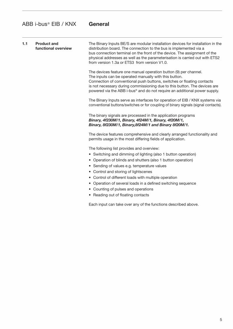
The Binary Inputs BE/S are modular installation devices for installation in the distribution board. The connection to the bus is implemented via a bus connection terminal on the front of the device. The assignment of the physical addresses as well as the parameterisation is carried out with ETS2 from version 1.3a or ETS3 from version V1.0.
The devices feature one manual operation button (9) per channel. The inputs can be operated manually with this button.Connection of conventional push buttons, switches or floating contacts is not necessary during commissioning due to this button. The devices are powered via the ABB i-bus® and do not require an additional power supply.
The Binary Inputs serve as interfaces for operation of EIB / KNX systems via conventional buttons/switches or for coupling of binary signals (signal contacts).
The binary signals are processed in the application programs Binary, 4f230M/1, Binary, 4f24M/1, Binary, 4f20M/1, Binary, 8f230M/1, Binary,8f24M/1 and Binary 8f20M/1.
The device features comprehensive and clearly arranged functionality and permits usage in the most differing fields of application.
The following list provides and overview:
• Switching and dimming of lighting (also 1 button operation)
• Operation of blinds and shutters (also 1 button operation)
• Sending of values e.g. temperature values
• Control and storing of lightscenes
• Control of different loads with multiple operation
• Operation of several loads in a defined switching sequence
• Counting of pulses and operations
• Reading out of floating contacts
Each input can take over any of the functions described above.
1.1 Product and functional overview
General
6
ABB i-bus® EIB / KNX
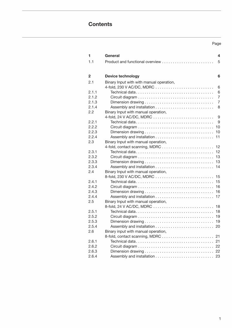
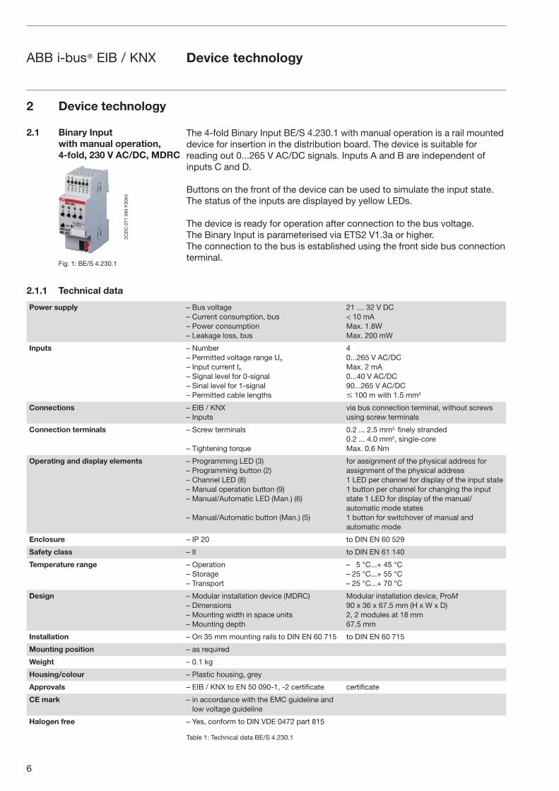
The 4-fold Binary Input BE/S 4.230.1 with manual operation is a rail mounted device for insertion in the distribution board. The device is suitable for reading out 0...265 V AC/DC signals. Inputs A and B are independent of inputs C and D.
Buttons on the front of the device can be used to simulate the input state. The status of the inputs are displayed by yellow LEDs.
The device is ready for operation after connection to the bus voltage. The Binary Input is parameterised via ETS2 V1.3a or higher.The connection to the bus is established using the front side bus connection terminal.
Power supply – Bus voltage– Current consumption, bus– Power consumption– Leakage loss, bus
21 … 32 V DC < 10 mAMax. 1.8WMax. 200 mW
Inputs – Number– Permitted voltage range Un
– Input current In– Signal level for 0-signal– Sinal level for 1-signal– Permitted cable lengths
40...265 V AC/DCMax. 2 mA0...40 V AC/DC90...265 V AC/DC� 100 m with 1.5 mm2
Connections – EIB / KNX– Inputs
via bus connection terminal, without screws using screw terminals
Connection terminals – Screw terminals
– Tightening torque
0.2 ... 2.5 mm2, finely stranded 0.2 ... 4.0 mm2, single-core Max. 0.6 Nm
Operating and display elements – Programming LED (3)– Programming button (2)– Channel LED (8)– Manual operation button (9)– Manual/Automatic LED (Man.) (6)
– Manual/Automatic button (Man.) (5)
for assignment of the physical address for assignment of the physical address1 LED per channel for display of the input state 1 button per channel for changing the input state 1 LED for display of the manual/automatic mode states1 button for switchover of manual and automatic mode
Enclosure – IP 20 to DIN EN 60 529
Safety class – II to DIN EN 61 140
Temperature range – Operation– Storage– Transport
– 5 °C...+ 45 °C– 25 °C...+ 55 °C– 25 °C...+ 70 °C
Design – Modular installation device (MDRC)– Dimensions– Mounting width in space units– Mounting depth
Modular installation device, ProM 90 x 36 x 67.5 mm (H x W x D) 2, 2 modules at 18 mm67.5 mm
Installation – On 35 mm mounting rails to DIN EN 60 715 to DIN EN 60 715
Mounting position – as required
Weight – 0.1 kg
Housing/colour – Plastic housing, grey
Approvals – EIB / KNX to EN 50 090-1, -2 certificate certificate
CE mark – in accordance with the EMC guideline and low voltage guideline
Halogen free – Yes, conform to DIN VDE 0472 part 815
Table 1: Technical data BE/S 4.230.1
2 Device technology
2.1 Binary Input with manual operation, 4-fold, 230 V AC/DC, MDRC
Fig. 1: BE/S 4.230.1
2.1.1 Technical data
Device technology
2CD
C 0
71 5
94 F
0004
7
ABB i-bus® EIB / KNX
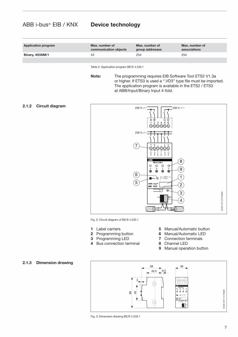
Table 2: Application program BE/S 4.230.1
Note: The programming requires EIB Software Tool ETS2 V1.3a or higher. If ETS3 is used a “.VD3” type file must be imported. The application program is available in the ETS2 / ETS3 at ABB/Input/Binary Input 4-fold.
Fig. 2: Circuit diagram of BE/S 4.230.1
1 Label carriers 5 Manual/Automatic button 2 Programming button 6 Manual/Automatic LED3 Programming LED 7 Connection terminals4 Bus connection terminal 8 Channel LED 9 Manual operation button
Fig. 3: Dimension drawing BE/S 4.230.1
2.1.2 Circuit diagram
2.1.3 Dimension drawing
Application program Max. number ofcommunication objects
Max. number ofgroup addresses
Max. number ofassociations
Binary, 4f230M/1 43 254 254
����������
� �
���
����������
� �� � � � ��
�
� �
���������
�� � ����
�
�� �� �� ��
�
�
�
�
�
�
�
�
�
� � �� �� � � ��
�����
����� �����
�
2CD
C 0
72 2
72 F
0004
Device technology
�
��
��
���� ���
��
����������
� �
���
����������
� �� � � � ��
�
� �
���������
�� � ����
�
�� �� �� ��
��
2CD
C 0
72 1
14 F
0005

8
ABB i-bus® EIB / KNX
The Binary Input is a modular installation device for fast installation in the distribution board on 35 mm mounting rails to DIN EN 60 715.
The electrical connection is implemented using screw terminals. The connection to the bus is implemented using the supplied bus connection terminal.
The device is ready for operation after connection to the bus voltage. Accessibility of the devices for the purpose operation, testing, visual inspection, maintenance and repair must be must be provided (conform to DIN VDE 0100-520).
Commissioning requirementsTo put the Binary Input BE/S 4.230.1 into operation, you require a PC with the Engineering Tool Software ETS2 from V1.3a onwards in conjunction with an RS232 interface or a USB interface. The device is ready for operation after connection to the bus voltage.
The installation and commissioning may only be carried out by electrical specialists. The appropriate norms, guidelines, regulations and specifications should be observed when planning and setting up electrical installations.
– The device should be protected from damp, dirt and damage during transport, storage and operation.
– The device should not be operated outside the specified technical data!
– The device should only be operated in a closed housing (distribution board)!
Supplied stateThe Binary Input is supplied with the physical address 15.15.255. The Binary, 4f230M/1 user program is preinstalled. Hence, only group addresses and parameters must be loaded during commissioning. The entire application can be reloaded as required. A longer downtime may result if the application program is changed or after a discharge.
Assignment of the physical addressThe assignment and programming of the physical address is carried out in the ETS.
CleaningIf devices become dirty, they can be cleaned using a dry cloth. Should a dry cloth not remove the dirt, they can be cleaned using a slightly damp cloth and soap solution. Corrosive materials or solutions should never be used.
MaintenanceThe device is maintenance-free. No repairs should be carried out by unauthorised personnel if damage occurs (e.g. during transport or storage). The warranty expires if the device is opened.
2.1.4 Assembly and installation
Device technology
9
ABB i-bus® EIB / KNX
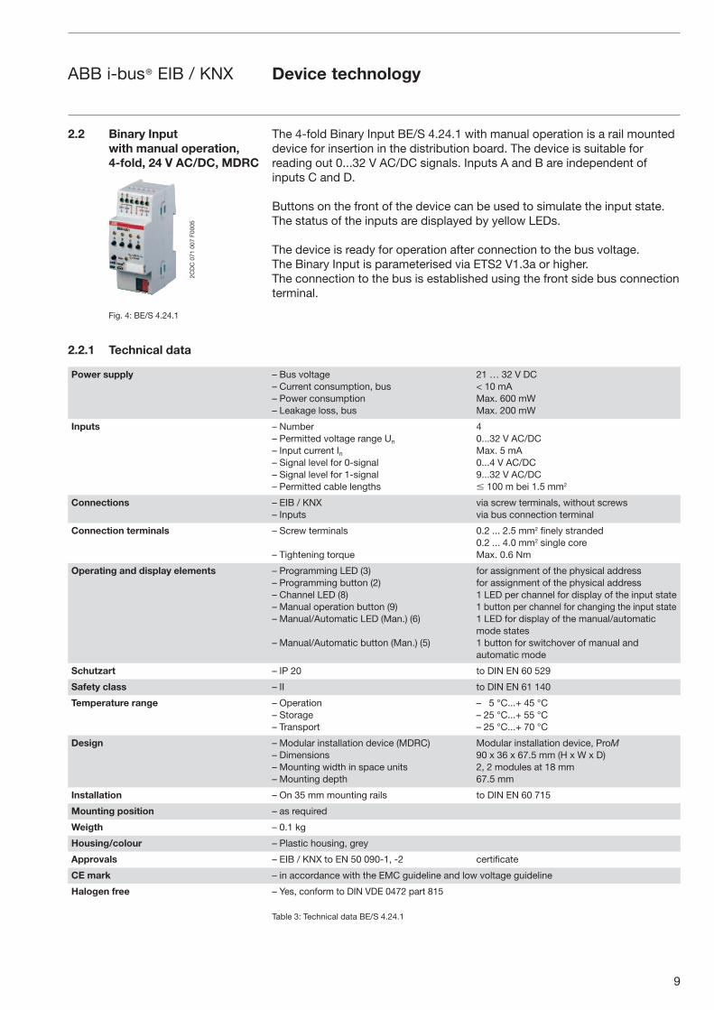
The 4-fold Binary Input BE/S 4.24.1 with manual operation is a rail mounted device for insertion in the distribution board. The device is suitable for reading out 0...32 V AC/DC signals. Inputs A and B are independent of inputs C and D.
Buttons on the front of the device can be used to simulate the input state. The status of the inputs are displayed by yellow LEDs.
The device is ready for operation after connection to the bus voltage. The Binary Input is parameterised via ETS2 V1.3a or higher.The connection to the bus is established using the front side bus connection terminal.
2.2 Binary Input with manual operation, 4-fold, 24 V AC/DC, MDRC
Fig. 4: BE/S 4.24.1
2.2.1 Technical data
Power supply – Bus voltage– Current consumption, bus– Power consumption– Leakage loss, bus
21 … 32 V DC< 10 mAMax. 600 mWMax. 200 mW
Inputs – Number– Permitted voltage range Un
– Input current In– Signal level for 0-signal– Signal level for 1-signal– Permitted cable lengths
40...32 V AC/DCMax. 5 mA0...4 V AC/DC9...32 V AC/DC� 100 m bei 1.5 mm2
Connections – EIB / KNX– Inputs
via screw terminals, without screwsvia bus connection terminal
Connection terminals – Screw terminals
– Tightening torque
0.2 ... 2.5 mm2 finely stranded0.2 ... 4.0 mm2 single coreMax. 0.6 Nm
Operating and display elements – Programming LED (3)– Programming button (2)– Channel LED (8)– Manual operation button (9)– Manual/Automatic LED (Man.) (6)
– Manual/Automatic button (Man.) (5)
for assignment of the physical addressfor assignment of the physical address1 LED per channel for display of the input state1 button per channel for changing the input state1 LED for display of the manual/automatic mode states1 button for switchover of manual andautomatic mode
Schutzart – IP 20 to DIN EN 60 529
Safety class – II to DIN EN 61 140
Temperature range – Operation– Storage– Transport
– 5 °C...+ 45 °C– 25 °C...+ 55 °C– 25 °C...+ 70 °C
Design – Modular installation device (MDRC)– Dimensions– Mounting width in space units– Mounting depth
Modular installation device, ProM90 x 36 x 67.5 mm (H x W x D)2, 2 modules at 18 mm67.5 mm
Installation – On 35 mm mounting rails to DIN EN 60 715
Mounting position – as required
Weigth – 0.1 kg
Housing/colour – Plastic housing, grey
Approvals – EIB / KNX to EN 50 090-1, -2 certificate
CE mark – in accordance with the EMC guideline and low voltage guideline
Halogen free – Yes, conform to DIN VDE 0472 part 815
Table 3: Technical data BE/S 4.24.1
Device technology
2CD
C 0
71 0
07 F
0005
10
ABB i-bus® EIB / KNX
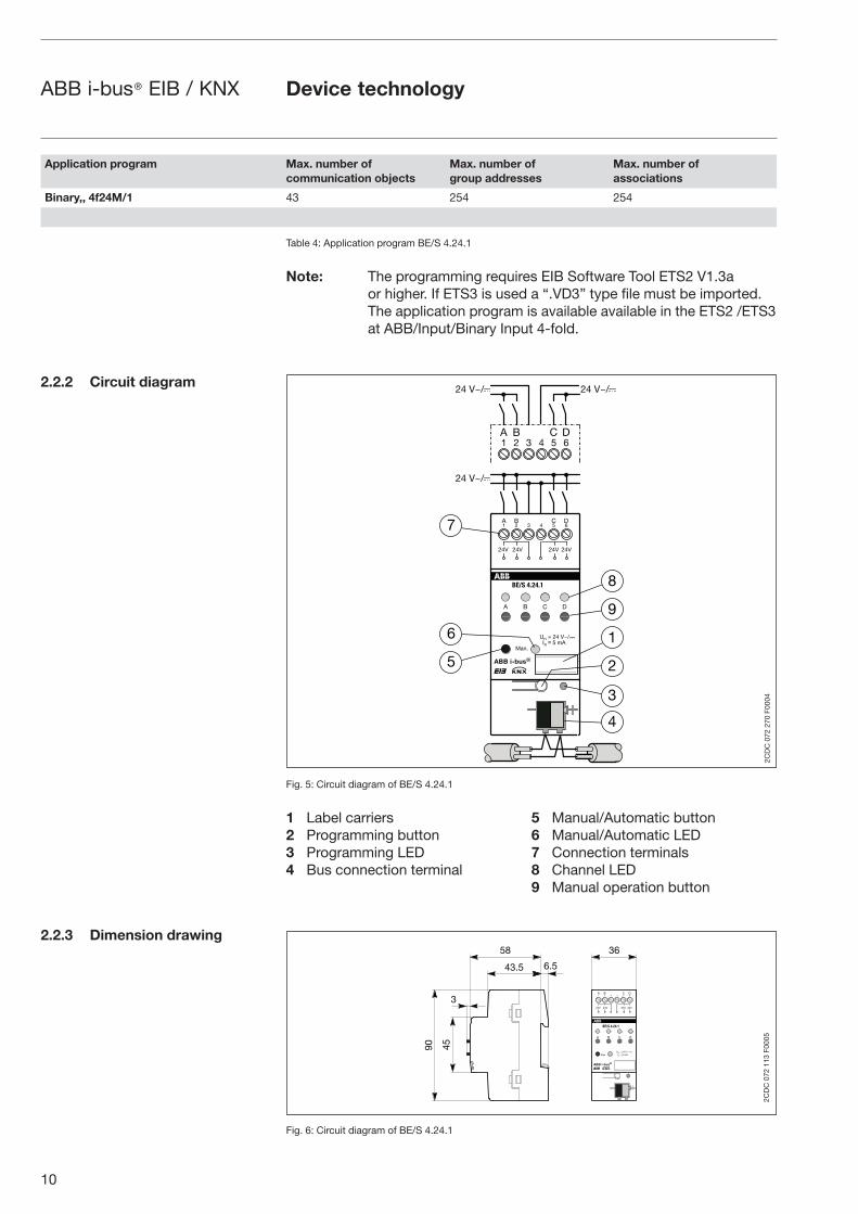
2.2.2 Circuit diagram
2.2.3 Dimension drawing
Table 4: Application program BE/S 4.24.1
Note: The programming requires EIB Software Tool ETS2 V1.3a or higher. If ETS3 is used a “.VD3” type file must be imported. The application program is available available in the ETS2 /ETS3 at ABB/Input/Binary Input 4-fold.
Fig. 5: Circuit diagram of BE/S 4.24.1
1 Label carriers 5 Manual/Automatic button 2 Programming button 6 Manual/Automatic LED3 Programming LED 7 Connection terminals4 Bus connection terminal 8 Channel LED 9 Manual operation button
Fig. 6: Circuit diagram of BE/S 4.24.1
Application program Max. number ofcommunication objects
Max. number ofgroup addresses
Max. number ofassociations
Binary,, 4f24M/1 43 254 254
�����������
� �� � � � ��
�
���������
� ���
�
��� ��� ��� ���
���������
�
�
�
�
�
�
�
� � �� �� � � ��
����
���� ����
� �� �
���
�
�
�
2CD
C 0
72 2
70 F
0004
Device technology
�
��
��
���� ���
��
� �
���
�����������
� �� � � � ��
�
� �
���������
�� � ����
�
��� ��� ��� ���
���������
��
2CD
C 0
72 1
13 F
0005
11
ABB i-bus® EIB / KNX
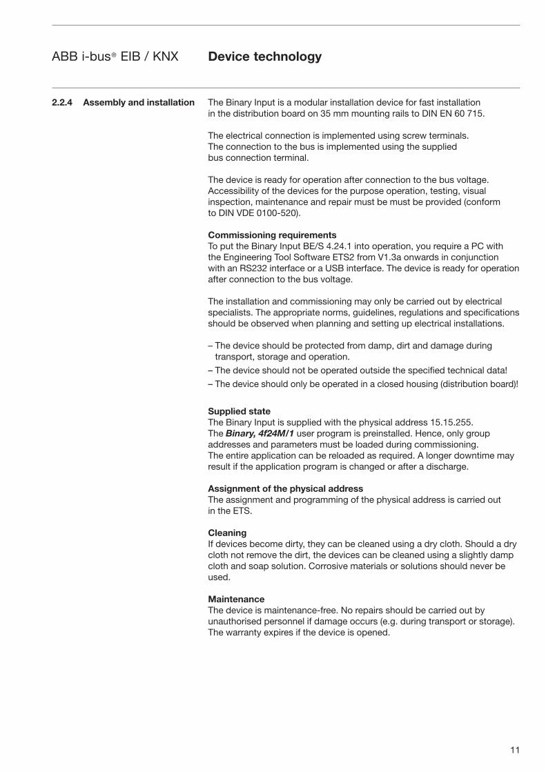
The Binary Input is a modular installation device for fast installation in the distribution board on 35 mm mounting rails to DIN EN 60 715.
The electrical connection is implemented using screw terminals. The connection to the bus is implemented using the supplied bus connection terminal.
The device is ready for operation after connection to the bus voltage.Accessibility of the devices for the purpose operation, testing, visual inspection, maintenance and repair must be must be provided (conform to DIN VDE 0100-520).
Commissioning requirementsTo put the Binary Input BE/S 4.24.1 into operation, you require a PC withthe Engineering Tool Software ETS2 from V1.3a onwards in conjunction with an RS232 interface or a USB interface. The device is ready for operation after connection to the bus voltage.
The installation and commissioning may only be carried out by electrical specialists. The appropriate norms, guidelines, regulations and specifica tions should be observed when planning and setting up electrical installations.
– The device should be protected from damp, dirt and damage during transport, storage and operation.
– The device should not be operated outside the specified technical data!
– The device should only be operated in a closed housing (distribution board)!
Supplied stateThe Binary Input is supplied with the physical address 15.15.255. The Binary, 4f24M/1 user program is preinstalled. Hence, only group addresses and parameters must be loaded during commissioning. The entire application can be reloaded as required. A longer downtime may result if the application program is changed or after a discharge.
Assignment of the physical addressThe assignment and programming of the physical address is carried outin the ETS.
CleaningIf devices become dirty, they can be cleaned using a dry cloth. Should a drycloth not remove the dirt, the devices can be cleaned using a slightly dampcloth and soap solution. Corrosive materials or solutions should never beused.
MaintenanceThe device is maintenance-free. No repairs should be carried out byunauthorised personnel if damage occurs (e.g. during transport or storage). The warranty expires if the device is opened.
2.2.4 Assembly and installation
Device technology
12
ABB i-bus® EIB / KNX
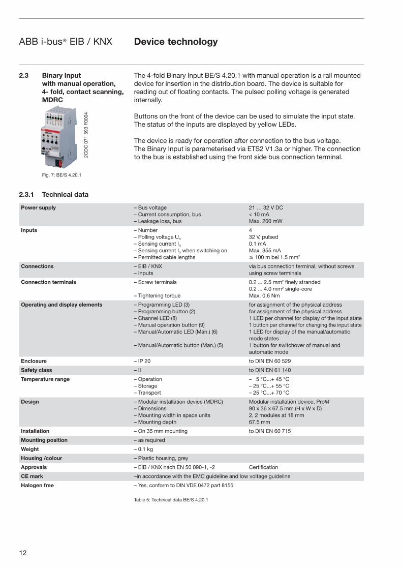
2.3 Binary Input with manual operation, 4- fold, contact scanning, MDRC
Fig. 7: BE/S 4.20.1
2.3.1 Technical data
The 4-fold Binary Input BE/S 4.20.1 with manual operation is a rail mounted device for insertion in the distribution board. The device is suitable for reading out of floating contacts. The pulsed polling voltage is generated internally.
Buttons on the front of the device can be used to simulate the input state. The status of the inputs are displayed by yellow LEDs.
The device is ready for operation after connection to the bus voltage. The Binary Input is parameterised via ETS2 V1.3a or higher. The connection to the bus is established using the front side bus connection terminal.
Power supply – Bus voltage– Current consumption, bus– Leakage loss, bus
21 … 32 V DC< 10 mAMax. 200 mW
Inputs – Number– Polling voltage Un
– Sensing current In– Sensing current In when switching on– Permitted cable lengths
432 V, pulsed0.1 mAMax. 355 mA� 100 m bei 1.5 mm2
Connections – EIB / KNX– Inputs
via bus connection terminal, without screws using screw terminals
Connection terminals – Screw terminals
– Tightening torque
0.2 ... 2.5 mm2 finely stranded0.2 ... 4.0 mm2 single-coreMax. 0.6 Nm
Operating and display elements – Programming LED (3)– Programming button (2)– Channel LED (8)– Manual operation button (9)– Manual/Automatic LED (Man.) (6)
– Manual/Automatic button (Man.) (5)
for assignment of the physical address for assignment of the physical address1 LED per channel for display of the input state 1 button per channel for changing the input state 1 LED for display of the manual/automatic mode states1 button for switchover of manual andautomatic mode
Enclosure – IP 20 to DIN EN 60 529
Safety class – II to DIN EN 61 140
Temperature range – Operation– Storage– Transport
– 5 °C...+ 45 °C– 25 °C...+ 55 °C– 25 °C...+ 70 °C
Design – Modular installation device (MDRC)– Dimensions– Mounting width in space units– Mounting depth
Modular installation device, ProM90 x 36 x 67.5 mm (H x W x D)2, 2 modules at 18 mm67.5 mm
Installation – On 35 mm mounting to DIN EN 60 715
Mounting position – as required
Weight – 0.1 kg
Housing /colour – Plastic housing, grey
Approvals – EIB / KNX nach EN 50 090-1, -2 Certification
CE mark –in accordance with the EMC guideline and low voltage guideline
Halogen free – Yes, conform to DIN VDE 0472 part 8155
Table 5: Technical data BE/S 4.20.1
Device technology
2CD
C 0
71 5
93 F
0004
13
ABB i-bus® EIB / KNX
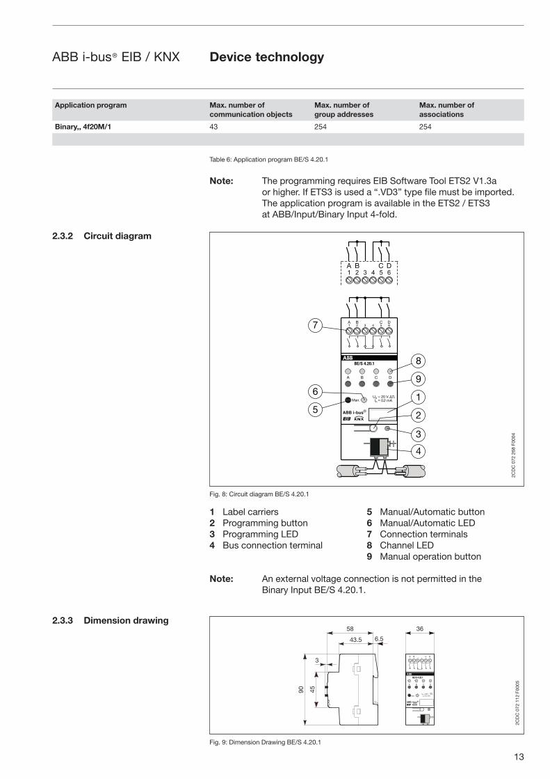
Table 6: Application program BE/S 4.20.1
Note: The programming requires EIB Software Tool ETS2 V1.3a or higher. If ETS3 is used a “.VD3” type file must be imported. The application program is available in the ETS2 / ETS3 at ABB/Input/Binary Input 4-fold.
Fig. 8: Circuit diagram BE/S 4.20.1
1 Label carriers 5 Manual/Automatic button 2 Programming button 6 Manual/Automatic LED3 Programming LED 7 Connection terminals4 Bus connection terminal 8 Channel LED 9 Manual operation button
Note: An external voltage connection is not permitted in the Binary Input BE/S 4.20.1.
Fig. 9: Dimension Drawing BE/S 4.20.1
2.3.2 Circuit diagram
2.3.3 Dimension drawing
Application program Max. number ofcommunication objects
Max. number ofgroup addresses
Max. number ofassociations
Binary,, 4f20M/1 43 254 254
� �
���
����������
� �� � � � ��
�
� �
���������
����������� �������
�
�
�
�
�
�
�
�
�
�
� � �� �� � � ��
�
2CD
C 0
72 2
68 F
0004
Device technology
� �
���
����������
� �� � � � ��
�
� �
���������
����������� ��������
�
��
��
���� ���
��
��
�
2CD
C 0
72 1
12 F
0005
14
ABB i-bus® EIB / KNX
The Binary Input is a modular installation device for fast installation in the distribution board on 35 mm mounting rails to DIN EN 60 715.
The electrical connection is implemented using screw terminals. The connection to the bus is implemented using the supplied bus connection terminal.
The device is ready for operation after connection to the bus voltage.Accessibility of the devices for the purpose operation, testing, visual inspection, maintenance and repair must be must be provided (conform to DIN VDE 0100-520).
Commissioning requirementsTo put the Binary Input BE/S 4.20.1 into operation, you require a PC with the Engineering Tool Software ETS2 from V1.3a onwards in conjunction with an RS232 interface or a USB interface. The device is ready for operation after connection to the bus voltage.
The installation and commissioning may only be carried out by electrical specialists. The appropriate norms, guidelines, regulations and specifications should be observed when planning and setting up electrical installations.
– The device should be protected from damp, dirt and damage during transport, storage and operation.
– The device should not be operated outside the specified technical data!
– The device should only be operated in a closed housing (distribution board)!
Supplied stateThe Binary Input is supplied with the physical address 15.15.255. The Binary, 4f20M/1 user program is preinstalled. Hence, only group addresses and parameters must be loaded during commissioning. The entire application can be reloaded as required. A longer downtime may result if the application program is changed or after a discharge.
Assignment of the physical addressThe assignment and programming of the physical address is carried out in the ETS.
CleaningIf devices become dirty, they can be cleaned using a dry cloth. Should a dry cloth not remove the dirt, they can be cleaned using a slightly damp cloth and soap solution. Corrosive materials or solutions should never be used.
MaintenanceThe device is maintenance-free. No repairs should be carried out by unauthorised personnel if damage occurs (e.g. during transport or storage). The warranty expires if the device is opened.
2.3.4 Assembly and installation
Device technology
15
ABB i-bus® EIB / KNX
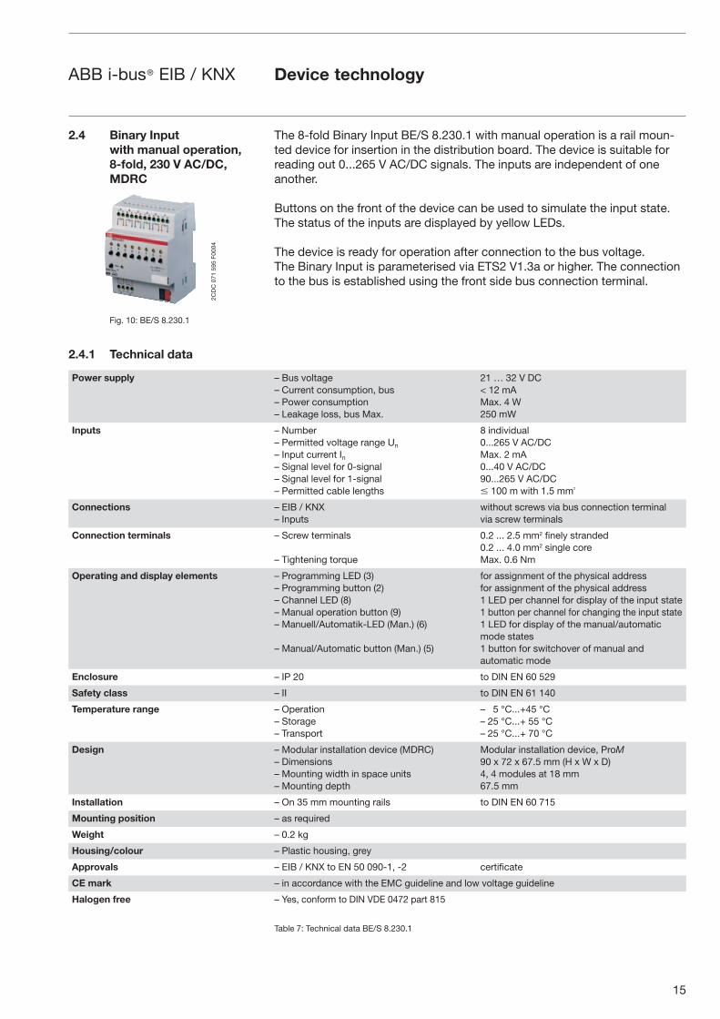
The 8-fold Binary Input BE/S 8.230.1 with manual operation is a rail moun-ted device for insertion in the distribution board. The device is suitable for reading out 0...265 V AC/DC signals. The inputs are independent of one another.
Buttons on the front of the device can be used to simulate the input state. The status of the inputs are displayed by yellow LEDs.
The device is ready for operation after connection to the bus voltage. The Binary Input is parameterised via ETS2 V1.3a or higher. The connection to the bus is established using the front side bus connection terminal.
2.4 Binary Input with manual operation, 8-fold, 230 V AC/DC, MDRC
Fig. 10: BE/S 8.230.1
2.4.1 Technical data
Power supply – Bus voltage– Current consumption, bus– Power consumption– Leakage loss, bus Max.
21 … 32 V DC< 12 mAMax. 4 W250 mW
Inputs – Number– Permitted voltage range Un
– Input current In– Signal level for 0-signal– Signal level for 1-signal– Permitted cable lengths
8 individual0...265 V AC/DC Max. 2 mA 0...40 V AC/DC 90...265 V AC/DC� 100 m with 1.5 mm²
Connections – EIB / KNX– Inputs
without screws via bus connection terminal via screw terminals
Connection terminals – Screw terminals
– Tightening torque
0.2 ... 2.5 mm2 finely stranded 0.2 ... 4.0 mm2 single core Max. 0.6 Nm
Operating and display elements – Programming LED (3)– Programming button (2)– Channel LED (8)– Manual operation button (9)– Manuell/Automatik-LED (Man.) (6)
– Manual/Automatic button (Man.) (5)
for assignment of the physical address for assignment of the physical address 1 LED per channel for display of the input state 1 button per channel for changing the input state1 LED for display of the manual/automatic mode states 1 button for switchover of manual and automatic mode
Enclosure – IP 20 to DIN EN 60 529
Safety class – II to DIN EN 61 140
Temperature range – Operation – Storage– Transport
– 5 °C...+45 °C– 25 °C...+ 55 °C– 25 °C...+ 70 °C
Design – Modular installation device (MDRC) – Dimensions – Mounting width in space units – Mounting depth
Modular installation device, ProM90 x 72 x 67.5 mm (H x W x D)4, 4 modules at 18 mm67.5 mm
Installation – On 35 mm mounting rails to DIN EN 60 715
Mounting position – as required
Weight – 0.2 kg
Housing/colour – Plastic housing, grey
Approvals – EIB / KNX to EN 50 090-1, -2 certificate
CE mark – in accordance with the EMC guideline and low voltage guideline
Halogen free – Yes, conform to DIN VDE 0472 part 815
Table 7: Technical data BE/S 8.230.1
Device technology
2CD
C 0
71 5
95 F
0004
16
ABB i-bus® EIB / KNX
Table 8: Application program BE/S 8.230.1
Note: The programming requires EIB Software Tool ETS2 V1.3a or higher. If ETS3 is used a “.VD3” type file must be imported. The application program is available in the ETS2 / ETS3 at ABB/Input/Binary Input 4-fold.
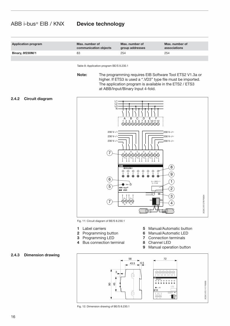
Fig. 11: Circuit diagram of BE/S 8.230.1
1 Label carriers 5 Manual/Automatic button 2 Programming button 6 Manual/Automatic LED3 Programming LED 7 Connection terminals4 Bus connection terminal 8 Channel LED 9 Manual operation button
Fig. 12: Dimension drawing of BE/S 8.230.1
Application program Max. number ofcommunication objects
Max. number ofgroup addresses
Max. number ofassociations
Binary, 8f230M/1 83 254 254
2.4.2 Circuit diagram
2.4.3 Dimension drawing
�����
�����
�����
����������
����������
�� � � � ��
� � � �� � � �� ����
�
��� �� �� ��
�
���������
�� ������
� � � �
���
� �� �
�� �� �� �� �� ��
�� ��
�
�
�
�
�
�
�
�
�
�
� � � � � �� � � � �� � � � �� ����
�����
�����
�����
� � �!
2CD
C 0
72 2
78 F
0004
Device technology
�
��
��
��� �
��
����������
����������
�� � � � ��
� � � �� � � �� ����
�
��� �� �� ��
�
����������
�� ������
� � � �
���
� � �
�� �� �� �� �� ��
�� ��
��
2CD
C 0
72 1
17 F
0005

17
ABB i-bus® EIB / KNX
The Binary Input is a modular installation device for fast installation in the distribution board on 35 mm mounting rails to DIN EN 60 715.
The electrical connection is implemented using screw terminals. The connection to the bus is implemented using the supplied bus connection terminal.
The device is ready for operation after connection to the bus voltage.Accessibility of the devices for the purpose operation, testing, visual inspection, maintenance and repair must be must be provided (conform to DIN VDE 0100-520).
Commissioning requirementsTo put the Binary Input BE/S 8.230.1 into operation, you require a PC with the Engineering Tool Software ETS2 from V1.3a onwards in conjunction with an RS232 interface or a USB interface. The device is ready for operation after connection to the bus voltage.
The installation and commissioning may only be carried out by electrical specialists. The appropriate norms, guidelines, regulations and specifications should be observed when planning and setting up electrical installations.
– The device should be protected from damp, dirt and damage during transport, storage and operation.
– The device should not be operated outside the specified technical data!
– The device should only be operated in a closed housing (distribution board)!
Supplied stateThe Binary Input is supplied with the physical address 15.15.255. The Binary, 8f230M/1 user program is preinstalled. Hence, only group addresses and parameters must be loaded during commissioning. The entire application can be reloaded as required. A longer downtime may result if the application program is changed or after a discharge.
Assignment of the physical addressThe assignment and programming of the physical address is carried out in the ETS.
CleaningIf devices become dirty, they can be cleaned using a dry cloth. Should a dry cloth not remove the dirt, they can be cleaned using a slightly damp cloth and soap solution. Corrosive materials or solutions should never be used.
MaintenanceThe device is maintenance-free. No repairs should be carried out by unauthorised personnel if damage occurs (e.g. during transport or storage). The warranty expires if the device is opened.
2.4.4 Assembly and installation
Device technology
18
ABB i-bus® EIB / KNX
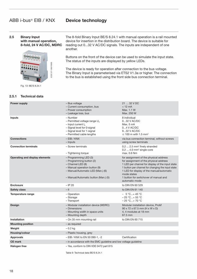
The 8-fold Binary Input BE/S 8.24.1 with manual operation is a rail mounted device for insertion in the distribution board. The device is suitable for reading out 0...32 V AC/DC signals. The inputs are independent of one another.
Buttons on the front of the device can be used to simulate the input state. The status of the inputs are displayed by yellow LEDs.
The device is ready for operation after connection to the bus voltage. The Binary Input is parameterised via ETS2 V1.3a or higher. The connection to the bus is established using the front side bus connection terminal.
2.5 Binary Input with manual operation, 8-fold, 24 V AC/DC, MDRC
Fig. 13: BE/S 8.24.1
2.5.1 Technical data
Power supply – Bus voltage– Current consumption, bus– Power consumption– Leakage loss, bus
21 … 32 V DC< 12 mAMax. 1.1 WMax. 250 W
Inputs – Number– Permitted voltage range Un
– Input current In– Signal level for 0-signal– Signal level for 1-signal– Permitted cable lengths
8 individual 0...32 V AC/DCMax. 5 mA0...4 V AC/DC9...32 V AC/DC � 100 m with 1.5 mm2
Connections – EIB / KNX– Inputs
via bus connection terminal, without screwsusing screw terminals
Connection terminals – Screw terminals
– Tightening torque
0.2 ... 2.5 mm2 finely stranded0.2 ... 4.0 mm2 single-coremax. 0.6 Nm
Operating and display elements – Programming LED (3)– Programming button (2)– Channel LED (8)– Manual operation button (9)– Manual/Automatic LED (Man.) (6)
– Manual/Automatic button (Man.) (5)
for assignment of the physical addressfor assignment of the physical address1 LED per channel for display of the input state1 button per channel for changing the input state1 LED for display of the manual/automaticmode states1 button for switchover of manual andautomatic mode
Enclosure – IP 20 to DIN EN 60 529
Safety class – II to DIN EN 61 140
Temperature range – Operation– Storage– Transport
– 5 °C...+ 45 °C– 25 °C...+ 55 °C– 25 °C...+ 70 °C
Design – Modular installation device (MDRC)– Dimensions– Mounting width in space units– Mounting depth
Modular installation device, ProM 90 x 72 x 67.5 mm (H x W x D) 4, 4 modules at 18 mm67.5 mm
Installation – On 35 mm mounting rail to DIN EN 60 715
Mounting position – as required
Weight – 0.2 kg
Housing/colour – Plastic housing, grey
Approvals – EIB / KNX to EN 50 090-1, -2 Certification
CE mark – in accordance with the EMC guideline and low voltage guideline
Halogen free – Yes, conform to DIN VDE 0472 part 815
Table 9: Technical data BE/S 8.24.1
Device technology
2CD
C 0
71 0
09 F
0005
19
ABB i-bus® EIB / KNX
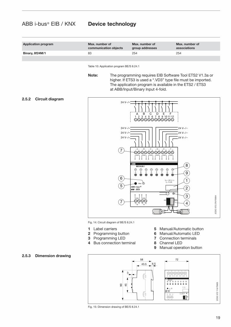
Table 10: Application program BE/S 8.24.1
Note: The programming requires EIB Software Tool ETS2 V1.3a or higher. If ETS3 is used a “.VD3” type file must be imported. The application program is available in the ETS2 / ETS3 at ABB/Input/Binary Input 4-fold.
Fig. 14: Circuit diagram of BE/S 8.24.1
1 Label carriers 5 Manual/Automatic button 2 Programming button 6 Manual/Automatic LED3 Programming LED 7 Connection terminals4 Bus connection terminal 8 Channel LED 9 Manual operation button
Fig. 15: Dimension drawing of BE/S 8.24.1
Application program Max. number ofcommunication objects
Max. number ofgroup addresses
Max. number ofassociations
Binary, 8f24M/1 83 254 254
2.5.2 Circuit diagram
2.5.3 Dimension drawing
�����������
�� � � � ��
� � � �� � � �� ����
�
��� �� �� ��
�
���������
����������� � ����
���
� � � �
���
� �� �
��� ��� ��� ��� ���
��� ���
�
�
�
�
�
�
�
�
�
�
� � � � � �� � � � �� � � � �� ����
����
����
����
����
����
����
����
2CD
C 0
72 2
76 F
0004
Device technology
�
��
��
���� ���
��
�����������
�� � � � ��
� � � �� � � �� ����
�
��� �� �� ��
�
���������
����������� � ����
���
� � � �
���
� �� �
��� ��� ��� ��� ���
��� ���
��
2CD
C 0
72 1
16 F
0005
20
ABB i-bus® EIB / KNX
The Binary Input is a modular installation device for fast installation in the distribution board on 35 mm mounting rails to DIN EN 60 715.
The electrical connection is implemented using screw terminals. The connection to the bus is implemented using the supplied bus connection terminal.
The device is ready for operation after connection to the bus voltage. Accessibility of the devices for the purpose operation, testing, visual inspection, maintenance and repair must be must be provided (conform to DIN VDE 0100-520).
Commissioning requirementsTo put the Binary Input BE/S 8.24.1 into operation, you require a PC with the Engineering Tool Software ETS2 from V1.3a onwards in conjunction with an RS232 interface or a USB interface. The device is ready for operation after connection to the bus voltage.
The installation and commissioning may only be carried out by electrical specialists. The appropriate norms, guidelines, regulations and specifications should be observed when planning and setting up electrical installations.
– The device should be protected from damp, dirt and damage during transport, storage and operation.
– The device should not be operated outside the specified technical data!
– The device should only be operated in a closed housing (distribution board)!
Supplied stateThe Binary Input is supplied with the physical address 15.15.255. The Binary, 8f20M/1 user program is preinstalled. Hence, only group addresses and parameters must be loaded during commissioning. The entire application can be reloaded as required. A longer downtime may result if the application program is changed or after a discharge.
Assignment of the physical addressThe assignment and programming of the physical address is carried out in the ETS.
CleaningIf devices become dirty, they can be cleaned using a dry cloth. Should a dry cloth not remove the dirt, they can be cleaned using a slightly damp cloth and soap solution. Corrosive materials or solutions should never be used.
MaintenanceThe device is maintenance-free. No repairs should be carried out by unauthorised personnel if damage occurs (e.g. during transport or storage). The warranty expires if the device is opened.
2.5.4 Assembly and installation
Device technology
21
ABB i-bus® EIB / KNX
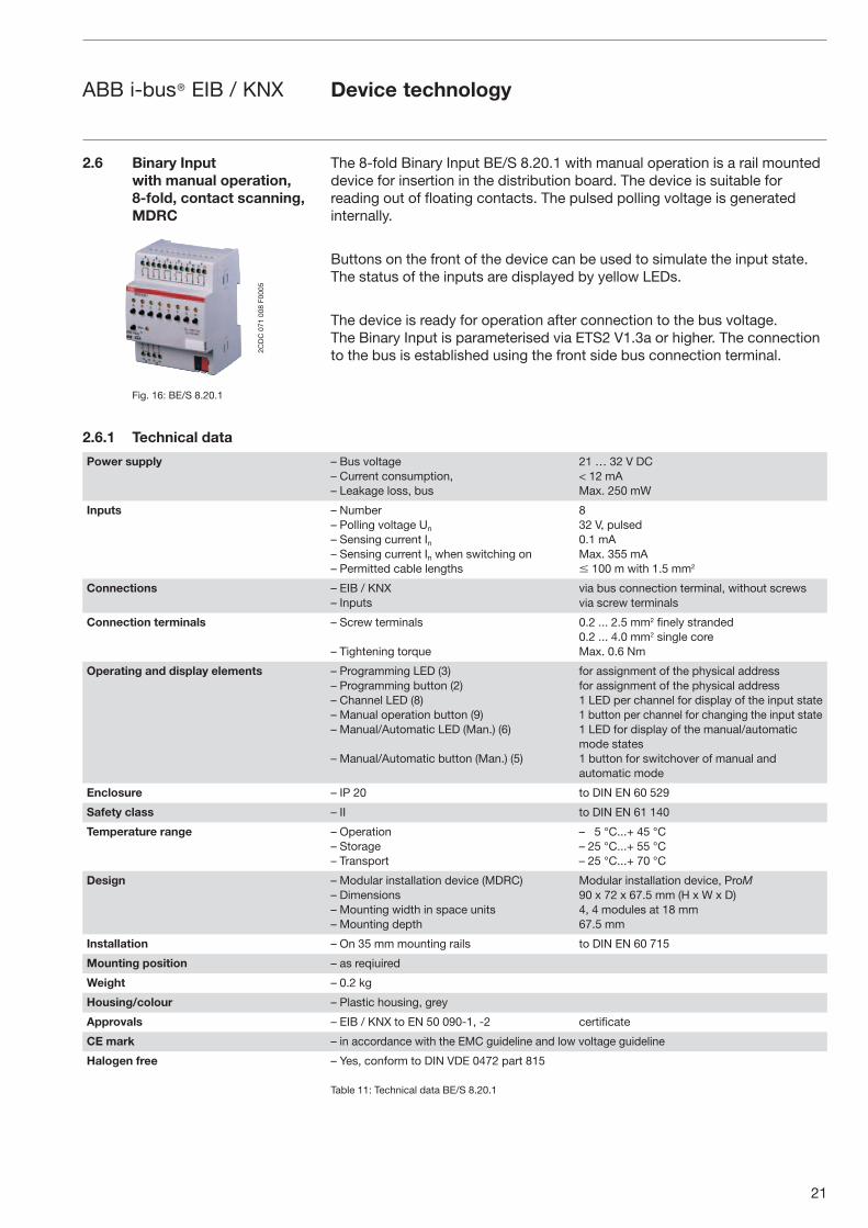
The 8-fold Binary Input BE/S 8.20.1 with manual operation is a rail mounted device for insertion in the distribution board. The device is suitable for reading out of floating contacts. The pulsed polling voltage is generated internally.
Buttons on the front of the device can be used to simulate the input state. The status of the inputs are displayed by yellow LEDs.
The device is ready for operation after connection to the bus voltage. The Binary Input is parameterised via ETS2 V1.3a or higher. The connection to the bus is established using the front side bus connection terminal.
2.6 Binary Input with manual operation, 8-fold, contact scanning, MDRC
Fig. 16: BE/S 8.20.1
2.6.1 Technical data
Power supply – Bus voltage– Current consumption,– Leakage loss, bus
21 … 32 V DC< 12 mAMax. 250 mW
Inputs – Number– Polling voltage Un
– Sensing current In– Sensing current In when switching on– Permitted cable lengths
832 V, pulsed 0.1 mAMax. 355 mA� 100 m with 1.5 mm2
Connections – EIB / KNX– Inputs
via bus connection terminal, without screwsvia screw terminals
Connection terminals – Screw terminals
– Tightening torque
0.2 ... 2.5 mm2 finely stranded0.2 ... 4.0 mm2 single coreMax. 0.6 Nm
Operating and display elements – Programming LED (3)– Programming button (2)– Channel LED (8)– Manual operation button (9)– Manual/Automatic LED (Man.) (6)
– Manual/Automatic button (Man.) (5)
for assignment of the physical addressfor assignment of the physical address1 LED per channel for display of the input state1 button per channel for changing the input state1 LED for display of the manual/automatic mode states1 button for switchover of manual and automatic mode
Enclosure – IP 20 to DIN EN 60 529
Safety class – II to DIN EN 61 140
Temperature range – Operation– Storage– Transport
– 5 °C...+ 45 °C– 25 °C...+ 55 °C– 25 °C...+ 70 °C
Design – Modular installation device (MDRC)– Dimensions– Mounting width in space units– Mounting depth
Modular installation device, ProM90 x 72 x 67.5 mm (H x W x D)4, 4 modules at 18 mm67.5 mm
Installation – On 35 mm mounting rails to DIN EN 60 715
Mounting position – as reqiuired
Weight – 0.2 kg
Housing/colour – Plastic housing, grey
Approvals – EIB / KNX to EN 50 090-1, -2 certificate
CE mark – in accordance with the EMC guideline and low voltage guideline
Halogen free – Yes, conform to DIN VDE 0472 part 815
Table 11: Technical data BE/S 8.20.1
Device technology
2CD
C 0
71 0
08 F
0005
22
ABB i-bus® EIB / KNX
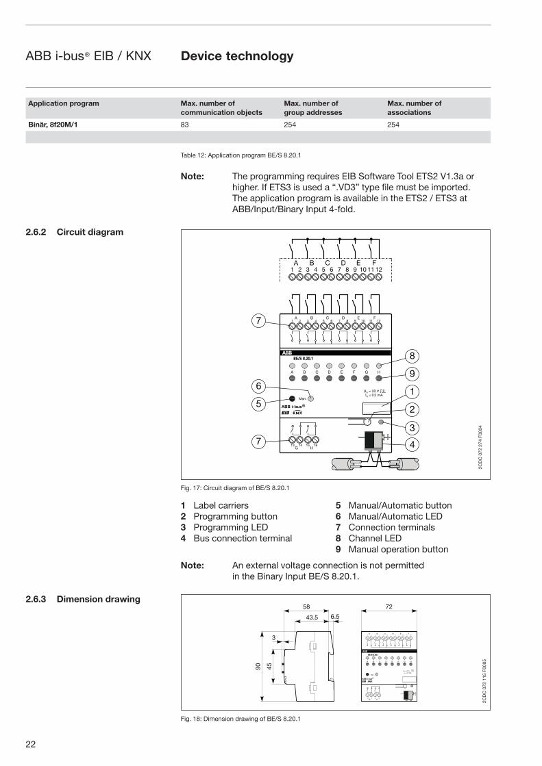
Table 12: Application program BE/S 8.20.1
Note: The programming requires EIB Software Tool ETS2 V1.3a or higher. If ETS3 is used a “.VD3” type file must be imported. The application program is available in the ETS2 / ETS3 at ABB/Input/Binary Input 4-fold.
Fig. 17: Circuit diagram of BE/S 8.20.1
1 Label carriers 5 Manual/Automatic button 2 Programming button 6 Manual/Automatic LED3 Programming LED 7 Connection terminals4 Bus connection terminal 8 Channel LED 9 Manual operation button
Note: An external voltage connection is not permitted in the Binary Input BE/S 8.20.1.
Fig. 18: Dimension drawing of BE/S 8.20.1
Application program Max. number ofcommunication objects
Max. number ofgroup addresses
Max. number ofassociations
Binär, 8f20M/1 83 254 254
2.6.2 Circuit diagram
2.6.3 Dimension drawing
� � � �
���
����������
�� � � � ��
� � � �� � � �� ����
�
� �
���������
����������� ��������
��� ��
��� ��
� �
�
�
�
�
�
�
�
�
�
�
� � � � � �� � � � �� � � � �� ����
2CD
C 0
72 2
74 F
0004
Device technology
�
��
��
���� ���
��
��
� � � �
���
����������
�� � � � ��
� � � �� � � �� ����
�
�
���������
����������� ��������
��� ��
��� ��
� �
2CD
C 0
72 1
15 F
0005
23
ABB i-bus® EIB / KNX
The Binary Input is a modular installation device for fast installation in the distribution board on 35 mm mounting rails to DIN EN 60 715.
The electrical connection is implemented using screw terminals. The connection to the bus is implemented using the supplied bus connection terminal.
The device is ready for operation after connection to the bus voltage.Accessibility of the devices for the purpose operation, testing, visual inspection, maintenance and repair must be must be provided (conform to DIN VDE 0100-520).
Commissioning requirementsTo put the Binary Input BE/S 8.20.1 into operation, you require a PC with the Engineering Tool Software ETS2 from V1.3a onwards in conjunction with an RS232 interface or a USB interface. The device is ready for operation after connection to the bus voltage.
The installation and commissioning may only be carried out by electrical specialists. The appropriate norms, guidelines, regulations and specifications should be observed when planning and setting up electrical installations.
– The device should be protected from damp, dirt and damage during transport, storage and operation.
– The device should not be operated outside the specified technical data!
– The device should only be operated in a closed housing (distribution board)!
Supplied stateThe Binary Input is supplied with the physical address 15.15.255. The Binary, 8f20M/1 user program is preinstalled. Hence, only group addresses and parameters must be loaded during commissioning. The entire application can be reloaded as required. A longer downtime may result if the application program is changed or after a discharge.
Assignment of the physical addressThe assignment and programming of the physical address is carried out in the ETS.
CleaningIf devices become dirty, they can be cleaned using a dry cloth. Should a dry cloth not remove the dirt, the devices can be cleaned using a slightly damp cloth and soap solution. Corrosive materials or solutions should never be used.
MaintenanceThe device is maintenance-free. No repairs should be carried out by unauthorised personnel if damage occurs (e.g. during transport or storage). The warranty expires if the device is opened.
2.6.4 Assembly and installation
Device technology
24
ABB i-bus® EIB / KNX
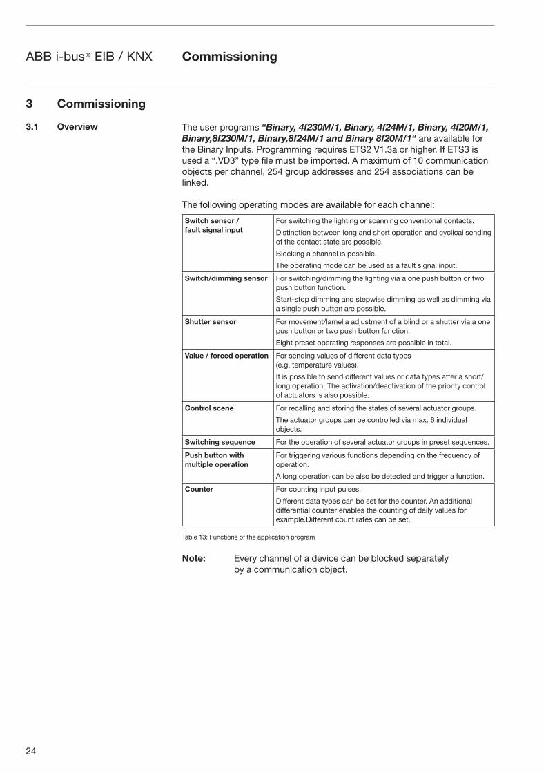
The user programs “Binary, 4f230M/1, Binary, 4f24M/1, Binary, 4f20M/1, Binary,8f230M/1, Binary,8f24M/1 and Binary 8f20M/1“ are available for the Binary Inputs. Programming requires ETS2 V1.3a or higher. If ETS3 is used a “.VD3” type file must be imported. A maximum of 10 communication objects per channel, 254 group addresses and 254 associations can be linked.
The following operating modes are available for each channel:
Switch sensor /fault signal input
For switching the lighting or scanning conventional contacts.
Distinction between long and short operation and cyclical sending of the contact state are possible.
Blocking a channel is possible.
The operating mode can be used as a fault signal input.
Switch/dimming sensor For switching/dimming the lighting via a one push button or two push button function.
Start-stop dimming and stepwise dimming as well as dimming via a single push button are possible.
Shutter sensor For movement/lamella adjustment of a blind or a shutter via a one push button or two push button function.
Eight preset operating responses are possible in total.
Value / forced operation For sending values of different data types (e.g. temperature values).
It is possible to send different values or data types after a short/long operation. The activation/deactivation of the priority control of actuators is also possible.
Control scene For recalling and storing the states of several actuator groups.
The actuator groups can be controlled via max. 6 individual objects.
Switching sequence For the operation of several actuator groups in preset sequences.
Push button with multiple operation
For triggering various functions depending on the frequency of operation.
A long operation can be also be detected and trigger a function.
Counter For counting input pulses.
Different data types can be set for the counter. An additional differential counter enables the counting of daily values for example.Different count rates can be set.
Table 13: Functions of the application program
Note: Every channel of a device can be blocked separately by a communication object.
3 Commissioning
3.1 Overview
Commissioning
25
ABB i-bus® EIB / KNX
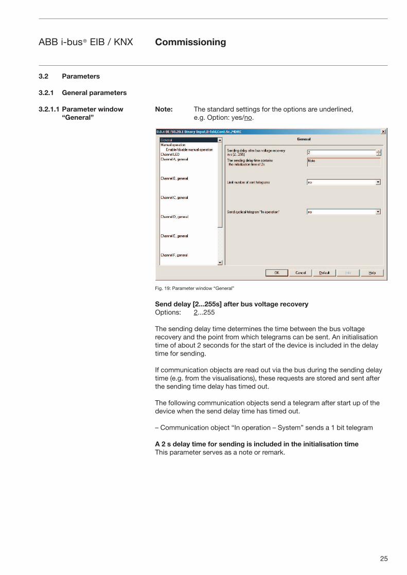
Note: The standard settings for the options are underlined,e.g. Option: yes/no.
Fig. 19: Parameter window “General”
Send delay [2...255s] after bus voltage recovery Options: 2...255
The sending delay time determines the time between the bus voltage recovery and the point from which telegrams can be sent. An initialisation time of about 2 seconds for the start of the device is included in the delay time for sending.
If communication objects are read out via the bus during the sending delay time (e.g. from the visualisations), these requests are stored and sent after the sending time delay has timed out.
The following communication objects send a telegram after start up of the device when the send delay time has timed out.
– Communication object “In operation – System” sends a 1 bit telegram
A 2 s delay time for sending is included in the initialisation timeThis parameter serves as a note or remark.
3.2 Parameters
3.2.1 General parameters
3.2.1.1 Parameter window “General”
Commissioning
26
ABB i-bus® EIB / KNX
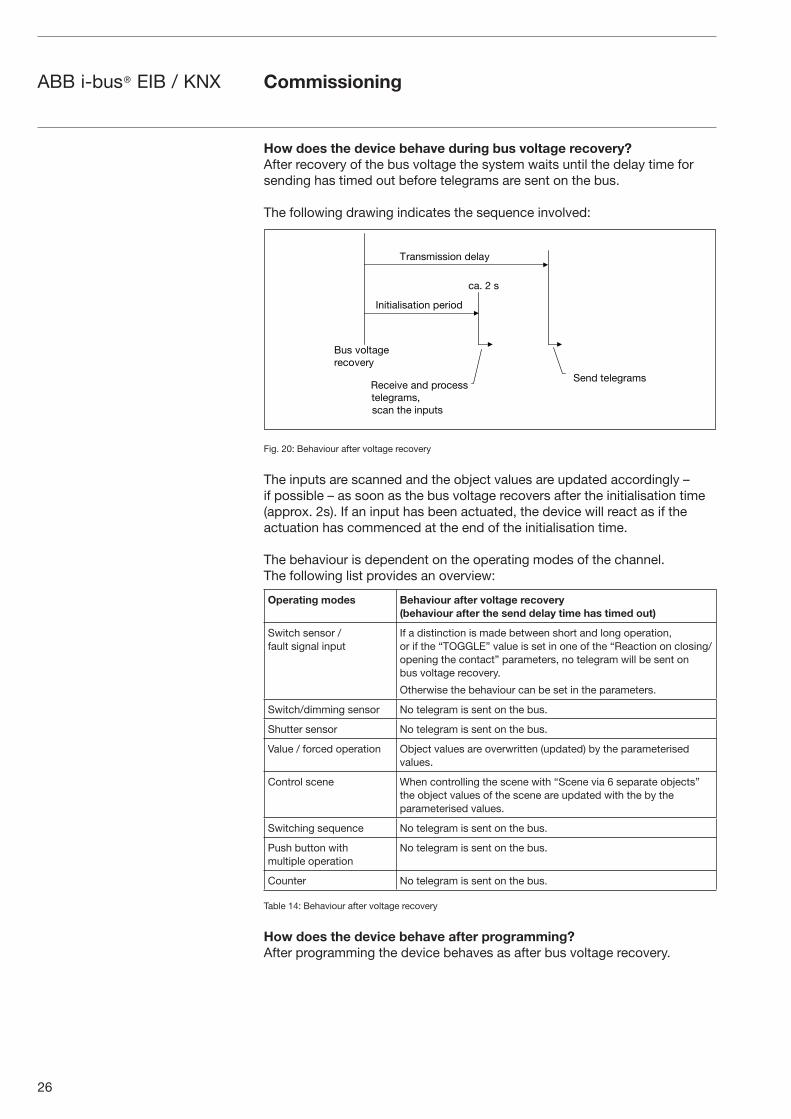
How does the device behave during bus voltage recovery?After recovery of the bus voltage the system waits until the delay time for sending has timed out before telegrams are sent on the bus.
The following drawing indicates the sequence involved:
Fig. 20: Behaviour after voltage recovery
The inputs are scanned and the object values are updated accordingly – if possible – as soon as the bus voltage recovers after the initialisation time (approx. 2s). If an input has been actuated, the device will react as if the actuation has commenced at the end of the initialisation time.
The behaviour is dependent on the operating modes of the channel. The following list provides an overview:
Operating modes Behaviour after voltage recovery(behaviour after the send delay time has timed out)
Switch sensor /fault signal input
If a distinction is made between short and long operation, or if the “TOGGLE” value is set in one of the “Reaction on closing/opening the contact” parameters, no telegram will be sent on bus voltage recovery.
Otherwise the behaviour can be set in the parameters.
Switch/dimming sensor No telegram is sent on the bus.
Shutter sensor No telegram is sent on the bus.
Value / forced operation Object values are overwritten (updated) by the parameterised values.
Control scene When controlling the scene with “Scene via 6 separate objects” the object values of the scene are updated with the by the parameterised values.
Switching sequence No telegram is sent on the bus.
Push button with multiple operation
No telegram is sent on the bus.
Counter No telegram is sent on the bus.
Table 14: Behaviour after voltage recovery
How does the device behave after programming?After programming the device behaves as after bus voltage recovery.
�"# $%&'�()*)+%$)*,
+�� � #
-*��#�.##.%� /)&�,
0)�/ ')&)(*��#
��.'.�&.#�'.%� 1)*.%/
2)+).$) ��/ 1*%+)##')&)(*��#3#+�� '4) .�1"'#
Commissioning
27
ABB i-bus® EIB / KNX
Limit the number of telegrams Options: yes/no
A telegram limitation is implemented to control the bus load created by the device.
When yes is selected in the Limit the number of telegrams parameter the Max. number of sent ... and Duration of the... parameters appear.
Max. number of sent telegrams within the observation periodOptions: 0...20...255
This parameter sets the number of telegrams which can be sent within an observation period.
Duration of the observation periodOptions: 50 ms/100 ms/200 ms/500 ms/1 s/2 s/5 s/10 s/30 s/1 min
The duration of the observation period is set with this parameter.
What is a limitation of the telegram rate and an observation period?A new observation period starts after the end of the previous observation period or – in the event of a bus voltage recovery – after the end of the send delay time. The sent telegrams are counted. As soon as the Max. number of transmitted telegrams... has been reached, no further telegrams are sent on the bus until the end of the observation period.
With the start of a new observation period, the telegram counter is reset to zero and the sending of telegrams is permitted again.
Send cyclic “In operation” telegram Options: yes/no
Option no = Cyclic “In operation” telegram is not sent
Option yes = the “In operation – System” communication object appears
With yes selected in the Send cyclic “In operation” telegram, the parameters Basic and Factor appear.
BasicOptions: 1 s/10 s/1 min/10 min/1 h
Factor [1...255]Options: 1...60...255
Commissioning
28
ABB i-bus® EIB / KNX
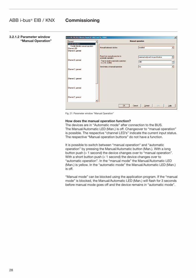
Fig. 21: Parameter window “Manual Operation”
How does the manual operation function?The devices are in “Automatic mode” after connection to the BUS. The Manual/Automatic LED (Man.) is off. Changeover to “manual operation” is possible. The respective “channel LED’s” indicate the current input status. The respective “Manual operation buttons” do not have a function.
It is possible to switch between “manual operation“ and “automatic operation” by pressing the Manual/Automatic button (Man.). With a long button push (> 1 second) the device changes over to “manual operation”. With a short button push (< 1 second) the device changes over to “automatic operation”. In the “manual mode” the Manual/Automatic LED (Man.) is yellow. In the “automatic mode” the Manual/Automatic LED (Man.) is off.
“Manual mode” can be blocked using the application program. If the “manual mode” is blocked, the Manual/Automatic LED (Man.) will flash for 3 seconds before manual mode goes off and the device remains in “automatic mode”.
3.2.1.2 Parameter window “Manual Operation”
Commissioning
29
ABB i-bus® EIB / KNX
Manual OperationOptions: enable/block via communications object/enable
The parameter defines if the switchover between the “manual operation“ and “automatic operation” operating states is blocked or enabled using the Manual/Automatic button (Man.) on the Binary Input.
If the enable/block via communications object is selected, the “block manual operation key” communications object appears.
Telegram value “0” enable manual operation button “1” block manual operation button
Note: The manual operation can automatically overwrite the input states.
How is switchover made between “automatic operation” and “manual operation”?When switching over from “automatic operation” to the “manual operation”, the Manual/Automatic LED (Man.) will flash for 3 seconds in “manual operation” after the Manual/Automatic button (Man.) is pressed. If “manual operation” is enabled via the application program, switchover to “manual operation” occurs and the Manual/Automatic LED (Man.) is on. The respective “channel LED’s” indicate the current input status.
The states of the individual channels can be changed by the “manual operation buttons”. Telegrams will be sent to the Bus if group addresses are assigned! Any signal changes from the installation system are not taken into consideration. With switchover to the “automatic operation” the respective “channel LED’s” will once again indicate their current states. The communi-cation objects are updated and telegrams will be sent if necessary.
Reset from “manual operation” to “automation operation” Options: via button/automatic and via button
This parameter defines how long the Binary Input remains in the “manual operation” state after the “Manual/Automatic button (Man.)” has been pressed.
If the automatic and via button option is selected, the Binary Input will remain in “manual operation” until the Manual/Automatic button (Man.) is pressed again or the parameterised Time for automatic reset [10...6.000s] has timed out.
If the via button option is selected, the Binary Input will remain in “manual operation” until the Manual/Automatic button (Man.) is pressed again.
Commissioning
30
ABB i-bus® EIB / KNX
How is switchover made between “manual operation” and “automatic operation”?The Manual/Automatic button (Man.) is pressed for 1 s when switching over from “manual operation” to the “automatic operation”. The Manual/Auto-matic LED (Man.) flashes for 3 seconds and switchover of the operating state occurs. Depending on the parameterisation, the operating state can switch back automatically to “automatic operation” after a predefined time has timed out. The device is in “automatic operation” if the Manual/Auto-matic LED (Man.) is off.
Thereafter, the current input states are scanned, displayed and sent if necessary. The operating state will also change automatically to “automatic operation” if the “manual/automatic operation” is blocked via a telegram. The Manual/Automatic LED (Man.) will also flash for 3 seconds with an automatic change of the operating state. In the “automatic operation” state the manual operation button is not operational for every channel.In the “manual operation” state the input states can be simulated via the manual operation buttons. Changes of incoming input states from the installation system are not passed on. With switchover, the current input states are automatically scanned, displayed and sent if necessary.
If the option automatic and via button in the reset from “manual operation” to “automatic operation” parameter is selected, the following parameter will appear.
Time for automatic reset [10...6.000 s] Options: 10...300...6000
For setting the time for automatic reset from the “manual operation” to “automatic operation” state after the last push of a button.
Send manual operation status Options: yes/no
If the “yes” option is selected, the “Man. operating status” communications object appears.
Telegram value “0” Automatic operation “1” Manual operation
If the yes option is selected in the Send manual operation status parameter, the following note will appear.
Status is always sent after change.
Commissioning
31
ABB i-bus® EIB / KNX
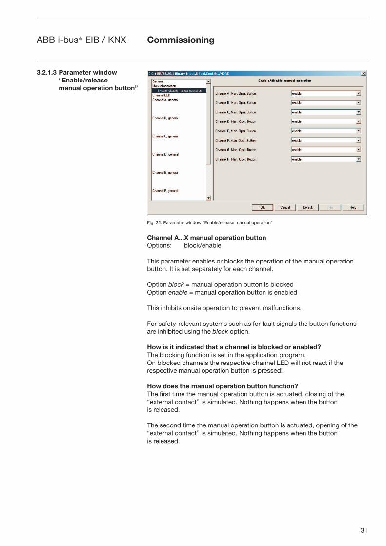
Fig. 22: Parameter window “Enable/release manual operation”
Channel A...X manual operation button Options: block/enable
This parameter enables or blocks the operation of the manual operation button. It is set separately for each channel.
Option block = manual operation button is blockedOption enable = manual operation button is enabled
This inhibits onsite operation to prevent malfunctions.
For safety-relevant systems such as for fault signals the button functions are inhibited using the block option.
How is it indicated that a channel is blocked or enabled? The blocking function is set in the application program.On blocked channels the respective channel LED will not react if the respective manual operation button is pressed!
How does the manual operation button function?The first time the manual operation button is actuated, closing of the “external contact” is simulated. Nothing happens when the button is released.
The second time the manual operation button is actuated, opening of the “external contact” is simulated. Nothing happens when the button is released.
3.2.1.3 Parameter window “Enable/release manual operation button”
Commissioning
32
ABB i-bus® EIB / KNX
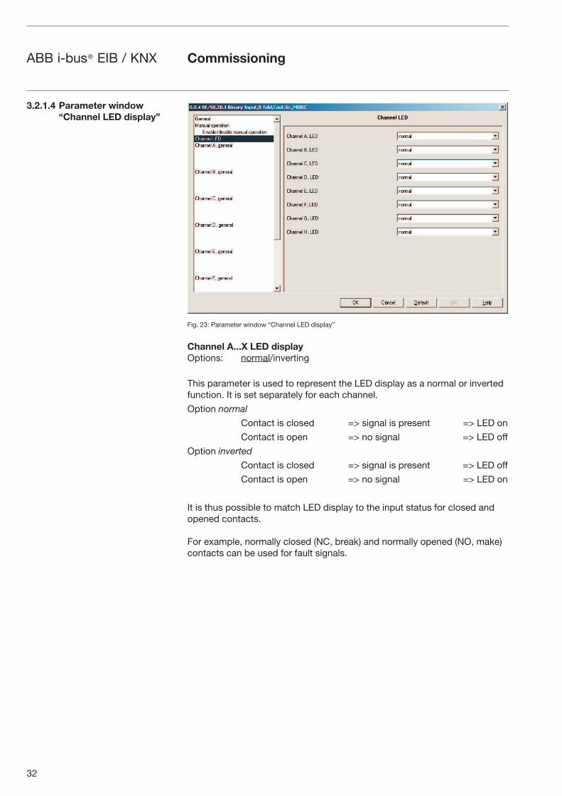
Fig. 23: Parameter window “Channel LED display”
Channel A...X LED display Options: normal/inverting
This parameter is used to represent the LED display as a normal or inverted function. It is set separately for each channel.
Option normal
Contact is closed => signal is present => LED on
Contact is open => no signal => LED off
Option inverted
Contact is closed => signal is present => LED off
Contact is open => no signal => LED on
It is thus possible to match LED display to the input status for closed and opened contacts.
For example, normally closed (NC, break) and normally opened (NO, make) contacts can be used for fault signals.
3.2.1.4 Parameter window “Channel LED display”
Commissioning
33
ABB i-bus® EIB / KNX
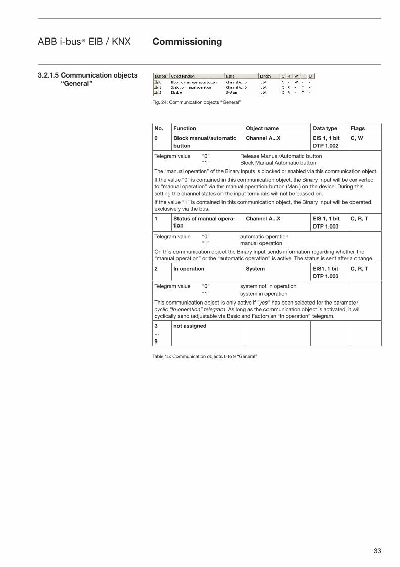
Fig. 24: Communication objects “General”
No. Function Object name Data type Flags
0 Block manual/automaticbutton
Channel A...X EIS 1, 1 bitDTP 1.002
C, W
Telegram value “0” Release Manual/Automatic button “1” Block Manual Automatic button
The “manual operation” of the Binary Inputs is blocked or enabled via this communication object.
If the value “0” is contained in this communication object, the Binary Input will be converted to “manual operation” via the manual operation button (Man.) on the device. During this setting the channel states on the input terminals will not be passed on.
If the value “1” is contained in this communication object, the Binary Input will be operated exclusively via the bus.
1 Status of manual opera-tion
Channel A...X EIS 1, 1 bitDTP 1.003
C, R, T
Telegram value “0” automatic operation “1” manual operation
On this communication object the Binary Input sends information regarding whether the “manual operation” or the “automatic operation” is active. The status is sent after a change.
2 In operation System EIS1, 1 bitDTP 1.003
C, R, T
Telegram value “0” system not in operation “1” system in operation
This communication object is only active if “yes” has been selected for the parameter cyclic “In operation” telegram. As long as the communication object is activated, it will cyclically send (adjustable via Basic and Factor) an “In operation” telegram.
3...9
not assigned
Table 15: Communication objects 0 to 9 “General”
3.2.1.5 Communication objects “General”
Commissioning
34
ABB i-bus® EIB / KNX
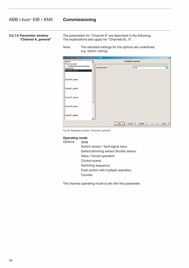
The parameters for “Channel A” are described in the following.The explanations also apply for “Channels B...X”.
Note: The standard settings for the options are underlined, e.g. option: yes/no.
Fig. 25: Parameter window “Channel A, general”
Operating mode Options: none
Switch sensor / fault signal input
Switch/dimming sensor Shutter sensor
Value / forced operation
Control scene
Switching sequence
Push button with multiple operation
Counter
The channel operating mode is set with this parameter.
3.2.1.6 Parameter window “Channel A, general”
Commissioning
35
ABB i-bus® EIB / KNX
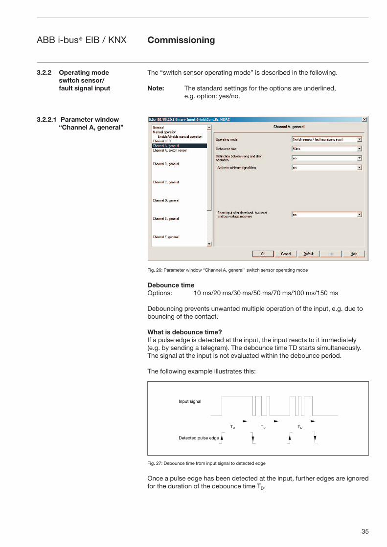
The “switch sensor operating mode” is described in the following.
Note: The standard settings for the options are underlined, e.g. option: yes/no.
Fig. 26: Parameter window “Channel A, general” switch sensor operating mode
Debounce timeOptions: 10 ms/20 ms/30 ms/50 ms/70 ms/100 ms/150 ms
Debouncing prevents unwanted multiple operation of the input, e.g. due to bouncing of the contact.
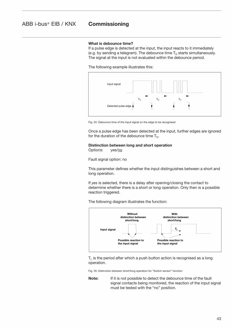
What is debounce time?If a pulse edge is detected at the input, the input reacts to it immediately (e.g. by sending a telegram). The debounce time TD starts simultaneously. The signal at the input is not evaluated within the debounce period.
The following example illustrates this:
Fig. 27: Debounce time from input signal to detected edge
Once a pulse edge has been detected at the input, further edges are ignored for the duration of the debounce time TD.
3.2.2 Operating mode switch sensor/fault signal input
3.2.2.1 Parameter window“Channel A, general”
-� -� -�
��1"' #.(��&
�)')+')/ 1"&#) )/()
Commissioning
36
ABB i-bus® EIB / KNX
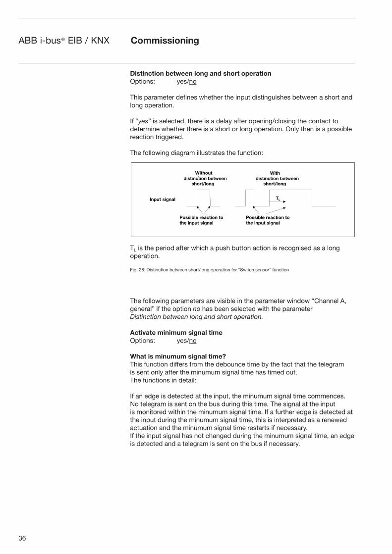
Distinction between long and short operation Options: yes/no
This parameter defines whether the input distinguishes between a short and long operation.
If “yes” is selected, there is a delay after opening/closing the contact to determine whether there is a short or long operation. Only then is a possible reaction triggered.
The following diagram illustrates the function:
TL is the period after which a push button action is recognised as a long operation.
Fig. 28: Distinction between short/long operation for “Switch sensor” function
The following parameters are visible in the parameter window “Channel A, general” if the option no has been selected with the parameter Distinction between long and short operation.
Activate minimum signal time Options: yes/no
What is minumum signal time?This function differs from the debounce time by the fact that the telegram is sent only after the minumum signal time has timed out. The functions in detail:
If an edge is detected at the input, the minumum signal time commences. No telegram is sent on the bus during this time. The signal at the input is monitored within the minumum signal time. If a further edge is detected at the input during the minumum signal time, this is interpreted as a renewed actuation and the minumum signal time restarts if necessary.If the input signal has not changed during the minumum signal time, an edge is detected and a telegram is sent on the bus if necessary.
��� ������������ � �������
�� ���� ��
������������ � �������
�� ���� ��
������� ������
� ������ ������ � � ��� ����� ������
� ������ ������ � � ��� ����� ������
Commissioning
37
ABB i-bus® EIB / KNX
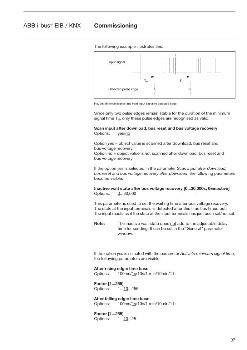
The following example illustrates this:
Fig. 29: Minimum signal time from input signal to detected edge
Since only two pulse edges remain stable for the duration of the minimum signal time TM, only these pulse edges are recognised as valid.
Scan input after download, bus reset and bus voltage recovery Options: yes/no
Option yes = object value is scanned after download, bus reset and bus voltage recovery.Option no = object value is not scanned after download, bus reset and bus voltage recovery.
If the option yes is selected in the parameter Scan input after download, bus reset and bus voltage recovery after download, the following parameters become visible.
Inactive wait state after bus voltage recovery [0...30,000s, 0=inactive] Options: 0...30,000
This parameter is used to set the waiting time after bus voltage recovery. The state at the input terminals is detected after this time has timed out. The input reacts as if the state at the input terminals has just been set/not set.
Note: The inactive wait state does not add to the adjustable delay time for sending. It can be set in the “General” parameter window.
If the option yes is selected with the parameter Activate minimum signal time, the following parameters are visible.
After rising edge: time base Options: 100ms/1s/10s/1 min/10min/1 h
Factor [1...255]Options: 1...10...255
After falling edge: time baseOptions: 100ms/1s/10s/1 min/10min/1 h
Factor [1...255] Options: 1...10...25
Commissioning
- -
��1"' #.(��&
�)')+')/ 1"&#) )/()
38
ABB i-bus® EIB / KNX
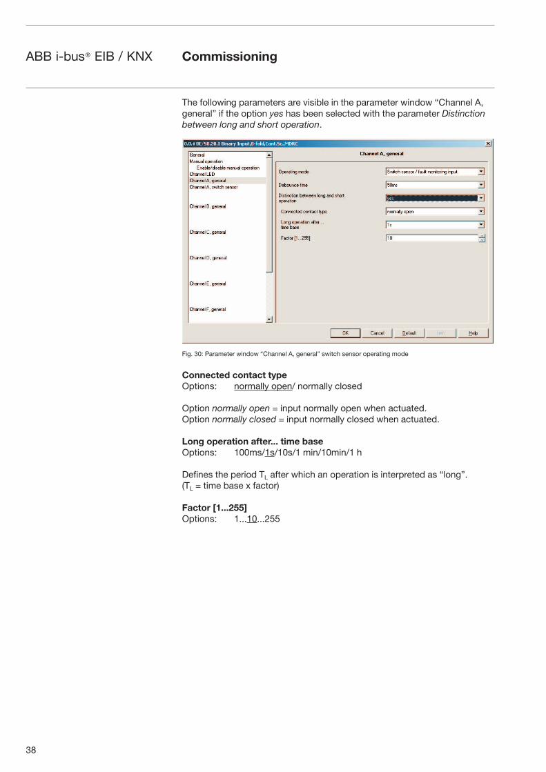
The following parameters are visible in the parameter window “Channel A, general” if the option yes has been selected with the parameter Distinction between long and short operation.
Fig. 30: Parameter window “Channel A, general” switch sensor operating mode
Connected contact typeOptions: normally open/ normally closed
Option normally open = input normally open when actuated. Option normally closed = input normally closed when actuated.
Long operation after... time baseOptions: 100ms/1s/10s/1 min/10min/1 h
Defines the period TL after which an operation is interpreted as “long”. (TL = time base x factor)
Factor [1...255]Options: 1...10...255
Commissioning
39
ABB i-bus® EIB / KNX
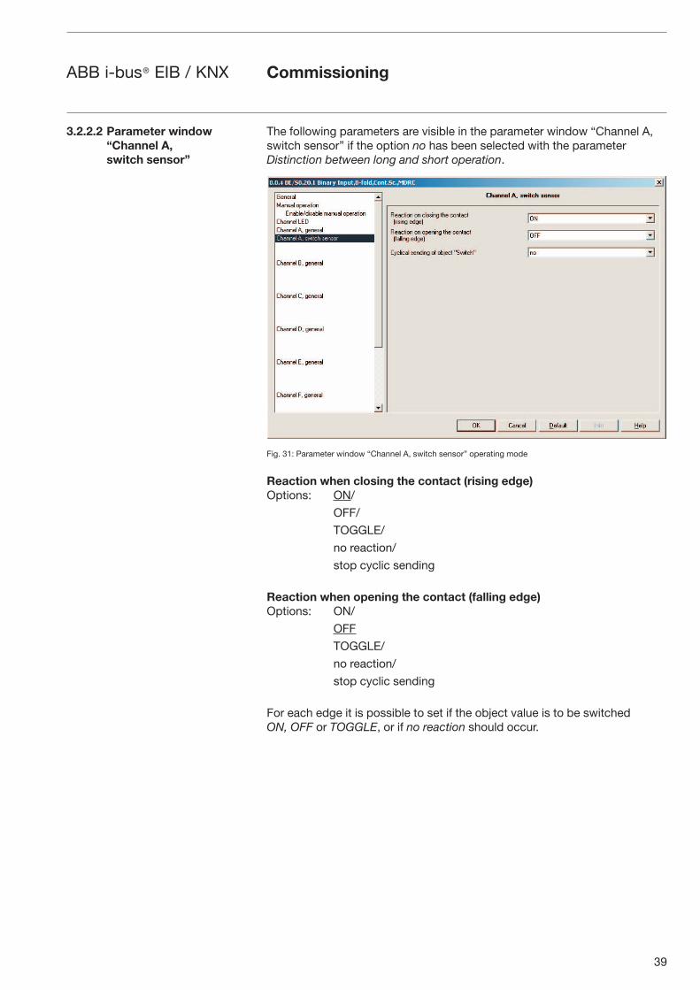
The following parameters are visible in the parameter window “Channel A, switch sensor” if the option no has been selected with the parameter Distinction between long and short operation.
Fig. 31: Parameter window “Channel A, switch sensor” operating mode
Reaction when closing the contact (rising edge)Options: ON/
OFF/
TOGGLE/
no reaction/
stop cyclic sending
Reaction when opening the contact (falling edge)Options: ON/
OFF
TOGGLE/
no reaction/
stop cyclic sending
For each edge it is possible to set if the object value is to be switched ON, OFF or TOGGLE, or if no reaction should occur.
Commissioning
3.2.2.2 Parameter window “Channel A, switch sensor”
40
ABB i-bus® EIB / KNX
If the option yes is selected in the parameter Cyclical sending of object “Switch” is selected, the following parameter appears.
Cyclical sending of object “Switch”Options: no/
if “switch” = ON/
if “switch” = OFF/
always
Option if “Switch” = ON = object value is sent cyclically
Option if “Switch” = OFF = object value is sent cyclically
Option always = communication object “Switch” is sent cyclically
What is cyclic sending?Cyclic sending enables the communication object “Switch” to send automatically at a fixed interval.
If cyclical sending is only carried out for a specific object value (ON or OFF), this condition refers to the value of the communication object. It is therefore possible in principle to start the cyclical sending by sending a value to the communication object “Switch. As this reaction is generally unwanted, the “write” flag and “update” flag of the communication object have to be deleted in the setting to ensure that it cannot by changed via the bus. If however this functionality is required, the flags must be set accordingly.
When the “Switch” object changes and after bus voltage recovery (once the transmission delay has elapsed), the object value is sent immediately on the bus and the transmission cycle time restarts.
The next two parameters are only visible if the options ON, OFF or always in the cyclical sending of object “Switch” have been selected.
Telegram is repeated every ... (“sending cycle time”): base Options: 1 s/10 s/1 min/10 min/1 h
The cycle time for sending describes the interval between two cyclically sent telegrams.
Cycle time for sending = time base x factor.
Factor [1...255]Options: 1...30...255
Commissioning
41
ABB i-bus® EIB / KNX
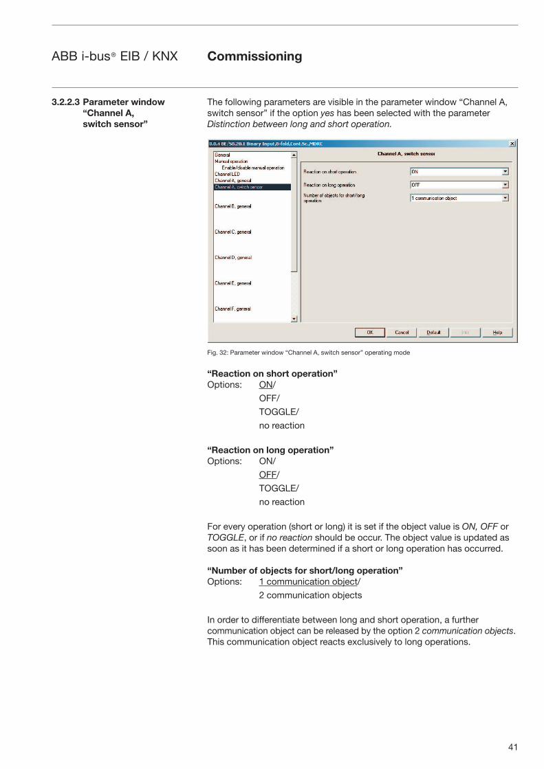
The following parameters are visible in the parameter window “Channel A, switch sensor” if the option yes has been selected with the parameter Distinction between long and short operation.
Fig. 32: Parameter window “Channel A, switch sensor” operating mode
“Reaction on short operation”Options: ON/
OFF/
TOGGLE/
no reaction
“Reaction on long operation”Options: ON/
OFF/
TOGGLE/
no reaction
For every operation (short or long) it is set if the object value is ON, OFF or TOGGLE, or if no reaction should be occur. The object value is updated as soon as it has been determined if a short or long operation has occurred.
“Number of objects for short/long operation” Options: 1 communication object/
2 communication objects
In order to differentiate between long and short operation, a further communication object can be released by the option 2 communication objects. This communication object reacts exclusively to long operations.
3.2.2.3 Parameter window “Channel A, switch sensor”
Commissioning
42
ABB i-bus® EIB / KNX
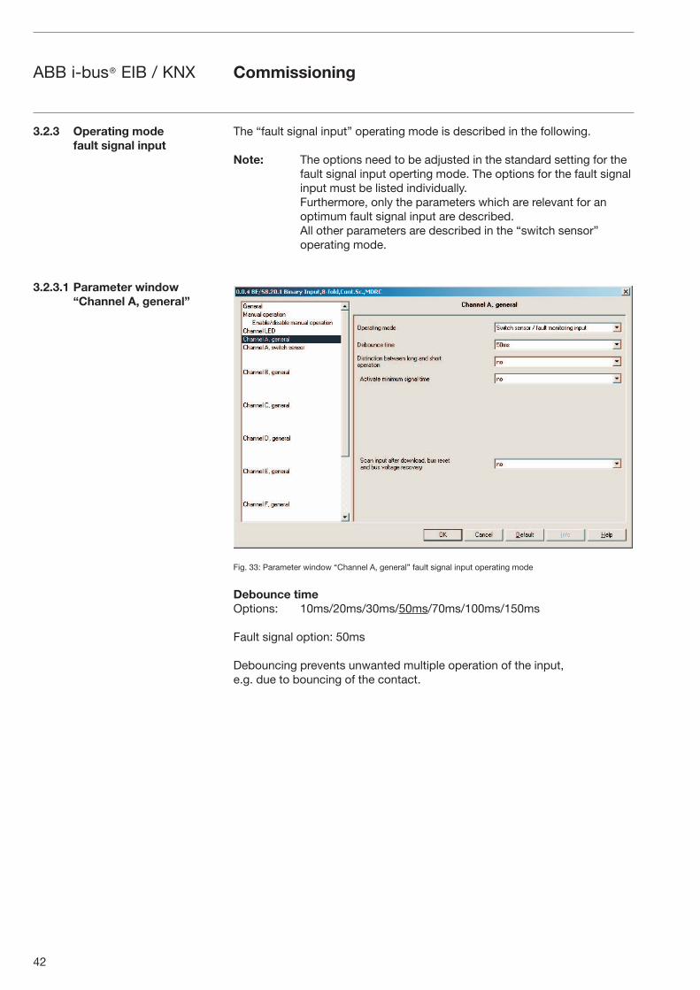
The “fault signal input” operating mode is described in the following.
Note: The options need to be adjusted in the standard setting for the fault signal input operting mode. The options for the fault signal input must be listed individually.Furthermore, only the parameters which are relevant for an optimum fault signal input are described.All other parameters are described in the “switch sensor”operating mode.
Fig. 33: Parameter window “Channel A, general” fault signal input operating mode
Debounce timeOptions: 10ms/20ms/30ms/50ms/70ms/100ms/150ms
Fault signal option: 50ms
Debouncing prevents unwanted multiple operation of the input, e.g. due to bouncing of the contact.
3.2.3 Operating mode fault signal input
3.2.3.1 Parameter window“Channel A, general”
Commissioning
43
ABB i-bus® EIB / KNX
What is debounce time?If a pulse edge is detected at the input, the input reacts to it immediately (e.g. by sending a telegram). The debounce time TD starts simultaneously. The signal at the input is not evaluated within the debounce period.
The following example illustrates this:
Fig. 34: Debounce time of the input signal on the edge to be recognised
Once a pulse edge has been detected at the input, further edges are ignored for the duration of the debounce time TD.
Distinction between long and short operation Options: yes/no
Fault signal option: no
This parameter defines whether the input distinguishes between a short and long operation.
If yes is selected, there is a delay after opening/closing the contact to determine whether there is a short or long operation. Only then is a possible reaction triggered.
The following diagram illustrates the function:
TL is the period after which a push button action is recognised as a long operation.
Fig. 35: Distinction between short/long operation for “Switch sensor” function
Note: If it is not possible to detect the debounce time of the fault signal contacts being monitored, the reaction of the input signal must be tested with the “no” position.
Commissioning
-� -� -�
��1"' #.(��&
�)')+')/ 1"&#) )/()
��� ����������� � �������
�� ���� ��
������������ � �������
�� ���� ��
������� ������
� ������ ������ � � ��� ����� ������
� ������ ������ � � ��� ����� ������
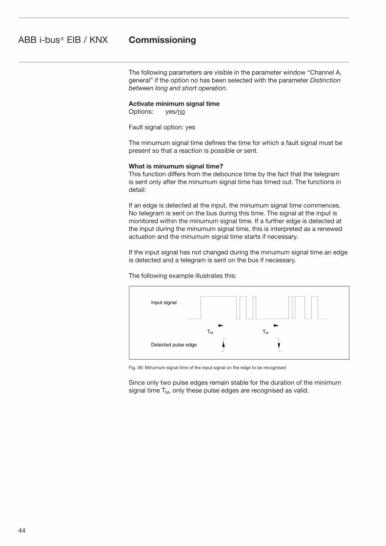
44
ABB i-bus® EIB / KNX
The following parameters are visible in the parameter window “Channel A, general” if the option no has been selected with the parameter Distinction between long and short operation.
Activate minimum signal time Options: yes/no
Fault signal option: yes
The minumum signal time defines the time for which a fault signal must be present so that a reaction is possible or sent.
What is minumum signal time?This function differs from the debounce time by the fact that the telegram is sent only after the minumum signal time has timed out. The functions in detail:
If an edge is detected at the input, the minumum signal time commences. No telegram is sent on the bus during this time. The signal at the input is monitored within the minumum signal time. If a further edge is detected at the input during the minumum signal time, this is interpreted as a renewed actuation and the minumum signal time starts if necessary.
If the input signal has not changed during the minumum signal time an edge is detected and a telegram is sent on the bus if necessary.
The following example illustrates this:
Fig. 36: Minumum signal time of the input signal on the edge to be recognised
Since only two pulse edges remain stable for the duration of the minimum signal time TM, only these pulse edges are recognised as valid.
Commissioning
�� ��
����� ������
�������� ����� ����
45
ABB i-bus® EIB / KNX
Scan input after download, bus reset and bus voltage recovery Options: yes/no
Fault signal option: yes
Option yes = object value is scanned after download, bus reset and bus voltage recovery.Option no = object value is not scanned after download, bus reset and bus voltage recovery.
If the option yes is selected in the parameter Scan input after download, bus reset and bus voltage recovery after download, the following parameter becomes visible.
Inactive wait state after bus voltage recovery [0...30,000s, 0=inactive] Options: 0...30.000
This parameter is used to set the waiting time after bus voltage recovery. The state at the input terminals is detected after this time has timed out. The input reacts as if the state at the input terminals has just been set/not set.
Commissioning
46
ABB i-bus® EIB / KNX Commissioning
If the option yes is selected with the parameter Activate minimum signal time, the following parameters are visible.
Note: Depending on the system type, it is recommendede to set a minimum signal time, for example, of 2s. With the evaluation, for example, of coupling switches, generator switches or incoming circuit-breakers from switchgear systems, a minumum signal time of less than 100 ms may be required.
After rising edge: time baseOptions: 100ms/1s/10s/1 min/10min/1 h
Fault signal option: 1s
After rising edge corresponds to a “normally opened” function.
Factor [1...255]Options: 1...10...255
Fault signal option: 2
After falling edge: time baseOptions: 100ms/1s/10s/1min/10min/1 h
Fault signal option: 1s
After falling edge corresponds to a “normally closed” function.
Factor [1...255]Options: 1...10...255
Fault signal option: 2
Note: It is absolutely essential to match the switching times with the user.Depending on the system, even lower signal times (switching times) may be required.
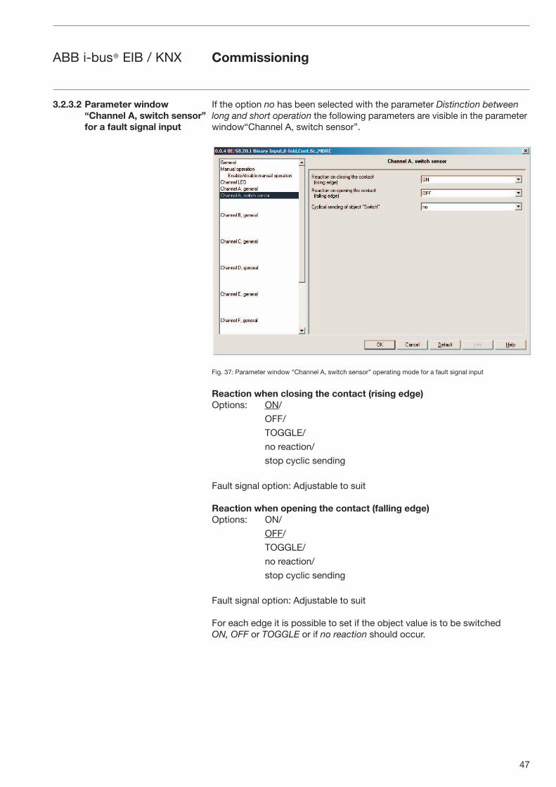
47
ABB i-bus® EIB / KNX Commissioning
If the option no has been selected with the parameter Distinction between long and short operation the following parameters are visible in the parameter window“Channel A, switch sensor”.
Fig. 37: Parameter window “Channel A, switch sensor” operating mode for a fault signal input
Reaction when closing the contact (rising edge)Options: ON/
OFF/
TOGGLE/
no reaction/
stop cyclic sending
Fault signal option: Adjustable to suit
Reaction when opening the contact (falling edge)Options: ON/
OFF/
TOGGLE/
no reaction/
stop cyclic sending
Fault signal option: Adjustable to suit
For each edge it is possible to set if the object value is to be switched ON, OFF or TOGGLE or if no reaction should occur.
3.2.3.2 Parameter window “Channel A, switch sensor” for a fault signal input
48
ABB i-bus® EIB / KNX Commissioning
If the option yes is selected in the parameter Cyclical sending of object “Switch” is selected, the following parameter appears.
Cyclical sending of object “Switch” Options: no/
if “Switch” = ON
if “Switch” = OFF/
always
Fault signal option: always
Option if “Switch” = ON = object value is sent cyclically
Option if “Switch” = OFF = object value is sent cyclically
Option always = communication object “Switch” is sent cyclically
What is cyclic sending?Cyclic sending enables the communication object “Switch” to send automatically at a fixed interval.
If cyclical sending is only carried out for a specific object value (ON or OFF), this condition refers to the value of the communication object. It is therefore possible in principle to start the cyclical sending by sending a value to the communication object “Switch”. As this reaction is generally unwanted, the “write” flag and “update” flag of the communication object have to be deleted in the setting to ensure that it cannot by changed via the bus. If however this functionality is required, the flags must be set accordingly.
When the “Switch” object changes and after bus voltage recovery (once the transmission delay has elapsed), the object value is sent immediately on the bus and the transmission cycle time restarts.
The next two parameters are only visible if the options ON, OFF or always in the cyclical sending of object “Switch” have been selected.
Telegram is repeated every ... (“sending cycle time”): time base Options: 1 s/10 s/1 min/10 min/1 h
Fault signal option: 1 s
The cycle time for sending describes the interval between two cyclically sent telegrams.Cycle time for sending = time base x factor.
Factor [1...255]Options: 1...30...255
Fault signal option: 30
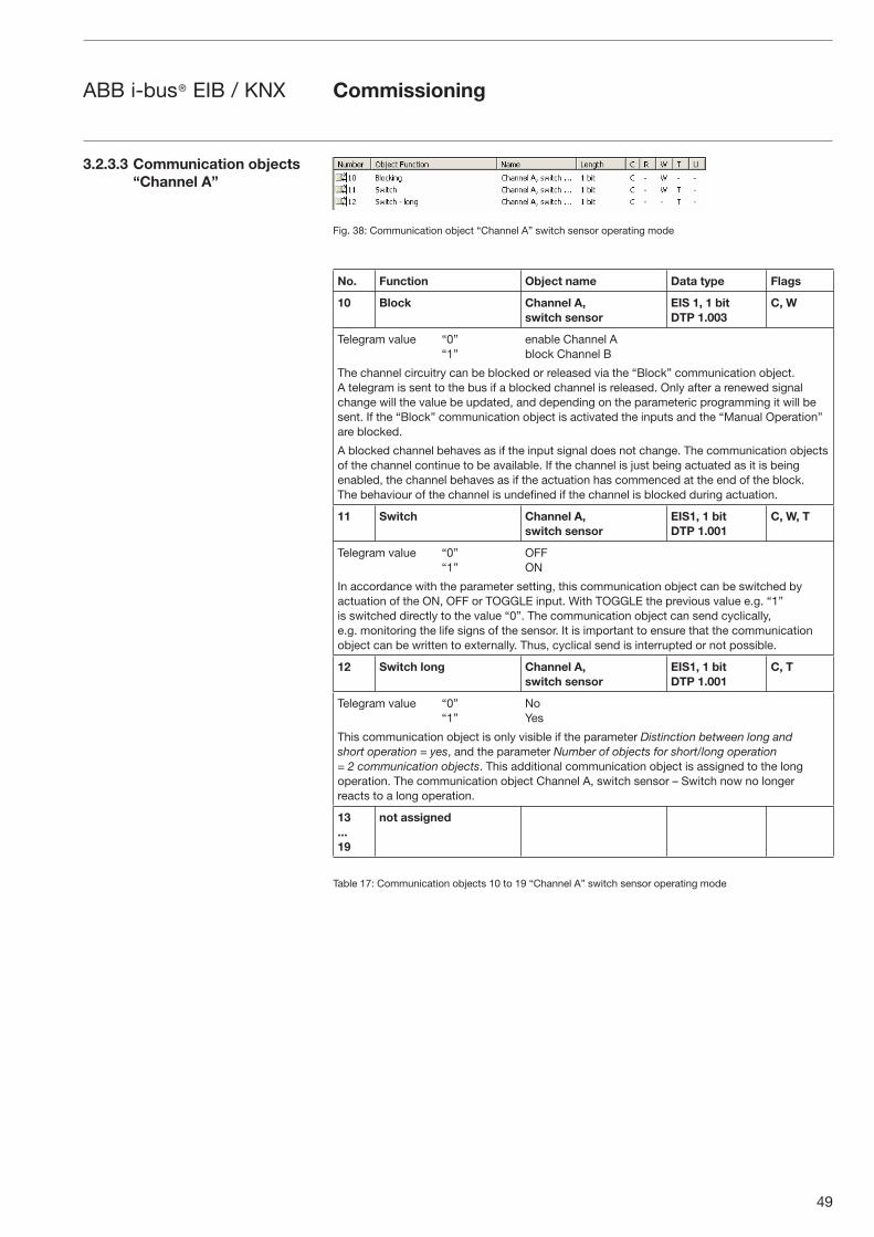
49
ABB i-bus® EIB / KNX Commissioning
Fig. 38: Communication object “Channel A” switch sensor operating mode
No. Function Object name Data type Flags
10 Block Channel A, switch sensor
EIS 1, 1 bitDTP 1.003
C, W
Telegram value “0” enable Channel A “1” block Channel B
The channel circuitry can be blocked or released via the “Block” communication object. A telegram is sent to the bus if a blocked channel is released. Only after a renewed signal change will the value be updated, and depending on the parameteric programming it will be sent. If the “Block” communication object is activated the inputs and the “Manual Operation” are blocked.
A blocked channel behaves as if the input signal does not change. The communication objects of the channel continue to be available. If the channel is just being actuated as it is being enabled, the channel behaves as if the actuation has commenced at the end of the block. The behaviour of the channel is undefined if the channel is blocked during actuation.
11 Switch Channel A, switch sensor
EIS1, 1 bitDTP 1.001
C, W, T
Telegram value “0” OFF “1” ON
In accordance with the parameter setting, this communication object can be switched by actuation of the ON, OFF or TOGGLE input. With TOGGLE the previous value e.g. “1” is switched directly to the value “0”. The communication object can send cyclically, e.g. monitoring the life signs of the sensor. It is important to ensure that the communication object can be written to externally. Thus, cyclical send is interrupted or not possible.
12 Switch long Channel A,switch sensor
EIS1, 1 bitDTP 1.001
C, T
Telegram value “0” No “1” Yes
This communication object is only visible if the parameter Distinction between long and short operation = yes, and the parameter Number of objects for short/long operation = 2 communication objects. This additional communication object is assigned to the long operation. The communication object Channel A, switch sensor – Switch now no longer reacts to a long operation.
13...19
not assigned
Table 17: Communication objects 10 to 19 “Channel A” switch sensor operating mode
3.2.3.3 Communication objects “Channel A”
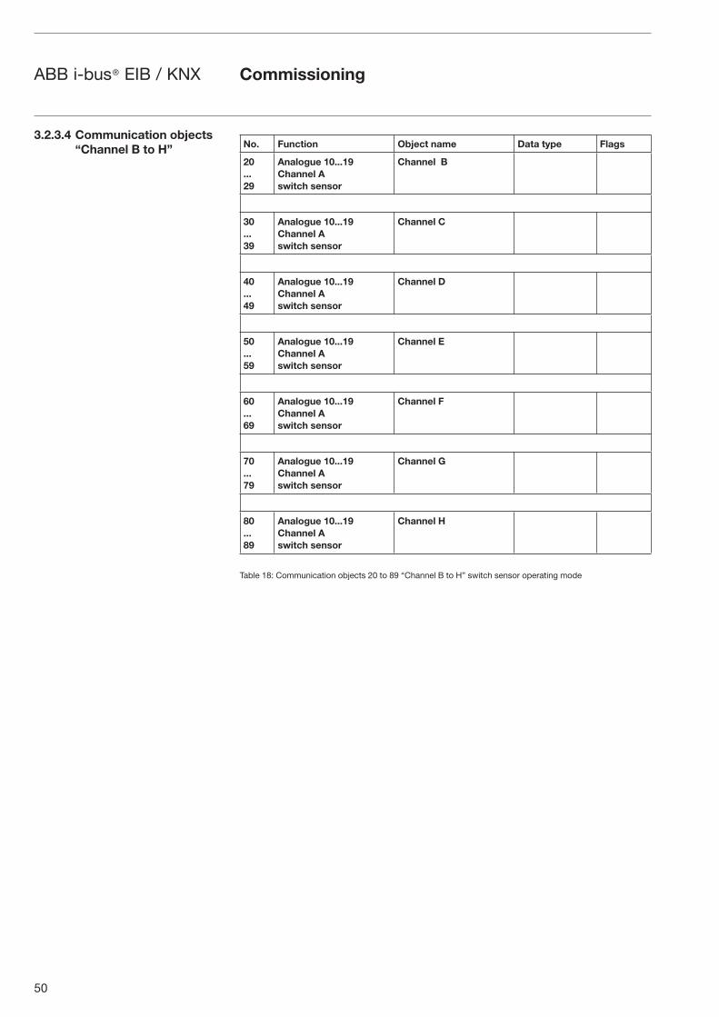
50
ABB i-bus® EIB / KNX Commissioning
No. Function Object name Data type Flags
20...29
Analogue 10...19 Channel A switch sensor
Channel B
30...39
Analogue 10...19 Channel A switch sensor
Channel C
40...49
Analogue 10...19 Channel A switch sensor
Channel D
50...59
Analogue 10...19 Channel A switch sensor
Channel E
60...69
Analogue 10...19 Channel A switch sensor
Channel F
70...79
Analogue 10...19 Channel A switch sensor
Channel G
80...89
Analogue 10...19 Channel A switch sensor
Channel H
Table 18: Communication objects 20 to 89 “Channel B to H” switch sensor operating mode
3.2.3.4 Communication objects “Channel B to H”
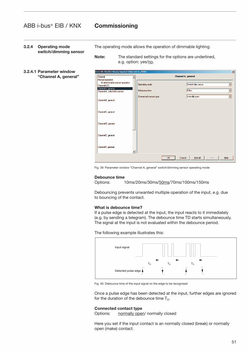
51
ABB i-bus® EIB / KNX Commissioning
The operating mode allows the operation of dimmable lighting.
Note: The standard settings for the options are underlined, e.g. option: yes/no.
Fig. 39: Parameter window “Channel A, general” switch/dimming sensor operating mode
Debounce timeOptions: 10ms/20ms/30ms/50ms/70ms/100ms/150ms
Debouncing prevents unwanted multiple operation of the input, e.g. due to bouncing of the contact.
What is debounce time?If a pulse edge is detected at the input, the input reacts to it immediately (e.g. by sending a telegram). The debounce time TD starts simultaneously. The signal at the input is not evaluated within the debounce period.
The following example illustrates this:
Fig. 40: Debounce time of the input signal on the edge to be recognised
Once a pulse edge has been detected at the input, further edges are ignored for the duration of the debounce time TD.
Connected contact typeOptions: normally open/ normally closed
Here you set if the input contact is an normally closed (break) or normally open (make) contact.
3.2.4 Operating mode switch/dimming sensor
3.2.4.1 Parameter window“Channel A, general”
-� -� -�
��1"' #.(��&
�)')+')/ 1"&#) )/()
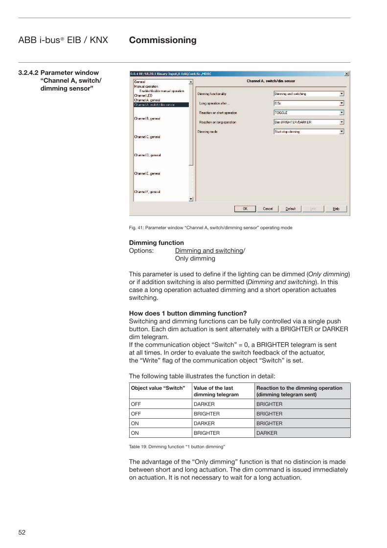
52
ABB i-bus® EIB / KNX Commissioning
Fig. 41: Parameter window “Channel A, switch/dimming sensor” operating mode
Dimming functionOptions: Dimming and switching/ Only dimming
This parameter is used to define if the lighting can be dimmed (Only dimming) or if addition switching is also permitted (Dimming and switching). In this case a long operation actuated dimming and a short operation actuates switching.
How does 1 button dimming function?Switching and dimming functions can be fully controlled via a single push button. Each dim actuation is sent alternately with a BRIGHTER or DARKER dim telegram.If the communication object “Switch” = 0, a BRIGHTER telegram is sent at all times. In order to evaluate the switch feedback of the actuator, the “Write” flag of the communication object “Switch” is set.
The following table illustrates the function in detail:
Object value “Switch” Value of the last dimming telegram
Reaction to the dimming operation(dimming telegram sent)
OFF DARKER BRIGHTER
OFF BRIGHTER BRIGHTER
ON DARKER BRIGHTER
ON BRIGHTER DARKER
Table 19: Dimming function “1 button dimming”
The advantage of the “Only dimming” function is that no distincion is made between short and long actuation. The dim command is issued immediately on actuation. It is not necessary to wait for a long actuation.
3.2.4.2 Parameter window “Channel A, switch/dimming sensor”
53
ABB i-bus® EIB / KNX Commissioning
How does 2 button dimming function?If “2 button dimming” is required, the function of the individual button must be set (e.g. “ON” or “Dim BRIGHTER”) with the parameters “Reaction to long or short operation”.
The user thus has complete freedom to choose which push buttons are combined with one another in order to dim a group of luminaries, or which function the individual push button has in this case.
Furthermore, 2 button dimming requires 2 channels, e.g. Channel A with short operation for switch on and long operation for dim brighter. Channel B with short operation for switch off and long operation for dim darker.
If the option Switching and dimming is selected with the Dimming functionality, the parameters long operation,..., Reaction on short... and Reaction on long... are visible in the parameter window “Channel A, switch/dimming sensor”.
Long operation after...Options: 0.3s/0.4s/0.5s/0.6s/0.8s/1 s/1.2s/1.5s/2s/3s/4s/
5s/6s/7s/8s/9s/10s
Defines the period TL after which an operation is interpreted as “long”.
“Reaction on short operation”Options: ON/
OFF/
TOGGLE/
no reaction
A short operation changes the value of the communication object “Telegram switch”. This parameter sets if the communication object “Telegram switch” TOGGLEs with short operation (typically: 1 button dimming) or only switches ON or OFF (typically: 2 button dimming).
“Reaction on long operation”Options: Dim BRIGHTER/
Dim DARKER/
Dim BRIGHTER/DARKER
A long operation changes the value of the communication object “Telegram Dimming”. With this parameter you determine if the communication object “Dimming” sends a BRIGHTER or DARKER telegram with long operation. With 1 button dimming the parameter “Dim BRIGHTER/DARKER” must be set. In this case the dim command which is the opposite to the last dim command is set.
54
ABB i-bus® EIB / KNX
The following parameters are visible in the parameter window if the option Only dimming is selected in the Dimming function instead of Reaction on short operation and Reaction on long operation.
Reaction on operationOptions: Dim BRIGHTER/
Dim DARKER/
Dim BRIGHTER/DARKER
With this parameter you determine if the communication object “Dimming” sends a BRIGHTER or DARKER telegram with long operation. With 1 button dimming the parameter “Dim BRIGHTER/DARKER” must be set. In this case the dim command opposite to the last dim command is set.
Dimming modeOptions: Start-stop-dimming/ Dimming steps
Normal Start-stop-dimming starts the dimming mode with a brighter or darker telegram and ends the dimming mode with a Start-stop-dimming telegram.
4-Bit dimming command:
Dec. Hex. Binary Dim command
0 0 0000 Stop
1 1 0001 100 % darker
8 8 1000 Stop
9 9 1001 100 % brighter
Table 20: 4 bit dim command for start-stop dimming
A table with further 4-Bit-Values can be found in the Appendix.
With Dimming steps the dimming telegram is sent cyclically during a long operation. The stop telegram ends the dimming process at the end of operation.
The next two parameters are only visible if the Dimming steps option is set in the Dimming mode parameter.
Brightness change on every sent telegramOptions: 100 %/50 %/25 %/12.5 %/6.25/3.13 %/1.56 %
This parameter is set to change the brightness (in percent) which is cyclically sent with every Dim telegram.
Cycle time for sending: Telegram is repeated every ...\...Options: 0.3s/0.4s/0.5s/0.6s/0.8s/1 s/1.2s/1.5s/2s/3s/4s/
5s/6s/7s/8s/9s/10s
The dimming telegram is sent cyclically during a long operation. The cycle time for sending corresponds with the time interval between two telegrams during cyclical sending.
Commissioning
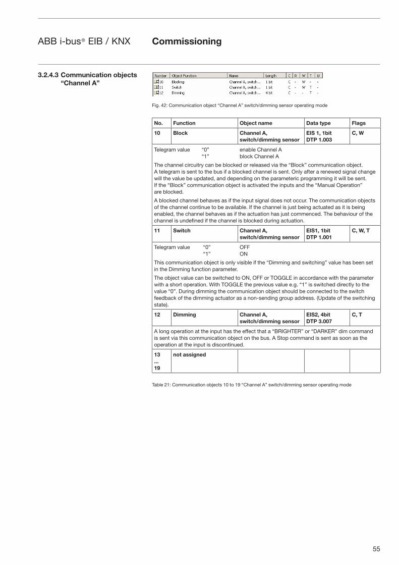
55
ABB i-bus® EIB / KNX
Fig. 42: Communication object “Channel A” switch/dimming sensor operating mode
No. Function Object name Data type Flags
10 Block Channel A, switch/dimming sensor
EIS 1, 1bitDTP 1.003
C, W
Telegram value “0” enable Channel A “1” block Channel A
The channel circuitry can be blocked or released via the “Block” communication object. A telegram is sent to the bus if a blocked channel is sent. Only after a renewed signal change will the value be updated, and depending on the parameteric programming it will be sent.If the “Block” communication object is activated the inputs and the “Manual Operation” are blocked.
A blocked channel behaves as if the input signal does not occur. The communication objects of the channel continue to be available. If the channel is just being actuated as it is being enabled, the channel behaves as if the actuation has just commenced. The behaviour of the channel is undefined if the channel is blocked during actuation.
11 Switch Channel A, switch/dimming sensor
EIS1, 1bitDTP 1.001
C, W, T
Telegram value “0” OFF “1” ON
This communication object is only visible if the “Dimming and switching” value has been set in the Dimming function parameter.
The object value can be switched to ON, OFF or TOGGLE in accordance with the parameter with a short operation. With TOGGLE the previous value e.g. “1” is switched directly to the value “0”. During dimming the communication object should be connected to the switch feedback of the dimming actuator as a non-sending group address. (Update of the switching state).
12 Dimming Channel A, switch/dimming sensor
EIS2, 4bitDTP 3.007
C, T
A long operation at the input has the effect that a “BRIGHTER” or “DARKER” dim command is sent via this communication object on the bus. A Stop command is sent as soon as the operation at the input is discontinued.
13...19
not assigned
Table 21: Communication objects 10 to 19 “Channel A” switch/dimming sensor operating mode
Commissioning
3.2.4.3 Communication objects “Channel A”
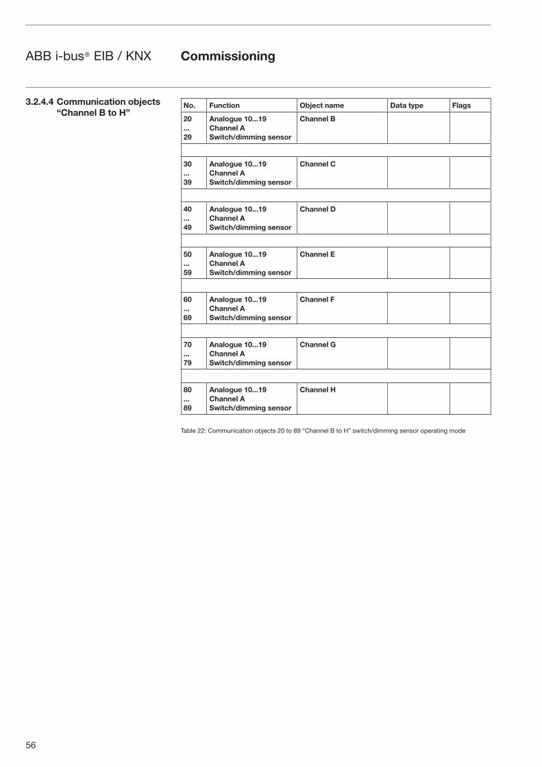
56
ABB i-bus® EIB / KNX
No. Function Object name Data type Flags
20...29
Analogue 10...19 Channel A Switch/dimming sensor
Channel B
30...39
Analogue 10...19 Channel A Switch/dimming sensor
Channel C
40...49
Analogue 10...19 Channel A Switch/dimming sensor
Channel D
50...59
Analogue 10...19 Channel A Switch/dimming sensor
Channel E
60...69
Analogue 10...19 Channel A Switch/dimming sensor
Channel F
70...79
Analogue 10...19 Channel A Switch/dimming sensor
Channel G
80...89
Analogue 10...19 Channel A Switch/dimming sensor
Channel H
Table 22: Communication objects 20 to 89 “Channel B to H” switch/dimming sensor operating mode
3.2.4.4 Communication objects “Channel B to H”
Commissioning
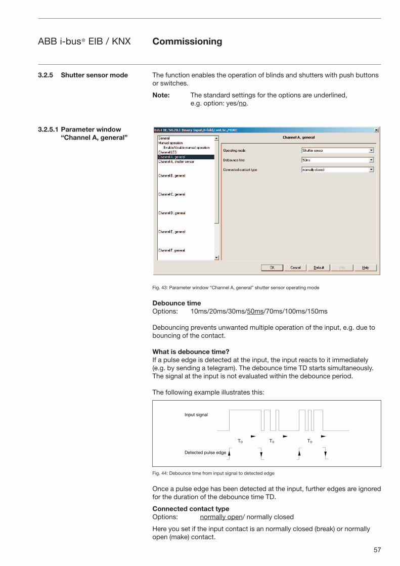
57
ABB i-bus® EIB / KNX
The function enables the operation of blinds and shutters with push buttons or switches.
Note: The standard settings for the options are underlined, e.g. option: yes/no.
Fig. 43: Parameter window “Channel A, general” shutter sensor operating mode
Debounce timeOptions: 10ms/20ms/30ms/50ms/70ms/100ms/150ms
Debouncing prevents unwanted multiple operation of the input, e.g. due to bouncing of the contact.
What is debounce time?If a pulse edge is detected at the input, the input reacts to it immediately (e.g. by sending a telegram). The debounce time TD starts simultaneously. The signal at the input is not evaluated within the debounce period.
The following example illustrates this:
Fig. 44: Debounce time from input signal to detected edge
Once a pulse edge has been detected at the input, further edges are ignored for the duration of the debounce time TD.
Connected contact typeOptions: normally open/ normally closed
Here you set if the input contact is an normally closed (break) or normally open (make) contact.
Commissioning
3.2.5 Shutter sensor mode
3.2.5.1 Parameter window“Channel A, general”
-� -� -�
��1"' #.(��&
�)')+')/ 1"&#) )/()
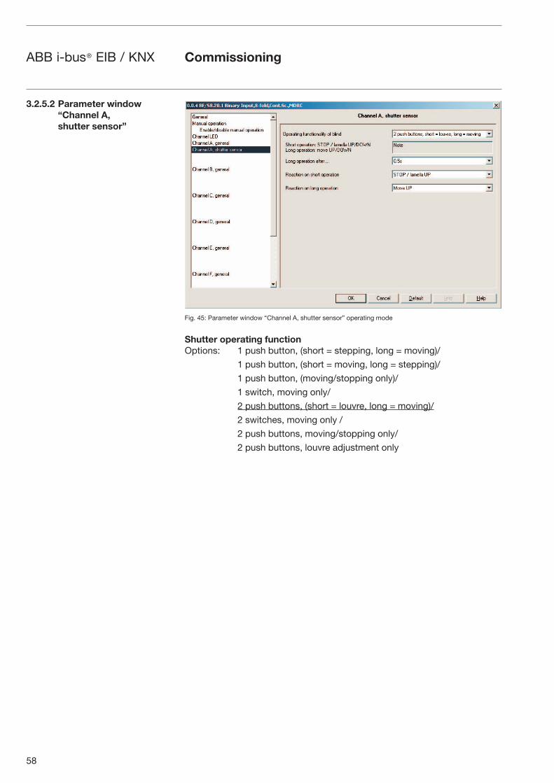
58
ABB i-bus® EIB / KNX Commissioning
3.2.5.2 Parameter window “Channel A, shutter sensor”
Fig. 45: Parameter window “Channel A, shutter sensor” operating mode
Shutter operating functionOptions: 1 push button, (short = stepping, long = moving)/
1 push button, (short = moving, long = stepping)/
1 push button, (moving/stopping only)/
1 switch, moving only/
2 push buttons, (short = louvre, long = moving)/
2 switches, moving only /
2 push buttons, moving/stopping only/
2 push buttons, louvre adjustment only
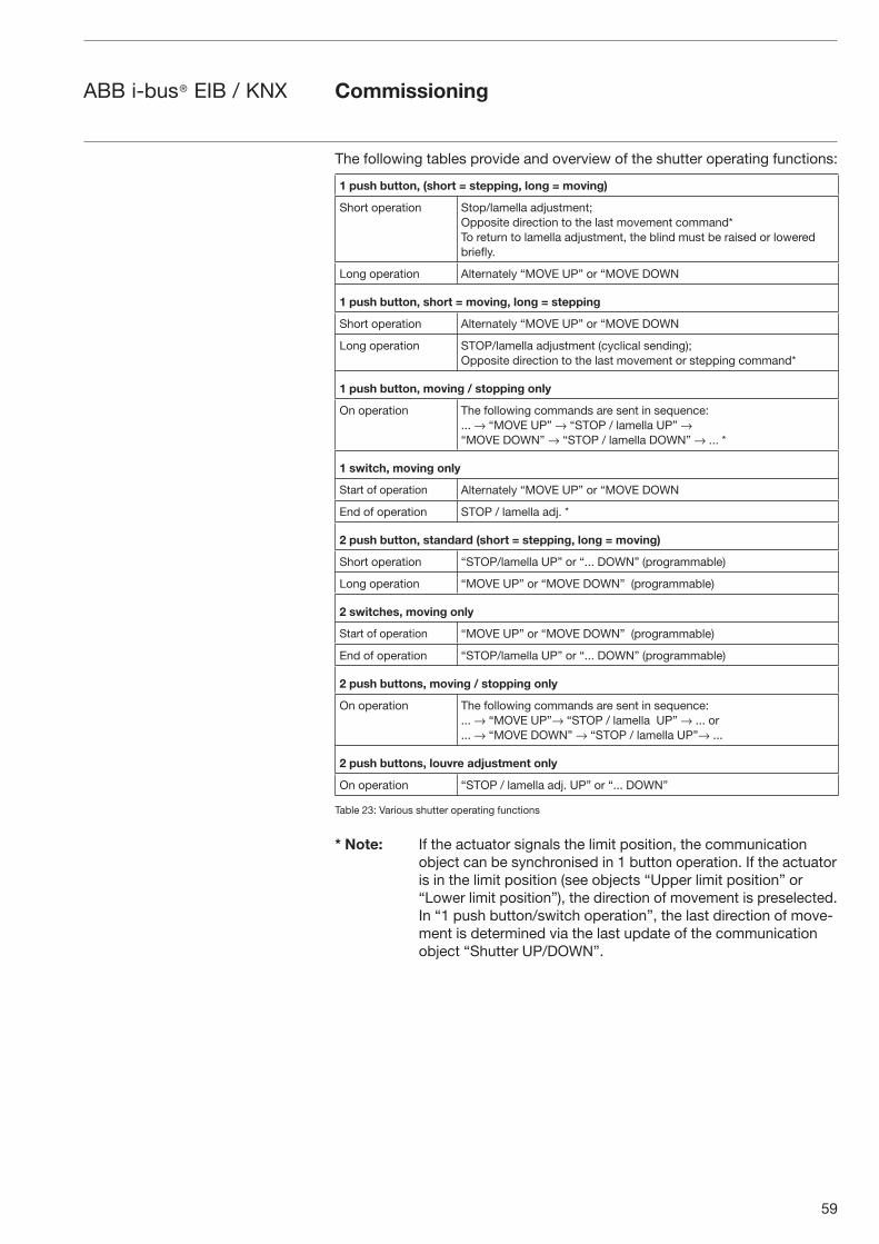
59
ABB i-bus® EIB / KNX
The following tables provide and overview of the shutter operating functions:
1 push button, (short = stepping, long = moving)
Short operation Stop/lamella adjustment;Opposite direction to the last movement command*To return to lamella adjustment, the blind must be raised or lowered briefly.
Long operation Alternately “MOVE UP” or “MOVE DOWN
1 push button, short = moving, long = stepping
Short operation Alternately “MOVE UP” or “MOVE DOWN
Long operation STOP/lamella adjustment (cyclical sending);Opposite direction to the last movement or stepping command*
1 push button, moving / stopping only
On operation The following commands are sent in sequence:... → “MOVE UP” → “STOP / lamella UP” →“MOVE DOWN” → “STOP / lamella DOWN” → ... *
1 switch, moving only
Start of operation Alternately “MOVE UP” or “MOVE DOWN
End of operation STOP / lamella adj. *
2 push button, standard (short = stepping, long = moving)
Short operation “STOP/lamella UP” or “... DOWN” (programmable)
Long operation “MOVE UP” or “MOVE DOWN” (programmable)
2 switches, moving only
Start of operation “MOVE UP” or “MOVE DOWN” (programmable)
End of operation “STOP/lamella UP” or “... DOWN” (programmable)
2 push buttons, moving / stopping only
On operation The following commands are sent in sequence:... → “MOVE UP”→ “STOP / lamella UP” → ... or... → “MOVE DOWN” → “STOP / lamella UP”→ ...
2 push buttons, louvre adjustment only
On operation “STOP / lamella adj. UP” or “... DOWN”
Table 23: Various shutter operating functions
* Note: If the actuator signals the limit position, the communication object can be synchronised in 1 button operation. If the actuator is in the limit position (see objects “Upper limit position” or “Lower limit position”), the direction of movement is preselected. In “1 push button/switch operation”, the last direction of move-ment is determined via the last update of the communication object “Shutter UP/DOWN”.
Commissioning
60
ABB i-bus® EIB / KNX Commissioning
Differing parameters appear depending on the selection you have made in the parameter Operating functionality of blind. All parameters are described in the following.
Long operation after...Options: 0.3s/0.4s/0.5s/0.6s/0.8s/1 s/1.2s/1.5s/2s/3s/4s/
5s/6s/7s/8s/9s/10s
Defines the period TL after which an operation is interpreted as “long”.
Telegram “STOP/lamella adj.” is repeated every...Options: 0.3s/0.4s/0.5s/0.6s/0.8s/1 s/1.2s/1.5s/2s/3s/4s/
5s/6s/7s/8s/9s/10s
The interval between two “lamella” telegrams is set here.
“Reaction on short operation”Options: STOP / lamella UP/
STOP / lamella DOWN
“Reaction on long operation”Options: Move UP/
Move DOWN
It can be set whether the input triggers commands for movement upwards (“UP”) or downwards (“DOWN”).
“Reaction on operation”Options: Move UP/ Move DOWN
It can be set whether the input triggers commands for movement upwards (“Move UP”) or downwards (“Move DOWN”).
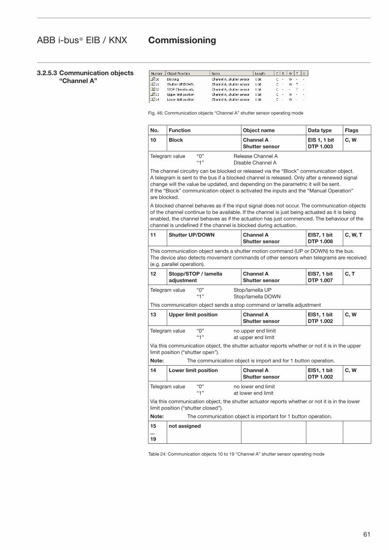
61
ABB i-bus® EIB / KNX Commissioning
Fig. 46: Communication objects “Channel A” shutter sensor operating mode
No. Function Object name Data type Flags
10 Block Channel AShutter sensor
EIS 1, 1 bit DTP 1.003
C, W
Telegram value “0” Release Channel A “1” Disable Channel A
The channel circuitry can be blocked or released via the “Block” communication object. A telegram is sent to the bus if a blocked channel is released. Only after a renewed signal change will the value be updated, and depending on the parametric it will be sent. If the “Block” communication object is activated the inputs and the “Manual Operation” are blocked.
A blocked channel behaves as if the input signal does not occur. The communication objects of the channel continue to be available. If the channel is just being actuated as it is being enabled, the channel behaves as if the actuation has just commenced. The behaviour of the channel is undefined if the channel is blocked during actuation.
11 Shutter UP/DOWN Channel AShutter sensor
EIS7, 1 bit DTP 1.008
C, W, T
This communication object sends a shutter motion command (UP or DOWN) to the bus.The device also detects movement commands of other sensors when telegrams are received(e.g. parallel operation).
12 Stopp/STOP / lamella adjustment
Channel AShutter sensor
EIS7, 1 bit DTP 1.007
C, T
Telegram value “0” Stop/lamella UP “1” Stop/lamella DOWN
This communication object sends a stop command or lamella adjustment
13 Upper limit position Channel AShutter sensor
EIS1, 1 bit DTP 1.002
C, W
Telegram value “0” no upper end limit “1” at upper end limit
Via this communication object, the shutter actuator reports whether or not it is in the upper limit position (“shutter open”).
Note: The communication object is import and for 1 button operation.
14 Lower limit position Channel AShutter sensor
EIS1, 1 bit DTP 1.002
C, W
Telegram value “0” no lower end limit “1” at lower end limit
Via this communication object, the shutter actuator reports whether or not it is in the lower limit position (“shutter closed”).
Note: The communication object is important for 1 button operation.
15...19
not assigned
Table 24: Communication objects 10 to 19 “Channel A” shutter sensor operating mode
3.2.5.3 Communication objects “Channel A”
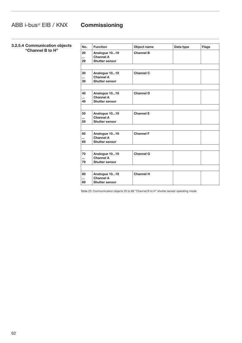
62
ABB i-bus® EIB / KNX Commissioning
No. Function Object name Data type Flags
20...29
Analogue 10...19 Channel A Shutter sensor
Channel B
30...39
Analogue 10...19 Channel A Shutter sensor
Channel C
40...49
Analogue 10...19 Channel A Shutter sensor
Channel D
50...59
Analogue 10...19 Channel A Shutter sensor
Channel E
60...69
Analogue 10...19 Channel A Shutter sensor
Channel F
70...79
Analogue 10...19 Channel A Shutter sensor
Channel G
80...89
Analogue 10...19 Channel A Shutter sensor
Channel H
Table 25: Communication objects 20 to 89 “Channel B to H” shutter sensor operating mode
3.2.5.4 Communication objects “Channel B to H”
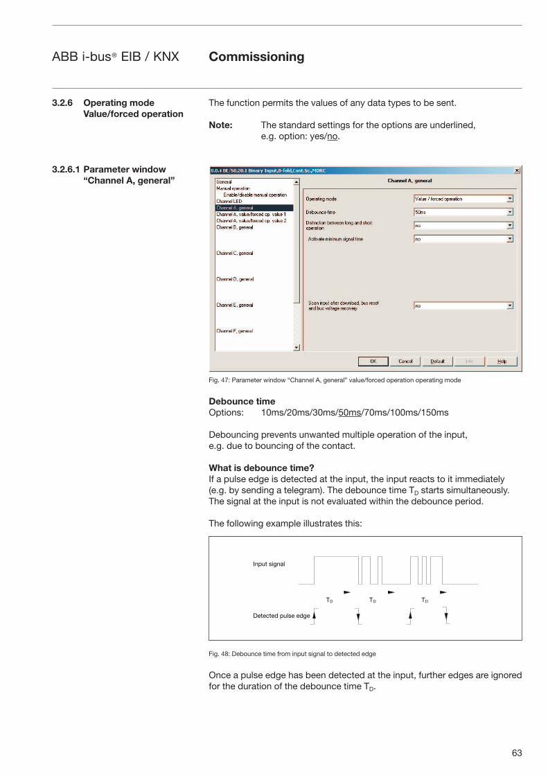
63
ABB i-bus® EIB / KNX Commissioning
The function permits the values of any data types to be sent.
Note: The standard settings for the options are underlined, e.g. option: yes/no.
Fig. 47: Parameter window “Channel A, general” value/forced operation operating mode
Debounce timeOptions: 10ms/20ms/30ms/50ms/70ms/100ms/150ms
Debouncing prevents unwanted multiple operation of the input, e.g. due to bouncing of the contact.
What is debounce time?If a pulse edge is detected at the input, the input reacts to it immediately (e.g. by sending a telegram). The debounce time TD starts simultaneously. The signal at the input is not evaluated within the debounce period.
The following example illustrates this:
Fig. 48: Debounce time from input signal to detected edge
Once a pulse edge has been detected at the input, further edges are ignored for the duration of the debounce time TD.
3.2.6 Operating mode Value/forced operation
3.2.6.1 Parameter window “Channel A, general”
-� -� -�
��1"' #.(��&
�)')+')/ 1"&#) )/()
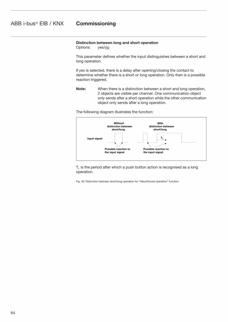
64
ABB i-bus® EIB / KNX Commissioning
Distinction between long and short operation Options: yes/no
This parameter defines whether the input distinguishes between a short and long operation.
If yes is selected, there is a delay after opening/closing the contact to determine whether there is a short or long operation. Only then is a possible reaction triggered.
Note: When there is a distinction between a short and long operation, 2 objects are visible per channel. One communication object only sends after a short operation while the other communication object only sends after a long operation.
The following diagram illustrates the function:
TL is the period after which a push button action is recognised as a long operation.
Fig. 49: Distinction between short/long operation for “Value/forced operation” function
��� ����������� � �������
�� ���� ��
������������ � �������
�� ���� ��
������� ������
� ������ ������ � � ��� ����� ������
� ������ ������ � � ��� ����� ������
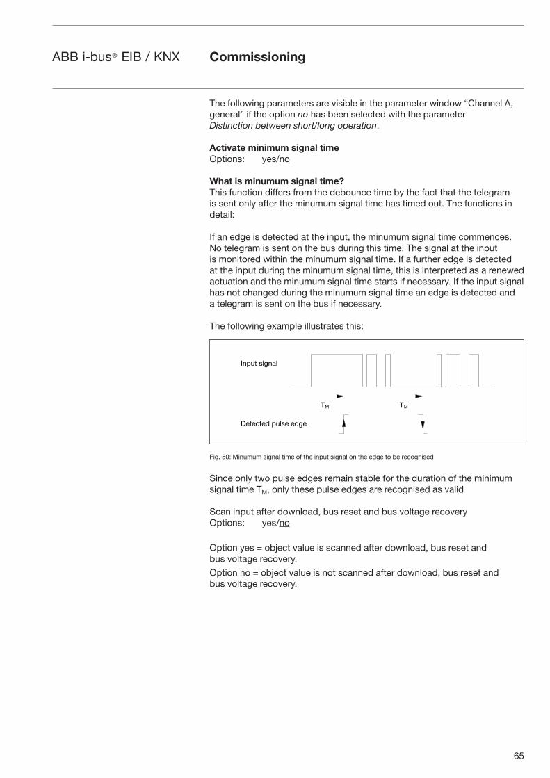
65
ABB i-bus® EIB / KNX Commissioning
The following parameters are visible in the parameter window “Channel A, general” if the option no has been selected with the parameter Distinction between short/long operation.
Activate minimum signal time Options: yes/no
What is minumum signal time?This function differs from the debounce time by the fact that the telegram is sent only after the minumum signal time has timed out. The functions in detail:
If an edge is detected at the input, the minumum signal time commences. No telegram is sent on the bus during this time. The signal at the input is monitored within the minumum signal time. If a further edge is detected at the input during the minumum signal time, this is interpreted as a renewed actuation and the minumum signal time starts if necessary. If the input signal has not changed during the minumum signal time an edge is detected and a telegram is sent on the bus if necessary.
The following example illustrates this:
Fig. 50: Minumum signal time of the input signal on the edge to be recognised
Since only two pulse edges remain stable for the duration of the minimum signal time TM, only these pulse edges are recognised as valid
Scan input after download, bus reset and bus voltage recovery Options: yes/no
Option yes = object value is scanned after download, bus reset and bus voltage recovery.
Option no = object value is not scanned after download, bus reset and bus voltage recovery.
- -
��1"' #.(��&
�)')+')/ 1"&#) )/()
66
ABB i-bus® EIB / KNX Commissioning
If the option yes is selected in the parameter Scan input after download, bus reset and bus voltage recovery after download, the following parameter becomes visible.
Inactive wait state after bus voltage recovery [0...30,000s, 0=inactive] Options: 0...30,000
This parameter is used to set the waiting time after bus voltage recovery. The state at the input terminals is detected after this time has timed out. The input reacts as if the state at the input terminals has just been set/not set.
Note: The inactive wait state does not add to the adjustable delay time for sending. It can be set in the “General” parameter window.
If the option yes is selected with the parameter Activate minimum signal time, the following parameters are visible.
After rising edge: base Options: 100ms/1s/10s/1 min/10min/1 h
Factor [1...255]Options: 1...10...255
After falling edge: time baseOptions: 100ms/1s/10s/1 min/10min/1 h
Factor [1...255]Options: 1...10...255
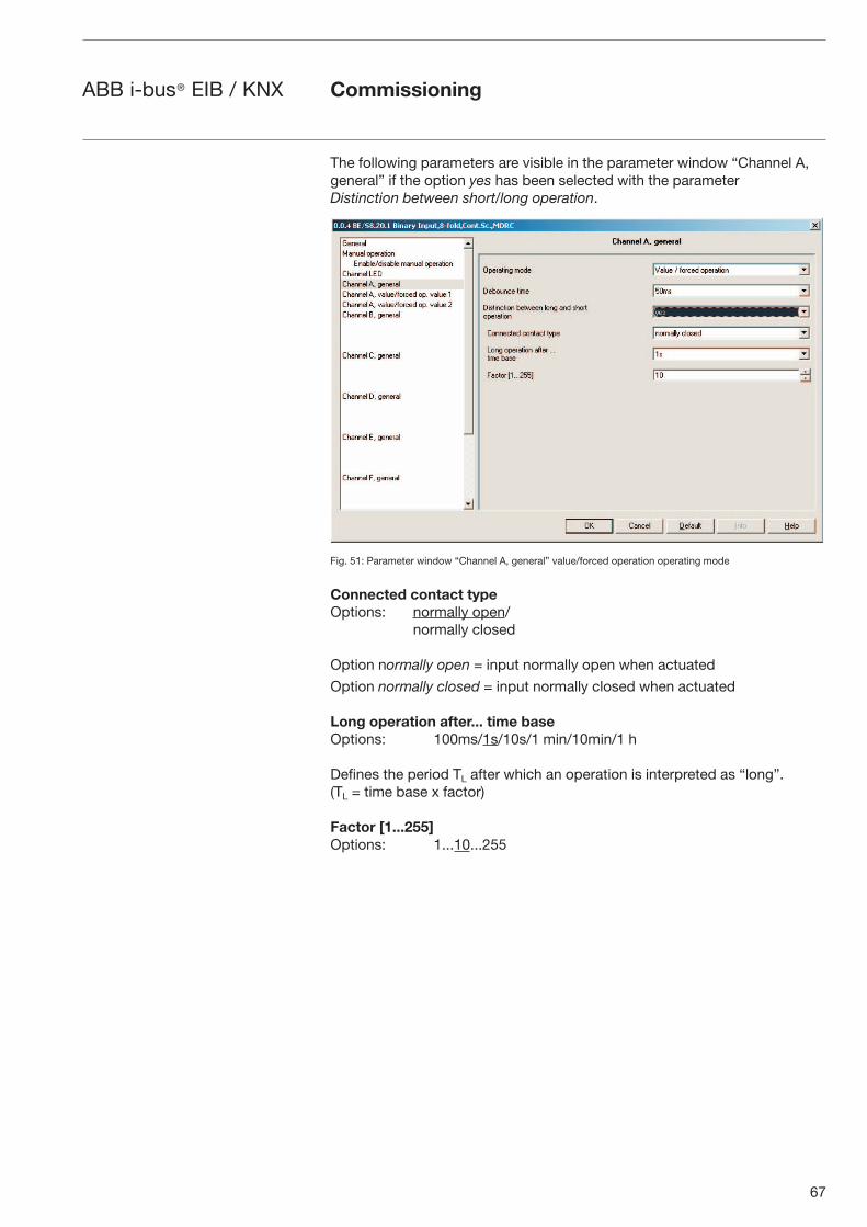
67
ABB i-bus® EIB / KNX
The following parameters are visible in the parameter window “Channel A, general” if the option yes has been selected with the parameter Distinction between short/long operation.
Fig. 51: Parameter window “Channel A, general” value/forced operation operating mode
Connected contact typeOptions: normally open/ normally closed
Option normally open = input normally open when actuated
Option normally closed = input normally closed when actuated
Long operation after... time baseOptions: 100ms/1s/10s/1 min/10min/1 h
Defines the period TL after which an operation is interpreted as “long”. (TL = time base x factor)
Factor [1...255]Options: 1...10...255
Commissioning
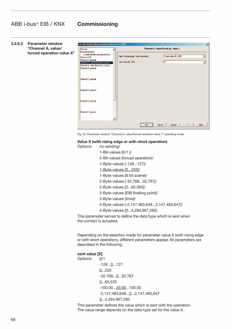
68
ABB i-bus® EIB / KNX Commissioning
Fig. 52: Parameter window “Channel A, value/forced operation value 1” operating mode
Value X (with rising edge or with short operation)Options: no sending/
1-Bit-values [0/1 ]/
2-Bit-values (forced operation)/
1-Byte-values [-128...127]/
1-Byte-values [0...255]/
1-Byte-values (8 bit scene)/
2-Byte-values [-32,768...32,767]/
2-Byte-values [0...65,565]/
2-Byte-values [EIB floating point]/
3-Byte-values [time]/
4-Byte-values [-2,147,483,648...2,147,483,647]/
4-Byte-values [0...4,294,967,295]
This parameter serves to define the data type which is sent when the contact is actuated.
Depending on the selection made for parameter value X (with rising edge or with short operation), different parameters appear. All parameters are described in the following.
sent value [X]Options: 0/1
-128...0...127
0...255
-32.768...0...32.767
0...65,535
-100.00...20.00...100.00
-2,147,483,648...0...2,147,483,647
0...4,294,967,295
This parameter defines the value which is sent with the operation. The value range depends on the data type set for the value X.
3.2.6.2 Parameter window “Channel A, value/forced operation value X”
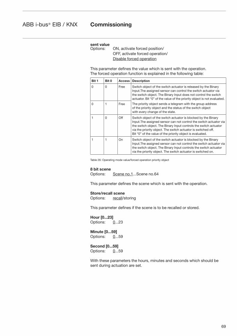
69
ABB i-bus® EIB / KNX
sent valueOptions: ON, activate forced position/ OFF, activate forced operation/ Disable forced operation
This parameter defines the value which is sent with the operation.The forced operation function is explained in the following table:
Bit 1 Bit 0 Access Description
0 0 Free Switch object of the switch actuator is released by the Binary Input.The assigned sensor can control the switch actuator via the switch object. The Binary Input does not control the switch actuator. Bit “0” of the value of the priority object is not evaluated.
The priority object sends a telegram with the group address of the priority object and the status of the switch object with every change of the state.
0 1 Free
1 0 Off Switch object of the switch actuator is blocked by the Binary Input.The assigned sensor can not control the switch actuator via the switch object. The Binary Input controls the switch actuator via the priority object. The switch actuator is switched off.Bit “0” of the value of the priority object is evaluated.
1 1 On Switch object of the switch actuator is blocked by the Binary Input.The assigned sensor can not control the switch actuator via the switch object. The Binary Input controls the switch actuator via the priority object. The switch actuator is switched on.
Table 26: Operating mode value/forced operation priority object
8 bit sceneOptions: Scene no.1...Scene no.64
This parameter defines the scene which is sent with the operation.
Store/recall scene Options: recall/storing
This parameter defines if the scene is to be recalled or stored.
Hour [0...23] Options: 0...23
Minute [0...59] Options: 0...59
Second [0...59] Options: 0...59
With these parameters the hours, minutes and seconds which should be sent during actuation are set.
Commissioning
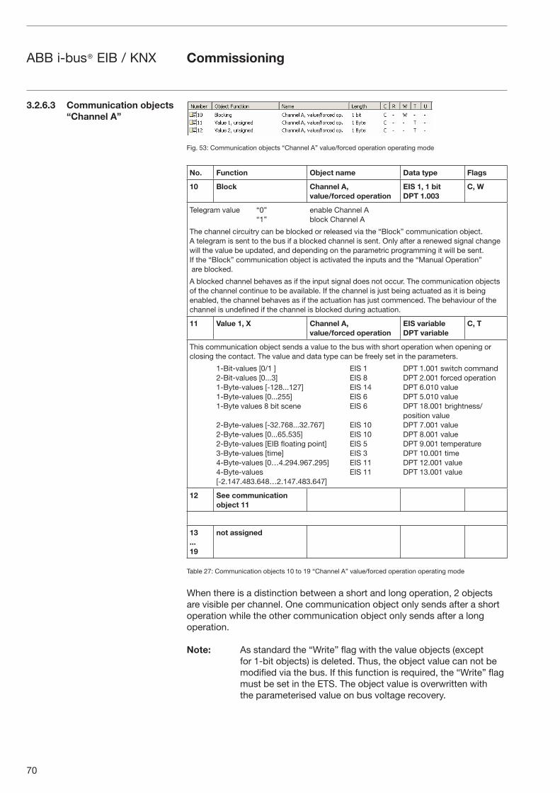
70
ABB i-bus® EIB / KNX
Fig. 53: Communication objects “Channel A” value/forced operation operating mode
No. Function Object name Data type Flags
10 Block Channel A, value/forced operation
EIS 1, 1 bitDPT 1.003
C, W
Telegram value “0” enable Channel A “1” block Channel A
The channel circuitry can be blocked or released via the “Block” communication object. A telegram is sent to the bus if a blocked channel is sent. Only after a renewed signal change will the value be updated, and depending on the parametric programming it will be sent. If the “Block” communication object is activated the inputs and the “Manual Operation” are blocked.
A blocked channel behaves as if the input signal does not occur. The communication objects of the channel continue to be available. If the channel is just being actuated as it is being enabled, the channel behaves as if the actuation has just commenced. The behaviour of the channel is undefined if the channel is blocked during actuation.
11 Value 1, X Channel A, value/forced operation
EIS variableDPT variable
C, T
This communication object sends a value to the bus with short operation when opening or closing the contact. The value and data type can be freely set in the parameters.
1-Bit-values [0/1 ] EIS 1 DPT 1.001 switch command 2-Bit-values [0...3] EIS 8 DPT 2.001 forced operation 1-Byte-values [-128...127] EIS 14 DPT 6.010 value 1-Byte-values [0...255] EIS 6 DPT 5.010 value 1-Byte values 8 bit scene EIS 6 DPT 18.001 brightness/
position value 2-Byte-values [-32.768...32.767] EIS 10 DPT 7.001 value 2-Byte-values [0...65.535] EIS 10 DPT 8.001 value 2-Byte-values [EIB floating point] EIS 5 DPT 9.001 temperature 3-Byte-values [time] EIS 3 DPT 10.001 time 4-Byte-values [0…4.294.967.295] EIS 11 DPT 12.001 value 4-Byte-values EIS 11 DPT 13.001 value [-2.147.483.648…2.147.483.647]
12 See communicationobject 11
13...19
not assigned
Table 27: Communication objects 10 to 19 “Channel A” value/forced operation operating mode
When there is a distinction between a short and long operation, 2 objects are visible per channel. One communication object only sends after a short operation while the other communication object only sends after a long operation.
Note: As standard the “Write” flag with the value objects (except for 1-bit objects) is deleted. Thus, the object value can not be modified via the bus. If this function is required, the “Write” flag must be set in the ETS. The object value is overwritten with the parameterised value on bus voltage recovery.
3.2.6.3 Communication objects “Channel A”
Commissioning
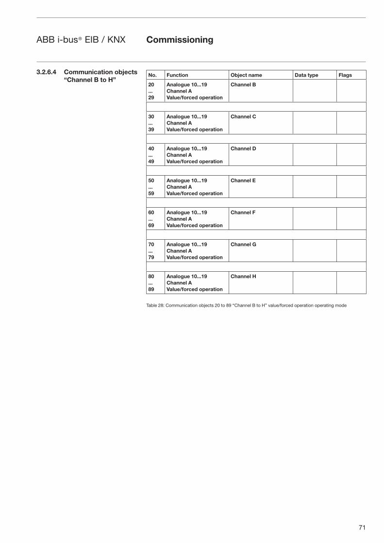
71
ABB i-bus® EIB / KNX
No. Function Object name Data type Flags
20...29
Analogue 10...19 Channel A Value/forced operation
Channel B
30...39
Analogue 10...19 Channel A Value/forced operation
Channel C
40...49
Analogue 10...19 Channel A Value/forced operation
Channel D
50...59
Analogue 10...19 Channel A Value/forced operation
Channel E
60...69
Analogue 10...19 Channel A Value/forced operation
Channel F
70...79
Analogue 10...19 Channel A Value/forced operation
Channel G
80...89
Analogue 10...19 Channel A Value/forced operation
Channel H
Table 28: Communication objects 20 to 89 “Channel B to H” value/forced operation operating mode
Commissioning
3.2.6.4 Communication objects “Channel B to H”
72
ABB i-bus® EIB / KNX
This operating mode enables the recall and saving of states of multipleoperating mode actuator groups. An actuator group comprises several communication objects that are linked with the same group address. It can consist of e.g. switch actuators (1-bit values) or dimming actuators (1-byte values).
Note: The standard settings for the options are underlined, e.g. option: yes/no
Store sceneThe scene is simply adapted by saving the current actuator values.
The communication object “Store scene indication” sends the value “1”. The values of the affected communication objects are scanned via the bus. The scene is only stored when all scans are answered. The communication object “Store scene indication” sends the value “0”.
3.2.7 Control scene operating mode
Commissioning
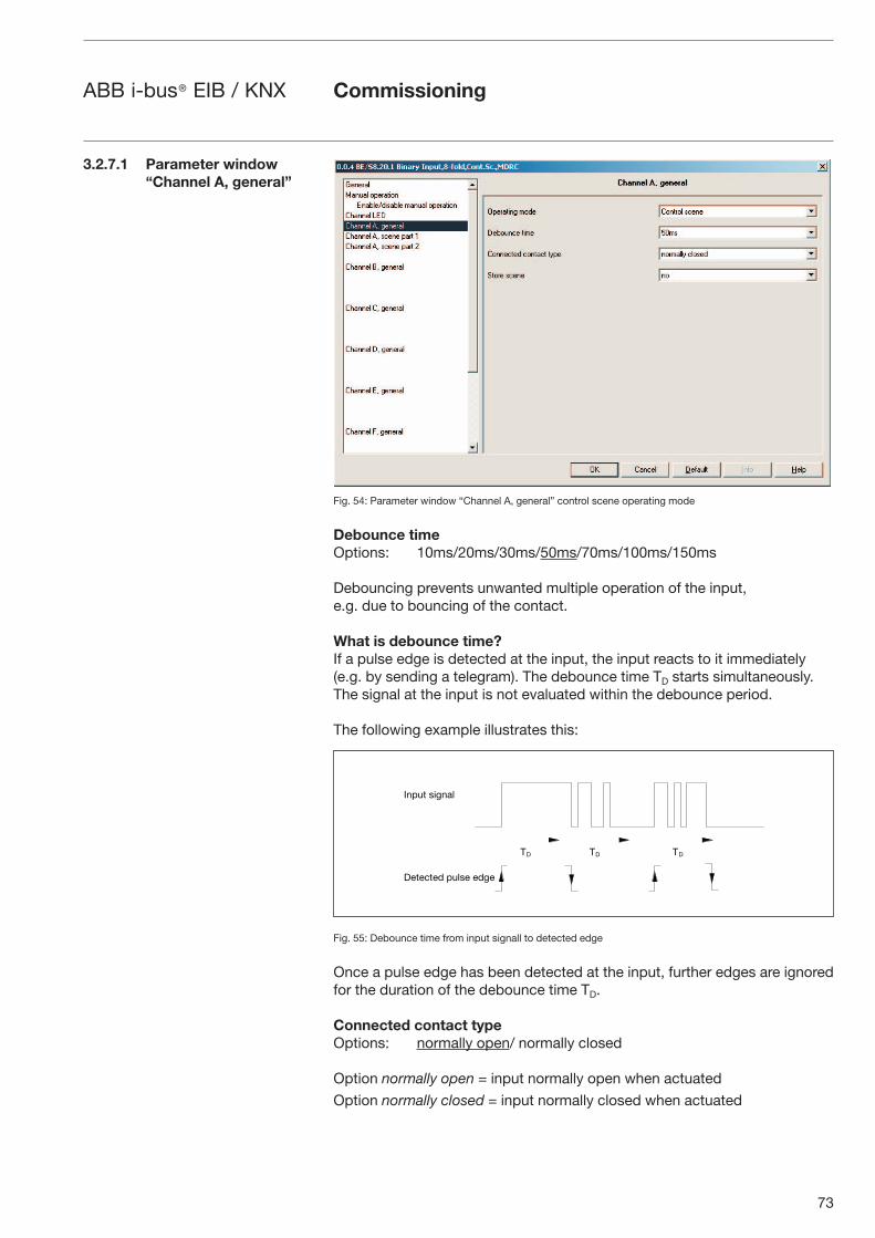
73
ABB i-bus® EIB / KNX
Fig. 54: Parameter window “Channel A, general” control scene operating mode
Debounce timeOptions: 10ms/20ms/30ms/50ms/70ms/100ms/150ms
Debouncing prevents unwanted multiple operation of the input, e.g. due to bouncing of the contact.
What is debounce time?If a pulse edge is detected at the input, the input reacts to it immediately (e.g. by sending a telegram). The debounce time TD starts simultaneously. The signal at the input is not evaluated within the debounce period.
The following example illustrates this:
Fig. 55: Debounce time from input signall to detected edge
Once a pulse edge has been detected at the input, further edges are ignored for the duration of the debounce time TD.
Connected contact typeOptions: normally open/ normally closed
Option normally open = input normally open when actuated
Option normally closed = input normally closed when actuated
Commissioning
3.2.7.1 Parameter window“Channel A, general”
�� �� ��
����� ����
� � �� � ���� �
74
ABB i-bus® EIB / KNX
Store sceneOptions: no/
on long operation/
object value = 1 /
on long operation and object value = 1
This parameter determines the manner in which storing of the current scene is initiated and which function the “Store scene” communication object has. This is dependent on the scene control.
Option on long operation =The scene is stored as soon as an operation is detected and ends as soon as the button is released.
Option object value = 1 =If the “Store scene” communication object receives the value “1”, storing is activated. If the “Store scene” communication object receives the value “0”, storing is ended.
Option on long operation and object value = 1=As soon as a long operation is detected and the “Enable storing” communication object has the value “1”, storing is activated. Storing is ended as soon as the “Enable storing” communication object has the value “0” or the button is released.
Note: If storing has not been successful when ending, the “Store scene indication” communication object sends the value “0”.
If the object on long operation and on long operation and object value = 1 has been selected in the Store scene the following parameter appears.
Long operation after...Options: 0.3s/0.4s/0.5s/0.6s/0.8s/1 s/1.2s/1.5s/2s/3s/4s/
5s/6s/7s/8s/9s/10s
Defines the period TL after which an operation is interpreted as “long”.
Commissioning
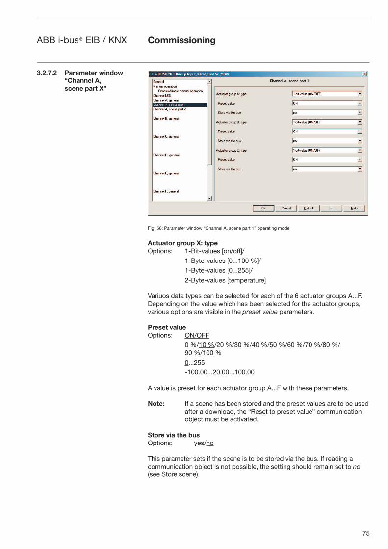
75
ABB i-bus® EIB / KNX
Fig. 56: Parameter window “Channel A, scene part 1” operating mode
Actuator group X: typeOptions: 1-Bit-values [on/off]/
1-Byte-values [0...100 %]/
1-Byte-values [0...255]/
2-Byte-values [temperature]
Variuos data types can be selected for each of the 6 actuator groups A...F. Depending on the value which has been selected for the actuator groups, various options are visible in the preset value parameters.
Preset valueOptions: ON/OFF
0 %/10 %/20 %/30 %/40 %/50 %/60 %/70 %/80 %/90 %/100 %
0...255
-100.00...20.00...100.00
A value is preset for each actuator group A...F with these parameters.
Note: If a scene has been stored and the preset values are to be used after a download, the “Reset to preset value” communication object must be activated.
Store via the busOptions: yes/no
This parameter sets if the scene is to be stored via the bus. If reading a communication object is not possible, the setting should remain set to no (see Store scene).
Commissioning
3.2.7.2 Parameter window “Channel A, scene part X”
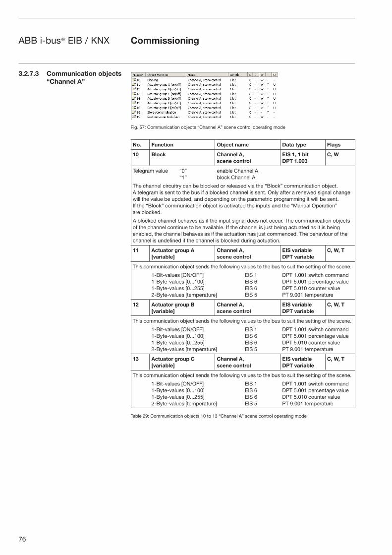
76
ABB i-bus® EIB / KNX
Fig. 57: Communication objects “Channel A” scene control operating mode
No. Function Object name Data type Flags
10 Block Channel A, scene control
EIS 1, 1 bitDPT 1.003
C, W
Telegram value “0” enable Channel A “1” block Channel A
The channel circuitry can be blocked or released via the “Block” communication object. A telegram is sent to the bus if a blocked channel is sent. Only after a renewed signal change will the value be updated, and depending on the parametric programming it will be sent. If the “Block” communication object is activated the inputs and the “Manual Operation” are blocked.
A blocked channel behaves as if the input signal does not occur. The communication objects of the channel continue to be available. If the channel is just being actuated as it is being enabled, the channel behaves as if the actuation has just commenced. The behaviour of the channel is undefined if the channel is blocked during actuation.
11 Actuator group A[variable]
Channel A, scene control
EIS variableDPT variable
C, W, T
This communication object sends the following values to the bus to suit the setting of the scene.
1-Bit-values [ON/OFF] EIS 1 DPT 1.001 switch command 1-Byte-values [0...100] EIS 6 DPT 5.001 percentage value 1-Byte-values [0...255] EIS 6 DPT 5.010 counter value 2-Byte-values [temperature] EIS 5 PT 9.001 temperature
12 Actuator group B[variable]
Channel A, scene control
EIS variableDPT variable
C, W, T
This communication object sends the following values to the bus to suit the setting of the scene.
1-Bit-values [ON/OFF] EIS 1 DPT 1.001 switch command 1-Byte-values [0...100] EIS 6 DPT 5.001 percentage value 1-Byte-values [0...255] EIS 6 DPT 5.010 counter value 2-Byte-values [temperature] EIS 5 PT 9.001 temperature
13 Actuator group C[variable]
Channel A, scene control
EIS variableDPT variable
C, W, T
This communication object sends the following values to the bus to suit the setting of the scene.
1-Bit-values [ON/OFF] EIS 1 DPT 1.001 switch command 1-Byte-values [0...100] EIS 6 DPT 5.001 percentage value 1-Byte-values [0...255] EIS 6 DPT 5.010 counter value 2-Byte-values [temperature] EIS 5 PT 9.001 temperature
Table 29: Communication objects 10 to 13 “Channel A” scene control operating mode
Commissioning
3.2.7.3 Communication objects “Channel A”
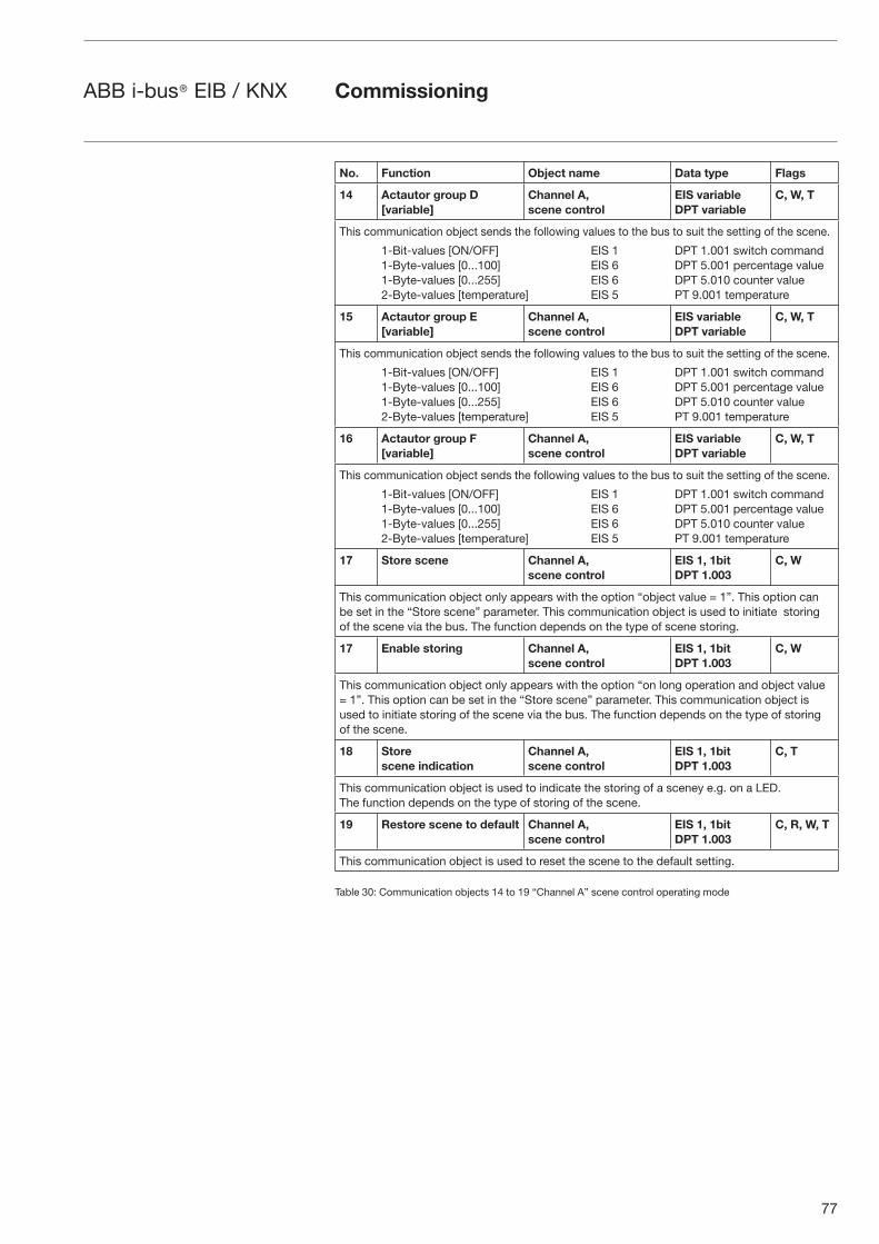
77
ABB i-bus® EIB / KNX
No. Function Object name Data type Flags
14 Actautor group D[variable]
Channel A, scene control
EIS variableDPT variable
C, W, T
This communication object sends the following values to the bus to suit the setting of the scene.
1-Bit-values [ON/OFF] EIS 1 DPT 1.001 switch command 1-Byte-values [0...100] EIS 6 DPT 5.001 percentage value 1-Byte-values [0...255] EIS 6 DPT 5.010 counter value 2-Byte-values [temperature] EIS 5 PT 9.001 temperature
15 Actautor group E[variable]
Channel A, scene control
EIS variableDPT variable
C, W, T
This communication object sends the following values to the bus to suit the setting of the scene.
1-Bit-values [ON/OFF] EIS 1 DPT 1.001 switch command 1-Byte-values [0...100] EIS 6 DPT 5.001 percentage value 1-Byte-values [0...255] EIS 6 DPT 5.010 counter value 2-Byte-values [temperature] EIS 5 PT 9.001 temperature
16 Actautor group F[variable]
Channel A, scene control
EIS variableDPT variable
C, W, T
This communication object sends the following values to the bus to suit the setting of the scene.
1-Bit-values [ON/OFF] EIS 1 DPT 1.001 switch command 1-Byte-values [0...100] EIS 6 DPT 5.001 percentage value 1-Byte-values [0...255] EIS 6 DPT 5.010 counter value 2-Byte-values [temperature] EIS 5 PT 9.001 temperature
17 Store scene Channel A, scene control
EIS 1, 1bitDPT 1.003
C, W
This communication object only appears with the option “object value = 1”. This option can be set in the “Store scene” parameter. This communication object is used to initiate storing of the scene via the bus. The function depends on the type of scene storing.
17 Enable storing Channel A, scene control
EIS 1, 1bitDPT 1.003
C, W
This communication object only appears with the option “on long operation and object value = 1”. This option can be set in the “Store scene” parameter. This communication object is used to initiate storing of the scene via the bus. The function depends on the type of storing of the scene.
18 Storescene indication
Channel A, scene control
EIS 1, 1bitDPT 1.003
C, T
This communication object is used to indicate the storing of a sceney e.g. on a LED. The function depends on the type of storing of the scene.
19 Restore scene to default Channel A, scene control
EIS 1, 1bitDPT 1.003
C, R, W, T
This communication object is used to reset the scene to the default setting.
Table 30: Communication objects 14 to 19 “Channel A” scene control operating mode
Commissioning
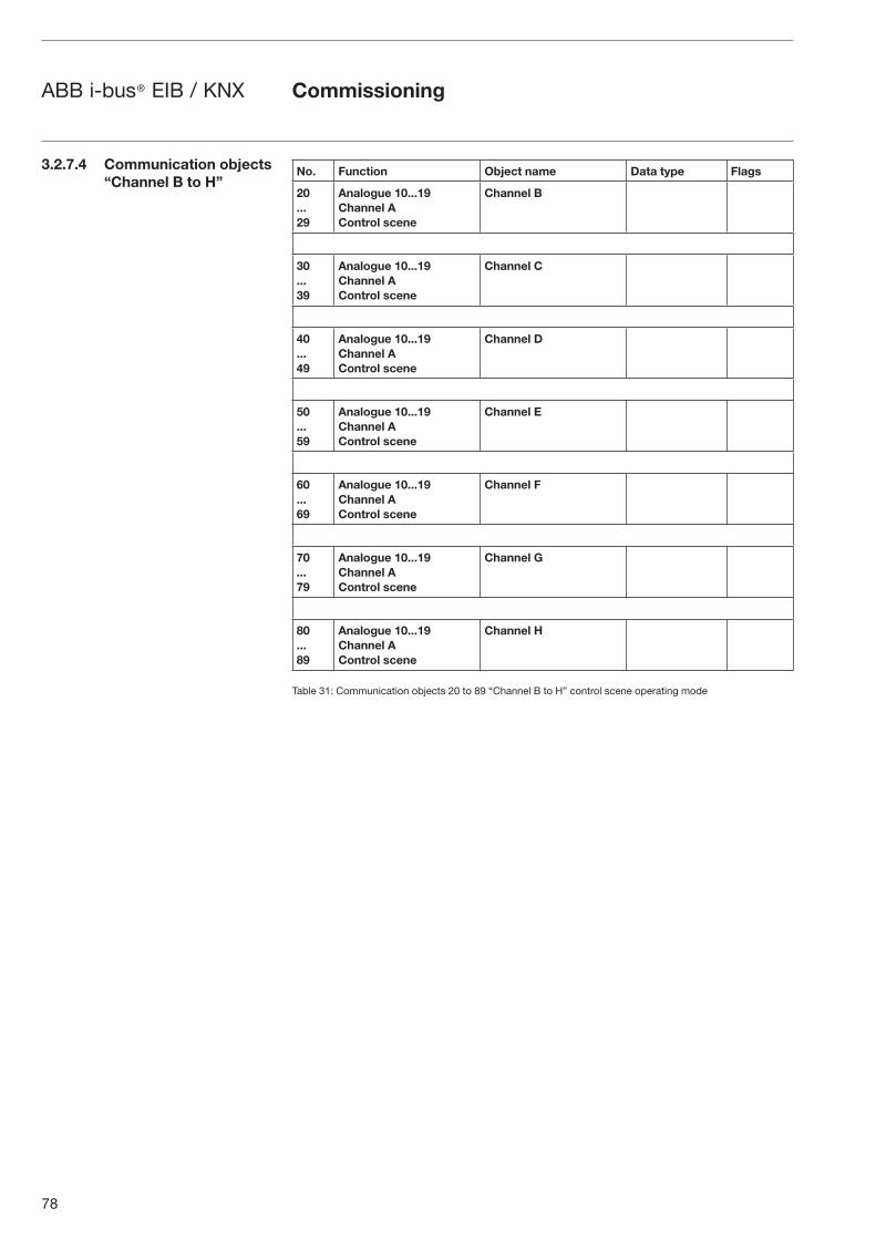
78
ABB i-bus® EIB / KNX
No. Function Object name Data type Flags
20...29
Analogue 10...19 Channel A Control scene
Channel B
30...39
Analogue 10...19 Channel A Control scene
Channel C
40...49
Analogue 10...19 Channel A Control scene
Channel D
50...59
Analogue 10...19 Channel A Control scene
Channel E
60...69
Analogue 10...19 Channel A Control scene
Channel F
70...79
Analogue 10...19 Channel A Control scene
Channel G
80...89
Analogue 10...19 Channel A Control scene
Channel H
Table 31: Communication objects 20 to 89 “Channel B to H” control scene operating mode
3.2.7.4 Communication objects “Channel B to H”
Commissioning
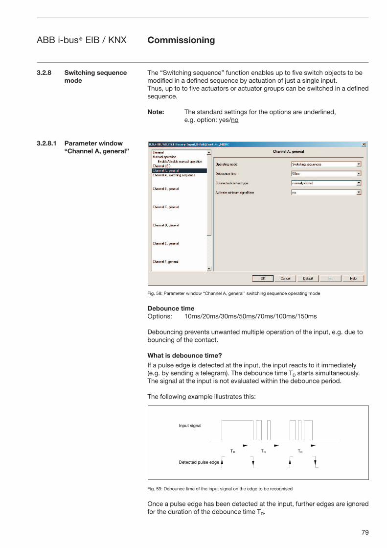
79
ABB i-bus® EIB / KNX
The “Switching sequence” function enables up to five switch objects to be modified in a defined sequence by actuation of just a single input. Thus, up to to five actuators or actuator groups can be switched in a defined sequence.
Note: The standard settings for the options are underlined, e.g. option: yes/no
Fig. 58: Parameter window “Channel A, general” switching sequence operating mode
Debounce timeOptions: 10ms/20ms/30ms/50ms/70ms/100ms/150ms
Debouncing prevents unwanted multiple operation of the input, e.g. due to bouncing of the contact.
What is debounce time?If a pulse edge is detected at the input, the input reacts to it immediately (e.g. by sending a telegram). The debounce time TD starts simultaneously. The signal at the input is not evaluated within the debounce period.
The following example illustrates this:
Fig. 59: Debounce time of the input signal on the edge to be recognised
Once a pulse edge has been detected at the input, further edges are ignored for the duration of the debounce time TD.
3.2.8 Switching sequence mode
3.2.8.1 Parameter window“Channel A, general”
�� �� ��
����� ����
� � �� � ���� �
Commissioning
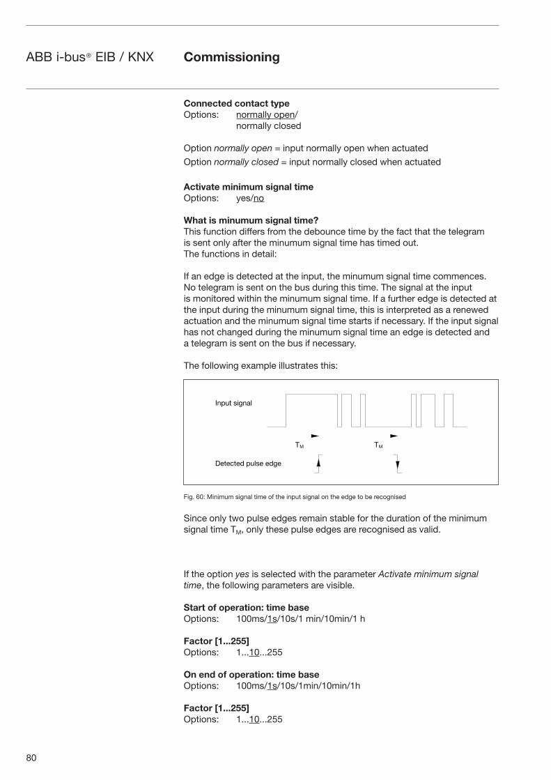
80
ABB i-bus® EIB / KNX
Connected contact typeOptions: normally open/ normally closed
Option normally open = input normally open when actuated
Option normally closed = input normally closed when actuated
Activate minimum signal time Options: yes/no
What is minumum signal time?This function differs from the debounce time by the fact that the telegram is sent only after the minumum signal time has timed out. The functions in detail:
If an edge is detected at the input, the minumum signal time commences. No telegram is sent on the bus during this time. The signal at the input is monitored within the minumum signal time. If a further edge is detected at the input during the minumum signal time, this is interpreted as a renewed actuation and the minumum signal time starts if necessary. If the input signal has not changed during the minumum signal time an edge is detected and a telegram is sent on the bus if necessary.
The following example illustrates this:
Fig. 60: Minimum signal time of the input signal on the edge to be recognised
Since only two pulse edges remain stable for the duration of the minimum signal time TM, only these pulse edges are recognised as valid.
If the option yes is selected with the parameter Activate minimum signal time, the following parameters are visible.
Start of operation: time baseOptions: 100ms/1s/10s/1 min/10min/1 h
Factor [1...255]Options: 1...10...255
On end of operation: time baseOptions: 100ms/1s/10s/1min/10min/1h
Factor [1...255]Options: 1...10...255
Commissioning
�� ��
����� ����
� � �� � ���� �
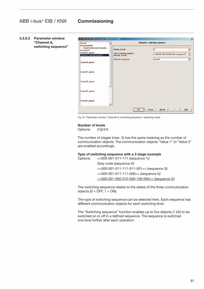
81
ABB i-bus® EIB / KNX
Fig. 61: Parameter window “Channel A, switching sequence” operating mode
Number of levelsOptions: 2/3/4/5
The number of stages (max. 5) has the same meaning as the number of communication objects: The communication objects “Value 1” to “Value 5” are enabled accordingly.
Type of switching sequence with a 3 stage exampleOptions: =>000-001-011-111 (sequence 1)/
Gray code (sequence 2)/
<=000-001-011-111-011-001=> (sequence 3)/
<=000-001-011-111-000=> (sequence 4)/
<=000-001-000-010-000-100-000=> (sequence 5)/
The switching sequence relates to the states of the three communication objects (0 = OFF, 1 = ON).
The type of switching sequence can be selected here. Each sequence has different communication objects for each switching level.
The “Switching sequence” function enables up to five objects (1 bit) to be switched on or off in a defined sequence. The sequence is switched one level further after each operation.
Commissioning
3.2.8.2 Parameter window “Channel A, switching sequence”
82
ABB i-bus® EIB / KNX
Switching sequence 000-001-011-111 (sequence 1)With this sequence a further communication object is switched on with each actuation. If all the communication objects are switched on, all further operations are ignored. At least two inputs are therefore required, one of which switches up a level and the other which switches down a level in the sequence.
Note: The communication objects of the inputs must have the same group address.
Switching sequence Value of the communication objects
Input operation number Binary code “Switch3” “Switch2” “Switch1”
0 000 OFF OFF OFF
1 001 OFF OFF ON
2 011 OFF ON ON
3 111 ON ON ON
Table 32: Switching sequence 1
Switching sequence Gray code (sequence 2)This switching sequence runs through all the combinations of the communi-cation objects in succession. Only the value of one communication object is changed between two switching levels. A clear application of this switching sequence is e.g. the switching of two groups of luminaries in the sequence 00 – 01 – 11 – 10 – 00 ...
You can find a ‘Gray code table’ in the appendix.
Switching sequence <=000-001-011-111-011-001=> (sequence 3)With this sequence a further communication object is switched on each actuation. When all the communication objects are switched on, they are switched off again one after the other, starting with the last object that was switched on.
Switching sequence Value of the communication objects
Input operation number Binary code “Switch3” “Switch2” “Switch1”
0 000 OFF OFF OFF
1 001 OFF OFF ON
2 011 OFF ON ON
3 111 ON ON ON
4 011 OFF ON ON
5 001 OFF OFF ON
...
Table 33: Switching sequence 3
Commissioning
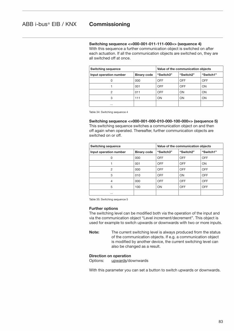
83
ABB i-bus® EIB / KNX
Switching sequence <=000-001-011-111-000=> (sequence 4)With this sequence a further communication object is switched on after each actuation. If all the communication objects are switched on, they areall switched off at once.
Switching sequence Value of the communication objects
Input operation number Binary code “Switch3” “Switch2” “Switch1”
0 000 OFF OFF OFF
1 001 OFF OFF ON
2 011 OFF ON ON
3 111 ON ON ON
...
Table 34: Switching sequence 4
Switching sequence <=000-001-000-010-000-100-000=> (sequence 5)This switching sequence switches a communication object on and then off again when operated. Thereafter, further communication objects are switched on or off.
Switching sequence Value of the communication objects
Input operation number Binary code “Switch3” “Switch2” “Switch1”
0 000 OFF OFF OFF
1 001 OFF OFF ON
2 000 OFF OFF OFF
3 010 OFF ON OFF
4 000 OFF OFF OFF
5 100 ON OFF OFF
...
Table 35: Switching sequence 5
Further optionsThe switching level can be modified both via the operation of the input and via the communication object “Level increment/decrement”. This object is used for example to switch upwards or downwards with two or more inputs.
Note: The current switching level is always produced from the status of the communication objects. If e.g. a communication object is modified by another device, the current switching level can also be changed as a result.
Direction on operation Options: upwards/downwards
With this parameter you can set a button to switch upwards or downwards.
Commissioning
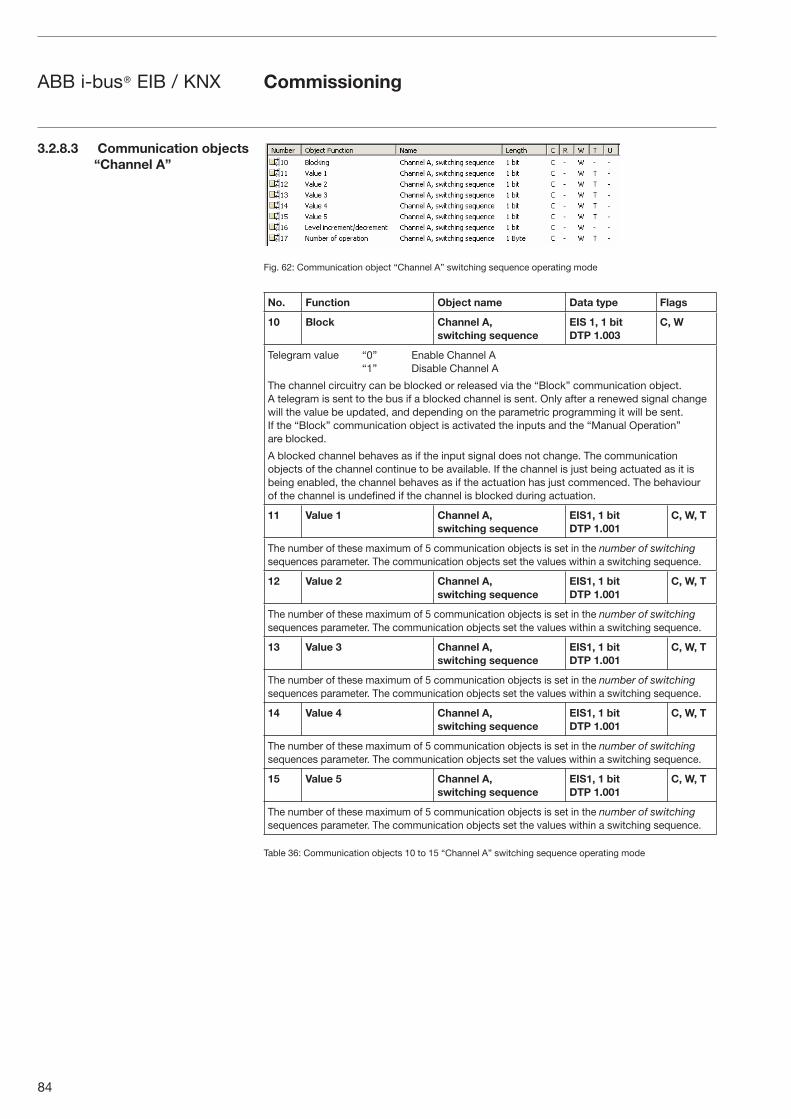
84
ABB i-bus® EIB / KNX
Fig. 62: Communication object “Channel A” switching sequence operating mode
No. Function Object name Data type Flags
10 Block Channel A,switching sequence
EIS 1, 1 bitDTP 1.003
C, W
Telegram value “0” Enable Channel A “1” Disable Channel A
The channel circuitry can be blocked or released via the “Block” communication object. A telegram is sent to the bus if a blocked channel is sent. Only after a renewed signal change will the value be updated, and depending on the parametric programming it will be sent. If the “Block” communication object is activated the inputs and the “Manual Operation” are blocked.
A blocked channel behaves as if the input signal does not change. The communication objects of the channel continue to be available. If the channel is just being actuated as it is being enabled, the channel behaves as if the actuation has just commenced. The behaviour of the channel is undefined if the channel is blocked during actuation.
11 Value 1 Channel A,switching sequence
EIS1, 1 bitDTP 1.001
C, W, T
The number of these maximum of 5 communication objects is set in the number of switching sequences parameter. The communication objects set the values within a switching sequence.
12 Value 2 Channel A,switching sequence
EIS1, 1 bitDTP 1.001
C, W, T
The number of these maximum of 5 communication objects is set in the number of switching sequences parameter. The communication objects set the values within a switching sequence.
13 Value 3 Channel A,switching sequence
EIS1, 1 bitDTP 1.001
C, W, T
The number of these maximum of 5 communication objects is set in the number of switching sequences parameter. The communication objects set the values within a switching sequence.
14 Value 4 Channel A,switching sequence
EIS1, 1 bitDTP 1.001
C, W, T
The number of these maximum of 5 communication objects is set in the number of switching sequences parameter. The communication objects set the values within a switching sequence.
15 Value 5 Channel A,switching sequence
EIS1, 1 bitDTP 1.001
C, W, T
The number of these maximum of 5 communication objects is set in the number of switching sequences parameter. The communication objects set the values within a switching sequence.
Table 36: Communication objects 10 to 15 “Channel A” switching sequence operating mode
Commissioning
3.2.8.3 Communication objects “Channel A”
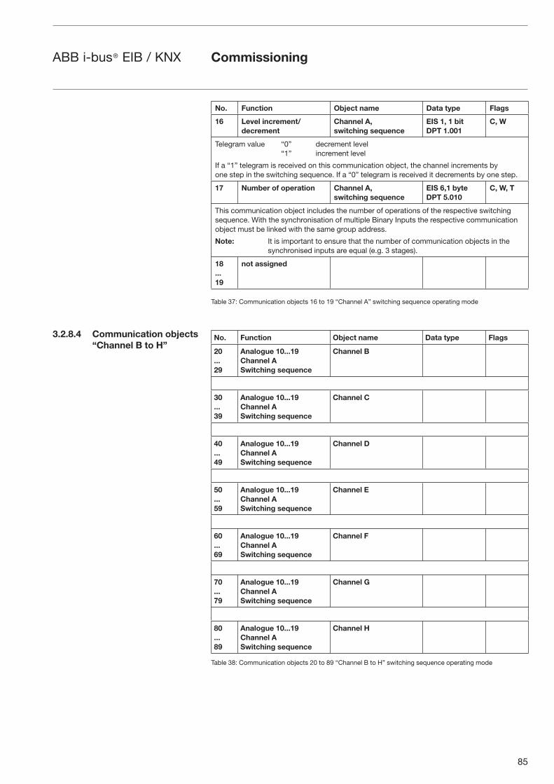
85
ABB i-bus® EIB / KNX
No. Function Object name Data type Flags
16 Level increment/decrement
Channel A, switching sequence
EIS 1, 1 bitDPT 1.001
C, W
Telegram value “0” decrement level“1” increment level
If a “1” telegram is received on this communication object, the channel increments by one step in the switching sequence. If a “0” telegram is received it decrements by one step.
17 Number of operation Channel A, switching sequence
EIS 6,1 byteDPT 5.010
C, W, T
This communication object includes the number of operations of the respective switching sequence. With the synchronisation of multiple Binary Inputs the respective communication object must be linked with the same group address.
Note: It is important to ensure that the number of communication objects in the synchronised inputs are equal (e.g. 3 stages).
18...19
not assigned
Table 37: Communication objects 16 to 19 “Channel A” switching sequence operating mode
No. Function Object name Data type Flags
20...29
Analogue 10...19 Channel A Switching sequence
Channel B
30...39
Analogue 10...19 Channel A Switching sequence
Channel C
40...49
Analogue 10...19 Channel A Switching sequence
Channel D
50...59
Analogue 10...19 Channel A Switching sequence
Channel E
60...69
Analogue 10...19 Channel A Switching sequence
Channel F
70...79
Analogue 10...19 Channel A Switching sequence
Channel G
80...89
Analogue 10...19 Channel A Switching sequence
Channel H
Table 38: Communication objects 20 to 89 “Channel B to H” switching sequence operating mode
Commissioning
3.2.8.4 Communication objects “Channel B to H”
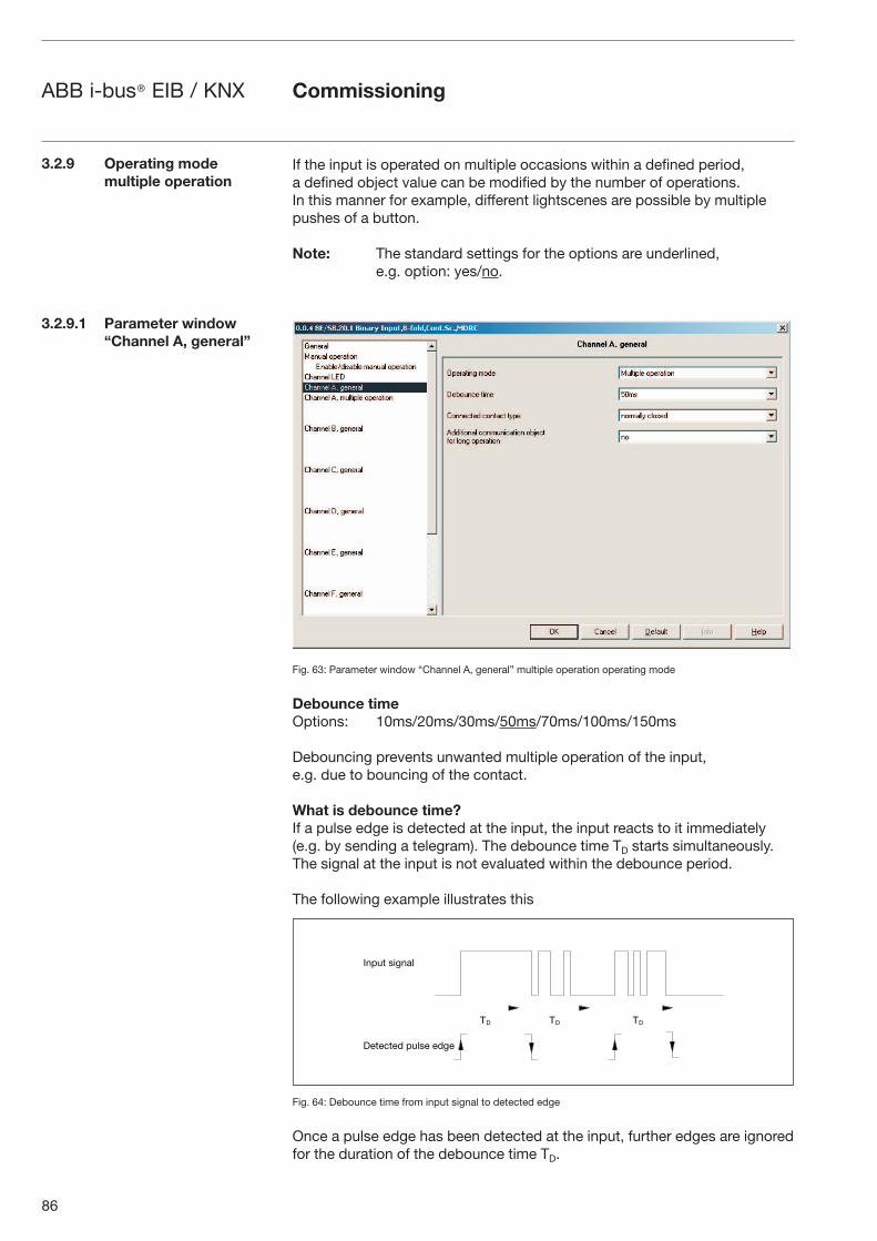
86
ABB i-bus® EIB / KNX
If the input is operated on multiple occasions within a defined period, a defined object value can be modified by the number of operations. In this manner for example, different lightscenes are possible by multiple pushes of a button.
Note: The standard settings for the options are underlined, e.g. option: yes/no.
Fig. 63: Parameter window “Channel A, general” multiple operation operating mode
Debounce timeOptions: 10ms/20ms/30ms/50ms/70ms/100ms/150ms
Debouncing prevents unwanted multiple operation of the input, e.g. due to bouncing of the contact.
What is debounce time?If a pulse edge is detected at the input, the input reacts to it immediately (e.g. by sending a telegram). The debounce time TD starts simultaneously. The signal at the input is not evaluated within the debounce period.
The following example illustrates this
Fig. 64: Debounce time from input signal to detected edge
Once a pulse edge has been detected at the input, further edges are ignored for the duration of the debounce time TD.
3.2.9 Operating mode multiple operation
3.2.9.1 Parameter window “Channel A, general”
Commissioning
�� �� ��
����� ����
� � �� � ���� �
87
ABB i-bus® EIB / KNX
Connected contact typeOptions: normally open/normally closed
Option normally open = input normally open when actuated
Option normally closed = input normally closed when actuated
Additional communication object for long operation Options: yes/no
A further function is performed with longer operation of the input via the “Long operation” communication object. If one or more short operations are performed within the maximum time of a long operation, the short operations are ignored.
If the option yes is selected in the parameter Additional communication object for long operation, the following parameters are visible.
Long operation after...Options: 0.3s/0.4s/0.5s/0.6s/0.8s/1 s/1.2s/1.5s/2s/3s/4s/
5s/6s/7s/8s/9s/10s
Defines the period TL after which an operation is interpreted as “long”.
Commissioning
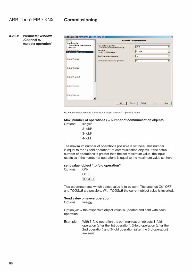
88
ABB i-bus® EIB / KNX
Fig. 65: Parameter window “Channel A, multiple operation” operating mode
Max. number of operations ( = number of communication objects)Options: single/
2-fold/
3-fold/
4-fold
The maximum number of operations possible is set here. This number is equal to the “x-fold operation” of communication objects. If the actual number of operations is greater than the set maximum value, the input reacts as if the number of operations is equal to the maximum value set here.
sent value (object “...-fold operation”) Options: ON/
OFF/
TOGGLE
This parameter sets which object value is to be sent. The settings ON, OFF and TOGGLE are possible. With TOGGLE the current object value is inverted.
Send value on every operation Options: yes/no
Option yes = the respective object value is updated and sent with each operation.
Example With 3-fold operation the communication objects 1-fold operation (after the 1st operation), 2-fold operation (after the 2nd operation) and 3-fold operation (after the 3rd operation) are sent.
Commissioning
3.2.9.2 Parameter window„Channel A, multiple operation”
89
ABB i-bus® EIB / KNX
Maximum time between two operationsOptions: 0.3s/0.4s/0.5s/0.6s/0.8s/1s/1.2s/1.5s/2s/3s/4s/
5s/6s/7s/8s/9s/10s
This parameter sets the maximum allowed interval between two operations. After operation the time entered here must time out. If no further operations occur within this time, the “Long operation” communication object is sent and the count is reinitiated with the next operation.
If the option yes is selected in the parameter Additional communication object for long operation, the following parameters appear.
sent value (communication object “Long operation”) Options: ON/
OFF/
TOGGLE
A further function is performed with longer operation of the input via the “Long operation” communication object. If one or more short operations are performed within the maximum time of a long operation, the short operations are ignored.
Commissioning
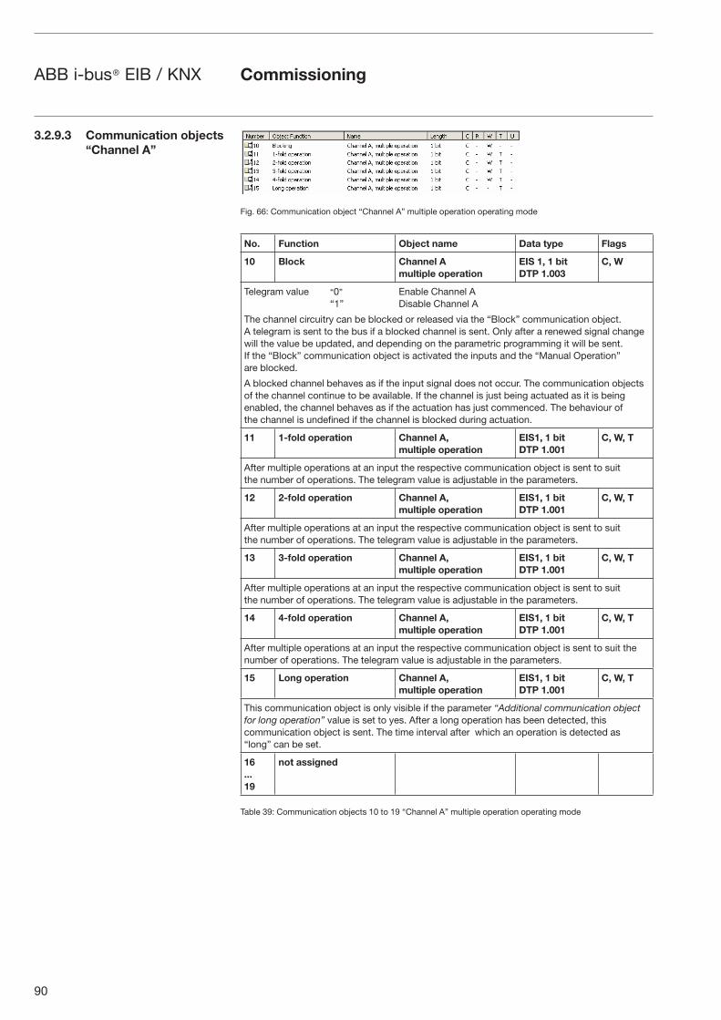
90
ABB i-bus® EIB / KNX
Fig. 66: Communication object “Channel A” multiple operation operating mode
No. Function Object name Data type Flags
10 Block Channel A multiple operation
EIS 1, 1 bitDTP 1.003
C, W
Telegram value “0” Enable Channel A“1” Disable Channel A
The channel circuitry can be blocked or released via the “Block” communication object. A telegram is sent to the bus if a blocked channel is sent. Only after a renewed signal change will the value be updated, and depending on the parametric programming it will be sent. If the “Block” communication object is activated the inputs and the “Manual Operation” are blocked.
A blocked channel behaves as if the input signal does not occur. The communication objects of the channel continue to be available. If the channel is just being actuated as it is being enabled, the channel behaves as if the actuation has just commenced. The behaviour of the channel is undefined if the channel is blocked during actuation.
11 1-fold operation Channel A,multiple operation
EIS1, 1 bitDTP 1.001
C, W, T
After multiple operations at an input the respective communication object is sent to suit the number of operations. The telegram value is adjustable in the parameters.
12 2-fold operation Channel A, multiple operation
EIS1, 1 bitDTP 1.001
C, W, T
After multiple operations at an input the respective communication object is sent to suit the number of operations. The telegram value is adjustable in the parameters.
13 3-fold operation Channel A, multiple operation
EIS1, 1 bitDTP 1.001
C, W, T
After multiple operations at an input the respective communication object is sent to suit the number of operations. The telegram value is adjustable in the parameters.
14 4-fold operation Channel A, multiple operation
EIS1, 1 bitDTP 1.001
C, W, T
After multiple operations at an input the respective communication object is sent to suit the number of operations. The telegram value is adjustable in the parameters.
15 Long operation Channel A, multiple operation
EIS1, 1 bitDTP 1.001
C, W, T
This communication object is only visible if the parameter “Additional communication object for long operation” value is set to yes. After a long operation has been detected, this communication object is sent. The time interval after which an operation is detected as “long” can be set.
16...19
not assigned
Table 39: Communication objects 10 to 19 “Channel A” multiple operation operating mode
Commissioning
3.2.9.3 Communication objects “Channel A”
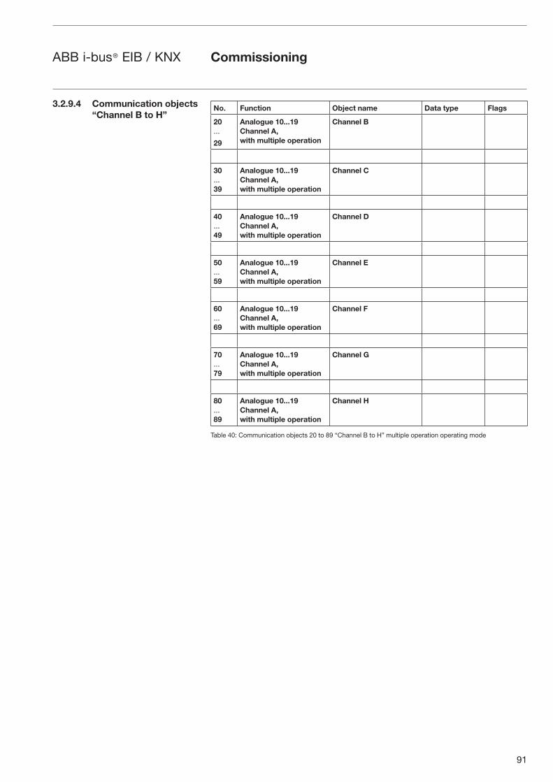
91
ABB i-bus® EIB / KNX
No. Function Object name Data type Flags
20...
29
Analogue 10...19 Channel A, with multiple operation
Channel B
30...39
Analogue 10...19 Channel A, with multiple operation
Channel C
40...49
Analogue 10...19 Channel A, with multiple operation
Channel D
50...59
Analogue 10...19 Channel A, with multiple operation
Channel E
60...69
Analogue 10...19 Channel A, with multiple operation
Channel F
70...79
Analogue 10...19 Channel A, with multiple operation
Channel G
80...89
Analogue 10...19 Channel A, with multiple operation
Channel H
Table 40: Communication objects 20 to 89 “Channel B to H” multiple operation operating mode
3.2.9.4 Communication objects “Channel B to H”
Commissioning
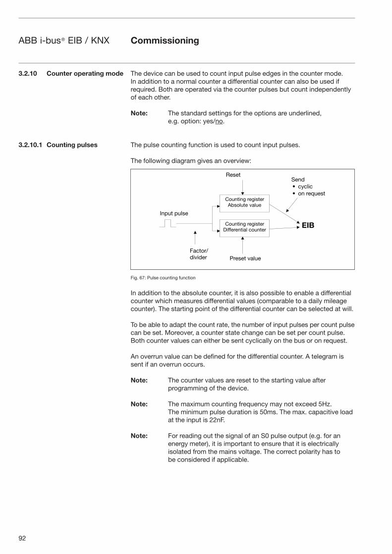
92
ABB i-bus® EIB / KNX
The device can be used to count input pulse edges in the counter mode. In addition to a normal counter a differential counter can also be used if required. Both are operated via the counter pulses but count independently of each other.
Note: The standard settings for the options are underlined, e.g. option: yes/no.
The pulse counting function is used to count input pulses.
The following diagram gives an overview:
Fig. 67: Pulse counting function
In addition to the absolute counter, it is also possible to enable a differential counter which measures differential values (comparable to a daily mileage counter). The starting point of the differential counter can be selected at will.
To be able to adapt the count rate, the number of input pulses per count pulse can be set. Moreover, a counter state change can be set per count pulse. Both counter values can either be sent cyclically on the bus or on request.
An overrun value can be defined for the differential counter. A telegram is sent if an overrun occurs.
Note: The counter values are reset to the starting value after programming of the device.
Note: The maximum counting frequency may not exceed 5Hz. The minimum pulse duration is 50ms. The max. capacitive load at the input is 22nF.
Note: For reading out the signal of an S0 pulse output (e.g. for an energy meter), it is important to ensure that it is electrically isolated from the mains voltage. The correct polarity has to be considered if applicable.
Commissioning
3.2.10 Counter operating mode
3.2.10.1 Counting pulses
������ � �� �������� ����
������ � �� ���� � ���� ����� �
���������� � �� � � ����
� � �
���
����� ����
� ��� ������ �� � �� ��
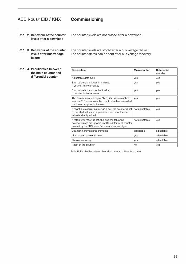
93
ABB i-bus® EIB / KNX Commissioning
The counter levels are not erased after a download.
The counter levels are stored after a bus voltage failure. The counter states can be sent after bus voltage recovery.
Description Main counter Differential counter
Adjustable data type yes yes
Start value is the lower limit value,if counter is incremented
yes yes
Start value is the upper limit value,if counter is decremented
yes yes
The communication object “MC: limit value reached” sends a “1”, as soon as the count pulse has exceeded the lower or upper limit value.
yes yes
If “continue circular counting” is set, the counter is set to the start value and a possible overrun of the start value is simply added.
not adjustable yes
If “stop until reset” is set, this and the following counter pulses are ignored until the differential counter is reset by the “DC: reset” conmmunication object.
not adjustable yes
Counter increments/decrements adjustable adjustable
Limit value 1 preset to zero yes adjustable
Circular counting yes adjustable
Reset of the counter no yes
Table 41: Peculiarities between the main counter and differential counter
3.2.10.2 Behaviour of the counter levels after a download
3.2.10.3 Behaviour of the counter levels after bus voltage failure
3.2.10.4 Peculiarities between the main counter and differential counter
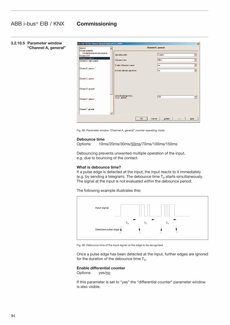
94
ABB i-bus® EIB / KNX
Fig. 68: Parameter window “Channel A, general” counter operating mode
Debounce timeOptions: 10ms/20ms/30ms/50ms/70ms/100ms/150ms
Debouncing prevents unwanted multiple operation of the input, e.g. due to bouncing of the contact.
What is debounce time?If a pulse edge is detected at the input, the input reacts to it immediately (e.g. by sending a telegram). The debounce time TD starts simultaneously. The signal at the input is not evaluated within the debounce period.
The following example illustrates this:
Fig. 69: Debounce time of the input signal on the edge to be recognised
Once a pulse edge has been detected at the input, further edges are ignored for the duration of the debounce time TD.
Enable differential counter Options: yes/no
If this parameter is set to “yes” the “differential counter” parameter window is also visible.
Commissioning
�� �� ��
����� ����
� � �� � ���� �
3.2.10.5 Parameter window“Channel A, general”
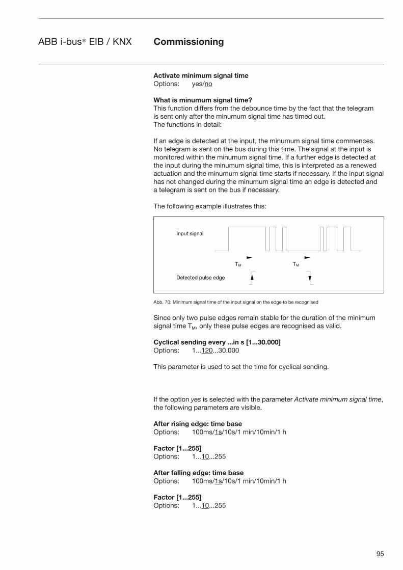
95
ABB i-bus® EIB / KNX Commissioning
Activate minimum signal time Options: yes/no
What is minumum signal time?This function differs from the debounce time by the fact that the telegram is sent only after the minumum signal time has timed out. The functions in detail:
If an edge is detected at the input, the minumum signal time commences. No telegram is sent on the bus during this time. The signal at the input is monitored within the minumum signal time. If a further edge is detected at the input during the minumum signal time, this is interpreted as a renewed actuation and the minumum signal time starts if necessary. If the input signal has not changed during the minumum signal time an edge is detected and a telegram is sent on the bus if necessary.
The following example illustrates this:
Abb. 70: Minimum signal time of the input signal on the edge to be recognised
Since only two pulse edges remain stable for the duration of the minimum signal time TM, only these pulse edges are recognised as valid.
Cyclical sending every ...in s [1...30.000] Options: 1...120...30.000
This parameter is used to set the time for cyclical sending.
If the option yes is selected with the parameter Activate minimum signal time, the following parameters are visible.
After rising edge: time base Options: 100ms/1s/10s/1 min/10min/1 h
Factor [1...255]Options: 1...10...255
After falling edge: time baseOptions: 100ms/1s/10s/1 min/10min/1 h
Factor [1...255]Options: 1...10...255
�� ��
����� ����
� � �� � ���� �
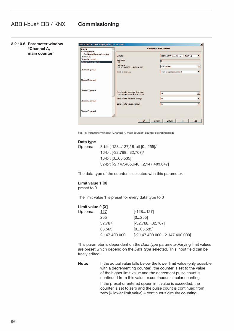
96
ABB i-bus® EIB / KNX Commissioning
Fig. 71: Parameter window “Channel A, main counter” counter operating mode
Data typeOptions: 8-bit [-128...127]/ 8-bit [0...255]/
16-bit [-32,768...32,767]/
16-bit [0...65.535]
32-bit [-2,147,485,648...2,147,483,647]
The data type of the counter is selected with this parameter.
Limit value 1 [0]preset to 0
The limit value 1 is preset for every data type to 0
Limit value 2 [X]Options: 127 [-128...127]
255 [0...255]
32.767 [-32.768...32.767]
65.565 [0...65.535]
2.147.400.000 [-2.147.400.000...2.147.400.000]
This parameter is dependent on the Data type parameter.Varying limit values are preset which depend on the Data type selected. This input field can be freely edited.
Note: If the actual value falls below the lower limit value (only possible with a decrementing counter), the counter is set to the value of the higher limit value and the decrement pulse count is continued from this value = continuous circular counting.
If the preset or entered upper limit value is exceeded, the counter is set to zero and the pulse count is continued from zero (= lower limit value) = continuous circular counting.
3.2.10.6 Parameter window“Channel A, main counter”
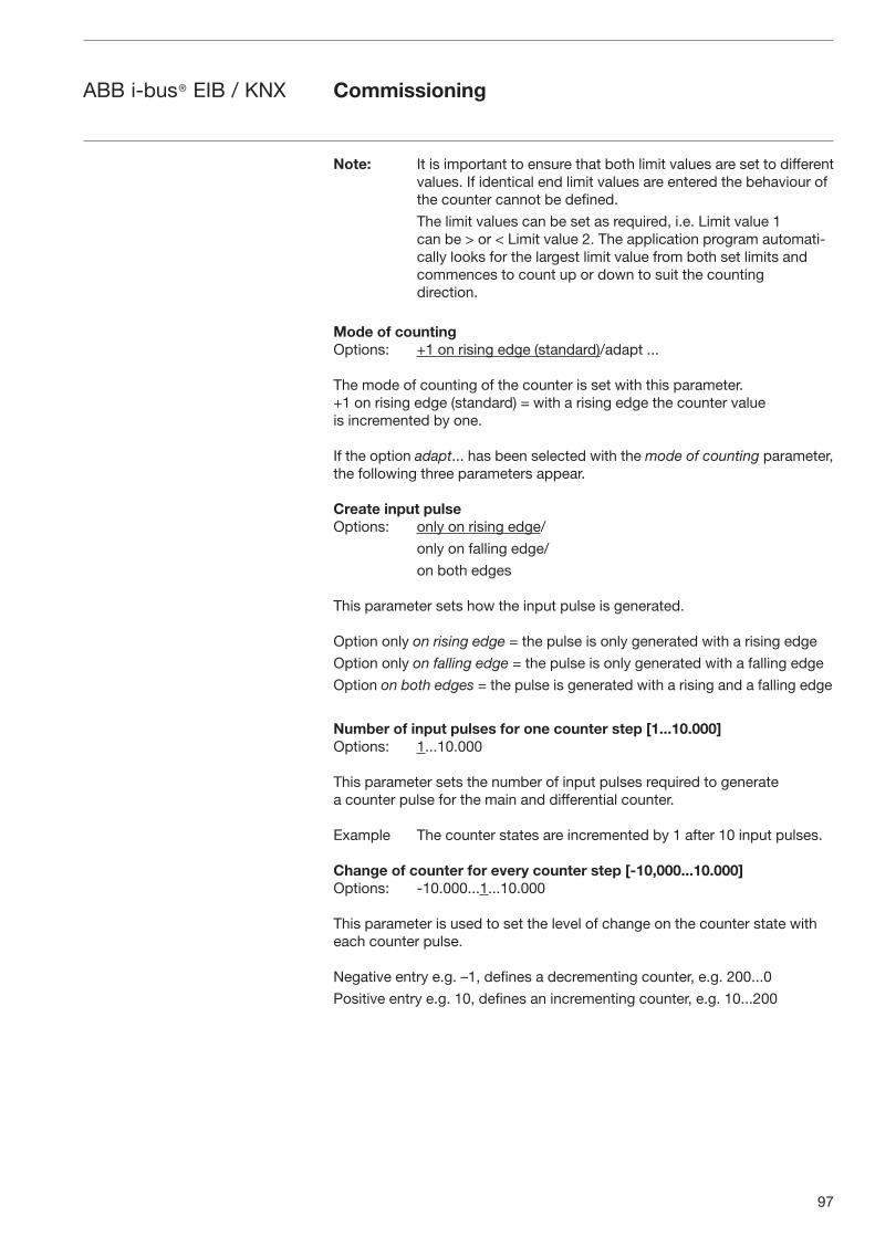
97
ABB i-bus® EIB / KNX Commissioning
Note: It is important to ensure that both limit values are set to different values. If identical end limit values are entered the behaviour of the counter cannot be defined.
The limit values can be set as required, i.e. Limit value 1 can be > or < Limit value 2. The application program automati-cally looks for the largest limit value from both set limits and commences to count up or down to suit the counting direction.
Mode of countingOptions: +1 on rising edge (standard)/adapt ...
The mode of counting of the counter is set with this parameter.+1 on rising edge (standard) = with a rising edge the counter value is incremented by one.
If the option adapt... has been selected with the mode of counting parameter, the following three parameters appear.
Create input pulseOptions: only on rising edge/
only on falling edge/
on both edges
This parameter sets how the input pulse is generated.
Option only on rising edge = the pulse is only generated with a rising edge
Option only on falling edge = the pulse is only generated with a falling edge
Option on both edges = the pulse is generated with a rising and a falling edge
Number of input pulses for one counter step [1...10.000] Options: 1...10.000
This parameter sets the number of input pulses required to generate a counter pulse for the main and differential counter.
Example The counter states are incremented by 1 after 10 input pulses.
Change of counter for every counter step [-10,000...10.000] Options: -10.000...1...10.000
This parameter is used to set the level of change on the counter state with each counter pulse.
Negative entry e.g. –1, defines a decrementing counter, e.g. 200...0
Positive entry e.g. 10, defines an incrementing counter, e.g. 10...200
98
ABB i-bus® EIB / KNX Commissioning
Send counter values on download bus reset and bus voltage recovery Options: yes/no
If “yes” is set here, the device sends the communication object “Counter value” on the bus after bus voltage recovery (after the send delay time has timed out).
Send counter values on changeOptions: yes/no
This parameter is used to select if a change of the counter state is to be sent.
Send counter values cyclicallyOptions: yes/no
This parameter is used to determine if the counter values are to be sent cyclically on the bus.
If the option yes is selected with the Enable differential counter parameter, the following parameters are visible.
Fig. 72: Parameter window “Channel A, differential counter” counter operating mode
Data typeOptions: 8-bit [-128...127]/
8-bit [0...255]/
16-bit [-32,768...32,767]/
16-bit [0...65.535]
32-bit [-2,147,485,648...2,147,483,647]
The data type of the differential counter is selected with this parameter.
3.2.10.7 Parameter window “Channel A, differential counter”
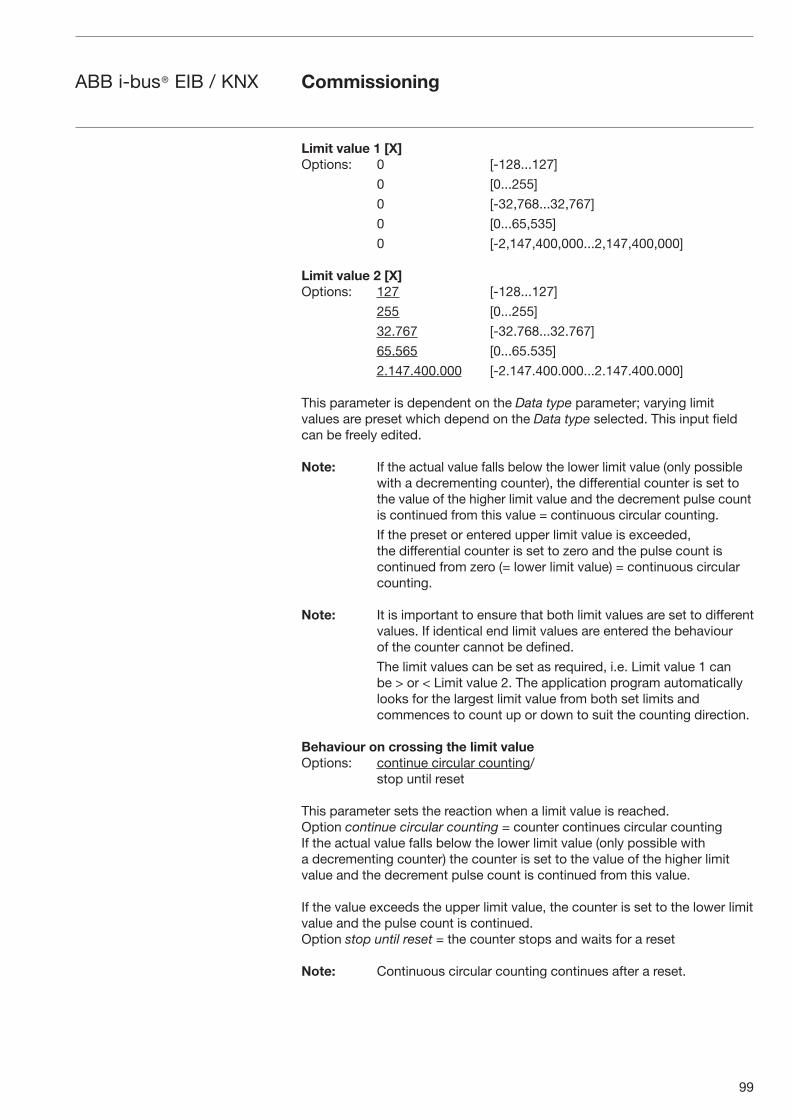
99
ABB i-bus® EIB / KNX Commissioning
Limit value 1 [X]Options: 0 [-128...127]
0 [0...255]
0 [-32,768...32,767]
0 [0...65,535]
0 [-2,147,400,000...2,147,400,000]
Limit value 2 [X]Options: 127 [-128...127]
255 [0...255]
32.767 [-32.768...32.767]
65.565 [0...65.535]
2.147.400.000 [-2.147.400.000...2.147.400.000]
This parameter is dependent on the Data type parameter; varying limit values are preset which depend on the Data type selected. This input field can be freely edited.
Note: If the actual value falls below the lower limit value (only possible with a decrementing counter), the differential counter is set tothe value of the higher limit value and the decrement pulse count is continued from this value = continuous circular counting.
If the preset or entered upper limit value is exceeded, the differential counter is set to zero and the pulse count is continued from zero (= lower limit value) = continuous circular counting.
Note: It is important to ensure that both limit values are set to different values. If identical end limit values are entered the behaviour of the counter cannot be defined.
The limit values can be set as required, i.e. Limit value 1 can be > or < Limit value 2. The application program automatically looks for the largest limit value from both set limits and commences to count up or down to suit the counting direction.
Behaviour on crossing the limit value Options: continue circular counting/ stop until reset
This parameter sets the reaction when a limit value is reached.Option continue circular counting = counter continues circular countingIf the actual value falls below the lower limit value (only possible with a decrementing counter) the counter is set to the value of the higher limit value and the decrement pulse count is continued from this value.
If the value exceeds the upper limit value, the counter is set to the lower limit value and the pulse count is continued.Option stop until reset = the counter stops and waits for a reset
Note: Continuous circular counting continues after a reset.
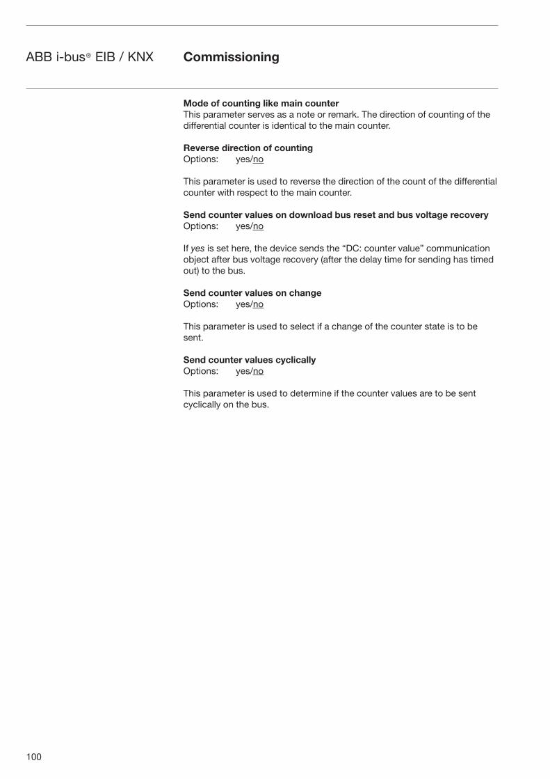
100
ABB i-bus® EIB / KNX Commissioning
Mode of counting like main counterThis parameter serves as a note or remark. The direction of counting of the differential counter is identical to the main counter.
Reverse direction of countingOptions: yes/no
This parameter is used to reverse the direction of the count of the differential counter with respect to the main counter.
Send counter values on download bus reset and bus voltage recovery Options: yes/no
If yes is set here, the device sends the “DC: counter value” communication object after bus voltage recovery (after the delay time for sending has timed out) to the bus.
Send counter values on change Options: yes/no
This parameter is used to select if a change of the counter state is to be sent.
Send counter values cyclically Options: yes/no
This parameter is used to determine if the counter values are to be sent cyclically on the bus.
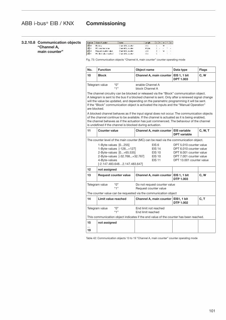
101
ABB i-bus® EIB / KNX Commissioning
Fig. 73: Communication objects “Channel A, main counter” counter operating mode
No. Function Object name Data type Flags
10 Block Channel A, main counter EIS 1, 1 bitDPT 1.003
C, W
Telegram value “0” enable Channel A“1” block Channel A
The channel circuitry can be blocked or released via the “Block” communication object. A telegram is sent to the bus if a blocked channel is sent. Only after a renewed signal change will the value be updated, and depending on the parametric programming it will be sent. If the “Block” communication object is activated the inputs and the “Manual Operation” are blocked.
A blocked channel behaves as if the input signal does not occur. The communication objects of the channel continue to be available. If the channel is actuated as it is being enabled, the channel behaves as if the actuation has just commenced. The behaviour of the channel is undefined if the channel is blocked during actuation.
11 Counter value Channel A, main counter EIS variableDPT variable
C, W, T
The counter level of the main counter (MC) can be read via the communication object.
1-Byte-values [0...255] EIS 6 DPT 5.010 counter value 1-Byte-values [-128...+127] EIS 14 DPT 6.010 counter value 2-Byte-values [0...+65.535] EIS 10 DPT 8.001 counter value 2-Byte-values [-32.768...+32.767] EIS 10 DPT 7.001 counter value 4-Byte-values EIS 11 DPT 13.001 counter value [-2.147.483.648…2.147.483.647]
12 not assigned
13 Request counter value Channel A, main counter EIS 1, 1 bitDTP 1.003
C, W
Telegram value “0” Do not request counter value“1” Request counter value
The counter value can be requested via the communication object
14 Limit value reached Channel A, main counter EIS1, 1 bitDTP 1.002
C, T
Telegram value “0” End limit not reached “1” End limit reached
This communication object indicates if the end value of the counter has been reached.
15...19
not assigned
Table 42: Communication objects 13 to 19 “Channel A, main counter” counter operating mode
3.2.10.8 Communication objects“Channel A, main counter”
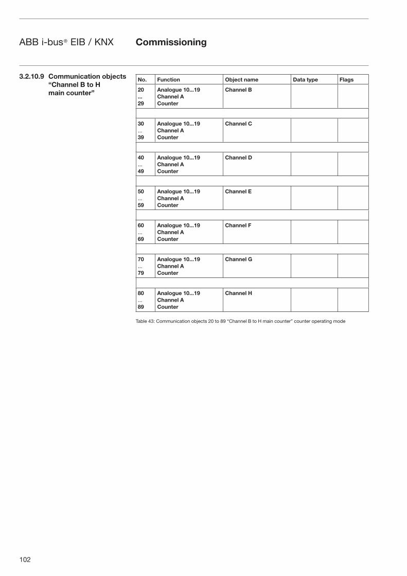
102
ABB i-bus® EIB / KNX Commissioning
No. Function Object name Data type Flags
20...29
Analogue 10...19 Channel A Counter
Channel B
30...39
Analogue 10...19 Channel A Counter
Channel C
40...49
Analogue 10...19 Channel A Counter
Channel D
50...59
Analogue 10...19 Channel A Counter
Channel E
60...69
Analogue 10...19 Channel A Counter
Channel F
70...79
Analogue 10...19 Channel A Counter
Channel G
80...89
Analogue 10...19 Channel A Counter
Channel H
Table 43: Communication objects 20 to 89 “Channel B to H main counter” counter operating mode
3.2.10.9 Communication objects “Channel B to H main counter”
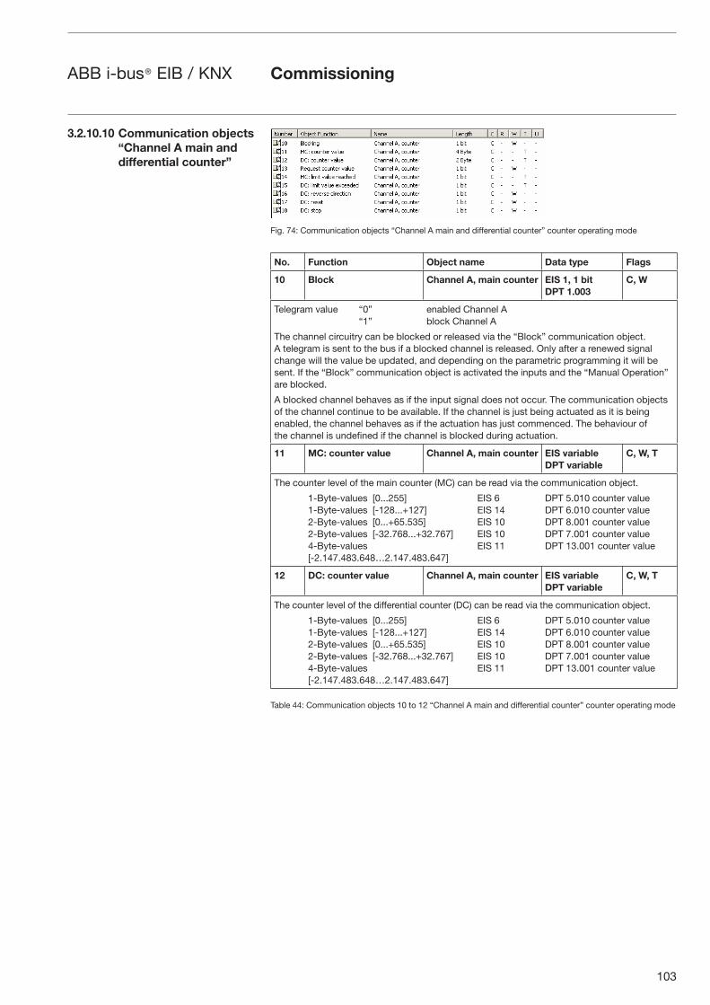
103
ABB i-bus® EIB / KNX Commissioning
Fig. 74: Communication objects “Channel A main and differential counter” counter operating mode
No. Function Object name Data type Flags
10 Block Channel A, main counter EIS 1, 1 bitDPT 1.003
C, W
Telegram value “0” enabled Channel A“1” block Channel A
The channel circuitry can be blocked or released via the “Block” communication object. A telegram is sent to the bus if a blocked channel is released. Only after a renewed signal change will the value be updated, and depending on the parametric programming it will be sent. If the “Block” communication object is activated the inputs and the “Manual Operation” are blocked.
A blocked channel behaves as if the input signal does not occur. The communication objects of the channel continue to be available. If the channel is just being actuated as it is being enabled, the channel behaves as if the actuation has just commenced. The behaviour of the channel is undefined if the channel is blocked during actuation.
11 MC: counter value Channel A, main counter EIS variableDPT variable
C, W, T
The counter level of the main counter (MC) can be read via the communication object.
1-Byte-values [0...255] EIS 6 DPT 5.010 counter value 1-Byte-values [-128...+127] EIS 14 DPT 6.010 counter value 2-Byte-values [0...+65.535] EIS 10 DPT 8.001 counter value 2-Byte-values [-32.768...+32.767] EIS 10 DPT 7.001 counter value 4-Byte-values EIS 11 DPT 13.001 counter value [-2.147.483.648…2.147.483.647]
12 DC: counter value Channel A, main counter EIS variableDPT variable
C, W, T
The counter level of the differential counter (DC) can be read via the communication object.
1-Byte-values [0...255] EIS 6 DPT 5.010 counter value 1-Byte-values [-128...+127] EIS 14 DPT 6.010 counter value 2-Byte-values [0...+65.535] EIS 10 DPT 8.001 counter value 2-Byte-values [-32.768...+32.767] EIS 10 DPT 7.001 counter value 4-Byte-values EIS 11 DPT 13.001 counter value [-2.147.483.648…2.147.483.647]
Table 44: Communication objects 10 to 12 “Channel A main and differential counter” counter operating mode
3.2.10.10 Communication objects “Channel A main and differential counter”
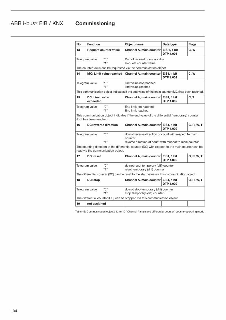
104
ABB i-bus® EIB / KNX Commissioning
No. Function Object name Data type Flags
13 Request counter value Channel A, main counter EIS 1, 1 bitDTP 1.003
C, W
Telegram value “0” Do not request counter value “1” Request counter value
The counter value can be requested via the communication object.
14 MC: Limit value reached Channel A, main counter EIS1, 1 bitDTP 1.002
C, W
Telegram value “0” limit value not reached“1” limit value reached
This communication object indicates if the end value of the main counter (MC) has been reached.
15 DC: Limit value exceeded
Channel A, main counter EIS1, 1 bitDTP 1.002
C, T
Telegram value “0” End limit not reached “1” End limit reached
This communication object indicates if the end value of the differential (temporary) counter (DC) has been reached.
16 DC: reverse direction Channel A, main counter EIS1, 1 bitDTP 1.002
C, R, W, T
Telegram value “0” do not reverse direction of count with respect to main counter
“1” reverse direction of count with respect to main counter
The counting direction of the differential counter (DC) with respect to the main counter can be read via the communication object.
17 DC: reset Channel A, main counter EIS1, 1 bitDTP 1.002
C, R, W, T
Telegram value “0” do not reset temporary (diff) counter “1” reset temporary (diff) counter
The differential counter (DC) can be reset to the start value via this communication object
18 DC: stop Channel A, main counter EIS1, 1 bitDTP 1.002
C, R, W, T
Telegram value “0” do not stop temporary (diff) counter “1” stop temporary (diff) counter
The differential counter (DC) can be stopped via this communication object.
19 not assigned
Table 45: Communication objects 13 to 19 “Channel A main and differential counter” counter operating mode
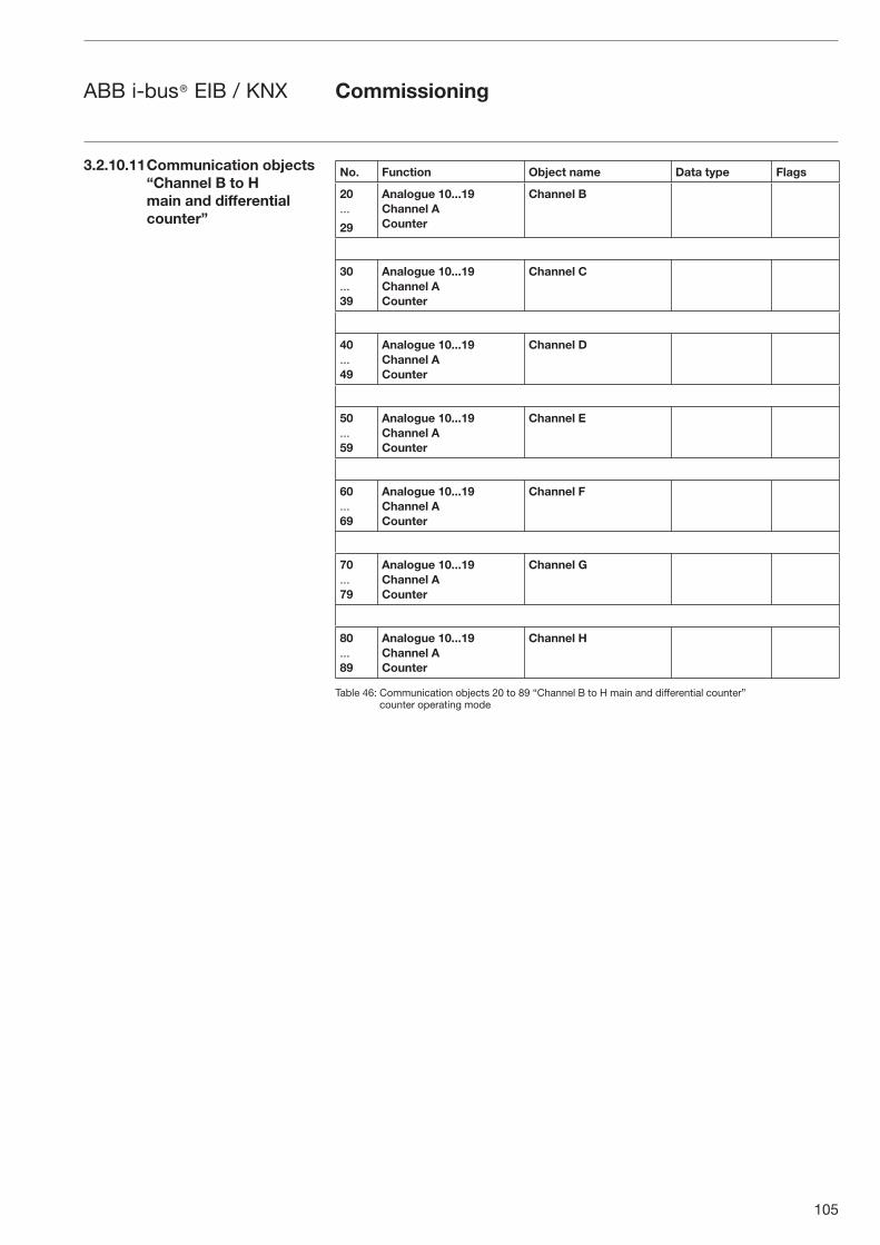
105
ABB i-bus® EIB / KNX Commissioning
No. Function Object name Data type Flags
20...
29
Analogue 10...19 Channel A Counter
Channel B
30...39
Analogue 10...19 Channel A Counter
Channel C
40...49
Analogue 10...19 Channel A Counter
Channel D
50...59
Analogue 10...19 Channel A Counter
Channel E
60...69
Analogue 10...19 Channel A Counter
Channel F
70...79
Analogue 10...19 Channel A Counter
Channel G
80...89
Analogue 10...19 Channel A Counter
Channel H
Table 46: Communication objects 20 to 89 “Channel B to H main and differential counter” counter operating mode
3.2.10.11 Communication objects “Channel B to H main and differential counter”
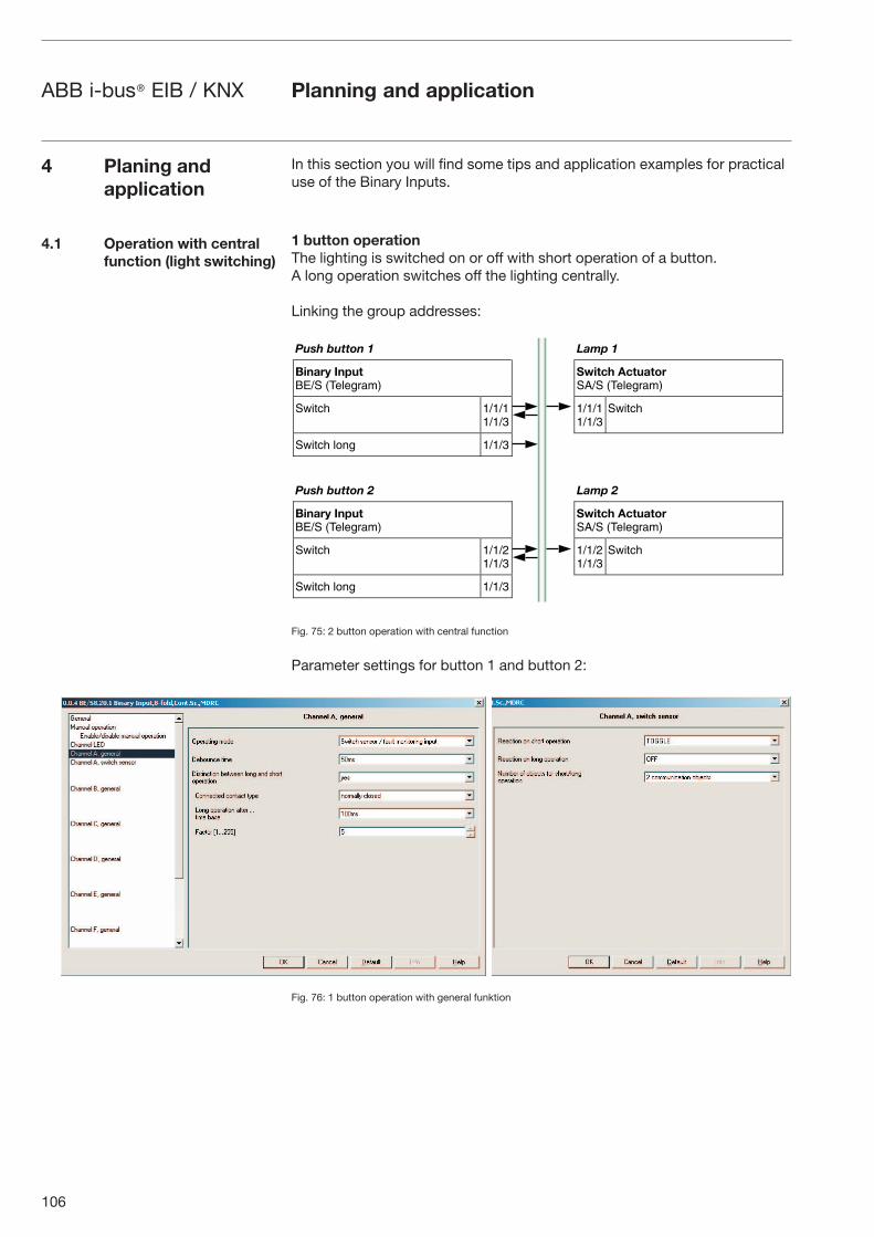
106
ABB i-bus® EIB / KNX Planning and application
In this section you will find some tips and application examples for practical use of the Binary Inputs.
1 button operationThe lighting is switched on or off with short operation of a button. A long operation switches off the lighting centrally.
Linking the group addresses:
Fig. 75: 2 button operation with central function
Parameter settings for button 1 and button 2:
Fig. 76: 1 button operation with general funktion
4 Planing and application
4.1 Operation with central function (light switching)
���� ������ ��
������ ������� �������
� ���� ����������� �������
������ ����������
����������
������
������ ��� �����
���� ������ � �� �
������ ������� �������
� ���� ����������� �������
������ ����������
����������
������
������ ��� �����
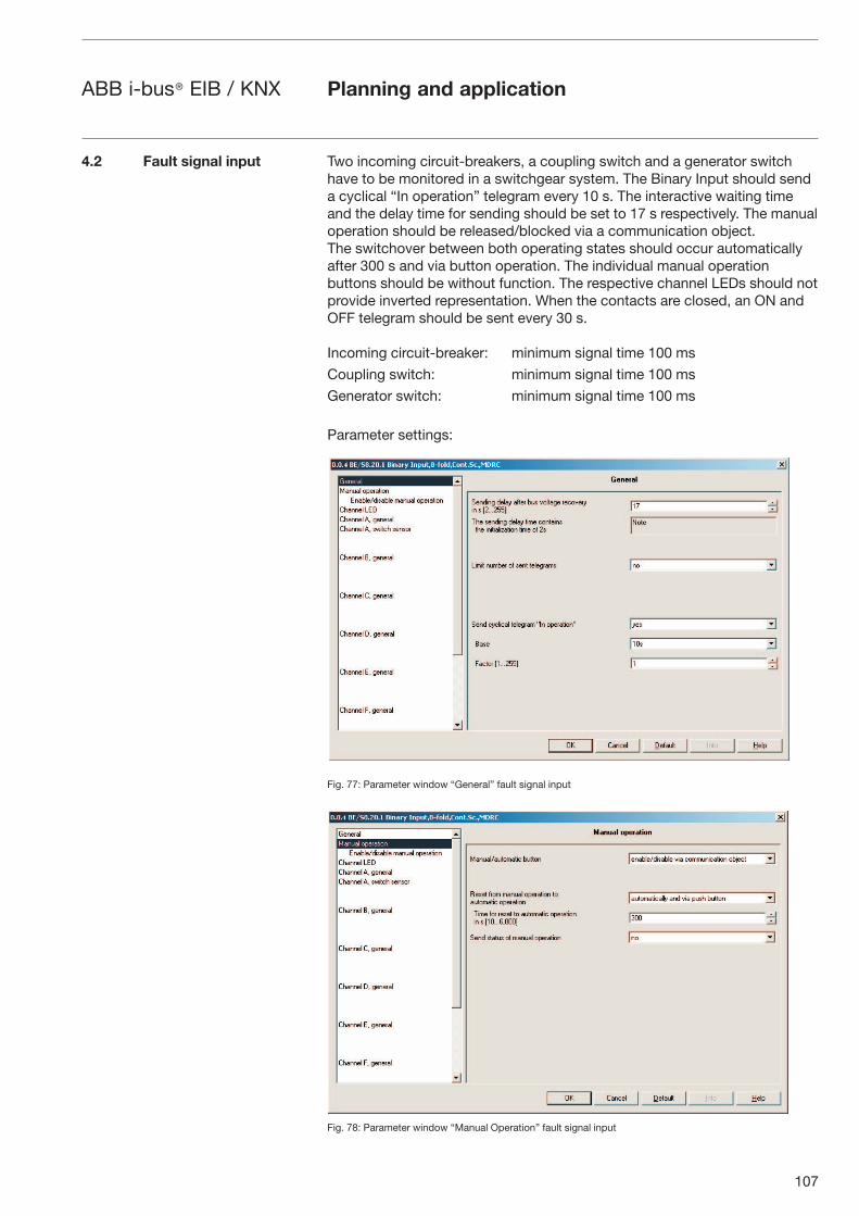
107
ABB i-bus® EIB / KNX Planning and application
Two incoming circuit-breakers, a coupling switch and a generator switch have to be monitored in a switchgear system. The Binary Input should send a cyclical “In operation” telegram every 10 s. The interactive waiting timeand the delay time for sending should be set to 17 s respectively. The manual operation should be released/blocked via a communication object. The switchover between both operating states should occur automatically after 300 s and via button operation. The individual manual operation buttons should be without function. The respective channel LEDs should not provide inverted representation. When the contacts are closed, an ON and OFF telegram should be sent every 30 s.
Incoming circuit-breaker: minimum signal time 100 ms
Coupling switch: minimum signal time 100 ms
Generator switch: minimum signal time 100 ms
Parameter settings:
Fig. 77: Parameter window “General” fault signal input
Fig. 78: Parameter window “Manual Operation” fault signal input
4.2 Fault signal input
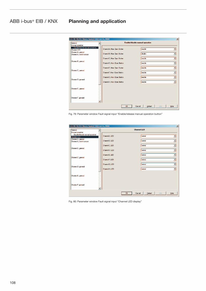
108
ABB i-bus® EIB / KNX Planning and application
Fig. 79: Parameter window Fault signal input “Enable/release manual operation button”
Fig. 80: Parameter window Fault signal input “Channel LED display”
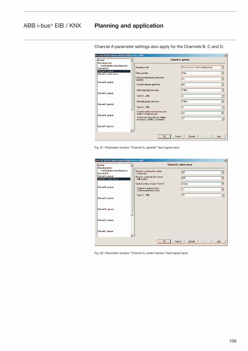
109
ABB i-bus® EIB / KNX Planning and application
Channel A parameter settings also apply for the Channels B, C and D.
Fig. 81: Parameter window “Channel A, general” fault signal input
Fig. 82: Parameter window “Channel A, switch sensor” fault signal input
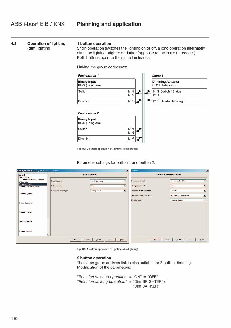
110
ABB i-bus® EIB / KNX Planning and application
1 button operationShort operation switches the lighting on or off, a long operation alternately dims the lighting brighter or darker (opposite to the last dim process). Both buttons operate the same luminaries.
Linking the group addresses:
Fig. 83: 2 button operation of lighting (dim lighting)
Parameter settings for button 1 and button 2:
Fig. 84: 1 button operation of lighting (dim lighting)
2 button operationThe same group address link is also suitable for 2 button dimming. Modification of the parameters:
“Reaction on short operation” = “ON” or “OFF““Reaction on long operation” = “Dim BRIGHTER” or
“Dim DARKER”
4.3 Operation of lighting (dim lighting)
���� ������ ��
������ ������� �������
������� ����������� �������
������ ����������
����������
������ � ������
������ ����� ����� ������� ������
���� ������ �
������ ������� �������
������ ����������
������ �����
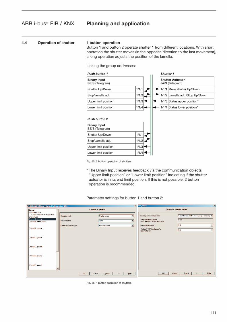
111
ABB i-bus® EIB / KNX Planning and application
1 button operationButton 1 and button 2 operate shutter 1 from different locations. With short operation the shutter moves (in the opposite direction to the last movement), a long operation adjusts the position of the lamella.
Linking the group addresses:
Fig. 85: 2 button operation of shutters
* The Binary Input receives feedback via the communication objects “Upper limit position” or “Lower limit position” indicating if the shutter actuator is in its end limit position. If this is not possible, 2 button operation is recommended.
Parameter settings for button 1 and button 2:
Fig. 86: 1 button operation of shutters
4.4 Operation of shutter
���� ������ �������
������ ������� �������
������ ������� ��� �������
������ �!����� ����� ����� "��� ������ �!�����
���!�������� ��#$ ����� ����� %������ ��#$ ����! �!�����
�!!� ����� !������� ����� ����� ������ �!!� !�������&
%��� ����� !������� ����' ����' ������ ���� !�������&
���� ������ �
������ ������� �������
������ �!����� �����
���!�%������ ��#$ �����
�!!� ����� !������� �����
%��� ����� !������� ����'
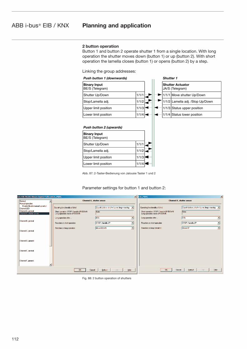
112
ABB i-bus® EIB / KNX Planning and application
2 button operationButton 1 and button 2 operate shutter 1 from a single location. With long operation the shutter moves down (button 1) or up (button 2). With short operation the lamella closes (button 1) or opens (button 2) by a step.
Linking the group addresses:
Abb. 87: 2-Taster-Bedienung von Jalousie Taster 1 und 2
Parameter settings for button 1 and button 2:
Fig. 88: 2 button operation of shutters
���� ������ ����������� �������
������ ������� �������
������ ������� ��� �������
������ �!����� ����� ����� "��� ������ �!�����
���!�%������ ��#$ ����� ����� %������ ��#$ ����! �!�����
�!!� ����� !������� ����� ����� ������ �!!� !�������
%��� ����� !������� ����' ����' ������ ���� !�������
���� ������ � �� ������
������ ������� �������
������ �!����� �����
���!�%������ ��#$ �����
�!!� ����� !������� �����
%��� ����� !������� ����'
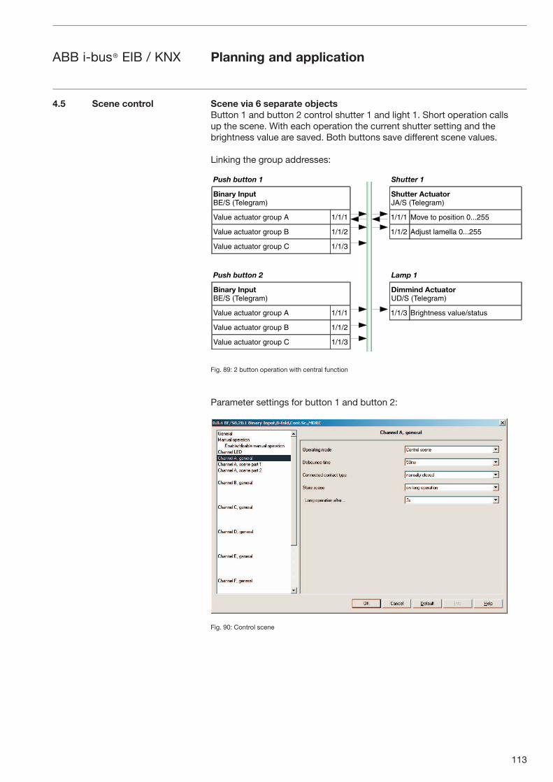
113
ABB i-bus® EIB / KNX Planning and application
Scene via 6 separate objectsButton 1 and button 2 control shutter 1 and light 1. Short operation calls up the scene. With each operation the current shutter setting and the brightness value are saved. Both buttons save different scene values.
Linking the group addresses:
Fig. 89: 2 button operation with central function
Parameter settings for button 1 and button 2:
Fig. 90: Control scene
4.5 Scene control
���� ������ �������
������ ������� �������
������ ������� ��� �������
(���� ������� ��! � ����� ����� "��� �� !������� )$$$�**
(���� ������� ��! � ����� ����� ��#��� ������� )$$$�**
(���� ������� ��! + �����
���� ������ � ��
������ ������� �������
������� ����������� �������
(���� ������� ��! � ����� ����� �������� ������������
(���� ������� ��! � �����
(���� ������� ��! + �����
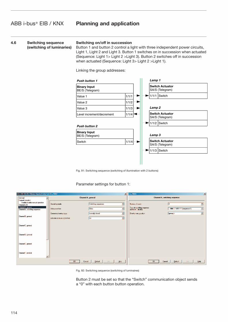
114
ABB i-bus® EIB / KNX Planning and application
Switching on/off in successionButton 1 and button 2 control a light with three independent power circuits, Light 1, Light 2 and Light 3. Button 1 switches on in succession when actuated (Sequence: Light 1> Light 2 >Light 3). Button 2 switches off in succession when actuated (Sequence: Light 3> Light 2 >Light 1).
Linking the group addresses:
Fig. 91: Switching sequence (switching of illumination with 2 buttons)
Parameter settings for button 1:
Fig. 92: Switching sequence (switching of luminaires)
Button 2 must be set so that the “Switch” communication object sends a “0” with each button button operation.
4.6 Switching sequence (switching of luminaries)
���� ������
������ ������� �������
(���� � �����
(���� � �����
(���� � �����
%���� ����������������� ����'
���� ������ �
������ ������� �������
������ ����'
��
� ���� ����������� �������
����� ������
�� �
� ���� ����������� �������
����� ������
�� �
� ���� ����������� �������
����� ������
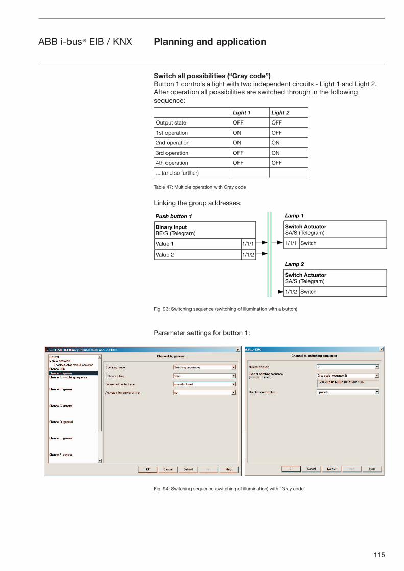
115
ABB i-bus® EIB / KNX Planning and application
Switch all possibilities (“Gray code”)Button 1 controls a light with two independent circuits - Light 1 and Light 2. After operation all possibilities are switched through in the following sequence:
Light 1 Light 2
Output state OFF OFF
1st operation ON OFF
2nd operation ON ON
3rd operation OFF ON
4th operation OFF OFF
... (and so further)
Table 47: Multiple operation with Gray code
Linking the group addresses:
Fig. 93: Switching sequence (switching of illumination with a button)
Parameter settings for button 1:
Fig. 94: Switching sequence (switching of illumination) with “Gray code”
���� ������
������ ������� �������
(���� � �����
(���� � �����
��
� ���� ����������� �������
����� ������
�� �
� ���� ����������� �������
����� ������
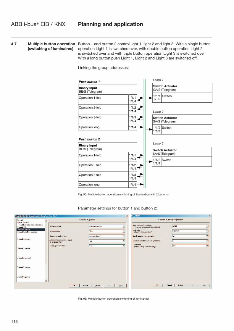
116
ABB i-bus® EIB / KNX Planning and application
Button 1 and button 2 control light 1, light 2 and light 3. With a single button operation Light 1 is switched over, with double button operation Light 2 is switched over and with triple button operation Light 3 is switched over. With a long button push Light 1, Light 2 and Light 3 are switched off.
Linking the group addresses:
Fig. 95: Multiple button operation (switching of illumination with 2 buttons)
Parameter settings for button 1 and button 2:
Fig. 96: Multiple button operation (switching of luminaries)
4.7 Multiple button operation (switching of luminaires)
���� ������
������ ������� �������
,!������ �-.��� ���������'
,!������ �-.��� ���������'
,!������ �-.��� ���������'
,!������ ��� ����'
���� ������ �
������ ������� �������
,!������ �-.��� ���������'
,!������ �-.��� ���������'
,!������ �-.��� ���������'
,!������ ��� ����'
������
������
� ���������������� !������"
#�#�$#�#�%
�&��'
������
� ���������������� !������"
#�#�##�#�%
�&��'
� ���������������� !������"
#�#�( �&��'#�#�%
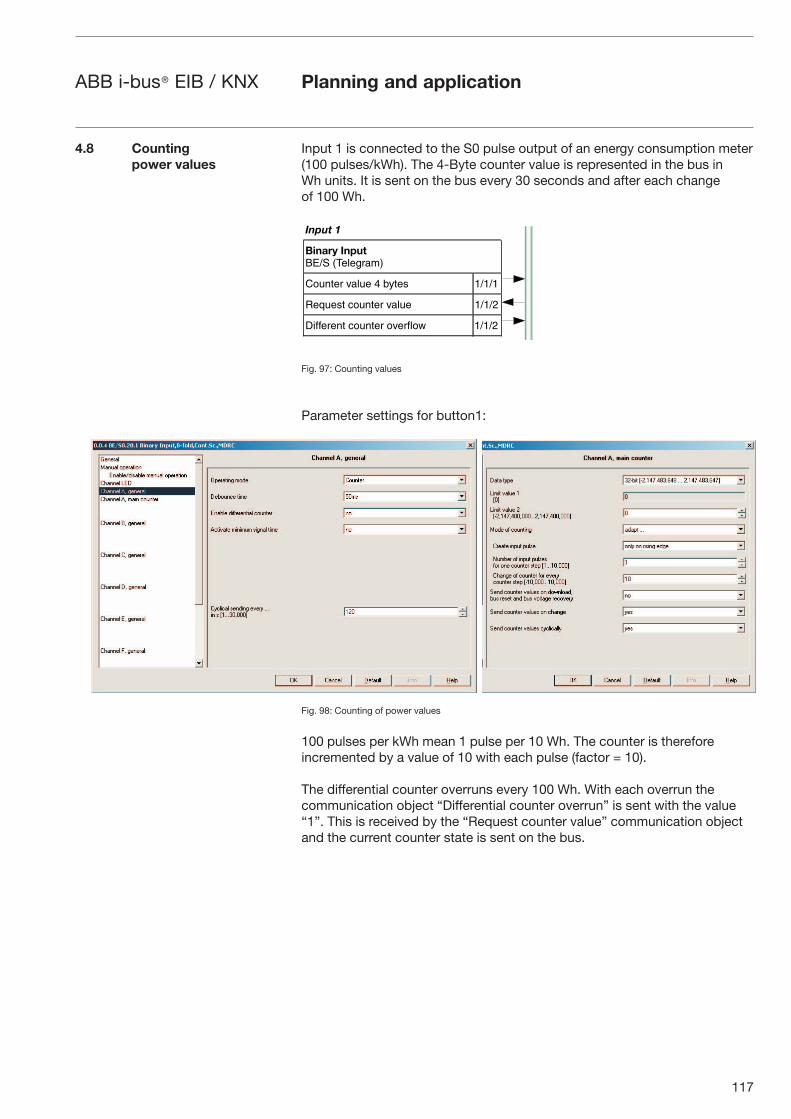
117
ABB i-bus® EIB / KNX Planning and application
Input 1 is connected to the S0 pulse output of an energy consumption meter(100 pulses/kWh). The 4-Byte counter value is represented in the bus in Wh units. It is sent on the bus every 30 seconds and after each change of 100 Wh.
Fig. 97: Counting values
Parameter settings for button1:
Fig. 98: Counting of power values
100 pulses per kWh mean 1 pulse per 10 Wh. The counter is therefore incremented by a value of 10 with each pulse (factor = 10).
The differential counter overruns every 100 Wh. With each overrun the communication object “Differential counter overrun” is sent with the value “1”. This is received by the “Request counter value” communication object and the current counter state is sent on the bus.
4.8 Counting power values
�� ��
������ ������� �������
+����� ����� ' /0��� �����
��1���� ������ ����� �����
��..���� ������ ���.��� �����

118
ABB i-bus® EIB / KNX
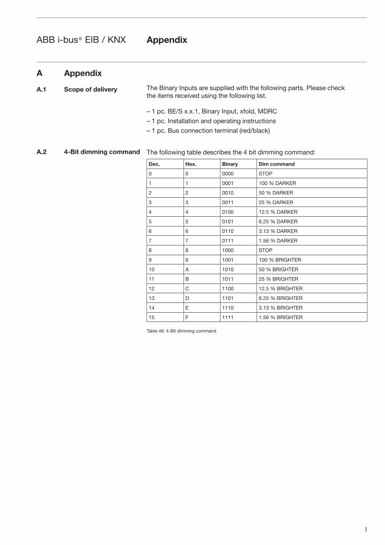
I
ABB i-bus® EIB / KNX Appendix
The Binary Inputs are supplied with the following parts. Please check the items received using the following list.
– 1 pc. BE/S x.x.1, Binary Input, xfold, MDRC
– 1 pc. Installation and operating instructions
– 1 pc. Bus connection terminal (red/black)
The following table describes the 4 bit dimming command:
Dec. Hex. Binary Dim command
0 0 0000 STOP
1 1 0001 100 % DARKER
2 2 0010 50 % DARKER
3 3 0011 25 % DARKER
4 4 0100 12.5 % DARKER
5 5 0101 6.25 % DARKER
6 6 0110 3.13 % DARKER
7 7 0111 1.56 % DARKER
8 8 1000 STOP
9 9 1001 100 % BRIGHTER
10 A 1010 50 % BRIGHTER
11 B 1011 25 % BRIGHTER
12 C 1100 12.5 % BRIGHTER
13 D 1101 6.25 % BRIGHTER
14 E 1110 3.13 % BRIGHTER
15 F 1111 1.56 % BRIGHTER
Table 48: 4-Bit dimming command
A Appendix
A.1 Scope of delivery
A.2 4-Bit dimming command
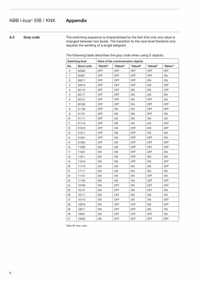
II
ABB i-bus® EIB / KNX Appendix
The switching sequence is characterised by the fact that only one value is changed between two levels. The transition to the next level therefore only requires the sending of a single telegram.
The following table describes the gray code when using 5 objects:
Switching level Value of the communication objects
No. Short code. “Value5” “Value4” “Value3” “Value2” “Value1”
0 00000 OFF OFF OFF OFF OFF
1 00001 OFF OFF OFF OFF ON
2 00011 OFF OFF OFF ON ON
3 00010 OFF OFF OFF ON OFF
4 00110 OFF OFF ON ON OFF
5 00111 OFF OFF ON ON ON
6 00101 OFF OFF ON OFF ON
7 00100 OFF OFF ON OFF OFF
8 01100 OFF ON ON OFF OFF
9 01101 OFF ON ON OFF ON
10 01111 OFF ON ON ON ON
11 01110 OFF ON ON ON OFF
12 01010 OFF ON OFF ON OFF
13 01011 OFF ON OFF ON ON
14 01001 OFF ON OFF OFF ON
15 01000 OFF ON OFF OFF OFF
16 11000 ON ON OFF OFF OFF
17 11001 ON ON OFF OFF ON
18 11011 ON ON OFF ON ON
19 11010 ON ON OFF ON OFF
20 11110 ON ON ON ON OFF
21 11111 ON ON ON ON ON
22 11101 ON ON ON OFF ON
23 11100 ON ON ON OFF OFF
24 10100 ON OFF ON OFF OFF
25 10101 ON OFF ON OFF ON
26 10111 ON OFF ON ON ON
27 10110 ON OFF ON ON OFF
28 10010 ON OFF OFF ON OFF
29 10011 ON OFF OFF ON ON
30 10001 ON OFF OFF OFF ON
31 10000 ON OFF OFF OFF OFF
Table 49: Gray code
A.3 Gray code
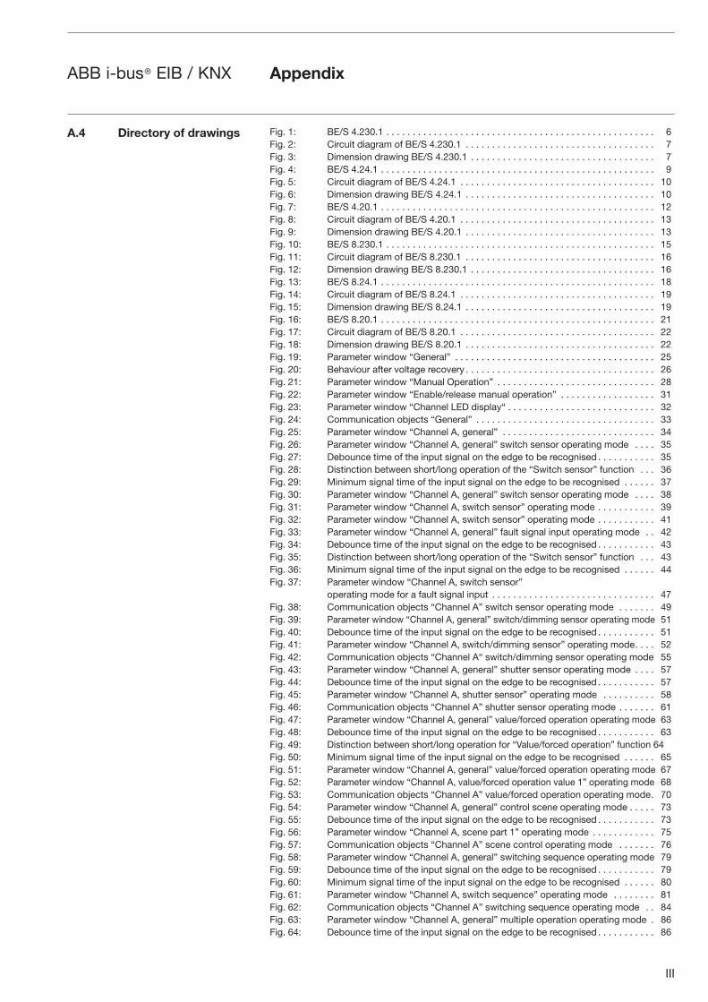
III
ABB i-bus® EIB / KNX Appendix
Fig. 1: BE/S 4.230.1 . . . . . . . . . . . . . . . . . . . . . . . . . . . . . . . . . . . . . . . . . . . . . . . . . . . 6Fig. 2: Circuit diagram of BE/S 4.230.1 . . . . . . . . . . . . . . . . . . . . . . . . . . . . . . . . . . . . 7Fig. 3: Dimension drawing BE/S 4.230.1 . . . . . . . . . . . . . . . . . . . . . . . . . . . . . . . . . . . 7Fig. 4: BE/S 4.24.1 . . . . . . . . . . . . . . . . . . . . . . . . . . . . . . . . . . . . . . . . . . . . . . . . . . . . 9Fig. 5: Circuit diagram of BE/S 4.24.1 . . . . . . . . . . . . . . . . . . . . . . . . . . . . . . . . . . . . . 10Fig. 6: Dimension drawing BE/S 4.24.1 . . . . . . . . . . . . . . . . . . . . . . . . . . . . . . . . . . . . 10Fig. 7: BE/S 4.20.1 . . . . . . . . . . . . . . . . . . . . . . . . . . . . . . . . . . . . . . . . . . . . . . . . . . . . 12Fig. 8: Circuit diagram of BE/S 4.20.1 . . . . . . . . . . . . . . . . . . . . . . . . . . . . . . . . . . . . . 13Fig. 9: Dimension drawing BE/S 4.20.1 . . . . . . . . . . . . . . . . . . . . . . . . . . . . . . . . . . . . 13Fig. 10: BE/S 8.230.1 . . . . . . . . . . . . . . . . . . . . . . . . . . . . . . . . . . . . . . . . . . . . . . . . . . . 15Fig. 11: Circuit diagram of BE/S 8.230.1 . . . . . . . . . . . . . . . . . . . . . . . . . . . . . . . . . . . . 16Fig. 12: Dimension drawing BE/S 8.230.1 . . . . . . . . . . . . . . . . . . . . . . . . . . . . . . . . . . . 16Fig. 13: BE/S 8.24.1 . . . . . . . . . . . . . . . . . . . . . . . . . . . . . . . . . . . . . . . . . . . . . . . . . . . . 18Fig. 14: Circuit diagram of BE/S 8.24.1 . . . . . . . . . . . . . . . . . . . . . . . . . . . . . . . . . . . . . 19Fig. 15: Dimension drawing BE/S 8.24.1 . . . . . . . . . . . . . . . . . . . . . . . . . . . . . . . . . . . . 19Fig. 16: BE/S 8.20.1 . . . . . . . . . . . . . . . . . . . . . . . . . . . . . . . . . . . . . . . . . . . . . . . . . . . . 21Fig. 17: Circuit diagram of BE/S 8.20.1 . . . . . . . . . . . . . . . . . . . . . . . . . . . . . . . . . . . . . 22Fig. 18: Dimension drawing BE/S 8.20.1 . . . . . . . . . . . . . . . . . . . . . . . . . . . . . . . . . . . . 22Fig. 19: Parameter window “General” . . . . . . . . . . . . . . . . . . . . . . . . . . . . . . . . . . . . . . 25Fig. 20: Behaviour after voltage recovery . . . . . . . . . . . . . . . . . . . . . . . . . . . . . . . . . . . . 26Fig. 21: Parameter window “Manual Operation” . . . . . . . . . . . . . . . . . . . . . . . . . . . . . . 28Fig. 22: Parameter window “Enable/release manual operation” . . . . . . . . . . . . . . . . . . 31Fig. 23: Parameter window “Channel LED display“ . . . . . . . . . . . . . . . . . . . . . . . . . . . . 32Fig. 24: Communication objects “General” . . . . . . . . . . . . . . . . . . . . . . . . . . . . . . . . . . 33Fig. 25: Parameter window “Channel A, general” . . . . . . . . . . . . . . . . . . . . . . . . . . . . . 34Fig. 26: Parameter window “Channel A, general” switch sensor operating mode . . . . 35Fig. 27: Debounce time of the input signal on the edge to be recognised . . . . . . . . . . . 35Fig. 28: Distinction between short/long operation of the “Switch sensor” function . . . 36Fig. 29: Minimum signal time of the input signal on the edge to be recognised . . . . . . 37Fig. 30: Parameter window “Channel A, general” switch sensor operating mode . . . . 38Fig. 31: Parameter window “Channel A, switch sensor” operating mode . . . . . . . . . . . 39Fig. 32: Parameter window “Channel A, switch sensor” operating mode . . . . . . . . . . . 41Fig. 33: Parameter window “Channel A, general” fault signal input operating mode . . 42Fig. 34: Debounce time of the input signal on the edge to be recognised . . . . . . . . . . . 43Fig. 35: Distinction between short/long operation of the “Switch sensor” function . . . 43Fig. 36: Minimum signal time of the input signal on the edge to be recognised . . . . . . 44Fig. 37: Parameter window “Channel A, switch sensor”
operating mode for a fault signal input . . . . . . . . . . . . . . . . . . . . . . . . . . . . . . . 47Fig. 38: Communication objects “Channel A” switch sensor operating mode . . . . . . . 49Fig. 39: Parameter window “Channel A, general” switch/dimming sensor operating mode 51Fig. 40: Debounce time of the input signal on the edge to be recognised . . . . . . . . . . . 51Fig. 41: Parameter window “Channel A, switch/dimming sensor” operating mode . . . . 52Fig. 42: Communication objects “Channel A“ switch/dimming sensor operating mode 55Fig. 43: Parameter window “Channel A, general” shutter sensor operating mode . . . . 57Fig. 44: Debounce time of the input signal on the edge to be recognised . . . . . . . . . . . 57Fig. 45: Parameter window “Channel A, shutter sensor” operating mode . . . . . . . . . . 58Fig. 46: Communication objects “Channel A” shutter sensor operating mode . . . . . . . 61Fig. 47: Parameter window “Channel A, general” value/forced operation operating mode 63Fig. 48: Debounce time of the input signal on the edge to be recognised . . . . . . . . . . . 63Fig. 49: Distinction between short/long operation for “Value/forced operation” function 64Fig. 50: Minimum signal time of the input signal on the edge to be recognised . . . . . . 65Fig. 51: Parameter window “Channel A, general” value/forced operation operating mode 67Fig. 52: Parameter window “Channel A, value/forced operation value 1” operating mode 68Fig. 53: Communication objects “Channel A” value/forced operation operating mode . 70Fig. 54: Parameter window “Channel A, general” control scene operating mode . . . . . 73Fig. 55: Debounce time of the input signal on the edge to be recognised . . . . . . . . . . . 73Fig. 56: Parameter window “Channel A, scene part 1” operating mode . . . . . . . . . . . . 75Fig. 57: Communication objects “Channel A” scene control operating mode . . . . . . . 76Fig. 58: Parameter window “Channel A, general” switching sequence operating mode 79Fig. 59: Debounce time of the input signal on the edge to be recognised . . . . . . . . . . . 79Fig. 60: Minimum signal time of the input signal on the edge to be recognised . . . . . . 80Fig. 61: Parameter window “Channel A, switch sequence” operating mode . . . . . . . . 81Fig. 62: Communication objects “Channel A” switching sequence operating mode . . 84Fig. 63: Parameter window “Channel A, general” multiple operation operating mode . 86Fig. 64: Debounce time of the input signal on the edge to be recognised . . . . . . . . . . . 86
A.4 Directory of drawings
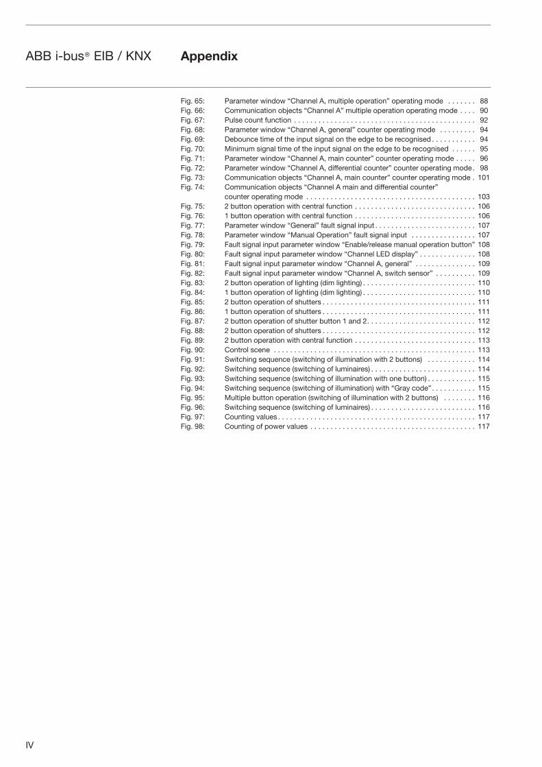
IV
ABB i-bus® EIB / KNX Appendix
Fig. 65: Parameter window “Channel A, multiple operation” operating mode . . . . . . . 88Fig. 66: Communication objects “Channel A” multiple operation operating mode . . . . 90Fig. 67: Pulse count function . . . . . . . . . . . . . . . . . . . . . . . . . . . . . . . . . . . . . . . . . . . . . 92Fig. 68: Parameter window “Channel A, general” counter operating mode . . . . . . . . . 94Fig. 69: Debounce time of the input signal on the edge to be recognised . . . . . . . . . . . 94Fig. 70: Minimum signal time of the input signal on the edge to be recognised . . . . . . 95Fig. 71: Parameter window “Channel A, main counter” counter operating mode . . . . . 96Fig. 72: Parameter window “Channel A, differential counter” counter operating mode . 98Fig. 73: Communication objects “Channel A, main counter” counter operating mode . 101Fig. 74: Communication objects “Channel A main and differential counter” counter operating mode . . . . . . . . . . . . . . . . . . . . . . . . . . . . . . . . . . . . . . . . . . 103Fig. 75: 2 button operation with central function . . . . . . . . . . . . . . . . . . . . . . . . . . . . . . 106Fig. 76: 1 button operation with central function . . . . . . . . . . . . . . . . . . . . . . . . . . . . . . 106Fig. 77: Parameter window “General” fault signal input . . . . . . . . . . . . . . . . . . . . . . . . . 107Fig. 78: Parameter window “Manual Operation” fault signal input . . . . . . . . . . . . . . . . 107Fig. 79: Fault signal input parameter window “Enable/release manual operation button” 108Fig. 80: Fault signal input parameter window “Channel LED display” . . . . . . . . . . . . . . 108Fig. 81: Fault signal input parameter window “Channel A, general” . . . . . . . . . . . . . . . 109Fig. 82: Fault signal input parameter window “Channel A, switch sensor” . . . . . . . . . . 109Fig. 83: 2 button operation of lighting (dim lighting) . . . . . . . . . . . . . . . . . . . . . . . . . . . . 110Fig. 84: 1 button operation of lighting (dim lighting) . . . . . . . . . . . . . . . . . . . . . . . . . . . . 110Fig. 85: 2 button operation of shutters . . . . . . . . . . . . . . . . . . . . . . . . . . . . . . . . . . . . . . 111Fig. 86: 1 button operation of shutters . . . . . . . . . . . . . . . . . . . . . . . . . . . . . . . . . . . . . . 111Fig. 87: 2 button operation of shutter button 1 and 2 . . . . . . . . . . . . . . . . . . . . . . . . . . . 112Fig. 88: 2 button operation of shutters . . . . . . . . . . . . . . . . . . . . . . . . . . . . . . . . . . . . . . 112Fig. 89: 2 button operation with central function . . . . . . . . . . . . . . . . . . . . . . . . . . . . . . 113Fig. 90: Control scene . . . . . . . . . . . . . . . . . . . . . . . . . . . . . . . . . . . . . . . . . . . . . . . . . . 113Fig. 91: Switching sequence (switching of illumination with 2 buttons) . . . . . . . . . . . . 114Fig. 92: Switching sequence (switching of luminaires) . . . . . . . . . . . . . . . . . . . . . . . . . . 114Fig. 93: Switching sequence (switching of illumination with one button) . . . . . . . . . . . . 115Fig. 94: Switching sequence (switching of illumination) with “Gray code” . . . . . . . . . . . 115Fig. 95: Multiple button operation (switching of illumination with 2 buttons) . . . . . . . . 116Fig. 96: Switching sequence (switching of luminaires) . . . . . . . . . . . . . . . . . . . . . . . . . . 116Fig. 97: Counting values . . . . . . . . . . . . . . . . . . . . . . . . . . . . . . . . . . . . . . . . . . . . . . . . . 117Fig. 98: Counting of power values . . . . . . . . . . . . . . . . . . . . . . . . . . . . . . . . . . . . . . . . . 117
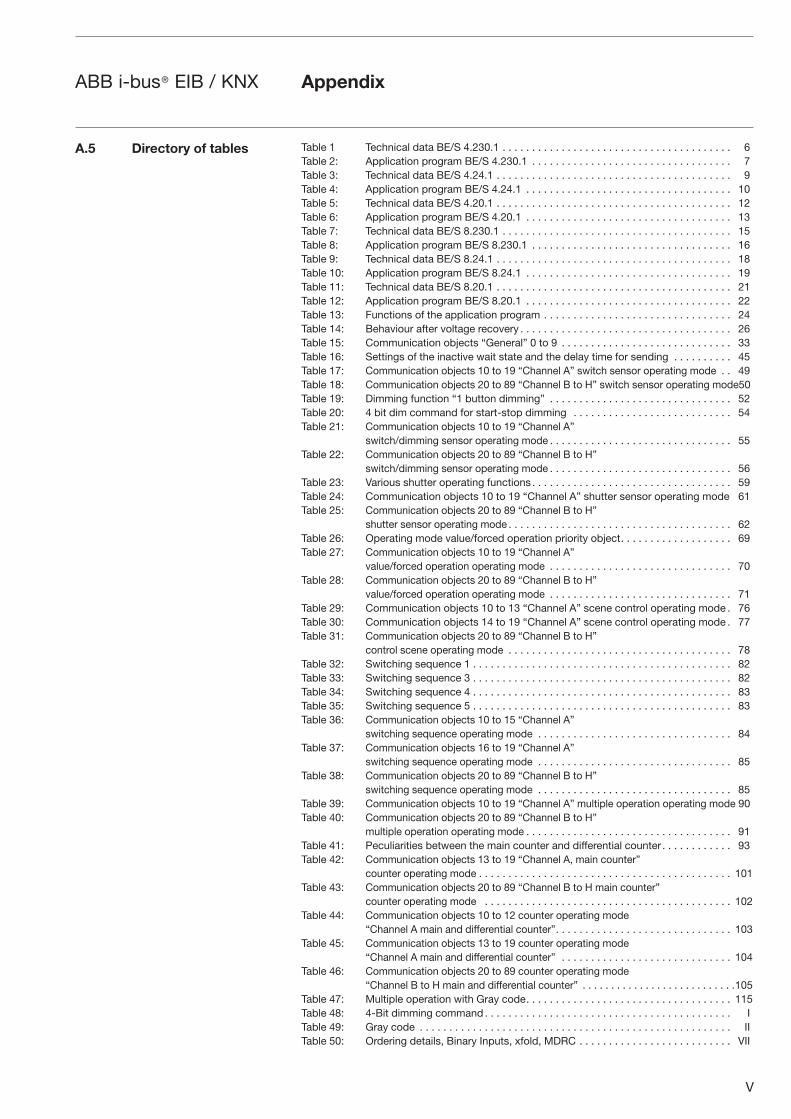
V
ABB i-bus® EIB / KNX Appendix
Table 1 Technical data BE/S 4.230.1 . . . . . . . . . . . . . . . . . . . . . . . . . . . . . . . . . . . . . . . 6Table 2: Application program BE/S 4.230.1 . . . . . . . . . . . . . . . . . . . . . . . . . . . . . . . . . . 7Table 3: Technical data BE/S 4.24.1 . . . . . . . . . . . . . . . . . . . . . . . . . . . . . . . . . . . . . . . . 9Table 4: Application program BE/S 4.24.1 . . . . . . . . . . . . . . . . . . . . . . . . . . . . . . . . . . . 10Table 5: Technical data BE/S 4.20.1 . . . . . . . . . . . . . . . . . . . . . . . . . . . . . . . . . . . . . . . . 12Table 6: Application program BE/S 4.20.1 . . . . . . . . . . . . . . . . . . . . . . . . . . . . . . . . . . . 13Table 7: Technical data BE/S 8.230.1 . . . . . . . . . . . . . . . . . . . . . . . . . . . . . . . . . . . . . . . 15Table 8: Application program BE/S 8.230.1 . . . . . . . . . . . . . . . . . . . . . . . . . . . . . . . . . . 16Table 9: Technical data BE/S 8.24.1 . . . . . . . . . . . . . . . . . . . . . . . . . . . . . . . . . . . . . . . . 18Table 10: Application program BE/S 8.24.1 . . . . . . . . . . . . . . . . . . . . . . . . . . . . . . . . . . . 19Table 11: Technical data BE/S 8.20.1 . . . . . . . . . . . . . . . . . . . . . . . . . . . . . . . . . . . . . . . . 21Table 12: Application program BE/S 8.20.1 . . . . . . . . . . . . . . . . . . . . . . . . . . . . . . . . . . . 22Table 13: Functions of the application program . . . . . . . . . . . . . . . . . . . . . . . . . . . . . . . . 24Table 14: Behaviour after voltage recovery . . . . . . . . . . . . . . . . . . . . . . . . . . . . . . . . . . . . 26Table 15: Communication objects “General” 0 to 9 . . . . . . . . . . . . . . . . . . . . . . . . . . . . . 33Table 16: Settings of the inactive wait state and the delay time for sending . . . . . . . . . . 45Table 17: Communication objects 10 to 19 “Channel A” switch sensor operating mode . . 49Table 18: Communication objects 20 to 89 “Channel B to H” switch sensor operating mode 50Table 19: Dimming function “1 button dimming” . . . . . . . . . . . . . . . . . . . . . . . . . . . . . . . 52Table 20: 4 bit dim command for start-stop dimming . . . . . . . . . . . . . . . . . . . . . . . . . . . 54Table 21: Communication objects 10 to 19 “Channel A”
switch/dimming sensor operating mode . . . . . . . . . . . . . . . . . . . . . . . . . . . . . . . 55Table 22: Communication objects 20 to 89 “Channel B to H”
switch/dimming sensor operating mode . . . . . . . . . . . . . . . . . . . . . . . . . . . . . . . 56Table 23: Various shutter operating functions . . . . . . . . . . . . . . . . . . . . . . . . . . . . . . . . . . 59Table 24: Communication objects 10 to 19 “Channel A” shutter sensor operating mode 61Table 25: Communication objects 20 to 89 “Channel B to H”
shutter sensor operating mode . . . . . . . . . . . . . . . . . . . . . . . . . . . . . . . . . . . . . . 62Table 26: Operating mode value/forced operation priority object . . . . . . . . . . . . . . . . . . . 69Table 27: Communication objects 10 to 19 “Channel A”
value/forced operation operating mode . . . . . . . . . . . . . . . . . . . . . . . . . . . . . . . 70Table 28: Communication objects 20 to 89 “Channel B to H”
value/forced operation operating mode . . . . . . . . . . . . . . . . . . . . . . . . . . . . . . . 71Table 29: Communication objects 10 to 13 “Channel A” scene control operating mode . 76Table 30: Communication objects 14 to 19 “Channel A” scene control operating mode . 77Table 31: Communication objects 20 to 89 “Channel B to H”
control scene operating mode . . . . . . . . . . . . . . . . . . . . . . . . . . . . . . . . . . . . . . 78Table 32: Switching sequence 1 . . . . . . . . . . . . . . . . . . . . . . . . . . . . . . . . . . . . . . . . . . . . 82Table 33: Switching sequence 3 . . . . . . . . . . . . . . . . . . . . . . . . . . . . . . . . . . . . . . . . . . . . 82Table 34: Switching sequence 4 . . . . . . . . . . . . . . . . . . . . . . . . . . . . . . . . . . . . . . . . . . . . 83Table 35: Switching sequence 5 . . . . . . . . . . . . . . . . . . . . . . . . . . . . . . . . . . . . . . . . . . . . 83Table 36: Communication objects 10 to 15 “Channel A”
switching sequence operating mode . . . . . . . . . . . . . . . . . . . . . . . . . . . . . . . . . 84Table 37: Communication objects 16 to 19 “Channel A”
switching sequence operating mode . . . . . . . . . . . . . . . . . . . . . . . . . . . . . . . . . 85Table 38: Communication objects 20 to 89 “Channel B to H”
switching sequence operating mode . . . . . . . . . . . . . . . . . . . . . . . . . . . . . . . . . 85Table 39: Communication objects 10 to 19 “Channel A” multiple operation operating mode 90Table 40: Communication objects 20 to 89 “Channel B to H”
multiple operation operating mode . . . . . . . . . . . . . . . . . . . . . . . . . . . . . . . . . . . 91Table 41: Peculiarities between the main counter and differential counter . . . . . . . . . . . . 93Table 42: Communication objects 13 to 19 “Channel A, main counter”
counter operating mode . . . . . . . . . . . . . . . . . . . . . . . . . . . . . . . . . . . . . . . . . . . 101Table 43: Communication objects 20 to 89 “Channel B to H main counter”
counter operating mode . . . . . . . . . . . . . . . . . . . . . . . . . . . . . . . . . . . . . . . . . . 102Table 44: Communication objects 10 to 12 counter operating mode “Channel A main and differential counter” . . . . . . . . . . . . . . . . . . . . . . . . . . . . . . 103Table 45: Communication objects 13 to 19 counter operating mode “Channel A main and differential counter” . . . . . . . . . . . . . . . . . . . . . . . . . . . . . 104Table 46: Communication objects 20 to 89 counter operating mode “Channel B to H main and differential counter” . . . . . . . . . . . . . . . . . . . . . . . . . . . 105Table 47: Multiple operation with Gray code . . . . . . . . . . . . . . . . . . . . . . . . . . . . . . . . . . . 115Table 48: 4-Bit dimming command . . . . . . . . . . . . . . . . . . . . . . . . . . . . . . . . . . . . . . . . . . ITable 49: Gray code . . . . . . . . . . . . . . . . . . . . . . . . . . . . . . . . . . . . . . . . . . . . . . . . . . . . . IITable 50: Ordering details, Binary Inputs, xfold, MDRC . . . . . . . . . . . . . . . . . . . . . . . . . . VII
A.5 Directory of tables
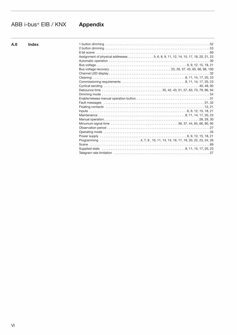
VI
ABB i-bus® EIB / KNX Appendix
1 button dimming . . . . . . . . . . . . . . . . . . . . . . . . . . . . . . . . . . . . . . . . . . . . . . . . . . . . . . . . . . . 522 button dimming . . . . . . . . . . . . . . . . . . . . . . . . . . . . . . . . . . . . . . . . . . . . . . . . . . . . . . . . . . . 538 bit scene . . . . . . . . . . . . . . . . . . . . . . . . . . . . . . . . . . . . . . . . . . . . . . . . . . . . . . . . . . . . . . . . 69Assignment of physical addresses . . . . . . . . . . . . . . 5, 6, 8, 9, 11, 12, 14, 15, 17, 18, 20, 21, 23Automatic operation . . . . . . . . . . . . . . . . . . . . . . . . . . . . . . . . . . . . . . . . . . . . . . . . . . . . . . . . . 30Bus voltage . . . . . . . . . . . . . . . . . . . . . . . . . . . . . . . . . . . . . . . . . . . . . . . . . . . 6, 9, 12, 15, 18, 21Bus voltage recovery . . . . . . . . . . . . . . . . . . . . . . . . . . . . . . . . . . . 25, 26, 37, 45, 65, 66, 98, 100Channel LED display . . . . . . . . . . . . . . . . . . . . . . . . . . . . . . . . . . . . . . . . . . . . . . . . . . . . . . . . . 32Cleaning . . . . . . . . . . . . . . . . . . . . . . . . . . . . . . . . . . . . . . . . . . . . . . . . . . . . 8, 11, 14, 17, 20, 23Commissioning requirements . . . . . . . . . . . . . . . . . . . . . . . . . . . . . . . . . . . . 8, 11, 14, 17, 20, 23Cyclical sending . . . . . . . . . . . . . . . . . . . . . . . . . . . . . . . . . . . . . . . . . . . . . . . . . . . . . . 40, 48, 95Debounce time . . . . . . . . . . . . . . . . . . . . . . . . . . . . . . . . . . 35, 42, 43, 51, 57, 63, 73, 79, 86, 94Dimming mode . . . . . . . . . . . . . . . . . . . . . . . . . . . . . . . . . . . . . . . . . . . . . . . . . . . . . . . . . . . . . 54Enable/release manual operation button . . . . . . . . . . . . . . . . . . . . . . . . . . . . . . . . . . . . . . . . . . 31Fault messages . . . . . . . . . . . . . . . . . . . . . . . . . . . . . . . . . . . . . . . . . . . . . . . . . . . . . . . . . 31, 32Floating contacts . . . . . . . . . . . . . . . . . . . . . . . . . . . . . . . . . . . . . . . . . . . . . . . . . . . . . . . . 12, 21Inputs . . . . . . . . . . . . . . . . . . . . . . . . . . . . . . . . . . . . . . . . . . . . . . . . . . . . . . . 6, 9, 12, 15, 18, 21Maintenance . . . . . . . . . . . . . . . . . . . . . . . . . . . . . . . . . . . . . . . . . . . . . . . . . 8, 11, 14, 17, 20, 23Manual operation . . . . . . . . . . . . . . . . . . . . . . . . . . . . . . . . . . . . . . . . . . . . . . . . . . . . . . 28, 29, 30Minumum signal time . . . . . . . . . . . . . . . . . . . . . . . . . . . . . . . . . . . . . . 36, 37, 44, 65, 66, 80, 95Observation period . . . . . . . . . . . . . . . . . . . . . . . . . . . . . . . . . . . . . . . . . . . . . . . . . . . . . . . . . . 27Operating mode . . . . . . . . . . . . . . . . . . . . . . . . . . . . . . . . . . . . . . . . . . . . . . . . . . . . . . . . . . . . 34Power supply . . . . . . . . . . . . . . . . . . . . . . . . . . . . . . . . . . . . . . . . . . . . . . . . . 6, 9, 12, 15, 18, 21Programming . . . . . . . . . . . . . . . . . . . . . . .4, 7, 8 , 10, 11, 13, 14, 16, 17, 19, 20, 22, 23, 24, 26Scene . . . . . . . . . . . . . . . . . . . . . . . . . . . . . . . . . . . . . . . . . . . . . . . . . . . . . . . . . . . . . . . . . . . . 69Supplied state . . . . . . . . . . . . . . . . . . . . . . . . . . . . . . . . . . . . . . . . . . . . . . . 8, 11, 14, 17, 20, 23Telegram rate limitation . . . . . . . . . . . . . . . . . . . . . . . . . . . . . . . . . . . . . . . . . . . . . . . . . . . . . . 27
A.6 Index
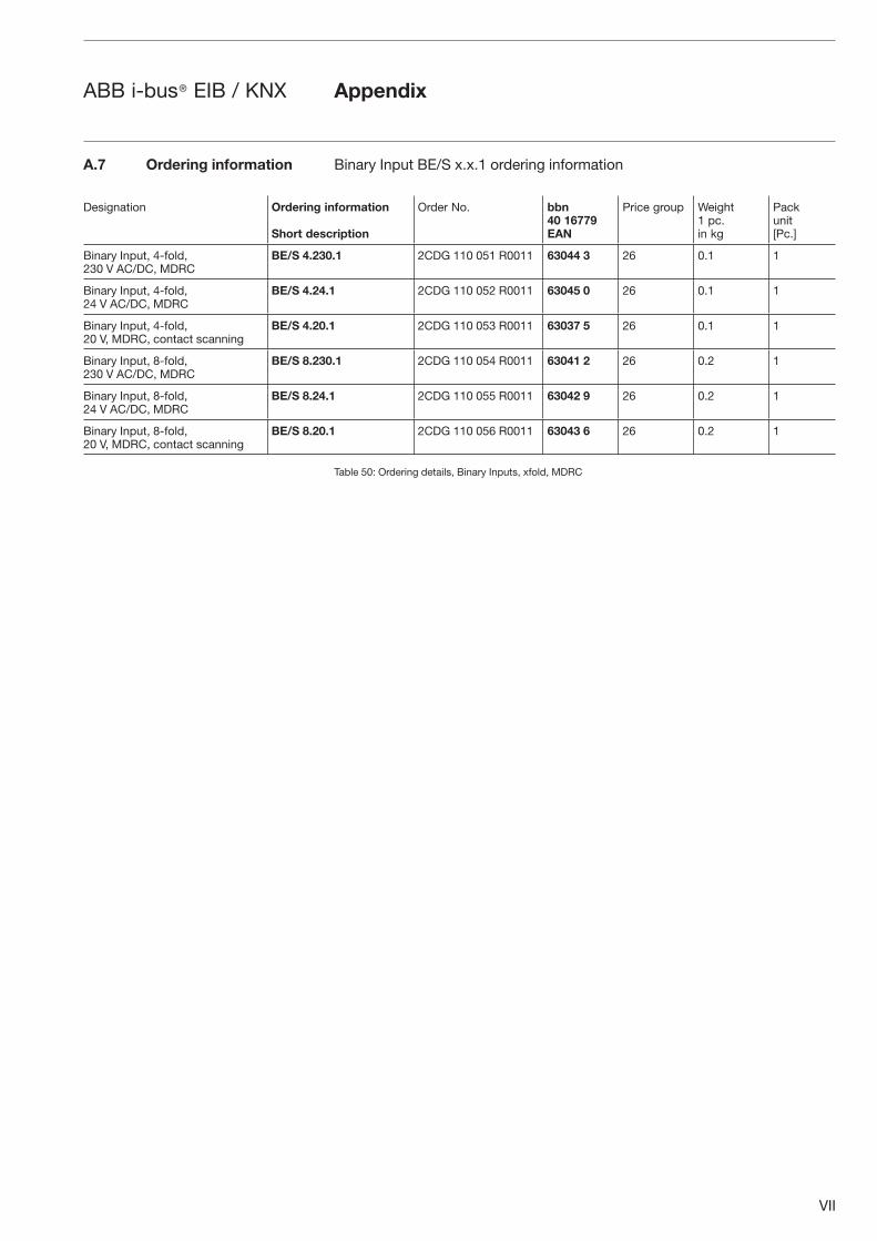
VII
ABB i-bus® EIB / KNX Appendix
Binary Input BE/S x.x.1 ordering information
Table 50: Ordering details, Binary Inputs, xfold, MDRC
A.7 Ordering information
Designation Ordering information
Short description
Order No. bbn40 16779EAN
Price group Weight1 pc.in kg
Pack unit[Pc.]
Binary Input, 4-fold,230 V AC/DC, MDRC
BE/S 4.230.1 2CDG 110 051 R0011 63044 3 26 0.1 1
Binary Input, 4-fold,24 V AC/DC, MDRC
BE/S 4.24.1 2CDG 110 052 R0011 63045 0 26 0.1 1
Binary Input, 4-fold,20 V, MDRC, contact scanning
BE/S 4.20.1 2CDG 110 053 R0011 63037 5 26 0.1 1
Binary Input, 8-fold,230 V AC/DC, MDRC
BE/S 8.230.1 2CDG 110 054 R0011 63041 2 26 0.2 1
Binary Input, 8-fold,24 V AC/DC, MDRC
BE/S 8.24.1 2CDG 110 055 R0011 63042 9 26 0.2 1
Binary Input, 8-fold,20 V, MDRC, contact scanning
BE/S 8.20.1 2CDG 110 056 R0011 63043 6 26 0.2 1
VIII
ABB i-bus® EIB / KNX
A.8 Notes
Appendix
IX
ABB i-bus® EIB / KNX Appendix
X
ABB i-bus® EIB / KNX Appendix

The information in this leaflet is subject to change without further notice. Pub
. No.
2C
DC
504
042
D02
01
Your EIB-Partner