Embed Size (px)
Citation preview
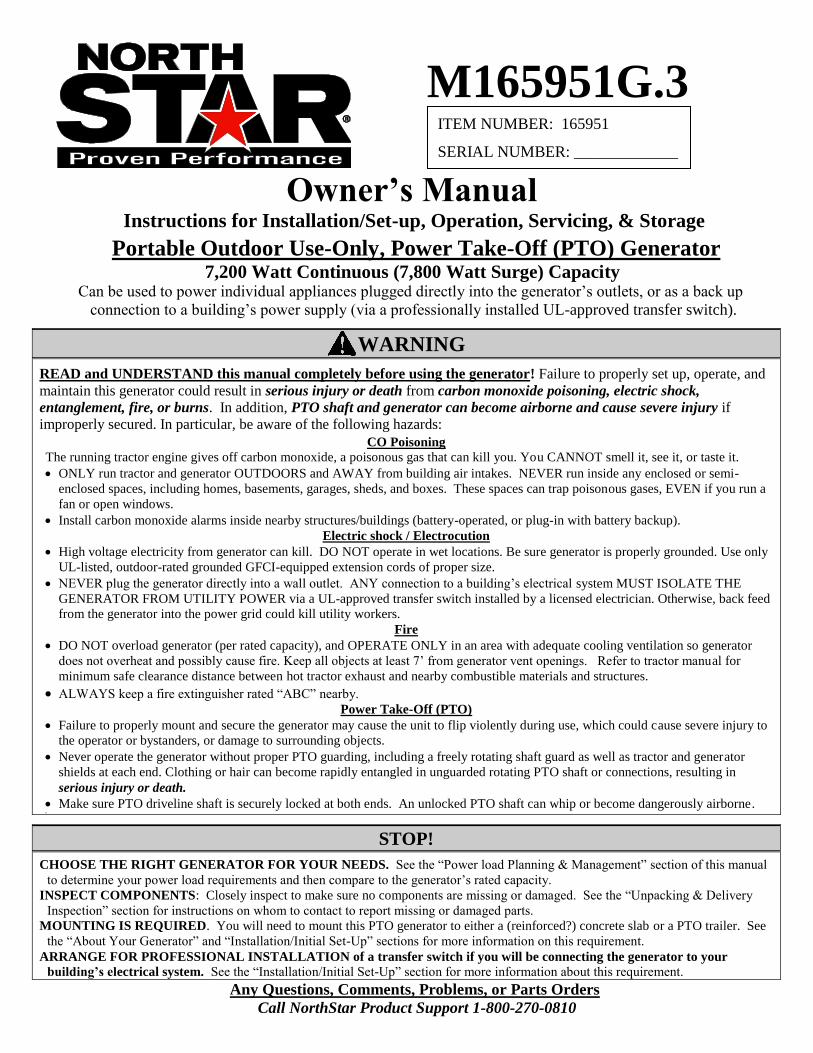
M165951G.3
Owner’s Manual Instructions for Installation/Set-up, Operation, Servicing, & Storage
Portable Outdoor Use-Only, Power Take-Off (PTO) Generator 7,200 Watt Continuous (7,800 Watt Surge) Capacity
Can be used to power individual appliances plugged directly into the generator’s outlets, or as a back up
connection to a building’s power supply (via a professionally installed UL-approved transfer switch).
WARNING
READ and UNDERSTAND this manual completely before using the generator! Failure to properly set up, operate, and
maintain this generator could result in serious injury or death from carbon monoxide poisoning, electric shock,
entanglement, fire, or burns. In addition, PTO shaft and generator can become airborne and cause severe injury if
improperly secured. In particular, be aware of the following hazards:
CO Poisoning
The running tractor engine gives off carbon monoxide, a poisonous gas that can kill you. You CANNOT smell it, see it, or taste it.
ONLY run tractor and generator OUTDOORS and AWAY from building air intakes. NEVER run inside any enclosed or semi-
enclosed spaces, including homes, basements, garages, sheds, and boxes. These spaces can trap poisonous gases, EVEN if you run a
fan or open windows.
Install carbon monoxide alarms inside nearby structures/buildings (battery-operated, or plug-in with battery backup).
Electric shock / Electrocution
High voltage electricity from generator can kill. DO NOT operate in wet locations. Be sure generator is properly grounded. Use only
UL-listed, outdoor-rated grounded GFCI-equipped extension cords of proper size.
NEVER plug the generator directly into a wall outlet. ANY connection to a building’s electrical system MUST ISOLATE THE
GENERATOR FROM UTILITY POWER via a UL-approved transfer switch installed by a licensed electrician. Otherwise, back feed
from the generator into the power grid could kill utility workers.
Fire
DO NOT overload generator (per rated capacity), and OPERATE ONLY in an area with adequate cooling ventilation so generator
does not overheat and possibly cause fire. Keep all objects at least 7’ from generator vent openings. Refer to tractor manual for
minimum safe clearance distance between hot tractor exhaust and nearby combustible materials and structures.
ALWAYS keep a fire extinguisher rated “ABC” nearby. Power Take-Off (PTO)
Failure to properly mount and secure the generator may cause the unit to flip violently during use, which could cause severe injury to
the operator or bystanders, or damage to surrounding objects.
Never operate the generator without proper PTO guarding, including a freely rotating shaft guard as well as tractor and generator
shields at each end. Clothing or hair can become rapidly entangled in unguarded rotating PTO shaft or connections, resulting in
serious injury or death.
Make sure PTO driveline shaft is securely locked at both ends. An unlocked PTO shaft can whip or become dangerously airborne.
STOP!
CHOOSE THE RIGHT GENERATOR FOR YOUR NEEDS. See the “Power load Planning & Management” section of this manual
to determine your power load requirements and then compare to the generator’s rated capacity.
INSPECT COMPONENTS: Closely inspect to make sure no components are missing or damaged. See the “Unpacking & Delivery
Inspection” section for instructions on whom to contact to report missing or damaged parts.
MOUNTING IS REQUIRED. You will need to mount this PTO generator to either a (reinforced?) concrete slab or a PTO trailer. See
the “About Your Generator” and “Installation/Initial Set-Up” sections for more information on this requirement.
ARRANGE FOR PROFESSIONAL INSTALLATION of a transfer switch if you will be connecting the generator to your
building’s electrical system. See the “Installation/Initial Set-Up” section for more information about this requirement.
Any Questions, Comments, Problems, or Parts Orders
Call NorthStar Product Support 1-800-270-0810
ITEM NUMBER: 165951
SERIAL NUMBER: _____________
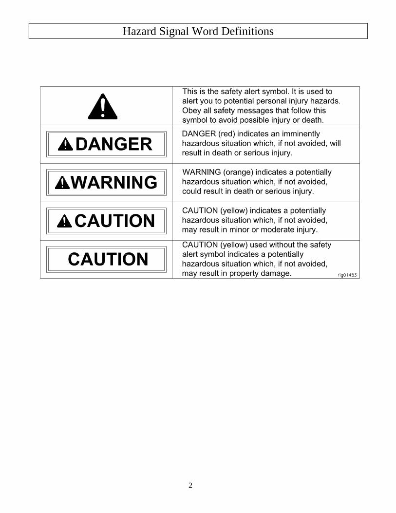
Hazard Signal Word Definitions
2
Table of Contents
3
Hazard Signal Word Definitions ................................................................................................. 2
About Your Generator ................................................................................................................. 4
Specifications ................................................................................................................................. 6
Safety Label Locations .................................................................................................................. 7
Machine Component Identification ............................................................................................. 8
Power Load Planning & Management ........................................................................................ 10
Installation / Initial Set-Up:
1. Unpacking & Delivery Inspection .......................................................................................... 12
2. Planning the Power Load ........................................................................................................ 13
3. Set-up as a PORTABLE or BUILDING BACK-UP Power Source ...................................... 13
4. Selecting a Suitable Site ......................................................................................................... 16
5. Mounting the Generator ......................................................................................................... 18
6. Grounding the Generator ........................................................................................................ 20
Operation:
1. General Safety Rules for Operation ....................................................................................... 21
2. Preparing for Operation .......................................................................................................... 22
3. Connecting to the Tractor ....................................................................................................... 24
4. Starting the Generator ............................................................................................................. 25
5. Connecting Loads ................................................................................................................... 26
6. Stopping .................................................................................................................................. 28
7. Storage & Exercise ................................................................................................................. 28
Maintenance & Repair .................................................................................................................. 29
Troubleshooting ............................................................................................................................. 31
Summary of Important Safety Information for Operation ....................................................... 32
PTO Generator Exploded View ................................................................................................... 35
Wiring Diagram ............................................................................................................................. 36
PTO Gearbox Exploded View ...................................................................................................... 37
Limited Warranty ......................................................................................................................... 39
About Your Generator
4
Thank you for purchasing your NorthStar PTO generator!
About Your Generator
This PTO-driven, portable generator is designed to provide up to 7200 Watts of electrical
power (7200 watts continuous, 7800 watts Surge). Connected to your tractor’s power take-off
(PTO)*, the generator can supply power:
1. As a portable power source. You can plug appliances directly into the generator’s
electrical outlets.
2. As a back-up, standby power source for a building. A licensed electrician can connect
the generator to your building’s electrical system via the installation of an UL-approved
transfer switch. (See the “Installation & Initial Set-up” section of this manual to learn
more about specific requirements and precautions relating to wiring the generator to your
building’s electrical system.)
* Your tractor’s PTO must produce a minimum of 14 HP at 540 RPM.
You must select a generator adequately sized for your power needs. You need to
determine the power needs of all the appliances/tools you wish to power at the same time and
choose a generator rated to provide at least that power level. See the “Power Load Planning &
Management” section of this manual to determine your specific power load requirements and
then compare them to this generator’s rated capacity. You must not overload the generator.
Overloading will cause damage to the generator and attached electrical devices, and may also
result in fire.
This generator must be mounted on a reinforced concrete slab or a PTO generator
trailer, so that the generator will not flip during use due to the rotational force of the PTO.
The slab or trailer must be of adequate size and strength to withstand operating torque without
flipping or structural failure. A trailer designed specifically for use with PTO generators rated
up to 60,000 Watts is available from NorthStar -- Item #165959. More detailed information
about mounting can be found in the “Installation / Initial Set-Up” section of this manual.
Be sure to read about site selection and grounding requirements for running this
generator. More detailed information can be found in the “Installation & Initial Set-up, Steps
5 & 6” of this manual.
Optional accessories available from NorthStar include PTO drivelines, UL-approved transfer
switches and extension cords. Contact NorthStar Product Support at 1-800-270-0810 with
questions about optional accessories or to order.
Read this Manual
WARNING
Improper use or maintenance of this generator can result in serious injury or death from
carbon monoxide poisoning, electric shock/electrocution, entanglement, flying objects,
fire, or burns. In addition, PTO shaft and generator can become airborne and cause
severe injury if improperly secured.
Read this manual completely before using the generator and follow all instructions and
safety rules.
About Your Generator (cont’d)
5
You must follow all instructions and safety precautions presented throughout this manual. A
summary of important safety information can be found at the end of the manual. Keep this
manual for reference and review.
Proper preparation, operation, and maintenance will result in operator safety as well as best
performance and long life of the generator. Failure to follow the instructions in this manual
for proper mounting, set-up, operation, and maintenance of the generator will void the
manufacturer’s warranty.
Before using, the user shall determine the suitability of this product for its intended use and
assumes liability therein. The purchaser and/or user shall assume liability for any modification
and/or alterations of this equipment from original design and manufacture, or for any non-
standard application, or for use as a subcomponent in another piece of equipment.
NorthStar is constantly improving its products. The specifications outlined herein are subject
to change without prior notice or obligation.
Contact NorthStar Product Support at 1-800-270-0810 for any questions about the
appropriate use of this generator.
Warranty Registration
Please fill out and submit the warranty registration card so that we have your contact
information for any future product literature or replacement parts you may need.
ATTENTION:
All Rental Companies and Private Owners who loan this
equipment to others!
All persons to whom you rent/loan this generator must have access to and read this manual.
Keep this owner’s manual with the generator at all times and advise all persons who will
operate the machine to read it. You must also provide personal instruction on how to safely
operate the generator and remain available to answer any questions a renter/borrower might
have.
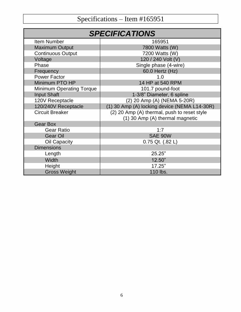
Specifications – Item #165951
6
SPECIFICATIONS Item Number 165951 Maximum Output 7800 Watts (W) Continuous Output 7200 Watts (W) Voltage 120 / 240 Volt (V) Phase Single phase (4-wire) Frequency 60.0 Hertz (Hz) Power Factor 1.0 Minimum PTO HP 14 HP at 540 RPM Minimum Operating Torque 101.7 pound-foot Input Shaft 1-3/8” Diameter, 6 spline 120V Receptacle (2) 20 Amp (A) (NEMA 5-20R) 120/240V Receptacle (1) 30 Amp (A) locking device (NEMA L14-30R) Circuit Breaker (2) 20 Amp (A) thermal, push to reset style
(1) 30 Amp (A) thermal magnetic Gear Box
Gear Ratio 1:7 Gear Oil SAE 90W Oil Capacity 0.75 Qt. (.82 L)
Dimensions Length 25.25”
Width 12.50” Height 17.25” Gross Weight 110 lbs.
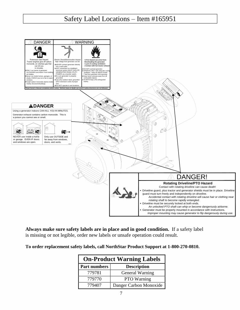
Safety Label Locations – Item #165951
7
DANGER!
Driveline guard, plus tractor and generator shields must be in place. Driveline
guard must turn freely and independently on driveline.
Accidental contact with rotating driveline will cause hair or clothing near
rotating shaft to become rapidly entangled.
Driveline must be securely locked at both ends.
An unlocked PTO shaft can whip or become dangerously airborne.
Generator must be properly mounted in accordance with instructions.
Improper mounting may cause generator to flip dangerously during use.
Contact with rotating driveline can cause death!
Rotating Driveline/PTO Hazard
Always make sure safety labels are in place and in good condition. If a safety label
is missing or not legible, order new labels or unsafe operation could result.
To order replacement safety labels, call NorthStar Product Support at 1-800-270-0810.
On-Product Warning Labels
Part numbers Description
779781 General Warning
779770 PTO Warning
779407 Danger Carbon Monoxide
NEVER use inside a home
or garage. EVEN IF doors
and windows are open.
Generator exhaust contains carbon monoxide. This is
a poison you cannot see or smell.
Using a generator indoors CAN KILL YOU IN MINUTES.
DANGER
Only use OUTSIDE and
far away from windows,
doors, and vents.
DO NOT overload generator.
OPERATE ONLY with adequate cooling
ventilation. Keep all objects at least
7 feet from generator vent openings.
Keep tractor exhause away from all
combustible objects.
ALWAYS keep a fire extinguisher
nearby.
A Fire Hazard can arise from:
Overloading the generator
Lack of cooling ventilation
Contact with hot tractor exhaust
WARNING
NEVER connect generator directly
into a wall outlet.
ANY connection to a building's
electrical system MUST ISOLATE
GENERATOR FROM UTILITY
POWER via a transfer switch.
Be sure generator is properly
grounded.
Use only outdoor-rated, grounded
GFCI extension cords of proper
size.
DO NOT operate in wet locations.
Electric Shock/Electrocution Hazard
High voltage from generator can kill.
Read Owner's Manual completely before using. Serious injury or death can result if safety directions are not followed.
ONLY run tractor & generator
OUTDOORS and AWAY from building
air intakes.
Never run inside homes, garages, or
sheds, EVEN if you run a fan or open
windows.
Install carbon monoxide alarms inside
nearby structures/buildings.
DANGER
Poisonous Gas Hazard
Tractor engines give off carbon
monoxide, an odorless gas that
can kill you
in minutes.
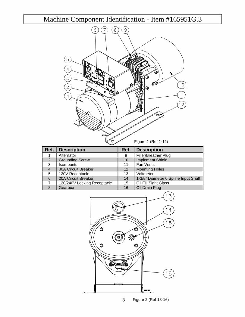
Machine Component Identification - Item #165951G.3
8
Figure 1 (Ref 1-12)
Ref. Description Ref. Description
1 Alternator 9 Filler/Breather Plug 2 Grounding Screw 10 Implement Shield 3 Isomounts 11 Fan Vents 4 30A Circuit Breaker 12 Mounting Holes 5 120V Receptacle 13 Voltmeter 6 20A Circuit Breaker 14 1-3/8” Diameter 6 Spline Input Shaft 7 120/240V Locking Receptacle 15 Oil Fill Sight Glass 8 Gearbox 16 Oil Drain Plug
Figure 2 (Ref 13-16)
Machine Component Identification – Item #165951G.3 (cont’d)
9
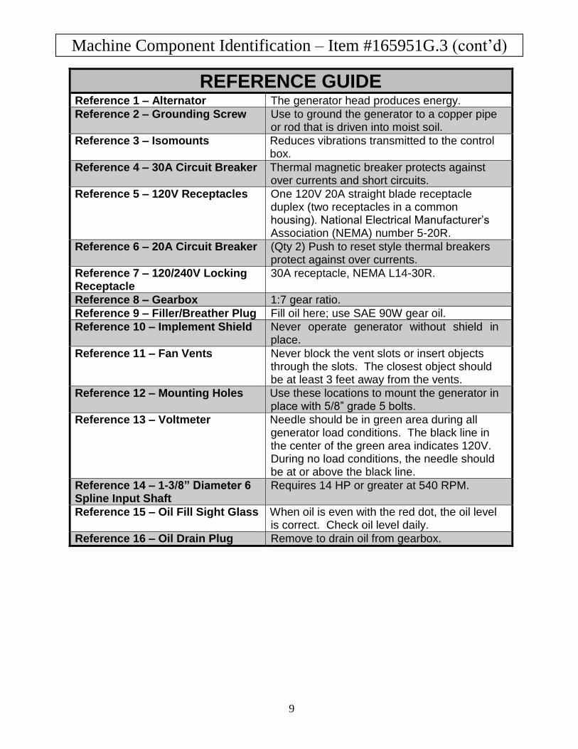
REFERENCE GUIDE Reference 1 – Alternator The generator head produces energy.
Reference 2 – Grounding Screw Use to ground the generator to a copper pipe or rod that is driven into moist soil.
Reference 3 – Isomounts Reduces vibrations transmitted to the control box.
Reference 4 – 30A Circuit Breaker Thermal magnetic breaker protects against over currents and short circuits.
Reference 5 – 120V Receptacles One 120V 20A straight blade receptacle duplex (two receptacles in a common housing). National Electrical Manufacturer’s Association (NEMA) number 5-20R.
Reference 6 – 20A Circuit Breaker (Qty 2) Push to reset style thermal breakers protect against over currents.
Reference 7 – 120/240V Locking Receptacle
30A receptacle, NEMA L14-30R.
Reference 8 – Gearbox 1:7 gear ratio.
Reference 9 – Filler/Breather Plug Fill oil here; use SAE 90W gear oil.
Reference 10 – Implement Shield Never operate generator without shield in place.
Reference 11 – Fan Vents Never block the vent slots or insert objects through the slots. The closest object should be at least 3 feet away from the vents.
Reference 12 – Mounting Holes Use these locations to mount the generator in place with 5/8” grade 5 bolts.
Reference 13 – Voltmeter Needle should be in green area during all generator load conditions. The black line in the center of the green area indicates 120V. During no load conditions, the needle should be at or above the black line.
Reference 14 – 1-3/8” Diameter 6 Spline Input Shaft
Requires 14 HP or greater at 540 RPM.
Reference 15 – Oil Fill Sight Glass When oil is even with the red dot, the oil level is correct. Check oil level daily.
Reference 16 – Oil Drain Plug Remove to drain oil from gearbox.
Power Load Planning & Management
10
WARNING
NEVER exceed the rated wattage capacity of your generator.
OVERLOADING may cause SERIOUS DAMAGE to the generator and
attached electrical devices, and may result in fire.
Your generator MUST BE SIZED PROPERLY to provide both the running and starting (surge)
wattage of the devices you will be powering. Before using your generator, determine the running
and starting wattage requirements of all the electrical devices you will be powering simultaneously.
The sum of the running and starting wattages of the devices being powered must not exceed the
continuous output rating of your generator. (The continuous output rating of your generator is listed
in the “Specifications” section of this manual.) Note that:
Devices without electric motors such as light bulbs, radios, and televisions have the same
running and starting wattage.
Devices with electric motors such as refrigerators, compressors, and hand tools typically
require a starting wattage that is 3 to 5 times greater than the running wattage.
The running and starting wattage requirements are often listed on a device’s nameplate. If wattage
is not given on the device’s nameplate, the wattage may be calculated by multiplying the nameplate
voltage by nameplate amperage, Watts = Volts X Amps.
Example conversion to watts: 120 Volts X 5 Amps = 600 Watts
If only the running voltage is given on the nameplate for a device with an electric motor, the starting
wattage can be approximated to be three to five times the running wattage.
Estimates for the running wattage requirements for common devices are listed in Table 4 below.
Guidance for starting wattages is provided in the table’s footnotes.
Table 4
Device
Running
Watts
Device
Running
Watts
Air conditioner (12.000 BTU) 1700 (a,b) Jet pump 800 (a)
Battery charger (20 Amp) 500 Lawn mower 1200
Belt sander (3”) 1000 Light bulb (100 Watt) 100
Chain saw 1200 Microwave oven 700
Circular saw (6½”) 2000 (a,b) Milk cooler 1100 (a)
Coffee maker 1800 (a,b) Oil burner on furnace 300
Compressor (1 HP) 1400 (a,b) Oil-fired space heater (140,000 Btu) 400
Compressor (3/4 HP) 1800 (a) Oil-fired space heater (85,000 Btu) 225
Compressor (1/2 HP) 1400 (a) Oil-fired space heater (30,000 Btu) 150
Curling iron 700 Oven 4500
Dishwasher 1200 Paint sprayer, Airless (1/3 HP) 600 (a)
Edge trimmer 500 Paint sprayer, Airless (handheld) 150
Electric nail gun 1200 Radio 200
Electric range (1 element) 1500 Refrigerator 600 (b)
Electric skillet 1250 Slow cooker 200
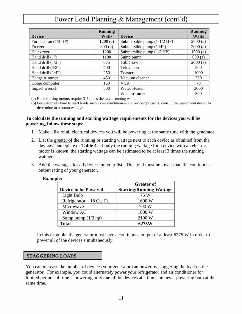
Power Load Planning & Management (cont’d)
11
Device
Running
Watts
Device
Running
Watts
Furnace fan (1/3 HP) 1200 (a) Submersible pump (1-1/2 HP) 2800 (a)
Freezer 800 (b) Submersible pump (1 HP) 2000 (a)
Hair dryer 1200 Submersible pump (1/2 HP) 1500 (a)
Hand drill (1”) 1100 Sump pump 600 (a)
Hand drill (1/2”) 875 Table saw 2000 (a)
Hand drill (3/8”) 500 Television 500
Hand drill (1/4”) 250 Toaster 1000
Hedge trimmer 450 Vacuum cleaner 250
Home computer 150 VCR 70
Impact wrench 500 Water Heater 3000
Weed trimmer 500 (a) Hard-starting motors require 3-5 times the rated running watts
(b) For extremely hard to start loads such as air conditioners and air compressors, consult the equipment dealer to
determine maximum wattage
To calculate the running and starting wattage requirements for the devices you will be
powering, follow these steps:
1. Make a list of all electrical devices you will be powering at the same time with the generator.
2. List the greater of the running or starting wattage next to each device as obtained from the
devices’ nameplate or Table 4. If only the running wattage for a device with an electric
motor is known, the starting wattage can be estimated to be at least 3 times the running
wattage.
3. Add the wattages for all devices on your list. This total must be lower than the continuous
output rating of your generator.
Example:
Device to be Powered
Greater of
Starting/Running Wattage
Light Bulb 75 W
Refrigerator – 18 Cu. Ft. 1600 W
Microwave 700 W
Window AC 1800 W
Sump pump (1/3 hp) 2100 W
Total 6275W
In this example, the generator must have a continuous output of at least 6275 W in order to
power all of the devices simultaneously.
You can increase the number of devices your generator can power by staggering the load on the
generator. For example, you could alternately power your refrigerator and air conditioner for
limited periods of time -- powering only one of the devices at a time and never powering both at the
same time.
STAGGERING LOADS
Installation / Initial Set-Up
12
There are a number of important steps required to set up your generator for initial use. These
steps are:
Steps for Installation / Initial Set-Up
1. Unpacking & delivery inspection.
2. Planning the power load to stay within the generator’s rated
capacity.
3. Setting up generator for the type of power generation you need:
a. portable power source, or
b. connected to a building as a back-up power source.
4. Selecting a site for using the generator.
5. Mounting the generator.
6. Grounding the generator.
Each of these steps is discussed in detail below:
1. Unpacking & Delivery Inspection
1. You should inspect the generator immediately after you receive delivery.
See the “Machine Component Identification” section of this manual for a
diagram of the generator and its components.
If you have missing or damaged components, contact Product Support at 1-800-270-0810.
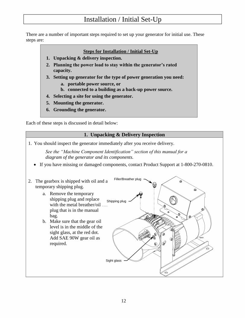
2. The gearbox is shipped with oil and a
temporary shipping plug.
a. Remove the temporary
shipping plug and replace
with the metal breather/oil fill
plug that is in the manual
bag.
b. Make sure that the gear oil
level is in the middle of the
sight glass, at the red dot.
Add SAE 90W gear oil as
required.
Filler/Breather plug
Shipping plug
Sight glass
Installation / Initial Set-Up
13
2. Planning the Power Load
Plan your power load so that you do not exceed the generator’s rated capacity.
See the “Power Load Planning & Management” section of this manual to review how to plan and
manage power loads for the generator.
3. Set-up either as a BUILDING BACK-UP or PORTABLE Power Source
This generator is designed to provide up to 7200W of continuous electrical power. It can supply
electricity in two ways:
1. As a back-up, standby power source for a building. For this application, you must arrange
for a licensed electrician to connect the generator to your building’s electrical system via the
installation of an UL-approved transfer switch. The transfer switch must be installed in
accordance with building electrical code and guidelines supplied by your power company.
2. As a portable power source. You can plug appliances or tools directly into the generator’s
electrical outlets.
Specific requirements for each are given below.
Note: Regardless of whether you use your generator as a back-up power source connected to a
building or as a portable power source, you must not overload the generator. Overloading
may cause serious damage to the generator and attached electrical devices.
Using as a
Back-up Power
Source for a
Building
Contact a licensed electrician to install an UL-approved transfer switch if
you want to use your generator as a back-up power source for a building.
What does a transfer switch do? It:
a) Safely connects the generator to your building’s electrical system by
isolating your generator from your utility company’s power lines,
AND
b) Connects your generator to a critical subset of your building’s circuits
that are needed for emergency power needs.
If your generator will be connected to your building’s electrical system, it
MUST ALWAYS be isolated from the utility power grid with a UL-approved
transfer switch installed by a licensed electrician in compliance with all
applicable building and electrical codes, and in accordance with guidelines
supplied by your power company.
DANGER: A transfer switch must be installed in order to isolate your
generator from the utility power grid. If your generator is NOT
properly isolated from the utility system, serious hazards will arise:
When your generator is running, its output will back feed into
the utility power line and transformer that are normally used to
provide you with power. The transformer will step up the
current to the normal line voltage. An unsuspecting utility line
worker working on what he thinks is a deactivated line could
be electrocuted.
Installation / Initial Set-Up
14
If your generator is connected (running or not) when utility
power is restored, your generator will be destroyed. It could
also explode or cause fire.
In addition to isolating your generator from the utility system, the transfer
switch connects your generator to a limited set of circuits in your building
that have been chosen as critical to operate during a power outage.
This generator can power up to 7200 watts, which may not power your entire
home or farm outbuilding -- you must work with the installing electrician to
determine which devices/appliances you wish to power during an outage.
The electrician can help you determine which circuits and devices can be
powered simultaneously without overloading the generator.
(See the previous section of this manual entitled “Power Load Planning &
Management” for more information on load application and selection.)
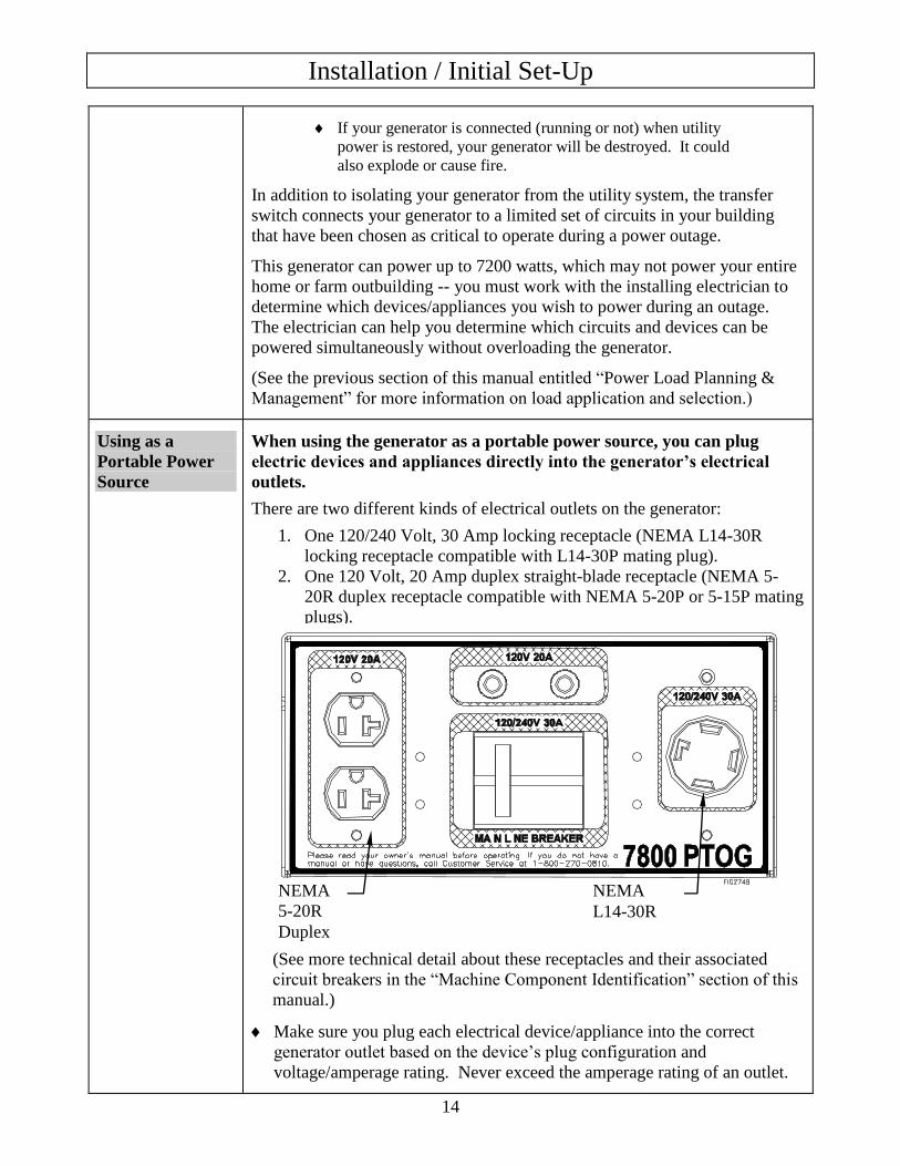
Using as a
Portable Power
Source
When using the generator as a portable power source, you can plug
electric devices and appliances directly into the generator’s electrical
outlets.
There are two different kinds of electrical outlets on the generator:
1. One 120/240 Volt, 30 Amp locking receptacle (NEMA L14-30R
locking receptacle compatible with L14-30P mating plug).
2. One 120 Volt, 20 Amp duplex straight-blade receptacle (NEMA 5-
20R duplex receptacle compatible with NEMA 5-20P or 5-15P mating
plugs).
(See more technical detail about these receptacles and their associated
circuit breakers in the “Machine Component Identification” section of this
manual.)
Make sure you plug each electrical device/appliance into the correct
generator outlet based on the device’s plug configuration and
voltage/amperage rating. Never exceed the amperage rating of an outlet.
NEMA
5-20R
Duplex
NEMA
L14-30R
Installation / Initial Set-Up
15
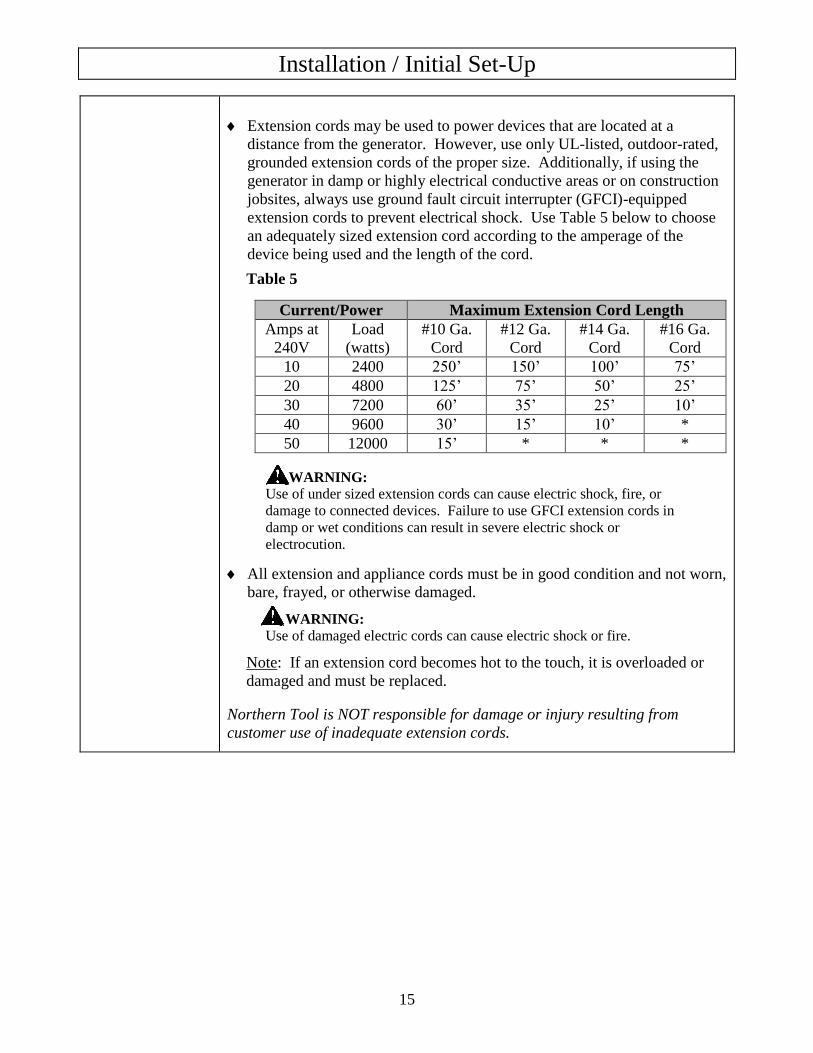
Extension cords may be used to power devices that are located at a
distance from the generator. However, use only UL-listed, outdoor-rated,
grounded extension cords of the proper size. Additionally, if using the
generator in damp or highly electrical conductive areas or on construction
jobsites, always use ground fault circuit interrupter (GFCI)-equipped
extension cords to prevent electrical shock. Use Table 5 below to choose
an adequately sized extension cord according to the amperage of the
device being used and the length of the cord.
Table 5
Current/Power Maximum Extension Cord Length
Amps at
240V
Load
(watts)
#10 Ga.
Cord
#12 Ga.
Cord
#14 Ga.
Cord
#16 Ga.
Cord
10 2400 250’ 150’ 100’ 75’
20 4800 125’ 75’ 50’ 25’
30 7200 60’ 35’ 25’ 10’
40 9600 30’ 15’ 10’ *
50 12000 15’ * * *
WARNING:
Use of under sized extension cords can cause electric shock, fire, or
damage to connected devices. Failure to use GFCI extension cords in
damp or wet conditions can result in severe electric shock or
electrocution.
All extension and appliance cords must be in good condition and not worn,
bare, frayed, or otherwise damaged.
WARNING:
Use of damaged electric cords can cause electric shock or fire.
Note: If an extension cord becomes hot to the touch, it is overloaded or
damaged and must be replaced.
Northern Tool is NOT responsible for damage or injury resulting from
customer use of inadequate extension cords.

Installation / Initial Set-Up
16
4. Select a Suitable Site
Before using the generator, you must select a suitable OUTDOOR location for installation and
operation of your generator.
If you will be mounting the generator to a concrete slab, you must choose the location
of the slab according to all the criteria listed below.
If the generator will be mounted to a trailer, you should follow all the criteria listed
below to select a suitable location each time you use the generator.
WARNING:
You must choose a suitable site for operating your generator to avoid equipment damage
and/or injury and possible death from carbon monoxide poisoning, electric shock, or fire.
Choose a site that meets all of the criteria specified.
Site/Location Criteria:
Dry, level surface The generator should be positioned on a dry, firm, level surface. Ensure that the generator will sit during operation. Apply the tractor’s
parking brake, and if trailer-mounted block the trailer’s wheels to prevent
sliding and shifting.
Outdoors only –
dangerous carbon
monoxide exhaust
WARNING: Carbon monoxide poisoning hazard
The exhaust from your tractor contains carbon monoxide (CO), a
poisonous gas that can kill. You cannot smell it, see it, or taste it.
Follow the directions below for choosing a location to operate your
generator in order to avoid carbon monoxide poisoning.
The location you choose to operate the generator must be OUTDOORS
and away from all air intakes:
Never run the generator or tractor inside any closed or semi-enclosed
spaces (even if outdoors), including homes, garages, basements, sheds, or
boxes. These spaces can trap poisonous gases, even if you run a fan or
open windows.
Place the tractor so that the exhaust fumes will not be directed towards
people or building air intakes.
Ensure that working, battery-operated or battery back-up carbon monoxide
alarms are used in any dwelling/structure that is in close proximity to the
running generator.
Adequate cooling
ventilation
The generator needs adequate, unobstructed flow of air to allow for
proper cooling of generator head.
Situate so there is adequate clearance around generator to allow for
cooling airflow so that heat does not build up. Never block vent slots.
The closest object should be at 7 feet away from vents.
Installation / Initial Set-Up
17
Do not run the generator in close proximity to other heat-generating
equipment, such as another generator. The combined heat that is
generated may raise air temperature in the immediate area and there will
not be adequate cooling ventilation.
Do not allow debris to accumulate and block airflow.
Do not operate with a tarp, blanket, or cover surrounding the generator.
Hot tractor
exhaust clearance
The exhaust gas from your tractor is extremely hot and can cause
combustible materials to catch on fire.
Position tractor at a safe distance from all nearby combustible materials
and buildings/structures. Refer to your tractor manual to determine the
safe clearance distance required for hot tractor exhaust in particular.
Keep a fire extinguisher rated “ABC” nearby. Keep it properly charged
and be familiar with its use.
No wet conditions Choose a location where the generator will NOT be exposed to rain,
snow, or direct sunlight. Exposure to water can cause electric shock.
You may operate the generator under an outdoor, canopy-like structure of
heat-resistant material that is open on all sides. Make sure that all parts of
canopy are:
at least 7’ from generator
at an adequate safe clearance from hot tractor exhaust.
Allow for adequate clearance above generator so that heat from generator
does not build up.
Away from
dust/dirt
Do not use the generator in extremely dusty or dirty conditions. Excessive dust and dirt can cause premature failure of the machine.
Hearing
protection
Generators can produce noise levels of up to 95 dB in close proximity,
which can be dangerous to human hearing with prolonged exposure.
(This is in addition to the noise produced by the tractor.)
Hearing protection may be required for persons working within 15-20 feet of
the running generator for an extended period of time.
Installation / Initial Set-Up
18
5. Mounting the generator
This generator must be securely mounted on a reinforced concrete slab or a PTO generator
trailer before it is connected to your tractor’s PTO.* This will prevent the generator from flipping
due to the rotational torque of the PTO.
The slab or trailer you use must be of adequate size and strength to withstand up to
101.7 pound-foot of operating torque without flipping or structural failure.
WARNING: Failure to properly mount and secure the generator may cause the unit
to flip violently during use, which could cause severe injury to the operator or
bystanders, or damage to surrounding objects.
Failure to properly mount the generator is not only unsafe, but will void the manufacturer’s
warranty.
* Instructions for connecting generator to tractor PTO is provided later in this manual in the Operation
section, “Step 3. Connecting to the Tractor”.
Mounting to a
trailer
Mount to a trailer if you plan to use the generator as a portable source of
power.
WARNING:
Never mount to a trailer that is not wide enough or strong enough to
handle the operating torque. An inadequate trailer may flip or fail due
to generator’s operating torque, potentially causing injury or death.
1. Use only a wide base trailer that is specifically designed for mounting a
PTO generator.
A PTO generator trailer is designed to be of adequate size and strength
to withstand the generator’s operating torque without flipping or
structural failure.
o The trailer wheelbase must be wide enough to prevent flipping.
o The trailer base must be constructed of thick enough steel to
prevent metal fatigue from the constant vibration of the generator.
A trailer specifically designed for use with PTO generators rated up to
60,000 Watts is available from NorthStar -- Item #165959.
2. Mount the generator on the trailer so it is:
o Balanced forward of the trailer axle to prevent the trailer from
tipping backward.
o Centered side-to-side between the trailer’s wheels to minimize the
possibility the trailer will flip due to operating torque.
If using the NorthStar PTO trailer (Item #165959), specific mounting bolt
patterns are illustrated in the trailer’s Owner’s Manual for various
NorthStar PTO generator models.
3. Bolt the generator to the trailer base using four, 5/8” grade 5 bolts. See the
next section: “Mounting to a concrete slab”, Figure 6.
Installation / Initial Set-Up
19
Mounting to a
concrete slab
If you will be using the generator in a permanent location, you may
mount the generator to a reinforced concrete slab.
1. Choose a location for the slab that is as close to the load as possible (to
minimize voltage drop) and which also meets all the criteria specified in
the previous section, “4. Select a Suitable Location”.
2. The slab must:
o Be of adequate size and weight to properly anchor the generator and
resist flipping under operating torque. Typically the slab will need to
be at least 2 feet x 2 feet x 4 inches thick.
o Be reinforced with rebar in a direction perpendicular to the PTO shaft.
Rebar will strengthen the concrete to resist cracking and breaking as a
result of operating torque and vibration.
o Provide adequate elevation to ensure that the PTO driveline angle
between the generator and tractor will not exceed 15 degrees. Note:
The smaller the angle, the longer the driveline will last.
For technical guidance on the design and construction of reinforced
concrete slabs, refer to the American Concrete Institute (ACI) web site at
www.concrete.org. The ACI has published several Technical Committee
documents concerning the design and construction of concrete slabs.
WARNING:
Never attempt to mount generator to a slab that is not large enough or
strong enough to withstand the operating torque. Slab failure could
result in the generator flipping violently and possibly causing injury
or death to those nearby.
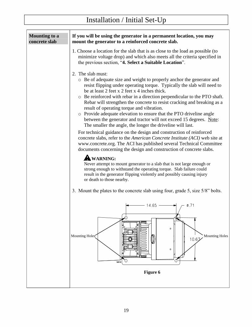
3. Mount the plates to the concrete slab using four, grade 5, size 5/8” bolts.
Mounting Holes Mounting Holes
Figure 6

Installation / Initial Set-Up
20
6. Grounding the generator
Always ensure the generator is properly grounded to prevent electrical shock.
You must always ground the generator by the following method when using the generator as a
portable electrical source:
1) Drive a ¾” or 1” copper pipe or rod into the ground close to the generator. The pipe/rod
must penetrate moist earth – the depth required will be dictated by local soil conditions.
Consult with an electrician.
2) Connect an approved ground clamp to the pipe.
3) Run an 8 gauge wire from the clamp to the generator grounding screw located on the rear of
the generator head.
4) Do not connect the generator grounding post to a water pipe or a ground used by a radio
system.
5) The generator must be grounded every time it is moved.
If a licensed electrician installs the generator with a connection to your building’s electrical circuit
for use as a back-up power system, grounding may alternatively be completed through the
building’s grounding system. Ask your electrician. If the generator is not grounded through your
building’s electrical system, follow the procedure above.
WARNING:
Operating the generator when it is not properly grounded can result in electrical shock.
Grounding Post
8 Ga. Wire
Copper
Pipe/Rod
Ground
Operation
21
Once you have set up your generator for use, it is time to start your generator. The following
are the procedures necessary for safe, successful operation of your generator.
Operation Procedures
1. General Safety Rules for Operation
2. Preparing for Operation
3. Connecting to the Tractor
4. Starting the Generator
5. Connecting Electrical Loads
6. Stopping
7. Storage & Exercise of Generator
Each of these procedures is discussed in detail below:
1. General safety rules for operation
Before starting the generator, review the following general safety rules for operation:
WARNING:
Failure to follow safety rules may result in serious injury or death to the operator or
bystanders.
Know proper use/how to stop. Be thoroughly familiar with proper use of the equipment and all
generator controls, output receptacles, and connections. Know how to stop the generator quickly if
needed.
Instruct operators. The generator owner must instruct all operators in safe generator set-up and
operation. Only trained adults should set up and operate the generator – Do not let children operate.
Intended use. Carefully read about and understand the intended use of this generator. Do not use for
other purposes, as unforeseen hazards or equipment damage may result.
Under the influence. Never operate, or let anyone else operate, the generator while under the influence
of alcohol, drugs, or medication.
Safety guards / controls. Do not operate the generator unless all safety covers, guards, and barriers are
in place and in good working order, and all controls are properly adjusted for safe operation
Damaged. Do not operate the generator with damaged, missing, or broken parts.
Modifications. Do not modify the generator in any way. Modifications can create serious safety hazards
and will also void the warranty.
Malfunction during operation. Immediately turn off the generator if any of the following conditions
arise during operation:
o Excessive change in tractor engine speed, slow or fast
o Overheating in load connecting devices
o Sparking or arcs from generator
o Loss of electrical output
o Receptacle damage
o Excessive vibration
o Flame or smoke
o Abnormal noise
Operation (cont’d)
22
Adjusting / repairing. Always turn off generator and remove PTO driveline before working on the
generator. Always discharge the capacitor before working on the generator head to prevent electrical
shock. (See Maintenance & Repair section of this manual for instructions on how to do this.)
Carbon monoxide poisoning. The running tractor engine gives off carbon monoxide, a poisonous gas
that can kill you. You CANNOT smell it, see it, or taste it. Follow all instructions for site selection and
positioning the tractor and generator, and avoid inhaling the exhaust. If you start to feel sick, dizzy, or
weak, shut off the tractor and get to fresh air RIGHT AWAY. See a doctor. You may have carbon
monoxide poisoning.
Electrical cords. Use only UL-listed, outdoor-rated, three prong extension cords of the proper size. All
extension and appliance cords must be in good condition and not worn, bare, frayed, or otherwise
damaged. Use of inadequate or damaged electric cords can cause electric shock or fire.
GFCI extension cords. Always use ground fault circuit interrupter (GFCI)-equipped extension cords in
damp or highly electrical conductive areas and on construction jobsites to prevent electrical shock.
Avoid contact. Avoid contact with bare wires, terminals, connections, etc. while the unit is running.
Wet conditions. Do not operate the generator or handle any electrical equipment while standing in water,
while barefoot, while hands are wet or while in the rain or snow. Electric shock may result.
Electric shock accident. If an electric shock accident occurs, immediately shut down the source of
electrical power. If this is not possible, attempt to free the victim from the live conductor. Avoid direct
contact with victim. Use a nonconducting implement, such as a dry rope or board, to free the victim from
the live conductor. Apply first aid and get immediate medical help.
Smoking/sparks. Never smoke near the running generator, and never operate near sources of sparks or
flames.
Hot parts. Parts of the generator are extremely hot during and after operation and can burn you. Never
touch hot gearbox, and do not touch any other part of the generator unless you have first determined if it
is hot. Wait a sufficient time for parts to cool before touching any part of the generator.
Moving parts. Keep hands, feet, and apparel away from PTO connections, drive shaft, belts, fans, and
other moving parts. Never attempt to remove drive shaft or any guard or shield while the unit is
operating.
2. Preparing for Operation
Mount
generator
Make sure the generator is mounted in accordance with instructions given
in “Installation / Initial Set-up section, Step 5: Mounting the Generator” of
this manual.
WARNING:
Always ensure generator is properly mounted to prevent it from flipping
during use, which could cause equipment damage and injury to nearby
persons.
Position
generator
Position tractor and generator in accordance with the instructions given in
“Installation / Initial Set-up section, Step 4: Select a Suitable Site” of this
manual. Operate outside only, on dry, level ground with adequate clearance and
ventilation. Apply parking brake, and block trailer wheels if generator is trailer-
mounted.
WARNING: Carbon monoxide poisoning hazard
The tractor engine gives off carbon monoxide exhaust, a poisonous gas
that can kill. You CANNOT smell it, see it, or taste it. ONLY run
Operation (cont’d)
23
generator OUTDOORS and away from air intakes. NEVER run tractor
and generator inside any enclosed or semi-enclosed spaces, including
homes, garages, basements, sheds, boxes, pick-up truck beds, RVs, or
boats. These spaces can trap poisonous gases, EVEN if you run a fan or
open windows.
Ground
generator
Make sure the generator is grounded in accordance with instructions given
in “Installation / Initial Set-up section, Step 6: Grounding the Generator” of
this manual.
WARNING: Electric shock hazard
Always ensure generator is properly grounded to prevent electrical shock.
IMPORTANT: The generator must be grounded every time it is moved.
Perform
regular
maintenance
Make sure that any regular maintenance has been performed as prescribed
in this manual in the “Maintenance & Repair” section.
Check/add oil Check the gear box oil level and add oil as needed.
1. First time use only: If you have not already done so, remove the temporary
shipping plug from the oil port and replace with the metal breather/oil fill
plug that is in the manual bag.
2. Check oil level using the sight mounted on the gearbox. When oil level is
even with the red dot, the oil level is correct.
3. If oil needs to be added, remove the filler/breather plug at the top of the
gearbox. Use SAE 90W gear oil to refill so that oil level is even with the
red dot. Do not overfill. Overfilling can cause the oil to overheat and cause
damage to generator.
WARNING: Burn hazard
Never open oil port while generator is running. Hot oil can spray over
face and body. ˙
IMPORTANT:
Under long, continuous-run operating conditions, be prepared to:
Check gear oil level daily.
Change gear oil monthly (see instructions in “Maintenance & Repair”
section of this manual).
Personal
Protection
1) Hearing can be damaged from prolonged, close-range exposure to the type of
noise produced by this generator. The use of ear plugs or other hearing
protection device is recommended for persons working within 15-20 feet of
the running generator for an extended period of time.
2) Loose or dangling apparel and long hair can become quickly entangled in
moving/rotating parts. Metal jewelry can conduct electricity. Never wear
jewelry or loose-fitting clothing such as neckties, scarves, or long-sleeved
or untucked shirts when starting or adjusting the generator. Tie back and
secure hair close to the head.
Operation (cont’d)
24
3. Connecting to the Tractor
Follow the instructions in this section to connect the generator to the tractor’s PTO via a
driveline shaft (purchased separately).
Acquire PTO
driveline shaft
Acquire a synchronized 1-3/8”, 6 spline PTO driveline rated at 24 HP
minimum.
A suitable PTO driveline, available from Northern Tool (Item #165936),
includes the following advanced safety features:
A telescoping shaft
o to provide flexible accommodation of mounting distance between
tractor and generator
o to allow for dynamic compression and stretching while turning or
driving a trailer-mounted generator over uneven ground.
Protrusion-free end yokes with slide collars that lock into place.
An internal cable stop to prevent separation of driveline halves.
A non-rotating tubular shaft guard with anchoring chain, plus shield cones
that cover the rotating yokes with a 2” overlap
Grease zerks to allow for proper lubrication of driveline joints.
It is strongly recommended that any driveline utilized have these safety
features.
Attach PTO
driveline shaft
Connect the PTO driveline shaft to the tractor and generator:
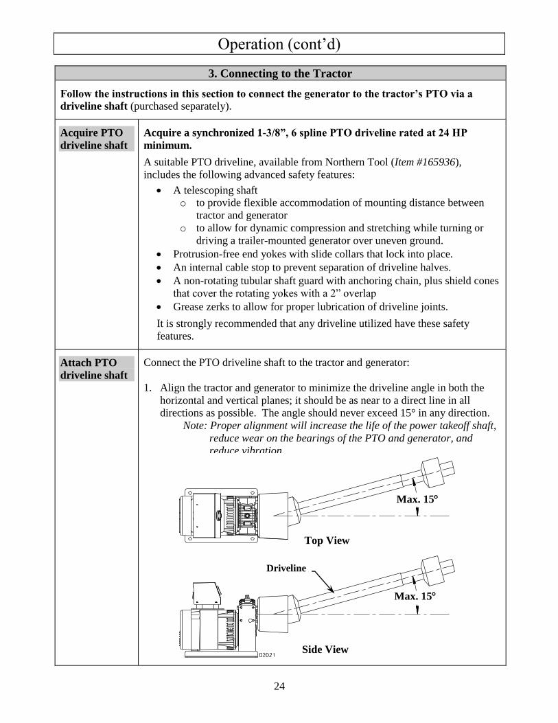
1. Align the tractor and generator to minimize the driveline angle in both the
horizontal and vertical planes; it should be as near to a direct line in all
directions as possible. The angle should never exceed 15° in any direction.
Note: Proper alignment will increase the life of the power takeoff shaft,
reduce wear on the bearings of the PTO and generator, and
reduce vibration.
Top View
Side View
Driveline
Max. 15
Max. 15
Operation (cont’d)
25
2. Ensure that the tractor PTO is disengaged and the tractor is turned OFF.
3. Connect one end of the PTO driveline shaft to the generator’s input shaft.
4. Connect the other end to the tractor PTO stub.
WARNING:
Make sure PTO driveline shaft is securely locked at both ends. Unlocked
PTO shafts can whip or become dangerously airborne.
Secure
driveline guard
& check
shields
1. A driveline GUARD must ALWAYS be used with the driveline shaft.
Secure the driveline guard according to manufacturer’s instructions.
2. Make sure the tractor and generator shields are in place at both ends of the
driveline shaft:
o On the tractor where the driveline connects to the PTO stub
o On the generator where the driveline connects to the input shaft.
WARNING:
Never operate the generator without proper PTO guarding, including a
freely rotating shaft guard as well as tractor and generator shields at both
ends. Clothing or hair can become rapidly entangled in unguarded
rotating PTO shaft or connections, resulting in serious injury or death.
4. Starting the Generator
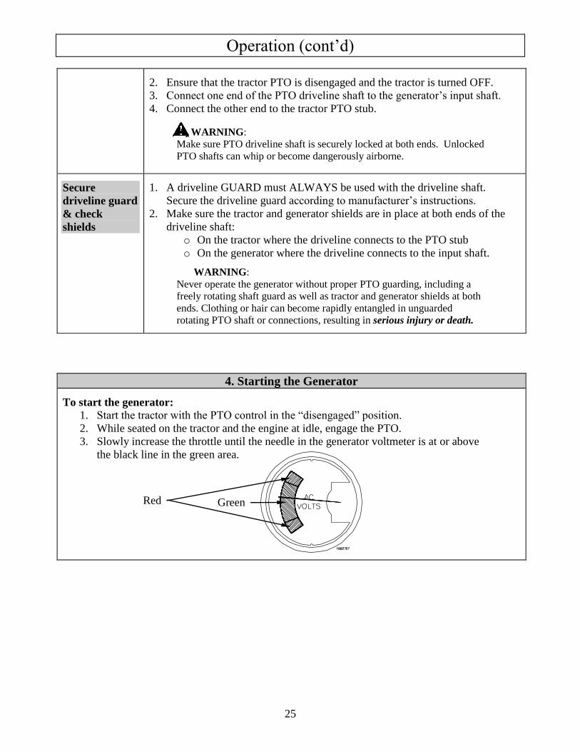
To start the generator:
1. Start the tractor with the PTO control in the “disengaged” position.
2. While seated on the tractor and the engine at idle, engage the PTO.
3. Slowly increase the throttle until the needle in the generator voltmeter is at or above
the black line in the green area.
Red Green
Operation (cont’d)
26
5. Connecting Loads
You will want to be careful when connecting loads so as not to overload the generator, especially if
you are powering devices with motors that require a higher starting power load.
Instructions are provided below for connecting loads when you are using the generator:
o As a portable power source
o Connected to a building as a back-up power source
WARNING:
Do not overload generator. Make sure that combined starting and running loads do
not exceed rated capacity of generator. Overloading the generator can cause damage
to the generator and attached electrical devices, and may result in fire.
Using as a
Portable Power
Source
Connect electrical loads one at a time according to the following
instructions:
1. Allow engine to reach operating speed by allowing it to warm up for
approximately 5 minutes before connecting electrical devices.
2. After engine is warmed up, begin connecting the loads one at a time.
WARNING: Stay clear of the rotating PTO driveline!
Start with those that require the highest wattage first. The
recommended sequence is as follows:
a. Connect items with motors such as refrigerators, freezers, air
conditioners, or small hand tools, one at a time. Let each motor
stabilize before connecting the next device.
b. Connect any lights you are planning on powering.
c. Connect voltage sensitive equipment such as electronics via surge
protectors. Plug devices such as TV’s, computers, and microwaves
into a UL listed voltage surge protector, then plug the surge
protector into the generator.
3. After connecting each load, return to the driver’s seat. Readjust the
throttle until the needle on the generator’s voltmeter is close to the
black line in the green area.
o If the needle will not rise to the green area no matter what the
engine speed, the generator is either overloaded or there is a
problem.
o Shut off the tractor and refer to the Troubleshooting guide at the end
of this manual for assistance with possible problems.
Also check your tractor’s PTO rating to make sure it is capable
of producing a minimum of 24 HP at 540 RPM. This is not
necessarily equivalent to the HP rating for the tractor itself.
Operation (cont’d)
27
WARNING:
The generator must be run at the correct speed in order to
produce the proper electrical voltage and frequency. Failure
to do so could result in damage to equipment powered by
the generator and possible injury to the individual.
Note: All engines have a tendency to slow down when a load is applied.
When electrical loads are connected to the generator, the engine is
more heavily loaded and as a result the speed drops slightly.
This slight decrease in speed, together with the voltage drop within
the generator itself, results in a slightly lower voltage when the
generator is loaded to its full capacity than when it is running with no
load. Additionally, there may be small brief surges and drops in
voltage as motors connected to the generator cycle on or off.
The slight variation in voltage, as long as the needle remains in the
green area, has no appreciable effect in the operation of motors,
lights, and most appliances.
Using as a
Back-up Power
Source for a
Building
Each transfer switch installation will be unique. Proper instructions for how
to safely bring the generator online with the building’s electrical system
should be provided by the installing electrician, who should also provide
personal instruction to the owner/operator.
Failure to follow the proper procedure as provided by the electrician could
expose persons to the hazards noted above.
Note: After you have brought the generator online with the transfer switch,
you will need to adjust the tractor’s throttle speed to maintain correct
output voltage under load. Adjust the throttle until the needle on the
generator’s voltmeter is close to the black line in the green area. (See
more detail about maintaining proper voltage in the instructions given
above for using the generator as a portable power source.)
Operation (cont’d)
28
6. Stopping
Stop the generator using the following steps:
1. Disconnect all loads to generator. (Never reduce throttle with electrical loads connected.
Damage to generator and loads will occur.)
2. After all loads are disconnected, slowly reduce PTO speed to a minimum and then disengage
PTO.
3. Shut OFF the tractor engine.
4. Remove the PTO driveline shaft from generator and tractor.
7. Storage & Exercise
When you are finished using the generator, you must:
o Disconnect all loads and PTO driveline
o Store the generator properly
o Plan on exercising the engine regularly
Detailed instructions are provided below.
Disconnect loads &
PTO
When you are finished using the generator:
1. Make sure all loads are disconnected from generator’s outlets.
2. Make sure the generator is disconnected from the PTO.
Store in
appropriate
location
1. Let generator cool for at least five minutes before storing. Hot
equipment can be a fire hazard near combustible materials.
2. Store the generator in a location that is:
o Clean and dry. It is important to keep the generator windings free of
moisture.
o Away from extreme high or low temperatures.
Exercise generator
every 4 weeks
The generator should be exercised regularly.
At least every four weeks, start the generator and let it run for 10 to 15
minutes.
Monthly exercising of the generator will:
o Dry out any moisture that has accumulated in the windings. If left,
this moisture can cause corrosion in the winding.
o Ensure that the unit is operating properly should it be needed in an
emergency.
Perform regular
maintenance
Perform periodic maintenance as directed in this manual to keep the
generator in safe working condition.
Maintenance & Repair
29
Inspect and maintain your generator as specified below in order to keep it in safe and optimal
working order. Follow all safety rules and recommended maintenance steps.
WARNING
ALWAYS shut off the engine, remove PTO driveline and discharge the capacitor before
cleaning, adjusting, or servicing the generator. Make sure all guards and shields are
replaced before using.
Note: The generator head is brushless and maintenance free. The bearing is a heavy-duty
sealed ball bearing which requires no maintenance or lubrication.
Maintenance & Repair
Follow safety rules Read and follow these safety rules whenever you will be servicing the
generator:
Turn off generator. Always stop tractor engine and remove PTO driveline
before working on the engine or generator to prevent accidental starting.
Discharge capacitor. When the generator is shut down, the capacitor may
maintain a charge. Always discharge the capacitor before working on the
generator head to prevent electrical shock. Discharge using a screwdriver with an
insulated handle. While wearing safety glasses, touch opposite terminals of the
capacitor together with the tip of the screwdriver. If there is stored charge in the
capacitor, a spark will be generated thereby discharging the capacitor.
Replace guards. Make sure all guards and shields are replaced after servicing
the generator.
Repair. Major service, including the installation or replacement of parts, should
be performed only by a qualified electrical service technician. Obtain factory
approved parts from Northern Tool Product Support at 1-800-270-0810.
Replacement parts. If a part needs replacement, only use factory approved
repair parts. Replacement parts that do not meet specifications may result in a
safety hazard or poor operation of the generator and will void the warranty.
Maintain gear oil Check the gear oil level before each use and add oil as needed. Change
gear oil every year.
WARNING: Burn hazard
Never open oil port while generator is running. Hot oil can spray over
face and body.
1. Check/add oil before each use:
a. Check oil level using the sight mounted on the gear box. When oil
level is even with the red dot, the oil level is correct.
b. If oil needs to be added, remove the filler/breather plug at the top of
the gearbox. Use SAE 90W gear oil to refill so that oil level is even
with the red dot. Do not overfill. Overfilling can cause the oil to
overheat and cause damage to generator.
Maintenance & Repair (cont’d)
30
2. Change oil every year:
a. Drain oil from gearbox (drain plug is underneath gearbox).
b. Replace drain plug.
c. Refill with SAE 90W gear oil. Refill so that oil level is even with the
red dot.
IMPORTANT:
Under long, continuous-run operating conditions, be prepared to add and
change oil more frequently:
Check gear oil level daily.
Change gear oil monthly.
Check receptacles Check receptacles before each use to make sure they are not cracked or
broken.
If a receptacle is cracked or otherwise damaged, do not use until replaced
with an authorized factory part. Using cracked or damaged receptacles can be
both dangerous to the operator and destructive to the equipment.
Keep generator
clean
Keep generator clean.
If dust or debris accumulates on the generator, clean the generator with a
damp cloth or soft bristle brush. Do not allow air intakes to become blocked.
Note: Do not spray generator with a garden hose or pressure washer.
Water may enter the generator and cause damage to the rotor, stator, or
internal windings.
IMPORTANT:
If a part needs replacement, only use parts that meet the manufacturer’s specifications. Replace-
ment parts that do not meet specifications may result in a safety hazard or poor operation of the
generator.
Contact NorthStar Product Support at 1-800-270-0810 for any
questions, problems, or parts orders.
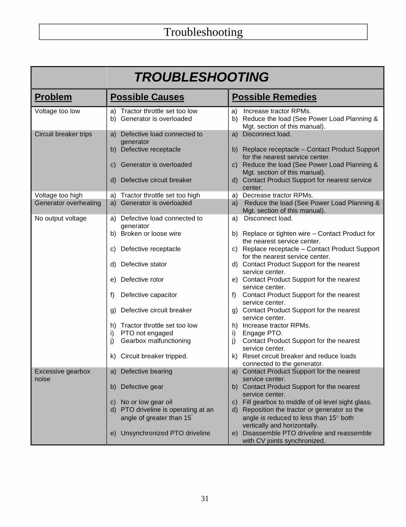
Troubleshooting
31
TROUBLESHOOTING
Problem Possible Causes Possible Remedies
Voltage too low a) Tractor throttle set too low b) Generator is overloaded
a) Increase tractor RPMs. b) Reduce the load (See Power Load Planning &
Mgt. section of this manual). Circuit breaker trips a) Defective load connected to
generator b) Defective receptacle c) Generator is overloaded d) Defective circuit breaker
a) Disconnect load. b) Replace receptacle – Contact Product Support
for the nearest service center. c) Reduce the load (See Power Load Planning &
Mgt. section of this manual). d) Contact Product Support for nearest service
center. Voltage too high a) Tractor throttle set too high a) Decrease tractor RPMs. Generator overheating a) Generator is overloaded a) Reduce the load (See Power Load Planning &
Mgt. section of this manual). No output voltage a) Defective load connected to
generator b) Broken or loose wire c) Defective receptacle d) Defective stator e) Defective rotor f) Defective capacitor g) Defective circuit breaker h) Tractor throttle set too low i) PTO not engaged j) Gearbox malfunctioning k) Circuit breaker tripped.
a) Disconnect load. b) Replace or tighten wire – Contact Product for
the nearest service center. c) Replace receptacle – Contact Product Support
for the nearest service center. d) Contact Product Support for the nearest
service center. e) Contact Product Support for the nearest
service center. f) Contact Product Support for the nearest
service center. g) Contact Product Support for the nearest
service center. h) Increase tractor RPMs. i) Engage PTO. j) Contact Product Support for the nearest
service center. k) Reset circuit breaker and reduce loads
connected to the generator. Excessive gearbox noise
a) Defective bearing b) Defective gear c) No or low gear oil d) PTO driveline is operating at an
angle of greater than 15 e) Unsynchronized PTO driveline
a) Contact Product Support for the nearest service center.
b) Contact Product Support for the nearest service center.
c) Fill gearbox to middle of oil level sight glass. d) Reposition the tractor or generator so the
angle is reduced to less than 15 both vertically and horizontally.
e) Disassemble PTO driveline and reassemble with CV joints synchronized.
Summary of Important Safety Information for Operation
32
This section provides a summary of the various safety procedures and measures that have been
presented throughout the manual. Keep this summary handy and refer to it to refresh your memory
about how to safely use your generator.
WARNING
Carefully read and make sure you understand the following safety information before using
the generator.
Improper use or maintenance of the generator can result in serious injury or death from
carbon monoxide poisoning, electric shock, entanglement, fire, or burns. In addition,
PTO shaft and generator can become airborne and cause severe injury if improperly
secured.
General Read manual. Read this Owner’s Manual and the engine Owner’s Manual completely before attempting to
set-up and use the generator. Serious injury or death can result if safety instructions are not followed.
Instruct operators. The generator owner must instruct all operators in safe generator set-up and operation.
Do not allow anyone to operate the generator who has not read the Owner’s Manual and been instructed on its
safe use.
Adults only. Only trained adults should set up and operate the generator. Do not let children operate.
Under the influence. Never operate, or let anyone else operate, the generator while under the influence of
alcohol, drugs, or medication.
Intended use. Carefully read about and understand the intended use of this generator. Do not use for other
purposes, as unforeseen hazards or equipment damage may result.
Prohibition Against Modifications Modifications prohibited. Never modify or alter the generator in any way. Modifications can create serious
safety hazards and will also void the warranty.
Guards. Do not operate generator unless all guards and cover shields, which prevent access to moving parts
and pinch points, are in place. Failure to guard the power transmission mechanisms may result in serious
injury or death.
Safety – Installation & Set-up Mount generator. Failure to properly mount and secure the generator may cause the unit to flip violently
during use, which could cause severe injury to the operator or bystanders, or damage to surrounding objects.
The generator must be securely mounted to either a reinforced concrete slab or a trailer.
Slab or trailer must be of adequate size and strength to withstand operating torque without flipping or
structural failure.
See the “Installation / Initial Set-Up” section of this Owner’s Manual for mounting requirements and
instructions.
Dry, level surface. Situate generator on a dry, firm, level surface. Ensure generator sits level and will not
slide or shift during operation. Apply parking brake, and block trailer wheels if generator is trailer-mounted.
Operate OUTSIDE only – dangerous carbon monoxide exhaust! The running tractor gives off carbon
monoxide exhaust, a poisonous gas that can kill. You CANNOT smell it, see it, or taste it. ONLY run
generator OUTDOORS and away from building air intakes. NEVER run generator inside homes, garages,
sheds, or other semi-enclosed spaces. These spaces can trap poisonous gases, EVEN if you run a fan or open
windows
Cooling ventilation. The generator needs adequate, unobstructed flow of air to allow for proper cooling of
engine and generator head so it does not overheat and possibly cause fire. Situate so there is adequate
clearance around generator to allow for cooling airflow. Do not allow debris to accumulate and block airflow.
Keep all objects at least 7 feet away from vent slots.
Grounding. Always ensure generator is properly grounded to prevent electrical shock. This generator is
equipped with a grounding post. Always complete the grounding path from the generator to a copper pipe/rod
driven into moist earth to a sufficient depth. Check with an electrician for local grounding requirements. If a
licensed electrician installs the generator with a connection to your building’s electrical circuit for use as a
standby power system, grounding will be complete through the building’s grounding system.
Summary of Important Safety Information for Operation (cont’d)
33
Isolate connection to building’s electrical circuit. Never plug the generator directly into a wall outlet.
ANY connection to a building’s electrical system MUST ISOLATE THE GENERATOR FROM UTILITY
POWER via an UL-approved transfer switch installed by a licensed electrician in compliance with all
applicable local building and electrical codes. If the generator is not isolated from the utility power system by
such means, generator output will back feed into the utility power grid. This may result in injury or death to
utility power workers or others who contact the lines during a power outage. It may also cause the generator
to explode or cause fires when utility power is restored. Wet conditions. Water conducts electricity. Do not operate generator where it is wet. Operate on a dry
surface under an open, canopy-like structure.
CO alarms. Ensure that working, battery-operated or battery back-up carbon monoxide alarms are used in
any dwelling/structure that is in close proximity to the running generator.
Hot tractor exhaust. Tractor exhaust can be extremely hot and cause fire. Refer to your tractor manual to
determine safe clearance distance required between hot tractor exhaust and nearby combustible objects.
Fire extinguisher. Keep a fire extinguisher rated “ABC” by the National Fire Protection Association nearby.
Keep it properly charged and be familiar with its use.
Safety – Before Use
Know how to operate Review safety rules. Before each use of this generator, review the “Rules for Safe Operation.” Failure to
follow these rules may result in serious injury or death.
Know how to operate. Be thoroughly familiar with all controls and with the proper use of the equipment.
Know how to stop the generator quickly if needed.
Personal protective equipment Hearing protection. The use of earplugs or other hearing protection device is recommended for those in
close proximity to the generator while it is operating.
No loose / dangling apparel. Loose or dangling apparel and long hair can become entangled in
moving/rotating parts. Metal jewelry can conduct electricity. Never wear jewelry or loose-fitting clothing
such as neckties, scarves, or long-sleeved or untucked shirts when operating the generator. Tie back hair and
secure close to head.
Safety – During Use Safety equipment / controls. Always operate the generator with all safety covers, guards, and barriers in
place and in good working order, and all controls properly adjusted for safe operation.
Know how to stop. Be thoroughly familiar with proper use of the equipment and all generator controls,
output receptacles, and connections. Know how to stop the generator quickly if needed.
Damaged. Do not operate the generator with damaged, missing, or broken parts.
Carbon monoxide exhaust. The running tractor engine gives off carbon monoxide, a poisonous gas that can
kill you. You CANNOT smell it, see it, or taste it. If you start to feel sick, dizzy, or weak while using the
generator, shut off the tractor and get to fresh air RIGHT AWAY. See a doctor. You may have carbon
Smoking/sparks. Never smoke near the running generator, and never operate near sources of sparks or
flames.
PTO shaft secured. Make sure PTO driveline shaft is securely locked at both ends. An unlocked PTO shaft
can whip or become dangerously airborne.
PTO guards. Never operate the generator without proper PTO guarding, including a freely rotating shaft
guard as well as tractor and generator shields at each end. Clothing or hair can become rapidly entangled in
unguarded rotating PTO shaft or connections, resulting in serious injury or death.
Driveline angle. Never operate the generator continuously when the PTO driveline shaft is at an angle
greater than 15° either horizontally or vertically.
Check output voltage. Check output voltage to ensure the generator is working properly before connecting
loads to the generator. Failure to do so could result in damage to equipment powered by the generator and
possible injury to the individual. Do not adjust output speed of engine to change voltage. If voltage is not
within specified range, have generator repaired by factory-authorized personnel.
Stabilize before connecting loads. Start generator and let engine stabilize before connecting electrical loads.
Do not overload. Do not overload the generator. Make sure that combined starting and running loads do not
exceed rated capacity of generator or damage will result.
Summary of Important Safety Information for Operation (cont’d)
34
Protect sensitive electronics. Some electronic equipment, such as computers and audio/video equipment,
can be damaged by small fluctuations in the flow of power. Use a surge suppressor for any voltage-sensitive
electronic equipment you will be powering with the generator.
Electrical cords. Use only UL-listed, outdoor-rated, three prong extension cords of the proper size. All
extension and appliance cords must be in good condition and not worn, bare, frayed, or otherwise damaged.
Use of inadequate or damaged electric cords can cause electric shock or fire.
GFCI extension cords. Always use ground fault circuit interrupter (GFCI)-equipped extension cords to
prevent electrical shock in damp or highly electrical conductive areas and on construction jobsites.
Wet conditions. Do not operate the generator or handle any electrical equipment while standing in water,
while barefoot, while hands are wet or while in the rain or snow. Electric shock may result.
Avoid contact. Avoid contact with bare wires, terminals, connections, etc. while the unit is running.
Electric shock accident. If an electric shock accident occurs, immediately shut down the source of electrical
power. If this is not possible, attempt to free the victim from the live conductor. Avoid direct contact with
victim. Use a nonconducting implement, such as a dry rope or board, to free the victim from the live
conductor. Apply first aid and get immediate medical help.
Hot parts. Parts of the generator are extremely hot during and after operation and can burn you. Never touch
hot gearbox, and do not touch any other part of the generator unless you have first determined if it is hot. Wait
a sufficient time for parts to cool before touching any part of the generator.
Moving parts. Keep hands, feet, and apparel away from PTO connections, drive shaft, belts, fans, and other
moving parts. Never attempt to remove drive shaft or any guard or shield while the unit is operating.
Malfunction during operation. Immediately turn off the generator if any of the following conditions arise
during operation:
o Excessive change in tractor engine speed, slow or fast
o Overheating in load connecting devices
o Sparking or arcs from generator
o Loss of electrical output
o Receptacle damage
o Excessive vibration
o Flame or smoke
o Abnormal noise
Adjusting / repairing. Always turn off generator and remove PTO driveline before working on or cleaning
the generator.
Safety – After use Driveline removed. Always stop tractor engine and remove driveline after use.
Cool before storing. Let generator cool for at least five minutes before storing. Hot equipment can be a fire
hazard near combustible materials.
Storage location. Store the generator in a dry location.
Exercise regularly. Exercise generator every four weeks to dry out moisture that accumulates in the
windings. If generator cannot be exercised on a regular basis, prepare generator for long-term storage.
Periodic maintenance. Perform periodic maintenance as directed in this manual to keep the generator in safe
working condition.
Safety - Inspection/Maintenance Inspect and maintain your generator on a regular basis and repair as needed to keep it in safe working condition:
Generator off & driveline detached. Always stop tractor engine and remove PTO driveline before working
on or cleaning the generator.
Discharge capacitor. When the generator is shut down, the capacitor may maintain a charge. Always
discharge the capacitor before working on the generator head to prevent electrical shock.
Clear debris/deposits. Keep generator head and moving parts clean. This will ensure the generator is in safe
working condition.
Replace guards / shields. Make sure all guards and shields are replaced after servicing the generator.
Replacement parts. If a part needs replacement, only use parts that meet the manufacturer’s specifications.
Replacement parts that do not meet specifications may result in a safety hazard or poor operation of the
generator and will void the warranty
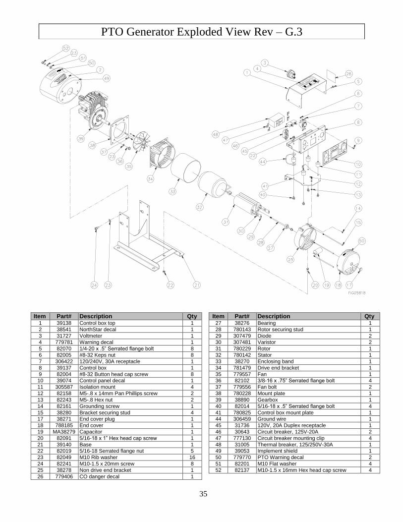
PTO Generator Exploded View Rev – G.3
35
Item Part# Description Qty Item Part# Description Qty 1 39138 Control box top 1 27 38276 Bearing 1
2 38541 NorthStar decal 1 28 780143 Rotor securing stud 1
3 31727 Voltmeter 1 29 307479 Diode 2
4 779781 Warning decal 1 30 307481 Varistor 2
5 82070 1/4-20 x .5” Serrated flange bolt 8 31 780229 Rotor 1
6 82005 #8-32 Keps nut 8 32 780142 Stator 1
7 306422 120/240V, 30A receptacle 1 33 38270 Enclosing band 1
8 39137 Control box 1 34 781479 Drive end bracket 1
9 82004 #8-32 Button head cap screw 8 35 779557 Fan 1
10 39074 Control panel decal 1 36 82102 3/8-16 x .75” Serrated flange bolt 4
11 305587 Isolation mount 4 37 779556 Fan bolt 2
12 82158 M5-.8 x 14mm Pan Phillips screw 2 38 780228 Mount plate 1
13 82243 M5-.8 Hex nut 2 39 38890 Gearbox 1
14 82161 Grounding screw 1 40 82014 5/16-18 x .5” Serrated flange bolt 4
15 38280 Bracket securing stud 4 41 780825 Control box mount plate 1
17 38271 End cover plug 1 44 306459 Ground wire 1
18 788185 End cover 1 45 31736 120V, 20A Duplex receptacle 1
19 MA38279 Capacitor 1 46 30643 Circuit breaker, 125V-20A 2
20 82091 5/16-18 x 1” Hex head cap screw 1 47 777130 Circuit breaker mounting clip 4
21 39140 Base 1 48 31005 Thermal breaker, 125/250V-30A 1
22 82019 5/16-18 Serrated flange nut 5 49 39053 Implement shield 1
23 82049 M10 Rib washer 16 50 779770 PTO Warning decal 2
24 82241 M10-1.5 x 20mm screw 8 51 82201 M10 Flat washer 4
25 38278 Non drive end bracket 1 52 82137 M10-1.5 x 16mm Hex head cap screw 4
26 779406 CO danger decal 1
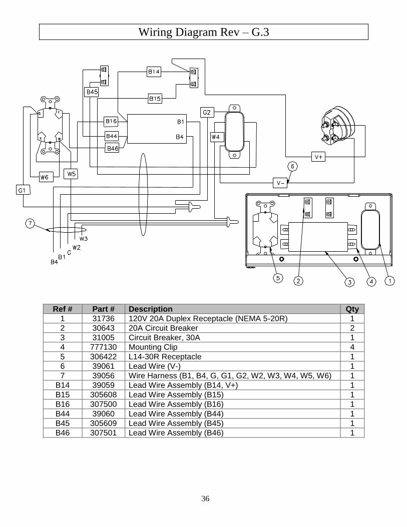
Wiring Diagram Rev – G.3
36
Ref # Part # Description Qty
1 31736 120V 20A Duplex Receptacle (NEMA 5-20R) 1
2 30643 20A Circuit Breaker 2
3 31005 Circuit Breaker, 30A 1
4 777130 Mounting Clip 4
5 306422 L14-30R Receptacle 1
6 39061 Lead Wire (V-) 1
7 39056 Wire Harness (B1, B4, G, G1, G2, W2, W3, W4, W5, W6) 1
B14 39059 Lead Wire Assembly (B14, V+) 1
B15 305608 Lead Wire Assembly (B15) 1
B16 307500 Lead Wire Assembly (B16) 1
B44 39060 Lead Wire Assembly (B44) 1
B45 305609 Lead Wire Assembly (B45) 1
B46 307501 Lead Wire Assembly (B46) 1
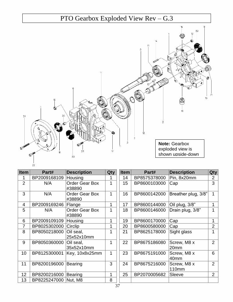
PTO Gearbox Exploded View Rev – G.3
37
Item Part# Description Qty Item Part# Description Qty
1 BP2009168109 Housing 1 14 BP8575378000 Pin, 8x20mm 2
2 N/A Order Gear Box #38890
1 15 BP8600103000 Cap 3
3 N/A Order Gear Box #38890
1 16 BP8600142000 Breather plug, 3/8” 1
4 BP2009169246 Flange 1 17 BP8600144000 Oil plug, 3/8” 1
5 N/A Order Gear Box #38890
1 18 BP8600146000 Drain plug, 3/8” 1
6 BP2009109109 Housing 1 19 BP8600170000 Cap 1
7 BP8025302000 Circlip 1 20 BP8600580000 Cap 2
8 BP8050218000 Oil seal, 25x52x10mm
1 21 BP8625178000 Sight glass 1
9 BP8050360000 Oil seal, 35x52x10mm
1 22 BP8675186080 Screw, M8 x 20mm
2
10 BP8125300001 Key, 10x8x25mm 1 23 BP8675191000 Screw, M8 x 40mm
6
11 BP8200196000 Bearing 3 24 BP8675216000 Screw, M8 x 110mm
2
12 BP8200216000 Bearing 1 25 BP2070005682 Sleeve 2
13 BP8225247000 Nut, M8 8
Note: Gearbox exploded view is shown upside-down when compared to its orientation on the generator.

38
This page has intentionally been left blank.
Limited Warranty
39
Dear Valued Customer:
The NorthStar Product you just purchased is built with the finest material and craftsmanship. Use this product
properly and enjoy the benefits from its high performance. By purchasing a NorthStar product, you show a
desire for quality and durability.
Like all mechanical equipment this unit requires a due amount of care. Treat this unit like the high quality
piece of machinery it is. Neglect and improper handling may impair its performance. Please thoroughly read
the instructions and understand the operation before using your product.
Limited Warranty
NorthStar shall warranty any piece of equipment manufactured, or parts of equipment manufactured, to be free
from defects in material or workmanship for a period of 2 years from the date of purchase by user. This
warranty applies to the original purchaser of the equipment and is non transferable. Verification of purchase is
the responsibility of the buyer. Parts will be replaced or repaired at no charge, except when the equipment has
failed due to lack of proper maintenance. Any misuse, abuse, alteration or improper installation or operations
will void warranty. Determining whether a part is to be replaced or repaired is the sole decision of NorthStar.
NOTE: Some services performed by parties other than NorthStar may void warranty.
This warranty covers parts only. It will not provide for replacement of complete products due to defective parts.
Components not manufactured by NorthStar such as engines are guaranteed by their manufacturer and can be
serviced at factory-authorized locations near you. Any costs incurred due to replacement or repair of items
outside of a NorthStar approved facility is the responsibility of the buyer and not covered under warranty.
NorthStar can supply you with the service center location in your area.
This warranty specifically excludes the following; failure of parts due to damage caused by accident, fire,
flood, windstorm, acts of God, applications not approved by NorthStar in writing, corrosion caused by
chemicals, use of replacement parts which do not conform to manufacturer’s specifications, and damage caused
by vandalism. Additional exclusions: loss of running time, inconvenience, loss of income, or loss of use,
including any implied warranty of merchantability of fitness for a specific use.
Warranty does not cover items subject to normal wear such as tires, receptacles or any part subject to direct
physical contact by the public. This warranty does not cover any personal injury or damage to surrounding
property caused by failure of any part.
This warranty is in lieu of any other warranty expressed or implied and NorthStar assumes no other
responsibility or liability outside that expressed within this warranty.
Please fill in the following information and have it on hand when you call in a warranty claim.
Customer Number: ______________________________________________________________
Date of Purchase: _______________________________________________________________
NorthStar Serial Number: _________________________________________________________
Item Number: __________________________________________________________________

40
Manufactured by
Northern Tool + Equipment Co.,
2800 SouthCross Drive West
P.O. Box 1499 Burnsville, MN 55337-0499