Embed Size (px)
Citation preview

✓
PRODUCT MANUAL
© A
GD S
yste
ms L
imite
d 20
18 D
oc. R
ef 6
45 P
M Is
s3

2
Table of Contents
Introduction 3 Product and technology 3 Key features 3 Typical applications 3 Product overview image 4 Product overview 4
Installation and Commissioning 5 Physical Installation 5 Step 1 – Mounting height 5 Step 2 – Detector alignment 5 Step 3 – Detector view 5
Electrical Installation 6 Connections 6 Ethernet Connector Type 6 Opto-Coupler Ratings 6 Power Up Sequence 6
Connecting 7 Connecting Wifi 7 Connecting device 7
Set-up device using Wifi AGD Touch-setup 8 Step 1 – Name site 8 Step 2 – Set zone 8 Step 3 – Calibrate 9 Home page 9
Troubleshooting – 10 Physical installation 10 Electrical installation 11 Connecting / Commissioning 12
Technical Specifications 13 Product Specification 13
End of life document 14Notes 15Contact 16 Disclaimer 16 Warranty 16 Contact Details 16
safer, greener, more efficient

3
Product and technology
The AGD 645 Pedestrian Detector has been designed for the detection and monitoring of pedestrians waiting to cross the road to ensure the crossing phase is called only when pedestrians are present.
The AGD 645 builds on the popular AGD 640 Pedestrian Detector which has successfully been deployed on over 15,000 sites worldwide. The ground-up development of the 645 is a 3D HD stereo-vision optical system capable of detecting moving and stationary targets over a large 10m x 3m zone. The 645 maintains class leading shadow and unwanted object rejection.
Key Features
• 10m x 3m zone adjacent to the detector saving on infrastructure costs.
• AGD 3D HD optical stereo vision technology provides greater performance even at low light levels.
• WiFi AGD Touch-setup technology with 3 step browser setup speeds up installation and reduces installer risk.
• AGD Quick-mask zone selection allows easy configuration of curved or irregular detection zones saving even more time on site.
• IP remote access and live video functionality for greater access to site data improving safety of users.
• Compatibility with old and new controllers makes the AGD645 an ideal solution for any site.
tyPical aPPlications
5m x 3m Toucan Crossing 10m x 3m Super Crossing using single units
Introduction

4
Product overview image
Product overview
The AGD 645 Pedestrian Detector is an optical product that makes crossings safer by delivering robust detection within a larger zone than previously possible. Multiple units easily integrate to comfortably cover new style ‘super-crossings’.
It is a high-performance product that processes information on board with new chip-set and sophisticated algorithms for automated decision-making to provide ultra-reliable detection.
The AGD 645 Pedestrian Detector employs a 3D HD stereo vision optical system that detects moving and stationary targets over a large 10m x 3m zone. It has an outstanding capability to detect people while rejecting shadows, litter, leaves and small objects such as birds walking through the zone.
Designed into the platform to cover the needs of ‘Smart City’ systems are IP, Power Over Ethernet, and real-time video capabilities which allow the 645 to feed data and pictures ‘down the wire’ straight into ITS control rooms – empowering truly informed decision making.
safer, greener, more efficient
Camera One
Camera Two
Low voltage supply and
opto isolator detect
outputs
Power-Up LED (red) and WiFi indicator (blue)
Ethernet connector
Introduction
5
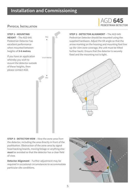
Physical installation
STEP 1 - MOUNTING HEIGHT – The AGD 645 Pedestrian Detector has excellent performance when mounted between heights of 3-6 metres.
If you have an application whereby you wish to mount the detector outside of these heights, then please contact AGD.
STEP 2 - DETECTOR ALIGNMENT – The AGD 645 Pedestrian Detector should be mounted using the supplied hardware. Adjust the tilt angle so that the arrow marking on the housing and mounting foot line up (for 10m zone coverage, the unit must be tilted further back). Ensure that the detector is securely fixed and the mounting nut is tight.
STEP 3 - DETECTOR VIEW – View the zone-area from the detector, including the area directly in front of the pushbutton. Obstruction of the zone-area by signal head backing boards, moving foliage or anything else must be avoided so that the detector has a clear field of view.
Detector Alignment – Further adjustment may be required in occasional circumstances to accommodate particular site conditions.
Installation and Commissioning
6
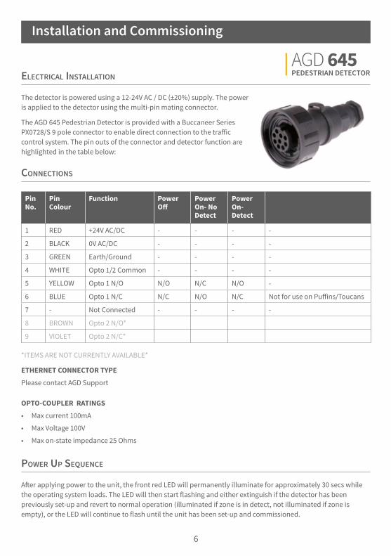
Power uP sequence
After applying power to the unit, the front red LED will permanently illuminate for approximately 30 secs while the operating system loads. The LED will then start flashing and either extinguish if the detector has been previously set-up and revert to normal operation (illuminated if zone is in detect, not illuminated if zone is empty), or the LED will continue to flash until the unit has been set-up and commissioned.
*ITEMS ARE NOT CURRENTLY AVAILABLE*
ETHERNET CONNECTOR TYPE
Please contact AGD Support
OPTO-COUPLER RATINGS
• Max current 100mA
• Max Voltage 100V
• Max on-state impedance 25 Ohms
electrical installation
The detector is powered using a 12-24V AC / DC (±20%) supply. The power is applied to the detector using the multi-pin mating connector.
The AGD 645 Pedestrian Detector is provided with a Buccaneer Series PX0728/S 9 pole connector to enable direct connection to the traffic control system. The pin outs of the connector and detector function are highlighted in the table below:
connections
Installation and Commissioning
Pin No.
Pin Colour
Function Power Off
Power On- No Detect
Power On- Detect
1 RED +24V AC/DC - - - -
2 BLACK 0V AC/DC - - - -
3 GREEN Earth/Ground - - - -
4 WHITE Opto 1/2 Common - - - -
5 YELLOW Opto 1 N/O N/O N/C N/O -
6 BLUE Opto 1 N/C N/C N/O N/C Not for use on Puffins/Toucans
7 - Not Connected - - - -
8 BROWN Opto 2 N/O*
9 VIOLET Opto 2 N/C*

7
connecting
The AGD 645 Pedestrian Detector has been designed with efficiency and ease of use in mind. It is connected to using a WiFi enabled device (laptop, tablet or phone) and setup simply using a browser window.
This step-through process describes the actions required to setup the detector upon initial deployment when first removed from the box.
CONNECTING WIFI
Check the red LED is illuminated and flashing on the front of the unit. Search for the unit and identify the unit by its serial number:
645:XXXXXX-XXXX-TBD (the ‘X’ denotes the S/N, TBD is a renamable field used to name the pole location the 645 is installed on)
Click ‘connect’ and input the default password:
Agd645:XXXXXX-XXXX (the ‘X’ denotes the S/N)
AGD Systems recommend you change the password via the Advanced screen option.
The LED on the front of the unit should now be illuminated blue to show WiFi is successfully connected and your device should show connected.`
CONNECTING DEVICE
Complete Wifi connection step as above.
Launch a browser on your smartphone, tablet or laptop (Modern versions of: Internet Explorer, Google Chrome and Safari are all supported - 2016 onwards).
In the address bar of your browser, enter the ‘IP Address’: http://10.42.0.1:8080
You will be presented with your initial AGD Touch-setup page.
Installation and Commissioning

8
STEP 2 – SET ZONE
The second action is to ‘Set Zone’ using the quick-mask ‘zone’ tool. Draw a boundary around the area in which you are interested in detecting pedestrians. Take care to draw around poles, railings, foliage and other items that might be in the field of view.
Note the extra area that has been drawn around the tactiles, this is necessary to provide coverage at the extremities of the zone and is explained in the troubleshooting section.
When the zone is set, click ‘Next’.
set-uP device using agd touch-setuP
When logged in to the device for the first time you are presented with the set-up screen. This is the AGD Touch-Setup, a three stage process that allows installers to configure the device quickly and efficiently.
STEP 1 – NAME SITE
The first action is to name the devices ‘Install Location’.
*Note - This will change the SSID of the device (the Wifi name of the device). However, the default password will remain the same unless changed in ‘Advanced’ settings
When finished naming the ‘Install Location’ proceed to the next step by clicking ‘Next’.
*Note - there are additional parameters on this initial release of product that are not supported in this manual. Please contact AGD for further support.
Installation and Commissioning
9
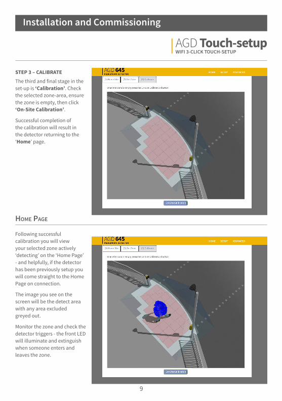
STEP 3 – CALIBRATE
The third and final stage in the set-up is ‘Calibration’. Check the selected zone-area, ensure the zone is empty, then click ‘On-Site Calibration’.
Successful completion of the calibration will result in the detector returning to the ‘Home’ page.
home Page
Following successful calibration you will view your selected zone actively ‘detecting’ on the ‘Home Page’ - and helpfully, if the detector has been previously setup you will come straight to the Home Page on connection.
The image you see on the screen will be the detect area with any area excluded greyed out.
Monitor the zone and check the detector triggers - the front LED will illuminate and extinguish when someone enters and leaves the zone.
Installation and Commissioning

10
Physical installation
If the unit is not operating correctly, please check the following, has the unit been:
1) Mounted within the recommended height of 3-6 metres?
2) Angled according to the installation guide to provide good coverage of the detection area?
3) Installed with any obstructions in the viewable area such as the traffic signal head?
If trouble with operation persists please contact AGD Technical Support.
AGD TECHNICAL SUPPORT
eMail: [email protected]
Tel: +44-1452-557404
Troubleshooting

11
electrical installation
If the unit is not operating correctly, please check the following:
1) Is power present at the unit?
2) Is the red LED illuminated when power is applied to the unit?
3) Is there sufficient current to run the unit - identified by the red LED failing to flash and the operating system not starting correctly? Refer to technical specification table.
If trouble with operation persists please contact AGD Technical Support.
AGD TECHNICAL SUPPORT
eMail: [email protected]
Tel: +44-1452-557404
Troubleshooting

12
connecting / commissioning
If the unit is not operating in the prescribed manner, please check the following:
1) Is the LED on the front of the unit you wish to connect to illuminated blue to show that the WiFi network is successfully connected?
2) Has the correct IP Address been entered into the browser address bar?
3) Have you followed the AGD Touch-setup stages correctly and verified correct operation?
If trouble with operation persists please contact AGD Technical Support.
AGD TECHNICAL SUPPORT
eMail: [email protected]
Tel: +44-1452-557404
Troubleshooting

13
180mm 166mm
160mm
117mm
PRODUCT DIMENSIONS
Technical Specifications
Product Specification
Description Pedestrian Detector
Technology AGD 3D HD Optical Stereo Vision
Detection Zone 10m x 3m (Polygonal Mask Set-up)
Mounting Height 3-6m (3.5m nominal)
Power Supply 24V AC/DC
Power 8.0W @ 24V AC/DC (330mA)
Detect Output Single Opto / IP Ready
LED Indication Front LEDs for detect and WiFi connection
Real-time Video Yes
Housing Material Black Polycarbonate / Aluminium
Sealing IP65
Operating Temp -20°C to +60°C
Configuration WiFi AGD Touch-Setup
Lux Level Below 15 lux an infrared illuminator such as a Raytec VAR-12-1 is recommended
Dimensions W 181mm x D 160mm x H 117mm
Weight 1400g
Complies with BS EN 50293, BS EN62368, Type Approval Ref: AGD AP601113
Patent No. GB 2448617

14
Intentionally left blank
End of life document

15
Notes

16
disclaimer
While we (AGD Systems) endeavour to keep the information in this manual correct at the time of download or print, we make no representations or warranties of any kind, express or implied, about the completeness, accuracy, reliability, suitability or availability with respect to the information, products, services, or related graphics contained herein for any purpose. Any reliance you place on such information is therefore strictly at your own risk. In no event will we be liable for any loss or damage including without limitation, indirect or consequential loss or damage, or any loss or damage whatsoever arising from loss of data or profits arising out of, or in connection with, the use of this manual.
warranty
All AGD products are covered by a 12 month return to factory warranty. Products falling outside this period may be returned to AGD Systems for: evaluation, repair, update or re-calibration, any of which may be chargeable.
© A
GD S
yste
ms L
imite
d 20
18 D
oc. R
ef 6
45 P
M Is
s3
traffic.group
AGD Systems Limited White Lion House, Gloucester Road, Cheltenham, GL51 0TF, UK Tel: +44 (0) 1452 854212 eMail: [email protected] Web: agd-systems.com