Embed Size (px)
Citation preview
Doc. No. AC-OMQ0008-B
PRODUCT NAME
AIR COMBINATION
MODEL/ Series
AC10(A,B)-※ -A
AC20(A,B,C,D)-※ -A
AC25(B,C)-※ -A
AC30(A,B,C,D)-※ -A
AC40(A,B,C,D)-※ -A

Contents PAGE
1. PRECAUTION FOR SAFETY 1~8
2. APPLICATION 9
3. SPECIFICATIONS. . . 9
4. SERIESMAP AND COMBINATION OF EQUIPMENT. . . 10
5. HOW TO ORDER 11~15
6. ATTACHMENTS / ACCESSORIES(OPTIONS)PART NUMBER 16
7. TROUBLE SHOOTING 16
8. SPARE PARTS LIST 16
9. HOW TO REPLACE 17
10. DISASSEMBLY DRAWING . 18~19
11. DIMENSIONS . 20~24
1
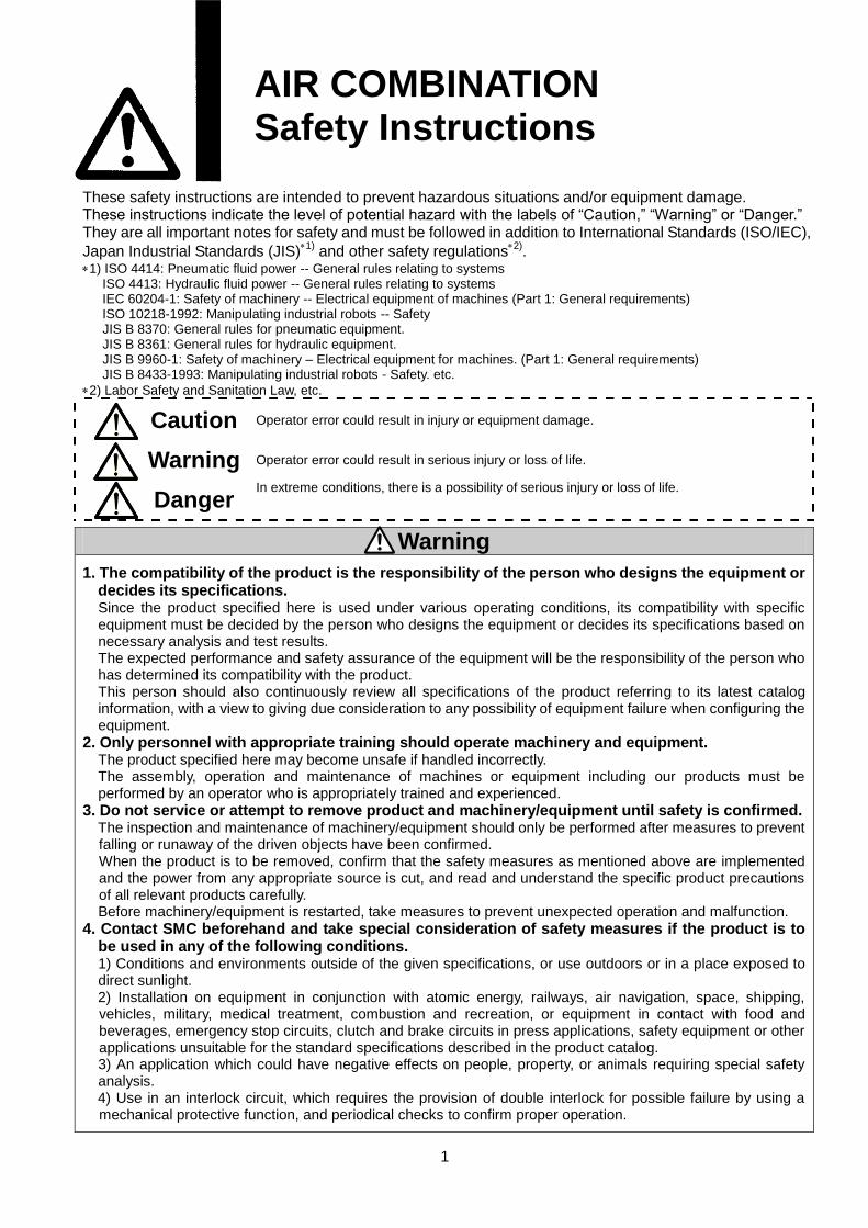
AIR COMBINATION
Safety Instructions
These safety instructions are intended to prevent hazardous situations and/or equipment damage. These instructions indicate the level of potential hazard with the labels of “Caution,” “Warning” or “Danger.” They are all important notes for safety and must be followed in addition to International Standards (ISO/IEC),
Japan Industrial Standards (JIS)1)
and other safety regulations2)
. 1) ISO 4414: Pneumatic fluid power -- General rules relating to systems ISO 4413: Hydraulic fluid power -- General rules relating to systems IEC 60204-1: Safety of machinery -- Electrical equipment of machines (Part 1: General requirements) ISO 10218-1992: Manipulating industrial robots -- Safety JIS B 8370: General rules for pneumatic equipment. JIS B 8361: General rules for hydraulic equipment. JIS B 9960-1: Safety of machinery – Electrical equipment for machines. (Part 1: General requirements) JIS B 8433-1993: Manipulating industrial robots - Safety. etc. 2) Labor Safety and Sanitation Law, etc.
Caution Operator error could result in injury or equipment damage.
Warning Operator error could result in serious injury or loss of life.
Danger In extreme conditions, there is a possibility of serious injury or loss of life.
Warning 1. The compatibility of the product is the responsibility of the person who designs the equipment or
decides its specifications. Since the product specified here is used under various operating conditions, its compatibility with specific equipment must be decided by the person who designs the equipment or decides its specifications based on necessary analysis and test results. The expected performance and safety assurance of the equipment will be the responsibility of the person who has determined its compatibility with the product. This person should also continuously review all specifications of the product referring to its latest catalog information, with a view to giving due consideration to any possibility of equipment failure when configuring the equipment.
2. Only personnel with appropriate training should operate machinery and equipment. The product specified here may become unsafe if handled incorrectly. The assembly, operation and maintenance of machines or equipment including our products must be performed by an operator who is appropriately trained and experienced.
3. Do not service or attempt to remove product and machinery/equipment until safety is confirmed. The inspection and maintenance of machinery/equipment should only be performed after measures to prevent falling or runaway of the driven objects have been confirmed. When the product is to be removed, confirm that the safety measures as mentioned above are implemented and the power from any appropriate source is cut, and read and understand the specific product precautions of all relevant products carefully. Before machinery/equipment is restarted, take measures to prevent unexpected operation and malfunction.
4. Contact SMC beforehand and take special consideration of safety measures if the product is to be used in any of the following conditions. 1) Conditions and environments outside of the given specifications, or use outdoors or in a place exposed to direct sunlight. 2) Installation on equipment in conjunction with atomic energy, railways, air navigation, space, shipping, vehicles, military, medical treatment, combustion and recreation, or equipment in contact with food and beverages, emergency stop circuits, clutch and brake circuits in press applications, safety equipment or other applications unsuitable for the standard specifications described in the product catalog. 3) An application which could have negative effects on people, property, or animals requiring special safety analysis. 4) Use in an interlock circuit, which requires the provision of double interlock for possible failure by using a mechanical protective function, and periodical checks to confirm proper operation.
2
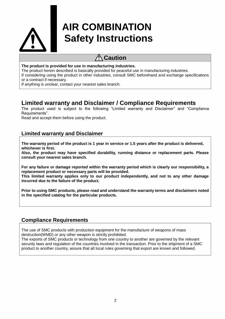
AIR COMBINATION Safety Instructions
Caution The product is provided for use in manufacturing industries. The product herein described is basically provided for peaceful use in manufacturing industries. If considering using the product in other industries, consult SMC beforehand and exchange specifications or a contract if necessary. If anything is unclear, contact your nearest sales branch.
Limited warranty and Disclaimer / Compliance Requirements The product used is subject to the following “Limited warranty and Disclaimer” and “Compliance Requirements”. Read and accept them before using the product.
Limited warranty and Disclaimer The warranty period of the product is 1 year in service or 1.5 years after the product is delivered, whichever is first. Also, the product may have specified durability, running distance or replacement parts. Please consult your nearest sales branch. For any failure or damage reported within the warranty period which is clearly our responsibility, a replacement product or necessary parts will be provided. This limited warranty applies only to our product independently, and not to any other damage incurred due to the failure of the product. Prior to using SMC products, please read and understand the warranty terms and disclaimers noted in the specified catalog for the particular products.
Compliance Requirements The use of SMC products with production equipment for the manufacture of weapons of mass destruction(WMD) or any other weapon is strictly prohibited. The exports of SMC products or technology from one country to another are govemed by the relevant security laws and regulation of the countries involved in the transaction. Prior to the shipment of a SMC product to another country, assure that all local rules goveming that export are known and followed.
当社の製品は、製造業向けとして提供していま
す。
ここに掲載されている当社の製品は、主に製
造業を目的とした平和利用向けに提供してい
ます。
製造業以外でのご使用を検討される場合には、
当社にご相談いただき必要に応じて仕様書の
取り交わし、
契約などを行ってください。
当社の製品は、製造業向けとして提供していま
す。
ここに掲載されている当社の製品は、主に製
造業を目的とした平和利用向けに提供してい
ます。
製造業以外でのご使用を検討される場合には、
当社にご相談いただき必要に応じて仕様書の
取り交わし、
契約などを行ってください。

! WARNING
○ Air combination
①
②
Polycarbonate Nylon
Hydrochloric acid
△ ×
Chromic acid
Potash
× ○Ammonia water
Carbonate of soda
Sodium sulphide
Sulphate of potash × △Sulphate of soda
Carbon tetrachloride
Chloroform △Ethylene chloride
Methylene chloride
Benzene
Toluene △Paint thinner
Acetone Photographic film
Methyl ethyl ketone Dry cleaning × ×
Cyclohexane Textile industries
Ethyl alcohol
IPA △ ×
Methyl alcohol
Gasoline
Kerosene
Phthalic acid dim ethyl
Phthalic acid diethyl × ○Acetic acid
Methyl ether
Ethyl ether
Cutting oil
Brake oil additives × ×
Rubber accelerator
Thread -lock fluid
Seawater × △Leak tester
When the above factors are present, or there is some doubt, use a metal case for safety.
③
External parts including the bonnet (material: polyacetal), bowl, sight dome (material:
polycarbonate) are made of resin. Organic solvents including synthetic fluid, chemicals
including acetone, alcohol, ethylene chloride, sulphuric acid, nitrate, hydrochrolic acid,
cutting oil, kerosene, gasoline, lock material of screw are harmful. Do not use the products
where containing those.
Effects organic solvents and chemicals, and where these elements are
likely to adhere to the equipment.
Chemical data for substances causing degradation (Reference)
Acid washing liquid
for metalsSulphuric acid, Phosphoric acid
Material
Precautions for design
Acid
×
×
×
×
-
Sodium hydroxide (Caustic soda)
Calcium hydroxide (Slack lime)
Consult SMC if no leakage is allowed due to the environment, or operating fluid is not air.
AlcoholAntifreeze
Adhesives
Degreasing of metals
Industrial salts
Water-soluble cutting
oil
Coatings
Dry cleaning
Cleaning liquid for
metals
Printing ink
Dilution
Inorganic
salts
Chlorine
solvents
Aromatic
series
Ketone
Alkaline
Other
Oil
Methyl amino
Brake oil additives
Synthetic oil
Anti-rust additives
-
Ester
Ether
Amino
○:Essentially safe. △:Some effects may occur. ×:Effects will occur.
○
○
3
Type Chemical name Application examples
-
Protect from ultra violet ray and radiation heat by shield.
○ Air filter, Lubricator, Filter-regulator and Mist separator
① Avoid the application where charge and discharge of pressure to bowl is switched frequently.
This may damage the bowl. A metal bowl is recommended in these cases.
○ Regulator and Filter-regulator
①
! CAUTION
○ Air filter, Filter-regulator and Mist separator
①
○ Regulator and Filter-regulator
① Air consumption from release port is 0.1L/min(ANR) or less.
! WARNING
○ Air combination
①
○ Air filter, Filter-regulator and Mist separator
①Output of compressor: 0.75kW or more.
Discharged flow rate: 100L/ min (ANR) or more.
Operating pressure: 0.1MPa or more at min..
②
○ Regulator and Filter-regulator
①
②
③
④
⑤
○ Lubricator
①
②
③
④
⑤
Selection
A safety device needs to be installed if output pressure is exceeding the set pressure, otherwise this
can cause the breakage of outlet device and equipment or malfunction.
AD17-A and AD27-A with auto drain may leak during exhaust of pressure. (This leakage is allowed
in their constructions and not failure.) Be sure to connect piping for drain.
Mineral grease used on internal surfaces and packing may leak to the outlet. Please contact SMC if
this is a problem.
Operating pressure: 0.1MPa or more at min. for AD17-A and AD27-A, 0.15MPa or more at min. for
AD37-A and AD47-A.
Consult SMC if using this product for purposes other than its primary use of lubricating air line
equipment.
Long absence of operation or operation with outlet circuit sealed or balance circuit may cause
pressure fluctuation in outlet set pressure. Please consult SMC if this is a problem.
Set pressure of outlet pressure shall be 85% or less of inlet pressure. Pressure over 85% makes
operation susceptible to flow and inlet pressure which lead to cause unstable operation.
N.O type auto drain should be used under the following requirements to avoid operating failure.
N.C. type auto drain should be used under the following requirements to avoid operating failure.
4
If multiple auto drains are used, confirm used compressor has capacity over the result of multiplying
the above capacity and the number of used auto drains.
{For example, in case of two auto drain, the compressor need the capacity over 1.5kW [200L/ min
(ANR)].}
Maximum set pressure range in the spec. has margin. Pressure set may be higher than the
maximum value.
If regulator is used with circuit which requires high exhaust sensitivity or set precision, please
consult SMC.
The use at high frequency such as the use in press machine may damage internal components and
cause operating failure of the equipment installed to secondary side. Contact SMC for such a use.
Small air consumption may prevent the oil from dropping. Confirm air flow necessary to produce the
drops required for the correct amount of oil.
Do not supply the air from secondary side (reverse air flow). Otherwise, internal components may be
damaged.
If piping is branched at inlet side, the oil may flow back. Avoid the reverse flow by installing a check
valve (AKM series) to inlet side.
It is possible to exhaust the residual pressure to the inlet when releasing the inlet pressure, but the
exhaust can fail at a set pressure of 0.15MPa or less.
When the backflow function is necessary at 0.15MPa or less, a regulator with backflow function is
recommended.
! WARNING
○ Air combination
①
②
! CAUTION
○ Air combination
①
②
○ Air filter, Filter-regulator and Mist separator
①
○ Lubricator
①
! WARNING
○ Regulator and Filter-regulator
①
② Operate the pressure adjusting handle manually. Tools may break the handle.
○ Lubricator
①
②
③
! CAUTION
○ Regulator and Filter-regulator
① Check inlet pressure before setting up.
②
・Pull the pressure regulator handle to unlock. (You can visually verity this with the "orange
mark" that appears in the gap.)
③
④
⑤
⑥
Install vertically so that outlet of drain would turned downward. Use with the outlet of drain turned
horizontal or upward causes malfunction.
djust pressure incrementally. Pressure may become lower than set pressure if adjusted by
decreasing the value. Rotate the handle clockwise to raise the set pressure. Counterclockwise to
reduce the pressure. Moreover, please lock the handle after setting pressure.
Outlet pressure may rise if eliminate the inlet pressure after pressure setting and supply pressure
again. The pressure becomes close to the set pressure after air is consumed in outlet.
Be sure to unlock the handle before adjusting the pressure and lock it after setting the pressure.
Failure to follow this procedure can damage the handle and the outlet pressure may fluctuate.
5
Outlet pressure may change if filter regulator is used for long periods. Please confirm set
pressure regularly.
For the regulator with the pressure gauge, do not apply pressure exceeding the maximum scale
of the pressure gauge in order to protect the gauge.
・Push the pressure regulator handle to lock. When the handle is not easily locked, turn it
left and right a little and then push it. (When the handle is locked, the "orange mark", i.e.,
the gap will disappear.)
On AL10-A, some dripping may occur even when needle is fully opened.
Installation
Adjustment
Adjust the pressure adjusting handle ensuring correct inlet pressure and outlet pressure.
Excessive rotation may cause damage to internal parts.
Adjustment of the oil adjustment valve should be carried out manually. The use of tools, etc. can
result in damage to the unit. (AL20-A to AL40-A)
Install the bowl vertically with bowl facing down. If it is inclined, dripping may not be confirmed.
Turning the oil adjustment valve counterclockwise increases the dripping amount, and turning it
clockwise reduces the dripping amount. From the fully closed position, three rotations will bring it
to the fully open position. Please do not rotate it any further than this.
Note that the numbered scale markings are guidelines for adjusting the position, and not
indicators of the dripping amount. (AL20-A to AL40-A)
Connect the product ensuring the direction of " " (IN) and " " (OUT) for air direction or an
arrow. Wrong connection may cause malfunction.
Install with enough space around each assembly component to perform regular maintenance and
operation. The required space is shown on 「11. Dimensions」 (P20 to 24).
Do not drop or apply impact during transportation or installation. It will cause damage to the
product or operation failure.
Do not install in areas of high humidity or high temperature. The product cannot be used in the
horizontal or upward directions outside of the specifications.
2 1
⑦
! WARNING
○ Air combination
①
②
③
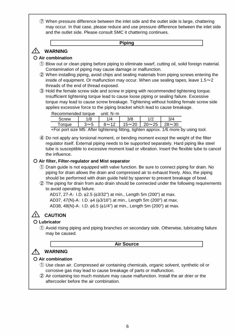
Recommended torque unit: N・mScrew 1/8 1/4 3/8 1/2 3/4
Torque 3~5 8~12 15~20 20~25 28~30*For port size M5: After tightening fitting, tighten approx. 1/6 more by using tool.
④
○ Air filter, Filter-regulator and Mist separator
①
②
AD17, 27-A: I.D. f2.5 (f3/32") at min., Length 5m (200") at max.
AD37, 47(N)-A: I.D. f4 (f3/16") at min., Length 5m (200") at max.
AD38, 48(N)-A: I.D. f6.5 (f1/4") at min., Length 5m (200") at max.
! CAUTION
○ Lubricator
①
! WARNING
○ Air combination
①
②
6
Piping
Air Source
Do not apply any torsional moment, or bending moment except the weight of the filter
regulator itself. External piping needs to be supported separately. Hard piping like steel
tube is susceptible to excessive moment load or vibration. Insert the flexible tube to cancel
the influence.
Drain guide is not equipped with valve function. Be sure to connect piping for drain. No
piping for drain allows the drain and compressed air to exhaust freely. Also, the piping
should be performed with drain guide held by spanner to prevent breakage of bowl.
The piping for drain from auto drain should be connected under the following requirements
to avoid operating failure.
Avoid rising piping and piping branches on secondary side. Otherwise, lubricating failure
may be caused.
When pressure difference between the inlet side and the outlet side is large, chattering
may occur. In that case, please reduce and use pressure difference between the inlet side
and the outlet side. Please consult SMC it chattering continues.
Blow out or clean piping before piping to eliminate swarf, cutting oil, solid foreign material.
Contamination of piping may cause damage or malfunction.
When installing piping, avoid chips and sealing materials from piping screws entering the
inside of equipment. Or malfunction may occur. When use sealing tapes, leave 1.5~2
threads of the end of thread exposed.
Hold the female screw side and screw in piping with recommended tightening torque.
Insufficient tightening torque lead to cause loose piping or sealing failure. Excessive
torque may lead to cause screw breakage. Tightening without holding female screw side
applies excessive force to the piping bracket which lead to cause breakage.
Use clean air. Compressed air containing chemicals, organic solvent, synthetic oil or
corrosive gas may lead to cause breakage of parts or malfunction.
Air containing too much moisture may cause malfunction. Install the air drier or the
aftercooler before the air combination.
! WARNING
○ Air combination
①
○ Air filter, Lubricator, Filter-regulator and Mist separator
①
②
③
○ Air filter, Filter-regulator and Mist separator
①
② Drain the bowl by opening drain cock before the drain level in the bowl reaches baffle.
○ Regulator
①
○ Lubricator
①
②
③
Open and close drain cock manually. Open and close too much may damage the drain cock.
Use class 1 turbine oil (without additives) ISO VG32. Using other lubricant can cause damage
to devices and result in malfunction.
In AL10-A and AL20-A series, lubrication during pressurization is not possible.
Exhaust the inlet pressure and check that there is no pressure within the product. Supply oil
after removing the oil supply plug.
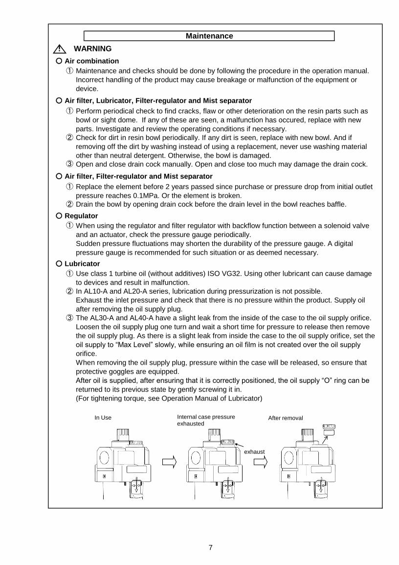
The AL30-A and AL40-A have a slight leak from the inside of the case to the oil supply orifice.
Loosen the oil supply plug one turn and wait a short time for pressure to release then remove
the oil supply plug. As there is a slight leak from inside the case to the oil supply orifice, set the
oil supply to “Max Level” slowly, while ensuring an oil film is not created over the oil supply
orifice.
When removing the oil supply plug, pressure within the case will be released, so ensure that
protective goggles are equipped.
After oil is supplied, after ensuring that it is correctly positioned, the oil supply “O” ring can be
returned to its previous state by gently screwing it in.
(For tightening torque, see Operation Manual of Lubricator)
Maintenance
7
Maintenance and checks should be done by following the procedure in the operation manual.
Incorrect handling of the product may cause breakage or malfunction of the equipment or
device.
Perform periodical check to find cracks, flaw or other deterioration on the resin parts such as
bowl or sight dome. If any of these are seen, a malfunction has occured, replace with new
parts. Investigate and review the operating conditions if necessary.
Check for dirt in resin bowl periodically. If any dirt is seen, replace with new bowl. And if
removing off the dirt by washing instead of using a replacement, never use washing material
other than neutral detergent. Otherwise, the bowl is damaged.
Replace the element before 2 years passed since purchase or pressure drop from initial outlet
pressure reaches 0.1MPa. Or the element is broken.
When using the regulator and filter regulator with backflow function between a solenoid valve
and an actuator, check the pressure gauge periodically.
Sudden pressure fluctuations may shorten the durability of the pressure gauge. A digital
pressure gauge is recommended for such situation or as deemed necessary.
exhaust
In Use After removal Internal case pressure exhausted

! CAUTION
○ Regulator and Filter-regulator
①
○ Air filter, Filter-regulator and Mist separator
①
②
③
○ Lubricator
①
② Use clean oil to avoid dripping failure.
③ The lubricating amount should be less than the upper limit of oil level.
④
If the first operation is performed and defective setting and the exhaust leakage is found, it is
likely there is foreign object in an internal valve seat part. Failure to remove these parts may
cause damage to internal parts.
8
Rotate the handle counterclockwise (O←direction) to exhaust the condensate of
the C1SF-A and C2SF(-C)-A.
Press the push button to exhaust the condensate of the C3SF(-W)-A and C4SF(-W)-A.
Check the element periodically and replace it with a new one if necessary. If it is found that
outlet pressure drops or the flow is restricted, check the condition of the element.
The manual exhaust for emergency case can be performed by counterclockwise rotation of the
handle in AD17-A and AD27-A. (O←direction)
For AD37-A, AD38-A, AD47-A and AD48-A, rotate the drain cock counterclockwise in that
case. (O←direction)
Check the dripping amount once a day. Dripping failure may cause damage to lubricated
objects.
Discharge drain to avoid that drain exceeds the upper limit of the air filter. Excessive drain in
the lubricator may cause dripping failure.
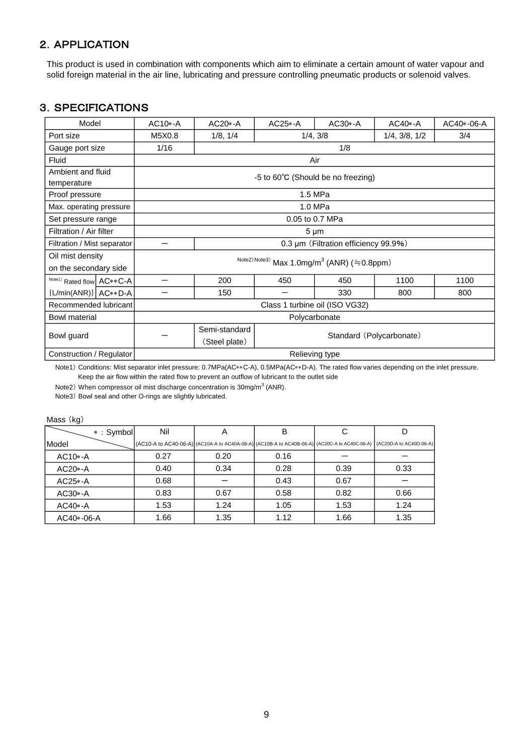
2.APPLICATION
3.SPECIFICATIONS
AC**C-A
{L/min(ANR)} AC**D-A
Note1) Conditions: Mist separator inlet pressure: 0.7MPa(AC**C-A), 0.5MPa(AC**D-A). The rated flow varies depending on the inlet pressure.
Keep the air flow within the rated flow to prevent an outflow of lubricant to the outlet side
Note2) When compressor oil mist discharge concentration is 30mg/m3 (ANR).
Note3) Bowl seal and other O-rings are slightly lubricated.
Mass (kg)
* : Symbol
Model
AC10*-A
AC20*-A
AC25*-A
AC30*-A
AC40*-A
AC40*-06-A
0.27 --0.160.20
-
Note2)Note3) Max 1.0mg/m
3 (ANR) (≒0.8ppm)
-
-
-
Relieving type
Polycarbonate
Class 1 turbine oil (ISO VG32)
1/16
M5X0.8
AC10*-A
Air
-5 to 60℃ (Should be no freezing)
5 μm
0.05 to 0.7 MPa
1.0 MPa
1.5 MPa
This product is used in combination with components which aim to eliminate a certain amount of water vapour and
solid foreign material in the air line, lubricating and pressure controlling pneumatic products or solenoid valves.
on the secondary side
Bowl guard(Steel plate)
Standard (Polycarbonate)
Note1)
Rated flow 1100 1100
- 330 800 800
200
150
450 450
Oil mist density
Port size
Fluid
Proof pressure
Max. operating pressure
Set pressure range
Gauge port size
Ambient and fluid
0.82 0.66
1.35 1.12 1.66 1.35
1.53 1.241.24 1.05
0.40
0.68
(AC20C-A to AC40C-06-A) (AC20D-A to AC40D-06-A)
1.53
1.66
0.33
-
0.67 0.58
C
0.28 0.39
- 0.43 0.67
1/8
0.83
0.34
(AC10-A to AC40-06-A)
Nil A DB
(AC10A-A to AC40A-06-A) (AC10B-A to AC40B-06-A)
Filtration / Air filter
AC40*-A AC40*-06-A
temperature
AC20*-A
3/4
AC30*-A
1/8, 1/4 1/4, 3/8
9
0.3 μm (Filtration efficiency 99.9%)
Construction / Regulator
Semi-standard
Recommended lubricant
AC25*-A
Bowl material
1/4, 3/8, 1/2
Model
Filtration / Mist separator
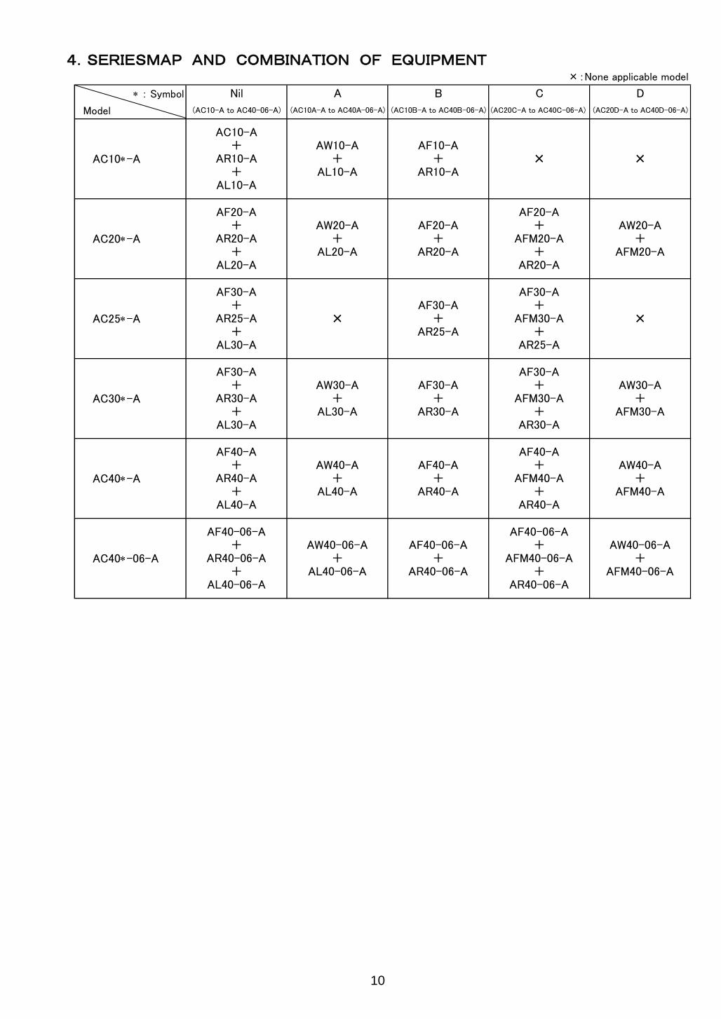
4.SERIESMAP AND COMBINATION OF EQUIPMENT×:None applicable model
* : Symbol
Model
AC10*-A
AC10-A+
AR10-A+
AL10-A
AW10-A+
AL10-A
AF10-A+
AR10-A× ×
D
(AC20D-A to AC40D-06-A)
C
AF20-A+
AFM20-A+
AR20-A
AW20-A+
AFM20-A
AF30-A+
AR30-A+
AL30-A
AF40-A+
AR40-A+
AL40-A
B
(AC10B-A to AC40B-06-A)
AW20-A+
AL20-A
AF30-A+
AR25-A+
AL30-A
Nil
(AC10-A to AC40-06-A)
×
AW30-A+
AL30-A
10
AF20-A+
AR20-A
AF30-A+
AR25-A
AF30-A+
AFM30-A+
AR25-A
×
AF30-A+
AR30-A
AF30-A+
AFM30-A+
AR30-A
AW30-A+
AFM30-A
AW40-A+
AL40-A
AF40-A+
AR40-A
AF40-A+
AFM40-A+
AR40-A
AW40-A+
AFM40-A
AW40-06-A+
AL40-06-A
AF40-06-A+
AR40-06-A
AF40-06-A+
AFM40-06-A+
AR40-06-A
AW40-06-A+
AFM40-06-A AC40*-06-A
A
(AC10A-A to AC40A-06-A) (AC20C-A to AC40C-06-A)
AF20-A+
AR20-A+
AL20-A
AF40-06-A+
AR40-06-A+
AL40-06-A
AC20*-A
AC25*-A
AC30*-A
AC40*-A

5.HOW TO ORDER
10 20 25 30 40
● - - - -- ● ● ● ●
N - ● ● ● ● F - ● ● ● ●
+M5 ● - - - -01 - ● - - -02 - ● ● ● ●03 - - ● ● ●04 - - - - ●06 - - - - ●+Nil Without auto drain ● ● ● ● ●
C N.C. (Normally closed) Drain port is closed when pressure is not applied. ● ● ● ● ● D N.O. (Normally open) Drain port is open when pressure is not applied. - - ● ● ●
+Nil Without pressure gauge ● ● ● ● ●
Round type pressure gauge (without limit indicator) ● - - - -Round type pressure gauge (with limit indicator) - ● ● ● ●
M Round type pressure gauge (with color zone) - ● ● ● ●
+Nil Without attachment ● ● ● ● ●K Mounting position:AF+AR+K+AL - ● ● ● ●
+Nil Without attachment ● ● ● ● ●
S Mounting position:AF+AR+S+AL - ● ● ● ●
+Nil Without attachment ● ● ● ● ●
T Mounting position:AF+T+AR+AL ● ● ● ● ●
+Nil Without attachment ● ● ● ● ●V Mounting position:AF+AR+AL+V - ● ● ● ●+Nil 0.05 to 0.7 MPa setting ● ● ● ● ●1 0.02 to 0.2 MPa setting ● ● ● ● ●
+Nil Polycarbonate bowl ● ● ● ● ●2 Metal bowl ● ● ● ● ●6 Nylon bowl ● ● ● ● ●8 Metal bowl with level gauge - - ● ● ●C With bowl guard - ● - - -6C With bowl guard (Nylon bowl) - ● - - -
+Nil With drain cock ● ● ● ● ●
Drain guide 1/8 - ● - - -Drain guide 1/4 - - ● ● ●
W Drain cock with barb fitting (for φ 6 x φ 4 nylon tube) - - ● ● ●
+Nil Without drain cock ● ● ● ● ●
3 Lubricator with drain cock ● ● ● ● ●
+Nil Relieving type ● ● ● ● ●N Non-relieving type ● ● ● ● ●
+Nil Flow direction:Left to right ● ● ● ● ●R Flow direction:Right to left ● ● ● ● ●
+Nil Name plate and pressure gauge in imperial units:MPa ● ● ● ● ●
Z ○ ○ ○ ○ ○
Symbol Description Body size
Pipe thread type
NilMetric thread (M5)
RcNPTG
Port size
M51/81/43/81/23/4
Op
tio
n
aFloat type
auto drain
b Pressure gauge G
Att
ach
me
nt
c Check valve
d Pressure switch
e T-spacer
fPressure relief
3 port valve
Se
mi-sta
nd
ard
g Set pressure
h Bowl
iAir filter
drain port
m Pressure unit
11
Name plate, caution plate for bowl, and pressure gauge in imperial units: psi, ゜F
J
jLubricator lubricant
exhaust port
kExhaust
mechanism
l Flow direction
1
2
3
4
6
5
・Option / Semi-standard : Select one each for a to m.
・Option / Attachment / Semi-standard symbol : When more than
one specification is required, indicate in alphanumeric order.
Example) AC30-03DM-KSTV-13NR-A
Note 3)
Note7)
Note 8)
Note 8)
Note 6)
Note 9)
Note 14)
Note 16)
Note 17)
AC 30 - 03 DG 1N - A -
1 3 4 5
F
2
1N
6
-
Note 4)
Note 5)
Note 15)
Note 1) Drain guide is NPT1/8 (applicable to the AC20-A) and NPT1/4 (applicable to the AC25-A to AC40-A). The auto drain port comes with φ3/8" One-touch fitting (applicable to the AC25-A to AC40-A). Note 2) Drain guide is G1/8 (applicable to the AC20-A) and G1/4 (applicable to the AC25-A to AC40-A). Note 3) Option G, M are not assembled and supplied loose
at the time of shipment.
Note 4) When pressure is not applied, condensate which does not start the auto drain mechanism will be left in the bowl. Releasing the residual condensate before ending operations for the day is recommended. Note 5) If the compressor is small (0.75 kW, discharge flow is less than 100 L/min[ANR]), air leakage from the drain cock
may occur during start of operations. N.C. type is recommended. Note 6) When the pressure gauge is attached, a 1.0 MPa pressure gauge will be fitted for standard (0.7 MPa) type. 0.4 MPa pressure gauge for 0.2 MPa type (1.0 MPa pressure gauge only for the AC10-A). Note 7) Not available with piping port size: 06 Note 8) The bracket position varies depending on the T-spacer or pressure switch mounting. Note 9) Pressure can be set higher than the specification pressure in some cases, but use pressure within the specification range. Note 10) Refer to Chemical data on page 3 for chemical resistance of the bowl. Note 11) A bowl guard is provided as standard equipment (polycarbonate).
Note 12) A bowl guard is provided as standard equipment (nylon). Note 13) Float type auto drain: The combination of C and D is not possible. Note 14) Without a valve function Note 15) The combination of metal bowl: 2 and 8 is not available. Note 16) When choosing with W: Filter drain port, the drain cock of a lubricator will be with barb fittings. Note 17) For pipe thread type: M5, NPT. This product is for overseas use only according to the new Measurement Law. (The SI unit type is provided for use in Japan.) MPa and psi are shown together on the pressure unit. Cannot be used with M: Round pressure gauge (with color zone). Available by request for special.
Note 18) ○: For pipe thread type: M5, NPT only
Note 1)
Note 2)
Note 10)
Note11)
Note 13)
Note11) Note11)
Note12) Note12) Note12)
Note18) Note18) Note18) Note18) Note18)

10 20 30 40
● - - -- ● ● ●
N - ● ● ● F - ● ● ●
+M5 ● - - -01 - ● - -02 - ● ● ●03 - - ● ●04 - - - ●06 - - - ●+Nil Without auto drain ● ● ● ●
C N.C. (Normally closed) Drain port is closed when pressure is not applied. ● ● ● ● D N.O. (Normally open) Drain port is open when pressure is not applied. - - ● ●
+Nil Without pressure gauge ● ● ● ●
Round type pressure gauge (without limit indicator) ● - - -Round type pressure gauge (with limit indicator) - ● ● ●
M Round type pressure gauge (with color zone) - ● ● ●+Nil Without attachments ● ● ● ●K - ● ● ●+Nil Without attachments ● ● ● ●
S Mounting position:AW+S+AL - ● ● ●+Nil Without attachments ● ● ● ●V Mounting position:AW+AL+V - ● ● ●+Nil 0.05 to 0.7 MPa setting ● ● ● ●1 0.02 to 0.2 MPa setting ● ● ● ●+Nil Polycarbonate bowl ● ● ● ●2 Metal bowl ● ● ● ●6 Nylon bowl ● ● ● ●8 Metal bowl with level gauge - - ● ●C With bowl guard - ● - -
6C With bowl guard (Nylon bowl) - ● - -+Nil With drain cock ● ● ● ●
Drain guide 1/8 - ● - -Drain guide 1/4 - - ● ●
W Drain cock with barb fitting (for φ 6 x φ 4 nylon tube) - - ● ●+Nil Without drain cock ● ● ● ●
3 Lubricator with drain cock ● ● ● ●+Nil Relieving type ● ● ● ●N Non-relieving type ● ● ● ●+Nil Flow direction: Left to right ● ● ● ●R Flow direction: Right to left ● ● ● ●+Nil Name plate and pressure gauge in imperial units:MPa ● ● ● ●
Z ○ ○ ○ ○
Body size
RcNil
1/8
G
j
k
Exhaust
mechanism
12
Name plate, caution plate for bowl, and pressure gauge in imperial units: psi, ゜F
Flow direction
Filter regulator
drain port
g Bowl
Op
tio
n
Symbol
Pipe thread typeNPT
G
l
Set pressure
Description
Metric thread (M5)
Pressure relief
3 port valve
d
3/4
Port size
Pressure gauge
Check valve
Pressure switch
b
J
Mounting position:AW+K+AL
Pressure unit
M5
e
3/81/2
h
aFloat type
auto drain
f
c
1/4
iLubricator lubricant
exhaust port
Se
mi-sta
nd
ard
Att
ach
me
nt
1
2
3
4
6
5
AC 30 - 03 DG 1N - A -
1 3 4 5
F
2
1N
6
- A
Note 3)
Note 6)
Note 9)
Note 10)
Note 1)
Note 2)
Note7)
Note11) Note11)
Note12) Note12)
Note 14)
Note 15)
Note 16)
Note 17) Note18) Note18) Note18) Note18)
・Option / Semi-standard : Select one each for a to l.
・Option / Attachment / Semi-standard symbol : When more than
one specification is required, indicate in alphanumeric order.
Example) AC30A-03DM-KSV-13NR-A
Note 4)
Note 5)
Note 8)
Note 13)
Note 1) Drain guide is NPT1/8 (applicable to the AC20A-A) and NPT1/4 (applicable to the AC30A-A to AC40A-A). The auto drain port comes with φ3/8" One-touch fitting (applicable to the AC30A-A to AC40A-A). Note 2) Drain guide is G1/8 (applicable to the AC20A-A) and G1/4 (applicable to the AC30A-A to AC40A-A). Note 3) Option G, M are not assembled and supplied loose
at the time of shipment. Note 4) When pressure is not applied, condensate which does not start the auto drain mechanism will be left in the bowl. Releasing the residual condensate before ending operations for the day is recommended. Note 5) If the compressor is small (0.75 kW, discharge flow is less than 100 L/min[ANR]), air leakage from the drain
cock may occur during start of operations. N.C. type is recommended. Note 6) When the pressure gauge is attached, a 1.0 MPa pressure gauge will be fitted for standard (0.7 MPa) type. 0.4 MPa pressure gauge for 0.2 MPa type (1.0 MPa pressure gauge only for the AC10A-A). Note 7) Not available with piping port size: 06 Note 8) The bracket position varies depending on the pressure switch mounting. Note 9) Pressure can be set higher than the specification pressure in some cases, but use pressure within the specification range. Note 10) Refer to Chemical data on page 3 for chemical resistance of the bowl. Note 11) A bowl guard is provided as standard equipment (polycarbonate).
Note 12) A bowl guard is provided as standard equipment (nylon). Note 13) Float type auto drain: The combination of C and D is not possible. Note 14) Without a valve function Note 15) The combination of metal bowl: 2 and 8 is not available. Note 16) When choosing with W: Filter drain port, the drain cock of a lubricator will be with barb fittings. Note 17) For pipe thread type: M5, NPT. This product is for overseas use only according to the new Measurement Law. (The SI unit type is provided for use in Japan.) MPa and psi are shown together on the pressure unit. Cannot be used with M: Round pressure gauge (with color zone). Available by request for special.
Note 18) ○: For pipe thread type: M5, NPT only
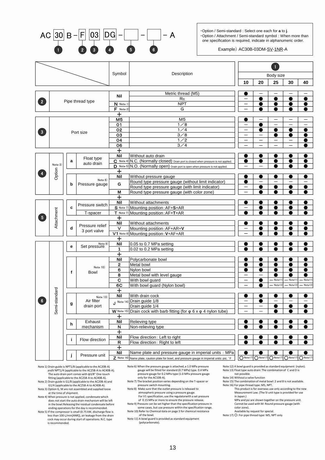
10 20 25 30 40
● - - - -- ● ● ● ●
N - ● ● ● ● F - ● ● ● ●
+M5 ● - - - -01 - ● - - -02 - ● ● ● ●03 - - ● ● ●04 - - - - ●06 - - - - ●+Nil Without auto drain ● ● ● ● ●
C N.C. (Normally closed) Drain port is closed when pressure is not applied. ● ● ● ● ● D N.O. (Normally open) Drain port is open when pressure is not applied. - - ● ● ●
+Nil Without pressure gauge ● ● ● ● ●
Round type pressure gauge (without limit indicator) ● - - - -Round type pressure gauge (with limit indicator) - ● ● ● ●
M Round type pressure gauge (with color zone) - ● ● ● ●+Nil Without attachments ● ● ● ● ●
S Mounting position:AF+S+AR - ● ● ● ●T-spacer T Mounting position:AF+T+AR ● ● ● ● ●
+Nil Without attachments ● ● ● ● ●V Mounting position:AF+AR+V - ● ● ● ●
V1 Mounting position:V+AF+AR - ● ● ● ●+Nil 0.05 to 0.7 MPa setting ● ● ● ● ●1 0.02 to 0.2 MPa setting ● ● ● ● ●+Nil Polycarbonate bowl ● ● ● ● ●2 Metal bowl ● ● ● ● ●6 Nylon bowl ● ● ● ● ●8 Metal bowl with level gauge - - ● ● ●C With bowl guard - ● - - -
6C With bowl guard (Nylon bowl) - ● - - -+Nil With drain cock ● ● ● ● ●
Drain guide 1/8 - ● - - -Drain guide 1/4 - - ● ● ●
W Drain cock with barb fitting (for φ 6 x φ 4 nylon tube) - - ● ● ●+Nil Relieving type ● ● ● ● ●N Non-relieving type ● ● ● ● ●+Nil Flow direction: Left to right ● ● ● ● ●R Flow direction: Right to left ● ● ● ● ●+Nil ● ● ● ● ●
Z ○ ○ ○ ○ ○
13
Body size
Port size
Symbol
Name plate and pressure gauge in imperial units:MPa
J
3/4
e Set pressure
Air filter
drain port
f
1/2
Op
tio
nA
tta
ch
me
nt c
b
i
j
Bowl
Pressure gauge
Pipe thread type
Float type
auto drain
Exhaust
mechanism
a
d
Name plate, caution plate for bowl, and pressure gauge in imperial units: psi, ゜FPressure unit
Se
mi-sta
nd
ard
h
g
M5
Pressure switch
Pressure relief
3 port valve
Flow direction
1/43/8
NilRc
1/8
G
Description
Metric thread (M5)
NPTG
1
2
3
4
6
5
Note 9)
AC 30 - 03 DG 1N - A -
1 3 4 5
F
2
1N
6
- B
Note 8)
Note 3)
Note 6)
Note 10)
Note11)
Note12)
Note11)
Note12)
Note11)
Note12)
Note 14)
Note 15)
Note 16) Note17) Note17) Note17) Note17) Note17)
Note 1)
Note 2)
Note 4)
Note 5)
Note 7)
Note 7)
Note 13)
・Option / Semi-standard : Select one each for a to j.
・Option / Attachment / Semi-standard symbol : When more than
one specification is required, indicate in alphanumeric order.
Example) AC30B-03DM-SV-1NR-A
Note 1) Drain guide is NPT1/8 (applicable to the AC20B-A) andV NPT1/4 (applicable to the AC25B-A to AC40B-A). The auto drain port comes with φ3/8" One-touch fitting (applicable to the AC25B-A to AC40B-A). Note 2) Drain guide is G1/8 (applicable to the AC20B-A) and G1/4 (applicable to the AC25B-A to AC40B-A). Note 3) Option G, M are not assembled and supplied loose
at the time of shipment. Note 4) When pressure is not applied, condensate which does not start the auto drain mechanism will be left in the bowl.Releasing the residual condensate before ending operations for the day is recommended. Note 5) If the compressor is small (0.75 kW, discharge flow is less than 100 L/min[ANR]), air leakage from the drain cock may occur during start of operations. N.C. type is recommended.
Note 6) When the pressure gauge is attached, a 1.0 MPa pressure gauge will be fitted for standard (0.7 MPa) type. 0.4 MPa pressure gauge for 0.2 MPa type (1.0 MPa pressure gauge only for the AC10B-A). Note 7) The bracket position varies depending on the T-spacer or pressure switch mounting. Note 8) Make sure that the outlet pressure is released to atmospheric pressure using a pressure gauge. For V1 specification, use the regulatorwith a set pressure of 0.15 MPa or more to ensure the pressure release. Note 9) Pressure can be set higher than the specification pressure in some cases, but use pressure within the specification range. Note 10) Refer to Chemical data on page 3 for chemical resistance of the bowl. Note 11) A bowl guard is provided as standard equipment (polycarbonate).
Note 12) A bowl guard is provided as standard equipment (nylon). Note 13) Float type auto drain: The combination of C and D is not possible. Note 14) Without a valve function Note 15) The combination of metal bowl: 2 and 8 is not available. Note 16) For pipe thread type: M5, NPT. This product is for overseas use only according to the new Measurement Law. (The SI unit type is provided for use in Japan.) MPa and psi are shown together on the pressure unit. Cannot be used with M: Round pressure gauge (with color zone). Available by request for special.
Note 17) ○: For pipe thread type: M5, NPT only

20 25 30 40
Nil ● ● ● ● N ● ● ● ● F ● ● ● ●
+01 ● - - -02 ● ● ● ●03 - ● ● ●04 - - - ●06 - - - ●+Nil Without auto drain ● ● ● ●
C N.C. (Normally closed) Drain port is closed when pressure is not applied. ● ● ● ● D N.O. (Normally open) Drain port is open when pressure is not applied. - ● ● ●
+Nil Without pressure gauge ● ● ● ●G Round type pressure gauge (with limit indicator) ● ● ● ●M Round type pressure gauge (with color zone) ● ● ● ●+Nil Without attachments ● ● ● ●
S Mounting position:AF+AFM+S+AR ● ● ● ●T-spacer T Mounting position:AF+AFM+T+AR ● ● ● ●
+Nil Without attachments ● ● ● ●V Mounting position:AF+AFM+AR+V ● ● ● ●
V1 Mounting position:V+AF+AFM+AR ● ● ● ●+Nil 0.05 to 0.7 MPa setting ● ● ● ●1 0.02 to 0.2 MPa setting ● ● ● ●+Nil Polycarbonate bowl ● ● ● ●2 Metal bowl ● ● ● ●6 Nylon bowl ● ● ● ●8 Metal bowl with level gauge - ● ● ●C With bowl guard ● - - -
6C With bowl guard (Nylon bowl) ● - - -+Nil With drain cock ● ● ● ●
Drain guide 1/8 ● - - -Drain guide 1/4 - ● ● ●
W Drain cock with barb fitting (for φ 6 x φ 4 nylon tube) - ● ● ●+Nil Relieving type ● ● ● ●N Non-relieving type ● ● ● ●+Nil Flow direction: Left to right ● ● ● ●R Flow direction: Right to left ● ● ● ●+Nil ● ● ● ●
Z ○ ○ ○ ○
Symbol Description Body size
Pipe thread type
RcNPT
G
Port size
1/81/43/81/23/4
Op
tio
n
aFloat type
auto drain
b Pressure gauge
Att
ach
me
nt c
Pressure switch
dPressure relief
3 port valve
Se
mi-sta
nd
ard
e Set pressure
f Bowl
g
Air filter
Mist separator
drain port
14
Name plate and pressure gauge in imperial units:MPa
Name plate, caution plate for bowl, and pressure gauge in imperial units: psi, ゜F
J
hExhaust
mechanism
i Flow direction
j Pressure unit
1
2
3
4
6
5
AC 30 - 03 DG 1N - A -
1 3 4 5
F
2
1N
6
- C
Note 13)
Note 3)
Note 6)
Note 7)
Note 7)
Note 8)
Note 9)
Note 10)
Note11)
Note12)
Note11)
Note12)
Note11)
Note12)
Note 14)
Note 15)
Note 16) Note17) Note17) Note17) Note17)
Note 1)
Note 2)
Note 4)
Note 5)
・Option / Semi-standard : Select one each for a to j.
・Option / Attachment / Semi-standard symbol : When more than
one specification is required, indicate in alphanumeric order.
Example) AC30C-03DM-SV-1NR-A
Note 1) Drain guide is NPT1/8 (applicable to the AC20C-A) and NPT1/4 (applicable to the AC25C-A to AC40C-A). The auto drain port comes with φ3/8" One-touch fitting (applicable to the AC25C-A to AC40C-A). Note 2) Drain guide is G1/8 (applicable to the AC20C-A) and G1/4 (applicable to the AC25C-A to AC40C-A). Note 3) Option G, M are not assembled and supplied loose
at the time of shipment.
Note 4) When pressure is not applied, condensate which does not start the auto drain mechanism will be left in the bowl. Releasing the residual condensate before ending operations for the day is recommended. Note 5) If the compressor is small (0.75 kW, discharge flow is less than 100 L/min[ANR]), air leakage from the drain cock may occur during start of operations. N.C. type
Note 6) When the pressure gauge is attached, a 1.0 MPa pressure gauge will be fitted for standard (0.7 MPa) type. 0.4 MPa pressure gauge for 0.2 MPa type.
Note 7) The bracket position varies depending on the T-spacer or pressure switch mounting. Note 8) Make sure that the outlet pressure is released to atmospheric pressure using a pressure gauge. For V1 specification, use the regulator with a set pressure of 0.15 MPa or more to ensure the pressure release. Note 9) Pressure can be set higher than the specification pressure in some cases, but use pressure within the specification range. Note 10) Refer to Chemical data on page 3 for chemical resistance of the bowl. Note 11) A bowl guard is provided as standard equipment (polycarbonate). Note 12) A bowl guard is provided as standard equipment (nylon).
Note 13) Float type auto drain: The combination of C and D is not possible. Note 14) Without a valve function Note 15) The combination of metal bowl: 2 and 8 is not available. Note 16) For pipe thread type: NPT. This product is for overseas use only according to the new Measurement Law. (The SI unit type is provided for use in Japan.) MPa and psi are shown together on the pressure unit. Cannot be used with M: Round pressure gauge (with color zone). Available by request for special.
Note 17) ○: For pipe thread type: NPT only
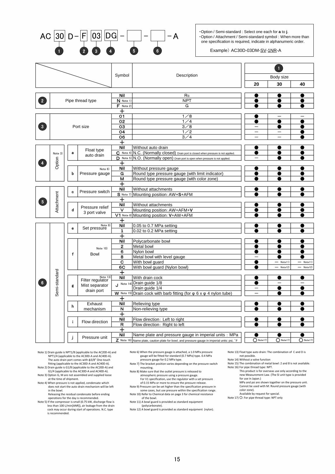
20 30 40
Nil ● ● ● N ● ● ● F ● ● ●
+01 ● - -02 ● ● ●03 - ● ●04 - - ●06 - - ●+Nil Without auto drain ● ● ●
C N.C. (Normally closed) Drain port is closed when pressure is not applied. ● ● ● D N.O. (Normally open) Drain port is open when pressure is not applied. - ● ●
+Nil Without pressure gauge ● ● ●G Round type pressure gauge (with limit indicator) ● ● ●M Round type pressure gauge (with color zone) ● ● ●+Nil Without attachments ● ● ●
S Mounting position:AW+S+AFM ● ● ●+Nil Without attachments ● ● ●V Mounting position:AW+AFM+V ● ● ●
V1 Mounting position:V+AW+AFM ● ● ●+Nil 0.05 to 0.7 MPa setting ● ● ●1 0.02 to 0.2 MPa setting ● ● ●+Nil Polycarbonate bowl ● ● ●2 Metal bowl ● ● ●6 Nylon bowl ● ● ●8 Metal bowl with level gauge - ● ●C With bowl guard ● - -
6C With bowl guard (Nylon bowl) ● - -+Nil With drain cock ● ● ●
Drain guide 1/8 ● - -Drain guide 1/4 - ● ●
W Drain cock with barb fitting (for φ 6 x φ 4 nylon tube) - ● ●+Nil Relieving type ● ● ●N Non-relieving type ● ● ●+Nil Flow direction: Left to right ● ● ●R Flow direction: Right to left ● ● ●+Nil ● ● ●
Z ○ ○ ○
Symbol Description Body size
Pipe thread type
RcNPT
G
Port size
1/81/43/81/23/4
Op
tio
n
aFloat type
auto drain
b Pressure gauge
Att
ach
me
nt c Pressure switch
dPressure relief
3 port valve
Se
mi-sta
nd
ard
e Set pressure
f Bowl
g
Filter regulator
Mist separator
drain port
15
Name plate and pressure gauge in imperial units:MPa
Name plate, caution plate for bowl, and pressure gauge in imperial units: psi, ゜F
J
hExhaust
mechanism
i Flow direction
j Pressure unit
1
2
3
4
6
5
AC 30 - 03 DG 1N - A -
1 3 4 5
F
2
1N
6
- D
Note 1)
Note 2)
Note 3) Note 4)
Note 5)
Note 6)
Note 7)
Note 8)
Note 9)
Note 10)
Note 13)
Note 14)
Note 15)
Note 16) Note17) Note17) Note17)
・Option / Semi-standard : Select one each for a to j.
・Option / Attachment / Semi-standard symbol : When more than
one specification is required, indicate in alphanumeric order.
Example) AC30D-03DM-SV-1NR-A
Note 1) Drain guide is NPT1/8 (applicable to the AC20D-A) and NPT1/4 (applicable to the AC30D-A and AC40D-A). The auto drain port comes with φ3/8" One-touch fitting (applicable to the AC30D-A and AC40D-A). Note 2) Drain guide is G1/8 (applicable to the AC20D-A) and G1/4 (applicable to the AC30D-A and AC40D-A). Note 3) Option G, M are not assembled and supplied loose
at the time of shipment.
Note 4) When pressure is not applied, condensate which does not start the auto drain mechanism will be left in the bowl. Releasing the residual condensate before ending operations for the day is recommended. Note 5) If the compressor is small (0.75 kW, discharge flow is less than 100 L/min[ANR]), air leakage from the drain cock may occur during start of operations. N.C. type is recommended.
Note 6) When the pressure gauge is attached, a 1.0 MPa pressure gauge will be fitted for standard (0.7 MPa) type. 0.4 MPa pressure gauge for 0.2 MPa type.
Note 7) The bracket position varies depending on the pressure switch mounting. Note 8) Make sure that the outlet pressure is released to atmospheric pressure using a pressure gauge. For V1 specification, use the regulator with a set pressure of 0.15 MPa or more to ensure the pressure release. Note 9) Pressure can be set higher than the specification pressure in some cases, but use pressure within the specification range. Note 10) Refer to Chemical data on page 3 for chemical resistance of the bowl. Note 11) A bowl guard is provided as standard equipment (polycarbonate). Note 12) A bowl guard is provided as standard equipment (nylon).
Note 13) Float type auto drain: The combination of C and D is not possible. Note 14) Without a valve function Note 15) The combination of metal bowl: 2 and 8 is not available. Note 16) For pipe thread type: NPT. This product is for overseas use only according to the new Measurement Law. (The SI unit type is provided for use in Japan.) MPa and psi are shown together on the pressure unit. Cannot be used with M: Round pressure gauge (with color zone). Available by request for special.
Note 17) ○: For pipe thread type: NPT only
Note11)
Note12)
Note11)
Note12)
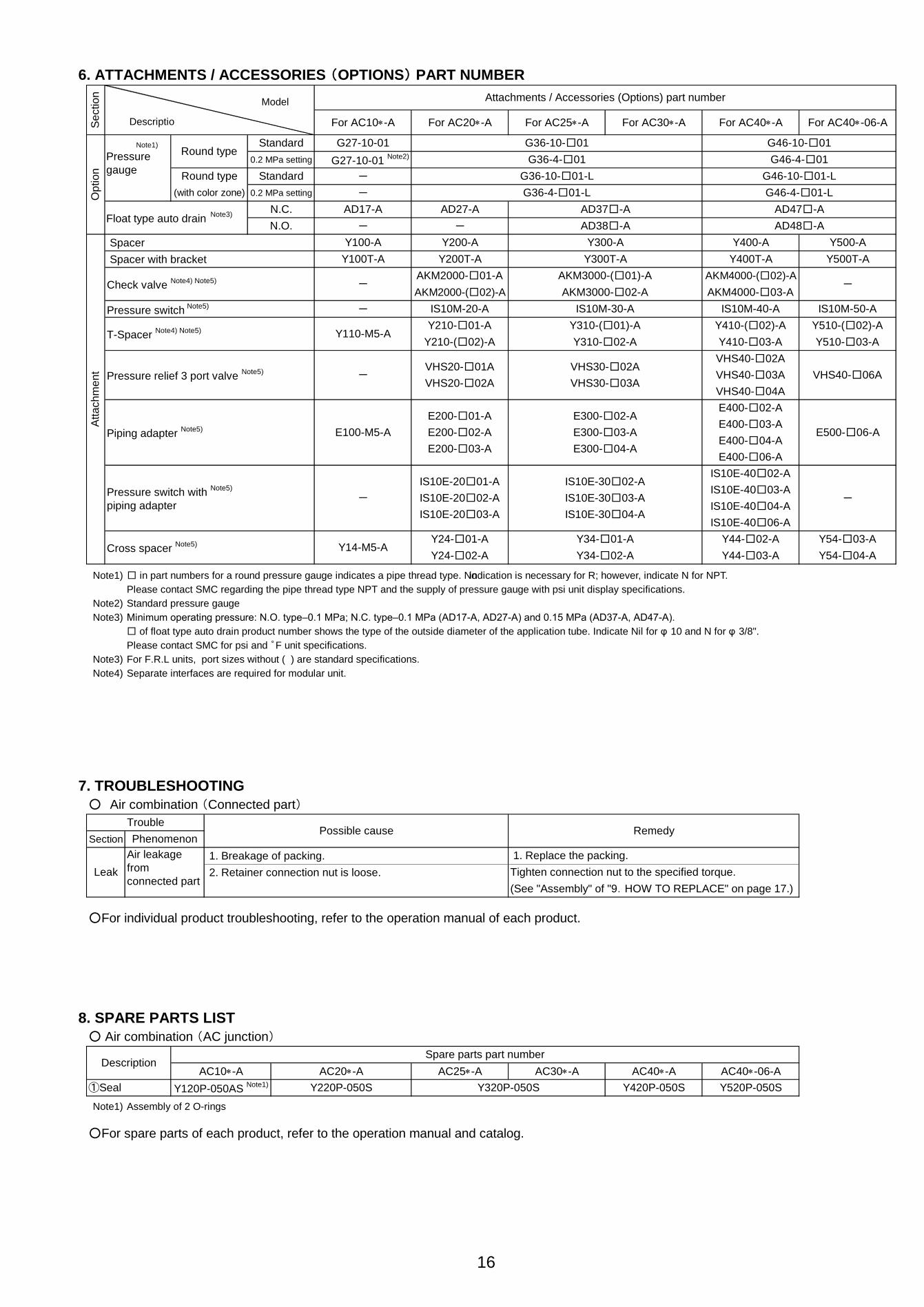
6. ATTACHMENTS / ACCESSORIES (OPTIONS) PART NUMBER
Spacer
Spacer with bracket
Pressure switch Note5)
Note1) □ in part numbers for a round pressure gauge indicates a pipe thread type. Noindication is necessary for R; however, indicate N for NPT.
Please contact SMC regarding the pipe thread type NPT and the supply of pressure gauge with psi unit display specifications.
Note2) Standard pressure gauge
Note3) Minimum operating pressure: N.O. type–0.1 MPa; N.C. type–0.1 MPa (AD17-A, AD27-A) and 0.15 MPa (AD37-A, AD47-A).
□ of float type auto drain product number shows the type of the outside diameter of the application tube. Indicate Nil for φ 10 and N for φ 3/8".
Please contact SMC for psi and ゜F unit specifications.
Note3) For F.R.L units, port sizes without ( ) are standard specifications.
Note4) Separate interfaces are required for modular unit.
7. TROUBLESHOOTING
○ Air combination (Connected part)
1. Breakage of packing.
2. Retainer connection nut is loose.
○For individual product troubleshooting, refer to the operation manual of each product.
8. SPARE PARTS LIST
○ Air combination (AC junction)
Note1) Assembly of 2 O-rings
○For spare parts of each product, refer to the operation manual and catalog.
AC40*-06-A
Y520P-050S
AC30*-A
Y510-□03-A
Y510-(□02)-A
IS10E-40□06-A
Y410-□03-A
Y410-(□02)-A
E400-□06-A
VHS30-□02A
E100-M5-A
-
IS10M-50-A
-
Y500T-A
Y54-□04-A
Y54-□03-A
-
E500-□06-A
VHS40-□06A
-
AD17-A
-
-
G27-10-01 Note2)
For AC20*-A
AD38□-A
AD27-A
-
Y200-A
Y200T-A
Attachments / Accessories (Options) part number
For AC10*-A
Y100T-A
Y100-A
Section
Round type
(with color zone) 0.2 MPa setting
Check valve Note4) Note5)
Se
ction
-
G36-10-□01
For AC25*-A For AC30*-A For AC40*-A For AC40*-06-A
Y300-A
AKM2000-(□02)-A AKM3000-□02-A
AD37□-A
Trouble
AC10*-A AC25*-A
Y320P-050S
G46-10-□01
G46-4-□01
G46-10-□01-L
-
-
Y110-M5-A
N.O.Float type auto drain
Note3)
16
①Seal
Description
Y220P-050S
AC20*-A
Leak
AC40*-A
Standard
G46-4-□01-L
AD48□-A
AD47□-A
Y400-A Y500-A
G36-4-□01
G36-10-□01-L
G36-4-□01-L
N.C.
Op
tion
0.2 MPa setting
Standard
Note1)
Pressure
gauge
Round type
E200-□01-A
IS10M-20-A
Y210-□01-A
AKM2000-□01-A
E200-□02-A
Y300T-A
AKM3000-(□01)-A
E200-□03-A
Y400T-A
AKM4000-(□02)-A
E300-□04-A
E300-□03-A
E300-□02-AE400-□02-A
Y310-(□01)-A
Y44-□02-A
Atta
ch
men
t
IS10M-30-A
Y310-□02-A
VHS30-□03A
VHS40-□02A
VHS40-□03A
Y24-□01-A
IS10E-20□02-A IS10E-30□03-A
IS10E-20□01-A
Y420P-050S
Y34-□01-A
Possible cause
Y24-□02-A
1. Replace the packing.
Y120P-050AS Note1)
Spare parts part number
Y14-M5-A
Y210-(□02)-A
Phenomenon
VHS20-□01APressure relief 3 port valve
Note5)
T-Spacer Note4) Note5)
Pressure switch with Note5)
piping adapter
Cross spacer Note5)
Piping adapter Note5)
Air leakage
from
connected part
Y44-□03-AY34-□02-A
Remedy
IS10E-40□02-AIS10E-30□02-A
IS10E-40□04-A
Tighten connection nut to the specified torque.
(See "Assembly" of "9.HOW TO REPLACE" on page 17.)
E400-□04-A
E400-□03-A
IS10E-40□03-A
IS10E-20□03-A IS10E-30□04-A
G27-10-01
VHS40-□04A
AKM4000-□03-A
IS10M-40-A
VHS20-□02A
Descriptio
Model

9.HOW TO REPLACE
! WARNING
・Before replacement, ensure that the air combination assembly is not pressurized.
・Rotate the pressure adjusting handle of the regulator and filter-regulator to zero.
・Replace refering to "10. DISASSEMBLY DRAWING" (P18 to P19).
・After replacement, ensure that specified function is satisfied and external leakage is not found before starting operation.
○ Air combination
ProcessDisassembly ① Remove the connected piping as necessary.
②
Nominal :
AC10,20-A 3
AC25,30-A 4
AC40(-06)-A 5
③ Remove the component.
Assembly ④
⑤
⑥
Nominal : Tightening torque :
AC10,20-A 3 AC10,20-A 0.6±0.05 N・m
AC25,30-A 4 AC25,30-A 1.5±0.05 N・m
AC40(-06)-A 5 AC40(-06)-A 3.0±0.1 N・m
【Modular connection ( Assembly ) 】
○For individual product troubleshooting, refer to the operation manual of each product.
17
Remove the nut and retainer.
Inset a hexagon wrench into the hexagon
socket of the nut and rotate it anticlockwise to
remove the nut and retainer.
Make sure to hold the parts removed by hand
to prevent them from dropping.
Tighten the nut.
Insert a hexagon wrench into the hexagon
socket of the nut and tighten the nut by
rotating it clockwise.
The tightening torque of the lock nut is shown
in the right side as a guide.
Mount the retainer to the spacer bolt and
tighten them temporarily by rotating the nut
clockwise while holding the product by hand.
Procedure
-
Hexagon wrench
Tools
-
Hexagon wrench
-
-
Mount a spacer to the product.
Align the groove of the product with the raised
part of the spacer.
Pay attention to the IN and OUT direction.
Check item
-
-
-
-
-
Tightening
Installing
Installing
No distortion.
Align the rear surface of bracket.
Each equipment has to be on the same straight line without misalignments.
【Precautions for modular connection (Assembly)】

10.DISASSEMBLY DRAWING
18
1) F.R.L Combination
Air filt
er
Spac
er w
ith
brac
ket
Spac
er w
ith
brac
ket
Reg
ulat
or
Lub
rica
tor
①P
acki
ng
Spac
er
Ret
aine
r
Nut
B
olt
Set
ting
conv
ex
Set
ting
conc
ave
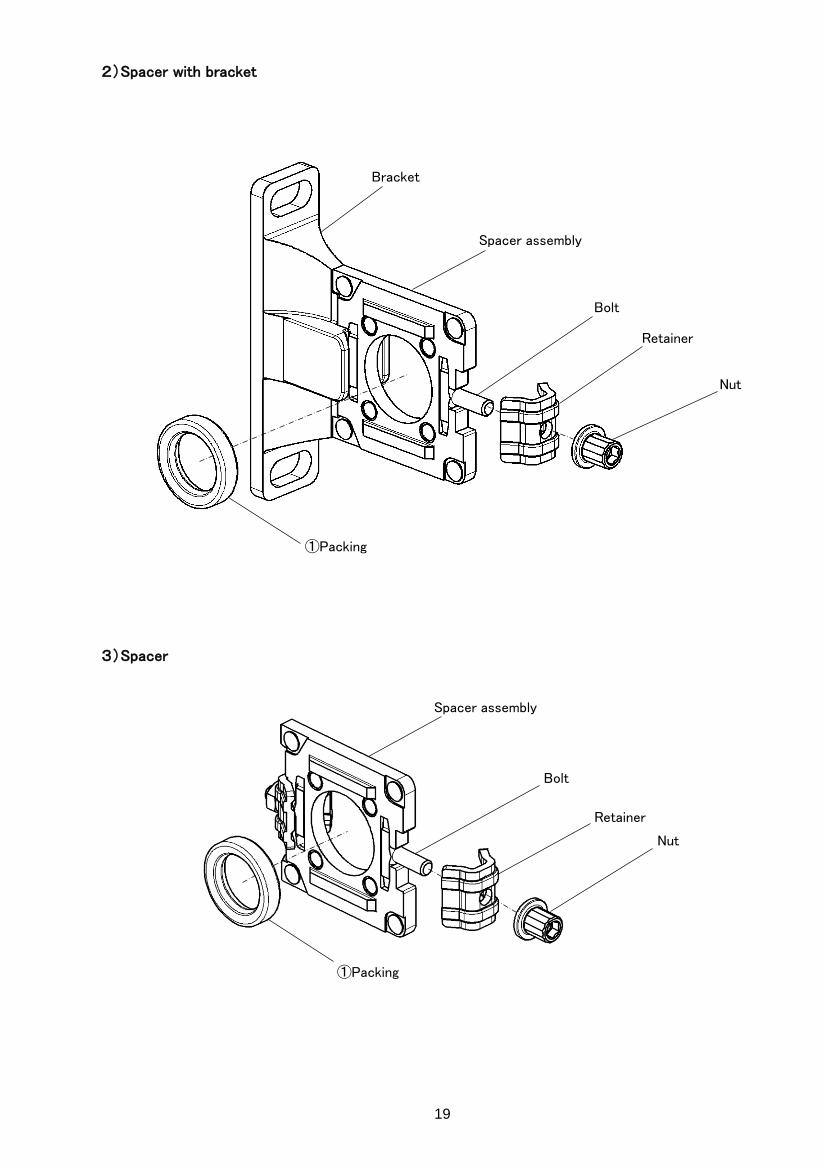
2)Spacer with bracket
3)Spacer
19
Nut
Retainer
Bolt
Spacer assembly
Bracket
①Packing
Nut
Retainer
Bolt
Spacer assembly
①Packing
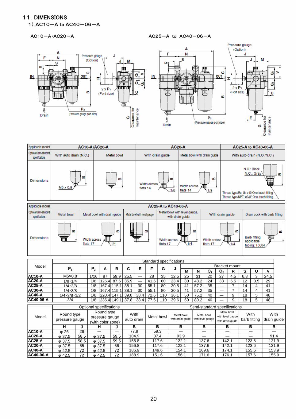
11.DIMENSIONS1) AC10-A to AC40-06-A
M N Q1 Q2 R S U V
AC10-A 1/16 87 59.9 25.5 ― 28 35 12.5 25 31 20 27 4.5 6.8 3 24.5AC20-A 1/8 126.4 87.6 35.9 ― 41.6 60 23.4 30 43.2 24 33 5.5 12 3.5 29AC25-A 1/8 167.4 115.1 38.1 30 55.1 80 30.5 41 57.2 35 ― 7 14 4 41AC30-A 1/8 167.4 115.1 38.1 30 55.1 80 30.5 41 57.2 35 ― 7 14 4 41AC40-A 1/8 220.4 147.1 39.8 38.4 72.6 110 36.1 50 75.2 40 ― 9 18 5 48AC40-06-A 1/8 235.4 149.1 37.8 38.4 77.6 110 39.6 50 80.2 40 ― 9 18 5 48
J JAC10-A 26 ―AC20-A 58.5 59.5AC25-A 58.5 59.5AC30-A 65 66AC40-A 72 72AC40-06-A 72 72
Model
Standard specifications
P1 P2 A B C E F G JBracket mount
M5×0.8
1/8・1/41/4・3/81/4・3/8
1/4・3/8・1/23/4
Model
Optional specifications Semi-standard specifications
Round type
pressure gauge
Round type
pressure gauge
(with color zone)
With
auto drainMetal bowl
Metal bowl
with drain guide
Metal bowl
with level gauge
Metal bowlWith
barb fitting
With
drain guide with level gauge
with drain guide
H H B B B B B B B
φ 26 ― 77.9 59.3 ― ― ― ― ―
φ 37.5 φ 37.5 104.9 87.4 93.9 ― ― ― 91.4
φ 37.5 φ 37.5 156.8 117.6 122.1 137.6 142.1 123.6 121.9
φ 37.5 φ 37.5 156.8 117.6 122.1 137.6 142.1 123.6 121.9
φ 42.5 φ 42.5 186.9 149.6 154.1 169.6 174.1 155.6 153.9
φ 42.5 φ 42.5 188.9 151.6 156.1 171.6 176.1 157.6 155.9
20
AC10-A・AC20-A AC25-A to AC40-06-A
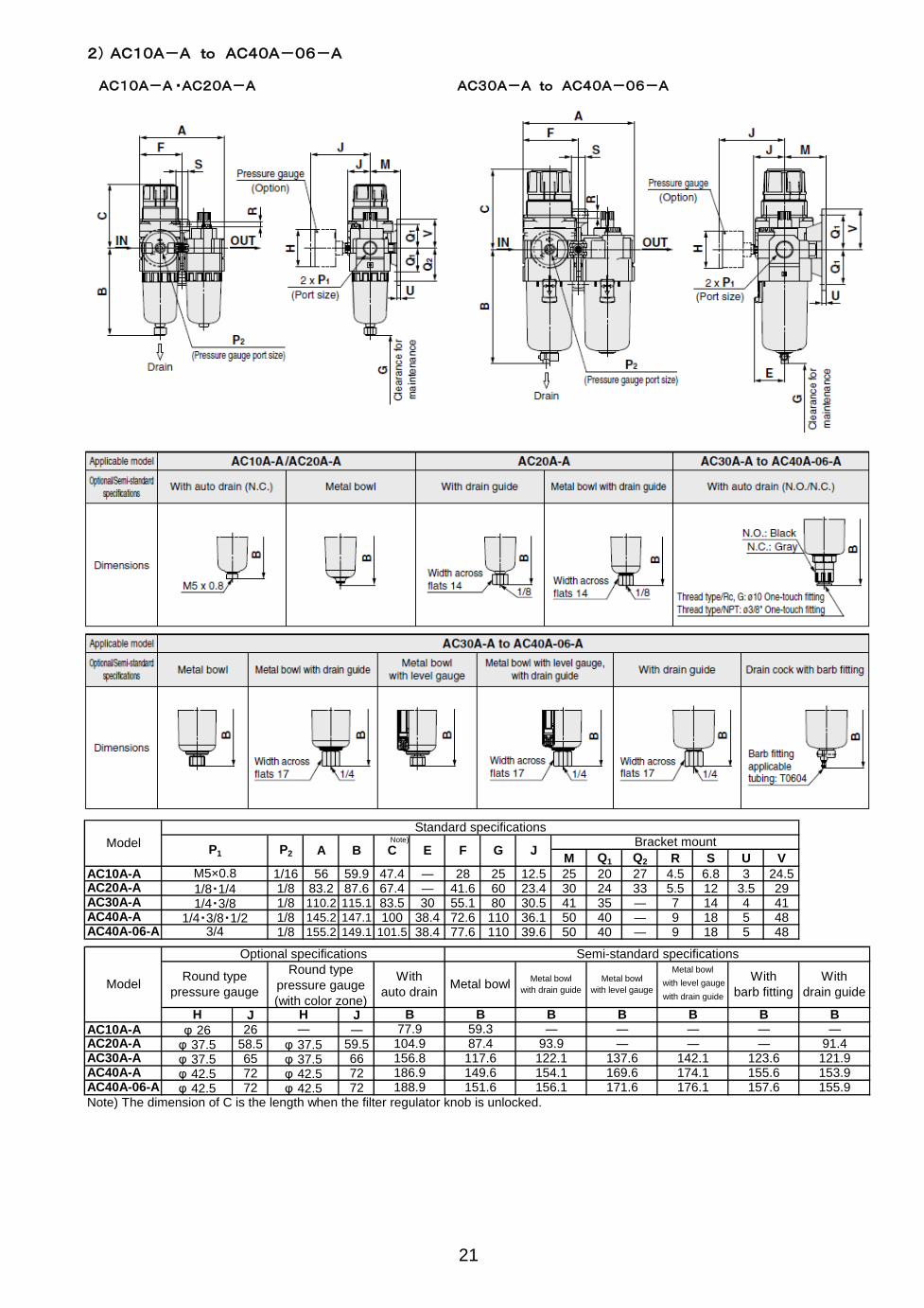
2) AC10A-A to AC40A-06-A
M Q1 Q2 R S U V
AC10A-A 1/16 56 59.9 47.4 ― 28 25 12.5 25 20 27 4.5 6.8 3 24.5AC20A-A 1/8 83.2 87.6 67.4 ― 41.6 60 23.4 30 24 33 5.5 12 3.5 29AC30A-A 1/8 110.2 115.1 83.5 30 55.1 80 30.5 41 35 ― 7 14 4 41AC40A-A 1/8 145.2 147.1 100 38.4 72.6 110 36.1 50 40 ― 9 18 5 48AC40A-06-A 1/8 155.2 149.1 101.5 38.4 77.6 110 39.6 50 40 ― 9 18 5 48
J JAC10A-A 26 ―AC20A-A 58.5 59.5AC30A-A 65 66AC40A-A 72 72AC40A-06-A 72 72Note) The dimension of C is the length when the filter regulator knob is unlocked.
176.1 157.6 155.9
21
Metal bowl
with level gauge
with drain guide
φ 42.5 φ 42.5 188.9 151.6 156.1 171.6
121.9
φ 42.5 φ 42.5 186.9 149.6 154.1 169.6 174.1 155.6 153.9
― 91.4
φ 37.5 φ 37.5 156.8 117.6 122.1 137.6 142.1 123.6
― ― ――φ 37.5 φ 37.5 104.9 87.4 93.9 ―
φ 26 ― 77.9 59.3 ― ―B B B B B B
Semi-standard specifications
Round type
pressure gauge
Round type
pressure gauge
(with color zone)
With
auto drainMetal bowl
Metal bowl
with drain guide
Metal bowl
with level gauge
With
barb fitting
With
drain guide
M5×0.8
1/8・1/41/4・3/8
1/4・3/8・1/23/4
Model
Optional specifications
H H B
C E F G JBracket mountModel
Standard specifications
P1 P2 A BNote)
AC10A-A ・AC20A-A AC30A-A to AC40A-06-A

3) AC20B-A to AC40B-06-A
M Q1 Q2 R S U V
AC10B-A 1/16 56 59.9 11 ― 28 25 12.5 25 20 27 4.5 6.8 3 24.5AC20B-A 1/8 83.2 87.6 23.5 ― 41.6 25 23.4 30 24 33 5.5 12 3.5 29AC25B-A 1/8 110.2 115.1 23.5 30 55.1 35 30.5 41 35 ― 7 14 4 41AC30B-A 1/8 110.2 115.1 27 30 55.1 35 30.5 41 35 ― 7 14 4 41AC40B-A 1/8 145.2 147.1 33.5 38.4 72.6 40 36.1 50 40 ― 9 18 5 48AC40B-06-A 1/8 155.2 149.1 33.5 38.4 77.6 40 39.6 50 40 ― 9 18 5 48
J JAC10B-A 26 ―AC20B-A 58.5 59.5AC25B-A 58.5 59.5AC30B-A 65 66AC40B-A 72 72AC40B-06-A 72 72 176.1 157.6 155.9φ 42.5 φ 42.5 188.9 151.6 156.1 171.6
142.1 123.6 121.9
φ 42.5 φ 42.5 186.9 149.6 154.1 153.9
121.9
169.6 174.1φ 37.5 φ 37.5 156.8 117.6 122.1 137.6
155.6
― 91.4
φ 37.5 φ 37.5 156.8 117.6 122.1 137.6 142.1 123.6
― ― ―
φ 37.5 φ 37.5 104.9 87.4 93.9 ― ―
B B B B
φ 26 ― 77.9 59.3 ― ―
Metal bowlWith
barb fitting
With
drain guide with level gauge
with drain guide
H H B B B
3/4
Model
Optional specifications Semi-standard specifications
Round type
pressure gauge
Round type
pressure gauge
(with color zone)
With
auto drainMetal bowl
Metal bowl
with drain guide
Metal bowl
with level gauge
1/4・3/81/4・3/8・1/2
B C E F
1/8・1/41/4・3/8
P2 A G J
22
Model
Standard specifications
P1
Bracket mount
M5×0.8
AC10B-A・AC20B-A AC25B-A to AC40B-06-A
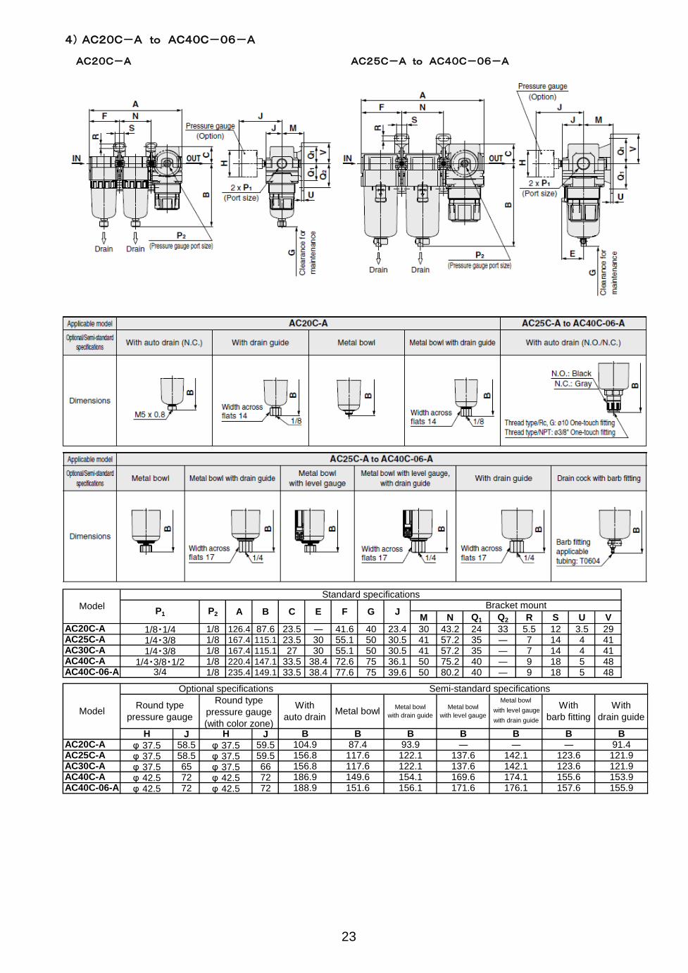
4) AC20C-A to AC40C-06-A
M N Q1 Q2 R S U V
AC20C-A 1/8 126.4 87.6 23.5 ― 41.6 40 23.4 30 43.2 24 33 5.5 12 3.5 29AC25C-A 1/8 167.4 115.1 23.5 30 55.1 50 30.5 41 57.2 35 ― 7 14 4 41AC30C-A 1/8 167.4 115.1 27 30 55.1 50 30.5 41 57.2 35 ― 7 14 4 41AC40C-A 1/8 220.4 147.1 33.5 38.4 72.6 75 36.1 50 75.2 40 ― 9 18 5 48AC40C-06-A 1/8 235.4 149.1 33.5 38.4 77.6 75 39.6 50 80.2 40 ― 9 18 5 48
J JAC20C-A 58.5 59.5AC25C-A 58.5 59.5AC30C-A 65 66AC40C-A 72 72AC40C-06-A 72 72 176.1 157.6 155.9φ 42.5 φ 42.5 188.9 151.6 156.1 171.6
142.1 123.6 121.9
φ 42.5 φ 42.5 186.9 149.6 154.1 153.9
121.9
169.6 174.1φ 37.5 φ 37.5 156.8 117.6 122.1 137.6
155.6
― 91.4
φ 37.5 φ 37.5 156.8 117.6 122.1 137.6 142.1 123.6
B B B
φ 37.5 φ 37.5 104.9 87.4 93.9 ― ―
With
barb fitting
With
drain guide with level gauge
with drain guide
H H B B B B
Model
Optional specifications Semi-standard specifications
Round type
pressure gauge
Round type
pressure gauge
(with color zone)
With
auto drainMetal bowl
Metal bowl
with drain guide
Metal bowl
with level gauge
Metal bowl
1/4・3/8・1/23/4
B C E F
1/4・3/81/4・3/8
P2 A G J
23
Model
Standard specifications
P1
Bracket mount
1/8・1/4
AC20C-A AC25C-A to AC40C-06-A
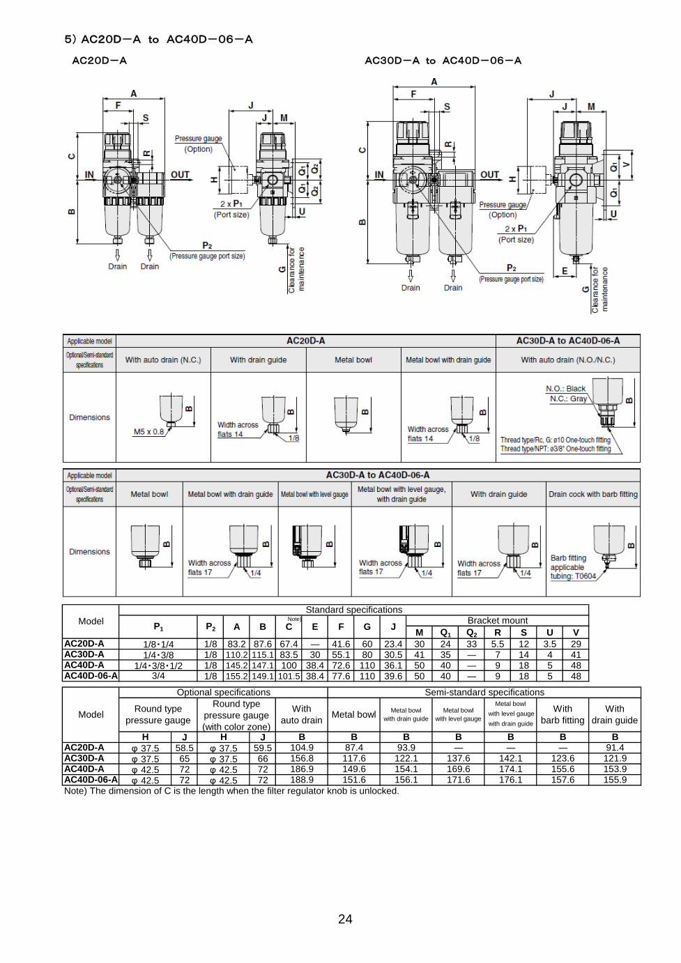
5) AC20D-A to AC40D-06-A
M Q1 Q2 R S U V
AC20D-A 1/8 83.2 87.6 67.4 ― 41.6 60 23.4 30 24 33 5.5 12 3.5 29AC30D-A 1/8 110.2 115.1 83.5 30 55.1 80 30.5 41 35 ― 7 14 4 41AC40D-A 1/8 145.2 147.1 100 38.4 72.6 110 36.1 50 40 ― 9 18 5 48AC40D-06-A 1/8 155.2 149.1 101.5 38.4 77.6 110 39.6 50 40 ― 9 18 5 48
J JAC20D-A 58.5 59.5AC30D-A 65 66AC40D-A 72 72AC40D-06-A 72 72Note) The dimension of C is the length when the filter regulator knob is unlocked.
157.6 155.9174.1 155.6 153.9
φ 42.5 φ 42.5 188.9 151.6 156.1 171.6 176.1φ 42.5 φ 42.5 186.9 149.6 154.1 169.6
91.4
φ 37.5 φ 37.5 156.8 117.6 122.1 137.6 142.1 123.6 121.9
B B
φ 37.5 φ 37.5 104.9 87.4 93.9 ― ― ―
With
drain guide with level gauge
with drain guide
H H B B B B B
With
auto drainMetal bowl
Metal bowl
with drain guide
Metal bowl
with level gauge
Metal bowlWith
barb fitting
Bracket mount
1/8・1/41/4・3/8
1/4・3/8・1/23/4
Model
Optional specifications Semi-standard specifications
Round type
pressure gauge
Round type
pressure gauge
(with color zone)
B C E F G J
24
Model
Standard specifications
P1 P2 A
AC20D-A AC30D-A to AC40D-06-A
Note)

Revision history
A P16 9.HOW TO REPLACE
【Precautions for modular connection
(Assembly)】is added. Jan 2013
B Addition : Nylon bowl, Metal bowl, AC10-A
The shape of spacer changed. June 2015
4-14-1, Sotokanda, Chiyoda-ku, Tokyo 101-0021 JAPAN Tel: + 81 3 5207 8249 Fax: +81 3 5298 5362 URL http://www.smcworld.com Note: Specifications are subject to change without prior notice and any obligation on the part of the manufacturer. © 2008 SMC Corporation All Rights Reserved