Embed Size (px)
Citation preview

Installation Guide WRC-3160 & WUL-3924 2015-09-02 Douglas Lighting Controls www.douglaslightingcontrols.com 1
Room Controller*™
WRC-3160
WUL-3924
Installation Manual
*Patent Pending
(shown with UL924 Relay Expansion Pack)

Installation Guide WRC-3160 & WUL-3924 2015-09-02 Douglas Lighting Controls www.douglaslightingcontrols.com 2
This page intentionally blank.

Installation Guide WRC-3160 & WUL-3924 2015-09-02 Douglas Lighting Controls www.douglaslightingcontrols.com 3
WARNING!
SYSTEM MUST BE INSTALLED IN ACCORDANCE WITH LOCAL AND NATIONAL ELECTRICAL CODES
INDOOR USE ONLY
Risk of Electric Shock. More than one disconnect switch is required to de-energize the device before servicing. All Servicing should be performed by qualified service personnel. This unit has more than one power supply connection point. To reduce the risks of electric shock disconnect both the branch circuit breakers / fuses & emergency power supplies before servicing.
SAVE THESE INSTRUCTIONS
READ AND FOLLOW ALL SAFETY INSTRUCTIONS.
Be aware that Line Voltage Connections may be 120Vac or 277Vac or 347Vac
Do not use outdoors.
Do not mount near gas or electric heaters.
Equipment should be mounted in locations and at heights where it will not readily be subjected to tampering by unauthorized personnel.
The use of accessory equipment not recommended by the manufacturer may cause an unsafe condition.
Do not use this equipment for other than intended use.

Installation Guide WRC-3160 & WUL-3924 2015-09-02 Douglas Lighting Controls www.douglaslightingcontrols.com 4
Table of Contents
1. INTRODUCTION ....................................................................................................... 5
1.1. GENERAL DESCRIPTION ....................................................................................... 5
2. DESIGN FEATURES ................................................................................................ 5
3. COMPATIBLE DEVICES .......................................................................................... 7
4. SPECIFICATIONS .................................................................................................... 8
4.1. MOUNTING .......................................................................................................... 8 4.2. POWER ............................................................................................................... 8 4.3. INPUTS: ............................................................................................................... 8 4.4. OUTPUT POWER SUPPLY: ..................................................................................... 8 4.5. CONTACT RATINGS .............................................................................................. 8 4.6. OPERATION ENVIRONMENT ................................................................................... 8 4.7. STORAGE TEMP: .................................................................................................. 8 4.8. APPROVALS: ........................................................................................................ 8
5. DIMENSIONS ........................................................................................................... 9
6. INSTALLATION FEATURES .................................................................................. 10
7. INSTALLATION DIAGRAMS .................................................................................. 10
8. INSTALLATION ...................................................................................................... 13
9. WIRING AND START-UP ....................................................................................... 13
10. CENTRALIZED SYSTEM ....................................................................................... 15
11. LED STATUS INDICATOR ..................................................................................... 15
12. KIT WIRING DIAGRAMS ........................................................................................ 16
Installation Guide WRC-3160 & WUL-3924 2015-09-02 Douglas Lighting Controls www.douglaslightingcontrols.com 5
1. INTRODUCTION
1.1. General Description
The Dialog Room Controller provides localized distributed lighting control for a specific application, defined space or room.
The product is factory configured to be used without the need for onsite programming prior to commissioning.
2. DESIGN FEATURES
The Dialog Room Controller is plenum Class 2 power unit rated for indoor environments that are stationary, non-vibrating, non-corrosive atmosphere and non-condensing humidity with an Ambient Operation Temperature of 32°F to 100°F (0°C to 38°C).
High voltage connections are pre-wired with colour coded, tinned, flying leads. The high voltage compartment is not accessible and has no serviceable components.
Low voltage push-connect terminal blocks are labeled and colour coded.
A ½” threaded chase nipple with locknut is integrated into the chassis for installation to standard size junction boxes
Two ½” knockouts and two break-away tabs allow direct wiring access to the low voltage compartment.
A 120° opening lid is notched to stay in the open position to provide access to the low voltage compartment and circuit test buttons
A top-mounted bi-colour LED indicates device status and allows for easy device locating
Dialog Room Controller is a 24Vac data line source for use with the Dialog Dual Technology Occupancy Sensors, Daylight Sensors and Digital Wall Station Switches
Plug ‘N Control™ ready out-of-the-box
Demand Response Ready
Installation Guide WRC-3160 & WUL-3924 2015-09-02 Douglas Lighting Controls www.douglaslightingcontrols.com 6
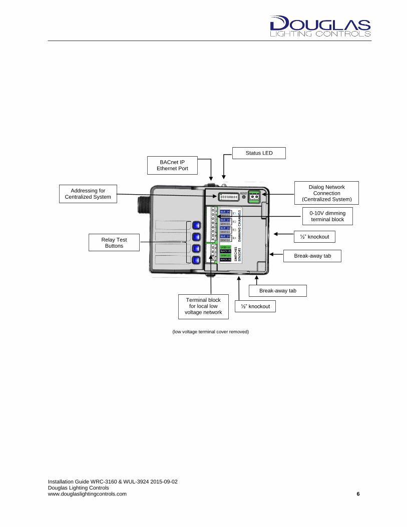
Status LED
BACnet IP Ethernet Port
Dialog Network Connection
(Centralized System)
(low voltage terminal cover removed)
½” knockout
Break-away tab
½” knockout
Break-away tab
0-10V dimming terminal block
Terminal block for local low
voltage network
Relay Test Buttons
Addressing for Centralized System
Installation Guide WRC-3160 & WUL-3924 2015-09-02 Douglas Lighting Controls www.douglaslightingcontrols.com 7
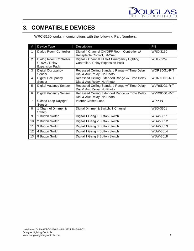
3. COMPATIBLE DEVICES
WRC-3160 works in conjunctions with the following Part Numbers:
# Device Type Description PN
1 Dialog Room Controller Digital 4 Channel ON/OFF Room Controller w/ Receptacle Control, BACnet
WRC-3160
2 Dialog Room Controller UL924 / Relay Expansion Pack
Digital 2 Channel UL924 Emergency Lighting Controller / Relay Expansion Pack
WUL-3924
3 Digital Occupancy Sensor
Recessed Ceiling Standard Range w/ Time Delay Dial & Aux Relay, No Photo
WORSDG1-R-T
4 Digital Occupancy Sensor
Recessed Ceiling Extended Range w/ Time Delay Dial & Aux Relay, No Photo
WORXDG1-R-T
5 Digital Vacancy Sensor Recessed Ceiling Standard Range w/ Time Delay Dial & Aux Relay, No Photo
WVRSDG1-R-T
6 Digital Vacancy Sensor Recessed Ceiling Extended Range w/ Time Delay Dial & Aux Relay, No Photo
WVRXDG1-R-T
7 Closed Loop Daylight Sensor
Interior Closed Loop WPP-INT
8 1 Channel Dimmer & Switch
Digital Dimmer & Switch, 1 Channel WSD-3501
9 1 Button Switch Digital 1 Gang 1 Button Switch WSW-3511
10 2 Button Switch Digital 1 Gang 2 Button Switch WSW-3512
11 3 Button Switch Digital 1 Gang 3 Button Switch WSW-3513
12 4 Button Switch Digital 1 Gang 4 Button Switch WSW-3514
13 8 Button Switch Digital 1 Gang 8 Button Switch WSW-3518
Installation Guide WRC-3160 & WUL-3924 2015-09-02 Douglas Lighting Controls www.douglaslightingcontrols.com 8
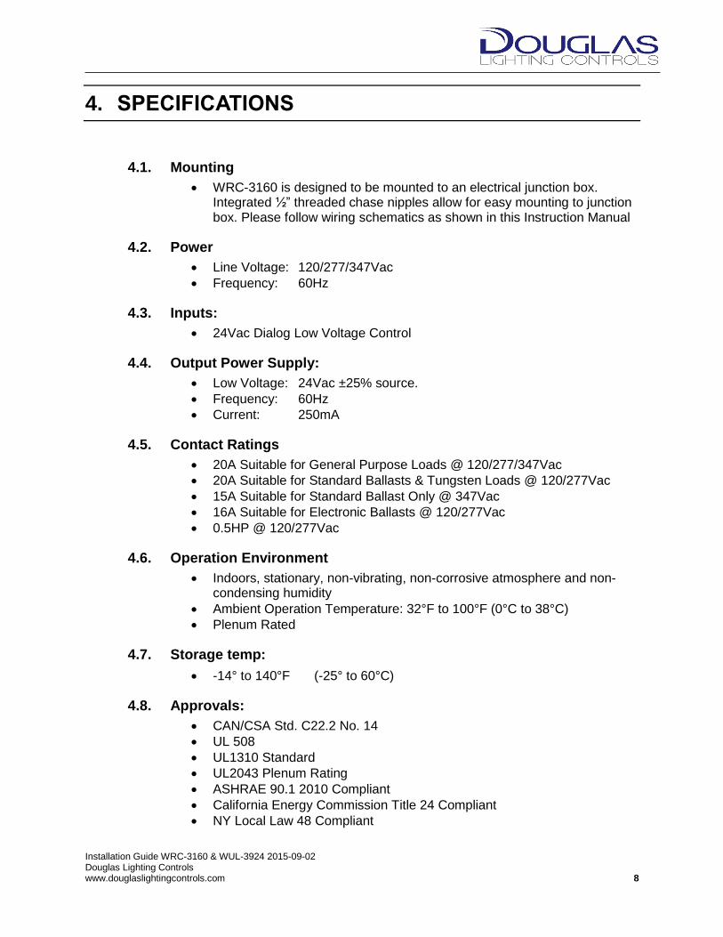
4. SPECIFICATIONS
4.1. Mounting
WRC-3160 is designed to be mounted to an electrical junction box. Integrated ½” threaded chase nipples allow for easy mounting to junction box. Please follow wiring schematics as shown in this Instruction Manual
4.2. Power
Line Voltage: 120/277/347Vac
Frequency: 60Hz
4.3. Inputs:
24Vac Dialog Low Voltage Control
4.4. Output Power Supply:
Low Voltage: 24Vac ±25% source.
Frequency: 60Hz
Current: 250mA
4.5. Contact Ratings
20A Suitable for General Purpose Loads @ 120/277/347Vac
20A Suitable for Standard Ballasts & Tungsten Loads @ 120/277Vac
15A Suitable for Standard Ballast Only @ 347Vac
16A Suitable for Electronic Ballasts @ 120/277Vac
0.5HP @ 120/277Vac
4.6. Operation Environment
Indoors, stationary, non-vibrating, non-corrosive atmosphere and non-condensing humidity
Ambient Operation Temperature: 32°F to 100°F (0°C to 38°C)
Plenum Rated
4.7. Storage temp:
-14° to 140°F (-25° to 60°C)
4.8. Approvals:
CAN/CSA Std. C22.2 No. 14
UL 508
UL1310 Standard
UL2043 Plenum Rating
ASHRAE 90.1 2010 Compliant
California Energy Commission Title 24 Compliant
NY Local Law 48 Compliant

Installation Guide WRC-3160 & WUL-3924 2015-09-02 Douglas Lighting Controls www.douglaslightingcontrols.com 9
5. DIMENSIONS
[4.17”] 106mm
Installation Guide WRC-3160 & WUL-3924 2015-09-02 Douglas Lighting Controls www.douglaslightingcontrols.com 10
6. INSTALLATION FEATURES
Electrical rough-in can be done before devices arrive on-site (see installation examples below)
Lightweight chassis allows for the device to be installed directly onto standard 4”x4” square metal junction boxes using existing knockouts.
Distance between the ½” chase nipples on WRC-3160 and WUL3924 are spaced to fit into existing 4”x4” square metal junction box knockouts
Chase nipples include locknuts
WRC-3160 should be installed with either rigid metallic conduit (as shown below) or with flexible metallic conduit. Not intended for use with Rigid Non-Metallic Conduit.
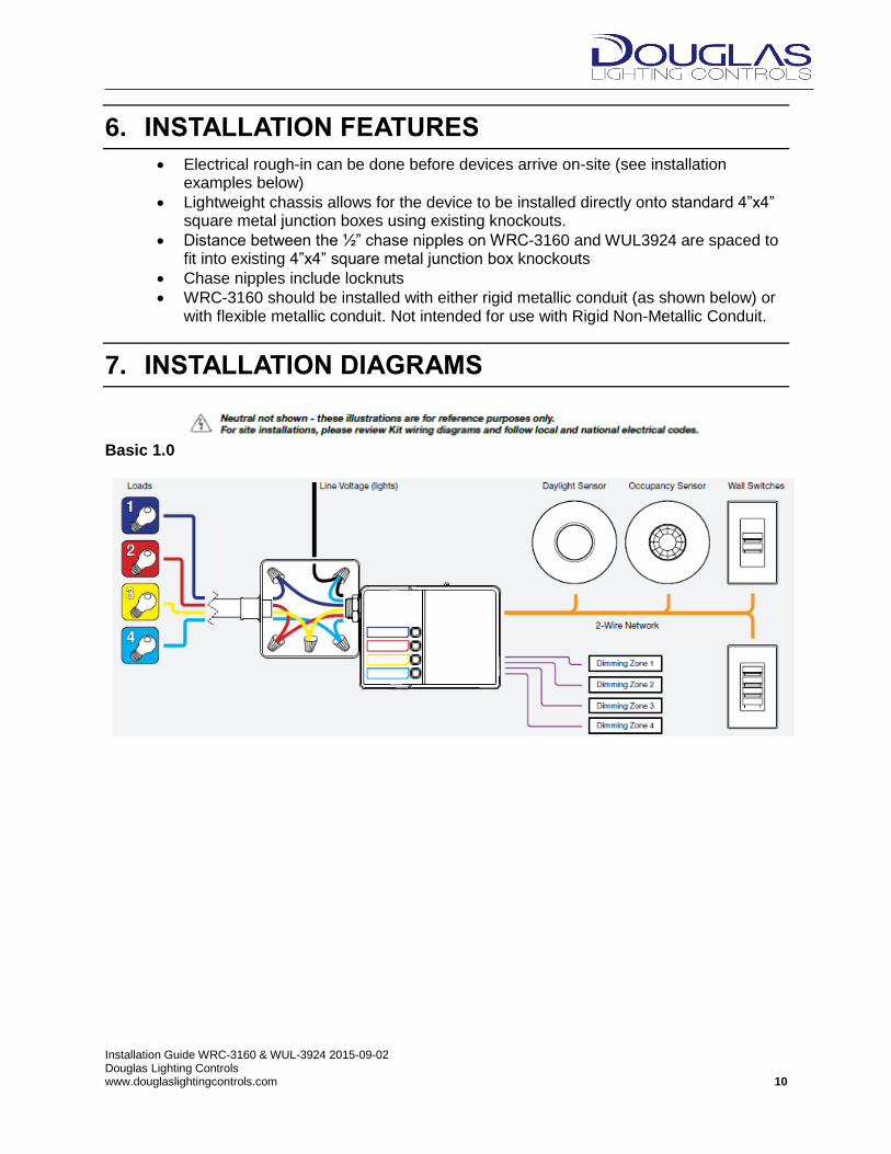
7. INSTALLATION DIAGRAMS
Basic 1.0

Installation Guide WRC-3160 & WUL-3924 2015-09-02 Douglas Lighting Controls www.douglaslightingcontrols.com 11
Basic + Emergency 2.0
Basic + Receptacle 3.0

Installation Guide WRC-3160 & WUL-3924 2015-09-02 Douglas Lighting Controls www.douglaslightingcontrols.com 12
Basic + Receptacle + Emergency 4.0
Emergency (Remote Installation) 5.0

Installation Guide WRC-3160 & WUL-3924 2015-09-02 Douglas Lighting Controls www.douglaslightingcontrols.com 13
8. INSTALLATION
1. Install Dialog Room Controller chase nipples through a 1/2” knockout in standard 4”x4” square metal junction box
2. Attach and tighten locknut
3. If the installation requires the UL924 Relay Expansion Pack WUL-3924, (connected to WRC-3160 at factory), a second standard 4”x4” square metal junction box is needed (see installation examples 3.0 or 4.0 above)
4. Emergency Relay Expansion Pack can be remotely located (see installation example 5.0)
5. Install peripheral devices and run 18/2 data line back to Dialog Room Controller
9. WIRING AND START-UP
CAUTION Risk of Electric Shock. More than one disconnect switch is required to de-energize the device before servicing. All Servicing should be performed by qualified service personnel. This unit has more than one power supply connection point. To reduce the risks of electric shock disconnect both the branch circuit breakers / fuses & emergency power supplies before servicing.
Dialog Room Controller is a 24Vac data line source for use with the Dialog Dual Technology Occupancy Sensors, Daylight Sensors and Digital Wall Station Switches. All switches or loads required to be supported by the sensor must be included in the loading capacity of the Dialog Room Controller. Controller can support up to 100mA of peripheral devices. The Dialog Room Controller is equipped with #12AWG tined leads. Use appropriate sized wire-nuts to connect the wires to the incoming load terminations. When using field-installed conductors ensure a 60ºC minimum rating. Wire leads are color coded to match circuit labels. Follow circuit wiring information found on the inside of low voltage terminal door.
1. Connect power, load, and control wiring as shown on appropriate Kit Wiring Diagram
2. Power up system 3. Wait 15 seconds for system to start-up and run system checks
Installation Guide WRC-3160 & WUL-3924 2015-09-02 Douglas Lighting Controls www.douglaslightingcontrols.com 14
4. Check LED status light 5. When is Solid Green or Flashing Green, test relays with Blue relay test buttons to
confirm intended load control a. If LED not Solid Green or Flashing Green, see LED Status Indicators
(Section 9) 6. Installation & configuration complete!
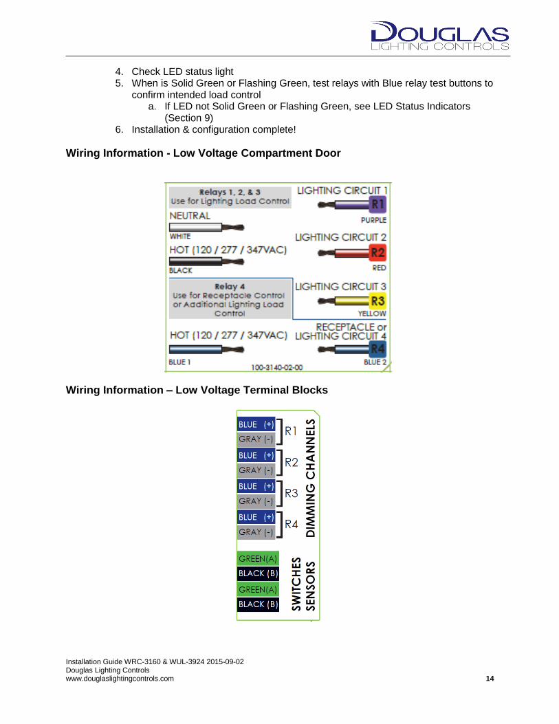
Wiring Information - Low Voltage Compartment Door
Wiring Information – Low Voltage Terminal Blocks

Installation Guide WRC-3160 & WUL-3924 2015-09-02 Douglas Lighting Controls www.douglaslightingcontrols.com 15
10. CENTRALIZED SYSTEM
The Dialog Room Controller can be integrated into a centralized Dialog system for global scheduling and control. When using Dialog Room Controllers in a centralized system please be aware of the following:
The Dialog centralized controller (WUL-3150) is programmed to recognise the Dialog Room Controller (WRC-3160)
The Dialog Room Controller is factory addressed by setting the addressing DIP switches DIP Switch Addressing
DIP 1 2 3 4 5 6 7 8
Binary 1 2 4 8 16 32 N/A N/A
Addressing is done by moving DIP switches up. E.g. For address 10, DIP 2 (value=2) and DIP 4 (value=8) are in up position (2+8=10). The central controller (WUL-3150) is then programmed to control address 10.
11. LED STATUS INDICATOR
The WRC-3160 has a locator and system status bi-color LED on the top surface. There are also 2 LEDs (Green and Orange) on the Ethernet connector.
Status LED Description
Green – Solid Daylight Sensor address 0.1 is connected to provide 2 zone CLC
Green – Blinking Daylight Sensor address 0.1 and 0.2 are connected to provide 2 zone CLC
Green/Red - Blinking Daylight Sensor is NOT connected
Red – Solid Incorrect Wiring or a Short
Red – Blinking Dialog downstream is failing to drive the bus
Ethernet LED Description
Blinking Ethernet Initializing (during start-up for 30 seconds)
Green – Solid Ethernet Initialized
Green – Blinking BACnet transmitting data
OFF Ethernet failed to initialized
Installation Guide WRC-3160 & WUL-3924 2015-09-02 Douglas Lighting Controls www.douglaslightingcontrols.com 16
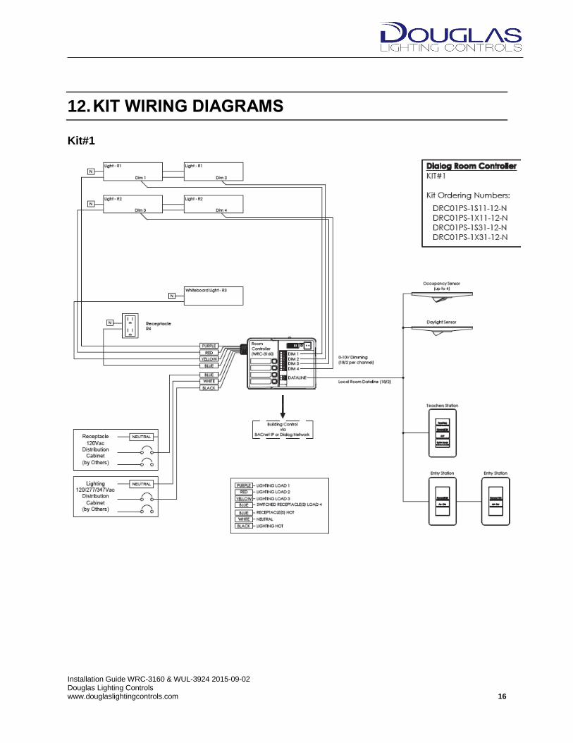
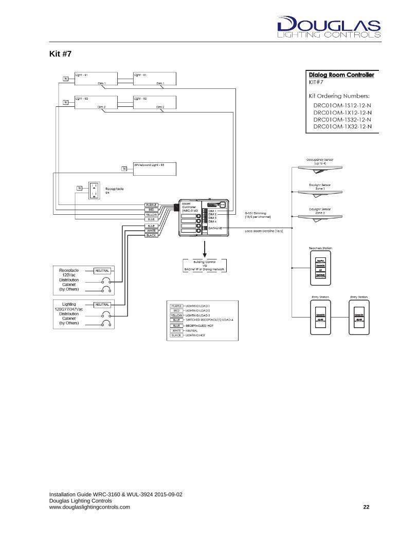
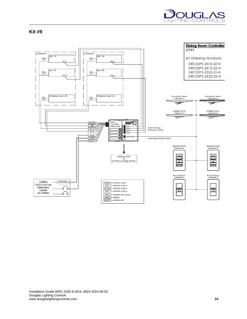
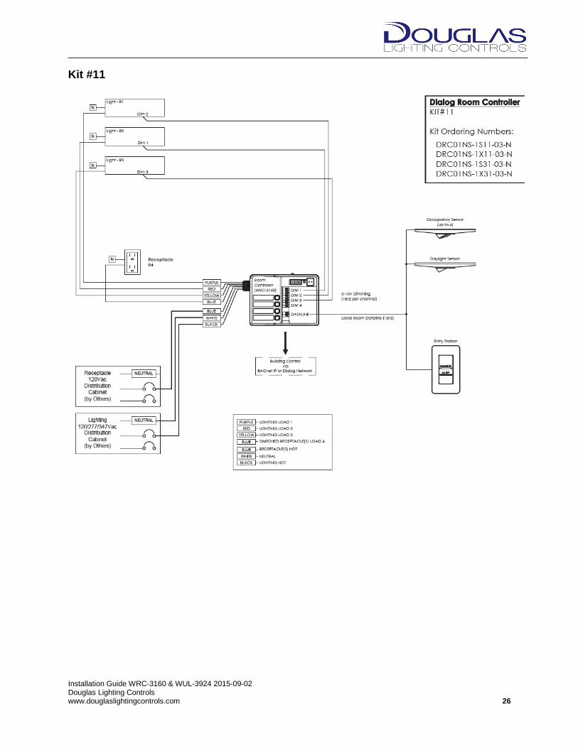
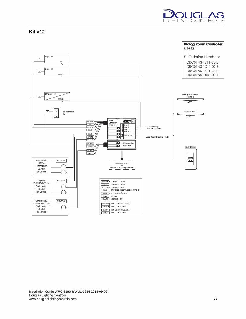
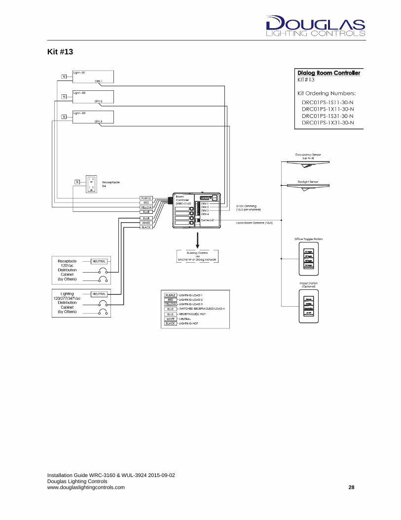
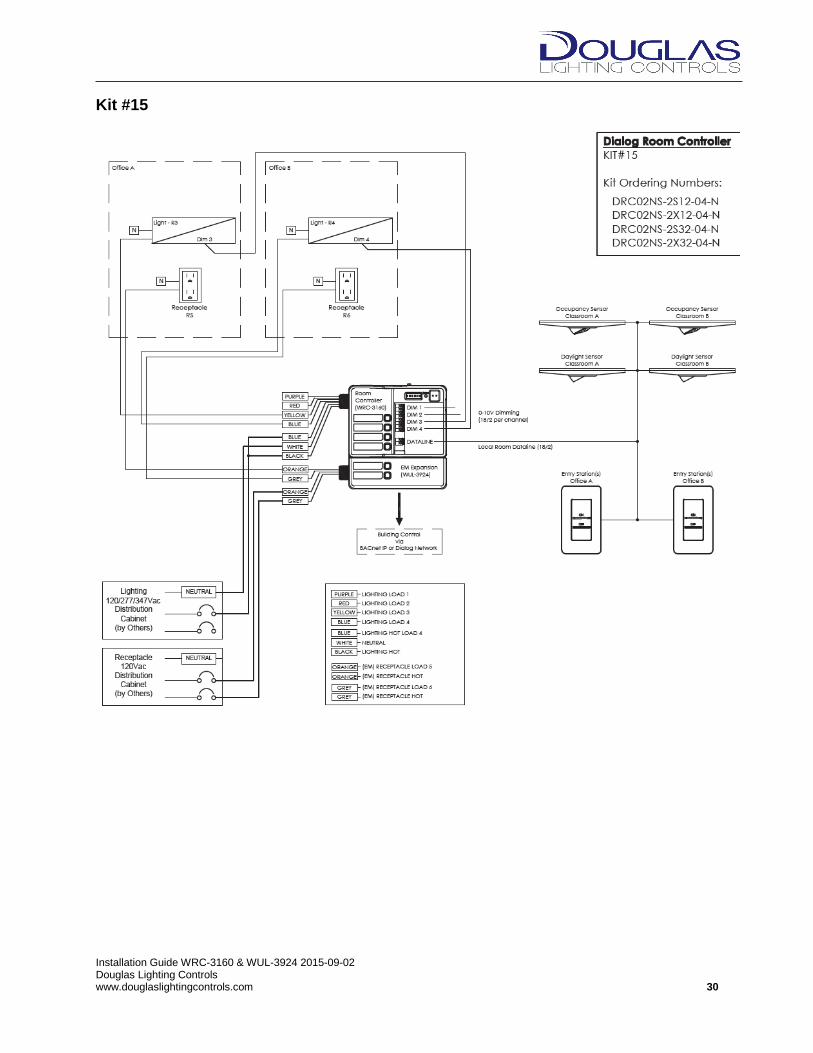
12. KIT WIRING DIAGRAMS
Kit#1
Installation Guide WRC-3160 & WUL-3924 2015-09-02 Douglas Lighting Controls www.douglaslightingcontrols.com 17
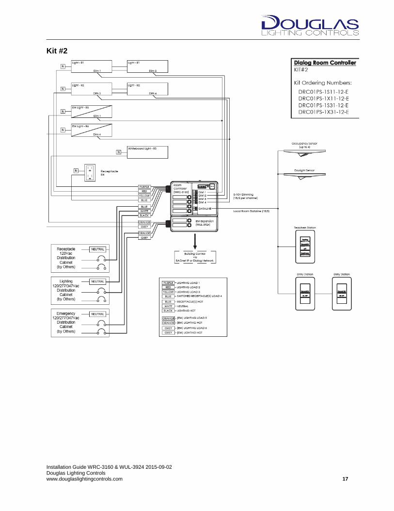
Kit #2

Installation Guide WRC-3160 & WUL-3924 2015-09-02 Douglas Lighting Controls www.douglaslightingcontrols.com 18
Kit #3
Installation Guide WRC-3160 & WUL-3924 2015-09-02 Douglas Lighting Controls www.douglaslightingcontrols.com 19
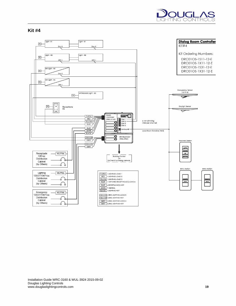
Kit #4

Installation Guide WRC-3160 & WUL-3924 2015-09-02 Douglas Lighting Controls www.douglaslightingcontrols.com 20
Kit #5
Installation Guide WRC-3160 & WUL-3924 2015-09-02 Douglas Lighting Controls www.douglaslightingcontrols.com 21
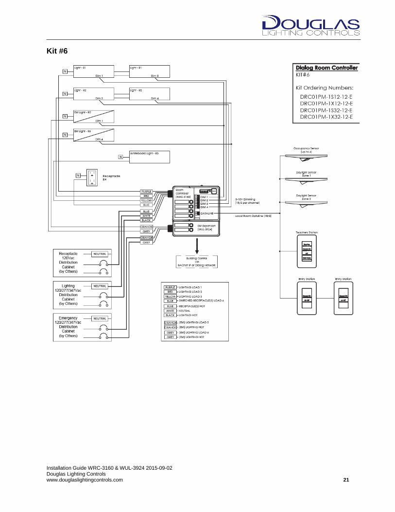
Kit #6
Installation Guide WRC-3160 & WUL-3924 2015-09-02 Douglas Lighting Controls www.douglaslightingcontrols.com 22
Kit #7

Installation Guide WRC-3160 & WUL-3924 2015-09-02 Douglas Lighting Controls www.douglaslightingcontrols.com 23
Kit #8
Installation Guide WRC-3160 & WUL-3924 2015-09-02 Douglas Lighting Controls www.douglaslightingcontrols.com 24
Kit #9

Installation Guide WRC-3160 & WUL-3924 2015-09-02 Douglas Lighting Controls www.douglaslightingcontrols.com 25
Kit #10
Installation Guide WRC-3160 & WUL-3924 2015-09-02 Douglas Lighting Controls www.douglaslightingcontrols.com 26
Kit #11
Installation Guide WRC-3160 & WUL-3924 2015-09-02 Douglas Lighting Controls www.douglaslightingcontrols.com 27
Kit #12
Installation Guide WRC-3160 & WUL-3924 2015-09-02 Douglas Lighting Controls www.douglaslightingcontrols.com 28
Kit #13

Installation Guide WRC-3160 & WUL-3924 2015-09-02 Douglas Lighting Controls www.douglaslightingcontrols.com 29
Kit #14
Installation Guide WRC-3160 & WUL-3924 2015-09-02 Douglas Lighting Controls www.douglaslightingcontrols.com 30
Kit #15

Installation Guide WRC-3160 & WUL-3924 2015-09-02 Douglas Lighting Controls www.douglaslightingcontrols.com 31
This page intentionally blank.

Installation Guide WRC-3160 & WUL-3924 2015-09-02 Douglas Lighting Controls www.douglaslightingcontrols.com 32
Douglas Lighting Controls 4455 Juneau Street Burnaby, BC V5C 4C4 Canada Direct: (604) 873-2797 Toll-Free: (877) 873-2797 Email: [email protected] Website: www.douglaslightingcontrols.com
Douglas Lighting Controls is a member of the Panasonic Group