Embed Size (px)
Citation preview

PRODUCT
SELECTION
GUIDE 2003
A Y A G E O C O M P A N YA Y A G E O C O M P A N Y

This Selection Guide offers an overview of the product ranges made by FERROXCUBE It contains short-form data for quick selection by development engineers and offers an overview for purchasing, production and service departments. For information on availability and prices, please contact our Sales representatives.
Comprehensive data can be found in Data Handbook “Soft Ferrites and Accessories 2002” as well as on the CD2002. For the latest info, please visit our web site on www.ferroxcube.com.
List of contents pageGeneral introduction 2Application matrix 8
Power conversion and Signal processingMaterials and applications 12Bobbins and accessories 18Integrated Inductive Components (IIC) 22Planar E cores 24E cores 28EI cores 36EFD cores 38EP cores 40EP/LP cores 42EPX cores 44EQ cores 46Planar ER cores 50ER cores 52 ETD cores 54Frame and Bar cores 56P cores 58PH cores 61P/I cores 62 PT cores 64PTS cores 66PM cores 68PQ cores 70RM cores 72RM/I cores 74RM/ILP cores 76U cores 78I cores 80UR cores 82Ferrite toroids 84Gapped ferrite toroids 94Iron powder toroids 95
List of contents (continued) pageEMI-suppressionMaterials and applications 96Multilayer suppressors (MLS, MLP, MLN) 102Multilayer inductors (MLI, MLH) 105SMD beads and Common-mode chokes(BDS, CMS) 108Beads and Beads on wire (BD, BDW) 109Cable shields (CST, CSA, CSC, CSU, CSF) 110Bobbin cores (BC) 112Miniature drum cores (D) 112Multi hole cores (MHC, MHB, MHR) 113Rods (ROD) 114Tubes (TUB) 115Wideband chokes (WBC) 116
Specialty ferrites Materials and applications 120Machined ferrite cores 121Toroids for particle accelerators 122
Appendix 123
1
www.ferroxcube.com FERROXCUBE

FERROXCUBE
© Ferroxcube International Holding B.V. 2003All rights are reserved. Reproduction in whole or in part is prohibited without the prior written consent of the copyright owner. The information presented in this document does not form part of any quotation or contract, is believed to be accurate and reliable and may be changed without notice. No liability will be accepted by the publisher for any consequence of its use. Publication thereof does not convey nor imply any license under patent- or other industrial or intellectual property rights.
2
FERROXCUBE www.ferroxcube.com

Advanced application support gives you the edgeAdvanced application support gives you the edge
3
www.ferroxcube.com FERROXCUBE

Ordering information
PRODUCT STATUS DEFINITIONS
STATUS INDICATION DEFINITION
PrototypeThese are products that have been made as development samples for the purpose of technical evaluation only. The data for these types is provisional and is subject to change.
Design-in These products are recommended for new designs.
PreferredThese products are recommended for use in current designs and are available via our sales channels.
SupportThese products are not recommended for new designs and may not be available through all our sales channels. Customers are advised to check for availability.
4
FERROXCUBE www.ferroxcube.com

Environmental aspects of Soft Ferrites
The nature of Soft Ferrites
5
www.ferroxcube.com FERROXCUBE

Need more information?Visit our web site on
www.ferroxcube.com
6
FERROXCUBE www.ferroxcube.com

New products and Highlights
1000
0 20 2000
100
200
400
600
800
T (˚C)40 60 80 120 140 160 180
Pv(kW/m3)
3C94 3C93
100
0
20
40
60
80
1500 2000 3000H (A/m)
2500 3500
µ∆
3C94
3C9225 %
100 ˚C
7
www.ferroxcube.com FERROXCUBE

8
FERROXCUBE www.ferroxcube.com
Application Matrix
POWER CONVERSION
Application area
Magnetic function
Telecommunication Electronic DataProcessing
(EDP)
Soundand
Vision
Lighting
Current transformers
3B7, 3C81, 3C90, 3C91, 3C92, 3E5, 3E6, 3E7, 3E27, 3F35, 4C65
3B7, 3C81, 3C90, 3C91, 3C92, 3E5, 3E6, 3E7, 3E27, 3F35, 4C65
3B7, 3C81, 3C90, 3C91, 3C92, 3E5, 3E6, 3E7, 3E27, 3F35, 4C65
Toroids, U cores Toroids, U cores Toroids, U cores
Driver transformers
3B7, 3C81, 3C90, 3C91, 3C92, 3C94, 3E27, 3F35, 3H3
3B7, 3C81, 3C90, 3C91, 3C92, 3C94, 3E27, 3F35, 3H3
3B7, 3C81, 3C90, 3C91, 3C92, 3C94, 3E27, 3F35, 3H3
3B7, 3C81, 3C90, 3C91, 3C92, 3C94, 3E27, 3F35, 3H3
E, EFD, EP, planar ER, P/I, RM/I, Toroids
E, EFD, EP, planar ER, P/I, RM/I, Toroids
E, EFD, EP, planar ER, P/I, RM/I, Toroids
E, EFD, EP, planar ER, P/I, RM/I, Toroids
Magnetic regulators3R1 3R1 3R1
Toroids, IIC Toroids, IIC Toroids, IIC
Power inductors
2P, 3C81, 3C90, 3C91, 3C92, 3C94, 3F3, 3F35, 3F4
2P, 3C30, 3C81, 3C90, 3C91, 3C94, 3F3, 3F35, 3F4
2P, 3C30, 3C81, 3C90, 3C91, 3C94, 3F3, 3F35, 3F4
2P, 3C30, 3C81, 3C90, 3C91, 3C94, 3F3, 3F35, 3F4
E, Planar E, EQ, EQ/LP, ER, Planar ER, ETD, P/I, PM, PQ, PT, PTS, RM/I, RM/ILP, U, Toroids, Gapped toroids, BC, D
E, Planar E, EQ, EQ/LP, ER, Planar ER, ETD, P/I, PM, PQ, PT, PTS, RM/I, RM/ILP, U, Toroids, Gapped toroids, BC, D
E, Planar E, EQ, EQ/LP, ER, Planar ER, ETD, P/I, PM, PQ, PT, PTS, RM/I, RM/ILP, U, Toroids, Gapped toroids, BC, D
E, Planar E, EQ, EQ/LP, ER, Planar ER, ETD, P/I, PM, PQ, PT, PTS, RM/I, RM/ILP, U, Toroids, Gapped toroids, BC, D
Power transformers
3C81, 3C90, 3C91, 3C92, 3C93, 3C94, 3C96, 3F3, 3F35, 3F4, 3F45, 3F5, 4F1
3C81, 3C90, 3C91, 3C92, 3C93, 3C94, 3C96, 3F3, 3F35, 3F4, 3F45, 3F5, 4F1
3C81, 3C90, 3C91, 3C92, 3C93, 3C94, 3C96, 3F3, 3F35, 3F4, 3F45, 3F5, 4F1
3C81, 3C90, 3C91, 3C92, 3C93, 3C94, 3C96, 3F3, 3F35, 3F4, 3F45, 3F5, 4F1
E, Planar E, EC, EFD, EPX, EQ, EQ/LP, ER, Planar ER, ETD, P/I, PM, PQ, PT, PTS, RM/I, RM/ILP, Toroids
E, Planar E, EC, EFD, EPX, EQ, EQ/LP, ER, Planar ER, ETD, P/I, PM, PQ, PT, PTS, RM/I, RM/ILP, Toroids
E, Planar E, EC, EFD, EPX, EQ, EQ/LP, ER, Planar ER, ETD, P/I, PM, PQ, PT, PTS, RM/I, RM/ILP, Toroids
E, Planar E, EC, EFD, EPX, EQ, EQ/LP, ER, Planar ER, ETD, P/I, PM, PQ, PT, PTS, RM/I, RM/ILP, Toroids
Line outputtransformers (LOT)
3C30, 3C34 3C30, 3C34
UR UR
LCD backlighttransformers
3C90, 3C91 3C90, 3C91 3C90, 3C91
FRM & BAR, EFD FRM & BAR, EFD FRM & BAR, EFD
Power inductors on PCB3C30, 3F35, 3F4 3C30, 3F35, 3F4 3C30, 3F35, 3F4
MLI, MLH, IIC MLI, MLH, IIC MLI, MLH, IIC

9
www.ferroxcube.com FERROXCUBE
POWER CONVERSION
Domestic AppliancesAutomotiveElectronics
Measurement,Control,
Scientifi c and Medical
ElectricTools
EMC servicesand Equipment
3B7, 3C81, 3C90, 3C91, 3C92, 3E5, 3E6, 3E7, 3E27, 3F35, 4C65
3B7, 3C81, 3C90, 3C91, 3C92, 3E5, 3E6, 3E7, 3E27, 3F35, 4C65
Toroids, U cores Toroids, U cores
3B7, 3C81, 3C90, 3C91, 3C92, 3C94, 3E27, 3F35, 3H3
3B7, 3C81, 3C90, 3C91, 3C92, 3C94, 3E27, 3F35, 3H3
3B7, 3C81, 3C90, 3C91, 3C92, 3C94, 3E27, 3F35, 3H3
3B7, 3C81, 3C90, 3C91, 3C92, 3C94, 3E27, 3F35, 3H3
E, EFD, EP, planar ER, P/I, RM/I, Toroids
E, EFD, EP, planar ER, P/I, RM/I, Toroids
E, EFD, EP, planar ER, P/I, RM/I, Toroids
E, EFD, EP, planar ER, P/I, RM/I, Toroids
3R1
Toroids, IIC
2P, 3C30, 3C81, 3C90, 3C91, 3C94, 3F3, 3F35, 3F4
2P, 3C30, 3C81, 3C90, 3C91, 3C94, 3F3, 3F35, 3F4
2P, 3C30, 3C81, 3C90, 3C91, 3C94, 3F3, 3F35, 3F4
E, Planar E, EQ, EQ/LP, ER, Planar ER, ETD, P/I, PM, PQ, PT, PTS, RM/I, RM/ILP, U, Toroids, Gapped toroids, BC, D
E, Planar E, EQ, EQ/LP, ER, Planar ER, ETD, P/I, PM, PQ, PT, PTS, RM/I, RM/ILP, U, Toroids, Gapped toroids, BC, D
E, Planar E, EQ, EQ/LP, ER, Planar ER, ETD, P/I, PM, PQ, PT, PTS, RM/I, RM/ILP, U, Toroids, Gapped toroids, BC, D
3C81, 3C90, 3C91, 3C92, 3C93, 3C94, 3C96, 3F3, 3F35, 3F4, 3F45, 3F5, 4F1
3C81, 3C90, 3C91, 3C92, 3C93, 3C94, 3C96, 3F3, 3F35, 3F4, 3F45, 3F5, 4F1
3C81, 3C90, 3C91, 3C92, 3C93, 3C94, 3C96, 3F3, 3F35, 3F4, 3F45, 3F5, 4F1
E, Planar E, EC, EFD, EPX, EQ, EQ/LP, ER, Planar ER, ETD, P/I, PM, PQ, PT, PTS, RM/I, RM/ILP, Toroids
E, Planar E, EC, EFD, EPX, EQ, EQ/LP, ER, Planar ER, ETD, P/I, PM, PQ, PT, PTS, RM/I, RM/ILP, Toroids
E, Planar E, EC, EFD, EPX, EQ, EQ/LP, ER, Planar ER, ETD, P/I, PM, PQ, PT, PTS, RM/I, RM/ILP, Toroids
3C15, 3C30, 3C34, 3C81
UR
3C90, 3C91
FRM & BAR, EFD
3C30, 3F35, 3F4 3C30, 3F35, 3F4
MLI, MLH, IIC MLI, MLH, IIC
Application Matrix

10
FERROXCUBE www.ferroxcube.com
Application Matrix
EMI SUPPRESSION
Application area
Magnetic function
Telecommunication Electronic DataProcessing
(EDP)
Soundand
Vision
Lighting
EMI-suppressionon PCB
3B1, 3S1, 3S4, 4A15, 4B1,4S2, 4S4, 4S7
3B1, 3S1, 3S4, 4A15, 4B1,4S2, 4S4, 4S7
3B1, 3S1, 3S4, 4A15, 4B1,4S2, 4S4, 4S7
BDW, BDS, CMS, WBC, WBS, MLS, MLP, MLN, IIC
BDW, BDS, CMS, WBC, WBS, MLS, MLP, MLN, IIC
BDW, BDS, CMS, WBC, WBS, MLS, MLP, MLN, IIC
EMI-suppressionin power lines
2P, 3B1, 3C90, 3S1, 3S3, 3S4, 4A15, 4B1, 4S2
2P, 3B1, 3C90, 3S1, 3S3, 3S4, 4A15, 4B1, 4S2
2P, 3B1, 3C90, 3S1, 3S3, 3S4, 4A15, 4B1, 4S2
2P, 3B1, 3C90, 3S1, 3S3, 3S4, 4A15, 4B1, 4S2
ROD, BC, BD, BDW, MHC, WBC, Toroids
ROD, BC, BD, BDW, MHC, WBC, Toroids
ROD, BC, BD, BDW, MHC, WBC, Toroids
ROD, BC, BD, BDW, MHC, WBC, Toroids
EMI-suppressionin mains fi lters
2P, 3C11, 3E25, 3E26, 3E27, 3E5, 3E6, 3S4, 4A11, 4A15, 4C65
2P, 3C11, 3E25, 3E26, 3E27, 3E5, 3E6, 3S4, 4A11, 4A15, 4C65
2P, 3C11, 3E25, 3E26, 3E27, 3E5, 3E6, 3S4, 4A11, 4A15, 4C65
2P, 3C11, 3E25, 3E26, 3E27, 3E5, 3E6, 3S4, 4A11, 4A15, 4C65
Toroids (T, TC, TL, TN, TX),U cores (U), ROD
Toroids (T, TC, TL, TN, TX),U cores (U), ROD
Toroids (T, TC, TL, TN, TX),U cores (U), ROD
Toroids (T, TC, TL, TN, TX),U cores (U), ROD
EMI-suppressionon signal wires and cables
3B1, 3C11, 3C90, 3E25, 3E26, 3E27, 3E5, 3E6, 3S1, 3S4, 4A11, 4A15, 4B1, 4C65, 4S2
3B1, 3C11, 3C90, 3E25, 3E26, 3E27, 3E5, 3E6, 3S1, 3S4, 4A11, 4A15, 4B1, 4C65, 4S2
3B1, 3C11, 3C90, 3E25, 3E26, 3E27, 3E5, 3E6, 3S1, 3S4, 4A11, 4A15, 4B1, 4C65, 4S2
BD, MHC, Cable shields, TUB, Toroids (T, TC, TL, TN, TX)
BD, MHC, Cable shields, TUB, Toroids (T, TC, TL, TN, TX)
BD, MHC, Cable shields, TUB, Toroids (T, TC, TL, TN, TX)
EMI-absorbing powdersand surfaces
4S60 4S60
Tiles (PLT), Granules, Powders Tiles (PLT), Granules, Powders
SIGNAL PROCESSING
Application area
Magnetic function
Telecommunication Electronic DataProcessing
(EDP)
Soundand
Vision
Lighting
Filter inductors (signal)3B7, 3D3, 3H3
P, PT, RM
Inductive delay lines3E27, 3E5, 3E6, 3E7, 3E8 3E27, 3E5, 3E6, 3E7, 3E8 3E27, 3E5, 3E6, 3E7, 3E8
Toroids Toroids Toroids
Proximity switches3B7, 3D3
PH
Tuning coils andantennas
3B1, 3C90, 4B1, 4C65, 4D2, 4E1
3B1, 3C90, 4B1, 4C65, 4D2, 4E1
ROD, TUB ROD, TUB
Wideband transformers
3C11, 3E27, 3E28, 3E5, 3E55, 3E6, 3E7, 3E8, 3H3
3C11, 3E27, 3E28, 3E5, 3E55, 3E6, 3E7, 3E8, 3H3
3C11, 3E27, 3E28, 3E5, 3E55, 3E6, 3E7, 3E8, 3H3
E, EFD, EP, EP/LP, EPX, Planar ER, P/I, RM/I, RM/ILP, Toroids, Gapped toroids, MHB
E, EFD, EP, EP/LP, EPX, Planar ER, P/I, RM/I, RM/ILP, Toroids, Gapped toroids, MHB
E, EFD, EP, EP/LP, EPX, Planar ER, P/I, RM/I, RM/ILP, Toroids, Gapped toroids, MHB

11
www.ferroxcube.com FERROXCUBE
SIGNAL PROCESSING
Domestic AppliancesAutomotiveElectronics
Measurement,Control,
Scientifi c and Medical
ElectricTools
EMC servicesand Equipment
3B7, 3D3, 3H3
P, PT, RM
3E27, 3E5, 3E6, 3E7, 3E8
Toroids
3B7, 3D3
PH
3B1, 3C90, 4B1, 4C65, 4D2, 4E1
3B1, 3C90, 4B1, 4C65, 4D2, 4E1
ROD, TUB ROD, TUB
3C11, 3E27, 3E28, 3E5, 3E55, 3E6, 3E7, 3E8, 3H3
3C11, 3E27, 3E28, 3E5, 3E55, 3E6, 3E7, 3E8, 3H3
3C11, 3E27, 3E28, 3E5, 3E55, 3E6, 3E7, 3E8, 3H3
E, EFD, EP, EP/LP, EPX, Planar ER, P/I, RM/I, RM/ILP, Toroids, Gapped toroids, MHB
E, EFD, EP, EP/LP, EPX, Planar ER, P/I, RM/I, RM/ILP, Toroids, Gapped toroids, MHB
E, EFD, EP, EP/LP, EPX, Planar ER, P/I, RM/I, RM/ILP, Toroids, Gapped toroids, MHB
Application Matrix
EMI SUPPRESSION
Domestic AppliancesAutomotiveElectronics
Measurement,Control,
Scientifi c and Medical
ElectricTools
EMC servicesand Equipment
3B1, 3S1, 3S4, 4A15, 4B1,4S2, 4S4, 4S7
3B1, 3S1, 3S4, 4A15, 4B1,4S2, 4S4, 4S7
3B1, 3S1, 3S4, 4A15, 4B1,4S2, 4S4, 4S7
BDW, BDS, CMS, WBC, WBS, MLS, MLP, MLN, IIC
BDW, BDS, CMS, WBC, WBS, MLS, MLP, MLN, IIC
BDW, BDS, CMS, WBC, WBS, MLS, MLP, MLN, IIC
2P, 3B1, 3C90, 3S1, 3S3, 3S4, 4A15, 4B1, 4S2
2P, 3B1, 3C90, 3S1, 3S3, 3S4, 4A15, 4B1, 4S2
2P, 3B1, 3C90, 3S1, 3S3, 3S4, 4A15, 4B1, 4S2
2P, 3B1, 3C90, 3S1, 3S3, 3S4, 4A15, 4B1, 4S2
2P, 3B1, 3C90, 3S1, 3S3, 3S4, 4A15, 4B1, 4S2
ROD, BC, BD, BDW, MHC, WBC, Toroids
ROD, BC, BD, BDW, MHC, WBC, Toroids
ROD, BC, BD, BDW, MHC, WBC, Toroids
ROD, BC, BD, BDW, MHC, WBC, Toroids
ROD, BC, BD, BDW, MHC, WBC, Toroids
2P, 3C11, 3E25, 3E26, 3E27, 3E5, 3E6, 3S4, 4A11, 4A15, 4C65
2P, 3C11, 3E25, 3E26, 3E27, 3E5, 3E6, 3S4, 4A11, 4A15, 4C65
2P, 3C11, 3E25, 3E26, 3E27, 3E5, 3E6, 3S4, 4A11, 4A15, 4C65
2P, 3C11, 3E25, 3E26, 3E27, 3E5, 3E6, 3S4, 4A11, 4A15, 4C65
Toroids (T, TC, TL, TN, TX),U cores (U), ROD
Toroids (T, TC, TL, TN, TX),U cores (U), ROD
Toroids (T, TC, TL, TN, TX),U cores (U), ROD
Toroids (T, TC, TL, TN, TX),U cores (U), ROD
3B1, 3C11, 3C90, 3E25, 3E26, 3E27, 3E5, 3E6, 3S1, 3S4, 4A11, 4A15, 4B1, 4C65, 4S2
3B1, 3C11, 3C90, 3E25, 3E26, 3E27, 3E5, 3E6, 3S1, 3S4, 4A11, 4A15, 4B1, 4C65, 4S2
3B1, 3C11, 3C90, 3E25, 3E26, 3E27, 3E5, 3E6, 3S1, 3S4, 4A11, 4A15, 4B1, 4C65, 4S2
BD, MHC, Cable shields, TUB, Toroids (T, TC, TL, TN, TX)
BD, MHC, Cable shields, TUB, Toroids (T, TC, TL, TN, TX)
BD, MHC, Cable shields, TUB, Toroids (T, TC, TL, TN, TX)
4S60 4S60 4S60
Tiles (PLT), Granules, Powders Tiles (PLT), Granules, Powders Tiles (PLT), Granules, Powders

12
FERROXCUBE www.ferroxcube.com
Property Test conditions Power transformers and power inductors
Symbol f (kHz) Bpeak or H T (ºC) unit 3C30 3C34 3C81 3C90 3C91 3C92 3C93 3C94 3C96 3F3 3F35 3F4 3F451) 3F51) 4F1 3R1
µi (± 20%) ≤ 10 ≤ 0.1 mT 25 2100 2100 2700 2300 3000 1500 1800 2300 2000 2000 1400 900 900 650 ≈ 80 800
B 10
250 A/m 100
mT
≥ 370 ≥ 370 ≈ 330 ≥ 340 ≥ 330 ≈ 410 ≈ 380 ≥ 340 ≥ 370 ≥ 330 ≥ 330 ≥ 300 ≈ 330 ≈ 220 ≥ 100 ≥ 285
1200 A/m 100 ≈ 440 ≈ 440 ≈ 360 ≈ 380 ≈ 370 ≈ 460 ≈ 430 ≈ 380 ≈ 440 ≈ 370 ≈ 420 ≈ 350 ≈ 370 ≈ 340 ≈ 300 ≈ 340
3000 A/m 25 ≈ 500 ≈ 500 ≈ 450 ≈ 450 ≈ 450 ≈ 550 ≈ 530 ≈ 450 ≈ 500 ≈ 450 ≈ 500 ≈ 400 ≈ 420 ≈ 390 ≈ 350 ≈ 420
Hc 10 25 A/m ≈ 15 ≈ 15 ≈ 15 ≈ 15 ≈ 15 ≈ 15 ≈ 15 ≈ 15 ≈ 15 ≈ 15 ≈ 40 ≈ 60 ≈ 60 ≈ 60 ≈ 150 ≈ 40
Br 10 25 mT ≈ 180 ≈ 180 ≈ 110 ≈ 170 ≈ 110 ≈ 170 ≈ 170 ≈ 170 ≈ 170 ≈ 150 ≈ 200 ≈ 150 ≈ 150 ≈ 150 ≈ 200 ≈ 340
Pv
25 200 mT
100 kW/m3
≤ 80 ≤ 185 ≤ 80
100 100 mT ≤ 80 ≤ 80 ≤ 80 ≈ 552) ≈ 50 ≈ 50 ≤ 60 ≤ 45 ≤ 80
100 200 mT ≈ 450 ≤ 400 ≈ 450 ≈ 3302) ≈ 350 ≈ 350 ≤ 400 ≤ 330
200 100 mT ≈ 170
400 50 mT ≤ 170 ≤ 140 ≤ 150 ≤ 80
50050 mT ≈ 300 ≤ 120
100 mT ≈ 800
1000
30 mT ≤ 200
50 mT ≈ 300
70 mT ≈ 700
300010 mT ≤ 320 ≤ 320 ≈ 100 ≤ 200
30 mT ≈ 900
10000 5 mT ≤ 200
Tc ºC ≥ 240 ≥ 240 ≥ 210 ≥ 220 ≥ 220 ≥ 280 ≥ 240 ≥ 220 ≥ 240 ≥ 200 ≥ 240 ≥ 220 ≥ 300 ≥ 300 ≥ 260 ≥ 230
ρ DC Ωm ≈ 2 ≈ 5 ≈ 1 ≈ 5 ≈ 5 ≈ 5 ≈ 5 ≈ 5 ≈ 5 ≈ 2 ≈ 10 ≈ 10 ≈ 10 ≈ 10 ≈ 105 ≈ 103
density kg/m3 ≈ 4800 ≈ 4800 ≈ 4800 ≈ 4800 ≈ 4800 ≈ 4800 ≈ 4800 ≈ 4800 ≈ 4800 ≈ 4750 ≈ 4750 ≈ 4700 ≈ 4800 ≈ 4750 ≈ 4600 ≈ 4700
ferrite type MnZn MnZn MnZn MnZn MnZn MnZn MnZn MnZn MnZn MnZn MnZn MnZn MnZn MnZn NiZn MnZn
Materials and Applications
Properties measured on sintered, unground ring cores of dimensions ∅ 25 x ∅ 15 x 10 mm, which are not subjected to external stresses.
1) preliminary specifi cation 2) at 60 °C
Products generally comply with the material specifi cation. However deviations may occur due to shape, size and grinding operations etc. Specifi ed product properties are given in the data sheets or product drawings.
Property Test conditions Output chokes / EMI-suppression
Symbol f (kHz) Bpeak or H T (ºC) unit 2P40 2P50 2P65 2P80 2P90
µi (± 10%) ≤ 10 ≤ 0.1 mT 25 40 50 65 80 90
B 10 25000 A/m 25 mT 900 1000 1150 1400 1600
Hc 10 25 A/m 2000 1800 1500 1200 900
Br 10 25 mT 250 300 350 400 450
Tmax ºC 140 140 140 140 140
material Fe Fe Fe Fe Fe
Iron Powder Materials
13
www.ferroxcube.com FERROXCUBE
Materials and ApplicationsPower transformers/inductors
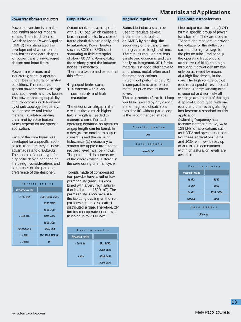
Power conversion is a major application area for modern ferrites. The introduction of Switched Mode Power Supplies (SMPS) has stimulated the development of a number of new ferrites and core shapes for power transformers, ouput chokes and input fi lters.
Power transformers and inductors generally operate under loss or saturation limited conditions. This requires special power ferrites with high saturation levels and low losses.The power handling capability of a transformer is determined by circuit topology, frequency, core geometry and ferrite material, available winding area, and by other factors which depend on the specifi c application.
Each of the core types was developed for a specifi c appli-cation, therefore they all have advantages and drawbacks. The choice of a core type for a specifi c design depends on the design considerations and sometimes on the personal preference of the designer.
Line output transformers
Line output transformers (LOT) form a specifi c group of power transformers. They are used in TV sets and monitors to provide the voltage for the defl ection coil and the high voltage for the picture tube. Traditionally the operating frequency is rather low (16 kHz) so a high throughput power density can only be achieved by means of a high fl ux density in the core. The high voltage output requires a special, resin potted winding. A large winding area is required and normally all windings are on one of the legs. A special U core type, with one round and one rectangular leg has become a standard for this application. Switching frequency has recently increased to 32, 64 or 128 kHz for applications such as HDTV and special monitors. For these applications, 3C30 and 3C34 with low losses up to 300 kHz in combination with high saturation levels are available.
Magnetic regulators
Saturable inductors can be used to regulate several independent outputs of an SMPS by blocking the secondary of the transformer during variable lenghts of time. The circuits required are both simple and economic and can easily be integrated. 3R1 ferrite material is a good alternative to amorphous metal, often used for these applications.In technical performance 3R1 is comparable to amorphous metal, its price level is much lower. The squareness of the B-H loop would be spoiled by any airgap in the magnetic circuit, so a toroid or IIC without partial gap is the recommended shape.
Output chokes
Output chokes have to operate with a DC load which causes a bias magnetic fi eld. In a closed ferrite circuit this can easily lead to saturation. Power ferrites such as 3C90 or 3F35 start saturating at fi eld strengths of about 50 A/m. Permeability drops sharply and the inductor looses its effectivity.There are two remedies against this effect:
gapped ferrite cores a material with a low permeability and high saturation
The effect of an airgap in the circuit is that a much higher fi eld strength is needed to saturate a core. For each operating condition an optimum airgap length can be found. In a design, the maximum output current (I) and the value of inductance (L) necessary to smooth the ripple current to the required level must be known. The product I2L is a measure of the energy which is stored in the core during one half cycle.
Toroids made of compressed iron powder have a rather low permeability (max. 90) com-bined with a very high satura-tion level (up to 1500 mT). The permeability is low because the isolating coating on the iron particles acts as a so called distributed airgap. Therefore, 2P toroids can operate under bias fi elds of up to 2000 A/m.
F e r r i t e c h o i c e
frequency range
< 100 kHz
< 400 kHz
200-1000 kHz
1-4 MHz
> 3 MHz
3C81, 3C90, 3C91,
3C92, 3C93,
3C94, 3C96
3C92, 3C93
3C94, 3C96
3F35, 3F4
3F4, 3F45, 3F5, 4F1
4F1
F e r r i t e c h o i c e
3R1
C o r e s h a p e s
toroids, IIC
F e r r i t e c h o i c e
frequency range
16 kHz
32 kHz
64 kHz
128 kHz
3C30
3C30
3C30, 3C34
3C34
C o r e s h a p e s
UR cores
F e r r i t e c h o i c e
frequency range
< 500 kHz
< 1 MHz
2P.., 3C90,
3C92, 3C94
3C90, 3C92
3C94, 3F35

14
FERROXCUBE www.ferroxcube.com
Materials and ApplicationsDriver transformers
In many electronic circuits, small tansformers are used to drive or trigger transistors, thyristors of MOSFETS. It is a convenient way to provide galvanic isolation and synchronisation or reversal of drive pulses.
Sometimes these transformers operate under low- signal conditions but in most cases they have to operate at high fl ux density. MOSFET gates have high capacitances and therefore require high currents to switch fast.
The choice of ferrite depends on these drive conditions and operating frequency. For low power the high permeability grades are suitable, more severe conditions require power materials.
Current transformers
A current transformer is used to measure or detect a current without making contact. A common example is a ring core with a winding around a current carrying wire. The magnetic fi eld around the wire creates a fl ux in the ring core which leads to an output voltage directly proportional to the current in the winding.
In effect the wire acts as a one-turn primary for the current transformer. This principle is often used to measure currents in power converters, or to detect current in an earth-leak safety switch.A split toroid or two U-core halves are used in applications such as oscilloscope measuring probes. The sensitivity of this type of transformer if largely controlled by the material permeability. So, depending on the current range, a high permeability grade is chosen.For AC the highest occuring frequency determines the choice of the material.
F e r r i t e c h o i c e
frequency range
< 100 kHz
< 500 kHz
< 1 MHz
< 5 MHz
3E5, 3E6, 3E7
3E27
3B7, 3C81, 3C90,
3C91, 3C92, 3F35
4C65
C o r e s h a p e s
Ring cores U cores
F e r r i t e c h o i c e
low - level drive
high - level drive
3H3, 3B7, 3E27
3C81, 3C90, 3C91,
3C92, 3F35
Property MnZn ferrites NiZn ferrites unit
Young’s modulus (90 - 150) x 103 (80 - 150) x 103 N/mm2
Compressive strength 200 - 600 200 - 700 N/mm2
Tensile strength 20 - 65 30 - 60 N/mm2
Vickers hardness 600 - 700 800 - 900 N/mm2
Coeffi cient of linear expansion
(10 - 12) x 10-6 (7 - 8) x 10-6 K-1
Specifi c heat 700 - 800 ≈ 750 J kg-1 K-1
Termal conductivity (3.5 - 5.0) x 10-3 (3.5 - 5.0) x 10-3 J mm-1 s-1 K-1
The above fi gures are the average values measured on a wide range of commercially available MnZn and NiZn materials

15
www.ferroxcube.com FERROXCUBE

16
FERROXCUBE www.ferroxcube.com
Property Test conditions Filter inductors Wideband transformers
Symbol f (kHz) Bpeak or H T (ºC) unit 3D3 3H3 3B7 3E27 3E28 3E5 3E55 3E61) 3E71) 3E81)
µi (± 20%) ≤ 10 ≤ 0.1 mT 25 750 2000 2300 6000 400 10000 10000 12000 15000 18000
tanδ/µi
10
≤ 0.1 mT 25 (x 10-6)
≤ 10 ≤ 10 ≤ 10 ≤ 10
30 ≤ 1.6 ≤ 25 ≤ 30 ≤ 30 ≤ 30 ≤ 30
100 ≤ 2.5 ≤ 5 ≤ 15 ≤ 5 ≤ 75
300 ≤ 10
500 ≈ 25
1000 ≤ 30 ≈ 120
3000
10000
ηB10
1.5 - 3 mT 2510-3 T-1 ≤ 1 ≤ 0.2 ≤ 1 ≤ 1 ≤ 1
100 ≤ 1.8 ≤ 0.6
αF ≤ 10 ≤ 0.1 mT
5 - 25
10-6 K-1
0.7 ± 0.3
25 - 55 0.7 ± 0.3
25 - 70 1.5 ± 1 0.7 ± 0.3 0 ± 0.6
DF10
≤ 0.1 mT 25 (x 10-6)≤ 12 ≤ 3 ≤ 3.5
100
B 10250 A/m 100
mT≈ 260 ≈ 250 ≈ 300 ≈ 250 ≈ 260 ≈ 210 ≈ 2002) ≈ 210 ≈ 210 ≈ 150
3000 A/m 25 ≈ 400 ≈ 400 ≈ 450 ≈ 400 ≈ 400 ≈ 380 ≈ 380 ≈ 380 ≈ 380 ≈ 380
Hc 10 25 A/m ≈ 75 ≈ 15 ≈ 15 ≈ 5 ≈ 5 ≈ 5 ≈ 5 ≈ 4 ≈ 4 ≈ 4
Br 10 25 mT ≈ 150 ≈ 70 ≈ 150 ≈ 100 ≈ 100 ≈ 80 ≈ 150 ≈ 100 ≈ 100 ≈ 100
Tc ºC ≥ 200 ≥ 160 ≥ 170 ≥ 150 ≥ 145 ≥ 125 ≥ 100 ≥ 130 ≥ 130 ≥ 100
ρ DC Ωm ≈ 2 ≈ 2 ≈ 1 ≈ 0.5 ≈ 1 ≈ 0.5 ≈ 0.1 ≈ 0.1 ≈ 0.1 ≈ 0.1
density kg/m3 ≈ 4700 ≈ 4700 ≈ 4800 ≈ 4800 ≈ 4800 ≈ 4900 ≈ 5000 ≈ 4900 ≈ 4900 ≈ 5000
ferrite type MnZn MnZn MnZn MnZn MnZn MnZn MnZn MnZn MnZn MnZn
Materials and Applications
Properties measured on sintered, unground ring cores of dimensions ∅ 25 x ∅ 15 x 10 mm, which are not subjected to external stresses.
1) Measured on sintered, unground ring cores of dimensions ∅ 14 x ∅ 9 x 5 mm, which are not subjected to external stresses.2) at 80 °C
Products generally comply with the material specifi cation. However deviations may occur due to shape, size and grinding operations etc. Specifi ed product properties are given in the data sheets or product drawings.

17
www.ferroxcube.com FERROXCUBE
Materials and ApplicationsFilter inductors (signal)
Ferrite fi lter inductors are used in combination with high quality capacitors in very stable and selective fi lters. The following design parameters are important for high quality fi lter inductors:
low losses, high Q precise inductance high stability over periods of time fi xed temperature dependence
The quality factor (Q) of a fi lter inductor should generally be as high as possible. For this reason fi lter materials such as 3H3 and 3D3 have low magnetic losses in their frequency ranges.
These materials also have controlled temperature factors (αF) to compensate the nega-tive temperature coeffi cients of the fi lter capacitors. The drift of permeability with time DF (desaccomodation factor) is kept as low as possible in these fi lter materials.
high saturation fl ux density
A recent application is in low-pass fi lters for ADSL. Since there is dc bias current, power materials like 3C81, 3C90, 3C91 or 3C92 are used because of their higher satura-tion level.
Proximity switches
Magnetic proximity switches generally consist of a PH core half and a winding on a coil former. This inductor is part of a tuned oscillator circuit. A magnetic fl ux protrudes in front of the core. When a conductive object moves into this stray fl ux, eddy currents start to fl ow in it, lowering the quality factor (Q) of the circuit. When this decreases below a critical level, the oscillator stops and the object is detected.There are applications throughout industry in all sorts of production equipment to detect positions of moving parts. The ferrite used should have a low loss level at the frequency of the oscillator. (e.g. 1 MHz), therefore an appropriate fi lter material like 3D3 performs well.
As temperature stability must be resonably good, materials with controlled temperature behaviour are chosen. However, since the magnetic circuit is open this is not very critical. For a good detection range the Q of the circuit should be as high as possible. This Q-factor is controlled mainly by the resistance of the winding. Magnetic losses in the ferrite generally contribute less then 10% because of the open circuit.
Inductive delay lines
In many electronic devices it is necessary to delay pulses for a short, well defi ned time (some nano- or microseconds). One method of doing this is to pass the pulses through an inductor- capacitor network.The inductance delays the rise of the current until the ferrite core saturates.
The delay time is determined by the saturation fl ux in the ferrite core and the applied voltage.
Requirements for the material are:
high pulse permeability high saturation fl ux density
The main application area is in data processing. As the inductor should be as compact as possible, small toroids are mostly used to avoid the degrading effect of the parasitic airgap.
Wideband transformers
Pulse and signal transformers, also known as wideband transformers, are frequently used in communications systems and digital networks such as ISDN and DSL.They provide impedance matching and galvanic isolation and transform signal amplitudes. Signal power levels are usually low. To transmit analog signals or digital pulses with little distortion, good wideband characteristics are needed.The principal functions of the transformer core are to provide optimum coupling between the windings, and a high inductance under pulse conditions.To achieve this, high perme-ability ferrite materials such as 3E27, 3E5, 3E6, 3E7 and 3E8 are used. When there is a DC component in the signal it is often better to take a lower permeability grade such as the special DC-bias material 3E28. For DSL transformers Total Harmonic Distortion (THD) is a critical factor. The new low THD ferrite material 3E55 helps to solve many design problems.The trend is towards smaller and lower profi le pulse transformers. With the increas-ing integration of digital elec-tronics, magnetic components are becoming the biggest com-ponents on the PCB. Increasing the material permeability and using closed magnetic cores, like toroids, are two ways to achieve miniaturization.However, other cores are also widely used but with polished pole faces to eliminate the effect of the gap between core halves as much as possible.
F e r r i t e c h o i c e
frequency range
< 300 kHz
300 kHz - 2 MHz
3H3, 3C81, 3C90,
3C91, 3C92
3D3
F e r r i t e c h o i c e
3E27, 3E5, 3E6, 3E7, 3E8
C o r e s h a p e s
small toroids
F e r r i t e c h o i c e
< 2 MHz 3D3
frequency range
C o r e s h a p e s
PH cores
F e r r i t e c h o i c e
without DC
with DC
3C11, 3E27, 3E5,
3E55, 3E6, 3E7, 3E8
3H3
3E55, 3E28
18
FERROXCUBE www.ferroxcube.com
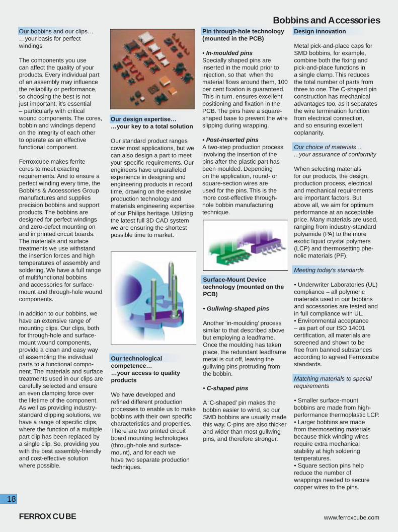
Bobbins and AccessoriesOur bobbins and our clips… …your basis for perfect windings
The components you use can affect the quality of your products. Every individual part of an assembly may infl uence the reliability or performance, so choosing the best is not just important, it’s essential – particularly with critical wound components. The cores, bobbin and windings depend on the integrity of each other to operate as an effective functional component.
Ferroxcube makes ferrite cores to meet exacting requirements. And to ensure a perfect winding every time, the Bobbins & Accessories Group manufactures and supplies precision bobbins and support products. The bobbins are designed for perfect windings and zero-defect mounting on and in printed circuit boards. The materials and surface treatments we use withstand the insertion forces and high temperatures of assembly and soldering. We have a full range of multifunctional bobbins and accessories for surface-mount and through-hole wound components.
In addition to our bobbins, we have an extensive range of mounting clips. Our clips, both for through-hole and surface-mount wound components, provide a clean and easy way of assembling the individual parts to a functional compo-nent. The materials and surface treatments used in our clips are carefully selected and ensure an even clamping force over the lifetime of the component. As well as providing industry-standard clipping solutions, we have a range of specifi c clips, where the function of a multiple part clip has been replaced by a single clip. So, providing you with the best assembly-friendly and cost-effective solution where possible.
Design innovation
Metal pick-and-place caps for SMD bobbins, for example, combine both the fi xing and pick-and-place functions in a single clamp. This reduces the total number of parts from three to one. The C-shaped pin construction has mechanical advantages too, as it separates the wire termination function from electrical connection, and so ensuring excellent coplanarity.
Our choice of materials… ...your assurance of conformity
When selecting materials for our products, the design, production process, electrical and mechanical requirements are important factors. But above all, we aim for optimum performance at an acceptable price. Many materials are used, ranging from industry-standard polyamide (PA) to the more exotic liquid crystal polymers (LCP) and thermosetting phe-nolic materials (PF).
Meeting today’s standards
• Underwriter Laboratories (UL) compliance – all polymeric materials used in our bobbins and accessories are tested and in full compliance with UL. • Environmental acceptance – as part of our ISO 14001 certifi cation, all materials are screened and shown to be free from banned substances according to agreed Ferroxcube standards.
Matching materials to special requirements
• Smaller surface-mount bobbins are made from high-performance thermoplastic LCP. • Larger bobbins are made from thermosetting materials because thick winding wires require extra mechanical stability at high soldering temperatures. • Square section pins help reduce the number of wrappings needed to secure copper wires to the pins.
Our design expertise… …your key to a total solution
Our standard product ranges cover most applications, but we can also design a part to meet your specifi c requirements. Our engineers have unparalleled experience in designing and engineering products in record time, drawing on the extensive production technology and materials engineering expertise of our Philips heritage. Utilizing the latest full 3D CAD system we are ensuring the shortest possible time to market.
Our technological competence… …your access to quality products
We have developed and refi ned different production processes to enable us to make bobbins with their own specifi c characteristics and properties. There are two printed circuit board mounting technologies (through-hole and surface-mount), and for each we have two separate production techniques.
Surface-Mount Device technology (mounted on the PCB)
• Gullwing-shaped pins
Another ‘in-moulding’ process similar to that described above but employing a leadframe. Once the moulding has taken place, the redundant leadframe metal is cut off, leaving the gullwing pins protruding from the bobbin.
• C-shaped pins
A ‘C-shaped’ pin makes the bobbin easier to wind, so our SMD bobbins are usually made this way. C-pins are also thicker and wider than most gullwing pins, and therefore stronger.
Pin through-hole technology (mounted in the PCB)
• In-moulded pins Specially shaped pins are inserted in the mould prior to injection, so that when the material fl ows around them, 100 per cent fi xation is guaranteed. This in turn, ensures excellent positioning and fi xation in the PCB. The pins have a square-shaped base to prevent the wire slipping during wrapping.
• Post-inserted pins A two-step production process involving the insertion of the pins after the plastic part has been moulded. Depending on the application, round- or square-section wires are used for the pins. This is the more cost-effective through-hole bobbin manufacturing technique.

19
www.ferroxcube.com FERROXCUBE
Bobbins and Accessories
Core typePin Through-Hole
(PTH)Surface-Mount Device
(SMD)Specials
E (EF)
Sizes: E13, 16, 19, 20,25, 30, 32, 34, 41, 42,
47, 55, 56, 65
Clips and Claspsavailable for most
products
Sizes: E5.3, 6.3, 13
Multi-section,Caps and Clips
available
Sizes: E20
High insulationtwo pieces male /female bobbins
EFD
Sizes: EFD15, 20,25, 30
15 and 20 L-pin,low build height
Sizes: EFD10, 12,15, 20, 25
One piece pick and place metal Covers /Clamps, C-pin design
(except for EFD25)
ETD + EPX
Sizes: ETD29, 34,39, 44, 49, 54, 59
Complete range in-moulded pins. Clips
available
Sizes: EPX7, 9
Gullwing pin type with 2.0/2.54 mm distance.
Clamps available
Sizes: ETD34
Two pieces male/female high insulation factor
EP
Sizes: EP7, 10, 13, 17, 20
(also for EP13/LP)All phenolic parts, both
single Clips and Clasps / Springs available
Sizes: EP5, 7, 10, 13
Single Clips, also C-pins phenolic
version
ER + EQ EQ30Phenolic part, 10 pins
ER9.5, 11, 14.5 Gullwing pin type
in high performance thermoplastic.
Clamps available
RM
Sizes: RM4, 5, 6, 7,8, 10, 12, 14
Clips available,both in-moulded and post-inserted pin versions
Sizes: RM4, 5, 6
Both phenolic andthermoplastic
types, low profi leClips available
Sizes: RM5, 6, 8,10, 14
In-moulded L-pinversion for easy
winding
P + PQ
Sizes: P11, 14, 18, 22, 26, 30, 36, 42
Multi-section, complete range of Bobbins,
Tag-plates, Springs, Containers.High stability
assembled product.
Sizes: PQ20, 26, 32, 35
L-pin post-inserted versions in high
performance thermo-plastic material
U + Special productsSizes: U10, 15
15 multi-section
Sizes: T9
Cover and Tagplate,C-pin version
Custom Designsfor all core types
Special products
Sizes: E16
High insulating andcoupling factor.
Robust design inphenolic material.
Sizes: FRM 9,10,12,15
high performance thermo-plastic material, FRM9 is C-pin version.
Sizes: E14, 18, 22
Range of Clamps available
P/I uses P accessoriesPT & PTS use proper or P accessories

20
FERROXCUBE www.ferroxcube.com

21
www.ferroxcube.com FERROXCUBE

22
FERROXCUBE www.ferroxcube.com
Integrated Inductive Components (IIC)The IIC design
For the majority of today’s designs it is desirable to have low profi le inductive components. This allows designers not only to make low profi le equipment, but also to place the component anywhere on the PC board without need to adapt the equipment housing. This is especially true when the inductive component matches the height of other components on the board, for instance ICs.A possible way to reach this goal is demonstrated in the new Integrated Inductive Component (IIC). This consists of a rectangular ferrite sleeve with a copper lead frame inserted. The lead frame is moulded with a high-tech resin to secure the leads and insulate them from the ferrite core. After insertion the leads are bent into a ‘gull wing’ shape to form contact pads as with most surface-mount ICs.The fi nished product looks like an IC from the outside (SOT). It can be handled by standard pick-and-place equipment and soldered on the board along with other ICs. The leads in the moulding form one half of a winding which is completed by a track on the PC board. In this way, depending on the board layout, core material and confi guration, several magnetic functions can be realized.
IIC with partial / full airgap
This product type has an airgap to improve energy storage capability. With partial gap, its performance has all the characteristics of a stepped choke. Possible magnetic functions are :
- power inductor- output choke- EMI-choke with bias
Features and Benefi ts:
Inductive surface-mount component that looks like a standard IC outline (SOT).
Windings are completed by PC board tracks.
Automatic placement and soldering together with other ICs on the board.
Suitable for refl ow soldering.
Wide range of magnetic functions can be realized with the same product, depending on track layout.
Superior physical properties.
Available in standard EIA and EIAJ tape-and-reel.
Operating temperature -55 °C to +150 °C.
IIC without airgap
This design is suitable for the following magnetic functions:
- power transformer- common-mode choke
The IIC can be used as a low profi le power transformer in high-frequency DC/DC converters, especially those working with low voltage and power levels.
Although isolation voltage is specifi ed at 500 V, the IIC10 should not be used in AC/DC applications as a safety isolation transformer. The short distance between the leads makes it unsuitable for that function.
Made in our top-quality 3S4 suppression material or the high-permeability 3E6, the design is ideal for common- mode choke in signal or supply lines, especially if these carry large currents. The sturdy lead frame will take almost any current surge without damage.
Power inductors are used in modern high-frequency DC/DC buck/boost convert-ers or resonant converters. Because operating frequen-cies are usually high(≥ 200 kHz), inductors with a lower number of turns can be used.This makes IIC10 suitable for these applica-tions. The curves of L as a function of DC bias show the effect of its airgap. For most applications, high saturation fl ux density and low power losses are key requirements. Therefore 3C30 is the ideal material here. However for very high frequencies(≥ 500 kHz), 3F35 or3F4 would be a better choice.
EMI-chokes often suffer from saturation when used without current compensa-tion in lines with DC or AC bias currents. The airgap avoids complete saturation to a large extend. The sup-pression effect remains at an acceptable level for high current levels.

23
www.ferroxcube.com FERROXCUBE
Integrated Inductive Components (IIC)
Core typeIIC10-14/4
IIC10P-14/4
efec
tive
core
par
amet
ers
core factorΣ l/A(mm-1)
2.47
eff. volumeVe (mm3)
338
eff. lengthle (mm)
28.9
eff. areaAe (mm2)
11.7
min. areaAmin (mm2)
11.7
mass (g) ≈ 1.85
dim
ensi
ons
(mm
)
A 14.4 ± 0.2
B 4 ± 0.08
C 7.2 ± 0.15
D 10.45 max
E 4.38 max
F 2.7± 0.2
G 1.0
H 0.6 max
I 0.3
A
B
C D
G H
I
E
F
IICs without airgap
AL (nH)at B = 0.1 mT
f = 10 kHzT = 25 °C
AL (nH)at B = 0.1 mTf = 500 kHzT = 25 °C
AL (nH)at B = 0.1 mT
f = 1 MHzT = 25 °C
|Z|typ (Ω)at 100 MHzfor 1 turnT = 25 °C
E.T (Vµs)f = 100 kHzH = 800 A/mIreset = 70 mA
T = 100 °C
IIC10-14/4-3E6 600 ± 30 % - - - -
IIC10-14/4-3F4 - - 450 ± 25 % - -
IIC10-14/4-3F35 - 700 ± 25 % - - -
IIC10-14/4-3R1 - - - - ≥ 33
IIC10-14/4-3S4 - - - ≈ 35 -
IICs with partial airgap
L (µH)for 10 turns
no bias current
f = 100 kHzT = 25 °C
L (µH)for 10 turns
no bias current
f = 500 kHzT = 25 °C
L (µH)for 10 turns
no bias current
f = 1 MHzT = 25 °C
L (µH)for 10 turnsbias current
1 Af = 100 kHzT = 25 °C
L (µH)for 10 turnsbias current
1 Af = 500 kHzT = 25 °C
L (µH)for 10 turnsbias current
1 Af = 1 MHzT = 25 °C
IIC10P-14/4-3C30 92 ± 25 % - - ≥ 5 -
IIC10P-14/4-3F4 - - 45 ± 25 % - - ≥ 5
IIC10P-14/4-3F35 - 70 ± 25 % - - ≥ 5
IIC 10P - 14/4 - 3E6core type
number of leads
core size
core materialgap type :P - partial gapG - full gap
IICs with full airgap
L (µH)for 10 turns
no bias currentf = 500 kHzT = 25 °C
L (µH)for 10 turns
no bias currentf = 1 MHzT = 25 °C
L (µH)for 10 turns
bias current 4 Af = 500 kHzT = 25 °C
L (µH)for 10 turns
bias current 4 Af = 1 MHzT = 25 °C
IIC10G-14/4-3F35 8 ± 15 % - ≥ 6
IIC10G-14/4-3F4 7.5 ± 15 % - ≥ 5.5

24
FERROXCUBE www.ferroxcube.com
Planar E cores
Core type
dimensions (mm) effective core parameters
A B C D E F
core factor Σ l/A
(mm-1)
eff. volume
Ve (mm3)
eff. length
le (mm3)
eff. area Ae
(mm2)
min. area Amin
(mm2)
mass of core
half(g)
E14/3.5/5 (E-E combination)
14 ± 0.3
3.5 ± 0.1
5 ± 0.1
2 ± 0.1
11 ± 0.25
3 ± 0.05
1.43 300 20.7 14.5 14.5 ≈ 0.6
PLT14/5/1.5 (E-PLT combination)
14 ± 0.3
5 ± 0.1
1.5 ± 0.05
- - - 1.16 240 16.7 14.5 14.5 ≈ 0.5
E18/4/10 (E-E combination)
18 ± 0.35
4 ± 0.1
10 ± 0.2
2 ± 0.1
14 ± 0.3
4 ± 0.1
0.616 960 24.3 39.5 39.5 ≈ 2.4
PLT18/10/2 (E-PLT combination)
18 ± 0.35
10 ± 0.2
2 ± 0.05
- - - 0.514 800 20.3 39.5 39.5 ≈ 1.7
E22/6/16 (E-E combination)
21.8 ± 0.4
5.7 ± 0.1
15.8 ± 0.3
3.2 ± 0.1
16.8 ± 0.4
5 ± 0.1
0.414 2550 32.5 78.5 78.5 ≈ 6.5
PLT22/16/2.5 (E-PLT combination)
21.8 ± 0.4
15.8 ± 0.3
2.5 ± 0.05
- - - 0.332 2040 26.1 78.5 78.5 ≈ 4
E32/6/20 (E-E combination)
31.75 ± 0.64
6.35 ± 0.13
20.32 ± 0.41
3.18 ± 0.13
24.9 min
6.35 ± 0.13
0.323 5380 41.7 129 129 ≈ 13
PLT32/20/3 (E-PLT combination)
31.75 ± 0.64
20.32 ± 0.41
3.18 ± 0.13
- - - 0.278 4560 35.9 129 129 ≈ 10
E38/8/25 (E-E combination)
38.1 ± 0.76
8.26 ± 0.13
25.4 ± 0.51
4.45 ± 0.13
30.23 min
7.62 ± 0.15
0.272 10200 52.6 194 194 ≈ 25
PLT38/25/4 (E-PLT combination)
38.1 ± 0.76
25.4 ± 0.51
3.81 ± 0.13
- - - 0.226 8460 43.7 194 194 ≈ 18
E43/10/28 (E-E combination)
43.2 ± 0.9
9.5 ± 0.13
27.9 ± 0.6
5.4 ± 0.13
34.7 min
8.1 ± 0.2
0.276 13900 61.7 225 225 ≈ 35
PLT43/28/4 (E-PLT combination)
43.2 ± 0.9
27.9 ± 0.6
4.1 ± 0.13
- - - 0.226 11500 50.8 225 225 ≈ 24
E58/11/38 (E-E combination)
58.4 ± 1.2
10.5 ± 0.13
38.1 ± 0.8
6.5 ± 0.13
50 min
8.1 ± 0.2
0.268 24600 81.2 305 305 ≈ 62
PLT58/38/4 (E-PLT combination)
58.4 ± 1.2
38.1 ± 0.8
4.1 ± 0.13
- - - 0.224 20800 68.3 305 305 ≈ 44
E64/10/50 (E-E combination)
63.8 ± 1.3
10.2 ± 0.13
50.3 ± 1
5.1 ± 0.13
53.6 ± 1.1
10.2 ± 0.2
0.156 40700 79.7 511 511 ≈ 100
PLT64/50/5 (E-PLT combination)
63.8 ± 1.3
50.3 ± 1
5.08 ± 0.13
- - - 0.136 35500 69.0 522 522 ≈ 78
Planar magnetics offer an attractive alternative to conventional core shapes when a low profi le of magnetic devices is required. Basically this is a construction method of inductive components whose windings are fabricated using printed circuit tracks or copper stampings separated by insulating sheets or constructed from multilayer circuit boards. These windings are placed in low profi le ferrite EE- or E-PLT combinations. Planar devices can be constructed as stand alone components or ‘integrated’ into a multilayer mother board with slots for the ferrite E-core.
Principal advantages of planar magnetics are:
• Low profi le construction• Low leakage inductance• Excellent repeatability of parasitic properties• Ease of construction and assembly• Cost effective• Greater reliability• Excellent thermal characteristics, easy to heatsink.
The Ferroxcube range of planar E cores are all made from press tooling. This gives the advantage of radiused corners and edges. It also means that clamp recesses can be incorporated.
E core (E) plate (PLT)
A
D
B
C
EF
C B
A

25
www.ferroxcube.com FERROXCUBE
Planar E cores Core type E14/3.5/5 E18/4/10 E22/6/16 E32/6/20 E38/8/25 E43/10/28 E58/11/38 E64/10/50
Matching plates PLT14/5/1.5 PLT18/10/2 PLT22/16/2.5 PLT32/20/3 PLT38/25/4 PLT43/28/4 PLT58/38/4 PLT64/50/5
3C90 1280 / 1500 3200 / 3680 5150 / 6150 6425 / 7350 7940 / 9250 8030 / 9250 8480 / 9970 14640/16540
3C92 960 / 1130 2330 / 2690 3700 / 4410 5000 / 5760 6100 / 7150 6300 / 7460 6600 / 7770 11200 / 12700
3C93 1100 / 1300 2700 / 3100 4300 / 5000 5900 / 6780 7250 / 8500 7310 / 8700 7710 / 9070 13300/15050
3C94 A160 - E E160 - E E250 - E E250 - E E315 - E E630 - EA160 - P A160 - P A250 - P A250 - P A315 - P A630 - P
A100 - E A250 - E E250 - E E315 - E E315 - E E400 - E E1000 - EA100 - P A250 - P A250 - P A315 - P A315 - P A400 - P A1000 - P
A63 - E A160 - E A315 - E A315 - E E400 - E E400 - E E630 - E A1600 - EA63 - P A160 - P A315 - P A315 - P A400 - P A400 - P A630 - P A1600 - PA100 - E A250 - E A400 - E A400 - E A630 - E A630 - E A1000 - E A2500 - EA100 - P A250 - P A400 - P A400 - P A630 - P A630 - P A1000 - P A2500 - PA160 - E A315 - E A630 - E A630 - E A1000 - E A1000 - E A1600 - E A3150 - EA160 - P A315 - P A630 - P A630 - P A1000 - P A1000 - P A1600 - P A3150 - P
1280 / 1500 3200 / 3680 5150 / 6150 6425 / 7350 7940 / 9250 8030 / 9250 8480 / 9970 14640/16540
3C96 A160 - E E160 - EA160 - P A160 - P
A100 - E A250 - E E250 - EA100 - P A250 - P A250 - P
A63 - E A160 - E A315 - E A315 - EA63 - P A160 - P A315 - P A315 - PA100 - E A250 - E A400 - E A400 - EA100 - P A250 - P A400 - P A400 - PA160 - E A315 - E A630 - E A630 - EA160 - P A315 - P A630 - P A630 - P
1200 / 1350 2900 / 3250 4600 / 5450 6425 / 7350
3F3 1100 / 1300 2700 / 3100 4300 / 5000 5900 / 6780 7250 / 8500 7310 / 8700 7710 / 9070 13300/15050
3F35 A160 - EA160 - P
A100 - E A250 - EA100 - P A250 - P
A63 - E A160 - E A315 - EA63 - P A160 - P A315 - PA100 - E A250 - E A400 - EA100 - P A250 - P A400 - PA160 - E A315 - E A630 - EA160 - P A315 - P A630 - P
900 / 1050 2200 / 2500 3500 / 4100
3F4 A160 - E E160 - E E250 - E E250 - E E315 - E E630 - EA160 - P A160 - P A250 - P A250 - P A315 - P A630 - P
A100 - E A250 - E E250 - E E315 - E E315 - E E400 - E E1000 - EA100 - P A250 - P A250 - P A315 - P A315 - P A400 - P A1000 - P
A63 - E A160 - E A315 - E A315 - E E400 - E E400 - E E630 - E A1600 - EA63 - P A160 - P A315 - P A315 - P A400 - P A400 - P A630 - P A1600 - PA100 - E A250 - E A400 - E A400 - E A630 - E A630 - E A1000 - E A2500 - EA100 - P A250 - P A400 - P A400 - P A630 - P A630 - P A1000 - P A2500 - PA160 - E A315 - E A630 - E A630 - E A1000 - E A1000 - E A1600 - E A3150 - EA160 - P A315 - P A630 - P A630 - P A1000 - P A1000 - P A1600 - P A3150 - P650/780 1550 / 1800 2400 / 2900 3200 / 3700 3880 /4600 3870 / 4660 4030 / 4780 6960 / 7920
high
µ
halv
es 3E65600 / 6400 13500 / 15500 22000 / 26000
AL value (nH) measured at B ≤ 0.1 mT, f ≤ 10 kHz, T = 25°C
gapped core half with symmetrical gap (E). AL = 160 nH measured in combination with an Equal-gapped E core half. gapped core half with asymmetrical gap (A). AL = 25 nH in combination with an ungapped E core half. gapped core half with asymmetrical gap (A). AL = 25 nH in combination with a plate.ungapped core half. AL = 1100/1300 nH measured in combination with an ungapped half / plate.
E160 - EA25 - EA25 - P
1100/1300
AL tolerance: ± 5% ± 8% ± 10% ± 25% + 40%− 30%± 3%
E 32/6 - 3C90 - E 250 - Ecore type
core size
core material
gap typeA-asymmetrical gap to AL valueE-symmetrical gap to AL value
version:E-combine with E coreP-combine with plate
AL value (nH)
PLT 18 / 10 / 2 - 3C90core type
(plate)
plate size
material

26
FERROXCUBE www.ferroxcube.com
Planar E cores with recess
Core type E14/3.5/5/R
PLT14/5/1.5/S
(E-PLT combina-
tion)
E18/4/10/R
PLT18/10/2/S
(E-PLT combina-
tion)
E22/6/16/R
PLT22/16/2.5/S
(E-PLT combina-
tion)
E32/6/20/R
PLT32/20/3/R
(E-PLT combina-
tion)
efec
tive
core
par
amet
ers
core factorΣ l/A(mm-1)
1.15 0.498 0.324 0.278
eff. volumeVe (mm3)
230 830 2100 4560
eff. lengthle (mm)
16.4 20.3 26.1 35.1
eff. areaAe (mm2)
14.2 40.8 80.4 130
min. areaAmin (mm2)
10.9 35.9 72.6 119
mass of core half (g)
≈ 0.6 ≈ 0.5 ≈ 2.4 ≈ 1.7 ≈ 6.5 ≈ 4 ≈ 13 ≈ 10
dim
ensi
ons
(mm
)
A 14 ± 0.3 14 ± 0.3 18 ± 0.35 18 ± 0.35 21.8 ± 0.4 21.8 ± 0.4 31.75 ± 0.64 31.75 ± 0.64
B 3.5 ± 0.1 5 ± 0.1 4 ± 0.1 10 ± 0.2 5.7 ± 0.1 15.8 ± 0.3 6.35 ± 0.13 20.32 ± 0.41
C 5 ± 0.1 1.8 ± 0.05 10 ± 0.2 2.4 ± 0.05 15.8 ± 0.3 2.9 ± 0.05 20.32 ± 0.41 3.18 ± 0.13
D 2 ± 0.1 1.5 ± 0.1 2 ± 0.1 2 ± 0.1 3.2 ± 0.1 2.5 ± 0.1 3.18 ± 0.2 5.3
E 11 ± 0.25 2.5 + 0.2 14 ± 0.3 2.5 + 0.2 16.8 ± 0.4 2.9 + 0.2 24.9 min 5 + 0.2
F 3 ± 0.05 - 4 ± 0.1 - 5 ± 0.1 - 6.35 ± 0.13 -
G 2.8 ± 0.15 - 3.3 ± 0.15 - 4.7 ± 0.15 - 5.3 -
H 2.5 + 0.2 - 2.5 + 0.2 - 2.8 + 0.2 - 5 + 0.2 -
mou
ntin
g pa
rts CLM
CLI
For those customers not in favor of glueing we developed a new range of planar E cores with matching plates and metal clamps. These cores can easily be mounted together with the PCB winding without the use of any glue. The E cores have recesses (E/R) to prevent the clamp from slipping off. The plates have slots (PLT/S) to limit any sideways movement during vibrations or shocks. The combinations with recessed plate need clips on the side.This clamping method is only available for E-PLT-combinations, not for EE-combinations. It is particularly suitable for the cores in high permeability materials like 3E6. Any glue on the mating faces would potentially degradel the high AL value of these core assemblies.Planar cores in high µ material 3E6 are recommended for use in common mode input fi lters or in wideband transformers.
Summary:¨ no glue necessary¨ plate with slot or recess to prevent sideways movement¨ no AL reduction of high permeability cores due to glue on the mating faces
E core with recess (E/R)
A
D
BG
C
EF
H plate withslot (PLT/S)
D
C B
A
D
C B
E
plate withrecess (PLT/R)
E

27
www.ferroxcube.com FERROXCUBE
Planar E cores with recessCore type E14/3.5/5/R E18/4/10/R E22/6/16/R E32/6/20/R
Matching plates PLT14/5/1.5/S PLT18/10/2/S PLT22/16/2.5/S PLT32/20/3/R
3C90 1500 3680 6150 7350
3C92 960 / 1130 2330 / 2690 3700 / 4410 5000 / 5760
3C93 1100 / 1300 2700 / 3100 4300 / 5000 5900 / 6780
3C94 A63-P A100-P A160-P A160-P
A100-P A160-P A250-P A250-P
A160-P A250-P A315-P A315-P
1500 A315-P A400-P A400-P
3680 A630-P A630-P
6150 7350
3C96 A160 - P A160 - P
A100 - P A250 - P A250 - P
A63 - P A160 - P A315 - P A315 - P
A100 - P A250 - P A400 - P A400 - P
A160 - P A315 - P A630 - P A630 - P
1350 2500 4100 7350
3F3 1300 3100 5000 6780
3F35 A160 - P
A100 - P A250 - P
A63 - P A160 - P A315 - P
A100 - P A250 - P A400 - P
A160 - P A315 - P A630 - P
1050 2500 4100
3F4 A63-P A100-P A160-P A160-P
A100-P A160-P A250-P A250-P
A160-P A250-P A315-P A315-P
780 A315-P A400-P A400-P
1800 A630-P A630-P
2900 3700
high
µ
halv
es
3E66400 15500 26000
gapped core half with asymmetrical gap (A). AL = 63 nH measured in combination with a plate. ungapped core half. AL = 1280 nH measured in combination with a plate.
A63-P1280
AL value (nH) measured at B ≤ 0.1 mT, f ≤ 10 kHz, T = 25°C
AL tolerance: ± 5% ± 8% ± 10% ± 25% + 40%− 30%± 3%
CLM - E14/PLT14
corresponding plate (only main dim.)
corresponding E core (only main dim.)
accessory type
E14/3.5/5/R-3F3-A100-P
core type
recess
material
core size
version:E-combine withE core
gap type :A-asymmetrical gapto AL value
AL value (nH)
P-combine withplate
E-symmetrical gapto AL value
PLT14/5/1.5/S-3F3
core type
core size S - slotR - recess
material

28
FERROXCUBE www.ferroxcube.com
E cores
Core type(old core description)
E5.3/2.7/2 E6.3/2.9/2 E8.8/4.1/2 E13/6/3E13/6/6
(814E250)E13/7/4(EF12.6)
E16/8/5(EF16)
efec
tive
core
par
amet
ers
core factorΣ l/A(mm-1) 4.70 3.67 3.13 2.74 1.37 2.39 1.87
eff. volumeVe (mm3) 33.3 40.6 78 281 559 369 750
eff. lengthle (mm) 12.5 12.2 15.6 27.8 27.7 29.7 37.6
eff. areaAe (mm2) 2.66 3.3 5.0 10.1 20.2 12.4 20.1
min. areaAmin (mm2) 2.63 2.6 3.6 10.1 20.2 12.2 19.3
mass of core half (g) ≈ 0.08 ≈ 0.12 ≈ 0.25 ≈ 0.7 ≈ 1.4 ≈ 0.9 ≈ 2.0
dim
ensi
ons
(mm
)
A 5.25 ± 0.1 6.3 − 0.25 9 ± 0.4 12.7 ± 0.25 12.7 ± 0.25 12.6 + 0.5 / −0.4 16 + 0.7 / −0.5
B 2.65 ± 0.05 2.9 − 0.1 4.1 − 0.2 5.7 ± 0.13 5.7 ± 0.13 6.5 − 0.2 8.2 − 0.3
C 2.0 − 0.1 2.0 − 0.1 2.0 − 0.2 3.18 ± 0.13 6.4 ± 0.13 3.7 − 0.3 4.7 − 0.4
D 1.9 + 0.15 1.85 + 0.1 2.03 + 0.32 4.1 ± 0.13 4.1 ± 0.13 4.5 + 0.3 5.7 + 0.4
E 3.8 + 0.2 3.6 + 0.2 5.2 ± 0.13 9.5 ± 0.25 9.5 ± 0.25 8.9 + 0.6 11.3 + 0.6
F 1.4 − 0.1 1.4 − 0.1 1.9 ± 0.12 3.2 ± 0.13 3.2 ± 0.13 3.7 − 0.3 4.7 − 0.3
bobb
ins
CP 1S
CPH 1S - 6P 1S - 6P
CPHS1S - 4P1S - 6P2S - 6P
1S - 4P1S - 6P2S - 4P2S - 6P
CSH 1S - 6P - C1S - 6P - CA
1S - 8P1S - 10P - C
1S - 6P - C1S-9P
1S - 14P
CSHS 1S - 10P
mou
ntin
g pa
rts
CLM
CLA
CLI
SPR
COV
The shape of E cores is derived from the classical iron sheet lamination cores. For the original E range in fact the dimensions of the existing lamina-tion range were taken so that already commercially available coil formers and mounting hardware could be used. The former EF range has been optimized for the use of ferrite as a core material. Cross sections were rearranged resulting in a homogenious magnetic fl ux density in the core and more space for the windings. Main use is as power transformer or choke in SMPS. E cores have a simple shape and can therefore be produced more economically than more complicated cores.
A drawback is the rectangular cross-section of the centre pole which makes it more diffi cult to wind, especially with heavy wires. Also the structure of the core is rather open resulting in stray fl ux sometines causing interference problems.
Summary:• simple, economic shape• square cross-section, not easy for heavy wires• large effective ferrite area• low magnetic self shielding
BD
FEA
C

29
www.ferroxcube.com FERROXCUBE
E cores
Core type(old core description)
E16/12/5(EL16)
E19/8/5(813E187)
E19/8/9(813E343)
E20/10/5 E20/10/6(EF20)
E20/14/5(EC19)
E22/16/10 E25/9/6E25/10/6
(812E250)
efec
tive
core
par
amet
ers
core factorΣ l/A(mm-1) 2.85 1.77 0.960 1.37 1.45 2.54 0.695 1.23 1.24
eff. volumeVe (mm3) 1070 900 1650 1340 1490 1513 5143 1860 1930
eff. lengthle (mm) 55.3 39.9 39.9 42.8 46.0 62.0 59.8 47.4 49.0
eff. areaAe (mm2) 19.4 22.6 41.3 31.2 32.0 24.4 86 38.4 39.5
min. areaAmin (mm2) 19.4 22.1 41.1 25.2 32.0 22.8 80 37.0 37.0
mass of core half (g) ≈ 2.6 ≈ 2.3 ≈ 4 ≈ 4 ≈ 3.7 ≈ 4.3 ≈ 14 ≈ 4.8 ≈ 4.8
dim
ensi
ons
(mm
)
A 16 ± 0.3 19.1 ± 0.4 19.05 ± 0.38 20.7−1.1 20+0.8 /−0.6 20 ± 0.3 22 ± 0.5 25.4 ± 0.6 25.4 ± 0.6
B 12.25 ± 0.2 8.1 ± 0.13 8.05 ± 0.13 10 ± 0.2 10.2 − 0.4 13.55 ± 0.15 15.75 ± 0.5 9.45 ± 0.2 9.65 ± 0.2
C 4.85 ± 0.2 4.7 ± 0.13 8.71 ± 0.13 5.3 − 0.4 5.9 − 0.5 5 ± 0.2 10 ± 0.25 6.3 ± 0.3 6.35 ± 0.25
D 10.25 ± 0.25 5.7 ± 0.13 5.69 ± 0.13 6.3 + 0.4 7 + 0.4 11.15 ± 0.15 9.75 ± 0.25 6.5 ± 0.3 6.4 min
E 12 ± 0.3 14.3 ± 0.3 14.33 ± 0.3 12.8 + 0.8 14.1 + 0.8 14.3 min 13 min 19.3 ± 0.5 18.8 min
F 4 ± 0.2 4.7 ± 0.13 4.75 ± 0.13 5.2 − 0.4 5.9 − 0.4 4.55 ± 0.15 8 ± 0.25 6.35 ± 0.25 6.35 ± 0.25
bobb
ins
CP 1S 1S 1S 1S
CPH 1S - 8PD 1S - 8P1S - 10P
1S - 10PD - A
CPCI 1S - 5P
CPCO 1S - 5P
CPHS
CPV 1S - 6P
CSH 1S - 8P 1S - 8P - C
E 25/13/7 - 3C90 - A 250
AL value (nH)or gap size (µm)
core type
core size
core materialgap typeA- asymmetrical gap to AL valueE- symmetrical gap to AL valueG- mechanical gap
C S H S - E13/4 - 1S - 10P - T
special version
number &type of pinsD - dualterminationF - flatL - long
number of sections
coil former(bobbin)
plasticmaterial type:P- thermoplasticS- thermoset
mounting orientation:H- horizontalV- verticalCI-coaxial, inner partCO-coaxial, outer part
associatedcore type
mounting type: S- surface mount
CLM - E25/13/7
hardware typeCLM - clampCLA - claspSPR - springCLI - clip
associatedcore type

30
FERROXCUBE www.ferroxcube.com
E cores
Core type(old core description)
E25/13/7(EF25)
E25/13/11 E30/15/7 E31/13/9E32/16/9(EF32)
E34/14/9(E375)
E35/18/10 E36/21/12E41/17/12
(E21)E42/21/15
efec
tive
core
par
amet
ers
core factorΣ l/A(mm-1) 1.11 0.733 1.12 0.740 0.894 0.850 0.807 0.762 0.517 0.548
eff. volumeVe (mm3) 2990 4500 4000 5150 6180 5590 8070 12160 11500 17300
eff. lengthle (mm) 58.5 57.5 67.0 61.9 74 69.3 80.7 96 77.0 97.0
eff. areaAe (mm2) 52.0 78.4 60.0 83.2 83 80.7 100 126 149 178
min. areaAmin (mm2) 52.0 78.4 49.0 83.2 83 80.7 100 121 142 175
mass of core half (g) ≈ 8 ≈ 11 ≈ 11 ≈ 13 ≈ 16 ≈ 14 ≈ 15 ≈ 31 ≈ 30 ≈ 44
dim
ensi
ons
(mm
)
A 25 + 0.8/−0.7 25 + 0.8/−0.7 30.8 − 1.4 30.9 ± 0.5 32 + 0.9/−0.7 34.3 ± 0.6 35 ± 0.5 36 ± 0.7 40.6 ± 0.65 43 − 1.7
B 12.8 − 0.5 12.8 − 0.5 15 ± 0.2 13.4 ± 0.15 16.4 − 0.4 14.1 ± 0.15 17.5 ± 0.25 21.75 − 0.4 16.6 ± 0.2 21 ± 0.2
C 7.5 − 0.5 11 − 0.5 7.3 − 0.5 9.4 ± 0.3 9.5 − 0.7 9.3 ± 0.25 10 ± 0.3 12 − 0.6 12.4 ± 0.3 15.2 − 0.6
D 8.7 + 0.5 8.7 + 0.5 9.7 + 0.5 8.6 min 11.2 + 0.6 9.8 ± 0.13 12.5 ± 0.25 15.75 + 0.6 10.4 min 14.8 + 0.6
E 17.5 + 1.0 17.5 + 1.0 19.5 + 1.0 21.9 min 22.7 + 1.2 25.5 min 24.5 min 24.5 + 1.2 28.6 min 29.5 + 1.4
F 7.5 ± 0.5 7.5 ± 0.5 7.2 − 0.5 9.4 ± 0.25 9.5 − 0.6 9.3 ± 0.2 10 ± 0.3 10.2 − 0.5 12.45 ± 0.25 12.2 − 0.5
bobb
ins
CP 1S 1S 1S 1S
CPH1S - 10P 1S - 12P 1S - 12PD 1S - 12PD
1S-10PD-A1S-10P
CPHS
CPV 1S - 6P
CSH 1S - 8P - C1S - 10P
1S - 12P - C
mou
ntin
g pa
rts
CLM
CLA
CLI
SPR
BD
FEA
C

31
www.ferroxcube.com FERROXCUBE
E cores
Core type(old core description)
E42/21/20 E42/33/20 E47/20/16 E50/27/15 E55/28/21 E55/28/25E56/24/19(E75)
E65/32/27 E71/33/32 E80/38/20
efec
tive
core
par
amet
ers
core factorΣ l/A(mm-1) 0.417 0.614 0.380 0.530 0.350 0.239 0.320 0.274 0.218 0.470
eff. volumeVe (mm3) 22700 34200 20800 26900 44000 52000 36000 79000 102000 72300
eff. lengthle (mm) 97.0 145 88.9 120 124 123 107 147 149 184
eff. areaAe (mm2) 233 236 234 225 353 420 337 540 683 392
min. areaAmin (mm2) 233 234 226 213 345 411 337 530 676 392
mass of core half (g) ≈ 56 ≈ 82 ≈ 53 ≈ 68 ≈ 108 ≈ 130 ≈ 90 ≈ 205 ≈ 260 ≈ 180
dim
ensi
ons
(mm
)
A 43 − 1.7 42 + 1/ − 0.7 46.9 ± 0.8 50 ± 1 56.2 − 2.1 56.2 − 2.1 56.1 ± 1 65.0+1.5/−1.2 70.5 ± 1 80 ± 1.6
B 21 ± 0.2 32.8 − 0.4 19.6 ± 0.2 27.2 ± 0.2 27.5 ± 0.3 27.5 ± 0.3 23.6 ± 0.25 32.8 − 0.6 33.2 − 0.5 38.1 ± 0.3
C 20 − 0.8 20 − 0.8 15.6 ± 0.25 14.6 ± 0.4 21.0 − 0.8 25 − 0.8 18.8 ± 0.25 27.4 − 0.8 32 − 0.8 19.8 ± 0.4
D 14.8 + 0.6 26 + 1 12.1 min 18.6 ± 0.13 18.5 + 0.8 18.5 + 0.8 14.6 ± 0.13 22.2 + 0.8 21.9 + 0.7 28.2 ± 0.3
E 29.5 + 1.4 29.5 + 1.4 32.4 ± 0.65 34.1 min 37.5 + 1.5 37.5 + 1.5 38.1 min 44.2 + 1.8 48 + 1.5 59.1 min
F 12.2 − 0.5 12.2 − 0.5 15.6 ± 0.25 14.6 ± 0.4 17.2 − 0.5 17.2 − 0.5 18.8 ± 0.25 20 − 0.7 22 − 0.7 19.8 ± 0.4
bobb
ins
CP1S 1S
1S - A1S
1S 1S 1S
CPH 1S - 12PD 1S - 12PD 1S - 14P 1S - 12PD
CPHS
CPV
CSH
mou
ntin
g pa
rts
CLM
CLA
CLI
SPR
E 25/13/7 - 3C94 - A 250
AL value (nH)or gap size (µm)
core type
core size
core materialgap typeA- asymmetrical gap to AL valueE- symmetrical gap to AL valueG- mechanical gap
CLM - E25/13/7
hardware typeCLM - clampCLA - claspSPR - springCLI - clip
associatedcore type
C S H S - E13/4 - 1S - 10P - T
special version
number &type of pinsD - dualterminationF - flatL - long
number of sections
coil former(bobbin)
plasticmaterial type:P- thermoplasticS- thermoset
mountingorientation:H- horizontalV- vertical
associatedcore type
mounting type: S- surface mount

32
FERROXCUBE www.ferroxcube.com
Core type(old core description)
E5.3/2.7/2 E6.3/2.9/2 E8.8/4.1/2 E13/6/3E13/6/6
(814E250)E13/7/4(EF12.6)
E16/8/5(EF16)
E16/12/5(EL16)
E19/8/5(813E187)
core
HAL
VES
for g
ener
al p
urpo
se tr
ansf
orm
ers
and
pow
er a
pplic
atio
ns
3C81 1950 1500
3C90 730 1470 800 1100 800 1170
3C91 A63 E63
A100 E100
A160 A160
A250 A250
A315 A315
1950 1500
3C94 A63 A63 A63 A63 E63
A100 A100 A100 A100 E100
A160 A160 A160 A160 A160
A250 A250 A250 A250 A250
A315 A315 A315 A315 A315
300 400 530 730 1470 800 1100 800 1170
3C96 A63 A63 A63 A63 E63
A100 A100 A100 A100 E100
A160 A160 A160 A160 A160
A250 A250 A250 A250 A250
A315 A315 A315 A315 A315
275 380 480 730 1470 800 1100 800 1000
3F3 265 360 460 A63 A63 A63 E63
A100 A100 A100 E100
A160 A160 A160 A160
A250 A250 A250 A250
A315 A315 A315 A315
1250 700 980 1000
3F35 225 300 380 1000 560 760 810
3F4 165 225 280
hig
h µ
co
re
hal
ves
3C11
3E26 2000
3E27 1300 2600 1500 2200 2300
3E5 1400 1700
3E6 1600 2100 2500
E cores
AL value (nH) measured at B ≤ 0.1 mT, f ≤ 10 kHz, T = 25°C
gapped core half with symmetrical gap (E). AL = 63 nH measured in combination with an Equal-gapped core half. gapped core half with asymmetrical gap (A). AL = 315 nH measured in combination with a non-gapped core half. ungapped core half. AL = 1950 nH measured in combination with another ungapped core half.
E63A3151950
AL tolerance: ± 5% ± 8% ± 10% ± 15% ± 20% ± 25% + 40%− 30%
+ 30%− 20%

33
www.ferroxcube.com FERROXCUBE
Core type(old core description)
E19/8/9(813E343)
E20/10/5E20/10/6(EF20)
E20/14/5(EC19)
E22/16/10 E25/9/6 E25/10/6E25/13/7(EF25)
E25/13/11
core
HAL
VES
for g
ener
al p
urpo
se tr
ansf
orm
ers
and
pow
er a
pplic
atio
ns
3C81 2740 2340 2460
3C90 2150 1500 1450 900 3090 2000 1600 1900 2800
3C91 E63 E63 E63
E100 A100 A100
A160 A160 A160
A250 A250 A250
A315 A315 A315
2740 2340 2460
3C94 E63 A63 A63 A63 E63 E63 E63
E100 A100 A100 A100 A100 A100 E100
A160 A160 A160 A160 A160 A160 A160
A250 A250 A250 A250 A250 A250 A250
A315 A315 A315 A315 A315 A315 A315
2150 1500 1450 900 3090 2000 1600 1900 2800
3C96 E63 A63 A63 E63 E63 E63
E100 A100 A100 A100 A100 E100
A160 A160 A160 A160 A160 A160
A250 A250 A250 A250 A250 A250
A315 A315 A315 A315 A315 A315
1830 1400 1350 1470 1650 2700
3F3 E63 A63 A63 E63 E63 E63
E100 A100 A100 A100 A100 E100
A160 A160 A160 A160 A160 A160
A250 A250 A250 A250 A250 A250
A315 A315 A315 A315 A315 A315
1830 1400 1350 1470 1650 2700
3F35 1490 1060 1000 1150 1250 2000
3F4
hig
h µ
co
re
hal
ves
3C11 2600 2600 2600 3100
3E26 2300
3E27 4250 2800 2700 3200 4000
E cores
AL value (nH) measured at B ≤ 0.1 mT, f ≤ 10 kHz, T = 25°C
gapped core half with symmetrical gap (E). AL = 63 nH measured in combination with an Equal-gapped core half. gapped core half with asymmetrical gap (A). AL = 315 nH measured in combination with a non-gapped core half. ungapped core half. AL = 1950 nH measured in combination with another ungapped core half.
E63A3151950
AL tolerance: ± 5% ± 8% ± 10% ± 15% ± 20% ± 25% + 40%− 30%
+ 30%− 20%

34
FERROXCUBE www.ferroxcube.com
Core type(old core description)
E30/15/7 E31/13/9E32/14/9(EF32)
E34/14/9(E375)
E35/18/10 E36/21/12 E41/17/12 E42/21/15 E42/21/20
core
HAL
VES
for g
ener
al p
urpo
se tr
ansf
orm
ers
and
pow
er a
pplic
atio
ns
3C81 2500 3735 3200 5370 5300 6950
3C90 1900 2970 2500 2440 2500 2650 4100 3950 5000
3C91 E100 E100 E100 E100 E100 E100
A160 E160 E160 E160 E160 E160
A250 A250 A250 E250 E250 E250
A315 A315 A315 A315 A315 E315
A400 A400 A400 A400 A400 A400
A630 A630 A630 A630 A630 A630
2500 3735 3200 5370 5300 6950
3C94 E100 E100 E100 E100 E100 E100 E100 E100 E100
A160 E160 E160 E160 E160 E160 E160 E160 E160
A250 A250 A250 A250 A250 E250 E250 E250 E250
A315 A315 A315 A315 A315 A315 A315 A315 E315
A400 A400 A400 A400 A400 A400 A400 A400 A400
A630 A630 A630 A630 A630 A630 A630 A630 A630
1900 2970 2500 2440 2500 2650 4100 4100 5200
3C96 E100 E100 E100 E100
A160 E160 E160 E160
A250 A250 A250 A250
A315 A315 A315 A315
A400 A400 A400 A400
A630 A630 A630 A630
1600 2650 2300 2125
3F3 E100 E100 E100 E100 E100 E100 E100
A160 A160 E160 E160 E160 E160 E160
A250 A250 A250 A250 E250 E250 E250
A315 A315 A315 A315 A315 A315 E315
A400 A400 A400 A400 A400 A400 A400
A630 A630 A630 A630 A630 A630 A630
1600 2650 2300 2125 3575 3600 4600
3F35 1250 1950 1700 1680
3F4
hig
h µ
co
re
hal
ves
3C11 3300 4000 8000
3E27 4100 6790 5000 4700 9400 8000 10500
E cores
AL value (nH) measured at B ≤ 0.1 mT, f ≤ 10 kHz, T = 25°C
gapped core half with symmetrical gap (E). AL = 63 nH measured in combination with an Equal-gapped core half. gapped core half with asymmetrical gap (A). AL = 315 nH measured in combination with a non-gapped core half. ungapped core half. AL = 1950 nH measured in combination with another ungapped core half.
E63A3151950
AL tolerance: ± 5% ± 8% ± 10% ± 15% ± 20% ± 25% + 40%− 30%
+ 30%− 20%

35
www.ferroxcube.com FERROXCUBE
Core type(old core description)
E42/33/20 E47/20/16 E50/27/15 E55/28/21 E55/28/25E56/24/19
(E75)E65/32/27 E71/33/32 E80/38/20
core
HAL
VES
for g
ener
al p
urpo
se tr
ansf
orm
ers
and
pow
er a
pplic
atio
ns
3C81 7540 5500 8625 9500 6730
3C90 4000 5500 4350 6300 8000 6900 8600 10800 5070
3C91 E100 E100 E100 E100 E100
E160 E160 E160 E160 E160
E250 E250 E250 E250 E250
E315 E315 E315 E315 E315
E400 E400 E400 E400 E400
A630 A630 E630 E630 E630
7540 5500 8625 9500 6730
3C94 E100 E100 E100 E100 E100 E100 E100 E100 E100
E160 E160 E160 E160 E160 E160 E160 E160 E160
E250 E250 E250 E250 E250 E250 E250 E250 E250
A315 E315 E315 E315 E315 E315 E315 E315 E315
A400 E400 E400 E400 E400 E400 E400 E400 E400
A630 A630 A630 E630 E630 E630 E630 E630 E630
4000 5600 4350 6400 8000 6900 8600 10800 5070
3F3 E100 E100 E100 E100 E100 E100 E100
E160 E160 E160 E160 E160 E160 E160
E250 E250 E250 E250 E250 E250 E250
A315 E315 E315 E315 E315 E315 E315
A400 E400 E400 E400 E400 E400 E400
A630 A630 E630 E630 E630 E630 E630
3700 5100 5700 7400 7300 10000 4590
3F35
3F4
hig
h µ
co
re
hal
ves
3C11 12800 16700
3E27 11475 15400 14580
E cores
AL value (nH) measured at B ≤ 0.1 mT, f ≤ 10 kHz, T = 25°C
gapped core half with symmetrical gap (E). AL = 63 nH measured in combination with an Equal-gapped core half. gapped core half with asymmetrical gap (A). AL = 315 nH measured in combination with a non-gapped core half. ungapped core half. AL = 1950 nH measured in combination with another ungapped core half.
E63A3151950
AL tolerance: ± 5% ± 8% ± 10% ± 15% ± 20% ± 25% + 40%− 30%
+ 30%− 20%

36
FERROXCUBE www.ferroxcube.com
EI cores
Core type E16/12/5 E20/14/5 E22/15/6 E25/17/6 E28/17/11 E30/21/11 E33/23/13 E35/24/10 E40/27/12
Matching bar I16/2.4/5 I20/2.3/5 I22/4/6 I25/3/6 I28/3.5/11 I30/5.5/11 I33/5/13 I35/5/10 I40/7.5/12
efec
tive
core
par
amet
ers
core factorΣ l/A(mm-1) 1.85 1.76 1.33 1.27 0.588 0.524 0.567 0.786 0.542
eff. volumeVe (mm3) 701 913 1450 2070 4120 6720 7910 6270 11100
eff. lengthle (mm) 35.8 40.1 44.0 51.3 49.2 59.2 66.9 70.2 77.5
eff. areaAe (mm2) 19.4 22.8 33.1 40.3 83.7 113 118 89.3 143
min. areaAmin (mm2) 19.4 22.0 32.0 39 83.7 104 114 88.0 133
mass of E core (g) ≈ 2.7 ≈ 3.8 ≈ 5.9 ≈ 8.0 ≈ 17 ≈ 25 ≈ 31 ≈ 24 ≈ 42
mass of I core (g) ≈ 0.9 ≈ 1.1 ≈ 2.3 ≈ 2.5 ≈ 5.1 ≈ 8.6 ≈ 10 ≈ 7.4 ≈ 17
dim
ensi
ons
(mm
)
A 16 ± 0.3 20 ± 0.3 22 ± 0.5 25.4 ± 0.5 28 ± 0.55 30.25 ± 0.6 33 ± 0.65 34.9 ± 0.7 40.2 ± 0.7
B 12.25 ± 0.213.55 ±
0.1515 ± 0.25 17 ± 0.25 17.3 ± 0.25 21.3 ± 0.25
23.75 ± 0.25
23.8 ± 0.2527.25 ±
0.25
C 4.85 ± 0.2 5 ± 0.2 5.75 ± 0.25 6.35 ± 0.25 10.75 ± 0.210.65 ±
0.3512.7 ± 0.3 9.5 ± 0.35
11.85 ± 0.35
D 10.25 ± 0.25
11.5 ± 0.15 11 ± 0.25 13.83 ± 0.3 12.8 ± 0.2 16.3 ± 0.319.25 ±
0.2519.05 ± 0.4
20.25 ± 0.25
E 12 ± 0.3 14.3 min 15.95 min 18.64 min 18.6 min 19.85 min 23.6 min 24.93 min 29 ± 0.5
F 4 ± 0.2 4.55 ± 0.15 5.75 ± 0.25 6.35 ± 0.15 7.25 ± 0.2510.65 ±
0.259.7 ± 0.3 9.4 ± 0.25
11.85 ± 0.35
G 2.4 ± 0.2 2.3 ± 0.2 4 ± 0.2 3.18 ± 0.2 3.5 ± 0.2 5.5 ± 0.2 5 ± 0.2 4.75 ± 0.2 7.5 ± 0.3
The shape of EI cores, more precisely a core set consisting of an E core and an I core, is magnetically equivalent to an E core set with shorter legs. For typical characteristics, see therefore the E core section.
Summary:• simple, economic shape• square cross-section, not easy for heavy wires• large effective ferrite area• low magnetic self shielding
BD
FEA
C
C
G
A

37
www.ferroxcube.com FERROXCUBE
Core type E16/12/5 E20/14/5 E22/15/6 E25/17/6 E28/17/11 E30/21/11 E33/23/13 E35/24/10 E40/27/12
Matching bar I16/2.4/5 I20/2.3/5 I22/4/6 I25/3/6 I28/3.5/11 I30/5.5/11 I33/5/13 I35/5/10 I40/7.5/12
core
hal
ves
for
gen
eral
p
urp
ose
tra
nsf
orm
ers
and
p
ow
er a
pp
licat
ion
s 3C90 1000 1290 1750 1750 3625 4300 4300 2960 4110
3F3 1500 3420
EI cores
AL value (nH) measured at B ≤ 0.1 mT, f ≤ 10 kHz, T = 25°C
ungapped E core half, AL = 1200 nH measured in combination with an I core half.
12000
AL tolerance: ± 25%
E 16/12/5 - 3C90
core type
core size
core material
I 16/2.4/5 - 3C90
core type
core size
core material

38
FERROXCUBE www.ferroxcube.com
EFD cores
Core type EFD10 EFD12 EFD15 EFD20 EFD25 EFD30
efec
tive
core
par
amet
ers
core factorΣ l/A(mm-1)
3.29 2.50 2.27 1.52 1.00 0.98
eff. volumeVe (mm3)
171 325 510 1460 3300 4700
eff. lengthle (mm)
23.7 28.5 34.0 47.0 57.0 68.0
eff. areaAe (mm2)
7.2 11.4 15.0 31.0 58.0 69.0
min. areaAmin (mm2)
6.5 10.7 12.2 29.0 55.0 66.0
mass of core half (g)
≈ 0.45 ≈ 0.9 ≈ 1.4 ≈ 3.5 ≈ 8 ≈ 12
dim
ensi
ons
(mm
)
A 10.5 ± 0.3 12.5 ± 0.3 15 ± 0.4 20 ± 0.55 25 ± 0.65 30 ± 0.8
B 5.2 ± 0.1 6.2 ± 0.1 7.5 ± 0.15 10 ± 0.15 12.5 ± 0.15 15 ± 0.15
C 2.7 ± 0.1 3.5 ± 0.1 4.65 ± 0.15 6.65 ± 0.15 9.1 ± 0.2 9.1 ± 0.2
D 3.75 ± 0.15 4.55 ± 0.15 5.5 ± 0.25 7.7 ± 0.25 9.3 ± 0.25 11.2 ± 0.3
E 7.65 ± 0.25 9 ± 0.25 11 ± 0.35 15.4 ± 0.5 18.7 ± 0.6 22.4 ± 0.75
F 4.55 ± 0.15 5.4 ± 0.15 5.3 ± 0.15 8.9 ± 0.2 11.4 ± 0.2 14.6 ± 0.25
G 1.45 ± 0.05 2 ± 0.1 2.4 ± 0.1 3.6 ± 0.15 5.2 ± 0.15 4.9 ± 0.15
bobb
ins
CPHS 1S - 8P 1S - 8P 1S - 10P 1S-10P
CSHS 1S - 8P 1S - 10P 1S-12P
CPH 1S - 8P 1S - 10P
CSH 1S - 8P 1S - 8P 1S - 10P 1S - 12P
mou
ntin
g pa
rts
CLI
CLM
Economic Flat Design (EFD) power transformer cores offer a signifi cant advance in circuit miniaturization. Their low build height and high throughput power-density make them ideally suited to applications where space is at a premium.
Throughput power of a ferrite core transformer is essentially proportional to its volume. So the transformer is one of the main limitations in a DC-DC converter’s size. Now, with the introduction of the EFD system, a signifi cant reduction in transformer core height has been achieved.
EFD transformer cores combine both extreme fl atness with a very high throughput power-density for frequencies up to 1 MHz and higher.
Every transformer, based on the EFD range, has a lower building height than any other existing low-profi le design with the same magnetic volume. This is achieved by placing the centre pole of the core always in the centre of the fi nished transformer, thus making maximum use of the winding area.
Summary:• very low build height• very high throughput power density• complete range of accessories including SMD coil formers• available from several sources
B D
C
G
AEF

39
www.ferroxcube.com FERROXCUBE
Core type EFD10 EFD12 EFD15 EFD20 EFD25 EFD30
3C90 585-S 825-S 950-S 1300 2200 2100
3C94 A25-S A40-S A63-S E63 A160 A160
A40-S A63-S A100-S A100 A250 A250
A63-S A100-S A160-S A160 A315 A315
585-S 825-S 950-S A250 A400 A400
A315 A630 A630
1300 2200 2100
3C96 E63 A160 A160
A100 A250 A250
A25-S A40-S A63-S A160 A315 A315
A40-S A63-S A100-S A250 A400 A400
A63-S A100-S A160-S A315 A630 A630
525-S 750-S 850-S 1200 2000 1900
3F3 500-S 700-S 780-S 1200 2000 1900
3F35 400-S 550-S 630-S 920 1500 1450
3F4 A25-S A40-S A63-S E63 A160 A160
A40-S A63-S A100-S A100 A250 A250
A63-S A100-S A160-S A160 A315 A315
280-S 380-S 400-S A250 A400 A400
A315 A630 A630
650 1000 1000
hig
h µ
co
res 3E5 2000-S 2800-S 3600-S
EFD cores
AL value (nH) measured at B ≤ 0.1 mT, f ≤ 10 kHz, T = 25°C
gapped core set with symmetrical gap (E). AL = 63 nH. gapped core set with asymmetrical gap (A). AL = 315 nH. ungapped core half. AL = 1200 nH measured in combination with another ungapped core half.
E63-SA315-S12000
AL tolerance:
± 5% ± 8% ± 10% ± 25% + 40%− 30%± 3%
EFD 15 - 3F3 - A 250 - S
AL value (nH) or gapsize (µm)
set
gap typeA- asymmetrical gap to AL valueE- symmetrical gap to AL valueG- mechanical gap
core type
core size
core material
C P H S - EFD15 - 1S - 8P
number of pins orsolder pads
number of sections
associated core type
coil former(bobbin)
plasticmaterial type:P- thermoplasticS- thermoset
mountingorientation:H- horizontal
mounting type: S- surface mount

40
FERROXCUBE www.ferroxcube.com
EP cores
Core type EP5 EP7 EP10 EP13 EP17 EP20
efec
tive
core
par
amet
ers
core factorΣ l/A(mm-1)
3.20 1.45 1.70 1.24 0.870 0.520
eff. volumeVe (mm3)
28.7 165 215 472 999 3230
eff. lengthle (mm)
9.70 15.5 19.3 24.2 29.5 41.1
eff. areaAe (mm2)
3.00 10.7 11.3 19.5 33.7 78.7
min. areaAmin (mm2)
2.27 8.55 8.55 14.9 25.5 60.8
mass of core set (g)
≈ 0.5 ≈ 0.8 ≈ 1.1 ≈ 2.4 ≈ 5 ≈ 16
dim
ensi
ons
(mm
)
A 6 ± 0.15 9.4 − 0.4 11.5 ± 0.3 12.8 − 0.6 18 ± 0.4 24 ± 0.5
B 5.6 ± 0.1 7.5 − 0.2 10.2 ± 0.2 13 − 0.3 16.8 ± 0.2 21.4 ± 0.2
C 3.8 ± 0.1 6.5 − 0.3 7.6 ± 0.2 9 − 0.4 11 ± 0.25 15 ± 0.35
D 4.0 ± 0.2 5 + 0.4 7.85 − 0.4 9 + 0.4 11.4 ± 0.3 14.4 ± 0.3
E 4.4 ± 0.15 7.2 + 0.4 9.4 ± 0.2 9.7 + 0.6 12 ± 0.4 16.5 ± 0.4
F 1.7 ± 0.1 3.4 − 0.2 3.3 ± 0.15 4.5 − 0.3 5.7 ± 0.18 8.8 ± 0.25
G 0.9 ± 0.1 1.7 ± 0.1 1.8 ± 0.13 2.4 ± 0.1 3.3 ± 0.2 4.5 ± 0.2
bobb
ins
CSH
1S - 4P - B1S - 6P
1S - 6P - B2S - 4P - TA2S - 6P - T
1S - 8P2S - 8P
1S - 10P1S - 10P - T
2S - 10P
1S - 8P2S - 8P
1S - 10P - T2S - 10P - T
CSHS
1S - 5P1S - 6P
1S - 8P - L2S - 8P - L
1S - 8P-T 1S - 10P-T
CPH
CPHS1S - 6P 1S - 8P-T
2S - 8P1S - 10P
2S - 10P - T
mou
ntin
g pa
rts CLI
CLI/P
CLA
SPR
The EP core range was specially designed for wideband transformer applications. The shape of the assembly is almost cubical, allowing high packing densities on the PCB. The winding except the bottom is completely surrounded by ferrite. Shielding from neighbouring cores is therefore excellent. The bobbins have two rows of pins allowing easy design of multiple output transformers.Cores are available in high permeability materials for wide band transformers and in power materials for small power transformers.
Summary:• cubical design for dense packing• excellent magnetic shielding• easy design of multiple output transformers
G
C
EF A
D
B
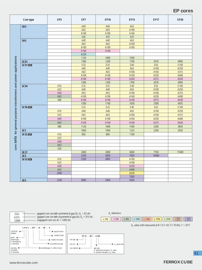
41
www.ferroxcube.com FERROXCUBE
Core type EP5 EP7 EP10 EP13 EP17 EP20 co
re s
ets
for
gen
eral
pu
rpo
se t
ran
sfo
rmer
s an
d p
ow
er a
pp
licat
ion
s
3D3 A40 A40 A63A63 A63 A100
A100 A100 A160530 470 670
3H3 A40 A40 A63A63 A63 A100
A100 A100 A160A160 A160A2501120 1000 1500
3C81 1300 1200 1700 2670 49003C91 E25 E25 E40 E63 E160
A40 A40 A63 A100 A250A63 A63 A100 A160 A315
A100 A100 A160 A250 A400A160 A160 A250 A315 A6301300 1200 1700 2670 4900
3C94 A16 E25 E25 E40 E63 E160A25 A40 A40 A63 A100 A250A40 A63 A63 A100 A160 A315A63 A100 A100 A160 A250 A400400 A160 A160 A160 A315 A630
1200 1140 1650 2500 44353C96 E25 E25 E40 E63 E160
A16 A40 A40 A63 A100 A250A25 A63 A63 A100 A160 A315A40 A100 A100 A160 A250 A400A63 A160 A160 A160 A315 A630380 1120 1000 1500 2200 3850
3F3 1000 1000 1325 2200 3550
3F35 A16 850 800 1100A25A40A63320
3E27 3400 3400 4600 7100 116003E5 5200 4800 7000 100003E55 A16 5200 4800 A100
A25 A160A40 A250A63 A4002000 A630
70003E6 2200 5800 5400 8500
EP cores
AL value (nH) measured at B ≤ 0.1 mT, f ≤ 10 kHz, T = 25°C
gapped core set with symmetrical gap (E). AL = 63 nH. gapped core set with asymmetrical gap (A). AL = 315 nH. ungapped core set. AL = 1200 nH.
E63-A315-12000
AL tolerance:
± 5% ± 8% ± 25% + 40%− 30%± 3% ± 12% ± 15% + 30%
− 20%
EP 13 - 3F3 - A 250
AL value (nH)
gap typeA- asymmetrical gap to AL valueE- symmetrical gap to AL value
core type
core size
core material
C P H S - EP7 - 1S - 6P - X
number of pins
special version
number of sections
associated core type
coil former(bobbin)
plasticmaterial type:P- thermoplasticS- thermoset
mountingorientation:H- horizontal
mounting type: S- surface mount
± 10%
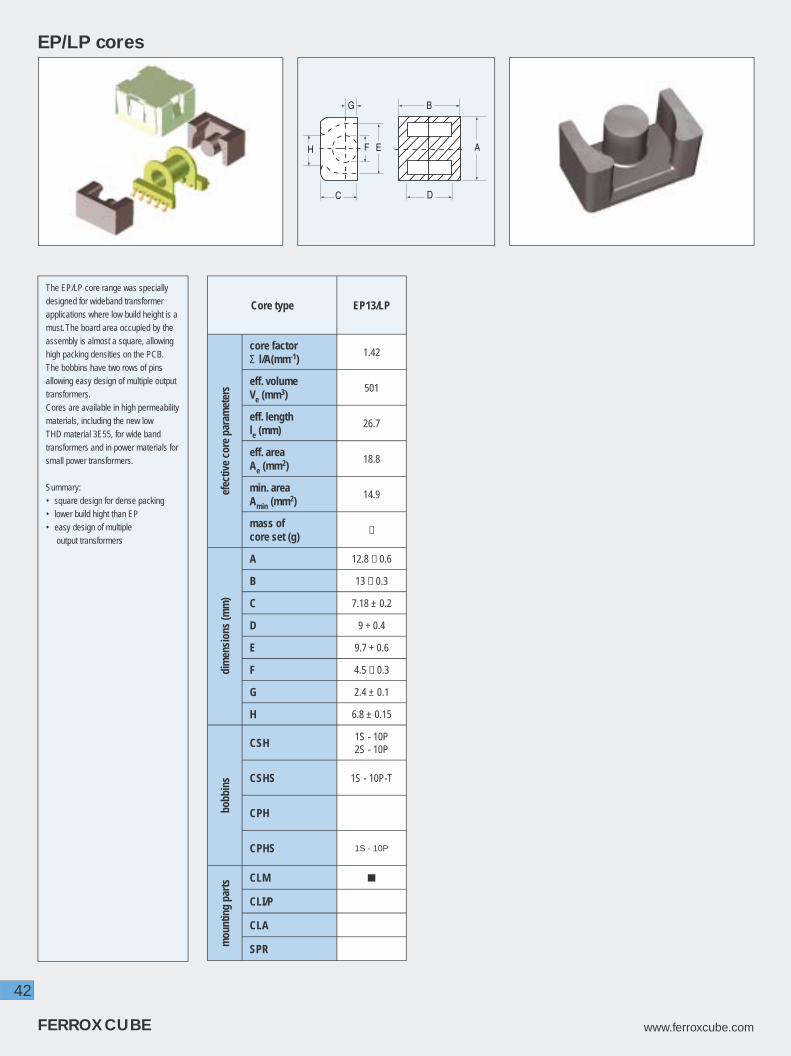
42
FERROXCUBE www.ferroxcube.com
EP/LP cores
Core type EP13/LP
efec
tive
core
par
amet
ers
core factorΣ l/A(mm-1)
1.42
eff. volumeVe (mm3)
501
eff. lengthle (mm)
26.7
eff. areaAe (mm2)
18.8
min. areaAmin (mm2)
14.9
mass of core set (g)
≈
dim
ensi
ons
(mm
)
A 12.8 − 0.6
B 13 − 0.3
C 7.18 ± 0.2
D 9 + 0.4
E 9.7 + 0.6
F 4.5 − 0.3
G 2.4 ± 0.1
H 6.8 ± 0.15
bobb
ins
CSH 1S - 10P2S - 10P
CSHS 1S - 10P-T
CPH
CPHS 1S - 10P
mou
ntin
g pa
rts CLM
CLI/P
CLA
SPR
The EP/LP core range was specially designed for wideband transformer applications where low build height is a must. The board area occupied by the assembly is almost a square, allowing high packing densities on the PCB. The bobbins have two rows of pins allowing easy design of multiple output transformers.Cores are available in high permeability materials, including the new low THD material 3E55, for wide band transformers and in power materials for small power transformers.
Summary:• square design for dense packing• lower build hight than EP• easy design of multiple output transformers
G
C
EF A
D
B
H

43
www.ferroxcube.com FERROXCUBE
Core type EP13/LP
core
set
s fo
r g
ener
al p
urp
ose
tr
ansf
orm
ers
and
po
wer
app
licat
ion
s
3C94 1400
3C96 1200
3F35 950
3E55 A100
A160
A250
A315
A400
A630
6000
3E6 6700
EP/LP cores
gapped core set with symmetrical gap (E). AL = 63 nH. gapped core set with asymmetrical gap (A). AL = 315 nH. ungapped core set. AL = 1200 nH.
E63-A315-12000
AL value (nH) measured at B ≤ 0.1 mT, f ≤ 10 kHz, T = 25°C
AL tolerance:
± 5% ± 8% ± 25% + 40%− 30%± 3% ± 12% ± 15% + 30%
− 20%
EP 13 - 3F3 - A 250
AL value (nH)
gap typeA- asymmetrical gap to AL valueE- symmetrical gap to AL value
core type
core size
core material
C P H S - EP7 - 1S - 6P - X
number of pins
special version
number of sections
associated core type
coil former(bobbin)
plasticmaterial type:P- thermoplasticS- thermoset
mountingorientation:H- horizontal
mounting type: S- surface mount

44
FERROXCUBE www.ferroxcube.com
A
BD
C
EF
G
H
A
D
E
J
FGH
Open roofClosed roof
EPX cores
Core type EPX7 EPX8 EPX9 EPX10
Shape closed roof closed roof closed roof open roof
efec
tive
core
par
amet
ers
core factorΣ l/A(mm-1)
0.931 1.04 1.15 1.45
eff. volumeVe (mm3)
255 279 304 325
eff. lengthle (mm)
15.4 17.0 18.7 21.7
eff. areaAe (mm2)
16.5 16.4 16.3 15.0
min. areaAmin (mm2)
14.5 14.5 14.5 12.5
mass of core set (g)
≈ 1.2 ≈ 1.3 ≈ 1.4 ≈ 1.5
dim
ensi
ons
(mm
)
A 9.4 − 0.4 9.4 − 0.4 9.4 − 0.4 11.8 − 0.6
B 7.5 − 0.2 8.5 − 0.2 9.5 − 0.2 10.4 − 0.2
C 9 − 0.4 9 − 0.4 9 − 0.4 7.85 − 0.4
D 4.6 + 0.4 5.6 + 0.4 6.6 + 0.4 7.2 + 0.4
E 7.2 + 0.4 7.2 + 0.4 7.2 + 0.4 9.1 + 0.4
F 3.4 − 0.2 3.4 − 0.2 3.4 − 0.2 3.45 − 0.3
G 1.7 ± 0.1 1.7 ± 0.1 1.7 ± 0.1 1.85 ± 0.1
H 2.3 2.3 2.3 1.4
J 5.0
bobb
ins
CSH
CSHS1S-8P
1S-8P-T1S-8P
1S-8P-T
CPH
CPHS
mou
ntin
gpa
rts
CLM
EPX cores were derived from EP cores specially for pulse transformers in ISDN and ADSL applications. In comparison to EP cores they feature an increased centre pole area and achieve the same AL and THD performance in a smaller core volume. The new EPX designs, complete with SMD bobbin and clip, satisfy the need for slimmer pulse transformers.
They are available in the high perme-ability material 3E6 for ISDN pulse transformers and in the low harmonic distortion material 3E55 for ADSL wideband applications. Power materials are introduced along with these.
Summary:• increased centre pole area• same performance as EP cores in a smaller volume• SMD bobbins and clips available
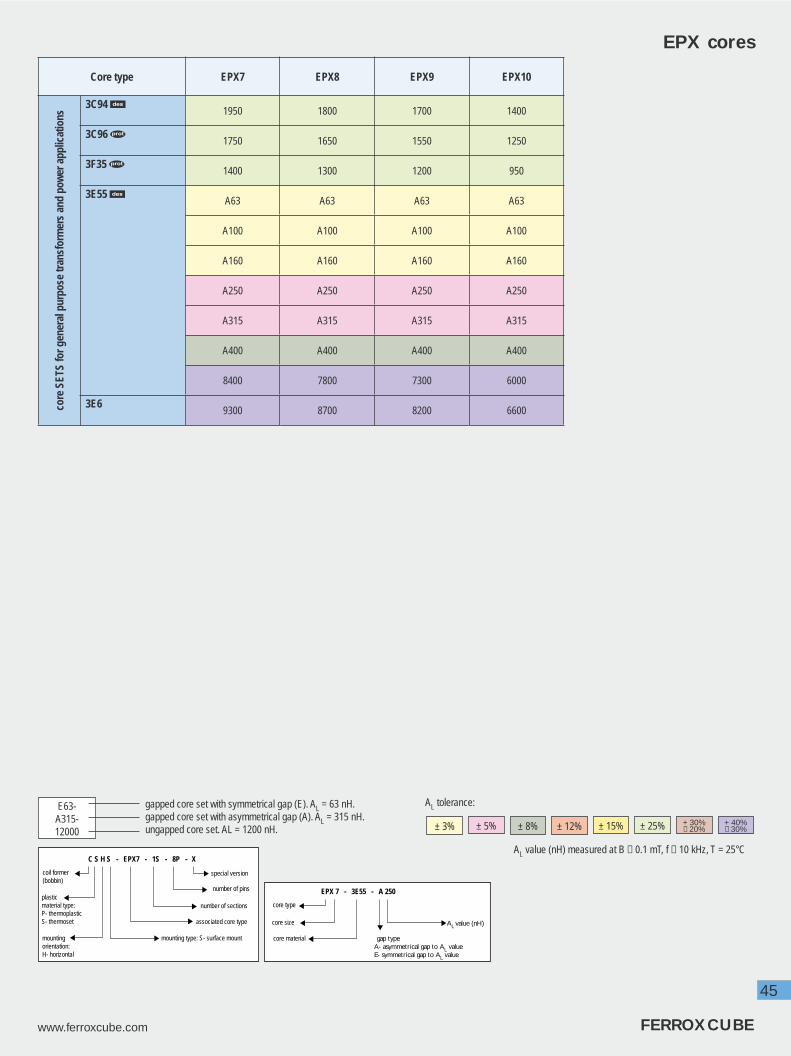
45
www.ferroxcube.com FERROXCUBE
Core type EPX7 EPX8 EPX9 EPX10
core
SET
S fo
r gen
eral
pur
pose
tran
sfor
mer
s an
d po
wer
app
licat
ions
3C94 1950 1800 1700 1400
3C96 1750 1650 1550 1250
3F35 1400 1300 1200 950
3E55 A63 A63 A63 A63
A100 A100 A100 A100
A160 A160 A160 A160
A250 A250 A250 A250
A315 A315 A315 A315
A400 A400 A400 A400
8400 7800 7300 6000
3E69300 8700 8200 6600
EPX cores
AL value (nH) measured at B ≤ 0.1 mT, f ≤ 10 kHz, T = 25°C
gapped core set with symmetrical gap (E). AL = 63 nH. gapped core set with asymmetrical gap (A). AL = 315 nH. ungapped core set. AL = 1200 nH.
E63-A315-12000
AL tolerance:
± 5% ± 8% ± 25% + 40%− 30%± 3% ± 12% ± 15% + 30%
− 20%
EPX 7 - 3E55 - A 250
AL value (nH)
gap typeA- asymmetrical gap to AL valueE- symmetrical gap to AL value
core type
core size
core material
C S H S - EPX7 - 1S - 8P - X
number of pins
special version
number of sections
associated core type
coil former(bobbin)
plasticmaterial type:P- thermoplasticS- thermoset
mountingorientation:H- horizontal
mounting type: S- surface mount

46
FERROXCUBE www.ferroxcube.com
EQ cores
Core type EQ13PLT13/9/1
(EQ/PLT combination)EQ20/R 1) PLT20/14/2/S 2)
(EQ/PLT combination)
efec
tive
core
par
amet
ers
core factorΣ l/A(mm-1)
0.911 0.803 0.563 0.420
eff. volumeVe (mm3)
348 315 1960 1500
eff. lengthle (mm)
17.5 15.9 33.2 25.1
eff. areaAe (mm2)
19.9 19.8 59 59.8
min. areaAmin (mm2)
19.2 19.2 55 55
mass of core half (g)
≈ 0.9 ≈ 0.6 ≈ 5.5 ≈ 3
dim
ensi
ons
(mm
)
A 30 ± 0.4 12.8 ± 0.3 20 ± 0.35 20 ± 0.35
B 8 ± 0.15 8.7 ± 0.25 6.3 ± 0.1 14 ± 0.3
C 20 ± 0.3 1.1 ± 0.1 14 ± 0.3 2.3 ± 0.05
D 5.3 ± 0.2 - 4.1 ± 0.15 -
E 26 ± 0.4 - 18 ± 0.35 -
F 11 ± 0.2 - 8.8 ± 0.15 -
G 19.45 ± 0.4 - 12.86 ± 0.35 -
bobb
ins
CSV
The EQ core design is derived from the ER and PQ. The range is optimized for use in compact AC/DC notebook adapters and DC/DC converters.For instance, the EQ30 has the capability to handle a power range of 50 to 70 W (fl yback topology) in an enclosed casing of a notebook adapter or 100 to 150 W in low profi le DC/DC converter . The advantages of EQ cores are a simple core shape, round centre pole, high Ae value , a large winding window, low profi le and a large surface area for heat dissipation.
Summary :
• Simple core shape
• Round centre pole
• High Ae value
• Large winding window
• Low profi le
• Large surface area for
heat dissipation
B D
F
EG
A
C
plate (PLT)EQ core (EQ)
C B
A
1) Core has clip recesses2) Plate has a slot to accomodate a mounting clip.(Similar to Planar E cores with recess.)

47
www.ferroxcube.com FERROXCUBE
Core type EQ25 EQ25/LPPLT25/18/2
(EQ/LP/PLT combination)EQ30
PLT30/20/3(EQ/PLT combination)
efec
tive
core
par
amet
ers
core factorΣ l/A(mm-1)
0.414 - 0.294 0.426 0.292
eff. volumeVe (mm3)
4145 - 2370 4970 3400
eff. lengthle (mm)
41.4 - 26.4 46 31.5
eff. areaAe (mm2)
100 - 89.7 108 108
min. areaAmin (mm2)
95 - 82.8 95 95
mass of core half (g)
≈ 12 ≈ 8.5 ≈ 5 ≈ 13.5 ≈ 8
dim
ensi
ons
(mm
)
A 25 ± 0.4 25 ± 0.4 25 ± 0.4 30 ± 0.4 30 ± 0.4
B 8 ± 0.1 5.6 ± 0.05 18 ± 0.3 8 ± 0.15 20 ± 0.3
C 18 ± 0.3 18 ± 0.3 2.3 ± 0.05 20 ± 0.3 2.7 ± 0.1
D 5.15 ± 0.15 3.2 ± 0.15 - 5.3 ± 0.2 -
E 22 ± 0.4 22 ± 0.4 - 26 ± 0.4 -
F 11 ± 0.2 11 ± 0.2 - 11 ± 0.2 -
G 14.5 min 14.5 min - 19.45 ± 0.4 -
bobb
ins
CSV 1S - 10P
EQ cores
core material
core type
core size
C S V - EQ30 - 1S - 10P - X
number of pins
special version
number of sections
associated core type
coil former(bobbin)
plasticmaterial type:P- thermoplasticS- thermoset
mountingorientation:V- horizontal
EQ 30 - 3C96

48
FERROXCUBE www.ferroxcube.com
Core type EQ13EQ13
+PLT13/9/1
EQ20/R EQ20/R
+PLT20/14/2/S
EQ25EQ25/LP
+PLT25/18/2
EQ30EQ30
+PLT30/20/3
core
hal
ves
for
po
wer
ap
plic
atio
ns
3C94 1700 1800 3500 4750 4800 6100 4300 6550
3C96 1600 1700 3150 4350 4400 5600 3900 6000
3F35 1300 1350 2400 3300 3350 4350 3050 4600
3F4 950 1000 1700 2200 2300 3100 2150 3200
EQ cores
AL value (nH) measured at B ≤ 0.1 mT, f ≤ 10 kHz, T = 25°C
ungapped core half, AL = 1200 nH measured in combination with another ungapped core half.
12000
AL tolerance: ± 25%
49
www.ferroxcube.com FERROXCUBE

50
FERROXCUBE www.ferroxcube.com
Planar ER cores
Core type ER9.5 ER11 ER14.5 ER18 ER23
efec
tive
core
par
amet
ers
core factorΣ l/A(mm-1)
1.67 1.23 1.08 0.730 0.530
eff. volumeVe (mm3)
120 174 333 667 1340
eff. lengthle (mm)
14.2 14.7 19.0 22.1 26.6
eff. areaAe (mm2)
8.47 11.9 17.6 30.2 50.2
min. areaAmin (mm2)
7.6 10.3 17.3 30.1 50.0
mass of core half (g)
≈ 0.35 ≈ 0.5 ≈ 0.9 1.6 3.2
dim
ensi
ons
(mm
)
A 9.5 − 0.3 11 − 0.35 14.5 ± 0.2 18.0 ± 0.35 23.2 ± 0.45
B 2.45 ± 0.05 2.45 ± 0.05 2.95 ± 0.05 3.15 ± 0.1 3.6 ± 0.1
C 5 − 0.2 6 − 0.2 6.8 − 0.2 9.7 ± 0.2 12.5 ± 0.25
D 1.6 + 0.15 1.5 + 0.15 1.55 + 0.2 1.6 ± 0.1 1.6 ± 0.1
E 7.5 + 0.25 8.7 + 0.3 11.8 ± 0.2 15.6 ± 0.3 20.2 ± 0.4
F 7.1 + 0.2 8 + 0.2 11.8 ± 0.2 13.5 min 17.5 min
G 3.5 − 0.2 4.25 − 0.25 4.8 − 0.2 6.2 ± 0.15 8.0 ± 0.2
bobb
ins CPVS
1S - 8P 1S - 10P 1S - 10P
mou
ntin
g pa
rts CLM
The ER core design is derived from the original E core and, like ETD and EC cores, has a round centre pole and outer legs with a radius to accomodate round coil formers.These cores are mainly used for power transformers. The round centre pole allows the use of thicker wires while the shorter turn length keeps the copper losses low.Planar ER cores are very suitable to build small SMD or planar power and signal tranformers. For the 3 smallest sizes matching SMD coil formers and clips are available.
Summary:
• round centre pole
• outer legs with a radius
• for the smaller sizes,
• SMD coilformers and clamps are available
• moderate shielding
B D
A
C
EFG

51
www.ferroxcube.com FERROXCUBE
Core typeER9.5SETS
ER11SETS
ER14.5SETS
ER18SETS
ER23SETS
core
s fo
r g
ener
al p
urp
ose
tra
nsf
orm
ers
and
po
wer
ap
plic
atio
ns
3C92 63-S 100-S 100-S A160-S A250-S
100-S 160-S 160-S A250-S A400-S
160-S 250-S 250-S A400-S A630-S
750-S 1050-S 1250-S 1900-S 2800-S
3C93 850-S 1200-S 1400-S 2200-S 3200-S
3C94 A63-S A100-S A100-S
A100-S A160-S A160-S
A160-S A250-S A250-S
1000-S 1400-S 1600-S
3C96
900-S 1250-S 1500-S
A160-S A250-S
A250-S A400-S
A400-S A630-S
2400-S 3400-S
3F3A63-S A100-S A100-S
A100-S A160-S A160-S
A160-S A250-S A250-S
850-S 1200-S 1400-S
3F35
700-S 1000-S 1150-S
A160-S A250-S
A250-S A400-S
A400-S A630-S
1800-S 2600-S
3F4 A40-S A63-S A100-S
A63-S A100-S A160-S
A100-S A160-S A250-S
525-S 725-S 850-S
3E5 3600-S 5000-S
3E64800-S 6700-S 7900-S
Planar ER cores
AL value (nH) measured at B ≤ 0.1 mT, f ≤ 10 kHz, T = 25°C
gapped core set with asymmetrical gap (A), AL = 63 nH. ungapped core set, AL = 1000 nH. ungapped core half, AL = 2900 nH measured in combination with another ungapped core half.
A63-S-1000-S-
2900
AL tolerance:
± 5% ± 8% ± 25% + 40%− 30%± 3% ± 12% ± 15% + 30%
− 20%
ER 18 - 3C90 - A 250 - X
special version
AL value (nH) or gapsize ( µm)
gap typeA- asymmetrical gap to AL valueE- symmetrical gap to AL valueG- mechanical gap
core type
core size
core material
C P V S - ER11 - 1S - 10P
number of pins orsolder pads
number of sections
associated core type
coil former(bobbin)
plasticmaterial type:P- thermoplasticS- thermoset
mountingorientation:H- horizontalV- vertical
mounting type: S- surface mount

52
FERROXCUBE www.ferroxcube.com
Core type ER28 ER28L ER35 ER35W ER40 ER42 ER42A ER48 ER54
efec
tive
core
par
amet
ers
core factorΣ l/A(mm-1)
0.786 0.928 0.849 0.900 0.658 0.509 0.582 0.392 0.370
eff. volumeVe (mm3)
5260 6140 9710 9548 14600 19200 16800 25500 23000
eff. lengthle (mm)
64.0 75.5 90.8 92.7 98 98.8 99 100 91.8
eff. areaAe (mm2)
81.4 81.4 107 103 149 194 170 255 250
min. areaAmin (mm2)
77.0 77.0 100 100 139 189 170 248 240
mass of core half (g)
≈ 14 ≈ 16 ≈ 23 ≈ 27 ≈ 37 ≈ 50 ≈ 42 ≈ 64 ≈ 61
dim
ensi
ons
(mm
)
A 28.55 ± 0.55 28.55 ± 0.55 35 ± 0.65 35 ± 0.65 40 ± 0.7 42 ± 0.7542 + 1.0 /
− 0.748 ± 1 53.5 ± 1
B 14 ± 0.2 16.9 ± 0.25 20.7 ± 0.2 20.9 ± 0.2 22.4 ± 0.2 22.4 ± 0.2 21.8 ± 0.4 21.1 − 0.4 18.3 ± 0.2
C 11.4 ± 0.35 11.4 ± 0.35 11.4 ± 0.35 11.3 ± 0.35 13.4 ± 0.35 15.6 ± 0.4 15.6 ± 0.421 + 0.3 /
− 0.517.95 ± 0.35
D 9.75 ± 0.4 12.65 ± 0.4 14.75 ± 0.35 15 ± 0.2 15.45 ± 0.35 15.45 ± 0.35 15.6 + 0.7 14.7 + 0.7 11.1 ± 0.3
E 21.75 ± 0.5 21.75 ± 0.5 26.15 ± 0.55 27.1 ± 0.7 29.6 ± 0.6 30.05 ± 0.65 30.4 + 1.238 + 0.5 /
− 0.840.65 ± 0.85
F 9.9 ± 0.25 9.9 ± 0.25 11.3 ± 0.25 11.3 ± 0.25 13.3 ± 0.25 15.5 ± 0.3 15 − 0.6 18 ± 0.3 17.9 ± 0.4
ER cores
FEA
C
BD
The ER core design is derived from the original E core and, like ETD and EC cores, has a round centre pole and outer legs with a radius to accomodate round coil formers.These cores are mainly used for power transformers. The round centre pole allows the use of thicker wires while the shorter turn length keeps the copper losses low.
Summary:
• round centre pole
• outer legs with a radius
• moderate shielding

53
www.ferroxcube.com FERROXCUBE
Core typeER28
HALVESER28L
HALVESER35
HALVESER35WHALVES
ER40HALVES
ER42HALVES
ER42AHALVES
ER48HALVES
ER54HALVES
core
s fo
r g
ener
al p
urp
ose
tra
nsf
orm
ers
an
d p
ow
er a
pp
licat
ion
s
3C90
2900 2500 2800 3000 3600 4600 4000 5700 6100
3C94
2900 2500 2800 3600 4600 4000 5700 6100
ER cores
AL value (nH) measured at B ≤ 0.1 mT, f ≤ 10 kHz, T = 25°C
gapped core set with asymmetrical gap (A), AL = 63 nH. ungapped core set, AL = 1000 nH. ungapped core half, AL = 2900 nH measured in combination with another ungapped core half.
A63-S-1000-S-
2900
AL tolerance:
± 5% ± 8% ± 25% + 40%− 30%± 3% ± 12% ± 15% + 30%
− 20%
ER 35 - 3C90 - A 250 - X
special version
AL value (nH) or gapsize (µm)
gap typeA- asymmetrical gap to AL valueE- symmetrical gap to AL valueG- mechanical gap
core type
core size
core material
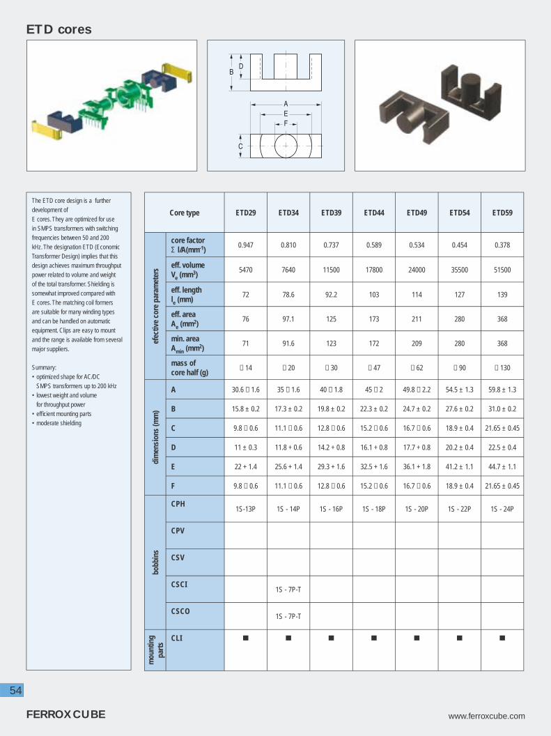
54
FERROXCUBE www.ferroxcube.com
ETD cores
Core type ETD29 ETD34 ETD39 ETD44 ETD49 ETD54 ETD59
efec
tive
core
par
amet
ers
core factorΣ l/A(mm-1)
0.947 0.810 0.737 0.589 0.534 0.454 0.378
eff. volumeVe (mm3)
5470 7640 11500 17800 24000 35500 51500
eff. lengthle (mm)
72 78.6 92.2 103 114 127 139
eff. areaAe (mm2)
76 97.1 125 173 211 280 368
min. areaAmin (mm2)
71 91.6 123 172 209 280 368
mass of core half (g)
≈ 14 ≈ 20 ≈ 30 ≈ 47 ≈ 62 ≈ 90 ≈ 130
dim
ensi
ons
(mm
)
A 30.6 − 1.6 35 − 1.6 40 − 1.8 45 − 2 49.8 − 2.2 54.5 ± 1.3 59.8 ± 1.3
B 15.8 ± 0.2 17.3 ± 0.2 19.8 ± 0.2 22.3 ± 0.2 24.7 ± 0.2 27.6 ± 0.2 31.0 ± 0.2
C 9.8 − 0.6 11.1 − 0.6 12.8 − 0.6 15.2 − 0.6 16.7 − 0.6 18.9 ± 0.4 21.65 ± 0.45
D 11 ± 0.3 11.8 + 0.6 14.2 + 0.8 16.1 + 0.8 17.7 + 0.8 20.2 ± 0.4 22.5 ± 0.4
E 22 + 1.4 25.6 + 1.4 29.3 + 1.6 32.5 + 1.6 36.1 + 1.8 41.2 ± 1.1 44.7 ± 1.1
F 9.8 − 0.6 11.1 − 0.6 12.8 − 0.6 15.2 − 0.6 16.7 − 0.6 18.9 ± 0.4 21.65 ± 0.45
bobb
ins
CPH1S-13P 1S - 14P 1S - 16P 1S - 18P 1S - 20P 1S - 22P 1S - 24P
CPV
CSV
CSCI1S - 7P-T
CSCO1S - 7P-T
mou
ntin
g pa
rts
CLI
The ETD core design is a further development ofE cores. They are optimized for use in SMPS transformers with switching frequencies between 50 and 200 kHz. The designation ETD (Economic Transformer Design) implies that this design achieves maximum throughput power related to volume and weight of the total transformer. Shielding is somewhat improved compared with E cores. The matching coil formers are suitable for many winding types and can be handled on automatic equipment. Clips are easy to mount and the range is available from several major suppliers.
Summary:• optimized shape for AC/DC SMPS transformers up to 200 kHz• lowest weight and volume for throughput power• effi cient mounting parts• moderate shielding
FEA
C
BD

55
www.ferroxcube.com FERROXCUBE
Core type ETD29 ETD34 ETD39 ETD44 ETD49 ETD54 ETD59
core
hal
ves
for
po
wer
ap
plic
atio
ns
3C90
2350 2700 3000 3800 4200 5000 6000
3C94
2350 2700 3000 3800 4200 5000 6000
3C96
2200 2500 2800 3500 3900 4600 5600
3F3
2200 2500 2800 3500 3900 4600 5600
3F35
1600 1850
ETD cores
AL value (nH) measured at B ≤ 0.1 mT, f ≤ 10 kHz, T = 25°C
ungapped core half, AL = 2900 nH measured in combination with another ungapped core half.
2900AL tolerance:
± 5% ± 8% ± 25% + 40%− 30%± 3% ± 12% ± 15% + 30%
− 20%
ETD 34 - 3C90 - A 250
AL value (nH) orgap size (µm)
gap type A- asymmetrical gap to AL valueE- symmetrical gap to AL valueG- mechanical gap
core type
core size
core material
C P H - ETD29 - 1S - 13P
number & type of pinsD - dual terminationF - flatL - long
associated core type
number of sections
coil former(bobbin)
plasticmaterial type:P- thermoplasticS- thermoset
H- horizontalV- verticalCI - coaxial, inner partCO-coaxial, outer part

56
FERROXCUBE www.ferroxcube.com
Frame and Bar cores
Core typeFRM
20/5/15FRM
21/4/12FRM
24/3.9/10FRM
27/3.8/9BAR
20/3/5.5BAR
22/2/6BAR
25/2.2/4BAR
28/3.8/2.3
efec
tive
core
par
amet
ers
core factorΣ l/A(mm-1)
3.29 5.06 5.65 5.56 3.29 5.06 5.65 5.56
eff. volumeVe (mm3)
655 312 370 504 655 312 370 504
eff. lengthle (mm)
46 40 45.8 52.1 46 40 45.8 50
eff. areaAe (mm2)
14 7.9 8.1 9.7 14 7.9 8.1 9.0
min. areaAmin (mm2)
7.4 5.7 6 8.7 7.4 5.7 6 8.7
mass of core half (g)
≈ 2.1 ≈ 1.5 ≈ 1.3 ≈ 1.6 ≈ 1.5 ≈ 1 ≈ 1.2 ≈ 1.2
dim
ensi
ons
(mm
)
A 19.7 ± 0.3 21 ± 0.2 23.8 ± 0.3 26.7 ± 0.7 19.9 ± 0.3 21.8 ± 0.3 24.7 ± 0.3 28 ± 0.5
B 15.6 ± 0.3 16.2 ± 0.3 19.2 ± 0.3 19.7 ± 0.6 2.85 ± 0.05 1.8 ± 0.1 2.15 ± 0.05 3.8 ± 0.1
C 14.8 ± 0.3 11.8 ± 0.25 9.8 ± 0.2 9.0 ± 0.3 5.45 ± 0.15 5.5 ± 0.2 4.4 ± 0.2 2.3 ± 0.1
D 11.4 ± 0.25 8.9 ± 0.2 7.3 ± 0.2 6.5 ± 0.2
E 4.6 ± 0.1 4.0 ± 0.1 3.85 ± 0.1 3.8 ± 0.2
bobb
ins
CPHS
mou
ntin
g pa
rts
COV
Cores with a design similar to Frame and Bar cores have been available from Philips under the name of H cores, since 1971. They were mainly applied as signal transformers in Telecom applications. The new Frame and Bar cores have been modifi ed to a slim and elongated rectangular shape in order to meet the dimension requirements of a fl at LCD panel. The elongated rectangular shape is also optimized to accommodate the large number of turns required to generate the high ignition voltage (1400 Vrms) for a backlight discharge lamp. Besides this, the Frame and Bar core is also easy to assemble into a transformer and has been adopted as a standard core for the LCD backlight inverter transformer. A backlight inverter is an electronic DC to AC circuit that drives a Cold Cathode Fluorescent Lamp (CCFL) for the backlighting of a notebook LCD display or LCD monitor .
Summary :• Narrow design• Easy to assemble• Large winding space to accommodate a large number of turns
A
E
B
CD
A
B
C

57
www.ferroxcube.com FERROXCUBE
Core type FRM20/5/15 FRM21/4/12 FRM24/3.9/10 FRM27/3.8/9
Matching cores BAR20/3/5.5 BAR22/2/6 BAR25/2.2/4 BAR28/3.8/2.3
core
hal
ves
for
po
wer
ap
plic
atio
ns
3C90 500 400 370 350
3C91 600 470 440 420
Frame and Bar cores
AL value (nH) measured at B ≤ 0.1 mT, f ≤ 10 kHz, T = 25°C
ungapped core set, AL = 500 nH..600AL tolerance:
± 5% ± 8% ± 25% + 40%− 30%± 3% ± 12% ± 15% + 30%
− 20%
FRM20/5/15 - 3C90
core type
core size core material
BAR20/3/5.5 - 3C90
core type
core size core material
C P H S - FRM20/15 - 8S - 10P
number of pins orsolder pads
number of sections
associated core type
coil former(bobbin)
plasticmaterial type:P- thermoplasticS- thermoset
mountingorientation:H- horizontalV- vertical mounting type: S- surface mount

58
FERROXCUBE www.ferroxcube.com
P cores
Core type P9/5 P11/7 P14/8 P18/11 P22/13 P26/16
efec
tive
core
par
amet
ers
core factorΣ l/A(mm-1)
1.24 0.956 0.789 0.597 0.497 0.400
eff. volumeVe (mm3)
126 251 495 1120 2000 3530
eff. lengthle (mm)
12.5 15.5 19.8 25.8 31.5 37.6
eff. areaAe (mm2)
10.1 16.2 25.1 43.3 63.4 93.9
min. areaAmin (mm2)
7.9 13.2 19.8 36.0 50.9 77.4
mass of core set (g)
≈ 0.8 ≈ 1.8 ≈ 3.2 ≈ 6.0 ≈ 12 ≈ 20
dim
ensi
ons
(mm
)
a 6.5 ± 0.25 6.8 ± 0.25 9.5 ± 0.3 13.4 ± 0.3 15 ± 0.4 18 ± 0.4
b 2 ± 0.2 2.2 ± 0.3 2.7 + 1.2 3.8 ± 0.6 3.8 ± 0.6 3.8 ± 0.6
d1 9.3 − 0.3 11.3 − 0.4 14.3 − 0.5 18.4 − 0.8 22 − 0.8 25.5 ± 0.5
d2 7.5 + 0.25 9 + 0.4 11.6 + 0.4 14.9 + 0.5 17.9 + 0.6 21.2 + 0.8
d3 3.9 − 0.2 4.7 − 0.2 6 − 0.2 7.6 − 0.3 9.4 − 0.3 11.5 − 0.4
d4 2.1 ± 0.1 2.1 ± 0.1 3.1 ± 0.1 3.1 ± 0.1 4.4 + 0.3 5.4 + 0.2
h1 5.4 − 0.3 6.5 + 0.1 / − 0.2 8.4 + 0.1 / − 0.2 10.6 ± 0.1 13.4 ± 0.2 16 ± 0.2
h2 3.6 + 0.3 4.4 + 0.3 5.6 + 0.4 7.2 + 0.4 9.2 + 0.4 11 + 0.4
bobb
ins
CP
1S1S-A
1S1S-A2S - A3S - A
1S1S-A2S
2S-A3S - A
1S1S-A2S
2S-A3S
3S-A
1S1S-A2S
2S-A3S
3S-A
1S1S-A2S
2S-A3S
3S-A
CPV
1S - 4SPD1S - 4SPDL2S - 4SPD2S - 4SPDL
1S - 6PD1S - 6PDL2S - 6PD2S - 6PDL
2S-6SP
1S - 6PD1S - 6PDL2S - 6PD2S - 6PDL3S - 6PD3S - 6PDL
1S - 6PD1S - 6PDL2S - 6PD2S - 6PDL3S - 6PD3S - 6PDL
1S - 6PD1S - 6PDL2S - 6PD
2S - 6PDL3S - 6PD
3S - 6PDL
mou
ntin
g pa
rts
TGP 4P 6P 8P 8P 8P
CON
SPR
CLM/TP
CLM/TS
WAS-CLM/TP
WAS-CLM/TS
The P core is the earliest design for telecom fi lter inductors. As with RM-cores there is a complete, standardized range (IEC 133). The cores are available in a range of AL-values from many suppliers. The core surrounds the winding almost completely so magnetic shielding is outstanding. The slots in the core are rather narrow which complicates assembly and mounting. A complete range of accessories is available, but most are not optimized for easy automatic handling.
Summary:• excellent magnetic shielding• complete range of sizes and material grades• not easy to assemble and mount• diffi cult to get leads out• mains insulation diffi cult
h1
h2
d4
b
d3
d2
d1
a

59
www.ferroxcube.com FERROXCUBE
P cores P14/8 - 3H3 - A 250
AL value (nH)
core type
core size
corematerial
gap typeA- asymmetrical gap to AL valueE- symmetrical gap to AL value
C P V - P14/8 - 1S - 4SPDL
numberof sections
number & type of pinsD - dual terminationF - flatL - longSP - slanted pin row coil former (bobbin)
mounting orientationV- vertical
plastic material type:P- thermoplasticS- thermoset
associatedcore type
C LM / T P - P14/8 - XX - X special version
hardware type:BPL- baseplate,CLM- clamp,CON- container,SPR- spring,TGP- tagplate,WAS- washerhardware shape:D- "D" shaped,T- "T" shaped,R- round,U- "U" shaped,
mounting type/orientation:,P- PCB-mount,S- screw-mount,C- chassis-mountH- horizontalV- vertical
associatedcore/hardware
numberof pins
Core type P30/19 P36/22 P42/29 P66/56
efec
tive
core
par
amet
ers
core factorΣ l/A(mm-1)
0.330 0.264 0.259 0.172
eff. volumeVe (mm3)
6190 10700 18200 88200
eff. lengthle (mm)
45.2 53.2 68.6 123
eff. areaAe (mm2)
137 202 265 717
min. areaAmin (mm2)
116 172 214 591
mass of core set (g)
≈ 34 ≈ 54 ≈ 104 ≈ 550
dim
ensi
ons
(mm
)
a 20.5 ± 0.5 26.2 ± 0.6 32 ± 0.7
b 4.3 ± 0.6 4.9 ± 0.6 5.1 ± 0.6 7.26 ± 0.25
d1 30 ± 0.5 36.2 − 1.2 42.4 ± 0.7 66.29 ± 1.19
d2 25 + 0.8 29.9 + 1 35.6 + 1.4 54.51 ± 1.02
d3 13.5 − 0.4 16.2 − 0.6 17.7 − 0.6 28.19 ± 0.61
d4 5.4 + 0.2 5.4 + 0.2 5.4 + 0.2 6.5 ± 0.15
h1 18.8 ± 0.2 21.7 ± 0.3 29.4 ± 0.1 57.3 ± 0.5
h2 13 + 0.4 14.6 + 0.4 20.3 + 0.4 43.28 ± 0.5
bobb
ins CP
1S1S-A2S
2S-A3S
3S-A
1S1S-A2S
2S-A3S
3S-A
1S1S-A2S
2S-A
1S
CPV 1S - 6PD1S - 6PDL
mou
ntin
g pa
rts
TGP 9P 10P 10P
CON
SPR
CLM/TP
CLM/TS
WAS-CLM/TP
WAS-CLM/TS

60
FERROXCUBE www.ferroxcube.com
Core type P9/5 P11/7 P14/8 P18/11 P22/13 P26/16 P30/19 P36/22 P42/29 P66/56
core
s se
ts f
or
sig
nal
fi lt
er a
pp
licat
ion
s
3D3 E40 E16 E40 E63 E40 E100
A63 E63 E63 E100 E63 E160
630 E40 E100 E160 E100 E250
E63 1000 1400 E160 2150
A100 1700
800
3H3 E40 A160 A160 E160 E160 E160
A63 A250 A250 A250 E250 E250
1100 1650 A315 A315 A315 E315
A400 A400 A400 E400
2150 A630 A630 A630
3100 3900 5000
core
s se
ts f
or
po
wer
ap
plic
atio
ns
3C81 1350 2050 2800 4000 5200 6700 8300 10800 11500 18200
3C91 1350 A100 E63 E100 A160 E160 E250 E315 E315
A160 A100 A160 A250 A250 A315 E400 E400
A250 A160 A250 A315 A315 A400 A630 A630
2050 A250 A315 A400 A400 A630 A1000 A1000
A315 A400 A630 A630 A1000 A1600 A1600
2800 4000 5200 6700 8300 10800 11500 18200
3F3 1100 A100 E63 E100 A160 E160 E250
A160 A100 A160 A250 A250 E250 E315 E315
A250 A160 A250 A315 A315 A315 E400 E400
1650 A250 A315 A400 A400 A400 A630 A630
A315 A400 A630 A630 A630 A1000 A1000
2000 2850 3530 4600 A1000 A1600 A1600
5750 7350 7700 12350
high
µse
ts
3E27 2300 3400 5750 7500 9250 12000 15100 17500 19000
P cores
AL value (nH) measured at B ≤ 0.1 mT, f ≤ 10 kHz, T = 25°C
gapped core set with symmetrical gap (E). AL = 63 nH. gapped core set with asymmetrical gap (A). AL = 315 nH. ungapped core set. AL = 1200 nH.
E63-A315-12000
AL tolerance:
± 5% ± 8% ± 25% + 40%− 30%± 3% ± 12% ± 15% + 30%
− 20%

61
www.ferroxcube.com FERROXCUBE
PH cores
Core type PH5.6/3.6-3D3 PH7.4/3.9-3D3 PH9.4/4.8-3D3 PH14/7.5-3D3 PH26/9.2-3D3
dim
ensi
ons
(mm
)
a 4 ± 0.2 5.7 ± 0.4 6.5 ± 0.3 9.5 ± 0.3 18 ± 0.4
b 1.5 ± 0.15 1.6 + 0.3 2 ± 0.2 3.3 ± 0.6 3.8 ± 0.6
d1 5.75 − 0.35 7.4 − 0.3 9.4 − 0.4 14.4 − 0.6 25.5 ± 0.5
d2 4.5 + 0.35 5.8 + 0.25 7.5 + 0.35 11.6 + 0.5 21.2 + 0.8
d3 2.5 − 0.1 3 − 0.12 3.9 − 0.2 6 − 0.2 11.5 − 0.4
d4 0.95 + 0.1 1.38 + 0.1 2 + 0.1 3 + 0.1 5.4 + 0.2
h1 3.6 − 0.25 3.95 − 0.3 4.8 − 0.4 7.5 − 0.2 9.2 − 0.45
h2 2.8 + 0.25 2.8 + 0.2 3.55 + 0.3 5.6 + 0.3 5.9 + 0.4
mass of core half (g) 0.2 0.4 0.7 3 12
The PH core range consists of potcore halves specially designed for use in proximity switches. Their shape is derived from the IEC standard P-core range. Outside diameters are adapted to fi t standardized sizes of proximity switch housings.Since the cores are used as halves, their height is increased to accommodate the winding.A complete range of coil formers is available.
Summary:• range of standard sizes• higher shape than normal P core halves to accommodate windings
d3
b
d2
d1
a d4
h2
h1
PH 9.4/4.8 - 3D3
core material
core size
core type

62
FERROXCUBE www.ferroxcube.com
P/I cores
Core type P11/7/I P14/8/I P18/11/I P22/13/I P26/16/I
efec
tive
core
par
amet
ers
core factorΣ l/A(mm-1)
0.860 0.700 0.560 0.450 0.360
eff. volumeVe (mm3)
309 628 1270 2460 4370
eff. lengthle (mm)
16.3 21.0 26.7 33.3 39.6
eff. areaAe (mm2)
19.0 29.9 47.5 73.4 110
min. areaAmin (mm2)
13.7 23.6 37.4 58.1 87.0
mass of core half (g)
≈ 1.9 ≈ 3.5 ≈ 7 ≈ 13 ≈ 21
dim
ensi
ons
(mm
)
a 6.8 ± 0.25 9.5 ± 0.3 13.4 ± 0.3 15 ± 0.4 18 ± 0.4
b 2.2 ± 0.3 3.3 ± 0.6 3.8 ± 0.6 3.8 ± 0.6 3.8 ± 0.6
d1 11.1 ± 0.2 14.05 ± 0.25 17.9 ± 0.3 21.5 ± 0.3 25.5 ± 0.5
d2 9.2 ± 0.2 11.8 ± 0.2 15.1 ± 0.25 18.2 ± 0.3 21.6 ± 0.4
d3 4.6 ± 0.1 5.9 ± 0.1 7.4 ± 0.15 9.2 ± 0.15 11.3 ± 0.2
h1 6.6 ± 0.15 8.4 ± 0.15 10.6 ± 0.15 13.4 ± 0.2 16.2 ± 0.2
h2 4.6 ± 0.15 5.8 ± 0.2 7.4 ± 0.2 9.4 ± 0.2 11.2 ± 0.2
P cores with solid centre poles have approximately a 15% higher effective area than the corresponding P cores with central hole. This makes them more suitable for applications where high fl ux densities are used. This will be the case in power conversion where the P core is still popular mainly because of its excellent magnetic shielding. This helps to avoid EMI problems, especially at higher switching frequencies.
h1
h2
b
d3
d2
d1
a
remark: for coil formers andmounting parts see P cores.

63
www.ferroxcube.com FERROXCUBE
Core type P11/7/I P14/8/I P18/11/I P22/13/I P26/16/I
core
s se
ts f
or
gen
eral
pu
rpo
se t
ran
sfo
rmer
s an
d p
ow
er a
pp
licat
ion
s
3C81 2100 2900 4200 5330 7000
3C90 A63 A100 A160 A250 E250
A100 A160 A250 A315 A315
A160 A250 A315 A400 A400
A250 A315 A400 A630 A630
A315 A400 A630 A1000 A1000
2010 2695 3660 4785 6230
3C91 A63 A100 A160 A250 E250
A100 A160 A250 A315 A315
A160 A250 A315 A400 A400
A250 A315 A400 A630 A630
A315 A400 A630 A1000 A1000
2100 2900 4200 5330 7000
3F3 A63 A100 A160 A250 E250
A100 A160 A250 A315 A315
A160 A250 A315 A400 A400
A250 A315 A400 A630 A630
A315 A400 A630 A1000 A1000
1750 2400 3110 4070 5250
P/I cores
AL value (nH) measured at B ≤ 0.1 mT, f ≤ 10 kHz, T = 25°C
gapped core set with symmetrical gap (E). AL = 250 nH. gapped core set with asymmetrical gap (A). AL = 315 nH. ungapped core set. AL = 2400 nH.
E250-A315-2400
AL tolerance:
± 5% ± 8% ± 25% + 40%− 30%± 3% ± 12% ± 15% + 30%
− 20%
P14/8/I - 3F3 - A 250
AL value (nH)core type
core size
/I for coreswithout center
hole corematerial
gap typeA- asymmetrical gap to AL valueE- symmetrical gap to AL value

64
FERROXCUBE www.ferroxcube.com
PT cores
Core type PT14/8 PT18/11 PT23/11 PT23/18
efec
tive
core
par
amet
ers
core factorΣ l/A(mm-1)
0.910 0.670 0.470 0.670
eff. volumeVe (mm3)
492 1110 1740 2590
eff. lengthle (mm)
21.1 27.2 28.6 41.6
eff. areaAe (mm2)
23.3 40.6 61.0 62.2
min. areaAmin (mm2)
19.9 32.9 53.6 53.6
mass of core set (g)
≈ 2.8 ≈ 6 ≈ 10.5 ≈ 14
dim
ensi
ons
(mm
)
a 9.4 ± 0.15 11.94 ± 0.2 15.2 ± 0.25 15.2 ± 0.25
b 8.6 min 10.5 min 13.2 min 13.2 min
d1 14.05 ± 0.25 18.0 ± 0.4 22.9 ± 0.45 22.9 ± 0.45
d2 11.8 ± 0.2 15.15 ± 0.25 18.3 ± 0.35 18.3 ± 0.35
d3 5.9 ± 0.1 7.4 ± 0.15 9.7 ± 0.2 9.7 ± 0.2
d4 3.1 ± 0.075 3.1 ± 0.075 5.1 ± 0.1 5.1 ± 0.1
h1 8.3 ± 0.15 10.6 ± 0.15 11 ± 0.25 18 ± 0.35
h2 5.8 ± 0.2 7.4 ± 0.2 7.5 ± 0.25 14.4 ± 0.35
bobb
ins
CPV 1S - 6P1S - 10P
1S - 10P 1S - 10P
mou
ntin
g pa
rts BPL/D-CLM/C
CLM/C
WAS-CLM/C
A disadvantage of the classical P core design has always been the narrow wire slots, making it diffi cult to make strong coil formers with integrated solder pins. In the PT design this problem is solved by cutting away the sides of one core half. This creates ample room for wires and coil former fl anges. A range of special PT coil formers is available but also most standard P core accessories can be used.
• complete range of core sizes
• special coil formers with integrated pins
• also P core accessories can be used
h1
h2
d4b
d3
d2
d1
a

65
www.ferroxcube.com FERROXCUBE
Core type PT14/8 PT18/11 PT23/11 PT23/18
core
s se
ts f
or
gen
eral
pu
rpo
se t
ran
sfo
rmer
s an
d p
ow
er a
pp
licat
ion
s
3C812400 3130 5500 4100
3C91 A63 A100 A160 A160
A100 A160 A250 A250
A160 A250 A315 A315
A250 A315 A400 A400
A315 A400 A630 A630
2400 3130 5500 4100
3F3A63 A100 A160 A160
A100 A160 A250 A250
A160 A250 A315 A315
A250 A315 A400 A400
A315 A400 A630 A630
1650 2500 3700 2750
3E274500 5760 8400 6400
PT cores
AL value (nH) measured at B ≤ 0.1 mT, f ≤ 10 kHz, T = 25°C
gapped core set with symmetrical gap (E). AL = 250 nH. gapped core set with asymmetrical gap (A). AL = 315 nH. ungapped core set. AL = 2400 nH.
E250-A315-2400
AL tolerance:
± 5% ± 8% ± 25% + 40%− 30%± 3% ± 12% ± 15% + 30%
− 20%
PT14/8 - 3C81 - A 250
AL value (nH)core type
core size
corematerial
gap typeA- unsymmetrical gap to AL valueE- symmetrical gap to AL value
C P V - PT14/8 - 1S - 4SPDL
numberof sections
number & type of pinsD - dual terminationF - flatL - longSP - slanted pin row
coil former(bobbin)
mountingorientationV- vertical
plasticmaterial type:P- thermoplasticS- thermoset
associatedcore type

66
FERROXCUBE www.ferroxcube.com
PTS cores
Core type PTS14/8 PTS18/11 PTS23/11 PTS23/18 PTS30/19/I PTS34/19/I PTS40/27/I
efec
tive
core
par
amet
ers
core factorΣ l/A(mm-1)
1.02 0.770 0.550 0.770 0.412 0.339 0.346
eff. volumeVe (mm3)
495 1070 1810 2630 5940 8140 14400
eff. lengthle (mm)
22.5 28.7 31.6 45.1 49.5 52.5 70.5
eff. areaAe (mm2)
22.0 37.2 57.2 58.3 120 155 204
min. areaAmin (mm2)
19.9 32.9 53.6 53.6 111 145 201
mass of core set (g)
≈ 2.5 ≈ 5 ≈ 9 ≈ 13 ≈ 31 ≈ 46 ≈ 66
dim
ensi
ons
(mm
)
a 9.4 ± 0.15 11.94 ± 0.2 15.2 ± 0.25 15.2 ± 0.25 20.3 ± 0.25 24 ± 0.3 28.3 ± 0.35
b 8.6 min 10.5 min 13.2 min 13.2 min 17.8 min 17.0 min 20.0 min
d1 14.05 ± 0.25 18.0 ± 0.4 22.9 ± 0.45 22.9 ± 0.45 30 ± 0.5 33.5+0.3/−0.5 39.8+0.2/−0.7
d2 11.8 ± 0.2 15.15 ± 0.25 18.3 ± 0.35 18.3 ± 0.35 25.4 ± 0.4 27+0.3/−0.5 33.2+0.2/−0.6
d3 5.9 ± 0.1 7.4 ± 0.15 9.7 ± 0.2 9.7 ± 0.2 13.3 ± 0.2 13.85 ± 0.25 16 ± 0.25
d4 3.1 ± 0.075 3.1 ± 0.075 5.1 ± 0.1 5.1 ± 0.1 0 0 0
h1 8.3 ± 0.15 10.6 ± 0.15 11 ± 0.25 18 ± 0.35 18.8 ± 0.2 19.4 ± 0.2 26.9 ± 0.2
h2 5.8 ± 0.2 7.4 ± 0.2 7.5 ± 0.25 14.4 ± 0.35 13.2 ± 0.2 13.4 ± 0.2 19.7 ± 0.3
bobb
ins
CPV 1S - 6P1S - 10P
1S - 10P 1S - 10P
mou
ntin
g pa
rts BPL/D-CLM/C
CLM/C
WAS-CLM/C
A disadvantage of the classical P core design has always been the narrow wire slots, making it diffi cult to make strong coil formers with integrated solder pins. In the PTS design this problem is solved by cutting away the sides of both core halves. This creates ample room for wires and coil former fl anges. A range of special PTS coil formers is available but also most standard P core accessories can be used.
• complete range of core sizes
• special coil formers with integrated pins
• also P core accessories can be used for most sizes
h1
h2
d4
b
d3
d2
d1
a

67
www.ferroxcube.com FERROXCUBE
Core type PTS14/8 PTS18/11 PTS23/11 PTS23/18 PTS30/19/I PTS34/19/I PTS40/27/I
core
s se
ts f
or
gen
eral
pu
rpo
se t
ran
sfo
rmer
s an
d p
ow
er a
pp
licat
ion
s
3C81 2330 3000 4890 3800
3C91 A63 A100 A160 A160
A100 A160 A250 A250
A160 A250 A315 A315
A250 A315 A400 A400
A315 A400 A630 A630
2330 3000 4890 3800
3C92 3830 4770 4740
3C94 5400 6800 6800
3C96 4840 6070 6060
3F3 A63 A100 A160 A160
A100 A160 A250 A250
A160 A250 A315 A315
A250 A315 A400 A400
A315 A400 A630 A630
1625 2225 3280 2500
3F35 3600 4500 4470
3E27 4370 5140 7250 5945
PTS cores
AL value (nH) measured at B ≤ 0.1 mT, f ≤ 10 kHz, T = 25°C
gapped core set with symmetrical gap (E). AL = 250 nH. gapped core set with asymmetrical gap (A). AL = 315 nH. ungapped core set. AL = 2400 nH.
E250-A315-2400
AL tolerance:
± 5% ± 8% ± 25% + 40%− 30%± 3% ± 12% ± 15% + 30%
− 20%
PTS14/8 - 3C81 - A 250
AL value (nH)core type
core size
corematerial
gap typeA- unsymmetrical gap to AL valueE- symmetrical gap to AL value
C P V - PTS14/8 - 1S - 4SPDL
numberof sections
number & type of pinsD - dual terminationF - flatL - longSP - slanted pin row
coil former(bobbin)
mountingorientationV- vertical
plasticmaterial type:P- thermoplasticS- thermoset
associatedcore type

68
FERROXCUBE www.ferroxcube.com
PM cores PM cores are a variation on classic P cores, suitable for large high power transformers and energy storage chokes. They have larger wire slots facilitating easy assembly, but still the good shielding of a closed core shape. PM cores can be found in transmission and radar equipment and in various high power industrial installations.
Summary :• good shielding• easy assembly• robust core shape• available in state of the art power materials
d1
d2
d3
d4
h1
h2a
b
c
e
gapped core set with asymmetrical gap (A). AL = 315 nH. ungapped core set. AL = 1200 nH.
A315-1200
AL value (nH) measured at B ≤ 0.1 mT, f ≤ 10 kHz, T = 25°C
AL tolerance: ± 25%
Core type PM87/70 PM114/93
efec
tive
core
par
amet
ers
core factorΣ l/A(mm-1)
0.161 0.116
eff. volumeVe (mm3)
133000 344000
eff. lengthle (mm)
146 200
eff. areaAe (mm2)
910 1720
min. areaAmin (mm2)
700 1380
mass of core set (g)
770 1940
dim
ensi
ons
(mm
)
a 41 ± 1.5 53.5 ± 1.5
b 13 20
c 35 ± 1 44 ± 1
d1 87 − 3 114 − 4.5
d2 67.1 + 2.1 88 + 3.7
d3 31.7 − 1 43 − 1.4
d4 8.5 + 0.3 5.4 + 0.4
e 5 − 0.4 5.3 + 0.4
h1 70 − 0.8 93 − 1
h2 48 + 0.8 63 + 1.6
Core type PM87/70 PM114/93
Core
set
s 3C90 A13800 A20000
3C94 A13800 A20000
PM 114/93 − 3C94
core type
core size
core material

69
www.ferroxcube.com FERROXCUBE

70
FERROXCUBE www.ferroxcube.com
PQ cores
Core type PQ20/16 PQ20/20 PQ26/20 PQ26/25 PQ32/20 PQ32/30 PQ35/35 PQ40/40 PQ50/50
efec
tive
core
par
amet
ers
core factorΣ l/A(mm-1)
0.607 0.731 0.372 0.451 0.331 0.447 0.454 0.507 0.345
eff. volumeVe (mm3)
2330 2850 5470 6530 9440 12500 16300 20500 37100
eff. lengthle (mm)
37.6 45.7 45 54.3 55.9 74.7 86.1 102 113
eff. areaAe (mm2)
61.9 62.6 121 120 169 167 190 201 328
min. areaAmin (mm2)
59.1 59.1 109 108 142 142 162 175 314
mass of core set (g)
≈ 11 ≈ 14 ≈ 29 ≈ 32 ≈ 47 ≈ 62 ≈ 80 ≈ 95 ≈ 195
dim
ensi
ons
(mm
)
A 21.3 ± 0.4 21.3 ± 0.4 27.3 ± 0.46 27.3 ± 0.46 33 ± 0.5 33 ± 0.5 36.1 ± 0.6 41.5 ± 0.9 51 ± 0.7
B 16.2 ± 0.2 20.2 ± 0.2 20.2 ± 0.25 24.7 ± 0.25 20.6 ± 0.25 30.3 ± 0.25 34.7 ± 0.25 39.8 ± 0.3 50 ± 0.5
C 14 ± 0.4 14 ± 0.4 19 ± 0.45 19 ± 0.45 22 ± 0.5 22 ± 0.5 26 ± 0.5 28 ± 0.6 32 ± 0.6
D 10.3 ± 0.3 14.3 ± 0.3 11.5 ± 0.3 16.1 ± 0.3 11.5 ± 0.3 21.3 ± 0.3 25 ± 0.3 29.5 ± 0.4 36.1 ± 0.6
E 18 ± 0.4 18 ± 0.4 22.5 ± 0.46 22.5 ± 0.46 27.5 ± 0.5 27.5 ± 0.5 32 ± 0.5 37 ± 0.6 44 ± 0.7
F 8.8 ± 0.2 8.8 ± 0.2 12 ± 0.2 12 ± 0.2 13.5 ± 0.25 13.5 ± 0.25 14.4 ± 0.25 14.9 ± 0.3 20 ± 0.35
G 12 min 12 min 15.5 min 15.5 min 19 min 19 min 23.5 min 28 min 32 min
H 4 min 4 min 6 min 6 min 5.5 min 5.5 min 6 min 6.05 min 8.15 min
J 7.9 min 7.9 min 10.5 min 10.5 min 11.6 min 11.6 min 11.8 min 15 min 18 min
bobb
ins
CPV 1S - 14P1S - 14PD
1S - 14P1S - 14PD
1S - 12P1S - 12PD
1S - 12P1S - 12PD
1S - 12P1S - 12PD
1S - 12P1S - 12PD
mou
ntin
g pa
rts
CLM/P
PQ cores, like RM/I cores, have round solid centre poles and round winding areas.On the outside the design is rectangular. Top and bottom of a core set are completely fl at, allowing good thermal contact with heat sinks.PQ cores are mainly used in power conversion. Therefore they are only offered in power materials. For most core sizes matching coil formers are available.
E F H
J
C
B
D
G A

71
www.ferroxcube.com FERROXCUBE
Core type PQ20/16 PQ20/20 PQ26/20 PQ26/25 PQ32/20 PQ32/30 PQ35/35 PQ40/40 PQ50/50
core
s se
ts f
or
gen
eral
pu
rpo
se t
ran
sfo
rmer
s an
d p
ow
er a
pp
licat
ion
s
3C81 4080 3580 7020 6010 7560 6570 6000
3C90 3250 2820 5530 4700 6000 5040 5200
3C91 A160 A160 E250 E250 E315 E315 E315
A250 A250 A315 A315 A400 A400 A400
A315 A315 A400 A400 A630 A630 A630
A400 A400 A630 A630 A1000 A1000 A1000
A630 A630 A1000 A1000 A1600 A1600 A1600
4080 3580 7020 6010 7560 6570 6000 6100 9200
3C94 A160 A160 E250 E250 E315 E315 E315
A250 A250 A315 A315 A400 A400 A400
A315 A315 A400 A400 A630 A630 A630
A400 A400 A630 A630 A1000 A1000 A1000
A630 A630 A1000 A1000 A1600 A1600 A1600
3600 3150 6200 5250 6800 5600 5200 4900 7400
3C96 3250 2820 5530 4700 6000 5040 4700 4200 6300
3F3 A160 A160 E250 E250 E315 E315 E315
A250 A250 A315 A315 A400 A400 A400
A315 A315 A400 A400 A630 A630 A630
A400 A400 A630 A630 A1000 A1000 A1000
A630 A630 A1000 A1000 A1600 A1600 A1600
3080 2650 5200 4390 6000 4580 4570
3F35 2300 2000 3900 3300 4550 3500
PQ cores
gapped core set with symmetrical gap (E). AL = 250 nH. gapped core set with asymmetrical gap (A). AL = 315 nH. ungapped core set. AL = 2400 nH.
E250-A315-2400 AL value (nH) measured at B ≤ 0.1 mT, f ≤ 10 kHz, T = 25°C
AL tolerance:
± 5% ± 8% ± 25% + 40%− 30%± 3% ± 12% ± 15% + 30%
− 20%
PQ 20/16 - 3C81 - A 250
AL value (nH)
number & type of pinsD - dual terminationF - flatL - long
gap typeA- unsymmetrical gap to AL valueE- symmetrical gap to AL value
core type
core size
core material
CPV - PQ20/16 - 1S - 14P
associated core type
number of sections
coil former(bobbin)
plasticmaterial type:P- thermoplasticS- thermoset
mountingorientation:H- horizontalV- vertical

72
FERROXCUBE www.ferroxcube.com
RM cores
Core type RM4 RM5 RM6S RM8
efec
tive
core
par
amet
ers
core factorΣ l/A(mm-1)
1.94 1.01 0.863 0.683
eff. volumeVe (mm3)
230 450 840 1850
eff. lengthle (mm)
21.3 21.4 27.3 35.5
eff. areaAe (mm2)
11.0 21.2 31.0 52.0
min. areaAmin (mm2)
8.1 14.8 23.8 39.5
mass of core set (g)
≈ 1.5 ≈ 3.1 ≈ 5.1 ≈ 11
dim
ensi
ons
(mm
)
a 9.8 − 0.4 12.3 − 0.5 14.7 − 0.6 19.7 − 0.8
b 11 − 0.5 14.9 max 17.9 − 0.7 23.2 − 0.9
c 4.6 − 0.2 7.4 − 0.4 8.2 − 0.4 11 − 0.5
d2 7.95 + 0.4 10.2 + 0.4 12.4 + 0.5 17 + 0.6
d3 3.9 − 0.2 4.9 − 0.2 6.4 − 0.2 8.55 − 0.3
e 5.8 min 6.0 min 8.4 min 9.5 min
h1 10.4 ± 0.1 10.4 ± 0.1 12.4 ± 0.1 16.4 ± 0.1
h2 7 + 0.4 6.3 + 0.4 8 + 0.4 10.8 + 0.4
bobb
ins
CSV 1S - 5P1S - 6P
1S - 6P - T2S - 5P
1S - 4P1S - 4P - T
2S - 4P1S - 5P
1S - 6P - G1S - 6P - T
2S - 5P2S - 6P
1S - 4P2S - 4P1S - 6P2S - 6P1S - 8P
1S - 8P1S - 12P2S - 8P2S - 12P
mou
ntin
g pa
rts CLI/P RM4/5 RM4/5 RM6 RM8
RM cores were designed for use in high Q, high stability fi lter inductors. Their shape allows economic utilization of surface area on the PCB. The range is standardized in IEC 431 and is available worldwide from many suppliers. The sizes are based on the standard PCB grid distance. RM 5, for instance, fi ts on a board space of 5 x 5 modules of 2.5 mm grid. Coil formers and clips were optimized for automated winding and mounting.The slots provide suffi cient space for leads of windings. Magnetic shielding is not as good as with P-cores, but still effective.
Summary:• standardized range• complete range of accessories• easy for automated winding• simple mounting system• effi cient utilization of PCB area• wider slots to get leads out• good magnetic shielding• good selection of coil formers
h2
h1
d2d3
a
e
c
b
remark: coil formers CSVseries with other pinconfi gurations availableon request.

73
www.ferroxcube.com FERROXCUBE
Core type RM4 RM5 RM6S RM8
core
s se
ts f
or
low
fl u
x le
vel a
pp
licat
ion
s
3D3 E40 E40 E63 E100
A63 E63 E100 E160
400 E100 A160 1240
800 950
3H3 E63 A160 A160 A250
E100 A250 A250 A315
A160 A315 A315 A400
900 A400 A400 A630
1650 2100 2850
RM cores
gapped core set with symmetrical gap (E). AL = 63 nH. gapped core set with asymmetrical gap (A). AL = 315 nH. ungapped core set. AL = 1200 nH.
E63-A315-1200
AL value (nH) measured at B ≤ 0.1 mT, f ≤ 10 kHz, T = 25°C
AL tolerance:
± 5% ± 8% ± 25% + 40%− 30%± 3% ± 12% ± 15% + 30%
− 20%
RM 6 S - 3H3 - A 250 - X
special version
AL value (nH)
core type
core size
R or S for RM6
core material gap typeA- asymmetrical gap to AL valueE- symmetrical gap to AL value
C P V - RM5 - 1S - 8P
number & type of pinsD - dual terminationF - flatL - long
number of sections
associated core type
coil former(bobbin)
plastic material type:P- thermoplasticS- thermoset
mounting orientation:V- vertical

74
FERROXCUBE www.ferroxcube.com
RM/I cores
For applications other than fi lter inductors the centre hole in the RM core is not necessary. Inductance adjustment is generally not required. For wideband and power transformers core performance can be improved by using a solid centre pole.AL-values will be higher and less fl ux concentrations occur in the core because its cross section has become more uniform.
Although RM cores were not designed for the function of power transformer or output choke they are frequently used for this purpose. Reason is the availability of a complete and standardized range of cores and accessories. For power applications a range of special, dual termination, coil formers is available.
Summary:• standardized range• complete range of coil formers• simple assembly and mounting• small winding area
h2
h1
d2d3
a
e
c
b
Core type RM4/I RM5/I RM6S/I RM8/I RM10/I RM12/I RM14/I
efec
tive
core
par
amet
ers
core factorΣ l/A(mm-1)
1.69 0.935 0.784 0.604 0.462 0.388 0.353
eff. volumeVe (mm3)
322 574 1090 2440 4310 8340 13900
eff. lengthle (mm)
23.3 23.2 29.2 38.4 44.6 56.6 70.0
eff. areaAe (mm2)
13.8 24.8 37.0 63.0 96.6 146 198
min. areaAmin (mm2)
11.5 18.1 31.2 55.4 89.1 125 168
mass of core set (g)
≈ 1.7 ≈ 3.2 ≈ 5.5 ≈ 13 ≈ 22 ≈ 46 ≈ 69
dim
ensi
ons
(mm
)
a 9.8 − 0.4 12.3 − 0.5 14.7 − 0.6 19.7 − 0.8 24.7 − 1.1 29.8 − 1.1 34.7 − 1.2
b 11 − 0.5 14.9 max 17.9 − 0.7 23.2 − 0.9 28.5 − 1.3 37.4 − 1.3 42.2 − 1.4
c 4.6 − 0.2 6.8 − 0.4 8.2 − 0.4 11 − 0.5 13.5 − 0.5 16.1 − 0.5 19 − 0.6
d2 7.95 + 0.4 10.2 + 0.4 12.4 + 0.5 17 + 0.6 21.2 + 0.9 25 + 1 29 + 1.2
d3 3.9 − 0.2 4.9 − 0.2 6.4 − 0.2 8.55 − 0.3 10.9 − 0.4 12.8 − 0.4 15 − 0.6
e 5.8 min 6 min 8.4 min 9.5 min 10.9 min 12.9 min 17 min
h1 10.4 ± 0.1 10.4 ± 0.1 12.4 ± 0.1 16.4 ± 0.1 18.6 ± 0.1 24.5 ± 0.1 30.1 ± 0.1
h2 7 + 0.4 6.3 + 0.4 8 + 0.4 10.8 + 0.4 12.4 + 0.6 16.8 + 0.6 20.8 + 0.6
bobb
ins
CPV 1S - 6PD 1S - 8PD 1S - 8PD 1S - 12PD 1S - 12PD 1S - 12PD 1S - 12PD
CSV 1S - 6P 1S - 6P2S - 6P
1S - 6P2S - 6P1S - 8P
1S - 12P2S - 12P
1S - 12P2S - 12P
1S - 12P 1S - 12P
CPVS 1S - 6P
CSVS 1S - 8P 1S - 8P1S - 8P - B1S - 8P - T
mou
ntin
g pa
rts CLI RM4/5/I RM4/5/I RM6/I RM8/I
CLI/P RM4/5/IRM4/5
RM4/5/IRM4/5
RM6/IRM6
RM8/IRM8
RM10/I RM12/I RM14/I

75
www.ferroxcube.com FERROXCUBE
Core type RM4/I RM5/I RM6S/I RM8/I RM10/I RM12/I RM14/I co
res
sets
fo
r g
ener
al p
urp
ose
tra
nsf
orm
ers
and
po
wer
ap
plic
atio
ns
3D3 A160 A250 A315A250 A315 A400A315 A400 A6301050 1400 1900
3H3 A315 A400 A400A400 A630 A630A630 A1000 A10002350 3250 4400
3C81 3000 4100 55003C90 1125 2000 2600 3300 4500 5600 66003C91 A63 E100 E160
A100 A160 A250A160 A250 A315A250 A315 A400A315 A400 A6303000 4100 5500
3C94 1125 A63 A63 A100 A160 A160 A250A100 A100 A160 A250 A250 A315A160 A160 A250 A315 A315 A400A250 A250 A315 A400 A400 A630A315 A315 A400 A630 A630 A10002000 A400 3300 4500 5600 6600
A6302600
3C96 1000 A63 A63 A100 A160 A160 A250A100 A100 A160 A250 A250 A315A160 A160 A250 A315 A315 A400A250 A250 A315 A400 A400 A630A315 A315 A400 A630 A630 A10001800 A400 3000 4050 5050 5700
A6302350
3F3 950 1700 2150 3000 4050 5050 5700
3F35 A100 A63 A63 A100 A160A160 A100 A100 A160 A250A250 A160 A160 A250 A315800 A250 A250 A315 A400
1300 A315 A400 A6301750 2400 3100
3F4 A100 A100 A63 A100A160 A160 A100 A160A250 A250 A160 A250560 900 A250 A315
A315 A4001250 1700
3E27 4975 6000 8000 10700
3E5 3500 6700 8600 12500 16000
3E6 8500 11000 15500
RM/I cores
gapped core set with symmetrical gap (E). AL = 63 nH. gapped core set with asymmetrical gap (A). AL = 315 nH. ungapped core set. AL = 1200 nH.
E63-A315-1200
AL value (nH) measured at B ≤ 0.1 mT, f ≤ 10 kHz, T = 25°C
AL tolerance:
± 5% ± 8% ± 25% + 40%− 30%± 3% ± 12% ± 15% + 30%
− 20%
C P V S - RM5/I - 1S - 8P
number & type of pinsD - dual terminationF - flatL - long
number of sections
associated core type
coil former(bobbin)
plasticmaterial type:P- thermoplasticS- thermoset
mountingorientation:V- vertical
mounting type: S- surface mount
RM 6 S /I - 3F3 - A 250
AL value (nH)core type
core size
R or S for RM6, /I for cores withoutcenter hole core material
gap typeA- asymmetrical gap to AL valueE- symmetrical gap to AL value

76
FERROXCUBE www.ferroxcube.com
RM/ILP cores
These low-profi le RM cores have solid centre poles and a lower height than the standard RM range. They are ideal to construct transformers and inductors with a lower build height needed for low profi le equipment. The cores can also be used for planar designs, either combined with PCB windings as a stand-alone device, or with integrated PCB-windings.
Summary:• low build height• suitable for planar designs
h2
h1
d2d3
a
e
c
b
Core type RM4/ILP RM5/ILP RM6S/ILP RM8/ILP RM10/ILP RM12/ILP RM14/ILP
efec
tive
core
par
amet
ers
core factorΣ l/A(mm-1)
1.20 0.710 0.580 0.440 0.340 0.280 0.250
eff. volumeVe (mm3)
251 430 820 1860 3360 6200 10230
eff. lengthle (mm)
17.3 17.5 21.8 28.7 33.9 42.0 50.9
eff. areaAe (mm2)
14.5 24.5 37.5 64.9 99.1 148 201
min. areaAmin (mm2)
11.3 18.1 31.2 55.4 89.1 125 168
mass of core set (g)
≈ 1.3 ≈ 2.6 ≈ 4.4 ≈ 10 ≈ 17 ≈ 35 ≈ 55
dim
ensi
ons
(mm
)
a 9.8 − 0.4 12.3 − 0.5 14.7 − 0.6 19.7 − 0.8 24.7 − 1.1 29.8 − 1.1 34.7 − 1.2
b 11 − 0.5 14.9 max 17.9 − 0.7 23.2 − 0.9 28.5 − 1.3 37.4 − 1.3 42.2 − 1.4
c 4.6 − 0.2 6.8 − 0.4 8.2 − 0.4 11 − 0.5 13.5 − 0.5 16.1 − 0.5 19 − 0.6
d2 7.95 + 0.4 10.2 + 0.4 12.4 + 0.5 17 + 0.6 21.2 + 0.9 25 + 1 29 + 1.2
d3 3.9 − 0.2 4.9 − 0.2 6.4 − 0.2 8.55 − 0.3 10.9 − 0.4 12.8 − 0.4 15 − 0.6
e 5.8 min 6 min 8.4 min 9.5 min 10.9 min 12.9 min 17 min
h1 7.8 − 0.2 7.8 − 0.2 9 − 0.2 11.6 − 0.2 13− 0.2 16.8 − 0.2 20.5 − 0.2
h2 4.3 + 0.4 3.6 + 0.4 4.5 + 0.4 5.9 + 0.4 6.7 + 0.4 9 + 0.5 11.1 + 0.6
bobb
ins
CPV 1S-12PD
CSV 1S-10P1S-12P
CSVS 1S-8PL 1S-8P 1S-8P1S-8P-B
mou
ntin
g pa
rts CLI RM4/5/ILP RM4/5/ILP RM6/ILP
CLI/P RM8/ILP RM10/ILP

77
www.ferroxcube.com FERROXCUBE
Core type RM4/ILP RM5/ILP RM6S/ILP RM8/ILP RM10/ILP RM12/ILP RM14/ILP
core
s se
ts f
or
gen
eral
pu
rpo
se t
ran
sfo
rmer
s an
d p
ow
er a
pp
licat
ion
s
3D3 A160 A250 A315
A250 A315 A400
A315 A400 A630
1350 1850 2500
3H3 A315 A400 A400
A400 A630 A630
A630 A1000 A1000
2900 4100 5600
3C90 1400 2350 3175 4100 5600 7100 8400
3C94 1400 A160 A315 A250 A315 A315 A400
A250 A400 A315 A400 A400 A630
A315 A630 A400 A630 A630 A1000
2350 3175 4100 5600 7100 8400
3C96 1250 A160 A315 A250 A315 A315 A400
A250 A400 A315 A400 A400 A630
A315 A630 A400 A630 A630 A1000
2100 2900 3800 5200 6700 7700
3F3 1200 2000 2700 3800 5200 6700 7700
3F35 A100 A100 A160 A250 A315
A160 A160 A250 A315 A400
A250 A250 A315 A400 A630
1000 1700 2200 3100 4000 5000 5800
3F4 A100 A100 A160 A250
A160 A160 A250 A315
A250 A250 A315 A400
750 1250 1600 2200 3000 3600 4200
3E5 5000 8500 10500 16000 22000
3E6 6000 10000 13000 19500 27000
RM/ILPcores
gapped core set with asymmetrical gap (A). AL = 315 nH. ungapped core set. AL = 1200 nH.
A315-1200
AL value (nH) measured at B ≤ 0.1 mT, f ≤ 10 kHz, T = 25°C
AL tolerance:
± 5% ± 8% ± 25% + 40%− 30%± 3% ± 12% ± 15% + 30%
− 20%
RM 6 S/ILP - 3C90 - A 250
AL value (nH)core type
core size
R or S for RM6,/I for cores withoutcenter hole, LP forlow profile
core material
gap typeA- asymmetrical gap to AL valueE- symmetrical gap to AL value
C P V S - RM6/ILP - 1S - 8P
number & type of pinsD - dual terminationL - long
number of sections
associated core type
mounting type: S- surface mount
coil former(bobbin)
plastic material type:P- thermoplasticS- thermoset
mounting orientation:V- vertical

78
FERROXCUBE www.ferroxcube.com
U cores
Core type U10/8/3 U11/8/5 U15/11/6 U20/16/7U25/16/6
(376U250)
efec
tive
core
par
amet
ers
core factorΣ l/A(mm-1)
4.74 3.20 1.60 1.21 2.07
eff. volumeVe (mm3)
309 501 1680 3800 3380
eff. lengthle (mm)
38.3 40.0 52 68 83.6
eff. areaAe (mm2)
8.07 12.5 32.3 56 40.3
min. areaAmin (mm2)
7.91 12.5 32.3 56 40.3
mass of core half (g)
≈ 0.9 ≈ 1.5 ≈ 4 ≈ 9 ≈ 8
dim
ensi
ons
(mm
) A 9.9 ± 0.3 10.5 ± 0.2 15.4 ± 0.5 20.8 ± 0.6 25.4 + 0.5/ − 0.4
B 8.2 − 0.2 7.8 ± 0.1 11.45 ± 0.2 15.6 ± 0.2 15.9 ± 0.13
C 2.85 ± 0.15 5 ± 0.15 6.25 + 0.4 7.5 ± 0.25 6.4 ± 0.13
D 5 + 0.3 5.3 ± 0.3 6.4 ± 0.35 8.3 ± 0.3 9.5 ± 0.13
E 4.35 ± 0.2 5.5 ± 0.2 5.4 ± 0.4 6.4 ± 0.4 12.7 ± 0.25
bobb
ins
CPH 1S - 4P1S - 4P2S - 4P
core
hal
ves
3C81 1400
3C90 420 680 1400 1900 1200
3C91 1400
3C94 470 680 1400 1900 1200
3C11 2400 3100 2050
3E27 1200 3400 4800 2500
U cores, with rectangular cross-sections, are easy to produce and are relatively inexpensive. For this reason they are very popular in low cost applications such as interference fi lters and output chokes in radio and TV equipment. There is no real optimization for transformer winding designs and the core is rather bulky.Large U cores like U93 and U100 are suitable for very high throughput powers. They can be stacked to form transformers, capable of handling several kW’s in applications such as industrial HF welding.
Summary:• simple, economic shape• can be stacked for high power• bulky sizes• no self-shielding
A E
B
CD
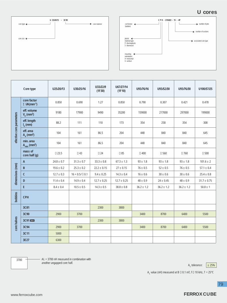
79
www.ferroxcube.com FERROXCUBE
U cores
AL value (nH) measured at B ≤ 0.1 mT, f ≤ 10 kHz, T = 25°C
AL = 3700 nH measured in combination with another ungapped core half.
3700
AL tolerance: ± 25%
Core type U25/20/13 U30/25/16U33/22/9
(1F30)U67/27/14
(1F10)U93/76/16 U93/52/30 U93/76/30 U100/57/25
efec
tive
core
par
amet
ers
core factorΣ l/A(mm-1)
0.850 0.690 1.27 0.850 0.790 0.307 0.421 0.478
eff. volumeVe (mm3)
9180 17900 9490 35200 159000 217000 297000 199000
eff. lengthle (mm)
88.2 111 110 173 354 258 354 308
eff. areaAe (mm2)
104 161 86.5 204 448 840 840 645
min. areaAmin (mm2)
104 161 86.5 204 448 840 840 645
mass of core half (g)
≈ 23.5 ≈ 43 ≈ 24 ≈ 85 ≈ 400 ≈ 560 ≈ 760 ≈ 500
dim
ensi
ons
(mm
) A 24.8 ± 0.7 31.3 ± 0.7 33.3 ± 0.8 67.3 ± 1.3 93 ± 1.8 93 ± 1.8 93 ± 1.8 101.6 ± 2
B 19.6 ± 0.2 25.3 ± 0.2 22.2 ± 0.15 27 ± 0.15 76 ± 0.5 52 ± 0.5 76 ± 0.5 57.1 ± 0.4
C 12.7 ± 0.3 16 + 0.5/ − 0.1 9.4 ± 0.25 14.3 ± 0.4 16 ± 0.6 30 ± 0.6 30 ± 0.6 25.4 ± 0.8
D 11.4 ± 0.4 14.9 ± 0.4 12.7 ± 0.25 12.7 ± 0.25 48 ± 0.9 24 ± 0.45 48 ± 0.9 31.7 ± 0.75
E 8.4 ± 0.4 10.5 ± 0.5 14.3 ± 0.5 38.8 ± 0.8 36.2 ± 1.2 36.2 ± 1.2 36.2 ± 1.2 50.8 ± 1
bobb
ins
CPH
core
hal
ves
3C81 2300 3800
3C90 2900 3700 3400 8700 6400 5500
3C91 2300 3800
3C94 2900 3700 3400 8700 6400 5500
3C11 5000
3E27 6300
U 25/20/13 - 3C90
core type
core size
core material
C P H - U10/8/3 - 1S - 4P
number of pins
associated core type
number of sections
coil former(bobbin)
plasticmaterial type:P- thermoplasticS- thermoset
mountingorientation:H- horizontalV- vertical

80
FERROXCUBE www.ferroxcube.com
I cores
Core type I20/6/5 1),2)
I25/6/6(376B250)
+U25/16/6
I25/7/7 1)I93/28/16
+U93/76/16
I93/28/30+
U93/52/30 orU93/76/30
I100/25/25+
U100/57/25
dim
ensi
ons
(mm
)
A 19.8 ± 0.525.4 +0.64 /
−0.2525 ± 0.7 93 ± 1.8 93 ± 1.8 101.6 ± 2
B 6.3 ± 0.25 6.4 ± 0.13 7.5 + 0.2/ − 0.3 27.5 ± 0.5 30 ± 0.6 25.4 ± 0.8
C 5.1 ± 0.2 6.4 ± 0.13 7.5 + 0.2/ − 0.3 16 ± 0.6 27.5 ± 0.5 25.4 ± 0.8
mass (g) ≈ 3 ≈ 4.5 ≈ 7 ≈ 200 ≈ 370 ≈ 300
core
s
3C81 1750
3C90 1500 460010700
67008700
3C91 1750
3C94 1500 460010700
67008700
3C11 2500
3E27 3000
I cores are often used in combina-tion with U-cores to build a simple transformer or inductor.The smaller types, I20/6/5 and I25/6/6 fi t the range of U coil formers.This combination is suitable for easy to wind inductors in applications such as interference fi lters and output chokes.As with rods, the magnetic circuit is open which is an advantage when the currents have a high DC content.
Summary:• simple, economic shape• often combined with U cores• for open circuit inductors• no self-shielding
AC
B
1) To be used as bar core (without counter part)2) Same coil former as U15/11/6
I 20/6/5 - 3C90
core type
core size
core material AL tolerance: ± 25%

81
www.ferroxcube.com FERROXCUBE

82
FERROXCUBE www.ferroxcube.com
UR cores
Core type Shape
dimensions (mm) effective core parameters
A B C D Emin F
core factorΣ l/A
(mm-1)
eff. volume
Ve (mm3)
eff. length
le (mm)
eff. areaAe
(mm2)
mass of
core half (g)
UR28/20/146 28.3 20.4 11.2 13.0 8.5 7.5 0.990 9460 97 98 25
UR35/28/135 35.2 28.3 12.7 18.8 13.1 9.3 1.100 15900 132 120 42
UR39/35/153 38.7 35.2 14.9 24.8 15.0 9.1 1.094 24300 163 149 64
UR42/21/124 41.8 20.6 11.9 11.1 18.2 11.9 1.09 11800 113 104 31
UR42/32/155 42.5 31.8 15.2 20.2 14.4 12.0 0.832 26670 149 179 69
UR43/34/162 42.1 34.0 15.8 24.0 15.7 9.6 0.982 27100 163 166 71
UR44/36/151 43.8 35.9 14.65 24.45 16.65 11.8 1.006 28700 170 169 71
UR47/36/165 47.55 35.7 15.95 23.8 18.25 12.6 0.900 33800 174 194 86
UR48/39/175 48.0 39.4 17.0 26.4 17.4 13.0 0.865 39990 186 215 99
UR64/29/144 64.0 29.5 13.8 18.1 36.1 13.8 1.26 27000 185 147 71
UR64/40/207 64.0 40.5 20.0 26.5 23.2 20.0 0.726 61000 210 290 160
TYPE 1
AE
F
D
C
B
TYPE 2 TYPE 3
This type is suitable for Line Output Transformers (LOT) in TV-sets. The round leg allows easy winding, also of strip conductors. Because of the high voltages involved, the round shape helps to prevent corona effect.
UR 28/20/13 - 3C30
core materialcore type
core size

83
www.ferroxcube.com FERROXCUBE
UR cores
TYPE 6TYPE 4 TYPE 7TYPE 5
Shape
product range
3C81/3F3 3C30 3C34
6 - UR28/20/13 - 3C30 UR28/20/13 - 3C34
5 - UR35/28/13 - 3C30 UR35/28/13 - 3C34
3 - UR39/35/15 - 3C30 UR39/35/15 - 3C34
4 UR42/21/12 - 3C81 - -
5 - UR42/32/15 - 3C30 UR42/32/15 - 3C34
2 - UR43/34/16 - 3C30 UR43/34/16 - 3C34
1 - UR44/36/15 - 3C30 UR44/36/15 - 3C34
5 - UR47/36/16 - 3C30 UR47/36/16 - 3C34
5 - UR48/39/17 - 3C30 UR48/39/17 - 3C34
4 UR64/29/14 - 3C81 - -
7 - - -
7 UR64/40/20 - 3F3 - -
Our present selection is displayed in the table above. In principle any core type can be supplied in all available grades.Other customized shapes can be manufactured on request.

84
FERROXCUBE www.ferroxcube.com
Ferrite Toroids
Core type
dimensions (mm) efective core parameters
outside diameter D
inside diameter D
height H
core factorΣ l/A(mm-1)
eff. volumeVe (mm3)
eff. lengthle (mm)
eff. areaAe (mm2)
mass (g)
TC2.5/1.3/0.8 2.54 ± 0.1 1.27 ± 0.1 0.8 ± 0.1 11.3 2.7 5.53 0.49 0.012TC2.5/1.3/1.3 2.54 ± 0.1 1.27 ± 0.1 1.27 ± 0.1 7.14 4.29 5.53 0.76 0.022TC2,5/1.3/2.5 2.54 ± 0.1 1.27 ± 0.1 2.54 ± 0.1 3.57 8.57 5.53 1.55 0.044TC2.5/1.5/0.8 2.5 ± 0.1 1.5 ± 0.1 0.8 - 0.1 16.4 2.21 6.02 0.37 0.012TC2.5/1.5/1-S 2.5 ± 0.1 1.5 ± 0.1 1.0 ± 0.1 12.3 2.94 6.02 0.489 0.015TC3.1/1.3/1.3 3.05 ± 0.15 1.27 ± 0.5 1.27 ± 0.15 5.65 6.35 5.99 1.06 0.033TC3.1/1.8/2 3.05 ± 0.15 1.78 ± 0.15 2.03 ± 0.15 5.75 9.10 7.23 1.26 0.05TC3.4/1.8/1.3 3.43 ± 0.18 1.78 ± 0.18 1.27 ± 0.18 7.93 7.3 7.62 0.96 0.035TC3.4/1.8/2 3.35 ± 0.13 1.78 ± 0.13 2.03 ± 0.13 4.90 11.6 7.54 1.54 0.059TC3.4/1.8/2.1 3.38 ± 0.13 1.78 ± 0.13 2.06 ± 0.13 4.97 11.5 7.54 1.52 0.06TC3.4/1.8/2.3 3.43 ± 0.15 1.78 ± 0.1 2.3 ± 0.1 4.16 14.0 7.63 1.83 0.068TC3.5/1.6/1.3 3.5 ± 0.15 1.6 ± 0.15 1.27 ± 0.15 6.32 8.3 7.25 1.15 0.043TC3.5/1.8/1.3 3.46 ± 0.15 1.78 ± 0.1 1.27 ± 0.1 7.44 7.87 7.65 1.03 0.04TC3.5/1.8/1.5 3.46 ± 0.13 1.78 ± 0.13 1.5 ± 0.13 6.30 9.30 7.65 1.21 0.05TC3.5/1.8/1.8 3.46 ± 0.15 1.78 ± 0.1 1.78 ± 0.1 5.31 11.0 7.65 1.44 0.06TC3.5/1.8/2 3.46 ± 0.15 1.78 ± 0.1 2.0 ± 0.1 4.73 12.4 7.6 1.62 0.05TC3.9/1.8/1.8 3.94 ± 0.2 1.78 ± 0.15 1.78 ± 0.15 4.44 14.8 8.1 1.83 0.086TC3.9/1.8/2.5 3.94 ± 0.15 1.78 ± 0.15 2.54 ± 0.15 3.11 21.1 8.1 2.6 0.12TC3.9/2.2/1.3 3.94 ± 0.17 2.24 ± 0.18 1.27 ± 0.18 9.20 9.2 9.2 1.00 0.045TC4/1.8/0.8 4.0 ± 0.15 1.78 ± 0.1 0.8 − 0.1 10.3 6.43 8.16 0.79 0.035TC4/2/2 4.0 ± 0.15 2.0 ± 0.1 2.0 ± 0.1 4.54 16.7 8.71 1.92 0.095TC4/2.2/1.1 4.0 ± 0.15 2.2 ± 0.1 1.1 ± 0.1 9.55 8.82 9.18 0.961 0.04TC4/2.2/1.3 4.0 ± 0.15 2.2 ± 0.1 1.27 ± 0.1 8.28 10.2 9.18 1.11 0.05TC4/2.2/1.6 4.0 ± 0.15 2.2 ± 0.1 1.6 ± 0.1 6.56 12.9 9.2 1.40 0.06TC4/2.2/1.8 4.0 ± 0.15 2.2 ± 0.1 1.78 ± 0.1 5.9 14.3 9.18 1.56 0.07TC4/2.2/2 4.0 ± 0.15 2.2 ± 0.1 2.0 ± 0.1 5.26 16.1 9.18 1.75 0.08TC4.8/2.3/1.3 4.8 ± 0.15 2.3 ± 0.1 1.27 ± 0.1 6.73 15.5 10.2 1.52 0.09TC5.8/3.1/0.8 5.84 ± 0.15 3.05 ± 0.15 0.75 ± 0.1 12.9 13.2 13.0 1.01 0.07TC5.8/3.1/1.5 5.84 ± 0.18 3.05 ± 0.18 1.52 ± 0.18 6.52 26.1 13.0 2.00 0.13TC5.8/3.1/3.2 5.84 ± 0.15 3.05 ± 0.15 3.17 ± 0.15 3.04 55.8 13.0 4.28 0.31TC5.9/3.1/3.1 5.85 ± 0.15 3.05 ± 0.15 3.05 ± 0.15 3.16 53.8 13.0 4.12 0.14TC6/4/2 6.0 ± 0.15 4.0 ± 0.15 2.0 ± 0.1 7.75 30.2 15.3 1.97 0.15TC6/4/3 6.0 ± 0.15 4.0 ± 0.15 3.0 ± 0.15 5.17 45.2 15.3 2.96 0.23TC6.3/3.8/2.5 6.3 ± 0.15 3.8 ± 0.15 2.5 ± 0.15 4.97 46.5 15.2 3.06 0.23TC7.6/3.2/4.8 7.6 ± 0.25 3.18 ± 0.2 4.78 ± 0.2 1.51 148 15.0 9.92 0.7TC7.6/3.2/5.2 7.6 ± 0.25 3.18 ± 0.2 5.15 ± 0.2 1.41 160 15.0 10.6 0.75TC8.2/3.7/4 8.2 ± 0.25 3.73 ± 0.15 4.0 ± 0.15 1.99 144 16.9 8.5 0.7TC9/6/31) 9.0 ± 0.2 6.0 ± 0.2 3.0 ± 0.15 5.17 102 22.9 4.44 0.5TL9/6/31) 9.3 ± 0.4 5.75 ± 0.3 3.25 ± 0.3 5.17 102 22.9 4.44 0.5TN9/6/31) 9.5 ± 0.3 5.4 ± 0.3 3.4 ± 0.25 5.17 102 22.9 4.44 0.5TC9.5/4.8/3.2 9.5 ± 0.31 4.75 ± 0.18 3.2 ± 0.18 2.98 144 20.7 6.95 0.7TN10/6/4 10.6 ± 0.3 5.2 ± 0.3 4.4 ± 0.3 3.07 188 24.1 7.8 0.95
Toroids have the best possible shape from the magnetic point of view. The fl ux path is completely closed so the capabilities of the ferrite are fully exploited. Especially for high permeability ferrites the effect of even a minor airgap in the magnetic circuit can spoil up to 50% of the effective permeability. A further advantage is the very low leakage fi eld which makes it a
suitable shape for power and pulse transformers.Ring cores are mainly used for pulse- and wide band transformers and interference suppression coils but also in special power supplies.
Summary:• simple economic shape• very low stray fl ux and leakage inductance• not easy to wind
D H
d
T = Toroid (Ring Core), TN = Toroid Nylon coated, TL = Toroid Laquered, TX = Toroid epoXy coated, TC = Toroid parylene C coated
1) 8-pad SMD tag plate (TGPS9) and cover (COV9) are available

85
www.ferroxcube.com FERROXCUBE
Ferrite Toroids
Core type
dimensions (mm) efective core parameters
outside diameter D
inside diameter D
height H
core factorΣ l/A(mm-1)
eff. volumeVe (mm3)
eff. lengthle (mm)
eff. areaAe (mm2)
mass (g)
TX10/6/4 10.25 ± 0.4 5.75 ± 0.3 4.25 ± 0.3 3.07 188 24.1 7.8 0.95TX13/7.1/4.8 12.95 ± 0.4 6.9 ± 0.35 5.03 ± 0.3 2.40 361 29.5 12.3 1.8TN13/7.5/5 13.0 ± 0.35 6.8 ± 0.35 5.4 ± 0.3 2.46 368 30.1 12.2 1.8TX13/7.5/5 12.75 ± 0.4 7.25 ± 0.35 5.25 ± 0.3 2.46 368 30.1 12.2 1.8TX13/7.9/6.4 12.95 ± 0.4 7.67 ± 0.4 6.6 ± 0.4 2.21 442 31.2 14.1 2.2TN14/9/5 14.6 ± 0.4 8.2 ± 0.35 5.5 ± 0.3 2.84 430 35 12.3 2.1TX14/9/5 14.25 ± 0.4 8.75 ± 0.35 5.25 ± 0.3 2.84 430 35 12.3 2.1TN14/9/9 14.8 ± 0.4 8.0 ± 0.4 9.5 ± 0.4 1.58 774 35 22.1 3.8TX14/9/9 14.25 ± 0.4 8.75 ± 0.35 9.25 ± 0.4 1.58 774 35 22.1 3.8TX16/9.1/4.7 16.13 ± 0.5 8.82 ± 0.4 4.95 ± 0.3 2.53 548 37.2 14.7 2.7TN16/9.6/6.3 16.7 ± 0.5 8.7 ± 0.4 6.8 ± 0.4 1.95 760 38.5 19.7 3.8TX16/9.6/6.3 16.25 ± 0.5 9.35 ± 0.4 6.55 ± 0.4 1.95 760 38.5 19.7 3.8TN19/11/10 19.7 ± 0.6 9.7 ± 0.4 10.5 ± 0.5 1.08 1795 44.0 40.8 9.2TN19/11/15 19.9 ± 0.6 9.5 ± 0.4 15.5 ± 0.55 0.718 2692 44.0 61.2 13.8TN20/10/7 20.6 ± 0.6 9.2 ± 0.4 7.5 ± 0.45 1.30 1465 43.6 33.6 7.7TX20/10/7 20.25 ± 0.6 9.75 ± 0.4 7.25 ± 0.45 1.30 1465 43.6 33.6 7.7TX22/14/6.4 22.35 ± 0.7 13.47 ± 0.6 6.75 ± 0.4 2.20 1340 54.2 24.8 6.5TX22/14/13 22.35 ± 0.7 13.47 ± 0.6 13.1 ± 0.5 1.07 2750 54.2 50.9 14TN23/14/7 23.7 ± 0.7 13.1 ± 0.6 7.5 ± 0.45 1.81 1722 55.8 30.9 8.4TN25/15/10 25.8 ± 0.7 14.0 ± 0.6 10.6 ± 0.5 1.23 2944 60.2 48.9 15TX25/15/10 25.25 ± 0.7 14.75 ± 0.6 10.4 ± 0.5 1.23 2944 60.2 48.9 15TN26/15/10 26.8 ± 0.7 13.5 ± 0.6 10.6 ± 0.5 1.08 3360 60.1 55.9 17TX26/15/10 26.25 ± 0.7 14.25 ± 0.6 10.4 ± 0.5 1.08 3360 60.1 55.9 17TN26/15/20 26.9 ± 0.7 13.2 ± 0.6 20.5 ± 0.6 0.538 6720 60.1 112 34TN29/11/6 29.6 ± 0.7 10.0 ± 0.4 6.4 ± 0.4 1.04 2680 52.9 50.8 14TN29/19/7.5 29.7 ± 0.7 18.2 ± 0.6 8.1 ± 0.5 1.98 2700 73.2 36.9 13.5TX29/19/7.5 29.25 ± 0.7 18.75 ± 0.6 7.9 ± 0.5 1.98 2700 73.2 36.9 13.5TX29/19/7.6 29.25 ± 0.7 18.75 ± 0.6 8.0 ± 0.5 2.06 2600 73.2 35.5 13TN29/19/15 29.9 ± 0.7 18.1 ± 0.6 15.5 ± 0.6 0.98 5410 73.2 73.9 28TX29/19/15 29.25 ± 0.7 18.75 ± 0.6 15.4 ± 0.5 0.98 5410 73.2 73.9 28TL32/19/13 31.75 ± 0.8 18.75 ± 0.7 12.9 ± 0.5 0.99 5820 76 76.5 29TN32/19/13 32.2 ± 0.8 18.1 ± 0.6 13 ± 0.5 0.99 5820 76 76.5 29TN36/23/10 36.8 ± 0.9 22.1 ± 0.7 10.7 ± 0.6 1.40 5730 89.6 63.9 28TX36/23/10 36.25 ± 0.9 22.75 ± 0.7 10.56 ± 0.5 1.46 5540 89.7 61.8 27TN36/23/15 36.9 ± 0.9 21.9 ± 0.7 15.7 ± 0.6 0.935 8600 89.6 95.9 42TX36/23/15 36.25 ± 0.9 22.75 ± 0.7 15.6 ± 0.6 0.96 8440 89.7 94.1 40TX39/20/13 39.15 ± 0.9 19.3 ± 0.7 13.2 ± 0.5 0.76 9513 84.9 112 45TX42/26/13 42.1 ± 1.1 25.9 ± 0.8 13 ± 0.5 1.076 9860 103 95.8 53TX42/26/18 42.1 ± 1.1 25.9 ± 0.8 18 ± 0.7 0.769 13810 103 134 55TX50/30/19 50.4 ± 1.1 29.7 ± 0.8 19.5 ± 0.6 0.65 22378 120.4 186 100TX51/32/19 51.05 ± 1.5 31.5 ± 1 19.5 ± 0.6 0.73 21500 125 172 100TL55/32/18 55.8 ± 1.7 32.1 ± 1 18.3 ± 0.9 0.651 26580 131.5 202 134
T = Toroid (Ring Core), TN = Toroid Nylon coated, TL = Toroid Laquered, TX = Toroid epoXy coated, TC = Toroid parylene C coated
Isolation voltage
Toroids with polyamide, epoxy and laquer coating(TN, TX and TL)
diameter:
Toroids with parylene coating (TC): 1000 VDC
< 1212-20> 20
: 1000 VDC: 1500 VDC: 2000 VDC
T N 36/23/15 - 3E25 - X
special version
core material
core size D / d / H(uncoated coredimensions)
core type
coating type
- C - parylene C- L - laquer- N - polyamide 11 (nylon)- X - epoxy

86
FERROXCUBE www.ferroxcube.com
Core type
dimensions (mm) efective core parameters
outside diameter D
inside diameter D
height H
core factorΣ l/A(mm-1)
eff. volumeVe (mm3)
eff. lengthle (mm)
eff. areaAe (mm2)
mass (g)
TL58/41/18 58.7 ± 1.1 40.5 ± 0.9 17.9 ± 0.7 1.0 23200 152.4 152.4 110TL63/38/25 63.4 ± 2.1 37.7 ± 1.3 25.3 ± 1 0.497 46500 152 306 220TX63/38/25 63.4 ± 2.1 37.7 ± 1.3 25.3 ± 1 0.497 46500 152 306 220TL74/39/13 73.9 ± 1.52 38.61 ± 1.32 12.95 ± 0.5 0.80 34300 165 208 170TX74/39/13 73.9 ± 1.52 38.61 ± 1.32 12.95 ± 0.5 0.80 34300 165 208 170TL80/40/15 80.4 ± 2.6 39.7 ± 1.3 15.3 ± 0.6 0.604 50200 174 288 240TL87/54/14 87.4 ± 1.35 54 ± 1 13.8 ± 0.45 0.987 46400 214 217 220T87/56/13 87 ± 1.25 56 ± 0.9 12.7 ± 0.25 1.123 42133 217.5 194 200TL102/66/15 102.4 ± 2.1 65.5 ± 1.4 15.3 ± 0.7 0.956 68200 255 267 325T107/65/18 107 ± 2 65 ± 1.3 18 ± 0.35 0.700 96000 259 370 456TL107/65/18 107.4 ± 2 64.7 ± 1.4 18.3 ± 0.55 0.700 96000 259 370 456T107/65/25 107 ± 2 65 ± 1.3 25 ± 0.75 0.504 133000 259 514 680T140/106/25 140 ± 3 106 ± 2 25 ± 1 0.903 161100 382 422 800
T = Toroid (Ring Core), TN = Toroid Nylon coated, TL = Toroid Laquered, TX = Toroid epoXy coated, TC = Toroid parylene C coated
Ferrite Toroids

87
www.ferroxcube.com FERROXCUBE
Ferrite Toroids

88
FERROXCUBE www.ferroxcube.com
MaterialColour
codeCore type
3B7 3C11 3C81 3C90 3D3 3E5 3E6 3E7 3E8 3E25
TC2.5/1.3/0.8
TC2.5/1.3/1.3 1835 970
TC2.5/1.3/2.5
TC2.5/1.5/0.8 765
TC2.5/1.5/1-S 920 1020
TC3.1/1.3/1.3 2225 1225
TC3.1/1.8/2
TC3.4/1.8/1.3 375 110 1580
TC3.4/1.8/2 3080 1420
TC3.4/1.8/2.1 1420
TC3.4/1.8/2.3
TC3.5/1.6/1.3 862
TC3.5/1.8/1.3
TC3.5/1.8/1.5
TC3.5/1.8/1.8
TC3.5/1.8/2
TC3.9/1.8/1.8
TC3.9/1.8/2.5
TC3.9/2.2/1.3 325 97
TC4/1.8/0.8
TC4/2/2 1190
TC4/2.2/1.1 1120 1315 725
TC4/2.2/1.3 720
TC4/2.2/1.6 1630 1915 1050
TC4/2.2/1.8 2130
TC4/2.2/2 3590 1315
TC4.8/2.3/1.3 430
TC5.8/3.1/0.8
TC5.8/3.1/1.5 4501) 1960 2940
TC5.8/3.1/3.2 940 310 4130
TC5.9/3.1/3.1 3960
TC6/4/2 1380 1620 890
TC6/4/3 2430
AL tolerance: ± 20% ± 30% + 25%− 20%
+ 30%− 40%
+ 20%− 40%± 25% + 40%
− 30%
nominal AL value (nH) measured at B ≤ 0.1 mT, f ≤ 10 kHz, T = 25°C12000
Ferrite Toroids
1) outer diameter = 6.0 ± 0.18 mm

89
www.ferroxcube.com FERROXCUBE
Ferrite ToroidsMaterial
Colour code
Core type3E27 3E28 3F3 3F4 3R1 3S4 4A11 4A15 4B1 4C65
TC2.5/1.3/0.8 94
TC2.5/1.3/1.3 300 150
TC2.5/1.3/2.5 1400
TC2.5/1.5/0.8
TC2.5/1.5/1-S 513 410 71
TC3.1/1.3/1.3 190
TC3.1/1.8/2 1100
TC3.4/1.8/1.3 660
TC3.4/1.8/2
TC3.4/1.8/2.1 1045
TC3.4/1.8/2.3 1207
TC3.5/1.6/1.3
TC3.5/1.8/1.3 930 120
TC3.5/1.8/1.5 170
TC3.5/1.8/1.8 950
TC3.5/1.8/2 1060
TC3.9/1.8/1.8 1400
TC3.9/1.8/2.5 2020
TC3.9/2.2/1.3 575
TC4/1.8/0.8 486
TC4/2/2 1623 1110
TC4/2.2/1.1 260 92 16
TC4/2.2/1.3 122
TC4/2.2/1.6 380 325 134 24
TC4/2.2/1.8
TC4/2.2/2
TC4.8/2.3/1.3 1030
TC5.8/3.1/0.8 390
TC5.8/3.1/1.5 890 50 25
TC5.8/3.1/3.2 1650
TC5.9/3.1/3.1
TC6/4/2 325 275 114 20
TC6/4/3
AL tolerance: ± 20% ± 30% + 25%− 20%
+ 30%− 40%
+ 20%− 40%± 25% + 40%
− 30%
nominal AL value (nH) measured at B ≤ 0.1 mT, f ≤ 10 kHz, T = 25°C12000
= available (no AL spec.)

90
FERROXCUBE www.ferroxcube.com
Ferrite ToroidsMaterial
Colour code
Core type3B7 3C11
white3C81
brown/white3C90
ultramarine3D3 3E5
yellow/white3E6
purple/white3E7 3E8 3E25
orange
TC6.3/3.8/2.5 2150 2530 3600 1390
TC7.6/3.2/4.8 1915 8360 12500
TC7.6/3.2/5.2
TC8.2/3.7/4 7560
TC9/6/3 2070 2435
TL9/6/3 2070
TN9/6/3 560 1340
TC9.5/4.8/3.2 1000 1200 330 4390 5323 6590
TN10/6/4 1750 940 306 2250
TX10/6/4 3470 4085
TX13/7.1/4.8 1475 1260 415 5400
TN13/7.5/5 2200 1170 2810
TX13/7.5/5 4340 5095
TX13/7.9/6.4 1620 1380 5900 3000
TN14/9/5 1900 1015 2430
TX14/9/5 3760 4415
TN14/9/9 3400 1825 4370
TX14/9/9 6760 7955
TX16/9.1/4.7 1400 1215 5200
TN16/9.6/6.3 2700 1480 3540
TX16/9.6/6.3 5470 6430
TN19/11/10 5000 2680 6420
TN19/11/15 7500 4020 9630
TN20/10/7 4150 2230 5340
TX20/10/7 8250 9685
TX22/14/6.4 1650 1400 454 6000
TX22/14/13 2795 12080
TN23/14/7 3000 1600 3820
TN25/15/10 4400 2350 5620
TX25/15/10 8680 10200
TN26/15/10 5000 2645 6420
TX26/15/10 10000
TN26/15/20 10000 5400 12800
TN29/11/6 5100 2780
TN29/19/7.5 2700 1460 3550
AL tolerance: ± 20% ± 30% + 25%− 20%
+ 30%− 40%
+ 20%− 40%± 25% + 40%
− 30%
nominal AL value (nH) measured at B ≤ 0.1 mT, f ≤ 10 kHz, T = 25°C12000
T = Toroid (Ring Core), TN = Toroid Nylon coated, TL = Toroid Laquered, TX = Toroid epoXy coated, TC = Toroid parylene C coated

91
www.ferroxcube.com FERROXCUBE
Ferrite Toroids
AL tolerance: ± 20% ± 30% + 25%− 20%
+ 30%− 40%
+ 20%− 40%± 25% + 40%
− 30%
nominal AL value (nH) measured at B ≤ 0.1 mT, f ≤ 10 kHz, T = 25°C12000
MaterialColour
codeCore type
3E27green
3E28 3F3blue
3F4beige
3R1black
3S4 4A11pink
4A15 4B1 4C65violet
TC6.3/3.8/2.5 500 177
TC7.6/3.2/4.8 3800
TC7.6/3.2/5.2 3580
TC8.2/3.7/4 440
TC9/6/3
TL9/6/3
TN9/6/3 440 170 30
TC9.5/4.8/3.2 2135 890
TN10/6/4 740 286 52
TX10/6/4
TX13/7.1/4.8 2750 990
TN13/7.5/5 900 460 360 610 64
TX13/7.5/5
TX13/7.9/6.4 3000 1100
TN14/9/5 790 310 55
TX14/9/5
TN14/9/9 1430 560
TX14/9/9
TX16/9.1/4.7 2600
TN16/9.6/6.3 1160 450
TX16/9.6/6.3
TN19/11/10
TN19/11/15
TN20/10/7 121
TX20/10/7
TX22/14/6.4 3055 75
TX22/14/13 6110 2200
TN23/14/7 1250 485 87
TN25/15/10 1840
TX25/15/10
TN26/15/10 817
TX26/15/10
TN26/15/20
TN29/11/6
TN29/19/7.5
T = Toroid (Ring Core), TN = Toroid Nylon coated, TL = Toroid Laquered, TX = Toroid epoXy coated, TC = Toroid parylene C coated
= available (no AL spec.)

92
FERROXCUBE www.ferroxcube.com
Ferrite ToroidsMaterial
Colour code
Core type3B7 3C11
white3C81
brown/white3C90
ultramarine3D3 3E5
yellow/white3E6
purple/white3E25
orange
TX29/19/7.5 6340
TX29/19/7.6 1740
TN29/19/15 2960 10780 7000
TX29/19/15 12850
TL32/19/13 10700
TN32/19/13 5450 2910 6950
TN36/23/10 3900 2060
TX36/23/10
TN36/23/15 5800 3090 7390
TX36/23/15 3670 3090 11400 13600
TX39/20/13 4700 3800 16700
TX42/26/13 5000 2690 6425
TX42/26/18 12900
TX50/30/19 19400
TX51/32/19 4800 3980 17300 8890
TL55/32/18 10620
TL58/41/18 5400 2890 6900
TL63/38/25 13900
TX63/38/25 25280
TL74/39/13 15776
TX74/39/13 4350 3620 8060
TL80/40/15 4780
TL87/54/14 5470 2930
T87/56/13 11190
TL102/66/15 5300 7900
T107/65/18
TL107/65/18 9900
T107/65/25
T140/106/25 3200 7700
AL tolerance: ± 20% ± 30% + 25%− 20%
+ 30%− 40%
+ 20%− 40%± 25% + 40%
− 30%
nominal AL value (nH) measured at B ≤ 0.1 mT, f ≤ 10 kHz, T = 25°C12000
T = Toroid (Ring Core), TN = Toroid Nylon coated, TL = Toroid Laquered, TX = Toroid epoXy coated, TC = Toroid parylene C coated

93
www.ferroxcube.com FERROXCUBE
Ferrite Toroids
AL tolerance: ± 20% ± 30% + 25%− 20%
+ 30%− 40%
+ 20%− 40%± 25% + 40%
− 30%
nominal AL value (nH) measured at B ≤ 0.1 mT, f ≤ 10 kHz, T = 25°C12000
MaterialColour
codeCore type
3E27green
3E28 3F3blue
3F4beige
3R1black
3S4 4A11pink
4B1 4C65violet
TX29/19/7.5
TX29/19/7.6 3225
TN29/19/15
TX29/19/15
TL32/19/13
TN32/19/13 2270 885
TN36/23/10 112
TX36/23/10
TN36/23/15 2420 2285 940 170
TX36/23/15 6800
TX39/20/13 8720 3150
TX42/26/13 6425 820
TX42/26/18
TX50/30/19
TX51/32/19 8890 3200
TL55/32/18 10620 1350
TL58/41/18
TL63/38/25 4550
TX63/38/25
TL74/39/13
TX74/39/13 2900
TL80/40/15
TL87/54/14
T87/56/13
TL102/66/15 165
T107/65/18 1354
TL107/65/18 3230
T107/65/25 4485 1870
T140/106/25
T = Toroid (Ring Core), TN = Toroid Nylon coated, TL = Toroid Laquered, TX = Toroid epoXy coated, TC = Toroid parylene C coated
= available (no AL spec.)

94
FERROXCUBE www.ferroxcube.com
Gapped Ferrite Toroids
Core type
dimensions (mm) efective core parameters
outside diameter D
inside diameter D
height H
core factorΣ l/A(mm-1)
eff. volumeVe (mm3)
eff. lengthle (mm)
eff. areaAe (mm2)
mass (g)
TC4/2.2/0.8 4.0 ± 0.15 2.2 ± 0.1 0.8 ± 0.075 13.1 6.42 9.18 0.699 0.03
TC4.5/2.3/0.8 4.45 ± 0.18 2.29 ± 0.13 0.76 +0.2/−0.08 11.9 8.19 9.87 0.829 0.04
TC4.5/2.3/1.1 4.45 ± 0.18 2.29 ± 0.13 1.14 ± 0.08 8.35 11.7 9.87 1.18 0.06
TC5.8/3.1/3.1 5.84 ± 0.15 3.05 ± 0.15 3.05 ± 0.15 3.17 53.5 13.0 4.11 0.27
TC5.8/3.1/3.5 5.84 ± 0.15 3.05 ± 0.15 3.5 ± 0.15 2.76 61.4 13.0 4.71 0.29
TC6.3/3.8/3.2 6.3 ± 0.15 3.8 ± 0.15 3.18 ± 0.15 3.91 59.2 15.2 3.89 0.28
TC7.6/3.2/3.2 7.6 ± 0.25 3.18 ± 0.15 3.18 ± 0.15 2.27 98.8 15.0 6.60 0.47
TC7.6/3.2/4.8 7.6 ± 0.25 3.18 ± 0.15 4.78 ± 0.2 1.51 148 15.0 9.92 0.71
TC9.5/4.8/4.8 9.5 ± 0.3 4.78 ± 0.2 4.78 ± 0.2 1.91 225 20.8 10.8 1.1
TC10/6/4 10 ± 0.2 6.0 ± 0.2 4.0 ± 0.15 3.07 188 24.1 7.8 0.95
Gapped toroids share proper-ties with ungapped toroids like a simple economic shape.Ferroxcube has developed a range of gapped toroids, both in power material 3C94, for power applications, and in special, high perm, stable µ(T) material 3E55 with low THD for telecom applications.They are parylene coated and the gap is sealed with special glue, which is temperature
resistant up to 250 °C, thus avoiding product deterioration, even under extreme operating conditions.
Summary :• simple economic shape• different AL-values possible• compact and robust product• not easy to wind
D H
d
AL tolerance: ± 10% ± 15%
nominal AL value (nH) measured at B ≤ 0.1 mT, f ≤ 10 kHz, T = 25°C120
Core type TC4/2.2/0.8 TC4.5/2.3/0.8 TC4.5/2.3/1.1 TC5.8/3.1/3.1 TC5.8/3.1/3.5 TC6.3/3.8/3.2 TC7.6/3.2/3.2 TC7.6/3.2/4.8 TC9.5/4.8/4.8 TC10/6/4
core
s fo
r te
leco
m t
ran
sfo
rmer
san
d p
ow
er a
pp
licat
ion
s
3C94 A13 A15.9 A25.5 A50F
3E55 A55 63 A22 A43 A63 A80
A40 A78 A120
A63 A110 A120F
A145F
Isolation voltage
Toroids with parylene (TC) : 1000 VDC
T C 9.5/4.8 − 3E55 − A 120 X
special version- F - non-sealed gap
core material
core size D / H(uncoated coredimensions)
core type
coating type
- C - parylene C gapped
AL value (nH)

95
www.ferroxcube.com FERROXCUBE
Iron Powder Toroids
Core type TN7.5/4.1/3 TN12/8/4.4 TN17/9.8/4.4 TN20/13/6 TN24/15/7.5 TN27/15/11 TN33/20/11
efec
tive
core
par
amet
ers
core factorΣ l/A(mm-1)
3.58 3.30 2.55 2.44 1.76 1.02 1.23
eff. volumeVe (mm3)
83 290 635 1020 1895 3720 5200
eff. lengthle (mm)
17.3 30.9 40.2 49.9 57.8 61.6 80.0
eff. areaAe (mm2)
4.81 9.37 15.8 20.4 32.8 60.4 65.0
mass of core half (g)
≈ 0.6 ≈ 2 ≈ 5 ≈ 7.5 ≈ 13 ≈ 25 ≈ 35
dim
ensi
ons
(mm
) D 8.1 ± 0.3 13.0 ± 0.3 17.8 ± 0.3 20.5 ± 0.5 24.3 ± 0.5 27.5 ± 0.5 33.6 ± 0.5
d 3.5 ± 0.3 7.4 ± 0.3 8.9 ± 0.3 12.3 ± 0.5 13.8 ± 0.5 14.0 ± 0.5 19.2 ± 0.5
H 3.3 ± 0.5 4.8 ± 0.5 4.8 ± 0.5 6.5 ± 0.5 8.1 ± 0.5 11.4 ± 0.5 11.5 ± 0.5
A L (nH)
± 1
0%
2P40dark yellow
14 15 20 21 29 49 41
2P50dark blue
18 19 25 26 36 62 51
2P65dark red
23 25 32 34 47 80 67
2P80dark green
28 31 40 41 57 94 82
2P90dark brown
301) 331) 421) 441) 611) 1051) 871)
Due to the high saturation fl ux density of iron powder (950...1600 mT) these ring cores are very suitable for output chokes carrying high DC currents. Another application is found in lamp dimmers as ballast choke.
The cores are made of electrolytic iron powder, mixed with a small amount of resin for insulation. They are coated with polyamide 11 (thickness 0.1 - 0.3 mm). The isolation voltage between core and winding is up to 1500 V.
Summary:• high saturation fl ux density• suitable for output chokes• for EMI-suppression with high DC bias
D d
H
1)AL tolerance: + 10/ -15%
T N 20/13/6 - 2P90
core material
core size
core type
coating typeN- polyamide 11
(nylon)

96
FERROXCUBE www.ferroxcube.com
Property Test conditions EMI-suppression
Symbol f (kHz) Bpeak or H T (ºC) unit 3B1 3C11 3E5 3E61) 3E71) 3E81) 3E25 3E26 3E27 4A11 4A15 4B1 4C65
µi (± 20%) ≤ 10 ≤ 0.1 mT 25 900 4300 10000 12000 15000 18000 6000 7000 6000 850 1200 250 125
tanδ/µi
30
≤ 0.1 mT 25 (x 10-6)
≤ 25 ≤ 30 ≤ 30 ≤ 30
100 ≤ 20 ≤ 75 ≤ 25 ≤ 20 ≤ 15
300 ≤ 200 ≤ 200
450 ≤ 50
1000 ≤ 100 ≤ 300 ≤ 90
3000 ≤ 1000 ≤ 1500 ≤ 300 ≤ 80
10000 ≤ 130
B
10
250 A/m 100mT
≈ 200 ≈ 180 ≈ 210 ≈ 210 ≈ 210 ≈ 200 ≈ 180 ≈ 290 ≈ 280 ≈ 180 ≈ 180 ≈ 260 ≈ 250
3000 A/m 25 ≈ 370 ≈ 340 ≈ 380 ≈ 380 ≈ 380 ≈ 380 ≈ 380 ≈ 450 ≈ 400 ≈ 320 ≈ 340 ≈ 350 ≈ 380
Hc 25A/m ≈ 25 ≈ 10 ≈ 5 ≈ 4 ≈ 4 ≈ 4 ≈ 5 ≈ 5 ≈ 5 ≈ 35 ≈ 25 ≈ 150 ≈ 250
Br mT ≈ 190 ≈ 120 ≈ 80 ≈ 100 ≈ 100 ≈ 100 ≈ 100 ≈ 120 ≈ 120 ≈ 110 ≈ 150 ≈ 240 ≈ 280
Tc ºC ≥ 150 ≥ 125 ≥ 125 ≥ 130 ≥ 130 ≥ 100 ≥ 125 ≥ 155 ≥ 150 ≥ 125 ≥ 125 ≥ 250 ≥ 350
ρ DC 25 Ωm ≈ 0.2 ≈ 1 ≈ 0.5 ≈ 0.1 ≈ 0.1 ≈ 0.1 ≈ 0.5 ≈ 0.5 ≈ 0.5 ≈ 105 ≈ 105 ≈ 105 ≈ 105
density kg/m3 ≈ 4800 ≈ 4900 ≈ 4900 ≈ 4900 ≈ 4900 ≈ 5000 ≈ 4900 ≈ 4900 ≈ 4800 ≈ 5100 ≈ 5100 ≈ 4600 ≈ 4500
ferrite type MnZn MnZn MnZn MnZn MnZn MnZn MnZn MnZn MnZn NiZn NiZn NiZn NiZn
Materials and Applications for EMI-suppression
Products generally comply with the material specifi cation. However deviations may occur due to shape, size and grinding operations etc. Specifi ed product properties are given in the data sheets or product drawings.
Property Test conditions EMI-suppression
Symbol f (MHz) Bpeak or H T (ºC) unit 3S1 3S3 3S4 4S2
µi (± 20%) ≤ 0.01 ≤ 0.1 mT 25 ≈ 4000 ≈ 350 ≈ 1700 ≈ 700
|Z|1)
1
≤ 0.1 mT 25 Ω
≥ 30
3 ≥ 25
10 ≥ 60
30 ≥ 25 ≥ 60 ≥ 50
100 ≥ 60 ≥ 80
300 ≥ 100 ≥ 90 ≥ 90
B
0.01
250 A/m 100mT
≈ 180 ≈ 250 ≈ 140 ≈ 180
3000 A/m 25 ≈ 400 ≈ 350 ≈ 350 ≈ 350
Hc 25 A/m ≈ 10 ≈ 60 ≈ 20 ≈ 30
Br 25 mT ≈ 120 ≈ 230 ≈ 170 ≈ 120
Tc ºC ≥ 125 ≥ 225 ≥ 110 ≥ 125
ρ DC Ωm ≈ 1 ≈ 104 ≈ 104 ≈ 105
density kg/m3 ≈ 4900 ≈ 4800 ≈ 4800 ≈ 5000
ferrite type MnZn MnZn MnZn NiZn
Properties measured on sintered, unground ring cores of dimensions ∅ 25 x ∅ 15 x 10 mm, which are not subjected to external stresses.
1) Measured on a bead of dimensions ∅ 5 x ∅ 2 x 10 mm.
Properties measured on sintered, unground ring cores of dimensions ∅ 25 x ∅ 15 x 10 mm, which are not subjected to external stresses.1) Measured on sintered, unground ring cores of dimensions ∅ 14 x ∅ 9 x 5 mm, which are not subjected to external stresses.

97
www.ferroxcube.com FERROXCUBE
Materials and ApplicationsEMI-suppression on PCB
Suppression beads and wideband chokes show high impedance levels over a wide frequency range caused by ferrimagnetic resonant losses in the ferrite material. This impedance is used to absorb interference signals over a wide frequency range. Our S-materials were developed for maximum impedance for frequencies up to 1 GHz.In multilayer suppressors several layers of ferrite are used to create more winding turns, resulting in higher impedance levels
EMI-suppression on signal wires and cables
When interference signals are conducted by cables of a considerable length these will act as an antenna and radiate RF power. Special cable shields are available to suppress the currents and to avoid problems with EMC limits. The product can be in one piece for mounting during manufacturing or split for retrofi t solution. A split product uses special clamps to prevent a parasitic airgap with loss of impedance. Toroids can be effective as well, especially when more than a single turn is required to reach the minimum damping. Also here current-compensation is applied. In the case of an I/O cable, such as coax or fl at cable, the problem is not saturation by high currents. The reason for the current-compensation is now that the actual signal is also of RF frequency and it would be suppressed together with the interference. The current-compensated inductor has the limitation that it is only active against common-mode interference.
EMI-suppression in mains fi lters
In mains input fi lters, effective use is made of the permeability of the ferrite to form an LC fi lter. To save volume, the permeability of the ferrite core must be as high as possible in the frequency range of the interfering signal. Ring cores are therefore very popular for this application (no airgap) but also U-cores have been used. It is important to take into account any magnetic bias fi eld, caused by DC or low frequency AC-currents. To avoid saturation of the ferrite, the use of current- compensation is common practice.Two windings with an equal number of turns are applied to the core. The winding directions are such that the incoming current through one winding and the equally large outgoing current through the other generate opposite fl uxes of equal magnitude. Current-compensation would be almost ideal with both windings along the total circumference, one over the other. But in practical cases each winding is placed on one half of the core because of insulation requirements.However, a current-compensated choke is only active against common-mode interference. If differential-mode suppression is required, cores with an airgap or made of a low permeability material like iron powder should be applied.
frequency range
< 30 MHz
30 MHz - 1000 MHz
3B1, 3S1
3S4, 4A15, 4B1, 4S2
C o r e s h a p e s
BDW, BDS, CMS, WBC, WBS,
multilayer suppressors, IIC
frequency range material
< 30 MHz
30 MHz - 1000 MHz
3B1, 3C11, 3C90, 3E25,3E26, 3E27, 3E5, 3E6, 3S1
3S4, 4B1, 4S2, 4A11,4A15, 4C65
C o r e s h a p e s
cable shields, tubes and beads
ring cores and multi-hole beads
frequency range
3C11, 3E25, 3E26,3E27, 3E5, 3E6
3C90
4A11, 4A15
3S4, 4C65
< 500 kHz
500 kHz - 3 MHz
3 MHz - 30 MHz
> 30 MHz
C o r e s h a p e s
ring cores, U cores
EMI-suppression in power lines
Often a DC supply or AC current is passing through the inductor to allow normal operation of the connected equipment. This current induces a high magnetic fi eld strength in the ferrite core, which can lead to saturation. Impedance levels then decrease along with permeability, especially at low frequencies. The infl uence of a bias current can be limited by choosing a ferrite core with a lower permeability, an airgap or with an open magnetic circuit, like rods, tubes or bobbin cores.When the interference is common-mode, current compensation can be applied to avoid negative effects. In common-mode chokes 2 similar windings on a ferrite core carry opposing currents. The magnetic fl uxes resulting from bias currents or large differential signals cancel out. In this way saturation as well as damping of the useful signals is avoided.
frequency range
< 30 MHz
30 MHz - 1000 MHz
2P, 3B1, 3C90,3S1
3S3, 3S4, 4A15,4B1, 4S2
C o r e s h a p e s
iron powder ring cores, bobbin cores and rods
BD, BDW, MHC, WBC

98
FERROXCUBE www.ferroxcube.com
Materials and Applications for EMI-suppression
Sources and propagation
The source determines whether the interference is a transient or random variation in time or a periodical signal. The frequency spectrum will be continuous for a random interference source. Examples are commutation motors, broadcast transmitters etc. Switched-mode power supplies generate periodic signals, causing emissions with a line spectrum. In practice both types of sources can be broadband.
Interferences can propagate as an electromagnetic wave in free space, but also as a current via conductive paths such as the mains network, to which the majority of electrical equipment is connected.Below 30 MHz this is the main propagation mode. Effective suppression is achieved by placing a high impedance in series (inductor), a low impedance in parallel (capacitor) or a combination of both (fi lter).
Propagation via the mains can take place in two different modes: common-mode and differential-mode or a mix of both.
Common-mode :Phase and null interference voltages are equal. This is likely to occur if phase and null are close together and interference is coupling in from an external fi eld (radiation or cross-talk).
Differential-mode :Phase and null interference voltages have opposite phase angle but equal magnitude. This is likely to occur in case of switching equipment connected to the mains.
Ferrites supporting the drive for Electromagnetic Compatibility
To help circuit designers meet EMC requirements, Ferroxcube supplies a broad range of ferrite products for interference-suppression applications. We offer smart solutions to comply with stringent EMC regulations. In the fi eld of electromagnetic compatibility several trends attribute to a growing necessity of EMC engineering.
In signal processing :
• Change from analogue to digital (steep pulse edges, overshoot, ringing).• Increase of clock frequencies.
In power conversion :
• Change from linear to switched-mode power supplies (high switching frequency, harmonics).• Increase of switching frequencies.
These trends, directed to functional upgrading or reducing cost, inevitably also contribute to an increasing level of electromagnetic interference (EMI). Together with the increasing use of electron-ics this leads to a general EMC degradation. As a consequence, legislation is getting world-wide more strict.
The most important regulations are the European Norms (EN) which are applicable in all European Union (EU) and European Free Trade Associated (EFTA) countries, FCC in the United States and VCCI in Japan. The uniform legislation in the European Union is along the lines of the EMC directive 89/336/EEC. For every product to which no specifi c European Norm applies, a general regulation is mandatory. These are the so called Generic Require-ments (residential, commercial and light industry : EN 61000-6-3 for emissions and EN 61000-6-1 for immunity). This includes all electric and electronic products, no matter how trivial they seem to be. All equipment has to be tested to acquire the CE mark before being offered on the market. Since the European EMC regulations are the most advanced, they are used as a yardstick worldwide.
Regulations
Historically, all EMC regulations stated emission limits only. These defi ne the maximum level of interference allowed as a function of frequency. In case of conducted interference it applies to the voltage on all inputs and outputs of the equipment, in case of radiated interference it applies to the fi eld strength at a certain distance. Often two levels are stated :
• Class A for commercial and industrial areas.• Class B for domestic and residential areas.
Class B is always stricter than class A. Recently, also immunity is becoming subject of regulation. Taking into account the severity of the EMC problem, equipment must also be able to operate without functional degradation in a minimum EMI ambient. The difference between the actual level of emissions or susceptibility and the EMC limits is the required attenuation by fi ltering or shielding.
dB
receiver
source
EMC margin
safetymargin
supplier
EMS limit
EME limit
EMS level
EME level
frequencyEMC = Electro Magnetic CompatabilityEMS = Electro Magnetic SusceptabilityEME = Electro Magnetic Emission
Principles of Electromagnetic Compatibility

99
www.ferroxcube.com FERROXCUBE
Materials and Applications for EMI-suppression
Design considerations
When starting a design, many problems can be avoided by using good design practices. In order of priority these are :
• avoid generating interference by lowering clock rates and/or using smoother pulse shapes
• keep away from the interference source by separating power components and circuits from signal tracks
• impede its propagation by decreasing the length of conductors and component leads
• suppress with ferrites and/or capacitors
The following points should be considered while taking EMI-suppression measures:
• The insertion of ferrite components lowers equally well emission and susceptibility, the essence is blocking the propagation path. The ferrite part should always be located as close to the source as possible. All intermediate circuitry and cable length acts as antenna and produces radiated interference.
• The ferrite and the conductor should be close together. Beads, tubes and cable shields should fi t close around the wire or cable. If this is not the case, stray fl ux is generated, which converts into mutual inductance if other circuits are close enough to be in the stray fi eld.
• Especially for open core types like rods and bobbin cores, stray fl ux can be a problem. Bobbin cores are better than rods in this respect. Apart from keeping distance to other circuit parts, the positioning is important. For long thin rods a horizontal position is the best. The core axis is horizontal and the magnetic fi eld almost parallel to the PCB. This results in low induced voltages in PCB tracks.
• For inductors with many turns, the winding method infl uences the parasitic coil capacitance. Too high capacitance values causes early frequency roll-off of the impedance. Methods to reduce parasitic capacitance are multi-chamber winding (sepa-ration of turns in groups), and 90 degree cross-winding (electri-cal decoupling of adjacent turns).
At low frequencies, a ferrite inductor behaves like a low-loss inductance. Interferences occur at elevated frequencies and there the picture changes. Losses start to increase and at a certain fre-quency, the ferrimagnetic resonant frequency, permeability drops rapidly and the impedance becomes almost completely resistive. For applications where inductance is required the operating fre-quency should stay well below this resonance. However, effective interference suppression is achieved up to much higher frequen-cies. The impedance peaks well above the resonant frequency and the ferrite is effective in a wide frequency band around it.
The material choice depends on the critical interference frequen-cies. Ideally the maximum in the impedance curve should coincide with these frequencies. According to Snoek’s law, the resonant frequency is inversely proportional to the initial permeability. The higher the interference frequency, the lower the material permeability should be. The whole RF spectrum can be covered with a few materials if the right permeability steps are chosen. Our range of S-materials (e.g. 3S1, 3S3, 3S4, 4S2 ) are optimized to offer high impedance levels over a wide frequency range. At the resonant frequency and above, the impedance is largely resistive, which is a favourable characteristic of ferrites.A resistive impedance dissipates interfering signals rather than refl ecting them back to the source. Small oscillations at high frequency could otherwise damage semiconductors or negatively affect circuit operation. Therefore it is better to absorb them.
EMI-suppression with ferrites
At RF frequencies a ferrite inductor shows a high impedance which suppresses unwanted interference. The resulting voltage over the load impedance will be lower than without suppression component, the ratio of the two is the insertion loss.
The insertion loss is expressed as:
IL = 20 . log10 ( Eo / E ) [dB]
= 20 . log10 |Zi+ZL+Zs|
[dB] |Zi+ZL|
where E is the voltage on the load with inductor and Eo without.
U
Z
Z
Z
I s
L
i
i
U
Z
Z
Z
I s
L
i
i Zp
pI

100
FERROXCUBE www.ferroxcube.com
Materials and Applications for EMI-suppression
Surface Mount Beads and Chokes box
Contains a range of beads, common mode chokes and wideband chokes for Surface Mount applications. These SMD components are suitable to prevent generated interference and to suppress incoming noise signals and parasitic oscilla-tions. All products are delivered in tape-and-reel according to IEC and EIA standards ready for use on automatic mounting machines.
Ordering code: SAMPLEBOX9
Multilayer Suppressors box
Contains a selection of suppressors in 4 different sizes: 0603, 0805, 1206 and 1806.
Ordering code: SAMPLEBOX12
EMI-suppression Products box
Contains leaded cores for automatic insertion in PCB’s with different design confi gurations, plus beads and multihole cores in several materials, specially developed for interference applications, and ranging from small to large sizes to cover the different mechanical requirements for the particular design.
Ordering code: SAMPLEBOX11
Cable shielding sample box
Offers a broad range of cable shielding products. This includes tubular cable shields for coaxial cables and rectangular cores for fl at ribbon cables as well as split types for retro-fi t solutions with the proper accessories. These products provide a high level of impedance over a wide frequency range and allow EMI-suppression techniques to be used on both internal and external cabling in electronic equipment.
Ordering code: SAMPLEBOX10
Sample boxes containing specially selected ranges of ferrite products are available from Ferroxcube to help equipment manufacturers develop optimum solutions for EMI-suppression. Each sample box contains an assortment of suppression cores that aids circuit designers in the often trial-and-error process of fi nding the most suitable EMI-suppression compo-nent.
All sample boxes come with a specifi c brochure with all necessary information about product types, product description, location of the
components and electrical performance and characteristics.

101
www.ferroxcube.com FERROXCUBE

102
FERROXCUBE www.ferroxcube.com
Multilayer Suppressors
• Multi-Layer Suppressor : MLS 0603-4S4-600 1 2 3 41. Product type2. Size3. Internal code4. Impedance value
• Multi-Layer Power bead : MLP 1806-151 1 2 31. Product type2. Size3. Impedance value
• Multi-Layer Narrow band : MLN 1206-201 1 2 31. Product type2. Size3. Impedance value
Impedance value
• Expressed in ohm (Ω).• First two digits are signifi cant fi gures.• Last digit is the number of zeros to follow.• Examples:
070 7 Ω 600 60 Ω 101 100 Ω 151 150 Ω 152 1500 Ω 102 1000 Ω
Tolerance:Standard products have a tolerance on impedance of ±25%.
A
B
CD
Size A (mm) B (mm) C (mm) D (mm) mass (mg)
0402 1.0 ± 0.15 0.50 ± 0.15 0.50 ± 0.15 0.25 ± 0.15 ≈ 1
0603 1.6 ± 0.20 0.80 ± 0.15 0.80 ± 0.15 0.40 ± 0.20 ≈ 5
0805 2.0 ± 0.20 1.25 ± 0.20 0.90 ± 0.20 0.50 ± 0.30 ≈ 11
1206 3.2 ± 0.20 1.60 ± 0.20 1.10 ± 0.20 0.50 ± 0.30 ≈ 28
1210 3.2 ± 0.20 2.50 ± 0.20 1.30 ± 0.20 0.50 ± 0.30 ≈ 50
1806 4.5 ± 0.25 1.60 ± 0.20 1.60 ± 0.20 0.50 ± 0.30 ≈ 55
1812 4.5 ± 0.25 3.20 ± 0.20 1.50 ± 0.20 0.50 ± 0.30 ≈ 100
Multilayer products are truly miniature components and have connecting surfaces that solder directly to the solder lands on a substrate. The multilayer electrode and terminations are made of silver to ensure high electrical conductivity. The electrode is embedded in a ferrite monolithic structure, which provides a good magnetic shielding and makes it very appropriate for high density mounting.Multilayer suppressors are a powerful solution for EMI/RFI attenuation in a variety of electronic equipment. When installed in series with signal and/or power circuits high frequency noise is suppressed. There is no need for ground termination, which makes these devices very suitable for circuits where this is diffi cult to achieve. Typical suppression frequencies range from 10MHz to 1000MHz and rated currents are 0.1 and 6 A.Multilayer suppressors are specially designed to reduce noise in low impedance circuits while keeping the signal free from distortion. This is because at the interfering frequencies these components behave resistive. The high frequency noise is converted into heat rather than refl ected to the source. This dissipation prevents ringing and parasitic oscillations.
Features:
• Monolithic structure for closed magnetic path and high reliability.
• Standard EIA and EIAJ sizes: 0402, 0603, 0805, 1206, 1210, 1806, 1812.
• This multilayer chip suppressor results in magnetic shielding: the absence of leakage fl ux makes it most suitable for high density mounting.
• Suitable for wave and refl ow soldering.• Wide range of impedance values.• Superior physical properties.• Available in standard EIA and EIAJ
tape-and-reel.• Operating temperature -40ºC to
+125ºC.• 100% sorting out on impedance.

103
www.ferroxcube.com FERROXCUBE
Multilayer Suppressors
• RDC: Resistance of component for DC current. • Maximum rated current: measure of current capacity of the component. When the maximum rated current is applied, temperature rise shall not exceed 20°C.• Standard tolerance on impedance is ±25%.• Other tolerances can be provided upon request.• Operating temperature: -40°C to +125°C.
Multilayer Suppressor - MLS (general purpose)
Type Number Size Z±25%at 100 MHz
(Ω)
RDCmax(Ω)
Imax(mA)
MLS0402-4S4-060 0402 6 0.05 500
MLS0402-4S4-100 0402 10 0.05 500
MLS0402-4S4-400 0402 40 0.3 300
MLS0402-4S4-800 0402 80 0.4 200
MLS0402-4S4-121 0402 120 0.5 200
MLS0402-4S4-241 0402 240 0.5 200
MLS0402-4S4-481 0402 480 0.8 100
MLS0603-4S4-110 0603 11 0.05 500
MLS0603-4S4-190 0603 19 0.08 500
MLS0603-4S7-300 0603 30 0.1 400
MLS0603-4S7-400 0603 40 0.1 400
MLS0603-4S7-600 0603 60 0.1 300
MLS0603-4S7-800 0603 80 0.15 300
MLS0603-4S7-101 0603 100 0.25 250
MLS0603-4S7-121 0603 120 0.3 250
MLS0603-4S7-151 0603 150 0.3 250
MLS0603-4S7-221 0603 220 0.3 200
MLS0603-4S7-301 0603 300 0.35 230
MLS0603-4S7-451 0603 450 0.5 200
MLS0603-4S7-601 0603 600 0.45 210
MLS0603-4S7-751 0603 750 0.7 200
MLS0603-4S7-102 0603 1000 0.6 190
MLS0603-4S4-152 0603 1500 1 50
MLS0805-4S4-070 0805 7 0.1 600
MLS0805-4S4-090 0805 9 0.1 600
MLS0805-4S4-110 0805 11 0.1 600
MLS0805-4S4-170 0805 17 0.1 500
MLS0805-4S4-300 0805 30 0.1 600
MLS0805-4S4-600 0805 60 0.1 600
MLS0805-4S7-700 0805 70 0.15 500
MLS0805-4S7-800 0805 80 0.15 500
MLS0805-4S7-121 0805 120 0.2 400
MLS0805-4S7-151 0805 150 0.25 200
MLS0805-4S7-221 0805 220 0.3 300
MLS0805-4S7-301 0805 300 0.3 200
MLS0805-4S7-401 0805 400 0.3 300
MLS0805-4S7-501 0805 500 0.4 300
MLS0805-4S7-601 0805 600 0.3 200
MLS0805-4S4-751 0805 750 0.5 200
MLS0805-4S7-102 0805 1000 0.5 200
MLS0805-4S7-152 0805 1500(1) 0.6 200
MLS0805-4S4-202 0805 2000 0.8 100
MLS1206-4S4-190 1206 19 0.05 600
(1) at 50 MHz(2) at 30 MHz
MLS1206-4S4-260 1206 26 0.05 600
MLS1206-4S4-300 1206 30 0.1 600
MLS1206-4S4-500 1206 50 0.1 500
MLS1206-4S4-600 1206 60 0.1 500
MLS1206-4S4-700 1206 70 0.1 600
MLS1206-4S4-900 1206 90 0.15 500
MLS1206-4S4-121 1206 120 0.15 500
MLS1206-4S4-151 1206 150 0.15 500
MLS1206-4S4-201 1206 200 0.2 400
MLS1206-4S4-401 1206 400 0.2 400
MLS1206-4S4-501 1206 500 0.2 400
MLS1206-4S4-601 1206 600 0.3 400
MLS1206-4S7-102 1206 1000 0.4 200
MLS1206-4S7-122 1206 1200(1) 0.4 200
MLS1206-4S7-202 1206 2000(2) 0.6 200
MLS1210-4S4-320 1210 32 0.2 500
MLS1210-4S4-600 1210 60 0.2 500
MLS1210-4S4-900 1210 90 0.2 500
MLS1806-4S4-500 1806 50 0.2 600
MLS1806-4S4-600 1806 60 0.2 600
MLS1806-4S4-800 1806 80 0.1 600
MLS1806-4S4-101 1806 100 0.3 500
MLS1806-4S4-151 1806 150 0.2 500
MLS1806-4S4-171 1806 170 0.3 500
MLS1812-4S4-700 1812 70 0.3 500
MLS1812-4S4-121 1812 120 0.3 500

104
FERROXCUBE www.ferroxcube.com
Type Number Size Z±25%at 100 MHz
(Ω)
RDCmax(Ω)
Imax(mA)
MLP0603-110 0603 11 0.02 4000
MLP0603-250 0603 25 0.03 3000
MLP0603-400 0603 40 0.035 3000
MLP0603-600 0603 60 0.04 2500
MLP0603-121 0603 120 0.05 1800
MLP0603-301 0603 300 0.1 2000
MLP0603-501 0603 500 0.15 1500
MLP0603-601 0603 600 0.2 1000
MLP0603-102 0603 1000 0.25 800
MLP0805-110 0805 11 0.01 6000
MLP0805-170 0805 17 0.02 5000
MLP0805-300 0805 30 0.02 4000
MLP0805-600 0805 60 0.03 3000
MLP0805-800 0805 80 0.04 3000
MLP0805-121 0805 120 0.04 3000
MLP0805-201 0805 200 0.05 2500
MLP0805-301 0805 300 0.08 2000
MLP0805-601 0805 600 0.1 2000
MLP0805-102 0805 1000 0.12 1500
MLP1206-190 1206 19 0.015 6000
MLP1206-320 1206 32 0.015 4000
MLP1206-500 1206 50 0.02 4000
MLP1206-700 1206 70 0.025 3000
MLP1206-800 1206 80 0.025 3000
MLP1206-101 1206 100 0.03 2500
MLP1206-301 1206 300 0.06 2000
MLP1206-601 1206 600 0.1 1800
MLP1206-102 1206 1000 (1) 0.15 1500
MLP1206-122 1206 1200 (1) 0.18 1500
MLP1206-152 1206 1500 (1) 0.2 1200
MLP1210-600 1210 60 0.025 4000
MLP1210-900 1210 90 0.025 3000
MLP1806-500 1806 50 0.02 6000
MLP1806-600 1806 60 0.02 5000
MLP1806-800 1806 80 0.025 4000
MLP1806-151 1806 150 0.1 2000
MLP1812-700 1812 70 0.03 6000
MLP1812-121 1812 120 0.03 4000
Type Number Size Z±25%at 100 MHz
(Ω)
RDCmax(Ω)
Imax(mA)
MLN0603-060 0603 6 0.05 500
MLN0603-100 0603 10 0.07 400
MLN0603-400 0603 40 0.30 300
MLN0603-800 0603 80 0.40 300
MLN0603-121 0603 120 0.40 300
MLN0603-241 0603 240 0.40 200
MLN0603-301 0603 300 0.50 200
MLN0603-481 0603 480 0.60 150
MLN0603-601 0603 600 0.60 100
MLN0805-060 0805 6 0.07 800
MLN0805-110 0805 11 0.10 700
MLN0805-260 0805 26 0.20 600
MLN0805-320 0805 32 0.20 600
MLN0805-600 0805 60 0.30 500
MLN0805-750 0805 75 0.30 500
MLN0805-900 0805 90 0.30 500
MLN0805-121 0805 120 0.40 400
MLN0805-151 0805 150 0.40 400
MLN0805-171 0805 170 0.50 400
MLN0805-221 0805 220 0.50 300
MLN0805-301 0805 300 0.50 300
MLN0805-401 0805 400 0.50 300
MLN0805-501 0805 500 0.50 200
MLN0805-601 0805 600 0.50 200
MLN0805-102 0805 1000 0.60 100
MLN0805-122 0805 1200 0.70 100
MLN0805-152 0805 1500 0.70 100
MLN1206-320 1206 32 0.20 600
MLN1206-600 1206 60 0.30 500
MLN1206-800 1206 80 0.30 500
MLN1206-900 1206 90 0.30 500
MLN1206-121 1206 120 0.40 400
MLN1206-151 1206 150 0.40 400
MLN1206-201 1206 200 0.50 300
MLN1206-221 1206 220 0.50 300
MLN1206-351 1206 350 0.60 300
MLN1206-401 1206 400 0.60 300
MLN1206-601 1206 600 0.80 300
MLN1206-122 1206 1200 1.00 200
Multilayer Narrow Band - MLNMultilayer Power Beads - MLP (high current)
(1) at 50 MHz
Multilayer Suppressors

105
www.ferroxcube.com FERROXCUBE
Multilayer Inductors
A
B
CD
Multilayer products are truly miniature components and have connecting surfaces that solder directly to the solder lands on a substrate. The multilayer electrode and terminations are made of silver to ensure high electrical conductivity. The electrode is embedded in a ferrite monolithic structure, which provides a good magnetic shielding and makes it very appropriate for high density mounting.Our range of multilayer chip inductors offers magnetic shielding, in fi ve standard sizes (0402, 0603, 0805, 080505 and 1206), which are specially designed for electronic products. It offers minimum fl ux leakage thus eliminating cross talk. They have inductances between 1 nH and 18 µH.
Features:• Monolithic structure for closed
magnetic path and high reliability.• Standard EIA and EIAJ sizes: 0402,
0603, 0805, 080505, 1206.• This multilayer chip inductor results
in magnetic shielding: the absence of leakage fl ux makes it most suitable for high density mounting.
• Suitable for wave and refl ow soldering.• Wide range of inductance values.• Superior physical properties.• Available in standard EIA and EIAJ
tape-and-reel.• Operating temperature -40ºC to
+125ºC.• 100% sorting out on inductance.
• MultiLayer Inductor: MLI 0805-R68-10 1 2 3 41. Product type2. Size3. Inductance value4. Tolerance (%)
• MultiLayer inductor High frequency: MLH 0402-4N7-03 1 2 3 41. Product type2. Size3. Inductance value4. Tolerance
Inductance value:• Expressed in nH or µH• Three different methods to indicate value: 4N7 4.7 nH 82N 82 nH R10 0.10 µH 1R8 1.8 µH 820 82 µH 151 150 µH
Tolerance:• Last two digits represent tolerance: ‘05’, ‘10’ or ‘20’ in %• In MLH ‘03’ = ± 0.3 nH in absolute value, ‘5’ = ± 5% in percentage.
Size A (mm) B (mm) C (mm) D (mm) mass (mg)
0402 1.0 ± 0.15 0.50 ± 0.15 0.50 ± 0.15 0.25 ± 0.15 ≈ 1
0603 1.6 ± 0.20 0.80 ± 0.15 0.80 ± 0.15 0.30 ± 0.20 ≈ 5
0805 2.0 ± 0.20 1.25 ± 0.20 * 0.50 ± 0.30 ≈ 11
Multilayer Inductor MLH
Multilayer Inductor MLI
Size A (mm) B (mm) C (mm) D (mm) mass (mg)
0603 1.6 ± 0.15 0.80 ± 0.15 0.80 ± 0.15 0.30 ± 0.20 ≈ 5
0805 2.0 ± 0.20 1.25 ± 0.20 0.90 ± 0.20 0.50 ± 0.30 ≈ 11
080505 2.0 ± 0.20 1.25 ± 0.20 1.25 ± 0.20 0.50 ± 0.30 ≈ 15
1206 3.2 ± 0.20 1.60 ± 0.20 1.10 ± 0.20 0.50 ± 0.30 ≈ 28
* NOTE:for types L < 180 nH 0.90 ± 0.20for types L ≥ 180 nH 1.20 ± 0.30

106
FERROXCUBE www.ferroxcube.com
Multilayer InductorsMultilayer Inductors - MLI (general purpose)
Type Number L(µH) L tol. Qmin
L,Qtest f(MHz)
SRFmin
(MHz)
RDCmax(Ω)
Imax(mA)
MLI0603-47N-20 0.047 ±20% 20 50 260 0.3 50
MLI0603-68N-20 0.068 ±20% 20 50 250 0.3 50
MLI0603-82N-20 0.082 ±20% 20 50 245 0.3 50
MLI0603-R10-10 0.1 ±10% 30 25 240 0.5 50
MLI0603-R12-10 0.12 ±10% 30 25 205 0.5 50
MLI0603-R15-10 0.15 ±10% 30 25 180 0.6 50
MLI0603-R18-10 0.18 ±10% 30 25 165 0.6 50
MLI0603-R22-10 0.22 ±10% 30 25 150 0.8 50
MLI0603-R27-10 0.27 ±10% 30 25 136 0.8 50
MLI0603-R33-10 0.33 ±10% 30 25 125 0.85 35
MLI0603-R39-10 0.39 ±10% 30 25 110 1 35
MLI0603-R47-10 0.47 ±10% 30 25 105 1.35 35
MLI0603-R56-10 0.56 ±10% 30 25 95 1.55 35
MLI0603-R68-10 0.68 ±10% 30 25 85 1.7 35
MLI0603-R82-10 0.82 ±10% 30 25 75 2.1 35
MLI0603-1R0-10 1.0 ±10% 35 10 65 0.6 25
MLI0603-1R2-10 1.2 ±10% 35 10 60 0.8 25
MLI0603-1R5-10 1.5 ±10% 35 10 55 0.8 25
MLI0603-1R8-10 1.8 ±10% 35 10 50 0.95 25
MLI0603-2R2-10 2.2 ±10% 35 10 45 1.15 15
MLI0603-2R7-10 2.7 ±10% 35 10 40 1.35 15
MLI0603-3R3-10 3.3 ±10% 35 10 38 1.55 15
MLI0603-3R9-10 3.9 ±10% 35 10 36 1.7 15
MLI0603-4R7-10 4.7 ±10% 35 10 33 2.1 15
MLI0603-5R6-10 5.6 ±10% 35 4 22 1.55 5
MLI0603-6R8-10 6.8 ±10% 35 4 20 1.7 5
MLI0603-8R2-10 8.2 ±10% 30 4 18 2.1 5
MLI0603-100-10 10 ±10% 30 2 17 2.55 5
MLI0805-47N-20 0.047 ±20% 25 50 320 0.2 300
MLI0805-68N-20 0.068 ±20% 25 50 280 0.2 300
MLI0805-82N-20 0.082 ±20% 25 50 255 0.2 300
MLI0805-R10-10 0.1 ±10% 30 25 235 0.3 250
MLI0805-R12-10 0.12 ±10% 30 25 220 0.3 250
MLI0805-R15-10 0.15 ±10% 30 25 200 0.4 250
MLI0805-R18-10 0.18 ±10% 30 25 185 0.4 250
MLI0805-R22-10 0.22 ±10% 30 25 170 0.5 250
MLI0805-R27-10 0.27 ±10% 30 25 150 0.5 250
MLI0805-R33-10 0.33 ±10% 30 25 145 0.55 250
MLI0805-R39-10 0.9 ±10% 30 25 135 0.65 250
MLI0805-R47-10 0.47 ±10% 30 25 125 0.65 250
MLI0805-R56-10 0.56 ±10% 30 25 115 0.75 150
MLI0805-R68-10 0.68 ±10% 30 25 105 0.8 150
MLI0805-R82-10 0.82 ±10% 30 25 100 1 150
MLI0805-1R0-10 1.0 ±10% 45 10 75 0.45 50
MLI0805-1R2-10 1.2 ±10% 45 10 65 0.5 50
MLI0805-1R5-10 1.5 ±10% 45 10 60 0.5 50
MLI0805-1R8-10 1.8 ±10% 45 10 55 0.6 50
MLI0805-2R2-10 2.2 ±10% 45 10 50 0.65 30
MLI080505-2R7-10 2.7 ±10% 45 10 45 0.75 30
MLI080505-3R3-10 3.3 ±10% 45 10 41 0.8 30
MLI080505-3R9-10 3.9 ±10% 45 10 38 0.9 30
MLI080505-4R7-10 4.7 ±10% 45 10 35 1 30
MLI080505-5R6-10 5.6 ±10% 45 4 32 0.9 15
MLI080505-6R8-10 6.8 ±10% 45 4 29 1 15
MLI080505-8R2-10 8.2 ±10% 45 4 26 1.1 15
MLI080505-100-10 10 ±10% 45 2 24 1.15 15
MLI080505-120-10 12 ±10% 45 2 22 1.25 15
MLI080505-150-10 15 ±10% 30 1 19 0.8 5
MLI080505-180-10 18 ±10% 30 1 18 0.9 5
MLI1206-47N-20 0.047 ±20% 25 50 320 0.15 300
MLI1206-68N-20 0.068 ±20% 25 50 280 0.25 300
MLI1206-R10-10 0.1 ±10% 30 25 235 0.25 250
MLI1206-R12-10 0.12 ±10% 30 25 220 0.3 250
MLI1206-R15-10 0.15 ±10% 30 25 200 0.3 250
MLI1206-R18-10 0.18 ±10% 30 25 185 0.4 250
MLI1206-R22-10 0.22 ±10% 30 25 170 0.4 250
MLI1206-R27-10 0.27 ±10% 30 25 150 0.5 250
MLI1206-R33-10 0.33 ±10% 30 25 145 0.6 250
MLI1206-R39-10 0.39 ±10% 30 25 135 0.5 200
MLI1206-R47-10 0.47 ±10% 30 25 125 0.6 200
MLI1206-R56-10 0.56 ±10% 30 25 115 0.7 150
MLI1206-R68-10 0.68 ±10% 30 25 105 0.8 150
MLI1206-R82-10 0.82 ±10% 30 25 100 0.9 150
MLI1206-1R0-10 1.0 ±10% 45 10 110 0.4 100
MLI1206-1R2-10 1.2 ±10% 45 10 100 0.5 100
MLI1206-1R5-10 1.5 ±10% 45 10 90 0.5 80
MLI1206-1R8-10 1.8 ±10% 45 10 80 0.5 70
MLI1206-2R2-10 2.2 ±10% 45 10 70 0.6 60
MLI1206-2R7-10 2.7 ±10% 45 10 70 0.6 60
MLI1206-3R3-10 3.3 ±10% 45 10 60 0.7 60
MLI1206-3R9-10 3.9 ±10% 45 10 55 0.8 50
MLI1206-4R7-10 4.7 ±10% 45 10 50 0.9 50
MLI1206-5R6-10 5.6 ±10% 45 4 32 0.7 25
MLI1206-6R8-10 6.8 ±10% 45 4 29 0.8 25
MLI1206-8R2-10 8.2 ±10% 45 4 26 0.9 25
MLI1206-100-10 10 ±10% 45 2 24 1 25
MLI1206-120-10 12 ±10% 45 2 22 1.05 15
MLI1206-150-10 15 ±10% 35 1 19 0.7 5
MLI1206-180-10 18 ±10% 35 1 18 0.75 5
• RDC: Resistance of component for DC current. • Maximum rated current: measure of current capacity of the component. • Other tolerances can be provided upon request.• Operating temperature: -40°C to +125°C.

107
www.ferroxcube.com FERROXCUBE
Multilayer Inductors
Type Number L(nH)100MHz
Ltol.
Qmin100MHz
Qtyp100MHz
Qtyp800MHz
SRFmin
(MHz)
RDCmax(Ω)
Imax(mA)
MLH0402-1N0-03 1.0 ±0.3 8 9 28 6000 0.10 300
MLH0402-1N2-03 1.2 ±0.3 8 9 28 6000 0.10 300
MLH0402-1N5-03 1.5 ±0.3 8 10 28 6000 0.10 300
MLH0402-1N8-03 1.8 ±0.3 8 10 28 6000 0.10 300
MLH0402-2N2-03 2.2 ±0.3 8 10 29 6000 0.12 300
MLH0402-2N7-03 2.7 ±0.3 8 11 30 6000 0.12 300
MLH0402-3N3-03 3.3 ±0.3 8 11 30 5200 0.15 300
MLH0402-3N9-03 3.9 ±0.3 8 11 31 5150 0.15 300
MLH0402-4N7-03 4.7 ±0.3 8 11 31 4800 0.18 300
MLH0402-5N6-03 5.6 ±0.3 8 11 31 4100 0.20 300
MLH0402-6N8-5 6.8 ±5% 8 11 33 3800 0.25 300
MLH0402-8N2-5 8.2 ±5% 8 12 32 3500 0.25 300
MLH0402-10N-5 10.0 ±5% 8 12 32 3300 0.30 300
MLH0402-12N-5 12.0 ±5% 8 12 31 2600 0.30 300
MLH0402-15N-5 15.0 ±5% 8 12 30 2300 0.40 300
MLH0402-18N-5 18.0 ±5% 8 12 29 2050 0.50 300
MLH0402-22N-5 22.0 ±5% 8 12 28 1900 0.60 300
MLH0402-27N-5 27.0 ±5% 8 12 27 1700 0.70 300
MLH0402-33N-5 33.0 ±5% 8 10 25 1550 1.5 200
MLH0402-39N-5 39.0 ±5% 8 10 25 1450 1.8 200
MLH0402-47N-5 47.0 ±5% 8 9 22 1300 2.0 200
MLH0402-56N-5 56.0 ±5% 8 10 21 1250 2.0 200
MLH0603-1N0-03 1.0 ±0.3 10 12 50 6000 0.10 500
MLH0603-1N2-03 1.2 ±0.3 10 13 65 6000 0.10 500
MLH0603-1N5-03 1.5 ±0.3 10 13 47 6000 0.10 500
MLH0603-1N8-03 1.8 ±0.3 10 13 51 6000 0.10 500
MLH0603-2N2-03 2.2 ±0.3 11 13 46 6000 0.10 500
MLH0603-2N7-03 2.7 ±0.3 11 13 45 6000 0.10 500
MLH0603-3N3-03 3.3 ±0.3 11 13 51 5900 0.12 500
MLH0603-3N9-03 3.9 ±0.3 11 13 52 5600 0.14 500
MLH0603-4N7-03 4.7 ±0.3 11 13 41 4800 0.16 500
MLH0603-5N6-5 5.6 ±0.3 11 13 41 4350 0.18 500
MLH0603-6N8-5 6.8 ±5% 11 13 44 3750 0.22 500
MLH0603-8N2-5 8.2 ±5% 11 13 44 3300 0.24 500
MLH0603-10N-5 10.0 ±5% 11 13 45 2850 0.26 400
MLH0603-12N-5 12.0 ±5% 13 15 46 2500 0.28 400
MLH0603-15N-5 15.0 ±5% 13 15 48 2150 0.32 400
MLH0603-18N-5 18.0 ±5% 13 15 48 2100 0.35 400
MLH0603-22N-5 22.0 ±5% 15 17 45 1850 0.40 400
MLH0603-27N-5 27.0 ±5% 15 17 43 1680 0.45 400
MLH0603-33N-5 33.0 ±5% 15 18 39 1580 0.55 400
MLH0603-39N-5 39.0 ±5% 15 18 37(1) 1400 0.60 300
MLH0603-47N-5 47.0 ±5% 15 18 35(1) 1200 0.70 300
Multilayer Inductors - MLH (high frequency)
MLH0603-56N-5 56.0 ±5% 15 18 32(1) 1100 0.75 300
MLH0603-68N-5 68.0 ±5% 15 18 34(1) 1050 0.85 300
MLH0603-82N-5 82.0 ±5% 15 18 32(1) 900 1.0 300
MLH0603-R10-5 100 ±5% 15 18 20(1) 850 1.2 300
MLH0603-R12-5 120 ±5% 8(3) 16(3) 23(2) 730 1.6 250
MLH0603-R15-5 150 ±5% 8(3) 14(3) 23(2) 650 2.0 250
MLH0603-R18-5 180 ±5% 8(3) 14(3) 21(2) 570 2.4 250
MLH0603-R22-5 220 ±5% 8(3) 13(3) 20(2) 530 2.8 200
MLH0805-1N5-03 1.5 ±0.3 11 13 40 6000 0.10 500
MLH0805-1N8-03 1.8 ±0.3 11 13 45 6000 0.10 500
MLH0805-2N2-03 2.2 ±0.3 11 13 48 6000 0.10 500
MLH0805-2N7-03 2.7 ±0.3 11 13 40 6000 0.10 500
MLH0805-3N3-03 3.3 ±0.3 13 15 56 6000 0.13 500
MLH0805-3N9-03 3.9 ±0.3 13 15 54 5400 0.15 500
MLH0805-4N7-03 4.7 ±0.3 13 15 50 4500 0.20 500
MLH0805-5N6-03 5.6 ±0.3 13 15 53 4000 0.23 500
MLH0805-6N8-5 6.8 ±5% 13 15 51 3650 0.25 500
MLH0805-8N2-5 8.2 ±5% 13 15 53 3000 0.28 500
MLH0805-10N-5 10.0 ±5% 14 16 45 2500 0.30 500
MLH0805-12N-5 12.0 ±5% 14 16 48 2450 0.35 400
MLH0805-15N-5 15.0 ±5% 15 17 48 2000 0.40 400
MLH0805-18N-5 18.0 ±5% 15 17 43 1750 0.45 400
MLH0805-22N-5 22.0 ±5% 15 17 47 1700 0.50 400
MLH0805-27N-5 27.0 ±5% 16 18 38 1550 0.55 400
MLH0805-33N-5 33.0 ±5% 17 19 35 1350 0.60 400
MLH0805-39N-5 39.0 ±5% 19 21 40 1300 0.65 400
MLH0805-47N-5 47.0 ±5% 19 21 38 1200 0.70 400
MLH0805-56N-5 56.0 ±5% 16 21 31 1150 0.75 400
MLH0805-68N-5 68.0 ±5% 19 21 28 1000 0.80 400
MLH0805-82N-5 82.0 ±5% 20 22 16 850 0.90 400
MLH0805-R10-5 100 ±5% 21 23 - 730 1.0 400
MLH0805-R12-5 120(3) ±5% 13(3) 22 - 650 1.2 300
MLH0805-R15-5 150(3) ±5% 13(3) 22 - 550 1.4 300
MLH0805-R18-5 180(3) ±5% 13(3) 23 - 500 1.6 300
MLH0805-R22-5 220(3) ±5% 12(3) 20 - 450 1.8 300
MLH0805-R27-5 270(3) ±5% 12(3) 20 - 400 2.0 300
MLH0805-R33-5 330(3) ±5% 12(3) 22 - 380 3.0 300
MLH0805-R39-5 390(3) ±5% 10(3) 17 - 330 3.5 300
MLH0805-R47-5 470(3) ±5% 10(3) 17 - 300 4.0 300
(1) at 500 MHz(2) at 300 MHz(3) at 50 MHz
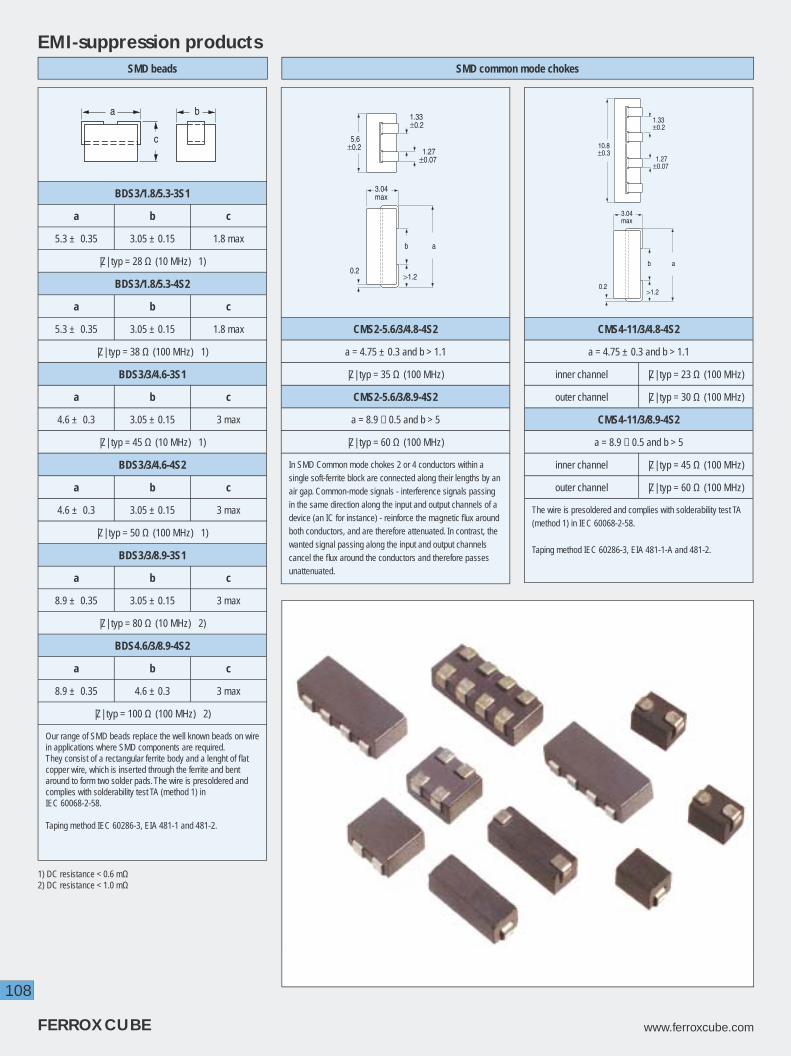
108
FERROXCUBE www.ferroxcube.com
EMI-suppression products
BDS3/1.8/5.3-3S1
a b c
5.3 ± 0.35 3.05 ± 0.15 1.8 max
|Z| typ = 28 Ω (10 MHz) 1)
BDS3/1.8/5.3-4S2
a b c
5.3 ± 0.35 3.05 ± 0.15 1.8 max
|Z| typ = 38 Ω (100 MHz) 1)
BDS3/3/4.6-3S1
a b c
4.6 ± 0.3 3.05 ± 0.15 3 max
|Z| typ = 45 Ω (10 MHz) 1)
BDS3/3/4.6-4S2
a b c
4.6 ± 0.3 3.05 ± 0.15 3 max
|Z| typ = 50 Ω (100 MHz) 1)
BDS3/3/8.9-3S1
a b c
8.9 ± 0.35 3.05 ± 0.15 3 max
|Z| typ = 80 Ω (10 MHz) 2)
BDS4.6/3/8.9-4S2
a b c
8.9 ± 0.35 4.6 ± 0.3 3 max
|Z| typ = 100 Ω (100 MHz) 2)
Our range of SMD beads replace the well known beads on wire in applications where SMD components are required.They consist of a rectangular ferrite body and a lenght of fl at copper wire, which is inserted through the ferrite and bent around to form two solder pads. The wire is presoldered and complies with solderability test TA (method 1) inIEC 60068-2-58.
Taping method IEC 60286-3, EIA 481-1 and 481-2.
a
1.33±0.2
1.27±0.07
b
>1.2
3.04max
5.6±0.2
0.2
CMS2-5.6/3/4.8-4S2
a = 4.75 ± 0.3 and b > 1.1
|Z| typ = 35 Ω (100 MHz)
CMS2-5.6/3/8.9-4S2
a = 8.9 − 0.5 and b > 5
|Z| typ = 60 Ω (100 MHz)
In SMD Common mode chokes 2 or 4 conductors within a single soft-ferrite block are connected along their lengths by an air gap. Common-mode signals - interference signals passing in the same direction along the input and output channels of a device (an IC for instance) - reinforce the magnetic fl ux around both conductors, and are therefore attenuated. In contrast, the wanted signal passing along the input and output channels cancel the fl ux around the conductors and therefore passes unattenuated.
ab
>1.2
3.04max
0.2
1.33±0.2
1.27±0.07
10.8±0.3
CMS4-11/3/4.8-4S2
a = 4.75 ± 0.3 and b > 1.1
inner channel |Z| typ = 23 Ω (100 MHz)
outer channel |Z| typ = 30 Ω (100 MHz)
CMS4-11/3/8.9-4S2
a = 8.9 − 0.5 and b > 5
inner channel |Z| typ = 45 Ω (100 MHz)
outer channel |Z| typ = 60 Ω (100 MHz)
The wire is presoldered and complies with solderability test TA (method 1) in IEC 60068-2-58.
Taping method IEC 60286-3, EIA 481-1-A and 481-2.
SMD beads SMD common mode chokes
b
c
a
1) DC resistance < 0.6 mΩ2) DC resistance < 1.0 mΩ

109
www.ferroxcube.com FERROXCUBE
EMI-suppression productsBeads on wire
dD
L
l
Type Numberdimensions |Z| typ (Ω)
at 100 MHzD L l d
BDW3.5/3.5-4S2 3.5 ± 0.2 3.5 − 0.5 64.4 0.65 58
BDW3.5/4.7-4S2 3.5 ± 0.2 4.7 − 0.5 64.4 0.65 75
BDW3.5/5.3-4S2 3.5 ± 0.25 5.25 ± 0.25 64.4 0.64 82
BDW3.5/6-4S2 3.5 ± 0.2 6.0 ± 0.25 64.4 0.65 100
BDW3.5/6.7-4S2 3.5 ± 0.2 6.7 ± 0.25 64.4 0.65 110
BDW3.5/7.6-4S2 3.5 ± 0.2 7.6 ± 0.35 64.4 0.65 131
BDW3.5/8.9-4S2 3.5 ± 0.2 8.9 ± 0.35 64.4 0.65 146
BDW3.5/9.5-4S2 3.5 ± 0.25 9.5 ± 0.3 64.4 0.64 150
BDW3.5/11-4S2 3.5 ± 0.25 11.4 ± 0.4 64.4 0.64 180
BDW3.5/14-4S2 3.5 ± 0.25 13.8 ± 0.5 64.4 0.64 220
Beads-on-wire are suitable to suppress unwanted signals between parts of a PCB. They consist of a suppression bead fi xed on a length of wire and taped on a bandolier. The bandolier fi ts most commonly used automatic mounting machines.The tape complies to tape standards IEC 60286 part 1 and EIA-RS-96-D.
d
DL
Type Numberdimensions |Z| typ (Ω)
at 10 MHzD L L
BD3/0.7/4-3S1 3 ± 0.1 0.7 + 0.1 4 ± 0.2 49
BD3/1/10-3S1 3 ± 0.1 1 + 0.1/− 0.05 10 ± 0.3 91
BD5.1/0.8/4-3S1 5.1 − 0.3 0.75 + 0.1 4 ± 0.2 66
BD5.1/0.8/10-3S1 5.1 − 0.3 0.75 + 0.1 10 ± 0.3 160
BD5.1/1.5/4-3S1 5.1 − 0.3 1.5 + 0.15 4 ± 0.2 40
BD5.1/1.5/10-3S1 5.1 − 0.3 1.5 + 0.15 10 ± 0.3 100
BD5.1/2/4-3S1 5.1 − 0.3 2 + 0.2 4 ± 0.2 30
BD5.1/2/10-3S1 5.1 − 0.3 2 + 0.2 10 ± 0.3 76
Type Numberdimensions |Z| typ (Ω)
at 100 MHzD L L
BD1.9/0.8/9.8-4S2 1.9 + 0.2 0.8 + 0.2 9.75 − 0.2 69
BD3/0.7/4-4S2 3 ± 0.1 0.7 + 0.1 4 ± 0.2 63
BD3/0.8/10-4S2 3 ± 0.1 0.75 + 0.1 10 ± 0.3 156
BD3/1/4-4S2 3 ± 0.1 1 + 0.1/− 0.05 4 ± 0.2 48
BD3/1/10-4S2 3 ± 0.1 1 + 0.1/− 0.05 10 ± 0.3 119
BD3.5/1.3/3.3-4S2 3.5 ± 0.2 1.3 ± 0.1 3.25 ± 0.25 40
BD3.5/1.3/6-4S2 3.5 ± 0.2 1.3 ± 0.1 6 ± 0.25 60
BD3.5/1.3/13-4S2 3.5 ± 0.2 1.3 ± 0.1 12.7 ± 0.35 125
BD5.1/0.8/4-4S2 5.1 − 0.3 0.75 + 0.1 4 ± 0.2 85
BD5.1/0.8/10-4S2 5.1 − 0.3 0.75 + 0.1 10 ± 0.3 213
BD5.1/1.5/4-4S2 5.1 − 0.3 1.5 + 0.15 4 ± 0.2 51
BD5.1/1.5/10-4S2 5.1 − 0.3 1.5 + 0.15 10 ± 0.3 130
BD5.1/2/4-4S2 5.1 − 0.3 2 + 0.2 4 ± 0.2 40
BD5.1/2/7.1-4S2 5.1 − 0.3 2 + 0.2 7.1 ± 0.2 78
BD5.1/2/10-4S2 5.1 − 0.3 2 + 0.2 10 ± 0.3 100
BD6.4/3/25-4S2 6.35 ± 0.15 2.95 + 0.45 25.4 ± 0.75 200
BD7.7/2.3/7.6-4S2 7.65 - 0.25 2.25 + 0.25 7.55 ± 0.25 92
BD8/1.5/4-4S2 8 ± 0.2 1.5 + 0.15 4 ± 0.2 71
BD8/1.5/10-4S2 8 ± 0.2 1.5 + 0.15 10 ± 0.3 181
BD8/2/4-4S2 8 ± 0.2 2 + 0.2 4 ± 0.2 61
BD8/2/10-4S2 8 ± 0.2 2 + 0.2 10 ± 0.3 151
BD8/3/4-4S2 8 ± 0.2 3 + 0.2 4 ± 0.2 43
BD8/3/10-4S2 8 ± 0.2 3 + 0.2 10 ± 0.3 106
EMI-suppression beads
Colour marking: 4S2 has a fl ash of yellow paint.
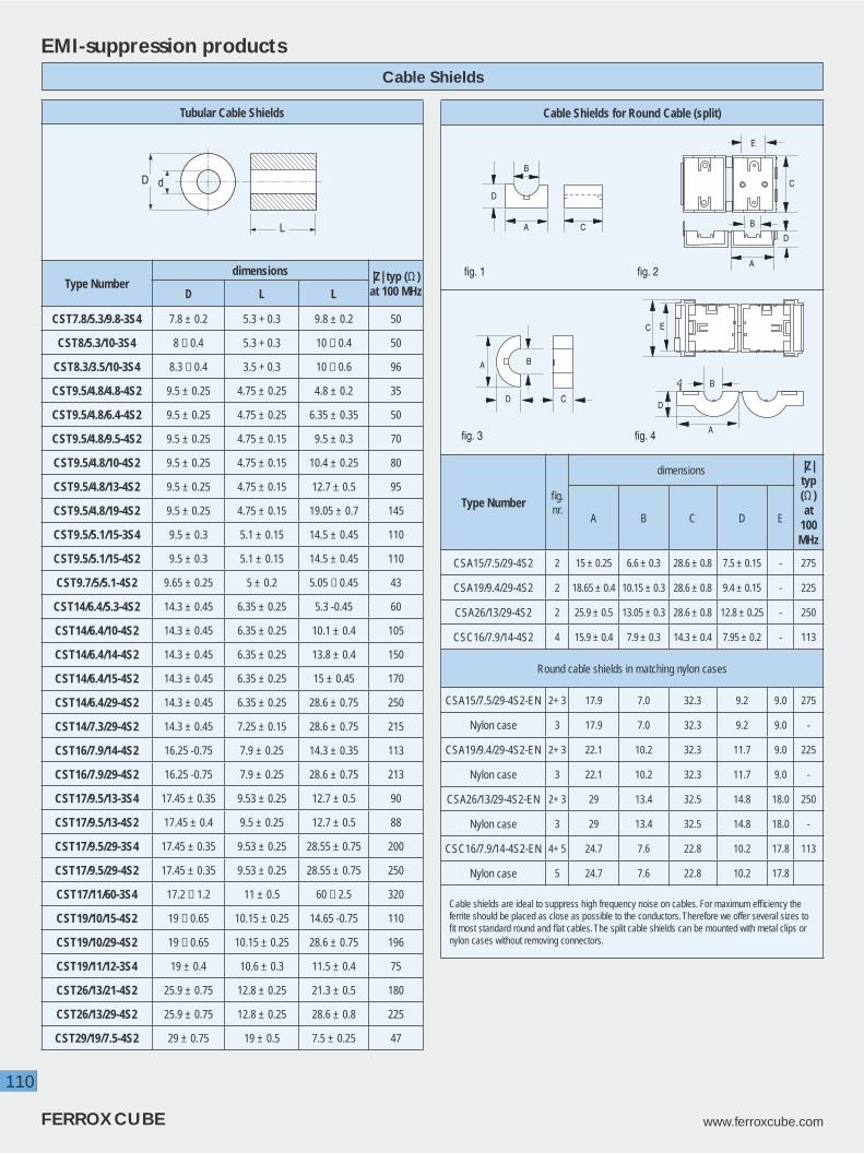
110
FERROXCUBE www.ferroxcube.com
EMI-suppression products
Tubular Cable Shields
D
L
d
Type Numberdimensions |Z| typ (Ω)
at 100 MHzD L L
CST7.8/5.3/9.8-3S4 7.8 ± 0.2 5.3 + 0.3 9.8 ± 0.2 50
CST8/5.3/10-3S4 8 − 0.4 5.3 + 0.3 10 − 0.4 50
CST8.3/3.5/10-3S4 8.3 − 0.4 3.5 + 0.3 10 − 0.6 96
CST9.5/4.8/4.8-4S2 9.5 ± 0.25 4.75 ± 0.25 4.8 ± 0.2 35
CST9.5/4.8/6.4-4S2 9.5 ± 0.25 4.75 ± 0.25 6.35 ± 0.35 50
CST9.5/4.8/9.5-4S2 9.5 ± 0.25 4.75 ± 0.15 9.5 ± 0.3 70
CST9.5/4.8/10-4S2 9.5 ± 0.25 4.75 ± 0.15 10.4 ± 0.25 80
CST9.5/4.8/13-4S2 9.5 ± 0.25 4.75 ± 0.15 12.7 ± 0.5 95
CST9.5/4.8/19-4S2 9.5 ± 0.25 4.75 ± 0.15 19.05 ± 0.7 145
CST9.5/5.1/15-3S4 9.5 ± 0.3 5.1 ± 0.15 14.5 ± 0.45 110
CST9.5/5.1/15-4S2 9.5 ± 0.3 5.1 ± 0.15 14.5 ± 0.45 110
CST9.7/5/5.1-4S2 9.65 ± 0.25 5 ± 0.2 5.05 − 0.45 43
CST14/6.4/5.3-4S2 14.3 ± 0.45 6.35 ± 0.25 5.3 -0.45 60
CST14/6.4/10-4S2 14.3 ± 0.45 6.35 ± 0.25 10.1 ± 0.4 105
CST14/6.4/14-4S2 14.3 ± 0.45 6.35 ± 0.25 13.8 ± 0.4 150
CST14/6.4/15-4S2 14.3 ± 0.45 6.35 ± 0.25 15 ± 0.45 170
CST14/6.4/29-4S2 14.3 ± 0.45 6.35 ± 0.25 28.6 ± 0.75 250
CST14/7.3/29-4S2 14.3 ± 0.45 7.25 ± 0.15 28.6 ± 0.75 215
CST16/7.9/14-4S2 16.25 -0.75 7.9 ± 0.25 14.3 ± 0.35 113
CST16/7.9/29-4S2 16.25 -0.75 7.9 ± 0.25 28.6 ± 0.75 213
CST17/9.5/13-3S4 17.45 ± 0.35 9.53 ± 0.25 12.7 ± 0.5 90
CST17/9.5/13-4S2 17.45 ± 0.4 9.5 ± 0.25 12.7 ± 0.5 88
CST17/9.5/29-3S4 17.45 ± 0.35 9.53 ± 0.25 28.55 ± 0.75 200
CST17/9.5/29-4S2 17.45 ± 0.35 9.53 ± 0.25 28.55 ± 0.75 250
CST17/11/60-3S4 17.2 − 1.2 11 ± 0.5 60 − 2.5 320
CST19/10/15-4S2 19 − 0.65 10.15 ± 0.25 14.65 -0.75 110
CST19/10/29-4S2 19 − 0.65 10.15 ± 0.25 28.6 ± 0.75 196
CST19/11/12-3S4 19 ± 0.4 10.6 ± 0.3 11.5 ± 0.4 75
CST26/13/21-4S2 25.9 ± 0.75 12.8 ± 0.25 21.3 ± 0.5 180
CST26/13/29-4S2 25.9 ± 0.75 12.8 ± 0.25 28.6 ± 0.8 225
CST29/19/7.5-4S2 29 ± 0.75 19 ± 0.5 7.5 ± 0.25 47
Cable Shields
Cable Shields for Round Cable (split)
fig. 1 fig. 2
CA
D
B
A
B
C
D
E
fig. 3 fig. 4
BA
CD
A
B
EC
D
Type Number fi g.nr.
dimensions |Z| typ (Ω) at
100 MHz
A B C D E
CSA15/7.5/29-4S2 2 15 ± 0.25 6.6 ± 0.3 28.6 ± 0.8 7.5 ± 0.15 - 275
CSA19/9.4/29-4S2 2 18.65 ± 0.4 10.15 ± 0.3 28.6 ± 0.8 9.4 ± 0.15 - 225
CSA26/13/29-4S2 2 25.9 ± 0.5 13.05 ± 0.3 28.6 ± 0.8 12.8 ± 0.25 - 250
CSC16/7.9/14-4S2 4 15.9 ± 0.4 7.9 ± 0.3 14.3 ± 0.4 7.95 ± 0.2 - 113
Round cable shields in matching nylon cases
CSA15/7.5/29-4S2-EN 2+ 3 17.9 7.0 32.3 9.2 9.0 275
Nylon case 3 17.9 7.0 32.3 9.2 9.0 -
CSA19/9.4/29-4S2-EN 2+ 3 22.1 10.2 32.3 11.7 9.0 225
Nylon case 3 22.1 10.2 32.3 11.7 9.0 -
CSA26/13/29-4S2-EN 2+ 3 29 13.4 32.5 14.8 18.0 250
Nylon case 3 29 13.4 32.5 14.8 18.0 -
CSC16/7.9/14-4S2-EN 4+ 5 24.7 7.6 22.8 10.2 17.8 113
Nylon case 5 24.7 7.6 22.8 10.2 17.8
Cable shields are ideal to suppress high frequency noise on cables. For maximum effi ciency the ferrite should be placed as close as possible to the conductors. Therefore we offer several sizes to fi t most standard round and fl at cables. The split cable shields can be mounted with metal clips or nylon cases without removing connectors.

111
www.ferroxcube.com FERROXCUBE
Flat Cable Shields (split)
AB
C
E
D
fig. 1 fig. 2 fig. 3
A
B
C
D
EBA
C
E
D
Type Number fi g.nr.
dimensions |Z| typ (Ω) at
100 MHz
A B C D E
CSU45/6.4/29-4S2 1 45.1 ± 0.75 34.4 ± 0.7 28.6 ± 0.7 6.35 ± 0.25 0.85 ± 0.2 225
CSU76/6.4/13-3S4 1 76.2 ± 1.5 65.3 ± 1.3 12.7 ± 0.4 6.35 ± 0.25 0.85 ± 0.2 110
CSU76/6.4/15-3S4 1 76.2 ± 1.5 65.3 ± 1.3 15.0 ± 0.6 6.35 ± 0.25 0.85 ± 0.2 159
CSU76/6.4/29-4S2 1 76.2 ± 1.5 65.3 ± 1.3 28.6 ± 0.8 6.35 ± 0.25 0.85 ± 0.2 215
CSU76/6.4/29-3S4 1 76.2 ± 1.5 65.3 ± 1.3 28.6 ± 0.8 6.35 ± 0.25 0.85 ± 0.2 235
CLI-CSU6.4 3 16.1 11.0 12.7 11.4 8.0 -
Flat cable shields in matching nylon cases
CSU45/6.4/29-4S2-EN 1+ 2 49.5 34.3 32.3 8.1 20 225
Nylon case 2 49.5 34.3 32.3 8.1 20 -
CSU76/6.4/29-4S2-EN 1+ 2 80.8 65.5 32.3 8.1 50.8 215
Nylon case 2 80.8 65.5 32.3 8.1 50.8 -
*) can be supplied with nylon case upon request
Flat Cable Shields
C
BE
DA
E
D
B
A
A
A
A - AC
fig. 4 fig. 5
Type Number fi g.nr.
dimensions |Z| typ (Ω) at
100 MHz
A B C D E
CSF38/12/25-3S4 4 38.1 ± 1.0 12.1 ± 0.35 25.4 ± 0.75 26.7 ± 0.75 1.9 ± 0.35 215
CSF38/12/25-3S4-S 5 38.5 ± 0.6 12.1 ± 0.4 25.4 ± 0.8 26.8 ± 0.8 1.9 ± 0.4 196
Cable Shields
EMI-suppression products

112
FERROXCUBE www.ferroxcube.com
EMI-suppression products
a
db
c
BC13/4.8/16-3C90 1)
a b c d
12.8 − 0.5 16 4.8 ± 0.2 10
AL (nH) ≈ 50
BC22/12/14-3C90
a b c d
22 ± 1 14 ± 1 12 ± 0.3 8.6 ± 0.6
AL (nH) ≈ 86
BC22/12/18-3C90
a b c d
22 ± 1 18 ± 1 12 ± 0.3 12.6 ± 0.6
AL (nH) ≈ 85
BC22/12/19-3C90
a b c d
22 ±1 18.5 ±1 12 ± 0.3 10.5 + 0.6
AL (nH) ≈ 94
BC22/12/38-3C90
a b c d
22 ± 1 38 ± 1.4 12 ± 0.3 30 + 1.4
AL (nH) ≈ 74
BC23/12/14-3C90 2)
a b c d
22.6 ± 1 14 ± 1 12 ± 0.3 8.6 ± 0.6
AL (nH) ≈ 92
Bobbin cores are easy to wind with thick copper wire. Application is mainly as power inductor in output stages of converters or as EMI choke in lines with high DC currents. The magnetic circuit is open, resulting in high current capability, but also in quite some stray fl ux.AL measured with fully wound bobbin
1) no central hole, 2 wire slots2) no wire slots
Bobbin Cores
A B
C
D
Type Numberdimensions
A B C D
D38152012-3C92 3.8 ± 0.15 2.0 ± 0.1 1.5 ± 0.1 1.2 ± 0.1
D41150803-3C92 4.1 ± 0.15 0.8 ± 0.1 1.5 ± 0.1 0.3 ± 0.1
D41150803-4A11 4.1 ± 0.15 0.8 ± 0.1 1.5 ± 0.1 0.3 ± 0.1
D41150803-4B1 4.1 ± 0.15 0.8 ± 0.1 1.5 ± 0.1 0.3 ± 0.1
D41151306-4A11 4.11 ± 0.15 1.27 ± 0.1 1.45 ± 0.1 0.64 ± 0.1
D41151407-3C92 4.1 ± 0.15 1.4 ± 0.1 1.5 ± 0.1 0.7 ± 0.1
D41151407-4A11 4.1 ± 0.15 1.4 ± 0.1 1.5 ± 0.1 0.7 ± 0.1
D41151407-4B1 4.1 ± 0.15 1.4 ± 0.1 1.5 ± 0.1 0.7 ± 0.1
D41151811-3C92 4.1 ± 0.15 1.8 ± 0.1 1.5 ± 0.1 1.1 ± 0.1
D41161004-3C92 4.1 ± 0.15 1.0 ± 0.1 1.6 ± 0.1 0.35 ± 0.1
D41161609-4B1 4.1 ± 0.15 1.6 ± 0.1 1.6 ± 0.1 0.9 ± 0.1
D42180903-3C92 4.2 ± 0.15 0.9 ± 0.1 1.8 ± 0.1 0.28 ± 0.1
D42182012-3C92 4.2 ± 0.15 2.0 ± 0.1 1.8 ± 0.1 1.2 ± 0.1
D42200903-4B1 4.2 ± 0.15 0.9 ± 0.1 2.0 ± 0.1 0.3 ± 0.1
D42201105-3C92 4.2 ± 0.15 1.1 ± 0.1 2.0 ± 0.1 0.5 ± 0.1
D58150803-3C92 5.8 ± 0.15 0.8 ± 0.1 1.5 ± 0.1 0.3 ± 0.1
Mini drum cores are used wherever miniaturization requires very small and thin inductors. They can be found as micro power inductors in applications such as telecom, lap tops, set-top boxes and hand held equipment.
Summary :• very low profi le (height down to 0.8 mm)• advanced power and high resistivity materials• very high saturation• broad bandwidth• micro-precision in mechanical dimensions• custom designs possible
Miniature Drum Cores

113
www.ferroxcube.com FERROXCUBE
EMI-suppression products
MHC6
MHB2
MHR2
MHR6
L D
d
45° 45°
H
L D
d
H
L D
d
L H
d
D
Type Numberdimensions
D L l d
MHC6-6/10-3S4 6 ± 0.3 0.7 + 0.2 10 ± 0.5 -
MHC6-6/10-4B1 6 ± 0.3 0.7 + 0.2 10 ± 0.5 -
MHC6-6/5-4B1 6 ± 0.3 0.7 + 0.2 5 − 0.2 -
MHB2-14/8.5/8-4B1 8.5 − 0.5 3.5 + 0.5 8 ± 0.3 14 ± 0.5
MHB2-14/8.5/14-4B1 8.5 − 0.5 3.5 + 0.5 14 ± 0.4 14 ± 0.5
MHB2-13/8/6-4B1 1) 8.0 ± 0.3 3 ± 0.3 6 ± 0.3 13 ± 0.3
MHB2-13/8/6-3C901) 8.0 ± 0.3 3 ± 0.3 6 ± 0.3 13 ± 0.3
MHR2-11/5.4/11-4A11 5.4 ± 0.3 2.0 ± 0.3 10.9 ± 0.3 10.8 ± 0.3
MHR2-11/5.4/11-3C90 5.4 ± 0.3 2.0 ± 0.3 10.9 ± 0.4 10.8 ± 0.3
MHR6-6.1/4/10-3B1 4 ± 0.2 0.7 + 0.3 10 ± 0.5 6.1 ± 0.3
Multi-hole cores are used for small HF transformers, for voltage or impedance matching in TV, com-munications, data transmission, instrumentation and similar applications. They are available with 2 and 6 holes (twin cores and six-hole cores), in round and rectangular shapes.
1) Chamfered holes and sides.
Summary :• wide range of shapes• several materials• for HF matching and suppression
Multi Hole Cores

114
FERROXCUBE www.ferroxcube.com
EMI-suppression products
L D
Material Type numberDimensions (mm)
D L
3B1
ROD1.6/9-3B1-D 1.6 + 0.05 9 ± 0.2ROD2/20-3B1-D 2 − 0.05 20 − 0.9ROD3/15-3B1-D 3 − 0.05 15 − 0.8ROD3/20-3B1-D 3 − 0.05 20 − 0.9ROD3/25-3B1-D 3 − 0.05 25 − 1.0ROD4/15-3B1-D 4 − 0.05 15 − 0.8ROD4/20-3B1-D 4 − 0.05 20 − 0.9ROD4/25-3B1-D 4 − 0.05 25 − 1.0ROD5/20-3B1-D 5 − 0.05 20 − 0.9ROD5/25-3B1-D 5 − 0.05 25 − 1.0ROD5/30-3B1-D 5 − 0.05 30 − 1.2ROD6/30-3B1-D 6 − 0.10 30 − 1.2ROD6/40-3B1-D 6 − 0.10 40 − 1.6ROD6/50-3B1-D 6 − 0.10 50 ± 1.0ROD8/50-3B1 8 − 0.40 50 ± 1.0
ROD8/150-3B1 8 − 0.40 150 ± 3ROD8/200-3B1 8 − 0.40 200 ± 4
3S3
ROD3/20-3S3 3 − 0.3 20 ± 0.4ROD3.3/17-3S3 3.3 ± 0.10 17 ± 0.3ROD5/20-3S3 5 − 0.30 20 ± 0.5ROD5/25-3S3 5 − 0.30 25 − 1.0
ROD5.3/18-3S3 5.25 − 0.3 18 ± 0.3ROD6/25-3S3 6 − 0.30 25 ± 0.6ROD6/30-3S3 6 − 0.30 30 ± 0.9
ROD6.5/25-3S3 6.5 − 0.30 25 ± 0.6ROD8/25-3S3 8 − 0.5 25 ± 0.75ROD8/32-3S3 8 − 0.5 32 − 2
4B1
ROD1.6/9-4B1-D 1.6 + 0.05 9 ± 0.2ROD2/20-4B1-D 2 − 0.05 20 − 0.9ROD3/15-4B1-D 3 − 0.05 15 − 0.8ROD3/20-4B1-D 3 − 0.05 20 − 0.9ROD3/25-4B1-D 3 − 0.05 25 − 1.0ROD4/15-4B1-D 4 − 0.05 15 − 0.8ROD4/20-4B1-D 4 − 0.05 20 − 0.9ROD4/25-4B1-D 4 − 0.05 25 − 1.0ROD5/20-4B1 5 − 0.30 20 ± 0.5
ROD5/20-4B1-D 5 − 0.05 20 − 0.9ROD5/25-4B1-D 5 − 0.05 25 − 1.0ROD5/30-4B1-D 5 − 0.05 30 − 1.2ROD6/30-4B1-D 6 − 0.10 30 − 1.2ROD6/40-4B1-D 6 − 0.10 40 − 1.6ROD6/50-4B1-D 6 − 0.10 50 ± 1.0ROD6.5/25-4B1 6.5 − 0.30 25 ± 0.6ROD8/32-4B1 8 − 0.5 32 -2ROD8/50-4B1 8 − 0.40 50 ± 1.0ROD8/150-4B1 8 − 0.40 150 ± 3ROD8/200-4B1 8 − 0.40 200 ± 4
ROD10/200-4B1 10 − 0.50 200 ± 4
Rods
Generally, ferrite rods are used as the core of solenoidal chokes. Such a choke can carry a high DC current without being saturated because of the open magnetic circuit. In most cases, the frequency range
will not be limited by the material, but by the coil capacitance. Curvature and mechanical tolerances of the standard range fulfi l the requirements of DIN41291 or its equivalent IEC 60233-1966.
The L value and Q factor are measured (up to 6 mm outer diameter) in a standard coil, according to DIN 41276 or its equivalent IEC 732-1982, and compared with a standard rod.
Summary :• For solenoidal coils• Open circuit, no self shielding• Not easily saturated by load currents

115
www.ferroxcube.com FERROXCUBE
EMI-suppression products
L
Dd
Material Type numberDimensions (mm)
D d L
3B1
TUB3.1/1.3/19-3B1-DL 3.1 − 0.02 1.3 + 0.2 18.8 − 0.5TUB3.5/1.2/5-3B1 3.5 − 0.25 1.2 + 0.15 5 − 0.3TUB3.5/1.3/3-3B1 3.5 + 0.1/− 0.2 1.3 + 0.2 3 + 0.5
TUB3.5/1.3/7.5-3B1 3.5 ± 0.2 1.3 + 0.2 7.5 + 0.5TUB3.7/1.2/3.5-3B1 3.7− 0.4 1.2 + 0.2 3.5 − 0.5TUB4/1.6/15-3B1 4 − 0.25 1.6 + 0.15 15 − 0.8TUB4/1.6/40-3B1 4 − 0.25 1.6 + 0.15 40 − 1.6
TUB4/2/5-3B1 4 ± 0.2 2 ± 0.2 5 ± 0.5TUB4.1/2/7-3B1-D 4.1 + 0.1 2 + 0.2 7 ± 0.2
TUB4.1/2/11-3B1-D 4.1 + 0.1 2 + 0.2 11 ± 0.2TUB4.2/2/12-3B1-DL 4.15 − 0.05 2 + 0.2 12.2 − 0.4
TUB4.3/2/15-3B1 4.3 − 0.2 2 + 0.2 15.4 − 0.8TUB4.3/2/26-3B1 4.3 − 0.2 2 + 0.2 25.5 − 1TUB5.3/3/22-3B1 5.3 − 0.2 3 + 0.2 22.4 − 0.8TUB6/3/20-3B1 6 − 0.3 3 + 0.2 20 − 0.9TUB8/4/20-3B1 8 − 0.4 4 + 0.3 20 − 0.9TUB8/4/40-3B1 8 − 0.4 4 + 0.3 40 − 1.6
TUB8/4.2/51-3B1 8 − 0.4 4.2 + 0.6 51.4 − 2.8TUB9.5/6.5/17-3B1 9.5 ± 0.3 6.5 ± 0.2 17 + 0.5/− 0.4TUB10/4.2/20-3B1 10 − 0.5 4.2 + 0.3 20 − 0.9
3C90
TUB4/1.6/40-3C90 4 − 0.25 1.6 + 0.15 40 − 1.6TUB5/2/50-3C90 5 − 0.3 2 + 0.2 50 ± 1TUB6/3/20-3C90 6 − 0.3 3 + 0.2 20 − 0.9TUB6/3/30-3C90 6 − 0.3 3 + 0.2 30 − 1.2TUB8/4/40-3C90 8 − 0.4 4 + 0.3 40 − 1.6
TUB10/4.2/20-3C90 10 − 0.5 4.2 + 0.3 20 − 0.9TUB10/6.5/20-3C90 10 − 0.5 6.5 + 0.4 20 − 0.9
4B1
TUB3.5/1.2/5-4B1 3.5 − 0.25 1.2 + 0.15 5 − 0.3TUB3.7/1.2/3.5-4B1 3.7 − 0.4 1.2 + 0.2 3.5 − 0.5TUB3.8/2.8/8-4B1 3.8 ± 0.1 2.8 ± 0.1 8 ± 0.25TUB4/1.6/15-4B1 4 − 0.25 1.6 + 0.15 15 − 0.8TUB4/1.6/40-4B1 4 − 0.25 1.6 + 0.15 40 − 1.6TUB4/3/9.5-4B1 4 ± 0.1 3 + 0.2 9.45 + 0.75TUB4.1/2/7-4B1 4.1 + 0.2 2 + 0.2 7 ± 0.2
TUB4.1/2/26-4B1 4.1 + 0.2 2 + 0.2 25.5 − 1TUB4.2/2/12-4B1-DL 4.15 − 0.05 2 + 0.2 12.2 − 0.4
TUB4.3/2/15-4B1 4.3 − 0.2 2 + 0.2 15.4 − 0.8TUB6/3/20-4B1 6 − 0.3 3 + 0.2 20 − 0.9TUB6/3/30-4B1 6 − 0.3 3 + 0.2 30 − 1.2TUB8/4/20-4B1 8 − 0.4 4 + 0.3 20 − 0.9
TUB8/4.2/51-4B1 8 − 0.4 4.2 + 0.6 51.4 − 2.8TUB10/6.5/20-4B1 10 − 0.5 6.5 + 0.4 20 − 0.9
Tubes
Tubes can be used in solenoid coils with almost the same effect as rods. The inner hole is often used to insert wires to make a ferrite coil former. In EMI suppression applications tubes can also be shifted over wires. Because the magnetic fl ux path is then closed, a steep increase in impedance results.
In such cases however the sensitivity for DC currents is rather high. Curvature and mechanical tolerances of the standard range fulfi l the requirements of DIN 41291 or its equivalent IEC 60233-1966.
Summary :• Full range of standard sizes• For general EMI suppression• With wires inserted used as ferrite coil former

116
FERROXCUBE www.ferroxcube.com
EMI-suppression productsWideband Chokes
WBC1.5/A
40± 5
40± 5
1014
max
∅0.6
6
WBC1.5/A-4S2
|Z| at frequency
Ω MHz
2131) 10
4001) 50
4701) 100
WBC1.5/A-3S4
|Z| at frequency
Ω MHz
≥ 300 120
WBC1.5/A-4B1
|Z| at frequency
Ω MHz
≥ 350 250
WBC1.5/1.5/A
14 max
40± 5
40± 5
10
∅0.6
6
WBC1.5/1.5/A-4S2
|Z| at frequency
Ω MHz
2133) 10
4003) 50
4703) 100
WBC1.5/1.5/A-3S4
|Z| at frequency
Ω MHz
≥ 7002) 50
WBC1.5/1.5/A-4B1
|Z| at frequency
Ω MHz
≥ 8002) 110
WBC1.5/1.5/A-4A15
|Z| at frequency
Ω MHz
10003) 50
10003) 180
WBC2/R
10 14 max
40± 5
3.5
∅0.6
6
WBC2/R-4S2
|Z| at frequency
Ω MHz
3001) 10
6501) 50
6001) 100
WBC2/R-4A15
|Z| at frequency
Ω MHz
≥ 730 50
≥ 750 180
WBC2.5/A
14 max
40± 5
40± 5
10
∅0.6
6
WBC2.5/A-4S2
|Z| at frequency
Ω MHz
4001) 10
8501) 50
7251) 100
WBC2.5/A-3S4
|Z| at frequency
Ω MHz
≥ 600 50
WBC2.5/A-4B1
|Z| at frequency
Ω MHz
≥ 700 180
WBC2.5/A-4A15
|Z| at frequency
Ω MHz
8001) 50
8201) 180
Wide-band chokes are an alternative to a bead when more impedance or damping is required. In these products the conductor wire is wound through holes in a multi-hole ferrite core, thus separating them physically and reducing coil capacitance. The result is a high impedance over a wide frequency range, a welcome feature for many interference problems. The present design has excellent properties and reliability by keeping the number of electrical interfaces to an absolute minimum.
1) Minimum guaranteed impedance is |Z|typ − 20 %.2) |Z| measured with both windings connected in series.3) Minimum guaranteed impedance is |Z|typ − 20 % ; measured with one winding.
1) Minimum guaranteed impedance is IZI typ -20%.
2) IZI measured with both windings connected in series.
3) Minimum guaranteed impedance is IZI typ -20%; measured with one winding.
1) Minimum guaranteed impedance is IZI typ -20%.
1) Minimum guaranteed impedance is IZI typ -20%.

117
www.ferroxcube.com FERROXCUBE
EMI-suppression productsWideband Chokes
WBC2.5/R
12.5±1
∅0.6
10 13.5max
6 2.5
4 +20
WBC2.5/R-3S4
|Z| at frequency
Ω MHz
≥ 600 50
WBC2.5/R-4B1
|Z| at frequency
Ω MHz
≥ 700 75
WBC2.5/R-4S2
|Z| at frequency
Ω MHz
4001) 10
8501) 50
7251) 100
WBC2.5/SP
colour code3S4 = blue
4B1 = green
12.5±1
2.5±1
2.5 0+2
∅0.6
WBC2.5/SP-3S4
|Z| at frequency
Ω MHz
≥ 600 50
WBC2.5/SP-4B1
|Z| at frequency
Ω MHz
≥ 700 75
WBC3/R
10 14 max
20 min
3.5
∅0.6
6
WBC3/R-4S2
|Z| at frequency
Ω MHz
5001) 10
10001) 50
6881) 100
WBC3/R-3S4
|Z| at frequency
Ω MHz
≥ 650 63
WBC3/R-4B1
|Z| at frequency
Ω MHz
≥ 800 110
WBC3/R-4A15
|Z| at frequency
Ω MHz
≥ 1000 50
≥ 1000 180
1) Minimum guaranteed impedance is IZI typ -20%.
1) Minimum guaranteed impedance is IZI typ -20%.

118
FERROXCUBE www.ferroxcube.com

119
www.ferroxcube.com FERROXCUBE

120
FERROXCUBE www.ferroxcube.com
Property Test conditions Specialty Ferrites
Symbol f (kHz) Bpeak or H T (ºC) unit 4E2 4M2 4B3 8C12 8C11
µi (± 20%) ≤ 10 ≤ 0.1 mT 25 25 140 300 900 1200
B
10
250 A/m 100mT
≈ 150 ≈ 150 ≈ 250 ≈ 150 ≈ 200
3000 A/m 25 ≈ 320 ≈ 300 ≈ 400 ≈ 270 ≈ 300
Hc 25A/m ≈ 400 ≈ 100 ≈ 60 ≈ 30 ≈ 20
Br mT ≈ 200 ≈ 100 ≈ 200 ≈ 110 ≈ 150
Tc ºC ≥ 400 ≥ 200 ≥ 250 ≥ 125 ≥ 125
ρ DC 25 Ωm ≈ 105 ≈ 105 ≈ 105 ≈ 105 ≈ 105
density kg/m3 ≈ 4000 ≈ 5000 ≈ 5000 ≈ 5100 ≈ 5100
ferrite type NiZn NiZn NiZn NiZn NiZn
Specialty Ferrite materials and applicationsProducts generally comply with the material specifi cation. However deviations may occur due to shape, size and grinding operations etc. Specifi ed product properties are given in the data sheets or product drawings.
Properties measured on sintered, unground ring cores of dimensions ∅ 25 x ∅ 15 x 10 mm,which are not subjected to external stresses.
Scientifi c particle accelleratorsgenerally use large ferrite ringsto tune caveties and concentratethe beam. Ferrite pole pieces,often called kicker magnets,concentrate the magnetic fl uxbursts which defl ect the beaminto experiment chambers.Ferrite rings on supply lines ofe.g. short pulsed radarequipment, delay current riseuntil they saturate causing verysteep pulses.
Accellerator coresand pulse shapers
F e r r i t e c h o i c e
< 1 MHz 8C11, 8C12
frequency range
< 10 MHz 4B3, 4M2
< 100 MHz 4E2

121
www.ferroxcube.com FERROXCUBE
Specialty Ferrites
Machined ferrites and specialty shapes
We stock blocks of most of our material grades and are able to machine all sorts of prototype cores from these blocks. Very close tolerances can be realized, if required.
Ferrites are very hard and brittle and, therefore, diffi cult to work. Machining and grinding ferrites and similar materials to micron precision places stringent requirements on machines and men. To attain optimum standards requires very close cooperation between us and the manufacturers of the machines and the machine tools we use.
There are several reasons to go for machined ferrite cores. Sometimes samples are required on very short notice, while pressing tools are not yet available. On other occasions only a limited number of cores will be needed and it is not worthwhile to make a tool at all. Cores can be so complicated or large that machining is the only viable solution. A good example of a shape that can easily be produced is a planar E core. In a rectangular block of the right dimensions only 2 rectangular grooves have to be made.
The following drawings provide a good impression of the variety of cores we have produced. For some of the cores we also have pressing tools available.
Machined ferrite products
35.3
178.8142.263.5
17.2
82.6
7561.2
25
50
75
50.7
40
400390 60
40
H
D
d
34.7
111.389.6119
o
50
11

122
FERROXCUBE www.ferroxcube.com
Material Type Numberdimensions
mass(g)D d H
4B3 T500/240/25-4B3 500 ± 2 240 ± 0.2 25 ± 0.2 ≈ 19000
4M2T76/38/13-4M2 76.2 ± 0.1 38.1 ± 0.1 12.7 ± 0.1 ≈ 220
T500/300/25-4M2 500 ± 0.1 300 ± 0.1 25 ± 0.1 ≈ 16000
8C11
T76/38/13-8C11 76.2 ± 0.1 38.1 ± 0.1 12.7 ± 0.1 ≈ 220
T170/110/20-8C11 170 ± 0.2 110.2 ± 0.2 20 ± 0.2 ≈ 1300
T240/160/20-8C11 240 ± 0.3 160 ± 0.3 20 ± 0.3 ≈ 2500
8C12
T76/38/13-8C12 76.2 ± 0.1 38.1 ± 0.1 12.7 ± 0.1 ≈ 220
T498/270/25-8C12 498 ± 0.1 270 ± 0.2 25 ± 0.2 ≈ 17000
T498/300/25-8C12 498 ± 0.1 300 ± 0.2 25 ± 0.2 ≈ 15000
Our range of large ring cores and blocks was developed especially for use in scientifi c particle accelerators. Applications include kicker magnets and acceleration stations. Dynamic behaviour under pulse conditions is important for both applications, so special ferrite grades are optimized for low losses at high fl ux densities. These large rings have also been used successfully in delay lines for very high powers such as in pulsed lasers or radar equipment. Sizes other than those mentioned in the tables can be made on request.
• standard range of sizes• optimized grades for particle accelerators• other sizes on request
Specialty FerritesFerrite Toroids for Particle Accelerators
D
dH
T 500/300/25 − 4M2
core material
core size
core type

123
www.ferroxcube.com FERROXCUBE
Appendix
4
Inductance factor calculation
Defi nition of termsPermeabilityWhen a magnetic fi eld is applied to a soft magnetic material, the resulting fl ux density is composed of that of free space plus the contribution of the aligned domains.
B µ0H J or B+ µ0 H M+( )= = [1]
where µ0 = 4π.10 -7 H/m, J is the magnetic polarization and M is the magnetization.The ratio of fl ux density and applied fi eld is called absolute permeability.
[2]BH---- µ0 1 M
H-----+
µabsolute= =
It is usual to express this absolute permeability as the product of the magnetic constant of free space and the relative permeability (µr).
[3]BH---- µ0µr=
Since there are several versions of µr depending on conditions the index ‘r’ is generally removed and replaced by the applicable symbol e.g. µi, µa, µ∆ etc.
Initial permeabilityThe initial permeability is measured in a closed magnetic circuit (ring core) using a very low fi eld strength.
[4]µi
1µ0------ × B∆
H∆--------H∆ 0→( )
=
Initial permeability is dependent on temperature and frequency.
5
Inductance factor calculation
Effective permeabilityIf an airgap is introduced in a closed magnetic circuit, magnetization becomes more diffi cult. As a result, the fl ux density for a given magnetic fi eld strength is lower.Effective permeability is dependent on the initial permeability of the soft magnetic material and the dimensions of airgaps and circuit.
[5]µe
µi
1G × µi
le-----------------+
---------------------------=
where G is the gap length and le is the effective length of magnetic circuit. This simple formula is a good approximation only for small airgaps. For longer airgaps some fl ux will cross the gap outside its normal area (fringing fl ux) causing an increase of the effective permeability.
Amplitude permeabilityThe relationship between higher fi eld strength and fl ux densities without the presence of a bias fi eld, is given by the amplitude permeability (µa).
[6]µa1µ0------ × B
H----=
Since the BH loop is far from linear, values depend on the applied fi eld strength.
Incremental permeabilityThe permeability observed when an alternating magnetic fi eld is superimposed on a static bias fi eld, is called the incremental permeability.
[7]µ∆1µ0------
B∆H∆-------- HDC
=
If the amplitude of the alternating fi eld is negligibly small, the permeability is then called the reversible permeability (µrev).
6
Inductance factor calculation
Effective core dimensionsTo facilitate calculations on a non-uniform soft magnetic core, the effective dimensions are given on each data sheet. These dimensions, effective area (Ae), effective length (le) and effective volume (Ve) defi ne a hypothetical ring core which would have the same magnetic properties as the non-uniform core.The reluctance of the ideal ring core would be:
[9]le
µ × Ae------------------
For the non-uniform core shapes, this is usually written as:
[10]1µe------ × Σ l
A----
the core factor divided by the permeability. The inductance of the core can now be calculated using this core factor:
[11]Lµ0 × N
2
1µe------ × Σ l
A----
-----------------------1.257 × 10
9– × N2
1µe------ × Σ l
A----
-------------------------------------------------- (in H)= =
The effective area is used to calculate the fl ux density in a core, for sine wave:
[12]BU 2 × 10
9
ωAeN------------------------------
2.25U × 108
fNAe----------------------------------(in mT)= =
for square wave:
[13]B0.25U × 10
9
fNAe----------------------------------(in mT)=
where:Ae is the effective area in mm2 .U is the voltage in Vf is the frequency in HzN is the number of turns.
7
Inductance factor calculation
The magnetic fi eld strength (H) is calculated using the effective length (Ie ):
[14]HIN 2
le--------------(A/m)=
If the cross-sectional area of a core is non-uniform, there will always be a point where the real cross-section is minimal. This value is known as Amin and is used to calculate the maximum fl ux density in a core. In well designed ferrite core a large difference between Ae and Amin is avoided. Narrow parts of the core could saturate or cause much higher hysteresis losses.
Inductance factor (AL)To facilitate inductance calculations, the inductance factor, known as the AL value (nH), is given in each data sheet. The inductance factor of a core is defi ned as:
[15]L N2 × AL (nH)=
The value of AL is calculated from the core factor and the effective permeability:
[16]AL =µ0µe × 10
6
Σ l A⁄( )------------------------------ =1.257µe
Σ l A⁄( )--------------------- (nH)

124
FERROXCUBE www.ferroxcube.com
Appendix
8
Inductance factor calculation
Inductance calculations on rods and tubesRods and tubes are generally used to increase the inductance of a coil. The magnetic circuit is very open and therefore the mechanical dimensions have more infl uence on the inductance than the ferrite’s permeability (see Fig.1) unless the rod is very slender. In order to establish the effect of a rod on the inductance of a coil, the following procedure should be carried out:
• Calculate the length to diameter ratio of the rod (l/d).
• Find this value on the horizontal axis and draw a vertical line.The intersection of this line with the curve of the material permeability gives the effective rod permeability (µrod).
The inductance of the coil, provided the winding covers the whole length of the rod is given by:
[17]L µ0µrodN
2A
l----------- H( )=
where:N = number of turnsA = cross sectional area of rod (mm2)I = length of coil. (mm)
Fig.1 Rod permeability (µrod) as a function of length to diameter ratio with material permeability as a parameter.
103
102
10
Length / diameter ratio
µrod
µi = 10.000
5000
2000
1000
700500
400
300
200
150
100
70
40
20
10
1 10 100