Embed Size (px)
Citation preview
Product Selection Guide: T5 Series- 250, 400 & 800 Amps

| StarlinePower.com
INTRODUCTION & SPECSIntroductionUniversal Electric Corporation (UEC) is the leader in electrical power distribution in the mission critical, commercial and light industrial industries with STARLINE Track Busway. This system was designed to meet the rugged specification of the UL857, Busway and Associated Fittings, with the flexible features of track lighting - and is available in systems with 250, 400 & 800 amps with isolated ground.
Track Busway is the simple, versatile, fast and economical solution for supplying power to electrical loads and is unique because the busway can be instantly tapped at any location, with a variety of plug-in units.
The Product Selection Guide was developed to help the design engineer understand and consider all of the options available with STARLINE Track Busway when designing a system.
This guide is all-inclusive; however, UEC excels at collaborating with design engineers to provide solutions for any application. If you have a need that is not found in this guide, please contact us at 1-800-245-6378 or email us at [email protected]. We will be happy to answer your questions over the telephone or schedule a visit with one of our local representatives.
Also, if viewing this guide in print, please keep in mind that this is a working document. UEC reseves the right to change information and descriptions of listed services and products. The latest version of this guide is available for download at downloads.uecorp.com/starline/busway/.
SpecsThis specification covers the electrical characteristics and general requirements for a track busway system, hereafter referred to as (Track Busway). The system shall be designed primarily for overhead distribution of electrical power; supporting designated work areas and equipment. Once installed the Busway will provide a simple, versatile, fast and economic means of distributing power. Loads fed from a variety of plug-in units can be easily added or removed without shutting power down to the busway.
The Track Busway shall be designed and manufactured to the following standards:
1. Underwriters Laboratories Standard, UL 857 – The common UL, CSA, and ANCE Standard for Busways that is derived from the fifth edition of CSA Standard C22.2 No. 27, the twelfth edition of UL 857, and the second edition of NMX-J-148-1998-ANCE.2. Low Voltage Switchgear and Controlgear Assemblies, Part 1: Type Tested and partially type tested Assemblies, IEC 61439-1 & IEC 61439-6.
*All standards and certifications available upon request
T5 Series
4.1

| StarlinePower.com
T5 Series
TABLE OF CONTENTSGROUND OPTIONS............................................................................................................................................................4.4 POLARITY TIPS.....................................................................................................................................................................4.5SYSTEM LAYOUT TIPS........................................................................................................................................................4.6COMPONENT RELATIONSHIP TIPS.............................................................................................................................4.7
250T5 Systems SYSTEM LAYOUT DRAWING............................................................................................................................................4.8STRAIGHT SECTIONS........................................................................................................................................................4.9 STRAIGHT SECTIONS: PRODUCT NUMBERS..........................................................................................................4.10ELBOW SECTIONS...........................................................................................................................................................4.11 ELBOW SECTIONS: PRODUCT NUMBERS..............................................................................................................4.12TEE SECTIONS...................................................................................................................................................................4.13 TEE SECTIONS: PRODUCT NUMBERS....................................................................................................................4.14END FEED UNITS...............................................................................................................................................................4.15END FEED UNITS: METERING......................................................................................................................................4.16 END FEED UNITS: PRODUCT NUMBERS..................................................................................................................4.17ABOVE FEED UNITS.........................................................................................................................................................4.18 ABOVE FEED UNITS: PRODUCT NUMBERS.............................................................................................................4.19
400T5 SystemsSYSTEM LAYOUT DRAWING.........................................................................................................................................4.20STRAIGHT SECTIONS.....................................................................................................................................................4.21 STRAIGHT SECTIONS: PRODUCT NUMBERS..........................................................................................................4.22ELBOW SECTIONS...........................................................................................................................................................4.23 ELBOW SECTIONS: PRODUCT NUMBERS..............................................................................................................4.24TEE SECTIONS...................................................................................................................................................................4.25 TEE SECTIONS: PRODUCT NUMBERS....................................................................................................................4.26END FEED UNITS...............................................................................................................................................................4.27END FEED UNITS: METERING......................................................................................................................................4.28 END FEED UNITS: PRODUCT NUMBERS.................................................................................................................4.29ABOVE FEED UNITS.........................................................................................................................................................4.30 ABOVE FEED UNITS: PRODUCT NUMBERS.............................................................................................................4.31
800T5 SystemsSYSTEM LAYOUT DRAWING.........................................................................................................................................4.32STRAIGHT SECTIONS.....................................................................................................................................................4.33 STRAIGHT SECTIONS: PRODUCT NUMBERS..........................................................................................................4.34ELBOW SECTIONS...........................................................................................................................................................4.35 ELBOW SECTIONS: PRODUCT NUMBERS..............................................................................................................4.36TEE SECTIONS...................................................................................................................................................................4.37 TEE SECTIONS: PRODUCT NUMBERS....................................................................................................................4.38END FEED UNITS...............................................................................................................................................................4.39END FEED UNITS: METERING......................................................................................................................................4.40 END FEED UNITS: PRODUCT NUMBERS.................................................................................................................4.41
4.2
| StarlinePower.com
T5 Series
TABLE OF CONTENTS (cont'd)
RAL Colors............................................................................................................................................................................4.42
ACCESSORIES: SUPPORT HARDWARE..................................................................................................................4.43ACCESSORIES: SUPPORT HARDWARE..................................................................................................................4.44ACCESSORIES: SUPPORT HARDWARE..................................................................................................................4.45ACCESSORIES: CONNECTION HARDWARE.........................................................................................................4.46ACCESSORIES: CONNECTION HARDWARE.........................................................................................................4.47ADD-ON ACCESSORIES: DATA CHANNEL..............................................................................................................4.48ADD-ON ACCESSORIES: DATA CHANNEL..............................................................................................................4.49
SERVICES............................................................................................................................................................................4.50
4.3
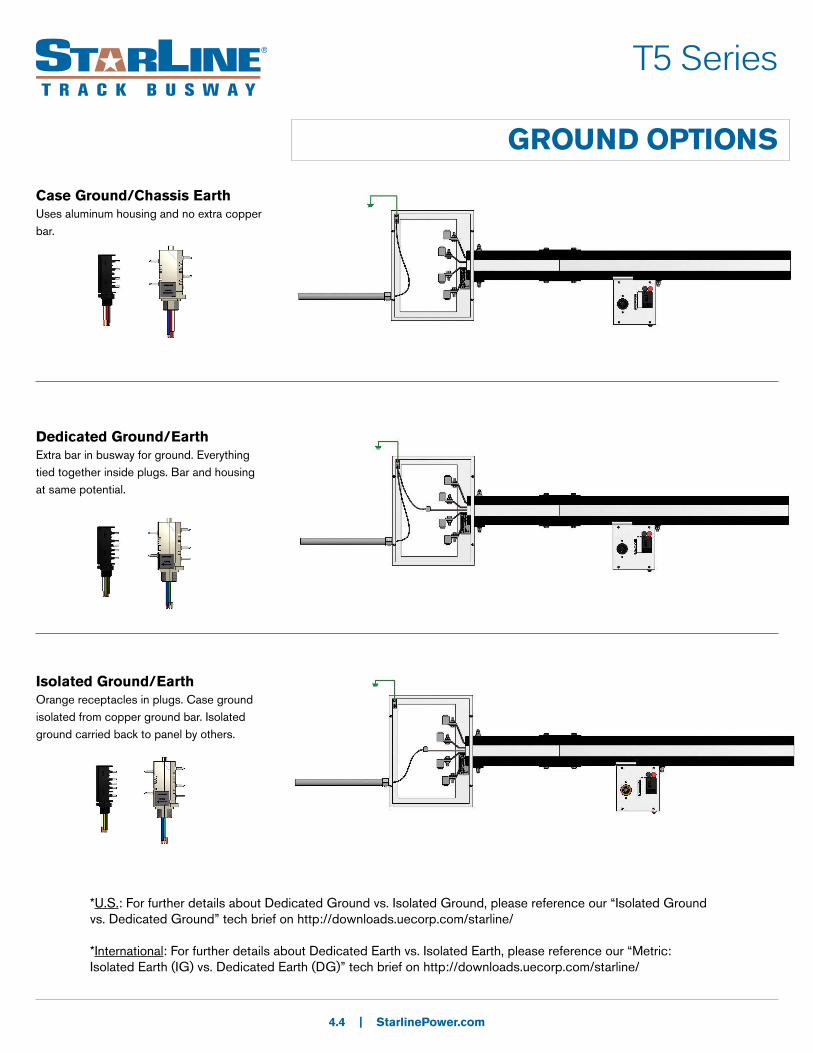
GROUND OPTIONS
Case Ground/Chassis EarthUses aluminum housing and no extra copper bar.
4.4 | StarlinePower.com
Dedicated Ground/EarthExtra bar in busway for ground. Everything tied together inside plugs. Bar and housing at same potential.
Isolated Ground/EarthOrange receptacles in plugs. Case ground isolated from copper ground bar. Isolated ground carried back to panel by others.
T5 Series
*U.S.: For further details about Dedicated Ground vs. Isolated Ground, please reference our “Isolated Ground vs. Dedicated Ground” tech brief on http://downloads.uecorp.com/starline/
*International: For further details about Dedicated Earth vs. Isolated Earth, please reference our “Metric: Isolated Earth (IG) vs. Dedicated Earth (DG)” tech brief on http://downloads.uecorp.com/starline/
POLARITY TIPS
4.5 | StarlinePower.com
T5 Series
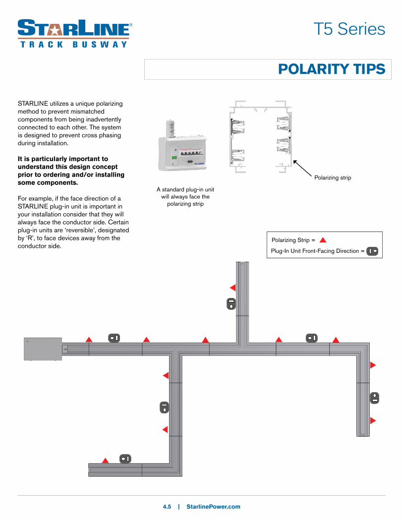
STARLINE utilizes a unique polarizing method to prevent mismatched components from being inadvertently connected to each other. The system is designed to prevent cross phasing during installation.
It is particularly important to understand this design concept prior to ordering and/or installing some components.
For example, if the face direction of a STARLINE plug-in unit is important in your installation consider that they will always face the conductor side. Certain plug-in units are ‘reversible’, designated by ‘R’, to face devices away from the conductor side.
Polarizing Strip =
Plug-In Unit Front-Facing Direction =
Polarizing strip
A standard plug-in unit will always face the
polarizing strip

SYSTEM LAYOUT TIPS
4.6 | StarlinePower.com
T5 Series
Busway Housing SectionsStandard Busway lengths are available in 5 ft (1.5m) 10 ft (3m) and 20 foot (6m)increments (except for 800T5 where the max length is 10 ft. or 3m). Although the factory can cut individual STARLINE Track Busway sections to any length under 20 feet (6m), it is highly recommended to keep all layout runs in increments of 5 feet (1.5m) to simplify layout and installation. Custom lengths can be made but can increase lead time and make layout and installation a bit more complex.
Busway Tees and Elbows SectionsTry to keep all runs as straight as possible as tees and elbows are added cost. Pay close attention to polarity on the elbows. The polarity will need to match the adjacent busway section(s) to be compatible.
Length of Busway for a One Volt Drop in Line to Line Voltage:
SYSTEM DESIGNATION
DISTRIBUTED LOAD
VOLTAGE DROP @ 0.8 PF
Single Phase
VOLTAGE DROP @ 0.8 PF
Three Phase250T5 (standard) 250 amps 28 Ft. (8.5m) 48 Ft. (14.6m)
400T5 (standard) 400 amps 37 Ft. (11.3m) 65 Ft. (19.8m)
800T5 (standard) 800 amps 15 Ft. (4.6m) 25 Ft. (7.6m)
Power FeedsDetermine location of power feeds based on relation to power source, existing feeders and voltage drop concerns for longer runs.
Support HardwareSupport hardware is spaced no more than 10 ft. (3m) apart. Refer to page 4.43 for support hardware details. Contact your local Starline applications engineer for any questions.
InstallationPrinted installation drawings are supplied with each system shipment and they are also available for download online at http://downloads.uecorp.com/starline/busway/. CAD and BIM files of these drawings are also available by contacting your local Starline applications engineer.

COMPONENT RELATIONSHIP TIPS
4.7 | StarlinePower.com
T5 Series
When ordering material, it is important to understand the relationship between various components.
Examples:
• The T5 series of plug-in units are compatible with all T5 Busway systems
• Each piece of housing (straights and elbows) requires a joint kit (containing two housing couplers and one bus connector). Determine the total number of housing sections (regardless of length) as this becomes the number of joint kits that will be needed. -Add one extra joint kit for each tee section
• If this is your first installation for T5 systems, you will need to order an Installation Tool (ST5IT).
• General support hardware rule to follow:
10 ft./3m maximum spacing between supports and we recommend 10% more than the required quantity to cover potential layout changes.
• Total Power Feeds and End Caps can be determined by counting the total number of unconnected runs.
• Before specifying or ordering elbow or tee connectors, it is important to understand polarity and the relationship to direction of outlets. Please refer to pg. 4.5 Polarity Tips for more detail.
| StarlinePower.com
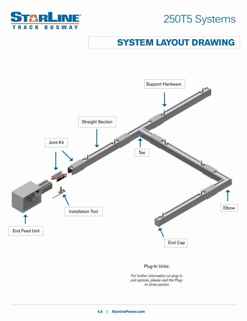
SYSTEM LAYOUT DRAWING
End Feed Unit
Installation Tool
Straight Section
End Cap
Tee
Elbow
Support Hardware
250T5 Systems
4.8
Plug-In Units:
For further information on plug-in unit options, please visit the Plug-
In Units section
Joint Kit

250T5 Systems
STRAIGHT SECTIONS
Product DescriptionTrack Busway straight section consists of an extruded aluminum shell with “spring-pressure” type copper channel busbars contained in a full length insulator mounted on the interior walls. The aluminum extrusion acts as a 100% ground path. Each housing has a continuous access slot over its entire length for the insertion of turn-n-lock plug-in units. Housing configurations include 4-pole varieties, optional isolated ground, optional oversize (200%) neutral. The housing sections join together using Bus connectors which fit into the channels of the adjoining section. An Installation tool is used to force the blades into the busbar channels for a solid “spring-pressure” electrical connection.
4.9 | StarlinePower.com
Housing Section
5.050” (128mm)
(N)
(L1)
(L2)(L3)
Housing Coupler
Bus Connector
MATERIAL: Extruded Aluminum
RATINGS: 100% Ground Path
250 Amps
250T5C4/250T5CG: 600 Volt
250T5CN/250T5CF: 600 Volt
LENGTH: 10 Ft. (3m), 20 Ft. (6m); or custom lengths between 2 - 20 Ft. (.6 - 6m)
VOLTAGE DROP: distributed load
Single Phase 1V per 28ft (8.5m)
(.8PF)
Three Phase 1V per 48ft (14.6m)
(.8PF)
L1 or Phase AL2 or Phase BL3 or Phase C
NeutralGround
US
L1 or Phase AL2 or Phase BL3 or Phase C
NeutralGround
Metric
4.360” (111mm)
Installation Tool
WEIGHT:
10 ft. (3m) 4 pole: 41 lbs/18.6 kg
10 ft. (3m) 4 pole w/ ground: 46 lbs/20.9 kg
10 ft. (3m) 4 pole w/ 200% N: 47 lbs/21.3 kg
10 ft. (3m) 4 pole w/ ground & 200% N: 51 lbs/23.1 kg
250T5 Systems
STRAIGHT SECTIONS: PRODUCT NUMBERS
4.10 | StarlinePower.com
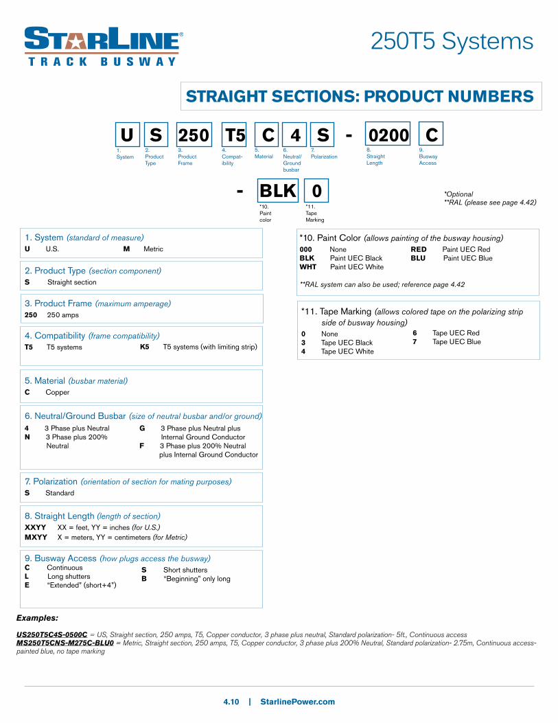
U S 250 T5 C 4 S - 0200 C
- BLK 0*10. Paint color
1. System
2. Product Type
3. Product Frame
4. Compat-ibility
5.Material
6.Neutral/Ground busbar
7.Polarization
8. Straight Length
9.Busway Access
*Optional**RAL (please see page 4.42)
*11. Tape Marking
1. System (standard of measure)U U.S. M Metric
2. Product Type (section component)S Straight section
3. Product Frame (maximum amperage)250 250 amps
4. Compatibility (frame compatibility)T5 T5 systems
5. Material (busbar material)C Copper
6. Neutral/Ground Busbar (size of neutral busbar and/or ground)
7. Polarization (orientation of section for mating purposes)S Standard
8. Straight Length (length of section)XXYY XX = feet, YY = inches (for U.S.)MXYY X = meters, YY = centimeters (for Metric)
9. Busway Access (how plugs access the busway)C ContinuousL Long shuttersE “Extended” (short+4”)
4 3 Phase plus Neutral N 3 Phase plus 200% Neutral
G 3 Phase plus Neutral plus Internal Ground ConductorF 3 Phase plus 200% Neutral plus Internal Ground Conductor
*10. Paint Color (allows painting of the busway housing)000 None BLK Paint UEC BlackWHT Paint UEC White
**RAL system can also be used; reference page 4.42
RED Paint UEC RedBLU Paint UEC Blue
*11. Tape Marking (allows colored tape on the polarizing strip side of busway housing)0 None 3 Tape UEC Black4 Tape UEC White
6 Tape UEC Red7 Tape UEC Blue
Examples:
US250T5C4S-0500C = US, Straight section, 250 amps, T5, Copper conductor, 3 phase plus neutral, Standard polarization- 5ft., Continuous accessMS250T5CNS-M275C-BLU0 = Metric, Straight section, 250 amps, T5, Copper conductor, 3 phase plus 200% Neutral, Standard polarization- 2.75m, Continuous access- painted blue, no tape marking
K5 T5 systems (with limiting strip)
S Short shuttersB “Beginning” only long
250T5 Systems
ELBOW SECTIONS
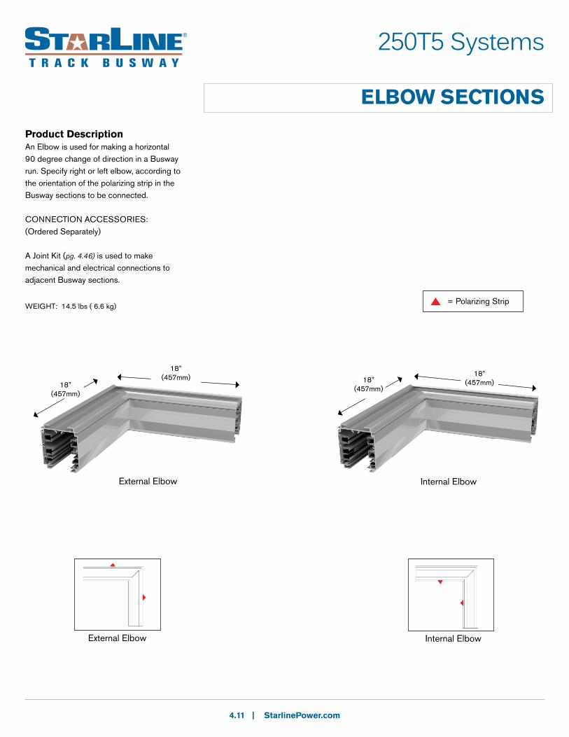
Product DescriptionAn Elbow is used for making a horizontal 90 degree change of direction in a Busway run. Specify right or left elbow, according to the orientation of the polarizing strip in the Busway sections to be connected.
CONNECTION ACCESSORIES:(Ordered Separately)
A Joint Kit (pg. 4.46) is used to make mechanical and electrical connections to adjacent Busway sections.
4.11 | StarlinePower.com
External Elbow Internal Elbow
18” (457mm)
18” (457mm) 18”
(457mm)18” (457mm)
External Elbow Internal Elbow
= Polarizing StripWEIGHT: 14.5 lbs ( 6.6 kg)

250T5 Systems
ELBOW SECTIONS: PRODUCT NUMBERS
4.12 | StarlinePower.com
U E 250 T5 C 4 S - IN
- BLK 0*9. Paint color
1. System
2. Product Type
3. Product Frame
4. Compat-ibility
5.Material
6.Neutral/Ground busbar
7.Polarization
8. Turning Direction
*10. Tape Marking
1. System (standard of measure)U U.S. M Metric
2. Product Type (section component)E Elbow section
3. Product Frame (maximum amperage)250 250 amps
4. Compatibility (frame compatibility)T5 T5 systems
5. Material (busbar material)C Copper
6. Neutral/Ground Busbar (size of neutral busbar and/or ground)
7. Polarization (orientation of section for mating purposes)S Standard
8. Turning Direction (direction of section polarizing strip)IN Internal EX External
4 3 Phase plus Neutral N 3 Phase plus 200% Neutral
G 3 Phase plus Neutral plus Internal Ground ConductorF 3 Phase plus 200% Neutral plus Internal Ground Conductor
*10. Paint Color (allows painting of the busway housing)000 None BLK Paint UEC BlackWHT Paint UEC White
**RAL system can also be used; reference page 4.42
RED Paint UEC RedBLU Paint UEC Blue
*11. Tape Marking (allows colored tape on the polarizing strip side of busway housing)0 None 3 Tape UEC Black4 Tape UEC White
6 Tape UEC Red7 Tape UEC Blue
Examples:
UE250T5C4S-IN-BLU4 = US, Elbow section, 250 amps, T5, Copper conductor, 3 phase plus neutral, Standard polarization- Internal- painted black, white tapeME250T5CGS-EX = Metric, Elbow section, 250 amps, T5, Copper conductor, 3 phase plus neutral plus isolated/dedicated ground, Standard polarization- External
*Optional**RAL (please see page 4.42)
K5 T5 systems (with limiting strip)
250T5 Systems
TEE SECTIONS
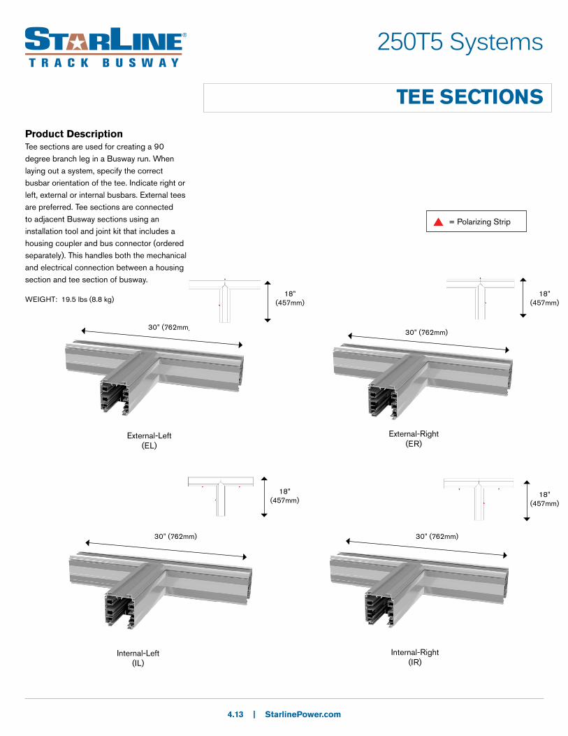
Product DescriptionTee sections are used for creating a 90 degree branch leg in a Busway run. When laying out a system, specify the correct busbar orientation of the tee. Indicate right or left, external or internal busbars. External tees are preferred. Tee sections are connected to adjacent Busway sections using an installation tool and joint kit that includes a housing coupler and bus connector (ordered separately). This handles both the mechanical and electrical connection between a housing section and tee section of busway.
4.13 | StarlinePower.com
External-Left(EL)
External-Right(ER)
Internal-Left(IL)
Internal-Right(IR)
30” (762mm)
18” (457mm)
18” (457mm)
18” (457mm)
18” (457mm)
30” (762mm)
30” (762mm) 30” (762mm)
= Polarizing Strip
WEIGHT: 19.5 lbs (8.8 kg)

250T5 Systems
TEE SECTIONS: PRODUCT NUMBERS
4.14 | StarlinePower.com
U T 250 T5 C 4 S - IR
- BLK 0*9. Paint color
1. System
2. Product Type
3. Product Frame
4. Compat-ibility
5.Material
6.Neutral/Ground busbar
7.Polarization
8. Turning Direction
*10. Tape Marking
1. System (standard of measure)U U.S. M Metric
2. Product Type (section component)T Tee section
3. Product Frame (maximum amperage)250 250 amps
4. Compatibility (frame compatibility)T5 T5 systems
5. Material (busbar material)C Copper
6. Neutral/Ground Busbar (size of neutral busbar and/or ground)
7. Polarization (orientation of section for mating purposes)S Standard
8. Turning Direction (direction of section polarizing strip)IL Internal-Left EL External-Left
IR Internal-Right ER External-Right
4 3 Phase plus Neutral N 3 Phase plus 200% Neutral
G 3 Phase plus Neutral plus Internal Ground ConductorF 3 Phase plus 200% Neutral plus Internal Ground Conductor
*9. Paint Color (allows painting of the busway housing)000 None BLK Paint UEC BlackWHT Paint UEC White
**RAL system can also be used; reference page 4.42
RED Paint UEC RedBLU Paint UEC Blue
*10. Tape Marking (allows colored tape on the polarizing strip side of busway housing)0 None 3 Tape UEC Black4 Tape UEC White
6 Tape UEC Red7 Tape UEC Blue
Examples:
UT250T5C4S-IR-RED0 = US, Tee section, 250 amps, T5, Copper conductor, 3 phase plus neutral, Standard polarization- Internal-Right- painted red, no tape markingMT250T5CFS-EL = Metric, Tee section, 250 amps, T5, Copper conductor, 3 phase plus 200% neutral plus isolated/dedicated ground, Standard polarization- External-Left
*Optional**RAL (please see page 4.42)
K5 T5 systems (with limiting strip)

250T5 Systems
END FEED UNITSProduct DescriptionEnd power feed units connect to the end of the Busway. A standard size, factory assembled unit consists of a 12 x 16 x 6.6 in. (305 x 406 x 168mm) steel junction box, with removable sides, connected to a 12 in. (305mm) section of Busway. The assembly includes connection lugs and a ground lug for wires up to 300MCM (150mm2) for standard size boxes, and (2) 250MCM (120mm2) or up to (1) 600MCM (300mm2) for large size boxes.
End power feed units are connected to adjacent Busway sections using a housing coupler and bus connector (ordered separately).
Special need power feed units for confined spaces, as found in mission critical data centers, can also be designed and fabricated
4.15 | StarlinePower.com
standard orientation
reversed orientation
Top View
S L F
R
Boxes
Standard Large FusedLugs
Standard
Double
Bolt
Box size and Lug options:Refer to option 8. Lug/Box Options on pg. 4.17 End Feed Units: Product Numbers
Standard box with rectangular Infrared
(IR) window
Fused box
12” (305mm)
16” (406mm)
6.6” (168mm)
30” (762mm)
15.5” (394mm)
10” (254mm)
*Standard busway stub size is 1 ft. (.3m)
12” (305mm)
12” (305mm)
WEIGHT:
Standard Box: 19.5 lbs (8.8 kg)
Fused Box: 82 - 90 lbs (37.2 - 40.8 kg)
*Isolated or dedicated ground is determined at the feed during installation. For further details about Dedicated Ground vs. Isolated Ground, please reference our tech brief on http://downloads.uecorp.com/starline/
250T5 Systems
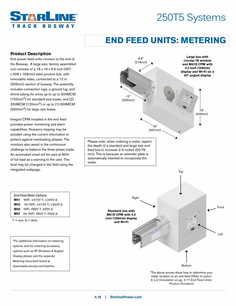
END FEED UNITS: METERINGProduct DescriptionEnd power feed units connect to the end of the Busway. A large size, factory assembled unit consists of a 18 x 16 x 6.6 inch (457 x 406 x 168mm) steel junction box, with removable sides, connected to a 12 in. (305mm) section of busway. The assembly includes connection lugs, a ground lug, and shrink tubing for wires up to up to 300MCM (150mm2) for standard size boxes, and (2) 250MCM (120mm2) or up to (1) 600MCM (300mm2) for large size boxes.
Integral CPM installed in the end feed provides power monitoring and alarm capabilities. Nuisance tripping may be avoided using the current information to protect against overloading phases. The monitors also assist in the continuous challenge to balance the three phase loads. An automated email will be sent at 80% of full load as a warning to the user. This level may be changed in the field using the integrated webpage.
4.16 | StarlinePower.com
16” (406mm)
8.6” (218mm)
Large box with circular IR window
and M41D CPM with 4.3 inch (109mm)
display and Wi-Fi on a 30° angled display
Please note: when ordering a meter, expect the depth of a standard and large size end feed box to increase 2-3 inches (50-76 mm). This is because an extender plate is automatically inserted to incorporate the meter.
18” (457mm)
12” (305mm)
Standard box with M41D CPM with 4.3
inch (109mm) display and Wi-Fi
Front
Top
Left
Bottom
Right
*The above arrows show how to determine your meter location on an end feed (Refer to option 9. Lid Orientation on pg. 4.17 End Feed Units:
Product Numbers)
End Feed Meter Options:
M41 WiFi, ≤415V Y, ≤240V Δ
M43 No WiFi, ≤415V Y, ≤240V Δ
M45 WiFi, 480V Y, 400V Δ
M47 No WiFi, 480V Y, 400V Δ
Y = wye, Δ = delta
*For additional information on metering
options, and for metering accessory
options such as IR Windows & Angled
Display please visit the separate
Metering document found at
downloads.uecorp.com/starline.
250T5 Systems
END FEED UNITS: PRODUCT NUMBERS
4.17 | StarlinePower.com
U F 250 T5 C 4 S - S N S N - 0100 C
- BLK 0 - M41 S 1*14. Paint color
1. System
2. Product Type
3. Product Frame
4. Compat-ibility
5.Material
6.Neutral/Ground busbar
7.Polarization
8. Lug/box options
9.Lid orientation
10.AccessoriesPackage
11.Accessories Location
12. Straight Length
13.Busway Access
*15. Tape Marking
*16. MeterRelease
*17. M40 Options
*18. System configuration and CT type
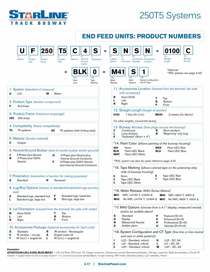
1. System (standard of measure)U U.S. M Metric
2. Product Type (section component)F End Feed
3. Product Frame (maximum amperage)250 250 amps
4. Compatibility (frame compatibility)T5 T5 systems
5. Material (busbar material)C Copper
6. Neutral/Ground Busbar (size of neutral busbar and/or ground)
7. Polarization (orientation of section for mating purposes)S Standard R Reversed
8. Lug/Box Options (choice of standard/double/bolt lugs and box size)S Standard lugs, standard boxL Standard lugs, large box
9. Lid Orientation (viewed from the terminal, the side with meter)N None (N/A)L LeftR Right
10. Accessories Package (optional accessories for feed units)S Standard R IR window - RectangularC IR window - circular A Angled meter lidT IR (rect.) + angled lid L IR (circ.) + angled lid
11. Accessories Location (viewed from the terminal, the side with accessory)N None (N/A)L LeftR Right
13. Busway Access (how plugs access the busway)C Continuous S Short shuttersL Long shutters B “Beginning” only longE “Extended” (Short + 4”)
4 3 Phase plus Neutral N 3 Phase plus 200% Neutral
G 3 Phase plus Neutral plus Internal Ground ConductorF 3 Phase plus 200% Neutral plus Internal Ground Conductor
F Standard lugs, fused boxR Bolt lugs, large box
T TopB BottomF Front
T TopB BottomF Front
*14. Paint Color (allows painting of the busway housing)000 None BLK Paint UEC BlackWHT Paint UEC White
**RAL system can also be used; reference page 4.42
RED Paint UEC RedBLU Paint UEC Blue
*15. Tape Marking (allows colored tape on the polarizing strip side of busway housing)0 None 3 Tape UEC Black4 Tape UEC White
6 Tape UEC Red7 Tape UEC Blue
*16. Meter Release (M40 Series Meters)M41 WiFi, ≤415V Y, ≤240V Δ
M43 No WiFi, ≤415V Y, ≤240V ΔM45 WiFi, 480V Y, 400V Δ
M47 No WiFi, 480V Y, 400V Δ
*17. M40 Options (choose from a 4.1” display, measured neutral, and/or an audible alarm)S Standard D DisplayN (Measured) NeutralA Audible alarm
F Featured (D+A)E Enhanced (N+A)P Professional (D+N)U Ultimate (D+N+A)
*18. System Configuration and CT Type (line-line or line-neutral and wye or delta systems)1 LLD - Standard, milivolt 2 LLY - Standard, milivolt3 LNY - Standard, milivolt
K LLD - SC, 5AL LLY - SC, 5AM LNY - SC, 5A
Examples:UF250T5C4R-LRLL-0100C-BLK0-M47S1 = US, end Feed, 250 amps, T5, Copper conductor, 3 phase plus neutral, Reversed polarization- Std lugs, Large box, Right lid orientation, Circular IR window + angled meter lid, left accessory location- 1 ft., Continuous access-painted Black, no tape marking- M47 meter, Standard options, LLD- standard, milivolt
*Optional**RAL (please see page 4.42)
K5 T5 systems (with limiting strip)
12. Straight Length (length of section)0100 1 foot (for U.S.) M030 .3 meters (for Metric)
For other lengths, consult the factory

250T5 Systems
ABOVE FEED UNITS
Product DescriptionThe above feed power unit supplies power from the topside of the Busway. Factory assembled unit consists of a 25 x 12 x 8 inch (635 x 305 x 203mm) steel junction box that is mounted on top of a 36 inch (914mm) section of Busway.
*36 inches (914mm) is the minimum and standard length of busway that an above feed is provided with.
Above feed units can be placed at the end or anywhere along a Busway run. Connections to adjoining Busway sections are made by the standard means, requiring couplers and bus connectors which are sold separately.
4.18 | StarlinePower.com
12” (305mm)
8” (203mm)
25” (635mm)
36” (914mm)
busway section
*Isolated or dedicated ground is determined at the feed during installation. For further details about Dedicated Ground vs. Isolated Ground, please reference our tech brief on http://downloads.uecorp.com/starline/
Standard (S) Reversed (R)
WEIGHT: 45.5 lbs (20.6 kg)

250T5 Systems
ABOVE FEED UNITS: PRODUCT NUMBERS
4.19 | StarlinePower.com
U A 250 T5 C 4 S - D N S N - 0300 C 018
- BLK 0 - M41 S 1*15. Paint color
1. System
2. Product Type
3. Product Frame
4. Compat-ibility
5.Material
6.Neutral/Ground busbar
7.Polarization
8. Lug/box options
9.Lid orientation
10.AccessoriesPackage
11.Accessories Location
12. Straight Length
13.Busway Access
*16. Tape Marking
*17. MeterRelease
*18. M40 Options
*19. System configuration and CT type
1. System (standard of measure)U U.S. M Metric
2. Product Type (section component)A Above Feed
3. Product Frame (maximum amperage)250 250 amps
4. Compatibility (frame compatibility)T5 T5 systems
5. Material (busbar material)C Copper
6. Neutral/Ground Busbar (size of neutral busbar and/or ground)
7. Polarization (orientation of section for mating purposes)S Standard R Reversed
8. Lug Options (other than standard lugs, there is also the option for double lugs and bolt lugs)D Double lugs, standard box
9. Lid Orientation (viewed from the terminal, the side with meter)N None (N/A)L LeftR Right
10. Accessories Package (optional accessories for feed units)S Standard
12. Straight Length (length of section)0300 3 feet (for U.S.) M100 1 meter (for Metric)
For other lengths, consult the factory
4 3 Phase plus Neutral N 3 Phase plus 200% Neutral
G 3 Phase plus Neutral plus Internal Ground ConductorF 3 Phase plus 200% Neutral plus Internal Ground Conductor
T TopF FrontA Rear
*15. Paint Color (allows painting of the busway housing)000 None BLK Paint UEC BlackWHT Paint UEC White
**RAL system can also be used; reference page 4.42
RED Paint UEC RedBLU Paint UEC Blue
*16. Tape Marking (allows colored tape on the polarizing strip side of busway housing)0 None 3 Tape UEC Black4 Tape UEC White
6 Tape UEC Red7 Tape UEC Blue
*17. Meter Release (M40 Series Meters)M41 WiFi, ≤415V Y, ≤240V Δ
M43 No WiFi, ≤415V Y, ≤240V Δ
*18. M40 Options (choose from a 4.1” display, measured neutral, and/or an audible alarm)S Standard D DisplayN (Measured) NeutralA Audible alarm
F Featured (D+A)E Enhanced (N+A)P Professional (D+N)U Ultimate (D+N+A)
*19. System Configuration and CT Type (line-line or line-neutral and wye or delta systems)1 LLD - Standard, milivolt 2 LLY - Standard, milivolt3 LNY - Standard, milivolt
K LLD - SC, 5AL LLY - SC, 5AM LNY - SC, 5A
Examples:UA250T5CFS-DLSN-0300C018-M41D2 = US, Above feed, 250 amps, T5, Copper conductor, 3 phase plus 200% neutral plus internal ground conductor, Standard polarization- Double lugs, standard box, Left lid orientation, Standard accessory package, No accessory location- 3 ft., Continuous access, 18 inches- M41 meter, Display, LLY- Standard, milivolt
11. Accessories Location (viewed from the terminal, the side with accessory)N None (N/A)L Left
R RightT Top
F FrontA Rear
14. Feed Location (location of the center of the top feed)018 18 inches (for U.S.)045 45 centimeters (for Metric)
For other lengths, consult the factory
14.Feed Location
*Optional**RAL (please see page 4.42)
K5 T5 systems (with limiting strip)
13. Busway Access (how plugs access the busway)C Continuous S Short shuttersL Long shutters B “Beginning” only longE “Extended” (Short + 4”)
M45 WiFi, 480V Y, 400V Δ
M47 No WiFi, 480V Y, 400V Δ

| StarlinePower.com
SYSTEM LAYOUT DRAWING
End Feed Unit
Installation Tool
Housing SectionEnd Cap
Tee
Elbow
Support Hardware
400T5 Systems
4.20
Plug-In Unit example:
For further information on plug-in unit options, please visit the Plug-
In Units section
Joint Kit
400T5 Systems
STRAIGHT SECTIONS
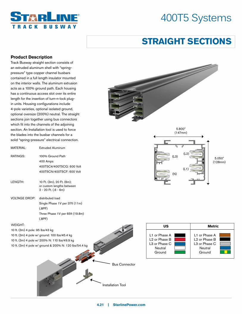
Product DescriptionTrack Busway straight section consists of an extruded aluminum shell with “spring-pressure” type copper channel busbars contained in a full length insulator mounted on the interior walls. The aluminum extrusion acts as a 100% ground path. Each housing has a continuous access slot over its entire length for the insertion of turn-n-lock plug-in units. Housing configurations include 4-pole varieties, optional isolated ground, optional oversize (200%) neutral. The straight sections join together using bus connectors which fit into the channels of the adjoining section. An Installation tool is used to force the blades into the busbar channels for a solid “spring-pressure” electrical connection.
4.21 | StarlinePower.com
5.050” (128mm)
(N)
(L1)
(L2)(L3)
Installation Tool
Bus Connector
MATERIAL: Extruded Aluminum
RATINGS: 100% Ground Path
400 Amps
400T5C4/400T5CG: 600 Volt
400T5CN/400T5CF: 600 Volt
LENGTH: 10 Ft. (3m), 20 Ft. (6m); or custom lengths between 2 - 20 Ft. (.6 - 6m)
VOLTAGE DROP: distributed load
Single Phase 1V per 37ft (11m)
(.8PF)
Three Phase 1V per 65ft (19.8m)
(.8PF)
L1 or Phase AL2 or Phase BL3 or Phase C
NeutralGround
US
L1 or Phase AL2 or Phase BL3 or Phase C
NeutralGround
Metric
5.800” (147mm)
WEIGHT:
10 ft. (3m) 4 pole: 95 lbs/43 kg
10 ft. (3m) 4 pole w/ ground: 100 lbs/45.4 kg
10 ft. (3m) 4 pole w/ 200% N: 110 lbs/49.9 kg
10 ft. (3m) 4 pole w/ ground & 200% N: 120 lbs/54.4 kg
400T5 Systems
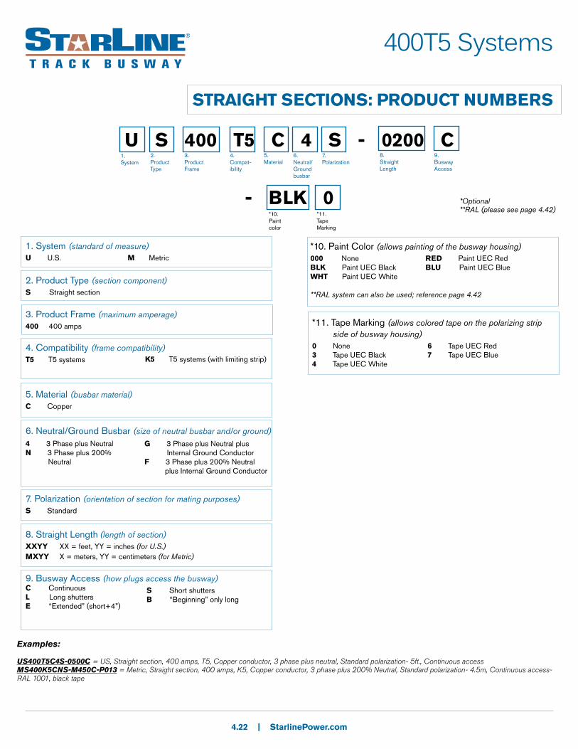
STRAIGHT SECTIONS: PRODUCT NUMBERS
4.22 | StarlinePower.com
U S 400 T5 C 4 S - 0200 C
- BLK 0*10. Paint color
1. System
2. Product Type
3. Product Frame
4. Compat-ibility
5.Material
6.Neutral/Ground busbar
7.Polarization
8. Straight Length
9.Busway Access
*Optional**RAL (please see page 4.42)
*11. Tape Marking
1. System (standard of measure)U U.S. M Metric
2. Product Type (section component)S Straight section
3. Product Frame (maximum amperage)400 400 amps
4. Compatibility (frame compatibility)T5 T5 systems
5. Material (busbar material)C Copper
6. Neutral/Ground Busbar (size of neutral busbar and/or ground)
7. Polarization (orientation of section for mating purposes)S Standard
8. Straight Length (length of section)XXYY XX = feet, YY = inches (for U.S.)MXYY X = meters, YY = centimeters (for Metric)
9. Busway Access (how plugs access the busway)C ContinuousL Long shuttersE “Extended” (short+4”)
4 3 Phase plus Neutral N 3 Phase plus 200% Neutral
G 3 Phase plus Neutral plus Internal Ground ConductorF 3 Phase plus 200% Neutral plus Internal Ground Conductor
*10. Paint Color (allows painting of the busway housing)000 None BLK Paint UEC BlackWHT Paint UEC White
**RAL system can also be used; reference page 4.42
RED Paint UEC RedBLU Paint UEC Blue
*11. Tape Marking (allows colored tape on the polarizing strip side of busway housing)0 None 3 Tape UEC Black4 Tape UEC White
6 Tape UEC Red7 Tape UEC Blue
Examples:
US400T5C4S-0500C = US, Straight section, 400 amps, T5, Copper conductor, 3 phase plus neutral, Standard polarization- 5ft., Continuous accessMS400K5CNS-M450C-P013 = Metric, Straight section, 400 amps, K5, Copper conductor, 3 phase plus 200% Neutral, Standard polarization- 4.5m, Continuous access- RAL 1001, black tape
K5 T5 systems (with limiting strip)
S Short shuttersB “Beginning” only long

400T5 Systems
ELBOW SECTIONS
Product DescriptionAn Elbow is used for making a horizontal 90 degree change of direction in a Busway run. Specify external or internal elbow, according to the orientation of the polarizing strip in the Busway sections to be connected.
CONNECTION ACCESSORIES:(Ordered Separately)
Joint Kits (pg. 4.46) are used to make mechanical and electrical connections to adjacent Busway sections.
4.23 | StarlinePower.com
External Elbow Internal Elbow
18” (457mm)
18” (457mm) 18”
(457mm)18” (457mm)
External Elbow Internal Elbow
= Polarizing Strip
WEIGHT: 28 lbs ( 12.7 kg)
400T5 Systems
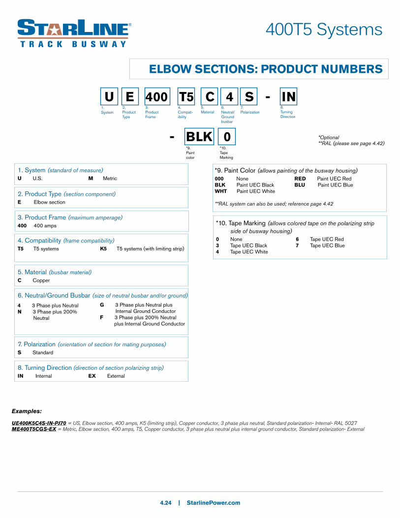
ELBOW SECTIONS: PRODUCT NUMBERS
4.24 | StarlinePower.com
U E 400 T5 C 4 S - IN
- BLK 0*9. Paint color
1. System
2. Product Type
3. Product Frame
4. Compat-ibility
5.Material
6.Neutral/Ground busbar
7.Polarization
8. Turning Direction
*10. Tape Marking
1. System (standard of measure)U U.S. M Metric
2. Product Type (section component)E Elbow section
3. Product Frame (maximum amperage)400 400 amps
4. Compatibility (frame compatibility)T5 T5 systems
5. Material (busbar material)C Copper
6. Neutral/Ground Busbar (size of neutral busbar and/or ground)
7. Polarization (orientation of section for mating purposes)S Standard
8. Turning Direction (direction of section polarizing strip)IN Internal EX External
4 3 Phase plus Neutral N 3 Phase plus 200% Neutral
G 3 Phase plus Neutral plus Internal Ground ConductorF 3 Phase plus 200% Neutral plus Internal Ground Conductor
*9. Paint Color (allows painting of the busway housing)000 None BLK Paint UEC BlackWHT Paint UEC White
**RAL system can also be used; reference page 4.42
RED Paint UEC RedBLU Paint UEC Blue
*10. Tape Marking (allows colored tape on the polarizing strip side of busway housing)0 None 3 Tape UEC Black4 Tape UEC White
6 Tape UEC Red7 Tape UEC Blue
Examples:
UE400K5C4S-IN-PJ70 = US, Elbow section, 400 amps, K5 (limiting strip), Copper conductor, 3 phase plus neutral, Standard polarization- Internal- RAL 5027ME400T5CGS-EX = Metric, Elbow section, 400 amps, T5, Copper conductor, 3 phase plus neutral plus internal ground conductor, Standard polarization- External
*Optional**RAL (please see page 4.42)
K5 T5 systems (with limiting strip)
400T5 Systems
TEE SECTIONS
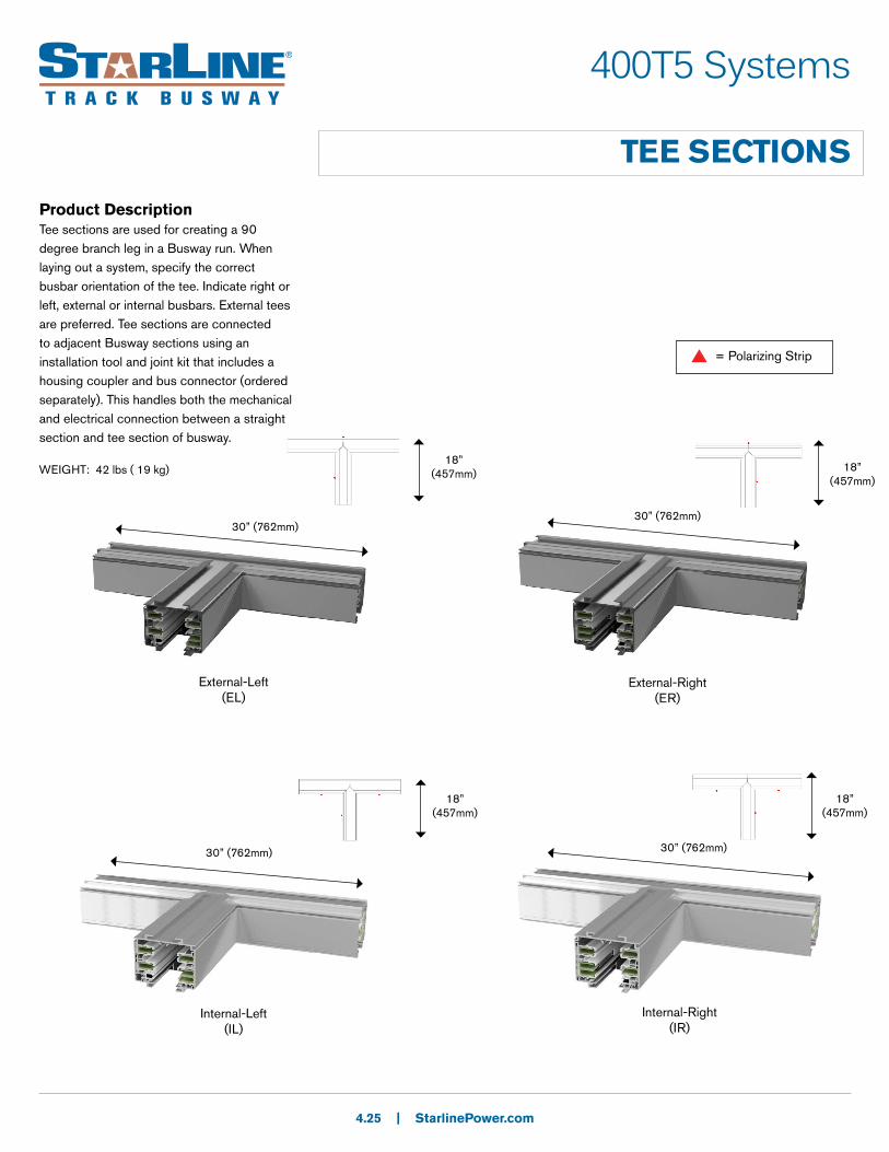
Product DescriptionTee sections are used for creating a 90 degree branch leg in a Busway run. When laying out a system, specify the correct busbar orientation of the tee. Indicate right or left, external or internal busbars. External tees are preferred. Tee sections are connected to adjacent Busway sections using an installation tool and joint kit that includes a housing coupler and bus connector (ordered separately). This handles both the mechanical and electrical connection between a straight section and tee section of busway.
4.25 | StarlinePower.com
External-Left(EL)
External-Right(ER)
Internal-Left(IL)
Internal-Right(IR)
30” (762mm)
18” (457mm)
18” (457mm)
18” (457mm)
18” (457mm)
30” (762mm)
30” (762mm) 30” (762mm)
= Polarizing Strip
WEIGHT: 42 lbs ( 19 kg)
400T5 Systems
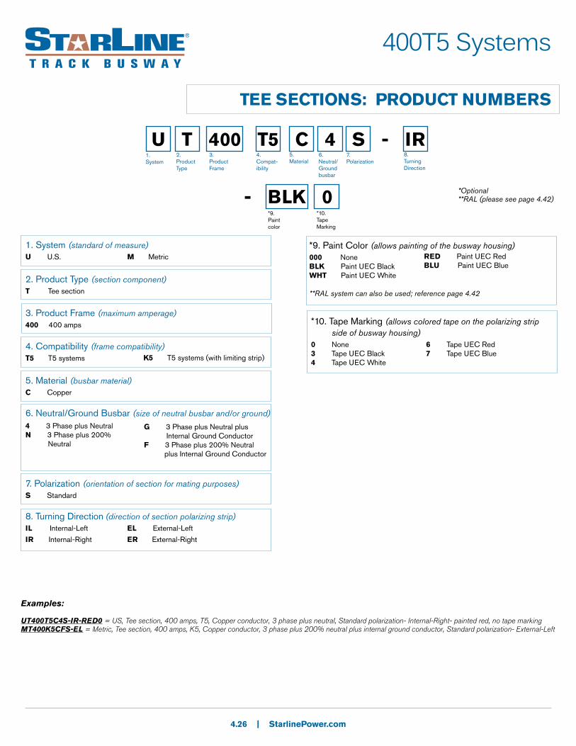
TEE SECTIONS: PRODUCT NUMBERS
4.26 | StarlinePower.com
U T 400 T5 C 4 S - IR
- BLK 0*9. Paint color
1. System
2. Product Type
3. Product Frame
4. Compat-ibility
5.Material
6.Neutral/Ground busbar
7.Polarization
8. Turning Direction
*10. Tape Marking
1. System (standard of measure)U U.S. M Metric
2. Product Type (section component)T Tee section
3. Product Frame (maximum amperage)400 400 amps
4. Compatibility (frame compatibility)T5 T5 systems
5. Material (busbar material)C Copper
6. Neutral/Ground Busbar (size of neutral busbar and/or ground)
7. Polarization (orientation of section for mating purposes)S Standard
8. Turning Direction (direction of section polarizing strip)IL Internal-Left EL External-Left
IR Internal-Right ER External-Right
4 3 Phase plus Neutral N 3 Phase plus 200% Neutral
G 3 Phase plus Neutral plus Internal Ground ConductorF 3 Phase plus 200% Neutral plus Internal Ground Conductor
*9. Paint Color (allows painting of the busway housing)000 None BLK Paint UEC BlackWHT Paint UEC White
**RAL system can also be used; reference page 4.42
RED Paint UEC RedBLU Paint UEC Blue
*10. Tape Marking (allows colored tape on the polarizing strip side of busway housing)0 None 3 Tape UEC Black4 Tape UEC White
6 Tape UEC Red7 Tape UEC Blue
Examples:
UT400T5C4S-IR-RED0 = US, Tee section, 400 amps, T5, Copper conductor, 3 phase plus neutral, Standard polarization- Internal-Right- painted red, no tape markingMT400K5CFS-EL = Metric, Tee section, 400 amps, K5, Copper conductor, 3 phase plus 200% neutral plus internal ground conductor, Standard polarization- External-Left
*Optional**RAL (please see page 4.42)
K5 T5 systems (with limiting strip)
400T5 Systems
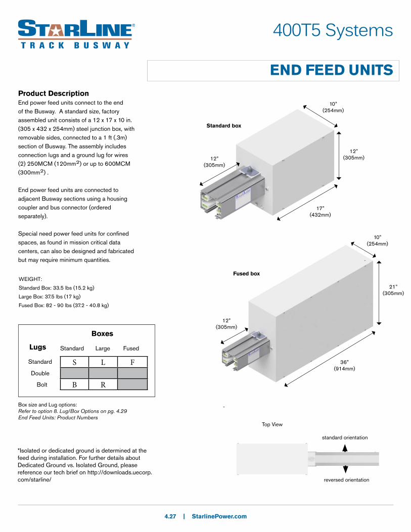
END FEED UNITSProduct DescriptionEnd power feed units connect to the end of the Busway. A standard size, factory assembled unit consists of a 12 x 17 x 10 in. (305 x 432 x 254mm) steel junction box, with removable sides, connected to a 1 ft (.3m) section of Busway. The assembly includes connection lugs and a ground lug for wires (2) 250MCM (120mm2) or up to 600MCM (300mm2) .
End power feed units are connected to adjacent Busway sections using a housing coupler and bus connector (ordered separately).
Special need power feed units for confined spaces, as found in mission critical data centers, can also be designed and fabricated but may require minimum quantities.
4.27 | StarlinePower.com
-
standard orientation
reversed orientation
Top View
S L F
B R
Boxes
Standard Large FusedLugs
Standard
Double
Bolt
Box size and Lug options:Refer to option 8. Lug/Box Options on pg. 4.29 End Feed Units: Product Numbers
Standard box
17” (432mm)
12” (305mm)
10” (254mm)
12” (305mm)
Fused box
10” (254mm)
36” (914mm)
21” (305mm)
12” (305mm)
*Isolated or dedicated ground is determined at the feed during installation. For further details about Dedicated Ground vs. Isolated Ground, please reference our tech brief on http://downloads.uecorp.com/starline/
WEIGHT:
Standard Box: 33.5 lbs (15.2 kg)
Large Box: 37.5 lbs (17 kg)
Fused Box: 82 - 90 lbs (37.2 - 40.8 kg)
400T5 Systems
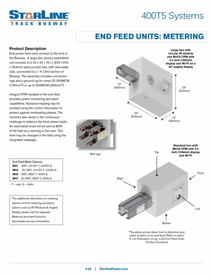
END FEED UNITS: METERINGProduct DescriptionEnd power feed units connect to the end of the Busway. A large size, factory assembled unit consists of a 24 x 24 x 10 in. (610 x 610 x 254mm) steel junction box, with removable side, connected to a 1 ft (.3m) section of Busway. The assembly includes connection lugs and a ground lug for wires (2) 250MCM (120mm2) or up to 600MCM (300mm2) .
Integral CPM installed in the end feed provides power monitoring and alarm capabilities. Nuisance tripping may be avoided using the current information to protect against overloading phases. The monitors also assist in the continuous challenge to balance the three phase loads. An automated email will be sent at 80% of full load as a warning to the user. This level may be changed in the field using the integrated webpage.
4.28 | StarlinePower.com
24” (610mm)
12” (305mm) 24”
(610mm)
10” (254mm)
Large box with circular IR window
and M41D CPM with 4.3 inch (109mm)
display and Wi-Fi on a 30° angled display
Standard box with M41D CPM with 4.3
inch (109mm) display and Wi-FiBolt lugs
*The above arrows show how to determine your meter location on an end feed (Refer to option 9. Lid Orientation on pg. 4.29 End Feed Units:
Product Numbers)
Top
Front
Bottom
Left
Right
End Feed Meter Options:
M41 WiFi, ≤415V Y, ≤240V Δ
M43 No WiFi, ≤415V Y, ≤240V Δ
M45 WiFi, 480V Y, 400V Δ
M47 No WiFi, 480V Y, 400V Δ
Y = wye, Δ = delta
*For additional information on metering
options, and for metering accessory
options such as IR Windows & Angled
Display please visit the separate
Metering document found at
downloads.uecorp.com/starline.

400T5 Systems
END FEED UNITS: PRODUCT NUMBERS
4.29 | StarlinePower.com
U F 400 T5 C 4 S - S N S N - 0100 C
- BLK 0 - M41 S 1*14. Paint color
1. System
2. Product Type
3. Product Frame
4. Compat-ibility
5.Material
6.Neutral/Ground busbar
7.Polarization
8. Lug/box options
9.Lid orientation
10.AccessoriesPackage
11.Accessories Location
12. Straight Length
13.Busway Access
*15. Tape Marking
*16. MeterRelease
*17. M40 Options
*18. System configuration and CT type
1. System (standard of measure)U U.S. M Metric
2. Product Type (section component)F End Feed
3. Product Frame (maximum amperage)400 400 amps
4. Compatibility (frame compatibility)T5 T5 systems
5. Material (busbar material)C Copper
6. Neutral/Ground Busbar (size of neutral busbar and/or ground)
7. Polarization (orientation of section for mating purposes)S Standard R Reversed
8. Lug/Box Options (choice of standard/double/bolt lugs and box size)S Standard lugs, standard boxL Standard lugs, large boxF Standard lugs, fused box
9. Lid Orientation (viewed from the terminal, the side with meter)N None (N/A)L LeftR Right
10. Accessories Package (optional accessories for feed units)S Standard R IR window - RectangularC IR window - circular A Angled meter lidT IR (rect.) + angled lid L IR (circ.) + angled lid
11. Accessories Location (viewed from the terminal, the side with accessory)N None (N/A)L LeftR Right
13. Busway Access (how plugs access the busway)C Continuous S Short shuttersL Long shutters B “Beginning” only longE “Extended” (Short + 4”)
4 3 Phase plus Neutral N 3 Phase plus 200% Neutral
G 3 Phase plus Neutral plus Internal Ground ConductorF 3 Phase plus 200% Neutral plus Internal Ground Conductor
B Bolt lugs, standard boxR Bolt lugs, large box
T TopB BottomF Front
T TopB BottomF Front
*14. Paint Color (allows painting of the busway housing)000 None BLK Paint UEC BlackWHT Paint UEC White
**RAL system can also be used; reference page 4.42
RED Paint UEC RedBLU Paint UEC Blue
*15. Tape Marking (allows colored tape on the polarizing strip side of busway housing)0 None 3 Tape UEC Black4 Tape UEC White
6 Tape UEC Red7 Tape UEC Blue
*16. Meter Release (M40 Series Meters)M41 WiFi, ≤415V Y, ≤240V Δ
M43 No WiFi, ≤415V Y, ≤240V Δ
*17. M40 Options (choose from a 4.1” display, measured neutral, and/or an audible alarm)S Standard D DisplayN (Measured) NeutralA Audible alarm
F Featured (D+A)E Enhanced (N+A)P Professional (D+N)U Ultimate (D+N+A)
*18. System Configuration and CT Type (line-line or line-neutral and wye or delta systems)1 LLD - Standard, milivolt 2 LLY - Standard, milivolt3 LNY - Standard, milivolt
K LLD - SC, 5AL LLY - SC, 5AM LNY - SC, 5A
Examples:UF400T5C4R-LRLL-0100C-BLK0-M47S1 = US, end Feed, 400 amps, T5, Copper conductor, 3 phase plus neutral, Reversed polarization- Std lugs, Large box, Right lid orientation, Circular IR window + angled meter lid, left accessory location- 1 ft., Continuous access-painted Black, no tape marking- M47 meter, Standard options, LLD- standard, milivolt
*Optional**RAL (please see page 4.42)
K5 T5 systems (with limiting strip)
12. Straight Length (length of section)0100 1 foot (for U.S.) M030 .3 meters (for Metric)
For other lengths, consult the factory
M45 WiFi, 480V Y, 400V Δ
M47 No WiFi, 480V Y, 400V Δ
400T5 Systems
ABOVE FEED UNITS
4.30 | StarlinePower.com
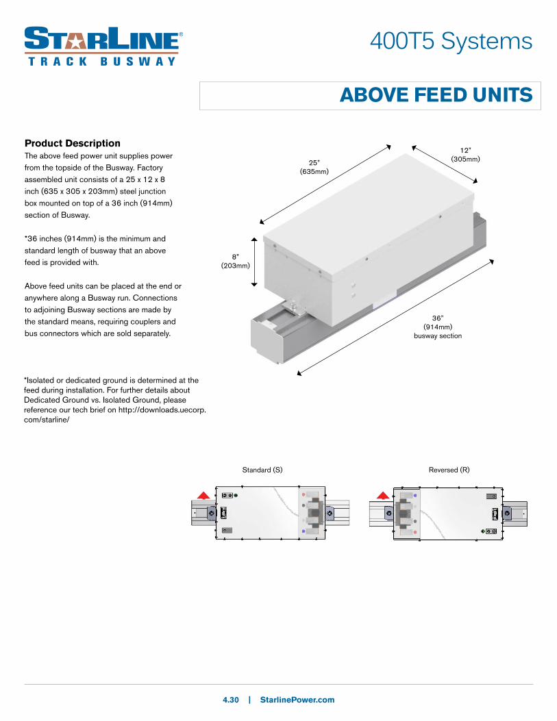
25” (635mm)
8” (203mm)
12” (305mm)
36” (914mm)
busway section
Product DescriptionThe above feed power unit supplies power from the topside of the Busway. Factory assembled unit consists of a 25 x 12 x 8 inch (635 x 305 x 203mm) steel junction box mounted on top of a 36 inch (914mm) section of Busway.
*36 inches (914mm) is the minimum and standard length of busway that an above feed is provided with.
Above feed units can be placed at the end or anywhere along a Busway run. Connections to adjoining Busway sections are made by the standard means, requiring couplers and bus connectors which are sold separately.
*Isolated or dedicated ground is determined at the feed during installation. For further details about Dedicated Ground vs. Isolated Ground, please reference our tech brief on http://downloads.uecorp.com/starline/
Standard (S) Reversed (R)
400T5 Systems
ABOVE FEED UNITS: PRODUCT NUMBERS
4.31 | StarlinePower.com
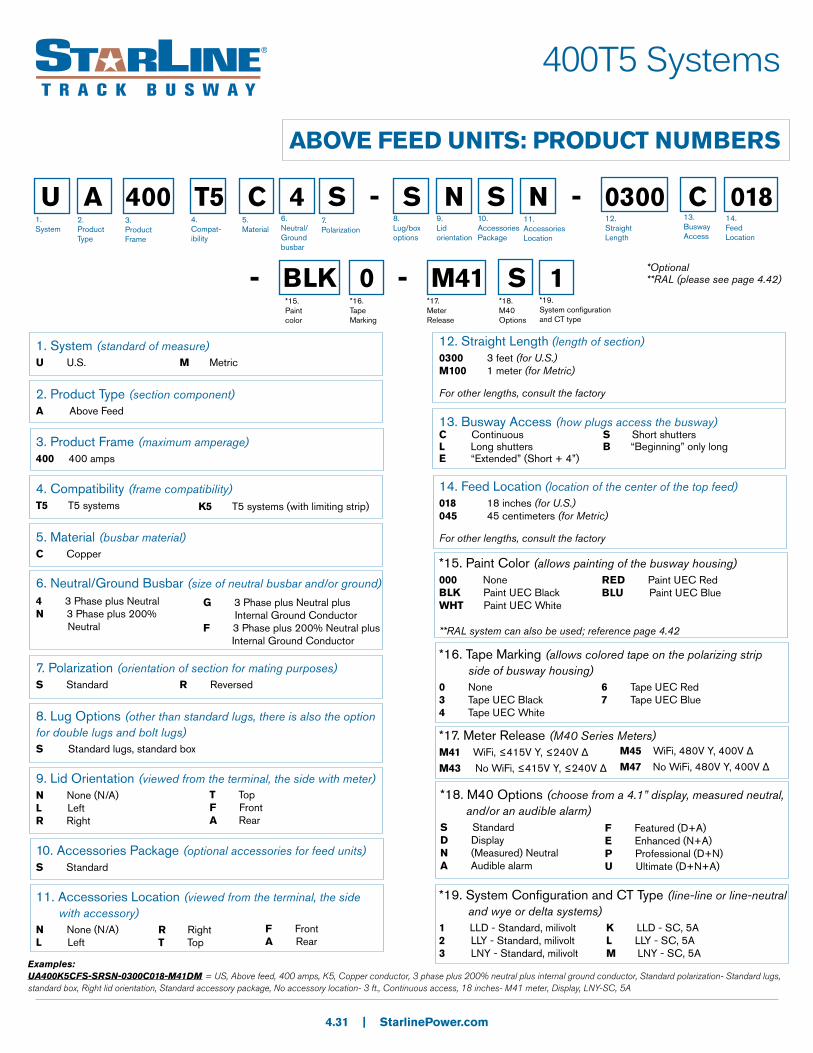
U A 400 T5 C 4 S - S N S N - 0300 C 018
- BLK 0 - M41 S 1*15. Paint color
1. System
2. Product Type
3. Product Frame
4. Compat-ibility
5.Material
6.Neutral/Ground busbar
7.Polarization
8. Lug/box options
9.Lid orientation
10.AccessoriesPackage
11.Accessories Location
12. Straight Length
13.Busway Access
*16. Tape Marking
*17. MeterRelease
*18. M40 Options
*19. System configuration and CT type
1. System (standard of measure)U U.S. M Metric
2. Product Type (section component)A Above Feed
3. Product Frame (maximum amperage)400 400 amps
4. Compatibility (frame compatibility)T5 T5 systems
5. Material (busbar material)C Copper
6. Neutral/Ground Busbar (size of neutral busbar and/or ground)
7. Polarization (orientation of section for mating purposes)S Standard R Reversed
8. Lug Options (other than standard lugs, there is also the option for double lugs and bolt lugs)S Standard lugs, standard box
9. Lid Orientation (viewed from the terminal, the side with meter)N None (N/A)L LeftR Right
10. Accessories Package (optional accessories for feed units)S Standard
4 3 Phase plus Neutral N 3 Phase plus 200% Neutral
G 3 Phase plus Neutral plus Internal Ground ConductorF 3 Phase plus 200% Neutral plus Internal Ground Conductor
T TopF FrontA Rear
*15. Paint Color (allows painting of the busway housing)000 None BLK Paint UEC BlackWHT Paint UEC White
**RAL system can also be used; reference page 4.42
RED Paint UEC RedBLU Paint UEC Blue
*16. Tape Marking (allows colored tape on the polarizing strip side of busway housing)0 None 3 Tape UEC Black4 Tape UEC White
6 Tape UEC Red7 Tape UEC Blue
*17. Meter Release (M40 Series Meters)M41 WiFi, ≤415V Y, ≤240V Δ
M43 No WiFi, ≤415V Y, ≤240V Δ
*18. M40 Options (choose from a 4.1” display, measured neutral, and/or an audible alarm)S Standard D DisplayN (Measured) NeutralA Audible alarm
F Featured (D+A)E Enhanced (N+A)P Professional (D+N)U Ultimate (D+N+A)
*19. System Configuration and CT Type (line-line or line-neutral and wye or delta systems)1 LLD - Standard, milivolt 2 LLY - Standard, milivolt3 LNY - Standard, milivolt
K LLD - SC, 5AL LLY - SC, 5AM LNY - SC, 5A
Examples:UA400K5CFS-SRSN-0300C018-M41DM = US, Above feed, 400 amps, K5, Copper conductor, 3 phase plus 200% neutral plus internal ground conductor, Standard polarization- Standard lugs, standard box, Right lid orientation, Standard accessory package, No accessory location- 3 ft., Continuous access, 18 inches- M41 meter, Display, LNY-SC, 5A
11. Accessories Location (viewed from the terminal, the side with accessory)N None (N/A)L Left
R RightT Top
F FrontA Rear
14.Feed Location
*Optional**RAL (please see page 4.42)
K5 T5 systems (with limiting strip)
13. Busway Access (how plugs access the busway)C Continuous S Short shuttersL Long shutters B “Beginning” only longE “Extended” (Short + 4”)
12. Straight Length (length of section)0300 3 feet (for U.S.)M100 1 meter (for Metric)
For other lengths, consult the factory
14. Feed Location (location of the center of the top feed)018 18 inches (for U.S.)045 45 centimeters (for Metric)
For other lengths, consult the factory
M45 WiFi, 480V Y, 400V Δ
M47 No WiFi, 480V Y, 400V Δ
| StarlinePower.com
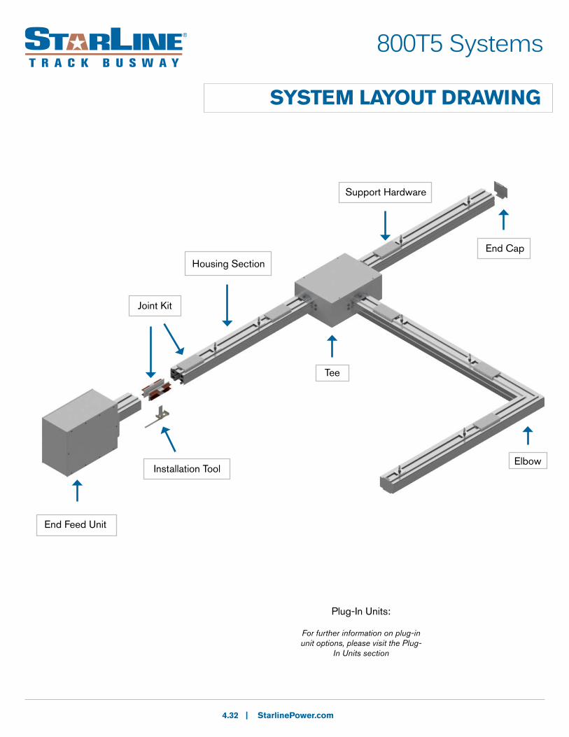
SYSTEM LAYOUT DRAWING
End Feed Unit
Installation Tool
Housing Section
End Cap
Elbow
Support Hardware
800T5 Systems
4.32
Plug-In Units:
For further information on plug-in unit options, please visit the Plug-
In Units section
Tee
Joint Kit

800T5 Systems
STRAIGHT SECTIONS
Product DescriptionTrack Busway straight section consists of an extruded aluminum shell with you choice of copper or copper-aluminum channel busbars contained in a full length insulator mounted on the interior walls. The aluminum extrusion acts as a 100% ground path. Each housing has a continuous access slot over its entire length for the insertion of plug-in units. Housing configurations include 4-pole varieties, with optional isolated ground. The housing sections join together using Bus connectors which fit into the channels of the adjoining section. An Installation tool is used to force the blades into the busbar channels for a solid “spring-pressure” electrical connection.
4.33 | StarlinePower.com
5.050” (128mm)
(N)
(L1)
(L2)(L3)
Installation Tool
Bus Connector
MATERIAL: Extruded Aluminum
RATINGS: 100% Ground Path
800 Amps
600 Volt
LENGTH: 5 ft.(1.5m), Max 10 ft.(3m) or custom lengths between 2 - 10 ft. (.6 - 3m)
VOLTAGE DROP: distributed load
Single Phase 1V per 15ft (4.5m)
(.8PF)
Three Phase 1V per 25ft (7.6m)
(.8PF)
L1 or Phase AL2 or Phase BL3 or Phase C
NeutralGround
US
L1 or Phase AL2 or Phase BL3 or Phase C
NeutralGround
Metric
6.4” (163mm)
Housing Coupler
(G)
WEIGHT:
10 ft. (3m) 4 pole w/ ground & 200% N: 152 lbs/23.1 kg
Access PanelAccess Panel
Side view with access panels:Refer to option 9. Busway Access on pg. 4.34 Straight Sections: Product Numbers
800T5 Systems
STRAIGHT SECTIONS: PRODUCT NUMBERS
4.34 | StarlinePower.com
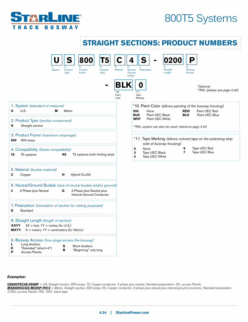
U S 800 T5 C 4 S - 0200 P
- BLK 0*10. Paint color
1. System
2. Product Type
3. Product Frame
4. Compat-ibility
5.Material
6.Neutral/Ground busbar
7.Polarization
8. Straight Length
9.Busway Access
*Optional**RAL (please see page 4.42)
*11. Tape Marking
1. System (standard of measure)U U.S. M Metric
2. Product Type (section component)S Straight section
3. Product Frame (maximum amperage)800 800 amps
4. Compatibility (frame compatibility)T5 T5 systems
5. Material (busbar material)C Copper
6. Neutral/Ground Busbar (size of neutral busbar and/or ground)
7. Polarization (orientation of section for mating purposes)S Standard
8. Straight Length (length of section)XXYY XX = feet, YY = inches (for U.S.)MXYY X = meters, YY = centimeters (for Metric)
9. Busway Access (how plugs access the busway)L Long shuttersE “Extended” (short+4”)P Access Panels
4 3 Phase plus Neutral
G 3 Phase plus Neutral plus Internal Ground Conductor
*10. Paint Color (allows painting of the busway housing)000 None BLK Paint UEC BlackWHT Paint UEC White
**RAL system can also be used; reference page 4.42
RED Paint UEC RedBLU Paint UEC Blue
*11. Tape Marking (allows colored tape on the polarizing strip side of busway housing)0 None 3 Tape UEC Black4 Tape UEC White
6 Tape UEC Red7 Tape UEC Blue
Examples:
US800T5C4S-0500P = US, Straight section, 800 amps, T5, Copper conductor, 3 phase plus neutral, Standard polarization- 5ft., access PanelsMS800K5CGS-M225P-P013 = Metric, Straight section, 800 amps, K5, Copper conductor, 3 phase plus netural plus internal ground connector, Standard polarization- 2.25m, access Panels- RAL 1001, black tape
K5 T5 systems (with limiting strip)
S Short shuttersB “Beginning” only long
H Hybrid (Cu/Al)
800T5 Systems
ELBOW SECTIONS
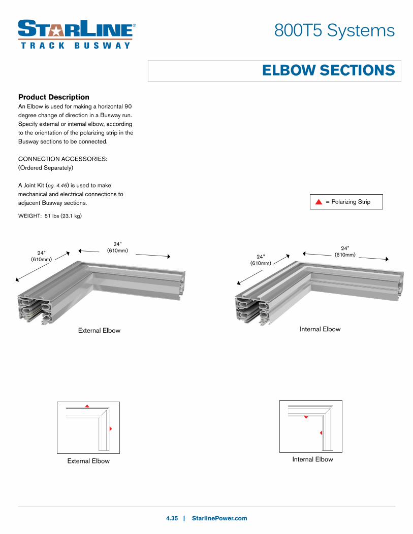
Product DescriptionAn Elbow is used for making a horizontal 90 degree change of direction in a Busway run. Specify external or internal elbow, according to the orientation of the polarizing strip in the Busway sections to be connected.
CONNECTION ACCESSORIES:(Ordered Separately)
A Joint Kit (pg. 4.46) is used to make mechanical and electrical connections to adjacent Busway sections.
4.35 | StarlinePower.com
External Elbow Internal Elbow
24” (610mm)
24” (610mm) 24”
(610mm)24” (610mm)
External Elbow Internal Elbow
= Polarizing Strip
WEIGHT: 51 lbs (23.1 kg)
800T5 Systems
ELBOW SECTIONS: PRODUCT NUMBERS
4.36 | StarlinePower.com
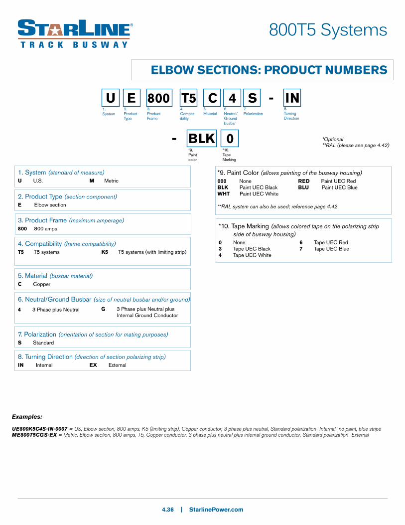
U E 800 T5 C 4 S - IN
- BLK 0*9. Paint color
1. System
2. Product Type
3. Product Frame
4. Compat-ibility
5.Material
6.Neutral/Ground busbar
7.Polarization
8. Turning Direction
*10. Tape Marking
1. System (standard of measure)U U.S. M Metric
2. Product Type (section component)E Elbow section
3. Product Frame (maximum amperage)800 800 amps
4. Compatibility (frame compatibility)T5 T5 systems
5. Material (busbar material)C Copper
6. Neutral/Ground Busbar (size of neutral busbar and/or ground)
7. Polarization (orientation of section for mating purposes)S Standard
8. Turning Direction (direction of section polarizing strip)IN Internal EX External
4 3 Phase plus Neutral
G 3 Phase plus Neutral plus Internal Ground Conductor
*9. Paint Color (allows painting of the busway housing)000 None BLK Paint UEC BlackWHT Paint UEC White
**RAL system can also be used; reference page 4.42
RED Paint UEC RedBLU Paint UEC Blue
*10. Tape Marking (allows colored tape on the polarizing strip side of busway housing)0 None 3 Tape UEC Black4 Tape UEC White
6 Tape UEC Red7 Tape UEC Blue
Examples:
UE800K5C4S-IN-0007 = US, Elbow section, 800 amps, K5 (limiting strip), Copper conductor, 3 phase plus neutral, Standard polarization- Internal- no paint, blue stripeME800T5CGS-EX = Metric, Elbow section, 800 amps, T5, Copper conductor, 3 phase plus neutral plus internal ground conductor, Standard polarization- External
*Optional**RAL (please see page 4.42)
K5 T5 systems (with limiting strip)
800T5 Systems
TEE SECTIONS
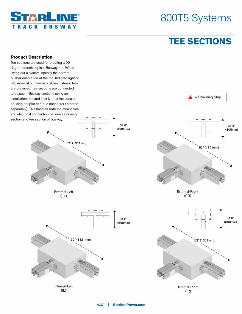
Product DescriptionTee sections are used for creating a 90 degree branch leg in a Busway run. When laying out a system, specify the correct busbar orientation of the tee. Indicate right or left, external or internal busbars. Exterior tees are preferred. Tee sections are connected to adjacent Busway sections using an installation tool and joint kit that includes a housing coupler and bus connector (ordered separately). This handles both the mechanical and electrical connection between a housing section and tee section of busway.
4.37 | StarlinePower.com
External-Left(EL)
External-Right(ER)
Internal-Left(IL)
Internal-Right(IR)
31.8” (808mm)
= Polarizing Strip
31.8” (808mm)
31.8” (808mm)
31.8” (808mm)
52” (1321mm)52” (1321mm)
52” (1321mm) 52” (1321mm)

800T5 Systems
TEE SECTIONS: PRODUCT NUMBERS
4.38 | StarlinePower.com
U T 800 T5 C 4 S - IR
- BLK 0*9. Paint color
1. System
2. Product Type
3. Product Frame
4. Compat-ibility
5.Material
6.Neutral/Ground busbar
7.Polarization
8. Turning Direction
*10. Tape Marking
1. System (standard of measure)U U.S. M Metric
2. Product Type (section component)T Tee section
3. Product Frame (maximum amperage)800 800 amps
4. Compatibility (frame compatibility)T5 T5 systems
5. Material (busbar material)C Copper
6. Neutral/Ground Busbar (size of neutral busbar and/or ground)
7. Polarization (orientation of section for mating purposes)S Standard
8. Turning Direction (direction of section polarizing strip)IL Internal-Left EL External-Left
IR Internal-Right ER External-Right
4 3 Phase plus Neutral
G 3 Phase plus Neutral plus Internal Ground Conductor
*9. Paint Color (allows painting of the busway housing)000 None BLK Paint UEC BlackWHT Paint UEC White
**RAL system can also be used; reference page 4.42
RED Paint UEC RedBLU Paint UEC Blue
*10. Tape Marking (allows colored tape on the polarizing strip side of busway housing)0 None 3 Tape UEC Black4 Tape UEC White
6 Tape UEC Red7 Tape UEC Blue
Examples:
UT800T5C4S-IR-PE90 = US, Tee section, 800 amps, T5, Copper conductor, 3 phase plus neutral, Standard polarization- Internal-Right- RAL 4009, no tape markingMT800K5CGS-EL = Metric, Tee section, 800 amps, K5, Copper conductor, 3 phase plus neutral plus internal ground conductor, Standard polarization- External-Left
*Optional**RAL (please see page 4.42)
K5 T5 systems (with limiting strip)
800T5 Systems
END FEED UNITS
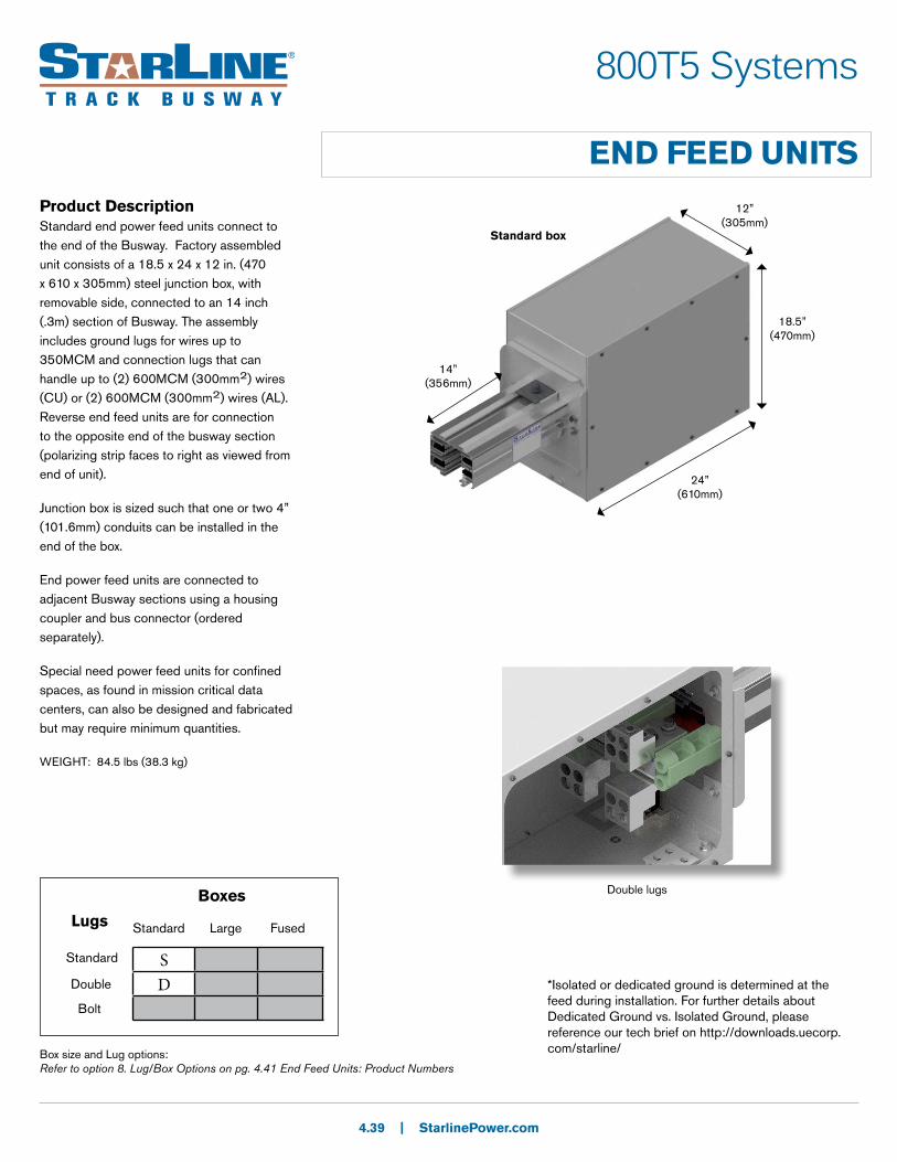
Product DescriptionStandard end power feed units connect to the end of the Busway. Factory assembled unit consists of a 18.5 x 24 x 12 in. (470 x 610 x 305mm) steel junction box, with removable side, connected to an 14 inch (.3m) section of Busway. The assembly includes ground lugs for wires up to 350MCM and connection lugs that can handle up to (2) 600MCM (300mm2) wires (CU) or (2) 600MCM (300mm2) wires (AL). Reverse end feed units are for connection to the opposite end of the busway section (polarizing strip faces to right as viewed from end of unit).
Junction box is sized such that one or two 4” (101.6mm) conduits can be installed in the end of the box.
End power feed units are connected to adjacent Busway sections using a housing coupler and bus connector (ordered separately).
Special need power feed units for confined spaces, as found in mission critical data centers, can also be designed and fabricated but may require minimum quantities.
4.39 | StarlinePower.com
SD
Boxes
Standard Large FusedLugs
Standard
Double
Bolt
Box size and Lug options:Refer to option 8. Lug/Box Options on pg. 4.41 End Feed Units: Product Numbers
24” (610mm)
18.5” (470mm)
12” (305mm)
14” (356mm)
Double lugs
Standard box
*Isolated or dedicated ground is determined at the feed during installation. For further details about Dedicated Ground vs. Isolated Ground, please reference our tech brief on http://downloads.uecorp.com/starline/
WEIGHT: 84.5 lbs (38.3 kg)
800T5 Systems
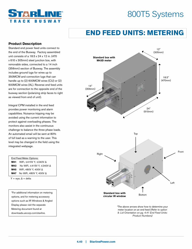
END FEED UNITS: METERINGProduct DescriptionStandard end power feed units connect to the end of the Busway. Factory assembled unit consists of a 18.5 x 24 x 12 in. (470 x 610 x 305mm) steel junction box, with removable sides, connected to a 14 inch (356mm) section of Busway. The assembly includes ground lugs for wires up to 350MCM and connection lugs that can handle up to (2) 600MCM wires (CU) or (2) 600MCM wires (AL). Reverse end feed units are for connection to the opposite end of the busway section (polarizing strip faces to right as viewed from end of unit).
Integral CPM installed in the end feed provides power monitoring and alarm capabilities. Nuisance tripping may be avoided using the current information to protect against overloading phases. The monitors also assist in the continuous challenge to balance the three phase loads. An automated email will be sent at 80% of full load as a warning to the user. This level may be changed in the field using the integrated webpage.
4.40 | StarlinePower.com
Standard box with M43D meter
18.5” (470mm)
24” (610mm)
12” (305mm)
14” (356mm)
Standard box with circular IR window
*The above arrows show how to determine your meter location on an end feed (Refer to option 9. Lid Orientation on pg. 4.41 End Feed Units:
Product Numbers)
Front
Left
Bottom
Top
Right
*For additional information on metering
options, and for metering accessory
options such as IR Windows & Angled
Display please visit the separate
Metering document found at
downloads.uecorp.com/starline.
End Feed Meter Options:
M41 WiFi, ≤415V Y, ≤240V Δ
M43 No WiFi, ≤415V Y, ≤240V Δ
M45 WiFi, 480V Y, 400V Δ
M47 No WiFi, 480V Y, 400V Δ
Y = wye, Δ = delta
800T5 Systems
END FEED UNITS: PRODUCT NUMBERS
4.41 | StarlinePower.com
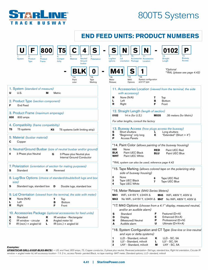
U F 800 T5 C 4 S - S N S N - 0102 P
- BLK 0 - M41 S 1*14. Paint color
1. System
2. Product Type
3. Product Frame
4. Compat-ibility
5.Material
6.Neutral/Ground busbar
7.Polarization
8. Lug/box options
9.Lid orientation
10.AccessoriesPackage
11.Accessories Location
12. Straight Length
13.Busway Access
*15. Tape Marking
*16. MeterRelease
*17. M40 Options
*18. System configuration and CT type
1. System (standard of measure)U U.S. M Metric
2. Product Type (section component)F End Feed
3. Product Frame (maximum amperage)800 800 amps
4. Compatibility (frame compatibility)T5 T5 systems
5. Material (busbar material)C Copper
6. Neutral/Ground Busbar (size of neutral busbar and/or ground)
7. Polarization (orientation of section for mating purposes)S Standard R Reversed
8. Lug/Box Options (choice of standard/double/bolt lugs and box size)S Standard lugs, standard box
9. Lid Orientation (viewed from the terminal, the side with meter)N None (N/A)L LeftR Right
10. Accessories Package (optional accessories for feed units)S Standard R IR window - RectangularC IR window - circular A Angled meter lidT IR (rect.) + angled lid L IR (circ.) + angled lid
11. Accessories Location (viewed from the terminal, the side with accessory)N None (N/A)L LeftR Right
13. Busway Access (how plugs access the busway)S Short shutters L Long shutters B “Beginning” only long E “Extended” (Short + 4”)P Access Panels
4 3 Phase plus Neutral
G 3 Phase plus Neutral plus Internal Ground Conductor
D Double lugs, standard box
T TopB BottomF Front
T TopB BottomF Front
*14. Paint Color (allows painting of the busway housing)000 None BLK Paint UEC BlackWHT Paint UEC White
**RAL system can also be used; reference page 4.42
RED Paint UEC RedBLU Paint UEC Blue
*15. Tape Marking (allows colored tape on the polarizing strip side of busway housing)0 None 3 Tape UEC Black4 Tape UEC White
6 Tape UEC Red7 Tape UEC Blue
*16. Meter Release (M40 Series Meters)M41 WiFi, ≤415V Y, ≤240V Δ
M43 No WiFi, ≤415V Y, ≤240V Δ
*17. M40 Options (choose from a 4.1” display, measured neutral, and/or an audible alarm)S Standard D DisplayN (Measured) NeutralA Audible alarm
F Featured (D+A)E Enhanced (N+A)P Professional (D+N)U Ultimate (D+N+A)
*18. System Configuration and CT Type (line-line or line-neutral and wye or delta systems)1 LLD - Standard, milivolt 2 LLY - Standard, milivolt3 LNY - Standard, milivolt
K LLD - SC, 5AL LLY - SC, 5AM LNY - SC, 5A
Examples:UF800T5C4R-SRLL-0102P-BLK0-M47S1 = US, end Feed, 800 amps, T5, Copper conductor, 3 phase plus neutral, Reversed polarization- Std lugs, standard box, Right lid orientation, Circular IR window + angled meter lid, left accessory location- 1 ft. 2 in., access Panels- painted Black, no tape marking- M47 meter, Standard options, LLD- standard, milivolt
*Optional**RAL (please see page 4.42)
K5 T5 systems (with limiting strip)
12. Straight Length (length of section)0102 14 in (for U.S.) M035 .35 meters (for Metric)
For other lengths, consult the factory
M45 WiFi, 480V Y, 400V Δ
M47 No WiFi, 480V Y, 400V Δ

| StarlinePower.com
RAL Colors
0 100
1 101
2 102
3 103
4 200
5 201
A 300
B 301
C 302
D 303
E 400
F 401
G 500
H 501
J 502
K 600
L 601
M 602
N 603
P 700
Q 701
R 702
S 703
T 704
U 800
V 801
W 802
X 900
Y 901
Z 902
0 0
1 1
2 2
3 3
4 4
5 5
6 6
7 7
8 8
9 9
2nd Character 3rd Character
Example:
P B 2 = Paint RAL 3012
1st Character
P Paint
T5 Series
4.42
| StarlinePower.com
T5 Series
ACCESSORIES: SUPPORT HARDWARE
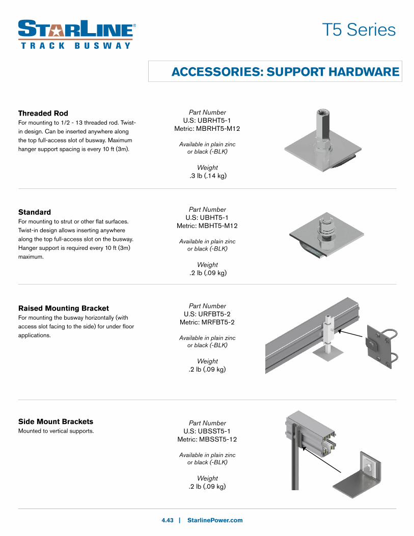
Threaded RodFor mounting to 1/2 - 13 threaded rod. Twist-in design. Can be inserted anywhere along the top full-access slot of busway. Maximum hanger support spacing is every 10 ft (3m).
Part Number U.S: UBRHT5-1
Metric: MBRHT5-M12
Available in plain zinc or black (-BLK)
Weight .3 lb (.14 kg)
StandardFor mounting to strut or other flat surfaces. Twist-in design allows inserting anywhere along the top full-access slot on the busway. Hanger support is required every 10 ft (3m) maximum.
Part NumberU.S: UBHT5-1
Metric: MBHT5-M12
Available in plain zinc or black (-BLK)
Weight .2 lb (.09 kg)
4.43
Raised Mounting BracketFor mounting the busway horizontally (with access slot facing to the side) for under floor applications.
Part Number U.S: URFBT5-2
Metric: MRFBT5-2
Available in plain zinc or black (-BLK)
Weight.2 lb (.09 kg)
Side Mount BracketsMounted to vertical supports.
Part NumberU.S: UBSST5-1
Metric: MBSST5-12
Available in plain zinc or black (-BLK)
Weight.2 lb (.09 kg)
| StarlinePower.com
T5 Series
ACCESSORIES: SUPPORT HARDWARE
4.44
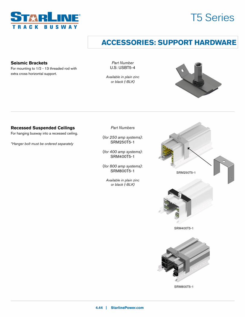
Recessed Suspended CeilingsFor hanging busway into a recessed ceiling.
*Hanger bolt must be ordered separately
Part Numbers
(for 250 amp systems):SRM250T5-1
(for 400 amp systems):SRM400T5-1
(for 800 amp systems):SRM800T5-1
Available in plain zinc or black (-BLK)
Seismic BracketsFor mounting to 1/2 - 13 threaded rod with extra cross horizontal support.
Part Number U.S: USBT5-4
Available in plain zinc or black (-BLK)
SRM250T5-1
SRM400T5-1
SRM800T5-1
| StarlinePower.com
T5 Series
ACCESSORIES: SUPPORT HARDWARE
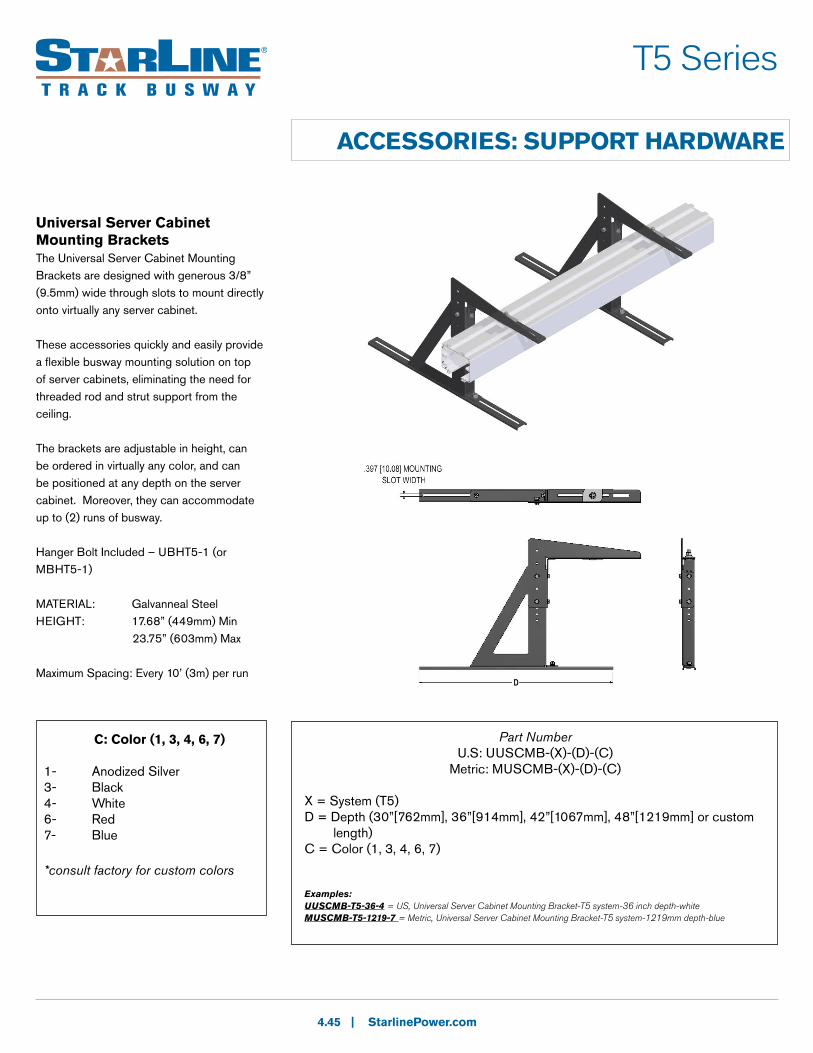
Universal Server Cabinet Mounting BracketsThe Universal Server Cabinet Mounting Brackets are designed with generous 3/8” (9.5mm) wide through slots to mount directly onto virtually any server cabinet.
These accessories quickly and easily provide a flexible busway mounting solution on top of server cabinets, eliminating the need for threaded rod and strut support from the ceiling.
The brackets are adjustable in height, can be ordered in virtually any color, and can be positioned at any depth on the server cabinet. Moreover, they can accommodate up to (2) runs of busway.
Hanger Bolt Included – UBHT5-1 (or MBHT5-1)
MATERIAL: Galvanneal Steel HEIGHT: 17.68” (449mm) Min 23.75” (603mm) Max
Maximum Spacing: Every 10’ (3m) per run
4.45
C: Color (1, 3, 4, 6, 7)
1- Anodized Silver3- Black4- White6- Red7- Blue
*consult factory for custom colors
Part NumberU.S: UUSCMB-(X)-(D)-(C)
Metric: MUSCMB-(X)-(D)-(C)
X = System (T5)D = Depth (30”[762mm], 36”[914mm], 42”[1067mm], 48”[1219mm] or custom length)C = Color (1, 3, 4, 6, 7)
Examples:UUSCMB-T5-36-4 = US, Universal Server Cabinet Mounting Bracket-T5 system-36 inch depth-white MUSCMB-T5-1219-7 = Metric, Universal Server Cabinet Mounting Bracket-T5 system-1219mm depth-blue

| StarlinePower.com
T5 Series
ACCESSORIES: CONNECTION HARDWARE
(for 250 amp systems): SJK250T5-1
SJK250T5G-1SJK250T5N-1SJK250T5F-1
(for 400 amp systems)SJK400T5-1
SJK400T5G-1SJK400T5N-1SJK400T5F-1
(for 800 amp systems)SJK800T5-1
SJK800GT5-1
Available in all standard and RAL colors
4.46
Joint KitFor the connection of adjacent busway sections. One kit is required at each joint. Each kit is comprised of a housing coupler pair and bus connector set.
Bus Connector: copper blades secured to an insulating mounting plate. This makes the electrical connection between sections.
Housing Couplers: consists of two 12-screw couplers-one for the top and one for the bottom. These make the mechanical connection between busway sections.
*Installation tool is required (see below)
housing couplers
bus connectors
Installation ToolAn installation tool is used to install the bus connector between two adjacent sections of busway. A joint kit, which is comprised of two housing couplers and a bus connector set, is required at every joint.
Busway sections are butted together and the top housing coupler is installed. The bus connector is inserted, centered and seated in the slot of the busway. The installation tool is inserted into the jointed intersection and rotated 90 degrees to form a spring-loaded, secure electrical connection. The housing coupler is then positioned over the bottom joint and tightened.
Part Numbers
Part NumberST5IT
No available colors
Weight3.1 lb (1.4 kg)

| StarlinePower.com
ACCESSORIES: CONNECTION HARDWARE
4.47
T5 Series
SEC400T5
5.7” (145mm)
End CapFor covering the end of T5 busway systems.
SEC250T5
4.25” (108mm)
Part Numbers
(for 250 amp systems):SEC250T5
(for 400 amp systems):SEC400T5
(for 800 amp systems):SEC800T5
Available in all standard and RAL colors
Weight: .4 lb (.18 kg)
Optional Closure StripThe Closure Strip snaps into the bottom access slot of T5 housing to close off access to power around the installed plug-in units. It is normally shipped in 10 ft (3m) sections.
The Closure Strip is offered in both PVC material and aluminum.
The aluminum Closure Strip affixes with an adhesive backing to the access slot of T5 housing.
Part Number SCST5-1
Aluminum closure strip:SCST5-1-AL
Available in all standard colors
6.4” (163mm)
5” (127mm)
5” (127mm)
SEC800T5
5” (127mm)

| StarlinePower.com
ADD-ON ACCESSORIES: DATA CHANNEL
4.48
T5 Series
Part NumberU.S:
UDCCT5-10-SIL (silver)UDCCT5-10-BLK (black)
UDCCT5-10-GRN (green)UDCCT5-10-YEL (yellow)UDCCT5-10-W (white)UDCCT5-10-RED (red)UDCCT5-10-BLU (blue)
Metric:MDCCT5-3-SIL (silver)MDCCT5-3-BLK (black)
MDCCT5-3-GRN (green)MDCCT5-3-YEL (yellow)MDCCT5-3-W (white)MDCCT5-3-RED (red)MDCCT5-3-BLU (blue)
Data Channel CoverThe Data Channel Cover is used to hold cables into position and hide them from view. It can also be used for a variety of busway identification applications, and it is available in many different colors.
The Data Channel Cover is available in lengths of 10 ft. (3m).
Please contact sales to order the quantity needed.
Hinged Wire WayThe Hinged Wire Way provides a seamless, integrated cable management solution that allows users to easily route cabling while leaving it easily accessible and identifiable.Discreet slots located every 6 inches (150mm) provide built-in accessibility for cable drops.
The Hinged Wire Way is available in lengths up to 10 ft. (3m).
Please contact sales to order the quantity and length needed.
Part NumberU.S: UHWWT5-10
Metric: MHWWT5-3
Available in gray only

| StarlinePower.com
ADD-ON ACCESSORIES: DATA CHANNEL
4.49
T5 Series
Part NumberSMMBT5-1
Available in plain zinc or black (-BLK)
Multi Use Mounting BracketThe Multi Use Mounting Bracket is an all-purpose bracket that easily attaches to any position on the busway. The bracket comes with 1/4 inch (6.5mm) slotted holes throughout to allow for the attachment of a wide variety of accessories. Each bracket is capable of supporting a load of 25 lbs (12 kg).
The Multi Use Mounting Bracket is commonly used for suspending compressed air lines, tap box cable management and suspending accessory lighting.
Data Cable StrapThe Data Cable Strap provides a seamless, integrated cable management solution that allows users to easily route cabling while leaving it easily accessible and identifiable. The 12 inch (305mm) adjustable velcro strap can accommodate a wide variety and quantity of cables, and can be easily positioned along the busway to accommodate various cable management needs.
Part NumberSVCST5-12
No available colors
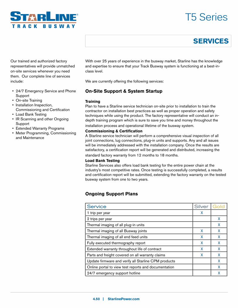
| StarlinePower.com
SERVICES
4.50
T5 Series
With over 25 years of experience in the busway market, Starline has the knowledge and expertise to ensure that your Track Busway system is functioning at a best-in-class level.
We are currently offering the following services:
On-Site Support & System Startup
TrainingPlan to have a Starline service technician on-site prior to installation to train the contractor on installation best practices as well as proper operation and safety techniques while using the product. The factory representative will conduct an in-depth training program which is sure to save you time and money throughout the installation process and operational lifetime of the busway system.Commissioning & CertificationA Starline service technician will perform a comprehensive visual inspection of all joint connections, lug connections, plug-in units and supports. Any and all issues will be immediately addressed with the installation company. Once the results are satisfactory, a certification report will be generated and distributed, increasing the standard factory warranty from 12 months to 18 months.Load Bank TestingStarline Services also offers load bank testing for the entire power chain at the industry’s most competitive rates. Once testing is successfully completed, a results and certification report will be submitted, extending the factory warranty on the tested busway system from one to two years.
Ongoing Support Plans
Our trained and authorized factory representatives will provide unmatched on-site services whenever you need them. Our complete line of services include:
• 24/7 Emergency Service and Phone Support• On-site Training• Installation Inspection, Commissioning and Certification• Load Bank Testing• IR Scanning and other Ongoing Support• Extended Warranty Programs• Meter Programming, Commissioning and Maintenance
Service Silver Gold1 trip per year X
2 trips per year X
Thermal imaging of all plug-in units X
Thermal imaging of all Busway joints X X
Thermal imaging of all end feed units X X
Fully executed thermography report X X
Extended warranty throughout life of contract X X
Parts and freight covered on all warranty claims X X
Update firmware and verify all Starline CPM products X
Online portal to view test reports and documentation X
24/7 emergency support hotline X

| StarlinePower.com
SERVICES (cont'd)
4.51
T5 Series
Metering Services
A trained Starline service technician is always available to help you with the start-up, programming, integration and verification of your Starline CPM metering devices. End-users are provided a full meter report and guide to ensure ease of use once our technician has completed the job. The Starline service technician will provide training while on-site pertaining to meter operation and care, programming and use of the CPM Mobile App.
Meter Upgrade Thinking about upgrading your unmetered components? Is it time to replace older metering products with something new and improved? Starline offers a full-service meter retrofit program for any type of plug-in or end feed unit. You no longer have to replace an entire module just to add a meter. Save money and downtime with the Starline CPM upgrade program.
Warranty Programs
Standard WarrantyStarline Track Busway is proud to stand behind its American made, best-in-class busway products. Every Starline product is backed by a one year factory warranty that covers replacement parts and freight on components that are found to have defects related to shipping, workmanship or material.
Extended Warranty To ensure less downtime and unmatched field service support, be sure to purchase one of Starline’s customizable extended warranty programs. You can choose the length of your warranty and whether to add a yearly Ongoing Support visit as a standard. Replacement parts are guaranteed for all parts covered under warranty and will be quickly delivered to the site.
*All warranties are subject to the proper commissioning and certification of the Track Busway system performed by a Starline service technician or factory representative. Systems that had previously been in operation and have surpassed the factory warranty term are subject to a visual inspection and certification before an extended warranty can be applied. Please contact the factory for further details.

REV 1
While every effort has been made to ensure the accuracy of all information, Universal Electric Corporation does not accept liability for any errors or omissions and reserves the right to
change information and descriptions of listed services and products.
Most STARLINE systems and most standard components are UL, CE or ETL listed.
www.StarlinePower.com [email protected]
Universal Electric Corporation, manufacturer of Starline Track Busway, has been a global leader in power distribution since 1924. The company’s focus on innovation continues to pave the way for safer, more flexible and reliable electrical power distribution systems. Other Starline products include the Critical Power Monitor (CPM), which works in conjunction with Starline Track Busway to improve energy efficiency; Plug-In Raceway, the flexible, wall-mounted power distribution system; and DC Solutions, the revolutionary 380V direct current alternative for data centers.
United States168 Georgetown Rd. Canonsburg, PA 15317 800-245-6378 +1 724-597-7800
UK & Northern Europe804 Oxford Avenue, Slough Trading Estate Slough, Berkshire SL14LN +44 (0) 1753 376 700
Asia Pacific Region OfficeLevel 8 Samsung Hub 3 Church Street Singapore 049483 +65 6408 0165
S.W. Asia Region OfficeGround Floor, E-1 Block, Beech Building Manyata Embassy Business Park Outer Ring Road Bangalore, India 560045 +91 80 4276 4627