Embed Size (px)
Citation preview
Use of the AHRI Certified TM Mark in-dicates a manufacturer’s participationin the program. For verification of certi-fication for individual products, go towww.ahridirectory.org .
427 41 1501 01 10/19/10
PHJ3Product Specifications
13 SEER, R−410APACKAGE HEAT PUMP FOR MANUFACTURED HOUSING, RESIDENTIAL, AND LIGHT COMMERCIAL APPLICATIONS2 − 5 TONSSingle Phase, 208/230 V, 60 HzBUILT TO LAST, EASY TO INSTALL AND SERVICE• Compact, fully self−contained, electric cooling unit with horizontal supply and return ducts
• Light weight, compact construction ideal for manufactured housing and residential applications
• Environmentally sound R−410A refrigerant
• Vibration isolation provides quiet operation. Compressors have internal over current protection
• Liquid refrigerant filter driers
• Hand holds built into the unit base pan
• Designed to be serviced from both the side and front
• Accessory electric heaters with single point connections
• Durable pre−painted steel cabinet
• No−rust base pan with integrated drain pan standard on all units
• Direct−drive ECM multi−speed, blower motor standard on all models
• Louvered coil enclosure for protection against vandalism and hail damage
• Aerodynamic fan blade design reduces the overall sound
• All models available with optional factory installed tin−coated copper evaporator coil. (These models are identified with letters TP in the 11th and 12th positions in the model numbers)
LIMITED WARRANTY*• 5−year parts limited warranty (including compressor and coils)
−With timely registration, an additional 5 year parts limited warranty (including compressor and coils)*Applies to original purchaser/homeowner, some limitations may apply. See warranty certificate for details.
UNIT PERFORMANCE DATA
Model Number
COOLING HEATING
Unit Dimensions H x W x D in [mm ]
OperatingWeight lbs
[kg]Capacity
BTU/h SEER EER
NETHEATING
CAPACITY HSPFPHJ324000K000APHJ324000KTP0A 24,000 13.5 11.5 23,800 7.7 30 [765]x51 [1295]x32 [813] 263 [120]
PHJ330000K000APHJ330000KTP0A 28,800 13.5 11.5 28,600 7.7 30 [765]x51 [1295]x32 [813] 264 [120]
PHJ336000K000APHJ336000KTP0A 36,000 13.5 11.5 34,400 7.7 34 [867]x51 [1295]x32 [813] 285 [130]
PHJ342000K000APHJ342000KTP0A 41,500 13.5 11.5 41,000 7.7 42 [1070]x51 [1295]x32 [813] 339 [154]
PHJ348000K000APHJ348000KTP0A 46,500 13.5 11.5 46,500 7.7 42 [1070]x51 [1295]x32 [813] 358 [163]
PHJ360000K000APHJ360000KTP0A 55,000 13.0 11.0 55,000 7.7 42 [1070]x51 [1295]x32 [813] 371 [169]
2 Specifications subject to change without notice. 427 41 1501 01
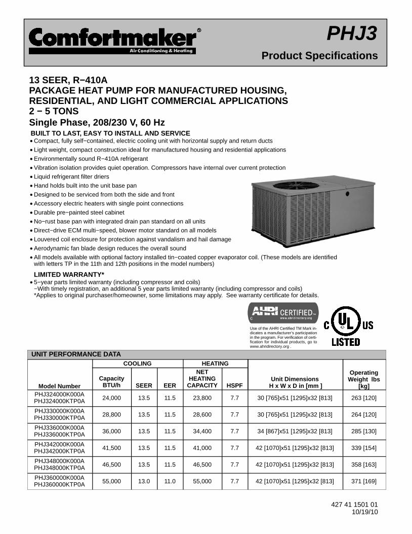
MODEL NOMENCLATURE
MODEL SERIES1 2, 3 4 5,6 7,8,9 10 11,12 13 14
P HJ 3 36 000 K 00 0 AP = Package
HJ = Heat Pump
3 = 13 SEER24 = 2 Tons
30 = 2.5 Tons36 = 3 Tons
42 = 3.5 Tons
48 = 4 Tons60 = 5 Tons NOMINAL COOLING CAPACITY
000 = no factory heat NOMINAL HEATING BTUH (input)
K = 208/230−1−60 VOLTAGE00 = No optionsTP − Tin Plated Evaporator Main Tubes FACTORY INSTALLED OPTIONS
0 = Standard FEATURE CODESales Model Digit
3Specifications subject to change without notice.427 41 1501 01
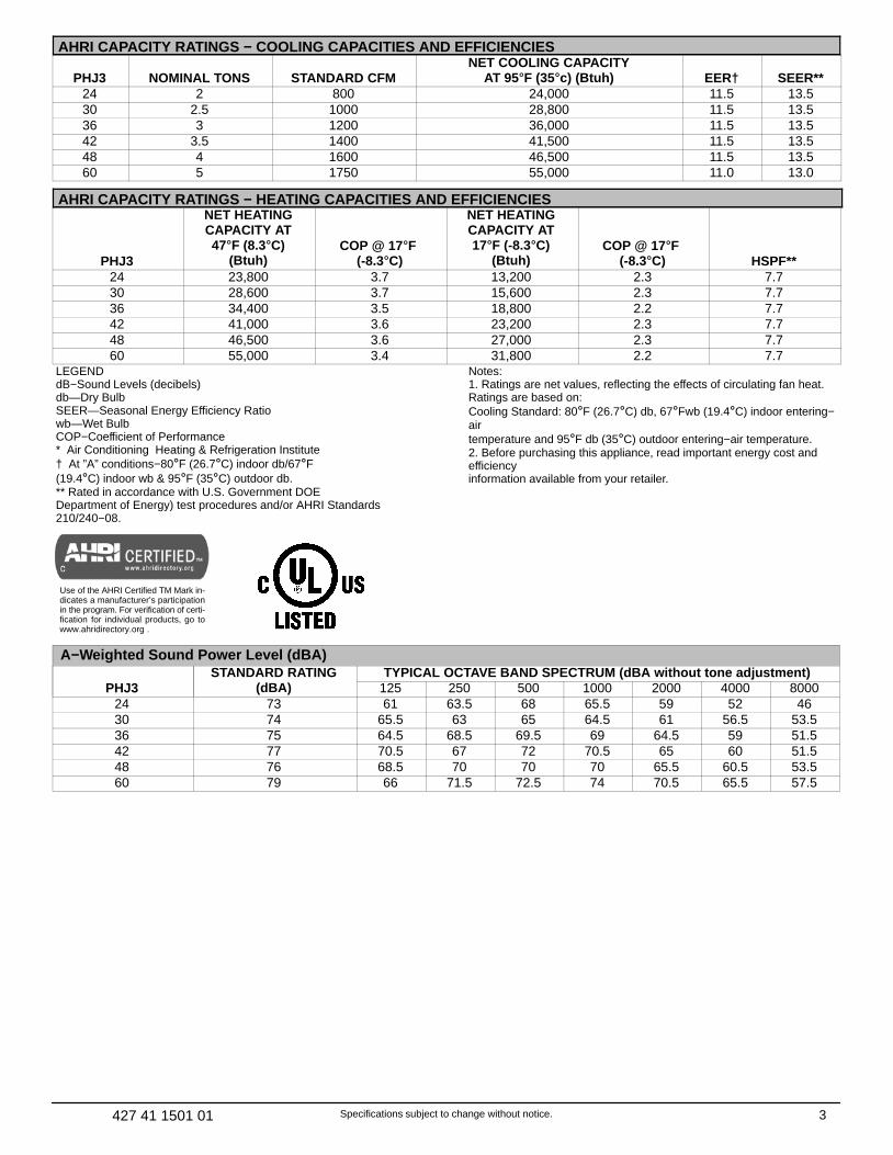
AHRI CAPACITY RATINGS − COOLING CAPACITIES AND EFFICIENCIES
PHJ3 NOMINAL TONS STANDARD CFMNET COOLING CAPACITY
AT 95�F (35�c) (Btuh) EER† SEER**24 2 800 24,000 11.5 13.530 2.5 1000 28,800 11.5 13.536 3 1200 36,000 11.5 13.542 3.5 1400 41,500 11.5 13.548 4 1600 46,500 11.5 13.560 5 1750 55,000 11.0 13.0
AHRI CAPACITY RATINGS − HEATING CAPACITIES AND EFFICIENCIES
PHJ3
NET HEATINGCAPACITY AT47�F (8.3�C)
(Btuh)COP @ 17�F
(-8.3�C)
NET HEATINGCAPACITY AT17�F (-8.3�C)
(Btuh)COP @ 17�F
(-8.3�C) HSPF**24 23,800 3.7 13,200 2.3 7.730 28,600 3.7 15,600 2.3 7.736 34,400 3.5 18,800 2.2 7.742 41,000 3.6 23,200 2.3 7.748 46,500 3.6 27,000 2.3 7.760 55,000 3.4 31,800 2.2 7.7
LEGENDdB−Sound Levels (decibels)db—Dry BulbSEER—Seasonal Energy Efficiency Ratiowb—Wet BulbCOP−Coefficient of Performance* Air Conditioning Heating & Refrigeration Institute† At ”A” conditions−80�F (26.7�C) indoor db/67�F (19.4�C) indoor wb & 95�F (35�C) outdoor db.** Rated in accordance with U.S. Government DOE Department of Energy) test procedures and/or AHRI Standards210/240−08.
Notes:1. Ratings are net values, reflecting the effects of circulating fan heat.Ratings are based on:Cooling Standard: 80�F (26.7�C) db, 67�Fwb (19.4�C) indoor entering−airtemperature and 95�F db (35�C) outdoor entering−air temperature.2. Before purchasing this appliance, read important energy cost andefficiencyinformation available from your retailer.
Use of the AHRI Certified TM Mark in-dicates a manufacturer’s participationin the program. For verification of certi-fication for individual products, go towww.ahridirectory.org .
A−Weighted Sound Power Level (dBA)
PHJ3STANDARD RATING
(dBA)TYPICAL OCTAVE BAND SPECTRUM (dBA without tone adjustment)
125 250 500 1000 2000 4000 800024 73 61 63.5 68 65.5 59 52 4630 74 65.5 63 65 64.5 61 56.5 53.536 75 64.5 68.5 69.5 69 64.5 59 51.542 77 70.5 67 72 70.5 65 60 51.548 76 68.5 70 70 70 65.5 60.5 53.560 79 66 71.5 72.5 74 70.5 65.5 57.5
4 Specifications subject to change without notice. 427 41 1501 01
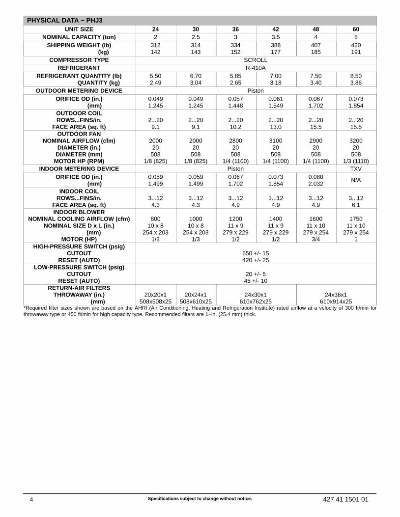
PHYSICAL DATA − PHJ3UNIT SIZE 24 30 36 42 48 60
NOMINAL CAPACITY (ton) 2 2.5 3 3.5 4 5SHIPPING WEIGHT (lb) (kg)
312142
314143
334152
388177
407185
420191
COMPRESSOR TYPE SCROLLREFRIGERANT R-410A
REFRIGERANT QUANTITY (lb) QUANTITY (kg)
5.502.49
6.703.04
5.852.65
7.003.18
7.503.40
8.503.86
OUTDOOR METERING DEVICE PistonORIFICE OD (in.) (mm)
0.0491.245
0.0491.245
0.0571.448
0.0611.549
0.0671.702
0.0731.854
OUTDOOR COILROWS...FINS/in.
FACE AREA (sq. ft)
2...209.1
2...209.1
2...2010.2
2...2013.0
2...2015.5
2...2015.5
OUTDOOR FANNOMINAL AIRFLOW (cfm)
DIAMETER (in.)DIAMETER (mm)
MOTOR HP (RPM)
200020508
1/8 (825)
200020508
1/8 (825)
280020508
1/4 (1100)
310020508
1/4 (1100)
290020508
1/4 (1100)
320020508
1/3 (1110)INDOOR METERING DEVICE Piston TXV
ORIFICE OD (in.) (mm)
0.0591.499
0.0591.499
0.0671.702
0.0731.854
0.0802.032
N/A
INDOOR COILROWS...FINS/in.
FACE AREA (sq. ft)
3...124.3
3...124.3
3...124.9
3...124.9
3...124.9
3...126.1
INDOOR BLOWERNOMINAL COOLING AIRFLOW (cfm)
NOMINAL SIZE D x L (in.) (mm)
MOTOR (HP)
800
10 x 8254 x 203
1/3
100010 x 8
254 x 2031/3
120011 x 9
279 x 2291/2
140011 x 9
279 x 2291/2
1600
11 x 10279 x 254
3/4
1750
11 x 10279 x 254
1HIGH-PRESSURE SWITCH (psig)
CUTOUTRESET (AUTO)
650 +/- 15420 +/- 25
LOW-PRESSURE SWITCH (psig)CUTOUT
RESET (AUTO)
20 +/- 545 +/- 10
RETURN-AIR FILTERSTHROWAWAY (in.) (mm)
20x20x1
508x508x25
20x24x1
508x610x25
24x30x1
610x762x25
24x36x1
610x914x25*Required filter sizes shown are based on the AHRI (Air Conditioning, Heating and Refrigeration Institute) rated airflow at a velocity of 300 ft/min forthrowaway type or 450 ft/min for high capacity type. Recommended filters are 1−in. (25.4 mm) thick.

5Specifications subject to change without notice.427 41 1501 01
UNIT DIMENSIONS − PHJ324−36
PH
J324
PH
J330
PH
J336
6 Specifications subject to change without notice. 427 41 1501 01
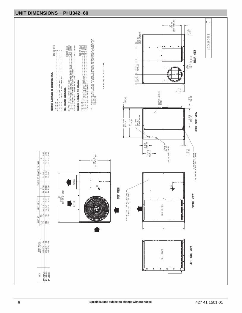
UNIT DIMENSIONS − PHJ342−60
PH
J342
PH
J348
PH
J360
7Specifications subject to change without notice.427 41 1501 01
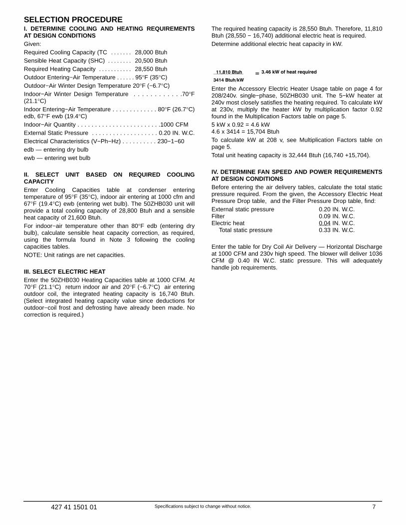
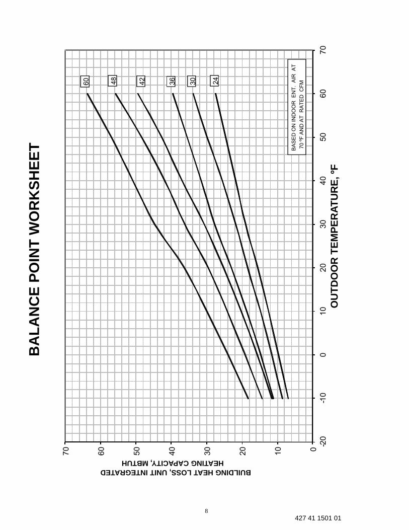
SELECTION PROCEDUREI. DETERMINE COOLING AND HEATING REQUIREMENTSAT DESIGN CONDITIONSGiven:Required Cooling Capacity (TC 28,000 Btuh. . . . . . .Sensible Heat Capacity (SHC) 20,500 Btuh. . . . . . . .Required Heating Capacity 28,550 Btuh. . . . . . . . . . .Outdoor Entering−Air Temperature 95°F (35°C). . . . . .Outdoor−Air Winter Design Temperature 20°F (−6.7°C)Indoor−Air Winter Design Temperature . . . . . . . . . . . .70°F(21.1°C)Indoor Entering−Air Temperature . . . . . . . . . . . . . 80°F (26.7°C)edb, 67°F ewb (19.4°C)Indoor−Air Quantity . . . . . . . . . . . . . . . . . . . . . . . .1000 CFMExternal Static Pressure . . . . . . . . . . . . . . . . . . . 0.20 IN. W.C.Electrical Characteristics (V−Ph−Hz) . . . . . . . . . . 230−1−60edb — entering dry bulbewb — entering wet bulb
II. SELECT UNIT BASED ON REQUIRED COOLINGCAPACITYEnter Cooling Capacities table at condenser enteringtemperature of 95°F (35°C), indoor air entering at 1000 cfm and67°F (19.4°C) ewb (entering wet bulb). The 50ZHB030 unit willprovide a total cooling capacity of 28,800 Btuh and a sensibleheat capacity of 21,600 Btuh.For indoor−air temperature other than 80°F edb (entering drybulb), calculate sensible heat capacity correction, as required,using the formula found in Note 3 following the coolingcapacities tables.NOTE: Unit ratings are net capacities.
III. SELECT ELECTRIC HEATEnter the 50ZHB030 Heating Capacities table at 1000 CFM. At70°F (21.1°C) return indoor air and 20°F (−6.7°C) air enteringoutdoor coil, the integrated heating capacity is 16,740 Btuh.(Select integrated heating capacity value since deductions foroutdoor−coil frost and defrosting have already been made. Nocorrection is required.)
The required heating capacity is 28,550 Btuh. Therefore, 11,810Btuh (28,550 − 16,740) additional electric heat is required.Determine additional electric heat capacity in kW.
11,810 Btuh
3414 Btuh/kW
= 3.46 kW of heat required
Enter the Accessory Electric Heater Usage table on page 4 for208/240v. single−phase, 50ZHB030 unit. The 5−kW heater at240v most closely satisfies the heating required. To calculate kWat 230v, multiply the heater kW by multiplication factor 0.92found in the Multiplication Factors table on page 5.5 kW x 0.92 = 4.6 kW4.6 x 3414 = 15,704 BtuhTo calculate kW at 208 v, see Multiplication Factors table onpage 5.Total unit heating capacity is 32,444 Btuh (16,740 +15,704).
IV. DETERMINE FAN SPEED AND POWER REQUIREMENTSAT DESIGN CONDITIONSBefore entering the air delivery tables, calculate the total staticpressure required. From the given, the Accessory Electric HeatPressure Drop table, and the Filter Pressure Drop table, find:External static pressure 0.20 IN. W.C.Filter 0.09 IN. W.C.Electric heat 0.04 IN. W.C. Total static pressure 0.33 IN. W.C.
Enter the table for Dry Coil Air Delivery — Horizontal Dischargeat 1000 CFM and 230v high speed. The blower will deliver 1036CFM @ 0.40 IN W.C. static pressure. This will adequatelyhandle job requirements.
8427 41 1501 01
0
10
20
30
40
50
60
70
-20
-10
010
20
30
40
50
60
70
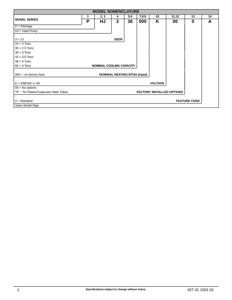
BUILDING HEAT LOSS, UNIT INTEGRATEDHEATING CAPACITY, MBTUH
OU
TD
OO
R T
EM
PE
RA
TU
RE
, ºF
BA
LA
NC
E P
OIN
T W
OR
KS
HE
ET
60
BA
SE
D O
N IN
DO
OR
E
NT
. A
IR A
T
70 º
F A
ND
AT
R
AT
ED
C
FM4
8
42
36
30
24

9427 41 1501 01
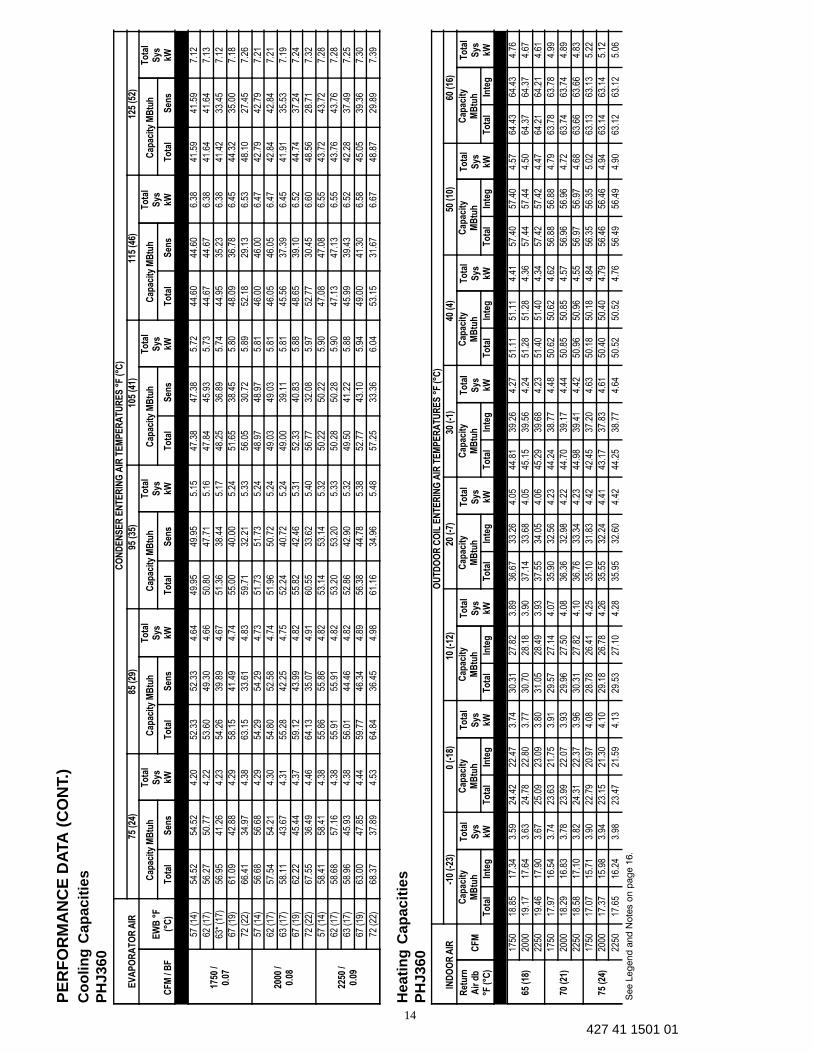
PE
RF
OR
MA
NC
E D
ATA
Co
olin
g C
apac
itie
s
PH
J324
EV
AP
OR
AT
OR
AIR
CO
ND
EN
SE
R E
NT
ER
ING
AIR
TE
MP
ER
AT
UR
ES
°F
(°C
)
75 (
24)
85 (
29)
95 (
35)
105
(41)
115
(46)
125
(52)
CF
M /
BF
EW
B °
F(°
C)
Cap
acit
y M
Btu
hT
ota
lS
ysK
W
Cap
acit
y M
Btu
hT
ota
lS
ysK
W
Cap
acit
y M
Btu
hT
ota
lS
ysK
W
Cap
acit
y M
Btu
hT
ota
lS
ysK
W
Cap
acit
y M
Btu
hT
ota
lS
ysK
W
Cap
acit
y M
Btu
hT
ota
lS
ysK
WT
ota
lS
ens
To
tal
Sen
sT
ota
lS
ens
To
tal
Sen
sT
ota
lS
ens
To
tal
Sen
s
700
/ 0.0
8
57 (
14)
22.9
622
.96
1.61
22.4
122
.41
1.82
21.8
521
.85
2.05
20.6
720
.67
2.30
19.1
419
.14
2.58
17.5
017
.50
2.90
62 (
17)
23.6
921
.83
1.61
22.9
621
.68
1.82
22.1
821
.56
2.06
20.8
021
.27
2.30
19.1
819
.18
2.58
17.5
317
.53
2.90
63*
(17)
24.0
117
.90
1.62
23.2
917
.65
1.83
22.5
017
.48
2.06
21.2
017
.16
2.30
19.1
816
.18
2.58
16.9
315
.19
2.89
67 (
19)
25.1
317
.88
1.62
24.5
617
.79
1.84
23.7
217
.60
2.07
22.8
917
.60
2.33
21.3
117
.22
2.61
19.1
116
.34
2.91
72 (
22)
26.3
214
.26
1.63
25.9
814
.21
1.85
25.1
213
.86
2.09
24.2
913
.62
2.35
23.4
713
.52
2.64
21.7
713
.02
2.96
800
/ 0.1
0
57 (
14)
23.6
323
.63
1.63
23.0
723
.07
1.84
22.4
622
.46
2.07
21.6
821
.68
2.33
20.1
920
.19
2.61
18.4
918
.49
2.92
62 (
17)
24.0
622
.94
1.63
23.3
722
.84
1.84
22.6
022
.82
2.07
21.7
121
.71
2.33
20.2
220
.22
2.61
18.5
318
.53
2.92
63 (
17)
24.3
518
.61
1.63
23.6
418
.46
1.84
22.8
418
.37
2.08
21.7
218
.34
2.33
19.7
117
.50
2.60
17.4
116
.44
2.91
67 (
19)
25.4
118
.51
1.64
24.8
818
.54
1.86
24.0
018
.38
2.09
23.1
318
.35
2.35
21.7
718
.42
2.63
19.5
717
.63
2.93
72 (
22)
26.5
414
.57
1.65
26.2
314
.57
1.87
25.3
814
.26
2.10
24.5
214
.04
2.36
23.6
013
.86
2.66
22.1
513
.70
2.98
900
/ 0.1
1
57 (
14)
24.1
124
.11
1.64
23.6
023
.60
1.86
22.9
522
.95
2.09
22.3
422
.34
2.35
21.0
021
.00
2.63
19.2
619
.26
2.94
62 (
17)
24.3
523
.89
1.65
23.7
023
.84
1.86
22.9
622
.96
2.09
22.3
722
.37
2.35
21.0
321
.03
2.63
19.2
919
.29
2.95
63 (
17)
24.5
919
.25
1.65
23.9
219
.21
1.86
23.0
819
.15
2.09
22.0
919
.38
2.34
20.1
218
.68
2.62
17.8
217
.62
2.93
67 (
19)
25.6
219
.06
1.66
25.1
219
.22
1.87
24.2
219
.09
2.10
23.3
519
.14
2.36
22.1
219
.49
2.65
19.9
518
.82
2.96
72 (
22)
26.7
014
.83
1.66
26.3
914
.85
1.89
25.5
714
.60
2.12
24.6
814
.39
2.38
23.7
214
.27
2.67
22.4
114
.30
3.00
Hea
tin
g C
apac
itie
s
PH
J324
IND
OO
R A
IRO
UT
DO
OR
CO
IL E
NT
ER
ING
AIR
TE
MP
ER
AT
UR
ES
°F
(°C
)
-10
(-23
)0
(-18
)10
(-1
2)20
(-7
)30
(-1
)40
(4)
50 (
10)
60 (
16)
Ret
urn
Air
db
°F (
°C)
CF
M
Cap
acit
yM
Btu
hT
ota
lS
ys kW
Cap
acit
yM
Btu
hT
ota
lS
ys kW
Cap
acit
yM
Btu
hT
ota
lS
ys kW
Cap
acit
yM
Btu
hT
ota
lS
ys kW
Cap
acit
yM
Btu
hT
ota
lS
ys kW
Cap
acit
yM
Btu
hT
ota
lS
ys kW
Cap
acit
yM
Btu
hT
ota
lS
ys kW
Cap
acit
yM
Btu
hT
ota
lS
ys kWT
ota
lIn
teg
To
tal
Inte
gT
ota
lIn
teg
To
tal
Inte
gT
ota
lIn
teg
To
tal
Inte
gT
ota
lIn
teg
To
tal
Inte
g
65 (
18)
700
7.28
6.69
1.47
9.93
9.14
1.58
12.7
311
.69
1.65
15.7
714
.31
1.71
19.1
716
.80
1.76
22.0
022
.00
1.80
24.9
324
.93
1.86
28.0
028
.00
1.93
800
7.38
6.79
1.47
10.0
69.
261.
5712
.89
11.8
31.
6416
.00
14.5
11.
6919
.24
16.8
61.
7322
.03
22.0
31.
7624
.89
24.8
91.
8027
.83
27.8
31.
86
900
7.47
6.88
1.48
10.1
99.
371.
5713
.05
11.9
81.
6316
.17
14.6
71.
6719
.28
16.9
01.
7022
.02
22.0
21.
7324
.80
24.8
01.
7627
.58
27.5
81.
80
70 (
21)
700
6.86
6.31
1.54
9.53
8.77
1.65
12.3
511
.33
1.73
15.3
813
.95
1.79
18.9
716
.62
1.85
21.7
621
.76
1.90
24.6
624
.66
1.96
27.6
727
.67
2.03
800
6.97
6.42
1.54
9.68
8.91
1.65
12.5
211
.49
1.72
15.5
914
.14
1.77
19.0
516
.69
1.82
21.8
121
.81
1.85
24.6
524
.65
1.90
27.5
527
.55
1.96
900
7.08
6.51
1.55
9.80
9.02
1.65
12.6
711
.63
1.71
15.7
714
.30
1.76
19.1
016
.73
1.79
21.8
221
.82
1.82
24.5
924
.59
1.86
27.3
427
.34
1.90
75 (
24)
700
6.38
5.87
1.61
9.11
8.38
1.73
11.9
410
.96
1.81
14.9
613
.57
1.88
18.6
816
.37
1.96
21.5
321
.53
2.00
24.4
124
.41
2.06
27.3
527
.35
2.14
800
6.50
5.98
1.61
9.25
8.51
1.73
12.1
111
.12
1.80
15.1
813
.76
1.86
18.8
516
.51
1.92
21.5
821
.58
1.95
24.4
124
.41
2.00
27.2
727
.27
2.06
900
6.62
6.09
1.62
9.38
8.63
1.72
12.2
611
.25
1.79
15.3
513
.92
1.84
18.9
216
.57
1.89
21.6
021
.60
1.92
24.3
424
.34
1.96
27.0
727
.07
2.01
See L
eg
en
d a
nd
No
tes o
n p
ag
e 1
6.
10427 41 1501 01
PE
RF
OR
MA
NC
E D
ATA
(C
ON
T.)
Co
olin
g C
apac
itie
sP
HJ3
30
EV
AP
OR
AT
OR
AIR
CO
ND
EN
SE
R E
NT
ER
ING
AIR
TE
MP
ER
AT
UR
ES
°F
(°C
)
75 (
24)
85 (
29)
95 (
35)
105
(41)
115
(46)
125
(52)
CF
M /
BF
EW
B °
F(°
C)
Cap
acit
y M
Btu
hT
ota
lS
ys kW
Cap
acit
y M
Btu
hT
ota
lS
ys kW
Cap
acit
y M
Btu
hT
ota
lS
ys kW
Cap
acit
y M
Btu
hT
ota
lS
ys kW
Cap
acit
y M
Btu
hT
ota
lS
ys kW
Cap
acit
y M
Btu
hT
ota
lS
ys kWT
ota
lS
ens
To
tal
Sen
sT
ota
lS
ens
To
tal
Sen
sT
ota
lS
ens
To
tal
Sen
s
875
/ 0.0
8
57 (
14)
27.8
227
.82
1.97
27.3
027
.30
2.20
26.5
326
.53
2.45
25.5
025
.50
2.75
24.1
924
.19
3.08
22.5
722
.57
3.47
62 (
17)
28.3
825
.57
1.98
27.7
525
.67
2.20
26.8
425
.54
2.46
25.6
325
.09
2.75
24.2
424
.24
3.08
22.6
022
.60
3.47
63*
(17)
28.6
920
.76
1.98
28.0
620
.76
2.21
27.1
620
.58
2.46
25.9
420
.16
2.75
24.3
719
.46
3.08
22.2
818
.53
3.45
67 (
19)
29.8
220
.56
1.99
29.3
120
.71
2.22
28.5
120
.67
2.48
27.3
920
.44
2.77
26.0
120
.06
3.10
24.3
819
.55
3.48
72 (
22)
31.1
016
.25
2.00
30.7
516
.22
2.24
30.0
316
.06
2.50
29.0
615
.79
2.80
27.8
015
.42
3.13
26.2
014
.93
3.51
1000
/0.
09
57 (
14)
28.4
328
.43
2.00
27.9
627
.96
2.23
27.2
627
.26
2.49
26.2
926
.29
2.78
25.0
725
.07
3.11
23.6
623
.66
3.49
62 (
17)
28.7
426
.78
2.00
28.1
527
.00
2.23
27.2
827
.28
2.49
26.3
126
.31
2.78
25.1
025
.10
3.11
23.6
923
.69
3.49
63 (
17)
28.9
921
.57
2.00
28.3
921
.71
2.23
27.5
121
.66
2.49
26.3
021
.37
2.78
24.7
920
.84
3.11
22.7
319
.92
3.49
67 (
19)
30.0
921
.27
2.01
29.6
021
.54
2.24
28.8
021
.60
2.50
27.6
921
.48
2.80
26.3
121
.22
3.13
24.6
620
.78
3.51
72 (
22)
31.3
116
.55
2.02
30.9
916
.61
2.26
30.2
816
.51
2.52
29.3
216
.30
2.82
28.0
415
.98
3.16
26.4
515
.54
3.54
1125
/0.
10
57 (
14)
28.8
528
.85
2.02
28.4
428
.44
2.25
27.7
727
.77
2.51
26.8
226
.82
2.81
25.6
425
.64
3.14
24.2
524
.25
3.52
62 (
17)
29.0
227
.77
2.02
28.4
528
.45
2.25
27.7
927
.79
2.51
26.8
426
.84
2.81
25.6
625
.66
3.14
24.2
724
.27
3.52
63 (
17)
29.2
122
.27
2.03
28.6
322
.55
2.26
27.7
622
.62
2.51
26.5
622
.44
2.80
25.0
922
.04
3.13
23.1
821
.25
3.51
67 (
19)
30.2
921
.86
2.04
29.8
222
.26
2.27
29.0
122
.42
2.53
27.9
122
.42
2.82
26.5
322
.26
3.16
24.8
721
.88
3.53
72 (
22)
31.4
916
.86
2.05
31.1
616
.94
2.28
30.4
616
.89
2.55
29.5
116
.74
2.84
28.2
216
.46
3.18
26.6
316
.08
3.56
Hea
tin
g C
apac
itie
sP
HJ3
30IN
DO
OR
AIR
OU
TD
OO
R C
OIL
EN
TE
RIN
G A
IR T
EM
PE
RA
TU
RE
S °
F (
°C)
10
(23
)0
(18
)10
(1
2)20
(7
)30
(1
)40
(4)
50 (
10)
60 (
16)
Ret
urn
Air
d
b°F (°C
)C
FM
Cap
acit
yM
Btu
hT
ota
lS
ys kW
Cap
acit
yM
Btu
hT
ota
lS
ys kW
Cap
acit
yM
Btu
hT
ota
lS
ys kW
Cap
acit
yM
Btu
hT
ota
lS
ys kW
Cap
acit
yM
Btu
hT
ota
lS
ys kW
Cap
acit
yM
Btu
hT
ota
lS
ys kW
Cap
acit
yM
Btu
hT
ota
lS
ys kW
Cap
acit
yM
Btu
hT
ota
lS
ys kWT
ota
lIn
teg
To
tal
Inte
gT
ota
lIn
teg
To
tal
Inte
gT
ota
lIn
teg
To
tal
Inte
gT
ota
lIn
teg
To
tal
Inte
g
65 (
18)
875
8.92
8.21
1.74
11.8
410
.90
1.81
15.0
013
.77
1.88
18.5
216
.80
1.96
21.8
719
.17
2.03
25.6
625
.66
2.12
29.9
729
.97
2.24
34.4
834
.48
2.34
1000
9.05
8.32
1.74
11.9
911
.03
1.81
15.1
713
.93
1.87
18.6
716
.93
1.94
22.0
719
.34
2.01
25.9
125
.91
2.09
30.2
730
.27
2.18
34.1
034
.10
2.27
1125
9.16
8.43
1.75
12.1
211
.15
1.81
15.3
414
.08
1.87
18.8
017
.05
1.93
22.2
419
.48
1.99
26.1
226
.12
2.07
30.1
530
.15
2.14
33.5
233
.52
2.21
70 (
21)
875
8.51
7.83
1.82
11.4
710
.55
1.90
14.6
313
.42
1.97
18.3
016
.60
2.06
21.6
018
.93
2.14
25.3
325
.33
2.23
29.5
629
.56
2.34
34.1
334
.13
2.46
1000
8.65
7.96
1.83
11.6
310
.70
1.89
14.8
113
.59
1.96
18.4
516
.74
2.04
21.8
019
.10
2.11
25.5
925
.59
2.19
29.8
929
.89
2.30
33.8
533
.85
2.38
1125
8.77
8.07
1.84
11.7
710
.83
1.90
14.9
713
.74
1.96
18.5
816
.85
2.03
21.9
719
.25
2.09
25.8
025
.80
2.17
29.9
529
.95
2.25
33.3
833
.38
2.33
75 (
24)
875
8.05
7.41
1.90
11.0
610
.17
1.99
14.2
313
.06
2.07
18.0
316
.35
2.17
21.3
318
.69
2.25
25.0
025
.00
2.34
29.1
629
.16
2.46
33.7
933
.79
2.58
1000
8.19
7.54
1.91
11.2
210
.32
1.99
14.4
113
.23
2.06
18.2
016
.51
2.15
21.5
218
.86
2.22
25.2
525
.25
2.30
29.4
829
.48
2.41
33.5
833
.58
2.50
1125
8.31
7.65
1.92
11.3
610
.45
1.99
14.5
713
.38
2.05
18.3
516
.64
2.14
21.6
919
.00
2.20
25.4
725
.47
2.28
29.6
829
.68
2.36
33.1
833
.18
2.44
See L
eg
en
d a
nd
No
tes o
n p
ag
e 1
6.
11427 41 1501 01
PE
RF
OR
MA
NC
E D
ATA
(C
ON
T.)
Co
olin
g C
apac
itie
sP
HJ3
36
EV
AP
OR
AT
OR
AIR
CO
ND
EN
SE
R E
NT
ER
ING
AIR
TE
MP
ER
AT
UR
ES
°F
(°C
)
75 (
24)
85 (
29)
95 (
35)
105
(41)
115
(46)
125
(52)
CF
M /
BF
EW
B °
F(°
C)
Cap
acit
y M
Btu
hT
ota
lS
ys kW
Cap
acit
y M
Btu
hT
ota
lS
ys kW
Cap
acit
y M
Btu
hT
ota
lS
ys kW
Cap
acit
y M
Btu
hT
ota
lS
ys kW
Cap
acit
y M
Btu
hT
ota
lS
ys kW
Cap
acit
y M
Btu
hT
ota
lS
ys kWT
ota
lS
ens
To
tal
Sen
sT
ota
lS
ens
To
tal
Sen
sT
ota
lS
ens
To
tal
Sen
s
1050
/0.
07
57 (
14)
34.8
034
.80
2.48
33.6
833
.68
2.76
32.3
632
.36
3.07
30.9
630
.96
3.42
29.3
629
.36
3.81
27.1
127
.11
4.25
62 (
17)
35.8
332
.61
2.49
34.4
832
.11
2.77
32.9
131
.40
3.07
31.2
230
.68
3.42
29.4
029
.40
3.81
27.1
527
.15
4.25
63*
(17)
36.3
626
.67
2.50
34.9
926
.14
2.77
33.3
725
.44
3.08
31.5
924
.73
3.42
29.4
424
.21
3.81
26.4
022
.91
4.24
67 (
19)
38.3
826
.96
2.51
37.1
126
.57
2.79
35.5
025
.95
3.10
33.6
325
.17
3.45
31.6
624
.52
3.84
29.2
324
.13
4.28
72 (
22)
40.7
321
.67
2.53
39.6
221
.27
2.81
38.0
820
.69
3.12
36.2
219
.95
3.48
34.0
319
.09
3.87
31.8
518
.32
4.33
1200
/0.
08
57 (
14)
35.8
635
.86
2.52
34.7
434
.74
2.80
33.3
933
.39
3.11
31.8
831
.88
3.46
30.4
130
.41
3.85
28.3
028
.30
4.30
62 (
17)
36.4
634
.39
2.52
35.1
333
.99
2.80
33.5
733
.21
3.11
31.9
031
.90
3.46
30.4
430
.44
3.85
28.3
328
.33
4.30
63 (
17)
36.9
027
.87
2.53
35.5
527
.41
2.80
33.9
026
.75
3.11
32.0
426
.02
3.46
30.0
225
.74
3.85
27.0
424
.67
4.28
67 (
19)
38.8
928
.05
2.54
37.6
227
.77
2.82
36.0
027
.20
3.13
34.0
926
.44
3.48
32.0
525
.78
3.88
29.7
125
.67
4.32
72 (
22)
41.1
622
.23
2.56
40.0
721
.90
2.84
38.5
221
.34
3.16
36.6
420
.63
3.51
34.4
019
.76
3.91
32.1
718
.97
4.36
1350
/0.
10
57 (
14)
36.6
436
.64
2.55
35.5
435
.54
2.83
34.1
734
.17
3.14
32.5
732
.57
3.49
30.9
730
.97
3.89
29.1
329
.13
4.34
62 (
17)
36.9
635
.90
2.55
35.6
835
.46
2.83
34.1
834
.18
3.14
32.6
032
.60
3.49
31.0
031
.00
3.89
29.1
629
.16
4.34
63 (
17)
37.3
328
.93
2.56
35.9
628
.55
2.83
34.2
927
.93
3.14
32.3
827
.19
3.49
30.4
227
.02
3.88
27.5
426
.23
4.31
67 (
19)
39.2
629
.02
2.57
38.0
128
.83
2.85
36.3
628
.31
3.16
34.4
327
.58
3.51
32.3
426
.90
3.91
30.0
726
.98
4.36
72 (
22)
41.4
722
.69
2.59
40.4
022
.43
2.87
38.8
521
.91
3.19
36.9
521
.25
3.54
34.6
820
.35
3.94
32.3
919
.54
4.39
Hea
tin
g C
apac
itie
sP
HJ3
36IN
DO
OR
AIR
OU
TD
OO
R C
OIL
EN
TE
RIN
G A
IR T
EM
PE
RA
TU
RE
S °
F (
°C)
10
(23
)0
(18
)10
(1
2)20
(7
)30
(1
)40
(4)
50 (
10)
60 (
16)
Ret
urn
Air
db
°F (
°C)
CF
M
Cap
acit
yM
Btu
hT
ota
lS
ys kW
Cap
acit
yM
Btu
hT
ota
lS
ys kW
Cap
acit
yM
Btu
hT
ota
lS
ys kW
Cap
acit
yM
Btu
hT
ota
lS
ys kW
Cap
acit
yM
Btu
hT
ota
lS
ys kW
Cap
acit
yM
Btu
hT
ota
lS
ys kW
Cap
acit
yM
Btu
hT
ota
lS
ys kW
Cap
acit
yM
Btu
hT
ota
lS
ys kWT
ota
lIn
teg
To
tal
Inte
gT
ota
lIn
teg
To
tal
Inte
gT
ota
lIn
teg
To
tal
Inte
gT
ota
lIn
teg
To
tal
Inte
g
65 (
18)
1050
11.5
410
.62
2.30
15.0
513
.85
2.39
18.9
517
.39
2.49
23.3
821
.20
2.60
27.9
824
.52
2.70
31.9
231
.92
2.79
36.0
536
.05
2.88
40.3
440
.34
2.99
1200
11.7
310
.79
2.31
15.2
714
.05
2.39
19.2
117
.63
2.48
23.7
821
.56
2.58
28.0
624
.59
2.66
31.9
231
.92
2.74
35.9
435
.94
2.82
40.0
040
.00
2.90
1350
11.9
010
.95
2.32
15.4
614
.23
2.40
19.4
217
.83
2.48
24.2
922
.03
2.59
28.0
724
.59
2.64
31.8
631
.86
2.71
35.7
335
.73
2.78
39.4
739
.47
2.84
70 (
21)
1050
10.9
510
.08
2.41
14.5
013
.34
2.51
18.4
216
.90
2.61
22.7
620
.64
2.71
27.7
124
.28
2.83
31.5
931
.59
2.92
35.6
635
.66
3.02
39.9
139
.91
3.13
1200
11.1
510
.25
2.42
14.7
213
.55
2.51
18.6
717
.14
2.60
23.0
720
.92
2.69
27.7
824
.34
2.79
31.6
131
.61
2.87
35.5
935
.59
2.96
39.6
239
.62
3.04
1350
11.3
110
.41
2.44
14.9
113
.72
2.52
18.8
917
.34
2.60
23.3
521
.17
2.69
27.8
324
.38
2.77
31.5
731
.57
2.84
35.4
335
.43
2.91
39.1
939
.19
2.98
75 (
24)
1050
10.3
29.
492.
5413
.90
12.7
92.
6317
.85
16.3
82.
7322
.18
20.1
22.
8427
.45
24.0
52.
9831
.26
31.2
63.
0735
.27
35.2
73.
1739
.45
39.4
53.
28
1200
10.5
19.
672.
5514
.12
13.0
02.
6318
.11
16.6
22.
7322
.49
20.4
02.
8227
.54
24.1
32.
9431
.29
31.2
93.
0135
.23
35.2
33.
1039
.24
39.2
43.
19
1350
10.6
79.
822.
5614
.31
13.1
72.
6418
.33
16.8
22.
7222
.75
20.6
32.
8127
.60
24.1
82.
9131
.28
31.2
82.
9835
.11
35.1
13.
0638
.87
38.8
73.
13
See L
eg
en
d a
nd
No
tes o
n p
ag
e 1
6.
12427 41 1501 01
PE
RF
OR
MA
NC
E D
ATA
(C
ON
T.)
Co
olin
g C
apac
itie
sP
HJ3
42
EV
AP
OR
AT
OR
AIR
CO
ND
EN
SE
R E
NT
ER
ING
AIR
TE
MP
ER
AT
UR
ES
°F
(°C
)
75 (
24)
85 (
29)
95 (
35)
105
(41)
115
(46)
125
(52)
CF
M /
BF
EW
B °
F(°
C)
Cap
acit
y M
Btu
hT
ota
lS
ys kW
Cap
acit
y M
Btu
hT
ota
lS
ys kW
Cap
acit
y M
Btu
hT
ota
lS
ys kW
Cap
acit
y M
Btu
hT
ota
lS
ys kW
Cap
acit
y M
Btu
hT
ota
lS
ys kW
Cap
acit
y M
Btu
h
To
tal
Sys kW
To
tal
Sen
sT
ota
lS
ens
To
tal
Sen
sT
ota
lS
ens
To
tal
Sen
sT
ota
lS
ens
1225
/0.
11
57 (
14)
39.4
439
.44
2.86
37.8
937
.89
3.16
35.2
635
.26
3.49
32.8
332
.83
3.86
30.2
930
.29
4.29
27.5
327
.53
4.77
62 (
17)
40.8
336
.35
2.87
38.8
735
.37
3.17
35.7
133
.63
3.49
32.8
832
.88
3.86
30.3
330
.33
4.29
27.5
727
.57
4.77
63*
(17)
41.7
729
.61
2.87
39.7
528
.75
3.18
36.7
327
.48
3.50
33.2
126
.03
3.87
29.7
324
.59
4.28
25.9
422
.96
4.74
67 (
19)
45.2
030
.87
2.90
43.0
730
.03
3.21
40.8
129
.14
3.56
37.3
127
.80
3.92
33.3
626
.29
4.33
29.4
824
.79
4.80
72 (
22)
50.0
625
.07
2.95
47.7
624
.23
3.26
45.3
123
.37
3.61
42.7
222
.45
4.01
39.7
221
.41
4.44
34.6
919
.71
4.89
1400
/0.
12
57 (
14)
40.9
940
.99
2.91
39.3
639
.36
3.22
37.5
437
.54
3.56
34.3
134
.31
3.92
31.6
331
.63
4.35
28.7
628
.76
4.83
62 (
17)
41.7
038
.58
2.91
39.6
339
.63
3.22
37.6
037
.60
3.56
34.3
634
.36
3.92
31.6
731
.67
4.35
28.7
928
.79
4.83
63 (
17)
42.5
931
.37
2.92
40.5
030
.50
3.23
38.1
929
.53
3.57
33.9
027
.77
3.92
30.3
126
.24
4.33
26.4
824
.45
4.79
67 (
19)
46.0
732
.76
2.95
43.8
731
.91
3.26
41.5
031
.00
3.61
38.8
529
.98
3.99
34.0
528
.14
4.38
30.0
526
.52
4.85
72 (
22)
51.0
426
.26
3.00
48.6
525
.41
3.32
46.1
024
.53
3.67
43.4
223
.60
4.06
40.3
922
.57
4.50
35.4
420
.92
4.95
1575
/0.
14
57 (
14)
42.3
542
.35
2.96
40.6
540
.65
3.27
38.8
238
.82
3.62
35.7
435
.74
3.98
32.8
232
.82
4.41
29.8
229
.82
4.89
62 (
17)
42.5
342
.53
2.96
40.7
040
.70
3.27
38.8
638
.86
3.62
35.7
835
.78
3.98
32.8
632
.86
4.41
29.8
529
.85
4.89
63 (
17)
43.2
733
.10
2.97
41.1
132
.21
3.27
38.7
631
.24
3.62
34.5
129
.44
3.96
30.8
327
.78
4.38
26.9
926
.99
4.84
67 (
19)
46.8
034
.63
3.00
44.5
033
.75
3.31
42.0
932
.83
3.66
39.3
731
.78
4.04
34.6
529
.90
4.44
30.5
528
.07
4.90
72 (
22)
51.8
327
.42
3.05
49.3
626
.56
3.36
46.7
525
.67
3.72
43.9
824
.73
4.11
40.9
323
.70
4.55
36.0
522
.10
5.00
Hea
tin
g C
apac
itie
sP
HJ3
42IN
DO
OR
AIR
OU
TD
OO
R C
OIL
EN
TE
RIN
G A
IR T
EM
PE
RA
TU
RE
S °
F (
°C)
10
(23
)0
(18
)10
(1
2)20
(7
)30
(1
)40
(4)
50 (
10)
60 (
16)
Ret
urn
Air
db
°F (
°C)
CF
M
Cap
acit
yM
Btu
hT
ota
lS
ys kW
Cap
acit
yM
Btu
hT
ota
lS
ys kW
Cap
acit
yM
Btu
hT
ota
lS
ys kW
Cap
acit
yM
Btu
hT
ota
lS
ys kW
Cap
acit
yM
Btu
hT
ota
lS
ys kW
Cap
acit
yM
Btu
hT
ota
lS
ys kW
Cap
acit
yM
Btu
hT
ota
lS
ys kW
Cap
acit
yM
Btu
hT
ota
lS
ys kWT
ota
lIn
teg
To
tal
Inte
gT
ota
lIn
teg
To
tal
Inte
gT
ota
lIn
teg
To
tal
Inte
gT
ota
lIn
teg
To
tal
Inte
g
65 (
18)
1225
12.1
411
.17
2.54
16.2
014
.90
2.65
20.6
818
.98
2.77
25.5
923
.21
2.90
31.1
327
.28
3.05
37.0
937
.09
3.24
42.8
542
.85
3.42
49.4
949
.49
3.66
1400
12.3
911
.40
2.56
16.4
915
.17
2.66
21.0
219
.29
2.78
25.9
823
.56
2.89
31.7
727
.84
3.04
37.4
737
.47
3.20
43.3
843
.38
3.37
50.1
750
.17
3.58
1575
12.6
211
.61
2.58
16.7
215
.38
2.68
21.2
919
.54
2.78
26.3
023
.86
2.89
32.5
128
.49
3.04
37.8
437
.84
3.17
43.8
443
.84
3.33
50.7
850
.78
3.53
70 (
21)
1225
11.3
410
.44
2.65
15.4
414
.20
2.77
19.9
318
.30
2.90
24.8
622
.54
3.03
30.2
726
.52
3.18
36.5
936
.59
3.40
42.2
242
.22
3.58
48.7
248
.72
3.83
1400
11.5
610
.63
2.67
15.6
914
.43
2.79
20.2
418
.58
2.90
25.2
222
.87
3.02
30.7
026
.90
3.16
36.9
836
.98
3.36
42.7
242
.72
3.52
49.4
149
.41
3.75
1575
11.7
710
.83
2.70
15.9
514
.67
2.80
20.5
418
.85
2.91
25.5
723
.19
3.02
31.1
227
.27
3.15
37.3
237
.32
3.33
43.1
843
.18
3.48
49.9
849
.98
3.69
75 (
24)
1225
10.5
09.
662.
7814
.61
13.4
52.
9019
.14
17.5
73.
0324
.09
21.8
53.
1729
.48
25.8
33.
3236
.02
36.0
23.
5641
.59
41.5
93.
7647
.96
47.9
64.
00
1400
10.7
49.
882.
8014
.89
13.7
02.
9219
.48
17.8
83.
0324
.48
22.2
03.
1629
.93
26.2
33.
3036
.44
36.4
43.
5242
.07
42.0
73.
7048
.62
48.6
23.
92
1575
10.9
510
.08
2.83
15.1
613
.95
2.93
19.7
818
.16
3.04
24.8
122
.50
3.16
30.3
326
.57
3.29
36.8
136
.81
3.49
42.5
242
.52
3.65
49.2
049
.20
3.87
See L
eg
en
d a
nd
No
tes o
n p
ag
e 1
6.

13427 41 1501 01
PE
RF
OR
MA
NC
E D
ATA
(C
ON
T.)
Co
olin
g C
apac
itie
sP
HJ3
48
EV
AP
OR
AT
OR
AIR
CO
ND
EN
SE
R E
NT
ER
ING
AIR
TE
MP
ER
AT
UR
ES
°F
(°C
)
75 (
24)
85 (
29)
95 (
35)
105
(41)
115
(46)
125
(52)
CF
M /
BF
EW
B °
F(°
C)
Cap
acit
y M
Btu
hT
ota
lS
ys kW
Cap
acit
y M
Btu
hT
ota
lS
ys kW
Cap
acit
y M
Btu
hT
ota
lS
ys kW
Cap
acit
y M
Btu
hT
ota
lS
ys kW
Cap
acit
y M
Btu
hT
ota
lS
ys kW
Cap
acit
y M
Btu
hT
ota
lS
ys kWT
ota
lS
ens
To
tal
Sen
sT
ota
lS
ens
To
tal
Sen
sT
ota
lS
ens
To
tal
Sen
s
1400
/0.
07
57 (
14)
45.2
045
.20
3.18
43.3
343
.33
3.55
41.3
441
.34
3.95
38.1
238
.12
4.35
35.1
335
.13
4.81
32.1
532
.15
5.34
62 (
17)
46.7
141
.68
3.18
44.3
740
.56
3.56
41.9
639
.40
3.95
38.1
538
.15
4.35
35.1
935
.19
4.81
32.2
032
.20
5.34
63*
(17)
47.5
334
.01
3.18
45.1
132
.92
3.56
42.5
931
.77
3.96
38.5
829
.94
4.36
34.5
728
.26
4.80
30.6
726
.63
5.30
67 (
19)
50.9
635
.23
3.19
48.4
534
.13
3.59
45.7
633
.06
3.99
42.9
831
.89
4.43
38.8
630
.18
4.90
34.5
728
.52
5.40
72 (
22)
55.4
328
.68
3.21
52.7
427
.63
3.62
49.8
826
.55
4.04
46.9
125
.38
4.49
43.7
924
.21
4.97
39.8
622
.94
5.50
1600
/0.
08
57 (
14)
47.0
647
.06
3.22
45.0
645
.06
3.60
42.9
642
.96
4.01
40.2
040
.20
4.44
36.8
736
.87
4.90
33.6
533
.65
5.42
62 (
17)
47.7
844
.55
3.22
45.4
243
.39
3.61
42.9
942
.99
4.01
40.2
740
.27
4.45
36.9
336
.93
4.90
33.7
133
.71
5.42
63 (
17)
48.4
535
.96
3.22
45.9
534
.89
3.61
43.3
433
.74
4.01
39.6
832
.11
4.43
35.4
030
.31
4.86
31.3
628
.61
5.36
67 (
19)
51.8
837
.20
3.23
49.2
636
.11
3.63
46.5
035
.00
4.04
43.6
133
.83
4.48
39.7
632
.48
4.95
35.4
130
.72
5.47
72 (
22)
56.3
329
.83
3.25
53.5
428
.78
3.67
50.6
127
.67
4.09
47.5
426
.48
4.54
44.3
325
.28
5.02
40.4
624
.19
5.55
1800
/0.
09
57 (
14)
48.5
148
.51
3.26
46.4
046
.40
3.66
44.1
944
.19
4.06
41.8
041
.80
4.50
38.4
038
.40
4.98
35.0
035
.00
5.50
62 (
17)
48.7
446
.97
3.26
46.4
346
.43
3.66
44.2
444
.24
4.06
41.8
541
.85
4.50
38.4
538
.45
4.98
35.0
535
.05
5.50
63 (
17)
49.1
637
.79
3.27
46.5
736
.66
3.66
43.9
035
.58
4.06
40.6
034
.14
4.49
36.1
132
.25
4.92
31.9
830
.41
5.42
67 (
19)
52.5
639
.02
3.28
49.8
837
.94
3.68
47.0
336
.80
4.09
44.1
035
.61
4.53
40.4
134
.58
5.01
36.0
532
.74
5.53
72 (
22)
57.0
030
.86
3.30
54.1
529
.81
3.71
51.1
728
.67
4.14
48.0
027
.47
4.59
44.7
426
.23
5.07
40.9
025
.30
5.60
Hea
tin
g C
apac
itie
sP
HJ3
48
IND
OO
R A
IR
OU
TD
OO
R C
OIL
EN
TE
RIN
G A
IR T
EM
PE
RA
TU
RE
S °
F (
°C)
10
(23
)0
(18
)10
(1
2)20
(7
)30
(1
)40
(4)
50 (
10)
60 (
16)
Ret
urn
Air
db
°F (
°C)
CF
M
Cap
acit
yM
Btu
hT
ota
lS
ys kW
Cap
acit
yM
Btu
hT
ota
lS
ys kW
Cap
acit
yM
Btu
hT
ota
lS
ys kW
Cap
acit
yM
Btu
hT
ota
lS
ys kW
Cap
acit
yM
Btu
hT
ota
lS
ys kW
Cap
acit
yM
Btu
hT
ota
lS
ys kW
Cap
acit
yM
Btu
hT
ota
lS
ys kW
Cap
acit
yM
Btu
hT
ota
lS
ys kWT
ota
lIn
teg
To
tal
Inte
gT
ota
lIn
teg
To
tal
Inte
gT
ota
lIn
teg
To
tal
Inte
gT
ota
lIn
teg
To
tal
Inte
g
65 (
18)
1400
14.7
413
.56
2.91
19.5
117
.95
3.03
24.5
022
.49
3.16
29.8
427
.06
3.30
36.3
631
.86
3.49
42.0
342
.03
3.65
48.5
648
.56
3.83
56.0
956
.09
4.03
1600
14.9
713
.78
2.93
19.7
818
.20
3.05
24.8
122
.77
3.17
30.2
127
.40
3.29
36.6
932
.15
3.47
42.4
542
.45
3.61
49.1
449
.14
3.77
56.4
156
.41
3.93
1800
15.1
813
.97
2.96
20.0
118
.42
3.07
25.0
923
.02
3.18
30.5
427
.69
3.30
36.9
732
.40
3.46
42.8
542
.85
3.59
49.6
149
.61
3.74
56.5
856
.58
3.87
70 (
21)
1400
14.1
513
.01
3.03
18.9
217
.41
3.16
23.9
121
.95
3.29
29.2
326
.51
3.44
35.8
831
.44
3.65
41.4
741
.47
3.81
47.9
047
.90
4.01
55.4
255
.42
4.22
1600
14.3
813
.23
3.06
19.2
017
.66
3.17
24.2
322
.24
3.30
29.6
126
.85
3.43
36.2
531
.76
3.62
41.9
141
.91
3.77
48.4
748
.47
3.95
55.8
255
.82
4.12
1800
14.5
813
.42
3.09
19.4
417
.89
3.19
24.5
122
.49
3.31
29.9
127
.12
3.44
36.5
432
.02
3.61
42.3
042
.30
3.75
48.9
448
.94
3.91
56.0
156
.01
4.06
75 (
24)
1400
13.4
712
.39
3.17
18.2
716
.81
3.30
23.2
821
.37
3.44
28.5
725
.91
3.59
34.5
230
.25
3.77
40.9
540
.95
3.98
47.2
647
.26
4.19
54.6
954
.69
4.42
1600
13.7
112
.61
3.20
18.5
517
.07
3.31
23.5
921
.66
3.44
28.9
526
.25
3.58
35.6
731
.25
3.78
41.3
841
.38
3.94
47.8
247
.82
4.13
55.1
955
.19
4.32
1800
13.9
312
.81
3.23
18.8
017
.30
3.33
23.8
821
.92
3.45
29.2
726
.55
3.58
36.0
531
.59
3.77
41.7
341
.73
3.91
48.2
848
.28
4.09
55.4
355
.43
4.25
See L
eg
en
d a
nd
No
tes o
n p
ag
e 1
6.
14427 41 1501 01
PE
RF
OR
MA
NC
E D
ATA
(C
ON
T.)
Co
olin
g C
apac
itie
sP
HJ3
60
EV
AP
OR
AT
OR
AIR
CO
ND
EN
SE
R E
NT
ER
ING
AIR
TE
MP
ER
AT
UR
ES
°F
(°C
)
75 (
24)
85 (
29)
95 (
35)
105
(41)
115
(46)
125
(52)
CF
M /
BF
EW
B °
F(°
C)
Cap
acit
y M
Btu
hT
ota
lS
ys kW
Cap
acit
y M
Btu
hT
ota
lS
ys kW
Cap
acit
y M
Btu
hT
ota
lS
ys kW
Cap
acit
y M
Btu
hT
ota
lS
ys kW
Cap
acit
y M
Btu
hT
ota
lS
ys kW
Cap
acit
y M
Btu
hT
ota
lS
ys kWT
ota
lS
ens
To
tal
Sen
sT
ota
lS
ens
To
tal
Sen
sT
ota
lS
ens
To
tal
Sen
s
1750
/0.
07
57 (
14)
54.5
254
.52
4.20
52.3
352
.33
4.64
49.9
549
.95
5.15
47.3
847
.38
5.72
44.6
044
.60
6.38
41.5
941
.59
7.12
62 (
17)
56.2
750
.77
4.22
53.6
049
.30
4.66
50.8
047
.71
5.16
47.8
445
.93
5.73
44.6
744
.67
6.38
41.6
441
.64
7.13
63*
(17)
56.9
541
.26
4.23
54.2
639
.89
4.67
51.3
638
.44
5.17
48.2
536
.89
5.74
44.9
535
.23
6.38
41.4
233
.45
7.12
67 (
19)
61.0
942
.88
4.29
58.1
541
.49
4.74
55.0
040
.00
5.24
51.6
538
.45
5.80
48.0
936
.78
6.45
44.3
235
.00
7.18
72 (
22)
66.4
134
.97
4.38
63.1
533
.61
4.83
59.7
132
.21
5.33
56.0
530
.72
5.89
52.1
829
.13
6.53
48.1
027
.45
7.26
2000
/0.
08
57 (
14)
56.6
856
.68
4.29
54.2
954
.29
4.73
51.7
351
.73
5.24
48.9
748
.97
5.81
46.0
046
.00
6.47
42.7
942
.79
7.21
62 (
17)
57.5
454
.21
4.30
54.8
052
.58
4.74
51.9
650
.72
5.24
49.0
349
.03
5.81
46.0
546
.05
6.47
42.8
442
.84
7.21
63 (
17)
58.1
143
.67
4.31
55.2
842
.25
4.75
52.2
440
.72
5.24
49.0
039
.11
5.81
45.5
637
.39
6.45
41.9
135
.53
7.19
67 (
19)
62.2
245
.44
4.37
59.1
243
.99
4.82
55.8
242
.46
5.31
52.3
340
.83
5.88
48.6
539
.10
6.52
44.7
437
.24
7.24
72 (
22)
67.5
536
.49
4.46
64.1
335
.07
4.91
60.5
533
.62
5.40
56.7
732
.08
5.97
52.7
730
.45
6.60
48.5
628
.71
7.32
2250
/0.
09
57 (
14)
58.4
158
.41
4.38
55.8
655
.86
4.82
53.1
453
.14
5.32
50.2
250
.22
5.90
47.0
847
.08
6.55
43.7
243
.72
7.28
62 (
17)
58.6
857
.16
4.38
55.9
155
.91
4.82
53.2
053
.20
5.33
50.2
850
.28
5.90
47.1
347
.13
6.55
43.7
643
.76
7.28
63 (
17)
58.9
645
.93
4.38
56.0
144
.46
4.82
52.8
642
.90
5.32
49.5
041
.22
5.88
45.9
939
.43
6.52
42.2
837
.49
7.25
67 (
19)
63.0
047
.85
4.44
59.7
746
.34
4.89
56.3
844
.78
5.38
52.7
743
.10
5.94
49.0
041
.30
6.58
45.0
539
.36
7.30
72 (
22)
68.3
737
.89
4.53
64.8
436
.45
4.98
61.1
634
.96
5.48
57.2
533
.36
6.04
53.1
531
.67
6.67
48.8
729
.89
7.39
Hea
tin
g C
apac
itie
sP
HJ3
60
IND
OO
R A
IR
OU
TD
OO
R C
OIL
EN
TE
RIN
G A
IR T
EM
PE
RA
TU
RE
S °
F (
°C)
10
(23
)0
(18
)10
(1
2)20
(7
)30
(1
)40
(4)
50 (
10)
60 (
16)
Ret
urn
Air
db
°F (
°C)
CF
M
Cap
acit
yM
Btu
hT
ota
lS
ys kW
Cap
acit
yM
Btu
hT
ota
lS
ys kW
Cap
acit
yM
Btu
hT
ota
lS
ys kW
Cap
acit
yM
Btu
hT
ota
lS
ys kW
Cap
acit
yM
Btu
hT
ota
lS
ys kW
Cap
acit
yM
Btu
hT
ota
lS
ys kW
Cap
acit
yM
Btu
hT
ota
lS
ys kW
Cap
acit
yM
Btu
hT
ota
lS
ys kWT
ota
lIn
teg
To
tal
Inte
gT
ota
lIn
teg
To
tal
Inte
gT
ota
lIn
teg
To
tal
Inte
gT
ota
lIn
teg
To
tal
Inte
g
65 (
18)
1750
18.8
517
.34
3.59
24.4
222
.47
3.74
30.3
127
.82
3.89
36.6
733
.26
4.05
44.8
139
.26
4.27
51.1
151
.11
4.41
57.4
057
.40
4.57
64.4
364
.43
4.76
2000
19.1
717
.64
3.63
24.7
822
.80
3.77
30.7
028
.18
3.90
37.1
433
.68
4.05
45.1
539
.56
4.24
51.2
851
.28
4.36
57.4
457
.44
4.50
64.3
764
.37
4.67
2250
19.4
617
.90
3.67
25.0
923
.09
3.80
31.0
528
.49
3.93
37.5
534
.05
4.06
45.2
939
.68
4.23
51.4
051
.40
4.34
57.4
257
.42
4.47
64.2
164
.21
4.61
70 (
21)
1750
17.9
716
.54
3.74
23.6
321
.75
3.91
29.5
727
.14
4.07
35.9
032
.56
4.23
44.2
438
.77
4.48
50.6
250
.62
4.62
56.8
856
.88
4.79
63.7
863
.78
4.99
2000
18.2
916
.83
3.78
23.9
922
.07
3.93
29.9
627
.50
4.08
36.3
632
.98
4.22
44.7
039
.17
4.44
50.8
550
.85
4.57
56.9
656
.96
4.72
63.7
463
.74
4.89
2250
18.5
817
.10
3.82
24.3
122
.37
3.96
30.3
127
.82
4.10
36.7
633
.34
4.23
44.9
839
.41
4.42
50.9
650
.96
4.55
56.9
756
.97
4.68
63.6
663
.66
4.83
75 (
24)
1750
17.0
715
.71
3.90
22.7
920
.97
4.08
28.7
826
.41
4.25
35.1
031
.83
4.42
42.4
537
.20
4.63
50.1
850
.18
4.84
56.3
556
.35
5.02
63.1
363
.13
5.22
2000
17.3
715
.98
3.94
23.1
521
.30
4.10
29.1
826
.78
4.26
35.5
532
.24
4.41
43.1
737
.83
4.61
50.4
050
.40
4.79
56.4
656
.46
4.94
63.1
463
.14
5.12
2250
17.6
516
.24
3.98
23.4
721
.59
4.13
29.5
327
.10
4.28
35.9
532
.60
4.42
44.2
538
.77
4.64
50.5
250
.52
4.76
56.4
956
.49
4.90
63.1
263
.12
5.06
See L
eg
en
d a
nd
No
tes o
n p
ag
e 1
6.
15427 41 1501 01
PE
RF
OR
MA
NC
E D
ATA
(C
ON
T.)
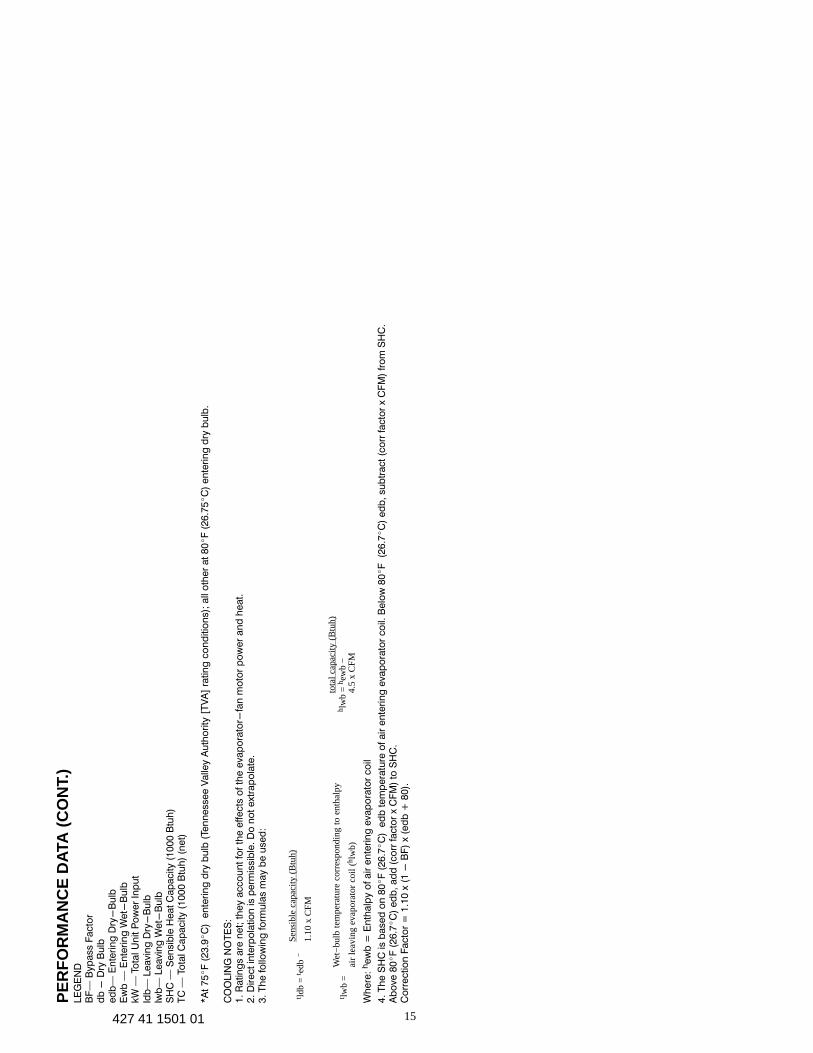
LE
GE
ND
BF
— B
yp
ass F
acto
rd
b -
Dry
Bu
lbed
b—
En
teri
ng
Dry
-B
ulb
Ew
b —
En
teri
ng
Wet-
Bu
lbkW
— T
ota
l U
nit P
ow
er
Inp
ut
ldb
— L
eavin
g D
ry-
Bu
lblw
b—
Leavin
g W
et-
Bu
lbS
HC
— S
en
sib
le H
eat
Cap
acity (
1000 B
tuh
)T
C —
To
tal C
ap
acity (
10
00
Btu
h)
(net)
*A
t 7
5�F
(23.9�C
) e
nte
rin
g d
ry b
ulb
(Te
nn
essee V
alle
y A
uth
ori
ty [
TV
A]
ratin
g c
on
ditio
ns);
all
oth
er
at
80�F
(26.7
5�C
) en
terin
g d
ry b
ulb
.
CO
OLIN
G N
OT
ES
:1
. R
atin
gs a
re n
et;
th
ey a
cco
un
t fo
r th
e e
ffects
of th
e e
vap
ora
tor-
fan
mo
tor
po
wer
an
d h
eat.
2. D
irect
inte
rpo
latio
n is p
erm
issib
le. D
o n
ot
ext
rap
ola
te.
3. T
he fo
llow
ing
fo
rmu
las m
ay b
e u
sed
:
Sens
ible
cap
acity
(B
tuh)
1.10
x C
FMt ld
b =
t edb
−
Wet
−bu
lb t
empe
ratu
re c
orre
spon
ding
to
enth
alpy
air
leav
ing
evap
orat
or c
oil (
h lw
b)t lw
b =
tota
l cap
acity
(B
tuh)
4.5
x C
FMh l
wb
= h
ewb
−
Wh
ere
: hew
b =
En
thalp
y o
f air
en
teri
ng
evap
ora
tor
co
il
4. T
he S
HC
is b
ased
on
80�F
(26.7�C
) e
db
tem
pera
ture
of air
en
teri
ng
evap
ora
tor
co
il. B
elo
w 8
0�F
(2
6.7�C
) ed
b, su
btr
act (c
orr
facto
r x
CF
M)
fro
m S
HC
. A
bo
ve 8
0�F
(26.7�C
) ed
b, ad
d (
co
rr facto
r x
CF
M)
to S
HC
. C
orr
ectio
n F
acto
r =
1.1
0 x
(1 -
BF
) x
(ed
b +
80).
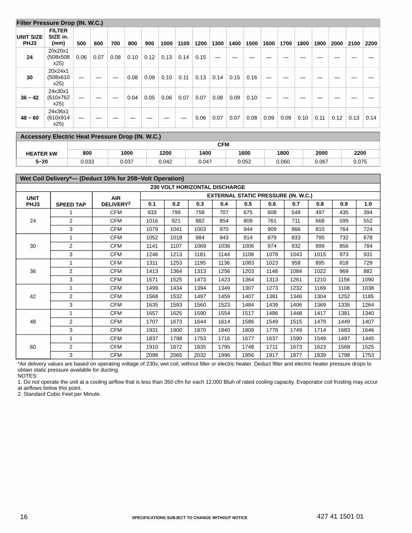
SPECIFICATIONS SUBJECT TO CHANGE WITHOUT NOTICE16 427 41 1501 01
Filter Pressure Drop (IN. W.C.)
UNIT SIZEPHJ3
FILTERSIZE in.
(mm) 500 600 700 800 900 1000 1100 1200 1300 1400 1500 1600 1700 1800 1900 2000 2100 2200
2420x20x1(508x508
x25)0.06 0.07 0.08 0.10 0.12 0.13 0.14 0.15 — — — — — — — — — —
3020x24x1(508x610
x25)— — — 0.08 0.09 0.10 0.11 0.13 0.14 0.15 0.16 — — — — — — —
36 − 4224x30x1(610x762
x25)— — — 0.04 0.05 0.06 0.07 0.07 0.08 0.09 0.10 — — — — — — —
48 − 6024x36x1(610x914
x25)— — — — — — — 0.06 0.07 0.07 0.08 0.09 0.09 0.10 0.11 0.12 0.13 0.14
Accessory Electric Heat Pressure Drop (IN. W.C.)
HEATER kW
CFM
800 1000 1200 1400 1600 1800 2000 2200
5−20 0.033 0.037 0.042 0.047 0.052 0.060 0.067 0.075
Wet Coil Delivery*— (Deduct 10% for 208−Volt Operation)230 VOLT HORIZONTAL DISCHARGE
UNITPHJ3 SPEED TAP
AIRDELIVERY2
EXTERNAL STATIC PRESSURE (IN. W.C.)
0.1 0.2 0.3 0.4 0.5 0.6 0.7 0.8 0.9 1.0
24
1 CFM 933 799 758 707 675 608 549 497 435 394
2 CFM 1016 921 882 854 809 761 711 668 599 552
3 CFM 1079 1041 1003 970 944 909 866 810 764 724
30
1 CFM 1052 1018 984 943 914 879 833 795 732 678
2 CFM 1141 1107 1069 1036 1006 974 932 899 856 784
3 CFM 1246 1213 1181 1144 1108 1078 1043 1015 973 931
36
1 CFM 1311 1253 1195 1136 1083 1023 958 895 818 729
2 CFM 1413 1364 1313 1256 1203 1148 1084 1022 969 882
3 CFM 1571 1525 1473 1423 1364 1313 1261 1210 1156 1090
42
1 CFM 1499 1434 1394 1349 1307 1273 1232 1169 1108 1038
2 CFM 1568 1532 1497 1459 1407 1381 1346 1304 1252 1185
3 CFM 1635 1593 1560 1523 1484 1439 1406 1369 1335 1264
48
1 CFM 1657 1625 1590 1554 1517 1486 1448 1417 1381 1340
2 CFM 1707 1673 1644 1614 1586 1549 1515 1479 1449 1407
3 CFM 1931 1900 1870 1840 1809 1778 1749 1714 1683 1646
60
1 CFM 1837 1798 1753 1716 1677 1637 1590 1549 1497 1445
2 CFM 1910 1872 1835 1795 1748 1711 1673 1623 1568 1525
3 CFM 2098 2065 2032 1996 1956 1917 1877 1839 1798 1753
*Air delivery values are based on operating voltage of 230v, wet coil, without filter or electric heater. Deduct filter and electric heater pressure drops toobtain static pressure available for ducting.NOTES:1. Do not operate the unit at a cooling airflow that is less than 350 cfm for each 12,000 Btuh of rated cooling capacity. Evaporator coil frosting may occurat airflows below this point.2. Standard Cubic Feet per Minute.
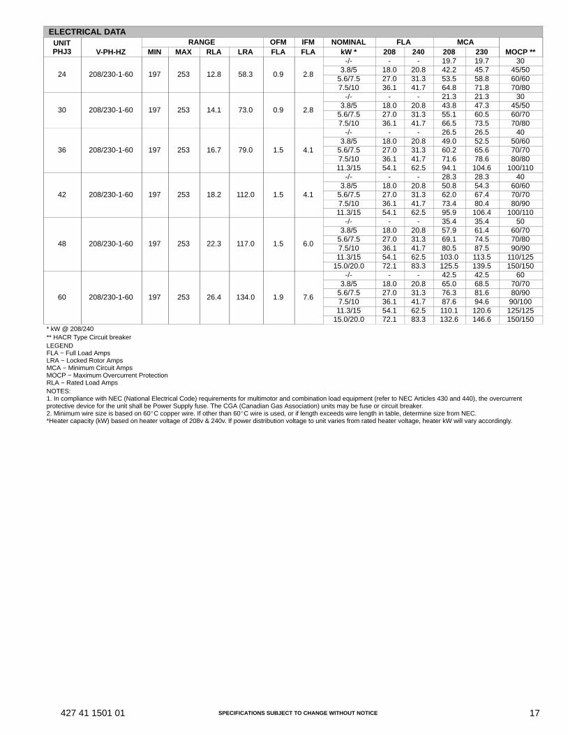
SPECIFICATIONS SUBJECT TO CHANGE WITHOUT NOTICE 17427 41 1501 01
ELECTRICAL DATAUNITPHJ3 V-PH-HZ
RANGE OFM IFM NOMINAL FLA MCAMOCP **MIN MAX RLA LRA FLA FLA kW * 208 240 208 230
24 208/230-1-60 197 253 12.8 58.3 0.9 2.8
-/- - - 19.7 19.7 303.8/5 18.0 20.8 42.2 45.7 45/50
5.6/7.5 27.0 31.3 53.5 58.8 60/607.5/10 36.1 41.7 64.8 71.8 70/80
30 208/230-1-60 197 253 14.1 73.0 0.9 2.8
-/- - - 21.3 21.3 303.8/5 18.0 20.8 43.8 47.3 45/50
5.6/7.5 27.0 31.3 55.1 60.5 60/707.5/10 36.1 41.7 66.5 73.5 70/80
36 208/230-1-60 197 253 16.7 79.0 1.5 4.1
-/- - - 26.5 26.5 403.8/5 18.0 20.8 49.0 52.5 50/60
5.6/7.5 27.0 31.3 60.2 65.6 70/707.5/10 36.1 41.7 71.6 78.6 80/8011.3/15 54.1 62.5 94.1 104.6 100/110
42 208/230-1-60 197 253 18.2 112.0 1.5 4.1
-/- - - 28.3 28.3 403.8/5 18.0 20.8 50.8 54.3 60/60
5.6/7.5 27.0 31.3 62.0 67.4 70/707.5/10 36.1 41.7 73.4 80.4 80/9011.3/15 54.1 62.5 95.9 106.4 100/110
48 208/230-1-60 197 253 22.3 117.0 1.5 6.0
-/- - - 35.4 35.4 503.8/5 18.0 20.8 57.9 61.4 60/70
5.6/7.5 27.0 31.3 69.1 74.5 70/807.5/10 36.1 41.7 80.5 87.5 90/9011.3/15 54.1 62.5 103.0 113.5 110/125
15.0/20.0 72.1 83.3 125.5 139.5 150/150
60 208/230-1-60 197 253 26.4 134.0 1.9 7.6
-/- - - 42.5 42.5 603.8/5 18.0 20.8 65.0 68.5 70/70
5.6/7.5 27.0 31.3 76.3 81.6 80/907.5/10 36.1 41.7 87.6 94.6 90/10011.3/15 54.1 62.5 110.1 120.6 125/125
15.0/20.0 72.1 83.3 132.6 146.6 150/150* kW @ 208/240** HACR Type Circuit breakerLEGENDFLA − Full Load AmpsLRA − Locked Rotor AmpsMCA − Minimum Circuit AmpsMOCP − Maximum Overcurrent ProtectionRLA − Rated Load AmpsNOTES:1. In compliance with NEC (National Electrical Code) requirements for multimotor and combination load equipment (refer to NEC Articles 430 and 440), the overcurrentprotective device for the unit shall be Power Supply fuse. The CGA (Canadian Gas Association) units may be fuse or circuit breaker. 2. Minimum wire size is based on 60�C copper wire. If other than 60�C wire is used, or if length exceeds wire length in table, determine size from NEC.*Heater capacity (kW) based on heater voltage of 208v & 240v. If power distribution voltage to unit varies from rated heater voltage, heater kW will vary accordingly.
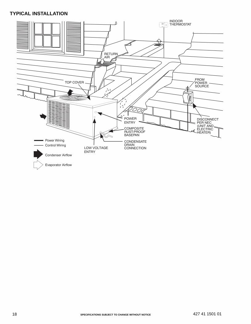
SPECIFICATIONS SUBJECT TO CHANGE WITHOUT NOTICE18 427 41 1501 01
TYPICAL INSTALLATION
TOP COVER
INDOORTHERMOSTAT
DISCONNECTPER NEC(UNIT ANDELECTRICHEATER)
FROMPOWERSOURCE
RETURNAIR
POWERENTRY
COMPOSITERUST-PROOFBASEPAN
CONDENSATEDRAINCONNECTION
Power Wiring
Control Wiring
Condenser Airflow
Evaporator Airflow
LOW VOLTAGEENTRY

SPECIFICATIONS SUBJECT TO CHANGE WITHOUT NOTICE 19427 41 1501 01
TYPICAL CONNECTION WIRING SCHEMATIC 208/230−1−60
24 VoltThermostatConnections
24 VoltThermostatConnections
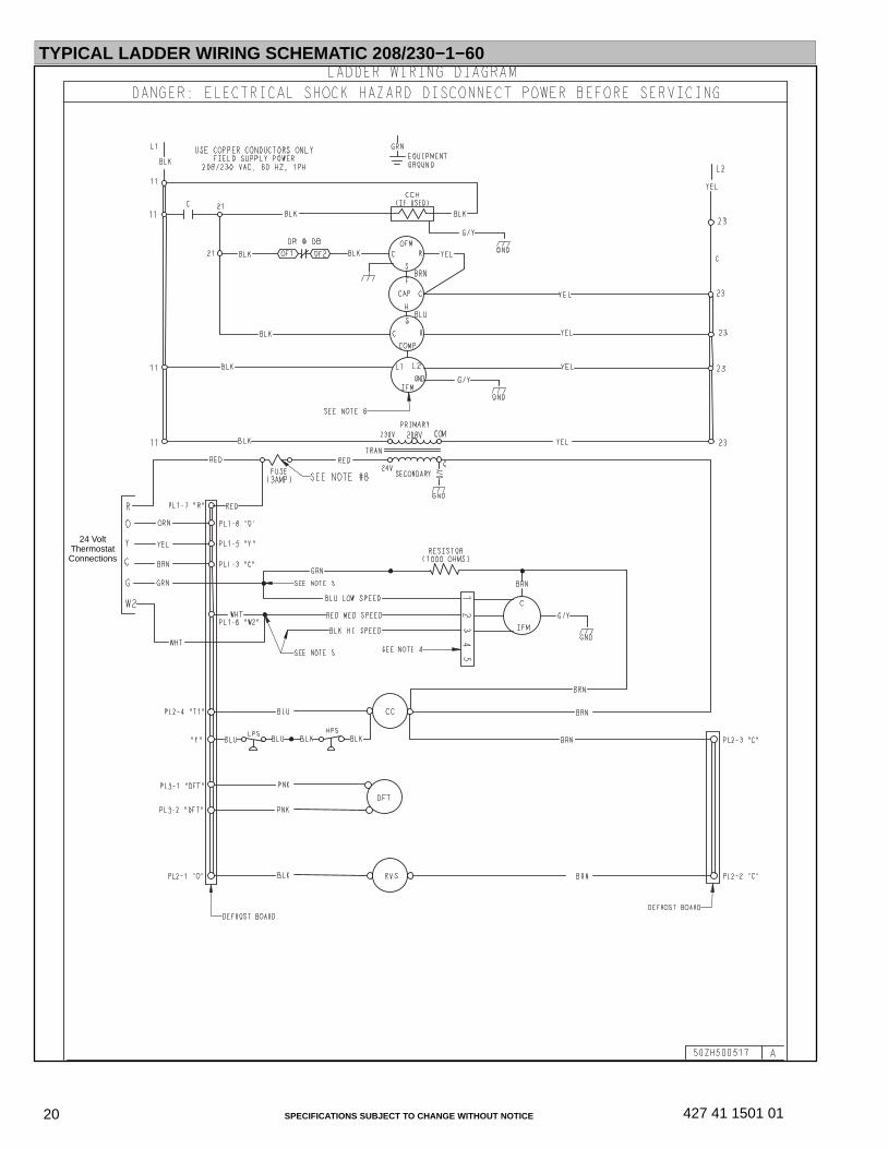
SPECIFICATIONS SUBJECT TO CHANGE WITHOUT NOTICE20 427 41 1501 01
TYPICAL LADDER WIRING SCHEMATIC 208/230−1−60
24 VoltThermostatConnections
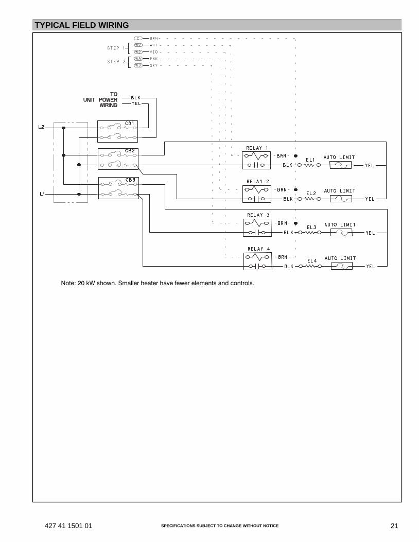
SPECIFICATIONS SUBJECT TO CHANGE WITHOUT NOTICE 21427 41 1501 01
TYPICAL FIELD WIRING
Note: 20 kW shown. Smaller heater have fewer elements and controls.
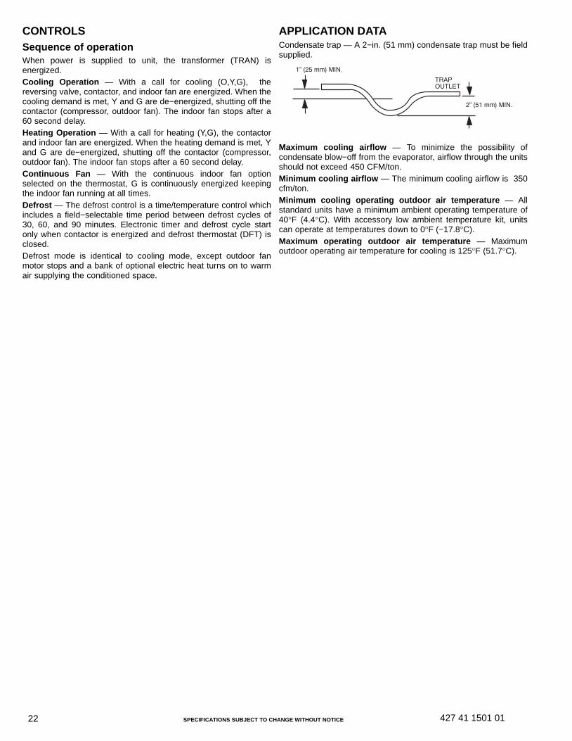
SPECIFICATIONS SUBJECT TO CHANGE WITHOUT NOTICE22 427 41 1501 01
CONTROLSSequence of operationWhen power is supplied to unit, the transformer (TRAN) isenergized.Cooling Operation — With a call for cooling (O,Y,G), thereversing valve, contactor, and indoor fan are energized. When thecooling demand is met, Y and G are de−energized, shutting off thecontactor (compressor, outdoor fan). The indoor fan stops after a60 second delay.Heating Operation — With a call for heating (Y,G), the contactorand indoor fan are energized. When the heating demand is met, Yand G are de−energized, shutting off the contactor (compressor,outdoor fan). The indoor fan stops after a 60 second delay.Continuous Fan — With the continuous indoor fan optionselected on the thermostat, G is continuously energized keepingthe indoor fan running at all times.Defrost — The defrost control is a time/temperature control whichincludes a field−selectable time period between defrost cycles of30, 60, and 90 minutes. Electronic timer and defrost cycle startonly when contactor is energized and defrost thermostat (DFT) isclosed.Defrost mode is identical to cooling mode, except outdoor fanmotor stops and a bank of optional electric heat turns on to warmair supplying the conditioned space.
APPLICATION DATACondensate trap — A 2−in. (51 mm) condensate trap must be fieldsupplied.
1” (25 mm) MIN.
2” (51 mm) MIN.
TRAPOUTLET
Maximum cooling airflow — To minimize the possibility ofcondensate blow−off from the evaporator, airflow through the unitsshould not exceed 450 CFM/ton.Minimum cooling airflow — The minimum cooling airflow is 350cfm/ton.Minimum cooling operating outdoor air temperature — Allstandard units have a minimum ambient operating temperature of40°F (4.4°C). With accessory low ambient temperature kit, unitscan operate at temperatures down to 0°F (−17.8°C).Maximum operating outdoor air temperature — Maximumoutdoor operating air temperature for cooling is 125°F (51.7°C).
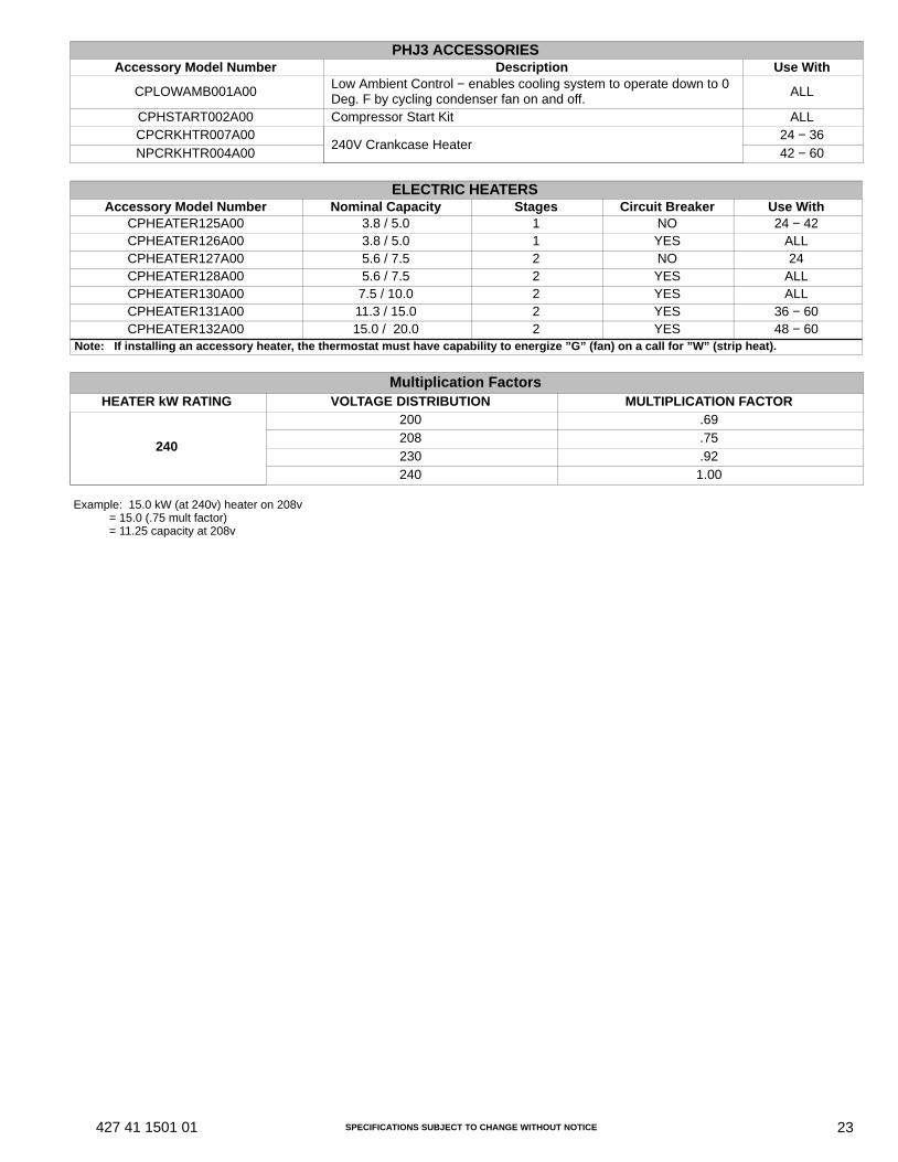
SPECIFICATIONS SUBJECT TO CHANGE WITHOUT NOTICE 23427 41 1501 01
PHJ3 ACCESSORIESAccessory Model Number Description Use With
CPLOWAMB001A00Low Ambient Control − enables cooling system to operate down to 0Deg. F by cycling condenser fan on and off. ALL
CPHSTART002A00 Compressor Start Kit ALLCPCRKHTR007A00
240V Crankcase Heater24 − 36
NPCRKHTR004A00 42 − 60
ELECTRIC HEATERSAccessory Model Number Nominal Capacity Stages Circuit Breaker Use With
CPHEATER125A00 3.8 / 5.0 1 NO 24 − 42CPHEATER126A00 3.8 / 5.0 1 YES ALLCPHEATER127A00 5.6 / 7.5 2 NO 24CPHEATER128A00 5.6 / 7.5 2 YES ALLCPHEATER130A00 7.5 / 10.0 2 YES ALLCPHEATER131A00 11.3 / 15.0 2 YES 36 − 60CPHEATER132A00 15.0 / 20.0 2 YES 48 − 60
Note: If installing an accessory heater, the thermostat must have capability to energize ”G” (fan) on a call for ”W” (strip heat).
Multiplication FactorsHEATER kW RATING VOLTAGE DISTRIBUTION MULTIPLICATION FACTOR
240
200 .69208 .75230 .92240 1.00
Example: 15.0 kW (at 240v) heater on 208v = 15.0 (.75 mult factor) = 11.25 capacity at 208v
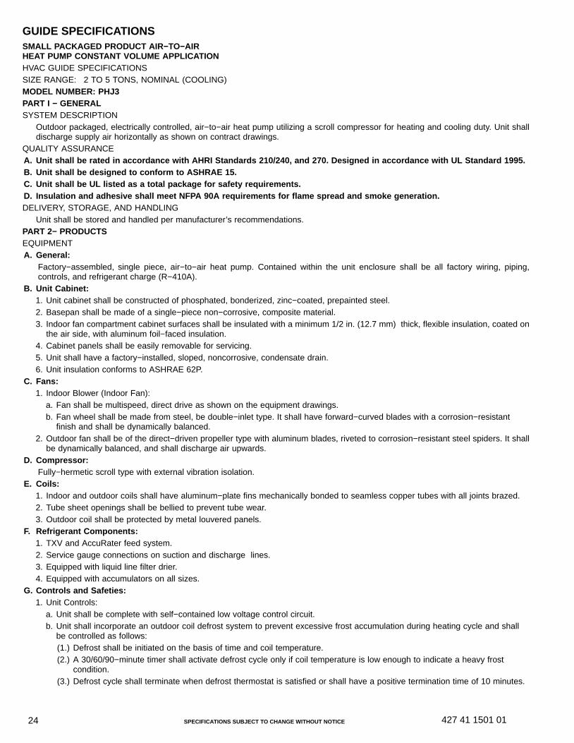
SPECIFICATIONS SUBJECT TO CHANGE WITHOUT NOTICE24 427 41 1501 01
GUIDE SPECIFICATIONSSMALL PACKAGED PRODUCT AIR−TO−AIRHEAT PUMP CONSTANT VOLUME APPLICATIONHVAC GUIDE SPECIFICATIONSSIZE RANGE: 2 TO 5 TONS, NOMINAL (COOLING)MODEL NUMBER: PHJ3PART I − GENERALSYSTEM DESCRIPTION
Outdoor packaged, electrically controlled, air−to−air heat pump utilizing a scroll compressor for heating and cooling duty. Unit shalldischarge supply air horizontally as shown on contract drawings.
QUALITY ASSURANCEA. Unit shall be rated in accordance with AHRI Standards 210/240, and 270. Designed in accordance with UL Standard 1995.B. Unit shall be designed to conform to ASHRAE 15.C. Unit shall be UL listed as a total package for safety requirements.D. Insulation and adhesive shall meet NFPA 90A requirements for flame spread and smoke generation.DELIVERY, STORAGE, AND HANDLING
Unit shall be stored and handled per manufacturer’s recommendations.PART 2− PRODUCTSEQUIPMENTA. General:
Factory−assembled, single piece, air−to−air heat pump. Contained within the unit enclosure shall be all factory wiring, piping,controls, and refrigerant charge (R−410A).
B. Unit Cabinet:1. Unit cabinet shall be constructed of phosphated, bonderized, zinc−coated, prepainted steel.2. Basepan shall be made of a single−piece non−corrosive, composite material.3. Indoor fan compartment cabinet surfaces shall be insulated with a minimum 1/2 in. (12.7 mm) thick, flexible insulation, coated on
the air side, with aluminum foil−faced insulation.4. Cabinet panels shall be easily removable for servicing.5. Unit shall have a factory−installed, sloped, noncorrosive, condensate drain.6. Unit insulation conforms to ASHRAE 62P.
C. Fans:1. Indoor Blower (Indoor Fan):
a. Fan shall be multispeed, direct drive as shown on the equipment drawings.b. Fan wheel shall be made from steel, be double−inlet type. It shall have forward−curved blades with a corrosion−resistant
finish and shall be dynamically balanced.2. Outdoor fan shall be of the direct−driven propeller type with aluminum blades, riveted to corrosion−resistant steel spiders. It shall
be dynamically balanced, and shall discharge air upwards.D. Compressor:
Fully−hermetic scroll type with external vibration isolation.E. Coils:
1. Indoor and outdoor coils shall have aluminum−plate fins mechanically bonded to seamless copper tubes with all joints brazed.2. Tube sheet openings shall be bellied to prevent tube wear.3. Outdoor coil shall be protected by metal louvered panels.
F. Refrigerant Components:1. TXV and AccuRater feed system.2. Service gauge connections on suction and discharge lines.3. Equipped with liquid line filter drier.4. Equipped with accumulators on all sizes.
G. Controls and Safeties:1. Unit Controls:
a. Unit shall be complete with self−contained low voltage control circuit.b. Unit shall incorporate an outdoor coil defrost system to prevent excessive frost accumulation during heating cycle and shall
be controlled as follows:(1.) Defrost shall be initiated on the basis of time and coil temperature.(2.) A 30/60/90−minute timer shall activate defrost cycle only if coil temperature is low enough to indicate a heavy frost
condition.(3.) Defrost cycle shall terminate when defrost thermostat is satisfied or shall have a positive termination time of 10 minutes.
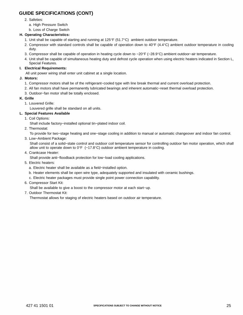
SPECIFICATIONS SUBJECT TO CHANGE WITHOUT NOTICE 25427 41 1501 01
GUIDE SPECIFICATIONS (CONT)2. Safeties:
a. High Pressure Switchb. Loss of Charge Switch
H. Operating Characteristics:1. Unit shall be capable of starting and running at 125°F (51.7°C) ambient outdoor temperature.2. Compressor with standard controls shall be capable of operation down to 40°F (4.4°C) ambient outdoor temperature in cooling
duty.3. Compressor shall be capable of operation in heating cycle down to −20°F (−28.9°C) ambient outdoor−air temperature.4. Unit shall be capable of simultaneous heating duty and defrost cycle operation when using electric heaters indicated in Section L,
Special Features.I. Electrical Requirements:
All unit power wiring shall enter unit cabinet at a single location.J. Motors:
1. Compressor motors shall be of the refrigerant−cooled type with line break thermal and current overload protection.2. All fan motors shall have permanently lubricated bearings and inherent automatic−reset thermal overload protection.3. Outdoor−fan motor shall be totally enclosed.
K. Grille1. Louvered Grille:
Louvered grille shall be standard on all units.L. Special Features Available
1. Coil Options:Shall include factory−installed optional tin−plated indoor coil.
2. Thermostat:To provide for two−stage heating and one−stage cooling in addition to manual or automatic changeover and indoor fan control.
3. Low−Ambient Package:Shall consist of a solid−state control and outdoor coil temperature sensor for controlling outdoor fan motor operation, which shallallow unit to operate down to 0°F (−17.8°C) outdoor ambient temperature in cooling.
4. Crankcase Heater:Shall provide anti−floodback protection for low−load cooling applications.
5. Electric heaters:a. Electric heater shall be available as a field−installed option.b. Heater elements shall be open wire type, adequately supported and insulated with ceramic bushings.c. Electric heater packages must provide single point power connection capability.
6. Compressor Start Kit:Shall be available to give a boost to the compressor motor at each start−up.
7. Outdoor Thermostat Kit:Thermostat allows for staging of electric heaters based on outdoor air temperature.