Embed Size (px)
Citation preview
TD
-201
Rev
No. 0
0
Fo
rm N
o.
PRODUCT STANDARD
HYDERABAD
TC 65439
Rev No. 00
Page 1 of 24
CO
PY
RIG
HT
AN
D C
ON
FID
EN
TIA
L
Th
e in
form
ati
on
on
th
is d
ocu
men
t is
th
e p
rop
erty
of
BH
AR
AT
HE
AV
Y E
LE
CT
RIC
AL
S L
I MIT
ED
,
It m
ust
no
t b
e u
sed
dir
ectl
y o
r in
dir
ectl
y i
n a
ny
way
det
rim
enta
l to
th
e in
tere
st o
f th
e co
mp
any
.
Ref
.
Do
c
Revisions: Prepared:
(I.S)
Approved:
(RAM)
Date:
26.04.20
Refer to record of revisions:
HYDERABAD
SPECIFICATION FOR
INTEGRATED TURBINE AND COMPRESSOR CONTROL
SYSTEM (ITCCS) & OVERSPEED DETECTION SYSTEM
(ODS)
TC65439-R00 Page 1 of 30
TD
-201
Rev
No.0
0
Fo
rm N
o.
PRODUCT STANDARD
HYDERABAD
TC 65439
Rev No.00
Page 2 of 24
CO
PY
RIG
HT
AN
D C
ON
FID
EN
TIA
L
Th
e in
form
atio
n o
n t
his
do
cum
ent
is t
he
pro
per
ty o
f B
HA
RA
T H
EA
VY
EL
EC
TR
ICA
LS
LI M
ITE
D.
It m
ust
no
t b
e u
sed
dir
ectl
y o
r in
dir
ectl
y i
n a
ny
way
det
r im
enta
l to
th
e in
tere
st o
f th
e co
mp
any
.
Ref
.
Do
c
HYDERABAD
INSTRUCTIONS TO BIDDERS:
a) Bidders are advised to contact BHEL for essential technical queries in writing within one week
of issue of RFQ. Offers with incomplete information will not be considered for evaluation, and
are likely to be rejected without any further correspondence with the Bidder.
b) Unsolicited requests from bidders for alterations to their already submitted offer will not be
permitted. These would not be taken cognizance, and offers will be evaluated without taking into
account such requests/correspondence.
c) Any technical features over & above BHEL specification requirements proposed by Bidder will
not be given preference for the purpose of evaluation.
d) Bidders shall comply BHEL specifications in total. Incomplete offers will be rejected. In case
feasible deviations are proposed by the bidder and subsequently withdrawn, no commercial
implications can be claimed by the bidder.
e) Bidders are advised to quote models and makes with proven track record of successful operation.
Offers shall include supporting catalogue and published literature [duly highlighting, as
appropriate, the offered variant with complete de-codification of the offered models. In case of
discrepancy between bidder’s offer and published documents, details furnished in published
documents will be taken for the purpose of evaluation.
f) In the event of any conflict between these specifications, data sheets, related standards, codes etc.
the bidder shall refer the matter to the purchaser for clarifications and only after obtaining the
same shall proceed with the manufacture/procurement of the items in question.
g) Bidder shall submit duly filled deviation format enclosed with this specification along with
technical offer, otherwise, it will be presumed that there are no deviations from this specification.
Offer without this deviation list will not be evaluated & shall be rejected. If, there are no
deviations, bidder shall submit signed copy of deviation format, mentioning “No Deviations”.
h) Bidder shall include all items required for implementation of system as per this specification as a
complete package, exclusion of any required item, however not explicitly listed in this
specification is not acceptable.
i) Changes if any made by BHEL during technical evaluation on the specification requirements or
Bill of material, bidder is requested by the purchase to submit impact price (amount to be
reduced or increased to the original offered price) for those changed items only, other items for
which there are no technical changes, unit rates shall be maintained as it is.
j) Bidder shall include UNIT prices for all spare items. Bidder may attach separate sheet for the
same.
k) Bidder shall include PRICE SCHEDULE format attached with this specification for its technical
and commercial bids. Technical bid shall contain the PRICE SCHEDULE with ‘QUOTED’
against each RFQ item.
l) Sourcing of any raw material or finish good products, any testing and processing on
product (e.g. assembly) from China is not allowed except for the following: Electronic
cards, modules, power supplies, barriers, isolators, network components etc. may have
some internal components / parts manufactured in China, however the supplier shall not be
from China.
m) In case of any technical query, bidders may contact the following BHEL engineer before
submission of offer:
Name: Ramniwas Sangwa
Designation: Manager
Deptt: TC Engineering
Phone: +91 40 2318 3548
Email: [email protected]
TC65439-R00 Page 2 of 30
TD
-201
Rev
No. 0
0
Fo
rm N
o.
PRODUCT STANDARD
HYDERABAD
TC 65439
Rev No. 00
Page 3 of 24
CO
PY
RIG
HT
AN
D C
ON
FID
EN
TIA
L
Th
e in
form
atio
n o
n t
his
do
cum
ent
is t
he
pro
per
ty o
f B
HA
RA
T H
EA
VY
EL
EC
TR
ICA
LS
LIM
ITE
D,
It m
ust
no
t b
e u
sed
dir
ectl
y o
r in
dir
ectl
y i
n a
ny
way
det
rim
enta
l to
th
e in
ter e
st o
f th
e co
mp
any
.
Ref
.
Do
c
Revisions: Prepared:
(I.S)
Approved:
(RAM)
Date:
26.04.20
Refer to record of revisions:
HYDERABAD
TABLE OF CONTENTS
Clause No. Title
1 SCOPE
2 TECHNICAL REQUIREMENTS
3 SYSTEM ENGINEERING
4 ENGINEERING MANUALS
5 COMMISSIONING OF THE SYSTEM
6 SPARES PHILOSOPHY
7 DOCUMENTATION
8 STANDARD WARRANTY (DEFECT LIABILITY PERIOD)
9 EXTENDED WARRANTY
10 POST WARRANTY COMPREHENSIVE ANNUAL
MAINTENANCE CONTRACT (PWCAMC)
11 PACKING, MARKING & SHIPPING
12 COMMISSIONING ASSISTANCE
13 TRAINING
14 DEVIATION FORMAT
15 PROVEN TRACK RECORD
16 PROVEN TRACK RECORD FORMAT
17 TENDER EVALUATION CRITERIA
18 LOGISTIC SUPPORT
19 CHECK LIST
20 SYSTEM CONFIGURATION & ARCHITECTURE
21 VARIANT TABLE
22 PRICE SCHEDULE
RECORD OF REVISIONS
TC65439-R00 Page 3 of 30
TD
-201
Rev
No.0
0
Fo
rm N
o.
PRODUCT STANDARD
HYDERABAD
T C 65439
Rev No. 00
Page 4 of 24
CO
PY
RIG
HT
AN
D C
ON
FID
EN
TIA
L
Th
e in
form
atio
n o
n t
his
do
cum
ent
is t
he
pr o
per
ty o
f B
HA
RA
T H
EA
VY
EL
EC
TR
ICA
LS
LIM
ITE
D.
It m
ust
no
t b
e u
sed
dir
ectl
y o
r in
dir
ectl
y i
n a
ny
way
det
r im
enta
l to
th
e in
tere
st o
f th
e co
mp
any
.
Ref
.
Do
c
HYDERABAD
1. SCOPE:
1.1 This Specification defines the requirement of Integrated Turbine and Compressor Control System
(herein called ITCCS through this specification) and Electronic overspeed detection system (ODS)
for steam turbine driven compressor train. The scope of bidder shall include Design, Selection,
Manufacture, Assembly, Testing (FAT), Packing, Supply, documentation, training and supervision
of commissioning & SAT of complete package.
1.2 The ITCCS shall comprise of the following control applications / programs:
1.2.1 Steam Turbine Governing (speed and / or extraction) control.
1.2.2 Compressor control like antisurge, performance, load sharing control etc. (Refer Variant
table for number of compressor control application / stages.)
1.2.3 Compressor Performance / Capacity control.
1.2.4 Auxiliary equipment / device monitoring, control, interlock and protection (Refer Variant
table for details).
1.2.5 Steam Turbine ODS (Independent of ITCCS hardware as per API-612, 7th ed. and API-670,
5th ed.).
1.2.6 Engineering and operator HMI workstation with 22” monitor with A4 laser printer.
1.2.7 Safe area (IP-55) panel (Rittal TS8 / PS4 series).
1.2.8 Network accessories as per RFQ.
1.3 It is the responsibility of the vendor for engineering of the complete ITCCS & ODS package along
with detailed Bill of material and model selection. If there is shortage or mismatch of any items
identified at any stage up to commissioning the complete package, vendor shall
rectify/replace/supply the items without any commercial or delivery implications.
1.4 The following items are in BHEL / Customer scope:
1.4.1 Field devices.
1.4.2 Cables from/to field / DCS / ESD / EWS & OWS HMI to ITCCS panel.
2. TECHNICAL REQUIREMENTS:
2.1 TECHINICAL REQUIREMENT – ITCCS:
2.1.1 The ITCCS hardware shall be with DMR / TMR configuration (refer Variant Table). The
redundancy shall be on electronic module (CPU, IO etc.) level. For example, redundancy
(DMR / TMR) built into single electronic module is not acceptable. In case with vendor
offering redundancy built into electronic module (single electronic module is internally Dual
/ Triple Redundant), vendor shall offer and supply redundant electronic modules. CPU
redundancy shall be on electronic module level only. Refer attached System architecture for
detail.
2.1.2 ITCCS cards shall be Hot Swap type i.e. it shall be possible to program, re-program, remove
from rack and insert into rack with system shutdown. The ITCCS electronic cards including
CPU, IO, Communication, PS shall be on-line configurable and on-line repairable.
2.1.3 Complete ITCCS hardware shall be SIL-3 certified as per IEC61508 / IEC61511.
2.1.4 The ITCCS loop scan / response time (total time to read input, processing time and output)
shall be as per the machine dynamics and safety and shall be maximum 40 milliseconds. Any
faster response required based on machine dynamics shall be considered by vendor. The
input sampling interval shall be as per machine dynamics within the controller response time
as above. The processor cycle time shall be considered to meet the overall response time.
TC65439-R00 Page 4 of 30
TD
-201
Rev
No.0
0
Fo
rm N
o.
PRODUCT STANDARD
HYDERABAD
T C 65439
Rev No. 00
Page 5 of 24
CO
PY
RIG
HT
AN
D C
ON
FID
EN
TIA
L
Th
e in
form
atio
n o
n t
his
do
cum
ent
is t
he
pr o
per
ty o
f B
HA
RA
T H
EA
VY
EL
EC
TR
ICA
LS
LIM
ITE
D.
It m
ust
no
t b
e u
sed
dir
ectl
y o
r in
dir
ectl
y i
n a
ny
way
det
r im
enta
l to
th
e in
tere
st o
f th
e co
mp
any
.
Ref
.
Do
c
HYDERABAD
2.1.5 The response / scan time demonstrated during FAT by measuring the time delay between
change in any analog input and corresponding change in analog output. This is applicable for
governing and antisurge / performance / load sharing control applications inside ITCCS.
2.1.6 ITCCS panel shall be located in Rack room (RR) and the following operator interfaces shall
be considered.
a) One EWS & OWS HMI workstation with 21” / 22” monitor (make model will be informed
during detail engineering to match with other monitors). The workstation shall be used as
engineering, configuration and operator station, accordingly development, logic
modification and run time licensed software's shall be provided. The EWS & OWS HMI
workstation shall have following minimum hardware configuration:
i. Make: DELL / HP.
ii. HDD ≥ 1 TB, RAID 1 configuration.
iii. CPU: Intel Xeon or better.
iv. RAM ≥ 8 GB
v. OS: Windows latest version with Microsoft office.
vi. Ethernet: Dual Channel 10 / 100 Ethernet card.
b) The workstation shall be used for following functions:
i. Programming, Engineering, configuration of ITCCS.
ii. Loading / Unloading / backup of ITCCS program.
iii. HMI Graphic Screens development and modification.
iv. Trends, Alarm Historian & SOE.
v. Capability to transfer / export trends, Historian data / SOE to MS Excel.
c) The software licenses shall not be time bound or limited to specific period of use (like valid
for 1 year etc.). The software license shall not expire after a certain period.
d) The HMI Workstation shall be supplied with antivirus software, valid for at least 3 years
from date of activation.
e) The complete software backup image of As-Shipped workstation shall be supplied in a
USB.
f) A second software backup image of the As-Commissioned HMI workstation shall be
created after commissioning and a copy of the same shall be submitted to BHEL in a USB.
g) Vendor to supply program loader (laptop, if specified in RFQ) along with necessary
maintenance software's (licensed software's) for application program engineering,
modification, uploading/ unloading in the ITCC.
h) In case laptop is not specified in RFQ, vendor shall supply necessary maintenance
software's (licensed software's) for application program engineering, modification,
uploading/ unloading the ITCCS. In this case, the laptop shall be supplied by BHEL.
i) Connecting cable to ITCCS & ODS system shall be provided. Licensed version of latest
antivirus with 3-year validity shall be provided in all Laptops and EWS & OWS
workstation. The Antivirus shall be activated during commissioning.
j) Vendor shall supply two licensed copies of all ITCCS & ODS software in CD / DVD / USB
with passwords / keys to access the software.
k) The ITCCS program / configuration shall be stored in non-volatile memory or battery back-
up for configuration shall be provided (minimum 72 hours) in case of volatile memory
along with battery drain indication.
TC65439-R00 Page 5 of 30
TD
-201
Rev
No.0
0
Fo
rm N
o.
PRODUCT STANDARD
HYDERABAD
T C 65439
Rev No. 00
Page 6 of 24
CO
PY
RIG
HT
AN
D C
ON
FID
EN
TIA
L
Th
e in
form
atio
n o
n t
his
do
cum
ent
is t
he
pr o
per
ty o
f B
HA
RA
T H
EA
VY
EL
EC
TR
ICA
LS
LIM
ITE
D.
It m
ust
no
t b
e u
sed
dir
ectl
y o
r in
dir
ectl
y i
n a
ny
way
det
r im
enta
l to
th
e in
tere
st o
f th
e co
mp
any
.
Ref
.
Do
c
HYDERABAD
2.1.7 The steam turbine governing (GOV) application inside ITCCS shall have following
minimum features:
a) The GOV shall be API 670 & 612 compliant.
b) GOV shall accept input from 3 speed sensors, the pole wheel details will be furnished
during detailed engineering.
c) It shall be possible to program the GOV to operate the steam turbine from zero speed to
rated speed with ramp rates, idle speeds, critical speeds for Hot, Cold and Warm conditions
as per the startup curves to be furnished during detailed engineering.
d) The governing valve characteristics shall be programmed in the GOV for linearization.
e) The GOV shall be capable of operating in Auto, semi auto and manual modes.
f) The GOV shall accept external 4-20 mA signal from DCS or Local as a manual speed / load
setpoint to governor. The governor shall have bumpless transfer for auto / manual selection
or local / remote selection. The auto/manual selection and local/ remote selection facility
shall be configured in governor and available on the HMI.
g) HMI shall include features like assignable speed range, adjustable speed set point, remote
speed set point input, digital speed indication, adjustable speed ramp, override for testing
the external Overspeed trip system etc.
2.1.8 The compressor control application inside ITCCS shall have following minimum
features:
a) Compressor Control mean Compressor Antisurge, Performance, Load sharing etc. In some
cases, Compressor Control applications / controllers like Performance, Load sharing etc.
may not be applicable. Please refer the Variant Table for Project Specific Controllers /
Applications.
b) Each antisurge control application shall have minimum five analog inputs (or six if two
flow transmitters are used based on flow range). The output shall be to single antisurge
control valve (sometime two outputs to two ASC valves if valve size is big).
c) In addition to above, there shall be provision for manual override (open command) to ASC
valve through 4-20 mA signal from DCS.
d) Sufficient number of digital IO shall be considered for transmitter fault, trip, purge, load /
unload, run / stop etc.
e) The antisurge algorithm shall be based on invariant coordinate system. Vendor shall design
the antisurge algorithm such that it is immune to changes in gas properties (like change in
mol. Weight, pressure, temperature etc.)
f) Compressor speed, if required shall be connected from GOV application.
g) Project Specific data like Process P&ID, Isometrics, Instrument datasheets shall be
provided during detail engineering; however, the number of Compressor Control
applications / controllers (Antisurge, Performance, Load sharing etc.) shall be as specified
in Enquiry.
h) The input and output IOs for Performance / load sharing etc. if applicable, shall be decided
as per the project requirements. There shall be provision for giving external control
setpoints from DCS for performance / load sharing control. Vendor to indicate and include
the same.
TC65439-R00 Page 6 of 30
TD
-201
Rev
No.0
0
Fo
rm N
o.
PRODUCT STANDARD
HYDERABAD
T C 65439
Rev No. 00
Page 7 of 24
CO
PY
RIG
HT
AN
D C
ON
FID
EN
TIA
L
Th
e in
form
atio
n o
n t
his
do
cum
ent
is t
he
pr o
per
ty o
f B
HA
RA
T H
EA
VY
EL
EC
TR
ICA
LS
LIM
ITE
D.
It m
ust
no
t b
e u
sed
dir
ectl
y o
r in
dir
ectl
y i
n a
ny
way
det
r im
enta
l to
th
e in
tere
st o
f th
e co
mp
any
.
Ref
.
Do
c
HYDERABAD
2.1.9 The auxiliary control application inside ITCCS shall have following minimum features:
a) The auxiliary device control application shall be independent of governing and compressor
control application. It shall not stop function if main steam turbine governing and
compressor control application are not running / tripped.
b) Lube oil pump drive turbine (API-611) speed control (2 speed inputs and analog outputs to
governing valve and DCS). The ODS based on 3 speed inputs for this steam turbine shall be
through trip amplifiers. The three relay outputs from trip amplifiers shall be 2oo3 voted in
ITCCS and DO shall be provided to trip the lube oil steam turbine. The same is also
applicable if the steam turbine is used for any other pump like condensate pump.
2.2 TECHINICAL REQUIREMENT– Electronic overspeed detection system (ODS):
2.2.1 The Electronic ODS shall be API 670 & 612 compliant and SIL-3 certified as per IEC61508 /
IEC61511.
2.2.2 The Electronic ODS shall be independent of the ITCCS. Separate electrical over speed trip
circuits consisting of speed sensors and logic devices shall be used to provide in 2oo3 voting
configuration.
2.2.3 The Electronic ODS shall accept input from 3 speed sensors, the pole wheel details will be
furnished during detailed engineering.
2.2.4 The Electronic ODS shall be assembled in the ITCCS panel.
2.2.5 The Electronic ODS shall have online testing / repair facility and internal function generator
and fully redundant power supplies.
2.2.6 The Electronic ODS shall sense an Overspeed event and change the state of its output relays
within 40 milliseconds maximum.
2.2.7 Program loader laptop / workstation (as specified in RFQ) shall be loaded with software for
program loading / unloading and settings configuration of ODS.
2.3 TECHINICAL REQUIREMENT – GENERAL:
2.3.1 ITCCS & ODS electronic modules shall be conformal coated to G3 environment as per ISA.
2.3.2 The analog input and output signals shall be 24VDC, 4-20mA, SMART HART, 2 wire and
powered from the ITCCS through barriers / isolators. The Governing IH converter is high
power device and may be 4- wire, powered through separate 24VDC.
2.3.3 If specified as per Variant table, the analog IO shall be HART capable / enabled. Serial
Connectivity shall be provided to Purchaser HART management system. In case IO cards are
not HART capable, HART connection shall be provided through HART multiplexer in
conjunction with barriers / isolators.
2.3.4 The controller shall monitor each transmitter input signal for high and low values. Alarm
limits shall be set at 95% increasing and 5% decreasing signals. When a transmitter input
signal exceeds the alarm limit, a relay will de-energise to actuate a command “transmitter out
of range” alarm (alarm by others) in the control center. The controller output signal shall de-
energise a relay at 95% decreasing value to actuate “Controller operating” alarm (by others)
in the control room.
2.3.5 The controller shall monitor its output and initiate an alarm if output failure is detected.
2.3.6 The controller shall be designed with a fail-safe mode to prevent a process upset caused by a
transmitter or input failure. The controller vendor shall specify the fail-safe mode required for
each specific installation.
TC65439-R00 Page 7 of 30
TD
-201
Rev
No.0
0
Fo
rm N
o.
PRODUCT STANDARD
HYDERABAD
T C 65439
Rev No. 00
Page 8 of 24
CO
PY
RIG
HT
AN
D C
ON
FID
EN
TIA
L
Th
e in
form
atio
n o
n t
his
do
cum
ent
is t
he
pr o
per
ty o
f B
HA
RA
T H
EA
VY
EL
EC
TR
ICA
LS
LIM
ITE
D.
It m
ust
no
t b
e u
sed
dir
ectl
y o
r in
dir
ectl
y i
n a
ny
way
det
r im
enta
l to
th
e in
tere
st o
f th
e co
mp
any
.
Ref
.
Do
c
HYDERABAD
2.3.7 Two feeders of UPS power supply shall be provided at ITCCS panel by purchaser, all other
power supplies for ITCCS, ODS, HMI, separate & independent 24VDC-5A power supply for
I/H converters (Redundant), power supply for Laptop, Printer, barriers, isolators etc. shall be
generated / provided by the vendor from ITCCS panel.
2.3.8 The workstation, Laptop and printer shall be suitable for power supply range of 90 to 270 V
ac 50/60 Hz. Power cable and other accessories for Laptop and printer shall be supplied by
the vendor.
2.3.9 For Speed measurement, Magnetic Pickups (MPU, Explosion proof type) or Proximity
sensors (intrinsic safe) are required. The same shall be suitable for hazardous area
classification for IEC Zone-1 & Zone-2 Group IIC, Temperature class T3.
2.3.10 All inputs and outputs from hazardous area shall be provided with barriers and from safe area
shall be provided with isolators / relays.
2.3.11 The vendor shall design and provide earthing as per the protecting earthing system according
to IEC rules.
2.3.12 It is vendor’s responsibility to supply a system, which functionally meets all the requirements
of this specification. Any item not supplied but required to meet the specification
requirements, during the execution of the order or during commissioning to meet the proper
functioning of the system, shall be supplied by the vendor at no extra delivery and no extra
price.
2.3.13 Communication cables shall be supplied with connectors at both ends. Necessary additional
SIO modules as required shall be supplied and assembled in the cabinet by the vendor for
achieving the dual redundant communication to DCS.
2.3.14 It shall be possible to operate, program, and diagnose the control system faults from the HMI.
2.4 TECHINICAL REQUIREMENT – INSPECTION & TESTING:
2.4.1 Bidder to furnish the QA plan & FAT procedure along with the data sheets of all the
equipment in line with attached ITP for approval after placement of order.
2.4.2 The controllers / fully assembled system (if applicable) shall be tested in an integral manner
by simulation. Customer / Consultant / BHEL and/ or BHEL authorized representatives shall
inspect the system at supplier works during factory acceptance test (FAT).
2.4.3 The latest certificates for use in hazardous areas shall be furnished for instruments /
equipment (if applicable) by the vendor as specified below:
• Certificates from statutory authorities like BASEFA, FM, PTB, UL and LCIE etc. for
items of foreign origin and from CIMFR etc. for items of Indian origin.
• Approval certificates from CCE (Chief Controller of Explosives)/ PESO for items to be
installed Hazardous area in India, irrespective of country of origin and the same is
mandatory. In case CCE certificate is not available for any item at the time of offer, vendor
shall confirm that the certificate shall be furnished during detailed engineering and before
dispatch.
• Approval certificate from BIS (Bureau of Indian Standards) for all flameproof instruments
of Indian origin.
2.5 TECHINICAL REQUIREMENT – IO SUMMARY:
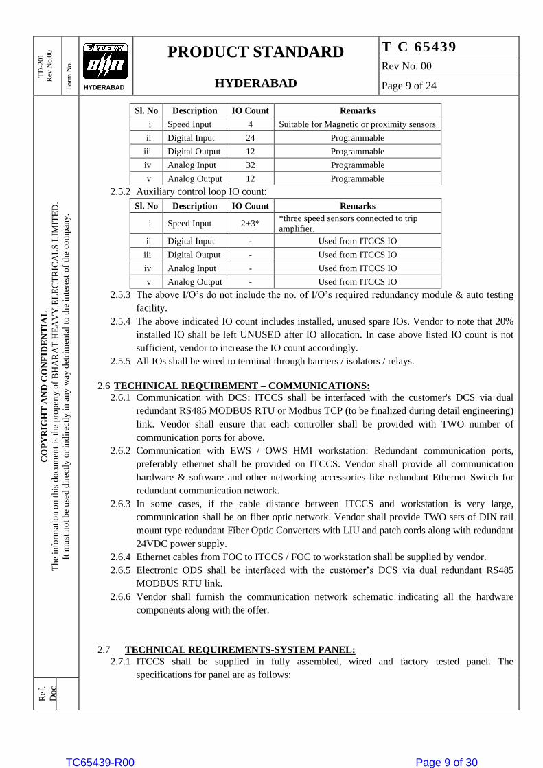
2.5.1 ITCCS IOs for Governing and Compressor control applications are as follows. This IO Count
does not include IO’s for Overspeed protection system and Auxiliary control loops.
TC65439-R00 Page 8 of 30
TD
-201
Rev
No.0
0
Fo
rm N
o.
PRODUCT STANDARD
HYDERABAD
T C 65439
Rev No. 00
Page 9 of 24
CO
PY
RIG
HT
AN
D C
ON
FID
EN
TIA
L
Th
e in
form
atio
n o
n t
his
do
cum
ent
is t
he
pr o
per
ty o
f B
HA
RA
T H
EA
VY
EL
EC
TR
ICA
LS
LIM
ITE
D.
It m
ust
no
t b
e u
sed
dir
ectl
y o
r in
dir
ectl
y i
n a
ny
way
det
r im
enta
l to
th
e in
tere
st o
f th
e co
mp
any
.
Ref
.
Do
c
HYDERABAD
Sl. No Description IO Count Remarks
i Speed Input 4 Suitable for Magnetic or proximity sensors
ii Digital Input 24 Programmable
iii Digital Output 12 Programmable
iv Analog Input 32 Programmable
v Analog Output 12 Programmable
2.5.2 Auxiliary control loop IO count:
Sl. No Description IO Count Remarks
i Speed Input 2+3* *three speed sensors connected to trip
amplifier.
ii Digital Input - Used from ITCCS IO
iii Digital Output - Used from ITCCS IO
iv Analog Input - Used from ITCCS IO
v Analog Output - Used from ITCCS IO
2.5.3 The above I/O’s do not include the no. of I/O’s required redundancy module & auto testing
facility.
2.5.4 The above indicated IO count includes installed, unused spare IOs. Vendor to note that 20%
installed IO shall be left UNUSED after IO allocation. In case above listed IO count is not
sufficient, vendor to increase the IO count accordingly.
2.5.5 All IOs shall be wired to terminal through barriers / isolators / relays.
2.6 TECHINICAL REQUIREMENT – COMMUNICATIONS:
2.6.1 Communication with DCS: ITCCS shall be interfaced with the customer's DCS via dual
redundant RS485 MODBUS RTU or Modbus TCP (to be finalized during detail engineering)
link. Vendor shall ensure that each controller shall be provided with TWO number of
communication ports for above.
2.6.2 Communication with EWS / OWS HMI workstation: Redundant communication ports,
preferably ethernet shall be provided on ITCCS. Vendor shall provide all communication
hardware & software and other networking accessories like redundant Ethernet Switch for
redundant communication network.
2.6.3 In some cases, if the cable distance between ITCCS and workstation is very large,
communication shall be on fiber optic network. Vendor shall provide TWO sets of DIN rail
mount type redundant Fiber Optic Converters with LIU and patch cords along with redundant
24VDC power supply.
2.6.4 Ethernet cables from FOC to ITCCS / FOC to workstation shall be supplied by vendor.
2.6.5 Electronic ODS shall be interfaced with the customer’s DCS via dual redundant RS485
MODBUS RTU link.
2.6.6 Vendor shall furnish the communication network schematic indicating all the hardware
components along with the offer.
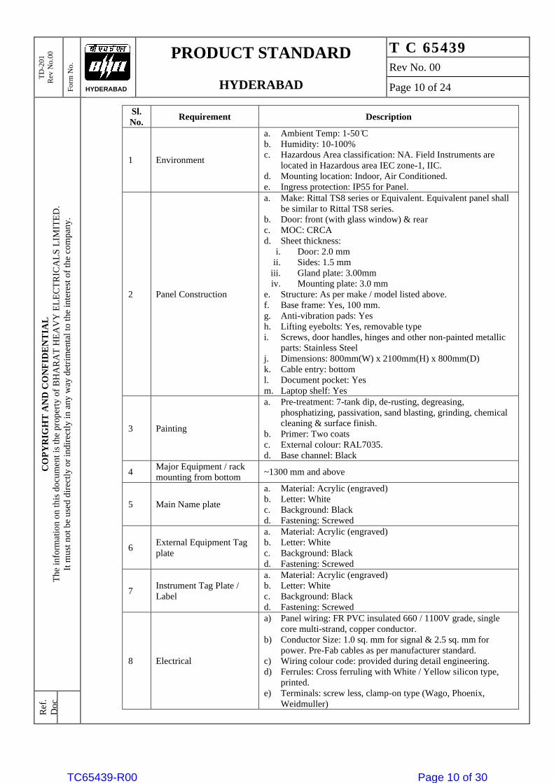
2.7 TECHNICAL REQUIREMENTS-SYSTEM PANEL:
2.7.1 ITCCS shall be supplied in fully assembled, wired and factory tested panel. The
specifications for panel are as follows:
TC65439-R00 Page 9 of 30
TD
-201
Rev
No.0
0
Fo
rm N
o.
PRODUCT STANDARD
HYDERABAD
T C 65439
Rev No. 00
Page 10 of 24
CO
PY
RIG
HT
AN
D C
ON
FID
EN
TIA
L
Th
e in
form
atio
n o
n t
his
do
cum
ent
is t
he
pr o
per
ty o
f B
HA
RA
T H
EA
VY
EL
EC
TR
ICA
LS
LIM
ITE
D.
It m
ust
no
t b
e u
sed
dir
ectl
y o
r in
dir
ectl
y i
n a
ny
way
det
r im
enta
l to
th
e in
tere
st o
f th
e co
mp
any
.
Ref
.
Do
c
HYDERABAD
Sl.
No. Requirement Description
1 Environment
a. Ambient Temp: 1-50 ̊C
b. Humidity: 10-100%
c. Hazardous Area classification: NA. Field Instruments are
located in Hazardous area IEC zone-1, IIC.
d. Mounting location: Indoor, Air Conditioned.
e. Ingress protection: IP55 for Panel.
2 Panel Construction
a. Make: Rittal TS8 series or Equivalent. Equivalent panel shall
be similar to Rittal TS8 series.
b. Door: front (with glass window) & rear
c. MOC: CRCA
d. Sheet thickness:
i. Door: 2.0 mm
ii. Sides: 1.5 mm
iii. Gland plate: 3.00mm
iv. Mounting plate: 3.0 mm
e. Structure: As per make / model listed above.
f. Base frame: Yes, 100 mm.
g. Anti-vibration pads: Yes
h. Lifting eyebolts: Yes, removable type
i. Screws, door handles, hinges and other non-painted metallic
parts: Stainless Steel
j. Dimensions: 800mm(W) x 2100mm(H) x 800mm(D)
k. Cable entry: bottom
l. Document pocket: Yes
m. Laptop shelf: Yes
3 Painting
a. Pre-treatment: 7-tank dip, de-rusting, degreasing,
phosphatizing, passivation, sand blasting, grinding, chemical
cleaning & surface finish.
b. Primer: Two coats
c. External colour: RAL7035.
d. Base channel: Black
4 Major Equipment / rack
mounting from bottom ~1300 mm and above
5 Main Name plate
a. Material: Acrylic (engraved)
b. Letter: White
c. Background: Black
d. Fastening: Screwed
6 External Equipment Tag
plate
a. Material: Acrylic (engraved)
b. Letter: White
c. Background: Black
d. Fastening: Screwed
7 Instrument Tag Plate /
Label
a. Material: Acrylic (engraved)
b. Letter: White
c. Background: Black
d. Fastening: Screwed
8 Electrical
a) Panel wiring: FR PVC insulated 660 / 1100V grade, single
core multi-strand, copper conductor.
b) Conductor Size: 1.0 sq. mm for signal & 2.5 sq. mm for
power. Pre-Fab cables as per manufacturer standard.
c) Wiring colour code: provided during detail engineering.
d) Ferrules: Cross ferruling with White / Yellow silicon type,
printed.
e) Terminals: screw less, clamp-on type (Wago, Phoenix,
Weidmuller)
TC65439-R00 Page 10 of 30
TD
-201
Rev
No.0
0
Fo
rm N
o.
PRODUCT STANDARD
HYDERABAD
T C 65439
Rev No. 00
Page 11 of 24
CO
PY
RIG
HT
AN
D C
ON
FID
EN
TIA
L
Th
e in
form
atio
n o
n t
his
do
cum
ent
is t
he
pr o
per
ty o
f B
HA
RA
T H
EA
VY
EL
EC
TR
ICA
LS
LIM
ITE
D.
It m
ust
no
t b
e u
sed
dir
ectl
y o
r in
dir
ectl
y i
n a
ny
way
det
r im
enta
l to
th
e in
tere
st o
f th
e co
mp
any
.
Ref
.
Do
c
HYDERABAD
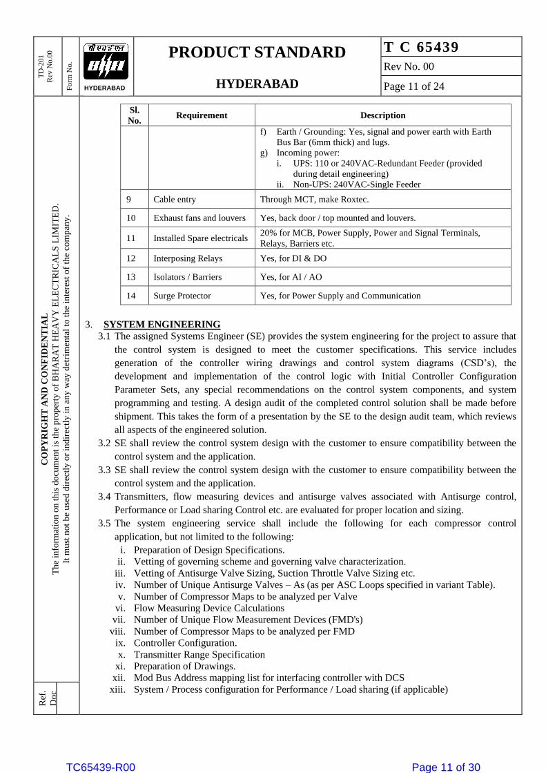
Sl.
No. Requirement Description
f) Earth / Grounding: Yes, signal and power earth with Earth
Bus Bar (6mm thick) and lugs.
g) Incoming power:
i. UPS: 110 or 240VAC-Redundant Feeder (provided
during detail engineering)
ii. Non-UPS: 240VAC-Single Feeder
9 Cable entry Through MCT, make Roxtec.
10 Exhaust fans and louvers Yes, back door / top mounted and louvers.
11 Installed Spare electricals 20% for MCB, Power Supply, Power and Signal Terminals,
Relays, Barriers etc.
12 Interposing Relays Yes, for DI & DO
13 Isolators / Barriers Yes, for AI / AO
14 Surge Protector Yes, for Power Supply and Communication
3. SYSTEM ENGINEERING
3.1 The assigned Systems Engineer (SE) provides the system engineering for the project to assure that
the control system is designed to meet the customer specifications. This service includes
generation of the controller wiring drawings and control system diagrams (CSD’s), the
development and implementation of the control logic with Initial Controller Configuration
Parameter Sets, any special recommendations on the control system components, and system
programming and testing. A design audit of the completed control solution shall be made before
shipment. This takes the form of a presentation by the SE to the design audit team, which reviews
all aspects of the engineered solution.
3.2 SE shall review the control system design with the customer to ensure compatibility between the
control system and the application.
3.3 SE shall review the control system design with the customer to ensure compatibility between the
control system and the application.
3.4 Transmitters, flow measuring devices and antisurge valves associated with Antisurge control,
Performance or Load sharing Control etc. are evaluated for proper location and sizing.
3.5 The system engineering service shall include the following for each compressor control
application, but not limited to the following:
i. Preparation of Design Specifications.
ii. Vetting of governing scheme and governing valve characterization.
iii. Vetting of Antisurge Valve Sizing, Suction Throttle Valve Sizing etc.
iv. Number of Unique Antisurge Valves – As (as per ASC Loops specified in variant Table).
v. Number of Compressor Maps to be analyzed per Valve
vi. Flow Measuring Device Calculations
vii. Number of Unique Flow Measurement Devices (FMD's)
viii. Number of Compressor Maps to be analyzed per FMD
ix. Controller Configuration.
x. Transmitter Range Specification
xi. Preparation of Drawings.
xii. Mod Bus Address mapping list for interfacing controller with DCS
xiii. System / Process configuration for Performance / Load sharing (if applicable)
TC65439-R00 Page 11 of 30
TD
-201
Rev
No.0
0
Fo
rm N
o.
PRODUCT STANDARD
HYDERABAD
T C 65439
Rev No. 00
Page 12 of 24
CO
PY
RIG
HT
AN
D C
ON
FID
EN
TIA
L
Th
e in
form
atio
n o
n t
his
do
cum
ent
is t
he
pr o
per
ty o
f B
HA
RA
T H
EA
VY
EL
EC
TR
ICA
LS
LIM
ITE
D.
It m
ust
no
t b
e u
sed
dir
ectl
y o
r in
dir
ectl
y i
n a
ny
way
det
r im
enta
l to
th
e in
tere
st o
f th
e co
mp
any
.
Ref
.
Do
c
HYDERABAD
4. ENGINEERING MANUALS
4.1 The design and specifications shall be formally documented in the Engineering Manuals and
provided in three hard copies and one CD. This includes:
i. Control system diagrams
ii. A wiring and jumper list
iii. A system description
iv. Controller dimensional drawings
v. Panel structural and layout drawings
vi. A bill of materials
vii. Controller instruction manuals
viii. Initial controller configuration parameters (refer Note)
4.2 Note: ‘Initial Controller Configuration Parameter Sets’ are calculated and prepared using project-
specific data for channel assignments and functionality where possible. Gains, biases and control
responses are necessarily maintained at conservative levels for safety reasons during initial start.
5. COMMISSIONING OF THE SYSTEM
5.1 The Control system representative from the nearest location from the site shall supervise the
erection, Commissioning, configuration and tuning of the controller & accessories supplied by
vendor.
5.2 The Field Engineer shall be responsible on site for system integration and commissioning, to
troubleshoot and correct any connectivity issues and to tune the system in response to actual
system dynamics.
5.3 Vendor shall optimize the overall system with respect to appropriate integration and interface with
customer’s DCS etc.
6. SPARES PHILOSOPHY:
6.1 The system shall meet the following spare philosophy. This philosophy shall be applicable for
items like IO’s, barriers, isolators, relays, terminals, lamps, push buttons etc.
6.2 SPARES PHILOSOPHY: Vendor shall include following spares in their scope of supply:
a) INSTALLED ENGINEERING SPARES (part of main system): Installed engineering
spares shall be provided in each sub-system for each type of electronic module to enhance the
specified system functional requirements by 20%. The basis of offering installed engineering
spares shall include:
i. For a system with conventional and / or smart analog input / output, discrete (contact)
input / output, 20% spare input / output of each type shall be considered for
calculating I/O modules and all other related accessories.
ii. For all serial input / outputs to the system, 20% spare serial I/0 ports of each type of
serial input / output shall be provided.
iii. 20% spare accessories like relays, switches, lamps, fuses, circuit breakers, barriers,
isolators, terminals etc.
iv. The engineering spares shall be wired up to the field cable interface and shall be in
ready-to-operate condition when field cable is connected to spare assigned terminals.
v. Spare pairs of the incoming cables shall be terminated on spare terminals in the
marshaling / barrier cabinets as applicable.
vi. The system shall be fully engineered considering 20% installed engineering spares
including processor loading.
b) SPARE SPACE REQUIREMENT: In addition to installed engineering spares specified in
Installed Engineering Spares of this specification, the system shall be provided with
following spare space:
TC65439-R00 Page 12 of 30
TD
-201
Rev
No.0
0
Fo
rm N
o.
PRODUCT STANDARD
HYDERABAD
T C 65439
Rev No. 00
Page 13 of 24
CO
PY
RIG
HT
AN
D C
ON
FID
EN
TIA
L
Th
e in
form
atio
n o
n t
his
do
cum
ent
is t
he
pr o
per
ty o
f B
HA
RA
T H
EA
VY
EL
EC
TR
ICA
LS
LIM
ITE
D.
It m
ust
no
t b
e u
sed
dir
ectl
y o
r in
dir
ectl
y i
n a
ny
way
det
r im
enta
l to
th
e in
tere
st o
f th
e co
mp
any
.
Ref
.
Do
c
HYDERABAD
i. I/O racks of programmable logic controller shall have 20% usable spare space for
installing additional I/O cards of each type in future. However internal wiring for the
same shall be connected up to the I/O terminals.
ii. Processor system of programmable logic controller shall have capability to execute
additional 20% logics.
iii. Each operator console shall contain 20% usable spare group and related display
capability in addition to as specified in Installed Engineering Spares of this
specification.
iv. The system shall have capability to extend its historical trending, logging and user's
memory by 20% to meet future expansion with/without adding additional memory
modules.
v. The communication sub-system shall have sufficient capacity to handle additional data
contributed by addition of 20% I/O over and above installed engineering spares.
vi. Usable spare space in panels and cabinets to install 10% spare hardwired items like
relays, switches, lamps, fuses, circuit breakers, barriers, isolators, terminals, and panel
mounted instrument etc. in future.
c) SPARE MEMORY REQUIREMENT:
i. The system shall be provided with a minimum of 40% spare memory capacity, as
required for application program and data base to meet specified functional
requirements.
ii. It shall be possible to extend the memory by at least 20% over and above the actual
requirement at a later date.
d) SPARE SOFTWARE CAPABILITY:
i. Sufficient additional software capacity shall be available in the system to take care of
spares requirement as specified in Installed Engineering Spares and Spare Space
Requirement of this specification to meet all functional requirements of this
specification.
ii. Unless specifically indicated otherwise, the offered system shall have software licenses
to cover all the tag numbers indicated in the material requisition, including installed
engineering spares and spare space indicated in this specification.
e) MANDATORY SPARES:
i. Mandatory spares shall be ware-house spares and shall be supplied as loose items.
Refer Variant table for quantity and details.
ii. Spare modules for all types of CPU cards, IO cards, Communication cards, power
supplies, termination assemblies, pre-fab cables, signal conditioners, barriers, etc.
iii. Spare networking components like Ethernet switches, fiber optic converters, surge
protection devices, patch cords, LIU etc.
iv. Spare power line filters, lamps, fuses (100%) and circuit breakers, Relay, Barrier, 24V
DC PS, Fan, Filter etc.
f) COMMISSIONING & CONSUMABLE SPARES:
i. Vendor shall be responsible to supply any spares which are found necessary to replace
failed modules, failed sub-systems, or corrupted / faulty software while performing pre-
commissioning and commissioning activities.
ii. Against commissioning spares, a complement of commissioning spares such as CPU
cards, IO cards, Power supplies, Isolators, Barriers, Termination assemblies, pre-fab
cables, fuses, connectors, EEPROMs and any other item deemed necessary considering
that the failure of any component of the system should not delay the commissioning of
the system.
iii. Consumable spares like fuses (1 dozen, each type), printer head 02 nos, paper rims: 10.
TC65439-R00 Page 13 of 30
TD
-201
Rev
No.0
0
Fo
rm N
o.
PRODUCT STANDARD
HYDERABAD
T C 65439
Rev No. 00
Page 14 of 24
CO
PY
RIG
HT
AN
D C
ON
FID
EN
TIA
L
Th
e in
form
atio
n o
n t
his
do
cum
ent
is t
he
pr o
per
ty o
f B
HA
RA
T H
EA
VY
EL
EC
TR
ICA
LS
LIM
ITE
D.
It m
ust
no
t b
e u
sed
dir
ectl
y o
r in
dir
ectl
y i
n a
ny
way
det
r im
enta
l to
th
e in
tere
st o
f th
e co
mp
any
.
Ref
.
Do
c
HYDERABAD
7. DOCUMENTATION:
7.1 Documentation shall be in three steps, during offer submission as response to BHEL RFQ, drawing
approval stage, and during delivery of items stage (as-built). All the documents shall be preferably
in A4 size (Drawings in Auto-CAD, and documentation in A4 Size PDF) shall be used for
submission. The documentation aesthetics shall be in line with international standards. Incomplete
data, without title blocks, name of the item, document number, revision number, page number etc.
will not be acceptable. Bidder shall be responsible for creating, making and arranging complete
documentation as per BHEL requirements at all stages.
7.2 During Technical offer submission: Two copies of following
• Filled up check list.
• Catalogues of ITCCS, ODS and other hardware.
• Configuration diagram of system
• Details of Software.
• Write-up of System.
• Hardware (rack) configuration & Communication interface diagram.
• Deviation list as per “deviation format" if any.
• Compliance certificate (duly signed & stamped copy of complete specification).
• Un-priced price schedule.
• PTR (mandatory) for all the items.
• Filled in Certificate of logistics support as per format.
7.3 Vendor shall visit BHEL office within one week of PO/LOI to collect the project specific
information (Tag no’s, services, range, etc.) for engineering their drawings/documents.
7.4 During drawing approval after PO placement:
• Control system description.
• Control system diagram / Architecture.
• HMI graphics
• Antisurge control valve sizing verification / recommendation.
• IO List / Pressure / Flow / Temperature instrument range recommendation.
• Recommendation regarding items in the antisurge loop (Piping length etc.)
• General arrangement, BOM and Wiring Diagram
• MODBUS address list for serial communication
• Quality plan & FAT Procedure.
• Type Test & Statutory certificates.
7.5 It is the responsibility of the vendor to review the documents for total compliance with all the
BHEL specifications furnished with the inquiry before submitting to BHEL.
7.6 The data sheets will be forwarded by BHEL to Customer/Consultant for approval, comments if any
from Customer/Consultant shall be clarified and revise the data sheets if required by the vendor in
line with BHEL/EIL specifications furnished with the inquiry.
7.7 Vendor has to attend technical meeting with Customer/Consultant along with BHEL if required for
technical discussions and obtaining approval of documents for the package items.
7.8 Along with material, final documentation in 6 Copies shall be sent to project site and two numbers
of soft copies in CD with the following listed documents. However, one advance copy shall be
handed over to BHEL- Engineering for approval before dispatching multiple sets of 6 copies to the
project site.
• Packing list.
• All the documents submitted during drawing approval after incorporating FAT
corrections if any.
TC65439-R00 Page 14 of 30
TD
-201
Rev
No.0
0
Fo
rm N
o.
PRODUCT STANDARD
HYDERABAD
T C 65439
Rev No. 00
Page 15 of 24
CO
PY
RIG
HT
AN
D C
ON
FID
EN
TIA
L
Th
e in
form
atio
n o
n t
his
do
cum
ent
is t
he
pr o
per
ty o
f B
HA
RA
T H
EA
VY
EL
EC
TR
ICA
LS
LIM
ITE
D.
It m
ust
no
t b
e u
sed
dir
ectl
y o
r in
dir
ectl
y i
n a
ny
way
det
r im
enta
l to
th
e in
tere
st o
f th
e co
mp
any
.
Ref
.
Do
c
HYDERABAD
• Inspection reports
• Photo copies of BHEL Approved documents
• Test certificates
• Warrantee certificates
• Operation & Maintenance manuals
• Commissioning procedure.
7.9 It is Vendors responsibility for obtaining approvals on drawings/documents from BHEL/Customer
within time frame and dispatch material in time to project site office as per purchase order delivery
schedule. Further vendor requests for any clarifications or approvals for delivery extensions etc.
are not entertained at any stage.
7.10 Within 15 days after commissioning:
• Final reports giving details of commissioning data, its analysis and recommendations,
if any.
• Vendor shall supply the portion of system engineering document, which requires
updating as per commissioning data, and 6 copies & 2 CD’s of it shall be furnished.
7.11 Vendor shall provide the re-packing instructions after the testing is completed in BHEL works.
7.12 The following documents shall be provided to vendor after PO placement. Vendor to check and
inform if any additional data/ document is required and specify the same in its offer.
i. Turbine & Compressor Datasheet.
ii. Compressor Performance Maps.
iii. Turbine & Compressor Process P&ID.
iv. Turbine Tooth wheel drawing.
v. Governing valve characteristics curve.
vi. Compressor Suction (or discharge) Flow Element Datasheet.
vii. Antisurge Control Valve Datasheet.
viii. Suction Throttle Valve Datasheet (if applicable).
ix. Performance Controller Objective / Variable.
8. STANDARD WARRANTY (DEFECT LIABILITY PERIOD):
8.1 The vendor shall guarantee trouble free performance of the supplied systems and work during this
warranty period. In case of any defect or non-performance of the system or a component during
this guarantee period, the same shall be replaced/ rectified free of cost. Any such replacement /
repair shall to be carried out within 72 hours of reporting the issue to the vendor. In this regard,
vendor is advised to consider periodic maintenance checks, as required in order to ensure 100%
availability / trouble free performance.
8.2 During warranty period, vendor shall supply all spares and consumables for ITCCS & ODS
package items. vendor shall provide warranty maintenance services and supply of spares for
maintaining an uptime of 98% for each system. Any fault shall be attended within 72 hrs.
8.3 All equipment / instrument supplied shall be guaranteed upto 31st August 2023 is proved under
normal operating conditions to be of inadequate design or of defective material or of poor
workmanship. In such event the guarantee period for the particular equipment / instrument shall be
another 12 months from the date of acceptance by PURCHASER / OWNER of such replaced /
repaired equipment / instrument. However, this extended guarantee period shall have an upper
limit till 31st August 2024.
9. EXTENDED WARRANTY:
9.1 In addition to standard warranty specified above, extended warranty of 2 years for ITCCS & ODS
package shall be considered. The extended warranty shall start after expiry of standard warranty
(defect liability period) indicated above.
TC65439-R00 Page 15 of 30
TD
-201
Rev
No.0
0
Fo
rm N
o.
PRODUCT STANDARD
HYDERABAD
T C 65439
Rev No. 00
Page 16 of 24
CO
PY
RIG
HT
AN
D C
ON
FID
EN
TIA
L
Th
e in
form
atio
n o
n t
his
do
cum
ent
is t
he
pr o
per
ty o
f B
HA
RA
T H
EA
VY
EL
EC
TR
ICA
LS
LIM
ITE
D.
It m
ust
no
t b
e u
sed
dir
ectl
y o
r in
dir
ectl
y i
n a
ny
way
det
r im
enta
l to
th
e in
tere
st o
f th
e co
mp
any
.
Ref
.
Do
c
HYDERABAD
9.2 The terms and condition of extended warranty shall be same as those for standard warranty (defect
liability period).
10. POST WARRANTY COMPREHENSIVE ANNUAL MAINTENANCE CONTRACT
(PWCAMC, if specified in RFQ):
10.1 Comprehensive post warranty annual maintenance contract for 3 years duration shall be provided
for Package. PWCAMC shall be executed after expiry of extended warranty.
10.2 Vendor shall propose 3 year’s post warranty maintenance contract & contract shall exclusively
mention the service to be provided, methodology, scope of work, and Vendor’s responsibility with
year wise break-up.
10.3 In the event of any malfunction of the system hardware / system software, experienced service
engineer shall be made available at site within 24 hours on the receipt of such Information from
OWNER.
10.4 The contract shall include supply of maintenance spares, tools & tackles as required, Travel,
boarding & lodging of service engineer. The quote shall be made year wise upto 3 Years.
10.5 Contract shall include on site stock & shall give cost of each item after expiry of 3 Years AMC
with escalation formula.
10.6 The service under Post Warranty Maintenance Contract including supply of spare parts and
services shall broadly encompass:
o Preventive maintenance
o Periodic maintenance
o Emergency service
o Software support
10.7 Preventive maintenance: Once in a year, involving complete overhaul of the system, inspection of
hardware and software, fault prediction, inspection of power supply quality, environmental and
operating condition checks, calibration checks, major repairs/replacements and detailed reporting.
10.8 Periodic maintenance: Site visits, minimum four to six times in a year, inspection of general
healthiness of the system, study and advice on daily maintenance, inspection of H/W & S/W. if any
problem is reported, running of test programs, on-line servicing and solving reported problems.
10.9 Checks shall be conducted on running system i.e. (a) On-line sub-systems (b) Power supply checks
(c) Others vendor to mention.
10.10 Software maintenance: Maintain existing software to improve and utilize existing application and
improve performance of the system. Minor modification of the software shall also be covered
under this scope.
10.11 Emergency service: Any failure shall be on system suppliers' account. The Engineer must report
at site within 24 hrs of report of failure, with necessary spares. The system must be brought back
within 24 hours after reporting at site.
10.12 NOTE-1. Vendor to note that while carrying out the Post Warranty Maintenance Contract
activities OWNER'S engineers may associate with system engineers. On job training of these
associated engineers shall be covered under this scope.
10.13 Note-2. All financial aspects of the Post Warranty Maintenance Contract must be listed clearly by
the Vendor.
10.14 Vendor shall stock 1 no of each type of card / module and any other additional spares
recommended, at owner site, and these shall not be part of the mandatory spares. Vendor can use
these spares during the AMC. The spares used shall be replaced by vendor within 7 days with no
cost to Owner. Vendor shall maintain a record of all faults during the PWCAMC.
10.15 Purchase order for PWCAMC shall be placed before expiry of extended warranty as per
commercial terms and conditions).
TC65439-R00 Page 16 of 30
TD
-201
Rev
No.0
0
Fo
rm N
o.
PRODUCT STANDARD
HYDERABAD
T C 65439
Rev No. 00
Page 17 of 24
CO
PY
RIG
HT
AN
D C
ON
FID
EN
TIA
L
Th
e in
form
atio
n o
n t
his
do
cum
ent
is t
he
pr o
per
ty o
f B
HA
RA
T H
EA
VY
EL
EC
TR
ICA
LS
LIM
ITE
D.
It m
ust
no
t b
e u
sed
dir
ectl
y o
r in
dir
ectl
y i
n a
ny
way
det
r im
enta
l to
th
e in
tere
st o
f th
e co
mp
any
.
Ref
.
Do
c
HYDERABAD
11. PACKING, MARKING & SHIPPING:
11.1 PACKING:
i. All the items shall be packed in very good quality packing; the packing shall be such that the
items should not be damaged during loading, unloading and transportation, the packing shall
be suitable for 6 months of outdoor storage from the date of shipment.
ii. The operation and maintenance manuals of all the items 2 copies shall be included in the
packing.
iii. One copy of the packing list shall be fixed on the packing with suitable protection to with
stand loading, unloading, transportation and rain.
iv. Adequate amount of silica gel or equivalent shall be provided in each box before dispatch for
the removal of moisture till installation.
v. All safety instructions for storage and handling shall be indicated on external surface of each
box.
11.2 PACKING LIST:
i. Detailed packing list with description, quantity, tag nos, make and model no. etc. including
the list of O&M manuals shall be prepared by vendor and submitted to BHEL before
dispatch.
ii. As this system shall be used in BHEL shop for machine testing, the minimum items required
for testing shall be packed separately. Other items, which are not required for testing, shall be
packed and marked separately to dispatch directly to site. Vendor shall identify this list in
their offer.
iii. All the items shall be shipped in a single shipment.
iv. It is the responsibility of the vendor to check that all the items are dispatched along all the
accessories i.e. Cable glands / MCT, Mounting brackets, adapters etc. Queries if any received
from site regarding the ITCCS & ODS package items, shall be clarified by vendor
immediately, malfunction or defects of any items reported from site within the guarantee
period shall be replaced at site immediately without any commercial or delivery implications.
v. Bidder to consider and include charges for one visit to site as part of the main package as and
when informed by BHEL to resolve issues if any reported from site regarding material
discrepancy of the ITCCS & ODS package items.
11.3 Each device shall be identified with the following information as a minimum.
i. OEM name or identity
ii. Manufacturer’s model and /or serial number
iii. instrument range
iv. Tag no.
The above information shall be in a permanent form on a stainless-steel nameplate and
permanently attached to the device/equipment.
12. PRE-COMMISSIONING & COMMISSIONING ASSISTANCE:
Pre-Commissioning & Commissioning assistance at site & BHEL works during turbine testing for the
above equipment shall be provided by vendor (Lump sum). A total period of 5 working days for pre-
commissioning, excluding travel time and 2 visits shall be considered. A total period of 12 working
days for commissioning, excluding travel time and 3 visits shall be considered. The offer shall be
inclusive of Travel, Boarding & Lodging and local conveyance during the visit. BHEL may decide to
place order for additional number of days & visits (refer actual no of days / number of visits in Price
Schedule / RFQ).
13. TRAINING (If specified in RFQ):
13.1 The training shall include configuration, operation and maintenance of the ITCCS and ODS
package. The training shall be conducted at site. All requisite training material for the said training
shall be provided by the vendor during the training.
TC65439-R00 Page 17 of 30
TD
-201
Rev
No.0
0
Fo
rm N
o.
PRODUCT STANDARD
HYDERABAD
T C 65439
Rev No. 00
Page 18 of 24
CO
PY
RIG
HT
AN
D C
ON
FID
EN
TIA
L
Th
e in
form
atio
n o
n t
his
do
cum
ent
is t
he
pr o
per
ty o
f B
HA
RA
T H
EA
VY
EL
EC
TR
ICA
LS
LIM
ITE
D.
It m
ust
no
t b
e u
sed
dir
ectl
y o
r in
dir
ectl
y i
n a
ny
way
det
r im
enta
l to
th
e in
tere
st o
f th
e co
mp
any
.
Ref
.
Do
c
HYDERABAD
13.2 Training of 5 engineers for 5 days excluding travel time at site and one visit inclusive of Travel,
Boarding, Lodging and local conveyance shall be considered.
14. DEVIATION FORMAT:
14.1 Bidder shall submit duly filled deviation format (as given below) along with technical offer,
otherwise, it will be presumed that there are no deviations from this specification. Offer without
this deviation list will not be evaluated & shall be considered for rejection. If, there are no
deviations, bidder shall submit signed copy of this format, mentioning “No Deviations”.
Sl.No Clause No. of
Spec Deviation
Reason for
deviation
Deviation category
Product/design
limitation Optimization
1
2
15. PROVEN TRACK RECORD
The system being offered as per specification shall have well proven performance record of operating
satisfactorily in two similar units in a hydrocarbon processing industry for a minimum of 8000 running
Hours. The above criteria shall be applicable to main equipment, sub- components as well as brought
out items if any. Prototype equipment / instruments or instrument under phase out cycle shall not be
offered or supplied. Bidder shall submit necessary supporting documents / past users confirmation
supporting to above PTR requirements along with technical offer. Bidder to furnish the PTR details as
per clause 16 and the Certificate for logistics support as per clause 18 along with the offer.
16. PROVEN TRACK RECORD FORMAT
a) Name of the Bidder
b) Whether manufacturer & supplier:
c) Whether System Integrator & Supplier:
d) Name of Packager:
Sl.
No PTR Requirement Ref-1 Ref-2 Ref-3 Ref-4
1 Description of the items offered
2 Description of item as manufactured & Supplied/
engineered (identify bidder’s scope of work)
3 Purchaser’s name, address, Tel no, Fax no, email
and contact person
4 Date of order placed
5 Contractual completion date
6 Actual completion date/ month & year of
commissioning
7 Reasons of delay if any
8 Approved value of order
9 Details of major break down till date.
17. TENDER EVALUATION CRITERIA
17.1 The total price for the complete package i.e. Main System, Mandatory spares, commissioning
charges and training, warranty, extended warranty & PWAMC shall be considered for L1
evaluation.
17.2 Duly signed & stamped un-priced price schedule and unit prices shall be submitted along with
technical offer by bidder as a token of concurrence that all items are quoted without which the
offer will not be evaluated. For unpriced bid bidder to fill 'Quoted' for each item and submit
PRICE SCHEDULE with technical bid.
TC65439-R00 Page 18 of 30
TD
-201
Rev
No.0
0
Fo
rm N
o.
PRODUCT STANDARD
HYDERABAD
T C 65439
Rev No. 00
Page 19 of 24
CO
PY
RIG
HT
AN
D C
ON
FID
EN
TIA
L
Th
e in
form
atio
n o
n t
his
do
cum
ent
is t
he
pr o
per
ty o
f B
HA
RA
T H
EA
VY
EL
EC
TR
ICA
LS
LIM
ITE
D.
It m
ust
no
t b
e u
sed
dir
ectl
y o
r in
dir
ectl
y i
n a
ny
way
det
r im
enta
l to
th
e in
tere
st o
f th
e co
mp
any
.
Ref
.
Do
c
HYDERABAD
18. LOGISTIC SUPPORT
i. Vendor shall ensure and provide the following information/ details along with the offer.
i. Local service facilities in India is available or not from the vendor?
ii. If not available, where the vendors approved service facility presently located nearest to India.
iii. Instruments / System shall be user serviceable.
iv. User reference list
v. When was quoted model introduced in the market?
ii. Certificate for logistics support (by Principal)
(To be signed by Principal’s corporate level signatory on company’s letterhead and submitted along
with the offer)
I, on behalf of M/s …………………………… confirm that the
…………………………… quoted by M/s …………………………… for <by BHEL, Later>
Gas Compressor of <by BHEL, Later> Project shall continue to be supported by us. The quoted
item shall not be withdrawn from Indian market in next five (5) years from the date of placement
of order as a matter of our corporate policy.
I further confirm that in case of placement of order by M/s BHEL on M/s
…………………………… we shall continue to support M/s BHEL / END USER in providing
back-up engineering, maintenance support and spare part to M/s BHEL / END USER for a period
of 10 years from the date of expiry of warranty.
SIGNATURE WITH SEAL
AUTHORIZED, SENIOR MANAGEMENT LEVEL
iii. Certificate for Logistics Support (by Vendor)
(To be signed by Vendor’s corporate level signatory on company’s letterhead and submitted along
with the offer)
I, on behalf of M/s …………………………… confirm that the
…………………………… quoted by M/s …………………………… for <by BHEL, Later>
Project shall continue to be supported by us and our principal(s). The quoted item shall not be
withdrawn from Indian market in next five (5) years from the date of placement of order as a
matter of our corporate policy as supported by attached certificate from our principal(s) M/s
……………………………
I further confirm that in case of placement of order by M/s BHEL on us, we shall
continue to support M/s BHEL / END USER in providing back-up engineering, maintenance
support and spare part to M/s BHEL / END USER for a period of 10 years from the date of
expiry of warranty.
SIGNATURE WITH SEAL
AUTHORIZED, SENIOR MANAGEMENT LEVEL SIGNATORY
TC65439-R00 Page 19 of 30
TD
-201
Rev
No.0
0
Fo
rm N
o.
PRODUCT STANDARD
HYDERABAD
T C 65439
Rev No. 00
Page 20 of 24
CO
PY
RIG
HT
AN
D C
ON
FID
EN
TIA
L
Th
e in
form
atio
n o
n t
his
do
cum
ent
is t
he
pr o
per
ty o
f B
HA
RA
T H
EA
VY
EL
EC
TR
ICA
LS
LIM
ITE
D.
It m
ust
no
t b
e u
sed
dir
ectl
y o
r in
dir
ectl
y i
n a
ny
way
det
r im
enta
l to
th
e in
tere
st o
f th
e co
mp
any
.
Ref
.
Do
c
HYDERABAD
19. CHECK LIST:
(TO BE FILLED BY BIDDER AND SUBMITTED ALONG WITH OFFER)
SL.
NO. DESCRIPTION
vendor
confirmation
Comments /
Remarks
i.
Offer for complete package as per BHEL specification
Vendors shall furnish the complete bill of material offered against
the respective material codes.
ii.
Offer for Mandatory spares as per BHEL specification.
Vendor shall furnish the bill of material of mandatory spares
offered.
iii. Clause wise confirmation / deviation to BHEL specification (as
per the deviation format as per clause no 14) included in the offer.
iv.
Reference list for ITCCS & accessories satisfying the Proven
track record requirement as per clause no 16 of BHEL
specification included in the offer.
v.
Reference list for Electronic ODS satisfying the Proven track
record requirement as per clause no 16 of BHEL specification
included in the offer.
vi. Certificate of logistic support as per clause no 18 of BHEL
specification included in the offer for ITCCS.
vii. Certificate of logistic support as per clause no 18 of BHEL
specification included in the offer for ODS.
viii. Certificate of logistic support as per clause no 18 of BHEL
specification included in the offer for ITCCS software.
ix. Filled in Unpriced Price schedule as per clause no 22 is included
in the technical offer.
x. Offer for extended warranty included.
xi. Offer for PWAMC included.
xii. UNIT prices for all spare items included.
(Signature and stamp of bidder with date)
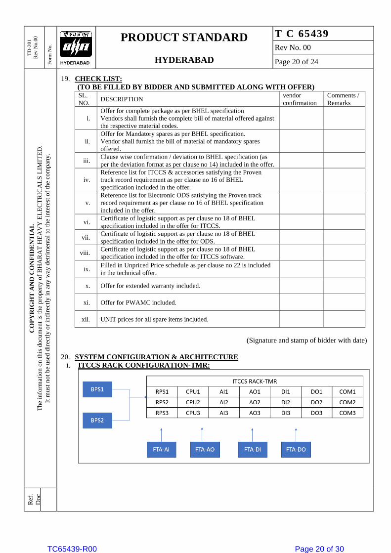
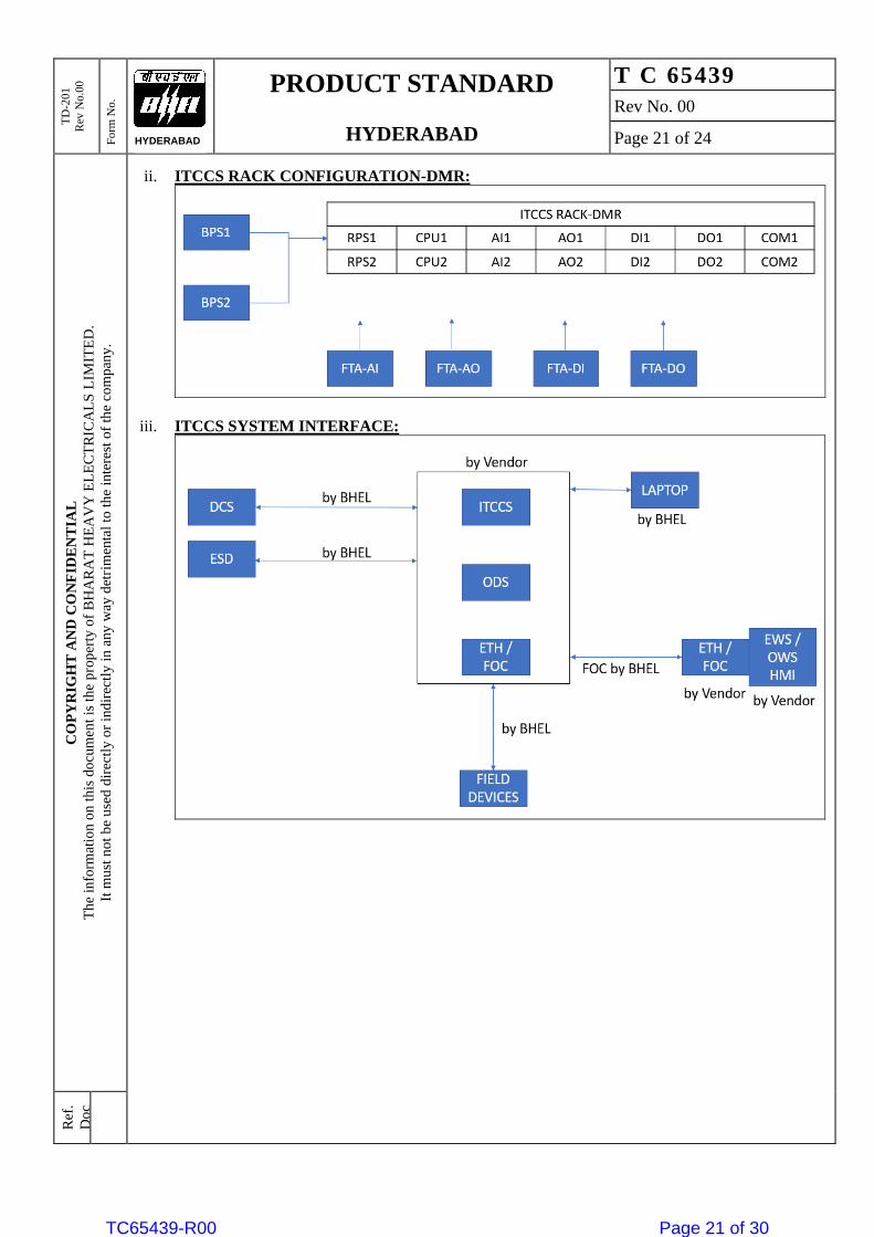
20. SYSTEM CONFIGURATION & ARCHITECTURE
i. ITCCS RACK CONFIGURATION-TMR:
TC65439-R00 Page 20 of 30
TD
-201
Rev
No.0
0
Fo
rm N
o.
PRODUCT STANDARD
HYDERABAD
T C 65439
Rev No. 00
Page 21 of 24
CO
PY
RIG
HT
AN
D C
ON
FID
EN
TIA
L
Th
e in
form
atio
n o
n t
his
do
cum
ent
is t
he
pr o
per
ty o
f B
HA
RA
T H
EA
VY
EL
EC
TR
ICA
LS
LIM
ITE
D.
It m
ust
no
t b
e u
sed
dir
ectl
y o
r in
dir
ectl
y i
n a
ny
way
det
r im
enta
l to
th
e in
tere
st o
f th
e co
mp
any
.
Ref
.
Do
c
HYDERABAD
ii. ITCCS RACK CONFIGURATION-DMR:
iii. ITCCS SYSTEM INTERFACE:
TC65439-R00 Page 21 of 30
TD
-201
Rev
No.0
0
Fo
rm N
o.
PRODUCT STANDARD
HYDERABAD
T C 65439
Rev No. 00
Page 22 of 24
CO
PY
RIG
HT
AN
D C
ON
FID
EN
TIA
L
Th
e in
form
atio
n o
n t
his
do
cum
ent
is t
he
pr o
per
ty o
f B
HA
RA
T H
EA
VY
EL
EC
TR
ICA
LS
LIM
ITE
D.
It m
ust
no
t b
e u
sed
dir
ectl
y o
r in
dir
ectl
y i
n a
ny
way
det
r im
enta
l to
th
e in
tere
st o
f th
e co
mp
any
.
Ref
.
Do
c
HYDERABAD
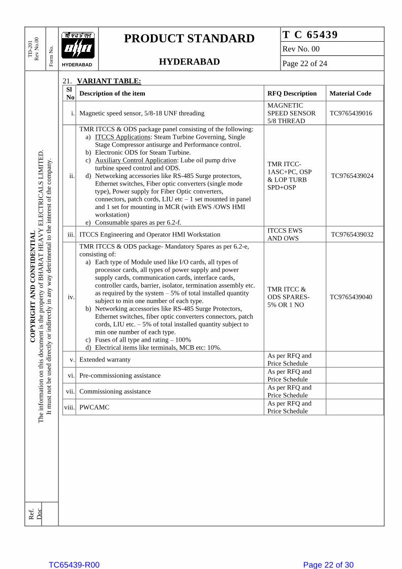
21. VARIANT TABLE: Sl
No Description of the item RFQ Description Material Code
i. Magnetic speed sensor, 5/8-18 UNF threading
MAGNETIC
SPEED SENSOR
5/8 THREAD
TC9765439016
ii.
TMR ITCCS & ODS package panel consisting of the following:
a) ITCCS Applications: Steam Turbine Governing, Single
Stage Compressor antisurge and Performance control.
b) Electronic ODS for Steam Turbine.
c) Auxiliary Control Application: Lube oil pump drive
turbine speed control and ODS.
d) Networking accessories like RS-485 Surge protectors,
Ethernet switches, Fiber optic converters (single mode
type), Power supply for Fiber Optic converters,
connectors, patch cords, LIU etc – 1 set mounted in panel
and 1 set for mounting in MCR (with EWS /OWS HMI
workstation)
e) Consumable spares as per 6.2-f.
TMR ITCC-
1ASC+PC, OSP
& LOP TURB
SPD+OSP
TC9765439024
iii. ITCCS Engineering and Operator HMI Workstation ITCCS EWS
AND OWS TC9765439032
iv.
TMR ITCCS & ODS package- Mandatory Spares as per 6.2-e,
consisting of:
a) Each type of Module used like I/O cards, all types of
processor cards, all types of power supply and power
supply cards, communication cards, interface cards,
controller cards, barrier, isolator, termination assembly etc.
as required by the system – 5% of total installed quantity
subject to min one number of each type.
b) Networking accessories like RS-485 Surge Protectors,
Ethernet switches, fiber optic converters connectors, patch
cords, LIU etc. – 5% of total installed quantity subject to
min one number of each type.
c) Fuses of all type and rating – 100%
d) Electrical items like terminals, MCB etc: 10%.
TMR ITCC &
ODS SPARES-
5% OR 1 NO
TC9765439040
v. Extended warranty As per RFQ and
Price Schedule
vi. Pre-commissioning assistance As per RFQ and
Price Schedule
vii. Commissioning assistance As per RFQ and
Price Schedule
viii. PWCAMC As per RFQ and
Price Schedule
TC65439-R00 Page 22 of 30
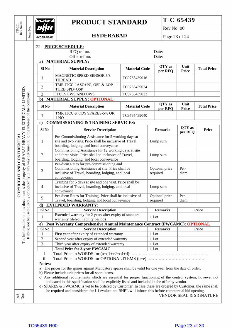
TD
-201
Rev
No.0
0
Fo
rm N
o.
PRODUCT STANDARD
HYDERABAD
T C 65439
Rev No. 00
Page 23 of 24
CO
PY
RIG
HT
AN
D C
ON
FID
EN
TIA
L
Th
e in
form
atio
n o
n t
his
do
cum
ent
is t
he
pr o
per
ty o
f B
HA
RA
T H
EA
VY
EL
EC
TR
ICA
LS
LIM
ITE
D.
It m
ust
no
t b
e u
sed
dir
ectl
y o
r in
dir
ectl
y i
n a
ny
way
det
r im
enta
l to
th
e in
tere
st o
f th
e co
mp
any
.
Ref
.
Do
c
HYDERABAD
22. PRICE SCHEDULE:
RFQ ref no. Date:
Offer ref no. Date:
a) MATERIAL SUPPLY:
Sl No Material Description Material Code QTY as
per RFQ
Unit
Price Total Price
1 MAGNETIC SPEED SENSOR 5/8
THREAD TC9765439016
2 TMR ITCC-1ASC+PC, OSP & LOP
TURB SPD+OSP TC9765439024
3 ITCCS EWS AND OWS TC9765439032
b) MATERIAL SUPPLY: OPTIONAL
Sl No Material Description Material Code QTY as
per RFQ
Unit
Price Total Price
1 TMR ITCC & ODS SPARES-5% OR
1 NO TC9765439040
c) COMMISSIONING & TRAINING SERVICES:
Sl No Service Description Remarks QTY as
per RFQ Price
1
Pre-Commissioning Assistance for 5 working days at
site and two visits. Price shall be inclusive of Travel,
boarding, lodging, and local conveyance
Lump sum
2
Commissioning Assistance for 12 working days at site
and three visits. Price shall be inclusive of Travel,
boarding, lodging, and local conveyance
Lump sum
3
Per-diem Rates for pre-commissioning and
Commissioning Assistance at site. Price shall be
inclusive of Travel, boarding, lodging, and local
conveyance
Optional price
required
Per-
diem
4
Training for 5 days at site and one visit. Price shall be
inclusive of Travel, boarding, lodging, and local
conveyance
Lump sum
5 Per-diem Rates for Training. Price shall be inclusive of
Travel, boarding, lodging, and local conveyance
Optional price
required
Per-
diem
d) EXTENDED WARRANTY: Sl No Service Description Remarks Price
1 Extended warranty for 2 years after expiry of standard
warranty (defect liability period) 1 Lot
e) Post Warranty Comprehensive Annual Maintenance Contract (PWCAMC): OPTIONAL
Sl No Service Description Remarks Price
1 First year after expiry of extended warranty 1 Lot
2 Second year after expiry of extended warranty 1 Lot
3 Third year after expiry of extended warranty 1 Lot
Total Price for 3-year PWCAMC 1 Lot
i. Total Price in WORDS for (a+c1+c2+c4+d): ………………………………………………
ii. Total Price in WORDS for OPTIONAL ITEMS (b+e): ………………………………….
Notes: a) The prices for the spares against Mandatory spares shall be valid for one year from the date of order.
b) Please include unit prices for all spare items.
c) Any additional requirements which are essential for proper functioning of the control system, however not
indicated in this specification shall be explicitly listed and included in the offer by vendor.
d) SPARES & PWCAMC is yet to be ordered by Customer. In case these are ordered by Customer, the same shall
be required and considered for L1 evaluation. BHEL will inform this before commercial bid opening.
VENDOR SEAL & SIGNATURE
TC65439-R00 Page 23 of 30
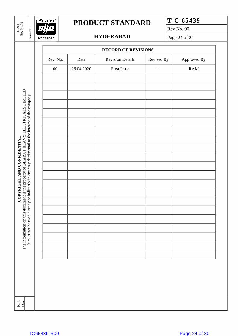
TD
-201
Rev
No.0
0
Fo
rm N
o.
PRODUCT STANDARD
HYDERABAD
T C 65439
Rev No. 00
Page 24 of 24
CO
PY
RIG
HT
AN
D C
ON
FID
EN
TIA
L
Th
e in
form
atio
n o
n t
his
do
cum
ent
is t
he
pr o
per
ty o
f B
HA
RA
T H
EA
VY
EL
EC
TR
ICA
LS
LIM
ITE
D.
It m
ust
no
t b
e u
sed
dir
ectl
y o
r in
dir
ectl
y i
n a
ny
way
det
r im
enta
l to
th
e in
tere
st o
f th
e co
mp
any
.
Ref
.
Do
c
HYDERABAD
RECORD OF REVISIONS
Rev. No. Date Revision Details Revised By Approved By
00 26.04.2020 First Issue ---- RAM
TC65439-R00 Page 24 of 30
STA
ND
AR
D SP
EC
IFIC
AT
ION
NO
.
6-81
-20
40
Rev
. 2
co
o
CI) rn 0-
INSP
EC
TIO
❑
J)
Rev
ised
and R
eis
sue
d
Issu
ed
for
imp
lem
enta
tion
a>
u) E
-o
(7)
a> a>
E ir> o c (-) o
o (z1 c.) -o c
U)
.o
a>
2
Copy
righ
t EIL
— A
ll r
ights
rese
rve
d
22.0
3.2
01
2
o
IC C1
Form
at N
o. 8
-00
-0001-F
7 R
ev.
0
Page 475 of 2764 TC65439-R00 Page 25 of 30
Co
pyr
igh
t EIL
— A
ll ri
ghts
re
serv
ed
For
mat
No. 8
-00-0
001
-F7
Re
v. 0
Ab
bre
via
tions
STA
ND
AR
D SP
EC
IFIC
AT
ION
NO
.
N a> cr> 10 a_
6-81
-204
0 R
ev. 2
o
-4-, W ...
CD
C.) CD
0 • ... -4-■ Ch
''''' N C.'-'3
. -, 45cn
cn cb 0
;... cb bl) z; cli 0 1:".,
0 s..,
0 -.--, c..)- cb
c..) • --, cl>
cb .' C1-) ct P01 cu -,--, l■---2, 'rzs t)i) 1.) rz4 c_> 1-w tJ) Ci) • • (1..) (1) t11) CC! .11::: 1.) a)› • ,-1 -I-, .4:-1 .4 i•-• -1--, Cl:$ .2 .E c,:: v) o a> (,, o ri) (1.> ,--• t5 7)› CL) -1- Ci.) . Cf) b10
0 E oa, o c,1 ,... o .TQ
1.) E' !4' CD a) ,--, > CCI 0 "1:/ ,...,
-4-, i-. • 0..) = C..) 2D.0 0 1-, cz; ›, .i.: '' ,- • •-• +•.,
V) c) 0.> . L) 0 • •--. : ."(;)'
,i.... -o E o
cb cf) ru C> cl> s--, 4 cy C> c,z1 .4 ••■•-, ,92 C> 1--+ 6.,-) "-* C, ;•-■ c> -.) 0-■ 4,5 ,..,> Q C) E
C..) -4-- 4-' . ,.., r ccS « E ....,-, .-~c, c,:l • v).-■ cuv) --, v)C> ,,-, ,h(1.) cu .--Imi ••-•' CCSs.., c./1 • til.) cf) • ""
,,,; > ».. tc,J0 0 4 cb 1.) -^' • z: 0 cZt cL) -0 1.> rn $•-■ 0 • -, C>
" ~ 0 -7-■ C) -0 -0 ,.. - cn c> t25 C> (I) ° .4 .- ' •,--' - ",-,-, ,-,7z$ :-Es •':. -.. ;-. ,... -e c
cl .) ci) • . -' -4. -, cl. .) CL) 0
0 ...0
Z Z Z /..■ r=k-, P. P-4 P--, CY v1HH >33v
H g.. H :-.
E" F--4 L) L) ) E" 9 4 o 4 un CD' g.4., ,=, 1:: C) :1.-, 4 C) u4 C,' 4 F.-, L) E. un c...) 4., E--4 4 C.- F-',-." P.7' .4
Z Z Z a., a... rzi.., rzL., a., a., CY r4 un E-. E-. :D >' o a.) 5" 1..,
Z a .>
rz..,
E >,..C.. cz: ,- 4:
,:s CZt tn.
o E .-
.- CZ
E a.>
o. -o o o ...o
a> o o- .- ;... a> ;... o
a> a> "cA' w E c'z o v,
.7.: a>
'-g rz4 o cts
E $... ..-. Q1 .- c,z c..> a.> o
•
c>
tzi F!.... o .-, ;... o
0 -4-,› (...) E E • .. J.,) (/) CZ i•2•4 5. Ci) E .,
..o
,,zt .-.,.; ,i.) -,,; o > +6> r..) c. _,) • - ..., . ,... - , ... cn <I.> ,.., r=4 Cci C> • •-, ,y, Cc> C.> cct
•
• ,-. >C $-■ • 1DI) E-4 "r.) a.) 0,..., o , .- cu
E-■ ... cz: u4 6L) 5. "Fi '""' ... -.'
a> c7,), ,...., .) b/0 ed V)
▪
0.) 3-■ 3-; 0 • ~
•
0 0-) ti) e t,,,) th,) Ha-) 8 5. c,:: ,..> -c-,,t g - u, cu T__,- Hc> •,7") &.) > ._ .)
o ›. a> a> a.> ,.,...CL) .-C~C3 s...fj Ij cii LI4 '45 CE' 4
•
- C':
.-E)
•
.4,.. . ,... "~ H. +-■ i_r_, o -0 c) = s-, O -0 C1> C> +e)
• L.T4 -r) .,..c.) 0 #1 2 I u4 7.) R. ,i.) ,.,.. +.• .._,
▪
0 ,,,,.
.-., ,,..) i... ,,, _, o ▪ ,,
v) >, -5 ".> cu CZt • "-' tz!'
... ch • -c, -
cu ,... '1.' P. P-, ,._,-, , .2 E = ,4 a> a> a> E., •-• -
`,,'', >, eL) c-) c, ,)„, ,.0 ... .3, A 0 .4=' E ,1). . 2 f -2 ._
▪
,,, 0 •- .7, "I' .;,:l. P:1 C..) C) C..) C....) C:: F.4 ..r: 2 '..T.: A 4a> E 25-..cr Ec ti) ce ,-, ,..
,.. 0.) Cl> cb b1) cn
. .C7CP c'C
"CS k."> ?e" ce
w = -o
CD ce < c..) H r_T, c..) a. = ;... w s- c4 1 ■ o o :... w o
;-. 4 ,-, E--( .....
-4,,, = cu W 5. o H, ,4 OL-■ P.-■ C_) C....) E~ c:u > E cip ..,"/: ,?2. L) W' ., W t-1-4 F-■ rzi.., c.) ,-
<r=C Q(.....)(-)(...:(=-)CWW.Ww E-■ a., C...) W L.2,4 ° cl.
.-1 z
•
a> o Z 0 •-■ (..)
Page 476 of 2764 TC65439-R00 Page 26 of 30
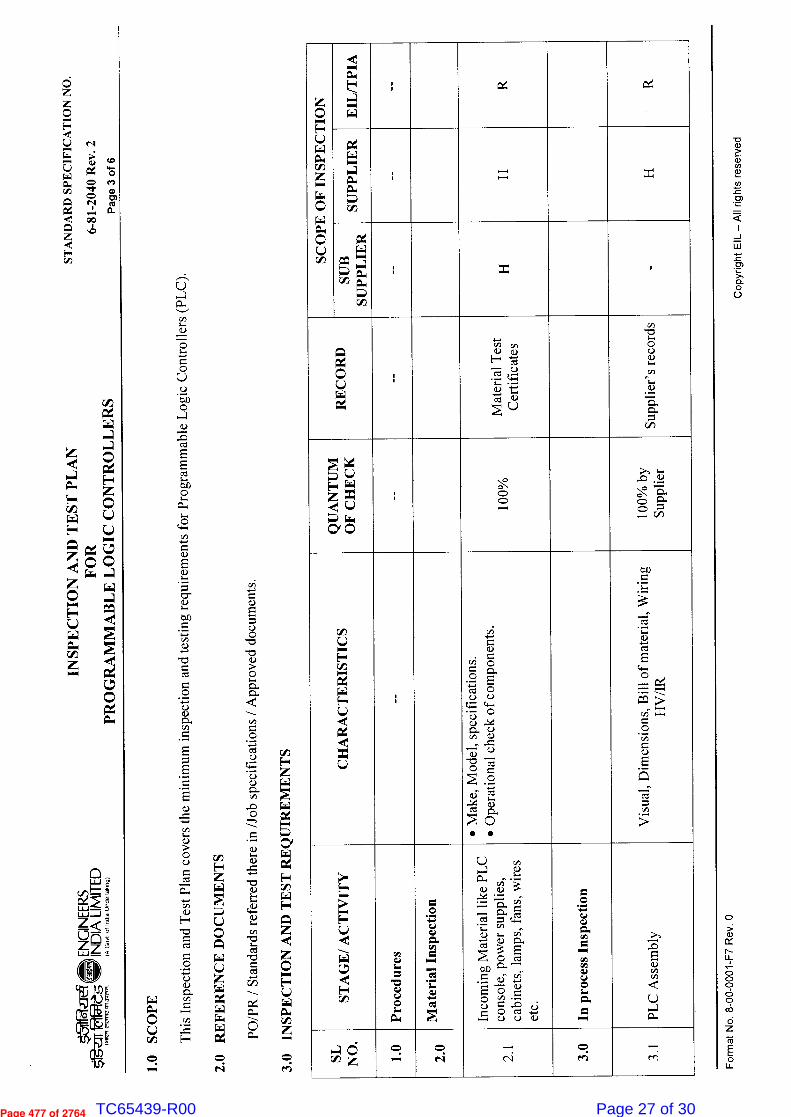
STA
ND
AR
D S
PE
CIF
ICA
TIO
N N
O.
6-81
-2040 R
ev. 2
c.)
z z
E4
Qwâ
(:)
0.4
z O C.7
0.1
1.0 SC
OP
E
ci) H z
z
O
PO
/PR
/ S
tan
dard
s re
ferr
ed th
ere
in /
Job
spec
ific
atio
ns /
App
rove
d do
cum
ents
.
3.0
IN
SPE
CT
ION
AN
D T
EST
RE
QU
IRE
ME
NT
S
Co
pyr
ight E
IL —
All
rig
hts
re
serv
ed
For
mat N
o.
8-0
0-0
001-F
7 Rev
. 0
SCO
PE
OF
INS
PE
CT
ION
d ,-, o. a ,-, w
i tx
SU
PP
LIE
R
x
SU
B
SU
PPL
IER
x
R o L,) .
Mat
eria
l Tes
t C
erti
fica
tes
Sup
plie
r's
reco
rds
QU
AN
TU
M
OF
CH
EC
K
,:- . . ,_.
100%
by
Sup
plie
r
CH
AR
AC
TE
RIS
TIC
S
•
Mak
e, M
ode
l, sp
ecif
icat
ions
.
•
Ope
rati
onal
che
ck o
f co
mpo
nent
s.
Vis
ual,
Dim
ensi
ons,
Bil
l of
mat
eria
l, W
irin
g H
V/I
R
ST
AG
E/ A
CT
IVIT
Y
Pro
ced
ure
s
Mat
erial In
spec
tion
Inco
min
g M
ater
ial li
ke P
LC
co
nso
le, p
ower
sup
pli
es,
ac
bin
ets,
lam
ps, f
ans,
wir
es
etc.
In p
roce
ss I
nsp
ecti
on
PL
C A
ssem
bly
4 C3 z z
c::, -
c::, r,i
.- -
c■i c= efi
— rn
Page 477 of 2764 TC65439-R00 Page 27 of 30
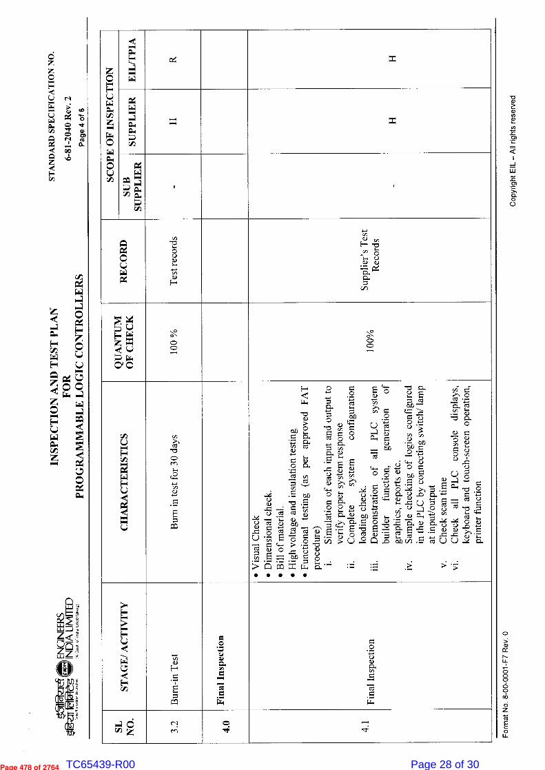
6-81
-20
40
Rev
. 2
STA
ND
AR
D S
PEC
IFIC
AT
ION
NO
.
Copy
right E
IL —
All
rig
hts
res
erve
d F
orm
at N
o. 8
-00
-0001-F
7 R
ev.
0
SCO
PE
OF
INSP
EC
TIO
N
-eC ■—■ tso
■4 ■—■ W
SUPP
LIE
R
SUB
SU
PPL
IER
. .
0 L.)
Tes
t rec
ords
R CA
v)
c,
-■ r-,) ell ci,)
:J.~.. $:1. S:L
CI)
QU
AN
TU
M
OF
CH
EC
K
0 o --,
C> C>
CH
AR
AC
TE
RIS
TIC
S
Bur
n in
test
for
30
days
F-4 <
b/) ;,_, , cL,
-4-, 0. CA CC2
4
C.)'''
9. '='-' ccl cn c'd v)
..- •E ba C.)
'4 rA e..) CC: CZ1
,-- ' Z..
9 el a.) u, ,_ 0 Ck: ,,.., C.0
C.) ' ''' E — e_ ,0 o c'zt 6:.> b- "- -4— = c-> v) -- >L1G1xw
CD
,g -2,
o 1474,
0 cz! o c.) .4" Cl.
$:14 (1)
.E '..' .... _E ,5 4_,a> L. -4-, ,,, (,) >, a> ›-, ,,, c.. cn o '-' CU
(0 0 CD ..--, Lo -I...,
4.'eCj i°". C1) , ,, cl., . ~ ,-,
a> E ,:: '-' • - a> o
,., cip > c.) r> o
5:1. "— :=
..-
,n.., ..)
E ,,,,.; ci.. a> - L) E
C>
0 -4--. C-) t-':1 C.) '''
CF). p.., v) v, c>
Cl> • ,... bA 'Ij'
o ..,;_-; c,d c>
- c■-■ cl.) ,,--• - 2 o 0 c9 ev) 8
-••:-; .(Ê . c, • — o
c.> o. <-) .0 (L)
C...)
C) ''' '' C") ■-.) Ch CA
eV) C. 0 CL) P-, 0 0.) 2 -r,„ ,
Zt
:. ,-, •,- cd ••-, 0.) ,.., ocs
— C1 .sz, b.1) C/D . -.
.— . >:
,,,'" >-, o
-0 CL, 0
CL) -6 1->
CA ° C,.)
o v) c>
c..> c) ,; cu 4 ..,
." E r-%-•
.- -o o
o., -.-' .•1"
c.,: •"•...
° C..) "C$
$,., "0
`" czl ;„
$,,, ,-- ,-- o ,
<-> C..) ..0 .y-,
•- CL) CL) ›^,
,-c ,. • ir.: c (-) (-) -- Q.
• —
STA
GE
/ AC
TIV
ITY
Bur
n-in
Tes
t
Fin
al I
nspe
ctio
n c o • — c.5 o.> cl.
—c7c1 E— .1-■
Ci z z cl en
c::, •i:
_. .1:
Page 478 of 2764 TC65439-R00 Page 28 of 30
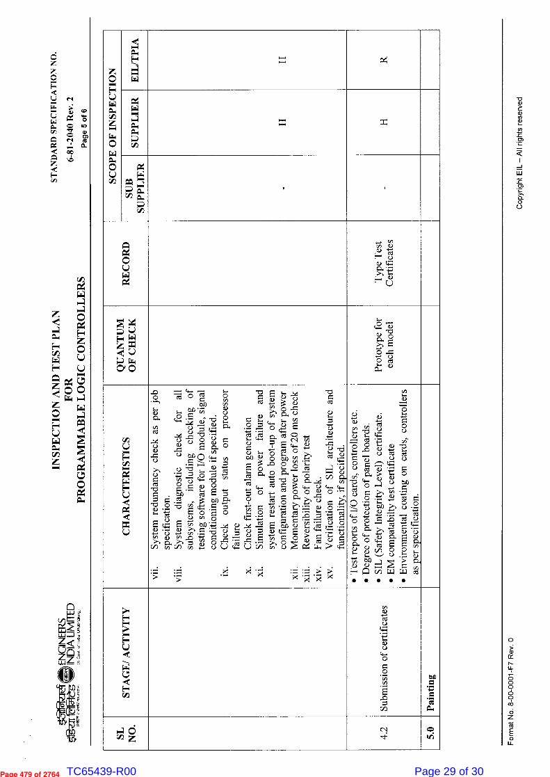
6-8
1-2
040
Rev
. 2
STA
ND
AR
D S
PE
CIF
ICA
TIO
N N
O.
Cop
yrigh
t EIL
— A
ll rig
hts
rese
rved
F
orm
at N
o. 8
-00-
0001
-F7 Rev
. 0
SC
OP
E O
F IN
SP
EC
TIO
N
EIL
/TP
IA
SU
PP
LIE
R
SU
B
SU
PP
LIE
R
2 o c.)
Typ
e T
est
Cer
tifi
cate
s
QU
AN
TU
M
OF
CH
EC
K
Pro
toty
pe f
or
each
mod
el
CH
AR
AC
TE
RIS
TIC
S
vii.
Sys
tem
re
dund
ancy
che
ck a
s p
er j
ob
spec
ific
atio
n.
viii.
Sys
tem
di
agno
stic
c
heck
for a
ll su
bsys
tem
s,
incl
udin
g c
heck
ing o
f te
stin
g so
ftw
are
for
I/O
mo
dule
, sig
nal
cond
itio
nin
g m
odu
le i
f sp
ecif
ied.
ix
. C
heck
out
put s
tatu
s o
n p
roce
ssor
fa
ilur
e
x.
Che
ck f
irst
-out
ala
rm g
ener
atio
n
xi.
Sim
ulat
ion o
f p
ower
fa
ilur
e an
d sy
stem
res
tart
au
to b
oot-
up o
f sy
stem
co
nfig
urat
ion
and
prog
ram
aft
er p
ower
xii.
Mom
enta
ry p
ower
Los
s o
f 20
ms
chec
k
xiii.
Rev
ersi
bili
ty o
f p o
lari
ty tes
t
xiv.
Fan
fai
lure
che
ck.
xv.
Ver
ific
atio
n o
f S
IL a
rchi
tect
ure
an
d fu
ncti
onal
ity,
if s
ec i
fied
.
•
Tes
t rep
orts
of
I/O
car
ds, c
ont
roll
ers
etc.
•
Deg
ree
of
prot
ecti
on o
f pa
nel bo
ards
.
•
SIL
(S
afet
y In
tegr
ity
Lev
el) cert
ific
ate.
•
EM
com
pat
abil
ty tes
t cer
tifi
cate
•
Env
iron
men
tal
coat
ing
on
car
ds, c
on
tro
llers
as
per
sp
ecif
icat
ion.
ST
AG
E/ A
CT
IVIT
Y
Sub
mis
sion
of
cert
ific
ates
Pai
nti
ng
C:5 wp cv 4 5.
0
Page 479 of 2764 TC65439-R00 Page 29 of 30
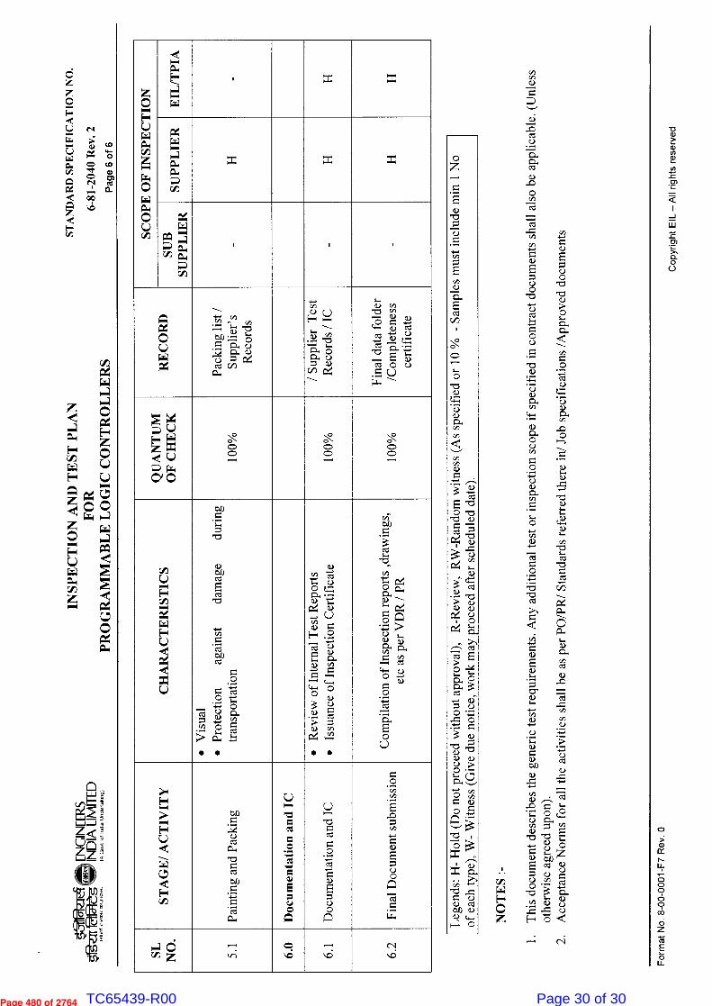
Z <
Wzâ
STA
ND
AR
D S
PE
CIF
ICA
TIO
N N
O.
to
4.6 co
O) Q.
6-81
-2040 R
ev. 2
SCO
PE
OF
INSP
EC
TIO
N
d •-, 01.4
4 •• W
SUP
PL
IER
Z
SUB
SU
PP
LIE
R
,
R L.)
Pac
kin
g lis
t /
Supp
lier
' s
Rec
or d
s
/ S
up
pli
er T
est
R
ecord
s / IC
Fin
al dat
a fo
lder
/C
om
ple
ten
ess
cert
ific
ate
QU
AN
TU
M
OF
CH
EC
K
. . ,_. . . . . ,...
CH
AR
AC
TE
RIS
TIC
S
•
Vis
ual
•
Pro
tect
ion
agai
nst
d
amag
e duri
ng
tran
sport
atio
n
•
Rev
iew
of
Inte
rnal
Tes
t R
epor
ts
•
Issu
ance
of
Insp
ecti
on C
erti
fica
te
Com
pil
atio
n o
f In
spec
tion
rep
ort
s ,d
raw
ing
s,
etc
as p
er V
DR
/ P
R
ST
AG
E/ A
CT
IVIT
Y
Pain
ting
an
d Pa
ckin
g
Doc
umen
tati
on a
nd
IC
Do
cum
enta
tion
and
IC
Fin
al D
ocu
men
t su
bm
issi
on
C3 cip z .— L.-;
o vi
—. ,.6
c-v ■il:;
-0 0
aal
-a-d— .4 v) e,
5 v) -5
a> E a>
E c> o
c> .io 0 -11:3 -0 o >) cct 0 • Cl
▪
.. CS CL, c> < ...
•
r Ê -e 0 ci.>: .- 4-.., c•il • (> c> a> O. c> v, a>
c...
• 0 o ...., cn '---. CS C>
. --, ..«. ;-.. +C> C> • --9,
;-. (4.C>
-4-..
Cop
yrig
ht E
IL —
All
right
s re
serv
ed
Form
at N
o. 8
-00-
0001
-F7 Rev
. 0
Page 480 of 2764 TC65439-R00 Page 30 of 30


![CATALOG MINIDOCK STANDARD TC - I-PEX · 2020. 8. 3. · MINIDOCK®STANDARD Component Parts Detail [ i-pex.com ] 202008R0 Plug Assembly :](https://img.pdfslide.net/doc/110x75/5fdfca9a01b64e236e4d59d5/catalog-minidock-standard-tc-i-pex-2020-8-3-minidockstandard-component.jpg)