Embed Size (px)
Citation preview

Copyright 2006 Carrier Corporation Form 50H-1PD
High-Efficiency (HE, HJ) units wellexceed ASHRAE 90.1 energy effi-ciency standards. Electric heating with electric cooling rooftop units offer:• A wide assortment of factory-
installed options available, including high static drives that provide additional performance range
• Optional factory-installed COBRA™ energy recovery unit (option on 50HE003-007 and 50HJ004-014 units only)
• Factory-installed PremierLink™digital communicating controls
• Factory-installed optional gear driven EconoMi$er IV (vertical return for sizes 003-012 only) for use with standard rooftop unit con-trols (includes CO2 sensor control capability)
• Factory-installed optional gear driven EconoMi$er2 for use with PremierLink DDC controls (includes 4 to 20 mA actuator for demand control ventilation
• Humidi-MiZer™ adaptive dehumidi-fication system (50HE003-006 and 50HJ004-014 only)
WEATHERMASTER® 50HE003-00650HJ004-028
Single-Package Rooftop UnitsElectric Heating/Electric Cooling
2 to 25 Nominal Tons
ProductData
50HJ008-014
50HJ015,017
50HJ020-028
50HE003-00650HJ004-007

2
Features/BenefitsEvery compact one-piece unit arrives fully assembled, charged, tested, and ready to run.Quiet, efficient operation and dependable performanceCompressors have vibration isolators for quiet operation. Efficient fan and motor design permits operation at low sound levels.
Unit sizes 008-028 offer lower utility costs through part-load operation using 2 or 3 stages of cooling.
Quiet and efficient operation is provid-ed by belt-driven evaporator fans (stan-dard on all units over 5 tons). The belt-driven evaporator-fan is equipped with variable-pitch pulleys which allow adjust-ment within the rpm ranges of the factory-supplied pulleys.
Increased operating efficiency is achieved through computer-designed coils featuring staggered internally enhanced copper tubes. Fins are ripple-edged for strength, lanced, and double waved for higher heat transfer.
Durable, dependable constructionDesigned for durability in any climate, the weather-resistant cabinets areconstructed of galvanized steel and bond-
erized, and all exterior panels are coated with a prepainted baked enamel finish. The paint finish is non-chalking, and is capable of withstanding ASTM (Ameri-can Society for Testing andMaterials) B117 500-hour Salt Spray Test. All internal cabinet panels are primed, permitting longer life and a more attractive appearance for theentire unit.
In addition, all size 003-014 units are designed with a single, continuous top piece to eliminate any possible leaks at seams or gasketing. Totally enclosed con-denser-fan motors and permanently lubri-cated bearings provide additional unit de-pendability.Easy installation and conversionAll units are shipped in the vertical duct configuration for fit-up to standard roof curbs. The contractor can order and install the roof curb early in the construc-tion stage, before decisions on size re-quirements are made.
All units feature a base rail design with forklift slots and rigging holes for easier maneuvering. Durable packaging pro-tects all units during shipment and stor-age.
The units can be easily converted from a vertical to a horizontal duct configura-tion by relocating the panels
supplied with the unit (sizes 003-014 only).To convert size 003-014 units from verti-cal to horizontal discharge, simply relo-cate 2 panels. The same basic unit can be used for a variety of applications and can be quickly modified at the jobsite.To convert size 015-028 units from verti-cal to horizontal discharge, use the op-tional horizontal supply/return adapter roof curb (50HJ015-017) or accessory conversion kit (020-028).Convenient duct openings in the unit basepans permit side-by-side or concen-tric duct connections (seeApplication data section) without requir-ing internal unit modification.NOTE: On units using horizontal sup-ply and return, the accessory barometric relief or power exhaust MUST be installed on the return ductwork.Thru-the-bottom service connection ca-pability comes standard with the rooftop unit to allow power and control wiring to be routed through the unit’s basepan, minimizing roof penetrations (003-014 units requier a thru-the-bottom accessory kit to prevent water leaks). Power and control connections are made on the same side of the unit to simplify installation.The non-corrosive sloped condensate drain pan (size 003-014) permits either an external horizontal side
Table of contentsPage
Features/Benefits . . . . . . . . . . . . . . . . . . . . . . . . . . . . . . . . . . . . . . . . . . . . . . . . .2-4Model Number Nomenclature. . . . . . . . . . . . . . . . . . . . . . . . . . . . . . . . . . . . . . .5-8ARI Capacity Ratings . . . . . . . . . . . . . . . . . . . . . . . . . . . . . . . . . . . . . . . . . . . 9, 10Options and Accessories . . . . . . . . . . . . . . . . . . . . . . . . . . . . . . . . . . . . . . . . .19-2750HE, HJPhysical Data . . . . . . . . . . . . . . . . . . . . . . . . . . . . . . . . . . . . . . . . . . . . . . . . . . .11-18Base Unit Dimensions . . . . . . . . . . . . . . . . . . . . . . . . . . . . . . . . . . . . . . . . . . . .28-36Accessory Dimensions . . . . . . . . . . . . . . . . . . . . . . . . . . . . . . . . . . . . . . . . . . . .37-44Selection Procedure . . . . . . . . . . . . . . . . . . . . . . . . . . . . . . . . . . . . . . . . . . . . . 45, 46Performance Data. . . . . . . . . . . . . . . . . . . . . . . . . . . . . . . . . . . . . . . . . . . . . . .47-116Electrical Data . . . . . . . . . . . . . . . . . . . . . . . . . . . . . . . . . . . . . . . . . . . . . . . .117-165Typical Wiring Schematics. . . . . . . . . . . . . . . . . . . . . . . . . . . . . . . . . . . . . . .166-181Typical Piping and Wiring . . . . . . . . . . . . . . . . . . . . . . . . . . . . . . . . . . . . . . 182, 183Guide Specifications . . . . . . . . . . . . . . . . . . . . . . . . . . . . . . . . . . . . . . . . . . .201-234Controls. . . . . . . . . . . . . . . . . . . . . . . . . . . . . . . . . . . . . . . . . . . . . . . . . . . . .184-195Application Data. . . . . . . . . . . . . . . . . . . . . . . . . . . . . . . . . . . . . . . . . . . . . .196-200Index . . . . . . . . . . . . . . . . . . . . . . . . . . . . . . . . . . . . . . . . . . . . . . . . . . . . . . . . . . 235

3
condensate drain (outside the roof curb) or an internal vertical bottom drain (inside the roof curb). Both options require an external, field-supplied P-trap.Standard 2-in. throwaway filters are easily accessed through a removable pan-el located above the air intake hood. No tools are required to change unit filters.Belt-driven evaporator-fan motors al-low maximum on-site flexibility without changing motors or drives.Field-installed accessory electric heat-ers are available in a wide range of capac-ities. An available single-point wiring kit makes installation simple.Low voltage wiring connections are eas-ily made thanks to the large terminal board which is located for quick, conve-nient access.
In addition, color-coded wires permit easy tracing and diagnostics.
Proven compressor reliabilityDesign techniques feature computer-pro-grammed balance between compressor, condenser, and evaporator. Carrier-speci-fied hermetic compressors are equipped with compressor overcurrent and over-temperature protection to ensure depend-ability.
All units have Carrier’s exclusiveAcutrol™ (003-014) or TXV (thermostat-ic expansion valve) metering device (015-028) which precisely controls refrigerant flow, preventing slugging and flood-back, while maintaining optimum unit perfor-mance. Refrigerant filter driers are stan-dard.
Integrated economizers and out-door-air dampersAvailable as options or accessories, econ-omizers and manual outdoor-air dampers introduce outdoor air which mixes with the conditioned air, improving indoor-air quality and often reducing energy con-sumption.
During a first stage call for cooling, if the outdoor-air temperature is below the economizer control changeover set point, the mixed-air sensor modulates the economizer outdoor-air damper open to take advantage of free cooling provided by the outside air. When second-stage cooling is called for, the compressor is en-ergized in addition to the economizer. If the outdoor-air temperature is above the changeover set point, the first stage of compression is activated and the econ-omizer damper stays at minimum posi-tion.
Accessory upgrade kits allow for control by differential dry-bulb tempera-
ture (outdoor vs return), outdoor air en-thalpy changeover, or more precise differ-ential enthalpy control.
Units can be equipped with different economizer options to meet specific con-trols applications. The factory-installed or field-installed EconoMi$er IV and EconoMi$er2 are available. The EconoMi$er IV is used with the standard rooftop unit controls and includes an in-dustry standard, stand-alone,solid-state control. The control can be used with a CO2 sensor for DCV (demand control ventilation) operation. For direct digital control (DDC) applications, the EconoMi$er2 can be operated using Pre-mierLink™ controls or a third party con-troller. The EconoMi$er2 includes 4 to 20 mA actuator capability for demand con-trol ventilation applications.
All economizers incorporate a parallel blade, gear-driven damper system for effi-cient air mixing and reliablecontrol. In addition, the standard damper actuator includes a springreturn to provide reliable closure on pow-er loss. The economizers for sizes 003-014 are equipped with up to 100% baro-metric relief capability for high outdoor airflow operations. Economizers for unit sizes 003-014 are available, factory-in-stalled, for vertical return only. Economiz-ers for unit sizes 015-028 are compatible for vertical or horizontal return. An op-tional field-installed barometric relief package is available for 015-028 size units.
In addition, single-stage power exhaust is available as a field-installed accessory for EconoMi$er IV to help maintain proper building pressure.
For units without economizer, year-round ventilation is enhanced by a manual outdoor-air damper. On size 003-014 units, a 25% or 50% manual damper is available as a field-installed accessory. Unit sizes 015-028 are equipped with a manual 25% damper.
Service optionsServicing a rooftop unit has never been easier with the new factory- installed ser-vice options for these rooftop units. These options include the following:• Hinged access panels are provided for
the filter/indoor-fan motor, compres-sors, evaporator fan, and control box areas. Quick access to major compo-nents is accomplished by simply unlatching and swinging open the vari-ous panels. Each hinged panel is per-manently mounted to the unit, thereby eliminating the concern of a dropped or wind-blown panel puncturing deli-cate roof materials. The 4 extended access panels are also equipped with ‘‘tie back’’ retaining devices to hold
the door in the open position while ser-vicing the unit.
• An external, covered, 115-v Ground Fault Interrupt (GFI) receptacle is pro-vided as a convenient power source for drills, lights, refrigerant recovery units, or other electrical service tools. A fac-tory-supplied step down transformer is connected to the “load” side of the unit main power connection (size 003-014). For sizes 015-028, connect the outlet to a field-supplied and properly fused branch circuit power supply.
• Slide out “motor-drive-blower”reduces service time (only on 50HJ017).
• An integral non-fused disconnect switch within the rooftop unit reduces installation time, labor and material costs. Safety is assured by an interlock which prevents access to the control box unless the switch is in the OFF position. In addition, the externally mounted handle incorporates power lockout capability to further protect service personnel.
Carrier PremierLink™ controls add reliability, efficiency, and sim-plificationThe PremierLink direct digital controls can be ordered as a factory-installed op-tion (003-014 only) or as a field-installed accessory (003-028). Designed and man-ufactured exclusively by Carrier, the con-trols can be used to actively monitor and control all modes of operations, as well as monitor the following diagnostics and features: unit number, zone temperature, zone set point, zone humidity set point,discharge air temperatures, fan status, stages of heating, stages of cooling, damper position, outdoor-air tempera-ture, outdoor humidity level, filter status, fire shutdown status, IAQ (indoor air quality) set point, enthalpy status, differ-ential enthalpy status, heat/cool lockout, cfm set point, pre-occupancy purge, econ-omizer controls and early morning warm-up.
This controller has a 38.4K baud com-munications capability and is compatible with ComfortLink™ Controls, CCN (Car-rier Comfort Network®) and Comfort-VIEW™ Software. The Scrolling Mar-quee and Navigator™ device are optional tools that can be used for programming and monitoring the unit for optimal per-formance. The addition of the Carrier CO2 sensor in the conditioned space pro-vides ASHRAE 62.1 (American Society of Heating, Refrigeration and Air Condi-tioning Engineers) compliance and De-mand Control Ventilation.
The PremierLink™ peer-to-peer,Internet ready communicating control is

4
designed specifically for Constant Volume (CV) and Variable Volume and Tempera-ture (VVT®) applications. This compre-hensive controls system allows all Carrier rooftops with a 3-wire communication bus to be daisy chained together on a roof to create a fully functional HVAC (heating, ventilation, and air conditioning) automa-tion system.
Indoor-air quality begins with Car-rier rooftopsSloped condensate pans minimize biological growth in rooftop units inaccordance with ASHRAE Standard 62. Two-inch filters with optional dirty filter indicator switch provide for greater particle reduction in the return air. The face-split evaporator coils improve the dehumidification capability of standard units, maximize building hu-midity control.
Optional proportional reacting CO2 sensor is available with the EconoMi$er IV or EconoMi$er2 outdoor air damper option or accessory to aid the IAQ benefits.
Humidi-MiZer™ adaptive dehu-midification system (003-014)Carrier’s Humidi-MiZer adaptive dehu-midification system is an all-inclusive fac-tory-installed option that can be ordered with any Weathermaster® 50HE003-006 and 50HJ004-014 rooftop unit to meet the demand for providing a flexible and high performing solution to accommodate all of these design related issues. This system expands the envelope of operation of Car-rier’s Weathermaster 50HJ003-014 roof-top products to provide unprecedented flexibility to meet year round comfort conditions. The Humidi-MiZer adaptive dehumidification system has the indus-try’s only dual dehumidification mode set-
ting. The Humidi-MiZer system includes two new modes of operation. The Weath-ermaster rooftop coupled with the Humi-di-MiZer system is capable of operating in normal design cooling mode, subcooling mode, and hot gas reheat mode. Normal design cooling mode is when the unit willoperate under its normal sequence of oper-ation by cycling compressorsto maintain comfort conditions.Subcooling mode will operate to satisfy part load type conditions when the space requires combined sensible and a higher proportion of latent load control. Hot Gas Reheat mode will operate when outdoor temperatures diminish and the need for la-tent capacity is required for sole humidity control. Hot Gas Reheat mode will pro-vide neutral air for maximum dehumidifi-cation operation.
COBRA™ energy recovery units (50HE003-006 and 50HJ004-014 only)Carrier’s factory-installed optionalCOBRA units recover energy from the building exhaust air and precondition ventilation air for the rooftop unit during winter and summer operation. These units are designed to satisfy the higher ventila-tion requirements and other building codes while minimizing energy costs.
Factory installation of the 62AQ sec-tion provides the benefit of reduced field-installation time, single point power con-nections, and the assurance of a factory test for the complete COBRA unit. The COBRA energy recovery section re-quires less maintenance than other energy recovery systems and can be serviced by any qualified refrigeration technician.
The COBRA energy recovery units uti-lize Carrier’s high-efficiency 50HE003-006 or 50HJ004-014 rooftop units and
provide 2 to 121/2 tons of cooling capacity with the capability to pre-condition 600 to 3000 cfm of outdoor air.
Indoor-air quality (IAQ) generallyrefers to the level of pollutants inside a building. These pollutants include ciga-rette smoke, carbon dioxide exhaled by occupants, radon gas, car exhaust, paint fumes, and odors.
Concern over increased indoor air pol-lutants has been spurred by several issues: 1) changes in new building construction methods and retrofit of older buildings have reduced air infiltration rates; 2) Synthetic materials release airborne particles, odors, and chemicals; and 3) HVAC (heating, ventilation, and air conditioning) systems that bring in mini-mal fresh air.
In 1989, IAQ concerns caused ASHRAE to recommend increased venti-lation for all public buildings. Simply introducing fresh air into a build-ing, however, is not always practical or cost effective. Additional ven-tilation can overload HVAC systems and increase energy costs.
Carrier’s COBRA energy recovery unit solves this dilemma by providing in-creased fresh air while keeping increased costs to a minimum. In addition, the COBRA energy recovery unit helps reduce humidity levels, which helps to prevent deterioration of building materials and retards the growth of mold and mildew.
The COBRA energy recovery unit pro-vides the best solution to retaining the en-ergy-conserving benefits of today’s tight-er building construction while improving indoor-air quality.
Features/Benefits (cont)

5
50HE003-006
LEGEND
*Contact factory for availability and applications.†Refer to 50HJ Price Pages or contact your local Carrier
Representative for FIOP code table.
Al — AluminumCu — CopperDDC — Direct Digital ControlsFIOP — Factory-Installed OptionRTU — Rooftop Unit
50HE003-006 UNITS AREENERGY STAR QUALIFIED
Quality AssuranceCertified to ISO 9001:2000
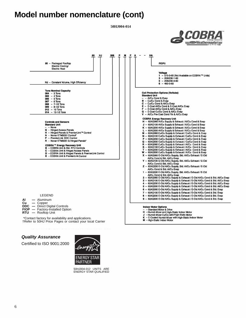
Model number nomenclature
6
50HJ004-014
Model number nomenclature (cont)
LEGEND
*Contact factory for availability and applications.†Refer to 50HJ Price Pages or contact your local Carrier
Al — AluminumCu — CopperDDC — Direct Digital ControlsFIOP — Factory-Installed OptionRTU — Rooftop Unit
50HJ004-012 UNITS AREENERGY STAR QUALIFIED
Quality AssuranceCertified to ISO 9001:2000

7
50HJ015,017
LEGEND
*Refer to 50HJ price pages or contactyour local Carrier representative forFIOP code table.
Al — AluminumCu — Copper
Quality AssuranceCertified to ISO 9001:2000
50HJ015-017 UNITS AREENERGY STAR QUALIFIED

8
Model number nomenclature (cont)
LEGENDAl — AluminumCu — CopperFIOP — Factory-Installed Option
*Refer to 50HJ price pages or contact your local Carrier representative for FIOP code table.
Quality AssuranceCertified to ISO 9001:2000
50HJ020-028
50HJ020-028 UNITS AREENERGY STAR QUALIFIED

9
ARI* CAPACITY RATINGS — 50HE003-006
LEGEND
*Air-Conditioning and Refrigeration Institute.†Applies only to units with capacity of 65,000 Btuh or less.**ARI does not require EER ratings for units with capacity below
65,000 Btuh. For these units, the EER rating at ARI Standard condi-tions is provided for information only.
††IPLV is not applicable to single-compressor units.NOTES:
1. Rated in accordance with ARI Standard 210-94 or 360-93.
2. Ratings are net values, reflecting the effects of circulating fan heat.Ratings are based on:
Cooling Standard: 80 F db, 67 wb indoor entering-air tempera-ture and 95 F db outdoor entering-air temperature.IPLV Standard: 80 F db, 67 F wb indoor entering-air temperatureand 80 F db outdoor entering-air temperature.
3. All 50HE and HJ units are in compliance with ASHRAE 90.1 2001Energy Standard for minimum SEER and EER requirements.Refer to state and local codes or visit the following website: http://bcap-energy.org to determine if compliance with this standard per-tains to a given geographical area of the United States.
ARI* CAPACITY RATINGS — 50HJ004-014
LEGEND
*Air-Conditioning and Refrigeration Institute.†Applies only to units with capacity of 65,000 Btuh or less.**ARI does not require EER ratings for units with capacity below
65,000 Btuh. For these units, the EER rating at ARI Standard condi-tions is provided for information only.
††IPLV is not applicable to single-compressor units.NOTES:
1. Rated in accordance with ARI Standard 210-94 or 360-93.
2. Ratings are net values, reflecting the effects of circulating fan heat.Ratings are based on:
Cooling Standard: 80 F db, 67 wb indoor entering-air tempera-ture and 95 F db outdoor entering-air temperature.IPLV Standard: 80 F db, 67 F wb indoor entering-air temperatureand 80 F db outdoor entering-air temperature.
3. All 50HE and HJ units are in compliance with ASHRAE 90.1 2001Energy Standard for minimum SEER and EER requirements.Refer to state and local codes or visit the following website: http://bcap-energy.org to determine if compliance with this standard per-tains to a given geographical area of the United States.
UNIT50HE
NOMINAL TONS
NET COOLING CAP (Btuh) SEER† EER CFM cfm/ton
SOUND RATING(decibels)
003 2 24,000 14.1 12.0 800 400 76004 3 36,200 14.0 11.8 1,200 400 76005 4 46,000 14.0 11.7 1,600 400 76006 5 59,000 14.0 11.9 1,750 350 80
EER — Energy Efficiency RatioIPLV — Integrated Part-Load ValueSEER — Seasonal Energy Efficiency Ratio
UNIT50HJ
NOMINALTONS
NET COOLING CAP(Btuh)
TOTALkW SEER† EER SOUND RATING
(decibels) IPLV††
004 3 36,000 3.2 13.0 11.2** 76 N/A005 4 46,000 4.1 13.0 11.1** 76 N/A006 5 61,000 5.5 13.0 11.0** 80 N/A007 6 73,000 6.7 — 11.1 80 N/A008 71/2 74,000 8.2 — 11.0 82 11.6009 81/2 104,000 8.8 — 11.8 82 13.1012 10 120,000 10.9 — 11.0 84 11.4014 121/2 140,000 14.3 — 9.8 86 10.5
EER — Energy Efficiency RatioIPLV — Integrated Part-Load ValueSEER — Seasonal Energy Efficiency Ratio
ARI* capacity ratings

10
ARI* CAPACITY RATINGS — 50HJ015,017
LEGEND
*Air Conditioning and Refrigeration Institute.NOTES:
1. Rated in accordance with ARI Standards 360-93 and 270-95.2. ARI ratings are net values, reflecting the effects of circulating fan
heat.
3. Ratings are based on:
Cooling Standard: 80 F db, 67 F wb indoor entering-air tempera-ture and 95 F db air entering outdoor unit.IPLV Standard: 80 F db, 67 F wb indoor entering-air temperatureand 80 F db outdoor entering-air temperature.
4. All 50HE and HJ units are in compliance with ASHRAE 90.1 2001Energy Standard for minimum SEER and EER requirements.Refer to state and local codes or visit the following website: http://bcap-energy.org to determine if compliance with this standard per-tains to a given geographical area of the United States.
ARI* CAPACITY RATINGS — 50HJ020-028
LEGEND
*Air Conditioning and Refrigeration Institute.†IPLV values are calculated based on control configuration T.CTL = 2 (2 Stage Y1).
**Size 028 unit is not listed with ARI, but is tested to ARI standards.
NOTES:1. Rated in accordance with ARI Standards 360-93 and 270-95.2. ARI ratings are net values, reflecting the effects of circulating fan
heat.
3. Ratings are based on:
Cooling Standard: 80 F db, 67 F wb indoor entering-air tempera-ture and 95 F db air entering outdoor unit.IPLV Standard: 80 F db, 67 F wb indoor entering-air temperatureand 80 F db outdoor entering-air temperature.
4. All 50HE and HJ units are in compliance with ASHRAE 90.1 2001Energy Standard for minimum EER requirements. Refer to stateand local codes or visit the following website: http://bcap-energy.org to determine if compliance with this standard pertainsto a given geographical area of the United States.
UNIT50HJ
NOMINALTONS
NET COOLINGCAPACITY
(Btuh)TOTALWATTS EER SOUND RATING
(decibels) IPLV
015 12 152,000 14,074 10.80 8.8 11.8017 15 176,000 16,296 10.80 8.8 11.7
db — Dry BulbEER — Energy Efficiency RatioIPLV — Integrated Part-Load Valueswb — Wet Bulb
UNIT50HJ
NOMINALTONS CFM NET COOLING
CAPACITY (Btuh)TOTAL
kW EER SOUND RATING(dB) IPLV†
020 18 5,500 200,000 18.5 10.8 81.7 12.0024 20 6,000 234,000 21.7 10.8 81.7 11.9028** 25 7,500 278,000 27.8 10.0 84.6 10.9
db — Dry BulbEER — Energy Efficiency RatioIPLV — Integrated Part-Load Valueswb — Wet Bulb
ARI* capacity ratings (cont)

11
LEGEND
*Single/three phase .
**Base unit weight does not include any options or accessaries. See Options andAccessary weight tables for additioinal weight information.
BASE UNIT 50HE 003 004 005 006 NOMINAL CAPACITY (tons) 2 3 4 5 OPERATING WEIGHT(lb) Base Unit** 435 445 465 635 COMPRESSOR Scroll Quantity 1 1 1 1 Oil (oz) 25 42 56 53 REFRIGERANT TYPE R-22Expansion Device Operating Charge (lb-oz)
Acutrol™ MeteringDevice
Standard Unit 5---3 7---11 8---8 12---11 Unit With Humidi-Mizer Adaptive Dehumidification System 10---2 14---0 14---13 21---0CONDENSER FAN Propeller Quantity...Diameter (in.) 1...22 1...22 1...22 1...22 Nominal Cfm 3000 3500 3500 4100 Motor Hp...Rpm 1/8...825 1/8...825 1/8...825 1/4...1100 Watts Input (Total) 180 180 180 320CONDENSER COIL Enhanced Copper Tubes, Aluminum LancedFins Rows...Fins/in. 1...17 1...17 2...17 2...17 Total Face Area (sq ft) 14.6 14.6 16.5 16.5EVAPORATOR COIL Enhanced Copper Tubes, Aluminum Double-Wavy Fins Standard Unit Rows...Fins/in. 2...15 2...15 2...15 4...15 Total Face Area (sq ft) 4.2 5.5 5.5 5.5 Humidi-Mizer Coil Adaptive Dehumidification System Rows...Fins/in. 1...17 1...17 2...17 2...17 Total Face Area (sq ft) 3.5 3.9 3.9 3.9EVAPORATOR FAN Centrifugal Type, Belt Drive Quantity...Size (in.) 1...10 x 10 1...10 x 10 1...10 x 10 1...10 x 10 Nominal Cfm 800 1200 1600 2000 Maximum Continuous Bhp Std 0.58 1.20 1.20 1.30/2.40*
Hi-Static 2.40 2.40 2.90 Motor Frame Size Std 48 48 48 48/56†
Hi-Static 56 56 56 Motor Rpm Std 1620 1620 1620 1725
Hi-Static 1725 1725 1725 Fan Rpm Range Std 400-1000 680-1044 770-1185 1035-1460
Hi-Static 1075-1455 1075-1455 1300-1685 Motor Bearing Type Ball Ball Ball Ball Maximum Fan Rpm 1620 2100 2100 2100 Motor Pulley Pitch Diameter A/B (in.) Std 2.4/3.2 1.9/2.9 1.9/2.0 2.4/3.4
Hi-Static 2.8/3.8 2.8/3.8 3.4/4.4 Nominal Motor Shaft Diameter (in.) Std 5/8 1/2 1/2 5/8
Hi-Static 7/8 5/8 5/8 5/8 Fan Pulley Pitch Diameter (in.) Std 4.0 4.5 4.0 4.0
Hi-Static 4.5 4.5 4.0 4.5 Belt — Type...Length (in.) Std 1...A...36 1...A...36 1....4...36 1...A...40
Hi-Static 1...A...39 1...A...39 1...A...40 Pulley Center Line Distance (in.) 10.0 -12.4 10.0-12.4 10.0-12.4 14.7-15.5 Speed Change per Full Turn of Movable Pulley Flange (rpm) Std 60 65 70 75
Hi-Static 65 65 60 Movable Pulley Maximum Full Turns from Closed Position Std 5 5 5 6
Hi-Static 6 6 5 Factory Setting — Full Turns Open Std 3 3 3 3
Hi-Static 31/2 31/2 31/2 Factory Speed Setting(rpm) Std 756 826 936 1248
Hi-Static 1233 1233 1396 Fan Shaft Diameter at Pulley (in.) 5/8 5/8 5/8 5/8
HIGH-PRESSURE SWITCH (psig)Standard CompressorInternal Relief 450+50Cutout 428Reset (Auto.) 320LOSS-OF-CHARGE SWITCH (LiquidLIne) (psig)Cutout 7±3Reset(Auto.) 22±5FREEZE PROTECTION THERMOSTAT Opens(F) 30±5Closes(F) 45±5OUTDOOR-AIR INLET SCREENS Cleanable Screen quantity and size varies with option selected.RETURN-AIRFILTERS Throw away Quantity...Size (in.) 2...16x25x2
Bhp — Brake Horsepower
Physical data — 50HE50H
E

12
LEGENDBhp — Brake Horsepower*Single-phase/three-phase.
**Base unit weight does not include any options or accessaries. See Options andAccessary weight tables for additioinal weight information.
UNIT 50HJ 004 005 006 007NOMINAL CAPACITY (tons) 3 4 5 6OPERATING WEIGHT (lb)
Base Unit** 435 445 465 540COMPRESSOR Scroll
Quantity 1 1 1 1Oil (oz) 42 53 50 60
REFRIGERANT TYPE R-22Expansion Device Acutrol™ Metering DeviceOperating Charge (lb-oz)Standard Unit 5-8 10-2 10-0 12- 8Unit With Humidi-MiZer Adaptive Dehumidification System 9-0 15-8 17-0 21-0
CONDENSER FAN Propeller TypeQuantity...Diameter (in.) 1...22 1...22 1...22 1...22Nominal Cfm 3500 3500 4100 4100Motor Hp...Rpm 1/8...825 1/8...825 1/4...1100 1/4...1100Watts Input (Total) 180 180 320 320
CONDENSER COIL High-Efficiency Enhanced Copper Tubes, Lanced Aluminum FinsRows...Fins/in. 1...17 2...17 2...17 2...17Total Face Area (sq ft) 14.6 16.5 16.5 21.3
EVAPORATOR FAN Centrifugal Type, Belt DriveQuantity...Size (in.) 1...10 x 10 1...10 x 10 1...10 x 10 1...10 x 10Nominal Cfm 1200 1600 2000 2400Maximum Continuous Bhp
Standard 1.20 1.20 1.30/2.40* 2.40High Static 2.40 2.40 2.90 2.90
Motor FrameStandard 48 48 56 56High Static 56 56 56 56
Motor RPM 1725Standard 1620 1620 1725High Static 1725 1725 1725 1725
Fan Rpm RangeStandard 680-1044 770-1185 1035-1460/1035-1460* 1120-1585High Static 1075-1455 1075-1455 1300-1685 1300-1685
Motor Bearing Type Ball Ball Ball BallMaximum Fan Rpm 2100 2100 2100 2100Motor Pulley Pitch Diameter A/B (in.)
Standard 1.9/2.9 1.9/2.9 2.4/3.4 2.4/3.4High Static 2.8/3.8 2.8/3.8 3.4/4.4 3.4/4.4
Nominal Motor Shaft Diameter (in.)Standard 1/2 1/2 5/8 5/8High Static 5/8 5/8 7/8 7/8
Fan Pulley Pitch Diameter (in.)Standard 4.5 4.0 4.0 3.7High Static 4.5 4.5 4.5 4.5
Belt — Quantity...Type...Length (in.)Standard 1...A...36 1...A...36 1...A...40 1...A...38High Static 1...A...39 1...A...39 1...A...40 1...A...40
Pulley Center Line Distance (in.) 10.0-12.4 10.0-12.4 14.7-15.5 14.7-15.5Speed Change per Full Turn ofMovable Pulley Flange (rpm)
Standard 65 70 75 95High Static 65 65 60 60
Movable Pulley Maximum Full TurnsFrom Closed Position
Standard 5 5 6 5High Static 6 6 5 5
Factory Setting — Full Turns OpenStandard 3 3 3 3High Static 31/2 31/2 31/2 31/2
Factory Speed Setting (rpm)Standard 826 936 1248 1304High Static 1233 1233 1396 1396
Fan Shaft Diameter at Pulley (in.) 5/8 5/8 5/8 5/8EVAPORATOR COIL High-Efficiency Enhanced Copper Tubes, Aluminum Double-Wavy Fins
Standard UnitRows...Fins/in. 2...15 2...15 4...15 4...15Total Face Area (sq ft) 5.5 5.5 5.5 7.3
Unit With Humidi-MiZer Adaptive Dehumidification SystemRows...Fins/in. 1...17 2...17 2...17 2...17Total Face Area (sq ft) 3.9 3.9 3.9 5.2
HIGH-PRESSURE SWITCH (psig)Standard Compressor Internal Relief (Differential) 450 ± 50Cutout 428Reset (Auto.) 320
LOSS-OF-CHARGE/LOW-PRESSURESWITCH (Liquid Line) (psig)
Cutout 7 ± 3Reset (Auto.) 22 ± 5
FREEZE-PROTECTION THERMOSTATOpens (F) 30Closes (F) 45
OUTDOOR-AIR INLET SCREENS Cleanable. Screen size and quantity varies by option selected.RETURN-AIR FILTERS Throwaway
Quantity...Size (in.) 2...16 x 25 x 2 2...16 x 16 x 2
Physical data — 50HJ50
HJ
13
LEGENDBhp — Brake Horsepower**Base unit weight does not include any options or accessaries. See Options andAccessary weight tables for additioinal weight information.
UNIT 50HJ 008 009 012 014NOMINAL CAPACITY (tons) 71/2 81/2 10 121/2OPERATING WEIGHT (lb)
Base Unit** 755 895 915 930 High Static 1725 1725 1725 1725COMPRESSOR Scroll
Quantity 2 2 2 2Oil (oz) (each compressor) 53 53 50 60
REFRIGERANT TYPE R-22Expansion Device Acutrol™ Metering DeviceOperating Charge (lb-oz)Standard Unit
Circuit 1 7-10 9- 8 9-6 9-8Circuit 2 8- 2 8-13 10-9 9-5
Unit With Humidi-MiZer Adaptive Dehumidification SystemCircuit 1 13-0 16-0 16-8 15-3Circuit 2 13-6 16-8 17-8 16-8
CONDENSER FAN Propeller TypeQuantity...Diameter (in.) 2...22 2...22 2...22 2...22Nominal Cfm 6500 6500 7000 7000Motor Hp...Rpm 1/8...825 1/8...825 1/4...1100 1/4...1100Watts Input (Total) 650 650 650 650
CONDENSER COIL High-Efficiency Enhanced Copper Tubes, Lanced Aluminum FinsRows...Fins/in. 2...17 2...17 2...17 2...17Total Face Area (sq ft) 20.5 25.0 25.0 25.0
EVAPORATOR FAN Centrifugal Type, Belt DriveSize (in.) 15 x 15 15 x 15 15 x 15 15 x 15Nominal Cfm — Standard 3000 3400 4000 5000Maximum Continuous Bhp
Standard 2.90 2.90 3.70 5.25High Static 4.20 4.20 5.25 —
Motor Frame 56 56 56 56Fan Rpm Range
Standard 840-1085 840-1085 860-1080 830-1130High Static 860-1080 860-1080 830-1130 —
Motor Rpm Standard 1725 1725 1725 1740 High Static 1725 1725 1740 —
Motor Bearing Type Ball Ball Ball BallMaximum Fan Rpm 2100 2100 2100 2100Motor Pulley Pitch Diameter A/B (in.)
Standard 3.4/4.4 3.4/4.4 4.0/5.0 2.8/3.8High Static 4.0/5.0 4.0/5.0 2.8/3.8 —
Nominal Motor Shaft Diameter (in.) 7/8 7/8 7/8 7/8Fan Pulley Pitch Diameter (in.)
Standard 7.0 7.0 8.0 5.8High Static 8.0 8.0 5.8 —
Belt — Quantity...Type...Length (in.)Standard 1...A...48 1...A...51 1...A...53 1...BX...48High Static 1...A...53 1...A...53 1...BX...45 —
Pulley Center Line Distance (in.) 16.75-19.25 16.75-19.25 15.85-17.50 15.85-17.50Speed Change per Full Turn ofMovable Pulley Flange (rpm)
Standard 50 50 45 60High Static 60 60 60 —
Movable Pulley Maximum Full TurnsFrom Closed Position
Standard 5 5 5 6High Static 5 5 6 —
Factory Setting — Full Turns Open 5 5 5 5Factory Speed Setting (rpm)
Standard 840 840 860 887High Static 860 860 890 —
Fan Shaft Diameter at Pulley (in.) 1 1 1 1EVAPORATOR COIL High-Efficiency Enhanced Copper Tubes, Aluminum Double-Wavy Fins, Face Split
Standard UnitRows...Fins/in. 3...15 4...15 4...15 4...15Total Face Area (sq ft) 8.9 11.1 11.1 11.1
Unit with Humidi-MiZer Adaptive Dehumidification SystemRows...Fins/in. 2...17 2...17 2...17 2...17Total Face Area (sq ft) 6.3 8.4 8.4 8.4
HIGH-PRESSURE SWITCH (psig)Standard Compressor Internal Relief (Differential) 450 ± 50Cutout 428Reset (Auto.) 320
LOSS-OF-CHARGE/LOW-PRESSURESWITCH (Liquid Line) (psig)
Cutout 7 ± 3Reset (Auto.) 22 ± 5
FREEZE-PROTECTION THERMOSTATOpens (F) 30 ± 5Closes (F) 45 ± 5
OUTDOOR-AIR INLET SCREENS Cleanable. Screen size and quantity varies with option selected.RETURN-AIR FILTERS Throwaway
Quantity...Size (in.) 4...16 x 20 x 2 4...20 x 20 x 2 4...20 x 20 x 2 4...20 x 20 x 2
50HJ

14
LEGEND
*Base unit weight does not include any options or accessaries. See Options andAccessary weight tables for additioinal weight information.**Circuit 1 uses the lower portion of condenser coil and lower portion of evapora-
tor coils, and Circuit 2 uses the upper portion of both coils.††Due to belt and pulley style, pulley cannot be set from 0 to 11/2 turns open.
UNIT 50HJ 015 017UNIT VOLTAGE 208/230 460 575 208/230 460 575NOMINAL CAPACITY (tons) 12 15OPERATING WEIGHT (lb)
Base Unit* 1725 1800COMPRESSOR
Quantity...Model (Ckt 1, Ckt 2) 2...ZR72KC 1...ZR94KC, 1...ZR72KCNumber of Refrigerant Circuits 2 2Crankcase Heater Watts 70 70Loading (% of Full Capacity) 0, 53, 100 0, 60, 100Oil (oz) (Ckt 1, Ckt 2) 60, 60 85, 60
REFRIGERANT TYPE R-22Expansion Device TXVOperating Charge (lb)**
Circuit 1 20.7 19.5Circuit 2 13.4 13.45
CONDENSER FAN Propeller TypeNominal Cfm 10,500 10,500Quantity...Diameter (in.) 3...22 3...22Motor Hp...Rpm 1/2...1050 1/2...1050Watts Input (Total) 1100 1100
CONDENSER COIL Cross-Hatched 3/8-in. Copper Tubes, Aluminum Lanced, Aluminum Pre-Coated, or Cop-per Plate Fins
Rows...Fins/in. 4...15 4...15Total Face Area (sq ft) 21.7 21.7
EVAPORATOR FAN Centrifugal TypeQuantity...Size (in.) 2...12 x 12 2...12 x 12Type Drive Belt BeltNominal Cfm 5200 6000Std Motor Hp 2.9 3.0 5Opt Motor Hp 3.7 N/AMotor Nominal Rpm 1725 1745Std Maximum Continuous Bhp 3.13 3.38 6.13Opt Maximum Continuous Bhp 4.26 N/A N/AMotor Frame Size 56H 184TFan Rpm Range Low-Medium Static 895-1147 895-1147 873-1021
High Static 1040-1315 N/A 1025-1200Motor Bearing Type Ball BallMaximum Allowable Rpm 1,550 1,550Motor Pulley Pitch Dia. Low-Medium Static 3.1/4.1 3.1/4.1 4.9/5.9
High Static 3.7/4.7 N/A 4.9/5.9Nominal Motor Shaft Diameter (in.) 7/8 7/8 11/8Fan Pulley Pitch Diameter (in.) Low-Medium Static 6.0 6.0 9.4
High Static 6.0 6.0 8.0Nominal Fan Shaft Diameter (in.) 13/16 13/16 17/16Belt, Quantity...Type...Length (in.) Low-Medium Static 1...BX...45 1...BX...45 1...BX...50
High Static 1...BX...45 1...BX...45 1...BX...48Pulley Center Line Distance (in.) 14.5-16.0 14.5-16.0 13.3-14.8Speed Change per Full Turn of Movable Low-Medium Static 45 45 37Pulley Flange (Rpm) High Static 45 N/A 44
Movable Pulley Maximum Full TurnsFrom Closed Position 6 6 4††
Factory Speed 3.5 3.5 3.5Factory Speed Setting (Rpm) Low-Medium Static 987 987 965
High Static 1155 N/A 1134EVAPORATOR COIL Cross-Hatched 3/8-in. Copper Tubes, Aluminum Lanced or Copper Plate Fins, Face Split
Rows...Fins/in. 4...15 4...15Total Face Area (sq ft) 17.5 17.5
HIGH-PRESSURE SWITCH (psig)Cutout 426Reset (Auto.) 320
LOW-PRESSURE SWITCH (psig)Cutout 27Reset (Auto.) 44
FREEZE PROTECTION THERMOSTAT (F)Opens 30 ± 5Closes 45 ± 5
OUTDOOR-AIR INLET SCREENS CleanableQuantity...Size (in.) 2...20 x 25 x 1
1...20 x 20 x 1RETURN-AIR FILTERS Throwaway
Quantity...Size (in.) 4...20 x 20 x 24...16 x 20 x 2
Al — AluminumBhp — Brake HorsepowerCu — CopperTXV — Thermostatic Expansion Valve
Physical data — 50HJ (cont)50
HJ
15
LEGEND
*Base unit weight does not include any options or accessaries. See Options andAccessary weight tables for additioinal weight information.
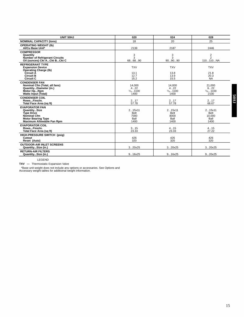
UNIT 50HJ 020 024 028NOMINAL CAPACITY (tons) 18 20 25OPERATING WEIGHT (lb)
Al/Cu Base Unit* 2139 2187 2446COMPRESSOR
Quantity 3 3 2Number of Refrigerant Circuits 3 3 2Oil (ounces) Ckt A...Ckt B...Ckt C 68...68...90 90...90...90 110...110...NA
REFRIGERANT TYPEExpansion Device TXV TXV TXVOperating Charge (lb)
Circuit A 13.1 13.8 21.8 Circuit B 12.7 13.9 20.3 Circuit C 15.2 15.5 NACONDENSER FAN
Nominal Cfm (Total, all fans) 14,000 14,000 21,000Quantity...Diameter (in.) 4...22 4...22 6...22Motor Hp...Rpm 1/4...1100 1/4...1100 1/4...1100Watts Input (Total) 1400 1400 2100
CONDENSER COILRows...Fins/in. 2...17 2...17 2...17Total Face Area (sq ft) 57.78 57.78 66.67
EVAPORATOR FANQuantity...Size 2...15x11 2...15x11 2...15x11Type Drive Belt Belt BeltNominal Cfm 7000 8000 10,000Motor Bearing Type Ball Ball BallMaximum Allowable Fan Rpm 1400 1400 1400
EVAPORATOR COILRows...Fins/in. 3...15 4...15 4...15Total Face Area (sq ft) 23.33 23.33 27.22
HIGH-PRESSURE SWITCH (psig)Cutout 426 426 426Reset (Auto) 320 320 320
OUTDOOR-AIR INLET SCREENSQuantity...Size (in.) 3...20x25 3...20x25 3...20x25
RETURN-AIR FILTERSQuantity...Size (in.) 9...16x25 9...16x25 9...20x25
TXV — Thermostatic Expansion Valve
50HJ

16
EVAPORATOR FAN DATA — 50HJ020-028 VERTICAL SUPPLY/RETURN UNITS
50HJ020 024 028
208/230and 460 v 575 v 208/230
and 460 v 575 v 208/230and 460 v 575 v
LOW RANGEMotor Hp N/A N/A 3.7 5 5 5Drive Motor Nominal Rpm N/A N/A 1725 1745 1745 1745Drive Maximum Continuous Bhp N/A N/A 4.25 5.75 5.75 5.75Drive Maximum Continuous Watts N/A N/A 3698 4900 4900 4900Motor Frame Size N/A N/A 56HZ 184T S184T 184TMotor Shaft Diameter (in.) N/A N/A 7/8 11/8 11/8 11/8Fan Rpm Range N/A N/A 685-939 751-954 687-873 687-873Motor Pulley Min. Pitch Diameter (in.) N/A N/A 2.7 3.7 3.7 3.7Motor Pulley Max. Pitch Diameter (in.) N/A N/A 3.7 4.7 4.7 4.7Blower Pulley Pitch Diameter (in.) N/A N/A 6.8 8.6 9.4 9.4Blower Pulley Shaft Diameter (in.) N/A N/A 1.1875 1.1875 1.1875 1.1875Blower Pulley Type N/A N/A Fixed Fixed Fixed FixedPulley Center Line Distance (in.) N/A N/A 11.293-13.544 9.81-13.055 9.81-13.055 9.81-13.055Belt, Quantity..Type..Length (in.) N/A N/A 1...BX…38 1...BX...40 1...BX...41 1...BX...41Speed Change per Turn - Moveable Pulley (rpm) N/A N/A 42 34 31 31Moveable Pulley Maximum Full Turns N/A N/A 6 6 6 6Factory Speed Setting (rpm) N/A N/A 812 853 780 780MID-LOW RANGEMotor Hp 3.7 3 5 5 5 5Motor Nominal Rpm 1725 1725 1745 1745 1745 1745Maximum Continuous Bhp 4.25 3.45 5.75 5.75 5.75 5.75Maximum Continuous Watts 3698 3149 4900 4900 4900 4900Motor Frame Size 56HZ 56HZ S184T 184T S184T 184TMotor Shaft Diameter (in.) 7/8 7/8 11/8 11/8 11/8 11/8Fan Rpm Range 647-886 810-1072 949-1206 949-1206 805-1007 805-1007Motor Pulley Min. Pitch Diameter (in.) 2.7 3.1 3.7 3.7 4.8 4.8Motor Pulley Max. Pitch Diameter (in.) 3.7 4.1 4.7 4.7 6.0 6.0Blower Pulley Pitch Diameter (in.) 7.2 6.6 6.8 6.8 10.4 10.4Blower Pulley Shaft Diameter (in.) 1.1875 1.1875 1.1875 1.1875 1.1875 1.1875Blower Pulley Type Fixed Fixed Fixed Fixed Fixed FixedPulley Center Line Distance (in.) 11.293-13.544 11.286-14.475 9.81-13.055 9.81-13.055 9.81-13.055 9.81-13.055Belt, Quantity..Type..Length (in.) 1...BX...38 1...BX...38 1...BX...38 1...BX...38 1...BX...45 1...BX...45Speed Change per Turn - Moveable Pulley (rpm) 40 44 43 43 34 34Moveable Pulley Maximum Full Turns 6 6 6 6 6 6Factory Speed Setting (rpm) 767 941 1078 1078 906 906MID-HIGH RANGEMotor Hp 5 5 7.5 7.5 7.5 7.5Motor Nominal Rpm 1745 1745 1745 1745 1745 1745Maximum Continuous Bhp 5.75 5.75 8.63 8.63 8.63 8.63Maximum Continuous Watts 4900 4900 7267 7267 7267 7267Motor Frame Size S184T 184T S213T S213T S213T S213TMotor Shaft Diameter (in.) 11/8 11/8 13/8 13/8 13/8 13/8Fan Rpm Range 897-1139 873-1108 941-1176 941-1176 941-1176 941-1176Motor Pulley Min. Pitch Diameter (in.) 3.7 3.7 4.8 4.8 4.8 4.8Motor Pulley Max. Pitch Diameter (in.) 4.7 4.7 6.0 6.0 6.0 6.0Blower Pulley Pitch Diameter (in.) 7.2 7.4 8.9 8.9 8.9 8.9Blower Pulley Shaft Diameter (in.) 1.1875 1.1875 1.1875 1.1875 1.1875 1.1875Blower Pulley Type Fixed Fixed Fixed Fixed Fixed FixedPulley Center Line Distance (in.) 9.81-13.055 9.81-13.055 9.025-12.179 9.025-12.179 9.025-12.179 9.025-12.179Belt, Quantity..Type..Length (in.) 1...BX...38 1...BX...38 1...BX...42 1...BX...42 1...BX...42 1...BX...42Speed Change per Turn - Moveable Pulley (rpm) 40 39 39 39 39 39Moveable Pulley Maximum Full Turns 6 6 6 6 6 6Factory Speed Setting (rpm) 1018 991 1059 1059 1059 1059HIGH RANGEMotor Hp 7.5 7.5 10 10 10 10Motor Nominal Rpm 1745 1745 1745 1745 1745 1745Maximum Continuous Bhp 8.63 8.63 11.5 11.5 11.5 11.5Maximum Continuous Watts 7267 7267 9582 9582 9582 9582Motor Frame Size S213T S213T S215T S215T S215T S215TMotor Shaft Diameter (in.) 13/8 13/8 13/8 13/8 13/8 13/8Fan Rpm Range 1078-1274 1078-1274 1014-1297 1014-1297 1014-1297 1014-1297Motor Pulley Min. Pitch Diameter (in.) 5.5 5.5 4.3 4.3 4.3 4.3Motor Pulley Max. Pitch Diameter (in.) 6.5 6.5 5.5 5.5 5.5 5.5Blower Pulley Pitch Diameter (in.) 8.9 8.9 7.4 7.4 7.4 7.4Blower Pulley Shaft Diameter (in.) 1.1875 1.1875 1.1875 1.1875 1.1875 1.1875Blower Pulley Type Fixed Fixed Fixed Fixed Fixed FixedPulley Center Line Distance (in.) 9.025-12.179 9.025-12.179 9.025-12.179 9.025-12.179 9.025-12.179 9.025-12.179Belt, Quantity..Type..Length (in.) 1...BX...42 1...BX...42 2...BX...38 2...BX...38 2...BX...38 2...BX...38Speed Change per Turn - Moveable Pulley (rpm) 33 33 47 47 47 47Moveable Pulley Maximum Full Turns 6 6 6 6 6 6Factory Speed Setting (rpm) 1176 1176 1156 1156 1156 1156
Physical data — 50HJ (cont)50
HJ

17
EVAPORATOR FAN DATA — 50HJ020-028 HORIZONTAL SUPPLY/RETURN UNITS
50HJ020 024 028
208/230and 460 v 575 v 208/230
and 460 v 575 v 208/230and 460 v 575 v
LOW RANGEMotor Hp N/A N/A 3.7 5 5 5Motor Nominal Rpm N/A N/A 1725 1745 1745 1745Maximum Continuous Bhp N/A N/A 4.25 5.75 5.75 5.75Maximum Continuous Watts N/A N/A 3698 4900 4900 4900Motor Frame Size N/A N/A 56HZ 184T S184T 184TMotor Shaft Diameter (in.) N/A N/A 7/8 11/8 11/8 11/8Fan Rpm Range N/A N/A 685-939 751-954 687-873 687-873Motor Pulley Min. Pitch Diameter (in.) N/A N/A 2.7 3.7 3.7 3.7Motor Pulley Max. Pitch Diameter (in.) N/A N/A 3.7 4.7 4.7 4.7Blower Pulley Pitch Diameter (in.) N/A N/A 6.8 8.6 9.4 9.4Blower Pulley Shaft Diameter (in.) N/A N/A 1.1875 1.1875 1.1875 1.1875Blower Pulley Type N/A N/A Fixed Fixed Fixed FixedDrive Pulley Center Line Distance (in.) N/A N/A 11.293-13.544 9.81-13.055 9.81-13.055 9.81-13.055Drive Belt, Quantity..Type..Length (in.) N/A N/A 1...BX…38 1...BX...40 1...BX...41 1...BX...41Drive Speed Change per Turn - Moveable Pulley (rpm) N/A N/A 42 34 31 31Drive Moveable Pulley Maximum Full Turns N/A N/A 6 6 6 6Drive Factory Speed Setting (rpm) N/A N/A 812 853 780 780MID-LOW RANGEMotor Hp 3.7 3 5 5 5 5Motor Nominal Rpm 1725 1725 1745 1745 1745 1745Maximum Continuous Bhp 4.25 3.45 5.75 5.75 5.75 5.75Maximum Continuous Watts 3698 3149 4900 4900 4900 4900Motor Frame Size 56HZ 56HZ S184T 184T S184T 184TMotor Shaft Diameter (in.) 7/8 7/8 11/8 11/8 11/8 11/8Fan Rpm Range 647-886 810-1072 949-1206 949-1206 805-1007 805-1007Motor Pulley Min. Pitch Diameter (in.) 2.7 3.1 3.7 3.7 4.8 4.8Motor Pulley Max. Pitch Diameter (in.) 3.7 4.1 4.7 4.7 6.0 6.0Blower Pulley Pitch Diameter (in.) 7.2 6.6 6.8 6.8 10.4 10.4Blower Pulley Shaft Diameter (in.) 1.1875 1.1875 1.1875 1.1875 1.1875 1.1875Blower Pulley Type Fixed Fixed Fixed Fixed Fixed FixedPulley Center Line Distance (in.) 11.293-13.544 11.286-14.475 9.81-13.055 9.81-13.055 9.81-13.055 9.81-13.055Belt, Quantity..Type..Length (in.) 1...BX...38 1...BX...38 1...BX...38 1...BX...38 1...BX...45 1...BX...45Speed Change per Turn - Moveable Pulley (rpm) 40 44 43 43 34 34Moveable Pulley Maximum Full Turns 6 6 6 6 6 6Factory Speed setting (rpm) 767 941 1078 1078 906 906MID-HIGH RANGEMotor Hp 5 5 7.5 7.5 7.5 7.5Motor Nominal Rpm 1745 1745 1745 1745 1745 1745Maximum Continuous Bhp 5.75 5.75 8.63 8.63 8.63 8.63Maximum Continuous Watts 4900 4900 7267 7267 7267 7267Motor Frame Size S184T 184T S213T S213T S213T S213TMotor Shaft Diameter (in.) 11/8 11/8 13/8 13/8 13/8 13/8Fan Rpm Range 897-1139 873-1108 941-1176 941-1176 941-1176 941-1176Motor Pulley Min. Pitch Diameter (in.) 3.7 3.7 4.8 4.8 4.8 4.8Motor Pulley Max. Pitch Diameter (in.) 4.7 4.7 6.0 6.0 6.0 6.0Blower Pulley Pitch Diameter (in.) 7.2 7.4 8.9 8.9 8.9 8.9Blower Pulley Shaft Diameter (in.) 1.1875 1.1875 1.1875 1.1875 1.1875 1.1875Blower Pulley Type Fixed Fixed Fixed Fixed Fixed FixedDrive Pulley Center Line Distance (in.) 9.81-13.055 9.81-13.055 9.025-12.179 9.025-12.179 9.025-12.179 9.025-12.179Belt, Quantity..Type..Length (in.) 1...BX...38 1...BX...38 1...BX...42 1...BX...42 1...BX...42 1...BX...42Speed Change per Turn - Moveable Pulley (rpm) 40 39 39 39 39 39Moveable Pulley Maximum Full Turns 6 6 6 6 6 6Factory Speed Setting (rpm) 1018 991 1059 1059 1059 1059HIGH RANGEMotor Hp 7.5 7.5 10 10 10 10Motor Nominal Rpm 1745 1745 1745 1745 1745 1745Maximum Continuous Bhp 8.63 8.63 11.5 11.5 11.5 11.5Maximum Continuous Watts 7267 7267 9582 9582 9582 9582Motor Frame Size S213T S213T S215T S215T S215T S215TMotor Shaft Diameter (in.) 13/8 13/8 13/8 13/8 13/8 13/8Fan Rpm Range 1078-1274 1078-1274 1014-1297 1014-1297 1014-1297 1014-1297Motor Pulley Min. Pitch Diameter (in.) 5.5 5.5 4.3 4.3 4.3 4.3Motor Pulley Max. Pitch Diameter (in.) 6.5 6.5 5.5 5.5 5.5 5.5Blower Pulley Pitch Diameter (in.) 8.9 8.9 7.4 7.4 7.4 7.4Blower Pulley Shaft Diameter (in.) 1.1875 1.1875 1.1875 1.1875 1.1875 1.1875Blower Pulley Type Fixed Fixed Fixed Fixed Fixed FixedPulley Center Line Distance (in.) 9.025-12.179 9.025-12.179 9.025-12.179 9.025-12.179 9.025-12.179 9.025-12.179Belt, Quantity..Type..Length (in.) 1...BX...42 1...BX...42 2...BX...38 2...BX...38 2...BX...38 2...BX...38Speed Change per Turn - Moveable Pulley (rpm) 33 33 47 47 47 47Moveable Pulley Maximum Full Turns 6 6 6 6 6 6Factory Speed Setting (rpm) 1176 1176 1156 1156 1156 1156
50HJ

18
OPTIONS AND ACCESSARIES — 50HE/HJ 003-014(Weight Adders)
LEGEND
OPTIONS AND ACCESSORIES — 50HJ015-017(Weight Adders)
OPTIONS AND ACCESSORIES — 50HJ020-028(Weight Adders)
LEGEND
Option / Accessory OPTION/ACCESSORY WEIGHTS
003 004 005 006 007 008 009 012 014 lb kg lb kg lb kg lb kg lb kg lb kg lb kg lb kg lb kg
Humidi-MiZer Adaptive Dehumidification System 13 6 15 7 23 10 25 11 29 13 44 20 51 23 51 23 51 23 Power Exhaust - vertical 50 23 50 23 50 23 50 23 50 23 75 34 75 34 75 34 75 34 Power Exhaust - horizontal 30 14 30 14 30 14 30 14 30 14 30 14 30 14 30 14 30 14 EconoMi$er ( IV or 2) 50 23 50 23 50 23 50 23 50 23 75 34 75 34 75 34 75 34 Two Position damper (25%) 22 10 22 10 22 10 22 10 22 10 32 15 32 15 32 15 32 15 Two Position damper (100%) 39 18 39 18 39 18 39 18 39 18 58 26 58 26 58 26 58 26 Manual Dampers 12 5 12 5 12 5 12 5 18 8 18 8 18 8 18 8 18 8 Hail Guard (louvered) 16 7 16 7 16 7 16 7 16 7 34 15 34 15 34 15 34 15 Hail Guard (standard hood assembly) 25 11 25 11 25 11 25 11 25 11 38 17 50 23 50 23 50 23 Cu/Cu Condenser Coil 5 2 6 3 13 6 13 6 15 7 12 5 23 10 23 10 23 10 Cu/Cu Condenser and Evaporator Coils 10 5 12 5 19 9 21 10 26 12 25 11 49 22 49 22 49 22 Roof Curb (14-in. curb) 115 52 115 52 115 52 115 52 115 52 143 65 143 65 143 65 143 65 Roof Curb (24-in. curb) 197 89 197 89 197 89 197 89 197 89 245 111 245 111 245 111 245 111
Cu — Copper
Option / Accessory OPTION/ACCESSORY WEIGHTS
015 017 lb kg lb kg
Barometric Relief Damper 50 23 50 23 Power Exhaust 85 39 85 39 EconoMi$er (IV or 2) 90 41 90 41 Two Position (motorized) Damper 120 54 120 54 Hail Guard 60 27 60 27 Cu/Cu evaporator 130 59 130 59 Cu/Cu Condenser Coil 150 68 150 68 Cu/Cu Condenser and Evaporator Coils 280 127 280 127 Glycol Coil 115 53 115 53 Roof Curb (14-in. curb) 170 77 170 77 Roof Curb (24-in. curb) 343 156 286 130 Horizontal Adapter Roof Curb (Preassembled) 250 113 250 113 Horizontal Adapter Roof Curb (Field-assembled) 343 156 343 156 Domestic Crating 75 34 75 34 Export Crating 500 227 500 227
OPTION/ACCESSORY
OPTION/ACCESSORY WEIGHTS50HJ020 50HJ024 50HJ028
lb kg lb kg lb kgBarometric Relief Damper 50 23 50 23 50 23Power Exhaust 125 57 125 57 125 57Economizer 170 77 170 77 195 88Cu Condenser Coil 162 73 162 73 202 92Cu Condenser and Evaporator Coils 316 143 290 132 365 166Electric Heat 85 39 85 39 85 39Roof Curb (14 inch) 210 95 210 95 210 95Optional Indoor Motor 28 13 28 13 20 9Two-Position Damper 45 20 45 20 45 20Hail Guard 85 39 85 39 100 45Horizontal Airflow 90 41 90 41 90 41CO2 Sensor 5 2 5 2 5 2Return Smoke Detector 5 2 5 2 5 2Supply Smoke Detector 5 2 5 2 5 2Non-Fused Disconnect 15 7 15 7 15 7Non-Powered Convenience Outlet 20 9 20 9 20 9Enthalpy Sensor 2 1 2 1 2 1Differential Enthalpy Sensor 3 1 3 1 3 1Drip Edge 5 2 5 2 5 2Manual Damper 25 11 25 11 25 11
Cu — Copper
Physical data — 50HE/HJ (cont)50
HE
/HJ

19
50HE003-006 and 50HJ004-014
*Factory-installed.†Field-installed.NOTES: 1. Refer to unit price pages or contact your local representative for accessory and optionpackage information.2. Some options may increase product lead times.
Category ITEM OPTION* ACCESSORY†Cabinet Hinged Access Panels X
Hinged Panel Kit for Economizer X Thru-the-Bottom Connections (gas, power, controls, conv outlet) X
Coil Options Copper Fins - condenser coil X Copper Fins - evaporator and condenser coil X E-Coat outdoor coil (Al / Cu) and indoor coil (Al / Cu) X E-Coat outdoor coil (Al / Cu) X E-Coat outdoor coil (Cu / Cu) X Pre-Coated Aluminum condenser fins X
Condenser Protection Condenser Coil Grille X Condenser Coil Hail Guard (louvered) X Condenser Coil Hail Guard (standard hood assembly) X
Dehumidification & IAQ Humidi-MiZer™ Adaptive Dehumidification Package X Demand Control Ventilation CO2 Sensors X UV Lights X
Economizers & Outdoor Air EconoMi$er IV (for Electro-Mech unit, includes barometric relief) X X EconoMi$er 2 (for DDC unit, includes barometric relief) X X 100% Two-Position Damper (motorized) X 25% Two-Position Damper (motorized) X Manual Outdoor-Air Damper X Power Exhaust (prop fan) X
Economizer Sensors Return Air Temperature Sensor X Return Air Enthalpy Sensor X Outdoor Air Differential Temperature Sensor X Outdoor Air Differential Enthalpy Sensor X Return Air CO2 Sensor (duct mounted) X Space CO2 Sensor (wall mounted) X
Electrical & Controls PremierLink™ DDC Communicating Controller X X Novar 3051 Controller X Convenience Outlet (Load Side powered) X Unit-Mounted Non-Fused Disconnect X Time Guard II (Compressor Cycle Delay) Control Circuit X Fan/Filter Status switches X
Electric Heat Electric Heat XEnergy Recovery Energy Recovery Ventilator (62M) X
Energy Recovery heatpump (COBRA™ ) XEnergy Recovery heatpump (62AQ Energy$Recycler™ ) X
Indoor Motor & Drive Standard Static Motor and Drive X High-Static Motor and Drive X
Low Ambient Control Motormaster® Head Pressure Controller (Kit XRoof Curbs Roof Curbs 14" (Vertical and Horizontal Discharge) X
Roof Curbs 24" (Vertical and Horizontal Discharge) X 62M Full Perimeter curb X COBRA Full Perimeter Roof Curb X COBRA or 62AQ Sleeper Rail (for use with Standard Unit Roof Curb) X
Thermostats Light Commercial Thermidistat™ Device X Humidistat X Communicating Thermostat X Non-communicating Thermostat X
Options and accessories50H
E/H
J

20
50HJ015,017
*Factory-installed.†Field-installed.NOTES: 1. Refer to unit price pages or contact your local representative for accessory and option package information.2. Some options may increase product lead times.
Category ITEM OPTION* ACCESSORY† Cabinet Hinged Access Panels X
Service Option with (6) Hinged Access Panels, Non-Fused Dis-connect and Non-Powered 115 v GFI Convenience Outlet
X
Coil Options Copper Fins - condenser coil X Copper Fins - evaporator and condenser coil X E-Coat outdoor coil (Al / Cu) X E-Coat outdoor coil (Cu / Cu) X Pre-Coat aluminum Fins on outdoor coil X
Condenser Protection Condenser Coil Hail Guard (standard hood assembly) X Dehumidification & IAQ Demand Control Ventilation CO2 Sensors X
UV Lights X Economizers & Outdoor Air EconoMi$er IV (for Electro-Mech unit) X X
EconoMi$er 2 (for DDC unit) X X Barometric Relief X 25% Two-Position Damper (motorized) X 25% Manual Outdoor-Air Damper X Power Exhaust (prop fan) X
Economizer Sensors Return Air Temperature Sensor X Return Air Enthalpy Sensor X Outdoor Air Differential Temperature Sensor X Outdoor Air Differential Enthalpy Sensor X Return Air CO2 Sensor (duct mounted) X Space CO2 Sensor (wall mounted) X
Electrical & Controls PremierLink™ DDC Communicating Controller X X Convenience Outlet (non-powered) X
Energy Recovery Energy Recovery Ventilator (62M) X Heat Options Electric Heaters X
Glycol Coil X Indoor Motor & Drive Low-Medium Static Fan Drive X
High-Static Fan Drive X Low Ambient Control Motormaster® Head Pressure Controller (Kit X Roof Curbs Roof Curbs 14" (Vertical Supply & Return) X
Roof Curbs 24" (Vertical Supply & Return) X Horizontal Adapter Curb (Horizontal Supply & Return) X 62M Full Perimeter curb X
Thermostats Light Commercial Thermidistat™ Device X Humidistat X Communicating Thermostat X Non-communicating Thermostat X
Options and accessories (cont)50
HJ

21
50HJ020-028
*Factory-installed.†Field-installed.NOTES: 1. Refer to unit price pages or contact your local representative for accessory and option package information.2. Some options may increase product lead times.
Category ITEM OPTION* ACCESSORY†Cabinet Hinged Access Panels X
Drip Edge Kit X Horizontal Conversion Kit (not required on 020 & 024) X X
Coil Options Copper Fins - condenser coil X Copper Fins - evaporator and condenser coil X E-Coat outdoor coil (Al / Cu) and indoor coil (Al / Cu) X E-Coat outdoor coil (Al / Cu) X E-Coat outdoor coil (Cu / Cu) X E-Coat outdoor coil and indoor coil (Cu / Cu) X Pre-Coat aluminum Fins on outdoor coil X
Condenser Protection Condenser Coil Hail Guard X XDehumidification & IAQ Demand Control Ventilation CO2 Sensors X
UV Lights XEconomizers & Outdoor Air EconoMi$er IV (for Electro-Mech unit) X X
EconoMi$er 2 (for DDC unit) X Barometric Relief X X Two-Position Damper (motorized) X X Manual Outdoor-Air Damper X X Power Exhaust (prop fan) X X
Economizer Sensors Return Air Temperature Sensor X Return Air Enthalpy Sensor X Outdoor Air Differential Temperature Sensor X Outdoor Air Differential Enthalpy Sensor X Return Air CO2 Sensor (duct mounted) X Space CO2 Sensor (wall mounted) X
Electrical & Controls PremierLink™ DDC Communicating Controller X Non-Fused Disconnect X Convenience Outlet (line-side powered) X Convenience Outlet (non-powered) X Return and Supply Smoke Detector X Return Smoke Detector X X Supply Smoke Detector X Phase Loss Detection X
Energy Recovery Energy Recovery Ventilator (62M) XElectric Heaters Electric Heaters XIndoor Motor & Drive Low Range Drive X
Mid-Low Range Drive X Mid-High Range Drive X High Range Drive X
Roof Curbs Roof Curbs 14" (Vertical or Horizontal Supply & Return) X Roof Curbs 24" (Vertical or Horizontal Supply & Return) X 62M Full Perimeter curb X
Thermostats Light Commercial Thermidistat™ Device X Humidistat X Communicating Thermostat X Non-communicating Thermostat X
50HJ

22
Carrier PremierLink™ controls are available as a factory-in-stalled or as a field-installed accessory. The controls can beused to actively monitor and control all modes of operations.Roof curbs (horizontal and vertical) permit installation andsecuring of ductwork to curb prior to mounting unit on thecurb. Both 14-in. and 24-in. roof curbs are available.EconoMi$er IV is available as a factory-installed option invertical supply/return configuration only for unit sizes 003-014. Vertical or horizontal configuration is available for unitsizes 015-028. (The EconoMi$er IV is available as a field-in-stalled accessory for horizontal and/or vertical supply returnconfigurations.) The EconoMi$er IV is provided with an indus-try standard, stand-alone, solid-state controller that is easy toconfigure and troubleshoot. The EconoMi$er IV is compatiblewith non-DDC applications. The EconoMi$er IV is equippedwith a barometric relief damper capable of relieving up to100% return air for unit sizes 003-014 only. Dry bulb outdoor-air temperature sensor is provided as standard. The return airsensor, indoor enthalpy sensor, and outdoor enthalpy sensor areprovided as field-installed accessories to provide enthalpy con-trol, differential enthalpy control, and differential dry bulb tem-perature control.EconoMi$er2 is available as a factory-installed option in verti-cal supply/return configuration for unit sizes 003-014 only.(The EconoMi$er2 is available as a field-installed accessoryfor horizontal and/or vertical supply return configurations.)The EconoMi$er2 is provided without a controller for use withfactory-installed PremierLink™ controls or field-installedthird-party controls. The EconoMi$er2 is equipped with a baro-metric relief damper capable of relieving up to 100% return air.Dry bulb outdoor-air temperature sensor is provided as stan-dard. The enthalpy, differential temperature (adjustable), anddifferential enthalpy control are provided as field-installed ac-cessories. The EconoMi$er2 is capable of control from a 4 to20 mA signal through optional 4 to 20 mA design without mi-croprocessor control (required for PremierLink™ or third partycontrol interface).Manual outdoor-air damper can be preset to admit up to 50%outdoor air for year round ventilation.Two-position damper package is available as an accessory.Both 25% or 100% outdoor air dampers are available.
Head pressure control (Motormaster®) package maintainscondensing temperature between 90 F and 110 F at outdoor am-bient temperatures down to –20 F by condenser-fan speed mod-ulation or condenser-fan cycling and wind baffles.Electric resistance heaters are UL listed and available tomatch heating requirements. Single point kits available foreach heater when required.Unit-mounted, non-fused disconnect switch provides unitpower shutoff. The switch is accessible from outside the unitand provides power off lockout capability.Convenience outlet is factory-installed and internally mountedwith easily accessible 115-v female receptacle for temporaryuse of service tools. The device connects to the load-side of thedisconnect. For a line-side convenience outlet, contact your lo-cal Carrier representative.Compressor cycle delay (Time Guard II) prevents unit fromrestarting for minimum of 5 minutes after shutdown.Thru-the-bottom utility connectors permit electrical connec-tions to be brought to the unit through the basepan.Fan/filter status switch provides status of indoor (evaporator)fan (ON/ OFF) or filter (CLEAN/DIRTY).62AQ Energy$Recycler™ heat pump unit recovers energyfrom building exhaust air and pre-conditions ventilation air toallow higher ventilation requirements and minimizing energycost. Utilizes a specialized heat pump system to transfer energybetween outdoor and exhaust systems.62M Energy Recovery Ventilator is a wheel device that re-covers energy from the building exhaust air and preconditionsventilation air. The 62M is a field-installed accessory.Power exhaust accessory will provide system exhaust of up to100% of return air (vertical only). The power exhaust is a field-installed accessory (separate vertical and horizontal design).Ultraviolet germicidal lamps eliminate odor causing moldand fungus that may develop in the wet area of the evaporatorsection of the unit. The high output, low temperature germicid-al lamps are field installed in the evaporator section of the unit,aimed at the evaporator coil and condensate pan.Hinged panel option provides hinged access panels for the fil-ter, compressor, evaporator fan, and control box areas. Filterhinged panels permit tool-less entry for changing filters. Eachhinged panel is permanently attached to the rooftop unit.
Options and accessories (cont)50
HJ

23
ECONOMI$ER IV CONTROLLER
ACCESSORY ENERGY$RECYLERTM UNIT (2 TO 12 1/2 TON UNITS ONLY)
EXHAUSTAIR
CONDENSER-FANDISCHARGE AIR
FRESH AIRINLET
MOUNTINGKIT
FILTERACCESS
OUTDOOR-AIRINLET
RETURN AIRBAFFLE
ROOF CURB
RETURN AIR
SUPPLY AIR
OUTDOOR AIRFLOW
INDOOR AIRFLOW
ACCESSORY SUPPORT RAIL
TR1
24 VacCOM
TR
24 VacHOT
1 2
3 4
5
EF EF1
+ _
P1
T1
P
T
N
EXH
2V 10V
EXH
Set
Set
2V 10V
2V 10V
DCV
DCV
FreeCool
B C
A D
SO+
SR+
SR
SO
AQ1
AQ
DCV
MinPos
Open
Max
N1
GEAR-DRIVEN ECONOMI$ER IV COMPONENT PARTS
(Required when standard roof curb is used)
50HJ

24
UNIT-MOUNTED DISCONNECT (Sizes 003-012)
CONVENIENCE OUTLET
UNIT-MOUNTED DISCONNECT (Sizes 015-028)
Options and accessories (cont)50
HJ
25
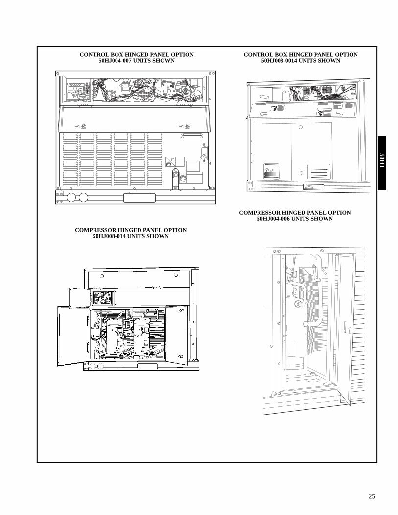
CONTROL BOX HINGED PANEL OPTION50HJ004-007 UNITS SHOWN
COMPRESSOR HINGED PANEL OPTION50HJ004-006 UNITS SHOWN
CONTROL BOX HINGED PANEL OPTION50HJ008-0014 UNITS SHOWN
COMPRESSOR HINGED PANEL OPTION50HJ008-014 UNITS SHOWN
50HJ

26
EVAPORATOR-FAN HINGED PANEL OPTION50HJ008-014 UNIT SHOWN
FILTER HINGED PANEL OPTION50HJ003-014 UNIT SHOWN
BAROMETRIC RELIEF OR POWER EXHAUST(015-028 Shown)
Options and accessories (cont)50
HJ

27
62M MATED WITH 50HJ004-014
62M MATED WITH 50HJ017
50HJ

28
UN
ITST
D U
NIT
W
EIG
HT
ECO
NO
MI$
ER IV
WEI
GH
TVE
RT.
EC
ON
IVW
/P.E
. WEI
GH
T(A
)C
OR
NER
WEI
GH
T(B
)C
OR
NER
WEI
GH
T(C
)C
OR
NER
WEI
GH
T(D
)C
OR
NER
WEI
GH
T“J
”Lb
Kg
LbK
gLb
Kg
LbK
gLb
Kg
LbK
gLb
Kg
ft-in
.m
m50
HJ0
0443
519
750
22.7
9040
.912
456
.210
648
.195
43.1
110
49.9
2-95
/ 1684
6.5
50H
J005
445
202
5022
.790
40.9
127
57.6
108
49.0
9744
.011
351
.32-
95/ 16
846.
550
HJ0
0646
521
150
22.7
9040
.913
360
.311
351
.310
145
.811
853
.52-
95/ 16
846.
550
HJ0
0754
024
550
22.7
9040
.915
570
.313
259
.911
652
.613
762
.13-
55/ 16
1050
.0
Base unit dimensions — 50HE003-00650
HE

29
UN
ITST
D U
NIT
W
EIG
HT
ECO
NO
MI$
ER IV
WEI
GH
TVE
RT.
EC
ON
IVW
/P.E
. WEI
GH
T(A
)C
OR
NER
WEI
GH
T(B
)C
OR
NER
WEI
GH
T(C
)C
OR
NER
WEI
GH
T(D
)C
OR
NER
WEI
GH
T“J
”Lb
Kg
LbK
gLb
Kg
LbK
gLb
Kg
LbK
gLb
Kg
ft-in
.m
m50
HJ0
0443
519
750
22.7
9040
.912
456
.210
648
.195
43.1
110
49.9
2-95
/ 1684
6.5
50H
J005
445
202
5022
.790
40.9
127
57.6
108
49.0
9744
.011
351
.32-
95/ 16
846.
550
HJ0
0646
521
150
22.7
9040
.913
360
.311
351
.310
145
.811
853
.52-
95/ 16
846.
550
HJ0
0754
024
550
22.7
9040
.915
570
.313
259
.911
652
.613
762
.13-
55/ 16
1050
.0
Base unit dimensions — 50HJ004-00750H
J

30
UN
ITST
D U
NIT
W
EIG
HT
ECO
NO
MI$
ER IV
WEI
GH
TVE
RT.
EC
ON
IVW
/P.E
. WEI
GH
T(A
)C
OR
NER
WEI
GH
T(B
)C
OR
NER
WEI
GH
T(C
)C
OR
NER
WEI
GH
T(D
)C
OR
NER
WEI
GH
T“H
”“J
”“K
”Lb
Kg
LbK
gLb
Kg
LbK
gLb
Kg
LbK
gLb
Kg
ft-in
.m
mft-
in.
mm
ft-in
.m
m50
HJ0
0875
534
275
34.1
145
65.9
164
7414
064
208
9424
311
02-
07/ 8
632
3-55
/ 1610
502-
911 / 1
685
650
HJ0
0989
540
675
34.1
145
65.9
195
8816
675
247
112
288
131
2-10
7 / 888
54-
15/ 16
1253
3-03
/ 892
450
HJ0
1291
541
575
34.1
145
65.9
199
9017
077
252
114
294
134
2-10
7 / 888
54-
15/ 16
1253
3-03
/ 892
450
HJ0
1493
042
275
34.1
145
65.9
202
9217
278
256
116
300
136
1-27
/ 837
84-
15/ 16
1253
3-03
/ 892
4
Base unit dimensions — 50HJ008-01450
HJ

31
Base unit dimensions — COBRA™ energy 50H
E/H
J

32
50H
J

33
Base unit dimensions — COBRA™ energy50H
J

34
50H
J

35
Base unit dimensions — 50HJ015,01750H
J

36
Base unit dimensions— 50HJ020-02850
HJ

37
Accessory dimensions — 50HJ004-00750H
J

38
Accessory dimensions — 50HJ008-01450
HJ

39
COBRA™ ENERGY RECOVERY UNIT FULL-PERIMETER ROOF CURB — 50HJ004-007 WITH 62AQ060,100
COBRA ENERGY RECOVERY UNIT FULL-PERIMETER ROOF CURB — 50HJ008-014 WITH 62AQ200,300
Accessory dimensions — 50HJ004-01450H
J
40
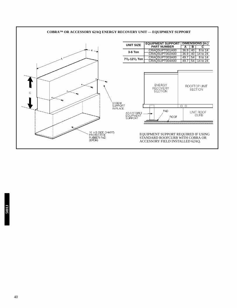
COBRA™ OR ACCESSORY 62AQ ENERGY RECOVERY UNIT — EQUIPMENT SUPPORT
UNIT SIZE EQUIPMENT SUPPORTPART NUMBER
DIMENSIONS (in.)A B C
3-6 Ton CRAQSUPT001A00 36.9 40 8 to 14CRAQSUPT002A00 36.9 40 14 to 24
71/2-121/2 Ton CRAQSUPT003A00 49.7 54 8 to 14CRAQSUPT004A00 49.7 54 14 to 24
EQUIPMENT SUPPORT REQUIRED IF USING STANDARD ROOFCURB WITH COBRA OR ACCESSORY FIELD INSTALLED 62AQ.
50H
J

41
PKG.
NO
. REF
.C
UR
BH
EIG
HT
DES
CR
IPTI
ON
CR
RFC
UR
B01
0A00
1′-
2″ (3
05)
Stan
dard
Cur
b 14
″ H
igh
CR
RFC
UR
B01
1A00
2′-
0″ (6
10)
Stan
dard
Cur
b fo
r Uni
tsR
equi
ring
Hig
h In
stal
latio
nC
RR
FCU
RB
012A
002′
-0″
(610
)S
ide
Sup
ply
and
Ret
urn
Cur
b fo
r Hig
h In
stal
latio
n
NO
TES
:1.
Roo
f cur
b ac
cess
ory
is s
hipp
ed d
isas
sem
bled
.2.
Insu
late
d pa
nels
: 1″
thic
k ne
opre
ne c
oate
d 11
/ 2 lb
den
sity
.3.
Dim
ensi
ons
in (
) are
in m
illim
eter
s.
4. D
irect
ion
of a
irflo
w.
5.R
oof c
urb:
16
ga. (
VA03
-56)
stl.
6.A
90
degr
ee e
lbow
mus
t be
ins
talle
d on
the
sup
ply
duct
wor
kbe
low
the
unit
disc
harg
e fo
r uni
ts e
quip
ped
with
ele
ctric
hea
ters
.7.
To p
reve
nt th
e ha
zard
of s
tagn
ant w
ater
bui
ld-u
p in
the
drai
n pa
n of
the
indo
or s
ectio
n, u
nit c
an o
nly
be p
itche
d as
sho
wn.
DIM
ENS
ION
S* (
degr
ees
and
inch
es)
UN
ITA
BD
eg.
in.
Deg
.in
.A
LL.2
8.4
5.2
8.4
3
Accessory dimensions — 50HJ015,01750H
J
42
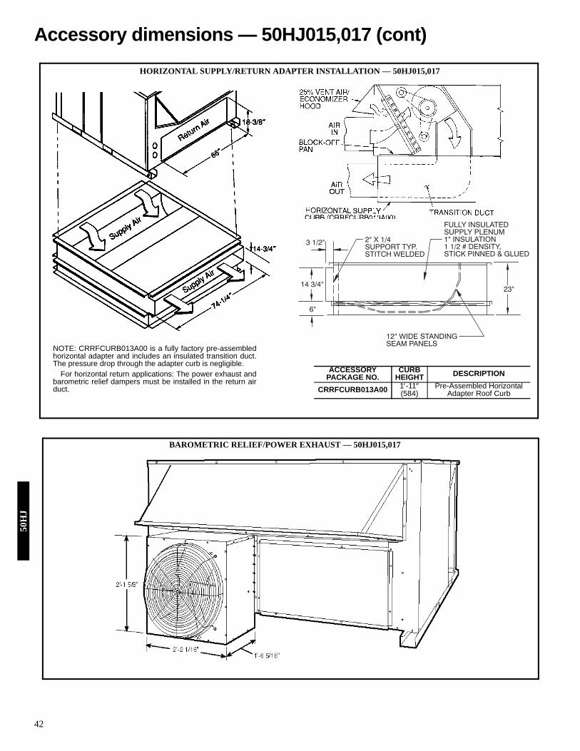
NOTE: CRRFCURB013A00 is a fully factory pre-assembledhorizontal adapter and includes an insulated transition duct.The pressure drop through the adapter curb is negligible.
For horizontal return applications: The power exhaust andbarometric relief dampers must be installed in the return airduct.
ACCESSORYPACKAGE NO.
CURBHEIGHT DESCRIPTION
CRRFCURB013A00 1′-11″(584)
Pre-Assembled Horizontal Adapter Roof Curb
HORIZONTAL SUPPLY/RETURN ADAPTER INSTALLATION — 50HJ015,017
23"14 3/4"
6"
3 1/2"
FULLY INSULATEDSUPPLY PLENUM1" INSULATION1 1/2 # DENSITY,STICK PINNED & GLUED
2" X 1/4SUPPORT TYP.STITCH WELDED
12" WIDE STANDINGSEAM PANELS
BAROMETRIC RELIEF/POWER EXHAUST — 50HJ015,017
Accessory dimensions — 50HJ015,017 (cont)50
HJ

43
FACTORY-INSTALLED CONVENIENCE OUTLET — 50HJ015,017
FACTORY-INSTALLED NON-FUSED DISCONNECT — 50HJ015,017
50HJ

44
Accessory dimensions — 50HJ020-02850
HJ

45
I Determine cooling and heating loads at design condi-tions.Given:Required Cooling Capacity (TC) . . . . . . . . 67,000 BtuhSensible Heat Capacity (SHC) . . . . . . . . . . 46,000 BtuhRequired Heating Capacity. . . . . . . . . . . . . 50,000 BtuhOutdoor Entering-Air Temperature db . . . . . . . . . . 95 FOutdoor Entering-Air Temperature wb . . . . . . . . . 75 FOutdoor-Air Entering Airflow Cfm . . . . . . . . . 450 cfmOutdoor-Air Winter Design Temperature . . . . . . . . .0° FIndoor-Air Winter Design Temperature . . . . . . . . . 70 FAir to room including outdoor air. . . . . . . . . . 2000 cfmExternal Static Pressure . . . . . . . Supply — 0.60 in. wg
Return — 0.2 in. wgIndoor-Air Temperature db (room air) . . . . . . . . . . 78 FIndoor-Air Temperature wb (room air). . . . . . . . . . 65 FIndoor-Air Exhaust Cfm . . . . . . . . . . . . . . . . . . 450 cfmElectrical Characteristics (V-Ph-Hz) . . . . . . . .230-3-60Vertical discharge unit with Energy$Recycler™ unitrequired.
II Determine fan speed and power requirements atdesign conditions.Before entering the Fan Performance tables, calculatethe total static pressure required based on unit compo-nent. From the given and the Accessory Electric HeatersStatic Pressure table on page 101 find:External static pressure supply 0.6 in. wgExternal static pressure return 0.2 in. wgAccessory static electric heater 0.11 in. wgTotal Static 0.9 in. wgEnter the Fan Performance table for vertical discharge,50HJ006 (page 66) at 0.90 in. wg. At 2000 cfm the rpmis 1264 and bhp is 1.44 (interpolation required).NOTE: Convert bhp to Fan Heat and Watts using theformula found in the note following the Evaporator-FanMotor Efficiency table on page 194.For this example:Watts = (746 x Bhp)/(motor efficiency)Watts = (746 x 1.44)/(0.84) = 1279 wattsIndoor Fan Heat = watts x 3.413 Btuh/watt
= 1279 x 3.413= 4365 Btuh
III Select Energy$Recycler unit based on OutdoorEntering Cfm (optional).Entering Energy$Recycler cooling rating table in theEnergy$Recycler Product Data literature at 450 cfmentering outdoor airflow. Choose Model 62AQ060.Using 450 cfm outdoor supply airflow, 95 F OD db, and75 F OD wb find performance of the 62AQ060 at theseconditions:Energy$Recycler Gross Cooling
Capacity is 13,000 BtuhEnergy$Recycler Gross Sensible
Capacity is 10,090 BtuhCompressor power is 1.06 kWEnergy$Recycler Leaving db is 73 FEnergy$Recycler Leaving wb is 66.9 F
IV Using the simplified* method below, calculate theapproximate mixed air temperature for the SmallRooftop (SRT) evaporator coil.Using the outdoor-air entering cfm, the room cfm andthe room exhaust airflow with their respective db andwb temperatures, determine the db and wb entering therooftop evaporator coil.a) Estimate the mixed air db to the evaporator coil.
t mix db = ((cfm oa x t oa db) + ((cfm ra – cfm exh) xt ra db)) / ((cfm oa + (cfm ra – cfm exh)))= ((450 cfm x 73.0 F) + ((2000 cfm – 450 cfm) x 78 F)) / ((450 cfm + (2000 cfm – 450 cfm)))Mixed air into the rooftop evaporator coil = 76.9 F db
b) Estimate the mixed air wb to the evaporator coil.t mix wb* = ((cfm oa x t oa wb) + ((cfm ra – cfmexh) x t ra wb)) / (cfm oa + (cfm ra – cfm exh))= ((450 cfm x 66.9 F) + ((2000 cfm – 450 cfm) x 65 F)) / ((450 cfm + (2000 cfm – 450 cfm)))Mixed air temperature into the rooftop evaporator =65.4 F wb*Simplified method of determining wet bulb (wb) tem-
perature of mixture. This approximation is usedbecause the wb lines in the area of the psychrometricchart used in the calculation is relatively linear, pro-viding a close approximation. A more accurate solu-tion can be found using the E-Cat program.
LEGEND
V Determine the cooling load requirement for the roof-top unit.Customer load is 67,000 BtuhLess TC supplied by the
Energy$Recycler –13,000 BtuhRooftop cooling load required is 54,000 Btuh
VI Select the rooftop unit based on mixed air enteringconditions and cooling load.Enter cooling capacity table at outdoor entering temper-ature 95 F, mixed air entering evaporator at 2000 cfm,76.9 F db, and 65.4 F wb.The 50HJ006 will provide a total gross cooling capacityof 59,420 Btuh and sensible cooling of 43,420 Btuh.Because these values were not at 80 F entering db, theywere calculated based on the notes following the Cool-ing Capacity tables.NOTE: Unit ratings are gross capacities and do notinclude the effect of evaporator-fan motor heat. To cal-culate net capacities see Steps VII and VIII.
VII Select net heating capacity of unit to meet designcondition requirements.Enter the 62AQ060 Heating rating table at 450 cfm. At70 F and 0° F find the heating value for theEnergy$Recycler to be 15.2 MBtuh. Since theEnergy$Recycler uses room air, the instantaneous heatis also the Integrated Heat Rating.The customer heat requirement is 50,000 Btuh.Fan heat from Step II 4,365 Btuh
cfm — cubic feet per minute of airdb — dry bulbexh — Energy$Recycler dischargemix — mixture of outdoor + return airoa — outside air leaving Energy$Recyclerra — return airt — temperaturewb — wet bulb
Selection procedure (with 50HJ006 example)50H
J

46
Energy$Recycler Heat Capacity 15,200 Btuhadd ER optional supply fan heat
if supplied + 0 BtuhTotal Unit heat with Energy$Recycler 19,565 BtuhDetermine additional electric heat capacity.The required heating capacity is 50,000 Btuh. There-fore, 30,435 Btuh (50,000 – 19,565) additional heat isrequired.Determine additional electric heat in kW.(30,435/3413 Btuh/kW) = 8.92 kW of heat is required.Enter Electric Heating Usage tables, page 109, for50HJ006 at 208/230, 3 phase. The 10.5 kW heater at240 v most closely satisfies the heating required. To cal-culate kW at 230 v use the Multiplication Factors table.10.5 kW x 0.92 = 9.668 kW10.5 kW x 0.92 x 3413 Btuh/kW = 32,970 BtuhTotal unit net heating capacity is 52,535 Btuh (32,970 +19,565).
VIII Determine net cooling capacity.Cooling capacities are gross capacities and do notinclude in do or (evaporator)or optional Energy$Recy-cler supply fan heat.Determine net cooling capacity using the following for-mula:Net Capacity = (Gross Capacity Rooftop Unit +Energy$Recycler) – (IFM Heat + OptionalEnergy$Recycler Supply Fan motor heat)Gross Total Cooling
Rooftop unit 59,420 BtuhEnergy$Recycler 13,000 BtuhTotal 72,420 Btuh
LessIFM heat (from Step II) – 4,365 BtuhOpt. Energy$Recycler SupplyFan Motor Heat noneNet Total Capacity 68,055 Btuh
Gross Sensible CoolingRooftop from run 43,400 BtuhEnergy$Recycler 10,090 BtuhTotal 53,490 Btuh
LessIFM heat (from Step II) – 4,365 BtuhOpt. Energy$Recycler SupplyFan Motor Heat noneNet Sensible Capacity 49,125 Btuh
IX Determine the operating watts of the unit.Cooling with Energy$Recycler unit in operation:Rooftop unit:Compressor watts from cooling
capacity tables . . . . . . . . . . . . . . . . . . . . . 4,440 wattsIndoor fan motor from Step II† . . . . . . . . . . 1,279 wattsOutdoor fan motor from Physical Data table find 1/4 hp†
assume OD motor efficiency is 0.75.Watts = 746 x hp)/(motor Eff)
= (746 x 1/4)/(0.75)= 249 watts
†Dual circuit units will have two indoor and two out-door fans, double values.
b) Energy$Recycler unit:Compressor watts from
Energy$Recycler Product Dataliterature 1,060 watts
Optional supply fan fromEnergy$Recycler Product Dataliterature fan curves none
Exhaust fan, from Energy$RecyclerProduct Data literature fan curveat 450 cfm, 0.2 in. wg Static 110 watts
Total watts for the unit in operationat design conditions 7,138 watts
X Electrical data RLA, FLA, LRA, MCA and MOCP.Separate Power Supply:If the 62AQ is wired for separate power see the Electri-cal Data table.Single Power Supply with Unit:The unit is 230 v-3-60 Hz. Look up the 50HJ006 with-out convenience outlet in the Electrical Data table andwith a 10.5 kW heater, find unit electrical data. For therooftop unit the data is MCA = 38.8 amps, MOCP = 40, Min Unit Disconnect Size FLA = 36, andLRA = 168.From the Table of “X” and “Y” values in theEnergy$Recycler Product Data literature find 230 v, for62AQ060300, “X” = 8.1 amps and “Y” = 9.3 amps.Add “X” amps to the MCA and MOCP and add “Y”amps to the minimum disconnect size.
**The calculated MOCP is 48.1 amps; it is rounded down to 40amps. Compare it to MCA; it must be larger than the MCA of46.9 amps, so it is rounded up 50 amps.
The wiring of the unit must be suitable for the MCA cal-culated above, and the maximum overcurrent protection(MOCP) device must be selected to meet the calculatedMOCP.If the overcurrent protective device for the combinationload is equal to or less than 60 amps, a single disconnectmay be used for BOTH the main unit and the 62AQ pro-vided that the wire ampacity supplying the 62AQ issized for a minimum of 33% larger than the overcurrentprotection device value (i.e., 60 amps x 0.33 = 20amps), no further subfusing would be required.If the overcurrent protection device is greater than 60amps and the old overcurrent protection device was lessthan 60 amps, a FUSED disconnect no greater than 60amps must be provided for the Main Unit and a SEPA-RATE FUSED disconnect must be provided for the62AQ unit.If the old overcurrent protection device is greater than60 amps, a disconnect is required for the MAIN UNITas well as a FUSED DISCONNECT for the 62AQ unit.In this example a 50-amp disconnect would be used forthe combination load of the 50HJ006 with a 10.5 kWheater and the 62AQ060 Energy$Recycler unit.
MCA MOCP FLA LRASRT 38.8 40 36 16862AQ 8.1 8.1 9.3 31.7Total 46.9 amps 48.1** amps 45.3 amps 199.7 amps
Selection procedure (cont)50
HJ

47
COOLING CAPACITIES, STANDARD UNITS50HE003 (2 Tons)
Temp (F) Air Entering Evaporator -- CFM/BFAir Ent 600/0.12 800/0.14 1000/0.18
Condenser Air Entering Evaporator -- Ewb (F)(Edb) 57 62 67 72 57 62 67 72 57 62 67 72
75TCG 22.6 24.3 26.7 29 25 25.7 28.1 30.2 26.6 26.8 29 30.9SHG 21.7 19.5 16.4 13 24 22.9 18.6 14.1 25.6 25.4 20.6 15.1CMP 1.18 1.19 1.2 1.21 1.19 1.19 1.2 1.21 1.19 1.2 1.21 1.22
85TCG 21.3 23 25.7 28 24.2 24.7 27.2 29.6 25.9 25.9 27.9 30.2SHG 20.5 19 16 12.7 23.3 22.4 18.4 14.1 24.9 24.9 20.3 15.1CMP 1.36 1.37 1.38 1.39 1.38 1.38 1.39 1.4 1.38 1.38 1.39 1.4
95TCG 19.9 21 24.7 27.2 23.1 23.3 26 28.6 25 24.9 26.9 29.3SHG 19.1 18.2 15.7 12.4 22.2 21.9 18.1 13.9 24 24 20.2 15.1CMP 1.56 1.57 1.59 1.6 1.58 1.58 1.59 1.61 1.59 1.59 1.6 1.61
105TCG 18.4 18.8 23.2 26 21.3 21.3 24.8 27.4 23.9 23.9 25.6 28.2SHG 17.7 17.3 15.1 12 20.5 20.5 17.7 13.5 23 23 19.9 14.8CMP 1.78 1.78 1.81 1.82 1.8 1.8 1.82 1.83 1.81 1.81 1.82 1.84
115TCG 16.6 16.5 20.5 24.7 19.7 19.7 22.4 26 22 22 24.1 26.7SHG 16 15.9 14.1 11.6 19 19 16.9 13.1 21.1 21.1 19.5 14.5CMP 2.01 2.01 2.05 2.08 2.05 2.05 2.06 2.08 2.06 2.06 2.07 2.09
125TCG 15 15 17.7 22.2 17.7 17.7 19.6 24.4 19.7 19.8 20.5 25.2SHG 14.5 14.5 13.2 10.8 17 17 16 12.7 19 19 18.3 14.1CMP 2.27 2.27 2.3 2.34 2.3 2.3 2.32 2.35 2.32 2.32 2.33 2.36
50HE004 (3 Tons)Temp (F) Air Entering Evaporator -- CFM/BFAir Ent 900/0.10 1200/0.13 1500/0.16
Condenser Air Entering Evaporator -- Ewb (F)(Edb) 57 62 67 72 57 62 67 72 57 62 67 72
75TCG 32 34.5 38.9 42.8 35.1 37.1 40.9 44.9 38.1 38.5 42.2 45.9SHG 32 28.9 25 20.4 35.1 33.6 28.3 22.3 38.1 37.4 31.2 23.9CMP 1.94 1.96 1.98 2 1.96 1.97 1.99 2.01 1.98 1.98 2 2.02
85TCG 30.9 33.2 37.5 41.4 33.8 34.9 39.4 43.3 36.9 37 40.5 44.3SHG 30.9 28.3 24.5 19.8 33.8 32.5 27.8 21.8 36.9 36.7 30.7 23.3CMP 2.19 2.21 2.24 2.26 2.22 2.23 2.25 2.27 2.24 2.24 2.26 2.28
95TCG 29.5 31.4 35.4 39.7 31.8 32.3 37.7 41.5 35.1 35.2 38.8 42.5SHG 29.5 27.3 23.6 19.2 31.8 31.2 27.2 21.2 35 35.2 30 22.8CMP 2.47 2.49 2.52 2.54 2.5 2.51 2.54 2.56 2.53 2.53 2.54 2.56
105TCG 28 29.5 33 38 29.5 29.5 34.7 39.7 32.3 32.2 36.8 40.8SHG 28 26.4 22.6 18.6 29.4 29.4 26 20.7 32.3 32.2 29.5 22.5CMP 2.78 2.79 2.83 2.86 2.81 2.81 2.85 2.87 2.84 2.84 2.86 2.88
115TCG 26.3 27.1 30.7 35.2 27.6 27.6 31.1 37.6 29.6 29.5 32.9 38.5SHG 26.3 25.3 21.7 17.7 27.6 27.6 24.5 20 29.6 29.5 27.8 21.9CMP 3.1 3.11 3.16 3.2 3.15 3.15 3.18 3.22 3.17 3.17 3.2 3.23
125TCG 24.4 24.7 28.1 32.1 25.5 25.5 27.5 33.7 27 27 28.5 35.8SHG 24.4 24.1 20.7 16.6 25.5 25.4 22.9 18.8 27 27 26 21.2CMP 3.45 3.46 3.51 3.56 3.51 3.51 3.53 3.59 3.53 3.53 3.55 3.6
50HE005 (4 Tons)Temp (F) Air Entering Evaporator -- CFM/BFAir Ent 1200/0.05 1600/0.07 2000/0.09
Condenser Air Entering Evaporator -- Ewb (F)(Edb) 62 67 72 62 67 72 62 67 72
75TCG 46.3 51.1 55.7 48.8 53.5 58 50.7 54.9 59.1SHG 39.9 33.8 27.1 46.3 38.6 29.8 50.6 42.7 32CMP 2.36 2.37 2.38 2.37 2.38 2.39 2.37 2.38 2.39
85TCG 42.9 49 54 46.2 51.5 56.4 49.2 52.8 57.4SHG 38.5 33 26.6 45.2 37.9 29.4 49.1 42.2 31.7CMP 2.69 2.71 2.72 2.71 2.72 2.74 2.72 2.72 2.74
95TCG 38.7 45.8 51.9 42.6 48.8 54.2 46.8 50.4 55.5SHG 36.5 31.8 25.9 42.5 37.1 28.9 46.8 41.6 31.4CMP 3.05 3.08 3.11 3.07 3.1 3.12 3.1 3.11 3.12
105TCG 34.4 41.1 49.1 39 43.8 51.5 43.3 46.3 52.8SHG 34.3 30 24.9 39 35.3 28.2 43.3 40.4 30.9CMP 3.42 3.48 3.53 3.47 3.5 3.54 3.5 3.52 3.54
115TCG 31.4 36.3 44.7 35.8 38.4 47.3 39.2 40.6 49.5SHG 31.4 28.1 23.5 35.8 33.3 26.9 39.2 38.1 30.1CMP 3.85 3.9 3.96 3.9 3.92 3.98 3.93 3.94 4
125TCG 28.2 31.1 39.8 31.9 33 41.6 35.3 35.4 43.9SHG 28.1 26.2 21.8 31.9 31.1 25.1 35.3 35.4 28.4CMP 4.31 4.35 4.42 4.36 4.37 4.44 4.4 4.4 4.46
50HE006 (5 Tons)Temp (F) Indoor Entering Air -- CFM/BFOutdoor 1500/0.26 1750/.31 2000/.35 2500/.45
Entering Air Indoor Entering Air -- Ewb (F)(Edb) 57 62 67 72 57 62 67 72 57 62 67 72 57 62 67 72
75TCG 57 60.2 66.5 72 60.3 62.3 68.5 73.8 63.2 64.1 69.7 75.6 67.4 67.4 71.8 77.6SHG 55.3 50.5 42.4 33.5 58.6 55.2 45.7 35.4 61.3 59.5 48.6 37.4 65.5 65.5 54.4 40.7CMP 3.1 3.11 3.12 3.14 3.11 3.12 3.13 3.15 3.11 3.12 3.13 3.16 3.12 3.12 3.14 3.17
85TCG 54.1 56.9 64 70.2 58.3 59.7 65.9 72 60.9 61.4 67.3 73.4 65.3 65.2 69.6 75.3SHG 52.6 49.1 41.4 33 56.6 54.1 44.8 35 59.2 58.4 48 36.9 63.4 63.4 54.4 40.4CMP 3.5 3.52 3.54 3.56 3.52 3.53 3.54 3.57 3.53 3.54 3.54 3.58 3.54 3.54 3.56 3.59
95TCG 50.2 53 61.1 67.5 55 55.6 62.9 69.3 58.6 58.6 64.3 70.6 62.8 62.8 66.4 72.7SHG 48.8 47.4 40.3 32.2 53.4 52.3 43.8 34.2 56.9 56.8 47.2 36.1 61 61 53.4 40CMP 3.94 3.95 3.99 4.02 3.97 3.97 4.01 4.03 3.99 3.99 4.02 4.03 4.01 4.01 4.02 4.05
105TCG 47.4 47.9 56.5 64.3 50.9 51 59.5 66.1 54.7 54.8 60.9 67.4 59.9 60 62.9 69SHG 46 45.2 38.7 31.1 49.5 49.5 42.6 33.2 53.1 53.2 45.9 35.2 58.2 58.3 52.4 38.8CMP 4.42 4.42 4.48 4.51 4.44 4.44 4.5 4.53 4.47 4.47 4.51 4.54 4.5 4.5 4.52 4.54
115TCG 43.1 43.2 50.3 60.8 47.3 47.3 52.6 62.6 50.1 50.1 55.6 63.9 56 55.9 58.2 65.4SHG 41.8 42 36.4 30 45.9 45.9 40.2 32.1 48.7 48.7 44.1 34.2 54.4 54.3 50.8 37.9CMP 4.92 4.92 4.98 5.05 4.96 4.96 5 5.07 4.98 4.98 5.02 5.08 5.03 5.03 5.05 5.08
125TCG 39 39 43.9 55.7 42.3 42.3 46.9 58.5 46.1 46.1 48.2 59.7 50.9 50.9 51.3 61.4SHG 37.9 37.9 34.1 28.3 41.1 41 38.2 30.8 44.8 44.8 41.6 32.9 49.4 49.4 48.2 36.9CMP 5.47 5.46 5.52 5.62 5.51 5.51 5.55 5.64 5.54 5.54 5.56 5.66 5.59 5.59 5.59 5.66
Performance data — 50HE
LEGEND
NOTES:1. Direct interpolation is permissible. Do not extrapolate.2. The following formulas may be used:
where hewb = enthalpy of air entering indoor coil3. The SHC is based on 80 F edb temperature of air entering
evaporator coil.Below 80 F db, subtract (corr factor x cfm) from SHC.Above 80 F db, add (corr factor x cfm) to SHC.Correction Factor = 1.10 x (1 – BF) x (db – 80)
BF — Bypass FactorEdb — Entering Dry BulbEwb — Entering Wet BulbCOMP — Compressor Power kwSHG — Gross Sensible Capacity (1000 Btuh) TCG — Compressor Cooling Capicity (1000 Btuh)
tldb = tedb –sensible heat capacity
(Btuh)1.1 x cfm
tlwb =
wet-bulb temperature corresponding to enthalpy ofair leaving indoor coil (hlwb)
hlwb =
hewb –
total capacity (Btuh)4.5 x cfm
50HE

48
COOLING CAPACITIES, STANDARD UNITS50HJ004 (3 TONS)
Temp (F)Air Ent
Condenser(Edb)
Air Entering Evaporator — CFM/BF900/0.14 1200/0.17 1500/0.20
Air Entering Evaporator — Ewb (F)78 72 67 62 78 72 67 62 78 72 67 62
75TC 45.6 41.9 38.7 35.7 46.8 43.5 40.8 37.7 48.1 44.8 41.8 39.0SHC 14.5 20.4 25.2 29.7 14.7 21.8 28.2 33.8 14.8 23.3 30.7 37.0kW 2.24 2.19 2.16 2.12 2.26 2.21 2.18 2.15 2.28 2.23 2.19 2.16
85TC 44.4 40.7 37.5 34.5 45.7 42.1 39.3 36.4 47.0 43.5 40.4 37.6SHC 14.1 19.9 24.7 29.2 14.4 21.5 27.7 33.2 14.8 23.2 30.3 36.4kW 2.51 2.46 2.42 2.39 2.53 2.47 2.44 2.41 2.54 2.50 2.45 2.42
95TC 42.9 39.3 36.1 33.1 44.6 40.8 37.8 34.9 42.0 38.9 36.1SHC 13.6 19.5 24.1 28.4 14.0 21.1 27.2 32.5 22.8 29.9 35.6kW 2.80 2.75 2.71 2.66 2.83 2.77 2.73 2.69 2.79 2.74 2.71
105TC 41.3 37.7 34.6 31.7 39.3 36.2 33.4 40.1 37.2 34.7SHC 13.0 18.8 23.5 27.8 20.7 26.6 31.8 22.1 29.3 34.7kW 3.11 3.06 3.02 2.98 3.09 3.04 3.01 3.10 3.06 3.03
115TC 36.0 33.0 29.7 37.4 34.5 31.5 38.1 35.5 33.2SHC 18.3 22.9 26.7 19.9 26.1 30.9 21.3 28.7 33.2kW 3.41 3.36 3.31 3.43 3.39 3.34 3.44 3.41 3.37
125TC 34.2 31.3 27.8 35.6 32.7 29.4 36.3 33.6 31.9SHC 17.6 22.2 25.8 19.4 25.4 29.4 20.8 28.0 31.8kW 3.78 3.73 3.66 3.80 3.76 3.71 3.81 3.78 3.75
50HJ005 (4 TONS)
Temp (F)Air Ent
Condenser(Edb)
Air Entering Evaporator — CFM/BF1200/0.17 1450/0.19 1600/0.21 2000/0.24
Air Entering Evaporator — Ewb (F)78 72 67 62 78 72 67 62 78 72 67 62 78 72 67 62
75TC 58.6 54.0 50.7 44.2 59.6 55.9 52.2 47.7 59.9 56.4 52.8 49.1 61.5 58.1 54.5 50.6SHC 18.3 26.1 32.7 37.5 18.7 27.6 35.1 41.8 18.7 28.2 36.2 43.8 19.2 30.2 39.5 47.5kW 2.80 2.80 2.80 2.80 2.90 2.80 2.80 2.80 2.90 2.80 2.80 2.80 2.90 2.80 2.80 2.80
85TC 56.4 52.2 48.9 41.9 57.3 54.1 50.4 45.9 58.1 54.5 51.0 47.2 59.5 55.3 52.3 48.7SHC 17.6 25.4 32.0 36.4 17.9 26.9 34.5 40.8 18.2 27.5 35.7 42.8 18.5 28.6 38.5 46.6kW 3.30 3.20 3.20 3.20 3.30 3.20 3.20 3.20 3.30 3.20 3.20 3.20 3.30 3.20 3.20 3.20
95TC 54.2 50.7 46.9 39.5 55.0 51.9 48.4 43.5 56.3 52.5 48.9 45.2 57.5 53.9 50.1 46.7SHC 16.9 24.9 31.1 35.0 17.2 26.1 33.6 39.6 17.6 26.8 34.7 41.8 17.8 28.8 37.5 45.6kW 3.70 3.60 3.60 3.60 3.70 3.70 3.60 3.60 3.70 3.70 3.60 3.60 3.70 3.70 3.60 3.60
105TC 52.0 48.8 44.5 36.7 52.7 49.8 46.2 40.7 53.8 50.2 46.7 42.1 54.7 51.5 48.2 44.7SHC 16.2 24.3 30.2 33.6 16.5 25.3 32.8 38.2 16.8 26.0 33.9 40.3 17.1 27.9 37.4 44.4kW 4.20 4.10 4.10 4.00 4.20 4.10 4.10 4.10 4.20 4.10 4.10 4.10 4.20 4.10 4.10 4.10
115TC 49.9 46.5 41.1 34.3 50.4 47.7 43.3 37.0 41.3 48.0 44.4 38.5 51.9 48.9 45.7 42.0SHC 15.5 23.4 28.9 32.4 15.8 24.9 31.8 36.3 16.0 25.4 33.4 38.3 16.3 27.1 36.9 42.0kW 4.70 4.60 4.60 4.50 4.70 4.70 4.60 4.60 4.70 4.60 4.60 4.60 4.70 4.70 4.60 4.60
125TC 47.5 43.8 37.5 32.4 45.1 39.0 33.8 45.3 40.1 35.4 46.3 42.6 38.8SHC 15.0 22.5 27.4 31.5 24.1 30.2 33.7 24.7 31.9 35.4 26.5 35.9 38.8kW 5.20 5.20 5.10 5.10 5.20 5.20 5.10 5.20 5.20 5.10 5.20 5.20 5.20
50HJ006 (5 TONS)
Temp (F)Air Ent
Condenser(Edb)
Air Entering Evaporator — CFM/BF1500/0.08 1750/0.09 2000/0.11 2500/0.13
Air Entering Evaporator — Ewb (F)78 72 67 62 78 72 67 62 78 72 67 62 78 72 67 62
75TC 80.4 70.8 65.4 58.5 82.5 72.5 67.3 61.1 83.7 73.0 68.4 62.8 74.8 70.3 64.8SHC 25.6 34.1 42.7 49.9 26.1 35.7 45.5 54.2 26.3 36.8 48.0 57.8 39.6 53.0 63.4kW 3.65 3.53 3.49 3.44 3.68 3.55 3.50 3.46 3.70 3.55 3.51 3.47 3.57 3.54 3.48
85TC 78.5 68.9 63.2 55.3 70.5 65.1 57.9 72.2 66.4 60.2 73.2 68.1 62.9SHC 25.1 33.5 41.8 48.4 35.0 44.8 52.8 37.0 47.6 56.8 39.3 52.5 62.4kW 4.20 3.98 3.94 3.87 4.00 3.96 3.90 4.03 3.97 3.92 4.04 3.99 3.94
95TC 66.8 60.6 52.4 68.3 62.5 54.3 69.3 63.8 56.6 71.2 65.6 60.6SHC 32.8 40.7 47.0 34.5 43.8 51.1 36.0 46.7 55.0 39.1 51.8 60.5kW 4.48 4.43 4.35 4.50 4.45 4.37 4.51 4.46 4.40 4.55 4.48 4.44
105TC 64.3 57.7 49.9 65.9 59.8 51.7 66.9 61.1 54.1 68.4 62.8 58.4SHC 32.0 39.6 45.8 33.7 42.8 49.7 35.3 45.7 53.5 38.4 51.0 58.4kW 5.03 4.96 4.87 5.05 4.99 4.90 5.06 5.00 4.93 5.08 5.02 4.98
115TC 61.5 54.8 47.3 62.8 56.7 49.1 64.0 58.2 51.6 65.4 59.9 56.1SHC 31.0 38.4 44.5 32.5 41.6 48.2 34.4 44.6 51.6 37.4 50.0 56.1kW 5.61 5.55 5.46 5.62 5.58 5.49 5.65 5.60 5.52 5.67 5.61 5.57
125TC 58.7 51.6 44.5 59.9 53.4 46.2 60.8 54.9 49.0 62.2 56.8 53.5SHC 30.0 37.2 43.1 31.7 40.4 46.2 33.3 43.4 48.9 36.4 48.9 53.4kW 6.27 6.19 6.09 6.28 6.21 6.13 6.29 6.24 6.17 6.31 6.27 6.22
50HJ007 (6 TONS)
Temp (F)Air Ent
Condenser(Edb)
Air Entering Evaporator — CFM/BF1800/0.05 2100/0.06 2400/0.06 3000/0.08
Air Entering Evaporator — Ewb (F)78 72 67 62 78 72 67 62 78 72 67 62 78 72 67 62
75TC 93.5 86.7 80.7 74.4 95.3 88.8 82.7 76.6 97.3 90.5 84.4 78.2 92.6 86.3 81.0SHC 29.9 43.0 53.7 63.8 30.1 45.0 57.4 68.9 30.7 47.2 61.2 73.6 51.2 67.4 80.7kW 4.73 4.58 4.46 4.33 4.77 4.63 4.50 4.38 4.82 4.67 4.55 4.41 4.72 4.58 4.47
85TC 91.3 84.1 78.2 72.0 93.0 86.4 80.3 74.1 88.2 81.7 75.7 90.2 84.0 78.8SHC 29.2 42.0 52.6 62.7 29.6 44.5 56.6 68.0 46.8 60.2 72.5 50.6 67.4 78.7kW 5.29 5.10 4.97 4.85 5.34 5.16 5.03 4.90 5.21 5.06 4.93 5.26 5.12 4.99
95TC 89.0 81.3 75.3 69.2 83.4 77.3 71.3 85.1 78.9 72.9 87.2 80.6 76.2SHC 28.4 41.0 51.4 61.4 43.4 55.3 66.6 45.8 59.2 71.2 50.2 65.8 76.2kW 5.85 5.65 5.52 5.39 5.71 5.57 5.44 5.77 5.62 5.48 5.83 5.66 5.55
105TC 77.9 72.0 66.1 80.0 73.8 68.0 81.6 75.3 69.6 83.4 77.1 73.2SHC 39.7 50.2 60.0 42.2 54.0 65.2 44.6 57.8 69.3 49.0 64.5 73.2kW 6.22 6.08 5.94 6.29 6.13 6.00 6.34 6.17 6.04 6.40 6.22 6.12
115TC 74.7 68.4 61.8 75.9 70.0 64.1 77.6 71.3 66.5 78.7 73.0 70.1SHC 38.7 48.8 58.1 40.8 52.6 63.2 43.3 56.4 66.4 46.9 63.2 70.0kW 6.84 6.68 6.49 6.87 6.71 6.56 6.93 6.75 6.63 6.96 6.80 6.72
125TC 70.3 63.6 57.2 71.8 65.5 59.1 72.9 66.8 61.9 74.0 68.6 66.4SHC 37.2 47.0 55.8 39.5 51.0 59.1 41.7 55.0 61.9 45.4 61.8 66.3kW 7.43 7.25 7.03 7.48 7.30 7.13 7.51 7.35 7.22 7.54 7.41 7.33
Performance data — 50HJ
Do not operate at these conditions.
LEGEND
NOTES:1. Direct interpolation is permissible. Do not extrapolate.2. The following formulas may be used:
where hewb = enthalpy of air entering indoor coil3. The SHC is based on 80 F edb temperature of air entering
evaporator coil.Below 80 F db, subtract (corr factor x cfm) from SHC.Above 80 F db, add (corr factor x cfm) to SHC.Correction Factor = 1.10 x (1 – BF) x (db – 80)
BF — Bypass FactorEdb — Entering Dry BulbEwb — Entering Wet BulbkW — Compressor Motor Power InputSHC — Sensible Heat Capacity (1000 Btuh) GrossTC — Total Capacity (1000 Btuh) Gross
tldb = tedb –sensible heat capacity
(Btuh)1.1 x cfm
tlwb =
wet-bulb temperature corresponding to enthalpy ofair leaving indoor coil (hlwb)
hlwb =
hewb –
total capacity (Btuh)4.5 x cfm
50H
J

49
COOLING CAPACITIES, STANDARD UNITS (cont)
50HJ008 (71/2 TONS)
Temp (F)Air Ent
Condenser(Edb)
Air Entering Evaporator — CFM/BF2250/0.095 3000/0.110 3750/0.135
Air Entering Evaporator — Ewb (F)78 72 67 62 78 72 67 62 78 72 67 62
75TC 111.9 105.5 96.9 87.6 113.3 107.3 99.6 90.7 114.7 110.3 101.9 93.8SHC 35.4 50.6 63.6 75.7 35.9 53.3 69.2 83.7 38.8 58.0 76.6 92.2kW 5.15 5.15 5.07 5.04 5.42 5.16 5.11 5.06 5.68 5.20 5.13 5.07
85TC 108.8 102.5 93.6 83.6 111.9 105.1 96.5 87.5 114.1 107.7 99.0 90.6SHC 34.4 49.7 62.4 73.9 35.3 52.8 68.4 82.2 35.7 57.3 75.9 90.0kw 5.86 5.86 5.79 5.73 6.15 5.89 5.82 5.77 6.43 5.93 5.86 5.78
95TC 107.4 98.9 90.1 79.3 109.3 101.6 92.9 83.5 110.8 103.8 95.3 87.4SHC 34.0 48.5 61.2 71.9 34.3 51.9 67.2 80.2 34.9 56.2 74.9 87.3kW 6.69 6.65 6.58 6.49 6.94 6.69 6.61 6.53 7.21 6.72 6.64 6.57
105TC 103.4 95.3 86.2 75.7 97.6 88.8 79.6 100.0 91.0 84.1SHC 32.6 47.3 59.6 70.2 50.7 65.9 78.0 55.3 73.6 84.1kW 7.52 7.51 7.44 7.31 7.55 7.48 7.36 7.59 7.50 7.41
115TC 91.0 82.0 71.6 93.2 84.5 75.4 95.6 86.6 80.7SHC 45.9 58.0 68.1 49.3 64.2 75.3 54.2 72.1 80.7kW 8.43 8.33 8.20 8.46 8.37 8.27 8.52 8.42 8.34
125TC 86.2 77.8 68.1 88.3 80.0 71.9 90.0 81.9 77.2SHC 44.1 56.4 66.3 47.5 62.6 71.8 52.1 70.1 77.2kW 9.38 9.29 9.14 9.43 9.34 9.24 9.47 9.38 9.32
50HJ009 (81/2 TONS)
Temp (F)Air Ent
Condenser(Edb)
Air Entering Evaporator — CFM/BF2550/0.11 3000/0.12 3400/0.13 4250/0.17
Air Entering Evaporator — Ewb (F)57 62 67 72 57 62 67 72 57 62 67 72 57 62 67 72
75TC 94.6 101.0 110.0 119.2 100.4 104.4 113.4 121.8 104.2 106.8 115.8 123.4 109.8 111.0 119.0 125.8SHC 94.6 84.4 69.4 54.4 100.4 92.4 75.0 57.2 104.2 99.0 80.0 59.8 109.8 110.4 89.4 64.2kW 5.72 5.76 5.76 5.82 5.74 5.76 5.80 5.86 5.74 5.76 5.82 5.88 5.76 5.78 5.84 5.90
85TC 91.0 97.4 106.8 115.8 97.4 101.0 110.0 119.6 101.2 103.0 112.0 121.6 108.0 108.0 116.0 123.4SHC 91.0 83.0 68.8 53.2 97.4 91.2 74.2 57.0 101.2 97.6 78.8 59.6 108.0 108.0 89.4 64.2kW 6.46 6.50 6.52 6.58 6.50 6.52 6.54 6.60 6.5 6.52 6.54 6.64 6.54 6.54 6.60 6.64
95TC 85.2 91.4 103.0 112.8 93.4 96.6 106.2 116.0 98.2 99.2 108.4 117.8 104.6 104.6 111.6 121.2SHC 85.2 80.4 67.2 52.6 93.4 89.4 73.0 55.8 98.2 96.2 78.2 58.8 104.6 104.6 88.0 64.6kW 7.24 7.28 7.36 7.42 7.30 7.32 7.38 7.44 7.34 7.36 7.40 7.46 7.36 7.36 7.42 7.50
105TC 80.0 82.2 98.6 108.6 87.0 87.8 101.6 111.8 93.4 93.6 103.8 114.0 101.0 100.8 106.8 116.6SHC 80.0 76.6 65.6 51.2 87.0 85.6 71.6 54.8 93.4 93.2 76.6 57.8 101.0 100.8 86.8 63.6kW 8.08 8.12 8.26 8.32 8.16 8.16 8.28 8.36 8.20 8.20 8.30 8.38 8.28 8.28 8.30 8.40
115TC 73.6 74.6 89.4 103.4 81.0 81.2 95.2 106.4 86.2 86.2 98.4 108.4 96.4 96.4 101.6 111.8SHC 73.6 73.0 62.2 49.6 81.0 81.2 69.4 53.0 86.2 86.2 75.0 56.4 96.4 96.4 85.4 62.8kW 9.00 9.00 9.16 9.28 9.08 9.08 9.22 9.30 9.14 9.14 9.26 9.34 9.22 9.22 9.30 9.38
125TC 68.6 68.6 80.2 98.2 74.4 74.4 84.0 101.0 79.2 79.2 86.8 102.8 88.0 88.0 93.8 105.6SHC 68.6 68.6 59.0 48.0 74.4 74.4 65.4 51.6 79.2 79.2 71.0 54.6 88.0 88.0 82.8 61.0kW 9.98 9.98 10.14 10.32 10.06 10.06 10.18 10.36 10.14 10.14 10.22 10.38 10.24 10.24 10.28 10.42
50HJ012 (10 TONS)
Temp (F)Air Ent
Condenser(Edb)
Air Entering Evaporator — CFM/BF3000/0.31 3200/0.34 4000/0.46 5000/0.61
Air Entering Evaporator — Ewb (F)78 72 67 62 78 72 67 62 78 72 67 62 78 72 67 62
75TC 152.7 140.3 129.4 115.0 153.1 141.2 130.4 118.1 154.9 145.2 134.0 122.1 158.1 147.5 136.6 125.3SHC 46.7 65.6 82.2 97.4 47.3 66.7 84.4 101.5 49.8 71.3 93.1 113.5 51.0 77.9 103.7 124.7kW 7.34 7.35 7.21 7.12 7.54 7.37 7.23 7.13 7.71 7.46 7.31 7.17 8.10 7.51 7.37 7.22
85TC 150.5 137.7 125.3 110.0 151.5 138.9 126.6 113.6 142.6 130.6 117.7 144.6 133.3 122.3SHC 44.7 65.0 81.2 95.2 44.9 66.3 83.6 99.7 71.0 92.8 112.0 76.9 103.1 122.2kW 8.28 8.29 8.13 8.02 8.51 8.32 8.16 8.03 8.40 8.24 8.09 8.45 8.31 8.16
95TC 147.7 133.8 120.7 103.0 135.1 121.9 107.2 138.8 125.8 112.8 141.7 128.5 118.5SHC 43.9 63.9 79.6 92.2 65.2 82.0 97.0 70.6 91.5 109.7 76.9 102.5 118.4kW 9.33 9.33 9.16 8.98 9.35 9.18 9.00 9.44 9.27 9.07 9.51 9.33 9.19
105TC 128.7 115.4 96.5 129.8 116.6 99.7 133.7 120.3 107.1 136.7 122.8 114.5SHC 62.3 77.6 89.4 63.6 80.2 93.5 69.4 89.6 106.8 76.0 100.6 114.3kW 10.46 10.28 10.00 10.47 10.30 10.07 10.57 10.38 10.21 10.66 10.43 10.31
115TC 123.2 109.1 90.8 124.3 110.3 92.2 127.9 114.4 100.8 130.9 116.8 110.1SHC 60.4 75.1 86.6 61.9 77.8 90.0 67.6 87.6 100.7 74.6 98.7 109.9kW 11.66 11.47 11.20 11.68 11.51 11.25 11.77 11.60 11.41 11.89 11.66 11.58
125TC 117.5 101.8 86.2 118.5 103.0 87.4 121.6 107.1 96.0 124.1 110.3 104.8SHC 58.5 72.5 84.5 60.0 75.0 87.3 65.8 85.1 96.0 72.5 96.9 104.8kW 12.99 12.77 12.50 13.02 12.81 12.55 13.10 12.92 12.74 13.19 13.01 12.91
50HJ014 (121/2 TONS)
Temp (F)Air Ent
Condenser(Edb)
Air Entering Evaporator — CFM/BF3750/0.08 4300/0.09 5000/0.11 6250/0.13
Air Entering Evaporator — Ewb (F)72 67 62 72 67 62 72 67 62 72 67 62
75TC 167.1 154.3 142.0 169.8 157.7 144.8 173.5 160.6 148.4 176.5 164.5 153.3SHC 82.5 103.5 123.6 85.8 109.7 132.0 90.3 117.7 141.9 98.2 130.7 153.1kW 9.44 9.18 8.95 9.50 9.26 9.01 9.60 9.33 9.07 9.68 9.43 9.17
85TC 162.3 149.3 135.6 165.1 152.5 139.6 168.8 155.3 143.5 172.1 159.2 149.3SHC 80.9 101.4 120.9 84.4 107.9 129.9 89.6 115.8 139.8 97.6 129.3 149.1kW 10.49 10.18 9.97 10.55 10.27 10.02 10.67 10.32 10.11 10.75 10.43 10.21
95TC 156.5 143.7 126.3 159.6 146.8 131.3 162.3 149.8 136.5 166.5 153.2 144.5SHC 79.1 99.5 116.5 83.0 106.1 126.0 87.6 114.2 135.8 95.8 127.7 144.4kW 11.60 11.30 11.01 11.69 11.39 11.10 11.75 11.47 11.20 11.87 11.56 11.35
105TC 150.0 136.2 115.7 153.0 139.3 120.9 155.6 142.5 128.5 158.8 145.9 138.8SHC 76.5 96.7 111.2 80.8 103.5 120.0 85.7 112.3 128.4 93.6 125.9 138.7kW 12.76 12.42 12.09 12.83 12.52 12.20 12.91 12.62 12.32 12.96 12.72 12.52
115TC 141.8 122.2 104.4 144.3 126.1 110.8 147.7 129.4 118.9 150.7 135.2 130.1SHC 73.6 91.2 104.2 77.9 98.5 110.8 83.4 107.3 118.4 91.8 121.9 129.9kW 13.85 13.55 13.22 13.94 13.64 13.35 14.05 13.73 13.50 14.14 13.86 13.70
125TC 132.5 108.6 93.9 134.8 111.4 100.7 137.6 114.4 106.6 140.3 122.9 120.1SHC 70.9 85.7 93.8 74.9 92.9 100.7 80.2 101.4 106.5 89.0 116.3 120.1kW 15.04 14.66 14.44 15.14 14.75 14.55 15.23 14.85 14.72 15.29 14.94 14.84
Performance data — 50HJ (cont)
Do not operate at these conditions.
LEGEND
NOTES:1. Direct interpolation is permissible. Do not extrapolate.2. The following formulas may be used:
where hewb = enthalpy of air entering indoor coil3. The SHC is based on 80 F edb temperature of air entering
evaporator coil.Below 80 F db, subtract (corr factor x cfm) from SHC.Above 80 F db, add (corr factor x cfm) to SHC.Correction Factor = 1.10 x (1 – BF) x (db – 80)
BF — Bypass FactorEdb — Entering Dry BulbEwb — Entering Wet BulbkW — Compressor Motor Power InputSHC — Sensible Heat Capacity (1000 Btuh) GrossTC — Total Capacity (1000 Btuh) Gross
tldb = tedb –sensible heat capacity
(Btuh)1.1 x cfm
tlwb =
wet-bulb temperature corresponding to enthalpy ofair leaving indoor coil (hlwb)
hlwb =
hewb –
total capacity (Btuh)4.5 x cfm
50HJ

50
COOLING CAPACITIES — STANDARD UNITS (cont)
LEGEND
NOTES:1. Direct interpolation is permissible. Do not extrapolate.2. The following formulas may be used:
tlwb = Wet-bulb temperature corresponding to enthalpy of air leaving evapo-rator coil (hlwb)
Where: hewb = Enthalpy of air entering evaporator coil3. The SHC is based on 80 F edb temperature of air entering evaporator coil.
Below 80 F edb, subtract (corr factor x cfm) from SHC.Above 80 F edb, add (corr factor x cfm) to SHC.
Interpolation is permissible.Correction Factor = 1.10 x (1 – BF) x (edb – 80).
4. Use chart below for bypass factor.
50HJ015 (12 Tons)Temp (F)Air Ent
Condenser(Edb)
Air Entering Evaporator — Cfm/BF3600/0.01 4375/0.01 5000/0.01
Air Entering Evaporator — Ewb (F)54 58 62 67 72 76 80 54 58 62 67 72 76 80 54 58 62 67 72 76 80
60TC 152 156 161 174 189 201 213 161 164 167 180 195 207 218 169 171 172 184 199 211 222SHC 152 144 135 114 92.9 75.4 57.5 161 156 150 125 99.6 78.7 57.5 169 166 162 134 105 81.3 57.4kW 7.56 7.65 7.74 8.01 8.33 8.6 8.86 7.76 7.82 7.88 8.14 8.46 8.72 8.97 7.92 7.95 7.98 8.24 8.55 8.82 9.06
70TC 148 152 156 169 183 195 206 157 160 162 174 189 200 211 165 166 167 179 193 204 214SHC 148 141 133 112 90.6 73.2 55.4 157 153 148 123 97.3 76.5 55.3 165 162 160 132 103 79.1 55.3kW 8.5 8.58 8.67 8.97 9.26 9.53 9.8 8.7 8.75 8.81 9.07 9.39 9.66 9.91 8.86 8.89 8.91 9.16 9.49 9.76 9.99
75TC 146 150 154 166 181 192 204 155 158 160 172 186 197 208 163 164 164 176 189 201 212SHC 146 139 132 111 89.7 72.2 54.6 155 151 146 122 96.2 75.5 54.6 163 161 158 131 101 78.1 54.5kW 9.02 9.1 9.18 9.45 9.8 10.1 10.4 9.22 9.27 9.31 9.58 9.91 10.2 10.5 9.39 9.41 9.43 9.68 9.99 10.3 10.6
85TC 142 145 149 161 175 186 196 151 153 154 166 179 190 200 158 159 159 170 183 194 203SHC 142 136 129 109 87.4 70 52.4 151 147 144 119 93.9 73.2 52.3 158 157 155 128 99.1 75.8 52.2kW 10.1 10.2 10.3 10.6 10.9 11.2 11.5 10.3 10.4 10.4 10.7 11 11.3 11.6 10.5 10.5 10.5 10.8 11.1 11.4 11.7
95TC 138 141 143 155 168 179 189 147 148 149 160 173 183 192 153 153 154 164 177 187 195SHC 138 133 127 106 85 67.7 50.1 147 144 141 117 91.6 70.9 50 153 153 152 126 96.9 73.5 49.9kW 11.4 11.4 11.5 11.8 12.2 12.4 12.7 11.6 11.6 11.6 11.9 12.3 12.6 12.8 11.8 11.8 11.8 12 12.4 12.7 12.9
105TC 134 136 138 149 162 172 181 141 142 143 153 166 176 184 148 148 148 157 169 179 186SHC 134 129 124 104 82.4 65.3 47.7 141 139 137 114 89 68.4 47.5 148 148 148 123 94.3 70.9 47.4kW 12.7 12.8 12.8 13.2 13.5 13.8 14.1 12.9 13 13 13.3 13.6 13.9 14.2 13.1 13.1 13.1 13.4 13.7 14 14.3
115TC 129 130 132 143 155 164 172 136 137 138 146 158 168 175 142 142 142 149 161 171 177SHC 129 125 121 101 79.8 62.7 45.1 136 135 133 111 86.3 65.9 45 142 142 142 120 91.6 68.4 45kW 14.2 14.2 14.3 14.6 15 15.3 15.6 14.4 14.4 14.5 14.7 15.1 15.5 15.7 14.6 14.6 14.6 14.8 15.2 15.6 15.7
125TC 124 125 126 136 147 156 163 131 131 132 140 150 159 165 136 136 136 142 153 162 167SHC 124 121 118 98.2 77 60.1 42.5 131 130 128 109 83.5 63.2 42.5 136 136 136 117 88.7 65.7 42.4kW 15.8 15.8 15.9 16.2 16.6 17 17.2 16.1 16.1 16.1 16.4 16.7 17.1 17.3 16.3 16.2 16.2 16.4 16.8 17.2 17.4
50HJ015 (12 Tons) (cont)Temp (F)Air Ent
Condenser(Edb)
Air Entering Evaporator — Cfm/BF5625/0.02 6250/0.02
Air Entering Evaporator — Ewb (F)54 58 62 67 72 76 80 54 58 62 67 72 76 80
60TC 175 175 176 187 202 214 224 180 180 180 190 204 216 226SHC 175 173 171 142 110 83.8 57.3 180 180 180 151 115 86.2 57.2kW 8.03 8.05 8.07 8.3 8.61 8.87 9.1 8.14 8.15 8.16 8.36 8.66 8.93 9.14
70TC 170 171 171 181 195 207 216 175 176 176 184 198 209 218SHC 170 169 168 140 108 81.5 55.2 175 176 176 148 113 84 55.1kW 8.98 8.99 9.01 9.23 9.55 9.81 10 9.09 9.1 9.11 9.3 9.61 9.87 10.1
75TC 168 168 169 179 192 203 213 173 173 173 181 195 206 215SHC 168 167 166 139 107 80.5 54.4 173 173 173 147 112 83 54.3kW 9.5 9.51 9.52 9.75 10.1 10.3 10.6 9.62 9.62 9.62 9.81 10.1 10.4 10.6
85TC 163 163 164 172 185 196 205 168 168 168 175 188 198 206SHC 163 162 162 136 104 78.2 52.2 168 168 168 145 109 80.6 52.1kW 10.6 10.6 10.6 10.9 11.2 11.5 11.7 10.7 10.7 10.8 10.9 11.2 11.5 11.8
95TC 158 158 158 166 178 189 196 162 162 162 168 180 190 197SHC 158 157 157 134 102 75.9 49.8 162 162 162 142 107 78.3 49.7kW 11.9 11.9 11.9 12.1 12.4 12.7 12.9 12 12 12 12.1 12.5 12.8 13
105TC 152 152 152 159 171 181 187 157 157 157 161 173 182 188SHC 152 152 152 131 99.3 73.3 47.4 157 157 157 139 104 75.7 47.4kW 13.2 13.2 13.2 13.4 13.8 14.1 14.3 13.4 13.4 13.4 13.5 13.9 14.2 14.4
115TC 146 146 146 151 163 172 177 150 150 150 153 165 174 178SHC 146 146 146 128 96.6 70.7 44.9 150 150 150 136 102 73.1 44.8kW 14.7 14.7 14.7 14.9 15.3 15.6 15.8 14.9 14.9 14.9 14.9 15.4 15.7 15.8
125TC 140 140 140 144 155 163 167 144 144 144 146 156 164 168SHC 140 140 140 125 93.7 67.9 42.4 144 144 144 133 98.7 70.2 42.3kW 16.4 16.4 16.4 16.5 16.9 17.2 17.4 16.5 16.5 16.5 16.6 17 17.3 17.4
BF — Bypass FactorEdb — Entering Dry-BulbEwb — Entering Wet-BulbkW — Compressor Motor Power Inputldb — Leaving Dry-Bulblwb — Leaving Wet-BulbSHC — Sensible Heat Capacity (1000 Btuh) GrossTC — Total Capacity (1000 Btuh) Gross
tldb = tedb –sensible capacity (Btuh)
1.10 x cfm
hlwb = hewb –total capacity (Btuh)
4.5 x cfm
BYPASSFACTOR
(BF)
ENTERING AIR DRY-BULB TEMP (F)79 78 77 76 75 under 7581 82 83 84 85 over 85
Correction Factor.05 1.04 2.07 3.11 4.14 5.18
Use formulashown below.
.10 .98 1.96 2.94 3.92 4.90
.20 .87 1.74 2.62 3.49 4.36
.30 .76 1.53 2.29 3.05 3.82
CFMENTERING WET-BULB (F)
54 58 62 67 72 76 80Bypass Factor
3600 0.355 0.158 0.054 0.038 0.049 0.000 0.0004375 0.439 0.255 0.112 0.043 0.057 0.000 0.0005000 0.486 0.314 0.126 0.054 0.037 0.000 0.0005625 0.525 0.360 0.174 0.066 0.073 0.000 0.0006250 0.551 0.410 0.202 0.080 0.079 0.000 0.000
50H
J
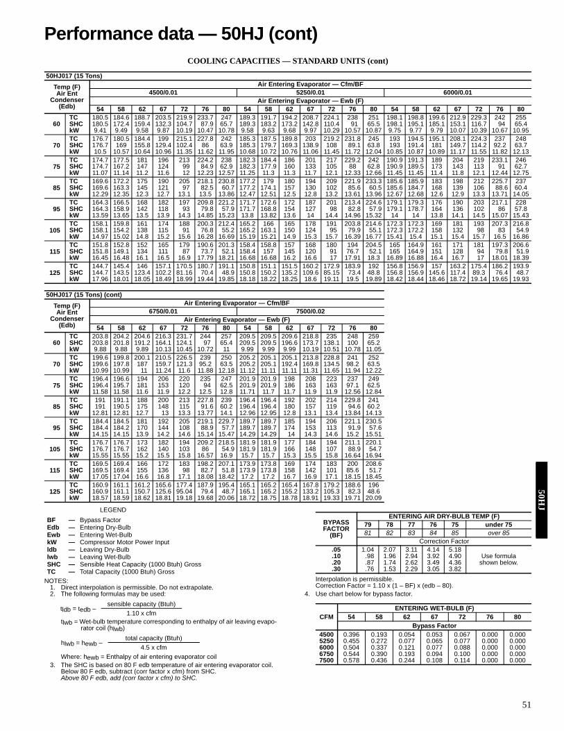
51
COOLING CAPACITIES — STANDARD UNITS (cont)
LEGEND
NOTES:1. Direct interpolation is permissible. Do not extrapolate.2. The following formulas may be used:
tlwb = Wet-bulb temperature corresponding to enthalpy of air leaving evapo-rator coil (hlwb)
Where: hewb = Enthalpy of air entering evaporator coil3. The SHC is based on 80 F edb temperature of air entering evaporator coil.
Below 80 F edb, subtract (corr factor x cfm) from SHC.Above 80 F edb, add (corr factor x cfm) to SHC.
Interpolation is permissible.Correction Factor = 1.10 x (1 – BF) x (edb – 80).
4. Use chart below for bypass factor.
50HJ017 (15 Tons)Temp (F)Air Ent
Condenser(Edb)
Air Entering Evaporator — Cfm/BF4500/0.01 5250/0.01 6000/0.01
Air Entering Evaporator — Ewb (F)54 58 62 67 72 76 80 54 58 62 67 72 76 80 54 58 62 67 72 76 80
60TC 180.5 184.6 188.7 203.5 219.9 233.7 247 189.3 191.7 194.2 208.7 224.1 238 251 198.1 198.8 199.6 212.9 229.3 242 255SHC 180.5 172.4 159.4 132.3 104.7 87.9 65.7 189.3 183.2 173.2 142.8 110.4 91 65.5 198.1 195.1 185.1 153.1 116.7 94 65.4kW 9.41 9.49 9.58 9.87 10.19 10.47 10.78 9.58 9.63 9.68 9.97 10.29 10.57 10.87 9.75 9.77 9.79 10.07 10.39 10.67 10.95
70TC 176.7 180.5 184.4 199 215.1 227.8 242 185.3 187.5 189.8 203 219.2 231.8 245 193 194.5 195.1 208.1 224.3 237 248SHC 176.7 169 155.8 129.4 102.4 86 63.9 185.3 179.7 169.3 138.9 108 89.1 63.8 193 191.4 181 149.7 114.2 92.2 63.7kW 10.5 10.57 10.64 10.96 11.35 11.62 11.95 10.68 10.72 10.76 11.06 11.45 11.72 12.04 10.85 10.87 10.89 11.17 11.55 11.82 12.13
75TC 174.7 177.5 181 196 213 224.2 238 182.3 184.4 186 201 217 229.2 242 190.9 191.3 189 204 219 233.1 246SHC 174.7 167.2 147 124 99 84.9 62.9 182.3 177.9 160 133 105 88 62.8 190.9 189.5 173 143 113 91 62.7kW 11.07 11.14 11.2 11.6 12 12.23 12.57 11.25 11.3 11.3 11.7 12.1 12.33 12.66 11.45 11.45 11.4 11.8 12.1 12.44 12.75
85TC 169.6 172.2 175 190 205 218.1 230.8 177.2 179 180 194 209 221.9 233.3 185.6 185.9 183 198 212 225.7 237SHC 169.6 163.3 145 121 97 82.5 60.7 177.2 174.1 157 130 102 85.6 60.5 185.6 184.7 168 139 106 88.6 60.4kW 12.29 12.35 12.3 12.7 13.1 13.5 13.86 12.47 12.51 12.5 12.8 13.2 13.61 13.96 12.67 12.68 12.6 12.9 13.3 13.71 14.05
95TC 164.3 166.5 168 182 197 209.8 221.2 171.7 172.6 172 187 201 213.4 224.6 179.1 179.3 176 190 203 217.1 228SHC 164.3 158.9 142 118 93 79.8 57.9 171.7 168.8 154 127 98 82.8 57.9 179.1 178.7 164 136 102 86 57.8kW 13.59 13.65 13.5 13.9 14.3 14.85 15.23 13.8 13.82 13.6 14 14.4 14.96 15.32 14 14 13.8 14.1 14.5 15.07 15.43
105TC 158.1 159.8 161 174 188 200.3 212.4 165.2 166 165 178 191 203.8 214.6 172.3 172.3 169 181 193 207.3 216.8SHC 158.1 154.2 138 115 91 76.8 55.2 165.2 163.1 150 124 95 79.9 55.1 172.3 172.2 158 132 98 83 54.9kW 14.97 15.02 14.8 15.2 15.6 16.28 16.69 15.19 15.21 14.9 15.3 15.7 16.39 16.77 15.41 15.4 15.1 15.4 15.7 16.5 16.86
115TC 151.8 152.8 152 165 179 190.6 201.3 158.4 158.8 157 168 180 194 204.5 165 164.9 161 171 181 197.3 206.6SHC 151.8 149.1 134 111 87 73.7 52.1 158.4 157 145 120 91 76.7 52.1 165 164.9 151 128 94 79.8 51.9kW 16.45 16.48 16.1 16.5 16.9 17.79 18.21 16.68 16.68 16.2 16.6 17 17.91 18.3 16.89 16.88 16.4 16.7 17 18.01 18.39
125TC 144.7 145.4 146 157.1 170.5 180.7 191.1 150.8 151.1 151.5 160.2 172.9 183.9 192 156.8 156.9 157 163.2 175.4 186.2 193.9SHC 144.7 143.5 123.4 102.2 81.16 70.4 48.9 150.8 150.2 135.2 109.6 85.15 73.4 48.8 156.8 156.9 145.6 117.4 89.3 76.4 48.7kW 17.96 18.01 18.05 18.49 18.99 19.44 19.85 18.18 18.22 18.25 18.6 19.11 19.5 19.89 18.42 18.44 18.46 18.72 19.14 19.65 19.93
50HJ017 (15 Tons) (cont)Temp (F)Air Ent
Condenser(Edb)
Air Entering Evaporator — Cfm/BF6750/0.01 7500/0.02
Air Entering Evaporator — Ewb (F)54 58 62 67 72 76 80 54 58 62 67 72 76 80
60TC 203.8 204.2 204.6 216.3 231.7 244 257 209.5 209.5 209.6 218.8 235 248 259SHC 203.8 201.8 191.2 164.1 124.1 97 65.4 209.5 209.5 196.6 173.7 138.1 100 65.2kW 9.88 9.88 9.89 10.13 10.45 10.72 11 9.99 9.99 9.99 10.19 10.51 10.78 11.05
70TC 199.6 199.8 200.1 210.5 226.5 239 250 205.2 205.1 205.1 213.8 228.8 241 252SHC 199.6 197.8 187 159.7 121.3 95.2 63.5 205.2 205.1 192.4 169.8 134.5 98.2 63.5kW 10.99 10.99 11 11.24 11.6 11.88 12.18 11.12 11.11 11.11 11.31 11.65 11.94 12.22
75TC 196.4 196.6 194 206 220 235 247 201.9 201.9 198 208 223 237 249SHC 196.4 195.7 181 153 120 94 62.5 201.9 201.9 186 163 163 97.1 62.5kW 11.58 11.58 11.6 11.9 12.2 12.5 12.8 11.71 11.7 11.7 11.9 11.9 12.56 12.84
85TC 191 191.1 188 200 213 227.8 239 196.4 196.4 192 202 214 229.8 241SHC 191 190.5 175 148 115 91.6 60.2 196.4 196.4 180 157 119 94.6 60.2kW 12.81 12.81 12.7 13 13.3 13.77 14.1 12.96 12.95 12.8 13.1 13.4 13.84 14.13
95TC 184.4 184.5 181 192 205 219.1 229.7 189.7 189.7 185 194 206 221.1 230.5SHC 184.4 184.2 170 144 108 88.9 57.7 189.7 189.7 174 153 113 91.9 57.6kW 14.15 14.15 13.9 14.2 14.6 15.14 15.47 14.29 14.29 14 14.3 14.6 15.2 15.51
105TC 176.7 176.7 173 182 194 209.2 218.5 181.9 181.9 177 184 194 211.1 220.1SHC 176.7 176.7 162 140 103 86 54.9 181.9 181.9 166 148 107 88.9 54.7kW 15.55 15.55 15.2 15.5 15.8 16.57 16.9 15.7 15.7 15.3 15.5 15.8 16.64 16.94
115TC 169.5 169.4 166 172 183 198.2 207.1 173.9 173.8 169 174 183 200 208.6SHC 169.5 169.4 155 136 98 82.7 51.8 173.9 173.8 158 142 101 85.6 51.7kW 17.05 17.04 16.6 16.8 17.1 18.08 18.42 17.2 17.2 16.7 16.9 17.1 18.15 18.45
125TC 160.9 161.1 161.2 165.6 177.4 187.9 195.4 165.1 165.2 165.4 167.8 179.2 188.6 196SHC 160.9 161.1 150.7 125.6 95.04 79.4 48.7 165.1 165.2 155.2 133.2 105.3 82.3 48.6kW 18.57 18.59 18.62 18.81 19.18 19.68 20.06 18.72 18.75 18.78 18.91 19.33 19.71 20.09
BF — Bypass FactorEdb — Entering Dry-BulbEwb — Entering Wet-BulbkW — Compressor Motor Power Inputldb — Leaving Dry-Bulblwb — Leaving Wet-BulbSHC — Sensible Heat Capacity (1000 Btuh) GrossTC — Total Capacity (1000 Btuh) Gross
tldb = tedb –sensible capacity (Btuh)
1.10 x cfm
hlwb = hewb –total capacity (Btuh)
4.5 x cfm
BYPASSFACTOR
(BF)
ENTERING AIR DRY-BULB TEMP (F)79 78 77 76 75 under 7581 82 83 84 85 over 85
Correction Factor.05 1.04 2.07 3.11 4.14 5.18
Use formulashown below.
.10 .98 1.96 2.94 3.92 4.90
.20 .87 1.74 2.62 3.49 4.36
.30 .76 1.53 2.29 3.05 3.82
CFMENTERING WET-BULB (F)
54 58 62 67 72 76 80Bypass Factor
4500 0.396 0.193 0.054 0.053 0.067 0.000 0.0005250 0.455 0.272 0.077 0.065 0.077 0.000 0.0006000 0.504 0.337 0.121 0.077 0.088 0.000 0.0006750 0.544 0.390 0.193 0.094 0.100 0.000 0.0007500 0.578 0.436 0.244 0.108 0.114 0.000 0.000
Performance data — 50HJ (cont)50H
J

52
COOLING CAPACITIES — STANDARD UNITS (cont)
LEGEND
NOTES:1. Direct interpolation is permissible. Do not extrapolate.2. The following formulas may be used:
tlwb = Wet-bulb temperature corresponding to enthalpy of air leaving evapo-rator coil (hlwb)
Where: hewb = Enthalpy of air entering evaporator coil3. The SHC is based on 80 F edb temperature of air entering evaporator coil.
Below 80 F edb, subtract (corr factor x cfm) from SHC.Above 80 F edb, add (corr factor x cfm) to SHC.
Interpolation is permissible.Correction Factor = 1.10 x (1 – BF) x (edb – 80).
4. Use chart below for bypass factor.
50HJ020 (18 Tons)Temp (F)Air Ent
Condenser(Edb)
Air Entering Evaporator — Cfm/BF5400/0.05 6300/0.06 7200/0.07
Air Entering Evaporator — Ewb (F)54 58 62 67 72 76 80 54 58 62 67 72 76 80 54 58 62 67 72 76 80
60TC 202 206 211 229 248 263 279 212 215 218 235 254 269 285 220 221 223 239 259 273 289SHC 202 193 184 155 124 99.3 74.7 212 205 199 166 131 103 74.9 220 216 213 177 138 106 75kW 10.2 10.3 10.4 10.6 10.8 11 11.2 10.4 10.4 10.4 10.7 10.9 11.1 11.3 10.5 10.5 10.5 10.7 11 11.2 11.4
70TC 197 202 206 223 242 256 272 207 209 212 228 247 262 277 215 216 217 233 252 267 282SHC 197 189 181 152 122 97 72.5 207 202 196 163 129 101 72.7 215 212 210 174 135 104 72.8kW 11.4 11.5 11.5 11.8 12 12.2 12.5 11.6 11.6 11.6 11.9 12.1 12.3 12.6 11.7 11.7 11.7 11.9 12.2 12.4 12.6
75TC 195 199 203 219 238 253 268 204 206 209 225 244 258 273 212 213 214 229 248 263 277SHC 195 187 180 150 120 95.8 71.3 204 199 195 162 127 99.3 71.4 212 210 208 173 134 103 71.5kW 12.1 12.2 12.2 12.5 12.7 13 13.2 12.3 12.3 12.3 12.6 12.8 13 13.3 12.4 12.4 12.4 12.6 12.9 13.1 13.3
85TC 190 193 196 213 231 246 260 199 201 202 218 236 251 264 206 207 208 222 240 255 268SHC 190 183 177 148 118 93.4 68.8 199 195 191 159 125 96.9 68.9 206 205 204 170 131 100 69kW 13.5 13.5 13.6 13.8 14.1 14.4 14.6 13.6 13.7 13.7 13.9 14.2 14.5 14.7 13.7 13.8 13.8 14 14.3 14.5 14.8
95TC 184 187 190 205 222 236 250 193 194 195 210 227 241 254 200 200 201 214 231 245 258SHC 184 179 173 144 114 90.2 65.9 193 190 187 156 121 93.7 66.1 200 199 199 167 128 97.1 66.2kW 15 15 15.1 15.4 15.7 15.9 16.2 15.1 15.2 15.2 15.5 15.8 16 16.3 15.3 15.3 15.3 15.5 15.8 16.1 16.3
105TC 178 180 182 197 213 228 240 186 187 188 201 217 232 244 193 193 193 205 221 235 247SHC 178 173 169 141 111 87.3 62.9 186 184 183 152 118 90.8 63.1 193 193 193 163 124 94.1 63.2kW 16.6 16.7 16.7 17 17.3 17.7 17.9 16.8 16.8 16.8 17.1 17.4 17.8 18 16.9 16.9 16.9 17.2 17.5 17.8 18
115TC 171 172 174 188 203 217 228 179 179 179 192 207 221 232 185 185 185 195 210 224 235SHC 171 168 165 137 107 83.6 59.6 179 178 178 149 114 87.1 59.7 185 185 185 159 121 90.4 59.9kW 18.4 18.4 18.4 18.8 19.1 19.4 19.7 18.6 18.6 18.6 18.9 19.2 19.5 19.8 18.7 18.7 18.7 19 19.3 19.6 19.9
125TC 164 165 165 178 192 205 216 171 171 171 182 196 208 219 177 177 177 185 199 211 222SHC 164 162 160 134 104 79.8 56.1 171 171 171 145 110 83.2 56.3 177 177 177 155 117 86.5 56.4kW 20.2 20.3 20.3 20.6 21 21.3 21.6 20.4 20.4 20.4 20.8 21.1 21.4 21.7 20.6 20.6 20.6 20.8 21.2 21.5 21.8
50HJ020 (18 Tons) (cont)Temp (F)Air Ent
Condenser(Edb)
Air Entering Evaporator — Cfm/BF8100/0.08 9000/0.09
Air Entering Evaporator — Ewb (F)54 58 62 67 72 76 80 54 58 62 67 72 76 80
60TC 227 227 228 243 262 277 293 233 233 233 246 265 280 295SHC 227 226 224 187 144 109 75.1 233 233 233 198 151 113 75.1kW 10.5 10.6 10.6 10.7 11 11.2 11.4 10.6 10.6 10.6 10.8 11 11.3 11.5
70TC 222 222 222 236 255 271 284 228 228 227 239 258 272 287SHC 222 221 221 185 142 107 72.8 228 228 227 195 148 110 72.9kW 11.8 11.8 11.8 12 12.2 12.5 12.7 11.9 11.9 11.8 12 12.3 12.5 12.7
75TC 219 219 219 232 251 266 280 225 224 224 235 254 268 282SHC 219 218 218 183 140 106 71.6 225 224 224 193 147 109 71.7kW 12.5 12.5 12.5 12.7 12.9 13.2 13.4 12.6 12.5 12.5 12.7 13 13.2 13.4
85TC 213 213 213 225 243 258 271 218 218 218 228 245 260 273SHC 213 213 213 180 138 103 69.1 218 218 218 190 144 107 69.2kW 13.8 13.8 13.8 14.1 14.3 14.6 14.8 13.9 13.9 13.9 14.1 14.4 14.6 14.8
95TC 206 206 206 217 234 248 260 211 211 211 220 236 250 262SHC 206 206 206 177 134 100 66.3 211 211 211 187 141 103 66.4kW 15.4 15.4 15.4 15.6 15.9 16.1 16.4 15.5 15.5 15.5 15.6 15.9 16.2 16.4
105TC 199 199 199 208 224 238 249 203 203 204 210 226 240 251SHC 199 199 199 173 131 97.2 63.2 203 203 204 183 137 100 63.4kW 17 17.1 17.1 17.3 17.6 17.9 18.1 17.2 17.2 17.2 17.3 17.6 17.9 18.1
115TC 191 191 191 198 213 226 237 195 195 195 201 215 228 238SHC 191 191 191 169 127 93.5 60 195 195 195 179 133 96.6 60kW 18.8 18.8 18.8 19 19.3 19.7 19.9 18.9 18.9 18.9 19.1 19.4 19.7 19.9
125TC 182 182 182 188 201 213 224 186 186 186 190 203 215 225SHC 182 182 182 165 123 89.6 56.5 186 186 186 174 129 92.6 56.6kW 20.7 20.7 20.7 20.9 21.2 21.6 21.9 20.9 20.9 20.9 21 21.3 21.6 21.9
BF — Bypass FactorEdb — Entering Dry-BulbEwb — Entering Wet-BulbkW — Compressor Motor Power Inputldb — Leaving Dry-Bulblwb — Leaving Wet-BulbSHC — Sensible Heat Capacity (1000 Btuh) GrossTC — Total Capacity (1000 Btuh) Gross
tldb = tedb –sensible capacity (Btuh)
1.10 x cfm
hlwb = hewb –total capacity (Btuh)
4.5 x cfm
BYPASSFACTOR
(BF)
ENTERING AIR DRY-BULB TEMP (F)79 78 77 76 75 under 7581 82 83 84 85 over 85
Correction Factor.05 1.04 2.07 3.11 4.14 5.18
Use formulashown below.
.10 .98 1.96 2.94 3.92 4.90
.20 .87 1.74 2.62 3.49 4.36
.30 .76 1.53 2.29 3.05 3.82
CFMENTERING WET-BULB (F)
54 58 62 67 72 76 80Bypass Factor
5400 0.424 0.238 0.125 0.120 0.138 0.000 0.0006300 0.478 0.304 0.153 0.132 0.145 0.000 0.0007200 0.525 0.364 0.190 0.144 0.153 0.000 0.0008100 0.562 0.414 0.231 0.156 0.162 0.000 0.0009000 0.594 0.456 0.281 0.168 0.170 0.000 0.000
50H
J

53
COOLING CAPACITIES — STANDARD UNITS (cont)
LEGEND
NOTES:1. Direct interpolation is permissible. Do not extrapolate.2. The following formulas may be used:
tlwb = Wet-bulb temperature corresponding to enthalpy of air leaving evapo-rator coil (hlwb)
Where: hewb = Enthalpy of air entering evaporator coil3. The SHC is based on 80 F edb temperature of air entering evaporator coil.
Below 80 F edb, subtract (corr factor x cfm) from SHC.Above 80 F edb, add (corr factor x cfm) to SHC.
Interpolation is permissible.Correction Factor = 1.10 x (1 – BF) x (edb – 80).
4. Use chart below for bypass factor.
50HJ024 (20 Tons)Temp (F)Air Ent
Condenser(Edb)
Air Entering Evaporator — Cfm/BF6,000/0.04 7,000/0.05 8,000/0.05
Air Entering Evaporator — Ewb (F)54 58 62 67 72 76 80 54 58 62 67 72 76 80 54 58 62 67 72 76 80
60TC 235 242 248 267 288 306 323 247 251 256 274 296 312 330 257 259 262 279 300 317 333SHC 235 224 212 178 143 115 86.6 247 238 230 191 151 119 87 257 251 246 204 159 123 86.7kW 11.5 11.6 11.7 12 12.4 12.7 13 11.7 11.8 11.8 12.1 12.5 12.8 13.1 11.9 11.9 11.9 12.2 12.6 12.9 13.1
70TC 231 237 242 261 282 300 316 242 246 250 268 289 305 323 252 254 256 273 293 310 326SHC 231 220 209 175 141 113 84.5 242 234 227 189 149 117 84.9 252 247 243 201 156 120 84.6kW 13.1 13.2 13.3 13.6 14 14.3 14.6 13.3 13.3 13.4 13.7 14.1 14.4 14.8 13.4 13.5 13.5 13.8 14.2 14.5 14.8
75TC 228 234 239 257 278 295 311 239 243 246 264 285 301 318 249 250 252 269 290 305 322SHC 228 218 208 174 139 112 83.1 239 232 225 187 147 115 83.6 249 245 241 199 155 119 83.5kW 13.9 14 14.1 14.5 14.9 15.2 15.6 14.1 14.2 14.2 14.6 15 15.3 15.7 14.3 14.3 14.4 14.7 15.1 15.4 15.8
85TC 223 227 231 250 270 287 303 234 236 238 256 277 292 310 243 244 245 261 282 296 314SHC 223 213 204 171 136 109 80.5 234 227 221 184 144 112 80.9 243 240 236 196 152 116 81.3kW 15.6 15.7 15.8 16.2 16.6 17.1 17.4 15.8 15.9 15.9 16.3 16.8 17.2 17.6 16 16.1 16.1 16.5 16.9 17.3 17.7
95TC 216 219 223 241 260 277 292 226 228 230 247 267 282 298 235 235 236 251 272 285 303SHC 216 208 200 167 132 105 77.2 226 221 217 180 141 109 77.7 235 233 231 192 148 112 78kW 17.4 17.5 17.6 18.1 18.6 19 19.4 17.7 17.7 17.8 18.2 18.7 19.1 19.6 17.9 17.9 17.9 18.3 18.9 19.2 19.7
105TC 208 211 214 231 249 265 279 218 219 220 236 256 270 285 226 226 226 241 260 273 290SHC 208 202 195 163 129 101 73.6 218 215 212 176 137 105 74 226 226 225 188 145 108 74.4kW 19.3 19.4 19.5 20 20.6 21 21.5 19.6 19.6 19.7 20.2 20.8 21.2 21.6 19.9 19.9 19.9 20.3 20.9 21.3 21.8
115TC 200 202 204 220 237 253 266 209 210 210 225 243 257 271 217 217 217 229 248 260 275SHC 200 195 190 158 124 97.2 69.5 209 207 206 171 132 101 70 217 217 217 183 140 104 70.4kW 21.3 21.4 21.5 22 22.7 23.2 23.6 21.7 21.7 21.7 22.2 22.9 23.3 23.8 21.9 21.9 21.9 22.4 23 23.4 23.9
125TC 191 192 193 208 224 239 251 199 199 200 212 230 243 255 207 207 206 216 232 245 257SHC 191 188 185 153 120 92.8 65.3 199 199 199 166 128 96.4 65.7 207 207 206 178 135 99.8 65.5kW 23.5 23.5 23.6 24.2 24.8 25.4 25.9 23.8 23.8 23.8 24.4 25 25.5 26 24.1 24.1 24.1 24.5 25.1 25.7 26.1
50HJ024 (20 Tons) (cont)Temp (F)Air Ent
Condenser(Edb)
Air Entering Evaporator — Cfm/BF9,000/0.06 10,000/0.07
Air Entering Evaporator — Ewb (F)54 58 62 67 72 76 80 54 58 62 67 72 76 80
60TC 265 266 267 284 305 321 338 272 272 272 287 307 325 340SHC 265 262 260 216 166 126 87 272 271 271 227 173 130 86.7kW 12 12 12 12.3 12.7 12.9 13.2 12.1 12.1 12.1 12.4 12.7 13 13.3
70TC 260 261 261 277 298 315 331 266 267 267 281 301 317 333SHC 260 258 256 213 164 124 85 266 267 267 225 171 127 84.7kW 13.6 13.6 13.6 13.9 14.3 14.6 14.9 13.7 13.7 13.7 14 14.3 14.6 15
75TC 256 257 258 273 294 310 326 263 263 263 277 296 312 327SHC 256 255 254 211 162 123 83.7 263 263 263 223 169 126 83.4kW 14.5 14.5 14.5 14.8 15.2 15.5 15.8 14.6 14.6 14.6 14.9 15.2 15.6 15.9
85TC 250 250 250 265 285 301 316 257 256 256 268 287 303 317SHC 250 250 249 208 159 120 81 257 256 256 220 166 123 80.7kW 16.2 16.2 16.2 16.5 17 17.4 17.7 16.4 16.4 16.4 16.6 17 17.4 17.7
95TC 242 242 242 255 274 288 304 248 248 248 258 276 292 306SHC 242 242 242 204 155 116 77.8 248 248 248 215 162 120 77.6kW 18.1 18.1 18.1 18.4 18.9 19.3 19.7 18.3 18.3 18.2 18.5 19 19.4 19.7
105TC 233 233 233 244 263 275 291 239 239 239 247 264 279 291SHC 233 233 233 200 152 112 74.2 239 239 239 211 158 116 73.9kW 20.1 20.1 20.1 20.4 21 21.4 21.8 20.3 20.2 20.2 20.5 21 21.5 21.8
115TC 223 223 223 232 250 262 276 229 228 228 235 251 263 276SHC 223 223 223 195 147 108 70.2 229 228 228 206 154 111 69.9kW 22.2 22.1 22.1 22.5 23.1 23.5 24 22.3 22.3 22.3 22.6 23.1 23.6 24
125TC 213 212 212 219 234 247 258 218 217 217 222 235 248 259SHC 213 212 212 189 142 103 65.4 218 217 217 200 148 106 65.2kW 24.3 24.3 24.3 24.6 25.2 25.7 26.2 24.5 24.5 24.5 24.7 25.3 25.8 26.2
BF — Bypass FactorEdb — Entering Dry-BulbEwb — Entering Wet-BulbkW — Compressor Motor Power Inputldb — Leaving Dry-Bulblwb — Leaving Wet-BulbSHC — Sensible Heat Capacity (1000 Btuh) GrossTC — Total Capacity (1000 Btuh) Gross
tldb = tedb –sensible capacity (Btuh)
1.10 x cfm
hlwb = hewb –total capacity (Btuh)
4.5 x cfm
BYPASSFACTOR
(BF)
ENTERING AIR DRY-BULB TEMP (F)79 78 77 76 75 under 7581 82 83 84 85 over 85
Correction Factor.05 1.04 2.07 3.11 4.14 5.18
Use formulashown below.
.10 .98 1.96 2.94 3.92 4.90
.20 .87 1.74 2.62 3.49 4.36
.30 .76 1.53 2.29 3.05 3.82
CFMENTERING WET-BULB (F)
54 58 62 67 72 76 80Bypass Factor
6,000 0.386 0.197 0.108 0.109 0.134 0.000 0.0007,000 0.444 0.260 0.131 0.121 0.138 0.000 0.0008,000 0.492 0.321 0.163 0.133 0.145 0.000 0.0009,000 0.532 0.375 0.205 0.146 0.154 0.000 0.000
10,000 0.566 0.420 0.245 0.158 0.164 0.000 0.000
Performance data — 50HJ (cont)50H
J

54
COOLING CAPACITIES — STANDARD UNITS (cont)
LEGEND
NOTES:1. Direct interpolation is permissible. Do not extrapolate.2. The following formulas may be used:
tlwb = Wet-bulb temperature corresponding to enthalpy of air leaving evapo-rator coil (hlwb)
Where: hewb = Enthalpy of air entering evaporator coil3. The SHC is based on 80 F edb temperature of air entering evaporator coil.
Below 80 F edb, subtract (corr factor x cfm) from SHC.Above 80 F edb, add (corr factor x cfm) to SHC.
Interpolation is permissible.Correction Factor = 1.10 x (1 – BF) x (edb – 80).
4. Use chart below for bypass factor.
50HJ028 (25 Tons)Temp (F)Air Ent
Condenser(Edb)
Air Entering Evaporator — Cfm/BF7,500/0.05 8,250/0.06 9,500/0.07
Air Entering Evaporator — Ewb (F)54 58 62 67 72 76 80 54 58 62 67 72 76 80 54 58 62 67 72 76 80
60TC 287 296 304 331 359 385 408 297 304 310 336 367 390 414 311 315 319 345 375 398 421SHC 287 274 261 220 178 145 110 297 285 273 229 185 148 110 311 303 294 246 194 152 111kW 15.5 15.7 15.9 16.5 17.3 17.9 18.6 15.7 15.9 16 16.7 17.4 18.1 18.7 16 16.1 16.2 16.9 17.6 18.3 19
70TC 279 286 293 318 345 367 392 288 293 298 323 350 372 397 301 303 306 329 357 381 403SHC 279 267 255 214 173 139 105 288 278 268 224 178 142 105 301 294 287 239 188 147 105kW 17 17.2 17.3 18 18.7 19.3 20 17.2 17.3 17.5 18.1 18.8 19.4 20.1 17.5 17.6 17.7 18.3 19 19.7 20.3
75TC 275 281 287 311 338 360 383 283 288 293 316 343 365 388 296 298 300 323 349 372 394SHC 275 264 252 212 170 136 102 283 274 265 221 176 139 103 296 290 284 237 185 144 103kW 17.9 18.1 18.2 18.8 19.5 20.1 20.8 18.1 18.2 18.4 18.9 19.7 20.3 20.9 18.4 18.5 18.5 19.1 19.8 20.5 21.1
85TC 267 272 277 299 324 345 366 274 278 282 304 329 350 370 286 287 289 311 334 355 375SHC 267 257 247 207 165 131 97.3 274 267 259 216 171 134 97.3 286 282 278 232 180 139 97.3kW 19.8 19.9 20 20.6 21.2 21.8 22.4 20 20.1 20.1 20.7 21.4 22 22.6 20.2 20.3 20.3 20.9 21.5 22.1 22.7
95TC 259 263 267 288 311 331 350 267 270 273 293 315 335 354 278 279 281 299 322 340 358SHC 259 251 242 202 160 126 92.5 267 261 255 212 166 129 92.5 278 276 273 227 175 134 92.4kW 22.1 22.2 22.3 22.8 23.4 23.9 24.5 22.3 22.4 22.5 22.9 23.5 24 24.6 22.6 22.6 22.6 23.1 23.6 24.2 24.7
105TC 253 256 260 279 301 318 335 260 262 264 282 304 322 338 269 270 270 287 308 326 342SHC 253 246 239 198 156 122 87.9 260 255 250 207 162 125 87.8 269 268 267 222 171 129 87.7kW 24.9 25 25.1 25.4 25.9 26.4 26.9 25.1 25.1 25.1 25.5 26 26.5 26.9 25.2 25.2 25.2 25.6 26.1 26.6 27.1
115TC 246 249 252 270 291 305 320 253 255 256 274 294 309 323 262 262 262 277 298 312 328SHC 246 240 235 195 152 118 83.5 253 250 246 204 158 121 83.4 262 261 261 218 167 125 83.9kW 28.1 28.2 28.3 28.6 29 29.3 29.6 28.3 28.3 28.3 28.6 29 29.4 29.7 28.4 28.4 28.4 28.7 29.1 29.4 29.9
125TC 238 240 242 259 279 293 305 245 246 246 262 281 295 310 253 253 253 266 284 298 313SHC 238 234 230 190 148 114 79.2 245 243 240 199 153 116 79.7 253 253 253 214 162 120 79.9kW 31.6 31.7 31.7 32 32.4 32.6 32.9 31.8 31.8 31.8 32.1 32.4 32.7 33 31.9 31.9 31.9 32.1 32.5 32.7 33.1
50HJ028 (25 Tons) (cont)Temp (F)Air Ent
Condenser(Edb)
Air Entering Evaporator — Cfm/BF10,750/0.08 12,000/0.09
Air Entering Evaporator — Ewb (F)54 58 62 67 72 76 80 54 58 62 67 72 76 80
60TC 322 324 327 351 380 404 429 332 333 334 357 386 410 432SHC 322 317 313 260 203 157 111 332 330 329 276 212 162 111kW 16.3 16.4 16.4 17 17.8 18.5 19.2 16.6 16.6 16.6 17.2 18 18.6 19.2
70TC 311 312 314 336 364 386 408 320 320 321 341 368 392 414SHC 311 308 305 255 198 151 105 320 320 319 269 206 156 106kW 17.8 17.8 17.9 18.4 19.2 19.8 20.5 18 18 18 18.5 19.3 20 20.6
75TC 306 307 308 329 356 378 398 315 315 315 333 360 383 404SHC 306 304 302 252 195 149 103 315 314 314 266 203 153 103kW 18.7 18.7 18.7 19.3 20 20.6 21.3 18.9 18.9 18.9 19.4 20.1 20.8 21.4
85TC 295 296 297 315 340 362 379 303 303 303 319 344 365 385SHC 295 295 294 246 189 144 97.3 303 303 303 260 198 148 97.9kW 20.5 20.5 20.5 21 21.7 22.3 22.8 20.7 20.7 20.7 21.1 21.8 22.4 23
95TC 286 286 286 303 327 344 364 293 293 294 307 330 347 366SHC 286 286 286 241 185 138 93 293 293 294 255 193 142 92.8kW 22.7 22.7 22.7 23.1 23.8 24.3 24.9 22.9 22.9 22.9 23.2 23.9 24.4 24.9
105TC 277 277 277 290 312 329 347 284 284 285 295 314 331 352SHC 277 277 277 236 179 133 88.3 284 284 285 250 188 137 88.7kW 25.4 25.4 25.4 25.7 26.2 26.7 27.2 25.5 25.6 25.6 25.8 26.3 26.7 27.3
115TC 268 269 269 281 300 315 332 274 274 275 283 303 317 333SHC 268 269 269 232 176 129 84.4 274 274 275 245 184 133 84kW 28.5 28.5 28.5 28.7 29.2 29.5 30 28.6 28.6 28.6 28.8 29.2 29.5 30
125TC 260 259 259 269 287 300 316 265 265 264 271 289 302 318SHC 260 259 259 227 171 125 80 265 265 264 240 179 129 80.1kW 32 32 32 32.1 32.5 32.8 33.2 32.1 32.1 32.1 32.2 32.5 32.8 33.3
BF — Bypass FactorEdb — Entering Dry-BulbEwb — Entering Wet-BulbkW — Compressor Motor Power Inputldb — Leaving Dry-Bulblwb — Leaving Wet-BulbSHC — Sensible Heat Capacity (1000 Btuh) GrossTC — Total Capacity (1000 Btuh) Gross
tldb = tedb –sensible capacity (Btuh)
1.10 x cfm
hlwb = hewb –total capacity (Btuh)
4.5 x cfm
BYPASSFACTOR
(BF)
ENTERING AIR DRY-BULB TEMP (F)79 78 77 76 75 under 7581 82 83 84 85 over 85
Correction Factor.05 1.04 2.07 3.11 4.14 5.18
Use formulashown below.
.10 .98 1.96 2.94 3.92 4.90
.20 .87 1.74 2.62 3.49 4.36
.30 .76 1.53 2.29 3.05 3.82
CFMENTERING WET-BULB (F)
54 58 62 67 72 76 80Bypass Factor
7,500 0.407 0.208 0.097 0.104 0.123 0.000 0.0008,250 0.443 0.256 0.110 0.112 0.128 0.000 0.0009,500 0.494 0.324 0.138 0.123 0.136 0.000 0.000
10,750 0.536 0.380 0.181 0.134 0.145 0.000 0.00012,000 0.571 0.427 0.232 0.145 0.154 0.000 0.000
50H
J

55
COOLING CAPACITIES — UNITS WITH HUMIDI-MIZER™ ADAPTIVE DEHUMIDIFICATION SYSTEM OPTION
LEGEND
NOTES:1. Direct interpolation is permissible. Do not extrapolate.
2. The following formulas may be used:
Where: hewb = Enthalpy of air entering evaporator coil.3. The SHC is based on 80 F edb temperature of air entering evapo-
rator coil.Below 80 F edb, subtract (corr factor x cfm) from SHC.Above 80 F edb, add (corr factor x cfm) to SHC.Correction Factor = 1.10 x (1 – BF) x (edb – 80).
50HJ004 (3 TONS) — SUBCOOLING MODE
Temp (F)Air Ent
Condenser(Edb)
Air Entering Evaporator — Cfm/BF900/0.14 1200/0.17 1500/0.20
Air Entering Evaporator — Ewb (F)72 67 62 72 67 62 72 67 62
75TC 41.3 37.3 34.3 43.5 39.2 35.9 45.5 41.6 38.2SHC 17.5 22.4 26.7 19.6 25.5 31.2 21.5 28.5 35.2kW 2.19 2.14 2.10 2.21 2.16 2.14 2.24 2.19 2.16
85TC 38.6 34.4 31.6 41.3 37.5 33.3 43.5 38.6 35.5SHC 15.2 20.1 25.1 17.1 23.2 29.0 18.9 26.3 32.9kW 2.46 2.40 2.37 2.47 2.43 2.40 2.51 2.45 2.42
95TC 35.9 31.4 28.8 39.2 35.9 30.6 41.3 35.7 32.9SHC 13.0 17.9 23.3 14.5 21.1 26.9 16.1 24.2 30.6kW 2.74 2.68 2.63 2.76 2.74 2.67 2.80 2.75 2.71
105TC 33.8 29.7 27.4 36.3 32.2 28.7 38.1 32.8 30.4SHC 10.9 15.8 21.0 12.5 18.9 24.6 14.0 21.7 28.1kW 3.05 3.00 2.97 3.09 3.04 2.99 3.12 3.07 3.03
115TC 31.8 28.0 25.5 33.2 28.7 26.5 34.9 30.0 27.9SHC 9.0 13.7 18.4 10.3 16.8 22.3 11.9 19.3 25.2kW 3.40 3.36 3.31 3.45 3.38 3.32 3.48 3.41 3.37
125TC 28.7 26.3 23.4 29.7 25.5 22.9 31.3 27.1 25.5SHC 6.9 12.2 17.3 7.9 14.5 20.6 9.2 17.3 22.3kW 3.78 3.73 3.66 3.84 3.77 3.71 3.87 3.79 3.75
50HJ004 (3 TONS) — HOT GAS REHEAT MODE
Temp (F)Air Ent
Condenser(Edb)
Air Entering Evaporator — Ewb (F)75 Dry Bulb
62.5 Wet Bulb(50% Relative)
75 Dry Bulb64 Wet Bulb
(55% Relative)
75 Dry Bulb65.3 Wet Bulb(60% Relative)
Air Entering Evaporator — Cfm900 1200 1500 900 1200 1500 900 1200 1500
80TC 12.83 15.84 18.20 13.24 16.31 18.73 13.58 16.72 19.18SHC 4.06 5.69 6.98 2.21 3.83 5.12 .59 2.20 3.50kW 2.12 2.12 2.12 2.13 2.13 2.13 2.14 2.14 2.14
75TC 13.61 16.44 18.67 14.03 16.93 19.20 14.39 17.34 19.67SHC 4.62 6.16 7.37 2.89 4.43 5.65 1.40 2.93 4.15kW 2.11 2.11 2.11 2.12 2.12 2.12 2.14 2.14 2.14
70TC 14.39 17.05 19.14 14.82 17.54 19.68 15.19 17.96 20.15SHC 5.17 6.62 7.77 3.58 5.03 6.18 2.20 3.65 4.80kW 2.10 2.10 2.10 2.12 2.12 2.12 2.13 2.13 2.13
60TC 15.95 18.26 20.08 16.40 18.77 20.63 16.79 19.21 21.11SHC 6.27 7.55 8.56 4.95 6.23 7.24 3.81 5.09 6.10kW 2.09 2.09 2.09 2.11 2.11 2.11 2.12 2.12 2.12
50TC 17.50 19.48 21.02 17.98 20.00 21.58 18.40 20.45 22.07SHC 7.37 8.47 9.35 6.32 7.43 8.30 5.42 6.52 7.39kW 2.07 2.07 2.07 2.10 2.10 2.10 2.12 2.12 2.12
40TC 19.06 20.69 21.07 19.56 21.23 22.54 20.00 21.70 23.03SHC 8.47 9.40 10.13 7.71 8.63 9.36 7.02 7.95 8.69kW 2.06 2.06 2.06 2.08 2.08 2.08 2.11 2.11 2.11
BF — Bypass FactorEdb — Entering Dry BulbEwb — Entering Wet BulbkW — Compressor Motor Power InputSHC — Sensible Heat Capacity (1000 Btuh) GrossTC — Total Capacity (1000 Btuh) Gross
tldb = tedb –sensible capacity (Btuh)
1.10 x cfmtlwb = Wet-bulb temperature corresponding to enthalpy of
air leaving evaporator coil (hlwb)
hlwb = hewb –total capacity (Btuh)
4.5 x cfm
Performance data — 50HJ (cont)50H
J

56
COOLING CAPACITIES — UNITS WITH HUMIDI-MIZER™ ADAPTIVE DEHUMIDIFICATION SYSTEM OPTION (cont)
LEGEND
*Negative SHC value indicates that the air entering the coil is beingheated.
NOTES:1. Direct interpolation is permissible. Do not extrapolate.
2. The following formulas may be used:
Where: hewb = Enthalpy of air entering evaporator coil.3. The SHC is based on 80 F edb temperature of air entering evapo-
rator coil.Below 80 F edb, subtract (corr factor x cfm) from SHC.Above 80 F edb, add (corr factor x cfm) to SHC.Correction Factor = 1.10 x (1 – BF) x (edb – 80).
50HJ005 (4 TONS) — SUBCOOLING MODE
Temp (F)Air Ent
Condenser(Edb)
Air Entering Evaporator — Cfm/BF1200/0.17 1450/0.19 1600/0.21 2000/0.24
Air Entering Evaporator — Ewb (F)72 67 62 72 67 62 72 67 62 72 67 62
75TC 52.9 47.5 41.5 55.7 50.9 47.5 57.0 51.7 48.1 60.5 55.6 52.1SHC 22.7 28.4 33.4 26.1 34.1 38.9 25.9 33.7 41.6 29.4 39.1 47.5kW 2.87 2.86 2.82 2.89 2.87 2.84 2.89 2.86 2.85 2.90 2.88 2.85
85TC 49.2 43.8 37.1 52.1 47.2 43.6 52.9 47.9 43.7 55.4 51.4 47.0SHC 19.8 25.5 30.4 22.2 29.5 35.8 22.4 31.1 38.7 24.2 36.0 44.3kW 3.26 3.25 3.21 3.28 3.26 3.23 3.28 3.26 3.24 3.28 3.26 3.24
95TC 45.8 40.1 32.8 48.2 43.6 39.4 48.8 44.0 39.3 51.7 47.4 43.0SHC 17.2 22.5 27.3 18.4 24.8 32.6 19.0 28.1 35.9 20.7 33.0 41.0kW 3.71 3.68 3.64 3.72 3.69 3.67 3.72 3.69 3.67 3.74 3.70 3.68
105TC 41.6 37.0 29.7 43.2 38.9 35.4 43.9 39.7 34.7 46.5 41.4 37.5SHC 13.5 19.5 23.9 14.7 21.7 29.2 15.0 23.7 30.6 16.4 27.8 35.1kW 4.20 4.17 4.11 4.20 4.17 4.14 4.20 4.17 4.15 4.22 4.19 4.16
115TC 37.2 33.2 27.1 38.4 34.0 30.8 39.4 35.5 30.0 41.3 35.2 31.9SHC 9.9 16.4 20.7 11.3 18.5 25.6 11.2 19.7 25.4 12.4 22.4 28.6kW 4.73 4.68 4.62 4.74 4.71 4.64 4.73 4.72 4.65 4.74 4.72 4.69
125TC 32.4 28.1 24.9 33.8 28.1 27.4 35.3 30.5 26.6 36.1 32.0 28.7SHC 7.2 12.9 18.3 8.4 14.5 21.9 16.8 21.1 21.2 9.5 18.3 24.1kW 5.29 5.23 5.15 5.30 5.25 5.19 5.29 5.27 5.21 5.30 5.29 5.25
50HJ005 (4 TONS) — HOT GAS REHEAT MODE*
Temp (F)Air Ent
Condenser(Edb)
Air Entering Evaporator — Ewb (F)75 Dry Bulb
62.5 Wet Bulb(50% Relative)
75 Dry Bulb64 Wet Bulb
(55% Relative)
75 Dry Bulb65.3 Wet Bulb(60% Relative)
Air Entering Evaporator — Cfm1200 1450 1600 1200 1450 1600 1200 1450 1600
80TC 12.13 14.30 15.43 14.98 17.20 18.36 17.44 19.71 20.90SHC 1.01 1.60 1.90 -0.18 0.41 0.72 -1.20 -0.61 -0.30kW 2.76 2.76 2.76 2.75 2.75 2.75 2.74 2.74 2.74
75TC 13.25 15.28 16.34 15.96 18.05 19.14 18.31 20.44 21.56SHC 1.60 2.14 2.43 0.50 1.05 1.34 -0.45 0.11 0.40kW 7.54 7.54 7.57 7.61 7.64 7.66 7.66 7.70 7.71
70TC 14.37 16.27 17.26 16.94 18.90 19.92 19.17 21.17 22.22SHC 2.18 2.69 2.96 1.17 1.69 1.96 0.30 0.82 1.10kW 2.70 2.70 2.70 2.70 2.70 2.70 2.70 2.70 2.70
60TC 16.60 18.24 19.10 18.91 20.60 21.48 20.91 22.64 23.54SHC 3.35 3.79 4.03 2.52 2.97 3.21 1.80 2.25 2.50kW 2.64 2.64 2.64 2.65 2.65 2.65 2.65 2.65 2.65
50TC 18.83 20.22 20.94 20.87 22.30 23.04 22.65 24.10 24.86SHC 4.51 4.89 5.09 3.86 4.25 4.45 3.30 3.69 3.89kW 2.59 2.59 2.59 2.60 2.60 2.60 2.61 2.61 2.61
40TC 21.06 22.19 22.78 22.84 24.00 24.61 24.38 25.57 26.19SHC 5.68 5.99 6.16 5.21 5.53 5.69 4.80 5.12 5.29kW 2.53 2.53 2.53 2.55 2.55 2.55 2.57 2.57 2.57
BF — Bypass FactorEdb — Entering Dry BulbEwb — Entering Wet BulbkW — Compressor Motor Power InputSHC — Sensible Heat Capacity (1000 Btuh) GrossTC — Total Capacity (1000 Btuh) Gross
tldb = tedb –sensible capacity (Btuh)
1.10 x cfmtlwb = Wet-bulb temperature corresponding to enthalpy of
air leaving evaporator coil (hlwb)
hlwb = hewb –total capacity (Btuh)
4.5 x cfm
50H
J

57
COOLING CAPACITIES — UNITS WITH HUMIDI-MIZER™ ADAPTIVE DEHUMIDIFICATION SYSTEM OPTION (cont)
LEGEND
*Negative SHC value indicates that the air entering the coil is beingheated.
NOTES:1. Direct interpolation is permissible. Do not extrapolate.
2. The following formulas may be used:
Where: hewb = Enthalpy of air entering evaporator coil.3. The SHC is based on 80 F edb temperature of air entering evapo-
rator coil.Below 80 F edb, subtract (corr factor x cfm) from SHC.Above 80 F edb, add (corr factor x cfm) to SHC.Correction Factor = 1.10 x (1 – BF) x (edb – 80).
50HJ006 (5 TONS) — SUBCOOLING MODE
Temp (F)Air Ent
Condenser(Edb)
Air Entering Evaporator — Cfm/BF1500/0.08 1750/0.09 2000/0.11 2500/0.13
Air Entering Evaporator — Ewb (F)72 67 62 72 67 62 72 67 62 72 67 62
75TC 69.9 62.7 56.2 74.7 67.3 61.0 78.5 71.2 64.8 81.7 75.5 69.3SHC 29.0 36.9 43.9 31.7 40.5 51.2 34.5 44.2 55.4 37.8 52.0 62.8kW 3.61 3.55 3.51 3.64 3.58 3.49 3.65 3.60 3.51 3.62 3.58 3.51
85TC 65.9 59.1 51.7 70.6 63.2 56.3 75.5 66.8 60.7 78.1 70.8 65.1SHC 25.3 34.0 41.9 27.5 37.6 48.0 30.7 41.6 52.0 33.8 47.4 58.0kW 4.05 3.97 3.91 4.07 4.01 3.92 4.11 4.00 3.95 4.08 4.02 3.96
95TC 61.9 55.2 47.7 66.5 58.8 51.3 70.4 61.9 55.7 74.2 65.9 60.6SHC 21.6 31.1 40.0 23.5 34.5 44.6 26.0 38.6 47.9 30.0 42.8 52.6kW 4.53 4.43 4.35 4.55 4.47 4.37 4.56 4.42 4.41 4.58 4.49 4.44
105TC 57.7 51.1 44.9 61.8 54.5 47.7 65.1 57.2 50.8 68.4 60.3 56.1SHC 18.1 27.8 35.7 20.0 31.2 40.1 22.1 34.3 43.5 26.1 38.9 48.5kW 5.05 4.93 4.84 5.09 4.97 4.88 5.11 4.96 4.92 5.11 5.03 4.98
115TC 53.4 47.2 42.0 56.6 50.0 44.2 59.6 52.5 46.2 62.6 54.9 51.6SHC 14.7 24.6 31.5 16.5 27.8 35.7 18.2 30.0 39.0 22.1 34.9 44.3kW 5.60 5.49 5.40 5.64 5.52 5.45 5.69 5.55 5.48 5.69 5.61 5.57
125TC 48.7 42.0 36.9 51.3 45.0 39.0 54.1 46.8 40.9 56.9 49.2 45.9SHC 10.9 19.6 28.0 12.5 22.2 31.5 13.5 24.0 34.0 16.5 28.0 38.8kW 6.26 6.12 6.02 6.28 6.18 6.09 6.33 6.18 6.13 6.33 6.27 6.22
50HJ006 (5 TONS) — HOT GAS REHEAT MODE*
Temp (F)Air Ent
Condenser(Edb)
Air Entering Evaporator — Ewb (F)75 Dry Bulb
62.5 Wet Bulb(50% Relative)
75 Dry Bulb64 Wet Bulb
(55% Relative)
75 Dry Bulb65.3 Wet Bulb(60% Relative)
Air Entering Evaporator — Cfm1500 1750 2000 1500 1750 2000 1500 1750 2000
80TC 17.67 19.23 20.59 17.51 19.09 20.48 17.37 18.98 20.39SHC -0.39 0.07 0.46 -1.61 -1.15 -0.75 -2.67 -2.21 -1.80kW 3.45 3.45 3.45 3.48 3.48 3.48 3.50 3.50 3.50
75TC 18.55 20.03 21.32 18.45 19.95 21.27 18.36 19.89 21.23SHC 0.28 0.71 1.09 -0.85 -0.42 -0.04 -1.83 -1.39 -1.01kW 3.43 3.43 3.43 3.46 3.46 3.46 3.49 3.49 3.49
70TC 19.44 20.83 22.06 19.39 20.81 22.06 19.35 20.80 22.07SHC 0.95 1.36 1.71 -0.09 0.32 0.68 -0.99 -0.58 -0.22kW 3.42 3.42 3.42 3.45 3.45 3.45 3.48 3.48 3.48
60TC 21.20 22.44 23.53 21.27 22.54 23.65 21.33 22.62 23.75SHC 2.30 2.65 2.95 1.44 1.80 2.11 0.70 1.06 1.37kW 3.38 3.38 3.38 3.42 3.42 3.42 3.46 3.46 3.46
50TC 22.96 24.05 25.00 23.15 24.26 25.23 23.31 24.43 25.42SHC 3.64 3.94 4.20 2.97 3.27 3.53 2.39 2.69 2.96kW 3.35 3.35 3.35 3.40 3.40 3.40 3.43 3.43 3.43
40TC 24.73 25.66 26.48 25.03 25.98 26.81 25.28 26.25 27.10SHC 4.99 5.23 5.45 4.50 4.75 4.96 4.07 4.32 4.54kW 3.32 3.32 3.32 3.37 3.37 3.37 3.41 3.41 3.41
BF — Bypass FactorEdb — Entering Dry BulbEwb — Entering Wet BulbkW — Compressor Motor Power InputSHC — Sensible Heat Capacity (1000 Btuh) GrossTC — Total Capacity (1000 Btuh) Gross
tldb = tedb –sensible capacity (Btuh)
1.10 x cfmtlwb = Wet-bulb temperature corresponding to enthalpy of
air leaving evaporator coil (hlwb)
hlwb = hewb –total capacity (Btuh)
4.5 x cfm
Performance data — 50HJ (cont)50H
J

58
COOLING CAPACITIES — UNITS WITH HUMIDI-MIZER™ ADAPTIVE DEHUMIDIFICATION SYSTEM OPTION (cont)
LEGEND
*Negative SHC value indicates that the air entering the coil is beingheated.
NOTES:1. Direct interpolation is permissible. Do not extrapolate.
2. The following formulas may be used:
Where: hewb = Enthalpy of air entering evaporator coil.3. The SHC is based on 80 F edb temperature of air entering evapo-
rator coil.Below 80 F edb, subtract (corr factor x cfm) from SHC.Above 80 F edb, add (corr factor x cfm) to SHC.Correction Factor = 1.10 x (1 – BF) x (edb – 80).
50HJ007 (6 TONS) — SUBCOOLING MODE
Temp (F)Air Ent
Condenser(Edb)
Air Entering Evaporator — Cfm/BF1800/0.05 2100/0.06 2400/0.06 3000/0.08
Air Entering Evaporator — Ewb (F)72 67 62 72 67 62 72 67 62 72 67 62
75TC 82.6 75.6 68.5 84.9 78.0 70.9 85.9 79.5 73.5 89.1 82.7 77.0SHC 36.0 44.8 55.4 37.5 49.1 59.7 38.8 51.1 64.0 41.8 58.1 70.2kW 4.60 4.52 4.36 4.67 4.57 4.46 4.70 4.57 4.45 4.77 4.61 4.51
85TC 78.2 71.6 64.5 80.9 73.4 65.8 82.0 74.4 67.9 85.8 78.2 72.3SHC 31.4 41.2 51.7 33.0 44.7 55.8 34.7 47.4 60.1 37.6 54.3 66.7kW 5.16 5.03 4.89 5.22 5.11 4.96 5.26 5.09 4.97 5.32 5.17 5.04
95TC 73.8 67.4 60.2 76.3 68.3 60.5 77.5 69.3 62.3 82.0 72.8 67.5SHC 27.0 37.6 47.9 28.2 40.0 51.6 30.2 43.7 56.2 33.6 49.2 62.9kW 5.75 5.60 5.44 5.80 5.66 5.48 5.84 5.68 5.53 5.90 5.73 5.60
105TC 68.4 62.6 55.9 71.4 64.3 56.2 72.1 64.6 58.3 75.7 67.0 62.4SHC 22.3 33.5 43.5 23.4 36.5 48.0 25.4 38.4 50.2 29.1 45.2 56.2kW 6.37 6.22 6.06 6.45 6.27 6.10 6.46 6.29 6.16 6.53 6.36 6.24
115TC 63.4 57.8 50.7 66.0 60.1 51.5 66.4 59.6 54.5 68.8 60.8 57.5SHC 18.1 29.5 38.9 18.8 32.9 44.1 20.7 33.3 43.8 24.3 41.4 49.7kW 7.04 6.89 6.68 7.10 6.91 6.74 7.12 6.95 6.83 7.16 7.01 6.92
125TC 55.5 49.6 45.8 58.4 52.4 46.1 57.6 52.1 49.5 59.2 52.8 53.1SHC 15.3 24.0 35.2 15.7 27.5 39.0 17.5 27.5 38.4 20.9 34.6 44.4kW 7.80 7.61 7.38 7.83 7.67 7.49 7.89 7.72 7.58 7.92 7.78 7.70
50HJ007 (6 TONS) — HOT GAS REHEAT MODE*
Temp (F)Air Ent
Condenser(Edb)
Air Entering Evaporator — Ewb (F)75 Dry Bulb
62.5 Wet Bulb(50% Relative)
75 Dry Bulb64 Wet Bulb
(55% Relative)
75 Dry Bulb65.3 Wet Bulb(60% Relative)
Air Entering Evaporator — Cfm1800 2100 2400 1800 2100 2400 1800 2100 2400
80TC 27.41 28.12 28.75 27.25 27.98 28.62 27.12 27.86 28.51SHC 5.74 7.61 9.25 1.68 3.52 5.14 -1.85 -0.03 1.58kW 4.40 4.39 4.39 4.44 4.44 4.44 4.49 4.49 4.49
75TC 27.98 28.66 29.24 27.89 28.58 29.18 27.81 28.52 29.13SHC 5.73 7.48 9.02 1.92 3.65 5.18 -1.38 0.34 1.85kW 4.45 4.45 4.45 4.50 4.50 4.50 4.55 4.55 4.55
70TC 28.55 29.19 29.74 28.53 29.18 29.74 28.51 29.17 29.74SHC 5.71 7.35 8.79 2.17 3.79 5.22 -0.91 0.70 2.12kW 4.51 4.51 4.51 4.57 4.57 4.57 4.62 4.62 4.62
60TC 29.70 30.25 30.74 29.80 30.37 30.86 29.89 30.47 30.97SHC 5.67 7.09 8.34 2.65 4.06 5.29 0.04 1.43 2.65kW 4.62 4.62 4.62 4.69 4.69 4.69 4.75 4.75 4.75
50TC 30.84 31.32 31.73 31.07 31.56 31.98 31.27 31.77 32.20SHC 5.63 6.83 7.89 3.14 4.33 5.37 0.98 2.15 3.19kW 4.74 4.74 4.74 4.82 4.82 4.82 4.89 4.89 4.89
40TC 31.99 32.38 32.73 32.35 32.75 33.12 32.66 33.07 33.43SHC 5.60 6.57 7.43 3.63 4.59 5.44 1.92 2.88 3.72kW 4.86 4.86 4.86 4.95 4.95 4.95 5.02 5.02 5.02
BF — Bypass FactorEdb — Entering Dry BulbEwb — Entering Wet BulbkW — Compressor Motor Power InputSHC — Sensible Heat Capacity (1000 Btuh) GrossTC — Total Capacity (1000 Btuh) Gross
tldb = tedb –sensible capacity (Btuh)
1.10 x cfmtlwb = Wet-bulb temperature corresponding to enthalpy of
air leaving evaporator coil (hlwb)
hlwb = hewb –total capacity (Btuh)
4.5 x cfm
50H
J
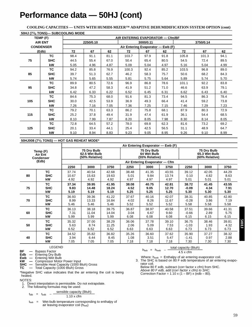
59
COOLING CAPACITIES — UNITS WITH HUMIDI-MIZER™ ADAPTIVE DEHUMIDIFICATION SYSTEM OPTION (cont)
LEGEND
*Negative SHC value indicates that the air entering the coil is beingheated.
NOTES:1. Direct interpolation is permissible. Do not extrapolate.2. The following formulas may be used:
Where: hewb = Enthalpy of air entering evaporator coil.3. The SHC is based on 80 F edb temperature of air entering evapo-
rator coil.Below 80 F edb, subtract (corr factor x cfm) from SHC.Above 80 F edb, add (corr factor x cfm) to SHC.Correction Factor = 1.10 x (1 – BF) x (edb – 80).
50HJ (71/2 TONS)— SUBCOOLING MODETEMP (F) AIR ENT
CONDENSER (Edb)
AIR ENTERING EVAPORATOR — Cfm/BF 2250/0.10 3000/0.11 3750/0.14
Air Entering Evaporator — Ewb (F) 72 67 62 72 67 62 72 67 62
75 TC 98.4 91.1 81.1 103.7 97.9 91.8 105.8 101.3 94.1
SHC 44.5 55.4 67.0 50.4 65.4 80.5 54.5 72.4 89.5 kW 5.05 4.96 4.87 5.09 5.04 4.97 5.16 5.04 4.99
85 TC 94.2 85.8 76.9 100.3 92.4 85.2 103.5 96.8 89.0
SHC 39.7 51.3 62.7 46.2 58.3 75.7 50.6 68.2 84.3 kW 5.74 5.65 5.55 5.81 5.75 5.64 5.89 5.74 5.70
95 TC 89.9 80.5 72.6 96.9 86.8 78.6 101.1 92.2 83.8
SHC 34.8 47.2 58.3 41.9 51.2 71.0 46.6 63.9 79.1 kW 6.42 6.33 6.22 6.52 6.45 6.31 6.62 6.43 6.40
105 TC 84.6 75.3 68.0 91.6 81.3 73.4 94.5 86.3 78.4
SHC 30.0 42.5 53.9 36.9 49.3 66.4 41.4 59.2 73.8 kW 7.26 7.16 7.05 7.36 7.25 7.15 7.46 7.29 7.23
115 TC 79.2 70.1 63.3 86.2 75.8 68.1 87.9 80.3 72.9
SHC 25.2 37.8 49.4 31.9 47.4 61.9 36.1 54.4 68.5 kW 8.10 7.99 7.87 8.20 8.05 7.98 8.30 8.14 8.05
125 TC 72.8 64.5 57.2 78.0 69.8 62.3 81.6 73.2 69.2
SHC 20.1 33.4 44.1 25.4 42.5 56.5 31.1 48.9 64.7 kW 9.10 8.94 8.83 9.23 9.05 8.95 9.26 9.10 8.99
50HJ008 (71/2 TONS) — HOT GAS REHEAT MODE*
Temp (F)Air Ent
Condenser(Edb)
Air Entering Evaporator — Ewb (F)75 Dry Bulb
62.5 Wet Bulb(50% Relative)
75 Dry Bulb64 Wet Bulb
(55% Relative)
75 Dry Bulb65.3 Wet Bulb(60% Relative)
Air Entering Evaporator — Cfm2250 3000 3750 2250 3000 3750 2250 3000 3750
80TC 37.74 40.54 42.68 38.48 41.35 43.55 39.12 42.05 44.29SHC 10.67 15.63 19.63 5.01 9.84 13.74 0.10 4.82 8.63kW 4.92 4.92 4.92 4.97 4.97 4.97 5.01 5.01 5.01
75TC 37.34 39.95 41.95 38.08 40.75 42.81 38.72 41.45 43.55SHC 9.83 14.48 18.24 4.52 9.05 12.70 -0.09 4.34 7.91kW 5.19 5.19 5.19 5.25 5.25 5.25 5.30 5.30 5.30
70TC 36.93 39.36 41.22 37.67 40.16 42.07 38.31 40.85 42.80SHC 8.99 13.33 16.84 4.02 8.26 11.67 -0.28 3.86 7.19kW 5.46 5.46 5.46 5.52 5.52 5.52 5.58 5.58 5.58
60TC 36.13 38.18 39.75 36.87 38.97 40.58 37.51 39.66 41.31SHC 7.31 11.04 14.04 3.04 6.67 9.60 -0.66 2.89 5.75kW 5.99 5.99 5.99 6.08 6.08 6.08 6.15 6.15 6.15
50TC 35.32 37.00 38.29 36.06 37.78 39.10 36.75 38.46 39.81SHC 5.63 8.74 11.25 2.06 5.09 7.53 -1.03 1.93 4.32kW 6.52 6.52 6.52 6.63 6.63 6.63 6.73 6.73 6.73
40TC 34.52 35.82 36.82 35.26 36.60 37.62 35.90 37.27 38.32SHC 3.94 6.44 8.45 1.08 3.51 5.47 -1.41 0.97 2.88kW 7.05 7.05 7.05 7.18 7.18 7.18 7.30 7.30 7.30
BF — Bypass FactorEdb — Entering Dry BulbEwb — Entering Wet BulbkW — Compressor Motor Power InputSHC — Sensible Heat Capacity (1000 Btuh) GrossTC — Total Capacity (1000 Btuh) Gross
tldb = tedb –sensible capacity (Btuh)
1.10 x cfmtlwb = Wet-bulb temperature corresponding to enthalpy of
air leaving evaporator coil (hlwb)
hlwb = hewb –total capacity (Btuh)
4.5 x cfm
Performance data — 50HJ (cont)50H
J

60
COOLING CAPACITIES — UNITS WITH HUMIDI-MIZER™ ADAPTIVE DEHUMIDIFICATION SYSTEM OPTION (cont)
LEGEND
NOTES:1. Direct interpolation is permissible. Do not extrapolate.
2. The following formulas may be used:
Where: hewb = Enthalpy of air entering evaporator coil.3. The SHC is based on 80 F edb temperature of air entering evapo-
rator coil.Below 80 F edb, subtract (corr factor x cfm) from SHC.Above 80 F edb, add (corr factor x cfm) to SHC.Correction Factor = 1.10 x (1 – BF) x (edb – 80).
50HJ009 (81/2 TONS) — SUBCOOLING MODE
Temp (F)Air Ent
Condenser(Edb)
Air Entering Evaporator — Cfm/BF2550/0.08 3000/0.09 3400/0.11 4250/0.13
Air Entering Evaporator — Ewb (F)72 67 62 72 67 62 72 67 62 72 67 62
75TC 114.1 104.1 97.8 116.3 108.5 103.4 117.6 111.9 108.0 122.2 118.9 111.4SHC 49.8 64.2 81.2 52.6 70.8 89.0 55.4 76.9 95.4 62.0 87.0 107.2kW 5.57 5.46 5.44 5.59 5.50 5.44 5.60 5.51 5.44 5.62 5.62 5.69
85TC 107.3 98.4 92.6 111.0 101.8 98.0 113.0 104.2 102.0 117.1 111.4 106.1SHC 42.2 58.3 76.0 47.1 64.5 83.5 51.2 70.2 89.2 57.3 81.2 101.2kW 6.32 6.30 6.15 6.32 6.27 6.18 6.34 6.22 6.20 6.30 6.31 6.45
95TC 101.9 92.4 86.8 105.3 95.5 92.8 107.4 97.7 96.5 112.1 103.7 100.3SHC 35.4 51.9 70.3 40.1 58.5 77.9 44.9 64.9 83.7 52.1 74.0 94.8kW 7.06 7.13 6.93 7.06 7.06 6.95 7.06 6.99 6.98 7.01 7.04 7.17
105TC 94.5 85.4 77.0 97.6 88.3 82.4 99.9 90.6 88.0 104.1 96.1 94.0SHC 29.7 45.7 63.2 33.9 52.2 70.1 38.0 58.3 75.7 44.4 67.6 88.5kW 7.99 8.00 7.81 8.01 7.97 7.85 8.02 7.94 7.89 7.96 7.96 8.08
115TC 86.4 75.0 68.3 89.3 80.2 74.1 91.4 83.2 78.4 96.5 88.4 87.1SHC 24.0 38.7 56.4 27.4 45.6 62.9 31.1 51.9 67.0 37.0 60.8 81.8kW 8.91 8.83 8.66 8.93 8.86 8.76 8.97 8.86 8.84 8.91 8.93 8.90
125TC 78.6 65.5 60.2 81.3 68.9 64.7 83.3 71.6 68.2 88.5 78.8 78.9SHC 18.3 32.0 48.8 21.2 38.0 53.5 24.1 44.1 57.5 29.4 53.3 73.8kW 9.81 9.65 9.53 9.86 9.68 9.64 9.89 9.71 9.75 9.90 9.72 9.88
50HJ009 (81/2 TONS) — HOT GAS REHEAT MODE
Temp (F)Air Ent
Condenser(Edb)
Air Entering Evaporator — Ewb (F)75 Dry Bulb
62.5 Wet Bulb(50% Relative)
75 Dry Bulb64 Wet Bulb
(55% Relative)
75 Dry Bulb65.3 Wet Bulb(60% Relative)
Air Entering Evaporator — Cfm2550 3000 3400 4250 2550 3000 3400 4250 2550 3000 3400 4250
80TC 43.44 46.26 48.45 52.38 45.26 48.15 50.39 54.43 46.84 49.79 52.08 56.20SHC 12.34 16.78 20.29 26.74 5.79 10.15 13.60 19.93 0.11 4.40 7.80 14.03kW 6.31 6.31 6.31 6.31 6.05 6.05 6.05 6.05 5.83 5.83 5.83 5.83
75TC 44.33 47.00 49.06 52.78 46.12 48.85 50.97 54.78 47.67 50.46 52.63 56.52SHC 12.92 17.12 20.44 26.54 6.81 10.94 14.20 20.20 1.51 5.58 8.79 14.70kW 6.38 6.38 6.8 6.38 6.15 6.15 6.15 6.15 5.95 5.95 5.95 5.95
70TC 45.22 47.73 49.68 53.18 46.98 49.55 51.55 55.14 48.51 51.14 53.18 56.84SHC 13.50 17.47 20.59 26.34 7.83 11.73 14.81 20.46 2.92 6.76 9.79 15.36kW 6.46 6.46 6.46 6.46 6.25 6.25 6.25 6.25 6.07 6.07 6.07 6.07
60TC 46.99 49.19 50.90 53.97 48.70 50.96 52.71 55.86 50.18 52.49 54.27 57.49SHC 14.67 18.15 20.90 25.95 9.88 13.31 16.01 20.99 5.73 9.11 11.78 16.68kW 6.60 6.60 6.60 6.60 6.45 6.45 6.45 6.45 6.32 6.32 6.32 6.32
50TC 48.77 50.66 52.13 54.77 50.42 52.36 53.87 56.57 51.85 53.83 55.37 58.14SHC 15.83 18.83 21.20 25.56 11.93 14.89 17.22 21.51 8.55 11.47 13.77 18.01kW 6.74 6.74 6.74 6.74 6.64 6.64 6.64 6.64 6.56 6.56 6.56 6.56
40TC 50.54 52.13 53.35 55.56 52.14 53.76 55.02 57.29 53.53 55.18 56.47 58.78SHC 17.00 19.52 21.51 25.16 13.98 16.47 18.43 22.04 11.36 13.82 15.76 19.33kW 6.88 6.88 6.88 6.88 6.84 6.84 6.84 6.84 6.81 6.81 6.81 6.81
BF — Bypass FactorEdb — Entering Dry BulbEwb — Entering Wet BulbkW — Compressor Motor Power InputSHC — Sensible Heat Capacity (1000 Btuh) GrossTC — Total Capacity (1000 Btuh) Gross
tldb = tedb –sensible capacity (Btuh)
1.10 x cfmtlwb = Wet-bulb temperature corresponding to enthalpy of
air leaving evaporator coil (hlwb)
hlwb = hewb –total capacity (Btuh)
4.5 x cfm
50H
J

61
COOLING CAPACITIES — UNITS WITH HUMIDI-MIZER™ ADAPTIVE DEHUMIDIFICATION SYSTEM OPTION (cont)
LEGEND
*Negative SHC value indicates that the air entering the coil is being heated.NOTES:
1. Direct interpolation is permissible. Do not extrapolate.
2. The following formulas may be used:
Where: hewb = Enthalpy of air entering evaporator coil.3. The SHC is based on 80 F edb temperature of air entering evaporator
coil.Below 80 F edb, subtract (corr factor x cfm) from SHC.Above 80 F edb, add (corr factor x cfm) to SHC.Correction Factor = 1.10 x (1 – BF) x (edb – 80).
50HJ012 (10 TONS) — SUBCOOLING MODE
Temp (F)Air Ent
Condenser(Edb)
Air Entering Evaporator — Cfm/BF3000/0.03 3200/0.03 4000/0.04 5000/0.04
Air Entering Evaporator — Ewb (F)72 67 62 72 67 62 72 67 62 72 67 62
75TC 134.3 122.5 111.4 135.8 124.3 113.0 138.4 129.5 123.5 143.3 136.5 130.2SHC 60.0 76.1 93.7 61.3 79.1 97.4 68.0 89.5 109.4 75.2 100.9 123.3kW 7.03 6.84 6.72 7.01 6.89 6.77 7.10 6.92 6.77 7.15 7.03 6.88
85TC 127.6 115.4 104.6 128.9 118.1 107.0 132.5 121.5 116.6 137.2 128.0 122.9SHC 51.5 68.8 87.2 53.9 72.0 91.2 61.0 82.7 102.4 68.6 93.6 115.9kW 7.96 7.86 7.59 7.94 7.78 7.51 8.02 7.84 7.69 8.02 7.94 7.79
95TC 120.9 108.3 97.8 121.9 111.8 101.0 126.5 113.4 109.7 131.1 119.4 115.5SHC 43.0 61.5 80.6 46.5 64.8 84.9 53.9 75.9 95.4 62.0 86.2 108.4kW 8.88 8.87 8.46 8.86 8.66 8.26 8.94 8.76 8.60 8.89 8.85 8.69
105TC 112.0 99.9 90.4 113.1 103.2 93.4 117.2 105.0 100.7 122.1 110.5 105.9SHC 36.1 54.1 73.8 38.8 57.8 78.9 45.6 68.2 86.8 53.0 78.3 99.7kW 10.0 10.0 9.6 10.0 9.8 9.5 10.1 9.9 9.8 10.1 10.0 9.9
115TC 103.0 91.5 83.1 104.3 94.6 85.9 107.8 96.7 91.7 113.0 101.6 96.4SHC 29.2 46.7 66.9 31.2 50.7 72.9 37.3 60.6 78.3 44.0 70.3 90.9kW 11.2 11.1 10.8 11.2 11.0 10.7 11.3 11.1 11.0 11.3 11.2 11.1
125TC 94.1 83.1 75.7 95.5 86.0 78.3 98.5 88.3 82.7 104.0 92.7 86.8SHC 22.3 39.3 60.1 23.5 43.7 66.8 29.0 52.9 69.7 35.0 62.4 82.2kW 12.35 12.15 11.94 12.38 12.13 11.92 12.48 12.27 12.25 12.53 12.30 12.28
50HJ012 (10 TONS) — HOT GAS REHEAT MODE*
Temp (F)Air Ent
Condenser(Edb)
Air Entering Evaporator — Ewb (F)75 Dry Bulb
62.5 Wet Bulb(50% Relative)
75 Dry Bulb64 Wet Bulb
(55% Relative)
75 Dry Bulb65.3 Wet Bulb(60% Relative)
Air Entering Evaporator — Cfm3000 3200 4000 5000 3000 3200 4000 5000 3000 3200 4000 5000
80TC 49.15 50.16 53.80 57.72 51.04 52.08 55.86 59.94 52.67 53.74 57.65 61.86SHC 9.58 12.02 20.74 29.89 2.88 5.29 13.88 22.89 -2.92 -0.55 7.93 16.83kW 7.39 7.38 7.38 7.37 7.45 7.45 7.44 7.43 7.50 7.50 7.49 7.49
75TC 49.60 50.61 54.30 58.28 51.45 52.50 56.33 60.45 53.05 54.14 58.09 62.34SHC 10.07 12.38 20.60 29.23 3.82 6.09 14.20 22.70 -1.60 0.64 8.65 17.05kW 7.56 7.56 7.55 7.55 7.63 7.63 7.62 7.62 7.69 7.69 7.69 7.68
70TC 50.04 51.07 54.81 58.83 51.86 52.92 56.80 60.96 53.43 54.53 58.52 62.82SHC 10.56 12.73 20.47 28.58 4.75 6.89 14.52 22.52 -0.28 1.83 9.36 17.26kW 7.73 7.73 7.72 7.72 7.81 7.81 7.81 7.80 7.89 7.88 7.88 7.87
60TC 50.93 51.98 55.81 59.93 52.68 53.77 57.73 61.99 54.20 55.32 59.39 63.77SHC 11.54 13.44 20.19 27.28 6.62 8.49 15.16 22.15 2.36 4.21 10.79 17.70kW 8.07 8.07 8.07 8.06 8.18 8.18 8.17 8.17 8.27 8.27 8.26 8.26
50TC 51.82 52.90 56.81 61.03 53.50 54.62 58.66 63.01 54.96 56.10 60.26 64.73SHC 12.53 14.14 19.92 25.98 8.50 10.09 15.80 21.78 5.00 6.58 12.22 18.14kW 8.42 8.42 8.41 8.41 8.54 8.54 8.54 8.54 8.66 8.65 8.65 8.65
40TC 52.71 53.81 57.82 62.13 54.32 55.46 59.59 64.04 55.72 56.89 61.13 65.69SHC 13.51 14.85 19.64 24.67 10.37 11.70 16.43 21.41 7.64 8.96 13.65 18.58kW 8.76 8.76 8.76 8.75 8.91 8.91 8.91 8.90 9.04 9.04 9.04 9.03
BF — Bypass FactorEdb — Entering Dry BulbEwb — Entering Wet BulbkW — Compressor Motor Power InputSHC — Sensible Heat Capacity (1000 Btuh) GrossTC — Total Capacity (1000 Btuh) Gross
tldb = tedb –sensible capacity (Btuh)
1.10 x cfm
tlwb = Wet-bulb temperature corresponding to enthalpy of air leaving evaporator coil (hlwb)
hlwb = hewb –total capacity (Btuh)
4.5 x cfm
Performance data — 50HJ (cont)50H
J

62
COOLING CAPACITIES — UNITS WITH HUMIDI-MIZER™ ADAPTIVE DEHUMIDIFICATION SYSTEM OPTION (cont)
LEGEND
*Negative SHC value indicates that the air entering the coil is beingheated.
NOTES:1. Direct interpolation is permissible. Do not extrapolate.
2. The following formulas may be used:
Where: hewb = Enthalpy of air entering evaporator coil.3. The SHC is based on 80 F edb temperature of air entering evapo-
rator coil.Below 80 F edb, subtract (corr factor x cfm) from SHC.Above 80 F edb, add (corr factor x cfm) to SHC.Correction Factor = 1.10 x (1 – BF) x (edb – 80).
50HJ014 (121/2 TONS) — SUBCOOLING MODE
Temp (F)Air Ent
Condenser(Edb)
Air Entering Evaporator — Cfm/BF3750/0.08 4300/0.09 5000/0.11 6250/0.13
Air Entering Evaporator — Ewb (F)72 67 62 72 67 62 72 67 62 72 67 62
75TC 156.3 144.2 132.3 160.0 148.4 136.2 162.8 150.6 138.2 169.0 157.5 145.6SHC 66.6 87.6 112.1 72.5 94.8 121.3 76.9 99.6 127.5 87.0 115.5 142.7kW 9.28 8.98 8.59 9.35 9.08 8.80 9.40 9.18 8.9 9.43 9.18 8.93
85TC 147.6 136.2 123.7 150.7 140.1 127.2 154.1 140.8 127.9 161.1 148.0 135.4SHC 58.7 80.0 103.8 63.5 86.5 112.2 68.7 91.0 118.1 77.7 107.8 133.2kW 10.29 9.93 9.58 10.36 10.08 9.77 10.40 10.34 10.03 10.45 10.18 9.88
95TC 138.9 128.2 115.1 141.4 131.8 118.3 145.3 131.0 117.6 153.1 138.4 125.1SHC 50.8 72.3 95.5 54.4 78.1 103.2 60.5 82.3 108.7 68.5 100.0 123.7kW 11.29 10.87 10.57 11.37 11.08 10.74 11.40 11.50 11.1 11.46 11.17 10.83
105TC 129.1 117.8 105.8 131.7 121.0 108.7 134.8 119.9 107.7 140.9 126.9 115.9SHC 42.1 63.5 86.5 45.4 69.0 93.9 51.2 74.2 101.3 57.7 90.2 113.6kW 12.59 12.14 11.82 12.67 12.34 11.96 12.70 12.67 12.28 12.79 12.46 12.08
115TC 119.2 107.3 96.4 122.1 110.2 99.0 124.2 108.8 97.8 128.7 115.3 106.7SHC 33.5 54.8 77.5 36.4 59.8 84.7 41.9 66.1 93.8 46.8 80.5 103.5kW 13.90 13.40 13.08 13.98 13.59 13.18 14.00 13.83 13.41 14.11 13.75 13.33
125TC 109.4 96.9 87.1 112.4 99.4 89.3 113.7 97.7 87.8 116.5 103.8 97.5SHC 24.8 46.0 68.5 27.4 50.7 75.5 32.6 58.0 86.4 36.0 70.7 93.5kW 15.20 14.67 14.33 15.28 14.85 14.40 15.30 15.00 14.54 15.44 15.04 14.58
50HJ014 (121/2 TONS) — HOT GAS REHEAT MODE*
Temp (F)Air Ent
Condenser(Edb)
Air Entering Evaporator — Ewb (F)75 Dry Bulb
62.5 Wet Bulb(50% Relative)
75 Dry Bulb64 Wet Bulb
(55% Relative)
75 Dry Bulb65.3 Wet Bulb(60% Relative)
Air Entering Evaporator — Cfm3750 4300 5000 6250 3750 4300 5000 6250 3750 4300 5000 6250
80TC 43.54 45.21 47.05 49.78 45.46 47.16 49.05 51.85 47.11 48.86 50.78 53.64SHC -4.36 0.76 6.50 15.20 -9.51 -4.35 1.45 10.22 -13.97 -8.77 -2.93 5.90kW 8.70 8.70 8.70 8.70 8.82 8.82 8.82 8.82 8.92 8.92 8.92 8.92
75TC 44.45 46.02 47.75 50.32 46.33 47.94 49.71 52.34 47.96 49.60 51.41 54.10SHC -3.84 0.96 6.36 14.53 -8.66 -3.81 1.63 9.86 -12.84 -7.96 -2.48 5.82kW 8.90 8.90 8.90 8.90 9.03 9.03 9.03 9.03 9.14 9.14 9.14 9.14
70TC 45.36 46.82 48.45 50.86 47.20 48.71 50.37 52.84 48.80 50.34 52.04 54.55SHC -3.32 1.17 6.21 13.85 -7.81 -3.28 1.80 9.50 -11.71 -7.14 -2.02 5.74kW 9.10 9.10 9.10 9.10 9.24 9.24 9.24 9.24 9.36 9.36 9.36 9.36
60TC 47.17 48.44 49.84 51.93 48.95 50.25 51.69 53.83 50.49 51.82 53.29 55.47SHC -2.28 1.59 5.93 12.50 -6.12 -2.22 2.16 8.79 -9.45 -5.52 -1.11 5.57kW 9.51 9.51 9.51 9.51 9.66 9.66 9.66 9.66 9.80 9.80 9.80 9.80
50TC 48.98 50.05 51.24 53.00 50.70 51.80 53.01 54.82 52.18 53.31 54.55 56.39SHC -1.24 2.00 5.64 11.15 -4.43 -1.15 2.52 8.07 -7.18 -3.89 -0.19 5.41kW 9.91 9.91 9.91 9.91 10.09 10.09 10.09 10.09 10.24 10.24 10.24 10.24
40TC 50.79 51.67 52.64 54.07 52.44 53.34 54.33 55.80 53.87 54.79 55.80 57.30SHC -0.20 2.41 5.35 9.80 -2.73 -.019 2.87 7.36 -4.92 -2.26 0.72 5.24kW 10.31 10.31 10.31 10.31 10.51 10.51 10.51 10.51 10.68 10.68 10.68 10.68
BF — Bypass FactorEdb — Entering Dry BulbEwb — Entering Wet BulbkW — Compressor Motor Power InputSHC — Sensible Heat Capacity (1000 Btuh) GrossTC — Total Capacity (1000 Btuh) Gross
tldb = tedb –sensible capacity (Btuh)
1.10 x cfmtlwb = Wet-bulb temperature corresponding to enthalpy of
air leaving evaporator coil (hlwb)
hlwb = hewb –total capacity (Btuh)
4.5 x cfm
50H
J

63
GLYCOL HEATING PERFORMANCE
LEGEND
*∆P is the fluid pressure in ft of head.
NOTES:1. This accessory glycol coil is intended for use with a MINIMUM of 25% glycol
solution. It IS NOT intended for use solely with water due to freeze-up condi-tions and the resulting water damage to the conditioned space.
2. Water ∆ = 20 F.
FAN PERFORMANCE — VERTICAL DISCHARGE UNITS
LEGEND
*Factory provided drive range 639-936 Rpm. All other rpms require field-sup-plied drive.
NOTES:1. Boldface shaded areas indicates field-supplied drive is required.2. Maximum continuous bhp is 0.58.3. See page 77 for general fan performance notes.
GLYCOL COIL (50HJ015,017)
TemperatureEntering
Air Entering — Cfm4400 5400 7200
Percent Glycol25 50 25 50 25 50
Edb Ewt Cap Gpm Ldb Cap Gpm Ldb Cap Gpm Ldb Cap Gpm Ldb Cap Gpm Ldb Cap Gpm Ldb
55200 310 33 120 293 33 116 347 37 115 327 37 111 405 43 107 381 43 104180 255 27 108 237 27 105 285 30 104 264 30 101 332 35 98 306 35 95160 200 21 97 181 21 93 223 24 94 202 23 90 259 27 89 233 27 85
70200 274 29 127 257 29 124 306 32 123 287 33 119 357 38 116 333 38 113180 218 23 116 201 23 112 244 26 112 224 26 109 284 30 107 259 30 104160 164 17 104 146 17 100 183 19 101 162 19 98 212 22 97 187 22 94
80200 249 26 132 233 27 129 279 30 128 260 30 125 325 34 122 302 34 119180 194 21 121 177 20 117 217 23 117 197 23 114 252 26 113 228 27 109160 140 15 109 123 14 106 156 16 107 136 16 103 180 18 103 156 19 100
GLYCOL COIL (50HJ015,017) (cont)
TemperatureEntering
Air Entering — Cfm9000
25 50Edb Ewt Cap Gpm Ldb Cap Gpm Ldb
55200 453 48 102 425 48 99180 371 39 93 342 39 90160 290 31 85 260 30 82
70200 400 42 111 372 42 108180 317 34 103 287 33 100160 237 25 94 208 24 91
80200 364 39 118 337 38 115180 281 30 109 254 29 106160 201 21 101 173 20 78
GLYCOL COIL RATINGS (50HJ015,017)Entering
FluidTemp (F)
Cfm4,000 5,000 6,000 8,000 10,000
Gpm ∆P* Gpm ∆P* Gpm ∆P* Gpm ∆P* Gpm ∆P*200 27 1.2 31 1.5 35 1.8 41 2.4 47 2.9180 22 0.9 25 1.1 27 1.3 32 1.6 36 2.0160 16 0.6 19 0.7 20 0.8 24 1.0 27 1.2
Cap — Btuh × 1000Edb — Entering Dry Bulb Temperature (F)Ewt — Entering Water Temperature (F)Gpm — Gallons Per MinuteLdb — Leaving Dry-Bulb Temperature (F)
50HE003 (2 TONS) — STANDAR MOTOR (BELT DRIVE)*
AIRFLOW (Cfm)
EXTERNALSTATIC PRESSURE (in. wg)0.1 0.2 0.4 0.6 0.8 1.0
Rpm Bhp Rpm Bhp Rpm Bhp Rpm Bhp Rpm Bhp Rpm Bhp600 500 0.08 531 0.08 607 0.14 713 0.21 788 0.29 878 0.37 700 529 0.09 567 0.09 633 0.16 739 0.24 816 0.32 902 0.41 800 547 0.1 592 0.12 660 0.19 761 0.27 845 0.37 937 0.47 900 570 0.13 620 0.14 691 0.22 793 0.32 870 0.42 957 0.53
1000 599 0.15 650 0.16 717 0.26 818 0.36 894 0.47 981 0.58
Bhp — Brake Horsepower Input to Fan
Performance data — 50HE/HJ (cont)50H
E/H
J

64
FAN PERFORMANCE — VERTICAL DISCHARGE UNITS (cont)
LEGEND
*Motor drive range: 680 to 1044 rpm. All other rpms require field-supplieddrive.
NOTES:1. Boldface indicates field-supplied drive is required.2. Maximum continuous bhp is 1.20.3. See page 77 for general fan performance notes.
LEGEND
*Motor drive range: 1075 to 1455 rpm. All other rpms require field-supplieddrive.
NOTES:1. Boldface indicates field-supplied drive is required.2. Maximum continuous bhp is 2.40.3. See page 77 for general fan performance notes.
50HE/HJ004 (3 TONS) — STANDARD MOTOR (BELT DRIVE)*
Airflow(Cfm)
External Static Pressure (in. wg0.2 0.4 0.6 0.8 1.0
Rpm Bhp Watts Rpm Bhp Watts Rpm Bhp Watts Rpm Bhp Watts Rpm Bhp Watts900 566 0.14 142 690 0.23 228 791 0.32 320 879 0.42 418 957 0.52 522
1000 598 0.17 173 718 0.27 267 817 0.37 366 903 0.47 471 981 0.58 5811100 632 0.21 210 748 0.31 311 844 0.42 418 929 0.53 530 1006 0.65 6461200 666 0.25 252 778 0.36 361 873 0.48 476 956 0.60 594 1031 0.72 7181300 701 0.30 300 809 0.42 418 902 0.54 540 983 0.67 665 1057 0.80 7961400 737 0.36 355 842 0.48 481 932 0.61 610 1012 0.75 744 1085 0.89 8811500 774 0.42 417 875 0.55 551 962 0.69 689 1041 0.83 830 1112 0.98 974
50HE/HJ004 (3 TONS) — STANDARD MOTOR (BELT DRIVE)* (cont)
Airflow(Cfm)
External Static Pressure (in. wg)1.2 1.4 1.6 1.8 2.0
Rpm Bhp Watts Rpm Bhp Watts Rpm Bhp Watts Rpm Bhp Watts Rpm Bhp Watts900 1029 0.63 630 1095 0.75 742 1157 0.86 859 1216 0.99 980 1272 1.11 1105
1000 1052 0.70 695 1118 0.82 814 1179 0.94 937 1237 1.07 1064 1293 1.20 11951100 1076 0.77 767 1141 0.90 892 1202 1.03 1021 1260 1.16 1154 — — —1200 1100 0.85 845 1165 0.98 977 1225 1.12 1112 — — — — — —1300 1126 0.94 930 1189 1.07 1069 — — — — — — — — —1400 1152 1.03 1023 1215 1.17 1168 — — — — — — — — —1500 1179 1.13 1123 — — — — — — — — — — — —
Bhp — Brake Horsepower Input to FanWatts — Input Watts to Motor
50HE/HJ004 (3 TONS) — HIGH-STATIC MOTOR (BELT DRIVE)*
Airflow(Cfm)
External Static Pressure (in. wg)0.2 0.4 0.6 0.8 1.0
Rpm Bhp Watts Rpm Bhp Watts Rpm Bhp Watts Rpm Bhp Watts Rpm Bhp Watts900 566 0.14 142 690 0.23 228 791 0.32 320 879 0.42 418 957 0.52 522
1000 598 0.17 173 718 0.27 267 817 0.37 366 903 0.47 471 981 0.58 5811100 632 0.21 210 748 0.31 311 844 0.42 418 929 0.53 530 1006 0.65 6461200 666 0.25 252 778 0.36 361 873 0.48 476 956 0.60 594 1031 0.72 7181300 701 0.30 300 809 0.42 418 902 0.54 540 983 0.67 665 1057 0.80 7961400 737 0.36 355 842 0.48 481 932 0.61 610 1012 0.75 744 1085 0.89 8811500 774 0.42 417 875 0.55 551 962 0.69 689 1041 0.83 830 1112 0.98 974
50HE/HJ004 (3 TONS) — HIGH-STATIC MOTOR (BELT DRIVE)* (cont)
Airflow(Cfm)
External Static Pressure (in. wg)1.2 1.4 1.6 1.8 2.0
Rpm Bhp Watts Rpm Bhp Watts Rpm Bhp Watts Rpm Bhp Watts Rpm Bhp Watts900 1029 0.63 630 1095 0.75 742 1157 0.86 859 1216 0.99 980 1272 1.11 1105
1000 1052 0.70 695 1118 0.82 814 1179 0.94 937 1237 1.07 1064 1293 1.20 11951100 1076 0.77 767 1141 0.90 892 1202 1.03 1021 1260 1.16 1154 1314 1.30 12911200 1100 0.85 845 1165 0.98 977 1225 1.12 1112 1282 1.26 1252 1337 1.40 13951300 1126 0.94 930 1189 1.07 1069 1249 1.22 1211 1306 1.36 1356 1360 1.51 15061400 1152 1.03 1023 1215 1.17 1168 1274 1.32 1317 1330 1.48 1469 1384 1.63 16251500 1179 1.13 1123 1241 1.28 1275 1300 1.44 1431 1355 1.60 1590 1408 1.76 1752
Bhp — Brake Horsepower Input to FanWatts — Input Watts to Motor
50H
E/H
J

65
FAN PERFORMANCE — VERTICAL DISCHARGE UNITS (cont)
LEGEND
*Motor drive range: 770 to 1185 rpm. All other rpms require field-supplieddrive.
NOTES:1. Boldface indicates field-supplied drive is required.2. Maximum continuous bhp is 1.20.3. See page 77 for general fan performance notes.
LEGEND
*Motor drive range: 1075 to 1455 rpm. All other rpms require field-supplieddrive.
NOTES:1. Boldface indicates field-supplied drive is required.2. Maximum continuous bhp is 2.40.3. See page 77 for general fan performance notes. 76 for general fan performance
50HE/HJ005 (4 TONS) — STANDARD MOTOR (BELT DRIVE)*
Airflow(Cfm)
External Static Pressure (in. wg)0.2 0.4 0.6 0.8 1.0
Rpm Bhp Watts Rpm Bhp Watts Rpm Bhp Watts Rpm Bhp Watts Rpm Bhp Watts1200 666 0.25 252 778 0.36 361 873 0.48 476 956 0.60 594 1031 0.72 7181300 701 0.30 300 809 0.42 418 902 0.54 540 983 0.67 665 1057 0.80 7961400 737 0.36 355 842 0.48 481 932 0.61 610 1012 0.75 744 1085 0.89 8811500 774 0.42 417 875 0.55 551 962 0.69 689 1041 0.83 830 1112 0.98 9741600 811 0.49 487 909 0.63 629 994 0.78 774 1071 0.93 923 1141 1.08 10761700 849 0.57 565 943 0.72 715 1026 0.87 869 1101 1.03 1025 1170 1.19 11851800 887 0.65 651 978 0.81 810 1059 0.98 972 1133 1.14 1136 — — —1900 926 0.75 746 1014 0.92 914 1092 1.09 1084 — — — — — —2000 965 0.86 852 1050 1.03 1028 — — — — — — — — —
50HE/HJ005 (4 TONS) — STANDARD MOTOR (BELT DRIVE)* (cont)
Airflow(Cfm)
External Static Pressure (in. wg)1.2 1.4 1.6 1.8 2.0
Rpm Bhp Watts Rpm Bhp Watts Rpm Bhp Watts Rpm Bhp Watts Rpm Bhp Watts1200 1100 0.85 845 1165 0.98 977 1225 1.12 1112 — — — — — —1300 1126 0.94 930 1189 1.07 1069 — — — — — — — — —1400 1152 1.03 1023 1215 1.17 1168 — — — — — — — — —1500 1179 1.13 1123 — — — — — — — — — — — —1600 — — — — — — — — — — — — — — —1700 — — — — — — — — — — — — — — —1800 — — — — — — — — — — — — — — —1900 — — — — — — — — — — — — — — —2000 — — — — — — — — — — — — — — —
Bhp — Brake Horsepower Input to FanWatts — Input Watts to Motor
50HE/HJ005 (4 TONS) — HIGH-STATIC MOTOR (BELT DRIVE)*
Airflow(Cfm)
External Static Pressure (in. wg)0.2 0.4 0.6 0.8 1.0
Rpm Bhp Watts Rpm Bhp Watts Rpm Bhp Watts Rpm Bhp Watts Rpm Bhp Watts1200 666 0.25 252 778 0.36 361 873 0.48 476 956 0.60 594 1031 0.72 7181300 701 0.30 300 809 0.42 418 902 0.54 540 983 0.67 665 1057 0.80 7961400 737 0.36 355 842 0.48 481 932 0.61 610 1012 0.75 744 1085 0.89 8811500 774 0.42 417 875 0.55 551 962 0.69 689 1041 0.83 830 1112 0.98 9741600 811 0.49 487 909 0.63 629 994 0.78 774 1071 0.93 923 1141 1.08 10761700 849 0.57 565 943 0.72 715 1026 0.87 869 1101 1.03 1025 1170 1.19 11851800 887 0.65 651 978 0.81 810 1059 0.98 972 1133 1.14 1136 1200 1.31 13041900 926 0.75 746 1014 0.92 914 1092 1.09 1084 1164 1.26 1257 1231 1.44 14322000 965 0.86 852 1050 1.03 1028 1127 1.21 1206 1197 1.39 1387 1262 1.58 1570
50HE/HJ005 (4 TONS) — HIGH-STATIC MOTOR (BELT DRIVE)* (cont)
Airflow(Cfm)
External Static Pressure (in. wg)1.2 1.4 1.6 1.8 2.0
Rpm Bhp Watts Rpm Bhp Watts Rpm Bhp Watts Rpm Bhp Watts Rpm Bhp Watts1200 1100 0.85 845 1165 0.98 977 1225 1.12 1112 1282 1.26 1252 1337 1.40 13951300 1126 0.94 930 1189 1.07 1069 1249 1.22 1211 1306 1.36 1356 1360 1.51 15061400 1152 1.03 1023 1215 1.17 1168 1274 1.32 1317 1330 1.48 1469 1384 1.63 16251500 1179 1.13 1123 1241 1.28 1275 1300 1.44 1431 1355 1.60 1590 1408 1.76 17521600 1206 1.24 1231 1268 1.40 1391 1326 1.56 1553 1381 1.73 1719 1433 1.90 18881700 1235 1.36 1349 1295 1.52 1515 1352 1.69 1685 1407 1.87 1858 1459 2.04 20341800 1264 1.48 1475 1323 1.66 1649 1380 1.84 1826 1434 2.02 2006 1485 2.20 21891900 1293 1.62 1611 1352 1.80 1792 1408 1.99 1976 1461 2.17 2163 1512 2.37 23532000 1324 1.77 1756 1381 1.96 1945 1436 2.15 2137 1489 2.34 2332 — — —
Bhp — Brake Horsepower Input to FanWatts — Input Watts to Motor
Performance data — 50HE/HJ (cont)50H
E/H
J

66
FAN PERFORMANCE — VERTICAL DISCHARGE UNITS (cont)
LEGEND
*Motor drive range: 1035 to 1460 rpm. All other rpms require field-supplieddrive.
NOTES:1. Boldface indicates field-supplied drive is required.2. Maximum continuous bhp is 1.30.3. See page 77 for general fan performance notes.
LEGEND
*Motor drive range: 1035 to 1460 rpm. All other rpms require field-supplieddrive.
NOTES:1. Boldface indicates field-supplied drive is required.2. Maximum continuous bhp is 2.40.3. See page 77 for general fan performance notes.
50HE/HJ006 (5 TONS) — STANDARD MOTOR (BELT DRIVE) — SINGLE PHASE*
Airflow(Cfm)
External Static Pressure (in. wg)0.2 0.4 0.6 0.8 1.0
Rpm Bhp Watts Rpm Bhp Watts Rpm Bhp Watts Rpm Bhp Watts Rpm Bhp Watts1500 790 0.40 353 897 0.53 471 991 0.68 600 1075 0.83 739 1152 1.00 8881600 828 0.46 412 931 0.60 536 1022 0.75 670 1104 0.92 813 1180 1.09 9661700 866 0.54 478 966 0.68 608 1054 0.84 747 1134 1.01 895 1208 1.19 10531800 905 0.62 551 1001 0.77 687 1087 0.94 832 1165 1.11 985 1238 1.29 11481900 944 0.71 633 1037 0.87 774 1120 1.04 925 1197 1.22 1084 — — —2000 983 0.81 723 1073 0.98 870 1154 1.16 1026 — — — — — —2100 1023 0.92 821 1110 1.10 975 1189 1.28 1137 — — — — — —2200 1063 1.05 929 1147 1.23 1089 — — — — — — — — —2300 1104 1.18 1046 — — — — — — — — — — — —2400 — — — — — — — — — — — — — — —2500 — — — — — — — — — — — — — — —
50HE/HJ006 (5 TONS) — STANDARD MOTOR (BELT DRIVE) — SINGLE PHASE* (cont)
Airflow(Cfm)
External Static Pressure (in. wg)1.2 1.4 1.6 1.8 2.0
Rpm Bhp Watts Rpm Bhp Watts Rpm Bhp Watts Rpm Bhp Watts Rpm Bhp Watts1500 1224 1.18 1045 — — — — — — — — — — — —1600 1250 1.27 1128 — — — — — — — — — — — —1700 — — — — — — — — — — — — — — —1800 — — — — — — — — — — — — — — —1900 — — — — — — — — — — — — — — —2000 — — — — — — — — — — — — — — —2100 — — — — — — — — — — — — — — —2200 — — — — — — — — — — — — — — —2300 — — — — — — — — — — — — — — —2400 — — — — — — — — — — — — — — —2500 — — — — — — — — — — — — — — —
Bhp — Brake Horsepower Input to FanWatts — Input Watts to Motor
50HE/HJ006 (5 TONS) — STANDARD MOTOR (BELT DRIVE) — THREE PHASE*
Airflow(Cfm)
External Static Pressure (in. wg)0.2 0.4 0.6 0.8 1.0
Rpm Bhp Watts Rpm Bhp Watts Rpm Bhp Watts Rpm Bhp Watts Rpm Bhp Watts1500 790 0.40 353 897 0.53 471 991 0.68 600 1075 0.83 739 1152 1.00 8881600 828 0.46 412 931 0.60 536 1022 0.75 670 1104 0.92 813 1180 1.09 9661700 866 0.54 478 966 0.68 608 1054 0.84 747 1134 1.01 895 1208 1.19 10531800 905 0.62 551 1001 0.77 687 1087 0.94 832 1165 1.11 985 1238 1.29 11481900 944 0.71 633 1037 0.87 774 1120 1.04 925 1197 1.22 1084 1268 1.41 12512000 983 0.81 723 1073 0.98 870 1154 1.16 1026 1229 1.34 1190 1299 1.53 13622100 1023 0.92 821 1110 1.10 975 1189 1.28 1137 1262 1.47 1306 1330 1.67 14832200 1063 1.05 929 1147 1.23 1089 1224 1.41 1256 1295 1.61 1431 1362 1.82 16142300 1104 1.18 1046 1185 1.37 1212 1260 1.56 1386 1329 1.76 1567 1395 1.98 17542400 1145 1.32 1174 1223 1.52 1346 1296 1.72 1526 1364 1.93 1712 1428 2.15 19052500 1185 1.48 1311 1262 1.68 1490 1333 1.89 1676 1399 2.10 1868 1462 2.33 2067
50HE/HJ006 (5 TONS) — STANDARD MOTOR (BELT DRIVE) — THREE PHASE* (cont)
Airflow(Cfm)
External Static Pressure (in. wg)1.2 1.4 1.6 1.8 2.0
Rpm Bhp Watts Rpm Bhp Watts Rpm Bhp Watts Rpm Bhp Watts Rpm Bhp Watts1500 1224 1.18 1045 1291 1.36 1212 1354 1.56 1387 1414 1.77 1570 1472 1.98 17611600 1250 1.27 1128 1316 1.46 1299 1379 1.66 1478 1438 1.87 1664 1495 2.09 18581700 1278 1.37 1219 1343 1.57 1394 1405 1.77 1576 1463 1.99 1766 1520 2.21 19641800 1306 1.48 1318 1370 1.69 1497 1431 1.90 1683 1489 2.11 1877 1545 2.34 20781900 1335 1.61 1426 1398 1.81 1609 1458 2.03 1799 1515 2.25 1997 — — —2000 1364 1.74 1542 1427 1.95 1730 1486 2.17 1925 1542 2.39 2126 — — —2100 1395 1.88 1668 1456 2.09 1860 1514 2.32 2060 — — — — — —2200 1426 2.03 1804 1486 2.25 2001 — — — — — — — — —2300 1457 2.19 1949 — — — — — — — — — — — —2400 1489 2.37 2106 — — — — — — — — — — — —2500 — — — — — — — — — — — — — — —
Bhp — Brake Horsepower Input to FanWatts — Input Watts to Motor
50H
E/H
J
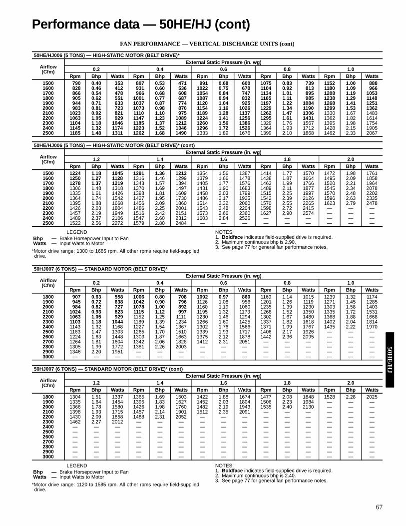
67
FAN PERFORMANCE — VERTICAL DISCHARGE UNITS (cont)
LEGEND
*Motor drive range: 1300 to 1685 rpm. All other rpms require field-supplieddrive.
NOTES:1. Boldface indicates field-supplied drive is required.2. Maximum continuous bhp is 2.90.3. See page 77 for general fan performance notes.
LEGEND
*Motor drive range: 1120 to 1585 rpm. All other rpms require field-supplieddrive.
NOTES:1. Boldface indicates field-supplied drive is required.2. Maximum continuous bhp is 2.40.3. See page 77 for general fan performance notes.
50HE/HJ006 (5 TONS) — HIGH-STATIC MOTOR (BELT DRIVE)*
Airflow(Cfm)
External Static Pressure (in. wg)0.2 0.4 0.6 0.8 1.0
Rpm Bhp Watts Rpm Bhp Watts Rpm Bhp Watts Rpm Bhp Watts Rpm Bhp Watts1500 790 0.40 353 897 0.53 471 991 0.68 600 1075 0.83 739 1152 1.00 8881600 828 0.46 412 931 0.60 536 1022 0.75 670 1104 0.92 813 1180 1.09 9661700 866 0.54 478 966 0.68 608 1054 0.84 747 1134 1.01 895 1208 1.19 10531800 905 0.62 551 1001 0.77 687 1087 0.94 832 1165 1.11 985 1238 1.29 11481900 944 0.71 633 1037 0.87 774 1120 1.04 925 1197 1.22 1084 1268 1.41 12512000 983 0.81 723 1073 0.98 870 1154 1.16 1026 1229 1.34 1190 1299 1.53 13622100 1023 0.92 821 1110 1.10 975 1189 1.28 1137 1262 1.47 1306 1330 1.67 14832200 1063 1.05 929 1147 1.23 1089 1224 1.41 1256 1295 1.61 1431 1362 1.82 16142300 1104 1.18 1046 1185 1.37 1212 1260 1.56 1386 1329 1.76 1567 1395 1.98 17542400 1145 1.32 1174 1223 1.52 1346 1296 1.72 1526 1364 1.93 1712 1428 2.15 19052500 1185 1.48 1311 1262 1.68 1490 1333 1.89 1676 1399 2.10 1868 1462 2.33 2067
50HE/HJ006 (5 TONS) — HIGH-STATIC MOTOR (BELT DRIVE)* (cont)
Airflow(Cfm)
External Static Pressure (in. wg)1.2 1.4 1.6 1.8 2.0
Rpm Bhp Watts Rpm Bhp Watts Rpm Bhp Watts Rpm Bhp Watts Rpm Bhp Watts1500 1224 1.18 1045 1291 1.36 1212 1354 1.56 1387 1414 1.77 1570 1472 1.98 17611600 1250 1.27 1128 1316 1.46 1299 1379 1.66 1478 1438 1.87 1664 1495 2.09 18581700 1278 1.37 1219 1343 1.57 1394 1405 1.77 1576 1463 1.99 1766 1520 2.21 19641800 1306 1.48 1318 1370 1.69 1497 1431 1.90 1683 1489 2.11 1877 1545 2.34 20781900 1335 1.61 1426 1398 1.81 1609 1458 2.03 1799 1515 2.25 1997 1570 2.48 22022000 1364 1.74 1542 1427 1.95 1730 1486 2.17 1925 1542 2.39 2126 1596 2.63 23352100 1395 1.88 1668 1456 2.09 1860 1514 2.32 2060 1570 2.55 2265 1623 2.79 24782200 1426 2.03 1804 1486 2.25 2001 1543 2.48 2204 1598 2.72 2415 — — —2300 1457 2.19 1949 1516 2.42 2151 1573 2.66 2360 1627 2.90 2574 — — —2400 1489 2.37 2106 1547 2.60 2312 1603 2.84 2526 — — — — — —2500 1522 2.56 2272 1579 2.80 2484 — — — — — — — — —
Bhp — Brake Horsepower Input to FanWatts — Input Watts to Motor
50HJ007 (6 TONS) — STANDARD MOTOR (BELT DRIVE)*
Airflow(Cfm)
External Static Pressure (in. wg)0.2 0.4 0.6 0.8 1.0
Rpm Bhp Watts Rpm Bhp Watts Rpm Bhp Watts Rpm Bhp Watts Rpm Bhp Watts1800 907 0.63 558 1006 0.80 708 1092 0.97 860 1169 1.14 1015 1239 1.32 11741900 945 0.72 638 1042 0.90 796 1126 1.08 956 1201 1.26 1119 1271 1.45 12852000 984 0.82 727 1078 1.00 892 1160 1.19 1060 1235 1.39 1230 1303 1.58 14032100 1024 0.93 823 1115 1.12 997 1195 1.32 1173 1268 1.52 1350 1335 1.72 15312200 1063 1.05 929 1152 1.25 1111 1230 1.46 1294 1302 1.67 1480 1368 1.88 16682300 1103 1.18 1044 1189 1.39 1234 1266 1.60 1425 1337 1.82 1618 1402 2.04 18142400 1143 1.32 1168 1227 1.54 1367 1302 1.76 1566 1371 1.99 1767 1435 2.22 19702500 1183 1.47 1303 1265 1.70 1510 1339 1.93 1717 1406 2.17 1926 — — —2600 1224 1.63 1448 1303 1.87 1663 1375 2.12 1878 1442 2.36 2095 — — —2700 1264 1.81 1604 1342 2.06 1828 1412 2.31 2051 — — — — — —2800 1305 1.99 1772 1381 2.26 2003 — — — — — — — — —2900 1346 2.20 1951 — — — — — — — — — — — —3000 — — — — — — — — — — — — — — —
50HJ007 (6 TONS) — STANDARD MOTOR (BELT DRIVE)* (cont)
Airflow(Cfm)
External Static Pressure (in. wg)1.2 1.4 1.6 1.8 2.0
Rpm Bhp Watts Rpm Bhp Watts Rpm Bhp Watts Rpm Bhp Watts Rpm Bhp Watts1800 1304 1.51 1337 1365 1.69 1503 1422 1.88 1674 1477 2.08 1848 1528 2.28 20251900 1335 1.64 1454 1395 1.83 1627 1452 2.03 1804 1506 2.23 1984 — — —2000 1366 1.78 1580 1426 1.98 1760 1482 2.19 1943 1535 2.40 2130 — — —2100 1398 1.93 1715 1457 2.14 1901 1512 2.35 2091 — — — — — —2200 1430 2.09 1858 1488 2.31 2052 — — — — — — — — —2300 1462 2.27 2012 — — — — — — — — — — — —2400 — — — — — — — — — — — — — — —2500 — — — — — — — — — — — — — — —2600 — — — — — — — — — — — — — — —2700 — — — — — — — — — — — — — — —2800 — — — — — — — — — — — — — — —2900 — — — — — — — — — — — — — — —3000 — — — — — — — — — — — — — — —
Bhp — Brake Horsepower Input to FanWatts — Input Watts to Motor
Performance data — 50HE/HJ (cont)50H
E/H
J

68
FAN PERFORMANCE — VERTICAL DISCHARGE UNITS (cont)
LEGEND
*Motor drive range: 1300 to 1685 rpm. All other rpms require field-supplieddrive.
NOTES:1. Boldface indicates field-supplied drive is required.2. Maximum continuous bhp is 2.90.3. See page 77 for general fan performance notes.
50HJ007 (6 TONS) — HIGH-STATIC MOTOR (BELT DRIVE)*
Airflow(Cfm)
External Static Pressure (in. wg)0.2 0.4 0.6 0.8 1.0
Rpm Bhp Watts Rpm Bhp Watts Rpm Bhp Watts Rpm Bhp Watts Rpm Bhp Watts1800 907 0.63 558 1006 0.80 708 1092 0.97 860 1169 1.14 1015 1239 1.32 11741900 945 0.72 638 1042 0.90 796 1126 1.08 956 1201 1.26 1119 1271 1.45 12852000 984 0.82 727 1078 1.00 892 1160 1.19 1060 1235 1.39 1230 1303 1.58 14032100 1024 0.93 823 1115 1.12 997 1195 1.32 1173 1268 1.52 1350 1335 1.72 15312200 1063 1.05 929 1152 1.25 1111 1230 1.46 1294 1302 1.67 1480 1368 1.88 16682300 1103 1.18 1044 1189 1.39 1234 1266 1.60 1425 1337 1.82 1618 1402 2.04 18142400 1143 1.32 1168 1227 1.54 1367 1302 1.76 1566 1371 1.99 1767 1435 2.22 19702500 1183 1.47 1303 1265 1.70 1510 1339 1.93 1717 1406 2.17 1926 1470 2.41 21362600 1224 1.63 1448 1303 1.87 1663 1375 2.12 1878 1442 2.36 2095 1504 2.60 23132700 1264 1.81 1604 1342 2.06 1828 1412 2.31 2051 1478 2.56 2275 1539 2.82 25012800 1305 1.99 1772 1381 2.26 2003 1450 2.52 2235 1514 2.78 2467 — — —2900 1346 2.20 1951 1420 2.47 2191 1488 2.74 2431 — — — — — —3000 1387 2.41 2142 1459 2.69 2391 — — — — — — — — —
50HJ007 (6 TONS) — HIGH-STATIC MOTOR (BELT DRIVE)* (cont)
Airflow(Cfm)
External Static Pressure (in. wg)1.2 1.4 1.6 1.8 2.0
Rpm Bhp Watts Rpm Bhp Watts Rpm Bhp Watts Rpm Bhp Watts Rpm Bhp Watts1800 1304 1.51 1337 1365 1.69 1503 1422 1.88 1674 1477 2.08 1848 1528 2.28 20251900 1335 1.64 1454 1395 1.83 1627 1452 2.03 1804 1506 2.23 1984 1557 2.44 21682000 1366 1.78 1580 1426 1.98 1760 1482 2.19 1943 1535 2.40 2130 1586 2.61 23192100 1398 1.93 1715 1457 2.14 1901 1512 2.35 2091 1565 2.57 2284 1616 2.79 24812200 1430 2.09 1858 1488 2.31 2052 1543 2.53 2249 1596 2.76 2449 — — —2300 1462 2.27 2012 1520 2.49 2212 1574 2.72 2416 — — — — — —2400 1495 2.45 2175 1552 2.68 2383 — — — — — — — — —2500 1529 2.64 2349 1585 2.89 2564 — — — — — — — — —2600 1562 2.85 2533 — — — — — — — — — — — —2700 — — — — — — — — — — — — — — —2800 — — — — — — — — — — — — — — —2900 — — — — — — — — — — — — — — —3000 — — — — — — — — — — — — — — —
Bhp — Brake Horsepower Input to FanWatts — Input Watts to Motor
50H
J

69
FAN PERFORMANCE — VERTICAL DISCHARGE UNITS (cont)
LEGEND
*Motor drive range: 840 to 1085 rpm. All other rpms require field-supplieddrive.
NOTES:1. Boldface indicates field-supplied drive is required.2. Maximum continuous bhp is 2.90.3. See page 77 for general fan performance notes.
50HJ008 (71/2 TONS) — STANDARD MOTOR (BELT DRIVE)*
Airflow(Cfm)
External Static Pressure (in. wg)0.2 0.4 0.6 0.8 1.0
Rpm Bhp Watts Rpm Bhp Watts Rpm Bhp Watts Rpm Bhp Watts Rpm Bhp Watts2250 511 0.53 492 591 0.73 680 660 0.95 885 722 1.19 1106 779 1.44 13422300 519 0.56 518 597 0.76 709 666 0.98 916 727 1.22 1140 784 1.48 13782400 534 0.61 571 611 0.82 768 678 1.05 982 739 1.30 1210 795 1.56 14532500 550 0.67 629 624 0.89 832 690 1.13 1051 750 1.38 1285 805 1.64 15332550 558 0.71 660 631 0.93 866 697 1.17 1088 756 1.42 1324 811 1.69 15742600 565 0.74 691 638 0.97 901 703 1.21 1125 762 1.46 1365 816 1.73 16172700 581 0.81 758 652 1.04 974 716 1.29 1204 774 1.55 1449 828 1.83 17072800 597 0.89 829 667 1.13 1051 729 1.38 1287 786 1.65 1538 839 1.93 18012900 613 0.97 905 681 1.22 1133 742 1.48 1376 799 1.75 1632 851 2.04 19003000 630 1.06 985 696 1.31 1220 756 1.58 1469 811 1.86 1731 863 2.15 20043100 646 1.15 1071 711 1.41 1313 770 1.68 1568 824 1.97 1835 875 2.27 21143200 663 1.25 1162 726 1.51 1411 784 1.79 1672 837 2.09 1944 888 2.39 22293300 679 1.35 1259 741 1.62 1514 798 1.91 1781 851 2.21 2060 900 2.52 23513400 696 1.46 1361 756 1.74 1623 812 2.03 1896 864 2.34 2181 913 2.66 24783500 713 1.58 1469 772 1.86 1737 827 2.16 2017 878 2.48 2308 926 2.80 26103600 729 1.70 1583 787 1.99 1857 841 2.30 2144 892 2.62 2441 — — —3700 746 1.83 1703 803 2.13 1985 856 2.44 2277 906 2.77 2580 — — —3750 755 1.89 1766 811 2.20 2051 864 2.52 2346 913 2.84 2653 — — —
50HJ008 (71/2 TONS) — STANDARD MOTOR (BELT DRIVE)* (cont)
Airflow(Cfm)
External Static Pressure (in. wg)1.2 1.4 1.6 1.8 2.0
Rpm Bhp Watts Rpm Bhp Watts Rpm Bhp Watts Rpm Bhp Watts Rpm Bhp Watts2250 832 1.71 1592 882 1.99 1855 928 2.29 2131 973 2.59 2420 — — —2300 837 1.75 1630 886 2.03 1896 933 2.33 2174 977 2.64 2463 — — —2400 847 1.83 1710 896 2.12 1980 942 2.43 2262 986 2.74 2556 — — —2500 857 1.92 1794 905 2.22 2069 951 2.52 2355 995 2.84 2653 — — —2550 862 1.97 1838 910 2.27 2114 956 2.58 2403 999 2.90 2704 — — —2600 867 2.02 1884 915 2.32 2162 961 2.63 2453 — — — — — —2700 878 2.12 1978 926 2.42 2261 971 2.74 2556 — — — — — —2800 889 2.23 2077 936 2.54 2365 981 2.86 2664 — — — — — —2900 900 2.34 2181 947 2.65 2474 — — — — — — — — —3000 912 2.46 2290 958 2.78 2588 — — — — — — — — —3100 923 2.58 2406 969 2.90 2708 — — — — — — — — —3200 935 2.71 2526 — — — — — — — — — — — —3300 947 2.84 2652 — — — — — — — — — — — —3400 — — — — — — — — — — — — — — —3500 — — — — — — — — — — — — — — —3600 — — — — — — — — — — — — — — —3700 — — — — — — — — — — — — — — —3750 — — — — — — — — — — — — — — —
Bhp — Brake Horsepower Input to FanWatts — Input Watts to Motor
Performance data — 50HJ (cont)50H
J

70
FAN PERFORMANCE — VERTICAL DISCHARGE UNITS (cont)
LEGEND
*Motor drive range: 860 to 1080 rpm. All other rpms require field-supplieddrive.
NOTES:1. Boldface indicates field-supplied drive is required.2. Maximum continuous bhp is 4.20.3. See page 77 for general fan performance notes.
50HJ008 (71/2 TONS) — HIGH-STATIC MOTOR (BELT DRIVE)*
Airflow(Cfm)
External Static Pressure (in. wg)0.2 0.4 0.6 0.8 1.0
Rpm Bhp Watts Rpm Bhp Watts Rpm Bhp Watts Rpm Bhp Watts Rpm Bhp Watts2250 511 0.53 492 591 0.73 680 660 0.95 885 722 1.19 1106 779 1.44 13422300 519 0.56 518 597 0.76 709 666 0.98 916 727 1.22 1140 784 1.48 13782400 534 0.61 571 611 0.82 768 678 1.05 982 739 1.30 1210 795 1.56 14532500 550 0.67 629 624 0.89 832 690 1.13 1051 750 1.38 1285 805 1.64 15332550 558 0.71 660 631 0.93 866 697 1.17 1088 756 1.42 1324 811 1.69 15742600 565 0.74 691 638 0.97 901 703 1.21 1125 762 1.46 1365 816 1.73 16172700 581 0.81 758 652 1.04 974 716 1.29 1204 774 1.55 1449 828 1.83 17072800 597 0.89 829 667 1.13 1051 729 1.38 1287 786 1.65 1538 839 1.93 18012900 613 0.97 905 681 1.22 1133 742 1.48 1376 799 1.75 1632 851 2.04 19003000 630 1.06 985 696 1.31 1220 756 1.58 1469 811 1.86 1731 863 2.15 20043100 646 1.15 1071 711 1.41 1313 770 1.68 1568 824 1.97 1835 875 2.27 21143200 663 1.25 1162 726 1.51 1411 784 1.79 1672 837 2.09 1944 888 2.39 22293300 679 1.35 1259 741 1.62 1514 798 1.91 1781 851 2.21 2060 900 2.52 23513400 696 1.46 1361 756 1.74 1623 812 2.03 1896 864 2.34 2181 913 2.66 24783500 713 1.58 1469 772 1.86 1737 827 2.16 2017 878 2.48 2308 926 2.80 26103600 729 1.70 1583 787 1.99 1857 841 2.30 2144 892 2.62 2441 939 2.95 27493700 746 1.83 1703 803 2.13 1985 856 2.44 2277 906 2.77 2580 953 3.10 28943750 755 1.89 1766 811 2.20 2051 864 2.52 2346 913 2.84 2653 959 3.18 2969
50HJ008 (71/2 TONS) — HIGH-STATIC MOTOR (BELT DRIVE)* (cont)
Airflow(Cfm)
External Static Pressure (in. wg)1.2 1.4 1.6 1.8 2.0
Rpm Bhp Watts Rpm Bhp Watts Rpm Bhp Watts Rpm Bhp Watts Rpm Bhp Watts2250 832 1.71 1592 882 1.99 1855 928 2.29 2131 973 2.59 2420 1015 2.92 27202300 837 1.75 1630 886 2.03 1896 933 2.33 2174 977 2.64 2463 1020 2.97 27662400 847 1.83 1710 896 2.12 1980 942 2.43 2262 986 2.74 2556 1028 3.07 28612500 857 1.92 1794 905 2.22 2069 951 2.52 2355 995 2.84 2653 1037 3.18 29622550 862 1.97 1838 910 2.27 2114 956 2.58 2403 999 2.90 2704 1041 3.23 30142600 867 2.02 1884 915 2.32 2162 961 2.63 2453 1004 2.95 2755 1045 3.29 30682700 878 2.12 1978 926 2.42 2261 971 2.74 2556 1013 3.07 2862 1055 3.41 31802800 889 2.23 2077 936 2.54 2365 981 2.86 2664 1023 3.19 2975 1064 3.54 32972900 900 2.34 2181 947 2.65 2474 991 2.98 2778 1033 3.32 3094 1073 3.67 34193000 912 2.46 2290 958 2.78 2588 1001 3.11 2897 1043 3.45 3217 1083 3.80 35473100 923 2.58 2406 969 2.90 2708 1012 3.24 3022 1053 3.59 3347 1093 3.95 36823200 935 2.71 2526 980 3.04 2834 1023 3.38 3152 1064 3.73 3482 1103 4.10 38213300 947 2.84 2652 992 3.18 2966 1034 3.53 3289 1075 3.89 3623 — — —3400 959 2.99 2785 1003 3.33 3103 1045 3.68 3432 1086 4.04 3771 — — —3500 972 3.13 2923 1015 3.48 3246 1057 3.84 3581 — — — — — —3600 984 3.29 3068 1027 3.64 3396 1068 4.01 3736 — — — — — —3700 997 3.45 3218 1040 3.81 3553 1080 4.18 3897 — — — — — —3750 1004 3.54 3296 1046 3.90 3633 — — — — — — — — —
Bhp — Brake Horsepower Input to FanWatts — Input Watts to Motor
50H
J

71
FAN PERFORMANCE — VERTICAL DISCHARGE UNITS (cont)
LEGEND
*Motor drive range: 840 to 1085 rpm. All other rpms require field-supplieddrive.
NOTES:1. Boldface indicates field-supplied drive is required.2. Maximum continuous bhp is 2.90.3. See page 77 for general fan performance notes.
50HJ009 (81/2 TONS) — STANDARD MOTOR (BELT DRIVE)*
Airflow(Cfm)
External Static Pressure (in. wg)0.2 0.4 0.6 0.8 1.0
Rpm Bhp Watts Rpm Bhp Watts Rpm Bhp Watts Rpm Bhp Watts Rpm Bhp Watts2500 489 0.41 386 564 0.54 506 629 0.67 625 688 0.80 745 741 0.93 8662600 502 0.45 424 576 0.59 548 640 0.72 672 697 0.85 797 750 0.99 9232700 515 0.50 465 587 0.64 594 650 0.77 723 707 0.91 852 760 1.05 9822800 529 0.55 508 599 0.69 642 661 0.83 776 718 0.98 910 769 1.12 10442900 542 0.59 555 611 0.74 693 672 0.89 832 728 1.04 970 779 1.19 11093000 556 0.65 604 623 0.80 748 684 0.95 891 738 1.11 1034 789 1.26 11773100 569 0.70 656 636 0.86 805 695 1.02 953 749 1.18 1100 799 1.34 12493200 583 0.76 712 648 0.93 865 707 1.09 1018 760 1.26 1170 809 1.42 13233300 597 0.83 770 661 1.00 929 718 1.17 1086 771 1.33 1244 820 1.50 14013400 611 0.89 832 674 1.07 996 730 1.24 1158 782 1.42 1320 831 1.59 14833500 625 0.96 898 687 1.14 1066 742 1.32 1233 794 1.50 1400 841 1.68 15673600 639 1.04 967 700 1.22 1140 754 1.41 1312 805 1.59 1484 852 1.78 16563700 654 1.11 1040 713 1.31 1218 767 1.50 1395 817 1.69 1571 863 1.87 17483800 668 1.20 1116 726 1.39 1299 779 1.59 1481 828 1.78 1662 874 1.98 18443900 683 1.28 1197 739 1.48 1385 792 1.69 1572 840 1.88 1758 886 2.08 19434000 697 1.37 1281 753 1.58 1474 804 1.79 1666 852 1.99 1857 897 2.20 20484100 712 1.47 1370 766 1.68 1567 817 1.89 1764 864 2.10 1960 909 2.31 21554200 726 1.57 1462 780 1.79 1665 830 2.00 1866 876 2.22 2067 920 2.43 22684300 741 1.67 1559 794 1.89 1767 843 2.12 1973 889 2.34 2179 932 2.56 2384
50HJ009 (81/2 TONS) — STANDARD MOTOR (BELT DRIVE)* (cont)
Airflow(Cfm)
EXTERNAL STATIC PRESSURE (in. wg)1.2 1.4 1.6 1.8 2.0
Rpm Bhp Watts Rpm Bhp Watts Rpm Bhp Watts Rpm Bhp Watts Rpm Bhp Watts2500 791 1.06 988 837 1.19 1112 881 1.33 1236 922 1.46 1362 962 1.60 14902600 799 1.12 1049 845 1.26 1177 889 1.40 1306 930 1.54 1436 969 1.68 15682700 808 1.19 1113 854 1.34 1245 897 1.48 1378 938 1.62 1513 977 1.77 16482800 817 1.26 1179 863 1.41 1316 905 1.56 1454 946 1.71 1592 985 1.86 17322900 827 1.34 1249 872 1.49 1390 914 1.64 1532 954 1.80 1675 993 1.95 18193000 836 1.42 1322 881 1.57 1467 923 1.73 1613 963 1.89 1761 1001 2.05 19093100 846 1.50 1398 890 1.66 1547 932 1.82 1698 972 1.98 1849 1010 2.15 20023200 856 1.58 1477 899 1.75 1631 941 1.92 1786 980 2.08 1942 1018 2.25 20993300 866 1.67 1559 909 1.84 1718 950 2.01 1878 989 2.19 2038 1027 2.36 21993400 876 1.76 1645 919 1.94 1808 960 2.12 1972 998 2.29 2137 1036 2.47 23033500 886 1.86 1734 929 2.04 1902 969 2.22 2071 1008 2.40 2240 1045 2.58 24103600 897 1.96 1827 939 2.14 2000 979 2.33 2173 1017 2.52 2347 1054 2.70 25213700 907 2.06 1924 949 2.25 2101 989 2.44 2279 1027 2.63 2457 1063 2.83 26363800 918 2.17 2025 959 2.37 2207 999 2.56 2389 1036 2.76 2571 — — —3900 929 2.28 2130 970 2.48 2316 1009 2.68 2502 1046 2.88 2690 — — —4000 940 2.40 2238 980 2.61 2429 1019 2.81 2620 — — — — — —4100 951 2.52 2351 991 2.73 2547 — — — — — — — — —4200 962 2.65 2468 1002 2.86 2668 — — — — — — — — —4300 973 2.78 2589 — — — — — — — — — — — —
Bhp — Brake Horsepower Input to FanWatts — Input Watts to Motor
Performance data — 50HJ (cont)50H
J

72
FAN PERFORMANCE — VERTICAL DISCHARGE UNITS (cont)
LEGEND
*Motor drive range: 860 to 1080 rpm. All other rpms require field-supplieddrive.
NOTES:1. Boldface indicates field-supplied drive is required.2. Maximum continuous bhp is 4.20.3. See page 77 for general fan performance notes.
50HJ009 (81/2 TONS) — HIGH-STATIC MOTOR (BELT DRIVE)*
Airflow(Cfm)
External Static Pressure (in. wg)0.2 0.4 0.6 0.8 1.0
Rpm Bhp Watts Rpm Bhp Watts Rpm Bhp Watts Rpm Bhp Watts Rpm Bhp Watts2500 489 0.41 386 564 0.54 506 629 0.67 625 688 0.80 745 741 0.93 8662600 502 0.45 424 576 0.59 548 640 0.72 672 697 0.85 797 750 0.99 9232700 515 0.50 465 587 0.64 594 650 0.77 723 707 0.91 852 760 1.05 9822800 529 0.55 508 599 0.69 642 661 0.83 776 718 0.98 910 769 1.12 10442900 542 0.59 555 611 0.74 693 672 0.89 832 728 1.04 970 779 1.19 11093000 556 0.65 604 623 0.80 748 684 0.95 891 738 1.11 1034 789 1.26 11773100 569 0.70 656 636 0.86 805 695 1.02 953 749 1.18 1100 799 1.34 12493200 583 0.76 712 648 0.93 865 707 1.09 1018 760 1.26 1170 809 1.42 13233300 597 0.83 770 661 1.00 929 718 1.17 1086 771 1.33 1244 820 1.50 14013400 611 0.89 832 674 1.07 996 730 1.24 1158 782 1.42 1320 831 1.59 14833500 625 0.96 898 687 1.14 1066 742 1.32 1233 794 1.50 1400 841 1.68 15673600 639 1.04 967 700 1.22 1140 754 1.41 1312 805 1.59 1484 852 1.78 16563700 654 1.11 1040 713 1.31 1218 767 1.50 1395 817 1.69 1571 863 1.87 17483800 668 1.20 1116 726 1.39 1299 779 1.59 1481 828 1.78 1662 874 1.98 18443900 683 1.28 1197 739 1.48 1385 792 1.69 1572 840 1.88 1758 886 2.08 19434000 697 1.37 1281 753 1.58 1474 804 1.79 1666 852 1.99 1857 897 2.20 20484100 712 1.47 1370 766 1.68 1567 817 1.89 1764 864 2.10 1960 909 2.31 21554200 726 1.57 1462 780 1.79 1665 830 2.00 1866 876 2.22 2067 920 2.43 22684300 741 1.67 1559 794 1.89 1767 843 2.12 1973 889 2.34 2179 932 2.56 2384
50HJ009 (81/2 TONS) — HIGH-STATIC MOTOR (BELT DRIVE)* (cont)
Airflow(Cfm)
External Static Pressure (in. wg)1.2 1.4 1.6 1.8 2.0
Rpm Bhp Watts Rpm Bhp Watts Rpm Bhp Watts Rpm Bhp Watts Rpm Bhp Watts2500 791 1.06 988 837 1.19 1112 881 1.33 1236 922 1.46 1362 962 1.60 14902600 799 1.12 1049 845 1.26 1177 889 1.40 1306 930 1.54 1436 969 1.68 15682700 808 1.19 1113 854 1.34 1245 897 1.48 1378 938 1.62 1513 977 1.77 16482800 817 1.26 1179 863 1.41 1316 905 1.56 1454 946 1.71 1592 985 1.86 17322900 827 1.34 1249 872 1.49 1390 914 1.64 1532 954 1.80 1675 993 1.95 18193000 836 1.42 1322 881 1.57 1467 923 1.73 1613 963 1.89 1761 1001 2.05 19093100 846 1.50 1398 890 1.66 1547 932 1.82 1698 972 1.98 1849 1010 2.15 20023200 856 1.58 1477 899 1.75 1631 941 1.92 1786 980 2.08 1942 1018 2.25 20993300 866 1.67 1559 909 1.84 1718 950 2.01 1878 989 2.19 2038 1027 2.36 21993400 876 1.76 1645 919 1.94 1808 960 2.12 1972 998 2.29 2137 1036 2.47 23033500 886 1.86 1734 929 2.04 1902 969 2.22 2071 1008 2.40 2240 1045 2.58 24103600 897 1.96 1827 939 2.14 2000 979 2.33 2173 1017 2.52 2347 1054 2.70 25213700 907 2.06 1924 949 2.25 2101 989 2.44 2279 1027 2.63 2457 1063 2.83 26363800 918 2.17 2025 959 2.37 2207 999 2.56 2389 1036 2.76 2571 1073 2.95 27553900 929 2.28 2130 970 2.48 2316 1009 2.68 2502 1046 2.88 2690 1082 3.09 28774000 940 2.40 2238 980 2.61 2429 1019 2.81 2620 1056 3.02 2812 1092 3.22 30044100 951 2.52 2351 991 2.73 2547 1029 2.94 2743 1066 3.15 2939 1102 3.36 31364200 962 2.65 2468 1002 2.86 2668 1040 3.08 2869 1076 3.29 3070 1112 3.51 32714300 973 2.78 2589 1013 3.00 2794 1050 3.22 2999 1087 3.44 3205 1122 3.66 3411
Bhp — Brake Horsepower Input to FanWatts — Input Watts to Motor
50H
J

73
FAN PERFORMANCE — VERTICAL DISCHARGE UNITS (cont)
LEGEND
*Motor drive range: 860 to 1080 rpm. All other rpms require field-supplieddrive.
NOTES:1. Boldface indicates field-supplied drive is required.2. Maximum continuous bhp is 3.70.3. See page 77 for general fan performance notes.
50HJ012 (10 TONS) — STANDARD MOTOR (BELT DRIVE)*
Airflow(Cfm)
External Static Pressure (in. wg)0.2 0.4 0.6 0.8 1.0
Rpm Bhp Watts Rpm Bhp Watts Rpm Bhp Watts Rpm Bhp Watts Rpm Bhp Watts3000 556 0.65 604 623 0.80 748 684 0.95 891 738 1.11 1034 789 1.26 11773100 569 0.70 656 636 0.86 805 695 1.02 953 749 1.18 1100 799 1.34 12493200 583 0.76 712 648 0.93 865 707 1.09 1018 760 1.26 1170 809 1.42 13233300 597 0.83 770 661 1.00 929 718 1.17 1086 771 1.33 1244 820 1.50 14013400 611 0.89 832 674 1.07 996 730 1.24 1158 782 1.42 1320 831 1.59 14833500 625 0.96 898 687 1.14 1066 742 1.32 1233 794 1.50 1400 841 1.68 15673600 639 1.04 967 700 1.22 1140 754 1.41 1312 805 1.59 1484 852 1.78 16563700 654 1.11 1040 713 1.31 1218 767 1.50 1395 817 1.69 1571 863 1.87 17483800 668 1.20 1116 726 1.39 1299 779 1.59 1481 828 1.78 1662 874 1.98 18443900 683 1.28 1197 739 1.48 1385 792 1.69 1572 840 1.88 1758 886 2.08 19434000 697 1.37 1281 753 1.58 1474 804 1.79 1666 852 1.99 1857 897 2.20 20484100 712 1.47 1370 766 1.68 1567 817 1.89 1764 864 2.10 1960 909 2.31 21554200 726 1.57 1462 780 1.79 1665 830 2.00 1866 876 2.22 2067 920 2.43 22684300 741 1.67 1559 794 1.89 1767 843 2.12 1973 889 2.34 2179 932 2.56 23844400 755 1.78 1660 807 2.01 1873 856 2.23 2084 901 2.46 2295 944 2.69 25054500 770 1.89 1766 821 2.13 1984 869 2.36 2200 914 2.59 2415 956 2.82 26304600 785 2.01 1876 835 2.25 2099 882 2.49 2320 926 2.72 2541 968 2.96 27604700 800 2.14 1991 849 2.38 2219 895 2.62 2445 939 2.86 2670 980 3.10 28954800 815 2.26 2111 863 2.51 2344 909 2.76 2575 952 3.01 2805 993 3.25 30344900 829 2.40 2235 877 2.65 2473 922 2.91 2709 965 3.16 2944 1005 3.41 31785000 844 2.54 2365 891 2.80 2608 936 3.06 2849 978 3.31 3089 1018 3.57 3328
50HJ012 (10 TONS) — STANDARD MOTOR (BELT DRIVE)* (cont)
Airflow(Cfm)
External Static Pressure (in. wg)1.2 1.4 1.6 1.8 2.0
Rpm Bhp Watts Rpm Bhp Watts Rpm Bhp Watts Rpm Bhp Watts Rpm Bhp Watts3000 836 1.42 1322 881 1.57 1467 923 1.73 1613 963 1.89 1761 1001 2.05 19093100 846 1.50 1398 890 1.66 1547 932 1.82 1698 972 1.98 1849 1010 2.15 20023200 856 1.58 1477 899 1.75 1631 941 1.92 1786 980 2.08 1942 1018 2.25 20993300 866 1.67 1559 909 1.84 1718 950 2.01 1878 989 2.19 2038 1027 2.36 21993400 876 1.76 1645 919 1.94 1808 960 2.12 1972 998 2.29 2137 1036 2.47 23033500 886 1.86 1734 929 2.04 1902 969 2.22 2071 1008 2.40 2240 1045 2.58 24103600 897 1.96 1827 939 2.14 2000 979 2.33 2173 1017 2.52 2347 1054 2.70 25213700 907 2.06 1924 949 2.25 2101 989 2.44 2279 1027 2.63 2457 1063 2.83 26363800 918 2.17 2025 959 2.37 2207 999 2.56 2389 1036 2.76 2571 1073 2.95 27553900 929 2.28 2130 970 2.48 2316 1009 2.68 2502 1046 2.88 2690 1082 3.09 28774000 940 2.40 2238 980 2.61 2429 1019 2.81 2620 1056 3.02 2812 1092 3.22 30044100 951 2.52 2351 991 2.73 2547 1029 2.94 2743 1066 3.15 2939 1102 3.36 31364200 962 2.65 2468 1002 2.86 2668 1040 3.08 2869 1076 3.29 3070 1112 3.51 32714300 973 2.78 2589 1013 3.00 2794 1050 3.22 2999 1087 3.44 3205 1122 3.66 34114400 985 2.91 2715 1024 3.14 2924 1061 3.36 3134 1097 3.59 3345 — — —4500 996 3.05 2845 1035 3.28 3059 1072 3.51 3274 — — — — — —4600 1008 3.20 2979 1046 3.43 3199 1083 3.67 3418 — — — — — —4700 1020 3.34 3119 1058 3.58 3343 — — — — — — — — —4800 1032 3.50 3263 — — — — — — — — — — — —4900 1044 3.66 3413 — — — — — — — — — — — —5000 — — — — — — — — — — — — — — —
Bhp — Brake Horsepower Input to FanWatts — Input Watts to Motor
Performance data — 50HJ (cont)50H
J

74
FAN PERFORMANCE — VERTICAL DISCHARGE UNITS (cont)
LEGEND
*Motor drive range: 830 to 1130 rpm. All other rpms require field-supplieddrive.
NOTES:1. Boldface indicates field-supplied drive is required.2. Maximum continuous bhp is 5.25.3. See page 77 for general fan performance notes.
50HJ012 (10 TONS) — HIGH-STATIC MOTOR (BELT DRIVE)*
Airflow(Cfm)
External Static Pressure (in. wg)0.2 0.4 0.6 0.8 1.0
Rpm Bhp Watts Rpm Bhp Watts Rpm Bhp Watts Rpm Bhp Watts Rpm Bhp Watts3000 556 0.65 604 623 0.80 748 684 0.95 891 738 1.11 1034 789 1.26 11773100 569 0.70 656 636 0.86 805 695 1.02 953 749 1.18 1100 799 1.34 12493200 583 0.76 712 648 0.93 865 707 1.09 1018 760 1.26 1170 809 1.42 13233300 597 0.83 770 661 1.00 929 718 1.17 1086 771 1.33 1244 820 1.50 14013400 611 0.89 832 674 1.07 996 730 1.24 1158 782 1.42 1320 831 1.59 14833500 625 0.96 898 687 1.14 1066 742 1.32 1233 794 1.50 1400 841 1.68 15673600 639 1.04 967 700 1.22 1140 754 1.41 1312 805 1.59 1484 852 1.78 16563700 654 1.11 1040 713 1.31 1218 767 1.50 1395 817 1.69 1571 863 1.87 17483800 668 1.20 1116 726 1.39 1299 779 1.59 1481 828 1.78 1662 874 1.98 18443900 683 1.28 1197 739 1.48 1385 792 1.69 1572 840 1.88 1758 886 2.08 19434000 697 1.37 1281 753 1.58 1474 804 1.79 1666 852 1.99 1857 897 2.20 20484100 712 1.47 1370 766 1.68 1567 817 1.89 1764 864 2.10 1960 909 2.31 21554200 726 1.57 1462 780 1.79 1665 830 2.00 1866 876 2.22 2067 920 2.43 22684300 741 1.67 1559 794 1.89 1767 843 2.12 1973 889 2.34 2179 932 2.56 23844400 755 1.78 1660 807 2.01 1873 856 2.23 2084 901 2.46 2295 944 2.69 25054500 770 1.89 1766 821 2.13 1984 869 2.36 2200 914 2.59 2415 956 2.82 26304600 785 2.01 1876 835 2.25 2099 882 2.49 2320 926 2.72 2541 968 2.96 27604700 800 2.14 1991 849 2.38 2219 895 2.62 2445 939 2.86 2670 980 3.10 28954800 815 2.26 2111 863 2.51 2344 909 2.76 2575 952 3.01 2805 993 3.25 30344900 829 2.40 2235 877 2.65 2473 922 2.91 2709 965 3.16 2944 1005 3.41 31785000 844 2.54 2365 891 2.80 2608 936 3.06 2849 978 3.31 3089 1018 3.57 3328
50HJ012 (10 TONS) — HIGH-STATIC MOTOR (BELT DRIVE)* (cont)
Airflow(Cfm)
External Static Pressure (in. wg)1.2 1.4 1.6 1.8 2.0
Rpm Bhp Watts Rpm Bhp Watts Rpm Bhp Watts Rpm Bhp Watts Rpm Bhp Watts3000 836 1.42 1322 881 1.57 1467 923 1.73 1613 963 1.89 1761 1001 2.05 19093100 846 1.50 1398 890 1.66 1547 932 1.82 1698 972 1.98 1849 1010 2.15 20023200 856 1.58 1477 899 1.75 1631 941 1.92 1786 980 2.08 1942 1018 2.25 20993300 866 1.67 1559 909 1.84 1718 950 2.01 1878 989 2.19 2038 1027 2.36 21993400 876 1.76 1645 919 1.94 1808 960 2.12 1972 998 2.29 2137 1036 2.47 23033500 886 1.86 1734 929 2.04 1902 969 2.22 2071 1008 2.40 2240 1045 2.58 24103600 897 1.96 1827 939 2.14 2000 979 2.33 2173 1017 2.52 2347 1054 2.70 25213700 907 2.06 1924 949 2.25 2101 989 2.44 2279 1027 2.63 2457 1063 2.83 26363800 918 2.17 2025 959 2.37 2207 999 2.56 2389 1036 2.76 2571 1073 2.95 27553900 929 2.28 2130 970 2.48 2316 1009 2.68 2502 1046 2.88 2690 1082 3.09 28774000 940 2.40 2238 980 2.61 2429 1019 2.81 2620 1056 3.02 2812 1092 3.22 30044100 951 2.52 2351 991 2.73 2547 1029 2.94 2743 1066 3.15 2939 1102 3.36 31364200 962 2.65 2468 1002 2.86 2668 1040 3.08 2869 1076 3.29 3070 1112 3.51 32714300 973 2.78 2589 1013 3.00 2794 1050 3.22 2999 1087 3.44 3205 1122 3.66 34114400 985 2.91 2715 1024 3.14 2924 1061 3.36 3134 1097 3.59 3345 1132 3.81 35554500 996 3.05 2845 1035 3.28 3059 1072 3.51 3274 1108 3.74 3489 1142 3.97 37044600 1008 3.20 2979 1046 3.43 3199 1083 3.67 3418 1118 3.90 3638 1152 4.14 38574700 1020 3.34 3119 1058 3.58 3343 1094 3.83 3567 1129 4.07 3792 1163 4.31 40164800 1032 3.50 3263 1069 3.74 3492 1105 3.99 3721 1140 4.24 3950 1174 4.48 41794900 1044 3.66 3413 1081 3.91 3646 1117 4.16 3880 1151 4.41 4113 1184 4.66 43475000 1056 3.82 3566 1093 4.08 3805 1128 4.34 4044 1162 4.59 4282 1195 4.85 4520
Bhp — Brake Horsepower Input to FanWatts — Input Watts to Motor
50H
J

75
FAN PERFORMANCE — VERTICAL DISCHARGE UNITS (cont)
LEGEND
*Motor drive range: 830 to 1130 rpm. All other rpms require field-supplieddrive.
NOTES:1. Boldface indicates field-supplied drive is required.2. Maximum continuous bhp is 5.25.3. See page 77 for general fan performance notes.
50HJ014 (121/2 TONS) — STANDARD MOTOR (BELT DRIVE)*
Airflow(Cfm)
External Static Pressure (in. wg)0.2 0.4 0.6 0.8 1.0
Rpm Bhp Watts Rpm Bhp Watts Rpm Bhp Watts Rpm Bhp Watts Rpm Bhp Watts3700 654 1.11 1040 713 1.31 1218 767 1.50 1395 817 1.69 1571 863 1.87 17483800 668 1.20 1116 726 1.39 1299 779 1.59 1481 828 1.78 1662 874 1.98 18443900 683 1.28 1197 739 1.48 1385 792 1.69 1572 840 1.88 1758 886 2.08 19434000 697 1.37 1281 753 1.58 1474 804 1.79 1666 852 1.99 1857 897 2.20 20484100 712 1.47 1370 766 1.68 1567 817 1.89 1764 864 2.10 1960 909 2.31 21554200 726 1.57 1462 780 1.79 1665 830 2.00 1866 876 2.22 2067 920 2.43 22684300 741 1.67 1559 794 1.89 1767 843 2.12 1973 889 2.34 2179 932 2.56 23844400 755 1.78 1660 807 2.01 1873 856 2.23 2084 901 2.46 2295 944 2.69 25054500 770 1.89 1766 821 2.13 1984 869 2.36 2200 914 2.59 2415 956 2.82 26304600 785 2.01 1876 835 2.25 2099 882 2.49 2320 926 2.72 2541 968 2.96 27604700 800 2.14 1991 849 2.38 2219 895 2.62 2445 939 2.86 2670 980 3.10 28954800 815 2.26 2111 863 2.51 2344 909 2.76 2575 952 3.01 2805 993 3.25 30344900 829 2.40 2235 877 2.65 2473 922 2.91 2709 965 3.16 2944 1005 3.41 31785000 844 2.54 2365 891 2.80 2608 936 3.06 2849 978 3.31 3089 1018 3.57 33285100 859 2.68 2499 906 2.95 2747 949 3.21 2994 991 3.47 3238 1030 3.73 34835200 874 2.83 2640 920 3.10 2892 963 3.37 3143 1004 3.64 3393 1043 3.91 36425300 889 2.99 2784 934 3.26 3042 977 3.54 3298 1017 3.81 3553 1056 4.08 38075400 904 3.15 2936 949 3.43 3198 990 3.71 3459 1030 3.99 3719 1068 4.27 39775500 920 3.32 3092 963 3.60 3359 1004 3.89 3625 1044 4.17 3890 1081 4.45 41535600 935 3.49 3253 977 3.78 3525 1018 4.07 3796 1057 4.36 4066 1094 4.65 43355700 950 3.67 3421 992 3.97 3698 1032 4.26 3974 1070 4.56 4249 1107 4.85 45225800 965 3.85 3594 1006 4.16 3876 1046 4.46 4157 1084 4.76 4436 1120 5.06 47155900 980 4.05 3773 1021 4.35 4060 1060 4.66 4346 1098 4.97 4630 — — —6000 995 4.24 3958 1036 4.56 4250 1074 4.87 4541 1111 5.18 4831 — — —6100 1011 4.45 4149 1050 4.77 4446 1088 5.09 4742 — — — — — —6200 1026 4.66 4347 1065 4.99 4649 — — — — — — — — —6300 1041 4.88 4550 — — — — — — — — — — — —
50HJ014 (121/2 TONS) — STANDARD MOTOR (BELT DRIVE)* (cont)
Airflow(Cfm)
External Static Pressure (in. wg)1.2 1.4 1.6 1.8 2.0
Rpm Bhp Watts Rpm Bhp Watts Rpm Bhp Watts Rpm Bhp Watts Rpm Bhp Watts3700 907 2.06 1924 949 2.25 2101 989 2.44 2279 1027 2.63 2457 1063 2.83 26363800 918 2.17 2025 959 2.37 2207 999 2.56 2389 1036 2.76 2571 1073 2.95 27553900 929 2.28 2130 970 2.48 2316 1009 2.68 2502 1046 2.88 2690 1082 3.09 28774000 940 2.40 2238 980 2.61 2429 1019 2.81 2620 1056 3.02 2812 1092 3.22 30044100 951 2.52 2351 991 2.73 2547 1029 2.94 2743 1066 3.15 2939 1102 3.36 31364200 962 2.65 2468 1002 2.86 2668 1040 3.08 2869 1076 3.29 3070 1112 3.51 32714300 973 2.78 2589 1013 3.00 2794 1050 3.22 2999 1087 3.44 3205 1122 3.66 34114400 985 2.91 2715 1024 3.14 2924 1061 3.36 3134 1097 3.59 3345 1132 3.81 35554500 996 3.05 2845 1035 3.28 3059 1072 3.51 3274 1108 3.74 3489 1142 3.97 37044600 1008 3.20 2979 1046 3.43 3199 1083 3.67 3418 1118 3.90 3638 1152 4.14 38574700 1020 3.34 3119 1058 3.58 3343 1094 3.83 3567 1129 4.07 3792 1163 4.31 40164800 1032 3.50 3263 1069 3.74 3492 1105 3.99 3721 1140 4.24 3950 1174 4.48 41794900 1044 3.66 3413 1081 3.91 3646 1117 4.16 3880 1151 4.41 4113 1184 4.66 43475000 1056 3.82 3566 1093 4.08 3805 1128 4.34 4044 1162 4.59 4282 1195 4.85 45205100 1068 4.00 3726 1104 4.26 3969 1139 4.52 4212 1173 4.78 4456 1206 5.04 46995200 1080 4.17 3891 1116 4.44 4139 1151 4.70 4386 1185 4.97 4634 — — —5300 1093 4.35 4060 1128 4.63 4314 1163 4.90 4566 1196 5.17 4819 — — —5400 1105 4.54 4236 1140 4.82 4494 1174 5.10 4751 — — — — — —5500 1118 4.74 4417 1152 5.02 4679 — — — — — — — — —5600 1130 4.94 4603 — — — — — — — — — — — —5700 — — — — — — — — — — — — — — —5800 — — — — — — — — — — — — — — —5900 — — — — — — — — — — — — — — —6000 — — — — — — — — — — — — — — —6100 — — — — — — — — — — — — — — —6200 — — — — — — — — — — — — — — —6300 — — — — — — — — — — — — — — —
Bhp — Brake Horsepower Input to FanWatts — Input Watts to Motor
Performance data — 50HJ (cont)50H
J

76
FAN PERFORMANCE — VERTICAL DISCHARGE UNITS (cont)
LEGEND
*Standard low-medium static drive range is 895 to 1147 rpm. Alternate high-staticdrive range is 1040 to 1315 (for 208/230 and 460-v units). The alternate high-static drive range is not available for 575-v units. Other rpms require a field-supplied drive.
NOTES:1. Boldface indicates field-supplied drive required.2. Maximum continuous bhp for the standard motor is 3.13 (for 208/230 and
460-v units) or 3.38 (for 575-v units). The maximum continuous watts is2700 (for 208/230 and 460-v units) or 3065 (for 575-v units). Do not adjustmotor rpm such that motor maximum bhp and/or watts is exceeded at themaximum operating cfm.
3. Fan performance is identical for horizontal discharge applications usingCarrier horizontal adapter curb.
4. See page 77 for general fan performance notes.
LEGEND
*Standard low-medium static drive range is 895 to 1147 rpm. Alternate high-staticdrive range is 1040 to 1315. Other rpms require a field-supplied drive.
NOTES:1. Boldface indicates field-supplied drive required.2. Maximum continuous bhp for the standard motor is 4.26. The maximum
continuous watts is 3610. Do not adjust motor rpm such that motor maxi-mum bhp and/or watts is exceeded at the maximum operating cfm.
3. Fan performance is identical for horizontal discharge applications usingCarrier horizontal adapter curb.
4. See page 77 for general fan performance notes.
50HJ015 (12 TONS) WITH STANDARD MOTOR*
Airflow(Cfm)
Available External Static Pressure (in. wg)0.2 0.4 0.6 0.8 1.0
Rpm Watts Bhp Rpm Watts Bhp Rpm Watts Bhp Rpm Watts Bhp Rpm Watts Bhp3750 542 687 0.72 649 841 0.96 737 1045 1.19 813 1229 1.43 882 1419 1.684000 564 792 0.83 666 956 1.08 754 1170 1.33 829 1364 1.58 897 1565 1.834250 586 903 0.96 684 1078 1.21 771 1302 1.47 846 1506 1.73 913 1716 2.004500 610 1021 1.09 702 1207 1.35 789 1440 1.63 863 1653 1.90 929 1873 2.184750 634 1147 1.24 721 1343 1.51 806 1584 1.80 880 1807 2.08 946 2037 2.375000 659 1281 1.40 741 1486 1.68 823 1735 1.98 897 1968 2.28 963 2207 2.575250 684 1423 1.58 762 1637 1.86 841 1894 2.17 914 2135 2.48 980 2385 2.795500 710 1572 1.78 783 1796 2.06 859 2060 2.38 932 2311 2.70 997 2571 3.035750 736 1732 1.98 805 1965 2.28 878 2235 2.60 949 2496 2.94 1014 2765 3.276000 762 1900 2.21 828 2143 2.51 898 2419 2.84 967 2689 3.18 — — —6250 788 2080 2.45 851 2332 2.76 918 2612 3.09 — — — — — —
50HJ015 (12 TONS) WITH STANDARD MOTOR* (cont)
Airflow(Cfm)
Available External Static Pressure (in. wg)1.2 1.4 1.6 1.8 2.0
Rpm Watts Bhp Rpm Watts Bhp Rpm Watts Bhp Rpm Watts Bhp Rpm Watts Bhp3750 947 1617 1.93 1009 1823 2.20 1069 2051 2.47 1127 2301 2.75 1184 2563 3.054000 960 1773 2.09 1020 1989 2.36 1079 2227 2.64 1135 2486 2.93 1190 2756 3.234250 975 1934 2.27 1033 2161 2.54 1090 2408 2.83 1144 2676 3.12 — — —4500 990 2102 2.45 1047 2339 2.74 1102 2596 3.03 1155 2843 3.33 — — —4750 1006 2276 2.66 1062 2524 2.95 1116 2790 3.24 — — — — — —5000 1022 2457 2.87 1078 2717 3.17 — — — — — — — — —5250 1039 2646 3.10 — — — — — — — — — — — —5500 1056 2843 3.35 — — — — — — — — — — — —5750 — — — — — — — — — — — — — — —6000 — — — — — — — — — — — — — — —6250 — — — — — — — — — — — — — — —
Bhp — Brake HorsepowerWatts — Input Watts to Motor
50HJ015 (12 TONS) WITH OPTIONAL MOTOR*
Airflow(Cfm)
Available External Static Pressure (in. wg)0.2 0.4 0.6 0.8 1.0
Rpm Watts Bhp Rpm Watts Bhp Rpm Watts Bhp Rpm Watts Bhp Rpm Watts Bhp3750 542 687 0.72 649 841 0.96 737 1045 1.19 813 1229 1.43 882 1419 1.684000 564 792 0.83 666 956 1.08 754 1170 1.33 829 1364 1.58 897 1565 1.834250 586 903 0.96 684 1078 1.21 771 1302 1.47 846 1506 1.73 913 1716 2.004500 610 1021 1.09 702 1207 1.35 789 1440 1.63 863 1653 1.90 929 1873 2.184750 634 1147 1.24 721 1343 1.51 806 1584 1.80 880 1807 2.08 946 2037 2.375000 659 1281 1.40 741 1486 1.68 823 1735 1.98 897 1968 2.28 963 2207 2.575250 684 1423 1.58 762 1637 1.86 841 1894 2.17 914 2135 2.48 980 2385 2.795500 710 1572 1.78 783 1796 2.06 859 2060 2.38 932 2311 2.70 997 2571 3.035750 736 1732 1.98 805 1965 2.28 878 2235 2.60 949 2496 2.94 1014 2765 3.276000 762 1900 2.21 828 2143 2.51 898 2419 2.84 967 2689 3.18 1031 2968 3.536250 788 2080 2.45 851 2332 2.76 918 2612 3.09 985 2892 3.45 1048 3181 3.81
50HJ015 (12 TONS) WITH OPTIONAL MOTOR* (cont)
Airflow(Cfm)
Available External Static Pressure (in. wg)1.2 1.4 1.6 1.8 2.0
Rpm Watts Bhp Rpm Watts Bhp Rpm Watts Bhp Rpm Watts Bhp Rpm Watts Bhp3750 947 1617 1.93 1009 1823 2.20 1069 2051 2.47 1127 2301 2.75 1184 2563 3.054000 960 1773 2.09 1020 1989 2.36 1079 2227 2.64 1135 2486 2.93 1190 2756 3.234250 975 1934 2.27 1033 2161 2.54 1090 2408 2.83 1144 2676 3.12 1197 2954 3.424500 990 2102 2.45 1047 2339 2.74 1102 2596 3.03 1155 2872 3.33 1207 3158 3.634750 1006 2276 2.66 1062 2524 2.95 1116 2790 3.24 1168 3073 3.55 1218 3366 3.865000 1022 2457 2.87 1078 2717 3.17 1131 2990 3.48 1182 3280 3.79 1231 3579 4.105250 1039 2646 3.10 1094 2916 3.41 1146 3198 3.73 1196 3493 4.04 — — —5500 1056 2843 3.35 1111 3124 3.67 1162 3412 3.99 — — — — — —5750 1073 3048 3.60 1128 3339 3.94 — — — — — — — — —6000 1090 3261 3.88 1145 3562 4.22 — — — — — — — — —6250 1107 3483 4.16 — — — — — — — — — — — —
Bhp — Brake HorsepowerWatts — Input Watts to Motor
50H
J

77
FAN PERFORMANCE — VERTICAL DISCHARGE UNITS (cont)
LEGEND
*Standard low-medium static drive range is 873 to 1021 rpm. Alternate high-staticdrive range is 1025 to 1200. Other rpms require a field-supplied drive.
NOTES:1. Maximum continuous bhp for the standard motor is 6.13. The maximum
continuous watts is 5180. Do not adjust motor rpm such that motor maxi-mum bhp and/or watts is exceeded at the maximum operating cfm.
2. Fan performance is identical for horizontal discharge applications using Car-rier horizontal adapter curb.
3. See below for general fan performance notes.
GENERAL FAN PERFORMANCE NOTESNOTES:
1. Values include losses for filters, unit casing, and wet coils. Seepages 102-105 for accessory/factory-installed option static pres-sure information.
2. Extensive motor and electrical testing on these units ensures thatthe full range of the motor can be utilized with confidence. Usingyour fan motors up to the wattage ratings shown will not result innuisance tripping or premature motor failure. Unit warranty will not
be affected. See Evaporator-Fan Motor Performance tables onpages 96-99 for additional information.
3. Use of a field-supplied motor may affect wire sizing. Contact yourCarrier representative for details.
4. Interpolation is permissible. Do not extrapolate.5. Field-supplied drive requires changing belt and motor pulley to
meet desired air flow. See application data or contact your localCarrier representative for details.
50HJ017* (15 TONS)
Airflow(Cfm)
Available External Static Pressure (in. wg)0.2 0.4 0.6 0.8 1.0 1.2
Rpm Watts Bhp Rpm Watts Bhp Rpm Watts Bhp Rpm Watts Bhp Rpm Watts Bhp Rpm Watts Bhp4500 753 1307 1.53 753 1307 1.53 784 1397 1.64 859 1635 1.92 928 1880 2.20 993 2133 2.504800 747 1384 1.62 747 1384 1.62 806 1563 1.83 878 1808 2.12 946 2060 2.42 1009 2319 2.725100 741 1465 1.72 752 1500 1.76 828 1745 2.05 898 1996 2.34 964 2255 2.65 1026 2521 2.965700 735 1659 1.95 805 1895 2.22 876 2156 2.53 942 2423 2.84 1004 2696 3.16 1064 2975 3.496000 759 1854 2.18 832 2118 2.48 901 2388 2.80 965 2663 3.12 1026 2943 3.45 1083 3228 3.796300 790 2088 2.45 860 2360 2.77 926 2638 3.09 988 2920 3.43 1048 3208 3.76 1104 3501 4.116600 821 2340 2.74 888 2621 3.07 952 2906 3.41 1013 3196 3.75 1070 3491 4.10 1125 3791 4.456900 852 2611 3.06 917 2900 3.40 979 3194 3.75 1038 3492 4.10 1094 3794 4.45 1147 4101 4.817200 883 2903 3.40 946 3200 3.75 1006 3501 4.11 1063 3807 4.47 1118 4117 4.83 1170 4431 5.207500 914 3215 3.77 975 3521 4.13 1033 3830 4.49 1089 4143 4.86 1142 4461 5.23 1193 4781 5.61
50HJ017* (15 TONS) (cont)
Airflow(Cfm)
Available External Static Pressure (in. wg)1.4 1.6 1.8 2.0 2.2 2.4
Rpm Watts Bhp Rpm Watts Bhp Rpm Watts Bhp Rpm Watts Bhp Rpm Watts Bhp Rpm Watts Bhp4500 1055 2394 2.81 1114 2662 3.12 1170 2938 3.45 1224 3220 3.78 1276 3509 4.12 1326 3805 4.464800 1070 2585 3.03 1127 2859 3.35 1183 3139 3.68 1236 3427 4.02 1287 3721 4.36 1336 4020 4.725100 1086 2794 3.28 1142 3073 3.60 1196 3359 3.94 1248 3650 4.28 1299 3949 4.63 1347 4253 4.995700 1120 3260 3.82 1174 3551 4.17 1226 3848 4.51 1277 4151 4.87 1325 4458 5.23 1373 4772 5.606000 1139 3520 4.13 1192 3817 4.48 1243 4119 4.83 1292 4427 5.19 1340 4741 5.56 1387 5060 5.936300 1158 3799 4.46 1210 4102 4.81 1260 4410 5.17 1309 4724 5.54 1356 5043 5.91 — — —6600 1178 4095 4.80 1229 4405 5.17 1278 4720 5.54 1326 5039 5.91 — — — — — —6900 1199 4412 5.18 1249 4728 5.55 1297 5050 5.92 — — — — — — — — —7200 1221 4749 5.57 1270 5072 5.95 — — — — — — — — — — — —7500 1243 5107 5.99 — — — — — — — — — — — — — — —
50HJ017* (15 TONS) (cont)
Airflow(Cfm)
Available External Static Pressure (in. wg)2.6 2.8 3.0 3.2
Rpm Watts Bhp Rpm Watts Bhp Rpm Watts Bhp Rpm Watts Bhp4500 1375 4107 4.82 1421 4414 5.18 1467 4728 5.55 1511 5047 5.924800 1384 4326 5.07 1430 4638 5.44 1475 4955 5.81 — — —5100 1395 4563 5.35 1440 4879 5.72 — — — — — —5700 1418 5091 5.97 — — — — — — — — —6000 — — — — — — — — — — — —6300 — — — — — — — — — — — —6600 — — — — — — — — — — — —6900 — — — — — — — — — — — —7200 — — — — — — — — — — — —7500 — — — — — — — — — — — —
Bhp — Brake HorsepowerWatts — Input Watts to Motor
Performance data — 50HJ (cont)50H
J

78
FAN PERFORMANCE — VERTICAL DISCHARGE UNITS (cont)
LEGEND
*Motor drive ranges:Low Range: Not UsedMid-Low Range: 647-886 (208/230 and 460-v), 810-1072 (575-v)Mid-High Range: 897-1139 (208/230 and 460-v), 873-1108 (575-v)High Range: 1078-1274
All other rpms require field-supplied drive.
NOTES:1. Maximum continuous bhp is:
Low Range: Not UsedMid-Low Range: 4.25 (208/230 and 460-v), 3.45 (575-v)Mid-High Range: 5.75High Range: 8.63
2. See page 77 for general fan performance notes.
50HJ020* (18 TONS)
Airflow(Cfm)
Available External Static Pressure (in. wg)0.2 0.4 0.6 0.8 1.0
Rpm Watts Bhp Rpm Watts Bhp Rpm Watts Bhp Rpm Watts Bhp Rpm Watts Bhp3500 423 522 0.60 521 715 0.82 605 906 1.04 679 1093 1.26 747 1278 1.474000 454 675 0.78 545 884 1.02 625 1093 1.26 697 1299 1.49 762 1502 1.734500 487 859 0.99 572 1082 1.24 648 1307 1.50 717 1529 1.76 780 1750 2.015000 522 1077 1.24 601 1311 1.51 673 1550 1.78 739 1789 2.06 800 2026 2.335500 559 1330 1.53 632 1573 1.81 700 1826 2.10 763 2080 2.39 822 2332 2.686000 598 1621 1.86 664 1873 2.15 729 2137 2.46 789 2405 2.77 846 2671 3.076500 637 1953 2.25 698 2212 2.54 759 2486 2.86 817 2766 3.18 871 3046 3.507000 677 2327 2.68 734 2593 2.98 791 2876 3.31 846 3167 3.64 898 3459 3.987500 718 2745 3.16 770 3018 3.47 824 3309 3.81 876 3609 4.15 926 3913 4.508000 759 3209 3.69 808 3489 4.01 858 3787 4.36 907 4095 4.71 956 4410 5.078500 801 3722 4.28 846 4007 4.61 893 4311 4.96 940 4628 5.32 986 4952 5.69
50HJ020* (18 TONS) (cont)
Airflow(Cfm)
Available External Static Pressure (in. wg)1.2 1.4 1.6 1.8 2.0
Rpm Watts Bhp Rpm Watts Bhp Rpm Watts Bhp Rpm Watts Bhp Rpm Watts Bhp3500 810 1461 1.68 868 1642 1.89 923 1821 2.09 975 1999 2.30 1024 2176 2.504000 823 1703 1.96 880 1902 2.19 934 2100 2.42 985 2296 2.64 1034 2490 2.864500 839 1969 2.26 894 2185 2.51 947 2400 2.76 997 2613 3.01 1045 2826 3.255000 857 2261 2.60 911 2494 2.87 962 2726 3.14 1011 2956 3.40 1058 3185 3.665500 877 2583 2.97 930 2832 3.26 979 3080 3.54 1027 3326 3.83 1073 3570 4.116000 899 2937 3.38 950 3202 3.68 999 3465 3.98 1045 3726 4.29 1090 3986 4.586500 923 3327 3.83 972 3606 4.15 1020 3883 4.47 1065 4159 4.78 1108 4434 5.107000 948 3753 4.32 996 4045 4.65 1042 4337 4.99 1086 4627 5.32 1128 4917 5.657500 975 4219 4.85 1021 4525 5.20 1066 4829 5.55 1109 5134 5.90 1150 5436 6.258000 1002 4727 5.44 1047 5045 5.80 1091 5362 6.17 1133 5680 6.53 1173 5995 6.908500 1031 5280 6.07 1075 5609 6.45 1117 5938 6.83 1158 6268 7.21 1197 6596 7.59
Bhp — Brake Horsepower Input to FanWatts — Input Watts to Motor
50H
J

79
FAN PERFORMANCE — VERTICAL DISCHARGE UNITS (cont)
LEGEND
*Motor drive ranges:Low Range: 685-939 (208/230 and 460-v), 751-954 (575-v)Mid-Low Range: 949-1206Mid-High Range: 941-1176High Range: 1014-1297
All other rpms require field-supplied drive.
NOTES:1. Maximum continuous bhp is:
Low Range: 4.25 (208/230 and 460-v), 5.75 (575-v)Mid-Low Range: 5.75Mid-High Range: 8.63High Range: 11.50
2. See page 77 for general fan performance notes.
50HJ024* (20 TONS)
Airflow(Cfm)
Available External Static Pressure (in. wg)0.2 0.4 0.6 0.8 1.0
Rpm Watts Bhp Rpm Watts Bhp Rpm Watts Bhp Rpm Watts Bhp Rpm Watts Bhp5,000 533 1106 1.27 611 1342 1.54 682 1582 1.82 748 1822 2.10 808 2059 2.375,500 571 1366 1.57 643 1613 1.86 711 1867 2.15 773 2121 2.44 832 2374 2.736,000 610 1666 1.92 676 1922 2.21 740 2188 2.52 800 2456 2.82 857 2724 3.136,500 650 2007 2.31 712 2271 2.61 772 2548 2.93 829 2829 3.25 883 3110 3.587,000 691 2391 2.75 748 2663 3.06 805 2949 3.39 859 3242 3.73 911 3536 4.077,500 732 2820 3.24 786 3100 3.57 839 3395 3.91 891 3698 4.25 941 4004 4.618,000 775 3297 3.79 824 3585 4.12 874 3887 4.47 924 4200 4.83 972 4516 5.198,500 817 3823 4.40 863 4118 4.74 911 4428 5.09 958 4749 5.46 1003 5075 5.849,000 860 4400 5.06 904 4702 5.41 948 5019 5.77 993 5347 6.15 1036 5683 6.549,500 903 5031 5.79 944 5339 6.14 986 5663 6.51 1028 5998 6.90 1070 6343 7.29
10,000 947 5715 6.57 985 6030 6.93 1025 6360 7.32 1065 6703 7.71 1105 7055 8.11
50HJ024* (20 TONS) (cont)
Airflow(Cfm)
Available External Static Pressure (in. wg)1.2 1.4 1.6 1.8 2.0
Rpm Watts Bhp Rpm Watts Bhp Rpm Watts Bhp Rpm Watts Bhp Rpm Watts Bhp5,000 865 2294 2.64 918 2527 2.91 969 2760 3.17 1018 2990 3.44 1065 3219 3.705,500 886 2625 3.02 938 2875 3.31 988 3123 3.59 1035 3369 3.87 1081 3614 4.166,000 910 2990 3.44 960 3254 3.74 1008 3518 4.05 1054 3779 4.35 1099 4040 4.656,500 935 3391 3.90 984 3670 4.22 1030 3948 4.54 1075 4224 4.86 1118 4499 5.187,000 961 3830 4.40 1008 4123 4.74 1054 4415 5.08 1098 4706 5.41 1140 4996 5.757,500 989 4311 4.96 1035 4617 5.31 1079 4922 5.66 1122 5227 6.01 1163 5530 6.368,000 1018 4835 5.56 1062 5153 5.93 1105 5472 6.29 1147 5790 6.66 1187 6106 7.028,500 1048 5405 6.22 1091 5735 6.60 1133 6065 6.98 1173 6396 7.36 1212 6725 7.739,000 1079 6022 6.93 1121 6364 7.32 1161 6706 7.71 1201 7048 8.11 1239 7390 8.509,500 1112 6691 7.70 1152 7042 8.10 1191 7395 8.51 1229 7749 8.91 1266 8102 9.32
10,000 1145 7412 8.52 1184 7773 8.94 1222 8135 9.36 1259 8500 9.78 1295 8864 10.20
Bhp — Brake Horsepower Input to FanWatts — Input Watts to Motor
Performance data — 50HJ (cont)50H
J

80
FAN PERFORMANCE — VERTICAL DISCHARGE UNITS (cont)
LEGEND
*Motor drive ranges:Low Range: 687-873Mid-Low Range: 805-1007Mid-High Range: 941-1176High Range: 1014-1297
All other rpms require field-supplied drive.NOTES:
1. Maximum continuous bhp is:
Low Range: 5.75Mid-Low Range: 5.75Mid-High Range: 8.63High Range: 11.50
2. See page 77 for general fan performance notes.
FAN PERFORMANCE — HORIZONTAL DISCHARGE UNITS
LEGEND
*Factory provided drive range 639-936 Rpm. All other rpms require field-sup-plied drive.
NOTES:1. Boldface shaded areas indicates field-supplied drive is required.2. Maximum continuous bhp is 0.58.3. See page 77 for general fan performance notes.
50HJ028* (25 TONS)
Airflow(Cfm)
Available External Static Pressure (in. wg)0.2 0.4 0.6 0.8 1.0
Rpm Watts Bhp Rpm Watts Bhp Rpm Watts Bhp Rpm Watts Bhp Rpm Watts Bhp6,500 734 2384 2.74 752 2482 2.85 803 2,752 3.16 848 2,998 3.45 891 3,250 3.747,000 728 2506 2.88 792 2911 3.35 844 3,220 3.70 887 3,484 4.01 928 3,742 4.307,500 746 2738 3.15 831 3375 3.88 884 3,734 4.29 927 4,023 4.63 966 4,293 4.948,000 786 3148 3.62 869 3868 4.45 925 4,292 4.94 968 4,612 5.30 1006 4,901 5.648,500 827 3611 4.15 905 4384 5.04 964 4,891 5.63 1008 5,251 6.04 1046 5,564 6.409,000 870 4125 4.74 940 4921 5.66 1003 5,529 6.36 1049 5,939 6.83 1086 6,281 7.229,500 913 4691 5.40 975 5480 6.30 1042 6,202 7.13 1089 6,674 7.68 1127 7,053 8.11
10,000 957 5312 6.11 1010 6073 6.98 1079 6,906 7.94 1128 7,453 8.57 1167 7,876 9.0610,500 1002 5988 6.89 1047 6715 7.72 1115 7,635 8.78 1167 8,275 9.52 1207 8,751 10.0611,000 1047 6719 7.73 1086 7416 8.53 1150 8,388 9.65 1205 9,133 10.50 1247 9,674 11.1311,500 1092 7507 8.63 1126 8180 9.41 1185 9,163 10.54 1242 10,025 11.53 1286 10,642 12.2412,000 1137 8356 9.61 1168 9009 10.36 1220 9,975 11.47 1278 10,945 12.59 1325 11,654 13.4012,500 1182 9264 10.65 1210 9903 11.39 1256 10,835 12.46 1314 11,891 13.68 — — —
50HJ028* (25 TONS) (cont)
Airflow(Cfm)
Available External Static Pressure (in. wg)1.2 1.4 1.6 1.8 2.0
Rpm Watts Bhp Rpm Watts Bhp Rpm Watts Bhp Rpm Watts Bhp Rpm Watts Bhp6,500 934 3,521 4.05 978 3,822 4.40 1023 4,160 4.78 1071 4,540 5.22 1119 4,961 5.717,000 967 4,010 4.61 1007 4,297 4.94 1048 4,612 5.30 1090 4,960 5.70 1134 5344 6.157,500 1003 4,565 5.25 1040 4,847 5.57 1078 5,148 5.92 1116 5,474 6.30 1155 5,830 6.718,000 1041 5,181 5.96 1076 5,465 6.29 1111 5,762 6.63 1146 6,076 6.99 1181 6,412 7.378,500 1081 5,859 6.74 1114 6,150 7.07 1147 6,448 7.42 1179 6,756 7.77 1212 7,081 8.149,000 1121 6,595 7.59 1153 6,899 7.93 1184 7,202 8.28 1215 7,512 8.64 1246 7,832 9.019,500 1161 7,390 8.50 1193 7,710 8.87 1223 8,025 9.23 1253 8,340 9.59 1282 8,660 9.96
10,000 1202 8,244 9.48 1233 8,584 9.87 1263 8,913 10.25 1291 9,237 10.62 1319 9,563 11.0010,500 1242 9,154 10.53 1273 9,519 10.95 1303 9,866 11.35 1331 10,203 11.73 1358 10,537 12.1211,000 1282 10,118 11.64 1314 10,514 12.09 1343 10,884 12.52 1371 11,237 12.92 1397 11,584 13.3211,500 1322 11,136 12.81 1354 11,568 13.30 1384 11,964 13.76 — — — — — —12,000 — — — — — — — — — — — — — — —12,500 — — — — — — — — — — — — — — —
Bhp — Brake Horsepower Input to FanWatts — Input Watts to Motor
50HE003 (2TONS)— STANDARD MOTOR (BELT DRIVE)*
AIR-FLOW (Cfm)
EXTERNALSTATIC PRESSURE (in. wg)0.1 0.2 0.4 0.6 0.8 1.0
Rpm Bhp Rpm Bhp Rpm Bhp Rpm Bhp Rpm Bhp Rpm Bhp600 490 0.08 521 0.08 597 0.14 703 0.21 788 0.29 868 0.37 700 519 0.09 557 0.09 623 0.16 729 0.24 816 0.32 892 0.41 800 537 0.1 582 0.12 650 0.19 751 0.27 845 0.37 927 0.47 900 560 0.13 610 0.14 681 0.22 783 0.32 870 0.42 947 0.53
1000 589 0.15 640 0.16 707 0.26 808 0.36 894 0.47 971 0.58
Bhp — Brake Horsepower Input to Fan
Performance data — 50HE/HJ (cont)50
HE
/HJ
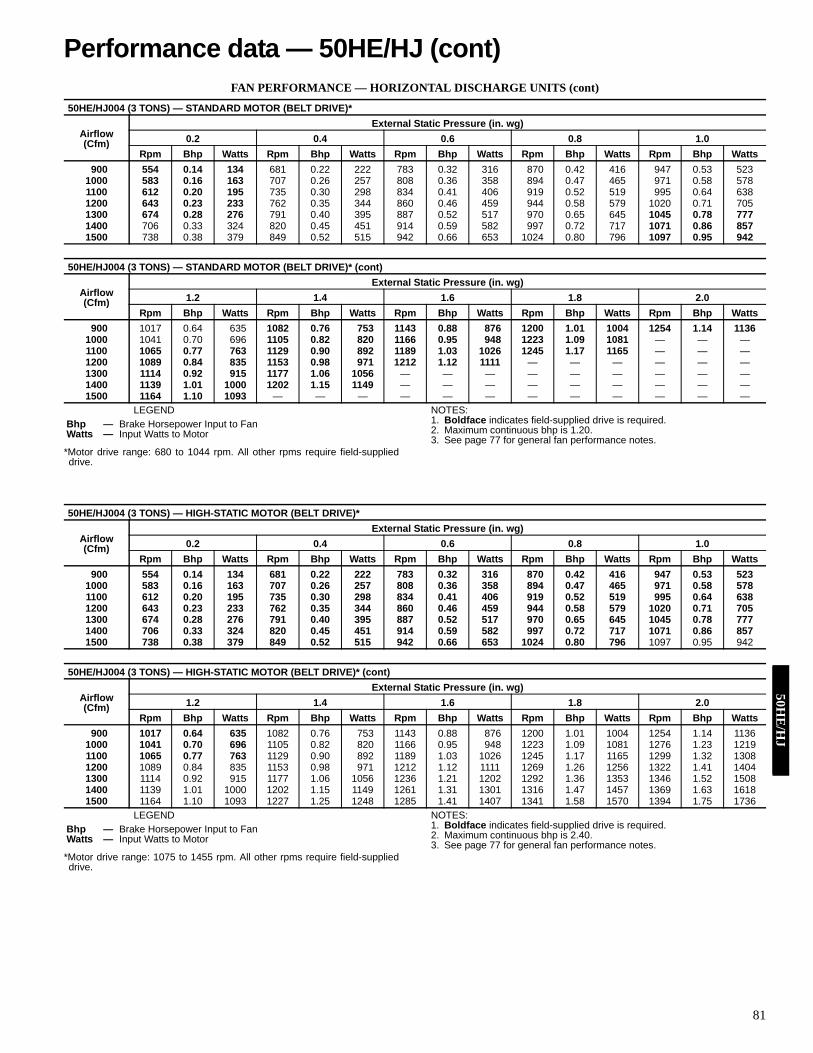
81
FAN PERFORMANCE — HORIZONTAL DISCHARGE UNITS (cont)
LEGEND
*Motor drive range: 680 to 1044 rpm. All other rpms require field-supplieddrive.
NOTES:1. Boldface indicates field-supplied drive is required.2. Maximum continuous bhp is 1.20.3. See page 77 for general fan performance notes.
LEGEND
*Motor drive range: 1075 to 1455 rpm. All other rpms require field-supplieddrive.
NOTES:1. Boldface indicates field-supplied drive is required.2. Maximum continuous bhp is 2.40.3. See page 77 for general fan performance notes.
50HE/HJ004 (3 TONS) — STANDARD MOTOR (BELT DRIVE)*
Airflow(Cfm)
External Static Pressure (in. wg)0.2 0.4 0.6 0.8 1.0
Rpm Bhp Watts Rpm Bhp Watts Rpm Bhp Watts Rpm Bhp Watts Rpm Bhp Watts900 554 0.14 134 681 0.22 222 783 0.32 316 870 0.42 416 947 0.53 523
1000 583 0.16 163 707 0.26 257 808 0.36 358 894 0.47 465 971 0.58 5781100 612 0.20 195 735 0.30 298 834 0.41 406 919 0.52 519 995 0.64 6381200 643 0.23 233 762 0.35 344 860 0.46 459 944 0.58 579 1020 0.71 7051300 674 0.28 276 791 0.40 395 887 0.52 517 970 0.65 645 1045 0.78 7771400 706 0.33 324 820 0.45 451 914 0.59 582 997 0.72 717 1071 0.86 8571500 738 0.38 379 849 0.52 515 942 0.66 653 1024 0.80 796 1097 0.95 942
50HE/HJ004 (3 TONS) — STANDARD MOTOR (BELT DRIVE)* (cont)
Airflow(Cfm)
External Static Pressure (in. wg)1.2 1.4 1.6 1.8 2.0
Rpm Bhp Watts Rpm Bhp Watts Rpm Bhp Watts Rpm Bhp Watts Rpm Bhp Watts900 1017 0.64 635 1082 0.76 753 1143 0.88 876 1200 1.01 1004 1254 1.14 1136
1000 1041 0.70 696 1105 0.82 820 1166 0.95 948 1223 1.09 1081 — — —1100 1065 0.77 763 1129 0.90 892 1189 1.03 1026 1245 1.17 1165 — — —1200 1089 0.84 835 1153 0.98 971 1212 1.12 1111 — — — — — —1300 1114 0.92 915 1177 1.06 1056 — — — — — — — — —1400 1139 1.01 1000 1202 1.15 1149 — — — — — — — — —1500 1164 1.10 1093 — — — — — — — — — — — —
Bhp — Brake Horsepower Input to FanWatts — Input Watts to Motor
50HE/HJ004 (3 TONS) — HIGH-STATIC MOTOR (BELT DRIVE)*
Airflow(Cfm)
External Static Pressure (in. wg)0.2 0.4 0.6 0.8 1.0
Rpm Bhp Watts Rpm Bhp Watts Rpm Bhp Watts Rpm Bhp Watts Rpm Bhp Watts900 554 0.14 134 681 0.22 222 783 0.32 316 870 0.42 416 947 0.53 523
1000 583 0.16 163 707 0.26 257 808 0.36 358 894 0.47 465 971 0.58 5781100 612 0.20 195 735 0.30 298 834 0.41 406 919 0.52 519 995 0.64 6381200 643 0.23 233 762 0.35 344 860 0.46 459 944 0.58 579 1020 0.71 7051300 674 0.28 276 791 0.40 395 887 0.52 517 970 0.65 645 1045 0.78 7771400 706 0.33 324 820 0.45 451 914 0.59 582 997 0.72 717 1071 0.86 8571500 738 0.38 379 849 0.52 515 942 0.66 653 1024 0.80 796 1097 0.95 942
50HE/HJ004 (3 TONS) — HIGH-STATIC MOTOR (BELT DRIVE)* (cont)
Airflow(Cfm)
External Static Pressure (in. wg)1.2 1.4 1.6 1.8 2.0
Rpm Bhp Watts Rpm Bhp Watts Rpm Bhp Watts Rpm Bhp Watts Rpm Bhp Watts900 1017 0.64 635 1082 0.76 753 1143 0.88 876 1200 1.01 1004 1254 1.14 1136
1000 1041 0.70 696 1105 0.82 820 1166 0.95 948 1223 1.09 1081 1276 1.23 12191100 1065 0.77 763 1129 0.90 892 1189 1.03 1026 1245 1.17 1165 1299 1.32 13081200 1089 0.84 835 1153 0.98 971 1212 1.12 1111 1269 1.26 1256 1322 1.41 14041300 1114 0.92 915 1177 1.06 1056 1236 1.21 1202 1292 1.36 1353 1346 1.52 15081400 1139 1.01 1000 1202 1.15 1149 1261 1.31 1301 1316 1.47 1457 1369 1.63 16181500 1164 1.10 1093 1227 1.25 1248 1285 1.41 1407 1341 1.58 1570 1394 1.75 1736
Bhp — Brake Horsepower Input to FanWatts — Input Watts to Motor
Performance data — 50HE/HJ (cont)50H
E/H
J

82
FAN PERFORMANCE — HORIZONTAL DISCHARGE UNITS (cont)
LEGEND
*Motor drive range: 770 to 1185 rpm. All other rpms require field-supplieddrive.
NOTES:1. Boldface indicates field-supplied drive is required.2. Maximum continuous bhp is 1.20.3. See page 77 for general fan performance notes.
LEGEND
*Motor drive range: 1075 to 1455 rpm. All other rpms require field-supplieddrive.
NOTES:1. Boldface indicates field-supplied drive is required.2. Maximum continuous bhp is 2.40.3. See page 77 for general fan performance notes.
50HE/HJ005 (4 TONS) — STANDARD MOTOR (BELT DRIVE)*
Airflow(Cfm)
External Static Pressure (in. wg)0.2 0.4 0.6 0.8 1.0
Rpm Bhp Watts Rpm Bhp Watts Rpm Bhp Watts Rpm Bhp Watts Rpm Bhp Watts1200 643 0.23 233 762 0.35 344 860 0.46 459 944 0.58 579 1020 0.71 7051300 674 0.28 276 791 0.40 395 887 0.52 517 970 0.65 645 1045 0.78 7771400 706 0.33 324 820 0.45 451 914 0.59 582 997 0.72 717 1071 0.86 8571500 738 0.38 379 849 0.52 515 942 0.66 653 1024 0.80 796 1097 0.95 9421600 771 0.44 440 879 0.59 584 971 0.74 731 1051 0.89 881 1124 1.04 10351700 804 0.51 507 910 0.66 661 1000 0.82 816 1079 0.98 974 1151 1.14 11361800 837 0.59 582 941 0.75 745 1029 0.91 909 1107 1.08 1075 — — —1900 871 0.67 665 972 0.84 837 1059 1.02 1010 1136 1.19 1184 — — —2000 906 0.76 756 1004 0.94 938 1089 1.12 1119 — — — — — —
50HE/HJ005 (4 TONS) — STANDARD MOTOR (BELT DRIVE)*
Airflow(Cfm)
External Static Pressure (in. wg)1.2 1.4 1.6 1.8 2.0
Rpm Bhp Watts Rpm Bhp Watts Rpm Bhp Watts Rpm Bhp Watts Rpm Bhp Watts1200 1089 0.84 835 1153 0.98 971 1212 1.12 1111 — — — — — —1300 1114 0.92 915 1177 1.06 1056 — — — — — — — — —1400 1139 1.01 1000 1202 1.15 1149 — — — — — — — — —1500 1164 1.10 1093 — — — — — — — — — — — —1600 1190 1.20 1193 — — — — — — — — — — — —1700 — — — — — — — — — — — — — — —1800 — — — — — — — — — — — — — — —1900 — — — — — — — — — — — — — — —2000 — — — — — — — — — — — — — — —
Bhp — Brake Horsepower Input to FanWatts — Input Watts to Motor
50HE/HJ005 (4 TONS) — HIGH-STATIC MOTOR (BELT DRIVE)*
Airflow(Cfm)
External Static Pressure (in. wg)0.2 0.4 0.6 0.8 1.0
Rpm Bhp Watts Rpm Bhp Watts Rpm Bhp Watts Rpm Bhp Watts Rpm Bhp Watts1200 643 0.23 233 762 0.35 344 860 0.46 459 944 0.58 579 1020 0.71 7051300 674 0.28 276 791 0.40 395 887 0.52 517 970 0.65 645 1045 0.78 7771400 706 0.33 324 820 0.45 451 914 0.59 582 997 0.72 717 1071 0.86 8571500 738 0.38 379 849 0.52 515 942 0.66 653 1024 0.80 796 1097 0.95 9421600 771 0.44 440 879 0.59 584 971 0.74 731 1051 0.89 881 1124 1.04 10351700 804 0.51 507 910 0.66 661 1000 0.82 816 1079 0.98 974 1151 1.14 11361800 837 0.59 582 941 0.75 745 1029 0.91 909 1107 1.08 1075 1178 1.25 12441900 871 0.67 665 972 0.84 837 1059 1.02 1010 1136 1.19 1184 1206 1.37 13612000 906 0.76 756 1004 0.94 938 1089 1.12 1119 1165 1.31 1301 1234 1.49 1486
50HE/HJ005 (4 TONS) — HIGH-STATIC MOTOR (BELT DRIVE)* (cont)
Airflow(Cfm)
External Static Pressure (in. wg)1.2 1.4 1.6 1.8 2.0
Rpm Bhp Watts Rpm Bhp Watts Rpm Bhp Watts Rpm Bhp Watts Rpm Bhp Watts1200 1089 0.84 835 1153 0.98 971 1212 1.12 1111 1269 1.26 1256 1322 1.41 14041300 1114 0.92 915 1177 1.06 1056 1236 1.21 1202 1292 1.36 1353 1346 1.52 15081400 1139 1.01 1000 1202 1.15 1149 1261 1.31 1301 1316 1.47 1457 1369 1.63 16181500 1164 1.10 1093 1227 1.25 1248 1285 1.41 1407 1341 1.58 1570 1394 1.75 17361600 1190 1.20 1193 1252 1.36 1355 1311 1.53 1520 1366 1.70 1690 1418 1.87 18631700 1217 1.31 1301 1278 1.48 1470 1336 1.65 1642 1391 1.83 1818 1443 2.01 19981800 1244 1.42 1417 1305 1.60 1593 1362 1.78 1772 1416 1.97 1955 1468 2.15 21411900 1271 1.55 1541 1331 1.73 1724 1388 1.92 1911 1442 2.11 2101 1494 2.31 22942000 1298 1.68 1674 1358 1.87 1865 1415 2.07 2059 1468 2.27 2256 — — —
Bhp — Brake Horsepower Input to FanWatts — Input Watts to Motor
50H
E/H
J

83
FAN PERFORMANCE — HORIZONTAL DISCHARGE UNITS (cont)
LEGEND
*Motor drive range: 1035 to 1460 rpm. All other rpms require field-supplieddrive.
NOTES:1. Boldface indicates field-supplied drive is required.2. Maximum continuous bhp is 1.30.3. See page 77 for general fan performance notes.
LEGEND *Motor drive range: 1035 to 1460 rpm. All other rpms require field-supplieddrive.
NOTES:1. Boldface indicates field-supplied drive is required.2. Maximum continuous bhp is 2.40.3. See page 77 for general fan performance notes.
50HE/HJ006 (5 TONS) — STANDARD MOTOR (BELT DRIVE) — SINGLE PHASE*
Airflow(Cfm)
External Static Pressure (in. wg)0.2 0.4 0.6 0.8 1.0
Rpm Bhp Watts Rpm Bhp Watts Rpm Bhp Watts Rpm Bhp Watts Rpm Bhp Watts1500 724 0.33 295 837 0.45 402 937 0.59 524 1028 0.74 660 1111 0.91 8081600 757 0.39 343 866 0.51 455 962 0.65 580 1050 0.81 719 1132 0.98 8701700 790 0.45 398 894 0.58 514 988 0.72 643 1074 0.88 784 1154 1.06 9381800 823 0.52 458 924 0.65 579 1015 0.80 712 1099 0.96 857 1177 1.14 10131900 857 0.59 525 955 0.73 650 1043 0.89 787 1125 1.05 936 1201 1.23 10962000 892 0.67 599 986 0.82 729 1072 0.98 870 1151 1.15 1022 — — —2100 927 0.77 680 1017 0.92 815 1101 1.08 960 1178 1.26 1116 — — —2200 962 0.87 769 1050 1.02 909 1131 1.19 1059 — — — — — —2300 997 0.97 865 1082 1.14 1010 — — — — — — — — —2400 1033 1.09 970 1115 1.26 1120 — — — — — — — — —2500 1069 1.22 1084 — — — — — — — — — — — —
50HE/HJ006 (5 TONS) — STANDARD MOTOR (BELT DRIVE) — SINGLE PHASE* (cont)
Airflow(Cfm)
External Static Pressure (in. wg)1.2 1.4 1.6 1.8 2.0
Rpm Bhp Watts Rpm Bhp Watts Rpm Bhp Watts Rpm Bhp Watts Rpm Bhp Watts1500 1188 1.09 970 1261 1.29 1143 — — — — — — — — —1600 1208 1.16 1033 — — — — — — — — — — — —1700 1229 1.24 1103 — — — — — — — — — — — —1800 — — — — — — — — — — — — — — —1900 — — — — — — — — — — — — — — —2000 — — — — — — — — — — — — — — —2100 — — — — — — — — — — — — — — —2200 — — — — — — — — — — — — — — —2300 — — — — — — — — — — — — — — —2400 — — — — — — — — — — — — — — —2500 — — — — — — — — — — — — — — —
Bhp — Brake Horsepower Input to FanWatts — Input Watts to Motor
50HE/HJ006 (5 TONS) — STANDARD MOTOR (BELT DRIVE) — THREE PHASE*
Airflow(Cfm)
External Static Pressure (in. wg)0.2 0.4 0.6 0.8 1.0
Rpm Bhp Watts Rpm Bhp Watts Rpm Bhp Watts Rpm Bhp Watts Rpm Bhp Watts1500 724 0.33 295 837 0.45 402 937 0.59 524 1028 0.74 660 1111 0.91 8081600 757 0.39 343 866 0.51 455 962 0.65 580 1050 0.81 719 1132 0.98 8701700 790 0.45 398 894 0.58 514 988 0.72 643 1074 0.88 784 1154 1.06 9381800 823 0.52 458 924 0.65 579 1015 0.80 712 1099 0.96 857 1177 1.14 10131900 857 0.59 525 955 0.73 650 1043 0.89 787 1125 1.05 936 1201 1.23 10962000 892 0.67 599 986 0.82 729 1072 0.98 870 1151 1.15 1022 1226 1.33 11852100 927 0.77 680 1017 0.92 815 1101 1.08 960 1178 1.26 1116 1251 1.44 12832200 962 0.87 769 1050 1.02 909 1131 1.19 1059 1206 1.37 1218 1277 1.56 13892300 997 0.97 865 1082 1.14 1010 1161 1.31 1165 1235 1.50 1329 1304 1.69 15032400 1033 1.09 970 1115 1.26 1120 1192 1.44 1279 1264 1.63 1448 1332 1.83 16252500 1069 1.22 1084 1149 1.39 1239 1223 1.58 1403 1293 1.77 1576 1360 1.98 1757
50HE/HJ006 (5 TONS) — STANDARD MOTOR (BELT DRIVE) — THREE PHASE* (cont)
Airflow(Cfm)
External Static Pressure (in. wg)1.2 1.4 1.6 1.8 2.0
Rpm Bhp Watts Rpm Bhp Watts Rpm Bhp Watts Rpm Bhp Watts Rpm Bhp Watts1500 1188 1.09 970 1261 1.29 1143 1330 1.49 1327 1395 1.71 1523 1457 1.95 17291600 1208 1.16 1033 1279 1.36 1208 1347 1.57 1394 1412 1.79 1590 1474 2.02 17971700 1229 1.24 1103 1299 1.44 1280 1366 1.65 1468 1429 1.88 1665 1490 2.11 18731800 1250 1.33 1181 1319 1.53 1360 1385 1.74 1549 1448 1.97 1748 1508 2.20 19571900 1273 1.43 1266 1341 1.63 1447 1405 1.84 1638 1467 2.07 1839 1527 2.31 20502000 1296 1.53 1359 1363 1.74 1542 1427 1.95 1736 1488 2.18 1939 — — —2100 1320 1.64 1459 1386 1.85 1646 1448 2.07 1842 1508 2.30 2047 — — —2200 1345 1.77 1568 1409 1.98 1758 1471 2.20 1956 — — — — — —2300 1371 1.90 1686 1434 2.11 1878 1494 2.34 2080 — — — — — —2400 1397 2.04 1812 1459 2.26 2008 — — — — — — — — —2500 1424 2.19 1948 — — — — — — — — — — — —
Bhp — Brake Horsepower Input to FanWatts — Input Watts to Motor
Performance data — 50HE/HJ (cont)50H
E/H
J
84
FAN PERFORMANCE — HORIZONTAL DISCHARGE UNITS (cont)
LEGEND
*Motor drive range: 1300 to 1685 rpm. All other rpms require field-supplieddrive.
NOTES:1. Boldface indicates field-supplied drive is required.2. Maximum continuous bhp is 2.90.3. See page 77 for general fan performance notes.
LEGEND
*Motor drive range: 1120 to 1585 rpm. All other rpms require field-supplieddrive.
NOTES:1. Boldface indicates field-supplied drive is required.2. Maximum continuous bhp is 2.40.3. See page 77 for general fan performance notes.
50HE/HJ006 (5 TONS) — HIGH-STATIC MOTOR (BELT DRIVE)*
Airflow(Cfm)
External Static Pressure (in. wg)0.2 0.4 0.6 0.8 1.0
Rpm Bhp Watts Rpm Bhp Watts Rpm Bhp Watts Rpm Bhp Watts Rpm Bhp Watts1500 724 0.33 295 837 0.45 402 937 0.59 524 1028 0.74 660 1111 0.91 8081600 757 0.39 343 866 0.51 455 962 0.65 580 1050 0.81 719 1132 0.98 8701700 790 0.45 398 894 0.58 514 988 0.72 643 1074 0.88 784 1154 1.06 9381800 823 0.52 458 924 0.65 579 1015 0.80 712 1099 0.96 857 1177 1.14 10131900 857 0.59 525 955 0.73 650 1043 0.89 787 1125 1.05 936 1201 1.23 10962000 892 0.67 599 986 0.82 729 1072 0.98 870 1151 1.15 1022 1226 1.33 11852100 927 0.77 680 1017 0.92 815 1101 1.08 960 1178 1.26 1116 1251 1.44 12832200 962 0.87 769 1050 1.02 909 1131 1.19 1059 1206 1.37 1218 1277 1.56 13892300 997 0.97 865 1082 1.14 1010 1161 1.31 1165 1235 1.50 1329 1304 1.69 15032400 1033 1.09 970 1115 1.26 1120 1192 1.44 1279 1264 1.63 1448 1332 1.83 16252500 1069 1.22 1084 1149 1.39 1239 1223 1.58 1403 1293 1.77 1576 1360 1.98 1757
50HE/HJ006 (5 TONS) — HIGH-STATIC MOTOR (BELT DRIVE)* (cont)
Airflow(Cfm)
External Static Pressure (in. wg)1.2 1.4 1.6 1.8 2.0
Rpm Bhp Watts Rpm Bhp Watts Rpm Bhp Watts Rpm Bhp Watts Rpm Bhp Watts1500 1188 1.09 970 1261 1.29 1143 1330 1.49 1327 1395 1.71 1523 1457 1.95 17291600 1208 1.16 1033 1279 1.36 1208 1347 1.57 1394 1412 1.79 1590 1474 2.02 17971700 1229 1.24 1103 1299 1.44 1280 1366 1.65 1468 1429 1.88 1665 1490 2.11 18731800 1250 1.33 1181 1319 1.53 1360 1385 1.74 1549 1448 1.97 1748 1508 2.20 19571900 1273 1.43 1266 1341 1.63 1447 1405 1.84 1638 1467 2.07 1839 1527 2.31 20502000 1296 1.53 1359 1363 1.74 1542 1427 1.95 1736 1488 2.18 1939 1546 2.42 21512100 1320 1.64 1459 1386 1.85 1646 1448 2.07 1842 1508 2.30 2047 1566 2.55 22622200 1345 1.77 1568 1409 1.98 1758 1471 2.20 1956 1530 2.44 2164 1587 2.68 23802300 1371 1.90 1686 1434 2.11 1878 1494 2.34 2080 1553 2.58 2290 1609 2.83 25092400 1397 2.04 1812 1459 2.26 2008 1518 2.49 2213 1576 2.73 2425 — — —2500 1424 2.19 1948 1484 2.42 2147 1543 2.65 2355 1599 2.89 2571 — — —
Bhp — Brake Horsepower Input to FanWatts — Input Watts to Motor
50HJ007 (6 TONS) — STANDARD MOTOR (BELT DRIVE)*
Airflow(Cfm)
External Static Pressure (in. wg)0.2 0.4 0.6 0.8 1.0
Rpm Bhp Watts Rpm Bhp Watts Rpm Bhp Watts Rpm Bhp Watts Rpm Bhp Watts1800 822 0.51 455 927 0.66 589 1018 0.82 728 1100 0.98 873 1174 1.15 10241900 855 0.59 520 957 0.74 659 1046 0.91 805 1127 1.08 956 1200 1.25 11132000 889 0.66 591 988 0.83 737 1075 1.00 888 1154 1.18 1045 1226 1.36 12082100 923 0.75 668 1019 0.92 821 1104 1.10 979 1182 1.29 1142 1253 1.48 13102200 957 0.85 753 1051 1.03 912 1134 1.21 1077 1210 1.40 1245 1280 1.60 14192300 992 0.95 845 1083 1.14 1011 1164 1.33 1182 1239 1.53 1357 1308 1.73 15372400 1026 1.06 945 1115 1.26 1118 1195 1.46 1295 1268 1.66 1476 1336 1.87 16622500 1061 1.19 1053 1148 1.39 1233 1226 1.59 1416 1297 1.81 1604 1364 2.02 17962600 1097 1.32 1169 1181 1.53 1356 1257 1.74 1546 1327 1.96 1740 1393 2.18 19382700 1132 1.46 1294 1214 1.67 1487 1289 1.90 1684 1358 2.12 1885 1422 2.35 20892800 1168 1.61 1428 1247 1.83 1629 1320 2.06 1832 1388 2.30 2039 — — —2900 1204 1.77 1572 1281 2.00 1779 1353 2.24 1989 — — — — — —3000 1240 1.94 1725 1315 2.18 1939 — — — — — — — — —
50HJ007 (6 TONS) — STANDARD MOTOR (BELT DRIVE)* (cont)
Airflow(Cfm)
External Static Pressure (in. wg)1.2 1.4 1.6 1.8 2.0
Rpm Bhp Watts Rpm Bhp Watts Rpm Bhp Watts Rpm Bhp Watts Rpm Bhp Watts1800 1244 1.33 1182 1308 1.51 1345 1369 1.70 1513 1427 1.90 1687 1483 2.10 18671900 1268 1.44 1275 1332 1.63 1443 1393 1.82 1617 1450 2.02 1796 1505 2.23 19792000 1294 1.55 1376 1357 1.74 1549 1417 1.95 1727 1474 2.15 1911 1528 2.36 21002100 1320 1.67 1483 1382 1.87 1662 1441 2.08 1845 1498 2.29 2034 — — —2200 1346 1.80 1598 1408 2.01 1782 1466 2.22 1971 — — — — — —2300 1372 1.94 1721 1434 2.15 1911 1491 2.37 2105 — — — — — —2400 1400 2.09 1852 1460 2.31 2047 — — — — — — — — —2500 1427 2.24 1992 — — — — — — — — — — — —2600 — — — — — — — — — — — — — — —2700 — — — — — — — — — — — — — — —2800 — — — — — — — — — — — — — — —2900 — — — — — — — — — — — — — — —3000 — — — — — — — — — — — — — — —
Bhp — Brake Horsepower Input to FanWatts — Input Watts to Motor
50H
E/H
J

85
FAN PERFORMANCE — HORIZONTAL DISCHARGE UNITS (cont)
LEGEND
*Motor drive range: 1300 to 1685 rpm. All other rpms require field-supplieddrive.
NOTES:1. Boldface indicates field-supplied drive is required.2. Maximum continuous bhp is 2.90.3. See page 77 for general fan performance notes.
50HJ007 (6 TONS) — HIGH-STATIC MOTOR (BELT DRIVE)*
Airflow(Cfm)
External Static Pressure (in. wg)0.2 0.4 0.6 0.8 1.0
Rpm Bhp Watts Rpm Bhp Watts Rpm Bhp Watts Rpm Bhp Watts Rpm Bhp Watts1800 822 0.51 455 927 0.66 589 1018 0.82 728 1100 0.98 873 1174 1.15 10241900 855 0.59 520 957 0.74 659 1046 0.91 805 1127 1.08 956 1200 1.25 11132000 889 0.66 591 988 0.83 737 1075 1.00 888 1154 1.18 1045 1226 1.36 12082100 923 0.75 668 1019 0.92 821 1104 1.10 979 1182 1.29 1142 1253 1.48 13102200 957 0.85 753 1051 1.03 912 1134 1.21 1077 1210 1.40 1245 1280 1.60 14192300 992 0.95 845 1083 1.14 1011 1164 1.33 1182 1239 1.53 1357 1308 1.73 15372400 1026 1.06 945 1115 1.26 1118 1195 1.46 1295 1268 1.66 1476 1336 1.87 16622500 1061 1.19 1053 1148 1.39 1233 1226 1.59 1416 1297 1.81 1604 1364 2.02 17962600 1097 1.32 1169 1181 1.53 1356 1257 1.74 1546 1327 1.96 1740 1393 2.18 19382700 1132 1.46 1294 1214 1.67 1487 1289 1.90 1684 1358 2.12 1885 1422 2.35 20892800 1168 1.61 1428 1247 1.83 1629 1320 2.06 1832 1388 2.30 2039 1452 2.53 22492900 1204 1.77 1572 1281 2.00 1779 1353 2.24 1989 1419 2.48 2202 1482 2.72 24193000 1240 1.94 1725 1315 2.18 1939 1385 2.43 2156 1451 2.68 2376 — — —
50HJ007 (6 TONS) — HIGH-STATIC MOTOR (BELT DRIVE)* (cont)
Airflow(Cfm)
External Static Pressure (in. wg)1.2 1.4 1.6 1.8 2.0
Rpm Bhp Watts Rpm Bhp Watts Rpm Bhp Watts Rpm Bhp Watts Rpm Bhp Watts1800 1244 1.33 1182 1308 1.51 1345 1369 1.70 1513 1427 1.90 1687 1483 2.10 18671900 1268 1.44 1275 1332 1.63 1443 1393 1.82 1617 1450 2.02 1796 1505 2.23 19792000 1294 1.55 1376 1357 1.74 1549 1417 1.95 1727 1474 2.15 1911 1528 2.36 21002100 1320 1.67 1483 1382 1.87 1662 1441 2.08 1845 1498 2.29 2034 1552 2.51 22272200 1346 1.80 1598 1408 2.01 1782 1466 2.22 1971 1522 2.44 2165 1575 2.66 23632300 1372 1.94 1721 1434 2.15 1911 1491 2.37 2105 1547 2.59 2304 1600 2.82 25072400 1400 2.09 1852 1460 2.31 2047 1517 2.53 2247 1572 2.76 2451 — — —2500 1427 2.24 1992 1487 2.47 2192 1543 2.70 2398 — — — — — —2600 1455 2.41 2140 1514 2.64 2346 1570 2.88 2557 — — — — — —2700 1483 2.59 2297 1541 2.83 2509 — — — — — — — — —2800 1512 2.77 2463 — — — — — — — — — — — —2900 1541 2.97 2640 — — — — — — — — — — — —3000 — — — — — — — — — — — — — — —
Bhp — Brake Horsepower Input to FanWatts — Input Watts to Motor
Performance data — 50HJ (cont)50H
J

86
FAN PERFORMANCE — HORIZONTAL DISCHARGE UNITS (cont)
LEGEND
*Motor drive range: 840 to 1085 rpm. All other rpms require field-supplieddrive.
NOTES:1. Boldface indicates field-supplied drive is required.2. Maximum continuous bhp is 2.90.3. See page 77 for general fan performance notes.
50HJ008 (71/2 TONS) — STANDARD MOTOR (BELT DRIVE)*
Airflow(Cfm)
External Static Pressure (in. wg)0.2 0.4 0.6 0.8 1.0
Rpm Bhp Watts Rpm Bhp Watts Rpm Bhp Watts Rpm Bhp Watts Rpm Bhp Watts2250 465 0.43 402 555 0.64 596 629 0.86 802 694 1.10 1021 753 1.34 12522300 471 0.45 421 560 0.66 618 634 0.89 828 699 1.13 1050 757 1.38 12832400 483 0.49 461 571 0.71 665 644 0.94 881 708 1.19 1109 766 1.45 13482500 495 0.54 503 581 0.77 715 654 1.01 937 717 1.26 1171 775 1.52 14162550 501 0.56 526 587 0.79 740 659 1.04 967 722 1.29 1204 779 1.56 14522600 507 0.59 549 592 0.82 767 664 1.07 996 727 1.33 1237 784 1.60 14882700 519 0.64 597 603 0.88 823 674 1.14 1059 737 1.40 1306 793 1.68 15632800 532 0.70 649 614 0.95 882 684 1.21 1125 746 1.48 1378 803 1.76 16412900 544 0.75 703 625 1.01 944 695 1.28 1194 756 1.56 1453 812 1.85 17233000 557 0.82 761 637 1.08 1009 705 1.36 1266 766 1.64 1533 822 1.94 18083100 570 0.88 823 648 1.16 1079 716 1.44 1342 776 1.73 1615 831 2.03 18973200 583 0.95 888 660 1.23 1151 727 1.53 1422 787 1.82 1702 841 2.13 19913300 596 1.03 957 672 1.32 1228 738 1.61 1506 797 1.92 1792 851 2.24 20883400 609 1.10 1030 684 1.40 1308 749 1.71 1593 808 2.02 1887 861 2.35 21883500 622 1.19 1106 696 1.49 1392 760 1.81 1685 818 2.13 1985 872 2.46 22943600 635 1.27 1187 708 1.59 1481 771 1.91 1781 829 2.24 2088 882 2.58 24033700 649 1.36 1272 720 1.69 1573 783 2.02 1881 840 2.35 2195 892 2.70 25173750 655 1.41 1316 726 1.74 1621 789 2.07 1932 845 2.41 2250 897 2.76 2575
50HJ008 (71/2 TONS) — STANDARD MOTOR (BELT DRIVE)* (cont)
Airflow(Cfm)
External Static Pressure (in. wg)1.2 1.4 1.6 1.8 2.0
Rpm Bhp Watts Rpm Bhp Watts Rpm Bhp Watts Rpm Bhp Watts Rpm Bhp Watts2250 806 1.60 1494 856 1.87 1747 903 2.15 2009 947 2.45 2282 988 2.75 25642300 811 1.64 1528 860 1.91 1784 907 2.20 2048 950 2.49 2323 992 2.80 26072400 819 1.71 1599 868 1.99 1859 915 2.28 2129 958 2.58 2410 1000 2.89 26982500 828 1.79 1672 877 2.08 1938 923 2.37 2214 966 2.68 2499 — — —2550 832 1.83 1710 881 2.12 1979 927 2.42 2258 971 2.73 2545 — — —2600 836 1.88 1749 885 2.17 2021 931 2.47 2302 975 2.78 2592 — — —2700 845 1.96 1830 894 2.26 2107 940 2.57 2394 983 2.88 2689 — — —2800 854 2.05 1914 903 2.36 2197 948 2.67 2488 — — — — — —2900 864 2.15 2002 912 2.46 2290 957 2.77 2587 — — — — — —3000 873 2.24 2093 921 2.56 2388 966 2.89 2691 — — — — — —3100 882 2.35 2189 930 2.67 2489 — — — — — — — — —3200 892 2.45 2288 939 2.78 2595 — — — — — — — — —3300 901 2.56 2391 948 2.90 2704 — — — — — — — — —3400 911 2.68 2499 — — — — — — — — — — — —3500 921 2.80 2610 — — — — — — — — — — — —3600 — — — — — — — — — — — — — — —3700 — — — — — — — — — — — — — — —3750 — — — — — — — — — — — — — — —
Bhp — Brake Horsepower Input to FanWatts — Input Watts to Motor
50H
J

87
FAN PERFORMANCE — HORIZONTAL DISCHARGE UNITS (cont)
LEGEND
*Motor drive range: 860 to 1080 rpm. All other rpms require field-supplieddrive.
NOTES:1. Boldface indicates field-supplied drive is required.2. Maximum continuous bhp is 4.20.3. See page 77 for general fan performance notes.
50HJ008 (71/2 TONS) — HIGH-STATIC MOTOR (BELT DRIVE)*
Airflow(Cfm)
External Static Pressure (in. wg)0.2 0.4 0.6 0.8 1.0
Rpm Bhp Watts Rpm Bhp Watts Rpm Bhp Watts Rpm Bhp Watts Rpm Bhp Watts2250 465 0.43 402 555 0.64 596 629 0.86 802 694 1.10 1021 753 1.34 12522300 471 0.45 421 560 0.66 618 634 0.89 828 699 1.13 1050 757 1.38 12832400 483 0.49 461 571 0.71 665 644 0.94 881 708 1.19 1109 766 1.45 13482500 495 0.54 503 581 0.77 715 654 1.01 937 717 1.26 1171 775 1.52 14162550 501 0.56 526 587 0.79 740 659 1.04 967 722 1.29 1204 779 1.56 14522600 507 0.59 549 592 0.82 767 664 1.07 996 727 1.33 1237 784 1.60 14882700 519 0.64 597 603 0.88 823 674 1.14 1059 737 1.40 1306 793 1.68 15632800 532 0.70 649 614 0.95 882 684 1.21 1125 746 1.48 1378 803 1.76 16412900 544 0.75 703 625 1.01 944 695 1.28 1194 756 1.56 1453 812 1.85 17233000 557 0.82 761 637 1.08 1009 705 1.36 1266 766 1.64 1533 822 1.94 18083100 570 0.88 823 648 1.16 1079 716 1.44 1342 776 1.73 1615 831 2.03 18973200 583 0.95 888 660 1.23 1151 727 1.53 1422 787 1.82 1702 841 2.13 19913300 596 1.03 957 672 1.32 1228 738 1.61 1506 797 1.92 1792 851 2.24 20883400 609 1.10 1030 684 1.40 1308 749 1.71 1593 808 2.02 1887 861 2.35 21883500 622 1.19 1106 696 1.49 1392 760 1.81 1685 818 2.13 1985 872 2.46 22943600 635 1.27 1187 708 1.59 1481 771 1.91 1781 829 2.24 2088 882 2.58 24033700 649 1.36 1272 720 1.69 1573 783 2.02 1881 840 2.35 2195 892 2.70 25173750 655 1.41 1316 726 1.74 1621 789 2.07 1932 845 2.41 2250 897 2.76 2575
50HJ008 (71/2 TONS) — HIGH-STATIC MOTOR (BELT DRIVE)* (cont)
Airflow(Cfm)
External Static Pressure (in. wg)1.2 1.4 1.6 1.8 2.0
Rpm Bhp Watts Rpm Bhp Watts Rpm Bhp Watts Rpm Bhp Watts Rpm Bhp Watts2250 806 1.60 1494 856 1.87 1747 903 2.15 2009 947 2.45 2282 988 2.75 25642300 811 1.64 1528 860 1.91 1784 907 2.20 2048 950 2.49 2323 992 2.80 26072400 819 1.71 1599 868 1.99 1859 915 2.28 2129 958 2.58 2410 1000 2.89 26982500 828 1.79 1672 877 2.08 1938 923 2.37 2214 966 2.68 2499 1008 3.00 27932550 832 1.83 1710 881 2.12 1979 927 2.42 2258 971 2.73 2545 1012 3.05 28422600 836 1.88 1749 885 2.17 2021 931 2.47 2302 975 2.78 2592 1016 3.10 28912700 845 1.96 1830 894 2.26 2107 940 2.57 2394 983 2.88 2689 1024 3.21 29932800 854 2.05 1914 903 2.36 2197 948 2.67 2488 991 2.99 2790 1032 3.32 30992900 864 2.15 2002 912 2.46 2290 957 2.77 2587 1000 3.10 2894 1041 3.44 32093000 873 2.24 2093 921 2.56 2388 966 2.89 2691 1008 3.22 3003 1049 3.56 33233100 882 2.35 2189 930 2.67 2489 975 3.00 2798 1017 3.34 3115 1057 3.69 34413200 892 2.45 2288 939 2.78 2595 984 3.12 2909 1026 3.47 3233 1066 3.82 35643300 901 2.56 2391 948 2.90 2704 993 3.24 3024 1035 3.60 3353 1075 3.96 36903400 911 2.68 2499 958 3.02 2817 1002 3.37 3144 1044 3.73 3479 1084 4.10 38213500 921 2.80 2610 967 3.15 2935 1011 3.50 3268 1053 3.87 3608 — — —3600 931 2.92 2726 977 3.28 3057 1021 3.64 3396 1062 4.01 3743 — — —3700 941 3.05 2847 987 3.41 3184 1030 3.78 3529 1071 4.16 3882 — — —3750 946 3.12 2908 992 3.48 3249 1035 3.86 3597 — — — — — —
Bhp — Brake Horsepower Input to FanWatts — Input Watts to Motor
Performance data — 50HJ (cont)50H
J

88
FAN PERFORMANCE — HORIZONTAL DISCHARGE UNITS (cont)
LEGEND
*Motor drive range: 840 to 1085 rpm. All other rpms require field-supplieddrive.
NOTES:1. Boldface indicates field-supplied drive is required.2. Maximum continuous bhp is 2.90.3. See page 77 for general fan performance notes.
50HJ009 (81/2 TONS) — STANDARD MOTOR (BELT DRIVE)*
Airflow(Cfm)
External Static Pressure (in. wg)0.2 0.4 0.6 0.8 1.0
Rpm Bhp Watts Rpm Bhp Watts Rpm Bhp Watts Rpm Bhp Watts Rpm Bhp Watts2500 462 0.37 348 541 0.50 467 614 0.64 594 681 0.78 728 744 0.93 8682600 474 0.41 381 551 0.54 505 622 0.68 635 688 0.83 773 750 0.98 9162700 486 0.45 417 561 0.58 545 630 0.73 679 695 0.88 820 756 1.04 9672800 498 0.49 456 571 0.63 587 639 0.78 725 702 0.93 870 762 1.09 10202900 510 0.53 497 581 0.68 632 648 0.83 774 710 0.99 922 768 1.15 10763000 523 0.58 541 592 0.73 680 657 0.88 825 718 1.05 977 775 1.22 11353100 536 0.63 587 603 0.78 730 666 0.94 879 726 1.11 1035 783 1.28 11963200 549 0.68 637 614 0.84 783 676 1.00 936 735 1.17 1096 790 1.35 12603300 562 0.74 689 626 0.90 839 686 1.07 996 743 1.24 1159 798 1.42 13283400 575 0.80 744 637 0.96 898 696 1.14 1059 752 1.31 1226 806 1.50 13983500 588 0.86 802 649 1.03 961 707 1.21 1125 762 1.39 1296 815 1.58 14723600 601 0.93 864 661 1.10 1026 717 1.28 1194 771 1.47 1369 823 1.66 15483700 614 1.00 929 673 1.17 1095 728 1.36 1267 781 1.55 1445 832 1.75 16293800 628 1.07 997 685 1.25 1167 739 1.44 1343 791 1.64 1525 841 1.84 17123900 641 1.15 1069 697 1.33 1243 750 1.53 1423 801 1.72 1608 850 1.93 17994000 655 1.23 1144 709 1.42 1322 761 1.61 1506 812 1.82 1695 860 2.03 18904100 668 1.31 1223 722 1.51 1405 773 1.71 1593 822 1.92 1786 870 2.13 19844200 682 1.40 1305 734 1.60 1492 784 1.80 1683 833 2.02 1880 880 2.23 20824300 696 1.49 1392 747 1.70 1582 796 1.91 1777 844 2.12 1979 890 2.34 2184
50HJ009 (81/2 TONS) — STANDARD MOTOR (BELT DRIVE)* (cont)
Airflow(Cfm)
External Static Pressure (in. wg)1.2 1.4 1.6 1.8 2.0
Rpm Bhp Watts Rpm Bhp Watts Rpm Bhp Watts Rpm Bhp Watts Rpm Bhp Watts2500 804 1.09 1013 861 1.25 1164 915 1.41 1319 967 1.59 1479 1017 1.76 16422600 809 1.14 1065 864 1.31 1219 918 1.48 1378 969 1.65 1541 1018 1.83 17082700 813 1.20 1119 869 1.37 1277 921 1.54 1439 972 1.72 1606 1021 1.90 17762800 819 1.26 1176 873 1.43 1337 925 1.61 1503 975 1.79 1673 1023 1.98 18472900 824 1.32 1235 878 1.50 1400 929 1.68 1569 978 1.87 1742 1026 2.06 19203000 830 1.39 1298 883 1.57 1466 934 1.76 1638 982 1.95 1815 1029 2.14 19963100 837 1.46 1363 889 1.65 1534 938 1.83 1710 986 2.03 1891 1033 2.23 20753200 843 1.53 1431 894 1.72 1606 944 1.91 1785 991 2.11 1969 1037 2.31 21573300 850 1.61 1502 901 1.80 1680 949 2.00 1863 996 2.20 2051 1041 2.40 22423400 858 1.69 1576 907 1.88 1758 955 2.09 1944 1001 2.29 2135 1046 2.50 23313500 865 1.77 1653 914 1.97 1838 961 2.18 2029 1007 2.38 2223 1051 2.60 24223600 873 1.86 1733 921 2.06 1922 967 2.27 2116 1012 2.48 2314 1056 2.70 25163700 881 1.95 1816 928 2.16 2010 974 2.37 2207 1019 2.58 2409 1062 2.80 26153800 889 2.04 1904 936 2.25 2100 981 2.47 2302 1025 2.69 2507 — — —3900 898 2.14 1995 944 2.35 2195 988 2.57 2399 1032 2.80 2608 — — —4000 907 2.24 2089 952 2.46 2293 996 2.68 2501 — — — — — —4100 916 2.35 2187 960 2.57 2395 1004 2.80 2607 — — — — — —4200 925 2.45 2289 969 2.68 2500 — — — — — — — — —4300 934 2.57 2395 978 2.80 2610 — — — — — — — — —
Bhp — Brake Horsepower Input to FanWatts — Input Watts to Motor
50H
J

89
FAN PERFORMANCE — HORIZONTAL DISCHARGE UNITS (cont)
LEGEND
*Motor drive range: 860 to 1080 rpm. All other rpms require field-supplieddrive.
NOTES:1. Boldface indicates field-supplied drive is required.2. Maximum continuous bhp is 4.20.3. See page 77 for general fan performance notes.
50HJ009 (81/2 TONS) — HIGH-STATIC MOTOR (BELT DRIVE)*
Airflow(Cfm)
External Static Pressure (in. wg)0.2 0.4 0.6 0.8 1.0
Rpm Bhp Watts Rpm Bhp Watts Rpm Bhp Watts Rpm Bhp Watts Rpm Bhp Watts2500 462 0.37 348 541 0.50 467 614 0.64 594 681 0.78 728 744 0.93 8682600 474 0.41 381 551 0.54 505 622 0.68 635 688 0.83 773 750 0.98 9162700 486 0.45 417 561 0.58 545 630 0.73 679 695 0.88 820 756 1.04 9672800 498 0.49 456 571 0.63 587 639 0.78 725 702 0.93 870 762 1.09 10202900 510 0.53 497 581 0.68 632 648 0.83 774 710 0.99 922 768 1.15 10763000 523 0.58 541 592 0.73 680 657 0.88 825 718 1.05 977 775 1.22 11353100 536 0.63 587 603 0.78 730 666 0.94 879 726 1.11 1035 783 1.28 11963200 549 0.68 637 614 0.84 783 676 1.00 936 735 1.17 1096 790 1.35 12603300 562 0.74 689 626 0.90 839 686 1.07 996 743 1.24 1159 798 1.42 13283400 575 0.80 744 637 0.96 898 696 1.14 1059 752 1.31 1226 806 1.50 13983500 588 0.86 802 649 1.03 961 707 1.21 1125 762 1.39 1296 815 1.58 14723600 601 0.93 864 661 1.10 1026 717 1.28 1194 771 1.47 1369 823 1.66 15483700 614 1.00 929 673 1.17 1095 728 1.36 1267 781 1.55 1445 832 1.75 16293800 628 1.07 997 685 1.25 1167 739 1.44 1343 791 1.64 1525 841 1.84 17123900 641 1.15 1069 697 1.33 1243 750 1.53 1423 801 1.72 1608 850 1.93 17994000 655 1.23 1144 709 1.42 1322 761 1.61 1506 812 1.82 1695 860 2.03 18904100 668 1.31 1223 722 1.51 1405 773 1.71 1593 822 1.92 1786 870 2.13 19844200 682 1.40 1305 734 1.60 1492 784 1.80 1683 833 2.02 1880 880 2.23 20824300 696 1.49 1392 747 1.70 1582 796 1.91 1777 844 2.12 1979 890 2.34 2184
50HJ009 (81/2 TONS) — HIGH-STATIC MOTOR (BELT DRIVE)* (cont)
Airflow(Cfm)
External Static Pressure (in. wg)1.2 1.4 1.6 1.8 2.0
Rpm Bhp Watts Rpm Bhp Watts Rpm Bhp Watts Rpm Bhp Watts Rpm Bhp Watts2500 804 1.09 1013 861 1.25 1164 915 1.41 1319 967 1.59 1479 1017 1.76 16422600 809 1.14 1065 864 1.31 1219 918 1.48 1378 969 1.65 1541 1018 1.83 17082700 813 1.20 1119 869 1.37 1277 921 1.54 1439 972 1.72 1606 1021 1.90 17762800 819 1.26 1176 873 1.43 1337 925 1.61 1503 975 1.79 1673 1023 1.98 18472900 824 1.32 1235 878 1.50 1400 929 1.68 1569 978 1.87 1742 1026 2.06 19203000 830 1.39 1298 883 1.57 1466 934 1.76 1638 982 1.95 1815 1029 2.14 19963100 837 1.46 1363 889 1.65 1534 938 1.83 1710 986 2.03 1891 1033 2.23 20753200 843 1.53 1431 894 1.72 1606 944 1.91 1785 991 2.11 1969 1037 2.31 21573300 850 1.61 1502 901 1.80 1680 949 2.00 1863 996 2.20 2051 1041 2.40 22423400 858 1.69 1576 907 1.88 1758 955 2.09 1944 1001 2.29 2135 1046 2.50 23313500 865 1.77 1653 914 1.97 1838 961 2.18 2029 1007 2.38 2223 1051 2.60 24223600 873 1.86 1733 921 2.06 1922 967 2.27 2116 1012 2.48 2314 1056 2.70 25163700 881 1.95 1816 928 2.16 2010 974 2.37 2207 1019 2.58 2409 1062 2.80 26153800 889 2.04 1904 936 2.25 2100 981 2.47 2302 1025 2.69 2507 1068 2.91 27163900 898 2.14 1995 944 2.35 2195 988 2.57 2399 1032 2.80 2608 1074 3.03 28214000 907 2.24 2089 952 2.46 2293 996 2.68 2501 1038 2.91 2713 1080 3.14 29304100 916 2.35 2187 960 2.57 2395 1004 2.80 2607 1046 3.03 2822 1087 3.26 30424200 925 2.45 2289 969 2.68 2500 1011 2.91 2716 1053 3.15 2935 1094 3.39 31594300 934 2.57 2395 978 2.80 2610 1020 3.03 2828 1061 3.27 3052 1101 3.52 3279
Bhp — Brake Horsepower Input to FanWatts — Input Watts to Motor
Performance data — 50HJ (cont)50H
J

90
FAN PERFORMANCE — HORIZONTAL DISCHARGE UNITS (cont)
LEGEND
*Motor drive range: 860 to 1080 rpm. All other rpms require field-supplieddrive.
NOTES:1. Boldface indicates field-supplied drive is required.2. Maximum continuous bhp is 3.70.3. See page 77 for general fan performance notes.
50HJ012 (10 TONS) — STANDARD MOTOR (BELT DRIVE)*
Airflow(Cfm)
External Static Pressure (in. wg)0.2 0.4 0.6 0.8 1.0
Rpm Bhp Watts Rpm Bhp Watts Rpm Bhp Watts Rpm Bhp Watts Rpm Bhp Watts3000 523 0.58 541 592 0.73 680 657 0.88 825 718 1.05 977 775 1.22 11353100 536 0.63 587 603 0.78 730 666 0.94 879 726 1.11 1035 783 1.28 11963200 549 0.68 637 614 0.84 783 676 1.00 936 735 1.17 1096 790 1.35 12603300 562 0.74 689 626 0.90 839 686 1.07 996 743 1.24 1159 798 1.42 13283400 575 0.80 744 637 0.96 898 696 1.14 1059 752 1.31 1226 806 1.50 13983500 588 0.86 802 649 1.03 961 707 1.21 1125 762 1.39 1296 815 1.58 14723600 601 0.93 864 661 1.10 1026 717 1.28 1194 771 1.47 1369 823 1.66 15483700 614 1.00 929 673 1.17 1095 728 1.36 1267 781 1.55 1445 832 1.75 16293800 628 1.07 997 685 1.25 1167 739 1.44 1343 791 1.64 1525 841 1.84 17123900 641 1.15 1069 697 1.33 1243 750 1.53 1423 801 1.72 1608 850 1.93 17994000 655 1.23 1144 709 1.42 1322 761 1.61 1506 812 1.82 1695 860 2.03 18904100 668 1.31 1223 722 1.51 1405 773 1.71 1593 822 1.92 1786 870 2.13 19844200 682 1.40 1305 734 1.60 1492 784 1.80 1683 833 2.02 1880 880 2.23 20824300 696 1.49 1392 747 1.70 1582 796 1.91 1777 844 2.12 1979 890 2.34 21844400 710 1.59 1482 760 1.80 1677 808 2.01 1876 855 2.23 2081 900 2.46 22904500 723 1.69 1577 773 1.90 1775 820 2.12 1978 866 2.35 2187 910 2.57 24004600 737 1.80 1675 785 2.01 1877 832 2.24 2085 877 2.46 2297 921 2.70 25144700 751 1.91 1778 798 2.13 1984 844 2.35 2195 889 2.59 2412 932 2.82 26334800 765 2.02 1885 812 2.25 2095 856 2.48 2310 900 2.71 2531 942 2.95 27564900 779 2.14 1996 825 2.37 2210 869 2.61 2430 912 2.85 2654 953 3.09 28835000 793 2.26 2112 838 2.50 2330 881 2.74 2554 923 2.98 2782 965 3.23 3014
50HJ012 (10 TONS) — STANDARD MOTOR (BELT DRIVE)* (cont)
Airflow(Cfm)
External Static Pressure (in. wg)1.2 1.4 1.6 1.8 2.0
Rpm Bhp Watts Rpm Bhp Watts Rpm Bhp Watts Rpm Bhp Watts Rpm Bhp Watts3000 830 1.39 1298 883 1.57 1466 934 1.76 1638 982 1.95 1815 1029 2.14 19963100 837 1.46 1363 889 1.65 1534 938 1.83 1710 986 2.03 1891 1033 2.23 20753200 843 1.53 1431 894 1.72 1606 944 1.91 1785 991 2.11 1969 1037 2.31 21573300 850 1.61 1502 901 1.80 1680 949 2.00 1863 996 2.20 2051 1041 2.40 22423400 858 1.69 1576 907 1.88 1758 955 2.09 1944 1001 2.29 2135 1046 2.50 23313500 865 1.77 1653 914 1.97 1838 961 2.18 2029 1007 2.38 2223 1051 2.60 24223600 873 1.86 1733 921 2.06 1922 967 2.27 2116 1012 2.48 2314 1056 2.70 25163700 881 1.95 1816 928 2.16 2010 974 2.37 2207 1019 2.58 2409 1062 2.80 26153800 889 2.04 1904 936 2.25 2100 981 2.47 2302 1025 2.69 2507 1068 2.91 27163900 898 2.14 1995 944 2.35 2195 988 2.57 2399 1032 2.80 2608 1074 3.03 28214000 907 2.24 2089 952 2.46 2293 996 2.68 2501 1038 2.91 2713 1080 3.14 29304100 916 2.35 2187 960 2.57 2395 1004 2.80 2607 1046 3.03 2822 1087 3.26 30424200 925 2.45 2289 969 2.68 2500 1011 2.91 2716 1053 3.15 2935 1094 3.39 31594300 934 2.57 2395 978 2.80 2610 1020 3.03 2828 1061 3.27 3052 1101 3.52 32794400 944 2.69 2504 986 2.92 2723 1028 3.16 2946 1068 3.40 3173 1108 3.65 34034500 954 2.81 2618 996 3.05 2840 1037 3.29 3067 1076 3.54 3297 — — —4600 963 2.93 2736 1005 3.18 2962 1045 3.42 3192 1085 3.67 3426 — — —4700 974 3.07 2858 1014 3.31 3088 1054 3.56 3322 — — — — — —4800 984 3.20 2985 1024 3.45 3219 — — — — — — — — —4900 994 3.34 3116 1034 3.60 3353 — — — — — — — — —5000 1005 3.49 3251 — — — — — — — — — — — —
Bhp — Brake Horsepower Input to FanWatts — Input Watts to Motor
50H
J
91
FAN PERFORMANCE — HORIZONTAL DISCHARGE UNITS (cont)
LEGEND
*Motor drive range: 830 to 1130 rpm. All other rpms require field-supplieddrive.
NOTES:1. Boldface indicates field-supplied drive is required.2. Maximum continuous bhp is 5.25.3. See page 77 for general fan performance notes.
50HJ012 (10 TONS) — HIGH-STATIC MOTOR (BELT DRIVE)*
Airflow(Cfm)
External Static Pressure (in. wg)0.2 0.4 0.6 0.8 1.0
Rpm Bhp Watts Rpm Bhp Watts Rpm Bhp Watts Rpm Bhp Watts Rpm Bhp Watts3000 523 0.58 541 592 0.73 680 657 0.88 825 718 1.05 977 775 1.22 11353100 536 0.63 587 603 0.78 730 666 0.94 879 726 1.11 1035 783 1.28 11963200 549 0.68 637 614 0.84 783 676 1.00 936 735 1.17 1096 790 1.35 12603300 562 0.74 689 626 0.90 839 686 1.07 996 743 1.24 1159 798 1.42 13283400 575 0.80 744 637 0.96 898 696 1.14 1059 752 1.31 1226 806 1.50 13983500 588 0.86 802 649 1.03 961 707 1.21 1125 762 1.39 1296 815 1.58 14723600 601 0.93 864 661 1.10 1026 717 1.28 1194 771 1.47 1369 823 1.66 15483700 614 1.00 929 673 1.17 1095 728 1.36 1267 781 1.55 1445 832 1.75 16293800 628 1.07 997 685 1.25 1167 739 1.44 1343 791 1.64 1525 841 1.84 17123900 641 1.15 1069 697 1.33 1243 750 1.53 1423 801 1.72 1608 850 1.93 17994000 655 1.23 1144 709 1.42 1322 761 1.61 1506 812 1.82 1695 860 2.03 18904100 668 1.31 1223 722 1.51 1405 773 1.71 1593 822 1.92 1786 870 2.13 19844200 682 1.40 1305 734 1.60 1492 784 1.80 1683 833 2.02 1880 880 2.23 20824300 696 1.49 1392 747 1.70 1582 796 1.91 1777 844 2.12 1979 890 2.34 21844400 710 1.59 1482 760 1.80 1677 808 2.01 1876 855 2.23 2081 900 2.46 22904500 723 1.69 1577 773 1.90 1775 820 2.12 1978 866 2.35 2187 910 2.57 24004600 737 1.80 1675 785 2.01 1877 832 2.24 2085 877 2.46 2297 921 2.70 25144700 751 1.91 1778 798 2.13 1984 844 2.35 2195 889 2.59 2412 932 2.82 26334800 765 2.02 1885 812 2.25 2095 856 2.48 2310 900 2.71 2531 942 2.95 27564900 779 2.14 1996 825 2.37 2210 869 2.61 2430 912 2.85 2654 953 3.09 28835000 793 2.26 2112 838 2.50 2330 881 2.74 2554 923 2.98 2782 965 3.23 3014
50HJ012 (10 TONS) — HIGH-STATIC MOTOR (BELT DRIVE)* (cont)
Airflow(Cfm)
External Static Pressure (in. wg)1.2 1.4 1.6 1.8 2.0
Rpm Bhp Watts Rpm Bhp Watts Rpm Bhp Watts Rpm Bhp Watts Rpm Bhp Watts3000 830 1.39 1298 883 1.57 1466 934 1.76 1638 982 1.95 1815 1029 2.14 19963100 837 1.46 1363 889 1.65 1534 938 1.83 1710 986 2.03 1891 1033 2.23 20753200 843 1.53 1431 894 1.72 1606 944 1.91 1785 991 2.11 1969 1037 2.31 21573300 850 1.61 1502 901 1.80 1680 949 2.00 1863 996 2.20 2051 1041 2.40 22423400 858 1.69 1576 907 1.88 1758 955 2.09 1944 1001 2.29 2135 1046 2.50 23313500 865 1.77 1653 914 1.97 1838 961 2.18 2029 1007 2.38 2223 1051 2.60 24223600 873 1.86 1733 921 2.06 1922 967 2.27 2116 1012 2.48 2314 1056 2.70 25163700 881 1.95 1816 928 2.16 2010 974 2.37 2207 1019 2.58 2409 1062 2.80 26153800 889 2.04 1904 936 2.25 2100 981 2.47 2302 1025 2.69 2507 1068 2.91 27163900 898 2.14 1995 944 2.35 2195 988 2.57 2399 1032 2.80 2608 1074 3.03 28214000 907 2.24 2089 952 2.46 2293 996 2.68 2501 1038 2.91 2713 1080 3.14 29304100 916 2.35 2187 960 2.57 2395 1004 2.80 2607 1046 3.03 2822 1087 3.26 30424200 925 2.45 2289 969 2.68 2500 1011 2.91 2716 1053 3.15 2935 1094 3.39 31594300 934 2.57 2395 978 2.80 2610 1020 3.03 2828 1061 3.27 3052 1101 3.52 32794400 944 2.69 2504 986 2.92 2723 1028 3.16 2946 1068 3.40 3173 1108 3.65 34034500 954 2.81 2618 996 3.05 2840 1037 3.29 3067 1076 3.54 3297 1115 3.79 35314600 963 2.93 2736 1005 3.18 2962 1045 3.42 3192 1085 3.67 3426 1123 3.93 36644700 974 3.07 2858 1014 3.31 3088 1054 3.56 3322 1093 3.82 3560 1131 4.08 38014800 984 3.20 2985 1024 3.45 3219 1063 3.71 3456 1102 3.96 3697 1139 4.23 39434900 994 3.34 3116 1034 3.60 3353 1073 3.85 3594 1111 4.12 3839 1148 4.38 40885000 1005 3.49 3251 1044 3.74 3492 1082 4.01 3737 1119 4.27 3986 1156 4.55 4238
Bhp — Brake Horsepower Input to FanWatts — Input Watts to Motor
Performance data — 50HJ (cont)50H
J

92
FAN PERFORMANCE — HORIZONTAL DISCHARGE UNITS (cont)
LEGEND
*Motor drive range: 830 to 1130 rpm. All other rpms require field-supplieddrive.
NOTES:1. Boldface indicates field-supplied drive is required.2. Maximum continuous bhp is 5.25.3. See page 77 for general fan performance notes.
NOTE: REFER TO 50HJ015,017 VERTICAL FAN PERFORMANCE TABLES ON PAGES 76 AND 77 FOR FAN PERFORMANCE WITH HORIZON-TAL ADAPTER CURB.
50HJ014 (121/2 TONS) — STANDARD MOTOR (BELT DRIVE)*
Airflow(Cfm)
External Static Pressure (in. wg)0.2 0.4 0.6 0.8 1.0
Rpm Bhp Watts Rpm Bhp Watts Rpm Bhp Watts Rpm Bhp Watts Rpm Bhp Watts3700 614 1.00 929 673 1.17 1095 728 1.36 1267 781 1.55 1445 832 1.75 16293800 628 1.07 997 685 1.25 1167 739 1.44 1343 791 1.64 1525 841 1.84 17123900 641 1.15 1069 697 1.33 1243 750 1.53 1423 801 1.72 1608 850 1.93 17994000 655 1.23 1144 709 1.42 1322 761 1.61 1506 812 1.82 1695 860 2.03 18904100 668 1.31 1223 722 1.51 1405 773 1.71 1593 822 1.92 1786 870 2.13 19844200 682 1.40 1305 734 1.60 1492 784 1.80 1683 833 2.02 1880 880 2.23 20824300 696 1.49 1392 747 1.70 1582 796 1.91 1777 844 2.12 1979 890 2.34 21844400 710 1.59 1482 760 1.80 1677 808 2.01 1876 855 2.23 2081 900 2.46 22904500 723 1.69 1577 773 1.90 1775 820 2.12 1978 866 2.35 2187 910 2.57 24004600 737 1.80 1675 785 2.01 1877 832 2.24 2085 877 2.46 2297 921 2.70 25144700 751 1.91 1778 798 2.13 1984 844 2.35 2195 889 2.59 2412 932 2.82 26334800 765 2.02 1885 812 2.25 2095 856 2.48 2310 900 2.71 2531 942 2.95 27564900 779 2.14 1996 825 2.37 2210 869 2.61 2430 912 2.85 2654 953 3.09 28835000 793 2.26 2112 838 2.50 2330 881 2.74 2554 923 2.98 2782 965 3.23 30145100 807 2.39 2232 851 2.63 2455 894 2.88 2682 935 3.13 2914 976 3.38 31505200 821 2.53 2357 864 2.77 2584 906 3.02 2815 947 3.27 3050 987 3.53 32925300 835 2.67 2487 878 2.91 2718 919 3.17 2953 959 3.42 3193 999 3.69 34375400 850 2.81 2622 891 3.06 2856 932 3.32 3096 971 3.58 3339 1010 3.85 35885500 864 2.96 2762 905 3.22 3000 945 3.48 3242 984 3.74 3491 1022 4.01 37435600 878 3.12 2906 918 3.38 3148 958 3.64 3396 996 3.91 3648 1034 4.19 39035700 892 3.28 3055 932 3.54 3302 971 3.81 3554 1008 4.09 3810 1045 4.36 40695800 907 3.44 3211 945 3.71 3461 984 3.99 3716 1021 4.26 3976 1057 4.55 42405900 921 3.61 3370 959 3.89 3626 997 4.17 3885 1033 4.45 4149 1069 4.74 44166000 935 3.79 3536 973 4.07 3795 1010 4.35 4059 1046 4.64 4326 1082 4.93 45986100 949 3.98 3707 987 4.26 3970 1023 4.54 4238 1059 4.84 4510 1094 5.13 47856200 964 4.16 3883 1000 4.45 4151 1036 4.74 4422 1071 5.04 4698 — — —6300 978 4.36 4066 1014 4.65 4337 1050 4.95 4613 1084 5.25 4892 — — —
50HJ014 (121/2 TONS) — STANDARD MOTOR (BELT DRIVE)* (cont)
Airflow(Cfm)
External Static Pressure (in. wg)1.2 1.4 1.6 1.8 2.0
Rpm Bhp Watts Rpm Bhp Watts Rpm Bhp Watts Rpm Bhp Watts Rpm Bhp Watts3700 881 1.95 1816 928 2.16 2010 974 2.37 2207 1019 2.58 2409 1062 2.80 26153800 889 2.04 1904 936 2.25 2100 981 2.47 2302 1025 2.69 2507 1068 2.91 27163900 898 2.14 1995 944 2.35 2195 988 2.57 2399 1032 2.80 2608 1074 3.03 28214000 907 2.24 2089 952 2.46 2293 996 2.68 2501 1038 2.91 2713 1080 3.14 29304100 916 2.35 2187 960 2.57 2395 1004 2.80 2607 1046 3.03 2822 1087 3.26 30424200 925 2.45 2289 969 2.68 2500 1011 2.91 2716 1053 3.15 2935 1094 3.39 31594300 934 2.57 2395 978 2.80 2610 1020 3.03 2828 1061 3.27 3052 1101 3.52 32794400 944 2.69 2504 986 2.92 2723 1028 3.16 2946 1068 3.40 3173 1108 3.65 34034500 954 2.81 2618 996 3.05 2840 1037 3.29 3067 1076 3.54 3297 1115 3.79 35314600 963 2.93 2736 1005 3.18 2962 1045 3.42 3192 1085 3.67 3426 1123 3.93 36644700 974 3.07 2858 1014 3.31 3088 1054 3.56 3322 1093 3.82 3560 1131 4.08 38014800 984 3.20 2985 1024 3.45 3219 1063 3.71 3456 1102 3.96 3697 1139 4.23 39434900 994 3.34 3116 1034 3.60 3353 1073 3.85 3594 1111 4.12 3839 1148 4.38 40885000 1005 3.49 3251 1044 3.74 3492 1082 4.01 3737 1119 4.27 3986 1156 4.55 42385100 1015 3.64 3391 1054 3.90 3636 1092 4.17 3885 1129 4.44 4137 1165 4.71 43935200 1026 3.79 3536 1064 4.06 3784 1101 4.33 4037 1138 4.60 4293 1174 4.88 45535300 1037 3.95 3685 1075 4.22 3938 1111 4.50 4194 1147 4.78 4454 1183 5.06 47185400 1048 4.12 3840 1085 4.39 4096 1121 4.67 4356 1157 4.95 4619 1192 5.24 48865500 1059 4.29 3999 1096 4.57 4259 1132 4.85 4523 1167 5.14 4790 — — —5600 1070 4.46 4163 1106 4.75 4427 1142 5.03 4695 — — — — — —5700 1082 4.65 4333 1117 4.93 4601 1152 5.22 4872 — — — — — —5800 1093 4.83 4508 1128 5.13 4779 — — — — — — — — —5900 1105 5.03 4688 — — — — — — — — — — — —6000 1116 5.23 4873 — — — — — — — — — — — —6100 — — — — — — — — — — — — — — —6200 — — — — — — — — — — — — — — —6300 — — — — — — — — — — — — — — —
Bhp — Brake Horsepower Input to FanWatts — Input Watts to Motor
50H
J

93
FAN PERFORMANCE — HORIZONTAL DISCHARGE UNITS (cont)
LEGEND
*Motor drive ranges:Low Range: Not UsedMid-Low Range: 647-886 (208/230 and 460-v), 810-1072 (575-v)Mid-High Range: 897-1139 (208/230 and 460-v), 873-1108 (575-v)High Range: 1078-1274
All other rpms require field-supplied drive.
NOTES:1. Maximum continuous bhp is:
Low Range: Not UsedMid-Low Range: 4.25 (208/230 and 460-v), 3.45 (575-v)Mid-High Range: 5.75High Range: 8.63
2. See page 77 for general fan performance notes.
50HJ020* (18 TONS)
Airflow(Cfm)
Available External Static Pressure (in. wg)0.2 0.4 0.6 0.8 1.0
Rpm Watts Bhp Rpm Watts Bhp Rpm Watts Bhp Rpm Watts Bhp Rpm Watts Bhp3500 445 546 0.63 526 712 0.82 603 892 1.03 681 1102 1.27 761 1346 1.554000 484 718 0.83 559 896 1.03 627 1079 1.24 694 1280 1.47 763 1505 1.734500 524 923 1.06 596 1116 1.28 658 1308 1.50 717 1508 1.73 777 1724 1.985000 566 1166 1.34 634 1373 1.58 692 1576 1.81 747 1781 2.05 800 1996 2.305500 608 1450 1.67 672 1667 1.92 729 1884 2.17 780 2099 2.41 829 2318 2.676000 651 1777 2.04 712 2002 2.30 766 2232 2.57 815 2459 2.83 862 2686 3.096500 695 2152 2.47 753 2381 2.74 805 2623 3.02 852 2863 3.29 897 3100 3.577000 740 2576 2.96 794 2807 3.23 844 3059 3.52 890 3312 3.81 933 3561 4.107500 785 3051 3.51 836 3282 3.77 885 3544 4.08 929 3807 4.38 971 4069 4.688000 831 3581 4.12 878 3810 4.38 925 4077 4.69 969 4352 5.01 1009 4625 5.328500 878 4167 4.79 922 4394 5.05 966 4664 5.36 1008 4948 5.69 1048 5233 6.02
50HJ020* (18 TONS) (cont)
Airflow(Cfm)
Available External Static Pressure (in. wg)1.2 1.4 1.6 1.8 2.0
Rpm Watts Bhp Rpm Watts Bhp Rpm Watts Bhp Rpm Watts Bhp Rpm Watts Bhp3500 — — — — — — — — — — — — — — —4000 833 1759 2.02 — — — — — — — — — — — —4500 838 1961 2.26 900 2223 2.56 962 2507 2.88 — — — — — —5000 854 2226 2.56 909 2473 2.84 964 2740 3.15 1020 3029 3.48 — — —5500 878 2546 2.93 927 2787 3.21 976 3042 3.50 1026 3315 3.81 1077 3606 4.156000 907 2918 3.36 952 3158 3.63 996 3408 3.92 1041 3672 4.22 1087 3950 4.546500 939 3339 3.84 981 3583 4.12 1022 3834 4.41 1063 4094 4.71 1105 4364 5.027000 974 3809 4.38 1013 4059 4.67 1052 4314 4.96 1090 4575 5.26 1128 4843 5.577500 1010 4328 4.98 1047 4587 5.28 1084 4848 5.58 1120 5112 5.88 1156 5382 6.198000 1047 4896 5.63 1083 5165 5.94 1118 5435 6.25 1153 5706 6.56 1187 5980 6.888500 1085 5515 6.34 1120 5795 6.66 1154 6074 6.99 1187 6353 7.31 1220 6634 7.63
Bhp — Brake Horsepower Input to FanWatts — Input Watts to Motor
Performance data — 50HJ (cont)50H
J

94
FAN PERFORMANCE — HORIZONTAL DISCHARGE UNITS (cont)
LEGEND
*Motor drive ranges:Low Range: 685-939 (208/230 and 460-v), 751-954 (575-v)Mid-Low Range: 949-1206Mid-High Range: 941-1176High Range: 1014-1297
All other rpms require field-supplied drive.
NOTES:1. Maximum continuous bhp is:
Low Range: 4.25 (208/230 and 460-v), 5.75 (575-v)Mid-Low Range: 5.75Mid-High Range: 8.63High Range: 11.50
2. See page 77 for general fan performance notes.
50HJ024* (20 TONS)
Airflow(Cfm)
Available External Static Pressure (in. wg)0.2 0.4 0.6 0.8 1.0
Rpm Watts Bhp Rpm Watts Bhp Rpm Watts Bhp Rpm Watts Bhp Rpm Watts Bhp5,000 575 1193 1.37 642 1400 1.61 700 1603 1.84 754 1810 2.08 808 2028 2.335,500 619 1483 1.71 682 1702 1.96 737 1918 2.21 788 2134 2.45 837 2355 2.716,000 663 1817 2.09 723 2046 2.35 776 2276 2.62 825 2503 2.88 871 2731 3.146,500 708 2198 2.53 765 2435 2.80 816 2677 3.08 863 2916 3.35 906 3155 3.637,000 753 2629 3.02 807 2871 3.30 857 3125 3.59 902 3377 3.88 944 3626 4.177,500 800 3112 3.58 850 3357 3.86 898 3621 4.16 942 3885 4.47 982 4146 4.778,000 847 3650 4.20 894 3897 4.48 940 4169 4.80 982 4445 5.11 1022 4717 5.438,500 894 4244 4.88 939 4491 5.17 982 4770 5.49 1024 5056 5.82 1062 5340 6.149,000 941 4896 5.63 983 5145 5.92 1025 5428 6.24 1065 5723 6.58 1103 6018 6.929,500 989 5610 6.45 1029 5858 6.74 1069 6145 7.07 1108 6447 7.41 1144 6753 7.77
10,000 1037 6386 7.34 1075 6634 7.63 1113 6923 7.96 1150 7231 8.32 1186 7546 8.68
50HJ024* (20 TONS) (cont)
Airflow(Cfm)
Available External Static Pressure (in. wg)1.2 1.4 1.6 1.8 2.0
Rpm Watts Bhp Rpm Watts Bhp Rpm Watts Bhp Rpm Watts Bhp Rpm Watts Bhp5,000 862 2260 2.60 917 2510 2.89 972 2781 3.20 1028 3073 3.53 1084 3384 3.895,500 886 2586 2.97 935 2829 3.25 985 3089 3.55 1035 3365 3.87 1086 3660 4.216,000 916 2965 3.41 960 3207 3.69 1005 3461 3.98 1050 3728 4.29 1096 4009 4.616,500 949 3395 3.90 990 3641 4.19 1032 3894 4.48 1073 4157 4.78 1114 4430 5.107,000 984 3875 4.46 1023 4127 4.75 1062 4383 5.04 1100 4647 5.34 1139 4918 5.667,500 1021 4406 5.07 1059 4666 5.37 1095 4928 5.67 1131 5195 5.98 1167 5468 6.298,000 1059 4988 5.74 1095 5258 6.05 1130 5528 6.36 1165 5800 6.67 1199 6077 6.998,500 1099 5623 6.47 1133 5903 6.79 1167 6182 7.11 1200 6463 7.43 1232 6745 7.769,000 1138 6312 7.26 1172 6603 7.59 1205 6893 7.93 1237 7182 8.26 1268 7472 8.599,500 1179 7057 8.12 1212 7359 8.46 1244 7660 8.81 1275 7959 9.15 1305 8258 9.50
10,000 1220 7860 9.04 1252 8174 9.40 1283 8485 9.76 1313 8794 10.11 1342 9103 10.47
Bhp — Brake Horsepower Input to FanWatts — Input Watts to Motor
50H
J

95
FAN PERFORMANCE — HORIZONTAL DISCHARGE UNITS (cont)
LEGEND
*Motor drive ranges:Low Range: 687-873Mid-Low Range: 805-1007Mid-High Range: 941-1176High Range: 1014-1297
All other rpms require field-supplied drive.
NOTES:1. Maximum continuous bhp is:
Low Range: 5.75Mid-Low Range: 5.75Mid-High Range: 8.63High Range: 11.50
2. See page 77 for general fan performance notes.
50HJ028* (25 TONS)
Airflow(Cfm)
Available External Static Pressure (in. wg)0.2 0.4 0.6 0.8 1.0
Rpm Watts Bhp Rpm Watts Bhp Rpm Watts Bhp Rpm Watts Bhp Rpm Watts Bhp6,500 759 2,517 2.89 804 2,753 3.17 844 2,975 3.42 883 3,202 3.68 922 3,445 3.967,000 810 3,020 3.47 853 3,274 3.77 891 3,509 4.04 928 3,743 4.30 964 3,986 4.587,500 862 3,581 4.12 903 3,856 4.43 939 4,105 4.72 974 4,348 5.00 1008 4,596 5.298,000 913 4,206 4.84 953 4,500 5.18 988 4,765 5.48 1021 5,019 5.77 1053 5,274 6.078,500 965 4,894 5.63 1003 5,209 5.99 1037 5,491 6.32 1069 5,758 6.62 1100 6,022 6.939,000 1017 5,651 6.50 1054 5,988 6.89 1087 6,285 7.23 1118 6,567 7.55 1147 6,841 7.879,500 1069 6,477 7.45 1105 6,834 7.86 1137 7,150 8.22 1167 7,446 8.56 1195 7,733 8.89
10,000 1121 7,376 8.48 1156 7,755 8.92 1187 8,089 9.30 1216 8,400 9.66 1243 8,699 10.0110,500 1173 8,350 9.60 1207 8,751 10.06 1238 9,103 10.47 1266 9,430 10.85 1292 9,744 11.2111,000 1226 9,401 10.81 1259 9,823 11.30 1288 10,194 11.72 1316 10,538 12.12 1342 10,866 12.5011,500 1278 10,532 12.11 1310 10,975 12.62 1339 11,366 13.07 1366 11,726 13.49 — — —12,000 1331 11,745 13.51 — — — — — — — — — — — —12,500 — — — — — — — — — — — — — — —
50HJ028* (25 TONS) (cont)
Airflow(Cfm)
Available External Static Pressure (in. wg)1.2 1.4 1.6 1.8 2.0
Rpm Watts Bhp Rpm Watts Bhp Rpm Watts Bhp Rpm Watts Bhp Rpm Watts Bhp6,500 962 3,710 4.27 1003 4,005 4.61 1045 4,334 4.98 1090 4,701 5.41 1135 5,103 5.877,000 1000 4,245 4.88 1037 4,527 5.21 1075 4,836 5.56 1115 5,174 5.95 1155 5,547 6.387,500 1041 4,854 5.58 1075 5,129 5.90 1110 5,424 6.24 1145 5,744 6.61 1182 6,091 7.018,000 1085 5,535 6.37 1116 5,808 6.68 1148 6,096 7.01 1180 6,403 7.36 1214 6,733 7.748,500 1129 6,289 7.23 1159 6,563 7.55 1189 6,849 7.88 1219 7,149 8.22 1249 7,467 8.599,000 1175 7,115 8.18 1204 7,394 8.50 1232 7,681 8.83 1260 7,978 9.18 1288 8,289 9.539,500 1222 8,016 9.22 1249 8,301 9.55 1276 8,591 9.88 1302 8,890 10.22 1329 9,198 10.58
10,000 1270 8,993 10.34 1296 9,286 10.68 1321 9,582 11.02 1346 9,884 11.37 1371 10,193 11.7210,500 1318 10,048 11.56 1343 10,351 11.90 1367 10,655 12.25 1391 10,960 12.61 — — —11,000 1366 11,183 12.86 1390 11,496 13.22 — — — — — — — — —11,500 — — — — — — — — — — — — — — —12,000 — — — — — — — — — — — — — — —12,500 — — — — — — — — — — — — — — —
Bhp — Brake Horsepower Input to FanWatts — Input Watts to Motor
Performance data — 50HJ (cont)50H
J

96
EVAPORATOR-FAN MOTOR PERFORMANCE — 50HE003-006 and 50HJ004-014 — STANDARD MOTOR
LEGENDBhp — Brake Horsepower*Extensive motor and electrical testing on these units ensures that the full horsepower and watts range of themotors can be utilized with confidence. Using your fan motors up to the ratings shown in this table will notresult in nuisance tripping or premature motor failure. Unit warranty will not be affected.
EVAPORATOR-FAN MOTOR PERFORMANCE — 50HE004-006 and 50HJ004-014 — HIGH-STATIC MOTORS
LEGENDBhp — Brake Horsepower*Extensive motor and electrical testing on these units ensures that the fullhorsepower and watts range of the motors can be utilized with confidence.Using your fan motors up to the ratings shown in this table will not result innuisance tripping or premature motor failure. Unit warranty will not beaffected.
UNIT 50HE, 50HJ
UNITPHASE
MAXIMUMCONTINUOUS BHP*
MAXIMUMOPERATING WATTS* UNIT VOLTAGE MAXIMUM
AMP DRAW
003 Single 0.58 580 208/230 2.0
004
Single 1.20 1000 208/230 4.9
Three 1.20 1000208/230 4.9
460 2.2575 2.2
005
Single 1.20 1000 208/230 4.9
Three 1.20 1000208/230 4.9
460 2.2575 2.2
006
Single 1.30 1650 208/230 9.2
Three 2.40 2120208/230 6.7
460 3.0575 3.0
007 Three 2.40 2120208/230 6.7
460 3.0575 3.0
008,009 Three 2.90 2615208/230 8.6
460 3.9575 3.9
012 Three 3.70 3775208/230 12.2
460 5.5575 5.5
014 Three 5.25 4400208/230 17.3
460 8.5575 8.5
UNIT50HE, 50HJ
UNITPHASE
MAXIMUMCONTINUOUS BHP*
MAXIMUMOPERATING WATTS* UNIT VOLTAGE MAXIMUM
AMP DRAW
004 Three 2.40 2120208/230 6.7
460 3.0575 3.0
005 Three 2.40 2120208/230 6.7
460 3.0575 3.0
006 Three 2.90 2615208/230 8.6
460 3.9575 3.9
007 Three 2.90 2615208/230 8.6
460 3.9575 3.9
008,009 Three 4.20 3775208/230 12.2
460 5.5575 5.5
012 Three 5.25 4400208/230 17.3
460 8.5575 8.5
Performance data — 50HE/HJ (cont)50
HE
/HJ

97
EVAPORATOR FAN MOTOR PERFORMANCE — 50HJ015,017
LEGEND
EVAPORATOR-FAN MOTOR EFFICIENCY — 50HE003-006, 50HJ004-014
*Single-phase/3-phase.NOTES:1. Convert watts to bhp using the following formula:
2. The EPACT (Energy Policy Act of 1992) regulates energy require-ments for specific types of indoor fan motors. Motors regulated byEPACT include any general purpose, T-frame (three-digit, 143 andlarger), single-speed, foot mounted, polyphase, squirrel cage induc-tion motors of NEMA (National Electrical Manufacturers Association)design A and B, manufactured for use in the United States. Rangingfrom 1 to 200 Hp, these continuous-duty motors operate on 230 and460 volt, 60 Hz power. If a motor does not fit into these specifica-tions, the motor does not have to be replaced by an EPACT- compli-ant energy-efficient motor. Variable-speed motors are exempt fromEPACT compliance requirements. Therefore, the indoor fan motorsfor Carrier 50HJ004-014 units are exempt from these requirements.
EVAPORATOR-FAN MOTOR EFFICIENCY — 50HJ015,017
NOTE: All indoor-fan motors 5 hp and larger meet the minimum effi-ciency requirements as established by the Energy Policy Act of 1992(EPACT) effective October 24, 1997.
Field-Supplied DriveWhere "field supplied drive" is indicated, the factory supplied pulley and belt combination must be changed to achieve the desired fan rpm. Beltsizing must be obtained based on desired pulley size. To calculate the necessary pulley size, use the following formula: D2 = D1 * (RPM2)/(RPM1)where:D2 = new motor pulley diameterD1 = existing median pulley diameterRPM2 = desired blower RPMRPM 1 = median blower RPM
UNIT 50HJ NOMINAL HP VOLTAGE MAX WATTS EFF. % MAX BHP MAX BkW MAX AMPS
015(Standard
Motor)
2.9 208 2700 85.8 3.13 2.34 9.462.9 230 2700 85.8 3.13 2.34 8.62.9 460 2700 85.8 3.13 2.34 4.33 575 3065 81.7 3.38 2.53 3.9
015(Optional
Motor)
3.7 208 3610 85.8 4.26 3.27 10.53.7 230 3610 85.8 4.26 3.27 10.53.7 460 3610 85.8 4.26 3.27 4.8
0175 208 5180 87.5 6.13 4.57 15.85 230 5180 87.5 6.13 4.57 15.85 460 5180 87.5 6.13 4.57 7.95 575 5180 87.5 6.13 4.57 6.0
BHP — Brake HorsepowerBkW — Brake Kilowatts
MOTOR 50HE/HJ EFFICIENCY
003,004,005 75006 74/84*007 84
008,009 80012 85014 87
bhp = watts input x motor efficiency746
MOTORHORSEPOWER
MOTOR EFFICIENCY(%)
3.0 81.72.9, 3.7 85.8
5.0 87.5
Performance data — 50HE/HJ (cont)50H
E/H
J

98
EVAPORATOR FAN MOTOR PERFORMANCE — 50HJ020-028
LEGEND
UNIT DRIVE ORIENTATION MOTOR P/N
NOMINAL HP VOLTAGE MAX
WATTSEFFICIENCY
%MAX BHP
MAX BkW
MAX AMPS
50HJ020
Low Vertical
N/A N/A 208 N/A N/A N/A N/A N/AN/A N/A 230 N/A N/A N/A N/A N/AN/A N/A 460 N/A N/A N/A N/A N/AN/A N/A 575 N/A N/A N/A N/A N/A
Mid-Low Vertical
HD60FK651 3.7 208 3698 85.8 4.25 3.17 10.6HD60FK651 3.7 230 3698 85.8 4.25 3.17 9.6HD60FK651 3.7 460 3698 85.8 4.25 3.17 4.8HD58DL575 3.0 575 3149 81.7 3.45 2.57 3.9
Mid-High Vertical
HD60FL650 5 208 4900 87.5 5.75 4.29 16.7HD60FL650 5 230 4900 87.5 5.75 4.29 15.2HD60FL650 5 460 4900 87.5 5.75 4.29 7.6HD60FL575 5 575 4900 87.5 5.75 4.29 6.1
High Vertical
HD62FL650 7.5 208 7267 88.5 8.63 6.43 24.2HD62FL650 7.5 230 7267 88.5 8.63 6.43 22HD62FL650 7.5 460 7267 88.5 8.63 6.43 11HD62FL575 7.5 575 7267 88.5 8.63 6.43 9
Low Horizontal
N/A N/A 208 N/A N/A N/A N/A N/AN/A N/A 230 N/A N/A N/A N/A N/AN/A N/A 460 N/A N/A N/A N/A N/AN/A N/A 575 N/A N/A N/A N/A N/A
Mid-Low Horizontal
HD60FK651 3.7 208 3698 85.8 4.25 3.17 10.6HD60FK651 3.7 230 3698 85.8 4.25 3.17 9.6HD60FK651 3.7 460 3698 85.8 4.25 3.17 4.8HD58DL575 3 575 3149 81.7 3.45 2.57 3.9
Mid-High Horizontal
HD60FL650 5 208 4900 87.5 5.75 4.29 16.7HD60FL650 5 230 4900 87.5 5.75 4.29 15.2HD60FL650 5 460 4900 87.5 5.75 4.29 7.6HD60FL575 5 575 4900 87.5 5.75 4.29 6.1
High Horizontal
HD62FL650 7.5 208 7267 88.5 8.63 6.43 24.2HD62FL650 7.5 230 7267 88.5 8.63 6.43 22HD62FL650 7.5 460 7267 88.5 8.63 6.43 11HD62FL575 7.5 575 7267 88.5 8.63 6.43 9
50HJ024
Low Vertical
HD60FK651 3.7 208 3698 85.8 4.25 3.17 10.6HD60FK651 3.7 230 3698 85.8 4.25 3.17 9.6HD60FK651 3.7 460 3698 85.8 4.25 3.17 4.8HD60FL575 5 575 4900 87.5 5.75 4.29 6.1
Mid-Low Vertical
HD60FL650 5 208 4900 87.5 5.75 4.29 16.7HD60FL650 5 230 4900 87.5 5.75 4.29 15.2HD60FL650 5 460 4900 87.5 5.75 4.29 7.6HD60FL575 5 575 4900 87.5 5.75 4.29 6.1
Mid-High Vertical
HD62FL650 7.5 208 7267 88.5 8.63 6.43 24.2HD62FL650 7.5 230 7267 88.5 8.63 6.43 22HD62FL650 7.5 460 7267 88.5 8.63 6.43 11HD62FL575 7.5 575 7267 88.5 8.63 6.43 9
High Vertical
HD64FL650 10 208 9582 89.5 11.5 8.58 30.8HD64FL650 10 230 9582 89.5 11.5 8.58 28HD64FL650 10 460 9582 89.5 11.5 8.58 14HD64FL575 10 575 9582 89.5 11.5 8.58 11
Low Horizontal
HD60FK651 3.7 208 3698 85.8 4.25 3.17 10.6HD60FK651 3.7 230 3698 85.8 4.25 3.17 9.6HD60FK651 3.7 460 3698 85.8 4.25 3.17 4.8HD60FL575 5 575 4900 87.5 5.75 4.29 6.1
Mid-Low Horizontal
HD60FL650 5 208 4900 87.5 5.75 4.29 16.7HD60FL650 5 230 4900 87.5 5.75 4.29 15.2HD60FL650 5 460 4900 87.5 5.75 4.29 7.6HD60FL575 5 575 4900 87.5 5.75 4.29 6.1
Mid-High Horizontal
HD62FL650 7.5 208 7267 88.5 8.63 6.43 24.2HD62FL650 7.5 230 7267 88.5 8.63 6.43 22HD62FL650 7.5 460 7267 88.5 8.63 6.43 11HD62FL575 7.5 575 7267 88.5 8.63 6.43 9
High Horizontal
HD64FL650 10 208 9582 89.5 11.5 8.58 30.8HD64FL650 10 230 9582 89.5 11.5 8.58 28HD64FL650 10 460 9582 89.5 11.5 8.58 14HD64FL575 10 575 9582 89.5 11.5 8.58 11
BHP — Brake HorsepowerBkW — Brake Kilowatts
50H
J

99
EVAPORATOR FAN MOTOR PERFORMANCE — 50HJ020-028 (cont)
LEGEND
FAN RPM AT MOTOR PULLEY SETTING WITH STANDARD MOTOR* — 50HE003-006 and 50HJ004-014
*Approximate fan rpm shown (standard motor/drive).
UNIT DRIVE ORIENTATION MOTOR P/N
NOMINAL HP VOLTAGE MAX
WATTSEFFICIENCY
%MAX BHP
MAX BkW
MAX AMPS
50HJ028
Low Vertical
HD60FL650 5 208 4900 87.5 5.75 4.29 16.7HD60FL650 5 230 4900 87.5 5.75 4.29 15.2HD60FL650 5 460 4900 87.5 5.75 4.29 7.6HD60FL575 5 575 4900 87.5 5.75 4.29 6.1
Mid-Low Vertical
HD60FL650 5 208 4900 87.5 5.75 4.29 16.7HD60FL650 5 230 4900 87.5 5.75 4.29 15.2HD60FL650 5 460 4900 87.5 5.75 4.29 7.6HD60FL575 5 575 4900 87.5 5.75 4.29 6.1
Mid-High Vertical
HD62FL650 7.5 208 7267 88.5 8.63 6.43 24.2HD62FL650 7.5 230 7267 88.5 8.63 6.43 22HD62FL650 7.5 460 7267 88.5 8.63 6.43 11HD62FL575 7.5 575 7267 88.5 8.63 6.43 9
High Vertical
HD64FL650 10 208 9582 89.5 11.5 8.58 30.8HD64FL650 10 230 9582 89.5 11.5 8.58 28HD64FL650 10 460 9582 89.5 11.5 8.58 14HD64FL575 10 575 9582 89.5 11.5 8.58 11
Low Horizontal
HD60FL650 5 208 4900 87.5 5.75 4.29 16.7HD60FL650 5 230 4900 87.5 5.75 4.29 15.2HD60FL650 5 460 4900 87.5 5.75 4.29 7.6HD60FL575 5 575 4900 87.5 5.75 4.29 6.1
Mid-Low Horizontal
HD60FL650 5 208 4900 87.5 5.75 4.29 16.7HD60FL650 5 230 4900 87.5 5.75 4.29 15.2HD60FL650 5 460 4900 87.5 5.75 4.29 7.6HD60FL575 5 575 4900 87.5 5.75 4.29 6.1
Mid-High Horizontal
HD62FL650 7.5 208 7267 88.5 8.63 6.43 24.2HD62FL650 7.5 230 7267 88.5 8.63 6.43 22HD62FL650 7.5 460 7267 88.5 8.63 6.43 11HD62FL576 7.5 575 7267 88.5 8.63 6.43 9
High Horizontal
HD64FL650 10 208 9582 89.5 11.5 8.58 30.8HD64FL650 10 230 9582 89.5 11.5 8.58 28HD64FL650 10 460 9582 89.5 11.5 8.58 14HD64FL575 10 575 9582 89.5 11.5 8.58 11
BHP — Brake HorsepowerBkW — Brake Kilowatts
UNIT 50HE/HJ MOTOR PULLEY TURNS OPEN0 1/2 1 11/2 2 21/2 3 31/2 4 41/2 5 51/2 6
003 936 906 876 846 816 786 756 726 696 656 639 — —004 1044 1008 971 935 898 862 826 789 753 716 680 — —005 1185 1144 1102 1061 1019 978 936 895 853 812 770 — —006 1460 1425 1389 1354 1318 1283 1248 1212 1177 1141 1106 1070 1035007 1585 1538 1492 1445 1399 1352 1305 1259 1212 1166 1119 — —
008,009 1085 1060 1035 1010 985 960 935 910 890 865 840 — —012 1080 1060 1035 1015 990 970 950 925 905 880 860 — —014 1130 1112 1087 1062 1037 1212 987 962 937 912 887 962 830
Performance data — 50HE/HJ (cont)50H
E/H
J

100
FAN RPM AT MOTOR PULLEY SETTING WITH HIGH-STATIC MOTOR* — 50HE004-006 and 50HJ004-014
*Approximate fan rpm shown (high-static motor/drive).
FAN RPM AND MOTOR PULLEY SETTINGS* — 50HJ015,017
*Approximate fan rpm shown (belt slip may vary).†Indicates standard drive package.**Indicates alternate drive package.
††Due to belt and pulley style, pulley cannot be set to this number of turns open.
FAN RPM AND MOTOR PULLEY SETTINGS* — 50HJ020-028
*Approximate fan rpm shown.
UNIT 50HE/HJ MOTOR PULLEY TURNS OPEN0 1/2 1 11/2 2 21/2 3 31/2 4 41/2 5 51/2 6
004 1455 1423 1392 1360 1328 1297 1265 1233 1202 1170 1138 1107 1075005 1455 1423 1392 1360 1328 1297 1265 1233 1202 1170 1138 1107 1075006 1685 1589 1557 1525 1493 1460 1428 1396 1364 1332 1300 — —007 1685 1589 1557 1525 1493 1460 1428 1396 1364 1332 1300 — —008 1080 1025 1007 988 970 952 933 915 897 878 860 — —009 1080 1025 1007 988 970 952 933 915 897 878 860 — —012 1130 1112 1087 1062 1037 1212 987 962 937 912 887 962 830
UNIT 50HJ MOTOR PULLEY TURNS OPEN0 1/2 1 11/2 2 21/2 3 31/2 4 41/2 5 51/2 6
015 (208/230, 460 v)† 1147 1124 1101 1078 1055 1032 1010 987 964 941 918 895 ††015 (208/230, 460 v)** 1315 1292 1269 1246 1223 1200 1178 1155 1132 1109 1086 1063 1040015 (575 v)† 1147 1124 1101 1078 1055 1032 1010 987 964 941 918 895 ††017† †† †† †† †† 1021 1002 984 965 947 928 910 891 873017** †† †† †† †† 1200 1178 1156 1134 1112 1091 1069 1047 1025
50HJ RANGE MOTOR PULLEY TURNS OPEN0 1/2 1 11/2 2 21/2 3 31/2 4 41/2 5 51/2 6
20 (230 and 460 volt)
Low Range Vertical — — — — — — — — — — — — —Mid-Low Range Vertical 647 667 687 707 727 747 767 786 806 826 846 866 886Mid-High Range Vertical 897 917 937 958 978 998 1018 1038 1058 1079 1099 1119 1139
High Range Vertical 1078 1094 1111 1127 1143 1160 1176 1192 1209 1225 1241 1258 1274Low Range Horizontal — — — — — — — — — — — — —
Mid-Low Range Horizontal 647 667 687 707 727 747 767 786 806 826 846 866 886Mid-High Range Horizontal 897 917 937 958 978 998 1018 1038 1058 1079 1099 1119 1139
High Range Horizontal 1078 1094 1111 1127 1143 1160 1176 1192 1209 1225 1241 1258 1274
20 (575 volt)
Low Range Vertical — — — — — — — — — — — — —Mid-Low Range Vertical 810 832 854 876 897 919 941 963 985 1007 1028 1050 1072Mid-High Range Vertical 873 893 912 932 951 971 991 1010 1030 1049 1069 1088 1108
High Range Vertical 1078 1094 1111 1127 1143 1160 1176 1192 1209 1225 1241 1258 1274Low Range Horizontal — — — — — — — — — — — — —
Mid-Low Range Horizontal 810 832 854 876 897 919 941 963 985 1007 1028 1050 1072Mid-High Range Horizontal 873 893 912 932 951 971 991 1010 1030 1049 1069 1088 1108
High Range Horizontal 1078 1094 1111 1127 1143 1160 1176 1192 1209 1225 1241 1258 1274
24 (230 and 460 volt)
Low Range Vertical 685 706 727 749 770 791 812 833 854 876 897 918 939Mid-Low Range Vertical 949 970 992 1013 1035 1056 1078 1099 1120 1142 1163 1185 1206Mid-High Range Vertical 941 961 980 1000 1019 1039 1059 1078 1098 1117 1137 1156 1176
High Range Vertical 1014 1038 1061 1085 1108 1132 1156 1179 1203 1226 1250 1273 1297Low Range Horizontal 685 706 727 749 770 791 812 833 854 876 897 918 939
Mid-Low Range Horizontal 949 970 992 1013 1035 1056 1078 1099 1120 1142 1163 1185 1206Mid-High Range Horizontal 941 961 980 1000 1019 1039 1059 1078 1098 1117 1137 1156 1176
High Range Horizontal 1014 1038 1061 1085 1108 1132 1156 1179 1203 1226 1250 1273 1297
24 (575 volt)
Low Range Vertical 751 768 785 802 819 836 853 869 886 903 920 937 954Mid-Low Range Vertical 949 970 992 1013 1035 1056 1078 1099 1120 1142 1163 1185 1206Mid-High Range Vertical 941 961 980 1000 1019 1039 1059 1078 1098 1117 1137 1156 1176
High Range Vertical 1014 1038 1061 1085 1108 1132 1156 1179 1203 1226 1250 1273 1297Low Range Horizontal 751 768 785 802 819 836 853 869 886 903 920 937 954
Mid-Low Range Horizontal 949 970 992 1013 1035 1056 1078 1099 1120 1142 1163 1185 1206Mid-High Range Horizontal 941 961 980 1000 1019 1039 1059 1078 1098 1117 1137 1156 1176
High Range Horizontal 1014 1038 1061 1085 1108 1132 1156 1179 1203 1226 1250 1273 1297
28 (all voltages)
Low Range Vertical 687 703 718 734 749 765 780 796 811 827 842 858 873Mid-Low Range Vertical 805 822 839 856 872 889 906 923 940 957 973 990 1007Mid-High Range Vertical 941 961 980 1000 1019 1039 1059 1078 1098 1117 1137 1156 1176
High Range Vertical 1014 1038 1061 1085 1108 1132 1156 1179 1203 1226 1250 1273 1297Low Range Horizontal 687 703 718 734 749 765 780 796 811 827 842 858 873
Mid-Low Range Horizontal 805 822 839 856 872 889 906 923 940 957 973 990 1007Mid-High Range Horizontal 941 961 980 1000 1019 1039 1059 1078 1098 1117 1137 1156 1176
High Range Horizontal 1014 1038 1061 1085 1108 1132 1156 1179 1203 1226 1250 1273 1297
50H
E/H
J
101
ACCESSORY/FIOP ECONOMI$ER IV AND ECONOMI$ER2 STATIC PRESSURE* (in. wg) —50HE003-006, 50HJ004-007
LEGEND
*The static pressure must be added to external static pressure. The sum and the evaporator entering-air cfm should be used in conjunction with theFan Performance tables to determine indoor blower rpm and watts.
ACCESSORY/FIOP ECONOMI$ER IV AND ECONOMI$ER2 STATIC PRESSURE* (in. wg) — 50HJ008-014
LEGEND
*The static pressure must be added to external static pressure. The sum and the evaporator entering-air cfm should be used in conjunction with theFan Performance tables to determine indoor blower rpm and watts.
ACCESSORY/FIOP STATIC PRESSURE (in. wg)* — 50HJ015,017
LEGEND
*The static pressure must be added to external static pressure. The sum and the evaporator entering-air cfm should then be used in conjunction withthe Fan Performance tables to determine blower rpm and watts.
ACCESSORY/FIOP STATIC PRESSURE (in. wg)* — 50HJ020-028
LEGEND
*The static pressure must be added to external static pressure. The sum and the evaporator entering-air cfm shouldthen be used in conjunction with the Fan Performance tables to determine blower rpm and watts.
COMPONENTCFM
600 800 1000 1250 1500 1750 2000 2250 2500 2750 3000Vertical EconoMi$er IV and EconoMi$er2 0.010 0.020 0.035 0.045 0.065 0.08 0.12 0.145 0.175 0.22 0.255Horizontal EconoMi$er IV and EconoMi$er2 — — — — — 0.1 0.125 0.15 0.18 0.225 0.275
FIOP — Factory-Installed Option
COMPONENTCFM
2250 2500 2750 3000 3250 3500 3750 4000 4250 4500 4750 5000 5250 6250Vertical EconoMi$er IV and EconoMi$er2 0.06 0.075 0.09 0.115 0.13 0.15 0.17 0.195 0.22 0.25 0.285 0.325 0.36 —Horizontal EconoMi$er IV and EconoMi$er2 — 0.1 0.125 0.15 0.18 0.21 0.25 0.275 0.3 0.34 0.388 — — —
FIOP — Factory-Installed Option
COMPONENTCFM
4500 5000 5400 6000 7200 7500 9000 10,000 11,250EconoMi$er IV and EconoMi$er2 0.040 0.050 0.060 0.070 0.090 0.100 0.110 0.120 0.140
FIOP — Factory-Installed Option
COMPONENT CFM4,000 4,500 5,000 5,500 6,000 6,500 7,000 7,500 8,000
Economizer 0.02 0.03 0.04 0.05 0.06 0.07 0.08 0.09 0.10
COMPONENT CFM8,500 9,000 9,500 10,000 10,500 11,000 11,500 12,000
Economizer 0.02 0.03 0.04 0.05 0.06 0.07 0.08 0.09
FIOP — Factory-Installed Option
Performance data — 50HE/HJ (cont)50H
E/H
J

102
POWER EXHAUST OPTIONS
* Single or three phase rooftop unit.
* Single or three phase.
Vertical - Mounted in Economizer hood
Power Exhaust Part No. Power Exhaust Description Application Usage
Power Output (Hp
per fan)Fans per
PE
CRPWREXH021A01 Power Exhaust System (460-3-60) 004-007 0.24 2CRPWREXH022A01 Power Exhaust System (208/230-1-60) 008-014* 0.47 2CRPWREXH023A01 Power Exhaust System (460-3-60) 008-014 0.37 2CRPWREXH030A01 Power Exhaust System (208/230-1-60) 004-007* 0.23 2
Horizontal - Mounted in Return Ductwork
Power Exhaust Part No. Power Exhaust Description Application Usage
Power Output (Hp
per fan)Fans per
PE
CRPWREXH028A01 Power Exhaust System (208/230-1-60) ALL* 0.48 1CRPWREXH029A01 Power Exhaust System (460-3-60) ALL 0.48 1
VERTICAL ECONOMI$ER IV AND ECONOMI$ER2 PER-FORMANCE DATA (50HJ004-014)
VERTICAL POWER EXHAUST PERFORMANCE
HORIZONTAL ECONOMI$ER IV AND ECONOMI$ER2 PERFORMANCE DATA (50HJ004-014)
HORIZONTAL POWER EXHAUST PERFORMANCE
BAROMETRIC RELIEF FLOW CAPACITYBAROMETRIC RELIEF CAPACITY
50H
J

103
0
0 .1
0 .2
0 .3
0 .4
0 .5
0 .6
0 .7
0 .8
0 .9
3 2 5 0 3 3 5 0 3 4 5 0 3 5 5 0 3 6 5 0 3 7 5 0 3 8 5 0 3 9 5 0 4 0 5 0 4 2 5 0 4 4 5 0 4 6 5 0 4 8 5 0
E x h a u s t A ir F lo w (C F M )
ESP
Bet
wee
n R
etur
n D
uct a
nd O
A ("
wg)
L o w S p e e d 2 0 8 V M e d S p e e d 2 0 8 V H ig h S p e e d 2 0 8 V L o w S p e e d 2 3 0 ,4 6 0 ,5 7 5 V M e d S p e e d 2 3 0 ,4 6 0 ,5 7 5 V H ig h S p e e d 2 3 0 ,4 6 0 ,5 7 5 V
c
POWER EXHAUST PERFORMANCE (50HJ020-028)
FAN PERFORMANCE USING ACCESSORY POWER EXHAUST (50HJ015,017)
HUMIDI-MIZER™ ADAPTIVE DEHUMIDIFICATION COIL PRESSURE DROP
Performance data — 50HJ (cont)50H
J

104
ACCESSORY ELECTRIC HEATERS STATIC PRESSURE DROP (in. wg) — 50HE003-006 and 50HJ004-007
ACCESSORY ELECTRIC HEATERS STATIC PRESSURE DROP (in. wg) — 50HJ008-014
ACCESSORY ELECTRIC HEATER STATIC PRESSURE (in. wg) — 50HJ015,017 UNITS
LEGEND
*There are no electric heaters available for 017 575-v units.
NOTES:1. Heaters are rated at 240 v, 480 v, and 600 v.2. The factory assembled horizontal adapter substantially improves
fan performance.3. The static pressure must be added to external static pressure. The
sum and the evaporator entering-air cfm should then be used inconjunction with the Fan Performance table to determine blowerrpm, bhp, and watts.
COMPONENT CFM600 900 1200 1400 1600 1800 2000 2200 2400 2600
1HeaterModule 0.03 0.05 0.07 0.09 0.09 0.10 0.11 0.11 0.12 0.132Heater Modules 0.14 0.15 0.16 0.16 0.16 0.17 0.17 0.17 0.18 0.18
COMPONENT CFM2200 2500 3000 3500 4000 4500 5000 5500 6000
1 Heater Module 0.02 0.03 0.05 0.065 0.08 0.10 0.12 0.14 0.1552 Heater Modules 0.03 0.05 0.07 0.09 0.12 0.14 0.16 0.19 0.21
UNIT 50HJ HEATER RATED VOLTAGE* CFM ELECTRIC HEATERS PRESSURE DROP (kW)
015, 017
208/240-3-60
3,750 0.05 (14/19, 26/34) 0.06 (42/56) 0.07 (56/75)4,000 0.05 (14/19, 26/34) 0.06 (42/56) 0.07 (56/75)5,000 0.07 (14/19, 26/34) 0.08 (42/56) 0.10 (56/75)6,000 0.09 (14/19, 26/34) 0.12 (42/56) 0.15 (56/75)7,200 0.11 (14/19, 26/34) 0.16 (42/56) 0.20 (56/75)7,500 0.12 (14/19, 26/34) 0.17 (42/56) 0.21 (56/75)
480-3-60
3,750 0.05 (15, 32) 0.06 (55) 0.07 (80)4,000 0.05 (15, 32) 0.06 (55) 0.07 (80)5,000 0.07 (15, 32) 0.08 (55) 0.10 (80)6,000 0.09 (15, 32) 0.12 (55) 0.15 (80)7,200 0.11 (15, 32) 0.15 (55) 0.20 (80)7,500 0.12 (15, 32) 0.17 (55) 0.21 (80)
600-3-60
3,750 0.06 (40)4,000 0.06 (40)5,000 0.08 (40)6,000 0.12 (40)7,200 0.15 (40)7,500 0.17 (40)
FIOP — Factory-Installed Option
50H
E/H
J

105
ACCESSORY ELECTRIC HEAT STATIC PRESSURE (in. wg) — 50HJ020-028 UNITS
LEGEND
NOTES:1. Heaters are rated at 240 v, 480 v, and 600 v.
2. The static pressure must be added to external static pressure. Thesum and the evaporator entering-air cfm should then be used inconjunction with the Fan Performance table to determine blowerrpm, bhp, and watts.
ELECTRIC RESISTANCE HEATER DATA — 50HJ015-028
*Maximum number of stages using accessory low-ambient kit or head pressure control device and low-ambient kit.NOTE: Heaters are rated at 208, 240, 480, and 600 v. Use multiplication factors table to determine kW at different voltages.
UNIT50HJ
ELECTRIC HEATERS
UnitVoltages Cfm
NominalHeater Size
(kW)Pressure Drop
(in. wg)Nominal
Heater Size(kW)
Pressure Drop(in. wg)
NominalHeater Size
(kW)Pressure Drop
(in. wg)
020,024,028
208/240-3-60
4,800
25
0.01
50
0.02
75
0.035,000 0.01 0.02 0.046,000 0.02 0.04 0.067,000 0.03 0.06 0.088,000 0.04 0.08 0.129,000 0.05 0.10 0.15
10,000 0.06 0.13 0.2011,500 0.09 0.18 0.27
480-3-60
4,800 0.01 0.02 0.035,000 0.01 0.02 0.046,000 0.02 0.04 0.067,000 0.03 0.06 0.088,000 0.04 0.08 0.129,000 0.05 0.10 0.15
10,000 0.06 0.13 0.2011,500 0.09 0.18 0.27
575-3-60
4,800 0.01 0.02 0.035,000 0.01 0.02 0.046,000 0.02 0.04 0.067,000 0.03 0.06 0.088,000 0.04 0.08 0.129,000 0.05 0.10 0.15
10,000 0.06 0.13 0.2011,500 0.09 0.18 0.27
FIOP — Factory-Installed Option
UNIT50HJ
HEATER kWHEATERSTAGES
% HEATPER
STAGEMAXIMUMSTAGES*
MINIMUM HEATER AMPSUnit Voltages Heating Cfm208 230 240 460 480 575 600 Cfm L/s 208 230 240 460 480 575 600
01514 17 19 14 15 — — 1 100 1
3750 177039.3 43.4 45.3 17.2 17.9 — —
26 31 34 30 32 — — 2 50/50 2 71.3 78.9 82.3 37.3 39.0 — —42 52 56 50 55 37 40 2 33/67 3 117.0 129.4 135.0 63.3 66.1 37.0 38.6
01726 31 34 30 32 — — 2 50/50 2
3750 177071.3 78.8 82.3 37.3 39.0 — —
42 52 56 50 55 — — 2 33/67 3 117.0 129.4 135.0 63.3 66.1 — —56 69 75 73 80 — — 2 50/50 4 155.9 172.4 179.9 92.0 96.0 — —
020,024,028
19 23 25 23 25 23 25 2 50/50 24800 2265
52.0 58.0 60.0 29.0 30.0 23.0 24.038 46 50 46 50 44 48 2 50/50 2 104.0 115.0 120.0 58.0 60.0 44.0 46.056 69 75 69 75 72 78 2 50/50 2 156.0 173.0 180.0 86.0 90.0 72.0 75.0
Performance data — 50HJ (cont)50H
J

106
MULTIPLICATION FACTORS
NOTE: The following equation converts kW of heat energy to Btuh: kW x 3.413 = Btuh.EXAMPLE: 26.0 kW (at 240 v) heater on 208 v
= 26.0 (.75 mult factor)= 19.5 kW capacity at 208 v.
COOLING OPERATION AIR QUANTITY LIMITS — 50HJ015,017
OUTDOOR AIR LOW TEMPERATUREOPERATING LIMITS — 50HJ015,017
MINIMUM HEATING AIRFLOW —50HE003-006
MINIMUM HEATING AIRFLOW —50HJ004-014
OUTDOOR SOUND POWER (TOTAL UNIT)
OUTDOOR SOUND POWER (TOTAL UNIT)
LEGEND
NOTE: Indoor sound power is available in Carrier’s Electronic Catalog Program (ECAT) forspecific operating parameters.
HEATER RATINGVOLTAGE
ACTUAL HEATER VOLTAGE200 208 230 240 380 440 460 480 550 575 600
240 0.69 0.75 0.92 1.000 — — — — — — —480 — — — — 0.63 0.84 0.92 1.00 — — —600 — — — — — — — — 0.84 0.92 1.00
UNIT 50HJ MINIMUM CFM MAXIMUM CFM015 3600 6250017 4500 7500
UNITSIZE50HJ
TEMPERATURE LIMIT (F)Standard
UnitUnit With
Low Ambient KitUnit With
Motormaster® I Control015, 017 40 20 –20
UNIT 50HJ CFM003 600004 900005 1200006 1500
UNIT 50HJ CFM004 900005 1200006 1500007 1800008 2250009 2550012 3000014 3750
UNIT50HE
ARIRATING
(decibels)A-WEIGHT
(dB)OCTAVE BANDS
63 125 250 500 1000 2000 4000 8000003,004,
005 76 76.0 55.9 66.0 64.0 66.2 68.4 64.5 61.7 57.3
006 80 80.0 59.1 68.9 68.7 71.9 74.0 68.9 65.7 59.0
UNIT50HJ
ARIRATING
(decibels)A-WEIGHT
(dB)OCTAVE BANDS
63 125 250 500 1000 2000 4000 8000004,005 76 76.0 55.9 66.0 64.0 66.2 68.4 64.5 61.7 57.3006,007 80 80.0 59.1 68.9 68.7 71.9 74.0 68.9 65.7 59.0008,009 82 82.0 62.2 69.3 71.5 74.7 76.2 72.9 68.7 61.5
012 84 84.0 64.6 71.1 73.3 76.9 77.6 73.7 70.6 63.7014 86 86.0 63.7 69.9 72.5 78.2 81.1 77.3 73.3 66.8
015,017 88 87.6 90.8 88.7 86.4 84.3 83.5 78.4 75.6 66.8020-024 82 81.7 90.2 84.8 80.7 79.0 77.6 71.4 66.7 60.7
028 85 84.9 90.0 86.3 83.6 82.9 80.3 74.9 71.4 66.5
ARI — Air Conditioning and Refrigeration Institute
50H
E/H
J
107
ELECTRIC HEATER USAGE — 50HE003-006
See legend on page 108.
UNIT 50HE Voltage V-PH-60 Hz kW at each voltage HEATER SINGLE-POINT KITPART NUMBERCRHEATER---A00 or B00 PART NUMBER CRSINGLE---A00
003(2 tons) 208/230-1-60
—/ — NONE Not required3.3/ 4.0 001 Not required4.9/ 5.8 002 Not required6.5/ 8.0 003 Not required7.9/ 9.6 004 004
004(3 tons)
208/230-1-60
—/ — NONE Not required3.3/ 4.0 001 Not required4.9/ 5.8 002 Not required6.5/ 8.0 003 Not required7.9/ 9.6 004 0049.8/ 11.6 002,002 004
208/230-3-60
—/ — NONE Not required3.3/ 4.0 001 Not required4.9/ 5.8 002 Not required6.5/ 8.0 003 Not required7.9/ 9.6 004 Not required12/ 14.7 005 002
460-3-60
— NONE Not required5.5 006 Not required8.1 007 Not required
10.6 008 Not required12.9 009 Not required
005(4 tons)
208/230-1-60
— / — NONE Not required3.3/ 4.0 001 Not required6.5/ 8.0 003 Not required9.8/ 11.6 002,002 00413.1/ 16 003,003 004
16.0/ 19.3 004,004 004
208/230-3-60
— / — NONE Not required4.9/ 5.8 002 Not required6.5/ 8.0 003 Not required12/ 14.7 005 00216/ 19.3 004,004 002
460-3-60
— NONE Not required5.5 006 Not required
10.6 008 Not required12.9 009 Not required21.1 008,008 Not required
Performance data — 50HE (cont)50H
E

108
ELECTRIC HEATER USAGE — 50HE003-006 (cont)
LEGEND
*When utilizing 115-volt convenience outlet FIOP with standard motor,CRSINGLE004 must be used.
†When utilizing 115-volt convenience outlet FIOP with high-static motoronly, CRSINGLE002 must be used.
NOTES:1. For those kWs where two heater packages are furnished, the oppor-
tunity exists for two-stage capabilities.2. Non-fused disconnect switch cannot be used when rooftop electrical
ratings exceed 80 amps.3. Only those heaters and combinations of heaters shown above are
UL approved.
UNIT 50HE Voltage V-PH-60 Hz kW at each voltage HEATER SINGLE-POINT KITPART NUMBERCRHEATER---A00 or B00 PART NUMBER CRSINGLE---A00
006(5 tons)
208/230-1-60
— / — NONE Not required4.9/ 5.8 002 Not required6.5/ 8.0 003 0048.7/ 11.6 02,002 004
13.0/ 16.0 003,003 00415.8/ 19.3 004,004 004
208/230-3-60
— / — NONE Not required4.9/ 5.8 002 Not required7.9/ 9.6 004 Not required
12.0/ 14.7 005 00215.8/ 19.3 004,004 00219.9/ 24.3 004,005 002
460-3-60
— NONE Not required5.5 006 Not required
10.6 008 Not required12.9 009 Not required21.1 008,008 Not required23.4 008,009 Not required
FIOP — Factory-Installed OptionUL — Underwriters’ Laboratories
50H
E

109
ELECTRIC HEATER USAGE — 50HJ004-007
LEGEND
*When utilizing 115-volt convenience outlet FIOP with standard motor,CRSINGLE004 must be used.
†When utilizing 115-volt convenience outlet FIOP with high-static motoronly, CRSINGLE002 must be used.
NOTES:1. For those kWs where two heater packages are furnished, the oppor-
tunity exists for two-stage capabilities.2. Non-fused disconnect switch cannot be used when rooftop electrical
ratings exceed 80 amps.3. Only those heaters and combinations of heaters shown above are
UL approved.
UNIT SIZE50HJ
VOLTAGEV-PH-60 Hz
kW AT EACHVOLTAGE CRHEATER...A00, B00 SINGLE-POINT ELECTRIC
HEATER PACKAGES CRSINGLE...A00
004
208/230/240-1
3.3/ 4.0/ 4.4 101 Not Required4.9/ 5.8/ 6.5 102 Not Required6.5/ 8.0/ 8.7 103 Not Required7.9/ 9.6/10.5 104 Not Required*9.8/11.6/13.0 (2) 102 004
208/230/240-3
3.3/ 4.0/ 4.4 101 Not Required4.9/ 5.8/ 6.5 102 Not Required6.5/ 8.0/ 8.7 103 Not Required7.9/ 9.6/10.5 104 Not Required
12.0/14.7/16.0 105 Not Required†
460/480-3
5.5/ 6.0 106 Not Required8.1/ 8.8 107 Not Required
10.6/11.5 108 Not Required12.9/14.0 109 Not Required
005
208/230/240-1
3.3/ 4.0/ 4.4 101 Not Required6.5/ 8.0/ 8.7 103 Not Required9.8/11.6/13.0 (2) 102 004
13.1/16.0/17.4 (2) 103 00416.0/19.3/21.0 (2) 104 004
208/230/240-3
4.9/ 5.8/ 6.5 102 Not Required6.5/ 8.0/ 8.7 103 Not Required
12.0/14.7/16.0 105 Not Required†16.0/19.3/21.0 (2) 104 002
460/480-3
5.5/ 6.0 106 Not Required10.6/11.5 108 Not Required12.9/14.0 109 Not Required21.1/23.0 (2) 108 Not Required
006
208/230/240-1
4.9/ 5.8/ 6.5 102 Not Required6.5/ 8.0/ 8.7 103 Not Required*8.7/11.6/13.0 (2) 102 004
13.0/16.0/17.4 (2) 103 00415.8/19.3/21.0 (2) 104 004
208/230/240-3
4.9/ 5.8/ 6.5 102 Not Required7.9/ 9.6/10.5 104 Not Required
12.0/14.7/16.0 105 Not Required†15.8/19.3/21.0 (2) 104 00219.9/24.3/26.5 (1) 104 and
(1) 105 002
460/480-3
5.5/ 6.0 106 Not Required10.6/11.5 108 Not Required12.9/14.0 109 Not Required21.1/23.0 (2) 108 Not Required23.4/25.5 (1) 108 and
(1) 109 Not Required
007
208/230/240-3
4.9/ 5.8/ 6.5 102 Not Required7.9/ 9.6/10.5 104 Not Required
12.0/14.7/16.0 105 Not Required†15.8/19.3/21.0 (2) 104 00219.9/24.3/26.5 (1) 104 and
(1) 105 002
460/480-3
5.5/ 6.0 106 Not Required10.6/11.5 108 Not Required12.9/14.0 109 Not Required21.1/23.0 (2) 108 Not Required23.4/25.5 (1) 108 and
(1) 109 Not Required
FIOP — Factory-Installed OptionUL — Underwriters’ Laboratories
Performance data — 50HJ (cont)50H
J

110
ELECTRIC HEATER USAGE — 50HJ008-014
LEGEND
*For use with standard motor without convenience outlet only, whenutilizing high-static motor or 115-volt convenience outlet FIOP,CRSINGLE007 must be used.
†For use with standard motor without convenience outlet only, whenutilizing high-static motors or 115-v convenience outlet FIOP,CRSINGLE012 must be used.
**When utilizing 115-volt convenience outlet FIOP with high-staticmotor, CRSINGLE014A00 must be used.
††When utilizing high-static motor with or without 115-volt conve-nience outlet FIOP, CRSINGLE014A00 must be used.
***When utilizing 115-volt convenience outlet FIOP, CRSINGLE014A00must be used.
NOTES:1. For those kWs where two heater packages are furnished, the oppor-
tunity exists for two-stage capabilities.2. Non-fused disconnect switch cannot be used when rooftop electrical
ratings exceed 80 amps.3. Only those heaters and combinations of heaters shown above are
UL approved.4. CRSINGLE006A00 and CRSINGLE011A00 kits do not require fuses.
UNIT SIZE50HJ
VOLTAGEV-PH-60 Hz
kW AT EACHVOLTAGE CRHEATER...A00, B00 SINGLE-POINT ELECTRIC
HEATER PACKAGES CRSINGLE...A00
008
208/230/240-3
7.8/ 9.6/10.4 117 006*12.0/14.7/16.0 110 006*18.6/22.8/24.8 111 00724.0/29.4/32.0 112 00731.8/39.0/42.4 (1) 112 and
(1) 117 009
460/480-3
12.8/13.9 116 00615.2/16.5 113 00625.6/27.8 114 00630.4/33.0 115 00638.4/41.7 (1) 114 and
(1) 116 008
575-3 17.0 118 00634.0 119 006
009
208/230/240-3
7.8/ 9.6/10.4 117 01112.0/14.7/16.0 110 011†18.6/22.8/24.8 111 01224.0/29.4/32.0 112 01231.8/39.0/42.4 (1) 112 and
(1) 117 015
460/480-3
12.8/13.9 116 01115.2/16.5 113 01125.6/27.8 114 01130.4/33.0 115 01138.4/41.7 (1) 114 and
(1) 116 014
575-3 17.0 118 01134.0 119 011
012
208/230/240-3
7.8/ 9.6/10.4 117 011†12.0/14.7/16.0 110 01224.0/29.4/32.0 112 01231.8/38.9/42.4 (1) 112 and
(1) 117 015
37.5/46.0/50.0 (1) 112 and(1) 110 015
460/480-3
12.8/13.9 116 01115.2/16.5 113 01130.4/33.0 115 011**38.4/41.7 (1) 114 and
(1) 116 014
46.0/50.0 (1) 115 and(1) 113 014
575-317.0 118 01134.0 119 011††51.0 (1) 118 and
(1) 119 014
014
208/230/240-3
7.8/ 9.6/10.4 117 01212.0/14.7/16.0 110 01224.0/29.4/32.0 112 01231.8/38.9/42.4 (1) 112 and
(1) 117 015
37.5/46.0/50.0 (1) 112 and(1) 110 015
460/480-3
12.8/13.9 116 01115.2/16.5 113 01130.4/33.0 115 011***38.4/41.7 (1) 114 and
(1) 116 014
46.0/50.0 (1) 115 and(1) 113 014
575-317.0 118 01134.0 119 01451.0 (1) 118 and
(1) 119 014
FIOP — Factory-Installed OptionUL — Underwriters’ Laboratories
50H
J

111
ELECTRIC HEATER USAGE — COBRA™ ENERGY RECOVERY UNITS — 50HE003-006 AND 62AQ060
LEGEND NOTES:1. For those kWs where two heater packages are furnished, the oppor-
tunity exists for two-stage capabilities.2. Non-fused disconnect switch cannot be used when rooftop electrical
ratings exceed 80 amps.3. Only those heaters and combinations of heaters shown above are
UL approved.
50HE/62AQ UNIT SIZE NOMINAL V-PH-Hz kW AT EACH VOLTAGE CRHEATER---A00, B00 SINGLE-POINT ELECTRIC HEATER
PACKAGES CRSINGLE...A00
003(2 ton) 208/230-1-60
— / — — -3.3/ 4.0 001 -4.9/ 5.8 002 -6.5/ 8.0 003 0047.9/ 9.6 004 004
004(3 ton)
208/230-1-60
— / — — -3.3/ 4.0 001 -4.9/ 5.8 002 -6.5/ 8.0 003 0047.9/ 9.6 004 0059.8/ 11.6 002+002 005
208/230-3-60
— / — — -3.3/ 4.0 001 -4.9/ 5.8 002 -6.5/ 8.0 003 -7.9/ 9.6 004 -12/ 14.7 005 002, 003
460-3-60
— — -5.5 006 -8.1 007 -10.6 008 -12.9 009 025
005(4 ton)
208/230-1-60
— / — — -3.3/ 4 001 -6.5/ 8 003 004
9.8/ 11.6 002+002 00513.1/ 16 003+003 005
16.0/ 19.3 004+004 005
208/230-3-60
— / — — -4.9/ 5.8 002 -6.5/ 8 003 -
12/ 14.7 005 00216/ 19.3 004+004 003
460-3-60
— — -7.2 006 -13.8 008 -16.8 009 02527.7 008+008 025
006(5 ton)
208/230-1-60
— / — — -4.9/ 5.8 002 -6.5/ 8.0 003 004, 0058.7/ 11.6 002+002 005
13.0/ 16.0 003+003 00515.8/ 19.3 004+004 005
208/230-3-60
— / — — -4.9/ 5.8 002 -7.9/ 9.6 004 -
12.0/ 14.7 005 002, 00315.8/ 19.3 004+004 00319.9/ 24.3 004+005 003
460-3-60
— — -5.5 006 -10.6 008 -12.9 009 02521.1 008+008 02523.4 008+009 025
FIOP — Factory-Installed OptionUL — Underwriters’ Laboratories
Performance data — 50HE/HJ (cont)50H
E

112
ELECTRIC HEATER USAGE — COBRA™ ENERGY RECOVERY UNITS — 50HJ004-007 AND 62AQ060
LEGEND
*When utilizing 115-volt convenience outlet FIOP with high-staticmotor, CRSINGLE005A00 must be used.
†When utilizing 115-volt convenience outlet FIOP with high-staticmotor, CRSINGLE003A00 must be used.
**When utilizing 115-volt convenience outlet FIOP, CRSINGLE025A00must be used.
††For use with standard motor without convenience outlet only, whenutilizing high-static motor or 115-volt convenience outlet FIOP,CRSINGLE003A00 must be used.
NOTES:1. For those kWs where two heater packages are furnished, the oppor-
tunity exists for two-stage capabilities.2. Non-fused disconnect switch cannot be used when rooftop electrical
ratings exceed 80 amps.3. Only those heaters and combinations of heaters shown above are
UL approved.
50HJ/62AQUNIT SIZE
VOLTAGEV-PH-60 Hz
kW AT EACHVOLTAGE CRHEATER...A00, B00 SINGLE-POINT ELECTRIC HEATER
PACKAGES CRSINGLE...A00
004/060
208/230/240-1
3.3/ 4.0/ 4.4 101 Not Required4.9/ 5.8/ 6.5 102 Not Required6.5/ 8.0/ 8.7 103 0047.9/ 9.6/10.5 104 004*9.8/11.6/13.0 (2) 102 005
208/230/240-3
3.3/ 4.0/ 4.4 101 Not Required4.9/ 5.8/ 6.5 102 Not Required6.5/ 8.0/ 8.7 103 Not Required7.9/ 9.6/10.5 104 Not Required
12.0/14.7/16.0 105 002†
460/480-3
5.5/ 6.0 106 Not Required8.1/ 8.8 107 Not Required
10.6/11.5 108 Not Required12.9/14.0 109 Not Required**
005/060
208/230/240-1
3.3/ 4.0/ 4.4 101 Not Required6.5/ 8.0/ 8.7 103 0049.8/11.6/13.0 (2) 102 005
13.1/16.0/17.4 (2) 103 00516.0/19.3/21.0 (2) 104 005
208/230/240-3
4.9/ 5.8/ 6.5 102 Not Required6.5/ 8.0/ 8.7 103 Not Required
12.0/14.7/16.0 105 002†16.0/19.3/21.0 (2) 104 003
460/480-3
5.5/ 6.0 106 Not Required10.6/11.5 108 Not Required12.9/14.0 109 Not Required**21.1/23.0 (2) 108 025
006/060
208/230/240-1
4.9/ 5.8/ 6.5 102 0046.5/ 8.0/ 8.7 103 004*9.8/11.6/13.0 (2) 102 005
13.1/16.0/17.4 (2) 103 00516.0/19.3/21.0 (2) 104 005
208/230/240-3
4.9 /5.8/ 6.5 102 Not Required7.9/ 9.6/10.5 104 Not Required
12.0/14.7/16.0 105 002†16.0/19.3/21.0 (2) 104 00320.0/24.3/26.5 (1) 104 and
(1) 105 003
460/480-3
5.5 /6.0 106 Not Required10.6/11.5 108 Not Required12.9/14.0 109 Not Required**21.1/23.0 (2) 108 02523.4/25.5 (1) 108 and
(1) 109 025
007/060
208/230/240-3
4.9/ 5.8/ 6.5 102 Not Required7.9/ 9.6/10.5 104 Not Required
12.0/14.7/16.0 105 002††15.8/19.3/21.0 (2) 104 00319.9/24.3/26.5 (1) 104 and
(1) 105 003
460/480-3
5.5 /6.0 106 Not Required10.6/11.5 108 Not Required12.9/14.0 109 Not Required**21.1/23.0 (2) 108 02523.4/25.5 (1) 108 and
(1) 109 025
FIOP — Factory-Installed OptionUL — Underwriters’ Laboratories
50H
J

113
ELECTRIC HEATER USAGE — COBRA™ ENERGY RECOVERY UNITS — 50HE004-006 AND 62AQ100
LEGENDNOTES:1. For those kWs where two heater packages are furnished, the oppor-
tunity exists for two-stage capabilities.2. Non-fused disconnect switch cannot be used when rooftop electrical
ratings exceed 80 amps.3. Only those heaters and combinations of heaters shown above are
UL approved.
50HE/62AQ UNIT
SIZENOMINAL V-PH-Hz
kW AT EACH VOLTAGE
REQUIRED HEATER PART NUMBER . CRHEATER---A00
SINGLE-POINT HEATER PACKAGE PART NUMBER
CRSINGLE---A00
004/100
208/230-1-60
— / — — Not required3.3/ 4.0 001 Not required4.9/ 5.8 002 0046.5/ 8.0 003 0047.9/ 9.6 004 004, 0059.8/ 11.6 002+002 005
208/230-3-60
— / — — Not required3.3/ 4.0 001 Not required4.9/ 5.8 002 Not required6.5/ 8.0 003 Not required7.9/ 9.6 004 00212/ 14.7 005 002, 003
460-3-60
— — Not required5.5 006 Not required8.1 007 Not required
10.6 008 02512.9 009 025
005/100
208/230-1-60
— / — — Not required3.3/ 4 001 0046.5/ 8 003 004
9.8/ 11.6 002+002 00513.1/ 16 003+003 005
16.0/ 19.3 004+004 005
208/230-3-60
— / — — Not required4.9/ 5.8 002 Not required6.5/ 8 003 Not required
12/ 14.7 005 002, 00316/ 19.3 004+004 003
460-3-60
— — Not required5.5 006 Not required
10.6 008 02512.9 009 02521.1 008+008 025
006/100
208/230-1-60
— / — — Not required4.9/ 5.8 002 0046.5/ 8.0 003 004, 0058.7/ 11.6 002+002 005
13.0/ 16.0 003+003 00515.8/ 19.3 004+004 005
208/230-3-60
— / — — Not required4.9/ 5.8 002 Not required7.9/ 9.6 004 002
12.0/ 14.7 005 002, 00315.8/ 19.3 004+004 00319.9/ 24.3 004+005 003
460-3-60
— — Not required5.5 006 Not required
10.6 008 02512.9 009 02521.1 008+008 02523.4 008+009 025
FIOP — Factory-Installed OptionUL — Underwriters’ Laboratories
Performance data — 50HE/HJ (cont)50H
E

114
ELECTRIC HEATER USAGE — COBRA™ ENERGY RECOVERY UNITS — 50HJ004-007 AND 62AQ100
LEGEND
*When utilizing 115-volt convenience outlet FIOP,CRSINGLE005A00 must be used.
†When utilizing 115-volt convenience outlet FIOP,CRSINGLE002A00 must be used.
**When utilizing 115-volt convenience outlet FIOP with high-staticmotor, CRSINGLE003A00 must be used.
††When utilizing 115-volt convenience outlet FIOP,CRSINGLE004A00 must be used.
***For use with standard motor without convenience outlet only, whenutilizing high-static motor or 115-volt convenience outlet FIOP,CRSINGLE002A00 must be used.
†††When utilizing 115-volt convenience outlet FIOP,CRSINGLE003A00 must be used.
¶For use with standard motor without convenience outlet only, when uti-lizing high-static motor or 115-volt convenience outlet FIOP,CRSINGLE003A00 must be used.
NOTES:1. For those kWs where two heater packages are furnished, the oppor-
tunity exists for two-stage capabilities.2. Non-fused disconnect switch cannot be used when rooftop electrical
ratings exceed 80 amps.3. Only those heaters and combinations of heaters shown above are
UL approved.
50HJ/62AQUNIT SIZE
VOLTAGEV-PH-60 Hz
kW AT EACHVOLTAGE CRHEATER...A00, B00 SINGLE-POINT ELECTRIC HEATER
PACKAGES CRSINGLE...A00
004/100
208/230/240-1
3.3/ 4.0/ 4.4 101 Not Required4.9/ 5.8/ 6.5 102 0046.5/ 8.0/ 8.7 103 0047.9/ 9.6/10.5 104 004*9.8/11.6/13.0 (2) 102 005
208/230/240-3
3.3/ 4.0/ 4.4 101 Not Required4.9/ 5.8/ 6.5 102 Not Required6.5/ 8.0/ 8.7 103 Not Required7.9/ 9.6/10.5 104 Not Required†
12.0/14.7/16.0 105 002**
460/480-35.5/ 6.0 106 Not Required8.1/ 8.8 107 Not Required
10.6/11.5 108 02512.9/14.0 109 025
005/100
208/230/240-1
3.3/ 4.0/ 4.4 101 Not Required††6.5/ 8.0/ 8.7 103 0049.8/11.6/13.0 (2) 102 005
13.1/16.0/17.4 (2) 103 00516.0/19.3/21.0 (2) 104 005
208/230/240-34.9/ 5.8/ 6.5 102 Not Required6.5/ 8.0/ 8.7 103 Not Required
12.0/14.7/16.0 105 002**16.0/19.3/21.0 (2) 104 003
460/480-35.5/ 6.0 106 Not Required
10.6/11.5 108 02512.9/14.0 109 02521.1/23.0 (2) 108 025
006/100
208/230/240-1
4.9/ 5.8/ 6.5 102 0046.5/ 8.0/ 8.7 103 004*9.8/11.6/13.0 (2) 102 005
13.1/16.0/17.4 (2) 103 00516.0/19.3/21.0 (2) 104 005
208/230/240-3
4.9/ 5.8/ 6.5 102 Not Required7.9/ 9.6/10.5 104 Not Required*
12.0/14.7/16.0 105 002†††16.0/19.3/21.0 (2) 104 00320.0/24.3/26.5 (1) 104 and
(1) 105 003
460/480-3
5.5/ 6.0 106 Not Required10.6/11.5 108 02512.9/14.0 109 02521.1/23.0 (2) 108 02523.4/25.5 (1) 108 and
(1) 109 025
007/100
208/230/240-3
4.9/ 5.8/ 6.5 102 Not Required7.9/ 9.6/10.5 104 Not Required***
12.0/14.7/16.0 105 002¶15.8/19.3/21.0 (2) 104 00319.9/24.3/26.5 (1) 104 and
(1) 105 003
460/480-3
5.5/ 6.0 106 Not Required10.6/11.5 108 02512.9/14.0 109 02521.1/23.0 (2) 108 02523.4/25.5 (1) 108 and
(1) 109 025
FIOP — Factory-Installed OptionUL — Underwriters’ Laboratories
50H
J

115
ELECTRIC HEATER USAGE — COBRA™ ENERGY RECOVERY UNITS — 50HJ008-014 AND 62AQ200
LEGEND
*For use with standard motor without convenience outlet only, whenutilizing high-static motors or 115-volt convenience outlet FIOP,CRSINGLE009A00 must be used.
†When utilizing 115-volt convenience outlet FIOP with high-staticmotor, CRSINGLE008A00 must be used.
**For use with standard motor without convenience outlet only, whenutilizing high-static motors or 115-volt convenience outlet FIOP,CRSINGLE015A00 must be used.
††When utilizing 115-volt convenience outlet FIOP with high-staticmotor, CRSINGLE014A00 must be used.
***When utilizing 115-volt convenience outlet FIOP with high-staticmotor, CRSINGLE016A00 must be used.
†††For use with standard motor without convenience outlet only, whenutilizing 115-volt convenience outlet FIOP, CRSINGLE016A00 mustbe used.
NOTES:1. For those kWs where two heater packages are furnished, the oppor-
tunity exists for two-stage capabilities.2. Non-fused disconnect switch cannot be used when rooftop electrical
ratings exceed 80 amps.3. Only those heaters and combinations of heaters shown above are
UL approved.4. CRSINGLE006A00 and CRSINGLE011A00 kits do not require
fuses.
UNIT SIZE50HJ/62AQ
VOLTAGEV-PH-60 Hz
kW AT EACHVOLTAGE CRHEATER...A00, B00 SINGLE-POINT ELECTRIC HEATER
PACKAGES CRSINGLE...A00
008/200
208/230/240-3
7.8/ 9.6/10.4 117 00712.0/14.7/16.0 110 007*18.6/22.8/24.8 111 00924.0/29.4/32.0 112 00931.8/39.0/42.4 (1) 112 and
(1) 117 009
460/480-3
12.8/13.9 116 006*15.2/16.5 113 00625.6/27.8 114 006†30.4/33.0 115 00838.4/41.7 (1) 114 and
(1) 116 010
009/200
208/230/240-3
7.8/ 9.6/10.4 117 01212.0/14.7/16.0 110 012**18.6/22.8/24.8 111 01524.0/29.4/32.0 112 01531.8/39.0/42.4 (1) 112 and
(1) 117 015
460/480-3
12.8/13.9 116 01115.2/16.5 113 01125.6/27.8 114 011††30.4/33.0 115 01438.4/41.7 (1) 114 and
(1) 116 016
012/200
208/230/240-3
7.8/ 9.6/10.4 117 Standard on RTU12.0/14.7/16.0 110 Standard on RTU24.0/29.4/32.0 112 Standard on RTU31.8/38.9/42.4 (1) 112 and
(1) 117 Standard on RTU
37.5/46.0/50.0 (1) 112 and(1) 110 Standard on RTU
460/480-3
12.8/13.9 116 01115.2/16.5 113 01130.4/33.0 115 014***38.4/41.7 (1) 114 and
(1) 116 016
46.0/50.0 (1) 115 and(1) 113 016
014/200
208/230/240-3
7.8/ 9.6/10.4 117 Standard on RTU12.0/14.7/16.0 110 Standard on RTU24.0/29.4/32.0 112 Standard on RTU31.8/38.9/42.4 (1) 112 and
(1) 117 Standard on RTU
37.5/46.0/50.0 (1) 112 and(1) 110 Standard on RTU
460/480-3
12.8/13.9 116 01115.2/16.5 113 01130.4/33.0 115 014†††38.4/41.7 (1) 114 and
(1) 116 016
46.0/50.0 (1) 115 and(1) 113 016
FIOP — Factory-Installed OptionRTU — Rooftop UnitUL — Underwriters’ Laboratories
Performance data — 50HJ (cont)50H
J

116
ELECTRIC HEATER USAGE — COBRA™ ENERGY RECOVERY UNITS — 50HJ008-014 AND 62AQ300
LEGEND
*For use with standard motor without convenience outlet only, whenutilizing high-static motors or 115-volt convenience outlet FIOP,CRSINGLE009A00 must be used.
†For use with standard motor without convenience outlet only, whenutilizing high-static motors or 115-volt convenience outlet FIOP,CRSINGLE015A00 must be used.
**When utilizing 115-volt convenience outlet FIOP with high-staticmotor, CRSINGLE016A00 must be used.
††For use with standard motor without convenience outlet only, whenutilizing 115-volt convenience outlet FIOP, CRSINGLE016A00 mustbe used.
NOTES:1. For those kWs where two heater packages are furnished, the oppor-
tunity exists for two-stage capabilities.2. Non-fused disconnect switch cannot be used when rooftop electrical
ratings exceed 80 amps.3. Only those heaters and combinations of heaters shown above are
UL approved.4. CRSINGLE006A00 and CRSINGLE011A00 kits do not require
fuses.
UNIT SIZE50HJ/62AQ
VOLTAGEV-PH-60 Hz
kW AT EACHVOLTAGE CRHEATER...A00, B00 SINGLE-POINT ELECTRIC HEATER
PACKAGES CRSINGLE...A00
008/300
208/230/240-3
7.8/ 9.6/10.4 117 00712.0/14.7/16.0 110 007*18.6/22.8/24.8 111 00924.0/29.4/32.0 112 00931.8/39.0/42.4 (1) 112 and
(1) 117 009
460/480-3
12.8/13.9 116 00615.2/16.5 113 00625.6/27.8 114 00830.4/33.0 115 00838.4/41.7 (1) 114 and
(1) 116 010
009/300
208/230/240-3
7.8/ 9.6/10.4 117 01212.0/14.7/16.0 110 012†18.6/22.8/24.8 111 01524.0/29.4/32.0 112 01531.8/39.0/42.4 (1) 112 and
(1) 117 015
460/480-3
12.8/13.9 116 01115.2/16.5 113 01125.6/27.8 114 01130.4/33.0 115 01438.4/41.7 (1) 114 and
(1) 116 016
012/300
208/230/240-3
7.8/ 9.6/10.4 117 Standard on RTU12.0/14.7/16.0 110 Standard on RTU24.0/29.4/32.0 112 Standard on RTU31.8/38.9/42.4 (1)112 and
(1)117 Standard on RTU
37.5/46.0/50.0 (1)112 and(1)110 Standard on RTU
460/480-3
12.8/13.9 116 01115.2/16.5 113 01130.4/33.0 115 014**38.4/41.7 (1)114 and
(1)116 016
46.0/50.0 (1)115 and(1)113 016
014/300
208/230/240-3
7.8/ 9.6/10.4 117 Standard on RTU12.0/14.7/16.0 110 Standard on RTU24.0/29.4/32.0 112 Standard on RTU31.8/38.9/42.4 (1)112 and
(1)117 Standard on RTU
37.5/46.0/50.0 (1)112 and(1)110 Standard on RTU
460/480-3
12.8/13.9 116 01115.2/16.5 113 01130.4/33.0 115 014††38.4/41.7 (1)114 and
(1)116 016
46.0/50.0 (1)115 and(1)113 016
FIOP — Factory-Installed OptionRTU — Rooftop UnitUL — Underwriters’ Laboratories
50H
J

117
50HE003-006 STANDARD UNITS
See Legend and Notes on page 120
UNIT SIZE NOMINAL V-PH-Hz
IFMTYPE
CONV OUTLET
VOLTAGE RANGE COMP NO.1
OFMFLA
IFM FLA
ELECTRIC HEAT POWER SUPPLY * DISCONNECT SIZE
Min Max RLA LRA CRHEATER ---A00 or B00
Actual kW† FLA MCA MOCP** FLA LRA
003(2 tons)
208/230-1-60 STD
NO 187 254 10.9 63 0.7 2
NONE —/ — — / — 16.3/16.3 20/20 16/16 69/69001 3.3/ 4.0 15.9/18.3 22.4/25.4 25/30 21/23 69/69002 4.9/ 5.8 23.5/27.1 31.8/36.4 35/40 29/33 69/69003 6.5/ 8.0 31.4/36.3 41.8/47.8 45/50 38/44 69/69004 7.9/ 9.6 37.9/43.8 49.9/57.2 50/60 46/53 69/69
YES 187 254 10.9 63 0.7 2
NONE —/ — — / — 22.3/22.3 25/25 21/21 73/73001 3.3/ 4.0 15.9/18.3 27.4/30.4 30/35 26/29 73/73002 4.9/ 5.8 23.5/27.1 36.8/41.4 40/45 35/39 73/73003 6.5/ 8.0 31.4/36.3 46.8/52.8 50/60 44/50 73/73004 7.9/ 9.6 37.9/43.8 54.9/62.2 60/70 51/58 73/73
004(3 tons)
208/230-1-60 STD
NO 187 254 16 88 0.7 4.9
NONE —/ — — / — 25.6/25.6 30/30 25/25 101/101001 3.3/ 4.0 15.9/18.3 26.0/29.0 30/30 25/27 101/101002 4.9/ 5.8 23.5/27.1 35.5/40.0 40/40 33/37 101/101003 6.5/ 8.0 31.4/36.3 45.4/51.4 50/60 42/47 101/101004 7.9/ 9.6 37.9/43.8 53.5/60.8 60/70 49/56 101/101
002,002 9.8/ 11.6 46.9/54.2 64.8/73.8 70/80 60/68 101/101
YES 187 254 16 88 0.7 4.9
NONE —/ — — / — 31.6/31.6 35/35 30/30 106/106001 3.3/ 4.0 15.9/18.3 31.6/34.0 35/35 30/32 106/106002 4.9/ 5.8 23.5/27.1 40.5/45.0 45/45 38/42 106/106003 6.5/ 8.0 31.4/36.3 50.4/56.4 60/60 47/53 106/106004 7.9/ 9.6 37.9/43.8 58.5/65.8 60/70 55/61 106/106
002,002 9.8/ 11.6 46.9/54.2 69.8/78.8 70/80 65/73 106/106
208/230-3-60
STD
NO 187 254 10.3 77 0.7 4.9
NONE —/ — — / — 18.5/18.5 25/25 18/18 90/90001 3.3/ 4.0 9.2/10.6 18.5/19.4 25/25 18/18 90/90002 4.9/ 5.8 13.6/15.6 23.1/25.7 25/30 21/24 90/90003 6.5/ 8.0 18.1/20.9 28.8/32.3 30/35 26/30 90/90004 7.9/ 9.6 21.9/25.3 33.5/37.7 35/40 31/35 90/90
005A00 12/ 14.7 33.4/38.5 47.8/54.2 50/60 44/50 90/90
YES 187 254 10.3 77 0.7 4.9
NONE —/ — — / — 24.5/24.5 30/30 24/24 95/95001 3.3/ 4.0 9.2/10.6 24.5/24.5 30/30 24/24 95/95002 4.9/ 5.8 13.6/15.6 28.1/30.7 30/35 27/29 95/95003 6.5/ 8.0 18.1/20.9 33.8/37.3 35/40 32/35 95/95004 7.9/ 9.6 21.9/25.3 38.5/42.7 40/45 36/40 95/95005 12/ 14.7 33.4/38.5 52.8/59.2 60/60 50/55 95/95
HS
NO 187 254 10.3 77 0.7 5.8
NONE —/ — — / — 19.4/19.4 25/25 19/19 120/120001 3.3/ 4.0 9.2/10.6 19.4/20.5 25/25 19/19 120/120002 4.9/ 5.8 13.6/15.6 24.2/26.8 30/30 22/25 120/120003 6.5/ 8.0 18.1/20.9 29.9/33.4 35/35 28/31 120/120004 7.9/ 9.6 21.9/25.3 34.6/38.8 35/40 32/36 120/120005 12/ 14.7 33.4/38.5 48.9/55.4 50/60 45/51 120/120
YES 187 254 10.3 77 0.7 5.8
NONE —/ — — / — 25.4/25.4 30/30 25/25 124/124001 3.3/ 4.0 9.2/10.6 25.4/25.5 30/30 25/25 124/124002 4.9/ 5.8 13.6/15.6 29.2/31.8 35/35 28/30 124/124003 6.5/ 8.0 18.1/20.9 34.9/38.4 40/40 33/36 124/124004 7.9/ 9.6 21.9/25.3 39.6/43.8 40/45 37/41 124/124005 12/ 14.7 33.4/38.5 53.9/60.4 60/70 51/56 124/124
004(3 tons)
460-3-60
STD
NO 414 508 5.1 39 0.4 2.2
NONE — — 9 15 9 46006 5.5 7.2 11.8 15 11 46007 8.1 10.6 16 20 15 46008 10.6 13.8 20 25 18 46009 12.9 16.8 23.8 25 22 46
YES 414 508 5.1 39 0.4 2.2
NONE — — 11.7 15 11 48006 5.5 7.2 15.1 20 13 48007 8.1 10.6 19.4 20 17 48008 10.6 13.8 23.4 25 21 48009 12.9 16.8 27.2 30 24 48
HS
NO 414 508 5.1 39 0.4 2.6
NONE — — 9.4 15 9 60006 5.5 7.2 12.3 15 11 60007 8.1 10.6 16.5 20 15 60008 10.6 13.8 20.5 25 19 60009 12.9 16.8 24.3 25 22 60
YES 414 508 5.1 39 0.4 2.6
NONE — — 12.1 15 12 62006 5.5 7.2 15.6 20 14 63007 8.1 10.6 19.9 20 18 63008 10.6 13.8 23.9 25 21 63009 12.9 16.8 27.7 30 25 63
575-3-60
STDNO
518 632 4.2 31 0.4 1.9NONE — — 7.6 10 7 35
YES NONE — — 9.7 15 9 36
HSNO
518 632 4.2 31 0.4 2NONE — — 7.7 10 8 40
YES NONE — — 9.8 15 10 42
HumidiMi$erNO
518 632 4.2 31 0.4 2.6NONE — — 7.7 10 8 48
YES NONE — — 9.8 15 10 49
Electrical data — 50HE/HJ50H
E
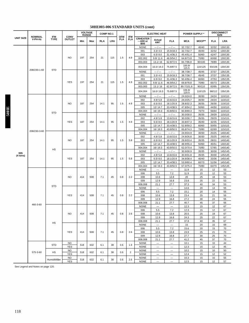
118
50HE003-006 STANDARD UNITS (cont)
See Legend and Notes on page 120.
UNIT SIZE NOMINAL V-PH-Hz
IFMTYPE
CONV OUTLET
VOLTAGE RANGE COMP NO.1
OFMFLA
IFM FLA
ELECTRIC HEAT POWER SUPPLY * DISCONNECT SIZE
Min Max RLA LRA CRHEATER
---A00 or B00
Actual kW† FLA MCA MOCP** FLA LRA
005(4 tons)
208/230-1-60 STD
NO 197 254 21 115 1.5 4.9
NONE — / — — / — 32.7/32.7 40/40 32/32 130/130001 3.3/ 4.0 15.9/18.3 32.7/32.7 40/40 32/32 130/130003 6.5/ 8.0 31.4/36.3 45.4/51.4 50/60 42/47 130/130
002,002 9.8/ 11.6 46.9/54.2 64.8/73.8 70/80 60/68 130/130003,003 13.1/ 16 62.8/72.5 84.7/96.8 90/100 78/89 130/130
004,004 16.0/ 19.3 75.8/87.5 100.9/115.5 110/125 93/106 130/130
YES 197 254 21 115 1.5 4.9
NONE — / — — / — 38.7/38.7 45/45 37/37 135/135001 3.3/ 4.0 15.9/18.3 38.7/38.7 45/45 37/37 135/135003 6.5/ 8.0 31.4/36.3 50.4/56.4 60/60 47/53 135/135
002,002 9.8/ 11.6 46.9/54.2 69.8/78.8 70/80 65/73 135/135003,003 13.1/ 16 62.8/72.5 89.7/101.8 90/110 83/95 135/135
004,004 16.0/ 19.3 75.8/87.5 105.9/120.5 110/125 98/112 135/135
208/230-3-60
STD
NO 187 254 14.1 95 1.5 4.9
NONE — / — — / — 24.0/24.0 30/30 24/24 110/110002 4.9/ 5.8 13.6/15.6 24.0/25.7 30/30 24/24 110/110003 6.5/ 8.0 18.1/20.9 28.8/32.3 30/35 26/30 110/110005 12/ 14.7 33.4/38.5 47.8/54.2 50/60 44/50 110/110
004,004 16/ 19.3 43.8/50.5 60.8/69.3 70/70 56/64 110/110
YES 187 254 14.1 95 1.5 4.9
NONE — / — — / — 30.0/30.0 35/35 29/29 115/115002 4.9/ 5.8 13.6/15.6 30.0/30.7 35/35 29/29 115/115003 6.5/ 8.0 18.1/20.9 33.8/37.3 35/40 32/35 115/115005 12/ 14.7 33.4/38.5 52.8/59.2 60/60 50/55 115/115
004,004 16/ 19.3 43.8/50.5 65.8/74.3 70/80 62/69 115/115
HS
NO 187 254 14.1 95 1.5 5.8
NONE — / — — / — 24.9/24.9 30/30 25/25 140/140002 4.9/ 5.8 13.6/15.6 24.9/26.8 30/30 25/25 140/140003 6.5/ 8.0 18.1/20.9 29.9/33.4 35/35 28/31 140/140005 12/ 14.7 33.4/38.5 48.9/55.4 50/60 45/51 140/140
004,004 16/ 19.3 43.8/50.5 62.0/70.4 70/80 57/65 140/140
YES 187 254 14.1 95 1.5 5.8
NONE — / — — / — 30.9/30.9 35/35 30/30 145/145002 4.9/ 5.8 13.6/15.6 30.9/31.8 35/35 30/30 145/145003 6.5/ 8.0 18.1/20.9 34.9/38.4 40/40 33/36 145/145005 12/ 14.7 33.4/38.5 53.9/60.4 60/70 51/56 145/145
004,004 16/ 19.3 43.8/50.5 67.0/75.4 70/80 63/70 145/145
460-3-60
STD
NO 414 508 7.1 45 0.8 2.2
NONE — — 11.9 15 12 53006 5.5 7.2 11.9 15 12 53008 10.6 13.8 20 25 18 53009 12.9 16.8 23.8 25 22 53
008,008 21.1 27.7 37.3 40 34 53
YES 414 508 7.1 45 0.8 2.2
NONE — — 14.6 20 14 55006 5.5 7.2 15.1 20 14 55008 10.6 13.8 23.4 25 21 55009 12.9 16.8 27.2 30 24 55
008,008 21.1 27.7 40.7 45 37 55
HS
NO 414 508 7.1 45 0.8 2.6
NONE — — 12.3 15 12 67006 5.5 7.2 12.3 15 12 67008 10.6 13.8 20.5 25 19 67009 12.9 16.8 24.3 25 22 67
008,008 21.1 27.7 37.8 40 35 67
YES 414 508 7.1 45 0.8 2.6
NONE — — 15 20 15 69006 5.5 7.2 15.6 20 15 70008 10.6 13.8 23.9 25 21 70009 12.9 16.8 27.7 30 25 70
008,008 21.1 27.7 41.2 45 37 70
575-3-60
STDNO
518 632 6.1 38 0.6 1.9NONE — — 10.1 15 10 44
YES NONE — — 12.3 15 12 45
HSNO
518 632 6.1 38 0.6 2NONE — — 10.2 15 10 50
YES NONE — — 12.4 15 12 52
HumidiMi$erNO
518 632 6.1 38 0.8 2.6NONE — — 10.3 15 10 55
YES NONE — — 12.5 15 12 57
50H
E
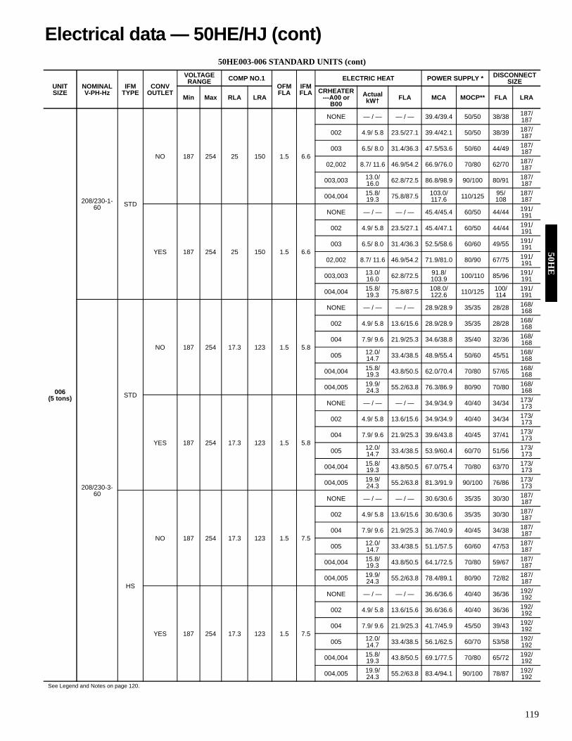
119
50HE003-006 STANDARD UNITS (cont)
See Legend and Notes on page 120.
UNIT SIZE
NOMINAL V-PH-Hz
IFMTYPE
CONV OUTLET
VOLTAGE RANGE COMP NO.1
OFMFLA
IFM FLA
ELECTRIC HEAT POWER SUPPLY * DISCONNECT SIZE
Min Max RLA LRA CRHEATER
---A00 or B00
Actual kW† FLA MCA MOCP** FLA LRA
006(5 tons)
208/230-1-60 STD
NO 187 254 25 150 1.5 6.6
NONE — / — — / — 39.4/39.4 50/50 38/38 187/187
002 4.9/ 5.8 23.5/27.1 39.4/42.1 50/50 38/39 187/187
003 6.5/ 8.0 31.4/36.3 47.5/53.6 50/60 44/49 187/187
02,002 8.7/ 11.6 46.9/54.2 66.9/76.0 70/80 62/70 187/187
003,003 13.0/ 16.0 62.8/72.5 86.8/98.9 90/100 80/91 187/
187
004,004 15.8/ 19.3 75.8/87.5 103.0/
117.6 110/125 95/108
187/187
YES 187 254 25 150 1.5 6.6
NONE — / — — / — 45.4/45.4 60/50 44/44 191/191
002 4.9/ 5.8 23.5/27.1 45.4/47.1 60/50 44/44 191/191
003 6.5/ 8.0 31.4/36.3 52.5/58.6 60/60 49/55 191/191
02,002 8.7/ 11.6 46.9/54.2 71.9/81.0 80/90 67/75 191/191
003,003 13.0/ 16.0 62.8/72.5 91.8/
103.9 100/110 85/96 191/191
004,004 15.8/ 19.3 75.8/87.5 108.0/
122.6 110/125 100/114
191/191
208/230-3-60
STD
NO 187 254 17.3 123 1.5 5.8
NONE — / — — / — 28.9/28.9 35/35 28/28 168/168
002 4.9/ 5.8 13.6/15.6 28.9/28.9 35/35 28/28 168/168
004 7.9/ 9.6 21.9/25.3 34.6/38.8 35/40 32/36 168/168
005 12.0/ 14.7 33.4/38.5 48.9/55.4 50/60 45/51 168/
168
004,004 15.8/ 19.3 43.8/50.5 62.0/70.4 70/80 57/65 168/
168
004,005 19.9/ 24.3 55.2/63.8 76.3/86.9 80/90 70/80 168/
168
YES 187 254 17.3 123 1.5 5.8
NONE — / — — / — 34.9/34.9 40/40 34/34 173/173
002 4.9/ 5.8 13.6/15.6 34.9/34.9 40/40 34/34 173/173
004 7.9/ 9.6 21.9/25.3 39.6/43.8 40/45 37/41 173/173
005 12.0/ 14.7 33.4/38.5 53.9/60.4 60/70 51/56 173/
173
004,004 15.8/ 19.3 43.8/50.5 67.0/75.4 70/80 63/70 173/
173
004,005 19.9/ 24.3 55.2/63.8 81.3/91.9 90/100 76/86 173/
173
HS
NO 187 254 17.3 123 1.5 7.5
NONE — / — — / — 30.6/30.6 35/35 30/30 187/187
002 4.9/ 5.8 13.6/15.6 30.6/30.6 35/35 30/30 187/187
004 7.9/ 9.6 21.9/25.3 36.7/40.9 40/45 34/38 187/187
005 12.0/ 14.7 33.4/38.5 51.1/57.5 60/60 47/53 187/
187
004,004 15.8/ 19.3 43.8/50.5 64.1/72.5 70/80 59/67 187/
187
004,005 19.9/ 24.3 55.2/63.8 78.4/89.1 80/90 72/82 187/
187
YES 187 254 17.3 123 1.5 7.5
NONE — / — — / — 36.6/36.6 40/40 36/36 192/192
002 4.9/ 5.8 13.6/15.6 36.6/36.6 40/40 36/36 192/192
004 7.9/ 9.6 21.9/25.3 41.7/45.9 45/50 39/43 192/192
005 12.0/ 14.7 33.4/38.5 56.1/62.5 60/70 53/58 192/
192
004,004 15.8/ 19.3 43.8/50.5 69.1/77.5 70/80 65/72 192/
192
004,005 19.9/ 24.3 55.2/63.8 83.4/94.1 90/100 78/87 192/
192
Electrical data — 50HE/HJ (cont)50H
E

120
50HE003-006 STANDARD UNITS (cont
LEGEND
†Heater capacity (kW) is based on heater voltage of 240 v, 480 v or 575 v. If power distributionvoltage to unit varies from rated heater voltage, heater kW will vary accordingly.
*The values listed in this table do not include power exhaust. See power exhaust table forpower exhaust requirements.
** Fuse or HACR breaker.NOTES:1. In compliance with NEC requirements for multimotor and combination load equipment (refer
to NEC Articles 430 and 440), the overcurrent protective device for the unit shall be fuse orHACR breaker.
2. Unbalanced 3-Phase Supply VoltageNever operate a motor where a phase imbalance in supply voltage is greater than 2%. Usethe following formula to determine the percent of voltage imbalance.% Voltage Imbalance
Example: Supply voltage is 460-3-60.
AB = 452 vBC = 464 vAC = 455 v
Determine maximum deviation from average voltage. (AB) 457 – 452 = 5 v(BC) 464 – 457 = 7 v (AC) 457 – 455 = 2 v
Maximum deviation is 7 v.Determine percent of voltage imbalance.
This amount of phase imbalance is satisfactory as it is below the maximum allowable 2%.
3. Non-fused disconnect switch cannot be used when rooftop unit electrical ratings exceed80 amps.
4. 575-v units have UL, Canada approval only. Electric heaters are not available for 004-007,575-v units.
5. For units with power exhaust: If a single power source is to be used, size wire to includepower exhaust MCA and MOCP.Check MCA and MOCP when power exhaust is powered through the unit. Determine thenew MCA including the power exhaust using the following formula:MCA New = MCA unit only + MCA of Power ExhaustFor example, using a 50HE/HJ006---5 unit with MCA = 28.9 and MOCP = 35, withCRPWREXH030A01 power exhaust.MCA New = 28.9 amps + 1.6 amps = 30.5 ampsIf the new MCA does not exceed the published MOCP, then MOCP would not change. TheMOCP in this example is 35 amps, the MCA New is below 35, therefore the MOCP isacceptable. If “MCA New” is larger than the published MOCP, raise the MOCP to the nextlarger size. For separate power, the MOCP for the power exhaust will be 15 amps per NEC
50HE POWER EXHAUST ELECTRICAL DATA
N/A — Not Available
UNIT SIZE NOMINAL V-PH-Hz
IFMTYPE
CONV OUTLET
VOLTAGE RANGE COMP NO.1
OFMFLA
IFM FLA
ELECTRIC HEAT POWER SUPPLY * DISCONNECT SIZE
Min Max RLA LRA CRHEATER ---A00 or B00
Actual kW† FLA MCA MOCP** FLA LRA
006(5 tons) (cont)
460-3-60
STD
NO 414 508 8.4 70 0.8 2.6
NONE — — 13.9 20 14 92006 5.5 7.2 13.9 20 14 92008 10.6 13.8 20.5 25 19 92009 12.9 16.8 24.3 25 22 92
008,008 21.1 27.7 37.8 40 35 92008,009 23.4 30.1 40.8 45 38 92
YES 414 508 8.4 70 0.8 2.6
NONE — — 16.6 20 16 94006 5.5 7.2 16.6 20 16 95008 10.6 13.8 23.9 25 21 95009 12.9 16.8 27.7 30 25 95
008,008 21.1 27.7 41.2 45 37 95008,009 23.4 30.1 44.2 45 40 95
HS
NO 414 508 8.4 70 0.8 3.4
NONE — — 14.7 20 14 101006 5.5 7.2 14.7 20 14 102008 10.6 13.8 21.5 25 20 102009 12.9 16.8 25.3 30 23 102
008,008 21.1 27.7 38.8 40 36 102008,009 23.4 30.1 41.8 45 38 102
YES 414 508 8.4 70 0.8 3.4
NONE — — 17.4 20 17 104006 5.5 7.2 17.4 20 17 104008 10.6 13.8 24.9 25 22 104009 12.9 16.8 28.7 30 26 104
008,008 21.1 27.7 42.2 45 38 104008,009 23.4 30.1 45.2 50 41 104
575-3-60
STDNO
518 632 7.1 53 0.6 2NONE — — 11.5 15 11 65
YES NONE — — 13.6 15 13 67
HSNO
518 632 7.1 53 0.6 2.8NONE — — 12.3 15 12 74
YES NONE — — 14.4 20 14 76
HumidiMi$erNO
518 632 7.1 53 0.8 3.4NONE — — 12.2 15 12 78
YES NONE — — 14.4 20 14 80
FLA — Full Load AmpsHACR — Heating, Air Conditioning and
RefrigerationIFM — Indoor (Evaporator) Fan MotorLRA — Locked Rotor AmpsMCA — Minimum Circuit AmpsMOCP — Maximum Overcurrent ProtectionNEC — National Electrical CodeOFM — Outdoor (Condenser) Fan MotorRLA — Rated Load AmpsUL — Underwriters’ Laboratories
= 100 x
max voltage deviation from average voltageaverage voltage
Average Voltage=
452 + 464 + 4553
=137
13
= 457
% Voltage Imbalance = 100 x =
7457
= 1.53%
IMPORTANT: If the supply voltage phase imbalance is more than 2%, contact your localelectric utility company immediately.
POWER EXHAUSTPART NO.
MCA(230 v)
MCA(460 v)
MCA(575 v)
MOCP(for separate
power source)CRPWREXH021A01 N/A 0.68 N/A 15CRPWREXH022A01 3.4 N/A 1.32 15CRPWREXH023A01 N/A 1.4 N/A 15CRPWREXH028A01 1.7 N/A 0.68 15CRPWREXH029A01 N/A 0.7 N/A 15CRPWREXH030A01 1.6 N/A 0.64 15
50H
E
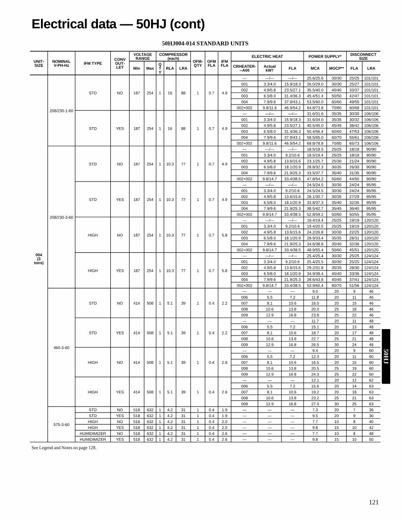
121
50HJ004-014 STANDARD UNITS
See Legend and Notes on page 128.
UNIT-SIZE
NOMINAL V-PH-Hz IFM TYPE
CONV OUT-LET
VOLTAGE RANGE
COMPRESSOR (each)
OFM-QTY
OFMFLA
IFMFLA
ELECTRIC HEAT POWER SUPPLY* DISCONNECT SIZE
Min MaxQTY
RLA LRA CRHEATER---A00
Actual kW† FLA MCA MOCP** FLA LRA
004 (3
tons)
208/230-1-60
STD NO 187 254 1 16 88 1 0.7 4.9
— —/— —/— 25.6/25.6 30/30 25/25 101/101001 3.3/4.0 15.9/18.3 26.0/29.0 30/30 25/27 101/101002 4.9/5.8 23.5/27.1 35.5/40.0 40/40 33/37 101/101003 6.5/8.0 31.4/36.3 45.4/51.4 50/50 42/47 101/101004 7.9/9.6 37.9/43.1 53.5/60.0 60/60 49/55 101/101
002+002 9.8/11.6 46.9/54.2 64.8/73.8 70/80 60/68 101/101
STD YES 187 254 1 16 88 1 0.7 4.9
— —/— —/— 31.6/31.6 35/35 30/30 106/106001 3.3/4.0 15.9/18.3 31.6/34.0 35/35 30/32 106/106002 4.9/5.8 23.5/27.1 40.5/45.0 45/45 38/42 106/106003 6.5/8.0 31.4/36.3 50.4/56.4 60/60 47/53 106/106004 7.9/9.6 37.9/43.1 58.5/65.0 60/70 55/61 106/106
002+002 9.8/11.6 46.9/54.2 69.8/78.8 70/80 65/73 106/106
208/230-3-60
STD NO 187 254 1 10.3 77 1 0.7 4.9
— —/— —/— 18.5/18.5 25/25 18/18 90/90001 3.3/4.0 9.2/10.6 18.5/19.4 25/25 18/18 90/90002 4.9/5.8 13.6/15.6 23.1/25.7 25/30 21/24 90/90003 6.5/8.0 18.1/20.9 28.8/32.3 30/35 26/30 90/90004 7.9/9.6 21.9/25.3 33.5/37.7 35/40 31/35 90/90
002+002 9.8/14.7 33.4/38.5 47.8/54.2 50/60 44/50 90/90
STD YES 187 254 1 10.3 77 1 0.7 4.9
— —/— —/— 24.5/24.5 30/30 24/24 95/95001 3.3/4.0 9.2/10.6 24.5/24.5 30/30 24/24 95/95002 4.9/5.8 13.6/15.6 28.1/30.7 30/35 27/29 95/95003 6.5/8.0 18.1/20.9 33.8/37.3 35/40 32/35 95/95004 7.9/9.6 21.9/25.3 38.5/42.7 35/45 36/40 95/95
002+002 9.8/14.7 33.4/38.5 52.8/59.2 50/60 50/55 95/95
HIGH NO 187 254 1 10.3 77 1 0.7 5.8
— —/— —/— 19.4/19.4 25/25 19/19 120/120001 3.3/4.0 9.2/10.6 19.4/20.5 25/25 19/19 120/120002 4.9/5.8 13.6/15.6 24.2/26.8 30/30 22/25 120/120003 6.5/8.0 18.1/20.9 29.9/33.4 35/35 28/31 120/120004 7.9/9.6 21.9/25.3 34.6/38.8 35/40 32/36 120/120
002+002 9.8/14.7 33.4/38.5 48.9/55.4 50/60 45/51 120/120
HIGH YES 187 254 1 10.3 77 1 0.7 5.8
— —/— —/— 25.4/25.4 30/30 25/25 124/124001 3.3/4.0 9.2/10.6 25.4/25.5 30/30 25/25 124/124002 4.9/5.8 13.6/15.6 29.2/31.8 35/35 28/30 124/124003 6.5/8.0 18.1/20.9 34.9/38.4 40/40 33/36 124/124004 7.9/9.6 21.9/25.3 39.6/43.8 40/45 37/41 124/124
002+002 9.8/14.7 33.4/38.5 53.9/60.4 60/70 51/56 124/124
460-3-60
STD NO 414 508 1 5.1 39 1 0.4 2.2
— — — 9.0 20 9 46006 5.5 7.2 11.8 20 11 46007 8.1 10.6 16.0 20 15 46008 10.6 13.8 20.0 25 18 46009 12.9 16.8 23.8 25 22 46
STD YES 414 508 1 5.1 39 1 0.4 2.2
— — — 11.7 20 11 48006 5.5 7.2 15.1 20 13 48007 8.1 10.6 18.7 20 17 48008 10.6 13.8 22.7 25 21 48009 12.9 16.8 26.5 30 24 48
HIGH NO 414 508 1 5.1 39 1 0.4 2.6
— — — 9.4 20 9 60006 5.5 7.2 12.3 20 11 60007 8.1 10.6 16.5 20 15 60008 10.6 13.8 20.5 25 19 60009 12.9 16.8 24.3 25 22 60
HIGH YES 414 508 1 5.1 39 1 0.4 2.6
— — — 12.1 20 12 62006 5.5 7.2 15.6 20 14 63007 8.1 10.6 19.2 20 18 63008 10.6 13.8 23.2 25 21 63009 12.9 16.8 27.0 30 25 63
575-3-60
STD NO 518 632 1 4.2 31 1 0.4 1.9 — — — 7.3 20 7 36STD YES 518 632 1 4.2 31 1 0.4 1.9 — — — 9.5 20 9 30HIGH NO 518 632 1 4.2 31 1 0.4 2.0 — — — 7.7 10 8 40HIGH YES 518 632 1 4.2 31 1 0.4 2.0 — — — 9.8 15 10 42
HUMIDIMIZER NO 518 632 1 4.2 31 1 0.4 2.6 — — — 7.7 10 8 48HUMIDIMIZER YES 518 632 1 4.2 31 1 0.4 2.6 — — — 9.8 15 10 50
Electrical data — 50HJ (cont)50H
J

122
50HJ004-014 STANDARD UNITS (cont)
See Legend and Notes on page 128.
UNIT-SIZE
NOMINAL V-PH-Hz IFM TYPE
CON-VOUT-
LET
VOLTAGE RANGE
COMPRESSOR (each)
OFMQTY
OFMFLA
IFMFLA
ELECTRIC HEAT POWER SUPPLY* DISCONNECT-SIZE
Min MaxQTY
RLA LRA CRHEATER---A00
Actual kW† FLA MCA MOCP** FLA LRA
005 (4 ton)
208/230-1-60
STD NO 197 254 1 23.7 126 1 0.7 4.9
— —/— —/— 35.2/35.2 45/45 34/34 139/139001 3.3/4.0 15.9/18.3 35.2/35.2 45/45 34/34 139/139003 6.5/8.0 31.4/36.3 45.4/51.4 50/60 42/47 139/139
002+002 9.8/11.6 46.9/54.2 64.8/73.8 70/80 60/68 139/139003+003 13.1/16 62.8/72.5 84.7/96.8 90/100 78/89 139/139
004+004 16.0/19.3 75.8/87.5 100.9/115.5 110/125 93/
106 139/139
STD YES 197 254 1 23.7 126 1 0.7
4.9 — —/— —/— 41.2/41.2 50/50 39/39 144/144001 3.3/4.0 15.9/18.3 41.2/41.2 50/50 39/39 144/144003 6.5/8.0 31.4/36.3 50.4/56.4 60/60 47/53 144/144
002+002 9.8/11.6 46.9/54.2 69.8/78.8 70/80 65/73 144/144003+003 13.1/16 62.8/72.5 89.7/101.8 90/100 83/95 144/144
004+004 16.0/19.3 75.8/87.5 105.9/120.5 110/125 98/112 144/144
208/230-3-60
STD NO 187 254 1 13.5 93 1 0.7 4.9
— —/— —/— 22.5/22.5 30/30 22/22 106/106002 4.9/5.8 13.6/15.6 23.1/25.7 30/30 22/24 106/106003 6.5/8 18.1/20.9 28.8/32.3 30/35 26/30 106/106005 12/14.7 33.4/38.5 47.8/54.2 50/60 44/50 106/106
004+004 16/19.3 43.8/50.5 60.8/59.3 70/70 56/64 106/106
STD YES 187 254 1 13.5 93 1 0.7 4.9
— —/— —/— 28.5/28.5 35/35 27/27 111/111002 4.9/5.8 13.6/15.6 28.5/30.7 35/35 27/29 111/111003 6.5/8 18.1/20.9 33.8/37.3 35/40 32/35 111/111005 12/14.7 33.4/38.5 52.8/59.2 60/60 50/55 111/111
004+004 16/19.3 43.8/50.5 65.8/74.3 70/80 62/69 111/111
HIGH NO 187 254 1 13.5 93 1 0.7 5.8
— —/— —/— 23.4/23.4 30/30 23/23 136/136002 4.9/5.8 13.6/15.6 24.2/26.8 30/30 23/25 136/136003 6.5/8 18.1/20.9 29.9/33.4 35/35 28/31 136/136005 12/14.7 33.4/38.5 48.9/55.4 50/60 45/51 136/136
004+004 16/19.3 43.8/50.5 62.0/70.4 70/80 57/65 136/136
HIGH YES 187 254 1 13.5 93 1 0.7 5.8
— —/— —/— 29.4/29.4 35/35 29/29 140/140002 4.9/5.8 13.6/15.6 29.4/31.8 35/35 29/30 140/140003 6.5/8 18.1/20.9 34.9/38.4 40/40 33/36 140/140005 12/14.7 33.4/38.5 53.9/60.4 60/70 51/56 140/140
004+004 16/19.3 43.8/50.5 67.0/75.4 70/80 63/70 140/140
460-3-60
STD NO 414 508 1 6.4 46.5 1 0.4 2.2
— — — 10.6 20 10 53006 5.5 7.2 11.8 20 11 54008 10.6 13.8 20.0 25 18 54009 12.9 16.8 23.8 25 22 54
008+008 21.1 27.7 37.3 40 34 54
STD YES 414 508 1 6.4 46.5 1 0.4 2.2
— — — 13.3 20 13 55006 5.5 7.2 15.1 20 13 56008 10.6 13.8 22.7 25 21 56009 12.9 16.8 26.5 30 24 56
008+008 21.1 27.7 40.0 45 37 56
HIGH NO 414 508 1 6.4 46.5 1 0.4 2.6
— — — 11.0 20 11 67006 5.5 7.2 12.3 20 11 68008 10.6 13.8 20.5 25 19 68009 12.9 16.8 24.3 25 22 68
008+008 21.1 27.7 37.8 40 35 68
HIGH YES 414 508 1 6.4 46.5 1 0.4 2.6
— — — 13.7 20 13 70006 5.5 7.2 15.6 20 14 70008 10.6 13.8 23.2 25 21 70009 12.9 16.8 27.0 30 25 70
008+008 21.1 27.7 40.5 45 37 70
575-3-60
STD NO 518 632 1 6.4 40 1 0.4 1.9 — — — 10.3 15 10 45STD YES 518 632 1 6.4 40 1 0.4 1.9 — — — 12.5 15 12 47HIGH NO 518 632 1 6.4 40 1 0.4 2.0 — — — 10.4 15 10 52HIGH YES 518 632 1 6.4 40 1 0.4 2.0 — — — 12.6 15 12 53
HUMIDIMIZER NO 518 632 1 6.4 4 1 0.4 2.6 — — — 10.4 15 10 57HUMIDIMIZER YES 518 632 1 6.4 4 1 0.4 2.6 — — — 12.6 15 12 59
50H
J

123
50HJ004-014 STANDARD UNITS (cont)
See Legend and Notes on page 128.
UNIT-SIZE
NOMINAL V-PH-Hz IFM TYPE
CONV OUT-LET
VOLTAGE RANGE
COMPRESSOR (each)
OFMQTY
OFMFLA
IFMFLA
ELECTRIC HEAT POWER SUPPLY* DISCONNEC SIZE
Min MaxQTY
RLA LRA CRHEATER ---A00
Actual kW† FLA MCA MOCP** FLA LRA
006(5 ton)
208/230-1-60
STD NO 187 254 1 28.8 169 1 1.5 8.8
— —/— —/— 46.3/46.3 60/60 45/45 216/216002 4.9/5.8 23.5/27.1 46.3/46.3 60/60 45/45 216/216003 6.5/8.0 31.4/36.3 50.3/56.3 60/60 46/52 216/216
002+002 8.7/11.6 46.9/54.2 69.7/78.7 70/80 64/72 216/216003+003 13.0/16.0 62.8/72.5 49.5/101.6 90/110 82/93 216/216
004+004 15.8/19.3 75.8/87.5 105.8/120.4 110/125 97/111 216/216
STD YES 187 254 1 28.8 169 1 1.5 8.8
— —/— —/— 52.3/52.3 60/60 50/50 221/221002 4.9/5.8 23.5/27.1 52.3/52.3 60/60 50/50 221/221003 6.5/8.0 31.4/36.3 55.3/61.3 60/70 52/57 221/221
002+002 8.7/11.6 46.9/54.2 74.7/83.7 80/90 70/78 221/221003+003 13.0/16.0 62.8/72.5 94.5/106.6 100/110 88/99 221/221
004+004 15.8/19.3 75.8/87.5 110.8/125.4 125/150 103/
116 221/221
208/230-3-60
STD NO 187 254 1 17.3 123 1 1.5 5.8
— —/— —/— 28.9/28.9 35/35 28/28 168/168002 4.9/5.8 13.6/15.6 28.9/28.9 35/35 28/28 168/168004 7.9/9.6 21.9/25.3 34.6/38.8 35/35 32/36 168/168005 12.0/14.7 33.4/38.5 48.9/55.4 50/50 45/51 168/168
004+004 15.8/19.3 43.8/50.5 62/70.4 70/70 57/65 168/168004+005 19.9/24.3 55.2/63.8 76.3/86.9 80/80 70/80 168/168
STD YES 187 254 1 17.3 123 1 1.5 5.8
— —/— —/— 34.9/34.9 40/40 34/34 173/173002 4.9/5.8 13.6/15.6 34.9/34.9 40/40 34/34 173/173004 7.9/9.6 21.9/25.3 39.6/43.8 40/40 37/41 173/173005 12.0/14.7 33.4/38.5 53.9/60.4 60/70 51/56 173/173
004+004 15.8/19.3 43.8/50.5 67/75.4 70/80 63/70 173/173004+005 19.9/24.3 55.2/63.8 81.3/91.9 90/100 76/86 173/173
HIGH NO 187 254 1 17.3 123 1 1.5 7.5
— —/— —/— 30.6/30.6 35/35 30/30 187/187002 4.9/5.8 13.6/15.6 30.6/30.6 35/35 30/30 187/187004 7.9/9.6 21.9/25.3 36.7/40.9 40/45 34/38 187/187005 12.0/14.7 33.4/38.5 51.1/57.5 60/60 47/53 187/187
004+004 15.8/19.3 43.8/50.5 64.1/72.5 70/80 59/67 187/187004+005 19.9/24.3 55.2/63.8 78.4/89.1 80/90 72/82 187/187
HIGH YES 187 254 1 17.3 123 1 1.5 7.5
— —/— —/— 36.6/36.6 40/40 36/36 192/192002 4.9/5.8 13.6/15.6 36.6/36.6 40/40 36/36 192/192004 7.9/9.6 21.9/25.3 41.7/45.9 45/50 39/43 192/192005 12.0/14.7 33.4/38.5 56.6/62.5 60/70 53/58 192/192
004+004 15.8/19.3 43.8/50.5 69.1/77.5 70/80 65/72 192/192004+005 19.9/24.3 55.2/63.8 83.4/94.1 90/100 78/87 192/192
460-3-60
STD NO 414 508 1 9 62 1 0.8 2.6
— — — 14.7 20 14 84006 5.5 7.2 14.7 20 10 84008 10.6 13.8 20.5 25 19 84009 12.9 16.8 24.3 25 22 84
008+008 21.1 27.7 37.8 40 35 84008+009 23.4 30.1 40.8 45 38 84
STD YES 414 508 1 9 62 1 0.8 2.6
— — — 17.4 20 17 86006 5.5 7.2 17.4 20 17 87008 10.6 13.8 23.2 25 21 87009 12.9 16.8 27.0 30 25 87
008+008 21.1 27.7 40.5 45 37 87008+009 23.4 30.1 43.5 45 40 87
HIGH NO 414 508 1 9 62 1 0.8 3.4
— — — 15.5 20 15 93006 5.5 7.2 15.5 20 15 94008 10.6 13.8 21.5 25 20 94009 12.9 16.8 25.3 30 23 94
008+008 21.1 27.7 38.8 40 36 94008+009 23.4 30.1 41.8 45 38 94
HIGH YES 414 508 1 9 62 1 0.8 3.4
— — — 18.2 20 18 96006 5.5 7.2 18.2 20 18 96008 10.6 13.8 24.2 25 22 96009 12.9 16.8 28.0 30 26 96
008+008 21.1 27.7 41.5 45 38 96008+009 23.4 30.1 44.5 45 41 96
575-3-60
STD NO 518 632 1 7.1 50 1 0.6 2.0 — — — 11.5 15 11 63STD YES 518 632 1 7.1 50 1 0.6 2.0 — — — 13.6 15 13 64HIGH NO 518 632 1 7.1 50 1 0.6 2.8 — — — 12.3 15 12 72HIGH YES 518 632 1 7.1 50 1 0.6 2.8 — — — 14.4 15 14 73
HUMIDIMIZER NO 518 632 1 7.1 50 1 0.6 3.4 — — — 12.2 15 12 76HUMIDIMIZER YES 518 632 1 7.1 50 1 0.6 3.4 — — — 14.4 20 14 77
Electrical data — 50HJ (cont)50H
J

124
50HJ004-014 STANDARD UNITS (cont)
See page 128 for legend and notes.
UNIT-SIZE
NOMINAL V-PH-Hz IFM TYPE CONV
OULET
VOLTAGERANGE
COMPRES-SOR
(each) OFMQTY
OFMFLA
IFMFLA
ELECTRIC HEAT POWER SUPPLY* DISCONNECTSIZE
Min MaxQTY
RLA LRA CRHEATER---A00
Actual kW† FLA MCA MOCP** FLA LRA
007(6 ton)
208/230-3-60
STD NO 187 254 1 20.5 156 1 1.4 5.8
— —/— —/— 32.8/32.8 40/40 32/32 200/200002 4.9/5.8 13.6/15.6 32.8/32.8 40/40 32/32 200/200004 7.9/9.6 21.9/25.3 34.6/38.8 40/40 32/36 200/200005 12.0/14.7 33.4/38.5 48.9/55.4 50/50 45/51 200/200
004+004 15.8/19.3 43.8/50.5 62.0/70.4 70/80 57/65 200/200004+005 19.9/24.3 55.2/63.8 76.3/86.9 80/90 70/80 200/200
STD YES 187 254 1 20.5 156 1 1.4 5.8
— —/— —/— 38.8/38.8 45/45 37/37 205/205002 4.9/5.8 13.6/15.6 38.8/38.8 45/45 37/37 205/205004 7.9/9.6 21.9/25.3 39.6/43.8 45/45 37/41 205/205005 12.0/14.7 33.4/38.5 53.9/60.4 60/70 51/56 205/205
004+004 15.8/19.3 43.8/50.5 67.0/75.4 70/80 63/70 205/205004+005 19.9/24.3 55.2/63.8 76.3/86.9 90/100 76/86 205/205
HIGH NO 187 254 1 20.5 156 1 1.4 7.5
— —/— —/— 34.5/34.5 40/40 34/34 219/219002 4.9/5.8 13.6/15.6 34.5/34.5 40/40 34/34 219/219004 7.9/9.6 21.9/25.3 36.7/40.9 40/45 34/38 219/219005 12.0/14.7 33.4/38.5 51.1/57.5 60/60 47/53 219/219
004+004 15.8/19.3 43.8/50.5 64.1/72.5 70/80 59/67 219/219004+005 19.9/24.3 55.2/63.8 78.4/89.1 80/90 72/82 219/219
HIGH YES 187 254 1 20.5 156 1 1.4 7.5
— —/— —/— 40.5/40.5 45/45 39/39 224/224002 4.9/5.8 13.6/15.6 40.5/40.5 45/45 39/39 224/224004 7.9/9.6 21.9/25.3 41.7/45.9 45/50 39/43 224/224005 12.0/14.7 33.4/38.5 56.1/62.5 60/70 53/58 224/224
004+004 15.8/19.3 43.8/50.5 69.1/77.5 70/80 65/72 224/224004+005 19.9/24.3 55.2/63.8 83.4/94.1 90/100 78/87 224/224
460-3-60
STD NO 414 508 1 9.6 75 1 0.6 2.6
— — — 15.2 20 15 97006 5.5 7.2 15.2 20 15 97008 10.6 13.8 20.5 25 19 97009 12.9 16.8 24.3 25 22 97
008+008 21.1 27.7 37.8 40 35 97008+009 23.4 30.7 41.6 45 38 97
STD YES 414 508 1 9.6 75 1 0.6 2.6
— — — 17.9 20 17 99006 5.5 7.2 17.9 20 17 99008 10.6 13.8 23.2 25 21 99009 12.9 16.8 27.0 30 25 99
008+008 21.1 27.7 40.5 45 37 99008+009 23.4 30.7 44.3 45 41 99
HIGH NO 414 508 1 9.6 75 1 0.6 3.4
— — — 16.0 20 16 106006 5.5 7.2 16.0 20 16 107008 10.6 13.8 21.5 25 20 107009 12.9 16.8 25.3 30 23 107
008+008 21.1 27.7 38.8 40 36 107008+009 23.4 30.7 42.6 45 39 107
HIGH YES 414 508 1 9.6 75 1 0.6 3.4
— — — 18.7 25 18 108006 5.5 7.2 18.7 25 18 109008 10.6 13.8 24.2 25 22 109009 12.9 16.8 28.0 30 26 109
008+008 21.1 27.7 41.5 45 38 109008+009 23.4 30.7 45.3 50 42 109
575-3-60
STD NO 518 632 1 7.7 56 1 0.6 2.0 — — — 11.5 15 11 63STD YES 518 632 1 7.7 56 1 0.6 2.0 — — — 13.6 15 13 64HIGH NO 518 632 1 7.7 56 1 0.6 2.8 — — — 12.3 15 12 72HIGH YES 518 632 1 7.7 56 1 0.6 2.8 — — — 14.4 20 14 73
HUMIDIMIZER NO 518 632 1 7.7 56 1 0.6 3.4 — — — 12.2 15 12 76HUMIDIMIZER YES 518 632 1 7.7 56 1 0.6 3.4 — — — 14.4 20 14 77
008 (7.5 ton) 208/230-3-60
STD NO 187 254 2 12.4 88 2 1.4 7.5
— —/— —/— 38.2/38.2 45/45 40/40 242/242017 7.8/9.6 21.7/25.0 38.2/40.6 45/45 40/40 242/242010 12.0/14.7 33.4/38.5 51.1/57.5 60/60 47/53 242/242011 18.6/22.8 51.7/59.7 74.0/84.0 80/90 68/77 242/242012 24.0/29.4 66.7/77.0 92.8/105.6 100/110 85/97 242/242
012+017 31.8/38.9 88.4/102.0 119.9/136.9 125/150 110/126 242/242
STD YES 187 254 2 12.4 88 2 1.4 7.5
— —/— —/— 44.2/44.2 50/50 46/46 247/247017 7.8/9.6 21.7/25.0 44./45.6 50/50 46/46 247/247010 12.0/14.7 33.4/38.5 56.1/62.5 60/70 53/58 247/247011 18.6/22.8 51.7/59.7 79.0/89.0 80/90 74/83 247/247012 24.0/29.4 66.7/77.0 97.8/110.6 100/125 91/103 247/247
012+017 31.8/38.9 88.4/102.0 124.9/141.9 125/150 116/131 247/247
50H
J

125
50HJ004-014 STANDARD UNITS (cont)
See page 128 for legend and notes.
UNIT-SIZE
NOMINAL V-PH-Hz IFM TYPE CONV
OULET
VOLTAGE RANGE
COMPRESSOR (each) OFM
QTYOFMFLA
IFMFLA
ELECTRIC HEAT POWER SUPPLY* DISCONNECT SIZE
Min MaxQTY
RLA LRA CRHEATER---A00
Actual kW† FLA MCA MOCP** FLA LRA
008(7.5 ton(cont)
208/230-3-60
HIGH NO 187 254 2 12.4 88 2 1.4 10.6
— —/— —/— 41.3/41.3 45/45 44/44 267/267017 7.8/9.6 21.7/25.0 41.3/44.5 50/50 44/44 267/267010 12.0/14.7 33.4/38.5 54.9/61.4 60/70 51/56 267/267011 18.6/22.8 51.7/59.7 77.9/87.8 80/90 72/81 267/267012 24.0/29.4 66.7/77.0 96.6/109.5 100/110 89/101 267/267
012+017 31.8/38.9 88.4/102.0 123.7/140.8 125/150 114/129 267/267
HIGH YES 187 254 2 12.4 88 2 1.4 10.6
— —/— —/— 47.3/47.3 50/50 49/49 271/271017 7.8/9.6 21.7/25.0 47.3/49.5 60/60 49/49 271/271010 12.0/14.7 33.4/38.5 59.9/66.4 70/70 56/62 271/271011 18.6/22.8 51.7/59.7 82.9/92.8 90/100 77/86 271/271012 24.0/29.4 66.7/77.0 101.6/114.5 110/125 94/106 271/271
012+017 31.8/38.9 88.4/102.0 128.7/145.8 150/150 119/135 271/271
460-3-60
STD NO 414 508 2 6.4 44 2 0.7 3.4
— — — 19.2 20 20 121016 12.8 16.7 25.1 20 23 121013 15.2 19.8 29.1 20 27 121014 25.5 33.4 46.0 50 42 121015 30.3 39.7 53.9 60 50 121
014+016 38.3 50.2 66.9 70 62 121
STD YES 414 508 2 6.4 44 2 0.7 3.4
— — — 21.9 20 23 123016 12.8 16.7 28.5 20 26 123013 15.2 19.8 31.8 35 29 123014 25.5 33.4 48.7 50 45 123015 30.3 39.7 56.6 60 52 123
014+016 38.3 50.2 69.6 70 64 123
HIGH NO 414 508 2 6.4 44 2 0.7 4.8
— — — 20.6 20 22 133016 12.8 16.7 26.9 20 25 134013 15.2 19.8 30.8 35 28 134014 25.5 33.4 47.8 50 44 134015 30.3 39.7 55.6 60 51 134
014+016 38.3 50.2 68.7 70 63 134
HIGH YES 414 508 2 6.4 44 2 0.7 4.8
— — — 23.3 20 24 135016 12.8 16.7 30.3 35 27 136013 15.2 19.8 33.5 35 31 136014 25.5 33.4 50.5 60 46 136015 30.3 39.7 58.3 60 54 136
014+016 38.3 50.2 71.4 80 66 136
575-3-60
STD NO 518 632 2 4.8 34 2 0.6 2.8— — — 14.8 20 16 91
018 17.0 16.4 23.9 25 22 91019 34.0 32.7 44.4 45 41 91
STD YES 518 632 2 4.8 34 2 0.6 2.8— — — 17.0 20 18 93
018 17.0 16.4 26.6 30 24 93019 34.0 32.7 44.4 45 43 93
HIGH NO 518 632 2 4.8 34 2 0.6 3.3— — — 15.3 20 16 101
018 17.0 16.4 24.6 25 23 101019 34.0 32.7 45.0 50 42 101
HIGH YES 518 632 2 4.8 34 2 0.6 3.3— — — 17.5 20 18 103
018 17.0 16.4 27.2 30 25 103019 34.0 32.7 45.0 50 44 103
HUMIDIMIZER NO 518 632 2 4.8 34 2 0.7 4.8—018020 —
17.034.1 —16.432.8 15.8 20 17 104
25.5 30 23 10445.7 50 42 104
HUMIDIMIZER YES 518 632 2 4.8 34 2 0.7 4.8—018021 —
17.034.2 —16.432.9 17.9 20 19 106
27.9 30 25 10645.7 50 44 106
009 (8.5 ton)
208/230-3-60
STD NO 187 254 2 13.4 105 2 1.4 7.5
— —/— —/— 40.2/40.2 45/45 42/42 276/276017 7.8/9.6 21.7/25.0 40.2/40.6 45/45 42/42 276/276010 12.0/14.7 33.4/38.5 51.1/57.5 60/60 47/53 276/276011 18.6/22.8 51.7/59.7 74.0/84.0 80/90 68/77 276/276012 24.0/29.4 66.7/77.0 92.8/105.6 100/110 85/97 276/276
012+017 31.8/38.9 88.4/102.0 119.9/136.9 110/150 110/126 276/276
STD YES 187 254 2 13.4 105 2 1.4 7.5
— —/— —/— 46.2/46.2 50/50 48/48 281/281017 7.8/9.6 21.7/25.0 46.2/46.2 50/50 48/48 281/281010 12.0/14.7 33.4/38.5 56.1/62.5 60/70 53/58 281/281011 18.6/22.8 51.7/59.7 79.0/89.0 80/90 74/83 281/281012 24.0/29.4 66.7/77.0 97.8/110.6 100/125 91/103 281/281
012+017 31.8/38.9 88.4/102.0 124.9/141.9 125/150 116/131 281/281
HIGH NO 187 254 2 13.4 105 2 1.4 10.6
— —/— —/— 43.3/43.3 50/50 46/46 301/301017 7.8/9.6 21.7/25.0 43.3/44.5 50/50 46/46 301/301010 12.0/14.7 33.4/38.5 54.9/61.4 60/70 51/56 301/301011 18.6/22.8 51.7/59.7 77.9/87.8 80/90 72/81 301/301012 24.0/29.4 66.7/77.0 96.6/109.5 100/110 89/101 301/301
012+017 31.8/38.9 88.4/102.0 123.7/140.8 125/150 114/129 301/301
Electrical data — 50HJ (cont)50H
J

126
50HJ004-014 STANDARD UNITS (cont)
See page 128 for legend and notes.
UNIT-SIZE
NOMINAL V-PH-Hz IFM TYPE CONV
OUTLET
VOLTAGE RANGE
COMPRESSOR (each) OFM
QTYOFMFLA
IFMFLA
ELECTRIC HEAT POWER SUPPLY* DISCONNECT SIZE
Min MaxQTY
RLA LRA CRHEATER---A00
Actual kW† FLA MCA MOCP** FLA LRA
009 (8.5 ton)
(cont)
208/230-3-60 HIGH YES 187 254 2 13.4 105 2 1.4 10.6
— —/— —/— 49.3/49.3 60/60 51/51 305/305017 7.8/9.6 21.7/25.0 49.3/49.5 60/60 51/51 305/305010 12.0/14.7 33.4/38.5 59.9/66.4 70/70 56/62 305/305011 18.6/22.8 51.7/59.7 82.9/92.8 90/100 77/86 305/305012 24.0/29.4 66.7/77.0 101.6/114.5 110/125 94/106 305/305
012+017 31.8/38.9 88.4/102.0 128.7/145.8 150/150 119/135 305/305
460-3-60
STD NO 414 508 2 7.4 55 2 0.7 3.4
— — — 21.5 30 23 143016 12.8 16.7 25.1 30 23 143013 15.2 19.8 29.1 30 27 143014 25.5 33.4 46.0 50 42 143015 30.3 39.7 53.9 60 50 143
014+016 38.3 50.2 66.9 70 62 143
STD YES 414 508 2 7.4 55 2 0.7 3.4
— — — 24.2 30 25 145016 12.8 16.7 28.5 30 26 145013 15.2 19.8 31.8 35 29 145014 25.5 33.4 48.7 50 45 145015 30.3 39.7 56.6 60 52 145
014+016 38.3 50.2 69.6 70 64 145
HIGH NO 414 508 2 7.4 55 2 0.7 4.8
— — — 22.9 30 24 155016 12.8 16.7 26.9 30 25 156013 15.2 19.8 30.8 35 28 156014 25.5 33.4 47.8 50 44 156015 30.3 39.7 55.6 60 51 156
014+016 38.3 50.2 68.7 70 63 156
HIGH YES 414 508 2 7.4 55 2 0.7 4.8
— — — 25.6 30 27 157016 12.8 16.7 30.3 35 27 158013 15.2 19.8 33.5 35 31 158014 25.5 33.4 50.5 60 46 158015 30.3 39.7 58.3 60 54 158
014+016 38.3 50.2 71.4 80 66 158
575-3-60
STD NO 518 632 2 6.4 44 2 0.6 2.8— — — 18.4 25 19 111
018 17.0 16.4 23.9 25 22 111019 34.0 32.7 44.4 45 41 111
STD YES 518 632 2 6.4 44 2 0.6 2.8— — — 20.6 25 21 113
018 17.0 16.4 26.6 30 24 113019 34.0 32.7 44.4 45 43 113
HIGH NO 518 632 2 6.4 44 2 0.6 3.3— — — 18.9 25 20 121
018 17.0 16.4 24.6 25 23 121019 34.0 32.7 45.0 50 41 121
HIGH YES 518 632 2 6.4 44 2 0.6 3.3— — — 21.1 25 22 123
018 17.0 16.4 27.9 30 25 123019 34.0 32.7 45.0 50 43 123
HUMIDIMIZER NO 518 632 2 6.4 44 2 0.7 3.3— — — 19.4 25 20 124
25.2 30 23 12445.7 50 42 124
HUMIDIMIZER YES 518 632 2 6.4 44 2 0.7 3.3— — — 21.5 25 22 126
27.9 30 25 12648.3 50 44 126
012(10 ton)
208/230-3-60
STD NO 187 254 2 17.6 125 2 1.4 10.6
— —/— —/— 53.0/53.0 60/60 56/56 341/341017 7.8/9.6 21.7/25.0 53.0/53.0 60/60 56/56 341/341010 12.0/14.7 33.4/38.5 54.9/61.4 60/70 56/56 341/341012 24.0/29.4 66.7/77.0 96.6/109.5 100/110 89/101 341/341
012+017 31.8/38.9 88.4/102.0 123.7/140.8 125/150 114/129 341/341012+010 37.5/45.9 104.2/104.2 143.5/133.5 150/150 132/151 341/341
STD YES 187 254 2 17.6 125 2 1.4 10.6
— —/— —/— 59.0/59.0 70/70 61/61 345/345017 7.8/9.6 21./25.0 59.0/59.0 70/70 61/61 345/345010 12.0/14.7 33.4/38.5 59.9/66.4 70/70 61/62 345/345012 24.0/29.4 66.7/77.0 101.6/114.5 110/125 94/106 345/345
012+017 31.8/38.9 88.4/102.0 128.7/145.8 150/150 119/135 345/345012+010 37.5/45.9 104.2/120.3 148.5/137.5 150/150 138/156 345/345
HIGH NO 187 254 2 17.6 125 2 1.4 15.0
— —/— —/— 57.4/57.4 70/70 61/61 364/364017 7.8/9.6 21.7/25.0 57.4/57.4 70/70 62/62 364/364010 12.0/14.7 33.4/38.5 60.4/66.9 70/80 61/62 364/364012 24.0/29.4 66.7/77.0 102.1/115.0 110/125 94/106 364/364
012+017 31.8/38.9 88.4/102.0 129.2/146.3 150/150 119/135 364/364012+010 37.5/45.9 104.2/120.3 149.0/139.0 150/175 137/156 364/364
50H
J

127
50HJ004-014 STANDARD UNITS (cont)
See page 128 for legend and notes.
UNIT-SIZE
NOMINAL V-PH-Hz IFM TYPE CONV
OUTLET
VOLTAGE RANGE
COMPRESSOR (each)
OFMQTY
OFMFLA
IFMFLA
ELECTRIC HEAT POWER SUPPLY* DISCONNECT SIZE
Min MaxQTY
RLA LRA CRHEATER---A00
Actual kW† FLA MCA MOCP** FLA LRA
012(10 ton)(cont)
208/230-3-60 HIGH YES 187 254 2 17.6 125 2 1.4 15.0
— —/— —/— 63.4/63.4 70/70 66/66 369/369017 7.8/9.6 21./25.0 63.4/63.4 70/70 66/66 369/369010 12.0/14.7 33.4/38.5 65.4/71.9 80/80 66/67 369/369
012 24.0/29.4 66.7/77.0 107.1/120.0 110/125 99/
111 369/369
012+017 31.8/38.9 88.4/102.0 134.2/151.3 150/175 124/
140 369/369
012+010 37.5/45.9 104.2/120.3 154.0/143.0 175/175 143/
161 369/369
460-3-60
STD NO 414 508 2 8.3 62.5 2 0.7 4.8
— — — 24.9 30 26 170016 12.8 16.7 26.9 30 26 171013 15.2 19.8 30.8 35 28 171015 30.3 39.7 55.6 60 51 171
014+016 38.3 50.2 68.7 70 63 171015+013 45.9 60.1 66.1 80 75 171
STD YES 414 508 2 8.3 62.5 2 0.7 4.8
— — — 27.6 30 29 172016 12.8 16.7 30.3 35 29 173013 15.2 19.8 33.5 35 31 173015 30.3 39.7 58.3 60 54 173
014+016 38.3 50.2 71.4 80 66 173015+013 45.9 60.1 70.1 80 77 173
HIGH NO 414 508 2 8.3 62.5 2 0.7 7.4
— — — 27.5 30 29 182016 12.8 16.7 30.1 35 29 18213 15.2 19.8 34.1 40 31 18215 30.3 39.7 58.9 60 54 182
014+016 38.3 50.2 71.9 80 66 182015+013 45.9 60.1 69.4 80 78 182
HIGH YES 414 508 2 8.3 62.5 2 0.7 7.4
— — — 30.2 35 32 184016 12.8 16.7 33.5 40 32 184013 15.2 19.8 36.8 40 34 184015 30.3 39.7 61.6 70 57 184
014+016 38.3 50.2 74.6 80 69 184015+013 45.9 60.1 73.4 80 80 184
575-3-60
STD NO 518 632 2 6.3 50 2 0.6 3.3
— — — 18.7 25 20 13318 17.0 16.4 24.6 25 23 133019 34.0 32.7 45.0 50 41 133
018+019 51.0 49.1 53.2 60 60 133
STD YES 518 632 2 6.3 50 2 0.6 3.3
— — — 20.8 25 22 135018 17.0 16.4 27.2 30 25 135019 34.0 32.7 45.0 50 43 135
018+019 51.0 49.1 55.8 60 62 135
575-3-60
HIGH NO 518 632 2 6.3 50 2 0.6 5.6
— — —16.432.7 21.0 25 22 139018 17.0 27.4 30 25 139019 34.0 47.9 50 44 139
018+019 51.0 49.1 56.1 70 63 139
HIGH YES 518 632 2 6.3 50 2 0.6 5.6
— — — 23.1 25 24 141018 17.0 16.4 30.1 35 27 141019 34.0 32.7 47.9 60 46 141
018+019 51.0 49.1 58.7 70 65 141
HUMIDIMIZER NO 518 632 2 6.3 50 2 0.7 7.4
— — — 21.2 25 23 146018 17.0 16.4 27.8 30 26 146019 34.0 32.7 48.3 50 44 146
018+019 51.0 49.1 56.5 70 63 146
HUMIDIMIZER YES 518 632 2 6.3 50 2 0.7 7.4
— — — 23.4 25 25 148018 17.0 16.4 30.5 50 28 148019 34.0 32.7 50.9 60 46 148
018+019 51.0 49.1 59.1 70 65 148
014(12.5 tons)
208/230-3-60 STD NO 187 254 2 19 156 2 1.4 15
— —/— —/— 60.6/60.6 70/70 64/64 426/426017 7.8/9.6 21.7//25.0 60.6/60.6 70/70 64/64 426/426010 12.0/14.7 33.4/38.5 60.4/66.9 70/70 64/64 426/426
012 24.0/29.4 66.7/77.0 102.1/115.0 110/125 94/
106 426/426
012+017 31.8/38.9 88.4/102.0 129.2/146.3 150/150 119/
135 426/426
012+010 37.5/45.9 104.2/120.3 149.0/139.0 150/175 137/
156 426/426
Electrical data — 50HJ (cont)50H
J

128
50HJ004-014 STANDARD UNITS (cont)
LEGEND
†Heater capacity (kW) is based on heater voltage of 240 v, 480 v or 575 v. If power distributionvoltage to unit varies from rated heater voltage, heater kW will vary accordingly.
*The values listed in this table do not include power exhaust. See power exhaust table forpower exhaust requirements.
** Fuse or HACR breaker.NOTES:1. In compliance with NEC requirements for multimotor and combination load equipment (refer
to NEC Articles 430 and 440), the overcurrent protective device for the unit shall be fuse orHACR breaker.
2. Unbalanced 3-Phase Supply VoltageNever operate a motor where a phase imbalance in supply voltage is greater than 2%. Usethe following formula to determine the percent of voltage imbalance.% Voltage Imbalance
Example: Supply voltage is 460-3-60.
AB = 452 vBC = 464 vAC = 455 v
Determine maximum deviation from average voltage. (AB) 457 – 452 = 5 v(BC) 464 – 457 = 7 v (AC) 457 – 455 = 2 v
Maximum deviation is 7 v.
Determine percent of voltage imbalance.
This amount of phase imbalance is satisfactory as it is below the maximum allowable 2%.
3. Non-fused disconnect switch cannot be used when rooftop unit electrical ratings exceed80 amps.
4. 575-v units have UL, Canada approval only. Electric heaters are not available for 004-007,575-v units.
5. For units with power exhaust: If a single power source is to be used, size wire to includepower exhaust MCA and MOCP.Check MCA and MOCP when power exhaust is powered through the unit. Determine thenew MCA including the power exhaust using the following formula:MCA New = MCA unit only + MCA of Power ExhaustFor example, using a 50HJ006---5 unit with MCA = 28.9 and MOCP = 35, withCRPWREXH030A01 power exhaust.MCA New = 28.9 amps + 1.6 amps = 30.5 ampsIf the new MCA does not exceed the published MOCP, then MOCP would not change. TheMOCP in this example is 35 amps, the MCA New is below 35, therefore the MOCP isacceptable. If “MCA New” is larger than the published MOCP, raise the MOCP to the nextlarger size. For separate power, the MOCP for the power exhaust will be 15 amps per NEC
50HJ POWER EXHAUST ELECTRICAL DATA
N/A — Not Available
UNIT SIZE NOMINAL V-PH-Hz IFM TYPE CONV
OUTLET
VOLTAGE RANGE
COMPRESSOR (each) OFM
QTYOFMFLA
IFMFLA
ELECTRIC HEAT POWER SUPPLY* DISCONNECT SIZE
Min Max QTY RLA LRA CRHEATER---A00
Actual kW† FLA MCA MOCP** FLA LRA
014(12.5 tons)
(cont)
208/230-3-60 STD YES 187 254 2 19 156 2 1.4 15
— —/— —/— 66.6/66.6 70/70 70/70 431/431016 7.8/9.6 21.7/25.0 66.6/66.6 70/70 70/70 431/431013 12.0/14.7 33.4/38.5 65.4/71.9 80/80 70/70 431/431015 24.0/29.4 66.7/77.0 107.1/120.0 110/125 99/111 431/431
014+016 31.8/38.9 88.4/102.0 134.2/151.3 150/175 124/140 431/431
015+013 37.5/45.9 104.2/120.3 154.0/143.0 175/175 143/161 431/431
460-3-60
STD NO 414 508 2 9 70 2 0.7 7.4
— — — 29.1 35 31 197016 12.8 16.7 30.1 35 31 197013 15.2 19.8 34.1 40 31 197015 30.3 39.7 58.9 60 54 197
014+016 38.3 50.2 71.9 80 66 197015+013 45.9 60.1 69.4 80 78 197
STD YES 414 508 2 9 70 2 0.7 7.4
— — — 31.8 35 33 199016 12.8 16.7 33.5 40 33 199013 15.2 19.8 36.8 40 34 199015 30.3 39.7 61.6 70 57 199
014+016 38.3 50.2 74.6 80 69 199015+013 45.9 60.1 73.4 80 80 199
575-3-60
STD NO 518 632 2 7.4 54 2 0.6 5.6
— — — 23.5 30 25 147018 17.0 16.4 27.4 30 25 147019 34.0 32.7 47.9 50 44 147
018+019 51.0 49.1 56.1 70 63 147
STD YES 518 632 2 7.4 54 2 0.6 5.6
— — — 25.6 30 27 149018 17.0 16.4 30.1 35 27 149019 34.0 32.7 47.9 50 46 149
018+019 51.0 49.1 58.7 70 65 149
HUMIDIMIZER NO 518 632 2 7.4 54 2 0.7 7.4
— — — 23.7 30 25 15418 17.0 16.4 27.8 35 26 154
019 34.0 32.7 48.3 50 44 154018+019 51.0 49.1 56.5 70 63 154
HUMIDIMIZER YES 518 632 2 7.4 54 2 0.7 7.4
— — — 25.9 35 27 15518 17.0 16.4 30.5 40 28 155
019 34.0 32.7 50.9 60 46 155018+019 51.0 49.1 59.1 80 65 155
FLA — Full Load AmpsHACR — Heating, Air Conditioning and
RefrigerationIFM — Indoor (Evaporator) Fan MotorLRA — Locked Rotor AmpsMCA — Minimum Circuit AmpsMOCP — Maximum Overcurrent ProtectionNEC — National Electrical CodeOFM — Outdoor (Condenser) Fan MotorRLA — Rated Load AmpsUL — Underwriters’ Laboratories
= 100 x
max voltage deviation from average voltageaverage voltage
Average Voltage=
452 + 464 + 4553
=137
13
= 457
% Voltage Imbalance = 100 x =
7457
= 1.53%
IMPORTANT: If the supply voltage phase imbalance is more than 2%, contact your localelectric utility company immediately.
POWER EXHAUSTPART NO.
MCA(230 v)
MCA(460 v)
MCA(575 v)
MOCP(for separate
power source)CRPWREXH021A01 N/A 0.68 N/A 15CRPWREXH022A01 3.4 N/A 1.32 15CRPWREXH023A01 N/A 1.4 N/A 15CRPWREXH028A01 1.7 N/A 0.68 15CRPWREXH029A01 N/A 0.7 N/A 15CRPWREXH030A01 1.6 N/A 0.64 15
50H
J

129
COBRA™ ENERGY RECOVERY UNITS — 50HE003-004 UNITS WITH 62AQ060
See legend and notes on page 132.
BASE UNIT SIZE
NONAL V-PH-Hz
IFM TYPE
CONV OUTLET
62AQ FLA
HEATER MODEL NO. CRHEATER-
--A00
ELECTRIC HEAT POWER SUPPLY * DISCONNECT SIZE
Actual kW † FLA MCA MOCP** FLA LRA
003(2 ton) 208/230-1-60 STD
NO 9.2
— — / — — / — 25.5/25.5 30/30 26/26 103/103001 3.3/ 4.0 15.9/ 18.3 32.8/35.9 40/40 31/34 103/103002 4.9/ 5.8 23.5/ 27.1 42.3/46.8 45/50 40/44 103/103003 6.5/ 8.0 31.4/ 36.3 52.2/58.3 60/60 49/55 103/103004 7.9/ 9.6 37.9/ 43.1 60.3/67.6 70/70 56/63 103/103
YES 9.2
— — / — — / — 31.5/31.5 35/35 32/32 107/107001 3.3/ 4.0 15.9/ 18.3 37.6/40.1 45/45 37/39 107/107002 4.9/ 5.8 23.5/ 27.1 47.1/51.0 50/60 45/49 107/107003 6.5/ 8.0 31.4/ 36.3 57.0/62.5 60/70 55/59 107/107004 7.9/ 9.6 37.9/ 43.1 65.1/71.8 70/80 62/68 107/107
004(3 ton)
208/230-1-60 STD
NO 9.2
— — / — — / — 34.8/34.8 40/40 35/35 135/135001 3.3/ 4.0 15.9/ 18.3 35.7/38.8 40/45 35/37 135/135002 4.9/ 5.8 23.5/ 27.1 45.2/49.7 50/50 43/47 135/135003 6.5/ 8.0 31.4/ 36.3 55.1/61.2 60/70 52/58 135/135004 7.9/ 9.6 37.9/ 43.1 63.2/70.5 70/80 60/67 135/135
002, 002 9.8/ 11.6 46.9/ 54.2 74.5/83.6 80/90 70/79 135/135
YES 9.2
— — / — — / — 40.8/40.8 45/45 41/41 140/140001 3.3/ 4.0 15.9/ 18.3 40.8/43.0 45/50 41/42 140/140002 4.9/ 5.8 23.5/ 27.1 50.0/53.9 60/60 49/52 140/140003 6.5/ 8.0 31.4/ 36.3 59.9/65.4 60/70 58/63 140/140004 7.9/ 9.6 37.9/ 43.1 68.0/74.7 70/80 65/71 140/140
002, 002 9.8/ 11.6 46.9/ 54.2 79.3/87.8 80/90 76/83 140/140
208/230-3-60
STD
NO 9.2
— — / — — / — 27.7/27.7 35/35 29/29 124/124001 3.3/ 4.0 15.9/ 18.3 27.7/29.1 35/35 29/29 124/124002 4.9/ 5.8 23.5/ 27.1 32.8/35.4 40/40 32/34 124/124003 6.5/ 8.0 31.4/ 36.3 38.5/42.0 45/45 37/40 124/124004 7.9/ 9.6 37.9/ 43.1 43.2/47.4 45/50 41/45 124/124005 12/ 14.7 33.4/ 38.5 57.5/64.0 60/70 55/60 124/124
YES 9.2
— — / — — / — 33.7/33.7 40/35 34/34 129/129001 3.3/ 4.0 15.9/ 18.3 33.7/33.7 40/40 34/34 129/129002 4.9/ 5.8 23.5/ 27.1 37.6/39.6 45/45 37/39 129/129003 6.5/ 8.0 31.4/ 36.3 43.3/46.2 50/50 43/45 129/129004 7.9/ 9.6 37.9/ 43.1 48.0/51.6 50/60 47/50 129/129005 12/ 14.7 33.4/ 38.5 62.3/68.2 70/70 60/65 129/129
HS
NO 9.2
— — / — — / — 28.6/28.6 35/35 30/30 154/154001 3.3/ 4.0 15.9/ 18.3 28.6/30.0 35/35 30/30 154/154002 4.9/ 5.8 23.5/ 27.1 33.7/36.3 40/40 33/35 154/154003 6.5/ 8.0 31.4/ 36.3 39.4/42.9 45/45 38/41 154/154004 7.9/ 9.6 37.9/ 43.1 44.1/48.3 50/50 42/46 154/154005 12/ 14.7 33.4/ 38.5 58.4/64.9 60/70 56/62 154/154
YES 9.2
— — / — — / — 34.6/34.6 40/40 35/35 158/158001 3.3/ 4.0 15.9/ 18.3 34.6/34.6 40/40 35/35 158/158002 4.9/ 5.8 23.5/ 27.1 38.5/40.5 45/45 38/40 158/158003 6.5/ 8.0 31.4/ 36.3 44.2/47.1 50/50 44/46 158/158004 7.9/ 9.6 37.9/ 43.1 48.9/52.5 60/60 48/51 158/158005 12/ 14.7 33.4/ 38.5 63.2/69.1 70/70 61/66 158/158
460-3-60 STD
NO 9.2
— — — 13.6 15 14 63006 5.5 7.2 16.7 20 16 63007 8.1 13.8 20.9 25 20 63008 10.6 16.8 25 25 24 63009 12.9 27.7 28.7 30 27 63
YES 9.2
— — — 16.3 20 17 65006 5.5 7.2 18.8 25 19 65007 8.1 13.8 23 25 22 65008 10.6 16.8 27.1 30 29 65009 12.9 27.7 30.8 35 32 65
Electrical data — 50HE (cont)50H
E

130
COBRA™ ENERGY RECOVERY UNITS — 50HE004-005 UNITS WITH 62AQ060
See legend and notes on page 132.
BASE UNIT SIZE
NONAL V-PH-Hz
IFM TYPE
CONV OUTLET
62AQ FLA
HEATER MODEL NO. CRHEATER-
--A00
ELECTRIC HEAT POWER SUPPLY * DISCONNECT SIZE
Actual kW † FLA MCA MOCP** FLA LRA
004 (3 ton) (cont)
460-3-60
STD
NO 9.2
— — — 13.6 15 14 63006 5.5 7.2 16.7 20 16 63007 8.1 13.8 20.9 25 20 63008 10.6 16.8 25 25 24 63009 12.9 27.7 28.7 30 27 63
YES 9.2
— — — 16.3 20 17 65006 5.5 7.2 18.8 25 19 65007 8.1 13.8 23 25 22 65008 10.6 16.8 27.1 30 29 65009 12.9 27.7 30.8 35 32 65
HS
NO 9.2
— — — 14 20 15 77006 5.5 7.2 17.1 20 17 77007 8.1 13.8 21.3 25 20 77008 10.6 16.8 25.4 30 24 77009 12.9 27.7 29.1 30 28 77
YES 9.2
— — — 16.7 20 17 79006 5.5 7.2 19.2 25 19 80007 8.1 13.8 23.4 25 23 80008 10.6 16.8 27.5 30 29 80009 12.9 27.7 31.2 35 32 80
005(4 ton)
208/230-1-60 STD
NO 9.2
— — / — — / — 41.1/41.1 50/50 41/41 162/162001 3.3/ 4 15.9/ 18.3 41.1/41.1 50/50 41/41 162/162003 6.5/ 8 31.4/ 36.3 55.1/61.2 60/70 52/58 162/162
002, 002 9.8/ 11.6 46.9/ 54.2 74.5/83.6 80/90 70/79 162/162003, 003 13.1/ 16 62.8/ 72.5 94.4/106.5 100/110 88/100 162/162004, 004 16.0/ 19.3 75.8/ 87.5 110.6/125.2 125/150 103/117 162/162
YES 9.2
— — / — — / — 47.1/47.1 60/60 47/47 167/167001 3.3/ 4 15.9/ 18.3 47.1/47.1 60/60 47/47 167/167003 6.5/ 8 31.4/ 36.3 59.9/65.4 60/70 58/63 167/167
002, 002 9.8/ 11.6 46.9/ 54.2 79.3/87.8 80/90 76/83 167/167003, 003 13.1/ 16 62.8/ 72.5 99.2/110.7 100/125 94/104 167/167004, 004 16.0/ 19.3 75.8/ 87.5 115.4/129.4 125/150 109/122 167/167
208/230-3-60
STD
NO 9.2
— — / — — / — 32.4/32.4 40/40 33/33 142/142002 4.9/ 5.8 13.6/ 15.6 32.8/35.4 40/40 33/34 142/142003 6.5/ 8 18.1/ 20.9 38.5/42.0 45/45 37/40 142/142005 12/ 14.7 33.4/ 38.5 57.5/64.0 60/70 55/60 142/142
004, 004 16/ 19.3 43.8/ 50.5 70.6/79.0 80/80 67/74 142/142
YES 9.2
— — / — — / — 38.4/38.4 45/45 39/39 147/147002 4.9/ 5.8 13.6/ 15.6 38.4/39.6 45/45 39/39 147/147003 6.5/ 8 18.1/ 20.9 43.3/46.2 50/50 43/45 147/147005 12/ 14.7 33.4/ 38.5 62.3/68.2 70/70 60/65 147/147
004, 004 16/ 19.3 43.8/ 50.5 75.4/83.2 80/90 72/79 147/147
HS
NO 9.2
— — / — — / — 33.3/33.3 40/40 34/34 172/172002 4.9/ 5.8 13.6/ 15.6 33.7/36.3 40/40 34/35 172/172003 6.5/ 8 18.1/ 20.9 39.4/42.9 45/45 38/41 172/172005 12/ 14.7 33.4/ 38.5 58.4/64.9 60/70 56/62 172/172
004, 004 16/ 19.3 43.8/ 50.5 71.5/79.9 80/80 68/75 172/172
YES 9.2
— — / — — / — 39.3/39.3 45/45 40/40 176/176002 4.9/ 5.8 13.6/ 15.6 39.3/40.5 45/45 40/40 176/176003 6.5/ 8 18.1/ 20.9 44.2/47.1 50/50 44/46 176/176005 12/ 14.7 33.4/ 38.5 63.2/69.1 70/70 61/66 176/176
004, 004 16/ 19.3 43.8/ 50.5 76.3/84.1 80/90 73/80 176/176
50H
E

131
COBRA™ ENERGY RECOVERY UNITS — 50HE005-006 UNITS WITH 62AQ060
See legend and notes on page 132.
BASE UNIT SIZE
NONAL V-PH-Hz
IFM TYPE
CONV OUTLET
62AQ FLA
HEATER MODEL NO. CRHEATER-
--A00
ELECTRIC HEAT POWER SUPPLY * DISCONNECT SIZE
Actual kW † FLA MCA MOCP** FLA LRA
005 (4 ton) (cont)
460-3-60
STD
NO 9.2
— — — 16.1 20 16 69006 7.2 7.2 16.7 20 16 69008 13.8 13.8 25 25 24 69009 16.8 16.8 28.7 30 27 69
008, 008 27.7 27.7 42.3 45 40 69
YES 9.2
— — — 18.8 25 19 71006 7.2 7.2 18.8 25 19 71008 13.8 13.8 27.1 30 26 71009 16.8 16.8 30.8 35 32 71
008, 008 27.7 27.7 44.4 45 44 71
HS
NO 9.2
— — — 16.5 20 17 83006 7.2 7.2 17.1 20 17 83008 13.8 13.8 25.4 30 24 83009 16.8 16.8 29.1 30 28 83
008, 008 27.7 27.7 42.7 45 40 83
YES 9.2
— — — 19.2 25 19 85006 7.2 7.2 19.2 25 19 86008 13.8 13.8 27.5 30 27 86009 16.8 16.8 31.2 35 32 86
008, 008 27.7 27.7 44.8 45 45 86
006(5 ton)
208/230-1-60 STD
NO 9.2
— — / — — / — 48.6/48.6 - 49/49 221/221002 4.9/ 5.8 23.5/ 27.1 48.6/51.4 60/60 49/49 221/221003 6.5/ 8.0 31.4/ 36.3 56.8/62.9 60/70 54/60 221/221
002, 002 8.7/ 11.6 46.9/ 54.2 76.2/85.3 80/90 72/80 221/221003, 003 13.0/ 16.0 62.8/ 72.5 96.1/108.2 100/110 90/102 221/221004, 004 15.8/ 19.3 75.8/ 87.5 112.3/126.9 125/150 105/119 221/221
YES 9.2
— — / — — / — 54.6/54.6 - 54/54 225/225002 4.9/ 5.8 23.5/ 27.1 54.6/55.6 60/60 54/54 225/225003 6.5/ 8.0 31.4/ 36.3 61.6/67.1 70/70 60/65 225/225
002, 002 8.7/ 11.6 46.9/ 54.2 81.0/89.5 90/90 78/85 225/225003, 003 13.0/ 16.0 62.8/ 72.5 100.9/112.4 110/125 96/106 225/225004, 004 15.8/ 19.3 75.8/ 87.5 117.1/131.1 125/150 111/124 225/225
208/230-3-60 STD
NO 9.2
— — / — — / — 38.1/38.1 45/45 39/39 202/202002 4.9/ 5.8 13.6/ 15.6 38.1/38.1 45/45 39/39 202/202004 7.9/ 9.6 21.9/ 25.3 44.1/48.3 50/50 42/46 202/202005 12.0/ 14.7 33.4/ 38.5 58.4/64.9 60/70 56/62 202/202
004, 004 15.8/ 19.3 43.8/ 50.5 71.5/79.9 80/80 68/75 202/202004, 005 19.9/ 24.3 55.2/ 63.8 85.8/96.4 90/100 81/91 202/202
YES 9.2
— — / — — / — 44.1/44.1 50/50 44/44 207/207002 4.9/ 5.8 13.6/ 15.6 44.1/44.1 50/50 44/44 207/207004 7.9/ 9.6 21.9/ 25.3 48.9/52.5 60/60 48/51 207/207005 12.0/ 14.7 33.4/ 38.5 63.2/69.1 70/70 61/66 207/207
004, 004 15.8/ 19.3 43.8/ 50.5 76.3/84.1 80/90 73/80 207/207004, 005 19.9/ 24.3 55.2/ 63.8 90.6/100.6 100/110 86/95 207/207
Electrical data — 50HE (cont)50H
E

132
COBRA™ ENERGY RECOVERY UNITS — 50HE006 UNITS WITH 62AQ060 (cont)
LEGEND
†Heater capacity (kW) is based on heater voltage of 240 v, 480 v or 575 v. If power distributionvoltage to unit varies from rated heater voltage, heater kW will vary accordingly.
*The values listed in this table do not include power exhaust. See power exhaust table forpower exhaust requirements.
** Fuse or HACR breaker.NOTES:1. In compliance with NEC requirements for multimotor and combination load equipment (refer
to NEC Articles 430 and 440), the overcurrent protective device for the unit shall be fuse orHACR breaker.
2. Unbalanced 3-Phase Supply VoltageNever operate a motor where a phase imbalance in supply voltage is greater than 2%. Usethe following formula to determine the percent of voltage imbalance.% Voltage Imbalance
Example: Supply voltage is 460-3-60.
AB = 452 vBC = 464 vAC = 455 v
Determine maximum deviation from average voltage. (AB) 457 – 452 = 5 v(BC) 464 – 457 = 7 v (AC) 457 – 455 = 2 v
Maximum deviation is 7 v.Determine percent of voltage imbalance.
This amount of phase imbalance is satisfactory as it is below the maximum allowable 2%.
BASE UNIT SIZE
NONAL V-PH-Hz
IFM TYPE
CONV OUTLET
62AQ FLA
HEATER MODEL NO. CRHEATER-
--A00
ELECTRIC HEAT POWER SUPPLY * DISCONNECT SIZE
Actual kW † FLA MCA MOCP** FLA LRA
006 (5 ton) (cont)
08/230-3-60(cont) HS
NO 9.2
— — / — — / — 39.8/39.8 45/45 41/41 221/221002 4.9/ 5.8 13.6/ 15.6 39.8/39.8 45/45 41/41 221/221004 7.9/ 9.6 21.9/ 25.3 45.9/50.1 50/60 44/48 221/221005 12.0/ 14.7 33.4/ 38.5 60.3/66.7 70/70 58/63 221/221
004, 004 15.8/ 19.3 43.8/ 50.5 73.3/81.7 80/90 70/77 221/221004, 005 19.9/ 24.3 55.2/ 63.8 87.6/98.3 90/100 83/93 221/221
YES 9.2
— — / — — / — 45.8/45.8 50/50 46/46 226/226002 4.9/ 5.8 13.6/ 15.6 45.8/45.8 50/50 46/46 226/226004 7.9/ 9.6 21.9/ 25.3 50.7/54.3 60/60 50/53 226/226005 12.0/ 14.7 33.4/ 38.5 65.1/70.9 70/80 63/68 226/226
004, 004 15.8/ 19.3 43.8/ 50.5 78.1/85.9 80/90 75/82 226/226004, 005 19.9/ 24.3 55.2/ 63.8 92.4/102.5 100/110 88/97 226/226
460-3-60
STD
NO 9.2
— — — 18.5 25 19 109006 5.5 7.2 18.5 25 19 109008 10.6 13.8 25.4 30 24 109009 12.9 16.8 29.1 30 28 109
008, 008 21.1 27.7 42.7 45 40 109008, 009 23.4 30.1 46.4 50 44 109
YES 9.2
— — — 21.2 25 21 111006 5.5 7.2 21.2 25 21 112008 10.6 13.8 27.5 30 27 112009 12.9 16.8 31.2 35 32 112
008, 008 21.1 27.7 44.8 45 45 112008, 009 23.4 30.1 48.5 50 48 112
HS
NO 9.2
— — — 19.3 25 20 118006 5.5 7.2 19.3 25 20 119008 10.6 13.8 26.2 30 25 119009 12.9 16.8 29.9 30 29 119
008, 008 21.1 27.7 43.5 45 41 119008, 009 23.4 30.1 47.2 50 44 119
YES 9.2
— — — 22 25 22 121006 5.5 7.2 22 25 22 121008 10.6 13.8 28.3 30 28 121009 12.9 16.8 32 35 33 121
008, 008 21.1 27.7 45.6 50 46 121008, 009 23.4 30.1 49.3 50 49 121
FLA — Full Load AmpsHACR — Heating, Air Conditioning and
RefrigerationIFM — Indoor (Evaporator) Fan MotorLRA — Locked Rotor AmpsMCA — Minimum Circuit AmpsMOCP — Maximum Overcurrent ProtectionNEC — National Electrical CodeOFM — Outdoor (Condenser) Fan MotorRLA — Rated Load AmpsUL — Underwriters’ Laboratories
= 100 x
max voltage deviation from average voltageaverage voltage
Average Voltage=
452 + 464 + 4553
=137
13
= 457
% Voltage Imbalance = 100 x =
7457
= 1.53%
IMPORTANT: If the supply voltage phase imbalance is more than 2%, contact your localelectric utility company immediately.
50H
E

133
COBRA™ ENERGY RECOVERY UNITS — 50HJ004-007 UNITS WITH 62AQ060
See legend and notes on page 136.
UNIT 50HJ NOMINAL V-PH-Hz
IFM TYPE
CONV OUT-LET
62AQ FLA
. CRHEATER---A00
ELECTRIC HEAT POWER SUPPLY * DISCONNECT SIZEActual kW † FLA MCA MOCP** FLA LRA
004(3 ton)
208/230-1-60 STD
NO 9.2
— — / — — / — 34.8/ 34.8 40/40 35/ 35 135001 3.3/ 4.0 15.9/ 18.3 35.7/ 38.8 40/45 35/ 37 135002 4.9/ 5.8 23.5/ 27.1 45.2/ 49.7 50/50 43/ 47 135003 6.5/ 8.0 31.4/ 36.3 55.1/ 61.2 60/ 70 52/ 58 135004 7.9/ 9.6 37.9/ 43.1 63.2/ 70.5 70/ 80 60/ 67 135
002+002 9.8/ 11.6 46.9/ 54.2 74.5/ 83.6 80/ 90 70/ 79 135
YES 9.2
— — / — — / — 40.8/ 40.8 45/45 41/ 41 140001 3.3/ 4.0 15.9/ 18.3 40.8/ 43.0 45/50 41/ 42 140002 4.9/ 5.8 23.5/ 27.1 50.0/ 53.9 60/60 49/ 52 140003 6.5/ 8.0 31.4/ 36.3 59.9/ 65.4 60/ 70 58/ 63 140004 7.9/ 9.6 37.9/ 43.1 68.0/ 74.7 70/ 80 65/ 71 140
002+002 9.8/ 11.6 46.9/ 54.2 79.3/ 87.8 80/ 90 76/ 83 140
208/230-3-60
STD
NO 9.2
— — / — — / — 27.7/ 27.7 35/35 29/ 29 124001 3.3/ 4.0 15.9/ 18.3 27.7/ 29.1 35/35 29/ 29 124002 4.9/ 5.8 23.5/ 27.1 32.8/ 35.4 40/40 32/ 34 124003 6.5/ 8.0 31.4/ 36.3 38.5/ 42.0 45/45 37/ 40 124004 7.9/ 9.6 37.9/ 43.1 43.2/ 47.4 45/50 41/ 45 124005 12/ 14.7 33.4/ 38.5 57.5/ 64.0 60/ 70 55/ 60 124
YES 9.2
— — / — — / — 33.7/ 33.7 40/35 34/ 34 129001 3.3/ 4.0 15.9/ 18.3 33.7/ 33.7 40/40 34/ 34 129002 4.9/ 5.8 23.5/ 27.1 37.6/ 39.6 45/45 37/ 39 129003 6.5/ 8.0 31.4/ 36.3 43.3/ 46.2 50/50 43/ 45 129004 7.9/ 9.6 37.9/ 43.1 48.0/ 51.6 50/60 47/ 50 129005 12/ 14.7 33.4/ 38.5 62.3/ 68.2 70/ 70 60/ 65 129
HIGH
NO 9.2
— — / — — / — 28.6/ 28.6 35/35 30/ 30 154001 3.3/ 4.0 15.9/ 18.3 28.6/ 30.0 35/35 30/ 30 154002 4.9/ 5.8 23.5/ 27.1 33.7/ 36.3 40/40 33/ 35 154003 6.5/ 8.0 31.4/ 36.3 39.4/ 42.9 45/45 38/ 41 154004 7.9/ 9.6 37.9/ 43.1 44.1/ 48.3 50/50 42/ 46 154005 12/ 14.7 33.4/ 38.5 58.4/ 64.9 60/ 70 56/ 62 154
YES 9.2
— — / — — / — 34.6/ 34.6 40/40 35/ 35 158001 3.3/ 4.0 15.9/ 18.3 34.6/ 34.6 40/40 35/ 35 158002 4.9/ 5.8 23.5/ 27.1 38.5/ 40.5 45/45 38/ 40 158003 6.5/ 8.0 31.4/ 36.3 44.2/ 47.1 50/50 44/ 46 158004 7.9/ 9.6 37.9/ 43.1 48.9/ 52.5 60/60 48/ 51 158005 12/ 14.7 33.4/ 38.5 63.2/ 69.1 70/ 70 61/ 66 158
460-3-60
STD
NO 9.2
— — — 13.6 20 14 63006 5.5 7.2 16.7 20 14 63007 8.1 13.8 20.9 25 15 63008 10.6 16.8 25 25 24 63009 12.9 27.7 28.7 30 27 63
YES 9.2
— — — 16.3 20 20 67006 5.5 7.2 18.8 25 20 68007 8.1 13.8 23 25 20 68008 10.6 16.8 27.1 30 29 68009 12.9 27.7 30.8 35 32 68
HIGH NO 9.2
— — — 14 20 15 77006 5.5 7.2 17.1 20 15 77007 8.1 13.8 21.3 25 15 77008 10.6 16.8 25.4 30 24 77009 12.9 27.7 29.1 30 28 77
460-3-60 HIGH YES 9.2
— — — 16.7 20 20 82006 5.5 7.2 19.2 25 20 82007 8.1 13.8 23.4 25 20 82008 10.6 16.8 27.5 30 29 82009 12.9 27.7 31.2 35 32 82
Electrical data — 50HJ (cont)50H
J

134
COBRA™ ENERGY RECOVERY UNITS — 50HJ004-007 UNITS WITH 62AQ060 (cont)
See legend and notes on page 136.
UNIT 50HJ NOMINAL V-PH-Hz
IFM TYPE
CONV OUTLET
62AQ FLA
. CRHEATER---A00
ELECTRIC HEAT POWER SUPPLY * DISCONNECT SIZEActual kW † FLA MCA MOCP** FLA LRA
005(4 ton)
208/230-1-60 STD
NO 9.2
— — / — — / — 44.4/ 44.4 60/60 44/ 44 173001 3.3/ 4 15.9/ 18.3 44.4/ 44.4 60/60 44/ 44 173003 6.5/ 8 31.4/ 36.3 55.1/ 61.2 60/ 70 52/ 58 173
002+002 9.8/ 11.6 46.9/ 54.2 74.5/ 83.6 80/ 90 70/ 79 173003+003 13.1/ 16 62.8/ 72.5 94.4/106.5 100/110 88/100 173004+004 16.0/ 19.3 75.8/ 87.5 110.6/125.2 125/150 103/117 173
YES 9.2
— — / — — / — 50.4/ 50.4 60/60 50/ 50 178001 3.3/ 4 15.9/ 18.3 50.4/ 50.4 60/60 50/ 50 178003 6.5/ 8 31.4/ 36.3 59.9/ 65.4 60/ 70 58/ 63 178
002+002 9.8/ 11.6 46.9/ 54.2 79.3/ 87.8 80/ 90 76/ 83 178003+003 13.1/ 16 62.8/ 72.5 99.2/110.7 100/125 94/104 178004+004 16.0/ 19.3 75.8/ 87.5 115.4/129.4 125/150 109/122 178
208/230-3-60
STD
NO 9.2
— — / — — / — 31.7/ 31.7 40/40 33/ 33 140002 4.9/ 5.8 13.6/ 15.6 32.8/ 35.4 40/40 33/ 34 140003 6.5/ 8 18.1/ 20.9 38.5/ 42.0 45/45 37/ 40 140005 12/ 14.7 33.4/ 38.5 57.5/ 64.0 60/ 70 55/ 60 140
004+004 16/ 19.3 43.8/ 50.5 70.6/ 79.0 80/ 80 67/ 74 140
YES 9.2
— — / — — / — 37.7/ 37.7 40/40 38/ 38 145002 4.9/ 5.8 13.6/ 15.6 37.7/ 39.6 45/45 38/ 39 145003 6.5/ 8 18.1/ 20.9 43.3/ 46.2 50/50 43/ 45 145005 12/ 14.7 33.4/ 38.5 62.3/ 68.2 70/ 70 60/ 65 145
004+004 16/ 19.3 43.8/ 50.5 75.4/ 83.2 80/ 90 72/ 79 145
HIGH
NO 9.2
— — / — — / — 32.6/ 32.6 40/40 34/ 34 170002 4.9/ 5.8 13.6/ 15.6 33.7/ 36.3 40/40 34/ 35 170003 6.5/ 8 18.1/ 20.9 39.4/ 42.9 45/45 38/ 41 170005 12/ 14.7 33.4/ 38.5 58.4/ 64.9 60/ 70 56/ 62 170
004+004 16/ 19.3 43.8/ 50.5 71.5/ 79.9 80/ 80 68/ 75 170
YES 9.2
— — / — — / — 38.6/ 38.6 45/45 39/ 39 174002 4.9/ 5.8 13.6/ 15.6 38.6/ 40.5 45/45 39/ 40 174003 6.5/ 8 18.1/ 20.9 44.2/ 47.1 50/50 44/ 46 174005 12/ 14.7 33.4/ 38.5 63.2/ 69.1 70/ 70 61/ 66 174
004+004 16/ 19.3 43.8/ 50.5 76.3/ 84.1 80/ 90 73/ 80 174
460-3-60
STD
NO 9.2
— — — 15.2 20 16 70006 7.2 7.2 16.7 20 16 71008 13.8 13.8 25 25 18 71009 16.8 16.8 28.7 30 27 71
008+008 27.7 27.7 42.3 45 40 71
YES 9.2
— — — 17.9 20 21 75006 7.2 7.2 18.8 25 21 75008 13.8 13.8 27.1 30 21 75009 16.8 16.8 30.8 35 32 75
008+008 27.7 27.7 44.4 45 44 75
HIGH
NO 9.2
— — — 15.6 20 16 84006 7.2 7.2 17.1 20 16 85008 13.8 13.8 25.4 30 19 85009 16.8 16.8 29.1 30 28 85
008+008 27.7 27.7 42.7 45 40 85
YES 9.2
— — — 18.3 20 22 89006 7.2 7.2 19.2 25 22 90008 13.8 13.8 27.5 30 22 90009 16.8 16.8 31.2 35 32 90
008+008 27.7 27.7 44.8 45 45 90
006(5 ton) 208/230-1-60 STD
NO 9.2
— — / — — / — 55.5/ 55.5 70/70 56/ 56 250002 4.9/ 5.8 23.5/ 27.1 55.5/ 55.5 70/ 70 56/ 56 250003 6.5/ 8.0 31.4/ 36.3 59.5/ 65.5 70/ 70 57/ 62 250
002+002 8.7/ 11.6 46.9/ 54.2 78.9/ 87.9 80/ 90 75/ 83 250003+003 13.0/ 16.0 62.8/ 72.5 98.7/110.8 100/125 93/104 250004+004 15.8/ 19.3 75.8/ 87.5 115.0/129.6 125/150 108/121 250
YES 9.2
— — / — — / — 61.5/ 61.5 70/70 61/ 61 255002 4.9/ 5.8 23.5/ 27.1 61.5/ 61.5 70/ 70 61/ 61 255003 6.5/ 8.0 31.4/ 36.3 64.3/ 69.7 70/ 70 62/ 67 255
002+002 8.7/ 11.6 46.9/ 54.2 83.7/ 92.1 90/100 80/ 88 255003+003 13.0/ 16.0 62.8/ 72.5 103.5/115.0 110/125 98/109 255004+004 15.8/ 19.3 75.8/ 87.5 119.8/133.8 125/150 113/126 255
50H
J

135
COBRA™ ENERGY RECOVERY UNITS — 50HJ004-007 UNITS WITH 62AQ060 (cont)
See legend and notes on page 136.
UNIT 50HJ NOMINAL V-PH-Hz
IFM TYPE
CONV OUTLET
62AQ FLA
. CRHEATER---A00
ELECTRIC HEAT POWER SUPPLY * DISCONNECT SIZEActual kW † FLA MCA MOCP** FLA LRA
006(5 ton)(cont)
208/230-3-60
STD
NO 9.2
— — / — — / — 38.1/ 38.1 45/45 39/ 39 202002 4.9/ 5.8 13.6/ 15.6 38.1/ 38.1 45/45 39/ 39 202004 7.9/ 9.6 21.9/ 25.3 44.1/ 48.3 50/50 42/ 46 202005 12.0/ 14.7 33.4/ 38.5 58.4/ 64.9 60/ 70 56/ 62 202
004+004 15.8/ 19.3 43.8/ 50.5 71.5/ 79.9 80/ 80 68/ 75 202004+005 19.9/ 24.3 55.2/ 63.8 85.8/ 96.4 90/100 81/ 91 202
YES 9.2
— — / — — / — 44.1/ 44.1 50/50 44/ 44 207002 4.9/ 5.8 13.6/ 15.6 44.1/ 44.1 50/50 44/ 44 207004 7.9/ 9.6 21.9/ 25.3 48.9/ 52.5 60/60 48/ 51 207005 12.0/ 14.7 33.4/ 38.5 63.2/ 69.1 70/ 70 61/ 66 207
004+004 15.8/ 19.3 43.8/ 50.5 76.3/ 84.1 80/ 90 73/ 80 207004+005 19.9/ 24.3 55.2/ 63.8 90.6/100.6 100/110 86/ 95 207
HIGH
NO 9.2
— — / — — / — 39.8/ 39.8 45/45 41/ 41 221002 4.9/ 5.8 13.6/ 15.6 39.8/ 39.8 45/45 41/ 41 221004 7.9/ 9.6 21.9/ 25.3 45.9/ 50.1 50/60 44/ 48 221005 12.0/ 14.7 33.4/ 38.5 60.3/ 66.7 70/ 70 58/ 63 221
004+004 15.8/ 19.3 43.8/ 50.5 73.3/ 81.7 80/ 90 70/ 77 221004+005 19.9/ 24.3 55.2/ 63.8 87.6/ 98.3 90/100 83/ 93 221
YES 9.2
— — / — — / — 45.8/ 45.8 50/50 46/ 46 226002 4.9/ 5.8 13.6/ 15.6 45.8/ 45.8 50/50 46/ 46 226004 7.9/ 9.6 21.9/ 25.3 50.7/ 54.3 60/60 50/ 53 226005 12.0/ 14.7 33.4/ 38.5 65.1/ 70.9 70/ 80 63/ 68 226
004+004 15.8/ 19.3 43.8/ 50.5 78.1/ 85.9 80/ 90 75/ 82 226004+005 19.9/ 24.3 55.2/ 63.8 92.4/102.5 100/110 88/ 97 226
460-3-60 STD
NO 9.2
— — — 19.3 25 20 101006 5.5 7.2 19.3 25 20 101008 10.6 13.8 25.4 30 20 101009 12.9 16.8 29.1 30 28 101
008+008 21.1 27.7 42.7 45 40 101008+009 23.4 30.1 46.4 50 44 101
YES 9.2
— — — 22 25 25 106006 5.5 7.2 22 25 25 106008 10.6 13.8 27.5 30 25 106009 12.9 16.8 31.2 35 32 106
008+008 21.1 27.7 44.8 45 45 106008+009 23.4 30.1 48.5 50 48 106
460-3-60 HIGH
NO 9.2
— — — 20.1 25 20 110006 5.5 7.2 20.1 25 20 111008 10.6 13.8 26.2 30 20 111009 12.9 16.8 29.9 30 29 111
008+008 21.1 27.7 43.5 45 41 111008+009 23.4 30.1 47.2 50 44 111
YES 9.2
— — — 22.8 25 26 115006 5.5 7.2 22.8 25 26 116008 10.6 13.8 28.3 30 26 116009 12.9 16.8 32 35 33 116
008+008 21.1 27.7 45.6 50 46 116008+009 23.4 30.1 49.3 50 49 116
Electrical data — 50HJ (cont)50H
J

136
COBRA™ ENERGY RECOVERY UNITS — 50HJ004-007 UNITS WITH 62AQ060 (cont)
LEGEND
†Heater capacity (kW) is based on heater voltage of 240 v, 480 v or 575 v. If power distributionvoltage to unit varies from rated heater voltage, heater kW will vary accordingly.
*The values listed in this table do not include power exhaust. See power exhaust table forpower exhaust requirements.
** Fuse or HACR breaker.
NOTES:1. In compliance with NEC requirements for multimotor and combination load equip-
ment (refer to NEC Articles 430 and 440), the overcurrent protective device for theunit shall be fuse or HACR breaker. UL, Canada units may be fuse or circuit breaker.
2. Unbalanced 3-Phase Supply VoltageNever operate a motor where a phase imbalance in supply voltage is greater than2%. Use the following formula to determine the percent of voltage imbalance.
Example: Supply voltage is 460-3-60.AB = 452 vBC = 464 vAC = 455 v
= 457Determine maximum deviation from average voltage.
(AB) 457 – 452 = 5 v(BC) 464 – 457 = 7 v (AC) 457 – 455 = 2 v
Maximum deviation is 7 v.Determine percent of voltage imbalance.
% Voltage Imbalance = 100 x
= 1.53%This amount of phase imbalance is satisfactory as it is below the maximum allowable2%.
UNIT 50HJ NOMINAL V-PH-Hz
IFM TYPE
CONV OUT-LET
62AQ FLA
. CRHEATER---A00
ELECTRIC HEAT POWER SUPPLY * DISCONNECT SIZEActual kW † FLA MCA MOCP** FLA LRA
007(6 ton)
208/230-3-60
STD
NO 9.2
— — / — — / — 42.0/ 42.0 50/50 42/42 234002 4.9/ 5.8 13.6/ 15.6 42.0/ 42.0 50/50 42/42 234004 7.9/ 9.6 21.9/ 25.3 44.1/ 48.3 50/50 42/46 234005 12.0/ 14.7 33.4/ 38.5 58.4/ 64.9 60/ 70 56/62 234
004+004 15.8/ 19.3 43.8/ 50.5 71.5/ 79.9 80/ 80 68/75 234004+005 19.9/ 24.3 55.2/ 63.8 85.8/ 96.4 90/100 81/91 234
YES 9.2
— — / — — / — 48.0/ 48.0 60/60 48/48 239002 4.9/ 5.8 13.6/ 15.6 48.0/ 48.0 60/60 48/48 239004 7.9/ 9.6 21.9/ 25.3 48.9/ 52.5 60/60 48/51 239005 12.0/ 14.7 33.4/ 38.5 63.2/ 69.1 70/ 70 61/66 239
004+004 15.8/ 19.3 43.8/ 50.5 76.3/ 84.1 80/ 90 73/80 239004+005 19.9/ 24.3 55.2/ 63.8 90.6/100.6 100/110 86/95 239
HIGH
NO 9.2
— — / — — / — 43.7/ 43.7 50/50 44/44 253002 4.9/ 5.8 13.6/ 15.6 43.7/ 43.7 50/50 44/44 253004 7.9/ 9.6 21.9/ 25.3 45.9/ 50.1 50/60 44/48 253005 12.0/ 14.7 33.4/ 38.5 60.3/ 66.7 70/ 70 58/63 253
004+004 15.8/ 19.3 43.8/ 50.5 73.3/ 81.7 80/ 90 70/77 253004+005 19.9/ 24.3 55.2/ 63.8 87.6/ 98.3 90/100 83/93 253
YES 9.2
— — / — — / — 49.7/ 49.7 60/60 50/50 258002 4.9/ 5.8 13.6/ 15.6 49.7/ 49.7 60/60 50/50 258004 7.9/ 9.6 21.9/ 25.3 50.7/ 54.3 60/60 50/53 258005 12.0/ 14.7 33.4/ 38.5 65.1/ 70.9 70/ 80 63/68 258
004+004 15.8/ 19.3 43.8/ 50.5 78.1/ 85.9 80/ 90 75/82 258004+005 19.9/ 24.3 55.2/ 63.8 92.4/102.5 100/110 88/97 258
460-3-60 STD
NO 9.2
— — — 19.8 25 20 114006 5.5 7.2 19.8 25 20 114008 10.6 13.8 25.4 30 20 114009 12.9 16.8 29.1 30 28 114
008+008 21.1 27.7 42.7 45 40 114008+009 23.4 30.7 46.4 50 44 114
YES 9.2
— — — 22.5 25 26 118006 5.5 7.2 22.5 25 26 119008 10.6 13.8 27.5 30 26 119009 12.9 16.8 31.2 35 32 119
008+008 21.1 27.7 44.8 45 45 119008+009 23.4 30.7 48.5 50 48 119
460-3-60 HIGH
NO 9.2
— — — 20.6 25 21 123006 5.5 7.2 20.6 25 21 124008 10.6 13.8 26.2 30 21 124009 12.9 16.8 29.9 30 29 124
008+008 21.1 27.7 43.5 45 41 124008+009 23.4 30.7 47.2 50 44 124
YES 9.2
— — — 23.3 30 26 128006 5.5 7.2 23.3 30 26 128008 10.6 13.8 28.3 30 26 128009 12.9 16.8 32 35 33 128
008+008 21.1 27.7 45.6 50 46 128008+009 23.4 30.7 49.3 50 49 128
FLA — Full Load AmpsHACR — Heating, Air Conditioning and
RefrigerationIFM — Indoor (Evaporator) Fan MotorLRA — Locked Rotor AmpsMCA — Minimum Circuit AmpsMOCP — Maximum Overcurrent ProtectionNEC — National Electrical CodeUL — Underwriters’ Laboratories
= 100 x max voltage deviation from average voltageaverage voltage
Average Voltage =452 + 464 + 455
3
=1371
3
IMPORTANT: If the supply voltage phase imbalance is more than 2%, contact yourlocal electric utility company immediately.
7457
50H
J

137
COBRA™ ENERGY RECOVERY UNITS — 50HE003-004 UNITS WITH 62AQ100
See legend and notes on page 140.
BASE UNIT SIZE
NONAL V-PH-Hz
IFM TYPE
CONV OUTLET
62AQ FLA
HEATER MODEL NO. CRHEATER-
--A00
ELECTRIC HEAT POWER SUPPLY * DISCONNECT SIZE
Actual kW † FLA MCA MOCP** FLA LRA
003(2 ton) 208/230-1-60 STD
NO 9.2
— — / — — / — 25.5/25.5 30/30 26/26 103/103001 3.3/ 4.0 15.9/ 18.3 32.8/35.9 40/40 31/34 103/103002 4.9/ 5.8 23.5/ 27.1 42.3/46.8 45/50 40/44 103/103003 6.5/ 8.0 31.4/ 36.3 52.2/58.3 60/60 49/55 103/103004 7.9/ 9.6 37.9/ 43.1 60.3/67.6 70/70 56/63 103/103
YES 9.2
— — / — — / — 31.5/31.5 35/35 32/32 107/107001 3.3/ 4.0 15.9/ 18.3 37.6/40.1 45/45 37/39 107/107002 4.9/ 5.8 23.5/ 27.1 47.1/51.0 50/60 45/49 107/107003 6.5/ 8.0 31.4/ 36.3 57.0/62.5 60/70 55/59 107/107004 7.9/ 9.6 37.9/ 43.1 65.1/71.8 70/80 62/68 107/107
004(3 ton)
208/230-1-60 STD
NO 9.2
— — / — — / — 34.8/34.8 40/40 35/35 135/135001 3.3/ 4.0 15.9/ 18.3 35.7/38.8 40/45 35/37 135/135002 4.9/ 5.8 23.5/ 27.1 45.2/49.7 50/50 43/47 135/135003 6.5/ 8.0 31.4/ 36.3 55.1/61.2 60/70 52/58 135/135004 7.9/ 9.6 37.9/ 43.1 63.2/70.5 70/80 60/67 135/135
002, 002 9.8/ 11.6 46.9/ 54.2 74.5/83.6 80/90 70/79 135/135
YES 9.2
— — / — — / — 40.8/40.8 45/45 41/41 140/140001 3.3/ 4.0 15.9/ 18.3 40.8/43.0 45/50 41/42 140/140002 4.9/ 5.8 23.5/ 27.1 50.0/53.9 60/60 49/52 140/140003 6.5/ 8.0 31.4/ 36.3 59.9/65.4 60/70 58/63 140/140004 7.9/ 9.6 37.9/ 43.1 68.0/74.7 70/80 65/71 140/140
002, 002 9.8/ 11.6 46.9/ 54.2 79.3/87.8 80/90 76/83 140/140
208/230-3-60
STD
NO 9.2
— — / — — / — 27.7/27.7 35/35 29/29 124/124001 3.3/ 4.0 15.9/ 18.3 27.7/29.1 35/35 29/29 124/124002 4.9/ 5.8 23.5/ 27.1 32.8/35.4 40/40 32/34 124/124003 6.5/ 8.0 31.4/ 36.3 38.5/42.0 45/45 37/40 124/124004 7.9/ 9.6 37.9/ 43.1 43.2/47.4 45/50 41/45 124/124005 12/ 14.7 33.4/ 38.5 57.5/64.0 60/70 55/60 124/124
YES 9.2
— — / — — / — 33.7/33.7 40/35 34/34 129/129001 3.3/ 4.0 15.9/ 18.3 33.7/33.7 40/40 34/34 129/129002 4.9/ 5.8 23.5/ 27.1 37.6/39.6 45/45 37/39 129/129003 6.5/ 8.0 31.4/ 36.3 43.3/46.2 50/50 43/45 129/129004 7.9/ 9.6 37.9/ 43.1 48.0/51.6 50/60 47/50 129/129005 12/ 14.7 33.4/ 38.5 62.3/68.2 70/70 60/65 129/129
HS
NO 9.2
— — / — — / — 28.6/28.6 35/35 30/30 154/154001 3.3/ 4.0 15.9/ 18.3 28.6/30.0 35/35 30/30 154/154002 4.9/ 5.8 23.5/ 27.1 33.7/36.3 40/40 33/35 154/154003 6.5/ 8.0 31.4/ 36.3 39.4/42.9 45/45 38/41 154/154004 7.9/ 9.6 37.9/ 43.1 44.1/48.3 50/50 42/46 154/154005 12/ 14.7 33.4/ 38.5 58.4/64.9 60/70 56/62 154/154
YES 9.2
— — / — — / — 34.6/34.6 40/40 35/35 158/158001 3.3/ 4.0 15.9/ 18.3 34.6/34.6 40/40 35/35 158/158002 4.9/ 5.8 23.5/ 27.1 38.5/40.5 45/45 38/40 158/158003 6.5/ 8.0 31.4/ 36.3 44.2/47.1 50/50 44/46 158/158004 7.9/ 9.6 37.9/ 43.1 48.9/52.5 60/60 48/51 158/158005 12/ 14.7 33.4/ 38.5 63.2/69.1 70/70 61/66 158/158
460-3-60 STD
NO 9.2
— — — 13.6 15 14 63006 5.5 7.2 16.7 20 16 63007 8.1 13.8 20.9 25 20 63008 10.6 16.8 25 25 24 63009 12.9 27.7 28.7 30 27 63
YES 9.2
— — — 16.3 20 17 65006 5.5 7.2 18.8 25 19 65007 8.1 13.8 23 25 22 65008 10.6 16.8 27.1 30 29 65009 12.9 27.7 30.8 35 32 65
Electrical data — 50HE (cont)50H
E

138
COBRA™ ENERGY RECOVERY UNITS — 50HE004-005 UNITS WITH 62AQ100
See legend and notes on page 140 .
BASE UNIT SIZE
NONAL V-PH-Hz
IFM TYPE
CONV OUTLET
62AQ FLA
HEATER MODEL NO. CRHEATER-
--A00
ELECTRIC HEAT POWER SUPPLY * DISCONNECT SIZE
Actual kW † FLA MCA MOCP** FLA LRA
004(3 ton)(cont)
460-3-60 HS
NO 9.2
— — — 14 20 15 77006 5.5 7.2 17.1 20 17 77007 8.1 13.8 21.3 25 20 77008 10.6 16.8 25.4 30 24 77009 12.9 27.7 29.1 30 28 77
YES 9.2
— — — 16.7 20 17 79006 5.5 7.2 19.2 25 19 80007 8.1 13.8 23.4 25 23 80008 10.6 16.8 27.5 30 29 80009 12.9 27.7 31.2 35 32 80
005(4 ton)
208/230-1-60 STD
NO 9.2
— — / — — / — 41.1/41.1 50/50 41/41 162/162001 3.3/ 4 15.9/ 18.3 41.1/41.1 50/50 41/41 162/162003 6.5/ 8 31.4/ 36.3 55.1/61.2 60/70 52/58 162/162
002, 002 9.8/ 11.6 46.9/ 54.2 74.5/83.6 80/90 70/79 162/162003, 003 13.1/ 16 62.8/ 72.5 94.4/106.5 100/110 88/100 162/162004, 004 16.0/ 19.3 75.8/ 87.5 110.6/125.2 125/150 103/117 162/162
YES 9.2
— — / — — / — 47.1/47.1 60/60 47/47 167/167001 3.3/ 4 15.9/ 18.3 47.1/47.1 60/60 47/47 167/167003 6.5/ 8 31.4/ 36.3 59.9/65.4 60/70 58/63 167/167
002, 002 9.8/ 11.6 46.9/ 54.2 79.3/87.8 80/90 76/83 167/167003, 003 13.1/ 16 62.8/ 72.5 99.2/110.7 100/125 94/104 167/167004, 004 16.0/ 19.3 75.8/ 87.5 115.4/129.4 125/150 109/122 167/167
208/230-3-60
STD
NO 9.2
— — / — — / — 32.4/32.4 40/40 33/33 142/142002 4.9/ 5.8 13.6/ 15.6 32.8/35.4 40/40 33/34 142/142003 6.5/ 8 18.1/ 20.9 38.5/42.0 45/45 37/40 142/142005 12/ 14.7 33.4/ 38.5 57.5/64.0 60/70 55/60 142/142
004, 004 16/ 19.3 43.8/ 50.5 70.6/79.0 80/80 67/74 142/142
YES 9.2
— — / — — / — 38.4/38.4 45/45 39/39 147/147002 4.9/ 5.8 13.6/ 15.6 38.4/39.6 45/45 39/39 147/147003 6.5/ 8 18.1/ 20.9 43.3/46.2 50/50 43/45 147/147005 12/ 14.7 33.4/ 38.5 62.3/68.2 70/70 60/65 147/147
004, 004 16/ 19.3 43.8/ 50.5 75.4/83.2 80/90 72/79 147/147
HS
NO 9.2
— — / — — / — 33.3/33.3 40/40 34/34 172/172002 4.9/ 5.8 13.6/ 15.6 33.7/36.3 40/40 34/35 172/172003 6.5/ 8 18.1/ 20.9 39.4/42.9 45/45 38/41 172/172005 12/ 14.7 33.4/ 38.5 58.4/64.9 60/70 56/62 172/172
004, 004 16/ 19.3 43.8/ 50.5 71.5/79.9 80/80 68/75 172/172
YES 9.2
— — / — — / — 39.3/39.3 45/45 40/40 176/176002 4.9/ 5.8 13.6/ 15.6 39.3/40.5 45/45 40/40 176/176003 6.5/ 8 18.1/ 20.9 44.2/47.1 50/50 44/46 176/176005 12/ 14.7 33.4/ 38.5 63.2/69.1 70/70 61/66 176/176
004, 004 16/ 19.3 43.8/ 50.5 76.3/84.1 80/90 73/80 176/176
460-3-60 STD
NO 9.2
— — — 16.1 20 16 69006 7.2 7.2 16.7 20 16 69008 13.8 13.8 25 25 24 69009 16.8 16.8 28.7 30 27 69
008, 008 27.7 27.7 42.3 45 40 69
YES 9.2
— — — 18.8 25 19 71006 7.2 7.2 18.8 25 19 71008 13.8 13.8 27.1 30 26 71009 16.8 16.8 30.8 35 32 71
008, 008 27.7 27.7 44.4 45 44 71
50H
E

139
COBRA™ ENERGY RECOVERY UNITS — 50HE005-006 UNITS WITH 62AQ100
See legend and notes on page 140.
BASE UNIT SIZE
NONAL V-PH-Hz
IFM TYPE
CONV OUTLET
62AQ FLA
HEATER MODEL NO. CRHEATER-
--A00
ELECTRIC HEAT POWER SUPPLY * DISCONNECT SIZE
Actual kW † FLA MCA MOCP** FLA LRA
005 (4 TON) (cont)
460-3-60 HS
NO 9.2
— — — 16.5 20 17 83006 7.2 7.2 17.1 20 17 83008 13.8 13.8 25.4 30 24 83009 16.8 16.8 29.1 30 28 83
008, 008 27.7 27.7 42.7 45 40 83
YES 9.2
— — — 19.2 25 19 85006 7.2 7.2 19.2 25 19 86008 13.8 13.8 27.5 30 27 86009 16.8 16.8 31.2 35 32 86
008, 008 27.7 27.7 44.8 45 45 86
006(5 ton)
208/230-1-60 STD
NO 9.2
— — / — — / — 48.6/48.6 - 49/49 221/221002 4.9/ 5.8 23.5/ 27.1 48.6/51.4 60/60 49/49 221/221003 6.5/ 8.0 31.4/ 36.3 56.8/62.9 60/70 54/60 221/221
002, 002 8.7/ 11.6 46.9/ 54.2 76.2/85.3 80/90 72/80 221/221003, 003 13.0/ 16.0 62.8/ 72.5 96.1/108.2 100/110 90/102 221/221004, 004 15.8/ 19.3 75.8/ 87.5 112.3/126.9 125/150 105/119 221/221
YES 9.2
— — / — — / — 54.6/54.6 - 54/54 225/225002 4.9/ 5.8 23.5/ 27.1 54.6/55.6 60/60 54/54 225/225003 6.5/ 8.0 31.4/ 36.3 61.6/67.1 70/70 60/65 225/225
002, 002 8.7/ 11.6 46.9/ 54.2 81.0/89.5 90/90 78/85 225/225003, 003 13.0/ 16.0 62.8/ 72.5 100.9/112.4 110/125 96/106 225/225004, 004 15.8/ 19.3 75.8/ 87.5 117.1/131.1 125/150 111/124 225/225
208/230-3-60
STD
NO 9.2
— — / — — / — 38.1/38.1 45/45 39/39 202/202002 4.9/ 5.8 13.6/ 15.6 38.1/38.1 45/45 39/39 202/202004 7.9/ 9.6 21.9/ 25.3 44.1/48.3 50/50 42/46 202/202005 12.0/ 14.7 33.4/ 38.5 58.4/64.9 60/70 56/62 202/202
004, 004 15.8/ 19.3 43.8/ 50.5 71.5/79.9 80/80 68/75 202/202004, 005 19.9/ 24.3 55.2/ 63.8 85.8/96.4 90/100 81/91 202/202
YES 9.2
— — / — — / — 44.1/44.1 50/50 44/44 207/207002 4.9/ 5.8 13.6/ 15.6 44.1/44.1 50/50 44/44 207/207004 7.9/ 9.6 21.9/ 25.3 48.9/52.5 60/60 48/51 207/207005 12.0/ 14.7 33.4/ 38.5 63.2/69.1 70/70 61/66 207/207
004, 004 15.8/ 19.3 43.8/ 50.5 76.3/84.1 80/90 73/80 207/207004, 005 19.9/ 24.3 55.2/ 63.8 90.6/100.6 100/110 86/95 207/207
HS
NO 9.2
— — / — — / — 39.8/39.8 45/45 41/41 221/221002 4.9/ 5.8 13.6/ 15.6 39.8/39.8 45/45 41/41 221/221004 7.9/ 9.6 21.9/ 25.3 45.9/50.1 50/60 44/48 221/221005 12.0/ 14.7 33.4/ 38.5 60.3/66.7 70/70 58/63 221/221
004, 004 15.8/ 19.3 43.8/ 50.5 73.3/81.7 80/90 70/77 221/221004, 005 19.9/ 24.3 55.2/ 63.8 87.6/98.3 90/100 83/93 221/221
YES 9.2
— — / — — / — 45.8/45.8 50/50 46/46 226/226002 4.9/ 5.8 13.6/ 15.6 45.8/45.8 50/50 46/46 226/226004 7.9/ 9.6 21.9/ 25.3 50.7/54.3 60/60 50/53 226/226005 12.0/ 14.7 33.4/ 38.5 65.1/70.9 70/80 63/68 226/226
004, 004 15.8/ 19.3 43.8/ 50.5 78.1/85.9 80/90 75/82 226/226004, 005 19.9/ 24.3 55.2/ 63.8 92.4/102.5 100/110 88/97 226/226
Electrical data — 50HE (cont)50H
E
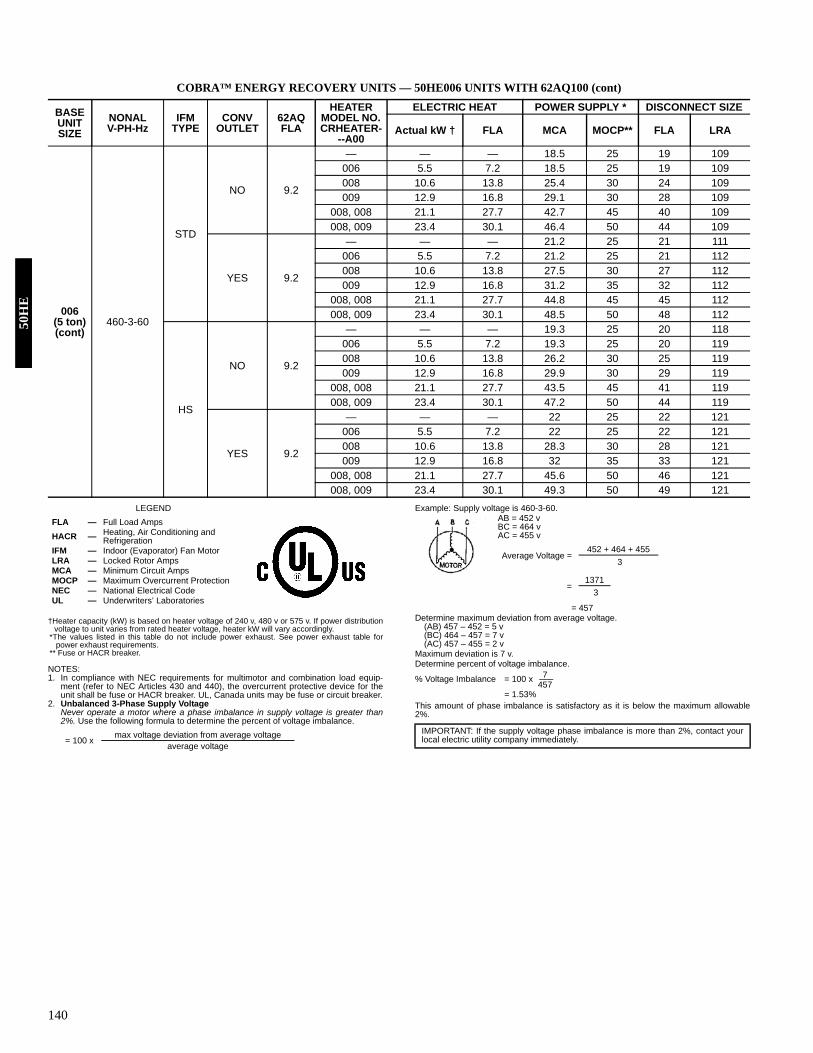
140
COBRA™ ENERGY RECOVERY UNITS — 50HE006 UNITS WITH 62AQ100 (cont)
LEGEND
†Heater capacity (kW) is based on heater voltage of 240 v, 480 v or 575 v. If power distributionvoltage to unit varies from rated heater voltage, heater kW will vary accordingly.
*The values listed in this table do not include power exhaust. See power exhaust table forpower exhaust requirements.
** Fuse or HACR breaker.
NOTES:1. In compliance with NEC requirements for multimotor and combination load equip-
ment (refer to NEC Articles 430 and 440), the overcurrent protective device for theunit shall be fuse or HACR breaker. UL, Canada units may be fuse or circuit breaker.
2. Unbalanced 3-Phase Supply VoltageNever operate a motor where a phase imbalance in supply voltage is greater than2%. Use the following formula to determine the percent of voltage imbalance.
Example: Supply voltage is 460-3-60.AB = 452 vBC = 464 vAC = 455 v
= 457Determine maximum deviation from average voltage.
(AB) 457 – 452 = 5 v(BC) 464 – 457 = 7 v (AC) 457 – 455 = 2 v
Maximum deviation is 7 v.Determine percent of voltage imbalance.
% Voltage Imbalance = 100 x
= 1.53%This amount of phase imbalance is satisfactory as it is below the maximum allowable2%.
BASE UNIT SIZE
NONAL V-PH-Hz
IFM TYPE
CONV OUTLET
62AQ FLA
HEATER MODEL NO. CRHEATER-
--A00
ELECTRIC HEAT POWER SUPPLY * DISCONNECT SIZE
Actual kW † FLA MCA MOCP** FLA LRA
006(5 ton)(cont)
460-3-60
STD
NO 9.2
— — — 18.5 25 19 109006 5.5 7.2 18.5 25 19 109008 10.6 13.8 25.4 30 24 109009 12.9 16.8 29.1 30 28 109
008, 008 21.1 27.7 42.7 45 40 109008, 009 23.4 30.1 46.4 50 44 109
YES 9.2
— — — 21.2 25 21 111006 5.5 7.2 21.2 25 21 112008 10.6 13.8 27.5 30 27 112009 12.9 16.8 31.2 35 32 112
008, 008 21.1 27.7 44.8 45 45 112008, 009 23.4 30.1 48.5 50 48 112
HS
NO 9.2
— — — 19.3 25 20 118006 5.5 7.2 19.3 25 20 119008 10.6 13.8 26.2 30 25 119009 12.9 16.8 29.9 30 29 119
008, 008 21.1 27.7 43.5 45 41 119008, 009 23.4 30.1 47.2 50 44 119
YES 9.2
— — — 22 25 22 121006 5.5 7.2 22 25 22 121008 10.6 13.8 28.3 30 28 121009 12.9 16.8 32 35 33 121
008, 008 21.1 27.7 45.6 50 46 121008, 009 23.4 30.1 49.3 50 49 121
FLA — Full Load AmpsHACR — Heating, Air Conditioning and
RefrigerationIFM — Indoor (Evaporator) Fan MotorLRA — Locked Rotor AmpsMCA — Minimum Circuit AmpsMOCP — Maximum Overcurrent ProtectionNEC — National Electrical CodeUL — Underwriters’ Laboratories
= 100 x max voltage deviation from average voltageaverage voltage
Average Voltage =452 + 464 + 455
3
=1371
3
IMPORTANT: If the supply voltage phase imbalance is more than 2%, contact yourlocal electric utility company immediately.
7457
50H
E

141
COBRA™ ENERGY RECOVERY UNITS — 50HJ004 UNITS WITH 62AQ100
See legend and notes on page 144.
UNIT 50HJ
NOMINAL V-PH-Hz
IFM TYPE
CONV OUTLET
62AQ FLA
CRHEATER---A00
ELECTRIC HEAT POWER SUPPLY * DISCONNECT SIZE
Actual kW† FLA MCA MOCP** FLA LRA
004(3 ton)
208/230-1-60 STD
NO 15.1
— — / — — / — 40.7/ 40.7 45/45 42/ 42 161
001 3.3/ 4.0 15.9/ 18.3 42.5/ 45.5 50/60 42/ 44 161
002 4.9/ 5.8 23.5/ 27.1 52.0/ 56.5 60/ 70 50/ 54 161
003 6.5/ 8.0 31.4/ 36.3 61.9/ 67.9 70/ 70 59/ 65 161
004 7.9/ 9.6 37.9/ 43.1 70.0/ 77.3 80/ 80 67/ 73 161
002+002 9.8/ 11.6 46.9/ 54.2 81.3/ 90.3 90/100 77/ 85 161
YES 15.1
— — / — — / — 46.7/ 46.7 50/50 48/ 48 166
001 3.3/ 4.0 15.9/ 18.3 47.3/ 49.7 60/60 48/ 49 166
002 4.9/ 5.8 23.5/ 27.1 56.8/ 60.7 70/70 56/ 59 166
003 6.5/ 8.0 31.4/ 36.3 66.7/ 72.1 70/ 80 65/ 70 166
004 7.9/ 9.6 37.9/ 43.1 74.8/ 81.5 80/ 90 72/ 78 166
002+002 9.8/ 11.6 46.9/ 54.2 86.1/ 94.5 90/100 82/ 90 166
208/230-3-60
STD
NO 15.1
— — / — — / — 33.6/ 33.6 40/40 36/ 36 150
001 3.3/ 4.0 15.9/ 18.3 34.1/ 35.9 45/45 36/ 36 150
002 4.9/ 5.8 23.5/ 27.1 39.6/ 42.2 50/50 39/ 41 150
003 6.5/ 8.0 31.4/ 36.3 45.3/ 48.8 60/60 44/ 47 150
004 7.9/ 9.6 37.9/ 43.1 50.0/ 54.2 60/60 48/ 52 150
005 12/ 14.7 33.4/ 38.5 64.3/ 70.7 70/ 80 61/ 67 150
YES 15.1
— — / — — / — 39.6/ 39.6 45/45 41/ 41 155
001 3.3/ 4.0 15.9/ 18.3 39.6/ 40.1 50/50 41/ 41 155
002 4.9/ 5.8 23.5/ 27.1 44.4/ 46.4 60/60 44/ 46 155
003 6.5/ 8.0 31.4/ 36.3 50.1/ 53.0 60/60 49/ 52 155
004 7.9/ 9.6 37.9/ 43.1 54.8/ 58.4 60/ 70 54/ 57 155
005 12/ 14.7 33.4/ 38.5 69.1/ 74.9 80/ 80 67/ 72 155
HIGH
NO 15.1
— — / — — / — 34.5/ 34.5 40/40 37/ 37 180
001 3.3/ 4.0 15.9/ 18.3 35.0/ 36.8 45/45 37/ 37 180
002 4.9/ 5.8 23.5/ 27.1 40.5/ 43.1 50/50 40/ 42 180
003 6.5/ 8.0 31.4/ 36.3 46.2/ 49.7 60/60 45/ 48 180
004 7.9/ 9.6 37.9/ 43.1 50.9/ 55.1 60/60 49/ 53 180
005 12/ 14.7 33.4/ 38.5 65.2/ 71.6 70/ 80 62/ 68 180
YES 15.1
— — / — — / — 40.5/ 40.5 45/45 42/ 42 184
001 3.3/ 4.0 15.9/ 18.3 40.5/ 41.0 50/50 42/ 42 184
002 4.9/ 5.8 23.5/ 27.1 45.3/ 47.3 60/60 45/ 47 184
003 6.5/ 8.0 31.4/ 36.3 51.0/ 53.9 60/60 50/ 53 184
004 7.9/ 9.6 37.9/ 43.1 55.7/ 59.3 70/ 70 55/ 58 184
005 12/ 14.7 33.4/ 38.5 70.0/ 75.8 80/ 80 68/ 73 184
460-3-60 STD
NO 15.1
— — — 16.5 20 18 76
006 5.5 7.2 20.1 25 18 76
007 8.1 13.8 24.3 30 18 77
008 10.6 16.8 28.4 35 27 80
009 12.9 27.7 32.1 35 31 83
YES 15.1
— — — 19.2 20 23 80
006 5.5 7.2 22.2 30 23 81
007 8.1 13.8 26.4 30 23 81
008 10.6 16.8 30.5 35 32 82
009 12.9 27.7 34.2 40 35 85
Electrical data — 50HJ (cont)50H
J

142
COBRA™ ENERGY RECOVERY UNITS — 50HJ004-005 UNITS WITH 62AQ100 (cont)
See legend and notes on page 144.
UNIT 50HJ
NOMINAL V-PH-Hz
IFM TYPE
CONV OUTLET
62AQ FLA
CRHEATER---A00
ELECTRIC HEAT POWER SUPPLY * DISCONNECT SIZE
Actual kW† FLA MCA MOCP** FLA LRA
004(3 ton)(cont)
460-3-60 HIGH
NO 15.1
— — — 16.9 20 18 90
006 5.5 7.2 20.5 25 18 90
007 8.1 13.8 24.7 30 18 91
008 10.6 16.8 28.8 35 28 94
009 12.9 27.7 32.5 35 31 97
YES 15.1
— — — 19.6 25 24 95
006 5.5 7.2 22.6 30 24 95
007 8.1 13.8 26.8 30 24 95
008 10.6 16.8 30.9 35 32 96
009 12.9 27.7 34.6 40 36 99
005(4 ton)
208/230-1-60 STD
NO 15.1
— — / — — / — 50.3/ 50.3 60/60 51/ 51 199
001 3.3/ 4 15.9/ 18.3 50.3/ 50.3 60/60 51/ 51 199
003 6.5/ 8 31.4/ 36.3 61.9/ 67.9 70/ 70 59/ 65 199
002+002 9.8/ 11.6 46.9/ 54.2 81.3/ 90.3 90/100 77/ 85 199
003+003 13.1/ 16 62.8/ 72.5 101.2/113.3 110/125 95/106 199
004+004 16.0/ 19.3 75.8/ 87.5 117.4/132.0 125/150 110/124 199
YES 15.1
— — / — — / — 56.3/ 56.3 70/70 57/ 57 204
001 3.3/ 4 15.9/ 18.3 56.3/ 56.3 70/ 70 57/ 57 204
003 6.5/ 8 31.4/ 36.3 66.7/ 72.1 70/ 80 65/ 70 204
002+002 9.8/ 11.6 46.9/ 54.2 86.1/ 94.5 90/100 82/ 90 204
003+003 13.1/ 16 62.8/ 72.5 106.0/117.5 110/125 101/111 204
004+004 16.0/ 19.3 75.8/ 87.5 122.2/136.2 125/150 116/128 204
208/230-3-60
STD
NO 15.1
— — / — — / — 37.6/ 37.6 45/45 39/ 39 166
002 4.9/ 5.8 13.6/ 15.6 39.6/ 42.2 50/50 39/ 41 166
003 6.5/ 8 18.1/ 20.9 45.3/ 48.8 60/60 44/ 47 166
005 12/ 14.7 33.4/ 38.5 64.3/ 70.7 70/ 80 61/ 67 166
004+004 16/ 19.3 43.8/ 50.5 77.3/ 85.8 80/ 90 73/ 81 166
YES 15.1
— — / — — / — 43.6/ 43.6 50/50 45/ 45 171
002 4.9/ 5.8 13.6/ 15.6 44.4/ 46.4 60/60 45/ 46 171
003 6.5/ 8 18.1/ 20.9 50.1/ 53.0 60/60 49/ 52 171
005 12/ 14.7 33.4/ 38.5 69.1/ 74.9 80/ 80 67/ 72 171
004+004 16/ 19.3 43.8/ 50.5 82.1/ 90.0 90/ 90 79/ 86 171
HIGH
NO 15.1
— — / — — / — 38.5/ 38.5 45/45 40/ 40 196
002 4.9/ 5.8 13.6/ 15.6 40.5/ 43.1 50/50 40/ 42 196
003 6.5/ 8 18.1/ 20.9 46.2/ 49.7 60/60 45/ 48 196
005 12/ 14.7 33.4/ 38.5 65.2/ 71.6 70/ 80 62/ 68 196
004+004 16/ 19.3 43.8/ 50.5 78.2/ 86.7 80/ 90 74/ 82 196
YES 15.1
— — / — — / — 44.5/ 44.5 50/50 46/ 46 200
002 4.9/ 5.8 13.6/ 15.6 45.3/ 47.3 60/60 46/ 47 200
003 6.5/ 8 18.1/ 20.9 51.0/ 53.9 60/60 50/ 53 200
005 12/ 14.7 33.4/ 38.5 70.0/ 75.8 80/ 80 68/ 73 200
004+004 16/ 19.3 43.8/ 50.5 83.0/ 90.9 90/100 80/ 87 200
STD NO 15.1
— — — 18.2 20 19 83
006 5.5 7.2 20.1 25 19 84
008 10.6 13.8 28.4 35 19 84
009 12.9 16.8 32.1 30 31 84
008+008 21.1 27.7 45.6 50 43 94
50H
J

143
COBRA™ ENERGY RECOVERY UNITS — 50HJ005-006 UNITS WITH 62AQ100 (cont)
See legend and notes on page 144.
UNIT 50HJ
NOMINAL V-PH-Hz
IFM TYPE
CONV OUTLET
62AQ FLA
CRHEATER---A00
ELECTRIC HEAT POWER SUPPLY * DISCONNECT SIZE
Actual kW† FLA MCA MOCP** FLA LRA
005(4 ton)(cont)
208/230-3-60 STD YES 15.1
— — — 20.9 25 25 88
006 5.5 7.2 22.2 30 25 88
008 10.6 13.8 30.5 35 25 88
009 12.9 16.8 34.2 40 35 88
008+008 21.1 27.7 47.7 50 48 96
460-3-60 HIGH
NO 15.1
— — — 18.6 25 19 97
006 5.5 7.2 20.5 25 19 98
008 10.6 13.8 28.8 35 19 98
009 12.9 16.8 32.5 35 31 98
008+008 21.1 27.7 46 50 43 108
YES 15.1
— — — 21.3 25 25 102
006 5.5 7.2 22.6 30 25 103
008 10.6 13.8 30.9 35 25 103
009 12.9 16.8 34.6 40 36 103
008+008 21.1 27.7 48.1 50 48 110
006(5 ton)
208/230-1-60 STD
NO 15.1
— — / — — / — 61.4/ 61.4 70/70 62/ 62 276
002 4.9/ 5.8 23.5/ 27.1 61.4/ 61.4 70/ 70 62/ 62 276
003 6.5/ 8.0 31.4/ 36.3 65.8/ 71.8 70/ 80 64/ 69 276
002+002 8.7/ 11.6 46.9/ 54.2 85.2/ 94.2 90/100 81/ 90 276
003+003 13.0/ 16.0 62.8/ 72.5 105.1/117.2 110/125 100/111 276
004+004 15.8/ 19.3 75.8/ 87.5 121.3/135.9 125/150 115/128 276
YES 15.1
— — / — — / — 67.4/ 67.4 80/80 68/ 68 281
002 4.9/ 5.8 23.5/ 27.1 67.4/ 67.4 80/ 80 68/ 68 281
003 6.5/ 8.0 31.4/ 36.3 70.6/ 76.0 80/ 80 69/ 74 281
002+002 8.7/ 11.6 46.9/ 54.2 90.0/ 98.4 90/100 87/ 95 281
003+003 13.0/ 16.0 62.8/ 72.5 109.9/121.4 110/125 105/116 281
004+004 15.8/ 19.3 75.8/ 87.5 126.1/140.1 150/150 120/133 281
208/230-3-60
STD
NO 15.1
— — / — — / — 44.0/ 44.0 50/50 46/ 46 228
002 4.9/ 5.8 13.6/ 15.6 44.0/ 44.0 50/50 46/ 46 228
004 7.9/ 9.6 21.9/ 25.3 50.9/ 55.1 60/60 49/ 53 228
005 12.0/ 14.7 33.4/ 38.5 65.2/ 71.6 70/ 80 62/ 68 228
004+004 15.8/ 19.3 43.8/ 50.5 78.2/ 86.7 80/ 90 74/ 82 228
004+005 19.9/ 24.3 55.2/ 63.8 92.6/103.2 100/110 88/ 97 228
YES 15.1
— — / — — / — 50.0/ 50.0 60/60 51/ 51 233
002 4.9/ 5.8 13.6/ 15.6 50.0/ 50.0 60/60 51/ 51 233
004 7.9/ 9.6 21.9/ 25.3 55.7/ 59.3 70/ 70 55/ 58 233
005 12.0/ 14.7 33.4/ 38.5 70.0/ 75.8 80/ 80 68/ 73 233
004+004 15.8/ 19.3 43.8/ 50.5 83.0/ 90.9 90/100 80/ 87 233
004+005 19.9/ 24.3 55.2/ 63.8 97.4/107.4 100/110 93/102 233
HIGH NO 15.1
— — / — — / — 45.7/ 45.7 60/60 48/ 48 247
002 4.9/ 5.8 13.6/ 15.6 45.7/ 45.7 60/60 48/ 48 247
004 7.9/ 9.6 21.9/ 25.3 52.6/ 56.8 60/ 70 51/ 55 247
005 12.0/ 14.7 33.4/ 38.5 66.9/ 73.3 70/ 80 64/ 70 247
004+004 15.8/ 19.3 43.8/ 50.5 79.9/ 88.4 80/ 90 76/ 84 247
004+005 19.9/ 24.3 55.2/ 63.8 94.3/104.9 100/110 90/ 99 247
Electrical data — 50HJ (cont)50H
J

144
COBRA™ ENERGY RECOVERY UNITS — 50HJ006-007 UNITS WITH 62AQ100
See legend and notes on page 144.
UNIT 50HJ
NOMINAL V-PH-Hz
IFM TYPE
CONV OUTLET
62AQ FLA
CRHEATER---A00
ELECTRIC HEAT POWER SUPPLY * DISCONNECT SIZEActual kW† FLA MCA MOCP** FLA LRA
006(5 ton)(cont)
208/230-3-60 HIGH YES 15.1
— — / — — / — 51.7/ 51.7 60/60 53/ 53 252002 4.9/ 5.8 13.6/ 15.6 51.7/ 51.7 60/60 53/ 53 252004 7.9/ 9.6 21.9/ 25.3 57.4/ 61.0 70/ 70 57/ 60 252005 12.0/ 14.7 33.4/ 38.5 71.7/ 77.5 80/ 80 70/ 75 252
004+004 15.8/ 19.3 43.8/ 50.5 84.7/ 92.6 90/100 82/ 89 252004+005 19.9/ 24.3 55.2/ 63.8 99.1/ 109.1 100/104 95/ 104 252
460-3-60
STD
NO 15.1
— — — 22.2 25 23 114006 5.5 7.2 22.2 25 23 114008 10.6 13.8 28.8 35 23 114009 12.9 16.8 32.5 35 31 114
008+008 21.1 27.7 46 50 43 114008+009 23.4 30.1 49.8 50 47 114
YES 15.1
— — — 24.9 30 28 119006 5.5 7.2 24.9 30 28 119008 10.6 13.8 30.9 35 28 119009 12.9 16.8 34.6 40 36 119
008+008 21.1 27.7 48.1 50 48 119008+009 23.4 30.1 51.9 60 52 119
HIGH
NO 15.1
— — — 23 30 24 123006 5.5 7.2 23 30 24 124008 10.6 13.8 29.6 35 24 124009 12.9 16.8 33.3 35 32 124
008+008 21.1 27.7 46.8 50 44 124008+009 23.4 30.1 50.6 60 48 124
YES 15.1
— — — 25.7 30 29 128006 5.5 7.2 25.7 30 29 129008 10.6 13.8 31.7 35 29 129009 12.9 16.8 35.4 40 37 129
008+008 21.1 27.7 48.9 50 49 129008+009 23.4 30.1 52.7 60 53 129
007(6 ton) 208/230-3-60
STD
NO 15.1
— — / — — / — 47.9/ 47.9 60/60 49/ 49 260002 4.9/ 5.8 13.6/ 15.6 47.9/ 47.9 60/60 49/ 49 260004 7.9/ 9.6 21.9/ 25.3 50.9/ 55.1 60/60 49/ 53 260005 12.0/ 14.7 33.4/ 38.5 65.2/ 71.6 70/ 80 62/ 68 260
004+004 15.8/ 19.3 43.8/ 50.5 78.2/ 86.7 80/ 90 74/ 82 260004+005 19.9/ 24.3 55.2/ 63.8 92.6/103.2 100/110 88/ 97 260
YES 15.1
— — / — — / — 53.9/ 53.9 60/60 55/ 55 265002 4.9/ 5.8 13.6/ 15.6 53.9/ 53.9 60/60 55/ 55 265004 7.9/ 9.6 21.9/ 25.3 55.7/ 59.3 70/ 70 55/ 58 265005 12.0/ 14.7 33.4/ 38.5 70.0/ 75.8 80/ 80 68/ 73 265
004+004 15.8/ 19.3 43.8/ 50.5 83.0/ 90.9 90/100 80/ 87 265004+005 19.9/ 24.3 55.2/ 63.8 97.4/107.4 100/110 93/102 265
HIGH
NO 15.1
— — / — — / — 49.6/ 49.6 60/60 51/ 51 279002 4.9/ 5.8 13.6/ 15.6 49.6/ 49.6 60/60 51/ 51 279004 7.9/ 9.6 21.9/ 25.3 52.6/ 56.8 60/ 70 51/ 55 279005 12.0/ 14.7 33.4/ 38.5 66.9/ 73.3 70/ 80 64/ 70 279
004+004 15.8/ 19.3 43.8/ 50.5 79.9/ 88.4 80/ 90 76/ 84 279004+005 19.9/ 24.3 55.2/ 63.8 94.3/104.9 100/110 90/ 99 279
YES 15.1
— — / — — / — 55.6/ 55.6 60/60 57/ 57 284002 4.9/ 5.8 13.6/ 15.6 55.6/ 55.6 60/60 57/ 57 284004 7.9/ 9.6 21.9/ 25.3 57.4/ 61.0 70/ 70 57/ 60 284005 12.0/ 14.7 33.4/ 38.5 71.7/ 77.5 80/ 80 70/ 75 284
004+004 15.8/ 19.3 43.8/ 50.5 84.7/ 92.6 90/100 82/ 89 284004+005 19.9/ 24.3 55.2/ 63.8 99.1/109.1 100/110 95/104 284
50H
J

145
COBRA™ ENERGY RECOVERY UNITS — 50HJ007 UNITS WITH 62AQ100
LEGEND
†Heater capacity (kW) is based on heater voltage of 240 v, 480 v or 575 v. If power distributionvoltage to unit varies from rated heater voltage, heater kW will vary accordingly.
*The values listed in this table do not include power exhaust. See power exhaust table forpower exhaust requirements.
** Fuse or HACR breaker.NOTES:1. In compliance with NEC requirements for multimotor and combination load equipment (refer
to NEC Articles 430 and 440), the overcurrent protective device for the unit shall be fuse orHACR breaker. UL, Canada units may be fuse or circuit breaker.
2. Unbalanced 3-Phase Supply VoltageNever operate a motor where a phase imbalance in supply voltage is greater than 2%. Usethe following formula to determine the percent of voltage imbalance.
Example: Supply voltage is 460-3-60.AB = 452 vBC = 464 vAC = 455 v
= 457Determine maximum deviation from average voltage.
(AB) 457 – 452 = 5 v(BC) 464 – 457 = 7 v (AC) 457 – 455 = 2 v
Maximum deviation is 7 v.Determine percent of voltage imbalance.
% Voltage Imbalance = 100 x = 1.53%
This amount of phase imbalance is satisfactory as it is below the maximum allowable 2%.
UNIT 50HJ
NOMINAL V-PH-Hz
IFM TYPE
CONV OUTLET
62AQ FLA
CRHEATER---A00
ELECTRIC HEAT POWER SUPPLY * DISCONNECT SIZE
Actual kW† FLA MCA MOCP** FLA LRA
007(6 ton)(cont)
460-3-60
STD
NO 15.1
— — — 22.8 30 23 127
006 5.5 7.2 22.8 30 23 127
008 10.6 13.8 28.8 35 23 127
009 12.9 16.8 32.5 35 31 127
008+008 21.1 27.7 46 50 43 127
008+009 23.4 30.7 49.8 50 47 127
YES 15.1
— — — 25.5 30 29 131
006 5.5 7.2 25.5 30 29 132
008 10.6 13.8 30.9 35 29 132
009 12.9 16.8 34.6 40 36 132
008+008 21.1 27.7 48.1 50 48 132
008+009 23.4 30.7 51.9 60 52 132
HIGH
NO 15.1
— — — 23.6 30 24 136
006 5.5 7.2 23.6 30 24 137
008 10.6 13.8 29.6 35 24 137
009 12.9 16.8 33.3 35 32 137
008+008 21.1 27.7 46.8 50 44 137
008+009 23.4 30.7 50.6 60 48 137
YES 15.1
— — — 26.3 30 30 141
006 5.5 7.2 26.3 30 30 141
008 10.6 13.8 31.7 35 30 141
009 12.9 16.8 35.4 40 37 141
008+008 21.1 27.7 48.9 50 49 141
008+009 23.4 30.7 52.7 60 53 141
FLA — Full Load AmpsHACR — Heating, Air Conditioning and RefrigerationIFM — Indoor (Evaporator) Fan MotorLRA — Locked Rotor AmpsMCA — Minimum Circuit AmpsMOCP — Maximum Overcurrent ProtectionNEC — National Electrical CodeUL — Underwriters’ Laboratories
= 100 xmax voltage deviation from average voltage
average voltage
Average Voltage =452 + 464 + 455
3
=1371
3
IMPORTANT: If the supply voltage phase imbalance is more than 2%, contact your localelectric utility company immediately.
7457
Electrical data — 50HJ (cont)50H
J
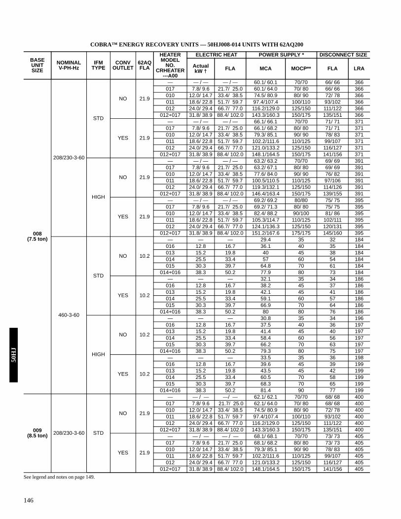
146
COBRA™ ENERGY RECOVERY UNITS — 50HJ008-014 UNITS WITH 62AQ200
See legend and notes on page 149.
BASE UNIT SIZE
NOMINAL V-PH-Hz
IFM TYPE
CONV OUTLET
62AQ FLA
HEATER MODEL
NO. CRHEATER
---A00
ELECTRIC HEAT POWER SUPPLY * DISCONNECT SIZE
Actual kW † FLA MCA MOCP** FLA LRA
008(7.5 ton)
208/230-3-60
STD
NO 21.9
— — / — — / — 60.1/ 60.1 70/70 66/ 66 366017 7.8/ 9.6 21.7/ 25.0 60.1/ 64.0 70/ 80 66/ 66 366010 12.0/ 14.7 33.4/ 38.5 74.5/ 80.9 80/ 90 72/ 78 366011 18.6/ 22.8 51.7/ 59.7 97.4/107.4 100/110 93/102 366012 24.0/ 29.4 66.7/ 77.0 116.2/129.0 125/150 111/122 366
012+017 31.8/ 38.9 88.4/ 102.0 143.3/160.3 150/175 135/151 366
YES 21.9
— — / — — / — 66.1/ 66.1 70/70 71/ 71 371017 7.8/ 9.6 21.7/ 25.0 66.1/ 68.2 80/ 80 71/ 71 371010 12.0/ 14.7 33.4/ 38.5 79.3/ 85.1 90/ 90 78/ 83 371011 18.6/ 22.8 51.7/ 59.7 102.2/111.6 110/125 99/107 371012 24.0/ 29.4 66.7/ 77.0 121.0/133.2 125/150 116/127 371
012+017 31.8/ 38.9 88.4/ 102.0 148.1/164.5 150/175 141/156 371
HIGH
NO 21.9
— — / — — / — 63.2/ 63.2 70/70 69/ 69 391017 7.8/ 9.6 21.7/ 25.0 63.2/ 67.1 80/ 80 69/ 69 391010 12.0/ 14.7 33.4/ 38.5 77.6/ 84.0 90/ 90 76/ 82 391011 18.6/ 22.8 51.7/ 59.7 100.5/110.5 110/125 97/106 391012 24.0/ 29.4 66.7/ 77.0 119.3/132.1 125/150 114/126 391
012+017 31.8/ 38.9 88.4/ 102.0 146.4/163.4 150/175 139/155 391
YES 21.9
— — / — — / — 69.2/ 69.2 80/80 75/ 75 395017 7.8/ 9.6 21.7/ 25.0 69.2/ 71.3 80/ 80 75/ 75 395010 12.0/ 14.7 33.4/ 38.5 82.4/ 88.2 90/100 81/ 86 395011 18.6/ 22.8 51.7/ 59.7 105.3/114.7 110/125 102/111 395012 24.0/ 29.4 66.7/ 77.0 124.1/136.3 125/150 120/131 395
012+017 31.8/ 38.9 88.4/ 102.0 151.2/167.6 175/175 145/160 395
460-3-60
STD
NO 10.2
— — — 29.4 35 32 184016 12.8 16.7 36.1 40 35 184013 15.2 19.8 40 45 38 184014 25.5 33.4 57 60 54 184015 30.3 39.7 64.8 70 61 184
014+016 38.3 50.2 77.9 80 73 184
YES 10.2
— — — 32.1 35 34 186016 12.8 16.7 38.2 45 37 186013 15.2 19.8 42.1 45 41 186014 25.5 33.4 59.1 60 57 186015 30.3 39.7 66.9 70 64 186
014+016 38.3 50.2 80 80 76 186
HIGH
NO 10.2
— — — 30.8 35 34 196016 12.8 16.7 37.5 40 36 197013 15.2 19.8 41.4 45 40 197014 25.5 33.4 58.4 60 56 197015 30.3 39.7 66.2 70 63 197
014+016 38.3 50.2 79.3 80 75 197
YES 10.2
— — — 33.5 35 36 198016 12.8 16.7 39.6 45 39 199013 15.2 19.8 43.5 45 42 199014 25.5 33.4 60.5 70 58 199015 30.3 39.7 68.3 70 65 199
014+016 38.3 50.2 81.4 90 77 199
009(8.5 ton) 208/230-3-60 STD
NO 21.9
— — / — —/ — 62.1/ 62.1 70/70 68/ 68 400017 7.8/ 9.6 21.7/ 25.0 62.1/ 64.0 70/ 80 68/ 68 400010 12.0/ 14.7 33.4/ 38.5 74.5/ 80.9 80/ 90 72/ 78 400011 18.6/ 22.8 51.7/ 59.7 97.4/107.4 100/110 93/102 400012 24.0/ 29.4 66.7/ 77.0 116.2/129.0 125/150 111/122 400
012+017 31.8/ 38.9 88.4/ 102.0 143.3/160.3 150/175 135/151 400
YES 21.9
— — / — — / — 68.1/ 68.1 70/70 73/ 73 405017 7.8/ 9.6 21.7/ 25.0 68.1/ 68.2 80/ 80 73/ 73 405010 12.0/ 14.7 33.4/ 38.5 79.3/ 85.1 90/ 90 78/ 83 405011 18.6/ 22.8 51.7/ 59.7 102.2/111.6 110/125 99/107 405012 24.0/ 29.4 66.7/ 77.0 121.0/133.2 125/150 116/127 405
012+017 31.8/ 38.9 88.4/ 102.0 148.1/164.5 150/175 141/156 405
50H
J

147
COBRA™ ENERGY RECOVERY UNITS — 50HJ008-014 UNITS WITH 62AQ200 (cont)
See legend and notes on page 149.
BASE UNIT SIZE
NOMINAL V-PH-Hz
IFM TYPE
CONV OUTLET
62AQ FLA
HEATER MODEL
NO. CRHEATER
---A00
ELECTRIC HEAT POWER SUPPLY * DISCONNECT SIZE
Actual kW † FLA MCA MOCP** FLA LRA
009(8.5 ton)
(cont)
208/230-3-60 HIGH
NO 21.9
— — / — — / — 65.2/ 65.2 70/70 71/ 71 425017 7.8/ 9.6 21.7/ 25.0 65.2/ 67.1 80/ 80 71/ 71 425010 12.0/ 14.7 33.4/ 38.5 77.6/ 84.0 90/ 90 76/ 82 425011 18.6/ 22.8 51.7/ 59.7 100.5/110.5 110/125 97/106 425012 24.0/ 29.4 66.7/ 77.0 119.3/132.1 125/150 114/126 425
012+017 31.8/ 38.9 88.4/ 102.0 146.4/163.4 150/175 139/155 425
YES 21.9
— — / — — / — 71.2/ 71.2 80/80 77/ 77 429017 7.8/ 9.6 21.7/ 25.0 71.2/ 71.3 80/ 80 77/ 77 429010 12.0/ 14.7 33.4/ 38.5 82.4 /88.2 90/100 81/ 86 429011 18.6/ 22.8 51.7/ 59.7 105.3/114.7 110/125 102/111 429012 24.0/ 29.4 66.7/ 77.0 124.1/136.3 125/150 120/131 429
012+017 31.8/ 38.9 88.4/ 102.0 151.2/167.6 175/175 145/160 429
460-3-60
STD
NO 10.2
— — — 31.7 35 34 206016 12.8 16.7 36.1 40 35 206013 15.2 19.8 40 45 38 206014 25.5 33.4 57 60 54 206015 30.3 39.7 64.8 70 61 206
014+016 38.3 50.2 77.9 80 73 206
YES 10.2
— — — 34.4 40 37 208016 12.8 16.7 38.2 45 37 208013 15.2 19.8 42.1 45 41 208014 25.5 33.4 59.1 60 57 208015 30.3 39.7 66.9 70 64 208
014+016 38.3 50.2 80 80 76 208
HIGH
NO 10.2
— — — 33.1 35 36 218016 12.8 16.7 37.5 40 36 219013 15.2 19.8 41.4 45 40 219014 25.5 33.4 58.4 60 56 219015 30.3 39.7 66.2 70 63 219
014+016 38.3 50.2 79.3 80 75 219
YES 10.2
— — — 35.8 40 38 220016 12.8 16.7 39.6 45 39 221013 15.2 19.8 43.5 45 42 221014 25.5 33.4 60.5 70 58 221015 30.3 39.7 68.3 70 65 221
014+016 38.3 50.2 81.4 90 77 221
012(10 ton) 208/230-3-60 STD
NO 21.9
— — / — — / — 74.9/ 74.9 80/ 80 81/ 81 465017 7.8/ 9.6 21.7/ 25.0 74.9/ 74.9 80/ 80 81/ 81 465010 12.0/ 14.7 33.4/ 38.5 77.6/ 84.0 90/ 90 81/ 82 465012 24.0/ 29.4 66.7/ 77.0 119.3/132.1 125/150 114/126 465
012+017 31.8/ 38.9 88.4/ 102.0 146.4/163.4 150/175 139/155 465010+012 37.5/ 45.9 104.2/ 104.2 166.2/156.2 175/175 157/176 465
YES 21.9
— — / — — / — 80.9/ 80.9 90/ 90 87/ 87 469017 7.8/ 9.6 21./ 25.0 80.9/ 80.9 90/ 90 87/ 87 469010 12.0/ 14.7 33.4/ 38.5 82.4/ 88.2 90/100 87/ 87 469012 24.0/ 29.4 66.7/ 77.0 124.1/136.3 125/150 120/131 469
012+017 31.8/ 38.9 88.4/ 102.0 151.2/167.6 175/175 145/160 469010+012 37.5/ 45.9 104.2/ 120.3 171.0/160.4 175/175 163/181 469
Electrical data — 50HJ (cont)50H
J

148
COBRA™ ENERGY RECOVERY UNITS — 50HJ008-014 UNITS WITH 62AQ200 (cont)
See legend and notes on page 149.
BASE UNIT SIZE
NOMINAL V-PH-Hz
IFM TYPE
CONV OUT-LET
62AQ FLA
HEATER MODEL NO. CRHEATER
---A00
ELECTRIC HEAT POWER SUPPLY * DISCONNECT SIZEActual kW † FLA MCA MOCP** FLA LRA
012(10 ton)(cont)
208/230-3-60 HIGH
NO 21.9
— — / — — / — 79.3/ 79.3 90/ 90 86/ 86 488017 7.8/ 9.6 21.7/ 25.0 79.3/ 79.3 90/ 90 86/ 86 488010 12.0/ 14.7 33.4/ 38.5 82.3/ 88.8 90/100 86/ 87 488012 24.0/ 29.4 66.7/ 77.0 124.0/136.9 125/150 119/131 488
012+017 31.8/ 38.9 88.4/ 102.0 151.1/168.2 175/175 144/160 488010+012 37.5/ 45.9 104.2/ 120.3 170.9/160.9 175/200 162/181 488
YES 21.9
— — / — — / — 85.3/ 85.3 90/ 90 92/ 92 493017 7.8/ 9.6 21./ 25.0 85.3/ 85.3 90/ 90 92/ 92 493010 12.0/ 14.7 33.4/ 38.5 87.1/ 93.0 100/100 92/ 92 493012 24.0/ 29.4 66.7/ 77.0 128.8/141.1 150/150 125/136 493
012+017 31.8/ 38.9 88.4/ 102.0 155.9/172.4 175/175 150/165 493010+012 37.5/ 45.9 104.2/ 120.3 175.7/165.1 200/200 168/186 493
460-3-60
STD
NO 10.2
— — — 35.1 40 38 233016 12.8 16.7 37.5 40 38 234013 15.2 19.8 41.4 45 40 234015 30.3 39.7 66.2 70 63 234
014+016 38.3 50.2 79.3 80 75 234013+015 45.9 60.1 76.7 90 86 234
YES 10.2
— — — 37.8 40 40 235016 12.8 16.7 39.6 45 40 236013 15.2 19.8 43.5 45 42 236015 30.3 39.7 68.3 70 65 236
014+016 38.3 50.2 81.4 90 77 236013+015 45.9 60.1 78.8 90 89 236
HIGH
NO 10.2
— — — 37.7 40 41 245016 12.8 16.7 40.3 45 41 245013 15.2 19.8 44.3 50 43 245015 30.3 39.7 69.1 70 66 245
014+016 38.3 50.2 82.1 90 78 245013+015 45.9 60.1 79.6 90 89 245
YES 10.2
— — — 40.4 45 43 247016 12.8 16.7 42.4 50 43 247013 15.2 19.8 46.4 50 45 247015 30.3 39.7 71.2 80 68 247
014+016 38.3 50.2 84.2 90 80 247013+015 45.9 60.1 81.7 90 92 247
014(12.5 ton) 208/230-3-60 STD
NO 21.9
— — / — — / — 82.5/ 82.5 90/ 90 89/ 89 550/550
017 7.8/ 9.6 21.7// 25.0 82.5/ 82.5 90/ 90 89/ 89 550/550
010 12.0/ 14.7 33.4/ 38.5 82.3/ 88.8 90/100 89/ 89 550/550
012 24.0/ 29.4 66.7/ 77.0 124.0/136.9 125/150 119/131 550/550
012+017 31.8/ 38.9 88.4/ 102.0 151.1/168.2 175/175 144/160 550/550
010+012 37.5/ 45.9 104.2/ 120.3 170.9/160.9 175/200 162/181 550/550
YES 21.9
— — / — — / — 88.5/ 88.5 100/100 95/ 95 555/555
017 7.8/ 9.6 21.7/ 25.0 88.5/ 88.5 100/100 95/ 95 555/555
010 12.0/ 14.7 33.4/ 38.5 87.1/ 93.0 100/100 95/ 95 555/555
012 24.0/ 29.4 66.7/ 77.0 128.8/141.1 150/150 125/136 555/555
012+017 31.8/ 38.9 88.4/ 102.0 155.9/172.4 175/175 150/165 555/555
010+012 37.5/ 45.9 104.2/ 120.3 175.7/165.1 200/200 168/186 555/555
50H
J

149
COBRA™ ENERGY RECOVERY UNITS — 50HJ008-014 UNITS WITH 62AQ200 (cont)
LEGEND
†Heater capacity (kW) is based on heater voltage of 240 v, 480 v or 575 v. If power distributionvoltage to unit varies from rated heater voltage, heater kW will vary accordingly.
*The values listed in this table do not include power exhaust. See power exhaust table forpower exhaust requirements.
** Fuse or HACR breaker.NOTES:1. In compliance with NEC requirements for multimotor and combination load equipment (refer
to NEC Articles 430 and 440), the overcurrent protective device for the unit shall be fuse orHACR breaker. UL, Canada units may be fuse or circuit breaker.
2. Unbalanced 3-Phase Supply VoltageNever operate a motor where a phase imbalance in supply voltage is greater than 2%. Usethe following formula to determine the percent of voltage imbalance.
Example: Supply voltage is 460-3-60.AB = 452 vBC = 464 vAC = 455 v
= 457Determine maximum deviation from average voltage.
(AB) 457 – 452 = 5 v(BC) 464 – 457 = 7 v (AC) 457 – 455 = 2 v
Maximum deviation is 7 v.Determine percent of voltage imbalance.
% Voltage Imbalance = 100 x = 1.53%
This amount of phase imbalance is satisfactory as it is below the maximum allowable 2%.
BASE UNIT SIZE
NOMINAL V-PH-Hz
IFM TYPE
CONV OUTLET
62AQ FLA
HEATER MODEL
NO. CRHEATER
---A00
ELECTRIC HEAT POWER SUPPLY * DISCONNECT SIZE
Actual kW † FLA MCA MOCP** FLA LRA
014(12.5 ton)
(cont)460-3-60 STD
NO 10.2
— — — 39.3 45 43 260016 9.6 16.7 40.3 45 43 260013 14.7 19.8 44.3 50 43 260015 29.4 39.7 69.1 70 66 260
014+016 38.9 50.2 82.1 90 78 260013+015 45.9 60.1 79.6 90 89 260
YES 10.2
— — — 42 45 45 262016 9.6 16.7 42.4 50 45 262013 14.7 19.8 46.4 50 45 262015 29.4 39.7 71.2 80 68 262
014+016 38.9 50.2 84.2 90 80 262013+015 45.9 60.1 81.7 90 92 262
FLA — Full Load AmpsHACR — Heating, Air Conditioning and RefrigerationIFM — Indoor (Evaporator) Fan MotorLRA — Locked Rotor AmpsMCA — Minimum Circuit AmpsMOCP — Maximum Overcurrent ProtectionNEC — National Electrical CodeUL — Underwriters’ Laboratories
= 100 xmax voltage deviation from average voltage
average voltage
Average Voltage =452 + 464 + 455
3
=1371
3
IMPORTANT: If the supply voltage phase imbalance is more than 2%, contact your localelectric utility company immediately.
7457
Electrical data — 50HJ (cont)50H
J

150
COBRA™ ENERGY RECOVERY UNITS — 50HJ008-014 UNITS WITH 62AQ300
See legend and notes on page 152.
BASE UNIT SIZE
NOMINAL V-PH-Hz
IFM TYPE
CONV OUT-LET
62AQ FLA
HEATER MODEL NO. CRHEATER-
--A00
ELECTRIC HEAT POWER SUPPLY * DISCONNECT SIZE
Actual kW † FLA MCA MOCP** FLA LRA
008(7.5 ton)
208/230-3-60
STD
NO 29.8
— — / — — / — 68.0/ 68.0 80/80 75/ 75 420/420 017 7.8/ 9.6 21.7/ 25.0 68.7/ 72.9 90/ 90 75/ 75 420/420 010 12.0/ 14.7 33.4/ 38.5 83.3/ 89.7 100/100 81/ 87 420/420 011 18.6/ 22.8 51.7/ 59.7 106.2/116.2 125/125 102/112 420/420 012 24.0/ 29.4 66.7/ 77.0 125.0/137.8 150/150 120/131 420/420
012+017 31.8/ 38.9 88.4/ 102.0 152.1/169.1 175/175 145/160 420/420
YES 29.8
— — / — — / — 74.0/ 74.0 80/80 80/ 80 425/425 017 7.8/ 9.6 21.7/ 25.0 74.0/ 77.1 90/ 90 80/ 80 425/425 010 12.0/ 14.7 33.4/ 38.5 88.1/ 93.9 100/110 87/ 92 425/425 011 18.6/ 22.8 51.7/ 59.7 111.0/120.4 125/125 108/116 425/425 012 24.0/ 29.4 66.7/ 77.0 129.8/142.0 150/150 125/136 425/425
012+017 31.8/ 38.9 88.4/ 102.0 156.9/173.3 175/175 150/165 425/425
HIGH
NO 29.8
— — / — — / — 71.1/ 71.1 80/80 78/ 78 445/445 017 7.8/ 9.6 21.7/ 25.0 71.8/ 76.0 90/ 90 78/ 78 445/445 010 12.0/ 14.7 33.4/ 38.5 86.4/ 92.8 100/110 85/ 91 445/445 011 18.6/ 22.8 51.7/ 59.7 109.3/119.3 125/125 106/115 445/445 012 24.0/ 29.4 66.7/ 77.0 128.1/140.9 150/150 123/135 445/445
012+017 31.8/ 38.9 88.4/ 102.0 155.2/172.2 175/175 148/164 445/445
YES 29.8
— — / — — / — 77.1/ 77.1 80/80 84/ 84 449/449 017 7.8/ 9.6 21.7/ 25.0 77.1/ 80.2 90/100 84/ 84 449/449 010 12.0/ 14.7 33.4/ 38.5 91.2/ 97.0 110/110 90/ 96 449/449 011 18.6/ 22.8 51.7/ 59.7 114.1/123.5 125/150 111/120 449/449 012 24.0/ 29.4 66.7/ 77.0 132.9/145.1 150/150 129/140 449/449
012+017 31.8/ 38.9 88.4/ 102.0 160.0/176.4 175/200 154/169 449/449
460-3-60
STD
NO 15.8
— — — 35 40 38 211016 12.8 16.7 44.4 60 41 211013 15.2 19.8 48.3 60 45 211014 25.5 33.4 65.3 80 61 211015 30.3 39.7 73.1 90 68 211
014+016 38.3 50.2 86.2 100 80 211
YES 15.8
— — — 37.7 40 41 213016 12.8 16.7 46.5 60 44 213013 15.2 19.8 50.4 60 47 213014 25.5 33.4 67.4 80 63 213015 30.3 39.7 75.2 90 70 213
014+016 38.3 50.2 88.3 100 82 213
HIGH
NO 15.8
— — — 36.4 40 40 223016 12.8 16.7 45.8 60 43 224013 15.2 19.8 49.7 60 47 224014 25.5 33.4 66.7 80 62 224015 30.3 39.7 74.5 90 69 224
014+016 38.3 50.2 87.6 100 81 224
YES 15.8
— — — 39.1 45 43 225016 12.8 16.7 47.9 60 45 226013 15.2 19.8 51.8 60 49 226014 25.5 33.4 68.8 80 65 226015 30.3 39.7 76.6 90 72 226
014+016 38.3 50.2 89.7 100 84 226
009(8.5 ton) 208/230-3-60 STD
NO 29.8
— — / — — 70.0/ 70.0 80/80 77/ 77 454/454 017 7.8/ 9.6 16.4 70.0/ 72.9 90/ 90 77/ 77 454/454 010 12.0/ 14.7 32.7 83.3/ 89.7 100/100 81/ 87 454/454 011 18.6/ 22.8 — 106.2/116.2 125/125 102/112 454/454 012 24.0/ 29.4 16.4 125.0/137.8 150/150 120/131 454/454
012+017 31.8/ 38.9 32.7 152.1/169.1 175/175 145/160 454/454
YES 29.8
— — / — — 76.0/ 76.0 80/80 82/ 82 459/459 017 7.8/ 9.6 16.4 76.0/ 77.1 90/ 90 82/ 82 459/459 010 12.0/ 14.7 32.7 88.1/ 93.9 100/110 87/ 92 459/459 011 18.6/ 22.8 — 111.0/120.4 125/125 108/116 459/459 012 24.0/ 29.4 16.4 129.8/142.0 150/150 125/136 459/459
012+017 31.8/ 38.9 32.7 156.9/173.3 175/175 150/165 459/459
50H
J

151
COBRA™ ENERGY RECOVERY UNITS — 50HJ008-014 UNITS WITH 62AQ300 (cont)
See legend and notes on page 152.
BASE UNIT SIZE
NOMINAL V-PH-Hz
IFM TYPE
CONV OUT-LET
62AQ FLA
HEATER MODEL NO. CRHEATER
---A00
ELECTRIC HEAT POWER SUPPLY * DISCONNECT SIZE
Actual kW † FLA MCA MOCP** FLA LRA
009(8.5 ton)
(cont)
208/230-3-60 HIGH
NO 29.8
— — / — — / — 73.1/ 73.1 80/80 80/ 80 479/479 017 7.8/ 9.6 21.7/ 25.0 73.1/ 76.0 90/ 90 80/ 80 479/479 010 12.0/ 14.7 33.4/ 38.5 86.4/ 92.8 100/110 85/ 91 479/479 011 18.6/ 22.8 51.7/ 59.7 109.3/119.3 125/125 106/115 479/479 012 24.0/ 29.4 66.7/ 77.0 128.1/140.9 150/150 123/135 479/479
012+017 31.8/ 38.9 88.4/ 102.0 155.2/172.2 175/175 148/164 479/479
YES 29.8
— — / — — / — 79.1/ 79.1 80/80 86/ 86 483/483 017 7.8/ 9.6 21.7/ 25.0 79.1/ 80.2 90/100 86/ 86 483/483 010 12.0/ 14.7 33.4/ 38.5 91.2/ 97.0 110/110 90/ 96 483/483 011 18.6/ 22.8 51.7/ 59.7 114.1/123.5 125/150 111/120 483/483 012 24.0/ 29.4 66.7/ 77.0 132.9/145.1 150/150 129/140 483/483
012+017 31.8/ 38.9 88.4/ 102.0 160.0/176.4 175/200 154/169 483/483
460-3-60
STD
NO 15.8
— — — 37.3 40 41 233016 12.8 16.7 44.4 60 41 233013 15.2 19.8 48.3 60 45 233014 25.5 33.4 65.3 80 61 233015 30.3 39.7 73.1 90 68 233
014+016 38.3 50.2 86.2 100 80 233
YES 15.8
— — — 40 45 43 235016 12.8 16.7 46.5 60 44 235013 15.2 19.8 50.4 60 47 235014 25.5 33.4 67.4 80 63 235015 30.3 39.7 75.2 90 70 235
014+016 38.3 50.2 88.3 100 82 235
HIGH
NO 15.8
— — — 38.7 45 42 245016 12.8 16.7 45.8 60 43 246013 15.2 19.8 49.7 60 47 246014 25.5 33.4 66.7 80 62 246015 30.3 39.7 74.5 90 69 246
014+016 38.3 50.2 87.6 100 81 246
YES 15.8
— — — 41.4 45 45 247016 12.8 16.7 47.9 60 45 248013 15.2 19.8 51.8 60 49 248014 25.5 33.4 68.8 80 65 248015 30.3 39.7 76.6 90 72 248
014+016 38.3 50.2 89.7 100 84 248
012(10 ton) 208/230-3-60
STD
NO 29.8
— — / — — / — 82.8/ 82.8 90/ 90 90/ 90 519017 7.8/ 9.6 21.7/ 25.0 82.8/ 82.8 90/ 90 90/ 90 519010 12.0/ 14.7 33.4/ 38.5 86.4/ 92.8 100/110 90/ 91 519012 24.0/ 29.4 66.7/ 77.0 128.1/140.9 150/150 123/135 519
012+017 31.8/ 38.9 88.4/ 102.0 155.2/172.2 175/175 148/164 519012+010 37.5/ 45.9 104.2/ 104.2 175.0/165.0 175/200 166/185 519
YES 29.8
— — / — — / — 88.8/ 88.8 100/100 96/ 96 523017 7.8/ 9.6 21./ 25.0 88.8/ 88.8 100/100 96/ 96 523010 12.0/14.7 33.4/ 38.5 91.2/ 97.0 110/110 96/ 96 523012 24.0/29.4 66.7/ 77.0 132.9/145.1 150/150 129/140 523
012+017 31.8/38.9 88.4/ 102.0 160.0/176.4 175/200 154/169 523012+010 37.5/45.9 104.2/120.3 179.8/169.2 200/200 172/190 523
HIGH
NO 29.8
— — / — — / — 87.2/ 87.2 100/100 95/ 95 542017 7.8/9.6 21.7/25.0 87.2/ 87.2 100/100 95/ 95 542010 12.0/ 14.7 33.4/38.5 90.8/ 97.2 100/110 95/ 96 542012 24.0/ 29.4 66.7/77.0 132.5/145.3 150/150 128/140 542
012+017 31.8/ 38.9 88.4/ 102.0 159.6/176.6 175/200 153/169 542012+010 37.5/ 45.9 104.2/ 120.3 179.4/169.4 200/200 171/190 542
YES 29.8
— — / — — / — 93.2/ 93.2 100/100 101/101 547017 7.8/ 9.6 21./25.0 93.2/ 93.2 100/100 101/101 547010 12.0/ 14.7 33.4/38.5 95.6/101.4 110/110 101/101 547012 24.0/ 29.4 66.7/77.0 137.3/149.5 150/150 134/145 547
012+017 31.8/ 38.9 88.4/102.0 164.4/180.8 175/200 159/174 547012+010 37.5/ 45.9 104.2/ 120.3 184.2/173.6 200/200 177/195 547
Electrical data — 50HJ (cont)50H
J

152
COBRA™ ENERGY RECOVERY UNITS — 50HJ008-014 UNITS WITH 62AQ300 (cont)
LEGEND
*Used to determine minimum disconnect per NEC.NOTES:1. In compliance with NEC requirements for multimotor and combination load equipment (refer
to NEC Articles 430 and 440), the overcurrent protective device for the unit shall be fuse orHACR breaker. UL, Canada units may be fuse or circuit breaker.
2. Unbalanced 3-Phase Supply VoltageNever operate a motor where a phase imbalance in supply voltage is greater than 2%. Usethe following formula to determine the percent of voltage imbalance.
Example: Supply voltage is 460-3-60.
AB = 452 vBC = 464 vAC = 455 v
= 457Determine maximum deviation from average voltage.
(AB) 457 – 452 = 5 v(BC) 464 – 457 = 7 v (AC) 457 – 455 = 2 v
Maximum deviation is 7 v.Determine percent of voltage imbalance.
% Voltage Imbalance = 100 x = 1.53%
This amount of phase imbalance is satisfactory as it is below the maximum allowable 2%.
BASE UNIT SIZE
NOMINAL V-PH-Hz
IFM TYPE
CONV OUT-LET
62AQ FLA
HEATER MODEL NO. CRHEATER-
--A00
ELECTRIC HEAT POWER SUPPLY * DISCONNECT SIZE
Actual kW † FLA MCA MOCP** FLA LRA
012(10 ton)(cont)
460-3-60
STD
NO 15.8
— — — 40.7 45 44 260016 12.8 16.7 45.8 60 44 261013 15.2 19.8 49.7 60 47 261015 30.3 39.7 66.7 80 62 261
014+016 38.3 50.2 87.6 100 81 261015+013 45.9 60.1 85 110 93 261
YES 15.8
— — — 43.4 45 47 262016 12.8 16.7 47.9 60 47 263013 15.2 19.8 51.8 60 49 263015 30.3 39.7 68.8 80 65 263
014+016 38.3 50.2 89.7 100 84 263015+013 45.9 60.1 87.1 110 95 263
HIGH
NO 15.8
— — — 43.3 50 47 272016 12.8 16.7 48.4 60 47 272013 15.2 19.8 52.3 60 50 272015 30.3 39.7 69.3 80 65 272
014+016 38.3 50.2 90.2 100 84 272015+013 45.9 60.1 87.6 110 96 272
YES 15.8
— — — 46 50 50 274016 12.8 16.7 50.5 60 50 274013 15.2 19.8 54.4 60 52 274015 30.3 39.7 71.4 90 68 274
014+016 38.3 50.2 92.3 100 87 274015+013 45.9 60.1 89.7 110 98 274
014(12.5 ton)
208/230-3-60 STD
NO 29.8
— — / — — / — 90.4/ 90.4 100/100 98/ 98 604/604 017 7.8/ 9.6 21.7// 25.0 90.4/ 90.4 100/100 98/ 98 604/604 010 12.0/ 14.7 33.4/ 38.5 90.8/ 97.2 100/110 98/ 98 604/604 012 24.0/ 29.4 66.7/ 77.0 132.5/145.3 150/150 128/140 604/604
012+017 31.8/ 38.9 88.4/ 102.0 159.6/176.6 175/200 153/169 604/604 012+010 37.5/ 45.9 104.2/ 120.3 179.4/169.4 200/200 171/190 604/604
YES 29.8
— — / — — / — 96.4/ 96.4 100/100 104/104 609/609 016 7.8/ 9.6 21.7/ 25.0 96.4/ 96.4 100/100 104/104 609/609 013 12.0/ 14.7 33.4/ 38.5 95.6/101.4 110/110 104/104 609/609 015 24.0/ 29.4 66.7/ 77.0 137.3/149.5 150/150 134/145 609/609
014+016 31.8/ 38.9 88.4/ 102.0 164.4/180.8 175/200 159/174 609/609 015+013 37.5/ 45.9 104.2/ 120.3 184.2/173.6 200/200 177/195 609/609
460-3-60 STD
NO 15.8
— — — 44.9 50 49 287016 12.8 16.7 48.4 60 49 287013 15.2 19.8 52.3 60 50 287015 30.3 39.7 48.4 70 49 287
014+016 38.3 50.2 90.2 100 84 287015+013 45.9 60.1 87.6 110 96 287
YES 15.8
— — — 47.6 50 51 289016 12.8 16.7 50.5 60 51 289013 15.2 19.8 54.4 60 52 289015 30.3 39.7 50.5 70 51 289
014+016 38.3 50.2 92.3 100 87 289015+013 45.9 60.1 89.7 110 98 289
FLA — Full Load AmpsHACR — Heating, Air Conditioning and RefrigerationIFM — Indoor (Evaporator) Fan MotorLRA — Locked Rotor AmpsMCA — Minimum Circuit AmpsMOCP — Maximum Overcurrent Protection
NEC — National Electrical CodeUL — Underwriters’ Laboratories
= 100 xmax voltage deviation from average voltage
average voltage
Average Voltage =452 + 464 + 455
3
=1371
3
IMPORTANT: If the supply voltage phase imbalance is more than 2%, contact your localelectric utility company immediately.
7457
50H
J
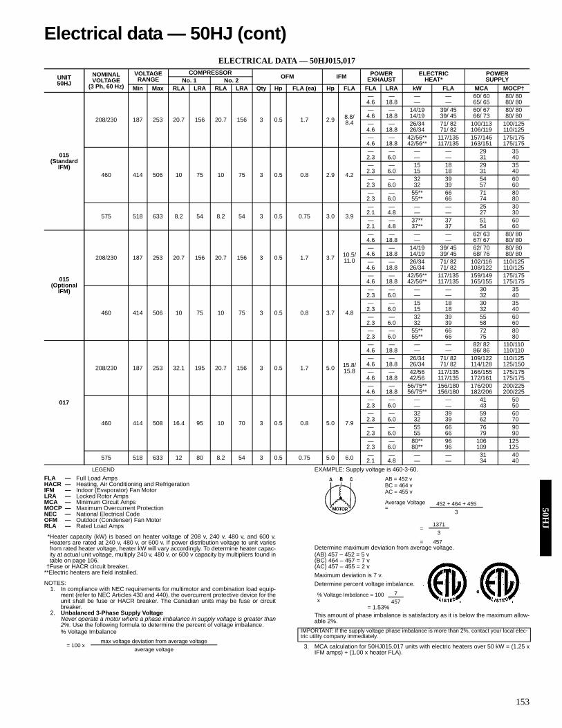
153
ELECTRICAL DATA — 50HJ015,017
LEGEND
*Heater capacity (kW) is based on heater voltage of 208 v, 240 v, 480 v, and 600 v.Heaters are rated at 240 v, 480 v, or 600 v. If power distribution voltage to unit variesfrom rated heater voltage, heater kW will vary accordingly. To determine heater capac-ity at actual unit voltage, multiply 240 v, 480 v, or 600 v capacity by multipliers found intable on page 106.
†Fuse or HACR circuit breaker.**Electric heaters are field installed.
NOTES:1. In compliance with NEC requirements for multimotor and combination load equip-
ment (refer to NEC Articles 430 and 440), the overcurrent protective device for theunit shall be fuse or HACR breaker. The Canadian units may be fuse or circuitbreaker.
2. Unbalanced 3-Phase Supply VoltageNever operate a motor where a phase imbalance in supply voltage is greater than2%. Use the following formula to determine the percent of voltage imbalance.% Voltage Imbalance
EXAMPLE: Supply voltage is 460-3-60.
Determine maximum deviation from average voltage.(AB) 457 – 452 = 5 v(BC) 464 – 457 = 7 v(AC) 457 – 455 = 2 vMaximum deviation is 7 v.Determine percent voltage imbalance.
= 1.53%This amount of phase imbalance is satisfactory as it is below the maximum allow-able 2%.
3. MCA calculation for 50HJ015,017 units with electric heaters over 50 kW = (1.25 xIFM amps) + (1.00 x heater FLA).
UNIT50HJ
NOMINALVOLTAGE
(3 Ph, 60 Hz)
VOLTAGERANGE
COMPRESSOR OFM IFM POWEREXHAUST
ELECTRICHEAT*
POWERSUPPLYNo. 1 No. 2
Min Max RLA LRA RLA LRA Qty Hp FLA (ea) Hp FLA FLA LRA kW FLA MCA MOCP†
015(Standard
IFM)
208/230 187 253 20.7 156 20.7 156 3 0.5 1.7 2.9 8.8/8.4
— — — — 60/ 60 80/ 804.6 18.8 — — 65/ 65 80/ 80— — 14/19 39/ 45 60/ 67 80/ 804.6 18.8 14/19 39/ 45 66/ 73 80/ 80— — 26/34 71/ 82 100/113 100/1254.6 18.8 26/34 71/ 82 106/119 110/125— — 42/56** 117/135 157/146 175/1754.6 18.8 42/56** 117/135 163/151 175/175
460 414 506 10 75 10 75 3 0.5 0.8 2.9 4.2
— — — — 29 352.3 6.0 — — 31 40— — 15 18 29 352.3 6.0 15 18 31 40— — 32 39 54 602.3 6.0 32 39 57 60— — 55** 66 71 802.3 6.0 55** 66 74 80
575 518 633 8.2 54 8.2 54 3 0.5 0.75 3.0 3.9— — — — 25 302.1 4.8 — — 27 30— — 37** 37 51 602.1 4.8 37** 37 54 60
015(Optional
IFM)
208/230 187 253 20.7 156 20.7 156 3 0.5 1.7 3.7 10.5/ 11.0
— — — — 62/ 63 80/ 804.6 18.8 — — 67/ 67 80/ 80— — 14/19 39/ 45 62/ 70 80/ 804.6 18.8 14/19 39/ 45 68/ 76 80/ 80— — 26/34 71/ 82 102/116 110/1254.6 18.8 26/34 71/ 82 108/122 110/125— — 42/56** 117/135 159/149 175/1754.6 18.8 42/56** 117/135 165/155 175/175
460 414 506 10 75 10 75 3 0.5 0.8 3.7 4.8
— — — — 30 352.3 6.0 — — 32 40— — 15 18 30 352.3 6.0 15 18 32 40— — 32 39 55 602.3 6.0 32 39 58 60— — 55** 66 72 802.3 6.0 55** 66 75 80
017
208/230 187 253 32.1 195 20.7 156 3 0.5 1.7 5.0 15.8/15.8
— — — — 82/ 82 110/1104.6 18.8 — — 86/ 86 110/110— — 26/34 71/ 82 109/122 110/1254.6 18.8 26/34 71/ 82 114/128 125/150— — 42/56 117/135 166/155 175/1754.6 18.8 42/56 117/135 172/161 175/175— — 56/75** 156/180 176/200 200/2254.6 18.8 56/75** 156/180 182/206 200/225
460 414 508 16.4 95 10 70 3 0.5 0.8 5.0 7.9
— — — — 41 502.3 6.0 — — 43 50— — 32 39 59 602.3 6.0 32 39 62 70— — 55 66 76 902.3 6.0 55 66 79 90— — 80** 96 106 1252.3 6.0 80** 96 109 125
575 518 633 12 80 8.2 54 3 0.5 0.75 5.0 6.0 — — — — 31 402.1 4.8 — — 34 40
FLA — Full Load AmpsHACR — Heating, Air Conditioning and RefrigerationIFM — Indoor (Evaporator) Fan MotorLRA — Locked Rotor AmpsMCA — Minimum Circuit AmpsMOCP — Maximum Overcurrent ProtectionNEC — National Electrical CodeOFM — Outdoor (Condenser) Fan MotorRLA — Rated Load Amps
= 100 xmax voltage deviation from average voltage
average voltage
AB = 452 vBC = 464 vAC = 455 v
Average Voltage =
452 + 464 + 4553
=1371
3
= 457
% Voltage Imbalance = 100 x
7457
IMPORTANT: If the supply voltage phase imbalance is more than 2%, contact your local elec-tric utility company immediately.
Electrical data — 50HJ (cont)50H
J

154
ELECTRICAL DATA — 50HJ020-028
LEGEND
*Fuse or HACR circuit breaker.†208/230 v 75-kW Electric Heat units must use dual-point wiring. The main table lists the
branch circuit values for the refrigeration part of the system. The following two tables list thebranch circuit values for the electric heat and values for a feeder circuit for both branch cir-cuits.
NOTES:1. In compliance with NEC requirements for multimotor and combination load equipment (refer
to NEC Articles 430 and 440), the overcurrent protective device for the unit shall be fuse orHACR breaker. Canadian units may be fuse or circuit breaker.
2. Unbalanced 3-Phase Supply VoltageNever operate a motor where a phase imbalance in supply voltage is greater than 2%. Usethe following formula to determine the percent of voltage imbalance.% Voltage Imbalance
Example: Supply voltage is 460-3-60.AB = 452 vBC = 464 vAC = 455 v
Determine maximum deviation from average voltage. (AB) 457 – 452 = 5 v(BC) 464 – 457 = 7 v (AC) 457 – 455 = 2 v
Maximum deviation is 7 v.Determine percent of voltage imbalance.
% Voltage Imbalance = 100 x
= 1.53%This amount of phase imbalance is satisfactory as it is below the maximum allowable 2%.
3. The 75-kW 208/240-v electric heat can be factory installed but it must be wired separately inthe field.
4. The convenience outlet full load amps (FLA) are 5, 3 and 3 for 208/230, 460, 575-v units,respectively.
5. The FLA load amps provided in the table for electric heaters are based on 208/240, 480 and600 v.
6. MCA calculation for 50HJ units with electric heaters over 50 kW is = 1.25 x (IFM + PowerExhaust + Convenience Outlet FLA amps) + 1.00 x (Electric Heater FLA).
UNIT SIZE50HJ
NOMINAL VOLTAGE
(3 Ph, 60 Hz)
VOLTAGE RANGE
COMPRESSOR OFM ELECTRIC HEAT IFM POWER
EXHAUSTPOWER SUPPLY
DISCONNECT SIZENo. 1 No. 2 No. 3
Min Max RLA LRA RLA LRA RLA LRA Qty Hp FLA (ea) kW FLA Hp FLA Qty Hp FLA
(ea) MCA MOCP* FLA
020
208/230 187 253 16.7 130 16.7 130 22.4 184 4 0.25 1.5
— —
3.7 10.6/9.6 — — — 78/ 77 100/ 90 83/ 822 1 5.9 90/ 89 100/100 97/ 96
5 16.7/15.2— — — 84/ 83 100/100 90/ 892 1 5.9 96/ 94 100/100 104/102
7.5 24.2/22— — — 92/ 89 100/100 99/ 962 1 5.9 104/101 125/110 112/110
19/25 52/ 60
3.7 10.6/9.6— — — 78/ 87 100/ 90 83/ 822 1 5.9 93/102 100/110 97/ 96
5 16.7/15.2 — — — 86/ 94 100/100 90/ 892 1 5.9 101/109 110/110 104/102
7.5 24.2/22— — — 95/103 100/110 99/ 962 1 5.9 110/117 125/125 112/110
38/50 104/120
3.7 10.6/9.6— — — 143/132 150/150 132/1492 1 5.9 158/147 175/150 145/163
5 16.7/15.2 — — — 151/139 175/150 139/1552 1 5.9 166/154 175/175 152/169
7.5 24.2/22— — — 160/148 175/150 147/1632 1 5.9 175/162 200/175 161/177
56/75† 156/180
3.7 10.6/9.6— — — 78/ 77 100/ 90 83/ 822 1 5.9 90/ 89 100/100 97/ 96
5 16.7/15.2 — — — 84/ 83 100/100 90/ 892 1 5.9 96/ 94 100/100 104/102
7.5 24.2/22— — — 92/ 89 100/100 99/ 962 1 5.9 104/101 125/110 112/110
460 414 506 9 70 9 70 10.7 90 4 0.25 0.7
— —
3.7 4.8— — — 39 45 422 1 3.1 45 50 49
5 7.6 — — — 42 50 452 1 3.1 48 50 52
7.5 11— — — 45 50 492 1 3.1 51 60 56
25 30
3.7 4.8— — — 44 45 422 1 3.1 51 60 49
5 7.6 — — — 47 50 452 1 3.1 55 60 52
7.5 11— — — 51 60 492 1 3.1 59 60 56
50 60
3.7 4.8— — — 66 80 752 1 3.1 74 80 82
5 7.6 — — — 70 80 782 1 3.1 77 80 85
7.5 11— — — 74 80 822 1 3.1 82 90 89
75 90
3.7 4.8— — — 96 100 1092 1 3.1 104 110 116
5 7.6 — — — 100 110 1122 1 3.1 107 125 119
7.5 11— — — 104 125 1162 1 3.1 112 125 123
FLA — Full Load Amps MCA — Minimum Circuit AmpsHACR — Heating, Air Conditioning and MOCP — Maximum Overcurrent Protection
Refrigeration NEC — National Electrical CodeIFM — Indoor (Evaporator) Fan Motor OFM — Outdoor (Condenser) Fan MotorLRA — Locked Rotor Amps RLA — Rated Load Amps
= 100 x
max voltage deviation from average volt-age
average voltage
Average Volt-age =
452 + 464 + 455
3
=137
13
= 457
IMPORTANT: If the supply voltage phase imbalance is more than 2%, contact yourlocal electric utility company immediately.
7457
50H
J

155
ELECTRICAL DATA — 50HJ020-028 (cont)
ELECTRIC HEAT BRANCH CIRCUIT 208/240 75-kW ELECTRIC HEAT†
FEEDER CIRCUIT FOR 208/230 UNIT WITH 75-kW ELECTRIC HEAT†
LEGEND
*Fuse or HACR circuit breaker.†208/230 v 75-kW Electric Heat units must use dual-point wiring. The main table lists the
branch circuit values for the refrigeration part of the system. The following two tables list thebranch circuit values for the electric heat and values for a feeder circuit for both branch cir-cuits.
NOTES:1. In compliance with NEC requirements for multimotor and combination load equipment (refer
to NEC Articles 430 and 440), the overcurrent protective device for the unit shall be fuse orHACR breaker. Canadian units may be fuse or circuit breaker.
2. Unbalanced 3-Phase Supply VoltageNever operate a motor where a phase imbalance in supply voltage is greater than 2%. Usethe following formula to determine the percent of voltage imbalance.% Voltage Imbalance
Example: Supply voltage is 460-3-60.AB = 452 vBC = 464 vAC = 455 v
Determine maximum deviation from average voltage. (AB) 457 – 452 = 5 v(BC) 464 – 457 = 7 v (AC) 457 – 455 = 2 v
Maximum deviation is 7 v.Determine percent of voltage imbalance.
% Voltage Imbalance = 100 x
= 1.53%This amount of phase imbalance is satisfactory as it is below the maximum allowable 2%.
3. The 75-kW 208/240-v electric heat can be factory installed but it must be wired separately inthe field.
4. The convenience outlet full load amps (FLA) are 5, 3 and 3 for 208/230, 460, 575-v units,respectively.
5. The FLA load amps provided in the table for electric heaters are based on 208/240, 480 and600 v.
6. MCA calculation for 50HJ units with electric heaters over 50 kW is = 1.25 x (IFM + PowerExhaust + Convenience Outlet FLA amps) + 1.00 x (Electric Heater FLA).
UNIT SIZE50HJ
NOMINAL VOLTAGE
(3 Ph, 60 Hz)
VOLTAGE RANGE
COMPRESSOR OFM ELECTRIC HEAT IFM POWER
EXHAUSTPOWER SUPPLY
DISCONNECT SIZENo. 1 No. 2 No. 3
Min Max RLA LRA RLA LRA RLA LRA Qty Hp FLA (ea) kW FLA Hp FLA Qty Hp FLA
(ea) MCA MOCP* FLA
020 575 518 633 7 55 7 55 9.3 73 4 0.25 0.7
— —
3 3.9— — — 32 40 352 1 2.4 37 45 40
5 6.1 — — — 35 40 372 1 2.4 39 45 43
7.5 9— — — 37 45 402 1 2.4 42 50 46
24.8 24
3 3.9— — — 35 40 352 1 2.4 41 45 40
5 6.1 — — — 38 40 372 1 2.4 44 45 43
7.5 9— — — 41 45 402 1 2.4 47 50 46
48.3 46
3 3.9— — — 62 70 572 1 2.4 68 70 63
5 6.1 — — — 65 70 602 1 2.4 71 80 65
7.5 9— — — 69 70 632 1 2.4 75 80 69
78 75
3 3.9— — — 80 90 912 1 2.4 86 90 96
5 6.1 — — — 83 90 932 1 2.4 89 100 99
7.5 9— — — 86 100 972 1 2.4 92 100 102
UNIT SIZE50HJ
NOMINAL VOLTAGE
(3 Ph, 60 Hz)
VOLTAGE RANGE
COMPRESSOR OFM ELECTRIC HEAT IFM POWER
EXHAUSTPOWER SUPPLY
DISCONNECT SIZENo. 1 No. 2 No. 3
Min Max RLA LRA RLA LRA RLA LRA Qty Hp FLA (ea) kW FLA Hp FLA Qty Hp FLA
(ea) MCA MOCP* FLA
020 208/240 187 253 — — — — — — — — — 56/75 156/180 — — — — — 156/180 175/200 179/207
UNIT SIZE50HJ
NOMINAL VOLTAGE
(3 Ph, 60 Hz)
VOLTAGE RANGE
COMPRESSOR OFM ELECTRIC HEAT IFM POWER
EXHAUSTPOWER SUPPLY
DISCONNECT SIZENo. 1 No. 2 No. 3
Min Max RLA LRA RLA LRA RLA LRA Qty Hp FLA (ea) kW FLA Hp FLA Qty Hp FLA
(ea) MCA MOCP* FLA
020 208/230 187 253 16.7 130 16.7 130 22.4 184 4 0.25 1.5 56/75 156/180
3.7 10.6/ 9.6— — — 169/192 200/225 192/2182 1 5.9 184/207 200/225 205/232
5 16.7/15.2 — — — 177/199 200/225 199/2242 1 5.9 192/214 200/225 212/238
7.5 24.2/22.0— — — 186/208 200/225 207/2322 1 5.9 201/222 225/225 221/246
FLA — Full Load Amps MCA — Minimum Circuit AmpsHACR — Heating, Air Conditioning and MOCP — Maximum Overcurrent Protection
Refrigeration NEC — National Electrical CodeIFM — Indoor (Evaporator) Fan Motor OFM — Outdoor (Condenser) Fan MotorLRA — Locked Rotor Amps RLA — Rated Load Amps
= 100 x
max voltage deviation from average volt-age
average voltage
Average Volt-age =
452 + 464 + 455
3
=137
13
= 457
IMPORTANT: If the supply voltage phase imbalance is more than 2%, contact yourlocal electric utility company immediately.
7457
Electrical data — 50HJ (cont)50H
J
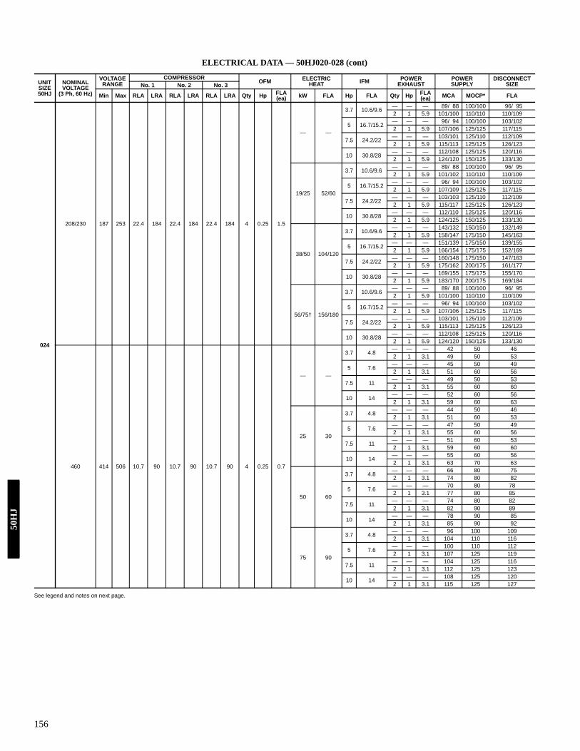
156
ELECTRICAL DATA — 50HJ020-028 (cont)
See legend and notes on next page.
UNIT SIZE50HJ
NOMINAL VOLTAGE
(3 Ph, 60 Hz)
VOLTAGE RANGE
COMPRESSOR OFM ELECTRIC HEAT IFM POWER
EXHAUSTPOWER SUPPLY
DISCONNECT SIZENo. 1 No. 2 No. 3
Min Max RLA LRA RLA LRA RLA LRA Qty Hp FLA (ea) kW FLA Hp FLA Qty Hp FLA
(ea) MCA MOCP* FLA
024
208/230 187 253 22.4 184 22.4 184 22.4 184 4 0.25 1.5
— —
3.7 10.6/9.6 — — — 89/ 88 100/100 96/ 952 1 5.9 101/100 110/110 110/109
5 16.7/15.2— — — 96/ 94 100/100 103/1022 1 5.9 107/106 125/125 117/115
7.5 24.2/22— — — 103/101 125/110 112/1092 1 5.9 115/113 125/125 126/123
10 30.8/28— — — 112/108 125/125 120/1162 1 5.9 124/120 150/125 133/130
19/25 52/60
3.7 10.6/9.6 — — — 89/ 88 100/100 96/ 952 1 5.9 101/102 110/110 110/109
5 16.7/15.2— — — 96/ 94 100/100 103/1022 1 5.9 107/109 125/125 117/115
7.5 24.2/22— — — 103/103 125/110 112/1092 1 5.9 115/117 125/125 126/123
10 30.8/28 — — — 112/110 125/125 120/1162 1 5.9 124/125 150/125 133/130
38/50 104/120
3.7 10.6/9.6— — — 143/132 150/150 132/1492 1 5.9 158/147 175/150 145/163
5 16.7/15.2— — — 151/139 175/150 139/1552 1 5.9 166/154 175/175 152/169
7.5 24.2/22 — — — 160/148 175/150 147/1632 1 5.9 175/162 200/175 161/177
10 30.8/28— — — 169/155 175/175 155/1702 1 5.9 183/170 200/175 169/184
56/75† 156/180
3.7 10.6/9.6— — — 89/ 88 100/100 96/ 952 1 5.9 101/100 110/110 110/109
5 16.7/15.2 — — — 96/ 94 100/100 103/1022 1 5.9 107/106 125/125 117/115
7.5 24.2/22— — — 103/101 125/110 112/1092 1 5.9 115/113 125/125 126/123
10 30.8/28— — — 112/108 125/125 120/1162 1 5.9 124/120 150/125 133/130
460 414 506 10.7 90 10.7 90 10.7 90 4 0.25 0.7
— —
3.7 4.8 — — — 42 50 462 1 3.1 49 50 53
5 7.6— — — 45 50 492 1 3.1 51 60 56
7.5 11— — — 49 50 532 1 3.1 55 60 60
10 14 — — — 52 60 562 1 3.1 59 60 63
25 30
3.7 4.8— — — 44 50 462 1 3.1 51 60 53
5 7.6— — — 47 50 492 1 3.1 55 60 56
7.5 11 — — — 51 60 532 1 3.1 59 60 60
10 14— — — 55 60 562 1 3.1 63 70 63
50 60
3.7 4.8— — — 66 80 752 1 3.1 74 80 82
5 7.6 — — — 70 80 782 1 3.1 77 80 85
7.5 11— — — 74 80 822 1 3.1 82 90 89
10 14— — — 78 90 852 1 3.1 85 90 92
75 90
3.7 4.8 — — — 96 100 1092 1 3.1 104 110 116
5 7.6— — — 100 110 1122 1 3.1 107 125 119
7.5 11— — — 104 125 1162 1 3.1 112 125 123
10 14 — — — 108 125 1202 1 3.1 115 125 127
50H
J

157
ELECTRICAL DATA — 50HJ020-028 (cont)
ELECTRIC HEAT BRANCH CIRCUIT 208/240 75-kW ELECTRIC HEAT†
FEEDER CIRCUIT FOR 208/230 UNIT WITH 75-kW ELECTRIC HEAT†
LEGEND
*Fuse or HACR circuit breaker.†208/230 v 75-kW Electric Heat units must use dual-point wiring. The main table lists the
branch circuit values for the refrigeration part of the system. The following two tables list thebranch circuit values for the electric heat and values for a feeder circuit for both branch cir-cuits.
NOTES:1. In compliance with NEC requirements for multimotor and combination load equipment (refer
to NEC Articles 430 and 440), the overcurrent protective device for the unit shall be fuse orHACR breaker. Canadian units may be fuse or circuit breaker.
2. Unbalanced 3-Phase Supply VoltageNever operate a motor where a phase imbalance in supply voltage is greater than 2%. Usethe following formula to determine the percent of voltage imbalance.% Voltage Imbalance
Example: Supply voltage is 460-3-60.AB = 452 vBC = 464 vAC = 455 v
Determine maximum deviation from average voltage. (AB) 457 – 452 = 5 v(BC) 464 – 457 = 7 v (AC) 457 – 455 = 2 v
Maximum deviation is 7 v.Determine percent of voltage imbalance.
% Voltage Imbalance = 100 x
= 1.53%This amount of phase imbalance is satisfactory as it is below the maximum allowable 2%.
3. The 75-kW 208/240-v electric heat can be factory installed but it must be wired separately inthe field.
4. The convenience outlet full load amps (FLA) are 5, 3 and 3 for 208/230, 460, 575-v units,respectively.
5. The FLA load amps provided in the table for electric heaters are based on 208/240, 480 and600 v.
6. MCA calculation for 50HJ units with electric heaters over 50 kW is = 1.25 x (IFM + PowerExhaust + Convenience Outlet FLA amps) + 1.00 x (Electric Heater FLA).
UNIT SIZE50HJ
NOMINAL VOLTAGE
(3 Ph, 60 Hz)
VOLTAGE RANGE
COMPRESSOR OFM ELECTRIC HEAT IFM POWER
EXHAUSTPOWER SUPPLY
DISCONNECT SIZENo. 1 No. 2 No. 3
Min Max RLA LRA RLA LRA RLA LRA Qty Hp FLA (ea) kW FLA Hp FLA Qty Hp FLA
(ea) MCA MOCP* FLA
024 575 518 633 9.3 73 9.3 73 9.3 73 4 0.25 0.7
— —
5 6.1— — — 39 45 422 1 2.4 44 50 48
7.5 9 — — — 42 50 462 1 2.4 47 50 51
10 11— — — 44 50 482 1 2.4 49 60 53
24.8 24
5 6.1— — — 39 45 422 1 2.4 44 50 48
7.5 9 — — — 42 50 462 1 2.4 47 50 51
10 11— — — 44 50 482 1 2.4 50 60 53
48.3 46
5 6.1— — — 65 70 602 1 2.4 71 80 65
7.5 9 — — — 69 70 632 1 2.4 75 80 69
10 11— — — 71 80 662 1 2.4 77 80 71
78 75
5 6.1— — — 83 90 932 1 2.4 89 100 99
7.5 9 — — — 86 100 972 1 2.4 92 100 102
10 11— — — 89 100 992 1 2.4 95 100 104
UNIT SIZE50HJ
NOMINAL VOLTAGE
(3 Ph, 60 Hz)
VOLTAGE RANGE
COMPRESSOR OFM ELECTRIC HEAT IFM POWER
EXHAUSTPOWER SUPPLY
DISCONNECT SIZENo. 1 No. 2 No. 3
Min Max RLA LRA RLA LRA RLA LRA Qty Hp FLA (ea) kW FLA Hp FLA Qty Hp FLA
(ea) MCA MOCP* FLA
024 208/240 187 253 — — — — — — — — — 56/75 156/180 — — — — — 156/180 175/200 179/207
UNIT SIZE50HJ
NOMINAL VOLTAGE
(3 Ph, 60 Hz)
VOLTAGE RANGE
COMPRESSOR OFM ELECTRIC HEAT IFM POWER
EXHAUSTPOWER SUPPLY
DISCONNECT SIZENo. 1 No. 2 No. 3
Min Max RLA LRA RLA LRA RLA LRA Qty Hp FLA (ea) kW FLA Hp FLA Qty Hp FLA
(ea) MCA MOCP* FLA
024 208/230 187 253 22.4 184 22.4 184 22.4 184 4 0.25 1.5 56/75 156/180
3.7 10.6/9.6— — — 169/192 200/225 192/2182 1 5.9 184/207 200/225 205/232
5 16.7/15.2 — — — 177/199 200/225 199/2242 1 5.9 192/214 200/225 212/238
7.5 24.2/22— — — 186/208 200/225 207/2322 1 5.9 201/222 225/225 221/246
10 30.8/28— — — 195/215 225/225 215/2392 1 5.9 209/230 225/250 228/253
FLA — Full Load Amps MCA — Minimum Circuit AmpsHACR — Heating, Air Conditioning and MOCP — Maximum Overcurrent Protection
Refrigeration NEC — National Electrical CodeIFM — Indoor (Evaporator) Fan Motor OFM — Outdoor (Condenser) Fan MotorLRA — Locked Rotor Amps RLA — Rated Load Amps
= 100 x
max voltage deviation from average volt-age
average voltage
Average Volt-age =
452 + 464 + 455
3
=137
13
= 457
IMPORTANT: If the supply voltage phase imbalance is more than 2%, contact yourlocal electric utility company immediately.
7457
Electrical data — 50HJ (cont)50H
J

158
ELECTRICAL DATA — 50HJ020-028 (cont)
LEGEND
*Fuse or HACR circuit breaker.†208/230 v 75-kW Electric Heat units must use dual-point wiring. The main table lists the
branch circuit values for the refrigeration part of the system. The following two tables list thebranch circuit values for the electric heat and values for a feeder circuit for both branch cir-cuits.
NOTES:1. In compliance with NEC requirements for multimotor and combination load equipment (refer
to NEC Articles 430 and 440), the overcurrent protective device for the unit shall be fuse orHACR breaker. Canadian units may be fuse or circuit breaker.
2. Unbalanced 3-Phase Supply VoltageNever operate a motor where a phase imbalance in supply voltage is greater than 2%. Usethe following formula to determine the percent of voltage imbalance.% Voltage Imbalance
Example: Supply voltage is 460-3-60.AB = 452 vBC = 464 vAC = 455 v
Determine maximum deviation from average voltage. (AB) 457 – 452 = 5 v(BC) 464 – 457 = 7 v (AC) 457 – 455 = 2 v
Maximum deviation is 7 v.Determine percent of voltage imbalance.
% Voltage Imbalance = 100 x
= 1.53%This amount of phase imbalance is satisfactory as it is below the maximum allowable 2%.
3. The 75-kW 208/240-v electric heat can be factory installed but it must be wired separately inthe field.
4. The convenience outlet full load amps (FLA) are 5, 3 and 3 for 208/230, 460, 575-v units,respectively.
5. The FLA load amps provided in the table for electric heaters are based on 208/240, 480 and600 v.
6. MCA calculation for 50HJ units with electric heaters over 50 kW is = 1.25 x (IFM + PowerExhaust + Convenience Outlet FLA amps) + 1.00 x (Electric Heater FLA).
UNIT SIZE50HJ
NOMINAL VOLTAGE
(3 Ph, 60 Hz)
VOLTAGE RANGE
COMPRESSOR OFM ELECTRIC HEAT IFM POWER
EXHAUSTPOWER SUPPLY
DISCONNECT SIZENo. 1 No. 2 No. 3
Min Max RLA LRA RLA LRA RLA LRA Qty Hp FLA (ea) kW FLA Hp FLA Qty Hp FLA
(ea) MCA MOCP* FLA
028
208/230 187 253 47.1 245 47.1 245 — — 6 0.25 1.5
— —
5 16.7/15.2 — — — 132/130 175/175 138/1362 1 5.9 143/142 175/175 151/150
7.5 24.2/22— — — 139/137 175/175 147/1442 1 5.9 151/149 175/175 160/158
10 30.8/28— — — 146/143 175/175 154/1512 1 5.9 158/155 200/200 168/164
19/25 52/60
5 16.7/15.2— — — 132/130 175/175 138/1362 1 5.9 143/142 175/175 151/150
7.5 24.2/22 — — — 139/137 175/175 147/1442 1 5.9 151/149 175/175 160/158
10 30.8/28— — — 146/143 175/175 154/1512 1 5.9 158/155 200/200 168/164
38/50 104/120
5 16.7/15.2— — — 151/139 175/175 139/1552 1 5.9 166/154 175/175 152/169
7.5 24.2/22 — — — 160/148 175/175 147/1632 1 5.9 175/162 200/175 161/177
10 30.8/28— — — 169/155 175/175 155/1702 1 5.9 183/170 200/200 169/184
56/75† 156/180
5 16.7/15.2— — — 132/130 175/175 138/1362 1 5.9 143/142 175/175 151/150
7.5 24.2/22 — — — 139/137 175/175 147/1442 1 5.9 151/149 175/175 160/158
10 30.8/28— — — 146/143 175/175 154/1512 1 5.9 158/155 200/200 168/164
460 414 506 19.6 125 19.6 125 — — 6 0.25 0.7
— —
5 7.6— — — 56 60 592 1 3.1 62 80 66
7.5 11 — — — 59 60 632 1 3.1 66 80 70
10 14— — — 62 80 662 1 3.1 69 80 73
25 30
5 7.6— — — 56 60 592 1 3.1 62 80 66
7.5 11 — — — 59 60 632 1 3.1 66 80 70
10 14— — — 62 80 662 1 3.1 69 80 73
50 60
5 7.6— — — 70 80 782 1 3.1 77 80 85
7.5 11 — — — 74 80 822 1 3.1 82 90 89
10 14— — — 78 90 852 1 3.1 85 90 92
75 90
5 7.6— — — 100 110 1122 1 3.1 107 125 119
7.5 11 — — — 104 125 1162 1 3.1 112 125 123
10 14— — — 108 125 1202 1 3.1 115 125 127
FLA — Full Load Amps MCA — Minimum Circuit AmpsHACR — Heating, Air Conditioning and MOCP — Maximum Overcurrent Protection
Refrigeration NEC — National Electrical CodeIFM — Indoor (Evaporator) Fan Motor OFM — Outdoor (Condenser) Fan MotorLRA — Locked Rotor Amps RLA — Rated Load Amps
= 100 x
max voltage deviation from average volt-age
average voltage
Average Volt-age =
452 + 464 + 455
3
=137
13
= 457
IMPORTANT: If the supply voltage phase imbalance is more than 2%, contact yourlocal electric utility company immediately.
7457
50H
J

159
ELECTRICAL DATA — 50HJ020-028 (cont)
ELECTRIC HEAT BRANCH CIRCUIT 208/240 75-kW ELECTRIC HEAT†
FEEDER CIRCUIT FOR 208/230 UNIT WITH 75-kW ELECTRIC HEAT†
LEGEND
*Fuse or HACR circuit breaker.†208/230 v 75-kW Electric Heat units must use dual-point wiring. The main table lists the
branch circuit values for the refrigeration part of the system. The following two tables list thebranch circuit values for the electric heat and values for a feeder circuit for both branch cir-cuits.
NOTES:1. In compliance with NEC requirements for multimotor and combination load equipment (refer
to NEC Articles 430 and 440), the overcurrent protective device for the unit shall be fuse orHACR breaker. Canadian units may be fuse or circuit breaker.
2. Unbalanced 3-Phase Supply VoltageNever operate a motor where a phase imbalance in supply voltage is greater than 2%. Usethe following formula to determine the percent of voltage imbalance.% Voltage Imbalance
Example: Supply voltage is 460-3-60.AB = 452 vBC = 464 vAC = 455 v
Determine maximum deviation from average voltage. (AB) 457 – 452 = 5 v(BC) 464 – 457 = 7 v (AC) 457 – 455 = 2 v
Maximum deviation is 7 v.Determine percent of voltage imbalance.
% Voltage Imbalance = 100 x
= 1.53%This amount of phase imbalance is satisfactory as it is below the maximum allowable 2%.
3. The 75-kW 208/240-v electric heat can be factory installed but it must be wired separately inthe field.
4. The convenience outlet full load amps (FLA) are 5, 3 and 3 for 208/230, 460, 575-v units,respectively.
5. The FLA load amps provided in the table for electric heaters are based on 208/240, 480 and600 v.
6. MCA calculation for 50HJ units with electric heaters over 50 kW is = 1.25 x (IFM + PowerExhaust + Convenience Outlet FLA amps) + 1.00 x (Electric Heater FLA).
UNIT SIZE50HJ
NOMINAL VOLTAGE
(3 Ph, 60 Hz)
VOLTAGE RANGE
COMPRESSOR OFM ELECTRIC HEAT IFM POWER
EXHAUSTPOWER SUPPLY
DISCONNECT SIZENo. 1 No. 2 No. 3
Min Max RLA LRA RLA LRA RLA LRA Qty Hp FLA (ea) kW FLA Hp FLA Qty Hp FLA
(ea) MCA MOCP* FLA
028 575 518 633 15.8 100 15.8 100 — — 6 0.25 0.7
— —
5 6.1— — — 46 60 482 1 2.4 51 60 54
7.5 9 — — — 49 60 522 1 2.4 54 60 57
10 11— — — 51 60 542 1 2.4 56 60 59
24.8 24
5 6.1— — — 46 60 482 1 2.4 51 60 54
7.5 9 — — — 49 60 522 1 2.4 54 60 57
10 11— — — 51 60 542 1 2.4 56 60 59
48.3 46
5 6.1— — — 65 70 602 1 2.4 71 80 65
7.5 9 — — — 69 70 632 1 2.4 75 80 69
10 11— — — 71 80 662 1 2.4 77 80 71
78 75
5 6.1— — — 83 90 932 1 2.4 89 100 99
7.5 9 — — — 86 100 972 1 2.4 92 100 102
10 11— — — 89 100 992 1 2.4 95 100 104
UNIT SIZE50HJ
NOMINAL VOLTAGE
(3 Ph, 60 Hz)
VOLTAGE RANGE
COMPRESSOR OFM ELECTRIC HEAT IFM POWER
EXHAUSTPOWER SUPPLY
DISCONNECT SIZENo. 1 No. 2 No. 3
Min Max RLA LRA RLA LRA RLA LRA Qty Hp FLA (ea) kW FLA Hp FLA Qty Hp FLA
(ea) MCA MOCP* FLA
028 208/240 187 253 — — — — — — — — — 56/75 156/180 — — — — — 156/180 175/200 179/207
UNIT SIZE50HJ
NOMINAL VOLTAGE
(3 Ph, 60 Hz)
VOLTAGE RANGE
COMPRESSOR OFM ELECTRIC HEAT IFM POWER
EXHAUSTPOWER SUPPLY
DISCONNECT SIZENo. 1 No. 2 No. 3
Min Max RLA LRA RLA LRA RLA LRA Qty Hp FLA (ea) kW FLA Hp FLA Qty Hp FLA
(ea) MCA MOCP* FLA
028 208/230 187 253 47.1 245 47.1 245 — — 6 0.25 1.5 56/75 156/180
5 16.7/15.2— — — 177/199 200/225 199/2242 1 5.9 192/214 200/225 212/238
7.5 24.2/22 — — — 186/208 200/225 207/2322 1 5.9 201/222 225/225 221/246
10 30.8/28— — — 195/215 225/225 215/2392 1 5.9 209/230 225/250 228/253
FLA — Full Load Amps MCA — Minimum Circuit AmpsHACR — Heating, Air Conditioning and MOCP — Maximum Overcurrent Protection
Refrigeration NEC — National Electrical CodeIFM — Indoor (Evaporator) Fan Motor OFM — Outdoor (Condenser) Fan MotorLRA — Locked Rotor Amps RLA — Rated Load Amps
= 100 x
max voltage deviation from average volt-age
average voltage
Average Volt-age =
452 + 464 + 455
3
=137
13
= 457
IMPORTANT: If the supply voltage phase imbalance is more than 2%, contact yourlocal electric utility company immediately.
7457
Electrical data — 50HJ (cont)50H
J

160
ELECTRICAL DATA — 50HJ020-028 WITH OPTIONAL CONVENIENCE OUTLET
LEGEND
*Fuse or HACR circuit breaker.†208/230 v 75-kW Electric Heat units must use dual-point wiring. The main table lists the
branch circuit values for the refrigeration part of the system. The following two tables list thebranch circuit values for the electric heat and values for a feeder circuit for both branch cir-cuits.
NOTES:1. In compliance with NEC requirements for multimotor and combination load equipment (refer
to NEC Articles 430 and 440), the overcurrent protective device for the unit shall be fuse orHACR breaker. Canadian units may be fuse or circuit breaker.
2. Unbalanced 3-Phase Supply VoltageNever operate a motor where a phase imbalance in supply voltage is greater than 2%. Usethe following formula to determine the percent of voltage imbalance.% Voltage Imbalance
Example: Supply voltage is 460-3-60.AB = 452 vBC = 464 vAC = 455 v
Determine maximum deviation from average voltage. (AB) 457 – 452 = 5 v(BC) 464 – 457 = 7 v (AC) 457 – 455 = 2 v
Maximum deviation is 7 v.Determine percent of voltage imbalance.
% Voltage Imbalance = 100 x
= 1.53%This amount of phase imbalance is satisfactory as it is below the maximum allowable 2%.
3. The 75-kW 208/240-v electric heat can be factory installed but it must be wired separately inthe field.
4. The convenience outlet full load amps (FLA) are 5, 3 and 3 for 208/230, 460, 575-v units,respectively.
5. The FLA load amps provided in the table for electric heaters are based on 208/240, 480 and600 v.
6. MCA calculation for 50HJ units with electric heaters over 50 kW is = 1.25 x (IFM + PowerExhaust + Convenience Outlet FLA amps) + 1.00 x (Electric Heater FLA).
UNIT SIZE50HJ
NOMINAL VOLTAGE
(3 Ph, 60 Hz)
VOLTAGE RANGE
COMPRESSOR OFM ELECTRIC HEAT IFM POWER
EXHAUSTPOWER SUPPLY
DISCONNECT SIZENo. 1 No. 2 No. 3
Min Max RLA LRA RLA LRA RLA LRA Qty Hp FLA (ea) kW FLA Hp FLA Qty Hp FLA
(ea) MCA MOCP* FLA
020
208/230 187 253 16.7 130 16.7 130 22.4 184 4 0.25 1.5
— —
3.7 10.6/9.6 — — — 83/ 82 100/100 89/ 882 1 5.9 95/ 94 100/100 103/101
5 16.7/15.2— — — 89/ 88 100/100 96/ 942 1 5.9 101/ 99 110/100 110/108
7.5 24.2/22— — — 97/ 94 100/100 105/1022 1 5.9 109/106 125/125 118/116
19/25 52/60
3.7 10.6/9.6— — — 85/ 93 100/100 89/ 882 1 5.9 99/108 100/110 103/101
5 16.7/15.2 — — — 92/100 100/110 96/ 942 1 5.9 107/115 110/125 110/108
7.5 24.2/22— — — 102/109 110/110 105/1022 1 5.9 116/124 125/125 118/116
38/50 104/120
3.7 10.6/9.6— — — 150/138 150/150 138/1552 1 5.9 164/153 175/175 151/168
5 16.7/15.2 — — — 157/145 175/150 145/1612 1 5.9 172/160 175/175 158/175
7.5 24.2/22— — — 167/154 175/175 153/1692 1 5.9 181/169 200/175 167/183
56/75† 156/180
3.7 10.6/9.6— — — 83/ 82 100/100 89/ 882 1 5.9 95/ 94 100/100 103/101
5 16.7/15.2 — — — 89/ 88 100/100 96/ 942 1 5.9 101/ 99 110/100 110/108
7.5 24.2/22— — — 97/ 94 100/100 105/1022 1 5.9 109/106 125/125 118/116
460 414 506 9 70 9 70 10.7 90 4 0.25 0.7
— —
3.7 4.8— — — 42 50 452 1 3.1 48 50 52
5 7.6 — — — 45 50 482 1 3.1 51 60 56
7.5 11— — — 48 50 522 1 3.1 54 60 59
25 30
3.7 4.8— — — 47 50 452 1 3.1 55 60 52
5 7.6 — — — 51 60 482 1 3.1 59 60 56
7.5 11— — — 55 60 522 1 3.1 63 70 59
50 60
3.7 4.8— — — 70 80 782 1 3.1 78 80 85
5 7.6 — — — 73 80 812 1 3.1 81 90 88
7.5 11— — — 78 80 852 1 3.1 85 90 92
75 90
3.7 4.8— — — 100 110 1122 1 3.1 108 125 120
5 7.6 — — — 103 125 1162 1 3.1 111 125 123
7.5 11— — — 108 125 1202 1 3.1 115 125 127
FLA — Full Load Amps MCA — Minimum Circuit AmpsHACR — Heating, Air Conditioning and MOCP — Maximum Overcurrent Protection
Refrigeration NEC — National Electrical CodeIFM — Indoor (Evaporator) Fan Motor OFM — Outdoor (Condenser) Fan MotorLRA — Locked Rotor Amps RLA — Rated Load Amps
= 100 x
max voltage deviation from average volt-age
average voltage
Average Volt-age =
452 + 464 + 455
3
=137
13
= 457
IMPORTANT: If the supply voltage phase imbalance is more than 2%, contact yourlocal electric utility company immediately.
7457
50H
J

161
ELECTRICAL DATA — 50HJ020-028 WITH OPTIONAL CONVENIENCE OUTLET
ELECTRIC HEAT BRANCH CIRCUIT 208/240 75-kW ELECTRIC HEAT†
FEEDER CIRCUIT FOR 208/230 UNIT WITH 75-kW ELECTRIC HEAT†
LEGEND
*Fuse or HACR circuit breaker.†208/230 v 75-kW Electric Heat units must use dual-point wiring. The main table lists the
branch circuit values for the refrigeration part of the system. The following two tables list thebranch circuit values for the electric heat and values for a feeder circuit for both branch cir-cuits.
NOTES:1. In compliance with NEC requirements for multimotor and combination load equipment (refer
to NEC Articles 430 and 440), the overcurrent protective device for the unit shall be fuse orHACR breaker. Canadian units may be fuse or circuit breaker.
2. Unbalanced 3-Phase Supply VoltageNever operate a motor where a phase imbalance in supply voltage is greater than 2%. Usethe following formula to determine the percent of voltage imbalance.% Voltage Imbalance
Example: Supply voltage is 460-3-60.AB = 452 vBC = 464 vAC = 455 v
Determine maximum deviation from average voltage. (AB) 457 – 452 = 5 v(BC) 464 – 457 = 7 v (AC) 457 – 455 = 2 v
Maximum deviation is 7 v.Determine percent of voltage imbalance.
% Voltage Imbalance = 100 x
= 1.53%This amount of phase imbalance is satisfactory as it is below the maximum allowable 2%.
3. The 75-kW 208/240-v electric heat can be factory installed but it must be wired separately inthe field.
4. The convenience outlet full load amps (FLA) are 5, 3 and 3 for 208/230, 460, 575-v units,respectively.
5. The FLA load amps provided in the table for electric heaters are based on 208/240, 480 and600 v.
6. MCA calculation for 50HJ units with electric heaters over 50 kW is = 1.25 x (IFM + PowerExhaust + Convenience Outlet FLA amps) + 1.00 x (Electric Heater FLA).
UNIT SIZE50HJ
NOMINAL VOLTAGE
(3 Ph, 60 Hz)
VOLTAGE RANGE
COMPRESSOR OFM ELECTRIC HEAT IFM POWER
EXHAUSTPOWER SUPPLY
DISCONNECT SIZENo. 1 No. 2 No. 3
Min Max RLA LRA RLA LRA RLA LRA Qty Hp FLA (ea) kW FLA Hp FLA Qty Hp FLA
(ea) MCA MOCP* FLA
020 575 518 633 7 55 7 55 9.3 73 4 0.25 0.7
— —
3 3.9 — — — 35 40 382 1 2.4 40 45 43
5 6.1 — — — 38 45 402 1 2.4 42 50 46
7.5 9 — — — 40 45 442 1 2.4 45 50 49
24.8 24
3 3.9 — — — 39 40 382 1 2.4 45 45 43
5 6.1 — — — 41 45 402 1 2.4 47 50 46
7.5 9 — — — 45 50 442 1 2.4 51 60 49
48.3 46
3 3.9 — — — 66 70 612 1 2.4 72 80 66
5 6.1 — — — 69 70 632 1 2.4 75 80 69
7.5 9 — — — 73 80 672 1 2.4 79 80 72
78 75
3 3.9 — — — 84 90 942 1 2.4 90 100 100
5 6.1 — — — 86 100 972 1 2.4 92 100 102
7.5 9 — — — 90 100 1002 1 2.4 96 100 106
UNIT SIZE50HJ
NOMINAL VOLTAGE
(3 Ph, 60 Hz)
VOLTAGE RANGE
COMPRESSOR OFM ELECTRIC HEAT IFM POWER
EXHAUSTPOWER SUPPLY
DISCONNECT SIZENo. 1 No. 2 No. 3
Min Max RLA LRA RLA LRA RLA LRA Qty Hp FLA (ea) kW FLA Hp FLA Qty Hp FLA
(ea) MCA MOCP* FLA020 208/240 187 253 — — — — — — — — — 56/75 156/180 — — — — — 156/180 175/200 179/207
UNIT SIZE50HJ
NOMINAL VOLTAGE
(3 Ph, 60 Hz)
VOLTAGE RANGE
COMPRESSOR OFM ELECTRIC HEAT IFM POWER
EXHAUSTPOWER SUPPLY
DISCONNECT SIZENo. 1 No. 2 No. 3
Min Max RLA LRA RLA LRA RLA LRA Qty Hp FLA (ea) kW FLA Hp FLA Qty Hp FLA
(ea) MCA MOCP* FLA
020 208/230 187 253 16.7 130 16.7 130 22.4 184 4 0.25 1.5 56/75 156/180
3.7 10.6/9.6 — — — 176/198 200/225 197/2242 1 5.9 190/213 200/225 211/237
5 16.7/15.2 — — — 183/205 200/225 204/2302 1 5.9 198/220 200/225 218/244
7.5 24.2/22 — — — 193/214 200/225 213/2382 1 5.9 207/229 225/250 227/252
FLA — Full Load Amps MCA — Minimum Circuit AmpsHACR — Heating, Air Conditioning and MOCP — Maximum Overcurrent Protection
Refrigeration NEC — National Electrical CodeIFM — Indoor (Evaporator) Fan Motor OFM — Outdoor (Condenser) Fan MotorLRA — Locked Rotor Amps RLA — Rated Load Amps
= 100 x
max voltage deviation from average volt-age
average voltage
Average Volt-age =
452 + 464 + 455
3
=137
13
= 457
IMPORTANT: If the supply voltage phase imbalance is more than 2%, contact yourlocal electric utility company immediately.
7457
Electrical data — 50HJ (cont)50H
J

162
ELECTRICAL DATA — 50HJ020-028 WITH OPTIONAL CONVENIENCE OUTLET (cont)
See legend and notes on next page.
UNIT SIZE50HJ
NOMINAL VOLTAGE
(3 Ph, 60 Hz)
VOLTAGE RANGE
COMPRESSOR OFM ELECTRIC HEAT IFM POWER
EXHAUSTPOWER SUPPLY
DISCONNECT SIZENo. 1 No. 2 No. 3
Min Max RLA LRA RLA LRA RLA LRA Qty Hp FLA (ea) kW FLA Hp FLA Qty Hp FLA
(ea) MCA MOCP* FLA
024
208/230 187 253 22.4 184 22.4 184 22.4 184 4 0.25 1.5
— —
3.7 10.6/9.6— — — 94 /93 100/100 102/1012 1 5.9 106/105 125/125 116/115
5 16.7/15.2— — — 101/ 99 110/100 109/1072 1 5.9 112/111 125/125 123/121
7.5 24.2/22 — — — 108/106 125/125 118/1152 1 5.9 120/118 125/125 131/129
10 30.8/28 — — — 117/113 125/125 125/1222 1 5.9 129/125 150/150 139/136
19/25 52/60
3.7 10.6/9.6— — — 94/ 93 100/100 102/1012 1 5.9 106/108 125/125 116/115
5 16.7/15.2— — — 101/100 110/110 109/1072 1 5.9 112/115 125/125 123/121
7.5 24.2/22 — — — 108/109 125/125 118/1152 1 5.9 120/124 125/125 131/129
10 30.8/28— — — 117/116 125/125 125/1222 1 5.9 129/131 150/150 139/136
38/50 104/120
3.7 10.6/9.6— — — 150/138 150/150 138/1552 1 5.9 164/153 175/175 151/168
5 16.7/15.2 — — — 157/145 175/150 145/1612 1 5.9 172/160 175/175 158/175
7.5 24.2/22— — — 167/154 175/175 153/1692 1 5.9 181/169 200/175 167/183
10 30.8/28— — — 175/161 175/175 161/1762 1 5.9 190/176 200/200 174/190
56/75† 156/180
3.7 10.6/9.6 — — — 94/ 93 100/100 102/1012 1 5.9 106/105 125/125 116/115
5 16.7/15.2— — — 101/ 99 110/100 109/1072 1 5.9 112/111 125/125 123/121
7.5 24.2/22— — — 108/106 125/125 118/1152 1 5.9 120/118 125/125 131/129
10 30.8/28 — — — 117/113 125/125 125/1222 1 5.9 129/125 150/150 139/136
460 414 506 10.7 90 10.7 90 10.7 90 4 0.25 0.7
— —
3.7 4.8— — — 45 50 492 1 3.1 52 60 56
5 7.6— — — 48 50 522 1 3.1 54 60 59
7.5 11 — — — 52 60 562 1 3.1 58 60 63
10 14— — — 55 60 602 1 3.1 62 70 67
25 30
3.7 4.8— — — 47 50 492 1 3.1 55 60 56
5 7.6 — — — 51 60 522 1 3.1 59 60 59
7.5 11— — — 55 60 562 1 3.1 63 70 63
10 14— — — 59 60 602 1 3.1 67 70 67
50 60
3.7 4.8 — — — 70 80 782 1 3.1 78 80 85
5 7.6— — — 73 80 812 1 3.1 81 90 88
7.5 11— — — 78 80 852 1 3.1 85 90 92
10 14 — — — 81 90 892 1 3.1 89 100 96
75 90
3.7 4.8— — — 100 110 1122 1 3.1 108 125 120
5 7.6— — — 103 125 1162 1 3.1 111 125 123
7.5 11 — — — 108 125 1202 1 3.1 115 125 127
10 14— — — 111 125 1232 1 3.1 119 125 130
50H
J
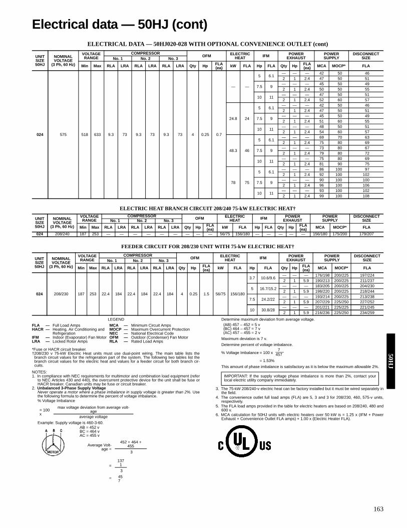
163
ELECTRICAL DATA — 50HJ020-028 WITH OPTIONAL CONVENIENCE OUTLET (cont)
ELECTRIC HEAT BRANCH CIRCUIT 208/240 75-kW ELECTRIC HEAT†
FEEDER CIRCUIT FOR 208/230 UNIT WITH 75-kW ELECTRIC HEAT†
LEGEND
*Fuse or HACR circuit breaker.†208/230 v 75-kW Electric Heat units must use dual-point wiring. The main table lists the
branch circuit values for the refrigeration part of the system. The following two tables list thebranch circuit values for the electric heat and values for a feeder circuit for both branch cir-cuits.
NOTES:1. In compliance with NEC requirements for multimotor and combination load equipment (refer
to NEC Articles 430 and 440), the overcurrent protective device for the unit shall be fuse orHACR breaker. Canadian units may be fuse or circuit breaker.
2. Unbalanced 3-Phase Supply VoltageNever operate a motor where a phase imbalance in supply voltage is greater than 2%. Usethe following formula to determine the percent of voltage imbalance.% Voltage Imbalance
Example: Supply voltage is 460-3-60.AB = 452 vBC = 464 vAC = 455 v
Determine maximum deviation from average voltage. (AB) 457 – 452 = 5 v(BC) 464 – 457 = 7 v (AC) 457 – 455 = 2 v
Maximum deviation is 7 v.Determine percent of voltage imbalance.
% Voltage Imbalance = 100 x
= 1.53%This amount of phase imbalance is satisfactory as it is below the maximum allowable 2%.
3. The 75-kW 208/240-v electric heat can be factory installed but it must be wired separately inthe field.
4. The convenience outlet full load amps (FLA) are 5, 3 and 3 for 208/230, 460, 575-v units,respectively.
5. The FLA load amps provided in the table for electric heaters are based on 208/240, 480 and600 v.
6. MCA calculation for 50HJ units with electric heaters over 50 kW is = 1.25 x (IFM + PowerExhaust + Convenience Outlet FLA amps) + 1.00 x (Electric Heater FLA).
UNIT SIZE50HJ
NOMINAL VOLTAGE
(3 Ph, 60 Hz)
VOLTAGE RANGE
COMPRESSOR OFM ELECTRIC HEAT IFM POWER
EXHAUSTPOWER SUPPLY
DISCONNECT SIZENo. 1 No. 2 No. 3
Min Max RLA LRA RLA LRA RLA LRA Qty Hp FLA (ea) kW FLA Hp FLA Qty Hp FLA
(ea) MCA MOCP* FLA
024 575 518 633 9.3 73 9.3 73 9.3 73 4 0.25 0.7
— —
5 6.1 — — — 42 50 462 1 2.4 47 50 51
7.5 9— — — 45 50 492 1 2.4 50 50 55
10 11— — — 47 50 512 1 2.4 52 60 57
24.8 24
5 6.1 — — — 42 50 462 1 2.4 47 50 51
7.5 9— — — 45 50 492 1 2.4 51 60 55
10 11— — — 48 50 512 1 2.4 54 60 57
48.3 46
5 6.1 — — — 69 70 632 1 2.4 75 80 69
7.5 9— — — 73 80 672 1 2.4 79 80 72
10 11— — — 75 80 692 1 2.4 81 90 75
78 75
5 6.1 — — — 86 100 972 1 2.4 92 100 102
7.5 9— — — 90 100 1002 1 2.4 96 100 106
10 11— — — 93 100 1022 1 2.4 99 100 108
UNIT SIZE50HJ
NOMINAL VOLTAGE
(3 Ph, 60 Hz)
VOLTAGE RANGE
COMPRESSOR OFM ELECTRIC HEAT IFM POWER
EXHAUSTPOWER SUPPLY
DISCONNECT SIZENo. 1 No. 2 No. 3
Min Max RLA LRA RLA LRA RLA LRA Qty Hp FLA (ea) kW FLA Hp FLA Qty Hp FLA
(ea) MCA MOCP* FLA024 208/240 187 253 — — — — — — — — — 56/75 156/180 — — — — — 156/180 175/200 179/207
UNIT SIZE50HJ
NOMINAL VOLTAGE
(3 Ph, 60 Hz)
VOLTAGE RANGE
COMPRESSOR OFM ELECTRIC HEAT IFM POWER
EXHAUSTPOWER SUPPLY
DISCONNECT SIZENo. 1 No. 2 No. 3
Min Max RLA LRA RLA LRA RLA LRA Qty Hp FLA (ea) kW FLA Hp FLA Qty Hp FLA
(ea) MCA MOCP* FLA
024 208/230 187 253 22.4 184 22.4 184 22.4 184 4 0.25 1.5 56/75 156/180
3.7 10.6/9.6 — — — 176/198 200/225 197/2242 1 5.9 190/213 200/225 211/237
5 16.7/15.2— — — 183/205 200/225 204/2302 1 5.9 198/220 200/225 218/244
7.5 24.2/22— — — 193/214 200/225 213/2382 1 5.9 207/229 225/250 227/252
10 30.8/28 — — — 201/221 225/225 221/2452 1 5.9 216/236 225/250 234/259
FLA — Full Load Amps MCA — Minimum Circuit AmpsHACR — Heating, Air Conditioning and MOCP — Maximum Overcurrent Protection
Refrigeration NEC — National Electrical CodeIFM — Indoor (Evaporator) Fan Motor OFM — Outdoor (Condenser) Fan MotorLRA — Locked Rotor Amps RLA — Rated Load Amps
= 100 x
max voltage deviation from average volt-age
average voltage
Average Volt-age =
452 + 464 + 455
3
=137
13
= 457
IMPORTANT: If the supply voltage phase imbalance is more than 2%, contact yourlocal electric utility company immediately.
7457
Electrical data — 50HJ (cont)50H
J

164
ELECTRICAL DATA — 50HJ020-028 WITH OPTIONAL CONVENIENCE OUTLET (cont)
LEGEND
*Fuse or HACR circuit breaker.†208/230 v 75-kW Electric Heat units must use dual-point wiring. The main table lists the
branch circuit values for the refrigeration part of the system. The following two tables list thebranch circuit values for the electric heat and values for a feeder circuit for both branch cir-cuits.
NOTES:1. In compliance with NEC requirements for multimotor and combination load equipment (refer
to NEC Articles 430 and 440), the overcurrent protective device for the unit shall be fuse orHACR breaker. Canadian units may be fuse or circuit breaker.
2. Unbalanced 3-Phase Supply VoltageNever operate a motor where a phase imbalance in supply voltage is greater than 2%. Usethe following formula to determine the percent of voltage imbalance.% Voltage Imbalance
Example: Supply voltage is 460-3-60.AB = 452 vBC = 464 vAC = 455 v
Determine maximum deviation from average voltage. (AB) 457 – 452 = 5 v(BC) 464 – 457 = 7 v (AC) 457 – 455 = 2 v
Maximum deviation is 7 v.Determine percent of voltage imbalance.
% Voltage Imbalance = 100 x
= 1.53%This amount of phase imbalance is satisfactory as it is below the maximum allowable 2%.
3. The 75-kW 208/240-v electric heat can be factory installed but it must be wired separately inthe field.
4. The convenience outlet full load amps (FLA) are 5, 3 and 3 for 208/230, 460, 575-v units,respectively.
5. The FLA load amps provided in the table for electric heaters are based on 208/240, 480 and600 v.
6. MCA calculation for 50HJ units with electric heaters over 50 kW is = 1.25 x (IFM + PowerExhaust + Convenience Outlet FLA amps) + 1.00 x (Electric Heater FLA).
UNIT SIZE50HJ
NOMINAL VOLTAGE
(3 Ph, 60 Hz)
VOLTAGE RANGE
COMPRESSOR OFM ELECTRIC HEAT IFM POWER
EXHAUSTPOWER SUPPLY
DISCONNECT SIZENo. 1 No. 2 No. 3
Min Max RLA LRA RLA LRA RLA LRA Qty Hp FLA (ea) kW FLA Hp FLA Qty Hp FLA
(ea) MCA MOCP* FLA
028
208/230 187 253 47.1 245 47.1 245 — — 6 0.25 1.5
— —
5 16.7/15.2— — — 137/135 175/175 144/1422 1 5.9 148/147 175/175 157/155
7.5 24.2/22— — — 144/142 175/175 152/1502 1 5.9 156/154 200/200 166/163
10 30.8/28 — — — 151/148 175/175 160/1572 1 5.9 163/160 200/200 173/170
19/25 52/60
5 16.7/15.2 — — — 137/135 175/175 144/1422 1 5.9 148/147 175/175 157/155
7.5 24.2/22— — — 144/142 175/175 152/1502 1 5.9 156/154 200/200 166/163
10 30.8/28— — — 151/148 175/175 160/1572 1 5.9 163/160 200/200 173/170
38/50 104/120
5 16.7/15.2 — — — 157/145 175/175 145/1612 1 5.9 172/160 175/175 158/175
7.5 24.2/22— — — 167/154 175/175 153/1692 1 5.9 181/169 200/200 167/183
10 30.8/28— — — 175/161 175/175 161/1762 1 5.9 190/176 200/200 174/190
56/75† 156/180
5 16.7/15.2 — — — 137/135 175/175 144/1422 1 5.9 148/147 175/175 157/155
7.5 24.2/22— — — 144/142 175/175 152/1502 1 5.9 156/154 200/200 166/163
10 30.8/28— — — 151/148 175/175 160/1572 1 5.9 163/160 200/200 173/170
460 414 506 19.6 125 19.6 125 — — 6 0.25 0.7
— —
5 7.6 — — — 59 60 622 1 3.1 65 80 69
7.5 11— — — 62 80 662 1 3.1 69 80 73
10 14— — — 65 80 692 1 3.1 72 90 77
25 30
5 7.6 — — — 59 60 622 1 3.1 65 80 69
7.5 11— — — 62 80 662 1 3.1 69 80 73
10 14— — — 65 80 692 1 3.1 72 90 77
50 60
5 7.6 — — — 73 80 812 1 3.1 81 90 88
7.5 11— — — 78 80 852 1 3.1 85 90 92
10 14— — — 81 90 892 1 3.1 89 100 96
75 90
5 7.6 — — — 103 125 1162 1 3.1 111 125 123
7.5 11— — — 108 125 1202 1 3.1 115 125 127
10 14— — — 111 125 1232 1 3.1 119 125 130
FLA — Full Load Amps MCA — Minimum Circuit AmpsHACR — Heating, Air Conditioning and MOCP — Maximum Overcurrent Protection
Refrigeration NEC — National Electrical CodeIFM — Indoor (Evaporator) Fan Motor OFM — Outdoor (Condenser) Fan MotorLRA — Locked Rotor Amps RLA — Rated Load Amps
= 100 x
max voltage deviation from average volt-age
average voltage
Average Volt-age =
452 + 464 + 455
3
=137
13
= 457
IMPORTANT: If the supply voltage phase imbalance is more than 2%, contact yourlocal electric utility company immediately.
745750
HJ

165
ELECTRICAL DATA — 50HJ020-028 WITH OPTIONAL CONVENIENCE OUTLET (cont)
ELECTRIC HEAT BRANCH CIRCUIT 208/240 75-kW ELECTRIC HEAT†
FEEDER CIRCUIT FOR 208/230 UNIT WITH 75-kW ELECTRIC HEAT†
LEGEND
*Fuse or HACR circuit breaker.†208/230 v 75-kW Electric Heat units must use dual-point wiring. The main table lists the
branch circuit values for the refrigeration part of the system. The following two tables list thebranch circuit values for the electric heat and values for a feeder circuit for both branch cir-cuits.
NOTES:1. In compliance with NEC requirements for multimotor and combination load equipment (refer
to NEC Articles 430 and 440), the overcurrent protective device for the unit shall be fuse orHACR breaker. Canadian units may be fuse or circuit breaker.
2. Unbalanced 3-Phase Supply VoltageNever operate a motor where a phase imbalance in supply voltage is greater than 2%. Usethe following formula to determine the percent of voltage imbalance.% Voltage Imbalance
Example: Supply voltage is 460-3-60.AB = 452 vBC = 464 vAC = 455 v
Determine maximum deviation from average voltage.
(AB) 457 – 452 = 5 v(BC) 464 – 457 = 7 v (AC) 457 – 455 = 2 v
Maximum deviation is 7 v.Determine percent of voltage imbalance.
% Voltage Imbalance = 100 x
= 1.53%This amount of phase imbalance is satisfactory as it is below the maximum allowable 2%.
3. The 75-kW 208/240-v electric heat can be factory installed but it must be wired separately inthe field.
4. The convenience outlet full load amps (FLA) are 5, 3 and 3 for 208/230, 460, 575-v units,respectively.
5. The FLA load amps provided in the table for electric heaters are based on 208/240, 480 and600 v.
6. MCA calculation for 50HJ units with electric heaters over 50 kW is = 1.25 x (IFM + PowerExhaust + Convenience Outlet FLA amps) + 1.00 x (Electric Heater FLA).
UNIT SIZE50HJ
NOMINAL VOLTAGE
(3 Ph, 60 Hz)
VOLTAGE RANGE
COMPRESSOR OFM ELECTRIC HEAT IFM POWER
EXHAUSTPOWER SUPPLY
DISCONNECT SIZENo. 1 No. 2 No. 3
Min Max RLA LRA RLA LRA RLA LRA Qty Hp FLA (ea) kW FLA Hp FLA Qty Hp FLA
(ea) MCA MOCP* FLA
028 575 518 633 15.8 100 15.8 100 — — 6 0.25 0.7
— —
5 6.1 — — — 49 60 522 1 2.4 54 60 57
7.5 9— — — 52 60 552 1 2.4 57 60 60
10 11— — — 54 60 572 1 2.4 59 60 63
24.8 24
5 6.1 — — — 49 60 522 1 2.4 54 60 57
7.5 9— — — 52 60 552 1 2.4 57 60 60
10 11— — — 54 60 572 1 2.4 59 60 63
48.3 46
5 6.1 — — — 69 70 632 1 2.4 75 80 69
7.5 9— — — 73 80 672 1 2.4 79 80 72
10 11— — — 75 80 692 1 2.4 81 90 75
78 75
5 6.1 — — — 86 100 972 1 2.4 92 100 102
7.5 9— — — 90 100 1002 1 2.4 96 100 106
10 11— — — 93 100 1022 1 2.4 99 100 108
UNIT SIZE50HJ
NOMINAL VOLTAGE
(3 Ph, 60 Hz)
VOLTAGE RANGE
COMPRESSOR OFM ELECTRIC HEAT IFM POWER
EXHAUSTPOWER SUPPLY
DISCONNECT SIZENo. 1 No. 2 No. 3
Min Max RLA LRA RLA LRA RLA LRA Qty Hp FLA (ea) kW FLA Hp FLA Qty Hp FLA
(ea) MCA MOCP* FLA
028 208/240 187 253 — — — — — — — — — 56/75 156/180 — — — — — 156/180 175/200 179/207
UNIT SIZE50HJ
NOMINAL VOLTAGE
(3 Ph, 60 Hz)
VOLTAGE RANGE
COMPRESSOR OFM ELECTRIC HEAT IFM POWER
EXHAUSTPOWER SUPPLY
DISCONNECT SIZENo. 1 No. 2 No. 3
Min Max RLA LRA RLA LRA RLA LRA Qty Hp FLA (ea) kW FLA Hp FLA Qty Hp FLA
(ea) MCA MOCP* FLA
028 208/230 187 253 47.1 245 47.1 245 — — 6 0.25 1.5 56/75 156/180
5 16.7/15.2— — — 183/205 200/225 204/2302 1 5.9 198/220 200/225 218/244
7.5 24.2/22 — — — 193/214 200/225 213/2382 1 5.9 207/229 225/250 227/252
10 30.8/28— — — 201/221 225/225 221/2452 1 5.9 216/236 225/250 234/259
FLA — Full Load Amps MCA — Minimum Circuit AmpsHACR — Heating, Air Conditioning and MOCP — Maximum Overcurrent Protection
Refrigeration NEC — National Electrical CodeIFM — Indoor (Evaporator) Fan Motor OFM — Outdoor (Condenser) Fan MotorLRA — Locked Rotor Amps RLA — Rated Load Amps
= 100 x
max voltage deviation from average volt-age
average voltage
Average Volt-age =
452 + 464 + 455
3
=137
13
= 457
IMPORTANT: If the supply voltage phase imbalance is more than 2%, contact yourlocal electric utility company immediately.
7457
Electrical data — 50HJ (cont)50H
J

166
50HE003-006 and 50HJ004-014 (50HJ008, 012, 208/230-3-60 and 50HJ008-014, 460-3-60 Shown)
Typical wiring schematics — 50HE/HJ50
HJ
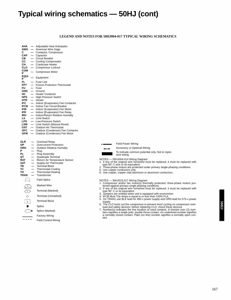
167
LEGEND AND NOTES FOR 50HJ004-017 TYPICAL WIRING SCHEMATICS
AHA — Adjustable Heat AnticipatorAWG — American Wire GageC — Contactor, CompressorCAP — CapacitorCB — Circuit BreakerCC — Cooling CompensatorCH — Crankcase HeaterCLO — Compressor LockoutCOMP — Compressor MotorEQUIP — EquipmentFL — Fuse LinkFPT — Freeze Protection ThermostatFU — FuseGND — GroundHC — Heater ContactorHPS — High-Pressure SwitchHTR — HeaterIFC — Indoor (Evaporator) Fan ContactorIFCB — Indoor Fan Circuit BreakerIFM — Indoor (Evaporator) Fan MotorIFR — Indoor (Evaporator) Fan RelayIRH — Indoor/Return Relative HumidityLS — Limit SwitchLPS — Low-Pressure SwitchLSM — Limit Switch (Manual Reset)OAT — Outdoor-Air ThermostatOFC — Outdoor (Condenser) Fan ContactorOFM — Outdoor (Condenser) Fan Motor
OLR — Overload RelayOP — Overcurrent ProtectionORH — Outdoor Relative HumidityP — PlugPL — Plug AssemblyQT — Quadruple TerminalRAT — Return Air Temperature SensorSAT — Supply-Air ThermostatTB — Terminal BlockTC — Thermostat-CoolingTH — Thermostat-HeatingTRAN — Transformer
Field Splice
Marked Wire
Terminal (Marked)
Terminal (Unmarked)
Terminal Block
Splice
Splice (Marked)
Factory Wiring
Field Control Wiring
NOTES — 50HJ004-014 Wiring Diagram:1. If any of the original wire furnished must be replaced, it must be replaced with
type 90° C wire or its equivalent.2. Three-phase motors are protected under primary single-phasing conditions.5. Use copper conductors only.6. Use copper, copper clad aluminum or aluminum conductors.
NOTES — 50HJ015,017 Wiring Diagram:1. Compressor and/or fan motor(s) thermally protected; three-phase motors pro-
tected against primary single phasing conditions.2. If any of the original wire furnished must be replaced, it must be replaced with
type 90° C or its equivalent.3. Jumpers are omitted when unit is equipped with economizer.4. IFCB Must Trip Amps is equal to or less than 140% FLA.5. On TRAN1 use BLK lead for 460-v power supply and ORN lead for 575-v power
supply.6. The CLO locks out the compressor to prevent short cycling on compressor over-
load and safety devices; before replacing CLO, check these devices.7. Number(s) indicates the line location of used contacts. A bracket over (2) num-
bers signifies a single pole, double throw contact. An underlined number signifiesa normally closed contact. Plain (no line) number signifies a normally open con-tact.
Field Power WiringAccessory or Optional WiringTo indicate common potential only. Not to repre-sent wiring.
Typical wiring schematics — 50HJ (cont)50H
J

168
CO
BR
A w
irin
g D
iagr
am (5
0HJ0
06 w
ith 6
2AQ
060/
100,
208
/230
-3-6
0) w
ith E
lect
ro-M
echa
nica
l Con
trol
s
50H
J

169
Cob
ra w
irin
g D
iagr
am (5
0HJ0
08-0
14 w
ith 6
2AQ
200,
460
-3-6
0) a
nd F
acto
ry In
stal
led
Prem
ierL
inks
Typical wiring schematics — 50HJ (cont)50H
J

170
50HJ015,017
50H
J

171
LOW VOLTAGE CONTROL SCHEMATIC — 50HJ020-028
Typical wiring schematics — 50HJ (cont)50H
J

172
POWER SCHEMATIC — 50HJ020-028
50H
J

173
CO
MPO
NE
NT
AR
RA
NG
EM
EN
T —
50H
J020
-028
---A
—C
ircui
t AA
UX
—A
uxili
ary
Con
tact
AL
—A
mbi
ent L
imit
---B
—C
ircui
t B---
C—
Circ
uit C
C—
Com
pres
sor,
Con
tact
orC
B—
Circ
uit B
reak
erC
CH
—C
rank
case
Hea
ter
CLO
—C
ompr
esso
r Loc
kout
CO
MP
—C
ompr
esso
rC
R—
Con
trol R
elay
ECB
—E
cono
miz
er C
ontro
l Boa
rdFC
S—
Fan
Cyc
ling
Sw
itch
FIO
P—
Fact
ory-
Inst
alle
d O
ptio
nFP
T—
Free
ze P
rote
ct T
herm
osta
tH
AC
R—
Hea
ting,
Air
Con
ditio
ning
, an
d R
efrig
erat
ion
HPS
—H
igh-
Pres
sure
Sw
itch
IAQ
—In
door
Air
Qua
lity
IDR
—In
duce
d D
raft
Rel
ayIF
C—
Indo
or F
an C
onta
ctor
IFC
B—
Indo
or F
an C
ircui
t Bre
aker
IFM
—In
door
Fan
Mot
orLP
S—
Low
-Pre
ssur
e S
witc
h
THE
RM
OST
AT/IG
C M
AR
KIN
GS
BM
—B
low
er M
otor
C—
Com
mon
CM
—C
ombu
stio
n M
otor
CS
—C
entri
fuga
l Sw
itch
G—
Fan
IFO
—In
door
Fan
On
L1—
Line
1R
—Th
erm
osta
t Pow
erR
T—
Pow
er S
uppl
ySS
—Sp
eed
Sen
sor
W—
Ther
mos
tat H
eat
W1
—1s
t Sta
ge o
f Hea
ting
W2
—2n
d St
age
of H
eatin
gX
—A
larm
Out
put
Y1—
1st S
tage
of C
oolin
gY2
—2n
d St
age
of C
oolin
g
OAT
—O
utdo
or A
ir Te
mpe
ratu
reO
FC—
Out
door
Fan
Con
tact
orO
FM—
Out
door
Fan
Mot
orPE
C—
Pow
er E
xhau
st C
onta
ctor
PEM
—P
ower
Exh
aust
Mot
orPL
—P
lug
SAT
—S
uppl
y-A
ir Te
mpe
ratu
reTB
—Te
rmin
al B
lock
TRA
N—
Tran
sfor
mer
Term
inal
Blo
ck
Term
inal
(Unm
arke
d)
Term
inal
(Mar
ked)
Splic
eFa
ctor
y W
iring
Fiel
d W
iring
To in
dica
te c
omm
on p
oten
tial
only.
Not
to re
pres
ent w
iring
.To
indi
cate
FIO
P o
r Acc
esso
ry
LEG
EN
D
NO
TES:
1.Fa
ctor
y w
iring
is in
acc
orda
nce
with
the
Nat
iona
l Ele
ctric
al C
odes
. Any
fiel
d m
odifi
ca-
tions
or a
dditi
ons
mus
t be
in c
ompl
ianc
e w
ith a
ll ap
plic
able
cod
es.
2.U
se 7
5 C
min
wire
for f
ield
pow
er s
uppl
y. U
se c
oppe
r wire
s fo
r all
units
.3.
All
circ
uit b
reak
ers
“Mus
t Trip
Am
ps” a
re e
qual
to o
r les
s th
an 1
56%
RLA
.4.
Com
pres
sor
and
fan
mot
ors
are
ther
mal
ly p
rote
cted
. Th
ree-
phas
e m
otor
s pr
otec
ted
agai
nst p
rimar
y si
ngle
-pha
se c
ondi
tions
.5.
The
CLO
lock
s ou
t th
e co
mpr
esso
r to
pre
vent
sho
rt cy
clin
g on
com
pres
sor
over
load
and
safe
ty d
evic
es. B
efor
e re
plac
ing
CLO
, che
ck th
ese
devi
ces.
Typical wiring schematics — 50HJ (cont)50H
J

174
ECONOMI$ER IV WIRING — 50HE003-006 AND 50HJ004-014 UNITS
LEGENDIAQ — Indoor Air QualityLA — Low Ambient Lockout DevicePOT — PotentiometerOAT — Outdoor-Air TempetureRAT — Return-Air Temperature
NOTES:Potentiometer Default settings:Power Exhaust MiddleMinimum Pos. Fully ClosedDCV Max. MiddleDCV Set MiddleEnthalpy C Setting
NOTES:1. 620 ohm, 1 watt 5% resister schould be removed only when using differential
enthalpy or dry bulb2. If a seperate field-supplied 24v transfomer is used for the IAQ sensor power
supply, it cannot have the secondary of the transformer grounded.3. For field-installed remote minimum position POT, remove black wire jumper
between P and P1 and set control minimum position POT to the minimumposition.
ECONOMI$ER IV WIRING — 50HJ015,017 UNITS
50H
E/H
J

175
ECONOMI$ER2 WIRING — 50HE003-006 AND 50HJ004-014 UNITS
ECONOMI$ER2 WIRING — 50HJ015,017 UNITS
NOTES:1. Switch on actuator must be in run position for economizer to operate.2. PremierLink™ control requires that the standard 50HJ540569 outside-air sensor be replaced by either the CROASENR001A00 dry bulb sensor or HH57A077
enthalpy sensor.3. 50HJ540573 actuator consists of the 50HJ540567 actuator and a harness with 500-ohm resistor.
LEGENDOAT — Outdoor Air Temperature SensorNOTES:
1. Switch on actuator must be in run position for economizer to operate.
4
3
5
2
8
6
7
1
10
11
9
12
PINK
VIOLET
BLACK
BLUE
YE
LLO
W
NOTE 1
NOTE 3
RUN
500 OHMRESISTOR
-+
OPTIONAL COSENSOR 4 - 20 mA
OUTPUT
50HJ540573ACTUATORASSEMBLY
RED
WHITE
ECONOMISER2 PLUG
DIRECT DRIVEACTUATOR
2
4
3
5
2
8
6
7
1
10
11
9
12
PINK
BLACK
BLUENOTE 1
NOTE 2
RUN
500 OHMRESISTOR
50HJ540573ACTUATORASSEMBLY
RED
WHITE
ECONOMISER2 PLUG
DIRECT DRIVEACTUATOR
OAT
Typical wiring schematics — 50HE/HJ (cont)50H
E/H
J

176
CONVENIENCE OUTLET (OPTIONAL) — 50HE003-006 AND 50HJ004-014
NON-FUSED DISCONNECT (OPTIONAL) — 50HE003-006 AND 50HJ004-014
NOTE: Use copper conductors only.
NOTE:Convenience outlet is intended for intermittent use of service equipment and not as a power source for extended operation of electrical loads.
50H
E/H
J

177
NON-FUSED DISCONNECT (OPTIONAL) — 50HJ015,017
NOTES:1. If the Non-Fused Disconnect Service Option is ordered for size 015 and 017 units, the Non-Fused Disconnect will be factory-installed.2. The Disconnect takes the place of TB-1 as shown on the unit wiring diagram label and the component arrangement label.
Typical wiring schematics — 50HJ (cont)50H
J

178
COBRA™ ENERGY RECOVERY UNIT CONTROL WIRING WITH THERMIDISTAT™ AND STANDARD CONTROLS
50H
J

179
COBRA™ ENERGY RECOVERY UNIT CONTROL WIRING WITH THERMOSTAT, HUMIDISTAT AND ELECTRO-MECHANICAL CONTROLS
Typical wiring schematics — 50HJ (cont)50H
J

180
COBRA™ ENERGY RECOVERY UNIT CONTROL WIRING WITH HUMIDISTAT, SPACE TEMPERATURE SENSOR, AND PREMIERLINK™ CONTROLS
50H
J

181
COBRA™ ENERGY RECOVERY UNIT CONTROL WIRING WITH THERMIDISTATTM, AND PREMIERLINK™ CONTROLS
Typical wiring schematics — 50HJ (cont)50H
J

182
VERTICAL DISCHARGE DUCTING
HORIZONTAL DISCHARGE DUCTING
LEGENDNEC — National Electrical Code*Factory-supplied, internally mounted disconnectavailable as an option.
Typical piping and wiring — 50HE003-006, 50
HE
/HJ
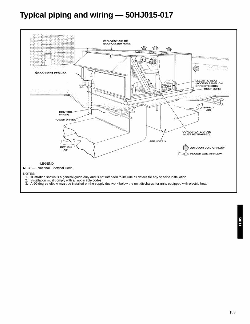
183
LEGEND
NOTES:1. Illustration shown is a general guide only and is not intended to include all details for any specific installation.2. Installation must comply with all applicable codes.3. A 90-degree elbow must be installed on the supply ductwork below the unit discharge for units equipped with electric heat.
NEC — National Electrical Code
Typical piping and wiring — 50HJ015-01750H
J

184
PremierLink™ Direct Digital Controls — The PremierLinkDirect Digital Controls (DDC) require the use of a Carrier elec-tronic thermostat or a CCN connection for time broadcast toinitiate its internal timeclock. This is necessary for broadcast oftime of day functions (occupied/unoccupied). Refer to Premier-LinkTM literature for more informationPremierLink Features:• Equipment Control Functions
Cooling StagesHeating StagesIndoor-Fan Motor4-Way Valve
• Economizer Control FunctionsDry Bulb ControlEnthalpy ControlDifferential EnthalpyPower Exhaust
• Advanced Control FunctionsSmoke DetectionOptimal Start (90.1)Unoccupied Free CoolSmart Staging and Optimal Staging
• Network ProtocolCCNInternet Ready 38.4 K baud rate
• Diagnostics/Advanced Service FeaturesDiagnosticsOnboard display
• SchedulingVia Communicating Stat
• User InterfaceNavigator (LEN protocol)LID2B (CCN)PC with Carrier software (CCN)
Indoor Air Quality (IAQ) Monitoring — An indoor air qual-ity (IAQ) controller will maintain indoor air quality within thespace at the set point level. The set point is calculated from thedifferential air quality that is configured by the user. As airquality within the space changes, the position of the econo-mizer damper will also change thus allowing more or less out-door air into the space. If IAQ is configured for low priority, thepositioning of the economizer damper can be overridden bycomfort requirements. If IAQ is configured for high priority,the controller will check the air quality every 30 seconds andwill perform supply air tempering when in IAQ mode if the fol-lowing criteria are met:• IAQ priority is high• Outdoor temperature is less than 55 F• Heat and cool set points have not been exceededDemand Control Ventilation — Certain criteria must be con-sidered when using the PremierLink™ controller for demandcontrol ventilation. When selecting the heating and coolingcapacity of the equipment, the maximum ventilation rate mustbe evaluated for design conditions along with the maximumdamper position to achieve desired conditioning of the space.Typical maximum ventilation rate should be ASHRAE occu-pied design cfm +5 to 10%. The PremierLink controller can also provide tempering of thesupply air when the space or return air temperature falls be-tween the occupied heat and cool set points or there is not a callfor heating or cooling in the Thermostat mode. The maximumventilation airflow rate should be checked by evaluating theunit’s heating capability to raise the supply air to an acceptablelevel during tempering of supply air. After determining the maximum ventilation airflow rate theIAQ maximum damper configuration needs to be configured.Demand control ventilation software may be used to assist indetermining the CO2 maximum ventilation recovery rate. Therecovery rate can be accomplished by using either proportion-al-anticipatory strategy or proportional integral (PI) control.
Controls50
HJ

185
CCN POINTS FOR PREMIERLINK CONTROLDESCRIPTION STATUS UNITS POINT LIMITS ACCESSSpace Temperature xxx.x dF SPT –40.0 to 245.0 dF R/WSupply Air Temperature xxx.x dF SAT –40.0 to 245.0 dF R/WOutside Air Temperature xxx.x dF OAT –40.0 to 245.0 dF R/WControl Setpoint xxx.x dF CLSP RCooling % Total Capacity xxx % CCAP 0 to 100 % RHeating % Total Capacity xxx % HCAP 0 to 100 % REconomizer Active No/Yes ECOS 0 to 1 RSupply Fan Relay Off/On SF 0 to 1 R/WSupply Fan Status Off/On SFS 0 to 1 REconomizer Position xxx.x % ECONPOS 0.0 to 100.0 % R/WCurrent Min Damper Pos xxx.x % IQMP 0.0 to 100.0 % RFilter Status Clean/Dirty FLTS 0 to 1 R/WRemote Occupied Mode Off/On RMTOCC 0 to 1 R/WHeat Stage 1 Off/On HS1 0 to 1 RHeat Stage 2 Off/On HS2 0 to 1 RHeat 3/Exhaust/Rev Valve Off/On H3_EX_RV 0 to 1 REnthalpy Low/High ENTH 0 to 1 R/WIndoor Air Quality xxxx.x IAQI 0.0 to 5000.0 R/WIndoor Air Quality Setpt xxxx.x IAQS 0.0 to 5000.0 ROutdoor Air Quality xxxx.x OAQ 0.0 to 5000.0 R/WFire Shutdown Normal/Alarm FSD 0 to 1 R/WSPT Offset xx.x ^F STO –15.0 to 15.0 ^F R/WCompressor 1 Off/On CMP1 0 to 1 RCompressor 2 Off/On CMP2 0 to 1 RCompressor Safety Off/On CMPSAFE 0 to 1 R
Controls (cont)50H
J

186
CA
RR
IER
CO
MFO
RT
LIN
K™
/PR
EM
IER
LIN
K™
CO
NT
RO
LS
50H
J
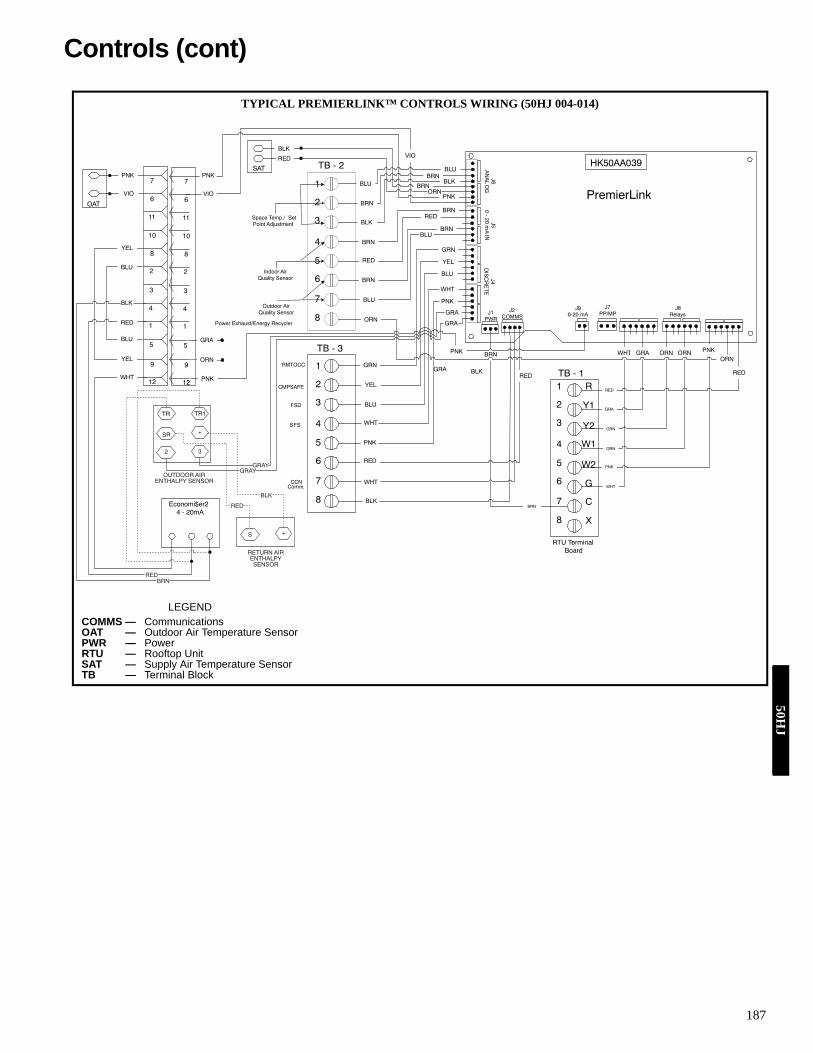
187
LEGENDCOMMS — CommunicationsOAT — Outdoor Air Temperature SensorPWR — PowerRTU — Rooftop UnitSAT — Supply Air Temperature SensorTB — Terminal Block
TYPICAL PREMIERLINK™ CONTROLS WIRING (50HJ 004-014)
TB - 1R
Y1
Y2
W1
W2
G
C
X
1
2
3
4
5
6
7
8
TB - 3
1
2
3
4
5
6
7
8
TB - 2
1
2
3
4
5
6
7
8J6
AN
AL
OG
J50 - 20 m
A IN
J4D
ISC
RE
TE
J1PWR
J2COMMS
J90-20 mA
J8Relays
HK50AA039
BRN
BRN WHT
WHT
RED
PNK
PNK
ORNORN
ORN
ORN
GRA
GRAORN
RED
J7PP/MP
WHT
BLK
RED
RED
PNK
WHT
BLK
PNK
WHT
BLU
ORN
YEL
GRN
BRN
BRN
RED
RED
BRN
BRN
BLK
BLK
BRN
BRN
BLU
BLU
1
2
3
4
5
6
7
8
9
10
11
12
1
2
3
4
5
6
7
8
9
10
11
12
PNK
PNK
VIO
VIO
GRA
ORN
PNK
PNK
GRA
GRA
GRA
SAT
BRNORN
BLK
RED
Space Temp./ SetPoint Adjustment
Indoor AirQuality Sensor
OAT
PNK
VIO
YEL
YEL
BLU
BLU
Economi$er24 - 20mA
BLK
RED
WHT
PremierLink
GRN
YEL
BLU
BLU
BLU
Outdoor AirQuality Sensor
Power Exhaust/Energy Recycler
CCNComm.
RMTOCC
SFS
CMPSAFE
FSD
RTU TerminalBoard
TR TR1
SR
2 3
+
+S
REDBRN
BLK
RED
GRAYGRAY
OUTDOOR AIRENTHALPY SENSOR
RETURN AIRENTHALPYSENSOR
Controls (cont)50H
J

188
TY
PIC
AL
PR
EM
IER
LIN
K™
CO
NT
RO
LS
WIR
ING
(50H
J015
,017
)
LEG
EN
DC
LO—
Com
pres
sor L
ocko
utC
MP
—C
ompr
esso
rEC
ON
O—
Eco
nom
izer
ENTH
—E
ntha
lpy
Sens
orIG
C—
Inte
grat
ed G
as U
nit C
ontro
ller
MG
V—
Mai
n G
as V
alve
OAT
—O
utdo
or A
ir Te
mpe
ratu
re S
enso
rPL
—P
lug
SAT
—S
uppl
y A
ir Te
mpe
ratu
re S
enso
rSP
T—
Spac
e Te
mpe
ratu
re S
enso
rTB
—Te
rmin
al B
lock
*If P
rem
ierL
ink
cont
rol i
s in
ther
mos
tat m
ode.
†TB
2 te
rmin
al d
esig
natio
ns fo
r 24
vac
disc
rete
inpu
ts. D
efau
lt is
for D
DC
con
trol.
50H
J

189
Operating sequence, 50HE003-006 and 50HJ 004-014 unitsCooling, units without economizer — When thermostat callsfor cooling, terminals G and Y1 are energized. The indoor(evaporator) fan contactor (IFC) and compressor contactor no.1 (C1) are energized, and evaporator-fan motor (IFM), com-pressor no. 1, and condenser fan(s) start. The liquid line sole-noid valve for compressor no. 1 is de-energized open. The con-denser-fan motor(s) runs continuously while unit is cooling.For units with 2 stages of cooling, if the thermostat calls for asecond stage of cooling by energizing Y2, compressor contac-tor no. 2 (C2) is energized and compressor no. 2 starts.Heating, units without economizer (units with electric heat)— Upon a call for heating through W1, indoor (evaporator) fancontactor (IFC) and heater contactor no. 1 (HC1) are energized.On units equipped for 2 stages of heat, when additional heat isneeded, heater contactor no. 2 is energized through W2.Cooling, units with EconoMi$er IV — When free cooling isnot available, the compressors will be controlled by the zonethermostat. When free cooling is available, the outdoor-airdamper is modulated by the EconoMi$er IV control to providea 50 to 55 F mixed-air temperature into the zone. As the mixed-air temperature fluctuates above 55 or below 50 F, the damperswill be modulated (open or close) to bring the mixed-air tem-perature back within control.
If mechanical cooling is utilized with free cooling, the out-door-air damper will maintain its current position at the timethe compressor is started. If the increase in cooling capacitycauses the mixed-air temperature to drop below 45 F, then theoutdoor-air damper position will be decreased to the minimumposition. If the mixed-air temperature continues to fall, the out-door-air damper will close. Control returns to normal once themixed-air temperature rises above 48 F.
If optional power exhaust is installed, as the outdoor-airdamper opens and closes, the power exhaust fans will be ener-gized and deenergized.
If field-installed accessory CO2 sensors are connected to theEconoMi$er IV control, a demand controlled ventilation strate-gy will begin to operate. As the CO2 level in the zone increasesabove the CO2 set point, the minimum position of the damperwill be increased proportionally. As the CO2 level decreasesbecause of the increase in fresh air, the outdoor-air damper willbe proportionally closed.
For EconoMi$er IV operation, there must be a thermostatcall for the fan (G). If the unit is occupied and the fan is on, thedamper will operate at minimum position. Otherwise, thedamper will be closed.
When the EconoMi$er IV control is in the occupied modeand a call for cooling exists (Y1 on the thermostat), the controlwill first check for indoor fan operation. If the fan is not on,then cooling will not be activated. If the fan is on, then the con-trol will open the EconoMi$er IV damper to the minimum po-sition.
On the initial power to the EconoMi$er IV control, it willtake the damper up to 21/2 minutes before it begins to positionitself. Any change in damper position will take up to 30 sec-onds to initiate. Damper movement from full closed to fullopen (or vice versa) will take between 11/2 and 21/2 minutes.
If free cooling can be used as determined from the appropri-ate changeover command (switch, dry bulb, enthalpy curve,differential dry bulb, or differential enthalpy), then the controlwill modulate the dampers open to maintain the mixed-air tem-perature set point at 50 to 55 F.
If there is a further demand for cooling (cooling second stage— Y2 is energized), then the control will bring on compressorstage 1 to maintain the mixed-air temperature set point. TheEconoMi$er IV damper will be open at maximum position.EconoMi$er IV operation is limited to a single compressor.Heating, units with EconoMi$er IVNOTE: The units have 2 stages of electric heat.
When the thermostat calls for one stage of heating, W1 is ener-gized. The thermostat must be configured such that the bloweroutput (G) is energized when there is a W1 call for heating. Theindoor fan contactor (IFC) and first stage electric heat contac-tor(s) are energized, and the indoor-fan motor and first stage elec-tric heater are started. The EconoMi$er IV damper modulates tothe minimum position.
If additional heating is required, the thermostat will call for asecond stage of heating, energizing W2. This will energize thesecond stage of electric heat. The EconoMi$er IV damper mod-ulates to the minimum position.
When the thermostat is satisfied, the EconoMi$er IV dampermodulates closed.Cooling, units with EconoMi$er2, PremierLink™ controland a thermostat — When free cooling is not available, thecompressors will be controlled by the PremierLink control inresponse to the Y1 and Y2 inputs from the thermostat.
The PremierLink control will use the following informationto determine if free cooling is available:• Indoor fan has been on for at least 30 seconds.• The SPT, SAT, and OAT inputs must have valid readings.• OAT must be less than 75 F.• OAT must be less than SPT.• Enthalpy must be LOW (may be jumpered if an enthalpy
sensor not available).• Economizer position is NOT forced.
Pre-cooling occurs when the is no call from the thermostatexcept G. Pre-cooling is defined as the economizer modulatesto provide 70 F supply air.
When free cooling is available the PremierLink control willcontrol the compressors and economizer to provide a supply-airtemperature determined to meet the Y1 and Y2 calls from thethermostat.
If optional power exhaust is installed, as the outdoor-airdamper opens and closes, the power exhaust fans will be ener-gized and deenergized.
Controls (cont)50H
J

190
If field-installed accessory CO2 sensors are connected to thePremierLink control, a PID-controlled demand ventilationstrategy will begin to operate. As the CO2 level in the zoneincreases above the CO2 set point, the minimum position of thedamper will be increased proportionally. As the CO2 leveldecreases because of the increase in fresh air, the outdoor-airdamper will be proportionally closed.Heating, units with EconoMi$er2, PremierLink™ controland a thermostat — When the thermostat calls for heating,terminal W1 is energized. The PremierLink control will movethe economizer damper to the minimum position if there is acall for G and closed if there is a call for W1 without G. TheIFC and heater contactor (HC1) are energized.
When the thermostat is satisfied and W1 is deenergized, theIFM stops after a 45-second time-off delay unless G is stillmaintained. Cooling, units with EconoMi$er2, PremierLink control anda room sensor — When free cooling is not available, the com-pressors will be controlled by the PremierLink controller usinga PID Error reduction calculation.
The PremierLink controller will use the following informa-tion to determine if free cooling is available:• Indoor fan has been on for at least 30 seconds.• The SPT, SAT, and OAT inputs must have valid readings.• OAT must be less than 75 F.• OAT must be less than SPT.• Enthalpy must be LOW (may be jumpered if an enthalpy
sensor is not available).• Economizer position is NOT forced.When free cooling is available, the outdoor-air damper is posi-tioned through the use of a Proportional Integral (PID) controlprocess to provide a calculated supply-air temperature into thezone. The supply air will maintain the space temperaturebetween the heating and cooling set points.
The PremierLink control will integrate the compressorsstages with the economizer based on logic built into the con-troller.
If an optional power exhaust is installed, as the outdoor-airdamper opens and closes, the power exhaust fans will be ener-gized and deenergized.
If field-installed accessory CO2 sensors are connected to thePremierLink control, a PID-controlled demand ventilationstrategy will begin to operate. As the CO2 level in the zoneincreases above the CO2 set point, the minimum position of thedamper will be increased proportionally. As the CO2 leveldecreases because of the increase in fresh air, the outdoor-airdamper will be proportionally closed.Heating, unit with EconoMi$er2, PremierLink control anda room sensor — Every 40 seconds the controller will calcu-late the required heat stages (maximum of 3) to maintain Sup-ply Air Temperature (SAT) if the following qualifyingconditions are met:• Indoor fan has been on for at least 30 seconds.• COOL mode is not active.
• OCCUPIED, TEMP. COMPENSATED START or HEATmode is active.
• SAT reading is available.• Fire shutdown mode is not active.
If all of the above conditions are met, the number of heatstages is calculated; otherwise the required number of heatstages will be set to 0.
If the PremierLink controller determines that heat stages arerequired, the economizer damper will be moved to minimumposition if occupied and closed if unoccupied.Operating Sequence COBRA units — (See COBRA/62AQApplication Data for additional information.)Cooling, units with COBRA™ energy recovery — The cool-ing changeover thermostat located on COBRA energy recoveryunit hood determines when the COBRA energy recovery unitgoes into economizer mode. When the outdoor temperature isbelow the cooling set point the unit will be in economizermode.
In the unoccupied mode, fans are normally set for AUTOoperation, causing the fans to cycle on only as needed for heat-ing or cooling. If the Thermidistat™ device is set for “AUTO”fan, the rooftop unit fan will be off except when cooling orhumidity control is required. The COBRA energy recovery unitfans will be off except when unit is running in the economizermode. If the Thermidistat fan setting is set to “ON”, theCOBRA energy recovery unit and rooftop unit fans will runcontinuously. If outdoor air is below the outdoor air thermostatset point, the compressors are locked off and the unit operatesin economizer mode when cooling is required. If outdoor air isunsuitable due to humidity or quality, the COBRA energyrecovery unit is off and only the rooftop unit compressor runswhen cooling is required. Note that the COBRA energy recov-ery unit does not run and dampers are closed when the outdoorair is unsuitable for cooling and the mode is unoccupied. If out-door air is suitable, first stage cooling is COBRA energy recov-ery unit in economizer mode and all compressors are off.Second stage cooling adds the COBRA energy recovery unitcompressor and rooftop unit compressor no. 1.
In occupied mode, when the COBRA energy recovery unitcompressor runs in cooling mode, it is extracting heat from theincoming outdoor air and rejecting heat to the exhaust air. TheCOBRA energy recovery unit and rooftop unit fans run contin-uously. On a first stage call, all compressors will be off if theoutdoor air is suitable for free cooling. Otherwise, the COBRAenergy recovery unit compressor and rooftop unit compressorno. 1 will run whenever there is a first stage demand for cool-ing. On a second stage call, the COBRA energy recovery unitcompressor and rooftop unit compressor no. 1 and 2 will runwhenever there is a demand for cooling. If there is a demandfor humidity control but not cooling, only the COBRA energyrecovery unit compressor will run. If there is a field-installedCO2 sensor and the levels are below that sensor set point, thenthe unit will operate in the unoccupied mode sequence (i.e.,COBRA energy recovery unit dampers closed and rooftop unitoperation only to maintain space conditions).
50H
J
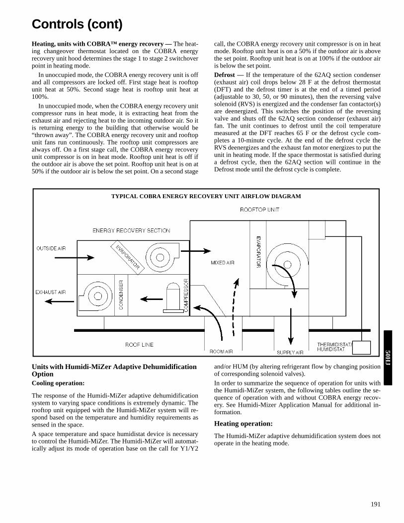
191
Heating, units with COBRA™ energy recovery — The heat-ing changeover thermostat located on the COBRA energyrecovery unit hood determines the stage 1 to stage 2 switchoverpoint in heating mode.
In unoccupied mode, the COBRA energy recovery unit is offand all compressors are locked off. First stage heat is rooftopunit heat at 50%. Second stage heat is rooftop unit heat at100%.
In unoccupied mode, when the COBRA energy recovery unitcompressor runs in heat mode, it is extracting heat from theexhaust air and rejecting heat to the incoming outdoor air. So itis returning energy to the building that otherwise would be“thrown away”. The COBRA energy recovery unit and rooftopunit fans run continuously. The rooftop unit compressors arealways off. On a first stage call, the COBRA energy recoveryunit compressor is on in heat mode. Rooftop unit heat is off ifthe outdoor air is above the set point. Rooftop unit heat is on at50% if the outdoor air is below the set point. On a second stage
call, the COBRA energy recovery unit compressor is on in heatmode. Rooftop unit heat is on a 50% if the outdoor air is abovethe set point. Rooftop unit heat is on at 100% if the outdoor airis below the set point.Defrost — If the temperature of the 62AQ section condenser(exhaust air) coil drops below 28 F at the defrost thermostat(DFT) and the defrost timer is at the end of a timed period(adjustable to 30, 50, or 90 minutes), then the reversing valvesolenoid (RVS) is energized and the condenser fan contactor(s)are deenergized. This switches the position of the reversingvalve and shuts off the 62AQ section condenser (exhaust air)fan. The unit continues to defrost until the coil temperaturemeasured at the DFT reaches 65 F or the defrost cycle com-pletes a 10-minute cycle. At the end of the defrost cycle theRVS deenergizes and the exhaust fan motor energizes to put theunit in heating mode. If the space thermostat is satisfied duringa defrost cycle, then the 62AQ section will continue in theDefrost mode until the defrost cycle is complete.
Units with Humidi-MiZer Adaptive Dehumidification OptionCooling operation:
The response of the Humidi-MiZer adaptive dehumidificationsystem to varying space conditions is extremely dynamic. Therooftop unit equipped with the Humidi-MiZer system will re-spond based on the temperature and humidity requirements assensed in the space.A space temperature and space humidistat device is necessaryto control the Humidi-MiZer. The Humidi-MiZer will automat-ically adjust its mode of operation base on the call for Y1/Y2
and/or HUM (by altering refrigerant flow by changing positionof corresponding solenoid valves).In order to summarize the sequence of operation for units withthe Humidi-MiZer system, the following tables outline the se-quence of operation with and without COBRA energy recov-ery. See Humidi-Mizer Application Manual for additional in-formation.
Heating operation:
The Humidi-MiZer adaptive dehumidification system does notoperate in the heating mode.
TYPICAL COBRA ENERGY RECOVERY UNIT AIRFLOW DIAGRAM
Controls (cont)50H
J

192
COBRATM Energy Recovery Unit Sequence of Operation — Unoccupied
LEGEND
* Second stage for Y2 call applicable on rooftop units with 2 circuits only.**The 62AQ always checks the OAT when it opens the OA damper.
Cooling: If indoor temp is < Y1: OAT < OAT thermostat setpoint = E$R compressor off OAT > OAT thermostat setpoint = E$R compressor on Heating: If indoor temp is > W1: OAT > OAT thermostat setpoint = E$R compressor off OAT < OAT thermostat setpoint = E$R compressor on†50% rooftop until heat only applicable with 2 stage electric or gas heat-
ing units.COBRATM Energy Recovery Unit Sequence of Operation — Occupied
LEGEND
* Second stage for Y2 call applicable on rooftop units with 2 circuits only.**The 62AQ always checks the OAT when it opens the OA damper.
Cooling: If indoor temp is < Y1: OAT < OAT thermostat setpoint = E$R compressor off OAT > OAT thermostat setpoint = E$R compressor on Heating: If indoor temp is > W1: OAT > OAT thermostat setpoint = E$R compressor off OAT < OAT thermostat setpoint = E$R compressor on†50% rooftop until heat only applicable with 2 stage electric or gas heating units.
UNOCCU[IEDCOOLING E$R Compressor E$R Fans RTU Compressor 1 RTU compressor 2* RTU Fans RTU Heat
Indoor Temperature Above Y2* Humidity Low & OAT Low On On (cyc.) On Off On (cyc.) Off Humidity Low & OAT High Off Off On On On (cyc.) Off Humidity High & OAT Low Off Off On On On (cyc.) Off Humidity High & OAT High Off Off On On On (cyc.) OffIndoor Temperature Between Y1 & Y2* Humidity Low & OAT Low Off On (cyc.) Off Off On (cyc.) Off Humidity Low & OAT High Off Off On Off On (cyc.) Off Humidity High & OAT Low Off Off On On On (cyc.) Off Humidity High & OAT High Off Off On On On (cyc.) OffIndoor Temperature Below Y1** Humidity Low Off Off Off Off Off Off Humidity High Off Off On On On (cyc.) OffNOTE: OAT < 55F all compression off
HEATING E$R Compressor E$R Fans RTU Compressor 1 RTU compressor 2* RTU Fans RTU Heat †
Indoor Temperature Above W1** Off Off Off Off OffIndoor Temperature Between W1 & W2 Off Off Off Off On (cyc.) On, 50%Indoor Temperature Below W2 Off Off Off Off On (cyc.) On, 100%
E4R — Energy$Recycler UnitOAT — Outdoor Air TemperatureRTU — Rooftop Unit
OCCU[IEDCOOLING E$R Compressor E$R Fans RTU Compressor 1 RTU compressor 2* RTU Fans RTU Heat
Indoor Temperature Above Y2* Humidity Low & OAT Low On On On Off On Off Humidity Low & OAT High On On On On On Off Humidity High & OAT Low On On On On On Off Humidity High & OAT High On On On On On OffIndoor Temperature Between Y1 & Y2* Humidity Low & OAT Low Off On On Off On Off Humidity Low & OAT High On On On Off On Off Humidity High & OAT Low On On On On On Off Humidity High & OAT High On On On On On OffIndoor Temperature Below Y1** Humidity Low Off On Off Off On Off Humidity High On On Off Off On OffNOTE: OAT < 55F all compression off
HEATING E$R Compressor E$R Fans RTU Compressor 1 RTU compressor 2* RTU Fans RTU Heat †
Indoor Temperature Above W1** Off On Off Off On OffIndoor Temperature Between W1 & W2 OAT >Set Pt (30 F) On On Off Off On Off OAT< Set Pt (30 F) On On Off Off On On, 50%Indoor Temperature Below W2 OAT >Set Pt (30 F) On On Off Off On On, 50% OAT< Set Pt (30 F) On On Off Off On On, 100%
E4R — Energy$Recycler UnitOAT — Outdoor Air TemperatureRTU — Rooftop Unit
50H
J

193
Operating sequence, 50HJ015,017Cooling, units without economizer — When thermostat callsfor cooling, terminals G and Y1 are energized. The indoor(evaporator) fan contactor (IFC) and compressor contactor no.1 (C1) are energized, and evaporator-fan motor (IFM), com-pressor no. 1 and condenser fan(s) start. The condenser-fan mo-tor(s) runs continuously while unit is cooling. When the ther-mostat calls for a second stage of cooling by energizing Y2,compressor contactor no. 2 (C2) is energized and compressorno. 2 starts.Heating, units without economizer (if accessory or optionalheater is installed) — Upon a call for heating through terminalW1, IFC and heater contactor no. 1 (HC1) are energized. Onunits equipped for 2 stages of heat, when additional heat isneeded, HC2 is energized through W2.Cooling, units with EconoMi$er IV — When free cooling isnot available, the compressors will be controlled by the zonethermostat. When free cooling is available, the outdoor-airdamper is modulated by the EconoMi$er IV control to providea 50 to 55 F mixed-air temperature into the zone. As the mixed-air temperature fluctuates above 55 or below 50 F, the damperswill be modulated (open or close) to bring the mixed-air tem-perature back within control.
If mechanical cooling is utilized with free cooling, the out-door-air damper will maintain its current position at the timethe compressor is started. If the increase in cooling capacitycauses the mixed-air temperature to drop below 45 F, then theoutdoor-air damper position will be decreased to the minimumposition. If the mixed-air temperature continues to fall, the out-door-air damper will close. Control returns to normal once themixed-air temperature rises above 48 F.
If optional power exhaust is installed, as the outdoor-airdamper opens and closes, the power exhaust fans will be ener-gized and deenergized.
If field-installed accessory CO2 sensors are connected to theEconoMi$er IV control, a demand controlled ventilation strate-gy will begin to operate. As the CO2 level in the zone increasesabove the CO2 set point, the minimum position of the damperwill be increased proportionally. As the CO2 level decreasesbecause of the increase in fresh air, the outdoor-air damper willbe proportionally closed.
For EconoMi$er IV operation, there must be a thermostatcall for the fan (G). If the unit is occupied and the fan is on, thedamper will operate at minimum position. Otherwise, thedamper will be closed.
When the EconoMi$er IV control is in the occupied modeand a call for cooling exists (Y1 on the thermostat), the controlwill first check for indoor fan operation. If the fan is not on,then cooling will not be activated. If the fan is on, then the con-trol will open the EconoMi$er IV damper to the minimum po-sition.
On the initial power to the EconoMi$er IV control, it willtake the damper up to 21/2 minutes before it begins to positionitself. Any change in damper position will take up to 30 sec-onds to initiate. Damper movement from full closed to fullopen (or vice versa) will take between 11/2 and 21/2 minutes.
If free cooling can be used as determined from the appropri-ate changeover command (switch, dry bulb, enthalpy curve,differential dry bulb, or differential enthalpy), then the controlwill modulate the dampers open to maintain the mixed-air tem-perature set point at 50 to 55 F.
If there is a further demand for cooling (cooling second stage— Y2 is energized), then the control will bring on compressorstage 1 to maintain the mixed-air temperature set point. TheEconoMi$er IV damper will be open at maximum position.EconoMi$er IV operation is limited to a single compressor.Heating, units with EconoMi$er IVNOTE: The units have 2 stages of electric heat.
When the thermostat calls for one stage of heating, W1 is ener-gized. The thermostat must be configured such that the bloweroutput (G) is energized when there is a W1 call for heating. Theindoor fan contactor (IFC) and first stage electric heat contac-tor(s) are energized, and the indoor-fan motor and first stage elec-tric heater are started. The EconoMi$er IV damper modulates tothe minimum position.
If additional heating is required, the thermostat will call for asecond stage of heating, energizing W2. This will energize thesecond stage of electric heat. The EconoMi$er IV damper mod-ulates to the minimum position.
When the thermostat is satisfied, the EconoMi$er IV dampermodulates closed.Cooling, units with EconoMi$er2, PremierLink™ controland a thermostat — When free cooling is not available, thecompressors will be controlled by the PremierLink control inresponse to the Y1 and Y2 inputs from the thermostat.
The PremierLink control will use the following informationto determine if free cooling is available:• Indoor fan has been on for at least 30 seconds.• The SPT, SAT, and OAT inputs must have valid readings.• OAT must be less than 75 F.• OAT must be less than SPT.• Enthalpy must be LOW (may be jumpered if an enthalpy
sensor not available).• Economizer position is NOT forced.
Pre-cooling occurs when the is no call from the thermostatexcept G. Pre-cooling is defined as the economizer modulatesto provide 70 F supply air.
When free cooling is available the PremierLink control willcontrol the compressors and economizer to provide a supply-airtemperature determined to meet the Y1 and Y2 calls from thethermostat.
If optional power exhaust is installed, as the outdoor-airdamper opens and closes, the power exhaust fans will be ener-gized and deenergized.
If field-installed accessory CO2 sensors are connected to thePremierLink control, a PID-controlled demand ventilationstrategy will begin to operate. As the CO2 level in the zoneincreases above the CO2 set point, the minimum position of thedamper will be increased proportionally. As the CO2 leveldecreases because of the increase in fresh air, the outdoor-airdamper will be proportionally closed.
Controls (cont)50H
J

194
Heating, units with EconoMi$er2, PremierLink™ controland a thermostat — When the thermostat calls for heating,terminal W1 is energized. The PremierLink control will movethe economizer damper to the minimum position if there is acall for G and closed if there is a call for W1 without G. TheIFC and heater contactor (HC1) is energized.
When the thermostat is satisfied and W1 is deenergized, theIFM stops after a 45-second time-off delay unless G is stillmaintained.Cooling, units with EconoMi$er2, PremierLink control anda room sensor — When free cooling is not available, the com-pressors will be controlled by the PremierLink controller usinga PID Error reduction calculation as indicated below.
The PremierLink controller will use the following informa-tion to determine if free cooling is available:• Indoor fan has been on for at least 30 seconds.• The SPT, SAT, and OAT inputs must have valid readings.• OAT must be less than 75 F.• OAT must be less than SPT.• Enthalpy must be LOW (may be jumpered if an enthalpy
sensor is not available).• Economizer position is NOT forced.When free cooling is available, the outdoor-air damper is posi-tioned through the use of a Proportional Integral (PID) controlprocess to provide a calculated supply-air temperature into thezone. The supply air will maintain the space temperaturebetween the heating and cooling set points.
The PremierLink control will integrate the compressorsstages with the economizer based on logic built into the con-troller.
If an optional power exhaust is installed, as the outdoor-airdamper opens and closes, the power exhaust fans will be ener-gized and deenergized.
If field-installed accessory CO2 sensors are connected to thePremierLink control, a PID-controlled demand ventilationstrategy will begin to operate. As the CO2 level in the zoneincreases above the CO2 set point, the minimum position of thedamper will be increased proportionally. As the CO2 leveldecreases because of the increase in fresh air, the outdoor-airdamper will be proportionally closed.Heating, unit with EconoMi$er2, PremierLink control anda room sensor — Every 40 seconds the controller will calcu-late the required heat stages (maximum of 3) to maintain Sup-ply Air Temperature (SAT) if the following qualifyingconditions are met:• Indoor fan has been on for at least 30 seconds.• COOL mode is not active.• OCCUPIED, TEMP. COMPENSATED START or HEAT
mode is active.• SAT reading is available.• Fire shutdown mode is not active.
If all of the above conditions are met, the number of heatstages is calculated; otherwise the required number of heatstages will be set to 0.
If the PremierLink controller determines that heat stages arerequired, the economizer damper will be moved to minimumposition if occupied and closed if unoccupied.
Operating sequence 50HJ020-028Cooling, units without economizer — When thermostat callsfor cooling, terminals G and Y1 are energized. Compressorcontactors A1 and B1 (except 028 units) are energized and in-door-fan motor, compressor, and outdoor fan starts. The out-door fan motor runs continuously while unit is cooling. If fur-ther cooling is required, the Y2 output from the thermostat en-ergizes compressor contactor C1 (B1 on 028 units).Heating, units without economizer (if accessory or optionalheater is installed) — Upon a call for heating through terminalW1, IFC and heater contactor no. 1 (HC1) are energized. Onunits equipped for 2 stages of heat, when additional heat isneeded, HC2 is energized through W2.Cooling, units with EconoMiz$er IV — When free coolingis not available, the compressors will be controlled by the zonethermostat. When free cooling is available, the outdoor-airdamper is modulated by the EconoMi$er IV control to providea 50 to 55 F mixed-air temperature into the zone. As the mixed-air temperature fluctuates above 55 or below 50 F, the damperswill be modulated (open or close) to bring the mixed-air tem-perature back within control.
If mechanical cooling is utilized with free cooling, the out-door-air damper will maintain its current position at the timethe compressor is started. If the increase in cooling capacitycauses the mixed-air temperature to drop below 45 F, then theoutdoor-air damper position will be decreased to the minimumposition. If the mixed-air temperature continues to fall, the out-door-air damper will close. Control returns to normal once themixed-air temperature rises above 48 F.
If optional power exhaust is installed, as the outdoor-airdamper opens and closes, the power exhaust fans will be ener-gized and deenergized.
If field-installed accessory CO2 sensors are connected to theEconoMi$er IV control, a demand controlled ventilation strate-gy will begin to operate. As the CO2 level in the zone increasesabove the CO2 set point, the minimum position of the damperwill be increased proportionally. As the CO2 level decreasesbecause of the increase in fresh air, the outdoor-air damper willbe proportionally closed.
For EconoMi$er IV operation, there must be a thermostatcall for the fan (G). If the unit is occupied and the fan is on, thedamper will operate at minimum position. Otherwise, thedamper will be closed.
When the EconoMi$er IV control is in the occupied modeand a call for cooling exists (Y1 on the thermostat), the controlwill first check for indoor fan operation. If the fan is not on,then cooling will not be activated. If the fan is on, then the con-trol will open the EconoMi$er IV damper to the minimum po-sition.
On the initial power to the EconoMi$er IV control, it willtake the damper up to 21/2 minutes before it begins to positionitself. Any change in damper position will take up to 30 sec-onds to initiate. Damper movement from full closed to fullopen (or vice versa) will take between 11/2 and 21/2 minutes.
50H
J

195
If free cooling can be used as determined from the appropri-ate changeover command (switch, dry bulb, enthalpy curve,differential dry bulb, or differential enthalpy), then the controlwill modulate the dampers open to maintain the mixed-air tem-perature set point at 50 to 55 F.
If there is a further demand for cooling (cooling second stage— Y2 is energized), then the control will bring on compressorstage 1 to maintain the mixed-air temperature set point. TheEconoMi$er IV damper will be open at maximum position.EconoMi$er IV operation is limited to a single compressor.Heating, units with EconoMi$er IVNOTE: The units have 2 stages of electric heat.
When the thermostat calls for one stage of heating, W1 is ener-gized. The thermostat must be configured such that the bloweroutput (G) is energized when there is a W1 call for heating. Theindoor fan contactor (IFC) and first stage electric heat contac-tor(s) are energized, and the indoor-fan motor and first stage elec-tric heater are started. The EconoMi$er IV damper modulates tothe minimum position.
If additional heating is required, the thermostat will call for asecond stage of heating, energizing W2. This will energize thesecond stage of electric heat. The EconoMi$er IV damper mod-ulates to the minimum position.
When the thermostat is satisfied, the EconoMi$er IV dampermodulates closed.
Controls (cont)50H
J

196
Condensate drain panA sloped condensate drain pan is supplied on all units. The con-densate pan must be externally trapped. Condensate drains arelocated on both the bottom and end of the unit.
DuctworkAll ductwork must be attached to flanges. If no flanges arepresent, they must be field supplied. Secure vertical dischargeductwork to roof curb. For horizontal discharge applications,attach ductwork to flanges. Field-supplied flanges can be at-tached to horizontal discharge openings and all ductwork at-tached to flanges.NOTE: For units with electric heat, a field-supplied 90-degreeelbow must be installed in the supply ductwork below the dis-charge connection.
ThermostatUse of 2-stage cooling thermostat is recommended for all unitsequipped with economizer. A 2-stage cooling thermostat is re-quired for size 015-028 units with integrated economizer.
Heating-to-cooling changeoverAll units are automatic changeover from heating to coolingwhen automatic changeover thermostat and subbase are used.
AirflowUnits are draw-thru on cooling and blow-thru on heating.
Maximum airflowTo minimize possibility of condensate blow-off from evapora-tor, airflow through units should not exceed 500 cfm/ton (sizes004-025) and 11,250 cfm (size 028).
Minimum airflowMinimum airflow for cooling is 300 cfm/ton (size 004-025)and 280 cfm/ton (028 units). Refer to Heating Capacities tablefor minimum heating airflow.
Minimum ambient operating temperatureMinimum ambient operating temperature for size 004-014standard units is 25 F. With accessory Motormaster® I or IIcontrol, units can operate at outdoor temperatures down to –20 F.
Unit sizes 015-028 are designed to operate at outdoor tem-peratures down to 40 F. With accessory Motormaster I or Mo-tormaster V control, units can operate at outdoor temperaturesdown to –20 F.NOTE: Under most application circumstances, if the rooftopunit is equipped with an economizer, low ambient controls arenot required. Unless the outdoor air is unsatisfactory for freecooling due to high temperature, excessive humidity, or poorair quality, outdoor air should be used.
Maximum operating outdoor-air temperatureMaximum outdoor operating temperature for cooling is shownbelow (60 Hz):
50HE003-006 125 F 50HJ004-015 125 F
50HJ017 120 F50HJ020-028 125 F
Motor dataDue to Carrier’s internal unit design (draw-thru over the mo-tor), air path, and specially designed motors, the full horsepow-er (maximum continuous bhp) listed in the Physical Data tablesand the notes following each Fan Performance table can be uti-lized with extreme confidence.
Using Carrier motors to the values listed in the Physical Da-ta, Fan Performance, and Evaporator-Fan Motor Data tableswill not result in nuisance tripping or premature motor failure.In addition, the unit warranty will not be affected.
Carrier PremierLink™ controlsThe Carrier PremierLink controls can be used with any thermo-stat.
Thru-the-bottom connections (sizes 003-014 only)
The accessory thru-the-bottom connections are needed to en-sure proper watertight connections when routing wiring andpiping through the basepan and roof curb. This accessory isused for electric and control power. Connections MUST be in-stalled prior to unit being placed on roof curb.
Field-supplied fan drivesIf the factory drive sets must be changed to obtain other wheelspeeds, consult your Carrier representative or the nearestBrowning Manufacturing Co. sales office with the requirednew wheel speed and the data from Physical Data tables (centerdistances, motor and fan shaft diameters, motor horsepower)for a modified drive set selection. For minor speed changes, thefan sheave size should be changed. (Do not reduce the size ofthe motor sheave; this will result in reduced belt horse-powerratings and reduced belt life, adjust the diameter of the factorysupplied adjustable sheave pulley.)
Humidi-MiZer Adaptive Dehumidification Option
Humidi-MiZer option expands unit performance by creating upto four different stages of Sensible Heat Ratio (SHR) based onneeds of the space. Allows for high sensible, high latent and/orpart-load performance of the rooftop unit.Option includes automatic changeover to sub-cooling andHGRH modes of operation. Temperature stat input and Humid-ity stat input required for proper operation. Includes Motor-Master I low ambient controller and compressor bellybandheater. See the Humidi-MiZer Application Data manual foradditional information.
Application data50
HJ

197
Concentric duct details
Condenser coil protectionPre-coated aluminum-fin coils have a durable epoxy-phenoliccoating applied to the fin prior to the fin stamping process toprovide protection in mildly corrosive coastal environments.Pre-coated coils have an inert barrier between the aluminum finand copper tube. This barrier electrically disconnects the dis-similar metals to minimize the potential for galvanic corrosion.This economical option provides substantial corrosion protec-tion beyond the standard uncoated coil construction.Copper-fin coils provide increased corrosion resistance inmoderate coastal environments where industrial air pollution isnot present. All copper coils eliminate bi-metallic constructionto eliminate the potential for galvanic corrosion. Application inindustrial environments is not recommended due to potentialattack from sulfur, sulfur oxide, nitrogen oxides, carbon andseveral other industrial airborne contaminants. In moderateseacoast environments, copper-fin coils have extended lifecompared to standard or pre-coated aluminum-fin coils.
E-Coated aluminum-fin coils undergo a precisely controlledscientific process that bonds an impermeable epoxy coating tothe specially prepared fin coil surface. E-Coating produces asmooth, consistent coating that is less brittle, more resilient andmore durable than previous postcoating processes. E-Coatedaluminum-fin coils offer economical protection and improvedcoil life in many contaminated environments.E-Coated copper-fin coils provide maximum protection invirtually all environments, this option combines the continu-ous, impenetrable barrier of the E-Coating process with the nat-ural resistance of an all-copper construction. E-Coated copper-fin coil assemblies ensure long life, even in environments thatcombine harsh coastal conditions with industrial contamina-tion.
CONDENSER COIL PROTECTION APPLICATIONS
LEGEND
CONCENTRIC DUCT DISTRIBUTION CONCENTRIC DUCT DETAILS
NOTE: Do not drill in this area, damage to basepanmay result in water leak.
Shaded area indicates block-off panels.NOTE: Dimensions A, A′ and B, B′ are obtained from field-suppliedceiling diffuser.
Concentric ducts may only be installed on units without electricheat. Personal injury or unit damage may result.
DESCRIPTION(Enviro-Shield™ Option)
ENVIRONMENTStandard, Non-Corrosive Mild Coastal Severe Coastal Industrial Combined Coastal and Industrial
Standard, Al/Cu XPre-Coated Al/Cu XCu/Cu XE-Coated Al/Cu X XE-Coated Cu/Cu X
Al/Cu — Aluminum Fin with Copper Tube Coil E-Coated — Extremely Flexible and Durable Epoxy Coating UniformlyCu/Cu — Copper Fin with Copper Tube Coil Applied to the Coil SurfacesEnviro-Shield — Family of Coil Protection Options Pre-Coated — Epoxy Coating Applied to Fin Stock Material
Application data (cont)50H
J

198
EconoMi$er IVThe EconoMi$er IV factory-installed economizer packageincludes a gear-driven damper system that modulates the returnair and outdoor air supply to the rooftop unit in order to takeadvantage of “free cooling” with outdoor air when conditionsare suitable. The system utilizes industry proven technologyavailable for integrating the use of outdoor air for cooling withmechanical cooling for 3 through 25-ton rooftop units. Theintuitive EconoMi$er IV solid-state controller optimizes andenhances rooftop operation through reduced energy consump-tion, optimal zone comfort, and efficient equipment cycling.This is accomplished by operating the compressors when theoutdoor air temperature is too warm, integrating the compres-sors with outdoor air when free cooling is available, and lock-ing out the compressor when outdoor air temperature is toocold. The detailed sequence of operation is described in thecontrols section with a brief description of selected applicationitems here.Thermostat interface — The EconoMi$er IV control wasdesigned to work with conventional thermostats that have Y1(cooling stage 1), Y2 (cooling stage 2), W1 (heat stage 1), W2(heat stage 2), and G (fan). In addition, the EconoMi$er IV willsupport an occupied/unoccupied switch (typically integratedinto the thermostat or Thermidistat™ device). When the switchis closed, it provides a 24-vac signal to the unit for occupiedmode, and provides no signal to indicate unoccupied mode.The EconoMi$er IV control can be configured to allow differ-ent minimum economizer damper positions and to allow theuse of mechanical cooling in the occupied mode.Control features — The EconoMi$er IV controller providessuperior functionality for rooftop unit operation. EconoMi$erIV control features are included as follows:Remote minimum position control — The EconoMi$er IV con-troller can be used with a field-supplied and field-installedremote minimum position control switch that will enable anddisable the EconoMi$er IV to open or close the damper beyondthe minimum position for modified ventilation, providing 2 to10 vdc output.NOTE: Minimum position signal takes priority over the DCV(demand control ventilation) maximum position signal.Demand control ventilation (DCV) — The EconoMi$er IV hasDCV capability when using an IAQ sensor. This sensor is typi-cally installed in the return duct or occupied space. Whenimplementing a DCV control scheme with the EconoMi$er IV,the control algorithm will modulate the position of the damperbetween two user-configured damper positions, MaximumDCV position and Minimum Occupied position. Design air-flow rates for these two damper positions should be such thatwhen the damper is at the Maximum DCV position, enoughfresh ventilation air will be brought in to remove contaminantsand CO2 generated by sources other than people (i.e., since inunoccupied mode). The Maximum DCV position is intended tosatisfy the IAQ “Base Ventilation Rate.” The Minimum Occu-pied position design airflow rate should be sufficient to satisfy
ventilation requirements for removing CO2 from all sourcesincluding people at the maximum occupancy.IAQ sensors — EconoMi$er IV can be utilized with any IAQ(CO2) sensor that provides a 2 to 10 vdc output. The controllerwill modulate the outdoor air damper to provide ventilationbased on the sensor output and the IAQ setting of the controller.When used, an IAQ sensor will modulate the damper from theminimum position (base ventilation rate based on CO2 levels)to maximum position (full occupancy ventilation rate).Damper operation — The EconoMi$er IV allows the damper tobe configured for two adjustable damper positions includingmaximum position and occupied minimum position. The two(2) position damper capability is a unique feature ofEconoMi$er IV and includes operation flexibility as follows:
1. Minimum Occupied Position: This adjustable positionallows a minimum ventilation airflow rate through theunit during occupied periods (base ventilation rate).
2. Demand Control Ventilation (DCV) Maximum Position:A DCV maximum occupied position is provided whenusing an IAQ sensor for DCV. See Demand Control Ven-tilation section on this page and Control section forsequence, The DCV Maximum Position limits outdoorairflow into the rooftop when the DCV routine overridesthe mixed air sensor. Setting the DCV Maximum positionof the outdoor-air damper prevents large amounts of hotor cold air into the space.
Power exhaust — The EconoMi$er IV has the capability tocontrol one (1) stage of power exhaust for maintaining air bal-ance and pressurization. Control is activated based on outdoor-air damper position (adjustable) factory set at the “middle”position (damper halfway open).Compressor staging — The EconoMi$er IV is an integratedeconomizer and has the ability to utilize simultaneous outdoorair and compressors. The EconoMi$er IV can be configured tosupport economizer and compressor operation for up to 4 com-pressors. Only one or two compressor operation is availablewith 3 to 121/2 ton units.Changeover strategies — The EconoMi$er IV controller canbe configured to accommodate all available economizer controlstrategies that place the rooftop unit in economizer modeincluding: Switch — Used when a remote signal from an energy manage-ment system will enable and disable the EconoMi$er IV(remote enable control).Outdoor dry bulb — EconoMi$er IV will be enabled based onthe outside-air temperature. This is provided standard with theEconoMi$er IV.Differential dry bulb — EconoMi$er IV will be enabled when-ever the outside-air temperature is lower than the return airtemperature.
IMPORTANT: When the DCV Maximum position is setbelow the minimum position, the minimum position over-rides the maximum position, negating most DCV functions.
50H
J

199
Outside air enthalpy — EconoMi$er IV will be enabled basedon the outside air enthalpy curves as shown in the EconoMi$erIV Changeover diagram below. The A, B, C, and D curvesshown have been in use for many years and have been includedas part of the latest ASHRAE 90.1 energy efficiency code. Thecurves are designed to take into consideration both outdoortemperature and humidity. These curves are used to set up theEconoMi$er IV controller to use the EconoMi$er IV for freecooling when the conditions to the left of the curve exist. Whenthe conditions are to the right of the curve, then outdoor aircooling will not be used and the outdoor air damper positionwill be set at the minimum position.
Deciding which curve is used is a function of the outdoor cli-mate and the type of economizer utilized. Since EconoMi$erIV is a fully integrated economizer, the range where outdoor aircan be utilized for free cooling is expanded and the A and Bcurves may be used. The control point table in the EconoMi$erIV Changeover diagram below provides assistance for whetherthe A and B curves will be suitable. In general terms, a hot and
humid climate may be a reason not to use the A curve, while acooler climate might be more applicable for using the A or Bcurve.
The EconoMi$er IV has expanded outdoor air capability. Fora changeover economizer which cannot utilize simultaneouseconomizer and compression, both A and B curves wouldpotentially be undesirable since the temperature and humiditylevels are too high without compression assistance to provideeffective cooling. Therefore, most changeover economizers uti-lize the D curve.Differential enthalpy — The EconoMi$er IV will be enabledbased on the comparison of the enthalpy of the return air andoutside air. When the outside air enthalpy is lower than thereturn side, the unit will be in economizer mode.
Using the EconoMi$er IV controller for implementing dif-ferent control changeover strategies requires the use of differ-ent combinations of dry bulb and humidity sensors as outlinedin the EconoMi$er IV Sensor Usage table.
ECONOMI$ER IV CHANGEOVER CURVES
CONTROLCURVE
ABCD
CONTROL POINTAPPROX. deg. F (deg. C)
AT 50% RH
73 (23)70 (21)67 (19)63 (17)
12
14
16
18
20
22
24
26
28
30
32
34
36
38
40
42
44
46
90100
8070
6050
40
30
20
10
ENTHALP
Y BTU
PER P
OUND D
RY AIR
85(29)
90(32)
95(35)
100(38)
105(41)
110(43)
35(2)
35(2)
40(4)
40(4)
105(41)
110(43)
45(7)
45(7)
50(10)
50(10)
55(13)
55(13)
60(16)
60(16)
65(18)
65(18)
70(21)
70(21)
75(24)
75(24)
80(27)
80(27)
85(29)
90(32)
95(35)
100(38)
A
A
B
B
C
C
D
D
RE
LATI
VE
HU
MID
ITY
(%)
HIGH LIMITCURVE
APPROXIMATE DRY BULB TEMPERATURE--degrees F (degrees C)
Application data (cont)50H
J

200
ECONOMI$ER IV SENSOR USAGE CHART
*CRENTDIF004A00 and CRTEMPSN002A00 accessories are usedon many different base units. As such, these kits may contain partsthat will not be needed for installation.
†33ZCSENCO2 is an accessory CO2 sensor.**33ZCASPCO2 is an accessory aspirator box required for duct-
mounted applications.††CRCBDIOX005A00 is an accessory that contains both
33ZCSENCO2 and 33ZCASPCO2 accessories.
APPLICATIONECONOMI$ER IV WITH OUTDOOR AIR
DRY BULB SENSORAccessories Required
Outdoor Air Dry Bulb None. The outdoor air dry bulb sensor is factory installed.Differential Dry Bulb CRTEMPSN002A00*
Single Enthalpy HH57AC078
Differential EnthalpyHH57AC078
andCRENTDIF004A00*
CO2 for DCV Control using aWall-Mounted CO2 Sensor 33ZCSENCO2
CO2 for DCV Control using aDuct-Mounted CO2 Sensor
33ZCSENCO2†and
33ZCASPCO2** OR CRCBDIOX005A00††
50H
J

201
Packaged Rooftop Electric Cooling Unit — Constant Volume ApplicationHVAC Guide Specifications Size Range:2 to 5 Tons, Nominal (Cooling)
3.3 to 25.5 kW, Nominal (Accessory Electric Heating)
Carrier Model Numbers:50HE003 - 006
Part 1 — General1.01 SYSTEM DESCRIPTION
Outdoor rooftop mounted, electrically controlled heating and cooling unit utilizing a hermetic compressor(s) for cooling duty. Unit shall discharge supply air vertically or horizontally as shown on contract drawings.
1.02 QUALITY ASSURANCEA. Unit shall exceed ASHRAE 90.1-2001 Energy Stan-
dards. Units 003 to 006 are Energy Star qualified.B. Unit shall be rated in accordance with ARI Standards
210 or 360. Designed in accordance with UL Standard1995.
C. Unit shall be designed to conform to ASHRAE 15, latestrevision.
D. Unit shall be UL-tested and certified in accordance withANSI Z21.47 Standards and UL-listed and certifiedunder Canadian standards as a total package for safetyrequirements.
E. Roof curb shall be designed to conform to NRCA Stan-dards.
F. Insulation and adhesive shall meet NFPA 90A require-ments for flame spread and smoke generation.
G. Unit casing shall be capable of withstanding 500-hoursalt spray exposure per ASTM B117 (scribed specimen).
H. Unit shall be designed in accordance with ISO9001:2000, and shall be manufactured in a facility regis-tered to ISO 9001:2000.
I. Each unit shall be subjected to a completely automatedrun testing on the assembly line. A factory-suppliedprintout indicating tested pressures, amperages, data,and inspectors; providing certification of the unit statusat the time of manufacture; shall be available uponrequest.
1.03 DELIVERY, STORAGE, AND HANDLINGUnit shall be stored and handled per manufacturer’s recommendations.
Part 2 — Products2.01 EQUIPMENT (STANDARD)
A. General:Factory assembled, single-piece heating and cooling unit. Contained within the unit enclosure shall be all factory wiring, piping, controls, refrigerant charge (R-22), and special features required prior to field start-up.
B. Unit Cabinet:1. Unit cabinet shall be constructed of galvanized
steel, and shall be bonderized and coated with aprepainted baked enamel finish on all externallyexposed surfaces.
2. Evaporator fan compartment interior cabinet sur-faces shall be insulated with a minimum 1/2-in.thick, 1 lb density, flexible fiberglass insulation,neoprene coated on the air side.
3. Cabinet panels shall be easily removable for servic-ing.
4. Holes shall be provided in the base rails for riggingshackles to facilitate maneuvering and overheadrigging.
5. Unit shall have a factory-installed, sloped conden-sate drain pan made of a non-corrosive material,providing a minimum 3/4-in.-14 NPT. connectionwith both vertical and horizontal drains, and shallcomply with ASHRAE Standard 62.
6. Unit shall have a factory-installed filter accesspanel to provide filter access with tool-lessremoval.
7. Unit shall have standard thru-the-bottom powerconnection capability (accessory kit is required).
C. Fans:1. Evaporator Fan:
a. Fan shall be direct or belt driven as shown onthe equipment drawings. Belt drive shallinclude an adjustable-pitch motor pulley.
b. Fan wheel shall be double-inlet type with for-ward-curved blades.
c. Bearings shall be sealed, permanently lubri-cated ball-bearing type for longer life and lowermaintenance.
2. Evaporator fan shall be made from steel with a cor-rosion-resistant finish and shall be dynamicallybalanced.
3. Condenser fan shall be of the direct-driven (withtotally enclosed motors) propeller type and shalldischarge air vertically.
4. Condenser fan shall have aluminum blades rivetedto corrosion-resistant steel spiders and shall bedynamically balanced.
SIZES 003 TO 006ARE ENERGY STARQUALIFIED
Guide specifications — 50HE003-00650H
E

202
D. Compressor(s):1. Fully hermetic type, internally protected scroll-
type.2. Factory mounted on rubber grommets and inter-
nally spring mounted for vibration isolation.3. Units shall be electrically and mechanically single
circuits (one compressor per circuit).E. Coils:
1. Standard evaporator and condenser coils shall havealuminum lanced plate fins mechanically bonded toseamless internally grooved copper tubes with alljoints brazed.
2. Testing:a. Evaporator and condenser coils shall be quali-
fied to UL 1995 burst test at 2,200 psi.b. Evaporator and condenser coils shall be leak
tested to 150 psig and pressure tested to 400psig.
3. Optional Coils:a. Optional pre-coated aluminum-fin coils shall
have a durable epoxy-phenolic coating to pro-vide protection in mildly corrosive coastal envi-ronments. Coating shall be applied to thealuminum fin stock prior to the fin stampingprocess to create an inert barrier between thealuminum fin and copper tube. Epoxy-phenolicbarrier shall minimize galvanic action betweendissimilar metals.
b. Copper-fin coils shall be constructed of copperfins mechanically bonded to copper tubes andcopper tube sheets. Galvanized steel tube sheetsshall not be acceptable. A polymer strip shallprevent coil assembly from contacting the sheetmetal coil pan to minimize potential for gal-vanic corrosion between coil and pan. All cop-per construction shall provide protection inmoderate coastal environments.
c. E-Coated aluminum-fin coils shall have a flexi-ble epoxy polymer coating uniformly applied toall coil surface areas without material bridgingbetween fins. Coating process shall ensure com-plete coil encapsulation. Color shall be highgloss black with gloss — 60 deg of 65 to 90%per ASTM D523-89. Uniform dry film thick-ness from 0.8 to 1.2 mil on all surface areasincluding fin edges. Superior hardness charac-teristics of 2H per ASTM D3363-92A andcross-hatch adhesion of 4B-5B per ASTMD3359-93. Impact resistance shall be up to 160in.-lb (ASTM D2794-93). Humidity and waterimmersion resistance shall be up to minimum
1000 and 250 hours respectively (ASTMD2247-92 and ASTM D870-92). Corrosiondurability shall be confirmed through testing tobe no less than 1000 hours salt spray per ASTMB117-90. Coil construction shall be aluminumfins mechanically bonded to copper tubes.
d. E-Coated copper-fin coils shall have a flexibleepoxy polymer coating uniformly applied to allcoil surface areas without material bridgingbetween fins. Coating process shall ensure com-plete coil encapsulation. Color shall be highgloss black with gloss — 60 deg of 65 to 90%per ASTM D523-89. Uniform dry film thick-ness from 0.8 to 1.2 mil on all surface areasincluding fin edges. Superior hardness charac-teristics of 2H per ASTM D3363-92A andcross-hatch adhesion of 4B-5B per ASTMD3359-93. Impact resistance shall be up to 160in.-lb (ASTM D2794-93). Humidity and waterimmersion resistance shall be up to minimum1000 and 250 hours respectively (ASTMD2247-92 and ASTM D870-92). Corrosiondurability shall be confirmed through testing tobe no less than 1000 hours salt spray per ASTMB117-90. Coil construction shall be copper finsmechanically bonded to copper tubes with cop-per tube sheets. Galvanized steel tube sheetsshall not be acceptable. A polymer strip shallprevent coil assembly from contacting sheetmetal coil pan to maintain coating integrity andminimize corrosion potential between coil andpan.
F. Refrigerant Components:Refrigerant circuit components shall include:1. Fixed orifice metering system (Acutrol™ device).2. Refrigerant filter drier.3. Service gage connections on suction, discharge,
and liquid lines.G. Filter Section:
1. Standard filter section shall consist of factory-installed, low velocity, throwaway 2-in. thick fiber-glass filters of commercially available sizes.
2. Filter face velocity shall not exceed 320 fpm atnominal airflows.
3. Filter section should use only one size filter.4. Filters shall be accessible through an access panel
with “no-tool” removal.H. Controls and Safeties:
1. Unit Controls:Unit shall be complete with self-contained low-voltage control circuit protected by a fuse on the
50H
E

203
2. Safeties:a. Unit shall incorporate a solid-state compressor
protector which provides anti-cycle reset capa-bility at the space thermostat, should any of thefollowing standard safety devices trip and shutoff compressor.1) Compressor overtemperature, overcurrent.2) Loss-of-charge/low-pressure switch.3) Freeze-protection thermostat, evaporator
coil.4) High-pressure switch.5) Automatic reset motor thermal overload
protector.The lockout protection shall be easily discon-nected at the control board, if necessary.
I. Operating Characteristics:1. Unit shall be capable of starting and running at 125
F ambient outdoor temperature, meeting maximumload criteria of ARI Standard 210/ 240 or 360 at +10% voltage.
2. Compressor with standard controls shall be capableof operation down to 25 F ambient outdoor temper-ature.
J. Electrical Requirements:All unit power wiring shall enter unit cabinet at a single factory-predrilled location.
K. Motors:1. Compressor motors shall be cooled by refrigerant
gas passing through motor windings and shall haveline break thermal and current overload protection.
2. Evaporator-fan motor shall have permanentlylubricated bearings and inherent automatic-resetthermal overload protection. Evaporator motors aredesigned specifically for Carrier and do NOT haveconventional horsepower (HP) ratings listed on themotor nameplate. Motors are designed and quali-fied in the “air-over” location downstream of thecooling coil and carry a “maximum continuousbhp” rating that is the maximum application bhprating for the motor; no “safety factors” above thatrating may be applied.
3. Totally enclosed condenser-fan motor shall havepermanently lubricated bearings, and inherentautomatic-reset thermal overload protection.
L. Special Features:Certain features are not applicable when the featuresdesignated * are specified. For assistance in amendingthe specifications, contact your local Carrier SalesOffice. *1. Carrier PremierLink™ Controls:
a. Shall be available as a factory-installed or as afield-installed accessory.
b. Shall work with Carrier Comfort Network®(CCN) and ComfortVIEW™ software.
c. Shall be compatible with ComfortLink™ con-trollers.
d. Shall be ASHRAE 62-2001 compliant.e. Shall accept a CO2 sensor in the conditioned
space — Demand Control Ventilation (DCV)ready.
f. Shall have baud communication rate of 38.4Kor faster.
g. Shall be Internet ready.h. Shall include an integrated economizer control-
ler.i. If an economizer is specified the EconoMi$er2
with the 4 to 20 mA actuator and no micropro-cessor control is required.
2. Roof Curbs (Horizontal and Vertical):a. Formed galvanized steel with wood naile strip
and shall be capable of supporting entire unitweight.
b. Permits installation and securing of ductwork tocurb prior to mounting unit on the curb.
*3. Integrated Economizers:a. Integrated integral modulating type capable of
simultaneous economizer and compressor oper-ation.
b. Available as a factory-installed option in verti-cal supply/return configuration only. (Availableas a field-installed accessory for dedicated hori-zontal and/or vertical supply return configura-tions.)
c. Includes all hardware and controls to providecooling with outdoor air.
d. Equipped with low-leakage dampers, not toexceed 2% leakage at 1 in. wg pressure differ-ential.
e. Capable of introducing up to 100% outdoor air.f. EconoMi$er IV and EconoMi$er2 shall be
equipped with a barometric relief damper capa-ble of relieving up to 100% return air.
g. Designed to close damper(s) during loss-of-power situations with spring return built intomotor.
h. Dry bulb outdoor-air temperature sensor shallbe provided as standard. Outdoor air sensor setpoint is adjustable and shall range from 40 to100 F. For the EconoMi$er IV, the return airsensor, indoor enthalpy sensor, and outdoorenthalpy sensor shall be provided as field-installed accessories to provide enthalpy con-trol, differential enthalpy control, and differen-tial dry bulb temperature control. For theEconoMi$er2, the enthalpy, differential temper-ature (adjustable), and differential enthalpy con-trol shall be provided as field-installedaccessories.
Guide specifications — 50HE003-006 (cont)50H
E

204
i. The EconoMi$er IV and EconoMi$er2 shallhave a gear-driven parallel blade design.
j. EconoMi$er IV microprocessor control shallprovide control of internal building pressurethrough its accessory power exhaust function.Factory set at 100%, with a range of 0% to100%.
k. EconoMi$er2 shall be capable of control from a4 to 20 mA signal through optional 4 to 20 mAdesign without microprocessor control(required for PremierLink™ or third party con-trol interface).
l. EconoMi$er IV Microprocessor Occupied Min-imum Damper Position Setting maintains theminimum airflow into the building during occu-pied period providing design ventilation rate forfull occupancy (damper position during heat-ing). A remote potentiometer may be used tooverride the set point.
m. EconoMi$er IV Microprocessor UnoccupiedMinimum Damper Position Setting — TheEconoMi$er IV dampers shall be completelyclosed when the unit is in the occupied mode.
n. EconoMi$er IV Microprocessor IAQ/DCVMaximum Damper Position Setting — Settingthe maximum position of the damper preventsthe introduction of large amounts of hot or coldair into the space. The position is intended tosatisfy the base minimum ventilation rate.
o. EconoMi$er IV Microprocessor IAQ/DCV con-trol modulates the outdoor-air damper to pro-vide ventilation based on the optional 2 to 10vdc CO2 sensor input.
p. Compressor lockout sensor (opens at 35 F,closes at 50 F).
q. Actuator shall be direct coupled to economizergear, eliminating linkage arms and rods.
r. Control LEDs:1) When the outdoor air damper is capable of
providing free cooling, the “Free Cool”LED shall illuminate.
2) The IAQ LED indicates when the moduleis on the DCV mode.3)3) The EXH LED indicates when the
exhaust fan contact is closed.s. Remote Minimum Position Control — A field-
installed accessory remote potentiometer allowsthe outdoor air damper to be opened or closedbeyond the minimum position in the occupiedmode for modified ventilation.
4. Manual Outdoor-Air Damper:Manual damper package shall consist of damper, birdscreen, and rainhood which can be
preset to admit up to 50% outdoor air for year round ventilation.
*5. 100% Two-Position Damper:a.Two-position damper package shall include
single blade damper and motor. Admits upto 100% outdoor air.
b.Damper shall close upon indoor (evaporator)fan shutoff.
c.Designed to close damper during loss ofpower situations.
d.Equipped with 15% barometric reliefdamper.
*6. 25% Two-Position Damper:a. Two-position damper package shall include
single blade damper and motor. Admits upto 25% outdoor air.
b.Damper shall close upon indoor (evaporator)fan shutoff.
*7. Head Pressure Control Package:Package shall consist of solid-state control andcondenser-coil temperature sensor to maintain con-densing temperature between 90 F and 110 F atoutdoor ambient temperatures down to –20 F bycondenser-fan speed modulation or condenser-fancycling and wind baffles.
8. Low Ambient Kit:When used, kit allows unit to operate at lower out-door ambient temperatures down to 20 F.
9. Electric Resistance Heaters and Single Point Kits:a. Open wire nichrome elements with all neces-
sary safety operating controls.b. UL listed and indicated on basic unit informa-
tive plate.c. Available in multiples to match heating require-
ments.d. Single point kits available for each heater when
required.10. Electronic Programmable Thermostat:
Unit shall be capable of using deluxe full-featuredelectronic thermostat. Thermostat shall use built-incompressor cycle delay control for both heatingand cooling duty. Thermostat shall be capable ofworking with Carrier direct digital controls.
11. Light Commercial Thermidistat™ Device:Field-installed wall-mounted thermostat is used tocontrol temperature and activation of the dehumidi-fication package. The Thermidistat device can beset for humidity settings from 50% to 90% relativehumidity. Automatic humidity control adjustsindoor humidity based on the outdoor temperaturesensor.
50H
E

205
*12. Thermostat and Subbase:Thermostat and subbase shall provide staged cool-ing and heating automatic (or manual) changeover,fan control, and indicator light.
* 13. Condenser Coil Hail Guard Assembly:Hail guard shall protect against damage from hailand flying debris.
14. Unit-Mounted, Non-Fused Disconnect Switch:Switch shall be factory-installed, internallymounted. NEC and UL approved non-fused switchshall provide unit power shutoff. Switch shall beaccessible from outside the unit and shall providepower off lockout capability.
15. Convenience Outlet:Outlet shall be factory-installed and internallymounted with easily accessible 115-v female recep-tacle. Shall include 15 amp GFI receptacle withindependent fuse protection. Voltage required tooperate convenience outlet shall be provided by afactory-installed step-down transformer. Shall beaccessible from outside the unit.
16. High-Static Indoor Fan Motor(s) and Drive(s) shallbe factory-installed to provide additional perfor-mance range.
17. Condenser Coil Grille:The grille protects the condenser coil from damageby large objects without increasing unit clearances.
18. Compressor Cycle Delay:Unit shall be prevented from restarting for mini-mum of 5 minutes after shutdown.
19. Thru-the-Bottom Utility Connectors:Kit shall provide connectors to permit electricalconnections to be brought to the unit through thebasepan.
20. Fan/Filter Status Switch:Switch shall provide status of indoor (evaporator)fan (ON/ OFF) or filter (CLEAN/DIRTY). Statusshall be displayed over communication bus whenused with direct digital controls or with an indica-tor light at the thermostat.
21. Energy$Recycler™ Unit:The package shall be an outdoor rooftop, surfacemounted, electronically controlled, air-to-air heatpump unit utilizing a hermetic compressor for cool-ing and heating duty.The Energy$Recycler unit shall recover energyfrom building exhaust air and precondition ventila-tion air to allow higher ventilation requirementsand minimizing energy cost.This factory-installed option or field-installedaccessory shall be available with the following:a. A mounting kit for the Energy$Recycler unit
for cantilever mounting off of the rooftop unitwith out the use of a slab or a roof curb.
b. A supplementary supply air fan kit to provideincreased air movement into the 62AQ unit.
c. A field-installed 460 v to 208/230 v transformerto provide power when the 208-230/1/6062AQ060 or 100 size Energy$Recycler unit isused with a 460 v rooftop unit.
d. An accessory sleeper rail is available for usewith a standard unit roof curb.
e. A field-installed 575 v to 208/230 v transformerprovides power when an Energy$Recycler unitis used with a 575 v unit.
22. Indoor Air Quality (CO2) Room Sensor(EconoMi$er IV):Sensor shall have the ability to provide demandventilation control through the EconoMi$er IV. TheIAQ sensor shall be wall mounted with an LEDdisplay in parts per million. The set point shallhave adjustment capability.
23. Return Air CO2 Sensor (EconoMi$er IV):Sensor shall have the ability to provide demandventilation control through the EconoMi$er IV. TheIAQ sensor shall be duct mounted. The set pointshall have adjustment capability.
24. Power Exhaust Accessory for EconoMi$er IV orEconoMi$er2:Power exhaust shall be used in conjunction withEconoMi$er IV or EconoMi$er2 to provide systemexhaust of up to 100% of return air (vertical only).The power exhaust is a field-installed accessory(separate vertical and horizontal design).NOTE: Horizontal power exhaust is intended tomount in return ductwork.As the outdoor-air damper opens and closes, bothpropeller fans are energized and deenergizedthrough the Economi$er IV controller. The setpoint is factory set at 100% of outdoor air, and isadjustable 0 to 100% to meet specific job require-ments. Available in 208/230-1-60 v or 460-3-60 v.An LED light on the controller indicates when thepower exhaust is operating.
25. Outdoor Air Enthalpy Sensor (EconoMi$er IV orEconoMi$er2):For the EconoMi$er2, the powerexhaust shall be controlled by the PremierLink™or third party controls.The outdoor air enthalpy sensor shall be used withthe EconoMi$er IV or EconoMi$er2 device to pro-vide single enthalpy control. When used in con-junction with a return air enthalpy sensor, theEconoMi$er IV or EconoMi$er2 device will pro-vide differential enthalpy control. The sensorallows the controller to determine if outside air issuitable for free cooling.
Guide specifications — 50HE003-006 (cont50H
E

206
26. Return Air Enthalpy Sensor (EconoMi$er IV orEconoMi$er2):The return air enthalpy sensor shall be used withthe EconoMi$er IV or EconoMi$er2 device. Whenused in conjunction with an outdoor air enthalpysensor, the EconoMi$er IV or EconoMi$er2 devicewill provide differential enthalpy control.
27. Return Air Temperature Sensor (EconoMi$er IV orEconoMi$er2):The return air temperature sensor shall be usedwith the EconoMi$er IV or EconoMi$er2 device.When used in conjunction with the standard out-door air temperature sensor, the controller will pro-vide differential temperature control.
28. Outdoor Air/Return Air Temperature Sensor(adjustable) (EconoMi$er2):Optional sensor uses the PremierLink control tocontrol outdoor air damper and compressor opera-tion.
29. Indoor Air Quality (CO2) Sensor (EconoMi$er2):a. Shall have the ability to provide demand venti-
lation indoor air quality (IAQ) control throughthe EconoMi$er2 with an IAQ sensor.
b. The IAQ sensor shall be available in ductmount, wall mount, and wall mount with LEDdisplay. The set point shall have adjustmentcapability.
c. Requires EconoMi$er2 or PremierLink controloptions.
30. Ultraviolet Germicidal Lamps:Ultraviolet germicidal lamps are designed to elimi-nate odor causing mold and fungus that maydevelop in the wet area of the evaporator section ofthe unit. The high output, low temperature germi-cidal lamps are field installed in the evaporator sec-tion of the unit, aimed at the evaporator coil andcondensate pan. The short wavelength ultravioletlight inhibits and kills mold, fungus and microbialgrowth. The lamps have an output rating at 45 F in400 fpm airflow of 120 microwatts/cm2 at 1 meter.
31. Humidi-MiZer™ Adaptive Dehumidification Sys-tem:a. The Humidi-MiZer dehumidification system
shall be factory-installed in the rooftop unit, andshall provide greater dehumidification of theoccupied space by two modes of dehumidifica-tion operations beside its normal design coolingmode:1) Subcooling mode further subcools the hot
liquid refrigerant leaving the condenser coilwhen both temperature and humidity in thespace are not satisfied.
2) Hot gas reheat mode shall mix a portion ofthe hot gas from the discharge of the com-pressor with the hot liquid refrigerant leav-ing the condenser coil to create a two-phaseheat transfer in the system, resulting in a
neutral leaving-air temperature when onlyhumidity in the space is not satisfied.
b. The system shall consist of a subcooling/reheatdehumidification coil located downstream ofthe standard evaporator coil. This dehumidifica-tion coil is a two-row coil on the 005 and 006units, and a one-row coil on 003 and 004 units.
c. The system shall include crankcase heater(s) forthe scroll compressor(s).
d. The system shall include a low outdoor air tem-perature switch to lock out both subcooling andhot gas reheat mode when the outdoor-air tem-perature is below 40 F.
e. The system shall include a Motormaster® lowambient control to ensure the normal designcooling mode capable of down to 0° F lowambient operation.
f. The system shall include a low-pressure switchon the suction line to ensure low pressure start-up of hot gas reheat mode at lower outdoor tem-perature condition.
g. The system operation may be controlled by afield-installed, wall-mounted humidistat. Thedehumidification circuit will then operate onlywhen needed. Field connections for the humi-distat are made in the low-voltage compartmentof the unit control box. The sensor can be set forany level between 55% and 80% relativehumidity.
h. The system shall include a Thermal ExpansionValve (TXV) to ensure a positive superheat con-dition and a balance of pressure drop.
32. Humidistat:Field-installed, wall-mounted humidistat is used tocontrol activation of the dehumidification package.The humidistat can be set for humidity levelsbetween 20% and 80% relative humidity.
33. Hinged Panel Option:Hinged panel option provide hinged access panelsfor the filter, compressor, evaporator fan, and con-trol box areas. Filter hinged panels permit tool-lessentry for changing filters. Each hinged panel is per-manently attached to the rooftop unit.
34. 62M Energy Recovery VentilatorOne-piece energy recovery ventilation (ERV) unitutilizing an ARI 1060 certified energy recoverycassette with permanently bonded silica gel desic-cant. UL std 1995, ETL tested and certified. Fac-tory assembled single piece unit with single pointpower connections. Unit shall be designed as astand-alone ERV or may be mated with any 2-25ton Carrier rooftop unit. For mated applications,the ERV unit shall operate in conjunction withrooftop unit fan. For additional specifications referto the 62M Product Data manual.
50H
E

207
Packaged Rooftop Electric Cooling Unit — Constant Volume ApplicationHVAC Guide Specifications Size Range: 3 to 121/2 Tons, Nominal (Cooling)
4.4 to 51 kW, Nominal(Accessory Electric Heating)
Carrier ModelNumbers:
50HJ
Part 1 — General1.01 SYSTEM DESCRIPTION
Outdoor rooftop mounted, electrically controlled heat-ing and cooling unit utilizing a hermetic compressor(s)for cooling duty. Unit shall discharge supply air verti-cally or horizontally as shown on contract drawings.
1.02 QUALITY ASSURANCEA. Unit shall well exceed ASHRAE 90.1-2001 Energy
Standards. Units 004 to 012 are Energy Star qualified.B. Unit shall be rated in accordance with ARI Standards
210 or 360. Designed in accordance with UL Standard1995.
C. Unit shall be designed to conform to ASHRAE 15, latestrevision.
D. Unit shall be UL-tested and certified in accordance withANSI Z21.47 Standards and UL-listed and certifiedunder Canadian standards as a total package for safetyrequirements.
E. Roof curb shall be designed to conform to NRCA Stan-dards.
F. Insulation and adhesive shall meet NFPA 90A require-ments for flame spread and smoke generation.
G. Unit casing shall be capable of withstanding 500-hoursalt spray exposure per ASTM B117 (scribed specimen).
H. Unit shall be designed in accordance with ISO9001:2000, and shall be manufactured in a facility regis-tered to ISO 9001:2000.
I. Each unit shall be subjected to a completely automatedrun testing on the assembly line. Units contain a factory-supplied printout indicating tested pressures, amperages,data, and inspectors; providing certification of the unitstatus at the time of manufacture.
1.03 DELIVERY, STORAGE, AND HANDLINGUnit shall be stored and handled per manufacturer’s rec-ommendations.
Part 2 — Products2.01 EQUIPMENT (STANDARD)
A. General:Factory assembled, single-piece heating and coolingunit. Contained within the unit enclosure shall be all fac-tory wiring, piping, controls, refrigerant charge (R-22),and special features required prior to field start-up.
B. Unit Cabinet:1. Unit cabinet shall be constructed of galvanized
steel, and shall be bonderized and coated with aprepainted baked enamel finish on all externallyexposed surfaces.
2. Evaporator fan compartment interior cabinet sur-faces shall be insulated with a minimum 1/2-in.thick, 1 lb density, flexible fiberglass insulation,neoprene coated on the air side.
3. Cabinet panels shall be easily removable for servic-ing.
4. Holes shall be provided in the base rails for riggingshackles to facilitate maneuvering and overheadrigging.
5. Unit shall have a factory-installed, sloped conden-sate drain pan made of a non-corrosive material,providing a minimum 3/4-in.-14 NPT. connectionwith both vertical and horizontal drains, and shallcomply with ASHRAE Standard 62.
6. Unit shall have a factory-installed filter accesspanel to provide filter access with tool-lessremoval.
7. Unit shall have standard thru-the-bottom powerconnection capability (accessory kit is required).
C. Fans:1. Evaporator Fan:
a. Fan shall be direct or belt driven as shown onthe equipment drawings. Belt drive shallinclude an adjustable-pitch motor pulley.
b. Fan wheel shall be double-inlet type with for-ward-curved blades.
c. Bearings shall be sealed, permanently lubri-cated ball-bearing type for longer life and lowermaintenance.
2. Evaporator fan shall be made from steel with a cor-rosion-resistant finish and shall be dynamicallybalanced.
3. Condenser fan shall be of the direct-driven (withtotally enclosed motors) propeller type and shalldischarge air vertically.
4. Condenser fan shall have aluminum blades rivetedto corrosion-resistant steel spiders and shall bedynamically balanced.
SIZES 004 TO 012ARE ENERGY STAR
Guide specifications — 50HJ004-01450H
J

208
D. Compressor(s):1. Fully hermetic type, internally protected scroll-
type.2. Factory mounted on rubber grommets and inter-
nally spring mounted for vibration isolation.3. On dual electrically and mechanically independent
circuits (008-014).E. Coils:
1. Standard evaporator and condenser coils shall havealuminum lanced plate fins mechanically bonded toseamless internally grooved copper tubes with alljoints brazed.
2. Dual compressor models (008-014), evaporatorcoils are face-split design (circuit no. 1 on bottom).
3. Testing:a. Evaporator and condenser coils shall be quali-
fied to UL 1995 burst test at 2,200 psi.b. Evaporator and condenser coils shall be leak
tested to 150 psig and pressure tested to 400psig.
4. Optional Coils:a. Optional pre-coated aluminum-fin coils shall
have a durable epoxy-phenolic coating to pro-vide protection in mildly corrosive coastal envi-ronments. Coating shall be applied to thealuminum fin stock prior to the fin stampingprocess to create an inert barrier between thealuminum fin and copper tube. Epoxy-phenolicbarrier shall minimize galvanic action betweendissimilar metals.
b. Copper-fin coils shall be constructed of copperfins mechanically bonded to copper tubes andcopper tube sheets. Galvanized steel tube sheetsshall not be acceptable. A polymer strip shallprevent coil assembly from contacting the sheetmetal coil pan to minimize potential for gal-vanic corrosion between coil and pan. All cop-per construction shall provide protection inmoderate coastal environments.
c. E-Coated aluminum-fin coils shall have a flexi-ble epoxy polymer coating uniformly applied toall coil surface areas without material bridgingbetween fins. Coating process shall ensure com-plete coil encapsulation. Color shall be highgloss black with gloss — 60 deg of 65 to 90%per ASTM D523-89. Uniform dry film thicknessfrom 0.8 to 1.2 mil on all surface areas includingfin edges. Superior hardness characteristics of2H per ASTM D3363-92A and cross-hatchadhesion of 4B-5B per ASTM D3359-93.Impact resistance shall be up to 160 in.-lb(ASTM D2794-93). Humidity and water immer-sion resistance shall be up to minimum 1000 and250 hours respectively (ASTM D2247-92 and
ASTM D870-92). Corrosion durability shall beconfirmed through testing to be no less than1000 hours salt spray per ASTM B117-90. Coilconstruction shall be aluminum fins mechani-cally bonded to copper tubes.
d. E-Coated copper-fin coils shall have a flexibleepoxy polymer coating uniformly applied to allcoil surface areas without material bridgingbetween fins. Coating process shall ensure com-plete coil encapsulation. Color shall be highgloss black with gloss — 60 deg of 65 to 90%per ASTM D523-89. Uniform dry film thick-ness from 0.8 to 1.2 mil on all surface areasincluding fin edges. Superior hardness charac-teristics of 2H per ASTM D3363-92A andcross-hatch adhesion of 4B-5B per ASTMD3359-93. Impact resistance shall be up to 160in.-lb (ASTM D2794-93). Humidity and waterimmersion resistance shall be up to minimum1000 and 250 hours respectively (ASTMD2247-92 and ASTM D870-92). Corrosiondurability shall be confirmed through testing tobe no less than 1000 hours salt spray per ASTMB117-90. Coil construction shall be copper finsmechanically bonded to copper tubes with cop-per tube sheets. Galvanized steel tube sheetsshall not be acceptable. A polymer strip shallprevent coil assembly from contacting sheetmetal coil pan to maintain coating integrity andminimize corrosion potential between coil andpan.
F. Refrigerant Components:Refrigerant circuit components shall include:
1. Fixed orifice metering system (Acutrol™ device).2. Refrigerant filter drier.3. Service gage connections on suction, discharge,
and liquid lines.G. Filter Section:
1. Standard filter section shall consist of factory-installed, low velocity, throwaway 2-in. thick fiber-glass filters of commercially available sizes.
2. Filter face velocity shall not exceed 320 fpm atnominal airflows.
3. Filter section should use only one size filter.4. Filters shall be accessible through an access panel
with “no-tool” removal.H. Controls and Safeties:
1. Unit Controls:Unit shall be complete with self-contained low-voltage control circuit protected by a fuse on the24-v transformer side (008-014 units have a reset-table circuit breaker).
50H
J

209
2. Safeties:a. Unit shall incorporate a solid-state compressor
protector which provides anti-cycle reset capa-bility at the space thermostat, should any of thefollowing standard safety devices trip and shutoff compressor.1) Compressor overtemperature,
overcurrent.2) Loss-of-charge/low-pressure switch.3) Freeze-protection thermostat, evaporator
coil.4) High-pressure switch.5) Automatic reset motor thermal overload
protector.The lockout protection shall be easily discon-nected at the control board, if necessary.
I. Operating Characteristics:1. Unit shall be capable of starting and running at 125
F ambient outdoor temperature, meeting maximumload criteria of ARI Standard 210/240 or 360 at +10% voltage.
2. Compressor with standard controls shall be capableof operation down to 25 F ambient outdoor temper-ature.
J. Electrical Requirements:All unit power wiring shall enter unit cabinet at a singlefactory-predrilled location.
K. Motors:1. Compressor motors shall be cooled by refrigerant
gas passing through motor windings and shall haveline break thermal and current overload protection.
2. Evaporator-fan motor shall have permanentlylubricated bearings and inherent automatic-resetthermal overload protection. Evaporator motors aredesigned specifically for Carrier and do NOT haveconventional horsepower (HP) ratings listed on themotor nameplate. Motors are designed and quali-fied in the “air-over” location downstream of thecooling coil and carry a “maximum continuousbhp” rating that is the maximum application bhprating for the motor; no “safety factors” above thatrating may be applied.
3. Totally enclosed condenser-fan motor shall havepermanently lubricated bearings, and inherentautomatic-reset thermal overload protection.
L. Special Features:Certain features are not applicable when the featuresdesignated * are specified. For assistance in amendingthe specifications, contact your local Carrier SalesOffice.
* 1. Carrier PremierLink™ Controls:a. Shall be available as a factory-installed or as a
field-installed accessory.b. Shall work with Carrier Comfort Network®
(CCN) and ComfortVIEW™ software.c. Shall be compatible with ComfortLink™ con-
trollers.
d. Shall be ASHRAE 62-2001 compliant.e. Shall accept a CO2 sensor in the conditioned
space — Demand Control Ventilation (DCV)ready.
f. Shall have baud communication rate of 38.4Kor faster.
g. Shall be Internet ready.h. Shall include an integrated economizer control-
ler.i. If an economizer is specified the EconoMi$er2
with the 4 to 20 mA actuator and no micropro-cessor control is required.
2. Roof Curbs (Horizontal and Vertical):a. Formed galvanized steel with wood nailer strip
and shall be capable of supporting entire unitweight.
b. Permits installation and securing of ductwork tocurb prior to mounting unit on the curb.
* 3. Integrated Economizers:a. Integrated integral modulating type capable of
simultaneous economizer and compressor oper-ation.
b. Available as a factory-installed option in verti-cal supply/return configuration only. (Availableas a field-installed accessory for dedicated hori-zontal and/or vertical supply return configura-tions.)
c. Includes all hardware and controls to providecooling with outdoor air.
d. Equipped with low-leakage dampers, not toexceed 2% leakage at 1 in. wg pressure differ-ential.
e. Capable of introducing up to 100% outdoor air.f. EconoMi$er IV and EconoMi$er2 shall be
equipped with a barometric relief damper capa-ble of relieving up to 100% return air.
g. Designed to close damper(s) during loss-of-power situations with spring return built intomotor.
h. Dry bulb outdoor-air temperature sensor shallbe provided as standard. Outdoor air sensor setpoint is adjustable and shall range from 40 to100 F. For the EconoMi$er IV, the return airsensor, indoor enthalpy sensor, and outdoorenthalpy sensor shall be provided as field-installed accessories to provide enthalpy con-trol, differential enthalpy control, and differen-tial dry bulb temperature control. For theEconoMi$er2, the enthalpy, differential temper-ature (adjustable), and differential enthalpy con-trol shall be provided as field-installedaccessories.
i. The EconoMi$er IV and EconoMi$er2 shallhave a gear-driven parallel blade design.
j. EconoMi$er IV microprocessor control shallprovide control of internal building pressure
Guide specifications — 50HJ004-014 (cont)50H
J

210
through its accessory power exhaust function.Factory set at 100%, with a range of 0% to100%.
k. EconoMi$er2 shall be capable of control from a4 to 20 mA signal through optional 4 to 20 mAdesign without microprocessor control(required for PremierLink™ or third party con-trol interface).
l. EconoMi$er IV Microprocessor Occupied Min-imum Damper Position Setting maintains theminimum airflow into the building during occu-pied period providing design ventilation rate forfull occupancy (damper position during heat-ing). A remote potentiometer may be used tooverride the set point.
m. EconoMi$er IV Microprocessor UnoccupiedMinimum Damper Position Setting — TheEconoMi$er IV damper shall be completelyclosed when the unit is in the occupied mode.
n. EconoMi$er IV Microprocessor IAQ/DCVMaximum Damper Position Setting — Settingthe maximum position of the damper preventsthe introduction of large amounts of hot or coldair into the space. This position is intended tosatisfy the base minimum ventilation rate.
o. EconoMi$er IV Microprocessor IAQ/DCV con-trol modulates the outdoor-air damper to pro-vide ventilation based on the optional 2 to 10vdc CO2 sensor input.
p. Compressor lockout sensor (opens at 35 F,closes at 50 F).
q. Actuator shall be direct coupled to economizergear, eliminating linkage arms and rods.
r. Control LEDs:1) When the outdoor-air damper is capable of
providing free cooling, the “Free Cool”LED shall illuminate.
2) The IAQ LED indicates when the moduleis on the DCV mode.
3) The EXH LED indicates when the exhaustfan contact is closed.
s. Remote Minimum Position Control — A field-installed accessory remote potentiometer shallallow the outdoor-air damper to be opened orclosed beyond the minimum position in theoccupied mode for modified ventilation.
4. Manual Outdoor-Air Damper:Manual damper package shall consist of damper,birdscreen, and rainhood which can be preset toadmit up to 50% outdoor air for year round ventila-tion.
* 5. 100% Two-Position Damper:a. Two-position damper package shall include sin-
gle blade damper and motor. Admits up to100% outdoor air.
b. Damper shall close upon indoor (evaporator)fan shutoff.
c. Designed to close damper during loss of powersituations.
d. Equipped with 15% barometric relief damper.* 6. 25% Two-Position Damper:
a. Two-position damper package shall include sin-gle blade damper and motor. Admits up to 25%outdoor air.
b. Damper shall close upon indoor (evaporator)fan shutoff.
* 7. Head Pressure Control Package:Control package shall consist of solid-state controland condenser-coil temperature sensor to maintaincondensing temperature between 90 F and 110 F atoutdoor ambient temperatures down to –20 F bycondenser-fan speed modulation or condenser-fancycling and wind baffles.
8. Low Ambient Kit:When used, kit shall allow unit to operate at loweroutdoor ambient temperatures down to 20 F.
9. Electric Resistance Heaters and Single Point Kits:a. Open wire nichrome elements with all neces-
sary safety operating controls.b. UL listed and indicated on basic unit informa-
tive plate.c. Available in multiples to match heating require-
ments.d. Single point kits available for each heater when
required.*10. Electronic Programmable Thermostat:
Unit shall be capable of using deluxe full-featuredelectronic thermostat. Thermostat shall use built-incompressor cycle delay control for both heatingand cooling duty. Thermostat shall be capable ofworking with Carrier direct digital controls.
11. Light Commercial Thermidistat™ Device:Field-installed wall-mounted thermostat is used tocontrol temperature and activation of the dehumidi-fication package. The Thermidistat device can beset for humidity settings from 50% to 90% relativehumidity. Automatic humidity control adjustsindoor humidity based on the outdoor temperaturesensor.
*12. Thermostat and Subbase:Thermostat and subbase shall provide staged cool-ing and heating automatic (or manual) changeover,fan control, and indicator light.
*13. Condenser Coil Hail Guard Assembly:Hail guard shall protect against damage from hailand flying debris.
14. Unit-Mounted, Non-Fused Disconnect Switch:Switch shall be factory-installed, internallymounted. NEC and UL approved non-fused switchshall provide unit power shutoff. Switch shall beaccessible from outside the unit and shall providepower off lockout capability.
50H
J

211
15. Convenience Outlet:Outlet shall be factory-installed and internallymounted with easily accessible 115-v female recep-tacle. Outlet shall include 15 amp GFI receptaclewith independent fuse protection. Voltage requiredto operate convenience outlet shall be provided bya factory-installed step-down transformer. Outletshall be accessible from outside the unit.
16. High-Static Indoor Fan Motor(s) and Drive(s)(004-012):High-static motor(s) and drive(s) shall be factory-installed to provide additional performance range.
17. Condenser Coil Grille:The grille protects the condenser coil from damageby large objects without increasing unit clearances.
18. Compressor Cycle Delay:Unit shall be prevented from restarting for mini-mum of 5 minutes after shutdown.
19. Thru-the-Bottom Utility Connectors:Kit shall provide connectors to permit electricalconnections to be brought to the unit through thebasepan.
20. Fan/Filter Status Switch:Provides status of indoor (evaporator) fan (ON/OFF) or filter (CLEAN/DIRTY). Status shall bedisplayed over communication bus when used withdirect digital controls or with an indicator light atthe thermostat.
21. Energy$Recycler™ Unit:The package shall be an outdoor rooftop, surfacemounted, electronically controlled, air-to-air heatpump unit utilizing a hermetic compressor for cool-ing and heating duty.The Energy$Recycler unit shall recover energyfrom building exhaust air and precondition ventila-tion air to allow higher ventilation requirementsand minimizing energy cost.This factory-installed option or field-installedaccessory shall be available with the following:a. A mounting kit for the Energy$Recycler unit
for cantilever mounting off of the rooftop unitwith out the use of a slab or a roof curb.
b. A supplementary supply air fan kit to provideincreased air movement into the 62AQ unit.
c. A field-installed 460 v to 208/230 v transformerto provide power when the 208-230/1/6062AQ060 or 100 size Energy$Recycler unit isused with a 460 v rooftop unit.
d. An accessory sleeper rail is available for usewith a standard unit roof curb.
e. A field-installed 575 v to 208/230 v transformerprovides power when an Energy$Recycler unit isused with a 575 v unit.
22. Indoor Air Quality (CO2) Room Sensor(EconoMi$er IV):
Sensor shall have the ability to provide demandventilation control through the EconoMi$er IV. TheIAQ sensor shall be wall mounted with an LEDdisplay in parts per million. The set point shallhave adjustment capability.
23. Return Air CO2 Sensor (EconoMi$er IV):Sensor shall have the ability to provide demandventilation control through the EconoMi$er IV. TheIAQ sensor shall be duct mounted. The set pointshall have adjustment capability.
24. Power Exhaust Accessory for EconoMi$er IV orEconoMi$er2:Power exhaust shall be used in conjunction withEconoMi$er IV or EconoMi$er2 to provide systemexhaust of up to 100% of return air (vertical only).The power exhaust is a field-installed accessory(separate vertical and horizontal design).NOTE: Horizontal power exhaust is intended tomount in return ductwork.As the outdoor-air damper opens and closes, bothpropeller fans are energized and deenergizedthrough the Economi$er IV controller. The setpoint is factory set at 100% of outdoor air, and isadjustable 0 to 100% to meet specific job require-ments. Available in 208/230-1-60 v or 460-3-60 v.An LED light on the controller indicates when thepower exhaust is operating.For the EconoMi$er2, the power exhaust shall becontrolled by the PremierLink™ or third party con-trols.
25. Outdoor Air Enthalpy Sensor (EconoMi$er IV orEconoMi$er2):The outdoor air enthalpy sensor shall be used withthe EconoMi$er IV or EconoMi$er2 device to pro-vide single enthalpy control. When used in con-junction with a return air enthalpy sensor, theEconoMi$er IV or EconoMi$er2 device will pro-vide differential enthalpy control. The sensorallows the unit to determine if outside air is suitablefor free cooling.
26. Return Air Enthalpy Sensor (EconoMi$er IV orEconoMi$er2):The return air enthalpy sensor shall be used withthe EconoMi$er IV or EconoMi$er2 device. Whenused in conjunction with an outdoor air enthalpysensor, the EconoMi$er IV or EconoMi$er2 devicewill provide differential enthalpy control.
27. Return Air Temperature Sensor (EconoMi$er IV orEconoMi$er2):The return air temperature sensor shall be usedwith the EconoMi$er IV or EconoMi$er2 device.When used in conjunction with the standard out-door air temperature sensor, the unit will providedifferential temperature control.
28. Outdoor Air/Return Air Temperature Sensor(adjustable) (EconoMi$er2):
Guide specifications — 50HJ004-014 (cont)50H
J

212
Optional sensor uses the PremierLink control tocontrol outdoor air damper and compressor opera-tion.
29. Indoor Air Quality (CO2) Sensor (EconoMi$er2):a. Shall have the ability to provide demand venti-
lation indoor air quality (IAQ) control throughthe EconoMi$er2 with an IAQ sensor.
b. The IAQ sensor shall be available in ductmount, wall mount, and wall mount with LEDdisplay. The set point shall have adjustmentcapability.
c. Requires EconoMi$er2 or PremierLink controloptions.
30. Ultraviolet Germicidal Lamps:Ultraviolet germicidal lamps are designed to elimi-nate odor causing mold and fungus that maydevelop in the wet area of the evaporator section ofthe unit. The high output, low temperature germi-cidal lamps are field installed in the evaporator sec-tion of the unit, aimed at the evaporator coil andcondensate pan. The short wavelength ultravioletlight inhibits and kills mold, fungus and microbialgrowth. The lamps have an output rating at 45 F in400 fpm airflow of 120 microwatts/cm2 at 1 meter.
31. Humidi-MiZer™ Adaptive Dehumidification System:a. The Humidi-MiZer dehumidification system
shall be factory-installed in the Weathermas-ter® 50HJ003-014 rooftop units, and shall pro-vide greater dehumidification of the occupiedspace by two modes of dehumidification opera-tions beside its normal design cooling mode:1) Subcooling mode further subcools the hot
liquid refrigerant leaving the condenser coilwhen both temperature and humidity in thespace are not satisfied.
2) Hot gas reheat mode shall mix a portion ofthe hot gas from the discharge of the com-pressor with the hot liquid refrigerant leav-ing the condenser coil to create a two-phaseheat transfer in the system, resulting in aneutral leaving-air temperature when onlyhumidity in the space is not satisfied.
b. The system shall consist of a subcooling/reheatdehumidification coil located downstream ofthe standard evaporator coil. This dehumidifica-tion coil is a two-row coil with the exception ofthe 004 unit, which has a one-row coil.
c. The system shall include crankcase heater(s) forthe scroll compressor(s).
d. The system shall include a low outdoor air tem-perature switch to lock out both subcooling and
hot gas reheat mode when the outdoor-air tem-perature is below 40 F.
e. The system shall include a Motormaster® lowambient control to ensure the normal designcooling mode capable of down to 0° F lowambient operation.
f. The system shall include a low-pressure switchon the suction line to ensure low pressure start-up of hot gas reheat mode at lower outdoor tem-perature condition.
g. The system operation may be controlled by afield-installed, wall-mounted humidistat. Thedehumidification circuit will then operate onlywhen needed. Field connections for the humi-distat are made in the low-voltage compartmentof the unit control box. The sensor can be set forany level between 55% and 80% relativehumidity.
h. The system shall include a Thermal ExpansionValve (TXV) to ensure a positive superheat con-dition and a balance of pressure drop.
i. For units with two compressors (sizes 008-014),depending on the conditions required to main-tain the space set points, one or both compres-sors can operate in subcooling mode, onecompressor could operate in subcooling modewhile the other operates in hot gas reheat mode,or one or both compressors can operate in hotgas reheat mode.
32. Humidistat:Field-installed, wall-mounted humidistat is used tocontrol activation of the dehumidification package.The humidistat can be set for humidity levelsbetween 20% and 80% relative humidity.
33. Hinged Panel Option:Hinged panel option provide hinged access panelsfor the filter, compressor, evaporator fan, and con-trol box areas. Filter hinged panels permit tool-lessentry for changing filters. Each hinged panel is per-manently attached to the rooftop unit.
34. 62M Energy Recovery VentilatorOne-piece energy recovery ventilation (ERV) unitutilizing an ARI 1060 certified energy recoverycassette with permanently bonded silica gel desic-cant. UL std 1995, ETL tested and certified. Fac-tory assembled single piece unit with single pointpower connections. Unit shall be designed as astand-alone ERV or may be mated with any 2-25ton Carrier rooftop unit. For mated applications,the ERV unit shall operate in conjunction withrooftop unit fan. For additional specifications referto the 62M Product Data manual.
50H
J

213
Packaged Rooftop Electric Cooling Unit with Energy Recovery Capability — Constant Volume ApplicationHVAC Guide SpecificationsSize Range: 2 to 5 Tons, Nominal (Cooling)
4.4 to 25.5 kW, Nominal (Accessory ElectricHeating)600 to 1000 cfm of outdoor air
Carrier Model Numbers:50HE
Part 1 — General1.01 SYSTEM DESCRIPTION
Outdoor rooftop mounted, electrically controlled heating and cooling unit utilizing a hermetic compressor(s) for cooling duty and accessory electric heat for heating duty. Energy recovery section is electrically controlled using a rotary compressor for cooling and heating duty. Unit shall discharge supply air vertically.
1.02 QUALITY ASSURANCEA. Unit well exceeds ASHRAE 90.1-2001 Energy Stan-
dards. Units are Energy Star qualified.B. Unit shall be rated in accordance with ARI Standards
210. Designed in accordance with UL Standard 1812/1995.
C. Unit shall be designed to conform to ASHRAE 15, latestrevision.
D. Unit shall be UL-tested and certified in accordance withANSI Z21.47 Standards and UL-listed and certifiedunder Canadian standards as a total package for safetyrequirements.
E. Roof curb shall be designed to conform to NRCA Stan-dards.
F. Insulation and adhesive shall meet NFPA 90A require-ments for flame spread and smoke generation.
G. Unit casing shall be capable of withstanding 500-hoursalt spray exposure per ASTM B117 (scribed specimen).
H. Unit casing shall be capable of withstanding FederalTest Method Standard No. 141 (Method 6061) 5000-hour salt spray.
I. Unit shall be designed in accordance with ISO9001:2000, and shall be manufactured in a facility regis-tered to ISO 9001:2000.
J. Unit shall be subjected to a completely automated runtesting on the assembly line. A factory-supplied printoutindicating tested pressures, amperages, data, and inspec-tors; providing certification of the unit status at the timeof manufacture shall be available upon request.
1.03 DELIVERY, STORAGE, AND HANDLINGUnit shall be stored and handled per manufacturer’s recommendations.
Part 2 — Products2.01 EQUIPMENT (STANDARD)
A. General:Factory assembled, single-piece heating and cooling rooftop unit with energy recovery capability for vertical discharge applications. Contained within the unit enclosure shall be all factory wiring, piping, controls, refrigerant charge (R-22), and special features required prior to field start-up.
B. Unit Cabinet:1. General:
a. Unit cabinet shall be constructed of galvanizedsteel, and shall be bonderized and coated with aprepainted baked enamel finish on all externallyexposed surfaces.
b. Cabinet panels shall be easily removable forservicing.
c. Holes shall be provided in the base rails for rig-ging shackles to facilitate maneuvering andoverhead rigging.
d. Unit shall have 2 factory-installed, sloped con-densate drain pans made of a non-corrosivematerial, providing a common connection witha minimum 3/4-in. drain, and shall comply withASHRAE Standard 62. Condensate drain mustbe installed per manufacturer’s recommenda-tions.
e. Unit shall have one factory-installed filteraccess panel to provide filter access with tool-less removal.
2. Rooftop Section:a. Evaporator fan compartment interior cabinet
surfaces shall be insulated with a minimum 1/2-in. thick, 1 lb density, flexible fiberglass insula-tion, neoprene coated on the air side. Aluminumfoil-faced fiberglass insulation shall be used inthe gas heat compartment.
b. Unit shall have standard thru-the-bottom powerconnection capability (accessory kit isrequired).
3. Energy Recovery Section:a. All internal panels shall be primer coated.b. Cabinet interior shall be insulated with a mini-
mum 1/2-in. thick, rigid foam board insulationwith foil facing on the air side.
C. Fans:1. Evaporator Fan (Rooftop Section):
a. Fan shall be direct or belt driven as shown onthe equipment drawings. Belt drive shallinclude an adjustable-pitch motor pulley.
Guide specifications — 50HE003-006 COBRATM 50H
E

214
b. Fan wheel shall be double-inlet type with for-ward-curved blades.
c. Bearings shall be sealed, permanently lubri-cated ball-bearing type for longer life and lowermaintenance.
d. Evaporator fan shall be made from steel with acorrosion-resistant finish and shall be dynami-cally balanced.
2. Condenser Fan (Rooftop Section):a. Fan shall be of the direct-driven (with totally
enclosed motors) propeller type and shall dis-charge air vertically.
b. Fan shall have aluminum blades riveted to cor-rosion-resistant steel spiders and shall bedynamically balanced.
3. Supply Fan and Exhaust Air Fan (Energy RecoverySection):a. Fans shall be of the double-inlet forward-curved
centrifugal type.b. Fan wheels shall be made from steel with a cor-
rosion-resistant finish and shall be statically anddynamically balanced.
c. Bearings shall be sealed and permanently lubri-cated for longer life and lower maintenance.
D. Compressor(s):1. Rooftop Section:
a. Fully hermetic type, internally protected scroll-type.
b. Factory mounted on rubber grommets and inter-nally spring mounted for vibration isolation.
2. Energy Recovery Section:a. Fully hermetic type with electrical overload
protection.b. Factory rubber shock mounted vibration isola-
tion.E. Coils:
1. Rooftop Section:a. Standard evaporator and condenser coils shall
have aluminum lanced plate fins mechanicallybonded to seamless internally grooved coppertubes with all joints brazed.
2. Energy Recovery Section:a. Supply and exhaust air coils shall have alumi-
num plate fins mechanically bonded to inter-nally enhanced seamless copper tubes with alljoints brazed.
b. Tube sheet openings shall be belled to preventtube wear.
3. Optional Coils:a. Copper-fin coils shall be constructed of copper
fins mechanically bonded to copper tubes andcopper tube sheets. Galvanized steel tube sheetsshall not be acceptable. A polymer strip shallprevent coil assembly from contacting the sheetmetal coil pan to minimize potential for gal-vanic corrosion between coil and pan. All cop-per construction shall provide protection inmoderate coastal environments.
b. E-Coated aluminum-fin coils shall have a flexi-ble epoxy polymer coating uniformly applied toall coil surface areas without material bridgingbetween fins. Coating process shall ensure com-plete coil encapsulation. Color shall be highgloss black with gloss — 60 deg of 65 to 90%per ASTM D523-89. Uniform dry film thick-ness from 0.8 to 1.2 mil on all surface areasincluding fin edges. Superior hardness charac-teristics of 2H per ASTM D3363-92A andcross-hatch adhesion of 4B-5B per ASTMD3359-93. Impact resistance shall be up to 160in.-lb (ASTM D2794-93). Humidity and waterimmersion resistance shall be up to minimum1000 and 250 hours respectively (ASTMD2247-92 and ASTM D870-92). Corrosiondurability shall be confirmed through testing tobe no less than 1000 hours salt spray per ASTMB117-90. Coil construction shall be aluminumfins mechanically bonded to copper tubes.
F. Refrigerant Components:1. 1.Rooftop section refrigerant circuit componentsall
include:a. Fixed orifice metering system (AcutrolTM
device).b. Refrigerant filter drier.c. Service gage connections on suction, discharge,
and liquid lines.2. Energy recovery section refrigerant circuit compo-
nents shall include:a. Fixed orifice metering device combined with
maximum overcurrent protection (MOCP) typethermostatic expansion valve (TXV) to preventcompressor overloading.
b. Service gage connections on suction and dis-charge lines to charge and evacuate the system.
c. Ability to route gage hoses through the energyrecovery section side panel to eliminate airbypass during diagnostic periods.
d. Reversing valve.e. Accumulator located in compressor suction
line.
50H
E

215
G. Filter Section:1. Rooftop Section:
a. Standard filter section shall consist of factory-installed, low velocity, throwaway 2-in. thickfiberglass filters of commercially availablesizes.
b. Filter face velocity shall not exceed 320 fpm atnominal airflows.
c. Filter section should use only one size filter.d. Filters shall be accessible through an access
panel with “no-tool” removal.2. Energy Recovery Section:
a. Standard filter section shall consist of factory-installed low-velocity, throwaway fiberglass fil-ters of commercially available sizes.
b. Filter face velocity shall not exceed 300 fpm atnominal airflows.
H. Controls and Safeties:1. Unit Controls:
Unit shall be complete with self-contained low-voltage control circuit protected by a fuse on the24-v transformer side.
2. Safeties:a. Rooftop Section:
1) Unit shall incorporate a solid-state com-pressor protector which provides anti-cyclereset capability at the space thermostat,should any of the following standard safetydevices trip and shut off compressor.
2) Compressor overtemperature, overcurrent.
3) Loss-of-charge/low-pressure switch.4) Freeze-protection thermostat, evaporator
coil.5) High-pressure switch.6) Automatic reset motor thermal overload
protector.7) The lockout protection shall be easily dis-
connected at the control board, if necessary.b. Energy recovery section shall be provided with
the following minimum protections:1) High-pressure switch.2) Unit shall incorporate an outdoor coil
defrost system to prevent excessive frostaccumulation during heating duty. Defrostsystem shall be initiated on the basis oftime and coil temperature. A 30/50/90minute timer shall activate defrost cycleonly if coil temperature is low enough toindicate a heavy frost condition. Defrostcycle shall terminate when the defrost ther-mostat is satisfied and shall have a positivetermination time of 10 minutes. A 5-minutetime delay shall be built into the defrost
control to prevent compressor shortcycling.
I. Operating Characteristics:1. Rooftop Section:
a. Unit shall be capable of starting and running at125 F ambient outdoor temperature, meetingmaximum load criteria of ARI Standard 210/240 or 360 at ± 10% voltage.
b. Compressor with standard controls shall becapable of operation down to 25 F ambient out-door temperature.
2. Energy Recovery Section:a. Unit shall be capable of starting and running at
125 F ambient outdoor temperature, meetingmaximum load criteria of ARI Standard 210/240 ± 10% voltage.
b. Compressor with standard controls shall becapable of operation down to 55 F ambient out-door temperature in cooling mode and –20 Fambient outdoor temperature in heating mode.
J. Electrical Requirements:All unit power wiring shall enter unit cabinet at a single factory-predrilled location.
K. Motors:1. Rooftop Section:
a. Compressor motors shall be cooled by refriger-ant gas passing through motor windings andshall have line break thermal and current over-load protection.
b. Evaporator-fan motor shall have permanentlylubricated bearings and inherent automatic-resetthermal overload protection. Evaporator motorsare designed specifically for Carrier and do nothave conventional horsepower (hp) ratingslisted on the motor nameplate. Motors aredesigned and qualified in the “air-over” locationdownstream of the cooling coil and carry amaximum continuous bhp rating that is themaximum application bhp rating for the motor;no “safety factors” above that rating may beapplied.
c. Totally enclosed condenser-fan motor shallhave permanently lubricated bearings, andinherent automatic-reset thermal overload pro-tection.
2. Energy Recovery Section:a. Compressor motors shall be cooled by refriger-
ant gas passing through motor windings andshall include thermal overload protection.
b. Supply and exhaust-air fan motor shall havepermanently lubricated bearings and inherentautomatic reset thermal overload protection.
Guide specifications — 50HE003-006 COBRATM 50H
E

216
L. Energy Recovery Section Supply and Exhaust AirDamper:
1. Modulating type supply air damper opens to presetposition any time system fans are energized to pro-vide specified ventilation airflow.
2. Motorized spring return supply air damper auto-matically closes on loss of power.
3. Capable of providing up to 100% outside air whenmatched to proper size rooftop unit.
4. Functions as economizer when outdoor airenthalpy sufficient to provide free cooling.
5. Barometric type exhaust air damper with adjustablestops to limit exhaust airflow to specified cfm.Gravity type damper closes automatically on lossof power or fan shut down.
6. Supply and exhaust rain hoods with cleanable alu-minum mesh filters on supply air inlet and birdscreens on exhaust air outlet standard.
M. Special Features:Certain features are not applicable when the features designated * are specified. For assistance in amending the specifications, contact your local Carrier Sales Office.1. Carrier PremierLink™ Controls:
a. Shall be available as a factory-installed or as afield-installed accessory.
b. Shall work with CCN and ComfortVIEW™software.
c. Shall be compatible with ComfortLink™ con-trollers.
d. Shall be ASHRAE 62-2001 compliant.e. Shall accept a CO2 sensor in the conditioned
space — Demand Control Ventilation (DCV)Ready.
f. Shall have baud communication rate of 38.4Kor faster.
g. Shall be Internet Ready.h. Shall include an integrated economizer control-
ler.2. Electronic Programmable Light Commercial Ther-
midistat™ Accessory:The Light Commercial Thermidistat Accessory is afully programmable thermostat with a built-inhumidistat.a. Provides direct control of energy recovery unit
control and rooftop unit fans in response tooccupied/unoccupied output signals.
b. Liquid crystal display (LCD) equipment func-tion indicators display operating mode.
c. Five-minute compressor delay with overridefunctions.
d. Keypad lock feature to prevent unauthorizedchanging of program control.
e. Holiday Mode — With a single touch of a but-ton mode adjusts all comfort levels for optimumefficiency while the home is unoccupied andrestores the settings to normal upon return.
f. Comfort and energy savings — Seven-day pro-gramming with 4 temperature changes andhumidity set point changes provided per day,means proper ventilation during occupied peri-ods and savings through reduced energy usagewhen the building is unoccupied.
g. Easy to use — Simple instructions are locatedinside the thermostat’s door.
h. Duplicate Programming — Copy the pro-grammed schedule of one day to the next usingthe copy function.
i. Override Capability — Hold function allowsthe regular schedule to be bypassed with a tem-porary setting.
j. Battery-Free — Non-volatile RAM chiprequires no battery backup. Retained in memoryso reprogramming is not required after powerloss.
3. Humidistat:Field-installed, wall-mounted humidistat is used tocontrol activation of the dehumidification package.The humidistat can be set for humidity levelsbetween 20% and 80% relative humidity.
4. Roof Curbs (Vertical):a. Full perimeter roof curb with exhaust capability
providing separate airstreams for energy recov-ery from the exhaust air without supply air con-tamination.
b. Formed galvanized steel with wood nailer stripand shall be capable of supporting entire unitweight.
c. Permits installation and securing of ductwork tocurb prior to mounting unit on the curb.
d. Sleeper rail shall be available for use with stan-dard unit roof curb.
5. Electric Resistance Heaters and Single Point Kits:a. Open wire nichrome elements with all neces-
sary safety operating controls.b. UL listed and indicated on basic unit informa-
tive plate.c. Available in multiples to match heating require-
ments.d. Single point kits available for each heater when
required.6. Head Pressure Control Package:
Consists of solid-state control and condenser-coiltemperature sensor to maintain condensing temper-ature between 90 F and 110 F at outdoor ambienttemperatures down to –20 F by condenser-fanspeed modulation or condenser-fan cycling andwind baffles.
50H
E

217
7. Condenser Coil Hail Guard Assembly:Hail guard shall protect against damage from hailand flying debris.
8. Unit-Mounted, Non-Fused Disconnect Switch:Shall be factory-installed, internally mounted. NECand UL approved non-fused switch shall provideunit power shutoff. Shall be accessible from out-side the unit and shall provide power off lockoutcapability. (80 amp MAXIMUM)
9. Convenience Outlet:Shall be factory-installed and internally mountedwith easily accessible 115-v female receptacle.Shall include 15 amp GFI receptacle with indepen-dent fuse protection. Voltage required to operateconvenience outlet shall be provided by a factory-installed step-down transformer. Shall be accessi-ble from outside the unit.
10. High-Static Indoor Fan Motor(s) and Drive(s)(004-006):High-static motor(s) and drive(s) shall be factory-installed to provide additional performance range.
11. Condenser Coil Grille:The grille protects the condenser coil from damageby large objects without increasing unit clearances.
12. Compressor Cycle Delay:Unit shall be prevented from restarting for mini-mum of 5 minutes after shutdown.
13. Thru-the-Bottom Utility Connectors:Kit shall provide connectors to permit gas and elec-trical connections to be brought to the unit throughthe basepan.
14. Fan/Filter Status Switch:Provides status of indoor (evaporator) fan (ON/OFF) or filter (CLEAN/DIRTY). Status shall bedisplayed over communication bus when used withdirect digital controls or with an indicator light atthe thermostat.
15. Outdoor Air Enthalpy Sensor:The outdoor air enthalpy sensor shall be used toprovide single enthalpy control. When used in con-junction with a return air enthalpy sensor, the unitwill provide differential enthalpy control. The sen-sor allows the unit to determine if outside air issuitable for free cooling.
16. Return Air Enthalpy Sensor:The return air enthalpy sensor shall be used in con-junction with an outdoor air enthalpy sensor to pro-vide differential enthalpy control.
17. Indoor Air Quality (CO2) Sensor:a. Shall have the ability to provide demand venti-
lation indoor air quality (IAQ) control.b. The IAQ sensor shall be available in duct
mount, wall mount, and wall mount with LEDdisplay. The set point shall have adjustmentcapability.
18. Hinged Panel Option:Hinged panel option provides hinged access panelsfor the filter, compressor, evaporator fan, and con-trol box areas. Filter hinged panels permit tool-lessentry for changing filters. Each hinged panel is per-manently attached to the rooftop unit.
Guide specifications — 50HE003-006 COBRATM 50H
E

218
Packaged Rooftop Electric Cooling Unit withEnergy Recovery Capability — ConstantVolume ApplicationHVAC Guide SpecificationsSize Range: 3 to 121/2 Tons, Nominal (Cooling)
4.4 to 51 kW, Nominal(Accessory Electric Heating)600 to 3000 cfm of outdoor air
Carrier ModelNumbers:
50HJ
Part 1 — General1.01 SYSTEM DESCRIPTION
Outdoor rooftop mounted, electrically controlled heat-ing and cooling unit utilizing a hermetic compressor(s)for cooling duty and accessory electric heat for heatingduty. Energy recovery section is electrically controlledusing a rotary compressor for cooling and heating duty.Unit shall discharge supply air vertically.
1.02 QUALITY ASSURANCEA. Unit well exceeds ASHRAE 90.1-2001 Energy Stan-
dards. Units are Energy Star qualified.B. Unit shall be rated in accordance with ARI Standards
210 or 360. Designed in accordance with UL Standard1812/1995.
C. Unit shall be designed to conform to ASHRAE 15, latestrevision.
D. Unit shall be UL-tested and certified in accordance withANSI Z21.47 Standards and UL-listed and certifiedunder Canadian standards as a total package for safetyrequirements.
E. Roof curb shall be designed to conform to NRCA Stan-dards.
F. Insulation and adhesive shall meet NFPA 90A require-ments for flame spread and smoke generation.
G. Unit casing shall be capable of withstanding 500-hoursalt spray exposure per ASTM B117 (scribed specimen).
H. Unit casing shall be capable of withstanding FederalTest Method Standard No. 141 (Method 6061) 5000-hour salt spray.
I. Unit shall be designed in accordance with ISO9001:2000, and shall be manufactured in a facility regis-tered to ISO 9001:2000.
J. Each unit shall be subjected to a completely automatedrun testing on the assembly line. A factory-suppliedprintout indicating tested pressures, amperages, data,and inspectors; providing certification of the unit statusat the time of manufacture shall be avalible uponrequest.
1.03 DELIVERY, STORAGE, AND HANDLINGUnit shall be stored and handled per manufacturer’s rec-ommendations.
Part 2 — Products2.01 EQUIPMENT (STANDARD)
A. General:Factory assembled, single-piece heating and coolingrooftop unit with energy recovery capability for verticaldischarge applications. Contained within the unit enclo-sure shall be all factory wiring, piping, controls, refrig-erant charge (R-22), and special features required priorto field start-up.
B. Unit Cabinet:1. General:
a. Unit cabinet shall be constructed of galvanizedsteel, and shall be bonderized and coated with aprepainted baked enamel finish on all externallyexposed surfaces.
b. Cabinet panels shall be easily removable forservicing.
c. Holes shall be provided in the base rails for rig-ging shackles to facilitate maneuvering andoverhead rigging.
d. Unit shall have 2 factory-installed, sloped con-densate drain pans made of a non-corrosivematerial, providing a common connection witha minimum 3/4-in. drain, and shall comply withASHRAE Standard 62. Condensate drain mustbe installed per manufacturer’s recommenda-tions.
e. Unit shall have one factory-installed filteraccess panel to provide filter access with tool-less removal.
2. Rooftop Section:a. Evaporator fan compartment interior cabinet
surfaces shall be insulated with a minimum 1/2-in. thick, 1 lb density, flexible fiberglass insula-tion, neoprene coated on the air side.
b. Unit shall have standard thru-the-bottom powerconnection capability (accessory kit isrequired).
3. Energy Recovery Section:a. All internal panels shall be primer coated.b. Cabinet interior shall be insulated with a mini-
mum 1/2-in. thick, rigid foam board insulationwith foil facing on the air side.
C. Fans:1. Evaporator Fan (Rooftop Section):
a. Fan shall be direct or belt driven as shown onthe equipment drawings. Belt drive shallinclude an adjustable-pitch motor pulley.
b. Fan wheel shall be double-inlet type with for-ward-curved blades.
c. Bearings shall be sealed, permanently lubri-cated ball-bearing type for longer life and lowermaintenance.
d. Evaporator fan shall be made from steel with acorrosion-resistant finish and shall be dynami-cally balanced.
Guide specifications — 50HJ004-014 COBRATM 50
HJ

219
2. Condenser Fan (Rooftop Section):a. Fan shall be of the direct-driven (with totally
enclosed motors) propeller type and shall dis-charge air vertically.
b. Fan shall have aluminum blades riveted to cor-rosion-resistant steel spiders and shall bedynamically balanced.
3. Supply Fan and Exhaust Air Fan (Energy RecoverySection):a. Fans shall be of the double-inlet forward-curved
centrifugal type.b. Fan wheels shall be made from steel with a cor-
rosion-resistant finish and shall be statically anddynamically balanced.
c. Bearings shall be sealed and permanently lubri-cated for longer life and lower maintenance.
D. Compressor(s):1. Rooftop Section:
a. Fully hermetic type, internally protected scroll-type.
b. Factory mounted on rubber grommets and inter-nally spring mounted for vibration isolation.
c. On independent circuits (008-014).2. Energy Recovery Section:
a. Fully hermetic type with electrical overloadprotection.
b. Factory rubber shock mounted vibration isola-tion.
E. Coils:1. Rooftop Section:
a. Standard evaporator and condenser coils shallhave aluminum lanced plate fins mechanicallybonded to seamless internally grooved coppertubes with all joints brazed.
b. Dual compressor models (size 008-014) shallhave face-split type evaporator coil (circuit no.1 on bottom).
2. Energy Recovery Section:a. Supply and exhaust air coils shall have alumi-
num plate fins mechanically bonded to inter-nally enhanced seamless copper tubes with alljoints brazed.
b. Tube sheet openings shall be belled to preventtube wear.
3. Optional Coils:a. Copper-fin coils shall be constructed of copper
fins mechanically bonded to copper tubes andcopper tube sheets. Galvanized steel tube sheetsshall not be acceptable. A polymer strip shallprevent coil assembly from contacting the sheetmetal coil pan to minimize potential for gal-vanic corrosion between coil and pan. All cop-per construction shall provide protection inmoderate coastal environments.
b. E-Coated aluminum-fin coils shall have a flexi-ble epoxy polymer coating uniformly applied toall coil surface areas without material bridgingbetween fins. Coating process shall ensure com-plete coil encapsulation. Color shall be highgloss black with gloss — 60 deg of 65 to 90%per ASTM D523-89. Uniform dry film thick-ness from 0.8 to 1.2 mil on all surface areasincluding fin edges. Superior hardness charac-teristics of 2H per ASTM D3363-92A andcross-hatch adhesion of 4B-5B per ASTMD3359-93. Impact resistance shall be up to 160in.-lb (ASTM D2794-93). Humidity and waterimmersion resistance shall be up to minimum1000 and 250 hours respectively (ASTMD2247-92 and ASTM D870-92). Corrosiondurability shall be confirmed through testing tobe no less than 1000 hours salt spray per ASTMB117-90. Coil construction shall be aluminumfins mechanically bonded to copper tubes.
F. Refrigerant Components:1. Rooftop section refrigerant circuit components
shall include:a. Fixed orifice metering system (AcutrolTM
device).b. Refrigerant filter drier.c. Service gage connections on suction, discharge,
and liquid lines.2. Energy recovery section refrigerant circuit compo-
nents shall include:a. Fixed orifice metering device combined with
maximum overcurrent protection (MOCP) typethermostatic expansion valve (TXV) to preventcompressor overloading.
b. Service gage connections on suction and dis-charge lines to charge and evacuate the system.
c. Ability to route gage hoses through the energyrecovery section side panel to eliminate airbypass during diagnostic periods.
d. Reversing valve.e. Accumulator located in compressor suction
line.
Guide specifications — 50HJ004-014 COBRATM 50H
J

220
G. Filter Section:1. Rooftop Section:
a. Standard filter section shall consist of factory-installed, low velocity, throwaway 2-in. thickfiberglass filters of commercially availablesizes.
b. Filter face velocity shall not exceed 320 fpm atnominal airflows.
c. Filter section should use only one size filter.d. Filters shall be accessible through an access
panel with “no-tool” removal.2. Energy Recovery Section:
a. Standard filter section shall consist of factory-installed low-velocity, throwaway fiberglass fil-ters of commercially available sizes.
b. Filter face velocity shall not exceed 300 fpm atnominal airflows.
H. Controls and Safeties:1. Unit Controls:
Unit shall be complete with self-contained low-voltage control circuit protected by a fuse on the24-v transformer side (size 008-014 units have aresettable circuit breaker).
2. Safeties:a. Rooftop Section:
1) Unit shall incorporate a solid-state com-pressor protector which provides anti-cyclereset capability at the space thermostat,should any of the following standard safetydevices trip and shut off compressor.
2) Compressor overtemperature, overcurrent.
3) Loss-of-charge/low-pressure switch.4) Freeze-protection thermostat, evaporator
coil.5) High-pressure switch.6) Automatic reset motor thermal overload
protector.7) The lockout protection shall be easily dis-
connected at the control board, if necessary.b. Energy recovery section shall be provided with
the following minimum protections:1) High-pressure switch.2) Unit shall incorporate an outdoor coil
defrost system to prevent excessive frostaccumulation during heating duty. Defrostsystem shall be initiated on the basis oftime and coil temperature. A 30/50/90minute timer shall activate defrost cycleonly if coil temperature is low enough toindicate a heavy frost condition. Defrostcycle shall terminate when the defrost thermostat is satisfied and shall have a pos-
itive termination time of 10 minutes. A 5-minute time delay shall be built into thedefrost control to prevent compressor shortcycling.
I. Operating Characteristics:1. Rooftop Section:
a. Unit shall be capable of starting and running at125 F ambient outdoor temperature, meetingmaximum load criteria of ARI Stan-dard 210/240 or 360 at ± 10% voltage.
b. Compressor with standard controls shall becapable of operation down to 25 F ambient out-door temperature.
2. Energy Recovery Section:a. Unit shall be capable of starting and running at
125 F ambient outdoor temperature, meetingmaximum load criteria of ARI Standard 210/240 ± 10% voltage.
b. Compressor with standard controls shall becapable of operation down to 55 F ambient out-door temperature in cooling mode and –20 Fambient outdoor temperature in heating mode.
J. Electrical Requirements:All unit power wiring shall enter unit cabinet at a singlefactory-predrilled location.
K. Motors:1. Rooftop Section:
a. Compressor motors shall be cooled by refriger-ant gas passing through motor windings andshall have line break thermal and current over-load protection.
b. Evaporator-fan motor shall have permanentlylubricated bearings and inherent automatic-resetthermal overload protection. Evaporator motorsare designed specifically for Carrier and do nothave conventional horsepower (hp) ratingslisted on the motor nameplate. Motors aredesigned and qualified in the “air-over” locationdownstream of the cooling coil and carry amaximum continuous bhp rating that is themaximum application bhp rating for the motor;no “safety factors” above that rating may beapplied.
c. Totally enclosed condenser-fan motor shallhave permanently lubricated bearings, andinherent automatic-reset thermal overload pro-tection.
2. Energy Recovery Section:a. Compressor motors shall be cooled by refriger-
ant gas passing through motor windings andshall include thermal overload protection.
50H
J

221
b. Supply and exhaust-air fan motor shall havepermanently lubricated bearings and inherentautomatic reset thermal overload protection.
L. Energy Recovery Section Supply and Exhaust AirDamper:
1. Modulating type supply air damper opens to presetposition any time system fans are energized to pro-vide specified ventilation airflow.
2. Motorized spring return supply air damper auto-matically closes on loss of power.
3. Capable of providing up to 100% outside air whenmatched to proper size rooftop unit.
4. Functions as economizer when outdoor airenthalpy sufficient to provide free cooling.
5. Barometric type exhaust air damper with adjustablestops to limit exhaust airflow to specified cfm.Gravity type damper closes automatically on lossof power or fan shut down.
6. Supply and exhaust rain hoods with cleanable alu-minum mesh filters on supply air inlet and birdscreens on exhaust air outlet standard.
M. Special Features:Certain features are not applicable when the featuresdesignated * are specified. For assistance in amendingthe specifications, contact your local Carrier SalesOffice.
* 1. Carrier PremierLink™ Controls:a. Shall be available as a factory-installed or as a
field-installed accessory.b. Shall work with CCN and ComfortVIEW™
software.c. Shall be compatible with ComfortLink™ con-
trollers.d. Shall be ASHRAE 62-2001 compliant.e. Shall accept a CO2 sensor in the conditioned
space — Demand Control Ventilation (DCV)Ready.
f. Shall have baud communication rate of 38.4Kor faster.
g. Shall be Internet Ready.h. Shall include an integrated economizer control-
ler.2. Electronic Programmable Light Commercial Ther-
midistat™ Accessory:The Light Commercial Thermidistat accessory is afully programmable thermostat with a built-inhumidistat.a. Provides direct control of energy recovery unit
control and rooftop unit fans in response tooccupied/unoccupied output signals.
b. Liquid crystal display (LCD) equipment func-tion indicators display operating mode.
c. Five-minute compressor delay with overridefunctions.
d. Keypad lock feature to prevent unauthorizedchanging of program control.
e. Holiday Mode — With a single touch of a but-ton mode adjusts all comfort levels for opti-mum efficiency while the home is unoccupiedand restores the settings to normal upon return.
f. Comfort and energy savings — Seven-day pro-gramming with 4 temperature changes andhumidity set point changes provided per day,means proper ventilation during occupied peri-ods and savings through reduced energy usagewhen the building is unoccupied.
g. Easy to use — Simple instructions are locatedinside the thermostat’s door.
h. Duplicate Programming — Copy the pro-grammed schedule of one day to the next usingthe copy function.
i. Override Capability — Hold function allowsthe regular schedule to be bypassed with a tem-porary setting.
j. Battery-Free — Non-volatile RAM chiprequires no battery backup. Retained in mem-ory so reprogramming is not required afterpower loss.
3. Humidistat:Field-installed, wall-mounted humidistat is used tocontrol activation of the dehumidification package.The humidistat can be set for humidity levelsbetween 20% and 80% relative humidity.
4. Roof Curbs (Vertical):a. Full perimeter roof curb with exhaust capability
providing separate airstreams for energy recov-ery from the exhaust air without supply air con-tamination.
b. Formed galvanized steel with wood nailer stripand shall be capable of supporting entire unitweight.
c. Permits installation and securing of ductwork tocurb prior to mounting unit on the curb.
d. Sleeper rail shall be available for use with stan-dard unit roof curb.
5. Electric Resistance Heaters and Single Point Kits:a. Open wire nichrome elements with all neces-
sary safety operating controls.b. UL listed and indicated on basic unit informa-
tive plate.c. Available in multiples to match heating require-
ments.d. Single point kits available for each heater when
required.
Guide specifications — 50HJ004-014 COBRATM 50H
J

222
* 6. Head Pressure Control Package:Consists of solid-state control and condenser-coiltemperature sensor to maintain condensing temper-ature between 90 F and 110 F at outdoor ambienttemperatures down to –20 F by condenser-fanspeed modulation or condenser-fan cycling andwind baffles.
* 7. Condenser Coil Hail Guard Assembly:Hail guard shall protect against damage from hailand flying debris.
8. Unit-Mounted, Non-Fused Disconnect Switch:Shall be factory-installed, internally mounted. NECand UL approved non-fused switch shall provideunit power shutoff. Shall be accessible from out-side the unit and shall provide power off lockoutcapability. (80 amp MAXIMUM)
9. Convenience Outlet:Shall be factory-installed and internally mountedwith easily accessible 115-v female receptacle.Shall include 15 amp GFI receptacle with indepen-dent fuse protection. Voltage required to operateconvenience outlet shall be provided by a factory-installed step-down transformer. Shall be accessi-ble from outside the unit.
10. High-Static Indoor Fan Motor(s) and Drive(s)(004-012):High-static motor(s) and drive(s) shall be factory-installed to provide additional performance range.
11. Condenser Coil Grille:The grille protects the condenser coil from damageby large objects without increasing unit clearances.
12. Compressor Cycle Delay:Unit shall be prevented from restarting for mini-mum of 5 minutes after shutdown.
13. Thru-the-Bottom Utility Connectors:Kit shall provide connectors to permit gas and elec-trical connections to be brought to the unit throughthe basepan.
14. Fan/Filter Status Switch:Provides status of indoor (evaporator) fan (ON/OFF) or filter (CLEAN/DIRTY). Status shall bedisplayed over communication bus when used withdirect digital controls or with an indicator light atthe thermostat.
15. Outdoor Air Enthalpy Sensor:The outdoor air enthalpy sensor shall be used toprovide single enthalpy control. When used in con-junction with a return air enthalpy sensor, the unitwill provide differential enthalpy control. The sen-
sor allows the unit to determine if outside air issuitable for free cooling.
16. Return Air Enthalpy Sensor:The return air enthalpy sensor shall be used in con-junction with an outdoor air enthalpy sensor to pro-vide differential enthalpy control.
17. Indoor Air Quality (CO2) Sensor:a. Shall have the ability to provide demand venti-
lation indoor air quality (IAQ) control.b. The IAQ sensor shall be available in duct
mount, wall mount, and wall mount with LEDdisplay. The set point shall have adjustmentcapability.
18. Humidi-MiZer™ Adaptive Dehumidification System:a. The Humidi-MiZer dehumidification system
shall be factory-installed in the Weathermas-ter® 50HJ003-014 rooftop units, and shall pro-vide greater dehumidification of the occupiedspace by two modes of dehumidification opera-tions beside its normal design cooling mode:1) Subcooling mode further subcools the hot
liquid refrigerant leaving the condenser coilwhen both temperature and humidity in thespace are not satisfied.
2) Hot gas reheat mode shall mix a portion ofthe hot gas from the discharge of the com-pressor with the hot liquid refrigerant leav-ing the condenser coil to create a two-phaseheat transfer in the system, resulting in aneutral leaving-air temperature when onlyhumidity in the space is not satisfied.
b. The system shall consist of a subcooling/reheatdehumidification coil located downstream ofthe standard evaporator coil. This dehumidifica-tion coil is a two-row coil with the exception ofthe 004 unit, which has a one-row coil.
c. The system shall include crankcase heater(s) forthe scroll compressor(s).
d. The system shall include a low outdoor air tem-perature switch to lock out both subcooling andhot gas reheat mode when the outdoor-air tem-perature is below 40 F.
e. The system shall include a Motormaster® lowambient control to ensure the normal designcooling mode capable of down to 0° F lowambient operation.
f. The system shall include a low-pressure switchon the suction line to ensure low pressure start-up of hot gas reheat mode at lower outdoor tem-perature condition.
50H
J

223
g. The system operation may be controlled by afield-installed, wall-mounted humidistat. Thedehumidification circuit will then operate onlywhen needed. Field connections for the humi-distat are made in the low-voltage compartmentof the unit control box. The sensor can be set forany level between 55% and 80% relativehumidity.
h. The system shall include a Thermal ExpansionValve (TXV) to ensure a positive superheat con-dition and a balance of pressure drop.
i. For units with two compressors (sizes 008-014),depending on the conditions required to main-
tain the space set points, one or both compres-sors can operate in subcooling mode, onecompressor could operate in subcooling modewhile the other operates in hot gas reheat mode,or one or both compressors can operate in hotgas reheat mode.
19. Hinged Panel Option:Hinged panel option provides hinged access panelsfor the filter, compressor, evaporator fan, and con-trol box areas. Filter hinged panels permit tool-lessentry for changing filters. Each hinged panel is per-manently attached to the rooftop unit.
Guide specifications — 50HJ004-014 COBRATM 50H
J

224
Packaged Rooftop Electric Cooling Unit with Electric or Glycol Heat — Constant Volume ApplicationHVAC Guide SpecificationsSize Range: 12 to 15 Tons Nominal (Cooling)
14 to 80 kW Nominal (Electric Heating)123,000 to 405,000 BtuhNominal (Glycol Heating Coil)
Carrier ModelNumber:
50HJ
Part 1 — General1.01 SYSTEM DESCRIPTION
Unit is an outdoor rooftop mounted, electrically con-trolled heating and cooling unit utilizing scroll hermeticcompressors for cooling duty and electric or glycol coilsfor heating duty. Supply air shall be discharged down-ward or horizontally (with horizontal supply/return curbadapter assembly), as shown on contract drawings. Stan-dard unit shall include a manual outdoor-air inlet.
1.02 QUALITY ASSURANCEA. Unit shall well exceed the energy efficiency require-
ments of ASHRAE Standard 90.1 - 2001. Units areEnergy Star qualified.
B. Unit shall be rated in accordance with ARI Standards270 and 360 and all units shall be designed in accor-dance with UL Standard 1995.
C. Unit shall be designed to conform to ASHRAE 15.D. Unit shall be ETL and ETL, Canada, tested and certified
in accordance with ANSI Z21.47 Standards as a totalpackage.
E. Roof curb shall be designed to conform to NRCA Stan-dards.
F. Insulation and adhesive shall meet NFPA 90A require-ments for flame spread and smoke generation.
G. Unit casing shall be capable of withstanding 500-hoursalt spray exposure per ASTM B117 (scribed specimen).
H. Unit shall be manufactured in a facility registered toISO 9001:2000.
1.03 DELIVERY, STORAGE, AND HANDLINGUnit shall be stored and handled per manufacturer’s rec-ommendations.
Part 2 — Products2.01 EQUIPMENT (STANDARD)
A. General:Each unit shall be a factory assembled, single-pieceheating and cooling unit. Contained within the unitenclosure shall be all factory wiring, piping, controls,
refrigerant charge (R-22), and special features requiredprior to field start-up.
B. Unit Cabinet:1. Constructed of galvanized steel (G90 — 1.8 oz. of
zinc per square foot of sheet metal), bonderizedand primer-coated on both sides and coated with abaked polyester thermosetting powdercoating fin-ish on the outer surface.
2. Indoor blower compartment interior surfaces shallbe insulated with a minimum 1/2-in. thick, 1 lb den-sity fiberglass insulation. Fiberglass insulationshall be bonded with a thermosetting resin (8 to12% by weight nominal, phenol formaldehyde typ-ical), and coated with an acrylic or other materialthat meets the NFPA 90 flame retardance require-ments and has an ‘‘R’’ Value of 3.70.
3. Cabinet panels shall be easily removable for servic-ing. Cabinet panels are minimum 20 gage. Panelsshall have 1/2-in. thick, 1.5-lb density insulation.
4. Filters shall be accessible through an access panel.5. Holes shall be provided in the base rails (minimum
12 gage) for rigging shackles to facilitate overheadrigging.
6. Unit shall contain a sloped drain pan, to preventstanding water from accumulating. Pan shall befabricated of hot dipped zinc coated minimumspangle steel. Zinc coating shall be G90 designa-tion according to ASTM Standard A653. Unit shallcontain a factory-installed nonferrous main con-densate drain connection.
C. Fans:1. Indoor blower (evaporator fan):
a. Fan shall be belt driven. Belt drive shall includean adjustable pulley. The standard fan driveshall have a factory-installed low-medium staticpressure fan drive. The alternate fan driveoption shall have a factory-installed high staticpressure fan drive.
b. Fan wheel shall be made from steel with a cor-rosion resistant finish. It shall be a dynamicallybalanced, double-inlet type with forward-curved blades.
2. Condenser fans shall be of the direct-driven propel-ler type, with corrosion-resistant blades riveted tocorrosion-resistant steel supports. They shall bedynamically balanced and discharge air upwards.
D. Compressor(s):1. Fully hermetic, scroll type, internally protected.2. Factory spring-shock mounted and internally
spring mounted for vibration isolation.3. On electrically and mechanically independent
refrigerant circuits.4. All compressors shall have 70 W crankcase heaters.
Guide specifications — 50HJ015,01750
HJ

225
E. Coils:1. Standard evaporator and condenser coils shall have
aluminum plate fins mechanically bonded to seam-less internally grooved copper tubes with all jointsbrazed.
2. Coils shall be leak tested at 150 psig and pressuretested at 450 psig.
F. Refrigerant Components:Refrigerant circuit components shall include:
1. Thermostatic expansion valve (TXV).2. Filter driers.3. Gage port and connections on suction, discharge,
and liquid lines.G. Filter Section:
Standard filter section shall consist of 2 sizes of factory-installed 2-in. thick throwaway fiberglass filters of com-mercially available sizes. Filters shall be approximately10% efficient with an airside pressure drop of approxi-mately 0.07 in. wg (clean).
H. Controls and Safeties:1. Unit Controls:
a. Economizer control (optional)b. Capacity control (2-step)c. Unit shall be complete with self-contained low-
voltage control circuit.2. Safeties:
a. Unit shall incorporate a solid-state compressorlockout which provides reset capability at thespace thermostat, should any of the followingsafety devices trip and shut off compressor:1) Compressor lockout protection provided
for either internal or external overload.2) Low-pressure switch.3) Dual freezestats (evaporator coil).4) High-pressure switch.
b. Supply-air thermostat shall be located in theunit.
c. Heating section shall be provided with a high-temperature limit switch.
I. Operating Characteristics:1. Unit shall be capable of starting and running at 120
F (size 017) or 125 F (size 015) ambient outdoortemperature per maximum load criteria of ARIStandard 360.
2. Unit with standard controls will operate in coolingdown to an outdoor ambient temperature of 40 F.
3. Unit shall be provided with fan time delay to pre-vent cold air delivery.
J. Electrical Requirements:All unit power wiring shall enter unit cabinet at a singlelocation.
K. Motors:1. Compressor motors shall be cooled by refrigerant
gas passing through motor windings and shall haveline break thermal and current overload protection.
2. All fan motors shall have permanently lubricated,sealed bearings and inherent automatic-reset ther-mal overload protection or manual reset calibratedcircuit breakers. Evaporator motors are designedspecifically for Carrier and do NOT have conven-tional horsepower (hp) ratings listed on the motornameplate. Motors are designed and qualified inthe “air-over” location downstream of the coolingcoil and carry a “maximum continuous bhp” ratingthat is the maximum application bhp rating for themotor; no “safety factors” above that rating may beapplied.
3. All indoor-fan motors 5 hp and larger shall meetthe minimum efficiency requirements as estab-lished by the Energy Policy Act of 1992 (EPACT)effective October 24, 1997.
L. Special Features:Certain features are not applicable when the featuresdesignated * are specified. For assistance in amendingthe specifications, contact your local Carrier SalesOffice.
* 1. Carrier PremierLink™ Controls:a. Shall be available as a factory-installed or as a
field-installed accessory.b. Shall work with CCN and ComfortVIEW™
software.c. Shall be compatible with ComfortLink™ con-
trollers.d. Shall be ASHRAE 62-2001 compliant.e. Shall accept a CO2 sensor in the conditioned
space — Demand Control Ventilation (DCV)Ready.
f. Shall have baud communication rate of 38.4Kor faster.
g. Shall be Internet Ready.h. Shall include an integrated economizer control-
ler.2. Optional Coils:
a. Optional pre-coated aluminum-fin coils shallhave a durable epoxy-phenolic coating to pro-vide protection in mildly corrosive coastal envi-ronments. Coating shall be applied to thealuminum fin stock prior to the fin stampingprocess to create an inert barrier between thealuminum fin and copper tube. Epoxy-phenolicbarrier shall minimize galvanic action betweendissimilar metals.
Guide specifications — 50HJ015,017 (cont)50H
J
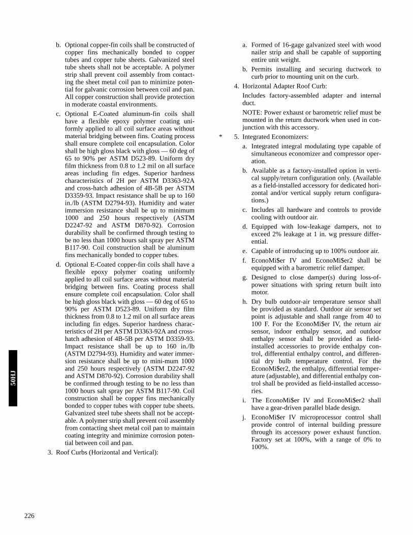
226
b. Optional copper-fin coils shall be constructed ofcopper fins mechanically bonded to coppertubes and copper tube sheets. Galvanized steeltube sheets shall not be acceptable. A polymerstrip shall prevent coil assembly from contact-ing the sheet metal coil pan to minimize poten-tial for galvanic corrosion between coil and pan.All copper construction shall provide protectionin moderate coastal environments.
c. Optional E-Coated aluminum-fin coils shallhave a flexible epoxy polymer coating uni-formly applied to all coil surface areas withoutmaterial bridging between fins. Coating processshall ensure complete coil encapsulation. Colorshall be high gloss black with gloss — 60 deg of65 to 90% per ASTM D523-89. Uniform dryfilm thickness from 0.8 to 1.2 mil on all surfaceareas including fin edges. Superior hardnesscharacteristics of 2H per ASTM D3363-92Aand cross-hatch adhesion of 4B-5B per ASTMD3359-93. Impact resistance shall be up to 160in./lb (ASTM D2794-93). Humidity and waterimmersion resistance shall be up to minimum1000 and 250 hours respectively (ASTMD2247-92 and ASTM D870-92). Corrosiondurability shall be confirmed through testing tobe no less than 1000 hours salt spray per ASTMB117-90. Coil construction shall be aluminumfins mechanically bonded to copper tubes.
d. Optional E-Coated copper-fin coils shall have aflexible epoxy polymer coating uniformlyapplied to all coil surface areas without materialbridging between fins. Coating process shallensure complete coil encapsulation. Color shallbe high gloss black with gloss — 60 deg of 65 to90% per ASTM D523-89. Uniform dry filmthickness from 0.8 to 1.2 mil on all surface areasincluding fin edges. Superior hardness charac-teristics of 2H per ASTM D3363-92A and cross-hatch adhesion of 4B-5B per ASTM D3359-93.Impact resistance shall be up to 160 in./lb(ASTM D2794-93). Humidity and water immer-sion resistance shall be up to mini-mum 1000and 250 hours respectively (ASTM D2247-92and ASTM D870-92). Corrosion durability shallbe confirmed through testing to be no less than1000 hours salt spray per ASTM B117-90. Coilconstruction shall be copper fins mechanicallybonded to copper tubes with copper tube sheets.Galvanized steel tube sheets shall not be accept-able. A polymer strip shall prevent coil assemblyfrom contacting sheet metal coil pan to maintaincoating integrity and minimize corrosion poten-tial between coil and pan.
3. Roof Curbs (Horizontal and Vertical):
a. Formed of 16-gage galvanized steel with woodnailer strip and shall be capable of supportingentire unit weight.
b. Permits installing and securing ductwork tocurb prior to mounting unit on the curb.
4. Horizontal Adapter Roof Curb:Includes factory-assembled adapter and internalduct.NOTE: Power exhaust or barometric relief must bemounted in the return ductwork when used in con-junction with this accessory.
* 5. Integrated Economizers:a. Integrated integral modulating type capable of
simultaneous economizer and compressor oper-ation.
b. Available as a factory-installed option in verti-cal supply/return configuration only. (Availableas a field-installed accessory for dedicated hori-zontal and/or vertical supply return configura-tions.)
c. Includes all hardware and controls to providecooling with outdoor air.
d. Equipped with low-leakage dampers, not toexceed 2% leakage at 1 in. wg pressure differ-ential.
e. Capable of introducing up to 100% outdoor air.f. EconoMi$er IV and EconoMi$er2 shall be
equipped with a barometric relief damper.g. Designed to close damper(s) during loss-of-
power situations with spring return built intomotor.
h. Dry bulb outdoor-air temperature sensor shallbe provided as standard. Outdoor air sensor setpoint is adjustable and shall range from 40 to100 F. For the EconoMi$er IV, the return airsensor, indoor enthalpy sensor, and outdoorenthalpy sensor shall be provided as field-installed accessories to provide enthalpy con-trol, differential enthalpy control, and differen-tial dry bulb temperature control. For theEconoMi$er2, the enthalpy, differential temper-ature (adjustable), and differential enthalpy con-trol shall be provided as field-installed accesso-ries.
i. The EconoMi$er IV and EconoMi$er2 shallhave a gear-driven parallel blade design.
j. EconoMi$er IV microprocessor control shallprovide control of internal building pressurethrough its accessory power exhaust function.Factory set at 100%, with a range of 0% to100%.
50H
J

227
k. EconoMi$er2 shall be capable of control from a4 to 20 mA signal through optional 4 to 20 mAdesign without microprocessor control(required for PremierLink™ or third party con-trol interface).
l. EconoMi$er IV Microprocessor Occupied Min-imum Damper Position Setting maintains theminimum airflow into the building during occu-pied period providing design ventilation rate forfull occupancy (damper position during heat-ing). A remote potentiometer may be used tooverride the set point.
m. EconoMi$er IV Microprocessor UnoccupiedMinimum Damper Position Setting — TheEconoMi$er IV dampers shall be completelyclosed when the unit is in the occupied mode.
n. EconoMi$er IV Microprocessor IAQ/DCVMaximum Damper Position Setting — Settingthe maximum position of the damper preventsthe introduction of large amounts of hot or coldair into the space. This position is intended tosatisfy the base minimum ventilation rate.
o. EconoMi$er IV Microprocessor IAQ controlmodulates the outdoor-air damper to provideventilation based on the optional 2 to 10 vdcCO2 sensor input.
p. Compressor lockout sensor (opens at 35 F,closes at 50 F).
q. Actuator shall be direct coupled to economizergear, eliminating linkage arms and rods.
r. Control LEDs:1) When the outdoor-air damper is capable of
providing free cooling, the “Free Cool”LED shall illuminate.
2) The IAQ LED indicates when the moduleis on the DCV mode.
3) The EXH LED indicates when the exhaustfan contact is closed.
s. Remote Minimum Position Control — A field-installed accessory remote potentiometer allowsthe outdoor-air damper to be opened or closedbeyond the minimum position in the occupiedmode for modified ventilation.
6. Two-Position Damper:Two-position damper package shall include singleblade damper and 24-v motor. Admits up to 25%
outdoor air, and shall close upon unit shutoff.Damper shall cover 3.8-in. high by 17.75-in. wide(117.8 sq. in.) opening in return air upper panel.
7. Accessory Compressor Cycle Delay:Compressor shall be prevented from restarting for aminimum of 5 minutes after shutdown.
* 8. Thermostats and Subbases:Thermostats and subbases shall provide stagedheating and cooling in addition to automatic (ormanual) changeover and fan control.
* 9. Barometric Relief Damper Package:a. Package shall include damper, seals, hardware,
and hoods to relieve excess internal pressure.b. Damper shall close due to gravity upon unit
shutdown.c. Damper package must be field-installed in
return-air ductwork when used with optionalside return connections.
*10. Power Exhaust:Package shall include an exhaust (propeller style)fan, 1/2 Hp 208-230, 460 v (factory-wired for 460v) direct drive motor, and damper for vertical flowunits with economizer to control over-pressuriza-tion of building. Power Exhaust package must befield-installed in return-air ductwork when usedwith optional side return connections.
*11. Head Pressure Control Package:Control package shall consist of an accessory out-door-air package and a solid-state control with con-denser coil temperature sensor for controllingcondenser-fan motor speed to maintain condensingtemperature between 90 F and 100 F at outdoorambient temperature down to –20 F.
12. Low-Ambient Kits:When used, kits shall allow units to operate atlower outdoor ambient temperatures down to 20 F.
*13. Electronic Programmable Thermostat:Unit shall be capable of using deluxe full-featuredelectronic thermostat.
14. Winter Start Time-Delay Relay:Used in conjunction with the accessory low-ambi-ent kit or head pressure control device, permitsoperation in cooling at lower outdoor ambient tem-peratures. See price pages for more information.
Guide specifications — 50HJ015,017 (cont)50H
J

228
15. Service Option Package:a. Hinged access panels for the filter, compressors,
evaporator fan, and control box areas. Filterhinged access panels permit tool-less entry forchanging filters. Evaporator fan hinged accesspanel shall be field-convertible to a tool-lessentry by removing and discarding screws. Eachexternal hinged access panel shall be perma-nently attached to the rooftop unit.
b. Convenience outlet: Shall be factory-installedand internally mounted with an externallyaccessible 115-v, 15 amp GFI, female recepta-cle with hinged cover. Voltage required to oper-ate convenience outlet shall be provided by afield-supplied and properly fused separatebranch circuit.
c. Non-fused disconnect switch: Shall be factory-installed, internally mounted, NEC and ULapproved. Non-fused switch shall provide unitpower shutoff. The control access door shall beinterlocked with the non-fused disconnect. Thedisconnect switch must be in the OFF positionto open the control box access door. Shall beaccessible from outside the unit and shall pro-vide power off lockout capability.
16. Electric Heater Package:a. Fully assembled for installation. The packages
are designed in accordance with UL safety stan-dards 1995 and listed by ETL. Heater construc-tion approved by UL 5306.
b. Heater element open coil resistance wire,nickel-chrome alloy, 0.29 inches inside diame-ter, strung through ceramic insulators mountedon metal frame. Coil ends are staked andwelded to terminal screw slots.
c. Heater assemblies are provided with integralfusing for protection of internal heater circuitsnot exceeding 48 amps each.
d. Auto reset thermo limit controls, magneticheater contactors (24 v coil) and terminal blockall mounted in electric heater control box (mini-mum 18 ga. galvanized steel) attached to end ofheater assembly.
e. Certain models (208-230/3/60, 42/56 and 56/75kW) require an additional heater control boxthat contains a field power terminal block, afield power wiring fuse block and fuses (125 A,250 V, class K5 or RK%); included with theelectric heater assembly package.
f. All power wiring leads are 10 AWG and controlwiring leads are 18 AWG, both rated at 105 deg.C.
17. Glycol Coil: (Hot Water Coil)Coil shall be 2-row copper tube (1/2-in. OD) withaluminum plate fins (15 fins/in.) and (1.625 in.OD) copper headers. Input and output connectionsshall be (1.625 in. ODM) copper stubs for sweatconnections. Coil shall be furnished with suitable
support rails, end plates, and hardware for readyfield installation in heater compartment.
18. Alternate Drive:Drive shall provide higher static drive capability toenhance evaporator-fan performance rpm range.
19. Hail Guard:Hail guard shall protect the condenser coil fromhail, flying debris, and damage by large objectswithout increasing unit clearances.
20. Ultraviolet Germicidal Lamps:Ultraviolet germicidal lamps are designed to elimi-nate odor causing mold and fungus that maydevelop in the wet area of the evaporator section ofthe unit. The high output, low temperature germi-cidal lamps are field installed in the evaporator sec-tion of the unit, aimed at the evaporator coil andcondensate pan. The short wavelength ultravioletlight inhibits and kills mold, fungus and microbialgrowth. The lamps have an output rating at 45 F in400 fpm airflow of 120 microwatts/cm2 at 1 meter.
21. Stainless Steel Condensate Pan:Stainless steel condensate pans shall be availablefor condensate collection.
22. Outdoor Air Enthalpy Sensor (EconoMi$er IV orEconoMi$er2):The outdoor air enthalpy sensor shall be used withthe EconoMi$er IV or EconoMi$er2 device to pro-vide single enthalpy control. When used in con-junction with a return air enthalpy sensor, theEconoMi$er IV or EconoMi$er2 device will pro-vide differential enthalpy control. The sensorallows the unit to determine if outside air is suitablefor free cooling.
23. Return Air Enthalpy Sensor (EconoMi$er IV orEconoMi$er2):The return air enthalpy sensor shall be used withthe EconoMi$er IV or EconoMi$er2 device. Whenused in conjunction with an outdoor air enthalpysensor, the EconoMi$er IV or EconoMi$er2 devicewill provide differential enthalpy control.
24. Return Air Temperature Sensor (EconoMi$er IV orEconoMi$er2):The return air temperature sensor shall be usedwith the EconoMi$er IV or EconoMi$er2 device.When used in conjunction with the standard out-door air temperature sensor, the EconoMi$er IV orEconoMi$er2 device will provide differential tem-perature control.
25. Indoor Air Quality (CO2) Room Sensor(EconoMi$er IV):Sensor shall have the ability to provide demandventilation control through the EconoMi$er IV. TheIAQ sensor shall be wall mounted with an LEDdisplay in parts per million. The set point shallhave adjustment capability.
50H
J

229
26. Return Air CO2 Sensor (EconoMi$er IV):Sensor shall have the ability to provide demandventilation control through the EconoMi$er IV. TheIAQ sensor shall be duct mounted. The set pointshall have adjustment capability.
27. Humidistat:Field-installed, wall-mounted humidistat is used tocontrol activation of the dehumidification package.The humidistat can be set for humidity levelsbetween 20% and 80% relative humidity.
28. Light Commercial Thermidistat™ Device:Field-installed wall-mounted thermidistat is used tocontrol temperature and activation of the dehumidi-fication package. The Thermidistat device can beset for humidity settings from 50% to 90% relativehumidity.
29. Fan/Filter Status Switch:Switch shall provide status of indoor (evaporator)fan (ON/OFF) or filter (CLEAN/DIRTY). Statusshall be displayed over communication bus when
used with direct digital controls or with an indica-tor light at the thermostat.
30. Manual Outdoor-Air Damper:Manual damper package shall consist of damper,birdscreen, and rainhood which can be preset toadmit up to 50% outdoor air for year round ventila-tion.
31. 62M Energy Recovery VentilatorOne-piece energy recovery ventilation (ERV) unitutilizing an ARI 1060 certified energy recoverycassette with permanently bonded silica gel desic-cant. UL std 1995, ETL tested and certified. Fac-tory assembled single piece unit with single pointpower connections. Unit shall be designed as astand-alone ERV or may be mated with any 2-25ton Carrier rooftop unit. For mated applications,the ERV unit shall operate in conjunction withrooftop unit fan. For additional specifications referto the 62M Product Data manual.
Guide specifications — 50HJ015,017 (cont)50H
J

230
Packaged Rooftop Electric Cooling Unit with Optional Electric Heat — Constant Volume ApplicationSize Range: 18 to 25 Tons, Nominal (Cooling)
19 to 78 kW Nominal (Electric Heating)
Carrier ModelNumber:
50HJ
Part 1 — General1.01 SYSTEM DESCRIPTION
Unit is an outdoor rooftop mounted, electrically con-trolled heating and cooling unit utilizing scroll hermeticcompressors with crankcase heaters for cooling dutyand gas combustion heat for heating duty. Supply airshall be discharged downward or horizontally, as shownon contract drawings.
1.02 QUALITY ASSURANCEA. Unit shall well exceed the energy efficiency require-
ments of ASHRAE standard 90.1-2001. Unit shall beEnergy Star qualified.
B. Unit shall be rated in accordance with ARI Standards270 and 360 and all units shall be designed in accor-dance with UL Standard 1995.
C. Unit shall be designed to conform to ASHRAE 15.D. Unit shall be UL and UL, Canada, tested and certified in
accordance with ANSI Z21.47 Standards as a total pack-age.
E. Roof curb shall be designed to conform to NRCA Stan-dards.
F. Insulation and adhesive shall meet NFPA 90A require-ments for flame spread and smoke generation.
G. Unit casing shall be capable of withstanding 500-hoursalt spray exposure per ASTM B117 (scribed specimen).
H. Unit shall be manufactured in a facility registered toISO 9001:2000.
1.03 DELIVERY, STORAGE, AND HANDLINGUnit shall be stored and handled per manufacturer’s rec-ommendations.
Part 2 — Products2.01 EQUIPMENT (STANDARD)
A. General:The 50HJ unit shall be a factory assembled, single-pieceheating (if equipped) and cooling unit. Contained withinthe unit enclosure shall be all factory wiring, piping,controls, refrigerant charge (R-22), and special featuresrequired prior to field start-up.
B. Unit Cabinet:1. Constructed of galvanized steel (G90 — 1.8 oz. of
zinc per square foot of sheet metal), bonderizedand primer-coated on both sides and coated with abaked polyester thermosetting powdercoating fin-ish on the outer surface.
2. Indoor blower compartment interior surfaces shallbe insulated with a minimum 1/2-in. thick, 1 lb den-sity fiberglass insulation. Fiberglass insulationshall be bonded with a thermosetting resin (8 to12% by weight nominal, phenol formaldehyde typ-ical), and coated with an acrylic or other materialthat meets the NFPA 90 flame retardance require-ments and has an ‘‘R’’ Value of 3.70. Aluminumfoil-faced fiberglass insulation shall be used in thegas heat compartment.
3. Cabinet panels shall have minimum 1/2-in. thick,1.5-lb. density insulation. Cabinet panels shall beesily removable for servicing.
4. Filters shall be accessible through an access panel.5. Holes shall be provided in the base rails (minimum
14 gage) for rigging shackles and level travel andmovement during overhead rigging operations.
6. Fork lift slots shall be available from two sides ofthe unit (end and side).
7. Unit shall contain a sloped drain pan, to preventstanding water from accumulating. Pan shall befabricated of epoxy powder coated steel.
C. Fans:1. Indoor blower (evaporator fan):
a. Centrifugal supply air blower shall have pillow-block ball bearings and adjustable belt drive.Blower assembly shall slide out of unit for ser-vicing.
b. Fan wheel shall be made from steel with a cor-rosion resistant finish. It shall be a dynamicallybalanced, double-inlet type with forward-curved blades.
c. The indoor fan system (blower wheels, motors,belts, and both bearings) shall slide out for easyaccess.
2. Condenser fans shall be of the direct-driven propel-ler type, with corrosion-resistant blades riveted tocorrosion-resistant steel supports. They shall bedynamically balanced and discharge air upwards.Condenser fan motors shall be totally enclosed andbe of a shaft down design.
D. Compressor(s):1. Fully hermetic, scroll type, internally protected.2. Factory spring-shock mounted and internally
spring mounted for vibration isolation.
Guide specifications — 50HJ020-02850
HJ

231
3. On electrically and mechanically independentrefrigerant circuits.
4. Reverse rotation protection capability.5. Crankcase heaters shall only be activated during
compressor OFF mode.E. Coils:
1. Standard evaporator and condenser coils shall havecopper or aluminum plate fins mechanicallybonded to seamless internally grooved coppertubes with all joints brazed.
2. Coils shall be leak tested at 150 psig (1034 kPa) andpressure tested at 450 psig (3103 kPa).
3. Optional pre-coated aluminum-fin coils shall havea durable epoxy-phenolic coating to provide pro-tection in mildly corrosive coastal environments.Coating shall be applied to the aluminum fin stockprior to the fin stamping process to create an inertbarrier between the aluminum fin and copper tube.Epoxy-phenolic barrier shall minimize galvanicaction between dissimilar metals.
4. Copper-fin coils shall be constructed of copper finsmechanically bonded to copper tubes and coppertube sheets. Galvanized steel tube sheets shall notbe acceptable. A polymer strip shall prevent coilassembly from contacting the sheet metal coil panto minimize potential for galvanic corrosionbetween coil and pan. All copper construction shallprovide protection in moderate coastal environ-ments.
5. E-Coated aluminum-fin coils shall have a flexibleepoxy polymer coating uniformly applied to all coilsurface areas without material bridging betweenfins. Coating process shall ensure complete coilencapsulation. Color shall be high gloss black withgloss — 60 deg of 65 to 90% per ASTM D523-89.Uniform dry film thickness from 0.8 to 1.2 mil onall surface areas including fin edges. Superior hard-ness characteristics of 2H per ASTM D3363-92Aand cross-hatch adhesion of 4B-5B per ASTMD3359-93. Impact resistance shall be up to 160 in./lb (ASTM D2794-93). Humidity and water immer-sion resistance shall be up to minimum 1000 and250 hours respectively (ASTM D2247-92 andASTM D870-92). Corrosion durability shall beconfirmed through testing to be no less than 1000hours salt spray per ASTM B117-90. Coil con-struction shall be aluminum fins mechanicallybonded to copper tubes.
6. E-Coated copper-fin coils shall have a flexibleepoxy polymer coating uniformly applied to all coilsurface areas without material bridging betweenfins. Coating process shall ensure complete coilencapsulation. Color shall be high gloss black withgloss — 60 deg of 65 to 90% per ASTM D523-89.Uniform dry film thickness from 0.8 to 1.2 mil onall surface areas including fin edges. Superior hard-
ness characteristics of 2H per ASTM D3363-92Aand cross-hatch adhesion of 4B-5B per ASTMD3359-93. Impact resistance shall be up to 160 in./lb (ASTM D2794-93). Humidity and water immer-sion resistance shall be up to minimum 1000 and250 hours respectively (ASTM D2247-92 andASTM D870-92). Corrosion durability shall beconfirmed through testing to be no less than 1000hours salt spray per ASTM B117-90. Coil con-struction shall be copper fins mechanically bondedto copper tubes with copper tube sheets. Galva-nized steel tube sheets shall not be acceptable. Apolymer strip shall prevent coil assembly from con-tacting sheet metal coil pan to maintain coatingintegrity and minimize corrosion potential betweencoil and pan.
F. Refrigerant Components:Each refrigerant circuit shall include:
1. Thermostatic expansion valve (TXV) with remov-able power element.
2. Filter driers.3. Gage port and connections on suction and dis-
charge.G. Filter Section:
Standard filter section shall consist of factory-installed2-in. thick throwaway fiberglass filters.
H. Controls and Safeties:1. Electro-Mechanical Control:
a. Economizer control (optional).b. Capacity control (2-step).c. Unit shall be complete with self-contained low-
voltage control circuit.2. Safeties:
a. Unit shall incorporate a solid-state compressorlockout which provides optional reset capabilityat the space thermostat, should any of the fol-lowing safety devices trip and shut off compres-sor:1) Compressor lockout protection provided
for either internal or external overload.2) Low-pressure protection.3) Freeze protection (evaporator coil).4) High-pressure protection (high pressure
switch or internal).I. Operating Characteristics:
1. Unit shall be capable of starting and running at 125F ambient outdoor temperature per maximum loadcriteria of ARI Standard 360.
2. Unit with standard controls will operate in coolingdown to an outdoor ambient temperature of 40 F.
3. Size 18 and 20 ton units shall have 3 fully indepen-dent refrigerant circuits to allow for 33% capacityper circuit.
Guide specifications — 50HJ020-028 (cont)50H
J

232
J. Electrical Requirements:All unit power wiring shall enter unit cabinet at a singlelocation.NOTE: On 208/230 v units using 75-kW heaters, sepa-rate wiring is required.
K. Motors:1. Compressor motors shall be cooled by refrigerant
gas passing through motor windings and shall haveline break thermal and current overload protection.
2. All fan motors shall have permanently lubricated,sealed bearings and inherent automatic-reset ther-mal overload protection or manual reset calibratedcircuit breakers.
3. All indoor-fan motors 5 hp and larger shall meetthe minimum efficiency requirements as estab-lished by the Energy Policy Act of 1992 (EPACT),effective October 24, 1997.
L. Special Features:Certain features are not applicable when the featuresdesignated * are specified. For assistance in amendingthe specifications, contact your local Carrier SalesOffice.
1. Full Perimeter Roof Curbs (Horizontal and Verti-cal):a. Formed of 14-gage galvanized steel with wood
nailer strip and shall be capable of supportingentire unit weight.
b. Permits installing and securing ductwork tocurb prior to mounting unit on the curb.
c. Retrofit roof curb kit shall be available for fit upto existing Carrier DP, DR, TJ roof curbs.
* 2. Integrated Economizers:a. Integrated integral modulating type capable of
simultaneous economizer and compressor oper-ation.
b. Available as a factory-installed option in verti-cal supply/return configuration only. (Availableas a field-installed accessory for dedicated hori-zontal and/or vertical supply return configura-tions.)
c. Includes all hardware and controls to providecooling with outdoor air.
d. Equipped with low-leakage dampers, not toexceed 2% leakage at 1 in. wg pressure differ-ential.
e. Capable of introducing up to 100% outdoor air.f. EconoMi$er IV shall be equipped with a baro-
metric relief damper.g. Designed to close damper(s) during loss-of-
power situations with spring return built intomotor.
h. Dry bulb outdoor-air temperature sensor shallbe provided as standard. Outdoor air sensor setpoint is adjustable and shall range from 40 to100 F. For the EconoMi$er IV, the return airsensor, indoor enthalpy sensor, and outdoorenthalpy sensor shall be provided as field-installed accessories to provide enthalpy con-trol, differential enthalpy control, and differen-tial dry bulb temperature control.
i. The EconoMi$er IV shall have a gear-drivenparallel blade design.
j. EconoMi$er IV microprocessor control shallprovide control of internal building pressurethrough its accessory power exhaust function.Factory set at 100%, with a range of 0% to100%.
k. EconoMi$er IV Microprocessor Occupied Min-imum Damper Position Setting maintains theminimum airflow into the building during occu-pied period providing design ventilation rate forfull occupancy (damper position during heat-ing). A remote potentiometer may be used tooverride the set point.
l. EconoMi$er IV Microprocessor UnoccupiedMinimum Damper Position Setting — TheEconoMi$er IV dampers shall be completelyclosed when the unit is in the occupied mode.
m. EconoMi$er IV Microprocessor IAQ/DCV con-trol modulates the outdoor-air damper to pro-vide ventilation based on the optional 2 to 10vdc CO2 sensor input.
n. Compressor lockout sensor (opens at 35 F,closes at 50 F).
o. Actuator shall be direct coupled to economizergear, eliminating linkage arms and rods.
p. Control LEDs:1) When the outdoor-air damper is capable of
providing free cooling, the “Free Cool”LED shall illuminate.
2) The IAQ LED indicates when the moduleis on the DCV mode.
3) The EXH LED indicates when the exhaustfan contact is closed.
q. Remote Minimum Position Control — A field-installed accessory remote potentiometer allowsthe outdoor-air damper to be opened or closedbeyond the minimum position in the occupiedmode for modified ventilation.
* 3. Barometric Relief Damper Package:a. Package shall include damper, seals, hardware,
and hoods to relieve excess internal pressure.b. Damper shall close due to gravity upon unit
shutdown.
50H
J

233
* 4. Power Exhaust:Package shall include an exhaust (centrifugal style)fan, 1 Hp 208-230, 460 v (factory-wired for 460 v)direct-drive motor, and damper for vertical flowunits with economizer to control over-pressuriza-tion of building.
* 5. Thermostats and Subbases:Thermostats and subbases shall provide stagedheating and cooling in addition to automatic (ormanual) changeover and fan control.
6. Electronic Programmable Thermostat:Unit shall be capable of using deluxe full-featuredelectronic thermostat.
7. Convenience Outlet:Outlet shall be factory-installed and internallymounted with an externally accessible 115-v, 15amp GFI, female receptacle with hinged cover. Astep down transformer shall be included so no addi-tional wiring is necessary.
8. Non-Fused Disconnect Switch:Switch shall be factory-installed, internallymounted, NEC and UL approved. Non-fusedswitch shall provide unit power shutoff. Shall beaccessible from outside the unit and shall providepower off lockout capability.
9. Electric Heater Package:a. Fully assembled for installation. The packages
are designed in accordance with UL safety stan-dards 1995 and listed by ETL. Heater construc-tion approved by UL 5306.
b. Heater element open coil resistance wire,nickel-chrome alloy, 0.29 inches inside diame-ter, strung through ceramic insulators mountedon metal frame. Coil ends are staked andwelded to terminal screw slots.
c. Heater assemblies are provided with integralfusing for protection of internal heater circuitsnot exceeding 48 amps each.
d. Auto reset thermo limit controls, magneticheater contactors (24 v coil) and terminal blockall mounted in electric heater control box (mini-mum 18 ga. Galvanized steel) attached to end ofheater assembly.
10. Hail Guard, Condenser Coil Grille:Grille shall protect the condenser coil from hail,flying debris, and damage by large objects withoutincreasing unit clearances.
11. Horizontal Kit:Horizontal kit shall contain all the necessary hard-ware to convert a vertical airflow unit to a horizon-tal airflow unit.The unit shall also be available as a horizontal air-flow unit directly from the factory.
12. Return Air Smoke Detector:The smoke detector shall send input to the control-ler to shut down the unit in case smoke is detected.The smoke detector shall be factory installed in thereturn air section or shall be available as a field-installed accessory.
13. Two-Position Damper:The damper shall admit up to 25% outdoor air andshall close upon shutdown. The package shallinclude a single-blade damper and motor.
14. Manual Damper:The damper shall have a manually adjustable out-side air intake for up to 33% outside air.
15. Motor/Drive Combinations:Low, mid-low, mid-high and high motor/drivecombinations are available to match evaporator fanperformance with each application.
16. Outdoor Air Enthalpy Sensor (EconoMi$er IV):The outdoor air enthalpy sensor is used to senseoutdoor air enthalpy for the EconoMi$er IV device.The outdoor air enthalpy sensor, in conjunctionwith the standard outdoor air temperature sensor,shall be used with the EconoMi$er IV device toprovide outdoor enthalpy. Outdoor air enthalpyshall be calculated by the EconoMi$er IV devicefrom the outdoor air temperature and humidityreadings. When the outdoor air enthalpy sensor isinstalled, the EconoMi$er IV can perform OutdoorAir Enthalpy control. With the additional installa-tion of an accessory return air temperature sensorand return air enthalpy sensor, differential enthalpycontrol can also be performed.
17. Return Air Enthalpy Sensor (EconoMi$er IV):The return air enthalpy sensor is used to sense returnair enthalpy for the EconoMi$er IV device. Thereturn air enthalpy sensor, in conjunction with theaccessory return air temperature sensor, shall beused with the EconoMi$er IV device to providereturn air enthalpy. Return air enthalpy shall be cal-culated by the EconoMi$er IV device from thereturn air temperature and humidity readings. Withthe additional installation of an accessory return airtemperature sensor and outdoor air enthalpy sensor,differential enthalpy control can also be performed.
18. Return Air Temperature Sensor (EconoMi$er IV):The return air temperature sensor is used to sensereturn air temperature for the EconoMi$er IVdevice. When the return air temperature sensor isinstalled, the EconoMi$er IV can perform Differen-tial Temperature control. The return air temperaturesensor, in conjunction with the accessory return airenthalpy sensor, shall be used with the EconoMi$erIV device to provide return air enthalpy. Return airenthalpy shall be calculated by the EconoMi$er IVdevice from the return air temperature and humidityreadings. With the additional installation of anaccessory return air enthalpy sensor and outdoor air
Guide specifications — 50HJ020-028 (cont)50H
J

234
entthalpy sensor, differential enthalpy control canalso be performed.
19. Indoor Air Quality (CO2) Room Sensor (EconoMi$er IV):Sensor shall have the ability to provide demandventilation control through the EconoMi$er IV. TheIAQ sensor shall be wall mounted with an LEDdisplay in parts per million. The set point shallhave adjustment capability.
20. Return Air CO2 Sensor (EconoMi$er IV):Sensor shall have the ability to provide demandventilation control through the EconoMi$er IV. TheIAQ sensor shall be duct mounted. The set pointshall have adjustment capability.
21. Supply Air Smoke Detector:The smoke detector shall send input to the control-ler to shut down the unit in case smoke is detected.The smoke detector shall be factory-installed in thesupply air section or shall be available as a field-installed accessory.
22. Supply and Return Air Smoke Detector:The smoke detector shall send input to the control-ler to shut down the unit in case smoke is detected.
The smoke detector shall be factory installed in thesupply and return air sections or shall be availableas a field-installed accessory.
23. Hinged Panel Option:Hinged panel option provide hinged access panelsfor the filter, compressor, evaporator fan, and con-trol box areas. Filter hinged panels permit tool-lessentry for changing filters. Each hinged panel is per-manently attached to the rooftop unit.
24. 62M Energy Recovery VentilatorOne-piece energy recovery ventilation (ERV) unitutilizing an ARI 1060 certified energy recoverycassette with permanently bonded silica gel desic-cant. UL std 1995, ETL tested and certified. Fac-tory assembled single piece unit with single pointpower connections. Unit shall be designed as astand-alone ERV or may be mated with any 2-25ton Carrier rooftop unit. For mated applications,the ERV unit shall operate in conjunction withrooftop unit fan. For additional specifications referto the 62M Product Data manual.
50H
J

Manufacturer reserves the right to change, at any time, specifications or designs without notice and without obligations. Replaces: NewPg 235
Carrier Corporation • 7310 W. Morris St. Indianapolis, IN 46231 Printed in U.S.A Edition Date 12-06 Catalog No. 50H-1PD
Airflow Configuration 196 Maximum 106-196 Minimum 106-196Application data 196-200ARI capacity ratings 50HE003-006 9 50HJ004-014 9 50HJ015, 017 10 50HJ020-028 10Changeover, heating to cooling 196COBRA™ energy recovery units 5, 178-181, 190, 191Concentric duct details 197Condenser coil protection 197Controls 184-195Convenience outlet 22, 24, 43, 176Cooling capacities 50HE003-006 47 50HJ004-014 48, 49, 55-62 50HJ015, 017 50, 51, 63 50HJ020-028 52-54Dimensions Accessory 50HJ004-014 37, 38 50HJ015, 017 41-43 50HJ020-028 44 COBRA energy recovery units 39, 40 Base unit 50HE003-006 28 50HJ004-014 29, 30 50HJ015, 017 35 50HJ020-028 36 COBRA energy recovery units 31-34Ductwork 196EconoMi$er IV 22, 174, 198-200 50HJ004-014 102, 174 50HJ015,017 174EconoMi$er2 22, 175 50HJ004-014 101, 175 50HJ015,017 175Electric heaters 22 50HE003-006 107, 108 50HJ004-014 109, 110 50HJ015, 017 105 50HJ020-028 105 COBRA energy recovery units 111-116Electrical data 50HE003-006 117-120 50HJ004-014 121-128 50HJ015, 017 152 50HJ020-028 153-164 COBRA energy recovery units 129-152Energy$Recycler™ unit 22, 23
Evaporator fan motor Efficiency 50HE/HJ003-014 97 50HJ015, 017 97 Performance 50HE/HJ003-014 96 50HJ015, 017 96 50HJ020-028 98, 99Fan performance tables 50HE003-006 vertical discharge units 63-67 50HJ004-014 vertical discharge units 64-80 50HE003-006 horizontal discharge units 80-84 50HJ004-014 horizontal discharge units 81-92 50HJ015, 017 76, 77 50HJ020-028 78-80, 93-95Fan rpm at motor pulley settings 50HE/HJ003-014 99, 100 50HJ015, 017 100 50HJ020-028 100Features/Benefits 2-4Glycol coil 63Guide specifications 50HE003-006 201-206 50HJ004-014 207-212 50HJ015, 017 224-229 50HJ020-028 230-34 COBRA energy recovery units 50HE003-006 213-217 50HJ004-014 218-223Hinged panels 22, 25, 26Humidi-MiZer™ adaptive dehumidification 50HJ004-014 4, 55-62, 103Humidistat 179, 180Indoor air quality (IAQ) 4Maximum ambient cooling operating temperature 196Minimum ambient cooling operating temperature 196Model number nomenclature 50HE003-006 5 50HJ004-014 6 50HJ015, 017 7 50HJ020-028 8
Motormaster® options 22Options and accessories 19-27Performance data 44-116Physical data 50HE003-006 11 50HJ004-014 12, 13 50HJ015, 017 14 50HJ020-028 15Piping and wiring 50HE/HJ003-014 183 50HJ015, 017 184Power exhaust 50HJ015, 017 103 with economizer 50HJ004-014 102PremierLink™ controls 3, 4, 22, 184-188Roof curb dimensions 50HJ004-014 37, 38 50HJ015, 017 41 50HJ020-028 44 COBRA energy recovery units 39, 40Selection procedure 50HJ004-028 45, 46Service options 3Sound data 50HE003-006 106 50HJ004-014 106 50HJ015, 017 106 50HJ020-028 106Static pressure drop Economizer 50HJ004-014 101 50HJ015, 017 101 50HJ020-028 101 Electric heat 50HE/HJ003-014 104 50HJ015, 017 104 50HJ020-028 105Thermidistat 178, 181Thermostat Application data 196Unit-mounted disconnect 22, 24, 43, 176, 177,Wiring 50HE/HJ003-014 166 50HJ015, 017 170 50HJ020-028 171, 172 EconoMi$er IV 174 EconoMi$er2 175
INDEX