Embed Size (px)
Citation preview

PRODUCTION OF AMORPHOUS SILICA FROM RICE HUSK IN FLUIDISED
BED SYSTEM
NGO SAIK PENG
A thesis submitted in fulfilment of the
requirements for the award of the degree of
Doctor of Philosophy
Faculty of Chemical Engineering and Natural Resources Engineering
Universiti Teknologi Malaysia
FEBRUARY 2006
iii
ACKNOWLEDGEMENT
I would like to express my most sincere gratitude and appreciation to my
supervisor, Assoc. Prof. Dr Mohd Rozainee bin Taib for his guidance and
supervision of this research works. Without his guidance, I believe this research
would not have been completed.
I am also grateful to my fellow research partners, Mr Tan Kean Giap, Mr
Anwar Johari, Mr Arshad Adam Salema, Mr Wan Ahmad Muhardi bin Wan
Muhammad, Mr Lim Sin Yang, Mr Simon Looi Yat Seong, Mr Chong Yee Hwang
and Ms Wong Cheng Teng for their valuable ideas, friendship and assistance. I am
equally grateful to the Research Assistants involved in my research especially Mr
Guee Boon Chye, whose assistance facilitated my experimental works.
My special thanks go to the School of Graduate Studies (SPS) who supported
me financially through the UTM Fellowship Award. Lastly but certainly not the
least, I am indebted to my parents for their endless support throughout the length of
my study.
iv
ABSTRACT
Conventional methods for the preparation of amorphous silica (SiO2) are
very energy-intensive and expensive. Amorphous silica has wide industrial
applications, with annual world consumption in the excess of 1 million tonnes
valued at RM4,500 per tonne. Rice husk ash contains amorphous silica in the excess
of 95 wt%. Thermal treatment of rice husk is deemed the most economical method
to recover this amorphous silica from the readily available rice husk (approximately
0.5 million tonnes per annum in Malaysia). Hence, the purpose of this research was
to recover amorphous silica from rice husk through thermal treatment in fluidised
bed system. Experimental works were conducted in fluidised bed combustor systems
to determine the optimum mixing parameters (sand size, fluidising velocity, static
bed height) and combustion parameters (temperature, air supply, rice husk moisture
content, feeding design) to produce amorphous, carbon-free silica from rice husk.
The fly and bottom ashes were analysed for their residual carbon contents and silica
structures through loss on ignition (LOI) tests and X-Ray Diffraction (XRD)
analyses, respectively. Computational fluid dynamics (CFD) modelling using
FLUENT was also conducted to optimise the fluidised bed design and to overcome
problems encountered in experimental works. Experimental results showed that
amorphous, siliceous ash with residual carbon content of down to 1.0 wt% could be
obtained by burning water-washed rice husk that was free from alkali metal
compounds (potassium oxide and sodium oxide). The short freeboard height of the
experimental fluidised bed resulted in the incomplete oxidation of carbon and sand
contamination in the ash. Modelling results showed that both problems could be
overcome by increasing the height of the fluidised bed to 5000mm. In addition, the
induction of swirling flows at the freeboard region was found to be beneficial in
increasing the residence time of ash in the combustor, leading to higher carbon
burnout.
v
ABSTRAK
Penyediaan silika amorfus (SiO2) secara konvensional menggunakan banyak
tenaga dan sangat mahal. Silika amorfus mempunyai penggunaan meluas di industri,
dengan kadar penggunaannya di seluruh dunia melebihi 1 juta tan setahun dinilaikan
pada RM4,500 per tan. Abu sekam padi mengandungi silika amorfus melebihi 95%.
Rawatan haba ke atas sekam padi (dihasilkan pada kira-kira 0.5 juta tan setahun di
Malaysia) adalah kaedah paling ekonomik untuk memperolehi silika amorfus. Oleh
itu, matlamat penyelidikan ini adalah untuk mendapatkan silika amorfus daripada
sekam padi melalui rawatan haba dalam lapisan terbendalir. Kerja eksperimen
dilaksanakan dalam pembakar lapisan terbendalir untuk menentukan parameter
percampuran (saiz pasir, halaju perbendaliran, ketinggian lapisan terbendalir) dan
parameter pembakaran (suhu, bekalan udara, kelembapan sekam padi, rekabentuk
sistem penyuapan) optimum bagi menghasilkan silika amorfus dan bebas karbon
daripada sekam padi. Abu terbang dan abu bawahan dianalisis untuk menentukan
baki karbon dan struktur silika masing-masing melalui analisis kehilangan jisim dan
analisis belauan sinar-x. Permodelan pengiraan dinamik bendalir menggunakan kod
program FLUENT juga dilaksanakan untuk pengoptimuman rekabentuk pembakar
serta mengatasi masalah operasi semasa kerja eksperimen. Keputusan eksperimen
menunjukkan abu sekam padi amorfus dengan kandungan karbon sisa serendah
1.0% dapat diperolehi dengan membakar sekam padi yang telah dibasuh dengan air
(bebas dari sebatian logam alkali iaitu kalium oksida dan natrium oksida).
Ketinggian pembakar yang tidak mencukupi menyebabkan pengoksidaan karbon
tidak lengkap serta pencemaran pasir dalam abu terbang. Keputusan permodelan
komputer menunjukkan masalah ini dapat diatasi dengan menambahkan ketinggian
pembakar ke 5000mm. Penghasilan aliran pusaran di bahagian atas pembakar juga
didapati berfaedah untuk meningkatkan masa mastautin abu di dalam pembakar, dan
seterusnya menyebabkan kadar pengoksidaan karbon yang lebih tinggi.

vi
TABLE OF CONTENTS
CHAPTER TITLE PAGE
TITLE PAGE i
DECLARATION ii
ACKNOWLEDGEMENT iii
ABSTRACT iv
ABSTRAK v
TABLE OF CONTENTS vi
LIST OF TABLES xi
LIST OF FIGURES xxi
LIST OF PLATES xxxii
LIST OF SYMBOLS xxxiv
LIST OF APPENDICES xl
1 INTRODUCTION 1
1.1 Introduction 1
1.2 Benefits of Research 2
1.2.1 Amorphous Silica 2
1.2.2 Rice Husk as Silica Source 4
1.2.3 Market Review for Amorphous Silica from
Rice Husk Ash 8
1.2.4 Evaluation of Available Technologies for
Production of Amorphous Silica from Rice
Husk 11
1.2.5 Fluidised Bed as Selected Technology 16
vii
1.2.6 Types of Fluidised Bed 19
1.3 Objectives of Research 21
1.4 Scopes of Research 22
1.5 Expected Results 23
1.6 Layout of the Thesis 24
2 LITERATURE REVIEW 26
2.1 Research History on Thermal Treatment of
Rice Husk in Fluidised Bed 26
2.2 Effects of Fluidisation Parameters on the
Mixing Characteristics of Rice Husk in
Fluidised Bed 28
2.2.1 Fluidising Velocity 29
2.2.2 Sand Size 31
2.2.3 Static Bed Height 33
2.3 Effects of Operating Parameters on the
Combustion Efficiency of Rice Husk in
Fluidised Bed 37
2.3.1 Time 37
2.3.2 Temperature 39
2.3.3 Presence of Impurities in Rice Husk 51
2.3.4 Air Supply 57
2.3.5 Moisture Content of Rice Husk 60
2.4 Effects of Fluidised Bed Design on the
Combustion Efficiency of Rice Husk in
Fluidised Bed 61
2.4.1 Freeboard Height 61
2.4.2 Feeding Design and Position of Feed Entry 63
3 METHODOLOGY 67
3.1 Introduction 67
3.2 Research Materials 67

viii
3.3 Experimental Techniques 75
3.3.1 Thermal Treatment in Muffle Furnace 75
3.3.2 Fluidisation Study in 80-mm Inner
Diameter Fluidised Bed Column 76
3.3.3 Combustion Study in 80-mm Inner
Diameter Fluidised Bed Combustor 80
3.3.4 Combustion Study in 210-mm Inner
Diameter Fluidised Bed Combustor 83
3.4 Analytical Techniques 90
3.4.1 Determination Silica Structure and Presence
of Contaminants in Rice Husk Ash through
X-Ray Diffraction (XRD) Analysis 90
3.4.2 Determination of Residual Carbon Content
in Rice Husk Ash through Loss on Ignition
(LOI) Test 90
3.4.3 Determination of Particle Size Distribution
of Rice Husk Ash through Sieve Analysis 91
3.4.4 Determination of Oxygen Level in
Combustion Gas 92
3.5 Modelling Technique through Computational
Fluid Dynamics (CFD) Code of FLUENT 92
3.5.1 Governing Equations 93
3.5.2 Numerical Solutions 106
4 RESULTS AND DISCUSSIONS ON
COMBUSTION OF RICE HUSK IN
FLUIDISED BED TO PRODUCE
AMORPHOUS SILICA 114
4.1 Basic Combustion Characteristics of Rice
Husk 114
4.2 Effect of Temperature and Residence Time on
the Formation of Silica Crystals in Rice Husk
Ash 119

ix
4.3 Effects of Fluidisation Parameters on the
Mixing of Rice Husk in Fluidised Bed 130
4.3.1 Sand Size 132
4.3.2 Fluidising Velocity (Umf Number) 135
4.3.3 Static Bed Height 137
4.4 Effect of Fluidisation Parameters on the
Mixing of Rice Husk in Fluidised Bed during
Combustion Process 139
4.4.1 Sand Size 139
4.4.2 Fluidising Velocity 150
4.5 Effect of Mixing Parameters on the
Combustion Efficiency of Rice Husk in
Fluidised Bed 153
4.5.1 Fluidising Velocity 153
4.5.2 Static Bed Height 164
4.6 Effect of Temperature on the Combustion
Efficiency of Rice Husk in Fluidised Bed 178
4.6.1 Bed Temperature 178
4.6.2 Freeboard Temperature 181
4.6.3 Heat Loss 193
4.7 Effect of Washing of Rice Husk on Its
Combustion Efficiency in Fluidised Bed 201
4.7.1 Determination of Pretreatment Method for
Rice Husk 201
4.7.2 Effect of Alkali Metals Removal in Rice
Husk on Its Combustion Efficiency in
Fluidised Bed 205
4.7.2.1 Primary Stage Combustion 205
4.7.2.2 Secondary Stage Combustion 209
4.8 Effect of Air Supply on the Combustion
Efficiency of Rice Husk in Fluidised Bed 220
4.8.1 Primary Air Factor 220
4.8.2 Primary-to-Secondary Air Ratio 227
4.8.3 Pneumatic Air Feeding Velocity 232
x
4.9 Effect of Moisture Content in Rice Husk on Its
Combustion Efficiency in Fluidised Bed 241
4.10 Effect of Feeding Design on the Combustion
Efficiency of Rice Husk in Fluidised Bed 246
4.10.1 Vortex Feeding 246
4.10.2 Vortex Feeding with Higher Fluidising
Velocity 263
4.11 Summary of Findings 273
5 RESULTS AND DISCUSSIONS ON
IMPROVEMENT IN DESIGN AND
OPERATION OF THE FLUIDISED BED
THROUGH CFD MODELLING 277
5.1 Increase in Fluidised Bed Freeboard Height 277
5.2 Improvement of Feeding Conditions 284
5.2.1 Feeding Velocity 284
5.2.2 Vortex Feeding 292
5.3 Summary of Findings 310
6 CONCLUSIONS AND RECOMMENDATIONS 313
6.1 Conclusions 313
6.2 Recommendations for Future Study 323
REFERENCES 325

xi
LIST OF TABLES
TABLE TITLE PAGE
Table 1-1: Market prices for amorphous rice husk ash for use
in cement industry 10
Table 1-2: Existing methods and technologies for preparation
of amorphous silica from rice husk 12
Table 1-3: Performance of existing thermal treatment
technologies in producing low carbon content rice
husk ash 18
Table 2-1: Properties of sewage sludge and rice husk (wt% dry
basis) 30
Table 2-2: Sand size and corresponding fluidisation velocity
reported in literature for combustion of rice husk in
fluidised bed 31
Table 2-3: Minimum fluidising velocity of sand of various size
ranges 33
Table 2-4: Static bed height used for the combustion of rice
husk as reported in existing literatures 34
Table 2-5: Temperature limits reported in various literatures
for the onset of crystallisation of silica in rice husk
ash 43
Table 2-6: Chemical properties of wheat straw and rice husk 54
Table 2-7: Optimum air factor reported in literature (as
reviewed by Natarajan et al., 1998a) for
combustion of rice husk in fluidised bed 57
xii
Table 2-8: Different rice husk feeding arrangements reported
in literature 64
Table 3-1: Chemical properties of rice husk 68
Table 3-2: List and identifications of combustion parameters
investigated in the 210-mm inner diameter fluidised
bed combustor 89
Table 3-3: Diffraction peaks of crystalline silica 90
Table 3-4: Properties of particles used in modelling the effect
of feeding method on rice husk combustion in the
210-mm inner diameter fluidised bed combustor 113
Table 4-1: Real-time tracking of combustion of a batch (4 g)
of water-washed rice husk particles in the muffle
furnace (650 – 750oC) 118
Table 4-2: Effect of temperature and residence time on the
formation of black char particles during thermal
treatment of raw rice husk in the muffle furnace 122
Table 4-3: Effect of temperature and residence time on the
formation of black char particles during thermal
treatment of water-washed rice husk* in the muffle
furnace 123
Table 4-4: Effect of temperature and residence time on the
formation of black char particles during thermal
treatment of water-washed rice husk* (submerged
particles) in the muffle furnace 124
Table 4-5: Effect of temperature and residence time on the
formation of black char particles during thermal
treatment of water-washed rice husk* (floating
particles) in the muffle furnace 125
Table 4-6: Diffractograms of rice husk ash samples from
thermal treatment of raw rice husk in the muffle
furnace at different temperatures and residence
times 127
Table 4-7: Diffractograms of rice husk ash samples from
thermal treatment of water-washed rice husk* in
xiii
the muffle furnace at different temperatures and
residence times 128
Table 4-8: Diffractograms of rice husk ash samples from
thermal treatment of water-washed rice husk in the
muffle furnace at 900oC for different residence
times 129
Table 4-9: Fluidisation properties of rice husk, rice husk char,
rice husk ash and silica sand samples 131
Table 4-10: Screening of commercial silica sand* size for
experimental study of rice husk combustion in
fluidised bed combustor systems 133
Table 4-11: Mixing behaviours of rice husk in the 80-mm inner
diameter fluidised bed column at different
fluidising velocities (sand size = 250 – 595 μm,
static bed height = 0.5 Dc, mass fraction of rice
husk in sand bed = 10 wt%) 136
Table 4-12: Mixing behaviours of rice husk in the 80-mm inner
diameter fluidised bed column at different static
bed heights (sand size = 250 – 595 μm, fluidising
velocity = 4 Umf, mass fraction of rice husk in sand
bed = 10 wt%) 138
Table 4-13: Fly ash samples from the combustion of rice husk
in the 80-mm inner diameter fluidised bed
combustor with a bed of 595 – 841 μm sand
(fluidising velocity = 3 – 5 Umf, static bed height =
0.5 Dc, primary air factor ≈ 1.0) 140
Table 4-14: Ash samples from the combustion of rice husk in
the 80-mm inner diameter fluidised bed combustor
with a bed of 250 – 595 μm sand (fluidising
velocity = 3 – 5 Umf, static bed height = 0.5 Dc,
primary air factor ≈ 1.0) 145
Table 4-15: Ash samples from the combustion of rice husk in
the 80-mm inner diameter fluidised bed combustor
xiv
at different fluidising velocities (sand size = 250 –
595 μm, static bed height = 0.5 Dc, primary air
factor ≈ 1.0) 151
Table 4-16: Diffractograms of fly ash samples from the
combustion of rice husk in the 210-mm inner
diameter fluidised bed at different fluidising
velocities (sand size = 250 – 595 μm, static bed
height = 0.5 Dc, primary air factor ≈ 1.0) 157
Table 4-17: Products and diffractograms of fly ash sample after
sand de-contamination stage 158
Table 4-18: Ash samples from the combustion of rice husk in
the 210-mm inner diameter fluidised bed
combustor at different fluidising velocities (sand
size = 250 – 595 μm, static bed height = 0.5 Dc,
primary air factor ≈ 1.0) 161
Table 4-19: Diffractograms of fly ash samples from the
combustion of rice husk in the 210-mm inner
diameter fluidised bed at different static bed heights
(sand size = 250 – 595 μm, fluidising velocity ≈ 3
Umf, primary air factor ≈ 1.0) 174
Table 4-20: Fly ash samples from the combustion of rice husk
in the 210-mm inner diameter fluidised bed at
different static bed heights (sand size = 250 – 595
μm, fluidising velocity ≈ 3 Umf, primary air factor ≈
1.0) 177
Table 4-21: Diffractograms of fly and bottom ashes from the
combustion of rice husk in the 80-mm inner
diameter fluidised bed at different bed temperatures
(sand size = 250 – 595 μm, static bed height = 0.5
Dc, fluidising velocity ≈ 4 Umf, primary air factor ≈
1.0) 179
Table 4-22: Diffractograms of ash samples from the
combustion of rice husk in the 210-mm inner
xv
diameter fluidised bed combustor at different
freeboard temperatures (sand size = 250 – 595 μm,
static bed height = 0.5 Dc, fluidising velocity = 4 –
5 Umf, primary air factor ≈ 1.0, oxygen level in
cyclone ≥ 6 vol%) 188
Table 4-23: Ash samples from the combustion of rice husk in
the 210-mm inner diameter fluidised bed at
different freeboard temperatures (sand size = 250 –
595 μm, static bed height = 0.5 Dc, fluidising
velocity = 4 – 5 Umf, primary air factor ≈ 1.0,
oxygen level in cyclone ≥ 6 vol%) 192
Table 4-24: Diffractograms of fly ash samples from the
combustion of rice husk in the non-insulated and
insulated 210-mm inner diameter fluidised bed
combustors (sand size = 250 – 595 μm, static bed
height = 0.5 Dc, fluidising velocity ≈ 3 Umf, primary
air factor ≈ 1.5) 199
Table 4-25: Ash samples from thermal treatment of raw, water-
washed and acid-leached rice husk 204
Table 4-26: Effect of alkali metals removal from rice husk on
the bed temperatures during combustion of rice
husk in the 210-mm inner diameter fluidised bed
(primary stage combustion) (sand size = 250 – 595
μm, static bed height = 0.5 Dc, fluidising velocity ≈
3 Umf, primary air factor ≈ 1.2) 206
Table 4-27: Physical appearances of the raw and water-washed
rice husk samples 206
Table 4-28: Diffractograms of ash samples from the
combustion of raw and water-washed rice husk in
the 210-mm inner diameter fluidised bed
combustor (effect of alkali metals removal on
combustion efficiency in the primary stage) (sand
xvi
size = 250 – 595 μm, static bed height = 0.5 Dc,
fluidising velocity ≈ 3 Umf, primary air factor ≈ 1.2) 207
Table 4-29: Ash samples from the combustion of raw and
water-washed rice husk in the 210-mm inner
diameter fluidised bed combustor (effect of alkali
metals removal on combustion efficiency in the
primary stage) (sand size = 250 – 595 μm, static
bed height = 0.5 Dc, fluidising velocity ≈ 3 Umf,
primary air factor ≈ 1.2) 208
Table 4-30: Silica structures of ash samples from the
combustion of raw and water-washed rice husk in
the 210-mm inner diameter fluidised bed (effect of
alkali metals removal on combustion efficiency in
the secondary stage) (sand size = 250 – 595 μm,
static bed height = 0.5 Dc, fluidising velocity ≈ 3
Umf, primary air factor ≈ 1.2, oxygen level in
cyclone = 6 – 12 vol%) 213
Table 4-31: Ash samples from the combustion of raw and
water-washed rice husk in the 210-mm inner
diameter fluidised bed (effect of alkali metals
removal on combustion efficiency in the secondary
stage) (sand size = 250 – 595 μm, static bed height
= 0.5 Dc, fluidising velocity ≈ 3 Umf, primary air
factor ≈ 1.2, oxygen level in cyclone = 6 – 12
vol%) 215
Table 4-32: Comparisons of ash samples before and after loss
on ignition tests (ash from combustion of raw rice
husk in the 210-mm inner diameter fluidised bed at
different freeboard temperatures; sand size = 250 –
595 μm, static bed height = 0.5 Dc, fluidising
velocity ≈ 3 Umf, primary air factor ≈ 1.2, oxygen
level in cyclone = 6 – 12 vol%) 219
xvii
Table 4-33: Diffractograms of fly and bottom ashes from the
combustion of rice husk in the 210-mm inner
diameter fluidised bed at different primary air
factors (sand size = 250 – 595 μm, static bed height
= 0.5 Dc, fluidising velocity = 5 – 6 Umf) 223
Table 4-34: Ash samples from the combustion of rice husk in
the 210-mm inner diameter fluidised bed at
different primary air factors (sand size = 250 – 595
μm, static bed height = 0.5 Dc, fluidising velocity =
5 – 6 Umf) 226
Table 4-35: Ash samples from the combustion of rice husk in
the 210-mm inner diameter fluidised bed at
different primary-to-secondary air ratios (sand size
= 250 – 595 μm, static bed height = 0.5 Dc,
fluidising velocity = 5.7 Umf, primary air factor =
0.65) 229
Table 4-36: Ash samples from the combustion of rice husk in
the 210-mm inner diameter fluidised bed
combustor at different primary-to-secondary air
ratios (sand size = 250 – 595 μm, static bed height
= 0.5 Dc, fluidising velocity = 5.7 Umf, primary air
factor = 0.65) 231
Table 4-37: Diffractograms of fly ash samples from the
combustion of rice husk in the 210-mm inner
diameter fluidised bed at different pneumatic air
feeding velocities (sand size = 250 – 595 μm, static
bed height = 0.5 Dc, fluidising velocity ≈ 3 Umf,
primary air factor ≈ 1.5) 236
Table 4-38: Fly ash samples from the combustion of rice husk
in the 210-mm inner diameter fluidised bed at
different pneumatic air feeding velocities (sand size
= 250 – 595 μm, static bed height = 0.5 Dc,
fluidising velocity ≈ 3 Umf, primary air factor ≈ 1.5) 240
xviii
Table 4-39: Rice husk samples used for the combustion of
water-washed rice husk at different moisture
contents in the 210-mm inner diameter fluidised
bed combustor 241
Table 4-40: Diffractograms of ash samples from the
combustion of water-washed rice husk at different
moisture contents in the 210-mm inner diameter
fluidised bed combustor (sand size = 250 – 595 μm,
static bed height = 0.5 Dc, fluidising velocity ≈ 3
Umf, primary air factor ≈ 1.2) 243
Table 4-41: Ash samples from the combustion of water-washed
rice husk at different moisture contents in the 210-
mm inner diameter fluidised bed combustor (sand
size = 250 – 595 μm, static bed height = 0.5 Dc,
fluidising velocity ≈ 3 Umf, primary air factor ≈ 1.2) 245
Table 4-42: Heat capacities of materials used in the
experimental study 252
Table 4-43: Comparisons of silica structures of ash samples
from the combustion of rice husk in the 210-mm
inner diameter fluidised bed with different feeding
methods (sand size = 250 – 595 μm, static bed
height = 0.5 Dc, fluidising velocity ≈ 3 Umf, primary
air factor ≈ 1.2) 254
Table 4-44: Ash samples from the combustion of rice husk in
the 210-mm inner diameter fluidised bed with
different feeding methods (sand size = 250 – 595
μm, static bed height = 0.5 Dc, fluidising velocity ≈
3 Umf, primary air factor ≈ 1.2) 257
Table 4-45: Comparisons of physical appearances of different
particles from the combustion of rice husk in
fluidised bed combustor 258
Table 4-46: Expected trajectories of particles in the
computational fluid dynamics (CFD) model of rice
xix
husk combustion in the 210-mm inner diameter
fluidised bed combustor with different feeding
methods 262
Table 4-47: Diffractograms of ash samples from the
combustion of rice husk in the 210-mm inner
diameter fluidised bed with inclined, tangential
feeding port at different fluidising velocities (sand
size = 250 – 595 μm, static bed height = 0.5 Dc,
primary air factor ≈ 1.2) 266
Table 4-48: Ash samples from the combustion of rice husk in
the 210-mm inner diameter fluidised bed with
inclined, tangential feeding port at different
fluidising velocities (sand size = 250 – 595 μm,
static bed height = 0.5 Dc, primary air factor ≈ 1.2) 268
Table 5-1: Trajectories and mass loss history of burning rice
husk particles with different sizes in the fluidised
bed combustor model (∅500mm × 5250mm) 281
Table 5-2: Histograms for residence time distribution from
computational fluid dynamics (CFD) modelling of
burning rice husk particles in the 210-mm inner
diameter fluidised bed combustor 286
Table 5-3: Trajectories and residence times of burning rice
husk particles in the 210-mm inner diameter
fluidised bed combustor from CFD modelling 287
Table 5-4: Computational fluid dynamics (CFD) modelling
results on the trajectories and residence times of
particles during the combustion of rice husk in the
210-mm inner diameter fluidised bed combustor
with inclined feeding port (Model FM-A) 295
Table 5-5: Computational fluid dynamics (CFD) modelling
results on the trajectories and residence times of
particles during the combustion of rice husk in the
xx
210-mm inner diameter fluidised bed combustor
with inclined, tangential feeding port (Model FM-B) 296
Table 5-6: Trajectories and residence times of fly ash particles
in Model FM-A (inclined feeding method) 299
Table 5-7: Trajectories and residence times of fly ash particles
in Model FM-B (inclined, tangential feeding
method) 300
Table 5-8: Trajectories of fly ash particles in Model FM-B
(inclined, tangential feeding) when the tangential
feeding velocity was reduced by half (from 1.1 m/s
to 0.55 m/s) 301
Table 5-9: Mass loss history of burning rice husk particles in
Model FM-A (inclined feeding method) 303
Table 5-10: Mass loss history of burning rice husk particles in
Model FM-B (inclined, tangential feeding method) 304
Table 5-11: Trajectories and residence times of bottom ash
particles in Model FM-A (inclined feeding method) 306
Table 5-12: Trajectories and residence times of bottom ash
particles in Model FM-B (inclined, tangential
feeding method) 307
xxi
LIST OF FIGURES
FIGURE TITLE PAGE
Figure 1-1: Power generation potential from rice husk mills 8
Figure 2-1: Diffractogram of fresh rice husk (taken from Liou,
2004) 40
Figure 2-2: Diffractogram of crystallised rice husk ash showing
characteristic crystal peak of cristobalite at 2θ angle
of 21.93o (rice husk sample fired at 1000oC at
different time intervals) (Ibrahim and Helmy, 1981) 41
Figure 2-3: Effect of secondary airflow on the temperature
distribution in the firebrick-insulated fluidised bed
combustor during the combustion of rice husk
(Chen et al., 1998) 59
Figure 2-4: Chart for transport disengaging height (TDH)
estimation of fine particle (Geldart A) beds (Zenz
and Weil, 1958) 63
Figure 3-1: Adiabatic flame temperatures from combustion of
rice husk sample at different air factors computed
using the FLAME programme code 69
Figure 3-2: Particle size distribution of silica sand samples used
in the experimental study 70
Figure 3-3: Bed particles used in the combustion of rice husk in
fluidised bed 71
Figure 3-4: Boat-like shape of whole rice husk 71
Figure 3-5: Diffractogram of fresh rice husk sample 72
xxii
Figure 3-6: Diffractogram of amorphous rice husk ash (from
thermal treatment of rice husk in muffle furnace at
600oC and 1 hour) 73
Figure 3-7: Diffractogram of crystallised rice husk ash
(exposure to temperature of 725oC for 10 hours in a
muffle furnace) 73
Figure 3-8: Diffractogram of fresh silica sand 74
Figure 3-9: Diffractogram of used silica sand (from fluidised
bed after combustion of rice husk) 74
Figure 3-10: Experimental setup of the 80-mm inner diameter
Perspex fluidised bed for investigation of
fluidisation and mixing behaviours of rice husk 77
Figure 3-11: Behavioural changes of bed with gas velocity in a
conventional fluidised bed (Howard, 1989) 78
Figure 3-12: Pressure drop versus gas velocity plot for
increasing and decreasing gas flow 79
Figure 3-13: Determination of terminal velocity from the plot of
pressure drop versus fluidisation velocity (Hao et
al., 1995) 79
Figure 3-14: Positions of thermocouples (T1 – T6), feeding port
and viewing port at the 210-mm inner diameter
fluidised bed combustor 86
Figure 3-15: Overall schematic diagram of the 210-mm inner
diameter fluidised bed combustor system 87
Figure 3-16: Algorithm for the solution of a non-adiabatic two-
mixture-fraction case in pre-PDF and FLUENT 105
Figure 3-17: Size distribution of elutriated sand particles during
the combustion of rice husk in the 210-mm inner
diameter fluidised bed (bed sand size 250 – 595
μm) 107
Figure 3-18: Three-dimensional computational grid of the
fluidised bed combustor model 107
xxiii
Figure 3-19: Three-dimensional computational grid of the 210-
mm inner diameter fluidised bed combustor 109
Figure 3-20: Three-dimensional computational grid of the 210-
mm inner diameter fluidised bed combustor with
inclined feeding port (Model FM-A) 111
Figure 3-21: Three-dimensional computational grid of the 210-
mm inner diameter fluidised bed combustor with
inclined, tangential feeding port (Model FM-B) 111
Figure 4-1: Experimental values of velocities range for the
fluidising state of rice husk, rice husk char, rice
husk ash and sand samples 132
Figure 4-2: Real-time temperature profiles during combustion
of rice husk in the 210-mm inner diameter fluidised
bed at 3.3 Umf 154
Figure 4-3: Real-time temperature profiles during combustion
of rice husk in the 210-mm inner diameter fluidised
bed at 2.5 Umf and 1.5 Umf 155
Figure 4-4: Residual carbon contents in fly ash samples from
the combustion of rice husk in the 210-mm inner
diameter fluidised bed at different fluidising
velocities (sand size = 250 – 595 μm, static bed
height = 0.5 Dc, primary air factor ≈ 1.0) 159
Figure 4-5: Estimated bubble size just before eruption at the
bed surface and bubble rise velocity at different
static bed heights in the 210-mm inner diameter
fluidised bed combustor (sand size = 250 – 595 μm,
fluidising velocity = 3 Umf) 165
Figure 4-6: Real-time temperature profiles during the
combustion of rice husk in the 210-mm inner
diameter fluidised bed combustor with sand static
bed height of 0.25 Dc (sand size = 250 – 595 μm,
fluidising velocity ≈ 3 Umf, primary air factor ≈ 1.0) 167
xxiv
Figure 4-7: Real-time temperature profiles during the
combustion of rice husk in the 210-mm inner
diameter fluidised bed combustor with sand static
bed height of 0.5 Dc (sand size = 250 – 595 μm,
fluidising velocity ≈ 3 Umf, primary air factor ≈ 1.0) 169
Figure 4-8: Real-time temperature profiles during the
combustion of rice husk in the 210-mm inner
diameter fluidised bed combustor with sand static
bed heights of 0.625 Dc and 0.75 Dc (sand size =
250 – 595 μm, fluidising velocity ≈ 3 Umf, primary
air factor ≈ 1.0) 171
Figure 4-9: Temperature profiles during the combustion of rice
husk in the 210-mm inner diameter fluidised bed
combustor at different static bed heights (sand size
= 250 – 595 μm, fluidising velocity ≈ 3 Umf,
primary air factor ≈ 1.0) 171
Figure 4-10: Effect of static bed height on the bed temperature
and residual carbon content in fly ash during
combustion of rice husk in the 210-mm inner
diameter fluidised bed combustor (sand size = 250
– 595 μm, fluidising velocity ≈ 3 Umf, primary air
factor ≈ 1.0) 175
Figure 4-11: Residual carbon contents in ash samples from the
combustion of rice husk in the 80-mm inner
diameter fluidised bed at different bed temperatures
(sand size = 250 – 595 μm, fluidising velocity ≈ 4
Umf, primary air factor ≈ 1.0) 181
Figure 4-12: Exact locations of thermocouples and secondary
burners at the 210-mm inner diameter fluidised bed
combustor column 182
Figure 4-13: Statistical analysis on the bed temperatures (T1)
during combustion of rice husk in the 210-mm
inner diameter fluidised bed at different freeboard
xxv
temperatures (sand size = 250 – 595 μm, static bed
height = 0.5 Dc, fluidising velocity = 4 – 5 Umf,
primary air factor ≈ 1.0, oxygen level in cyclone ≥
6 vol%) 183
Figure 4-14: Statistical analysis on the freeboard temperatures
(T3 – T6) during combustion of rice husk in the
210-mm inner diameter fluidised bed – Lower
freeboard temperature range (400 – 600oC) (sand
size = 250 – 595 μm, static bed height = 0.5 Dc,
fluidising velocity = 4 – 5 Umf, primary air factor ≈
1.0, oxygen level in cyclone ≥ 6 vol%) 185
Figure 4-15: Statistical analysis on the freeboard temperatures
(T3 – T6) during combustion of rice husk in the
210-mm inner diameter fluidised bed – Higher
freeboard temperature range (600 – 700oC) (sand
size = 250 – 595 μm, static bed height = 0.5 Dc,
fluidising velocity = 4 – 5 Umf, primary air factor ≈
1.0, oxygen level in cyclone ≥ 6 vol%) 186
Figure 4-16: Comparisons of residual carbon contents in ash
samples from the combustion of rice husk in the
210-mm inner diameter fluidised bed at different
freeboard temperatures (sand size = 250 – 595 μm,
static bed height = 0.5 Dc, fluidising velocity = 4 –
5 Umf, primary air factor ≈ 1.0, oxygen level in
cyclone ≥ 6 vol%) 190
Figure 4-17: Real-time temperature profiles during combustion
of rice husk in the non-insulated 210-mm inner
diameter fluidised bed combustor system (Case
Study HL1) (sand size = 250 – 595 μm, static bed
height = 0.5 Dc, fluidising velocity ≈ 3 Umf, primary
air factor ≈ 1.5) 194
Figure 4-18: Real-time temperature profiles during combustion
of rice husk in an insulated 210-mm inner diameter

xxvi
fluidised bed combustor system (Case Study HL2)
(sand size = 250 – 595 μm, static bed height = 0.5
Dc, fluidising velocity ≈ 3 Umf, primary air factor ≈
1.5) 196
Figure 4-19: Average combustor temperatures during
combustion of rice husk in the non-insulated and
insulated 210-mm inner diameter fluidised bed
combustors (sand size = 250 – 595 μm, static bed
height = 0.5 Dc, fluidising velocity ≈ 3 Umf, primary
air factor ≈ 1.5) 198
Figure 4-20: Fly ash samples from the combustion of rice husk
in the non-insulated and insulated 210-mm inner
diameter fluidised bed combustors (sand size = 250
– 595 μm, static bed height = 0.5 Dc, fluidising
velocity ≈ 3 Umf, primary air factor ≈ 1.5) 200
Figure 4-21: Real-time temperature profile during combustion of
raw rice husk in the 210-mm inner diameter
fluidised bed combustor (sand size = 250 – 595 μm,
static bed height = 0.5 Dc, fluidising velocity ≈ 3
Umf, primary air factor ≈ 1.2, oxygen level in
cyclone = 6 – 12 vol%) 210
Figure 4-22: Real-time temperature profile during combustion of
water-washed rice husk in the 210-mm inner
diameter fluidised bed combustor (sand size = 250
– 595 μm, static bed height = 0.5 Dc, fluidising
velocity ≈ 3 Umf, primary air factor ≈ 1.2, freeboard
temperatures (T4 – T6) = 700 – 900oC, oxygen
level in cyclone = 6 – 12 vol%) 211
Figure 4-23: Comparisons of average bed temperatures during
combustion of rice husk in the 210-mm inner
diameter fluidised bed at different primary air
factors (sand size = 250 – 595 μm, static bed height
= 0.5 Dc, fluidising velocity = 5 – 6 Umf) 222
xxvii
Figure 4-24: Residual carbon contents of ash samples from the
combustion of rice husk in the 210-mm inner
diameter fluidised bed at different primary air
factors (sand size = 250 – 595 μm, static bed height
= 0.5 Dc, fluidising velocity = 5 – 6 Umf) 224
Figure 4-25: Average combustor temperatures during
combustion of rice husk in the 210-mm inner
diameter fluidised bed at different primary-to-
secondary air ratios (sand size = 250 – 595 μm,
static bed height = 0.5 Dc, fluidising velocity = 5.7
Umf, primary air factor = 0.65) 227
Figure 4-26: Temperature profiles during the combustion of rice
husk in a non-insulated combustor (Armesto et al.,
2002) 228
Figure 4-27: Temperature profile along the 210-mm inner
diameter fluidised bed combustor during
combustion of rice husk at different pneumatic air
feeding velocities (sand size = 250 – 595 μm, static
bed height = 0.5 Dc, fluidising velocity ≈ 3 Umf,
primary air factor ≈ 1.5) 233
Figure 4-28: Average bed temperatures and residual carbon
contents in ash samples from the combustion of
rice husk in the 210-mm inner diameter fluidised
bed at different pneumatic air feeding velocities
(sand size = 250 – 595 μm, static bed height = 0.5
Dc, fluidising velocity ≈ 3 Umf, primary air factor ≈
1.5) 238
Figure 4-29: Total air velocity at the freeboard region of the
fluidised bed combustor at different pneumatic air
feeding velocities 238
Figure 4-30: Comparisons of bed temperatures during
combustion of water-washed rice husk at different
moisture contents in the 210-mm inner diameter

xxviii
fluidised bed combustor (sand size = 250 – 595 μm,
static bed height = 0.5 Dc, fluidising velocity ≈ 3
Umf, primary air factor ≈ 1.2) 242
Figure 4-31: Comparisons of residual carbon contents of ash
samples from the combustion of water-washed rice
husk at different moisture contents in the 210-mm
inner diameter fluidised bed combustor (sand size =
250 – 595 μm, static bed height = 0.5 Dc, fluidising
velocity ≈ 3 Umf, primary air factor ≈ 1.2) 244
Figure 4-32: Real-time temperature profiles during combustion
of rice husk in the 210-mm inner diameter fluidised
bed combustor with inclined feeding port (Case
Study FM1) (sand size = 250 – 595 μm, static bed
height = 0.5 Dc, fluidising velocity ≈ 3 Umf, primary
air factor ≈ 1.2) 248
Figure 4-33: Real-time temperature profiles during combustion
of rice husk in the 210-mm inner diameter fluidised
bed combustor with inclined, tangential feeding
port (Case Study FM2) (sand size = 250 – 595 μm,
static bed height = 0.5 Dc, fluidising velocity ≈ 3
Umf, primary air factor ≈ 1.2) 249
Figure 4-34: Average combustor temperatures during
combustion of rice husk in the 210-mm inner
diameter fluidised bed combustor utilising different
feeding methods (sand size = 250 – 595 μm, static
bed height = 0.5 Dc, fluidising velocity ≈ 3 Umf,
primary air factor ≈ 1.2) 250
Figure 4-35: Histogram of particle size distribution for fly ash
from the combustion of rice husk in the 210-mm
inner diameter fluidised bed combustor with
different feeding methods (sand size = 250 – 595
μm, static bed height = 0.5 Dc, fluidising velocity ≈
3 Umf, primary air factor ≈ 1.2) 260
xxix
Figure 4-36: Histogram of particle size distribution for bottom
ash from the combustion of rice husk in the 210-
mm inner diameter fluidised bed combustor with
different feeding methods (sand size = 250 – 595
μm, static bed height = 0.5 Dc, fluidising velocity ≈
3 Umf, primary air factor ≈ 1.2) 261
Figure 4-37: Average temperatures in the combustor during
combustion of rice husk in the 210-mm inner
diameter fluidised bed combustor with inclined,
tangential feeding port at different fluidising
velocities (sand size = 250 – 595 μm, static bed
height = 0.5 Dc, primary air factor ≈ 1.2) 264
Figure 4-38: Comparisons of residual carbon contents in ash
samples from the combustion of rice husk in the
210-mm inner diameter fluidised bed combustor
with inclined tangential feeding port at different
fluidising velocities (sand size = 250 – 595 μm,
static bed height = 0.5 Dc, primary air factor ≈ 1.2) 269
Figure 4-39: Particle size distribution of fly ash samples from
the combustion of rice husk in the 210-mm inner
diameter fluidised bed combustor with inclined,
tangential feeding at different fluidising velocities
(sand size = 250 – 595 μm, static bed height = 0.5
Dc, primary air factor ≈ 1.2) 271
Figure 4-40: Particle size distribution of bottom ash samples
from the combustion of rice husk in the 210-mm
inner diameter fluidised bed combustor with
inclined, tangential feeding at different fluidising
velocities (sand size = 250 – 595 μm, static bed
height = 0.5 Dc, primary air factor ≈ 1.2) 272
Figure 5-1: Trajectory of the 25 μm sand particle in the
fluidised bed combustor model (∅500mm ×
5250mm) 278
xxx
Figure 5-2: Trajectory of the 50 μm sand particle in the
fluidised bed combustor model (∅500mm ×
5250mm) 278
Figure 5-3: Trajectory of the 75 μm sand particle in the
fluidised bed combustor model (∅500mm ×
5250mm) 279
Figure 5-4: Trajectory of the 100 μm sand particle in the
fluidised bed combustor model (∅500mm ×
5250mm) 279
Figure 5-5: Trajectory of the 125 μm sand particle in the
fluidised bed combustor model (∅500mm ×
5250mm) 280
Figure 5-6: Residence time of burning rice husk particles with
different sizes in the fluidised bed model (∅500mm
× 5250mm) 283
Figure 5-7: Statistical analysis on the residence time
distribution from computational fluid dynamics
(CFD) modelling of burning rice husk particles in
the 210-mm inner diameter fluidised bed
combustor at different pneumatic air feeding
velocities 285
Figure 5-8: Recirculating zone near the feeding port of the
combustor in Model IV (pneumatic air feeding
velocity = 1.36 m/s) 288
Figure 5-9: Absence of recirculating zones inside the fluidised
bed combustor in Models I, II and III (pneumatic
air feeding velocities of 0.42 – 0.85 m/s) 289
Figure 5-10: Char fraction of a burning rice husk particle in
Model III (pneumatic air feeding velocity = 0.85
m/s) 291
Figure 5-11: Char fraction of a burning rice husk particle in
Model IV (pneumatic air feeding velocity = 1.36
m/s) 291
xxxi
Figure 5 12: Gas flow profile as indicated by trajectory of tracer
particle in the 210-mm inner diameter fluidised bed
with inclined feeding port (Model FM-A) 292
Figure 5-13: Gas flow profile inside in fluidised bed combustor
with inclined feeding port (Model FM-A) 293
Figure 5-14: Gas flow profile as indicated by trajectory of tracer
particle in the 210-mm inner diameter fluidised bed
with inclined, tangential feeding port (Model FM-B) 293
Figure 5-15: Comparisons of residence time of fly ash of
different sizes in Model FM-A (inclined feeding)
and Model FM-B (inclined, tangential feeding) 302
xxxii
LIST OF PLATES
PLATE TITLE PAGE
Plate 3-1: The 80-mm inner diameter fluidised bed combustor
system 82
Plate 3-2: The 210-mm inner diameter fluidised bed
combustor system (shown without insulation
material) 88
Plate 4-1: Ash product from burning raw rice husk inside the
muffle furnace (650 – 750oC) after 10 minutes of
combustion time 115
Plate 4-2: Higher flaming times for a group of rice husk
particles spread widely apart in the muffle furnace
(650 – 750oC) 116
Plate 4-3: Formation of dead zone at nearly two-third of the
sand bed (595 – 841 μm) at fluidising velocity of 3
Umf 141
Plate 4-4: Burning of rice husk was restricted to the top of the
sand bed (595 – 841 μm) at fluidising velocity of 3
Umf 141
Plate 4-5: Rapid accumulation of char and ash in the sand bed
(595 – 841 μm) at fluidising velocity of 3 Umf 142
Plate 4-6: Suspension burning of rice husk at fluidising
velocity of 4 Umf (sand size 595 – 841 μm) 143
Plate 4-7: Suspension burning of rice husk at fluidising
velocity of 5 Umf (sand size 595 – 841 μm) 143
xxxiii
Plate 4-8: Good mixing during the combustion of rice husk
(sand size 250 – 595 μm) at fluidising velocity of 3
Umf 146
Plate 4-9: Penetration of rice husk, char and ash into the sand
bed during combustion (sand size 250 – 595 μm) at
fluidising velocity of 3 Umf 146
Plate 4-10: Some degree of suspension burning during the
combustion of rice husk (sand size 250 – 595 μm)
at fluidising velocity of 4 Umf 148
Plate 4-11: Vigorous bed bubbling with good mixing of char
and rice husk in the sand bed during the
combustion of rice husk (sand size 250 – 595 μm)
at fluidising velocity of 5 Umf 148
Plate 4-12: Residual bottom ash retained in the bed after the
combustion of rice husk (sand size 250 – 595 μm)
at fluidising velocity of 5 Umf 149
Plate 4-13: The inclined feeding port at the 210-mm inner
diameter fluidised bed combustor 247
Plate 4-14: The inclined, tangential feeding port at the 210-mm
inner diameter fluidised bed combustor 247

xxxiv
LIST OF SYMBOLS
A - Area, (m2)
Ar - Archimedes number ( )
⎟⎟⎠
⎞⎜⎜⎝
⎛ −= 2
3
f
mfpf gdμ
ρρρ, (dimensionless)
ε1C , ε2C - Empirical constants, ( 42.11 =εC , 68.12 =εC )
dC , gC - Constants in PDF equations, ( dC = 2.0, gC = 2.86), (dimensionless)
DC - Drag coefficient, (dimensionless)
Cp - Heat capacity, [J/(kg • K)]
db - Bubble size, (m)
dbm - Limiting size of bubble expected in a very deep bed, (m)
dbo - Initial bubble size, (m)
Dc - Column diameter or fluidised bed inner diameter, (m)
dm - Mean particle diameter, (m)
dp - Particle diameter, (m)
dpi - Arithmetic mean diameter of screen apertures, (m)
dvs - Volume-surface mean diameter ⎟⎟⎟⎟
⎠
⎞
⎜⎜⎜⎜
⎝
⎛
=
∑=
n
i
pii dx1
)/(
1 , (m)
f - Mixture fraction, (dimensionless)
f - Time-averaged value of f, (dimensionless) 2'f - Mixture fraction variance, (dimensionless)
cf - Fractional conversion ⎟⎟⎠
⎞⎜⎜⎝
⎛
−=
finalinitial mmm '
, (dimensionless)
xxxv
DF - Drag force, (N)
g - Gravitational acceleration, (= 9.81 m/s2)
κG - Generation of turbulent kinetic energy, (m2/s2)
ch - Natural or forced convection coefficient, [W/(m2 • K)]
rh - Radiation heat transfer coefficient, [W/(m2 • K)]
H* - Instantaneous enthalpy, (kJ/kg)
cHΔ - Heat of combustion of the fuel at reference temperature of 25oC, (J)
iH - Specific enthalpy of the ith component at 25oC, [J/(kg • K)]
vH - Heat of vaporization of water, (J/mol)
k - Thermal conductivity, [W/(m • K)]
l - Latent heat of vaporisation, (J/kg)
Le - Eddy length scale, (m)
lor - Spacing between adjacent holes on a perforated plate, (m)
m - Mass, (kg) 'm - Instantaneous mass, (kg)
mi - Local mass fraction, (dimensionless)
n - Number of mole, (kg-mol)
in - Mole of the ith component in the feed or product, (kg-mol)
Nor - Number of orifices on a perforated plate, (dimensionless)
p - Partial fraction, (dimensionless)
P - Pressure, (N/m2)
p(f) - Probability Density Function i.e. fraction of time that the fluctuating
variable f takes on a value between f and f + Δf, (s), (dimensionless)
p1 - PDF of ffuel, (dimensionless)
p2 - PDF of psec, (dimensionless)
cQ - Rate of heat absorbed by inlet air, (MJ/min)
lossQ - Rate of heat loss through convection and radiation, (MJ/min)
pQ - Rate of heat evolved from the combustion process, assuming
complete reaction (MJ/min)
sQ - Heat required for sustaining the combustion process, (MJ)
xxxvi
vQ - Rate of heat consumed to vaporise the moisture content in the feed
material, (MJ/min)
r - Radius, (m)
R - Effects of rapid strain and streamline curvature, (kg/s4)
Re - Reynolds number ⎟⎟⎠
⎞⎜⎜⎝
⎛=
f
pf Udμ
ρ, (dimensionless)
Sm - Transfer of mass from reacting particles into gas phase, [kg/(m3 • s)]
T - Temperature, (K)
Tad - Adiabatic flame temperature, (K)
crosst - Particle eddy crossing time, (s)
LT - Fluid Lagrangian integral time ⎟⎠⎞
⎜⎝⎛ ≈
εκ15.0LT , (s)
u - Velocity component or velocity component in x-direction, (m/s) 'u - Fluctuating component of u , (m/s)
u - Instantaneous velocity component, (m/s)
iu , ju - Time-averaged velocity component
U, Uo - Fluidising gas velocity, (m/s)
Ub - Bubble rise velocity, (m/s)
Umf - Minimum fluidising velocity, (m/s)
Umf,m - Minimum fluidising velocity of a mixture of bed particles, (m/s)
Ums - Minimum spouting velocity, (m/s)
v - Velocity component in y-direction, (m/s)
Vm - Bubble ejection velocity, (m/s)
w - Velocity component in z-direction, (m/s)
xi - Mass fraction of the i-th size range in the particles screen analysis,
(dimensionless)
z - Height of bed of particles, (m)
xxxvii
Greek Letters
εα - Inverse effective Prandtl number for turbulent dissipation rate,
(dimensionless)
κα - Inverse effective Prandtl number for turbulent kinetic energy,
(dimensionless)
αs - Swirl constant, (dimensionless)
δ - Empirical constant, (dimensionless)
ε - Turbulent dissipation rate, (m2/s3)
ξ - Emissivity of the combustor surface, (dimensionless)
iφ - Instantaneous species concentration, density or temperature,
(kmol/m3, kg/m3 or K)
φs - Particle sphericity, (dimensionless)
∅ - Inner diameter of fluidised bed column, (m)
ς - Normally distributed random number, (dimensionless)
Ω - Swirl angular velocity, (rad/s)
ρ - Density, (kg/m3)
tσ - Constant in PDF equations (= 0.7), (dimensionless)
τ - Particle relaxation time (s)
eτ - Characteristic lifetime of the eddy, (s)
iτ - Fraction of time that f spends in the fΔ band, (s)
θ - Bragg angle in x-ray diffraction analysis, (o)
κ - Turbulent kinetic energy, (m2/s2)
μ - Dynamic fluid viscosity, (kg/m⋅s)
Subscripts
a - Air
feed - Feed
final - Final
fuel - Fuel
i - i-direction or chemical species i
xxxviii
initial - Initial
j - j-direction or chemical species j
m - Mixture
s - Sand
sec - Secondary fuel
t - Turbulent conditions
w - Water
Abbreviation
ASEAN Association of South-East Asian Nations
ASTM - American Society for Testing Materials
BET - Brunauer, Emmett and Teller
CFD - Computational Fluid Dynamics
DRW - Discrete Random Walk
EC - European Commission
FKKKSA Fakulti Kejuruteraan Kimia dan Kejuruteraan Sumber Asli
FSDP - Full-Scale Demonstration Project
HHV - Higher HeatingValue
IARC - International Agency for Research on Cancer
ID - Internal Diameter
LCD - Liquid Crystal Display
LHV - Lower Heating Value, (MJ/kg)
LOI - Loss on Ignition
LPG - Liquefied Petroleum Gas
LPM - Litre per Minute
MSW - Municipal Solid Waste
NIOSH National Institute for Occupational Safety and Health
NOx - Nitrogen Oxides
PDF - Probability Density Function
PMET - Pittsburg Mineral & Environmental Tech. Inc.
RHA - Rice Husk Ash
RM - Ringgit Malaysia
RMS - Root Mean Square

xxxix
SEM - Scanning Electron Microscopy
TDH - Transport Disengaging Height, (m)
USD - United States Dollar (USD 1 = RM 3.80)
UTM - Universiti Teknologi Malaysia
XRD - X-Ray Diffraction
xl
LIST OF APPENDICES
APPENDIX TITLE PAGE
Appendix A: Estimation of Bubble Eruption Velocity 339
Appendix B: Determination of Particle Sphericity (φs) 340
Appendix C: Properties of Rice Husk for its Definition as the
Burning Fuel Particle in CFD Modelling (Input
Data to Preprocessor PrePDF) 342
Appendix D: Chart for Determining Sphericity (φs) of Particles
and Theoretical Equations for Estimating Minimum
Fluidising Velocity (Umf) and Terminal Velocity
(Ut) 343
Appendix E: Real-Time Temperature Profiles during
Combustion of Rice Husk in the 210-mm Inner
Diameter Fluidised Bed at Different Freeboard
Temperatures 345
Appendix F: Real-Time Temperature Profiles during
Combustion of Raw and Water-Washed Rice Husk
in the 210-mm Inner Diameter Fluidised Bed 347
Appendix G: Mass Balance to Determine the Amount of
Stoichiometric Air for Combustion of Rice Husk 348
Appendix H: Real-Time Temperature Profiles during
Combustion of Rice Husk at Different Pneumatic
Air Feeding Velocities 349
Appendix I: List of Publications 350
CHAPTER 1
INTRODUCTION
1.1 Introduction
The purpose of this research was to produce amorphous silica fom rice husk
through thermal treatment using the fluidised bed technology. Rice husk ash
contains among the highest amount of biogenic silica still in its amorphous form (in
the excess of 95 wt% silica, SiO2) (Kaupp, 1984; Kapur, 1985; James and Rao,
1986) compared to other biomass materials, such as ash from sugarcane bagasse (57
– 73% SiO2) (Jenkins et al., 1996; Natarajan et al., 1998b; Stephens et al., 2003). In
addition, the percentage of ash in rice husk is many times higher (at 13 – 25 wt%,
dry basis) (Jenkins et al., 1998; Natarajan et al., 1998b; Armesto et al., 2002)
compared to that of sugarcane bagasse (at only 1.9 – 6.8 wt%, dry basis) (Jenkins et
al., 1998; Natarajan et al., 1998b; Das et al., 2004). Further, it was reported that such
a high percentage of silica is very unusual within nature and that no other plant
waste even approaches the amount of silica found in rice husk (Beagle, 1974). The
recovery of amorphous silica from rice husk is deemed the most economical source
of silica due to the presence of abundant source of rice husk around the country,
with annual generation rate of approximately 0.5 million tonnes (in the year 2003,
Department of Statistics Malaysia). Rice husk has a high calorific value, which at
approximately 13 MJ/kg is sufficient to promote sustainable combustion process,
thus reducing the cost of fuel required for the conversion process. This is in contrast
with the conventional preparation methods which are either energy-intensive
(vapour-phase reaction and thermal decomposition technique) or involves high raw
2
material costs (alkaline extraction method), all of which result in high production
costs.
1.2 Benefits of Research
1.2.1 Amorphous Silica
Silica or silicon dioxide (SiO2) exists in two forms, amorphous and
crystalline. Processing of silica of specific quality results in several types of
specialty silicas, such as colloidal silica, fumed silica, fused silica, high-purity
ground silica, silica gel and precipitated silica (McDonald, 1991). The global
demand for specialty silicas is growing at an annual rate of 3% with revenue
generation of more than RM 9.5 billion (USD 2.5 billion) (MineSet Partners LLC,
2004). Currently, the Asia Pacific region is the leading consumer in specialty silica
with demand exceeding RM 3 billion (USD 800 million) in 2003 (MineSet Partners
LLC, 2004).
Among these specialty silicas, silica in its amorphous form has wider
industrial applications (as high-purity ground silica and fumed silica) since
crystalline silica is carcinogenic to humans and is categorised as an IARC
(International Agency for Research on Cancer) Group 1 agent, whereby its exposure
could lead to the risk of silicosis. Amorphous silica is used mainly in specialty
coatings, plastics, rubber, electronics, abrasives, refractories and optics (McDonald,
1991). It is also a much sought after raw material for the synthesis of various fine
chemicals (sodium silicate, zeolite catalysts, aerogel, very pure silicon, silicon
nitride, silicon carbide and magnesium silicide). Since 1997, the world consumption
of amorphous silica is estimated to be in the excess of 1 million tonnes per annum
valued at approximately RM 4,500 per tonne (Chemlink Pty Ltd., 1997). The price
of amorphous silica is highly dependent on its grade (particle size and level of
impurities) and could range from RM 440 (USD 120; coarse, impure form) to
RM 21,000 (USD 5,500; ultra-fine, highly pure form) (McDonald, 1991). By
processing into higher end products such as sodium silicate, its economic value is
3
further elevated. For example, the production of one tonne of sodium silicate
requires approximately 135 kg of amorphous silica as raw material. Thus, one tonne
of amorphous silica will produce an equivalent of 7.4 tonnes of sodium silicate,
which in turn commands a price of RM 2,100 per tonne (USD 550 per tonne;
Chemical Market Reporter, 1999). Sodium silicate is then used for the synthesis of
nano-chemicals such as aerogel, with selling price of up to RM 19 million per tonne
(USD 500 per 100 g; The Star, 2003).
Conventional methods for preparation of amorphous silica requires the use of
high temperature (in the excess of 1500oC) and pressure for extracting silicon in
pure form from natural deposits of quartzite rock or quartz sand, such as through the
thermal decomposition technique and vapour-phase reaction (Tanner et al., 2000;
Wu et al., 2000; Sadasivan et al., 1998, Bogush et al., 1988 and Dielt et al., 1981).
Quartz sand is used as the raw material as it is the second most common mineral on
earth, therefore making it the most common form of crystalline silica. Another
preparation method is the sol-gel process but it involves high raw materials cost
(Tomozawa et al., 2001). Such preparation methods results in extremely high
production costs, which is subsequently reflected in its high market price.
Rice husk is found to contain amorphous silica in the range of 20 – 25 wt%
(Hamad, 1981 – 1982; Hanna et al., 1984; Patel et al., 1987; Nakata et al., 1989;
Real et al., 1996; Liou, 2004), which upon thermal degradation yields an ash product
with an excess of 95 wt% silica. In addition, rice husk is a form of waste from the
rice milling industries and is produced in abundance around the country. The
amorphous nature of silica in rice husk makes it extractable at a lower temperature
range (Kalapathy et al., 2002) and hence, thermal treatment of rice husk to produce
amorphous silica is viewed as a more economical process having the potential to
replace the conventional high temperature processes. This is because thermal
treatment of rice husk actually produces energy instead of consuming energy. The
energy produced could be recovered in the form of heat or electricity.

4
1.2.2 Rice Husk as Silica Source
The presence of silica in rice husk has been discovered as far back as 1938
(Martin, 1938; Chandrasekhar et al., 2003) while its recovery potential had been
realised since 1984 (Kaupp, 1984). It is considered a good source of silica having
the potential for large-scale production due to the following reasons:-
a) High Silica Content with Amorphous Characteristic
Rice husk contains silica in the range of 20 – 25 wt% (Real et al., 1996; Patel et al.,
1987, Conradt et al., 1992 and Chouhan et al., 2000). The silica (SiO2) in rice husk
exists in the hydrated amorphous form like silica gel. Thermal degradation and
pyrolysis of rice husk, followed by combustion of the char, result in a highly porous
and amorphous silica particulate mass with a varying percentage of unburnt carbon
(Kapur, 1985). Combusted at moderate temperature, the white ash obtained from
rice husk contains approximately 92 – 97 wt% amorphous silica (Mishra et al., 1985
and Chakraverty et al., 1988) and some amount of metallic impurities that can be
further removed by a simple acid-leaching treatment. Other studies consistently
reported that rice husk ash contains very high silica content such as Armesto et al.
(2002) (87.7 wt% as SiO2), Liou (2004) (>90 wt% silica), Kapur (1985) (>95 wt%
silica) and Houston (1972) (87 – 97 wt% silica).
b) Abundant and Cheap Source of Silica
Rice is cultivated in more than 75 countries (Natarajan et al., 1998a) and over 97%
of rice husk are generated in developing countries (Armesto et al., 2002). Rice husk
accounted for 14 – 35 wt% of the paddy harvested, depending on the variety, with an
average of 20 wt% (Jenkins, 1989 and Mahin, 1986). Thus, worldwide annual husk
output is estimated at 80 million tonnes (Kapur, 1985).
Closer to home, the annual paddy output in Malaysia, up to 2003, was 2.26 million
tonnes (Department of Statistics Malaysia) and considering rice husk accounted for
22% of this value, the amount of rice husk generated was approximately 0.5 million
tonnes per annum. Rice husk is considered as a form of waste from rice milling
processes and are often left to rot slowly in the field or burnt in the open. Although a
5
small portion of the rice husk is used as a component in animal beddings, the fact
that it is a cheap and abundant source of silica remains largely unrealised. To some
extent, rice husk has been utilised as fuel for cooking and parboiling of paddy rice in
some developing country, but it is neither fully nor efficiently utilised. Such under-
utilisation clearly shows the wastage and loss of resources which in reality could
generate revenue through the recovery of silica via methods such as combustion.
Kaupp (1984) noted that the ash content of approximately 20 wt% in rice husk
(which comprise of over 95 wt% silica) would make rice husk utilisation systems
become very economically attractive. According to Kapur (1985), when rice husk is
burnt under controlled conditions, the resulting ash is easily the cheapest bulk source
of highly reactive silica with a BET (Brunauer, Emmett and Teller method) surface
area which can be as high as 80 m2/g or more. Further, since the ash is obtained as a
fine powder, it does not require further grinding (James and Rao, 1986) and thus,
making it the most economical source of nanoscale silica (Liou, 2004).
c) Quality of Silica Comparable with Other Expensive Sources of Silica
As reviewed by Real et al. (1996), a number of published literatures (such as Mishra
et al., 1985; Chakraverty et al., 1988; and James and Rao, 1986) had concluded that
rice husk are an excellent source of high-grade amorphous silica. The silica obtained
from rice husk ash is a good material for synthesis of very pure silicon (Amick et al.,
1980; Amick, 1982 and Hunt et al., 1984), silicon nitride (Real et al., 1996; Yalçin
and Sevinç, 2001), silicon carbide (Krishnarao and Subrahmahyam, 1995; Gorthy
and Pudukottah, 1999) and magnesium silicide (Ghosh et al., 1991). In addition, this
silica has been claimed (Amick, 1982; Chakraverty et al., 1985; and Hunt et al.,
1984) to be an excellent source of very pure silicon, useful for manufacturing solar
cells for photovoltaic power generation and semiconductors. In the manufacture of
silicon carbide from rice husk silica, the processing temperature could be lowered to
1500oC due to the high surface area and intimate contact available from carbon and
silica in rice husk. This is considered to be less energy-intensive compared to
conventional methods using coal and quartz sand in electric furnaces (Hanna et al.,
1984), whereby the processing temperatures are in the order of 2500oC. With silica
content in the excess of 95 wt%, rice husk ash can also be used as a substitute for
silica in cement manufacture. Preliminary study conducted by Ajiwe et al. (2000)
6
showed that the produced cement had similar standard compared to commercial
cement.
d) Disposal Problem
The current practices to dispose of the large quantities of rice husk through open
burning or rotting in field are not environmental-friendly. Open burning results in air
pollution with the formation of smoke and particulate matters in the form of char
and ash. Rotting in field, on the other hand, results in formation of methane (CH4),
which is a potent greenhouse gas. Combustion of biomass such as rice husk can
actually reduce the greenhouse effect by converting emissions that would have been
methane into the less potent greenhouse gas carbon dioxide. Since CH4 is some 25
times more potent as a greenhouse gas than carbon dioxide (CO2), and since the two
gases have similar atmospheric residence times, trading off CH4 emissions for CO2
emissions from combustion leads to a large net reduction of the greenhouse effect
associated with the disposal of rice husk. Rotting in the field leads to a slow decay of
the material, with eventual emissions of approximately equal amount of CH4 and
CO2 from the carbon that is released during the decay (Morris et al., 1991).
e) High Energy Content
Rice husk has an average lower heating value (LHV) of 13 – 16 MJ/kg (Jenkins,
1989; Mahin, 1986 and Kapur, 1985). Comparisons by Natarajan et al. (1998a)
indicated that the LHV of rice husk is about one-third that of furnace oil, one-half
that of good quality coal and comparable with sawdust, lignite and peat. It was also
reported that the world annual energy potential of rice husk is 1.2 × 10⁹ GJ, with a
corresponding heating value of 15 MJ/kg. Thus, rice husk is a good renewable
energy source. Apart from solving its disposal problems, combustion offers the
potential for energy recovery from this waste.
In Malaysia, with a reported annual generation rate of rice husk at 0.424 million
tonnes in the year 2000, the potential energy generation from rice mills is 263 GWh
per annum. This translates to a potential capacity of 30 MW (National Energy
Balance Malaysia Year 2000 Report). The pressure to search for renewable energy
sources is mounting due to the depletion of fossil fuels and the rapid increase in
7
energy demand, from 25,558 toe (tonne of oil equivalent or equivalent to 42 GJ of
lower heating value) in 1998 to 31,515 toe in 2001 (National Energy Balance
Malaysia Reports for Year 1998 and 2001). In the Eighth Malaysia Plan (2001 –
2005), the Government replaces the Four-Fuel Diversification Policy with the new
Five-Fuel Diversification Policy, which adds renewable energy as a potential source
alongside existing four fuels utilised for power generation (oil, gas, coal and hydro).
The renewable energy focus is on biomass and the target contribution towards the
total electricity generation mix is 5% by 2005 and 10% by 2010. Utilising only 5%
of renewable energy could save the country RM5 billion over five years (NSTP, 29th
June 2002).
The use of rice husk as renewable energy has already been practised in Malaysia,
whereby Bernas and a private rice miller operate a few small (< 1 MW) rice husk
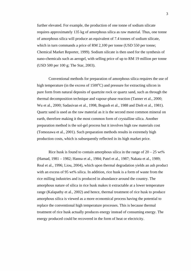
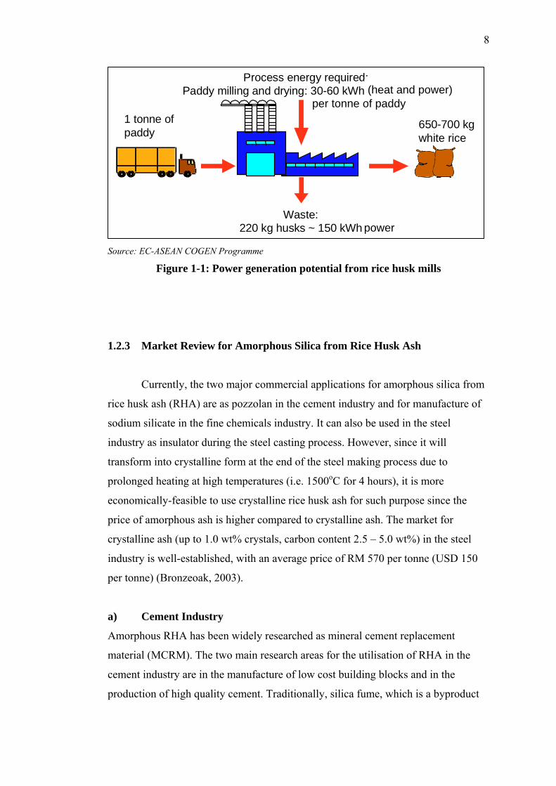
cogeneration plants to produce electricity and steam for paddy drying. As shown in
Figure 1-1, milling of 1 tonne of paddy produces about 220 kg of rice husk or
equivalent to approximately 150 kWh of potential power. In the year 1997, a Full-
Scale Demonstration Project (FSDP) under COGEN 3 using rice husk as fuel had
been implemented in Ban Heng Bee Rice Mill (1952) Sdn. Bhd. with the
commissioning of its 450 kW rice husk-fired cogeneration plant. COGEN 3 is the
third phase of the EC-ASEAN cooperation programme initiated by the European
Commission (EC) and the Association of South-East Asian Nations (ASEAN). It is
financed by the European Commission. COGEN 3 accelerates the implementation
of proven, clean and efficient cogeneration projects using biomass, coal or gas as
fuel. The projects are implemented through partnerships between ASEAN industrial
companies and European equipment suppliers.
8
Source: EC-ASEAN COGEN Programme
Figure 1-1: Power generation potential from rice husk mills
1.2.3 Market Review for Amorphous Silica from Rice Husk Ash
Currently, the two major commercial applications for amorphous silica from
rice husk ash (RHA) are as pozzolan in the cement industry and for manufacture of
sodium silicate in the fine chemicals industry. It can also be used in the steel
industry as insulator during the steel casting process. However, since it will
transform into crystalline form at the end of the steel making process due to
prolonged heating at high temperatures (i.e. 1500oC for 4 hours), it is more
economically-feasible to use crystalline rice husk ash for such purpose since the
price of amorphous ash is higher compared to crystalline ash. The market for
crystalline ash (up to 1.0 wt% crystals, carbon content 2.5 – 5.0 wt%) in the steel
industry is well-established, with an average price of RM 570 per tonne (USD 150
per tonne) (Bronzeoak, 2003).
a) Cement Industry
Amorphous RHA has been widely researched as mineral cement replacement
material (MCRM). The two main research areas for the utilisation of RHA in the
cement industry are in the manufacture of low cost building blocks and in the
production of high quality cement. Traditionally, silica fume, which is a byproduct
Process energy required:Paddy milling and drying: 30-60 kWh/tonne paddy
1 tonne ofpaddy
650-700 kgwhite rice
Waste:220 kg husks ~ 150 kWh power
(heat and power) per tonne of paddy
9
of metallurgical industry, is used for exactly the same purpose but its supply is
becoming limited and expensive for developing economies. The current price of
silica fume is reported to be RM 4,560 per tonne (USD 1,200 per tonne) in India
(Torftech News, 24th November 2003).
Research such as that conducted at FEUP (Faculdade de Engenharia, Universidade
do Porto or Faculty of Engineering of University of Porto) in Portugal had shown
that RHA concrete performed better than silica fume concrete. Further, studies by
Nehdi et al. (2003) showed that depending on the addition rate, RHA increased the
compressive strength of concrete by up to 40% at 56 days and was thus deemed
superior compared to silica fume. They also concluded that the performance of RHA
in reducing the rapid chloride penetrability of concrete was comparable to silica
fume and was slightly more efficient than silica fume in resisting surface scaling due
to deicing salts. Preliminary studies conducted by Ajiwe et al. (2000) also showed
that RHA-formulated cement (RHA substitution of 24.5 wt%, based on the analysis
by Bogue (1989) that the theoretical percentage fraction of silica in tricalcium
silicate or Portland cement was 26.3 wt%) had similar standard in terms of its
compressive strength and setting time compared to commercial cement.
The market of RHA for cement industry is not as well-developed as steel, but there
is a great potential due to the pozzolanic properties of RHA that are comparable to
cement. The potential is also driven by the absence of any health issues associated
with the use of crystalline ash (as in the steel industry) due to the use of amorphous
ash. In the United States of America, RHA has already been used commercially by
Pittsburg Mineral & Environmental Tech. Inc. (PMET) which is part of Alchemix
Corporation, Arizona, as a substitute for silica fume in the production of specialist
concrete. PMET specifies that the RHA for use as substitute for silica fume should
contain less than 1% of crystalline silica (>99% amorphous), carbon content less
than 6% and mean particle size of 7 – 9 μm (passing 45 μm sieve). The current
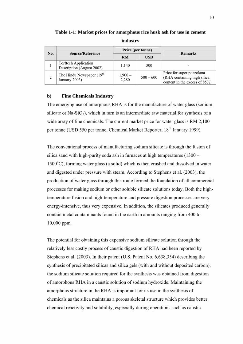
market prices for RHA sold to the cement industry were shown in Table 1-1. The
price could reach as high as RM 2,280 per tonne (USD 600 per tonne) for high
quality amorphous RHA with more than 85% silica content.
10
Table 1-1: Market prices for amorphous rice husk ash for use in cement
industry
Price (per tonne) No. Source/Reference
RM USD Remarks
1 Torftech Application Description (August 2002) 1,140 300 -
2 The Hindu Newspaper (19th January 2003)
1,900 – 2,280 500 – 600
Price for super pozzolana (RHA containing high silica content in the excess of 85%)
b) Fine Chemicals Industry
The emerging use of amorphous RHA is for the manufacture of water glass (sodium
silicate or Na2SiO3), which in turn is an intermediate raw material for synthesis of a
wide array of fine chemicals. The current market price for water glass is RM 2,100
per tonne (USD 550 per tonne, Chemical Market Reporter, 18th January 1999).
The conventional process of manufacturing sodium silicate is through the fusion of
silica sand with high-purity soda ash in furnaces at high temperatures (1300 –
1500oC), forming water glass (a solid) which is then crushed and dissolved in water
and digested under pressure with steam. According to Stephens et al. (2003), the
production of water glass through this route formed the foundation of all commercial
processes for making sodium or other soluble silicate solutions today. Both the high-
temperature fusion and high-temperature and pressure digestion processes are very
energy-intensive, thus very expensive. In addition, the silicates produced generally
contain metal contaminants found in the earth in amounts ranging from 400 to
10,000 ppm.
The potential for obtaining this expensive sodium silicate solution through the
relatively less costly process of caustic digestion of RHA had been reported by
Stephens et al. (2003). In their patent (U.S. Patent No. 6,638,354) describing the
synthesis of precipitated silicas and silica gels (with and without deposited carbon),
the sodium silicate solution required for the synthesis was obtained from digestion
of amorphous RHA in a caustic solution of sodium hydroxide. Maintaining the
amorphous structure in the RHA is important for its use in the synthesis of
chemicals as the silica maintains a porous skeletal structure which provides better
chemical reactivity and solubility, especially during operations such as caustic