Embed Size (px)
Citation preview

I-bullIL
Production of
Granular NPKs
in A monium Phosphate Plants
Some ImportantDifferences
International Fertilizer Development Center
Production of
Granular NPKs
in Ammonium Phosphate Plants
Some Important Differences
by James J Schultz
International Fertilizer Development Center
Preface The plant design and operating parameters required for producing agglomershyated compound (NPK) fertilizers especially urea-based and other temperatureshysensitive and hygroscopic granular products are often quite different from those required for the production of conventional ammonium phosphate fertilizersie diammonium phosphate (DAP) or monoammonium phosphate (MAP) These differences should be carefully considered when adapting a DAPMAP plantfor the production of NPKs The plant design and operating criteria described in this bulletin are intended to serve as a check list that may be used to helpguide those involved in the planning and design of new NPK projects or the modification of existing units
The data and recommendations contained in this bulletin are the distillation of a broad international base of experiences and results collected and formushylated over a number of years The author isgrateful tor the valuable insight offered by the many production engineering and researchdevelopment organizationsand individuals who candidly shared their experiences and knowledge offered suggestions and otherwise stimulated and supported the preparation of this publication
Library of Congress Cataloging-in-Publication Data
Schultz James J 1936-Production of granular NPKs in ammonium phosphate
plants-some important differences
(Technical bulletin International Fertilizer Development Center T-36)
Includes bibliographical references 1Nitrogen fertilizers ITitle
I1Series Technical bulletin (International Fertilizer Development Center) T-36 TP9634N5S38 1989 668624 89-26790 ISBN 0-88090-084-9
International Fertilizer Development Center PO Box 2040 Muscle Shoals Alabama 35662
Phone No 205-381-6600 TWX-810-731-3970 IFDEC MCHL Telefax (205)381-7408
Edited by E N Roth Typesetting and Layout by R FSandlin Cover Design by FRudolph Graphics by TL McGee
IFDC publications are listed in Publications of the international Fertilizer Development Center General Publication IFDC-G-1 which is available free of charge
Table of Contents
Introduction 1 Im portance of G ranule Form ation M echanism I
Agglom eration-Type Processes 1 Accretion-Type Processes 1
Equipment and Operating Parameters Unique to Agglomerated NPKs 2 Raw M aterial Particle Size 3 Liquid Phase 3 Estim ating Liquid Phase Values 4 Heat of Chem ical Reaction 4 Insoluble Binders 5 Liquid Phase Control 5 AcidAm m onia Neutralization M ethods 5 Preparing the Production Form ulation 7 Dry Raw Material Feed System 8 Solids Recycle 10 Granulator 10 Cocurrent Dryer 10 Countercurrent Process Cooler (Second-Stage Dryer) 12 Screens 14 O versize C rushers 15 Product Cooler 15 Conditioning 16 Storage and Bagging 16 Process Plant Dehum idific ji r 16
Recommendations Specific to the Production of NPKs Containing Urea 16 Verification of Recommended Plant Design and Operating Parameters 17 Conclusion 17 Appendix-Design and Operating Criteria for Urea-Based NPK
G ranulation Plants 18 Bibliography 20
Introduction Conventional ammonium phosphate granulationplants (DAP and MAP) equipped with atmospheric or
pressure tank-type preneutralizers are often rot ideal-ly suited for the production of granular NPK fertilizers especially those NPKs that contain relatively large amounts of urea or other very soluble hygroscopic and temperature-sensitive salt mixtures As a result many combination DAPNPK plants although well suitshyed for producing DAP or MAP often have difficulty in achieving the owners expectations when producing NPKs This bulletin describes the fundamental differ-ences between the granulation of DAPMAP and tiat of most NPKs and discusses the plant design features most often needed for routine production of high-quality NPKs In general it is less difficult to produce DAP or MAP in a plant designed to produce NPKs than to do the opposite provided of course that the NPK plant isequipped with systems for neutralizing large quantities of phosphoric acid and recovering ammonia
The NPK fertilizer granulation plant design and oper-ating parameters discussed in this bulletin are intend-ed to describe in general terms the mechanical and process conditions that should be met to achieve an optimum level of plant performance and NPK product quality None of the indicated criteria are absolute there may often be much latitude for modification variation depending upon the specific requirements with respect to (1) product formulations (grades and ratios) (2) raw materia quality and related physical and chemical properties (3)skill of the plant opera-tars (4) expected operating rate (capacity utilization) (5) expected product quality and related regulatory criteria (6) method of packaging storage and use (7) length of storage between production and use and (8)a host of site-specific and often variable fac-tors including climatic conditions infrastructure en-vironmental impaci criteria cultural practices and market requirements
An examination of selected papers indicated in the bibliography together with numerous other literature sources cited in these papers will provide a useful complement to this bulletin
Importance of Granule Formation Mechanism
The method of granule formation has a pronounced impact on the design and layout of the process equipment Therefore a good knowledge of the primary mechanism of granule formation growth and consolidation isessential in determining the de-sign features of the plant Although a more compre-
hensive description of the machanlsms of granule formation can be found in the literature the folowshying is a brief description of the two major granule forshymation mechanisms excluding drop formation (priin ecount eredIri frmation processes granulation
Agglomeration-Type Processes
With most granular NPK products (excluding the slurryshybased nitrophosphate-type processes) agglomerashytion isthe principal mechanism responsible for initial granule formation and subsequent growth (Figure 1) In most NPK formulations 50-75 of the raw materishyals are fed as dry solids These solid particles are assembled and joined into agglomerates (granules) by a combination of mechanical interlocking and cementing-much as a stonemason fashions a stone wall by using stones of varying size and shape and mortar as the cementing agent The cementingmedishyum for fertilizer granules isderived from salt solutions for example a preneutralized ammonium phosphate slurry andor the dissolution of salt on the surface of the soluble solid particles The size shape surface texshyture strength and solubility of the solid particles vary widely (Figure ) and have a major influence on the granulation characteristics of the mixture
Accretion-Type Processes The slurry-type granulation processes (DAP MAP TSP and some nitrophosphates) are quite different from the processes used for most NPKs with respect to the mechanism of granule formation and growth As a result the required process parameters for optimum operation of these slurry-type plants are also often quite different With a slurry-type granulation process a relatively thin film of moist slurry is repeatedly apshyplied dried and hardened to a relatively firm subshystrate consisting of granules that are often product size andor nearly product size Granule growth is primarily by accretion the process in which layer upon layer of new material is applied to a particle giving the final granule an onion-skin structure (Figure 1) In the process of course some agglomershyation also occurs but this is not the predominant mechanism
The recycle-to-product ratio required for accretionshytype granule development isnormally higher than that required for agglomeration-type processes Acshycordingly for a given production rate the material handling capacity of the equipment must be larger for accretion-type granulation plants than for most agglomeration-type plants However because of oarshyticular temperature-related processing requirements for some agglomerated NPKs certain equipment
Photo of Actual Fertilizer Granule (Agglomeration)
Scale 1mm
Photo of Actual Fertilizer Granule (Accretion)
Scale mm
Salt Bridges Between Larger Particles
Insoluble Binders Can Often be Used to Strengthen the Salt Bridges Between Particles
LyTp Layer-Type
Granule Growth
Granule Formed by Agglomeration
Figure 1 Principal Mechanisms for Granule Formation
especially the dryer and ocoler may actually be larger in some agglomeration-type plants to achieve the same production rate as in the accretion-type processes This is discussed in greater detail later
Granules formed by accretion are almost alwaysharder more spherical and more durable than thoseformed by agglomeration For example a typicalwell-formed DAP or TSP granule produced mainly byaccretion-type granulation may have a crushingstrength of about 4-5 kg whereas the crushingstrength of an agglomerated granule may not onlybe less (often less than 3 kg) but also more variable depending upon its raw material composition and a number of specific factors related to granule formashytion Some examples of the variability in granulestrength for a number of fertilizers are shown In Table 1
Granule Formed by Accretion
Equipment and Operating Parameters Unique to Agglomerated NPKs
A discussion of the key plant design and processingparameters required for the production of agglomershyated NPK products follows Specific reference ismade to the special features needed for the production of most urea-based NPKs and other NPKs that exhibit simishylar high solubility temperature sensitivity and critical relative humidity (CRH) characteristics The major devishyations from the recommended equipment and opershyating criteria normally found in conventional DAPMAP plants are discussed
i Critical relative humidity Isthe ambient relative humidity below which a mGcerlal loses moisture to the atmosphere and above which the material absorbs moisture from the atmosphere The CRH ofa material varies withtemperature
2
cl
Table 2 Typical Particle Size Data for Commercially Available Table 3 Solubility of Common Fertilizer Salts In Water a Materials Frequently Used to Produce Granular NPKs
Percent Retained on Indicated Mesha 4
4Material (475)
Ammonium suhiute (crystalline) 0
Diammonlum phosphateb (granular] 0
Monoammonlum phosphate (nongranular) 0
Potassium chloride (standard) 0
Potassium chloride (special standard) 0
Potassium sulfate (standard) 0
Single superphosphate(run-ofpile) 3
Triple superphosphate (runof-pile] 7
Urea (prilled)b 0
8(236) 16(100) 28(060) 48(030) 100(015)
0 1 7 75 98
22 98 100 100 100
1 7 30 65 90
0 6 55 90 99
0 0 5 35 90
0 15 75 95 100
11 25 36 52 76
14 19 26 51 80 15 92 95 00
a Tyler mesh opening size in mm indicated In parenthesesb Crushing of these materials Ispreferred to obtain a more uniform (homogeneous) NPK product
added to the granulator for example an ammonishyadddp ophaegra lorfoxlutens of a am shyum phosphate slurry an~dor solutions of urea or am-monium nitrate and (2)dissolution of a small portionof material on the surface of the soluble raw material and recycle partcles This dissolution iscaused by thecombination of heat and water contained in the above solutions or by steam or water Injected into thegranulator SolubiNiy data for some of the more com-mon fertilizer salts are given in)Table 3 Liquid pl-Asecontrol is the key to achieving the desired level of granulation efficiency and product quality Ideallyafter drying the liquid phase (salt solution) forms strong crystal bonds (salt bridges) between the porti-les of the agglomerate that are mechanically well
fitted and interlocked-again the concept of a stone wall
Estimating Liquid Phase ValuesExperience has shown that there are considerable
differences in the amounts of liquid phase generatshyed by the varicus materials normally used in the production of agglomerated NPKs Several years ago(during the 1960s) the Tennessee Valley ALthority (TVA)examined a wide variety of NPK production formula-tions that were known to perform well and devised a numerical value to express empirically the appar-ent liquid phase contribution that could be expect-ed from a number of materials commonly used toproduce NPKs These liquid phase factors are shown in Table 4 Experience has shown that when these values are used as a guide a liquid phase of about
8 16 -- shy 48-- 1 -Indicated
Fertilizer alt
Ammonium nitrate Ammonium sulfale Diammonlum phosphate Monoammonlum phosphate Potassium chloride Potassium nitrate Ootassium sulfate Urea
Approximate Concentration of Saturated So~utlon t
Temperature ---shy0C 20degC 100oC
(] 54 66 90 41 43 51 30 41 58 18 27 63 22 25 36 12 24 71
6 10 19 41 52 88
a Values indicated are fcrpure salts
300 kgtonne of product is about optimal for mostagglomeration-type NPK formulations Of course itshould be that phase while imshyappreciated liquidportant in granule formation is only one of the critershyia that must be carefully evaluated when estimatingthe granulation characteristics of a particular formulation
Table 4 Liquid Phase Factors for Selected Materials Freluently UsedInNPK Granulation (Agglomeration) Formulas
Ammonium nitrate (prills) 03U
INKGnlo A r F u
kglkg Material Liquid Phase Factor
Anhydrous ammonia 050 Ammonlalammonium nitrate solutions
(various compositions) 100 Wet-process phosphoric acid 100 Sulfuric acid 100 Superphosphoric acid 100Water or steam Ammonium sulfate (crystalline)
200 010
Single superphosphate (run-of-plle] 010 Triple superphosphate (run-of-pile)Potassium chloride (coarse or granular) 020
030Potassium chloride (standard) 000 Diammonlum phosphate (granular) 025Monoammonlum phosphate (nongranular] 020Urea (prilled) 030 To obtain the total weight of the liquid phase in a forniulatlon multiply the weight of each raw material In the formula (ki) by the appropriateliquid phase factor A total liquid phase weight value of about 300kgtonne is considered optimal in many cases
Heat of Chemcal Reaction
The level of liquid phase is also closely allied with another criterion ie the expected amount of heat created by various chemical r9actions In a given NPK formulation The amount of heat generated particushylarly within the granulator can have a marked effect on the amount of liquid phase formed and thereforethe resulting granulation characteristics of the mixshyture In general to achieve optimum granulation the calculated total liquid phase for a formulation using
4
the data in Table 4 should be lowered if the formula- desired chemical analysis The resulting liquid phase tion produces a large amount of chemical heat of can of course be adjusted within rather specific limits reaction However the optimum relationship between through the selection of raw materials or by controlling liquid phase and heat of reaction for a specific formu- the free water content andor chemical composition of lation must be learned from actual operating the slurry (for example the NH 3H3P0 4 mole ratio as
experience shown in Figure 3) However once this Isestablished (op-The most important heat-generating chemical reac- timized) the flow rates of the liquids must remain consshy
tion in most NPK plants isthe neutralization of acidic tant to ensure the correct analysis of the final product materials with ammonia The approximate amount of For this reason all agglomeration-type formulations heat released when ammonia reacts with some corn- should allow for a moderate degree of liquid phase mon fertilizer materials is shown in Table 5 As with If- tuning performed by the operator using steam andor quid phase experience has shown that if the amount water fed directly to the granulator The discretionary of heat released in the granulator isequivalent to about use of a small amount of steam andor water by the 45000-50000 kcaltonne of product conditions are operator helps to compensate for variations in granulashygenerally good for obtaining optimum granulation Of tion efficiency caused by changes in the temperature course like liquid phase the proper level of heat is just of the materials quantity and particle size of the recyshyanother one of the many critical criteria that must be cled material and minor (but normal) upsets within the met to obtain optimum granulation efficiency overall processing system This fine tuning of the process
by the operator is the basis for the observation NPK granulation by agglomeration is more of an art than
Insoluble Bnders a science The unique skill of an experienced granushylator operator often greatly overrides the effectivenessInsome cases the mechanical and crystal (salt bridge) of the most costly and sophisticated process design
bonding of particles can be greatly improved by add-ing about 5-15 of a finely divided insoluble binder and engineering skill
powder for example kaolin clay to the granulating mixture The binder powder helps to fill the many small AcidAmmonia Neutralization Methods voids between the particles and acts much like a satushyrated wick in helping to join the particles together As indicated earlier the acidammonia neutralization (Figure 1) This concept works particularly well with NPKs reactions create heat that contributes to the overall Iishycontaining large amounts of crystalline ammonium sul- quid phase conditions in the granulator and the effishyfate potassium chloride potassium sulfate andor ciency of the granulation process Thus the method kieserite (magnesium sulfate monohydrate) and rela- used for neutralization (reacting ammonia) can signifishytively low levels of suitable soluble salts or solid binders cantly influence the overall performance of the plant such as ammonium phosphate o superphosphate It A brief discussion of the most common methods used is important to note however that some insouble for neutralization in agglomeration-type NPK granulashybinders (clay for example) have the capacity for re- tion plants follows taining moisture thus making subsequent drying more Direct Neutralization in Granulator-This was one
of the most common methods used for reacting amshydifficult monia in the many NPK granulation plants that were operated in the United States and elsewhere during
Liquid Phase Control the 1960s and early 1970s Direct neutralization in the granulator is particularly well suited for NPK gradesIn all NPK formulations most of the liquid phase isob-containing large amounts of superphosphate (SSP or
tained from materials that are Introduced to the process at a fixed rate to achieve a final product with the TSP) and a relatively low level of nitrogen With direct
Table 5 Approximate Amount of Heat Released Wh in Ammonia Reacts With Various Materials Commonly Used to Produce Granular NPKs
Heat Released
Material Reacted With Ammonia Reaction Product (solid) NH3 Gas NH Liquid
-callkgNH reacted)
Wet-process phosphoric acid (54 P20 5) Monoommonium phosphate (MAP] 1890 1370
Wet-process phosphoric acid (54 P20s) Diammonium phosphate (DAP) 1510 90
Monoammonium phosphate (MAP) Diammonium phosphate (DAP) 1130 610
Triple superphosphate (TSP) Ammoniated TSP 1580 1060
Single superphosphate (SSP) Ammoniated SSP 1460 940
Sulfuric acid (100dego Ammonium sulfate 2165 1645
Degree of Ammonialion kg NH3Ikg Pg05
01 02 03 04 05 1000
goo-
0-0NH3H3P4
600
d 500
400-
E 300-
750C
200
00 100DC
0 0 4 shy0 02 04 0 08 10 12 14 16 18 20 22
NHjH3PO4 Mole Ratio
Figure 3 Effect of Mole Ratio on Solubility of Ammonium Phosphate
neutralization the best operation isusually obtained Ifthe aiiount of ammonia reacted in the granulatordoes not exceed the equivalent of about 50 kgtonneof product
In the direct neutralization process ammonia is dis-tributed beneath the bed of material in the granula-tar Ifsulfuric acid is used it too is usually distributed beneath the bed of material while the phosphoricacid Ifused is most often sprayed or dribbled on topof the bed When sulfuric acid is used precautionsshould be taken to ensure that the acid is added at aparticular location with respect to the ammonia to en-sure quick and uniform neutralization and thus mini-mize the unwanted reaction of sulfuric acid withpotassium chloride that most often is also present inthe formulation This reaction causes the formation of very corrosive hydrochloric acid which reacts rapidlywith ammonia to form a dense fume of ammonium chloride that Isvery difficult and costly to collect Inthe plants emission control (scrubbing) system
Tank-Type Neutralizers-The use of an atmospheric or pressurized tank-type neutralizer offers maximum flexibility in managing the acidammonia reactionsand obtaining the critical heatliquid phase criteria needed for good granulation when producing a wide variety of NPK grades Because the acidammo-nia reactions are only partially completed in these tank-type neutralizers they are often referred to aspreneutrallzers Such preneutralIzers are commonlyused In the majority of todays DAP plants
When a preneutralizer Is used large amounts of acid can be partially reacted with ammonia The
6
degree of reaction performed In the preneutralizer Is determined by a number of factors however the most Important criteria are the production of a fluid slurry that is easy to transport (pump) to the granulator anduniformly distribute onto the rolling bed of material In the granulator The fluidity of the preneutralized slurshyry is maintained through careful control of themole ratio temperature and free water
content of the reacted slurry The neutralization reacshytions that are only partially completed In the preneushytralizer are completed in the granulator where additional ammonia is added beneath the rollingbed of material
When sulfuric acid Is reacted In combination withphosphoric acid in the preneutralizer special preshy
cautions must be taken in the selection of construcshytion materials that will resist the more corrosiveenvironment caused by the sulfuric acid Also at the higher mole ratio and pH (for example about 15 and68 respectively) the presence of ammonium sulfate crystals tends to thicken the slurry and make pumpingdifficult thus operation at a lower NH 3H3P0 4 mole ratio and pH (about 04 and 20 respectively) is often preferred
Pipe-Type Reactors-In the mid-1970s TVA demonshystrated the feasibility of replacing a nonventionrl tank-type preneutralizer with a novel device referred to as a pipe reactor This type of reactor was a radical departure from the conventional tank-type preneushytralizer normally used to react large amounts of amshymonla with phosphoric acid The pipe reactor consists basically of a length of corrosion-resistant pipe (about3-6 m long) to which phosphoric acid ammonia andoften water are simultaneously added to one end through a piping configuration resembling a tee thus the name tee reactor The acid and ammonia react quite violently pressuring the unit and causing the sushyperheated mixture of ammonium phosphate slurry(melt)and water to forcefully discharge from the opshyposite end of the pipe that is positioned inside thegranulator Uniform distribution of the melt on topof the rolling bed of material In the granulator Isachieved by varying the configuration and orlentashytlion of the discharge opening of the pipe A major adshyvantage of the pipe reactor over conventional preneutralizers Is that It more effectively utilizes chem-Ical heat of reaction to evaporate unwanted water from the relatively dilute acid
Later the tee reactor was modified by TVA to also accept an additional flow of sulfuric acid throughanother pipe inlet located opposite the phosphoricacid Inlet giving the unit a cross configuration and thus the name pipe-cross reactor (PCR)
Use of the PCR makes itpossible to react a wide varlshyety of phosphoricsulfuric acid mixtures with ammonia This capability Isparticularly useful In NPK granulationplants and allows a greater choice In the selection of
raw materials to Improve granulation and optimize the disposing of certain problem materials such as exshyoverall cost of production cess scrubber liquor It should be noted however that
In general the mixture discharged from the PCR does the technology does not fit all situations equally well not require further reaction with ammonia in the granu- Therefore its poential should be carefully examined lator In some cases however the level of reaction in with regard to the particular circumstances the PCR may be altered (decreased) to minimize the escape of ammonia or to obtain improved granulation characteristics of the melt when it iscombined with Preparing the Production Formulation the solids in the granulator
Several variations of pipe-type reactors (and materi- According to the foregoing discussion a large number als of construction) are currently used in NPK DAP and of raw material and process variables must be consi-MAP plants sometimes in combination with convention- dered when developing NPK production formulations al tank-type preneutralizers Perhaps one of the greatest As with the operation of an NPK plant formulation too advantages offered by the use of pipe reactor technol- requires a considerable amount of skill and an element ogy in the NPK industry isthat it provides an opportunity of art to ensure that the particular formulation will to effectively use a greater variety of raw materials in- yield the desired results In a given plant cluding for example larger quantities of dilute acids A given NPK fertilizer can be formulated in many ways and scrubber liquor This added flexibility in raw materi- depending upon the available raw materials and al choices can often result in more favorable produc- specific equipment system Table 6 shows some examshytion costs and at the same time provide a method for pies of NPK production formulations that have been
Table 6 Examples of Typical Commercially Proven NPK Production Formulas In Which Agglomeration Is the Principal Mechanism for Granule Formation and Growtha
Direct Ammonlatlon In Granulator Pipe-CrossReactor [PCR Tank-Typo Preneutrallier (PN) Ursa SolutlonISteam (No Chemical Reaction)
Material as Fed to Processo 3-9-18 5-20-20 131313 824-24 131313 15-1515 171717 12121712 Mg 14-62124 Mg 16-0-30
d (kglfonne finished product)
Anhydrous ammonia-82 N 37 52 66 85 127 82
0 to PaRC 0100 to PCR (7580 (6570
PN) to PNI
Ammonia ammoniurn nitratesolutlon-46 N 145
Urea Iptils-46 N - 105 231 115 153 240
Ulea solution-35 N 155 204 156
Ammomum sullae (crystatrhne-21 N 24 S 50 205 121 300
Sulfuric acid-vaabs H50 63 64 40 192 261 108
(93HSOJ (78HSO( (78HSO (78HSO( (96HSO) (96HSO)
(100 tOPCR (00 to PCR (100 tO PN) (100 to PN)
Wet process phosphoric acid-54 PiO 170 63 443 250 292 330
(90 to PCR) (85 to PCR
SinglesupephosphOe POP-18 POs12 S 508 332 216
Triple superphosphate (OP)-46 P30 124
Monoommoncum phosphate (powderedl-10
N 50 PO tI
Dlammonium phosphatr crushed granules]shy
18N 46 PO 130 87
Phosphate rock (ground-32 PO 247 191 Potassium chlorideslandard)-60 K10 342 221 402 223 255 289 276 353 500
Potassium Sulate lstandard)-50 KO 18 S 320
Sulfate of potash magnesium (standard)shy
22 KO 11 Mg 22 S 110 Magnesium sulfatekieserle]-16 Mg22 5 ISO
Magnesium oxide-50 Mg 25
Insoluble binder It 0 10 Micronuttrlt mix(various nultrents as required 0 30 10
Conditioning agent (coaling on productl 10 10 15 15 15 10 15
Subtotal 1048 1070 1054 1083 1090 1055 1055 1040 1061 11-41
Eapororlon -48 70 54 83 90 55 55 40 61 -41
Total(product busi$ 1000 1 000 1000 1000 1000 1000 1000 1000 1000 1000
a Examples intended topartially illustrate offormulation posibililes depending upon spectla process equipment system available raw materials requirements product compositionlargo number agronomic
guarantees and other localfactors b Flows ofacid and ammonia to PC and PN may varyindicaled flowstypical forcommercicl practrce The addition clsteam andor water To the granulator is generally required to optimize granulation etlrciency
c Allmaterials ore led directly o granulator unless otherwise noted Indicatedcomposition istypical at Industry practrce d Values rounded ftar smplicity e Phosphoric acid is first led to fume scrubbing system and then onward to PN
7
successfully used In commercial practice Because the performance of these formulations in a givenplant will depend heavily upon a number of factors as described in this bulletin these examples areoffered only to illustrate the variability that should be taken into account In the planning and design of an NPK production facility
Dry Raw Material Feed System The chemical analysis of the finished product fromgranulation plants that use significant quantities of solid raw materials in the formulation depends heav-ily upon careful control of the solid raw material feeds
ilyupocntrlcaefuo th soidrawmatria feds to ensure that they are in the correct proportion andthat their flow rate is closely matched with the flows of the fluid materials (for example preneutralized slurshyry and ammonia) fed to the granulator
Some granulation plants use individual belt-typeweigh feeders to measure the continuous flow of eachsolid material to the process Other plants particularly those in the United States and Brazil use a combina-tion batch weighingcontinuous feed (stream-out) system
A common problem with using individual belt-typeweigh feeders for each material is that it is often difficult to maintain accurate control on a continushyous basis because of lumps and other variations in the flow properties of the nongranular solid materi-als Belt-type weigh feeders can be particularlytroublesome in NPK plants where a large number of grades are produced andor when lumpy damp orfinely textured raw materials are used For example inadequately cured superphosphate some forms of byproduct ammonium sulfate and some dry but fineshyly textured materials such as potash and kieserite often cause problems because they tend to bridgein the weigh feeder surge hoppers In many cases mechanical vibrators that are attached to the surgehoppers and designed to overcome these problemsactually increase the tendency of the material to compact and bridge
Variability in the raw material feed characteristics may lead to erratic performance of the continuous belt-type weigh feeders and increase the need to fre-quently change (adjust) the feed rates on the basisof the chemical analysis of the product Correctly ad-justing the raw material feed rates on the basis ofproduct analyses is also very difficult because of the lag time in the granulation plant system For exam-pie several hours are required for a change in the raw material feed rate to become fully evident in the final product (Figure 4) Unless the lag time in the plantIswell known and the sampling program is carefullysynchronized with this lag time the analytical findingswill be quite misieading and will thus result in a pro-
8
gram of constantly changing the feed rates without achieving the desired goal The lag time also varies with the raw material for example a change in easyshyto-granulate ammonium phosphate slurry will show up in the product much quicker than a change In a difficult-to-granulate material such as sulfate of potash Furthermore in most NPK formulations the recycle material has a very different chemical comshyposition from that of the final product thus a considershyable amount of time (often 3-6 h) Is required to achieve equilibrium after making a change in thefeed rate of a raw material However in a slurry-type process such as DAP granulation the neutralized feed and recycled materials are essentially the samein chemical composition and equilibrium Is more
quickly established
Recycle-to-Product Ratio lt
100 1040
90
0 70
60 0-CU 50 These data are theoretical
Actual time required to effect 4a 3 longer and mustbe dti rmIned
( experimentally
10
_0
Time Following Change InFeed Composition hour
Figure 4 Relationship Between Time and Change In Product Composition In Granulation Plant at Various Recycleshyto-Product Ratios
Most of the problems with individual belt-type weighfeeders and their possible adverse effect on thechemical analysis of NPKs can be almost completeshyly avoided by using a combination batch weighshyIngcontinuous stream-out feed system (Figure 5) The batch weighing system avoids the problem of uncershytain weighing accuracy caused by lumps and other variations In the dry raw material flow characteristics With this system a precisely weighed batch of drymaterials (usually a 2- to 4-t batch) Isdischarged Into
60
Raw Materials
I HOLDING HOPPERS
Typically six in a clus each having 5-tocllutnne capacity
Also smaller hoppers for minor constituents if needed
DISCHARGE GATES Contronitall manuall yed or automatically
rbe
HOPPERrWEIGHIdcorr TypIcaly 2- Io4onne batch size
Discharge Gate SURGE HOPPERMas flo dein minimizesMnng-ype segreation and
bridging
FEEDER Conlinuous slream-out weigh feeder
Jndicator c -- --RTo Granolation
L~~iProcess
Figure 5 Batch-Type Raw Material Weighing Unit With Continu-ous Feed System
a surge hopper equipped with a belt-type weigh feed-er (stream-out feeder) In some plants a variable speed screw-type conveyor is very effective especially if the feed material is very fine and free flowing The rate of this feeder Is synchronized with the flow rate of slurry from the preneutralizer (or pipe-type reactor) and other fluids fed to the granulator This system Isquite simple and the operator can check the accuracy of the stream-out feeder by simply using a stopwatch to check the time required to feed a batch of known weight The operator can do this as frequently as necessary (usually about twice per work shift) to ensure accurate feeding and proper matching of the dry feed with the slurry and other fluids fed to the process
Certain formulations may require a large number of dry raw materials which may vary widely In both quan-tity and physical properties In this case the uniformity of the analysis of the individual granules of final product and the consistency of the granulation step can be Im-proved by mixing the weighed batch of raw materials before It enters the hopper supplying the stream-out feeder In this case It is also important after mixing to avoid subsequent segregation caused by the materialconing in the feeder hopper A relatively tall slender
Figure 6 depicts an example of such a system In which a combination weigh-hopperpaddle-typemixer Is used followed by a mass flow-type surge hopshyper supplying the stream-out feeder Ribbon-type
blenders or rotary drum-type mixers can also be used If a rotary drum-type mixer is used a separate weigh hopper offers a more practical and reliable mechanshyical design Of course the separate weigh-hopperdesign ulsc works well with any type of mixer and may
preferred because of its mechanical simplicity compared with the combination weighingmixingunits This more elaborate and more costly version ofthe batch-type weighing concept (Figure 6) isusuallyneeded only if many nutrient guarantees are reshy
quired (for example micronutrients) if the size and surshyface characteristics of the materials differ greatly fromeach other or when a high degree of uniformiiy In
each product granule is required Such a system is especially helpful in obtaining uniform distribution of small quantities of insoluble binders or other materialsthat may be used to promote granulation
Raw Materials
i HOLDING HOPPERSTypically six in a cluster each having 5-to 1O-fonne capacity Also smaller hoppers for minor constituents Ifneeded
- DISCHARGE GATES - - Controlled manually
or automatically
COMBINATION WEIGH -HOPFERIMIXER shy
_ Paddle- or Ribbon-Type Mixer AialiTo c-ou b-e a szea weigh hopper and drum-type mixer
I
Discharge Gate SURGE HOPPER Mass flow design minimizes coning-type segregation and bridging
FEEDER Continuous stream-out
____weigh feeder indicator
cylindrical hopper with a long tapered conical bottom ---- I Processdescribed In the literature as a mass flow hopper will minimize coning and ensure uniformity of the materi- Figure 6 Batch-Type Raw Material WeighlngMixing Unit With al entering the stream-out feeder Continuous Feed System
9
If ItIs not practical to modify an existing continuous belt-type weigh feeder system to the batch-type feed method then It is Important to devise some method for frequently checking the feed rates from the in-dividual belt-type weigh feeders and using these check results as a basis for adjusting the rates This method of feed rate adjustment Ismore accurate and more rapidly responsive than are adjustments made on the basis of product-sampling because It avoids the complications and uncertainties caused by sys-tem lag difficulty In collecting representative sam-ples and other uncontrollable variables In NPK plants where the agglomeration of solid materials is the principal granulation mechanism it is extremelyimportant to base any change in feed rate(s) on a representative product sample collected (composit-ed) over a period of at least 4 h Adjustments in feed rates made on the basis of frequent grab samplescan be very misleading even Ifthe feed rate(s) sam-
pling technique and analytical work are precise
Solids Recycle Unlike most slurry-typeaccretion granulation process-es NPK processes based on agglomeration seldom recycle a significant quantity of product-size materi-al to the granulator only undersize material isnormal-ly recycled The use of a recycle control system for controlling (optinizing) conditions in the granulator isone of personal choice and isoften of limited value except during periods of startup or when changing grades In most cases a floating recycle system is preferred in agglomeration-type NPK plants However the relative merits of floating and controlled recycle are often a topic of debate among NPK and DAP plant operators
In agglomeration-type granulation particles will agglomerate only If they can first be attracted to each other This attraction is then followed by inter-locking and bonding Raw material and recycle fines will often not agglomerate into product-size granules if they are too large They will simply repel each other and accumulate eventually overloading the system Therefore a facility for crushing a portion of the large fines is recommended if coarse-grade raw materials andor large-size product (and therefore large-size recycle fines) are anticipated Also the ef-ficient crushing of oversize material is essential to enshysure that the particle size distribution and therefce surface area of the material recycled to the granu-lator isreasonably uniform The relationship between particle size and surface area is shown in Table 7 For this reason it is recommended that the material dis-charged from the crushers be recycled to the screens to ensure that only fine material is returned to the granulator Many crushers are less than 5 0efficient
on a single pass therefore the need for recirculation of the material from tne crusher back to the screens should be carefully examined This is discussed in more detail later
Table 7 Relationship Between Particle Size and External Surface Area
- ie
oa TyleraNominal Tylera
Diameter Screen Size External Surface Area (mm) (mkg
0106 150 434 0250 60 185 0500 32 927 100 16 462 200400 95 231
116 475 4 0971 670800
1500 325 06880577
0307
a Theoretical assuming perfect spheres having a density of 13 glcm3
Granulator A longer-than-normal rotary drum granulator is preferred (length-to-diameter ratio of 3 or more) for granulation by agglomeration The longer granulashytor isneeded to (1)provide sufficient room for the unishyform distribution of slurry acids solutions ammonia and steam (2)promote intimate mixing of the solids and fluids and (3)provide time for initial agglomershyation (granule formation) and consolidation of the granules to occur in view of the operator before the material disappears into the dryer The art of granushylation implies that the granulator operator should be able to see what is happening and make the often subtle adjustments needed to avoid inefficient granushylation and the resulting problems caused by upsets in the recycle equilibrium (mass flow and particle size distribution) Some plants that depend heavily upon steam and recovered scrubber liquor as the source of liquid phase very effectively utilize a premixing unit (using for example a pugmill-type mixer) located imshymediately upstream from the rotary drum granulator This added step ensu-es uniform distribution of the Iishyquid phase and initiates agglomeration thus it atshyfords the operator another opportunity to optimize the granulation process
Cocurrent Dryer General-With agglomeration-type granulation the moisture (usually about 2-6) in the material fed to the dryer is distributed quite evenly throughout the granule structure this situation is very different from that prevailing in the slurry-type processes for examshyple DAP in which a moist film covers a relatively hot
10
and dry particle core In ether case a cocurrent (parallel flow) dryer is preferred because with such a flow configuration the hot inlet air first contacts the moist fertili7or and thus allows operation at a higher overall temperature difference between the drying air and the moist fertilizer while minimizing the risk of overheating and melting the fertilizer which becomes more temperature sensitive as it dries
With the agglomerated granules the diffusion of moisture from the core of the granule to the outside sur-face and then to the drying air must be quite cc refully regulated-loo much heat applied too quickly may melt the surface of the particles and cause cuse hardening resulting in granules with a soft moist center caLised by entrapped moisture Sometimes melting may lead to excessive agglomeration andor fouling of the dryer internals In still other cases too rapid evaporation may cause the granule to explode Fur-thermore ifevaporation occurs before proper consoli-datlon of the granules is achieved (promoted by the rolling and tumbling action in the dryer) the granules may be too porous and therefore quite weak
With agglomeration the inlet portion of the dryer should be viewed as an extension of the granulator because a considerable amount of final granule for-mation and consolidation occurs here Therefore op-timal performance of most NPK dryers requires an operator who is skilled and capable of exercising considerable judgment because the performance of the dryer is grectly influenced by the grade beingproduced and the characteristics of the individual raw materials
Some experienced operators prefer to omit one or two rows of lifting flights near the inlet end of the dryer to give a section of smooth shell immediately follow-Ing the forward-pitched throw (spiral) flights at the dryer inlet The length of the smooth section usuallyequals about one-half diameter to one full diameter of the dryer The lifting flights that follow immediately after the smooth shell section must be designed to provide full exposure of the moist particles to the dry-Ing air yet not be too closely spaced to cause plug-ging or make cleaning difficult
Temperature and Humidity Profile-In general ag-glomerated products require relatively gentle drying The temperature profile within the dryer is dependent upon the temperature sensitivity and the CRH of the material With urea-based or highly soluble ammo-nium nirate-based NPKs the dryer outlet temperature (product) usually should not exceed about 740C if kleserite is also present or the N-to-P20 5 ratio is high then a temperature of about 680C isabou maximum The relative humidity (RH) of the dryer outlet air should be at least 10-15 percentage points below that of the CRH of the material at the dryer outlet temperature Thus for most urea-based NPKs the RH of the air at its
outlet temperature (typicallyabout 74 0C) should not exceed about 20 because the CRH of the urea- or ammonium nitrate-based materials at this elevated temperature is usually about 30 and sometimes even lower (Figure 7) The moisture-holding capacity of air at typical NPK drying temperature and RH conshyditions isshown in Figure 8 The unique RH CRH and temperature criteria required for drying many NPKs especially the urea-based NPKs translate into largershythan-usual process airflows This results in the need for rotary dryers that are relatively large in diameter compared with those used to dry products such as DAP that are less sensitive with respect to temperature humiaity and particle entrainment
Air Velocity-The particle size distribution of most agglomerated NPKs entering the dryer Ismuch wider than that of DAP NPK granules are ailso relatively irshyregular in shape compared with well-formed DAP granules thus they exhibit a greater drag in the airshystream The effect of drag is clearly shown in Figure9 where the actual entrainment of irregular potash granules iscompared with theoretical values for pershyfect spheres To avoid excessive entrainment of the smaller and more irregular particles (those less than about Imm) found in most NPK plants It is necessary to operate the dryer at a lower air velocity than Iscusshytomary for DAP dryers This lower air velocity criterion for NPKs (about 20 to 25 ms empty-dryer [superficial] basis compared with about 3 to 4 ms for DAP) often limits the drying capacity of DAP plants that are conshyverted to the production of NPKs
Retention Time-Because the drying process for agshyglomerated NPKs is mainly controlled by the rate of diffusion of moisture from the core of the particles the point at which a longer retention time does not sigshynificantly promote further drying is more quickly reached with many NPKn (especially the verytemperature-sensitive urea-based NPKs) than with DAP or other accretion-type granular products The net result isthat a long retention time in the dryer is often less important with NPKs and sometimes quite unshydesirable The overriding factors are the temperature and RH profile in the unit (most importantly the differshyence between the material CRH and the RH of the dryshyng air) Ifthe dryer istoo long and the cooling effect of evaporation ceases the product may begin to overheat and melting may occur near the outlet end of the dryer This can result in a ring-like buildup of material on the inside of the dryer near the disshycharge end This buildup will cause a bed of material to form in the dryer which in turn will cause less effishycient drying overloading of the unit and a number of other problems including overgranulatioi-
Condition of Procuct at Dryer Discharge-The physical condition of NPK products dischaged from the dryer may vary widely depending upon the
11
80shy- O jMonoammonium Phosphate
70
O --- -Diammonium PhosphateO
60
= 50 Calcium 0 Urea-Ammnium Phosphate NPK Ammonium
(17117-17)Nirt
40- Nitrophosphate NPK CJ (17-6-18-2MgO)
30shy
20-
Source IFDC Experimental Determinations
20 30 40 50 60 70 80 90 Temperature OC
Figure 7 Effect of Temperature on Critical Relative Humidity of Selected Fertilizers
(1) raw material characteristics (2) formulation (3) dryer temperature and humidity profile (4) operatorskill and (5) the particular crystallization habit of the mixture This last point (crystallization habit) isthe least predictable Although it is quite easy to accurately determine the expected free water content it isonly by experience (trial and error) that the crystallization (hardening) characteristics of a particular fertilizer forshymulation can be accurately determined Impurities In the phosphoric acid and other raw materials the type and source of potash the temperature and moisture content and a host of other subtle and un-predictable factors often have a major influence upon the physical properties of the material dis-
charged from the dryer At times the product may be crisp hard and easily screened and crushed then again with all conditions apparently the same It may be dry but quite soft and plastlc-a condition that can quickly lead to screen blinding upsetting of the recycle loop and plugging of the crushers
Countercurrent Process Cooler
(Seond-Stage Dryer) The adverse effect of most of the transient and unshypredictable operational problems described above can be largely eliminated by routing all of the dryer
12
220 1
200shy
_ 180
o 160
o 140 3000 RH
_ 120shy20deg0 RH
0
C 100
80shy ~15 RH
60shy
o 40shy40shy
20shy
50 60 70 80 90 100
Air Temperature degC
Figure 8 Effect of Temperature and Relative Humidity on Moisture Content of Air
discharge material to a process cooler which may and temperature of the inlet air may be needed In be more properly referred to as a second-stage dryer some locations of course the need for this feature A countercurrent alr-to-fertilizer flow configuration is would be dependent upon local ambient conditions preferred for maximum cooling in this unit The trans- and the NPK product characteristics The processfer of fertilizer material from the dryer to the process cooler serves the following useful functions cooler should be made by means of an inclined conshyveyor belt a bucket elevator is not recommended be- It allows drying to continue typically about 15shycause of the problems associated with the buildup 25 of total drying occurs in the process cooler of material it the buckets and discharge chute ifthe material is plastic or sticky or if a slug of bad a It serves as a safety valve to accommodate material forms as a resuit of an upset caused by oper- process upsets It makes the entire system more ator error burnerair heater failure or a number of forgiving other routine problems that commonly occur In most NPK granulation plants It adds time at a slightly reduced (and controlla-
The heat transfer capacity of the process cooler ble) temperature profile to allow the material to should normally be about one-half to two-thirds that crystallize and harden before It is subjected to of the dryer The cooler should also be equipped with screening and crushing As a result toe screens are an air heater to temper (heat) the inlet air if needed more likely to remain clean (free from blinding) to decrease Its RH andor control the temperature pro- and the crushers will perform more efficientlyfile In the unit The addition of an air chilling unit with because the oversize particles are harder and subsequent reheat to more carefully control the RH therefore will fracture more easily Material
13
60shy
50
Particle Specific Gravity-m-- 2 0 15 0
bull 40 Theoretical
rMinimumHorizontalEE Carrying (Entrainment)
Z C
30
Horizontal Entrainment Determined20 Experimentally in IFDC Pilot Plant
Using a 092 m Diameter Rotary Dryer and Irregularly Shaped Granules of
10- Potassium Chloride (17 specific gravity)
l I 1 I I I I I I I I 1 i 1 l I
20 30 40 50 70 100 200 300 400 500 700 1000 2000 3000 4000 5000 Particle Diameter microns
Figure 9 Effect of Particle Size and Gas Velocity on Entrainment of Particles
plasticity and the resultant plugging of the crush- Square-mesh wire screen (stainless steel) should be ers screens and downstream chutes are largely used to ensure the production of well-rounded eliminated (minimum surface area) granules Well-formed
granules are of key importance to minimize surface contact points and residual dust and small parti-
Screens cles that cause caking during long-term storageThe screening action on a square-mesh wire screenA key element in NPK granulation is precision screen- is more likely to scrub the granules and more efshy
ing to ensure that the bagged product will have good fectively remove bits and pieces of fines This is esshylong-term storage properties This is especially ap- pecially true ifra horizontal gyratory-type screening
plicable to high-nitrogen grades manufactured from machine is used Stainless steel screen wire is either ammonium nitrate or urea If the process recommended because its reslstanceto corrosion screening system is well designed it is usually not resulsn eoote ires ace t rsi u
aditona dowstram sreeing results In a smoother wire surface that resists buildshynecesar to nstllnecessary to install additional downstream screening up of solids and plugging
facilities (for example polishing screens after final product cooling or before bagging) Of course such Product granules should be relatively large in the additional screening will be helpful but the relative range of 2-5 mm or even larger to minimize contact merits and need for such polishing-type screening area and therefore caking The production of such should be determined on the basis of the design and large granules will influence the particle size of the performance of the basic process screening system recycle and the resultant granulation propertiesand the specific product characteristics The follow- Even with a 2-mm recycle particle (maximum size)Ing process screening system Is recommended for it Is often not necessary to crush the recyclemosT NPKs especially those containing high levels of however this point must be carefully considered ammonium nitrate or urea depending upon the overall size distribution of the
14
recycle fraction The size distribution may change quite significantly from formula to formula even though the screen size range of the final product remains constant
Single-deck screens are recommended because they allow easy access for inspection and clean-ing without interrupting the process In addition to ensuring the production of fertilizers with a mini-mum tendency to cake clean screens are also of key importance in maintaining good process control
Horizontal gyratory-type screening machines are preferred over inclined units especially for the product screens The horizontal units are preferashyble because if they become blinded due to the lack of attention they will overload and stall thus they will automatically prevent fines from being discharged as product a major cause of caking If inclined screens become blinded they continue to operate while discharging fines with product thus causing considerable problems with caking on the one hand and control of granulation on the other Also as previously mentioned the horizontal-type units will more effectively scrub the granules to remove residual small particles and dust thus decreasing the risk of caking
The ratio of the fertilizer material feed rate to the screening surface area should be quite low For theoversize screen about 10-20 tphm 2 isrecommend-ed whereas only about 5-20 tphm2 isrecommend-ed for the product screen with the smaller open-ings Of course the design of the screening machine and the screen open area (product size)have a major influence on the screening capaci-havuner a given circumstance However it is im-pyunder a note cirman Hoen suim-r portant to note that many NPK plants often suffer from having too little screening capacity
Oversize Crushers
Crushers are not 100 efficient in crushing oversize material on a single pass an efficiency of about 50 or less Ismore likely The crushing efficiency actually obtained of course depends on a number of factors most Importantly the required particle size distribution and the crushing characteristics of the material
To avoid the risk of recycling a arge amount of un-crushed or only partially crushed oversize to the granulator and upsetting the granulation process which Isvery sensitive to particle size distribution the material from the crushers should be recirculated to the oversize screens as shown In Figure 10 Although this procedure Increases the capacity needed for the
screens and crushers it ensures that the maximum particle size of the material recycled to the granulashytor will be smaller than the product and thus improves granulation control
Material From Dryer or Cooler
Material From Crusher
OversizeOversize Screen
Crusher
Undersize Screen
Product
Undersize Material Recycled to Granulator
Figure 10 Closed-Loop Screening and Crushing System
Because the size distribution of the solid particles Becausuth size isrtin afgtheraticleisof such major importance in agglomeration-type
granulaion extraordinary care should be taken in determining the optimum particle size characteristics required for good granulation This type of informashytion is learned best through testing in commercialshyscale equipment Ifsuch large-scale testing isnot posshysible smaller scale (pilot plant) studies can often beeffectively used to provide valuable comparative data These test dala should then be used to detershymine the optimum design of the screening and crush-
Ing system
Product Cooler After screening a conventional rotary- or fluldized bed-type product cooler Is recommended The pershyforated tray countercurrent cascade-type cooler is also a good choice Of course the temperature and RH of the cooling air used in these units must be adshyjusted depending upon ambient conditions to effect cooling without wetting of the product A final product temperature of about 4300 or slightly less Is recomshymended Excessive cooling is not recommended esshypecially in humid areas because too much cooling could result In the absorption of atmospheric moisture by the material this could lead to caking
15
Conditioning
Many NPKs should be conditioned to add extra protec-tion against caking A kaolin-type clay isrecommend-ed Usually about 05-10 by weight is required however this depends heavily upon the NPK product characteristics and the properties of the clay The benefit of using oil or wax to help bind the clay to the granules isnot always clear the oil or wax does however help to settle dust in bulk storage and bagging areas even if it does not always fully adhere the clay to the granule surface If an oil-type binder is used all conveyor belts downstream from the binder addition system should be oil proof to avoid ply separation and failure Belting made from neoprene or polyvinyl chloride isnot severely affected by oil-type binders or other organic-type con-ditioning agents
The application of oil to NPKs especially thcse produced by agglomeration is often difficult Leshycause of the relatively unpredictable absorption characteristics of the granules from one grade to another For those grades containing ammonium ni-trate especially in combination with potassium chlo-ride the use of oil should be avoided for safety reasons A more detailed discussion of the potential safety hazards of mixing organic materials with nitrate-containing fertilizers can be found in the Fer-tilizer Manual and the references cited therein
The most effective way to add solid conditioning agents to granular fertilizers is by use of a specially designed rotary drum application unit The design parameters for such drums can also be found in the Fertilizer Manual
Storage and Bagging The recommended and usually most practical product storage and bagging system for hygroscop-ic NPKs consists of (1) a relatively small humidityshycontrolled bulk storage area (building) representing about I to 2 days production This bulk storage area should be divided according to the expected num-ber of grades produced over a I- to 2-day period a minimum of two or three drive-in storage bays is recommended This small and segregated storage method will also greatly facilitate changing of grades with a minimum of lost time This method of bulk storage before bagging will minimize and usuallyeliminate the accumulation of grade change products that are so far off specification that they can-not be shipped After a brief period of storage in bulk (overnight or perhaps a day or two) to allow for initial pile set and to certify the analyses the product should be bagged in moistureproof bags Bagging directly from the production unit or bulk storage of freshly made product in overhead bins is not recommended
The optimum bag construction for long-term storage in humid areas consists of an open-mouth bag fitted with a loose polyethylene film liner that is at least 01 mm thick The outer jacket should be constructed of woven polypropylene or some other stro g and durashyble material The liner should be tied and the outer jacket should be stitched The stitching should not penetrate the liner Heat sealing of the liner is not recommended because if precautions a 9 not taken such sealing usually entraps air that may result In pillow-shaped bags Handling especially stacking such pillow-shaped bags is difficult Venting enshytrapped air from such bags by percing the film liner isa common practice but this should be avoided beshycause such venting allows atmospheric moisture to seep into the bag causing wetting and caking
Process Plant Dehumidification If hygroscopic NPKs are produced (especially those containing urea) and the ambient relative humidity at the plant site isin excess of about 50 for more than about 8 consecutive hours on a routine basis it isesshysential that the process plant building (and bulk product storage building) be tightly enclosed and ventilated with low-RH air Furthermore if the tempershyature inside these enclosed buildings is excessive then it will be necessary to cool and dehumidify the air to maintain comfortable and safe working condishytions at an acceptable RH that will prevent wetting of the plant and equipment Excessive wetting caused by the hygroscopic fertilizer material and dust accumulations will lead to excessive corrosion elecshytrical failures safety problems (slippery floors and walkways) and a number of adverse process problems particularly with conveyor belt idlers dust collection systems screens and air handling systems
Recommendations Specific to theProduction of NPKs Containing Urea
Urea-based NPKs are among the granular fertilizers that are most difficult to produce On the basis of the foregoing general discussion and the particular characteristics of most urea-based NPKs the criteria shown in the Appendix are recommended as a startshying point for the basic design of a plant well suited for producing urea-basea NPKs or other NPKs that exshyhibit similar characteristics such as excessive plasticshyity low tolerance to elevated temperatures and low CRH These recommended design features are also applicable to the more tolerant NPKs However with these more tolerant NPKs more latitude in the designand operating criteria may be allowed
16
Phospho Acid
I ToAlmosphere
WaWaer
Solid Materials SlVent A V I nshy
(See Nolet)
Raw Material Surqe Hoppers
I -t
Wale
_ L 1 J Gas Scruping
System
PhoslrhoricAcid
OustCoctorso
___
Oversize
Screens
(Clusterat 6 Hoppers)
8andMSae S adMe
t
mO-
I
See Note21
Vent PaneutlizerScreens
Recycle
I
I
Product
Oversize
Crushers
CotnosRotaryCon S reednyem
0~MGnua e
PhosphorcAcidSuituricAcid-- Ammonia anuta or- -SeamlWate
Vent IVeni Vent
ConditioningAgent(l amp Of Bidder)
hoidUrea Venloto Aiiit A Heiler R otaily Dryer
teamL
UreaSoluioniMeil PreparationSystem
Figure 11 Recommended Agglomeration
Soli Ure um I -- RotayDrer - Scrbber ~ um~ eli ~I~rv~m ess oSleruberPdc i
Notes
I Snaded equipineni tIrls usuaiiy not inc iuOed in connhiionil
ammninum phosphate iAPHMAPi plants5 2 Pipe cross reactor IPCRi in Additon iO eeuiamoei piovides
mnxinium ie ibuity in toimuiailng 050M rod cont~rin ng rades 3 ROijry ci tiamitlled n I aem
SProcesspiani buiding mayhays io OndehuirRdled dependinA
uponCRl fic entiiiti andlanicent relatvr nurnidiri
Process Flow Diagram for Maximum flexibility InProducing Granular NPKs Based on
A process flow diagram of an NPK granulation plant embodying the recommended features is shown in Figure 11 Also Indicated in Figure 11 are the features that are most often missing In a plant designed primarily for the production of DAPMAP
Verification of Recommended Plant Design and Operating Parameters
The recommended design and operating parameters for NPK granulation plants described in this bulletin are thought to be near optimum on the basis of data obtained from a number of IFDC pilot plant-scale trials and experience with several commercial-scale operations However because no two formulations (grades) or plants respond in exactshyly the same way to a given set of conditions extraposhylation and judgment are required when attempting to set the design basis for aofnewsgrade or plant
Conclusion The fundamentals of granule formation and processshying for agglomerated NPK fertilizers differ markedly from those for DAPMAP fertilizers For this reason many well-designed DAPMAP plants experience difficulties when called upon to produce NPKs The difficulties are most pronounced when the NPKs contain urea or other temperature-sensitive and hygroscopic Ingreshy
dients The plant design and operating criteriadescribed in this bulletin are intended to guide those involved in planning new NPK plant projects o troubleshooting and modifying existing units This bulletin may also be used as a checklist during the various stages of project development to help ensure that the special requirements for NPK plants are not overlooked
17
APPENDIX-Design and Operating Criteria for Urea-Based NPK Granulation Plants
Solid Urea Feedstock-Prilled urea ispreferred because its small physical size helps to effect relatively homogeneous incorporashytion into the granule structure Very small and broken prills are the most desirable
Urea Solution-Ifthe urea content of formula ismore than about 20 it isoften preferable to dissolve a portion of the urea to produce a hot (1050C) 75-80 urea solution The availability of urea solution adds considershyable flexibility to the process The solution issprayed on top of the bed of material in the granulatorIn most instances a solution of urea is preferred over an anhydrous melt
Other Solid Raw MaterialsshyStandard-grade materials are preferred Nongranular run-of-pile (powdered) monoammonium phosshyphate and superphosphate are recommended Ifsuperphosphate isused in combination with urea itshould be ammoniated to miniiize unwanted reactions that result in the release of water of crystallizashytion contained in the superphosphate In general the use of superphosphate in combination with ureaisnot recommended and should be avoided even the superphosphate isammoniated Standardgrade muriate of potash is preferred because of its good flow characteristics and more optimumparticle-size distribution Good flow characteristics of all solid raw materials are desired to facilitate handling and accurate metering
Preneutralizer-Astandard atmospheric tank-type preneutralizer ispreferred An NH3H3PO4 mole ratio of about 05 to 06isrecommended in the preneutralizer to achieve a low free water content while still maintaining a fluidand pumpable slurry This is especially important if a significant amount of sulfuric acid isalso neushytralized in the unit The preneutralized slurry at a mole ratio of about 05 to 06 should be about 1270Cand contain no more than 15 free water The preneutralizer and its auxiliary equipment (agitatorpumps and piping) should be constructed of corrosion-resistant materials to facilitate the use of amixture of phosphoric and sulfuric acid thus adding considerable flexibility to the process In genershyal if a higher mole ratio (for example 15) is used especially if sulfuric acid isalso present the free water content of the slurry will have to be higher to facilitate pumping
Granulator (rotary)-The length-to-diameter ratio should be at least 3The greater length compared with most DAP and manyNorth American NPK plants facilitates granule formation and gives the operator more flexibility in conshytrolling the agglomeration process The NH3H3PO4 mole ratio of the material discharged from the granushylator may be quite variable depending upon the properties of the raw materials However a moleratio between 10 and about 18 isexpected to be optimum The lower mole ratio will simplify operationof the scrubbing system and tend to improve the process control The free moisture of the productdischarged from the granulator will usually be in the range of about 2 to 3 The recycle-to-productratio isexpected to vaiy from about 3 to 6 A ratio of 6 is recommended for design If the process isbased on a solid ammonium phosphate source (a preneutralized slurry is not used) then a designrecycle-to-product ratio of about 3 is sufficient
Cocurrent Dryer-The length-to-diameter ratio of this rotary unit should not exceed about 6 The superficial velocity of theair (at outlet conditions) should not exceed 24 msec maximum (20 msec preferred) The maximum temperature of the outlet air should not exceed 80degC and the RH at this temperature should not exshyceed 15 An outlet air temperature of about 750C at 20 RH is recommended as the design basis Themoisture of the material discharged from the dryer should not exceed 10 a value of 08 is recomshymended for design provided a second-stage dryer (process cooler) isused The temperature and hushymidity profile in the dryer is extremely important and the optimum values will vary from product to product
18
Countercurrent Process Cooler-(Second-Stage Dryer) The length-to-diameter ratio of this unit should not be less than 6 7 to 8 is preferred The inlet air should be tempered (heated) andor conditioned to ensure that the RH i 60 or less The superficial air veshylocity should not exceed 20 msec The low velocity is recommended because of the relatively large amount of minus 10 mm particles in the mate ial It is preferred that these small particles be removed (separated) by the screens rather than by the airflowidust collection system The unit should be designed to achieve a material (discharge) temperature of not more than about 540C at a free moisture conshytent of no more thon 06 Further cooling of the product fraction isperformed in a separate operation
ScreeningshySingle-deck horizontal gyratory-type units are recommended The screen wire should be stainless steel and of the square-mesh style If inclined electrically (or motor) vibrated screens are used they should be for oversize separation only not for product screening The hourly loading of the oversize screen should not exceed about 20 tm2 and the loading of the horizontal gyratory-type product screen should not exceed 50 of this valie (25-30 preferred)
Oversize Crushers-Double rotor chainmil-ty- rushers or double row cage mills are preferred The discharge assemshyblies of the mills should not be restricted and should be constructed of flexible rubber (conveyor beltshying) panels that can be flexed from the outside by an operator using a hammer A flared-type discharge assembly for the crushers is recommended to help avoid the accumulation of solids The crushed oversize should be recycled to the oversize screen on a closed-loop basis to ensure that only the fineshymaterial fraction from the screens is returned to the granulator as recycle
Product Cooling-Either a rotary-drum or fluidized-bed unit is recommended The single-pass counter-current cascadeshytype unit is also acceptable The cooling unit should be located immediately ahead of the condishytioning unit The RH of the cooling air at inlet conditions should not exceed 50 The temperature of the product discharged from the cooler should not exceed about 430C In all cases the temperashyture of the cooled product should be about 5degC above the average ambient temperature to avoid absorption of atmospheric moisture on the surface of the material
Conditioning-A standard rotary drum-type conditioning unit is recommended Screw-type mixing units should be avoided as they tend to grind and break the product granules
Bulk Storage and Process Plant Dehumidification-If ambient conditions normally exceed about 50 RH for extended periods (more than about 8-16 h) provisions should be made to dehumidify the process plant and bulk storage buildings Cooling and proper ventilation may also be necessary for worker comfort and safety Adequate ventilation is especially important because all buildings should be tightly constructed and closed to maintain a dry inside environment (RH of 40-50)
Bagging-The products should be bagged in moistureproof bags shortly after production Direct bagging from the production unit is not recommended because off-specification product could inadvertently be bagged and because flexibility is lost in handling product during grade-change periods In addishytion bag set (caking) isminimized if the fresh product isallowed to pile set for a short period of time
19
Bibliography 1 Achorn FP and DG Salladay 1976 TVAs New
Pipe-Cross Reactor Process for Granular Ammo-
nium Phosphates Paper presented at American Chemical Society Meeting San Francisco
2 Chinal P C DeBayeux and J F Priat 1986 Dual Pipe Reactor Process for DAP NP and NPK Production IN Proceedings of lhu 36th Annual Meeting of the Fertilizer Industry Round Table pp 30
3 Fischbein M and A M Brown 1988 High Qual-Ity Granular Ammonium Sulphate Productionity ranlar Muscle Shoals Alabama 35662mmoiumSulpateProdctinment Center Paper presented at the International Fertilizer In-dustry Association Limited Conference Edmon-ton Canada
4 Hemsley JDC and Francisco Roig 1972 The Manufacture of Granular Compound Fertilizers Based on Urea as the Principal Source of Nitro-gen IN Proceedings of the ISMA Technical Con-ference held in Seville Spain 20th to 24th November 1972 International Superphosphate and Compound Manufacturers Association Ltd London England
5 Hoffmeister G and C PHarrison 1977 PhysicalProperties of Granular Urea-Based NP and NPK
Fertilizers IN Proceedings of the 27th Annual Meeting Fertilizer Industry Round Table pp162-171
6 International Fertilizer Development Center 1979 FertilizerManual IFDC-R-I (also available from the United Nations Industrial Development Organiza-tion Vienna Austria) Muscle Shoals Alabama 35662 USA
7 Medbery J L and FTNlelsson 1981 Funshydamentals of Granulation INProceedings of the 182nd American Chemical Society National MeetingPaper No20New YorkNew YorkUSA
8 Salladay DG and BRParker 1980 Commershycialization of the TVA Pipe-Cross Reactor in Regional NPK and DAP Granulation Plants In the United States Paper presented at Annual Meet-Ing of the Fertlllser Association of India New Delhi India
9 Schultz J J and ED Frederick (Eds) 1988 NPKFertilizer Production Alternatives IFDC SpecialPublicto Pucinternatial Fl DeelPublication SP-9 International Fertilizer Develop-
USA USA
10 Schultz J J and J RPolo 1987 The Role of Agshyglomeration in the Fertilizer Industry Paper presented at the 20th Biennial Conference Instishytute for Briquetting and Agglomeration Orlando Florida USA
11Sheidrick WF1970 The Prediction of Granulashytion Plant Performance From Temperature Moisture Relationships in the Granulator IN Proceedings of the 20th Annual Meeting The Fershy
tilizer Industry Round Table pp 96-100 1 2 Sherrington PJ and R Oliver 1981 Granulation
Heyden amp Son Inc Philadelphia PennsylvaniaUSA
13 Tennessee Valley Authority 1976 Studies of Granulation of Compound Fertilizers ContainingUrea-A Literature Review Bulletin Y-108 Nationshyal Fertilizer Development Center Muscle Shoals Alabama 35660 USA
20
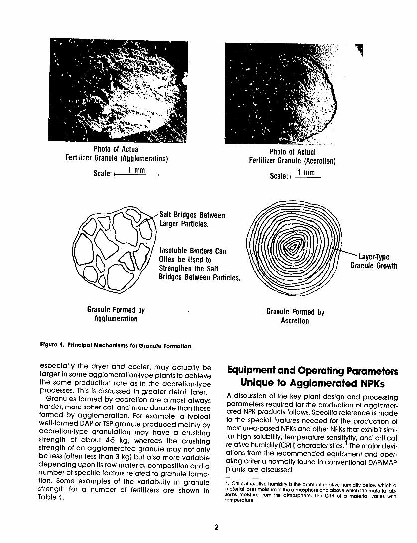
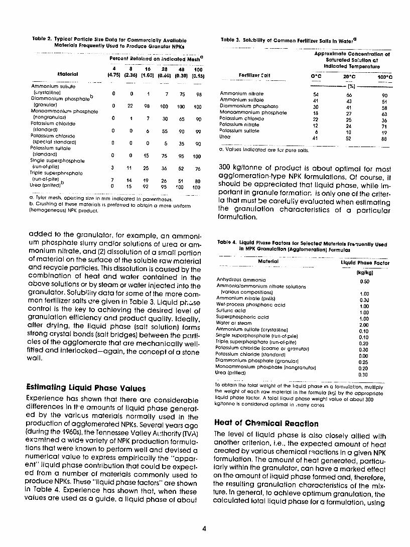
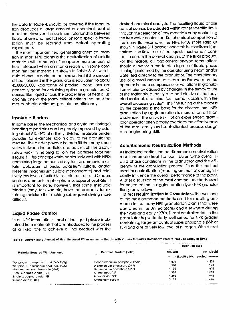
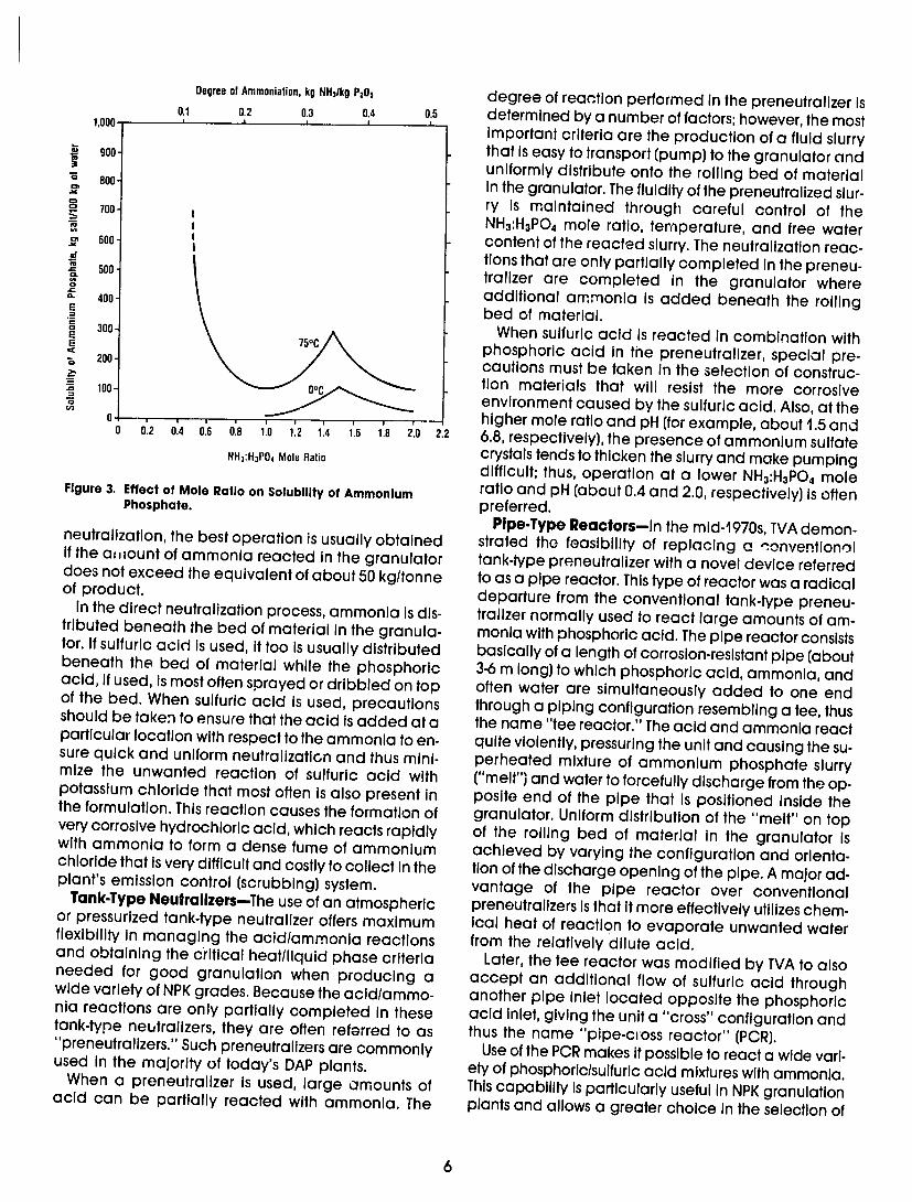
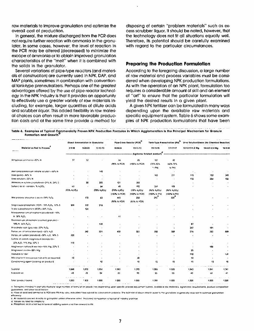
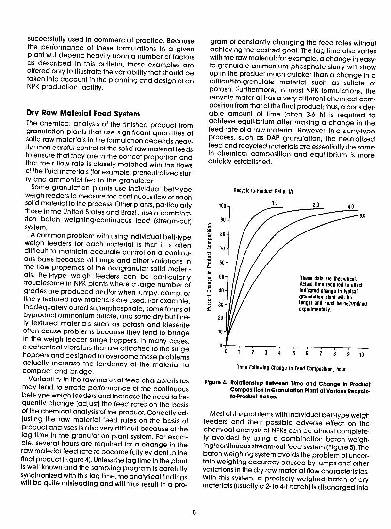
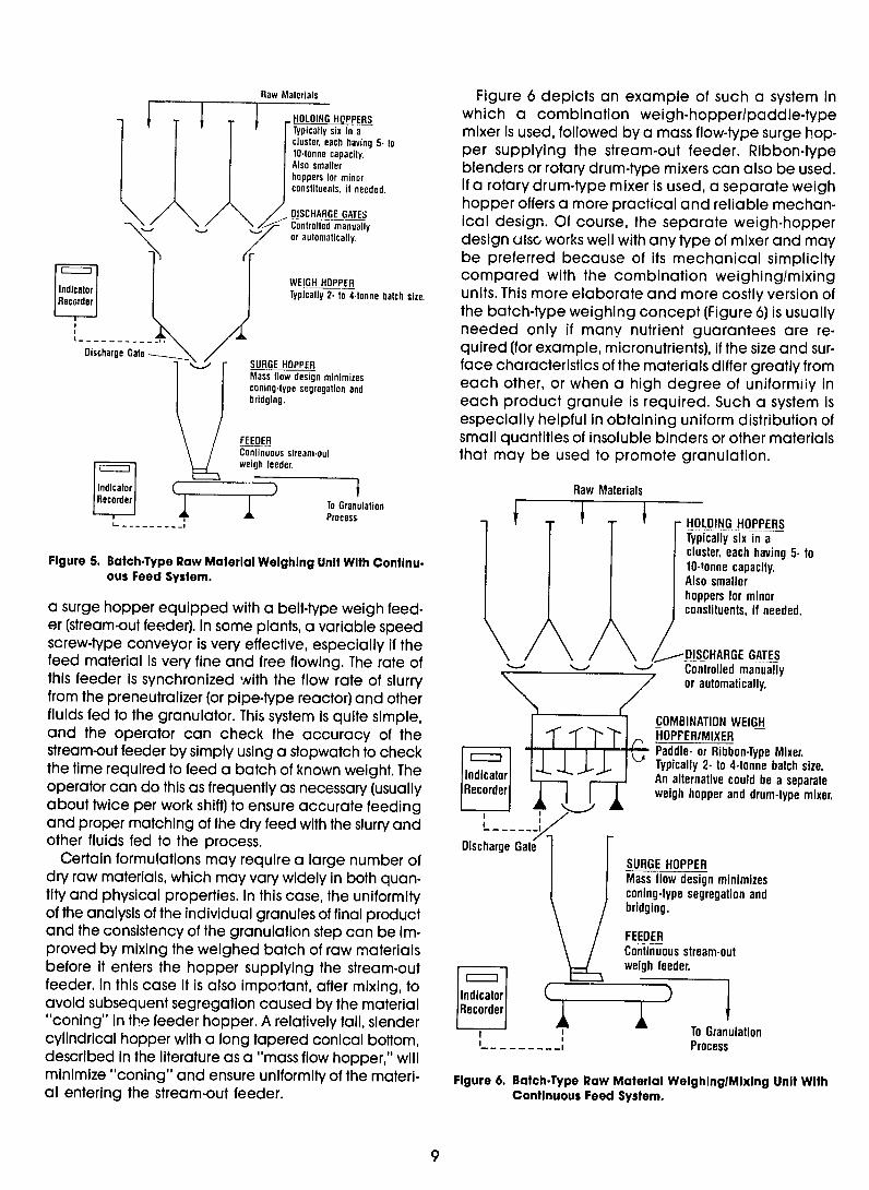
Raw Materials
I HOLDING HOPPERS
Typically six in a clus each having 5-tocllutnne capacity
Also smaller hoppers for minor constituents if needed
DISCHARGE GATES Contronitall manuall yed or automatically
rbe
HOPPERrWEIGHIdcorr TypIcaly 2- Io4onne batch size
Discharge Gate SURGE HOPPERMas flo dein minimizesMnng-ype segreation and
bridging
FEEDER Conlinuous slream-out weigh feeder
Jndicator c -- --RTo Granolation
L~~iProcess
Figure 5 Batch-Type Raw Material Weighing Unit With Continu-ous Feed System
a surge hopper equipped with a belt-type weigh feed-er (stream-out feeder) In some plants a variable speed screw-type conveyor is very effective especially if the feed material is very fine and free flowing The rate of this feeder Is synchronized with the flow rate of slurry from the preneutralizer (or pipe-type reactor) and other fluids fed to the granulator This system Isquite simple and the operator can check the accuracy of the stream-out feeder by simply using a stopwatch to check the time required to feed a batch of known weight The operator can do this as frequently as necessary (usually about twice per work shift) to ensure accurate feeding and proper matching of the dry feed with the slurry and other fluids fed to the process
Certain formulations may require a large number of dry raw materials which may vary widely In both quan-tity and physical properties In this case the uniformity of the analysis of the individual granules of final product and the consistency of the granulation step can be Im-proved by mixing the weighed batch of raw materials before It enters the hopper supplying the stream-out feeder In this case It is also important after mixing to avoid subsequent segregation caused by the materialconing in the feeder hopper A relatively tall slender
Figure 6 depicts an example of such a system In which a combination weigh-hopperpaddle-typemixer Is used followed by a mass flow-type surge hopshyper supplying the stream-out feeder Ribbon-type
blenders or rotary drum-type mixers can also be used If a rotary drum-type mixer is used a separate weigh hopper offers a more practical and reliable mechanshyical design Of course the separate weigh-hopperdesign ulsc works well with any type of mixer and may
preferred because of its mechanical simplicity compared with the combination weighingmixingunits This more elaborate and more costly version ofthe batch-type weighing concept (Figure 6) isusuallyneeded only if many nutrient guarantees are reshy
quired (for example micronutrients) if the size and surshyface characteristics of the materials differ greatly fromeach other or when a high degree of uniformiiy In
each product granule is required Such a system is especially helpful in obtaining uniform distribution of small quantities of insoluble binders or other materialsthat may be used to promote granulation
Raw Materials
i HOLDING HOPPERSTypically six in a cluster each having 5-to 1O-fonne capacity Also smaller hoppers for minor constituents Ifneeded
- DISCHARGE GATES - - Controlled manually
or automatically
COMBINATION WEIGH -HOPFERIMIXER shy
_ Paddle- or Ribbon-Type Mixer AialiTo c-ou b-e a szea weigh hopper and drum-type mixer
I
Discharge Gate SURGE HOPPER Mass flow design minimizes coning-type segregation and bridging
FEEDER Continuous stream-out
____weigh feeder indicator
cylindrical hopper with a long tapered conical bottom ---- I Processdescribed In the literature as a mass flow hopper will minimize coning and ensure uniformity of the materi- Figure 6 Batch-Type Raw Material WeighlngMixing Unit With al entering the stream-out feeder Continuous Feed System
9
If ItIs not practical to modify an existing continuous belt-type weigh feeder system to the batch-type feed method then It is Important to devise some method for frequently checking the feed rates from the in-dividual belt-type weigh feeders and using these check results as a basis for adjusting the rates This method of feed rate adjustment Ismore accurate and more rapidly responsive than are adjustments made on the basis of product-sampling because It avoids the complications and uncertainties caused by sys-tem lag difficulty In collecting representative sam-ples and other uncontrollable variables In NPK plants where the agglomeration of solid materials is the principal granulation mechanism it is extremelyimportant to base any change in feed rate(s) on a representative product sample collected (composit-ed) over a period of at least 4 h Adjustments in feed rates made on the basis of frequent grab samplescan be very misleading even Ifthe feed rate(s) sam-
pling technique and analytical work are precise
Solids Recycle Unlike most slurry-typeaccretion granulation process-es NPK processes based on agglomeration seldom recycle a significant quantity of product-size materi-al to the granulator only undersize material isnormal-ly recycled The use of a recycle control system for controlling (optinizing) conditions in the granulator isone of personal choice and isoften of limited value except during periods of startup or when changing grades In most cases a floating recycle system is preferred in agglomeration-type NPK plants However the relative merits of floating and controlled recycle are often a topic of debate among NPK and DAP plant operators
In agglomeration-type granulation particles will agglomerate only If they can first be attracted to each other This attraction is then followed by inter-locking and bonding Raw material and recycle fines will often not agglomerate into product-size granules if they are too large They will simply repel each other and accumulate eventually overloading the system Therefore a facility for crushing a portion of the large fines is recommended if coarse-grade raw materials andor large-size product (and therefore large-size recycle fines) are anticipated Also the ef-ficient crushing of oversize material is essential to enshysure that the particle size distribution and therefce surface area of the material recycled to the granu-lator isreasonably uniform The relationship between particle size and surface area is shown in Table 7 For this reason it is recommended that the material dis-charged from the crushers be recycled to the screens to ensure that only fine material is returned to the granulator Many crushers are less than 5 0efficient
on a single pass therefore the need for recirculation of the material from tne crusher back to the screens should be carefully examined This is discussed in more detail later
Table 7 Relationship Between Particle Size and External Surface Area
- ie
oa TyleraNominal Tylera
Diameter Screen Size External Surface Area (mm) (mkg
0106 150 434 0250 60 185 0500 32 927 100 16 462 200400 95 231
116 475 4 0971 670800
1500 325 06880577
0307
a Theoretical assuming perfect spheres having a density of 13 glcm3
Granulator A longer-than-normal rotary drum granulator is preferred (length-to-diameter ratio of 3 or more) for granulation by agglomeration The longer granulashytor isneeded to (1)provide sufficient room for the unishyform distribution of slurry acids solutions ammonia and steam (2)promote intimate mixing of the solids and fluids and (3)provide time for initial agglomershyation (granule formation) and consolidation of the granules to occur in view of the operator before the material disappears into the dryer The art of granushylation implies that the granulator operator should be able to see what is happening and make the often subtle adjustments needed to avoid inefficient granushylation and the resulting problems caused by upsets in the recycle equilibrium (mass flow and particle size distribution) Some plants that depend heavily upon steam and recovered scrubber liquor as the source of liquid phase very effectively utilize a premixing unit (using for example a pugmill-type mixer) located imshymediately upstream from the rotary drum granulator This added step ensu-es uniform distribution of the Iishyquid phase and initiates agglomeration thus it atshyfords the operator another opportunity to optimize the granulation process
Cocurrent Dryer General-With agglomeration-type granulation the moisture (usually about 2-6) in the material fed to the dryer is distributed quite evenly throughout the granule structure this situation is very different from that prevailing in the slurry-type processes for examshyple DAP in which a moist film covers a relatively hot
10
and dry particle core In ether case a cocurrent (parallel flow) dryer is preferred because with such a flow configuration the hot inlet air first contacts the moist fertili7or and thus allows operation at a higher overall temperature difference between the drying air and the moist fertilizer while minimizing the risk of overheating and melting the fertilizer which becomes more temperature sensitive as it dries
With the agglomerated granules the diffusion of moisture from the core of the granule to the outside sur-face and then to the drying air must be quite cc refully regulated-loo much heat applied too quickly may melt the surface of the particles and cause cuse hardening resulting in granules with a soft moist center caLised by entrapped moisture Sometimes melting may lead to excessive agglomeration andor fouling of the dryer internals In still other cases too rapid evaporation may cause the granule to explode Fur-thermore ifevaporation occurs before proper consoli-datlon of the granules is achieved (promoted by the rolling and tumbling action in the dryer) the granules may be too porous and therefore quite weak
With agglomeration the inlet portion of the dryer should be viewed as an extension of the granulator because a considerable amount of final granule for-mation and consolidation occurs here Therefore op-timal performance of most NPK dryers requires an operator who is skilled and capable of exercising considerable judgment because the performance of the dryer is grectly influenced by the grade beingproduced and the characteristics of the individual raw materials
Some experienced operators prefer to omit one or two rows of lifting flights near the inlet end of the dryer to give a section of smooth shell immediately follow-Ing the forward-pitched throw (spiral) flights at the dryer inlet The length of the smooth section usuallyequals about one-half diameter to one full diameter of the dryer The lifting flights that follow immediately after the smooth shell section must be designed to provide full exposure of the moist particles to the dry-Ing air yet not be too closely spaced to cause plug-ging or make cleaning difficult
Temperature and Humidity Profile-In general ag-glomerated products require relatively gentle drying The temperature profile within the dryer is dependent upon the temperature sensitivity and the CRH of the material With urea-based or highly soluble ammo-nium nirate-based NPKs the dryer outlet temperature (product) usually should not exceed about 740C if kleserite is also present or the N-to-P20 5 ratio is high then a temperature of about 680C isabou maximum The relative humidity (RH) of the dryer outlet air should be at least 10-15 percentage points below that of the CRH of the material at the dryer outlet temperature Thus for most urea-based NPKs the RH of the air at its
outlet temperature (typicallyabout 74 0C) should not exceed about 20 because the CRH of the urea- or ammonium nitrate-based materials at this elevated temperature is usually about 30 and sometimes even lower (Figure 7) The moisture-holding capacity of air at typical NPK drying temperature and RH conshyditions isshown in Figure 8 The unique RH CRH and temperature criteria required for drying many NPKs especially the urea-based NPKs translate into largershythan-usual process airflows This results in the need for rotary dryers that are relatively large in diameter compared with those used to dry products such as DAP that are less sensitive with respect to temperature humiaity and particle entrainment
Air Velocity-The particle size distribution of most agglomerated NPKs entering the dryer Ismuch wider than that of DAP NPK granules are ailso relatively irshyregular in shape compared with well-formed DAP granules thus they exhibit a greater drag in the airshystream The effect of drag is clearly shown in Figure9 where the actual entrainment of irregular potash granules iscompared with theoretical values for pershyfect spheres To avoid excessive entrainment of the smaller and more irregular particles (those less than about Imm) found in most NPK plants It is necessary to operate the dryer at a lower air velocity than Iscusshytomary for DAP dryers This lower air velocity criterion for NPKs (about 20 to 25 ms empty-dryer [superficial] basis compared with about 3 to 4 ms for DAP) often limits the drying capacity of DAP plants that are conshyverted to the production of NPKs
Retention Time-Because the drying process for agshyglomerated NPKs is mainly controlled by the rate of diffusion of moisture from the core of the particles the point at which a longer retention time does not sigshynificantly promote further drying is more quickly reached with many NPKn (especially the verytemperature-sensitive urea-based NPKs) than with DAP or other accretion-type granular products The net result isthat a long retention time in the dryer is often less important with NPKs and sometimes quite unshydesirable The overriding factors are the temperature and RH profile in the unit (most importantly the differshyence between the material CRH and the RH of the dryshyng air) Ifthe dryer istoo long and the cooling effect of evaporation ceases the product may begin to overheat and melting may occur near the outlet end of the dryer This can result in a ring-like buildup of material on the inside of the dryer near the disshycharge end This buildup will cause a bed of material to form in the dryer which in turn will cause less effishycient drying overloading of the unit and a number of other problems including overgranulatioi-
Condition of Procuct at Dryer Discharge-The physical condition of NPK products dischaged from the dryer may vary widely depending upon the
11
80shy- O jMonoammonium Phosphate
70
O --- -Diammonium PhosphateO
60
= 50 Calcium 0 Urea-Ammnium Phosphate NPK Ammonium
(17117-17)Nirt
40- Nitrophosphate NPK CJ (17-6-18-2MgO)
30shy
20-
Source IFDC Experimental Determinations
20 30 40 50 60 70 80 90 Temperature OC
Figure 7 Effect of Temperature on Critical Relative Humidity of Selected Fertilizers
(1) raw material characteristics (2) formulation (3) dryer temperature and humidity profile (4) operatorskill and (5) the particular crystallization habit of the mixture This last point (crystallization habit) isthe least predictable Although it is quite easy to accurately determine the expected free water content it isonly by experience (trial and error) that the crystallization (hardening) characteristics of a particular fertilizer forshymulation can be accurately determined Impurities In the phosphoric acid and other raw materials the type and source of potash the temperature and moisture content and a host of other subtle and un-predictable factors often have a major influence upon the physical properties of the material dis-
charged from the dryer At times the product may be crisp hard and easily screened and crushed then again with all conditions apparently the same It may be dry but quite soft and plastlc-a condition that can quickly lead to screen blinding upsetting of the recycle loop and plugging of the crushers
Countercurrent Process Cooler
(Seond-Stage Dryer) The adverse effect of most of the transient and unshypredictable operational problems described above can be largely eliminated by routing all of the dryer
12
220 1
200shy
_ 180
o 160
o 140 3000 RH
_ 120shy20deg0 RH
0
C 100
80shy ~15 RH
60shy
o 40shy40shy
20shy
50 60 70 80 90 100
Air Temperature degC
Figure 8 Effect of Temperature and Relative Humidity on Moisture Content of Air
discharge material to a process cooler which may and temperature of the inlet air may be needed In be more properly referred to as a second-stage dryer some locations of course the need for this feature A countercurrent alr-to-fertilizer flow configuration is would be dependent upon local ambient conditions preferred for maximum cooling in this unit The trans- and the NPK product characteristics The processfer of fertilizer material from the dryer to the process cooler serves the following useful functions cooler should be made by means of an inclined conshyveyor belt a bucket elevator is not recommended be- It allows drying to continue typically about 15shycause of the problems associated with the buildup 25 of total drying occurs in the process cooler of material it the buckets and discharge chute ifthe material is plastic or sticky or if a slug of bad a It serves as a safety valve to accommodate material forms as a resuit of an upset caused by oper- process upsets It makes the entire system more ator error burnerair heater failure or a number of forgiving other routine problems that commonly occur In most NPK granulation plants It adds time at a slightly reduced (and controlla-
The heat transfer capacity of the process cooler ble) temperature profile to allow the material to should normally be about one-half to two-thirds that crystallize and harden before It is subjected to of the dryer The cooler should also be equipped with screening and crushing As a result toe screens are an air heater to temper (heat) the inlet air if needed more likely to remain clean (free from blinding) to decrease Its RH andor control the temperature pro- and the crushers will perform more efficientlyfile In the unit The addition of an air chilling unit with because the oversize particles are harder and subsequent reheat to more carefully control the RH therefore will fracture more easily Material
13
60shy
50
Particle Specific Gravity-m-- 2 0 15 0
bull 40 Theoretical
rMinimumHorizontalEE Carrying (Entrainment)
Z C
30
Horizontal Entrainment Determined20 Experimentally in IFDC Pilot Plant
Using a 092 m Diameter Rotary Dryer and Irregularly Shaped Granules of
10- Potassium Chloride (17 specific gravity)
l I 1 I I I I I I I I 1 i 1 l I
20 30 40 50 70 100 200 300 400 500 700 1000 2000 3000 4000 5000 Particle Diameter microns
Figure 9 Effect of Particle Size and Gas Velocity on Entrainment of Particles
plasticity and the resultant plugging of the crush- Square-mesh wire screen (stainless steel) should be ers screens and downstream chutes are largely used to ensure the production of well-rounded eliminated (minimum surface area) granules Well-formed
granules are of key importance to minimize surface contact points and residual dust and small parti-
Screens cles that cause caking during long-term storageThe screening action on a square-mesh wire screenA key element in NPK granulation is precision screen- is more likely to scrub the granules and more efshy
ing to ensure that the bagged product will have good fectively remove bits and pieces of fines This is esshylong-term storage properties This is especially ap- pecially true ifra horizontal gyratory-type screening
plicable to high-nitrogen grades manufactured from machine is used Stainless steel screen wire is either ammonium nitrate or urea If the process recommended because its reslstanceto corrosion screening system is well designed it is usually not resulsn eoote ires ace t rsi u
aditona dowstram sreeing results In a smoother wire surface that resists buildshynecesar to nstllnecessary to install additional downstream screening up of solids and plugging
facilities (for example polishing screens after final product cooling or before bagging) Of course such Product granules should be relatively large in the additional screening will be helpful but the relative range of 2-5 mm or even larger to minimize contact merits and need for such polishing-type screening area and therefore caking The production of such should be determined on the basis of the design and large granules will influence the particle size of the performance of the basic process screening system recycle and the resultant granulation propertiesand the specific product characteristics The follow- Even with a 2-mm recycle particle (maximum size)Ing process screening system Is recommended for it Is often not necessary to crush the recyclemosT NPKs especially those containing high levels of however this point must be carefully considered ammonium nitrate or urea depending upon the overall size distribution of the
14
recycle fraction The size distribution may change quite significantly from formula to formula even though the screen size range of the final product remains constant
Single-deck screens are recommended because they allow easy access for inspection and clean-ing without interrupting the process In addition to ensuring the production of fertilizers with a mini-mum tendency to cake clean screens are also of key importance in maintaining good process control
Horizontal gyratory-type screening machines are preferred over inclined units especially for the product screens The horizontal units are preferashyble because if they become blinded due to the lack of attention they will overload and stall thus they will automatically prevent fines from being discharged as product a major cause of caking If inclined screens become blinded they continue to operate while discharging fines with product thus causing considerable problems with caking on the one hand and control of granulation on the other Also as previously mentioned the horizontal-type units will more effectively scrub the granules to remove residual small particles and dust thus decreasing the risk of caking
The ratio of the fertilizer material feed rate to the screening surface area should be quite low For theoversize screen about 10-20 tphm 2 isrecommend-ed whereas only about 5-20 tphm2 isrecommend-ed for the product screen with the smaller open-ings Of course the design of the screening machine and the screen open area (product size)have a major influence on the screening capaci-havuner a given circumstance However it is im-pyunder a note cirman Hoen suim-r portant to note that many NPK plants often suffer from having too little screening capacity
Oversize Crushers
Crushers are not 100 efficient in crushing oversize material on a single pass an efficiency of about 50 or less Ismore likely The crushing efficiency actually obtained of course depends on a number of factors most Importantly the required particle size distribution and the crushing characteristics of the material
To avoid the risk of recycling a arge amount of un-crushed or only partially crushed oversize to the granulator and upsetting the granulation process which Isvery sensitive to particle size distribution the material from the crushers should be recirculated to the oversize screens as shown In Figure 10 Although this procedure Increases the capacity needed for the
screens and crushers it ensures that the maximum particle size of the material recycled to the granulashytor will be smaller than the product and thus improves granulation control
Material From Dryer or Cooler
Material From Crusher
OversizeOversize Screen
Crusher
Undersize Screen
Product
Undersize Material Recycled to Granulator
Figure 10 Closed-Loop Screening and Crushing System
Because the size distribution of the solid particles Becausuth size isrtin afgtheraticleisof such major importance in agglomeration-type
granulaion extraordinary care should be taken in determining the optimum particle size characteristics required for good granulation This type of informashytion is learned best through testing in commercialshyscale equipment Ifsuch large-scale testing isnot posshysible smaller scale (pilot plant) studies can often beeffectively used to provide valuable comparative data These test dala should then be used to detershymine the optimum design of the screening and crush-
Ing system
Product Cooler After screening a conventional rotary- or fluldized bed-type product cooler Is recommended The pershyforated tray countercurrent cascade-type cooler is also a good choice Of course the temperature and RH of the cooling air used in these units must be adshyjusted depending upon ambient conditions to effect cooling without wetting of the product A final product temperature of about 4300 or slightly less Is recomshymended Excessive cooling is not recommended esshypecially in humid areas because too much cooling could result In the absorption of atmospheric moisture by the material this could lead to caking
15
Conditioning
Many NPKs should be conditioned to add extra protec-tion against caking A kaolin-type clay isrecommend-ed Usually about 05-10 by weight is required however this depends heavily upon the NPK product characteristics and the properties of the clay The benefit of using oil or wax to help bind the clay to the granules isnot always clear the oil or wax does however help to settle dust in bulk storage and bagging areas even if it does not always fully adhere the clay to the granule surface If an oil-type binder is used all conveyor belts downstream from the binder addition system should be oil proof to avoid ply separation and failure Belting made from neoprene or polyvinyl chloride isnot severely affected by oil-type binders or other organic-type con-ditioning agents
The application of oil to NPKs especially thcse produced by agglomeration is often difficult Leshycause of the relatively unpredictable absorption characteristics of the granules from one grade to another For those grades containing ammonium ni-trate especially in combination with potassium chlo-ride the use of oil should be avoided for safety reasons A more detailed discussion of the potential safety hazards of mixing organic materials with nitrate-containing fertilizers can be found in the Fer-tilizer Manual and the references cited therein
The most effective way to add solid conditioning agents to granular fertilizers is by use of a specially designed rotary drum application unit The design parameters for such drums can also be found in the Fertilizer Manual
Storage and Bagging The recommended and usually most practical product storage and bagging system for hygroscop-ic NPKs consists of (1) a relatively small humidityshycontrolled bulk storage area (building) representing about I to 2 days production This bulk storage area should be divided according to the expected num-ber of grades produced over a I- to 2-day period a minimum of two or three drive-in storage bays is recommended This small and segregated storage method will also greatly facilitate changing of grades with a minimum of lost time This method of bulk storage before bagging will minimize and usuallyeliminate the accumulation of grade change products that are so far off specification that they can-not be shipped After a brief period of storage in bulk (overnight or perhaps a day or two) to allow for initial pile set and to certify the analyses the product should be bagged in moistureproof bags Bagging directly from the production unit or bulk storage of freshly made product in overhead bins is not recommended
The optimum bag construction for long-term storage in humid areas consists of an open-mouth bag fitted with a loose polyethylene film liner that is at least 01 mm thick The outer jacket should be constructed of woven polypropylene or some other stro g and durashyble material The liner should be tied and the outer jacket should be stitched The stitching should not penetrate the liner Heat sealing of the liner is not recommended because if precautions a 9 not taken such sealing usually entraps air that may result In pillow-shaped bags Handling especially stacking such pillow-shaped bags is difficult Venting enshytrapped air from such bags by percing the film liner isa common practice but this should be avoided beshycause such venting allows atmospheric moisture to seep into the bag causing wetting and caking
Process Plant Dehumidification If hygroscopic NPKs are produced (especially those containing urea) and the ambient relative humidity at the plant site isin excess of about 50 for more than about 8 consecutive hours on a routine basis it isesshysential that the process plant building (and bulk product storage building) be tightly enclosed and ventilated with low-RH air Furthermore if the tempershyature inside these enclosed buildings is excessive then it will be necessary to cool and dehumidify the air to maintain comfortable and safe working condishytions at an acceptable RH that will prevent wetting of the plant and equipment Excessive wetting caused by the hygroscopic fertilizer material and dust accumulations will lead to excessive corrosion elecshytrical failures safety problems (slippery floors and walkways) and a number of adverse process problems particularly with conveyor belt idlers dust collection systems screens and air handling systems
Recommendations Specific to theProduction of NPKs Containing Urea
Urea-based NPKs are among the granular fertilizers that are most difficult to produce On the basis of the foregoing general discussion and the particular characteristics of most urea-based NPKs the criteria shown in the Appendix are recommended as a startshying point for the basic design of a plant well suited for producing urea-basea NPKs or other NPKs that exshyhibit similar characteristics such as excessive plasticshyity low tolerance to elevated temperatures and low CRH These recommended design features are also applicable to the more tolerant NPKs However with these more tolerant NPKs more latitude in the designand operating criteria may be allowed
16
Phospho Acid
I ToAlmosphere
WaWaer
Solid Materials SlVent A V I nshy
(See Nolet)
Raw Material Surqe Hoppers
I -t
Wale
_ L 1 J Gas Scruping
System
PhoslrhoricAcid
OustCoctorso
___
Oversize
Screens
(Clusterat 6 Hoppers)
8andMSae S adMe
t
mO-
I
See Note21
Vent PaneutlizerScreens
Recycle
I
I
Product
Oversize
Crushers
CotnosRotaryCon S reednyem
0~MGnua e
PhosphorcAcidSuituricAcid-- Ammonia anuta or- -SeamlWate
Vent IVeni Vent
ConditioningAgent(l amp Of Bidder)
hoidUrea Venloto Aiiit A Heiler R otaily Dryer
teamL
UreaSoluioniMeil PreparationSystem
Figure 11 Recommended Agglomeration
Soli Ure um I -- RotayDrer - Scrbber ~ um~ eli ~I~rv~m ess oSleruberPdc i
Notes
I Snaded equipineni tIrls usuaiiy not inc iuOed in connhiionil
ammninum phosphate iAPHMAPi plants5 2 Pipe cross reactor IPCRi in Additon iO eeuiamoei piovides
mnxinium ie ibuity in toimuiailng 050M rod cont~rin ng rades 3 ROijry ci tiamitlled n I aem
SProcesspiani buiding mayhays io OndehuirRdled dependinA
uponCRl fic entiiiti andlanicent relatvr nurnidiri
Process Flow Diagram for Maximum flexibility InProducing Granular NPKs Based on
A process flow diagram of an NPK granulation plant embodying the recommended features is shown in Figure 11 Also Indicated in Figure 11 are the features that are most often missing In a plant designed primarily for the production of DAPMAP
Verification of Recommended Plant Design and Operating Parameters
The recommended design and operating parameters for NPK granulation plants described in this bulletin are thought to be near optimum on the basis of data obtained from a number of IFDC pilot plant-scale trials and experience with several commercial-scale operations However because no two formulations (grades) or plants respond in exactshyly the same way to a given set of conditions extraposhylation and judgment are required when attempting to set the design basis for aofnewsgrade or plant
Conclusion The fundamentals of granule formation and processshying for agglomerated NPK fertilizers differ markedly from those for DAPMAP fertilizers For this reason many well-designed DAPMAP plants experience difficulties when called upon to produce NPKs The difficulties are most pronounced when the NPKs contain urea or other temperature-sensitive and hygroscopic Ingreshy
dients The plant design and operating criteriadescribed in this bulletin are intended to guide those involved in planning new NPK plant projects o troubleshooting and modifying existing units This bulletin may also be used as a checklist during the various stages of project development to help ensure that the special requirements for NPK plants are not overlooked
17
APPENDIX-Design and Operating Criteria for Urea-Based NPK Granulation Plants
Solid Urea Feedstock-Prilled urea ispreferred because its small physical size helps to effect relatively homogeneous incorporashytion into the granule structure Very small and broken prills are the most desirable
Urea Solution-Ifthe urea content of formula ismore than about 20 it isoften preferable to dissolve a portion of the urea to produce a hot (1050C) 75-80 urea solution The availability of urea solution adds considershyable flexibility to the process The solution issprayed on top of the bed of material in the granulatorIn most instances a solution of urea is preferred over an anhydrous melt
Other Solid Raw MaterialsshyStandard-grade materials are preferred Nongranular run-of-pile (powdered) monoammonium phosshyphate and superphosphate are recommended Ifsuperphosphate isused in combination with urea itshould be ammoniated to miniiize unwanted reactions that result in the release of water of crystallizashytion contained in the superphosphate In general the use of superphosphate in combination with ureaisnot recommended and should be avoided even the superphosphate isammoniated Standardgrade muriate of potash is preferred because of its good flow characteristics and more optimumparticle-size distribution Good flow characteristics of all solid raw materials are desired to facilitate handling and accurate metering
Preneutralizer-Astandard atmospheric tank-type preneutralizer ispreferred An NH3H3PO4 mole ratio of about 05 to 06isrecommended in the preneutralizer to achieve a low free water content while still maintaining a fluidand pumpable slurry This is especially important if a significant amount of sulfuric acid isalso neushytralized in the unit The preneutralized slurry at a mole ratio of about 05 to 06 should be about 1270Cand contain no more than 15 free water The preneutralizer and its auxiliary equipment (agitatorpumps and piping) should be constructed of corrosion-resistant materials to facilitate the use of amixture of phosphoric and sulfuric acid thus adding considerable flexibility to the process In genershyal if a higher mole ratio (for example 15) is used especially if sulfuric acid isalso present the free water content of the slurry will have to be higher to facilitate pumping
Granulator (rotary)-The length-to-diameter ratio should be at least 3The greater length compared with most DAP and manyNorth American NPK plants facilitates granule formation and gives the operator more flexibility in conshytrolling the agglomeration process The NH3H3PO4 mole ratio of the material discharged from the granushylator may be quite variable depending upon the properties of the raw materials However a moleratio between 10 and about 18 isexpected to be optimum The lower mole ratio will simplify operationof the scrubbing system and tend to improve the process control The free moisture of the productdischarged from the granulator will usually be in the range of about 2 to 3 The recycle-to-productratio isexpected to vaiy from about 3 to 6 A ratio of 6 is recommended for design If the process isbased on a solid ammonium phosphate source (a preneutralized slurry is not used) then a designrecycle-to-product ratio of about 3 is sufficient
Cocurrent Dryer-The length-to-diameter ratio of this rotary unit should not exceed about 6 The superficial velocity of theair (at outlet conditions) should not exceed 24 msec maximum (20 msec preferred) The maximum temperature of the outlet air should not exceed 80degC and the RH at this temperature should not exshyceed 15 An outlet air temperature of about 750C at 20 RH is recommended as the design basis Themoisture of the material discharged from the dryer should not exceed 10 a value of 08 is recomshymended for design provided a second-stage dryer (process cooler) isused The temperature and hushymidity profile in the dryer is extremely important and the optimum values will vary from product to product
18
Countercurrent Process Cooler-(Second-Stage Dryer) The length-to-diameter ratio of this unit should not be less than 6 7 to 8 is preferred The inlet air should be tempered (heated) andor conditioned to ensure that the RH i 60 or less The superficial air veshylocity should not exceed 20 msec The low velocity is recommended because of the relatively large amount of minus 10 mm particles in the mate ial It is preferred that these small particles be removed (separated) by the screens rather than by the airflowidust collection system The unit should be designed to achieve a material (discharge) temperature of not more than about 540C at a free moisture conshytent of no more thon 06 Further cooling of the product fraction isperformed in a separate operation
ScreeningshySingle-deck horizontal gyratory-type units are recommended The screen wire should be stainless steel and of the square-mesh style If inclined electrically (or motor) vibrated screens are used they should be for oversize separation only not for product screening The hourly loading of the oversize screen should not exceed about 20 tm2 and the loading of the horizontal gyratory-type product screen should not exceed 50 of this valie (25-30 preferred)
Oversize Crushers-Double rotor chainmil-ty- rushers or double row cage mills are preferred The discharge assemshyblies of the mills should not be restricted and should be constructed of flexible rubber (conveyor beltshying) panels that can be flexed from the outside by an operator using a hammer A flared-type discharge assembly for the crushers is recommended to help avoid the accumulation of solids The crushed oversize should be recycled to the oversize screen on a closed-loop basis to ensure that only the fineshymaterial fraction from the screens is returned to the granulator as recycle
Product Cooling-Either a rotary-drum or fluidized-bed unit is recommended The single-pass counter-current cascadeshytype unit is also acceptable The cooling unit should be located immediately ahead of the condishytioning unit The RH of the cooling air at inlet conditions should not exceed 50 The temperature of the product discharged from the cooler should not exceed about 430C In all cases the temperashyture of the cooled product should be about 5degC above the average ambient temperature to avoid absorption of atmospheric moisture on the surface of the material
Conditioning-A standard rotary drum-type conditioning unit is recommended Screw-type mixing units should be avoided as they tend to grind and break the product granules
Bulk Storage and Process Plant Dehumidification-If ambient conditions normally exceed about 50 RH for extended periods (more than about 8-16 h) provisions should be made to dehumidify the process plant and bulk storage buildings Cooling and proper ventilation may also be necessary for worker comfort and safety Adequate ventilation is especially important because all buildings should be tightly constructed and closed to maintain a dry inside environment (RH of 40-50)
Bagging-The products should be bagged in moistureproof bags shortly after production Direct bagging from the production unit is not recommended because off-specification product could inadvertently be bagged and because flexibility is lost in handling product during grade-change periods In addishytion bag set (caking) isminimized if the fresh product isallowed to pile set for a short period of time
19
Bibliography 1 Achorn FP and DG Salladay 1976 TVAs New
Pipe-Cross Reactor Process for Granular Ammo-
nium Phosphates Paper presented at American Chemical Society Meeting San Francisco
2 Chinal P C DeBayeux and J F Priat 1986 Dual Pipe Reactor Process for DAP NP and NPK Production IN Proceedings of lhu 36th Annual Meeting of the Fertilizer Industry Round Table pp 30
3 Fischbein M and A M Brown 1988 High Qual-Ity Granular Ammonium Sulphate Productionity ranlar Muscle Shoals Alabama 35662mmoiumSulpateProdctinment Center Paper presented at the International Fertilizer In-dustry Association Limited Conference Edmon-ton Canada
4 Hemsley JDC and Francisco Roig 1972 The Manufacture of Granular Compound Fertilizers Based on Urea as the Principal Source of Nitro-gen IN Proceedings of the ISMA Technical Con-ference held in Seville Spain 20th to 24th November 1972 International Superphosphate and Compound Manufacturers Association Ltd London England
5 Hoffmeister G and C PHarrison 1977 PhysicalProperties of Granular Urea-Based NP and NPK
Fertilizers IN Proceedings of the 27th Annual Meeting Fertilizer Industry Round Table pp162-171
6 International Fertilizer Development Center 1979 FertilizerManual IFDC-R-I (also available from the United Nations Industrial Development Organiza-tion Vienna Austria) Muscle Shoals Alabama 35662 USA
7 Medbery J L and FTNlelsson 1981 Funshydamentals of Granulation INProceedings of the 182nd American Chemical Society National MeetingPaper No20New YorkNew YorkUSA
8 Salladay DG and BRParker 1980 Commershycialization of the TVA Pipe-Cross Reactor in Regional NPK and DAP Granulation Plants In the United States Paper presented at Annual Meet-Ing of the Fertlllser Association of India New Delhi India
9 Schultz J J and ED Frederick (Eds) 1988 NPKFertilizer Production Alternatives IFDC SpecialPublicto Pucinternatial Fl DeelPublication SP-9 International Fertilizer Develop-
USA USA
10 Schultz J J and J RPolo 1987 The Role of Agshyglomeration in the Fertilizer Industry Paper presented at the 20th Biennial Conference Instishytute for Briquetting and Agglomeration Orlando Florida USA
11Sheidrick WF1970 The Prediction of Granulashytion Plant Performance From Temperature Moisture Relationships in the Granulator IN Proceedings of the 20th Annual Meeting The Fershy
tilizer Industry Round Table pp 96-100 1 2 Sherrington PJ and R Oliver 1981 Granulation
Heyden amp Son Inc Philadelphia PennsylvaniaUSA
13 Tennessee Valley Authority 1976 Studies of Granulation of Compound Fertilizers ContainingUrea-A Literature Review Bulletin Y-108 Nationshyal Fertilizer Development Center Muscle Shoals Alabama 35660 USA
20
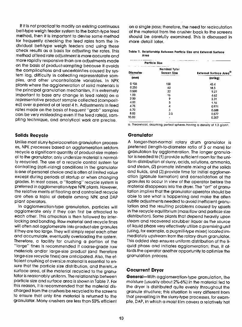
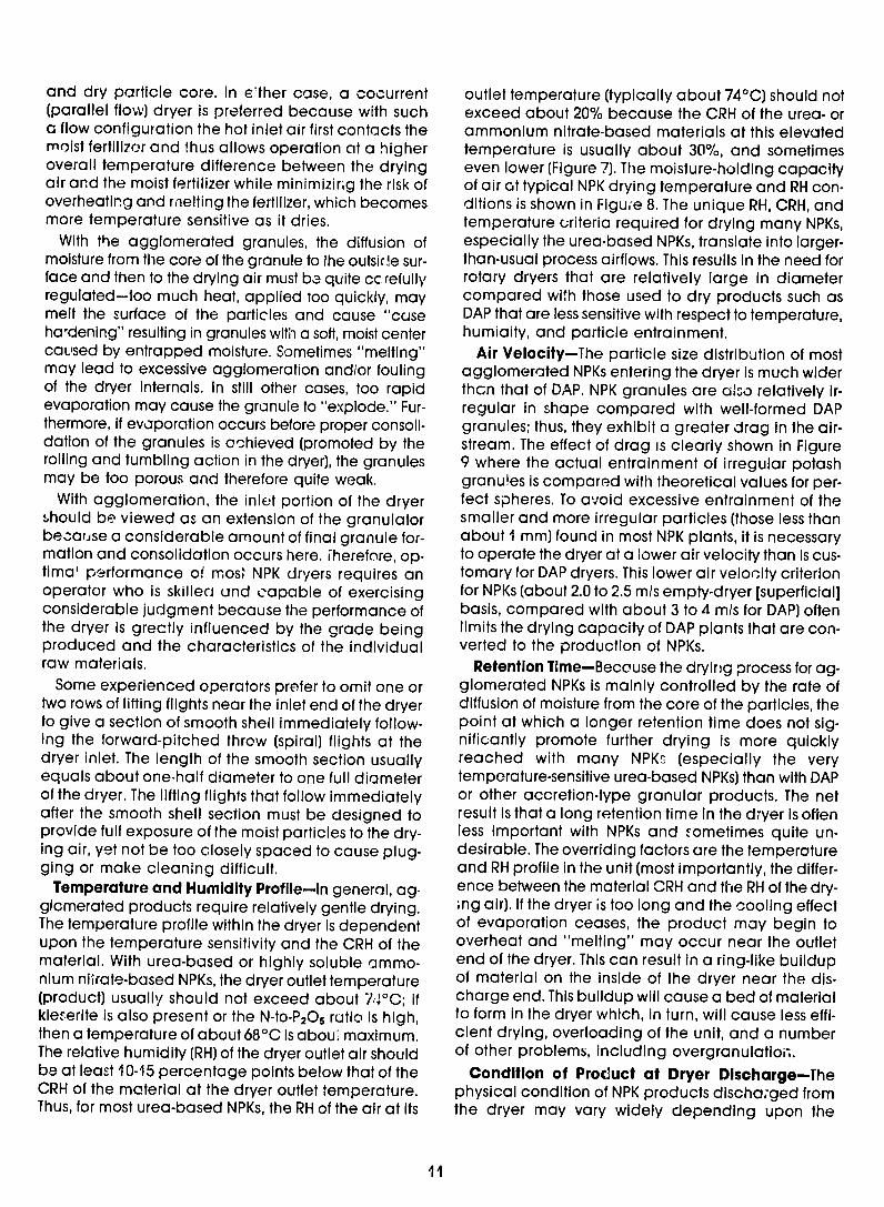
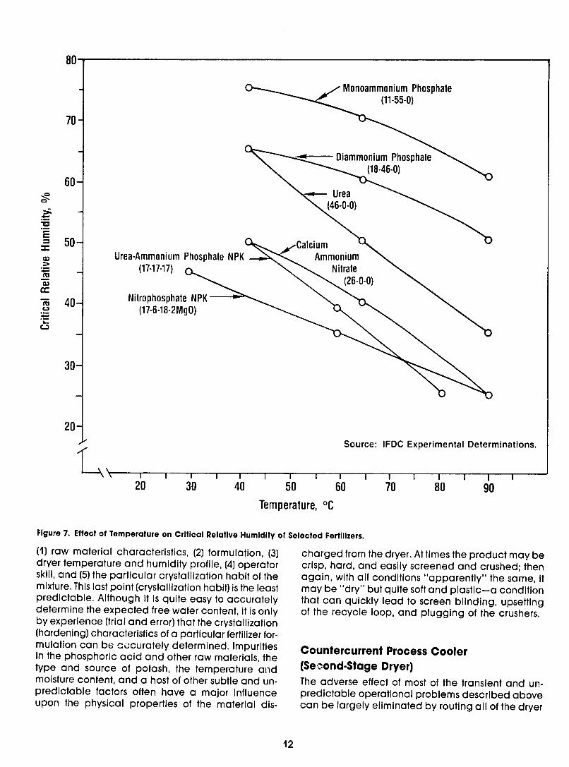
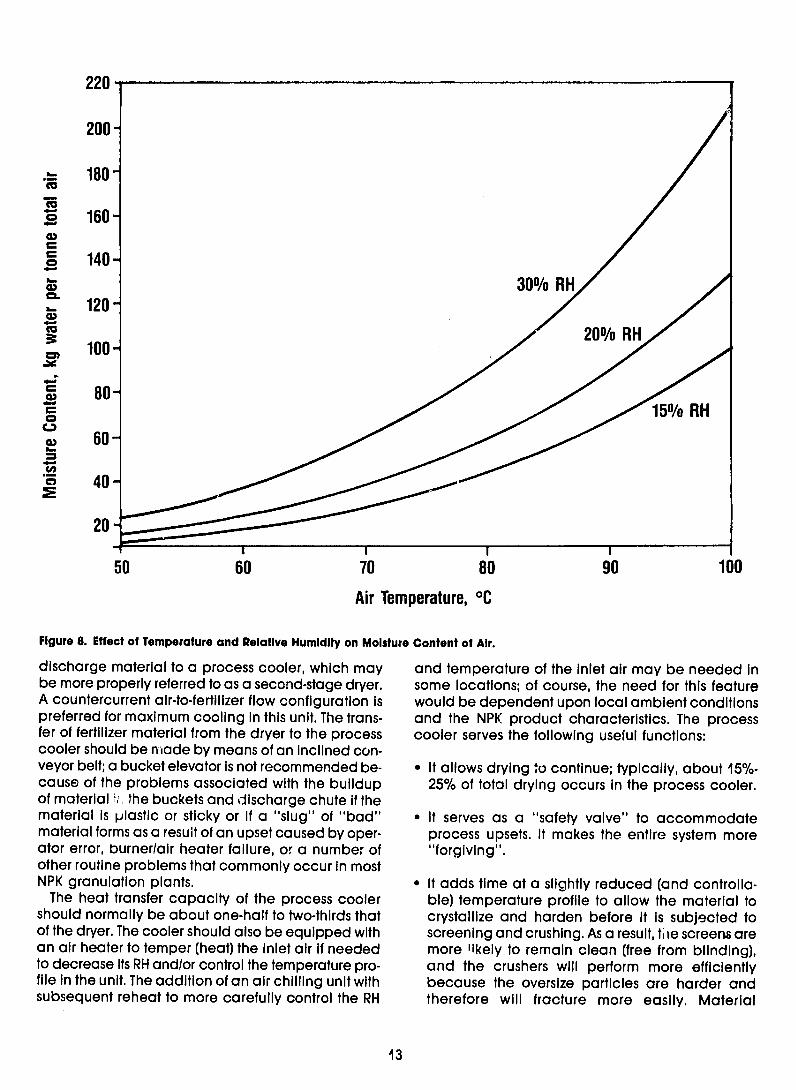
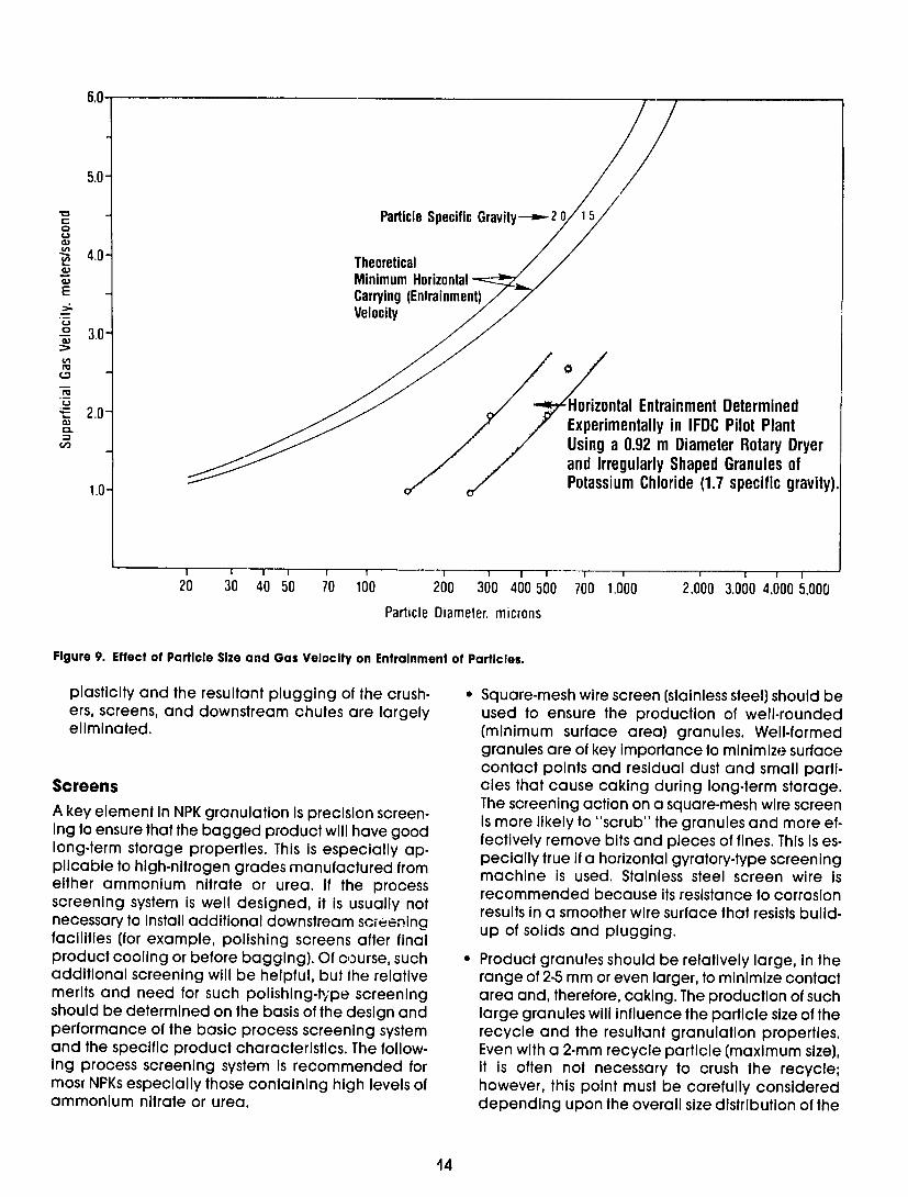
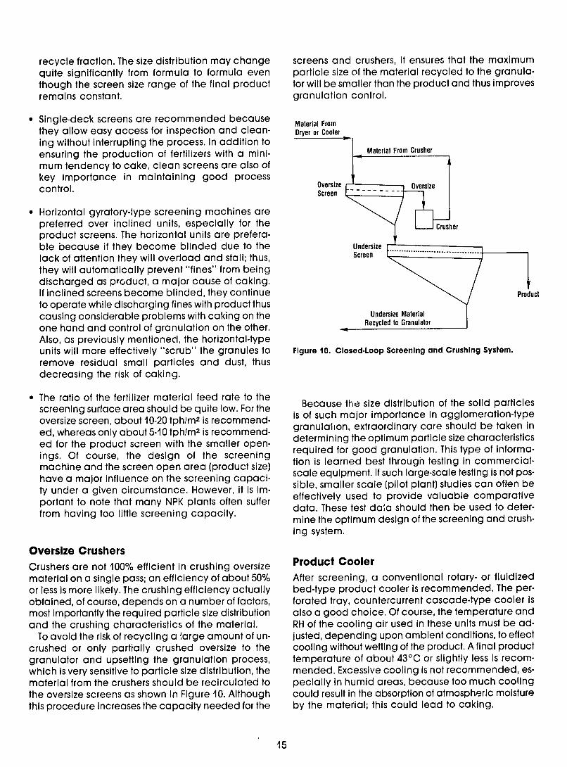
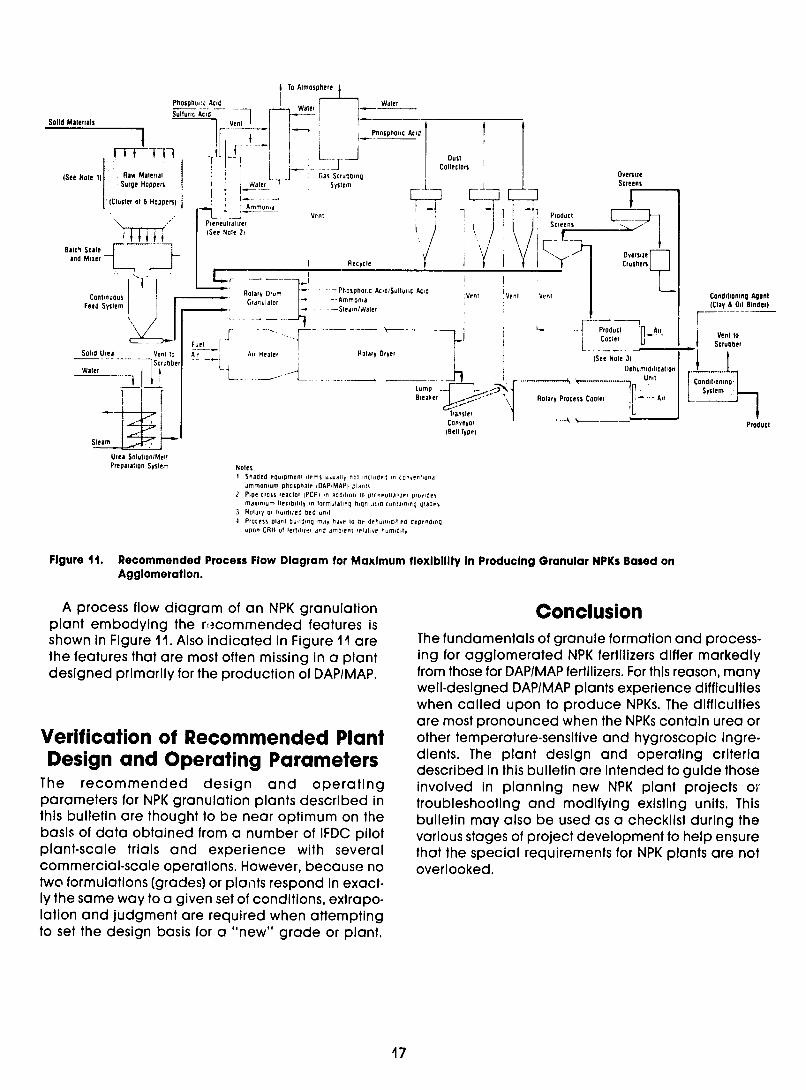
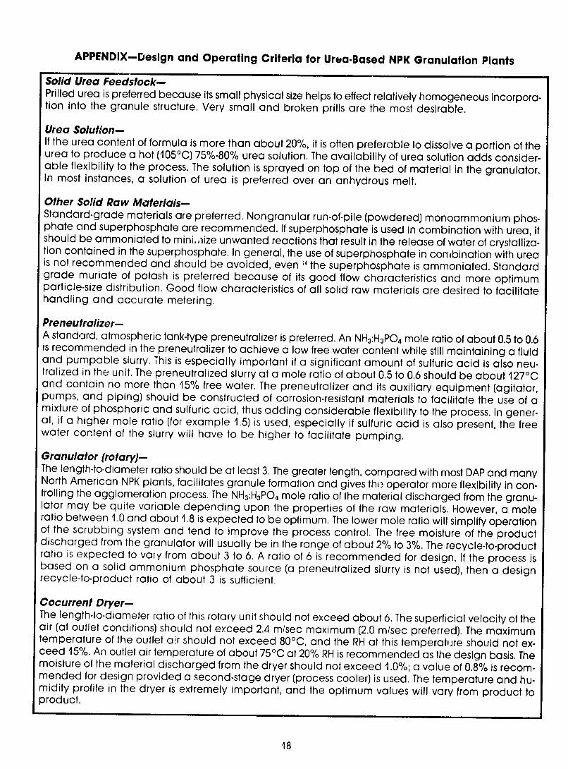
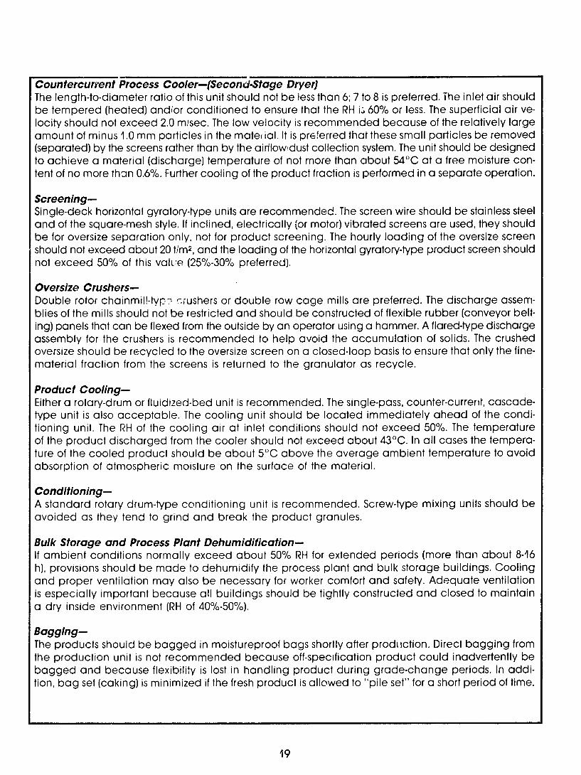