Embed Size (px)
Citation preview
Production of Transportation Fuels from Biomass at Pulp and Paper Mills - the Finnish Approach
Paterson McKeough and Esa KurkelaVTT, Finland
7th International Colloquium on Black Liquor Combustion and GasificationJyväskylä, Finland 31.7 - 2.8.2006
2
The Finnish Approach
Development and commercialisation of technology for producing multi-purpose synthesis gas (syngas) from solid biofuels:
– fluidised-bed gasification, applicable to a wide range of fuels:– woody biofuels, peat– straw and other agro-biomasses– waste-derived fuels
– novel catalytic gas reforming and conditioning
Envisaged commercial scale: 200 – 300 MWfeed; preferably integrated with energy-consuming paper mills
The long-term objective is no less than to develop superior bio-syngastechnology for export markets; e.g. a target cost of < 50 c/l has been set for Fischer-Tropsch diesel production based on this technology.
3
The Finnish Development Path
Current development stage led by VTT (Esa Kurkela): 0.5 MW process development unit (PDU) 2006 – 2007
Total budget ca. 4 MEUR, duration: 1.1.2004 – 31.3.2007
Current industrial consortium: Foster-Wheeler, Neste Oil, Andritz, Vapo, PVO, UPM, M-real, Metsä-Botnia, Stora-Enso
Demonstration of bio-syngas process planned for the period 2008 – 2010– size of demonstration plant: 20 – 50 MW feedstock input– operation of plant to be economically profitable: replacement of natural gas or
fuel oil– plant design studies already under way
The subsequent step: pre-commercial plant; 200 MW; commissioning 2013
4
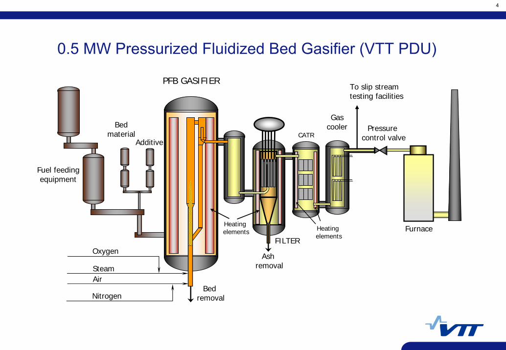
Pressure control valve
0.5 MW Pressurized Fluidized Bed Gasifier (VTT PDU)
Fuel feedingequipment
Bedmaterial
Additive
FILTER
PFB GASIFIER
Gascooler
CATR
Bed removal
Ash removal
Heating elements Heating
elementsFurnace
Air
Nitrogen
Steam
Oxygen
To slip stream testing facilities
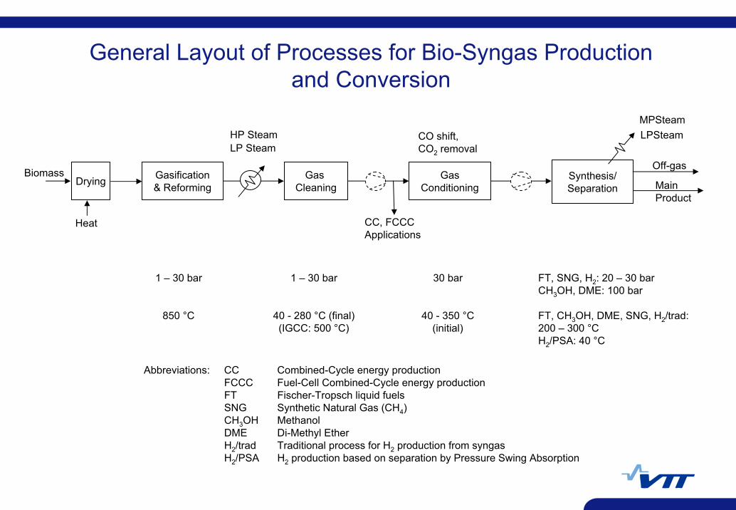
Biomass Gasification& Reforming
Gas Cleaning
GasConditioning
Synthesis/Separation Main
Product
HP Steam CO shift,CO2 removal
MPSteam
Off-gas
1 – 30 bar
850 °C
1 – 30 bar
40 - 280 °C (final)(IGCC: 500 °C)
30 bar
40 - 350 °C(initial)
FT, SNG, H2: 20 – 30 barCH3OH, DME: 100 bar
FT, CH3OH, DME, SNG, H2/trad:200 – 300 °CH2/PSA: 40 °C
Abbreviations: CC Combined-Cycle energy productionFCCC Fuel-Cell Combined-Cycle energy productionFT Fischer-Tropsch liquid fuelsSNG Synthetic Natural Gas (CH4)CH3OH MethanolDME Di-Methyl EtherH2/trad Traditional process for H2 production from syngasH2/PSA H2 production based on separation by Pressure Swing Absorption
General Layout of Processes for Bio-Syngas Production and Conversion
LPSteamLP Steam
Drying
Heat CC, FCCCApplications
6
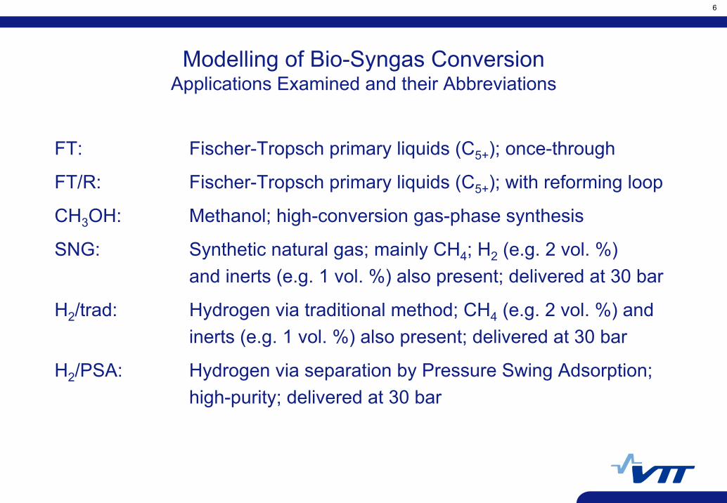
Modelling of Bio-Syngas ConversionApplications Examined and their Abbreviations
FT: Fischer-Tropsch primary liquids (C5+); once-through
FT/R: Fischer-Tropsch primary liquids (C5+); with reforming loop
CH3OH: Methanol; high-conversion gas-phase synthesis
SNG: Synthetic natural gas; mainly CH4; H2 (e.g. 2 vol. %)and inerts (e.g. 1 vol. %) also present; delivered at 30 bar
H2/trad: Hydrogen via traditional method; CH4 (e.g. 2 vol. %) andinerts (e.g. 1 vol. %) also present; delivered at 30 bar
H2/PSA: Hydrogen via separation by Pressure Swing Adsorption;high-purity; delivered at 30 bar
7
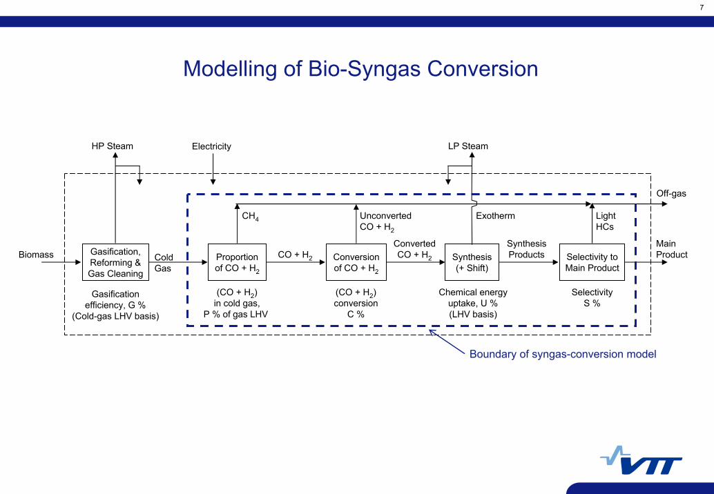
Biomass Gasification,Reforming &Gas Cleaning
Proportionof CO + H2
MainProductConversion
of CO + H2
Synthesis(+ Shift)
ColdGas
CO + H2
ConvertedCO + H2
SynthesisProducts Selectivity to
Main Product
HP Steam LP Steam
CH4 UnconvertedCO + H2
Exotherm LightHCs
Gasificationefficiency, G %
(Cold-gas LHV basis)
(CO + H2)in cold gas,
P % of gas LHV
(CO + H2)conversion
C %
Chemical energyuptake, U %(LHV basis)
SelectivityS %
Electricity
Off-gas
Modelling of Bio-Syngas Conversion
Boundary of syngas-conversion model
8
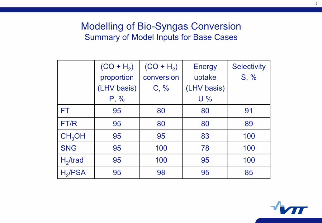
85959895H2/PSA
1009510095H2/trad1007810095SNG100839595CH3OH
89808095FT/R
91808095FT
SelectivityS, %
Energyuptake
(LHV basis)U %
(CO + H2)conversion
C, %
(CO + H2)proportion
(LHV basis)P, %
Modelling of Bio-Syngas ConversionSummary of Model Inputs for Base Cases
9
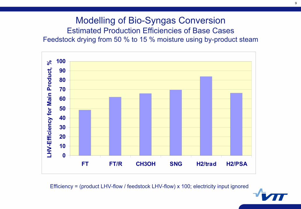
Modelling of Bio-Syngas ConversionEstimated Production Efficiencies of Base Cases
Feedstock drying from 50 % to 15 % moisture using by-product steam
Efficiency = (product LHV-flow / feedstock LHV-flow) x 100; electricity input ignored
0102030405060708090
100
FT FT/R CH3OH SNG H2/trad H2/PSA
LHV
-Effi
cien
cy fo
r Mai
n P
rodu
ct, %
10
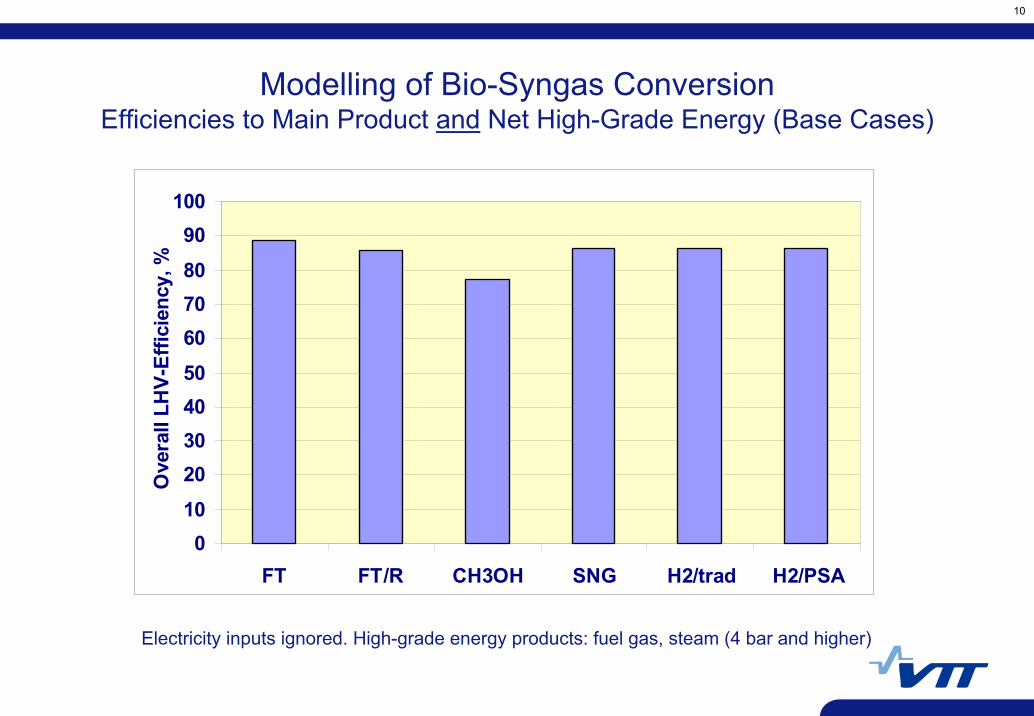
Modelling of Bio-Syngas ConversionEfficiencies to Main Product and Net High-Grade Energy (Base Cases)
Electricity inputs ignored. High-grade energy products: fuel gas, steam (4 bar and higher)
010
20304050607080
90100
FT FT/R CH3OH SNG H2/trad H2/PSA
Ove
rall
LHV-
Effic
ienc
y, %
11
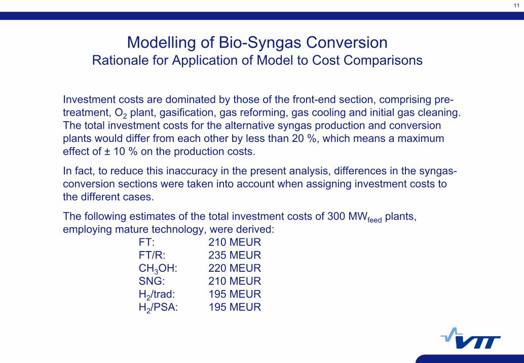
Modelling of Bio-Syngas ConversionRationale for Application of Model to Cost Comparisons
Investment costs are dominated by those of the front-end section, comprising pre-treatment, O2 plant, gasification, gas reforming, gas cooling and initial gas cleaning. The total investment costs for the alternative syngas production and conversion plants would differ from each other by less than 20 %, which means a maximum effect of ± 10 % on the production costs.
In fact, to reduce this inaccuracy in the present analysis, differences in the syngas-conversion sections were taken into account when assigning investment costs to the different cases.
The following estimates of the total investment costs of 300 MWfeed plants, employing mature technology, were derived:
FT: 210 MEURFT/R: 235 MEURCH3OH: 220 MEURSNG: 210 MEURH2/trad: 195 MEURH2/PSA: 195 MEUR
12
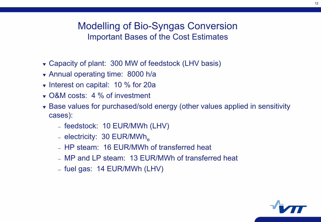
Capacity of plant: 300 MW of feedstock (LHV basis)Annual operating time: 8000 h/aInterest on capital: 10 % for 20a O&M costs: 4 % of investment Base values for purchased/sold energy (other values applied in sensitivity cases):
– feedstock: 10 EUR/MWh (LHV)– electricity: 30 EUR/MWhe
– HP steam: 16 EUR/MWh of transferred heat– MP and LP steam: 13 EUR/MWh of transferred heat– fuel gas: 14 EUR/MWh (LHV)
Modelling of Bio-Syngas ConversionImportant Bases of the Cost Estimates
13
0
10
20
30
40
50
60
70
80
FT FT/R CH3OH SNG H2/trad H2/PSA
Prod
uctio
n co
sts,
EU
R/M
Wh
Feed 0 EUR/MWh
Feed 5 EUR/MWh
Feed 10 EUR/MWh
Feed 15 EUR/MWh
Feed 20 EUR/MWh
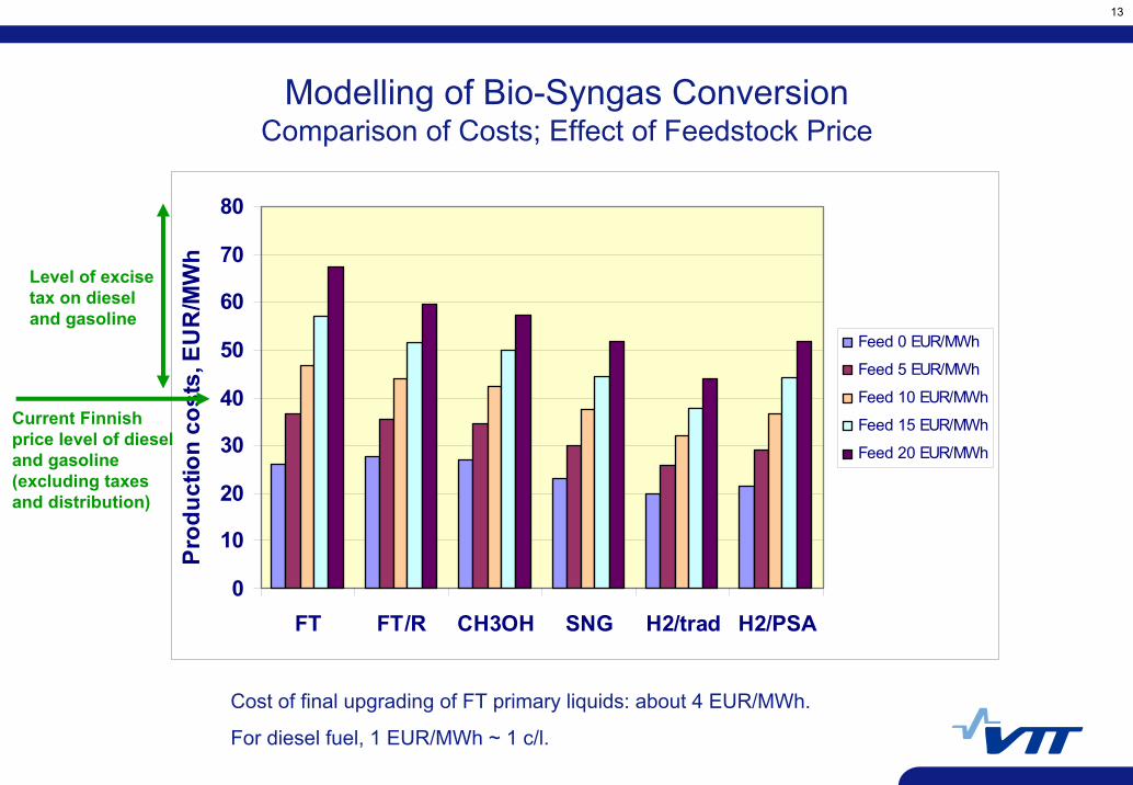
Modelling of Bio-Syngas ConversionComparison of Costs; Effect of Feedstock Price
Level of excise tax on diesel and gasoline
Current Finnish price level of diesel and gasoline (excluding taxes and distribution)
Cost of final upgrading of FT primary liquids: about 4 EUR/MWh.
For diesel fuel, 1 EUR/MWh ~ 1 c/l.
14
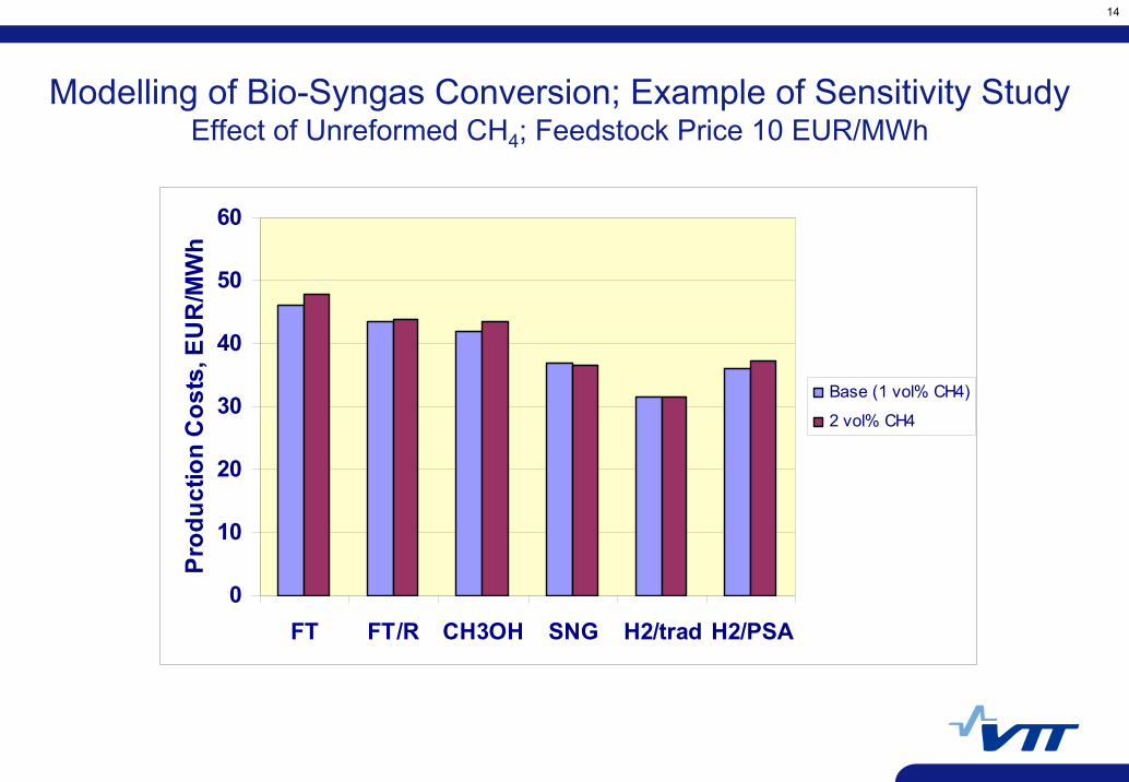
Modelling of Bio-Syngas Conversion; Example of Sensitivity StudyEffect of Unreformed CH4; Feedstock Price 10 EUR/MWh
0
10
20
30
40
50
60
FT FT/R CH3OH SNG H2/trad H2/PSA
Prod
uctio
n C
osts
, EU
R/M
Wh
Base (1 vol% CH4)
2 vol% CH4
15
By-Product Energy of Synthesis-Gas Conversion Processes
Processes for producing and converting synthesis gas yield significant by-product energy in the form of steam and off-gas.
This is illustrated by examples in following slides. A plant producing Fischer-Tropsch (FT) liquids yields significantly more by-product energy than a methanol plant.
A large amount of by-product energy means that significant synergy -and so lower costs - can be derived by integrating these processes with pulp and paper manufacturing.
A feature of the Fischer-Tropsch process is that the ratio of liquid product to gas product can be varied by altering the degree of recycle of off-gas to the gas-reforming step (two different cases shown in the following slides). This allows significant flexibility when integrating a FT plant with a paper mill.

Biomass Gasification& Reforming
Gas Cleaning
GasConditioning
Synthesis/Separation Main
Product
HP Steam
CC, FCCCApplications
CO shift,CO2 removal
MP Steam
Off-gas
LP SteamLP Steam
1 – 30 bar
850 °C
1 – 30 bar
40 - 280 °C (final)(IGCC: 500 °C)
30 bar
40 - 350 °C(initial)
FT, SNG, H2: 20 – 30 barCH3OH, DME: 100 bar
FT, CH3OH, DME, SNG, H2/trad:200 – 300 °CH2/PSA: 40 °C
Abbreviations: CC Combined-Cycle energy productionFCCC Fuel-Cell Combined-Cycle energy productionFT Fischer-Tropsch liquid fuelsSNG Synthetic Natural Gas (CH4)CH3OH MethanolDME Di-Methyl EtherH2/trad Traditional process for H2 production from syngasH2/PSA H2 production based on separation by Pressure Swing Absorption
Drying
Heat
Fischer-Tropsch Liquids Example / Once-Through
LP Steam
260 MW
38 MW
44 MW8 MW
30 MW
67 MW
126 MW
7 MW
Electricity consumption: 21 MWe
8 MW
MP Steam 8 MW
General Layout of Processes for Bio-Syngas Production and Conversion
Biomass Gasification& Reforming
Gas Cleaning
GasConditioning
Synthesis/Separation Main
Product
HP Steam
CC, FCCCApplications
CO shift,CO2 removal
MP Steam
Off-gas
LP Steam
1 – 30 bar
850 °C
1 – 30 bar
40 - 280 °C (final)(IGCC: 500 °C)
30 bar
40 - 350 °C(initial)
FT, SNG, H2: 20 – 30 barCH3OH, DME: 100 bar
FT, CH3OH, DME, SNG, H2/trad:200 – 300 °CH2/PSA: 40 °C
Abbreviations: CC Combined-Cycle energy productionFCCC Fuel-Cell Combined-Cycle energy productionFT Fischer-Tropsch liquid fuelsSNG Synthetic Natural Gas (CH4)CH3OH MethanolDME Di-Methyl EtherH2/trad Traditional process for H2 production from syngasH2/PSA H2 production based on separation by Pressure Swing Absorption
LP Steam
Drying
Heat
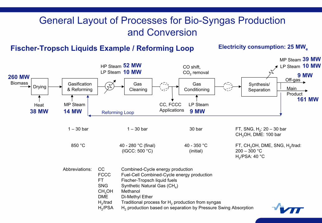
Fischer-Tropsch Liquids Example / Reforming Loop
LP Steam
260 MW
38 MW
39 MW
9 MW
161 MW
9 MW
Electricity consumption: 25 MWe
10 MW52 MW10 MW
Reforming Loop
MP Steam 14 MW
General Layout of Processes for Bio-Syngas Production and Conversion
18
Levels of Integration
Co-Production of Syngas Derivatives at Pulp and Paper Mills
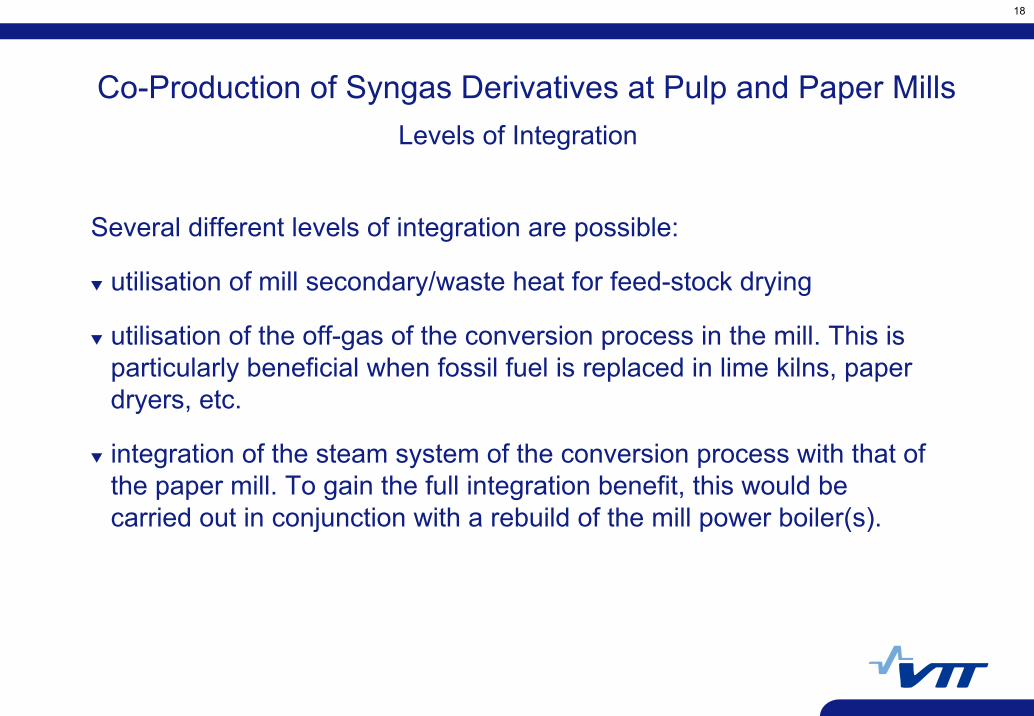
Several different levels of integration are possible:
utilisation of mill secondary/waste heat for feed-stock drying
utilisation of the off-gas of the conversion process in the mill. This is particularly beneficial when fossil fuel is replaced in lime kilns, paper dryers, etc.
integration of the steam system of the conversion process with that of the paper mill. To gain the full integration benefit, this would be carried out in conjunction with a rebuild of the mill power boiler(s).
19
Example of Mill Energy Balances Before and After the Integration of a Plant Producing Fischer-Tropsch (FT) Liquids
The next three slides (BEFORE, AFTER, NET CHANGES) show how the incremental energy balance is arrived at for one particular example of integration of an FT plant with a paper mill.
The NET CHANGES do not depend on the size of the original power-boiler process provided that the capacity of this process exceeds a certain minimum value. The minimum value corresponds to about half of the feedstock input to the FT plant. For example, if the latter is 260 MW, as in the following example, the minimum value for the fuel input to the original power-boiler process is about 130 MW.
If the fuel input to the original power-boiler process is less than this minimum value, the benefit of integration will be somewhat smaller than that in the following example.
20
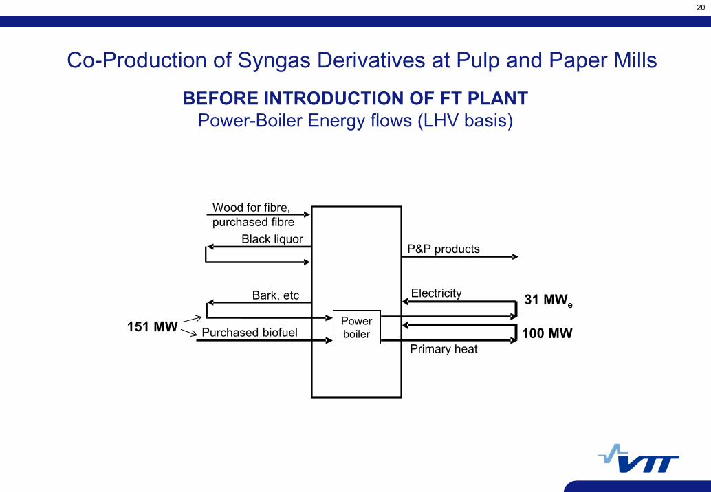
BEFORE INTRODUCTION OF FT PLANTPower-Boiler Energy flows (LHV basis)
Bark, etc
Black liquor
Purchased biofuel
P&P products
151 MW
Wood for fibre,purchased fibre
Co-Production of Syngas Derivatives at Pulp and Paper Mills
Powerboiler
Electricity
Primary heat100 MW
31 MWe
21
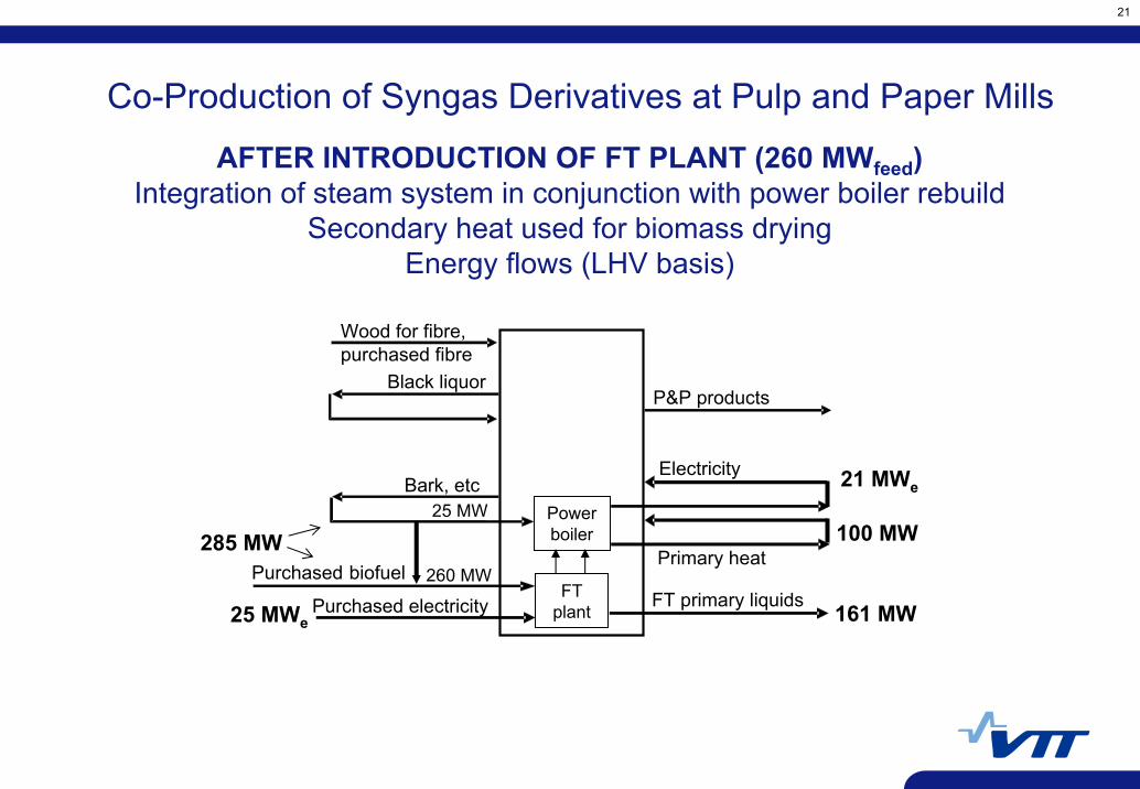
Bark, etc
Black liquorP&P products
Purchased electricity FT primary liquids 161 MW
25 MW
Wood for fibre,purchased fibre
25 MWe
Powerboiler
FT plant
Purchased biofuel 260 MW
Electricity
Primary heat100 MW
21 MWe
285 MW
Co-Production of Syngas Derivatives at Pulp and Paper Mills
AFTER INTRODUCTION OF FT PLANT (260 MWfeed)Integration of steam system in conjunction with power boiler rebuild
Secondary heat used for biomass dryingEnergy flows (LHV basis)
22
Bark, etc
Black liquor
Purchased biofuel
P&P products
Purchased electricityFT primary liquids
+ 161 MW
+ 134 MW*
Wood for fibre,purchased fibre
IntegratedPulp and Paper Mill
orStand-AlonePaper Mill
+ 35 MWe**
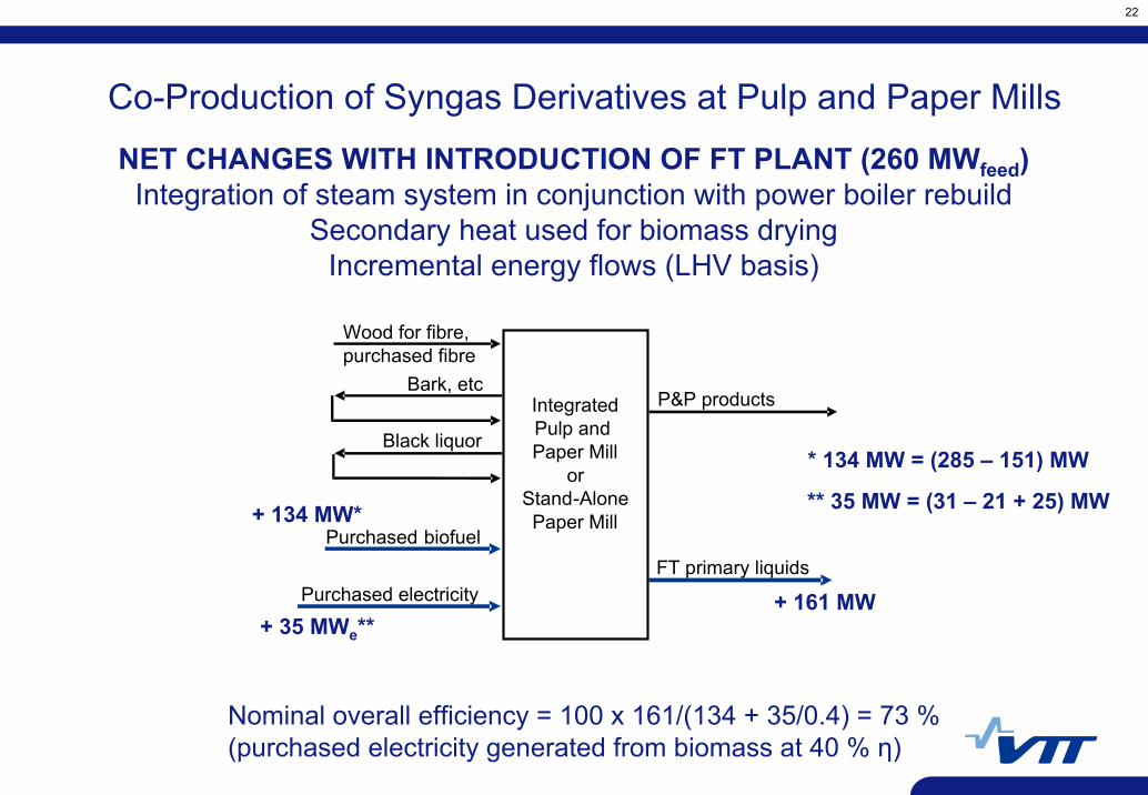
* 134 MW = (285 – 151) MW
** 35 MW = (31 – 21 + 25) MW
Co-Production of Syngas Derivatives at Pulp and Paper Mills
NET CHANGES WITH INTRODUCTION OF FT PLANT (260 MWfeed)Integration of steam system in conjunction with power boiler rebuild
Secondary heat used for biomass dryingIncremental energy flows (LHV basis)
Nominal overall efficiency = 100 x 161/(134 + 35/0.4) = 73 %(purchased electricity generated from biomass at 40 % η)
23
Bark, etc
Black liquor
Purchased biofuel
P&P products
Purchased electricityFT primary liquids
+ 126 MW
+ 114 MW
Wood for fibre,purchased fibre
IntegratedPulp and Paper Mill
orStand-AlonePaper Mill
+ 13 MWe
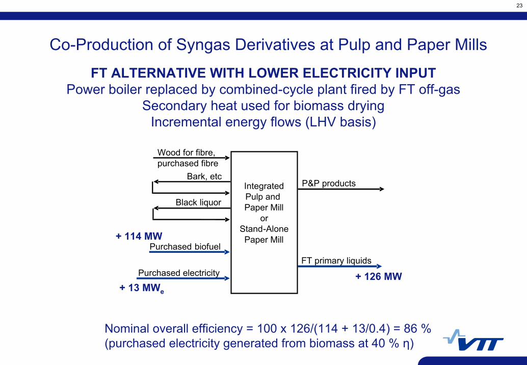
Co-Production of Syngas Derivatives at Pulp and Paper Mills
FT ALTERNATIVE WITH LOWER ELECTRICITY INPUTPower boiler replaced by combined-cycle plant fired by FT off-gas
Secondary heat used for biomass dryingIncremental energy flows (LHV basis)
Nominal overall efficiency = 100 x 126/(114 + 13/0.4) = 86 %(purchased electricity generated from biomass at 40 % η)
24
Bark, etc
Black liquor
Purchased biofuel
P&P products
Purchased electricityFT primary liquids
+ 134 MW
Wood for fibre,purchased fibre
IntegratedPulp and Paper Mill
orStand-AlonePaper Mill
+ 35 MWe
600 000 t/a
161 MW105 000 t/a
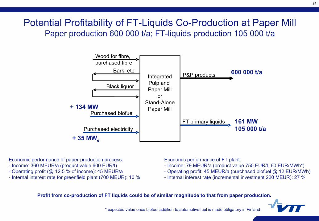
Potential Profitability of FT-Liquids Co-Production at Paper Mill Paper production 600 000 t/a; FT-liquids production 105 000 t/a
Economic performance of paper-production process:- Income: 360 MEUR/a (product value 600 EUR/t)- Operating profit (@ 12.5 % of income): 45 MEUR/a- Internal interest rate for greenfield plant (700 MEUR): 10 %
Economic performance of FT plant:- Income: 79 MEUR/a (product value 750 EUR/t, 60 EUR/MWh*)- Operating profit: 45 MEUR/a (purchased biofuel @ 12 EUR/MWh)- Internal interest rate (incremental investment 220 MEUR): 27 %
* expected value once biofuel addition to automotive fuel is made obligatory in Finland
Profit from co-production of FT liquids could be of similar magnitude to that from paper production.
25
Biomass-fired process(VTT concept)
Black-liquor-fired process (Chemrec)
Standard recovery-boiler as reference*
Advanced recoveryboiler as reference**
Primaryheat used
forbiomassdrying
Secondaryheat used
forbiomassdrying
Integratedpulp andpaper mill
Stand-alone
pulp mill
Integratedpulp andpaper mill
Stand-alone
pulp millη =63 %
η =70 %
η =62 %
η =66 %
η =58 %
η =60 %
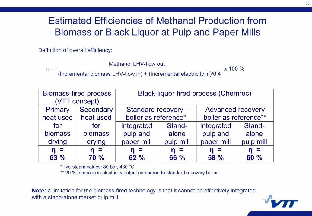
Estimated Efficiencies of Methanol Production from Biomass or Black Liquor at Pulp and Paper Mills
Definition of overall efficiency:
* live-steam values: 80 bar, 480 °C** 20 % increase in electricity output compared to standard recovery boiler
η = Methanol LHV-flow out
(Incremental biomass LHV-flow in) + (Incremental electricity in)/0.4x 100 %
Note: a limitation for the biomass-fired technology is that it cannot be effectively integrated with a stand-alone market pulp mill.

26
Estimated Costs of Methanol Production from Biomass or Black Liquor at a Large Integrated Pulp and Paper Mill
0
10
20
3040
50
60
70
80
5 10 15 20Biomass Fuel Price, EUR/MWh
Met
hano
l Pro
duct
ion
Cos
ts,
EUR
/MW
hFrom black liquor(415 MW); adv.RB as ref.
From biomass(260 MW);primary heat fordryingFrom biomass(260 MW);secondary heatfor drying
Level of excise tax on diesel and gasoline
Current Finnish price level of diesel and gasoline (excluding taxes and distribution)
Note: methanol production from black liquor would typically be somewhat more economic at a stand-alone market pulp mill having the same black-liquor flow as the above case.
27
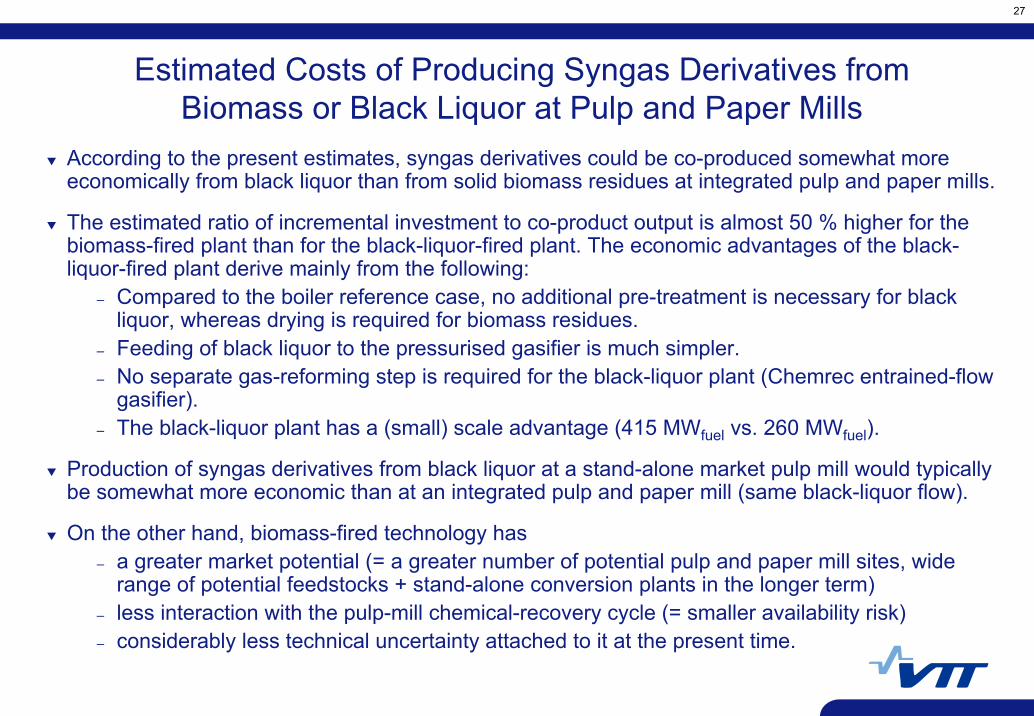
According to the present estimates, syngas derivatives could be co-produced somewhat more economically from black liquor than from solid biomass residues at integrated pulp and paper mills.
The estimated ratio of incremental investment to co-product output is almost 50 % higher for thebiomass-fired plant than for the black-liquor-fired plant. The economic advantages of the black-liquor-fired plant derive mainly from the following:
– Compared to the boiler reference case, no additional pre-treatment is necessary for black liquor, whereas drying is required for biomass residues.
– Feeding of black liquor to the pressurised gasifier is much simpler.– No separate gas-reforming step is required for the black-liquor plant (Chemrec entrained-flow
gasifier).– The black-liquor plant has a (small) scale advantage (415 MWfuel vs. 260 MWfuel).
Production of syngas derivatives from black liquor at a stand-alone market pulp mill would typically be somewhat more economic than at an integrated pulp and paper mill (same black-liquor flow).
On the other hand, biomass-fired technology has– a greater market potential (= a greater number of potential pulp and paper mill sites, wide
range of potential feedstocks + stand-alone conversion plants in the longer term)– less interaction with the pulp-mill chemical-recovery cycle (= smaller availability risk)– considerably less technical uncertainty attached to it at the present time.
Estimated Costs of Producing Syngas Derivatives fromBiomass or Black Liquor at Pulp and Paper Mills
28
The Finnish Development Path
Current development stage led by VTT (Esa Kurkela): 500 kW process development unit 2006 – 2007
Total budget ca. 4 MEUR, duration: 1.1.2004 – 31.3.2007
Current industrial consortium: Foster-Wheeler, Neste Oil, Andritz, Vapo, PVO, UPM, M-real, Metsä-Botnia, Stora-Enso
Demonstration of bio-syngas process planned for the period 2008 – 2010– size of demonstration plant: 20 – 50 MW feedstock input– operation of plant to be economically profitable: replacement of natural gas or
fuel oil– plant design studies already under way
The subsequent step: pre-commercial plant; 200 MW; commissioning 2013
Acknowledgement of funding sources: the National Technology Agency of Finland (Tekes), VTT and the companies of the consortium (above)