Embed Size (px)
Citation preview
PRODUCTS MANUAL
R3G SERIES
2 + 1 Redundant Power Supply
INDEX 1.1 Introduction page 1 1.2 Packing page 2 1.3 Model Designation page 2 1.4 Features page 3 1.5 Pre-Installation page 3 1.6 Drawing page 4 ~ 8 1.7 Specification page 9 1.8 Installation & Testing page 10 ~ 11 1.9 Hot-Swap Procedures page 11 ~ 12 1.10 Pinouts and function of connectors page 12 1.11 Trouble shooting page 13
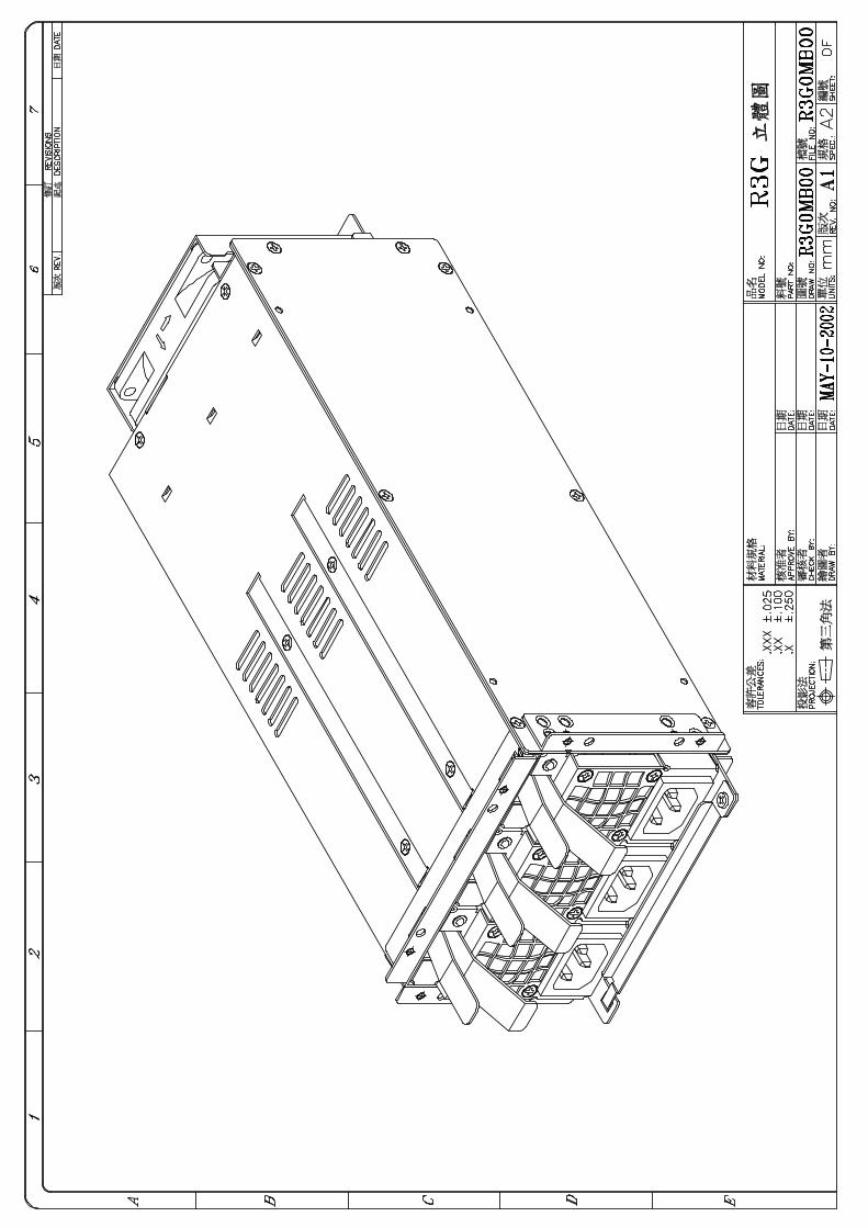
1.1 INTRODUCTION First of all, thank you for purchasing R3G Series – 2 + 1 Redundant power supply, the R3G is a 2+1, Hot-swappable/Hot-pluggable, Redundant power supply set, it consists of: (1) complete metal frame (nickel-plated) (2) 2 + 1 compact size power modules (3) backplane board The R3G Series hot swappable redundant power supply offer a maximum 650 watts of output power. They provide Active Power Factor correction (PFC) feature at full range AC Input complies with IEC 1000-3-2/3 for critical applications. The power unit’s size is compact each power modules built an interior 40 m/m ball bearing DC fan for better ventilation. Particularly an 80 m/m DC Fan built on the rear side of the whole system to make sure a safe working unit. Each power module has designed with 6 outputs including +3.3V, +5V, +12V, -12V, -5V & 5VSB circuits and higher current availability based on Intel ATX12V / EPS12V standards. All you can see on the backplane board is just passive components and this is the key point to a greater Power Supply MTBF. The unit features a warning sub-system, including LED display, buzzer alarm, TTL signal, I2C interface device ( optional feature ) etc., at the same time, it guides user the fast way to find out the power supply Good or Fail condition. When all the power modules are at normal condition, it balances the load share through its parallel design and results the power system increase reliability. To really discover the power and ease in using these products, we recommend that you read through this manual carefully.
1.2 PACKING Your R3G box package should consist of the following: (A) R3G *1 (B) Accessory pack (included one holding bracket for shipment)*1 (C) Products’ manual *1
1.3 MODEL DESIGNATION Model number identification: R3G – 6650P R3G --- 2 + 1 Redundant Power Supply for 3 U (AC Input) 6 --- for 6 DC outputs (5V/12V/-5V/-12V/3.3V/5VSB) for ATX12V / EPS12V Spec. 650 --- total output power, 650 (unit: watt) P --- P for built in PFC (full range).
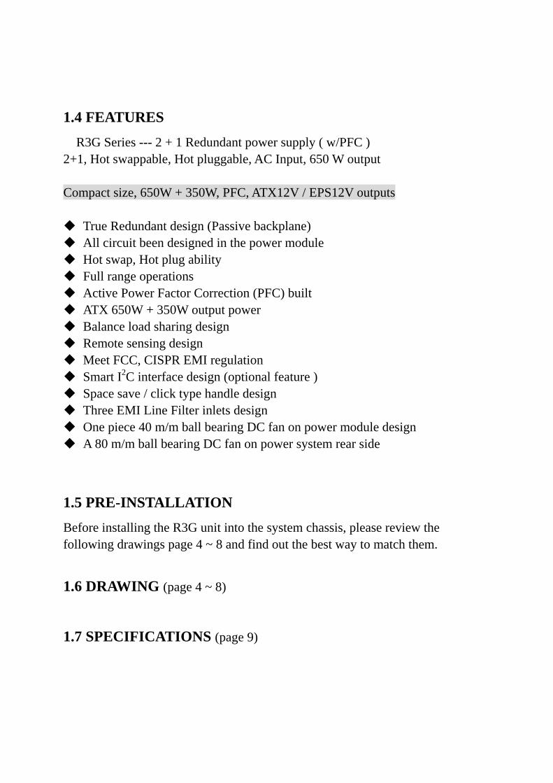
1.4 FEATURES R3G Series --- 2 + 1 Redundant power supply ( w/PFC ) 2+1, Hot swappable, Hot pluggable, AC Input, 650 W output Compact size, 650W + 350W, PFC, ATX12V / EPS12V outputs True Redundant design (Passive backplane) All circuit been designed in the power module Hot swap, Hot plug ability Full range operations Active Power Factor Correction (PFC) built ATX 650W + 350W output power Balance load sharing design Remote sensing design Meet FCC, CISPR EMI regulation Smart I2C interface design (optional feature ) Space save / click type handle design Three EMI Line Filter inlets design One piece 40 m/m ball bearing DC fan on power module design A 80 m/m ball bearing DC fan on power system rear side
1.5 PRE-INSTALLATION Before installing the R3G unit into the system chassis, please review the following drawings page 4 ~ 8 and find out the best way to match them.
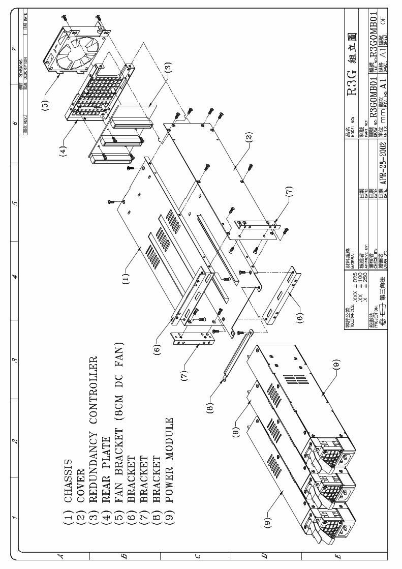
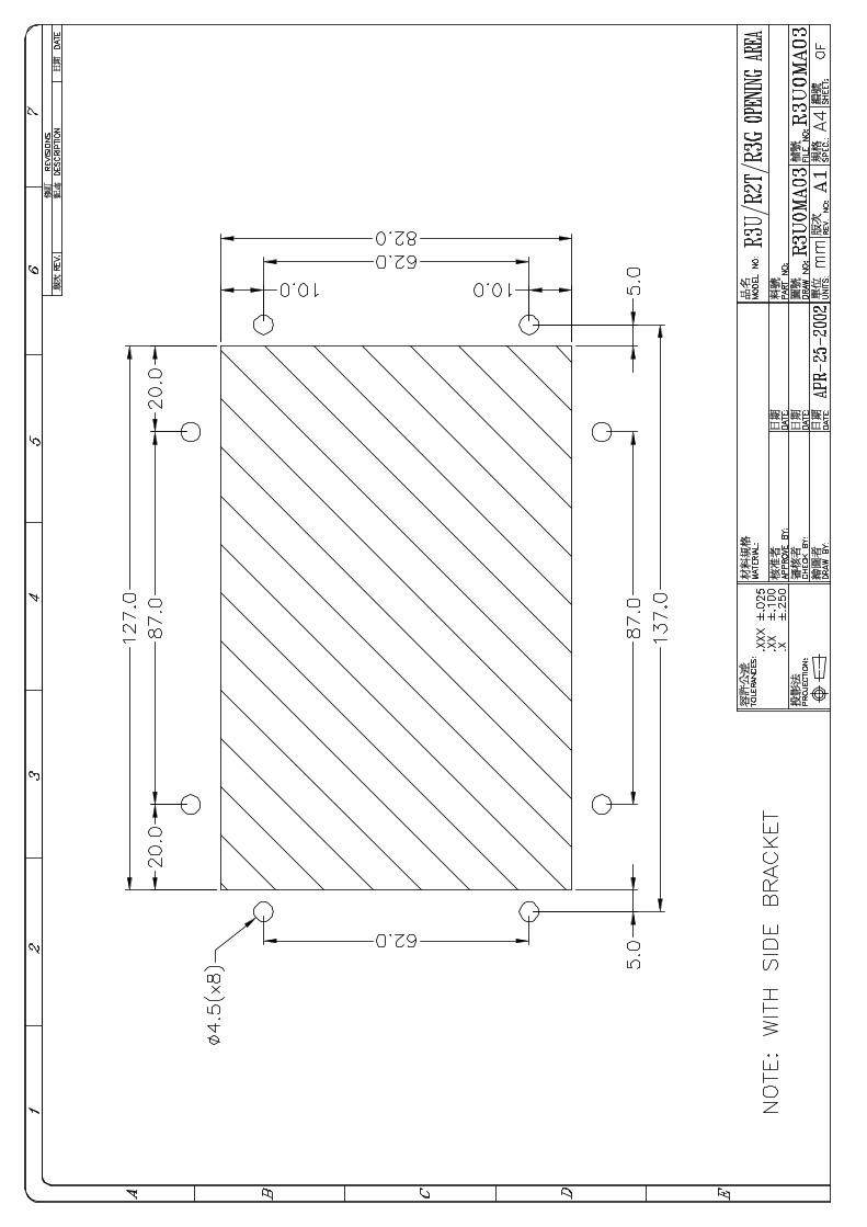
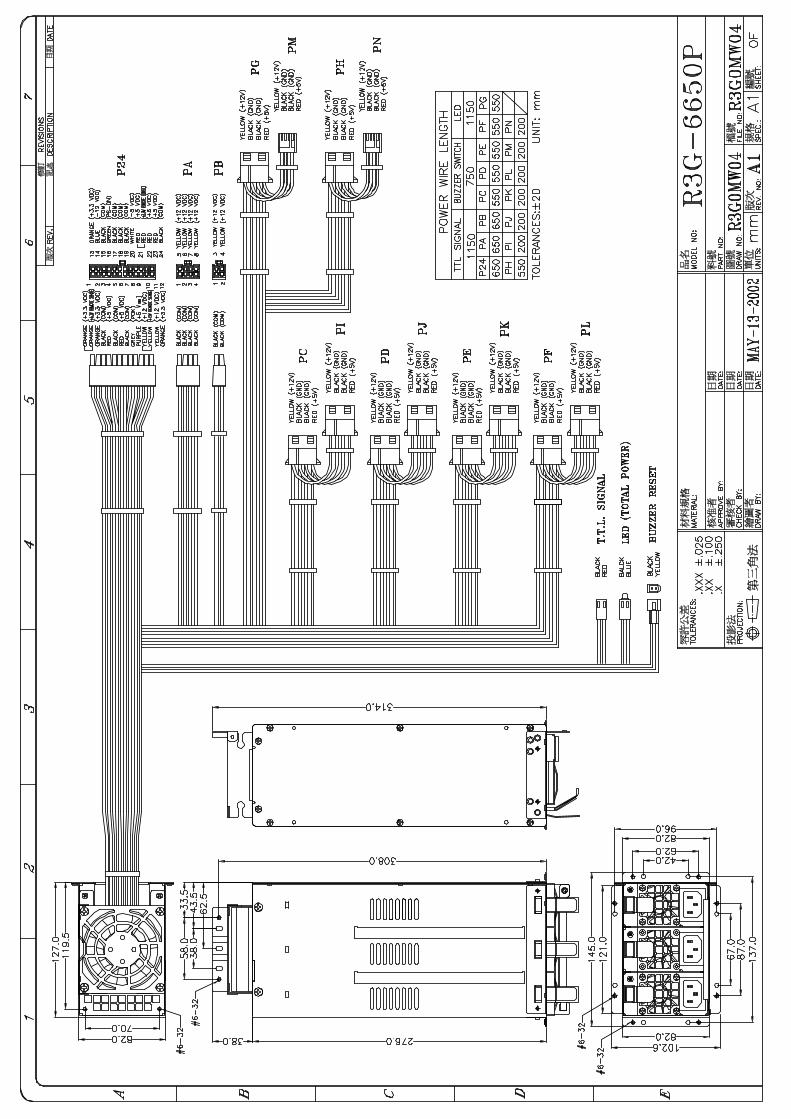
1.6 DRAWING (page 4 ~ 8)
1.7 SPECIFICATIONS (page 9)
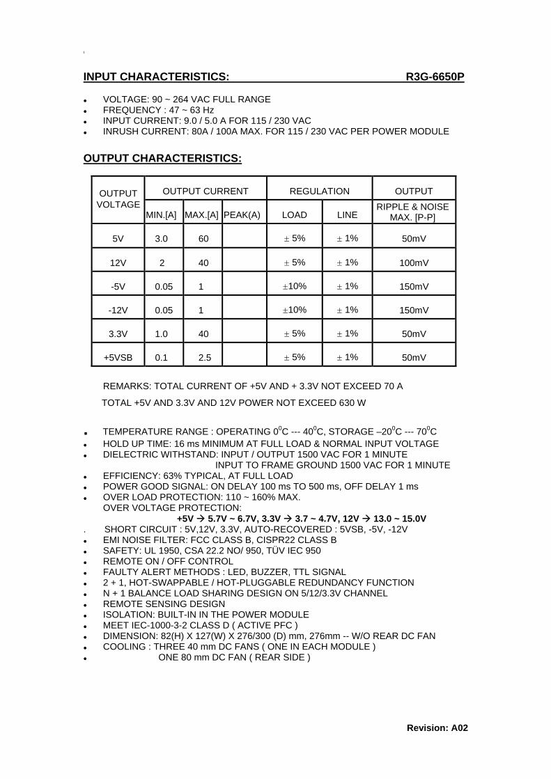
INPUT CHARACTERISTICS: R3G-6650P
VOLTAGE: 90 ~ 264 VAC FULL RANGE FREQUENCY : 47 ~ 63 Hz INPUT CURRENT: 9.0 / 5.0 A FOR 115 / 230 VAC INRUSH CURRENT: 80A / 100A MAX. FOR 115 / 230 VAC PER POWER MODULE
OUTPUT CHARACTERISTICS:
OUTPUT CURRENT REGULATION OUTPUT
MIN.[A] MAX.[A] PEAK(A) LOAD LINE
5V 3.0 60 ± 5% ± 1% 50mV
12V 2 40 ± 5% ± 1% 100mV
-5V 0.05 1 ±10% ± 1% 150mV
-12V 0.05 1 ±10% ± 1% 150mV
3.3V 1.0 40 ± 5% ± 1% 50mV
+5VSB 0.1 2.5 ± 5% ± 1% 50mV
OUTPUT VOLTAGE RIPPLE & NOISE
MAX. [P-P]
REMARKS: TOTAL CURRENT OF +5V AND + 3.3V NOT EXCEED 70 A
TOTAL +5V AND 3.3V AND 12V POWER NOT EXCEED 630 W
. TEMPERATURE RANGE : OPERATING 00C --- 400C, STORAGE –200C --- 700C HOLD UP TIME: 16 ms MINIMUM AT FULL LOAD & NORMAL INPUT VOLTAGE DIELECTRIC WITHSTAND: INPUT / OUTPUT 1500 VAC FOR 1 MINUTE
INPUT TO FRAME GROUND 1500 VAC FOR 1 MINUTE EFFICIENCY: 63% TYPICAL, AT FULL LOAD POWER GOOD SIGNAL: ON DELAY 100 ms TO 500 ms, OFF DELAY 1 ms OVER LOAD PROTECTION: 110 ~ 160% MAX.
OVER VOLTAGE PROTECTION: +5V 5.7V ~ 6.7V, 3.3V 3.7 ~ 4.7V, 12V 13.0 ~ 15.0V
. SHORT CIRCUIT : 5V,12V, 3.3V, AUTO-RECOVERED : 5VSB, -5V, -12V EMI NOISE FILTER: FCC CLASS B, CISPR22 CLASS B SAFETY: UL 1950, CSA 22.2 NO/ 950, TÜV IEC 950 REMOTE ON / OFF CONTROL FAULTY ALERT METHODS : LED, BUZZER, TTL SIGNAL 2 + 1, HOT-SWAPPABLE / HOT-PLUGGABLE REDUNDANCY FUNCTION N + 1 BALANCE LOAD SHARING DESIGN ON 5/12/3.3V CHANNEL REMOTE SENSING DESIGN ISOLATION: BUILT-IN IN THE POWER MODULE MEET IEC-1000-3-2 CLASS D ( ACTIVE PFC ) DIMENSION: 82(H) X 127(W) X 276/300 (D) mm, 276mm -- W/O REAR DC FAN COOLING : THREE 40 mm DC FANS ( ONE IN EACH MODULE ) ONE 80 mm DC FAN ( REAR SIDE )
Revision: A02

1.8 INSTALLATION & TESTING
Turn off (Remote off) the on/off switch. Mount the power supply in the system chassis using the proper mounting tool, the mounting holes in the power supply should match up with those in the case. Attach the connectors to the M/B by following the M/B instructions, there are various on connectors / pinouts in both power supply and M/B. They should match each other; otherwise the connection will cause undetectable harms. Attach all the remaining power supply connections to the various peripherals as needed, these connectors are “keyed”, so there will be only one possible way to connect them. Before applying power to the system, make sure there are no loose or incorrect connectors. You do not need to worry about the setting of AC Input because of the units’ full range or auto voltage selecting features. Double check that all connections to the M/B are matched properly. Maybe you would like to test the redundancy function before you put back the cover of your system chassis. Remote on the on/off switch, you will notice that if the power unit is operating properly, then individual LEDs, the total power warning LED ( please refer to Sec. 1.10 for detail explanation) are lit Green, now remove one of the power modules by pressing the click type handle, the warning buzzer in the power system will sound and the total power warning LED which display the status of the total power supply system will twinkle, the individual LEDs indicating the power supply’s status will not light. Meanwhile, the power supply will continue to backup the power output without affecting the computer system’s operation. The warning buzzer will continue sound, the user can reset the warning buzzer by pressing the buzzer reset switch which can be found on the front control panel of the system chassis, the reset switch can be connected by wires lead provided from the power supply system (please refer to Sec. 1.10). Insert the power module which is removed for testing earlier, the sound of the warning buzzer will disappear, the total power warning LED will turn Green again. The LED indicating the status of the power supply will light again, test others power supplies by performing the similar procedure.
If everything works out fine, then turn off (remote off) the power system, now put back the cover of the case and tighten with the screws which you have retained earlier. Now you have completed the installation of the R3G redundant power supply system.
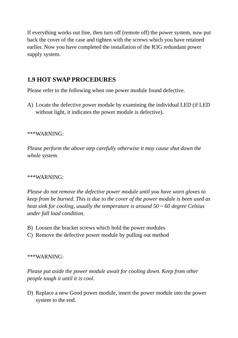
1.9 HOT SWAP PROCEDURES Please refer to the following when one power module found defective. A) Locate the defective power module by examining the individual LED (if LED
without light, it indicates the power module is defective). ***WARNING: Please perform the above step carefully otherwise it may cause shut down the whole system. ***WARNING: Please do not remove the defective power module until you have worn gloves to keep from be burned. This is due to the cover of the power module is been used as heat sink for cooling, usually the temperature is around 50 ~ 60 degree Celsius under full load condition. B) Loosen the bracket screws which hold the power modules C) Remove the defective power module by pulling out method ***WARNING: Please put aside the power module await for cooling down. Keep from other people tough it until it is cool. D) Replace a new Good power module, insert the power module into the power
system to the end.
E) Check the LED of the power module lit Green. F) Check the LED which indicates the total power system status, that should be
from twinkle to Green. G) Tighten the screws of bracket which hold the power modules to fix it. H) If you want to test this new power module in simulating defective situation.
Please refer to the Section 1.8 Installation & Testing Section.
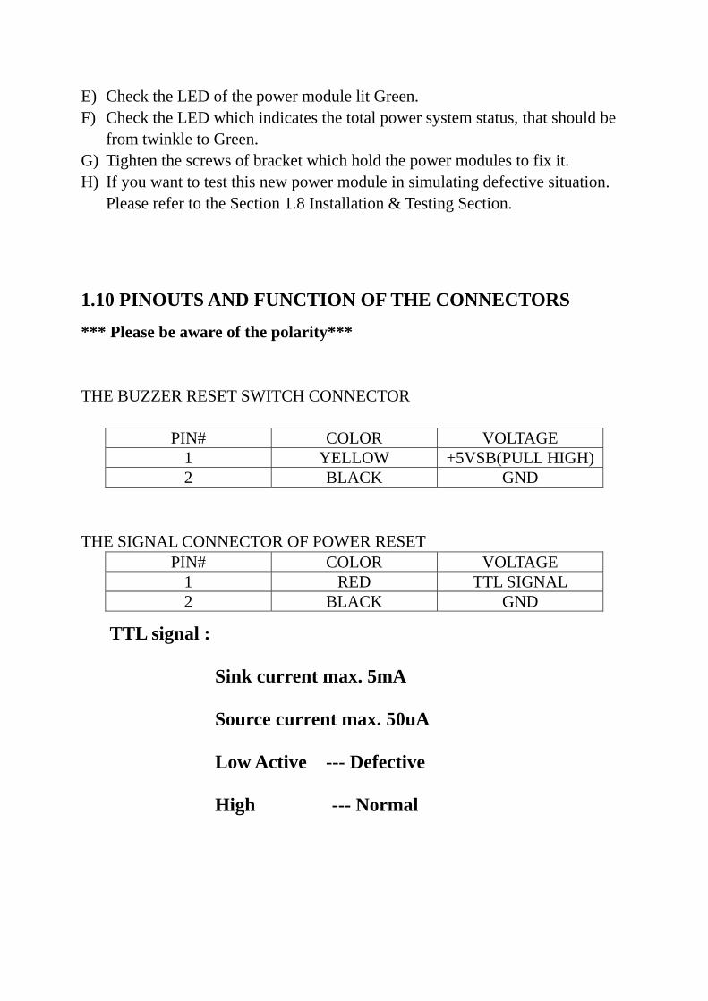
1.10 PINOUTS AND FUNCTION OF THE CONNECTORS
*** Please be aware of the polarity***
THE BUZZER RESET SWITCH CONNECTOR
PIN# COLOR VOLTAGE
1 YELLOW +5VSB(PULL HIGH) 2 BLACK GND
THE SIGNAL CONNECTOR OF POWER RESET
PIN# COLOR VOLTAGE 1 RED TTL SIGNAL 2 BLACK GND
TTL signal :
Sink current max. 5mA
Source current max. 50uA
Low Active --- Defective
High --- Normal
1.11 TROUBLE SHOOTING If you have followed these directions correctly, there should be no problem occurred. Some common symptoms are: the system doesn’t work, buzzer sound, work for a very short period, etc., please try the following steps to verify and correct it: 1. Check all the connections (correct pinouts, loose connections, wrong direction,
etc). 2. Check for short-circuits or defective peripherals by unhooking each peripheral
once at a time. When the systems functions again, you have solved the problem.
3. Once you hear the buzzer sound or see the LED twinkle, please be aware of : a. If the load is under the minimum / over the maximum load of each channel
(please refer the Sec. 1.7 specification)? b. If each power cord been well plugged into the inlet? Suppose the above condition been happened, please unplug the power cords, wait for 2 ~ 3 minutes for releasing the protection state, then test it again. c. If buzzer still sound or the LED shows power module is defective, please
locate which power module is defective, perform hot-swap procedure (please refer to the Sec. 1.9 Hot-swap procedures), sent the defective power module to your vendor for RMA operation.
d. If you can not fix the problem, please contact with your vendor for supporting. Note: *The description stated herein is subject to change without prior notice. *All brand names and trademarks are the property of their respective owners.
The “RELIABILITY “ solution to E-application
新巨企業股份有限公司 ZIPPY TECHNOLOGY CORP.
POWER DIVISION
HEADQUARTERS 10F, NO. 50, MIN CHYUAN RD., SHIN-TIEN CITY, TAIPEI HSIEN, TAIWAN, R.O.C. TEL: 886-2-29188512 FAX: 886-2-29134969 WEB SITE: http://www.zippy.com.tw E-mail:[email protected] USA OFFICE
U.S. East (Atlantic) 11 Melanie Lane, Unit 1B East Hanover, NJ 07936 TEL:1-973-463-9499 FAX:1-973-453-8014 E-mail:[email protected] U.S. West (Pacific) 961 CALLE NEGOCIO, SAN CLEMENTE CA 92673, USA TEL: 1-949 366 9525 FAX: 1- 949 366 9526 EMAIL: [email protected]
CANADA OFFICE
ZIPPY TECHNOLOGY CANADA INC. Unit3-3671 Viking Way Richmond, B.C V6V 2J5 Canada TEL:1-604-278-6615 FAX:1-604-278-6624 CELL: 1-778-288-9622 E-mail:[email protected]
Note: *The description stated herein is subject to change without prior notice. *All brand names and trademarks are the property of their respective owners