Embed Size (px)
DESCRIPTION
Pro/E Mechanica Wildfire 4.0 Contact With Friction Feature - Theoretical Fundamentals and Application Examples
Citation preview

The New Contact with Friction Feature in Mechanica W F 4.0– Theoretical Fundamentals and Application Examples –Dr.-Ing. Roland Jakel, PTC GSO CEREnglish Translation of the „Theoretical Fundamentals“-Part by Andy Deighton, PTC UKPresentation for the 1st European PTC Simulation Specialists MeetingMunich, 3rd + 4th of December 2009

Contents
Brief Introduction of PTC Simulation Services
Contact Theory:
Introduction to the penalty method used in Mechanica contact analysis
Explanation of the functionality used in contact with infinite friction
Overview of the contact specific measures
© 2009 PTC2
Tips, for when nothing else works…
Application examples of typical industrial componen ts:
Rolling load in a cylindrical roller bearing (Hertzian contact, friction free)
Torque transmission in a shaft-hub connection with shrink fit

PTC Simulation Services Introduction
PTC Global Services provides services for our own simulation products:
– Pro/ENGINEER Mechanica as a FEA tool with p-method for structural mechanical, thermal and thermo-mechanical analysis
– Pro/ENGINEER MDX and MDO (Mechanism Design Extension and Mechanism Dynamics Option) for kinematic and dynamic multi-body simulations
The benefits are accomplished as following:
– Required calculations
© 2009 PTC3
– Required calculations
– Development of the required analysis and optimization, working with the design team, directly on the working CAD data, including adoption of mechanical systems engineering tasks
– On-site simulation consulting � Software and calculation method knowledge transfer
– Simulation training and workshops from PTC University
The following slides show some examples of relevant references on the theme of contact calculations. Numerous other references from other clients and to other simulation issues can be provided upon request.

PTC University Further Educates Bosch Diesel System s in Nonlinear Contact Analysis with Pro/ENGINEER Mechanica ®
BUSINESS INITIATIVE� Bosch DS wanted to extend its engineers’ skills in nonlinear Mechanica contact simulation
and to familiarize them with the new developed friction contact model of the latest Mechanica release
� PTC University offered a specially customized in-center training workshop containing SOLUTION
Automotive
As the world's leading diesel systems manufacturer, the Bosch Diesel Systems Division, headquartered in Stuttgart, Germany, develops, applies and produces diesel injection systems which contribute to making vehicles cleaner and more economical. In the very early development phase, Finite Element analysis and optimization with Mechanica® assuresthat their highly pressurized systems work as reliable in their later service life.
© 2009 PTC
� PTC University offered a specially customized in-center training workshop containing knowledge transfer in Mechanica contact theory and analysis, and furthermore the opportunity to discuss and analyze typical Bosch DS products
� Acquired knowledge in the frictionless and friction containing contact model provided in Pro/ENGINEER Mechanica
� Acquired skills in setting up idealized, speed and accuracy optimized contact models
� Ability to assure the result quality of nonlinear contact analysis by carefully creating and interpreting contact measures and postprocessor plots
“PTC University provided a first-rate Mechanica con tact workshop that delivered the exact information we were looking for. In the training, o ur Mechanica Models were discussed and analyzed with reasonable idealizations. Typical dif ficulties and problems we observe when setting up and running contact analyses were treate d and helpful solutions were provided.”
Dipl.-Ing. Matthias Brunner, Engineering Technical Information Processing, Diesel Systems, Robert Bosch GmbH
RESULT
Top: A typical Bosch common rail Diesel injection system containing several pressurized components and contact analysis tasksBottom: A PTC University contact training example - von Mises stress distribution within a cylindrical roller bearing acc. to the Hertz theory

PTC University Educates Bosch Rexroth Engineers in Advanced Nonlinear Contact and Bolt Simulation with the Pro/MECHANICA FEM Code
BUSINESS INITIATIVE� Bosch Rexroth requested on-site Pro/MECHANICA contact & bolt
simulation workshops for their design and CAE engineers developing hydraulic equipment.
SOLUTION
Drive and Control Drive and Control Technologies
Bosch Rexroth AG, headquartered in Lohr am Main, Germany, is a developer, producer and supplier of drive and control technologies for hydraulic, electric, pneumatic or mechanical applications. In order to increase product quality in spite of reduced development time, the PTC University was charged with the further education in advanced contact and bolt analysis with Pro/MECHANICA.
© 2009 PTC5
� PTC offered simulation workshops providing basic principles of bolt analysis, necessary software knowledge, typical application tasks and furthermore solutions for special customer examples.
� Acquired knowledge about the contact theory used in Pro/MECHANICA and methods to assure numeric solution quality
� Acquired solution roadmaps for typical bolt analysis tasks
� Critical bolted designs can now be analyzed and optimized in Pro/MECHANICA before prototypes are being built and tested.
SOLUTION
“The Pro/MECHANICA simulation training provided by the PTC University exactly met what we needed: Solution methods in Pro/MECHANICA for all t ypes of bolted connections with different precision demands, starting from just obtaining for ce relations up to evaluating exact load and stress distributions in each single thread turn.” Dipl.-Ing. Katja Mild, Group Leader R&D, Bosch Rexr oth AG
RESULT One of the customer’s analysis tasks solved in Pro/MECHANICA during the contact & bolt analysis workshop:
Above: Pro/ENGINEER model of a hydraulic piston prepared for a detailed 2D axial symmetric contact analysis.
Right: Von Mises stress in the piston assembly when preloaded and pressurized.

BUSINESS INITIATIVE
P&S Tensioning Systems Ltd., located in St. Gallenkappel, Switzerland, is known worldwide for its SUPERBOLT® Multi Jackbolt Tensioners, which are designed as direct replacements for hex nuts. The main thread serves to position the tensioner on the bolt or stud against the hardened washer and the load bearing surface. Once it is positioned, actual tensioning of the bolt or stud is accomplished with simple hand tools by torquing the jackbolts which encircle the main thread.
� P&S wanted to show that their tensioning system also has big advantages when used in a crosshead bolted connection where the load untypically is not introduced into the clamped parts, but directly into the bolt. These connections are critical regarding rupture. No analytical standards or guidelines exist up to now how to analyze this type of bolted connection.
PTC Global Services Performs Advanced FEM Bolt Anal ysis for P&S
Connection Elements
© 2009 PTC6
standards or guidelines exist up to now how to analyze this type of bolted connection.
� PTC Global Services Consulting analyzed the existing crosshead connection and the alternative with the SUPERBOLT® Tensioner within advanced Pro/MECHANICA Structure contact analyses based on customer DXF data and provided a detailed presentation.
� Precise location of the overloaded area where typically rupture appears when a standard nut is used: Here, the first groove of the bolt thread inside the crosshead is critically loaded.
� Representation of the more equal load distribution along the thread when the SUPERBOLT® Tensioner is used.
SOLUTION
“On an international bolt application conference we learned how PTC analyzed a similar bolted connection within an ARIANE 5 rocket upper stage of EADS/CNES. We wanted to take advantage of this unique knowledge for our own product and we re fully satisfied with the results obtained by the use of PTC’s Pro/MECHANICA Structure FEM cod e, which exactly match our observations in the field.“ Norbert Schneider, Technical Director, P&S Tensioni ng Systems Ltd.
RESULT

BUSINESS INITIATIVE
PTC Global Services Consults RENK in 3D-Contact and Bolt FEM Analysis
SOLUTION
Drive Technology
RENK Aktiengesellschaft, a member of the MAN group, develops and produces its slide bearings and clutches directly at the production facilities in Hannover, Germany. The products are rated via computer programs and designed with the CAD system Pro/ENGINEER. This provides RENK with a high degree of flexibility when it comes to quickly meet customer requirements.
� For assuring strength and reliability of a very compact, bolted and highly loaded slide bearing housing, RENK AG was asking for consulting support in advanced FEM simulation with Pro/MECHANICA Structure
© 2009 PTC7
“The FEM simulation consulting, which was provided very quickly in excellent quality and with deep background knowledge, gave us valuable feedbac k about our own analysis procedures and showed us additional methods in applying the Pr o/MECHANICA software more efficient.”
Burghard Kohring, Project Manager, RENK AG Hannover
RESULT
� PTC Global Services offered a Pro/MECHANICA Structure consulting for 3D-contact and fastener analysis at the customer’s plant. This contained prepared example assemblies for further education as well as direct work and demonstrations with the original customer assembly for solving this analysis problem.
� Weak point in housing design approach identified and solution proposed � Deep knowledge and several new methods learned how to handle contact problems
and how to apply Pro/MECHANICA Structure for bolted assemblies� Better understanding of the used penalty method for contact analysis� Acquired ability to independently solve similar problems without further consulting
Casted housing of a slide bearing with contact pressure distribution at the interstice, coming from bolt pretension and operational shock load

The name Carl Zeiss is a byword for pioneering performance in camera lenses. For over 150 years, the technology pacesetter has been pushing back the frontiers of precision technology. Today, modern FEM tools are used to analyze deformations and strength of lens elements under mechanical and thermal loading to assure highest precision and reliability.
� Zeiss wanted to study the behavior of their achromaticlens elements consisting of glass with different thermal expansions and glued with a µm-thin layer, when preloaded by locking rings and thermally loaded.
BUSINESS INITIATIVE
PTC Global Services Supports Carl Zeiss Camera Lens Division in Analyzing and Optimizing Clamped, Achromatic Lens Elements wit h Pro/MECHANICA
SOLUTION
High-Precision Optics
© 2009 PTC8
� PTC Global Services developed an analysis model of a clamped achromatic lens element within an extensive on-site Carl Zeiss employee consulting.
� Detailed knowledge transferred to Zeiss employees how to use Pro/MECHANICA for advanced contact analyses with micrometer-small contact areas and extremely thin glue layers between the lens elements
� Ready-to-run Pro/MECHANICA Finite Element and MATHCAD Model for further studies delivered
SOLUTION
“The outstanding expert knowledge provided by PTC G lobal Services enabled us to perform our own detailed, precise and further-going finite elem ent studies with Pro/MECHANICA. This will allow us to develop and deliver cine and camera len ses still a notch above our actual ones, working yet more precise under extreme environmenta l conditions.”
Dipl.-Ing. Christian Bittner, Product Development C arl Zeiss AG Camera Lens Division
RESULT
Top left: Pro/ENGINEER model of the fitted lens elements with the thin glue layerTop center: P-meshed Pro/MECHANICA model showing radial thermal stress Top right: Thermal stress in the µm-thin glue layer between the lens elements Bottom left: Shear stress in lens element and fitting according to Hertz contact theoryBottom center: Contact pressure distribution from Pro/MECHANICA at locking ring lobe and corresponding analytical equations derived in MATHCAD for comparison Bottom right: Axial stress near thread of locking ring

BUSINESS INITIATIVE� ZF uses Pro/ENGINEER Mechanica very early within the design process
to select the best between different initial design ideas and to further optimize these ideas. For the necessary consequent education of the designers, PTC was charged
PTC Global Services Supports ZF Friedrichshafen AG in Finite Element Analysis
AutomotiveAutomotive
ZF develops and produces products serving the mobility of human beings and goods. Innovations in Driveline and Chassis Technology provide increased driving dynamics, safety, comfort and economy as well as lower fuel consumption and emissions in the vehicles of their customers: By land, by sea and in the air. ZF’s main priority is to meet its customers’ needs by using leading technology, quality and service. This is the key to strengthening their international market position.
© 2006 PTC9 © 2007 PTC
designers, PTC was charged
� PTC offered a Pro/ENGINEER Mechanica Finite Element Analysis training that was enriched with special customer examples
� Significantly enhanced FEM analysis knowledge and Pro/ENGINEER Mechanica application skills of the mechanical designers
� Solved several typical ZF product analysis tasks during the training� Decreased design loops between design and subsequent analysis
departments since the first prototypes will be pre-optimized
SOLUTION
“PTC Global Services gave our mechanical designers a n excellent and valuable technical, as well as didactical, further education in structural anal ysis with Pro/ENGINEER Mechanica. Furthermore, we could observe during the training h ow our typical given analysis tasks were solved live in a very short time span with the PTC software.”
Jörg Sielemann, Manager CAD/CAM Development an Appl ication
RESULT
Pro/MECHANICA contact analysis of a torque loaded park lock mechanism within a ZF gearbox: 3D Pro/E-Model (top), displacements (bottom left), stress (bottom right), created within half of an hour during the customized training.

BUSINESS INITIATIVE� Since all test rigs are unique and individually designed for the
actual customer demand, ZF uses Pro/ENGINEER Mechanica during the full development phase. Now, detailed fastener analysis shall also be performed within this FEM code
� PTC offered an individual simulation workshop that treated bolt
PTC Global Services Supports ZF Test Systems in Adv anced Nonlinear Contact and Bolt Simulation with Pro/ENGINEER ® Mechanica ®
SOLUTION
Automotive
ZF Test Systems, a business unit of ZF Passau GmbH in Germany, offers its customers the know-how of a major manufacturing group with the flexibility of a small division. Just 70 employees develop and produce tailor-made and ready-to-use test rigs for automotive component and system tests like rolling noise, oscillations, vehicle stiffness or power losses.
© 2009 PTC
� PTC offered an individual simulation workshop that treated bolt theory, explained prepared examples and solved bolt analysis tasks of new ZF products under development
� Analyzing the behavior of bolted connections numerically within Pro/ENGINEER Mechanica provides much higher accuracy compared to the previously performed hand analyses
� Complete assemblies can now be analyzed, including all fasteners even with non-regular geometry, using nonlinear contact for full accuracy or simplifying linearizations
“The comprehensive way the bolt theory was explained in the workshop showed us the deep engineering experience PTC has in this field. The proposed, ele gant method to linearize bolted connections in Pro/ENGINEER Mechanica under certain conditions all ows us to analyze them in huge Pro/ENGINEER assemblies even in our dynamic frequency and time a nalyses using the modal approach.”
Jens Eisenbeiß, Senior Manager Mechanical Design Te st Systems, ZF Passau GmbH
RESULTTop: Two of many ZF Test Systems products: Test bench for wheel behavior on different road surfaces (left); Brake noise test bench (right)Bottom left : Tension and bending loaded bolted flange with applied forces and moments, explaining the simplified linearized approach
Bottom right : Centrically loaded bolted connection acc. to the German VDI-Guideline 2230 “Systematic Calculation of High Duty Bolted Joints”; small image: Pro/ENGINEER model (pressure loaded bolted piston), wireframe image: Meshed, fully detailed 2D axial symmetric contact model containing all thread flanks (Pro/ENGINEER Mechanica integrated mode)

Contact Analysis in Mechanica
Assumptions for contact analysis in Mechanica (Wild fire 4.0):
Material is linear elastic
Force equilibrium is based on un-deformed structure(� only “small deformations” permitted!)
Contact is either perfect friction free or – for selection of potential friction with contact – the coefficient of friction is infinitely large contact – the coefficient of friction is infinitely large
Supported model types for contact:
3D solid models
2D plane stress
2D plane strain
2D axisymmetric
(Shells and beams are not supported)
© 2009 PTC11

Introduction to the Penalty Method used in Mechanic a (1)
Principals of the penalty method:
For a static contact analysis, the following system of equations are solved:
The non-linear stiffness matrix K is a function of the nonlinear force vector f and the displacement vector u
In practice, the contact between the surfaces is achieved by nonlinear spring
fufuKrrrr =⋅),(
In practice, the contact between the surfaces is achieved by nonlinear spring elements ( "gap element") - this is invisible to the user.
If a penetration of a contact edge is calculated (as a result of external loads or because of an interference fit), Mechanica tries to iteratively set the penetration depth by adjusting the stiffness of the spring elements to a small value, so that both local stresses and the global load balance is accurately achieved. A penetration depth of zero is not mathematically possible, because then the stiffness of these spring elements would be infinite!
The default setting for the penetration depth at contact is based on 5% of the square root of the contact area (value gained from experience).
© 2009 PTC12

Introduction to the Penalty Method used in Mechanic a (2)
Achieving convergence of the nonlinear matrix equat ion K(u,f) .u=f in contact analysis using Newton-Raphson technique:
Before convergence we can calculate the residual error corresponding to the latest solution of the displacement vector u: r=f-Ku. Here, the residual vector r, has the dimensions of force (this force must be zero for system convergence). The Newton-Raphson solution then solves for Kdu=r to determine the change in u in the next iteration.
The residual norm is the dot product r.du. It can be thought of physically as a residual energy, which should be zero when we're converged. We normalize the residual norm with the dot product of the total displacement and the total force vector, so the residual norm is: (r.du)/(u.f).
This residual norm must be smaller than the default value of 1.0E-14 to achieve convergence for the "Residual Norm Tolerance" in Mechanica.
Further reading: Crisfield, M: Nonlinear Finite Element Analysis of Solids and StructuresWiley, 1991, p 254.
© 2009 PTC13

Introduction to the Penalty Method used in Mechanic a (3)
Further information on the Newton-Raphson process i n Mechanica:
The iteration status is listed in the study *.pas file, the *. rpt and *.stt files do not give this information!
Typically an iteration process can be seen as follows:
Tolerance for the allowed residual norm (r.du)/(u.f)
© 2009 PTC14
Listing of the current residual norm and the sum of all contact surfaces in each step
Mechanica automatically reduces the stiffness of the contact gap-spring elements to improve the convergence of the matrix equation K.u=f
If necessary Mechanica independently increases the stiffness of the contact spring elements to reduce the penetration at the contact edges

Introduction to the Penalty Method used in Mechanic a (4)
Technical software implementation of Mechanica cont act analysis :
In a contact analysis, each calculation pass (for both Single-Pass or Multi-Pass convergence analysis) is performed in at least two load steps:
– A “load step 0” without external load (no load set is active, only the boundary condition set): When initial penetration at a contact edge due to press fit is recognized and can be calculated
– A “load step 1" with all external loads in the selected load set at the same time, building – A “load step 1" with all external loads in the selected load set at the same time, building on the converged system from load step 0!
– In addition, you can optionally define interim load intervals, where all loads are scaled in sync (not recommended for models with press fits)
An interference ( “press fit") can be achieved either by an actual interference in the Pro/E model or by using a thermal load (with modified coefficient of linear expansion), however in extreme cases, since the software solution process is different for both methods, depending on the problem different results may be obtained!
Here you can see the *.rpt file information, as shown in the following slide:
© 2009 PTC15

Introduction to the Penalty Method used in Mechanic a (5)
Technical software implementation of Mechanica cont act analysis :
Example without interference:In load increment 0 the contact area is zero in the case without external load and without press fit, the contact first occurs in increment 1 under external load (in this case a temperature load makes a shrinkage effect)
Example with interference:
© 2009 PTC16
makes a shrinkage effect)
In this case contact is non-zero in load increment 0 without external load, due to an interference fit in the Pro/ENGINEER model

Introduction to the Penalty Method used in Mechanic a (6)
Technical software implementation of Mechanica cont act analysis :
In extreme cases this can lead to different results:
With an interference fit in the model the transverse load is correctly combined in increment 1 with the already preloaded system in load
In the case of an interference fit in the model due to temperature load the combination of
© 2009 PTC17
preloaded system in load increment 0
combination of transverse load only occurs in increment 1, and in this case an undesired deformation and stress has occured
Example from Rich King,Mechanica Development

Introduction to the Penalty Method used in Mechanic a (7)
Contact measures
For every contact the following measures are available:
– Force: *)Contact force is calculated from the resulting spring force of the gap elements
– Load: Contact load is calculated from the integral of the contact pressure over the contact area � As a quality check of the results it‘s a good idea to compare the load/force� As a quality check of the results it‘s a good idea to compare the load/force
– Area: *)Contact area
– Maximum contact pressure
– Average contact pressure:corresponds to the load divided by the contact area (not force/contact area)
*) Default measures in Wildfire 4.0
Note: There are additional measures available for contact regions with infinite friction, which will be referred to later
© 2009 PTC18

Contact Analysis with Infinite Friction Functionali ty (1)
Contact with infinite friction
On selection of contact with friction with closed contact surfaces, any large shear load can be accommodated (independent of the magnitude of the pressure load) without sliding occurring
Infinite friction The shear force carried can be of any
After the analysis has run, it is therefore important to check whether the model is still valid or whether under a shear load a slip would occur between the contact surfaces because the friction resistance force (= pressure load x friction coefficient) is too low.
© 2009 PTC19
Infinite friction contact region
The shear force carried can be of any magnitude as long as a pressure force exists

The definition of „Slippage“ in a contact with fricti on analysis
Consider an arbitrary point xi on the edge of the contact with its local normal vector n and the local „Traction Vector“ t:
Contact Analysis with Infinite Friction Functionali ty (2)
The local area based force is now N (with the units of pressure = force/area), the local area based shear force is T („Tangential Traction“). T has the units of shear stress = force/area.
Slippage at the point xi does not occur (because of the general law of friction FR ≤ µ. FN), as long as the locally occurring area-based shear force T is less than the product of area based contact force N and Coefficient of Friction µ:
Si = T - µ.N ≤ 0
The value of the "slippage" Si can be seen as being very helpful for checking the validity of the contact analysis: It must be ≤ 0 for a valid model
© 2009 PTC20

Contact Analysis with Infinite Friction Functionali ty (3)
Measures to verify the validity of the contact mode l
The „Slippage“ Si is in general unevenly distributed over the contact area,therefore its characteristic values are made available in the form of three different measurements. Mechanica automatically puts these in the rpt file for true friction contacts, as long as an actual coefficent of friction is specified the the UI:
– InterfaceName_any_slippage:(better read as „maximum slippage Simax found in the contact region“)imax
– InterfaceName_complete_slippage:(better read as „minimum slippage Simin found in the contact region“)
– InterfaceName_average_slippage:(„average slippage Siav found in the contact region“)
– Additionally the measure InterfaceName_max_tang_traction is provided(better read as „maximum contact shear stress in the contact region“)
The characteristic values for the „Slippage“ and the „Tang Traction“ can be found not only in the rpt file, but also their complete distribution over the entire contact surface can be seen in the post-processor results
© 2009 PTC21

Tips, for when nothing else works…
What to do if a contact analysis doesn’t give a mea ningful result?
Experienced users can use different „Engine Command Line“ options or environment variables to influence the non-linear iteration:
– To control the maximum allowed penetration of the contact surfaces:Engine command line option: -contact_penetration NN is the multiplication factor for the max. allowed penetration depth. The default pentration depth is 0.05 (=5% of the square root value of the contact area). If you set N to 0.01 for example, the maximum penetration depth is reduced to 0.0005 (=0.05% of to 0.01 for example, the maximum penetration depth is reduced to 0.0005 (=0.05% of the square root value of the contact area).
– To change the maximum allowed number of iterations per load step Engine command line option: -contact_nr_its MM is the allowed number of iterations per load step, until the system stops, if no convergence has been reached. The default is 200 steps (see the *.pas file).
– To change the „Residual Norm Tolerance“:Environment variable: MSE_CONTACT_TOLERANCE_FACTOR yThe default tolerance is 1.0E-14. The environment variable y acts as multiplication factor to the default value. For example if you set y to 1.0E6, the residual norm tolerance is increased to 1.E-08.
© 2009 PTC22

Application Examples of Typical Industrial Componen ts
Rolling load in a cylindrical roller bearing (friction free Hertzian contact)
Torque transmission in a shaft-hub connection with shrink fit
© 2009 PTC23

Rolling Load in a Cylindrical Roller Bearing (1)
Details of the Models
FAG-Cylindrical Roller Bearing NU314E, Load Rating C0=220 kN
Shaft diameter 70 mmHousing diameter 150 mmBearing width 35 mm Bearing inner ring outside diameter 89 mm
Dr. Hans-Jürgen Böhmer (Schaeffler KG) must be thanked very much for the information and the discussions
Bearing inner ring outside diameter 89 mmBearing outer ring inside diameter 133 mmRoller length 24 mm, load carrying 22 mmRoller diameter: 22 mm (13 rollers)
Bearing and shaft material: SteelE=210000 MPa; ν=0,3
Housing material: Alu E=70000 MPa; ν=0,3 (alternatively also in Steel)
Contact without friction
© 2009 PTC24

Rolling Load in a Cylindrical Roller Bearing (2)
Background information
The FAG roller bearing catalogue states that the contact pressure at the maximum stress position between rolling elements and race reaches 4000 MPaon reaching the static load rating C0 (for this bearing 220000 N). This is a notional value, calculated through the application of Hertzian contact theory assuming linear-elastic material.
In reality when the bearing is subject to a load C0 a permanent plastic In reality when the bearing is subject to a load C0 a permanent plastic deformation would occur in the middle of the contact surfaces of the highest loaded roller and race of approximately 1/10000 the roller diameter. Due to high demands for positional accuracy required of the bearing, it should not be loaded as high as C0, for dynamic loading the bearing load must be much lower.
There is no catalogue information advising what material the housing and shaft should be or what fit and bearing play were used as a basis for the 4000 MPavalue. For the following studies, these values only serve as guidance to what stresses are to be expected in the rolling elements and the bearing races at various adopted extreme tolerances.
© 2009 PTC25

Rolling Load in a Cylindrical Roller Bearing (3)
Choice of limits and fit in the model
To calculate the influence from fitting tolerances to the bearing loading, the model will be analyzed with different extreme clearances:
– A variant with minimum clearance:
• Clearance to housing and shaft: 10 µm
• Bearing clearance also 10 µm; this means, each rolling element is 5 µm smaller than the half • Bearing clearance also 10 µm; this means, each rolling element is 5 µm smaller than the half diameter difference between inner- and outer race ring of 22 mm (for this bearing size, this is equivalent to the minimum clearance of a high precise C1NA- clearance group bearing)
– A variant with maximum clearance:
• Clearance to housing and shaft : 100 µm
• Bearing clearance 160 µm, this means, each rolling element is 80 µm smaller than the half diameter difference between inner- and outer race ring of 22 mm (for this bearing size, this is equivalent to the maximum clearance of a C5-clearance group bearing with increased play)Hint: „Normal“ group C0-bearings of this size have 40-75 µm clearance
• In addition, for the latter variant the soft Aluminum housing will be replaced by a stiffer steel housing, which should lead to higher contact pressures because of a more worse osculation
© 2009 PTC26

Rolling Load in a Cylindrical Roller Bearing (4)
Choice of the external load direction
For all variants the load vector is applied in a way, that six or seven rolling elements are within the loaded half of the bearing
© 2009 PTC27

Rolling Load in a Cylindrical Roller Bearing (5)
Idealization
The idealization of the bearing assembly is difficult, since the Hertzian stress state within a rolling body – having the maximum comparative (shear) stress below the contact surface – is created by preventing of the axial transverse strain. Therefore, here the plane stress state cannot be used.the plane stress state cannot be used.
In opposite, the „housing plate“ – outside the bearing load introduction – is just loaded in its plane, so here the plane stress condition would be fine for idealization
Since here just the bearing loads are of interest, the plane strain condition will be selected
© 2009 PTC28

Rolling Load in a Cylindrical Roller Bearing (6)
Ensuring the result quality through improved (refined) meshing and creation of contact specific measures
© 2009 PTC29

Rolling Load in a Cylindrical Roller Bearing (7)
Additional convergence consideration
To reach very accurate Hertz contact pressures, in general the described intervention into the allowed contact penetration depth may be necessary
This will be done exemplary for the analysis with a minimum clearance and 7 roller elements in contact. Standard penetration and 4 additional penetration settings are used, in which the allowed penetration will be reduced by a potency of ten, respectivelyof ten, respectively
Shown as a function of the allowed penetration depth: Maximum contact pressure, maximum von Mises-stress, CPU-time, total analysis time(4-processor computer DELL Precision 690, Windows XP 64 bit). Hint: Since parallel processes have been run on the same computer, especially the total analysis time are just an approximate guiding value!
As shown in the graphs on the next slide, the results are stable from a penetration reduction factor of 100, but the total analysis time then further increases since convergence is now more difficult to achieve. Therefore, all subsequent analyses are done with „-contact_penetration 0.01“ as (in this example!) ideal contact penetration setting!
© 2009 PTC30

Rolling Load in a Cylindrical Roller Bearing (8)
Selected ideal setting for all further analyses: -contact_penetration 0.01
Influence of the contact penetration setting
Here, convergence could not be obtained any more in all passes of the multi pass adaptive analysis, so highly increased analysis
maximum contact pressure [MPa] max. from Mises stress [MPa] CPU-time [s] total time [s]
© 2009 PTC31
increased analysis time!
Max. allowed interference in % of the square root of the contact area: 5 (default setting)Max. allowed interference in % of the square root of the contact area: 0.05Max. allowed interference in % of the square root of the contact area: 0.0005
Max. allowed interference in % of the square root of the contact area: 0.5Max. allowed interference in % of the square root of the contact area: 0.005

Rolling Load in a Cylindrical Roller Bearing (9)
Influence of the clearances and the housing materia l
© 2009 PTC32
maximum contact pressure [Mpa] max. from Mises stress [MPa]
contact area width 2b [mm]
6 rollers, tight clearance, Al-housing
6 rollers, large clearance, Al-housing
6 rollers, large clearance, St-housing
7 rollers, tight clearance, Al-housing
7 rollers, large clearance, Al-housing
7 rollers, large clearance, St-housing
6 rollers, tight clearance, Al-housing
6 rollers, large clearance, St-housing
7 rollers, large clearance, Al-housing
6 rollers, large clearance, Al-housing
7 rollers, tight clearance, Al-housing
7 rollers, large clearance, St-housing
Rolling Load in a Cylindrical Roller Bearing (10)
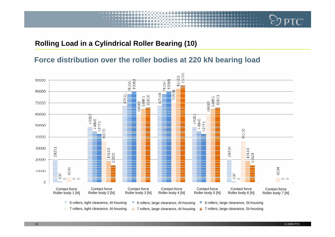
Force distribution over the roller bodies at 220 kN bearing load
© 2009 PTC33
6 rollers, tight clearance, Al-housing
7 rollers, tight clearance, Al-housing
Contact forceRoller body 1 [N]
6 rollers, large clearance, Al-housing
7 rollers, large clearance, Al-housing
6 rollers, large clearance, St-housing
7 rollers, large clearance, St-housing
Contact forceRoller body 2 [N]
Contact forceRoller body 3 [N]
Contact forceRoller body 4 [N]
Contact forceRoller body 5 [N]
Contact forceRoller body 6 [N]
Contact forceRoller body 7 [N]

Rolling Load in a Cylindrical Roller Bearing (11)
Analytical comparison computation, exemplary for th e highest loaded roller element with 85,556 kN contact force (Mathcad)
© 2009 PTC34
Hint:Mechanica analysis was done in multi pass adaptive convergence with 5 % on all measures!

Rolling Load in a Cylindrical Roller Bearing (12)
Result evaluation in the postprocessor
Subsequently, for time reasons just some exemplary evaluations are shown (von Mises stress and contact pressure)
Clear to see are the von Mises stress maxima below the contact surface, which would lead to pitting under repeated dynamic load
These stress maxima – acc. to the Hertz‘ theory – are located from the surface in a depth of 0.7 times the half contact width b of the pressure ellipse, which is in a depth of 0.7 times the half contact width b0 of the pressure ellipse, which is fulfilled in good approximation
Different values for the contact pressure and different number of roller bodies in contact as function of clearance and housing material are obtained also very well
© 2009 PTC35

Rolling Load in a Cylindrical Roller Bearing (13)
Von Mises stress distribution (6 rollers, tight clea rance, Al-housing)
© 2009 PTC36

Rolling Load in a Cylindrical Roller Bearing (14)
Von Mises stress distribution (7 rollers, tight cle arance, Al-housing)
© 2009 PTC37

Rolling Load in a Cylindrical Roller Bearing (15)
Von Mises stress distribution (7 rollers, large cle arance, St-housing)
© 2009 PTC38

Rolling Load in a Cylindrical Roller Bearing (16)
Contact pressure distribution (6 rollers, tight cle arance, Al-housing)
© 2009 PTC39
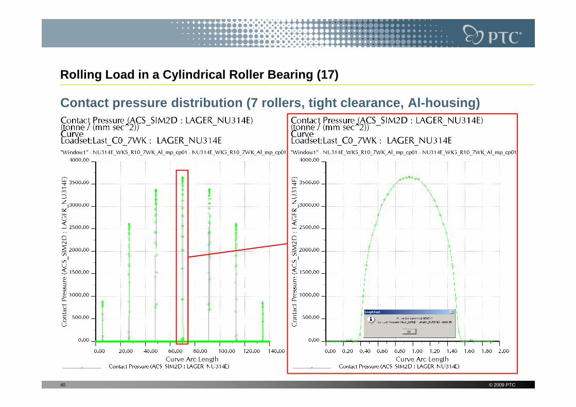
Rolling Load in a Cylindrical Roller Bearing (17)
Contact pressure distribution (7 rollers, tight cle arance, Al-housing)
© 2009 PTC40

Rolling Load in a Cylindrical Roller Bearing (18)
Contact pressure distribution (7 rollers, large cle arance, St-housing)
© 2009 PTC41

Torque-loaded shaft-hub joint with shrink fit (1)
Model presentation
Interference: 100 µm
Nominal diameter of the shrink fit: 70 mm
Sheave outer diameter: 200 mm
„Hub outer diameter“: 100 mm„Hub outer diameter“: 100 mm
Hub width: 40 mm
Torque to be transferred:2.5 kNm (exact value 2513.27 Nm)
Material of shaft and hub: Stainless steel, E=199900 MPa; ν=0.27
Assumed coefficient of friction: 0.2 (= degreased contact surfaces, pairing St-St, after heating in a stove up to 300 °C acc. to Decker „Machine Elements“)
© 2009 PTC42

Torque-loaded shaft-hub joint with shrink fit (2)
Main problem of the analytical estimation of the joint pressure is, that the traction sheave is not massive, but contains holes and is skimmed. So, the analytical „substitute diameter“ is not known and must be estimated
For massive, cylindrical hubs and shafts made of the same material, we have (when assuming a plain stress condition) for the radial stress in the joint (=negative contact pressure):
−⋅∆−=2
1 hubdE
sσ
In this equation, we have the interference ∆s=Dshaft-dhub= 100 µm and d = the nominal joint diameter
For our example, we obtain analytically for the radial stress:
– With Dhub=100 mm (=diameter of the skimmed part of the hub): -73 MPa
– With Dhub=200 mm (=outer diameter of the traction sheave): -125 MPa
As a consequence, the real contact pressure will be between these two values and vary over the joint width
© 2009 PTC43
−⋅∆−= 12 hub
hubr D
dE
d
sσ

Torque-loaded shaft-hub joint with shrink fit (3)
To save computation time, the FE-model is set up with cyclic symmetry (3D-contact needs significantly more computation time than 2D-contact!)
Torque is introduced ofer the disk circumference as surface load
© 2009 PTC44
Constrained shaft end

Torque-loaded shaft-hub joint with shrink fit (4)
Results of the pure shrink fit case (without operational load)
© 2009 PTC45
Radial Displacement Von Mises Stress

Torque-loaded shaft-hub joint with shrink fit (5)
Results of the pure shrink fit case (without operational load)
© 2009 PTC46
Radial Stress Circumferential Stress

Torque-loaded shaft-hub joint with shrink fit (6)
Results of the pure shrink fit case (without operational load)
© 2009 PTC47
Contact pressure at the joint surfaces
Slippage indicator at the joint surfaces

Torque-loaded shaft-hub joint with shrink fit (7)
Results with shrink fit and additional torque load
© 2009 PTC48
Displacement Magnitude Von Mises Stress

Torque-loaded shaft-hub joint with shrink fit (8)
Results with shrink fit and additional torque load
© 2009 PTC49
Radial Stress Tangential Stress
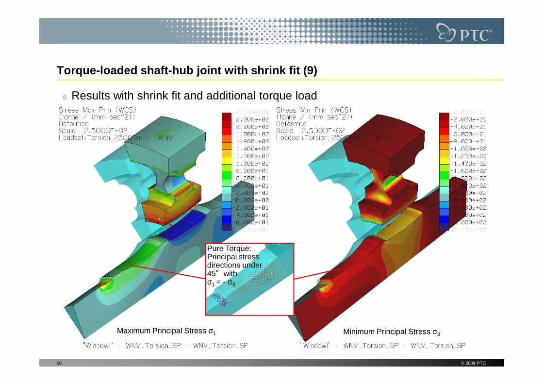
Torque-loaded shaft-hub joint with shrink fit (9)
Results with shrink fit and additional torque load
© 2009 PTC50
Maximum Principal Stress σ1 Minimum Principal Stress σ3
Pure Torque: Principal stress directions under 45°with σ1 = - σ3

Torque-loaded shaft-hub joint with shrink fit (10)
Results with shrink fit and additional torque load
© 2009 PTC51
Contact pressure at the joint surfaces
Slippage indicator at the joint surfaces
Here, local sliding possible because of the maximum torque in the shaft; may lead to fretting corrosion!

Torque-loaded shaft-hub joint with shrink fit (11)
Results with shrink fit and additional torque load
Difference to τRT, since the principal direction of the shear is not coming any longer from torque in circumferential direction, but from axial relative strains due to transverse
© 2009 PTC52
Maximum contact shear stress in the joint (=„Contact Tangential Traction Magnitude“)
Shear stress τRT in the joint:R=surface normalT=direction of the shear stress
strains due to transverse contraction!

Torque-loaded shaft-hub joint with shrink fit (12)
Additional consideration: Influence of the stress s tate and friction(see post processor plots of the two following slides)
The shown analytical solution for the radial stress at the joint (see slide 43) assumes a plane stress conditions which means, axial stresses are being neglected. This is confirmed by a Mechanica analysis with a 2D plane stress model, which results in a radial stress at the hub inner surface of -73MPa (for a hub outer diameter of 100 mm). Furthermore, an 2D axial symmetric model with friction-free contact leads to the same value (see upper images of the next slide)friction-free contact leads to the same value (see upper images of the next slide)
If we assume complete sticking at the contact surfaces (=infinite friction) and a very long shrink fit, we could analyze the connection with a 2D plain strain model. This increases the joint pressure from 73 to 100 MPa (lower left image next slide)
If we assume complete sticking (infinite friction) in a model of finite length (hub width 40 mm), we have a 2D plane strain condition just approximately in the middle of the connection: This leads to a max. radial stress of approx. -98 MPa in the axial symmetric model with infinite friction, shown in the lower right image next slide. But, here the assumption of infinite friction is not valid over long areas of the connection (see positive slippage indicator results on slide 55), so the assumption of a plane stress model for the classical analytical equation of slide 43 does make sense!
© 2009 PTC53
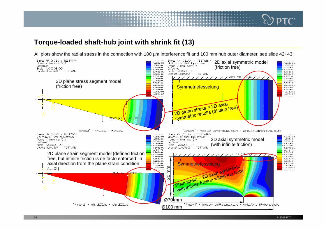
Torque-loaded shaft-hub joint with shrink fit (13)
2D plane stress segment model (friction free)
2D axial symmetric model (friction free)
Symmetriefesselung
All plots show the radial stress in the connection with 100 µm interference fit and 100 mm hub outer diameter, see slide 42+43!
© 2009 PTC54
2D plane strain segment model (defined friction free, but infinite friction is de facto enforced in axial direction from the plane strain condition εz=0!)
Symmetriefesselung
2D axial symmetric model (with infinite friction)
Ø70 mm
Ø100 mm
20 m
m

Torque-loaded shaft-hub joint with shrink fit (14)
Slippage indicator starts to be >0 from here: Infinite friction assumption becomes invalid!
Symmetriefesselung
2D axial symmetric model (with infinite friction)
Radialspannung
© 2009 PTC55
Ausgewerteter Pfad (Nabeninnenseite)
Maximum shear stress in the joint is bigger than friction coefficient x contact pressure. Model is invalid, sliding would appear!

Torque-loaded shaft-hub joint with shrink fit (15)
2. consideration: Influence of the „mounting procedu re“
If we compare the slippage indicator results from the 2D axial symmetric analysis of the shaft-hub-connection with infinite friction with the previously treated 3D-segment model, we observe that for the latter the indicator is nearly everywhere <0 (=valid model), whereas in the 2D-model we obtain mostly values >0 (=invalid model).
Furthermore, due to the similar interference we would expect higher stresses in Furthermore, due to the similar interference we would expect higher stresses in the 3D-model because of its bigger outer diameter (200 mm instead of 100 mm) -despite the holes. In fact, the contact pressure in the middle of the connection is approx. similar in both models with nearly 100 MPa.
The reason is the following: In opposite to the 3D segment model of the real connection, in all 2D models the 100 µm interference fit was not obtained by initial interference in the Pro/E-Geometry, but by cooling down the hub acc. to ∆l=l1α∆T! So, we have simulated the mounting procedure from thermal shrinking of the hub, which of course also creates shrinking in axial direction and so leads to additional shear stresses. In opposite to this, in the 3D initial interference model, shear stresses are created only by the much smaller axial transverse contraction effect!
© 2009 PTC56

Torque-loaded shaft-hub joint with shrink fit (16)
In reality, these shear stresses disappear as soon as the sticking friction in the joint is not big enough any more. So, the result of the 3D segment model with initial interpenetration is for sure more realistic than that of the 2D axial symmetric model with „thermal mounting“ (because of the predominantly positive slippage indicator in the 2D model).
If we want to obtain in the 2D axial symmetric model a result like in the 3D initial interference model, we have to use orthotropic material for the hub, in which we set the axial CTE equal to Zero. This can be compared better with a mounting procedure with pressurized oil, where axial length changes are created just by procedure with pressurized oil, where axial length changes are created just by the transverse contraction and not from additional thermal strains!
Important in all analyses with thermal shrinking with axial length change and infinite friction (in case of 2D plane strain also without friction) is, that the model must have at the beginning exactly a zero-gap and no additional gap, which has to be closed first „stress free“ from cooling the model down: In this case we would obtain an error in the result, since the condition of equilibrium is always done at the undeformed geometry!
The following slide shows the behavior of the 2D axial symmetric model with friction and orthotropic material (so without axial thermal strain!), which can now be compared better with the 3D initial interference model. The remaining difference is just from the different outer diameters of the hubs!
© 2009 PTC57

Torque-loaded shaft-hub joint with shrink fit (17)
Slippage indicator starts to be >0 from here: Model with infinite friction is now invalid just in the outer connection regions!
Symmetriefesselung
Axial symmetric model without axial thermal strains (with infinite friction)
Radialspannung
© 2009 PTC58
Ausgewerteter Pfad (Nabeninnenseite)
Maximum shear stress in the joint is bigger than friction coefficient x contact pressure. Model is invalid from here, sliding would appear!

Summary
The contact model with infinite friction
The new contact model with infinite friction is a very helpful extension of the existing, friction free contact model based on the penalty method
Even though just an infinite friction coefficient is assumed, the specific quantities (contact shear stress, slippage indicator with real coefficient of friction) allow valuable conclusions about the behavior of the real contact
But, because of the assumptions it is based on, the infinite friction contact model may also lead in certain cases to non-realistic results, so that here the simple contact model without
© 2009 PTC59
lead in certain cases to non-realistic results, so that here the simple contact model without friction can be the better approximation to reality! We can check if the validity of the infinite friction model is lost with help of the slippage indicators!
In general, the following must be noted:
Since contact analyses may become very complex (among other things due to the non-linear system to be solved), their processing is for sure no beginner’s or occasional task!
Deeper knowledge of the underlying theory (regarding software and structural mechanics) and user experience is necessary, even though the contact analysis is automated far-reaching, to obtain safe results!
Informations about the Presenter
Roland Jakel
Dipl.-Ing. for mechanical engineering (Technische Universität Clausthal)
Ph.-D. in design and analysis of engineering ceramics(FEM-Analysis with Marc/Mentat)
1996-2001 Employee at Dasa in Bremen (Daimler-Benz Aerospace, Product Division Space-Infrastructure, today EADS Astrium):
© 2009 PTC60
Division Space-Infrastructure, today EADS Astrium):
– Structural simulation (FEM-Analysis with NASTRAN/PATRAN and Mechanica)
– Project management for Ariane 5 Upper Stage „ESC-A“ Subsystems (Stage Damping System “SARO”, Inter Tank Structure)
At the former DENC AG („Design ENgineering Consultants“) from 2001-2005 responsible for structural simulation services and education with the PTC simulation products (Mechanica, MDX, MDO, BMX)
Since the DENC AG acquisition by PTC in 2005, Roland Jakel asprincipal consultant is responsible for the PTC simulation services within theGlobal Services Organization (GSO) for CER (Central Europe)