Embed Size (px)
Citation preview

Pro|ENGINEER®
W I L D F I R E 3 . 0 Schools Edition
Session 1 - Introduction
Written by: Hugh Johnson ([email protected])
These materials are 2008 by D and T Education Ltd
Conditions of use:
Copying and use of these materials is authorised only in those schools issued with them whilst attending training organised by D and T Education Ltd.
Supported by The Design and Technology
Association / DCSF CAD in School Programme

Hugh Johnson June 2008
__________________________________________________________________________ Pro|ENGINEER WILDFIRE 3.0 Page 2 of 13
Written by Hugh Johnson Copyright © 2008, D and T Education Ltd -- All
rights reserved under copyright law.
PTC, the PTC Logo, The Product Development Company, Create Collaborate Control, Simple Powerful Connected, Pro/ENGINEER, Pro/DESKTOP, Wildfire, Windchill, and all PTC product names and logos are trademarks or registered trademarks of PTC and/or its subsidiaries in the United States and in other countries. All other product names and marks referenced herein are trademarks or registered trademarks of their respective holders.
Conditions of use Copying and use of these materials is authorised
only in those schools issued with them whilst attending training organised by D and T Education Ltd. All other use is prohibited unless written permission is obtained from the copyright holder.
Acknowledgements John Lee, Senior Lecturer in Design and
Technology, Sheffield Hallam University Feedback To ensure these materials are of the highest
quality, users are asked to report errors to Hugh Johnson at [email protected] Suggestions for improvements and other activities would also be very welcome.

Hugh Johnson June 2008
__________________________________________________________________________ Pro|ENGINEER WILDFIRE 3.0 Page 3 of 13
Introduction to Pro/ENGINEER
®
This training course will incorporate the opportunity to gain accreditation in the new Pro/ENGINEER software currently being rolled out by the Design and Technology Association. This 3D solid modelling package incorporates powerful CAD capabilities that are used by design and engineering industries and forms one of the largest communities of users for any 3D CAD system worldwide.
Course Outline:
Session One:
Course aims and introduction New developments in CAD CAD modelling with Pro/ENGINEER including:
• Pro/ENGINEER interface
• Introductory features
• 2D Sketching
• 3D feature based modelling
• (extrude / shell / revolve etc’)
• Assembling components
• File management
• Software licensing and deployment
Pre-Course Tasks: Before starting this training you should study the Pro/E Competency document to assess your existing understanding and capability in this area. This is a useful exercise in helping you to establish what you already know, don't know and will need to know in this area of the Design and Technology curriculum. You will be asked to complete an 'initial needs analysis' when you receive the Resource DVD from The Design and Technology Association including some pre-requisite reading.
Accreditation: Successful completion of this training course and the associated tasks will provide individual teachers with a 300 seat copy of Pro/ENGINEER, Wildfire 3.0 Schools Edition. The schools education license covers use at school and by teachers and students at home for educational purposes. Only teachers who have attended training and progressed through to accreditation by completing the Post-course assessment tasks are licensed to use the software in schools.

Hugh Johnson June 2008
__________________________________________________________________________ Pro|ENGINEER WILDFIRE 3.0 Page 4 of 13
Before starting any new design, you need to make sure that the file you are about to use is going to be saved in the right place. To do this we need to create a new folder and set this as the working directory. The files you create and save will always be stored in whatever is set as the current working directory. It is therefore important to set the correct working directory at the beginning of each session so that all files are stored where you want them to be. When you open Pro/ENGINEER at the beginning of a session, you will see the Pro/ENGINEER Resource Centre page. On the left hand side of the page is the Folder Navigation pane
Browse to where you want to store your work and create a folder titled ProE_TRAINING To do this: Right click and choose New Folder Create a folder with your name. Right click again and set this as the Working Directory; All your subsequent work in this session will now be saved here.
2.0 Creating a new part 2.1 In the Windows toolbar across the top of the
screen left click on the File pull-down menu.
Left click New Part
Make sure that Part is selected as the Type
Give the part a name - in this case, “Pager”
Left click OK
Getting Started:

Hugh Johnson June 2008
__________________________________________________________________________ Pro|ENGINEER WILDFIRE 3.0 Page 5 of 13
2.2 You should now see the Pro/ENGINEER graphics window.
2.3 Left click the Sketch tool on the Feature
toolbar at the Right-hand side of the screen. The sketch dialogue box should open.
The Plane collector box is highlighted in
yyyeeelll lllooowww. You now need to select a sketching plane.
2.4 Left click the Front datum plane in the graphics window. The datum plane should turn Red to show that it is selected.
The name appears in the Plane collector and the highlight moves to the Reference collector.
The Top datum plane appears as the default reference.
2.5 Left click Sketch to accept the default
sketch placement. The Front datum plane rotates to appear flat on the screen, and the Sketcher drawing tools appear on the Right-hand side of the toolbar.
3.0 Creating a sketch 3.1 Adding Centrelines
Before you draw, it is useful to add centrelines to you sketch. Centrelines are useful as they allow you to mirror shapes and to quickly place sketches.
On the Sketcher toolbar, Left-click the
Centreline tool from the Line fly out menu.
Let the cursor snap to the vertical axis line and Left-click the left mouse button. A
yyyeeelll lllooowww centreline appears, attached to the cursor.
Move the cursor to rotate the centreline to coincide with the axis line; Left-click to place it.
Middle-click to exit the tool.
Sketcher Setup

Hugh Johnson June 2008
__________________________________________________________________________ Pro|ENGINEER WILDFIRE 3.0 Page 6 of 13
3.2 Left-click on the Rectangle sketching tool
and sketch a rectangle that is cantered on the centreline and rests on the Top datum plane.
The dimensions of this rectangle will be 50 (height) and 80 (width). We will edit the dimensions once the rectangle has been drawn.
You should see two opposing Red arrows appear when the rectangle is symmetrical about the centreline.
Left click to complete the rectangle and Middle Click to exit the tool.
3.2 Edit the dimensions to be 50 (height) and 80
(width) The sketch should now appear with grey (weak) dimensions displayed – (if you can’t see the dimensions left click on Select items)
3.3 Left click the tick in the Sketcher toolbar to complete the sketch.
4.0 Creating the extrusion
4.1 Left-click the Standard Orientation view from the Saved views fly out menu.
4.2 Left-click the Extrude tool from the Feature toolbar on the Right-hand side of the screen.
4.3 Set the height of the extrusion to be 12 in the Dashboard at the Bottom Left of the screen
4.4 Left click the Green tick at the Right-hand
side of the Dashboard to accept the extrusion.

Hugh Johnson June 2008
__________________________________________________________________________ Pro|ENGINEER WILDFIRE 3.0 Page 7 of 13
5.0 Adding Rounded edges You will now use the Round tool to add round features to selected corners and edges of the model 5.1 Use the Middle mouse wheel to tumble the
model so that you can see two of the corners of the extrusion
5.2 Left click to select the Round tool and
Left click on one of the corners of the extrusion.
5.3 Hold down the Ctrl key to select the three
remaining edges - they should all turn Red to show they are selected
5.4 Set the radius to 5 in the Dashboard 5.5 Left click the Green tick at the Right-hand
side of the Dashboard to accept the round. 5.6 Do the same for the top edges to finish
rounding the edges of the extrusion
6.0 Pager buttons 6.1 On the Sketcher toolbar, Left-click the Datum Plane Tool
6.2 Left-click on the Top Face of the pager
extrusion Left-click OK in the
Datum Plane dialogue box to accept
Hugh Johnson June 2008
__________________________________________________________________________ Pro|ENGINEER WILDFIRE 3.0 Page 8 of 13
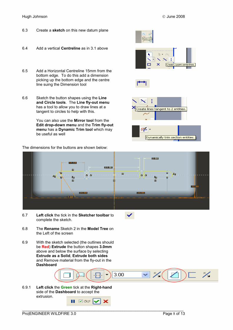
6.3 Create a sketch on this new datum plane 6.4 Add a vertical Centreline as in 3.1 above 6.5 Add a Horizontal Centreline 15mm from the
bottom edge. To do this add a dimension picking up the bottom edge and the centre line suing the Dimension tool
6.6 Sketch the button shapes using the Line
and Circle tools. The Line fly-out menu has a tool to allow you to draw lines at a tangent to circles to help with this.
You can also use the Mirror tool from the Edit drop-down menu and the Trim fly-out menu has a Dynamic Trim tool which may be useful as well
The dimensions for the buttons are shown below: 6.7 Left click the tick in the Sketcher toolbar to
complete the sketch.
6.8 The Rename Sketch 2 in the Model Tree on the Left of the screen
6.9 With the sketch selected (the outlines should
be Red) Extrude the button shapes 3.0mm above and below the surface by selecting Extrude as a Solid, Extrude both sides and Remove material from the fly-out in the Dashboard
6.9.1 Left click the Green tick at the Right-hand
side of the Dashboard to accept the extrusion.
Hugh Johnson June 2008
__________________________________________________________________________ Pro|ENGINEER WILDFIRE 3.0 Page 9 of 13
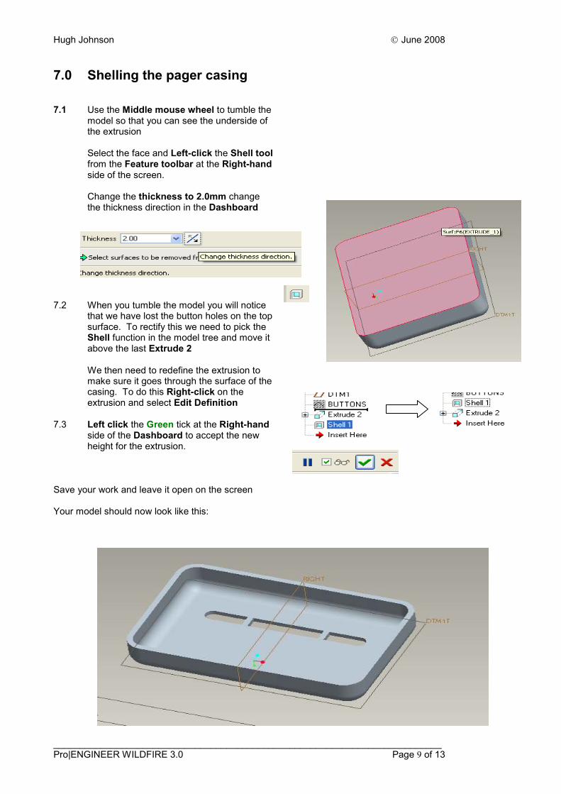
7.0 Shelling the pager casing 7.1 Use the Middle mouse wheel to tumble the
model so that you can see the underside of the extrusion
Select the face and Left-click the Shell tool from the Feature toolbar at the Right-hand side of the screen.
Change the thickness to 2.0mm change the thickness direction in the Dashboard
7.2 When you tumble the model you will notice
that we have lost the button holes on the top surface. To rectify this we need to pick the Shell function in the model tree and move it above the last Extrude 2
We then need to redefine the extrusion to make sure it goes through the surface of the casing. To do this Right-click on the extrusion and select Edit Definition
7.3 Left click the Green tick at the Right-hand
side of the Dashboard to accept the new height for the extrusion.
Save your work and leave it open on the screen Your model should now look like this:

Hugh Johnson June 2008
__________________________________________________________________________ Pro|ENGINEER WILDFIRE 3.0 Page 10 of 13
8.0 Creating the Pager Base 8.1 Keep the file for the Pager open and create
a new file called Pager_Base (remember to use underscore)
8.2 In the Windows toolbar across the top of
the screen left click on the Window pull-down menu and select the file PAGER.PTR
8.3 Right-click on the sketch called BUTTONS
in the Folder Navigation pane and select SUPRESS from the fly-out options
8.4 Select Sketch 1, Extrude 1, Round 1 and
Round 2 by Left-clicking each file in turn and holding SHIFT down. Right-click to GROUP the files
8.5 The files selected will now appear as a
group as shown. Go to EDIT on the Windows toolbar across the top of the screen left click on COPY from the pull-down menu
8.6 Switch back to the Pager_Base file and use
EDIT – PASTE to insert the copied files. At this point you can scale the copied files if you wish. Accept the default settings and select the TOP Datum Plane and confirm the sketch
8.7 You will be prompted to ‘select references’
to position the drawing. Select the Vertical and Horizontal centrelines to confirm the sketch. Drag a window around the sketch and reposition it central to the centrelines. (You can then zoom in and adjust the dimensions to place it central to both centrelines as shown)
8.9 Left click the tick in the Sketcher toolbar to
complete the sketch. The new part you have created should appear as shown below. You now need to SHELL it as before to create the base for the pager
Extension Task 1 Select the base and create a battery hole in it 20 high and the same width as the buttons. Use the dimensioning tool to find out how far the buttons are from end to end

Hugh Johnson June 2008
__________________________________________________________________________ Pro|ENGINEER WILDFIRE 3.0 Page 11 of 13
9.0 Creating and assembly 9.1 Open a new file and select ‘Assembly’ as
the file type. Call the file Pager_Assembly 9.2 You will see that the lower feature creation
toolbar icons have changed 9.3 Select ‘Add component to the assembly’
and browse to select the file called PAGER_BASE.PTR
9.4 Left click the Green tick at the Right-hand
side of the Dashboard to accept the part. 9.5 Select the part and hold SHIFT down whilst
also holding down the SCROLL wheel and move the part to the side
9.7 Repeat the sequence this time selecting the
PAGER.PTR file. Before you confirm the new part select the two thin faces of the parts as shown to Mate them together. Make sure Mate is selected in the Dashboard
9.6 Select to reposition the parts central
in the Graphics Window 9.7 Tumble the model and use the Zoom tool to
select two edges before using Align to line them up. Repeat this process to line up both parts and Left click the Green tick at the Right-hand side of the Dashboard to accept the assembly.
Your assembly should look like the one shown below:
Extension Task 2 Create a screen and a set of buttons using the geometry from existing sketches and add them to the final assembly as shown
Extension Task 3 Use the TEXT tool to add a company name to the front of the pager as shown

Hugh Johnson June 2008
__________________________________________________________________________ Pro|ENGINEER WILDFIRE 3.0 Page 12 of 13
10.0 Introduction to Rendering Pro/ENGINEER Wildfire 3.0 Schools Edition incorporates a range of very powerful rendering tools, which allow you to place your finished models into photorealistic environments. This includes a wide choice of realistic lighting, shadowing, and background ‘environments’. Photorealistic rendering in Pro/ENGINEER Wildfire 3.0 uses two rendering engines, PhotoRender and Photolux. The Photolux renderer has the more advanced capabilities but is more demanding in terms of computing capability. As a result rendering on older PCs may be quite slow. To access the Rendering tools: 10.1 In the Windows toolbar across the top of
the screen left click on the View pull-down menu and select Model Setup and Render Controls from the fly-out
10.2 In the Windows toolbar across the top of
the screen left click on the View pull-down menu and select the Realtime rendering option
10.3 Chose the ‘Assign colours and
appearances’ option from the Render Control to change the colour of the whole model or specific components
10.4 Use the Room Editor to alter the background
effects. Roll the wheels to position the Walls, Floor and Ceiling and scale then to suit
10.5 Once you have created the desired effects in
the room select File – Save As to save these setting for use with another model
10.6 Experiment further with the different effects
and settings to get a feel for the rendering capabilities of Pro/ENGINEER Wildfire 3.0 Schools Edition

Hugh Johnson June 2008
__________________________________________________________________________ Pro|ENGINEER WILDFIRE 3.0 Page 13 of 13
11.0 Extension Tasks 11.1 Go back to the model you have created of
the Pager and add a battery compartment detail on the underside of the model
11.2 In the Windows toolbar across the top of
the screen left click on the Help pull-down menu and select the Help Centre to access the Tutorials. Have a go at the ‘Creating Cubes, Rods, Cones, and Spheres’ tutorial or ‘Cell Phone’ in the ‘Getting Started with Pro/ENGINEER’ tutorial
11.3 Access the Internet and follow the link below
to access the CAD/CAM in Schools website and search the case studies for Pro/ENGINEER case studies
http://www.cadinschools.org/index.php
Mid Course Tasks: In order to gain the maximum benefit from this training and ensure that you are in a position to meet the accreditation requirements for the course, please attempt to complete at one of the following ‘mid course’ tasks before the next training session.
Task 1 View Pro/ENGINEER CADtrain Coach (e-learning management system) at the following URL http://www.ptc.com/services/learning/sub/coach/
Task 2 Access and use additional tutorials from Pro/ENGINEER Resource Centre, Windchill etc’ http://www.ptc.com/community/resource_center/proengineer/ Please note: To explore the tutorials, tips and tricks and some of the other aspects of the website you will need to create and account