Embed Size (px)
Citation preview

Prof. Günter Elsbett: Controlled shift-liners for optimized scavenging, improved thermal efficiency and multi-stroke capability for opposed piston engines and conventional engines
Page 2

Prof. Günter Elsbett: Controlled shift-liners for optimized scavenging, improved thermal efficiency and multi-stroke capability for opposed piston engines and conventional engines
Page 3
INTRODUCTION Opposed Piston Engines (OPEs) are looking back to 120 years of history and have been produced as Otto and Diesel engines, offering a promising challenge in specific output and thermal efficiency. Diesel-OPEs have been used regularly for commercial aircraft due to excellent power/weight ratio, but powering also merchant ships with big engines of several thousands of kW. Already 75 years ago a brake efficiency of more than 40% could be achieved. In recent decades these engines seem to be forgotten while the research and development engineers put their main focus on emission improvement. Conventional OPE-technology is known for emission problems, especially caused by scraping lubrication oil into in- and outlet ports, as common OPEs scavenging is limited for use in 2-stroke engines only. Now some new developments in OPE-technology show their relevance to future power-train challenges. Better thermal efficiency is attracting the development engineers, as two pistons share only one combustion chamber, thus leading to beneficial volume/surface ratio of the combustion chamber. Nevertheless, also in most today’s opposed-piston-engines the scavenging is still controlled by pistons.
-------------------- The engine presented is operated as 4-stroke-opposed-piston-engine (4SOPE) by arrangement of hydraulically shifted liners undisrupted by scavenging gaps so that the pistons with their rings are shielded against crossing any in- or outlet-ports. Some prototypes have been tested already successfully, demonstrating the function of shift-liners without problems and showing very low friction losses for the shift-liners. The wall thickness of these liners can be kept low – like conventional dry liners – as
they are guided and supported by the surrounding cylinder material, leading to low oscillating liner masses during shifting.
Fig.1 Cross-section of the 4SOPE The presented experimental-OPE was just created demonstrating the functions of the hydraulically shifted liners in a fired engine. The parts are machined from full pieces of material. This OPE is applied with a simple mechanical fuel injection system, single-hole pintle-nozzles and electric governor. Any emission treatment is not applied. Data: Single-cylinder, 4-stroke, natural aspirated, 108mm bore, 2x118mm stroke, P = 35 kW at 1500 rpm, bsfc = 262 g/kWh.
Fig.2 Engine mounted on test bench
Fig.3 Engine without peripheral parts

Prof. Günter Elsbett: Controlled shift-liners for optimized scavenging, improved thermal efficiency and multi-stroke capability for opposed piston engines and conventional engines
Page 4
The in- and outlet ports are located near the pistons top dead center area and are opened and closed by the upper end of the shift liners like sleeve-valves, which are closed by spring forces and opened by hydraulic actuation. Different to conventional OPEs there are no distinct exhaust or intake pistons and thermal load is nearly equally distributed on both pistons. The hydraulic system shares the lubrication oil with the engine, avoiding leakage problems and providing a simple oil circuit.
Fig.4 Function of VVT system Oil is filling the volume between tappet and hydraulic piston from oil-in through filling holes and pressure pipe. The rotating cam is lifting the tappet. When filling holes are closed by tappet end the trapped oil is compressed and moves the hydraulic pistons, that push on snap ring and at least shift the liner. When tappet guide sleeve is turned by the adjust rod in its thread, it causes an axial travel of the filling holes, thus changing the closing point position of filling holes. Oil and liner is pushed back the same way back by springs in a spring sleeve which is forcing on the liner end.
Fig.5 Push back springs on liner lower end
Fig.6 Push back springs tensioned The presented design offers two different options of injection system: Injection from the outer combustion chamber walls towards the chamber center (from cold to hot), or – appropriate to common systems – injection from above the combustion chamber center towards the chamber walls (from hot to cold). For the first option one or more injectors are positioned around the cylinder, providing the chance for multi-nozzle injection in different time and quantities (serial injection – no air swirl !). For the second option the cylinder wall must be considered as a virtual cylinder head where the classic injection layout (incl. combustion chamber) is rotated by 90°, providing conventional conditions.

Prof. Günter Elsbett: Controlled shift-liners for optimized scavenging, improved thermal efficiency and multi-stroke capability for opposed piston engines and conventional engines
Page 5
Fig.7 Injection with 2 injectors
Fig.8 Injection with 3 injectors
Fig.9 Swirl ring for intake port
Fig.9 Central chamber injection
Fig.10 Heat-shielded pistons (with bigger chamber-part in intake piston)
Fig.11 Central chamber injection, option The central chamber injection is providing state-of-the-art conditions as for well developed conventional engines today in production, but requiring only one injector for 2 pistons, or several combustion chambers with an own injector each.

Prof. Günter Elsbett: Controlled shift-liners for optimized scavenging, improved thermal efficiency and multi-stroke capability for opposed piston engines and conventional engines
Page 6
As no piston rings are crossing the in- and outlet ports, the presented engine is aiming for very big gas flow sections – not interrupted by window lands or port ribs. Therefore much bigger flow sectional areas can be achieved compared to conventional multi-valve technique, which results in better cylinder filling and less dynamic gas flow losses. Previous tests have been carried out already on conventional engines.
Fig.12 Previous experience (Elsbett 1969): Cam driven intake shift liner, big central exhaust valve, tested on MAN 0836 A critical point of this design is the safe sealing between shift liners and ports. A comparison between this 4SOPE and conventional valve function shows: Normal valves are kept closed by the cylinder pressure, even in case the valve seat is not 100% sealed. Already an extremely small leakage through the liner-seat is leading the gas pressure to the liner face, trying to open it against the push back spring forces. Several measures have been tested to avoid this opening. A good method is to use the gas pressure itself to keep the liner closed on its valve seat. This can be maintained by decreasing the outer sealing diameter below the inner liner diameter, which results in forces on the liner in closing direction.
Fig.13 Liner sealing area
Fig.14 Detail of liner sealing area
Fig.15 Liner with rolled-on valve ring

Prof. Günter Elsbett: Controlled shift-liners for optimized scavenging, improved thermal efficiency and multi-stroke capability for opposed piston engines and conventional engines
Page 7
The valve ring on the liner upper end can be fitted by rolling. A ring which was fitted to the liner by electron welding also showed a good reliability. However this design of a conical valve seat (like conventional poppet valve) is not a must. A flat valve seat is less sophisticated and easier to machine. And the gas flow is anyway straight from cylinder to the port.
Fig.16 Details of Flat-Valve sealing: 1)valve seat, 2) shift liner, 3) pressure relief groove, 4) pressure relief slot, 5) part of sealing area bigger than inner liner dia, 6)part of sealing area smaller than liner dia The structure of the engine is optimized for light weight design. All gas forces are conducted into through-bolts across the whole engine. So all parts in between are released from tensile stress.
Fig.17 Through-Bolt design
The trough-bolts fit the two crankcases and the cylinder assembly together. The two crankshafts are synchronized by five spur gears, whereas the center-gear is mounted on the camshaft. The gear ratio between crankshaft and camshaft is 1:2 like other four-stroke engines.
Fig.18 Basic engine
Fig.19 Gear Drive A big advantage of an OPE - compared to conventional engines - is the lower heat absorbing surface area.
Fig.20 Piston with combustion chamber
Prof. Günter Elsbett: Controlled shift-liners for optimized scavenging, improved thermal efficiency and multi-stroke capability for opposed piston engines and conventional engines
Page 8
From the beginning the thermodynamic theories were used as a basis of research and development of combustion engines. According to these theories Rudolf Diesel designed his first engine with a compression ratio of 1:100, looking for a maximum of expansion – but failed due to extreme heat losses. It took him many years of experiments demonstrating the better efficiency of Diesel cycle versus Otto-cycle and he corrected his understanding of physical rules many times (Rudolf Diesel, biography).
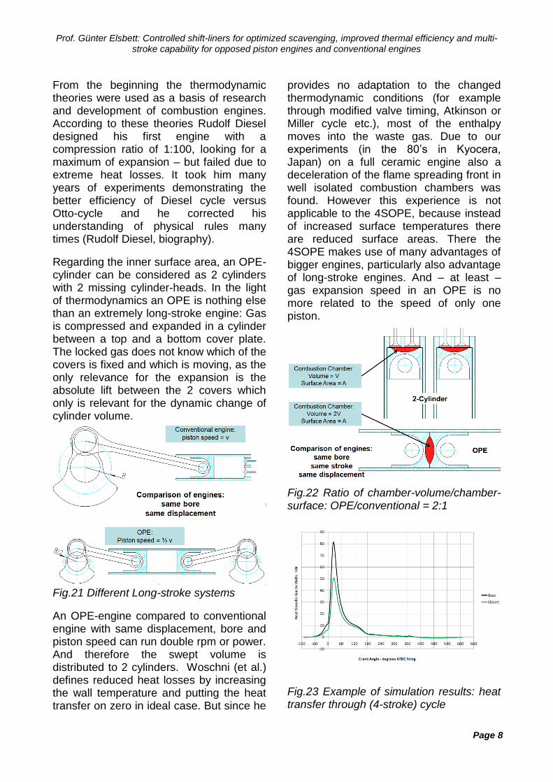
Regarding the inner surface area, an OPE-cylinder can be considered as 2 cylinders with 2 missing cylinder-heads. In the light of thermodynamics an OPE is nothing else than an extremely long-stroke engine: Gas is compressed and expanded in a cylinder between a top and a bottom cover plate. The locked gas does not know which of the covers is fixed and which is moving, as the only relevance for the expansion is the absolute lift between the 2 covers which only is relevant for the dynamic change of cylinder volume.
Fig.21 Different Long-stroke systems
An OPE-engine compared to conventional engine with same displacement, bore and piston speed can run double rpm or power. And therefore the swept volume is distributed to 2 cylinders. Woschni (et al.) defines reduced heat losses by increasing the wall temperature and putting the heat transfer on zero in ideal case. But since he
provides no adaptation to the changed thermodynamic conditions (for example through modified valve timing, Atkinson or Miller cycle etc.), most of the enthalpy moves into the waste gas. Due to our experiments (in the 80’s in Kyocera, Japan) on a full ceramic engine also a deceleration of the flame spreading front in well isolated combustion chambers was found. However this experience is not applicable to the 4SOPE, because instead of increased surface temperatures there are reduced surface areas. There the 4SOPE makes use of many advantages of bigger engines, particularly also advantage of long-stroke engines. And – at least – gas expansion speed in an OPE is no more related to the speed of only one piston.
Fig.22 Ratio of chamber-volume/chamber-surface: OPE/conventional = 2:1
Fig.23 Example of simulation results: heat transfer through (4-stroke) cycle

Prof. Günter Elsbett: Controlled shift-liners for optimized scavenging, improved thermal efficiency and multi-stroke capability for opposed piston engines and conventional engines
Page 9
The following table compares a traditional 2-stroke engine and the new 4SOPE with controlled shift-liners.
Fig.24 Comparison 2- and 4-stroke OPE
Fig.25 Comparison of scavenging sections The flow sectional areas provided by shift liners are larger than those in conventional 4-valve cylinderheads. In order to maintain a max. incoming air flow with poppet valves the intake valve diameter is bigger than for the exhaust valve. With shift-liners there is no need to accept this, so also the exhaust flow is most efficient.
Fig.26 Comparison of different scavenging
An interesting aspect of this technology might be that the described scavenging could be also applied to common engines with even better results for the flow areas.
The sectional area for shift-liners is easy calculated by A = Φcyl. π s
The area of a conventional poppet valve is calculated by Avalve = Φvalve π h, but is not only depending on lift, as it is restricted to Avalve = Φvalve π/4. For comparison to OPE the cumulated numbers of valves in two cylinder-heads must be taken into account as shown in Fig. 26
Fig.27 Conventional engine with shift-liner scavenging system
The structure and function of this engine is in principal the same as for the 4SOPE. But only one piston is used for powering the engine, the second piston is providing a simple variable compression ratio system (VCR) when changing its position inside the shift-liner.

Prof. Günter Elsbett: Controlled shift-liners for optimized scavenging, improved thermal efficiency and multi-stroke capability for opposed piston engines and conventional engines
Page 10
Due to shift-liners no oil is scraped by the piston rings into the ports; conditions are same with other conventional engines. All known means for engine improvement (common rail, turbo-charging, exhaust after-treatment, etc.) can be applied as well. Of course a 2-stroke-cycle with shift-liners is also possible without the emission handicaps of other 2-strokers. Flexible valve timing can be achieved as well and in 2SOPE no piston phase shifting is required. Therefore 100% mass balance is maintained.
Fig.28 Common Rail technology for scavenging components actuation
Using common rail technology there are an incredible number of opportunities for timing, e.g. the on-off use of Miller- or Atkinson-cycle during engine running. In-cylinder EGR is another option. Switching between two-stroke and four-stroke for one or more cylinder – also mixed for different cylinders – is possible as well as complete cylinder shut off one or more cylinders. Additional idling strokes can be added to the working cycle and these strokes could be used for post-expansion or for pumping gas to an accumulator, where later this gas can boost the engine on demand.
All kind of fuel can be burned: Diesel, Gasoline, Methanol, Ethanol, H2, LPG, CNG, Biogas, SVO (straight vegetable oil).
With all these advantages the 2 lines of the new scavenging system in OPEs and as well in traditional engines open a wide range of applications:
Stationary: Power Stations, Gen-Sets, CHP, Water Pumps (irrigation), Mining Marine: Vessels, River Ships, Sports- and Fun-boats Railway: Trams, Locomotives and other rolling stock Off Road: Forklifts, Tractors, Agriculture Machines, Construction Machines On Road: Vehicles of all kind, Passenger Car, SUV, Pickup, Truck, Bus, Motor Bike, Range Extender Military: Tanks, Jeeps and other military vehicles (on road and off road), Stationary Aviation: Propeller aircraft, Helicopter
CONCLUSIONS
Benefits of the technology presented:
For 2- and 4-stroke OPE’s: Lower heat losses due to optimized volume/surface ratio (2 pistons share one chamber) A/F mixture by injection from „Hot to Cold“ towards combustion chamber walls, or alternatively injection from „Cold to Hot“ towards combustion chamber center Large sectional areas for scavenging and variable unrestricted valve timing by using common rail technology Multi-stroke cycles are possible (2-stroke, 4-stroke, additional strokes for collecting air in a storage or for post-expansion. Exhaust or Intake can remain full open in TDC if required (no piston interference) Simple swirl creation, variable as well Intake and Exhaust near top dead center, therefore no hot or cold piston in an OPE Ideal mass balance for OPEs as no need for piston phase shifting Easy VCR system provided for traditional engines by using shift-liners The presented measures combine well known common engine technology with the benefits of shift-liner controlled opposed-piston-principle. This technology could be a base line for further research and development on the improvement of the combustion engine’s efficiency.