Embed Size (px)
Citation preview
PROFESSIONAL ENVIRONMENTALPROTECTION PRODUCTS
INSTRUCTIONS FOR USE
HIGH-PRESSURE LIFTING BAGS
2
CONTENT 1. IDENTIFICATION 41.1. TYPEOFPRODUCT 41.2. MANUFACTURER 42. PRODUCTDESCRIPTION 52.1. BASICFUNCTIONSANDAPPLICATIONAREAS 52.2. BASICDATA 52.3. ENVIRONMENTALCONDITIONSANDRESTRICTIONSOFUSE 92.4. SAFETYANDPERSONALPROTECTIVEEQUIPMENT 93. DEFINITIONS 94. PREPARATIONOFPRODUCTFORUSE 104.1. TRANSPORTANDSTORING 104.2. SAFETYPRECAUTIONSBEFOREUSE 104.3. REMOVALOFPACKAGING 104.4. DISPOSALOFPACKAGING 104.5. STORAGEANDPROTECTIONOFPRODUCTNOTINUSE 104.6. INSTRUCTIONSANDPERIODICTESTSREPORTS 115. INSTRUCTIONSFOROPERATIONS 115.1. RECOMMENDATIONSFORSAFEANDEFFICIENTWORK 115.1.1. CARRYING THE LIFTING BAG 115.1.2. WORKING ENVIRONMENT 125.2. CHOOSINGALIFTINGBAG 125.3. SYSTEMFORLIFTINGBAGINFLATION 125.3.1. PREPARATION OF LIFTING BAGS FOR LIFTING PROCEDURE 135.3.2. WORKING WITH THE CONTROLLERS 165.3.2.1. Dual controller and single controller with control levers 175.3.2.2. Controllers with a ball valve or a foot pump 175.3.3 DISCONNECTION OF LIFTING BAGS 175.4. LIFTINGPROCEDURE 195.4.1. LIFTING WITH A SINGLE LIFTING BAG 215.4.2. LIFTING WITH SEVERAL LIFTING BAGS, INCREASING THE LIFTING CAPACITY AND HEIGHT 225.4.2.1 Conventional lifting bags 225.4.2.2. Flat lifting bags 235.4.3. LIFTING OF LOADS OF UNUSUAL SHAPES 245.4.3.1. Lifting of pipes and profiles 245.4.3.2. Lifting of cylindrical objects 245.4.3.3. Separating and pushing with a lifting bag 25

3
5.5. UNEXPECTEDSITUATIONS 265.6. ACCESSORIES 275.7. DISPOSALOFWASTEMATERIAL 28
6. MAINTENANCEANDCLEANING 286.1. SAFETYPRECAUTIONS 28 6.2. MAINTENANCEANDCLEANINGAFTERUSE 286.2.1. MAINTENANCE OF LIFTING BAGS AFTER USE 286.2.1.1. Replacing the connector on the lifting bag 296.2.2. MAINTENANCE OF SUPPLY AND CONNECTING HOSES AFTER USE 306.2.3. MAINTENANCE OF THE CONTROLLER AFTER USE 316.3. PREVENTIVEMAINTENANCE 316.3.1. CHECK-UP INTERVAL 316.3.1.1. Visual test of the lifting bag 336.3.1.2. Function test of the sealing bag 336.3.1.3. Visual test of pressure reducing valve 336.3.1.4. Function test of pressure reducing valve 336.3.1.5. Visual test of the supply hose 346.3.1.6. Function test of the supply hose 346.3.1.7. Visual test of the controller 346.3.1.8. Function test of the controller 346.3.1.9. Function test of pressure gauges on the controller 356.3.1.10. Function test of the safety valve 356.4. SERVICELIFE 356.5. TROUBLESHOOTING 36
7. PRODUCTWARRANTY 377.1. LIMITEDPRODUCTLIABILITY 377.2. LIABILITYLIMIT 377.3. REJECTINGLIABILITYFORCONSEQUENTDAMAGE 377.4. POLICYWITHREGARDTOPOORQUALITYGOODS 387.5. REFUNDOFCUSTOMERTRANSPORTEXPENSES 387.6. GENERALPROVISIONS 38
8. ENCLOSURES 398.1. BRIEFINSTRUCTIONSONUSINGTHESAVATECHLIFTINGBAG 398.2. TESTREPORT:DATAABOUTTHETESTSPECIMENANDPERFORMANCE 418.3. TESTREPORT:VISUALCHECK-UPOFACCESSORIES 428.4. TESTREPORT:FUNCTIONTESTOFACCESSORIES 438.5. TESTREPORT:VISUALANDFUNCTIONTESTOFLIFTINGBAGS 44

4
1. IDENTIFICATION
1.1. TYPEOFPRODUCT
- Conventional lifting bags: SLK, SLK-H and SLK-L, - Flat lifting bags: SFB-K.
Fig. 1.1: Label on the lifting bag
1.2. MANUFACTURER
Škofjeloška cesta 6, 4000 Kranj, SloveniaTel: +386 (0)4 206 60 80, +386 (0)4 206 61 49Fax: +386 (0)4 206 64 60e-mail: [email protected]://www.savatech.si
Savatech d.o.o.Manufacturing and Marketing of Industrial Rubber Products and Tyres
Environmental Protection Products
Škofjeloška cesta 64502 KranjSlovenia
Tel: +386 (0)4 206 6388Fax: +386 (0)4 206 6390E-mail: [email protected]
www.savatech.eu www.savatech.com
Working pressure
Max. lifting capacity
Required air supply
Max. heightinflated
Lifting bag type
5
2.PRODUCTDESCRIPTION
2.1. BASICFUNCTIONSANDAPPLICATIONAREAS
Conventional and flat lifting bags are intended for lifting, lowering, positioning, separating and moving of loads weighing up to 88,000 kg. They are mainly used in rescue operations but are suitable for industrial purposes, too.
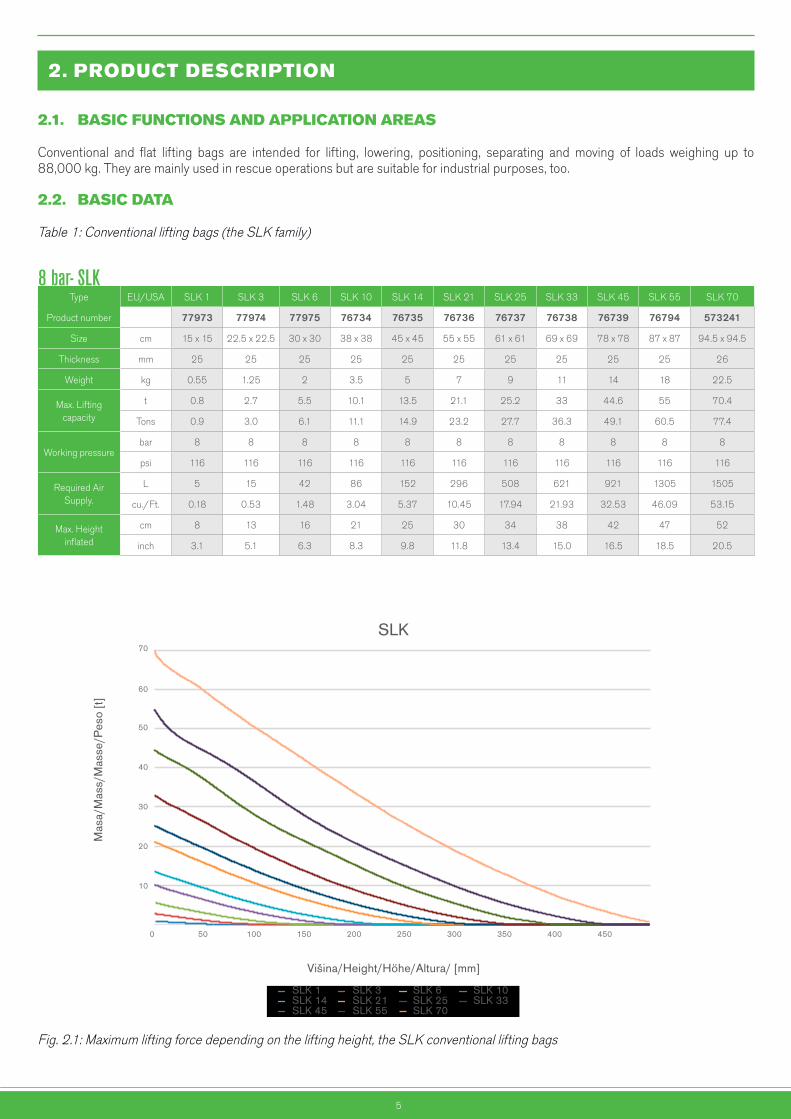
2.2. BASICDATA
Table 1: Conventional lifting bags (the SLK family)
Fig. 2.1: Maximum lifting force depending on the lifting height, the SLK conventional lifting bags
SLK-H
Mas
a/M
ass/
Mas
se/P
eso
[t]
SLK-H 1 SLK-H 4 SLK-H 7SLK-H 12 SLK-H 17 SLK-H 26SLK-H 32 SLK-H 41 SLK-H 56SLK-H 69 SLK-H 88
SLK
Mas
a/M
ass/
Mas
se/P
eso
[t]
Višina/Height/Höhe/Altura/ [mm]
SLK 1 SLK 3 SLK 6 SLK 10SLK 14 SLK 21 SLK 25 SLK 33SLK 45 SLK 55 SLK 70
Višina/Height/Höhe/Altura/ [mm]
0
10
20
30
40
50
60
70
0 50 100 150 200 250 300 350 400 450
10
20
30
40
50
60
70
80
90
0 50 100 150 200 250 300 350 400 450
8 bar- SLKType EU/USA SLK 1 SLK 3 SLK 6 SLK 10 SLK 14 SLK 21 SLK 25 SLK 33 SLK 45 SLK 55 SLK 70
Product number 77973 77974 77975 76734 76735 76736 76737 76738 76739 76794 573241
Size cm 15 x 15 22.5 x 22.5 30 x 30 38 x 38 45 x 45 55 x 55 61 x 61 69 x 69 78 x 78 87 x 87 94.5 x 94.5
Thickness mm 25 25 25 25 25 25 25 25 25 25 26
Weight kg 0.55 1.25 2 3.5 5 7 9 11 14 18 22.5
Max. Lifting capacity
t 0.8 2.7 5.5 10.1 13.5 21.1 25.2 33 44.6 55 70.4
Tons 0.9 3.0 6.1 11.1 14.9 23.2 27.7 36.3 49.1 60.5 77.4
Working pressurebar 8 8 8 8 8 8 8 8 8 8 8
psi 116 116 116 116 116 116 116 116 116 116 116
Required Air Supply.
L 5 15 42 86 152 296 508 621 921 1305 1505
cu./Ft. 0.18 0.53 1.48 3.04 5.37 10.45 17.94 21.93 32.53 46.09 53.15
Max. Height inflated
cm 8 13 16 21 25 30 34 38 42 47 52
inch 3.1 5.1 6.3 8.3 9.8 11.8 13.4 15.0 16.5 18.5 20.5
6
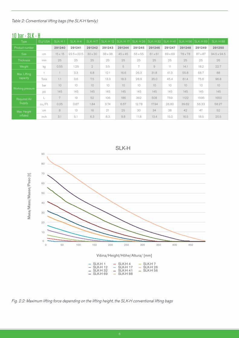
Table 2: Conventional lifting bags (the SLK-H family)
Fig. 2.2: Maximum lifting force depending on the lifting height, the SLK-H conventional lifting bags
SLK-H
Mas
a/M
ass/
Mas
se/P
eso
[t]
SLK-H 1 SLK-H 4 SLK-H 7SLK-H 12 SLK-H 17 SLK-H 26SLK-H 32 SLK-H 41 SLK-H 56SLK-H 69 SLK-H 88
SLK
Mas
a/M
ass/
Mas
se/P
eso
[t]
Višina/Height/Höhe/Altura/ [mm]
SLK 1 SLK 3 SLK 6 SLK 10SLK 14 SLK 21 SLK 25 SLK 33SLK 45 SLK 55 SLK 70
Višina/Height/Höhe/Altura/ [mm]
0
10
20
30
40
50
60
70
0 50 100 150 200 250 300 350 400 450
10
20
30
40
50
60
70
80
90
0 50 100 150 200 250 300 350 400 450
10 bar - SLK - HType EU/USA SLK- H 1 SLK- H 4 SLK- H 7 SLK- H 12 SLK- H 17 SLK- H 26 SLK- H 32 SLK- H 41 SLK- H 56 SLK- H 69 SLK- H 88
Product number 291240 291241 291242 291243 291244 291245 291246 291247 291248 291249 291250
Size cm 15 x 15 22.5 x 22.5 30 x 30 38 x 38 45 x 45 55 x 55 61 x 61 69 x 69 78 x 78 87 x 87 94.5 x 94.5
Thickness mm 25 25 25 25 25 25 25 25 25 25 26
Weight kg 0.55 1.25 2 3.5 5 7 9 11 14.1 18.2 22.7
Max. Lifting capacity
t 1 3.3 6.8 12.1 16.6 26.3 31.8 41.3 55.8 68.7 88
Tons 1.1 3.6 7.5 13.3 18.3 28.9 35.0 45.4 61.4 75.6 96.8
Working pressurebar 10 10 10 10 10 10 10 10 10 10 10
psi 145 145 145 145 145 145 145 145 145 145 145
Required Air Supply.
L 7 19 52 106 186 362 508 759 1122 1595 1650
cu./Ft. 0.25 0.67 1.84 3.74 6.57 12.78 17.94 26.80 39.62 56.33 58.27
Max. Height inflated
cm 8 13 16 21 25 30 34 38 42 47 52
inch 3.1 5.1 6.3 8.3 9.8 11.8 13.4 15.0 16.5 18.5 20.5
7
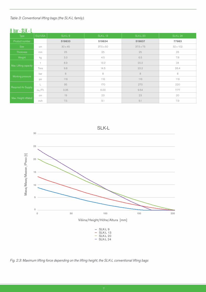
Table 3: Conventional lifting bags (the SLK-L family).
Fig. 2.3: Maximum lifting force depending on the lifting height, the SLK-L conventional lifting bags
SLK-L
Mas
a/M
ass/
Mas
se /
Pes
o [t]
Mas
a/M
ass/
Mas
se /
Pes
o [t]
Višina/Height/Höhe/Altura [mm]
SLK-L 9
SLK-L 20SLK-L 24
SLK-L 13
SFB-K
TEST REPORT
Višina/Height/Höhe/Altura [mm]
SFB-K 7/17
SFB-K 20/17SFB-K 10/17
SFB-K 33/17
0
5
10
15
20
25
30
0 50 100 150 200
0
10
20
30
40
50
60
70
0 50 100 150
8 bar - SLK - LType EU/USA SLK-L 9 SLK-L 13 SLK-L 20 SLK-L 24
Product number 519833 519834 519837 77983
Size cm 30 x 45 37.5 x 50 37.5 x 75 32 x 102
Thickness mm 25 25 25 25
Weight kg 3.3 4.5 6.5 7.8
Max. Lifting capacityt 8.9 13.2 20.2 24
Tons 9.8 14.5 22.2 26.4
Working pressurebar 8 8 8 8
psi 116 116 116 116
Required Air Supply.L 95 170 270 220
cu./Ft. 3.35 6.00 9.54 7.77
Max. Height inflatedcm 19 23 23 20
inch 7.5 9.1 9.1 7.9
8
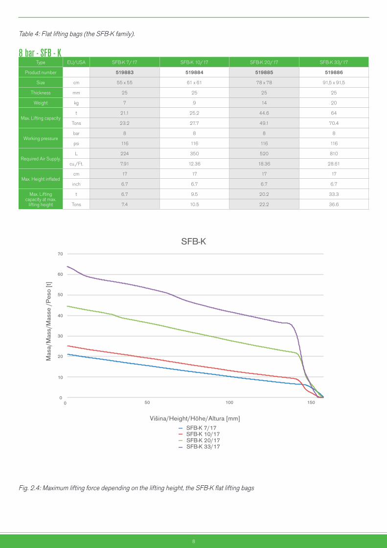
Table 4: Flat lifting bags (the SFB-K family).
Fig. 2.4: Maximum lifting force depending on the lifting height, the SFB-K flat lifting bags
SLK-LM
asa/
Mas
s/M
asse
/P
eso
[t]M
asa/
Mas
s/M
asse
/P
eso
[t]
Višina/Height/Höhe/Altura [mm]
SLK-L 9
SLK-L 20SLK-L 24
SLK-L 13
SFB-K
TEST REPORT
Višina/Height/Höhe/Altura [mm]
SFB-K 7/17
SFB-K 20/17SFB-K 10/17
SFB-K 33/17
0
5
10
15
20
25
30
0 50 100 150 200
0
10
20
30
40
50
60
70
0 50 100 150
SLK-L
Mas
a/M
ass/
Mas
se /
Pes
o [t]
Mas
a/M
ass/
Mas
se /
Pes
o [t]
Višina/Height/Höhe/Altura [mm]
SLK-L 9
SLK-L 20SLK-L 24
SLK-L 13
SFB-K
TEST REPORT
Višina/Height/Höhe/Altura [mm]
SFB-K 7/17
SFB-K 20/17SFB-K 10/17
SFB-K 33/17
0
5
10
15
20
25
30
0 50 100 150 200
0
10
20
30
40
50
60
70
0 50 100 150
8 bar - SFB - KType EU/USA SFB-K 7/17 SFB-K 10/17 SFB-K 20/17 SFB-K 33/17
Product number 519883 519884 519885 519886
Size cm 55 x 55 61 x 61 78 x 78 91,5 x 91,5
Thickness mm 25 25 25 25
Weight kg 7 9 14 20
Max. Lifting capacityt 21.1 25.2 44.6 64
Tons 23.2 27.7 49.1 70.4
Working pressurebar 8 8 8 8
psi 116 116 116 116
Required Air Supply.L 224 350 520 810
cu./Ft. 7.91 12.36 18.36 28.61
Max. Height inflatedcm 17 17 17 17
inch 6.7 6.7 6.7 6.7
Max. Liftingcapacity at max.
lifting height
t 6.7 9.5 20.2 33.3
Tons 7.4 10.5 22.2 36.6
9
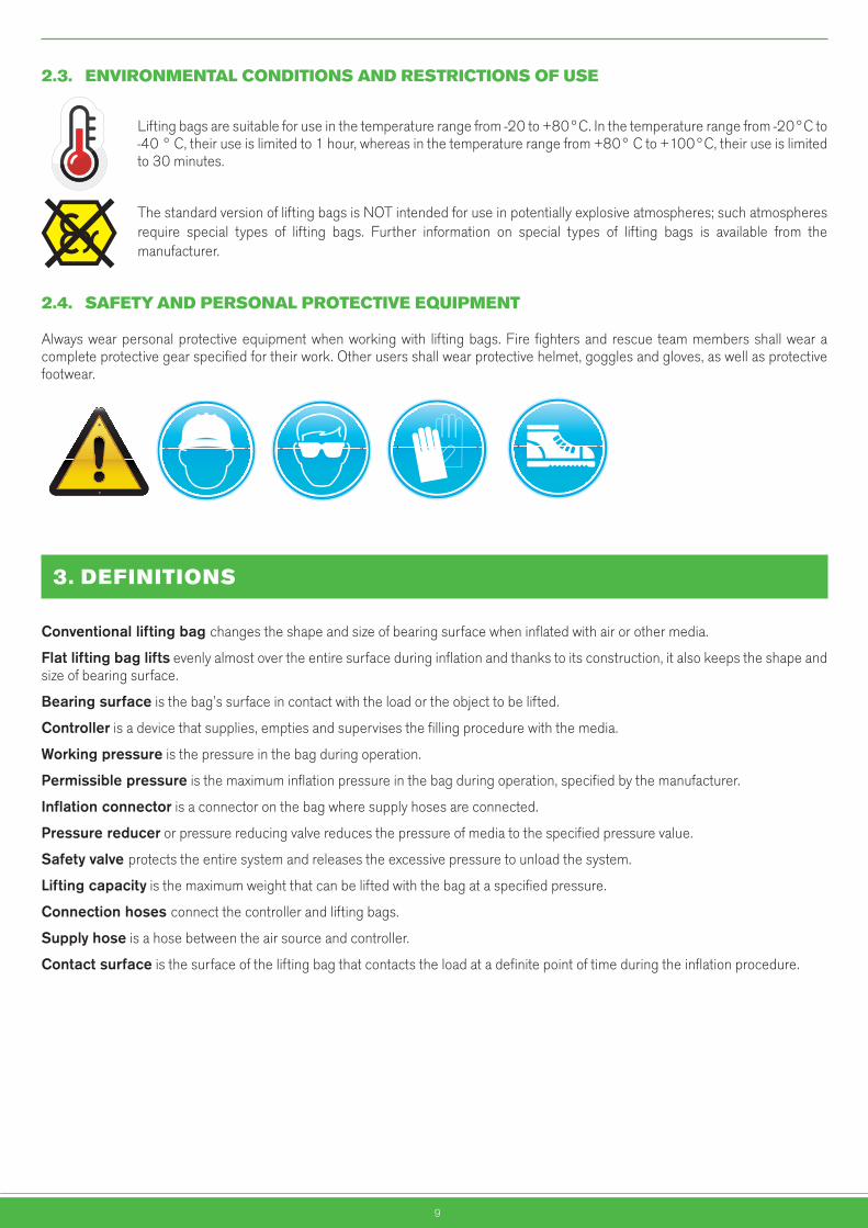
2.3. ENVIRONMENTALCONDITIONSANDRESTRICTIONSOFUSE
Lifting bags are suitable for use in the temperature range from -20 to +80°C. In the temperature range from -20°C to -40 ° C, their use is limited to 1 hour, whereas in the temperature range from +80° C to +100°C, their use is limited to 30 minutes.
The standard version of lifting bags is NOT intended for use in potentially explosive atmospheres; such atmospheres require special types of lifting bags. Further information on special types of lifting bags is available from the manufacturer.
2.4. SAFETYANDPERSONALPROTECTIVEEQUIPMENT
Always wear personal protective equipment when working with lifting bags. Fire fighters and rescue team members shall wear a complete protective gear specified for their work. Other users shall wear protective helmet, goggles and gloves, as well as protective footwear.
Obveznauporaba
zaščitnih čevljev
Obveznauporaba
antistatičneobutve
Obvezna uporaba
zaščite sluha
Obveznauporabazaščitnihrokavic
Obveznauporaba
respiratorja
Obveznauporaba
zaščite dihal
Splošnaobveznost
Obveznazaščita oči
Obveznauporaba
ščitnika obraza
Obveznauporaba
varnostnegapasu
Obveznapot za pešce
Obveznauporaba
zaščitnegakombineziona
Obveznauporabačelade
Obveznazaščitajeklenk
Obveznauporaba
zaščitnih čevljev
Obveznauporaba
antistatičneobutve
Obvezna uporaba
zaščite sluha
Obveznauporabazaščitnihrokavic
Obveznauporaba
respiratorja
Obveznauporaba
zaščite dihal
Splošnaobveznost
Obveznazaščita oči
Obveznauporaba
ščitnika obraza
Obveznauporaba
varnostnegapasu
Obveznapot za pešce
Obveznauporaba
zaščitnegakombineziona
Obveznauporabačelade
Obveznazaščitajeklenk
Nevarnostvrtečih delov
Nevarnoststisnjenja rok
Nevarnostvročih delov
Nevarnoststisnjenja telesa
Nevarnostpadca bremen
Nevarnosttransportnih
sredstev
Pozor!Splošna
nevarnost
Pozor!Elektrika
Nevarnosteksplozije
Nevarnostpožara
Nevarnostpadca
EX območje
3.DEFINITIONS
Conventionalliftingbagchanges the shape and size of bearing surface when inflated with air or other media.
Flatliftingbaglifts evenly almost over the entire surface during inflation and thanks to its construction, it also keeps the shape and size of bearing surface.
Bearingsurface is the bag’s surface in contact with the load or the object to be lifted.
Controller is a device that supplies, empties and supervises the filling procedure with the media.
Workingpressure is the pressure in the bag during operation.
Permissiblepressure is the maximum inflation pressure in the bag during operation, specified by the manufacturer.
Inflationconnector is a connector on the bag where supply hoses are connected.
Pressurereducer or pressure reducing valve reduces the pressure of media to the specified pressure value.
Safetyvalveprotects the entire system and releases the excessive pressure to unload the system.
Liftingcapacity is the maximum weight that can be lifted with the bag at a specified pressure.
Connectionhosesconnect the controller and lifting bags.
Supplyhose is a hose between the air source and controller.
Contactsurface is the surface of the lifting bag that contacts the load at a definite point of time during the inflation procedure.
10
4.PREPARATIONOFPRODUCTFORUSE
4.1. TRANSPORTANDSTORING
Lifting bags are packed in cardboard boxes. The sensitive parts of the bag are additionally protected. During transport, lifting bags should be placed horizontally or vertically. Bending or breaking of the bag is not allowed. Store lifting bags in a dark and dry place. Make sure they are not exposed to extreme temperatures (see Chapter 4.5)
4.2. SAFETYPRECAUTIONSBEFOREUSE
Carefullyreadtheinstructionsbeforeuse!
Rescue teams should participate in a training course held in conformity with internal training rules. Other users should attend a training course organised by the manufacturer or its authorised training service provider.
4.3. REMOVALOFPACKAGING
Do not use sharp objects such as knives, screwdrivers and similar, for removal of the packaging, as the bag could get damaged.
4.4. DISPOSALOFPACKAGING
Packaging is made of recyclable cardboard; it should be deposited in waste bins for recycled paper or cardboard packaging.
4.5. STORAGEANDPROTECTIONOFPRODUCTNOTINUSE
Lifting bags should be stored in a dry and dark space.
Lifting bags should be stored in the temperature range from +5 °C to +25 °C.
We recommend storing lifting bags horizontally. When the bag is stored horizontally, the inflation connector should face forward to be easily noticed when moving the bag and thus be able to prevent damaging it.
If the bag is stored upright, we recommend fixing it on the surface (a wall) to protect it from bending. The inflation connector should face upwards.
We recommend storing lifting bags in PVC pouches to minimise various environmental influences on the product during storage.
Nevarnostvrtečih delov
Nevarnoststisnjenja rok
Nevarnostvročih delov
Nevarnoststisnjenja telesa
Nevarnostpadca bremen
Nevarnosttransportnih
sredstev
Pozor!Splošna
nevarnost
Pozor!Elektrika
Nevarnosteksplozije
Nevarnostpožara
Nevarnostpadca
EX območje
11
4.6. INSTRUCTIONSANDPERIODICTESTSREPORTS
The instructions and periodic tests reports are enclosed to every lifting bag.
Keeptheinstructionsandperiodictestreportsthroughouttheservicelifeofthebag!
5.INSTRUCTIONSFOROPERATIONS
5.1. RECOMMENDATIONSFORSAFEANDEFFICIENTWORK
Non-compliancewiththeinstructionscanputsafetyofusersandthirdpersonsatriskandresultinvariousinjuries.Carefullyreadtheinstructionsforoperationbeforeusingthebag!
WARNING!NEVERREACHUNDERTHELOAD,WHICHISNOTPROTECTEDWITHMECHANICALSAFETYSUPPORTS!
•Neverexceedthemaximuminflationpressure.
•Neverplacemorethantwoconventionalbagsontopofeachother.
•Neverplacemorethanthreeflatbagsontopofeachother.
•Neverexceedthepressureof1barifnoloadisplacedonthebag.
•Inflatethebaguntilarequiredormaximumheight,ormaximumworkingpressureisreached.
•Improperuseofliftingbagsisnotallowed.Themanufacturerassumesnoresponsibilityfordamagesresulting fromimproperuseoftheproduct.
•Alwaysusethespecifiedpersonalprotectiveequipmentwhenworkingwiththeliftingbag.
5.1.1. CARRYING THE LIFTING BAG
Carry the bag in upright position and make sure the inflation connector always faces upwards to prevent damage in the case of a fall.
Larger and heavier lifting bags:•SLK 25, SLK 33, SLK 45, SLK 55, SLK 70•SLK–H 32, SLK-H 41, SLK-H 56, SLK-H 69, SLK-H 88•SLK-L 20, SLK-L 24•SFB-K 10/17, SFB-K 20/17, SFB-K 33/17
or several bags together should be placed horizontally and carried by two persons.
Nevarnostvrtečih delov
Nevarnoststisnjenja rok
Nevarnostvročih delov
Nevarnoststisnjenja telesa
Nevarnostpadca bremen
Nevarnosttransportnih
sredstev
Pozor!Splošna
nevarnost
Pozor!Elektrika
Nevarnosteksplozije
Nevarnostpožara
Nevarnostpadca
EX območje
Nevarnostvrtečih delov
Nevarnoststisnjenja rok
Nevarnostvročih delov
Nevarnoststisnjenja telesa
Nevarnostpadca bremen
Nevarnosttransportnih
sredstev
Pozor!Splošna
nevarnost
Pozor!Elektrika
Nevarnosteksplozije
Nevarnostpožara
Nevarnostpadca
EX območje

12
5.1.2. WORKING ENVIRONMENT
TEMPERATURE OF THE OBJECT TO BE LIFTED:
If the surface temperature of the object to be lifted exceeds 55°C, protect the bag’s surface in contact with the object by means of a fibreboard or rubber-coated steel board. The heat and temperatures exceeding the permissible values can damage the lifting bag. Bags preserve their lifting capacity and material properties up to the lowest temperature permitted which is -20°C.
LIGHTING OF THE WORKING PLACE:
It is dangerous to work in the dark, even though the positioning and inflating a bag is a simple procedure. Make sure that working place is not in the dark or in the shadow. We recommend using additional lighting also during the day when visibility is poor due to shading. Never use open fire for lighting in the dark.
PRESENCE OF AUTHORISED PERSONNEL:
Only qualified persons are allowed to prepare and lift/lower the load. Other persons should keep away from the area where lifting bags are prepared, lifted or lowered. In the event of hazards that could put safety of people and the environment at risk, such as outbreak of fire due to fuel leakage, the professional personnel should previously introduce the measures required for minimising such risks.
FIRE AREAS:
Lifting bags may be used in a fire area only after the contact temperature between the load and the ground drops under 55°C.
5.2. CHOOSINGALIFTINGBAG
The following data is required to be able to choose a suitable lifting bag:
•Shape of the load
•Weight of the load to be lifted
•Required lifting height
Consider the data about the load weight and required lifting height as well as the diagrams, see Fig. 2.1, 2.2, 2.3 and 2.4, in choosing a suitable lifting bag.
An example of choosing:
A load of 10 t is to be lifted to the height of 150 mm using one lifting bag.
Considering Fig. 2.1., the lifting capacity of conventional lifting bags SLK 33, SLK 45, SLK 55 or SLK 70 meets the requirements. The lifting capacity of the SLK 25 lifting bag is not sufficient for reaching the height of 150 mm.
As clear from Fig. 2.2, the conventional lifting bags SLK-H 32, SLK-H 41, SLK-H 56, SLK-H 69 and SLK-H 88 comply with the requirements for this particular application, too.
Looking at Fig.2.3, makes it clear that none of the lifting bags SLK-L is suitable for this application.
The SFB-K flat lifting bags (Fig 2.4), whose lifting capacity is practically independent of the lifting height, can be used as well. Since the required lifting height amounts to 150 mm, two lifting bags should be placed on top of each other, see Chapter 5.4.2.2.
5.3. SYSTEMFORLIFTINGBAGINFLATION
•Lifting bag may be inflated solely with air or water. •Other gases and liquids are not allowed.•Controllers with built-in safety valves should be used for inflation of lifting bags.•Never inflate a lifting bag without a load to more than 1 bar. •Inflate the lifting bag until the required or maximum lifting height or maximum working pressure is reached.
Nevarnostvrtečih delov
Nevarnoststisnjenja rok
Nevarnostvročih delov
Nevarnoststisnjenja telesa
Nevarnostpadca bremen
Nevarnosttransportnih
sredstev
Pozor!Splošna
nevarnost
Pozor!Elektrika
Nevarnosteksplozije
Nevarnostpožara
Nevarnostpadca
EX območje
Nevarnostvrtečih delov
Nevarnoststisnjenja rok
Nevarnostvročih delov
Nevarnoststisnjenja telesa
Nevarnostpadca bremen
Nevarnosttransportnih
sredstev
Pozor!Splošna
nevarnost
Pozor!Elektrika
Nevarnosteksplozije
Nevarnostpožara
Nevarnostpadca
EX območje
Nepooblaščenimvstop
prepovedan
Nepooblaščenimvstop
prepovedan
Prepovedandostop pešcem
Prepovedanoodpiranje medobratovanjem
Prepovedanogašenje z
vodo
Prepovedandostop industrijskim
vozilom
Prepovedanprevozoseb
Omejitevhitrosti
Prepovedanoodlaganje inskladiščenje
Prepovedkajenja
Prepovedanauporaba
odprtega ognja
Prepovedanauporaba
iskrečegaorodja
Prepovedandostop osebam s
srčnimspodbujevalnikom
Nepooblaščenimvstop
prepovedan
13
5.3.1. PREPARATION OF LIFTING BAGS FOR LIFTING PROCEDURE
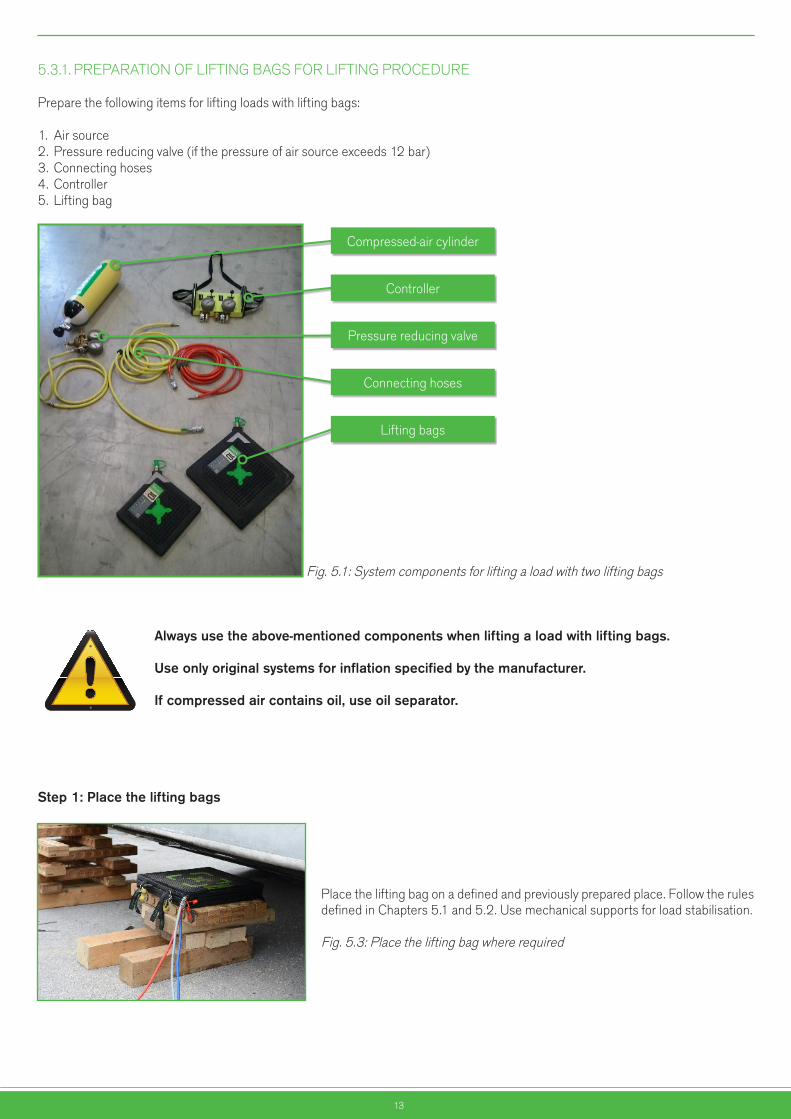
Prepare the following items for lifting loads with lifting bags:
1. Air source2. Pressure reducing valve (if the pressure of air source exceeds 12 bar)3. Connecting hoses 4. Controller5. Lifting bag
Fig. 5.1: System components for lifting a load with two lifting bags
Alwaysusetheabove-mentionedcomponentswhenliftingaloadwithliftingbags.
Useonlyoriginalsystemsforinflationspecifiedbythemanufacturer.
Ifcompressedaircontainsoil,useoilseparator.
Step1:Placetheliftingbags
Place the lifting bag on a defined and previously prepared place. Follow the rules defined in Chapters 5.1 and 5.2. Use mechanical supports for load stabilisation.
Fig. 5.3: Place the lifting bag where required
Nevarnostvrtečih delov
Nevarnoststisnjenja rok
Nevarnostvročih delov
Nevarnoststisnjenja telesa
Nevarnostpadca bremen
Nevarnosttransportnih
sredstev
Pozor!Splošna
nevarnost
Pozor!Elektrika
Nevarnosteksplozije
Nevarnostpožara
Nevarnostpadca
EX območje
Compressed-air cylinder
Controller
Pressure reducing valve
Connecting hoses
Lifting bags
14
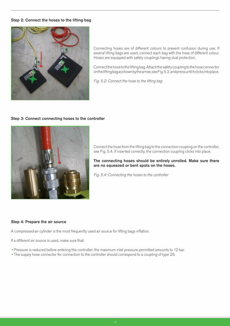
Step2:Connectthehosestotheliftingbag
Connecting hoses are of different colours to prevent confusion during use. If several lifting bags are used, connect each bag with the hose of different colour. Hoses are equipped with safety couplings having dual protection.
Connect the hose to the lifting bag. Attach the safety coupling to the hose connector on the lifting bag as shown by the arrow, see Fig. 5.2, and press until it clicks into place. Fig. 5.2: Connect the hose to the lifting bag
Step3:Connectconnectinghosestothecontroller
Connect the hose from the lifting bag to the connection coupling on the controller, see Fig. 5.4. If inserted correctly, the connection coupling clicks into place.
Theconnectinghosesshouldbeentirelyunrolled.Makesuretherearenosqueezedorbentspotsonthehoses.
Fig. 5.4: Connecting the hoses to the controller
Step4:Preparetheairsource
A compressed-air cylinder is the most frequently used air source for lifting bags inflation.
If a different air source is used, make sure that: •Pressure is reduced before entering the controller; the maximum inlet pressure permitted amounts to 12 bar. •The supply hose connector for connection to the controller should correspond to a coupling of type 26.
15
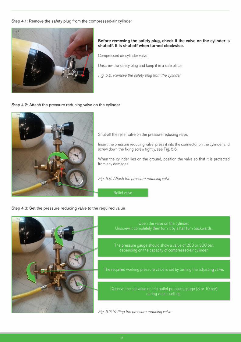
Step 4.1: Remove the safety plug from the compressed-air cylinder
Beforeremovingthesafetyplug,checkifthevalveonthecylinderisshut-off.Itisshut-offwhenturnedclockwise.
Compressed-air cylinder valve
Unscrew the safety plug and keep it in a safe place.
Fig. 5.5: Remove the safety plug from the cylinder
Step 4.2: Attach the pressure reducing valve on the cylinder
Shut-off the relief valve on the pressure reducing valve.
Insert the pressure reducing valve, press it into the connector on the cylinder and screw down the fixing screw tightly, see Fig. 5.6.
When the cylinder lies on the ground, position the valve so that it is protected from any damages.
Fig. 5.6: Attach the pressure reducing valve
Step 4.3: Set the pressure reducing valve to the required value
Fig. 5.7: Setting the pressure reducing valve
Relief valve
Open the valve on the cylinder. Unscrew it completely then turn it by a half turn backwards.
The pressure gauge should show a value of 200 or 300 bar, depending on the capacity of compressed-air cylinder.
The required working pressure value is set by turning the adjusting valve.
Observe the set value on the outlet pressure gauge (8 or 10 bar) during values setting.
16
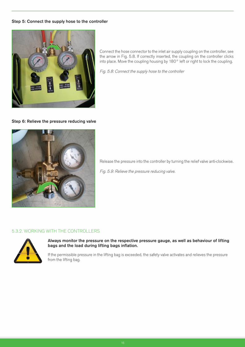
Step5:Connectthesupplyhosetothecontroller
Connect the hose connector to the inlet air supply coupling on the controller, see the arrow in Fig. 5.8. If correctly inserted, the coupling on the controller clicks into place. Move the coupling housing by 180° left or right to lock the coupling.
Fig. 5.8: Connect the supply hose to the controller
Step6:Relievethepressurereducingvalve
Release the pressure into the controller by turning the relief valve anti-clockwise.
Fig. 5.9: Relieve the pressure reducing valve.
5.3.2. WORKING WITH THE CONTROLLERS
Alwaysmonitorthepressureontherespectivepressuregauge,aswellasbehaviourofliftingbagsandtheloadduringliftingbagsinflation.
If the permissible pressure in the lifting bag is exceeded, the safety valve activates and relieves the pressure from the lifting bag.
Nevarnostvrtečih delov
Nevarnoststisnjenja rok
Nevarnostvročih delov
Nevarnoststisnjenja telesa
Nevarnostpadca bremen
Nevarnosttransportnih
sredstev
Pozor!Splošna
nevarnost
Pozor!Elektrika
Nevarnosteksplozije
Nevarnostpožara
Nevarnostpadca
EX območje
17
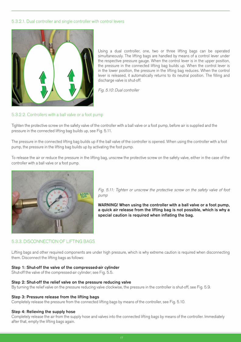
5.3.2.1. Dual controller and single controller with control levers
Using a dual controller, one, two or three lifting bags can be operated simultaneously. The lifting bags are handled by means of a control lever under the respective pressure gauge. When the control lever is in the upper position, the pressure in the connected lifting bag builds up. When the control lever is in the lower position, the pressure in the lifting bag reduces. When the control lever is released, it automatically returns to its neutral position. The filling and discharge valve is shut-off.
Fig. 5.10: Dual controller
5.3.2.2. Controllers with a ball valve or a foot pump
Tighten the protective screw on the safety valve of the controller with a ball valve or a foot pump, before air is supplied and the pressure in the connected lifting bag builds up, see Fig. 5.11.
The pressure in the connected lifting bag builds up if the ball valve of the controller is opened. When using the controller with a foot pump, the pressure in the lifting bag builds up by activating the foot pump.
To release the air or reduce the pressure in the lifting bag, unscrew the protective screw on the safety valve, either in the case of the controller with a ball valve or a foot pump.
Fig. 5.11: Tighten or unscrew the protective screw on the safety valve of foot pump
WARNING!Whenusingthecontrollerwithaballvalveorafootpump,aquickairreleasefromtheliftingbagisnotpossible,whichiswhyaspecialcautionisrequiredwheninflatingthebag.
5.3.3. DISCONNECTION OF LIFTING BAGS
Lifting bags and other required components are under high pressure, which is why extreme caution is required when disconnecting them. Disconnect the lifting bags as follows:
Step1:Shut-offthevalveofthecompressed-aircylinder Shut-off the valve of the compressed-air cylinder; see Fig. 5.5.
Step2:Shut-offthereliefvalveonthepressurereducingvalve By turning the relief valve on the pressure reducing valve clockwise, the pressure in the controller is shut-off, see Fig. 5.9.
Step3:Pressurereleasefromtheliftingbags Completely release the pressure from the connected lifting bags by means of the controller, see Fig. 5.10.
Step4:Relievingthesupplyhose Completely release the air from the supply hose and valves into the connected lifting bags by means of the controller. Immediately after that, empty the lifting bags again.
18
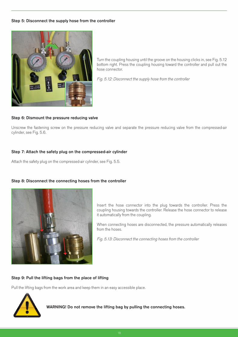
Step5:Disconnectthesupplyhosefromthecontroller
Turn the coupling housing until the groove on the housing clicks in, see Fig. 5.12 bottom right. Press the coupling housing toward the controller and pull out the hose connector.
Fig. 5.12: Disconnect the supply hose from the controller
Step6:Dismountthepressurereducingvalve
Unscrew the fastening screw on the pressure reducing valve and separate the pressure reducing valve from the compressed-air cylinder, see Fig. 5.6.
Step7:Attachthesafetyplugonthecompressed-aircylinder
Attach the safety plug on the compressed-air cylinder, see Fig. 5.5.
Step8:Disconnecttheconnectinghosesfromthecontroller
Insert the hose connector into the plug towards the controller. Press the coupling housing towards the controller. Release the hose connector to release it automatically from the coupling.
When connecting hoses are disconnected, the pressure automatically releases from the hoses.
Fig. 5.13: Disconnect the connecting hoses from the controller
Step9:Pulltheliftingbagsfromtheplaceoflifting
Pull the lifting bags from the work area and keep them in an easy accessible place.
WARNING!Donotremovetheliftingbagbypullingtheconnectinghoses.
Nevarnostvrtečih delov
Nevarnoststisnjenja rok
Nevarnostvročih delov
Nevarnoststisnjenja telesa
Nevarnostpadca bremen
Nevarnosttransportnih
sredstev
Pozor!Splošna
nevarnost
Pozor!Elektrika
Nevarnosteksplozije
Nevarnostpožara
Nevarnostpadca
EX območje

19
Step10:Disconnectconnectinghosesfromtheliftingbag
Press the hose coupling towards the lifting bag. Push the coupling housing away from the lifting bag and release the hose, after which the plug of the lifting bag automatically jumps out of the coupling.
Fig. 5.14: Disconnect the connecting hoses from the lifting bag
5.4. LIFTINGPROCEDURE
Before starting the work, check the place where the bag will be put.
Remove any glass fragments, sharp objects and other foreign particles to avoid damages or a breakdown of the bag. Make sure to prevent contact of the lifting bag with any sharp metal edges, tips of brackets, nails, screws and similar.
If a danger of slipping exists due to:•Oil stains•Chemicals that could affect the properties of rubber •Ice or snow strew some sand or any other granulated material on that place or use a rubber-coated steel plate as a protection.
If the bag is used on a non-consolidated or soft terrain, put a firm support such as a rubber-coated metal plate or fibreboard under the bag to assure stability during lifting and prevent a possible slipping of the load or the bag.
WARNING!AmechanicalsafetysupportMUSTbeusedinallliftingoperations.Itisnotallowedtoworkundertheloadthatissupportedwithaninflatedbagonly.Insert the bag on a prepared place or built support, see Fig. 5.15.
Nevarnostvrtečih delov
Nevarnoststisnjenja rok
Nevarnostvročih delov
Nevarnoststisnjenja telesa
Nevarnostpadca bremen
Nevarnosttransportnih
sredstev
Pozor!Splošna
nevarnost
Pozor!Elektrika
Nevarnosteksplozije
Nevarnostpožara
Nevarnostpadca
EX območje

20
WARNING!Itispossiblethatcertainpartsoftheloadarenotfixedontotheloadtobelifted.ItisNOTallowedtosupportthelooselyhangingpartswiththeinflatedbaginordertolifttheload.
Fig. 5.15: Mechanical safety support and bearing surface
A mechanical safety support should be firm enough to withstand the load. It should be placed on a solid surface to minimise possible slipping.
Whenconventionalliftingbagsareinflated,theircontactsurfacedecreaseswithliftingandsodoestheliftingcapacity.FortheliftingcapacitydependingontheliftingheightseeFig.2.1,2.2,2.3and2.4.
The lifting capacity is the highest at the beginning of lifting procedure when the lifting height is the lowest (Fig. 5.15). When the lifting bag is inflated, it gradually gets its spherical shape (Fig. 5.16), while the bearing surface and thus the lifting capacity reduce correspondingly.
Fig. 5.16: Bearing surface reduces while the lifting height increases
When the lifting height is at its maximum, the contact surface and lifting capacity of the lifting bags are at their minimum (Fig. 5.16).
Fig. 5.17: Minimum bearing surface at the maximum lifting height
Nevarnostvrtečih delov
Nevarnoststisnjenja rok
Nevarnostvročih delov
Nevarnoststisnjenja telesa
Nevarnostpadca bremen
Nevarnosttransportnih
sredstev
Pozor!Splošna
nevarnost
Pozor!Elektrika
Nevarnosteksplozije
Nevarnostpožara
Nevarnostpadca
EX območje
Nevarnostvrtečih delov
Nevarnoststisnjenja rok
Nevarnostvročih delov
Nevarnoststisnjenja telesa
Nevarnostpadca bremen
Nevarnosttransportnih
sredstev
Pozor!Splošna
nevarnost
Pozor!Elektrika
Nevarnosteksplozije
Nevarnostpožara
Nevarnostpadca
EX območje
21
5.4.1. LIFTING WITH A SINGLE LIFTING BAG
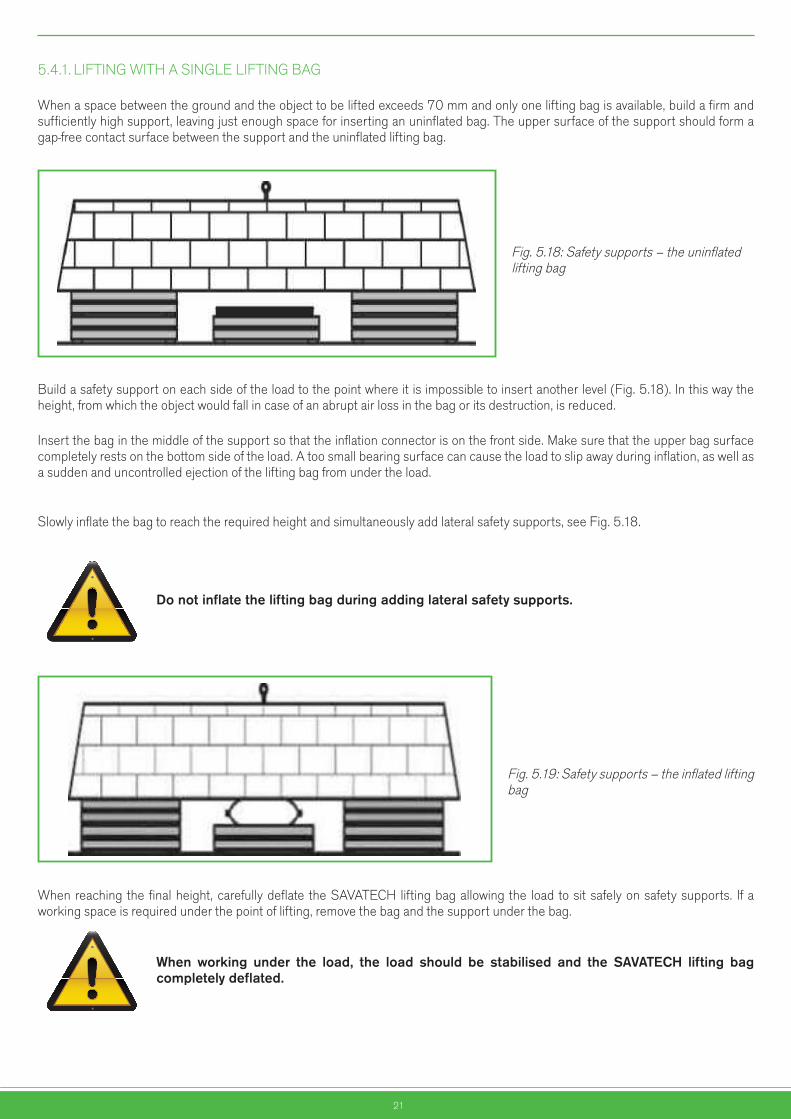
When a space between the ground and the object to be lifted exceeds 70 mm and only one lifting bag is available, build a firm and sufficiently high support, leaving just enough space for inserting an uninflated bag. The upper surface of the support should form a gap-free contact surface between the support and the uninflated lifting bag.
Fig. 5.18: Safety supports – the uninflated lifting bag
Build a safety support on each side of the load to the point where it is impossible to insert another level (Fig. 5.18). In this way the height, from which the object would fall in case of an abrupt air loss in the bag or its destruction, is reduced.
Insert the bag in the middle of the support so that the inflation connector is on the front side. Make sure that the upper bag surface completely rests on the bottom side of the load. A too small bearing surface can cause the load to slip away during inflation, as well as a sudden and uncontrolled ejection of the lifting bag from under the load. Slowly inflate the bag to reach the required height and simultaneously add lateral safety supports, see Fig. 5.18.
Donotinflatetheliftingbagduringaddinglateralsafetysupports.
Fig. 5.19: Safety supports – the inflated lifting bag
When reaching the final height, carefully deflate the SAVATECH lifting bag allowing the load to sit safely on safety supports. If a working space is required under the point of lifting, remove the bag and the support under the bag.
When working under the load, the load should be stabilised and the SAVATECH lifting bagcompletelydeflated.
Nevarnostvrtečih delov
Nevarnoststisnjenja rok
Nevarnostvročih delov
Nevarnoststisnjenja telesa
Nevarnostpadca bremen
Nevarnosttransportnih
sredstev
Pozor!Splošna
nevarnost
Pozor!Elektrika
Nevarnosteksplozije
Nevarnostpožara
Nevarnostpadca
EX območje
Nevarnostvrtečih delov
Nevarnoststisnjenja rok
Nevarnostvročih delov
Nevarnoststisnjenja telesa
Nevarnostpadca bremen
Nevarnosttransportnih
sredstev
Pozor!Splošna
nevarnost
Pozor!Elektrika
Nevarnosteksplozije
Nevarnostpožara
Nevarnostpadca
EX območje
22
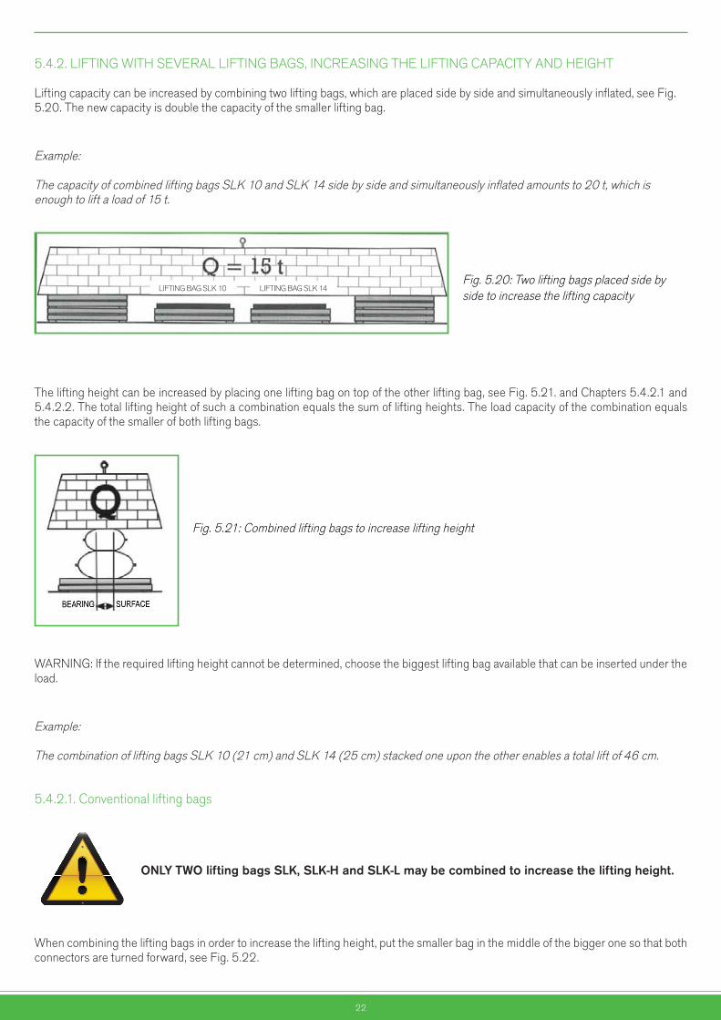
5.4.2. LIFTING WITH SEVERAL LIFTING BAGS, INCREASING THE LIFTING CAPACITY AND HEIGHT Lifting capacity can be increased by combining two lifting bags, which are placed side by side and simultaneously inflated, see Fig. 5.20. The new capacity is double the capacity of the smaller lifting bag.
Example: The capacity of combined lifting bags SLK 10 and SLK 14 side by side and simultaneously inflated amounts to 20 t, which is enough to lift a load of 15 t.
Fig. 5.20: Two lifting bags placed side by side to increase the lifting capacity
The lifting height can be increased by placing one lifting bag on top of the other lifting bag, see Fig. 5.21. and Chapters 5.4.2.1 and 5.4.2.2. The total lifting height of such a combination equals the sum of lifting heights. The load capacity of the combination equals the capacity of the smaller of both lifting bags.
Fig. 5.21: Combined lifting bags to increase lifting height
WARNING: If the required lifting height cannot be determined, choose the biggest lifting bag available that can be inserted under the load.
Example: The combination of lifting bags SLK 10 (21 cm) and SLK 14 (25 cm) stacked one upon the other enables a total lift of 46 cm.
5.4.2.1. Conventional lifting bags
ONLYTWOliftingbagsSLK,SLK-HandSLK-Lmaybecombinedtoincreasetheliftingheight.
When combining the lifting bags in order to increase the lifting height, put the smaller bag in the middle of the bigger one so that both connectors are turned forward, see Fig. 5.22.
Nevarnostvrtečih delov
Nevarnoststisnjenja rok
Nevarnostvročih delov
Nevarnoststisnjenja telesa
Nevarnostpadca bremen
Nevarnosttransportnih
sredstev
Pozor!Splošna
nevarnost
Pozor!Elektrika
Nevarnosteksplozije
Nevarnostpožara
Nevarnostpadca
EX območje
LIFTING BAG SLK 10 LIFTING BAG SLK 14
23
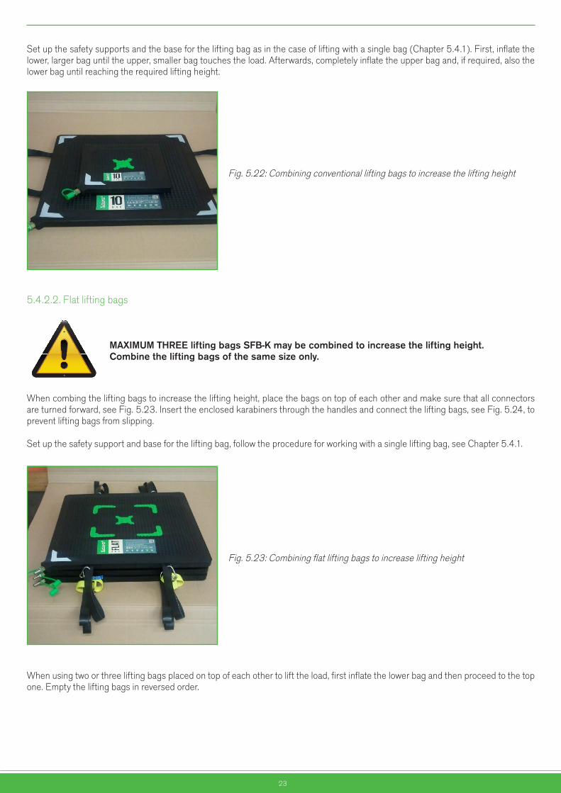
Set up the safety supports and the base for the lifting bag as in the case of lifting with a single bag (Chapter 5.4.1). First, inflate the lower, larger bag until the upper, smaller bag touches the load. Afterwards, completely inflate the upper bag and, if required, also the lower bag until reaching the required lifting height.
Fig. 5.22: Combining conventional lifting bags to increase the lifting height
5.4.2.2. Flat lifting bags
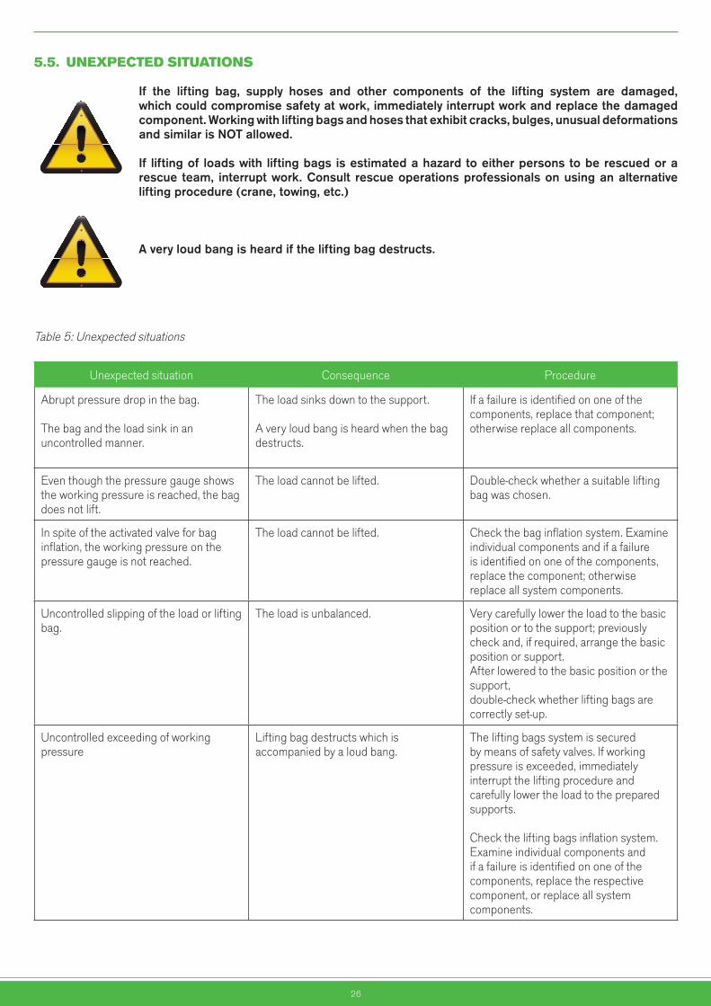
MAXIMUMTHREEliftingbagsSFB-Kmaybecombinedtoincreasetheliftingheight.Combinetheliftingbagsofthesamesizeonly.
When combing the lifting bags to increase the lifting height, place the bags on top of each other and make sure that all connectors are turned forward, see Fig. 5.23. Insert the enclosed karabiners through the handles and connect the lifting bags, see Fig. 5.24, to prevent lifting bags from slipping.
Set up the safety support and base for the lifting bag, follow the procedure for working with a single lifting bag, see Chapter 5.4.1.
Fig. 5.23: Combining flat lifting bags to increase lifting height
When using two or three lifting bags placed on top of each other to lift the load, first inflate the lower bag and then proceed to the top one. Empty the lifting bags in reversed order.
Nevarnostvrtečih delov
Nevarnoststisnjenja rok
Nevarnostvročih delov
Nevarnoststisnjenja telesa
Nevarnostpadca bremen
Nevarnosttransportnih
sredstev
Pozor!Splošna
nevarnost
Pozor!Elektrika
Nevarnosteksplozije
Nevarnostpožara
Nevarnostpadca
EX območje

24
Fig. 5.24: Combining flat lifting bags to increase lifting height
5.4.3. LIFTING OF LOADS OF UNUSUAL SHAPES
5.4.3.1. Lifting of pipes and profiles
The problem appears when the load does not rest over the entire lifting surface of the lifting bag. Moreover, the lifting bag can get damaged if it bends or is overloaded with pointy or sharp-edged loads.
Insert a rubber-coated metal plate or fibreboard between the lifting bag and the load to allow lifting force to evenly distribute over the entire bag’s lifting surface, see Fig. 5.25.
Fig. 5.25: Supporting the lifting bag with a fibreboard when lifting profiles or pipes
5.4.3.2. Lifting of cylindrical objects
Largercylindricalobjectssuchastankscannotbeliftedwithasingleliftingbag.Iftheloadisnotfirmlyfastened,itwillrollawayassoonasthebagbeginstoinflateandgetsitstypicalsphericalform.
For this reason, two lifting bags are used for lifting of cylindrical objects, placed one at each side of the object, see Fig. 5.26. Make sure that lifting bas are inflated evenly and simultaneously.
Nevarnostvrtečih delov
Nevarnoststisnjenja rok
Nevarnostvročih delov
Nevarnoststisnjenja telesa
Nevarnostpadca bremen
Nevarnosttransportnih
sredstev
Pozor!Splošna
nevarnost
Pozor!Elektrika
Nevarnosteksplozije
Nevarnostpožara
Nevarnostpadca
EX območje

25
Fig. 5.26: Lifting large cylindrical loads
5.4.3.3. Separating and pushing with a lifting bag
Lifting bags can further be used for separating and pushing objects; however, a problem can arise with thin-walled objects, as they could bend or tore due to the bag’s pressure. For this reason, lean the bag against a bar, a pillar or another firm and rigid element; if this is not possible, insert a rubber-coated plate or thick fibreboard between the bag and the object to allow distribution of the pushing force over a larger surface, see Fig. 5.27.
Fig. 5.27: Moving or separating objects
26
5.5. UNEXPECTEDSITUATIONS
If the lifting bag, supply hoses and other components of the lifting system are damaged,whichcouldcompromisesafetyatwork,immediatelyinterruptworkandreplacethedamagedcomponent.Workingwithliftingbagsandhosesthatexhibitcracks,bulges,unusualdeformationsandsimilarisNOTallowed.
If liftingof loadswithliftingbagsisestimatedahazardtoeitherpersonstoberescuedorarescueteam, interruptwork.Consult rescueoperationsprofessionalsonusinganalternativeliftingprocedure(crane,towing,etc.)
Averyloudbangisheardiftheliftingbagdestructs.
Table 5: Unexpected situations
Unexpected situation Consequence Procedure
Abrupt pressure drop in the bag.
The bag and the load sink in an uncontrolled manner.
The load sinks down to the support.
A very loud bang is heard when the bag destructs.
If a failure is identified on one of the components, replace that component; otherwise replace all components.
Even though the pressure gauge shows the working pressure is reached, the bag does not lift.
The load cannot be lifted. Double-check whether a suitable lifting bag was chosen.
In spite of the activated valve for bag inflation, the working pressure on the pressure gauge is not reached.
The load cannot be lifted. Check the bag inflation system. Examine individual components and if a failure is identified on one of the components, replace the component; otherwise replace all system components.
Uncontrolled slipping of the load or lifting bag.
The load is unbalanced. Very carefully lower the load to the basic position or to the support; previously check and, if required, arrange the basic position or support. After lowered to the basic position or the support, double-check whether lifting bags are correctly set-up.
Uncontrolled exceeding of working pressure
Lifting bag destructs which is accompanied by a loud bang.
The lifting bags system is secured by means of safety valves. If working pressure is exceeded, immediately interrupt the lifting procedure and carefully lower the load to the prepared supports.
Check the lifting bags inflation system. Examine individual components and if a failure is identified on one of the components, replace the respective component, or replace all system components.
Nevarnostvrtečih delov
Nevarnoststisnjenja rok
Nevarnostvročih delov
Nevarnoststisnjenja telesa
Nevarnostpadca bremen
Nevarnosttransportnih
sredstev
Pozor!Splošna
nevarnost
Pozor!Elektrika
Nevarnosteksplozije
Nevarnostpožara
Nevarnostpadca
EX območjeNevarnost
vrtečih delovNevarnost
stisnjenja rokNevarnost
vročih delovNevarnost
stisnjenja telesaNevarnost
padca bremenNevarnost
transportnihsredstev
Pozor!Splošna
nevarnost
Pozor!Elektrika
Nevarnosteksplozije
Nevarnostpožara
Nevarnostpadca
EX območje
27
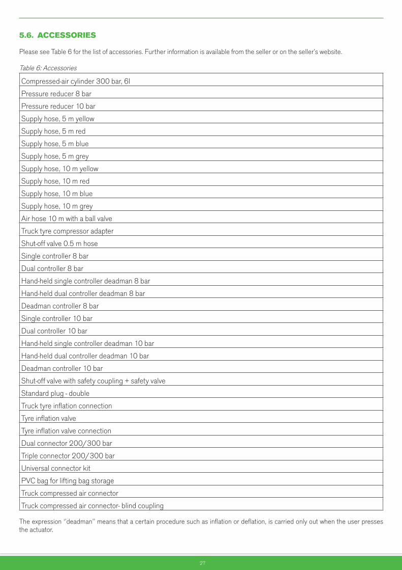
5.6. ACCESSORIES
Please see Table 6 for the list of accessories. Further information is available from the seller or on the seller’s website.
Table 6: Accessories
Compressed-air cylinder 300 bar, 6l
Pressure reducer 8 bar
Pressure reducer 10 bar
Supply hose, 5 m yellow
Supply hose, 5 m red
Supply hose, 5 m blue
Supply hose, 5 m grey
Supply hose, 10 m yellow
Supply hose, 10 m red
Supply hose, 10 m blue
Supply hose, 10 m grey
Air hose 10 m with a ball valve
Truck tyre compressor adapter
Shut-off valve 0.5 m hose
Single controller 8 bar
Dual controller 8 bar
Hand-held single controller deadman 8 bar
Hand-held dual controller deadman 8 bar
Deadman controller 8 bar
Single controller 10 bar
Dual controller 10 bar
Hand-held single controller deadman 10 bar
Hand-held dual controller deadman 10 bar
Deadman controller 10 bar
Shut-off valve with safety coupling + safety valve
Standard plug - double
Truck tyre inflation connection
Tyre inflation valve
Tyre inflation valve connection
Dual connector 200/300 bar
Triple connector 200/300 bar
Universal connector kit
PVC bag for lifting bag storage
Truck compressed air connector
Truck compressed air connector- blind coupling
The expression ‘’deadman’’ means that a certain procedure such as inflation or deflation, is carried only out when the user presses the actuator.
28
5.7. DISPOSALOFWASTEMATERIAL
A damaged or destroyed product or a product whose service life has expired should be withdrawn from the use. Since a lifting bag is not an ordinary waste but a reusable one, waste classification according to the valid local regulations applies.
The product is recyclable.
6. MAINTENANCEANDCLEANING
6.1. SAFETYPRECAUTIONS
Obveznauporaba
zaščitnih čevljev
Obveznauporaba
antistatičneobutve
Obvezna uporaba
zaščite sluha
Obveznauporabazaščitnihrokavic
Obveznauporaba
respiratorja
Obveznauporaba
zaščite dihal
Splošnaobveznost
Obveznazaščita oči
Obveznauporaba
ščitnika obraza
Obveznauporaba
varnostnegapasu
Obveznapot za pešce
Obveznauporaba
zaščitnegakombineziona
Obveznauporabačelade
Obveznazaščitajeklenk
Obveznauporaba
zaščitnih čevljev
Obveznauporaba
antistatičneobutve
Obvezna uporaba
zaščite sluha
Obveznauporabazaščitnihrokavic
Obveznauporaba
respiratorja
Obveznauporaba
zaščite dihal
Splošnaobveznost
Obveznazaščita oči
Obveznauporaba
ščitnika obraza
Obveznauporaba
varnostnegapasu
Obveznapot za pešce
Obveznauporaba
zaščitnegakombineziona
Obveznauporabačelade
Obveznazaščitajeklenk
Nevarnostvrtečih delov
Nevarnoststisnjenja rok
Nevarnostvročih delov
Nevarnoststisnjenja telesa
Nevarnostpadca bremen
Nevarnosttransportnih
sredstev
Pozor!Splošna
nevarnost
Pozor!Elektrika
Nevarnosteksplozije
Nevarnostpožara
Nevarnostpadca
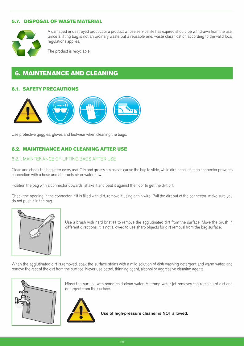
EX območjeUse protective goggles, gloves and footwear when cleaning the bags.
6.2. MAINTENANCEANDCLEANINGAFTERUSE
6.2.1. MAINTENANCE OF LIFTING BAGS AFTER USE
Clean and check the bag after every use. Oily and greasy stains can cause the bag to slide, while dirt in the inflation connector prevents connection with a hose and obstructs air or water flow.
Position the bag with a connector upwards, shake it and beat it against the floor to get the dirt off.
Check the opening in the connector; if it is filled with dirt, remove it using a thin wire. Pull the dirt out of the connector; make sure you do not push it in the bag.
Use a brush with hard bristles to remove the agglutinated dirt from the surface. Move the brush in different directions. It is not allowed to use sharp objects for dirt removal from the bag surface.
When the agglutinated dirt is removed, soak the surface stains with a mild solution of dish washing detergent and warm water, and remove the rest of the dirt from the surface. Never use petrol, thinning agent, alcohol or aggressive cleaning agents.
Rinse the surface with some cold clean water. A strong water jet removes the remains of dirt and detergent from the surface.
Useofhigh-pressurecleanerisNOTallowed.
Nevarnostvrtečih delov
Nevarnoststisnjenja rok
Nevarnostvročih delov
Nevarnoststisnjenja telesa
Nevarnostpadca bremen
Nevarnosttransportnih
sredstev
Pozor!Splošna
nevarnost
Pozor!Elektrika
Nevarnosteksplozije
Nevarnostpožara
Nevarnostpadca
EX območje
29
Place the lifting bag upright, wipe the connector with a clean cloth. Let the lifting bag dry in the air.
Neverdryliftingbagsinadrierorbymeansofheatingdevices.
Carefully examine the cleaned and dried lifting bags, as follows:
•Check the bag for air blisters, cuts or worn out sections that might be hidden under the dirt. Mark any damage or defect with a chalk. Consult the manufacturer or an authorised service about the damage and further use of the bag.
•Check the connector for any damage that disables connection. If damages prevent connection of the connection coupling with a supply hose, replace the connector.
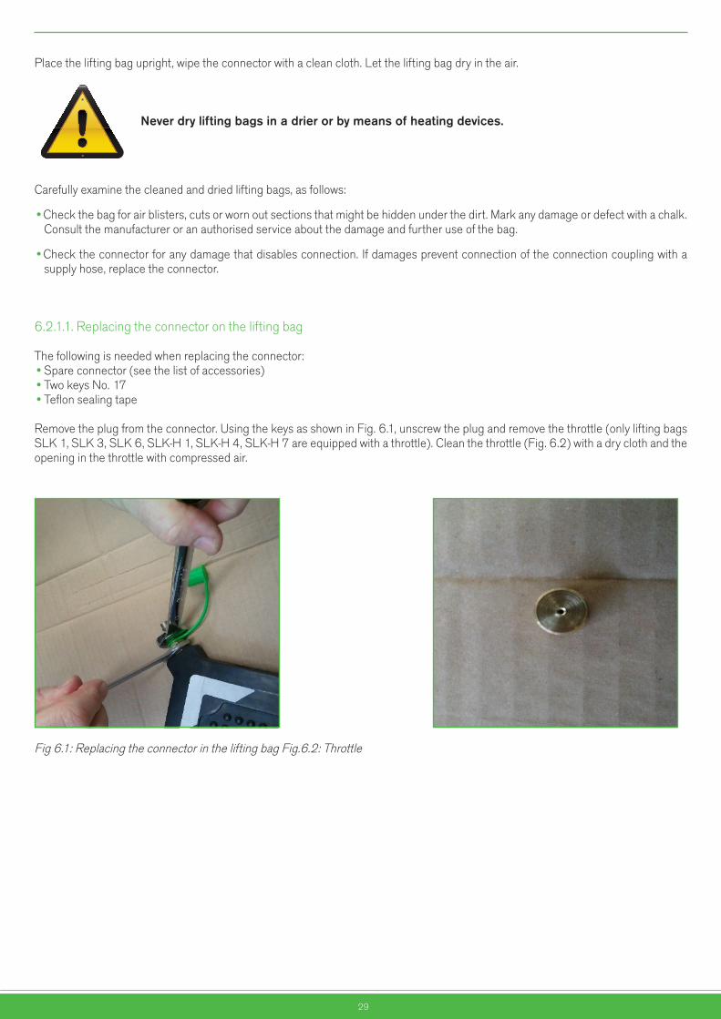
6.2.1.1. Replacing the connector on the lifting bag
The following is needed when replacing the connector:•Spare connector (see the list of accessories)•Two keys No. 17•Teflon sealing tape
Remove the plug from the connector. Using the keys as shown in Fig. 6.1, unscrew the plug and remove the throttle (only lifting bags SLK 1, SLK 3, SLK 6, SLK-H 1, SLK-H 4, SLK-H 7 are equipped with a throttle). Clean the throttle (Fig. 6.2) with a dry cloth and the opening in the throttle with compressed air.
Fig 6.1: Replacing the connector in the lifting bag Fig.6.2: Throttle
Nevarnostvrtečih delov
Nevarnoststisnjenja rok
Nevarnostvročih delov
Nevarnoststisnjenja telesa
Nevarnostpadca bremen
Nevarnosttransportnih
sredstev
Pozor!Splošna
nevarnost
Pozor!Elektrika
Nevarnosteksplozije
Nevarnostpožara
Nevarnostpadca
EX območje
30
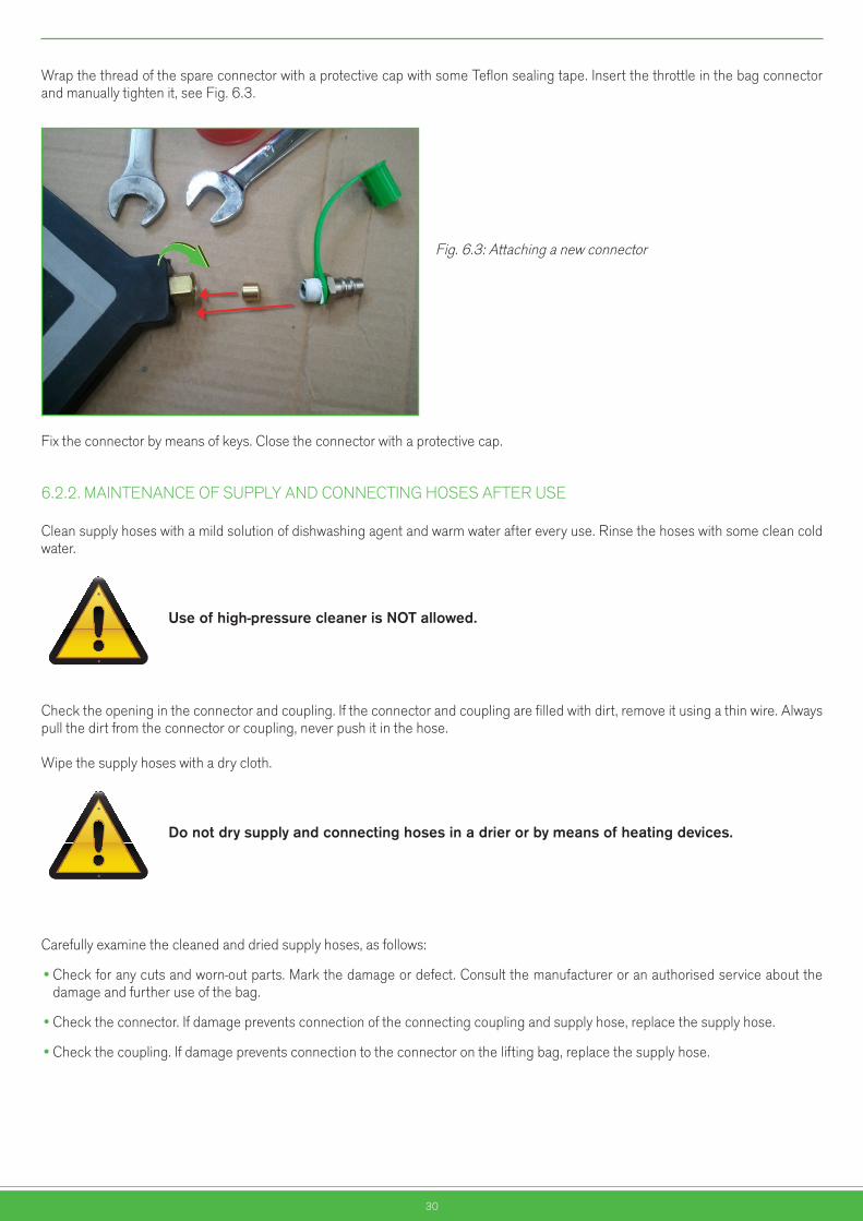
Wrap the thread of the spare connector with a protective cap with some Teflon sealing tape. Insert the throttle in the bag connector and manually tighten it, see Fig. 6.3.
Fig. 6.3: Attaching a new connector
Fix the connector by means of keys. Close the connector with a protective cap.
6.2.2. MAINTENANCE OF SUPPLY AND CONNECTING HOSES AFTER USE
Clean supply hoses with a mild solution of dishwashing agent and warm water after every use. Rinse the hoses with some clean cold water.
Useofhigh-pressurecleanerisNOTallowed.
Check the opening in the connector and coupling. If the connector and coupling are filled with dirt, remove it using a thin wire. Always pull the dirt from the connector or coupling, never push it in the hose.
Wipe the supply hoses with a dry cloth.
Donotdrysupplyandconnectinghosesinadrierorbymeansofheatingdevices.
Carefully examine the cleaned and dried supply hoses, as follows:
•Check for any cuts and worn-out parts. Mark the damage or defect. Consult the manufacturer or an authorised service about the damage and further use of the bag.
•Check the connector. If damage prevents connection of the connecting coupling and supply hose, replace the supply hose.
•Check the coupling. If damage prevents connection to the connector on the lifting bag, replace the supply hose.
Nevarnostvrtečih delov
Nevarnoststisnjenja rok
Nevarnostvročih delov
Nevarnoststisnjenja telesa
Nevarnostpadca bremen
Nevarnosttransportnih
sredstev
Pozor!Splošna
nevarnost
Pozor!Elektrika
Nevarnosteksplozije
Nevarnostpožara
Nevarnostpadca
EX območje
Nevarnostvrtečih delov
Nevarnoststisnjenja rok
Nevarnostvročih delov
Nevarnoststisnjenja telesa
Nevarnostpadca bremen
Nevarnosttransportnih
sredstev
Pozor!Splošna
nevarnost
Pozor!Elektrika
Nevarnosteksplozije
Nevarnostpožara
Nevarnostpadca
EX območje

31
6.2.3. MAINTENANCE OF THE CONTROLLER AFTER USE
Clean and maintain the controllers in compliance with the instructions about using the controllers.
6.3. PREVENTIVEMAINTENANCE
Preventive maintenance includes compulsory inspection of lifting bags and the associated equipment for lifting, performance of tests and replacement of damaged parts.
The enclosed check-up lists can be of assistance when carrying out preventive maintenance.
Always comply with the valid local regulations when carrying out preventive maintenance.
Always use personal protective equipment during check-ups and testing. Firefighters and rescue team members should wear the complete gear as specified for their work. Other users should wear protective helmet, goggles, gloves and footwear.
Obveznauporaba
zaščitnih čevljev
Obveznauporaba
antistatičneobutve
Obvezna uporaba
zaščite sluha
Obveznauporabazaščitnihrokavic
Obveznauporaba
respiratorja
Obveznauporaba
zaščite dihal
Splošnaobveznost
Obveznazaščita oči
Obveznauporaba
ščitnika obraza
Obveznauporaba
varnostnegapasu
Obveznapot za pešce
Obveznauporaba
zaščitnegakombineziona
Obveznauporabačelade
Obveznazaščitajeklenk
Obveznauporaba
zaščitnih čevljev
Obveznauporaba
antistatičneobutve
Obvezna uporaba
zaščite sluha
Obveznauporabazaščitnihrokavic
Obveznauporaba
respiratorja
Obveznauporaba
zaščite dihal
Splošnaobveznost
Obveznazaščita oči
Obveznauporaba
ščitnika obraza
Obveznauporaba
varnostnegapasu
Obveznapot za pešce
Obveznauporaba
zaščitnegakombineziona
Obveznauporabačelade
Obveznazaščitajeklenk
Nevarnostvrtečih delov
Nevarnoststisnjenja rok
Nevarnostvročih delov
Nevarnoststisnjenja telesa
Nevarnostpadca bremen
Nevarnosttransportnih
sredstev
Pozor!Splošna
nevarnost
Pozor!Elektrika
Nevarnosteksplozije
Nevarnostpožara
Nevarnostpadca
EX območjeObservetheinstructionsforsafework.
Ifadoubtarisesastothesafeperformanceofatest,immediatelyinterruptthetestandconsultthemanufactureroritsauthorisedrepresentativeaboutfurthersteps.
Functiontestsorpressuretests(boldwritten inthetables)areallowedonlyafterapreviousvisualcheckverifiesthebagisdefectfree.
ItisNOTALLOWEDtousetheliftingbagifavisualorfunctiontestshowsdamagesorleakagesontheliftingbag,damagesorirregularitiesinoperationoftheequipment.
6.3.1. CHECK-UP INTERVAL
Test Check-up interval Performed by Procedure
Visual testAfter every use
Annually
A person qualified for operating lifting bags Chapter 6.3.1.1.
Function testAfter every use
Annually
A person qualified for operating lifting bags Chapter 6.3.1.2.
Periodic test 5, 7, 9, 11, 12, 13 and 14 years after the manufacture
Manufacturer or a person authorised by the manufacturer
Nevarnostvrtečih delov
Nevarnoststisnjenja rok
Nevarnostvročih delov
Nevarnoststisnjenja telesa
Nevarnostpadca bremen
Nevarnosttransportnih
sredstev
Pozor!Splošna
nevarnost
Pozor!Elektrika
Nevarnosteksplozije
Nevarnostpožara
Nevarnostpadca
EX območje
Nevarnostvrtečih delov
Nevarnoststisnjenja rok
Nevarnostvročih delov
Nevarnoststisnjenja telesa
Nevarnostpadca bremen
Nevarnosttransportnih
sredstev
Pozor!Splošna
nevarnost
Pozor!Elektrika
Nevarnosteksplozije
Nevarnostpožara
Nevarnostpadca
EX območje
Nevarnostvrtečih delov
Nevarnoststisnjenja rok
Nevarnostvročih delov
Nevarnoststisnjenja telesa
Nevarnostpadca bremen
Nevarnosttransportnih
sredstev
Pozor!Splošna
nevarnost
Pozor!Elektrika
Nevarnosteksplozije
Nevarnostpožara
Nevarnostpadca
EX območje
32
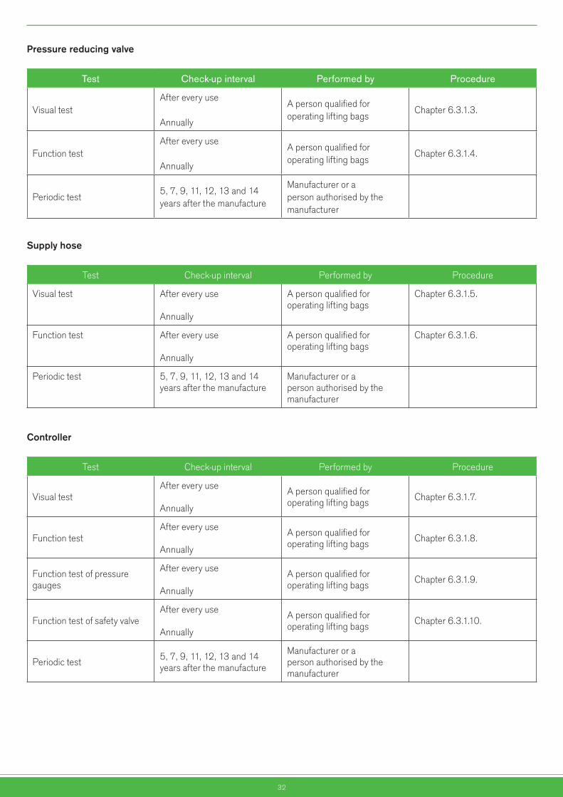
Pressurereducingvalve
Test Check-up interval Performed by Procedure
Visual testAfter every use
Annually
A person qualified for operating lifting bags
Chapter 6.3.1.3.
Function testAfter every use
Annually
A person qualified for operating lifting bags
Chapter 6.3.1.4.
Periodic test5, 7, 9, 11, 12, 13 and 14 years after the manufacture
Manufacturer or a person authorised by the manufacturer
Supplyhose
Test Check-up interval Performed by Procedure
Visual test After every use
Annually
A person qualified for operating lifting bags
Chapter 6.3.1.5.
Function test After every use
Annually
A person qualified for operating lifting bags
Chapter 6.3.1.6.
Periodic test 5, 7, 9, 11, 12, 13 and 14 years after the manufacture
Manufacturer or a person authorised by the manufacturer
Controller
Test Check-up interval Performed by Procedure
Visual testAfter every use
Annually
A person qualified for operating lifting bags Chapter 6.3.1.7.
Function testAfter every use
Annually
A person qualified for operating lifting bags Chapter 6.3.1.8.
Function test of pressure gauges
After every use
Annually
A person qualified for operating lifting bags Chapter 6.3.1.9.
Function test of safety valveAfter every use
Annually
A person qualified for operating lifting bags Chapter 6.3.1.10.
Periodic test 5, 7, 9, 11, 12, 13 and 14 years after the manufacture
Manufacturer or a person authorised by the manufacturer

33
6.3.1.1. Visual test of the lifting bag
Thenexttestmaybecarriedoutoutdooronly.Observeasafetydistancebetweenthepersonspresentandthetestobject,aswellasbetweentheneighbouringbuildingsandthetestobject.
Connect the unloaded lifting bag as specified in Chapter 5.3. Inflate the lifting bag to the pressure 0.2 x working pressure. Check visually for any unusual bulges, punctures, cuts or any other mechanical damages. Using a brush, apply some soapy water over the entire bag surface including the connection. Visually check sealing of the lifting bag and connection.
6.3.1.2. Function test of the sealing bag
Thenexttestmaybecarriedoutoutdooronly.Observeasafetydistancebetweenthepersonspresentandthetestobject,aswellasbetweentheneighbouringbuildingsandthetestobject.
Connect the unloaded lifting bag as specified in Chapter 5.3. Inflate the lifting bag to 0.5 x working pressure. The lifting bag is functional if the pressure in the lifting bag does not drop by more than 10% within an hour.
6.3.1.3. Visual test of pressure reducing valve
Visually check for damages on:
•Threads of the filling connection
•Pressure gauges and the maximum working pressure marking
•Protective caps on pressure gauges
•Relief valve
•Connecting hoses for tears, punctures or any other damages such as stiff areas and consequences of contact with acids
6.3.1.4. Function test of pressure reducing valve
Attach the pressure reducing valve on a standard compressed-air cylinder of capacity 6 l and pressure 300 bar. The compressed-air cylinder should be full. Shut off the relief valve.
Open the valve on the cylinder. The left pressure gauge should display the pressure 300 bar.
Using a brush, apply some soapy water on the connection between the pressure reducing valve and the cylinder and check sealing. Turn the adjusting valve to reduce the outlet pressure displayed on the right pressure gauge until the value shows 0 bar. Turn the adjusting valve in the opposite direction until the maximum value marked on the right pressure gauge is reached (8 or 10 bar, depends on the type). The adjusting valve should allow setting the value throughout the working area. The adjusting valve should move smoothly throughout the working area.
Using a brush, apply some soapy water on the connector and check sealing of the relief valve.
Connect the hose to the controller. Slowly open the relief valve until it is fully open. The relief valve should move smoothly at all times. The pressure gauge on the controller should display the same value as displayed on the right pressure gauge of the pressure reducing valve. Using a brush, apply some soapy water on the hose of the pressure reducing valve and connections between the hose and pressure reducing valve, as well as the hose and controller. Check sealing of hoses and connections.
Nevarnostvrtečih delov
Nevarnoststisnjenja rok
Nevarnostvročih delov
Nevarnoststisnjenja telesa
Nevarnostpadca bremen
Nevarnosttransportnih
sredstev
Pozor!Splošna
nevarnost
Pozor!Elektrika
Nevarnosteksplozije
Nevarnostpožara
Nevarnostpadca
EX območje
Nevarnostvrtečih delov
Nevarnoststisnjenja rok
Nevarnostvročih delov
Nevarnoststisnjenja telesa
Nevarnostpadca bremen
Nevarnosttransportnih
sredstev
Pozor!Splošna
nevarnost
Pozor!Elektrika
Nevarnosteksplozije
Nevarnostpožara
Nevarnostpadca
EX območje
34
6.3.1.5. Visual test of the supply hose
Visually check for damages on:
•Connection couplings
•Connector
•Hoses, any tears, punctures or any other damages such as stiff areas and consequences of contact with acids
6.3.1.6. Function test of the supply hose
Connect the controller and lifting bag with the supply hose, see Chapter 5.3.1. Inflate the lifting bag to 0.2 x working pressure. Using a brush, apply some soapy water on connections, supply hose, and check sealing of connections and hoses.
6.3.1.7. Visual test of the controller
Visually check for damages on:
•Inlet connecting couplings
•Outlet connecting couplings
•Pressure gauges and the maximum working pressure marking
•Protective caps on pressure gauges**
•Housing*
•Safety valve
* Dual controller** Controller with a ball valve
6.3.1.8. Function test of the controller
Connect the hose of pressure reducing valve, see Chapter 5.3.1, to check the function of the inlet coupling.Connect the controller and the lifting bag with the supply hose, see Chapter 5.3.1, and check the function of the outlet couplings.Move the control levers first into the lifting position and then into the lowering position. Control levers should move smoothly. When the control lever is in the lifting position, the connected lifting bags should lift.
WARNING:Donotexceed0.2xworkingpressureintheliftingbag.*
Open and shut the ball valve again. The valve should move smoothly. When the valve is open, the connected lifting bag should lift.
WARNING:Donotexceed0.2xworkingpressureintheliftingbag**.
* Dual controller** Controller with a ball valve
Nevarnostvrtečih delov
Nevarnoststisnjenja rok
Nevarnostvročih delov
Nevarnoststisnjenja telesa
Nevarnostpadca bremen
Nevarnosttransportnih
sredstev
Pozor!Splošna
nevarnost
Pozor!Elektrika
Nevarnosteksplozije
Nevarnostpožara
Nevarnostpadca
EX območjeNevarnost
vrtečih delovNevarnost
stisnjenja rokNevarnost
vročih delovNevarnost
stisnjenja telesaNevarnost
padca bremenNevarnost
transportnihsredstev
Pozor!Splošna
nevarnost
Pozor!Elektrika
Nevarnosteksplozije
Nevarnostpožara
Nevarnostpadca
EX območje
35
6.3.1.9. Function test of pressure gauges on the controller
The function of pressure gauges on the controller is tested by means of reference pressure gauges.
6.3.1.10. Function test of the safety valve
Connect the pressure reducing valves, see Chapter 5.3.1. Press the control lever into the lifting position and gradually build up pressure in the controller until the safety valve opens or the value 1.1 x working pressure is exceeded. (8 or 10 bar, depends on the type). The safety valve functions appropriately if it activates within the range of -0 +10% working pressure of the controller. The activated safety valve emits a characteristic sound.
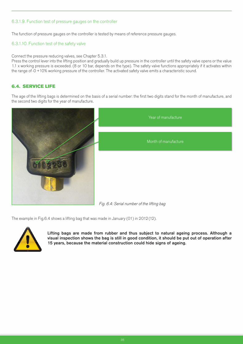
6.4. SERVICELIFE
The age of the lifting bags is determined on the basis of a serial number: the first two digits stand for the month of manufacture, and the second two digits for the year of manufacture.
Fig. 6.4: Serial number of the lifting bag
The example in Fig.6.4 shows a lifting bag that was made in January (01) in 2012 (12).
Lifting bags are made from rubber and thus subject to natural ageing process. Although avisualinspectionshowsthebagisstillingoodcondition,itshouldbeputoutofoperationafter15years,becausethematerialconstructioncouldhidesignsofageing.
Nevarnostvrtečih delov
Nevarnoststisnjenja rok
Nevarnostvročih delov
Nevarnoststisnjenja telesa
Nevarnostpadca bremen
Nevarnosttransportnih
sredstev
Pozor!Splošna
nevarnost
Pozor!Elektrika
Nevarnosteksplozije
Nevarnostpožara
Nevarnostpadca
EX območje
Year of manufacture
Month of manufacture
36
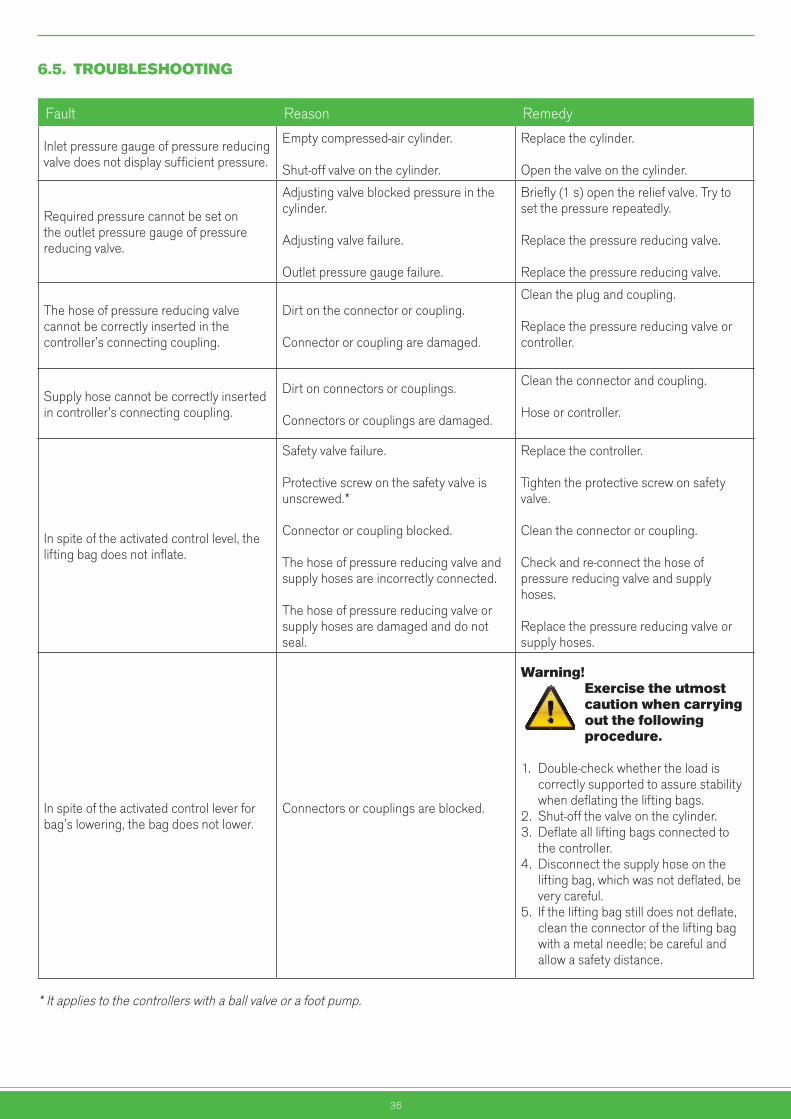
6.5. TROUBLESHOOTING
Fault Reason Remedy
Inlet pressure gauge of pressure reducing valve does not display sufficient pressure.
Empty compressed-air cylinder.
Shut-off valve on the cylinder.
Replace the cylinder.
Open the valve on the cylinder.
Required pressure cannot be set on the outlet pressure gauge of pressure reducing valve.
Adjusting valve blocked pressure in the cylinder.
Adjusting valve failure.
Outlet pressure gauge failure.
Briefly (1 s) open the relief valve. Try to set the pressure repeatedly.
Replace the pressure reducing valve.
Replace the pressure reducing valve.
The hose of pressure reducing valve cannot be correctly inserted in the controller’s connecting coupling.
Dirt on the connector or coupling.
Connector or coupling are damaged.
Clean the plug and coupling.
Replace the pressure reducing valve or controller.
Supply hose cannot be correctly inserted in controller’s connecting coupling.
Dirt on connectors or couplings.
Connectors or couplings are damaged.
Clean the connector and coupling.
Hose or controller.
In spite of the activated control level, the lifting bag does not inflate.
Safety valve failure.
Protective screw on the safety valve is unscrewed.*
Connector or coupling blocked.
The hose of pressure reducing valve and supply hoses are incorrectly connected.
The hose of pressure reducing valve or supply hoses are damaged and do not seal.
Replace the controller.
Tighten the protective screw on safety valve.
Clean the connector or coupling.
Check and re-connect the hose of pressure reducing valve and supply hoses.
Replace the pressure reducing valve or supply hoses.
In spite of the activated control lever for bag’s lowering, the bag does not lower.
Connectors or couplings are blocked.
Warning! Exercisetheutmost cautionwhencarrying outthefollowing procedure.
1. Double-check whether the load is correctly supported to assure stability when deflating the lifting bags. 2. Shut-off the valve on the cylinder.3. Deflate all lifting bags connected to the controller. 4. Disconnect the supply hose on the lifting bag, which was not deflated, be very careful.5. If the lifting bag still does not deflate, clean the connector of the lifting bag with a metal needle; be careful and allow a safety distance.
* It applies to the controllers with a ball valve or a foot pump.
Nevarnostvrtečih delov
Nevarnoststisnjenja rok
Nevarnostvročih delov
Nevarnoststisnjenja telesa
Nevarnostpadca bremen
Nevarnosttransportnih
sredstev
Pozor!Splošna
nevarnost
Pozor!Elektrika
Nevarnosteksplozije
Nevarnostpožara
Nevarnostpadca
EX območje
37
7. 7.WARRANTYCONDITIONS
7.1. GENERALCONDITIONS
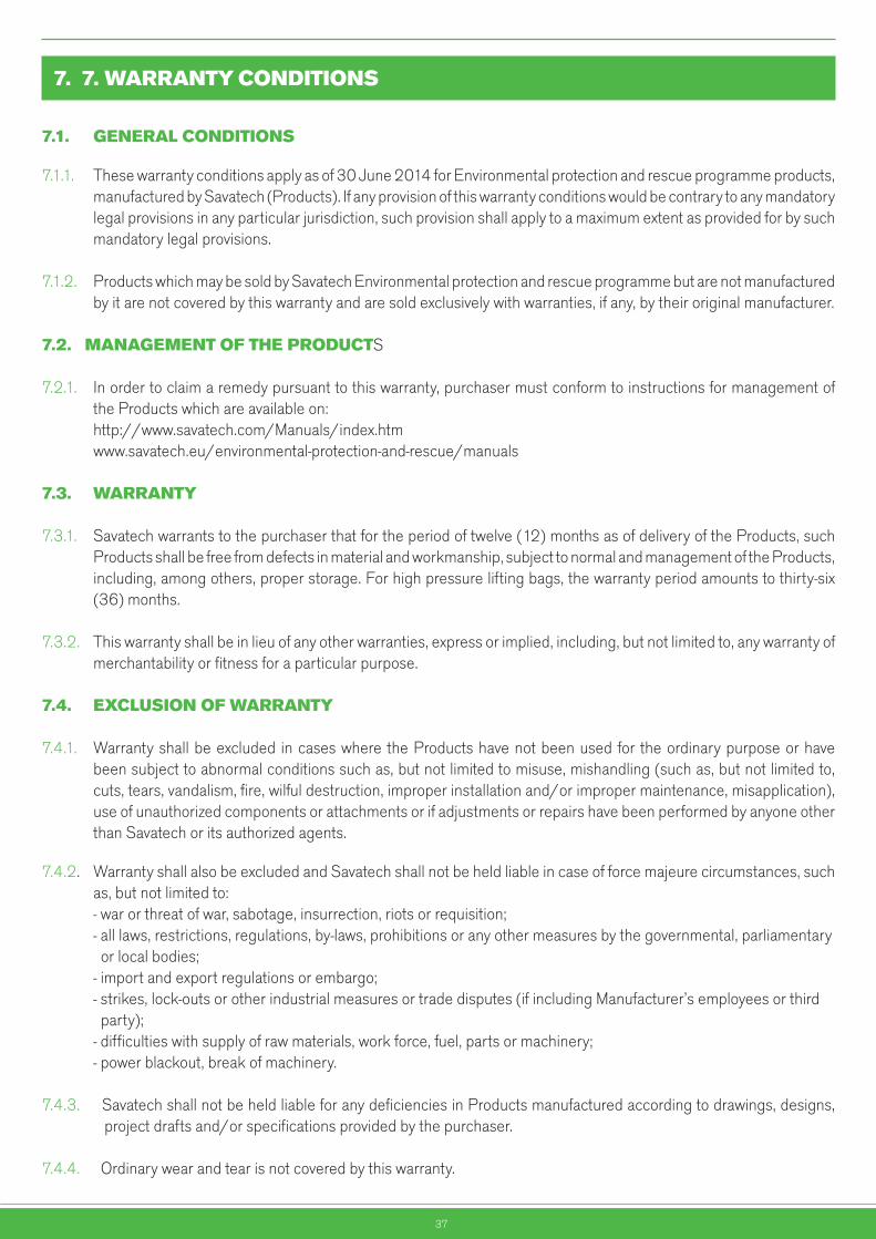
7.1.1. These warranty conditions apply as of 30 June 2014 for Environmental protection and rescue programme products, manufactured by Savatech (Products). If any provision of this warranty conditions would be contrary to any mandatory legal provisions in any particular jurisdiction, such provision shall apply to a maximum extent as provided for by such mandatory legal provisions.
7.1.2. Products which may be sold by Savatech Environmental protection and rescue programme but are not manufactured by it are not covered by this warranty and are sold exclusively with warranties, if any, by their original manufacturer.
7.2.MANAGEMENTOFTHEPRODUCTS 7.2.1. In order to claim a remedy pursuant to this warranty, purchaser must conform to instructions for management of the Products which are available on: http://www.savatech.com/Manuals/index.htm www.savatech.eu/environmental-protection-and-rescue/manuals
7.3. WARRANTY 7.3.1. Savatech warrants to the purchaser that for the period of twelve (12) months as of delivery of the Products, such Products shall be free from defects in material and workmanship, subject to normal and management of the Products, including, among others, proper storage. For high pressure lifting bags, the warranty period amounts to thirty-six (36) months.
7.3.2. This warranty shall be in lieu of any other warranties, express or implied, including, but not limited to, any warranty of merchantability or fitness for a particular purpose.
7.4. EXCLUSIONOFWARRANTY
7.4.1. Warranty shall be excluded in cases where the Products have not been used for the ordinary purpose or have been subject to abnormal conditions such as, but not limited to misuse, mishandling (such as, but not limited to, cuts, tears, vandalism, fire, wilful destruction, improper installation and/or improper maintenance, misapplication), use of unauthorized components or attachments or if adjustments or repairs have been performed by anyone other than Savatech or its authorized agents.
7.4.2. Warranty shall also be excluded and Savatech shall not be held liable in case of force majeure circumstances, such as, but not limited to: - war or threat of war, sabotage, insurrection, riots or requisition; - all laws, restrictions, regulations, by-laws, prohibitions or any other measures by the governmental, parliamentary or local bodies; - import and export regulations or embargo; - strikes, lock-outs or other industrial measures or trade disputes (if including Manufacturer’s employees or third party); - difficulties with supply of raw materials, work force, fuel, parts or machinery; - power blackout, break of machinery.
7.4.3. Savatech shall not be held liable for any deficiencies in Products manufactured according to drawings, designs, project drafts and/or specifications provided by the purchaser.
7.4.4. Ordinary wear and tear is not covered by this warranty.

38
7.5. MAKINGAWARRANTYCLAIM
7.5.1. Purchaser is obliged to take delivery of the Products and perform an ordinary inspection of the Product upon delivery.
7.5.2. Any claim by the purchaser with reference to the Products shall be deemed waived unless submitted in writing to Savatech within the earlier of (I) eight days as of the discovery of the defect, or (II) twelve months as of the date of delivery of the Products or thirty-six (36) months as of delivery of high pressure lifting bags. Discovery of the defect is deemed to have occurred when a defect could have reasonably been detected by the purchaser.
7.5.3. Claim must at least contain the following data: part number, serial number, description of defect, and must be substantiated by adequate evidence, such as pictures… Upon request, Savatech must be allowed to inspect the Product.
7.5.4. To obtain performance under this warranty, any products suspected of having a manufacturing defect in materials or workmanship shall be returned freight prepaid for inspection to SAVATECH d.o.o., Environmental protection and rescue programme, Škofjeloška c. 6, 4000 Kranj, Slovenia.
39
8. ENCLOSURES
8.1. BRIEFINSTRUCTIONSONUSINGTHESAVATECHLIFTINGBAG
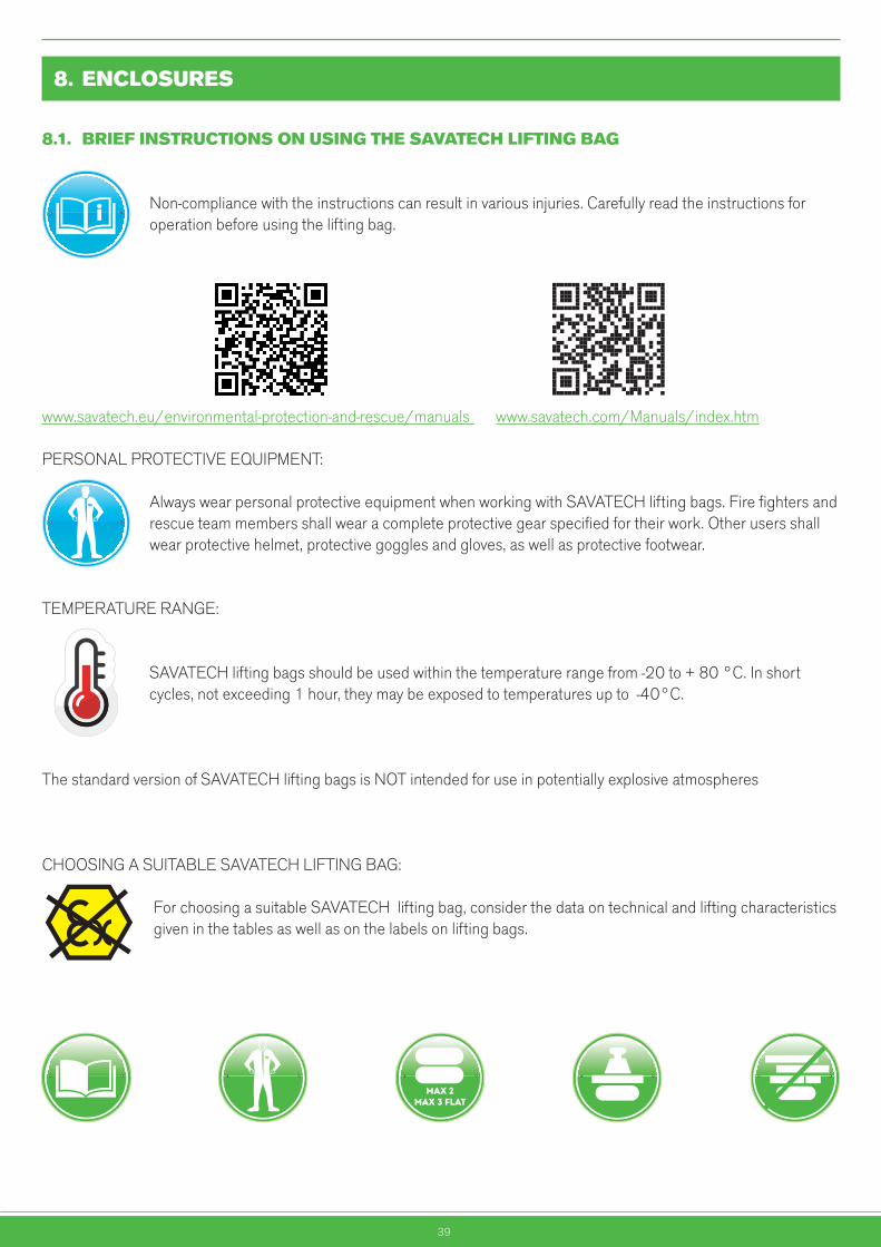
Non-compliance with the instructions can result in various injuries. Carefully read the instructions for operation before using the lifting bag.
www.savatech.eu/environmental-protection-and-rescue/manuals www.savatech.com/Manuals/index.htm
PERSONAL PROTECTIVE EQUIPMENT:
Always wear personal protective equipment when working with SAVATECH lifting bags. Fire fighters and rescue team members shall wear a complete protective gear specified for their work. Other users shall wear protective helmet, protective goggles and gloves, as well as protective footwear.
TEMPERATURE RANGE:
SAVATECH lifting bags should be used within the temperature range from -20 to + 80 °C. In short cycles, not exceeding 1 hour, they may be exposed to temperatures up to -40°C.
The standard version of SAVATECH lifting bags is NOT intended for use in potentially explosive atmospheres
CHOOSING A SUITABLE SAVATECH LIFTING BAG:
For choosing a suitable SAVATECH lifting bag, consider the data on technical and lifting characteristics given in the tables as well as on the labels on lifting bags.
MAX 2MAX 3 FLAT
MAX 2MAX 3 FLAT
MAX 2MAX 3 FLAT
MAX 2MAX 3 FLAT
MAX 2MAX 3 FLAT
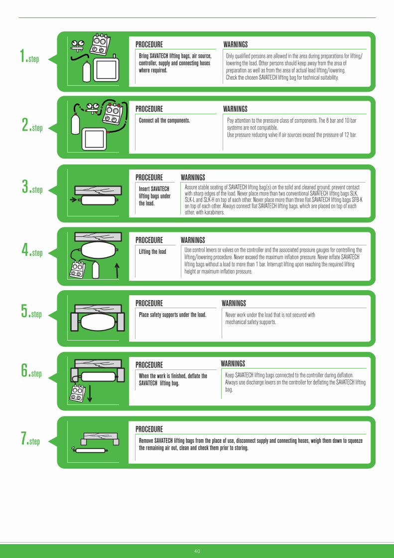
40
PROCEDURE WARNINGSOnly qualified persons are allowed in the area during preparations for lifting/ lowering the load. Other persons should keep away from the area of preparation as well as from the area of actual load lifting/lowering. Check the chosen SAVATECH lifting bag for technical suitability.
Bring SAVATECH lifting bags, air source, controller, supply and connecting hoses where required.
1.step
PROCEDURE WARNINGSPay attention to the pressure class of components. The 8 bar and 10 bar systems are not compatible.Use pressure reducing valve if air sources exceed the pressure of 12 bar.
Connect all the components. 2.step
PROCEDURE WARNINGSAssure stable seating of SAVATECH lifting bag(s) on the solid and cleaned ground; prevent contact with sharp edges of the load. Never place more than two conventional SAVATECH lifting bags SLK, SLK-L and SLK-H on top of each other. Never place more than three flat SAVATECH lifting bags SFB-K on top of each other. Always connect flat SAVATECH lifting bags, which are placed on top of each other, with karabiners.
Insert SAVATECHlifting bags underthe load.
3.step
PROCEDURE WARNINGSUse control levers or valves on the controller and the associated pressure gauges for controlling the lifting/lowering procedure. Never exceed the maximum inflation pressure. Never inflate SAVATECH lifting bags without a load to more than 1 bar. Interrupt lifting upon reaching the required lifting height or maximum inflation pressure.
Lifting the load 4.step
PROCEDURE WARNINGSNever work under the load that is not secured with mechanical safety supports.
WARNINGSKeep SAVATECH lifting bags connected to the controller during deflation.Always use discharge levers on the controller for deflating the SAVATECH lifting bag.
Place safety supports under the load.5.step
PROCEDUREWhen the work is finished, deflate the SAVATECH lifting bag.
6.step
PROCEDURERemove SAVATECH lifting bags from the place of use, disconnect supply and connecting hoses, weigh them down to squeeze the remaining air out, clean and check them prior to storing.
7.step

41
8.2. TESTREPORT:DATAABOUTTHETESTSPECIMENANDPERFOR
Testing of lifting bagsData about test specimen and test performance
Test date
Supervisor
Date of last test
User name
Test object
Accessories
Product Serial number Date of manufacture Remarks
Remarks:

42
8.3. TESTREPORT:VISUALCHECK-UPOFACCESSORIES
SAVA visual check-up of inflation device
YES NO
1. Pressure reducing valve
1.1 Sealing of connection with the cylinder
1.1.1 Threaded inflation connection on the cylinder undamaged
1.1.2 Both pressure gauges undamaged, maximum pressure markings in place
1.2.3 Protective caps of pressure gauges
1.2.4 Control lever for pressure regulator moves smoothly
1.2.5 Stop valve undamaged and operates smoothly
1.2.6 Air hose not torn, punctured or damaged, no stiff areas, consequence of acids, etc.
1.2.7 No visible damages on inflation connection
1.2.8 Hose is firmly connected
2. Supply hose, 5m, red
2.1 No visible defects on coupling
2.2 No visible defects on connection
2.3 Coupling and connection firmly connected
2.4 Hose not torn, punctured or damaged, no stiff areas, consequence of acids, etc.
3. Supply hose, 10m, blue
3.1 No visible defects on coupling
3.2 No visible defects on connection
3.3 Coupling and connection firmly connected
3.4 Hose not torn, punctured or damaged, no stiff areas, consequence of acids, etc.
4. ControllerF = fitting systemK = Deadman controller
4.1 Inlet coupling undamaged and operable
4.2 Stop valves (plug-in coupling) (F) and control levers (K) operate smoothly, no visible damages
4.3 Protective cap of pressure gauge available (F)
4.4 Maximum working pressure marking on pressure gauges (10 bar)
4.5 No damages on safety valves, washer in place
4.6 No visible defects on housing (K)
4.7 No visible defects on outlet couplings, operable

43
8.4. TESTREPORT:FUNCTIONTESTOFACCESSORIES
Function test
NOTE:If a doubt arises as to the safe testing of lifting bags, immediately interrupt the test and deliver lifting bags and equipment to the manufacturer for further testing.
INSTRUCTIONS:Function test may be carried out only after a successful visual test with zero defects.
Connect the pressure regulator to the compressed-air cylinder. Shut-off the stop valve on the pressure regulator. Open the valve on the compressed-air cylinder.
YES NO
Pressure gauge indicator displays pressure in the cylinder
Pressure gauge indicator displays reduced pressure
Pressure can be regulated throughout the area
Safety valve not activated at maximum pressure
Stop valve shuts-off and seals at maximum pressure
No strong pressure build-up within 5 minutes after the pressure is set to 4 bar
Connect the pressure regulator and the controller with the hose. Open stop valve on pressure regulator. Set the pressure to approximately 4 bar.
YES NO
Air hose and inlet coupling seal airtight
Connect supply hoses to the controller. Alternately, connect SAVA test pressure gauge with the stop valve on pressure regulator.Set pressure regulator to the maximum pressure.Carefully and slowly, open the ball valve as well as the rotary valve.
YES NO
Both couplings (controller and test pressure gauge) can be engaged or disengaged without difficulty
When opening the stop/rotary valve, the pressure gauge on the controller displays the pressure equal to the pressure on the test pressure gauge
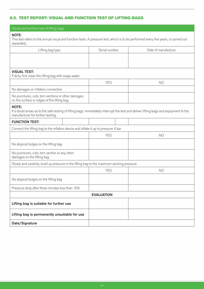
44
8.5. TESTREPORT:VISUALANDFUNCTIONTESTOFLIFTINGBAGS
Visual and function test of lifting bags
NOTE:This test refers to the annual visual and function tests. A pressure test, which is to be performed every five years, is carried out separately.
Lifting bag type Serial number Date of manufacture
VISUALTEST:If dirty, first clean the lifting bag with soapy water.
YES NO
No damages on inflation connection
No punctures, cuts, torn sections or other damages on the surface or edges of the lifting bag
NOTE:If a doubt arises as to the safe testing of lifting bags, immediately interrupt the test and deliver lifting bags and equipment to the manufacturer for further testing.
FUNCTIONTEST:
Connect the lifting bag to the inflation device and inflate it up to pressure 4 bar
YES NO
No atypical bulges on the lifting bag
No punctures, cuts, torn section or any other damages on the lifting bag
Slowly and carefully, build up pressure in the lifting bag to the maximum working pressure
YES NO
No atypical bulges on the lifting bag
Pressure drop after three minutes less than 10%
EVALUATION
Liftingbagissuitableforfurtheruse
Liftingbagispermanentlyunsuitableforuse
Date/Signature

45

Škofjeloška cesta 6, 4000 Kranj, SloveniaTel: +386 (0)4 206 60 80, +386 (0)4 206 61 49Fax: +386 (0)4 206 64 60e-mail: [email protected]://www.savatech.si
Škofjeloška cesta 6, 4000 Kranj, SloveniaTel: +386 (0)4 206 63 88Fax: +386 (0)4 206 64 60e-mail: [email protected] www.savatech.com