Embed Size (px)
Citation preview

ST100 SeriesThermal Mass Flow Meter
PROFIBUS PAManual
Fluid Components International LLC (FCI). All rights reserved.
ST100 Series Profibus PA
Fluid Components International LLC
Notice of Proprietary RightsThis document contains confidential technical data, including trade secrets and proprietary information which is the property of Fluid Components International LLC (FCI). Disclosure of this data to you is expressly conditioned upon your assent that its use is limited to use within your company only (and does not include manufacture or processing uses). Any other use is strictly prohibited without the prior written consent of FCI.
© Copyright 2011 by Fluid Components International LLC. All rights reserved. FCI is a registered trademark of Fluid Components International LLC. Information subject to change without notice.
Fluid Components International LLC i
ST100 Series Profibus PA 06EN003407 Rev. -
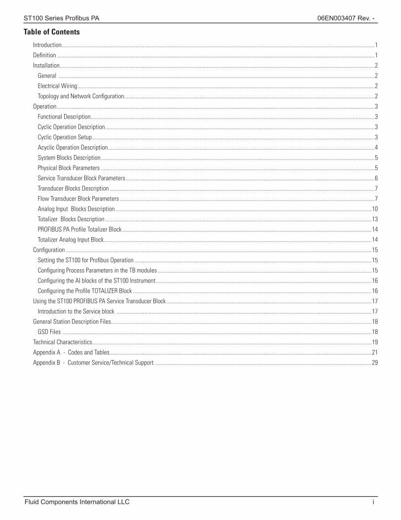
Table of Contents
Introduction .......................................................................................................................................................................................................................1
Definition ..........................................................................................................................................................................................................................1
Installation ........................................................................................................................................................................................................................2
General .........................................................................................................................................................................................................................2
Electrical Wiring ............................................................................................................................................................................................................2
Topology and Network Configuration ............................................................................................................................................................................2
Operation ..........................................................................................................................................................................................................................3
Functional Description...................................................................................................................................................................................................3
Cyclic Operation Description .........................................................................................................................................................................................3
Cyclic Operation Setup ..................................................................................................................................................................................................3
Acyclic Operation Description .......................................................................................................................................................................................4
System Blocks Description ............................................................................................................................................................................................5
Physical Block Parameters ............................................................................................................................................................................................5
Service Transducer Block Parameters ...........................................................................................................................................................................6
Transducer Blocks Description ......................................................................................................................................................................................7
Flow Transducer Block Parameters ...............................................................................................................................................................................7
Analog Input Blocks Description ................................................................................................................................................................................10
Totalizer Blocks Description .......................................................................................................................................................................................13
PROFIBUS PA Profile Totalizer Block ...........................................................................................................................................................................14
Totalizer Analog Input Block ........................................................................................................................................................................................14
Configuration ..................................................................................................................................................................................................................15
Setting the ST100 for Profibus Operation ...................................................................................................................................................................15
Configuring Process Parameters in the TB modules ...................................................................................................................................................15
Configuring the AI blocks of the ST100 Instrument ....................................................................................................................................................16
Configuring the Profile TOTALIZER Block ....................................................................................................................................................................16
Using the ST100 PROFIBUS PA Service Transducer Block .............................................................................................................................................17
Introduction to the Service block ...............................................................................................................................................................................17
General Station Description Files...................................................................................................................................................................................18
GSD Files ....................................................................................................................................................................................................................18
Technical Characteristics ................................................................................................................................................................................................19
Appendix A - Codes and Tables ....................................................................................................................................................................................21
Appendix B - Customer Service/Technical Support .....................................................................................................................................................29

ii Fluid Components International LLC
06EN003407 Rev. - ST100 Series Profius PA
INTENTIONALLY LEFT BLANK
ST100 Series Profibus PA
Fluid Components International LLC 1
IntroductionThis manual describes the ST100 PROFIBUS PA features, operation and configuration. The ST100 can provide up to 4 different process variables. It provides Flow, Temperature, Flow Totalizer, and Pressure, as outputs. The flow output can be selected as a volumetric flow, Mass flow or Velocity flow, depending on the model of the ST100. The basic ST100 can support up to two flow sensors and provides the average flow of the two sensors in a single output.
This document is written to be used with all members of the ST100 family of products that use the ST100 PROFIBUS PA digital communication Protocol.
The ST100 is compliant with the “PROFIBUS profile for Process Control Devices” specification Version 3.02. Profile: Multi-Variable Device.
The PROFIBUS PA is a master slave communication protocol. The ST100 with PROFIBUS PA has been configured as a “Multi-variable “ device. It implements both “Classical” and “Condensed” status and diagnostics. The ST100 PROFIBUS PA instrument also supports the Automatic Indent_Number adaptation feature.
The physical layer of the ST100 PROFIBUS PA instrument implements the H1 MBP interface; it operates at a baud rate of 31.25 Kbits/sec, and it supports power and signal on the same wires.
PROFIBUS PA is provided through an extension card that is fully integrated into the ST100 instrument.
DefinitionPhysical Block: This block describes the necessary parameters and functions of the device or the device hardware itself. Function Blocks: These blocks describe the functions of the device executing within the automation system. An example of a Function Block is the Analog Input (AI) block.
Transducer Block: This block contains the parameters of a device representing the necessary parameters and functions of the connection to the process. For example in the ST100 PROFIBUS PA the parameters are flow, temperature, FCI Totalizer, and pressure. The ST100 has two transducer blocks, Process TB and a Service TB. The Service TB is used for limited instrument configuration, some troubleshooting.
Analog Input (AI) Blocks: These blocks receive the ST100 Process Data Variables from the Process Data Transducer Block of the ST100 and make the process data of the ST100 available to other function blocks at the output.
There are 4 AI blocks in the ST100; Flow AI Block, Temperature AI Block, Totalizer AI Block, and Pressure AI block. Not all Process Variables are available in every member of the ST100 family.
Totalizer Blocks: The TOTALIZER block integrates (accumulates) the rate (i.e. Flow rate) to the corresponding integral. For example the ST100 offers two ways of providing the Totalize output of the Flow Rate; the FCI internally calculated “TOATLIZER” , or the PA Totalizer Function Block. The user can choose one or the other. Only one can be use at a time.
GSD Files: The GSD file is an electronic device data sheet or device data base file that identifies the ProfiBus device. All Profibus devices (class 1 masters and slaves) have their own GSD files.
FCI Configurator: A software tool that gives access to the ST100 functions and features. It facilitates basic instrument setup and configuration, as well as advance functions. The FCI configurator can interface through the ST100 USB Service port or the Ethernet Service port.
ST100 Series Profibus PA
2 Fluid Components International LLC
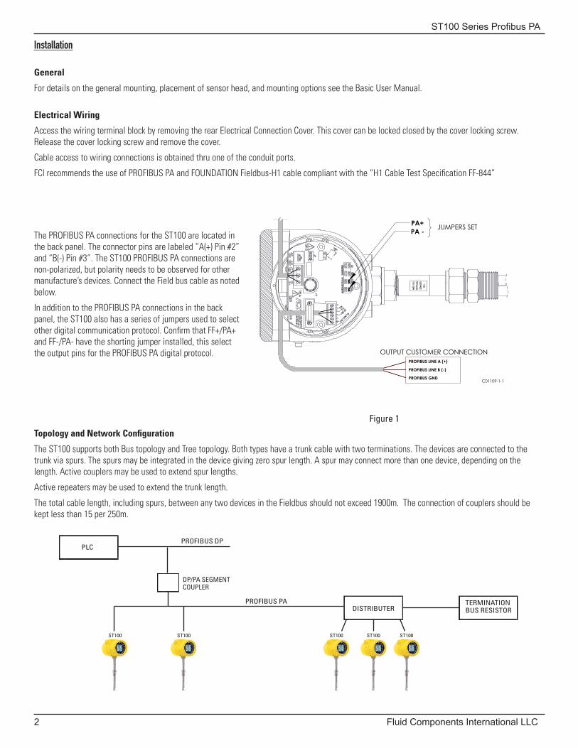
Topology and Network Configuration
The ST100 supports both Bus topology and Tree topology. Both types have a trunk cable with two terminations. The devices are connected to the trunk via spurs. The spurs may be integrated in the device giving zero spur length. A spur may connect more than one device, depending on the length. Active couplers may be used to extend spur lengths.
Active repeaters may be used to extend the trunk length.
The total cable length, including spurs, between any two devices in the Fieldbus should not exceed 1900m. The connection of couplers should be kept less than 15 per 250m.
Figure 1
Installation
General
For details on the general mounting, placement of sensor head, and mounting options see the Basic User Manual.
Electrical Wiring
Access the wiring terminal block by removing the rear Electrical Connection Cover. This cover can be locked closed by the cover locking screw.Release the cover locking screw and remove the cover.
Cable access to wiring connections is obtained thru one of the conduit ports.
FCI recommends the use of PROFIBUS PA and FOUNDATION Fieldbus-H1 cable compliant with the “H1 Cable Test Specification FF-844”
The PROFIBUS PA connections for the ST100 are located in the back panel. The connector pins are labeled “A(+) Pin #2” and “B(-) Pin #3”. The ST100 PROFIBUS PA connections are non-polarized, but polarity needs to be observed for other manufacture’s devices. Connect the Field bus cable as noted below.
In addition to the PROFIBUS PA connections in the back panel, the ST100 also has a series of jumpers used to select other digital communication protocol. Confirm that FF+/PA+ and FF-/PA- have the shorting jumper installed, this select the output pins for the PROFIBUS PA digital protocol.
PROFIBUS LINE A (+)
PROFIBUS LINE B (-)
PROFIBUS GND
PA+PA - JUMPERS SET
C01109-1-1
OUTPUT CUSTOMER CONNECTION
PLC
DISTRIBUTERTERMINATION BUS RESISTOR
DP/PA SEGMENT COUPLER
ST100 ST100 ST100 ST100 ST100
PROFIBUS DP
PROFIBUS PA
ST100 Series Profibus PA
Fluid Components International LLC 3
Operation
Functional Description
The ST100 is a Flowmeter with three flow classifications, volumetric flow, mass flow, and velocity flow. In addition, the ST100 family of instruments offers process temperature and process pressure.
The ST100 can support up to 2 flow sensors, the output is presented as an average of the two flow sensors. The ST100 has the capability of viewing the output of each sensor head.
In a two-sensor configuration, the cyclic data value for flow and temperature is the average of the two sensors.
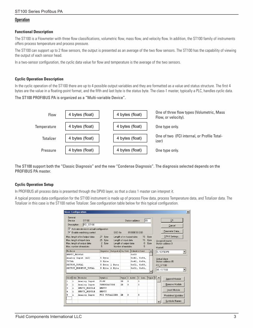
Cyclic Operation Description
In the cyclic operation of the ST100 there are up to 4 possible output variables and they are formatted as a value and status structure. The first 4 bytes are the value in a floating-point format, and the fifth and last byte is the status byte. The class-1 master, typically a PLC, handles cyclic data.
The ST100 PROFIBUS PA is organized as a “Multi-variable Device”.
Flow 4 bytes (float) 4 bytes (float) One of three flow types (Volumetric, Mass Flow, or velocity).
Temperature 4 bytes (float) 4 bytes (float) One type only.
Totalizer 4 bytes (float) 4 bytes (float) One of two (FCI internal, or Profile Total-izer)
Pressure 4 bytes (float) 4 bytes (float) One type only.
The ST100 support both the “Classic Diagnosis” and the new “Condense Diagnosis”. The diagnosis selected depends on the PROFIBUS PA master.
Cyclic Operation Setup
In PROFIBUS all process data is presented through the DPV0 layer, so that a class 1 master can interpret it.
A typical process data configuration for the ST100 instrument is made up of process Flow data, process Temperature data, and Totalizer data. The Totalizer in this case is the ST100 native Totalizer. See configuration table below for this typical configuration.
ST100 Series Profibus PA
4 Fluid Components International LLC
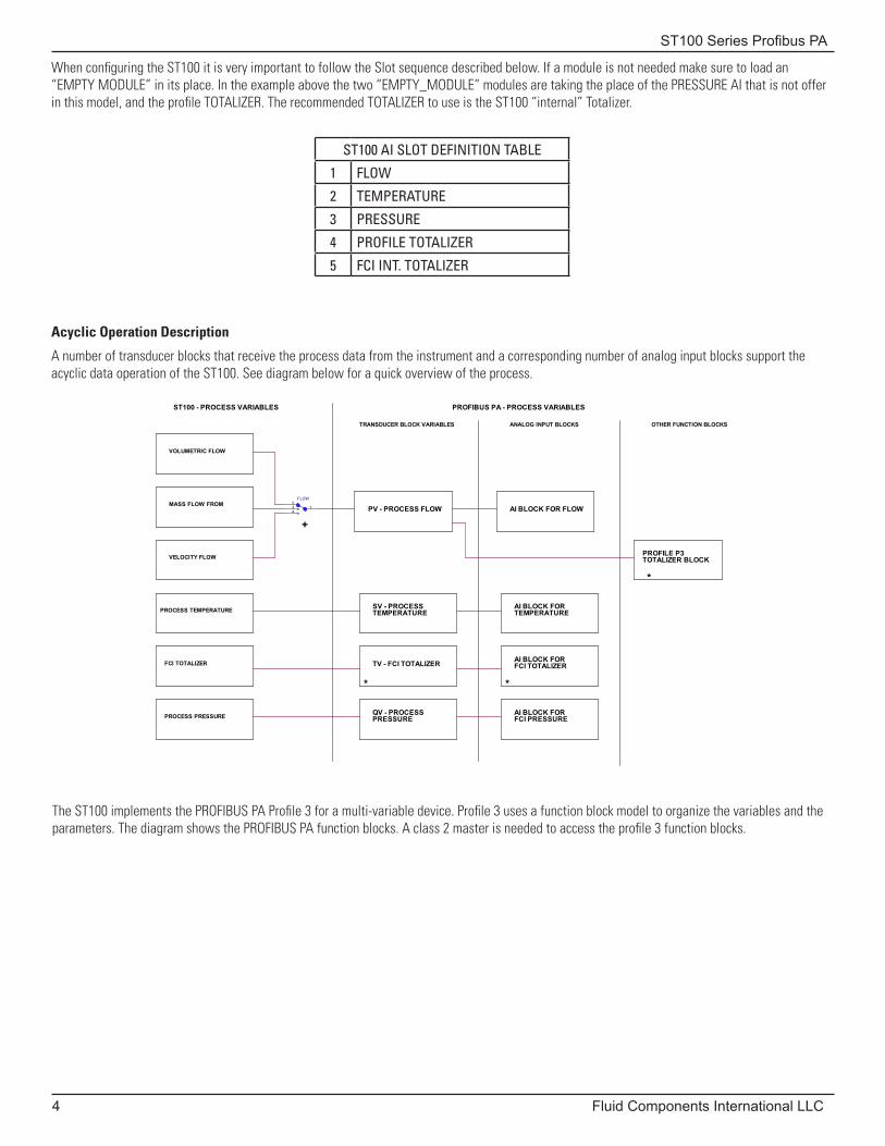
When configuring the ST100 it is very important to follow the Slot sequence described below. If a module is not needed make sure to load an “EMPTY MODULE” in its place. In the example above the two “EMPTY_MODULE” modules are taking the place of the PRESSURE AI that is not offer in this model, and the profile TOTALIZER. The recommended TOTALIZER to use is the ST100 “internal” Totalizer.
ST100 AI SLOT DEFINITION TABLE
1 FLOW
2 TEMPERATURE
3 PRESSURE
4 PROFILE TOTALIZER
5 FCI INT. TOTALIZER
Acyclic Operation Description
A number of transducer blocks that receive the process data from the instrument and a corresponding number of analog input blocks support the acyclic data operation of the ST100. See diagram below for a quick overview of the process.
The ST100 implements the PROFIBUS PA Profile 3 for a multi-variable device. Profile 3 uses a function block model to organize the variables and the parameters. The diagram shows the PROFIBUS PA function blocks. A class 2 master is needed to access the profile 3 function blocks.
PV - PROCESS FLOW
*
TV - FCI TOTALIZERFCI TOTALIZER
SV - PROCESSTEMPERATURE
AI BLOCK FOR FLOW
PROFIBUS PA - PROCESS VARIABLES
VOLUMETRIC FLOW
FLOW23 14
+
AI BLOCK FORTEMPERATURE
AI BLOCK FORFCI TOTALIZER
*
OTHER FUNCTION BLOCKS
AI BLOCK FORFCI PRESSURE
PROCESS TEMPERATURE
PROCESS PRESSURE
PROFILE P3TOTALIZER BLOCK
ST100 - PROCESS VARIABLES
VELOCITY FLOW
TRANSDUCER BLOCK VARIABLES
*
QV - PROCESSPRESSURE
MASS FLOW FROM
ANALOG INPUT BLOCKS
ST100 Series Profibus PA
Fluid Components International LLC 5
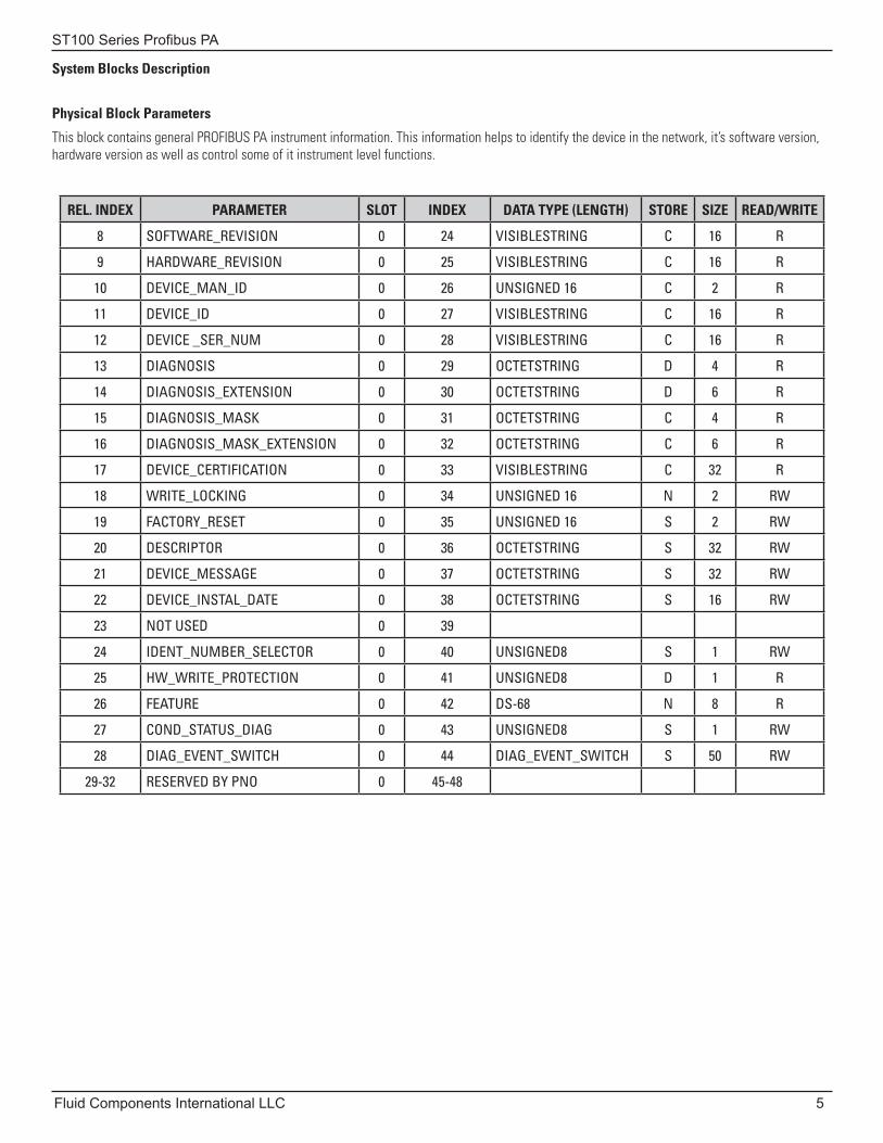
System Blocks Description
Physical Block Parameters
This block contains general PROFIBUS PA instrument information. This information helps to identify the device in the network, it’s software version, hardware version as well as control some of it instrument level functions.
REL. INDEX PARAMETER SLOT INDEX DATA TYPE (LENGTH) STORE SIZE READ/WRITE
8 SOFTWARE_REVISION 0 24 VISIBLESTRING C 16 R
9 HARDWARE_REVISION 0 25 VISIBLESTRING C 16 R
10 DEVICE_MAN_ID 0 26 UNSIGNED 16 C 2 R
11 DEVICE_ID 0 27 VISIBLESTRING C 16 R
12 DEVICE _SER_NUM 0 28 VISIBLESTRING C 16 R
13 DIAGNOSIS 0 29 OCTETSTRING D 4 R
14 DIAGNOSIS_EXTENSION 0 30 OCTETSTRING D 6 R
15 DIAGNOSIS_MASK 0 31 OCTETSTRING C 4 R
16 DIAGNOSIS_MASK_EXTENSION 0 32 OCTETSTRING C 6 R
17 DEVICE_CERTIFICATION 0 33 VISIBLESTRING C 32 R
18 WRITE_LOCKING 0 34 UNSIGNED 16 N 2 RW
19 FACTORY_RESET 0 35 UNSIGNED 16 S 2 RW
20 DESCRIPTOR 0 36 OCTETSTRING S 32 RW
21 DEVICE_MESSAGE 0 37 OCTETSTRING S 32 RW
22 DEVICE_INSTAL_DATE 0 38 OCTETSTRING S 16 RW
23 NOT USED 0 39
24 IDENT_NUMBER_SELECTOR 0 40 UNSIGNED8 S 1 RW
25 HW_WRITE_PROTECTION 0 41 UNSIGNED8 D 1 R
26 FEATURE 0 42 DS-68 N 8 R
27 COND_STATUS_DIAG 0 43 UNSIGNED8 S 1 RW
28 DIAG_EVENT_SWITCH 0 44 DIAG_EVENT_SWITCH S 50 RW
29-32 RESERVED BY PNO 0 45-48
ST100 Series Profibus PA
6 Fluid Components International LLC
REL. INDEX PARAMETER SLOT INDEX DATA TYPE (LENGTH) STORE SIZE READ/WRITE
8 FLOW_TYPE 10 24 UNSIGNED 8 D 1 RW
9 TOTALIZER_STATE 10 25 UNSIGNED 8 D 4 RW
10 PLENUM_SIZE_VALUE1 10 26 FLOAT D 4 RW
11 PLENUM_SIZE_VALUE2 10 27 FLOAT D 4 RW
12 WRITE_PROTECT_MODE 10 28 UNSIGNED 8 D 1 RW
13 FACTORY_RESTORE 10 29 UNSIGNED 8 D 1 RW
14 DEVICE_CO 10 30 OCTETSTRING D 10 R
15 DEVICE_SERIAL_NUM 10 31 OCTETSTRING D 10 R
16 DEVICE_SFTWR_VER 10 32 OCTETSTRING D 4 R
17 SENSORS_BANK_1 10 33 FLOAT D 48 R
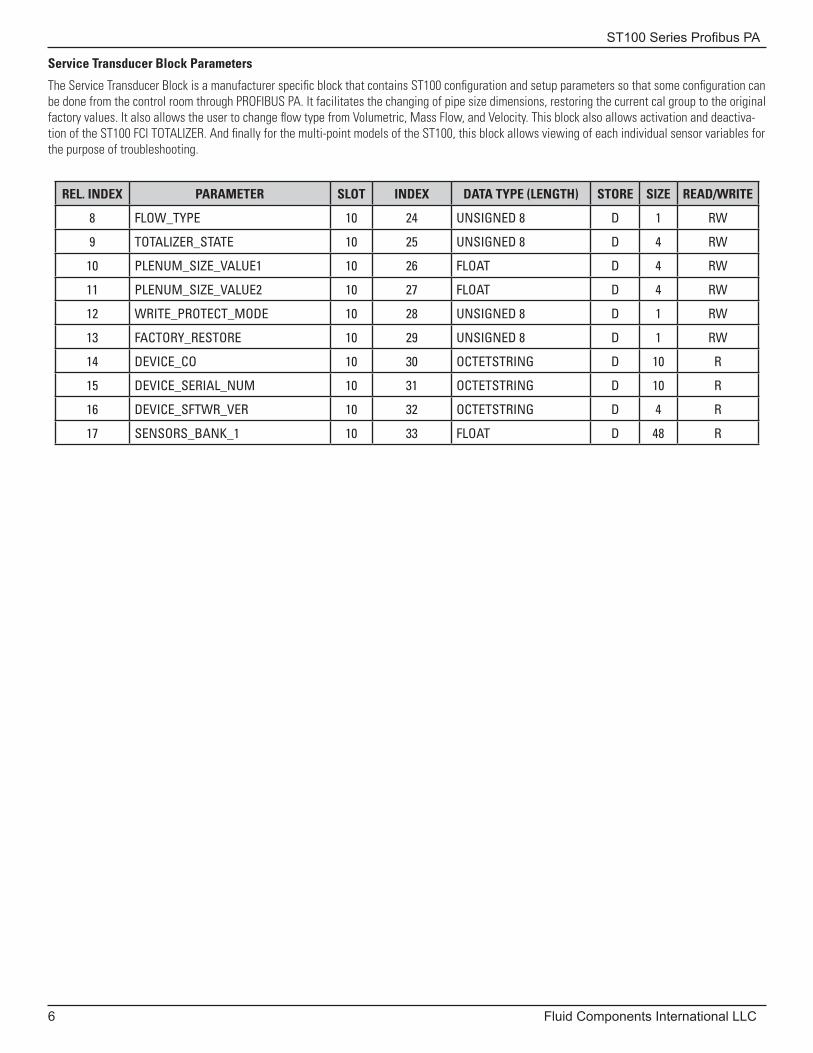
Service Transducer Block Parameters
The Service Transducer Block is a manufacturer specific block that contains ST100 configuration and setup parameters so that some configuration can be done from the control room through PROFIBUS PA. It facilitates the changing of pipe size dimensions, restoring the current cal group to the original factory values. It also allows the user to change flow type from Volumetric, Mass Flow, and Velocity. This block also allows activation and deactiva-tion of the ST100 FCI TOTALIZER. And finally for the multi-point models of the ST100, this block allows viewing of each individual sensor variables for the purpose of troubleshooting.
ST100 Series Profibus PA
Fluid Components International LLC 7
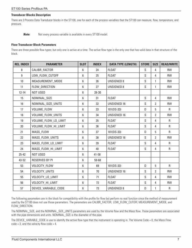
Transducer Blocks Description
There are 3 Process Data Transducer blocks in the ST100, one for each of the process variables that the ST100 can measure, flow, temperature, and pressure.
Note: Not every process variable is available in every ST100 model.
Flow Transducer Block Parameters
There are three possible flow types; but only one is active at a time. The active flow type is the only one that has valid data in that structure of the block.
REL. INDEX PARAMETER SLOT INDEX DATA TYPE (LENGTH) STORE SIZE READ/WRITE
8 CALIBR_FACTOR 6 24 FLOAT S 4 RW
9 LOW_FLOW_CUTOFF 6 25 FLOAT S 4 RW
10 MEASUREMENT_MODE 6 26 UNSIGNED 8 S 1 RW
11 FLOW_DIRECTION 6 27 UNSIGNED 8 S 1 RW
12-14 NOT USED 6 28-30
15 NOMINAL_SIZE 6 31 FLOAT S 4 RW
16 NOMINAL_SIZE_UNITS 6 32 UNSIGNED 16 S 2 RW
17 VOLUME_FLOW 6 33 101(DS-33) D 5 R
18 VOLUME_FLOW_UNITS 6 34 UNSIGNED 16 S 2 RW
19 VOLUME_FLOW_LO_LIMIT 6 35 FLOAT S 4 R
20 VOLUME_FLOW_HI_LIMIT 6 36 FLOAT S 4 R
21 MASS_FLOW 6 37 101(DS-33) D 5 R
22 MASS_FLOW_UNITS 6 38 UNSIGNED 16 S 2 RW
23 MASS_FLOW_LO_LIMIT 6 39 FLOAT S 4 R
24 MASS_FLOW_HI_LIMIT 6 40 FLOAT S 4 R
25-42 NOT USED 6 41-58
43-52 RESERVED BY PI 6 59-68
53 VELOCITY_FLOW 6 69 101(DS-33) D 5 R
54 VELOCITY_UNITS 6 70 UNSIGNED 16 S 2 RW
55 VELOCITY_LO_LIMIT 6 71 FLOAT S 4 RW
56 VELOCITY_HI_LIMIT 6 72 FLOAT S 4 RW
57 DEVICE_VARIABLE_CODE 6 73 UNSIGNED 8 D 1 R
The following parameters are in the block for compatibility with the profile for flow but perform no real function since the method of measurement used by the ST100 does not use those parameters. The parameters are CALIBR_FACTOR, LOW_FLOW_CUTOFF, MEASUREMENT_MODE, and FLOW_DIRECTION.
The NOMINAL_SIZE, and the NOMINAL_SIZE_UNITS parameters are used by the Volume flow and the Mass flow. These parameters are associated with the pipe dimensions and units. NOMINAL_SIZE is the diameter of the pipe.
The DEVICE_VARIABLE_CODE is use to identify the active flow type that the instrument is operating in. The Volume Code = 0, the Mass Flow code = 3, and the velocity flow code = 4.
ST100 Series Profibus PA
8 Fluid Components International LLC
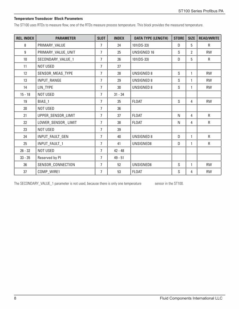
Temperature Transducer Block Parameters
The ST100 uses RTDs to measure flow, one of the RTDs measure process temperature. This block provides the measured temperature.
REL. INDEX PARAMETER SLOT INDEX DATA TYPE (LENGTH) STORE SIZE READ/WRITE
8 PRIMARY_VALUE 7 24 101(DS-33) D 5 R
9 PRIMARY_VALUE_UNIT 7 25 UNSIGNED 16 S 2 RW
10 SECONDARY_VALUE_1 7 26 101(DS-33) D 5 R
11 NOT USED 7 27
12 SENSOR_MEAS_TYPE 7 28 UNSIGNED 8 S 1 RW
13 INPUT_RANGE 7 29 UNSIGNED 8 S 1 RW
14 LIN_TYPE 7 30 UNSIGNED 8 S 1 RW
15 - 18 NOT USED 7 31 - 34
19 BIAS_1 7 35 FLOAT S 4 RW
20 NOT USED 7 36
21 UPPER_SENSOR_LIMIT 7 37 FLOAT N 4 R
22 LOWER_SENSOR_ LIMIT 7 38 FLOAT N 4 R
23 NOT USED 7 39
24 INPUT_FAULT_GEN 7 40 UNSIGNED 8 D 1 R
25 INPUT_FAULT_1 7 41 UNSIGNED8 D 1 R
26 - 32 NOT USED 7 42 - 48
33 - 35 Reserved by PI 7 49 - 51
36 SENSOR_CONNECTION 7 52 UNSIGNED8 S 1 RW
37 COMP_WIRE1 7 53 FLOAT S 4 RW
The SECONDARY_VALUE_1 parameter is not used, because there is only one temperature sensor in the ST100.
ST100 Series Profibus PA
Fluid Components International LLC 9
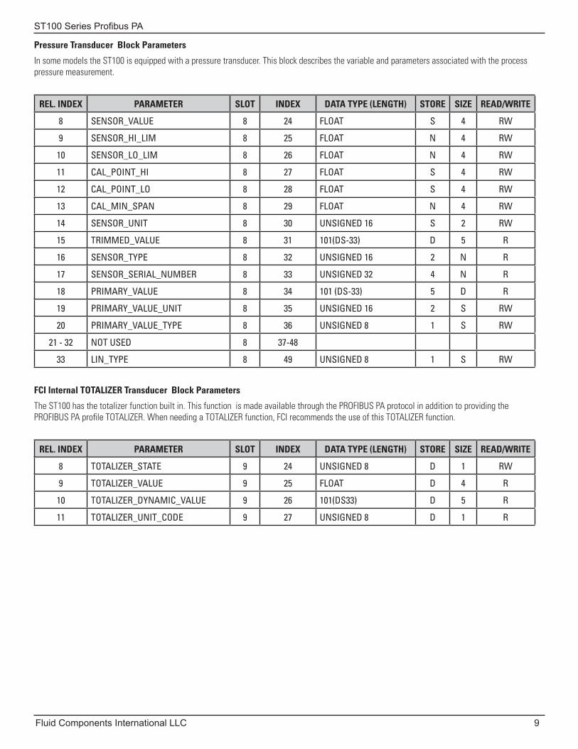
Pressure Transducer Block Parameters
In some models the ST100 is equipped with a pressure transducer. This block describes the variable and parameters associated with the process pressure measurement.
REL. INDEX PARAMETER SLOT INDEX DATA TYPE (LENGTH) STORE SIZE READ/WRITE
8 SENSOR_VALUE 8 24 FLOAT S 4 RW
9 SENSOR_HI_LIM 8 25 FLOAT N 4 RW
10 SENSOR_LO_LIM 8 26 FLOAT N 4 RW
11 CAL_POINT_HI 8 27 FLOAT S 4 RW
12 CAL_POINT_LO 8 28 FLOAT S 4 RW
13 CAL_MIN_SPAN 8 29 FLOAT N 4 RW
14 SENSOR_UNIT 8 30 UNSIGNED 16 S 2 RW
15 TRIMMED_VALUE 8 31 101(DS-33) D 5 R
16 SENSOR_TYPE 8 32 UNSIGNED 16 2 N R
17 SENSOR_SERIAL_NUMBER 8 33 UNSIGNED 32 4 N R
18 PRIMARY_VALUE 8 34 101 (DS-33) 5 D R
19 PRIMARY_VALUE_UNIT 8 35 UNSIGNED 16 2 S RW
20 PRIMARY_VALUE_TYPE 8 36 UNSIGNED 8 1 S RW
21 - 32 NOT USED 8 37-48
33 LIN_TYPE 8 49 UNSIGNED 8 1 S RW
FCI Internal TOTALIZER Transducer Block Parameters
The ST100 has the totalizer function built in. This function is made available through the PROFIBUS PA protocol in addition to providing the PROFIBUS PA profile TOTALIZER. When needing a TOTALIZER function, FCI recommends the use of this TOTALIZER function.
REL. INDEX PARAMETER SLOT INDEX DATA TYPE (LENGTH) STORE SIZE READ/WRITE
8 TOTALIZER_STATE 9 24 UNSIGNED 8 D 1 RW
9 TOTALIZER_VALUE 9 25 FLOAT D 4 R
10 TOTALIZER_DYNAMIC_VALUE 9 26 101(DS33) D 5 R
11 TOTALIZER_UNIT_CODE 9 27 UNSIGNED 8 D 1 R
ST100 Series Profibus PA
10 Fluid Components International LLC
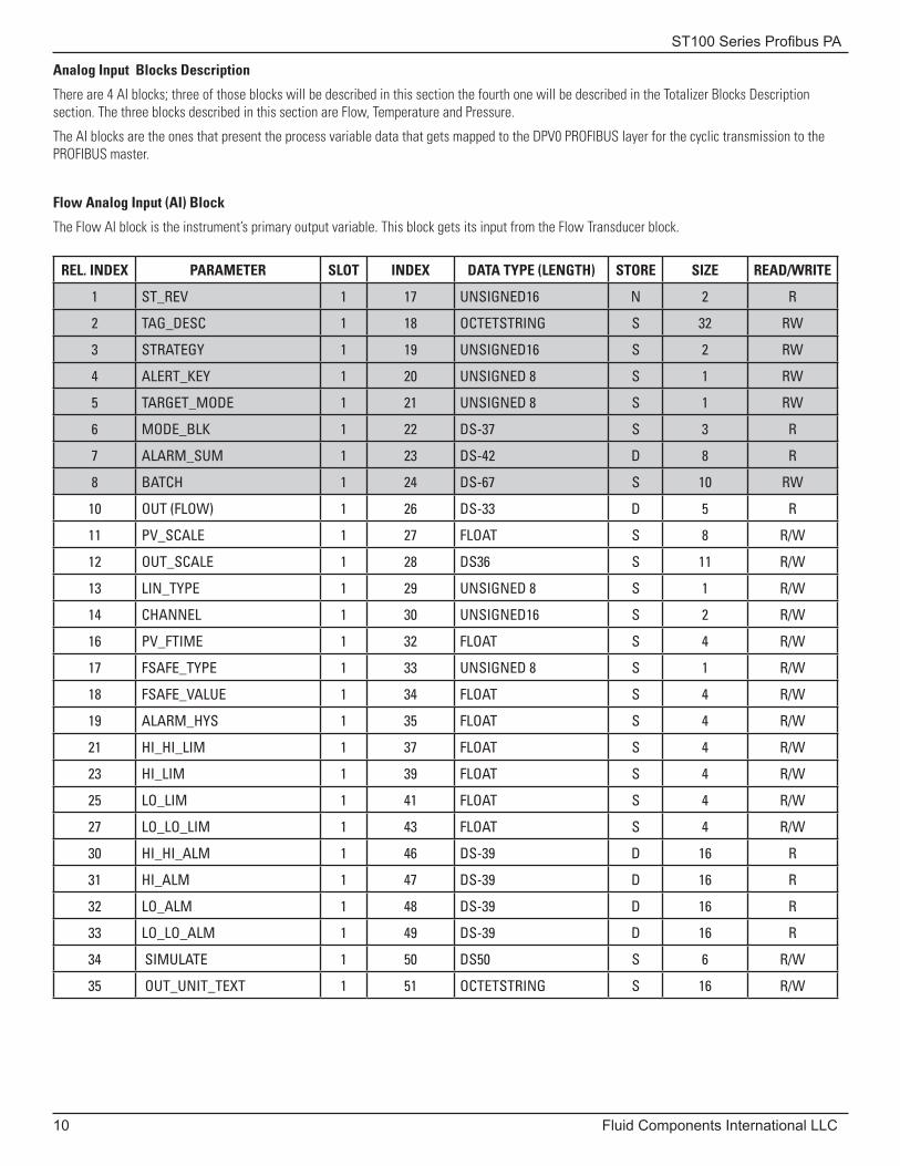
Analog Input Blocks Description
There are 4 AI blocks; three of those blocks will be described in this section the fourth one will be described in the Totalizer Blocks Description section. The three blocks described in this section are Flow, Temperature and Pressure.
The AI blocks are the ones that present the process variable data that gets mapped to the DPV0 PROFIBUS layer for the cyclic transmission to the PROFIBUS master.
Flow Analog Input (AI) Block
The Flow AI block is the instrument’s primary output variable. This block gets its input from the Flow Transducer block.
REL. INDEX PARAMETER SLOT INDEX DATA TYPE (LENGTH) STORE SIZE READ/WRITE
1 ST_REV 1 17 UNSIGNED16 N 2 R
2 TAG_DESC 1 18 OCTETSTRING S 32 RW
3 STRATEGY 1 19 UNSIGNED16 S 2 RW
4 ALERT_KEY 1 20 UNSIGNED 8 S 1 RW
5 TARGET_MODE 1 21 UNSIGNED 8 S 1 RW
6 MODE_BLK 1 22 DS-37 S 3 R
7 ALARM_SUM 1 23 DS-42 D 8 R
8 BATCH 1 24 DS-67 S 10 RW
10 OUT (FLOW) 1 26 DS-33 D 5 R
11 PV_SCALE 1 27 FLOAT S 8 R/W
12 OUT_SCALE 1 28 DS36 S 11 R/W
13 LIN_TYPE 1 29 UNSIGNED 8 S 1 R/W
14 CHANNEL 1 30 UNSIGNED16 S 2 R/W
16 PV_FTIME 1 32 FLOAT S 4 R/W
17 FSAFE_TYPE 1 33 UNSIGNED 8 S 1 R/W
18 FSAFE_VALUE 1 34 FLOAT S 4 R/W
19 ALARM_HYS 1 35 FLOAT S 4 R/W
21 HI_HI_LIM 1 37 FLOAT S 4 R/W
23 HI_LIM 1 39 FLOAT S 4 R/W
25 LO_LIM 1 41 FLOAT S 4 R/W
27 LO_LO_LIM 1 43 FLOAT S 4 R/W
30 HI_HI_ALM 1 46 DS-39 D 16 R
31 HI_ALM 1 47 DS-39 D 16 R
32 LO_ALM 1 48 DS-39 D 16 R
33 LO_LO_ALM 1 49 DS-39 D 16 R
34 SIMULATE 1 50 DS50 S 6 R/W
35 OUT_UNIT_TEXT 1 51 OCTETSTRING S 16 R/W
ST100 Series Profibus PA
Fluid Components International LLC 11
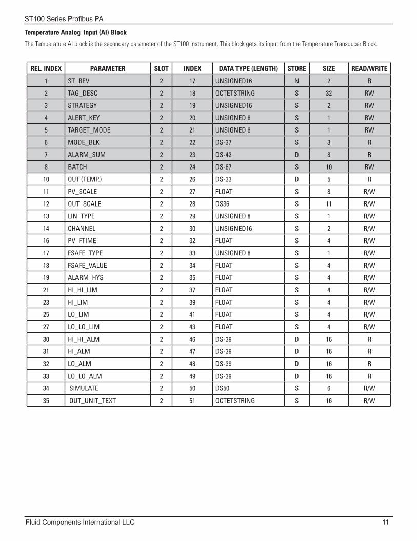
Temperature Analog Input (AI) Block
The Temperature AI block is the secondary parameter of the ST100 instrument. This block gets its input from the Temperature Transducer Block.
REL. INDEX PARAMETER SLOT INDEX DATA TYPE (LENGTH) STORE SIZE READ/WRITE
1 ST_REV 2 17 UNSIGNED16 N 2 R
2 TAG_DESC 2 18 OCTETSTRING S 32 RW
3 STRATEGY 2 19 UNSIGNED16 S 2 RW
4 ALERT_KEY 2 20 UNSIGNED 8 S 1 RW
5 TARGET_MODE 2 21 UNSIGNED 8 S 1 RW
6 MODE_BLK 2 22 DS-37 S 3 R
7 ALARM_SUM 2 23 DS-42 D 8 R
8 BATCH 2 24 DS-67 S 10 RW
10 OUT (TEMP.) 2 26 DS-33 D 5 R
11 PV_SCALE 2 27 FLOAT S 8 R/W
12 OUT_SCALE 2 28 DS36 S 11 R/W
13 LIN_TYPE 2 29 UNSIGNED 8 S 1 R/W
14 CHANNEL 2 30 UNSIGNED16 S 2 R/W
16 PV_FTIME 2 32 FLOAT S 4 R/W
17 FSAFE_TYPE 2 33 UNSIGNED 8 S 1 R/W
18 FSAFE_VALUE 2 34 FLOAT S 4 R/W
19 ALARM_HYS 2 35 FLOAT S 4 R/W
21 HI_HI_LIM 2 37 FLOAT S 4 R/W
23 HI_LIM 2 39 FLOAT S 4 R/W
25 LO_LIM 2 41 FLOAT S 4 R/W
27 LO_LO_LIM 2 43 FLOAT S 4 R/W
30 HI_HI_ALM 2 46 DS-39 D 16 R
31 HI_ALM 2 47 DS-39 D 16 R
32 LO_ALM 2 48 DS-39 D 16 R
33 LO_LO_ALM 2 49 DS-39 D 16 R
34 SIMULATE 2 50 DS50 S 6 R/W
35 OUT_UNIT_TEXT 2 51 OCTETSTRING S 16 R/W
ST100 Series Profibus PA
12 Fluid Components International LLC
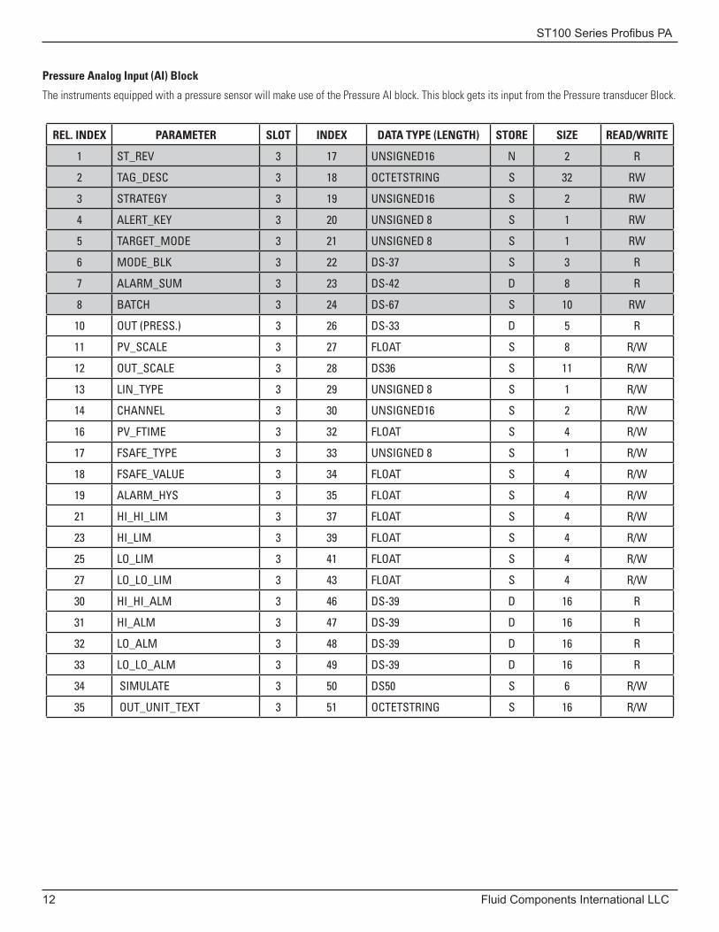
Pressure Analog Input (AI) Block
The instruments equipped with a pressure sensor will make use of the Pressure AI block. This block gets its input from the Pressure transducer Block.
REL. INDEX PARAMETER SLOT INDEX DATA TYPE (LENGTH) STORE SIZE READ/WRITE
1 ST_REV 3 17 UNSIGNED16 N 2 R
2 TAG_DESC 3 18 OCTETSTRING S 32 RW
3 STRATEGY 3 19 UNSIGNED16 S 2 RW
4 ALERT_KEY 3 20 UNSIGNED 8 S 1 RW
5 TARGET_MODE 3 21 UNSIGNED 8 S 1 RW
6 MODE_BLK 3 22 DS-37 S 3 R
7 ALARM_SUM 3 23 DS-42 D 8 R
8 BATCH 3 24 DS-67 S 10 RW
10 OUT (PRESS.) 3 26 DS-33 D 5 R
11 PV_SCALE 3 27 FLOAT S 8 R/W
12 OUT_SCALE 3 28 DS36 S 11 R/W
13 LIN_TYPE 3 29 UNSIGNED 8 S 1 R/W
14 CHANNEL 3 30 UNSIGNED16 S 2 R/W
16 PV_FTIME 3 32 FLOAT S 4 R/W
17 FSAFE_TYPE 3 33 UNSIGNED 8 S 1 R/W
18 FSAFE_VALUE 3 34 FLOAT S 4 R/W
19 ALARM_HYS 3 35 FLOAT S 4 R/W
21 HI_HI_LIM 3 37 FLOAT S 4 R/W
23 HI_LIM 3 39 FLOAT S 4 R/W
25 LO_LIM 3 41 FLOAT S 4 R/W
27 LO_LO_LIM 3 43 FLOAT S 4 R/W
30 HI_HI_ALM 3 46 DS-39 D 16 R
31 HI_ALM 3 47 DS-39 D 16 R
32 LO_ALM 3 48 DS-39 D 16 R
33 LO_LO_ALM 3 49 DS-39 D 16 R
34 SIMULATE 3 50 DS50 S 6 R/W
35 OUT_UNIT_TEXT 3 51 OCTETSTRING S 16 R/W
ST100 Series Profibus PA
Fluid Components International LLC 13
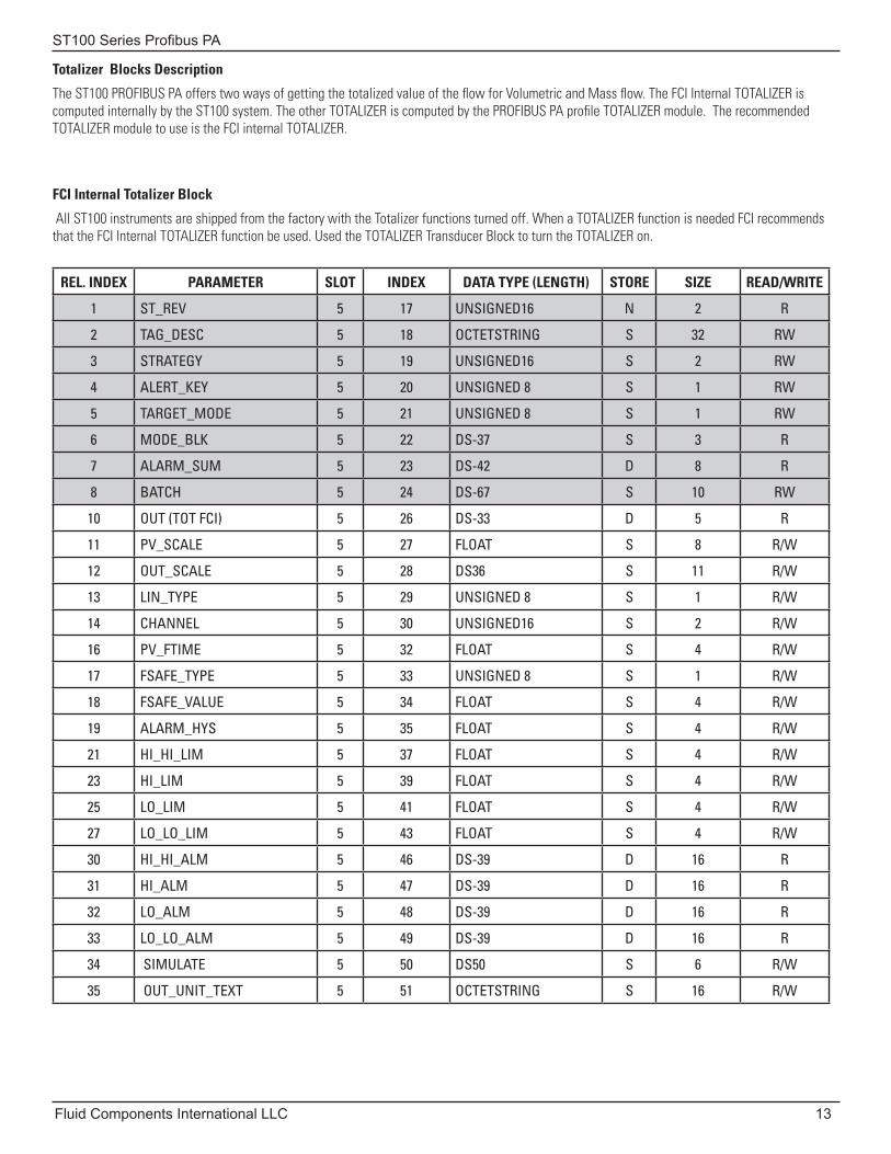
Totalizer Blocks Description
The ST100 PROFIBUS PA offers two ways of getting the totalized value of the flow for Volumetric and Mass flow. The FCI Internal TOTALIZER is computed internally by the ST100 system. The other TOTALIZER is computed by the PROFIBUS PA profile TOTALIZER module. The recommended TOTALIZER module to use is the FCI internal TOTALIZER.
FCI Internal Totalizer Block
All ST100 instruments are shipped from the factory with the Totalizer functions turned off. When a TOTALIZER function is needed FCI recommends that the FCI Internal TOTALIZER function be used. Used the TOTALIZER Transducer Block to turn the TOTALIZER on.
REL. INDEX PARAMETER SLOT INDEX DATA TYPE (LENGTH) STORE SIZE READ/WRITE
1 ST_REV 5 17 UNSIGNED16 N 2 R
2 TAG_DESC 5 18 OCTETSTRING S 32 RW
3 STRATEGY 5 19 UNSIGNED16 S 2 RW
4 ALERT_KEY 5 20 UNSIGNED 8 S 1 RW
5 TARGET_MODE 5 21 UNSIGNED 8 S 1 RW
6 MODE_BLK 5 22 DS-37 S 3 R
7 ALARM_SUM 5 23 DS-42 D 8 R
8 BATCH 5 24 DS-67 S 10 RW
10 OUT (TOT FCI) 5 26 DS-33 D 5 R
11 PV_SCALE 5 27 FLOAT S 8 R/W
12 OUT_SCALE 5 28 DS36 S 11 R/W
13 LIN_TYPE 5 29 UNSIGNED 8 S 1 R/W
14 CHANNEL 5 30 UNSIGNED16 S 2 R/W
16 PV_FTIME 5 32 FLOAT S 4 R/W
17 FSAFE_TYPE 5 33 UNSIGNED 8 S 1 R/W
18 FSAFE_VALUE 5 34 FLOAT S 4 R/W
19 ALARM_HYS 5 35 FLOAT S 4 R/W
21 HI_HI_LIM 5 37 FLOAT S 4 R/W
23 HI_LIM 5 39 FLOAT S 4 R/W
25 LO_LIM 5 41 FLOAT S 4 R/W
27 LO_LO_LIM 5 43 FLOAT S 4 R/W
30 HI_HI_ALM 5 46 DS-39 D 16 R
31 HI_ALM 5 47 DS-39 D 16 R
32 LO_ALM 5 48 DS-39 D 16 R
33 LO_LO_ALM 5 49 DS-39 D 16 R
34 SIMULATE 5 50 DS50 S 6 R/W
35 OUT_UNIT_TEXT 5 51 OCTETSTRING S 16 R/W
ST100 Series Profibus PA
14 Fluid Components International LLC
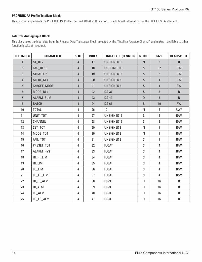
PROFIBUS PA Profile Totalizer Block
This function implements the PROFIBUS PA Profile specified TOTALIZER function. For additional information see the PROFIBUS PA standard.
Totalizer Analog Input Block
This block takes the input data from the Process Data Transducer Block, selected by the “Totalizer Average Channel” and makes it available to other function blocks at its output.
REL. INDEX PARAMETER SLOT INDEX DATA TYPE (LENGTH) STORE SIZE READ/WRITE
1 ST_REV 4 17 UNSIGNED16 N 2 R
2 TAG_DESC 4 18 OCTETSTRING S 32 RW
3 STRATEGY 4 19 UNSIGNED16 S 2 RW
4 ALERT_KEY 4 20 UNSIGNED 8 S 1 RW
5 TARGET_MODE 4 21 UNSIGNED 8 S 1 RW
6 MODE_BLK 4 22 DS-37 S 3 R
7 ALARM_SUM 4 23 DS-42 D 8 R
8 BATCH 4 24 DS-67 S 10 RW
10 TOTAL 4 26 101 N 5 RW*
11 UNIT_TOT 4 27 UNSIGNED16 S 2 R/W
12 CHANNEL 4 28 UNSIGNED16 S 2 R/W
13 SET_TOT 4 29 UNSIGNED 8 N 1 R/W
14 MODE_TOT 4 30 UNSIGNED 8 N 1 R/W
15 FAIL_TOT 4 31 UNSIGNED 8 S 1 R/W
16 PRESET_TOT 4 32 FLOAT S 4 R/W
17 ALARM_HYS 4 33 FLOAT S 4 R/W
18 HI_HI_LIM 4 34 FLOAT S 4 R/W
19 HI_LIM 4 35 FLOAT S 4 R/W
20 LO_LIM 4 36 FLOAT S 4 R/W
21 LO_LO_LIM 4 37 FLOAT S 4 R/W
22 HI_HI_ALM 4 38 DS-39 D 16 R
23 HI_ALM 4 39 DS-39 D 16 R
24 LO_ALM 4 40 DS-39 D 16 R
25 LO_LO_ALM 4 41 DS-39 D 16 R
ST100 Series Profibus PA
Fluid Components International LLC 15
ConfigurationFor details on the general mounting, placement of sensor head, and mounting options see the Installation, “Operation & Maintenance Manual” for the ST100 Series Thermal Mass Flow Meter, document number 06EN003400.
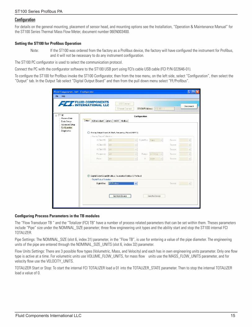
Setting the ST100 for Profibus Operation
Note: If the ST100 was ordered from the factory as a Profibus device, the factory will have configured the instrument for Profibus, and it will not be necessary to do any instrument configuration.
The ST100 PC configurator is used to select the communication protocol.
Connect the PC with the configurator software to the ST100 USB port using FCI’s cable USB cable (FCI P/N 022646-01).
To configure the ST100 for Profibus invoke the ST100 Configurator, then from the tree menu, on the left side, select “Configuration”, then select the “Output” tab. In the Output Tab select “Digital Output Board” and then from the pull down menu select “FF/Profibus”.
Configuring Process Parameters in the TB modules
The “Flow Transducer TB “ and the “Totalizer (FCI) TB” have a number of process related parameters that can be set within them. Theses parameters include “Pipe” size under the NOMINAL_SIZE parameter; three flow engineering unit types and the ability start and stop the ST100 internal FCI TOTALIZER.
Pipe Settings: The NOMINAL_SIZE (slot 6, index 31) parameter, in the “Flow TB”, is use for entering a value of the pipe diameter. The engineering units of the pipe are entered through the NOMINAL_SIZE_UNITS (slot 6, index 32) parameter.
Flow Units Settings: There are 3 possible flow types (Volumetric, Mass, and Velocity) and each has in own engineering units parameter. Only one flow type is active at a time. For volumetric units use VOLUME_FLOW_UNITS, for mass flow units use the MASS_FLOW_UNITS parameter, and for velocity flow use the VELOCITY_UNITS.
TOTALIZER Start or Stop: To start the internal FCI TOTALIZER load a 01 into the TOTALIZER_STATE parameter. Then to stop the internal TOTALIZER load a value of 0.
ST100 Series Profibus PA
16 Fluid Components International LLC
Configuring the AI blocks of the ST100 Instrument
The AI blocks are the ones that make the process variables available to the cyclic DPV0 layer of the PROFIBUS protocol. They are use to configure and set the way that the process data is presented. Each one of the AI blocks has been preset to the designated Transducer Block channel, and the default prescribed by the profile. These block are also use to set “process alarms”. The AI blocks configurable parameters are the ones designated by the last columns with a R/W definition in the AI block tables.
Note: Some of the settable parameters require putting the AI block in an “Out of Service” mode. In order to set the parameter to put the AI block in the OOS (Out of Service) mode you need to load the value of 80 in hex into the TARGET_MODE parameter. Then to return the AI block to the AUTO mode you need to load the hex value of 08 in to the TARGET_MODE.
Configuring the Profile TOTALIZER Block
When using the Profile TOTALIZER block confirm that the instrument flow is in volumetric or mass flow. There are 4 parameters that can be used to manipulate the operation of the Profile TOTALIZER.
SET_TOT: This parameter is used to set the Profile TOTALIZER block into the “normal” TOTALIZE mode using a value of 0. A value of 1 resets the TOTALIZER. A value of 2 presets the block.
MODE_TOT: This parameter controls the behavior of the totalization.
A value of 0: puts it into the BALANCED behavior.
A value of 1: puts it into the POS_ONLY totalization.
A Value of 2: puts it into the NEG_ONLY totalization.
A value of 3: puts it into the HOLD or stop behavior.
FAIL_TOT: This parameter sets the Fail-safe mode.
A value of 0: RUN - continue totalizing even if the input channel has a BAD status.
A value of 1: HOLD - Totalization stops when the input channel has a BAD status.
A value of 2: MEMORY - continue totalizing using last GOOD value when status is BAD.
PRESET_TOT: This parameter holds the value of the preset to be used by the PRESET mode.
ST100 Series Profibus PA
Fluid Components International LLC 17
Using the ST100 PROFIBUS PA Service Transducer Block
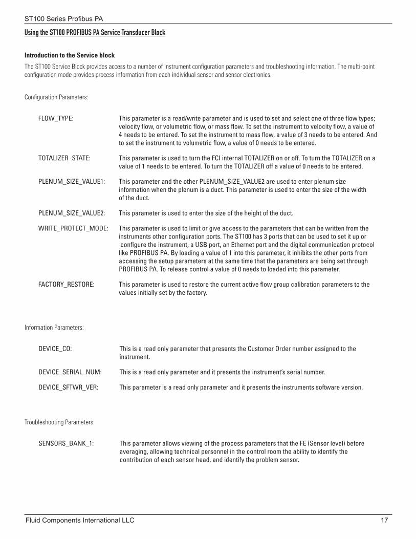
Introduction to the Service block
The ST100 Service Block provides access to a number of instrument configuration parameters and troubleshooting information. The multi-point configuration mode provides process information from each individual sensor and sensor electronics.
Configuration Parameters:
FLOW_TYPE: This parameter is a read/write parameter and is used to set and select one of three flow types; velocity flow, or volumetric flow, or mass flow. To set the instrument to velocity flow, a value of 4 needs to be entered. To set the instrument to mass flow, a value of 3 needs to be entered. And to set the instrument to volumetric flow, a value of 0 needs to be entered.
TOTALIZER_STATE: This parameter is used to turn the FCI internal TOTALIZER on or off. To turn the TOTALIZER on a value of 1 needs to be entered. To turn the TOTALIZER off a value of 0 needs to be entered.
PLENUM_SIZE_VALUE1: This parameter and the other PLENUM_SIZE_VALUE2 are used to enter plenum size information when the plenum is a duct. This parameter is used to enter the size of the width of the duct.
PLENUM_SIZE_VALUE2: This parameter is used to enter the size of the height of the duct.
WRITE_PROTECT_MODE: This parameter is used to limit or give access to the parameters that can be written from the instruments other configuration ports. The ST100 has 3 ports that can be used to set it up or configure the instrument, a USB port, an Ethernet port and the digital communication protocol like PROFIBUS PA. By loading a value of 1 into this parameter, it inhibits the other ports from accessing the setup parameters at the same time that the parameters are being set through PROFIBUS PA. To release control a value of 0 needs to loaded into this parameter.
FACTORY_RESTORE: This parameter is used to restore the current active flow group calibration parameters to the values initially set by the factory.
Information Parameters:
DEVICE_CO: This is a read only parameter that presents the Customer Order number assigned to the instrument.
DEVICE_SERIAL_NUM: This is a read only parameter and it presents the instrument’s serial number.
DEVICE_SFTWR_VER: This parameter is a read only parameter and it presents the instruments software version.
Troubleshooting Parameters:
SENSORS_BANK_1: This parameter allows viewing of the process parameters that the FE (Sensor level) before averaging, allowing technical personnel in the control room the ability to identify the contribution of each sensor head, and identify the problem sensor.
ST100 Series Profibus PA
18 Fluid Components International LLC
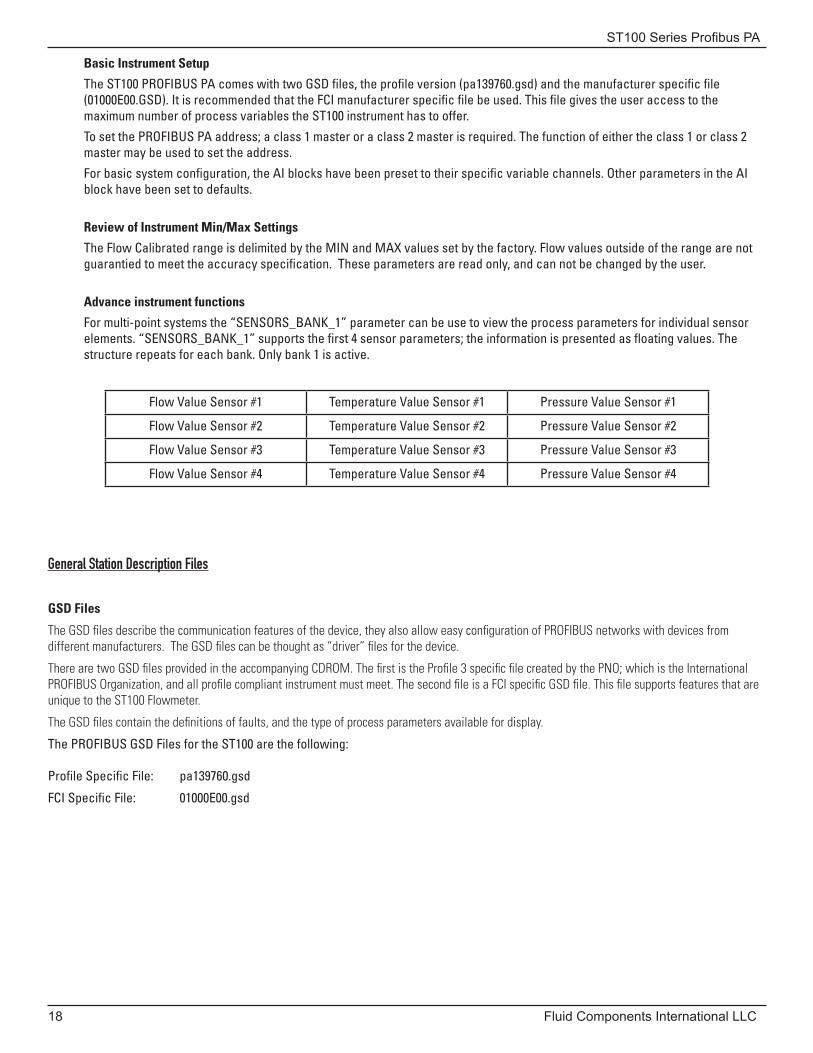
Basic Instrument Setup
The ST100 PROFIBUS PA comes with two GSD files, the profile version (pa139760.gsd) and the manufacturer specific file (01000E00.GSD). It is recommended that the FCI manufacturer specific file be used. This file gives the user access to the maximum number of process variables the ST100 instrument has to offer.
To set the PROFIBUS PA address; a class 1 master or a class 2 master is required. The function of either the class 1 or class 2 master may be used to set the address.
For basic system configuration, the AI blocks have been preset to their specific variable channels. Other parameters in the AI block have been set to defaults.
Review of Instrument Min/Max Settings
The Flow Calibrated range is delimited by the MIN and MAX values set by the factory. Flow values outside of the range are not guarantied to meet the accuracy specification. These parameters are read only, and can not be changed by the user.
Advance instrument functions
For multi-point systems the “SENSORS_BANK_1” parameter can be use to view the process parameters for individual sensor elements. “SENSORS_BANK_1” supports the first 4 sensor parameters; the information is presented as floating values. The structure repeats for each bank. Only bank 1 is active.
Flow Value Sensor #1 Temperature Value Sensor #1 Pressure Value Sensor #1
Flow Value Sensor #2 Temperature Value Sensor #2 Pressure Value Sensor #2
Flow Value Sensor #3 Temperature Value Sensor #3 Pressure Value Sensor #3
Flow Value Sensor #4 Temperature Value Sensor #4 Pressure Value Sensor #4
General Station Description Files
GSD Files
The GSD files describe the communication features of the device, they also allow easy configuration of PROFIBUS networks with devices from different manufacturers. The GSD files can be thought as “driver” files for the device.
There are two GSD files provided in the accompanying CDROM. The first is the Profile 3 specific file created by the PNO; which is the International PROFIBUS Organization, and all profile compliant instrument must meet. The second file is a FCI specific GSD file. This file supports features that are unique to the ST100 Flowmeter.
The GSD files contain the definitions of faults, and the type of process parameters available for display.
The PROFIBUS GSD Files for the ST100 are the following:
Profile Specific File: pa139760.gsd
FCI Specific File: 01000E00.gsd
ST100 Series Profibus PA
Fluid Components International LLC 19
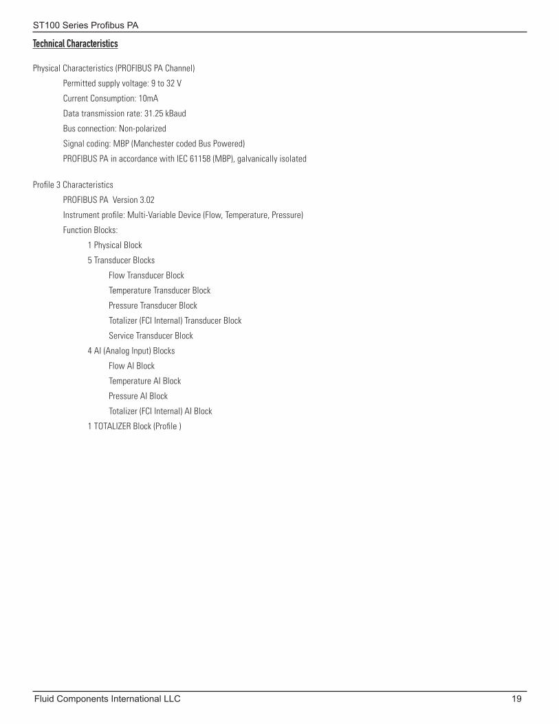
Technical Characteristics
Physical Characteristics (PROFIBUS PA Channel)
Permitted supply voltage: 9 to 32 V
Current Consumption: 10mA
Data transmission rate: 31.25 kBaud
Bus connection: Non-polarized
Signal coding: MBP (Manchester coded Bus Powered)
PROFIBUS PA in accordance with IEC 61158 (MBP), galvanically isolated
Profile 3 Characteristics
PROFIBUS PA Version 3.02
Instrument profile: Multi-Variable Device (Flow, Temperature, Pressure)
Function Blocks:
1 Physical Block
5 Transducer Blocks
Flow Transducer Block
Temperature Transducer Block
Pressure Transducer Block
Totalizer (FCI Internal) Transducer Block
Service Transducer Block
4 AI (Analog Input) Blocks
Flow AI Block
Temperature AI Block
Pressure AI Block
Totalizer (FCI Internal) AI Block
1 TOTALIZER Block (Profile )

ST100 Series Profibus PA
20 Fluid Components International LLC
INTENTIONALLY LEFT BLANK
ST100 Series Profibus PA
Fluid Components International LLC 21
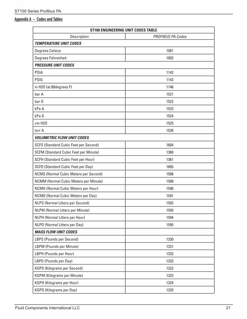
Appendix A - Codes and Tables
ST100 ENGINEERING UNIT CODES TABLE
Description PROFIBUS PA Codes
TEMPERATURE UNIT CODES
Degrees Celsius 1001
Degrees Fahrenheit 1002
PRESSURE UNIT CODES
PSIA 1142
PSIG 1143
in H2O (at 60degrees F) 1146
bar A 1521
bar G 1522
kPa A 1523
kPa G 1524
cm H2O 1525
torr A 1526
VOLUMETRIC FLOW UNIT CODES
SCFS (Standard Cubic Feet per Second) 1604
SCFM (Standard Cubic Feet per Minute) 1360
SCFH (Standard Cubic Feet per Hour) 1361
SCFD (Standard Cubic Feet per Day) 1605
NCMS (Normal Cubic Meters per Second) 1588
NCMM (Normal Cubic Meters per Minute) 1589
NCMH (Normal Cubic Meters per Hour) 1590
NCMD (Normal Cubic Meters per Day) 1591
NLPS (Normal Litters per Second) 1592
NLPM (Normal Litters per Minute) 1593
NLPH (Normal Litters per Hour) 1594
NLPD (Normal Litters per Day) 1595
MASS FLOW UNIT CODES
LBPS (Pounds per Second) 1330
LBPM (Pounds per Minute) 1331
LBPH (Pounds per Hour) 1332
LBPD (Pounds per Day) 1333
KGPS (Kilograms per Second) 1322
KGPM (Kilograms per Minute) 1323
KGPH (Kilograms per Hour) 1324
KGPD (Kilograms per Day) 1325
ST100 Series Profibus PA
22 Fluid Components International LLC
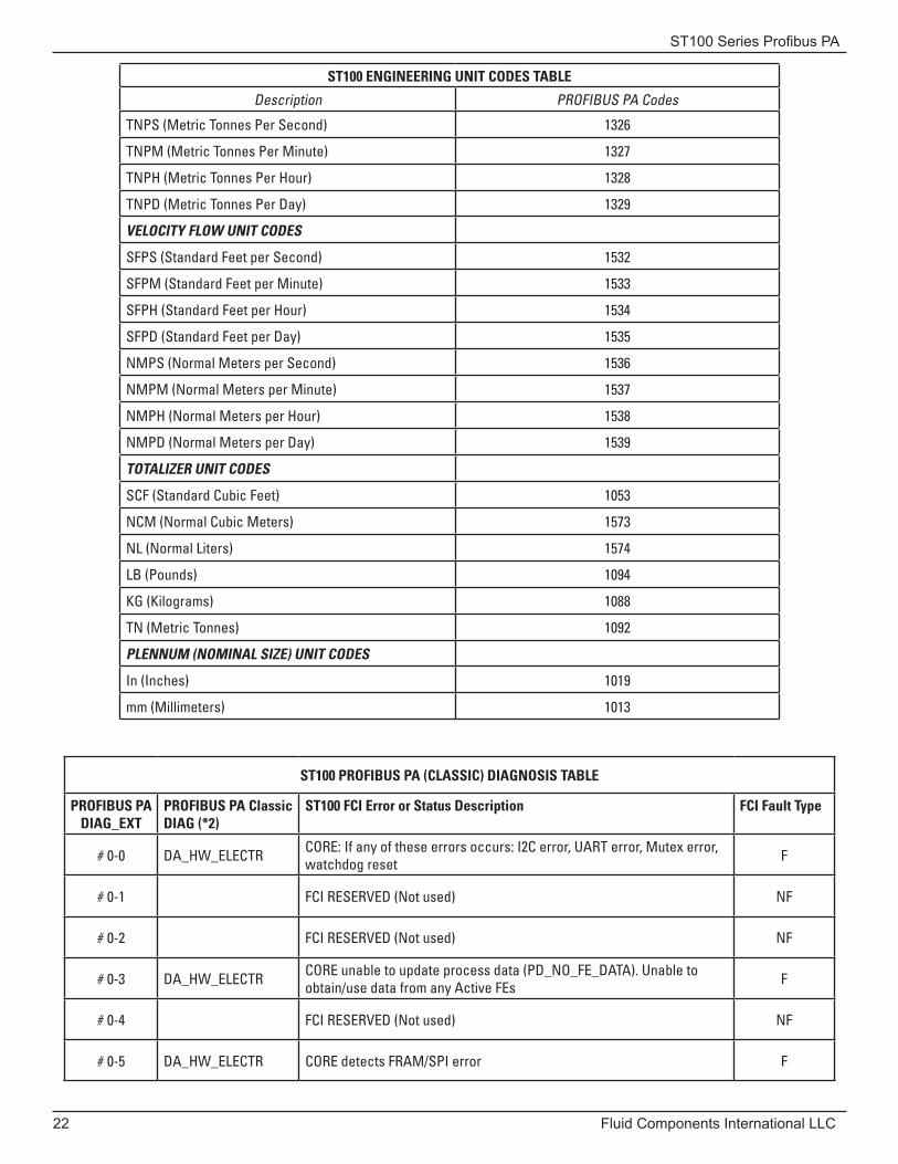
ST100 ENGINEERING UNIT CODES TABLE
Description PROFIBUS PA Codes
TNPS (Metric Tonnes Per Second) 1326
TNPM (Metric Tonnes Per Minute) 1327
TNPH (Metric Tonnes Per Hour) 1328
TNPD (Metric Tonnes Per Day) 1329
VELOCITY FLOW UNIT CODES
SFPS (Standard Feet per Second) 1532
SFPM (Standard Feet per Minute) 1533
SFPH (Standard Feet per Hour) 1534
SFPD (Standard Feet per Day) 1535
NMPS (Normal Meters per Second) 1536
NMPM (Normal Meters per Minute) 1537
NMPH (Normal Meters per Hour) 1538
NMPD (Normal Meters per Day) 1539
TOTALIZER UNIT CODES
SCF (Standard Cubic Feet) 1053
NCM (Normal Cubic Meters) 1573
NL (Normal Liters) 1574
LB (Pounds) 1094
KG (Kilograms) 1088
TN (Metric Tonnes) 1092
PLENNUM (NOMINAL SIZE) UNIT CODES
In (Inches) 1019
mm (Millimeters) 1013
ST100 PROFIBUS PA (CLASSIC) DIAGNOSIS TABLE
PROFIBUS PADIAG_EXT
PROFIBUS PA Classic DIAG (*2)
ST100 FCI Error or Status Description FCI Fault Type
# 0-0 DA_HW_ELECTR CORE: If any of these errors occurs: I2C error, UART error, Mutex error, watchdog reset F
# 0-1 FCI RESERVED (Not used) NF
# 0-2 FCI RESERVED (Not used) NF
# 0-3 DA_HW_ELECTR CORE unable to update process data (PD_NO_FE_DATA). Unable to obtain/use data from any Active FEs F
# 0-4 FCI RESERVED (Not used) NF
# 0-5 DA_HW_ELECTR CORE detects FRAM/SPI error F
ST100 Series Profibus PA
Fluid Components International LLC 23
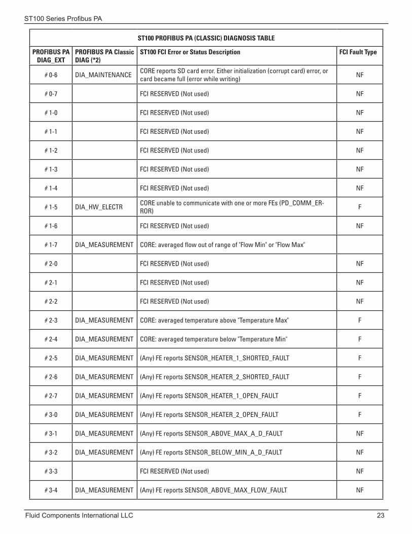
ST100 PROFIBUS PA (CLASSIC) DIAGNOSIS TABLE
PROFIBUS PADIAG_EXT
PROFIBUS PA Classic DIAG (*2)
ST100 FCI Error or Status Description FCI Fault Type
# 0-6 DIA_MAINTENANCE CORE reports SD card error. Either initialization (corrupt card) error, or card became full (error while writing) NF
# 0-7 FCI RESERVED (Not used) NF
# 1-0 FCI RESERVED (Not used) NF
# 1-1 FCI RESERVED (Not used) NF
# 1-2 FCI RESERVED (Not used) NF
# 1-3 FCI RESERVED (Not used) NF
# 1-4 FCI RESERVED (Not used) NF
# 1-5 DIA_HW_ELECTR CORE unable to communicate with one or more FEs (PD_COMM_ER-ROR) F
# 1-6 FCI RESERVED (Not used) NF
# 1-7 DIA_MEASUREMENT CORE: averaged flow out of range of "Flow Min" or "Flow Max"
# 2-0 FCI RESERVED (Not used) NF
# 2-1 FCI RESERVED (Not used) NF
# 2-2 FCI RESERVED (Not used) NF
# 2-3 DIA_MEASUREMENT CORE: averaged temperature above "Temperature Max" F
# 2-4 DIA_MEASUREMENT CORE: averaged temperature below "Temperature Min" F
# 2-5 DIA_MEASUREMENT (Any) FE reports SENSOR_HEATER_1_SHORTED_FAULT F
# 2-6 DIA_MEASUREMENT (Any) FE reports SENSOR_HEATER_2_SHORTED_FAULT F
# 2-7 DIA_MEASUREMENT (Any) FE reports SENSOR_HEATER_1_OPEN_FAULT F
# 3-0 DIA_MEASUREMENT (Any) FE reports SENSOR_HEATER_2_OPEN_FAULT F
# 3-1 DIA_MEASUREMENT (Any) FE reports SENSOR_ABOVE_MAX_A_D_FAULT NF
# 3-2 DIA_MEASUREMENT (Any) FE reports SENSOR_BELOW_MIN_A_D_FAULT NF
# 3-3 FCI RESERVED (Not used) NF
# 3-4 DIA_MEASUREMENT (Any) FE reports SENSOR_ABOVE_MAX_FLOW_FAULT NF
ST100 Series Profibus PA
24 Fluid Components International LLC
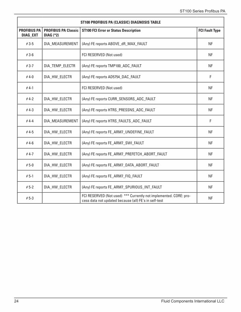
ST100 PROFIBUS PA (CLASSIC) DIAGNOSIS TABLE
PROFIBUS PADIAG_EXT
PROFIBUS PA Classic DIAG (*2)
ST100 FCI Error or Status Description FCI Fault Type
# 3-5 DIA_MEASUREMENT (Any) FE reports ABOVE_dR_MAX_FAULT NF
# 3-6 FCI RESERVED (Not used) NF
# 3-7 DIA_TEMP_ELECTR (Any) FE reports TMP100_ADC_FAULT NF
# 4-0 DIA_HW_ELECTR (Any) FE reports AD5754_DAC_FAULT F
# 4-1 FCI RESERVED (Not used) NF
# 4-2 DIA_HW_ELECTR (Any) FE reports CURR_SENSORS_ADC_FAULT NF
# 4-3 DIA_HW_ELECTR (Any) FE reports HTRS_PRESSNS_ADC_FAULT NF
# 4-4 DIA_MEASUREMENT (Any) FE reports HTRS_FAULTS_ADC_FAULT F
# 4-5 DIA_HW_ELECTR (Any) FE reports FE_ARM7_UNDEFINE_FAULT NF
# 4-6 DIA_HW_ELECTR (Any) FE reports FE_ARM7_SWI_FAULT NF
# 4-7 DIA_HW_ELECTR (Any) FE reports FE_ARM7_PREFETCH_ABORT_FAULT NF
# 5-0 DIA_HW_ELECTR (Any) FE reports FE_ARM7_DATA_ABORT_FAULT NF
# 5-1 DIA_HW_ELECTR (Any) FE reports FE_ARM7_FIQ_FAULT NF
# 5-2 DIA_HW_ELECTR (Any) FE reports FE_ARM7_SPURIOUS_INT_FAULT NF
# 5-3 FCI RESERVED (Not used) *** Currently not implemented. CORE: pro-cess data not updated because (all) FE's in self-test NF
ST100 Series Profibus PA
Fluid Components International LLC 25
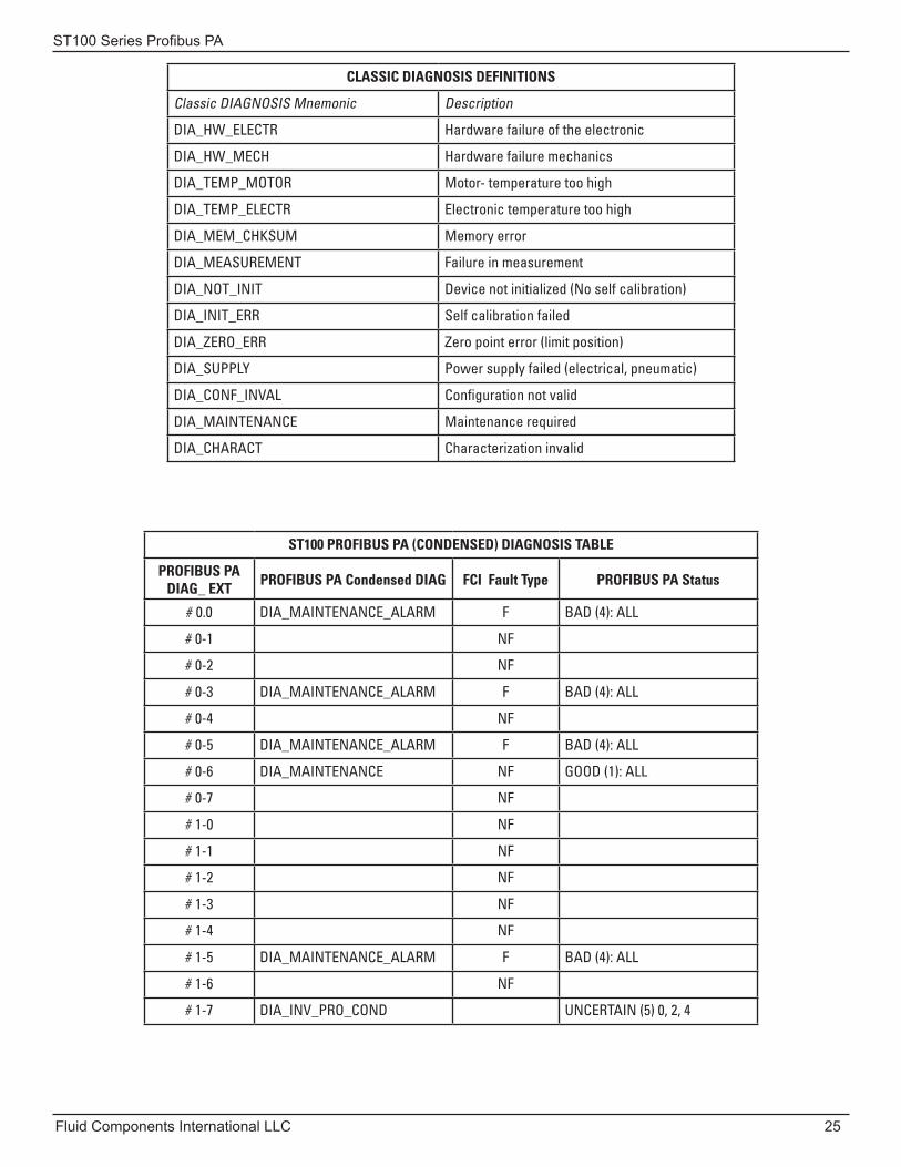
CLASSIC DIAGNOSIS DEFINITIONS
Classic DIAGNOSIS Mnemonic Description
DIA_HW_ELECTR Hardware failure of the electronic
DIA_HW_MECH Hardware failure mechanics
DIA_TEMP_MOTOR Motor- temperature too high
DIA_TEMP_ELECTR Electronic temperature too high
DIA_MEM_CHKSUM Memory error
DIA_MEASUREMENT Failure in measurement
DIA_NOT_INIT Device not initialized (No self calibration)
DIA_INIT_ERR Self calibration failed
DIA_ZERO_ERR Zero point error (limit position)
DIA_SUPPLY Power supply failed (electrical, pneumatic)
DIA_CONF_INVAL Configuration not valid
DIA_MAINTENANCE Maintenance required
DIA_CHARACT Characterization invalid
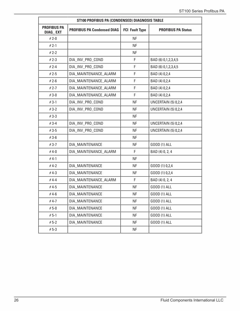
ST100 PROFIBUS PA (CONDENSED) DIAGNOSIS TABLE
PROFIBUS PA DIAG_ EXT PROFIBUS PA Condensed DIAG FCI Fault Type PROFIBUS PA Status
# 0.0 DIA_MAINTENANCE_ALARM F BAD (4): ALL
# 0-1 NF
# 0-2 NF
# 0-3 DIA_MAINTENANCE_ALARM F BAD (4): ALL
# 0-4 NF
# 0-5 DIA_MAINTENANCE_ALARM F BAD (4): ALL
# 0-6 DIA_MAINTENANCE NF GOOD (1): ALL
# 0-7 NF
# 1-0 NF
# 1-1 NF
# 1-2 NF
# 1-3 NF
# 1-4 NF
# 1-5 DIA_MAINTENANCE_ALARM F BAD (4): ALL
# 1-6 NF
# 1-7 DIA_INV_PRO_COND UNCERTAIN (5) 0, 2, 4
ST100 Series Profibus PA
26 Fluid Components International LLC
ST100 PROFIBUS PA (CONDENSED) DIAGNOSIS TABLE
PROFIBUS PA DIAG_ EXT PROFIBUS PA Condensed DIAG FCI Fault Type PROFIBUS PA Status
# 2-0 NF
# 2-1 NF
# 2-2 NF
# 2-3 DIA_INV_PRO_COND F BAD (6) 0,1,2,3,4,5
# 2-4 DIA_INV_PRO_COND F BAD (6) 0,1,2,3,4,5
# 2-5 DIA_MAINTENANCE_ALARM F BAD (4) 0,2,4
# 2-6 DIA_MAINTENANCE_ALARM F BAD (4) 0,2,4
# 2-7 DIA_MAINTENANCE_ALARM F BAD (4) 0,2,4
# 3-0 DIA_MAINTENANCE_ALARM F BAD (4) 0,2,4
# 3-1 DIA_INV_PRO_COND NF UNCERTAIN (5) 0,2,4
# 3-2 DIA_INV_PRO_COND NF UNCERTAIN (5) 0,2,4
# 3-3 NF
# 3-4 DIA_INV_PRO_COND NF UNCERTAIN (5) 0,2,4
# 3-5 DIA_INV_PRO_COND NF UNCERTAIN (5) 0,2,4
# 3-6 NF
# 3-7 DIA_MAINTENANCE NF GOOD (1) ALL
# 4-0 DIA_MAINTENANCE_ALARM F BAD (4) 0, 2, 4
# 4-1 NF
# 4-2 DIA_MAINTENANCE NF GOOD (1) 0,2,4
# 4-3 DIA_MAINTENANCE NF GOOD (1) 0,2,4
# 4-4 DIA_MAINTENANCE_ALARM F BAD (4) 0, 2, 4
# 4-5 DIA_MAINTENANCE NF GOOD (1) ALL
# 4-6 DIA_MAINTENANCE NF GOOD (1) ALL
# 4-7 DIA_MAINTENANCE NF GOOD (1) ALL
# 5-0 DIA_MAINTENANCE NF GOOD (1) ALL
# 5-1 DIA_MAINTENANCE NF GOOD (1) ALL
# 5-2 DIA_MAINTENANCE NF GOOD (1) ALL
# 5-3 NF
ST100 Series Profibus PA
Fluid Components International LLC 27
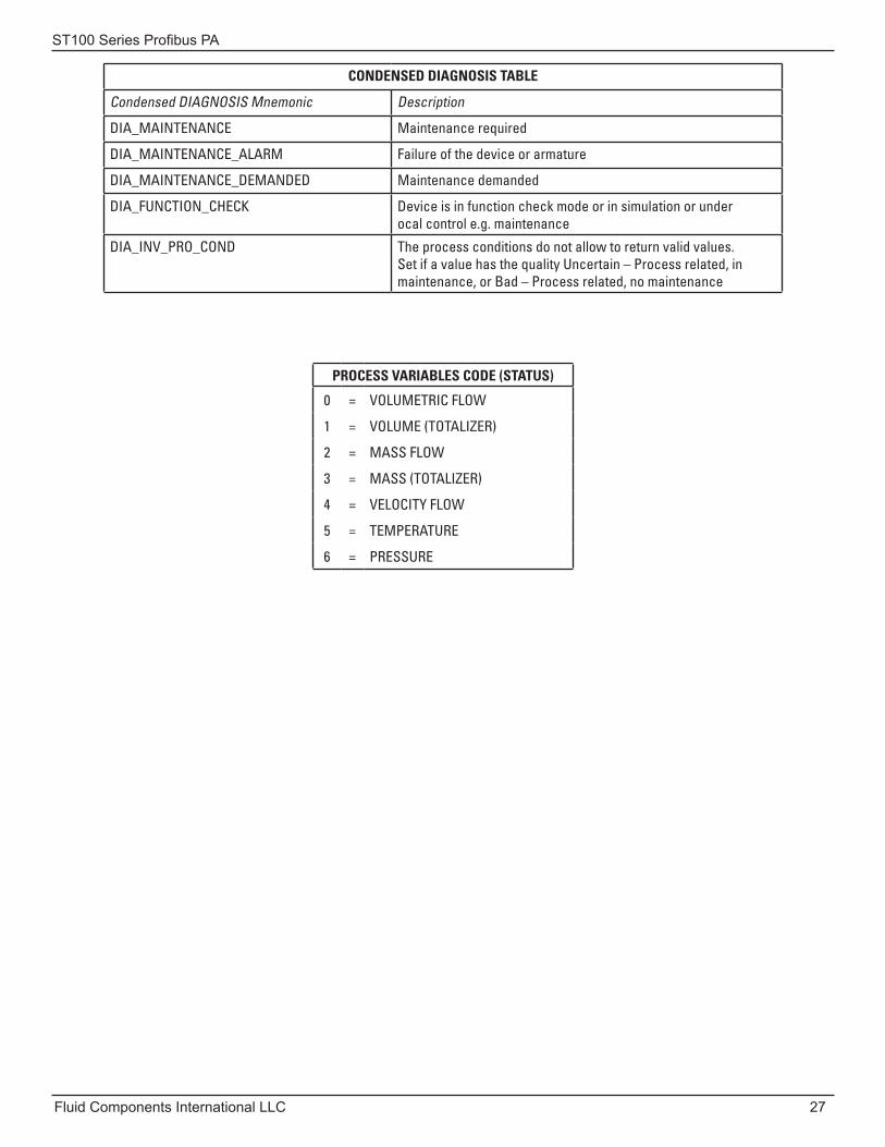
CONDENSED DIAGNOSIS TABLE
Condensed DIAGNOSIS Mnemonic Description
DIA_MAINTENANCE Maintenance required
DIA_MAINTENANCE_ALARM Failure of the device or armature
DIA_MAINTENANCE_DEMANDED Maintenance demanded
DIA_FUNCTION_CHECK Device is in function check mode or in simulation or under ocal control e.g. maintenance
DIA_INV_PRO_COND The process conditions do not allow to return valid values. Set if a value has the quality Uncertain – Process related, in maintenance, or Bad – Process related, no maintenance
PROCESS VARIABLES CODE (STATUS)
0 = VOLUMETRIC FLOW
1 = VOLUME (TOTALIZER)
2 = MASS FLOW
3 = MASS (TOTALIZER)
4 = VELOCITY FLOW
5 = TEMPERATURE
6 = PRESSURE

ST100 Series Profibus PA
28 Fluid Components International LLC
INTENTIONALLY LEFT BLANK
ST100 Series Profibus PA
Fluid Components International LLC 29
Appendix B - Customer Service/Technical SupportFCI provides full in-house technical support. Additional technical representation is also provided by FCI field representatives. Before contacting a field or in-house representative, please perform the troubleshooting techniques outlined in this document.
By MailFluid Components International LLC
1755 La Costa Meadows Dr.
San Marcos, CA 92078-5115 USA
Attn: Customer Service Department
By PhoneContact the area FCI regional representative. If a field representative is unable to be contacted or if a situation is unable to be resolved, contact the FCI Customer Service Department toll free at 1 (800) 854-1993.
By FaxTo describe problems in a graphical or pictorial manner, send a fax including a phone or fax number to the regional representative. Again, FCI is available by facsimile if all possibilities have been exhausted with the authorized factory representative. Our Fax number is 1 (760) 736-6250; it is available 7 days a week, 24 hours a day.
By E-MailFCI Customer Service can be contacted by e-mail at: [email protected].
Describe the problem in detail making sure a telephone number and best time to be contacted is stated in the e-mail.
International SupportFor product information or product support outside the contiguous United States, Alaska, or Hawaii, contact your country’s FCI International Representative or the one nearest to you.
After Hours SupportFor product information visit FCI’s Worldwide Web at www.fluidcomponents.com. For product support call 1 (800) 854-1993 and follow the prerecorded instructions.
Point of ContactThe point of contact for service, or return of equipment to FCI is your authorized FCI sales/service office. To locate the office nearest you, please go to www.fluidcomponents.com.
ST100 Series Profibus PA
30 Fluid Components International LLC
NOTES
ST100 Series Profibus PA
Fluid Components International LLC 31
INTENTIONALLY LEFT BLANK
Fluid Components International LLC
06EN003407 Rev. - ST100 Series Profibus PA
FCI’s Complete Customer Commitment. WorldwideISO 9001 and AS9100 Certified
Notice of Proprietary RightsThis document contains confidential technical data, including trade secrets and proprietary information which is the property of Fluid Components International LLC (FCI). Disclosure of this data to you is expressly conditioned upon your assent that its use is limited to use within your company only (and does not include manufacture or processing uses). Any other use is strictly prohibited without the prior written consent of FCI.
Visit FCI on the Worldwide Web: www.fluidcomponents.com
FCI World Headquarters1755 La Costa Meadows Drive | San Marcos, California 92078 USA | Phone: 760-744-6950 Toll Free (US): 800-854-1993 Fax: 760-736-6250
FCI EuropePersephonestraat 3-01 | 5047 TT Tilburg, The Netherlands | Phone: 31-13-5159989 Fax: 31-13-5799036
FCI Measurement and Control Technology (Beijing) Co., LTD | www.fluidcomponents.cnRoom 107, Xianfeng Building II, No.7 Kaituo Road, Shangdi IT Industry Base, Haidian District | Beijing 100085, P. R. ChinaPhone: 86-10-82782381 Fax: 86-10-58851152
© Copyright 2011 by Fluid Components International LLC. All rights reserved. FCI is a registered trademark of Fluid Components International LLC. Information subject to change without notice.