Embed Size (px)
Citation preview


Code Profile Diagram Remarks
Bore surface roughness
requirement
M
Outer metal case with rubber lining. Similar to design B but an additional rubber lining covering the internal face of the steel case. Particularly suitable for applications where corrosion could be a problem.
BC
J
Remark: “
“ ” r
Rubber and case covered O.D. This design provides the benefit of a metal-to metal press fit and the rubber O.D. sealing ability to counter rough or worn housings.
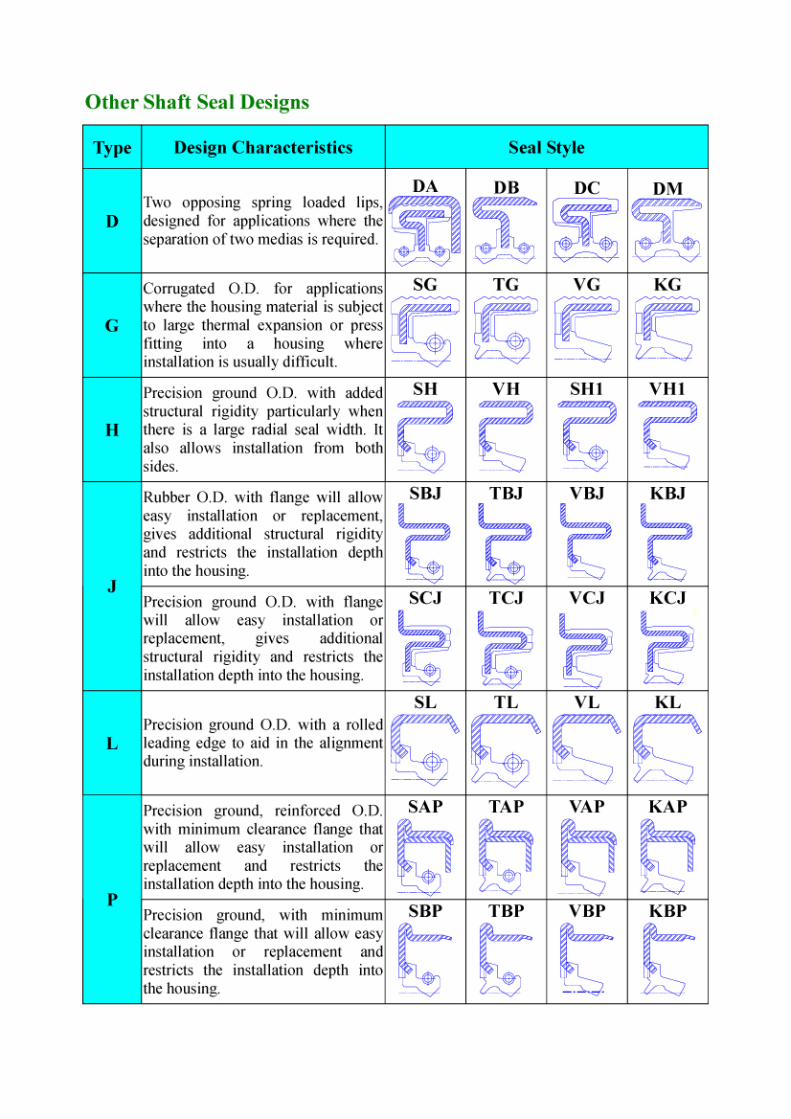
Rubber O.D. with flange
This design will allow easy installation or replacement, gives additional structural rigidity and restricts the installation depth into the housing.
” represents Ra 2.5 µm Max.
epresents Ra 3.75 µm Max.


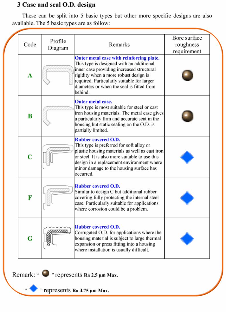
Seal lip with hydrodynamic aid design have greater pumping rate than normal seal
lip design (Figure 4-1).
0
0.1
0.2
0.3
0.4
0.5
0.6
0.7
0 500 1000 1500 2000 2500 3000 3500 4000SHAFT SPEED-RPM
PUM
P R
ATE
-CC
/MIN
ONE-DIRECTIONBI-BIRECTIONWITHOUT-AIDS
<Figure 4-1> Measured pump rate for various hydrodynamic design.
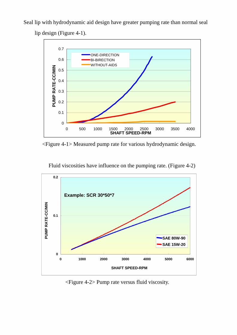
Fluid viscosities have influence on the pumping rate. (Figure 4-2)
Example: SCR 30*50*7
0
0.1
0.2
0 1000 2000 3000 4000 5000 6000
SHAFT SPEED-RPM
PUM
P R
ATE
-CC
/MIN
SAE 80W-90SAE 15W-20
<Figure 4-2> Pump rate versus fluid viscosity.

(1). Bi-directional:W type ⇔
Type Helix Profile Diagram
Lip Profile Diagram
Type Helix Profile Diagram
Lip Profile Diagram
W
W6
W1
W7
W2
W8
W3
W9
W4
W10
W5
W11

Type Helix Profile Diagram
Lip Profile Diagram
Type Helix Profile Diagram
Lip Profile Diagram
W12
W18
W13
W19
W14
W20
W15
W21
W16
W22
W17
W23

Type Helix Profile Diagram
Lip Profile Diagram
W24
(2). One-directional:L type ⇐
Type Helix Profile Diagram
Lip Profile Diagram
Type Helix Profile Diagram
Lip Profile Diagram
L
L3
L1
L4
L2
L5

Type Helix Profile Diagram
Lip Profile Diagram
Type Helix Profile Diagram
Lip Profile Diagram
L6
L9
L8
L10
(3). One-directional:L type ⇒
Type Helix Profile Diagram
Lip Profile Diagram
Type Helix Profile Diagram
Lip Profile Diagram
R
R3
R1
R4
R2
R6


Capacity Type
Speed (m/s) Pressure (bar)
Run-out (mm)
STBM (mm)
TC4P
TC4P
0.28 Max. 25 Max. -- 0.30 Mx.
TC-PL
TB-PL
30 Max. 0.5 Max. 0.25 Max. 0.25 Max.
15 Max. 3 Max. PA1
PA2
5 Max. 1 Max.
0.20 Max. 0.40 Max.
DC
DM
10 Max. 0.3 Max. 0.25 Max. 0.25 Max.
OSC
OSM
10 Max. 0.3 Max. 0.25 Max. 0.25 Max.
CNB
CNB2
0.075 Max.
98 Max. (NBR)
157 Max. (HNBR)
-- 0.30 Max.

Capacity Type
Speed (m/s) Pressure (bar)
Run-out (mm)
STBM (mm)
0.2 Max. 6.5 Max.
0.6 Max. 4.4 Max.
1.0 Max. 2.5 Max.
TC4
TC4S
1.5 Max. 1.6 Max.
-- 0.20 Max.