Embed Size (px)
Citation preview
Program 60-411—Hob Cutting Pattern for External Involute Gear
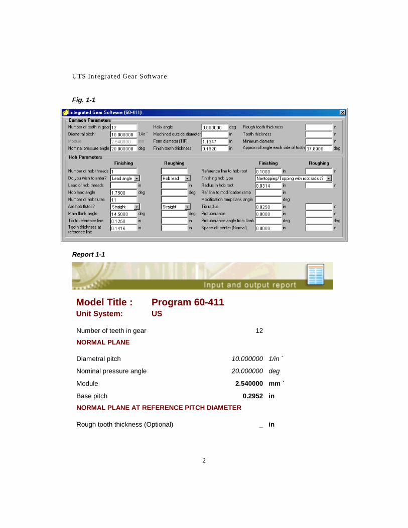
Introduction This model will plot the transverse plane projection of the positions of the cutting edges of a hob. (The transverse plane is the plane of rotation of the gear.) It may be used to evaluate the suitability of a hob for the production of a gear. The hob may have a “nominal” flank angle or may be an “off-lead” hob with a different flank angle. Non-topping, semi-topping, topping or tip relief hobs may be used. If a roughing hob is used prior to a semi-finishing or finishing hob, the model will provide a plot of both profile patterns. Some of the data controlling features on the plot are optional: Use of a roughing hob Rough hobbing tooth thickness Machined outside diameter Required form diameter Examples Example 1 This example demonstrates the procedure to be followed for a solution using a “short lead” topping hob with a radius in the hob tooth root. The gear is a 12 tooth, high-addendum spur pinion with a 20-degree pressure angle. The hob specifications are: Topping, Single thread - Short lead hob 11 flutes 14.5 degree flank angle 0.1250 inch Tip to reference line 0.1416 inch Tooth thickness at reference line 0.1000 inch Reference line to hob tooth root 0.0314 inch Radius in hob tooth root 0.0250 inch Tip radius No protuberance 1.75 degree lead angle straight flutes Figure 1-1 is the completed data input form for this pinion and hob. Click yes when prompted for true involute form diameter (TIF) and for finish hob shift data; otherwise, click no for all other dialogs.
UTS Integrated Gear Software
2
Fig. 1-1
Report 1-1
Model Title : Program 60-411 Unit System: US
Number of teeth in gear 12
NORMAL PLANE
Diametral pitch 10.000000 1/in `
Nominal pressure angle 20.000000 deg
Module 2.540000 mm `
Base pitch 0.2952 in
NORMAL PLANE AT REFERENCE PITCH DIAMETER
Rough tooth thickness (Optional) _ in
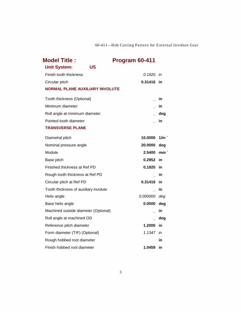
60-411—Hob Cutting Pattern for External Involute Gear
3
Model Title : Program 60-411 Unit System: US Finish tooth thickness 0.1920 in
Circular pitch 0.31416 in
NORMAL PLANE AUXILIARY INVOLUTE
Tooth thickness (Optional) _ in
Minimum diameter _ in
Roll angle at minimum diameter _ deg
Pointed tooth diameter _ in
TRANSVERSE PLANE
Diametral pitch 10.0000 1/in `
Nominal pressure angle 20.0000 deg
Module 2.5400 mm `
Base pitch 0.2952 in
Finished thickness at Ref PD 0.1920 in
Rough tooth thickness at Ref PD _ in
Circular pitch at Ref PD 0.31416 in
Tooth thickness of auxiliary involute _ in
Helix angle 0.000000 deg
Base helix angle 0.0000 deg
Machined outside diameter (Optional) _ in
Roll angle at machined OD _ deg
Reference pitch diameter 1.2000 in
Form diameter (TIF) (Optional) 1.1347 in
Rough hobbed root diameter in
Finish hobbed root diameter 1.0459 in
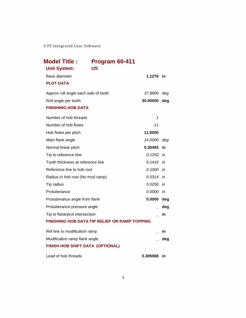
UTS Integrated Gear Software
4
Model Title : Program 60-411 Unit System: US Base diameter 1.1276 in
PLOT DATA
Approx roll angle each side of tooth 37.8900 deg
Roll angle per tooth 30.00000 deg
FINISHING HOB DATA
Number of hob threads 1
Number of hob flutes 11
Hob flutes per pitch 11.0000
Main flank angle 14.5000 deg
Normal linear pitch 0.30493 in
Tip to reference line 0.1250 in
Tooth thickness at reference line 0.1416 in
Reference line to hob root 0.1000 in
Radius in hob root (No mod ramp) 0.0314 in
Tip radius 0.0250 in
Protuberance 0.0000 in
Protuberance angle from flank 0.0000 deg
Protuberance pressure angle _ deg
Tip to flank/prot intersection _ in
FINISHING HOB DATA TIP RELIEF OR RAMP-TOPPING
Ref line to modification ramp _ in
Modification ramp flank angle _ deg
FINISH HOB SHIFT DATA (OPTIONAL)
Lead of hob threads 0.305068 in
60-411—Hob Cutting Pattern for External Involute Gear
5
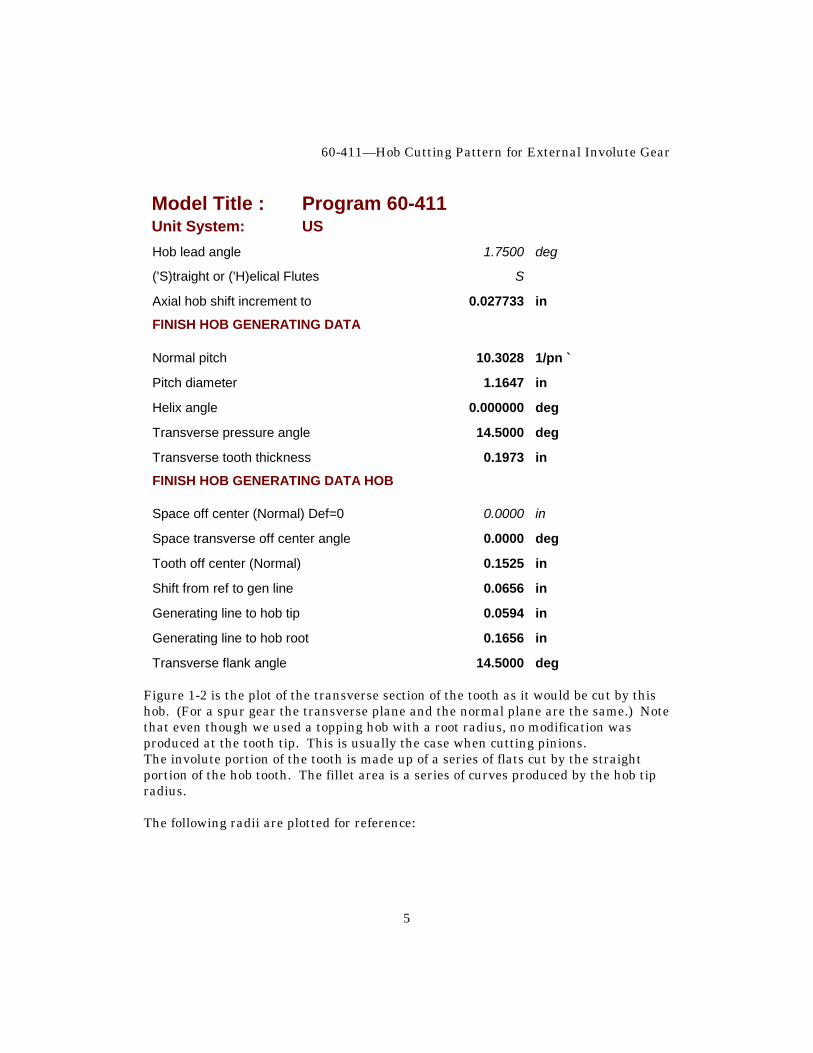
Model Title : Program 60-411 Unit System: US Hob lead angle 1.7500 deg
('S)traight or ('H)elical Flutes S
Axial hob shift increment to 0.027733 in
FINISH HOB GENERATING DATA
Normal pitch 10.3028 1/pn `
Pitch diameter 1.1647 in
Helix angle 0.000000 deg
Transverse pressure angle 14.5000 deg
Transverse tooth thickness 0.1973 in
FINISH HOB GENERATING DATA HOB
Space off center (Normal) Def=0 0.0000 in
Space transverse off center angle 0.0000 deg
Tooth off center (Normal) 0.1525 in
Shift from ref to gen line 0.0656 in
Generating line to hob tip 0.0594 in
Generating line to hob root 0.1656 in
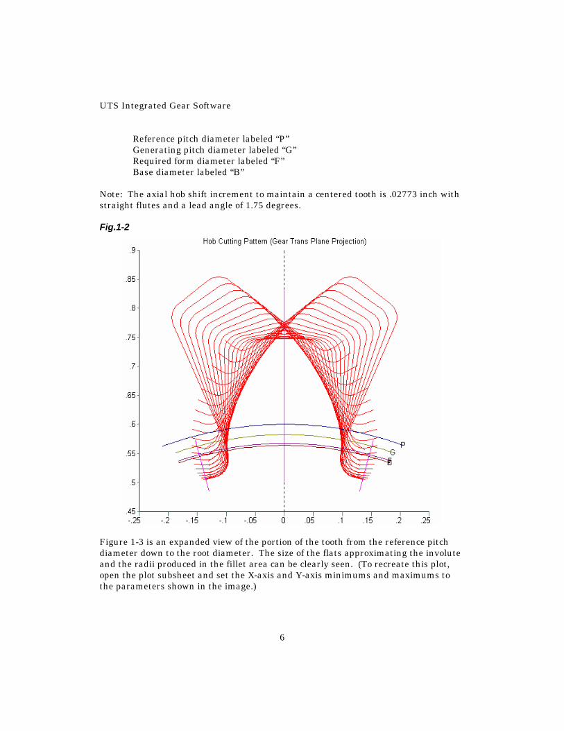
Transverse flank angle 14.5000 deg Figure 1-2 is the plot of the transverse section of the tooth as it would be cut by this hob. (For a spur gear the transverse plane and the normal plane are the same.) Note that even though we used a topping hob with a root radius, no modification was produced at the tooth tip. This is usually the case when cutting pinions. The involute portion of the tooth is made up of a series of flats cut by the straight portion of the hob tooth. The fillet area is a series of curves produced by the hob tip radius. The following radii are plotted for reference:
UTS Integrated Gear Software
6
Reference pitch diameter labeled “P” Generating pitch diameter labeled “G” Required form diameter labeled “F” Base diameter labeled “B” Note: The axial hob shift increment to maintain a centered tooth is .02773 inch with straight flutes and a lead angle of 1.75 degrees. Fig.1-2
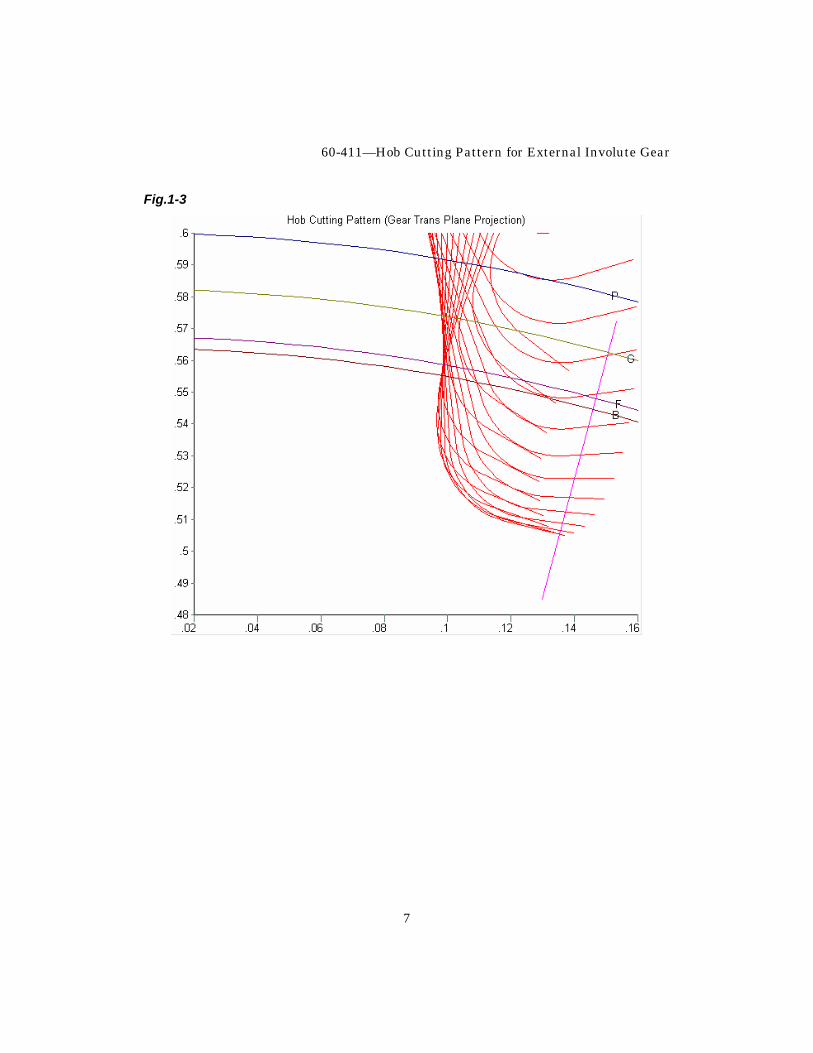
Figure 1-3 is an expanded view of the portion of the tooth from the reference pitch diameter down to the root diameter. The size of the flats approximating the involute and the radii produced in the fillet area can be clearly seen. (To recreate this plot, open the plot subsheet and set the X-axis and Y-axis minimums and maximums to the parameters shown in the image.)
60-411—Hob Cutting Pattern for External Involute Gear
7
Fig.1-3
UTS Integrated Gear Software
8
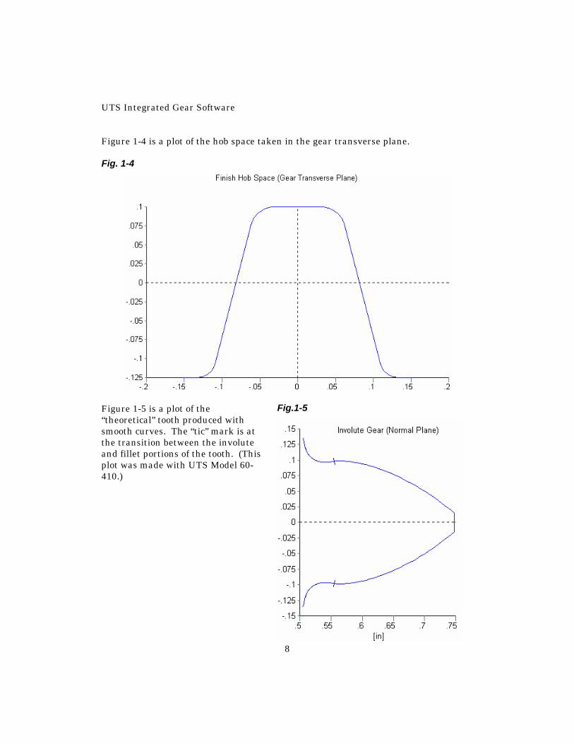
Figure 1-4 is a plot of the hob space taken in the gear transverse plane. Fig. 1-4
Figure 1-5 is a plot of the “theoretical” tooth produced with smooth curves. The “tic” mark is at the transition between the involute and fillet portions of the tooth. (This plot was made with UTS Model 60-410.)
Fig.1-5
60-411—Hob Cutting Pattern for External Involute Gear
9
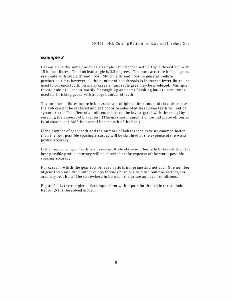
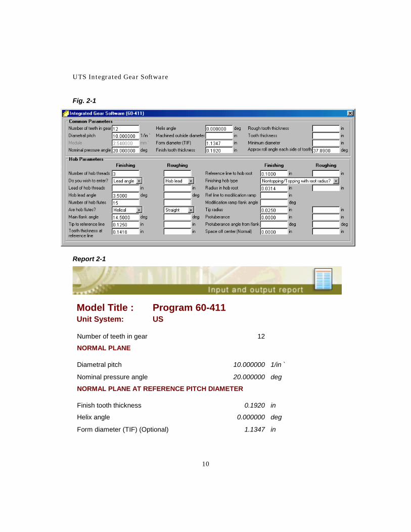
Example 2 Example 2 is the same pinion as Example 1 but hobbed with a triple thread hob with 15 helical flutes. The hob lead angle is 3.5 degrees. The most accurate hobbed gears are made with single thread hobs. Multiple thread hobs, in general, reduce production time, however, as the number of hob threads is increased fewer flutes are used to cut each tooth. In many cases an unusable gear may be produced. Multiple thread hobs are used primarily for roughing and semi-finishing but are sometimes used for finishing gears with a large number of teeth. The number of flutes in the hob must be a multiple of the number of threads or else the hob can not be centered and the opposite sides of at least some teeth will not be symmetrical. The effect of an off center hob can be investigated with the model by entering the amount of off center. (The maximum amount of normal plane off center is, of course, one half the normal linear pitch of the hob.) If the number of gear teeth and the number of hob threads have no common factor then the best possible spacing accuracy will be obtained at the expense of the worst profile accuracy. If the number of gear teeth is an even multiple of the number of hob threads then the best possible profile accuracy will be obtained at the expense of the worst possible spacing accuracy. For cases in which the gear tooth/thread ratio is not prime and not even (the number of gear teeth and the number of hob threads have one or more common factors) the accuracy results will be somewhere in between the prime and even conditions. Figure 2-1 is the completed data input form with inputs for the triple thread hob. Report 2-1 is the solved model.
UTS Integrated Gear Software
10
Fig. 2-1
Report 2-1
Model Title : Program 60-411 Unit System: US
Number of teeth in gear 12
NORMAL PLANE
Diametral pitch 10.000000 1/in `
Nominal pressure angle 20.000000 deg
NORMAL PLANE AT REFERENCE PITCH DIAMETER
Finish tooth thickness 0.1920 in
Helix angle 0.000000 deg
Form diameter (TIF) (Optional) 1.1347 in
60-411—Hob Cutting Pattern for External Involute Gear
11
Model Title : Program 60-411 Unit System: US PLOT DATA
Approx roll angle each side of tooth 37.8900 deg
FINISHING HOB DATA
Number of hob threads 3
Number of hob flutes 15
Hob flutes per pitch 5.0000
Main flank angle 14.5000 deg
Normal linear pitch 0.30493 in
Tip to reference line 0.1250 in
Tooth thickness at reference line 0.1416 in
Reference line to hob root 0.1000 in
Radius in hob root (No mod ramp) 0.0314 in
Tip radius 0.0250 in
Protuberance 0.0000 in
Protuberance angle from flank 0.0000 deg
Protuberance pressure angle _ deg
Tip to flank/prot intersection _ in
FINISHING HOB DATA TIP RELIEF OR RAMP-TOPPING
Ref line to modification ramp _ in
Modification ramp flank angle _ deg
FINISH HOB SHIFT DATA (OPTIONAL)
Lead of hob threads 0.916487 in
Hob lead angle 3.5000 deg
('S)traight or ('H)elical Flutes H
UTS Integrated Gear Software
12
Model Title : Program 60-411 Unit System: US Axial hob shift increment to 0.060871 in
FINISH HOB GENERATING DATA HOB
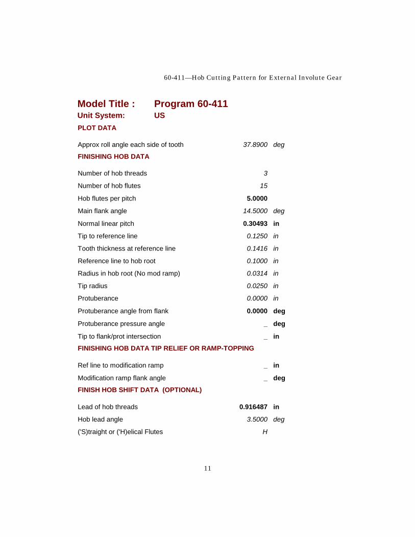
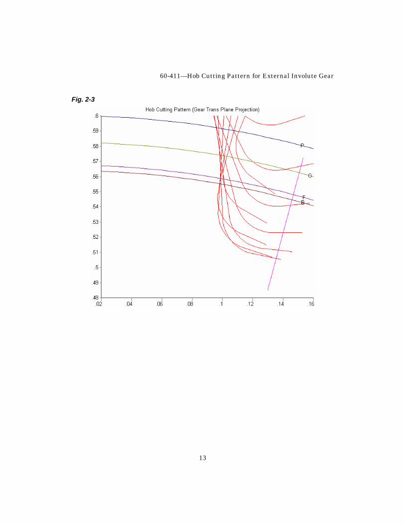
Space off center (Normal) Def=0 0.0000 in Figures 2-2 and 2-3 show the undesirable effect of changing to a triple thread hob for this pinion even though we increased the number of flutes from 11 to 15. The effect would not be as pronounced if there were more teeth in the gear. Fig. 2-2
60-411—Hob Cutting Pattern for External Involute Gear
13
Fig. 2-3
UTS Integrated Gear Software
14
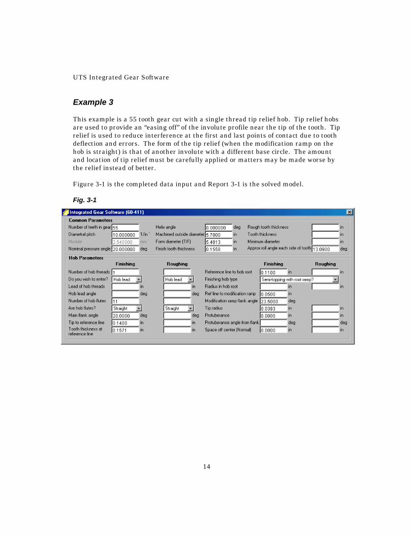
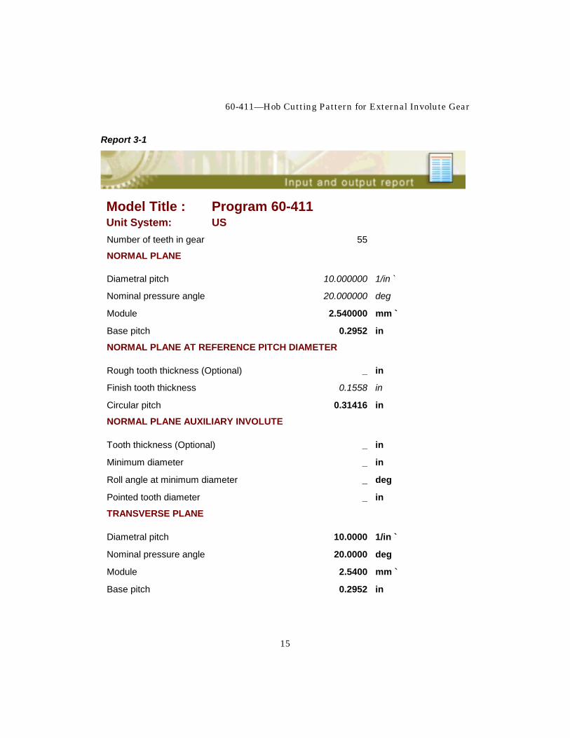
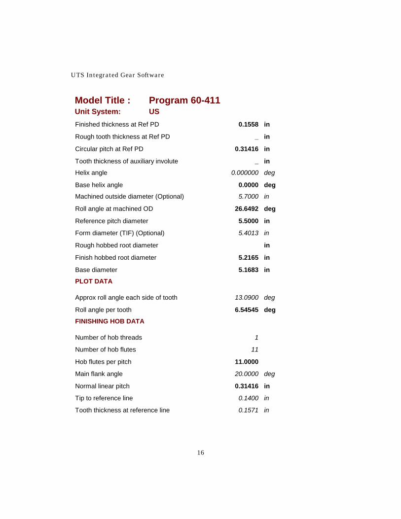
Example 3 This example is a 55 tooth gear cut with a single thread tip relief hob. Tip relief hobs are used to provide an “easing off” of the involute profile near the tip of the tooth. Tip relief is used to reduce interference at the first and last points of contact due to tooth deflection and errors. The form of the tip relief (when the modification ramp on the hob is straight) is that of another involute with a different base circle. The amount and location of tip relief must be carefully applied or matters may be made worse by the relief instead of better. Figure 3-1 is the completed data input and Report 3-1 is the solved model. Fig. 3-1
60-411—Hob Cutting Pattern for External Involute Gear
15
Report 3-1
Model Title : Program 60-411 Unit System: US Number of teeth in gear 55
NORMAL PLANE
Diametral pitch 10.000000 1/in `
Nominal pressure angle 20.000000 deg
Module 2.540000 mm `
Base pitch 0.2952 in
NORMAL PLANE AT REFERENCE PITCH DIAMETER
Rough tooth thickness (Optional) _ in
Finish tooth thickness 0.1558 in
Circular pitch 0.31416 in
NORMAL PLANE AUXILIARY INVOLUTE
Tooth thickness (Optional) _ in
Minimum diameter _ in
Roll angle at minimum diameter _ deg
Pointed tooth diameter _ in
TRANSVERSE PLANE
Diametral pitch 10.0000 1/in `
Nominal pressure angle 20.0000 deg
Module 2.5400 mm `
Base pitch 0.2952 in
UTS Integrated Gear Software
16
Model Title : Program 60-411 Unit System: US Finished thickness at Ref PD 0.1558 in
Rough tooth thickness at Ref PD _ in
Circular pitch at Ref PD 0.31416 in
Tooth thickness of auxiliary involute _ in
Helix angle 0.000000 deg
Base helix angle 0.0000 deg
Machined outside diameter (Optional) 5.7000 in
Roll angle at machined OD 26.6492 deg
Reference pitch diameter 5.5000 in
Form diameter (TIF) (Optional) 5.4013 in
Rough hobbed root diameter in
Finish hobbed root diameter 5.2165 in
Base diameter 5.1683 in
PLOT DATA
Approx roll angle each side of tooth 13.0900 deg
Roll angle per tooth 6.54545 deg
FINISHING HOB DATA
Number of hob threads 1
Number of hob flutes 11
Hob flutes per pitch 11.0000
Main flank angle 20.0000 deg
Normal linear pitch 0.31416 in
Tip to reference line 0.1400 in
Tooth thickness at reference line 0.1571 in
60-411—Hob Cutting Pattern for External Involute Gear
17
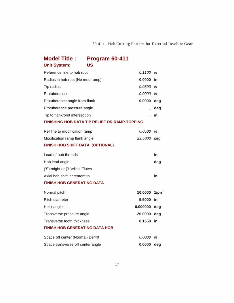
Model Title : Program 60-411 Unit System: US Reference line to hob root 0.1100 in
Radius in hob root (No mod ramp) 0.0000 in
Tip radius 0.0393 in
Protuberance 0.0000 in
Protuberance angle from flank 0.0000 deg
Protuberance pressure angle _ deg
Tip to flank/prot intersection _ in
FINISHING HOB DATA TIP RELIEF OR RAMP-TOPPING
Ref line to modification ramp 0.0500 in
Modification ramp flank angle 23.5000 deg
FINISH HOB SHIFT DATA (OPTIONAL)
Lead of hob threads in
Hob lead angle deg
('S)traight or ('H)elical Flutes
Axial hob shift increment to in
FINISH HOB GENERATING DATA
Normal pitch 10.0000 1/pn `
Pitch diameter 5.5000 in
Helix angle 0.000000 deg
Transverse pressure angle 20.0000 deg
Transverse tooth thickness 0.1558 in
FINISH HOB GENERATING DATA HOB
Space off center (Normal) Def=0 0.0000 in
Space transverse off center angle 0.0000 deg
UTS Integrated Gear Software
18
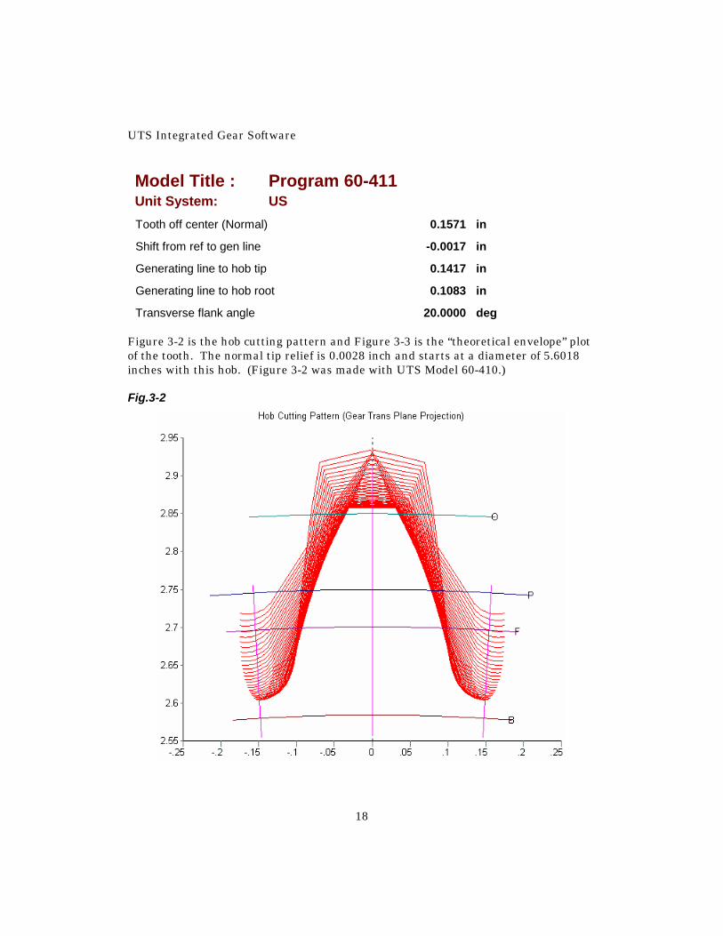
Model Title : Program 60-411 Unit System: US Tooth off center (Normal) 0.1571 in
Shift from ref to gen line -0.0017 in
Generating line to hob tip 0.1417 in
Generating line to hob root 0.1083 in
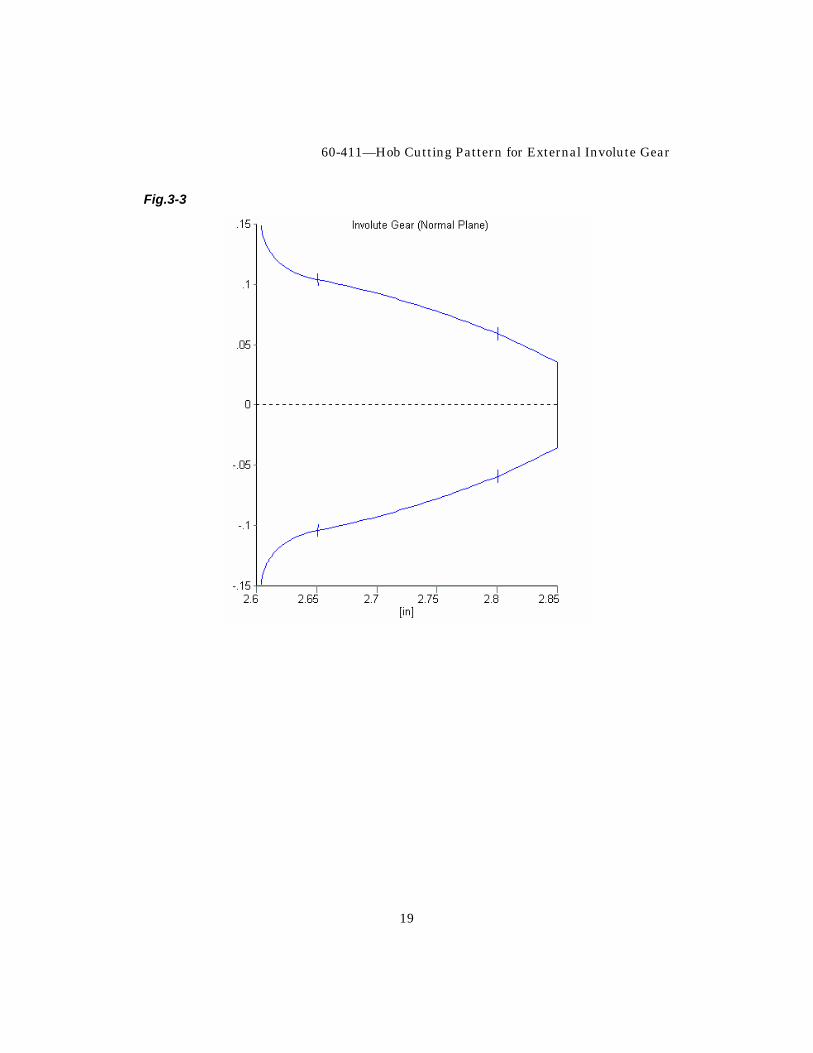
Transverse flank angle 20.0000 deg Figure 3-2 is the hob cutting pattern and Figure 3-3 is the “theoretical envelope” plot of the tooth. The normal tip relief is 0.0028 inch and starts at a diameter of 5.6018 inches with this hob. (Figure 3-2 was made with UTS Model 60-410.) Fig.3-2
60-411—Hob Cutting Pattern for External Involute Gear
19
Fig.3-3
UTS Integrated Gear Software
20
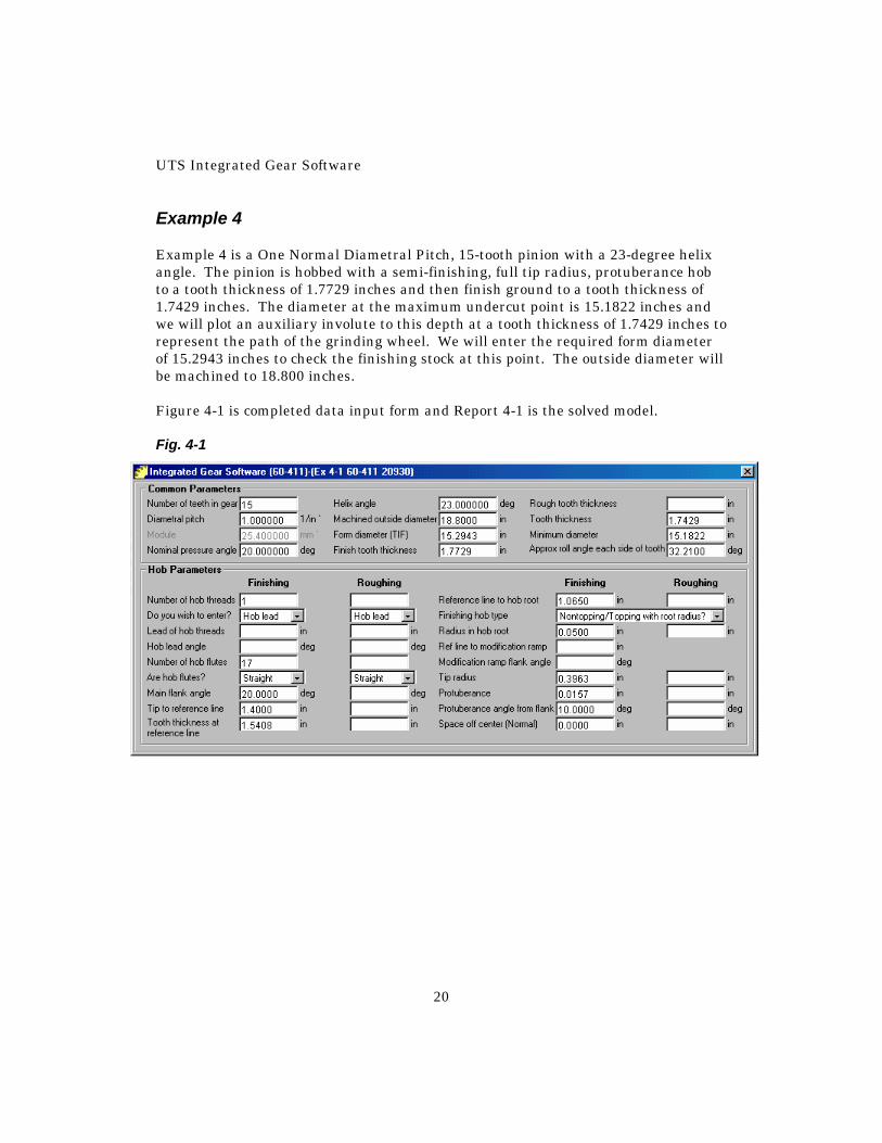
Example 4 Example 4 is a One Normal Diametral Pitch, 15-tooth pinion with a 23-degree helix angle. The pinion is hobbed with a semi-finishing, full tip radius, protuberance hob to a tooth thickness of 1.7729 inches and then finish ground to a tooth thickness of 1.7429 inches. The diameter at the maximum undercut point is 15.1822 inches and we will plot an auxiliary involute to this depth at a tooth thickness of 1.7429 inches to represent the path of the grinding wheel. We will enter the required form diameter of 15.2943 inches to check the finishing stock at this point. The outside diameter will be machined to 18.800 inches. Figure 4-1 is completed data input form and Report 4-1 is the solved model. Fig. 4-1

60-411—Hob Cutting Pattern for External Involute Gear
21
Report 4-1
Model Title : Program 60-411 Unit System: US
Number of teeth in gear 15
NORMAL PLANE
Diametral pitch 1.000000 1/in `
Nominal pressure angle 20.000000 deg
Module 25.400000 mm `
Base pitch 2.9521 in
NORMAL PLANE AT REFERENCE PITCH DIAMETER
Rough tooth thickness (Optional) _ in
Finish tooth thickness 1.7729 in
Circular pitch 3.14159 in
NORMAL PLANE AUXILIARY INVOLUTE
Tooth thickness (Optional) 1.7429 in
Minimum diameter 15.1822 in
Roll angle at minimum diameter 3.5090 deg
Pointed tooth diameter 19.6419 in
TRANSVERSE PLANE
Diametral pitch 0.9205 1/in `
Nominal pressure angle 21.5740 deg
Module 27.5936 mm `
Base pitch 3.1738 in
UTS Integrated Gear Software
22
Model Title : Program 60-411 Unit System: US Finished thickness at Ref PD 1.9260 in
Rough tooth thickness at Ref PD _ in
Circular pitch at Ref PD 3.41290 in
Tooth thickness of auxiliary involute 1.8934 in
Helix angle 23.000000 deg
Base helix angle 21.5410 deg
Machined outside diameter (Optional) 18.8000 in
Roll angle at machined OD 42.0693 deg
Reference pitch diameter 16.2954 in
Form diameter (TIF) (Optional) 15.2943 in
Rough hobbed root diameter in
Finish hobbed root diameter 13.9683 in
Base diameter 15.1538 in
PLOT DATA
Approx roll angle each side of tooth 32.2100 deg
Roll angle per tooth 24.00000 deg
FINISHING HOB DATA
Number of hob threads 1
Number of hob flutes 17
Hob flutes per pitch 17.0000
Main flank angle 20.0000 deg
Normal linear pitch 3.14159 in
Tip to reference line 1.4000 in
Tooth thickness at reference line 1.5408 in
60-411—Hob Cutting Pattern for External Involute Gear
23
Model Title : Program 60-411 Unit System: US Reference line to hob root 1.0650 in
Radius in hob root (No mod ramp) 0.0500 in
Tip radius 0.3963 in
Protuberance 0.0157 in
Protuberance angle from flank 10.0000 deg
Protuberance pressure angle 10.0000 deg
Tip to flank/prot intersection 0.3824 in
FINISHING HOB DATA TIP RELIEF OR RAMP-TOPPING
Ref line to modification ramp _ in
Modification ramp flank angle _ deg
FINISH HOB GENERATING DATA
Normal pitch 1.0000 1/pn `
Pitch diameter 16.2954 in
Helix angle 23.000000 deg
Transverse pressure angle 21.5740 deg
Transverse tooth thickness 1.9260 in
FINISH HOB GENERATING DATA HOB
Space off center (Normal) Def=0 0.0000 in
Space transverse off center angle 0.0000 deg
Tooth off center (Normal) 1.5708 in
Shift from ref to gen line 0.2364 in
Generating line to hob tip 1.1636 in
Generating line to hob root 1.3014 in
Transverse flank angle 21.5740 deg
UTS Integrated Gear Software
24
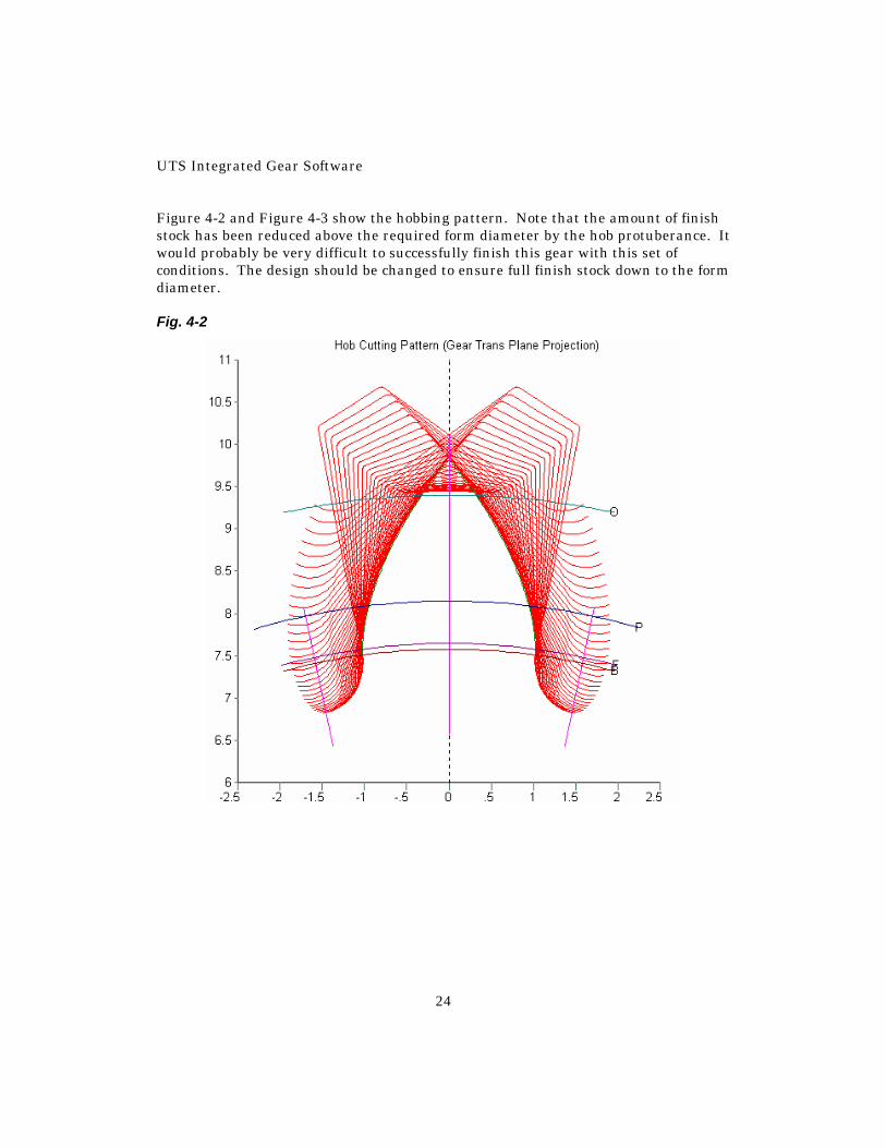
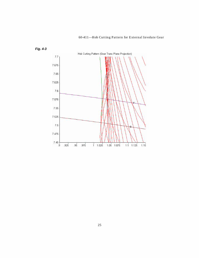
Figure 4-2 and Figure 4-3 show the hobbing pattern. Note that the amount of finish stock has been reduced above the required form diameter by the hob protuberance. It would probably be very difficult to successfully finish this gear with this set of conditions. The design should be changed to ensure full finish stock down to the form diameter. Fig. 4-2
60-411—Hob Cutting Pattern for External Involute Gear
25
Fig. 4-3
UTS Integrated Gear Software
26
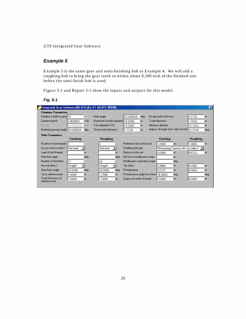
Example 5 Example 5 is the same gear and semi-finishing hob as Example 4. We will add a roughing hob to bring the gear teeth to within about 0.200 inch of the finished size before the semi-finish hob is used. Figure 5-1 and Report 5-1 show the inputs and outputs for this model. Fig. 5-1
60-411—Hob Cutting Pattern for External Involute Gear
27
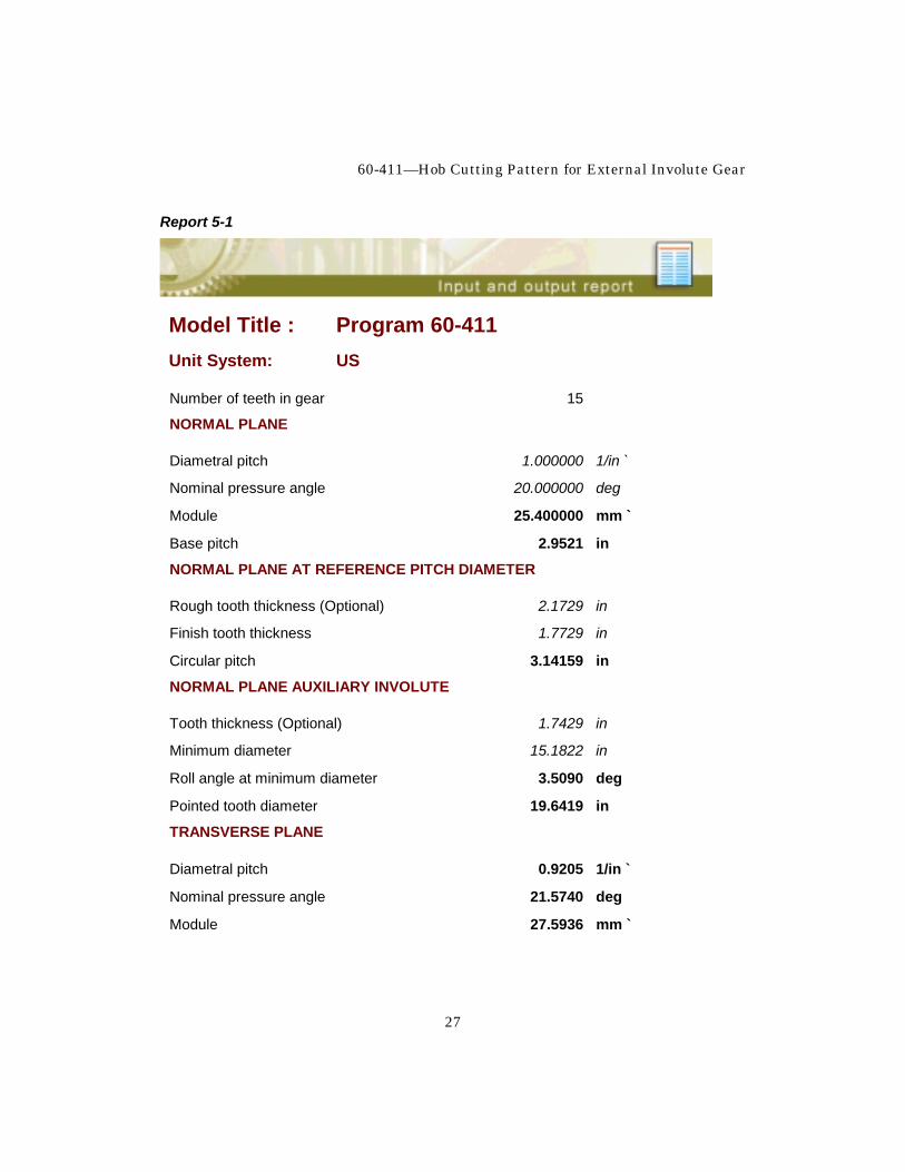
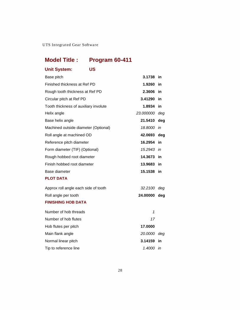
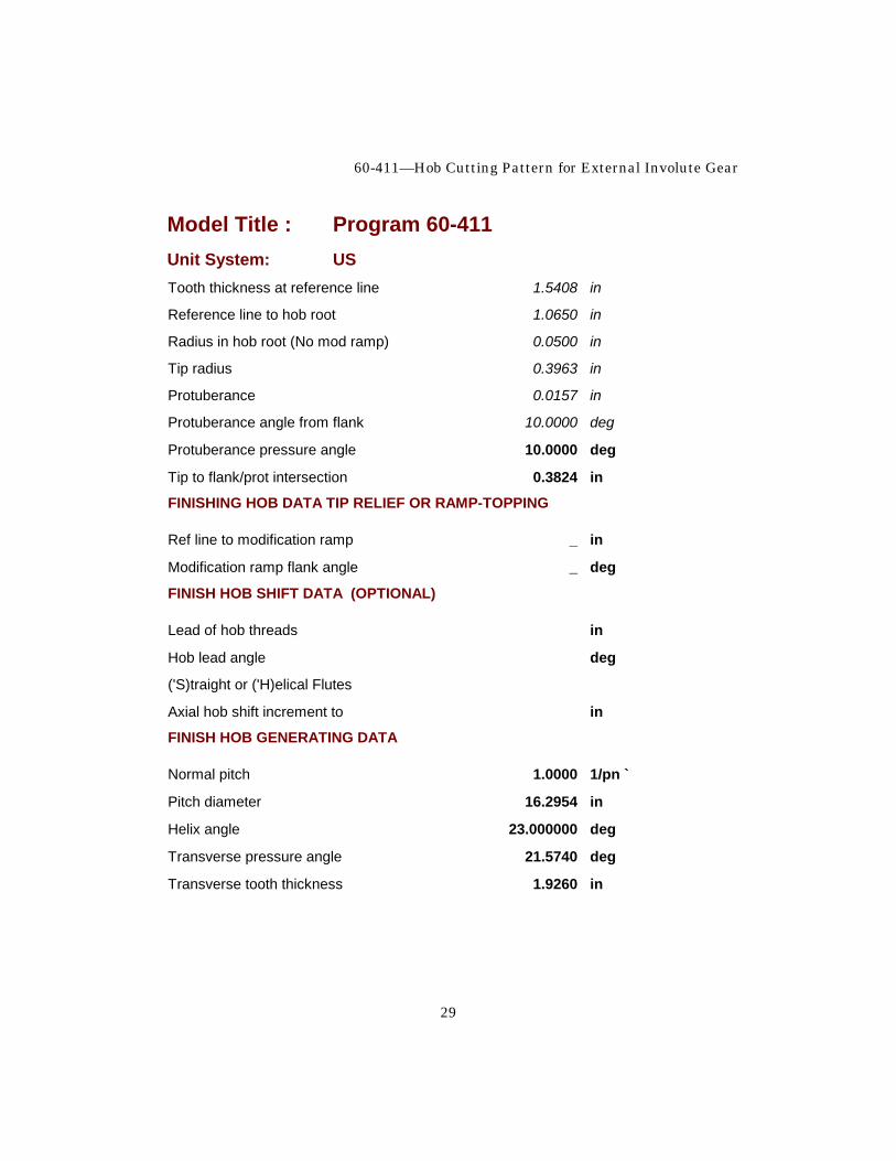
Report 5-1
Model Title : Program 60-411 Unit System: US
Number of teeth in gear 15
NORMAL PLANE
Diametral pitch 1.000000 1/in `
Nominal pressure angle 20.000000 deg
Module 25.400000 mm `
Base pitch 2.9521 in
NORMAL PLANE AT REFERENCE PITCH DIAMETER
Rough tooth thickness (Optional) 2.1729 in
Finish tooth thickness 1.7729 in
Circular pitch 3.14159 in
NORMAL PLANE AUXILIARY INVOLUTE
Tooth thickness (Optional) 1.7429 in
Minimum diameter 15.1822 in
Roll angle at minimum diameter 3.5090 deg
Pointed tooth diameter 19.6419 in
TRANSVERSE PLANE
Diametral pitch 0.9205 1/in `
Nominal pressure angle 21.5740 deg
Module 27.5936 mm `
UTS Integrated Gear Software
28
Model Title : Program 60-411 Unit System: US Base pitch 3.1738 in
Finished thickness at Ref PD 1.9260 in
Rough tooth thickness at Ref PD 2.3606 in
Circular pitch at Ref PD 3.41290 in
Tooth thickness of auxiliary involute 1.8934 in
Helix angle 23.000000 deg
Base helix angle 21.5410 deg
Machined outside diameter (Optional) 18.8000 in
Roll angle at machined OD 42.0693 deg
Reference pitch diameter 16.2954 in
Form diameter (TIF) (Optional) 15.2943 in
Rough hobbed root diameter 14.3673 in
Finish hobbed root diameter 13.9683 in
Base diameter 15.1538 in
PLOT DATA
Approx roll angle each side of tooth 32.2100 deg
Roll angle per tooth 24.00000 deg
FINISHING HOB DATA
Number of hob threads 1
Number of hob flutes 17
Hob flutes per pitch 17.0000
Main flank angle 20.0000 deg
Normal linear pitch 3.14159 in
Tip to reference line 1.4000 in
60-411—Hob Cutting Pattern for External Involute Gear
29
Model Title : Program 60-411 Unit System: US Tooth thickness at reference line 1.5408 in
Reference line to hob root 1.0650 in
Radius in hob root (No mod ramp) 0.0500 in
Tip radius 0.3963 in
Protuberance 0.0157 in
Protuberance angle from flank 10.0000 deg
Protuberance pressure angle 10.0000 deg
Tip to flank/prot intersection 0.3824 in
FINISHING HOB DATA TIP RELIEF OR RAMP-TOPPING
Ref line to modification ramp _ in
Modification ramp flank angle _ deg
FINISH HOB SHIFT DATA (OPTIONAL)
Lead of hob threads in
Hob lead angle deg
('S)traight or ('H)elical Flutes
Axial hob shift increment to in
FINISH HOB GENERATING DATA
Normal pitch 1.0000 1/pn `
Pitch diameter 16.2954 in
Helix angle 23.000000 deg
Transverse pressure angle 21.5740 deg
Transverse tooth thickness 1.9260 in
UTS Integrated Gear Software
30
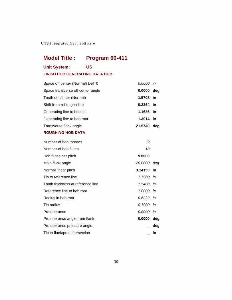
Model Title : Program 60-411 Unit System: US FINISH HOB GENERATING DATA HOB
Space off center (Normal) Def=0 0.0000 in
Space transverse off center angle 0.0000 deg
Tooth off center (Normal) 1.5708 in
Shift from ref to gen line 0.2364 in
Generating line to hob tip 1.1636 in
Generating line to hob root 1.3014 in
Transverse flank angle 21.5740 deg
ROUGHING HOB DATA
Number of hob threads 2
Number of hob flutes 18
Hob flutes per pitch 9.0000
Main flank angle 20.0000 deg
Normal linear pitch 3.14159 in
Tip to reference line 1.7500 in
Tooth thickness at reference line 1.5408 in
Reference line to hob root 1.0000 in
Radius in hob root 0.6232 in
Tip radius 0.1900 in
Protuberance 0.0000 in
Protuberance angle from flank 0.0000 deg
Protuberance pressure angle _ deg
Tip to flank/prot intersection _ in
60-411—Hob Cutting Pattern for External Involute Gear
31
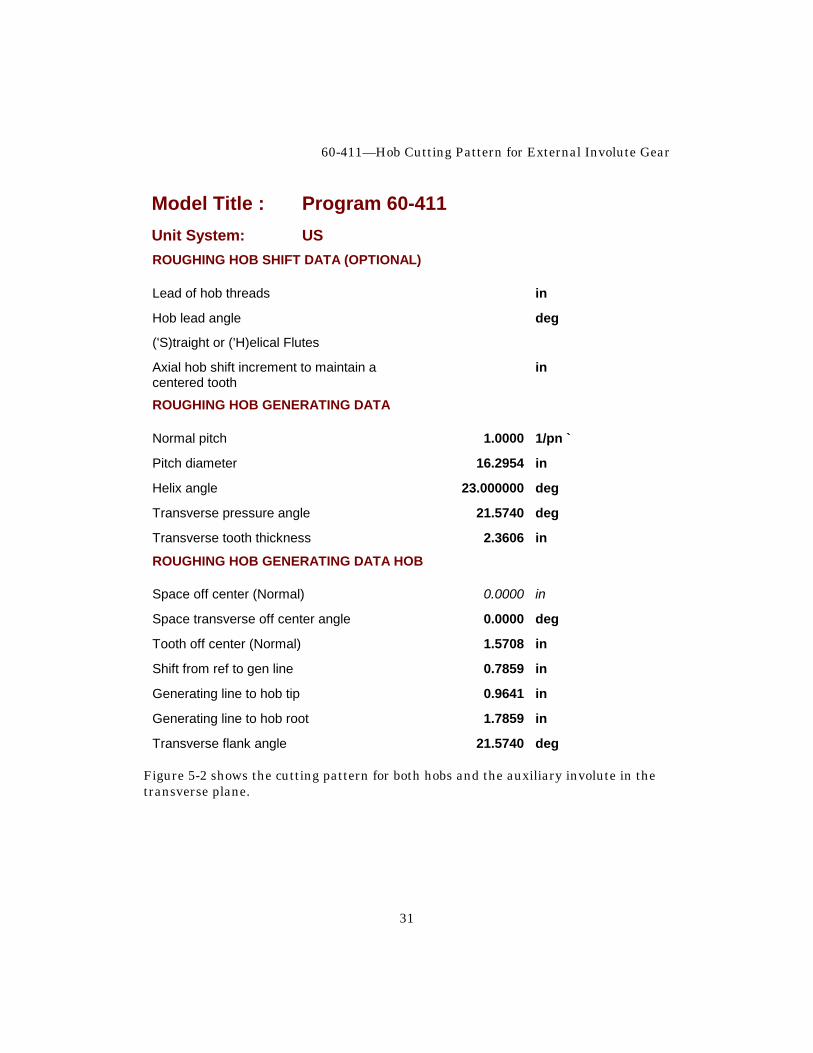
Model Title : Program 60-411 Unit System: US ROUGHING HOB SHIFT DATA (OPTIONAL)
Lead of hob threads in
Hob lead angle deg
('S)traight or ('H)elical Flutes
Axial hob shift increment to maintain a in centered tooth
ROUGHING HOB GENERATING DATA
Normal pitch 1.0000 1/pn `
Pitch diameter 16.2954 in
Helix angle 23.000000 deg
Transverse pressure angle 21.5740 deg
Transverse tooth thickness 2.3606 in
ROUGHING HOB GENERATING DATA HOB
Space off center (Normal) 0.0000 in
Space transverse off center angle 0.0000 deg
Tooth off center (Normal) 1.5708 in
Shift from ref to gen line 0.7859 in
Generating line to hob tip 0.9641 in
Generating line to hob root 1.7859 in
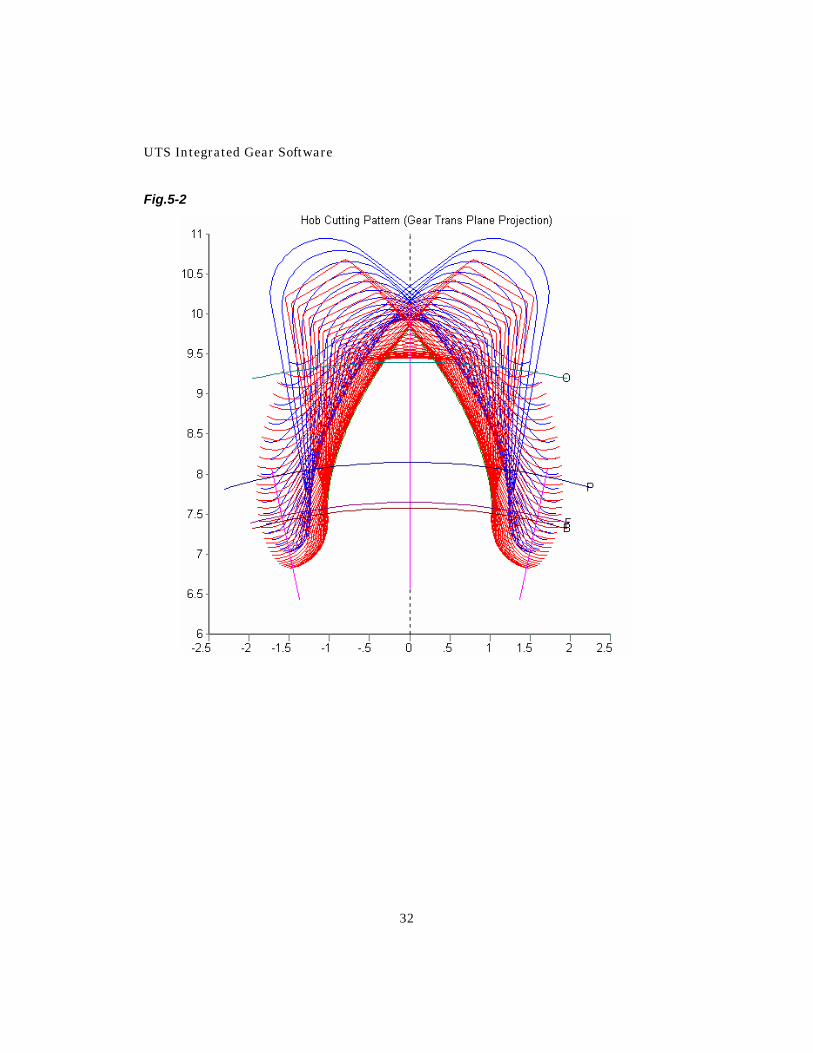
Transverse flank angle 21.5740 deg Figure 5-2 shows the cutting pattern for both hobs and the auxiliary involute in the transverse plane.
UTS Integrated Gear Software
32
Fig.5-2
60-411—Hob Cutting Pattern for External Involute Gear
33
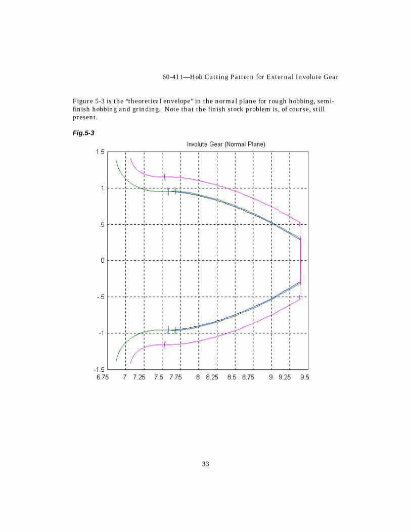
Figure 5-3 is the “theoretical envelope” in the normal plane for rough hobbing, semi-finish hobbing and grinding. Note that the finish stock problem is, of course, still present. Fig.5-3


![QUARTERLY OF APPLIED MATHEMATICS...Theoretically Correct Involute Hob", Machinery, 25, 429-433 (1919)], the authors have not run across any existing comprehensive exposition of the](https://img.pdfslide.net/doc/110x75/5f923282c0b75340115ba59e/quarterly-of-applied-theoretically-correct-involute-hob-machinery-25.jpg)