Embed Size (px)
Citation preview
Innovating Reliable Power
Programmable Power Supplies
EMEA - Edition 2
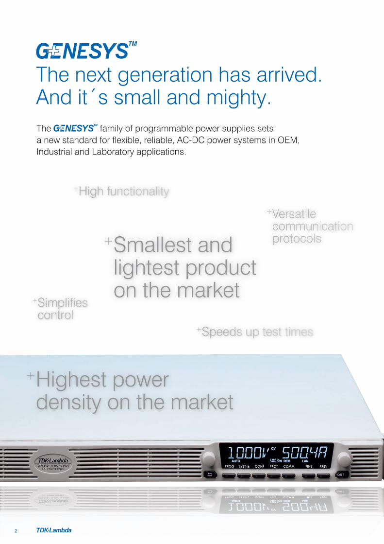
+ Smallest and lightest product on the market
+ Highest power density on the market
+ Versatile communication protocols
+High functionality
+ Simplifies control
+Speeds up test times
The family of programmable power supplies sets a new standard for flexible, reliable, AC-DC power systems in OEM, Industrial and Laboratory applications.
The next generation has arrived. And it´s small and mighty.
2

+ Versatile communication protocols
Specifications• 1.7-5kW in 1U
• 10kW in 2U / 15kW in 3U
• Wide Range of popular worldwide AC inputs: G5kW - G15kW: 3Ø (208, 400 & 480Vac), Wide range 3Ø 480Vac (342~528Vac) G1.7kW: 1Ø (85~265Vac)
• Output Voltage up to 600V, Current up to 1500A
• 5 year warranty
Applications• Test & Measurement systems, Component Device
Testing, Manufacturing and process control
• Semiconductor Processing & Burn-In, Aerospace & Satellite Testing, Medical Imaging, Green Technology
• ATE, Automotive, Automation, Laser diodes, Battery simulation
• Higher power systems can be configured with up to four 5kW units. Each unit is 1U with zero space between them (zero stack)
• OEM Designers have a wide variety of inputs and outputs from which to select depending on application and location
Features
General
• 1U benchtop and 19 Inch standard rack package
• Constant voltage/constant current operation modes/constant power (CP) Limit
• Internal Resistance Simulation
Control interfaces
• High resolution 16 bit ADCs & DACs
• RS-232/RS-485, USB, LAN ( 1.5) built-in as standard
• Isolated Analogue interface built-in as standard
• Integrated Anybus CompactCom interface platform
• Communications compatible with Z+ and GenesysTM
Programming
• Arbitrary Waveform Generator with Auto-Triggering (store up to 100 steps into four internal memory cells)
• Slew-Rate Control (V/I)
• Two user programmable output control pins (open drain) to activate external devices
• Easy auto-configuration for parallel systems up to 20kW
• Safe or Auto re-start and last settings memory
Environmental
• Fan speed profile controlled by ambient temperature and load
• Efficiency up to 92%
Mechanical
• High contrast, wide viewing angle LCD display with brightness and dimming control
• Blank front panel option
• Front Panel dust filter option
Find out more at: emea.tdk-lambda.com/genesysplus
3

1. Input Power ON/OFF Switch
2. Air Intake allows zero stacking for maximum system flexibility and power density
3. Reliable Detent Encoders for settings and Menu navigation
4. High Contrast/Brightness display with wide viewing angle, 16 segment LCD
5. Function/Status LEDs: Active modes and function indicators
6. Pushbuttons allow flexible user configuration
1. Isolated Analogue Programming, Monitoring and other control connector (DB26 Female)
2. USB Interface connector (Type B)
3. RS-232/RS-485 IN/OUT Remote Digital Interface (RJ-45 type) for Multi-Drop connection
4. LAN ( 1.5) Interface connector (RJ-45 type with LAN status indicators)
5. Auto paralleling Bus connectors (mini I/O type) for connecting Master unit-to-Slave and slave unti-to-slave unit
6. Remote/Local Output Voltage Sense Connections (spring cage)
7. Output Connections: Rugged busbars (shown) for models up to and including 100V Output; Plug connector: PHOENIX CONTACT IPC 5/4-STF-7.62 for models with Outputs >100V
8. G5kW Input: 208, 400 & 480Vac Three Phase, 50/60Hz (Model shown) AC Input Plug Connector: PHOENIX CONTACT Power Combicon PC 5/4-STCL1-7.62 Series with strain relief G1.7kW Input: 85~265Vac, Single Phase, 50/60Hz AC Input Plug Connector: PHOENIX CONTACT Power Combicon PC 5/3-STCL1-7.62 Series with strain relief
9. Optional Interface Position for IEEE 488.2 SCPI or Anybus Interface
10. Exhaust air assures reliable operation when units are zero stacked
11. Functional Ground connection (M4x8mm stud)
1 2 3 4 5 6 7
10
11
8
9
1
2
3 4
65
3
Panel Description
Front Panel GENESYS+™ G (1.7-5kW) NEW
Rear Panel GENESYS+™ G (1.7-5kW) NEW
www.emea.tdk-lambda.com4

Front Panel GENESYS+™ GSP (10kW) NEW
Rear Panel GENESYS+™ GSP (10kW) NEW
www.emea.tdk-lambda.com 5
1. Input Power ON/OFF Switch
2. Air Intake allows zero stacking for maximum system flexibility and power density
3. Reliable Detent Encoders for settings and Menu navigation
4. High Contrast/Brightness display with wide viewing angle, 16 segment LCD
5. Function/Status LEDs: Active modes and function indicators
6. Pushbuttons allow flexible user configuration
1
2
3 4
65
3
1. Isolated Analogue Programming, Monitoring and other control connector (DB26 Female)
2. USB Interface connector (Type B)
3. RS-232/RS-485 IN/OUT Remote Digital Interface (RJ-45 type) for Multi-Drop connection
4. LAN ( 1.5) Interface connector (RJ-45 type with LAN status indicators)
5. Auto paralleling Bus connectors (mini I/O type) for connecting Master unit-to-Slave and slave unit-to-slave unit
6. Remote/Local Output Voltage Sense Connections (spring cage)
7. Output Connections: Rugged busbars (shown) for models up to and including 100V Output; Plug connector: PHOENIX CONTACT DFK-IPC 16/4-STF-10.16 for models with Outputs >100V
8. Input: 208, 400 & 480Vac Three Phase, 50/60Hz AC Input Plug Connector: PHOENIX CONTACT DFK-IPC 16/4-STF-10.16 with strain relief
9. Optional Interface Position for IEEE 488.2 SCPI or Anybus Interface
10. Exhaust air assures reliable operation when zero stacked
11. Functional Ground connection (M4x8mm stud)
1
10
2 3 4 5 6 78
9 11
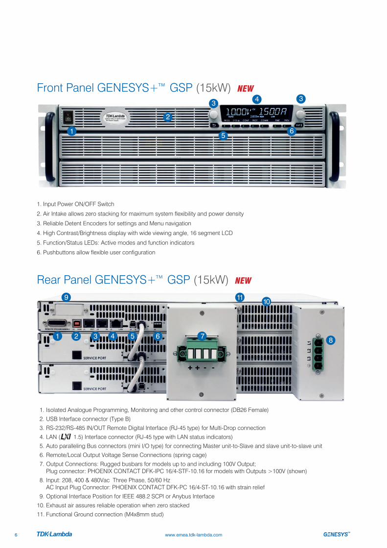
Front Panel GENESYS+™ GSP (15kW) NEW
Rear Panel GENESYS+™ GSP (15kW) NEW
www.emea.tdk-lambda.com6
1. Input Power ON/OFF Switch
2. Air Intake allows zero stacking for maximum system flexibility and power density
3. Reliable Detent Encoders for settings and Menu navigation
4. High Contrast/Brightness display with wide viewing angle, 16 segment LCD
5. Function/Status LEDs: Active modes and function indicators
6. Pushbuttons allow flexible user configuration
1. Isolated Analogue Programming, Monitoring and other control connector (DB26 Female)
2. USB Interface connector (Type B)
3. RS-232/RS-485 IN/OUT Remote Digital Interface (RJ-45 type) for Multi-Drop connection
4. LAN ( 1.5) Interface connector (RJ-45 type with LAN status indicators)
5. Auto paralleling Bus connectors (mini I/O type) for connecting Master unit-to-Slave and slave unit-to-slave unit
6. Remote/Local Output Voltage Sense Connections (spring cage)
7. Output Connections: Rugged busbars for models up to and including 100V Output; Plug connector: PHOENIX CONTACT DFK-IPC 16/4-STF-10.16 for models with Outputs >100V (shown)
8. Input: 208, 400 & 480Vac Three Phase, 50/60 Hz AC Input Plug Connector: PHOENIX CONTACT DFK-PC 16/4-ST-10.16 with strain relief
9. Optional Interface Position for IEEE 488.2 SCPI or Anybus Interface
10. Exhaust air assures reliable operation when zero stacked
11. Functional Ground connection (M4x8mm stud)
1
2
3 4
65
3
1
10
2 3 4 5 6 7 8
9 11

Output ON/OFF Status LED Alarm LED
Voltage/Current Preview mode
FINE Output setting
Communications Menu
Protection Menu
Configurations Menu
System Menu
Program Menu
Back
Voltage Encoder (Clickable)
Current Encoder
(Clickable)
Voltage Display + ‘V’ Symbol (16 Segment)
AUTO-start SAFE-start Indicator
FOLDback Voltage CurrentIndicator
Power Supply Address &
Power Indicator
Remote Communication Active, RS-232/-485, USB, LAN, OPT
(GPIB, Anybus, etc…)
Current Display + ‘A’ Symbol (16 Segment)
Operation Mode
External Voltage Programming
External Current Programming
LFP (Locked Front Panel) TRIGger System Active
Active Memory–Cell (Sequence)
MENU buttons andActive menu LEDs
Output Control buttons and Status LEDs
Front Panel Display indicators
Front Panel Display MENU/CONTROL buttons
www.emea.tdk-lambda.com 7

GENESYS+™ G&GSP Series Blank Front PanelA Blank Front Panel is available for applications where the front panel display and controls are not required and only remote interface (digital/analogue) is needed.
The Blank Front Panel option has all the standard product functions and features except the display. The power supply can be controlled via the rear panel Remote digital interface (LAN, USB, RS-232/RS-485) or via the remote Isolated Analogue interface.
GENESYS+™ Parallel and Series Configurations
Parallel operation – Master/Slave
• Auto paralleling Scalable Master-Slave Operation
• Active current sharing allows up to four identical units to be connected
• Total Real Current is programmed, measured and reported by the Master
• Up to four supplies operate as one
Scalable Power Systems
Factory assembly and test available for two and three unit systems 10kW/15kW. Parallel kit available for four unit systems 20kW. Order P/N: G/P - 4U
GSP 10kW in 2U GSP 15kW in 3U
Series operation
Two units may be connected in series to increase the output voltage or to provide bipolar output. (Max. 600V to Chassis Ground).
Standard Unit - Zero stacked up to 4 units Standard & Blank - Zero stacked up to 4 units
www.emea.tdk-lambda.com8
REM (LED)
OUT (LED)
POWER (LED)
12
3

Graphical User InterfaceAdvanced “Virtual Front Panel” allows programming and monitoring units with or without front panel display.
GUI Waveform Profile generator
User Interface
• Control and monitor up-to 31 units with “Address” bar
• Front panel set-up menu control (PROGram, SYSTem, CONFIguration, PROTection and COMMunication)
• Informative “Parameters” status bar
• Individual unit and Global command control
• Data logging including errors, events and recovery
• Realtime Graph and Waveform creator, store/load sequence
• Solar array mode - calculate MPP (Max Peak Power) for solar array
• Registers View: Operation Status, Fault, Event Status, ENABLE and INTERLOCK signals
• Remote communication state LOC, REM, LLO
• Programmed signals 1&2
www.emea.tdk-lambda.com 9

Technical Specifications: Unit with Air Filter Assembly Installed
• Derating (enviromental)
• Operating Temperature
• For all models (except 10V): 0°C to +40°C For 10V model: 0°C to +30°C, derate 5A/°C for 30°C < TA < +40°C
• Altitude
• For all modells (except 10V): derate 2°C/100m or 2% of load/100m (above 2000m)
• For 10V model: derate 1°C/100m or 2% of load/100m (above 2000m)
Air Filter Assembly Components Standard Unit (P/N: G-AFK)
• Air Filter Cover (two pieces)
• Slide Button #1 (two locations: near AC ON/OFF switch and near left-hand side of front panel display)
• Slide Button #2 (one location: right-hand side of front panel display)
• Filter foam (two pieces)
GENESYS+™ Front Panel Air Filter AssemblyFront panel dust cover is available for dusty air environment applications. Dust cover is removable snap-in filter (for easy maintenance)
Part Number (for standard unit): G-AFK
Part Number (for unit with blank front panel): GB-AFK
For GSP 10kW/15kW series order part number: GSP10kW-AFK / GSP15kW-AFK
Air Filter Kit
Filter Foam Technical Specifications
• Material: reticulated polyurethane foam
• Thickness: 4.0mm
• Porosity: 30ppi
• Operating Temperature Range: 0°C to +60°C
• Storage Temperature Range: -40°C to +85°C
• Humidity: 95% RH
Blank Front Panel Unit (P/N: GB-AFK)
• Air Filter Cover (one piece)
• Slide Button #1 (two locations)
• Filter foam (one piece)
www.emea.tdk-lambda.com10

RS-485 Link
LAN, USB, RS-232/RS-485, IEEE, Anybus
RS-485 Link
Multi-Drop Remote Programming via Communication InterfaceStandard Built-in LAN, USB, RS-232 & RS-485 allows “Multi-Drop” daisy-chain control of up to 31 Power supplies on the same communication bus. Can be Daisy chained via built-in RS-485 Interface.
• First unit is LAN, USB, RS-232, RS-485, etc.
• All other untis use RS-485 daisy chain with linking cable.
GENESYS+™ Family Output Voltage and Current
AC Input Range
Product Summary Air Filter Kit
Rated Power 1.7kW 5kW 10kW 15kW
1Ø, 85-265Vac * N/A N/A N/A
3P208 N/A * * *
3P400 N/A * * *
3P480 N/A * * *
www.emea.tdk-lambda.com 11
Models Series G (Std Front Panel Display) / GB (Blank Front Panel Display) GSP (Scalable Power)
Rated Power 1.7kW 5kW 10kW 15kW
Output Voltage [Vdc] Output Current [A]
0~10 0~170 0~500 0~1000 0~1500
0~20 0~85 0~250 0~500 0~750
0~30 0~56 0~170 0~340 0~510
0~40 0~42 0~125 0~250 0~375
0~60 0~28 0~85 0~170 0~255
0~80 0~21 0~65 0~130 0~195
0~100 0~17 0~50 0~100 0~150
0~150 0~11.2 0~34 0~68 0~102
0~300 0~5.6 0~17 0~34 0~51
0~600 0~2.8 0~8.5 0~17 0~25.5
Weight [kg/lb] 5/11 7.5/16.5 15.5/34.2 23.5/51.8
Model Output Voltage[Vdc]
OutputCurrent [A]
OutputPower [W]
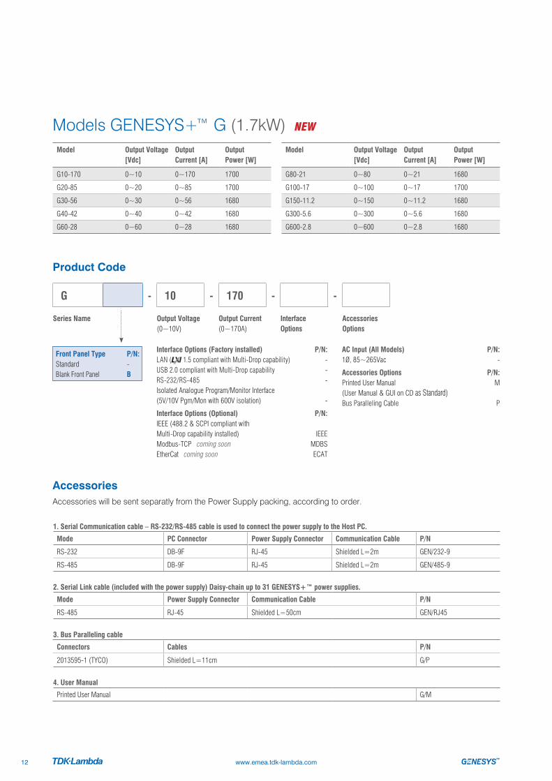
G10-170 0~10 0~170 1700
G20-85 0~20 0~85 1700
G30-56 0~30 0~56 1680
G40-42 0~40 0~42 1680
G60-28 0~60 0~28 1680
Model Output Voltage[Vdc]
OutputCurrent [A]
OutputPower [W]
G80-21 0~80 0~21 1680
G100-17 0~100 0~17 1700
G150-11.2 0~150 0~11.2 1680
G300-5.6 0~300 0~5.6 1680
G600-2.8 0~600 0~2.8 1680
Accessories Accessories will be sent separatly from the Power Supply packing, according to order.
1. Serial Communication cable – RS-232/RS-485 cable is used to connect the power supply to the Host PC.
Mode PC Connector Power Supply Connector Communication Cable P/N
RS-232 DB-9F RJ-45 Shielded L=2m GEN/232-9
RS-485 DB-9F RJ-45 Shielded L=2m GEN/485-9
2. Serial Link cable (included with the power supply) Daisy-chain up to 31 GENESYS+™ power supplies.
Mode Power Supply Connector Communication Cable P/N
RS-485 RJ-45 Shielded L=50cm GEN/RJ45
3. Bus Paralleling cable
Connectors Cables P/N
2013595-1 (TYCO) Shielded L=11cm G/P
4. User Manual
Printed User Manual G/M
Models GENESYS+™ G (1.7kW) NEW
Product Code
Interface Options (Factory installed) P/N:LAN ( 1.5 compliant with Multi-Drop capability) -USB 2.0 compliant with Multi-Drop capability -RS-232/RS-485 -Isolated Analogue Program/Monitor Interface (5V/10V Pgm/Mon with 600V isolation) -
Interface Options (Optional) P/N:IEEE (488.2 & SCPI compliant with Multi-Drop capability installed) IEEEModbus-TCP coming soon MDBSEtherCat coming soon ECAT
G - 10 - 170 - -
Series Name Output Voltage(0~10V)
Output Current(0~170A)
Interface Options
Accessories Options
AC Input (All Models) P/N: 1Ø, 85~265Vac -
Accessories Options P/N:Printed User Manual M (User Manual & GUI on CD as Standard)Bus Paralleling Cable P
Front Panel Type P/N:Standard -Blank Front Panel B
www.emea.tdk-lambda.com12
Model Output Voltage[Vdc]
Output Current[A]
Output Power[W]
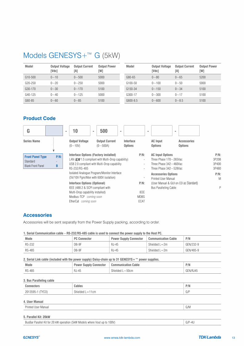
G10-500 0~10 0~500 5000
G20-250 0~20 0~250 5000
G30-170 0~30 0~170 5100
G40-125 0~40 0~125 5000
G60-85 0~60 0~85 5100
Model Output Voltage[Vdc]
Output Current[A]
Output Power[W]
G80-65 0~80 0~65 5200
G100-50 0~100 0~50 5000
G150-34 0~150 0~34 5100
G300-17 0~300 0~17 5100
G600-8.5 0~600 0~8.5 5100
Accessories Accessories will be sent separatly from the Power Supply packing, according to order.
1. Serial Communication cable – RS-232/RS-485 cable is used to connect the power supply to the Host PC.
Mode PC Connector Power Supply Connector Communication Cable P/N
RS-232 DB-9F RJ-45 Shielded L=2m GEN/232-9
RS-485 DB-9F RJ-45 Shielded L=2m GEN/485-9
2. Serial Link cable (included with the power supply) Daisy-chain up to 31 GENESYS+™ power supplies.
Mode Power Supply Connector Communication Cable P/N
RS-485 RJ-45 Shielded L=50cm GEN/RJ45
3. Bus Paralleling cable
Connectors Cables P/N
2013595-1 (TYCO) Shielded L=11cm G/P
4. User Manual
Printed User Manual G/M
5. Parallel Kit: 20kW
BusBar Parallel Kit for 20 kW operation (5kW Models where Vout up to 100V) G/P-4U
Models GENESYS+™ G (5kW)
Product Code
Interface Options (Factory installed) P/N:LAN ( 1.5 compliant with Multi-Drop capability) -USB 2.0 compliant with Multi-Drop capability -RS-232/RS-485 -Isolated Analogue Program/Monitor Interface (5V/10V Pgm/Mon with 600V isolation) -
Interface Options (Optional) P/N:IEEE (488.2 & SCPI compliant with Multi-Drop capability installed) IEEEModbus-TCP coming soon MDBSEtherCat coming soon ECAT
G - 10 - 500 - - -
Series Name Output Voltage(0~10V)
Output Current(0~500A)
Interface Options
AC Input Options
Accessories Options
AC Input Options P/N: Three Phase 170~265Vac 3P208 Three Phase 342~460Vac 3P400 Three Phase 342~528Vac 3P480
Accessories Options P/N:Printed User Manual M (User Manual & GUI on CD as Standard)Bus Paralleling Cable P
Front Panel Type P/N:Standard -Blank Front Panel B
www.emea.tdk-lambda.com 13

Model Output Voltage[Vdc]
Output Current[A]
Output Power[kW]
GSP10-1000 0~10 0~1000 10
GSP20-500 0~20 0~500 10
GSP30-340 0~30 0~340 10.2
GSP40-250 0~40 0~250 10
GSP60-170 0~60 0~170 10.2
Model Output Voltage[Vdc]
Output Current[A]
Output Power[kW]
GSP10-1500 0~10 0~1500 15
GSP20-750 0~20 0~750 15
GSP30-510 0~30 0~510 15.3
GSP40-375 0~40 0~375 15
GSP60-255 0~60 0~255 15.3
Model Output Voltage[Vdc]
Output Current[A]
Output Power[kW]
GSP80-130 0~80 0~130 10.4
GSP100-100 0~100 0~100 10
GSP150-68 0~150 0~68 10.2
GSP300-34 0~300 0~34 10.2
GSP600-17 0~600 0~17 10.2
Model Output Voltage[Vdc]
Output Current[A]
Output Power[kW]
GSP80-195 0~80 0~195 15.6
GSP100-150 0~100 0~150 15
GSP150-102 0~150 0~102 15.3
GSP300-51 0~300 0~51 15.3
GSP600-25.5 0~600 0~25.5 15.3
Models GENESYS+™ GSP (10kW) NEW
Models GENESYS+™ GSP (15kW)
Accessories Accessories will be sent separatly from the Power Supply packing, according to order.
1. Serial Communication cable – RS-232/RS-485 cable is used to connect the power supply to the Host PC.
Mode PC Connector Power Supply Connector Communication Cable P/N
RS-232 DB-9F RJ-45 Shielded L=2m GEN/232-9
RS-485 DB-9F RJ-45 Shielded L=2m GEN/485-9
3. Bus Paralleling cable (included with the power supply)
Connectors Cables P/N
2013595-1 (TYCO) Shielded L=11cm G/P
3. User Manual
Printed User Manual GSP/M
Product Code
Interface Options (Factory installed) P/N:LAN ( 1.5 compliant with Multi-Drop capability) -USB 2.0 compliant with Multi-Drop capability -RS-232/RS-485 -Isolated Analogue Program/Monitor Interface (5V/10V Pgm/Mon with 600V isolation) -
Interface Options (Optional) P/N:IEEE (488.2 & SCPI compliant with Multi-Drop capability installed) IEEEModbus-TCP coming soon MDBSEtherCat coming soon ECAT
G SP - 10 - 1500 - - -
Series Name Output Voltage(0~10V)
Output Current(0~1500A)
Interface Options
AC Input Options
Accessories Options
AC Input Options: P/N: Three Phase 170~265Vac 3P208 Three Phase 342~460Vac 3P400 Three Phase 342~528Vac 3P480
Accessories Options: P/N:Printed User Manual M (User Manual & GUI on CD as Standard)Bus Paralleling Cable P
Front Panel Type P/N:Standard -Blank Front Panel B
www.emea.tdk-lambda.com14
Specifications
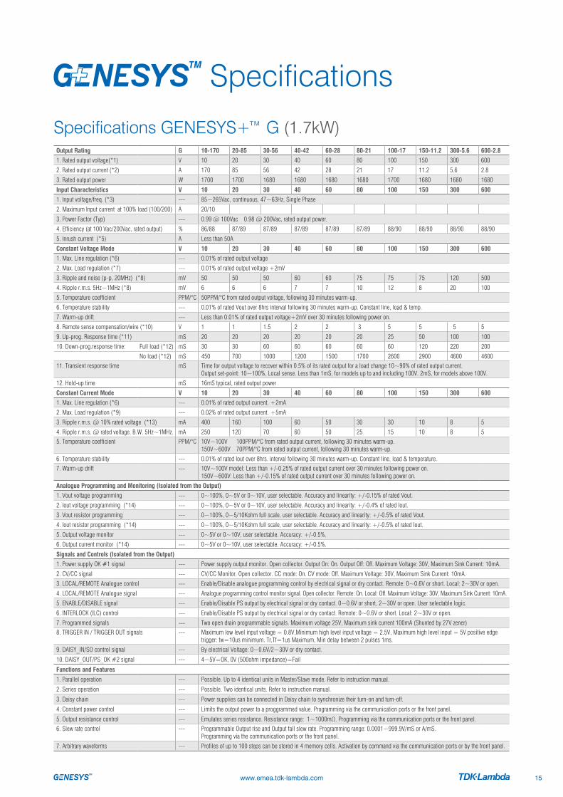
Specifications GENESYS+™ G (1.7kW)
www.emea.tdk-lambda.com 15
Output Rating G 10-170 20-85 30-56 40-42 60-28 80-21 100-17 150-11.2 300-5.6 600-2.8
1. Rated output voltage(*1) V 10 20 30 40 60 80 100 150 300 600
2. Rated output current (*2) A 170 85 56 42 28 21 17 11.2 5.6 2.8
3. Rated output power W 1700 1700 1680 1680 1680 1680 1700 1680 1680 1680
Input Characteristics V 10 20 30 40 60 80 100 150 300 600
1. Input voltage/freq. (*3) --- 85~265Vac, continuous, 47~63Hz, Single Phase
2. Maximum Input current at 100% load (100/200) A 20/10
3. Power Factor (Typ) --- 0.99 @ 100Vac 0.98 @ 200Vac, rated output power.
4. Efficiency (at 100 Vac/200Vac, rated output) % 86/88 87/89 87/89 87/89 87/89 87/89 88/90 88/90 88/90 88/90
5. Inrush current (*5) A Less than 50A
Constant Voltage Mode V 10 20 30 40 60 80 100 150 300 600
1. Max. Line regulation (*6) --- 0.01% of rated output voltage
2. Max. Load regulation (*7) --- 0.01% of rated output voltage +2mV
3. Ripple and noise (p-p, 20MHz) (*8) mV 50 50 50 60 60 75 75 75 120 500
4. Ripple r.m.s. 5Hz~1MHz (*8) mV 6 6 6 7 7 10 12 8 20 100
5. Temperature coefficient PPM/°C 50PPM/°C from rated output voltage, following 30 minutes warm-up.
6. Temperature stability --- 0.01% of rated Vout over 8hrs interval following 30 minutes warm-up. Constant line, load & temp.
7. Warm-up drift --- Less than 0.01% of rated output voltage+2mV over 30 minutes following power on.
8. Remote sense compensation/wire (*10) V 1 1 1.5 2 2 3 5 5 5 5
9. Up-prog. Response time (*11) mS 20 20 20 20 20 20 25 50 100 100
10. Down-prog.response time: Full load (*12) mS 30 30 60 60 60 60 60 120 220 200
No load (*12) mS 450 700 1000 1200 1500 1700 2600 2900 4600 460011. Transient response time mS Time for output voltage to recover within 0.5% of its rated output for a load change 10~90% of rated output current.
Output set-point: 10~100%, Local sense. Less than 1mS, for models up to and including 100V. 2mS, for models above 100V.
12. Hold-up time mS 16mS typical, rated output power
Constant Current Mode V 10 20 30 40 60 80 100 150 300 600
1. Max. Line regulation (*6) --- 0.01% of rated output current. +2mA
2. Max. Load regulation (*9) --- 0.02% of rated output current. +5mA
3. Ripple r.m.s. @ 10% rated voltage (*13) mA 400 160 100 60 50 30 30 10 8 5
4. Ripple r.m.s. @ rated voltage. B.W. 5Hz~1MHz. mA 250 120 70 60 50 25 15 10 8 55. Temperature coefficient PPM/°C 10V~100V 100PPM/°C from rated output current, following 30 minutes warm-up.
150V~600V 70PPM/°C from rated output current, following 30 minutes warm-up.
6. Temperature stability --- 0.01% of rated Iout over 8hrs. interval following 30 minutes warm-up. Constant line, load & temperature.
7. Warm-up drift --- 10V~100V model: Less than +/-0.25% of rated output current over 30 minutes following power on. 150V~600V: Less than +/-0.15% of rated output current over 30 minutes following power on.
Analogue Programming and Monitoring (Isolated from the Output)
1. Vout voltage programming --- 0~100%, 0~5V or 0~10V, user selectable. Accuracy and linearity: +/-0.15% of rated Vout.
2. Iout voltage programming (*14) --- 0~100%, 0~5V or 0~10V, user selectable. Accuracy and linearity: +/-0.4% of rated Iout.
3. Vout resistor programming --- 0~100%, 0~5/10Kohm full scale, user selectable. Accuracy and linearity: +/-0.5% of rated Vout.
4. Iout resistor programming (*14) --- 0~100%, 0~5/10Kohm full scale, user selectable. Accuracy and linearity: +/-0.5% of rated Iout.
5. Output voltage monitor --- 0~5V or 0~10V, user selectable. Accuracy: +/-0.5%.
6. Output current monitor (*14) --- 0~5V or 0~10V, user selectable. Accuracy: +/-0.5%.
Signals and Controls (Isolated from the Output)
1. Power supply OK #1 signal --- Power supply output monitor. Open collector. Output On: On. Output Off: Off. Maximum Voltage: 30V, Maximum Sink Current: 10mA.
2. CV/CC signal --- CV/CC Monitor. Open collector. CC mode: On. CV mode: Off. Maximum Voltage: 30V, Maximum Sink Current: 10mA.
3. LOCAL/REMOTE Analogue control --- Enable/Disable analogue programming control by electrical signal or dry contact. Remote: 0~0.6V or short. Local: 2~30V or open.
4. LOCAL/REMOTE Analogue signal --- Analogue programming control monitor signal. Open collector. Remote: On. Local: Off. Maximum Voltage: 30V, Maximum Sink Current: 10mA.
5. ENABLE/DISABLE signal --- Enable/Disable PS output by electrical signal or dry contact. 0~0.6V or short, 2~30V or open. User selectable logic.
6. INTERLOCK (ILC) control --- Enable/Disable PS output by electrical signal or dry contact. Remote: 0~0.6V or short. Local: 2~30V or open.
7. Programmed signals --- Two open drain programmable signals. Maximum voltage 25V, Maximum sink current 100mA (Shunted by 27V zener)8. TRIGGER IN / TRIGGER OUT signals --- Maximum low level input voltage = 0.8V,Minimum high level input voltage = 2.5V, Maximum high level input = 5V positive edge
trigger: tw=10us minimum. Tr,Tf=1us Maximum, Min delay between 2 pulses 1ms.
9. DAISY_IN/SO control signal --- By electrical Voltage: 0~0.6V/2~30V or dry contact.
10. DAISY_OUT/PS_OK #2 signal --- 4~5V=OK, 0V (500ohm impedance)=Fail
Functions and Features
1. Parallel operation --- Possible. Up to 4 identical units in Master/Slave mode. Refer to instruction manual.
2. Series operation --- Possible. Two identical units. Refer to instruction manual.
3. Daisy chain --- Power supplies can be connected in Daisy chain to synchronize their turn-on and turn-off.
4. Constant power control --- Limits the output power to a proggrammed value. Programming via the communication ports or the front panel.
5. Output resistance control --- Emulates series resistance. Resistance range: 1~1000mΩ. Programming via the communication ports or the front panel.
6. Slew rate control --- Programmable Output rise and Output fall slew rate. Programming range: 0.0001~999.9V/mS or A/mS. Programming via the communication ports or the front panel.
7. Arbitrary waveforms --- Profiles of up to 100 steps can be stored in 4 memory cells. Activation by command via the communication ports or by the front panel.

Specifications GENESYS+™ G (1.7kW)
www.emea.tdk-lambda.com16
*1: Minimum voltage is guaranteed to maximum 0.1% of rated output voltage.*2: Minimum current is guaranteed to maximum 0.2% of rated output current.*3: For cases where conformance to various safety standards (UL, IEC, etc…) is required, to be described as 100-240Vac (50/60Hz).*4: Signal and control ports interface cables length: Less than 3m, DC output power port cables length: Less than 30m. *5: Not including EMI filter inrush current, less than 0.2mS.*6: 85~132Vac or 170~265Vac. Constant load.*7: From No-Load to Full-Load, constant input voltage. Measured at the sensing point in Remote Sense.*8: For 10V~150V models: Measured with JEITA RC-9131C (1:1) probe. For 300~600V model: Measured with 100:1 probe.*9: For load voltage change, equal to the unit voltage rating, constant input voltage.*10: The maximum voltage on the power supply terminals must not exceed the rated voltage.*11: From 10% to 90% or 90% to 10% of Rated Output Voltage, with rated, resistive load.*12: From 90% to 10% of Rated Output Voltage.
Programming and Readback (USB, LAN, RS-232/ RS-485, Optional IEEE (*16) Interface)
V 10 20 30 40 60 80 100 150 300 600
1. Vout programming accuracy (*15) --- 0.05% of rated output voltage
2. Iout programming accuracy (*14) --- 0.1% of actual output current +0.2% of rated output current
3. Vout programming resolution --- 0.002% of rated output voltage
4. Iout programming resolution --- 0.002% of rated output current
5. Vout readback accuracy --- 0.05% of rated output voltage
6. Iout readback accuracy (*14) --- 0.2% of rated output current
7. Vout readback resolution (of rated output voltage) % 0.011% 0.006% 0.004% 0.003% 0.002% 0.002% 0.011% 0.007% 0.004% 0.002%
8. Iout readback resolution (of rated output current) % 0.007% 0.002% 0.003% 0.003% 0.005% 0.006% 0.007% 0.010% 0.003% 0.004%
Protective Functions V 10 20 30 40 60 80 100 150 300 6001. Foldback protection --- Output shut-down when power supply changes mode from CV or Power Limit to CC mode or from CC or Power Limit to CV mode.
User presetable. Reset by AC input recycle in autostart mode, by Power Switch, by OUTPUT button, by rear panel or by communication.
2. Over-voltage protection (OVP) --- Output shut-down. Reset by AC input recycle in autostart mode, by OUTPUT button, by rear panel or by communication.
3. Over-voltage programming range V 0.5~12 1~24 2~36 2~44.1 5~66.15 5~88.2 5~110.25 5~165.37 5~330.75 5~661.5
4. Over-voltage programming accuracy --- +/-1% of rated output voltage
5. Output under voltage limit (UVL) --- Prevents from adjusting Vout below limit. Does not apply in analogue programming. Preset by front panel or communication port.
6. Over temperature protection --- Shuts down the output. Auto recovery by autostart mode.
7. Output under voltage limit (UVL) --- Prevents adjustment of Vout below limit.
8. Output under voltage protection (UVP) --- Prevents adjustment of Vout below limit. P.S output turns Off during under voltage condition. Reset by AC input recycle in autostart mode, by Power Switch, by OUTPUT button, by rear panel or by communication.
Front Panel1. Control functions --- Multiple options with 2 Encoders
Vout/Iout/Power Limit manual adjustOVP/UVL/UVP manual adjustProtection Functions - OVP, UVL,UVP, Foldback, OCL, ENA, ILCCommunication Functions - Selection of LAN,IEEE,RS-232,RS-485,USB or Optional communication interface.Output ON/OFF. Front Panel Lock.Communication Functions - Selection of Baud Rate, Address, IP and communication language.Analogue Control Functions - Selection Voltage/resistive programming, 5V/10V, 5K/10K programmingAnalogue Monitor Functions - Selection of Voltage/Current Monitoring 5V/10V.
2. Display --- Vout: 4 digits, accuracy: 0.05% of rated output voltage +/-1 count. Iout: 4 digits, accuracy: 0.2% of rated output current +/-1 count.
3. Front Panel Buttons Indications --- OUTPUT ON, ALARM, PREVIEW, FINE, COMMUNICATION, PROTECTION,CONFIGURATION, SYSTEM, SEQUENCER.
4. Front Panel Display Indications --- Voltage, Current, Power, CV, CC, CP, External Voltage, External Current, Address, LFP, Autostart, Safetstart, Foldback V/I, Remote (communication), RS/USB/LAN/IEEE communication, Trigger, Load/Store Cell.
Environmental Conditions
1. Operating temperature --- 0~50°C, 100% load.
2. Storage temperature --- -30~85°C
3. Operating humidity % 20~90% RH (no condensation).
4. Storage humidity % 10~95% RH (no condensation).
5. Altitude --- Operating: 10000ft (3000m), output current derating 2%/100m or Ta derating 1°C/100m above 2000m. Non operating: 40000ft (12000m).
Mechanical
1. Cooling --- Forced air cooling by internal fans. Air flow direction: from Front panel to power supply rear
2. Weight kg Less than 5kg.
3. Dimensions (WxHxD) mm W: 423, H: 43.6, D: 441.5 (Without busbars and busbars cover), W: 423, H: 43.6, D: 553.5 (Including busbars and busbars cover) (Refer to Outline drawing).
4. Vibration --- MIL-810G, method 514.6, Procedure I, test condition Annex C - 2.1.3.1
5. Shock --- Less than 20G, half sine, 11mS. Unit is unpacked.
Safety/EMC
1. Applicable standards: Safety --- UL60950-1, CSA22.2 No.60950-1, IEC60950-1, EN60950-1.
1.1 Interface classification --- Vout ≤40V Models: Output, J1,J2,J3,J4,J5,J6,J7,J8 (sense) and J9 (communication options) are SELV.60≤ Vout ≤600V Models: Output, J8 (sense) are hazardous, J1,J2,J3,J4,J5,J6,J7 and J9 (communication options) are SELV
1.2 Withstand voltage --- Vout ≤40V Models: Input - Output (SELV): 4242Vdc 1min, Input - Ground: 2835Vdc 1min. 60V≤ Vout ≤100V Models: Input - Output: 4242Vdc 1min, Input - SELV: 4242Vdc 1min, Output - SELV: 850Vdc 1min, Output - Ground: 1500Vdc 1min, Input - Ground: 2835Vdc 1min. 100<Vout ≤600V Models: Input - Output: 4242Vdc 1min, Input - SELV: 4242Vdc 1min, Output - SELV: 1275Vdc 1min, Output - Ground: 2500Vdc 1min, Input - Ground: 2835Vdc 1min.
1.3 Insulation resistance --- 100Mohm at 25°C, 70%RH.
2. Conducted emission --- IEC/EN61204-3 Industrial environment, Annex H table H.1 , FCC Part 15-A, VCCI-A .
3. Radiated emission --- IEC/EN61204-3 Industrial environment, Annex H table H.3 and H4, FCC Part 15-A, VCCI-A
4. EMC compliance EMC(*4) --- According to IEC/EN61204-3 Industrial environment
*13: For 10V model, the ripple is measured at 2V and rated output current. For other models, the ripple is measured at 10% of rated output voltage. B.W 5Hz~1MHz.
*14: The Constant Current programming, readback and monitoring accuracy do not include the warm-up and Load regulation thermal drift.
*15: Measured at the sensing point.*16: Maximum ambient temperature for IEEE option is 40°C.

Specifications GENESYS+™ G (5kW)
www.emea.tdk-lambda.com 17
Output Rating G 10-500 20-250 30-170 40-125 60-85 80-65 100-50 150-34 300-17 600-8.5
1. Rated output voltage(*1) V 10 20 30 40 60 80 100 150 300 600
2. Rated output current (*2) A 500 (*3) 250 170 125 85 65 50 34 17 8.5
3. Rated output power W 5000 5000 5100 5000 5100 5200 5000 5100 5100 5100
Input Characteristics V 10 20 30 40 60 80 100 150 300 6001. Input voltage/freq. 3 phase, 3 wire + Ground (*4)
---
3-Phase, 200V models: 170~265Vac, 47~63Hz (Covers 200/230Vac)
3-Phase, 400V models: 342~460Vac, 47~63Hz (Covers 380/400/415Vac)
3-Phase, 480V models: 342~528Vac, 47~63Hz (Covers 380/400/415/440/460/480Vac)
2. Maximum Input current at 100% load
---
3-Phase, 200V models: 17.5A @ 200Vac
3-Phase, 400V models: 9.2A @ 380Vac
3-Phase, 480V models: 9.2A @ 380Vac
3. Power Factor (Typ) --- 0.94 @ 200/380Vac, rated output power.
4. Efficiency (*5) % 89.5 91 91 91 91 91 91 91 92 92
5. Inrush current (*6) A Less than 50A
Constant Voltage Mode V 10 20 30 40 60 80 100 150 300 600
1. Max. Line regulation (*7) --- 0.01% of rated output voltage
2. Max. Load regulation (*8) --- 0.01% of rated output voltage +5mV
3. Ripple and noise (p-p, 20MHz) (*9) mV 75 75 75 75 75 80 90 120 200 480
4. Ripple r.m.s. 5Hz~1MHz (*9) mV 8 10 12 12 12 15 15 20 60 100
5. Temperature coefficient PPM/°C 50PPM/°C from rated output voltage, following 30 minutes warm-up.
6. Temperature stability --- 0.01% of rated Vout over 8hrs interval following 30 minutes warm-up. Constant line, load & temp.
7. Warm-up drift --- Less than 0.05% of rated output voltage+2mV over 30 minutes following power on.
8. Remote sense compensation/wire (*10) V 2 2 5 5 5 5 5 5 5 5
9. Up-prog. Response time (*11) mS 30 30 30 30 50 50 50 50 50 100
10. Down-prog.response time: Full load (*11) mS 50 50 80 80 80 100 100 100 100 200
No load (*12) mS 300 600 800 900 1000 1200 1900 2000 3000 3000
11. Transient response time mS Time for output voltage to recover within 0.5% of its rated output for a load change 10~90% of rated output current. Output set-point: 10~100%, Local sense. Less than 1mS, for models up to and including 100V. 2mS, for models above 100V.
12. Start up delay Sec Less than 5 Sec
Constant Current Mode V 10 20 30 40 60 80 100 150 300 600
1. Max. Line regulation (*7) --- 0.05% of rated output current.
2. Max. Load regulation (*13) --- 0.08% of rated output current.
3. Ripple r.m.s. @ 10% rated voltage (*14) mA 1200 600 300 150 100 70 45 45 15 8
4. Ripple r.m.s. @ rated voltage. B.W. 5Hz~1MHz. mA 700 300 150 75 50 35 23 23 7.5 4
5. Temperature coefficient PPM/°C 10V~100V 100PPM/°C from rated output current, following 30 minutes warm-up. 150V~600V 70PPM/°C from rated output current, following 30 minutes warm-up.
6. Temperature stability --- 0.01% of rated Iout over 8hrs. interval following 30 minutes warm-up. Constant line, load & temperature.
7. Warm-up drift --- 10V~100V model: Less than +/-0.25% of rated output current over 30 minutes following power on. 150V~600V: Less than +/-0.15% of rated output current over 30 minutes following power on.
Analogue Programming and Monitoring (Isolated from the Output)
1. Vout voltage programming --- 0~100%, 0~5V or 0~10V, user selectable. Accuracy and linearity: +/-0.15% of rated Vout.
2. Iout voltage programming (*15) --- 0~100%, 0~5V or 0~10V, user selectable. Accuracy and linearity: +/-0.4% of rated Iout.
3. Vout resistor programming --- 0~100%, 0~5/10Kohm full scale, user selectable. Accuracy and linearity: +/-0.5% of rated Vout.
4. Iout resistor programming (*15) --- 0~100%, 0~5/10Kohm full scale, user selectable. Accuracy and linearity: +/-0.5% of rated Iout.
5. Output voltage monitor --- 0~5V or 0~10V, user selectable. Accuracy: +/-0.5%.
6. Output current monitor (*15) --- 0~5V or 0~10V, user selectable. Accuracy: +/-0.5%.
Signals and Controls (Isolated from the Output)
1. Power supply OK #1 signal --- Power supply output monitor. Open collector. Output On: On. Output Off: Off. Maximum Voltage: 30V, Maximum Sink Current: 10mA.
2. CV/CC signal --- CV/CC Monitor. Open collector. CC mode: On. CV mode: Off. Maximum Voltage: 30V, Maximum Sink Current: 10mA.
3. LOCAL/REMOTE Analogue control --- Enable/Disable analogue programming control by electrical signal or dry contact. Remote: 0~0.6V or short. Local: 2~30V or open.
4. LOCAL/REMOTE Analogue signal --- Analogue programming control monitor signal. Open collector. Remote: On. Local: Off. Maximum Voltage: 30V, Maximum Sink Current: 10mA.
5. ENABLE/DISABLE signal --- Enable/Disable PS output by electrical signal or dry contact. 0~0.6V or short, 2~30V or open. User selectable logic.
6. INTERLOCK (ILC) control --- Enable/Disable PS output by electrical signal or dry contact. Remote: 0~0.6V or short. Local: 2~30V or open.
7. Programmed signals --- Two open drain programmable signals. Maximum voltage 25V, Maximum sink current 100mA (Shunted by 27V zener)
8. TRIGGER IN / TRIGGER OUT signals --- Maximum low level input voltage = 0.8V,Minimum high level input voltage = 2.5V, Maximum high level input = 5V positive edge trigger: tw=10us minimum. Tr,Tf=1us Maximum, Min delay between 2 pulses 1ms.
9. DAISY_IN/SO control signal --- By electrical Voltage: 0~0.6V/2~30V or dry contact.
10. DAISY_OUT/PS_OK #2 signal --- 4~5V=OK, 0V (500ohm impedance)=Fail
Functions and Features
1. Parallel operation --- Possible. Up to 4 identical units in Master/Slave mode. Refer to instruction manual.
2. Series operation --- Possible. Two identical units. Refer to instruction manual.
3. Daisy chain --- Power supplies can be connected in Daisy chain to synchronize their turn-on and turn-off.
4. Constant power control --- Limits the output power to a proggrammed value. Programming via the communication ports or the front panel.
5. Output resistance control --- Emulates series resistance. Resistance range: 1~1000mΩ. Programming via the communication ports or the front panel.
6. Slew rate control --- Programmable Output rise and Output fall slew rate. Programming range: 0.0001~999.9V/mS or A/ms. or A/mS. Programming via the communication ports or the front panel.
7. Arbitrary waveforms --- Profiles of up to 100 steps can be stored in 4 memory cells. Activation by command via the communication ports or by the front panel.

Specifications GENESYS+™ G (5kW)
www.emea.tdk-lambda.com18
Programming and Readback (USB, LAN, RS-232/ RS-485, Optional IEEE(*19)(*20) Interface)
V 10 20 30 40 60 80 100 150 300 600
1. Vout programming accuracy (*16) --- 0.05% of rated output voltage
2. Iout programming accuracy (*15) --- 0.1% of actual output current+0.2% of rated output current
3. Vout programming resolution --- 0.002% of rated output voltage
4. Iout programming resolution --- 0.002% of rated output current
5. Vout readback accuracy --- 0.05% of rated output voltage
6. Iout readback accuracy (*15) --- 0.2% of rated output current
7. Vout readback resolution (of rated output voltage) % 0.011% 0.006% 0.004% 0.003% 0.002% 0.002% 0.011% 0.007% 0.004% 0.002%
8. Iout readback resolution (of rated output current) % 0.003% 0.005% 0.006% 0.009% 0.002% 0.002% 0.003% 0.004% 0.006% 0.002%
Protective Functions V 10 20 30 40 60 80 100 150 300 6001. Foldback protection --- Output shut-down when power supply changes mode from CV or Power Limit to CC mode or from CC or Power Limit to CV mode.
User presetable. Reset by AC input recycle in autostart mode, by Power Switch, by OUTPUT button, by rear panel or by communication.
2. Over-voltage protection (OVP) --- Output shut-down. Reset by AC input recycle in autostart mode, by OUTPUT button, by rear panel or by communication.
3. Over-voltage programming range V 0.5~12 1~24 2~36 2~44.1 5~66.15 5~88.2 5~110.25 5~165.37 5~330.75 5~661.5
4. Over-voltage programming accuracy --- +/-1% of rated output voltage
5. Output under voltage limit (UVL) --- Prevents from adjusting Vout below limit. Does not apply in analogue programming. Preset by front panel or communication port.
6. Over temperature protection --- Shuts down the output. Auto recovery by autostart mode.
7. Output under voltage limit (UVL) --- Prevents adjustment of Vout below limit.
8. Output under voltage protection (UVP) --- Prevents adjustment of Vout below limit. P.S output turns Off during under voltage condition. Reset by AC input recycle in autostartmode, by Power Switch, by OUTPUT button, by rear panel or by communication.
Front Panel1. Control functions --- Multiple options with 2 Encoders
Vout/Iout/Power Limit manual adjustOVP/UVL/UVP manual adjustProtection Functions - OVP, UVL,UVP, Foldback, OCL, ENA, ILCCommunication Functions - Selection of LAN,IEEE,RS-232,RS-485,USB or Optional communication interface.Output ON/OFF. Front Panel Lock.Communication Functions - Selection of Baud Rate, Address, IP and communication language.Analogue Control Functions - Selection Voltage/resistive programming, 5V/10V, 5K/10K programmingAnalogue Monitor Functions - Selection of Voltage/Current Monitoring 5V/10V.
2. Display --- Vout: 4 digits, accuracy: 0.05% of rated output voltage +/-1 count. Iout: 4 digits, accuracy: 0.2% of rated output current +/-1 count.
3. Front Panel Buttons Indications --- OUTPUT ON, ALARM, PREVIEW, FINE, COMMUNICATION, PROTECTION, CONFIGURATION, SYSTEM, SEQUENCER.
4. Front Panel Display Indications --- Voltage, Current, Power, CV, CC, CP, External Voltage, External Current, Address, LFP, Autostart, Safetstart, Foldback V/I, Remote (communication), RS/USB/LAN/IEEE communication, Trigger, Load/Store Cell.
Environmental Conditions
1. Operating temperature --- 0~50°C, 100% load.
2. Storage temperature --- -30~85°C
3. Operating humidity % 20~90% RH (no condensation).
4. Storage humidity % 10~95% RH (no condensation).
5. Altitude (*17) --- Operating: 10000ft (3000m), output current derating 2%/100m or Ta derating 1°C/100m above 2000m. Non operating: 40000ft (12000m).
Mechanical
1. Cooling --- Forced air cooling by internal fans. Air flow direction: from Front panel to power supply rear
2. Weight kg Less than 7.5kg.
3. Dimensions (WxHxD) mm W: 423, H: 43.6, D: 441.5 (Without busbars and busbars cover), W: 423, H: 43.6, D: 553.2 (Including busbars and busbars cover) (Refer to Outline drawing).
4. Vibration --- MIL-810G, method 514.6, Procedure I, test condition Annex C - 2.1.3.1
5. Shock --- Less than 20G, half sine, 11mS. Unit is unpacked.
Safety/EMC
1. Applicable standards: Safety --- UL60950-1, CSA22.2 No.60950-1, IEC60950-1, EN60950-1.
1.1 Interface classification --- Vout ≤40V Models: Output, J1,J2,J3,J4,J5,J6,J7,J8 (sense) and J9 (communication options) are SELV.60≤ Vout ≤600V Models: Output, J8 (sense) are hazardous, J1,J2,J3,J4,J5,J6,J7 and J9 (communication options) are SELV
1.2 Withstand voltage --- Vout ≤40V Models: Input - Output (SELV): 4242Vdc 1min, Input - Ground: 2835Vdc 1min.60V≤ Vout ≤100V Models: Input - Output: 4242Vdc 1min, Input - SELV: 4242Vdc 1min, Output - SELV: 850Vdc 1min, Output - Ground: 1500Vdc 1min, Input - Ground: 2835Vdc 1min. 100<Vout≤600VModels: Input - Output: 4242Vdc 1min, Input - SELV: 4242Vdc 1min, Output - SELV: 1275Vdc 1min, Output - Ground: 2500Vdc 1min, Input - Ground: 2835Vdc 1min.
1.3 Insulation resistance --- 100Mohm at 25°C, 70%RH.
2. Conducted emission --- IEC/EN61204-3 Industrial environment, Annex H table H.1 , FCC Part 15-A, VCCI-A .
3. Radiated emission --- IEC/EN61204-3 Industrial environment, Annex H table H.3 and H4, FCC Part 15-A, VCCI-A
4. EMC compliance EMC(*18) --- According to IEC/EN61204-3 Industrial environment
*1: Minimum voltage is guaranteed to maximum 0.1% of rated output voltage.*2: Minimum current is guaranteed to maximum 0.2% of rated output current.*3: Derate 5A/1°C above 40°C. *4: For cases where conformance to various safety standards (UL, IEC, etc...) is required, to be described as 190-240Vac (50/60Hz) for
3-Phase 200V models, 380~415Vac (50/60Hz) for 3-Phase 400V models and 380~480Vac (50/60Hz) for 3-Phase models.*5: 3-Phase 200V models: At 200Vac input voltage, 3-Phase 400/480V: At 380Vac input voltage. With rated output power.*6: Not including EMI filter inrush current, less than 0.2mS.*7: 3-Phase 200V models: 170~265Vac, 3-Phase 400V models: 342~460Vac, 3-Phase 480V models: 342~528Vac. Constant load.*8: From No-Load to Full-Load, constant input voltage. Measured at the sensing point in Remote Sense.*9: For 10V~150V models: Measured with JEITA RC-9131C (1:1) probe. For 300~600V model: Measured with 100:1 probe.*10: The maximum voltage on the power supply terminals must not exceed the rated voltage.*11: From 10% to 90% or 90% to 10% of Rated Output Voltage, with rated, resistive load.
*12: From 90% to 10% of Rated Output Voltage.*13: For load voltage change, equal to the unit voltage rating, constant input voltage.*14: For 10V model the ripple is measured at 2V and rated output current.
For other models, the ripple is measured at 10% of rated output voltage. B.W. 5Hz~1MHz. *15: The Constant Current programming, readback and monitoring accuracy do not include
the warm-up and Load regulation thermal drift.*16: Measured at the sensing point.*17: For 10V model Ta derating 2°C/100m.*18: Signal and control ports interface cables length: Less than 3m,
DC output power port cables length: Less than 30m. *19: Max. ambient temperature for using IEEE is 40°C.*20: For 10V model only: Max. output current for using IEEE is 400A up to 40°C and 450A up to 30°C.
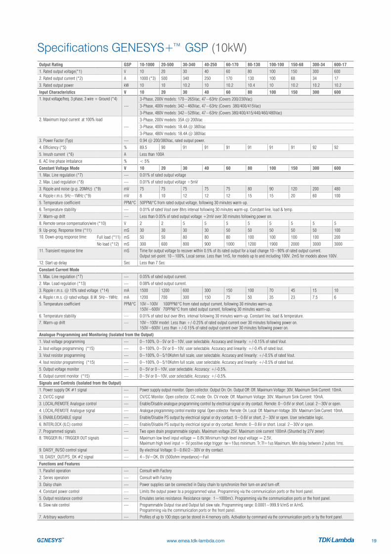
Specifications GENESYS+™ GSP (10kW)
www.emea.tdk-lambda.com 19
Output Rating GSP 10-1000 20-500 30-340 40-250 60-170 80-130 100-100 150-68 300-34 600-17
1. Rated output voltage(*1) V 10 20 30 40 60 80 100 150 300 600
2. Rated output current (*2) A 1000 (*3) 500 340 250 170 130 100 68 34 17
3. Rated output power kW 10 10 10.2 10 10.2 10.4 10 10.2 10.2 10.2
Input Characteristics V 10 20 30 40 60 80 100 150 300 6001. Input voltage/freq. 3 phase, 3 wire + Ground (*4)
---
3-Phase, 200V models: 170~265Vac, 47~63Hz (Covers 200/230Vac)
3-Phase, 400V models: 342~460Vac, 47~63Hz (Covers 380/400/415Vac)
3-Phase, 480V models: 342~528Vac, 47~63Hz (Covers 380/400/415/440/460/480Vac)
2. Maximum Input current at 100% load
---
3-Phase, 200V models: 35A @ 200Vac
3-Phase, 400V models: 18.4A @ 380Vac
3-Phase, 480V models: 18.4A @ 380Vac
3. Power Factor (Typ) --- 0.94 @ 200/380Vac, rated output power.
4. Efficiency (*5) % 89.5 90 91 91 91 91 91 91 92 92
5. Inrush current (*6) A Less than 100A
6. AC line phase imbalance % < 5%
Constant Voltage Mode V 10 20 30 40 60 80 100 150 300 600
1. Max. Line regulation (*7) --- 0.01% of rated output voltage
2. Max. Load regulation (*8) --- 0.01% of rated output voltage +5mV
3. Ripple and noise (p-p, 20MHz) (*9) mV 75 75 75 75 75 80 90 120 200 480
4. Ripple r.m.s. 5Hz~1MHz (*9) mV 8 10 12 12 12 15 15 20 60 100
5. Temperature coefficient PPM/°C 50PPM/°C from rated output voltage, following 30 minutes warm-up.
6. Temperature stability --- 0.01% of rated Vout over 8hrs interval following 30 minutes warm-up. Constant line, load & temp.
7. Warm-up drift --- Less than 0.05% of rated output voltage +2mV over 30 minutes following power on.
8. Remote sense compensation/wire (*10) V 2 2 5 5 5 5 5 5 5 5
9. Up-prog. Response time (*11) mS 30 30 30 30 50 50 50 50 50 100
10. Down-prog.response time: Full load (*11) mS 50 50 80 80 80 100 100 100 100 200
No load (*12) mS 300 600 800 900 1000 1200 1900 2000 3000 3000
11. Transient response time mS Time for output voltage to recover within 0.5% of its rated output for a load change 10~90% of rated output current. Output set-point: 10~100%, Local sense. Less than 1mS, for models up to and including 100V. 2mS for models above 100V.
12. Start up delay Sec Less than 7 Sec
Constant Current Mode
1. Max. Line regulation (*7) --- 0.05% of rated output current.
2. Max. Load regulation (*13) --- 0.08% of rated output current.
3. Ripple r.m.s. @ 10% rated voltage (*14) mA 1500 1200 600 300 150 100 70 45 15 10
4. Ripple r.m.s. @ rated voltage. B.W. 5Hz~1MHz. mA 1200 700 300 150 75 50 35 23 7.5 6
5. Temperature coefficient PPM/°C 10V~100V 100PPM/°C from rated output current, following 30 minutes warm-up. 150V~600V 70PPM/°C from rated output current, following 30 minutes warm-up.
6. Temperature stability --- 0.01% of rated Iout over 8hrs. interval following 30 minutes warm-up. Constant line, load & temperature.
7. Warm-up drift --- 10V~100V model: Less than +/-0.25% of rated output current over 30 minutes following power on. 150V~600V: Less than +/-0.15% of rated output current over 30 minutes following power on.
Analogue Programming and Monitoring (Isolated from the Output)
1. Vout voltage programming --- 0~100%, 0~5V or 0~10V, user selectable. Accuracy and linearity: +/-0.15% of rated Vout.
2. Iout voltage programming (*15) --- 0~100%, 0~5V or 0~10V, user selectable. Accuracy and linearity: +/-0.4% of rated Iout.
3. Vout resistor programming --- 0~100%, 0~5/10Kohm full scale, user selectable. Accuracy and linearity: +/-0.5% of rated Vout.
4. Iout resistor programming (*15) --- 0~100%, 0~5/10Kohm full scale, user selectable. Accuracy and linearity: +/-0.5% of rated Iout.
5. Output voltage monitor --- 0~5V or 0~10V, user selectable. Accuracy: +/-0.5%.
6. Output current monitor (*15) --- 0~5V or 0~10V, user selectable. Accuracy: +/-0.5%.
Signals and Controls (Isolated from the Output)
1. Power supply OK #1 signal --- Power supply output monitor. Open collector. Output On: On. Output Off: Off. Maximum Voltage: 30V, Maximum Sink Current: 10mA.
2. CV/CC signal --- CV/CC Monitor. Open collector. CC mode: On. CV mode: Off. Maximum Voltage: 30V, Maximum Sink Current: 10mA.
3. LOCAL/REMOTE Analogue control --- Enable/Disable analogue programming control by electrical signal or dry contact. Remote: 0~0.6V or short. Local: 2~30V or open.
4. LOCAL/REMOTE Analogue signal --- Analogue programming control monitor signal. Open collector. Remote: On. Local: Off. Maximum Voltage: 30V, Maximum Sink Current: 10mA.
5. ENABLE/DISABLE signal --- Enable/Disable PS output by electrical signal or dry contact. 0~0.6V or short, 2~30V or open. User selectable logic.
6. INTERLOCK (ILC) control --- Enable/Disable PS output by electrical signal or dry contact. Remote: 0~0.6V or short. Local: 2~30V or open.
7. Programmed signals --- Two open drain programmable signals. Maximum voltage 25V, Maximum sink current 100mA (Shunted by 27V zener)
8. TRIGGER IN / TRIGGER OUT signals --- Maximum low level input voltage = 0.8V,Minimum high level input voltage = 2.5V, Maximum high level input = 5V positive edge trigger: tw=10us minimum. Tr,Tf=1us Maximum, Min delay between 2 pulses 1ms.
9. DAISY_IN/SO control signal --- By electrical Voltage: 0~0.6V/2~30V or dry contact.
10. DAISY_OUT/PS_OK #2 signal --- 4~5V=OK, 0V (500ohm impedance)=Fail
Functions and Features
1. Parallel operation --- Consult with Factory
2. Series operation --- Consult with Factory
3. Daisy chain --- Power supplies can be connected in Daisy chain to synchronize their turn-on and turn-off.
4. Constant power control --- Limits the output power to a proggrammed value. Programming via the communication ports or the front panel.
5. Output resistance control --- Emulates series resistance. Resistance range: 1~1000mΩ. Programming via the communication ports or the front panel.
6. Slew rate control --- Programmable Output rise and Output fall slew rate. Programming range: 0.0001~999.9 V/mS or A/mS. Programming via the communication ports or the front panel.
7. Arbitrary waveforms --- Profiles of up to 100 steps can be stored in 4 memory cells. Activation by command via the communication ports or by the front panel.

Specifications GENESYS+™ GSP (15kW)
www.emea.tdk-lambda.com20
Output Rating GSP 10-1500 20-750 30-510 40-375 60-255 80-195 100-150 150-102 300-51 600-25.5
1. Rated output voltage(*1) V 10 20 30 40 60 80 100 150 300 600
2. Rated output current (*2) A 1500 (*3) 750 510 375 255 195 150 102 51 25.5
3. Rated output power kW 15 15 15.3 15 15.3 15.6 15 15.3 15.3 15.3
Input Characteristics V 10 20 30 40 60 80 100 150 300 6001. Input voltage/freq. 3 phase, 3 wire + Ground (*4)
---
3-Phase, 200V models: 170~265Vac, 47~63Hz (Covers 200/230Vac)
3-Phase, 400V models: 342~460Vac, 47~63Hz (Covers 380/400/415Vac)
3-Phase, 480V models: 342~528Vac, 47~63Hz (Covers 380/400/415/440/460/480Vac)
2. Maximum Input current at 100% load
---
3-Phase, 200V models: 52.5A @ 200Vac
3-Phase, 400V models: 27.6A @ 380Vac
3-Phase, 480V models: 27.6A @ 380Vac
3. Power Factor (Typ) --- 0.94 @ 200/380Vac, rated output power.
4. Efficiency (*5) % 89.5 90 91 91 91 91 91 91 92 92
5. Inrush current (*6) A Less than 150A
6. AC line phase imbalance % < 5%
Constant Voltage Mode V 10 20 30 40 60 80 100 150 300 600
1. Max. Line regulation (*7) --- 0.01% of rated output voltage
2. Max. Load regulation (*8) --- 0.01% of rated output voltage +5mV
3. Ripple and noise (p-p, 20MHz) (*9) mV 75 75 75 75 75 80 90 120 200 480
4. Ripple r.m.s. 5Hz~1MHz (*9) mV 8 10 12 12 12 15 15 20 60 100
5. Temperature coefficient PPM/°C 50PPM/°C from rated output voltage, following 30 minutes warm-up.
6. Temperature stability --- 0.01% of rated Vout over 8hrs interval following 30 minutes warm-up. Constant line, load & temp.
7. Warm-up drift --- Less than 0.05% of rated output voltage+2mV over 30 minutes following power on.
8. Remote sense compensation/wire (*10) V 2 2 5 5 5 5 5 5 5 5
9. Up-prog. Response time (*11) mS 30 30 30 30 50 50 50 50 50 100
10. Down-prog.response time: Full load (*11) mS 50 50 80 80 80 100 100 100 100 200
No load (*12) mS 300 600 800 900 1000 1200 1900 2000 3000 3000
11. Transient response time mS Time for output voltage to recover within 0.5% of its rated output for a load change 10~90% of rated output current. Output set-point: 10~100%, Local sense. Less than 1mS, for models up to and including 100V. 2mS for models above 100V.
12. Start up delay Sec Less than 7 Sec
13. Hold-up time ---
Constant Current Mode V 10 20 30 40 60 80 100 150 300 600
1. Max. Line regulation (*7) --- 0.05% of rated output current.
2. Max. Load regulation (*13) --- 0.08% of rated output current.
3. Ripple r.m.s. @ 10% rated voltage (*14) mA 2000 1200 600 300 180 100 70 45 15 10
4. Ripple r.m.s. @ rated voltage. B.W. 5Hz~1MHz. mA 1200 700 300 150 90 60 35 23 7.5 6
5. Temperature coefficient PPM/°C 10V~100V 100PPM/°C from rated output current, following 30 minutes warm-up. 150V~600V 70PPM/°C from rated output current, following 30 minutes warm-up.
6. Temperature stability --- 0.01% of rated Iout over 8hrs. interval following 30 minutes warm-up. Constant line, load & temperature.
7. Warm-up drift --- 10V~100V model: Less than +/-0.25% of rated output current over 30 minutes following power on. 150V~600V: Less than +/-0.15% of rated output current over 30 minutes following power on.
Analogue Programming and Monitoring (Isolated from the Output)
1. Vout voltage programming --- 0~100%, 0~5V or 0~10V, user selectable. Accuracy and linearity: +/-0.15% of rated Vout.
2. Iout voltage programming (*15) --- 0~100%, 0~5V or 0~10V, user selectable. Accuracy and linearity: +/-0.4% of rated Iout.
3. Vout resistor programming --- 0~100%, 0~5/10KΩ full scale, user selectable. Accuracy and linearity: +/-0.5% of rated Vout.
4. Iout resistor programming (*15) --- 0~100%, 0~5/10KΩ full scale, user selectable. Accuracy and linearity: +/-0.5% of rated Iout.
5. Output voltage monitor --- 0~5V or 0~10V, user selectable. Accuracy: +/-0.5%.
6. Output current monitor (*15) --- 0~5V or 0~10V, user selectable. Accuracy: +/-0.5%.
Signals and Controls (Isolated from the Output)
1. Power supply OK signal --- Power supply output monitor. Open collector. Output On: On. Output Off: Off. Maximum Voltage: 30V, Maximum Sink Current: 10mA.
2. CV/CC signal --- CV/CC Monitor. Open collector. CC mode: On. CV mode: Off. Maximum Voltage: 30V, Maximum Sink Current: 10mA.
3. LOCAL/REMOTE Analogue control --- Enable/Disable analogue programming control by electrical signal or dry contact. Remote: 0~0.6V or short. Local: 2~30V or open.
4. LOCAL/REMOTE Analogue signal --- Analogue programming control monitor signal. Open collector. Remote: On. Local: Off. Maximum Voltage: 30V, Maximum Sink Current: 10mA.
5. ENABLE/DISABLE Signal --- Enable/Disable PS output by electrical signal or dry contact. 0~0.6V or short, 2~30V or open. User selectable logic.
6. INTERLOCK (ILC) control --- Enable/Disable PS output by electrical signal or dry contact. Remote: 0~0.6V or short. Local: 2~30V or open.
7. Programmed signals --- Two open drain programmable signals. Maximum voltage 25V, Maximum sink current 100mA (Shunted by 27V zener)
8. TRIGGER IN / TRIGGER OUT signals --- Maximum low level input voltage = 0.8V,Minimum high level input voltage = 2.5V, Maximum high level input = 5V positive edge trigger: tw=10us minimum. Tr,Tf=1us Maximum, Min delay between 2 pulses 1ms.
Functions and Features
1. Parallel operation --- Consult with Factory
2. Series operation --- Consult with Factory
3. Daisy chain --- Power supplies can be connected in Daisy chain to synchronize their turn-on and turn-off.
4. Constant power control --- Limits the output power to a programmed value. Programming via the communication ports or the front panel.
5. Output resistance control --- Emulates series resistance. Resistance range: 1~1000m. Programming via the communication ports or the front panel.
6. Slew rate control --- Programmable Output rise and Output fall slew rate. Programming range: 0.0001~999.9V/mS or A/mS. Programming via the communication ports or the front panel.
7. Arbitrary waveforms --- Profiles of up to 100 steps can be stored in 4 memory cells. Activation by command via the communication ports or by the front panel.

Specifications GENESYS+™ GSP (10/15kW)
www.emea.tdk-lambda.com 21
Programming and Readback (USB, LAN, RS-232/ RS -485, Optional IEEE(*19)(*20) Interface)
V 10 20 30 40 60 80 100 150 300 600
1. Vout programming accuracy (*16) --- 0.05% of rated output voltage
2. Iout programming accuracy (*15) --- 0.3% of rated output current
3. Vout programming resolution --- 0.002% of rated output voltage
4. Iout programming resolution --- 0.002% of rated output current
5. Vout readback accuracy --- 0.05% of rated output voltage
6. Iout readback accuracy (*15) --- 0.2% of rated output current
7. Vout readback resolution (of rated output voltage) % 0.011% 0.006% 0.004% 0.003% 0.002% 0.002% 0.011% 0.007% 0.004% 0.002%
8. Iout readback resolution (of rated output current)
GSP 10kW GSP 15kW
% 0.012% 0.012%
0.003% 0.003%
0.004% 0.003%
0.005% 0.004%
0.007% 0.005%
0.009% 0.006%
0.012% 0.008%
0.002% 0.012%
0.003% 0.003%
0.006% 0.005%
Protective Functions V 10 20 30 40 60 80 100 150 300 6001. Foldback protection --- Output shut-down when power supply changes mode from CV or Power Limit to CC mode or from CC or Power Limit to CV mode.
User presetable. Reset by AC input recycle in autostart mode, by Power Switch, by OUTPUT button, by rear panel or by communication.
2. Over-voltage protection (OVP) --- Output shut-down. Reset by AC input recycle in autostart mode, by OUTPUT button, by rear panel or by communication.
3. Over-voltage programming range V 0.5~12 1~24 2~36 2~44.1 5~66.15 5~88.2 5~110.25 5~165.37 5~330.75 5~661.5
4. Over-voltage programming accuracy --- +/-1% of rated output voltage
5. Output under voltage limit (UVL) --- Prevents from adjusting Vout below limit. Does not apply in analogue programming. Preset by front panel or communication port.
6. Over temperature protection --- Shuts down the output. Auto recovery by autostart mode.
7. Output under voltage limit (UVL) --- Prevents adjustment of Vout below limit.
8. Output under voltage protection (UVP) --- Prevents adjustment of Vout below limit. P.S output turns Off during under voltage condition. Reset by AC input recycle in autostart mode, by Power Switch, by OUTPUT button, by rear panel or by communication.
Front Panel1. Control functions --- Multiple options with 2 Encoders • Vout/Iout/Power Limit manual adjust · OVP/UVL/UVP manual adjust • Protection Functions: OVP, UVL,
UVP, Foldback, OCL, ENA, ILC • Communication Functions: Selection of LAN,IEEE,RS-232,RS-485, USB or Optional communication interface • Output ON/OFF, Front Panel Lock • Communication Functions: Selection of Baud Rate, Address, IP and communication language • Analogue Control Functions: Selection Voltage/resistive programming, 5V/10V, 5K/10K programming • Analogue MonitorFunctions: Selection of Voltage/Current Monitoring 5V/10V
2. Display --- Vout: 4 digits, accuracy: 0.05% of rated output voltage +/-1 count. Iout: 4 digits, accuracy: 0.2% of rated output current +/-1 count.
3. Front Panel Buttons Indications --- OUTPUT ON, ALARM, PREVIEW, FINE, COMMUNICATION, PROTECTION,CONFIGURATION, SYSTEM, SEQUENCER.
4. Front Panel Display Indications --- Voltage, Current, Power, CV, CC, CP, External Voltage, External Current, Address, LFP, Autostart, Safetstart, Foldback V/I, Remote (communication), RS/USB/LAN/IEEE communication, Trigger, Load/Store Cell.
Environmental Conditions
1. Operating temperature --- 0~50°C, 100% load.
2. Storage temperature --- -30~85°C
3. Operating humidity % 20~90% RH (no condensation).
4. Storage humidity % 10~95% RH (no condensation).
5. Altitude (*17) --- Operating: 10000ft (3000m), output current derating 2%/100m or Ta derating 1°C/100m above 2000m. Non operating: 40000ft (12000m).
Mechanical
1. Cooling --- Forced air cooling by internal fans. Air flow direction: from Front panel to power supply rear
2. Weight GSP 10kW kg Less than 15.5kg.
3. Dimensions (WxHxD) GSP 10kW mm W: 423, H: 88, D: 441.5 (Without busbars and busbars cover), W: 423, H: 88, D: 640 (Including busbars and busbars cover) (Refer to Outline drawing).
2. Weight GSP 15kW kg Less than 23.5kg.
3. Dimensions (WxHxD) GSP 15kW mm W: 423, H: 132.5, D: 441.5 (Without busbars and busbars cover), W: 423, H: 132.5, D: 640 (Including busbars and busbars cover) (Refer to Outline drawing).
4. Vibration --- MIL-810G, method 514.6, Procedure I, test condition Annex C - 2.1.3.1
5. Shock --- Less than 20G, half sine, 11mS. Unit is unpacked.
Safety/EMC
1. Applicable standards: Safety --- UL60950-1, CSA22.2 No.60950-1, IEC60950-1, EN60950-1.
1.1 Interface classification --- Vout ≤40V Models: Output, J1,J2,J3,J4,J5,J6,J7,J8 (sense) and J9 (communication options) are SELV.60≤ Vout ≤600V Models: Output, J8 (sense) are hazardous, J1,J2,J3,J4,J5,J6,J7 and J9 (communication options) are SELV
1.2 Withstand voltage --- Vout ≤40V Models: Input - Output (SELV): 4242Vdc 1min, Input - Ground: 2835Vdc 1min.60V≤ Vout ≤100V Models: Input - Output: 4242Vdc 1min, Input - SELV: 4242Vdc 1min, Output - SELV: 850Vdc 1min, Output - Ground: 1500Vdc 1min, Input - Ground: 2835Vdc 1min.100<Vout ≤600V Models: Input - Output: 4242Vdc 1min, Input - SELV: 4242Vdc 1min, Output - SELV: 1275Vdc 1min, Output - Ground: 2500Vdc 1min, Input - Ground: 2835Vdc 1min.
1.3 Insulation resistance --- 100MΩ at 25°C, 70%RH.
2. Conducted emission --- IEC/EN61204-3 Industrial environment, Annex H table H.1 , FCC Part 15-A, VCCI-A .
3. Radiated emission --- IEC/EN61204-3 Industrial environment, Annex H table H.3 and H4, FCC Part 15-A, VCCI-A
4. EMC compliance EMC(*18) --- According to IEC/EN61204-3 Industrial environment
*1: Minimum voltage is guaranteed to maximum 0.1% of rated output voltage.*2: Minimum current is guaranteed to maximum 0.2% of rated output current.*3: Derate 10A/1°C above 40°C. *4: For cases where conformance to various safety standards (UL, IEC, etc...) is required, to be described as 190-240Vac (50/60Hz) for
3-Phase 200V models, 380~415Vac (50/60Hz) for 3-Phase 400V models and 380~480Vac (50/60Hz) for 3-Phase 480V models.*5: 3-Phase 200V models: At 200Vac input voltage, 3-Phase 400/480V: At 380Vac input voltage. With rated output power.*6: Not including EMI filter inrush current, less than 0.2mS.*7: 3-Phase 200V models: 170~265Vac, 3-Phase 400V models: 342~460Vac, 3-Phase 480V models: 342~528Vac. Constant load.*8: From No-Load to Full-Load, constant input voltage. Measured at the sensing point in Remote Sense.*9: For 10V~150V models: Measured with JEITA RC-9131C (1:1) probe. For 300~600V model: Measured with 100:1 probe.*10: The maximum voltage on the power supply terminals must not exceed the rated voltage.*11: From 10% to 90% or 90% to 10% of Rated Output Voltage, with rated, resistive load.
*12: From 90% to 10% of Rated Output Voltage.*13: For load voltage change, equal to the unit voltage rating, constant input voltage.*14: For 10V model the ripple is measured at 2V and rated output current.
For other models, the ripple is measured at 10% of rated output voltage. B.W. 5Hz~1MHz. *15: The Constant Current programming, readback and monitoring accuracy
do not include the warm-up and Load regulation thermal drift.*16: Measured at the sensing point.*17: For 10V model Ta derating 2°C/100m.*18: Signal and control ports interface cables length:
Less than 3m, DC output power port cables length: Less than 30m. *19: Max. ambient temperature for using IEEE is 40°C.*20: For 10V model only: Max. output current for using IEEE is 800A up to 40°C and
900A up to 30°C (GSP10kW); 1200A up to 40°C and 1350A up to 30°C (GSP15kW)

Outline Drawing GENESYS+™ G (1.7/5kW)
Outline Drawings
www.emea.tdk-lambda.com22
G5kW
G1.7kW

Outline Drawing GENESYS+™ G (1.7/5kW)(Models 150V/300V/600V)
Outline Drawings
www.emea.tdk-lambda.com 23
G5kW
G1.7kW

Outline Drawing GENESYS+™ GB (1.7/5kW)
www.emea.tdk-lambda.com24
G5kW
G1.7kW

Outline Drawing GENESYS+™ GSP (10kW)
www.emea.tdk-lambda.com 25
MO
DEL
DIM
ENSI
ON
10-4
0(V)
L160
-100
(V)
L2

Outline Drawing GENESYS+™ GSP (15kW)
www.emea.tdk-lambda.com26
MO
DEL
DIM
ENSI
ON
10-4
0(V)
L160
-100
(V)
L2

10_2
018
lam
_108
459
Whi
lst T
DK
-Lam
bda
trie
s to
ens
ure
that
the
info
rmat
ion
cont
aine
d in
this
Cat
alog
ue is
acc
urat
e it
does
not
acc
ept l
iabi
lity
for
any
inac
cura
cies
. In
exc
eptio
nal c
ircum
stan
ces
TDK
-Lam
bda
rese
rves
the
right
, with
out n
otic
e or
liab
ility
, to
with
draw
pro
duct
s or
alte
r sp
ecifi
catio
ns a
t any
tim
e.
Get in contact to find the best solution to your application.
TDK-Lambda EMEA · www.emea.tdk-lambda.com
Local Distribution
TDK-Lambda France SAS3 avenue du CanadaParc Technopolis – Bâtiment Sigma91940 Les UlisFranceTel. +33 1 60 12 71 65Fax +33 1 60 12 71 [email protected]
Italy Sales OfficeVia Giacomo Matteotti, 62 20092 Cinisello Balsamo (MI) Italy Tel. +39 02 61 29 38 63 Fax +39 02 61 29 09 00 [email protected] www.it.tdk-lambda.com
Netherlands [email protected] www.nl.tdk-lambda.com
TDK-Lambda UK Ltd.Kingsley Avenue Ilfracombe Devon EX34 8ES United Kingdom Tel. +44 12 71 85 66 66 Fax +44 12 71 86 48 94 [email protected] www.uk.tdk-lambda.com
TDK-Lambda Germany GmbHKarl-Bold-Strasse 40 77855 Achern Tel. +49 7841 666 0 Fax +49 7841 5000 [email protected] www.de.tdk-lambda.com
Austria Sales Office Aredstrasse 22 2544 Leobersdorf Austria Tel. +43 2256 655 84 Fax +43 2256 645 12 [email protected] www.at.tdk-lambda.com
Nordic Sales Office Haderslevvej 36B 6000 Kolding Denmark Tel. +45 8853 8086 [email protected] www.dk.tdk-lambda.com
TDK-Lambda Ltd.1 Alexander Yanai Segula, Petah-Tikva Israel Tel. +9 723 902 4333 Fax. +9 723 902 4777 [email protected] www.tdk-lambda.co.il
Switzerland Sales OfficeEichtalstrasse 55 8634 Hombrechtikon SwitzerlandTel. +41 44 850 53 53 Fax +41 44 850 53 50 [email protected] www.ch.tdk-lambda.com
C.I.S.
Commercial Support: Tel. +7 495 665-26 27
Technical Support:St. Petersburg Tel. +7 812 658-04 63 [email protected] www.tdk-lambda.ru