Embed Size (px)
Citation preview

Programmable RF Attenuation Project

Project goals
• Design and build a system to provide UMA test engineers a way to programmatically emulate the action of approaching / moving away from WIFI access points.
• For maximum flexibility, the system should contain multiple parameters that are configurable by the user.
• Evaluate the performance of various handsets for validation of end product.

Components required
• Faraday cage room – RF isolated room • Programmable RF attenuator (TTL inputs) • USB switch that provides TTL outputs• Cable interface to attenuator from USB switch• User windows application to drive the attenuator
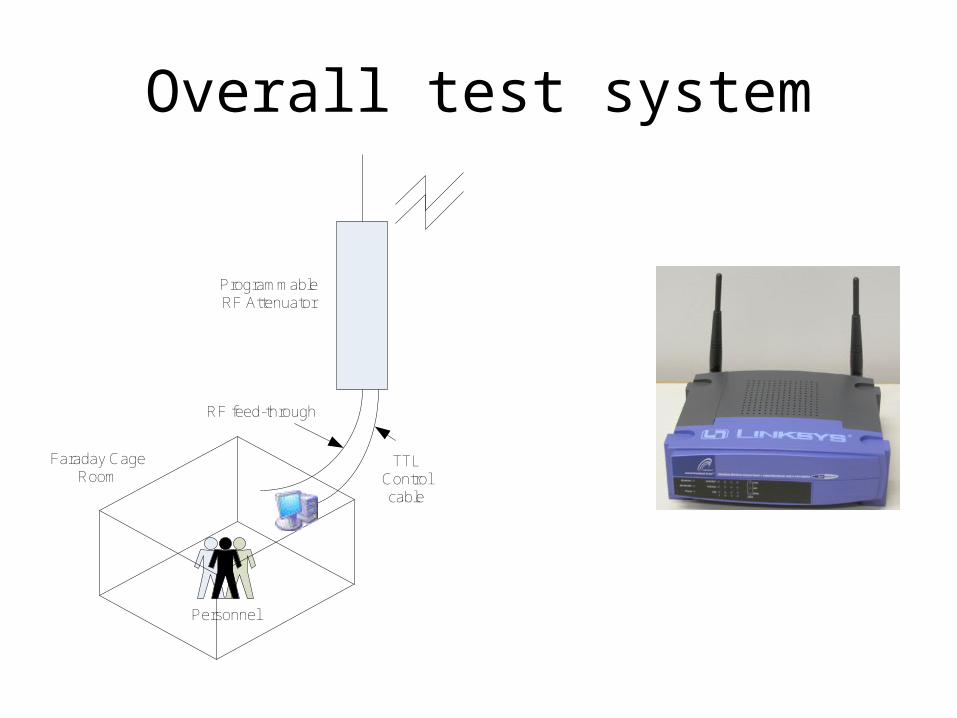
Personnel
Faraday Cage Room
Programmable RF Attenuator
RF feed-through
TTLControl cable
Overall test system

Basic Stamp Attenuator Controller
• Modified Virtual COM port USB I/O device connected to any terminal software.
• Input: a valid attenuation value• Output: a binary weighted
digital output (TTL)

Modify USB Basic Stamp
• Program basic stamp• Rewire I/O to
microcontroller• Assemble IDE cable
TTL ConnAttenuator
BASIC Stamp 1
63 pinout
<model>-63 dB(cell)
BASIC Stamp 1
xx.75 pinout
<model>-63.75
dB(cell)
1 P0 1 Vss 0.25
2 P1 2 Vss 0.50
3 P2 4 P0 1
4 P3 8 P1 2
5 P4 16 P2 4
6 P5 32 P3 8
7 P4 16
8 P5 32
9 Vdd +5V Vdd +5
10 Vss COM Vss COM
P6 Pin24 BS1USB
P6 Pin24 BS1USB
P7 Pin25 BS1USB
P7 Pin25 BS1USB

USB Attenuator Micro-controller flowListen for an incoming attenuation command
from the PC on controller pin 7
Input < 64?
YES NOWe have an input, Change the attenuation
Then send it out
Keep serial pins HIGH
Read actual pin states
Delay for stablization
Convert HEX to Decimal(valid inputs from 0 to 63 in lookup table)
Controller replies to PC on pin 6“CHANGE ATTN = XX”
Read the pins
Controller replies to PC on pin 6“NO CHANGE ATTN = XX”
Look for more input Look for more input

Com Port and configurationPoint to COM port control tab
User selects port
Is Serial port Open?
YES
NO“Check USB port or
select the correct port”
Has user made listbox
selections yet?
NO
YES
Wait for user To finish making
selections
User presses START
Build file folder and date stamped
log file
Calculate attenuation rate
serialPort_dataReceived event
Invoke AddReceive event handler
Add whatever has been received to the main holder “received”
Call ReadData every ½ second thenParse incoming strings for received DB value
Do we have data?
Verification received from controller, count
the time stamp
YES
Compare incoming string to the data that
was sent out
Ignore nullstrings
NO

Desktop Attenuator control UI

Configure Hand-in / Hand-out

Hand-in / Hand-out cycle definitiondB
Time
Select Step Size
in dB
Select Time Step
(seconds)
Select StartValue (dB)
Select StopValue (dB)
Select Half Cycle
count
SelectHalf Cycle
delayHalf cycle
delayHalf Cycle
count

Hand-in / Hand-out state machine
HIHOstate1
HIHOstate0
HIHOstate1.Start()
AttnSixtyToZero()
60 seconds
HIHOstate2
HIHOstate2.Start()
1,2,3, or 5 minutes
AttnZero()
isCONNUMAimage & isCONNimage
!isCONNUMAimage & !isCONNimage ORisCALLFAILimage
HIHOtimer
HIHOstate3HIHOstate3.Start()
AttnZeroToSixty()
HIHOtimer.Start()
RIROtest&
isUMAimage
No hand-in yet ,Wait another 30
secondsRove-in occurred, 60 dB attenuation STARTING NOW
Hand-in occurred, 60 dB attenuation STARTING NOW60
seconds
HIHOstate4
AttnSixty ()
AttnSixty ()
80 seconds
HIHOstate5
!isCONNUMAimage & isCONNimage
We have handedOut to GSMPASS case
isCONNUMAimage & isCONNimage ORisCALLFAILimage
We have Hand out to GSM
FAIL case
isUMAimage&
RIROtest
Rove OutTo
GSMFAIL
!isUMAimage&
RIROtest
Rove OutTo
GSMPASS