Embed Size (px)
Citation preview

MSI 200Programmable Safety Controllers
U S E R M A N U A L
EN
2011
/05
- 70
0932
We
rese
rve
the
right
to
mak
e te
chni
cal c
hang
es

© 2011Leuze electronic GmbH + Co. KGIn der Braike 1D-73277 Owen - Teck / GermanyPhone: +49 7021 573-0Fax: +49 7021 573-199http://[email protected]

Designation:
Revision:
Order No.:
This user manual is valid for
2011-05-26
Leuze electronic
Leuze electronic MSI 200
Device description, configuration, and startup of the MSI 200 safety con-toller with the MSI-EM200-8I4IO4 extension module
MSI 200
01
700932
Designation Order No.
MSI 200
MSI 201
MSI 202
MSI-EM200-8I4IO
MSI-EM201-8I4IO
MSI-EM202-8I4IO
547803
547813
547804
547814
User Manual

Please observe the following notes
In order to ensure the safe use of the product described, you have to read and understand this manual. The following notes provide information on how to use this manual.
User group of this manual
The use of products described in this manual is oriented exclusively to
– qualified electricians or persons instructed by them, who are familiar with applicable standards and other regulations regarding electrical engineering and, in particular, the relevant safety concepts.
– qualified application programmers and software engineers, who are familiar with the safety concepts of automation technology and applicable standards.
Leuze electronic GmbH + Co.KG is not liable for damages that result from improper use. Proper use also includes knowledge of the information contained in this user manual.
Explanation of symbols used and signal words
The following types of messages provide information about possible property damage and general information concerning proper operation and ease-of-use.
This is the safety alert symbol. It is used to alert you to potential personal injury hazards. Obey all safety messages that follow this symbol to avoid possible injury or death.
DANGER
This indicates a hazardous situation which, if not avoided, will result in death or serious injury.
WARNING
This indicates a hazardous situation which, if not avoided, could result in death or serious injury.
CAUTION
This indicates a hazardous situation which, if not avoided, could result in minor or moderate injury.
NOTE
This symbol and the accompanying text alerts the reader to a situation which may cause damage or malfunction to the device, either hardware or software, or surrounding property.
This symbol and the accompanying text provides additional information to the reader. It is also used as a reference to other sources of information (manuals, data sheets, literature) on the subject matter, product, etc.
MSI 200 Leuze electronic

General terms and conditions of use for technical documentation
Leuze electronic reserves the right to alter, correct, and/or improve the technical documentation and the products described in the technical documentation at its own discretion and without giving prior notice, insofar as this is reasonable for the user. The same applies to any technical changes that serve the purpose of technical progress.
The receipt of technical documentation (in particular data sheets, installation instructions, manuals, etc.) does not constitute any further duty on the part of Leuze electronic to furnish information on alterations to products and/or technical documentation. Any other agreement shall only apply if expressly confirmed in writing by Leuze electronic. Please note that the supplied documentation is product-specific documentation only and that you are responsible for checking the suitability and intended use of the products in your specific application, in particular with regard to observing the applicable standards and regulations.Although Leuze electronic makes every effort to ensure that the information content is accurate, up-to-date, and state-of-the-art, technical inaccuracies and/or printing errors in the information cannot be ruled out. Leuze electronic does not offer any guarantees as to the reliability, accuracy or completeness of the information. All information made available in the technical data is supplied without any accompanying guarantee, whether expressly mentioned, implied or tacitly assumed. This information does not include any guarantees regarding quality, does not describe any fair marketable quality, and does not make any claims as to quality guarantees or guarantees regarding the suitability for a special purpose.
Leuze electronic accepts no liability or responsibility for errors or omissions in the content of the technical documentation (in particular data sheets, installation instructions, manuals, etc.).
The aforementioned limitations of liability and exemptions from liability do not apply, in so far as liability must be assumed, e.g., according to product liability law, in cases of premeditation, gross negligence, on account of loss of life, physical injury or damage to health or on account of the violation of important contractual obligations. Claims for damages for the violation of important contractual obligations are, however, limited to contract-typical, predictable damages, provided there is no premeditation or gross negligence, or that liability is assumed on account of loss of life, physical injury or damage to health. This ruling does not imply a change in the burden of proof to the detriment of the user.
Leuze electronic MSI 200

Statement of legal authority
This manual, including all illustrations contained herein, is copyright protected. Use of this manual by any third party is forbidden. Reproduction, translation, and public disclosure, as well as electronic and photographic archiving or alteration requires the express written consent of Leuze electronic. Violators are liable for damages.
Leuze electronic reserves all rights in the case of patent award or listing of a registered design, in as far as this concerns software of Leuze electronic that meets the criteria of technicity or has technical relevance. Third-party products are always named without reference to patent rights. The existence of such rights shall not be excluded.
Windows 3.x, Windows 95, Windows 98, Windows NT, Windows 2000, Windows XP, Windows Vista and Windows 7 are trademarks of the Microsoft Corporation.
All other product names used are trademarks of the respective organizations.
How to contact us
Internet Up-to-date information on Leuze electronic products and our Terms and Conditions can be found on the Internet at:
www.leuze.com.
Subsidiaries If there are any problems that cannot be solved using the documentation, please contact your Leuze electronic subsidiary.Subsidiary contact information is available at www.leuze.com.
Published by .
Leuze electronic GmbH & Co. KGIn der Braike 173277 OwenGermanyPhone +49 - (0) 7021 573-0Fax +49 - (0) 7021 573-199
MSI 200 Leuze electronic

Table of contents
1 For your safety ........................................................................................................................1-11.1 Purpose of this user manual ..............................................................................1-11.2 General safety notes ..........................................................................................1-11.3 Electrical safety ..................................................................................................1-21.4 Safety of the machine or system ........................................................................1-31.5 Directives and standards....................................................................................1-41.6 Intended use ......................................................................................................1-61.7 Documentation ...................................................................................................1-7
2 System description .................................................................................................................2-12.1 Method of operation and structure of the MSI 200 safety system ......................2-12.2 Using the system................................................................................................2-52.3 System startup and restart behavior ..................................................................2-62.4 Error detection in I/O devices.............................................................................2-82.5 Diagnostic tools ..................................................................................................2-92.6 Password protection.........................................................................................2-142.7 Ordering data ...................................................................................................2-152.8 System requirements for the configuration software MSIsafesoft ....................2-15
3 Safety contoller MSI 200 ........................................................................................................3-13.1 Device description ..............................................................................................3-13.2 Operating modes (status) of MSI 200 ................................................................3-33.3 Operating and indication elements.....................................................................3-4
3.3.1 Diagnostic and status indicators .........................................................3-43.3.2 "Confirm" button .................................................................................3-6
3.4 Signal connections .............................................................................................3-73.4.1 Signal inputs .......................................................................................3-73.4.2 Safe outputs .......................................................................................3-83.4.3 Alarm outputs M0 to M3 .....................................................................3-93.4.4 Test clock outputs T0 and T1 .............................................................3-93.4.5 24 V/0 V supply connection ................................................................3-93.4.6 Supply connections A1 and A2 ...........................................................3-93.4.7 Grounded switching outputs O0- and O1- ........................................3-10
3.5 USB interface ...................................................................................................3-113.6 Data memory module (AC-MSI-CFG1) ............................................................3-123.7 Installing the safety contoller ............................................................................3-13
3.7.1 Mounting the safety contoller ............................................................3-133.7.2 Connecting the supply voltage .........................................................3-153.7.3 Connecting the signal lines ...............................................................3-16
3.8 Firmware update for MSI 200...........................................................................3-173.8.1 Safety notes for the firmware update ................................................3-17
Leuze electronic MSI 200 i

3.8.2 Requirement for firmware update .....................................................3-173.8.3 Running a firmware update ..............................................................3-18
3.9 Technical data MSI 200 ...................................................................................3-19
4 Extension module MSI-EM200-8I4IO .....................................................................................4-14.1 Device description ..............................................................................................4-14.2 Diagnostic and status indicators ........................................................................4-24.3 Signal connections .............................................................................................4-4
4.3.1 Signal inputs .......................................................................................4-44.3.2 Safe outputs .......................................................................................4-54.3.3 Clock/alarm outputs TM0 and TM1 ....................................................4-64.3.4 Supply connection A1/A2 ...................................................................4-7
4.4 Installing the safe extension device ...................................................................4-74.4.1 Mounting the safe extension device ...................................................4-74.4.2 Connecting the supply voltage ...........................................................4-74.4.3 Connecting the signal lines .................................................................4-8
4.5 Technical data MSI-EM200-8I4IO......................................................................4-9
5 Configuration software MSIsafesoft ........................................................................................5-15.1 Installing MSIsafesoft .........................................................................................5-15.2 Overview of functions and features ....................................................................5-15.3 Description of the user interface ........................................................................5-35.4 Safe functional blocks and functions..................................................................5-55.5 Operating the MSIsafesoft configuration software .............................................5-9
5.5.1 Creating the configuration project .....................................................5-105.5.2 Inserting and removing extension devices .......................................5-115.5.3 Inserting and connecting functions, functional blocks, and signals ..5-135.5.4 Device parameterization in the safe parameterization editor ...........5-175.5.5 Checking, downloading, and starting up the project .........................5-205.5.6 Documenting the signal assignment and the project ........................5-21
5.6 Simulation mode in MSIsafesoft.......................................................................5-23
6 Configuration and startup .......................................................................................................6-16.1 Configuration overview from A to Z ....................................................................6-16.2 Downloading the configuration from MSIsafesoft...............................................6-46.3 Downloading the configuration using the AC-MSI-CFG1 ...................................6-76.4 Uploading the configuration from the safety contoller .......................................6-96.5 Function test.....................................................................................................6-106.6 Startup mode....................................................................................................6-11
ii MSI 200 Leuze electronic

Table of contents
7 Application examples ..............................................................................................................7-1
8 Problems and solutions ..........................................................................................................8-18.1 General ..............................................................................................................8-18.2 Graphical connection editor ...............................................................................8-28.3 Parameterization editor ......................................................................................8-28.4 Online communication between MSIsafesoft and the safety contoller ..............8-38.5 Communication between the safety contoller and the extension device............8-58.6 Safety contoller messages .................................................................................8-5
A Index....................................................................................................................................... A-1
Leuze electronic MSI 200 iii

iv MSI 200 Leuze electronic
For your safety
1 For your safety
1.1 Purpose of this user manual
This user manual should enable the user to configure and start up the MSI 200 safety con-toller according to the safety requirements and the risk analysis performed.
The user manual is, therefore, designed as a system description. It provides an introduc-tory system overview, then describes the MSI 200 safety contoller, the MSI-EM200-8I4IO safe extension device, and the associated MSIsafesoft configuration software, and finally explains the necessary steps for configuration and startup.
For additional information and detailed step-by-step instructions for MSIsafesoft, please refer to the online help for the configuration software.
1.2 General safety notes
Requirements Knowledge of the following is required:
– The MSI 200 safety contoller used and the I/O devices (extension devices, sensors, actuators)
– The MSIsafesoft configuration software
– The safety directives for the field of application
Qualified personnel
This user manual is, therefore, aimed at:
– Qualified personnel who plan and design safety equipment for machines and systems and are familiar with regulations governing safety in the workplace and accident pre-vention
– Qualified personnel who install and operate safety equipment in machines and sys-tems
Qualified personnel are persons who, because of their education, experience, and instruc-tion, and their knowledge of relevant standards, regulations, accident prevention, and ser-vice conditions, have been authorized to carry out any required operations, and who are able to recognize and avoid any possible dangers.
The MSI 200 configurable safety contoller is referred to in this documentation as "safety contoller" for short.
WARNING: Personal injury and material damage if these safety notes are not fol-lowed.
Please observe all the safety notes outlined in this section when using the MSI 200 sa-fety contoller.
WARNING: In the context of the use of the MSI 200 safety contoller with MSIsafesoft configuration software and safe functional blocks, the following operations may only be carried out by qualified personnel:
– Planning, parameterization, configuration (development of safety logic)
– Installation, startup, servicing
– Maintenance, decommissioning
Leuze electronic MSI 200 1-1

For your safety
Safety of personnel and equipment
The safety of personnel and equipment can only be assured if the safe functional blocks are used correctly (see "Intended use" on page 1-6).
Error detection Depending on the wiring and parameterization of the inputs and outputs, the MSI 200 sa-fety contoller and the MSI-EM200-8I4IO safe extension device can detect various errors within the safety equipment (e.g., cross circuits).
Observe startup behavior Some of the safe functional blocks in the MSIsafesoft configuration software have parame-ters for specifying a startup inhibit and/or a restart inhibit. An active startup inhibit/restart inhibit can be removed by pressing a reset button that is connected and appropriately wired to the safety contoller or the MSI-EM200-8I4IO safe extension device.
Use these parameters in the MSIsafesoft configuration software to monitor the startup/re-start of the safety contoller.
Do not carry out any re-pairs, do not open the housing
In the event that an error caused by reconfiguring or modifying the wiring, etc. cannot be removed, please contact Leuze electronic immediately.
1.3 Electrical safety
Direct/indirect contact Protection against direct and indirect contact according to DIN VDE 0100-410 must be en-sured for all components connected to the MSI 200 safety contoller or extension devices. In the event of an error, parasitic voltages must not occur (single-fault tolerance).
Safe isolation Only use devices with safe isolation if hazardous contact voltages can occur at their con-nections.
Power supply unit Only use power supply units with safe isolation and PELV conforming to EN 50178/VDE 0160 (PELV). These units prevent short circuits between primary and secondary sides.
ESD
NOTE: Please note that responsibility for fault avoidance lies with the user.
WARNING: It is not permitted to make repairs to the MSI 200 safety contoller or the ex-tension modules. The housing must not be opened.
DANGER: Hazardous body currents or loss of functional safety.
In order to ensure electrical safety, please observe the following points and the informa-tion in the user manuals for the devices used (e.g., sensors, actuators or extension de-vices).
NOTE: Electrostatic discharge
The device contains components that can be damaged or destroyed by electrostatic di-scharge. When handling the device, observe the necessary safety precautions against electrostatic discharge (ESD) according to EN 61340-5-1 and EN 61340-5-2.
1-2 MSI 200 Leuze electronic

For your safety
1.4 Safety of the machine or system
Draw up and implement a safety concept
In order to use the system described in this document with the associated safe functional blocks, you must have drawn up an appropriate safety concept for your machine or system. This includes a hazard and risk analysis, as well as a test report for validating the safety functions.
The target safety integrity level (SIL according to IEC 61508 and category according to EN 954-1 or performance level according to EN ISO 13849-1) is ascertained on the basis of the risk analysis.
The safety integrity level or category ascertained determines:
– How safe sensors, control devices, and actuators should be wired within the overall safety function
– How safe functional blocks should be used in the safety logic (The safety logic is crea-ted using the MSIsafesoft configuration software.)
Within the safe control system used, the safe functional blocks support the following safety integrity requirements:
– Up to SIL 3 according to standard IEC 61508
– Up to SILCL 3 according to standard EN 62061
– Up to Category 4 acc. to standard EN 954-1 or PLe acc. to standard EN ISO 13849-1
Check hardware and de-vice parameterization
Please note that you must carry out a validation every time you make a safety-related mo-dification to your overall system. Use the relevant checklists when carrying out the valida-tion and also enter the details requested in the "Project Information" dialog box in the MSIsafesoft safe configuration software.
Use your test report to ensure that:
– The safe sensors and actuators are connected correctly in the MSI 200 safety appli-cation. To do this, use the "Wiring check" function in MSIsafesoft (see page 2-11).
– The inputs and outputs of the MSI 200 safety contoller have been parameterized cor-rectly.
– The signals have been connected to the safe sensors and actuators correctly (single-channel or two-channel).
– Cross-circuit detection is implemented in your application, if required (see page 2-8).
– All safe functional blocks and functions in the MSIsafesoft configuration software are connected correctly.
WARNING: Ensure the safety of the machine or system.
The operator bears sole responsibility for the safety of the machine or system. The Ma-chinery Directive must thus be observed.
Please note that you are responsible for implementing all additional requirements resul-ting from applicable directives and legislation in order to meet the above safety integrity requirements (see also "Directives and standards" on page 1-4).
Leuze electronic MSI 200 1-3
For your safety
1.5 Directives and standards
The manufacturers and operators of machines and systems in which the MSI 200 safety contoller is used are responsible for adhering to all applicable directives and legislation.
Directives and standards considered in the development and implementation of the safety contoller:
Directives – Machinery Directive 2006/42/EC
– Machinery Directive 98/38/EC
– EMC Directive 2004/108/EC
– Low-Voltage Directive 2006/95/EC
– Guideline for test and certification GS-ET-26: Bus systems for the transmission of sa-fety-related messages
Table 1-1 Standards
Standard Contents
IEC 61508-1:11.2002IEC 61508-2:12.2002IEC 61508-3:12.2002IEC 61508-4:11.2002IEC 61508-5:11.2002IEC 61508-6:06.2003IEC 61508-7:06.2003
Functional safety of safety-related electrical/electronic/programmable electronic systems
EN ISO 13849-1 Safety of machinery - Safety-related parts of control systems; best suited for less complex systems.
Part 1: General principles for design
This standard was created on the basis of EN 954-1:1996; quality management and reliability aspects have been added.
EN ISO 13849-2: 12.2003 Safety of machinery - Safety-related parts of control systems - Part 2: Validation
EN ISO 12100-2 Safety of machinery - Basic concepts, general principles for designPart 2: Technical principles
IEC 62061 Safety of machinery; Functional safety of electrical, electronic and programmable control sys-tems for machinery.Sector standard for machinery, created on the basis of IEC 61508.Safety for complex programmable systems.Proof of safety of devices as well as evaluation of risk reduction of the entire safety function through calculation.
EN 60204-1:11.1998 Safety of machinery - Electrical equipment of machines; Part 1: General requirements
EN ISO 13850 Safety of machinery; Emergency stop, principles for design
EN 61131-2:02.04 Programmable controllers; Part 2: Equipment requirements and tests
EN 61131-3:02.04 Programmable controllers; Part 3: Programming languages
EN 61496-1:06.98 Safety of machinery - Electro-sensitive protective equipment; Part 1: General requirements and tests
1-4 MSI 200 Leuze electronic

For your safety
EN 1088 Safety of machinery; Interlocking devices associated with guards, principles for design and selection
EN 953 Safety of machinery; Guards, general requirements for the design and construction of fixed and movable guards
EN 574 Safety of machinery; Two-hand control devices, functional aspects, principles for design
EN 50254:07.1999 High-efficiency communication subsystem for small data packages
EN 50178:04.1998 Electronic equipment for use in power installations
EC/ISO 7498 Information Technology; Open Systems Interconnection
Table 1-1 Standards
Standard Contents
Leuze electronic MSI 200 1-5

For your safety
1.6 Intended use
MSI 200 The safety contoller and all extension modules must only be used in industrial applications subject to conformance with standards IEC 61508, EN ISO 13849, EN 954, and EN 62061.
The safety contoller and all its extension modules are designed for evaluating safety-rela-ted sensors on a machine or system, which are connected to the inputs of the safety con-toller, and for controlling its outputs according to the configured safety logic.
The safety contoller can only perform its safety-related tasks if it has been integrated into the execution process correctly and in such a way as to avoid errors.
You must observe all information in this user manual as well as in the user manuals and online help listed in "Documentation" on page 1-7. In particular, you must only use the sa-fety contoller in accordance with the technical data listed in Section 3.9.
MSI-EM200-8I4IO The MSI-EM200-8I4IO safe extension module is an extension to the safety contoller. It pro-vides additional configurable inputs and outputs. When working with the MSI-EM200-8I4IO safe extension module, please also ensure compliance with the technical data listed in Section 4.5.
MSIsafesoft The MSIsafesoft safe configuration software is designed for the configuration of the safety contoller and its connected extension devices.
Safe functional blocks and functions in MSIsafesoft
The safe functional blocks and functions available in the MSIsafesoft configuration soft-ware for creating the safety logic are designed solely for use within the safety contoller and support specific safety functions.
The safe functional blocks/functions can only perform their safety-related tasks within the safe control system if they have been integrated into the execution process correctly and in such a way as to avoid errors.
The area of responsibility of the block manufacturer in terms of the function of a safe func-tional block or a safe function ends at the user interface, which is generated by the inputs and outputs of the functional blocks/functions.
In order to fully execute a safety function, it is your responsibility to connect the inputs and outputs of the safe functional blocks/functions in the MSIsafesoft configuration software:
– To your safety network
– To the single-channel or two-channel sensors and actuators connected to the inputs and outputs of the safety contoller
In defining the safety integrity level or category for the overall safety function, you must take into consideration all components involved in the execution of this safety function (sensors, actuators, wiring, etc.).
WARNING: Only use the MSI 200 safety contoller according to the information listed in this section.
You must observe all information in the online help for each functional block. Theoretical examples of the use of the safe functional blocks are described in "Application examp-les".
1-6 MSI 200 Leuze electronic

For your safety
1.7 Documentation
Latest documentation Make sure you always use the latest documentation. Find out from the manufacturer or their homepage on the Internet whether any changes or additions have been made to the documentation used.
When working on and with the MSI 200 safety contoller, you must always keep this docu-mentation and other items of product documentation to hand and observe the information therein.
You must observe all information:
– In the technical description of the safety contoller
– In the technical description of the MSI-EM200-8I4IO safe extension device
– In the user documentation for I/O devices (e.g., sensors/actuators, etc.) connected to the safety contoller and connected to safe functional blocks in the safety logic (MSIsafesoft configuration software)
– In the online help for the MSIsafesoft safe configuration software (see also Figure 1-1) and for each of the safe functional blocks
– In the documentation for the supplementary standard technology, if applicable
Calling online help The diagram below illustrates the various options for opening the online help and searching for information via context-sensitive help or via the contents or index.
Figure 1-1 Calling the online help in the configuration software MSIsafesoft
WARNING: In order to use a safe functional block or a safe function according to the re-quired safety integrity as defined by IEC 61508, EN ISO 13849 or EN 62061, you must take into consideration the entire path of the safety function (safety contoller, device pa-rameterization, wiring, sensors, actuators, single-channel or two-channel operation, etc.) starting from the "functional block I/O" interface.
Validate the entire path on completion.
Start page for the help system
Help page for the object
or
or or
Help page for the dialog box or area
Leuze electronic MSI 200 1-7

For your safety
1-8 MSI 200 Leuze electronic

System description
2 System description
2.1 Method of operation and structure of the MSI 200 safety system
The overall system: Hardware and software
The MSI 200 safety system consists of the following components:
– The MSI 200 safety contoller
– Optional MSI-EM200-8I4IO safe extension modules
– The MSIsafesoft configuration software
– Suitable safe control devices, sensors, and actuators (depending on the application)
The MSI 200 safety contoller is designed for monitoring and evaluating safety-related con-trol devices in machines and systems (see "Intended use" on page 1-6). The safety con-toller monitors the safe control devices and safety sensors connected at its inputs and at the inputs of the safe extension modules (if there are any). It evaluates the incoming sig-nals according to its configuration, and controls the outputs accordingly.
The MSIsafesoft configuration software is used to configure the MSI 200 safety contoller and the MSI-EM200-8I4IO safe extension module; it provides the relevant editors as well as suitable startup and diagnostic tools for this purpose.
Leuze electronic MSI 200 2-1

System description
The diagram below illustrates the overall system in an application example.
Figure 2-1 Example safety system structure
Hardware: MSI 200
The MSI 200 safety contoller offers 20 digital safe inputs for connecting a maximum of 20 single-channel or 10 two-channel safety-related sensors and control devices.
The MSI 200 has 4 digital safe outputs, each of which is set up as a semiconductor output (24 V DC/2 A (total current)). The outputs are designed to meet up to Category 4 according to EN 954-1.
Depending on the configuration, stop category 0 according to EN 60204-1 can be achieved for each output (see "Stop category 0" on page 2-5).
In addition, four signaling current paths, two test clocks at every two outputs, and two grounded switching outputs are available.
For more detailed information about the safety contoller, please refer to the device descrip-tion in Section 3.
The MSI 200 safety contoller can be used both with and without extension modules.
Hardware:MSI-EM200-8I4IO
The MSI-EM200-8I4IO safe extension module has eight safe digital inputs and four sig-nals, which can all be configured as safe inputs or all as outputs.
Upload online values du-ring the function test
Download configura-tion and control para-meters
Reset button for removing active startup/restart inhibits
Control signals for the con-tactors at the safety contoller outputs
Readback signal from the monitoring contacts of the contactor
Single-channel or two-channel con-nection to safety contoller
Safe control devices or sensors
MSIsafesoft on configuration computer
Indicator lamp
Check valve
Motor
USB
MSI 200
Contactor or relay
MSI-EM200-8I4IO
2-2 MSI 200 Leuze electronic

System description
The two module outputs TM0 and TM1 can be configured as alarm outputs or clock out-puts. Alarm outputs can be used, for example, to control a standard PLC or a basic detector unit (e.g., a signal lamp). Test clock outputs can be used to implement cross-circuit detec-tion for input signals.
For more detailed information about the MSI-EM200-8I4IO safe extension module, please refer to the device description in Section 4.
Software: MSIsafesoft
The MSI 200 safety contoller and the MSI-EM200-8I4IO safe extension modules can only be configured and parameterized using the MSIsafesoft configuration software, which is executed on a separate Windows® PC.
The software offers a graphical connection editor for this purpose. The safety logic can be created here by graphically connecting prepared safe functions and functional blocks to the inputs and outputs of the safety contoller. The connections are made intuitively using the mouse, and the editor prevents impermissible connections (e.g., between certain outputs).
In addition, the software provides a safe parameterization editor, which can be used to con-figure each input and output of the MSI 200 safety contoller and the MSI-EM200-8I4IO safe extension modules.
A special online mode supports a detailed function test of the safety logic executed in the MSI 200 safety contoller. Current signal values can be read from the MSI 200 safety con-toller, transmitted to the configuration software, and displayed there "live" in the connection editor.
For more detailed information about the configuration software, please refer to the software description in Section 5.
Safe communication Communication between the MSI 200 safety contoller and the configuration software is via a USB interface.
There is communication between the two components in both directions:
– PC → safety contoller: The configuration data and device parameters are downloaded from the configuration PC to the safety contoller. Configuration data refers to the ap-plication logic, which was created using MSIsafesoft.The configuration can also be downloaded using the plug-in data memory module. Please refer to "Downloading the configuration from MSIsafesoft" on page 6-4 and "Downloading the configuration using the AC-MSI-CFG1" on page 6-7.
– Safety contoller → PC: For diagnostic purposes, online values can be read from the MSI 200 safety contoller via the USB interface and displayed "live" in the software. For more detailed information, please refer to "Function test" on page 6-10.
Leuze electronic MSI 200 2-3

System description
Communication via the TBUS DIN rail connector
The MSI 200 safety contoller (master module) is equipped with an interface for the TBUS DIN rail connector. The Leuze electronic DIN rail connector can be used to connect up to ten extension modules like the MSI-EM200-8I4IO, for example. Communication with these modules is then established automatically via the connector on the DIN rail connector. Sa-fety-related cross-wiring is not required (see also "Mounting the safety contoller" on page 3-13).
Figure 2-2 TBUS DIN rail connector from Leuze electronic
The maximum continuous current for extension modules supplied via the TBUS is 4 A.
MSI 200 on yellow DIN rail con-nector AC-MSI-TCS(Order No.: 547821)
Safe extension moduleson yellow DIN rail connector AC-MSI-TCS(Order No.: 547821)
DIN railconnector
2-4 MSI 200 Leuze electronic

System description
2.2 Using the system
The MSI 200 safety contoller configured with MSIsafesoft is designed for monitoring and evaluating safety control devices and safety sensors in machines. Optional safe extension modules (MSI-EM200-8I4IO) provide additional safe inputs for the connection of safe con-trol devices/sensors.
Machinery Directives and various standards and safety regulations require machine or sys-tem manufacturers to meet a high standard of safety.
Safety circuits Safety control devices and safety sensors differ as follows:
Emergency stop control devices can only be detected in the event of dangerous operation and thus operate in the background. Safety door switches or light grids, for example, are often required for operational reasons and, therefore, regularly control the connection/dis-connection of the safety-related part of the machine.
The safety contoller can be configured flexibly. For the creation of the safety logic, it has safe functional blocks, which are part of the system. The MSI 200 can be used to imple-ment various safety functions in different safety circuits. Just some of the most important options are listed below:
– Emergency stop monitoring
– Safety door monitoring (with and without guard locking)
– Two-hand control devices (Types II and III)
– External device monitoring (feedback monitoring)
– Monitoring and checking electrosensitive protective equipment
– Mode selector switch (evaluation of a mode selector switch and an enable switch)
– Muting applications (light grid monitoring with parallel muting)
Stop category 0 Depending on the safety logic configured for the actual application, outputs of the safety contoller and the safe extension devices can be used to stop machines/drives with stop ca-tegory 0 according to EN 60204-1.
EN 60204-1 defines stop category 0 as uncontrolled stopping by immediate removal of power to a machine.
Whether a safe output meets stop category 0 depends on the safe functional blocks con-nected in the safety logic: Only if the module output is connected directly to the enable output of a safe functional block, which executes stop category 0 at its output, can the mo-dule output also meet this category.
Example The EmergencyStop functional block executes stop category 0 at its enable output. If this block output is connected directly to a module output, the safety contoller also executes stop category 0 at this output.
Figure 2-3 on page 2-7 shows an example of this type of connection.
Equipment on the machine The configuration and startup of the relevant safety circuit must be planned and verified precisely. Different machines are subject to different requirements for the implementation of a safety function.
The term "machine" is used here to represent any technical system equipped conforming to Machinery Directive 2006/42/EC.
Leuze electronic MSI 200 2-5

System description
Example: You are responsible for planning and implementing the startup behavior and the restart behavior according to your risk analysis. To prevent an unexpected startup, a reset button may be required to generate a manual reset signal at the machine. This will depend on both the results of the risk analysis and the signal path.
Additional safe control devices, such as three-position enable switches, etc., may be requi-red.
2.3 System startup and restart behavior
Startup "Startup" refers to the behavior of the MSI 200 safety contoller (and, therefore, also to that of the safe extension devices used) after switching on (or applying the supply voltage) and following configuration via USB interface or data memory module.
Unless a startup inhibit is configured, the safety contoller starts up immediately following successful configuration (i.e., after pressing the "Confirm" button). The signal inputs are then evaluated and the outputs are controlled accordingly.
Restart "Restart" refers to the behavior of the safety contoller and the safe extension devices after the safety function is triggered and following a return to normal operation (unlocking the emergency stop control device, for example), which makes safe operation possible again.
With an active startup/restart inhibit, the corresponding (inhibited) safe module output re-mains in the safe state. This prevents an undesired startup/restart of a machine controlled by the relevant output terminal block.
Reset button To enable the function of the machine, which is controlled by the module output affected by the active startup inhibit/restart inhibit, the inhibit must be removed by a reset signal.
As in the case of the stop category (see page 2-5), the startup and restart behavior of the safety contoller and the safe extension devices depends on a specific output, and how this output is connected in the configured safety logic.
The reset signal is used at the same time to exit the error state once the error cause has been removed.
Implementation using safe functional blocks
To implement a startup inhibit/restart inhibit, safe functional blocks which have the relevant parameters for activating the startup inhibit and/or restart inhibit must be used in the MSIsafesoft configuration software.
The safe state of an output terminal block is power off mode (signal value: FALSE).
2-6 MSI 200 Leuze electronic

System description
The table below lists the functional blocks that offer these parameters.
To configure a startup inhibit for a specific safe output, for example, this output must be directly connected in the safety logic to the output of a safe functional block, for which a startup inhibit is set via the parameters.
Example In the example below, EmergencyStop as well as a startup inhibit (S_RES parameter = FALSE) and a restart inhibit (A_RES = FALSE) are specified for the safe functional block. The OUT enable output for the functional block is connected directly to safe output O0, where O0 offers a restart inhibit and a startup inhibit. (EmergencyStop executes stop category 0 at the output, which is also transmitted to O0 by the direct con-nection.)
Figure 2-3 Implementing a startup inhibit, restart inhibit, and stop category 0 for safe output O0
Table 2-1 Functional blocks that support a startup inhibit/restart inhibit
Functional block name
Function Available inhibit
EmergencyStop Emergency stop monitoring Startup inhibit, restart inhibit
EDM External device monitoring Startup inhibit
EnableSwitch Evaluation of a three-position enable switch Restart inhibit
ESPE Monitoring of electrosensitive protective equipment (e.g., light grid)
Startup inhibit, restart inhibit
GuardLocking Monitoring of a safety door with four-stage interlocking Startup inhibit, restart inhibit
GuardMonitoring Monitoring of a safety door with two-stage interlocking Startup inhibit, restart inhibit
MutingPar_2Sensor Monitoring of two muting sensors and light grid Startup inhibit
MutingPar Monitoring of four muting sensors (two pairs of sensors in parallel) and light grid
Startup inhibit
MutingSeq Monitoring of four muting sensors (two pairs of sensors in sequence) and light grid
Startup inhibit
TestableSafetySensor Monitoring of a connected optoelectronic protective device (e.g., light curtain) with test function
Startup inhibit, restart inhibit
K1
23
24
13
14
S1
S2
12
11
14
13Reset
+24V
Not-HaltE-Stop
EmergencyStop
Wiring the safety contoller with safe control devices, sensors, and actuators
Leuze electronic MSI 200 2-7

System description
2.4 Error detection in I/O devices
Cross-circuit detection Cross circuits of the connected signal lines can be detected at the safe inputs.
A cross circuit is an unintentional, incorrect connection between redundant circuits.
Clock outputs T0 and T1 The safety contoller provides clock outputs T0 and T1 as an aid for detecting such a cross circuit. The test clocks output here are asynchronous.
For example, if two differently clocked signals are routed back to two inputs of the safety contoller along two channels via an emergency stop control device, a cross circuit can be reliably detected in this emergency stop circuit. In the event of a cross circuit, the same clock signal would be present at both inputs, instead of two different ones.
Figure 2-4 Implementing cross-circuit detection for an emergency stop control device at inputs I0 and I1 of the safety contoller
Parameterization editor in MSIsafesoft
For this purpose, cross-circuit detection for the safety contoller inputs to be monitored must be activated in the MSIsafesoft configuration software in the parameterization editor of the hardware editor.
The MSIsafesoft configuration software specifies the clock signals to be used: Cross-cir-cuit detection is implemented with test clock T0 for all "even" inputs (I0, I2, I4, ... I18). For "odd" inputs (I1, I3, I5, ... I19), test clock T1 must be used for cross-circuit detection.
S2 14
13
+24V
Reset
22
21
12
11
S1
Not-HaltE-Stop
Wiring the safety contoller with safe control devices, sensors, and actuators
Other safe functions/functional blocks
2-8 MSI 200 Leuze electronic

System description
Activating cross-circuit detection for the safety contoller inputs:
1. Open the parameterization editor by double-clicking in the MSIsafesoft hardware edi-tor.
2. Select the corresponding input.
3. In the selection box for this input, set "Cross-circuit detection", as shown in the image below, for inputs 0 and 1.
Figure 2-5 Parameterizing cross-circuit detection for a module input
2.5 Diagnostic tools
The MSIsafesoft configuration software, the MSI 200 safety contoller, and the MSI-EM200-8I4IO safe extension module provide various tools that can be used to diag-nose the active configuration on the safety contoller:
– Hardware diagnostics in the event of a safe functional block error
– Wiring check
– Diagnostic and status indicators on the safety contoller
– Online tool tips in the connection editor
Hardware diagnostics in the event of a safe functio-nal block error
When a safe functional block detects an error, it sets its ERR error output to TRUE and the OUT enable output to the safe status FALSE.
Cross-circuit detection is also supported at the inputs of the MSI-EM200-8I4IO safe ex-tension module. The TM0 and TM1 module outputs must be configured as clock outputs for this purpose. For further information about cross-circuit detection in the MSI-EM200-8I4IO safe extension module, please refer to the device description in Section 4.
For an overview of the diagnostic and status indicators, please refer to Table 3-1 on page 3-5.
DoppelklickDouble click
Leuze electronic MSI 200 2-9

System description
For further information, please refer to the descriptions of the safe functional blocks in the MSIsafesoft online help, particularly in the corresponding "ERR output" help topic.
If the ERR output of a safe functional block is TRUE, all the inputs that are connected di-rectly to the inputs of this functional block flash on the safety contoller or the corresponding safe extension device.
This tells you which module input is affected by the problem. You can take action to remove the fault (check the connecting cables to the sensors or the connected sensors themsel-ves, etc.).
The following example shows a simplified schematic view: An emergency stop control device with two N/C contacts is connected to inputs I0 and I1 of the safety contoller. The status of the N/C contacts is monitored by the Equivalent safe functional block. In our example, the functional block reports an error (ERR output = TRUE, the icon for the functional block is surrounded by a red border with the configuration soft-ware in online mode).
This function enables hardware errors to be located even without a PC. An error is indi-cated by the LED(s) at the inputs of the safety contoller flashing. The project documen-tation enables conclusions to be drawn regarding the relevant safe functional block based on which module input is flashing.
2-10 MSI 200 Leuze electronic

System description
Therefore, the LEDs for inputs I0 and I1, which are both directly connected to this functional block, flash on the safety contoller.
Figure 2-6 Hardware diagnostics in the event of a safe functional block error
Wiring check If the connection editor is in startup mode, the wiring check can be used to check the ter-minal block position of the input used in the logic. A graphical link directs the user to the right position and provides a better overview of the control cabinet.
1. Requirements: The MSI 200 safety contoller must be running.
Switch the connection editor to online mode, then to startup mode.
2. In the connection editor, position the cursor over the icon for the input or output you want to check, without clicking. The icon starts to flash after around one second.
Hardware diagnostics is also possible for inputs and outputs of safe extension devices (e.g., MSI-EM200-8I4IO).
Safety logic in MSIsafesoft, in online mode (error)
Safe control device, at inputs I0 and I1 of the MSI 200 safety contoller
LEDs of inputs I0 and I1 on the safety contoller
Emergency stop Reset
Leuze electronic MSI 200 2-11

System description
At the same time, the LED for the corresponding input/output flashes on the safety contoller or on the corresponding safe extension device.
Figure 2-7 Simplified schematic view: Wiring check
Diagnostic indicators on the safety contoller
There are four diagnostic indicators on the MSI 200 safety contoller.
– PWR (green): Indicator for the power supply of the safety contoller
– EXT (green): Indicator for communication with extension modules (with/without TBUS)
– ERR (red): Error display
– CFG (green): Indicator for the configuration status and communication via the USB in-terface
The LEDs indicate the status of the safety contoller.
A wiring check is also possible for inputs and outputs of safe extension devices (e.g., MSI-EM200-8I4IO).
LED for the wired input flashes on the safety contoller
Emergency stop Reset
Do not click
For a detailed list of possible indicator combinations and their meanings, please refer to "Diagnostic and status indicators" on page 3-4.
2-12 MSI 200 Leuze electronic

System description
Diagnostic indicators on the MSI-EM200-8I4IO safe extension device
There are two LEDs on the MSI-EM200-8I4IO safe extension device.
– PWR (green): Indicator for the power supply of the extension module
– ERR (red): Error display
Online tool tips in the con-nection editor
In online mode, when the MSIsafesoft configuration software reads signal values from the MSI 200 safety contoller and displays them "live" in the connection editor, the safe functio-nal blocks indicate their status and, in the event of an error, a description of the error as a tool tip as soon as you position the cursor over the icon for a functional block.
In the event of an error, the tool tip contains not only a description of the error, but also information on how to remove it. In the event of an error, the functional block icon is also outlined in red. This ensures that, in online mode, errors can be identified at a glance.
Figure 2-8 Example of an online tool tip in the event of an error
Offline tool tips Tool tips are also available while editing the safety logic in the connection editor. For all functional blocks, functions, and their I/Os, as well as for the buttons in the toolbar, descrip-tions are displayed as soon as the cursor is positioned over the item.
Figure 2-9 Examples of tool tips in the connection editor in offline mode (while editing the safety logic)
Leuze electronic MSI 200 2-13

System description
2.6 Password protection
MSI 200 and MSIsafesoft use two passwords to offer dual protection against unauthorized modifications to the configuration and the project in the configuration software.
Figure 2-10 Password protection for MSI 200 and MSIsafesoft
Controller password The controller password protects the configuration on the MSI 200 safety contoller against unauthorized access and the safety contoller itself against unauthorized changes of ope-rating mode. However, online values can be read from the safety contoller and displayed in MSIsafesoft without entering the controller password. However, a new configuration or new device parameters can only be downloaded to the safety contoller (and the safety con-toller can only be launched accordingly) once the controller password has been entered.
Project password The project password protects the configuration project in MSIsafesoft against unautho-rized modifications to the safety logic and the project information. You can still open and display projects without a password, but you can only change and save them once you have entered a project password. This ensures that only authorized persons in possession of the correct project password can change the safety logic.
Automatic logoff due to a long period of inactivity in MSIsafesoft
If no user activity is detected in MSIsafesoft for a certain period of time, you will be logged off from the project automatically. This prevents unauthorized persons from making chan-ges to the project if you have not logged off from the project.
This also applies to the MSI 200 safety contoller: If no user activity is detected for a prolon-ged period of time, you will have to enter the controller password again in order to continue to communicate with the safety contoller in MSIsafesoft.
During automatic logoff, for safety reasons the safety contoller remains in the mode that was running prior to automatic logoff.
Example: Automatic logoff does not cause startup mode to be exited, but you must log on again before you will be able to influence signals once more.
When an unconfigured MSI 200 safety contoller is connected to the configuration com-puter for the first time, MSIsafesoft automatically prompts the user to specify a controller password. This password can be modified later if required.
When creating a new project, you are automatically requested to define a password.
For further information about password protection, please refer to the online help for MSIsafesoft.
2-14 MSI 200 Leuze electronic

System description
2.7 Ordering data
2.8 System requirements for the configuration soft-ware MSIsafesoft
Products
Description Type Order No. Pcs./Pkt.
Configurable safety contoller
Module with screw connections
Module with spring-cage connections
MSI 201
MSI 202
547803
547813
1
1
Configurable safe extension module
Module with screw connections
Module with spring-cage connections
MSI-EM201-8I4IO
MSI-EM202-8I4IO
547804
547814
1
1
Data memory module for MSI 200 (supplied as standard with the safety contoller).
AC-MSI-CFG1 547820 10
Accessories
Description Type Order No. Pcs./Pkt
MSI TBUS standard connection plug (for fieldbus gateways) AC-MSI-TC 547823 10
MSI TBUS safety connection plug AC-MSI-TCS 547821 10
MSI commissioning set including MSIsafesoft configuration software, confi-guration cable (USB), and Quick Start Guide
MSI-SWC1 547825 1
MSI USB cable MSI-PC, 3 m AC-MSI-USB 547822 1
Under Windows Vista/Windows 7 Minimum Recommended
CPU 1 GHz x86 architecture 2 GHz x86 architecture
Main memory 1 GB 2 GB
Under Windows XP/2000 (SP4/SP2) Minimum Recommended
CPU 1 GHz x86 architecture 1 GHz x86 architecture
Main memory 512 MB 1 GB
All operating systems Minimum Recommended
Hard disk 1 GB free memory space 1 GB free memory space
Monitor/resolution SVGA/800 x 600 SVGA/800 x 600
Mouse required required
CD-ROM drive required required
USB interface required required
Internet Explorer 5.5 or later required required
Leuze electronic MSI 200 2-15

System description
2-16 MSI 200 Leuze electronic

Safety contoller MSI 200
3 Safety contoller MSI 200
3.1 Device description
The MSI 200 safety contoller is a configurable safety controller with 20 digital safe inputs, which enable the connection of a maximum of 20 single-channel or 10 two-channel safe sensors or control devices.
The four digital safe outputs, O0 to O3, are controlled after evaluating the incoming signals according to the configuration, which was created with the MSIsafesoft configuration soft-ware and downloaded to the safety contoller via USB interface.
The safety contoller also has two grounded switching outputs, O0- and O1-; these can be used, for example, to switch off a contactor connected to the safety contoller either via the output or via ground. Use of the grounded switching outputs increases the shutdown pro-tection and cross-circuit protection of the safety circuit.
In addition, the safety contoller has four non-safety-related digital alarm outputs (M0 to M3); these can be used, for example, to control a standard PLC or signaling units.
The two asynchronous test clocks at T0 and T1 provide safe cross-circuit detection at the inputs of the safety contoller, as described in "Error detection in I/O devices" on page 2-8.
All connection terminal blocks are plug-in. The individual terminal block bases are mechanically keyed to prevent incorrect connection. The safety contoller is available either with screw connections (on the left in Figure 3-1) or with spring-cage connections (on the right in Figure 3-1).
Figure 3-1 Screw connection (left) and spring-cage terminal blocks (right)
PWR
EXT
ERR
CFG
A1A1
A2A2
24V0V
O0-
01- T0T0
T1T1
M1
M2
M3
M0
CONFIRM
CFGSTICK
MSI100
I0
I8
I4I12
I1
I9
I5I13
I2
I10
I6I14
I3
I11
I7I15
O0
I16
O1
I17
O2
I18
O3
I19
www.leuze.de/MSI
PWR
EXT
ERR
CFG
A1A1
A2A2
24V0V
O0- 01- T0T0
T1T1
M1M2
M3
M0
CFGSTICK
I0
I8
I4I12
I1
I9
I5I13
I2
I10
I6I14
I3
I11
I7I15
O0
I16
O1
I17
O2
I18
O3
I19
CONFIRM
MSI100
www.leuze.de/MSI
Leuze electronic MSI 200 3-1

Safety contoller MSI 200
Figure 3-2 Block diagram of the MSI 200 safety contoller
The safety contoller can be used both with and without extension modules.
A1 A2 T0
24V 0V O0 O1 O2 O3 O0- O1-
T0 T1 T1 I0 I1 I19 M0 M1 M2 M3
TB
US
NO
N-S
AF
E
TB
US
SA
FE
POWER
24V DC
POWER
24V DC
TEST PULSE MONITORING
OUTPUT OUTPUTSAFE INPUT
LOGIC
SAFE OUTPUTUSB
CONF
STICK
3-2 MSI 200 Leuze electronic

Safety contoller MSI 200
3.2 Operating modes (status) of MSI 200
The diagram below illustrates the possible operating modes (status) of the MSI 200 safety contoller and the possible status transitions. When there is a USB connection to the PC, the module status is indicated on the far right of the status bar in the MSIsafesoft configu-ration software.
Figure 3-3 Possible operating modes (status) of the safety contoller
PLC: Connected
PLC: Error
The Safety controller and PCare connected via USB,
the safety controller is switched on
Download projectExecution will start after confirmation(Confirm button on controller)
Change fromsafe online modeto non-safecommissioning mode
Failureduring
execution
Failu
redu
ring
exec
ution
Connection editorOnline or offline
USB connection (PC – controller) may not be interruptedand the project in MSIsafesoft may not be changed.If this happens, the controller will stop and switchto a safe condition after 10 minutes.
PLC: No project
PLC: Commissioning
Commissioning
PLC: Timeout
Temporary condition during:- Saving (during download)- Initialization- Self-test of the controller
Yes
No
Temporary condition during:- Communication- Initialization- Self-test
Initial setup?
PLC: Timeout
Leuze electronic MSI 200 3-3

Safety contoller MSI 200
3.3 Operating and indication elements
All operating and indication elements for the MSI 200 safety contoller are located on the front of the device. The elements are described in the following sections.
Figure 3-4 Operating and indication elements of the safety contoller
3.3.1 Diagnostic and status indicators
Diagnostic indicators The four diagnostic indicators on the front of the device can be used to read the operating status of the safety contoller. The following LEDs are available (from left to right):
– "PWR": Indicator for the power supply of the safety contoller
– "EXT": Indicator for communication with extension modules (with/without TBUS DIN rail connector). This LED is only on if a TBUS device is connected.
– "ERR": Error indicator
– "CFG": Indicator for the configuration status and communication via the USB interface
The following table lists the possible indicator combinations for the diagnostic LEDs and their meanings. A distinction is made between slow flashing and fast flashing LEDs.
Diagnostic indicators
Data memory module
"Confirm" button
Status indicatorsfor safe inputs/outputs
3-4 MSI 200 Leuze electronic

Safety contoller MSI 200
The LED symbols in the table mean:
LED OFF
LED ON
LED flashing Slowly = 1.7 HzFast = 6.3 Hz
Table 3-1 Meaning of diagnostic indicators
PWR(green)
EXT(green)
ERR(red)
CFG(green)
Meaning
Device is switched off, no power supply at A1/A2
Initialization phase after power up (maximum duration: 4 s)
1.7 Hz Acknowledgment of new configuration required after download. → Press the "Confirm" button on the device.
6.3 Hz Acknowledgment of new configuration required after transmission via data memory module. → For sequence, refer to 6.3 on page 6-7.
1.7 Hz Extension device replaced: acknowledgment required. → Press the "Confirm" button on the device.
Normal operation without connected extension devices (TBUS communication)
Normal operation with connected extension devices (TBUS communication)
Limited operation with error affecting at least one in-put/output. → Remove error, deactivate input/output. Press the "Con-firm" button on the device for 10 s; this will induce a warm start of the device and reset the error message.
Default upon delivery. No configuration data on the data memory module. → Download project with MSIsafesoft.
No data memory module. → Insert data memory module and apply power supply.
6.3 Hz An error has occurred.→ Read out the error code with MSIsafesoft.
Leuze electronic MSI 200 3-5

Safety contoller MSI 200
LEDs for signal inputs/out-puts
The state of each of the 20 safe inputs and 4 safe outputs is indicated by an LED on the front of the device.
3.3.2 "Confirm" button
Confirming the new configuration
The "Confirm" button is located at the front of the MSI 200 safety contoller on the right-hand side, above the USB interface. Press this button using a pen to confirm a new configuration downloaded via the USB interface before it is accepted by the safety contoller.
See also "Downloading the configuration from MSIsafesoft" on page 6-4.
Warm start of the device To initiate a warm start of the device, press and hold down the "Confirm" button on the de-vice for 10 seconds. As part of the warm start process, all outputs are initially set to the safe state FALSE and pending error messages are reset as long as their cause has been removed. The device then enters the initialization phase.
Replacing the data memo-ry module
The "Confirm" button also plays an important role when replacing the data memory mo-dule. To download a new configuration by replacing the data memory module rather than via the USB interface, press and hold down the "Confirm" button while removing and inser-ting the data memory module using the specified procedure.
For the precise procedure, please refer to "Downloading the configuration using the AC-MSI-CFG1" on page 6-7.
Table 3-2 Status indicators for safe inputs and outputs
LED State Meaning
For each input("I0" to "I19")
No switching signal at the relevant input
Switching signal active at the input
Diagnostic error (see page 2-9)
Long ONShort OFF
Wiring check at an active input or antivalent input
Long OFFShort ON
Wiring check at an inactive input or antiva-lent input.
For each output("O0" to "O3")
Output inactive
Output active
Diagnostic error(see page 2-9)
Long ONShort OFF
Wiring check at an active output or antiva-lent input.
Long OFFShort ON
Wiring check at an inactive output or antiva-lent input.
3-6 MSI 200 Leuze electronic

Safety contoller MSI 200
3.4 Signal connections
All input and output connections, with the exception of the USB interface, are made via plug-in keyed connection terminal blocks.
Figure 3-5 Signal connections MSI 200
The various signal connections are described in the following sections.
3.4.1 Signal inputs
The safety contoller has 20 digital signal inputs (24 V HTL/3 mA) for the direct connection of safe control devices and/or safety sensors for monitoring and evaluating processes.
The safe inputs are linked to the safety logic in the connection editor of the MSIsafesoft configuration software. See also "Inserting and connecting functions, functional blocks, and signals" on page 5-13.
Signal redundancy due to dual signals
Every two adjacent signal inputs (i.e., I0 and I1, I2 and I3, etc.) are grouped together and interlocked by default to form a dual signal in the MSIsafesoft safe configuration software. This is indicated in the representation of the safety contoller in the hardware editor of the configuration software by a red padlock at the relevant inputs. The two signals are then al-ways used as a pair, i.e., both signals are dragged, dropped, cut or deleted together in the connection editor.
However, if required, this interlock can be removed and the dual signal split into two single signals.
Supply for logic andalarm outputs
Test clocks for cross-circuit detection
Supply forsafe outputs
Safe inputs
Safe outputs
Standard alarm outputs
Grounded switchingoutputs
Dual signals are not connected to one another internally; they are simply grouped to-gether.
Leuze electronic MSI 200 3-7

Safety contoller MSI 200
As input signals with even and odd IDs are processed in different ways in the safety con-toller, using dual signals ensures that the safety contoller will perform redundant proces-sing.
Two-channel sensors To ensure signal redundancy, the prepared dual signal must be used to process two-chan-nel signals (2-wire sensors and control devices). For example, in order to monitor or eva-luate both signals of an emergency stop control device redundantly and to performance level PL e according to EN ISO 13849-1 or EN 954-1 Category 4, these two adjacent sig-nal inputs (e.g., I0 and I1) must be connected.
Cross-circuit detection A "cross circuit" is an unintentional, incorrect connection between redundant circuits. The safety contoller provides clock outputs T0 and T1 as an aid for detecting such a cross cir-cuit.
For example, if two differently clocked signals are routed back to two inputs of the safety contoller along two channels via an emergency stop control device, a cross circuit can be reliably detected in this emergency stop circuit: In the event of a cross circuit, the same clock signal would be present at both inputs, instead of two different ones.
The MSIsafesoft configuration software specifies the clock signals to be used: Cross-circuit detection is implemented with test clock T0 for "even" inputs (I0, I2, I4, ... I18). For "odd" inputs (I1, I3, I5, ... I19), test clock T1 must be used for cross-circuit detection.
3.4.2 Safe outputs
The safety-related outputs O0 to O3 are designed as digital semiconductor outputs for 24 V DC/2 A (total current), up to Category 4 according to EN 954-1.
The outputs are controlled according to the configured safety logic. The safe outputs are linked to the safety logic that controls them in the connection editor of the MSIsafesoft con-figuration software. See also "Inserting and connecting functions, functional blocks, and si-gnals" on page 5-13.
For an example of two-channel connection of an emergency stop control device with dual signal and cross-circuit detection, please refer to Figure 2-4 in "Error detection in I/O devices" on page 2-8.
To increase cross-circuit protection, outputs O0 and O1 can also be used in connection with grounded switching outputs O0- and O1-, see "Grounded switching outputs O0- and O1-" on page 3-10.
An appropriate protective circuit (diode or varistor) for safe outputs O0 to O3 is strongly recommended.
The safe output signals are clocked with a test pulse of 1 ms.
3-8 MSI 200 Leuze electronic

Safety contoller MSI 200
3.4.3 Alarm outputs M0 to M3
The non-safety-related alarm outputs M0, M1, M2, and M3, are designed as digital semi-conductor outputs for 24 V DC/100 mA.
These alarm outputs can be used, for example, to control a standard PLC or a detector unit (e.g., a signal lamp).
As is the case for safe inputs and outputs, the alarm outputs are linked in the connection editor of MSIsafesoft (see "Inserting and connecting functions, functional blocks, and sig-nals" on page 5-13).
3.4.4 Test clock outputs T0 and T1
The test clocks output at outputs T0 and T1 are used for cross-circuit detection at the in-puts. Each output is available twice. The test clocks T0 and T1 output are asynchronous, i.e., T0 does not equal T1.
To implement cross-circuit detection, the relevant safe inputs must be configured accordin-gly using the parameterization editor (part of the hardware editor in MSIsafesoft).
The MSIsafesoft configuration software specifies the clock signals to be used: Cross-circuit detection is implemented with test clock T0 for "even" inputs (I0, I2, I4, ... I18). For "odd" inputs (I1, I3, I5, ... I19), test clock T1 must be used for cross-circuit detection.
Please also refer to "Signal inputs" on page 3-7 and "Error detection in I/O devices" on page 2-8.
3.4.5 24 V/0 V supply connection
The 24 V/0 V supply connection is used to supply the outputs of the safety contoller and the clock and grounded switching outputs with power.
3.4.6 Supply connections A1 and A2
The supply connection A1/A2 is used to supply the logic of the safety contoller and the alarm outputs with power.
At the double terminal block contacts, 2- and 3-wire sensors and control devices can be supplied directly by the safety contoller (Unom = 24 V DC).
NOTE: Alarm outputs must not be connected in parallel. Feedback to alarm outputs is not permitted.
For 3-wire sensors, ensure that the GND potential of the sensor/control device matches the GND potential of the safety contoller.
The maximum continuous current for devices connected to terminal blocks A1 and A2 is 6 A (limiting continuous current for looped-through current paths A1/A1 and A2/A2).
Leuze electronic MSI 200 3-9

Safety contoller MSI 200
3.4.7 Grounded switching outputs O0- and O1-
The grounded switching outputs O0- and O1- increase the shutdown protection and cross-circuit protection of the safety system. For example, these outputs can be used to discon-nect a contactor connected to the safety contoller via both the output and ground.
The diagram below shows an example application: The two contactors, K1 and K2, are switched between safe module output O0 and grounded switching output O-.
Figure 3-6 Example application for grounded switching outputs O0- and O1-
Grounded switching output O0- can only be used in connection with output O0, grounded switching output O1- can only be used in connection with output O1.
In order to use the grounded switching outputs, the corresponding parameters must be set for outputs O0 and O1 in the MSIsafesoft configuration software. For more detailed information, please refer to the online help topic "Parameterizing the inputs and outputs of the safety contoller".
+24V
S1 14
13Reset
-K1
42
41
-K2
42
41
22
21
12
11
S1
Not-HaltE-Stop
K2
K1
A1
A2
A1
A2
3313 23
3412 24
3313 23
3412 24
3-10 MSI 200 Leuze electronic

Safety contoller MSI 200
3.5 USB interface
The USB interface (Standard USB 2.0) is used for communication between the safety con-toller and the MSIsafesoft configuration software.
This includes:
– Download of the configuration data (i.e., for the MSIsafesoft project)
– Optional upload of the configuration in order to open it as a project and edit it as requi-red in MSIsafesoft
– Reading of values from the safety contoller during operation and displaying the read values "live" in the connection editor of MSIsafesoft (online mode)
– Forcing of signals on the running safety contoller for startup purposes (standard star-tup mode)
Once the USB connecting cable (mini-USB connector, 5-pos., maximum cable length 3 m) has been connected, the appropriately configured PC detects the safety contoller automatically.
If the MSIsafesoft configuration software has already been started, the software will detect the status of the safety contoller and display this in the status bar at the bottom right of the screen.
Figure 3-7 Status bar in the MSIsafesoft safe configuration software (safety contoller already contains a configuration project)
Before the safety contoller is connected to the configuration PC, the MSIsafesoft confi-guration software must be installed, with the associated USB drivers for the module.
NOTE: Electrostatic discharge
The safety contoller contains components that can be damaged or destroyed by electro-static discharge. When handling the USB interface, take the necessary safety precau-tions against electrostatic discharge (ESD) according to EN 61340-5-1 and EN 61340-5-2.
Leuze electronic MSI 200 3-11

Safety contoller MSI 200
3.6 Data memory module (AC-MSI-CFG1)
The safety contoller is equipped with a plug-in memory module, the AC-MSI-CFG1.
Figure 3-8 Data memory module AC-MSI-CFG1 on MSI 200
Data memory module as a hardkey
The data memory module must be inserted in the safety contoller both during normal ope-ration and for downloading configuration data from MSIsafesoft via the USB interface.
If no data memory module is inserted in the safety contoller or if it is removed, the safety contoller behaves as follows:
– If no data memory module is inserted when downloading configuration data, the con-figuration cannot be downloaded and MSIsafesoft outputs an error message.
– If no data memory module is inserted when the safety contoller is started, all outputs remain deactivated and the safety contoller indicates an error. The safety contoller does not execute any functions.
– If the data memory module is removed during operation, the safety contoller deactiva-tes all outputs and indicates an error. The safety contoller does not execute any more functions.
– If the data memory module is removed from the safety contoller and reinserted as de-scribed in "Downloading the configuration using the AC-MSI-CFG1" on page 6-7, the safety contoller deactivates all outputs and does not execute any functions until the IFS-CONFSTICK is inserted again correctly. The safety contoller does not indicate an error.
PWR
EXT
ERR
CFG
A1A1
A2A2
24V0V
O0-
01- T0T0
T1T1
M1
M2
M3
M0
CONFIRM
CFGSTICK
MSI100
I0
I8
I4I12
I1
I9
I5I13
I2
I10
I6I14
I3
I11
I7I15
O0
I16
O1
I17
O2
I18
O3
I19
www.leuze.de/MSI
As an alternative to downloading the configuration via the USB interface, it can be down-loaded to the safety contoller using the -IFSCONFSTICK. For a description of this pro-cedure, please refer to "Downloading the configuration using the AC-MSI-CFG1" on page 6-7.
3-12 MSI 200 Leuze electronic

Safety contoller MSI 200
3.7 Installing the safety contoller
3.7.1 Mounting the safety contoller
For standard extension modules, the safety contoller is equipped with an interface for the TBUS DIN rail connector on the mounting side (see page 2-4).
3.7.1.1 Mounting
WARNING: Serious personal injury or material damage.
Disregarding this warning may result in damage to equipment and/or serious personal injury.
Only qualified personnel may connect the power, start up, and operate this device.
According to the safety instructions in this documentation, qualified personnel are per-sons who are authorized to start up, to ground, and to mark devices, systems, and equip-ment according to the standards of safety technology. In addition, these persons must be familiar with all warning instructions and maintenance measures in this document.
CAUTION: Danger of injury and material damage.
Only mount and remove the safety contoller when the power supply is disconnected.
CAUTION: Danger of material damage due to incorrect mounting.
During mounting, observe the following notes:
– Use only the yellow TBUS DIN rail connector (Order No. 547821) to connect the MSI 200 safety contoller. Connection with another DIN rail connector is not permit-ted.
– Use only the yellow TBUS DIN rail connector (Order No. 547821) to connect safe extension devices. Connection with another DIN rail connector is not permitted.
– Safe extension devices must be mounted to the right of the master module.
– Use only the grey TBUS DIN rail connector (Order No. 547823) to connect standard devices. Connection with another DIN rail connector is not permitted.
– Standard devices must be mounted to the left of the master module.
Leuze electronic MSI 200 3-13

Safety contoller MSI 200
To mount the MSI 200 safety contoller, proceed as follows:
Mounting a 35 mm DIN rail 1. The safety contoller should only be mounted on 35 mm DIN rails according to EN 60715. To avoid contact resistance, only use clean and corrosion-free DIN rails.
Mounting TBUS DIN rail connectors (optional)
2. To use TBUS DIN rail connectors to create a connection station with a system power supply unit or with extension devices, proceed as follows:
– Connect together the required number of DIN rail connectors for the connection station (see Figure 3-9, A).
– Snap this group of DIN rail connectors onto the DIN rail (see B and C).
Figure 3-9 Mounting TBUS DIN rail connectors
Mounting the MSI 200 sa-fety contoller
3. Place the module onto the DIN rail from above as shown in Figure 3-10 so that the up-per holding keyway of the module is hooked onto the top edge of the DIN rail.
When using DIN rail connectors, ensure that the contact opening in the base of the module is aligned correctly over the contact block of the DIN rail connector.
Figure 3-10 Snapping the MSI 200 safety contoller onto the DIN rail
4. Push the lower part of the module that is furthest from the DIN rail towards the DIN rail until it engages with a click.
5. Check that the module is fixed securely on the DIN rail.
A
CB
TBUS DIN rail connector
3-14 MSI 200 Leuze electronic

Safety contoller MSI 200
6. When mounting additional modules on the DIN rail (e.g., gateway extension modules or power supply unit), place them on the DIN rail with no spacing, i.e., in direct contact with the sides of the housing. All standard extension devices must be mounted to the left of the safety contoller.
7. End clamps should be mounted on both sides of the module (or module group) to stop the module(s) from slipping on the DIN rail.
3.7.1.2 Removal
To remove the MSI 200 safety contoller, proceed as follows:
1. Pull the locking latch on the bottom of the module down using a screwdriver, for example, to release the module from the DIN rail.
2. Lift the bottom of the module away from the DIN rail slightly.
3. Pull the module diagonally upwards away from the DIN rail.
3.7.2 Connecting the supply voltage
The safety contoller has no main switch and is switched on simply by applying the supply voltage.
The safety logic and the alarm outputs are supplied with power via connections A1/A2; the safe outputs, clock outputs, and grounded switching outputs are supplied via connections 24V/0V.
Once the "PWR" status indicator is permanently on, the safety contoller is ready to operate.
3.7.2.1 Direct connection of the supply voltage to the MSI 200
Connect the supply voltage (as shown in the figure below):
1. Supply voltage for the safe module outputs and the grounded switching outputs to ter-minal block contacts "0V" and "24V"
2. Supply voltage for the logic of the safety contoller and the clock and alarm outputs to terminal block contacts "A1" (24 V) and "A2" (0 V).
Outputs "A1" and "A2" provide the supply voltage for supplying other modules, such as sensors (see "Supply connections A1 and A2" on page 3-9).
Leuze electronic MSI 200 3-15

Safety contoller MSI 200
Once the supply voltage has been applied, the safety contoller executes an initialization routine (all LEDs on).
Figure 3-11 Connecting the supply voltage at A1/A2 and 24V/0V
3.7.3 Connecting the signal lines
Cable lengths Many applications use large numbers of sensors or control devices. Depending on the size of the machine or system, a considerable amount of cabling may be required to wire the sensors. Make sure that the specified cable lengths are not exceeded, so as to ensure error-free operation of the safety circuits and, therefore, a reliable safety demand.
For reliable and touch-proof contacts, strip the cable ends as follows:
Figure 3-12 Connection to screw terminal blocks (left) and spring-cage terminal blocks (right)
CAUTION: Ensure signal redundancy.
Ensure signal redundancy when connecting the signal lines of two-channel control de-vices and sensors to the inputs of the safety contoller. Please refer to "Signal inputs" on page 3-7.
CAUTION: Avoid cross circuits and short circuits.
Prevent cross circuits and short circuits by using a suitable cable installation. Implement cross-circuit detection (see "Cross-circuit detection" on page 3-8).
Connections24 V DC/0 V
"PWR" diagnosticindicator
Connections A2 (2 terminal blocks each)A1
7 mmCO
I8
I4I12
1
I9
I5I13
I2
I10
I6I14
I3
I11
I7I15
0
I16
O1
I17
O2
I18
O3
I19
www.leuze.de/MSI
Screw ter-minal blocks
8 mm
I8
I4I12
I9
I5I13
I2
I10
I6I14
I3
I11
I7I15
I16
O1
I17
O2
I18
O3
I19
CON
www.leuze.de/MSI
Spring-cage terminal blocks
3-16 MSI 200 Leuze electronic

Safety contoller MSI 200
3.8 Firmware update for MSI 200
The firmware for the MSI 200 safety contoller can be updated using the MSIsafesoft safe configuration software.
You can download the latest firmware version from the Leuze electronic download page.
3.8.1 Safety notes for the firmware update
The following safety notes must be observed during and after the firmware update:
3.8.2 Requirement for firmware update
A number of requirements must be met in order for a new firmware version to be installed on the safety contoller. Before running the update, make sure that:
– The MSI 200 is connected to the PC via the USB cable and is switched on
– An data memory module is inserted in the MSI 200
– A project for the MSI 200 safety contoller is loaded in MSIsafesoft
– Simulation mode is deactivated in MSIsafesoft
– "Controller: Connected" and "Controller: Logged off" are displayed in the status bar of MSIsafesoft
– "Project: Write-protected" is displayed in the status bar of MSIsafesoft
Only the firmware for the safety contoller can be updated. The firmware for extension de-vices, e.g., MSI-EM200-8I4IO, cannot be updated using this method.
Updating the firmware does not delete or change the current configuration project. This means that once the new firmware has been confirmed manually, the safety contoller im-mediately resumes execution of the currently loaded project.
CAUTION: Once a firmware update is in progress, it must not be interrupted!
During the operation to update the firmware, you must not disconnect the USB cable or switch off the safety contoller. Interrupting the connection between the PC and safety contoller during the firmware installation can damage the device.
A faulty or incomplete firmware installation can render communication between the PC and safety contoller impossible. In this case, the faulty installation cannot be corrected with the assistance of MSIsafesoft.
CAUTION: Standard operation during firmware update!
While the firmware update is in progress, the MSI 200 operates in standard mode. The-re is no absolute guarantee that the safety demand will be detected in this phase.
Therefore, make sure that running the firmware update will not lead to any hazardous situations. Take action to prevent the machine from being started up unintentionally (by disconnecting the terminal blocks on the output side from the MSI 200, for example, and disconnecting the drives from the power supply).
CAUTION: On completion of the update, validate/verify the safety application!
Once the firmware update is complete, you must validate and verify the safety applica-tion again.
Leuze electronic MSI 200 3-17

Safety contoller MSI 200
3.8.3 Running a firmware update
To start the firmware update in MSIsafesoft, select the "Safe controller > Firmware update" menu command. The wizard, which will guide you through the update, is displayed.
Proceed as described in detail in the online help. You will find "Firmware update (safety contoller)" listed in the help contents (please also refer to "Online help" on page 5-2).
3-18 MSI 200 Leuze electronic

Safety contoller MSI 200
3.9 Technical data MSI 200
Connection method
Plug-in screw terminal blocks MSI 201, Order No. 547803
Plug-in spring-cage terminal blocks MSI 202, Order No. 547813
Logic input data
Nominal input voltage UN 24 V DC (A1/A2)
Permissible range 0.85 ... 1.1 x UN
Typical current consumption at UN 110 mA
Maximum response time < 30 ms
Buffering of voltage dips 20 ms
Recovery time restart < 10 s
Diagnostic indicator 4 LEDs (green, red)
Inputs (IN)
Number of safe inputs 20 (up to SIL 3/IEC 62061)
Nominal voltage UN 24 V DC (to ground A1/A2)
Typical current consumption at UN 4 mA
Signal level at "0" < 5 V
Signal level at "1" > 11 V
Status indicator 20 LEDs (green)
Output data
Safe semiconductor outputs 4 (Cat. 4/EN ISO 13849-1/EN 954)
Grounded switching outputs 2
Nominal voltage 24 V DC (24 V/0 V)
Permissible range 0.85 ... 1.1 x UN
Limiting continuous current 2 A (see Derating)
Maximum capacitive load 1 1 µF
Test pulses < 1 ms
Short-circuit protection Yes
Status indicator 4 LEDs (green)
1 When using electromechanical components (e.g., contactors), the capacitive load can be disregarded.
Clock outputs
Number 2
Nominal voltage 24 V DC (A1/A2)
Limiting continuous current 100 mA
Test pulses 1 ms, approx.
Short-circuit protection Yes
Leuze electronic MSI 200 3-19
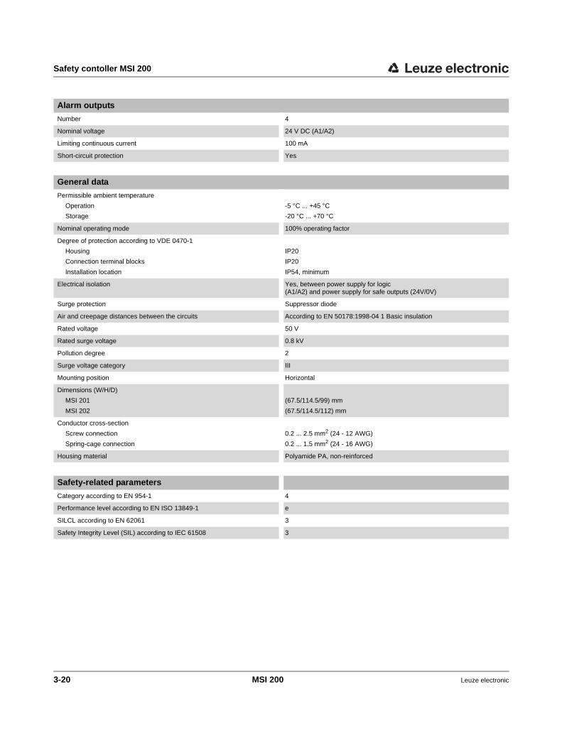
Safety contoller MSI 200
Alarm outputs
Number 4
Nominal voltage 24 V DC (A1/A2)
Limiting continuous current 100 mA
Short-circuit protection Yes
General data
Permissible ambient temperature
Operation
Storage
-5 °C ... +45 °C
-20 °C ... +70 °C
Nominal operating mode 100% operating factor
Degree of protection according to VDE 0470-1
Housing
Connection terminal blocks
Installation location
IP20
IP20
IP54, minimum
Electrical isolation Yes, between power supply for logic (A1/A2) and power supply for safe outputs (24V/0V)
Surge protection Suppressor diode
Air and creepage distances between the circuits According to EN 50178:1998-04 1 Basic insulation
Rated voltage 50 V
Rated surge voltage 0.8 kV
Pollution degree 2
Surge voltage category III
Mounting position Horizontal
Dimensions (W/H/D)
MSI 201
MSI 202
(67.5/114.5/99) mm
(67.5/114.5/112) mm
Conductor cross-section
Screw connection
Spring-cage connection
0.2 ... 2.5 mm2 (24 - 12 AWG)
0.2 ... 1.5 mm2 (24 - 16 AWG)
Housing material Polyamide PA, non-reinforced
Safety-related parameters
Category according to EN 954-1 4
Performance level according to EN ISO 13849-1 e
SILCL according to EN 62061 3
Safety Integrity Level (SIL) according to IEC 61508 3
3-20 MSI 200 Leuze electronic

Extension module MSI-EM200-8I4IO
4 Extension module MSI-EM200-8I4IO
4.1 Device description
The MSI-EM200-8I4IO safe extension module is an extension device for the MSI 200 sa-fety contoller. It provides the safety contoller with additional configurable inputs and out-puts to which safe control devices and sensors/actuators can be connected.
Just like the inputs and outputs of the safety contoller, the inputs and outputs of the safe extension module are connected in the MSIsafesoft configuration software. During opera-tion, the safe outputs of the extension module are controlled dependent upon the safety logic executed in the safety contoller.
The extension module has eight digital safe inputs (I4 - I11) and four signals (IO0 - IO3), which can be configured as either safe digital inputs or outputs. The signal direction (input or output) can only be changed over block by block, i.e., for all four signals (IO0 - IO3) at once.
Two more signals (TM0 and TM1) are also available; these can be configured either as non-safety-related digital alarm outputs or as clock outputs. If TM0 and TM1 are configured as clock outputs, they will support cross-circuit detection at the inputs of the safe extension module (see "Error detection in I/O devices" on page 2-8).
If the signals are configured as alarm outputs, a standard PLC or signaling units can be controlled, for example.
All connection terminal blocks are plug-in. The individual terminal block bases are mechanically keyed to prevent incorrect connection. The extension module comes with a choice of screw connections or spring-cage connections.
Figure 4-1 Extension module with screw connections
Leuze electronic MSI 200 4-1

Extension module MSI-EM200-8I4IO
Figure 4-2 Block diagram MSI-EM200-8I4IO
4.2 Diagnostic and status indicators
The LEDs on the safe extension module are located on the front of the device.
Figure 4-3 Diagnostic and status indicators on the extension device
Diagnostic indicators The two diagnostic indicators on the front of the device can be used to read the operating status of the extension module. The following LEDs are available:
– "PWR": Indicator for the power supply of the safety contoller
– "ERR": Error indicator
The following table lists the possible indicator combinations for the diagnostic LEDs and their meanings. A distinction is made between slow flashing and fast flashing LEDs.
Diagnostic indicators
Status indicatorsfor safe inputs and outputs
4-2 MSI 200 Leuze electronic

Extension module MSI-EM200-8I4IO
The LED symbols in the table mean:
LEDs for signal inputs/out-puts
The state of each of the eight safe inputs and four configurable safe inputs/outputs is indi-cated by a separate LED on the front of the device.
LED OFF
LED ON
LED flashing Slowly = 1.7 HzFast = 6.6 Hz
Table 4-1 Meaning of the diagnostic indicators
PWR(green)
ERR(red)
Meaning
Device is switched off, no power supply at 24 V/0 V or TBUS
Initialization phase after power up (maximum duration: 4 s)
Normal operation. A flashing LED at an input or output signals an error affecting the corresponding signal (see Table 4-2 below).
6.3 Hz
An error has occurred.→ Read out the error code with MSIsafesoft.
Table 4-2 Status indicators for safe inputs and outputs
LED State Meaning
For each input("I4" to "I11") and for "IO0" to "IO3", if these are confi-gured as safe inputs
No switching signal at the relevant input
Switching signal active at the input
Diagnostic error (see page 2-9)
Long ONShort OFF
Wiring check at an input or antivalent input.
For "IO0" to "IO3", if these are configured as safe out-puts
Output inactive
Output active
Diagnostic error (see page 2-9)
Long ONShort OFF
Wiring check at an output
Leuze electronic MSI 200 4-3

Extension module MSI-EM200-8I4IO
4.3 Signal connections
All of the inputs and outputs are connected using plug-in and keyed connection terminal blocks.
Figure 4-4 Signal connections MSI-EM200-8I4IO
The various signal connections are described in the following sections.
4.3.1 Signal inputs
The MSI-EM200-8I4IO safe extension module has 12 digital signal inputs (24 V HTL/3 mA) for the direct connection of safe control devices or safety sensors for mo-nitoring and evaluating processes. Four of the inputs (IO0 - IO3) can also be configured as safe digital outputs (see "Safe outputs" on page 4-5).
The safe inputs are linked to the safety logic in the connection editor of the MSIsafesoft configuration software. See also "Inserting and connecting functions, functional blocks, and signals" on page 5-13.
Signal redundancy due to dual signals
Every two adjacent signal inputs (i.e., I0 and I1, I2 and I3, etc.) are grouped together and interlocked by default to form a dual signal in the MSIsafesoft configuration software. This is indicated in the representation of the safe extension module in the hardware editor of the configuration software by a red padlock at the relevant inputs. The two signals are then al-ways used as a pair, i.e., both signals are dragged, dropped, cut or deleted together in the connection editor.
The parameterization editor (see "Device parameterization in the safe parameterization editor" on page 5-17) is used to set the input and output parameters and thus to select the configuration.
Outputs, can be configured eit-her as test clocks or as standard alarm outputs (TM0 and TM1)
Supply voltage forthe module
Safe inputs
Signals, can be configuredblock by block either as
safe digital inputs or as safeoutputs (IO0 -IO3)
4-4 MSI 200 Leuze electronic

Extension module MSI-EM200-8I4IO
If required, this interlock can be removed and the dual signal split into two single signals.
As input signals with even and odd IDs are processed in different ways in the safety con-toller, using dual signals ensures that the safety contoller will perform redundant proces-sing.
Two-channel sensors To ensure signal redundancy, the prepared dual signal must be used to process two-chan-nel signals (2-wire sensors and control devices). For example, in order to monitor or eva-luate both signals of an emergency stop control device redundantly and to performance level PL e according to EN ISO 13849-1 or EN 954- 1Category 4, these two adjacent sig-nal inputs (e.g., I0 and I1) must be connected.
Cross-circuit detection A cross circuit is an unintentional, incorrect connection between redundant circuits. The ex-tension module offers the TM0 and TM1 signals, which can be configured as clock outputs, to help detect such a cross circuit.
For example, if two differently clocked signals are routed back to two inputs of the safe ex-tension module along two channels via an emergency stop control device, a cross circuit can be reliably detected in this emergency stop circuit. In the event of a cross circuit, the same clock signal would be present at both inputs, instead of two different ones.
The MSIsafesoft configuration software specifies the clock signals to be used. Cross-circuit detection is implemented with the test clock at TM0 for "even" inputs (IO0 and IO2 as well as I4 ... I10). For "odd" inputs (IO1 and IO3 as well as I5 ... I11), the test clock at TM1 must be used for cross-circuit detection.
4.3.2 Safe outputs
Signals IO0 to IO3 can be configured as safety-related outputs. They are dimensioned as digital semiconductor outputs for 24 V DC/0.5 A (2 A total current), each to category 4 ac-cording to EN 954-1.
The outputs are controlled according to the configured safety logic. The safe outputs are linked to the safety logic that controls them in the connection editor of the MSIsafesoft con-figuration software. See also "Inserting and connecting functions, functional blocks, and si-gnals" on page 5-13.
Dual signals are not connected to one another internally; they are simply grouped to-gether.
Configuring the I/Os as inputs: If the I/Os (IO0 to IO3) are configured as inputs, the cross-circuit detection function supported by the extension module MUST be used; in other words, power must be supplied to the inputs concerned via the clock outputs TM0 and TM1 of the extension module. See also "Clock/alarm outputs TM0 and TM1" on page 4-6.
For an example of two-channel connection of an emergency stop control device with dual signal and cross-circuit detection, please refer to Figure 2-4 in "Error detection in I/O devices" on page 2-8.
An appropriate protective circuit (diode or varistor) for IO0 to IO3 signals configured as safe outputs is strongly recommended.
Leuze electronic MSI 200 4-5

Extension module MSI-EM200-8I4IO
4.3.3 Clock/alarm outputs TM0 and TM1
Outputs TM0 and TM1 of the MSI-EM200-8I4IO extension module can be configured as alarm outputs or clock outputs as required. The two options are described in the next two sections.
4.3.3.1 TM0 and TM1 as alarm outputs
Make the following settings in the safe parameterization editor (part of the hardware editor) to configure the TM0 or TM1 output as an alarm output:
– For TM0, set the "Configuration" parameter to the value "Alarm output (M0)"
– For TM1, set the "Configuration" parameter to the value "Alarm output (M1)"
Non-safety-related alarm outputs are dimensioned as digital semiconductor outputs for 24 V DC/100 mA. These alarm outputs can be used, for example, to control a standard PLC or a detector unit (e.g., a signal lamp).
The alarm outputs are linked in the same way as the safe inputs and outputs in the con-nection editor of MSIsafesoft (see "Inserting and connecting functions, functional blocks, and signals" on page 5-13).
4.3.3.2 TM0 and TM1 as clock outputs
Make the following settings in the safe parameterization editor to configure the TM0 or TM1 output as a clock output:
– For TM0, set the "Configuration" parameter to the value "Clock (T0)"
– For TM1, set the "Configuration" parameter to the value "Clock (T1)"
The test clocks output at outputs TM0 and TM1 (if the configuration settings have been made accordingly) are used for cross-circuit detection at the inputs of the same extension module. The test clocks T0 and T1 output are asynchronous, i.e., T0 does not equal T1.
To implement cross-circuit detection, the relevant safe inputs must be configured accordin-gly using the parameterization editor (part of the hardware editor in MSIsafesoft).
The MSIsafesoft configuration software specifies the clock signals to be used: Cross-circuit detection is implemented with the test clock at TM0 for "even" inputs (IO0 and IO2 as well as I4 ... I10). For "odd" inputs (IO1 and IO3 as well as I5 ... I11), the test clock at TM1 must be used for cross-circuit detection.
The safe output signals are clocked with a test pulse of 1 ms.
The parameterization editor (see "Device parameterization in the safe parameterization editor" on page 5-17) is used to set the input and output parameters and thus to select the configuration.
NOTE: Alarm outputs must not be connected in parallel. Feedback to alarm outputs is not permitted.
If the I/Os (IO0 to IO3) are configured as inputs, the cross-circuit detection function sup-ported by the extension module MUST be used; in other words, power must be supplied to the inputs concerned via the clock outputs TM0 and TM1 of the extension module (see "Clock/alarm outputs TM0 and TM1" on page 4-6).
4-6 MSI 200 Leuze electronic

Extension module MSI-EM200-8I4IO
Please also refer to "Signal inputs" on page 4-4 and "Error detection in I/O devices" on page 2-8.
4.3.4 Supply connection A1/A2
Voltage is supplied to the MSI-EM200-8I4IO safe extension module via supply connection A1 (24 V)/A2 (0 V) (see also "Connecting the supply voltage" on page 4-7).
4.4 Installing the safe extension device
4.4.1 Mounting the safe extension device
The extension device is mounted in the same way as the safety contoller (see "Mounting the safety contoller" on page 3-13).
4.4.2 Connecting the supply voltage
The extension module has no main switch and is switched on simply by applying the supply voltage at connections A1 (24 V) and A2 (0 V).
Once the "PWR" diagnostic indicator is permanently on, the extension module is ready to operate.
Once the supply voltage has been applied, the safe extension module executes an initiali-zation routine (all LEDs on).
Figure 4-5 Connecting the supply voltage
WARNING: Serious personal injury or material damage
Disregarding this warning may result in serious personal injury and/or material damage.
Only qualified personnel may connect the power, start up, and operate this device.
According to the safety instructions in this documentation, qualified personnel are per-sons who are authorized to start up, to ground, and to mark devices, systems, and equip-ment according to the standards of safety technology. In addition, these persons must be familiar with all warning instructions and maintenance measures in this document.
ConnectionsA1 (24 V DC) and
A2 (0 V)
"PWR" diagnosticindicator
Leuze electronic MSI 200 4-7

Extension module MSI-EM200-8I4IO
4.4.3 Connecting the signal lines
The signal lines are connected to the extension device in exactly the same way as on the safety contoller (see "Connecting the signal lines" on page 3-16).
CAUTION: Ensure signal redundancy.
Ensure signal redundancy when connecting the signal lines of two-channel control de-vices and sensors to the inputs of the safety contoller. Please refer to "Signal inputs" on page 4-4.
CAUTION: Avoid cross circuits and short circuits.
Prevent cross circuits and short circuits by using a suitable cable installation. Implement cross-circuit detection (see "Cross-circuit detection" on page 4-5).
4-8 MSI 200 Leuze electronic

Extension module MSI-EM200-8I4IO
4.5 Technical data MSI-EM200-8I4IO
Logic input data
Nominal input voltage UN 24 V DC (A1/A2)
Permissible range 0.85 ... 1.1 x UN
Typical current consumption at UN 100 mA
Maximum response time < 30 ms
Buffering of voltage dips 20 ms
Recovery time < 10 s
Diagnostic indicator 2 LEDs (green, red)
Inputs (IN)
Number of safe inputs 12 (up to SIL 3/IEC 62061)of which 4 can be configured as input or output
Nominal voltage UN 24 V DC
Typical current consumption at UN 4 mA
Signal level at "0" < 5 V
Signal level at "1" > 11 V
Status indicator 1 LED (green) per input
Output data
Number of safe outputs 4 (Cat. 4/EN 13849-1/EN 954)if the 4 inputs/outputs are configured as outputs
Nominal voltage 24 V DC
Limiting continuous current 4 x 0.5 A (see Derating)
Maximum capacitive load 1 1 µF
Test pulses < 1 ms
Status indicator 1 LED (green) per output
1 When using electromechanical components (e.g., contactors), the capacitive load can be disregarded.
Clock and alarm outputs
Number 2, can be used as clock outputs or alarm outputs dependent upon the confi-guration
Nominal voltage 24 V DC
Limiting continuous current 50 mA
Test pulses 1 ms, approx.
General data
Permissible ambient temperature
Operation
Storage
-5 °C ... +45 °C
-20 °C ... +70 °C
Nominal operating mode 100% operating factor
Degree of protection according to VDE 0470-1
Housing
Connection terminal blocks
Installation location
IP20
IP20
IP54, minimum
Leuze electronic MSI 200 4-9

Extension module MSI-EM200-8I4IO
Air and creepage distances between the circuits According to EN 50178:1998-04 1
Rated surge voltage 0.8 kV/basic insulation
Pollution degree 2
Surge voltage category III
Dimensions (W/H/D)
MSI-EM201-8I4IO
MSI-EM202-8I4IO
(22.5/114.5/99) mm
(22.5/114.5/112) mm
Conductor cross-section
Screw connection
Spring-cage connection
0.2 ... 2.5 mm2 (24 - 12 AWG)
0.2 ... 1.5 mm2 (24 - 16 AWG)
Housing material Polyamide PA, non-reinforced
General data
Safety characteristic data 1
Category according to EN 954-1 4
Performance level according to ISO 13849-1 e
SILCL according to EN 62061 3
Safety Integrity Level (SIL) according to IEC 61508 3
1 Data only applies if the safety function is demanded at least once a year.
4-10 MSI 200 Leuze electronic

Configuration software MSIsafesoft
5 Configuration software MSIsafesoft
5.1 Installing MSIsafesoft
The installation routine for the configuration software includes the installation of the driver for the USB interface. This driver is required for communication between the PC and the safety contoller.
Proceed as follows:
1. If you have downloaded the configuration software, extract the downloaded file and start the installation program (setup file).
If you have purchased the commissioning set MSI-SWC1, insert the supplied CD in the drive. A menu opens. Select "Install software" to start the installation program.(If you have deactivated the auto start option on your computer, open the "MSI-safesoft" folder on the CD-ROM and execute the setup file.)
2. Select the desired language for the installation routine. (This also sets the language for the MSIsafesoft user interface, which is set when the software is started for the first time.)
3. The installation program now guides you through the installation step by step.Follow the instructions on the screen.
4. Once MSIsafesoft is installed, you will be prompted to install the drivers for the safety contoller.Follow the instructions on the screen.
5. In the Windows dialog box for driver installation, select "Install the software automati-cally (recommended)".
Finally, a message appears indicating that the configuration software and drivers for the safety contoller have been fully installed.
5.2 Overview of functions and features
The MSIsafesoft safe configuration software is used to configure the MSI 200 safety con-toller and the extension modules used. The software supports the user in all operating pha-ses, from planning the application, through configuration to starting up the MSI 200 safety contoller, and compiling system documentation.
The MSIsafesoft functions support:
Adding/Removing extensi-on devices
– Up to ten extension modules can be added from the "Hardware" compartment of the toolbox by using drag & drop to move them to the hardware editor. Devices added pre-viously can be removed by selecting the corresponding command from the context menu in the hardware editor.
To ensure that the configuration software detects the safety contoller automatically and correctly, the software must be fully installed on the computer before the device is con-nected for the first time.
Leuze electronic MSI 200 5-1

Configuration software MSIsafesoft
Creating the safety logic – Creation of the safety logic with the help of a graphical connection editor. The circuit which the safety contoller runs on is created by graphically linking safe functional blocks certified according to the PLCopen specification via connecting lines and safe functions. Safe functions range from logic operations such as AND, OR, etc., to timer and trigger functions.
Linking inputs/outputs with safety logic
– The inputs and outputs of the safety contoller are linked to the safety logic using drag & drop.
Parameterizing inputs/out-puts
– The inputs and outputs of the safety contoller and of the extension devices (e.g., MSI-EM200-8I4IO) are parameterized using a safe parameterization editor.
Downloading/Uploading the configuration
– You can download the configuration project, including all device parameters, to the sa-fety contoller in a few steps. It is also possible to upload the project saved on the safety contoller to the connected PC, in order to display or edit it in the configuration software.
Online mode for function test
– During safe operation, you can read signal values from the safety contoller and display them in a special online mode. The connection editor indicates the current "live" status of each signal and the inputs and outputs of each functional block in the safety logic. The hardware editor in online mode maps the LEDs on the safety contoller.
Startup mode (additional) – There is a mandatory function test of the active system, e.g., the activation of the safe control devices. You can also use "standard" startup mode. Instead of pressing an ac-tual switch, you can force the corresponding signal in the connection editor and test the safety logic in this way.
Documentation, checklist
– The configuration software provides you with a project information dialog box, where you can save information relating to the project and complete a safety-related check-list. This dialog box is supplemented by an assignment list, where comments can be added to the signals of the safe devices used in order to document the wiring.
All documentation, including the graphical safety logic, the assignment list, and the de-vice parameters, can be printed out.
MSISIMsoft simulation – Simulation of the safety contoller, for example, for preliminary testing of the developed safety logic even if no safety contoller is available.
Online help You will find a description of the comprehensive functions of MSIsafesoft in the online help for the software.
There are various ways of calling the online help:
• In the "?" menu, select "Help topics". The table of contents for the online help appears. Search for a help topic as described below.
• In an active dialog box or window, press <F1>. The context-sensitive online help for the active dialog box or window appears.
• In the connection editor, select an object and press <F1> in order to view information relating to that object. For safe functions and functional blocks, general information about the objects can be accessed in this way.
• There is also specific functional block information, which can be called via the "Help" context menu command for the relevant functional block or function.
5-2 MSI 200 Leuze electronic
Configuration software MSIsafesoft
5.3 Description of the user interface
This section provides an overview of the user interface for the MSIsafesoft configuration software. For more detailed information, please refer to the online help.
Figure 5-1 User interface MSIsafesoft
The user interface consists of the following components:
1. MenuThe menus contain all commands for controlling the configuration software.
2. ToolbarFrequently used functions can be accessed quickly via the icons in the toolbar.
3. Connection editorThe connection editor is used to develop the safety logic by dragging graphical func-tional blocks from the toolbox and signals from the hardware window to the circuit (using drag & drop) and connecting them to one another.
4. ToolboxThe toolbox contains standard functions, safe functional blocks, safe functions, and connectors in the corresponding compartments. These elements can easily be dragged from the toolbox into the connection editor. The "Hardware" compartment contains extension devices (if there are any) as soon as the MSI 200 master module has been added to the hardware editor. If a fieldbus gateway is available, the "External signals" compartment will contain spe-cial exchange signals which have been designated specifically for data exchange bet-ween the safety contoller and a higher-level controller. This type of communication must take place via the intermediary of a suitable fieldbus module. If a higher-level standard PLC is involved, from the perspective of the safe application, these are al-ways standard signals which can be linked and processed accordingly in MSIsafesoft.The toolbox also contains a "Favorites" compartment, where you can insert frequently used functions and functional blocks as required.
The windows may be arranged differently to the format shown here, either when the soft-ware is delivered or once you have adapted the program to your preferences.
Leuze electronic MSI 200 5-3

Configuration software MSIsafesoft
5. Hardware editorThe hardware editor contains a graphical representation of the MSI 200 safety contol-ler. It also shows all the extension modules that you have inserted from the "Hardware" compartment of the toolbox. When configuring the safety logic, input and output sig-nals can be moved from here to the connection editor using drag & drop. Double-click on a module in the hardware editor to start the safe parameterization editor for the re-levant module (not shown in Figure 5-1).
6. Status barWhen working with the configuration software, the status bar displays messages and information, as well as the current logon status, the status of the safety contoller, and transmission progress when downloading or uploading the configuration from or to the safety contoller.
The following windows and dialog boxes are not visible in the figure:
– Message windowThe message window can be used to track the progress of the project checking func-tion. When the check is started, the message window opens automatically. If the sys-tem detects an error when checking the project, the relevant error location can be accessed directly by double-clicking with the left mouse button on the message in the message window.
– Assignment list for signalsThe assignment list contains the signal assignments for the individual inputs and out-puts of the MSI 200 safety contoller and the safe extension devices you have added. It provides "wiring documentation", which makes the project easier to understand, and helps to prevent incorrect connections being established in the connection editor.
– Project information dialog boxThis dialog box can be used to enter and display the most important information for the current configuration project (e.g., project-related data, manufacturer data, operator, installation location, data relating to safety inspections, revision history for the project).
5-4 MSI 200 Leuze electronic

Configuration software MSIsafesoft
5.4 Safe functional blocks and functions
The MSI 200 safety contoller is configured in the MSIsafesoft configuration software by graphically connecting prepared safe functions and safe functional blocks.
Figure 5-2 Safe functional blocks in the toolbox (excerpt)
The connections are made intuitively using the mouse, and the editor prevents impermis-sible connections (e.g., between certain outputs).
The safe functions include simple Boolean operations and basic functions used in standard digital technology.
Safe functions The following safe functions are available in the MSIsafesoft toolbox and can be easily added to the safety logic using drag & drop (in alphabetical order):
– AND (Boolean ANDing)
– CTUD (up/down counter)
– EQ (Boolean comparison)
– F_TRIG (detection of a falling edge)
– NOT (complement or negator)
– NOT_EQ (comparison for Boolean inequality)
– OR (Boolean ORing)
– PULSE_GEN (safe pulse generator)
– R_TRIG (detection of a rising edge)
– RS (bistable function: priority for resetting)
– SR (bistable function: priority for setting)
– TOF (timer for off delay)
– TON (timer for switch-on delay)
– TP (impulse encoder)
– XOR (Boolean EXORing)
Safe functional blocks The safe functional blocks provide basic safety-related functions for implementing the re-quired safety circuits. Table 5-1 lists the available functional blocks in alphabetical order.
Leuze electronic MSI 200 5-5

Configuration software MSIsafesoft
Table 5-1 Safe functional blocks
Name Icon in editor
Short description
Antivalent The Antivalent safe functional block monitors the signals of two safe input terminal blocks for different signal states.
Typically, these signals come from two-channel sensors or switches, such as an emergency stop control device.
EDM The EDM (external device monitoring) safe functional block monitors the defined initial state and the switching behavior of contactors connected to the safety contoller.
EmergencyStop The EmergencyStop safe functional block monitors the swit-ching states of an emergency stop control device. When the control device is actuated, the enable signal at output OUT is set to FALSE.
EnableSwitch The EnableSwitch safe functional block evaluates the signals of a manually activated three-stage enable switch (in ac-cordance with EN 60204) in order to identify its switching stage and direction.
This means that an enable switch can be used to remove sa-feguarding, provided that the appropriate safe operating mode (e.g., limitation of the speed or range of motion) is se-lected and active.
Equivalent The Equivalent safe functional block monitors the signals of two safe input terminal blocks for the same signal states.
Typically, these signals come from two-channel sensors or switches, such as an emergency stop control device.
5-6 MSI 200 Leuze electronic

Configuration software MSIsafesoft
ESPE The ESPE (electrosensitive protective equipment) safe func-tional block monitors the switching states of electrosensitive protective equipment (e.g., light grids). When the protective equipment is triggered, i.e., the light grid beam is interrupted, the enable signal at output OUT is set to FALSE.
GuardLocking The GuardLocking safe functional block supports the monito-ring of a guard with guard locking (safety door monitoring with four-stage interlocking according to EN 1088).
GuardMonitoring The GuardMonitoring safe functional block monitors a guard (e.g., safety door) with two-stage interlocking according to EN 1088.
ModeSelector The ModeSelector functional block evaluates the states of a mode selector switch with up to five positions.
A mechanical mode selector switch can be used, for example, to set a specific safety level (e.g., service mode, setup mode, cleaning mode, etc.) for operation of the safe application.
Table 5-1 Safe functional blocks (continued)
Name Icon in editor
Short description
Leuze electronic MSI 200 5-7

Configuration software MSIsafesoft
MutingPar_2Sensor The MutingPar_2Sensor safe functional block evaluates the signals of two muting sensors and one optoelectronic protec-tive device (e.g., light grid) in an application for parallel mu-ting using two sensors and sets the enable signal at output OUT.
This function can be used to temporarily deactivate (or "mute") protective equipment in the form of a light grid, for example, in order to allow an object which has been iden-tified by the muting sensors as permissible (for the muting operation) to pass through on an assembly conveyor.
However, if the light grid is interrupted by a worker's hand, for example, output OUT is set to FALSE to disable the hazard, as the protective equipment had not been previously "mu-ted".
MutingPar The MutingPar safe functional block evaluates the signals of four muting sensors and one optoelectronic protective device (e.g., light grid) in an application for parallel muting using four sensors and sets the enable signal at output OUT.
This function can be used to temporarily deactivate (or "mute") protective equipment in the form of a light grid, for example, in order to allow an object which has been iden-tified by the muting sensors as permissible (for the muting operation) to pass through on an assembly conveyor.
However, if the light grid is interrupted by a worker's hand, for example, output OUT is set to FALSE to disable the hazard, as the protective equipment had not been previously "mu-ted".
The use of four muting sensors enables the maximum per-missible muting duration to be monitored.
MutingSeq The MutingSeq safe functional block evaluates the signals of four muting sensors and one optoelectronic protective device (e.g., light grid) in an application for sequential muting using four sensors and sets the enable signal at output OUT.
This function can be used to temporarily deactivate (or "mute") protective equipment in the form of a light grid, for example, in order to allow an object which has been iden-tified by the muting sensors as permissible (for the muting operation) to pass through on an assembly conveyor.
However, if the light grid is interrupted by a worker's hand, for example, output OUT is set to FALSE to disable the hazard, as the protective equipment had not been previously "mu-ted".
The use of four muting sensors enables the maximum per-missible muting duration to be monitored.
Table 5-1 Safe functional blocks (continued)
Name Icon in editor
Short description
5-8 MSI 200 Leuze electronic

Configuration software MSIsafesoft
5.5 Operating the MSIsafesoft configuration software
Intuitive operation The MSIsafesoft configuration software follows the Windows standard for user activities. MSIsafesoft also supports additional functions. Examples include online diagnostic tools and simulation of the safety contoller.
Details in the online help The following sections provide a brief introduction to the most important software functions. The online help contains a detailed description of each software function.
For an overview of the steps required when configuring a project, please refer to "Configu-ration overview from A to Z" on page 6-1.
TestableSafetySensor The TestableSafetySensor functional block evaluates the status of a connected optoelectronic protective device (e.g., light curtain).
The functional block also has a test function for checking the connected protective equipment.
TwoHandControlTypeII The TwoHandControlTypeII safe functional block evaluates the switching behavior of a Type II two-hand control device connected to the safety contoller.
TwoHandControlTypeIII The TwoHandControlTypeIII safe functional block evaluates the switching behavior of a Type III two-hand control device connected to the safety contoller.
Online help is available for every functional block and every function.
To open the help for a particular safe functional block or safe function, right-click on the corresponding block in the MSIsafesoft connection editor and select "Help" from the con-text menu.
Table 5-1 Safe functional blocks (continued)
Name Icon in editor
Short description
Leuze electronic MSI 200 5-9
Configuration software MSIsafesoft
5.5.1 Creating the configuration project
When creating a new project, either use a project template or create an empty project using the Project Wizard.
"Empty" means that although the safety contoller is already available in the hardware editor for "wiring" the signals, the connection editor does not yet contain any safety logic.
If a project template is used, a predefined circuit, which can be modified or extended as required, will be inserted into the connection editor.
To create a new project, select "New Project..." in the "File" menu, use the keyboard short-cut <Ctrl>+<N> or click on the following icon:
In the "New Project" dialog box, select either the Project Wizard or a specific project tem-plate.
Figure 5-3 Project Wizard for creating a new configuration project
5-10 MSI 200 Leuze electronic

Configuration software MSIsafesoft
5.5.2 Inserting and removing extension devices
To change the bus configuration, drag & drop extension devices from the "Hardware" com-partment of the toolbox into the hardware editor. You can remove these again via the con-text menu in the hardware editor.
The hardware editor shows a graphical representation of the bus configuration (i.e., the sa-fety contoller used and available extension modules, as long as these are available for your safety contoller and are already in use in the project).
Inserting new devices into the hardware editor
To insert new devices into the hardware editor, proceed as follows:
1. Show the hardware editor ("View" menu, "Hardware Editor" command) and the toolbox ("View" menu, "Toolbox" command). If the auto-hide function is enabled, position the cursor over the minimized window as shown in Figure 5-7 for the hardware editor.
2. Click on the corresponding navigation bar to open the "Hardware" compartment in the toolbox.
3. Drag the required extension module into the connection editor from the toolbox com-partment as follows:
a) Left-click on the required object and hold the mouse button down. b) Hold the left mouse button down and drag the object from the toolbox to any
position in the hardware editor. Then release the mouse button.
Figure 5-4 Inserting an extension device into the hardware editor
4. First of all, a dialog box appears stating that the list of safe devices must be synchro-nized and, where applicable, that the user needs to provide confirmation. Confirm this dialog box with "OK".
There will only be a hardware compartment if your safety contoller features extension de-vices.
Leuze electronic MSI 200 5-11

Configuration software MSIsafesoft
5. The "Confirmation of Modified SDIO Devices" dialog box appears.
Use the module description (in the lower part of the dialog box) to check whether you are inserting the correct device.If the device is correct, confirm the dialog box by checking the box in the list of modified devices and then clicking "OK". The extension device is then automatically inserted in the correct position and is automatically given the next unassigned ID.
Figure 5-5 Hardware editor with master module and extension module inserted
6. Drag & drop the required input or output signals of the newly inserted module into the connection editor and connect them (see Figure 5-8 on page 5-15).
Removing devices from the hardware editor
To remove devices from the hardware editor, proceed as follows:
1. In the hardware editor, right-click on the device you want to remove and select the "Re-move device" command in the context menu.Please note that you can only ever remove the device at the end of the row (on the far right of the bus configuration).
2. Confirm the next dialog box that appears with "Yes".
3. Next, a dialog box appears stating that the list of safe devices must be synchronized and, where applicable, that the user needs to provide confirmation. Confirm this dialog box with "OK".
4. The "Confirmation of Modified SDIO Devices" dialog box appears.
If you want to delete the device in question, confirm the dialog box by checking the box in the list of deleted devices and then clicking "OK".The device is removed from the hardware editor and the ID is made available for any devices that are going to be inserted subsequently.
If there are signals available for data exchange between the safety contoller and a high-er-level controller, these are not dragged from the hardware editor into the connection editor. You can, however, drag & drop them from the "External Signals" compartment of the toolbox into the safety logic.
For further information, please refer to the online help (see "Extension devices in the hardware editor (bus configuration)").
5-12 MSI 200 Leuze electronic

Configuration software MSIsafesoft
5.5.3 Inserting and connecting functions, functional blocks, and signals
The safety logic is created in the connection editor as a network of safe functions and func-tional blocks. These functions and functional blocks are available in the various compart-ments of the toolbox and must be inserted in the connection editor from there.
In order to process the various signals (inputs, outputs, and alarm outputs of the safety contoller, and inserted extension devices) in the connection editor, the signals must be in-serted in the connection editor from the hardware editor and connected to other objects.
Functional blocks and functions in the toolbox
Safe functional blocks/functions and constants are always inserted into the connection edi-tor from the toolbox using drag & drop. To do this, proceed as follows:
1. Show the toolbox ("View, Toolbox" menu). If the auto-hide function is enabled, position the cursor over the minimized window as shown in Figure 5-7 for the hardware editor.
2. In the toolbox, open the required compartment by clicking on the corresponding navi-gation bar ("Safe Functions", "Safe Functional Blocks" or "Favorites").
3. Drag the required object into the connection editor from the toolbox compartment:
– Left-click on the required object and hold the mouse button down. – Hold the left mouse button down and drag the object from the toolbox to a free
position in the safety logic and then release the mouse button.– Signal constants can be dragged directly to functional block connections, thus
establishing the connection immediately on insertion.
The object is dropped at the selected position (aligned with the grid of the connection edi-tor).
Figure 5-6 Inserting safe functional blocks and functions
Input and output signals can only be inserted into the connection editor from the hard-ware editor and linked to functional blocks in the connection editor if you have logged on with the correct project password ("Project, Log On" menu).
Leuze electronic MSI 200 5-13

Configuration software MSIsafesoft
Signal inputs and signal outputs in the hardware editor
Input and output signals of the safety contoller and any extension devices that are being used are always inserted into the connection editor from the hardware editor using drag & drop.
To insert signals from the hardware editor, proceed as follows:
1. Show the hardware editor ("View, Hardware Editor" menu). If the auto-hide function is enabled, position the cursor over the minimized window as shown in the figure below.
Figure 5-7 Opening the hardware editor with the auto-hide function enabled
2. Drag the required (dual) input or output signal from the hardware editor into the con-nection editor (see Figure 5-8 on page 5-15).
– Left-click on the required (dual) signal and hold the mouse button down.– Hold the left mouse button down and drag the (dual) signal from the hardware
editor directly to a free connection (or two free connections, in the case of a dual signal) in the safety logic, then release the mouse button.
– Alternatively, you can store signals at any free position in the connection editor. The free signals must then be linked to free functional block connections manually (see "Connecting objects" on page 5-16).
If there are signals available for data exchange between the safety contoller and the higher-level controller, these signals cannot be taken from the hardware editor, but must be taken from the "External Signals" compartment of the toolbox and inserted into the safety logic using drag & drop.
Ensuring signal redundancy (dual signals)
When evaluating two-channel sensors or control devices, dual signals must be used to connect the two channels.
Dual signals always consist of one "even" and one "odd" input signal, e.g., I0 and I1.
In the case of dual signals, input signals with even and odd IDs are processed in different ways in the safety contoller. This ensures that the safety contoller will perform redundant processing.
If required, dual signals can be split into two individual signals.
Please note: Dual signals are not connected to one another internally; they are simply grouped together.
5-14 MSI 200 Leuze electronic

Configuration software MSIsafesoft
The (dual) signal is dropped at the selected position (aligned with the grid) and, if ap-plicable, directly connected to the corresponding connection.
Figure 5-8 Inserting a signal in the connection editor
Standard alarm signals M0 to M3: As well as 20 safe inputs and four safe outputs, the safety contoller also provides four non-safety-related alarm outputs. These alarm out-puts can be used, for example, to control a standard PLC or a simple detector unit (e.g., a signal lamp). Since the alarm signals are not safe, they are shown in gray rather than yellow in the connection editor.
Alarm outputs are edited in the same way as safe input/output signals.
Clock outputs T0 and T1 of the safety contoller cannot be moved to the connection edi-tor using drag & drop. To implement cross-circuit detection using these two test pulses, the relevant safety contoller inputs must instead be parameterized accordingly.
Clock/alarm outputs TM0 and TM1 of the MSI-EM200-8I4IO safe extension device can be configured as either clock outputs or alarm signals.
If the I/Os (IO0 - IO3) are configured as inputs, test clocks TM0 and TM1 must be used to supply power to these inputs (see "Signal inputs" on page 4-4 and "Clock/alarm out-puts TM0 and TM1" on page 4-6).
External signals
Depending on the higher-level controller and the safety contoller used, signals are spe-cifically available for data exchange and communication between the higher-level cont-roller and safety contoller.
These exchange signals cannot be dragged from the hardware editor to the circuit logic, but are available in the "External Signals" compartment of the toolbox. Drag & drop these external signals from the toolbox into the connection editor in the same way as signal constants or connectors, for example.
If a higher-level standard PLC is involved, from the perspective of the safe application, these are standard signals which can be linked and processed accordingly in MSIsafesoft.
Leuze electronic MSI 200 5-15

Configuration software MSIsafesoft
Connecting objects Signal inputs and outputs as well as constants can be connected as soon as they are in-serted in the connection editor (using drag & drop). Free terminal points are connected as described below.
Connecting objects by drawing a connecting line
1. Position the cursor over the connection area where the connecting line is to start. The cursor now appears as a cross (see (1) in the graphic below).
2. Left-click, hold the mouse button down, and drag the mouse directly to the destination connection area. If the connection is permitted, the line is green.
3. Now release the mouse button to create the connection. The connection editor auto-matically determines the path for the connecting line (automatic routing).
Figure 5-9 Connecting objects using a line
Connecting objects using drag & drop
This method is only suitable for connecting inputs, outputs, and signal constants.
1. Click on the (dual) signal or the constant to be connected and hold the mouse button down (see Figure 5-10).
2. Drag the object to the desired destination terminal point. If the relevant signals and connection areas are displayed within a green border (see Figure 5-10, (1)), release the mouse button.The dragged object is positioned automatically and the connecting line is drawn in (au-tomatic routing).
If required, the objects can then be moved, whereby the connection editor manages the connecting lines automatically.
Figure 5-10 Connecting signals that are not connected to blocks or functions
5-16 MSI 200 Leuze electronic

Configuration software MSIsafesoft
5.5.4 Device parameterization in the safe parameterization editor
The inputs and outputs of the safety contoller and the extension module can be paramete-rized. Specific properties can be defined for each input and output in a special safe para-meterization editor.
When checking a project in the MSIsafesoft configuration software, this data is used to create a parameterization file, which is subsequently transmitted to the safety contoller au-tomatically as part of the configuration project.
Opening the parameteriza-tion editor
The parameterization editor is a component of the hardware editor. To open this editor for all inputs/outputs (general view) of a specific device, double-click on the representation of the corresponding module in the hardware editor.
Figure 5-11 Opening the parameterization editor for all inputs/outputs of the MSI 200 safety contoller
To open the parameterization editor for only one specific input/output, double-click on the relevant signal in the graphical representation of the device:
Figure 5-12 Opening the parameterization editor for one specific input/output
Instead of double-clicking, you can also open the parameterization editor via the context menu. Right-click either directly on a specific input/output to open the parameters for it, or on any empty position in the graphical representation of the device to open the general view.
The parameters can only be edited if you have logged on with the correct project pass-word ("Project, Log On" menu).
DoppelklickDouble click
DoppelklickDouble click
Leuze electronic MSI 200 5-17

Configuration software MSIsafesoft
In both cases, select "Parameters" from the context menu.
Figure 5-13 Opening the parameterization editor via the context menu
Structure of the paramete-rization editor
The adjustable parameters are provided in table format.
At the top left of the table is the device type or the device ID and the "location ID", which is the unique security ID for the safe device. Every safe device can be unambiguously iden-tified using just this ID. Underneath you can see the name of the import file, provided that you have imported parameters (see "Exporting and importing parameters" on page 5-19).
The available parameters are then listed row by row. Each parameter (i.e., each row in the table) consists of a fixed parameter name and a variable value.
Modifying parameters In the interests of security, only predefined parameter values can be selected. Proceed as follows:
1. Click in the white field of the parameter you wish to change. The field displays an arrow for opening a selection list.
2. Click on the arrow to open up the list.
3. Click on the required value. This list is closed and the selected value is visible in the parameter field.
Figure 5-14 Modifying parameters in the parameterization editor
Unless the parameterization editor is closed or another device is selected, several editing steps can be undone (<Ctrl>+<Z>) or redone (<Ctrl>+<Y>).
If you have modified parameters and then close the editor with "OK", you are prompted to save the changes that have been made.
Input parameters for the safety contoller: Cross-circuit detection
A "cross circuit" is an unintentional, incorrect connection between redundant circuits. The safety contoller provides clock outputs T0 and T1 as an aid for detecting such a cross cir-cuit.
Certain parameters in the parameterization editor are dependent upon the configuration of the inputs and outputs. For example, clock/alarm outputs TM0 and TM1 must first be configured as clock outputs (test clock) if you wish to select cross-circuit detection for in-puts of the safe extension module (see "TM0 and TM1 as clock outputs" on page 4-6).
5-18 MSI 200 Leuze electronic

Configuration software MSIsafesoft
To activate cross-circuit detection for an input, set the corresponding cross-circuit detec-tion parameter ("no"/"yes, with test pulse T...") to "yes, with test pulse T..." (see Figure 5-14 above).
MSI-EM200-8I4IO:Cross-circuit detection
For the MSI-EM200-8I4IO safe extension module, clock/alarm outputs TM0 and TM1 must be configured as clock outputs (test clock) in order to facilitate parameterization for cross-circuit detection.
Output parameters for the safety contoller: Grounded switching out-put
The "additionally ground switching contact" parameter "no"/"yes, with O...-" is only availa-ble for outputs O0 and O1 of the MSI 200 safety contoller. Output O0 is connected to grounded switching output O0-, output O1 to grounded switching output O1-.
This parameter is used to specify whether the specified grounded switching output, which can assist in shutting down a single-channel application safely, should be switched in ad-dition to the relevant safe module output.
Figure 5-15 Setting the parameter for the use of grounded switching output O0-
Exporting and importing parameters
Once the inputs and outputs of the safety contoller have been parameterized, the parame-ter list can be exported to a file so that it can be used again later.
For information about exporting and importing parameters, please refer to the online help (see "Parameterizing the inputs/outputs of the safety contoller").
Printing parameters The print dialog box ("File, Print Project" menu) contains a "Safe parameters" checkbox. If this checkbox is selected before printing a project, all the parameters of the safe device are printed too.
The MSIsafesoft configuration software specifies the clock signals to be used: Cross-cir-cuit detection is implemented with test clock T0 for "even" inputs (I0, I2, I4, ... I18). For "odd" inputs (I1, I3, I5, ... I19), test clock T1 must be used for cross-circuit detection.
For additional information about cross-circuit detection, please refer to "Signal inputs" on page 3-7 and "Error detection in I/O devices" on page 2-8. An application example is also provided there.
If the I/Os (IO0 - IO3) are configured as inputs, test clocks TM0 and TM1 must be used to supply power to these inputs (see also "Signal inputs" on page 4-4 and "Clock/alarm outputs TM0 and TM1" on page 4-6).
The use of grounded switching outputs O0- and O1- increases cross-circuit protection, for example. For more detailed information about using grounded switching outputs O0- and O1- and a corresponding example application, please refer to "Grounded switching outputs O0- and O1-" on page 3-10.
Leuze electronic MSI 200 5-19

Configuration software MSIsafesoft
5.5.5 Checking, downloading, and starting up the project
Once the configuration project has been developed, i.e., the safety logic and the device pa-rameterization have been completed, the project must be checked. This involves checking the safety logic for errors, such as open function inputs.
To check the project, proceed as follows:
1. Click on the "Check Project" icon in the toolbar:
The progress of the checking function can be tracked in the message window, which opens automatically:If the configuration software detects an error, you can jump to the relevant location di-rectly by double-clicking on the message in the message window with the left mouse button.In the example below, an input is not connected. Double-clicking on the error message highlights the affected object (in a green border) in the connection editor.
Figure 5-16 Jumping to an error location in the safety logic from the message window when checking the configuration project
2. Correct the error and check the project again.
The project can only be checked if you have logged on with the correct project password ("Project, Log On" menu).
If the current project status has not yet been saved, this is done automatically prior to checking.
Check values (CRC): To ensure that any distortions to the configuration data during transmission to the safety contoller can be reliably detected, a check value (CRC) is cal-culated in the configuration software when the project is checked. The safety contoller also determines the check value for the downloaded data. If the check values on the sa-fety contoller and in the configuration software are identical, all data has been saved on the safety contoller without distortion. If the check values differ, a corresponding error message is output.
The check value (CRC) will also differ if subsequent modifications have been made to the project in the configuration software, but have not yet been downloaded to the safety contoller. A change to the product documentation can also modify the check value, for example.
5-20 MSI 200 Leuze electronic

Configuration software MSIsafesoft
3. Once a check has been completed without errors, the project can be transmitted to the safety contoller. For information about downloading a configuration project and the as-sociated startup of the safety contoller, please refer to „Downloading the configuration from MSIsafesoft“ on page 6-9.
5.5.6 Documenting the signal assignment and the project
Documenting signal as-signment
The system supports the maintenance of a signal assignment list.
1. Click on the following icon in the toolbar:
The "Assignment List" dialog box opens.
2. For each input, enter a meaningful short description in the right-hand field of the list by double-clicking in the field and typing in the text.
Figure 5-17 "Assignment List" dialog box
3. Once all the required texts have been entered, confirm the dialog box with "OK" to save the signal list.
Entering project documen-tation
Open the "Project Info" dialog box by selecting the "Project, Project Information..." menu.
This dialog box can be used to enter the most important information about the current pro-ject, from project-specific data (description of the application, designation, name of the creator/editor, etc.) to manufacturer data, the operator, and installation location, through to data relating to safety inspections, and a revision history for the project.
We strongly recommend that this "wiring documentation" is maintained on an ongoing basis, as it makes both the safety logic that has been created and the project as a whole easier to understand, and helps to prevent incorrect connections being established in the connection editor. We recommend entering signal names before editing the safety logic because any text entered in the connection editor is visible as tool tips.
For further information about signal information, please refer to the online help, which is opened by pressing <F1> when the "Assignment List" dialog box is active.
To ensure compliance with standards, the fields with yellow row headers must be com-pleted each time a new project version is developed.
Entries are not mandatory in fields with a gray background, although we do recommend completing all fields.
Leuze electronic MSI 200 5-21
Configuration software MSIsafesoft
Printing project documen-tation
The entire project can then be printed.
1. Select the "File, Print Project" menu.
A dialog box of the same name appears.
2. Select all checkboxes in the dialog box and click "OK".
Check values (CRC): If the project documentation is modified, the check value is recal-culated; i.e., the system detects that the project on the safety contoller differs from the configuration project.
If the check values on the safety contoller and in the configuration software are not iden-tical, a corresponding message is output.
For further information about project documentation, please refer to the online help, which is opened by pressing <F1> when the "Project Information" dialog box is active.
For further information about printing, page layouts, and print settings, please refer to the online help, which is opened by pressing <F1> when the "Print Project" dialog box is ac-tive.
5-22 MSI 200 Leuze electronic

Configuration software MSIsafesoft
5.6 Simulation mode in MSIsafesoft
The MSIsafesoft configuration software includes the MSISIMsoft controller simulation, which can be used to simulate the execution of the safety logic:
– If no safety contoller is available or
– If a simulated function test is recommended prior to the actual startup of the "real" sa-fety contoller
Figure 5-18 Simulation in MSIsafesoft
When working with the MSISIMsoft simulation instead of the safety contoller:
– If a safety contoller or an extension device is connected, it will not be addressed; i.e., its inputs will not be read and its outputs will not be written.
– Execute the same steps in the MSIsafesoft configuration software as you would if you were working with the real safety contoller, but ensure that the "Simulate Safety Con-troller" icon in the toolbar is activated (see Figure 5-19 on page 5-24). This means that you can force signals or display online values in the connection editor as usual. The simulation continues to run in the background, with the icon visible in the taskbar no-tification field (system tray, known as systray for short).
– The simulation can be configured for the current application, inputs can be "activated" in the simulation directly, and the effects on outputs can be monitored, thus simulating the inputs and outputs of the actual hardware.
– The timing of the machine/system can be simulated in expert mode.
WARNING: A simulation does not replace a function test.
The simulation of the safety application must not replace the proper function test using the safety contoller and safe control devices/sensors/actuators. The test using simulati-on may only be performed in addition to the standard function test, as a preliminary test, for example.
Leuze electronic MSI 200 5-23

Configuration software MSIsafesoft
Starting simulation mode To start the simulation and download a project, proceed as follows:
1. To start the simulation, click on the "Simulate Safety Controller" icon in the toolbar.
If the icon is activated, the simulation is active and all commands executed, such as "Download" or "Online Values", will relate to the simulation.
Figure 5-19 "Simulate Safety Controller" icon
2. Once the icon has been selected, a message window appears stating "Simulation being activated".
The project is then saved and checked automatically. Any errors detected are output in the message window.
3. Once a check has been completed without errors, the project can be downloaded as usual by clicking on the icon of the same name in the toolbar:
Unlike with the actual safety contoller, you do not have to log on with a controller pass-word when using the simulation.
4. Once the simulation has been started, the following entry is displayed on the far right of the status bar:
The MSISIMsoft application is displayed minimized in the Windows taskbar.
Exiting MSIsafesoft simu-lation mode
To switch from MSISIMsoft simulation to the real safety contoller, in the MSIsafesoft con-figuration software, click on the simulation icon in the toolbar, which already appears "ac-tivated":
The simulation is now deactivated (see information in the message window) and the pro-ject is saved automatically again and checked for use with the real safety contoller.
Not activated = MSI 200
Activated = Simulation
Icon
WARNING: Danger due to unintentional operations
As soon as simulation mode is exited, all "online" operations, such as downloading or forcing signals, affect the real safety hardware again.
Exiting simulation mode does not exit MSISIMsoft simulation.
Once you have clicked on the "Simulate Safety Controller" icon again, the destination system is reset in the configuration software, from the MSISIMsoft simulation to the real safety contoller. Essentially, this means that only the connection between the configura-tion software and the simulation software is interrupted. The MSISIMsoft simulation ap-plication is not exited automatically.
5-24 MSI 200 Leuze electronic
Configuration software MSIsafesoft
Exiting MSISIMsoft simu-lation
To exit MSISIMsoft simulation
First exit simulation mode in the configuration software (deselect the "Simulate Safety Con-troller" button).
5. Then select "Exit" in the MSISIMsoft context menu (in the Windows taskbar) or click "Exit" in the MSISIMsoft window.
Further information about operating MSISIMsoft
For further information about MSISIMsoft controller simulation, please refer to the "MSI-SIMsoft controller simulation" topic of the online help for the MSIsafesoft configuration soft-ware:
– Operating MSISIMsoft
– Simulating time sequences in MSISIMsoft expert mode
– Status of MSISIMsoft simulation
If MSISIMsoft is exited while the "Simulate Safety Controller" button is activated in MSIsafesoft, MSISIMsoft restarts automatically after being exited.
Leuze electronic MSI 200 5-25

Configuration software MSIsafesoft
5-26 MSI 200 Leuze electronic

Configuration and startup
6 Configuration and startup
6.1 Configuration overview from A to Z
The diagram below describes the simplified sequence, i.e., the general procedure, for de-veloping a configuration project and for starting up the MSI 200 safety contoller. For de-tailed information, please refer to the sections cited and the MSIsafesoft online help.
Figure 6-1 Flowchart: Configuration from A to Z (1 of 3)
MSIsafesoft: Create project using the Project Wizard or a project template
MSIsafesoft: Parameterize inputs/outputs of the safety contoller and the extension devices
Double-click on the device representation in the hardware editor to open the safe
parameterization editor for this device (see page 5-17).
Develop safety logic in the connection editor- Insert input/output signals from the hardware editor
- Enter signal information ("Project", "Assignment List" menu)- Insert functions and functional blocks from the toolbox
- Connect the objects - Safety networks
MSIsafesoft: Check project
Errors in the project?>> Message window in
MSIsafesoft
Yes
No
Continued (A) ...... Continued
(from B)
MSIsafesoft: Define bus structureUse drag & drop to move extension modules from the
toolbox ("Hardware" compartment) to the hardware editor
Leuze electronic MSI 200 6-1

Configuration and startup
Figure 6-2 Flowchart: Configuration from A to Z (2 of 3)
Alternative: Instead of using the safety contoller, check the function of the safety logic using MSISIMsoft simulation. To do this, use the SIM
button in MSIsafesoft to switch to simulation mode. The project is checked automatically. MSISIMsoft is minimized in the taskbar.
Download configuration project to safety contoller and acknowledge with "Confirm"
button (see page 6-4).+
MSI 200 starts in safe normal operation following acknowledgment. Is a startup inhibit active? If so, remove with the reset button.
Display in the MSIsafesoft status bar:
Display online values in the connection editor
... Continued (from A)Continued (B) ...
Continued (C) ...
Switch on the MSI 200 (apply supply voltage, see page 3-15) and connect to the USB interface of the PC (see page 3-11).
Are you using MSISIMsoft simulation? If you are using MSISIMsoft simulation instead of the safety contoller, download the configuration in the same way with
simulation active (see previous step). Acknowledgment is not required.
Continued (from D) ...
Optional: Lock safety networks to prevent editing in the connection editor
6-2 MSI 200 Leuze electronic

Configuration and startup
Figure 6-3 Flowchart: Configuration from A to Z (3 of 3)
Switch connection editor offlineStartup completed
Documentation in MSIsafesoftComplete the project information:
"Project, Project Information" menu
... Continued (from C)
Optional: Certify safety networks in the connection editor
Archive the project in MSIsafesoft(zip and save to backup medium)
Print the project in MSIsafesoft
Function test completed without errors?
Yes
No
Continued (D) ...
Carry out a function test (see page 6-10)
- Trigger safety demandvia control devices/sensors
- Analyze system response- Check device parameters
Standard startup mode (see page 6-11)- Force signals- Analyze
system response
Optional and only additional to function test: In MSIsafesoft, switch to
standard startup mode.Switch connection editor
offline, unlock safety networks if required, make corrections to the project
Are you using MSISIMsoft simulation? Use the I/O view and expert mode to set the simulation inputs.
Leuze electronic MSI 200 6-3

Configuration and startup
6.2 Downloading the configuration from MSIsafesoft
The configuration, including the device parameterization, is created in the MSIsafesoft con-figuration software as a project and must be downloaded to the safety contoller once com-plete. This data is usually transmitted via the USB interface of the safety contoller.
1. Ensure that:
– The safety contoller is switched on– The MSIsafesoft configuration software is installed on the configuration computer
(this installation also includes the required drivers)– The MSIsafesoft configuration software is started– An data memory module is inserted in the safety contoller (otherwise the
configuration cannot be downloaded)
2. Connect the USB cable to the safety contoller (mini-USB connector, 5-pos., maximum cable length 3 m) and to a USB port on the PC.
Once the connecting cable has been connected, the correspondingly configured PC detects the safety contoller automatically and indicates the safety contoller status at the bottom right of the status bar (see Figure 5-1 on page 5-3).
Figure 6-4 USB connection between PC and safety contoller
WARNING: Danger of damage due to unintentional/incorrect operations
Prior to startup, ensure that, if the safety contoller functions in an unintended or incorrect way, this will not cause damage.
Alternatively, the configuration can also be downloaded by inserting an data memory mo-dule that contains the relevant data. For further information, please refer to "Downloa-ding the configuration using the AC-MSI-CFG1" on page 6-7.
NOTE: Electrostatic discharge
The module contains components that can be damaged or destroyed by electrostatic di-scharge. When handling the module, take the necessary safety precautions against elec-trostatic discharge (ESD) according to EN 61340-5-1 and IEC 61340-5-1.
Status indicator for MSI 200
"CFG" LED flashes during data transmission
6-4 MSI 200 Leuze electronic

Configuration and startup
3. The project can only be downloaded to the safety contoller if you have logged on in MSIsafesoft with the correct controller password. In the "Safe Controller" menu, se-lect "Log On", enter the controller password in the dialog box, and click "OK".
4. Provided that the current project has been checked and has no errors (see page 5-20 or the MSIsafesoft online help), the project loaded in MSIsafesoft can be downloaded to the safety contoller by clicking on the following icon in the toolbar:Is there already a project on the safety contoller?
If the status bar has a yellow entry on the right "Controller: No project", the project is transmitted to the safety contoller without any further prompts.If another project or another version of the same project is already available on the sa-fety contoller and is being executed, a corresponding dialog box appears, indicating this fact. Click "Yes" in this dialog box to overwrite the current controller configuration on the safety contoller.During data transmission– A progress indicator is displayed in the MSIsafesoft status bar.– The "CFG" status indicator flashes quickly on the safety contoller (approximately
6 Hz).
5. Once data transmission has been completed successfully, the "CFG" status indicator flashes slowly (approximately 1.5 Hz) and a corresponding dialog box appears in the configuration software.
Do not confirm this message yet, first complete the following step.
Figure 6-5 Dialog box following successful data transmission
If data transmission is interrupted during the download, "Problems and solutions" starting on page 8-1 describes how to solve this problem.
WARNING: Danger due to activated outputs
Following acknowledgment, the safety contoller starts running immediately. Provided that no startup inhibit, which must be cancelled manually, is active, outputs may be acti-vated immediately after startup. Make sure that the safety contoller startup will not lead to any hazardous situations.
First acknowledge the configuration on the safety contoller (see step 6.) ...
Please note:
... before clicking "OK".
Leuze electronic MSI 200 6-5

Configuration and startup
6. Confirm the new configuration by pressing the "Confirm" button using a pen (see Figure 6-6).
Figure 6-6 Confirming the configuration with the "Confirm" button
The safety contoller is then reinitialized (all diagnostic indicators are on briefly) and then switches to safe normal operation (only "PWR" LED on).
Next steps Next, continue with the function test (see "Function test" on page 6-10).
WARNING: Danger due to activated outputs
Following acknowledgment, the safety contoller starts running immediately. Provided that no startup inhibit, which must be cancelled manually, is active, outputs may be acti-vated immediately after startup. Make sure that the safety contoller startup will not lead to any hazardous situations.
Startup inhibit active?
If a startup inhibit has been predefined in the configuration, it will now be active following startup. An active startup inhibit must be cancelled by pressing a reset button which is connected to the safety contoller according to the configuration.
For further information, please refer to "System startup and restart behavior" on page 2-6.
If the safety contoller is not initialized correctly, proceed as described in "Problems and solutions" on page 8-1.
PWR
EXT
ERR
CFG
A1A1
A2A2
24V0V
O0-
01- T0T0
T1T1
M1
M2
M3
M0
CONFIRM
CFGSTICK
MSI100
I4I12 I5
I13
I2
I6I14
I3
I7
2O3
www.leuze.de/MSI
Check values (CRC): To ensure that any distortions to the configuration data during transmission to the safety contoller can be reliably detected, a check value (CRC) is cal-culated in the configuration software when the project is checked. The safety contoller also determines the check value for the downloaded data. If the check values on the sa-fety contoller and in the configuration software are identical, all data has been saved on the safety contoller without distortion. If the check values differ, a corresponding error message is output.
The check value (CRC) will also differ if subsequent modifications have been made to the project in the configuration software, but have not yet been downloaded to the safety contoller. A change to the product documentation can also modify the check value, for example.
6-6 MSI 200 Leuze electronic

Configuration and startup
6.3 Downloading the configuration using the AC-MSI-CFG1
As well as being downloaded via the USB interface, configurations can also be downloa-ded using the data memory module. This means that the configuration of one device can be transferred to other safety contollers. This is useful if no configuration computer is available at an installation location or for transferring the configuration to a new device on device replacement.
To replace the data memory module, proceed as follows. This sequence ensures that the active configuration is not overwritten by accidental insertion of an data memory module.
Removing the data memo-ry module
1. The data memory module should not be replaced during operation. If the safety con-toller is already running, proceed as follows:
c) First, shut down the machine.d) Switch off the safety contoller. e) Remove the current data memory module.
Inserting the new data me-mory module
2. Insert the new data memory module in the safety contoller, which is switched off. The data memory module is mechanically keyed and cannot be inserted in the device in-correctly.
3. Switch the safety contoller on and wait until it has initialized (all four diagnostic indica-tors light up once during initialization). The safety contoller now detects the previously unknown data memory module and in-dicates this by making the "CFG" diagnostic indicator flash.
4. Remove the data memory module again.
5. Press the "Confirm" button on the device and hold it down.
WARNING: Danger of damage due to unintentional/incorrect operations
Prior to startup, ensure that, if the safety contoller functions in an unintended or incorrect way, this will not cause damage.
WARNING: Danger due to activated outputs
When the data memory module is replaced, outputs may be activated. Once the confi-guration has been downloaded in this way, the safety contoller starts program execution. Provided that no startup inhibit, which must be cancelled manually, is active, outputs may be activated immediately.
Make sure that the safety contoller startup will not lead to any hazardous situations.
Leuze electronic MSI 200 6-7

Configuration and startup
6. Reinsert the data memory module while holding down the "Confirm" button.
Figure 6-7 Inserting the data memory module
7. Release the "Confirm" button once the data memory module is inserted correctly. The safety contoller now initializes with the new configuration.
Startup inhibit active?
If a startup inhibit has been predefined in the configuration, it will now be active following startup.
You can remove an active startup inhibit by pressing a reset button connected to the sa-fety contoller.
For further information, please refer to "System startup and restart behavior" on page 2-6.
If the safety contoller is not initialized correctly, proceed as described in "Problems and solutions" on page 8-1.
When the data memory module has been removed correctly, all of the safety contoller outputs are FALSE. While the data memory module is not inserted, the safety contoller has no function.
If the data memory module is not removed correctly, the safety contoller also displays an error message.
PWR
EXT
ERR
CFG
A1A1
A2A2
24V0V
O0-
01- T0T0
T1T1
M1
M2
M3
M0
CONFIRM
CFGSTICK
MSI100
I4I12 I5
I13 I6
www.leuze.de/MSI
Hold down the "Confirm" button while inserting the data memory module
6-8 MSI 200 Leuze electronic

Configuration and startup
6.4 Uploading the configuration from the safety contol-ler
Projects downloaded to the safety contoller are saved there and can be uploaded to the PC and the configuration software again if required.
This may be required, for example, if a project has to be read from the safety contoller for diagnostic purposes.
To upload the project, proceed as follows:
1. If a project is currently open in the configuration software, save it before uploading the required project from the safety contoller.
2. Exit startup mode and the online mode of the configuration software.
The "Online Values" icon must not be selected prior to starting the upload and the sta-tus bar must show the controller status "Controller: Connected".
3. Click on the "Upload" icon in the toolbar:
4. Click "Yes" in the dialog box to confirm the upload.
5. Transmission from the safety contoller to the PC starts and a progress indicator is dis-played in the MSIsafesoft status bar.
6. If a project with the same name already exists on the PC, a prompt will appear where you must decide whether you want to overwrite the project which is already loaded or not.
In this dialog box, click:– "Yes" to overwrite the data of the existing project with that of the project which has
just been uploaded.Overwriting means that the current data will be lost and it will not be possible to recover it.
– "No" to save the uploaded project under a different name or in a different directory. The "Save Project As" dialog box appears. Here, select a directory, enter a file name, and click "Save".
7. You are now asked to enter the project password.Once you have entered the password you can edit and check the project, load it to the safety contoller, and start it up there as usual.
It is possible to upload a project from the safety contoller to the configuration software without the controller password. However, to edit the uploaded project you will need the correct project password.
Leuze electronic MSI 200 6-9

Configuration and startup
6.5 Function test
Validation Once the project has been uploaded to the safety contoller, it is executed there following manual acknowledgment. You must perform a function test to ensure that the safety con-toller and, by implication, the safety logic and all of the cabling are working correctly.
Online mode in MSIsafesoft
You can switch the MSIsafesoft configuration software to online mode so that online values can be read cyclically from the safety contoller and displayed in the connection editor and the hardware editor.
Safety demand/Monitoring signals
Once a safety demand has been triggered by activating the safe control devices, e.g., by pressing the emergency stop control device or opening the safety door, the behavior of the safety logic can be analyzed precisely in the configuration software, as in online mode the connection editor displays the value of every signal "live".
To perform a function test, proceed as follows:
Connected/Logged on 1. Connect the safety contoller, which is switched on, to the configuration computer via the USB interface, start the MSIsafesoft configuration software, and log on to the sa-fety contoller.
The status bar in MSIsafesoft displays the following entry on the right-hand side.
2. Switch MSIsafesoft to online mode by clicking on the "Display online valu-es" icon in the toolbar:
"Signal lines" and functional block connections are now displayed in the connection editor in different colors, according to their state (TRUE/FALSE), and to-gether with the current values. The hardware editor also supports the function test through "lit" LEDs.
3. Now trigger a safety demand via the safe control devices. Monitor the response of the machine and the configuration in the connection editor, which has been switched to online mode.
WARNING: Danger of injury or material damage due to unintentional system sta-tes or incorrect responses
Make sure that the act of triggering the safety demand will not pose a risk for people or materials.
The safety contoller is in the startup phase, i.e., unintentional system states or incorrect responses cannot be ruled out.
Do not enter any hazardous areas and ensure that no other persons can access the dan-ger zone either.
The system can only display online values if the project in the safety contoller and the project in the configuration system are identical. If you have made a change to a project after startup (even something as small as moving an object is classed as a change), you must check the project and send it to the safety contoller again before you can display online values.
6-10 MSI 200 Leuze electronic

Configuration and startup
Example:
Figure 6-8 Example of a function test for the safety system using MSIsafesoft online mode
6.6 Startup mode
In addition to the mandatory function test using online mode (see "Function test" on page 6-10), startup mode can also be used.
For example, instead of pressing the emergency stop control device or opening the safety door, in startup mode you can force the signal corresponding to the safe control device in the connection editor.
By forcing signals in the connection editor's online display, you can directly influence the safety contoller. This type of influence is commonly known as "forcing".
WARNING: The test in startup mode does not replace the proper function test
The test of the safety application using startup mode must not replace the proper function test using safe control devices. The test in startup mode may only be performed in addi-tion to the standard function test, as a preliminary test, for example.
WARNING: Eliminate hazards
Before forcing any signals, ensure that doing so will not pose a risk for people or mate-rials.
Emergency stop not pressed, no safety demand
Safety demand
Leuze electronic MSI 200 6-11

Configuration and startup
Starting startup mode 1. In MSIsafesoft, select "Startup Mode" from the "Safe Controller" menu.
2. A message appears, alerting you to possible hazards. Click "Yes" in this dialog box to exit safe mode and switch to standard startup mode.
The pink background of the status field in the configuration software status bar indica-tes that the safety contoller is running in standard mode:
The connection editor still displays online values, i.e., signals and connections, which are TRUE if green and FALSE if gray. The hardware editor is also visible in online mode.
Forcing signals 3. To force a signal in the connection editor, right-click on the corresponding signal and select the "Force" command from the signal context menu.
Alternatively, you can double-click on the signal with the left mouse button.The "Force" dialog box opens.
4. The signal designation can be seen at the top of the dialog box. The value to be forced is determined automatically from the current signal value and set in the dialog box.
5. Click "Force" to force the corresponding signal to the set value.
6. A dialog box appears, where you must expressly confirm the forcing procedure once more. Click "Yes" to continue.
The signal remains at the forced value until the forcing function is reset.
Resetting forcing Right-click on the signal you want to reset and select the "Force" command from the con-text menu. The "Force" dialog box opens.
In this dialog box you can either reset just the forced signal that is currently selected or all forced signals.
WARNING: Startup mode is a standard operating mode
As in online mode, the connection editor displays online values, which are read from the safety contoller. However, as signals can also be influenced in startup mode (which is not possible in online mode), startup mode is a standard operating mode.
Once the supplementary function test has been performed in startup mode, exit startup mode again. This resets forced signals.
Time limit: You have 30 seconds to change the operating mode (i.e., to click "Yes"). Af-ter this time, a corresponding error message is displayed and "Startup Mode" must be selected again in the "Safe Controller" menu.
WARNING: Eliminate hazards due to forcing
Be extremely careful when forcing signals with the safety contoller running. Forcing me-ans that the safe configuration is executed with the values of the signals you have forced.
WARNING: Eliminate hazards due to forcing
Before forcing any signals, ensure that doing so will not pose a risk for people or mate-rials.
If startup mode is exited while signals are forced, they will be reset.
6-12 MSI 200 Leuze electronic

Configuration and startup
Exiting startup mode To exit startup mode, switch back to "normal" online mode, which will cause the safety con-toller to run in a safe operating mode again.
1. In the "Safe Controller" menu, select the highlighted "Startup Mode" menu command (when startup mode is active, the icon next to the menu command appears activated).
2. A confirmation dialog box appears, where "Yes" should be clicked to exit startup mode. The yellow background of the status field on the right-hand side of the status bar indi-cates that the safety contoller is running in safe normal operation again.
Leuze electronic MSI 200 6-13

Configuration and startup
6-14 MSI 200 Leuze electronic

Application examples
7 Application examples
Functional block help: Application for each func-tional block
Application examples are available in the online help for the safe functional blocks.
The online help describes at least one typical application for each functional block and shows the safety logic configured in MSIsafesoft as well as the wiring of the MSI 200 safety contoller and the extension devices in the form of schematic views.
The online help also includes typical signal sequence diagrams, which illustrate the beha-vior of each functional block.
The following application examples are included in the online help for the functional blocks:
– Single-channel and two-channel emergency stop circuits
– Single-channel and two-channel safety door monitoring, with and without interlocking
– Mode selector switch selection with interlocking of the set operating mode and manual operating mode acknowledgment
– Evaluation of a three-position enable switch with confirmation of the selected safe ope-rating mode
– Parallel muting with two sensors
– Evaluation of a light curtain connected via a single channel
– Type II and Type III two-hand control devices
Leuze electronic MSI 200 7-1

Application examples
7-2 MSI 200 Leuze electronic

Problems and solutions
8 Problems and solutions
This section contains a list of possible problems which may occur when working with the configuration software and the safety contoller. The following descriptions are divided into categories corresponding to the different sections of the configuration software.
8.1 General
Table 8-1 Solutions for general problems
Problem Solution
When the MSIsafesoft safe configuration software was launched, the installation check identified a faulty system file.
A corresponding message window is displayed.
Uninstall the safe configuration software, then reinstall it by running the setup program from the installation CD.
The operating system test routine has identified that you are trying to launch the MSIsafesoft configuration software on an operating system that is not supported.
Install an operating system supported by MSIsafesoft (see "System requirements for the configuration software MSIsafesoft" on page 2-15) or consult the technical support team to find out whether a newer version of MSIsafesoft is available, which supports your current operating system.
An error has occurred (accompanied by a corresponding message), which cannot be removed using any of the mea-sures described here.
Please contact our technical support team.
The MSIsafesoft safe configuration software or one of its functions is not behaving as described in the user docu-mentation or the online help.
Please contact our technical support team.
Leuze electronic MSI 200 8-1

Problems and solutions
8.2 Graphical connection editor
8.3 Parameterization editor
Table 8-2 Solutions for problems with the graphical connection editor
Problem Solution
You have attempted to open a project, but the safety logic could not be loaded due to a checksum error.
A corresponding message window is displayed.
The project concerned is damaged and can no longer be used.
Use the latest backup copy of the project (as described in the online help under "Zipping and extracting projects").
If the problem persists, please contact our technical support team.
During editing, a message window appears where the con-nection editor reports damaged data, a sporadic error or a systematic error.
The project is closed automatically. You do not have the op-portunity to save the most recently made changes.
If the problem persists when the project is reopened, please contact our technical support team.
Table 8-3 Solutions for problems with the parameterization editor
Problem Solution
You have attempted to open the parameterization editor, but the data could not be loaded due to a checksum error.
A corresponding message window is displayed.
The project can no longer be used, as the parameterization data cannot be deleted.
Use the latest backup copy of the project (as described in the online help under "Zipping and extracting projects").
The parameterization editor responds unexpectedly to an entry in the parameter table, by displaying something other than what has been entered or selected, for example.
This may be traced back to a sporadic error or a systematic error.
Undo the last entry (by pressing <Ctrl>+<Z>), then repeat the entry.
If the result is still incorrect, please contact our technical support department.
During editing, a message window appears where the pa-rameterization editor reports damaged data, a sporadic error or a systematic error.
The project is closed automatically. You do not have the op-portunity to save the most recently made changes.
If the problem persists when the project is reopened, please contact our technical support team.
8-2 MSI 200 Leuze electronic

Problems and solutions
8.4 Online communication between MSIsafesoft and the safety contoller
Table 8-4 Solutions for communication problems between MSIsafesoft and MSI 200
Problem Solution
A connection cannot be established to the safety contoller.
The status bar does not display a status for the safety con-toller ("Timeout", "No project" or "Connected"; see informa-tion under the diagram below).
The status bar looks like this, for example:
Proceed as follows:
Remove the USB connecting cable from the PC and safetycontroller, then reinsert it.
YesIs a module statusdisplayed
in the status bar *?
No
Try to establish a USB connection to another safety controllerthat is not currently in use.
Yes
No
The first USB connectionused on the PC may befaulty. Use this port insteadof the one used first.
Try to establish the connection using another USB cable.
Yes
No
Use the functioningcable.
Please contact our technical support team.
Communication withMSI 200 ispossible. No furtheraction required.
* Possible module status on existing connection:
Temporary during initializationController: Timeout
Controller: No project
Controller: Connected
Download project
Start function test
Yes
No
Insert the USB cable in a different USB connection on your PC.
Use this safety controllerinstead of the one usedfirst.
Is a module statusdisplayed
in the status bar *?
Is a module statusdisplayed
in the status bar *?
Is a module statusdisplayed
in the status bar *?
Leuze electronic MSI 200 8-3

Problems and solutions
Transmission has been interrupted during the download procedure.
1. Start transmission again.
2. If the download fails once more, remove the USB con-necting cable from the interface on the configuration computer and reinsert it.
3. Once the safety contoller has been detected correctly (see display in the status bar), restart the download procedure.
Following successful project download, the MSIsafesoft safe configuration software identifies that the checksum of the project on the safety contoller does not match that of the project on the PC. A corresponding message window is dis-played.
Proceed as follows:
Table 8-4 Solutions for communication problems between MSIsafesoft and MSI 200
Problem Solution
Download the project to the safety againcontrollerand acknowledge by pressing the "Confirm" button.
Yes
Checksum errorstill indicated?
No
Download the project to another safety controller that is not currentlyin use.
No further actionrequired. You can startthe function test.
Use this safety controllerinstead of the one usedfirst.
Please contact our technical support team.
Checksum errorstill indicated?
Yes
No
8-4 MSI 200 Leuze electronic

Problems and solutions
8.5 Communication between the safety contoller and the extension device
8.6 Safety contoller messages
Table 8-5 Solutions for communication problems between MSI 200 and MSI-EM200-8I4IO
Problem Solution
Communication between the safety contoller and the exten-sion device via the DIN rail bus (TBUS) has been interrup-ted.
The "Data" LED is off on the safety contoller.
Check that all MSI-EM200-8I4IO extension modules are connected to the MSI 200 correctly. A connection is correct if there is a TBUS male connector under each extension module and the plug-in connection has been made properly (the module must snap into place).
Check whether the power supply at each extension module has been connected and switched on correctly.
Table 8-6 Solutions for messages from the MSI 200 safety contoller
Problem Solution
Following acknowledgment of the newly loaded configura-tion, the safety contoller is not initialized correctly ("Control-ler: Error" in the status bar and flashing "ERR" status indi-cator on the safety contoller).
1. Switch the safety contoller off and on again.
2. Download the project to the safety contoller again and acknowledge the new configuration by pressing the "Confirm" button on the device.
3. If the problem persists, please contact our technical support team.
The safety contoller reports an internal error. Please contact our technical support team.
Leuze electronic MSI 200 8-5

Problems and solutions
8-6 MSI 200 Leuze electronic

A Index
Numerics35 mm DIN rail ......................................................... 3-14
AAC-MSI-CFG1 ..................................... 2-3, 3-6, 6-4, 6-7
Downloading a configuration................................ 6-7Alarm outputs M0 - M3 ............................. 3-1, 3-9, 5-15Alarm outputs TM0, TM1 ........................................... 4-1Antivalent (safe functional block) ............................... 5-6Application example
Application examples for functional blocks .......... 7-1Cross-circuit detection.......................................... 2-8Grounded switching outputs O0-, O1-................ 3-10Restart inhibit ....................................................... 2-7Startup inhibit ....................................................... 2-7Stop category 0 .................................................... 2-7
Assignment list........................................................... 5-2Assignment list (MSIsafesoft) .................................. 5-21
CCable lengths to sensors/control devices ................ 3-16Category 4 acc. to EN ISO 13849 ............................. 1-3Check project............................................................. 6-2Check values (CRC) ............................... 5-20, 5-22, 6-6Checking and downloading the project...................... 6-1Clock outputs T0, T1.................................................. 4-1Clock/alarm outputs TM0 and TM1............................ 4-6Communication between the MSI 200 and MSIsafesoft .. 2-3, 3-11Configurable inputs/outputs IO0 - IO3 ....................... 4-1Configuration project, see Project
Confirm button ............... 2-6, 3-4, 3-6, 6-2, 6-5, 6-6, 6-7Connecting objects in the connection editor ............ 5-16Connection editor 2-3, 2-11, 3-7, 4-4, 5-3, 5-13, 5-14, 6-1, 6-10, 8-2Connections at MSI-EM200-8I4IO............................. 4-4Connections on the MSI 200 ..................................... 3-7Controller password, see Password protection
Create project ............................................................ 6-1Creating a project .................................................... 5-10Cross-circuit detection 1-2, 2-8, 3-8, 3-9, 4-5, 5-15, 5-18Cross-circuit protection ............................................ 3-10
DData exchange with higher-level PLC.... 5-3, 5-12, 5-14, 5-15Define bus configuration ............................................ 6-1Device parameterization editor ................. 2-8, 5-17, 8-2Diagnostic and status indicators ................................ 3-4Diagnostics
Hardware diagnostics .......................................... 2-9Online tool tips ................................................... 2-13Status indicators ....................................... 2-12, 2-13Wiring check ...................................................... 2-11
DIN rail connector, see TBUS DIN rail connector
DIN rail, see 35 mm DIN rail
Directives ................................................................... 1-4Documentation........................................................... 1-7Documenting signal assignment.............................. 5-21Downloading a configuration ..................................... 6-7Downloading a project ............................................... 6-7Dual signals .............................................. 3-7, 4-4, 5-14
EEDM (safe functional block)................................ 2-7, 5-6Electrical safety.......................................................... 1-2EMC Directive 2004/108/EC...................................... 1-4EmergencyStop (safe functional block) .............. 2-7, 5-6EnableSwitch (safe functional block) .................. 2-7, 5-6Equivalent (safe functional block) .............................. 5-6Error detection ........................................................... 1-2ESPE (safe functional block) ..................................... 2-7Exchange signals........................... 5-3, 5-12, 5-14, 5-15Expert mode (MSISIMsoft simulation) ....................... 6-3Extension device
Insert .................................................................. 5-11Removal............................................................. 5-12
Extension module
Technical data...................................................... 4-9External signals ............................. 5-3, 5-12, 5-14, 5-15
FFieldbus module ........................................................ 5-3Firmware update...................................................... 3-17Forcing........................... 3-11, 5-2, 5-23, 5-24, 6-3, 6-12Forcing of signals, see Forcing
Leuze electronic MSI 200 A-1

MSI 200
Function test ............................................. 6-3, 6-6, 6-10Functional blocks with startup or restart inhibit .......... 2-7Functional blocks/functions, safe................ 1-6, 5-5, 7-1Functions/functional blocks, safe................ 1-6, 5-5, 7-1
GGrounded switching outputs O0-, O1- .... 3-1, 3-10, 5-19GuardLocking (safe functional block) ................ 2-7, 5-7GuardMonitoring (safe functional block) ............ 2-7, 5-7Guideline for test and certification GS-ET-26 ............ 1-4
HHardware diagnostics ................................................ 2-9Hardware editor . 2-8, 3-7, 4-4, 5-1, 5-2, 5-4, 5-11, 5-12, 5-14, 5-17, 6-1, 6-10
IInserting functional blocks in the connection editor . 5-13Inserting functions in the connection editor ............. 5-13Intended use ...................................................... 1-6, 3-9
LLEDs
MSI-EM200-8I4IO ................................................ 4-3LEDs for inputs and outputs
MSI 200................................................................ 3-6Low-Voltage Directive 2006/95/EC............................ 1-4
MMachinery Directive 2006/42/EC ....................... 1-4, 2-5Machinery Directive 98/38/EC ................................... 1-4Method of operation of the MSI 200 system .............. 2-1ModeSelector (safe functional block)......................... 5-7
MSI 200 ..................................................................... 2-6Alarm outputs M0 - M3......................................... 3-9Behavior with no AC-MSI-CFG1 ................. 3-12, 6-8Clock outputs T0, T1..................................... 2-8, 3-9Confirm button ..................................................... 3-6Connecting the signal lines ................................ 3-16Connecting the supply voltage........................... 3-15Connection terminal blocks.................................. 3-1Cross-circuit detection ......................................... 2-8Device description................................................ 3-1Diagnostic tools.................................................... 2-9Downloading a configuration................................ 6-7Grounded switching outputs O0-, O1- ............... 3-10Hardware description ........................................... 3-1I/O device error detection..................................... 2-8Installation.......................................................... 3-13LEDs for inputs and outputs................................. 3-6Operating and indication elements ...................... 3-4Operating status................................................... 3-3Password protection .......................................... 2-14Safe outputs O0 - O3 ........................................... 3-8Safety functions, possible .................................... 2-5Signal inputs ........................................................ 3-7Status indicators ................................................ 2-12Supply outputs A1, A2 ......................................... 3-9System overview.................................................. 2-1Technical data.................................................... 3-19Uploading a project .............................................. 6-9USB interface..................................................... 3-11Using the system ................................................. 2-5
MSI 200 connection terminal blocks ................. 3-1, 3-16MSI 200 inputs........................................................... 3-7MSI 200 installation ................................................. 3-13MSI 200 mounting.................................................... 3-13MSI 200 operating status........................................... 3-3MSI 200 removal...................................................... 3-15MSI 200 signal inputs ................................................ 3-7MSI 200 status indicators ........................................ 2-12MSI 200 supply voltage ........................................... 3-15
A-2 MSI 200 Leuze electronic

Index
MSI-EM200-8I4IO
Block diagram ...................................................... 4-2Clock/alarm outputs TM0 and TM1...................... 4-6Connecting the signal lines .................................. 4-8Connecting the supply voltage ............................. 4-7Connection terminal blocks .................................. 4-1Device description................................................ 4-1Hardware description ........................................... 4-1Indication elements .............................................. 4-2Insertion in the hardware editor.......................... 5-11Installation ............................................................ 4-7LEDs .................................................................... 4-3Removal from the hardware editor..................... 5-12Safe outputs O0 - O3 ........................................... 4-5Signal inputs......................................................... 4-3Status indicators......................................... 2-13, 4-2Technical data...................................................... 4-9
MSI-EM200-8I4IO connection terminal blocks .. 4-1, 4-8MSI-EM200-8I4IO indication elements ...................... 4-2MSI-EM200-8I4IO inputs ................................... 4-3, 4-4MSI-EM200-8I4IO installation.................................... 4-7MSI-EM200-8I4IO signal inputs......................... 4-3, 4-4MSI-EM200-8I4IO status indicators......................... 2-13MSI-EM200-8I4IO supply voltage.............................. 4-7MSIsafesoft................................................................ 2-3
Assignment list ................................................... 5-21Checking and downloading the project ................ 6-5Connection editor ....................................... 5-3, 5-13Creating a project............................................... 5-10Cross-circuit detection........................................ 5-18Device parameterization editor .................. 2-8, 5-17Documenting signal assignment ........................ 5-21Hardware editor, see Hardware editor
Installing the software .......................................... 5-1Modifying device parameters ............................. 5-18Online tool tips ................................................... 2-13Operation ............................................................. 5-9Printing parameters............................................ 5-19Project Wizard.................................................... 5-10Simulation mode ................................................ 5-23Starting up a project ............................ 5-20, 6-5, 6-6System requirements ......................................... 2-15Toolbox ................................................................ 5-3Use of a grounded switching output................... 5-19User interface....................................................... 5-3
MSIsafesoft checklist ................................................. 5-2
MSIsafesoft documentation ....................................... 5-2MSIsafesoft online mode ................... 5-2, 6-2, 6-9, 6-10MSIsafesoft status bar 3-11, 5-4, 6-2, 6-4, 6-9, 6-10, 6-12MutingPar (safe functional block) ....................... 2-7, 5-8MutingPar_2Sensor (safe functional block) ........ 2-7, 5-8MutingSeq (safe functional block)....................... 2-7, 5-8
OOnline help................................................................. 7-1
Call ........................................................ 1-7, 5-2, 5-9Online tool tips in the connection editor................... 2-13Operating and indication elements ............................ 3-4Outputs O0 - O3 ........................... 3-1, 3-7, 3-8, 4-4, 4-5
PParameterization editor............................................ 5-17Parameterizing inputs/outputs .......................... 5-17, 6-1Password protection ......................................... 2-14, 6-9Performance level PLe according to EN ISO 13849. 3-8, 4-5Personnel, requirements............................................ 1-1Printing parameters ................................................. 5-19Problems and solutions ............................................. 8-1Project configuration and startup ............................... 6-1Project documentation ...................................... 5-21, 6-3Project password, see Password protection
Project Wizard ......................................................... 5-10
QQualifications for personnel ....................................... 1-1
RRepairs ...................................................................... 1-2Requirements for personnel ...................................... 1-1Restart inhibit.............................................. 1-2, 2-6, 2-7Risk analysis.............................................................. 1-3
SSafe functional blocks and functions ......................... 5-5Safe outputs, see Outputs O0 - O3
Safety concept ........................................................... 1-3Safety integrity .................................................... 1-3, 1-7
Leuze electronic MSI 200 A-3

MSI 200
Safety notes
Electrical............................................................... 1-2General ................................................................ 1-1Safety of the machine/system.............................. 1-3
Safety of personnel and equipment ........................... 1-2Safety of the machine/system.................................... 1-3Safety requirements................................................... 1-3Screw connections............................. 3-1, 3-16, 4-1, 4-8Sensor power supply ................................................. 3-9Signal assignment ..................................................... 5-2Signal inputs and outputs in the connection editor .. 5-14Signal sequence diagrams for functional blocks........ 7-1SIL 3 acc. to IEC 61508............................................. 1-3SILCL 3 acc. to EN 62061 ......................................... 1-3Simulation ........................................................ 5-23, 6-2Software system requirements ................................ 2-15Solutions for problems ............................................... 8-1Spring-cage connections ................... 3-1, 3-16, 4-1, 4-8Standards
EC/ISO 7498........................................................ 1-5EN 1088 ....................................................... 1-5, 5-7EN 50178 ............................................................. 1-5EN 50254 ............................................................. 1-5EN 574 ................................................................. 1-5EN 60204 ....................................... 1-4, 2-2, 2-5, 5-6EN 61131 ............................................................. 1-4EN 61496 ............................................................. 1-4EN 62061 ..................................................... 1-4, 1-6EN 953 ................................................................. 1-5EN 954 .................................................. 1-4, 3-8, 4-5EN ISO 12100 ...................................................... 1-4EN ISO 13849 ......................... 1-3, 1-4, 1-6, 3-8, 4-5EN ISO 13850 ...................................................... 1-4IEC 61508 ............................................. 1-3, 1-4, 1-6IEC 62061 .................................................... 1-3, 1-4
Starting up a project.................................. 5-20, 6-5, 6-6Startup inhibit ......................... 1-2, 2-6, 2-7, 6-2, 6-6, 6-8Startup mode ................... 2-11, 5-2, 6-3, 6-9, 6-11, 6-12Startup/restart behavior ..................................... 1-2, 2-6Status indicators
MSI-EM200-8I4IO ................................................ 4-2Stop category 0........................................... 2-2, 2-5, 2-7Supply outputs A1, A2 ............................................... 3-9System description of the MSI 200 ............................ 2-1
TTBUS ...................................... 2-4, 2-12, 3-4, 3-13, 3-14TBUS DIN rail connector .................................. 3-4, 3-14
Module communication ........................................ 2-4Technical data .................................................. 3-19, 4-9Test clocks T0, T1 ...... 2-8, 3-1, 3-8, 3-9, 4-5, 5-15, 5-18TestableSafetySensor (safe functional block) .... 2-7, 5-9Time limit when changing operating mode .............. 6-12Toolbox............................................................. 5-3, 5-13TwoHandControlTypeII (safe functional block).......... 5-9
UUpdating the firmware.............................................. 3-17Uploading the configuration from the MSI 200 .......... 6-9Uploading the project from the MSI 200 .................... 6-9USB interface..................................... 2-3, 3-11, 6-4, 6-7Use, intended...................................................... 1-6, 3-9
WWiring check ............................................................ 2-11Wiring documentation .............................................. 5-21
A-4 MSI 200 Leuze electronic


![FINAL PROJECT TECHNICITY 2014 › 2015 › 02 › 395.pdf · TECHNICITY 2014] 1. Topic We analyze how the management of tourist flows in the city of Malaga could be improved with](https://img.pdfslide.net/doc/110x75/5f12495601c3af11c828d787/final-project-technicity-2014-a-2015-a-02-a-395pdf-technicity-2014-1.jpg)