Embed Size (px)
Citation preview

Programmable Terminal NA・NB-series
Practices Guide HMI Remote Viewer NA5-15[]101[] NA5-12[]101[] NA5-9[]001[] NA5-7[]001[] NB10W-TW0[]B NB7W-TW[][]B NB5Q-TW0[]B NB3Q-TW0[]B
V430-E1-02

2
■ Introduction This guide provides reference information when using HMI Remote Viewer. It does not provide safety information. Be sure to obtain the NA・NB-series Programmable Terminal User's Manuals, read and understand the safety points and other information required for use, and test sufficiently before actually using the equipment.

3
Terms and Conditions Agreement
Warranty, Limitations of Liability
Warranties
Exclusive Warranty Omron’s exclusive warranty is that the Products will be free from defects in materials and workmanship for a period of twelve months from the date of sale by Omron (or such other period expressed in writing by Omron). Omron disclaims all other warranties, express or implied. Limitations OMRON MAKES NO WARRANTY OR REPRESENTATION, EXPRESS OR IMPLIED, ABOUT NON-INFRINGEMENT, MERCHANTABILITY OR FITNESS FOR A PARTICULAR PURPOSE OF THE PRODUCTS. BUYER ACKNOWLEDGES THAT IT ALONE HAS DETERMINED THAT THE PRODUCTS WILL SUITABLY MEET THE REQUIREMENTS OF THEIR INTENDED USE. Omron further disclaims all warranties and responsibility of any type for claims or expenses based on infringement by the Products or otherwise of any intellectual property right. Buyer Remedy Omron’s sole obligation hereunder shall be, at Omron’s election, to (i) replace (in the form originally shipped with Buyer responsible for labor charges for removal or replacement thereof) the non-complying Product, (ii) repair the non-complying Product, or (iii) repay or credit Buyer an amount equal to the purchase price of the non-complying Product; provided that in no event shall Omron be responsible for warranty, repair, indemnity or any other claims or expenses regarding the Products unless Omron’s analysis confirms that the Products were properly handled, stored, installed and maintained and not subject to contamination, abuse, misuse or inappropriate modification. Return of any Products by Buyer must be approved in writing by Omron before shipment. Omron Companies shall not be liable for the suitability or unsuitability or the results from the use of Products in combination with any electrical or electronic components, circuits, system assemblies or any other materials or substances or environments. Any advice, recommendations or information given orally or in writing, are not to be construed as an amendment or addition to the above warranty.
See http://www.omron.com/global/ or contact your Omron representative for published information.
Limitation on Liability; Etc
OMRON COMPANIES SHALL NOT BE LIABLE FOR SPECIAL, INDIRECT, INCIDENTAL, OR CONSEQUENTIAL DAMAGES, LOSS OF PROFITS OR PRODUCTION OR COMMERCIAL LOSS IN ANY WAY CONNECTED WITH THE PRODUCTS, WHETHER SUCH CLAIM IS BASED IN CONTRACT, WARRANTY, NEGLIGENCE OR STRICT LIABILITY. Further, in no event shall liability of Omron Companies exceed the individual price of the Product on which liability is asserted.
4
OMRON shall have no liability for any losses, damages or other costs incurred directly or indirectly by DDoS attacks (Distributed Denial of Service), computer viruses or other harmful technical programs, or unauthorized accesses in the event of any infection of “OMRON products”, installed software, or all computer devices, computer programs, networks or databases. Customers must take sufficient measures to (1) protect against antiviruses, (2) data input/output (3) restore lost data, (4) prevent "OMRON products" and installed software from being infected by computer virus, and (5) prevent unauthorized access to "OMRON products".
Application Considerations
Suitability of Use
Omron Companies shall not be responsible for conformity with any standards, codes or regulations which apply to the combination of the Product in the Buyer’s application or use of the Product. At Buyer’s request, Omron will provide applicable third party certification documents identifying ratings and limitations of use which apply to the Product. This information by itself is not sufficient for a complete determination of the suitability of the Product in combination with the end product, machine, system, or other application or use. Buyer shall be solely responsible for determining appropriateness of the particular Product with respect to Buyer’s application, product or system. Buyer shall take application responsibility in all cases. NEVER USE THE PRODUCT FOR AN APPLICATION INVOLVING SERIOUS RISK TO LIFE OR PROPERTY WITHOUT ENSURING THAT THE SYSTEM AS A WHOLE HAS BEEN DESIGNED TO ADDRESS THE RISKS, AND THAT THE OMRON PRODUCT(S) IS PROPERLY RATED AND INSTALLED FOR THE INTENDED USE WITHIN THE OVERALL EQUIPMENT OR SYSTEM.
Programmable Products
Omron Companies shall not be responsible for the user’s programming of a programmable Product, or any consequence thereof.
Disclaimers
Performance Data
Data presented in Omron Company websites, catalogs and other materials is provided as a guide for the user in determining suitability and does not constitute a warranty. It may represent the result of Omron’s test conditions, and the user must correlate it to actual application requirements. Actual performance is subject to the Omron’s Warranty and Limitations of Liability.
Change in Specifications
Product specifications and accessories may be changed at any time based on improvements and other reasons. It is our practice to change part numbers when published ratings or features are changed, or when significant construction changes are made. However, some specifications of the Product may be changed without any notice. When in doubt, special part numbers may be assigned to fix or establish key specifications for your application. Please consult with your Omron’s representative at any time to confirm actual

5
specifications of purchased Product.
Errors and Omissions
Information presented by Omron Companies has been checked and is believed to be accurate; however, no responsibility is assumed for clerical, typographical or proofreading errors or omissions.

6
Contents
Terms and Conditions Agreement ........................................................................ 3
Warranty, Limitations of Liability ............................................................................................. 3
Application Considerations ..................................................................................................... 4 Disclaimers .............................................................................................................................. 4
1 Related Manuals............................................................................................. 8
2 Precautions .................................................................................................... 9
3 Overview of the HMI Remote Viewer .......................................................... 10
3-1 System Configuration ............................................................................................. 10
4 Description of the HMI Remote Viewer Screen ......................................... 11
4-1 Initial Screen ........................................................................................................... 11
4-2 Setup Screen .......................................................................................................... 12 4-3 Display and Operation Screens .............................................................................. 13
5 Setting Procedures ...................................................................................... 14
6 Setting IP Address of the NJ ...................................................................... 15
7 Setting IP Address of the NA ...................................................................... 16
8 Setting VNC for the NA ................................................................................ 17
8-1 Setting with the Sysmac Studio .............................................................................. 17
8-2 Setting from the Device System Menu of the NA ................................................... 18
9 Setting the WE70-AP ................................................................................... 20
10 Network Setting for iOS Device .................................................................. 22
11 Installing and Starting the HMI Remote Viewer ........................................ 23
11-1 Installing the HMI Remote Viewer .......................................................................... 23

7
11-2 Starting the HMI Remote Viewer ............................................................................ 24
12 How to Operate the HMI Remote Viewer ................................................... 26
12-1 Tap Operation ........................................................................................................ 26 12-2 Drag Operation ....................................................................................................... 28
12-3 Flick Operation ....................................................................................................... 29 12-4 Pinch in/Pinch out Operation .................................................................................. 30 12-5 Deleting the Registered Screen ............................................................................. 31
13 Setting VNC for the NB ................................................................................ 32
13-1 Setting IP Address and VNC with the NB-Designer ............................................... 32
13-2 Starting the HMI Remote Viewer (NB) ................................................................... 34
Revision History ................................................................................................... 35

1.Related Manuals
8
1 Related Manuals
The following manuals are related to this manual.
Cat.No. Model Manual Name W501 NX701-[][][][]/ NX102-[][][][]/
NX1P2-[][][][][]/ NJ501-[][][][]/NJ301-[][][][]/ NJ101-[][][][]
NJ/NX-series CPU Unit Software User’s Manual
W506 NX701-[][][][]/ NX701-[][][][]/ NX1P2-[][][][][]/ NJ501-[][][][]/NJ301-[][][][]/ NJ101-[][][][]
NJ/NX-series CPU Unit Built-in EtherNet/IPTM Port User’s Manual
W504 SYSMAC-SE2[][][] Sysmac Studio Version 1 Operation Manual
W502 NX701-[][][][]/ NX701-[][][][]/ NX1P2-[][][][][]/ NJ501-[][][][]/NJ301-[][][][]/ NJ101-[][][][]
NJ/NX-series Instructions Reference Manual
V118 NA5-15W[][][][] NA5-12W[][][][] NA5-9W[][][][] NA5-7W[][][][]
NA-series Programmable Terminal Software User’s Manual
V119 NA5-15W[][][][] NA5-12W[][][][] NA5-9W[][][][] NA5-7W[][][][]
NA-series Programmable Terminal Device Connection User’s Manual
V120 NA5-15W[][][][] NA5-12W[][][][] NA5-9W[][][][] NA5-7W[][][][]
NA-series Programmable Terminal Startup Guide
N153 WE70-AP WE70-CL
WE70-AP/CL FA Wireless LAN Unit Operation Manual
0969584-7 W4S1-03B W4S1-05B W4S1-05C
[Instruction Sheet] W4S1 Switching Hub (ENG/JPN)
V109 NB-10W-TW0[]B NB7W-TW[][]B NB5Q-TW0[]B NB3Q-TW0[]B
NB-series Programmable Terminals Startup Guide Manual
V107 NB-10W-TW0[]B NB7W-TW[][]B NB5Q-TW0[]B NB3Q-TW0[]B
NB-series Programmable Terminals Setup Manual
V106 NB-10W-TW0[]B NB7W-TW[][]B NB5Q-TW0[]B NB3Q-TW0[]B
NB-series Programmable Terminals NB-Designer Operation Manual

2.Precautions
9
2 Precautions
(1) When building an actual system, check the specifications of the component devices of the system, use within the ratings and specified performance, and implement safety measures such as safety circuits to minimize the possibility of an accident. (2) For safe use of the system, obtain the manuals of the component devices of the system and check the information in each manual, including safety precautions, precautions for safe use. (3) It is the responsibility of the customer to check all laws, regulations, and standards that the system must comply with. (4) All rights reserved. No part of this publication may be reproduced, stored in a retrieval system, or transmitted, in any form, or by any means, mechanical, electronic, photocopying, recording, or otherwise, without the prior written permission of OMRON. (5) The information in this guide is current as of April 2018. No patent liability is assumed with respect to the use of the information contained herein. Moreover, because OMRON is constantly striving to improve its high-quality products, the information contained in this guide is subject to change without notice. (6) The operation of each design template has been tested using the device configuration indicated in section 4-1 in this guide. The screen operation after incorporating the template is not guaranteed. Special information in this document is classified as follows:
Precautions for Safe Use
Indicates precautions on what to do and what not to do to ensure safe usage of the product.
Precautions for Correct Use
Indicates precautions on what to do and what not to do to ensure proper operation and performance.
Additional Information
Additional information to read as required. This information is provided to increase understanding or make operation easier.
Copyrights and Trademarks Sysmac and SYSMAC are trademarks or registered trademarks of OMRON Corporation in Japan and other countries for OMRON factory automation products. Screenshots are used in accordance with Microsoft Corporation guidelines. Windows is a registered trademark of Microsoft Corporation in the USA and other countries. Apple, Apple logo, and iPad Air are registered trademarks of Apple Inc. in the USA and other countries. App Store is a service mark of Apple Inc. ODVA, CIP, CompoNet, DeviceNet, and EtherNet/IP are the registered trademarks of ODVA. Android and Google Play are the trademarks or registered trademarks of Google LLC. Company names and product names in this document are the trademarks or registered trademarks of their respective companies.

3.Overview of the HMI Remote Viewer
10
3 Overview of the HMI Remote Viewer HMI Remote Viewer is an application that provides a remote operation with VNC (Virtual Network Computing) by connecting NA/NB-series to VNC client device including iOS or Android tablet. This guide describes how to monitor and operate NA/NB screens from a tablet (iOS) using ”3-1 System Configuration”.
3-1 System Configuration The system configuration to use the HMI Remote Viewer is as follows:.
Manufacturer Name Model IP address OMRON CPU Unit NJ301-1100 192.168.250.1
OMRON HMI NA5-12W101S or NB7W-TW01B
192.168.250.2
OMRON Switching hub W4S1-05B - OMRON FA-wireless LAN Unit WE70-AP 192.168.250.50
iOS device - 192.168.250.100
Additional Information As long as IP address is not duplicated, it is not required to set the same IP address as indicated above.
Additional Information VNC client can also be connected with Personal Computer (PC) software. Before attempting the connection, you need to confirm whether VNC client can be connected to individual software.
Additional Information VNC function can be used without connecting the controller.
NJ301-1100 192.168.250.1
VNC server NA5-12W101S 192.168.250.2
WE70-AP 192.168.250.50
Dedicated application HMI Remote Viewer
W4S1-05B without IP address
VNC client 192.168.250.100
Or NB7W-TW01B

4.Description of the HMI Remote Viewer Screen
11
4 Description of the HMI Remote Viewer Screen This section describes HMI Remote Viewer screens on the iOS device.
4-1 Initial Screen This is the initial screen after starting the HMI Remote Viewer. A list of the registered NA/NB is displayed on the screen.
No Name Description
1 Thumbnail • Moves to the setup screen by pressing a thumbnail.
• Displays screens at a time when VNC was disconnected in thumbnail view.
• Displays a Sysmac logo if no connection has been made.
2 Display name • Sets any device name.
• Displays an IP address if no name is set.
3 “+” button • Sets a new screen by pressing this button.
(3)
(2)
(1)

4.Description of the HMI Remote Viewer Screen
12
4-2 Setup Screen This screen sets devices to be connected.
No Name Description
1 Thumbnail • Displays screens at a time when VNC was disconnected in thumbnail view.
• Displays a Sysmac logo if no connection has been made.
2 Display name • Displays a screen name.
• Displays a name under the thumbnail on the initial screen.
• Displays an IP address under the thumbnail on the initial screen if no name is set.
3 IP/ Host • Displays an IP address to be connected.
4 Last connected • Displays the data and time when VNC was most recently connected.
5 “Connect” button • Connects VNC to the NA/NB with the current setting by pressing this button.
6 “Remove” button • Clears the current setting by pressing this button.
• The cleared screen will not be displayed on the initial screen.
7 “Edit” button • Edits each setting by pressing this button.
(1)
(2)
(3)
(4) (6)
(5)
(7)

4.Description of the HMI Remote Viewer Screen
13
4-3 Display and Operation Screens This screen displays and operates NA/NB screens.
No Name Description
1 Operation screen • Displays the connected NA/NB screen.
• Operation is also available from a tablet.
2 “Disconnect” button • Disconnects VNC to the connected NA/NB.
• Moves to the setup screen after disconnecting VNC .
3 “Zoom in” button • Zoom in the current view.
4 “Zoom out” button • Zoom out the current view.
5 “Share” button • Performs the “Share” function provided by Apple.
(1)
(2)
(3)
(4)
(5)

5.Setting Procedures
14
5 Setting Procedures To “install the HMI Remote Viewer to an iOS device” and “perform VNC to the NA”, the following procedure is required.
The required settings and procedures to perform VNC connection between the iOS device and NA are described in the following pages.
Additional Information To use VNC connection, setting for NJ is not necessarily required.
Additional Information
When connecting to NB-series, the same procedure is used; however, replace the statement “Setting IP Address of the NA” with “Setting IP Address of the NB”.
Setting IP Address of the NA
Setting with the Sysmac Studio Setting on the Device System Menu
Setting the WE70-AP
Network Settings for iPad
Installing and Starting the
HMI Remote Viewer
Setting IP Address of the NJ
Setting the VNC function of the NA

6.Setting IP Address of the NJ
15
6 Setting IP Address of the NJ Perform the following procedure to set an IP address of the NJ.
1. Select [Multiview Explorer]->[Configurations and Setup]->[Controller Setup]->[Built-in EtherNet/IP Port Settings] on the NJ project. Double-click (or right-click-> Edit) to open the ”Built-in EtherNet/IP Port Settings” table.
2. Set the IP address and subnet mask as follows; IP address:192.168.250.1 Subnet mask:255.255.255.0
3. Transfer the project to the NJ.

7.Setting IP Address of the NA
16
7 Setting IP Address of the NA Perform the following procedure to set an IP address of the NA.
1. Select [Multiview Explorer]->[Configurations and Setup]->[HMI Settings] on the NA project. Double-click (or right-click-> Edit) to open the ”HMI Settings” table.
2. Select the icon on the “HMI Settings” table.
3. Set the IP address and subnet mask of Ethernet port 1 as follows; IP address:192.168.250.2 Subnet mask:255.255.255.0

8.Setting VNC for the NA
17
8 Setting VNC for the NA To publish the displayed NA screen, VNC server must be enabled. How to enable VNC server is described below. This setting can be made either by HMI Settings from the Sysmac Studio or from the Device System Menu of the NA.
8-1 Setting with the Sysmac Studio
Perform the following procedure to enables VNC function with the Sysmac Studio.
1. Select [Multiview Explorer]->[Configurations and Setup]->[ HMI Settings ] on the NA project. Double-click (or right-click-> Edit) to open the ”HMI Settings” table.
2. Select the icon on the “HMI Settings” table.
3. Select [Use] for [VNC Server] and set as follows; VNC:Use Port No.:5900 (default) Mode:Choose from ”View Only” or “View and Operate”. Password:must be set (5 to 8 alphanumeric characters long)
4. Transfer the project to the NA.

8.Setting VNC for the NA
18
8-2 Setting from the Device System Menu of the NA
Perform the following procedure to enables VNC function on the Device System Menu while NA is in operation.
1. Start the NA and select “Device System Menu” on the “Project System Menu” screen.
2. Select “Interface Settings”.
3. Select “VNC”.
4. Select “Enable VNC Server”, which allows you to set the VNC function.

8.Setting VNC for the NA
19
5. Select either of “View Only” or “View and Operate” from the “Mode” pull-down menu.
6. Select “Change Password”, set a new password (5 to 8 alphanumeric characters long), and click the “Apply” button.

9.Setting the WE70-AP
20
9 Setting the WE70-AP
A Wifi router is required to connect to an iOS device with Ethernet communications. Perform the following procedure to connect the NA-series to an iOS device using OMRON “WE70-AP”.
1. Connect the WE70-AP to a PC with an Ethernet cable, and turn on the WE70-AP.
2. Set the IP address and subnet mask of the PC as follows; IP address:192.168.0.200 Subnet mask:255.255.255.0 * The above is just an example. You can set any IP address and subnet mask as long as they are not duplicated among other devices.
3. Start the Web browser and enter http://192.168.0.1 (default IP address of WE70-AP) on the address bar. A dialog on the right is displayed. Set “admin” for the user name and leave the password box blank, and press the ”OK” button.
4. The ”Network settings” screen is displayed on the browser. Set ”192.168.250.50” to the IP address and click the ”Apply” button.
5. Click “Advanced settings” to open. Select “Valid” for “Spanning tree function” and click the ”Apply” button.

9.Setting the WE70-AP
21
Additional Information For how to wire and install the WE70-AP, refer to “WE70-AP/CL FA Wireless LAN Unit Operation Manual (Cat. No. N153)”.
Additional Information After restart, IP address of the WE70-AP will be changed. Accordingly, set”192.168.250.50” to the IP address of the web browser when using the web browser again to set the WE70-AP.
6. Click “Wireless settings” to open. Set ”08CH(2447 MHz)” to “Channel”, and click the ”Apply” button.
7. Click “Advanced settings” to open. Set “Invalid” to “ANY- connection Refusal”, set “Invalid” to ”11g protection function”, and click the ”Apply and restart” button. This ends the setting of the WE70-AP.
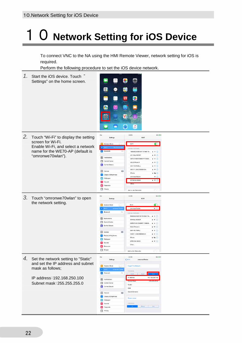
10.Network Setting for iOS Device
22
10 Network Setting for iOS Device To connect VNC to the NA using the HMI Remote Viewer, network setting for iOS is required. Perform the following procedure to set the iOS device network.
1. Start the iOS device. Touch ”Settings” on the home screen.
2. Touch “Wi-Fi” to display the setting screen for Wi-Fi. Enable Wi-Fi, and select a network name for the WE70-AP (default is “omronwe70wlan”).
3. Touch “omronwe70wlan” to open the network setting.
4. Set the network setting to ”Static” and set the IP address and subnet mask as follows; IP address:192.168.250.100 Subnet mask:255.255.255.0

11.Installing and Starting the HMI Remote Viewer
23
11 Installing and Starting the HMI Remote Viewer HMI Remote Viewer is the dedicated application that monitors and operates NA/NB screens, which is a VNC server. The following procedure describes steps from “starting the HMI Remote Viewer” to “connecting the NA-series with VNC connection”.
HMI Remote Viewer of iOS version can be installed from App Store, and Android version can be installed on Google Play for free of charge, respectively.
11-1 Installing the HMI Remote Viewer Perform the following procedure to install HMI Remote Viewer to the iOS device.
1. Start the iOS device. Touch ”App Store” on the home screen.
2. Touch the search box and enter ”HMI Remote Viewer”.
3. Install the HMI Remote Viewer.

11.Installing and Starting the HMI Remote Viewer
24
11-2 Starting the HMI Remote Viewer
1. After the HMI Remote Viewer is installed, ”HMI Viewer” is added on the home screen. Touch ”HMI Viewer” to start the HMI Remote Viewer.
2. Touch on the initial screen of the HMI Remote Viewer.
3. Set ”VNC-test (desired name)” to “Display name”, set “192.168.250.2 (IP address of the NA)” to ”IP/ Host”, and touch ”Save”.
4. Touch “Connect”.

11.Installing and Starting the HMI Remote Viewer
25
Additional Information If you set a password in step 3 when setting an IP address, the password entry in step 5 can be skipped.
5. Enter the password that you set for the VNC settings of the NA, and touch”OK”.
6. NA screen is displayed on the iOS device. Make sure that the screen is operational.
7. To disconnect the VNC connection, touch ”Disconnect” shown on the top left of the screen.
12.How to Operate the HMI Remote Viewer
26
12 How to Operate the HMI Remote Viewer This section describes how to operate the HMI Remote Viewer on the NA-series during VNC connection.
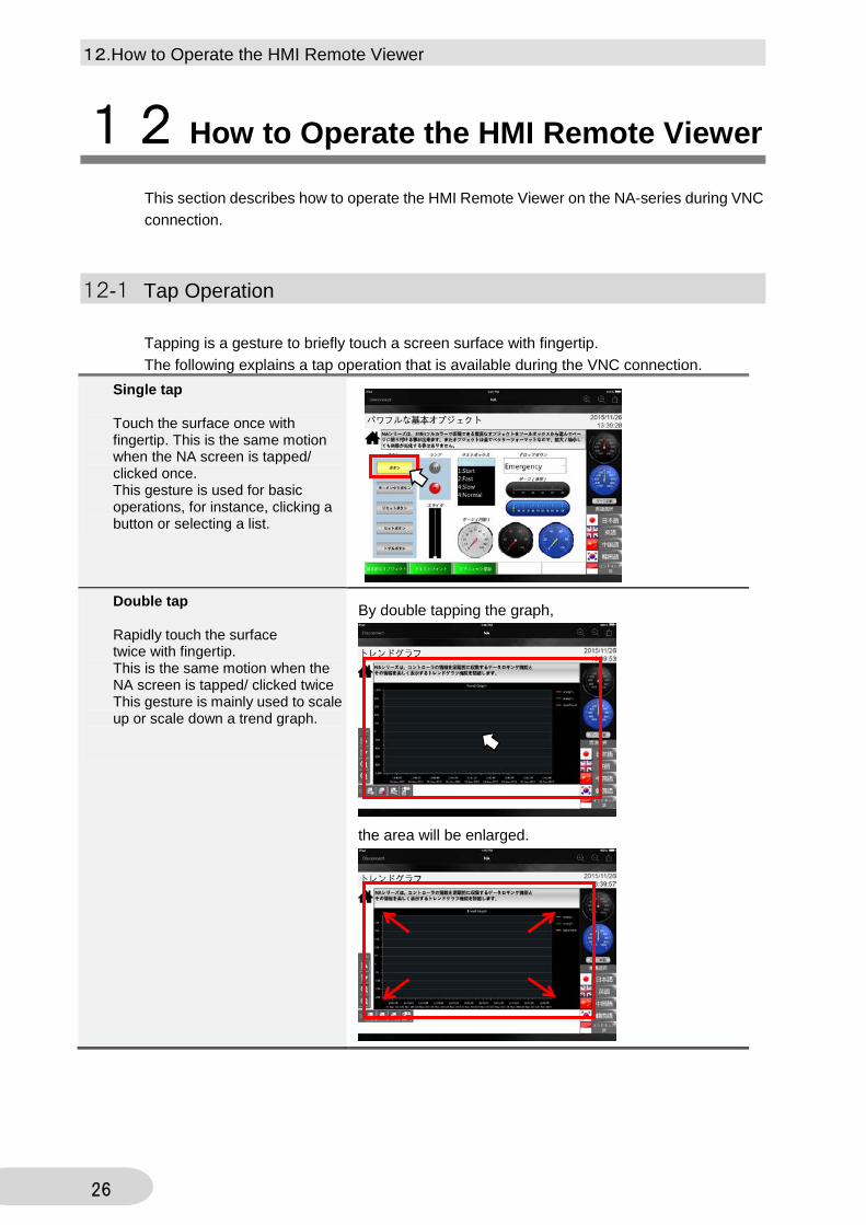
12-1 Tap Operation Tapping is a gesture to briefly touch a screen surface with fingertip. The following explains a tap operation that is available during the VNC connection.
Single tap Touch the surface once with fingertip. This is the same motion when the NA screen is tapped/ clicked once. This gesture is used for basic operations, for instance, clicking a button or selecting a list.
Double tap Rapidly touch the surface twice with fingertip. This is the same motion when the NA screen is tapped/ clicked twice This gesture is mainly used to scale up or scale down a trend graph.
By double tapping the graph,
the area will be enlarged.

12.How to Operate the HMI Remote Viewer
27
Long tap Press and hold the surface with fingertip. This is the same motion when the NA screen is pressed and held down. This gesture is mainly used to run a momentary button.
During a long tap, the tapped momentary button is being pressed down.

12.How to Operate the HMI Remote Viewer
28
12-2 Drag Operation Dragging is a gesture to move fingertip over the surface while the object is being pressed and held down. The following explains a drag operation during the VNC connection.
1. This is the same motion when dragging an object on the NA screen. This gesture is used to move a slider or scroll bar. Press the object that you want to move.
2. Move fingertip over the surface while the object is being pressed and held down, the object follows the movement of fingertip.
3. Move the object to the desired location and drop it by releasing the fingertip. The object will be placed in the location.

12.How to Operate the HMI Remote Viewer
29
12-3 Flick Operation Flicking is a gesture to quickly brush the surface with fingertip. The following explains a flick operation during the VNC connection.
1. Touch the screen and quickly brush the surface with fingertip. This gesture is used to scroll the listed items at once. Touch any location on the screen.
2. Quickly brush the surface with fingertip in an upward direction, the list will be scrolled down smoothly in a downward direction.

12.How to Operate the HMI Remote Viewer
30
12-4 Pinch in/Pinch out Operation
Pinching is a gesture to touch the surface with two fingers. The following explains the pinch in/pinch out operations during the VNC connection.
Pinch out Touch the surface with two fingers and bring them wider together. This gesture is used to enlarge the screen.
Pinch in Touch the surface with two fingers and bring them closer together. This gesture is used to scale down the enlarged screen. * The screen size cannot be reduced right after the connection.

12.How to Operate the HMI Remote Viewer
31
12-5 Deleting the Registered Screen The following explains how to delete the screens registered with the HMI Remote Viewer.
1. Touch ”Remove” on the setup screen.
2. A pop up is displayed. Touch ”Remove”.
3. The registered screen is deleted.

13.Setting VNC for the NB
32
13 Setting VNC for the NB Since the VNC function has been added to NB-Designer V1.46 and later, a remote connection using the HMI Remote Viewer is also supported by NB-series. How to set VNC function for NB-series is described below. How to connect the WE70 AP, iOS device, and HMI Remote Viewer is the same as when using NA. Accordingly, for the information, refer to sections 9 to 11 in this guide.
13-1 Setting IP Address and VNC with the NB-Designer Perform the following procedure to enables IP address and VNC function with the NB-Designer.
1. Double-click the PT placed on the Configurations and Setup window to display PT property.
2. Select the “PT” tab and set the IP address and subnet mask for network setting as follows; IP Address:192.168.250.2 Subnet Mask:255.255.255.0
3. Select “Enable VNC”

13.Setting VNC for the NB
33
Precautions for Correct Use
When logging-in from multiple clients with VNC, there is no restriction on the number of devices to be connected simultaneously. However, the response speed of screens may be deteriorated when the number of connected devices increases. Therefore, you need to check acceptable number of devices to be connected in your environment before the connection.
Precautions for Correct Use
You can set values start with 0, such as "001234", as a password on the NB-Designer, however, 0 will be ignored and the password will be set as "1234". If you enter "001234" when logging- in, an error will occur.
4. Set numeric passwords in range from 0 to 4294967295. (Within the range, no restrictions on the number of digits). A password must be set for monitor mode and operation mode, respectively. When the same password is set for both modes, the password is set for operation mode.
5. If you want to log-in from multiple clients, select ”Enable Multi Access”.

13.Setting VNC for the NB
34
13-2 Starting the HMI Remote Viewer (NB) Basically, the operation method is the same as Section 11-2 Starting the HMI Remote Viewer in this guide. Only the difference is the log-in operation.
1. Start the HMI Remote Viewer and display “Enter a password” screen. When a monitor mode password is entered, this is operated as monitor mode that enables only monitoring from VNC client. When an operation mode password is entered, this is operated as operation mode that also enables operation from VNC client.

35
Revision History Revision
code Date Revised content
01 January, 2016 Original production
02 April, 2018 Add some statements since HMI Remote Viewer is newly supported by
NB-series.

2018
0418(0418) V430-E1-02


![Channel Isolated Analog-Digital Converter Module/Channel ...€¦ · A - 2 [Installation Precautions] CAUTION Use the programmable controller in an environment that meets the general](https://img.pdfslide.net/doc/110x75/5f86134ed223da77bc75feb2/channel-isolated-analog-digital-converter-modulechannel-a-2-installation.jpg)


![Practices Guide Remote Solution - Omron · Programmable Terminal NB-series . Practices Guide . Remote Solution . NB3Q-TW0[]B NB5Q-TW0[]B](https://img.pdfslide.net/doc/110x75/6055a29317fdbf63635d2ca7/practices-guide-remote-solution-omron-programmable-terminal-nb-series-practices.jpg)


![Load Cell Input Module User's Manual - Mitsubishi Electric [Installation Precautions] [Wiring Precautions] CAUTION Use the programmable controller in an environment that meets the](https://img.pdfslide.net/doc/110x75/5aae03657f8b9a25088bb84d/load-cell-input-module-users-manual-mitsubishi-installation-precautions-wiring.jpg)