Embed Size (px)
Citation preview

VxWorksProgrammer’s Guide
®
5.4
Edition 1An ISO 9001 Registered Company
Copyright 1984 – 1999 Wind River Systems, Inc.
ALL RIGHTS RESERVED. No part of this publication may be copied in any form, by photocopy,
microfilm, retrieval system, or by any other means now known or hereafter invented without the
prior written permission of Wind River Systems, Inc.
VxWorks, IxWorks,Wind River Systems, the Wind River Systems logo, wind, and Embedded Internet
are registered trademarks of Wind River Systems, Inc. CrossWind, Tornado, VxMP, VxSim, VxVMI,
WindC++, WindConfig,Wind Foundation Classes, WindNet, WindPower, WindSh,andWindView are
trademarks of Wind River Systems, Inc.
All other trademarks used in this document are the property of their respective owners.
Corporate HeadquartersWind River Systems, Inc.
1010 Atlantic Avenue
Alameda, CA 94501-1153
USA
toll free (US): 800/545-WIND
telephone: 510/748-4100
facsimile: 510/749-2010
EuropeWind River Systems, S.A.R.L.
19, Avenue de Norvège
Immeuble B4, Bâtiment 3
Z.A. de Courtaboeuf 1
91953 Les Ulis Cédex
FRANCE
telephone: 33-1-60-92-63-00
facsimile: 33-1-60-92-63-15
JapanWind River Systems Japan
Pola Ebisu Bldg. 11F
3-9-19 Higashi
Shibuya-ku
Tokyo 150
JAPAN
telephone: 81-3-5467-5900
facsimile: 81-3-5467-5877
VxWorks Programmer’s Guide, 5.4Edition 1
6 May 99
Part #: DOC-12629-ZD-01
CUSTOMER SUPPORT
Telephone E-mail Fax
Corporate: 800/872-4977 toll free, U.S. & Canada
510/748-4100 direct
[email protected] 510/749-2164
Europe: 33-1-69-07-78-78 [email protected] 33-1-69-07-08-26
Japan: 011-81-3-5467-5900 [email protected] 011-81-3-5467-5877
If you purchased your Wind River Systems product from a distributor, please contact your
distributor to determine how to reach your technical support organization.
Please provide your license number when contacting Customer Support.

1 Overview ............................................................................... 1
2 Basic OS ............................................................................... 19
3 I/O System ............................................................................ 95
4 Local File Systems .............................................................. 175
5 C++ Development ................................................................ 227
6 Shared-Memory Objects ..................................................... 255
7 Virtual Memory Interface .................................................... 289
8 Configuration and Build ...................................................... 309
9 Target Shell .......................................................................... 369
Appendices .......................................................................... 381
A Motorola MC680x0 ............................................................... 383
B Sun SPARC, SPARClite ....................................................... 399
C Intel i960 ............................................................................... 417
D Intel x86 ................................................................................ 429
E MIPS R3000, R4000, R4650 ................................................. 477
F PowerPC ............................................................................... 489
G ARM ...................................................................................... 503
H VxSim .................................................................................... 525
I Coding Conventions ............................................................ 555
Index ..................................................................................... 577
iii


Contents
1 Overview ........................................................................................................................... 1
1.1 Introduction ...................................................................................................... 1
1.2 Getting Started with the Tornado Development System ............................ 2
1.3 VxWorks: A Partner in the Real-time Development Cycle ........................ 2
1.4 VxWorks Facilities: An Overview .................................................................. 3
Multitasking and Intertask Communications ................................ 6
POSIX Interfaces ................................................................................. 6
I/O System .......................................................................................... 7
Local File Systems .............................................................................. 8
Virtual Memory (Including VxVMI Option) .................................. 10
Shared-Memory Objects (VxMP Option) ....................................... 10
Target-Resident Tools ........................................................................ 11
C++ Development (including Wind Foundation Classes Option) 11
Utility Libraries .................................................................................. 11
Performance Evaluation .................................................................... 13
Target Agent ....................................................................................... 14
Board Support Packages (BSPs) ....................................................... 15
VxWorks Simulator (VxSim Option) ............................................... 15
1.5 Customer Services ............................................................................................ 16
1.6 Documentation Conventions .......................................................................... 17
v

VxWorks 5.4Programmer’s Guide
2 Basic OS ........................................................................................................................... 19
2.1 Introduction ...................................................................................................... 19
2.2 Wind Features and POSIX Features .............................................................. 20
2.3 Tasks ................................................................................................................... 20
2.3.1 Multitasking ....................................................................................... 20
2.3.2 Task State Transition .......................................................................... 21
2.3.3 Wind Task Scheduling ...................................................................... 22
Preemptive Priority Scheduling ...................................................... 23
Round-Robin Scheduling ................................................................. 23
Preemption Locks .............................................................................. 25
2.3.4 Tasking Control .................................................................................. 25
Task Creation and Activation .......................................................... 25
Task Names and IDs .......................................................................... 26
Task Options ....................................................................................... 27
Task Information ................................................................................ 28
Task Deletion and Deletion Safety .................................................. 28
Task Control ........................................................................................ 30
2.3.5 Tasking Extensions ............................................................................ 31
2.3.6 POSIX Scheduling Interface ............................................................. 32
Differences Between POSIX and Wind Scheduling ...................... 32
Getting and Setting POSIX Task Priorities ..................................... 33
Getting and Displaying the Current Scheduling Policy .............. 35
Getting Scheduling Parameters: Priority Limits and Time Slice 35
2.3.7 Task Error Status: errno .................................................................... 36
Layered Definitions of errno ............................................................ 36
A Separate errno Value for Each Task ............................................ 37
Error Return Convention .................................................................. 37
Assignment of Error Status Values ................................................. 38
2.3.8 Task Exception Handling ................................................................. 38
2.3.9 Shared Code and Reentrancy ........................................................... 39
Dynamic Stack Variables .................................................................. 40
Guarded Global and Static Variables .............................................. 40
vi

Contents
Task Variables ..................................................................................... 41
Multiple Tasks with the Same Main Routine ................................. 42
2.3.10 VxWorks System Tasks ...................................................................... 43
2.4 Intertask Communications .............................................................................. 45
2.4.1 Shared Data Structures ...................................................................... 45
2.4.2 Mutual Exclusion ............................................................................... 46
Interrupt Locks and Latency ............................................................ 46
Preemptive Locks and Latency ........................................................ 47
2.4.3 Semaphores ......................................................................................... 47
Semaphore Control ............................................................................ 48
Binary Semaphores ............................................................................ 49
Mutual-Exclusion Semaphores ........................................................ 52
Counting Semaphores ....................................................................... 56
Special Semaphore Options .............................................................. 57
POSIX Semaphores ............................................................................ 57
2.4.4 Message Queues ................................................................................. 65
Wind Message Queues ...................................................................... 66
POSIX Message Queues .................................................................... 68
Comparison of POSIX and Wind Message Queues ...................... 77
Displaying Message Queue Attributes ........................................... 78
Servers and Clients with Message Queues .................................... 78
2.4.5 Pipes ..................................................................................................... 79
2.4.6 Network Intertask Communication ................................................ 80
Sockets ................................................................................................. 80
Remote Procedure Calls (RPC) ........................................................ 81
2.4.7 Signals .................................................................................................. 81
Basic Signal Routines ......................................................................... 82
POSIX Queued Signals ...................................................................... 83
Signal Configuration ......................................................................... 84
2.5 Interrupt Service Code ..................................................................................... 85
2.5.1 Connecting Application Code to Interrupts .................................. 85
2.5.2 Interrupt Stack .................................................................................... 86
vii

VxWorks 5.4Programmer’s Guide
2.5.3 Special Limitations of ISRs ............................................................... 87
2.5.4 Exceptions at Interrupt Level ........................................................... 88
2.5.5 Reserving High Interrupt Levels ..................................................... 89
2.5.6 Additional Restrictions for ISRs at High Interrupt Levels .......... 89
2.5.7 Interrupt-to-Task Communication .................................................. 90
2.6 Watchdog Timers ............................................................................................. 90
2.7 POSIX Clocks and Timers ............................................................................... 92
2.8 POSIX Memory-Locking Interface ................................................................ 93
3 I/O System ........................................................................................................................ 95
3.1 Introduction ...................................................................................................... 95
3.2 Files, Devices, and Drivers ............................................................................. 96
3.2.1 File Names and the Default Device ................................................ 97
3.3 Basic I/O ........................................................................................................... 98
3.3.1 File Descriptors .................................................................................. 99
3.3.2 Standard Input, Standard Output, and Standard Error ............... 99
Global Redirection ............................................................................. 100
Task-Specific Redirection .................................................................. 100
3.3.3 Open and Close .................................................................................. 100
3.3.4 Create and Remove ........................................................................... 102
3.3.5 Read and Write ................................................................................... 102
3.3.6 File Truncation ................................................................................... 103
3.3.7 I/O Control ......................................................................................... 103
3.3.8 Pending on Multiple File Descriptors: The Select Facility ........... 104
3.4 Buffered I/O: Stdio .......................................................................................... 106
3.4.1 Using Stdio ......................................................................................... 107
viii

Contents
3.4.2 Standard Input, Standard Output, and Standard Error ............... 108
3.5 Other Formatted I/O ....................................................................................... 108
3.5.1 Special Cases: printf( ), sprintf( ), and sscanf( ) ............................. 108
3.5.2 Additional Routines: printErr( ) and fdprintf( ) ............................ 109
3.5.3 Message Logging ............................................................................... 109
3.6 Asynchronous Input/Output ......................................................................... 109
3.6.1 The POSIX AIO Routines .................................................................. 110
3.6.2 AIO Control Block ............................................................................. 111
3.6.3 Using AIO ........................................................................................... 112
AIO with Periodic Checks for Completion .................................... 113
Alternatives for Testing AIO Completion ...................................... 115
3.7 Devices in VxWorks ......................................................................................... 118
3.7.1 Serial I/O Devices (Terminal and Pseudo-Terminal Devices) ..... 118
Tty Options ......................................................................................... 119
Raw Mode and Line Mode ............................................................... 119
Tty Special Characters ....................................................................... 120
I/O Control Functions ....................................................................... 121
3.7.2 Pipe Devices ........................................................................................ 122
Creating Pipes ..................................................................................... 122
Writing to Pipes from ISRs ............................................................... 123
I/O Control Functions ....................................................................... 123
3.7.3 Pseudo Memory Devices .................................................................. 123
Installing the Memory Driver .......................................................... 124
I/O Control Functions ....................................................................... 124
3.7.4 Network File System (NFS) Devices ............................................... 124
Mounting a Remote NFS File System from VxWorks .................. 125
I/O Control Functions for NFS Clients .......................................... 125
3.7.5 Non-NFS Network Devices .............................................................. 126
Creating Network Devices ............................................................... 126
I/O Control Functions ....................................................................... 127
ix

VxWorks 5.4Programmer’s Guide
3.7.6 Block Devices ..................................................................................... 127
File Systems ........................................................................................ 127
RAM Disk Drivers ............................................................................. 128
SCSI Drivers ....................................................................................... 129
3.7.7 Sockets ................................................................................................. 139
3.8 Differences Between VxWorks and Host System I/O ................................ 139
3.9 Internal Structure ............................................................................................. 140
3.9.1 Drivers ................................................................................................. 142
The Driver Table and Installing Drivers ......................................... 143
Example of Installing a Driver ......................................................... 144
3.9.2 Devices ................................................................................................ 144
The Device List and Adding Devices ............................................. 145
Example of Adding Devices ............................................................ 146
3.9.3 File Descriptors .................................................................................. 146
The Fd Table ....................................................................................... 147
Example of Opening a File ............................................................... 147
Example of Reading Data from the File ......................................... 150
Example of Closing a File ................................................................. 150
Implementing select( ) ...................................................................... 152
Cache Coherency ............................................................................... 155
3.9.4 Block Devices ..................................................................................... 158
General Implementation ................................................................... 158
Low-Level Driver Initialization Routine ........................................ 160
Device Creation Routine ................................................................... 161
Read Routine (Direct-Access Devices) .......................................... 163
Read Routine (Sequential Devices) ................................................ 164
Write Routine (Direct-Access Devices) .......................................... 165
Write Routine (Sequential Devices) ............................................... 166
I/O Control Routine .......................................................................... 166
Device-Reset Routine ........................................................................ 167
Status-Check Routine ........................................................................ 168
Write-Protected Media ...................................................................... 168
Change in Ready Status .................................................................... 169
Write-File-Marks Routine (Sequential Devices) ............................ 169
Rewind Routine (Sequential Devices) ............................................ 170
x
Contents
Reserve Routine (Sequential Devices) ............................................ 170
Release Routine (Sequential Devices) ............................................. 170
Read-Block-Limits Routine (Sequential Devices) .......................... 171
Load/Unload Routine (Sequential Devices) .................................. 171
Space Routine (Sequential Devices) ................................................ 172
Erase Routine (Sequential Devices) ................................................. 173
3.9.5 Driver Support Libraries ................................................................... 173
4 Local File Systems ........................................................................................................... 175
4.1 Introduction ...................................................................................................... 175
4.2 MS-DOS-Compatible File System: dosFs ...................................................... 176
4.2.1 Disk Organization .............................................................................. 176
Clusters ................................................................................................ 177
Boot Sector .......................................................................................... 178
File Allocation Table .......................................................................... 178
Root Directory .................................................................................... 179
Subdirectories ..................................................................................... 180
Files ................................................................................................. 180
Volume Label ..................................................................................... 181
4.2.2 Initializing the dosFs File System .................................................... 181
4.2.3 Initializing a Device for Use with dosFs ......................................... 182
4.2.4 Volume Configuration ....................................................................... 183
DOS_VOL_CONFIG Fields .................................................................... 184
Calculating Configuration Values ................................................... 185
Standard Disk Configurations ......................................................... 186
4.2.5 Changes In Volume Configuration .................................................. 187
4.2.6 Using an Already Initialized Disk ................................................... 188
4.2.7 Accessing Volume Configuration Information .............................. 189
4.2.8 Mounting Volumes ............................................................................ 190
4.2.9 File I/O ................................................................................................ 190
4.2.10 Opening the Whole Device (Raw Mode) ........................................ 190
4.2.11 Creating Subdirectories ..................................................................... 191
xi

VxWorks 5.4Programmer’s Guide
4.2.12 Removing Subdirectories ................................................................. 192
4.2.13 Directory Entries ................................................................................ 192
4.2.14 Reading Directory Entries ................................................................ 193
4.2.15 File Attributes ..................................................................................... 193
4.2.16 File Date and Time ............................................................................. 195
4.2.17 Changing Disks .................................................................................. 196
Unmounting Volumes ....................................................................... 196
Announcing Disk Changes with Ready-Change .......................... 197
Disks with No Change Notification ................................................ 198
Synchronizing Volumes .................................................................... 198
Auto-Sync Mode ................................................................................ 199
4.2.18 Long Name Support .......................................................................... 199
4.2.19 Contiguous File Support .................................................................. 200
4.2.20 I/O Control Functions Supported by dosFsLib ........................... 202
4.2.21 Booting from a Local dosFs File System Using SCSI .................... 203
4.3 RT-11-Compatible File System: rt11Fs ........................................................... 204
4.3.1 Disk Organization ............................................................................. 205
4.3.2 Initializing the rt11Fs File System ................................................... 205
4.3.3 Initializing a Device for Use with rt11Fs ........................................ 206
4.3.4 Mounting Volumes ............................................................................ 207
4.3.5 File I/O ................................................................................................ 207
4.3.6 Opening the Whole Device (Raw Mode) ....................................... 207
4.3.7 Reclaiming Fragmented Free Disk Space ....................................... 208
4.3.8 Changing Disks .................................................................................. 208
Announcing Disk Changes with Ready-Change .......................... 208
Disks with No Change Notification ................................................ 209
4.3.9 I/O Control Functions Supported by rt11FsLib ........................... 209
4.4 Raw File System: rawFs .................................................................................. 209
4.4.1 Disk Organization ............................................................................. 210
xii

Contents
4.4.2 Initializing the rawFs File System ................................................... 211
4.4.3 Initializing a Device for Use with the rawFs File System ............ 211
4.4.4 Mounting Volumes ............................................................................ 212
4.4.5 File I/O ................................................................................................ 212
4.4.6 Changing Disks .................................................................................. 213
Unmounting Volumes ....................................................................... 213
Announcing Disk Changes with Ready-Change .......................... 213
Disks with No Change Notification ................................................ 214
Synchronizing Volumes .................................................................... 214
4.4.7 I/O Control Functions Supported by rawFsLib ........................... 215
4.5 Tape File System: tapeFs .................................................................................. 216
4.5.1 Tape Organization .............................................................................. 216
4.5.2 Using the tapeFs File System ............................................................ 216
Initializing the tapeFs File System ................................................... 216
Initializing a Device for Use with the tapeFs File System ............ 217
Mounting Volumes ............................................................................ 219
Modes of Operation ........................................................................... 219
File I/O ................................................................................................ 219
Changing Tapes .................................................................................. 219
I/O Control Functions Supported by tapeFsLib .......................... 220
4.6 CD-ROM File System: cdromFs ..................................................................... 221
4.7 The Target Server File System: TSFS .............................................................. 222
How It Works ...................................................................................... 222
Security Considerations .................................................................... 224
5 C++ Development ............................................................................................................. 227
5.1 Introduction ...................................................................................................... 227
5.2 C++ Development Under Tornado ................................................................ 228
5.2.1 Tools Support ...................................................................................... 228
WindSh ................................................................................................ 228
xiii

VxWorks 5.4Programmer’s Guide
Debugger ............................................................................................ 229
5.2.2 Programming Issues .......................................................................... 229
Making C++ Entry Points Accessible to C Code ........................... 229
5.2.3 Compiling C++ Applications ........................................................... 230
5.2.4 Configuration Constants .................................................................. 231
5.2.5 Munching C++ Application Modules ............................................ 232
5.2.6 Static Constructors and Destructors ............................................... 232
Calling Static Constructors and Destructors Interactively .......... 233
Constructors and Destructors in System Startup and Shutdown 233
5.2.7 Template Instantiation ...................................................................... 234
5.3 C++ Language and Library Support ............................................................. 236
5.3.1 Language Features ............................................................................ 237
Exception Handling .......................................................................... 237
Run-Time Type Information (RTTI) ................................................ 239
5.3.2 Standard Template Library (STL) .................................................... 239
Iostream Library ................................................................................ 239
String and Complex Number Classes ............................................ 240
5.4 Example ............................................................................................................. 240
5.5 Wind Foundation Classes ............................................................................... 250
5.5.1 VxWorks Wrapper Class Library ..................................................... 251
5.5.2 Tools.h++ Library .............................................................................. 254
6 Shared-Memory Objects ................................................................................................. 255
6.1 Introduction ...................................................................................................... 255
6.2 Using Shared-Memory Objects ...................................................................... 256
6.2.1 Name Database .................................................................................. 257
6.2.2 Shared Semaphores ........................................................................... 259
6.2.3 Shared Message Queues ................................................................... 263
xiv

Contents
6.2.4 Shared-Memory Allocator ................................................................ 268
Shared-Memory System Partition ................................................... 268
User-Created Partitions ..................................................................... 269
Using the Shared-Memory System Partition ................................. 270
Using User-Created Partitions ......................................................... 273
Side Effects of Shared-Memory Partition Options ........................ 276
6.3 Internal Considerations ................................................................................... 277
6.3.1 System Requirements ........................................................................ 277
6.3.2 Spin-lock Mechanism ........................................................................ 277
6.3.3 Interrupt Latency ............................................................................... 278
6.3.4 Restrictions .......................................................................................... 278
6.3.5 Cache Coherency ................................................................................ 279
6.4 Configuration .................................................................................................... 279
6.4.1 Shared-Memory Objects and Shared-Memory Network Driver 279
6.4.2 Shared-Memory Region .................................................................... 280
6.4.3 Initializing the Shared-Memory Objects Package ......................... 280
6.4.4 Configuration Example ..................................................................... 284
6.4.5 Initialization Steps ............................................................................. 285
6.5 Troubleshooting ................................................................................................ 286
6.5.1 Configuration Problems .................................................................... 286
6.5.2 Troubleshooting Techniques ............................................................. 286
7 Virtual Memory Interface ................................................................................................. 289
7.1 Introduction ...................................................................................................... 289
7.2 Basic Virtual Memory Support ....................................................................... 290
7.3 Virtual Memory Configuration ...................................................................... 290
7.4 General Use ....................................................................................................... 292
xv

VxWorks 5.4Programmer’s Guide
7.5 Using the MMU Programmatically ............................................................... 293
7.5.1 Virtual Memory Contexts ................................................................. 293
Global Virtual Memory ..................................................................... 293
Initialization ....................................................................................... 294
Page States .......................................................................................... 294
7.5.2 Private Virtual Memory .................................................................... 295
7.5.3 Noncacheable Memory ..................................................................... 302
7.5.4 Nonwritable Memory ....................................................................... 304
7.5.5 Troubleshooting ................................................................................. 306
7.5.6 Precautions ......................................................................................... 307
8 Configuration and Build .................................................................................................. 309
8.1 Introduction ...................................................................................................... 309
8.2 The Board Support Package (BSP) ................................................................. 310
The System Library ........................................................................... 311
Virtual Memory Mapping ................................................................ 312
The Serial Driver ................................................................................ 312
BSP Initialization Modules ............................................................... 312
BSP Documentation ........................................................................... 312
8.3 VxWorks Initialization Timeline .................................................................... 313
The VxWorks Entry Point: sysInit( ) ............................................... 313
The Initial Routine: usrInit( ) ........................................................... 314
Initializing the Kernel ....................................................................... 315
Initializing the Memory Pool ........................................................... 316
The Initial Task: usrRoot( ) ............................................................... 317
The System Clock Routine: usrClock( ) .......................................... 322
Initialization Summary ..................................................................... 322
8.4 Building, Loading, and Unloading Application Modules ......................... 325
8.4.1 Using VxWorks Header Files ........................................................... 325
VxWorks Header File: vxWorks.h ................................................... 325
Other VxWorks Header Files ........................................................... 326
ANSI Header Files ............................................................................. 326
xvi

Contents
The -I Compiler Flag ......................................................................... 326
VxWorks Nested Header Files ......................................................... 326
Internal Header Files ......................................................................... 327
VxWorks Private Header Files ......................................................... 328
8.4.2 Compiling Application Modules ..................................................... 329
The GNU Tools ................................................................................... 329
Cross-Development Commands ...................................................... 330
Defining the CPU Type ..................................................................... 330
Compiling C Modules ....................................................................... 332
Compiling C++ Modules .................................................................. 334
8.4.3 Static Linking (Optional) ................................................................... 334
8.4.4 Downloading an Application Module ............................................ 335
8.4.5 Module IDs and Group Numbers ................................................... 336
8.4.6 Unloading Modules ........................................................................... 336
8.5 Configuring VxWorks ...................................................................................... 337
8.5.1 The Environment Variables .............................................................. 337
8.5.2 The Configuration Header Files ...................................................... 338
The Global Configuration Header File: configAll.h ..................... 339
The BSP-specific Configuration Header File: config.h ................. 339
Selection of Optional Features ......................................................... 340
8.5.3 The Configuration Module: usrConfig.c ........................................ 343
8.6 Alternative VxWorks Configurations ............................................................ 344
8.6.1 Scaling Down VxWorks .................................................................... 344
Excluding Kernel Facilities ............................................................... 344
Excluding Network Facilities ........................................................... 345
Option Dependencies ........................................................................ 346
8.6.2 Executing VxWorks from ROM ....................................................... 346
8.6.3 Initialization Sequence for ROM-Based VxWorks ........................ 349
8.7 Building a VxWorks System Image ............................................................... 351
8.7.1 Available VxWorks Images ............................................................... 351
8.7.2 Rebuilding VxWorks with make ..................................................... 352
xvii
VxWorks 5.4Programmer’s Guide
Making on UNIX Hosts .................................................................... 352
Making on Windows Hosts .............................................................. 352
8.7.3 Including Customized VxWorks Code ........................................... 354
8.7.4 Linking the System Modules ........................................................... 355
8.7.5 Creating the System Symbol Table Module ................................... 356
8.8 Makefiles for BSPs and Applications ............................................................ 357
8.8.1 Make Variables ................................................................................... 359
Variables for Compilation Options ................................................. 359
Variables for BSP Parameters ........................................................... 361
Variables for Customizing the Run-Time ....................................... 362
8.8.2 Using Makefile Include Files for Application Modules ............... 363
8.8.3 Makefile for SIO Drivers ................................................................... 364
8.9 Creating Bootable Applications ..................................................................... 364
8.9.1 Creating a Standalone VxWorks System with a Built-in Symbol Table
366
8.9.2 Creating a VxWorks System in ROM .............................................. 367
General Procedures ........................................................................... 367
Boot ROM Compression ................................................................... 368
9 Target Shell ....................................................................................................................... 369
9.1 Introduction ...................................................................................................... 369
9.2 Target-Resident Shell ....................................................................................... 369
9.2.1 Creating the Target Shell .................................................................. 370
9.2.2 Using the Target Shell ....................................................................... 371
9.2.3 Debugging with the Target Shell ..................................................... 371
9.2.4 Aborting the Target Shell .................................................................. 372
9.2.5 Remote Login to the Target Shell .................................................... 373
Remote Login From Host: telnet and rlogin ................................. 373
Remote Login Security ...................................................................... 374
xviii

Contents
9.2.6 Summary of Target and Host Shell Differences ............................ 374
9.3 Other Target-Resident Facilities ..................................................................... 376
9.3.1 Target Symbol Table, Module Loader, and Module Unloader .... 376
9.3.2 Show Routines .................................................................................... 377
Appendices ....................................................................................................................... 381
A Motorola MC680x0 ........................................................................................................... 383
A.1 Introduction ...................................................................................................... 383
A.2 Building Applications ...................................................................................... 383
Defining the CPU Type ..................................................................... 384
Configuring the GNU ToolKit Environment ................................. 384
Compiling C or C++ Modules ......................................................... 384
A.3 Interface Variations .......................................................................................... 386
CPU-Specific Interfaces ..................................................................... 386
a.out-Specific Tools ............................................................................ 387
A.4 Architecture Considerations ........................................................................... 387
MC68060 Unimplemented Integer Instructions ............................ 388
Double-word Integers: long long .................................................... 388
Interrupt Stack .................................................................................... 388
MC68060 Superscalar Pipeline ......................................................... 389
Caches ................................................................................................. 389
Memory Management Unit .............................................................. 392
Floating-Point Support ...................................................................... 393
Memory Layout .................................................................................. 396
B Sun SPARC, SPARClite .................................................................................................... 399
B.1 Introduction ...................................................................................................... 399
B.2 Building Applications ...................................................................................... 399
Defining the CPU Type ..................................................................... 400
Configuring the GNU ToolKit Environment ................................. 400
xix

VxWorks 5.4Programmer’s Guide
Compiling C or C++ Modules ......................................................... 400
B.3 Interface Variations .......................................................................................... 401
a.out-Specific Tools for SPARC and SPARClite ............................. 406
B.4 Architecture Considerations ........................................................................... 406
Reserved Registers ........................................................................... 407
Processor Mode .................................................................................. 407
Vector Table Initialization ................................................................. 407
Double-word Integers: long long ................................................... 407
Interrupt Handling ............................................................................ 407
Floating-Point Support ..................................................................... 410
Stack Pointer Usage ........................................................................... 412
SPARClite Overview ......................................................................... 412
Memory Layout ................................................................................. 413
C Intel i960 ........................................................................................................................... 417
C.1 Introduction ...................................................................................................... 417
C.2 Building Applications ..................................................................................... 417
Defining the CPU Type ..................................................................... 418
Configuring the GNU ToolKit Environment ................................. 418
Compiling C or C++ Modules ........................................................ 418
Boot Loader Changes ........................................................................ 420
C.3 Interface Variations .......................................................................................... 421
Initialization ....................................................................................... 422
Data Breakpoint Routine bh( ) ........................................................ 422
Parameter Change for intLevelSet( ) .............................................. 422
Results Change for memLib ............................................................ 422
Math Routines .................................................................................... 423
Adding in Unresolved Routines ...................................................... 423
Floating-Point Task Option: VX_FP_TASK ........................................ 423
COFF-Specific Tools For i960 ........................................................... 424
Limitation on d( ) in WindSh ........................................................... 424
C.4 Architecture Considerations ........................................................................... 425
Byte Order ........................................................................................... 425
xx

Contents
Double-word Integers: long long .................................................... 425
VMEbus Interrupt Handling ............................................................ 425
Memory Layout .................................................................................. 426
D Intel x86 ............................................................................................................................. 431
D.1 Introduction ...................................................................................................... 431
D.2 Building Applications ...................................................................................... 431
Defining the CPU Type ..................................................................... 432
Configuring the GNU ToolKit Environment ................................. 432
Compiling C and C++ Modules ...................................................... 432
D.3 Interface Variations .......................................................................................... 434
Supported Routines in mathALib .................................................. 434
Architecture-Specific Global Variables ........................................... 434
Architecture-Specific Routines ......................................................... 435
a.out-Specific Tools for x86 ............................................................... 439
D.4 Architecture Considerations ........................................................................... 440
Operating Mode, Privilege Protection, and Byte Order ............... 441
Memory Segmentation ...................................................................... 441
I/O Mapped Devices ......................................................................... 441
Memory Mapped Devices ................................................................ 441
Memory Considerations for VME ................................................... 443
Interrupts and Exceptions ................................................................ 444
Registers .............................................................................................. 445
Counters .............................................................................................. 446
Double-word Integers: long long .................................................... 447
Context Switching .............................................................................. 447
ISA/EISA Bus ..................................................................................... 447
PC104 Bus ............................................................................................ 447
PCI Bus ................................................................................................ 447
Software Floating-Point Emulation ................................................. 448
VxWorks Memory Layout ................................................................ 448
D.5 Board Support Packages .................................................................................. 451
Boot Considerations for PC Targets ................................................ 451
Mounting a DOS File System ........................................................... 460
xxi

VxWorks 5.4Programmer’s Guide
DMA Buffer Alignment and cacheLib .......................................... 462
Support for Third-Party BSPs .......................................................... 462
VxWorks Images ................................................................................ 463
BSP-Specific Global Variables for 386 and 486 .............................. 463
Configuring the Pentium BSP .......................................................... 463
Configuring the PentiumPro BSP .................................................... 463
ROM Card and EPROM Support .................................................... 465
Device Drivers .................................................................................... 466
E MIPS R3000, R4000, R4650 ............................................................................................. 479
E.1 Introduction ...................................................................................................... 479
E.2 Building Applications ..................................................................................... 479
Defining the CPU Type ..................................................................... 480
Configuring the GNU ToolKit Environment ................................. 480
Compiling C or C++ Modules ......................................................... 480
E.3 Interface Variations .......................................................................................... 482
cacheR3kLib and cacheR4kLib ...................................................... 483
dbgLib ................................................................................................. 483
intArchLib .......................................................................................... 483
mathALib ........................................................................................... 483
taskArchLib ....................................................................................... 484
MMU Support .................................................................................... 484
ELF-specific Tools .............................................................................. 484
E.4 Architecture Considerations ........................................................................... 485
Gprel Addressing .............................................................................. 485
Reserved Registers ............................................................................ 485
Floating-Point Support ..................................................................... 485
Interrupts ............................................................................................ 486
Virtual Memory Mapping ................................................................ 488
64-bit Support (R4000 Targets Only) ............................................... 488
Memory Layout ................................................................................. 488
F PowerPC ........................................................................................................................... 491
F.1 Introduction ...................................................................................................... 491
xxii

Contents
F.2 Building Applications ...................................................................................... 491
Defining the CPU Type ..................................................................... 492
Configuring the GNU ToolKit Environment ................................. 492
Compiling C and C++ Modules ...................................................... 493
Compiling Modules for GDB ........................................................... 494
Unsupported Features ....................................................................... 494
F.3 Interface Changes ............................................................................................. 495
Memory Management Unit .............................................................. 495
HI and HIADJ Macros ....................................................................... 497
ELF-Specific Tools .............................................................................. 498
F.4 Architecture Considerations ........................................................................... 498
Processor Mode .................................................................................. 499
24-bit Addressing ............................................................................... 499
Byte Order ........................................................................................... 499
PowerPC Register Usage .................................................................. 499
Caches ................................................................................................. 500
Memory Management Unit .............................................................. 500
Floating-Point Support ...................................................................... 501
VxMP Support for Motorola PowerPC Boards ............................. 502
Memory Layout .................................................................................. 504
G ARM ................................................................................................................................... 507
G.1 Introduction ...................................................................................................... 507
G.2 Building Applications ...................................................................................... 508
Defining the CPU Type ..................................................................... 508
Configuring the GNU ToolKit Environment ................................. 508
Compiling C and C++ Modules ...................................................... 509
Boot Loader Changes ........................................................................ 510
G.3 Toolchain Information ..................................................................................... 512
Assembler Pseudo Operations ......................................................... 512
Additional ARM Compiler Options ................................................ 512
CrossWind and GDB ......................................................................... 513
G.4 Interface Variations .......................................................................................... 514
xxiii

VxWorks 5.4Programmer’s Guide
Restrictions on cret( ) and tt( ) ........................................................ 514
cacheLib .............................................................................................. 515
dbgLib ................................................................................................. 515
dbgArchLib ........................................................................................ 515
intALib ................................................................................................ 515
intArchLib .......................................................................................... 516
mmuALib ........................................................................................... 517
usrLib ................................................................................................. 517
vmLib ................................................................................................. 517
vxALib ................................................................................................ 517
vxLib ................................................................................................. 517
COFF-Specific Tools For ARM ......................................................... 518
G.5 Architecture Considerations ........................................................................... 518
Processor Mode and Byte Order ..................................................... 519
ARM/Thumb State ........................................................................... 519
Interrupts and Exceptions ................................................................ 520
Floating-Point Support ..................................................................... 522
Caches ................................................................................................. 522
Memory Management Unit .............................................................. 524
Memory Layout ................................................................................. 528
H VxSim ................................................................................................................................ 531
H.1 Introduction ...................................................................................................... 531
H.2 The Built-in Simulator ..................................................................................... 533
Installation and Configuration ........................................................ 533
Starting VxSim ................................................................................... 533
Rebooting VxSim ............................................................................... 533
Exiting VxSim ..................................................................................... 533
System-Mode Debugging ................................................................. 534
File Systems ........................................................................................ 534
H.3 Building Applications ..................................................................................... 535
Defining the CPU Type ..................................................................... 535
The Toolkit Environment .................................................................. 535
Compiling C and C++ Modules ...................................................... 535
Linking an Application to VxSim .................................................... 538
Architecture-Specific Tools ............................................................... 540
xxiv

Contents
H.4 Architecture Considerations ........................................................................... 540
Supported Configurations ................................................................ 540
The BSP Directory .............................................................................. 541
Interrupts ............................................................................................. 541
Clock and Timing Issues ................................................................... 544
H.5 VxSim Networking Component .................................................................... 545
Installing VxSim Network Drivers .................................................. 546
Configuring VxSim for Networking ............................................... 552
Running Multiple Simulators .......................................................... 553
System Mode Debugging ................................................................. 553
IP Addressing ..................................................................................... 555
Choosing Processor Numbers for Distinct Devices ...................... 556
Setting Up Remote Access ................................................................ 557
Setting up the Shared Memory Network (UNIX only) ................ 559
I Coding Conventions ........................................................................................................ 563
I.1 Introduction ...................................................................................................... 563
I.2 File Heading ...................................................................................................... 564
I.3 C Coding Conventions .................................................................................... 565
I.3.1 C Module Layout ............................................................................... 565
I.3.2 C Subroutine Layout ......................................................................... 567
I.3.3 C Declaration Formats ....................................................................... 568
Variables .............................................................................................. 569
Subroutines ......................................................................................... 570
I.3.4 C Code Layout .................................................................................... 571
Vertical Spacing .................................................................................. 571
Horizontal Spacing ............................................................................ 571
Indentation .......................................................................................... 572
Comments ........................................................................................... 574
I.3.5 C Naming Conventions .................................................................... 574
I.3.6 C Style .................................................................................................. 576
I.3.7 C Header File Layout ........................................................................ 577
xxv

VxWorks 5.4Programmer’s Guide
Structural ............................................................................................ 577
Order of Declaration ......................................................................... 577
I.3.8 Documentation Format Conventions for C ................................... 579
Layout ................................................................................................. 579
Format Commands ............................................................................ 580
Special Elements ................................................................................ 580
Formatting Displays .......................................................................... 582
Index ................................................................................................................................. 585
xxvi

1Overview
1.1 Introduction
This manual describes VxWorks, the high-performance real-time operating system
component of the Tornado development system. This manual includes the
following information:
■ How to use VxWorks facilities in the development of real-time applications.
(VxWorks networking facilities are covered in the VxWorks NetworkProgrammer’s Guide.)
■ How to use the optional components Wind Foundation Classes, VxMP, and
VxVMI.
■ How to configure and build VxWorks without using the project facility. (For
more information on the project facility, see Tornado User’s Guide: Projects.)
■ How to use the target-resident tools included in VxWorks.
■ Architecture-specific information for all architectures supported on VxWorks.
■ Wind River Systems’ C and C++ coding conventions.
This chapter begins by providing pointers to information on how to set up and
start using VxWorks as part of the Tornado development system. It then provides
an overview of the role of VxWorks in the development of real-time applications,
an overview of VxWorks facilities, a summary of Wind River Systems customer
services, and a summary of the document conventions followed in this manual.
1
VxWorks 5.4Programmer’s Guide
1.2 Getting Started with the Tornado Development System
See the following documents for information on installing and configuring the
Tornado development system, including VxWorks. Information on configuration
differs depending on whether your development host is UNIX or Windows; thus,
the Tornado User’s Guide is host specific.
■ Tornado Getting Started provides information on installing all components of
the Tornado Development System as well as a tutorial covering the main
features of Tornado.
■ The Tornado User’s Guide provides information on configuring and connecting
the host and target environments, building your VxWorks application, booting
VxWorks, and running Tornado.
For either host, 8. Configuration and Build in this manual provides information on
using Tornado 1.0.1-style manual methods for VxWorks configuration.
For a complete overview of Tornado documentation, see the documentation guide
in the Tornado User’s Guide.
1.3 VxWorks: A Partner in the Real-time Development Cycle
UNIX and Windows hosts are excellent systems for program development and for
many interactive applications. However, they are not appropriate for real-time
applications. On the other hand, traditional real-time operating systems provide
poor environments for application development or for non-real-time components
of an application, such as graphical user interfaces (GUIs).
Rather than trying to create a single operating system that “does it all,” the Wind
River philosophy is to utilize two complementary and cooperating operating
systems (VxWorks and UNIX, or VxWorks and Windows) and let each do what it
does best. VxWorks handles the critical real-time chores, while the host machine is
used for program development and for applications that are not time-critical.
You can scale VxWorks to include exactly the feature combinations your
application requires. During development, you can include additional features to
speed your work (such as the networking facilities), then exclude them to save
resources in the final version of your application.
2

1
1Overview
You can use the cross-development host machine to edit, compile, link, and store
real-time code, but then run and debug that real-time code on VxWorks. The
resulting VxWorks application can run standalone—either in ROM or disk-
based—with no further need for the network or the host system.
However, the host machine and VxWorks can also work together in a hybrid
application, with the host machine using VxWorks systems as real-time “servers”
in a networked environment. For instance, a VxWorks system controlling a robot
might itself be controlled by a host machine that runs an expert system, or several
VxWorks systems running factory equipment might be connected to host
machines that track inventory or generate reports.
1.4 VxWorks Facilities: An Overview
This section provides a summary of VxWorks facilities; they are described in more
detail in the following subsections. For details on any of these facilities, see the
appropriate chapters in this manual.
■ High-Performance Real-time Kernel Facilities
The VxWorks kernel, wind, includes multitasking with preemptive priority
scheduling, intertask synchronization and communications facilities, interrupt
handling support, watchdog timers, and memory management.
■ POSIX Compatibility
VxWorks provides most interfaces specified by the 1003.1b standard (formerly
the 1003.4 standard), simplifying your ports from other conforming systems.
■ I/O System
VxWorks provides a fast and flexible ANSI C-compatible I/O system,
including UNIX standard buffered I/O and POSIX standard asynchronous
I/O. VxWorks includes the following drivers:
Network driver – for network devices (Ethernet, shared memory)
Pipe driver – for intertask communication
RAM “disk” driver – for memory-resident files
SCSI driver – for SCSI hard disks, diskettes, and tape drives
Keyboard driver – for PC x86 keyboards (x86 BSP only)
Display driver – for PC x86 VGA displays (x86 BSP only)
3

VxWorks 5.4Programmer’s Guide
■ Local File Systems
VxWorks provides fast file systems tailored to real-time applications. One file
system is compatible with the MS-DOS® file system, another with the RT-11 file
system, a third is a “raw disk” file system, a fourth supports SCSI tape devices,
and a fifth supports CD-ROM devices.
■ C++ Development Support
In addition to general C++ support including the iostream library and the
standard template library, the optional component Wind Foundation Classes
adds the following C++ object libraries:
– VxWorks Wrapper Class library
– Tools.h++ library from Rogue Wave
■ Shared-Memory Objects (VxMP Option)
The VxMP option provides facilities for sharing semaphores, message queues,
and memory regions between tasks on different processors.
■ Virtual Memory (Including VxVMI Option)
VxWorks provides both bundled and unbundled (VxVMI) virtual memory
support for boards with an MMU, including the ability to make portions of
memory noncacheable or read-only, as well as a set of routines for virtual-
memory management.
■ Target-resident Tools
In the Tornado development system, the development tools reside on the host
system; see the Tornado User’s Guide for details. However, a target-resident
shell, module loader and unloader, and symbol table can be configured into
the VxWorks system if necessary.
■ Utility Libraries
VxWorks provides an extensive set of utility routines, including interrupt
handling, watchdog timers, message logging, memory allocation, string
formatting and scanning, linear and ring buffer manipulations, linked-list
manipulations, and ANSI C libraries.
Disk driver – for IDE and floppy disk drives (x86 BSP only)
Parallel port driver – for PC-style target hardware
4

1
1Overview
■ Performance Evaluation Tools
VxWorks performance evaluation tools include an execution timer for timing
a routine or group of routines, and utilities to show CPU utilization percentage
by task.
■ Target Agent
The target agent allows a VxWorks application to be remotely debugged using
the Tornado development tools.
■ Board Support Packages
Board Support Packages (BSPs) are available for a variety of boards and
provide routines for hardware initialization, interrupt setup, timers, memory
mapping, and so on.
■ VxWorks Simulator (VxSim) and Logic Analyzer (WindView)
Tornado comes with an integrated simulator and software logic analyzer on all
host platforms. VxSim simulates a VxWorks target for use as a prototyping and
testing environment. WindView provides advanced debugging tools for the
simulator environment.
The optional product VxSim provides networking capability and the ability to
run multiple simulators. The optional product WindView provides software
logic analyzer support for all WRS BSPs.
■ Network Facilities
VxWorks provides “transparent” access to other VxWorks and TCP/IP-
networked systems, a MUX interface (supporting advanced features such as
multicasting, polled-mode Ethernet, and zero-copy transmission), a BSD1
Sockets-compliant programming interface, remote procedure calls (RPC),
SNMP (optional), remote file access (including NFS client and server facilities
and a non-NFS facility utilizing RSH, FTP, or TFTP), BOOTP, proxy ARP,
DHCP, DNS, OSPF (optional), and RIP. All VxWorks network facilities comply
with standard Internet protocols, both loosely coupled over serial lines or
standard Ethernet connections and tightly coupled over a backplane bus using
shared memory.
For information on VxWorks network support, see the VxWorks NetworkProgrammer’s Guide.
1. BSD stands for Berkeley Software Distribution, and refers to a version of UNIX.
5

VxWorks 5.4Programmer’s Guide
Multitasking and Intertask Communications
Modern real-time systems are based on the complementary concepts of
multitasking and intertask communications. A multitasking environment allows
real-time applications to be constructed as a set of independent tasks, each with a
separate thread of execution and its own set of system resources. The intertask
communication facilities allow these tasks to synchronize and coordinate their
activity.
The VxWorks multitasking kernel, wind, uses interrupt-driven, priority-based task
scheduling. It features fast context switch times and low interrupt latency. Under
VxWorks, any subroutine can be spawned as a separate task, with its own context
and stack. Other basic task control facilities allow tasks to be suspended, resumed,
deleted, delayed, and moved in priority. See 2.3 Tasks, p.20 and the reference entry
for taskLib.
The wind kernel supplies semaphores as the basic task synchronization and
mutual-exclusion mechanism. There are several kinds of semaphores in wind,
specialized for different application needs: binary semaphores, counting
semaphores, mutual-exclusion semaphores, and POSIX semaphores. All of these
semaphore types are fast and efficient. In addition to being available to application
developers, they have also been used extensively in building higher-level facilities
in VxWorks.
For intertask communications, the wind kernel also supplies message queues,
pipes, sockets, and signals. The optional component VxMP provides shared-
memory objects as a communication mechanism for tasks executing on different
CPUs. For information on all these facilities, see 6. Shared-Memory Objects and
2.4 Intertask Communications, p.45. In addition, semaphores are described in the
semLib and semPxLib reference entries; message queues are described in the
msgQLib and mqPxLib reference entries; pipes are described in the pipeDrvreference entry and 2.4.5 Pipes, p.79; sockets are described in the sockLib reference
entry and 2.4.6 Network Intertask Communication, p.80; and signals are described in
the sigLib reference entry and 2.4.7 Signals, p.81.
POSIX Interfaces
POSIX (the Portable Operating System Interface) is a set of standards under
development by representatives of the software community, working under an
ISO/IEEE charter. The purpose of this effort is to support application portability at
the source level across operating systems. This effort has yielded a set of interfaces
(POSIX standard 1003.1b, formerly called 1003.4) for real-time operating system
6

1
1Overview
services. Using these interfaces makes it easier to move applications from one
operating system to another.
For a list of POSIX facilities, look under POSIX in the keyword index in the
VxWorks Reference Manual or in the Tornado Online Manuals. Nearly all POSIX
1003.1b interfaces are available in VxWorks, including POSIX interfaces for:
– asynchronous I/O
– semaphores
– message queues
– memory management
– queued signals
– scheduling
– clocks and timers
In addition, several interfaces from the traditional POSIX 1003.1 standard are also
supported.
I/O System
The VxWorks I/O system provides uniform device-independent access to many
kinds of devices. You can call seven basic I/O routines: creat( ), remove( ), open( ),close( ), read( ), write( ), and ioctl( ). Higher-level I/O routines (such as ANSI C-
compatible printf( ) and scanf( ) routines) are also provided.
VxWorks also provides a standard buffered I/O package (stdio) that includes ANSI
C-compatible routines such as fopen( ), fclose( ), fread( ), fwrite( ), getc( ), and
putc( ). These routines increase I/O performance in many cases.
The VxWorks I/O system also includes POSIX-compliant asynchronous I/O: a
library of routines that perform input and output operations concurrently with a
task’s other activities.
VxWorks includes device drivers for serial communication, disks, RAM disks,
SCSI tape devices, intertask communication devices (called pipes), and devices on
a network. Application developers can easily write additional drivers, if needed.
VxWorks allows dynamic installation and removal of drivers without rebooting
the system.
Internally, the VxWorks I/O system allows individual drivers complete control
over how the user requests are serviced. Drivers can easily implement different
protocols, unique device-specific routines, and even different file systems, without
interference from the I/O system itself. VxWorks also supplies several high-level
7
VxWorks 5.4Programmer’s Guide
packages that make it easy for drivers to implement common device protocols and
file systems.
For a detailed discussion of the I/O system, see 3. I/O System. Relevant reference
entries include ioLib for basic I/O routines available to tasks, fioLib and ansiStdiofor various format-driven I/O routines, aioPxLib for asynchronous I/O, and
iosLib and tyLib for routines available to driver writers. Also see the reference
entries for the supplied drivers.
Local File Systems
VxWorks includes several local file systems for use with block devices (disks).
These devices all use a standard interface so that file systems can be freely mixed
with device drivers. Local file systems for SCSI tape devices and CD-ROM devices
are also included. The VxWorks I/O architecture makes it possible to have several
different file systems on a single VxWorks system, even at the same time.
MS-DOS Compatible File System: dosFs
VxWorks provides the dosFs file system, which is compatible with the MS-DOS file
system (for MS-DOS versions up to and including 6.2). The capabilities of dosFs
offer considerable flexibility appropriate to the varying demands of real-time
applications. Major features include:
■ A hierarchical arrangement of files and directories, allowing efficient
organization and permitting an arbitrary number of files to be created on a
volume.
■ The ability to specify contiguous file allocation on a per-file basis. Contiguous
files offer enhanced performance, while non-contiguous files result in more
efficient use of disk space.
■ Compatibility with widely available storage and retrieval media. Diskettes
created with dosFs and on MS-DOS personal computers can be freely
interchanged and hard drives created with MS-DOS can be read by dosFs if it
is correctly configured.
■ Optional case-sensitive file names, with name lengths not restricted to the MS-
DOS eight-character + extension convention.
Services for file-oriented device drivers using dosFs are implemented in dosFsLib.
8

1
1Overview
RT-11 Compatible File System: rt11Fs
VxWorks provides the rt11Fs file system, which is compatible with that of the RT-
11 operating system. This file system has been used for real-time applications
because all files are contiguous. However, rt11Fs does have some drawbacks. It
lacks a hierarchical file organization that is particularly useful on large disks. Also,
the rigid contiguous allocation scheme may result in fragmented disk space. For
these reasons, dosFs is preferable to rt11Fs.
The VxWorks implementation of the RT-11 file system includes byte-addressable
random access (seeking) to all files. Each open file has a block buffer for optimized
reading and writing.
Services for file-oriented device drivers using rt11Fs are implemented in rt11FsLib.
Raw Disk File System: rawFs
VxWorks provides rawFs, a simple “raw disk file system” for use with disk devices.
rawFs treats the entire disk much like a single large file. The rawFs file system
permits reading and writing portions of the disk, specified by byte offset, and it
performs simple buffering. When only simple, low-level disk I/O is required,
rawFs has the advantages of size and speed.
Services for file-oriented device drivers using rawFs are implemented in
rawFsLib.
SCSI Sequential File System: tapeFs
VxWorks provides a file system for tape devices that do not use a standard file or
directory structure on tape. The tape volume is treated much like a raw device
where the entire volume is a large file. Any data organization on this large file is
the responsibility of a higher-level layer.
Services for SCSI sequential device drivers using tapeFs are implemented in
tapeFsLib.
cdRomFs
VxWorks provides the cdromFs file system which lets applications read any CD-
ROM that is formatted in accordance with ISO 9660 file system standards. After
initializing cdRomFs and mounting it on a CD-ROM block device, you can access
data on that device using the standard POSIX I/O calls.
9

VxWorks 5.4Programmer’s Guide
Alternative File Systems
In VxWorks, the file system is not tied to the device or its driver. A device can be
associated with any file system. Alternatively, you can supply your own file
systems that use standard drivers in the same way, by following the same standard
interfaces between the file system, the driver, and the VxWorks I/O system.
Virtual Memory (Including VxVMI Option)
Virtual memory support is provided for boards with Memory Management Units
(MMU). Bundled virtual memory support provides the ability to mark buffers
noncacheable. This is useful for multiprocessor environments where memory is
shared across processors or where DMA transfers take place. For information on
bundled virtual memory support, see 7. Virtual Memory Interface and the reference
entries for vmBaseLib and cacheLib.
Unbundled virtual memory support is available as the optional component
VxVMI. VxVMI provides the ability to make text segments and the exception
vector table read-only, and includes a set of routines for developers to manage their
own virtual memory contexts. For information on VxVMI, see 7. Virtual MemoryInterface and the reference entry for vmLib.
Shared-Memory Objects (VxMP Option)
The following shared-memory objects (available with VxWorks as the optional
component, VxMP) are used for communication and synchronization between
tasks on different CPUs:
■ Shared semaphores can be used to synchronize tasks on different CPUs as well
as provide mutual exclusion to shared data structures.
■ Shared message queues allow tasks on multiple processors to exchange
messages.
■ Shared memory management is available to allocate common data buffers for
tasks on different processors.
For information on VxMP, see 6. Shared-Memory Objects and the reference entries
for smObjLib, smObjShow, semSmLib, msgQSmLib, smMemLib, and
smNameLib.
10

1
1Overview
Target-Resident Tools
In the Tornado development system, a full suite of development tools reside and
execute on the host machine; see the Tornado User’s Guide for details. However, a
target-resident shell, symbol table, and module loader/unloader can be
configured into the VxWorks system if necessary, for example, to create a
dynamically configured run-time system.
For information on these target-resident tools, see 9. Target Shell and the reference
entries for shellLib, usrLib, dbgLib, loadLib, unldLib, and symLib.
C++ Development (including Wind Foundation Classes Option)
VxWorks supports C++ development. The GNU C++ compiler is shipped with
Tornado. The Tornado compiler provides support for multi-thread-safe exception
handling. Tornado includes a new version of the iostream library and the SGI
implementation of the Standard Template Library. The standard Tornado
interactive development tools such as the debugger, the shell, and the incremental
loader include C++ support.
In addition, you can order the Wind Foundation Classes optional component to
add the following libraries:
– VxWorks Wrapper Class library
– Tools.h++ library from Rogue Wave
For more information on these libraries, see 5. C++ Development.
Utility Libraries
VxWorks supplies many subroutines of general utility to application developers.
These routines are organized as a set of subroutine libraries, which are described
below. We urge you to use these libraries wherever possible. Using library utilities
reduces both development time and memory requirements for the application.
Interrupt Handling Support
VxWorks supplies routines for handling hardware interrupts and software traps
without having to resort to assembly language coding. Routines are provided to
connect C routines to hardware interrupt vectors, and to manipulate the processor
interrupt level.
11

VxWorks 5.4Programmer’s Guide
For information on interrupt handling, see the intLib and intArchLib reference
entries. Also see 2. Basic OS for information about the context where interrupt-
level code runs and for special restrictions that apply to interrupt service routines.
Watchdog Timers
A watchdog facility allows callers to schedule execution of their own routines after
specified time delays. As soon as the specified number of ticks have elapsed, the
specified “timeout” routine is called at the interrupt level of the system clock,
unless the watchdog is canceled first. This mechanism is entirely different from the
kernel’s task delay facility. For information on watchdog timers, see 2.6 WatchdogTimers, p.90 and the reference entry for wdLib.
Message Logging
A simple message logging facility allows applications to send error or status
messages to a logging task, which then formats and outputs the messages to a
system-wide logging device (such as the system console, disk, or accessible
memory). The message logging facility can be used from either interrupt level or
task level. For information on this facility, see 3.5.3 Message Logging, p.109 and the
reference entry for logLib.
Memory Allocation
VxWorks supplies a memory management facility useful for dynamically
allocating, freeing, and reallocating blocks of memory from a memory pool. Blocks
of arbitrary size can be allocated, and you can specify the size of the memory pool.
This memory scheme is built on a much more general mechanism that allows
VxWorks to manage several separate memory pools.
String Formatting and Scanning
VxWorks includes a complete set of ANSI C library string formatting and scanning
subroutines that implement printf( )/scanf( ) format-driven encoding and
decoding and associated routines. See the reference entries for fioLib and
ansiStdio.
Linear and Ring Buffer Manipulations
The library bLib contains buffer manipulation routines such as copying, filling,
comparing, and so on, that have been optimized for speed. The library rngLibprovides a set of general ring buffer routines that manage first-in-first-out (FIFO)
circular buffers. Additionally, these ring buffers have the property that a single
12

1
1Overview
writer and a single reader can access a ring buffer “simultaneously” without being
required to interlock their accesses explicitly.
Linked-List Manipulations
The library lstLib contains a complete set of routines for creating and
manipulating doubly-linked lists.
ANSI C Libraries
VxWorks provides all C libraries specified by ANSI X3.159-1989. The ANSI C
specification includes the following libraries: assert, ctype, errno, float, limits,
locale, math, setjmp, signal, stdarg, stdio, stddef, stdlib, string, and time.
The header files float.h, limits.h, errno.h, and stddef.h provide ANSI-specified
definitions and declarations. The more commonly used libraries are described in
the following reference entries:
Performance Evaluation
To understand and optimize the performance of a real-time system, it can be useful
to time some of the VxWorks or application routines. VxWorks provides various
timing facilities to help with this task.
The VxWorks execution timer can time any subroutine or group of subroutines.
Because the system clock is too slow to provide the resolution necessary to time
especially fast routines, the timer can also repeatedly execute a group of routines
until the time of a single iteration is known to a reasonable accuracy. For
information on the execution timer, see the timexLib reference entry.
VxWorks also provides the spy utility, which provides CPU utilization information
for each task: the CPU time consumed, the time spent at interrupt level, and the
amount of idle time. Time is displayed in ticks and in percentages. For information
on this utility, see the spyLib reference entry.2
ansiCtype routines for character manipulation
ansiMath trigonometric, exponential, and logarithmic routines
ansiSetjmp routines for implementing a non-local goto
ansiStdarg routines for traversing a variable-length argument list
ansiStdio routines for manipulating streams for input/output
ansiStdlib a variety of routines, including those for type translation,
memory allocation, and random number generation
sigLib signal-manipulation routines
13

VxWorks 5.4Programmer’s Guide
Even more powerful monitoring of the VxWorks system is available using the
optional product WindView; for more information, see the WindView User’s Guide.
Target Agent
The target agent follows the WDB (Wind DeBug) protocol, allowing a VxWorks
target to be connected to the Tornado development tools. In the target agent’s
default configuration, shown in Figure 1-1, the agent runs as the VxWorks task
tWdbTask. The Tornado target server sends debugging requests to the target
agent. The debugging requests often result in the target agent controlling or
manipulating other tasks in the system.
By default, the target server and agent communicate using the network. However,
you can use alternative communication paths. For more information on the default
configuration or alternative configurations of the target agent, see Tornado GettingStarted. For information on the Tornado target server, see the Tornado User’s Guide:Overview.
2. You can also use this utility through the Tornado browser; see the Tornado User’s Guide:Browser for details.
Figure 1-1 Interaction Between Target Server and Target Agent
HOST TARGET
VxWorks OS
CommunicationsDriver
tWdbTask
tUser1 tUser2Target Server
(Target Agent)
(Ethernet, SLIP, etc.)NETWORK
14

1
1Overview
Board Support Packages (BSPs)
Two target-specific libraries, sysLib and sysALib, are included with each port of
VxWorks. These libraries are the heart of VxWorks portability; they provide an
identical software interface to the hardware functions of all boards. They include
facilities for hardware initialization, interrupt handling and generation, hardware
clock and timer management, mapping of local and bus memory spaces, memory
sizing, and so on.
Each BSP also includes a boot ROM or other boot mechanism. Many of these
import the run-time image from the development host. For information on boot
ROMs and other booting mechanisms see Tornado Getting Started and 8.9 CreatingBootable Applications, p.364.
For information on target-specific libraries, see 8.2 The Board Support Package (BSP),p.310 and the target-specific reference entries for your board type.
VxWorks Simulator
VxSim, the VxWorks simulator, is a program that simulates a VxWorks target for
use as a prototyping and testing environment. The integrated version of the
simulator allows a single simulator to be run. The VxSim optional product adds
networking facilities, allowing the simulator to obtain an Internet address and
communicate with the host (or other nodes on the network) using the VxWorks
networking tools.
VxSim is essentially a port of VxWorks. In most regards, its capabilities are
identical to a true VxWorks system running on remote target hardware. You can
link in an application and rebuild the VxWorks image exactly the same way as in
any other VxWorks cross-development environment. All Tornado development
tools can be used with VxSim.
The difference between VxSim and a remote VxWorks target environment is that
in VxSim, the image executes on the host machine itself as a host process. There is
no emulation of instructions, because the code is in the host’s own CPU
architecture. Because target hardware interaction is not possible, device-driver
development may not be suitable for simulation. However, the VxWorks scheduler
is implemented in the VxSim process, maintaining true tasking interaction with
respect to priorities and preemption. This means that any application that is
written in a portable style and with minimal hardware interaction should be
portable between VxSim and VxWorks.
For more information on VxSim, see H. VxSim.
15

VxWorks 5.4Programmer’s Guide
1.5 Customer Services
A full range of support services is available from Wind River Systems to ensure
that you have the opportunity to make optimal use of the extensive features of
VxWorks.
This section summarizes the major services available. For more detailed
information, consult the Tornado User’s Guide: Customer Service.
Training
In the United States, Wind River Systems holds regularly scheduled classes on
Tornado and VxWorks. Customers can also arrange to have Tornado classes held
at their facility. The easiest way to learn about WRS training services, schedules,
and prices is through the World Wide Web. Point your site’s Web browser at the
following URL:
http://www.wrs.com/training
You can contact the Training Department at:
Outside of the United States, call your local distributor or nearest Wind River
Systems office for training information. See the back cover of this manual for a list
of Wind River Systems offices.
Customer Support
Direct contact with a staff of software engineers experienced in VxWorks is
available through the Wind River Systems Customer Support program. For
information on how to contact WRS Customer Support, see the copyright page at
the front of this manual.
Phone: 510/749-2148
800/545–WIND
Fax: 510/749–2378
E-mail: [email protected]
16

1
1Overview
1.6 Documentation Conventions
Typographical Conventions
VxWorks documentation uses the conventions shown in Table 1-1 to differentiate
various elements. Parentheses are always included to indicate a subroutine name,
as in printf( ).
Cross-References
Cross-references in this guide to a reference entry for a tool or module refer to an
entry in the VxWorks Reference Manual (for target libraries or subroutines) or to the
reference appendix in the Tornado User’s Guide (for host tools). These references are
also provided in the Tornado Online Manuals. For more information about how to
access online documentation, see the Tornado User’s Guide: Documentation Guide.
Table 1-1 Font Usage for Special Terms
Term Example
files, pathnames /etc/hosts
libraries, drivers memLib, nfsDrv
host tools more, chkdsk
subroutines semTake( )
boot commands p
code display main ();
keyboard input make CPU=MC68040 ...
display output value = 0
user-supplied parameters name
constants INCLUDE_NFS
C keywords, cpp directives #define
named key on keyboard RETURN
control characters CTRL+C
lower-case acronyms fd
17

VxWorks 5.4Programmer’s Guide
Other references from one book to another are always at the chapter level, and take
the form Book Title: Chapter Name.
Pathnames
The top-level Tornado directory structure includes three major directories (see the
Tornado User’s Guide: Directories and Files). Although all VxWorks files reside in the
target directory, in order to maintain consistency with other Tornado manuals this
manual uses pathnames of the following form: installDir/target. For example, if
you install Tornado in /group/wind on a UNIX host or in C:\Tornado on a
Windows host, the full pathname for the file shown as
installDir/target/config/all/configAll.h is
/group/wind/target/config/all/configAll.h (which is also
$WIND_BASE/target/config/all/configAll.h) on UNIX or
C:\Tornado\target\config\all\configAll.h on Windows.
NOTE: In this manual, forward slashes are used as pathname delimiters for both
UNIX and Windows file names since this is the default for VxWorks.
18

2Basic OS
2.1 Introduction
Modern real-time systems are based on the complementary concepts of
multitasking and intertask communications. A multitasking environment allows a
real-time application to be constructed as a set of independent tasks, each with its
own thread of execution and set of system resources. The intertask communication
facilities allow these tasks to synchronize and communicate in order to coordinate
their activity. In VxWorks, the intertask communication facilities range from fast
semaphores to message queues and pipes to network-transparent sockets.
Another key facility in real-time systems is hardware interrupt handling, because
interrupts are the usual mechanism to inform a system of external events. To get
the fastest possible response to interrupts, interrupt service routines (ISRs) inVxWorks run in a special context of their own, outside of any task’s context.
This chapter discusses the multitasking kernel, tasking facilities, intertask
communication, and interrupt handling facilities, which are at the heart of the
VxWorks run-time environment.
19
VxWorks 5.4Programmer’s Guide
2.2 Wind Features and POSIX Features
The POSIX standard for real-time extensions (1003.1b) specifies a set of interfaces
to kernel facilities. To improve application portability, the VxWorks kernel, wind,
includes both POSIX interfaces and interfaces designed specifically for VxWorks.
This manual (especially in this chapter) uses the qualifier “Wind” to identify
facilities designed expressly for use with the VxWorks wind kernel. For example,
you can find a discussion of Wind semaphores contrasted to POSIX semaphores in
Comparison of POSIX and Wind Semaphores, p.59.
2.3 Tasks
It is often essential to organize applications into independent, though cooperating,
programs. Each of these programs, while executing, is called a task. In VxWorks,
tasks have immediate, shared access to most system resources, while also
maintaining enough separate context to maintain individual threads of control.
2.3.1 Multitasking
Multitasking provides the fundamental mechanism for an application to control
and react to multiple, discrete real-world events. The VxWorks real-time kernel,
wind, provides the basic multitasking environment. Multitasking creates the
appearance of many threads of execution running concurrently when, in fact, the
kernel interleaves their execution on the basis of a scheduling algorithm. Each
apparently independent program is called a task. Each task has its own context,which is the CPU environment and system resources that the task sees each time it
is scheduled to run by the kernel. On a context switch, a task’s context is saved in
the task control block (TCB). A task’s context includes:
– a thread of execution, that is, the task’s program counter
– the CPU registers and (optionally) floating-point registers
– a stack for dynamic variables and function calls
– I/O assignments for standard input, output, and error
– a delay timer
– a timeslice timer
– kernel control structures
20
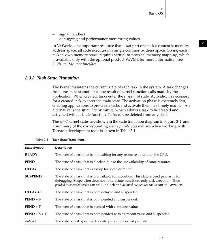
2
2Basic OS
– signal handlers
– debugging and performance monitoring values
In VxWorks, one important resource that is not part of a task’s context is memory
address space: all code executes in a single common address space. Giving each
task its own memory space requires virtual-to-physical memory mapping, which
is available only with the optional product VxVMI; for more information, see
7. Virtual Memory Interface.
2.3.2 Task State Transition
The kernel maintains the current state of each task in the system. A task changes
from one state to another as the result of kernel function calls made by the
application. When created, tasks enter the suspended state. Activation is necessary
for a created task to enter the ready state. The activation phase is extremely fast,
enabling applications to pre-create tasks and activate them in a timely manner. An
alternative is the spawning primitive, which allows a task to be created and
activated with a single function. Tasks can be deleted from any state.
The wind kernel states are shown in the state transition diagram in Figure 2-1, and
a summary of the corresponding state symbols you will see when working with
Tornado development tools is shown in Table 2-1.
Table 2-1 Task State Transitions
State Symbol Description
READY The state of a task that is not waiting for any resource other than the CPU.
PEND The state of a task that is blocked due to the unavailability of some resource.
DELAY The state of a task that is asleep for some duration.
SUSPEND The state of a task that is unavailable for execution. This state is used primarily for
debugging. Suspension does not inhibit state transition, only task execution. Thus
pended-suspended tasks can still unblock and delayed-suspended tasks can still awaken.
DELAY + S The state of a task that is both delayed and suspended.
PEND + S The state of a task that is both pended and suspended.
PEND + T The state of a task that is pended with a timeout value.
PEND + S + T The state of a task that is both pended with a timeout value and suspended.
state + I The state of task specified by state, plus an inherited priority.
21
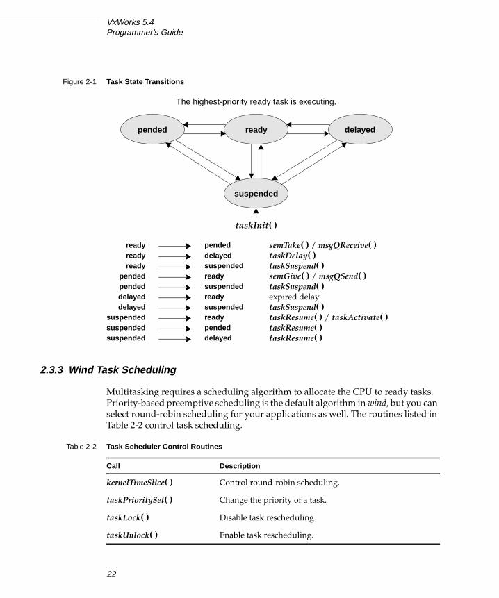
VxWorks 5.4Programmer’s Guide
2.3.3 Wind Task Scheduling
Multitasking requires a scheduling algorithm to allocate the CPU to ready tasks.
Priority-based preemptive scheduling is the default algorithm in wind, but you can
select round-robin scheduling for your applications as well. The routines listed in
Table 2-2 control task scheduling.
Figure 2-1 Task State Transitions
Table 2-2 Task Scheduler Control Routines
Call Description
kernelTimeSlice( ) Control round-robin scheduling.
taskPrioritySet( ) Change the priority of a task.
taskLock( ) Disable task rescheduling.
taskUnlock( ) Enable task rescheduling.
suspended
pended
taskInit( )
The highest-priority ready task is executing.
ready delayed
ready pendedready delayedready suspended
pended readypended suspendeddelayed readydelayed suspended
suspended readysuspended pendedsuspended delayed
semTake( ) / msgQReceive( )taskDelay( )taskSuspend( )semGive( ) / msgQSend( )taskSuspend( )expired delay
taskSuspend( )taskResume( ) / taskActivate( )taskResume( )taskResume( )
22

2
2Basic OS
Preemptive Priority Scheduling
With a preemptive priority-based scheduler, each task has a priority and the kernel
ensures that the CPU is allocated to the highest priority task that is ready to run.
This scheduling method is preemptive in that if a task that has higher priority than
the current task becomes ready to run, the kernel immediately saves the current
task’s context and switches to the context of the higher priority task. In Figure 2-2,
task t1 is preempted by higher-priority task t2, which in turn is preempted by t3.
When t3 completes, t2 continues executing. When t2 completes execution, t1continues executing.
The wind kernel has 256 priority levels, numbered 0 through 255. Priority 0 is the
highest and priority 255 is the lowest. Tasks are assigned a priority when created;
however, while executing, a task can change its priority using taskPrioritySet( ).The ability to change task priorities dynamically allows applications to track
precedence changes in the real world.
Round-Robin Scheduling
Preemptive priority scheduling can be augmented with round-robin scheduling. A
round-robin scheduling algorithm attempts to share the CPU fairly among all
ready tasks of the same priority. Without round-robin scheduling, when multiple
tasks of equal priority must share the processor, a single task can usurp the
processor by never blocking, thus never giving other equal-priority tasks a chance
to run.
Figure 2-2 Priority Preemption
t1
KEY: = preemption
time
HIGH
LOW
prio
rity
t3
t2
= task completion
t1
t2
23

VxWorks 5.4Programmer’s Guide
Round-robin scheduling achieves fair allocation of the CPU to tasks of the same
priority by an approach known as time slicing. Each task of a group of tasks
executes for a defined interval, or time slice; then another task executes for an equal
interval, in rotation. The allocation is fair in that no task of a priority group gets a
second slice of time before the other tasks of a group are given a slice.
Round-robin scheduling can be enabled with the routine kernelTimeSlice( ), which
takes a parameter for a time slice, or interval. This interval is the amount of time
each task is allowed to run before relinquishing the processor to another equal-
priority task.
More precisely, a run-time counter is kept for each task and incremented on every
clock tick. When the specified time-slice interval is completed, the counter is
cleared and the task is placed at the tail of the queue of tasks at its priority. New
tasks joining a priority group are placed at the tail of the group with a run-time
counter initialized to zero.
If a task is preempted by a higher priority task during its interval, its run-time
count is saved and then restored when the task is again eligible for execution.
Figure 2-3 shows round-robin scheduling for three tasks of the same priority: t1, t2,
and t3. Task t2 is preempted by a higher priority task t4 but resumes at the count
where it left off when t4 is finished.
Figure 2-3 Round-Robin Scheduling
t1
KEY: = preemption
time
HIGH
LOW
prio
rity
t2 t3 t1
t4
t2 t2
= task completion
time slice
t3
24

2
2Basic OS
Preemption Locks
The wind scheduler can be explicitly disabled and enabled on a per-task basis with
the routines taskLock( ) and taskUnlock( ). When a task disables the scheduler by
calling taskLock( ), no priority-based preemption can take place while that task is
running.
However, if the task explicitly blocks or suspends, the scheduler selects the next
highest-priority eligible task to execute. When the preemption-locked task
unblocks and begins running again, preemption is again disabled.
Note that preemption locks prevent task context switching but do not lock out
interrupt handling.
Preemption locks can be used to achieve mutual exclusion; however, keep the
duration of preemption locking to a minimum. For more information, see
2.4.2 Mutual Exclusion, p.46.
2.3.4 Tasking Control
The following sections give an overview of the basic VxWorks tasking routines,
which are found in the VxWorks library taskLib. These routines provide the means
for task creation, control, and information. See the reference entry for taskLib for
further discussion. For interactive use, you can control VxWorks tasks from the
host-resident shell; see the Tornado User’s Guide: Shell.
Task Creation and Activation
The routines listed in Table 2-3 are used to create tasks.
Table 2-3 Task Creation Routines
Call Description
taskSpawn( ) Spawn (create and activate) a new task.
taskInit( ) Initialize a new task.
taskActivate( ) Activate an initialized task.
25
VxWorks 5.4Programmer’s Guide
The arguments to taskSpawn( ) are the new task’s name (an ASCII string), priority,
an “options” word, stack size, main routine address, and 10 arguments to be
passed to the main routine as startup parameters:
id = taskSpawn ( name, priority, options, stacksize, main, arg1, …arg10 );
The taskSpawn( ) routine creates the new task context, which includes allocating
the stack and setting up the task environment to call the main routine (an ordinary
subroutine) with the specified arguments. The new task begins execution at the
entry to the specified routine.
The taskSpawn( ) routine embodies the lower-level steps of allocation,
initialization, and activation. The initialization and activation functions are
provided by the routines taskInit( ) and taskActivate( ); however, we recommend
you use these routines only when you need greater control over allocation or
activation.
Task Names and IDs
When a task is spawned, you can specify an ASCII string of any length to be the
task name. VxWorks returns a task ID, which is a 4-byte handle to the task’s data
structures. Most VxWorks task routines take a task ID as the argument specifying
a task. VxWorks uses a convention that a task ID of 0 (zero) always implies the
calling task.
A task name should not conflict with any existing task name. Furthermore, to use
the Tornado development tools to their best advantage, task names should not
conflict with globally visible routine or variable names. To avoid name conflicts,
VxWorks uses a convention of prefixing all task names started from the target with
the letter t and task names started from the host with the letter u.
You may not want to name some or all of your application’s tasks. If a NULL
pointer is supplied for the name argument of taskSpawn( ), then VxWorks assigns
a unique name. The name is of the form tN, where N is a decimal integer that
increases by one for each unnamed task that is spawned.
The taskLib routines listed in Table 2-4 manage task IDs and names.
NOTE: In the shell, task names are resolved to their corresponding task IDs to
simplify interaction with existing tasks; see the Tornado User’s Guide: Shell.
26

2
2Basic OS
Task Options
When a task is spawned, an option parameter is specified by performing a logical
OR operation on the desired options, listed in the following table. Note that
VX_FP_TASK must be specified if the task performs any floating-point operations.
To create a task that includes floating-point operations, use:
tid = taskSpawn ("tMyTask", 90, VX_FP_TASK, 20000, myFunc, 2387, 0, 0,0, 0, 0, 0, 0, 0, 0);
Task options can also be examined and altered after a task is spawned by means of
the routines listed in Table 2-6. Currently, only the VX_UNBREAKABLE option can
be altered.
Table 2-4 Task Name and ID Routines
Call Description
taskName( ) Get the task name associated with a task ID.
taskNameToId( ) Look up the task ID associated with a task name.
taskIdSelf( ) Get the calling task’s ID.
taskIdVerify( ) Verify the existence of a specified task.
Table 2-5 Task Options
Name Hex Value Description
VX_FP_TASK 0x8 Execute with the floating-point coprocessor.
VX_NO_STACK_FILL 0x100 Do not fill stack with 0xee.
VX_PRIVATE_ENV 0x80 Execute task with a private environment.
VX_UNBREAKABLE 0x2 Disable breakpoints for the task.
Table 2-6 Task Option Routines
Call Description
taskOptionsGet( ) Examine task options.
taskOptionsSet( ) Set task options.
27
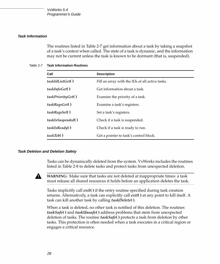
VxWorks 5.4Programmer’s Guide
Task Information
The routines listed in Table 2-7 get information about a task by taking a snapshot
of a task’s context when called. The state of a task is dynamic, and the information
may not be current unless the task is known to be dormant (that is, suspended).
Task Deletion and Deletion Safety
Tasks can be dynamically deleted from the system. VxWorks includes the routines
listed in Table 2-8 to delete tasks and protect tasks from unexpected deletion.
Tasks implicitly call exit( ) if the entry routine specified during task creation
returns. Alternatively, a task can explicitly call exit( ) at any point to kill itself. A
task can kill another task by calling taskDelete( ).
When a task is deleted, no other task is notified of this deletion. The routines
taskSafe( ) and taskUnsafe( ) address problems that stem from unexpected
deletion of tasks. The routine taskSafe( ) protects a task from deletion by other
tasks. This protection is often needed when a task executes in a critical region or
engages a critical resource.
Table 2-7 Task Information Routines
Call Description
taskIdListGet( ) Fill an array with the IDs of all active tasks.
taskInfoGet( ) Get information about a task.
taskPriorityGet( ) Examine the priority of a task.
taskRegsGet( ) Examine a task’s registers.
taskRegsSet( ) Set a task’s registers.
taskIsSuspended( ) Check if a task is suspended.
taskIsReady( ) Check if a task is ready to run.
taskTcb( ) Get a pointer to task’s control block.
! WARNING: Make sure that tasks are not deleted at inappropriate times: a task
must release all shared resources it holds before an application deletes the task.
28

2
2Basic OS
For example, a task might take a semaphore for exclusive access to some data
structure. While executing inside the critical region, the task might be deleted by
another task. Because the task is unable to complete the critical region, the data
structure might be left in a corrupt or inconsistent state. Furthermore, because the
semaphore can never be released by the task, the critical resource is now
unavailable for use by any other task and is essentially frozen.
Using taskSafe( ) to protect the task that took the semaphore prevents such an
outcome. Any task that tries to delete a task protected with taskSafe( ) is blocked.
When finished with its critical resource, the protected task can make itself available
for deletion by calling taskUnsafe( ), which readies any deleting task. To support
nested deletion-safe regions, a count is kept of the number of times taskSafe( ) and
taskUnsafe( ) are called. Deletion is allowed only when the count is zero, that is,
there are as many “unsafes” as “safes.” Protection operates only on the calling task.
A task cannot make another task safe or unsafe from deletion.
The following code fragment shows how to use taskSafe( ) and taskUnsafe( ) toprotect a critical region of code:
taskSafe ();semTake (semId, WAIT_FOREVER); /* Block until semaphore available */.. critical region.semGive (semId); /* Release semaphore */taskUnsafe ();
Deletion safety is often coupled closely with mutual exclusion, as in this example.
For convenience and efficiency, a special kind of semaphore, the mutual-exclusionsemaphore, offers an option for deletion safety. For more information, see Mutual-Exclusion Semaphores, p.52.
Table 2-8 Task-Deletion Routines
Call Description
exit( ) Terminate the calling task and free memory (task stacks and task
control blocks only).*
taskDelete( ) Terminate a specified task and free memory (task stacks and task
control blocks only).*
taskSafe( ) Protect the calling task from deletion.
taskUnsafe( ) Undo a taskSafe( ) (make the calling task available for deletion).
* Memory that is allocated by the task during its execution is not freed when the task
is terminated.
29

VxWorks 5.4Programmer’s Guide
Task Control
The routines listed in Table 2-9 provide direct control over a task’s execution.
VxWorks debugging facilities require routines for suspending and resuming a
task. They are used to freeze a task’s state for examination.
Tasks may require restarting during execution in response to some catastrophic
error. The restart mechanism, taskRestart( ), recreates a task with the original
creation arguments. The Tornado shell also uses this mechanism to restart itself in
response to a task-abort request; for information, see the Tornado User’s Guide: Shell.
Delay operations provide a simple mechanism for a task to sleep for a fixed
duration. Task delays are often used for polling applications. For example, to delay
a task for half a second without making assumptions about the clock rate, call:
taskDelay (sysClkRateGet ( ) / 2);
The routine sysClkRateGet( ) returns the speed of the system clock in ticks per
second. Instead of taskDelay( ), you can use the POSIX routine nanosleep( ) tospecify a delay directly in time units. Only the units are different; the resolution of
both delay routines is the same, and depends on the system clock. For details, see
2.7 POSIX Clocks and Timers, p.92.
As a side effect, taskDelay( ) moves the calling task to the end of the ready queue
for tasks of the same priority. In particular, you can yield the CPU to any other
tasks of the same priority by “delaying” for zero clock ticks:
taskDelay (NO_WAIT); /* allow other tasks of same priority to run */
A “delay” of zero duration is only possible with taskDelay( ); nanosleep( )considers it an error.
Table 2-9 Task Control Routines
Call Description
taskSuspend( ) Suspend a task.
taskResume( ) Resume a task.
taskRestart( ) Restart a task.
taskDelay( ) Delay a task; delay units are ticks.
nanosleep( ) Delay a task; delay units are nanoseconds.
30

2
2Basic OS
)
2.3.5 Tasking Extensions
To allow additional task-related facilities to be added to the system without
modifying the kernel, wind provides task create, switch, and delete hooks, which allow
additional routines to be invoked whenever a task is created, a task context switch
occurs, or a task is deleted. There are spare fields in the task control block (TCB)
available for application extension of a task’s context. These hook routines are
listed in Table 2-10; for more information, see the reference entry for taskHookLib.
User-installed switch hooks are called within the kernel context. Thus, switch
hooks do not have access to all VxWorks facilities. Table 2-11 summarizes the
routines that can be called from a task switch hook; in general, any routine that
does not involve the kernel can be called.
Table 2-10 Task Create, Switch, and Delete Hooks
Call Description
taskCreateHookAdd( ) Add a routine to be called at every task create.
taskCreateHookDelete( ) Delete a previously added task create routine.
taskSwitchHookAdd( ) Add a routine to be called at every task switch.
taskSwitchHookDelete( ) Delete a previously added task switch routine.
taskDeleteHookAdd( ) Add a routine to be called at every task delete.
taskDeleteHookDelete( ) Delete a previously added task delete routine.
Table 2-11 Routines that Can Be Called by Task Switch Hooks
Library Routines
bLib All routines
fppArchLib fppSave( ), fppRestore( )
intLib intContext( ), intCount( ), intVecSet( ), intVecGet( ), intLock( ), intUnlock( )
lstLib All routines except lstFree( )
mathALib All are callable if fppSave( )/fppRestore( ) are used
rngLib All routines except rngCreate( ) and roundlet( )
taskLib taskIdVerify( ), taskIdDefault( ), taskIsReady( ), taskIsSuspended( ), taskTcb(
vxLib vxTas( )
31

VxWorks 5.4Programmer’s Guide
2.3.6 POSIX Scheduling Interface
The POSIX 1003.1b scheduling routines, provided by schedPxLib, are shown in
Table 2-12. These routines let you use a portable interface to get and set task
priority, get the scheduling policy, get the maximum and minimum priority for
tasks, and if round-robin scheduling is in effect, get the length of a time slice. To
understand how to use the routines in this alternative interface, be aware of the
minor differences between the POSIX and Wind methods of scheduling.
Differences Between POSIX and Wind Scheduling
POSIX and Wind scheduling routines differ in the following ways:
■ POSIX scheduling is based on processes, while Wind scheduling is based on
tasks. Tasks and processes differ in several ways. Most notably, tasks can
address memory directly while processes cannot; and processes inherit only
some specific attributes from their parent process, while tasks operate in
exactly the same environment as the parent task.
Tasks and processes are alike in that they can be scheduled independently.
■ VxWorks documentation uses the term preemptive priority scheduling, while
the POSIX standard uses the term FIFO. This difference is purely one of
nomenclature: both describe the same priority-based policy.
■ The POSIX scheduling algorithms are applied on a process-by-process basis.
The Wind methodology, on the other hand, applies scheduling algorithms on
a system-wide basis—either all tasks use a round-robin scheme, or all use a
preemptive priority scheme.
■ The POSIX priority numbering scheme is the inverse of the Wind scheme. In
POSIX, the higher the number, the higher the priority; in the Wind scheme, the
lower the number, the higher the priority, where 0 is the highest priority.
Accordingly, the priority numbers used with the POSIX scheduling library
(schedPxLib) do not match those used and reported by all other components
of VxWorks. You can override this default by setting the global variable
posixPriorityNumbering to FALSE. If you do this, the Wind numbering
scheme (smaller number = higher priority) is used by schedPxLib, and its
priority numbers match those used by the other components of VxWorks.
The POSIX scheduling routines are included when INCLUDE_POSIX_SCHED is
selected for inclusion in the project facility VxWorks view; see Tornado User’s Guide:Projects for information on configuring VxWorks.
32

2
2Basic OS
Getting and Setting POSIX Task Priorities
The routines sched_setparam( ) and sched_getparam( ) set and get a task’s priority,
respectively. Both routines take a task ID and a sched_param structure (defined in
installDir/target/h/sched.h). A task ID of 0 sets or gets the priority for the calling
task. The sched_priority member of the sched_param structure specifies the new
task priority when sched_setparam( ) is called. The routine sched_getparam( ) fills
in the sched_priority with the specified task’s current priority.
Example 2-1 Getting and Setting POSIX Task Priorities
/* This example sets the calling task’s priority to 150, then verifies* that priority. To run from the shell, spawn as a task:
* -> sp priorityTest*/
/* includes */#include "vxWorks.h"#include "sched.h"
/* defines */#define PX_NEW_PRIORITY 150
STATUS priorityTest (void){struct sched_param myParam;
/* initialize param structure to desired priority */
Table 2-12 POSIX Scheduling Calls
Call Description
sched_setparam( ) Set a task’s priority.
sched_getparam( ) Get the scheduling parameters for a specified task.
sched_setscheduler( ) Set scheduling policy and parameters for a task.
sched_yield( ) Relinquish the CPU.
sched_getscheduler( ) Get the current scheduling policy.
sched_get_priority_max( ) Get the maximum priority.
sched_get_priority_min( ) Get the minimum priority.
sched_rr_get_interval( ) If round-robin scheduling, get the time slice length.
33

VxWorks 5.4Programmer’s Guide
myParam.sched_priority = PX_NEW_PRIORITY;if (sched_setparam (0, &myParam) == ERROR)
{printf ("error setting priority\n");return (ERROR);}
/* demonstrate getting a task priority as a sanity check; ensure it * is the same value that we just set. */
if (sched_getparam (0, &myParam) == ERROR){printf ("error getting priority\n");return (ERROR);}
if (myParam.sched_priority != PX_NEW_PRIORITY){printf ("error - priorities do not match\n");return (ERROR);}
elseprintf ("task priority = %d\n", myParam.sched_priority);
return (OK);}
The routine sched_setscheduler( ) is designed to set both scheduling policy and
priority for a single POSIX process (which corresponds in most other cases to a
single Wind task). In the VxWorks kernel, sched_setscheduler( ) controls only task
priority, because the kernel does not allow tasks to have scheduling policies that
differ from one another. If its policy specification matches the current system-wide
scheduling policy, sched_setscheduler( ) sets only the priority, thus acting like
sched_setparam( ). If its policy specification does not match the current one,
sched_setscheduler( ) returns an error.
The only way to change the scheduling policy is to change it for all tasks; there is
no POSIX routine for this purpose. To set a system-wide scheduling policy, use the
Wind function kernelTimeSlice( ) described in Round-Robin Scheduling, p.23.
Getting and Displaying the Current Scheduling Policy
The POSIX routine sched_getscheduler( ) returns the current scheduling policy.
There are two valid scheduling policies in VxWorks: preemptive priority
scheduling (in POSIX terms, SCHED_FIFO) and round-robin scheduling by
priority (SCHED_RR).
34
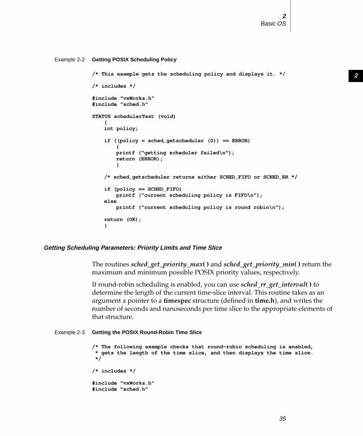
2
2Basic OS
Example 2-2 Getting POSIX Scheduling Policy
/* This example gets the scheduling policy and displays it. */
/* includes */
#include "vxWorks.h"#include "sched.h"
STATUS schedulerTest (void){int policy;
if ((policy = sched_getscheduler (0)) == ERROR){printf ("getting scheduler failed\n");return (ERROR);}
/* sched_getscheduler returns either SCHED_FIFO or SCHED_RR */
if (policy == SCHED_FIFO)printf ("current scheduling policy is FIFO\n");
elseprintf ("current scheduling policy is round robin\n");
return (OK);}
Getting Scheduling Parameters: Priority Limits and Time Slice
The routines sched_get_priority_max( ) and sched_get_priority_min( ) return the
maximum and minimum possible POSIX priority values, respectively.
If round-robin scheduling is enabled, you can use sched_rr_get_interval( ) todetermine the length of the current time-slice interval. This routine takes as an
argument a pointer to a timespec structure (defined in time.h), and writes the
number of seconds and nanoseconds per time slice to the appropriate elements of
that structure.
Example 2-3 Getting the POSIX Round-Robin Time Slice
/* The following example checks that round-robin scheduling is enabled,* gets the length of the time slice, and then displays the time slice.*/
/* includes */
#include "vxWorks.h"#include "sched.h"
35

VxWorks 5.4Programmer’s Guide
STATUS rrgetintervalTest (void){struct timespec slice;
/* turn on round robin */
kernelTimeSlice (30);
if (sched_rr_get_interval (0, &slice) == ERROR){printf ("get-interval test failed\n");return (ERROR);}
printf ("time slice is %l seconds and %l nanoseconds\n",slice.tv_sec, slice.tv_nsec);
return (OK);}
2.3.7 Task Error Status: errno
By convention, C library functions set a single global integer variable errno to an
appropriate error number whenever the function encounters an error. This
convention is specified as part of the ANSI C standard.
Layered Definitions of errno
In VxWorks, errno is simultaneously defined in two different ways. There is, as in
ANSI C, an underlying global variable called errno, which you can display by
name using Tornado development tools; see the Tornado User’s Guide. However,
errno is also defined as a macro in errno.h; this is the definition visible to all of
VxWorks except for one function. The macro is defined as a call to a function
__errno( ) that returns the address of the global variable, errno (as you might
guess, this is the single function that does not itself use the macro definition for
errno). This subterfuge yields a useful feature: because __errno( ) is a function, you
can place breakpoints on it while debugging, to determine where a particular error
occurs. Nevertheless, because the result of the macro errno is the address of the
global variable errno, C programs can set the value of errno in the standard way:
errno = someErrorNumber;
As with any other errno implementation, take care not to have a local variable of
the same name.
36

2
2Basic OS
A Separate errno Value for Each Task
In VxWorks, the underlying global errno is a single predefined global variable that
can be referenced directly by application code that is linked with VxWorks (either
statically on the host or dynamically at load time). However, for errno to be useful
in the multitasking environment of VxWorks, each task must see its own version
of errno. Therefore errno is saved and restored by the kernel as part of each task’s
context every time a context switch occurs. Similarly, interrupt service routines(ISRs) see their own versions of errno.
This is accomplished by saving and restoring errno on the interrupt stack as part
of the interrupt enter and exit code provided automatically by the kernel (see
2.5.1 Connecting Application Code to Interrupts, p.85). Thus, regardless of the
VxWorks context, an error code can be stored or consulted with direct
manipulation of the global variable errno.
Error Return Convention
Almost all VxWorks functions follow a convention that indicates simple success or
failure of their operation by the actual return value of the function. Many functions
return only the status values OK (0) or ERROR (-1). Some functions that normally
return a nonnegative number (for example, open( ) returns a file descriptor) also
return ERROR to indicate an error. Functions that return a pointer usually return
NULL (0) to indicate an error. In most cases, a function returning such an error
indication also sets errno to the specific error code.
The global variable errno is never cleared by VxWorks routines. Thus, its value
always indicates the last error status set. When a VxWorks subroutine gets an error
indication from a call to another routine, it usually returns its own error indication
without modifying errno. Thus, the value of errno that is set in the lower-level
routine remains available as the indication of error type.
For example, the VxWorks routine intConnect( ), which connects a user routine to
a hardware interrupt, allocates memory by calling malloc( ) and builds the
interrupt driver in this allocated memory. If malloc( ) fails because insufficient
memory remains in the pool, it sets errno to a code indicating an insufficient-
memory error was encountered in the memory allocation library, memLib. The
malloc( ) routine then returns NULL to indicate the failure. The intConnect( )routine, receiving the NULL from malloc( ), then returns its own error indication of
ERROR. However, it does not alter errno, leaving it at the “insufficient memory”
code set by malloc( ). For example:
37

VxWorks 5.4Programmer’s Guide
if ((pNew = malloc (CHUNK_SIZE)) == NULL)return (ERROR);
We recommend that you use this mechanism in your own subroutines, setting and
examining errno as a debugging technique. A string constant associated with
errno can be displayed using printErrno( ) if the errno value has a corresponding
string entered in the error-status symbol table, statSymTbl. See the reference entry
errnoLib for details on error-status values and building statSymTbl.
Assignment of Error Status Values
VxWorks errno values encode the module that issues an error, in the most
significant two bytes, and use the least significant two bytes for individual error
numbers. All VxWorks module numbers are in the range 1–500; errno values with
a “module” number of zero are used for source compatibility.
All other errno values (that is, positive values greater than or equal to 501<<16,
and all negative values) are available for application use.
See the reference entry on errnoLib for more information about defining and
decoding errno values with this convention.
2.3.8 Task Exception Handling
Errors in program code or data can cause hardware exception conditions such as
illegal instructions, bus or address errors, divide by zero, and so forth. The
VxWorks exception handling package takes care of all such exceptions. The default
exception handler suspends the task that caused the exception, and saves the state
of the task at the point of the exception. The kernel and other tasks continue
uninterrupted. A description of the exception is transmitted to the Tornado
development tools, which can be used to examine the suspended task; see the
Tornado User’s Guide: Shell for details.
Tasks can also attach their own handlers for certain hardware exceptions through
the signal facility. If a task has supplied a signal handler for an exception, the
default exception handling described above is not performed. Signals are also used
for signaling software exceptions as well as hardware exceptions. They are
described in more detail in 2.4.7 Signals, p.81 and in the reference entry for sigLib.
38

2
2Basic OS
2.3.9 Shared Code and Reentrancy
In VxWorks, it is common for a single copy of a subroutine or subroutine library to
be invoked by many different tasks. For example, many tasks may call printf( ), but
there is only a single copy of the subroutine in the system. A single copy of code
executed by multiple tasks is called shared code. VxWorks dynamic linking facilities
make this particularly easy. Shared code also makes the system more efficient and
easier to maintain; see Figure 2-4.
Shared code must be reentrant. A subroutine is reentrant if a single copy of the
routine can be called from several task contexts simultaneously without conflict.
Such conflict typically occurs when a subroutine modifies global or static
variables, because there is only a single copy of the data and code. A routine’s
references to such variables can overlap and interfere in invocations from different
task contexts.
Most routines in VxWorks are reentrant. However, all routines which have a
corresponding name_r( ) routine should be assumed non-reentrant. For example,
because ldiv( ) has a corresponding routine ldiv_r( ), you can assume that ldiv( ) is
not reentrant.
VxWorks I/O and driver routines are reentrant, but require careful application
design. For buffered I/O, we recommend using file-pointer buffers on a per-task
Figure 2-4 Shared Code
TASKS SHARED CODE
...
taskTwo (void){myFunc();
...}
myFunc();
taskOne (void){...
...}
}
myFunc (void){...
39

VxWorks 5.4Programmer’s Guide
basis. At the driver level, it is possible to load buffers with streams from different
tasks, due to the global file descriptor table in VxWorks. This may or may not be
desirable, depending on the nature of the application. For example, a packet driver
can mix streams from different tasks because the packet header identifies the
destination of each packet.
The majority of VxWorks routines use the following reentrancy techniques:
– dynamic stack variables
– global and static variables guarded by semaphores
– task variables
We recommend applying these same techniques when writing application code
that can be called from several task contexts simultaneously.
Dynamic Stack Variables
Many subroutines are pure code, having no data of their own except dynamic stack
variables. They work exclusively on data provided by the caller as parameters. The
linked-list library, lstLib, is a good example of this. Its routines operate on lists and
nodes provided by the caller in each subroutine call.
Subroutines of this kind are inherently reentrant. Multiple tasks can use such
routines simultaneously without interfering with each other, because each task
does indeed have its own stack. See Figure 2-5.
Guarded Global and Static Variables
Some libraries encapsulate access to common data. One example is the memory
allocation library, memLib, which manages pools of memory to be used by many
tasks. This library declares and uses its own static data variables to keep track of
pool allocation.
This kind of library requires some caution because the routines are not inherently
reentrant. Multiple tasks simultaneously invoking the routines in the library might
interfere with access to common variables. Such libraries must be made explicitly
reentrant by providing a mutual-exclusion mechanism to prohibit tasks from
simultaneously executing critical sections of code. The usual mutual-exclusion
mechanism is the semaphore facility provided by semLib and described in
2.4.3 Semaphores, p.47.
40

2
2Basic OS
Task Variables
Some routines that can be called by multiple tasks simultaneously may require
global or static variables with a distinct value for each calling task. For example,
several tasks may reference a private buffer of memory and yet refer to it with the
same global variable.
To accommodate this, VxWorks provides a facility called task variables that allows
4-byte variables to be added to a task’s context, so that the value of such a variable
is switched every time a task switch occurs to or from its owner task. Typically,
several tasks declare the same variable (4-byte memory location) as a task variable.
Each of those tasks can then treat that single memory location as its own private
variable; see Figure 2-6. This facility is provided by the routines taskVarAdd( ),taskVarDelete( ), taskVarSet( ), and taskVarGet( ), which are described in the
reference entry for taskVarLib.
Use this mechanism sparingly. Each task variable adds a few microseconds to the
context switching time for its task, because the value of the variable must be saved
and restored as part of the task’s context. Consider collecting all of a module’s task
variables into a single dynamically allocated structure, and then making all
accesses to that structure indirectly through a single pointer. This pointer can then
be the task variable for all tasks using that module.
Figure 2-5 Stack Variables and Shared Code
TASKS COMMON SUBROUTINETASK STACKS
...myDataOne...
...myDataTwo...
comFunc( ) ( myDataOne);
taskOne ( ){...
...}
...
taskTwo ( ){...
comFunc( ) ( myDataTwo);}
{
comFunc ( yourData ){...
41

VxWorks 5.4Programmer’s Guide
Multiple Tasks with the Same Main Routine
With VxWorks, it is possible to spawn several tasks with the same main routine.
Each spawn creates a new task with its own stack and context. Each spawn can also
pass the main routine different parameters to the new task. In this case, the same
rules of reentrancy described in Task Variables, p.41 apply to the entire task.
This is useful when the same function needs to be performed concurrently with
different sets of parameters. For example, a routine that monitors a particular kind
of equipment might be spawned several times to monitor several different pieces
of that equipment. The arguments to the main routine could indicate which
particular piece of equipment the task is to monitor.
In Figure 2-7, multiple joints of the mechanical arm use the same code. The tasks
manipulating the joints invoke joint( ). The joint number (jointNum) is used to
indicate which joint on the arm to manipulate.
2.3.10 VxWorks System Tasks
VxWorks includes several system tasks, described below.
Figure 2-6 Task Variables and Context Switches
OLD TCB
pTaskVar globDat
NEW TCB
pTaskVar
value savedin old
task’s TCB
value restoredfrom new
task’s TCB
current value ofglobDat
globDat
42

2
2Basic OS
The Root Task: tUsrRoot
The root task, tUsrRoot, is the first task executed by the kernel. The entry point of
the root task is usrRoot( ) in installDir/target/config/all/usrConfig.c and initializes
most VxWorks facilities. It spawns such tasks as the logging task, the exception
task, the network task, and the tRlogind daemon. Normally, the root task
terminates and is deleted after all initialization has occurred. You are free to add
any necessary initialization to the root task. For more information, see
8.5 Configuring VxWorks, p.337.
The Logging Task: tLogTask
The log task, tLogTask, is used by VxWorks modules to log system messages
without having to perform I/O in the current task context. For more information,
see 3.5.3 Message Logging, p.109 and the reference entry for logLib.
The Exception Task: tExcTask
The exception task, tExcTask, supports the VxWorks exception handling package
by performing functions that cannot occur at interrupt level. It must have the
highest priority in the system. Do not suspend, delete, or change the priority of this
task. For more information, see the reference entry for excLib.
Figure 2-7 Multiple Tasks Utilizing Same Code
joint_1
joint_2
joint_3
joint(int jointNum){/* joint code here */}
43

VxWorks 5.4Programmer’s Guide
The Network Task: tNetTask
The tNetTask daemon handles the task-level functions required by the VxWorks
network.
The Target Agent Task: tWdbTask
The target agent task, tWdbTask, is created if the target agent is set to run in task
mode; see 8.6.1 Scaling Down VxWorks, p.344. It services requests from the Tornado
target server; for information on this server, see the Tornado User’s Guide: Overview.
Tasks for Optional Components
The following VxWorks system tasks are created if their associated configuration
constants are defined; for more information, see 8.5 Configuring VxWorks, p.337.
tShellIf you have included the target shell in the VxWorks configuration, it is
spawned as this task. Any routine or task that is invoked from the target shell,
rather than spawned, runs in the tShell context. For more information, see
9. Target Shell.
tRlogindIf you have included the target shell and the rlogin facility in the VxWorks
configuration, this daemon allows remote users to log in to VxWorks. It
accepts a remote login request from another VxWorks or host system and
spawns tRlogInTask and tRlogOutTask. These tasks exist as long as the
remote user is logged on. During the remote session, the shell’s (and any other
task’s) input and output are redirected to the remote user. A tty-like interface
is provided to the remote user through the use of the VxWorks pseudo-
terminal driver, ptyDrv. For more information, see 3.7.1 Serial I/O Devices(Terminal and Pseudo-Terminal Devices), p.118 and the reference entry for
ptyDrv.
tTelnetdIf you have included the target shell and the telnet facility in the VxWorks
configuration, this daemon allows remote users to log in to VxWorks with
telnet. It accepts a remote login request from another VxWorks or host system
and spawns the input task tTelnetInTask and output task tTelnetOutTask.
These tasks exist as long as the remote user is logged on. During the remote
session, the shell’s (and any other task’s) input and output are redirected to the
remote user. A tty-like interface is provided to the remote user through the use
of the VxWorks pseudo-terminal driver, ptyDrv. See 3.7.1 Serial I/O Devices(Terminal and Pseudo-Terminal Devices), p.118 and the reference entry for
ptyDrv for further explanation.
44

2
2Basic OS
tPortmapdIf you have included the RPC facility in the VxWorks configuration, this
daemon is an RPC server that acts as a central registrar for RPC servers
running on the same machine. RPC clients query the tPortmapd daemon to
find out how to contact the various servers.
2.4 Intertask Communications
The complement to the multitasking routines described in the 2.3 Tasks, p.20 is the
intertask communication facilities. These facilities permit independent tasks to
coordinate their actions.
VxWorks supplies a rich set of intertask communication mechanisms, including:
■ Shared memory, for simple sharing of data.
■ Semaphores, for basic mutual exclusion and synchronization.
■ Message queues and pipes, for intertask message passing within a CPU.
■ Sockets and remote procedure calls, for network-transparent intertask
communication.
■ Signals, for exception handling.
The optional product, VxMP, provides intertask communication over the
backplane for tasks running on different CPUs. This includes shared semaphores,
shared message queues, shared memory, and the shared name database.
2.4.1 Shared Data Structures
The most obvious way for tasks to communicate is by accessing shared data
structures. Because all tasks in VxWorks exist in a single linear address space,
sharing data structures between tasks is trivial; see Figure 2-8. Global variables,
linear buffers, ring buffers, linked lists, and pointers can be referenced directly by
code running in different contexts.
45

VxWorks 5.4Programmer’s Guide
2.4.2 Mutual Exclusion
While a shared address space simplifies exchange of data, interlocking access to
memory is crucial to avoid contention. Many methods exist for obtaining exclusive
access to resources, and vary only in the scope of the exclusion. Such methods
include disabling interrupts, disabling preemption, and resource locking with
semaphores.
Interrupt Locks and Latency
The most powerful method available for mutual exclusion is the disabling of
interrupts. Such a lock guarantees exclusive access to the CPU:
funcA (){int lock = intLock();.. critical region that cannot be interrupted.intUnlock (lock);}
While this solves problems involving mutual exclusion with ISRs, it is
inappropriate as a general-purpose mutual-exclusion method for most real-time
systems, because it prevents the system from responding to external events for the
duration of these locks. Interrupt latency is unacceptable whenever an immediate
response to an external event is required. However, interrupt locking can
Figure 2-8 Shared Data Structures
TASKS MEMORY
task 1
task 2
task 3
accesssharedData
accesssharedData
accesssharedData
sharedData
46

2
2Basic OS
sometimes be necessary where mutual exclusion involves ISRs. In any situation,
keep the duration of interrupt lockouts short.
Preemptive Locks and Latency
Disabling preemption offers a somewhat less restrictive form of mutual exclusion.
While no other task is allowed to preempt the current executing task, ISRs are able
to execute:
funcA (){taskLock ();.. critical region that cannot be interrupted.taskUnlock ();}
However, this method can lead to unacceptable real-time response. Tasks of higher
priority are unable to execute until the locking task leaves the critical region, even
though the higher-priority task is not itself involved with the critical region. While
this kind of mutual exclusion is simple, if you use it, make sure to keep the
duration short. A better mechanism is provided by semaphores, discussed in
2.4.3 Semaphores, p.47.
2.4.3 Semaphores
VxWorks semaphores are highly optimized and provide the fastest intertask
communication mechanism in VxWorks. Semaphores are the primary means for
addressing the requirements of both mutual exclusion and task synchronization:
■ For mutual exclusion, semaphores interlock access to shared resources. They
provide mutual exclusion with finer granularity than either interrupt
disabling or preemptive locks, discussed in 2.4.2 Mutual Exclusion, p.46.
■ For synchronization, semaphores coordinate a task’s execution with external
events.
There are three types of Wind semaphores, optimized to address different classes
of problems:
binaryThe fastest, most general-purpose semaphore. Optimized for
synchronization or mutual exclusion.
47

VxWorks 5.4Programmer’s Guide
mutual exclusionA special binary semaphore optimized for problems inherent in mutual
exclusion: priority inheritance, deletion safety, and recursion.
countingLike the binary semaphore, but keeps track of the number of times a
semaphore is given. Optimized for guarding multiple instances of a
resource.
VxWorks provides not only the Wind semaphores, designed expressly for
VxWorks, but also POSIX semaphores, designed for portability. An alternate
semaphore library provides the POSIX-compatible semaphore interface; see
POSIX Semaphores, p.57.
The semaphores described here are for use on a single CPU. The optional product
VxMP provides semaphores that can be used across processors; see 6. Shared-Memory Objects.
Semaphore Control
Instead of defining a full set of semaphore control routines for each type of
semaphore, the Wind semaphores provide a single uniform interface for
semaphore control. Only the creation routines are specific to the semaphore type.
Table 2-13 lists the semaphore control routines.
The semBCreate( ), semMCreate( ), and semCCreate( ) routines return a
semaphore ID that serves as a handle on the semaphore during subsequent use by
Table 2-13 Semaphore Control Routines
Call Description
semBCreate( ) Allocate and initialize a binary semaphore.
semMCreate( ) Allocate and initialize a mutual-exclusion semaphore.
semCCreate( ) Allocate and initialize a counting semaphore.
semDelete( ) Terminate and free a semaphore.
semTake( ) Take a semaphore.
semGive( ) Give a semaphore.
semFlush( ) Unblock all tasks that are waiting for a semaphore.
48
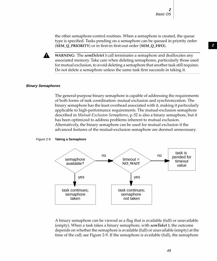
2
2Basic OS
the other semaphore-control routines. When a semaphore is created, the queue
type is specified. Tasks pending on a semaphore can be queued in priority order
(SEM_Q_PRIORITY) or in first-in first-out order (SEM_Q_FIFO).
Binary Semaphores
The general-purpose binary semaphore is capable of addressing the requirements
of both forms of task coordination: mutual exclusion and synchronization. The
binary semaphore has the least overhead associated with it, making it particularly
applicable to high-performance requirements. The mutual-exclusion semaphore
described in Mutual-Exclusion Semaphores, p.52 is also a binary semaphore, but it
has been optimized to address problems inherent to mutual exclusion.
Alternatively, the binary semaphore can be used for mutual exclusion if the
advanced features of the mutual-exclusion semaphore are deemed unnecessary.
A binary semaphore can be viewed as a flag that is available (full) or unavailable
(empty). When a task takes a binary semaphore, with semTake( ), the outcome
depends on whether the semaphore is available (full) or unavailable (empty) at the
time of the call; see Figure 2-9. If the semaphore is available (full), the semaphore
! WARNING: The semDelete( ) call terminates a semaphore and deallocates any
associated memory. Take care when deleting semaphores, particularly those used
for mutual exclusion, to avoid deleting a semaphore that another task still requires.
Do not delete a semaphore unless the same task first succeeds in taking it.
Figure 2-9 Taking a Semaphore
no nosemaphoreavailable?
timeout =NO_WAIT
yes yes
task continues;semaphore
not taken
task continues;semaphore
taken
task ispended for
timeoutvalue
49

VxWorks 5.4Programmer’s Guide
becomes unavailable (empty) and the task continues executing immediately. If the
semaphore is unavailable (empty), the task is put on a queue of blocked tasks and
enters a state of pending on the availability of the semaphore.
When a task gives a binary semaphore, using semGive( ), the outcome also
depends on whether the semaphore is available (full) or unavailable (empty) at the
time of the call; see Figure 2-10. If the semaphore is already available (full), giving
the semaphore has no effect at all. If the semaphore is unavailable (empty) and no
task is waiting to take it, then the semaphore becomes available (full). If the
semaphore is unavailable (empty) and one or more tasks are pending on its
availability, then the first task in the queue of blocked tasks is unblocked, and the
semaphore is left unavailable (empty).
Mutual Exclusion
Binary semaphores interlock access to a shared resource efficiently. Unlike
disabling interrupts or preemptive locks, binary semaphores limit the scope of the
mutual exclusion to only the associated resource. In this technique, a semaphore is
created to guard the resource. Initially the semaphore is available (full).
/* includes */#include "vxWorks.h"#include "semLib.h"
SEM_ID semMutex;
/* Create a binary semaphore that is initially full. Tasks *
Figure 2-10 Giving a Semaphore
no nosemaphoreavailable?
yes yes
task continues;semaphore
remainsunchanged
taskspended?
task continues,semaphore
made available
task at front ofqueue made ready;semaphore remains
unavailable
50

2
2Basic OS
* blocked on semaphore wait in priority order. */
semMutex = semBCreate (SEM_Q_PRIORITY, SEM_FULL);
When a task wants to access the resource, it must first take that semaphore. As long
as the task keeps the semaphore, all other tasks seeking access to the resource are
blocked from execution. When the task is finished with the resource, it gives back
the semaphore, allowing another task to use the resource.
Thus all accesses to a resource requiring mutual exclusion are bracketed with
semTake( ) and semGive( ) pairs:
semTake (semMutex, WAIT_FOREVER);.. critical region, only accessible by a single task at a time.semGive (semMutex);
Synchronization
When used for task synchronization, a semaphore can represent a condition or
event that a task is waiting for. Initially the semaphore is unavailable (empty). A
task or ISR signals the occurrence of the event by giving the semaphore (see
2.5 Interrupt Service Code, p.85 for a complete discussion of ISRs). Another task
waits for the semaphore by calling semTake( ). The waiting task blocks until the
event occurs and the semaphore is given.
Note the difference in sequence between semaphores used for mutual exclusion
and those used for synchronization. For mutual exclusion, the semaphore is
initially full, and each task first takes, then gives back the semaphore. For
synchronization, the semaphore is initially empty, and one task waits to take the
semaphore given by another task.
In Example 2-4, the init( ) routine creates the binary semaphore, attaches an ISR to
an event, and spawns a task to process the event. The routine task1( ) runs until it
calls semTake( ). It remains blocked at that point until an event causes the ISR to
call semGive( ). When the ISR completes, task1( ) executes to process the event.
There is an advantage of handling event processing within the context of a
dedicated task: less processing takes place at interrupt level, thereby reducing
interrupt latency. This model of event processing is recommended for real-time
applications.
Example 2-4 Using Semaphores for Task Synchronization
/* This example shows the use of semaphores for task synchronization. */
/* includes */
51

VxWorks 5.4Programmer’s Guide
#include "vxWorks.h"#include "semLib.h"#include "arch/ arch/iv arch.h" /* replace arch with architecture type */
SEM_ID syncSem; /* ID of sync semaphore */
init (int someIntNum){/* connect interrupt service routine */intConnect (INUM_TO_IVEC (someIntNum), eventInterruptSvcRout, 0);
/* create semaphore */syncSem = semBCreate (SEM_Q_FIFO, SEM_EMPTY);
/* spawn task used for synchronization. */taskSpawn ("sample", 100, 0, 20000, task1, 0,0,0,0,0,0,0,0,0,0);}
task1 (void){...semTake (syncSem, WAIT_FOREVER); /* wait for event to occur */printf ("task 1 got the semaphore\n");... /* process event */}
eventInterruptSvcRout (void){...semGive (syncSem); /* let task 1 process event */...}
Broadcast synchronization allows all processes that are blocked on the same
semaphore to be unblocked atomically. Correct application behavior often requires
a set of tasks to process an event before any task of the set has the opportunity to
process further events. The routine semFlush( ) addresses this class of
synchronization problem by unblocking all tasks pended on a semaphore.
Mutual-Exclusion Semaphores
The mutual-exclusion semaphore is a specialized binary semaphore designed to
address issues inherent in mutual exclusion, including priority inversion, deletion
safety, and recursive access to resources.
The fundamental behavior of the mutual-exclusion semaphore is identical to the
binary semaphore, with the following exceptions:
52

2
2Basic OS
■ It can be used only for mutual exclusion.■ It can be given only by the task that took it.■ It cannot be given from an ISR.■ The semFlush( ) operation is illegal.
Priority Inversion
Priority inversion arises when a higher-priority task is forced to wait an indefinite
period of time for a lower-priority task to complete. Consider the scenario in
Figure 2-11: t1, t2, and t3 are tasks of high, medium, and low priority, respectively.
t3 has acquired some resource by taking its associated binary guard semaphore.
When t1 preempts t3 and contends for the resource by taking the same semaphore,
it becomes blocked. If we could be assured that t1 would be blocked no longer than
the time it normally takes t3 to finish with the resource, there would be no problem
because the resource cannot be preempted. However, the low-priority task is
vulnerable to preemption by medium-priority tasks (like t2), which could inhibit
t3 from relinquishing the resource. This condition could persist, blocking t1 for an
indefinite period of time.
Figure 2-11 Priority Inversion
t3
t1
t3
t2
HIGH
LOW
KEY: = preemption= take semaphore
= give semaphore
= own semaphore
prio
rity
= priority inheritance/release
= block
time
t1
t3
53

VxWorks 5.4Programmer’s Guide
The mutual-exclusion semaphore has the option SEM_INVERSION_SAFE, which
enables a priority-inheritance algorithm. The priority-inheritance protocol assures
that a task that owns a resource executes at the priority of the highest-priority task
blocked on that resource. Once the task priority has been elevated, it remains at the
higher level until all mutual-exclusion semaphores that the task owns are released;
then the task returns to its normal, or standard, priority. Hence, the “inheriting”
task is protected from preemption by any intermediate-priority tasks. This option
must be used in conjunction with a priority queue (SEM_Q_PRIORITY).
In Figure 2-12, priority inheritance solves the problem of priority inversion by
elevating the priority of t3 to the priority of t1 during the time t1 is blocked on the
semaphore. This protects t3, and indirectly t1, from preemption by t2.
The following example creates a mutual-exclusion semaphore that uses the
priority inheritance algorithm:
semId = semMCreate (SEM_Q_PRIORITY | SEM_INVERSION_SAFE);
Deletion Safety
Another problem of mutual exclusion involves task deletion. Within a critical
region guarded by semaphores, it is often desirable to protect the executing task
from unexpected deletion. Deleting a task executing in a critical region can be
catastrophic. The resource might be left in a corrupted state and the semaphore
Figure 2-12 Priority Inheritance
t3
t1 t3 t1
t2
HIGH
LOW
prio
rity
time
54

2
2Basic OS
guarding the resource left unavailable, effectively preventing all access to the
resource.
The primitives taskSafe( ) and taskUnsafe( ) provide one solution to task deletion.
However, the mutual-exclusion semaphore offers the option SEM_DELETE_SAFE,
which enables an implicit taskSafe( ) with each semTake( ), and a taskUnsafe( )with each semGive( ). In this way, a task can be protected from deletion while it has
the semaphore. This option is more efficient than the primitives taskSafe( ) and
taskUnsafe( ), as the resulting code requires fewer entrances to the kernel.
semId = semMCreate (SEM_Q_FIFO | SEM_DELETE_SAFE);
Recursive Resource Access
Mutual-exclusion semaphores can be taken recursively. This means that the
semaphore can be taken more than once by the task that owns it before finally
being released. Recursion is useful for a set of routines that must call each other but
that also require mutually exclusive access to a resource. This is possible because
the system keeps track of which task currently owns the mutual-exclusion
semaphore.
Before being released, a mutual-exclusion semaphore taken recursively must be
given the same number of times it is taken. This is tracked by a count that
increments with each semTake( ) and decrements with each semGive( ).
Example 2-5 Recursive Use of a Mutual-Exclusion Semaphore
/* Function A requires access to a resource which it acquires by taking* mySem; function A may also need to call function B, which also* requires mySem:*/
/* includes */#include "vxWorks.h"#include "semLib.h"SEM_ID mySem;
/* Create a mutual-exclusion semaphore. */
init (){mySem = semMCreate (SEM_Q_PRIORITY);}
funcA (){semTake (mySem, WAIT_FOREVER);printf ("funcA: Got mutual-exclusion semaphore\n");...funcB ();...
55

VxWorks 5.4Programmer’s Guide
semGive (mySem);printf ("funcA: Released mutual-exclusion semaphore\n");}
funcB (){semTake (mySem, WAIT_FOREVER);printf ("funcB: Got mutual-exclusion semaphore\n");...semGive (mySem);printf ("funcB: Releases mutual-exclusion semaphore\n");}
Counting Semaphores
Counting semaphores are another means to implement task synchronization and
mutual exclusion. The counting semaphore works like the binary semaphore
except that it keeps track of the number of times a semaphore is given. Every time
a semaphore is given, the count is incremented; every time a semaphore is taken,
the count is decremented. When the count reaches zero, a task that tries to take the
semaphore is blocked. As with the binary semaphore, if a semaphore is given and
a task is blocked, it becomes unblocked. However, unlike the binary semaphore, if
a semaphore is given and no tasks are blocked, then the count is incremented. This
means that a semaphore that is given twice can be taken twice without blocking.
Table 2-14 shows an example time sequence of tasks taking and giving a counting
semaphore that was initialized to a count of 3.
Counting semaphores are useful for guarding multiple copies of resources. For
example, the use of five tape drives might be coordinated using a counting
Table 2-14 Counting Semaphore Example
Semaphore Call Count after Call Resulting Behavior
semCCreate( ) 3 Semaphore initialized with initial count of 3.
semTake( ) 2 Semaphore taken.
semTake( ) 1 Semaphore taken.
semTake( ) 0 Semaphore taken.
semTake( ) 0 Task blocks waiting for semaphore to be available.
semGive( ) 0 Task waiting is given semaphore.
semGive( ) 1 No task waiting for semaphore; count incremented.
56

2
2Basic OS
semaphore with an initial count of 5, or a ring buffer with 256 entries might be
implemented using a counting semaphore with an initial count of 256. The initial
count is specified as an argument to the semCCreate( ) routine.
Special Semaphore Options
The uniform Wind semaphore interface includes two special options. These
options are not available for the POSIX-compatible semaphores described in
POSIX Semaphores, p.57.
Timeouts
Wind semaphores include the ability to time out from the pended state. This is
controlled by a parameter to semTake( ) that specifies the amount of time in ticks
that the task is willing to wait in the pended state. If the task succeeds in taking the
semaphore within the allotted time, semTake( ) returns OK. The errno set when a
semTake( ) returns ERROR due to timing out before successfully taking the
semaphore depends upon the timeout value passed. A semTake( ) with NO_WAIT(0), which means do not wait at all, sets errno to S_objLib_OBJ_UNAVAILABLE. A
semTake( ) with a positive timeout value returns S_objLib_OBJ_TIMEOUT. A
timeout value of WAIT_FOREVER (-1) means wait indefinitely.
Queues
Wind semaphores include the ability to select the queuing mechanism employed
for tasks blocked on a semaphore. They can be queued based on either of two
criteria: first-in first-out (FIFO) order, or priority order; see Figure 2-13.
Priority ordering better preserves the intended priority structure of the system at
the expense of some overhead in semTake( ) in sorting the tasks by priority. A FIFO
queue requires no priority sorting overhead and leads to constant-time
performance. The selection of queue type is specified during semaphore creation
with semBCreate( ), semMCreate( ), or semCCreate( ). Semaphores using the
priority inheritance option (SEM_INVERSION_SAFE) must select priority-order
queuing.
POSIX Semaphores
POSIX defines both named and unnamed semaphores, which have the same
properties, but use slightly different interfaces. The POSIX semaphore library
provides routines for creating, opening, and destroying both named and unnamed
57

VxWorks 5.4Programmer’s Guide
semaphores. The POSIX semaphore routines provided by semPxLib are shown in
Table 2-15.
With named semaphores, you assign a symbolic name1 when opening the
semaphore; the other named-semaphore routines accept this name as an
argument.
The POSIX terms wait (or lock) and post (or unlock) correspond to the VxWorks
terms take and give, respectively.
The initialization routine semPxLibInit( ) is called by default when
INCLUDE_POSIX_SEM is selected for inclusion in the project facility VxWorks
view. The routines sem_open( ), sem_unlink( ), and sem_close( ) are for opening
and closing/destroying named semaphores only; sem_init( ) and sem_destroy( )are for initializing and destroying unnamed semaphores only. The routines for
locking, unlocking, and getting the value of semaphores are used for both named
and unnamed semaphores.
Figure 2-13 Task Queue Types
1. Some host operating systems, such as UNIX, require symbolic names for objects that are to
be shared among processes. This is because processes do not normally share memory in
such operating systems. In VxWorks, there is no requirement for named semaphores,
because all objects are located within a single address space, and reference to shared objects
by memory location is standard practice.
TCB
110
TCB
200
PRIORITY QUEUE FIFO QUEUE
priority
TCB
120 TCB
80
TCB
110
TCB
90TCB
100TCB
140
58

2
2Basic OS
Comparison of POSIX and Wind Semaphores
POSIX semaphores are counting semaphores; that is, they keep track of the number
of times they are given.
The Wind semaphore mechanism is similar to that specified by POSIX, except that
Wind semaphores offer additional features: priority inheritance, task-deletion
safety, the ability for a single task to take a semaphore multiple times, ownership
of mutual-exclusion semaphores, semaphore timeouts, and the choice of queuing
mechanism. When these features are important, Wind semaphores are preferable.
Using Unnamed Semaphores
In using unnamed semaphores, normally one task allocates memory for the
semaphore and initializes it. A semaphore is represented with the data structure
Table 2-15 POSIX Semaphore Routines
Call Description
semPxLibInit( ) Initialize the POSIX semaphore library (non-POSIX).
sem_init( ) Initialize an unnamed semaphore.
sem_destroy( ) Destroy an unnamed semaphore.
sem_open( ) Initialize/open a named semaphore.
sem_close( ) Close a named semaphore.
sem_unlink( ) Remove a named semaphore.
sem_wait( ) Lock a semaphore.
sem_trywait( ) Lock a semaphore only if it is not already locked.
sem_post( ) Unlock a semaphore.
sem_getvalue( ) Get the value of a semaphore.
! WARNING: The sem_destroy( ) call terminates an unnamed semaphore and
deallocates any associated memory; the combination of sem_close( ) and
sem_unlink( ) has the same effect for named semaphores. Take care when deleting
semaphores, particularly mutual exclusion semaphores, to avoid deleting a
semaphore still required by another task. Do not delete a semaphore unless the
deleting task first succeeds in locking that semaphore. (Likewise, for named
semaphores, close semaphores only from the same task that opens them.)
59

VxWorks 5.4Programmer’s Guide
sem_t, defined in semaphore.h. The semaphore initialization routine, sem_init( ),allows you to specify the initial value.
Once the semaphore is initialized, any task can use the semaphore by locking it
with sem_wait( ) (blocking) or sem_trywait( ) (non-blocking), and unlocking it
with sem_post( ).
As noted earlier, semaphores can be used for both synchronization and mutual
exclusion. When a semaphore is used for synchronization, it is typically initialized
to zero (locked). The task waiting to be synchronized blocks on a sem_wait( ). The
task doing the synchronizing unlocks the semaphore using sem_post( ). If the task
blocked on the semaphore is the only one waiting for that semaphore, the task
unblocks and becomes ready to run. If other tasks are blocked on the semaphore,
the task with the highest priority is unblocked.
When a semaphore is used for mutual exclusion, it is typically initialized to a value
greater than zero (meaning that the resource is available). Therefore, the first task
to lock the semaphore does so without blocking; subsequent tasks block (if the
semaphore value was initialized to 1).
Example 2-6 POSIX Unnamed Semaphores
/* This example uses unnamed semaphores to synchronize an action between* the calling task and a task that it spawns (tSyncTask). To run from* the shell, spawn as a task:* -> sp unnameSem
*/
/* includes */
#include "vxWorks.h"#include "semaphore.h"
/* forward declarations */
void syncTask (sem_t * pSem);
void unnameSem (void){sem_t * pSem;
/* reserve memory for semaphore */
pSem = (sem_t *) malloc (sizeof (sem_t));
/* initialize semaphore to unavailable */
if (sem_init (pSem, 0, 0) == -1){
60

2
2Basic OS
printf ("unnameSem: sem_init failed\n");return;}
/* create sync task */
printf ("unnameSem: spawning task...\n");taskSpawn ("tSyncTask", 90, 0, 2000, syncTask, pSem);
/* do something useful to synchronize with syncTask */
/* unlock sem */
printf ("unnameSem: posting semaphore - synchronizing action\n");if (sem_post (pSem) == -1)
{printf ("unnameSem: posting semaphore failed\n");return;}
/* all done - destroy semaphore */
if (sem_destroy (pSem) == -1) { printf ("unnameSem: sem_destroy failed\n"); return; }}
void syncTask(sem_t * pSem){/* wait for synchronization from unnameSem */
if (sem_wait (pSem) == -1){printf ("syncTask: sem_wait failed \n");return;}
elseprintf ("syncTask:sem locked; doing sync’ed action...\n");
/* do something useful here */}
Using Named Semaphores
The sem_open( ) routine either opens a named semaphore that already exists, or, as
an option, creates a new semaphore. You can specify which of these possibilities
you want by combining the following flag values:
61

VxWorks 5.4Programmer’s Guide
O_CREAT Create the semaphore if it does not already exist (if it exists, either fail
or open the semaphore, depending on whether O_EXCL is specified).
O_EXCL Open the semaphore only if newly created; fail if the semaphore exists.
The possible effects of a call to sem_open( ), depending on which flags are set and
on whether the semaphore accessed already exists, are shown in Table 2-16. There
is no entry for O_EXCL alone, because using that flag alone is not meaningful.
A POSIX named semaphore, once initialized, remains usable until explicitly
destroyed. Tasks can explicitly mark a semaphore for destruction at any time, but
the semaphore remains in the system until no task has the semaphore open.
If INCLUDE_POSIX_SEM_SHOW is selected for inclusion in the project facility
VxWorks view (for details, see Tornado User’s Guide: Projects), you can use show( )from the Tornado shell to display information about a POSIX semaphore:2
-> show semIdvalue = 0 = 0x0
The output is sent to the standard output device, and provides information about
the POSIX semaphore mySem with two tasks blocked waiting for it:
Semaphore name :mySemsem_open() count :3Semaphore value :0No. of blocked tasks :2
For a group of collaborating tasks to use a named semaphore, one of the tasks first
creates and initializes the semaphore (by calling sem_open( ) with the O_CREATflag). Any task that needs to use the semaphore thereafter opens it by calling
sem_open( ) with the same name (but without setting O_CREAT). Any task that has
opened the semaphore can use it by locking it with sem_wait( ) (blocking) or
sem_trywait( ) (non-blocking) and unlocking it with sem_post( ).
Table 2-16 Possible Outcomes of Calling sem_open( )
Flag Settings Semaphore Exists Semaphore Does Not Exist
None Semaphore is opened Routine fails
O_CREAT Semaphore is opened Semaphore is created
O_CREAT and O_EXCL Routine fails Semaphore is created
2. This is not a POSIX routine, nor is it designed for use from programs; use it from the
Tornado shell (see the Tornado User’s Guide: Shell for details).
62

2
2Basic OS
To remove a semaphore, all tasks using it must first close it with sem_close( ), and
one of the tasks must also unlink it. Unlinking a semaphore with sem_unlink( )removes the semaphore name from the name table. After the name is removed
from the name table, tasks that currently have the semaphore open can still use it,
but no new tasks can open this semaphore. The next time a task tries to open the
semaphore without the O_CREAT flag, the operation fails. The semaphore vanishes
when the last task closes it.
Example 2-7 POSIX Named Semaphores
/* In this example, nameSem() creates a task for synchronization. The* new task, tSyncSemTask, blocks on the semaphore created in nameSem().* Once the synchronization takes place, both tasks close the semaphore,* and nameSem() unlinks it. To run this task from the shell, spawn* nameSem as a task:
* -> sp nameSem, "myTest" */
/* includes */#include "vxWorks.h"#include "semaphore.h"#include "fcntl.h"
/* forward declaration */int syncSemTask (char * name);
int nameSem(char * name){sem_t * semId;
/* create a named semaphore, initialize to 0*/printf ("nameSem: creating semaphore\n");if ((semId = sem_open (name, O_CREAT, 0, 0)) == (sem_t *) -1)
{printf ("nameSem: sem_open failed\n");return;}
printf ("nameSem: spawning sync task\n");
taskSpawn ("tSyncSemTask", 90, 0, 2000, syncSemTask, name);
/* do something useful to synchronize with syncSemTask */
/* give semaphore */printf ("nameSem: posting semaphore - synchronizing action\n");if (sem_post (semId) == -1)
{
63

VxWorks 5.4Programmer’s Guide
printf ("nameSem: sem_post failed\n");return;}
/* all done */if (sem_close (semId) == -1)
{printf ("nameSem: sem_close failed\n");return;}
if (sem_unlink (name) == -1){printf ("nameSem: sem_unlink failed\n");return;}
printf ("nameSem: closed and unlinked semaphore\n");}
int syncSemTask(char * name)
{sem_t * semId;
/* open semaphore */printf ("syncSemTask: opening semaphore\n");if ((semId = sem_open (name, 0)) == (sem_t *) -1)
{printf ("syncSemTask: sem_open failed\n");return;}
/* block waiting for synchronization from nameSem */printf ("syncSemTask: attempting to take semaphore...\n");if (sem_wait (semId) == -1)
{printf ("syncSemTask: taking sem failed\n");return;}
printf ("syncSemTask: has semaphore, doing sync’ed action ...\n");
/* do something useful here */
if (sem_close (semId) == -1){printf ("syncSemTask: sem_close failed\n");return;}
}
64

2
2Basic OS
2.4.4 Message Queues
Modern real-time applications are constructed as a set of independent but
cooperating tasks. While semaphores provide a high-speed mechanism for the
synchronization and interlocking of tasks, often a higher-level mechanism is
necessary to allow cooperating tasks to communicate with each other. In VxWorks,
the primary intertask communication mechanism within a single CPU is messagequeues. The optional product, VxMP, provides global message queues that can be
used across processors; for more information, see 6. Shared-Memory Objects.
Message queues allow a variable number of messages, each of variable length, to
be queued. Any task or ISR can send messages to a message queue. Any task can
receive messages from a message queue. Multiple tasks can send to and receive
from the same message queue. Full-duplex communication between two tasks
generally requires two message queues, one for each direction; see Figure 2-14.
There are two message-queue subroutine libraries in VxWorks. The first of these,
msgQLib, provides Wind message queues, designed expressly for VxWorks; the
second, mqPxLib, is compatible with the POSIX standard (1003.1b) for real-time
extensions. See Comparison of POSIX and Wind Message Queues, p.77 for a
discussion of the differences between the two message-queue designs.
Figure 2-14 Full Duplex Communication Using Message Queues
task 2task 1
message queue 1
message queue 2
message
message
65

VxWorks 5.4Programmer’s Guide
Wind Message Queues
Wind message queues are created and deleted with the routines shown in
Table 2-17. This library provides messages that are queued in FIFO order, with a
single exception: there are two priority levels, and messages marked as high
priority are attached to the head of the queue.
A message queue is created with msgQCreate( ). Its parameters specify the
maximum number of messages that can be queued in the message queue and the
maximum length in bytes of each message. Enough buffer space is preallocated for
the specified number and length of messages.
A task or ISR sends a message to a message queue with msgQSend( ). If no tasks
are waiting for messages on that queue, the message is added to the queue’s buffer
of messages. If any tasks are already waiting for a message from that message
queue, the message is immediately delivered to the first waiting task.
A task receives a message from a message queue with msgQReceive( ). If messages
are already available in the message queue’s buffer, the first message is
immediately dequeued and returned to the caller. If no messages are available,
then the calling task blocks and is added to a queue of tasks waiting for messages.
This queue of waiting tasks can be ordered either by task priority or FIFO, as
specified in an option parameter when the queue is created.
Timeouts
Both msgQSend( ) and msgQReceive( ) take timeout parameters. When sending a
message, the timeout specifies how many ticks to wait for buffer space to become
available, if no space is available to queue the message. When receiving a message,
the timeout specifies how many ticks to wait for a message to become available, if
no message is immediately available. As with semaphores, the value of the timeout
parameter can have the special values of NO_WAIT (0), meaning always return
immediately, or WAIT_FOREVER (-1), meaning never time out the routine.
Table 2-17 Wind Message Queue Control
Call Description
msgQCreate( ) Allocate and initialize a message queue.
msgQDelete( ) Terminate and free a message queue.
msgQSend( ) Send a message to a message queue.
msgQReceive( ) Receive a message from a message queue.
66

2
2Basic OS
Urgent Messages
The msgQSend( ) function allows specification of the priority of the message as
either normal (MSG_PRI_NORMAL) or urgent (MSG_PRI_URGENT). Normal
priority messages are added to the tail of the list of queued messages, while urgent
priority messages are added to the head of the list.
Example 2-8 Wind Message Queues
/* In this example, task t1 creates the message queue and sends a message* to task t2. Task t2 receives the message from the queue and simply* displays the message.*/
/* includes */#include "vxWorks.h"#include "msgQLib.h"
/* defines */#define MAX_MSGS (10)#define MAX_MSG_LEN (100)
MSG_Q_ID myMsgQId;
task2 (void){char msgBuf[MAX_MSG_LEN];
/* get message from queue; if necessary wait until msg is available */if (msgQReceive(myMsgQId, msgBuf, MAX_MSG_LEN, WAIT_FOREVER) == ERROR)
return (ERROR);
/* display message */printf ("Message from task 1:\n%s\n", msgBuf);}
#define MESSAGE "Greetings from Task 1"task1 (void)
{/* create message queue */if ((myMsgQId = msgQCreate (MAX_MSGS, MAX_MSG_LEN, MSG_Q_PRIORITY))
== NULL)return (ERROR);
/* send a normal priority message, blocking if queue is full */if (msgQSend (myMsgQId, MESSAGE, sizeof (MESSAGE), WAIT_FOREVER,
MSG_PRI_NORMAL) == ERROR)return (ERROR);
}
67

VxWorks 5.4Programmer’s Guide
POSIX Message Queues
The POSIX message queue routines, provided by mqPxLib, are shown in
Table 2-18. These routines are similar to Wind message queues, except that POSIX
message queues provide named queues and messages with a range of priorities.
The initialization routine mqPxLibInit( ) makes the POSIX message queue
routines available; the system initialization code must call it before any tasks use
POSIX message queues. As shipped, usrInit( ) calls mqPxLibInit( ) when
INCLUDE_POSIX_MQ is selected for inclusion in the project facility VxWorks view.
Before a set of tasks can communicate through a POSIX message queue, one of the
tasks must create the message queue by calling mq_open( ) with the O_CREAT flag
set. Once a message queue is created, other tasks can open that queue by name to
send and receive messages on it. Only the first task opens the queue with the
O_CREAT flag; subsequent tasks can open the queue for receiving only
(O_RDONLY), sending only (O_WRONLY), or both sending and receiving
(O_RDWR).
To put messages on a queue, use mq_send( ). If a task attempts to put a message on
the queue when the queue is full, the task blocks until some other task reads a
message from the queue, making space available. To avoid blocking on mq_send( ),set O_NONBLOCK when you open the message queue. In that case, when the
Table 2-18 POSIX Message Queue Routines
Call Description
mqPxLibInit( ) Initialize the POSIX message queue library (non-POSIX).
mq_open( ) Open a message queue.
mq_close( ) Close a message queue.
mq_unlink( ) Remove a message queue.
mq_send( ) Send a message to a queue.
mq_receive( ) Get a message from a queue.
mq_notify( ) Signal a task that a message is waiting on a queue.
mq_setattr( ) Set a queue attribute.
mq_getattr( ) Get a queue attribute.
68

2
2Basic OS
queue is full, mq_send( ) returns -1 and sets errno to EAGAIN instead of pending,
allowing you to try again or take other action as appropriate.
One of the arguments to mq_send( ) specifies a message priority. Priorities range
from 0 (lowest priority) to 31 (highest priority).
When a task receives a message using mq_receive( ), the task receives the highest-
priority message currently on the queue. Among multiple messages with the same
priority, the first message placed on the queue is the first received (FIFO order). If
the queue is empty, the task blocks until a message is placed on the queue. To avoid
pending on mq_receive( ), open the message queue with O_NONBLOCK; in that
case, when a task attempts to read from an empty queue, mq_receive( ) returns -1
and sets errno to EAGAIN.
To close a message queue, call mq_close( ). Closing the queue does not destroy it,
but only asserts that your task is no longer using the queue. To request that the
queue be destroyed, call mq_unlink( ). Unlinking a message queue does not destroy
the queue immediately, but it does prevent any further tasks from opening that
queue, by removing the queue name from the name table. Tasks that currently
have the queue open can continue to use it. When the last task closes an unlinked
queue, the queue is destroyed.
Example 2-9 POSIX Message Queues
/* In this example, the mqExInit() routine spawns two tasks that* communicate using the message queue.*/
/* mqEx.h - message example header */
/* defines */#define MQ_NAME "exampleMessageQueue"
/* forward declarations */void receiveTask (void);void sendTask (void);
/* testMQ.c - example using POSIX message queues */
/* includes */#include "vxWorks.h"#include "mqueue.h"#include "fcntl.h"#include "errno.h"#include "mqEx.h"
/* defines */#define HI_PRIO 31#define MSG_SIZE 16
69

VxWorks 5.4Programmer’s Guide
int mqExInit (void){/* create two tasks */if (taskSpawn ("tRcvTask", 95, 0, 4000, receiveTask, 0, 0, 0, 0,
0, 0, 0, 0, 0, 0) == ERROR){printf ("taskSpawn of tRcvTask failed\n");return (ERROR);}
if (taskSpawn ("tSndTask", 100, 0, 4000, sendTask, 0, 0, 0, 0, 0, 0, 0, 0, 0, 0) == ERROR)
{printf ("taskSpawn of tSendTask failed\n");return (ERROR);}
}
void receiveTask (void){mqd_t mqPXId; /* msg queue descriptor */char msg[MSG_SIZE]; /* msg buffer */int prio; /* priority of message */
/* open message queue using default attributes */if ((mqPXId = mq_open (MQ_NAME, O_RDWR | O_CREAT, 0, NULL))
== (mqd_t) -1){printf ("receiveTask: mq_open failed\n");return;}
/* try reading from queue */if (mq_receive (mqPXId, msg, MSG_SIZE, &prio) == -1)
{printf ("receiveTask: mq_receive failed\n");return;}
else{printf ("receiveTask: Msg of priority %d received:\n\t\t%s\n",
prio, msg);}
}
/* sendTask.c - mq sending example */
/* includes */#include "vxWorks.h"#include "mqueue.h"#include "fcntl.h"#include "mqEx.h"
/* defines */#define MSG "greetings"#define HI_PRIO 30
70

2
2Basic OS
void sendTask (void){mqd_t mqPXId; /* msg queue descriptor */
/* open msg queue; should already exist with default attributes */if ((mqPXId = mq_open (MQ_NAME, O_RDWR, 0, NULL)) == (mqd_t) -1)
{printf ("sendTask: mq_open failed\n");return;}
/* try writing to queue */if (mq_send (mqPXId, MSG, sizeof (MSG), HI_PRIO) == -1)
{printf ("sendTask: mq_send failed\n");return;}
elseprintf ("sendTask: mq_send succeeded\n");
}
Notifying a Task that a Message is Waiting
A task can use the mq_notify( ) routine to request notification when a message for
it arrives at an empty queue. The advantage of this is that a task can avoid blocking
or polling to wait for a message.
The mq_notify( ) call specifies a signal to be sent to the task when a message is
placed on an empty queue. This mechanism uses the POSIX data-carrying
extension to signaling, which allows you, for example, to carry a queue identifier
with the signal (see POSIX Queued Signals, p.83).
The mq_notify( ) mechanism is designed to alert the task only for new messages
that are actually available. If the message queue already contains messages, no
notification is sent when more messages arrive. If there is another task that is
blocked on the queue with mq_receive( ), that other task unblocks, and no
notification is sent to the task registered with mq_notify( ).
Notification is exclusive to a single task: each queue can register only one task for
notification at a time. Once a queue has a task to notify, no attempts to register with
mq_notify( ) can succeed until the notification request is satisfied or cancelled.
Once a queue sends notification to a task, the notification request is satisfied, and
the queue has no further special relationship with that particular task; that is, the
queue sends a notification signal only once per mq_notify( ) request. To arrange for
one particular task to continue receiving notification signals, the best approach is
to call mq_notify( ) from the same signal handler that receives the notification
signals. This reinstalls the notification request as soon as possible.
71

VxWorks 5.4Programmer’s Guide
To cancel a notification request, specify NULL instead of a notification signal. Only
the currently registered task can cancel its notification request.
Example 2-10 Notifying a Task that a Message Queue is Waiting
/* In this example, a task uses mq_notify() to discover when a message* is waiting for it on a previously empty queue.*/
/* includes */#include "vxWorks.h"#include "signal.h"#include "mqueue.h"#include "fcntl.h"#include "errno.h"
/* defines */#define QNAM "PxQ1"#define MSG_SIZE 64 /* limit on message sizes */
/* forward declarations */static void exNotificationHandle (int, siginfo_t *, void *);static void exMqRead (mqd_t);
/************************************************************************* exMqNotify - example of how to use mq_notify()** This routine illustrates the use of mq_notify() to request notification* via signal of new messages in a queue. To simplify the example, a* single task both sends and receives a message.*/
int exMqNotify(char * pMess /* text for message to self */){struct mq_attr attr; /* queue attribute structure */struct sigevent sigNotify; /* to attach notification */struct sigaction mySigAction; /* to attach signal handler */mqd_t exMqId; /* id of message queue */
/* Minor sanity check; avoid exceeding msg buffer */if (MSG_SIZE <= strlen (pMess))
{printf ("exMqNotify: message too long\n");return (-1);}
/* Install signal handler for the notify signal - fill in a * sigaction structure and pass it to sigaction(). Because the * handler needs the siginfo structure as an argument, the * SA_SIGINFO flag is set in sa_flags. */
72

2
2Basic OS
mySigAction.sa_sigaction = exNotificationHandle;mySigAction.sa_flags = SA_SIGINFO;sigemptyset (&mySigAction.sa_mask);
if (sigaction (SIGUSR1, &mySigAction, NULL) == -1){printf ("sigaction failed\n");return (-1);}
/* Create a message queue - fill in a mq_attr structure with the * size and no. of messages required, and pass it to mq_open(). */attr.mq_flags = O_NONBLOCK; /* make nonblocking */attr.mq_maxmsg = 2;attr.mq_msgsize = MSG_SIZE;
if ( (exMqId = mq_open (QNAM, O_CREAT | O_RDWR, 0, &attr)) == (mqd_t) - 1 ){printf ("mq_open failed\n");return (-1);}
/* Set up notification: fill in a sigevent structure and pass it * to mq_notify(). The queue ID is passed as an argument to the * signal handler. */sigNotify.sigev_signo = SIGUSR1;sigNotify.sigev_notify = SIGEV_SIGNAL;sigNotify.sigev_value.sival_int = (int) exMqId;
if (mq_notify (exMqId, &sigNotify) == -1){printf ("mq_notify failed\n");return (-1);}
/* We just created the message queue, but it may not be empty; * a higher-priority task may have placed a message there while * we were requesting notification. mq_notify() does nothing if * messages are already in the queue; therefore we try to * retrieve any messages already in the queue. */exMqRead (exMqId);
/* Now we know the queue is empty, so we will receive a signal * the next time a message arrives. * * We send a message, which causes the notify handler to be * invoked. It is a little silly to have the task that gets the * notification be the one that puts the messages on the queue, * but we do it here to simplify the example.
* * A real application would do other work instead at this point. */
73

VxWorks 5.4Programmer’s Guide
if (mq_send (exMqId, pMess, 1 + strlen (pMess), 0) == -1){printf ("mq_send failed\n");return (-1);}
/* Cleanup */if (mq_close (exMqId) == -1)
{printf ("mq_close failed\n");return (-1);}
/* More cleanup */if (mq_unlink (QNAM) == -1)
{printf ("mq_unlink failed\n");return (-1);}
return (0);}
/************************************************************************* exNotificationHandle - handler to read in messages** This routine is a signal handler; it reads in messages from a message* queue.*/
static void exNotificationHandle(int sig, /* signal number */siginfo_t * pInfo, /* signal information */void * pSigContext /* unused (required by posix) */){struct sigevent sigNotify;mqd_t exMqId;
/* Get the ID of the message queue out of the siginfo structure. */exMqId = (mqd_t) pInfo->si_value.sival_int;
/* Request notification again; it resets each time a notification * signal goes out. */sigNotify.sigev_signo = pInfo->si_signo;sigNotify.sigev_value = pInfo->si_value;sigNotify.sigev_notify = SIGEV_SIGNAL;
if (mq_notify (exMqId, &sigNotify) == -1){printf ("mq_notify failed\n");return;}
74

2
2Basic OS
/* Read in the messages */exMqRead (exMqId);}
/************************************************************************* exMqRead - read in messages** This small utility routine receives and displays all messages* currently in a POSIX message queue; assumes queue has O_NONBLOCK.*/
static void exMqRead(mqd_t exMqId){char msg[MSG_SIZE];int prio;
/* Read in the messages - uses a loop to read in the messages * because a notification is sent ONLY when a message is sent on * an EMPTY message queue. There could be multiple msgs if, for * example, a higher-priority task was sending them. Because the * message queue was opened with the O_NONBLOCK flag, eventually * this loop exits with errno set to EAGAIN (meaning we did an * mq_receive() on an empty message queue). */while (mq_receive (exMqId, msg, MSG_SIZE, &prio) != -1)
{printf ("exMqRead: received message: %s\n",msg);}
if (errno != EAGAIN){printf ("mq_receive: errno = %d\n", errno);}
}
Message Queue Attributes
A POSIX message queue has the following attributes:
– an optional O_NONBLOCK flag
– the maximum number of messages in the message queue
– the maximum message size
– the number of messages currently on the queue
Tasks can set or clear the O_NONBLOCK flag (but not the other attributes) using
mq_setattr( ), and get the values of all the attributes using mq_getattr( ).
75

VxWorks 5.4Programmer’s Guide
Example 2-11 Setting and Getting Message Queue Attributes
/* This example sets the O_NONBLOCK flag, and examines message queue* attributes.*/
/* includes */#include "vxWorks.h"#include "mqueue.h"#include "fcntl.h"#include "errno.h"
/* defines */#define MSG_SIZE 16
int attrEx(char * name){mqd_t mqPXId; /* mq descriptor */struct mq_attr attr; /* queue attribute structure */struct mq_attr oldAttr; /* old queue attributes */char buffer[MSG_SIZE];int prio;
/* create read write queue that is blocking */attr.mq_flags = 0;attr.mq_maxmsg = 1;attr.mq_msgsize = 16;if ((mqPXId = mq_open (name, O_CREAT | O_RDWR , 0, &attr))
== (mqd_t) -1)return (ERROR);
elseprintf ("mq_open with non-block succeeded\n");
/* change attributes on queue - turn on non-blocking */attr.mq_flags = O_NONBLOCK;if (mq_setattr (mqPXId, &attr, &oldAttr) == -1)
return (ERROR);else
{/* paranoia check - oldAttr should not include non-blocking. */if (oldAttr.mq_flags & O_NONBLOCK)
return (ERROR);else
printf ("mq_setattr turning on non-blocking succeeded\n");}
/* try receiving - there are no messages but this shouldn't block */if (mq_receive (mqPXId, buffer, MSG_SIZE, &prio) == -1)
{if (errno != EAGAIN)
return (ERROR);else
76
2
2Basic OS
printf ("mq_receive with non-blocking didn’t block on empty queue\n");}
elsereturn (ERROR);
/* use mq_getattr to verify success */if (mq_getattr (mqPXId, &oldAttr) == -1)
return (ERROR);else
{/* test that we got the values we think we should */if (!(oldAttr.mq_flags & O_NONBLOCK) || (oldAttr.mq_curmsgs != 0))
return (ERROR);else
printf ("queue attributes are:\n\tblocking is %s\n\tmessage size is: %d\n\tmax messages in queue: %d\n\tno. of current msgs in queue: %d\n",oldAttr.mq_flags & O_NONBLOCK ? "on" : "off",oldAttr.mq_msgsize, oldAttr.mq_maxmsg,oldAttr.mq_curmsgs);
}
/* clean up - close and unlink mq */if (mq_unlink (name) == -1)
return (ERROR);if (mq_close (mqPXId) == -1)
return (ERROR);return (OK);}
Comparison of POSIX and Wind Message Queues
The two forms of message queues solve many of the same problems, but there are
some significant differences. Table 2-19 summarizes the main differences between
the two forms of message queues.
Table 2-19 Message Queue Feature Comparison
Feature Wind Message Queues POSIX Message Queues
Message Priority Levels 1 32
Blocked Task Queues FIFO or priority-based Priority-based
Receive with Timeout Optional Not available
Task Notification Not available Optional (one task)
Close/Unlink Semantics No Yes
77

VxWorks 5.4Programmer’s Guide
Another feature of POSIX message queues is, of course, portability: if you are
migrating to VxWorks from another 1003.1b-compliant system, using POSIX
message queues enables you to leave that part of the code unchanged, reducing the
porting effort.
Displaying Message Queue Attributes
The VxWorks show( ) command produces a display of the key message queue
attributes, for either kind of message queue3. For example, if mqPXId is a POSIX
message queue:
-> show mqPXIdvalue = 0 = 0x0
The output is sent to the standard output device, and looks like the following:
Message queue name : MyQueueNo. of messages in queue : 1Maximum no. of messages : 16Maximum message size : 16
Compare this to the output when myMsgQId is a Wind message queue:4
-> show myMsgQIdMessage Queue Id : 0x3adaf0Task Queuing : FIFOMessage Byte Len : 4Messages Max : 30Messages Queued : 14Receivers Blocked : 0Send timeouts : 0Receive timeouts : 0
Servers and Clients with Message Queues
Real-time systems are often structured using a client-server model of tasks. In this
model, server tasks accept requests from client tasks to perform some service, and
usually return a reply. The requests and replies are usually made in the form of
3. However, to get information on POSIX message queues, INCLUDE_POSIX_MQ_SHOWmust be defined in the VxWorks configuration; for information, see Tornado User’s Guide:Projects.
4. The built-in show( ) routine handles Wind message queues; see the Tornado User’s Guide:Shell for information on built-in routines. You can also use the Tornado browser to get infor-
mation on Wind message queues; see the Tornado User’s Guide: Browser for details.
78

2
2Basic OS
intertask messages. In VxWorks, message queues or pipes (see 2.4.5 Pipes, p.79) are
a natural way to implement this.
For example, client-server communications might be implemented as shown in
Figure 2-15. Each server task creates a message queue to receive request messages
from clients. Each client task creates a message queue to receive reply messages
from servers. Each request message includes a field containing the msgQId of the
client’s reply message queue. A server task’s “main loop” consists of reading
request messages from its request message queue, performing the request, and
sending a reply to the client’s reply message queue.
The same architecture can be achieved with pipes instead of message queues, or by
other means that are tailored to the needs of the particular application.
2.4.5 Pipes
Pipes provide an alternative interface to the message queue facility that goes
through the VxWorks I/O system. Pipes are virtual I/O devices managed by the
Figure 2-15 Client-Server Communications Using Message Queues
reply queue 1
reply queue 2
server task
request queue
message
message
message
client 2
client 1
79

VxWorks 5.4Programmer’s Guide
driver pipeDrv. The routine pipeDevCreate( ) creates a pipe device and the
underlying message queue associated with that pipe. The call specifies the name
of the created pipe, the maximum number of messages that can be queued to it,
and the maximum length of each message:
status = pipeDevCreate (" /pipe/name", max_msgs, max_length);
The created pipe is a normally named I/O device. Tasks can use the standard I/O
routines to open, read, and write pipes, and invoke ioctl routines. As they do with
other I/O devices, tasks block when they read from an empty pipe until data is
available, and block when they write to a full pipe until there is space available.
Like message queues, ISRs can write to a pipe, but cannot read from a pipe.
As I/O devices, pipes provide one important feature that message queues
cannot—the ability to be used with select( ). This routine allows a task to wait for
data to be available on any of a set of I/O devices. The select( ) routine also works
with other asynchronous I/O devices including network sockets and serial
devices. Thus, by using select( ), a task can wait for data on a combination of
several pipes, sockets, and serial devices; see 3.3.8 Pending on Multiple FileDescriptors: The Select Facility, p.104.
Pipes allow you to implement a client-server model of intertask communications;
see Servers and Clients with Message Queues, p.78.
2.4.6 Network Intertask Communication
Sockets
In VxWorks, the basis of intertask communications across the network is sockets. A
socket is an endpoint for communications between tasks; data is sent from one
socket to another. When you create a socket, you specify the Internet
communications protocol that is to transmit the data. VxWorks supports the
Internet protocols TCP and UDP. VxWorks socket facilities are source compatible
with BSD 4.4 UNIX.
TCP provides reliable, guaranteed, two-way transmission of data with streamsockets. In a stream-socket communication, two sockets are “connected,” allowing
a reliable byte-stream to flow between them in each direction as in a circuit. For this
reason TCP is often referred to as a virtual circuit protocol.
UDP provides a simpler but less robust form of communication. In UDP
communications, data is sent between sockets in separate, unconnected,
80

2
2Basic OS
individually addressed packets called datagrams. A process creates a datagram
socket and binds it to a particular port. There is no notion of a UDP “connection.”
Any UDP socket, on any host in the network, can send messages to any other UDP
socket by specifying its Internet address and port number.
One of the biggest advantages of socket communications is that it is
“homogeneous.” Socket communications among processes are exactly the same
regardless of the location of the processes in the network, or the operating system
under which they are running. Processes can communicate within a single CPU,
across a backplane, across an Ethernet, or across any connected combination of
networks. Socket communications can occur between VxWorks tasks and host
system processes in any combination. In all cases, the communications look
identical to the application, except, of course, for their speed.
For more information, see VxWorks Network Programmer’s Guide: Networking APIsand the reference entry for sockLib.
Remote Procedure Calls (RPC)
Remote Procedure Calls (RPC) is a facility that allows a process on one machine to
call a procedure that is executed by another process on either the same machine or
a remote machine. Internally, RPC uses sockets as the underlying communication
mechanism. Thus with RPC, VxWorks tasks and host system processes can invoke
routines that execute on other VxWorks or host machines, in any combination.
As discussed in the previous sections on message queues and pipes, many real-
time systems are structured with a client-server model of tasks. In this model,
client tasks request services of server tasks, and then wait for their reply. RPC
formalizes this model and provides a standard protocol for passing requests and
returning replies. Also, RPC includes tools to help generate the client interface
routines and the server skeleton.
For more information on RPC, see VxWorks Network Programmer’s Guide: RPC,Remote Procedure Calls.
2.4.7 Signals
VxWorks supports a software signal facility. Signals asynchronously alter the
control flow of a task. Any task or ISR can raise a signal for a particular task. The
task being signaled immediately suspends its current thread of execution and
executes the task-specified signal handler routine the next time it is scheduled to
81

VxWorks 5.4Programmer’s Guide
run. The signal handler executes in the receiving task’s context and makes use of
that task’s stack. The signal handler is invoked even if the task is blocked.
Signals are more appropriate for error and exception handling than as a general-
purpose intertask communication mechanism. In general, signal handlers should
be treated like ISRs; no routine should be called from a signal handler that might
cause the handler to block. Because signals are asynchronous, it is difficult to
predict which resources might be unavailable when a particular signal is raised. To
be perfectly safe, call only those routines that can safely be called from an ISR (see
Table 2-23). Deviate from this practice only when you are sure your signal handler
can not create a deadlock situation.
The wind kernel supports two types of signal interface: UNIX BSD-style signals
and POSIX-compatible signals. The POSIX-compatible signal interface, in turn,
includes both the fundamental signaling interface specified in the POSIX standard
1003.1, and the queued-signals extension from POSIX 1003.1b. For the sake of
simplicity, we recommend that you use only one interface type in a given
application, rather than mixing routines from different interfaces.
For more information on signals, see the reference entry for sigLib.
Basic Signal Routines
Table 2-20 shows the basic signal routines. To make these facilities available, the
signal library initialization routine sigInit( ) must be called, normally from
usrInit( ) in usrConfig.c, before interrupts are enabled.
The colorful name kill( ) harks back to the origin of these interfaces in UNIX BSD.
Although the interfaces vary, the functionality of BSD-style signals and basic
POSIX signals is similar.
In many ways, signals are analogous to hardware interrupts. The basic signal
facility provides a set of 31 distinct signals. A signal handler binds to a particular
signal with sigvec( ) or sigaction( ) in much the same way that an ISR is connected
to an interrupt vector with intConnect( ). A signal can be asserted by calling kill( ).This is analogous to the occurrence of an interrupt. The routines sigsetmask( ) and
sigblock( ) or sigprocmask( ) let signals be selectively inhibited.
Certain signals are associated with hardware exceptions. For example, bus errors,
illegal instructions, and floating-point exceptions raise specific signals.
82

2
2Basic OS
POSIX Queued Signals
The sigqueue( ) routine provides an alternative to kill( ) for sending signals to a
task. The important differences between the two are:
■ sigqueue( ) includes an application-specified value that is sent as part of the
signal. You can use this value to supply whatever context your signal handler
finds useful. This value is of type sigval (defined in signal.h); the signal
handler finds it in the si_value field of one of its arguments, a structure
siginfo_t. An extension to the POSIX sigaction( ) routine allows you to register
signal handlers that accept this additional argument.
■ sigqueue( ) enables the queueing of multiple signals for any task. The kill( )routine, by contrast, delivers only a single signal, even if multiple signals
arrive before the handler runs.
VxWorks includes seven signals reserved for application use, numbered
consecutively from SIGRTMIN. The presence of these reserved signals is required
by POSIX 1003.1b, but the specific signal values are not; for portability, specify
Table 2-20 Basic Signal Calls (BSD and POSIX 1003.1b)
POSIX 1003.1bCompatibleCall
UNIX BSDCompatibleCall
Description
signal( ) signal( ) Specify the handler associated with a signal.
kill( ) kill( ) Send a signal to a task.
raise( ) N/A Send a signal to yourself.
sigaction( ) sigvec( ) Examine or set the signal handler for a signal.
sigsuspend( ) pause( ) Suspend a task until a signal is delivered.
sigpending( ) N/A Retrieve a set of pending signals blocked from delivery.
sigemptyset( )sigfillset( )sigaddset( )sigdelset( )sigismember( )
sigsetmask( ) Manipulate a signal mask.
sigprocmask( ) sigsetmask( ) Set the mask of blocked signals.
sigprocmask( ) sigblock( ) Add to a set of blocked signals.
83

VxWorks 5.4Programmer’s Guide
these signals as offsets from SIGRTMIN (for example, write SIGRTMIN+2 to refer
to the third reserved signal number). All signals delivered with sigqueue( ) are
queued by numeric order, with lower-numbered signals queuing ahead of higher-
numbered signals.
POSIX 1003.1b also introduced an alternative means of receiving signals. The
routine sigwaitinfo( ) differs from sigsuspend( ) or pause( ) in that it allows your
application to respond to a signal without going through the mechanism of a
registered signal handler: when a signal is available, sigwaitinfo( ) returns the
value of that signal as a result, and does not invoke a signal handler even if one is
registered. The routine sigtimedwait( ) is similar, except that it can time out.
For detailed information on signals, see the reference entry for sigLib.
Signal Configuration
The basic signal facility is included in VxWorks by default with
INCLUDE_SIGNALS (located under kernel components in the project facility).
Before your application can use POSIX queued signals, they must be initialized
separately with sigqueueInit( ). Like the basic signals initialization function
sigInit( ), this function is normally called from usrInit( ) in usrConfig.c, after
sysInit( ) runs.
To initialize the queued signal functionality, also define
INCLUDE_POSIX_SIGNALS (located under POSIX components in the project
facility): with that definition, sigqueueInit( ) is called automatically.
The routine sigqueueInit( ) allocates nQueues buffers for use by sigqueue( ), which
requires a buffer for each currently queued signal (see the reference entry for
sigqueueInit( )). A call to sigqueue( ) fails if no buffer is available.
Table 2-21 POSIX 1003.1b Queued Signal Calls
Call Description
sigqueue( ) Send a queued signal.
sigwaitinfo( ) Wait for a signal.
sigtimedwait( ) Wait for a signal with a timeout.
84

2
2Basic OS
2.5 Interrupt Service Code
Hardware interrupt handling is of key significance in real-time systems, because it
is usually through interrupts that the system is informed of external events. For the
fastest possible response to interrupts, interrupt service routines (ISRs) in VxWorks
run in a special context outside of any task’s context. Thus, interrupt handling
involves no task context switch. The interrupt routines, listed in Table 2-22, are
provided in intLib and intArchLib.
For boards with an MMU, the optional product VxVMI provides write protection
for the interrupt vector table; see 7. Virtual Memory Interface.
2.5.1 Connecting Application Code to Interrupts
You can use system hardware interrupts other than those used by VxWorks.
VxWorks provides the routine intConnect( ), which allows C functions to be
connected to any interrupt. The arguments to this routine are the byte offset of the
interrupt vector to connect to, the address of the C function to be connected, and
an argument to pass to the function. When an interrupt occurs with a vector
established in this way, the connected C function is called at interrupt level with
the specified argument. When the interrupt handling is finished, the connected
Table 2-22 Interrupt Routines
Call Description
intConnect( ) Connect a C routine to an interrupt vector.
intContext( ) Return TRUE if called from interrupt level.
intCount( ) Get the current interrupt nesting depth.
intLevelSet( ) Set the processor interrupt mask level.
intLock( ) Disable interrupts.
intUnlock( ) Re-enable interrupts.
intVecBaseSet( ) Set the vector base address.
intVecBaseGet( ) Get the vector base address.
intVecSet( ) Set an exception vector.
intVecGet( ) Get an exception vector.
85

VxWorks 5.4Programmer’s Guide
function returns. A routine connected to an interrupt in this way is called an
interrupt service routine (ISR).
Interrupts cannot actually vector directly to C functions. Instead, intConnect( )builds a small amount of code that saves the necessary registers, sets up a stack
entry (either on a special interrupt stack, or on the current task’s stack) with the
argument to be passed, and calls the connected function. On return from the
function it restores the registers and stack, and exits the interrupt; see Figure 2-16.
For target boards with VME backplanes, the BSP provides two standard routines
for controlling VME bus interrupts, sysIntEnable( ) and sysIntDisable( ).
2.5.2 Interrupt Stack
Whenever the architecture allows it, all ISRs use the same interrupt stack. This stack
is allocated and initialized by the system at start-up according to specified
configuration parameters. It must be large enough to handle the worst possible
combination of nested interrupts.
Some architectures, however, do not permit using a separate interrupt stack. On
such architectures, ISRs use the stack of the interrupted task. If you have such an
architecture, you must create tasks with enough stack space to handle the worst
possible combination of nested interrupts and the worst possible combination of
ordinary nested calls. See the reference entry for your BSP to determine whether
your architecture supports a separate interrupt stack.
Use the checkStack( ) facility during development to see how close your tasks and
ISRs have come to exhausting the available stack space.
Figure 2-16 Routine Built by intConnect( )
Wrapper built by intConnect( ) Interrupt Service Routine
intConnect (INUM_TO_IVEC (someIntNum), myISR, someVal);
save registers
set up stack
invoke routine
restore registers and stack
exit
myISR(int val;)(/* deal with hardware*/
...)
86

2
2Basic OS
2.5.3 Special Limitations of ISRs
Many VxWorks facilities are available to ISRs, but there are some important
limitations. These limitations stem from the fact that an ISR does not run in a
regular task context: it has no task control block, for example, and all ISRs share a
single stack.
Table 2-23 Routines that Can Be Called by Interrupt Service Routines
Library Routines
bLib All routines
errnoLib errnoGet( ), errnoSet( )
fppArchLib fppSave( ), fppRestore( )
intLib intContext( ), intCount( ), intVecSet( ), intVecGet( )
intArchLib intLock( ), intUnlock( )
logLib logMsg( )
lstLib All routines except lstFree( )
mathALib All routines, if fppSave( )/fppRestore( ) are used
msgQLib msgQSend( )
pipeDrv write( )
rngLib All routines except rngCreate( ) and rngDelete( )
selectLib selWakeup( ), selWakeupAll( )
semLib semGive( ) except mutual-exclusion semaphores, semFlush( )
sigLib kill( )
taskLib taskSuspend( ), taskResume( ), taskPrioritySet( ), taskPriorityGet( ),taskIdVerify( ), taskIdDefault( ), taskIsReady( ), taskIsSuspended( ),taskTcb( )
tickLib tickAnnounce( ), tickSet( ), tickGet( )
tyLib tyIRd( ), tyITx( )
vxLib vxTas( ), vxMemProbe( )
wdLib wdStart( ), wdCancel( )
87

VxWorks 5.4Programmer’s Guide
For this reason, the basic restriction on ISRs is that they must not invoke routines
that might cause the caller to block. For example, they must not try to take a
semaphore, because if the semaphore is unavailable, the kernel tries to switch the
caller to the pended state. However, ISRs can give semaphores, releasing any tasks
waiting on them.
Because the memory facilities malloc( ) and free( ) take a semaphore, they cannot
be called by ISRs, and neither can routines that make calls to malloc( ) and free( ).For example, ISRs cannot call any creation or deletion routines.
ISRs also must not perform I/O through VxWorks drivers. Although there are no
inherent restrictions in the I/O system, most device drivers require a task context
because they might block the caller to wait for the device. An important exception
is the VxWorks pipe driver, which is designed to permit writes by ISRs.
VxWorks supplies a logging facility, in which a logging task prints text messages
to the system console. This mechanism was specifically designed so that ISRs
could use it, and is the most common way to print messages from ISRs. For more
information, see the reference entry for logLib.
An ISR also must not call routines that use a floating-point coprocessor. In
VxWorks, the interrupt driver code created by intConnect( ) does not save and
restore floating-point registers; thus, ISRs must not include floating-point
instructions. If an ISR requires floating-point instructions, it must explicitly save
and restore the registers of the floating-point coprocessor using routines in
fppArchLib.
All VxWorks utility libraries, such as the linked-list and ring-buffer libraries, can
be used by ISRs. As discussed earlier (2.3.7 Task Error Status: errno, p.36), the global
variable errno is saved and restored as a part of the interrupt enter and exit code
generated by the intConnect( ) facility. Thus errno can be referenced and modified
by ISRs as in any other code. Table 2-23 lists routines that can be called from ISRs.
2.5.4 Exceptions at Interrupt Level
When a task causes a hardware exception such as illegal instruction or bus error,
the task is suspended and the rest of the system continues uninterrupted.
However, when an ISR causes such an exception, there is no safe recourse for the
system to handle the exception. The ISR has no context that can be suspended.
Instead, VxWorks stores the description of the exception in a special location in low
memory and executes a system restart.
The VxWorks boot ROMs test for the presence of the exception description in low
memory and if it is detected, display it on the system console. The e command in
88

2
2Basic OS
the boot ROMs re-displays the exception description; see Tornado User’s Guide:Setup and Startup.
One example of such an exception is the message:
workQPanic: Kernel work queue overflow.
This exception usually occurs when kernel calls are made from interrupt level at a
very high rate. It generally indicates a problem with clearing the interrupt signal
or a similar driver problem.
2.5.5 Reserving High Interrupt Levels
The VxWorks interrupt support described earlier in this section is acceptable for
most applications. However, on occasion, low-level control is required for events
such as critical motion control or system failure response. In such cases it is
desirable to reserve the highest interrupt levels to ensure zero-latency response to
these events. To achieve zero-latency response, VxWorks provides the routine
intLockLevelSet( ), which sets the system-wide interrupt-lockout level to the
specified level. If you do not specify a level, the default is the highest level
supported by the processor architecture.
2.5.6 Additional Restrictions for ISRs at High Interrupt Levels
ISRs connected to interrupt levels that are not locked out (either an interrupt level
higher than that set by intLockLevelSet( ), or an interrupt level defined in
hardware as non-maskable) have special restrictions:
■ The ISR can be connected only with intVecSet( ).
■ The ISR cannot use any VxWorks operating system facilities that depend on
interrupt locks for correct operation.
! CAUTION: Some hardware prevents masking certain interrupt levels; check the
hardware manufacturer’s documentation. For example, on MC680x0 chips,
interrupt level 7 is non-maskable. Because level 7 is also the highest interrupt level
on this architecture, VxWorks uses 7 as the default lockout level—but this is in fact
equivalent to a lockout level of 6, since the hardware prevents locking out level 7.
89

VxWorks 5.4Programmer’s Guide
2.5.7 Interrupt-to-Task Communication
While it is important that VxWorks support direct connection of ISRs that run at
interrupt level, interrupt events usually propagate to task-level code. Many
VxWorks facilities are not available to interrupt-level code, including I/O to any
device other than pipes. The following techniques can be used to communicate
from ISRs to task-level code:
■ Shared Memory and Ring Buffers. ISRs can share variables, buffers, and ring
buffers with task-level code.
■ Semaphores. ISRs can give semaphores (except for mutual-exclusion
semaphores and VxMP shared semaphores) that tasks can take and wait for.
■ Message Queues. ISRs can send messages to message queues for tasks to
receive (except for shared message queues using VxMP). If the queue is full,
the message is discarded.
■ Pipes. ISRs can write messages to pipes that tasks can read. Tasks and ISRs can
write to the same pipes. However, if the pipe is full, the message written is
discarded because the ISR cannot block. ISRs must not invoke any I/O routine
on pipes other than write( ).
■ Signals. ISRs can “signal” tasks, causing asynchronous scheduling of their
signal handlers.
2.6 Watchdog Timers
VxWorks includes a watchdog-timer mechanism that allows any C function to be
connected to a specified time delay. Watchdog timers are maintained as part of the
system clock ISR. Normally, functions invoked by watchdog timers execute as
interrupt service code at the interrupt level of the system clock. However, if the
kernel is unable to execute the function immediately for any reason (such as a
previous interrupt or kernel state), the function is placed on the tExcTask work
queue. Functions on the tExcTask work queue execute at the priority level of the
tExcTask (usually 0). Restrictions on ISRs apply to routines connected to watchdog
timers. The functions in Table 2-24 are provided by the wdLib library.
A watchdog timer is first created by calling wdCreate( ). Then the timer can be
started by calling wdStart( ), which takes as arguments the number of ticks to
delay, the C function to call, and an argument to be passed to that function. After
90

2
2Basic OS
the specified number of ticks have elapsed, the function is called with the specified
argument. The watchdog timer can be canceled any time before the delay has
elapsed by calling wdCancel( ).
Example 2-12 Watchdog Timers
/* This example creates a watchdog timer and sets it to go off in* 3 seconds.*/
/* includes */#include "vxWorks.h"#include "logLib.h"#include "wdLib.h"
/* defines */#define SECONDS (3)
WDOG_ID myWatchDogId;task (void)
{/* Create watchdog */
if ((myWatchDogId = wdCreate( )) == NULL)return (ERROR);
/* Set timer to go off in SECONDS - printing a message to stdout */
if (wdStart (myWatchDogId, sysClkRateGet( ) * SECONDS, logMsg,"Watchdog timer just expired\n") == ERROR)
return (ERROR);
/* ... */}
Table 2-24 Watchdog Timer Calls
Call Description
wdCreate( ) Allocate and initialize a watchdog timer.
wdDelete( ) Terminate and deallocate a watchdog timer.
wdStart( ) Start a watchdog timer.
wdCancel( ) Cancel a currently counting watchdog timer.
91

VxWorks 5.4Programmer’s Guide
2.7 POSIX Clocks and Timers
A clock is a software construct (struct timespec, defined in time.h) that keeps time
in seconds and nanoseconds. The software clock is updated by system-clock ticks.
VxWorks provides a POSIX 1003.1b standard clock and timer interface.
The POSIX standard provides for identifying multiple virtual clocks, but only one
clock is required—the system-wide real-time clock, identified in the clock and
timer routines as CLOCK_REALTIME (also defined in time.h). VxWorks provides
routines to access the system-wide real-time clock; see the reference entry for
clockLib. (No virtual clocks are supported in VxWorks.)
The POSIX timer facility provides routines for tasks to signal themselves at some
time in the future. Routines are provided to create, set, and delete a timer; see the
reference entry for timerLib. When a timer goes off, the default signal (SIGALRM)
is sent to the task. Use sigaction( ) to install a signal handler that executes when the
timer expires (see 2.4.7 Signals, p.81).
Example 2-13 POSIX Timers
/* This example creates a new timer and stores it in timerid. */
/* includes */#include "vxWorks.h"#include "time.h"
int createTimer (void){timer_t timerid;
/* create timer */
if (timer_create (CLOCK_REALTIME, NULL, &timerid) == ERROR){printf ("create FAILED\n");return (ERROR);}
return (OK);}
An additional POSIX function, nanosleep( ), allows specification of sleep or delay
time in units of seconds and nanoseconds, as opposed to the ticks used by the
Wind taskDelay( ) function. Only the units are different, however, not the
precision: both delay routines have the same precision, determined by the system
clock rate.
92

2
2Basic OS
2.8 POSIX Memory-Locking Interface
Many operating systems perform memory paging and swapping. These techniques
allow the use of more virtual memory than there is physical memory on a system,
by copying blocks of memory out to disk and back. These techniques impose
severe and unpredictable delays in execution time; they are therefore undesirable
in real-time systems.
Because the wind kernel is designed specifically for real-time applications, it never
performs paging or swapping. However, the POSIX 1003.1b standard for real-time
extensions also covers operating systems that perform paging or swapping. On
such systems, applications that attempt real-time performance can use the POSIX
page-locking facilities to declare that certain blocks of memory must not be paged
or swapped.
To help maximize portability, VxWorks includes the POSIX page-locking routines.
Executing these routines makes no difference in VxWorks, because all memory is,
in effect, always locked. They are included only to make it easier to port programs
between other POSIX-conforming systems and VxWorks.
The POSIX page-locking routines are in mmanPxLib (the name reflects the fact
that these routines are part of the POSIX “memory-management” routines).
Because in VxWorks all pages are always kept in memory, the routines listed in
Table 2-25 always return a value of OK (0), and have no further effect.
The mmanPxLib library is included automatically when the configuration
constant INCLUDE_POSIX_MEM is selected for inclusion in the project facility
VxWorks view.
Table 2-25 POSIX Memory Management Calls
Call Purpose on Systems with Paging or Swapping
mlockall( ) Lock into memory all pages used by a task.
munlockall( ) Unlock all pages used by a task.
mlock( ) Lock a specified page.
munlock( ) Unlock a specified page.
93

VxWorks 5.4Programmer’s Guide
94

3I/O System
3.1 Introduction
The VxWorks I/O system is designed to present a simple, uniform, device-
independent interface to any kind of device, including:
– character-oriented devices such as terminals or communications lines
– random-access block devices such as disks
– virtual devices such as intertask pipes and sockets– monitor and control devices such as digital/analog I/O devices
– network devices that give access to remote devices
The VxWorks I/O system provides standard C libraries for both basic and buffered
I/O. The basic I/O libraries are UNIX-compatible; the buffered I/O libraries are
ANSI C-compatible. Internally, the VxWorks I/O system has a unique design that
makes it faster and more flexible than most other I/O systems. These are important
attributes in a real-time system.
This chapter first describes the nature of files and devices, and the user view of basic
and buffered I/O. The middle section discusses the details of some specific
devices. The final section is a detailed discussion of the internal structure of the
VxWorks I/O system.
Figure 3-1 diagrams the relationships between the different pieces of the VxWorks
I/O system. All the elements of the I/O system are discussed in this chapter, except
for file system routines, which are presented in 4. Local File Systems in this manual.
95

VxWorks 5.4Programmer’s Guide
3.2 Files, Devices, and Drivers
In VxWorks, applications access I/O devices by opening named files. A file can
refer to one of two things:
■ An unstructured “raw” device such as a serial communications channel or an
intertask pipe.
■ A logical file on a structured, random-access device containing a file system.
Consider the following named files:
Figure 3-1 Overview of the VxWorks I/O System
/usr/myfile /pipe/mypipe /tyCo/0
Driver Routines
xxRead( )xxWrite( )
Basic I/O Routines(device independent)
write( )read( )
Application
Hardware Devices
Buffered I/O: stdio
fread( )fwrite( )
Library Routines
tyLib
fioLib
fioRead( )printf( )sprintf( )
NetworkDisk Drive
Serial Device
File System Routines
xxRead( )xxWrite( )
96

3
3I/O System
The first refers to a file called myfile, on a disk device called /usr. The second is a
named pipe (by convention, pipe names begin with /pipe). The third refers to a
physical serial channel. However, I/O can be done to or from any of these in the
same way. Within VxWorks, they are all called files, even though they refer to very
different physical objects.
Devices are handled by program modules called drivers. In general, using the I/O
system does not require any further understanding of the implementation of
devices and drivers. Note, however, that the VxWorks I/O system gives drivers
considerable flexibility in the way they handle each specific device. Drivers strive
to follow the conventional user view presented here, but can differ in the specifics.
See 3.7 Devices in VxWorks, p.118.
Although all I/O is directed at named files, it can be done at two different levels:
basic and buffered. The two differ in the way data is buffered and in the types of calls
that can be made. These two levels are discussed in later sections.
3.2.1 File Names and the Default Device
A file name is specified as a character string. An unstructured device is specified
with the device name. In the case of file system devices, the device name is
followed by a file name. Thus the name /tyCo/0 might name a particular serial I/O
channel, and the name DEV1:/file1 probably indicates the file file1 on the DEV1:device.
When a file name is specified in an I/O call, the I/O system searches for a device
with a name that matches at least an initial substring of the file name. The I/O
function is then directed at this device.
If a matching device name cannot be found, then the I/O function is directed at a
default device. You can set this default device to be any device in the system,
including no device at all, in which case failure to match a device name returns an
error.
Non-block devices are named when they are added to the I/O system, usually at
system initialization time. Block devices are named when they are initialized for
use with a specific file system. The VxWorks I/O system imposes no restrictions on
the names given to devices. The I/O system does not interpret device or file names
in any way, other than during the search for matching device and file names.
It is useful to adopt some naming conventions for device and file names: most
device names begin with a slash (/), except non-NFS network devices and
VxWorks DOS devices (dosFs).
97

VxWorks 5.4Programmer’s Guide
By convention, NFS-based network devices are mounted with names that begin
with a slash. For example:
/usr
Non-NFS network devices are named with the remote machine name followed by
a colon. For example:
host:
The remainder of the name is the file name in the remote directory on the remote
system.
File system devices using dosFs are often named with uppercase letters and/or
digits followed by a colon. For example:
DEV1:
3.3 Basic I/O
Basic I/O is the lowest level of I/O in VxWorks. The basic I/O interface is source-
compatible with the I/O primitives in the standard C library. There are seven basic
I/O calls, shown in the following table.
NOTE: File names and directory names on dosFs devices are often separated by
backslashes (\). These can be used interchangeably with forward slashes (/).
! CAUTION: Because device names are recognized by the I/O system using simple
substring matching, a slash (/) should not be used alone as a device name.
Table 3-1 Basic I/O Routines
Call Description
creat( ) Create a file.
remove( ) Remove a file.
open( ) Open a file. (Optionally, create a file.)
close( ) Close a file.
98
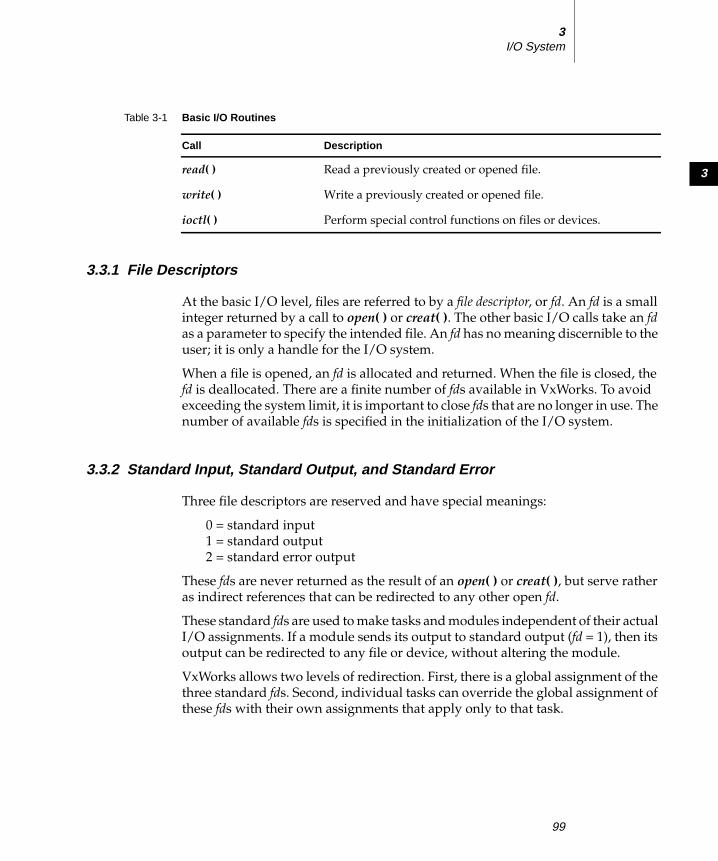
3
3I/O System
3.3.1 File Descriptors
At the basic I/O level, files are referred to by a file descriptor, or fd. An fd is a small
integer returned by a call to open( ) or creat( ). The other basic I/O calls take an fdas a parameter to specify the intended file. An fd has no meaning discernible to the
user; it is only a handle for the I/O system.
When a file is opened, an fd is allocated and returned. When the file is closed, the
fd is deallocated. There are a finite number of fds available in VxWorks. To avoid
exceeding the system limit, it is important to close fds that are no longer in use. The
number of available fds is specified in the initialization of the I/O system.
3.3.2 Standard Input, Standard Output, and Standard Error
Three file descriptors are reserved and have special meanings:
0 = standard input
1 = standard output
2 = standard error output
These fds are never returned as the result of an open( ) or creat( ), but serve rather
as indirect references that can be redirected to any other open fd.
These standard fds are used to make tasks and modules independent of their actual
I/O assignments. If a module sends its output to standard output (fd = 1), then its
output can be redirected to any file or device, without altering the module.
VxWorks allows two levels of redirection. First, there is a global assignment of the
three standard fds. Second, individual tasks can override the global assignment of
these fds with their own assignments that apply only to that task.
read( ) Read a previously created or opened file.
write( ) Write a previously created or opened file.
ioctl( ) Perform special control functions on files or devices.
Table 3-1 Basic I/O Routines
Call Description
99

VxWorks 5.4Programmer’s Guide
Global Redirection
When VxWorks is initialized, the global assignments of the standard fds are
directed, by default, to the system console. When tasks are spawned, they initially
have no task-specific fd assignments; instead, they use the global assignments.
The global assignments can be redirected using ioGlobalStdSet( ). The parameters
to this routine are the global standard fd to be redirected, and the fd to direct it to.
For example, the following call sets global standard output (fd = 1) to be the open
file with a file descriptor of fileFd:
ioGlobalStdSet (1, fileFd);
All tasks in the system that do not have their own task-specific redirection write
standard output to that file thereafter. For example, the task tRlogind calls
ioGlobalStdSet( ) to redirect I/O across the network during an rlogin session.
Task-Specific Redirection
The assignments for a specific task can be redirected using the routine
ioTaskStdSet( ). The parameters to this routine are the task ID (0 = self) of the task
with the assignments to be redirected, the standard fd to be redirected, and the fdto direct it to. For example, a task can make the following call to write standard
output to fileFd:
ioTaskStdSet (0, 1, fileFd);
All other tasks are unaffected by this redirection, and subsequent global
redirections of standard output do not affect this task.
3.3.3 Open and Close
Before I/O can be performed to a device, an fd must be opened to that device by
invoking the open( ) routine (or creat( ), as discussed in the next section). The
arguments to open( ) are the file name, the type of access, and, when necessary, the
mode:
fd = open (" name", flags, mode);
The possible access flags are shown in Table 3-2.
100

3
3I/O System
The mode parameter is used in the following special cases to specify the mode
(permission bits) of a file or to create subdirectories:
■ In general, you can open only preexisting devices and files with open( ).However, with NFS network, dosFs, and rt11Fs devices, you can also create
files with open( ) by or’ing O_CREAT with one of the access flags. In the case of
NFS devices, open( ) requires the third parameter specifying the mode of the
file:
fd = open (" name", O_CREAT | O_RDWR, 0644);
■ With both dosFs and NFS devices, you can use the O_CREAT option to create
a subdirectory by setting mode to FSTAT_DIR. Other uses of the mode
parameter with dosFs devices are ignored.
The open( ) routine, if successful, returns an fd (a small integer). This fd is then used
in subsequent I/O calls to specify that file. The fd is a global identifier that is not task
specific. One task can open a file, and then any other tasks can use the resulting fd(for example, pipes). The fd remains valid until close( ) is invoked with that fd:
close ( fd);
At that point, I/O to the file is flushed (completely written out) and the fd can no
longer be used by any task. However, the same fd number can again be assigned
by the I/O system in any subsequent open( ).
When a task exits or is deleted, the files opened by that task are not automatically
closed, because fds are not task specific. Thus, it is recommended that tasks
explicitly close all files when they are no longer required. As stated previously,
there is a limit to the number of files that can be open at one time.
Table 3-2 File Access Flags
Flag Hex Value Description
O_RDONLY 0 Open for reading only.
O_WRONLY 1 Open for writing only.
O_RDWR 2 Open for reading and writing.
O_CREAT 200 Create a new file.
O_TRUNC 400 Truncate the file.
101

VxWorks 5.4Programmer’s Guide
3.3.4 Create and Remove
File-oriented devices must be able to create and remove files as well as open
existing files. The creat( ) routine directs a file-oriented device to make a new file
on the device and return a file descriptor for it. The arguments to creat( ) are
similar to those of open( ) except that the file name specifies the name of the new
file rather than an existing one; the creat( ) routine returns an fd identifying the
new file.
fd = creat (" name", flag);
The remove( ) routine removes a named file on a file-oriented device:
remove (" name");
Do not remove files while they are open.
With non-file-system oriented device names, creat( ) acts exactly like open( );however, remove( ) has no effect.
3.3.5 Read and Write
After an fd is obtained by invoking open( ) or creat( ), tasks can read bytes from a
file with read( ) and write bytes to a file with write( ). The arguments to read( ) are
the fd, the address of the buffer to receive input, and the maximum number of bytes
to read:
nBytes = read ( fd, & buffer, maxBytes);
The read( ) routine waits for input to be available from the specified file, and
returns the number of bytes actually read. For file-system devices, if the number of
bytes read is less than the number requested, a subsequent read( ) returns 0 (zero),
indicating end-of-file. For non-file-system devices, the number of bytes read can be
less than the number requested even if more bytes are available; a subsequent
read( ) may or may not return 0. In the case of serial devices and TCP sockets,
repeated calls to read( ) are sometimes necessary to read a specific number of bytes.
(See the reference entry for fioRead( ) in fioLib). A return value of ERROR (-1)
indicates an unsuccessful read.
The arguments to write( ) are the fd, the address of the buffer that contains the data
to be output, and the number of bytes to be written:
actualBytes = write ( fd, & buffer, nBytes);
102
3
3I/O System
The write( ) routine ensures that all specified data is at least queued for output
before returning to the caller, though the data may not yet have been written to the
device (this is driver dependent). write( ) returns the number of bytes written; if
the number returned is not equal to the number requested, an error has occurred.
3.3.6 File Truncation
It is sometimes convenient to discard part of the data in a file. After a file is open
for writing, you can use the ftruncate( ) routine to truncate a file to a specified size.
Its arguments are an fd and the desired length of the file:
status = ftruncate ( fd, length);
If it succeeds in truncating the file, ftruncate( ) returns OK. If the size specified is
larger than the actual size of the file, or if the fd refers to a device that cannot be
truncated, ftruncate( ) returns ERROR, and sets errno to EINVAL.
The ftruncate( ) routine is part of the POSIX 1003.1b standard, but this
implementation is only partially POSIX-compliant: creation and modification
times are not updated. This call is supported only by dosFsLib, the DOS-
compatible file system library.
3.3.7 I/O Control
The ioctl( ) routine is an open-ended mechanism for performing any I/O functions
that do not fit the other basic I/O calls. Examples include determining how many
bytes are currently available for input, setting device-specific options, obtaining
information about a file system, and positioning random-access files to specific
byte positions. The arguments to the ioctl( ) routine are the fd, a code that identifies
the control function requested, and an optional function-dependent argument:
result = ioctl ( fd, function, arg);
For example, the following call uses the FIOBAUDRATE function to set the baud
rate of a tty device to 9600:
status = ioctl ( fd, FIOBAUDRATE, 9600);
The discussion of specific devices in 3.7 Devices in VxWorks, p.118 summarizes the
ioctl( ) functions available for each device. The ioctl( ) control codes are defined in
ioLib.h. For more information, see the reference entries for specific device drivers.
103
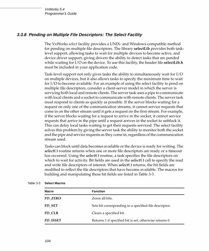
VxWorks 5.4Programmer’s Guide
3.3.8 Pending on Multiple File Descriptors: The Select Facility
The VxWorks select facility provides a UNIX- and Windows-compatible method
for pending on multiple file descriptors. The library selectLib provides both task-
level support, allowing tasks to wait for multiple devices to become active, and
device driver support, giving drivers the ability to detect tasks that are pended
while waiting for I/O on the device. To use this facility, the header file selectLib.hmust be included in your application code.
Task-level support not only gives tasks the ability to simultaneously wait for I/O
on multiple devices, but it also allows tasks to specify the maximum time to wait
for I/O to become available. For an example of using the select facility to pend on
multiple file descriptors, consider a client-server model in which the server is
servicing both local and remote clients. The server task uses a pipe to communicate
with local clients and a socket to communicate with remote clients. The server task
must respond to clients as quickly as possible. If the server blocks waiting for a
request on only one of the communication streams, it cannot service requests that
come in on the other stream until it gets a request on the first stream. For example,
if the server blocks waiting for a request to arrive in the socket, it cannot service
requests that arrive in the pipe until a request arrives in the socket to unblock it.
This can delay local tasks waiting to get their requests serviced. The select facility
solves this problem by giving the server task the ability to monitor both the socket
and the pipe and service requests as they come in, regardless of the communication
stream used.
Tasks can block until data becomes available or the device is ready for writing. The
select( ) routine returns when one or more file descriptors are ready or a timeout
has occurred. Using the select( ) routine, a task specifies the file descriptors on
which to wait for activity. Bit fields are used in the select( ) call to specify the read
and write file descriptors of interest. When select( ) returns, the bit fields are
modified to reflect the file descriptors that have become available. The macros for
building and manipulating these bit fields are listed in Table 3-3.
Table 3-3 Select Macros
Macro Function
FD_ZERO Zeros all bits.
FD_SET Sets bit corresponding to a specified file descriptor.
FD_CLR Clears a specified bit.
FD_ISSET Returns 1 if specified bit is set, otherwise returns 0.
104

3
3I/O System
Applications can use select( ) with any character I/O devices that provide support
for this facility (for example, pipes, serial devices, and sockets). For information on
writing a device driver that supports select( ), see Implementing select( ), p.152.
Example 3-1 The Select Facility
/* selServer.c - select example * In this example, a server task uses two pipes: one for normal-priority * requests, the other for high-priority requests. The server opens both * pipes and blocks while waiting for data to be available in at least one * of the pipes. */
#include "vxWorks.h"#include "selectLib.h"#include "fcntl.h"
#define MAX_FDS 2#define MAX_DATA 1024#define PIPEHI "/pipe/highPriority"#define PIPENORM "/pipe/normalPriority"
/************************************************************************* selServer - reads data as it becomes available from two different pipes** Opens two pipe fds, reading from whichever becomes available. The* server code assumes the pipes have been created from either another* task or the shell. To test this code from the shell do the following:* -> ld < selServer.o* -> pipeDevCreate ("/pipe/highPriority", 5, 1024)* -> pipeDevCreate ("/pipe/normalPriority", 5, 1024)* -> fdHi = open ("/pipe/highPriority", 1, 0)* -> fdNorm = open ("/pipe/normalPriority", 1, 0)* -> iosFdShow* -> sp selServer* -> i* At this point you should see selServer’s state as pended. You can now* write to either pipe to make the selServer display your message.* -> write fdNorm, "Howdy", 6* -> write fdHi, "Urgent", 7*/
STATUS selServer (void) { struct fd_set readFds; /* bit mask of fds to read from */ int fds[MAX_FDS]; /* array of fds on which to pend */ int width; /* number of fds on which to pend */ int i; /* index for fd array */ char buffer[MAX_DATA]; /* buffer for data that is read */
105

VxWorks 5.4Programmer’s Guide
/* open file descriptors */ if ((fds[0] = open (PIPEHI, O_RDONLY, 0)) == ERROR) return (ERROR); if ((fds[1] = open (PIPENORM, O_RDONLY, 0)) == ERROR) return (ERROR);
/* loop forever reading data and servicing clients */ FOREVER { /* clear bits in read bit mask */ FD_ZERO (&readFds);
/* initialize bit mask */ FD_SET (fds[0], &readFds); FD_SET (fds[1], &readFds); width = (fds[0] > fds[1]) ? fds[0] : fds[1]; width++;
/* pend, waiting for one or more fds to become ready */ if (select (width, &readFds, NULL, NULL, NULL) == ERROR) return (ERROR);
/* step through array and read from fds that are ready */ for (i=0; i< MAX_FDS; i++) { /* check if this fd has data to read */ if (FD_ISSET (fds[i], &readFds)) { /* typically read from fd now that it is ready */ read (fds[i], buffer, MAX_DATA); /* normally service request, for this example print it */ printf ("SELSERVER Reading from %s: %s\n", (i == 0) ? PIPEHI : PIPENORM, buffer); } } } }
3.4 Buffered I/O: Stdio
The VxWorks I/O library provides a buffered I/O package that is compatible with
the UNIX and Windows stdio package and provides full ANSI C support. To
include the stdio package in the VxWorks system, select INCLUDE_ANSI_STDIOfor inclusion in the project facility VxWorks view; see Tornado User’s Guide: Projectsfor information on configuring VxWorks.
106
3
3I/O System
Note that the implementation of printf( ), sprintf( ), and sscanf( ), traditionally
considered part of the stdio package, is part of a different package in VxWorks.
These routines are discussed in 3.5 Other Formatted I/O, p.108.
3.4.1 Using Stdio
Although the VxWorks I/O system is efficient, some overhead is associated with
each low-level call. First, the I/O system must dispatch from the device-
independent user call (read( ), write( ), and so on) to the driver-specific routine for
that function. Second, most drivers invoke a mutual exclusion or queuing
mechanism to prevent simultaneous requests by multiple users from interfering
with each other.
Because the VxWorks primitives are fast, this overhead is quite small. However, an
application processing a single character at a time from a file incurs that overhead
for each character if it reads each character with a separate read( ) call:
n = read ( fd, & char, 1);
To make this type of I/O more efficient and flexible, the stdio package implements
a buffering scheme in which data is read and written in large chunks and buffered
privately. This buffering is transparent to the application; it is handled
automatically by the stdio routines and macros. To access a file with stdio, a file is
opened with fopen( ) instead of open( ) (many stdio calls begin with the letter f):
fp = fopen ("/usr/foo", "r");
The returned value, a file pointer (or fp) is a handle for the opened file and its
associated buffers and pointers. An fp is actually a pointer to the associated data
structure of type FILE (that is, it is declared as FILE *). By contrast, the low-level I/O
routines identify a file with a file descriptor (fd), which is a small integer. In fact, the
FILE structure pointed to by the fp contains the underlying fd of the open file.
An already open fd can be associated belatedly with a FILE buffer by calling
fdopen( ):
fp = fdopen ( fd, "r");
After a file is opened with fopen( ), data can be read with fread( ), or a character at
a time with getc( ), and data can be written with fwrite( ), or a character at a time
with putc( ).
The routines and macros to get data into or out of a file are extremely efficient. They
access the buffer with direct pointers that are incremented as data is read or written
107

VxWorks 5.4Programmer’s Guide
by the user. They pause to call the low-level read or write routines only when a
read buffer is empty or a write buffer is full.
The FILE buffer is deallocated when fclose( ) is called.
3.4.2 Standard Input, Standard Output, and Standard Error
As discussed earlier in 3.3 Basic I/O, p.98, there are three special file descriptors (0,
1, and 2) reserved for standard input, standard output, and standard error. Three
corresponding stdio FILE buffers are automatically created when a task uses the
standard file descriptors, stdin, stdout, and stderr, to do buffered I/O to the standard
fds. Each task using the standard I/O fds has its own stdio FILE buffers. The FILEbuffers are deallocated when the task exits.
3.5 Other Formatted I/O
3.5.1 Special Cases: printf( ), sprintf( ), and sscanf( )
The routines printf( ), sprintf( ), and sscanf( ) are generally considered to be part of
the standard stdio package. However, the VxWorks implementation of these
routines, while functionally the same, does not use the stdio package. Instead, it
uses a self-contained, formatted, non-buffered interface to the I/O system in the
library fioLib. Note that these routines provide the functionality specified by
ANSI; however, printf( ) is not buffered.
Because these routines are implemented in this way, the full stdio package, which
is optional, can be omitted from a VxWorks configuration without sacrificing their
availability. Applications requiring printf-style output that is buffered can still
accomplish this by calling fprintf( ) explicitly to stdout.
! WARNING: The stdio buffers and pointers are private to a particular task. They are
not interlocked with semaphores or any other mutual exclusion mechanism,
because this defeats the point of an efficient private buffering scheme. Therefore,
multiple tasks must not perform I/O to the same stdio FILE pointer at the same
time.
108

3
3I/O System
While sscanf( ) is implemented in fioLib and can be used even if stdio is omitted,
the same is not true of scanf( ), which is implemented in the usual way in stdio.
3.5.2 Additional Routines: printErr( ) and fdprintf( )
Additional routines in fioLib provide formatted but unbuffered output. The
routine printErr( ) is analogous to printf( ) but outputs formatted strings to the
standard error fd (2). The routine fdprintf( ) outputs formatted strings to a
specified fd.
3.5.3 Message Logging
Another higher-level I/O facility is provided by the library logLib, which allows
formatted messages to be logged without having to do I/O in the current task’s
context, or when there is no task context. The message format and parameters are
sent on a message queue to a logging task, which then formats and outputs the
message. This is useful when messages must be logged from interrupt level, or
when it is desirable not to delay the current task for I/O or use the current task’s
stack for message formatting (which can take up significant stack space). The
message is displayed on the console unless otherwise redirected at system startup
using logInit( ) or dynamically using logFdSet( ).
3.6 Asynchronous Input/Output
Asynchronous Input/Output (AIO) is the ability to perform input and output
operations concurrently with ordinary internal processing. AIO enables you to
decouple I/O operations from the activities of a particular task when these are
logically independent.
The benefit of AIO is greater processing efficiency: it permits I/O operations to
take place whenever resources are available, rather than making them await
arbitrary events such as the completion of independent operations. AIO eliminates
some of the unnecessary blocking of tasks that is caused by ordinary synchronous
I/O; this decreases contention for resources between input/output and internal
processing, and expedites throughput.
109

VxWorks 5.4Programmer’s Guide
The VxWorks AIO implementation meets the specification in the POSIX 1003.1b
standard. To include AIO in your VxWorks configuration, select
INCLUDE_POSIX_AIO and INCLUDE_POSIX_AIO_SYSDRV in the project facility
VxWorks view; see Tornado User’s Guide: Projects for information on configuring
VxWorks. The second configuration constant enables the auxiliary AIO system
driver, required for asynchronous I/O on all current VxWorks devices.
3.6.1 The POSIX AIO Routines
The VxWorks library aioPxLib provides the POSIX AIO routines. To access a file
asynchronously, open it with the open( ) routine, like any other file. Thereafter, use
the file descriptor returned by open( ) in calls to the AIO routines. The POSIX AIO
routines (and two associated non-POSIX routines) are listed in Table 3-4.
The default VxWorks initialization code calls aioPxLibInit( ) automatically when
INCLUDE_POSIX_AIO is selected for inclusion in the project facility VxWorks view.
This routine takes one parameter, the maximum number of lio_listio( ) calls that
can be outstanding at one time. By default this parameter is MAX_LIO_CALLS
Table 3-4 Asynchronous Input/Output Routines
Function Description
aioPxLibInit( ) Initialize the AIO library (non-POSIX).
aioShow( ) Display the outstanding AIO requests (non-POSIX).*
* This function is not built into the Tornado shell. To use it from the Tornado shell, you
must select INCLUDE_POSIX_AIO_SHOW for inclusion in the project facility
VxWorks view. When you invoke the function, its output is sent to the standard
output device.
aio_read( ) Initiate an asynchronous read operation.
aio_write( ) Initiate an asynchronous write operation.
aio_listio( ) Initiate a list of up to LIO_MAX asynchronous I/O requests.
aio_error( ) Retrieve the error status of an AIO operation.
aio_return( ) Retrieve the return status of a completed AIO operation.
aio_cancel( ) Cancel a previously submitted AIO operation.
aio_suspend( ) Wait until an AIO operation is done, interrupted, or timed out.
110

3
3I/O System
(which can be seen on the Params tab of the properties window to be 0 by default).
When the parameter is 0, the value is taken from AIO_CLUST_MAX (defined in
installDir/target/h/private/aioPxLibP.h).
The AIO system driver, aioSysDrv, is initialized by default with the routine
aioSysInit( ) when both INCLUDE_POSIX_AIO and
INCLUDE_POSIX_AIO_SYSDRV are included. The purpose of aioSysDrv is to
provide request queues independent of any particular device driver, so that you
can use any VxWorks device driver with AIO.
The routine aioSysInit( ) takes three parameters: the number of AIO system tasks
to spawn, and the priority and stack size for these system tasks. The number of
AIO system tasks spawned equals the number of AIO requests that can be handled
in parallel. The default initialization call uses three constants, all defined in
configAll.h:
aioSysInit( MAX_AIO_SYS_TASKS, AIO_TASK_PRIORITY, AIO_TASK_STACK_SIZE )
When any of the parameters passed to aioSysInit( ) is 0, the corresponding value
is taken from AIO_IO_TASKS_DFLT, AIO_IO_PRIO_DFLT, and
AIO_IO_STACK_DFLT (all defined in installDir/target/h/aioSysDrv.h).
Table 3-5 lists the names of the constants called from usrConfig.c and their default
values (which can be seen on the Params tab of the properties window). It also
shows the constants used within initialization routines when the parameters are
left at their default values of 0, and where these constants are defined.
3.6.2 AIO Control Block
Each of the AIO calls takes an AIO control block (aiocb) as an argument to describe
the AIO operation. The calling routine must allocate space for the control block,
which is associated with a single AIO operation. No two concurrent AIO
Table 3-5 AIO Initialization Functions and Related Constants
InitializationFunction
configAll.h ConstantDef.
ValueHeader File Constantused when arg = 0
Def.Value
Header File(all in installDir/target
aioPxLibInit( ) MAX_LIO_CALLS 0 AIO_CLUST_MAX 100 h/private/aioPxLibP.h
aioSysInit( ) MAX_AIO_SYS_TASKS 0 AIO_IO_TASKS_DFLT 2 h/aioSysDrv.h
AIO_TASK_PRIORITY 0 AIO_IO_PRIO_DFLT 50 h/aioSysDrv.h
AIO_TASK_STACK_SIZE 0 AIO_IO_STACK_DFLT 0x7000 h/aioSysDrv.h
111

VxWorks 5.4Programmer’s Guide
operations can use the same control block; an attempt to do so yields undefined
results.
The aiocb and the data buffers it references are used by the system while
performing the associated request. Therefore, after you request an AIO operation,
you must not modify the corresponding aiocb before calling aio_return( ); this
function frees the aiocb for modification or reuse.
The aiocb structure is defined in aio.h. It contains the following fields:
aio_fildesfile descriptor for I/O
aio_offsetoffset from the beginning of the file
aio_bufaddress of the buffer from/to which AIO is requested
aio_nbytesnumber of bytes to read or write
aio_reqpriopriority reduction for this AIO request
aio_sigeventsignal to return on completion of an operation (optional)
aio_lio_opcodeoperation to be performed by a lio_listio( ) call
aio_sysVxWorks-specific data (non-POSIX)
For full definitions and important additional information, see the reference entry
for aioPxLib.
3.6.3 Using AIO
The routines aio_read( ), aio_write( ), or lio_listio( ) initiate AIO operations. The
last of these, lio_listio( ), allows you to submit a number of asynchronous requests
(read and/or write) at one time. In general, the actual I/O (reads and writes)
initiated by these routines does not happen immediately after the AIO request. For
! CAUTION: If a routine allocates stack space for the aiocb, that routine must call
aio_return( ) to free the aiocb before returning.
112

3
3I/O System
that reason, their return values do not reflect the outcome of the actual I/O
operation, but only whether a request is successful—that is, whether the AIO
routine is able to put the operation on a queue for eventual execution.
After the I/O operations themselves execute, they also generate return values that
reflect the success or failure of the I/O. There are two routines that you can use to
get information about the success or failure of the I/O operation: aio_error( ) and
aio_return( ). You can use aio_error( ) to get the status of an AIO operation
(success, failure, or in progress), and aio_return( ) to obtain the return values from
the individual I/O operations. Until an AIO operation completes, its error status
is EINPROGRESS. To cancel an AIO operation, call aio_cancel( ).
AIO with Periodic Checks for Completion
The following code uses a pipe for the asynchronous I/O operations. The example
creates the pipe, submits an AIO read request, verifies that the read request is still
in progress, and submits an AIO write request. Under normal circumstances, a
synchronous read to an empty pipe blocks and the task does not execute the write,
but in the case of AIO, we initiate the read request and continue. After the write
request is submitted, the example task loops, checking the status of the AIO
requests periodically until both the read and write complete. Because the AIO
control blocks are on the stack, we must call aio_return( ) before returning from
aioExample( ).
Example 3-2 Asynchronous I/O
/* aioEx.c - example code for using asynchronous I/O */
/* includes */
#include "vxWorks.h"#include "aio.h"#include "errno.h"
/* defines */
#define BUFFER_SIZE 200
/************************************************************************* aioExample - use AIO library** This example shows the basic functions of the AIO library.** RETURNS: OK if successful, otherwise ERROR.*/
113

VxWorks 5.4Programmer’s Guide
STATUS aioExample (void) { int fd; static char exFile [] = "/pipe/1stPipe"; struct aiocb aiocb_read; /* read aiocb */ struct aiocb aiocb_write; /* write aiocb */ static char * test_string = "testing 1 2 3"; char buffer [BUFFER_SIZE]; /* buffer for read aiocb */
pipeDevCreate (exFile, 50, 100);
if ((fd = open (exFile, O_CREAT | O_TRUNC | O_RDWR, 0666)) == ERROR) { printf ("aioExample: cannot open %s errno 0x%x\n", exFile, errno); return (ERROR); }
printf ("aioExample: Example file = %s\tFile descriptor = %d\n", exFile, fd);
/* initialize read and write aiocbs */ bzero ((char *) &aiocb_read, sizeof (struct aiocb)); bzero ((char *) buffer, sizeof (buffer)); aiocb_read.aio_fildes = fd; aiocb_read.aio_buf = buffer; aiocb_read.aio_nbytes = BUFFER_SIZE; aiocb_read.aio_reqprio = 0;
bzero ((char *) &aiocb_write, sizeof (struct aiocb)); aiocb_write.aio_fildes = fd; aiocb_write.aio_buf = test_string; aiocb_write.aio_nbytes = strlen (test_string); aiocb_write.aio_reqprio = 0;
/* initiate the read */ if (aio_read (&aiocb_read) == -1) printf ("aioExample: aio_read failed\n");
/* verify that it is in progress */ if (aio_error (&aiocb_read) == EINPROGRESS) printf ("aioExample: read is still in progress\n");
/* write to pipe - the read should be able to complete */ printf ("aioExample: getting ready to initiate the write\n"); if (aio_write (&aiocb_write) == -1) printf ("aioExample: aio_write failed\n");
/* wait til both read and write are complete */ while ((aio_error (&aiocb_read) == EINPROGRESS) || (aio_error (&aiocb_write) == EINPROGRESS)) taskDelay (1);
/* print out what was read */ printf ("aioExample: message = %s\n", buffer);
114
3
3I/O System
/* clean up */ if (aio_return (&aiocb_read) == -1) printf ("aioExample: aio_return for aiocb_read failed\n"); if (aio_return (&aiocb_write) == -1) printf ("aioExample: aio_return for aiocb_write failed\n");
close (fd); return (OK); }
Alternatives for Testing AIO Completion
A task can determine whether an AIO request is complete in any of the following
ways:
■ Check the result of aio_error( ) periodically, as in the previous example, until
the status of an AIO request is no longer EINPROGRESS.
■ Use aio_suspend( ) to suspend the task until the AIO request is complete.
■ Use signals to be informed when the AIO request is complete.
The following example is similar to the preceding aioExample( ), except that it uses
signals to be notified when the write is complete. If you test this from the shell,
spawn the routine to run at a lower priority than the AIO system tasks to assure
that the test routine does not block completion of the AIO request. (For details on
the shell, see the Tornado User’s Guide: Shell.)
Example 3-3 Asynchronous I/O with Signals
/* aioExSig.c - example code for using signals with asynchronous I/O */
/* includes */
#include "vxWorks.h"#include "aio.h"#include "errno.h"
/* defines */
#define BUFFER_SIZE 200#define LIST_SIZE 1#define EXAMPLE_SIG_NO 25 /* signal number */
/* forward declarations */
void mySigHandler (int sig, struct siginfo * info, void * pContext);
115

VxWorks 5.4Programmer’s Guide
/************************************************************************* aioExampleSig - use AIO library.** This example shows the basic functions of the AIO library.* Note if this is run from the shell it must be spawned. Use:* -> sp aioExampleSig** RETURNS: OK if successful, otherwise ERROR.*/
STATUS aioExampleSig (void) { int fd; static char exFile [] = "/pipe/1stPipe"; struct aiocb aiocb_read; /* read aiocb */ static struct aiocb aiocb_write; /* write aiocb */ struct sigaction action; /* signal info */ static char * test_string = "testing 1 2 3"; char buffer [BUFFER_SIZE]; /* aiocb read buffer */
pipeDevCreate (exFile, 50, 100);
if ((fd = open (exFile, O_CREAT | O_TRUNC| O_RDWR, 0666)) == ERROR) { printf ("aioExample: cannot open %s errno 0x%x\n", exFile, errno); return (ERROR); }
printf ("aioExampleSig: Example file = %s\tFile descriptor = %d\n", exFile, fd);
/* set up signal handler for EXAMPLE_SIG_NO */
action.sa_sigaction = mySigHandler; action.sa_flags = SA_SIGINFO; sigemptyset (&action.sa_mask); sigaction (EXAMPLE_SIG_NO, &action, NULL);
/* initialize read and write aiocbs */
bzero ((char *) &aiocb_read, sizeof (struct aiocb)); bzero ((char *) buffer, sizeof (buffer)); aiocb_read.aio_fildes = fd; aiocb_read.aio_buf = buffer; aiocb_read.aio_nbytes = BUFFER_SIZE; aiocb_read.aio_reqprio = 0;
bzero ((char *) &aiocb_write, sizeof (struct aiocb)); aiocb_write.aio_fildes = fd; aiocb_write.aio_buf = test_string; aiocb_write.aio_nbytes = strlen (test_string); aiocb_write.aio_reqprio = 0;
/* set up signal info */
aiocb_write.aio_sigevent.sigev_signo = EXAMPLE_SIG_NO;
116

3
3I/O System
aiocb_write.aio_sigevent.sigev_notify = SIGEV_SIGNAL; aiocb_write.aio_sigevent.sigev_value.sival_ptr = (void *) &aiocb_write;
/* initiate the read */
if (aio_read (&aiocb_read) == -1) printf ("aioExampleSig: aio_read failed\n");
/* verify that it is in progress */
if (aio_error (&aiocb_read) == EINPROGRESS) printf ("aioExampleSig: read is still in progress\n");
/* write to pipe - the read should be able to complete */
printf ("aioExampleSig: getting ready to initiate the write\n"); if (aio_write (&aiocb_write) == -1) printf ("aioExampleSig: aio_write failed\n");
/* clean up */
if (aio_return (&aiocb_read) == -1) printf ("aioExampleSig: aio_return for aiocb_read failed\n"); else printf ("aioExampleSig: aio read message = %s\n", aiocb_read.aio_buf);
close (fd); return (OK); }
void mySigHandler ( int sig, struct siginfo * info, void * pContext )
{ /* print out what was read */
printf ("mySigHandler: Got signal for aio write\n");
/* write is complete so let’s do cleanup for it here */
if (aio_return (info->si_value.sival_ptr) == -1) { printf ("mySigHandler: aio_return for aiocb_write failed\n"); printErrno (0); } }
117

VxWorks 5.4Programmer’s Guide
3.7 Devices in VxWorks
The VxWorks I/O system is flexible, allowing specific device drivers to handle the
seven I/O functions. All VxWorks device drivers follow the basic conventions
outlined previously, but differ in specifics; this section describes those specifics.
3.7.1 Serial I/O Devices (Terminal and Pseudo-Terminal Devices)
VxWorks provides terminal and pseudo-terminal device drivers (tty and ptydrivers). The tty driver is for actual terminals; the pty driver is for processes that
simulate terminals. These pseudo terminals are useful in applications such as
remote login facilities.1
VxWorks serial I/O devices are buffered serial byte streams. Each device has a ring
buffer (circular buffer) for both input and output. Reading from a tty device
extracts bytes from the input ring. Writing to a tty device adds bytes to the output
ring. The size of each ring buffer is specified when the device is created during
system initialization.
Table 3-6 Drivers Provided with VxWorks
Module Driver Description
ttyDrv Terminal driver
ptyDrv Pseudo-terminal driver
pipeDrv Pipe driver
memDrv Pseudo memory device driver
nfsDrv NFS client driver
netDrv Network driver for remote file access
ramDrv RAM driver for creating a RAM disk
scsiLib SCSI interface library
- Other hardware-specific drivers
1. For the remainder of this section, the term tty is used to indicate both tty and pty devices.
118

3
3I/O System
Tty Options
The tty devices have a full range of options that affect the behavior of the device.
These options are selected by setting bits in the device option word using the
ioctl( ) routine with the FIOSETOPTIONS function (see I/O Control Functions,
p.121). For example, to set all the tty options except OPT_MON_TRAP:
status = ioctl ( fd, FIOSETOPTIONS, OPT_TERMINAL & ~OPT_MON_TRAP);
Table 3-7 is a summary of the available options. The listed names are defined in the
header file ioLib.h. For more detailed information, see the reference entry for
tyLib.
Raw Mode and Line Mode
A tty device operates in one of two modes: raw mode (unbuffered) or line mode. Raw
mode is the default. Line mode is selected by the OPT_LINE bit of the device option
word (see Tty Options, p.119).
In raw mode, each input character is available to readers as soon as it is input from
the device. Reading from a tty device in raw mode causes as many characters as
Table 3-7 Tty Options
Library Description
OPT_LINE Select line mode. (See Raw Mode and Line Mode, p.119.)
OPT_ECHO Echo input characters to the output of the same channel.
OPT_CRMOD Translate input RETURN characters into NEWLINE (\n); translate
output NEWLINE into RETURN-LINEFEED.
OPT_TANDEM Respond to X-on/X-off protocol (CTRL+Q and CTRL+S).
OPT_7_BIT Strip the most significant bit from all input bytes.
OPT_MON_TRAP Enable the special ROM monitor trap character, CTRL+X by default.
OPT_ABORT Enable the special target shell abort character, CTRL+C by default.
(Only useful if the target shell is configured into the system; see
9. Target Shell in this manual for details.)
OPT_TERMINAL Set all of the above option bits.
OPT_RAW Set none of the above option bits.
119

VxWorks 5.4Programmer’s Guide
possible to be extracted from the input ring, up to the limit of the user’s read buffer.
Input cannot be modified except as directed by other tty option bits.
In line mode, all input characters are saved until a NEWLINE character is input; then
the entire line of characters, including the NEWLINE, is made available in the ring
at one time. Reading from a tty device in line mode causes characters up to the end
of the next line to be extracted from the input ring, up to the limit of the user’s read
buffer. Input can be modified by the special characters CTRL+H (backspace),
CTRL+U (line-delete), and CTRL+D (end-of-file), which are discussed in Tty SpecialCharacters, p.120.
Tty Special Characters
The following special characters are enabled if the tty device operates in line mode,
that is, with the OPT_LINE bit set:
■ The backspace character, by default CTRL+H, causes successive previous
characters to be deleted from the current line, up to the start of the line. It does
this by echoing a backspace followed by a space, and then another backspace.
■ The line-delete character, by default CTRL+U, deletes all the characters of the
current line.
■ The end-of-file (EOF) character, by default CTRL+D, causes the current line to
become available in the input ring without a NEWLINE and without entering
the EOF character itself. Thus if the EOF character is the first character typed
on a line, reading that line returns a zero byte count, which is the usual
indication of end-of-file.
The following characters have special effects if the tty device is operating with the
corresponding option bit set:
■ The flow control characters, CTRL+Q and CTRL+S, commonly known as
X-on/X-off protocol. Receipt of a CTRL+S input character suspends output to
that channel. Subsequent receipt of a CTRL+Q resumes the output. Conversely,
when the VxWorks input buffer is almost full, a CTRL+S is output to signal the
other side to suspend transmission. When the input buffer is empty enough, a
CTRL+Q is output to signal the other side to resume transmission. X-on/X-off
protocol is enabled by OPT_TANDEM.
■ The ROM monitor trap character, by default CTRL+X. This character traps to the
ROM-resident monitor program. Note that this is drastic. All normal VxWorks
functioning is suspended, and the computer system is controlled entirely by
the monitor. Depending on the particular monitor, it may or may not be
120

3
3I/O System
possible to restart VxWorks from the point of interruption.2 The monitor trap
character is enabled by OPT_MON_TRAP.
■ The special target shell abort character, by default CTRL+C. This character
restarts the target shell if it gets stuck in an unfriendly routine, such as one that
has taken an unavailable semaphore or is caught in an infinite loop. The target
shell abort character is enabled by OPT_ABORT.
The characters for most of these functions can be changed using the tyLib routines
shown in Table 3-8.
I/O Control Functions
The tty devices respond to the ioctl( ) functions in Table 3-9, defined in ioLib.h. For
more information, see the reference entries for tyLib, ttyDrv, and ioctl( ).
2. It will not be possible to restart VxWorks if unhandled external interrupts occur during the
boot countdown.
Table 3-8 Tty Special Characters
Character Description Modifier
CTRL+H backspace (character delete) tyBackspaceSet( )
CTRL+U line delete tyDeleteLineSet( )
CTRL+D EOF (end of file) tyEOFSet( )
CTRL+C target shell abort tyAbortSet( )
CTRL+X trap to boot ROMs tyMonitorTrapSet( )
CTRL+S output suspend N/A
CTRL+Q output resume N/A
Table 3-9 I/O Control Functions Supported by tyLib
Function Description
FIOBAUDRATE Set the baud rate to the specified argument.
FIOCANCEL Cancel a read or write.
FIOFLUSH Discard all bytes in the input and output buffers.
121

VxWorks 5.4Programmer’s Guide
3.7.2 Pipe Devices
Pipes are virtual devices by which tasks communicate with each other through the
I/O system. Tasks write messages to pipes; these messages can then be read by
other tasks. Pipe devices are managed by pipeDrv and use the kernel message
queue facility to bear the actual message traffic.
Creating Pipes
Pipes are created by calling the pipe create routine:
status = pipeDevCreate ("/pipe/name", maxMsgs, maxLength);
The new pipe can have at most maxMsgs messages queued at a time. Tasks that
write to a pipe that already has the maximum number of messages queued are
delayed until a message is dequeued. Each message in the pipe can be at most
maxLength bytes long; attempts to write longer messages result in an error.
FIOGETNAME Get the file name of the fd.
FIOGETOPTIONS Return the current device option word.
FIONREAD Get the number of unread bytes in the input buffer.
FIONWRITE Get the number of bytes in the output buffer.
FIOSETOPTIONS Set the device option word.
! CAUTION: To change the driver’s hardware options (for example, the number of
stop bits or parity bits), use the ioctl( ) function SIO_HW_OPTS_SET. Because this
command is not implemented in most drivers, you may need to add it to your BSP
serial driver, which resides in installDir/target/src/drv/sio. The details of how to
implement this command depend on your board’s serial chip. The constants
defined in the header file installDir/target/h/sioLib.h provide the POSIX
definitions for setting the hardware options.
Table 3-9 I/O Control Functions Supported by tyLib (Continued)
Function Description
122

3
3I/O System
Writing to Pipes from ISRs
VxWorks pipes are designed to allow ISRs to write to pipes in the same way as
task-level code. Many VxWorks facilities cannot be used from ISRs, including I/O
to devices other than pipes. However, ISRs can use pipes to communicate with
tasks, which can then invoke such facilities.
ISRs write to a pipe using the write( ) call. Tasks and ISRs can write to the same
pipes. However, if the pipe is full, the message is discarded because the ISRs
cannot pend. ISRs must not invoke any I/O function on pipes other than write( ).
I/O Control Functions
Pipe devices respond to the ioctl( ) functions summarized in Table 3-10. The
functions listed are defined in the header file ioLib.h. For more information, see
the reference entries for pipeDrv and for ioctl( ) in ioLib.
3.7.3 Pseudo Memory Devices
The memDrv driver allows the I/O system to access memory directly as a pseudo-
I/O device. Memory location and size are specified when the device is created.
This feature is useful when data must be preserved between boots of VxWorks or
when sharing data between CPUs. This driver does not implement a file system as
does ramDrv. The ramDrv driver must be given memory over which it has
absolute control; whereas memDrv provides a high-level method of reading and
writing bytes in absolute memory locations through I/O calls.
Table 3-10 I/O Control Functions Supported by pipeDrv
Function Description
FIOFLUSH Discard all messages in the pipe.
FIOGETNAME Get the pipe name of the fd.
FIONMSGS Get the number of messages remaining in the pipe.
FIONREAD Get the size in bytes of the first message in the pipe.
123

VxWorks 5.4Programmer’s Guide
Installing the Memory Driver
The driver is first initialized and then the device is created:
STATUS memDrv(void)
STATUS memDevCreate(char * name, char * base, int length)
Memory for the device is an absolute memory location beginning at base. The
length parameter indicates the size of the memory. For additional information on
the memory driver, see the reference entries for memDrv, memDevCreate( ), and
memDrv( ).
I/O Control Functions
The memory driver responds to the ioctl( ) functions summarized in Table 3-11.
The functions listed are defined in the header file ioLib.h. For more information,
see the reference entries for memDrv and for ioctl( ) in ioLib.
3.7.4 Network File System (NFS) Devices
Network File System (NFS) devices allow files on remote hosts to be accessed with
the NFS protocol. The NFS protocol specifies both client software, to read files from
remote machines, and server software, to export files to remote machines.
The driver nfsDrv acts as a VxWorks NFS client to access files on any NFS server
on the network. VxWorks also allows you to run an NFS server to export files to
other systems; see VxWorks Network Programmer’s Guide: File Access Applicationsl.
Using NFS devices, you can create, open, and access remote files exactly as though
they were on a file system on a local disk. This is called network transparency.
Table 3-11 I/O Control Functions Supported by memDrv
Function Description
FIOSEEK Set the current byte offset in the file.
FIOWHERE Return the current byte position in the file.
124

3
3I/O System
Mounting a Remote NFS File System from VxWorks
Access to a remote NFS file system is established by mounting that file system
locally and creating an I/O device for it using nfsMount( ). Its arguments are
(1) the host name of the NFS server, (2) the name of the host file system, and (3) the
local name for the file system.
For example, the following call mounts /usr of the host mars as /vxusr locally:
nfsMount ("mars", "/usr", "/vxusr");
This creates a VxWorks I/O device with the specified local name (/vxusr, in this
example). If the local name is specified as NULL, the local name is the same as the
remote name.
After a remote file system is mounted, the files are accessed as though the file
system were local. Thus, after the previous example, opening the file /vxusr/fooopens the file /usr/foo on the host mars.
The remote file system must be exported by the system on which it actually resides.
However, NFS servers can export only local file systems. Use the appropriate
command on the server to see which file systems are local. NFS requires
authentication parameters to identify the user making the remote access. To set
these parameters, use the routines nfsAuthUnixSet( ) and nfsAuthUnixPrompt( ).
Select INCLUDE_NFS for inclusion in the project facility VxWorks view to include
NFS client support in your VxWorks configuration; see Tornado User’s Guide:Projects for information on configuring VxWorks.
The subject of exporting and mounting NFS file systems and authenticating access
permissions is discussed in more detail in VxWorks Network Programmer’s Guide:File Access Applications. See also the reference entries nfsLib and nfsDrv, and the
NFS documentation from Sun Microsystems.
I/O Control Functions for NFS Clients
NFS client devices respond to the ioctl( ) functions summarized in Table 3-12. The
functions listed are defined in ioLib.h. For more information, see the reference
entries for nfsDrv and for ioctl( ) in ioLib.
125

VxWorks 5.4Programmer’s Guide
3.7.5 Non-NFS Network Devices
VxWorks also supports network access to files on the remote host through the
Remote Shell protocol (RSH) or the File Transfer Protocol (FTP). These
implementations of network devices use the driver netDrv. When a remote file is
opened using RSH or FTP, the entire file is copied into local memory. As a result,
the largest file that can be opened is restricted by the available memory. Read and
write operations are performed on the in-memory copy of the file. When closed,
the file is copied back to the original remote file if it was modified.
In general, NFS devices are preferable to RSH and FTP devices for performance
and flexibility, because NFS does not copy the entire file into local memory.
However, NFS is not supported by all host systems.
Creating Network Devices
To access files on a remote host using either RSH or FTP, a network device must
first be created by calling the routine netDevCreate( ). The arguments to
netDevCreate( ) are (1) the name of the device, (2) the name of the host the device
accesses, and (3) which protocol to use: 0 (RSH) or 1 (FTP).
For example, the following call creates an RSH device called mars: that accesses the
host mars. By convention, the name for a network device is the remote machine’s
name followed by a colon ( :).
netDevCreate ("mars:", "mars", 0);
Table 3-12 I/O Control Functions Supported by nfsDrv
Function Description
FIOFSTATGET Get file status information (directory entry data).
FIOGETNAME Get the file name of the fd.
FIONREAD Get the number of unread bytes in the file.
FIOREADDIR Read the next directory entry.
FIOSEEK Set the current byte offset in the file.
FIOSYNC Flush data to a remote NFS file.
FIOWHERE Return the current byte position in the file.
126
3
3I/O System
Files on a network device can be created, opened, and manipulated as if on a local
disk. Thus, opening the file mars:/usr/foo actually opens /usr/foo on host mars.
Note that creating a network device allows access to any file or device on the
remote system, while mounting an NFS file system allows access only to a
specified file system.
For the files of a remote host to be accessible with RSH or FTP, permissions and
user identification must be established on both the remote and local systems.
Creating and configuring network devices is discussed in detail in VxWorksNetwork Programmer’s Guide: File Access Applications and in the reference entry for
netDrv.
I/O Control Functions
RSH and FTP devices respond to the same ioctl( ) functions as NFS devices except
for FIOSYNC and FIOREADDIR. The functions are defined in the header file
ioLib.h. For more information, see the reference entries for netDrv and ioctl( ).
3.7.6 Block Devices
A block device is a device that is organized as a sequence of individually accessible
blocks of data. The most common type of block device is a disk. In VxWorks, the
term block refers to the smallest addressable unit on the device. For most disk
devices, a VxWorks block corresponds to a sector, although terminology varies.
Block devices in VxWorks have a slightly different interface than other I/O
devices. Rather than interacting directly with the I/O system, block device support
consists of low-level drivers that interact with a file system. The file system, in turn,
interacts with the I/O system. This arrangement allows a single low-level driver
to be used with various different file systems and reduces the number of I/O
functions that must be supported in the driver. The internal implementation of
low-level drivers for block devices is discussed in 3.9.4 Block Devices, p.158.
File Systems
For use with block devices, VxWorks is supplied with file system libraries
compatible with the MS-DOS (dosFs) and RT-11 (rt11Fs) file systems. In addition,
there is a library for a simple raw disk file system (rawFs), which treats an entire
disk much like a single large file. Also supplied is a file system that supports SCSI
127

VxWorks 5.4Programmer’s Guide
tape devices, which are organized so that individual blocks of data are read and
written sequentially, and a file system that supports CD-ROM devices. Use of these
file systems is discussed in 4. Local File Systems in this manual. Also see the
reference entries for dosFsLib, rt11FsLib, rawFsLib, tapeFsLib, and cdromFsLib.
RAM Disk Drivers
RAM drivers, as implemented in ramDrv, emulate disk devices but actually keep
all data in memory. Memory location and “disk” size are specified when a RAM
device is created by calling ramDevCreate( ). This routine can be called repeatedly
to create multiple RAM disks.
Memory for the RAM disk can be preallocated and the address passed to
ramDevCreate( ), or memory can be automatically allocated from the system
memory pool using malloc( ).
After the device is created, a name and file system (dosFs, rt11Fs, or rawFs) must
be associated with it using the file system’s device initialization routine or file
system’s make routine, for example, dosFsDevInit( ) or dosFsMkfs( ). Information
describing the device is passed to the file system in a BLK_DEV structure. A pointer
to this structure is returned by the RAM disk creation routine.
In the following example, a 200KB RAM disk is created with automatically
allocated memory, 512-byte sections, a single track, and no sector offset. The device
is assigned the name DEV1: and initialized for use with dosFs.
BLK_DEV *pBlkDev;DOS_VOL_DESC *pVolDesc;pBlkDev = ramDevCreate (0, 512, 400, 400, 0);pVolDesc = dosFsMkfs ("DEV1:", pBlkDev);
The dosFsMkfs( ) routine calls dosFsDevInit( ) with default parameters and
initializes the file system on the disk by calling ioctl( ) with the FIODISKINIT.
If the RAM disk memory already contains a disk image, the first argument to
ramDevCreate( ) is the address in memory, and the formatting arguments must be
identical to those used when the image was created. For example:
pBlkDev = ramDevCreate (0xc0000, 512, 400, 400, 0);pVolDesc = dosFsDevInit ("DEV1:", pBlkDev, NULL);
In this case, dosFsDevInit( ) must be used instead, because the file system already
exists on the disk and does not require re-initialization. This procedure is useful if
a RAM disk is to be created at the same address used in a previous boot of
VxWorks. The contents of the RAM disk are then preserved. Creating a RAM disk
128

3
3I/O System
with rt11Fs using rt11FsMkfs( ) and rt11FsDevInit( ) follows these same
procedures. For more information on RAM disk drivers, see the reference entry for
ramDrv. For more information on file systems, see 4. Local File Systems.
SCSI Drivers
SCSI is a standard peripheral interface that allows connection with a wide variety
of hard disks, optical disks, floppy disks, tape drives, and CD-ROM devices. SCSI
block drivers are compatible with the dosFs and rt11Fs libraries, and offer several
advantages for target configurations. They provide:
– local mass storage in non-networked environments
– faster I/O throughput than Ethernet networks
The SCSI-2 support in VxWorks supersedes previous SCSI support, although it
offers the option of configuring the original SCSI functionality, now known as
SCSI-1. With SCSI-2 enabled, the VxWorks environment can still handle SCSI-1
applications, such as file systems created under SCSI-1. However, applications that
directly used SCSI-1 data structures defined in scsiLib.h may require
modifications and recompilation for SCSI-2 compatibility.
The VxWorks SCSI implementation consists of two modules, one for the device-
independent SCSI interface and one to support a specific SCSI controller. The
scsiLib library provides routines that support the device-independent interface;
device-specific libraries provide configuration routines that support specific
controllers (for example, wd33c93Lib for the Western Digital WD33C93 device or
mb87030Lib for the Fujitsu MB87030 device). There are also additional support
routines for individual targets in sysLib.c.
Configuring SCSI Drivers
Constants associated with SCSI drivers are listed in Table 3-13. Define these in the
indicated portion of the VxWorks view or in the configuration files. To enable SCSI
functionality, select INCLUDE_SCSI for inclusion in the project facility VxWorks
view. This enables SCSI-1. To enable SCSI-2, you must select, in addition to SCSI-
1, INCLUDE_SCSI2.
Table 3-13 SCSI Constants
Constant Description Where to Configure
INCLUDE_SCSI Include SCSI interface. hardware/buses
INCLUDE_SCSI2 SCSI-2 extensions. hardware/buses
129

VxWorks 5.4Programmer’s Guide
Autoconfiguration, DMA, and booting from a SCSI device are defined
appropriately for each BSP. If you need to change these settings, see the online
reference for sysScsiConfig( ) under VxWorks Reference>Manual: Libraries and the
source file installDir/target/src/config/usrScsi.c. Except for dosFs, which can be
configured from the project facility, the file systems that can be used with SCSI
must be defined in config.h. (For more information see 8. Configuration and Build.)
Configuring the SCSI Bus ID
Each board in a SCSI-2 environment must define a unique SCSI bus ID for the SCSI
initiator. SCSI-1 drivers, which support only a single initiator at a time, assume an
initiator SCSI bus ID of 7. However, SCSI-2 supports multiple initiators, up to eight
initiators and targets at one time. Therefore, to ensure a unique ID, choose a value
in the range 0-7 to be passed as a parameter to the driver’s initialization routine
(for example, ncr710CtrlInitScsi2( )) by the sysScsiInit( ) routine in sysScsi.c. For
more information, see the reference entry for the relevant driver initialization
routine. If there are multiple boards on one SCSI bus, and all of these boards use
INCLUDE_SCSI_DMA Enable DMA for SCSI. sysLib.c or sysScsi.c
INCLUDE_SCSI_BOOT Allow booting from a SCSI device. sysLib.c or sysScsi.c
SCSI_AUTO_CONFIG Auto-configure and locate all
targets on a SCSI bus.
sysLib.c or sysScsi.c
INCLUDE_DOSFS Include the DOS file system. operating systemcomponents/IO systemcomponents
INCLUDE_TAPEFS Include the tape file system. config.h
INCLUDE_CDROMFS Include CD-ROM file system
support.
config.h
! CAUTION: Including SCSI-2 in your VxWorks image can significantly increase the
image size. If you receive a warning from vxsize when building VxWorks, or if the
size of your image becomes greater than that supported by the current setting of
RAM_HIGH_ADRS, be sure to see 8.6.1 Scaling Down VxWorks, p.344 and
8.9 Creating Bootable Applications, p.364 for information on how to resolve the
problem.
Table 3-13 SCSI Constants
Constant Description Where to Configure
130
3
3I/O System
the same BSP, then different versions of the BSP must be compiled for each board
by assigning unique SCSI bus IDs.
ROM Size Adjustment for SCSI Boot
If INCLUDE_SCSI_BOOT is defined, larger ROMs may be required for some
boards. If this is the case, the definition of ROM_SIZE in Makefile and in config.hshould be changed to a size that suits the capabilities of the target hardware.
Structure of the SCSI Subsystem
The SCSI subsystem supports libraries and drivers for both SCSI-1 and SCSI-2. It
consists of the following six libraries which are independent of any SCSI controller:
scsiLibroutines that provide the mechanism for switching SCSI requests to either
the SCSI-1 library (scsi1Lib) or the SCSI-2 library (scsi2Lib), as configured
by the board support package (BSP).
scsi1LibSCSI-1 library routines and interface, used when only INCLUDE_SCSI isselected for inclusion in the project facility VxWorks view (see ConfiguringSCSI Drivers, p.129.)
scsi2LibSCSI-2 library routines and all physical device creation and deletion
routines.
scsiCommonLibcommands common to all types of SCSI devices.
scsiDirectLibroutines and commands for direct access devices (disks).
scsiSeqLibroutines and commands for sequential access block devices (tapes).
Controller-independent support for the SCSI-2 functionality is divided into
scsi2Lib, scsiCommonLib, scsiDirectLib, and scsiSeqLib. The interface to any of
these SCSI-2 libraries can be accessed directly. However, scsiSeqLib is designed to
be used in conjunction with tapeFs, while scsiDirectLib works with dosFs, rt11Fs,
and rawFs. Applications written for SCSI-1 can be used with SCSI-2; however,
SCSI-1 device drivers cannot.
VxWorks targets using SCSI interface controllers require a controller-specific
device driver. These device drivers work in conjunction with the controller-
independent SCSI libraries, and they provide controller configuration and
131

VxWorks 5.4Programmer’s Guide
initialization routines contained in controller-specific libraries. For example, the
Western Digital WD33C93 SCSI controller is supported by the device driver
libraries wd33c93Lib, wd33c93Lib1, and wd33c93Lib2. Routines tied to SCSI-1
(such as wd33c93CtrlCreate( )) and SCSI-2 (such as wd33c93CtrlCreateScsi2( )) are
segregated into separate libraries to simplify configuration. There are also
additional support routines for individual targets in sysLib.c.
Booting and Initialization
To boot from a SCSI device, see 4.2.21 Booting from a Local dosFs File System UsingSCSI, p.203.
After VxWorks is built with SCSI support, the system startup code initializes the
SCSI interface by executing sysScsiInit( ) and usrScsiConfig( ) when
INCLUDE_SCSI is selected for inclusion in the project facility VxWorks view. The
call to sysScsiInit( ) initializes the SCSI controller and sets up interrupt handling.
The physical device configuration is specified in usrScsiConfig( ), which is in
installDir/target/src/config/usrScsi.c. The routine contains an example of the
calling sequence to declare a hypothetical configuration, including:
– definition of physical devices with scsiPhysDevCreate( )– creation of logical partitions with scsiBlkDevCreate( )– specification of a file system with either dosFsDevInit( ) or rt11FsDevInit( )
If you are not using SCSI_AUTO_CONFIG, modify usrScsiConfig( ) to reflect your
actual configuration. For more information on the calls used in this routine, see the
reference entries for scsiPhysDevCreate( ), scsiBlkDevCreate( ), dosFsDevInit( ),rt11FsDevInit( ), dosFsMkfs( ), and rt11FsMkfs( ).
Device-Specific Configuration Options
The SCSI libraries have the following default behaviors enabled:
– SCSI messages
– disconnects
– minimum period and maximum REQ/ACK offset
– tagged command queuing
– wide data transfer
Device-specific options do not need to be set if the device shares this default
behavior. However, if you need to configure a device that diverges from these
default characteristics, use scsiTargetOptionsSet( ) to modify option values. These
options are fields in the SCSI_OPTIONS structure, shown below. SCSI_OPTIONS is
declared in scsi2Lib.h. You can choose to set some or all of these option values to
suit your particular SCSI device and application.
132

3
3I/O System
typedef struct /* SCSI_OPTIONS - programmable options */{UINT selTimeOut; /* device selection time-out (us) */BOOL messages; /* FALSE => do not use SCSI messages */BOOL disconnect; /* FALSE => do not use disconnect */UINT8 maxOffset; /* max sync xfer offset (0 => async.) */UINT8 minPeriod; /* min sync xfer period (x 4 ns) */SCSI_TAG_TYPE tagType; /* default tag type */UINT maxTags; /* max cmd tags available (0 => untag */UINT8 xferWidth; /* wide data trnsfr width in SCSI units */} SCSI_OPTIONS;
There are numerous types of SCSI devices, each supporting its own mix of SCSI-2
features. To set device-specific options, define a SCSI_OPTIONS structure and
assign the desired values to the structure’s fields. After setting the appropriate
fields, call scsiTargetOptionsSet( ) to effect your selections. Example 3-5 illustrates
one possible device configuration using SCSI_OPTIONS.
Call scsiTargetOptionsSet( ) after initializing the SCSI subsystem, but before
initializing the SCSI physical device. For more information about setting and
implementing options, see the reference entry for scsiTargetOptionsSet( ).
The SCSI subsystem performs each SCSI command request as a SCSI transaction.
This requires the SCSI subsystem to select a device. Different SCSI devices require
different amounts of time to respond to a selection; in some cases, the selTimeOutfield may need to be altered from the default.
If a device does not support SCSI messages, the boolean field messages can be set
to FALSE. Similarly, if a device does not support disconnect/reconnect, the
boolean field disconnect can be set to FALSE.
The SCSI subsystem automatically tries to negotiate synchronous data transfer
parameters. However, if a SCSI device does not support synchronous data transfer,
set the maxOffset field to 0. By default, the SCSI subsystem tries to negotiate the
maximum possible REQ/ACK offset and the minimum possible data transfer
period supported by the SCSI controller on the VxWorks target. This is done to
maximize the speed of transfers between two devices. However, speed depends
upon electrical characteristics, like cable length, cable quality, and device
termination; therefore, it may be necessary to reduce the values of maxOffset or
minPeriod for fast transfers.
The tagType field defines the type of tagged command queuing desired, using one
of the following macros:
! WARNING: Calling scsiTargetOptionsSet( ) after the physical device has been
initialized may lead to undefined behavior.
133

VxWorks 5.4Programmer’s Guide
– SCSI_TAG_UNTAGGED– SCSI_TAG_SIMPLE– SCSI_TAG_ORDERED– SCSI_TAG_HEAD_OF_QUEUE
For more information about the types of tagged command queuing available, see
the ANSI X3T9-I/O Interface Specification Small Computer System Interface (SCSI-2).
The maxTags field sets the maximum number of command tags available for a
particular SCSI device.
Wide data transfers with a SCSI target device are automatically negotiated upon
initialization by the SCSI subsystem. Wide data transfer parameters are always
negotiated before synchronous data transfer parameters, as specified by the SCSI
ANSI specification, because a wide negotiation resets any prior negotiation of
synchronous parameters. However, if a SCSI device does not support wide
parameters and there are problems initializing that device, you must set the
xferWidth field to 0. By default, the SCSI subsystem tries to negotiate the
maximum possible transfer width supported by the SCSI controller on the
VxWorks target in order to maximize the default transfer speed between the two
devices. For more information on the actual routine call, see the reference entry for
scsiTargetOptionsSet( ).
SCSI Configuration Examples
The following examples show some possible configurations for different SCSI
devices. Example 3-4 is a simple block device configuration setup. Example 3-5
involves selecting special options and demonstrates the use of
scsiTargetOptionsSet( ). Example 3-6 configures a tape device and a tape file
system. Example 3-7 configures a SCSI device for synchronous data transfer.
Example 3-8 shows how to configure the SCSI bus ID. These examples can be
embedded either in the usrScsiConfig( ) routine or in a user-defined SCSI
configuration function.
Example 3-4 Configuring SCSI Drivers
In the following example, usrScsiConfig( ) was modified to reflect a new system
configuration. The new configuration has a SCSI disk with a bus ID of 4 and a
Logical Unit Number (LUN) of 0 (zero). The disk is configured with a dosFs file
system (with a total size of 0x20000 blocks) and a rawFs file system (spanning the
remainder of the disk). The following usrScsiConfig( ) code reflects this
modification.
134

3
3I/O System
/* configure Winchester at busId = 4, LUN = 0 */
if ((pSpd40 = scsiPhysDevCreate (pSysScsiCtrl, 4, 0, 0, NONE, 0, 0, 0))== (SCSI_PHYS_DEV *) NULL)
{SCSI_DEBUG_MSG ("usrScsiConfig: scsiPhysDevCreate failed.\n");}
else{/* create block devices - one for dosFs and one for rawFs */
if (((pSbd0 = scsiBlkDevCreate (pSpd40, 0x20000, 0)) == NULL) ||((pSbd1 = scsiBlkDevCreate (pSpd40, 0, 0x20000)) == NULL)){return (ERROR);}
/* initialize both dosFs and rawFs file systems */
if ((dosFsDevInit ("/sd0/", pSbd0, NULL) == NULL) ||(rawFsDevInit ("/sd1/", pSbd1) == NULL)){return (ERROR);}
}
If problems with your configuration occur, insert the following lines at the
beginning of usrScsiConfig( ) to obtain further information on SCSI bus activity.
#if FALSEscsiDebug = TRUE;scsiIntsDebug = TRUE;#endif
Do not declare the global variables scsiDebug and scsiIntsDebug locally. They can
be set or reset from the shell; see the Tornado User’s Guide: Shell for details.
Example 3-5 Configuring a SCSI Disk Drive with Asynchronous Data Transfer and No Tagged Command Queuing
In this example, a SCSI disk device is configured without support for synchronous
data transfer and tagged command queuing. The scsiTargetOptionsSet( ) routine
is used to turn off these features. The SCSI ID of this disk device is 2, and the LUN
is 0:
int which;SCSI_OPTIONS option;int devBusId;
devBusId = 2;which = SCSI_SET_OPT_XFER_PARAMS | SCSI_SET_OPT_TAG_PARAMS;option.maxOffset = SCSI_SYNC_XFER_ASYNC_OFFSET;
/* => 0 defined in scsi2Lib.h */option.minPeriod = SCSI_SYNC_XFER_MIN_PERIOD; /* defined in scsi2Lib.h */
135

VxWorks 5.4Programmer’s Guide
option.tagType = SCSI_TAG_UNTAGGED; /* defined in scsi2Lib.h */option.maxTag = SCSI_MAX_TAGS;
if (scsiTargetOptionsSet (pSysScsiCtrl, devBusId, &option, which) == ERROR){SCSI_DEBUG_MSG ("usrScsiConfig: could not set options\n", 0, 0, 0, 0,
0, 0);return (ERROR);}
/* configure SCSI disk drive at busId = devBusId, LUN = 0 */
if ((pSpd20 = scsiPhysDevCreate (pSysScsiCtrl, devBusId, 0, 0, NONE, 0, 0,0)) == (SCSI_PHYS_DEV *) NULL)
{SCSI_DEBUG_MSG ("usrScsiConfig: scsiPhysDevCreate failed.\n");return (ERROR);}
Example 3-6 Working with Tape Devices
SCSI tape devices can be controlled using common commands from
scsiCommonLib and sequential commands from scsiSeqLib. These commands
use a pointer to a SCSI sequential device structure, SEQ_DEV, defined in seqIo.h.
For more information on controlling SCSI tape devices, see the reference entries for
these libraries.
This example configures a SCSI tape device whose bus ID is 5 and whose LUN is
0. It includes commands to create a physical device pointer, set up a sequential
device, and initialize a tapeFs device.
/* configure Exabyte 8mm tape drive at busId = 5, LUN = 0 */
if ((pSpd50 = scsiPhysDevCreate (pSysScsiCtrl, 5, 0, 0, NONE, 0, 0, 0))== (SCSI_PHYS_DEV *) NULL)
{SCSI_DEBUG_MSG ("usrScsiConfig: scsiPhysDevCreate failed.\n");return (ERROR);}
/* configure the sequential device for this physical device */
if ((pSd0 = scsiSeqDevCreate (pSpd50)) == (SEQ_DEV *) NULL){SCSI_DEBUG_MSG ("usrScsiConfig: scsiSeqDevCreate failed.\n");
return (ERROR);}
/* setup the tape device configuration */
pTapeConfig = (TAPE_CONFIG *) calloc (sizeof (TAPE_CONFIG), 1);pTapeConfig->rewind = TRUE; /* this is a rewind device */pTapeConfig->blkSize = 512; /* uses 512 byte fixed blocks */
136

3
3I/O System
/* initialize a tapeFs device */
if (tapeFsDevInit ("/tape1", pSd0, pTapeConfig) == NULL){return (ERROR);}
/* rewind the physical device using scsiSeqLib interface directly*/
if (scsiRewind (pSd0) == ERROR){return (ERROR);}
Example 3-7 Configuring a SCSI Disk for Synchronous Data Transfer with Non-Default Offset and Period Values
In this example, a SCSI disk drive is configured with support for synchronous data
transfer. The offset and period values are user-defined and differ from the driver
default values.The chosen period is 25, defined in SCSI units of 4 ns. Thus the
period is actually 4 * 25 = 100 ns. The synchronous offset is chosen to be 2. Note
that you may need to adjust the values depending on your hardware environment.
int which;SCSI_OPTIONS option;int devBusId;
devBusId = 2;
which = SCSI_SET_IPT_XFER_PARAMS;option.maxOffset = 2;option.minPeriod = 25;
if (scsiTargetOptionsSet (pSysScsiCtrl, devBusId &option, which) ==ERROR){SCSI_DEBUG_MSG ("usrScsiConfig: could not set options\n",
0, 0, 0, 0, 0, 0)return (ERROR);}
/* configure SCSI disk drive at busId = devBusId, LUN = 0 */
if ((pSpd20 = scsiPhysDevCreate (pSysScsiCtrl, devBusId, 0, 0, NONE,0, 0, 0)) == (SCSI_PHYS_DEV *) NULL)
{SCSI_DEBUG_MSG ("usrScsiConfig: scsiPhysDevCreate failed.\n")return (ERROR);}
137
VxWorks 5.4Programmer’s Guide
Example 3-8 Changing the Bus ID of the SCSI Controller
To change the bus ID of the SCSI controller, modify sysScsiInit( ) in sysScsi.c. Set
the SCSI bus ID to a value between 0 and 7 in the call to xxxCtrlInitScsi2( ) (where
xxx is the controller name); the default bus ID for the SCSI controller is 7.
Troubleshooting
■ Incompatibilities Between SCSI-1 and SCSI-2
Applications written for SCSI-1 may not execute for SCSI-2 because data
structures in scsi2Lib.h, such as SCSI_TRANSACTION and SCSI_PHYS_DEV,
have changed. This applies only if the application used these structures
directly.
If this is the case, you can choose to configure only the SCSI-1 level of support,
or you can modify your application according to the data structures in
scsi2Lib.h. In order to set new fields in the modified structure, some
applications may simply need to be recompiled, and some applications will
have to be modified and then recompiled.
■ SCSI Bus Failure
If your SCSI bus hangs, it could be for a variety of reasons. Some of the more
common are:
– Your cable has a defect. This is the most common cause of failure.
– The cable exceeds the cumulative maximum length of 6 meters specified
in the SCSI-2 standard, thus changing the electrical characteristics of the
SCSI signals.
– The bus is not terminated correctly. Consider providing termination
power at both ends of the cable, as defined in the SCSI-2 ANSI
specification.
– The minimum transfer period is insufficient or the REQ/ACK offset is too
great. Use scsiTargetOptionsSet( ) to set appropriate values for these
options.
– The driver is trying to negotiate wide data transfers on a device that does
not support them. In rejecting wide transfers, the device-specific driver
cannot handle this phase mismatch. Use scsiTargetOptionsSet( ) to set the
appropriate value for the xferWidth field for that particular SCSI device.
138

3
3I/O System
3.7.7 Sockets
In VxWorks, the underlying basis of network communications is sockets. A socket
is an endpoint for communication between tasks; data is sent from one socket to
another. Sockets are not created or opened using the standard I/O functions.
Instead they are created by calling socket( ), and connected and accessed using
other routines in sockLib. However, after a stream socket (using TCP) is created
and connected, it can be accessed as a standard I/O device, using read( ), write( ),ioctl( ), and close( ). The value returned by socket( ) as the socket handle is in fact
an I/O system fd.
VxWorks socket routines are source-compatible with the BSD 4.4 UNIX socket
functions and the Windows Sockets (Winsock 1.1) networking standard. Use of
these routines is discussed in VxWorks Network Programmer’s Guide: NetworkingAPIs.
3.8 Differences Between VxWorks and Host System I/O
Most commonplace uses of I/O in VxWorks are completely source-compatible
with I/O in UNIX and Windows. However, note the following differences:
■ Device Configuration. In VxWorks, device drivers can be installed and
removed dynamically.
■ File Descriptors. In UNIX and Windows, fds are unique to each process. In
VxWorks, fds are global entities, accessible by any task, except for standard
input, standard output, and standard error (0, 1, and 2), which can be task
specific.
■ I/O Control. The specific parameters passed to ioctl( ) functions can differ
between UNIX and VxWorks.
■ Driver Routines. In UNIX, device drivers execute in system mode and are not
preemptible. In VxWorks, driver routines are in fact preemptible because they
execute within the context of the task that invoked them.
139

VxWorks 5.4Programmer’s Guide
3.9 Internal Structure
The VxWorks I/O system is different from most in the way the work of performing
user I/O requests is apportioned between the device-independent I/O system and
the device drivers themselves.
In many systems, the device driver supplies a few routines to perform low-level
I/O functions such as inputting or outputting a sequence of bytes to character-
oriented devices. The higher-level protocols, such as communications protocols on
character-oriented devices, are implemented in the device-independent part of the
I/O system. The user requests are heavily processed by the I/O system before the
driver routines get control.
While this approach is designed to make it easy to implement drivers and to
ensure that devices behave as much alike as possible, it has several drawbacks. The
driver writer is often seriously hampered in implementing alternative protocols
that are not provided by the existing I/O system. In a real-time system, it is
sometimes desirable to bypass the standard protocols altogether for certain
devices where throughput is critical, or where the device does not fit the standard
model.
In the VxWorks I/O system, minimal processing is done on user I/O requests
before control is given to the device driver. Instead, the VxWorks I/O system acts
as a switch to route user requests to appropriate driver-supplied routines. Each
driver can then process the raw user requests as appropriate to its devices. In
addition, however, several high-level subroutine libraries are available to driver
writers that implement standard protocols for both character- and block-oriented
devices. Thus the VxWorks I/O system gives you the best of both worlds: while it
is easy to write a standard driver for most devices with only a few pages of device-
specific code, driver writers are free to execute the user requests in nonstandard
ways where appropriate.
There are two fundamental types of device: block and character (or non-block; see
Figure 3-8). Block devices are used for storing file systems. They are random access
devices where data is transferred in blocks. Examples of block devices include
hard and floppy disks. Character devices are any device that does not fall in the
block category. Examples of character devices include serial and graphical input
devices, for example, terminals and graphics tablets.
As discussed in earlier sections, the three main elements of the VxWorks I/O
system are drivers, devices, and files. The following sections describe these
elements in detail. The discussion focuses on character drivers; however, much of
it is applicable for block devices. Because block drivers must interact with
140

3
3I/O System
VxWorks file systems, they use a slightly different organization; see 3.9.4 BlockDevices, p.158.
Example 3-9 shows the abbreviated code for a hypothetical driver that is used as
an example throughout the following discussions. This example driver is typical
of drivers for character-oriented devices.
In VxWorks, each driver has a short, unique abbreviation, such as net or tty, which
is used as a prefix for each of its routines. The abbreviation for the example driver
is xx.
Example 3-9 Hypothetical Driver
/************************************************************************** xxDrv - driver initialization routine** xxDrv() initializes the driver. It installs the driver via iosDrvInstall.* It may allocate data structures, connect ISRs, and initialize hardware.*/
STATUS xxDrv () {
xxDrvNum = iosDrvInstall (xxCreat, 0, xxOpen, 0, xxRead, xxWrite, xxIoctl); (void) intConnect (intvec, xxInterrupt, ...); ... }
/************************************************************************** xxDevCreate - device creation routine** Called to add a device called <name> to be serviced by this driver. Other* driver-dependent arguments may include buffer sizes, device addresses...* The routine adds the device to the I/O system by calling iosDevAdd.* It may also allocate and initialize data structures for the device,* initialize semaphores, initialize device hardware, and so on.*/
STATUS xxDevCreate (name, ...) char * name; ... { status = iosDevAdd (xxDev, name, xxDrvNum); ... }
NOTE: This discussion is designed to clarify the structure of VxWorks I/O facilities
and to highlight some considerations relevant to writing I/O drivers for VxWorks.
It is not a complete text on writing a device driver. For detailed information on this
subject, see the Tornado BSP Developer’s Kit User’s Guide.
141

VxWorks 5.4Programmer’s Guide
/************************************************************************** The following routines implement the basic I/O functions. The xxOpen()* return value is meaningful only to this driver, and is passed back as an* argument to the other I/O routines.*/
int xxOpen (xxDev, remainder, mode) XXDEV * xxDev; char * remainder; int mode; { /* serial devices should have no file name part */
if (remainder[0] != 0) return (ERROR); else return ((int) xxDev); }
int xxRead (xxDev, buffer, nBytes) XXDEV * xxDev; char * buffer; int nBytes; ...int xxWrite (xxDev, buffer, nBytes) ...int xxIoctl (xxDev, requestCode, arg) ...
/************************************************************************** xxInterrupt - interrupt service routine** Most drivers have routines that handle interrupts from the devices* serviced by the driver. These routines are connected to the interrupts* by calling intConnect (usually in xxDrv above). They can receive a* single argument, specified in the call to intConnect (see intLib).*/
VOID xxInterrupt (arg) ...
3.9.1 Drivers
A driver for a non-block device implements the seven basic I/O functions—
creat( ), remove( ), open( ), close( ), read( ), write( ), and ioctl( )—for a particular
kind of device. In general, this type of driver has routines that implement each of
these functions, although some of the routines can be omitted if the functions are
not operative with that device.
142

3
3I/O System
Drivers can optionally allow tasks to wait for activity on multiple file descriptors.
This is implemented using the driver’s ioctl( ) routine; see Implementing select( ),p.152.
A driver for a block device interfaces with a file system, rather than directly with
the I/O system. The file system in turn implements most I/O functions. The driver
need only supply routines to read and write blocks, reset the device, perform I/O
control, and check device status. Drivers for block devices have a number of
special requirements that are discussed in 3.9.4 Block Devices, p.158.
When the user invokes one of the basic I/O functions, the I/O system routes the
request to the appropriate routine of a specific driver, as detailed in the following
sections. The driver’s routine runs in the calling task’s context, as though it were
called directly from the application. Thus, the driver is free to use any facilities
normally available to tasks, including I/O to other devices. This means that most
drivers have to use some mechanism to provide mutual exclusion to critical
regions of code. The usual mechanism is the semaphore facility provided in
semLib.
In addition to the routines that implement the seven basic I/O functions, drivers
also have three other routines:
■ An initialization routine that installs the driver in the I/O system, connects to
any interrupts used by the devices serviced by the driver, and performs any
necessary hardware initialization (typically named xxDrv( )).
■ A routine to add devices that are to be serviced by the driver (typically named
xxDevCreate( )) to the I/O system.
■ Interrupt-level routines that are connected to the interrupts of the devices
serviced by the driver.
The Driver Table and Installing Drivers
The function of the I/O system is to route user I/O requests to the appropriate
routine of the appropriate driver. The I/O system does this by maintaining a table
that contains the address of each routine for each driver. Drivers are installed
dynamically by calling the I/O system internal routine iosDrvInstall( ). The
arguments to this routine are the addresses of the seven I/O routines for the new
driver. The iosDrvInstall( ) routine enters these addresses in a free slot in the
driver table and returns the index of this slot. This index is known as the drivernumber and is used subsequently to associate particular devices with the driver.
143

VxWorks 5.4Programmer’s Guide
Null (0) addresses can be specified for some of the seven routines. This indicates
that the driver does not process those functions. For non-file-system drivers,
close( ) and remove( ) often do nothing as far as the driver is concerned.
VxWorks file systems (dosFsLib, rt11FsLib, and rawFsLib) contain their own
entries in the driver table, which are created when the file system library is
initialized.
Example of Installing a Driver
Figure 3-2 shows the actions taken by the example driver and by the I/O system
when the initialization routine xxDrv( ) runs.
[1] The driver calls iosDrvInstall( ), specifying the addresses of the driver’s
routines for the seven basic I/O functions.
The I/O system:
[2] Locates the next available slot in the driver table, in this case slot 2.
[3] Enters the addresses of the driver routines in the driver table.
[4] Returns the slot number as the driver number of the newly installed driver.
3.9.2 Devices
Some drivers are capable of servicing many instances of a particular kind of device.
For example, a single driver for a serial communications device can often handle
many separate channels that differ only in a few parameters, such as device
address.
In the VxWorks I/O system, devices are defined by a data structure called a deviceheader (DEV_HDR). This data structure contains the device name string and the
driver number for the driver that services this device. The device headers for all
the devices in the system are kept in a memory-resident linked list called the devicelist. The device header is the initial part of a larger structure determined by the
individual drivers. This larger structure, called a device descriptor, contains
additional device-specific data such as device addresses, buffers, and semaphores.
144

3
3I/O System
The Device List and Adding Devices
Non-block devices are added to the I/O system dynamically by calling the internal
I/O routine iosDevAdd( ). The arguments to iosDevAdd( ) are the address of the
device descriptor for the new device, the device’s name, and the driver number of
the driver that services the device. The device descriptor specified by the driver
can contain any necessary device-dependent information, as long as it begins with
a device header. The driver does not need to fill in the device header, only the
device-dependent information. The iosDevAdd( ) routine enters the specified
device name and the driver number in the device header and adds it to the system
device list.
To add a block device to the I/O system, call the device initialization routine for
the file system required on that device (dosFsDevInit( ), rt11FsDevInit( ), or
rawFsDevInit( )). The device initialization routine then calls iosDevAdd( )automatically.
Figure 3-2 Example – Driver Initialization for Non-Block Devices
I/O system enters driverroutines in driver table.
DRIVER TABLE:
DRIVER CALL:
drvnum = iosDrvInstall (xxCreat, 0, xxOpen, 0, xxRead, xxWrite, xxIoctl);
xxCreat 0 xxOpen 0 xxRead xxWrite xxIoctl
open
01234
create remove close read write ioctl
I/O system returnsdriver number(drvnum = 2).
routines for seven I/O functions.
I/O system locates next
available slot in driver table.
Driver’s install routine specifies driver[1]
[2]
[3]
[4]
145

VxWorks 5.4Programmer’s Guide
Example of Adding Devices
In Figure 3-3, the example driver’s device creation routine xxDevCreate( ) adds
devices to the I/O system by calling iosDevAdd( ).
3.9.3 File Descriptors
Several fds can be open to a single device at one time. A device driver can maintain
additional information associated with an fd beyond the I/O system’s device
Figure 3-3 Example – Addition of Devices to I/O System
DRIVER CALLS: status = iosDevAdd (dev0, "/xx0", drvnum);
status = iosDevAdd (dev1, "/xx1", drvnum);
DEVICE LIST:
DRIVER TABLE:
I/O system adds device descriptorsto device list. Each descriptor containsdevice name and driver number (in thiscase 2) and any device-specific data.
open
01234
create remove close read write ioctl
"/dk0/"1
"/xx0"2
"/xx1"2
device-dependent
data
device-dependent
data
146

3
3I/O System
information. In particular, devices on which multiple files can be open at one time
have file-specific information (for example, file offset) associated with each fd. You
can also have several fds open to a non-block device, such as a tty; typically there
is no additional information, and thus writing on any of the fds produces identical
results.
The Fd Table
Files are opened with open( ) (or creat( )). The I/O system searches the device list
for a device name that matches the file name (or an initial substring) specified by
the caller. If a match is found, the I/O system uses the driver number contained in
the corresponding device header to locate and call the driver’s open routine in the
driver table.
The I/O system must establish an association between the file descriptor used by
the caller in subsequent I/O calls, and the driver that services it. Additionally, the
driver must associate some data structure per descriptor. In the case of non-block
devices, this is usually the device descriptor that was located by the I/O system.
The I/O system maintains these associations in a table called the fd table. This table
contains the driver number and an additional driver-determined 4-byte value. The
driver value is the internal descriptor returned by the driver’s open routine, and
can be any nonnegative value the driver requires to identify the file. In subsequent
calls to the driver’s other I/O functions (read( ), write( ), ioctl( ), and close( )), this
value is supplied to the driver in place of the fd in the application-level I/O call.
Example of Opening a File
In Figure 3-4 and Figure 3-5, a user calls open( ) to open the file /xx0. The I/O
system takes the following series of actions:
[1] It searches the device list for a device name that matches the specified file name
(or an initial substring). In this case, a complete device name matches.
[2] It reserves a slot in the fd table, which is used if the open is successful.
[3] It then looks up the address of the driver’s open routine, xxOpen( ), and calls
that routine. Note that the arguments to xxOpen( ) are transformed by the I/O
system from the user’s original arguments to open( ). The first argument to
xxOpen( ) is a pointer to the device descriptor the I/O system located in the full
file name search. The next parameter is the remainder of the file name specified
by the user, after removing the initial substring that matched the device name.
147

VxWorks 5.4Programmer’s Guide
Figure 3-4 Example: Call to I/O Routine open( ) [Part 1]
fd = open ("/xx0", O_RDONLY);
DEVICE LIST:
DRIVER TABLE:
USER CALL: DRIVER CALL:
xxdev = xxOpen (xxdev, "", O_RDONLY);
FD TABLE:
I/O system reservesa slot in the fd table.
xxOpen
open
01234
create remove close read write ioctl
"/dk0/"1
"/xx0"2
"/xx1"2
I/O system callsdriver’s open routinewith pointer todevice descriptor.
device-dependent
data
0123
drvnum value
4
I/O system findsname in device list.
[1] [2] [3]
148

3
3I/O System
Figure 3-5 Example: Call to I/O Routine open( ) [Part 2]
fd = open ("/xx0", O_RDONLY);
"/dk0/"1
"/xx0"2
"/xx1"2
DEVICE LIST:
DRIVER TABLE:
USER CALL: DRIVER CALL:
xxdev = xxOpen (xxdev, "", O_RDONLY);
FD TABLE:
I/O system returnsindex in fd table ofnew open file (fd = 3).
I/O system entersdriver number andidentifying value inreserved fd table slot.
Driver returns anyidentifying value, inthis case the pointer tothe device descriptor.
0123
drvnum value
xxdev2
device-dependent
data
open
01234
create remove close read write ioctl
4
[6] [5] [4]
149

VxWorks 5.4Programmer’s Guide
In this case, because the device name matched the entire file name, the
remainder passed to the driver is a null string. The driver is free to interpret
this remainder in any way it wants. In the case of block devices, this remainder
is the name of a file on the device. In the case of non-block devices like this one,
it is usually an error for the remainder to be anything but the null string. The
last parameter is the file access flag, in this case O_RDONLY; that is, the file is
opened for reading only.
[4] It executes xxOpen( ), which returns a value that subsequently identifies the
newly opened file. In this case, the value is the pointer to the device descriptor.
This value is supplied to the driver in subsequent I/O calls that refer to the file
being opened. Note that if the driver returns only the device descriptor, the
driver cannot distinguish multiple files opened to the same device. In the case
of non-block device drivers, this is usually appropriate.
[5] The I/O system then enters the driver number and the value returned by
xxOpen( ) in the reserved slot in the fd table. Again, the value entered in the fdtable has meaning only for the driver, and is arbitrary as far as the I/O system
is concerned.
[6] Finally, it returns to the user the index of the slot in the fd table, in this case 3.
Example of Reading Data from the File
In Figure 3-6, the user calls read( ) to obtain input data from the file. The specified
fd is the index into the fd table for this file. The I/O system uses the driver number
contained in the table to locate the driver’s read routine, xxRead( ). The I/O system
calls xxRead( ), passing it the identifying value in the fd table that was returned by
the driver’s open routine, xxOpen( ). Again, in this case the value is the pointer to
the device descriptor. The driver’s read routine then does whatever is necessary to
read data from the device.
The process for user calls to write( ) and ioctl( ) follow the same procedure.
Example of Closing a File
The user terminates the use of a file by calling close( ). As in the case of read( ), the
I/O system uses the driver number contained in the fd table to locate the driver’s
close routine. In the example driver, no close routine is specified; thus no driver
routines are called. Instead, the I/O system marks the slot in the fd table as being
available. Any subsequent references to that fd cause an error. However,
subsequent calls to open( ) can reuse that slot.
150

3
3I/O System
Figure 3-6 Example: Call to I/O Routine read( )
n = read (fd, buf, len);
"/dk0/"1
"/xx0"2
"/xx1"2
DEVICE LIST:
DRIVER TABLE:
USER CALL: DRIVER CALL:
n = xxRead (xxdev, buf, len);
FD TABLE:
xxRead
open
01234
create remove close read write ioctl
0123
drvnum value
xxdev24
device-dependent
data
I/O system transforms the user’s I/Oroutine calls into driver routine callsreplacing the fd with the value returnedby the driver’s open routine, xxOpen( ).
151

VxWorks 5.4Programmer’s Guide
Implementing select( )
Supporting select( ) in your driver allows tasks to wait for input from multiple
devices or to specify a maximum time to wait for the device to become ready for
I/O. Writing a driver that supports select( ) is simple, because most of the
functionality is provided in selectLib. You might want your driver to support
select( ) if any of the following is appropriate for the device:
■ The tasks want to specify a timeout to wait for I/O from the device. For
example, a task might want to time out on a UDP socket if the packet never
arrives.
■ The driver supports multiple devices, and the tasks want to wait
simultaneously for any number of them. For example, multiple pipes might be
used for different data priorities.
■ The tasks want to wait for I/O from the device while also waiting for I/O from
another device. For example, a server task might use both pipes and sockets.
To implement select( ), the driver must keep a list of tasks waiting for device
activity. When the device becomes ready, the driver unblocks all the tasks waiting
on the device.
For a device driver to support select( ), it must declare a SEL_WAKEUP_LISTstructure (typically declared as part of the device descriptor structure) and
initialize it by calling selWakeupListInit( ). This is done in the driver’s
xxDevCreate( ) routine. When a task calls select( ), selectLib calls the driver’s
ioctl( ) routine with the function FIOSELECT or FIOUNSELECT. If ioctl( ) is called
with FIOSELECT, the driver must do the following:
1. Add the SEL_WAKEUP_NODE (provided as the third argument of ioctl( )) tothe SEL_WAKEUP_LIST by calling selNodeAdd( ).
2. Use the routine selWakeupType( ) to check whether the task is waiting for data
to read from the device (SELREAD) or if the device is ready to be written
(SELWRITE).
3. If the device is ready (for reading or writing as determined by
selWakeupType( )), the driver calls the routine selWakeup( ) to make sure that
the select( ) call in the task does not pend. This avoids the situation where the
task is blocked but the device is ready.
If ioctl( ) is called with FIOUNSELECT, the driver calls selNodeDelete( ) to remove
the provided SEL_WAKEUP_NODE from the wakeup list.
When the device becomes available, selWakeupAll( ) is used to unblock all the
tasks waiting on this device. Although this typically occurs in the driver’s ISR, it
152

3
3I/O System
can also occur elsewhere. For example, a pipe driver might call selWakeupAll( )from its xxRead( ) routine to unblock all the tasks waiting to write, now that there
is room in the pipe to store the data. Similarly the pipe’s xxWrite( ) routine might
call selWakeupAll( ) to unblock all the tasks waiting to read, now that there is data
in the pipe.
Example 3-10 Driver Code Using the Select Facility
/* This code fragment shows how a driver might support select(). In this * example, the driver unblocks tasks waiting for the device to become ready * in its interrupt service routine. */
/* myDrvLib.h - header file for driver */
typedef struct /* MY_DEV */{DEV_HDR devHdr; /* device header */BOOL myDrvDataAvailable; /* data is available to read */BOOL myDrvRdyForWriting; /* device is ready to write */SEL_WAKEUP_LIST selWakeupList; /* list of tasks pended in select */} MY_DEV;
/* myDrv.c - code fragments for supporting select() in a driver */
#include "vxWorks.h"#include "selectLib.h"
/* First create and initialize the device */
STATUS myDrvDevCreate(char * name, /* name of device to create */){MY_DEV * pMyDrvDev; /* pointer to device descriptor*/... additional driver code ...
/* allocate memory for MY_DEV */pMyDrvDev = (MY_DEV *) malloc (sizeof MY_DEV);... additional driver code ...
/* initialize MY_DEV */pMyDrvDev->myDrvDataAvailable=FALSEpMyDrvDev->myDrvRdyForWriting=FALSE
/* initialize wakeup list */selWakeupListInit (&pMyDrvDev->selWakeupList);... additional driver code ...}
153

VxWorks 5.4Programmer’s Guide
/* ioctl function to request reading or writing */
STATUS myDrvIoctl(MY_DEV * pMyDrvDev, /* pointer to device descriptor */int request, /* ioctl function */int arg /* where to send answer */){... additional driver code ...
switch (request){... additional driver code ...
case FIOSELECT:
/* add node to wakeup list */
selNodeAdd (&pMyDrvDev->selWakeupList, (SEL_WAKEUP_NODE *) arg);
if (selWakeupType ((SEL_WAKEUP_NODE *) arg) == SELREAD&& pMyDrvDev->myDrvDataAvailable){/* data available, make sure task does not pend */selWakeup ((SEL_WAKEUP_NODE *) arg);}
if (selWakeupType ((SEL_WAKEUP_NODE *) arg) == SELWRITE&& pMyDrvDev->myDrvRdyForWriting){/* device ready for writing, make sure task does not pend */selWakeup ((SEL_WAKEUP_NODE *) arg);}
break;
case FIOUNSELECT:
/* delete node from wakeup list */selNodeDelete (&pMyDrvDev->selWakeupList, (SEL_WAKEUP_NODE *) arg);break;
... additional driver code ...}
}
/* code that actually uses the select() function to read or write */
void myDrvIsr(MY_DEV * pMyDrvDev;){
... additional driver code ...
/* if there is data available to read, wake up all pending tasks */
154

3
3I/O System
if (pMyDrvDev->myDrvDataAvailable)selWakeupAll (&pMyDrvDev->selWakeupList, SELREAD);
/* if the device is ready to write, wake up all pending tasks */
if (pMyDrvDev->myDrvRdyForWriting)selWakeupAll (&pMyDrvDev->selWakeupList, SELWRITE);
}
Cache Coherency
Drivers written for boards with caches must guarantee cache coherency. Cache
coherency means data in the cache must be in sync, or coherent, with data in RAM.
The data cache and RAM can get out of sync any time there is asynchronous access
to RAM (for example, DMA device access or VMEbus access). Data caches are used
to increase performance by reducing the number of memory accesses. Figure 3-7
shows the relationships between the CPU, data cache, RAM, and a DMA device.
Data caches can operate in one of two modes: writethrough and copyback. Write-
through mode writes data to both the cache and RAM; this guarantees cache
coherency on output but not input. Copyback mode writes the data only to the
cache; this makes cache coherency an issue for both input and output of data.
If a CPU writes data to RAM that is destined for a DMA device, the data can first
be written to the data cache. When the DMA device transfers the data from RAM,
there is no guarantee that the data in RAM was updated with the data in the cache.
Thus, the data output to the device may not be the most recent—the new data may
still be sitting in the cache. This data incoherency can be solved by making sure the
data cache is flushed to RAM before the data is transferred to the DMA device.
Figure 3-7 Cache Coherency
CPU
Data Cache
RAMDMA
Device
155

VxWorks 5.4Programmer’s Guide
If a CPU reads data from RAM that originated from a DMA device, the data read
can be from the cache buffer (if the cache buffer for this data is not marked invalid)
and not the data just transferred from the device to RAM. The solution to this data
incoherency is to make sure that the cache buffer is marked invalid so that the data
is read from RAM and not from the cache.
Drivers can solve the cache coherency problem either by allocating cache-safe
buffers (buffers that are marked non-cacheable) or flushing and invalidating cache
entries any time the data is written to or read from the device. Allocating cache-
safe buffers is useful for static buffers; however, this typically requires MMU
support. Non-cacheable buffers that are allocated and freed frequently (dynamic
buffers) can result in large amounts of memory being marked non-cacheable. An
alternative to using non-cacheable buffers is to flush and invalidate cache entries
manually; this allows dynamic buffers to be kept coherent.
The routines cacheFlush( ) and cacheInvalidate( ) are used to manually flush and
invalidate cache buffers. Before a device reads the data, flush the data from the
cache to RAM using cacheFlush( ) to ensure the device reads current data. After the
device has written the data into RAM, invalidate the cache entry with
cacheInvalidate( ). This guarantees that when the data is read by the CPU, the
cache is updated with the new data in RAM.
Example 3-11 DMA Transfer Routine
/* This a sample DMA transfer routine. Before programming the device to * output the data to the device, it flushes the cache by calling * cacheFlush(). On a read, after the device has transferred the data, the * cache entry must be invalidated using cacheInvalidate(). */
#include "vxWorks.h"#include "cacheLib.h"#include "fcntl.h"#include "example.h"void exampleDmaTransfer /* 1 = READ, 0 = WRITE */
(UINT8 *pExampleBuf,int exampleBufLen,int xferDirection){if (xferDirection == 1)
{myDevToBuf (pExampleBuf);cacheInvalidate (DATA_CACHE, pExampleBuf, exampleBufLen);}
156

3
3I/O System
else{cacheFlush (DATA_CACHE, pExampleBuf, exampleBufLen);myBufToDev (pExampleBuf);}
}
It is possible to make a driver more efficient by combining cache-safe buffer
allocation and cache-entry flushing or invalidation. The idea is to flush or
invalidate a cache entry only when absolutely necessary. To address issues of cache
coherency for static buffers, use cacheDmaMalloc( ). This routine initializes a
CACHE_FUNCS structure (defined in cacheLib.h) to point to flush and invalidate
routines that can be used to keep the cache coherent. The macros
CACHE_DMA_FLUSH and CACHE_DMA_INVALIDATE use this structure to
optimize the calling of the flush and invalidate routines. If the corresponding
function pointer in the CACHE_FUNCS structure is NULL, no unnecessary
flush/invalidate routines are called because it is assumed that the buffer is cache
coherent (hence it is not necessary to flush/invalidate the cache entry manually).
Some architectures allow the virtual address to be different from the physical
address seen by the device; see 7.3 Virtual Memory Configuration, p.290 in this
manual. In this situation, the driver code uses a virtual address and the device uses
a physical address. Whenever a device is given an address, it must be a physical
address. Whenever the driver accesses the memory, it uses the virtual address. The
driver translates the address using the following macros:
CACHE_DMA_PHYS_TO_VIRT (to translate a physical address to a virtual one) and
CACHE_DMA_VIRT_TO_PHYS (to translate a virtual address to a physical one).
Example 3-12 Address-Translation Driver
/* The following code is an example of a driver that performs address * translations. It attempts to allocate a cache-safe buffer, fill it, and * then write it out to the device. It uses CACHE_DMA_FLUSH to make sure * the data is current. The driver then reads in new data and uses * CACHE_DMA_INVALIDATE to guarantee cache coherency. */
#include "vxWorks.h"#include "cacheLib.h"#include "myExample.h"STATUS myDmaExample (void)
{void * pMyBuf;void * pPhysAddr;
/* allocate cache safe buffers if possible */
if ((pMyBuf = cacheDmaMalloc (MY_BUF_SIZE)) == NULL)return (ERROR);
157

VxWorks 5.4Programmer’s Guide
… fill buffer with useful information …
/* flush cache entry before data is written to device */
CACHE_DMA_FLUSH (pMyBuf, MY_BUF_SIZE);
/* convert virtual address to physical */
pPhysAddr = CACHE_DMA_VIRT_TO_PHYS (pMyBuf);
/* program device to read data from RAM */
myBufToDev (pPhysAddr);… wait for DMA to complete …… ready to read new data …
/* program device to write data to RAM */
myDevToBuf (pPhysAddr);… wait for transfer to complete …
/* convert physical to virtual address */
pMyBuf = CACHE_DMA_PHYS_TO_VIRT (pPhysAddr);
/* invalidate buffer */
CACHE_DMA_INVALIDATE (pMyBuf, MY_BUF_SIZE);… use data …
/* when done free memory */
if (cacheDmaFree (pMyBuf) == ERROR)return (ERROR);
return (OK);}
3.9.4 Block Devices
General Implementation
In VxWorks, block devices have a slightly different interface than other I/O
devices. Rather than interacting directly with the I/O system, block device drivers
interact with a file system. The file system, in turn, interacts with the I/O system.
Direct access block devices have been supported since SCSI-1 and are used
compatibly with dosFs, rt11Fs, and rawFs. In addition, VxWorks supports SCSI-2
sequential devices, which are organized so individual blocks of data are read and
written sequentially. When data blocks are written, they are added sequentially at
158

3
3I/O System
the end of the written medium; that is, data blocks cannot be replaced in the
middle of the medium. However, data blocks can be accessed individually for
reading throughout the medium. This process of accessing data on a sequential
medium differs from that of other block devices.
Figure 3-8 shows a layered model of I/O for both block and non-block (character)
devices. This layered arrangement allows the same block device driver to be used
with different file systems, and reduces the number of I/O functions that must be
supported in the driver.
Figure 3-8 Non-Block Devices vs. Block Devices
I/O System
driver table
Device(s) Device(s)
File SystemdosFs, rt11Fs, rawFs
BlockDevice Driver
Non-BlockDevice Driver
Application
or tapeFs
159

VxWorks 5.4Programmer’s Guide
A device driver for a block device must provide a means for creating a logical block
device structure, a BLK_DEV for direct access block devices or a SEQ_DEV for
sequential block devices. The BLK_DEV/SEQ_DEV structure describes the device
in a generic fashion, specifying only those common characteristics that must be
known to a file system being used with the device. Fields within the structures
specify various physical configuration variables for the device—for example, block
size, or total number of blocks. Other fields in the structures specify routines
within the device driver that are to be used for manipulating the device (reading
blocks, writing blocks, doing I/O control functions, resetting the device, and
checking device status). The BLK_DEV/SEQ_DEV structures also contain fields
used by the driver to indicate certain conditions (for example, a disk change) to the
file system.
When the driver creates the block device, the device has no name or file system
associated with it. These are assigned during the device initialization routine for
the chosen file system (for example, dosFsDevInit( ), rt11FsDevInit( ) or
tapeFsDevInit( )).
The low-level device driver for a block device is not installed in the I/O system
driver table, unlike non-block device drivers. Instead, each file system in the
VxWorks system is installed in the driver table as a “driver.” Each file system has
only one entry in the table, even though several different low-level device drivers
can have devices served by that file system.
After a device is initialized for use with a particular file system, all I/O operations
for the device are routed through that file system. To perform specific device
operations, the file system in turn calls the routines in the specified BLK_DEV or
SEQ_DEV structure.
A driver for a block device must provide the interface between the device and
VxWorks. There is a specific set of functions required by VxWorks; individual
devices vary based on what additional functions must be provided. The user
manual for the device being used, as well as any other drivers for the device, is
invaluable in creating the VxWorks driver. The following sections describe the
components necessary to build low-level block device drivers that adhere to the
standard interface for VxWorks file systems.
Low-Level Driver Initialization Routine
The driver normally requires a general initialization routine. This routine performs
all operations that are done one time only, as opposed to operations that must be
performed for each device served by the driver. As a general guideline, the
160
3
3I/O System
operations in the initialization routine affect the whole device controller, while
later operations affect only specific devices.
Common operations in block device driver initialization routines include:
– initializing hardware
– allocating and initializing data structures
– creating semaphores
– initializing interrupt vectors
– enabling interrupts
The operations performed in the initialization routine are entirely specific to the
device (controller) being used; VxWorks has no requirements for a driver
initialization routine.
Unlike non-block device drivers, the driver initialization routine does not call
iosDrvInstall( ) to install the driver in the I/O system driver table. Instead, the file
system installs itself as a “driver” and routes calls to the actual driver using the
routine addresses placed in the block device structure, BLK_DEV or SEQ_DEV (see
Device Creation Routine, p.161).
Device Creation Routine
The driver must provide a routine to create (define) a logical disk or sequential
device. A logical disk device may be only a portion of a larger physical device. If
this is the case, the device driver must keep track of any block offset values or other
means of identifying the physical area corresponding to the logical device.
VxWorks file systems always use block numbers beginning with zero for the start
of a device. A sequential access device can be either of variable block size or fixed
block size. Most applications use devices of fixed block size.
The device creation routine generally allocates a device descriptor structure that
the driver uses to manage the device. The first item in this device descriptor must
be a VxWorks block device structure (BLK_DEV or SEQ_DEV). It must appear first
because its address is passed by the file system during calls to the driver; having
the BLK_DEV or SEQ_DEV as the first item permits also using this address to
identify the device descriptor.
The device creation routine must initialize the fields within the BLK_DEV or
SEQ_DEV structure. The BLK_DEV fields and their initialization values are shown
in Table 3-14. The SEQ_DEV fields and their initialization values are shown in
Table 3-15.
161

VxWorks 5.4Programmer’s Guide
Table 3-14 Fields in the BLK_DEV Structure
Field Value
bd_blkRd Address of the driver routine that reads blocks from the device.
bd_blkWrt Address of the driver routine that writes blocks to the device.
bd_ioctl Address of the driver routine that performs device I/O control.
bd_reset Address of the driver routine that resets the device (NULL if
none).
bd_statusChk Address of the driver routine that checks disk status (NULL if
none).
bd_removable TRUE if the device is removable (for example, a floppy disk);
FALSE otherwise.
bd_nBlocks Total number of blocks on the device.
bd_bytesPerBlk Number of bytes per block on the device.
bd_blksPerTrack Number of blocks per track on the device.
bd_nHeads Number of heads (surfaces).
bd_retry Number of times to retry failed reads or writes.
bd_mode Device mode (write-protect status); generally set to O_RDWR.
bd_readyChanged TRUE if the device ready status has changed; initialize to TRUEto cause the disk to be mounted.
Table 3-15 Fields in the SEQ_DEV Structure
Field Value
sd_seqRd Address of the driver routine that reads blocks from the device.
sd_seqWrt Address of the driver routine that writes blocks to the device.
sd_ioctl Address of the driver routine that performs device I/O control.
sd_seqWrtFileMarks Address of the driver routine that writes file marks to the device.
sd_rewind Address of the driver routine that rewinds the sequential device.
sd_reserve Address of the driver routine that reserves a sequential device.
sd_release Address of the driver routine that releases a sequential device.
162

3
3I/O System
The device creation routine returns the address of the BLK_DEV or SEQ_DEVstructure. This address is then passed during the file system device initialization
call to identify the device.
Unlike non-block device drivers, the device creation routine for a block device
does not call iosDevAdd( ) to install the device in the I/O system device table.
Instead, this is done by the file system’s device initialization routine.
Read Routine (Direct-Access Devices)
The driver must supply a routine to read one or more blocks from the device. For
a direct access device, the read-blocks routine must have the following arguments
and result:
sd_readBlkLim Address of the driver routine that reads the data block limits
from the sequential device.
sd_load Address of the driver routine that either loads or unloads a
sequential device.
sd_space Address of the driver routine that moves (spaces) the medium
forward or backward to end-of-file or end-of-record markers.
sd_erase Address of the driver routine that erases a sequential device.
sd_reset Address of the driver routine that resets the device (NULL if
none).
sd_statusChk Address of the driver routine that checks sequential device
status (NULL if none).
sd_blkSize Block size of sequential blocks for the device. A block size of 0
means that variable block sizes are used.
sd_mode Device mode (write protect status).
sd_readyChanged TRUE if the device ready status has changed; initialize to TRUEto cause the sequential device to be mounted.
sd_maxVarBlockLimit Maximum block size for a variable block.
sd_density Density of sequential access media.
Table 3-15 Fields in the SEQ_DEV Structure (Continued)
Field Value
163

VxWorks 5.4Programmer’s Guide
STATUS xxBlkRd(DEVICE * pDev, /* pointer to device descriptor */int startBlk, /* starting block to read */int numBlks, /* number of blocks to read */char * pBuf /* pointer to buffer to receive data */)
pDev a pointer to the driver’s device descriptor structure, represented here
by the symbolic name DEVICE. (Actually, the file system passes the
address of the corresponding BLK_DEV structure; these are
equivalent, because the BLK_DEV is the first item in the device
descriptor.) This identifies the device.
startBlk the starting block number to be read from the device. The file system
always uses block numbers beginning with zero for the start of the
device. Any offset value used for this logical device must be added in
by the driver.
numBlks the number of blocks to be read. If the underlying device hardware
does not support multiple-block reads, the driver routine must do the
necessary looping to emulate this ability.
pBuf the address where data read from the disk is to be copied.
The read routine returns OK if the transfer is successful, or ERROR if a problem
occurs.
Read Routine (Sequential Devices)
The driver must supply a routine to read a specified number of bytes from the
device. The bytes being read are always assumed to be read from the current
location of the read/write head on the media. The read routine must have the
following arguments and result:
STATUS xxSeqRd(DEVICE * pDev, /* pointer to device descriptor */int numBytes, /* number of bytes to read */char * buffer, /* pointer to buffer to receive data */BOOL fixed /* TRUE => fixed block size */)
NOTE: In this and following examples, the routine names begin with xx. These
names are for illustration only, and do not have to be used by your device driver.
VxWorks references the routines by address only; the name can be anything.
164

3
3I/O System
pDev a pointer to the driver’s device descriptor structure, represented here
by the symbolic name DEVICE. (Actually, the file system passes the
address of the corresponding SEQ_DEV structure; these are
equivalent, because the SEQ_DEV structure is the first item in the
device descriptor.) This identifies the device.
numBytes the number of bytes to be read.
buffer the buffer into which numBytes of data are read.
fixed specifies whether the read routine reads fixed-sized blocks from the
sequential device or variable-sized blocks, as specified by the file
system. If fixed is TRUE, then fixed sized blocks are used.
The read routine returns OK if the transfer is completed successfully, or ERROR if
a problem occurs.
Write Routine (Direct-Access Devices)
The driver must supply a routine to write one or more blocks to the device. The
definition of this routine closely parallels that of the read routine. For direct-access
devices, the write routine is as follows:
STATUS xxBlkWrt(DEVICE * pDev, /* pointer to device descriptor */int startBlk, /* starting block for write */int numBlks, /* number of blocks to write */char * pBuf /* ptr to buffer of data to write */)
pDev a pointer to the driver’s device descriptor structure.
startBlk the starting block number to be written to the device.
numBlks the number of blocks to be written. If the underlying device hardware
does not support multiple-block writes, the driver routine must do the
necessary looping to emulate this ability.
pBuf the address of the data to be written to the disk.
The write routine returns OK if the transfer is successful, or ERROR if a problem
occurs.
165

VxWorks 5.4Programmer’s Guide
Write Routine (Sequential Devices)
The driver must supply a routine to write a specified number of bytes to the device.
The bytes being written are always assumed to be written to the current location
of the read/write head on the media. For sequential devices, the write routine is as
follows:
STATUS xxWrtTape(DEVICE * pDev, /* ptr to SCSI sequential device info */int numBytes, /* total bytes or blocks to be written */char * buffer, /* ptr to input data buffer */BOOL fixed /* TRUE => fixed block size */)
pDev a pointer to the driver’s device descriptor structure.
numBytes the number of bytes to be written.
buffer the buffer from which numBytes of data are written.
fixed specifies whether the write routine reads fixed-sized blocks from the
sequential device or variable-sized blocks, as specified by the file
system. If fixed is TRUE, then fixed sized blocks are used.
The write routine returns OK if the transfer is successful, or ERROR if a problem
occurs.
I/O Control Routine
The driver must provide a routine that can handle I/O control requests. In
VxWorks, most I/O operations beyond basic file handling are implemented
through ioctl( ) functions. The majority of these are handled directly by the file
system. However, if the file system does not recognize a request, that request is
passed to the driver’s I/O control routine.
Define the driver’s I/O control routine as follows:
STATUS xxIoctl(DEVICE * pDev, /* pointer to device descriptor */int funcCode, /* ioctl() function code */int arg /* function-specific argument */)
pDev a pointer to the driver’s device descriptor structure.
166

3
3I/O System
funcCode the requested ioctl( ) function. Standard VxWorks I/O control
functions are defined in the include file ioLib.h. Other user-defined
function code values can be used as required by your device driver.
The I/O control functions supported by the dosFs, rt11Fs, rawFs, and
tapeFs are summarized in 4. Local File Systems in this manual.
arg specific to the particular ioctl( ) function requested. Not all ioctl( )functions use this argument.
The driver’s I/O control routine typically takes the form of a multi-way switch
statement, based on the function code. The driver’s I/O control routine must
supply a default case for function code requests it does not recognize. For such
requests, the I/O control routine sets errno to S_ioLib_UNKNOWN_REQUEST and
returns ERROR.
The driver’s I/O control routine returns OK if it handled the request successfully;
otherwise, it returns ERROR.
Device-Reset Routine
The driver usually supplies a routine to reset a specific device, but it is not
required. This routine is called when a VxWorks file system first mounts a disk or
tape, and again during retry operations when a read or write fails.
Declare the driver’s device-reset routine as follows:
STATUS xxReset(DEVICE * pDev)
pDev a pointer to the driver’s device descriptor structure.
When called, this routine resets the device and controller. Do not reset other
devices, if it can be avoided. The routine returns OK if the driver succeeded in
resetting the device; otherwise, it returns ERROR.
If no reset operation is required for the device, this routine can be omitted. In this
case, the device-creation routine sets the xx_reset field in the BLK_DEV or
SEQ_DEV structure to NULL.
NOTE: In this and following examples, the names of fields in the BLK_DEV and
SEQ_DEV structures are parallel except for the initial letters bd_ or sd_. In these
cases, the initial letters are represented by xx_, as in the xx_reset field to represent
both the bd_reset field and the sd_reset field.
167

VxWorks 5.4Programmer’s Guide
Status-Check Routine
If the driver provides a routine to check device status or perform other preliminary
operations, the file system calls this routine at the beginning of each open( ) or
creat( ) on the device.
Define the status-check routine as follows:
STATUS xxStatusChk(DEVICE * pDev /* pointer to device descriptor */)
pDev a pointer to the driver’s device descriptor structure.
The routine returns OK if the open or create operation can continue. If it detects a
problem with the device, it sets errno to some value indicating the problem, and
returns ERROR. If ERROR is returned, the file system does not continue the
operation.
A primary use of the status-check routine is to check for a disk change on devices
that do not detect the change until after a new disk is inserted. If the routine
determines that a new disk is present, it sets the bd_readyChanged field in the
BLK_DEV structure to TRUE and returns OK so that the open or create operation
can continue. The new disk is then mounted automatically by the file system. (See
Change in Ready Status, p.169.)
Similarly, the status check routine can be used to check for a tape change. This
routine determines whether a new tape has been inserted. If a new tape is present,
the routine sets the sd_readyChanged field in the SEQ_DEV structure to TRUE and
returns OK so that the open or create operation can continue. The device driver
should not be able to unload a tape, nor should you physically eject a tape, while
a file descriptor is open on the tape device.
If the device driver requires no status-check routine, the device-creation routine
sets the xx_statusChk field in the BLK_DEV or SEQ_DEV structure to NULL.
Write-Protected Media
The device driver may detect that the disk or tape in place is write-protected. If this
is the case, the driver sets the xx_mode field in the BLK_DEV or SEQ_DEV structure
to O_RDONLY. This can be done at any time (even after the device is initialized for
use with the file system). The file system checks this value and does not allow
writes to the device until the xx_mode field is changed (to O_RDWR or
O_WRONLY) or the file system’s mode change routine (for example,
168

3
3I/O System
dosFsModeChange( )) is called to change the mode. (The xx_mode field is changed
automatically if the file system’s mode change routine is used.)
Change in Ready Status
The driver informs the file system whenever a change in the device’s ready status
is recognized. This can be the changing of a floppy disk, changing of the tape
medium, or any other situation that makes it advisable for the file system to
remount the disk.
To announce a change in ready status, the driver sets the xx_readyChanged field
in the BLK_DEV or SEQ_DEV structure to TRUE. This is recognized by the file
system, which remounts the disk during the next I/O initiated on the disk. The file
system then sets the xx_readyChanged field to FALSE. The xx_readyChangedfield is never cleared by the device driver.
Setting xx_readyChanged to TRUE has the same effect as calling the file system’s
ready-change routine (for example, dosFsReadyChange( )) or calling ioctl( ) with
the FIODISKCHANGE function code.
An optional status-check routine (see Status-Check Routine, p.168) can provide a
convenient mechanism for asserting a ready-change, particularly for devices that
cannot detect a disk change until after the new disk is inserted. If the status-check
routine detects that a new disk is present, it sets xx_readyChanged to TRUE. This
routine is called by the file system at the beginning of each open or create
operation.
Write-File-Marks Routine (Sequential Devices)
The sequential driver must provide a routine that can write file marks onto the tape
device. The write file marks routine must have the following arguments
STATUS xxWrtFileMarks(DEVICE * pDev, /* pointer to device descriptor */int numMarks, /* number of file marks to write */BOOL shortMark /* short or long file marks */)
pDev a pointer to the driver’s device descriptor structure.
numMarks the number of file marks to be written sequentially.
169

VxWorks 5.4Programmer’s Guide
shortMark the type of file mark (short or long). If shortMark is TRUE, short marks
are written.
The write file marks routine returns OK if the file marks are written correctly on
the tape device; otherwise, it returns ERROR.
Rewind Routine (Sequential Devices)
The sequential driver must provide a rewind routine in order to rewind tapes in
the tape device. The rewind routine is defined as follows:
STATUS xxRewind(DEVICE * pDev /* pointer to device descriptor */)
pDev a pointer to the driver’s device descriptor structure.
When called, this routine rewinds the tape in the tape device. The routine returns
OK if completion is successful; otherwise, it returns ERROR.
Reserve Routine (Sequential Devices)
The sequential driver can provide a reserve routine that reserves the physical tape
device for exclusive access by the host that is executing the reserve routine. The
tape device remains reserved until it is released by that host, using a release
routine, or by some external stimulus.
The reserve routine is defined as follows:
STATUS xxReserve(DEVICE * pDev /* pointer to device descriptor */)
pDev a pointer to the driver’s device descriptor structure.
If a tape device is reserved successfully, the reserve routine returns OK. However,
if the tape device cannot be reserved or an error occurs, it returns ERROR.
Release Routine (Sequential Devices)
This routine releases the exclusive access that a host has on a tape device. The tape
device is then free to be reserved again by the same host or some other host. This
170

3
3I/O System
routine is the opposite of the reserve routine and must be provided by the driver if
the reserve routine is provided.
The release routine is defined as follows:
STATUS xxReset(DEVICE * pDev /* pointer to device descriptor */)
pDev a pointer to the driver’s device descriptor structure.
If the tape device is released successfully, this routine returns OK. However, if the
tape device cannot be released or an error occurs, this routine returns ERROR.
Read-Block-Limits Routine (Sequential Devices)
The read-block-limits routine can poll a tape device for its physical block limits.
These block limits are then passed back to the file system so the file system can
decide the range of block sizes to be provided to a user.
The read-block-limits routine is defined as follows:
STATUS xxReadBlkLim(DEVICE * pDev, /* pointer to device descriptor */int *maxBlkLimit, /* maximum block size for device */int *minBlkLimit /* minimum block size for device */)
pDev a pointer to the driver’s device descriptor structure.
maxBlkLimitreturns the maximum block size that the tape device can handle to the
calling tape file system.
minBlkLimitreturns the minimum block size that the tape device can handle.
The routine returns OK if no error occurred while acquiring the block limits;
otherwise, it returns ERROR.
Load/Unload Routine (Sequential Devices)
The sequential device driver must provide a load/unload routine in order to
mount or unmount tape volumes from a physical tape device. Loading means that
171

VxWorks 5.4Programmer’s Guide
a volume is being mounted by the file system. This is usually done upon an open( )or a creat( ). However, a device should be unloaded or unmounted only when the
file system wants to eject the tape volume from the tape device.
The load/unload routine is defined as follows:
STATUS xxLoad(DEVICE * pDev, /* pointer to device descriptor */BOOL load /* load or unload device */)
pDev a pointer to the driver’s device descriptor structure.
load a boolean variable that determines if the tape is loaded or unloaded. If
load is TRUE, the tape is loaded. If load is FALSE, the tape is unloaded.
The load/unload routine returns OK if the load or unload operation ends
successfully; otherwise, it returns ERROR.
Space Routine (Sequential Devices)
The sequential device driver must provide a space routine that moves, or spaces,
the tape medium forward or backward. The amount of distance that the tape
spaces depends on the kind of search that must be performed. In general, tapes can
be searched by end-of-record marks, end-of-file marks, or other types of device-
specific markers.
The basic definition of the space routine is as follows; however, other arguments
can be added to the definition:
STATUS xxSpace(DEVICE * pDev, /* pointer to device descriptor */int count, /* number of spaces */int spaceCode /* type of space */)
pDev a pointer to the driver’s device descriptor structure.
count specifies the direction of search. A positive count value represents
forward movement of the tape device from its current location
(forward space); a negative count value represents a reverse
movement (back space).
spaceCode defines the type of space mark that the tape device searches for on the
tape medium. The basic types of space marks are end-of-record and
172

3
3I/O System
end-of-file. However, different tape devices may support more
sophisticated kinds of space marks designed for more efficient
maneuvering of the medium by the tape device.
If the device is able to space in the specified direction by the specified count and
space code, the routine returns OK; if these conditions cannot be met, it returns
ERROR.
Erase Routine (Sequential Devices)
The sequential driver must provide a routine that allows a tape to be erased. The
erase routine is defined as follows:
STATUS xxErase(DEVICE * pDev /* pointer to device descriptor */)
pDev a pointer to the driver’s device descriptor structure.
The routine returns OK if the tape is erased; otherwise, it returns ERROR.
3.9.5 Driver Support Libraries
The subroutine libraries in Table 3-16 may assist in the writing of device drivers.
Using these libraries, drivers for most devices that follow standard protocols can
be written with only a few pages of device-dependent code. See the reference entry
for each library for details.
173

VxWorks 5.4Programmer’s Guide
Table 3-16 VxWorks Driver Support Routines
Library Description
errnoLib Error status library
ftpLib ARPA File Transfer Protocol library
ioLib I/O interface library
iosLib I/O system library
intLib Interrupt support subroutine library
remLib Remote command library
rngLib Ring buffer subroutine library
ttyDrv Terminal driver
wdLib Watchdog timer subroutine library
174

4Local File Systems
4.1 Introduction
This chapter discusses the organization, configuration, and use of VxWorks file
systems. VxWorks provides two local file systems appropriate for real-time use
with block devices (disks): one is compatible with MS-DOS file systems and the
other with the RT-11 file system. The support libraries for these file systems are
dosFsLib and rt11FsLib. VxWorks also provides a simple raw file system, which
treats an entire disk much like a single large file. The support library for this “file
system” is rawFsLib.
VxWorks also provides a file system for tape devices that do not use a standard file
or directory structure on tape. The tape volume is treated much like a raw device
where the entire volume is a large file. The support library for this file system is
tapeFsLib. In addition, VxWorks provides a file system library, cdromFsLib, that
allows applications to read data from CD-ROMs formatted according to the ISO
9660 standard file system.
In VxWorks, the file system is not tied to a specific type of block device or its driver.
VxWorks block devices all use a standard interface so that file systems can be freely
mixed with device drivers. Alternatively, you can write your own file systems that
can be used by drivers in the same way, by following the same standard interfaces
between the file system, the driver, and the I/O system. VxWorks I/O architecture
makes it possible to have multiple file systems, even of different types, in a single
VxWorks system. The block device interface is discussed in 3.9.4 Block Devices,
p.158.
175
VxWorks 5.4Programmer’s Guide
4.2 MS-DOS-Compatible File System: dosFs
Diskettes formatted using the dosFs file system are compatible with MS-DOS
diskettes up to and including release 6.2. Hard disks initialized by the two file
systems have slightly different formats. However, the data itself is compatible and
dosFs can be configured to use a disk formatted by MS-DOS.
The dosFs file system offers considerable flexibility appropriate to the varying
demands of real-time applications. Major features include:
■ A hierarchical arrangement of files and directories, allowing efficient
organization and permitting an arbitrary number of files to be created on a
volume.
■ A choice of contiguous or non-contiguous files on a per-file basis. Non-
contiguous files result in more efficient use of available disk space, while
contiguous files offer enhanced performance.
■ Compatibility with widely available storage and retrieval media. Diskettes
created with VxWorks (that do not use dosFs extended filenames) and MS-
DOS PCs and other systems can be freely interchanged. Hard disks are
compatible if the partition table is accounted for.
■ The ability to boot VxWorks from any local SCSI device that has a dosFs file
system.
■ The ability to use longer file names than the 8-character filename plus
3-character extension (8.3) convention allowed by MS-DOS.
■ NFS (Network File System) support.
4.2.1 Disk Organization
The MS-DOS/dosFs file system provides the means for organizing disk data in a
flexible manner. It maintains a hierarchical set of named directories, each
containing files or other directories. Files can be appended; as they expand, new
disk space is allocated automatically. The disk space allocated to a file is not
necessarily contiguous, which results in a minimum of wasted space. However, to
enhance its real-time performance, the dosFs file system allows contiguous space
to be pre-allocated to files individually, thereby minimizing seek operations and
providing more deterministic behavior.
The general organization of an MS-DOS/dosFs file system is shown in Figure 4-1
and the various elements are discussed in the following sections.
176

4
4Local File Systems
Clusters
The disk space allocated to a file in an MS-DOS/dosFs file system consists of one
or more disk clusters. A cluster is a set of contiguous disk sectors.1 For floppy disks,
two sectors generally make up a cluster; for fixed disks, there can be more sectors
per cluster. A cluster is the smallest amount of disk space the file system can
allocate at a time. A large number of sectors per cluster allows a larger disk to be
described in a fixed-size File Allocation Table (FAT; see File Allocation Table, p.178),
but can result in wasted disk space.
Figure 4-1 MS-DOS Disk Organization
1. In this and subsequent sections covering the dosFs file system, the term sector refers to the
minimum addressable unit on a disk, because this is the term used by most MS-DOS docu-
mentation. In VxWorks, the units are normally referred to as blocks, and a disk device is
called a block device.
Sector 0Boot Sector
File Allocation Table (FAT)
(possibly multiple copies)
Root Directory
Files and Subdirectories
NOTE: If the number of reserved sectors (dosvc_nResrvd)is greater than 1, the first FAT copy does not immediatelyfollow the boot sector.
177

VxWorks 5.4Programmer’s Guide
Boot Sector
The first sector on an MS-DOS/dosFs hard disk or diskette is called the boot sector.This sector contains a variety of configuration data. Some of the data fields
describe the physical properties of the disk (such as the total number of sectors),
and other fields describe file system variables (such as the size of the root
directory).
The boot sector information is written to a disk when it is initialized. The dosFs file
system can use diskettes that are initialized on another system (for example, using
the FORMAT utility on an MS-DOS PC), or VxWorks can initialize the diskette,
using the FIODISKINIT function of the ioctl( ) call.
As the MS-DOS standard has evolved, various fields have been added to the boot
sector definition. Disks initialized under VxWorks use the boot sector fields
defined by MS-DOS version 5.0.
When MS-DOS initializes a hard disk, it writes a partition table in addition to the
boot sector. VxWorks does not create such a table. Therefore hard disks initialized
by the two systems are not identical. VxWorks can read files from a disk formatted
by MS-DOS if the block offset parameter in the device creation routine points
beyond the partition table to the first byte of the data area.
File Allocation Table
Each MS-DOS/dosFs volume contains a File Allocation Table (FAT). The FAT
contains an entry for each cluster on the disk that can be allocated to a file or
directory. When a cluster is unused (available for allocation), its entry is zero. If a
cluster is allocated to a file, its entry is the cluster number of the next portion of the
file. If a cluster is the last in a file, its entry is -1. Thus, the representation of a file
(or directory) consists of a linked list of FAT entries. In the example shown in
Figure 4-2, one file consists of clusters 2, 300, and 500. Cluster 3 is unused.
The FAT uses either 12 or 16 bits per entry. Disk volumes that contain up to 4085
clusters use 12-bit entries; disks with more than 4085 clusters use 16-bit entries. The
entries (particularly 12-bit entries) are encoded in a specific manner, done
originally to take advantage of the Intel 8088 architecture. However, all FAT
handling is done by the dosFs file system; thus the encoding and decoding is of no
concern to VxWorks applications.
NOTE: dosFs does not map bad disk sectors to the FAT.
178

4
4Local File Systems
A volume typically contains multiple copies of the FAT. This redundancy allows
data recovery in the event of a media error in the first FAT copy.
The size of the FAT and the number of FAT copies are determined by fields in the
boot sector. For disks initialized using the dosFs file system, these parameters are
specified during the dosFsDevInit( ) call by setting fields in the volume
configuration structure, DOS_VOL_CONFIG.
Root Directory
Each MS-DOS/dosFs volume contains a root directory. The root directory always
occupies a set of contiguous disk sectors immediately following the FAT copies.
The disk area occupied by the root directory is not described by entries in the FAT.
The root directory is of a fixed size; this size is specified by a field in the boot sector
as the maximum allowed number of directory entries. For disks initialized using
the dosFs file system, this size is specified during the dosFsDevInit( ) call, by
setting a field in the volume configuration structure, DOS_VOL_CONFIG.
Because the root directory has a fixed size, an error is returned if the directory is
full and an attempt is made to add entries to it.
Figure 4-2 FAT Entries
! CAUTION: The dosFs file system maintains multiple FAT copies if that is the
specified configuration; however, the copies are not automatically used in the
event of an error.
1
FATcluster
2
3
300
500
.
..
.
..
-1
.
..
.
..
500
0
300
0
179

VxWorks 5.4Programmer’s Guide
For more information on the contents of the directory entry, see 4.2.13 DirectoryEntries, p.192.
Subdirectories
In addition to the root directory, MS-DOS/dosFs volumes sometimes contain a
hierarchy of subdirectories. Like the root directory, subdirectories contain entries
for files and other subdirectories; however, in other ways they differ from the root
directory and resemble files:
■ First, each subdirectory is described by an entry in another directory, as is a
file. Such a directory entry has a bit set in the file-attribute byte to indicate that
it describes a subdirectory. Also, subdirectories, unlike the root directory, have
user-assigned names.
■ Second, the disk space allocated to a subdirectory is composed of a set of disk
clusters, linked by FAT entries. This means that a subdirectory can grow as
entries are added to it, and that the subdirectory is not necessarily made up of
contiguous clusters. The root directory, unlike subdirectories, can be made up
of any number of sectors, not necessarily equal to a whole number of clusters.
■ Third, subdirectories always contain two special entries. The “.” entry refers to
the subdirectory itself, while the “..” entry refers to the subdirectory’s parent
directory. The root directory does not contain these special entries.
Files
The disk space allocated to a file in the MS-DOS/dosFs file system is a set of
clusters that are chained together through entries in the FAT. A file is not
necessarily made up of contiguous clusters; the various clusters can be located
anywhere on the disk and in any order.
Each file has a descriptive entry in the directory where it resides. This entry
contains the file’s name, size, last modification date and time, and a field giving
several important attributes (read-only, system, hidden, modified since last
archived). It also contains the starting cluster number for the file; subsequent
clusters are located using the FAT.
180
4
4Local File Systems
Volume Label
An MS-DOS/dosFs disk can have a volume label associated with it. The volume
label is a special entry in the root directory. Rather than containing the name of a
file or subdirectory, the volume label entry contains a string used to identify the
volume. This string can contain up to 11 characters. The volume label entry is
identified by a special value of the file-attribute byte in the directory entry.
Note that a volume label entry is not reported using ls( ). However, it does occupy
one of the fixed number of entries in the root directory.
The volume label can be added to a dosFs volume by using the ioctl( ) call with the
FIOLABELSET function. This adds a label entry to the volume’s root directory if
none exists or changes the label string in an existing volume label entry. The
volume label entry takes up one of the fixed number of root directory entries;
attempting to add an entry when the root directory is full results in an error.
The current volume label string for a volume can be obtained by calling the ioctl( )call with the FIOLABELGET function. If the volume has no label, this call returns
ERROR and sets errno to S_dosFsLib_NO_LABEL.
Disks initialized under VxWorks or under MS-DOS 5.0 (or later) also contain the
volume label string within a boot sector field.
4.2.2 Initializing the dosFs File System
Note that before any other operations can be performed, the dosFs file system
library, dosFsLib, must be initialized by calling dosFsInit( ). This routine takes a
single parameter, the maximum number of dosFs file descriptors that can be open
at one time. That number of file descriptors is allocated during initialization; a
descriptor is used each time your application opens a file, directory, or the file
system device.
The dosFsInit( ) routine also makes an entry for the file system in the I/O system
driver table (with iosDrvInstall( )). This entry specifies entry points for dosFs file
operations and is used for all devices that use the dosFs file system. The driver
number assigned to the dosFs file system is recorded in a global variable
dosFsDrvNum.
The dosFsInit( ) routine is normally called by the usrRoot( ) task after starting the
VxWorks system. To use this initialization, select INCLUDE_DOSFS for inclusion in
the project facility VxWorks view, and set NUM_DOSFS_FILES to the desired
maximum open file count on the Params properties tab.
181

VxWorks 5.4Programmer’s Guide
4.2.3 Initializing a Device for Use with dosFs
After the dosFs file system is initialized, the next step is to create one or more
devices. Devices are created by the device driver’s device creation routine
(xxDevCreate( )). The driver routine returns a pointer to a block device descriptor
structure (BLK_DEV). The BLK_DEV structure describes the physical aspects of the
device and specifies the routines that the device driver provides to a file system.
For more information on block devices, see 3.9.4 Block Devices, p.158.
Immediately after its creation, the block device has neither a name nor a file system
associated with it. To initialize a block device for use with the dosFs file system, the
already-created block device must be associated with dosFs and a name must be
assigned to it. This is done with the dosFsDevInit( ) routine. Its parameters are the
name to be used to identify the device, a pointer to the block device descriptor
structure (BLK_DEV), and a pointer to the volume configuration structure
DOS_VOL_CONFIG (see 4.2.4 Volume Configuration, p.183). For example:
DOS_VOL_DESC *pVolDesc;DOS_VOL_CONFIG configStruct;pVolDesc = dosFsDevInit ("DEV1:", pBlkDev, &configStruct);
The dosFsDevInit( ) call performs the following tasks:
■ Assigns the specified name to the device and enters the device in the I/O
system device table (with iosDevAdd( )).
■ Allocates and initializes the file system’s volume descriptor for the device.
■ Returns a pointer to the volume descriptor. This pointer is subsequently used
to identify the volume during certain file system calls.
Initializing the device for use with dosFs does not format the disk, nor does it
initialize the disk with MS-DOS structures (root directory, FAT, and so on). This
permits using dosFsDevInit( ) with disks that already have data in an existing MS-
DOS file system; see 4.2.6 Using an Already Initialized Disk, p.188. Formatting and
DOS disk initialization can be done using the ioctl( ) functions FIODISKFORMATand FIODISKINIT, respectively.
The dosFsMkfs( ) call provides an easier method of initializing a dosFs device; it
does the following:
■ Provides a set of default configuration values.
■ Calls dosFsDevInit( ).
■ Initializes the disk structures using ioctl( ) with the FIODISKINIT function.
182

4
4Local File Systems
The routine dosFsMkfs( ) by default does not enable any dosFs-specific volume
options (DOS_OPT_CHANGENOWARN, DOS_OPT_AUTOSYNC,
DOS_OPT_LONGNAMES, DOS_OPT_LOWERCASE, or DOS_OPT_EXPORT). To
enable any combination of these options, use dosFsMkfsOptionsSet( ) before
calling dosFsMkfs( ) to initialize the disk. For more information on the default
configuration values, see the manual entry for dosFsMkfs( ).
4.2.4 Volume Configuration
The volume configuration structure, DOS_VOL_CONFIG, is used during the
dosFsDevInit( ) call. This structure contains various dosFs file system variables
describing the layout of data on the disk. Most of the fields in the structure
correspond to those in the boot sector. Table 4-1 lists the fields in the
DOS_VOL_CONFIG structure.
Calling dosFsConfigInit( )is a convenient way to initialize DOS_VOL_CONFIG. It
takes the configuration variables as parameters and fills in the structure. This is
useful for initializing devices interactively from the Tornado shell (see the TornadoUser’s Guide: Shell). The DOS_VOL_CONFIG structure must be allocated beforedosFsConfigInit( ) is called.
Table 4-1 DOS_VOL_CONFIG Fields
Field Description
dosvc_mediaByte Media-descriptor byte
dosvc_secPerClust Number of sectors per cluster
dosvc_nResrvd Number of reserved sectors that precede the first FAT copy; the
minimum is 1 (the boot sector)
dosvc_nFats Number of FAT copies
dosvc_secPerFat Number of sectors per FAT copy
dosvc_maxRootEnts Maximum number of entries in root directory
dosvc_nHidden Number of hidden sectors, normally 0
dosvc_options VxWorks-specific file system options
dosvc_reserved Reserved for future use by Wind River Systems
183

VxWorks 5.4Programmer’s Guide
DOS_VOL_CONFIG Fields
All but the last two DOS_VOL_CONFIG fields in Table 4-1 describe standard MS-
DOS characteristics. The field dosvc_options is specific to the dosFs file system.
Possible options for this field are shown in Table 4-2.
The first two options specify the action used to synchronize the disk buffers with
the physical device. The remaining options involve extensions to dosFs
capabilities.
DOS_OPT_CHANGENOWARNSet this option if the device is a disk that can be replaced without being
unmounted or having its change in ready-status declared. In this situation,
check the disk regularly to determine whether it has changed. This causes
significant overhead; thus, we recommend that you provide a mechanism
that always synchronizes and unmounts a disk before it is removed, or at
least announces a change in ready-status. If such a mechanism is in place,
or if the disk is not removable, do not set this option. Auto-sync mode is
enabled automatically when DOS_OPT_CHANGENOWARN is set (see the
description for DOS_OPT_AUTOSYNC, next). For more information on
DOS_OPT_CHANGENOWARN, see 4.2.17 Changing Disks, p.196.
DOS_OPT_AUTOSYNCSet this option to assure that directory and FAT data in the disk’s buffers
are written to the physical device as soon as possible after modification,
rather than only when the file is closed. This can be desirable in situations
where it is important that data be stored on the physical medium as soon
as possible so as to avoid loss in the event of a system crash. There is a
significant performance penalty incurred when using auto-sync mode;
Table 4-2 dosFs Volume Options
Option Hex Value Description
DOS_OPT_CHANGENOWARN 0x1 Disk may be changed without warning.
DOS_OPT_AUTOSYNC 0x2 Synchronize disk during I/O.
DOS_OPT_LONGNAMES 0x4 Use case-sensitive file names not
restricted to 8.3 convention.
DOS_OPT_EXPORT 0x8 Allow exporting using NFS.
DOS_OPT_LOWERCASE 0x40 Use lower case filenames on disk.
184

4
4Local File Systems
limit its use, therefore, to circumstances where there is a threat to data
integrity.
However, DOS_OPT_AUTOSYNC does not make dosFs automatically
write data to disk immediately after every write( ); doing so implies an
extreme performance penalty. If your application requires this effect, use
the ioctl( ) function FIOFLUSH after every call to write( ).
Note that auto-sync mode is automatically enabled whenever
DOS_OPT_CHANGENOWARN is set. For more information on auto-sync
mode, see 4.2.17 Changing Disks, p.196.
DOS_OPT_LONGNAMESSet this option to allow the use of case-sensitive file names, with name
lengths not restricted to MS-DOS’s 8.3 convention. For more information
on this option, see 4.2.18 Long Name Support, p.199.
DOS_OPT_EXPORTSet this option to initialize file systems that you intend to export using
NFS. With this option, dosFs initialization creates additional in-memory
data structures that are required to support the NFS protocol. While this
option is necessary to initialize a file system that can be exported, it does
not actually export the file system. See VxWorks Network Programmer’sGuide: File Access Applications.
DOS_OPT_LOWERCASESet this option to force filenames created by dosFs to use lowercase
alphabetical characters. (Normally, filenames are created using uppercase
characters, unless the DOS_OPT_LONGNAMES option is enabled.) This
option may be required if the dosFs volume is mounted by a PC-based
NFS client. This option has no effect if DOS_OPT_LONGNAMES is also
specified.
Calculating Configuration Values
The values for dosvc_secPerClust and dosvc_secPerFat in the DOS_VOL_CONFIGstructure must be calculated based on the particular device being used.
dosvc_secPerClustThis field specifies how many contiguous disk sectors make up a single
cluster. Because a cluster is the smallest amount of disk space that can be
allocated at a time, the size of a cluster determines how finely the disk
allocation can be controlled. A large number of sectors per cluster causes
more sectors to be allocated at a time and reduces the overall efficiency of
185

VxWorks 5.4Programmer’s Guide
disk space usage. For this reason, it is generally preferable to use the
smallest possible number of sectors per cluster, although having less than
two sectors per cluster is generally not necessary.
The maximum size of a FAT entry is 16 bits; thus, there is a maximum of
65,536 (64KB, or 0x10000) clusters that can be described. This is therefore
the maximum number of clusters for a device. To determine the
appropriate number of sectors per cluster, divide the total number of
sectors on the disk (the bd_nBlocks field in the device’s BLK_DEVstructure) by 0x10000 (64KB). Round up the resulting value to the next
whole number. The final result is the number of sectors per cluster; place
this value in the dosvc_secPerClust field in the DOS_VOL_CONFIGstructure.
dosvc_secPerFatThis field specifies the number of sectors required on the disk for each
copy of the FAT. To calculate this value, first determine the total number of
clusters on the disk. The total number of clusters is equal to the total
number of sectors (bd_nBlocks in the BLK_DEV structure) divided by the
number of sectors per cluster. As mentioned previously, the maximum
number of clusters on a disk is 64KB.
The cluster count must then be multiplied by the size of each FAT entry: if
the total number of clusters is 4085 or less, each FAT entry requires 12 bits
(11⁄2 bytes); if the number of clusters is greater than 4085, each FAT entry
requires 16 bits (2 bytes). The result of this multiplication is the total
number of bytes required by each copy of the FAT. This byte count is then
divided by the size of each sector (the bd_bytesPerBlk field in the
BLK_DEV structure) to determine the number of sectors required for each
FAT copy; if there is any remainder, add one (1) to the result. Place this
final value in the dosvc_secPerFat field.
Assuming 512-byte sectors, the largest possible FAT (with entries
describing 64KB clusters) occupies 256 sectors per copy, calculated as
follows:
Standard Disk Configurations
For floppy disks, a number of standard disk configurations are used in MS-DOS
systems. In general, these are uniquely identified by the media-descriptor byte
64KB entries × 2 bytes/entry= 256 sectors
512 bytes/sector
186

4
4Local File Systems
value (at least for a given size of floppy disk), although some manufacturers have
used duplicate values for different formats. Some widely used configurations are
summarized in Table 4-3.
Fixed disks do not use standard disk configurations because they are rarely
attached to a foreign system. Usually fixed disks use a media format byte of 0xF8.
4.2.5 Changes In Volume Configuration
As mentioned previously, various disk configuration parameters are specified
when the dosFs file system device is first initialized using dosFsDevInit( ). These
parameters are kept in the volume descriptor, DOS_VOL_DESC, for the device.
However, it is possible for a disk with different parameter values to be placed in a
drive after the device is already initialized. If another disk is substituted for the one
with the configuration parameters that were last entered into the volume
descriptor, the configuration parameters of the new disk must be obtained before
it can be used.
Table 4-3 MS-DOS Floppy Disk Configurations
Capacity 160KB 180KB 320KB 360KB 1.2MB 720KB 1.44MB
Size 5.25" 5.25" 5.25" 5.25" 5.25" 3.5" 3.5"
Sides 1 1 2 2 2 2 2
Tracks 40 40 40 40 80 80 80
Sectors/Track 8 9 8 9 15 9 18
Bytes/Sector 512 512 512 512 512 512 512
secPerClust 1 1 2 2 1 2 1
nResrvd 1 1 1 1 1 1 1
nFats 2 2 2 2 2 2 2
maxRootEnts 64 64 112 112 224 112 224
mediaByte 0xFE 0xFC 0xFF 0xFD 0xF9 0xF9 0xF0
secPerFat 1 2 1 2 7 3 9
nHidden 0 0 0 0 0 0 0
187

VxWorks 5.4Programmer’s Guide
When a disk is mounted, the boot sector information is read from the disk. This
data is used to update the configuration data in the volume descriptor. Note that
this happens the first time the disk is accessed, and again after the volume is
unmounted (using dosFsVolUnmount( )) or a ready-change operation is
performed. For more information, see 4.2.17 Changing Disks, p.196.
This automatic re-initialization of the configuration data has an important
implication. The volume descriptor data is used when initializing a disk (with
FIODISKINIT); thus, the disk is initialized with the configuration of the most
recently mounted disk, regardless of the original specification during
dosFsDevInit( ). Therefore, we recommend that you use FIODISKINITimmediately after dosFsDevInit( ), before any disk is mounted. (The device is
opened in raw mode, the FIODISKINIT ioctl( ) function is performed, and the
device is closed.)
4.2.6 Using an Already Initialized Disk
If you are using a disk that is already initialized with an MS-DOS boot sector, FAT,
and root directory (for example, by using the FORMAT utility in MS-DOS), it is not
necessary to provide the volume configuration data during dosFsDevInit( ).
You can omit the MS-DOS configuration data by specifying a NULL pointer instead
of the address of a DOS_VOL_CONFIG structure during dosFsDevInit( ). However,
only use this method if you are sure that the first use of the volume is with a
properly formatted and initialized disk.
When mounting an already initialized disk, all standard MS-DOS configuration
values are obtained from the disk’s boot sector. However, the options that are
specific to dosFs must be determined differently.
Disks that are already initialized with the DOS_OPT_LONGNAMES (case-sensitive
file names not restricted to 8.3 convention) option are recognized automatically by
a specific volume ID string that is placed in the boot sector.
The DOS_OPT_CHANGENOWARN, DOS_OPT_AUTOSYNC,
DOS_OPT_LOWERCASE, and DOS_OPT_EXPORT options are recorded only in
memory, not on disk. Therefore they cannot be detected when you initialize a disk
with NULL in place of the DOS_VOL_CONFIG structure pointer; you must re-
enable them each time you mount a disk. You can set default values for these
options with the dosFsDevInitOptionsSet( ) routine: the defaults apply to any
dosFs file systems you initialize with dosFsDevInit( ) thereafter, unless you supply
explicit DOS_VOL_CONFIG information.
188

4
4Local File Systems
You can also enable the DOS_OPT_CHANGENOWARN and DOS_OPT_AUTOSYNCoptions dynamically during disk operation, rather than during initialization, with
the dosFsVolOptionsSet( ) routine.
4.2.7 Accessing Volume Configuration Information
Disk configuration information is available using dosFsConfigShow( )2 and
dosFsConfigGet( ) from the Tornado shell. See the Tornado User’s Guide: Shell.
Use dosFsConfigShow( ) to display configuration information such as the largest
contiguous area and the device name. For example:
-> dosFsConfigShow "/RAM1/"value = 0 = 0x0
The output is sent to the standard output device, and looks like the following:
device name: /RAM1/total number of sectors: 400bytes per sector: 512media byte: 0xf0# of sectors per cluster: 2# of reserved sectors: 1# of FAT tables: 2# of sectors per FAT: 1max # of root dir entries: 112# of hidden sectors: 0removable medium: FALSEdisk change w/out warning: not enabledauto-sync mode: not enabledlong file names: not enabledexportable file system: not enabledvolume mode: O_RDWR (read/write)available space: 199680 bytesmax avail. contig space: 199680 bytes
The dosFsConfigGet( ) routine stores the disk configuration information in a
DOS_VOL_CONFIG structure. This can be useful if you have a pre-existing disk
and want to initialize a new disk with the same parameters, or if you initialized the
dosFs file system on the disk using dosFsMkfs( ) and need to obtain the actual
configuration values that were calculated.
2. dosFsConfigShow( ) is automatically when dosFs is included in your VxWorks image.
189

VxWorks 5.4Programmer’s Guide
4.2.8 Mounting Volumes
A disk volume is mounted automatically, generally during the first open( ) or
creat( ) operation for a file or directory on the disk. (Certain ioctl( ) calls also cause
the disk to be mounted.) If a NULL pointer is specified instead of the address of a
DOS_VOL_CONFIG structure during the dosFsDevInit( ) call, the disk is mounted
immediately to obtain the configuration values.
When a disk is mounted, the boot sector, FAT, and directory data are read from the
disk. The volume descriptor, DOS_VOL_DESC, is updated to reflect the
configuration of the newly mounted disk.
Automatic mounting occurs on the first file access following dosFsVolUnmount( )or a ready-change operation (see 4.2.17 Changing Disks, p.196), or periodically if
the disk is defined during the dosFsDevInit( ) call with the option
DOS_OPT_CHANGENOWARN set. Automatic mounting does not occur when a
disk is opened in raw mode; see 4.2.10 Opening the Whole Device (Raw Mode), p.190.
It is possible to mount a volume with usrFdConfig( ), but this routine does not
return the DOS_VOL_DESC structure. A volume mounted with usrFdConfig( ) can
not be operated on with most dosFs commands, including dosFsVolUnmount( ).However, the dosFs ioctl( ) commands, including FIOUNMOUNT, access the
volume information through the fd, so they can be used with usrFdConfig( ).
4.2.9 File I/O
Files on a dosFs file system device are created, deleted, written, and read using the
standard VxWorks I/O routines: creat( ), remove( ), write( ), and read( ). See
3.3 Basic I/O, p.98 for more information.
4.2.10 Opening the Whole Device (Raw Mode)
It is possible to open an entire dosFs volume. This is done by specifying only the
device name during the open( ) or creat( ) call. A file descriptor is returned, as
when a regular file is opened; however, operations on that file descriptor affect the
entire device. Opening the entire volume in this manner is called raw mode.
! CAUTION: Because device names are recognized by the I/O system using simple
substring matching, file systems should not use a slash (/) alone as a name;
unexpected results may occur.
190

4
4Local File Systems
The most common reason for opening the entire device is to obtain a file descriptor
for an ioctl( ) function that does not pertain to an individual file. An example is the
FIONFREE function, which returns the number of available bytes on the volume.
However, for many of these functions, the file descriptor can be any open file
descriptor to the volume, even one for a specific file.
When a disk is initialized with MS-DOS data structures (boot sector, empty root
directory, FAT), open the device in raw mode. The ioctl( ) function FIODISKINITperforms the initialization.
You can both read and write data on a disk in raw mode. In this mode, the entire
disk data area (that is, the disk portion following the boot sector, root directory, and
FAT) is treated much like a single large file. No directory entry is made to describe
any data written using raw mode.
For low-level I/O to an entire device, including the area used by MS-DOS data
structures, see 4.4 Raw File System: rawFs, p.209 and the online reference for
rawFsLib under VxWorks Reference Manual>Libraries.
4.2.11 Creating Subdirectories
Subdirectories can be created in any directory at any time, except in the root
directory if it has reached its maximum entry count. Subdirectories can be created
in two ways:
1. Using ioctl( ) with the FIOMKDIR function: The name of the directory to be
created is passed as a parameter to ioctl( ). The file descriptor used for the
ioctl( ) call is acquired either through opening the entire volume (raw mode),
a regular file, or another directory on the volume.
2. Using open( ): To create a directory, the O_CREAT option must be set in the flagsparameter to open, and the FSTAT_DIR option must be set in the modeparameter. The open( ) call returns a file descriptor that describes the new
directory. Use this file descriptor for reading only and close it when it is no
longer needed.
When creating a directory using either method, the new directory name must be
specified. This name can be either a full path name or a path name relative to the
current working directory.
191

VxWorks 5.4Programmer’s Guide
4.2.12 Removing Subdirectories
A directory that is to be deleted must be empty (except for the “.” and “..” entries).
The root directory can never be deleted. There are two methods for removing
directories:
1. Using ioctl( ) call with the FIORMDIR function, specifying the name of the
directory. Again, the file descriptor used can refer to any file or directory on the
volume, or to the entire volume itself.
2. Using the remove( ) function, specifying the name of the directory.
4.2.13 Directory Entries
Each dosFs directory contains a set of entries describing its files and immediate
subdirectories. Each entry contains the following information about a file or
subdirectory:
file name
an 8-byte string (padded with spaces, if necessary) specifying the base name
of the file. (Names can be up to 40 characters; for details see 4.2.18 Long NameSupport, p.199.)
file extension
a 3-byte string (space-padded) specifying an optional extension to the file or
subdirectory name. (If case-sensitive file names not restricted to the 8.3
convention are selected, the extension concept is not applicable.)
file attribute
a one-byte field specifying file characteristics; see 4.2.15 File Attributes, p.193.
time
the encoded creation or modification time for the file.
date
the encoded creation or modification date for the file.
cluster number
the number of the starting cluster within the file. Subsequent clusters are
found by searching the FAT.
file size
the size of the file, in bytes. This field is always 0 for entries describing
subdirectories.
192

4
4Local File Systems
4.2.14 Reading Directory Entries
Directories on dosFs volumes can be searched using the opendir( ), readdir( ),rewinddir( ), and closedir( ) routines. These calls can be used to determine the
names of files and subdirectories.
To obtain more detailed information about a specific file, use the fstat( ) or stat( )function. Along with standard file information, the structure used by these
routines also returns the file-attribute byte from a directory entry.
For more information, see the manual entry for dirLib.
4.2.15 File Attributes
The file-attribute byte in a dosFs directory entry consists of a set of flag bits, each
indicating a particular file characteristic. The characteristics described by the file-
attribute byte are shown in Table 4-4.
DOS_ATTR_RDONLY is checked when a file is opened for O_WRONLY or
O_RDWR. If the flag is set, open( ) returns ERROR and sets errno to
S_dosFsLib_READ_ONLY.
Table 4-4 Flags in the File-Attribute Byte
VxWorks Flag Name Hex value Description
DOS_ATTR_RDONLY 0x01 read-only file
DOS_ATTR_HIDDEN 0x02 hidden file
DOS_ATTR_SYSTEM 0x04 system file
DOS_ATTR_VOL_LABEL 0x08 volume label
DOS_ATTR_DIRECTORY 0x10 subdirectory
DOS_ATTR_ARCHIVE 0x20 file is subject to archiving
! CAUTION: The MS-DOS hidden file and system file flags, DOS_ATTR_HIDDENand DOS_ATTR_SYSTEM, are ignored by dosFsLib. If present, they are kept intact,
but they produce no special handling (for example, entries with these flags are
reported when searching directories).
193

VxWorks 5.4Programmer’s Guide
The volume label flag, DOS_ATTR_VOL_LABEL, indicates that a directory entry
contains the dosFs volume label for the disk. A label is not required. If used, there
can be only one volume label entry per volume, in the root directory. The volume
label entry is not reported when reading the contents of a directory (using
readdir( )). It can only be determined using the ioctl( ) function FIOLABELGET. The
volume label can be set (or reset) to any string of 11 or fewer characters, using the
ioctl( ) function FIOLABELSET. Any file descriptor open to the volume can be used
during these ioctl( ) calls.
The directory flag, DOS_ATTR_DIRECTORY, indicates that this entry is not a
regular file, but a subdirectory.
The archive flag, DOS_ATTR_ARCHIVE, is set when a file is created or modified.
This flag is intended for use by other programs that search a volume for modified
files and selectively archive them. Such a program must clear the archive flag since
VxWorks does not.
All the flags in the attribute byte, except the directory and volume label flags, can
be set or cleared using the ioctl( ) function FIOATTRIBSET. This function is called
after the opening of the specific file with the attributes to be changed. The attribute-
byte value specified in the FIOATTRIBSET call is copied directly; to preserve
existing flag settings, determine the current attributes using stat( ) or fstat( ), then
change them using bitwise and and or operations.
Example 4-1 Setting DosFs File Attributes
This example makes a dosFs file read-only, and leaves other attributes intact.
#include "vxWorks.h"#include "ioLib.h"#include "dosFsLib.h"#include "sys/stat.h"#include "fcntl.h"
STATUS changeAttributes (void){int fd;struct stat statStruct;
/* open file */
if ((fd = open ("file", O_RDONLY, 0)) == ERROR)return (ERROR);
/* get directory entry data */
if (fstat (fd, &statStruct) == ERROR)return (ERROR);
194

4
4Local File Systems
/* set read-only flag on file */
if (ioctl (fd, FIOATTRIBSET, (statStruct.st_attrib | DOS_ATTR_RDONLY))== ERROR)return (ERROR);
/* close file */
close (fd);}
4.2.16 File Date and Time
Directory entries contain a time and date for each file or directory. This time is set
when the file is created, and it is updated when a file that was modified is closed.
Entries describing subdirectories are not updated—they always contain the
creation date and time for the subdirectory.
The dosFsLib library maintains the date and time in an internal structure. While
there is currently no mechanism for automatically advancing the date or time, two
different methods for setting the date and time are provided.
The first method involves using two routines, dosFsDateSet( ) and
dosFsTimeSet( ). The following examples illustrate their use:
dosFsDateSet (1990, 12, 25); /* set date to Dec-25-1990 */dosFsTimeSet (14, 30, 22); /* set time to 14:30:22 */
These routines must be called periodically to update the time and date values.
The second method requires a user-supplied hook routine. If a time and date hook
routine is installed using dosFsDateTimeInstall( ), that routine is called whenever
dosFsLib requires the current date and time. You can use this to take advantage of
hardware time-of-day clocks that can be read to obtain the current time. It can also
be used with other applications that maintain actual time and date.
Define the date/time hook routine as follows (the name dateTimeHook is an
example; the actual routine name can be anything):
void dateTimeHook(DOS_DATE_TIME * pDateTime /* ptr to dosFs date & time struct */)
On entry to the hook routine, the DOS_DATE_TIME structure contains the last time
and date set in dosFsLib. Next, the hook routine fills the structure with the correct
values for the current time and date. Unchanged fields in the structure retain their
previous values.
195

VxWorks 5.4Programmer’s Guide
The MS-DOS specification provides only for 2-second granularity in file time-
stamps. If the number of seconds in the time specified during dosFsTimeSet( ) or
the date/time hook routine is odd, it is rounded down to the next even number.
The date and time used by dosFsLib is initially Jan-01-1980, 00:00:00.
4.2.17 Changing Disks
To increase performance, the dosFs file system keeps in memory copies of
directory entries and the file allocation table (FAT) for each mounted volume.
While this greatly speeds up access to files, it requires that dosFsLib be notified
when removable disks are changed (for example, when floppies are swapped).
Two different notification methods are provided: (1) dosFsVolUnmount( ) and (2)
the ready-change mechanism. The following sections are not generally applicable
for non-removable media (although dosFsVolUnmount( ) can be useful in system
shutdown situations).
Unmounting Volumes
The preferred method of announcing a disk change is to call dosFsVolUnmount( )prior to removing the disk. This call flushes all modified data structures to disk if
possible (see Synchronizing Volumes, p.198) and also marks any open file
descriptors as obsolete. During the next I/O operation, the disk is remounted. The
ioctl( ) call can also be used to initiate dosFsVolUnmount( ), by specifying the
FIOUNMOUNT function code. Any open file descriptor to the device can be used
in the ioctl( ) call.
Subsequent attempts to use obsolete file descriptors for I/O operations return an
S_dosFsLib_FD_OBSOLETE error. To free such file descriptors, use close( ), as usual.
This returns S_dosFsLib_FD_OBSOLETE as well, but it successfully frees the
descriptor. File descriptors acquired when opening the entire volume (raw mode)
are not marked as obsolete during dosFsVolUnmount( ) and can still be used.
ISRs must not call dosFsVolUnmount( ) directly, because it is possible for the call
to pend while the device becomes available. The ISR can instead give a semaphore
that prompts a task to unmount the volume. (Note that dosFsReadyChange( ) can
be called directly from ISRs; see Announcing Disk Changes with Ready-Change,
p.197.)
When dosFsVolUnmount( ) is called, it attempts to write buffered data out to the
disk. Its use is therefore inappropriate for situations where the disk-change
notification does not occur until a new disk is inserted, because the old buffered
196

4
4Local File Systems
data would be written to the new disk. In this case, use dosFsReadyChange( ),which is described in Announcing Disk Changes with Ready-Change, p.197.
If dosFsVolUnmount( ) is called after the disk is physically removed, the data-
flushing portion of its operation fails. However, the file descriptors are still marked
as obsolete and the disk is marked as requiring remounting. In this situation,
dosFsVolUnmount( ) does not return an error. To avoid lost data, explicitly
synchronize the disk before removing it (see Synchronizing Volumes, p.198).
Announcing Disk Changes with Ready-Change
The second method of informing dosFsLib that a disk change is taking place is
with the ready-change mechanism. A change in the disk’s ready-status is
interpreted by dosFsLib as indicating that the disk must be remounted before the
next I/O operation.
There are three ways to announce a ready-change:
■ By calling dosFsReadyChange( ) directly.
■ By calling ioctl( ) with the FIODISKCHANGE function.
■ By having the device driver set the bd_readyChanged field in the BLK_DEVstructure to TRUE; this has the same effect as notifying dosFsLib directly.
The ready-change mechanism does not provide the ability to flush data structures
to the disk. It merely marks the volume as needing remounting. Thus, buffered
data (data written to files, directory entries, or FAT changes) can be lost. This can
be avoided by synchronizing the disk before asserting ready-change (see
Synchronizing Volumes, p.198). The combination of synchronizing and asserting
ready-change provides all the functionality of dosFsVolUnmount( ), except for
marking file descriptors as obsolete.
Ready-change can be used in ISRs, because it does not attempt to flush data or
perform other operations that could cause delay.
The block device driver status-check routine (identified by the bd_statusChk field
in the BLK_DEV structure) can be useful for asserting ready-change for devices that
detect a disk change only after the new disk is inserted. This routine is called at the
! CAUTION: Do not attempt to unmount a volume that was mounted with
usrFdConfig( ) using dosFsVolUnmount( ). This routine does not return the
DOS_VOL_CONFIG structure required by dosFsVolUnmount( ). You can use
ioctl( ) with FIOUNMOUNT, which accesses volume information through the fd.
197

VxWorks 5.4Programmer’s Guide
beginning of each open( ) or creat( ) operation, before the file system checks for
ready-change. See 3.9.4 Block Devices, p.158.
Disks with No Change Notification
If it is not possible for dosFsVolUnmount( ) to be called or a ready-change to be
announced, then each time the disk is changed, the device must be specially
identified when it is initialized for use with the file system. This is done by setting
DOS_OPT_CHANGENOWARN in the dosvc_options field of the
DOS_VOL_CONFIG structure when calling dosFsDevInit( ); see 4.2.4 VolumeConfiguration, p.183.
This configuration option results in a significant performance penalty, because the
disk configuration data must be read in regularly from the physical disk (in case it
was removed and a new one inserted). In addition, setting
DOS_OPT_CHANGENOWARN also enables auto-sync mode; see Auto-Sync Mode,
p.199. Note that all that is required for disk change notification is that either the
dosFsVolUnmount( ) call or ready-change be issued each time the disk is changed.
It is not necessary that it be called from the device driver or an ISR. For example, if
your application provided a user interface through which an operator could enter
a command resulting in an dosFsVolUnmount( ) call before removing the disk, that
would be sufficient, and DOS_OPT_CHANGENOWARN does not need to be set.
However, it is important that the operator follow such a procedure strictly.
Synchronizing Volumes
When a disk is synchronized, all modified buffered data is physically written to the
disk, so that the disk is up to date. This includes data written to files, updated
directory information, and the FAT.
To avoid loss of data, synchronize a disk before removing it. You may need to
explicitly synchronize a disk, depending on when (or if) dosFsVolUnmount( ) iscalled. If your application does not call this routine, or it is called after the disk is
removed, use ioctl( ) to explicitly write the data to the device.
When dosFsVolUnmount( ) is called, an attempt is made to synchronize the device
before unmounting. If the disk is still present and writable at the time of the call,
synchronization takes place, and no further action is required to protect the
integrity of the data written to it before it is dismounted. However, if the
dosFsVolUnmount( ) call is made after a disk is removed, it is obviously too late to
synchronize, and dosFsVolUnmount( ) discards the buffered data.
198

4
4Local File Systems
To explicitly synchronize a disk before it is removed, use ioctl( ) specifying the
FIOSYNC function. (This could be done in response to an operator command.) Do
this if the dosFsVolUnmount( ) call is made after a disk is removed or if the routine
dosFsVolUnmount( ) is never called. The file descriptor used during the ioctl( ) call
is obtained when the whole volume (raw mode) is opened.
Auto-Sync Mode
dosFsLib provides a modified mode of synchronization called auto-sync. When
this option is enabled, data for modified directories and the FAT are physically
written to these devices as soon as they are logically altered. (Otherwise, such
changes are not necessarily written out until the involved file is closed.)
Auto-sync mode is enabled by setting DOS_OPT_AUTOSYNC in the
dosvc_options field of the DOS_VOL_CONFIG structure when dosFsDevInit( ) iscalled; see 4.2.4 Volume Configuration, p.183. Auto-sync mode is automatically
enabled if the volume does not have disk change notification (that is, if
DOS_OPT_CHANGENOWARN is set by dosFsDevInit( )).
Auto-sync results in a performance penalty, but it provides the highest level of data
security, because it minimizes the period during which directory and FAT data are
not up to date on the disk. Auto-sync is often desirable for applications where data
integrity is threatened by events such as a system crash.
4.2.18 Long Name Support
The dosFs long name support allows the use of case-sensitive file names longer
than MS-DOS’s 8.3 convention. These names can be up to 40 characters long and
can be made up of any ASCII characters. In addition, a dot ( . ), which in MS-DOS
indicates a file-name extension, has no special significance.
Long name support is enabled by setting DOS_OPT_LONGNAMES in the
dosvc_options field of the DOS_VOL_CONFIG structure when calling
dosFsDevInit( ).
! WARNING: If you use this feature, the disk is no longer MS-DOS compatible. Use
long name support only for storing data local to VxWorks, on a disk that is
initialized on a VxWorks system using dosFsDevInit( ) or dosFsMkfs( ).
199
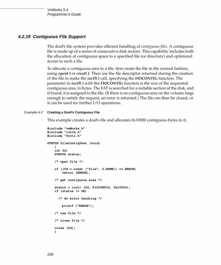
VxWorks 5.4Programmer’s Guide
4.2.19 Contiguous File Support
The dosFs file system provides efficient handling of contiguous files. A contiguous
file is made up of a series of consecutive disk sectors. This capability includes both
the allocation of contiguous space to a specified file (or directory) and optimized
access to such a file.
To allocate a contiguous area to a file, first create the file in the normal fashion,
using open( ) or creat( ). Then use the file descriptor returned during the creation
of the file to make the ioctl( ) call, specifying the FIOCONTIG function. The
parameter to ioctl( ) with the FIOCONTIG function is the size of the requested
contiguous area, in bytes. The FAT is searched for a suitable section of the disk, and
if found, it is assigned to the file. (If there is no contiguous area on the volume large
enough to satisfy the request, an error is returned.) The file can then be closed, or
it can be used for further I/O operations.
Example 4-2 Creating a DosFs Contiguous File
This example creates a dosFs file and allocates 0x10000 contiguous bytes to it.
#include "vxWorks.h"#include "ioLib.h"#include "fcntl.h"
STATUS fileContigTest (void){int fd;STATUS status;
/* open file */
if ((fd = creat ("file", O_RDWR)) == ERROR)return (ERROR);
/* get contiguous area */
status = ioctl (fd, FIOCONTIG, 0x10000);if (status != OK)
/* do error handling */
printf ("ERROR");
/* use file */
/* close file */
close (fd);}
200

4
4Local File Systems
It is also possible to request the largest available contiguous space. Use
CONTIG_MAX for the size of the contiguous area. For example:
status = ioctl (fd, FIOCONTIG, CONTIG_MAX);
It is important that the file descriptor used for the ioctl( ) call be the only descriptor
open to the file. Furthermore, because a file can be assigned a different area of the
disk than is originally allocated, perform the ioctl( ) FIOCONTIG operation before
any data is written to the file.
To deallocate unused reserved bytes, use the POSIX-compatible routine
ftruncate( ) or the ioctl( ) function FIOTRUNC.
Subdirectories can also be allocated a contiguous disk area in the same manner. If
the directory is created using the ioctl( ) function FIOMKDIR, it must be explicitly
opened to obtain a file descriptor to it; if the directory is created using options to
open( ), the returned file descriptor from that call can be used. A directory must be
empty (except for the “.” and “..” entries) when it has contiguous space allocated
to it.
When any file is opened, it is checked for contiguity. If a file is recognized as
contiguous, a more efficient technique for locating specific sections of the file is
used, rather than following cluster chains in the FAT, as must be done for
fragmented files. This enhanced handling of contiguous files takes place regardless
of whether the space is explicitly allocated using FIOCONTIG.
To find the maximum contiguous area on a device, use the ioctl( ) function
FIONCONTIG. This information can also be displayed by dosFsConfigShow( ).
Example 4-3 Finding the Maximum Contiguous Area on a DosFs Device
In this example, the size (in bytes) of the largest contiguous area is copied to the
integer pointed to by the third parameter to ioctl( ) (count).
#include "vxWorks.h"#include "fcntl.h"#include "ioLib.h"
STATUS contigTest (void){int count;int fd;
/* open device in raw mode */if ((fd = open ("/DEV1/", O_RDONLY, 0)) == ERROR)
return (ERROR);
/* find max contiguous area */ioctl (fd, FIONCONTIG, &count);
201

VxWorks 5.4Programmer’s Guide
/* close device and display size of largest contiguous area */close (fd);printf ("largest contiguous area = %d\n", count);}
4.2.20 I/O Control Functions Supported by dosFsLib
The dosFs file system supports the ioctl( ) functions listed in Table 4-5. These
functions are defined in the header file ioLib.h. For more information, see the
manual entries for dosFsLib and for ioctl( ) in ioLib.
Table 4-5 I/O Control Functions Supported by dosFsLib
FunctionDecimal
ValueDescription
FIOATTRIBSET 35 Set the file-attribute byte in the dosFs directory entry.
FIOCONTIG 36 Allocate contiguous disk space for a file or directory.
FIODISKCHANGE 13 Announce a media change.
FIODISKFORMAT 5 Format the disk (device driver function).
FIODISKINIT 6 Initialize a dosFs file system on a disk volume.
FIOFLUSH 2 Flush the file output buffer.
FIOFSTATGET 38 Get file status information (directory entry data).
FIOGETNAME 18 Get the file name of the fd.
FIOLABELGET 33 Get the volume label.
FIOLABELSET 34 Set the volume label.
FIOMKDIR 31 Create a new directory.
FIONCONTIG 41 Get the size of the maximum contiguous area on a device.
FIONFREE 30 Get the number of free bytes on the volume.
FIONREAD 1 Get the number of unread bytes in a file.
FIOREADDIR 37 Read the next directory entry.
FIORENAME 10 Rename a file or directory.
FIORMDIR 32 Remove a directory.
202

4
4Local File Systems
4.2.21 Booting from a Local dosFs File System Using SCSI
VxWorks can be booted from a local SCSI device. Before you can boot from SCSI,
you must make new boot ROMs that contain the SCSI library. Define
INCLUDE_SCSI in the project facility and INCLUDE_SCSI_BOOT in config.h and
rebuild bootrom.hex. (For configuration information, see 8.5 Configuring VxWorks,
p.337; INCLUDE_SCSI_BOOT can only be configured in config.h. For boot ROM
information, see 8.9 Creating Bootable Applications, p.364.)
After burning the SCSI boot ROMs, you can prepare the dosFs file system for use
as a boot device. The simplest way to do this is to partition the SCSI device so that
a dosFs file system starts at block 0. You can then make the new vxWorks image,
place it on your SCSI boot device, and boot the new VxWorks system. These steps
are shown in more detail below.
1. Create the SCSI device using scsiPhysDevCreate( ) (see SCSI Drivers, p.129),
and initialize the disk with a dosFs file system (see 4.2.2 Initializing the dosFsFile System, p.181). Modify the file installDir/target/src/config/usrScsiConfig.cto reflect your SCSI configuration. The following example creates a SCSI
device with a dosFs file system spanning the full device:
pPhysDev = scsiPhysDevCreate (pSysScsiCtrl, 2, 0, 0, -1, 0, 0, 0);pBlkDev = scsiBlkDevCreate (pPhysDev, 0, 0);dosFsDevInit ("/sd0/", pBlkDev, 0);
FIOSEEK 7 Set the current byte offset in a file.
FIOSYNC 21 Same as FIOFLUSH, but also re-reads buffered file data.
FIOTRUNC 42 Truncate a file to a specified length.
FIOUNMOUNT 39 Unmount a disk volume.
FIOWHERE 8 Return the current byte position in a file.
! WARNING: For use as a boot device, the directory name for the dosFs file system
must begin and end with slashes (as with /sd0/ used in the following example).
This is an exception to the usual naming convention for dosFs file systems and is
incompatible with the NFS requirement that device names not end in a slash.
Table 4-5 I/O Control Functions Supported by dosFsLib (Continued)
FunctionDecimal
ValueDescription
203
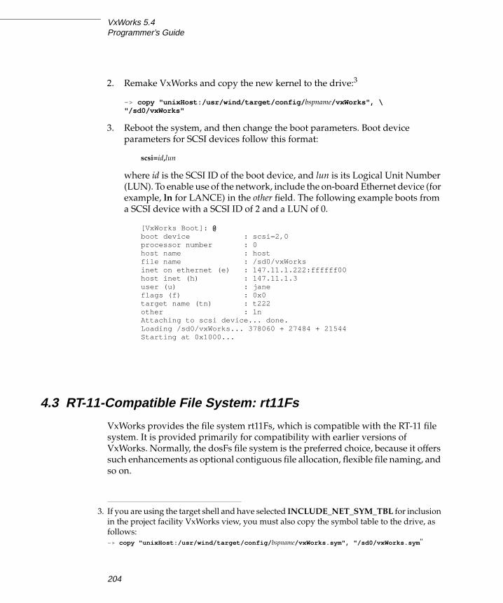
VxWorks 5.4Programmer’s Guide
2. Remake VxWorks and copy the new kernel to the drive:3
-> copy "unixHost:/usr/wind/target/config/ bspname/vxWorks", \"/sd0/vxWorks"
3. Reboot the system, and then change the boot parameters. Boot device
parameters for SCSI devices follow this format:
scsi=id,lun
where id is the SCSI ID of the boot device, and lun is its Logical Unit Number
(LUN). To enable use of the network, include the on-board Ethernet device (for
example, ln for LANCE) in the other field. The following example boots from
a SCSI device with a SCSI ID of 2 and a LUN of 0.
[VxWorks Boot]: @boot device : scsi=2,0processor number : 0host name : hostfile name : /sd0/vxWorksinet on ethernet (e) : 147.11.1.222:ffffff00host inet (h) : 147.11.1.3user (u) : janeflags (f) : 0x0target name (tn) : t222other : lnAttaching to scsi device... done.Loading /sd0/vxWorks... 378060 + 27484 + 21544Starting at 0x1000...
4.3 RT-11-Compatible File System: rt11Fs
VxWorks provides the file system rt11Fs, which is compatible with the RT-11 file
system. It is provided primarily for compatibility with earlier versions of
VxWorks. Normally, the dosFs file system is the preferred choice, because it offers
such enhancements as optional contiguous file allocation, flexible file naming, and
so on.
3. If you are using the target shell and have selected INCLUDE_NET_SYM_TBL for inclusion
in the project facility VxWorks view, you must also copy the symbol table to the drive, as
follows:
-> copy "unixHost:/usr/wind/target/config/ bspname/vxWorks.sym", "/sd0/vxWorks.sym "
204
4
4Local File Systems
4.3.1 Disk Organization
The rtllFs file system uses a simple disk organization. Although this simplicity
results in some loss of flexibility, rt11Fs is suitable for many real-time applications.
The rt11Fs file system maintains only contiguous files. A contiguous file consists of
a series of disk sectors that are consecutive. Contiguous files are well-suited to real-
time applications because little time is spent locating specific portions of a file. The
disadvantage of using contiguous files exclusively is that a disk can gradually
become fragmented, reducing the efficiency of the disk space allocation.
The rt11Fs disk format uses a single directory to describe all files on the disk. The
size of this directory is limited to a fixed number of directory entries. Along with
regular files, unused areas of the disk are also described by special directory
entries. These special entries are used to keep track of individual sections of free
space on the disk.
4.3.2 Initializing the rt11Fs File System
Before any other operations can be performed, the rt11Fs file system library,
rt11FsLib, must be initialized by calling rt11FsInit( ). This routine takes a single
parameter, the maximum number of rt11Fs file descriptors that can be open at one
time. This count is used to allocate a set of descriptors; a descriptor is used each
time a file or an rt11Fs device is opened.
The rt11FsInit( ) routine also makes an entry for the rt11Fs file system in the I/O
system driver table (with iosDrvInstall( )). This entry specifies entry points for the
rt11Fs file operations and is used for all devices that use the rt11Fs file system. The
driver number assigned to the rt11Fs file systems is placed in a global variable
rt11FsDrvNum.
The rt11FsInit( ) routine is normally called by the usrRoot( ) task after starting the
VxWorks system. To use this initialization, make sure INCLUDE_RT11FS is selected
for inclusion in the project facility VxWorks view, and set NUM_RT11FS_FILES to
the desired maximum open file count in the Params tab of the properties window.
! WARNING: The rt11Fs file system is considered obsolescent. In a future release of
VxWorks, rt11Fs may not be supported.
205

VxWorks 5.4Programmer’s Guide
4.3.3 Initializing a Device for Use with rt11Fs
After the rt11Fs file system is initialized, the next step is to create one or more
devices. Devices are created by the device driver’s device creation routine
(xxDevCreate( )). The driver routine returns a pointer to a block device descriptor
structure (BLK_DEV). The BLK_DEV structure describes the physical aspects of the
device and specifies the routines in the device driver that a file system can call. For
more information about block devices, see 3.9.4 Block Devices, p.158.
Immediately after its creation, the block device has neither a name nor a file system
associated with it. To initialize a block device for use with rt11Fs, the already-
created block device must be associated with rt11Fs and must have a name
assigned to it. This is done with rt11FsDevInit( ). Its parameters are:
– the name to be used to identify the device
– a pointer to the BLK_DEV structure
– a boolean value indicating whether the disk uses standard RT-11 skew and
interleave
– the number of entries to be used in the disk directory (in some cases, the actual
number used is greater than the number specified)
– a boolean value indicating whether this disk is subject to being changed
without notification to the file system
For example:
RT_VOL_DESC *pVolDesc;pVolDesc = rt11FsDevInit ("DEV1:", pBlkDev, rtFmt, nEntries, changeNoWarn);
The rt11FsDevInit( ) call assigns the specified name to the device and enters the
device in the I/O system device table (with iosDevAdd( )). It also allocates and
initializes the file system’s volume descriptor for the device. It returns a pointer to
the volume descriptor to the caller; this pointer is used to identify the volume
during some file system calls.
Note that initializing the device for use with the rt11Fs file system does not format
the disk, nor does it initialize the rt11Fs disk directory. These are done using ioctl( )with the functions FIODISKFORMAT and FIODISKINIT, respectively.
206

4
4Local File Systems
4.3.4 Mounting Volumes
A disk volume is mounted automatically, generally during the first open( ) or
creat( ) for a file or directory on the disk. (Certain ioctl( ) functions also cause the
disk to be mounted.) When a disk is mounted, the directory data is read it.
Automatic mounting reoccurs on the first file access following a ready-change
operation (see 4.3.8 Changing Disks, p.208) or periodically if the disk is defined
during the rt11FsDevInit( ) call with the changeNoWarn parameter set to TRUE.
Automatic mounting does not occur when a disk is opened in raw mode. For more
information, see 4.3.6 Opening the Whole Device (Raw Mode), p.207.
4.3.5 File I/O
Files on an rt11Fs file system device are created, deleted, written, and read using
the standard VxWorks I/O routines: creat( ), remove( ), write( ), and read( ). The
size of an rt11Fs file is determined during its initial open( ) or creat( ). Once closed,
additional space cannot be allocated to the file. For more information, see 3.3 BasicI/O, p.98.
4.3.6 Opening the Whole Device (Raw Mode)
It is possible to open an entire rt11Fs volume by specifying only the device name
during the open( ) or creat( ) call. A file descriptor is returned, as when opening a
regular file; however, operations on that file descriptor affect the entire device.
Opening the entire volume in this manner is called raw mode.
The most common reason for opening the entire device is to obtain a file descriptor
to perform an ioctl( ) function that does not pertain to an individual file. An
example is the FIOSQUEEZE function, which combines fragmented free space
across the entire volume.
When a disk is initialized with an rt11Fs directory, open the device in raw mode.
The ioctl( ) function FIODISKINIT performs the initialization.
A disk can be read or written in raw mode. In this case, the entire disk area is
treated much like a single large file. No directory entry is made to describe any
! CAUTION: Because device names are recognized by the I/O system using simple
substring matching, file systems should not use a slash (/) alone as a name;
unexpected results may occur.
207

VxWorks 5.4Programmer’s Guide
data written using raw mode, and care must be taken to avoid overwriting the
regular rt11Fs directory at the beginning of the disk. This type of I/O is also
provided by rawFsLib.
4.3.7 Reclaiming Fragmented Free Disk Space
As previously mentioned, the contiguous file allocation scheme used by the rt11Fs
file system can gradually result in disk fragmentation. In this situation, the
available free space on the disk is scattered in a number of small chunks. This
reduces the ability of the system to create new files.
To correct this condition, rt11FsLib includes the ioctl( ) function FIOSQUEEZE.
This routine moves files so that the free space is combined at the end of the disk.
When you call ioctl( ) with FIOSQUEEZE, it is critical that there be no open files on
the device. With large disks, this call may require considerable time to execute.
4.3.8 Changing Disks
To increase performance, rt11Fs keeps copies of directory entries for each volume
in memory. While this greatly speeds up access to files, it requires that rt11FsLibbe notified when removable disks are changed (for example, when floppies are
swapped). This notification is provided by the ready-change mechanism.
Announcing Disk Changes with Ready-Change
A change in ready-status is interpreted by rt11FsLib to mean that the disk must be
remounted during the next I/O operation. There are three ways to announce a
ready-change:
■ By calling rt11FsReadyChange( ) directly.
■ By calling ioctl( ) with FIODISKCHANGE.
■ By having the device driver set the bd_readyChanged field in the BLK_DEVstructure to TRUE; this has the same effect as notifying rt11FsLib directly.
The ready-change announcement does not cause buffered data to be flushed to the
disk; it merely marks the volume as needing remounting. As a result, data written
to files or directory entry changes can be lost. To avoid this loss of data, close all
files on the volume before changing the disk.
208

4
4Local File Systems
Ready-change can be used in ISRs, because it does not attempt to flush data or
perform other operations that could cause delay.
The block device driver status-check routine (identified by the bd_statusChk field
in the BLK_DEV structure) can be useful for asserting ready-change for devices that
only detect a disk change after the new disk is inserted. This routine is called at the
start of each open( ) or creat( ), before the file system checks for ready-change.
Disks with No Change Notification
If it is not possible for a ready-change to be announced each time the disk is
changed, the device must be specially identified when it is initialized for use with
the file system. This is done by setting the changeNoWarn parameter to TRUE
when calling rt11FsDevInit( ).
When this parameter is defined as TRUE, the disk is checked regularly to obtain
the current directory information (in case the disk is removed and a new one
inserted). As a result, this option causes a significant loss in performance.
4.3.9 I/O Control Functions Supported by rt11FsLib
The rt11Fs file system supports the ioctl( ) functions shown in Table 4-6. The
functions listed are defined in the header file ioLib.h. For more information, see
the manual entries for rt11FsLib and for ioctl( ) in ioLib.
4.4 Raw File System: rawFs
VxWorks provides a minimal “file system,” rawFs, for use in systems that require
only the most basic disk I/O functions. The rawFs file system, implemented in
rawFsLib, treats the entire disk volume much like a single large file. Although the
dosFs and rt11Fs file systems do provide this ability to varying degrees, the rawFs
file system offers advantages in size and performance if more complex functions
are not required.
209

VxWorks 5.4Programmer’s Guide
4.4.1 Disk Organization
As mentioned previously, rawFs imposes no organization of the data on the disk.
The rawFs file system maintains no directory information; thus there is no division
of the disk area into specific files, and no file names are used. All open( ) operations
on rawFs devices specify only the device name; no additional file names are
allowed.
The entire disk area is available to any file descriptor that is open for the device.
All read and write operations to the disk use a byte-offset relative to the start of the
first block on the disk.
Table 4-6 I/O Control Functions Supported by rt11FsLib
FunctionDecimal
ValueDescription
FIODIRENTRY 9 Get information about specified device directory entries.
FIODISKCHANGE 13 Announce a media change.
FIODISKFORMAT 5 Format the disk.
FIODISKINIT 6 Initialize an rt11Fs file system on a disk volume.
FIOFLUSH 2 Flush the file output buffer.
FIOFSTATGET 38 Get file status information (directory entry data).
FIOGETNAME 18 Get the file name of the fd.
FIONREAD 1 Get the number of unread bytes in a file.
FIOREADDIR 37 Read the next directory entry.
FIORENAME 10 Rename a file.
FIOSEEK 7 Reset the current byte offset in a file.
FIOSQUEEZE 15 Coalesce fragmented free space on an rt11Fs volume.
FIOWHERE 8 Return the current byte position in a file.
210

4
4Local File Systems
4.4.2 Initializing the rawFs File System
Before any other operations can be performed, the rawFs library, rawFsLib, must
be initialized by calling rawFsInit( ). This routine takes a single parameter, the
maximum number of rawFs file descriptors that can be open at one time. This
count is used to allocate a set of descriptors; a descriptor is used each time a rawFs
device is opened.
The rawFsInit( ) routine also makes an entry for the rawFs file system in the I/O
system driver table (with iosDrvInstall( )). This entry specifies the entry points for
rawFs file operations and is for all devices that use the rawFs file system. The
driver number assigned to the rawFs file systems is placed in a global variable
rawFsDrvNum.
The rawFsInit( ) routine is normally called by the usrRoot( ) task after starting the
VxWorks system. To use this initialization, define INCLUDE_RAWFS in the project
facility VxWorks view, and set NUM_RAWFS_FILES to the desired maximum open
file descriptor count on the Params tab of the properties window.
4.4.3 Initializing a Device for Use with the rawFs File System
After the rawFs file system is initialized, the next step is to create one or more
devices. Devices are created by the device driver’s device creation routine
(xxDevCreate( )). The driver routine returns a pointer to a block device descriptor
structure (BLK_DEV). The BLK_DEV structure describes the physical aspects of the
device and specifies the routines in the device driver that a file system can call. For
more information on block devices, see 3.9.4 Block Devices, p.158.
Immediately after its creation, the block device has neither a name nor a file system
associated with it. To initialize a block device for use with rawFs, the already-
created block device must be associated with rawFs and a name must be assigned
to it. This is done with the rawFsDevInit( ) routine. Its parameters are the name to
be used to identify the device and a pointer to the block device descriptor structure
(BLK_DEV):
RAW_VOL_DESC *pVolDesc;BLK_DEV *pBlkDev;pVolDesc = rawFsDevInit ("DEV1:", pBlkDev);
The rawFsDevInit( ) call assigns the specified name to the device and enters the
device in the I/O system device table (with iosDevAdd( )). It also allocates and
initializes the file system’s volume descriptor for the device. It returns a pointer to
211

VxWorks 5.4Programmer’s Guide
the volume descriptor to the caller; this pointer is used to identify the volume
during certain file system calls.
Note that initializing the device for use with rawFs does not format the disk. That
is done using an ioctl( ) call with the FIODISKFORMAT function.
No disk initialization (FIODISKINIT) is required, because there are no file system
structures on the disk. Note, however, that rawFs accepts that ioctl( ) function code
for compatibility with other file systems; in such cases, it performs no action and
always returns OK.
4.4.4 Mounting Volumes
A disk volume is mounted automatically, generally during the first open( ) or
creat( ) operation. (Certain ioctl( ) functions also cause the disk to be mounted.)
The volume is again mounted automatically on the first disk access following a
ready-change operation (see 4.4.6 Changing Disks, p.213).
4.4.5 File I/O
To begin I/O to a rawFs device, first open the device using the standard open( )function. (The creat( ) function can be used instead, although nothing is actually
“created.”) Data on the rawFs device is written and read using the standard I/O
routines write( ) and read( ). For more information, see 3.3 Basic I/O, p.98.
The character pointer associated with a file descriptor (that is, the byte offset where
reads and writes take place) can be set by using ioctl( ) with the FIOSEEK function.
Multiple file descriptors can be open simultaneously for a single device. These
must be carefully managed to avoid modifying data that is also being used by
another file descriptor. In most cases, such multiple open descriptors use FIOSEEKto set their character pointers to separate disk areas.
! CAUTION: Because device names are recognized by the I/O system using simple
substring matching, file systems should not use a slash (/) alone as a name;
unexpected results may occur.
212

4
4Local File Systems
4.4.6 Changing Disks
The rawFs file system must be notified when removable disks are changed (for
example, when floppies are swapped). Two different notification methods are
provided: (1) rawFsVolUnmount( ) and (2) the ready-change mechanism.
Unmounting Volumes
The first method of announcing a disk change is to call rawFsVolUnmount( ) prior
to removing the disk. This call flushes all modified file descriptor buffers if possible
(see Synchronizing Volumes, p.214) and also marks any open file descriptors as
obsolete. The next I/O operation remounts the disk. Calling ioctl( ) with
FIOUNMOUNT is equivalent to using rawFsVolUnmount( ). Any open file
descriptor to the device can be used in the ioctl( ) call.
Attempts to use obsolete file descriptors for further I/O operations produce an
S_rawFsLib_FD_OBSOLETE error. To free an obsolete descriptor, use close( ), as
usual. This frees the descriptor even though it produces the same error.
ISRs must not call rawFsVolUnmount( ) directly, because the call can pend while
the device becomes available. The ISR can instead give a semaphore that prompts
a task to unmount the volume. (Note that rawFsReadyChange( ) can be called
directly from ISRs; see Announcing Disk Changes with Ready-Change, p.213.)
When rawFsVolUnmount( ) is called, it attempts to write buffered data out to the
disk. Its use is therefore inappropriate for situations where the disk-change
notification does not occur until a new disk is inserted, because the old buffered
data would be written to the new disk. In this case, use rawFsReadyChange( ),which is described in Announcing Disk Changes with Ready-Change, p.213.
If rawFsVolUnmount( ) is called after the disk is physically removed, the data
flushing portion of its operation fails. However, the file descriptors are still marked
as obsolete, and the disk is marked as requiring remounting. An error is notreturned by rawFsVolUnmount( ); to avoid lost data in this situation, explicitly
synchronize the disk before removing it (see Synchronizing Volumes, p.214).
Announcing Disk Changes with Ready-Change
The second method of announcing that a disk change is taking place is with the
ready-change mechanism. A change in the disk’s ready-status is interpreted by
rawFsLib to indicate that the disk must be remounted during the next I/O call.
213

VxWorks 5.4Programmer’s Guide
There are three ways to announce a ready-change:
■ By calling rawFsReadyChange( ) directly.
■ By calling ioctl( ) with FIODISKCHANGE.
■ By having the device driver set the bd_readyChanged field in the BLK_DEVstructure to TRUE; this has the same effect as notifying rawFsLib directly.
The ready-change announcement does not cause buffered data to be flushed to the
disk. It merely marks the volume as needing remounting. As a result, data written
to files can be lost. This can be avoided by synchronizing the disk before asserting
ready-change. The combination of synchronizing and asserting ready-change
provides all the functionality of rawFsVolUnmount( ) except for marking file
descriptors as obsolete.
Ready-change can be used in ISRs, because it does not attempt to flush data or
perform other operations that could cause delay.
The block device driver status-check routine (identified by the bd_statusChk field
in the BLK_DEV structure) is useful for asserting ready-change for devices that
only detect a disk change after the new disk is inserted. This routine is called at the
beginning of each open( ) or creat( ), before the file system checks for ready-
change.
Disks with No Change Notification
If it is not possible for a ready-change to be announced each time the disk is
changed, close all file descriptors for the volume before changing the disk.
Synchronizing Volumes
When a disk is synchronized, all buffered data that is modified is written to the
physical device so that the disk is up to date. For the rawFs file system, the only
such data is that contained in open file descriptor buffers.
To avoid loss of data, synchronize a disk before removing it. You may need to
explicitly synchronize a disk, depending on when (or if) the rawFsVolUnmount( )call is issued.
When rawFsVolUnmount( ) is called, an attempt is made to synchronize the device
before unmounting. If this disk is still present and writable at the time of the call,
synchronization takes place automatically; there is no need to synchronize the disk
explicitly.
214

4
4Local File Systems
However, if the rawFsVolUnmount( ) call is made after a disk is removed, it is
obviously too late to synchronize, and rawFsVolUnmount( ) discards the buffered
data. Therefore, make a separate ioctl( ) call with the FIOSYNC function before
removing the disk. (For example, this could be done in response to an operator
command.) Any open file descriptor to the device can be used during the ioctl( )call. This call writes all modified file descriptor buffers for the device out to the
disk.
4.4.7 I/O Control Functions Supported by rawFsLib
The rawFs file system supports the ioctl( ) functions shown in Table 4-7. The
functions listed are defined in the header file ioLib.h. For more information, see
the manual entries for rawFsLib and for ioctl( ) in ioLib.
Table 4-7 I/O Control Functions Supported by rawFsLib
FunctionDecimal
ValueDescription
FIODISKCHANGE 13 Announce a media change.
FIODISKFORMAT 5 Format the disk (device driver function).
FIODISKINIT 6 Initialize a rawFs file system on a disk volume (not required).
FIOFLUSH 2 Same as FIOSYNC.
FIOGETNAME 18 Get the file name of the fd.
FIONREAD 1 Get the number of unread bytes on the device.
FIOSEEK 7 Set the current byte offset on the device.
FIOSYNC 21 Write out all modified file descriptor buffers.
FIOUNMOUNT 39 Unmount a disk volume.
FIOWHERE 8 Return the current byte position on the device.
215

VxWorks 5.4Programmer’s Guide
4.5 Tape File System: tapeFs
The tapeFs library, tapeFsLib, provides basic services for tape devices that do not
use a standard file or directory structure on tape. The tape volume is treated much
like a raw device where the entire volume is a large file. Any data organization on
this large file is the responsibility of a higher-level layer.
4.5.1 Tape Organization
The tapeFs file system imposes no organization of the data on the tape volume. It
maintains no directory information; there is no division of the tape area into
specific files; and no file names are used. An open( ) operation on the tapeFs device
specifies only the device name; no additional file names are allowed.
The entire tape area is available to any file descriptor open for the device. All read
and write operations to the tape use a location offset relative to the current location
of the tape head. When a file is configured as a rewind device and first opened, tape
operations begin at the beginning-of-medium (BOM); see Initializing a Device forUse with the tapeFs File System, p.217. Thereafter, all operations occur relative to
where the tape head is located at that instant of time. No location information, as
such, is maintained by tapeFs.
4.5.2 Using the tapeFs File System
Before tapeFs can be used, it must be configured by defining INCLUDE_TAPEFS in
the BSP file config.h. (See 8.5 Configuring VxWorks, p.337.) Note that the tape file
system must be configured with SCSI-2 enabled. See Configuring SCSI Drivers,
p.129 for configuration details.
Once the tape file system has been configured, you must initialize it and then
define a tape device. Once the device is initialized, the physical tape device is
available to the tape file system and normal I/O system operations can be
performed.
Initializing the tapeFs File System
The tapeFs library, tapeFsLib, is initialized by calling tapeFsInit( ). Each tape file
system can handle multiple tape devices. However, each tape device is allowed
only one file descriptor. Thus you cannot open two files on the same tape device.
216

4
4Local File Systems
The tapeFsInit( ) routine also makes an entry for the tapeFs file system in the I/O
system driver table (with iosDrvInstall( )). This entry specifies function pointers
to carry out tapeFs file operations on devices that use the tapeFs file system. The
driver number assigned to the tapeFs file system is placed in a global variable,
tapeFsDrvNum.
When initializing a tape device, tapeFsInit( ) is called automatically if
tapeFsDevInit( ) is called; thus, the tape file system does not require explicit
initialization.
Initializing a Device for Use with the tapeFs File System
Once the tapeFs file system has been initialized, the next step is to create one or
more devices that can be used with it. This is done using the sequential device
creation routine, scsiSeqDevCreate( ). The driver routine returns a pointer to a
sequential device descriptor structure, SEQ_DEV. The SEQ_DEV structure
describes the physical aspects of the device and specifies the routines in the device
driver that tapeFs can call. For more information on sequential devices, see the
manual entry for scsiSeqDevCreate( ), Configuring SCSI Drivers, p.129, 3.9.4 BlockDevices, p.158, and Example 3-6.
Immediately after its creation, the sequential device has neither a name nor a file
system associated with it. To initialize a sequential device for use with tapeFs, call
tapeFsDevInit( ) to assign a name and declare a file system. Its parameters are the
volume name, for identifying the device; a pointer to SEQ_DEV, the sequential
device descriptor structure; and a pointer to an initialized tape configuration
structure TAPE_CONFIG. This structure has the following form:
typedef struct /* TAPE_CONFIG tape device config structure */{int blkSize; /* block size; 0 => var. block size */BOOL rewind; /* TRUE => a rewind device; FALSE => no rewind */int numFileMarks; /* not used */int density; /* not used */} TAPE_CONFIG;
In the preceding definition of TAPE_CONFIG, only two fields, blkSize and rewind,
are currently in use. If rewind is TRUE, then a tape device is rewound to the
beginning-of-medium (BOM) upon closing a file with close( ). However, if rewindis FALSE, then closing a file has no effect on the position of the read/write head on
the tape medium.
For more information on initializing a tapeFs device, see the online reference for
tapeFsDevInit( ) under VxWorks Reference Manual>Libraries.
217

VxWorks 5.4Programmer’s Guide
The blkSize field specifies the block size of the physical tape device. Having set the
block size, each read or write operation has a transfer unit of blkSize. Tape devices
can perform fixed or variable block transfers, a distinction also captured in the
blkSize field.
Fixed Block and Variable Block Devices
A tape file system can be created for fixed block size transfers or variable block size
transfers, depending on the capabilities of the underlying physical device. The
type of data transfer (fixed block or variable block) is usually decided when the
tape device is being created in the file system, that is, before the call to
tapeFsDevInit( ). A block size of zero represents variable block size data transfers.
Once the block size has been set for a particular tape device, it is usually not
modified. To modify the block size, use the ioctl( ) functions FIOBLKSIZESET and
FIOBLKSIZEGET to set and get the block size on the physical device.
Note that for fixed block transfers, the tape file system buffers a block of data. If the
block size of the physical device is changed after a file is opened, the file should
first be closed and then re-opened in order for the new block size to take effect.
Example 4-4 Tape Device Configuration
There are many ways to configure a tape device. In this code example, a tape
device is configured with a block size of 512 bytes and the option to rewind the
device at the end of operations.
/* global variables assigned elsewhere */
SCSI_PHYS_DEV * pScsiPhysDev;
/* local variable declarations */
TAPE_VOL_DESC * pTapeVol;SEQ_DEV * pSeqDev;TAPE_CONFIG pTapeConfig;
/* initialization code */
pTapeConfig.blkSize = 512;pTapeConfig.rewind = TRUE;pSeqDev = scsiSeqDevCreate (pScsiPhysDev);pTapeVol = tapeFsDevInit ("/tape1", pSeqDev, pTapeConfig);
The tapeFsDevInit( ) call assigns the specified name to the device and enters the
device in the I/O system device table (with iosDevAdd( )). The return value of this
routine is a pointer to a volume descriptor structure that contains volume-specific
configuration and state information.
218

4
4Local File Systems
Mounting Volumes
A tape volume is mounted automatically during the open( ) operation. There is no
specific mount operation, that is, the mount is implicit in the open( ) operation.
Modes of Operation
The tapeFs tape volumes can be operated in only one of two modes: read-only
(O_RDONLY) or write-only (O_WRONLY). There is no read-write mode. The mode
of operation is defined when the file is opened using open( ).
File I/O
To begin I/O to a tapeFs device, the device is first opened using open( ). Data on
the tapeFs device is written and read using the standard I/O routines write( ) and
read( ). For more information, see 3.7.6 Block Devices, p.127.
End-of-file markers can be written using ioctl( ) with the MTWEOF function. For
more information, see I/O Control Functions Supported by tapeFsLib, p.220.
Changing Tapes
The tapeFs file system should be notified when removable media are changed (for
example, when tapes are swapped). The tapeFsVolUnmount( ) routine controls the
mechanism to unmount a tape volume.
A tape should be unmounted before it is removed. Prior to unmounting a tape
volume, an open file descriptor must be closed. Closing an open file flushes any
buffered data to the tape, thus synchronizing the file system with the data on the
tape. To flush or synchronize data, call ioctl( ) with the FIOFLUSH or FIOSYNCfunctions, prior to closing the file descriptor.
After closing any open file, call tapeFsVolUnmount( ) before removing the tape.
Once a tape has been unmounted, the next I/O operation must remount the tape
using open( ).
! CAUTION: Because device names are recognized by the I/O system using simple
substring matching, file systems should not use a slash (/) alone as a name;
unexpected results may occur.
219

VxWorks 5.4Programmer’s Guide
Interrupt handlers must not call tapeFsVolUnmount( ) directly, because it is
possible for the call to pend while the device becomes available. The interrupt
handler can instead give a semaphore that prompts a task to unmount the volume.
I/O Control Functions Supported by tapeFsLib
The tapeFs file system supports the ioctl( ) functions shown in Table 4-8. The
functions listed are defined in the header files ioLib.h, seqIo.h, and tapeFsLib.h.For more information, see the reference entries for tapeFsLib, ioLib, and ioctl( ).
The MTIOCTOP operation is compatible with the UNIX MTIOCTOP operation. The
argument passed to ioctl( ) with MTIOCTOP is a pointer to an MTOP structure that
contains the following two fields:
typedef struct mtop{short mt_op; /* operation */int mt_count; /* number of operations */} MTOP;
The mt_op field contains the type of MTIOCTOP operation to perform. These
operations are defined in Table 4-9. The mt_count field contains the number of
times the operation defined in mt_op should be performed.
Table 4-8 I/O Control Functions Supported by tapeFsLib
Function Value Meaning
FIOFLUSH 2 Write out all modified file descriptor buffers.
FIOSYNC 21 Same as FIOFLUSH.
FIOBLKSIZEGET 1001 Get the actual block size of the tape device by issuing a
driver command to it. Check this value with that set in
the SEQ_DEV data structure.
FIOBLKSIZESET 1000 Set the block size of the tape device on the device and in
the SEQ_DEV data structure.
MTIOCTOP 1005 Perform a UNIX-like MTIO operation to the tape
device. The type of operation and operation count is set
in an MTIO structure passed to the ioctl( ) routine. The
MTIO operations are defined in Table 4-9.
220

4
4Local File Systems
4.6 CD-ROM File System: cdromFs
The cdromFs library, cdromFsLib, lets applications read any CD-ROM that is
formatted in accordance with ISO 9660 file system standards. After initializing
cdromFs and mounting it on a CD-ROM block device, you can access data on that
device using the standard POSIX I/O calls: open( ), close( ), read( ), ioctl( ),readdir( ), and stat( ). The write( ) call always returns an error.
The cdromFs utility supports multiple drives, multiple open files, and concurrent
file access. When you specify a pathname, cdromFS accepts both “/” and “\”.
However, the backslash is not recommended because it might not be supported in
future releases.
The strict ISO 9660 specification allows only uppercase file names consisting of 8
characters plus a 3-character suffix.
Table 4-9 MTIOCTOP Operations
Function Value Meaning
MTWEOF 0 Write an end-of-file record or “file mark.”
MTFSF 1 Forward space over file mark.
MTBSF 2 Backward space over file mark.
MTFSR 3 Forward space over data block.
MTBSR 4 Backward space over data block.
MTREW 5 Rewind the tape device to the beginning-of-medium.
MTOFFL 6 Rewind and put the drive offline.
MTNOP 7 No operation, sets status in the SEQ_DEV structure only.
MTRETEN 8 Re-tension the tape (cartridge tape only).
MTERASE 9 Erase the entire tape.
MTEOM 10 Position tape to end-of-media.
MTNBSF 11 Backward space file to beginning-of-medium.
221

VxWorks 5.4Programmer’s Guide
CdromFs provides access to CD-ROM file systems using any standard BLK_DEVstructure. The basic initialization sequence is similar to installing a dosFs file
system on a SCSI device.
Before cdromFs can be used, it must be configured by defining
INCLUDE_CDROMFS in config.h. (See 8.5 Configuring VxWorks, p.337.) For
information on using cdromFs, see the online reference for cdromFsLib under
VxWorks Reference Manual>Libraries.
4.7 The Target Server File System: TSFS
The Target Server File System (TSFS) is a full-featured VxWorks file system, but the
files operated on by using the file system are actually located on the host. TSFS uses
a WDB driver to transfer requests from the I/O system to the target server. The
target server reads the request and executes it using the host file system. Thus
when you open a file with TSFS, the file being opened is actually on the host.
Future read( ) and write( ) calls on the file descriptor obtained from the open( ) call
actually read from and write to the opened host file.
The TSFS VIO driver is oriented toward file I/O rather than toward console
operations as is the Tornado 1.0 VIO driver. TSFS provides all the I/O features that
netDrv provides, without requiring any target resource beyond what is already
configured to support communication between target and target server. It is
possible to access host files randomly without copying the entire file to the target,
to load an object module from a virtual file source, and to supply the file name to
routines such as ld( ) and copy( ).
How It Works
Two steps are required to configure TSFS. First, TSFS must be included in your
VxWorks image. This creates a new file system entry, /tgtsvr. Then the target server
must be configured for TSFS, which involves assigning a root directory on your
host to TSFS. For example, you could set the TSFS root to c:\windview\logs.
Having done this, opening the file /tgtsvr/eventLog.wvr from the target causes
c:\windview\logs\eventLog.wvr to be opened on the host by the target server. A
new file descriptor representing that file is returned to the caller on the target.
222

4
4Local File Systems
Each I/O request, including open( ), is synchronous; the calling target task is
blocked until the operation is complete. This provides flow control not available in
the console VIO implementation. In addition, there is no need for WTX protocol
requests to be issued to associate the VIO channel with a particular host file; the
information is contained in the name of the file.
Consider a read( ) call. The driver transmits the ID of the file (previously
established by an open( ) call), the address of the buffer to receive the file data, and
the desired length of the read to the target server. The target server responds by
issuing the equivalent read( ) call on the host and transfers the data read to the
target program. The return value of read( ) and any errno that might arise are also
relayed to the target, so that the file appears to be local in every way. For detailed
information on the supported routines and ioctl requests, see the online reference
for wdbTsfsDrv under VxWorks Reference Manual>Libraries.
Socket Support
TSFS sockets are operated on in a similar way to other TSFS files, using open( ),close( ), read( ), write( ), and ioctl( ). To open a TSFS socket use one of the following
forms of filename:
"TCP: hostIP: port""TCP: hostname: port"
The flags and permissions arguments are ignored. The following examples show
how to use these filenames:
fd = open("/tgtsvr/TCP:phobos:6164"0,0) /* open socket and connect *//* to server phobos */
fd = open("/tgtsvr/TCP:150.50.50.50:6164",0,0) /* open socket and *//*connect to server *//* 150.50.50.50 */
The result of this open( ) call is to open a TCP socket on the host and connect it to
the target server socket at hostname or hostIP awaiting connections on port. The
resultant socket is non-blocking. Use read( ) and write( ) to read and write to the
TSFS socket. Because the socket is non-blocking, the read( ) call returns
immediately with an error and the appropriate errno if there is no data available
to read from the socket. Ioctls specific to TSFS sockets are discussed in the online
reference for wdbTsfsDrv under VxWorks Reference Manual>Libraries. This socket
configuration allows WindView to use the socket facility without requiring
sockLib and the networking modules on the target.
223

VxWorks 5.4Programmer’s Guide
Error Handling
Errors can arise at various points within TSFS and are reported back to the original
caller on the target, along with an appropriate error code. The error code returned
is the VxWorks errno which most closely matches the error experienced on the
host. If a WDB error is encountered, a WDB error message is returned rather than
a VxWorks errno.
Security Considerations
While TSFS has much in common with netDrv, the security considerations are
different. With TSFS, the host file operations are done on behalf of the user that
launched the target server. The user name given to the target as a boot parameter
has no effect. In fact, none of the boot parameters have any effect on the access
privileges of TSFS.
In this environment, it is less clear to the user what the privilege restrictions to
TSFS actually are, since the user ID and host machine that start the target server
may vary from invocation to invocation. In any case, any Tornado tool that
connects to a target server which is supporting TSFS has access to any file with the
same authorizations as the user that started that target server. For this reason, the
target server is locked by default when TSFS is started.
The options which have been added to the target server startup routine to control
target access to host files using TSFS include:
-R set the root of TSFS
For example, specifying -R /tftpboot prepends this string to all TSFS file
names received by the target server, so that /tgtsvr/etc/passwd maps to
/tftpboot/etc/passwd. If -R is not specified, TSFS is not activated and no
TSFS requests from the target will succeed. Restarting the target server
without specifying -R disables TSFS.
-RW make TSFS read-write
The target server interprets this option to mean that modifying operations
(including file create and delete or write) are authorized. If -RW is not
specified, the default is read only and no file modification are allowed.
224

4
4Local File Systems
Setting WIND_UID on Windows Hosts
The variable WIND_UID must be set to use TSFS with WindView on Windows
hosts. There are two ways to set it:
■ Use the System Properties dialog box, accessible through the Control Panel , to
set the value of WIND_UID. This technique makes the value available to all
tools in your environment.
■ Type a unique number or string at the DOS prompt:
% set WIND_UID= num
If you choose this option, you must set WIND_UID before starting both
Tornado and the target server because both must have WIND_UID set to the
same value. Note that this method sets WIND_UID only for tools that are
started from this DOS prompt.
For more information on WIND_UID, see the Tornado User’s Guide (Windowsversion): Target Server.
! WARNING: When you specify -RW the target server is locked (reserved to the user
who started it). The target server owner can unlock it, but then any Tornado tool
that attached to it has exactly the same file access permissions as the target server
owner. A target server started on UNIX is automatically owned by the user ID that
started it. A target server started on Windows is assigned to the variable
WIND_UID, which must be set as described in Setting WIND_UID on WindowsHosts, p.225.
NOTE: If you have an environment that mixes Windows and UNIX hosts, you may
want to set WIND_UID to your UNIX user ID number. This will allow you to attach
the Tornado session on your Windows host to a target server running on your
UNIX host.
225

VxWorks 5.4Programmer’s Guide
226

5C++ Development
Basic Support and the Optional Component
Wind Foundation Classes
5.1 Introduction
In the Tornado environment, C++ development support consists of the GNU C++
toolchain, run-time support, the Standard Template Library (STL), exception
handling, Run-Time Type Identification (RTTI), and the Iostream library. In
addition, Wind River Systems offers an optional product, the Wind Foundation
Classes, providing several additional class libraries to extend VxWorks
functionality.
This chapter discusses basic application development using C++ and provides
references to relevant information in other Wind River documentation. In addition,
the Iostream library and the Wind Foundation Classes are documented here.
The Standard Template Library provides support for “generic” programming. Two
template instantiation strategies are supported. Templates may be instantiated in
every translation unit that uses them, or the compiler can determine where to
instantiate them. The STL is VxWorks thread safe at the class level.
Exception handling is available for use in your application code. The GNU
Iostream library does not throw without specific enabling. The STL throws only in
some methods in the basic_string class.
The Iostream library provides support for formatted I/O in C++. The C++
language definition (like C) does not include special input and output statements,
relying instead on standard library facilities. The Iostream library provides C++
capabilities analogous to the C functions offered by the stdio library. The principal
differences are that the Iostream library gives you enhanced type security and can
be extended to support your own class definitions. The Iostream library is thread
safe at the object level.
227

VxWorks 5.4Programmer’s Guide
The Wind Foundation Classes consist of a group of libraries (some of which are
industry standard) that provide a broad range of C++ classes to extend VxWorks
functionality in several important ways. They are called Foundation classes because
they provide basic services which are fundamental to many programming tasks,
and which can be used in almost every application domain. For information about
how to install the Wind Foundation Classes, see Tornado Getting Started.
The Wind Foundation Classes consist of the following libraries:
■ VxWorks Wrapper Class library
■ Tools.h++ library from Rogue Wave Software
5.2 C++ Development Under Tornado
Basic C++ support is bundled with the Tornado development environment.
VxWorks provides header files containing C++ safe declarations for all routines
and the necessary run-time support. The standard Tornado interactive
development tools such as the debugger, the shell, and the incremental loader
include C++ support.
5.2.1 Tools Support
WindSh
Tornado supports both C and C++ as development languages. WindSh can
interpret simple C++ expressions. To exercise C++ facilities that are missing from
the C-expression interpreter, you can compile and download routines that
encapsulate the special C++ syntax. See the Tornado User’s Guide: Tornado ToolsReference or the HTML online reference for WindSh C++ options.
Demangling
When C++ functions are compiled, the class membership (if any) and the type and
number of the function’s arguments are encoded in the function’s linkage name.
This is called name mangling or mangling. The debugging and system information
228

5
5C++ Development
routines in WindSh can print C++ function names in demangled or mangled
representations.
The default representation is gnu. In addition, arm and none (no demangling) are
available options. To select an alternate mode, modify the Tcl variable
shDemangleStyle. For instance:
-> ?set shDemangleStyle none
Overloaded Function Names
When you invoke an overloaded function, WindSh prints the matching functions’
signatures and prompts you for the desired function. For more information on
how WindSh handles overloaded function names, including an example, see the
Tornado User’s Guide: Shell.
Debugger
The Tornado debugger supports debugging of C++ class member functions
including stepping through constructors and templates. For details, see the TornadoUser’s Guide: Tornado Tools Reference and Debugging with GDB.
5.2.2 Programming Issues
Making C++ Entry Points Accessible to C Code
If you want to reference a (non-overloaded, global) C++ symbol from your C code
you will need to give it C linkage by prototyping it using extern "C":
#ifdef __cplusplusextern "C" void myEntryPoint ();#elsevoid myEntryPoint ();#endif
You can also use this syntax to make C symbols accessible to C++ code. VxWorks
C symbols are automatically available to C++ because the VxWorks header files
use this mechanism for declarations.
229

VxWorks 5.4Programmer’s Guide
5.2.3 Compiling C++ Applications
The Tornado project tool fully supports C++. The recommended way to configure
and compile C++ applications is to use the project tool. The information below
may be useful for understanding the C++ environment but unless you have a
particular reason to use manual methods, you should use the methods explained
in the Tornado User’s Guide: Projects.
For details on the GNU compiler and on the associated tools, see the GNU ToolKitUser’s Guide.
When compiling C++ modules with the GNU compiler, invoke ccarch (just as for
C source) on any source file with a C++ suffix (such as .cpp). Compiling C++
applications in the VxWorks environment involves the following steps:
1. Each C++ source file is compiled into object code for your target architecture,
just as for C applications. For example, to compile for a 68K target:
cc68k -fno-builtin -I$WIND_BASE/target/h -nostdinc -O2 \-DCPU=MC68040 -c foo.cpp
cc68k -fno-builtin -I$WIND_BASE/target/h -nostdinc -O2 \-DCPU=MC68040 -c bar.cpp
2. The objects are munched (see 5.2.5 Munching C++ Application Modules, p.232).
In our example:
nm68k foo.o bar.o | wtxtcl $WIND_BASE/host/src/hutils/munch.tcl \-asm 68k > ctdt.c
cc68k -c ctdt.c
3. The objects are linked with the compiled munch output. (They may be
partially linked using -r for downloadable applications or statically linked
with a VxWorks BSP for bootable applications.) If you are using the GNU tools,
invoke the linker from the compiler driver as follows:
cc68k -r ctdt.o foo.o bar.o -o linkedObjs.o
Here we have linked two objects modules, foo.o and bar.o, to give a
downloadable object, linkedObjs.o. Using ccarch rather than ldarch performs
template instantiation if you use the -frepo option. (see 5.2.7 TemplateInstantiation, p.234).
NOTE: If you use a Wind River Systems makefile to build your application,
munching is handled by make.
230

5
5C++ Development
5.2.4 Configuration Constants
By default VxWorks kernels contain the C++ run-time, basic Iostream functionality
and support for the Standard Template Library. You may add/remove C++
components by including any of the following macros:
INCLUDE_CPLUSIncludes all basic C++ run-time support in VxWorks. This enables you to
download and run compiled and munched C++ modules. It does not
configure any of the Wind Foundation Class libraries into VxWorks.
INCLUDE_CPLUS_STLIncludes support for the standard template library.
INCLUDE_CPLUS_STRINGIncludes the basic components of the string type library.
INCLUDE_CPLUS_IOSTREAMSIncludes the basic components of the Iostream library.
INCLUDE_CPLUS_COMPLEXIncludes the basic components of the complex type library.
INCLUDE_CPLUS_IOSTREAMS_FULLIncludes the full Iostream library; this implies INCLUDE_CPLUS_IOSTREAMS.
INCLUDE_CPLUS_STRING_IOIncludes string I/O function; this implies INCLUDE_CPLUS_STRING and
INCLUDE_CPLUS_IOSTREAMS.
INCLUDE_CPLUS_COMPLEX_IOIncludes I/O for complex number objects; this implies
INCLUDE_CPLUS_IOSTREAMS and INCLUDE_CPLUS_COMPLEX.
To include one or more of the Wind Foundation Classes, include one or more of the
following constants:
! WARNING: In the linking step, -r is used to specify partial linking. A partially
linked file is still relocatable, and is suitable for downloading and linking using the
VxWorks module loader. The GNU ToolKit User’s Guide: Using ld describes a -Uroption for resolving references to C++ constructors. That option is for native
development, not for cross-development. Do not use -Ur with C++ modules for
VxWorks.
231

VxWorks 5.4Programmer’s Guide
INCLUDE_CPLUS_VXWIncludes the VxWorks Wrapper Class library.
INCLUDE_CPLUS_TOOLSIncludes Rogue Wave’s Tools.h++ class library.
For more information on configuring VxWorks, see the Tornado User’s Guide:Projects.
5.2.5 Munching C++ Application Modules
Modules written in C++ must undergo an additional host processing step before
being downloaded to a VxWorks target. This extra step (called munching, by
convention) initializes support for static objects and ensures that when the module
is downloaded to VxWorks, the C++ run-time support is able to call the correct
constructors and destructors in the correct order for all static objects.
The following commands will compile hello.cpp, then munch hello.o, resulting in
the munched file hello.out suitable for loading by the Tornado module loader:
cc68k -I installDir/target/h -DCPU=MC68020 -nostdinc -fno-builtin \-c hello.cpp
nm68k hello.o | wtxtcl installDir/host/src/hutils/munch.tcl \-asm 68k > ctdt.c
cc68k -c ctdt.cld68k -r -o hello.out hello.o ctdt.o
5.2.6 Static Constructors and Destructors
After munching, downloading, and linking, the static constructors and destructors
must be called.
NOTE: You can substitute the actual name of your installDir or use $WIND_BASE(UNIX) or %WIND_BASE% (Windows).
! CAUTION: The GNU ToolKit User’s Guide: Using ld describes a -Ur option for
resolving references to C++ constructors. That option is for native development,
not for cross-development. Do not use -Ur with C++ modules for VxWorks.
232

5
5C++ Development
Calling Static Constructors and Destructors Interactively
VxWorks provides two strategies for calling static constructors and destructors
interactively:
automaticStatic constructors are called as a side effect of downloading. Static destructorsare called as a side effect of unloading.
manualStatic constructors and destructors are called indirectly by invoking
cplusCtors( ) and cplusDtors( ).
Use cplusXtorSet( ) to change the strategy; see its entry in the windsh reference
entry for details. To report on the current strategy, call cplusStratShow( ).
Under the automatic strategy, which is the default, static constructors are called
immediately after a successful download. If the automatic strategy is set before a
module is downloaded, that module’s static constructors are called before the
module loader returns to its caller. Under the automatic strategy, the module
unloader calls a module’s static destructors before actually unloading the module.
The manual strategy causes static constructors to be called as a result of invoking
cplusCtors( ). Refer to the entries for cplusCtors( ) and cplusDtors( ) in the windshreference for more information. To invoke all currently-loaded static constructors
or destructors, manual mode can be used with no argument. Manual mode can
also be used to call static constructors and destructors explicitly on a module-by-
module basis.
Constructors and Destructors in System Startup and Shutdown
When you create bootable VxWorks applications, call static constructors during
system initialization. Modify the usrRoot( ) routine in usrConfig.c to include a call
to cplusCtorsLink( ). This calls all static constructors linked with your system.
To modify usrConfig.c to call cplusCtorsLink( ), locate the C++ initialization
sections:
#ifdef INCLUDE_CPLUS /* C++ product */cplusLibInit ();
#endif
#ifdef INCLUDE_CPLUS_MIN /* C++ product */cplusLibMinInit ();
#endif
233

VxWorks 5.4Programmer’s Guide
Next, add cplusCtorsLink( ) to one or both sections, depending on your system
requirements. In the following example, cplusCtorsLink( ) is called only when
minimal C++ is configured:
#ifdef INCLUDE_CPLUS_MIN /* C++ product */cplusLibMinInit ();cplusCtorsLink ();
#endif
A corresponding routine, cplusDtorsLink( ), is provided to call all static
destructors. This routine is useful in systems that have orderly shutdown
procedures. Include a call to cplusDtorsLink( ) at the point in your code where it
is appropriate to call all static destructors that were initially linked with your
system.
The cplusCtorsLink( ) and cplusDtorsLink( ) routines do not call static
constructors and destructors for modules that are downloaded after system
initialization. If your system uses the module downloader, follow the procedures
described in Calling Static Constructors and Destructors Interactively, p.233.
5.2.7 Template Instantiation
Our C++ toolchain supports three distinct template instantiation strategies. The
simplest (and the one that is used by default in VxWorks makefiles) is implicitinstantiation. In this case code for each template gets emitted in every module that
needs it. For this to work the body of a template must be available in each module
that uses it. Typically this is done by including template function bodies along with
their declarations in a header file. The disadvantage of implicit instantiation is that
it may lead to code duplication and larger application size.
The second approach is to explicitly instantiate any templates you require using
the syntax found in Example 5-1. In this case you should compile with
-fno-implicit-templates. This scheme allows you the most control over where
templates get instantiated and avoids code bloat.
! CAUTION: Static objects are not initialized until the call to cplusCtorsLink( ). Thus,
if your application uses static objects in usrRoot( ), call cplusCtorsLink( ) before
using them.
For cplusCtorsLink( ) to work correctly, you must perform the munch operation on
the fully-linked VxWorks image rather than on individual modules.
234

5
5C++ Development
-frepo
This approach combines the simplicity of implicit instantiation with the smaller
footprint obtained by instantiating templates by hand. It works by manipulating a
database of template instances for each module.
The compiler will generate files with the extension .rpo; these files list all the
template instantiations used in the corresponding object files which could be
instantiated there. The link wrapper collect2 then updates the .rpo files to tell the
compiler where to place those instantiations and rebuilds any affected object files.
The link-time overhead is negligible after the first pass, as the compiler continues
to place the instantiations in the same files.
Procedure
The header file for a template must contain the template body. If template bodies
are currently stored in .cpp files, the line #include theTemplate.cpp must be added
to theTemplate.h.
A full build with the -frepo option is required to create the .rpo files that tell the
compiler which templates to instantiate. The link step should be driven from ccarchrather than ldarch.
Subsequently individual modules can be compiled as usual (but with the -frepooption and no other template flags).
When a new template instance is required the relevant part of the project must be
rebuilt to update the .rpo files.
Loading Order
The Tornado tools’ dynamic linking ability requires that the module containing a
symbol definition be downloaded before a module that references it. For instance,
in the example below you should download PairA.o before downloading PairB.o.
(You could also prelink them and download the linked object).
Example
This example uses a standard VxWorks BSP makefile (for concreteness, we assume
a 68K target).
Example 5-1 Sample Makefile
make PairA.o PairB.o ADDED_C++FLAGS=-frepo
/* dummy link step to instantiate templates */cc68k -r -o Pair PairA.o PairB.o
235
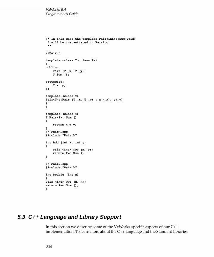
VxWorks 5.4Programmer’s Guide
/* In this case the template Pair<int>::Sum(void)* will be instantiated in PairA.o.*/
//Pair.h
template <class T> class Pair{public:
Pair (T _x, T _y);T Sum ();
protected:T x, y;
};
template <class T>Pair<T>::Pair (T _x, T _y) : x (_x), y(_y){}
template <class T>T Pair<T>::Sum (){
return x + y;}// PairA.cpp#include "Pair.h"
int Add (int x, int y){
Pair <int> Two (x, y);return Two.Sum ();
}
// PairB.cpp#include "Pair.h"
int Double (int x){Pair <int> Two (x, x);return Two.Sum ();}
5.3 C++ Language and Library Support
In this section we describe some of the VxWorks-specific aspects of our C++
implementation. To learn more about the C++ language and the Standard libraries
236

5
5C++ Development
consult any standard C++ reference (a good one is Stroustrup, The C++Programming Language, Third Edition). For documentation on the GNU
implementation of the Iostream library see
5.3.1 Language Features
We support many but not all of the new language features contained in the recently
approved ANSI C++ Standard. Tornado 2.0 has support for exception handling
and run-time type information, as well as improved template support. We do not
yet support the namespace feature although the compiler will accept (and ignore)
references to the std namespace.
Exception Handling
Our C++ compiler supports multithread safe exception handling by default. To
turn off exception handling support use the -fno-exceptions compiler flag.
Using Exceptions
You may have code which was designed around the pre-exception model of C++
compilation. Your calls to new may check the returned pointer for a failure value
of zero, for example. If you are worried that the exception handling enhancements
in this release will not compile your code correctly, you could adhere to the
following simple rules:
■ Use new (nothrow).
■ Do not explicitly turn on exceptions in your Iostream objects.
■ Do not use string objects or wrap them in “try { } catch (...) { }” blocks.
These rules derive from the following observations:
■ The GNU Iostream does not throw unless IO_THROW is defined when the
library is built and exceptions are explicitly enabled for the particular Iostream
object in use. The default is no exceptions. Exceptions have to be explicitly
turned on for each iostate flag that wants to throw.
■ The STL does not throw except in some methods in the basic_string class (of
which string is a specialization).
237

VxWorks 5.4Programmer’s Guide
Exception Handling Overhead
To support destruction of automatic objects during stack-unwinding the compiler
must insert house-keeping code into any function that creates an automatic (stack
based) object with a destructor.
Below are some of the costs of exception handling as measured on a PowerPC 604
target (BSP mv2604); counts are in executed instructions. 1,235 instructions are
executed to execute a “throw 1” and the associated “catch (...)”. There are 14
“extra” instructions to register and deregister automatic variables and temporary
objects with destructors and 29 “extra” instructions per non-inlined function for
exception-handling setup if any exception handling is used in the function. Finally,
the implementation executes 947 “extra” instructions upon encountering the first
exception-handling construct (try, catch, throw, or registration of an auto variable
or temporary).
first time normal casevoid test() { // 3+29 3+29
throw 1; // 1235 1235 total time to printf}
void doit() { // 3+29+947 3+29try { // 22 22
test(); // 1 1} catch (...) {
printf("Hi\n");}
}
struct A { ~A( ) { } };
void local_var ( ) { // 3+29A a; // 14
} // 4
-fno-exceptions can be used to turn exception handling off. Doing so will reduce
the overheads back to classical C++.
Unhandled Exceptions
As required by the Standard, an uncaught exception will eventually lead to a call
to terminate( ). The default behavior of this function is to suspend the offending
task and log a warning message to the console. You may install your own
termination handler by calling set_terminate( ) (defined in the header file
exception).
238

5
5C++ Development
Run-Time Type Information (RTTI)
This feature is turned on by default and adds a small overhead to any C++
program containing classes with virtual functions. If you do not need this feature
you may turn it off using -fno-rtti.
5.3.2 Standard Template Library (STL)
The Standard Template library consists of a small run-time component (which may
be configured into your kernel by selecting INCLUDE_CPLUS_STL for inclusion in
the project facility VxWorks view) and a set of header files.
Our STL port is VxWorks thread safe at the class level. This means that the client
has to provide explicit locking if two tasks want to use the same container object.
(For example, this could be done by using a semaphore; for details, see
2.4.3 Semaphores, p.47.) However two different objects of the same STL container
class may be accessed concurrently.
Iostream Library
This library is configured into VxWorks by selecting
INCLUDE_CPLUS_IOSTREAMS for inclusion in the project facility VxWorks view;
see 5.2.4 Configuration Constants, p.231.
The Iostream library header files reside in the standard VxWorks header file
directory, installDir/target/h. To use this library, include one or more of the header
files after the vxWorks.h header in the appropriate modules of your application.
The most frequently used header file is iostream.h, but others are available; see a
C++ reference such as Stroustrup for information.
The standard Iostream objects (cin, cout, cerr, and clog) are global: that is, they are
not private to any given task. They are correctly initialized regardless of the
number of tasks or modules that reference them and they may safely be used
across multiple tasks that have the same definitions of stdin, stdout, and stderr.
However they cannot safely be used in the case that different tasks have different
standard i/o file-descriptors; in this case, the responsibility for mutual exclusion
rests with the application.
The effect of private standard Iostream objects can be simulated by creating a new
Iostream object of the same class as the standard Iostream object (for example, cinis an istream_withassign), and assigning to it a new filebuf object tied to the
239

VxWorks 5.4Programmer’s Guide
appropriate file descriptor. The new filebuf and Iostream objects are private to the
calling task, ensuring that no other task can accidentally corrupt them.
ostream my_out (new filebuf (1)); /* 1 == STDOUT */istream my_in (new filebuf (0), &my_out); /* 0 == STDIN;
* TIE to my_out */
For complete details on the Iostreams library, see the online manual The GNU C++Iostream Library.
String and Complex Number Classes
These classes are part of the new Standard C++ library. They may be configured
into the kernel by selecting INCLUDE_CPLUS_STRING and
INCLUDE_CPLUS_COMPLEX for inclusion in the project facility VxWorks view.
You may optionally include I/O facilities for these classes by selecting
INCLUDE_CPLUS_STRING_IO and INCLUDE_CPLUS_COMPLEX_IO.
5.4 Example
Example 5-2 exercises various C++ features including the Standard Template
Library, user defined templates, Run-Time Type Identification, and exception
handling. To try it out, create a project containing factory.cpp and factory.h and
build and download linkedObjs.o. At the shell type:
-> testFactory
Full documentation on what you should except to see is given in the source code.
Example 5-2 Code Factory Example
/* factory.cpp - implements an object factory */
/* Copyright 1993-1998 Wind River Systems, Inc. */
/*
NOTE: Tornado 2.0 C++ support does not include support for multi-byte strings.
This includes certain classes which are part of the tools.h++ portion of the Wind
Foundation Classes.
240

5
5C++ Development
modification history--------------------01a,05oct98,sn wrote*/
/*DESCRIPTION
We implement an "object factory". The first step is to giveclasses human-readable names by registering them with a"global class registry". Then objects of a named type may becreated and registered with an "object registry".
This gives us an opportunity to exercise various C++ features:
* Standard Template LibraryA "map" is used as the basis for the various registries.
* User defined templatesThe class registry and object registry are both based on ageneric registry type.
* Run Time Type CheckingWe provide a function to determine the type of a registeredobject using "dynamic_cast".
* Exception HandlingIf we attempt to cast to the "wrong" type we have to handle aC++ exception.
We provide a C interface to facilitate easy testing from the Wind Shell.
Here is an example test run (you can run this whole test through thefunction testFactory()):
-> classRegistryShowShowing Class Registry ...Name Address=========================================================blue_t 0x6b1c7a0green_t 0x6b1c790red_t 0x6b1c7b0
-> objectRegistryShowShowing Object Registry ...Name Address=========================================================
-> objectCreate "green_t", "bob"Creating an object called 'bob' of type 'green_t'
-> objectCreate "red_t", "bill"Creating an object called 'bill' of type 'red_t'
-> objectRegistryShowShowing Object Registry ...Name Address=========================================================bill 0x6b1abf8
241
VxWorks 5.4Programmer’s Guide
bob 0x6b1ac18
-> objectTypeShowByName "bob"Looking up object 'bob'Attempting to ascertain type of object at 0x6b1ac18Attempting a dynamic_cast to red_t ...dynamic_cast threw an exception ... caught here!Attempting a dynamic_cast to blue_t ...dynamic_cast threw an exception ... caught here!Attempting a dynamic_cast to green_t ...Cast to green_t succeeded!green.
*/
/* includes */#include "factory.h"
/* locals */
/* pointer to the global class registry */LOCAL class_registry_t* pClassRegistry;
/* pointer to the global object registry */LOCAL object_registry_t* pObjectRegistry;
/*************************************************************************** testFactory - an example test run**/void testFactory (){
cout << "classRegistryShow ()" << endl;classRegistryShow ();cout << "objectRegistryShow ()" << endl;objectRegistryShow ();cout << "objectCreate (\"green_t\", \"bob\")" << endl;objectCreate ("green_t", "bob");cout << "objectCreate (\"red_t\", \"bill\")" << endl;objectCreate ("red_t", "bill");cout << "objectRegistryShow ()" << endl;objectRegistryShow ();cout << "objectTypeShowByName (\"bob\")" << endl;objectTypeShowByName ("bob");
}
/*************************************************************************** class_registry_t::create - create an object of type className** Look up 'className' in this registry. If it exists then* create an object of this type by using the registered class factory;* otherwise return NULL.** RETURNS : pointer to new object of type className or NULL.
242

5
5C++ Development
*/
object_t* class_registry_t::create(string className){object_factory_t* pFactory = lookup (className);if (pFactory != NULL)
{return lookup (className)-> create ();}
else{cout << "No such class in Class Registry. " << endl;return NULL;}
}
/*************************************************************************** classRegistryGet - get a reference to the global class registry** Create and populate a new class registry if necessary.** RETURNS : a reference to the global class registry*/
LOCAL class_registry_t& classRegistryGet (){if (pClassRegistry == NULL)
{pClassRegistry = new class_registry_t;pClassRegistry -> insert ("red_t", new red_factory_t);pClassRegistry -> insert ("blue_t", new blue_factory_t);pClassRegistry -> insert ("green_t", new green_factory_t);}
return *pClassRegistry;}
/*************************************************************************** objectRegistryGet - get a reference to the global object registry** Create a new object registry if necessary.** RETURNS : a reference to the global object registry*/
LOCAL object_registry_t& objectRegistryGet (){if (pObjectRegistry == NULL)
{pObjectRegistry = new object_registry_t;}
return *pObjectRegistry;
243

VxWorks 5.4Programmer’s Guide
}
/*************************************************************************** objectCreate - create an object of a given type** Use the class factory registered in the global class registry* under 'className' to create a new object. Register this object* in the global object registry under 'object name'.** RETURNS : object of type className*/
object_t* objectCreate(char* className,char* objectName){cout << "Creating an object called '" << objectName << "'"
<< " of type '" << className << "'" << endl;object_t* pObject = classRegistryGet().create (className);if (pObject != NULL)
{objectRegistryGet().insert(objectName, pObject);}
else{cout << "Could not create object. Sorry. " << endl;}
return pObject;}
/*************************************************************************** isRed* isBlue - is anObject a reference to an object of the specified type?* isGreen** Try a dynamic_cast. If this succeeds then return TRUE. If it fails* then catch the resulting exception and return FALSE.** RETURNS : TRUE or FALSE*/
/* isRed */
LOCAL BOOL isRed (object_t& anObject){try
{cout << "Attempting a dynamic_cast to red_t ..." << endl;dynamic_cast<red_t&> (anObject);cout << "Cast to red_t succeeded!" << endl;return TRUE;}
244

5
5C++ Development
catch (exception){cout << "dynamic_cast threw an exception ... caught here!" << endl;return FALSE;}
}
/* isBlue */
LOCAL BOOL isBlue (object_t& anObject){try
{cout << "Attempting a dynamic_cast to blue_t ..." << endl;dynamic_cast<blue_t&> (anObject);cout << "Cast to blue_t succeeded!" << endl;return TRUE;}
catch (exception){cout << "dynamic_cast threw an exception ... caught here!" << endl;return FALSE;}
}
/* isGreen */
LOCAL BOOL isGreen (object_t& anObject){try
{cout << "Attempting a dynamic_cast to green_t ..." << endl;dynamic_cast<green_t&> (anObject);cout << "Cast to green_t succeeded!" << endl;return TRUE;}
catch (exception){cout << "dynamic_cast threw an exception ... caught here!" << endl;return FALSE;}
}
/*************************************************************************** objectTypeShow - ascertain the type of an object** Use dynamic type checking to determine the type of an object.** RETURNS : N/A*/
LOCAL void objectTypeShow (object_t* pObject){cout << "Attempting to ascertain type of object at " << "0x" << hex
245

VxWorks 5.4Programmer’s Guide
<< (int) pObject << endl;if (isRed (*pObject))
{cout << "red." << endl;}
else if (isBlue (*pObject)){cout << "blue." << endl;}
else if (isGreen (*pObject)){cout << "green." << endl;}
}
/*************************************************************************** objectTypeShowByName - ascertain the type of a registered object** Lookup 'objectName' in the global object registry and* print the type of the associated object.** RETURNS : N/A*/
void objectTypeShowByName(char* objectName){cout << "Looking up object '" << objectName << "'" << endl;object_t *pObject = objectRegistryGet ().lookup (objectName);if (pObject != NULL)
{objectTypeShow (pObject);}
else{cout << "No such object in the Object Registry." << endl;}
}
/*************************************************************************** objectRegistryShow - show contents of global object registry** RETURNS : N/A*/
void objectRegistryShow (){cout << "Showing Object Registry ..." << endl;objectRegistryGet ().list ();}
246

5
5C++ Development
/*************************************************************************** classRegistryShow - show contents of global class registry** RETURNS : N/A*/
void classRegistryShow (){cout << "Showing Class Registry ..." << endl;classRegistryGet ().list ();}
/* factory.h - class declarations for the object factory */
/* Copyright 1993-1998 Wind River Systems, Inc. */
/*modification history--------------------01a,05oct98,sn wrote*/
#include <vxWorks.h>#include <iostream.h>#include <string>#include <typeinfo>#include <map>
/* * object_t hierarchy * * object_t * | * +------------+------------+ * | | | * red_t blue_t green_t * */
struct object_t{virtual void method () {}};
struct red_t : object_t{};
struct blue_t : object_t{};
247
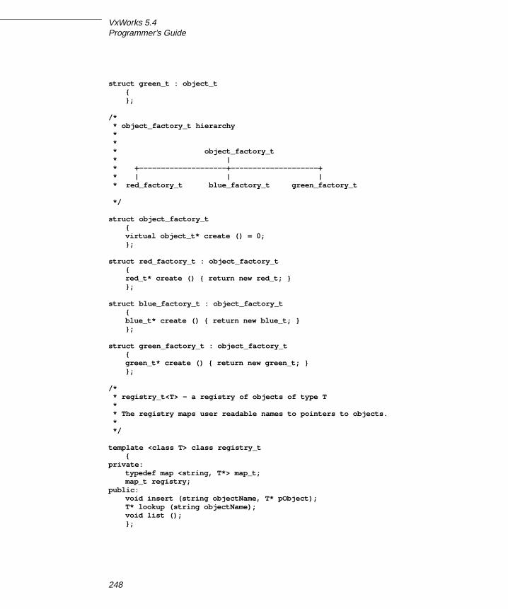
VxWorks 5.4Programmer’s Guide
struct green_t : object_t{};
/* * object_factory_t hierarchy * * * object_factory_t * | * +--------------------+--------------------+ * | | | * red_factory_t blue_factory_t green_factory_t
*/
struct object_factory_t{virtual object_t* create () = 0;};
struct red_factory_t : object_factory_t{red_t* create () { return new red_t; }};
struct blue_factory_t : object_factory_t{blue_t* create () { return new blue_t; }};
struct green_factory_t : object_factory_t{green_t* create () { return new green_t; }};
/* * registry_t<T> - a registry of objects of type T * * The registry maps user readable names to pointers to objects. * */
template <class T> class registry_t{
private:typedef map <string, T*> map_t;map_t registry;
public:void insert (string objectName, T* pObject);T* lookup (string objectName);void list ();};
248

5
5C++ Development
/* object_registry_t - a registry of objects derived from object_t */
typedef registry_t <object_t> object_registry_t;
/* class_registry_t - a registry of object factories ('classes') */
class class_registry_t : public registry_t <object_factory_t>{
public:object_t* create (string className) ;};
/* * template method definitions * * It is common to put template method definitions in header * files so that they may be instantiated whenever necessary. * */
/*************************************************************************** registry_t<T>::insert - register an object** Register object pointed to by pObject under 'objectName'.** RETURNS : N/A*/
template <class T>void registry_t<T>::insert
(string objectName,T* pObject){registry [objectName] = pObject;}
/*************************************************************************** registry_t<T>::lookup - lookup an object by name** Lookup 'objectName' in this registry and return a pointer* to the corresponding object.** RETURNS : a pointer to an object or NULL*/
template <class T>T* registry_t<T>::lookup
(string objectName)
249

VxWorks 5.4Programmer’s Guide
{return registry [objectName];}
/*************************************************************************** registry_t<T>::list - list objects in this registry** RETURNS : N/A*/
template <class T>void registry_t<T>::list ()
{cout << "Name \t" << "Address" << endl;cout << "====================================================" << endl;for (map_t::iterator i = registry.begin ();
i != registry.end (); ++i){cout << i -> first << " \t"
<< "0x" << hex << (int) i -> second << endl;}
}
/* function declarations */
/* objectCreate - create an object of a given type */object_t* objectCreate (char* className, char* objectName);
/* objectTypeShowByName - ascertain the type of a registered object */void objectTypeShowByName (char* objectName);
/* objectRegistryShow - show contents of global object registry */void objectRegistryShow ();
/* classRegistryShow - show contents of global class registry */void classRegistryShow ();
5.5 Wind Foundation Classes
The Wind Foundation Classes include three libraries:
– VxWorks Wrapper Class library
– Tools.h++ library from Rogue Wave Software
The VxWorks Wrapper Class library provides a thin C++ interface to several
standard VxWorks modules. The Tools.h++ foundation class library from Rogue
Wave Software supports a variety of C++ features.
250

5
5C++ Development
5.5.1 VxWorks Wrapper Class Library
The classes in this library are called wrapper classes because each class
encapsulates, or wraps, the interfaces for some portion of standard VxWorks
functionality. Select INCLUDE_CPLUS_VXW for inclusion in the project facility
VxWorks view to configure this library into VxWorks; see 5.2.4 ConfigurationConstants, p.231.
The VxWorks Wrapper Class library header files reside in the standard VxWorks
header file directory, installDir/target/h. The classes and their corresponding
header files are shown in Table 5-1. To use one of these classes, include the
corresponding header file in the appropriate modules of your application.
! CAUTION: In order to prevent dependency conflicts between VxWorks libraries
and Rogue Wave libraries, all VxWorks libraries, including the VxWorks Wrapper
Class Library, should be included before all Rogue Wave libraries, including the
Tools.h++ library.
Table 5-1 Header Files for VxWorks Wrapper Classes
Header File Description
vxwLoadLib.h Object module loader and unloader (wraps loadLib, unldLib,
moduleLib)
vxwLstLib.h Linked lists (wraps lstLib)
vxwMemPartLib.h Memory partitions (wraps memLib)
vxwMsgQLib.h Message queues (wraps msgQLib)
vxwRngLib.h Ring buffers (wraps rngLib)
vxwSemLib.h Semaphores (wraps semLib)
vxwSmLib.h Shared memory objects (adds support for shared memory semaphores,
message queues, and memory partitions)
vxwSymLib.h Symbol tables (wraps symLib)
vxwTaskLib.h Tasks (wraps taskLib, envLib, errnoLib, sigLib, and taskVarLib)
vxwWdLib.h Watchdog timers (wraps wdLib)
251

VxWorks 5.4Programmer’s Guide
The VxWorks Wrapper Classes are designed to provide C++ language bindings to
VxWorks modules that are inherently object-oriented, but for which only C
bindings have previously been available. Figure 5-1 shows the inheritance
relationships for all of the VxWorks Wrapper Classes. The classes are named to
correspond with the VxWorks features that they wrap. For example, VXWMsgQis the class of message queues, and provides a C++ interface to msgQLib.
Example 5-3 Watchdog Timers
To illustrate the way in which the wrapper classes provide C++ language bindings
for VxWorks objects, the following example exhibits methods in the watchdog
timer class, VXWWd. See 2.6 Watchdog Timers, p.90 for general information about
watchdog timers.
! CAUTION: The classes VXWError and VXWIdObject are used internally by the
VxWorks Wrapper Classes. They are listed in Figure 5-1 for completeness only.
These two classes are not intended for direct use by applications.
Figure 5-1 Wrapper-Class Inheritance
VXWError
VXWIdObject
VXWList
VXWMemPart
VXWModule
VXWMsgQ
VXWRingBuf
VXWBSem
VXWCSem
VXWMSem
VXWSmBSem
VXWSmCSem
VXWSmName
VXWSymTab
VXWTask
VXWWd
VXWSem
VXWSmMemBlock
VXWSmSem
VXWSmMemPart
VXWSmMsgQ
(Derived classes appear to the right.)
252

5
5C++ Development
/* Create a watchdog timer and set it to go off in 3 seconds. */
/* includes */
#include "vxWorks.h"#include "logLib.h"#include "vxwWdLib.h"
/* defines */
#define SECONDS (3)
task (void) { /* Create watchdog */
[1] VXWWd myWatchDog;
/* Set timer to go off in SECONDS - printing a message to stdout */
[2] if (myWatchDog.start (sysClkRateGet( ) * SECONDS, logMsg,int ("Watchdog timer just expired\n")) == ERROR)
return (ERROR);
while (TIMER_NEEDED){/* ... */}
[3] }
A notable difference from the C interface is that the wrapper classes allow you to
manipulate watchdog timers as objects rather than through an object ID. Line [1]
creates and names a watchdog object; C++ automatically calls the VXWWdconstructor, implicitly invoking the C routine wdCreate( ) to create a watchdog
timer.
Line [2] in the example illustrates how to use a method from the wrapper classes.
The example invokes the method start( ) for the instance myWatchDog of the class
VXWWd to call the timer. Because this method is invoked on a specific object, the
argument list for the method start( ) does not require an argument to identify
which timer to start (unlike wdStart( ), the corresponding C routine).
Finally, because myWatchDog is a local object, exiting from the routine task( ) on
line [3] automatically calls the destructor for the VXWWd watchdog class. This
implicit call to the destructor deallocates the watchdog object, and if the timer was
still running removes it from the system timer queues. Thus, for objects declared
on the stack, it is not necessary to call a routine equivalent to the C routine
wdDelete( ). (However, if an object is created dynamically with the operator new,
you must delete it explicitly with the operator delete, once your application no
longer needs the object.)
253

VxWorks 5.4Programmer’s Guide
For details of the wrapper classes and on each of the wrapper class functions, see
the VxWorks Reference Manual.
5.5.2 Tools.h++ Library
Tools.h++ is an industry-standard foundation class library from Rogue Wave
Software which supports the following features:
– A complete set of collection classes
– Template based classes
– Persistent store facility
– File classes and file space manager
– B-tree disk retrieval
– Multi-thread safety
– Multi-byte and wide character strings
– Localized string collation
– Parse and format times, dates, and currency in multiple locales
– Support for multiple time zones and daylight savings rules
– Support for localized messages
– Localized I/O streams
This library is configured into VxWorks by selecting INCLUDE_CPLUS_TOOLS for
inclusion in the project facility VxWorks view; see 5.2.4 Configuration Constants,
p.231.
The Tools.h++ library header files reside in the VxWorks header file directory
installDir/target/h/rw. To use this library, #include one or more of these header files
after the #include "vxWorks.h" statement and after the #include statements for all
other VxWorks libraries in the appropriate modules of your application. For a list
of all the header files and details on this library, see Rogue Wave’s Tools.h++Introduction and Reference Manual.
254

6Shared-Memory Objects
Optional Component VxMP
6.1 Introduction
VxMP is an optional VxWorks component that provides shared-memory objects
dedicated to high-speed synchronization and communication between tasks
running on separate CPUs. For information on how to install VxMP, see TornadoGetting Started.
Shared-memory objects are a class of system objects that can be accessed by tasks
running on different processors. They are called shared-memory objects because the
object’s data structures must reside in memory accessible by all processors.
Shared-memory objects are an extension of local VxWorks objects. Local objects are
only available to tasks on a single processor. VxMP supplies three kinds of shared-
memory objects:
■ shared semaphores (binary and counting)
■ shared message queues
■ shared-memory partitions (system- and user-created partitions)
Shared-memory objects provide the following advantages:
■ A transparent interface that allows shared-memory objects to be manipulated
with the same routines that are used for manipulating local objects.
■ High-speed inter-processor communication—no unnecessary packet passing
is required.
■ The shared memory can reside either in dual-ported RAM or on a separate
memory board.
255

VxWorks 5.4Programmer’s Guide
The components of VxMP consist of the following: a name database
(smNameLib), shared semaphores (semSmLib), shared message queues
(msgQSmLib), and a shared-memory allocator (smMemLib).
This chapter presents a detailed description of each shared-memory object and
internal considerations. It then describes configuration and troubleshooting.
6.2 Using Shared-Memory Objects
VxMP provides a transparent interface that makes it easy to execute code using
shared-memory objects on both a multiprocessor system and a single-processor
system. After an object is created, tasks can operate on shared objects with the
same routines used to operate on their corresponding local objects. For example,
shared semaphores, shared message queues, and shared-memory partitions have
the same syntax and interface as their local counterparts. Routines such as
semGive( ) , semTake( ), msgQSend( ), msgQReceive( ), memPartAlloc( ) , and
memPartFree( ) operate on both local and shared objects. Only the create routines
are different. This allows an application to run in either a single-processor or a
multiprocessor environment with only minor changes to system configuration,
initialization, and object creation.
All shared-memory objects can be used on a single-processor system. This is useful
for testing an application before porting it to a multiprocessor configuration.
However, for objects that are used only locally, local objects always provide the
best performance.
After the shared-memory facilities are initialized (see 6.4 Configuration, p.279 for
initialization differences), all processors are treated alike. Tasks on any CPU can
create and use shared-memory objects. No processor has priority over another
from a shared-memory object’s point of view.1
Systems making use of shared memory can include a combination of supported
architectures. This enables applications to take advantage of different processor
types and still have them communicate. However, on systems where the
processors have different byte ordering, you must call the macros ntohl and htonlto byte-swap the application’s shared data (see VxWorks Network Programmer’sGuide: TCP/IP Under VxWorks).
1. Do not confuse this type of priority with the CPU priorities associated with VMEbus access.
256

6
6Shared-Memory Objects
When an object is created, an object ID is returned to identify it. For tasks on
different CPUs to access shared-memory objects, they must be able to obtain this
ID. An object’s ID is the same regardless of the CPU. This allows IDs to be passed
using shared message queues, data structures in shared memory, or the name
database.
Throughout the remainder of this chapter, system objects under discussion refer to
shared objects unless otherwise indicated.
6.2.1 Name Database
The name database allows the association of any value to any name, such as a
shared-memory object’s ID with a unique name. It can communicate or advertise a
shared-memory block’s address and object type. The name database provides
name-to-value and value-to-name translation, allowing objects in the database to
be accessed either by name or by value. While other methods exist for advertising
an object’s ID, the name database is a convenient method for doing this.
Typically the task that creates an object also advertises the object’s ID by means of
the name database. By adding the new object to the database, the task associates
the object’s ID with a name. Tasks on other processors can look up the name in the
database to get the object’s ID. After the task has the ID, it can use it to access the
object.
For example, task t1 on CPU 1 creates an object. The object ID is returned by the
creation routine and entered in the name database with the name myObj. For task
t2 on CPU 0 to operate on this object, it first finds the ID by looking up the name
myObj in the name database.
This same technique can be used to advertise a shared-memory address. For
example, task t1 on CPU 0 allocates a chunk of memory and adds the address to
the database with the name mySharedMem. Task t2 on CPU 1 can find the address
of this shared memory by looking up the address in the name database using
mySharedMem.
Tasks on different processors can use an agreed-upon name to get a newly created
object’s value. See Table 6-1 for a list of name service routines. Note that retrieving
an ID from the name database need occur only one time for each task, and usually
occurs during application initialization.
The name database service routines automatically convert to or from network-byte
order; do not call htonl( ) or ntohl( ) explicitly for values from the name database.
The object types listed in Table 6-2 are defined in smNameLib.h.
257

VxWorks 5.4Programmer’s Guide
The following example shows the name database as displayed by
smNameShow( ), which is automatically included if INCLUDE_SM_OBJ is selected
for inclusion in the project facility VxWorks view. The parameter to
smNameShow( ) specifies the level of information displayed; in this case, 1
indicates that all information is shown. For additional information on
smNameShow( ), see its reference entry.
-> smNameShow 1value = 0 = 0x0
The output is sent to the standard output device, and looks like the following:
Name in Database Max : 100 Current : 5 Free : 95Name Value Type----------------- ------------- -------------myMemory 0x3835a0 SM_BLOCKmyMemPart 0x3659f9 SM_PART_IDmyBuff 0x383564 SM_BLOCKmySmSemaphore 0x36431d SM_SEM_BmyMsgQ 0x365899 SM_MSG_Q
Table 6-1 Name Service Routines
Routine Functionality
smNameAdd( ) Add a name to the name database.
smNameRemove( ) Remove a name from the name database.
smNameFind( ) Find a shared symbol by name.
smNameFindByValue( ) Find a shared symbol by value.
smNameShow( ) Display the name database to the standard output device;
automatically included if INCLUDE_SM_OBJ is selected.
Table 6-2 Shared-Memory Object Types
Constant Hex Value
T_SM_SEM_B 0
T_SM_SEM_C 1
T_SM_MSG_Q 2
T_SM_PART_ID 3
T_SM_BLOCK 4
258

6
6Shared-Memory Objects
6.2.2 Shared Semaphores
Like local semaphores, shared semaphores provide synchronization by means of
atomic updates of semaphore state information. See 2. Basic OS in this manual and
the reference entry for semLib for a complete discussion of semaphores. Shared
semaphores can be given and taken by tasks executing on any CPU with access to
the shared memory. They can be used for either synchronization of tasks running
on different CPUs or mutual exclusion for shared resources.
To use a shared semaphore, a task creates the semaphore and advertises its ID. This
can be done by adding it to the name database. A task on any CPU in the system
can use the semaphore by first getting the semaphore ID (for example, from the
name database). When it has the ID, it can then take or give the semaphore.
In the case of employing shared semaphores for mutual exclusion, typically there
is a system resource that is shared between tasks on different CPUs and the
semaphore is used to prevent concurrent access. Any time a task requires exclusive
access to the resource, it takes the semaphore. When the task is finished with the
resource, it gives the semaphore.
For example, there are two tasks, t1 on CPU 0 and t2 on CPU 1. Task t1 creates the
semaphore and advertises the semaphore’s ID by adding it to the database and
assigning the name myMutexSem. Task t2 looks up the name myMutexSem in the
database to get the semaphore’s ID. Whenever a task wants to access the resource,
it first takes the semaphore by using the semaphore ID. When a task is done using
the resource, it gives the semaphore.
In the case of employing shared semaphores for synchronization, assume a task on
one CPU must notify a task on another CPU that some event has occurred. The task
being synchronized pends on the semaphore waiting for the event to occur. When
the event occurs, the task doing the synchronizing gives the semaphore.
For example, there are two tasks, t1 on CPU 0 and t2 on CPU 1. Both t1 and t2 are
monitoring robotic arms. The robotic arm that is controlled by t1 is passing a
physical object to the robotic arm controlled by t2. Task t2 moves the arm into
position but must then wait until t1 indicates that it is ready for t2 to take the object.
Task t1 creates the shared semaphore and advertises the semaphore’s ID by adding
it to the database and assigning the name objReadySem. Task t2 looks up the name
objReadySem in the database to get the semaphore’s ID. It then takes the
semaphore by using the semaphore ID. If the semaphore is unavailable, t2 pends,
waiting for t1 to indicate that the object is ready for t2. When t1 is ready to transfer
control of the object to t2, it gives the semaphore, readying t2 on CPU1.
There are two types of shared semaphores, binary and counting. Shared
semaphores have their own create routines and return a SEM_ID. Table 6-3 lists the
259

VxWorks 5.4Programmer’s Guide
create routines. All other semaphore routines, except semDelete( ), operate
transparently on the created shared semaphore.
The use of shared semaphores and local semaphores differs in several ways:
■ The shared semaphore queuing order specified when the semaphore is created
must be FIFO. Figure 6-1 shows two tasks executing on different CPUs, both
trying to take the same semaphore. Task 1 executes first, and is put at the front
of the queue because the semaphore is unavailable (empty). Task 2 (executing
on a different CPU) tries to take the semaphore after task 1’s attempt and is put
on the queue behind task 1.
■ Shared semaphores cannot be given from interrupt level.
■ Shared semaphores cannot be deleted. Attempts to delete a shared semaphore
return ERROR and set errno to S_smObjLib_NO_OBJECT_DESTROY.
Use semInfo( ) to get the shared task control block of tasks pended on a shared
semaphore. Use semShow( ), if INCLUDE_SEM_SHOW is included in the project
facility VxWorks view, to display the status of the shared semaphore and a list of
pended tasks. The following example displays detailed information on the shared
semaphore mySmSemaphoreId as indicated by the second argument (0 =
summary, 1 = details):
-> semShow mySmSemaphoreId, 1value = 0 = 0x0
The output is sent to the standard output device, and looks like the following:
Semaphore Id : 0x36431dSemaphore Type : SHARED BINARYTask Queuing : FIFOPended Tasks : 2State : EMPTYTID CPU Number Shared TCB------------- ------------- --------------0xd0618 1 0x3642040x3be924 0 0x36421c
Table 6-3 Shared Semaphore Create Routines
Create Routine Description
semBSmCreate( ) Create a shared binary semaphore.
semCSmCreate( ) Create a shared counting semaphore.
260
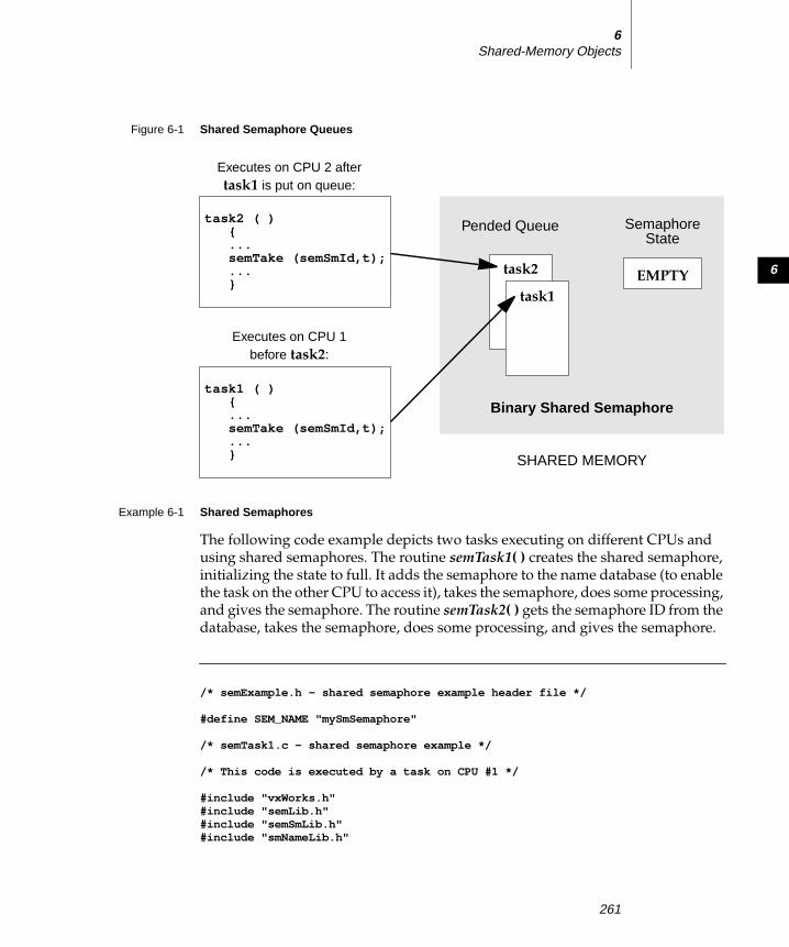
6
6Shared-Memory Objects
Example 6-1 Shared Semaphores
The following code example depicts two tasks executing on different CPUs and
using shared semaphores. The routine semTask1( ) creates the shared semaphore,
initializing the state to full. It adds the semaphore to the name database (to enable
the task on the other CPU to access it), takes the semaphore, does some processing,
and gives the semaphore. The routine semTask2( ) gets the semaphore ID from the
database, takes the semaphore, does some processing, and gives the semaphore.
/* semExample.h - shared semaphore example header file */
#define SEM_NAME "mySmSemaphore"
/* semTask1.c - shared semaphore example */
/* This code is executed by a task on CPU #1 */
#include "vxWorks.h"#include "semLib.h"#include "semSmLib.h"#include "smNameLib.h"
Figure 6-1 Shared Semaphore Queues
SHARED MEMORY
task2
task1
Pended Queue Semaphore
EMPTY
Executes on CPU 1before task2:
Executes on CPU 2 aftertask1 is put on queue:
State
Binary Shared Semaphore
task2 ( ){...semTake (semSmId,t);...}
task1 ( ){...semTake (semSmId,t);...}
261
VxWorks 5.4Programmer’s Guide
#include "stdio.h"#include "taskLib.h"#include "semExample.h"
/************************************************************************** semTask1 - shared semaphore user*/
STATUS semTask1 (void){SEM_ID semSmId;
/* create shared semaphore */
if ((semSmId = semBSmCreate (SEM_Q_FIFO, SEM_FULL)) == NULL)return (ERROR);
/* add object to name database */
if (smNameAdd (SEM_NAME, semSmId, T_SM_SEM_B) == ERROR)return (ERROR);
/* grab shared semaphore and hold it for awhile */
semTake (semSmId, WAIT_FOREVER);
/* normally do something useful */
printf ("Task1 has the shared semaphore\n");taskDelay (sysClkRateGet () * 5);printf ("Task1 is releasing the shared semaphore\n");
/* release shared semaphore */
semGive (semSmId);
return (OK);}
/* semTask2.c - shared semaphore example */
/* This code is executed by a task on CPU #2. */
#include "vxWorks.h"#include "semLib.h"#include "semSmLib.h"
#include "smNameLib.h"#include "stdio.h"#include "semExample.h"
262

6
6Shared-Memory Objects
/************************************************************************** semTask2 - shared semaphore user*/
STATUS semTask2 (void){SEM_ID semSmId;int objType;
/* find object in name database */
if (smNameFind (SEM_NAME, (void **) &semSmId, &objType, WAIT_FOREVER)== ERROR)return (ERROR);
/* take the shared semaphore */
printf ("semTask2 is now going to take the shared semaphore\n");semTake (semSmId, WAIT_FOREVER);
/* normally do something useful */
printf ("Task2 got the shared semaphore!!\n");
/* release shared semaphore */
semGive (semSmId);
printf ("Task2 has released the shared semaphore\n");
return (OK);}
6.2.3 Shared Message Queues
Shared message queues are FIFO queues used by tasks to send and receive variable-
length messages on any of the CPUs that have access to the shared memory. They
can be used either to synchronize tasks or to exchange data between tasks running
on different CPUs. See 2. Basic OS in this manual and the reference entry for
msgQLib for a complete discussion of message queues.
To use a shared message queue, a task creates the message queue and advertises
its ID. A task that wants to send or receive a message with this message queue first
gets the message queue’s ID. It then uses this ID to access the message queue.
For example, consider a typical server/client scenario where a server task t1 (on
CPU 1) reads requests from one message queue and replies to these requests with
a different message queue. Task t1 creates the request queue and advertises its ID
by adding it to the name database assigning the name requestQue. If task t2 (on
263

VxWorks 5.4Programmer’s Guide
CPU 0) wants to send a request to t1, it first gets the message queue ID by looking
up the name requestQue in the name database. Before sending its first request,
task t2 creates a reply message queue. Instead of adding its ID to the database, it
advertises the ID by sending it as part of the request message. When t1 receives the
request from the client, it finds in the message the ID of the queue to use when
replying to that client. Task t1 then sends the reply to the client by using this ID.
To pass messages between tasks on different CPUs, first create the message queue
by calling msgQSmCreate( ). This routine returns a MSG_Q_ID. This ID is used for
sending and receiving messages on the shared message queue.
Like their local counterparts, shared message queues can send both urgent or
normal priority messages.
The use of shared message queues and local message queues differs in several
ways:
■ The shared message queue task queueing order specified when a message
queue is created must be FIFO. Figure 6-2 shows two tasks executing on
different CPUs, both trying to receive a message from the same shared
message queue. Task 1 executes first, and is put at the front of the queue
because there are no messages in the message queue. Task 2 (executing on a
different CPU) tries to receive a message from the message queue after task 1’s
attempt and is put on the queue behind task 1.
■ Messages cannot be sent on a shared message queue at interrupt level. (This is
true even in NO_WAIT mode.)
■ Shared message queues cannot be deleted. Attempts to delete a shared
message queue return ERROR and sets errno to
S_smObjLib_NO_OBJECT_DESTROY.
To achieve optimum performance with shared message queues, align send and
receive buffers on 4-byte boundaries.
To display the status of the shared message queue as well as a list of tasks pended
on the queue, select INCLUDE_MSG_Q_SHOW for inclusion in the project facility
VxWorks view and call msgQShow( ). The following example displays detailed
information on the shared message queue 0x7f8c21 as indicated by the second
argument (0 = summary display, 1 = detailed display).
-> msgQShow 0x7f8c21, 1value = 0 = 0x0
The output is sent to the standard output device, and looks like the following:
264

6
6Shared-Memory Objects
Message Queue Id : 0x7f8c21Task Queuing : FIFOMessage Byte Len : 128Messages Max : 10Messages Queued : 0Receivers Blocked : 1Send timeouts : 0Receive timeouts : 0Receivers blocked :TID CPU Number Shared TCB---------- -------------------- --------------0xd0618 1 0x1364204
Example 6-2 Shared Message Queues
In the following code example, two tasks executing on different CPUs use shared
message queues to pass data to each other. The server task creates the request
message queue, adds it to the name database, and reads a message from the queue.
The client task gets the smRequestQId from the name database, creates a reply
message queue, bundles the ID of the reply queue as part of the message, and
sends the message to the server. The server gets the ID of the reply queue and uses
it to send a message back to the client. This technique requires the use of the
network byte-order conversion macros htonl( ) and ntohl( ), because the numeric
queue ID is passed over the network in a data field.
Figure 6-2 Shared Message Queues
Pended QueueMessage
Executes on CPU 1 before task2:
Executes on CPU 2 after task1:
task2
task1
Queue
Shared Message Queue
SHARED MEMORY
EMPTY
task2 ( ){...msgQReceive (smMsgQId,...);...}
task1 ( ){...msgQReceive (smMsgQId,...);...}
265

VxWorks 5.4Programmer’s Guide
/* msgExample.h - shared message queue example header file */
#define MAX_MSG (10)#define MAX_MSG_LEN (100)#define REQUEST_Q "requestQue"
typedef struct message{MSG_Q_ID replyQId;char clientRequest[MAX_MSG_LEN];} REQUEST_MSG;
/* server.c - shared message queue example server */
/* This file contains the code for the message queue server task. */
#include "vxWorks.h"#include "msgQLib.h"#include "msgQSmLib.h"#include "stdio.h"#include "smNameLib.h"#include "msgExample.h"#include "netinet/in.h"
#define REPLY_TEXT "Server received your request"
/************************************************************************** serverTask - receive and process a request from a shared message queue*/
STATUS serverTask (void){MSG_Q_ID smRequestQId; /* request shared message queue */REQUEST_MSG request; /* request text */
/* create a shared message queue to handle requests */
if ((smRequestQId = msgQSmCreate (MAX_MSG, sizeof (REQUEST_MSG),MSG_Q_FIFO)) == NULL)return (ERROR);
/* add newly created request message queue to name database */
if (smNameAdd (REQUEST_Q, smRequestQId, T_SM_MSG_Q) == ERROR)return (ERROR);
/* read messages from request queue */
FOREVER
266

6
6Shared-Memory Objects
{if (msgQReceive (smRequestQId, (char *) &request, sizeof (REQUEST_MSG),
WAIT_FOREVER) == ERROR)return (ERROR);
/* process request - in this case simply print it */
printf ("Server received the following message:\n%s\n",request.clientRequest);
/* send a reply using ID specified in client’s request message */
if (msgQSend ((MSG_Q_ID) ntohl ((int) request.replyQId),REPLY_TEXT, sizeof (REPLY_TEXT),WAIT_FOREVER, MSG_PRI_NORMAL) == ERROR)return (ERROR);
}}
/* client.c - shared message queue example client */
/* This file contains the code for the message queue client task. */
#include "vxWorks.h"#include "msgQLib.h"#include "msgQSmLib.h"#include "smNameLib.h"#include "stdio.h"#include "msgExample.h"#include "netinet/in.h"
/************************************************************************** clientTask - sends request to server and reads reply*/
STATUS clientTask(char * pRequestToServer /* request to send to the server */
/* limited to 100 chars */){MSG_Q_ID smRequestQId; /* request message queue */MSG_Q_ID smReplyQId; /* reply message queue */REQUEST_MSG request; /* request text */int objType; /* dummy variable for smNameFind */char serverReply[MAX_MSG_LEN]; /*buffer for server’s reply */
/* get request queue ID using its name */
if (smNameFind (REQUEST_Q, (void **) &smRequestQId, &objType,WAIT_FOREVER) == ERROR)return (ERROR);
267

VxWorks 5.4Programmer’s Guide
/* create reply queue, build request and send it to server */
if ((smReplyQId = msgQSmCreate (MAX_MSG, MAX_MSG_LEN,MSG_Q_FIFO)) == NULL)return (ERROR);
request.replyQId = (MSG_Q_ID) htonl ((int) smReplyQId);
strcpy (request.clientRequest, pRequestToServer);
if (msgQSend (smRequestQId, (char *) &request, sizeof (REQUEST_MSG),WAIT_FOREVER, MSG_PRI_NORMAL) == ERROR)return (ERROR);
/* read reply and print it */
if (msgQReceive (request.replyQId, serverReply, MAX_MSG_LEN,WAIT_FOREVER) == ERROR)return (ERROR);
printf ("Client received the following message:\n%s\n", serverReply);
return (OK);}
6.2.4 Shared-Memory Allocator
The shared-memory allocator allows tasks on different CPUs to allocate and release
variable size chunks of memory that are accessible from all CPUs with access to the
shared-memory system. Two sets of routines are provided: low-level routines for
manipulating user-created shared-memory partitions, and high-level routines for
manipulating a shared-memory partition dedicated to the shared-memory system
pool. (This organization is similar to that used by the local-memory manager,
memPartLib.)
Shared-memory blocks can be allocated from different partitions. Both a shared-
memory system partition and user-created partitions are available. User-created
partitions can be created and used for allocating data blocks of a particular size.
Memory fragmentation is avoided when fixed-sized blocks are allocated from
user-created partitions dedicated to a particular block size.
Shared-Memory System Partition
To use the shared-memory system partition, a task allocates a shared-memory
block and advertises its address. One way of advertising the ID is to add the
address to the name database. The routine used to allocate a block from the shared-
268

6
6Shared-Memory Objects
memory system partition returns a local address. Before the address is advertised
to tasks on other CPUs, this local address must be converted to a global address.
Any task that must use the shared memory must first get the address of the
memory block and convert the global address to a local address. When the task has
the address, it can use the memory.
However, to address issues of mutual exclusion, typically a shared semaphore is
used to protect the data in the shared memory. Thus in a more common scenario,
the task that creates the shared memory (and adds it to the database) also creates a
shared semaphore. The shared semaphore ID is typically advertised by storing it
in a field in the shared data structure residing in the shared-memory block. The
first time a task must access the shared data structure, it looks up the address of the
memory in the database and gets the semaphore ID from a field in the shared data
structure. Whenever a task must access the shared data, it must first take the
semaphore. Whenever a task is finished with the shared data, it must give the
semaphore.
For example, assume two tasks executing on two different CPUs must share data.
Task t1 executing on CPU 1 allocates a memory block from the shared-memory
system partition and converts the local address to a global address. It then adds the
global address of the shared data to the name database with the name
mySharedData. Task t1 also creates a shared semaphore and stores the ID in the
first field of the data structure residing in the shared memory. Task t2 executing on
CPU 2 looks up the name mySharedData in the name database to get the address
of the shared memory. It then converts this address to a local address. Before
accessing the data in the shared memory, t2 gets the shared semaphore ID from the
first field of the data structure residing in the shared-memory block. It then takes
the semaphore before using the data and gives the semaphore when it is done
using the data.
User-Created Partitions
To make use of user-created shared-memory partitions, a task creates a shared-
memory partition and adds it to the name database. Before a task can use the
shared-memory partition, it must first look in the name database to get the
partition ID. When the task has the partition ID, it can access the memory in the
shared-memory partition.
For example, task t1 creates a shared-memory partition and adds it to the name
database using the name myMemPartition. Task t2 executing on another CPU
wants to allocate memory from the new partition. Task t2 first looks up
269

VxWorks 5.4Programmer’s Guide
myMemPartition in the name database to get the partition ID. It can then allocate
memory from it, using the ID.
Using the Shared-Memory System Partition
The shared-memory system partition is analogous to the system partition for local
memory. Table 6-4 lists routines for manipulating the shared-memory system
partition.
Routines that return a pointer to allocated memory return a local address (that is,
an address suitable for use from the local CPU). To share this memory across
processors, this address must be converted to a global address before it is
advertised to tasks on other CPUs. Before a task on another CPU uses the memory,
it must convert the global address to a local address. Macros and routines are
provided to convert between local addresses and global addresses; see the header
file smObjLib.h and the reference entry for smObjLib.
Table 6-4 Shared-Memory System Partition Routines
Routine Functionality
smMemMalloc( ) Allocate a block of shared system memory.
smMemCalloc( ) Allocate a block of shared system memory for an array.
smMemRealloc( ) Resize a block of shared system memory.
smMemFree( ) Free a block of shared system memory.
smMemShow( ) Display usage statistics of the shared-memory system
partition on the standard output device; this routine is
automatically included if INCLUDE_SM_OBJ is selected for
inclusion in the project facility VxWorks view.
smMemOptionsSet( ) Set the debugging options for the shared-memory system
partition.
smMemAddToPool( ) Add memory to the shared-memory system pool.
smMemFindMax( ) Find the size of the largest free block in the shared-memory
system partition.
270
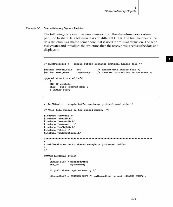
6
6Shared-Memory Objects
Example 6-3 Shared-Memory System Partition
The following code example uses memory from the shared-memory system
partition to share data between tasks on different CPUs. The first member of the
data structure is a shared semaphore that is used for mutual exclusion. The send
task creates and initializes the structure, then the receive task accesses the data and
displays it.
/* buffProtocol.h - simple buffer exchange protocol header file */
#define BUFFER_SIZE 200 /* shared data buffer size */#define BUFF_NAME "myMemory" /* name of data buffer in database */
typedef struct shared_buff{SEM_ID semSmId;char buff [BUFFER_SIZE];} SHARED_BUFF;
/* buffSend.c - simple buffer exchange protocol send side */
/* This file writes to the shared memory. */
#include "vxWorks.h"#include "semLib.h"#include "semSmLib.h"#include "smNameLib.h"#include "smObjLib.h"#include "stdio.h"#include "buffProtocol.h"
/************************************************************************** buffSend - write to shared semaphore protected buffer**/
STATUS buffSend (void){SHARED_BUFF * pSharedBuff;SEM_ID mySemSmId;
/* grab shared system memory */
pSharedBuff = (SHARED_BUFF *) smMemMalloc (sizeof (SHARED_BUFF));
271

VxWorks 5.4Programmer’s Guide
/** Initialize shared buffer structure before adding to database. The* protection semaphore is initially unavailable and the receiver blocks.
*/
if ((mySemSmId = semBSmCreate (SEM_Q_FIFO, SEM_EMPTY)) == NULL)return (ERROR);
pSharedBuff->semSmId = (SEM_ID) htonl ((int) mySemSmId);
/* * Convert address of shared buffer to a global address and add to * database. */
if (smNameAdd (BUFF_NAME, (void *) smObjLocalToGlobal (pSharedBuff),T_SM_BLOCK) == ERROR)
return (ERROR);
/* put data into shared buffer */
sprintf (pSharedBuff->buff,"Hello from sender\n");
/* allow receiver to read data by giving protection semaphore */
if (semGive (mySemSmId) != OK)return (ERROR);
return (OK);}
/* buffReceive.c - simple buffer exchange protocol receive side */
/* This file reads the shared memory. */
#include "vxWorks.h"#include "semLib.h"#include "semSmLib.h"#include "smNameLib.h"#include "smObjLib.h"#include "stdio.h"#include "buffProtocol.h"
/************************************************************************** buffReceive - receive shared semaphore protected buffer*/
STATUS buffReceive (void){SHARED_BUFF * pSharedBuff;SEM_ID mySemSmId;int objType;
272

6
6Shared-Memory Objects
/* get shared buffer address from name database */
if (smNameFind (BUFF_NAME, (void **) &pSharedBuff,&objType, WAIT_FOREVER) == ERROR)
return (ERROR);
/* convert global address of buff to its local value */
pSharedBuff = (SHARED_BUFF *) smObjGlobalToLocal (pSharedBuff);
/* convert shared semaphore ID to host (local) byte order */
mySemSmId = (SEM_ID) ntohl ((int) pSharedBuff->semSmId);
/* take shared semaphore before reading the data buffer */
if (semTake (mySemSmId,WAIT_FOREVER) != OK)return (ERROR);
/* read data buffer and print it */
printf ("Receiver reading from shared memory: %s\n", pSharedBuff->buff);
/* give back the data buffer semaphore */
if (semGive (mySemSmId) != OK)return (ERROR);
return (OK);}
Using User-Created Partitions
Shared-memory partitions have a separate create routine, memPartSmCreate( ),that returns a MEM_PART_ID. After a user-defined shared-memory partition is
created, routines in memPartLib operate on it transparently. Note that the address
of the shared-memory area passed to memPartSmCreate( ) (or
memPartAddToPool( )) must be the global address.
Example 6-4 User-Created Partition
This example is similar to Example 6-3, which uses the shared-memory system
partition. This example creates a user-defined partition and stores the shared data
in this new partition. A shared semaphore is used to protect the data.
273

VxWorks 5.4Programmer’s Guide
/* memPartExample.h - shared memory partition example header file */
#define CHUNK_SIZE (2400)#define MEM_PART_NAME "myMemPart"#define PART_BUFF_NAME "myBuff"#define BUFFER_SIZE (40)
typedef struct shared_buff{SEM_ID semSmId;char buff [BUFFER_SIZE];} SHARED_BUFF;
/* memPartSend.c - shared memory partition example send side */
/* This file writes to the user-defined shared memory partition. */
#include "vxWorks.h"#include "memLib.h"#include "semLib.h"#include "semSmLib.h"#include "smNameLib.h"#include "smObjLib.h"#include "smMemLib.h"#include "stdio.h"#include "memPartExample.h"
/*********************************************************************** memPartSend - send shared memory partition buffer*/
STATUS memPartSend (void){char * pMem;PART_ID smMemPartId;SEM_ID mySemSmId;SHARED_BUFF * pSharedBuff;
/* allocate shared system memory to use for partition */
pMem = smMemMalloc (CHUNK_SIZE);
/* Create user defined partition using the previously allocated * block of memory. * WARNING: memPartSmCreate uses the global address of a memory * pool as first parameter. */
274

6
6Shared-Memory Objects
if ((smMemPartId = memPartSmCreate (smObjLocalToGlobal (pMem), CHUNK_SIZE)) == NULL)
return (ERROR);
/* allocate memory from partition */
pSharedBuff = (SHARED_BUFF *) memPartAlloc ( smMemPartId,sizeof (SHARED_BUFF));
if (pSharedBuff == 0)return (ERROR);
/* initialize structure before adding to database */
if ((mySemSmId = semBSmCreate (SEM_Q_FIFO, SEM_EMPTY)) == NULL)return (ERROR);
pSharedBuff->semSmId = (SEM_ID) htonl ((int) mySemSmId);
/* enter shared partition ID in name database */
if (smNameAdd (MEM_PART_NAME, (void *) smMemPartId, T_SM_PART_ID) == ERROR)return (ERROR);
/* convert shared buffer address to a global address and add to database */
if (smNameAdd (PART_BUFF_NAME, (void *) smObjLocalToGlobal(pSharedBuff),T_SM_BLOCK) == ERROR)
return (ERROR);
/* send data using shared buffer */
sprintf (pSharedBuff->buff,"Hello from sender\n");
if (semGive (mySemSmId) != OK)return (ERROR);
return (OK);}
/* memPartReceive.c - shared memory partition example receive side */
/* This file reads from the user-defined shared memory partition. */
#include "vxWorks.h"#include "memLib.h"#include "stdio.h"#include "semLib.h"#include "semSmLib.h"#include "stdio.h"#include "memPartExample.h"
275

VxWorks 5.4Programmer’s Guide
/*********************************************************************** memPartReceive - receive shared memory partition buffer** execute on CPU 1 - use a shared semaphore to protect shared memory**/
STATUS memPartReceive (void){SHARED_BUFF * pBuff;SEM_ID mySemSmId;int objType;
/* get shared buffer address from name database */
if (smNameFind (PART_BUFF_NAME, (void **) &pBuff, &objType,WAIT_FOREVER) == ERROR)
return (ERROR);
/* convert global address of buffer to its local value */
pBuff = (SHARED_BUFF *) smObjGlobalToLocal (pBuff);
/* Grab shared semaphore before using the shared memory */
mySemSmId = (SEM_ID) ntohl ((int) pBuff->semSmId);semTake (mySemSmId,WAIT_FOREVER);printf ("Receiver reading from shared memory: %s\n", pBuff->buff);semGive (mySemSmId);
return (OK);}
Side Effects of Shared-Memory Partition Options
Like their local counterparts, shared-memory partitions (both system- and user-
created) can have different options set for error handling; see the reference entries
for memPartOptionsSet( ) and smMemOptionsSet( ).
If the MEM_BLOCK_CHECK option is used in the following situation, the system
can get into a state where the memory partition is no longer available. If a task
attempts to free a bad block and a bus error occurs, the task is suspended. Because
shared semaphores are used internally for mutual exclusion, the suspended task
still has the semaphore, and no other task has access to the memory partition. By
default, shared-memory partitions are created without the MEM_BLOCK_CHECKoption.
276

6
6Shared-Memory Objects
6.3 Internal Considerations
6.3.1 System Requirements
The shared-memory region used by shared-memory objects must be visible to all
CPUs in the system. Either dual-ported memory on the master CPU (CPU 0) or a
separate memory board can be used. The shared-memory objects’ anchor must be
in the same address space as the shared-memory region. Note that the memory
does not have to appear at the same address for all CPUs.
All CPUs in the system must support indivisible read-modify-write cycle across
the (VME) bus. The indivisible RMW is used by the spin-lock mechanism to gain
exclusive access to internal shared data structures; see 6.3.2 Spin-lock Mechanism,
p.277 for details. Because all the boards must support a hardware test-and-set, the
constant SM_TAS_TYPE must be set to SM_TAS_HARD on the Parameters tab of the
project facility VxWorks view.
CPUs must be notified of any event that affects them. The preferred method is for
the CPU initiating the event to interrupt the affected CPU. The use of interrupts is
dependent on the capabilities of the hardware. If interrupts cannot be used, a
polling scheme can be employed, although this generally results in a significant
performance penalty.
The maximum number of CPUs that can use shared-memory objects is 20 (CPUs
numbered 0 through 19). The practical maximum is usually a smaller number that
depends on the CPU, bus bandwidth, and application.
6.3.2 Spin-lock Mechanism
Internal shared-memory object data structures are protected against concurrent
access by a spin-lock mechanism. The spin-lock mechanism is a loop where an
attempt is made to gain exclusive access to a resource (in this case an internal data
structure). An indivisible hardware read-modify-write cycle (hardware test-and-
set) is used for this mutual exclusion. If the first attempt to take the lock fails,
multiple attempts are made, each with a decreasing random delay between one
attempt and the next. The average time it takes between the original attempt to
take the lock and the first retry is 70 microseconds on an MC68030 at 20MHz.
Operating time for the spin-lock cycle varies greatly because it is affected by the
! CAUTION: Boards that make use of VxMP must support hardware test-and-set
(indivisible read-modify-write cycle). PowerPC is an exception; see F. PowerPC.
277

VxWorks 5.4Programmer’s Guide
processor cache, access time to shared memory, and bus traffic. If the lock is not
obtained after the maximum number of tries specified by SM_OBJ_MAX_TRIES(defined in the Params tab of the properties window for shared memory objects in
the VxWorks view), errno is set to S_smObjLib_LOCK_TIMEOUT. If this error
occurs, set the maximum number of tries to a higher value. Note that any failure
to take a spin-lock prevents proper functioning of shared-memory objects. In most
cases, this is due to problems with the shared-memory configuration; see
6.5.2 Troubleshooting Techniques, p.286.
6.3.3 Interrupt Latency
For the duration of the spin-lock, interrupts are disabled to avoid the possibility of
a task being preempted while holding the spin-lock. As a result, the interrupt
latency of each processor in the system is increased. However, the interrupt latency
added by shared-memory objects is constant for a particular CPU.
6.3.4 Restrictions
Unlike local semaphores and message queues, shared-memory objects cannot be
used at interrupt level. No routines that use shared-memory objects can be called
from ISRs. An ISR is dedicated to handle time-critical processing associated with
an external event; therefore, using shared-memory objects at interrupt time is not
appropriate. On a multiprocessor system, run event-related time-critical
processing on the CPU where the time-related interrupt occurred.
Note that shared-memory objects are allocated from dedicated shared-memory
pools, and cannot be deleted.
When using shared-memory objects, the maximum number of each object type
must be specified on the Params tab of the properties window; see 6.4.3 Initializingthe Shared-Memory Objects Package, p.280. If applications are creating more than the
specified maximum number of objects, it is possible to run out of memory. If this
happens, the shared object creation routine returns an error and errno is set to
S_memLib_NOT_ENOUGH_MEM. To solve this problem, first increase the
maximum number of shared-memory objects of corresponding type; see Table 6-5
for a list of the applicable configuration constants. This decreases the size of the
shared-memory system pool because the shared-memory pool uses the remainder
of the shared memory. If this is undesirable, increase both the number of the
corresponding shared-memory objects and the size of the overall shared-memory
region, SM_OBJ_MEM_SIZE. See 6.4 Configuration, p.279 for a discussion of the
constants used for configuration.
278

6
6Shared-Memory Objects
6.3.5 Cache Coherency
When dual-ported memory is used on some boards without MMU or bus
snooping mechanisms, the data cache must be disabled for the shared-memory
region on the master CPU. If you see the following error message, make sure that
the constant INCLUDE_CACHE_ENABLE is not selected for inclusion in the
VxWorks view:
usrSmObjInit - cache coherent buffer not available. Giving up.
6.4 Configuration
To include shared-memory objects in VxWorks, select INCLUDE_SM_OBJ for
inclusion in the project facility VxWorks view. Most of the configuration is already
done automatically from usrSmObjInit( ) in usrConfig.c. However, you may also
need to modify some values in the Params tab of the properties window to reflect
your configuration; these are described in this section.
6.4.1 Shared-Memory Objects and Shared-Memory Network Driver
Shared-memory objects and the shared-memory network2 use the same memory
region, anchor address, and interrupt mechanism. Configuring the system to use
shared-memory objects is similar to configuring the shared-memory network
driver. For a more detailed description of configuring and using the shared-
memory network, see VxWorks Network Programmer’s Guide: Data Link LayerNetwork Components. If the default value for the shared-memory anchor address is
modified, the anchor must be on a 256-byte boundary.
One of the most important aspects of configuring shared-memory objects is
computing the address of the shared-memory anchor. The shared-memory anchor
is a location accessible to all CPUs on the system, and is used by both VxMP and
the shared-memory network driver. The anchor stores a pointer to the shared-
memory header, a pointer to the shared-memory packet header (used by the
shared-memory network driver), and a pointer to the shared-memory object
header.
2. Also known as the backplane network.
279

VxWorks 5.4Programmer’s Guide
The address of the anchor is defined in the Params tab of the Properties window
with the constant SM_ANCHOR_ADRS. If the processor is booted with the shared-
memory network driver, the anchor address is the same value as the boot device
(sm=anchorAddress). The shared-memory object initialization code uses the value
from the boot line instead of the constant. If the shared-memory network driver is
not used, modify the definition of SM_ANCHOR_ADRS as appropriate to reflect
your system.
Two types of interrupts are supported and defined by SM_INT_TYPE: mailbox
interrupts and bus interrupts (see VxWorks Network Programmer’s Guide: Data LinkLayer Network Components). Mailbox interrupts (SM_INT_MAILBOX) are the
preferred method, and bus interrupts (SM_INT_BUS) are the second choice. If
interrupts cannot be used, a polling scheme can be employed (SM_INT_NONE),
but this is much less efficient.
When a CPU initializes its shared-memory objects, it defines the interrupt type as
well as three interrupt arguments. These describe how the CPU is notified of
events. These values can be obtained for any attached CPU by calling
smCpuInfoGet( ).
The default interrupt method for a target is defined by SM_INT_TYPE,
SM_INT_ARG1, SM_INT_ARG2, and SM_INT_ARG3 on the Params tab.
6.4.2 Shared-Memory Region
Shared-memory objects rely on a shared-memory region that is visible to all
processors. This region is used to store internal shared-memory object data
structures and the shared-memory system partition.
The shared-memory region is usually in dual-ported RAM on the master, but it can
also be located on a separate memory card. The shared-memory region address is
defined when configuring the system as an offset from the shared-memory anchor
address, SM_ANCHOR_ADRS, as shown in Figure 6-3.
6.4.3 Initializing the Shared-Memory Objects Package
Shared-memory objects are initialized by default in the routine usrSmObjInit( ) in
installDir/target/src/config/usrSmObj.c. The configuration steps taken for the
master CPU differ slightly from those taken for the slaves.
The address for the shared-memory pool must be defined. If the memory is off-
board, the value must be calculated (see Figure 6-5).
280

6
6Shared-Memory Objects
The example configuration in Figure 6-4 uses the shared memory in the master
CPU’s dual-ported RAM. On the Params tab of the properties window for the
master, SM_OFF_BOARD is FALSE and SM_ANCHOR_ADRS is 0x600.
SM_OBJ_MEM_ADRS is set to NONE, because on-board memory is used (it is
malloc’ed at run-time); SM_OBJ_MEM_SIZE is set to 0x20000. For the slave, the
board maps the base of the VME bus to the address 0x1000000. SM_OFF_BOARD is
TRUE and the anchor address is 0x1800600. This is calculated by taking the
VMEbus address (0x800000) and adding it to the anchor address (0x600). Many
boards require further address translation, depending on where the board maps
VME memory. In this example, the anchor address for the slave is 0x1800600,
because the board maps the base of the VME bus to the address 0x1000000.
Figure 6-3 Shared-Memory Layout
Figure 6-4 Example Configuration: Dual-Ported Memory
SHARED MEMORYSM_ANCHOR_ADRS .
.
.
pointer to shared-memoryobjects’ shared-memory region
shared-memory objects
~~ ~~
0x600 (default) Shared-MemoryAnchor
Shared-MemoryRegion
CPU 0 CPU 1
RAM
0x600anchor
allocatedpool
VMEbus address of dualported RAM = 0x800000
Local address ofVMEbus address 0
is 0x1000000
sm=0x1800600
281

VxWorks 5.4Programmer’s Guide
In the example configuration in Figure 6-5, the shared memory is on a separate
memory board. On the Params tab for the master, SM_OFF_BOARD is TRUE,
SM_ANCHOR_ADRS is 0x3000000, SM_OBJ_MEM_ADRS is set to
SM_ANCHOR_ADRS, and SM_OBJ_MEM_SIZE is set to 0x100000. For the slave
board, SM_OFF_BOARD is TRUE and the anchor address is 0x2100000. This is
calculated by taking the VMEbus address of the memory board (0x2000000) and
adding it to the local VMEbus address (0x100000).
Some additional configuration are sometimes required to make the shared
memory non-cacheable, because the shared-memory pool is accessed by all
processors on the backplane. By default, boards with an MMU have the MMU
turned on. With the MMU on, memory that is off-board must be made
non-cacheable. This is done using the data structure sysPhysMemDesc in
sysLib.c. This data structure must contain a virtual-to-physical mapping for the
VME address space used for the shared-memory pool, and mark the memory as
non-cacheable. (Most BSPs include this mapping by default.) See 7.3 VirtualMemory Configuration, p.290 in this manual for additional information.
Figure 6-5 Example Configuration: an External Memory Board
! CAUTION: For the MC68030, if the MMU is off, data caching must be turned off
globally; see the reference entry for cacheLib.
CPU 1
VMEbus addressof RAM on externalboard = 0x2000000
Local address ofVMEbus address 0
is 0x100000
sm=0x2100000
External RAMBoard (1MB)
anchor
shared-memorypool
anchor = 0x3000000
CPU 0
Local address ofVMEbus address 0
is 0x1000000
282

6
6Shared-Memory Objects
When shared-memory objects are initialized, the memory size as well as the
maximum number of each object type must be specified. The master processor
specifies the size of memory using the constant SM_OBJ_MEM_SIZE. Symbolic
constants are used to set the maximum number of different objects. These
constants are specified on the Params tab of the properties window. See Table 6-5
for a list of these constants.
If the size of the objects created exceeds the shared-memory region, an error
message is displayed on CPU 0 during initialization. After shared memory is
configured for the shared objects, the remainder of shared memory is used for the
shared-memory system partition.
The routine smObjShow( ) displays the current number of used shared-memory
objects and other statistics, as follows:
-> smObjShowvalue = 0 = 0x0
The routine is automatically included if INCLUDE_SM_OBJ is selected for inclusion
in the project facility VxWorks view. The output of smObjShow( ) is sent to the
standard output device, and looks like the following:
Shared Mem Anchor Local Addr : 0x600Shared Mem Hdr Local Addr : 0x363ed0Attached CPU : 2Max Tries to Take Lock : 0Shared Object Type Current Maximum Available------------------ ------- ------- ---------Tasks 1 40 39Binary Semaphores 3 30 27
Table 6-5 Configuration Constants for Shared-Memory Objects
Symbolic ConstantDefaultValue
Description
SM_OBJ_MAX_TASK 40 Maximum number of tasks using shared-memory
objects.
SM_OBJ_MAX_SEM 30 Maximum number of shared semaphores
(counting and binary).
SM_OBJ_MAX_NAME 100 Maximum number of names in the name database.
SM_OBJ_MAX_MSG_Q 10 Maximum number of shared message queues.
SM_OBJ_MAX_MEM_PART 4 Maximum number of user-created shared-memory
partitions.
283

VxWorks 5.4Programmer’s Guide
Counting Semaphores 0 30 27Messages Queues 1 10 9Memory Partitions 1 4 3Names in Database 5 100 95
6.4.4 Configuration Example
The following example shows the configuration for a multiprocessor system with
three CPUs. The master is CPU 0, and shared memory is configured from its dual-
ported memory. This application has 20 tasks using shared-memory objects, and
uses 12 message queues and 20 semaphores. The maximum size of the name
database is the default value (100), and only one user-defined memory partition is
required. On CPU 0, the shared-memory pool is configured to be on-board. This
memory is allocated from the processor’s system memory. On CPU 1 and CPU 2,
the shared-memory pool is configured to be off-board. Table 6-6 shows the values
set on the Params tab of the properties window for INCLUDE_SM_OBJECTS in the
project facility.
! CAUTION: If the master CPU is rebooted, it is necessary to reboot all the slaves. If
a slave CPU is to be rebooted, it must not have tasks pended on a shared-memory
object.
Table 6-6 Configuration Settings for Three CPU System
CPU Symbolic Constant Value
Master
(CPU 0) SM_OBJ_MAX_TASK 20
SM_OBJ_MAX_SEM 20
SM_OBJ_MAX_NAME 100
SM_OBJ_MAX_MSG_Q 12
SM_OBJ_MAX_MEM_PART 1
SM_OFF_BOARD FALSE
SM_MEM_ADRS NONE
SM_MEM_SIZE 0x10000
SM_OBJ_MEM_ADRS NONE
284

6
6Shared-Memory Objects
Note that for the slave CPUs, the value of SM_OBJ_MEM_SIZE is not actually used.
6.4.5 Initialization Steps
Initialization is performed by default in usrSmObjInit( ), ininstallDir/target/src/config/usrSmObj.c. On the master CPU, the initialization of
shared-memory objects consists of the following:
1. Setting up the shared-memory objects header and its pointer in the shared-
memory anchor, with smObjSetup( ).
2. Initializing shared-memory object parameters for this CPU, with smObjInit( ).
3. Attaching the CPU to the shared-memory object facility, with smObjAttach( ).
On slave CPUs, only steps 2 and 3 are required.
SM_OBJ_MEM_SIZE 0x10000
Slaves
(CPU 1,
CPU 2) SM_OBJ_MAX_TASK 20
SM_OBJ_MAX_SEM 20
SM_OBJ_MAX_NAME 100
SM_OBJ_MAX_MSG_Q 12
SM_OBJ_MAX_MEM_PART 1
SM_OFF_BOARD TRUE
SM_ANCHOR_ADRS (char *) 0xfb800000
SM_MEM_ADRS SM_ANCHOR_ADRS
SM_MEM_SIZE 0x80000
SM_OBJ_MEM_ADRS (SM_MEM_ADRS + SM_MEM_SIZE)
SM_OBJ_MEM_SIZE 0x80000
Table 6-6 Configuration Settings for Three CPU System
CPU Symbolic Constant Value
285

VxWorks 5.4Programmer’s Guide
The routine smObjAttach( ) checks the setup of shared-memory objects. It looks
for the shared-memory heartbeat to verify that the facility is running. The shared-
memory heartbeat is an unsigned integer that is incremented once per second by
the master CPU. It indicates to the slaves that shared-memory objects are
initialized, and can be used for debugging. The heartbeat is the first field in the
shared-memory object header; see 6.5 Troubleshooting, p.286.
6.5 Troubleshooting
Problems with shared-memory objects can be due to a number of causes. This
section discusses the most common problems and a number of troubleshooting
tools. Often, you can locate the problem by rechecking your hardware and
software configurations.
6.5.1 Configuration Problems
Refer to the following list to confirm that your system is properly configured:
■ Be sure to verify that the constant INCLUDE_SM_OBJ is selected for inclusion
in the project facility VxWorks view for each processor using VxMP.
■ Be sure the anchor address specified is the address seen by the CPU. This can
be defined with the constant SM_ANCHOR_ADRS in the Params tab of the
properties window or at boot time (sm=) if the target is booted with the
shared-memory network.
■ If there is heavy bus traffic relating to shared-memory objects, bus errors can
occur. Avoid this problem by changing the bus arbitration mode or by
changing relative CPU priorities on the bus.
■ If memAddToPool( ), memPartSmCreate( ), or smMemAddToPool( ) fail, check
that any address you are passing to these routines is in fact a global address.
6.5.2 Troubleshooting Techniques
Use the following techniques to troubleshoot any problems you encounter:
286

6
6Shared-Memory Objects
■ The routine smObjTimeoutLogEnable( ) enables or disables the printing of an
error message indicating that the maximum number of attempts to take a spin-
lock has been reached. By default, message printing is enabled.
■ The routine smObjShow( ) displays the status of the shared-memory objects
facility on the standard output device. It displays the maximum number of
tries a task took to get a spin-lock on a particular CPU. A high value can
indicate that an application might run into problems due to contention for
shared-memory resources.
■ The shared-memory heartbeat can be checked to verify that the master CPU
has initialized shared-memory objects. The shared-memory heartbeat is in the
first 4-byte word of the shared-memory object header. The offset to the header
is in the sixth 4-byte word in the shared-memory anchor. (See VxWorks NetworkProgrammer’s Guide: Data Link Layer Network Components.)
Thus, if the shared-memory anchor were located at 0x800000:
[VxWorks Boot]: d 0x800000800000: 8765 4321 0000 0001 0000 0000 0000 002c *.eC!...........,*800010: 0000 0000 0000 0170 0000 0000 0000 0000 *...p............*800020: 0000 0000 0000 0000 0000 0000 0000 0000 *................*
The offset to the shared-memory object header is 0x170. To view the shared-
memory object header display 0x800170:
[VxWorks Boot]: d 0x800170800170: 0000 0050 0000 0000 0000 0bfc 0000 0350 *...P...........P*
In the preceding example, the value of the shared-memory heartbeat is 0x50.
Display this location again to ensure that the heartbeat is alive; if its value has
changed, shared-memory objects are initialized.
■ The global variable smIfVerbose, when set to 1 (TRUE), causes shared-
memory interface error messages to print to the console, along with additional
details of shared-memory operations. This variable enables you to get run-
time information from the device driver level that would be unavailable at the
debugger level. The default setting for smIfVerbose is 0 (FALSE). That can be
reset programmatically or from the shell.
287

VxWorks 5.4Programmer’s Guide
288

7Virtual Memory Interface
Basic Support and Optional Component VxVMI
7.1 Introduction
VxWorks provides two levels of virtual memory support. The basic level is
bundled with VxWorks and provides caching on a per-page basis. The full level is
unbundled, and requires the optional component, VxVMI. VxVMI provides write
protection of text segments and the VxWorks exception vector table, and an
architecture-independent interface to the CPU’s memory management unit
(MMU). For information on how to install VxVMI, see Tornado Getting Started.
This chapter contains the following sections:
■ The first describes the basic level of support.
■ The second describes configuration, and is applicable to both levels of support.
■ The third and fourth parts apply only to the optional component, VxVMI:
– The third is for general use, discussing the write protection implemented
by VxVMI.
– The fourth describes a set of routines for manipulating the MMU. VxVMI
provides low-level routines for interfacing with the MMU in an
architecture-independent manner, allowing you to implement your own
virtual memory systems.
289

VxWorks 5.4Programmer’s Guide
7.2 Basic Virtual Memory Support
For systems with an MMU, VxWorks allows you to perform DMA and
interprocessor communication more efficiently by rendering related buffers
noncacheable. This is necessary to ensure that data is not being buffered locally
when other processors or DMA devices are accessing the same memory location.
Without the ability to make portions of memory noncacheable, caching must be
turned off globally (resulting in performance degradation) or buffers must be
flushed/invalidated manually.
Basic virtual memory support is included by selecting INCLUDE_MMU_BASIC in
the project facility VxWorks view; see 7.3 Virtual Memory Configuration, p.290. It is
also possible to allocate noncacheable buffers using cacheDmaMalloc( ); see the
reference entry for cacheLib.
7.3 Virtual Memory Configuration
The following discussion of configuration applies to both bundled and unbundled
virtual memory support.
In the project facility, define the constants in Table 7-1 to reflect your system
configuration.
The appropriate default page size for your processor (4 KB or 8KB) is defined by
VM_PAGE_SIZE in your BSP. If you must change this value for some reason,
redefine VM_PAGE_SIZE in config.h. (See 8. Configuration and Build.)
Table 7-1 MMU Configuration Constants
Constant Description
INCLUDE_MMU_BASIC Basic MMU support without VxVMI option.
INCLUDE_MMU_FULL Full MMU support with the VxVMI option.
INCLUDE_PROTECT_TEXT Text segment protection (requires full MMU
support).
INCLUDE_PROTECT_VEC_TABLE Exception vector table protection (requires full
MMU support).
290

7
7Virtual Memory Interface
To make memory noncacheable, it must have a virtual-to-physical mapping. The
data structure PHYS_MEM_DESC in vmLib.h defines the parameters used for
mapping physical memory. Each board’s memory map is defined in sysLib.c using
sysPhysMemDesc (which is declared as an array of PHYS_MEM_DESC). In
addition to defining the initial state of the memory pages, the sysPhysMemDescstructure defines the virtual addresses used for mapping virtual-to-physical
memory. For a discussion of page states, see Page States, p.294.
Modify the sysPhysMemDesc structure to reflect your system configuration. For
example, you may need to add the addresses of interprocessor communication
buffers not already included in the structure. Or, you may need to map and make
noncacheable the VMEbus addresses of the shared-memory data structures. Most
board support packages have a section of VME space defined in
sysPhysMemDesc; however, this may not include all the space required by your
system configuration.
I/O devices and memory not already included in the structure must also be
mapped and made noncacheable. In general, off-board memory regions are
specified as noncacheable; see VxWorks Network Programmer’s Guide: Data LinkLayer Network Components.
The following example configuration consists of multiple CPUs using the shared-
memory network. A separate memory board is used for the shared-memory pool.
Because this memory is not already mapped, it must be added to
sysPhysMemDesc for all the boards on the network. The memory starts at
0x4000000 and must be made noncacheable, as shown in the following code
excerpt:
/* shared memory */{(void *) 0x4000000, /* virtual address */(void *) 0x4000000, /* physical address */0x20000, /* length *//* initial state mask */VM_STATE_MASK_VALID | VM_STATE_MASK_WRITABLE |VM_STATE_MASK_CACHEABLE,/* initial state */VM_STATE_VALID | VM_STATE_WRITABLE | VM_STATE_CACHEABLE_NOT}
! CAUTION: The regions of memory defined in sysPhysMemDesc must be page-
aligned, and must span complete pages. In other words, the first three fields
(virtual address, physical address, and length) of a PHYS_MEM_DESC structure
must all be even multiples of VM_PAGE_SIZE. Specifying elements of
sysPhysMemDesc that are not page-aligned leads to crashes during VxWorks
initialization.
291

VxWorks 5.4Programmer’s Guide
For MC680x0 boards, the virtual address must be the same as the physical address.
For other boards, the virtual and physical addresses are the same as a matter of
convention.
7.4 General Use
This section describes VxVMI’s general use and configuration for write-protecting
text segments and the exception vector table.
VxVMI uses the MMU to prevent portions of memory from being overwritten.
This is done by write-protecting pages of memory. Not all target hardware
supports write protection; see the architecture appendices in this manual for
further information. For most architectures, the page size is 8KB. An attempt to
write to a memory location that is write-protected causes a bus error.
When VxWorks is loaded, all text segments are write-protected; see 7.3 VirtualMemory Configuration, p.290. The text segments of additional object modules
loaded using ld( ) are automatically marked as read-only. When object modules are
loaded, memory to be write-protected is allocated in page-size increments. No
additional steps are required to write-protect application code.
During system initialization, VxWorks write-protects the exception vector table.
The only way to modify the interrupt vector table is to use the routine
intConnect( ), which write-enables the exception vector table for the duration of
the call.
To include write-protection, select the following in the project facility VxWorks
view:
INCLUDE_MMU_FULLINCLUDE_PROTECT_TEXTINCLUDE_PROTECT_VEC_TABLE
292

7
7Virtual Memory Interface
7.5 Using the MMU Programmatically
This section describes the facilities provided for manipulating the MMU
programmatically using low-level routines in vmLib. You can make data private
to a task or code segment, make portions of memory noncacheable, or write-
protect portions of memory. The fundamental structure used to implement virtual
memory is the virtual memory context (VMC).
For a summary of the VxVMI routines, see the reference entry for vmLib.
7.5.1 Virtual Memory Contexts
A virtual memory context (VM_CONTEXT, defined in vmLib) is made up of a
translation table and other information used for mapping a virtual address to a
physical address. Multiple virtual memory contexts can be created and swapped
in and out as desired.
Global Virtual Memory
Some system objects, such as text segments and semaphores, must be accessible to
all tasks in the system regardless of which virtual memory context is made current.
These objects are made accessible by means of global virtual memory. Global virtual
memory is created by mapping all the physical memory in the system (the
mapping is defined in sysPhysMemDesc) to the identical address in the virtual
memory space. In the default system configuration, this initially gives a one-to-one
relationship between physical memory and global virtual memory; for example,
virtual address 0x5000 maps to physical address 0x5000. On some architectures, it
is possible to use sysPhysMemDesc to set up virtual memory so that the mapping
of virtual-to-physical addresses is not one-to-one; see 7.3 Virtual MemoryConfiguration, p.290 for additional information.
Global virtual memory is accessible from all virtual memory contexts.
Modifications made to the global mapping in one virtual memory context appear
in all virtual memory contexts. Before virtual memory contexts are created, add all
global memory with vmGlobalMap( ). Global memory that is added after virtual
memory contexts are created may not be available to existing contexts.
293
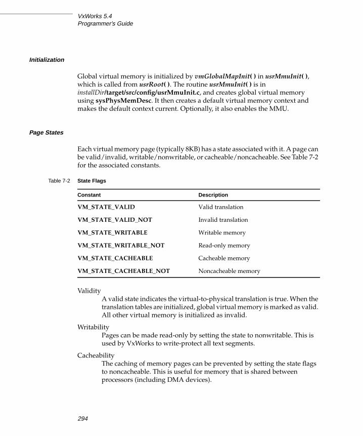
VxWorks 5.4Programmer’s Guide
Initialization
Global virtual memory is initialized by vmGlobalMapInit( ) in usrMmuInit( ),which is called from usrRoot( ). The routine usrMmuInit( ) is in
installDir/target/src/config/usrMmuInit.c, and creates global virtual memory
using sysPhysMemDesc. It then creates a default virtual memory context and
makes the default context current. Optionally, it also enables the MMU.
Page States
Each virtual memory page (typically 8KB) has a state associated with it. A page can
be valid/invalid, writable/nonwritable, or cacheable/noncacheable. See Table 7-2
for the associated constants.
Validity
A valid state indicates the virtual-to-physical translation is true. When the
translation tables are initialized, global virtual memory is marked as valid.
All other virtual memory is initialized as invalid.
Writability
Pages can be made read-only by setting the state to nonwritable. This is
used by VxWorks to write-protect all text segments.
Cacheability
The caching of memory pages can be prevented by setting the state flags
to noncacheable. This is useful for memory that is shared between
processors (including DMA devices).
Table 7-2 State Flags
Constant Description
VM_STATE_VALID Valid translation
VM_STATE_VALID_NOT Invalid translation
VM_STATE_WRITABLE Writable memory
VM_STATE_WRITABLE_NOT Read-only memory
VM_STATE_CACHEABLE Cacheable memory
VM_STATE_CACHEABLE_NOT Noncacheable memory
294

7
7Virtual Memory Interface
Change the state of a page with the routine vmStateSet( ). In addition to specifying
the state flags, a state mask must describe which flags are being changed; see
Table 7-3. Additional architecture-dependent states are specified in vmLib.h.
7.5.2 Private Virtual Memory
Private virtual memory can be created by creating a new virtual memory context.
This is useful for protecting data by making it inaccessible to other tasks or by
limiting access to specific routines. Virtual memory contexts are not automatically
created for tasks, but can be created and swapped in and out in an application-
specific manner.
At system initialization, a default context is created. All tasks use this default
context. To create private virtual memory, a task must create a new virtual memory
context using vmContextCreate( ), and make it current. All virtual memory
contexts share the global mappings that are created at system initialization; see
Figure 7-1. Only the valid virtual memory in the current virtual memory context
(including global virtual memory) is accessible. Virtual memory defined in other
virtual memory contexts is not accessible. To make another memory context
current, use vmCurrentSet( ).
To create a new virtual-to-physical mapping, use vmMap( ); both the physical and
virtual address must be determined in advance. The physical memory (which
must be page aligned) can be obtained using valloc( ). The easiest way to
determine the virtual address is to use vmGlobalInfoGet( ) to find a virtual page
that is not a global mapping. With this scheme, if multiple mappings are required,
a task must keep track of its own private virtual memory pages to guarantee it does
not map the same non-global address twice.
When physical pages are mapped into new sections of the virtual space, the
physical page is accessible from two different virtual addresses (a condition
known as aliasing): the newly mapped virtual address and the virtual address
equal to the physical address in the global virtual memory. This can cause
problems for some architectures, because the cache may hold two different values
Table 7-3 State Masks
Constant Description
VM_STATE_MASK_VALID Modify valid flag
VM_STATE_MASK_WRITABLE Modify write flag
VM_STATE_MASK_CACHEABLE Modify cache flag
295

VxWorks 5.4Programmer’s Guide
for the same underlying memory location. To avoid this, invalidate the virtual
page (using vmStateSet( )) in the global virtual memory. This also ensures that the
data is accessible only when the virtual memory context containing the new
mapping is current.
Figure 7-2 depicts two private virtual memory contexts. The new context (pvmc2)
maps virtual address 0x6000000 to physical address 0x10000. To prevent access to
this address from outside of this virtual context (pvmc1), the corresponding
physical address (0x10000) must be set to invalid. If access to the memory is made
using address 0x10000, a bus error occurs because that address is now invalid.
Example 7-1 Private Virtual Memory Contexts
In the following code example, private virtual memory contexts are used for
allocating memory from a task’s private memory partition. The setup routine,
contextSetup( ), creates a private virtual memory context that is made current
during a context switch. The virtual memory context is stored in the field spare1 in
the task’s TCB. Switch hooks are used to save the old context and install the task’s
private context. Note that the use of switch hooks increases the context switch
time. A user-defined memory partition is created using the private virtual memory
Figure 7-1 Global Mappings of Virtual Memory
...
PRIVATE
TRANSLATIONTABLE
Private
...
GLOBAL GLOBAL
TRANSLATIONTABLE
DefaultVirtual Memory Context Virtual Memory Context
MAPPING MAPPING MAPPING
296

7
7Virtual Memory Interface
context. The partition ID is stored in spare2 in the tasks TCB. Any task wanting a
private virtual memory context must call contextSetup( ). A sample task to test the
code is included.
/* contextExample.h - header file for vm contexts used by switch hooks */
#define NUM_PAGES (3)
/* context.c - use context switch hooks to make task private context current */
#include "vxWorks.h"#include "vmLib.h"#include "semLib.h"#include "taskLib.h"#include "taskHookLib.h"#include "memLib.h"#include "contextExample.h"
void privContextSwitch (WIND_TCB *pOldTask, WIND_TCB *pNewTask);
Figure 7-2 Mapping Private Virtual Memory
... ...
...
0
0x10000 0x10000
V
V
I
V
V
...
0x6000000
...
V
...
0x10000
VIRTUALADDRESS
PHYSICALADDRESS
STATE PHYSICALADDRESS
STATEVIRTUALADDRESS
invalidmapping
validmapping
pvmc1 pvmc2
GlobalVirtualMemory
PrivateVirtualMemory
PrivateVirtual Memory Context
NewVirtual Memory Context
297

VxWorks 5.4Programmer’s Guide
/************************************************************************** initContextSetup - install context switch hook**/
STATUS initContextSetup ( ){/* Install switch hook */
if (taskSwitchHookAdd ((FUNCPTR) privContextSwitch) == ERROR)return (ERROR);
return (OK);}
/************************************************************************** contextSetup - initialize context and create separate memory partition** Call only once for each task that wants a private context.** This could be made into a create-hook routine if every task on the* system needs a private context. To use as a create hook, the code for* installing the new virtual memory context should be replaced by simply* saving the new context in spare1 of the task’s TCB.*/
STATUS contextSetup (void){VM_CONTEXT_ID pNewContext;int pageSize;int pageBlkSize;char * pPhysAddr;char * pVirtAddr;UINT8 * globalPgBlkArray;int newMemSize;int index;WIND_TCB * pTcb;
/* create context */
pNewContext = vmContextCreate();
/* get page and page block size */
pageSize = vmPageSizeGet ();pageBlkSize = vmPageBlockSizeGet ();newMemSize = pageSize * NUM_PAGES;
/* allocate physical memory that is page aligned */
if ((pPhysAddr = (char *) valloc (newMemSize)) == NULL)return (ERROR);
298

7
7Virtual Memory Interface
/* Select virtual address to map. For this example, since only one page* block is used per task, simply use the first address that is not a* global mapping. vmGlobalInfoGet( ) returns a boolean array where each* element corresponds to a block of virtual memory.
*/
globalPgBlkArray = vmGlobalInfoGet();for (index = 0; globalPgBlkArray[index] == TRUE; index++)
;pVirtAddr = (char *) (index * pageBlkSize);
/* map physical memory to new context */
if (vmMap (pNewContext, pVirtAddr, pPhysAddr, newMemSize) == ERROR){free (pPhysAddr);return (ERROR);}
/* * Set state in global virtual memory to be invalid - any access to * this memory must be done through new context. */
if (vmStateSet(pNewContext, pPhysAddr, newMemSize, VM_STATE_MASK_VALID,VM_STATE_VALID_NOT) == ERROR)
return (ERROR);
/* get tasks TCB */
pTcb = taskTcb (taskIdSelf());
/* change virtual memory contexts */
/* * Stash the current vm context in the spare TCB field -- the switch * hook will install this when this task gets swapped out. */
pTcb->spare1 = (int) vmCurrentGet();
/* install new tasks context */
vmCurrentSet (pNewContext);
/* create new memory partition and store id in task’s TCB */
if ((pTcb->spare2 = (int) memPartCreate (pVirtAddr,newMemSize)) == NULL)return (ERROR);
return (OK);}
299

VxWorks 5.4Programmer’s Guide
/********************************************************************* privContextSwitch - routine to be executed on a context switch** If old task had private context, save it. If new task has private* context, install it.*/
void privContextSwitch(WIND_TCB *pOldTcb,WIND_TCB *pNewTcb)
{VM_CONTEXT_ID pContext = NULL;
/* If previous task had private context, save it--reset previous context. */
if (pOldTcb->spare1){pContext = (VM_CONTEXT_ID) pOldTcb->spare1;pOldTcb->spare1 = (int) vmCurrentGet ();
/* restore old context */
vmCurrentSet (pContext);}
/* * If next task has private context, map new context and save previous * context in task’s TCB. */
if (pNewTcb->spare1){pContext = (VM_CONTEXT_ID) pNewTcb->spare1;pNewTcb->spare1 = (int) vmCurrentGet();
/* install new tasks context */
vmCurrentSet (pContext);}
}
/* taskExample.h - header file for testing VM contexts used by switch hook */
/* This code is used by the sample task. */
#define MAX (10000000)
300

7
7Virtual Memory Interface
typedef struct myStuff {int stuff;int myStuff;} MY_DATA;
/* testTask.c - task code to test switch hooks */
#include "vxWorks.h"#include "memLib.h"#include "taskLib.h"#include "stdio.h"#include "vmLib.h"#include "taskExample.h"
IMPORT char *string = "test\n";
MY_DATA *pMem;
/************************************************************************** testTask - allocate private memory and use it** Loop forever, modifying memory and printing out a global string. Use this* in conjunction with testing from the shell. Since pMem points to private* memory, the shell should generate a bus error when it tries to read it.* For example:* -> sp testTask* -> d pMem*/
STATUS testTask (void){int val;WIND_TCB *myTcb;
/* install private context */
if (contextSetup () == ERROR)return (ERROR);
/* get TCB */
myTcb = taskTcb (taskIdSelf ());
/* allocate private memory */
if ((pMem = (MY_DATA *) memPartAlloc((PART_ID) myTcb->spare2, sizeof (MY_DATA))) == NULL)return (ERROR);
301

VxWorks 5.4Programmer’s Guide
/* * Forever, modify data in private memory and display string in * global memory. */
FOREVER{for (val = 0; val <= MAX; val++)
{/* modify structure */
pMem->stuff = val;pMem->myStuff = val / 2;
/* make sure can access global virtual memory */
printf (string);
taskDelay (sysClkRateGet() * 10);}
}return (OK);}
/************************************************************************** testVmContextGet - return a task’s virtual memory context stored in TCB** Used with vmContextShow() 1 to display a task’s virtual memory context.* For example, from the shell, type:* -> tid = sp (testTask)* -> vmContextShow (testVmContextGet (tid))*/
VM_CONTEXT_ID testVmContextGet(UINT tid){return ((VM_CONTEXT_ID) ((taskTcb (tid))->spare1));}
7.5.3 Noncacheable Memory
Architectures that do not support bus snooping must disable the memory caching
that is used for interprocessor communication (or by DMA devices). If multiple
1. This routine is not built in to the Tornado shell. To use it from the Tornado shell, you must
define INCLUDE_MMU_FULL_SHOW in your VxWorks configuration; see the TornadoUser’s Guide: Projects. When invoked this routine’s output is sent to the standard output
device.
302

7
7Virtual Memory Interface
processors are reading from and writing to a memory location, you must
guarantee that when the CPU accesses the data, it is using the most recent value. If
caching is used in one or more CPUs in the system, there can be a local copy of the
data in one of the CPUs’ data caches. In the example in Figure 7-3, a system with
multiple CPUs share data, and one CPU on the system (CPU 0) caches the shared
data. A task on CPU 0 reads the data [1] and then modifies the value [2]; however,
the new value may still be in the cache and not flushed to memory when a task on
another CPU (CPU 1) accesses it [3]. Thus the value of the data used by the task on
CPU 1 is the old value and does not reflect the modifications done by the task on
CPU 0; that value is still in CPU 0’s data cache [2].
To disable caching on a page basis, use vmStateSet( ); for example:
vmStateSet (pContext, pSData, len, VM_STATE_MASK_CACHEABLE, VM_STATE_CACHEABLE_NOT)
To allocate noncacheable memory, see the reference entry for cacheDmaMalloc( ).
Figure 7-3 Example of Possible Problems with Data Caching
CPU 0
CPU 1
DataCache
Access andmodify myVal .Cache myVal .
myVal = 100
(task executes first)
(task executes second)
Access myVal;myVal = 25
(not the valueof 100 just
set by CPU0).
[1][2]
[3]
Memory
myVal25
303

VxWorks 5.4Programmer’s Guide
7.5.4 Nonwritable Memory
Memory can be marked as nonwritable. Sections of memory can be write-
protected using vmStateSet( ) to prevent inadvertent access.
One use of this is to restrict modification of a data object to a particular routine. If
a data object is global but read-only, tasks can read the object but not modify it. Any
task that must modify this object must call the associated routine. Inside the
routine, the data is made writable for the duration of the routine, and on exit, the
memory is set to VM_STATE_WRITABLE_NOT.
Example 7-2 Nonwritable Memory
In this code example, to modify the data structure pointed to by pData, a task must
call dataModify( ). This routine makes the memory writable, modifies the data,
and sets the memory back to nonwritable. If a task tries to read the memory, it is
successful; however, if it tries to modify the data outside of dataModify( ), a bus
error occurs.
/* privateCode.h - header file to make data writable from routine only */
#define MAX 1024
typedef struct myData{char stuff[MAX];int moreStuff;} MY_DATA;
/* privateCode.c - uses VM contexts to make data private to a code segment */
#include "vxWorks.h"#include "vmLib.h"#include "semLib.h"#include "privateCode.h"
MY_DATA * pData;SEM_ID dataSemId;int pageSize;
/************************************************************************* initData - allocate memory and make it nonwritable*
304

7
7Virtual Memory Interface
* This routine initializes data and should be called only once.**/
STATUS initData (void){pageSize = vmPageSizeGet();
/* create semaphore to protect data */
dataSemId = semBCreate (SEM_Q_PRIORITY, SEM_EMPTY);
/* allocate memory = to a page */
pData = (MY_DATA *) valloc (pageSize);
/* initialize data and make it read-only */
bzero (pData, pageSize);if (vmStateSet (NULL, pData, pageSize, VM_STATE_MASK_WRITABLE,
VM_STATE_WRITABLE_NOT) == ERROR){semGive (dataSemId);return (ERROR);}
/* release semaphore */
semGive (dataSemId);return (OK);}
/********************************************************************** dataModify - modify data** To modify data, tasks must call this routine, passing a pointer to* the new data.* To test from the shell use:* -> initData* -> sp dataModify* -> d pData* -> bfill (pdata, 1024, 'X')*/
STATUS dataModify(MY_DATA * pNewData){
/* take semaphore for exclusive access to data */
semTake (dataSemId, WAIT_FOREVER);
/* make memory writable */
305

VxWorks 5.4Programmer’s Guide
if (vmStateSet (NULL, pData, pageSize, VM_STATE_MASK_WRITABLE,VM_STATE_WRITABLE) == ERROR)
{semGive (dataSemId);return (ERROR);}
/* update data*/
bcopy (pNewData, pData, sizeof(MY_DATA));
/* make memory not writable */
if (vmStateSet (NULL, pData, pageSize, VM_STATE_MASK_WRITABLE,VM_STATE_WRITABLE_NOT) == ERROR)
{semGive (dataSemId);return (ERROR);}
semGive (dataSemId);
return (OK);}
7.5.5 Troubleshooting
If INCLUDE_MMU_FULL_SHOW is included in the project facility VxWorks view,
you can use vmContextShow( ) to display a virtual memory context on the
standard output device. In the following example, the current virtual memory
context is displayed. Virtual addresses between 0x0 and 0x59fff are write
protected; 0xff800000 through 0xffbfffff are noncacheable; and 0x2000000 through
0x2005fff are private. All valid entries are listed and marked with a V+. Invalid
entries are not listed.
-> vmContextShow 0value = 0 = 0x0
The output is sent to the standard output device, and looks like the following:
VIRTUAL ADDR BLOCK LENGTH PHYSICAL ADDR STATE0x0 0x5a000 0x0 W- C+ V+ (global)0x5a000 0x1f3c000 0x5a000 W+ C+ V+ (global)0x1f9c000 0x2000 0x1f9c000 W+ C+ V+ (global)0x1f9e000 0x2000 0x1f9e000 W- C+ V+ (global)0x1fa0000 0x2000 0x1fa0000 W+ C+ V+ (global)0x1fa2000 0x2000 0x1fa2000 W- C+ V+ (global)0x1fa4000 0x6000 0x1fa4000 W+ C+ V+ (global)0x1faa000 0x2000 0x1faa000 W- C+ V+ (global)0x1fac000 0xa000 0x1fac000 W+ C+ V+ (global)0x1fb6000 0x2000 0x1fb6000 W- C+ V+ (global)
306

7
7Virtual Memory Interface
0x1fb8000 0x36000 0x1fb8000 W+ C+ V+ (global)0x1fee000 0x2000 0x1fee000 W- C+ V+ (global)0x1ff0000 0x2000 0x1ff0000 W+ C+ V+ (global)0x1ff2000 0x2000 0x1ff2000 W- C+ V+ (global)0x1ff4000 0x2000 0x1ff4000 W+ C+ V+ (global)0x1ff6000 0x2000 0x1ff6000 W- C+ V+ (global)0x1ff8000 0x2000 0x1ff8000 W+ C+ V+ (global)0x1ffa000 0x2000 0x1ffa000 W- C+ V+ (global)0x1ffc000 0x4000 0x1ffc000 W+ C+ V+ (global)0x2000000 0x6000 0x1f96000 W+ C+ V+0xff800000 0x400000 0xff800000 W- C- V+ (global)0xffe00000 0x20000 0xffe00000 W+ C+ V+ (global)0xfff00000 0xf0000 0xfff00000 W+ C- V+ (global)
7.5.6 Precautions
Memory that is marked as global cannot be remapped using vmMap( ). To add to
global virtual memory, use vmGlobalMap( ). For further information on adding
global virtual memory, see 7.5.2 Private Virtual Memory, p.295.
Performances of MMUs vary across architectures; in fact, some architectures may
cause the system to become non-deterministic. For additional information, see the
architecture-specific documentation for your hardware.
307

VxWorks 5.4Programmer’s Guide
308

8Configuration and Build
8.1 Introduction
The Tornado distribution includes a VxWorks system image for each target shipped.
The system image is a binary module that can be booted and run on a target system.
The system image consists of all desired system object modules linked together
into a single non-relocatable object module with no unresolved external references.
In most cases, you will find the supplied system image entirely adequate for initial
development. However, later in the cycle you may want to tailor its configuration
to reflect your application requirements.
In order to tailor the system image, you will need to understand the BSP structure
and the VxWorks initialization process. These topics are discussed in the following
sections:
■ 8.2 The Board Support Package (BSP), p.310
■ 8.3 VxWorks Initialization Timeline, p.313
In addition, this chapter describes in detail the manual cross-development
procedures used to create and run VxWorks systems and applications as well as
how to configure the system image by directly editing configuration files.
The following topics are included:
■ How to build, load, run, and unload VxWorks applications manually.
■ VxWorks configuration files and configuration options and parameters.
■ How to include manually generated configuration files in the project facility.
■ Some of the common alternative configurations of VxWorks.
309

VxWorks 5.4Programmer’s Guide
■ Rebuilding VxWorks system images, bootable applications, and ROM images
using manual methods.
VxWorks has been ported to numerous development and target systems, and can
support many different hardware configurations. Some of the cross-development
procedures discussed in this chapter depend somewhat on the specific system and
configuration you are running. The procedures in this chapter are presented in
generic form, and may differ slightly on your particular system.
For information specific to an architecture family, see the corresponding appendix
in this manual. Information specific to particular target boards is provided with
each BSP.
8.2 The Board Support Package (BSP)
The directory installDir/target/config/bspname contains the Board Support Package(BSP), which consists of files for the particular hardware used to run VxWorks,
such as a VME board with serial lines, timers, and other devices. The files include:
Makefile, sysLib.c, sysSerial.c, sysALib.s, romInit.s, bspname.h, and config.h.
Wind River Systems BSPs conform to a standard, introduced with BSP Version 1.1.
The standard is fully described in the Tornado BSP Developer’s Kit for VxWorks.
! WARNING: Use of the project facility for configuring and building applications is
largely independent of the methods used prior to Tornado 2.0 (which included
manually editing the configuration file config.h). The project facility provides the
recommended and simpler means for configuration and build, although the
manual method may still be used as described in this chapter.
To avoid confusion and errors, the two methods should not be used together for
the same project. The one exception is for any configuration macro that is not
exposed through the project facility GUI (which may be the case, for example, for
some BSP driver parameters). In this case, a configuration file must be edited, and
the project facility will implement the change in the subsequent build.
Note that the project facility overrides any changes made to a macro in config.hwhich is also exposed through the project facility. If you are using the project
facility, only edit macros in config.h which can not be configured through the
project facility.
310
8
8Configuration and Build
The System Library
The file sysLib.c provides the board-level interface on which VxWorks and
application code can be built in a hardware-independent manner. The functions
addressed in this file include:
■ Initialization functions
– initialize the hardware to a known state
– identify the system
– initialize drivers, such as SCSI or custom drivers
■ Memory/address space functions
– get the on-board memory size
– make on-board memory accessible to external bus (optional)
– map local and bus address spaces
– enable/disable cache memory
– set/get nonvolatile RAM (NVRAM)
– define the board’s memory map (optional)
– virtual-to-physical memory map declarations for processors with MMUs
■ Bus interrupt functions
– enable/disable bus interrupt levels
– generate bus interrupts
■ Clock/timer functions
– enable/disable timer interrupts
– set the periodic rate of the timer
■ Mailbox/location monitor functions (optional)
– enable mailbox/location monitor interrupts
The sysLib library does not support every feature of every board: some boards
may have additional features, others may have fewer, others still may have the
same features with a different interface. For example, some boards provide some
sysLib functions by means of hardware switches, jumpers, or PALs, instead of by
software-controllable registers.
The configuration modules usrConfig.c and bootConfig.c in config/all are
responsible for invoking this library’s routines at the appropriate time. Device
drivers can use some of the memory mapping routines and bus functions.
311

VxWorks 5.4Programmer’s Guide
Virtual Memory Mapping
For boards with MMU support, the data structure sysPhysMemDesc defines the
virtual-to-physical memory map. This table is typically defined in sysLib.c,
although some BSPs place it in a separate file, memDesc.c. It is declared as an array
of the data structure PHYS_MEM_DESC. No two entries in this descriptor can
overlap; each entry must be a unique memory space.
The sysPhysMemDesc array should reflect your system configuration, and you
may encounter a number of reasons for changing the MMU memory map, for
example: the need to change the size of local memory or the size of the VME master
access space, or because the address of the VME master access space has been
moved. For information on virtual memory mapping, as well as an example of
how to modify sysPhysMemDesc, see 7.3 Virtual Memory Configuration, p.290.
The Serial Driver
The file sysSerial.c provides board-specific initialization for the on-board serial
ports. The actual serial I/O driver is in the installDir/target/src/drv/sio directory.
The library ttyDrv uses the serial I/O driver to provide terminal operations for
VxWorks.
BSP Initialization Modules
The following files initialize the BSP:
■ The file romInit.s contains assembly-level initialization routines.
■ The file sysALib.s contains initialization and system-specific assembly-level
routines.
BSP Documentation
The file target.nr in the installDir/target/config/bspname directory is the source of
the online reference entry for target-specific information. (For information on how
to view these reference entries, see Tornado Getting Started.) The target.nr file
describes the supported board variations, the relevant jumpering, and supported
! CAUTION: A bus error can occur if you try to access memory that is not mapped.
312

8
8Configuration and Build
devices. It also includes an ASCII representation of the board layout with an
indication of board jumpers (if applicable) and the location of the ROM sockets.
8.3 VxWorks Initialization Timeline
This section covers the initialization sequence for VxWorks in a typical
development configuration. The steps are described in sequence of execution. This
is not the only way VxWorks can be bootstrapped on a particular processor. There
are often more efficient or robust techniques unique to a particular processor or
hardware; consult your hardware’s documentation.
For final production, the sequence can be revisited to include diagnostics or to
remove some of the generic operations that are required for booting a development
environment, but that are unnecessary for production. This description can
provide only an approximate guide to the processor initialization sequence and
does not document every exception to this time-line.
The early steps of the initialization sequence are slightly different for ROM-based
versions of VxWorks; for information, see 8.6.3 Initialization Sequence for ROM-Based VxWorks, p.349.
For a summary of the initialization time-line, see Table 8-1. The following sections
describe the initialization in detail by routine name. For clarity, the sequence is
divided into a number of main steps or function calls. The key routines are listed
in the headings and are described in chronological order.
The VxWorks Entry Point: sysInit( )
The first step in starting a VxWorks system is to load a system image into main
memory. This usually occurs as a download from the development host, under the
control of the VxWorks boot ROM. Next, the boot ROM transfers control to the
VxWorks startup entry point, sysInit( ). This entry point is configured by
RAM_LOW_ADRS in the makefile and in config.h. The VxWorks memory layout is
different for each architecture; for details, see the appendix that describes your
architecture.
The entry point, sysInit( ), is in the system-dependent assembly language module,
sysALib.s. It locks out all interrupts, invalidates caches if applicable, and
313

VxWorks 5.4Programmer’s Guide
initializes processor registers (including the C stack pointer) to default values. It
also disables tracing, clears all pending interrupts, and invokes usrInit( ), a C
subroutine in the usrConfig.c module. For some targets, sysInit( ) also performs
some minimal system-dependent hardware initialization, enough to execute the
remaining initialization in usrInit( ). The initial stack pointer, which is used only
by usrInit( ), is set to occupy an area below the system image but above the vector
table (if any).
The Initial Routine: usrInit( )
The usrInit( ) routine (in usrConfig.c) saves information about the boot type,
handles all the initialization that must be performed before the kernel is actually
started, and then starts the kernel execution. It is the first C code to run in VxWorks.
It is invoked in supervisor mode with all hardware interrupts locked out.
Many VxWorks facilities cannot be invoked from this routine. Because there is no
task context as yet (no TCB and no task stack), facilities that require a task context
cannot be invoked. This includes any facility that can cause the caller to be
preempted, such as semaphores, or any facility that uses such facilities, such as
printf( ). Instead, the usrInit( ) routine does only what is necessary to create an
initial task, usrRoot( ). This task then completes the startup.
The initialization in usrInit( ) includes the following:
Cache Initialization
The code at the beginning of usrInit( ) initializes the caches, sets the mode of the
caches and puts the caches in a safe state. At the end of usrInit( ), the instruction
and data caches are enabled by default.
Zeroing Out the System bss Segment
The C and C++ languages specify that all uninitialized variables must have initial
values of 0. These uninitialized variables are put together in a segment called bss.
This segment is not actually loaded during the bootstrap, because it is known to be
zeroed out. Because usrInit( ) is the first C code to execute, it clears the section of
memory containing bss as its very first action. While the VxWorks boot ROMs clear
all memory, VxWorks does not assume that the boot ROMs are used.
Initializing Interrupt Vectors
The exception vectors must be set up before enabling interrupts and starting the
kernel. First, intVecBaseSet( ) is called to establish the vector table base address.
314

8
8Configuration and Build
After intVecBaseSet( ) is called, the routine excVecInit( ) initializes all exception
vectors to default handlers that safely trap and report exceptions caused by
program errors or unexpected hardware interrupts.
Initializing System Hardware to a Quiescent State
System hardware is initialized by calling the system-dependent routine
sysHwInit( ). This mainly consists of resetting and disabling hardware devices
that can cause interrupts after interrupts are enabled (when the kernel is started).
This is important because the VxWorks ISRs (for I/O devices, system clocks, and
so on), are not connected to their interrupt vectors until the system initialization is
completed in the usrRoot( ) task. However, do not attempt to connect an interrupt
handler to an interrupt during the sysHwInit( ) call, because the memory pool is
not yet initialized.
Initializing the Kernel
The usrInit( ) routine ends with calls to two kernel initialization routines:
usrKernelInit( ) (defined in usrKernel.c)
calls the appropriate initialization routines for each of the specified
optional kernel facilities (see Table 8-1 for a list).
kernelInit( ) (part of kernelLib.c)
initiates the multitasking environment and never returns. It takes the
following parameters:
– The application to be spawned as the “root” task, typically usrRoot( ).
– The stack size.
– The start of usable memory; that is, the memory after the main text, data,
and bss of the VxWorks image. All memory after this area is added to the
system memory pool, which is managed by memPartLib. Allocation for
dynamic module loading, task control blocks, stacks, and so on, all come
out of this region. See Initializing the Memory Pool, p.316.
– The top of memory as indicated by sysMemTop( ). If a contiguous block of
memory is to be preserved from normal memory allocation, pass
sysMemTop( ) less the reserved memory.
NOTE: There are exceptions to this in some architectures; see the appendix that
describes your architecture for details.
315

VxWorks 5.4Programmer’s Guide
– The interrupt stack size. The interrupt stack corresponds to the largest
amount of stack space any interrupt-level routine uses, plus a safe margin
for the nesting of interrupts.
– The interrupt lock-out level. For architectures that have a level concept, it
is the maximum level. For architectures that do not have a level concept, it
is the mask to disable interrupts. See the appendix that describes your
architecture for details.
kernelInit( ) calls intLockLevelSet( ), disables round-robin mode, and creates an
interrupt stack if supported by the architecture. It then creates a root stack and TCB
from the top of the memory pool, spawns the root task, usrRoot( ), and terminates
the usrInit( ) thread of execution. At this time, interrupts are enabled; it is critical
that all interrupt sources are disabled and pending interrupts cleared.
Initializing the Memory Pool
VxWorks includes a memory allocation facility, in the module memPartLib, that
manages a pool of available memory. The malloc( ) routine allows callers to obtain
variable-size blocks of memory from the pool. Internally, VxWorks uses malloc( )for dynamic allocation of memory. In particular, many VxWorks facilities allocate
data structures during initialization. Therefore, the memory pool must be
initialized before any other VxWorks facilities are initialized.
Note that the Tornado target server manages a portion of target memory to
support downloading of object modules and other development functions.
VxWorks makes heavy use of malloc( ), including allocation of space for loaded
modules, allocation of stacks for spawned tasks, and allocation of data structures
on initialization. You are also encouraged to use malloc( ) to allocate any memory
your application requires. Therefore, it is recommended that you assign to the
VxWorks memory pool all unused memory, unless you must reserve some fixed
absolute memory area for a particular application use.
The memory pool is initialized by kernelInit( ). The parameters to kernelInit( )specify the start and end address of the initial memory pool. In the default
usrInit( ) distributed with VxWorks, the pool is set to start immediately following
the end of the booted system, and to contain all the rest of available memory.
The extent of available memory is determined by sysMemTop( ), which is a system-
dependent routine that determines the size of available memory. If your system
has other noncontiguous memory areas, you can make them available in the
general memory pool by later calling memAddToPool( ) in the usrRoot( ) task.
316

8
8Configuration and Build
The Initial Task: usrRoot( )
When the multitasking kernel starts executing, all VxWorks multitasking facilities
are available. Control is transferred to the usrRoot( ) task and the initialization of
the system can be completed. For example, usrRoot( ) performs the following:
– initialization of the system clock
– initialization of the I/O system and drivers
– creation of the console devices
– setting of standard in and standard out
– installation of exception handling and logging
– initialization of the pipe driver
– initialization of standard I/O
– creation of file system devices and installation of disk drivers
– initialization of floating-point support
– initialization of performance monitoring facilities
– initialization of the network
– initialization of optional facilities
– initialization of WindView (see the WindView User’s Guide)
– initialization of target agent
– execution of a user-supplied startup script
To review the complete initialization sequence within usrRoot( ), see
installDir/target/config/all/ usrConfig.c.
Modify these initializations to suit your configuration. The meaning of each step
and the significance of the various parameters are explained in the following
sections.
Initialization of the System Clock
The first action in the usrRoot( ) task is to initialize the VxWorks clock. The system
clock interrupt vector is connected to the routine usrClock( ) (described in TheSystem Clock Routine: usrClock( ), p.322) by calling sysClkConnect( ). Then, the
system clock rate (usually 60Hz) is set by sysClkRateSet( ). Most boards allow
clock rates as low as 30Hz (some even as low as 1Hz), and as high as several
thousand Hz. High clock rates (>1000Hz) are not desirable, because they can cause
system thrashing.1
The timer drivers supplied by WRS include a call to sysHwInit2( ) as part of the
sysClkConnect( ) routine. Wind River BSPs use sysHwInit2( ) to perform further
1. Thrashing occurs when clock interrupts are so frequent that the processor spends too much
time servicing the interrupts, and no application code can run.
317

VxWorks 5.4Programmer’s Guide
board initialization that is not completed in sysHwInit( ). For example, an
intConnect( ) of ISRs can take place here, because memory can be allocated now
that the system is multitasking.
Initialization of the I/O System
If INCLUDE_IO_SYSTEM is defined in configAll.h, the VxWorks I/O system is
initialized by calling the routine iosInit( ). The arguments specify the maximum
number of drivers that can be subsequently installed, the maximum number of
files that can be open in the system simultaneously, and the desired name of the
“null” device that is included in the VxWorks I/O system. This null device is a “bit-
bucket” on output and always returns end-of-file for input.
The inclusion or exclusion of INCLUDE_IO_SYSTEM also affects whether the
console devices are created, and whether standard in, standard out, and standard
error are set; see the next two sections for more information.
Creation of the Console Devices
If the driver for the on-board serial ports is included (INCLUDE_TTY_DEV), it is
installed in the I/O system by calling the driver’s initialization routine, typically
ttyDrv( ). The actual devices are then created and named by calling the driver’s
device-creation routine, typically ttyDevCreate( ). The arguments to this routine
includes the device name, a serial I/O channel descriptor (from the BSP), and input
and output buffer sizes.
The macro NUM_TTY specifies the number of tty ports (default is 2),
CONSOLE_TTY specifies which port is the console (default is 0), and
CONSOLE_BAUD_RATE specifies the bps rate (default is 9600). These macros are
specified in configAll.h, but can be overridden in config.h for boards with a
nonstandard number of ports.
PCs can use an alternative console with keyboard input and VGA output; see your
PC workstation documentation for details.
Setting of Standard In, Standard Out, and Standard Error
The system-wide standard in, standard out, and standard error assignments are
established by opening the console device and calling ioGlobalStdSet( ). These
assignments are used throughout VxWorks as the default devices for
communicating with the application developer. To make the console device an
interactive terminal, call ioctl( ) to set the device options to OPT_TERMINAL.
318
8
8Configuration and Build
Installation of Exception Handling and Logging
Initialization of the VxWorks exception handling facilities (supplied by the module
excLib) and logging facilities (supplied by logLib) takes place early in the
execution of the root task. This facilitates detection of program errors in the root
task itself or in the initialization of the various facilities.
The exception handling facilities are initialized by calling excInit( ) when
INCLUDE_EXC_HANDLING and INCLUDE_EXC_TASK are defined. The excInit( )routine spawns the exception support task, excTask( ). Following this
initialization, program errors causing hardware exceptions are safely trapped and
reported, and hardware interrupts to uninitialized vectors are reported and
dismissed. The VxWorks signal facility, used for task-specific exception handling,
is initialized by calling sigInit( ) when INCLUDE_SIGNALS is defined.
The logging facilities are initialized by calling logInit( ) when
INCLUDE_LOGGING is defined. The arguments specify the file descriptor of the
device to which logging messages are to be written, and the number of log message
buffers to allocate. The logging initialization also includes spawning the logging
task, logTask( ).
Initialization of the Pipe Driver
If named pipes are desired, define INCLUDE_PIPE in configAll.h so that pipeDrv( )is called automatically to initialize the pipe driver. Tasks can then use pipes to
communicate with each other through the standard I/O interface. Pipes must be
created with pipeDevCreate( ).
Initialization of Standard I/O
VxWorks includes an optional standard I/O package when INCLUDE_STDIO is
defined.
Creation of File System Devices and Initialization of Device Drivers
Many VxWorks configurations include at least one disk device or RAM disk with
a dosFs, rt11Fs, or rawFs file system. First, a disk driver is installed by calling the
driver’s initialization routine. Next, the driver’s device-creation routine defines a
device. This call returns a pointer to a BLK_DEV structure that describes the device.
The new device can then be initialized and named by calling the file system’s
device-initialization routine—dosFsDevInit( ), rt11FsDevInit( ), or
rawFsDevInit( )—when the respective constants INCLUDE_DOSFS,
INCLUDE_RT11FS, and INCLUDE_RAWFS are defined. (Before a device can be
initialized, the file system module must already be initialized with dosFsInit( ),
319

VxWorks 5.4Programmer’s Guide
rt11FsInit( ), or rawFsInit( ).) The arguments to the file system device-
initialization routines depend on the particular file system, but typically include
the device name, a pointer to the BLK_DEV structure created by the driver’s
device-creation routine, and possibly some file-system-specific configuration
parameters.
Initialization of Floating-Point Support
Support for floating-point I/O is initialized by calling the routine floatInit( ) when
INCLUDE_FLOATING_POINT is defined in configAll.h. Support for floating-point
coprocessors is initialized by calling mathHardInit( ) when INCLUDE_HW_FP is
defined. Support for software floating-point emulation is initialized by calling
mathSoftInit( ) when INCLUDE_SW_FP is defined. See the appropriate
architecture appendix for details on your processor’s floating-point support.
Inclusion of Performance Monitoring Tools
VxWorks has two built-in performance monitoring tools. A task activity summary
is provided by spyLib, and a subroutine execution timer is provided by timexLib.
These facilities are included by defining the macros INCLUDE_SPY and
INCLUDE_TIMEX, respectively, in configAll.h.
Initialization of the Network
Before the network can be used, it must be initialized with the routine
usrNetInit( ), which is called by usrRoot( ) when the constant INCLUDE_NET_INITis defined in one of the configuration header files. (The source for usrNetInit( ) isin installDir/target/src/config/usrNetwork.c.) The routine usrNetInit( ) takes a
configuration string as an argument. This configuration string is usually the “boot
line” that is specified to the VxWorks boot ROMs to boot the system (see TornadoGetting Started). Based on this string, usrNetInit( ) performs the following:
■ Initializes network subsystem by calling the routine netLibInit( ).
■ Attaches and configures appropriate network drivers.
■ Adds gateway routes.
■ Initializes the remote file access driver netDrv, and adds a remote file access
device.
■ Initializes the remote login facilities.
■ Optionally initializes the Remote Procedure Calls (RPC) facility.
■ Optionally initializes the Network File System (NFS) facility.
320

8
8Configuration and Build
As noted previously, the inclusion of some of these network facilities is controlled
by definitions in configAll.h; see Table 8-6 for a list of these constants. The network
initialization steps are described in the VxWorks Network Programmer’s Guide.
Initialization of Optional Products and Other Facilities
Shared memory objects are provided with the optional product VxMP. Before
shared memory objects can be used, they must be initialized with the routine
usrSmObjInit( ) (in installDir/target/src/config/usrSmObj.c), which is called from
usrRoot( ) if INCLUDE_SM_OBJ is defined.
Basic MMU support is provided if INCLUDE_MMU_BASIC is defined. Text
protection, vector table protection, and a virtual memory interface are provided
with the optional product VxVMI, if INCLUDE_MMU_FULL is defined. The MMU
is initialized by the routine usrMmuInit( ), located in
installDir/target/src/config/usrMmuInit.c. If the macros
INCLUDE_PROTECT_TEXT and INCLUDE_PROTECT_VEC_TABLE are also
defined, text protection and vector table protection are initialized.
The GNU C++ compiler is shipped with Tornado. To initialize C++ support for the
GNU compiler, define either INCLUDE_CPLUS or INCLUDE_CPLUS_MIN. To
include one or more of the Wind Foundation Class libraries, define the appropriate
INCLUDE_CPLUS_library macros (listed in Table 8-6).2
Initialization of WindView
Kernel instrumentation is provided with the optional product WindView. It is
initialized in usrRoot( ) when INCLUDE_WINDVIEW is defined in configAll.h.
Other WindView configuration constants control particular initialization steps; see
the WindView User’s Guide: Configuring WindView.
! CAUTION: The shared memory objects library requires information from fields in
the VxWorks boot line. The functions are contained in the usrNetwork.c file. If no
network services are included, usrNetwork.c is not included and the shared
memory initialization fails. The project facility calculates all dependencies but if
you are using manual configuration, either add INCLUDE_NETWORK to
configAll.h or extract the bootline cracking routines from usrNetwork.c and
include them elsewhere.
2. For information on using the GNU C++ compiler and the optional Wind Foundation
Classes, see 5. C++ Development and 8.4.2 Compiling Application Modules, p.329.
321

VxWorks 5.4Programmer’s Guide
Initialization of the Target Agent
If INCLUDE_WDB is defined, wdbConfig( ) in installDir/target/src/config/usrWdb.cis called. This routine initializes the agent’s communication interface, then starts
the agent. For information on configuring the agent and the agent’s initialization
sequence, see Tornado Getting Started.
Execution of a Startup Script
The usrRoot( ) routine executes a user-supplied startup script if the target-resident
shell is configured into VxWorks, INCLUDE_STARTUP_SCRIPT is defined, and the
script’s file name is specified at boot time with the startup script parameter (see
Tornado Getting Started). If the parameter is missing, no startup script is executed.
The System Clock Routine: usrClock( )
Finally, the system clock ISR usrClock( ) is attached to the system clock timer
interrupt by the usrRoot( ) task described The Initial Task: usrRoot( ), p.317. The
usrClock( ) routine calls the kernel clock tick routine tickAnnounce( ), which
performs OS bookkeeping. You can add application-specific processing to this
routine.
Initialization Summary
Table 8-1 shows a summary of the entire VxWorks initialization sequence for
typical configurations. For a similar summary applicable to ROM-based VxWorks
systems, see Overall Initialization for ROM-Based VxWorks, p.350.
Table 8-1 VxWorks Run-time System Initialization Sequence
Routine Activity File
sysInit( ) (a) lock out interrupts sysALib.s
(b) invalidate caches, if any
(c) initialize system interrupt tables with default
stubs (i960 only)
(d) initialize system fault tables with default stubs
(i960 only)
322

8
8Configuration and Build
(e) initialize processor registers to known default
values
(f) disable tracing
(g) clear all pending interrupts
(h) invoke usrInit( ) specifying boot type
usrInit( ) (a) zero bss (uninitialized data) usrConfig.c
(b) save bootType in sysStartType
(c) invoke excVecInit( ) to initialize all system and
default interrupt vectors
(d) invoke sysHwInit( )
(e) invoke usrKernelInit( )
(f) invoke kernelInit( )
usrKernelInit( ) The following routines are invoked if their
configuration constants are defined.
usrKernel.c
(a) classLibInit( )
(b) taskLibInit( )
(c) taskHookInit( )
(d) semBLibInit( )
(e) semMLibInit( )
(f) semCLibInit( )
(g) semOLibInit( )
(h) wdLibInit( )
(i) msgQLibInit( )
(j) qInit( ) for all system queues
(k) workQInit( )
kernelInit( ) Initialize and start the kernel. kernelLib.c
Table 8-1 VxWorks Run-time System Initialization Sequence (Continued)
Routine Activity File
323
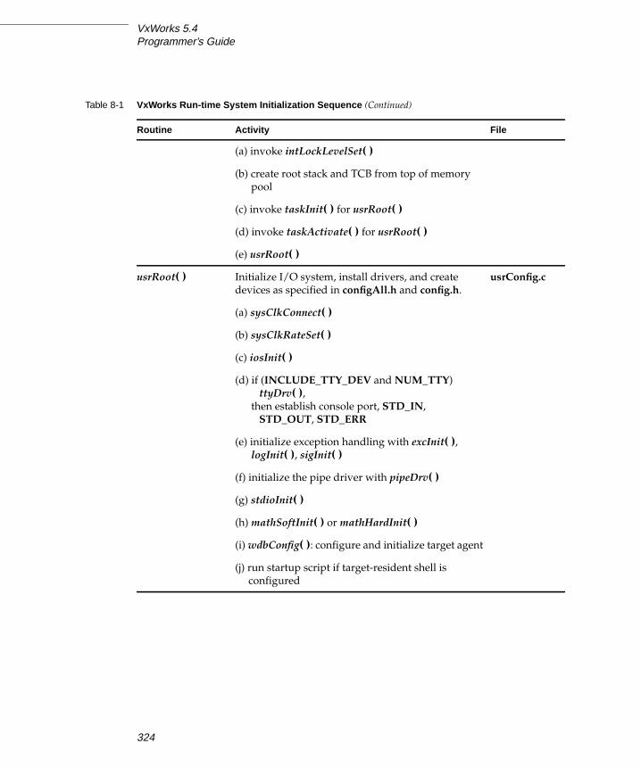
VxWorks 5.4Programmer’s Guide
(a) invoke intLockLevelSet( )
(b) create root stack and TCB from top of memory
pool
(c) invoke taskInit( ) for usrRoot( )
(d) invoke taskActivate( ) for usrRoot( )
(e) usrRoot( )
usrRoot( ) Initialize I/O system, install drivers, and create
devices as specified in configAll.h and config.h.
usrConfig.c
(a) sysClkConnect( )
(b) sysClkRateSet( )
(c) iosInit( )
(d) if (INCLUDE_TTY_DEV and NUM_TTY)
ttyDrv( ),then establish console port, STD_IN,
STD_OUT, STD_ERR
(e) initialize exception handling with excInit( ),logInit( ), sigInit( )
(f) initialize the pipe driver with pipeDrv( )
(g) stdioInit( )
(h) mathSoftInit( ) or mathHardInit( )
(i) wdbConfig( ): configure and initialize target agent
(j) run startup script if target-resident shell is
configured
Table 8-1 VxWorks Run-time System Initialization Sequence (Continued)
Routine Activity File
324

8
8Configuration and Build
8.4 Building, Loading, and Unloading Application Modules
In the Tornado development environment, application modules for the target
system are created and maintained on a separate development host. First, the
source code, generally in C or C++, is edited and compiled to produce a relocatable
object module. Application modules use VxWorks facilities by virtue of including
header files that define operating-system interfaces and data structures. The
resulting object modules can then be loaded and dynamically linked into a running
VxWorks system over the network.
The following sections describe in detail the procedures for carrying out cross-
development manually (without using the project facility).
8.4.1 Using VxWorks Header Files
Many application modules make use of VxWorks operating system facilities or
utility libraries. This usually requires that the source module refer to VxWorks
header files. The following sections discuss the use of VxWorks header files.
VxWorks header files supply ANSI C function prototype declarations for all global
VxWorks routines. The ANSI C prototypes are conditionally compiled; to use
them, the preprocessor constant _ _STDC_ _ must be defined. ANSI C compilers
define this constant by default. VxWorks provides all header files specified by the
ANSI X3.159-1989 standard.
VxWorks system header files are in the directory installDir/target/h and its
subdirectories.
VxWorks Header File: vxWorks.h
The header file vxWorks.h contains many basic definitions and types that are used
extensively by other VxWorks modules. Many other VxWorks header files require
these definitions. Thus, this file must be included first by every application module
that uses VxWorks facilities. Include vxWorks.h with the following line:
#include "vxWorks.h"
NOTE: The notation $(WIND_BASE) is used in makefiles to refer to the Tornado
installation directory. This chapter uses that notation because makefiles are the
most convenient way to run the Tornado compilation tools. If you run the compiler
from the Windows command prompt, write %WIND_BASE% instead.
325

VxWorks 5.4Programmer’s Guide
Other VxWorks Header Files
Application modules can include other VxWorks header files as needed to access
VxWorks facilities. For example, an application module that uses the VxWorks
linked-list subroutine library must include the lstLib.h file with the following line:
#include "lstLib.h"
The manual entry for each library lists all header files necessary to use that library.
ANSI Header Files
All ANSI-specified header files are included in VxWorks. (UNIX)
This implies that many familiar UNIX header files are available under VxWorks as
well. There are two file names that differ from the usual UNIX names: a_out.h(which corresponds to the UNIX a.out.h) and stdlib.h (which corresponds to the
UNIX malloc.h)
The -I Compiler Flag
By default, the compiler searches for header files first in the directory of the source
module and then in directories that apply only to the development host. With the
GNU compiler, you can avoid these host-system include directories with the
compilation flag -nostdinc. To access the VxWorks header files, the compiler must
also be directed to search $(WIND_BASE)/target/h. Thus, the following option
flag is standard for VxWorks compilation:
-I $(WIND_BASE)/target/h
Some header files are located in subdirectories. To refer to header files in these
subdirectories, be sure to specify the subdirectory name in the include statement,
so that the files can be located with a single -I specifier. For example:
#include "vxWorks.h"#include "sys/stat.h"
VxWorks Nested Header Files
Some VxWorks facilities make use of other, lower-level VxWorks facilities. For
example, the tty management facility uses the ring buffer subroutine library. The
326

8
8Configuration and Build
tty header file tyLib.h uses definitions that are supplied by the ring buffer header
file rngLib.h.
It would be inconvenient to require you to be aware of such include-file
interdependencies and ordering. Instead, all VxWorks header files explicitly
include all prerequisite header files. Thus, tyLib.h itself contains an include of
rngLib.h. (The exception to this is the basic VxWorks header file vxWorks.h, which
all other header files assume is already included.)
This, in turn, might lead to a problem: a header file could get included more than
once, if one were included by several other header files, or if it were also included
directly by the application module. Normally, including a header file more than
once generates fatal compilation errors, because the C preprocessor regards
duplicate definitions as potential sources of conflict. To avoid this problem, all
VxWorks header files contain conditional compilation statements and definitions
that ensure that their text is included only once, no matter how many times they
are specified by include statements. Thus, an application module can include just
those header files it needs directly, without regard for interdependencies or
ordering, and no conflicts arise.
Internal Header Files
Table 8-2 lists the subdirectories of installDir/target/h used by VxWorks for internal
header files. These header files are, for the most part, not intended for applications.
The following subdirectories are exceptions, and are sometimes required by
application programs:
■ installDir/target/h/net, which is used by network drivers for specific network
controllers.■ installDir/target/h/rpc, which is used by applications using the remote
procedure call library.■ installDir/target/h/sys, which is used by applications using standard POSIX
functions.
Table 8-2 Include Subdirectories
Subdirectory Use
installDir/target/h/arch Architecture-specific header files.
installDir/target/h/arpa Fundamental Internet header file.
installDir/target/h/make Generic makefile information.
327

VxWorks 5.4Programmer’s Guide
VxWorks Private Header Files
VxWorks modules are designed so that you never need to know or reference the
modules’ internal data structures. In general, all legitimate access to a facility is
provided by a module’s subroutine interfaces. The internal details should be
thought of as “hidden” from application developers. This means that the internal
implementations can change without affecting your use of the corresponding
facilities.
Internal details in VxWorks are hidden using two conventions. Some header files
mark hidden code using the following comments:
/* HIDDEN */.../* END HIDDEN */
Internal details are also hidden with private header files: files that are stored in the
directory installDir/target/h/private. The naming conventions for these files
parallel those in installDir/target/h with the library name followed by P.h. For
example, the private header file for semLib is
installDir/target/h/private/semLibP.h.
installDir/target/h/drv Device-driver header files.
installDir/target/h/net Network header files.
installDir/target/h/netinet Internet protocol header files.
installDir/target/h/private VxWorks private header files.
installDir/target/h/rpc Remote Procedure Call (RPC) header files.
installDir/target/h/rw Header files for Tools.h++ from Rogue Wave (Optional).
installDir/target/h/sys System header files specified by POSIX.
installDir/target/h/types Data types used by the system.
installDir/target/h/wdb Target-agent declarations.
Table 8-2 Include Subdirectories
Subdirectory Use
328

8
8Configuration and Build
8.4.2 Compiling Application Modules
Tornado includes a full-featured C and C++ compiler and associated tools,
collectively called the GNU ToolKit. Extensive documentation for this set of tools is
printed in a separate manual: the GNU ToolKit User’s Guide. This section provides
some general orientation about the source of these tools, and describes how the
tools are integrated into the Tornado development environment.
The GNU Tools
GNU (“GNU’s Not UNIX!”) is a project of the Free Software Foundation started by
Richard Stallman and others to promote free software. To the FSF, free software is
software whose source code can be copied, modified, and redistributed without
restriction. GNU software is not in the public domain; it is protected by copyright
and subject to the terms of the GNU General Public License, a legal document
designed to ensure that the software remains free—for example, by prohibiting
proprietary modifications and concomitant restrictions on its use. The General
Public License can be found in the file COPYING that accompanies the source code
for the GNU tools, and in the section titled Free Software at the back of the GNUToolKit User’s Guide.
It is important to be aware that the terms under which the GNU tools are
distributed do not apply to the software you create with them. In fact, the General
Public License makes no requirements of you as a software developer at all, as long
as you do not modify or redistribute the tools themselves. On the other hand, it
gives you the right to do both of these things, provided you comply with its terms
and conditions. It also permits you to make unrestricted copies for your own use.
The Wind River GNU distribution consists of the GNU ToolKit, which contains
GNU tools modified and configured for use with your VxWorks target
architecture. The source code for these tools is included.
! CAUTION: Never make references to any of the hidden definitions, or base any
assumptions on those definitions. The only supported uses of a module’s facilities
are through the public definitions in the header file, and through the module’s
subroutine interfaces. Although this rule is not currently enforced in any way, it is
in your interest to observe it. Your adherence ensures that your application code is
not affected by internal changes in the implementation of a VxWorks module.
329
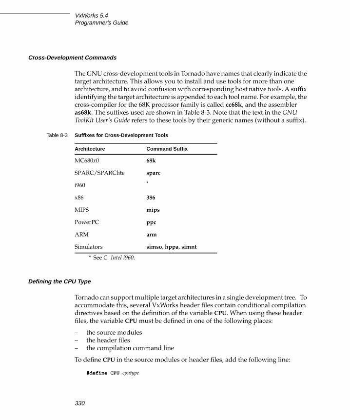
VxWorks 5.4Programmer’s Guide
Cross-Development Commands
The GNU cross-development tools in Tornado have names that clearly indicate the
target architecture. This allows you to install and use tools for more than one
architecture, and to avoid confusion with corresponding host native tools. A suffix
identifying the target architecture is appended to each tool name. For example, the
cross-compiler for the 68K processor family is called cc68k, and the assembler
as68k. The suffixes used are shown in Table 8-3. Note that the text in the GNUToolKit User’s Guide refers to these tools by their generic names (without a suffix).
Defining the CPU Type
Tornado can support multiple target architectures in a single development tree. To
accommodate this, several VxWorks header files contain conditional compilation
directives based on the definition of the variable CPU. When using these header
files, the variable CPU must be defined in one of the following places:
– the source modules
– the header files
– the compilation command line
To define CPU in the source modules or header files, add the following line:
#define CPU cputype
Table 8-3 Suffixes for Cross-Development Tools
Architecture Command Suffix
MC680x0 68k
SPARC/SPARClite sparc
i960 *
* See C. Intel i960.
x86 386
MIPS mips
PowerPC ppc
ARM arm
Simulators simso, hppa, simnt
330

8
8Configuration and Build
To define CPU on the compilation command line, add the following flag:
-DCPU=cputype
The constants shown in Table 8-4 are supported values for cputype.
With makefiles, the CPU definition can be added to the definition of the flags
passed to the compiler (usually CFLAGS).
In the source code, the file vxWorks.h must be included before any other files with
dependencies on the CPU flag.
As well as specifying the CPU value, you must usually run the compiler with one
or more option flags to generate object code optimally for the particular
architecture variant. These option flags usually begin with -m; see Compiling CModules, p.332.
Table 8-4 Values for cputype
Architecture Value
MC680x0 MC68000, MC68010, MC68020*, MC68040, MC68LC040†, MC68060,
CPU32
* MC68020 is the appropriate value for both the MC68020 and the MC68030 CPUs.
† MC68LC040 is the appropriate value for both the MC68LC040 and the MC68EC040.
SPARC, SPARClite SPARC‡
‡ SPARC is the appropriate value for both SPARC and SPARClite CPUs.
i960 I960CA, I960KB, I960KA, I960JX
i386,i486, Pentium,
PentiumPro
I80386, I80486, PENTIUM**
**PENTIUM is the appropriate value for both Pentium and PentiumPro CPUs.
MIPS R3000, R4000, R4650
PowerPC PPC403, PPC603, PPC604, PPC860
ARM ARM7TDMI, ARM7TDMI_T, ARMSA110, ARM710A, ARM810
Simulators SIMSPARCSOLARIS, SIMHPPA, SIMNT
331

VxWorks 5.4Programmer’s Guide
Compiling C Modules
The following is an example command to compile an application module for a
VxWorks MC68020 system:
% cc68k -fno-builtin -I %WIND_BASE%\target\h -nostdinc -O \-c -DCPU=MC68020 applic.c
This compiles the module applic.c into an object file applic.o. Table 8-5 shows a
similar example compiler invocation for each CPU architecture family.
The following list gives summary descriptions of the compiler flags in Table 8-5.
For more information, see the GNU ToolKit User’s Guide, or the architecture
appendices.
-c Compile only; do not link for execution under the host. The output is an
unlinked object module with the suffix “.o”, in this case applic.o.
Table 8-5 Compiler Invocation by Architecture Family
Architecture Example Invocation
MC680x0 cc68k -fno-builtin -I $(WIND_BASE)/target/h -nostdinc -O -c\-m68040 -DCPU=MC68040 applic.c
SPARC ccsparc -fno-builtin -I $(WIND_BASE)/target/h -nostdinc -O2 -c \-DCPU=SPARC applic.c
SPARClite ccsparc -fno-builtin -I $(WIND_BASE)/target/h -nostdinc -O2 -c \-msparclite -DCPU=SPARC applic.c
i960 See your i960 toolkit documentation and C. Intel i960.
i386/i486 cc386 -fno-builtin -I $(WIND_BASE)/target/h -nostdinc -O -c \-fno-defer-pop -mno-486 -DCPU=I80386 applic.c
MIPS ccmips -fno-builtin -I $(WIND_BASE)/target/h -nostdinc -O2 -c \-mcpu=r4000 -mips3 -G 0 -DCPU=R4000 applic.c
PowerPC ccppc -O2 -mcpu=603 -I$WIND_BASE/target/h -fno-builtin \-fno-for-scope -nostdinc -DCPU=PPC603 -D_GNU_TOOL -c applic.c
ARM ccarm -DCPU=ARM7TDMI -mcpu=arm7tdmi -mno-sched-prolog \-fno-builtin -O2 -nostdinc -I $WIND_BASE/target/h -c applic.c
Simulator ccsimso -DCPU=SIMSPARCSOLARIS -ansi -nostdinc -g \-fno-builtin -fvolatile -DRW_MULTI_THREAD -D_REENTRANT \-O2 -I. -I /wind/target/h -c applic.c
332

8
8Configuration and Build
-DCPU=archDefine the CPU type.
-DVX_IGNORE_GNU_LIBSDefine the constant used by the i960 configuration to suppress the use of
the GNU libraries (cc960 only).
-D_GNU_TOOLRequired; defines the compilation toolkit used to compile VxWorks or
applications (ccppc only).
-fno-builtinUse library calls even for common library subroutines.
-fno-defer-popAlways pop the arguments to each function call as soon as that function
returns.
-fno-for-scopeRequired; allows the scope of variables declared within a for loop to be
outside of the for loop.
-G 0 Do not use the MIPS global pointer (ccmips only).
-I $(WIND_BASE)/target/hInclude VxWorks header files (see 8.4.1 Using VxWorks Header Files, p.325).
-m68040Generate code for a specific variant of the MC680x0 family.
-mcpu=Generate MIPS R4200 or R4600 specific code (ccmips only).
-mips3Issue instructions from level 3 of the MIPS instruction set (ccmips only).
-mno-486Generate code optimized for an i386 rather than for an i486 (cc386 only).
-msparcliteGenerate SPARClite-specific code (ccsparc only).
-nostdincDo not search host-system header files; search only the directories
specified with the -I flag and the current directory for header files.
-O Perform standard optimizations.
-O2 Use level 2 optimization.
333

VxWorks 5.4Programmer’s Guide
Compiling C++ Modules
Tornado supports the GNU compiler, a standard part of the cross-compilation
tools distributed for Tornado, compiles source programs in either C or C++. To use
this compiler for C++, invoke ccarch on any source file with a C++ suffix (such as
.cpp). For complete information on using C++, including a detailed discussion of
compiling C++ modules, see 5. C++ Development.
Compiling C++ applications in the VxWorks environment involves the following
steps:
1. C++ source code is compiled into object code for a specific target architecture,
just as for C applications.
2. The compiled object module is munched. Munching is the process of scanning
an object module for non-local static objects, and generating data structures
that VxWorks run-time support can use to call the objects’ constructors and
destructors. The details are described in 5.2.5 Munching C++ ApplicationModules, p.232.
8.4.3 Static Linking (Optional)
After you compile an application module, you can load it directly into the target
with the Tornado dynamic loader (through the shell or through the debugger).
In general, application modules do not need to be linked with the linker from the
GNU ToolKit, ldarch. However, using ldarch may be required when several
application modules cross-reference each other. The following example is a
command to link several application modules, using the GNU linker for the
MC680x0 family of processors.
C:\devt> ld68k -o applic.o -r applic1.o applic2.o applic3.o
This creates the object module applic.o from the object modules applic1.o,
applic2.o, and applic3.o. The -r option is required, because the object-module
output must be left in relocatable form so that it can be downloaded and linked to
the target VxWorks image.
Any VxWorks facilities called by the application modules are reported by ldarch as
unresolved externals. These are resolved by the Tornado loader when the module
is loaded into VxWorks memory.
334

8
8Configuration and Build
8.4.4 Downloading an Application Module
After application object modules are compiled (and possibly linked by the host
ldarch command), they can be dynamically loaded into a running VxWorks system
by invoking the Tornado module loader. You can do this either from the Tornado
shell using the built-in command ld( ), or from the debugger using the Debug menu
or the load command.
The following is a typical load command from the Tornado shell:
-> ld <applic.o
This relocates the code from the host file applic.o, linking to previously loaded
modules, and loads the object module into the target’s memory. Once an
application module is loaded into target memory, any subroutine in the module
can be invoked directly from the shell, spawned as a task, connected to an
interrupt, and so on.
The shell ld( ) command, by default, adds only global symbols to the symbol table.
During debugging, you may want local symbols as well. To get all symbols loaded
(including local symbols), you can use the GDB command load from the debugger.
Because this command is meant for debugging, it always loads all symbols.
Alternately, you can load all symbols by calling the shell command ld( ) with a full
argument list instead of the shell-redirection syntax shown above. When you use
an argument list, you can get all symbols loaded by specifying a 1 as the first
argument, as in the following example:
-> ld 1,0,"applic.o"
In the foregoing examples, the object module applic.o comes from the shell’s
current working directory. Normally, you can use either relative path names or
absolute path names to identify object modules to ld( ). If you use a relative path
name, the shell converts it to an absolute path (using its current working directory)
before passing the download request to the target server. In order to avoid trouble
when the shell where you call ld( ) is not running on the same host as its target
server, Tornado supplies the LD_SEND_MODULES facility; see the Tornado User’sGuide: Shell. If you are using a remote target server and ld( ) fails with a “no such
file” message, be sure that LD_SEND_MODULES is set to “on.”
! WARNING: Do not link each application module with the VxWorks libraries.
Doing this defeats the load-time linking feature of Tornado, and wastes space by
writing multiple copies of VxWorks system modules on the target.
335

VxWorks 5.4Programmer’s Guide
For more information about loader arguments, see the discussion of ld( ) (in the
reference entry for windsh).
For information about the target-resident version of the loader (which also
requires the target-resident symbol table), see the VxWorks reference entry for
loadLib.
8.4.5 Module IDs and Group Numbers
When a module is loaded, it is assigned a module ID and a group number. Both the
module ID and the group number are used to reference the module. The module
ID is returned by ld( ) as well as by the target-resident loader routines. When
symbols are added to the symbol table, the associated module is identified by the
group number (a small integer). (Due to limitations on the size of the symbol table,
the module ID is inappropriate for this purpose.) All symbols with the same group
number are from the same module. When a module is unloaded, the group
number is used to identify and remove all the module’s symbols from the symbol
table.
8.4.6 Unloading Modules
Whenever you load a particular object module more than once, using the target
server (from either the shell or the debugger), the older version is unloaded
automatically. You can also unload a module explicitly: both the Tornado shell and
the target-resident VxWorks libraries include an unloader. To remove a module
from the shell, use the shell routine unld( ); see the reference entry for windsh.
For information about the target-resident version of the unloader (which also
requires the target-resident symbol table and loader), see the VxWorks reference
entry for unldLib.
After a module has been unloaded, any calls to routines in that module fail with
unpredictable results. Take care to avoid unloading any modules that are required
by other modules. One solution is to link interdependent files using the static
! CAUTION: (Windows) If you call ld( ) with an explicit argument list, any backslash
characters in the module-name argument must be doubled. If you supply the
module name with the redirection symbol, as in the earlier example in this section,
no double backslashes are needed. See the Tornado User’s Guide: Shell for more
discussion of this issue.
336

8
8Configuration and Build
linker ldarch as described in 8.4.3 Static Linking (Optional), p.334, so that they can
only be loaded and unloaded as a unit.
8.5 Configuring VxWorks
The configuration of VxWorks is determined by the configuration header files
installDir/target/config/all/configAll.h and
installDir/target/config/bspname/config.h. These files are used by the usrConfig.c,
bootConfig.c, and bootInit.c modules as they run the initialization routines
distributed in the directory installDir/target/src/config to configure VxWorks.
The VxWorks distribution includes the configuration files for the default
development configuration. You can create your own versions of these files to
better suit your particular configurations; this is described in the following
subsections. In addition, if you need multiple configurations, environment
variables are provided so you can move easily between them.
Including optional components in your VxWorks image can significantly increase
the image size. If you receive a warning from vxsize when building VxWorks, or if
the size of your image becomes greater than that supported by the current setting
of RAM_HIGH_ADRS, be sure to see 8.6.1 Scaling Down VxWorks, p.344 and
8.9 Creating Bootable Applications, p.364 for information on how to resolve the
problem.
8.5.1 The Environment Variables
In a development environment, you may have several different configurations you
wish to test, or you may wish to specify different target code in different situations.
In order to build VxWorks to these different specifications, you need to modify
your environment.
In general, your Tornado environment consists of three parts: the host code
(Tornado), the target code, and the configuration files discussed in this section. If
NOTE: To rebuild VxWorks for your own configuration, follow the procedures
described in the Tornado User’s Guide: Projects (recommended) or see 8.7 Building aVxWorks System Image, p.351.
337

VxWorks 5.4Programmer’s Guide
you use the default environment, your UNIX environment variables are defined as
follows:
On Windows hosts, the IDE automatically locates Tornado code in the following
locations:
To use different versions of usrConfig.c, bootConfig.c, and bootInit.c, store them
in a different directory and change the value of CONFIG_ALL. To use different
target code, point to the alternate directory by changing the value of TGT_DIR.
You can change the value of CONFIG_ALL by changing it either in your makefile
or on the command line. The value of TGT_DIR must be changed on the command
line.
To change CONFIG_ALL in your makefile, add the following command:
CONFIG_ALL = $WIND_BASE/target/config/ newDir
To change CONFIG_ALL on the command line, do the following:
% make ... CONFIG_ALL = $WIND_BASE/target/config/ newDir
To change TGT_DIR on the command line, do the following:
% make ... TGT_DIR = $ ALT_DIR/target
8.5.2 The Configuration Header Files
You can control VxWorks’s configuration by including or excluding definitions in
the global configuration header file configAll.h and in the target-specific
configuration header file config.h. This section describes these files.
Host code: $WIND_BASE/host/hosttype/bin
Target code: TGT_DIR = $WIND_BASE/target
Configuration code: CONFIG_ALL = $TGT_DIR/config/all
Host code: installDir/host/hosttype/bin
Target code: installDir/target
Configuration code: installDir/target/config/all
NOTE: Changing TGT_DIR will change the default value of CONFIG_ALL. If this
is not what you want, reset CONFIG_ALL as well.
338

8
8Configuration and Build
The Global Configuration Header File: configAll.h
The configAll.h header file, in the directory installDir/target/config/all, contains
default definitions that apply to all targets, unless redefined in the target-specific
header file config.h. The following options and parameters are defined in
configAll.h:
– kernel configuration parameters
– I/O system parameters
– NFS parameters
– selection of optional software modules
– selection of optional device controllers
– cache modes
– maximum number of the different shared memory objects
– device controller I/O addresses, interrupt vectors, and interrupt levels
– miscellaneous addresses and constants
The BSP-specific Configuration Header File: config.h
There is also a BSP-specific header file, config.h, in the directory
installDir/target/config/bspname. This file contains definitions that apply only to the
specific target, and can also redefine default definitions in configAll.h that are
inappropriate for the particular target. For example, if a target cannot access a
device controller at the default I/O address defined in configAll.h because of
addressing limitations, the address can be redefined in config.h.
The config.h header file includes definitions for the following parameters:
– default boot parameter string for boot ROMs
– interrupt vectors for system clock and parity errors
– device controller I/O addresses, interrupt vectors, and interrupt levels
– shared memory network parameters
– miscellaneous memory addresses and constants
! CAUTION: If any options from configAll.h need to be changed for this one BSP,
then any previous definition of that option should be undefined and redefined as
necessary in config.h. Unless options are to apply to all BSPs at your site, do not
change them in installDir/target/config/all/configAll.h.
339

VxWorks 5.4Programmer’s Guide
Selection of Optional Features
VxWorks ships with optional features and device drivers that can be included or
omitted from the target system. These are controlled by macros in the project
facility or the configuration header files that cause conditional compilation in the
installDir/target/config/all/usrConfig.c module.
The distributed versions of the configuration header files configAll.h and config.hinclude all the available software options and several network device drivers. If
you are not using the project facility (see Tornado User’s Guide: Projects), you define
a macro by moving it from the EXCLUDED FACILITIES section of the header file
to the INCLUDED SOFTWARE FACILITIES section.3 For example, to include the
ANSI C assert library, make sure the macro INCLUDE_ANSI_ASSERT is defined; to
include the Network File System (NFS) facility, make sure INCLUDE_NFS is
defined. Modification or exclusion of particular facilities is discussed in detail in
8.6 Alternative VxWorks Configurations, p.344.
Macros shown in Table 8-6 that end in XXX are not valid macros but represent
families of options where the XXX is replaced by a suffix declaring a specific
routine. For example, INCLUDE_CPLUS_XXX refers to a family of macros that
includes INCLUDE_CPLUS_MIN and INCLUDE_CPLUS_STL.
3. For a partial listing of the configuration macros, see Table 8-6. To see all the available macros
with their descriptions, see installDir/target/config/all/configAll.h (for macros applicable to
all bsps) and installDir/target/config/bspname/config.h (for macros applicable to a specific
BSP).
Table 8-6 Key VxWorks Options
Macro * Option
INCLUDE_ANSI_XXX * Various ANSI C library options
INCLUDE_BOOTLINE_INIT Parse boot device configuration information
INCLUDE_BOOTP * BOOTP support
INCLUDE_CACHE_SUPPORT * Cache support
INCLUDE_CPLUS * Bundled C++ support
INCLUDE_CPLUS_XXX Various C++ support options
340

8
8Configuration and Build
INCLUDE_DOSFS DOS-compatible file system
INCLUDE_FLOATING_POINT * Floating-point I/O
INCLUDE_FORMATTED_IO * Formatted I/O
INCLUDE_FTP_SERVER FTP server support
INCLUDE_IO_SYSTEM * I/O system package
INCLUDE_LOADER Target-resident object module loader package
INCLUDE_LOGGING * Logging facility
INCLUDE_MEM_MGR_BASIC * Core partition memory manager
INCLUDE_MEM_MGR_FULL * Full-featured memory manager
INCLUDE_MIB2_XXX Various MIB-2 options
INCLUDE_MMU_BASIC * Bundled MMU support
INCLUDE_MMU_FULL Unbundled MMU support (requires VxVMI)
INCLUDE_MSG_Q * Message queue support
INCLUDE_NETWORK * Network subsystem code
INCLUDE_NFS Network File System (NFS)
INCLUDE_NFS_SERVER NFS server
INCLUDE_PIPES * Pipe driver
INCLUDE_POSIX_XXX Various POSIX options
INCLUDE_PROTECT_TEXT Text segment write protection (requires VxVMI)
INCLUDE_PROTECT_VEC_TABLE Vector table write protection (requires VxVMI)
INCLUDE_PROXY_CLIENT * Proxy ARP client support
INCLUDE_PROXY_SERVER Proxy ARP server support
Table 8-6 Key VxWorks Options (Continued)
Macro * Option
341
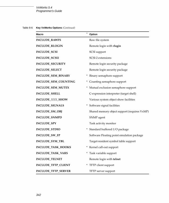
VxWorks 5.4Programmer’s Guide
INCLUDE_RAWFS Raw file system
INCLUDE_RLOGIN Remote login with rlogin
INCLUDE_SCSI SCSI support
INCLUDE_SCSI2 SCSI-2 extensions
INCLUDE_SECURITY Remote login security package
INCLUDE_SELECT Remote login security package
INCLUDE_SEM_BINARY * Binary semaphore support
INCLUDE_SEM_COUNTING * Counting semaphore support
INCLUDE_SEM_MUTEX * Mutual exclusion semaphore support
INCLUDE_SHELL C-expression interpreter (target shell)
INCLUDE_XXX_SHOW Various system object show facilities
INCLUDE_SIGNALS * Software signal facilities
INCLUDE_SM_OBJ Shared memory object support (requires VxMP)
INCLUDE_SNMPD SNMP agent
INCLUDE_SPY Task activity monitor
INCLUDE_STDIO * Standard buffered I/O package
INCLUDE_SW_FP Software Floating point emulation package
INCLUDE_SYM_TBL Target-resident symbol table support
INCLUDE_TASK_HOOKS * Kernel call-out support
INCLUDE_TASK_VARS * Task variable support
INCLUDE_TELNET Remote login with telnet
INCLUDE_TFTP_CLIENT * TFTP client support
INCLUDE_TFTP_SERVER TFTP server support
Table 8-6 Key VxWorks Options (Continued)
Macro * Option
342

8
8Configuration and Build
8.5.3 The Configuration Module: usrConfig.c
Use VxWorks configuration header files to configure your VxWorks system to meet
your development requirements. Users should not resort to changing the WRS-
supplied usrConfig.c, or any other module in the directory
installDir/target/config/all. If an extreme situation requires such a change, we
recommend you copy all the files in installDir/target/config/all to another
directory, and add a CONFIG_ALL macro to your makefile to point the make
system to the location of the modified files. For example, add the following to your
makefile after the first group of include statements:
# ../myAll contains a copy of all the ../all filesCONFIG_ALL = ../myAll
INCLUDE_TIMEX * Function execution timer
INCLUDE_TRIGGERING Function execution timer
INCLUDE_UNLOADER Target-resident object module unloader
package
INCLUDE_WATCHDOGS * Watchdog support
INCLUDE_WDB * Target agent
INCLUDE_WDB_TSFS * Target server file system
INCLUDE_WINDVIEW WindView command server; see the WindViewUser’s Guide for details
INCLUDE_ZBUF_SOCK Zbuf socket interface
* Items marked with an asterisk are included in the default configuration. Note that,
since this list of options is not complete, not all macros included in the default
configuration are listed here. Note also that their inclusion may be overridden in
config.h for your BSP.
Table 8-6 Key VxWorks Options (Continued)
Macro * Option
343

VxWorks 5.4Programmer’s Guide
8.6 Alternative VxWorks Configurations
The discussion of the usrConfig module in 8.5.3 The Configuration Module:usrConfig.c, p.343 outlined the default configuration for a development
environment. In this configuration, the VxWorks system image contains all of the
VxWorks modules that are necessary to allow you to interact with the system
through the Tornado host tools.
However, as you approach a final production version of your application, you may
want to change the VxWorks configuration in one or more of the following ways:
■ Change the configuration of the target agent.■ Decrease the size of VxWorks.■ Run VxWorks from ROM.
The following sections discuss the latter two alternatives to the typical
development configuration. For a discussion on reconfiguring the target agent, see
the Tornado User’s Guide: Projects.
8.6.1 Scaling Down VxWorks
In a production configuration, it is often desirable to remove some of the VxWorks
facilities to reduce the memory requirements of the system, to reduce boot time, or
for security purposes.
Optional VxWorks facilities can be omitted by commenting out or using #undef to
undefine their corresponding control constants in the header files configAll.h or
config.h. For example, logging facilities can be omitted by undefining
INCLUDE_LOGGING, and signalling facilities can be omitted by undefining
INCLUDE_SIGNALS.
VxWorks is structured to make it easy to exclude facilities you do not need.
However, not every BSP will be structured in this way. If you wish to minimize
your application, be sure to examine your BSP code and eliminate references to
facilities you do not need to include. Otherwise, they will be included even though
you undefined them in your VxWorks configuration files.
Excluding Kernel Facilities
The definition of the following constants in configAll.h is optional, because
referencing any of the corresponding kernel facilities from the application
automatically includes the kernel service:
344

8
8Configuration and Build
– INCLUDE_SEM_BINARY– INCLUDE_SEM_MUTEX– INCLUDE_SEM_COUNTING– INCLUDE_MSG_Q– INCLUDE_WATCHDOGS
These configuration constants appear in the default VxWorks configuration to
ensure that all kernel facilities are configured into the system, even if not
referenced by the application. However, if your goal is to achieve the smallest
possible system, exclude these constants; this ensures that the kernel does not
include facilities you are not actually using.
There are two other configuration constants that control optional kernel facilities:
INCLUDE_TASK_HOOKS and INCLUDE_CONSTANT_RDY_Q. Define these
constants in configAll.h if the application requires either kernel callouts (use of
task hook routines) or a constant-insertion-time, priority-based ready queue. A
ready queue with constant insert time allows the kernel to operate context
switches with a fixed overhead regardless of the number of tasks in the system.
Otherwise, the worst-case performance degrades linearly with the number of
ready tasks in the system. Note that the constant-insert-time ready queue uses 2KB
for the data structure; some systems do not have sufficient memory for this. In
those cases, the definition of INCLUDE_CONSTANT_RDY_Q may be omitted, thus
enabling use of a smaller (but less deterministic) ready queue mechanism.
Excluding Network Facilities
In some applications it may be appropriate to eliminate the VxWorks network
facilities. For example, in the ROM-based systems or standalone configurations
described in 8.9 Creating Bootable Applications, p.364, there may be no need for
network facilities.
To exclude the network facilities, be sure the following constants are not defined:
– INCLUDE_NETWORK– INCLUDE_NET_INIT– INCLUDE_NET_SYM_TBL– INCLUDE_NFS– INCLUDE_RPC
To exclude the Remote Procedure Call library (RPC), undefine INCLUDE_RPC.
345

VxWorks 5.4Programmer’s Guide
Option Dependencies
Option dependencies are coded in the file
installDir/target/src/config/usrDepend.c, so that when a particular option is
chosen, everything required is included. This assures you of a working system
with minimum effort. Although you can exclude the features that you do not need
by undefining them in config.h and configAll.h, you should be aware that in some
cases they may not be excluded because of dependencies.
For example, you cannot use telnet without running the network. Therefore, if in
your configAll.h file, the option INCLUDE_TELNET is selected but the option
INCLUDE_NET_INIT is not, usrDepend.c defines INCLUDE_NET_INIT for you.
Because the network initialization requires the network software, the
userDepend.c file also defines INCLUDE_NETWORK.
Because most of the dependencies are taken care of in usrDepend.c, that file is
currently included in usrConfig.c. This simplifies the build process and the
selection of options. However, you can change or add dependencies if you choose.
8.6.2 Executing VxWorks from ROM
You can put VxWorks or a VxWorks-based application into ROM; this is discussed
in 8.9.2 Creating a VxWorks System in ROM, p.367. For an example of a ROM-based
VxWorks application, see the VxWorks boot ROM program. The file
installDir/target/config/all/bootConfig.c is the configuration module for the boot
ROM, replacing the file usrConfig.c provided for the default VxWorks
development system.
In such ROM configurations, the text and data segments of the boot or VxWorks
image are first copied into the system RAM, then the boot procedure or VxWorks
executes in RAM. On some systems where memory is a scarce resource, it is
possible to save space by copying only the data segment to RAM. The text segment
remains in ROM and executes from that address space, and thus is termed
ROM resident. The memory that was to be occupied by the text segment in RAM is
now available for an application (up to 300KB for a standalone VxWorks system).
Note that ROM-resident VxWorks is not supported on all boards; see your target’s
man page if you are not sure that your board supports this configuration.
The drawback of a ROM-resident text segment is the limited data widths and
lower memory access time of the EPROM, which causes ROM-resident text to
execute more slowly than if it was in RAM. This can sometimes be alleviated by
using faster EPROM devices or by reconfiguring the standalone system to exclude
unnecessary system features.
346

8
8Configuration and Build
Aside from program text not being copied to RAM, the ROM-resident versions of
the VxWorks boot ROMs and the standalone VxWorks system are identical to the
conventional versions. A ROM-resident image is built with an uncompressed
version of either the boot ROM or standalone VxWorks system image. VxWorks
target makefiles include entries for building these images; see Table 8-7.
Because of the size of the system image, 512KB of EPROM is recommended for the
ROM-resident version of the standalone VxWorks system. More space is probably
required if applications are linked with the standalone VxWorks system. For a
ROM-resident version of the boot ROM, 256KB of EPROM is recommended. If you
use ROMs of a size other than the default, modify the value of ROM_SIZE in the
target makefile and config.h.
A new make target, vxWorks.res_rom_nosym, has been created to provide a
ROM-resident image without the symbol table. This is intended to be a standard
Table 8-7 Makefile ROM-Resident Images
Architecture Image FIle *
* All images have a corresponding file in Motorola S-record or Intel Hex format with
the same file name plus the extension .hex.
Description
MIPS and
PowerPC
bootrom_res_high ROM-resident boot ROM image. The
data segment is copied from ROM to
RAM at address RAM_HIGH_ADRS.
vxWorks.res_rom_res_low ROM-resident standalone system image
without compression. The data segment
is copied from ROM to RAM at address
RAM_LOW_ADRS.
vxWorks.res_rom_nosym_res_low ROM-resident standalone system image
without compression or symbol table.
Data segment is copied from ROM to
RAM at address RAM_LOW_ADRS.
All Other
Targets
bootrom_res ROM-resident boot ROM image.
vxWorks.res_rom ROM-resident standalone system image
without compression.
vxWorks.res_rom_nosym ROM-resident system image without
compression or symbol table. Ideal for
the Tornado environment.
347

VxWorks 5.4Programmer’s Guide
Figure 8-1 ROM-Resident Memory Layout
BOOT IMAGE VXWORKS IMAGE
texttext
data
RAM_HIGH_ADRS
ROM_TEXT_ADRS
RAM_LOW_ADRS
ROM
RAM
data
data
bss
bss
ROM
RAM
data
ROM_TEXT_ADRS
LOCAL_MEM_LOCAL_ADRS LOCAL_MEM_LOCAL_ADRS
= copied to RAM
348

8
8Configuration and Build
ROM image for use with the Tornado environment where the symbol table resides
on the host system. Being ROM-resident, the debug agent and VxWorks are ready
almost immediately after power-up or restart.
The data segment of a ROM-resident standalone VxWorks system is loaded at
RAM_LOW_ADRS (defined in the makefile) to minimize fragmentation. The data
segment of ROM-resident boot ROMs is loaded at RAM_HIGH_ADRS, so that
loading VxWorks does not overwrite the resident boot ROMs. For a CPU board
with limited memory (under 1MB of RAM), make sure that RAM_HIGH_ADRS is
less than LOCAL_MEM_SIZE by a margin sufficient to accommodate the data
segment. Note that RAM_HIGH_ADRS is defined in both the makefile and
config.h. These definitions must agree.
Figure 8-1 shows the memory layout for ROM-resident boot and VxWorks images.
The lower portion of the diagram shows the layout for ROM; the upper portion
shows the layout for RAM. LOCAL_MEM_LOCAL_ADRS is the starting address of
RAM. For the boot image, the data segment gets copied into RAM above
RAM_HIGH_ADRS (after space for bss is reserved). For the VxWorks image, the
data segment gets copied into RAM above RAM_LOW_ADRS (after space for bss is
reserved). Note that for both images the text segment remains in ROM.
8.6.3 Initialization Sequence for ROM-Based VxWorks
The early steps of system initialization are somewhat different for the ROM-based
versions of VxWorks: on most target architectures, the two routines romInit( ) and
romStart( ) execute instead of the usual VxWorks entry point, sysInit( ).
ROM Entry Point: romInit( )
At power-up the processor begins executing at romInit( ) (defined in
installDir/target/config/bspname/romInit.s). The romInit( ) routine disables
interrupts, puts the boot type (cold/warm) on the stack, performs hardware-
dependent initialization (such as clearing caches or enabling DRAM), and
branches to romStart( ). The stack pointer is initialized to reside below the data
section in the case of ROM-resident versions of VxWorks (in RAM versions, the
stack pointer instead resides below the text section).
Copying the VxWorks Image: romStart( )
Next, the romStart( ) routine (in installDir/target/config/all/bootInit.c) loads the
VxWorks system image into RAM. If the ROM-resident version of VxWorks is
selected, the data segment is copied from ROM to RAM and memory is cleared. If
VxWorks is not ROM resident, all of the text and code segment is copied and
349

VxWorks 5.4Programmer’s Guide
decompressed from ROM to RAM, to the location defined by RAM_HIGH_ADRSin Makefile. If VxWorks is neither ROM resident nor compressed, the entire text
and data segment is copied without decompression straight to RAM, to the
location defined by RAM_LOW_ADRS in Makefile.
Overall Initialization for ROM-Based VxWorks
Beyond romStart( ), the initialization sequence for ROM-based VxWorks
resembles the normal sequence, continuing with the usrInit( ) call.
Table 8-8 summarizes the complete initialization sequence. For details on the steps
after romInit( ) and romStart( ), see 8.3 VxWorks Initialization Timeline, p.313.
Table 8-8 ROM-Based VxWorks Initialization Sequence
Routine Activity File
1. romInit( ) (a) disable interrupts romInit.s
(b) save boot type (cold/warm)
(c) hardware-dependent initialization
(d) branch to romStart( )
2. romStart( ) (a) copy data segment from ROM to RAM; clear
memory
bootInit.c
(b) copy code segment from ROM to RAM,
decompressing if necessary
(c) invoke usrInit( ) with boot type
3. usrInit( ) Initial routine. usrConfig.c
4. usrKernelInit( ) Routines invoked if the corresponding
configuration constants are defined.
usrKernel.c
5. kernelInit( ) Initialize and start the kernel. kernelLib.c
6. usrRoot( ) Initialize I/O system, install drivers, and create
devices as configured in configAll.h and config.h.
usrConfig.c
Application routine Application code. Application
source file
350
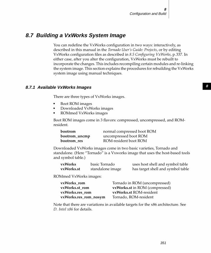
8
8Configuration and Build
8.7 Building a VxWorks System Image
You can redefine the VxWorks configuration in two ways: interactively, as
described in this manual in the Tornado User’s Guide: Projects, or by editing
VxWorks configuration files as described in 8.5 Configuring VxWorks, p.337. Ineither case, after you alter the configuration, VxWorks must be rebuilt to
incorporate the changes. This includes recompiling certain modules and re-linking
the system image. This section explains the procedures for rebuilding the VxWorks
system image using manual techniques.
8.7.1 Available VxWorks Images
There are three types of VxWorks images.
■ Boot ROM images■ Downloaded VxWorks images■ ROMmed VxWorks images
Boot ROM images come in 3 flavors: compressed, uncompressed, and ROM-
resident.
Downloaded VxWorks images come in two basic varieties, Tornado and
standalone. (Here “Tornado” is a Vxworks image that uses the host-based tools
and symbol table.)
ROMmed VxWorks images:
Note that there are variations in available targets for the x86 architecture. See
D. Intel x86 for details.
bootrom normal compressed boot ROM
bootrom_uncmp uncompressed boot ROM
bootrom_res ROM-resident boot ROM
vxWorks basic Tornado uses host shell and symbol table
vxWorks.st standalone image has target shell and symbol table
vxWorks_rom Tornado in ROM (uncompressed)
vxWorks.st_rom vxWorks.st in ROM (compressed)
vxWorks.res_rom vxWorks.st ROM-resident
vxWorks.res_rom_nosym Tornado, ROM-resident
351

VxWorks 5.4Programmer’s Guide
8.7.2 Rebuilding VxWorks with make
VxWorks uses the GNU make facility to recompile and relink modules. A file
called Makefile in each VxWorks target directory contains the directives for
rebuilding VxWorks for that target. See GNU ToolKit User’s Guide: GNU Make for a
detailed description of GNU make and of how to write makefiles.
Making on UNIX Hosts
With a UNIX host, you can use either the GNU version of make included with
Tornado or the version included with your UNIX system. If you choose that
version, see your host system’s reference for make for information about the
version of make supplied in that system.
To rebuild VxWorks on a UNIX host, first change to the VxWorks target directory
for the desired target, and invoke make as follows:
% cd ${WIND_BASE}/target/config/ bspname% make
Making on Windows Hosts
If you choose to use manual techniques on Windows hosts, you must use the
command line for building individual application modules. You can use either the
command line or the project facility in Tornado 1.0.1 compatibility mode to rebuild
BSPs. For information on how to implement Tornado 1.0.1 compatibility mode, see
the Tornado User’s Guide: Customization.
Rebuilding BSP Components
The Project menu includes entries for rebuilding every BSP installed on your
system as a part of Tornado. These entries all have the form Make bspname.
Figure 8-2 illustrates the Project menu in a Tornado system that has a family of
i386/i486 BSPs installed.
When you select any Make bspname menu entry, the make targets available are
grouped into the following categories (also illustrated in Figure 8-2):
Common Targets
The BSP make targets needed most often. Two of them also appear in the
next two categories: vxWorks, the VxWorks system image, and
bootrom.hex, the simplest form of the boot-program object code.
352

8
8Configuration and Build
The standard make target clean (which erases all objects that can be built
by the BSP makefile) is also in this category.
VxWorks Targets
Alternate forms of the VxWorks run-time image, as described in
8.7 Building a VxWorks System Image, p.351 and 8.9 Creating BootableApplications, p.364.
Boot ROM Targets
Alternate forms of the VxWorks boot program, discussed in
8.6.2 Executing VxWorks from ROM, p.346.
When you click any of the targets from the categories above, Tornado builds the
corresponding object in the BSP directory. Output from the build goes to a BuildOutput window, which you can use as a diagnostic aid.
Rebuilding VxWorks
To rebuild VxWorks, click the vxWorks target name under the appropriate Makebspname entry for your target in the Project menu. For example, Figure 8-2 shows
the vxWorks target selected for the EPC4 BSP.
You can also rebuild VxWorks from the Windows command prompt (or from a
batch file). Change to the config directory for the desired target, and invoke makeas follows:
C:\> cd tornado\target\config\ bspnameC:\tornado\target\config\ bspname> make
In either case, make compiles and links modules as necessary, based on the
directives in the target directory’s Makefile.
Figure 8-2 Rebuilding VxWorks from the Project Menu
353

VxWorks 5.4Programmer’s Guide
To rebuild VxWorks when only header files change:
% make clean VxWorks
This regenerate all .o files required by VxWorks. Or:
% make clean% make
The "make clean" removes all existing .o files, and then "make" recreates the new
.o files required by VxWorks.
8.7.3 Including Customized VxWorks Code
The directory installDir/target/target/src/usr contains the source code for certain
portions of VxWorks that you may wish to customize. For example, usrLib.c is a
popular place to add target-resident routines that provide application-specific
development aids. For a summary of other files in this directory, see the TornadoUser’s Guide: Directories and Files.
If you modify one of these files, an extra step is necessary before rebuilding your
VxWorks image: you must replace the modified object code in the appropriate
VxWorks archive. The Makefile in installDir/target/target/src/usr automates the
details; however, because this directory is not specific to a single architecture, you
must specify the value of the CPU variable on the make command line:
% make CPU=cputype
If you do this frequently on a Windows host, you can record the CPU definition in
the Build Target field of a custom command in the Project menu; see Tornado User’sGuide: Customization.
This step recompiles all modified files in the directory, and replaces the
corresponding object code in the appropriate architecture-dependent directory.
After that, the next time you rebuild VxWorks, the resulting system image includes
your modified code.
The following example illustrates replacing usrLib with a modified version,
rebuilding the archives, and then rebuilding the VxWorks system image. For the
NOTE: For the sake of compactness, most examples of calling make in this chapter
use the command line; in real practice, the Project menu is usually more
convenient. This is true for Windows hosts even if you use the Tornado 1.0.1
methods described in this section.
354

8
8Configuration and Build
sake of conciseness, the make output is not shown. The example assumes the epc4(I80386) BSP; replace the BSP directory name and CPU value as appropriate for
your environment. (On a Windows host, use copy instead of the UNIX cp.)
% cd ${WIND_BASE}/target/src/usr% cp usrLib.c usrLib.c.orig% cp develDir/usrLib.c usrLib.c% make CPU=I80386...
% cd ${WIND_BASE}/target/config/epc4% make...
8.7.4 Linking the System Modules
The commands to link a VxWorks system image are somewhat complicated.
Fortunately, it is not necessary to understand those commands in detail because
the Makefile in each VxWorks target directory includes the necessary commands.
However, for completeness, this section gives an explanation of the flags and
parameters used to link VxWorks.
VxWorks operating system modules are distributed in the form of an archive
library for each target architecture. The library is
installDir/target/lib/libcpugnuvx.a.
These modules are combined with the configuration module usrConfig.o by the
ldarch command on the host. (usrConfig.c is described in 8.5.3 The ConfigurationModule: usrConfig.c, p.343.) The following is an example command for linking a
VxWorks system using the GNU linker for the MC680x0:
ld68k -o vxWorks -X -N -Ttext 1000 -e _sysInit sysALib.o sysLib.o \usrConfig.o version.o /tornado/target/lib/lib cpugnuvx.a
The meanings of the flags in this command are as follows:
-o vxWorksname the output object module vxWorks.
-X eliminate some compiler-generated symbols from the symbol table.
-N do not configure the output object module for a virtual-memory system.
-Ttext 1000specify the relocation address as a hexadecimal constant; in this example,
1000 hexadecimal. This is the address where the system must be loaded in
355

VxWorks 5.4Programmer’s Guide
the target, and is also the address where execution starts. Some target
systems have limitations on where this relocation address can be.
-e _sysInitdefine the entry point to vxWorks. sysInit( ) is the first routine in
sysALib.o, which is the first module loaded by ldarch.
sysALib.o and sysLib.omodules that contain CPU-dependent initialization and support routines.
The module sysALib.o must be the first module specified in the ldarchcommand.
usrConfig.othe configuration module (described in detail in 8.5.3 The ConfigurationModule: usrConfig.c, p.343). If you have several different system
configurations, you may maintain several different configuration
modules, either in installDir/target or in your own directory.
version.oa module that defines the creation date and version number of this
vxWorks object module. It is created by compiling the output of
makeVersion, an auxiliary tool in the installDir/host/host-os/bin directory.
installDir/target/lib/libcpugnuvx.athe archive library that contains all the VxWorks modules.
Additional object modules:
You can link additional object modules (with .o suffix) into the run-time
VxWorks system by naming them on the ldarch command line. An easy
way to do this is to use the variable MACH_EXTRA in the BSP makefiles.
Define this variable and list the object modules to be linked with VxWorks.
Note that during development, application object modules are generally
not linked with the system (unless they are needed by the usrConfigmodule), because it is more convenient to load them incrementally from
the host, after booting VxWorks. See 8.9 Creating Bootable Applications,
p.364 for more detail on linking application modules in a bootable system.
i960 systems require additional Intel libraries, which are listed in the
makefiles for i960 BSPs.
8.7.5 Creating the System Symbol Table Module
The Tornado target server uses the VxWorks symbol table on the host system, both
for dynamic linking and for symbolic debugging. The symbol table file is created
356

8
8Configuration and Build
by the supplied tool xsym. Processing an object module with xsym creates a new
object module that contains all the symbols of the original file, but with no code or
data. The line in Makefile that creates this file executes the command as follows:
xsym < vxWorks > vxWorks.sym
The file vxWorks.sym is the symbol table that the target server loads when it
begins executing.
8.8 Makefiles for BSPs and Applications
Makefiles for VxWorks applications are easy to create by exploiting the makefiles
and make include files shipped with VxWorks BSPs. This section discusses how
the VxWorks BSP makefiles are structured. An example of how to utilize this
structure for application makefiles is in 8.8.2 Using Makefile Include Files forApplication Modules, p.363.
In Tornado, a set of supporting files in installDir/target/h/make makes it possible
for each BSP or application Makefile to be terse, specifying only the essential
parameters that are unique to the object being built.
Example 8-1 shows the makefile from the installDir/target/config/mv147 directory;
the makefile for any other BSP is similar. Two variables are defined at the start of
the makefile: CPU, to specify the target architecture, and TOOL to identify what
compilation tools to use. Based on the values of these variables and on the
environment variables defined as part of your Tornado configuration, the makefile
selects the appropriate set of definitions from installDir/target/h/make. After the
standard definitions, several variables define properties specific to this BSP.
Finally, the standard rules for building a BSP on your host are included.
Example 8-1 Makefile for MVME147
# Makefile - makefile for target/config/mv147## Copyright 1984-1995 Wind River Systems, Inc.## DESCRIPTION# This file contains rules for building VxWorks for the# Motorola MVME147.#*/
CPU = MC68020
357

VxWorks 5.4Programmer’s Guide
TOOL = gnu
include $(WIND_BASE)/target/h/make/defs.bspinclude $(WIND_BASE)/target/h/make/make.$(CPU)$(TOOL)include $(WIND_BASE)/target/h/make/defs.$(WIND_HOST_TYPE)
## Only redefine make definitions below this point, or your definitions## will be overwritten by the makefile stubs above.
TARGET_DIR = mv147VENDOR = MotorolaBOARD = MVME147, MVME147S-1
## The constants ROM_TEXT_ADRS, ROM_SIZE, and RAM_HIGH_ADRS are# defined in config.h as well as in this Makefile.# Both definitions of these constants must be identical.#
ROM_TEXT_ADRS = ff800008 # ROM entry addressROM_SIZE = 00020000 # number of bytes of ROM space
RAM_LOW_ADRS = 00001000 # RAM text/data addressRAM_HIGH_ADRS = 00090000 # RAM text/data address
HEX_FLAGS = -v -p $(ROM_TEXT_ADRS) -a 8
MACH_EXTRA =
## Only redefine make definitions above this point, or the expansion of## makefile target dependencies may be incorrect.
include $(WIND_BASE)/target/h/make/rules.bspinclude $(WIND_BASE)/target/h/make/rules.$(WIND_HOST_TYPE)
There are two kinds of include files in installDir/target/h/make (as reflected by the
two blocks of include statements in Example 8-1): variable definitions, and rule
definitions. Just as for #include statements in the C preprocessor, includestatements in makefiles accept the slash (/) character between directory segments
of a file name. This feature of GNU make helps to write portable makefiles.
The following make include files define variables. These files are useful for
application-module makefiles, as well as for BSP makefiles.
defs.bspStandard variable definitions for a VxWorks run-time system.
make.$(CPU)$(TOOL)Files named using this pattern (such as make.MC68060gnu) provide
definitions for a particular target architecture and a particular set of
358

8
8Configuration and Build
compilation tools, such as architecture-specific tool names and option
flags.
defs.$(WIND_HOST_TYPE)Files named using this pattern (such as make.x86-win32) provide
definitions that depend on the host system: names of tools that are
independent of the target architecture, and pathnames for the Tornado
installation on your host.
The following include files define make targets, and the rules to build them. These
files are usually not required for building application modules in separate
directories, because most of the rules they define are specific to the VxWorks run-
time system and boot programs.
rules.bspRules defining all the standard targets for building a VxWorks run-time
system (described in 8.7 Building a VxWorks System Image, p.351 and
8.9 Creating Bootable Applications, p.364). The rules for building object code
from C, C++, or assembly language are also spelled out here.
rules.$(WIND_HOST_TYPE)Files named using this pattern (such as make.x86-win32) specify targets
that depend only on the host system (dependency lists).
8.8.1 Make Variables
The variables defined in the make include files provide convenient defaults for
most situations, and allow individual makefiles to specify only the definitions that
are unique to each. This section describes the make variables most often used to
specify properties of BSPs or applications. The following lists are not intended to
be comprehensive; see the make include files for the complete set.
Variables for Compilation Options
The variables grouped in this section are useful for either BSP makefiles or
application-module makefiles. They specify aspects of how to invoke the compiler.
NOTE: Certain make variables are intended specifically for customization; see
Variables for Customizing the Run-Time, p.362. Do not override other variables in
BSP makefiles. They are described in the following sections for expository
purposes.
359

VxWorks 5.4Programmer’s Guide
CFLAGSThe complete set of option flags for any invocation of the C compiler. This
variable gathers the options specified in CC_COMPILER, CC_WARNINGS,
CC_OPTIM, CC_INCLUDE, CC_DEFINES, and ADDED_CFLAGS. To add
your own option flags, define them as ADDED_CFLAGS.
C++FLAGSThe complete set of option flags for any invocation of the C++ compiler.
This variable gathers together the options specified in C++_COMPILER,
C++_WARNINGS, CC_OPTIM, CC_INCLUDE, CC_DEFINES, and
ADDED_C++FLAGS. To add your own option flags, use
ADDED_C++FLAGS.
CC_COMPILEROption flags specific to compiling the C language. Default: -ansi-nostdinc.
C++_COMPILEROption flags specific to compiling the C++ language. Default: -ansi-nostdinc.
CC_WARNINGSOption flags to select the level of warning messages from the compiler,
when compiling C programs. Two predefined sets of warnings are
available: CC_WARNINGS_ALL (the compiler’s most comprehensive
collection of warnings) and CC_WARNINGS_NONE (no warning flags).
Default: CC_WARNINGS_ALL.
C++_WARNINGSOption flags to select the level of warning messages from the compiler,
when compiling C++ programs. The same two sets of flags are available as
for C programs. Default: CC_WARNINGS_NONE.
CC_OPTIMOptimization flags. Three sets of flags are predefined for each architecture:
CC_OPTIM_DRIVER (optimization level appropriate to a device driver),
CC_OPTIM_TARGET (optimization level for BSPs), and
CC_OPTIM_NORMAL (optimization level for application modules).
Default: CC_OPTIM_TARGET.
CC_INCLUDEStandard set of header-file directories. To add application-specific header-
file paths, specify them in EXTRA_INCLUDE.
360

8
8Configuration and Build
CC_DEFINESDefinitions of preprocessor constants. This variable is predefined to
propagate the makefile variable CPU to the preprocessor, to include any
constants required for particular target architectures, and to include the
value of the makefile variable EXTRA_DEFINE. To add application-specific
constants, specify them in EXTRA_DEFINE.
Variables for BSP Parameters
The variables included in this section specify properties of a particular BSP, and are
thus recorded in each BSP makefile. They are not normally used in application-
module makefiles.
TARGET_DIRName of the BSP (used for dependency lists and name of documentation
reference entry). The value matches the bspname directory name.
ROM_TEXT_ADRSAddress of the ROM entry point. Also defined in config.h; the two
definitions must match.
ROM_SIZENumber of bytes available in the ROM. Also defined in config.h; the two
definitions must match.
RAM_HIGH_ADRSRAM address where the boot ROM data segment is loaded. Must be a high
enough value to ensure loading VxWorks does not overwrite part of the
ROM program. Also defined in config.h; the two definitions must match.
See 8.9 Creating Bootable Applications, p.364 for more discussion.
RAM_LOW_ADRSBeginning address to use for the VxWorks run-time in RAM.
HEX_FLAGSOption flags for the program (such as hex, coffHex, or elfHex) that
converts a boot program into S-records or the equivalent.
LDFLAGSLinker options for the static link of VxWorks and boot ROMs.
ROM_LDFLAGSAdditional static-link option flags specific to boot ROM images.
361

VxWorks 5.4Programmer’s Guide
Variables for Customizing the Run-Time
The variables listed in this section make it easy to control what facilities are
statically linked into your run-time system. You can specify values for these
variables either from the make command line, or from your own makefiles (when
you take advantage of the predefined VxWorks make include files).
CONFIG_ALLLocation of a directory containing the architecture-independent BSP
configuration files. Set this variable if you maintain several versions of
these files for different purposes. Default: installDir/target/config/all.
LIB_EXTRALinker options to include additional archive libraries (you must specify
the complete option, including the -L for each library). These libraries
appear in the link command before the standard VxWorks libraries.
MACH_EXTRANames of application modules to include in the static link to produce a
VxWorks run-time. See 8.9 Creating Bootable Applications, p.364.
ADDED_MODULESDo not define a value for this variable in makefiles. This variable is
reserved for adding modules to a static link from the make command line.
Its value is used in the same way as MACH_EXTRA, to include additional
modules in the link. Reserving a separate variable for use from the
command line avoids the danger of overriding any object modules that are
already listed in MACH_EXTRA.
EXTRA_INCLUDEPreprocessor options to define any additional header-file directories
required for your application (you must specify the complete option,
including the -I).
EXTRA_DEFINEDefinitions for application-specific preprocessor constants (you must
specify the complete option, including the -D).
ADDED_CFLAGSApplication-specific compiler options for C programs.
ADDED_C++FLAGSApplication-specific compiler options for C++ programs.
362

8
8Configuration and Build
8.8.2 Using Makefile Include Files for Application Modules
You can exploit the VxWorks makefile structure to put together your own
application makefiles quickly and tersely. If you build your application directly in
a BSP directory (or in a copy of one), you can use the Makefile in that BSP, by
specifying variable definitions (Variables for Customizing the Run-Time, p.362) that
include the components of your application.
You can also take advantage of the Tornado makefile structure if you develop
application modules in separate directories. Example 8-2 illustrates the general
scheme: include the makefile headers that specify variables, and list the object
modules you want built as dependencies of a target. This simple scheme is usually
sufficient, because the Tornado makefile variables are carefully designed to fit into
the default rules that make knows about.4
Example 8-2 Skeleton Makefile for Application Modules
# Makefile - makefile for ...## Copyright ...## DESCRIPTION# This file specifies how to build ...#
## It is often convenient to override the following with "make CPU=..."CPU = cputypeTOOL = gnu
include $(WIND_BASE)/target/h/make/defs.bspinclude $(WIND_BASE)/target/h/make/make.$(CPU)$(TOOL)include $(WIND_BASE)/target/h/make/defs.$(WIND_HOST_TYPE)
## Only redefine make definitions below this point, or your definitions## will be overwritten by the makefile stubs above.
exe : myApp.o
4. However, if you are working with C++, it may be also convenient to copy the .cpp.out rule
from installDir/target/h/make/rules.bsp into your application’s Makefile.
NOTE: The target name exe is the Tornado convention for a default make target.
You may either use that target name (as in Example 8-2), or define a different
default rule in your makefiles. However, there must always be an exe target in
makefiles based on the Tornado makefile headers (even if the associated rules do
nothing).
363

VxWorks 5.4Programmer’s Guide
8.8.3 Makefile for SIO Drivers
The directory installDir/target/src/drv/sio/ contains source and templates for serial
drivers that support both polled and asynchronous communications. The makefile
for drivers in this directory is named Makefile.sio. Because this is not one of the
names make can find automatically, you must specify the makefile with the -foption when you build a driver in this directory.
For example, to build the driver cd2400Sio.c and install it in the VxWorks archives,
execute the following commands in this directory:
Windows
C:\tornado\target\src\drv\sio> make -f Makefile.sio CPU= cputype cd2400Sio.oC:\tornado\target\src\drv\sio> make -f Makefile.sio CPU= cputype default
UNIX
% make -f Makefile.sio CPU= cputype cd2400Sio.o default
8.9 Creating Bootable Applications
As you approach a final version of your application, you will probably want to add
modules to the bootable system image, and include startup of your application
with the system initialization routines. In this way, you can create a bootableapplication, which is completely initialized and functional after booting, without
requiring any interaction with the host-resident development tools.
Linking the application with VxWorks is really a two-step process. You must add
an entry point to the application in usrConfig.c, and you must modify the makefile
to link the application statically with VxWorks.
To start your application during system initialization, add code to the usrRoot( )routine in usrConfig.c. You can call application initialization routines, create
additional I/O devices, spawn application tasks, and so on, just as you do from the
Tornado shell during development. An example is provided in usrConfig.c. This
file includes and initializes a simple demo if the preprocessor constant
INCLUDE_DEMO is defined in one of the configuration files. In that situation,
usrRoot( ) spawns usrDemo( ) as a task as the last step in booting the system. You
364

8
8Configuration and Build
can simply insert the appropriate initialization of your application after the
conditional code to start the demo. For example:
/* spawn demo if selected */#if defined(INCLUDE_DEMO)
taskSpawn ("demo", 20, 0, 2000, (FUNCPTR)usrDemo, 0,0,0,0,0,0,0,0,0,0);#endif
taskSpawn ("myMod", 100, 0, 20000, (FUNCPTR)myModEntryPt,0,0,0,0,0,0,0,0,0,0);
To include your application modules in the bootable system image, add the names
of the application object modules (with the .o suffix) to MACH_EXTRA in Makefile.
For example, to link the module myMod.o, add a line like the following:
MACH_EXTRA = myMod.o...
Building the system image with the application linked in is the final part of this
step. In the target directory, execute the following command:
% make vxWorks
Application size is usually an important consideration in building bootable
applications. Generally, VxWorks boot ROM code is copied to a start address in
RAM above the constant RAM_HIGH_ADRS, and the ROM in turn copies the
downloaded system image starting at RAM_LOW_ADRS. The values of these
constants are architecture dependent, but in any case the system image must not
exceed the space between the two. Otherwise the system image overwrites the
boot ROM code while downloading, thus killing the booting process.
To help avoid this, the last command executed when you make a new VxWorks
image is vxsize, which shows the size of the new executable image and how much
space (if any) is left in the area below the space used for ROM code:
vxsize 386 -v 00100000 00020000 vxWorksvxWorks: 612328(t) + 69456(d) + 34736(b) = 716520 (235720 bytes left)
If your new image is too large, vxsize issues a warning. In this case, you can
reprogram the boot ROMs to copy the ROM code to a sufficiently high memory
address by increasing the value of RAM_HIGH_ADRS in config.h and in your
BSP’s Makefile (both values must agree). Then rebuild the boot ROMs by
executing the following command:
% make bootrom.hex
The binary image size of typical boot ROM code is 128KB or less. This small size is
achieved through compression; see Boot ROM Compression, p.368. The compressed
boot image begins execution with a single uncompressed routine, which
365

VxWorks 5.4Programmer’s Guide
uncompresses the remaining boot code to RAM. To avoid uncompressing and thus
initialize the system a bit faster, you can build a larger, uncompressed boot ROM
image by specifying the make target bootrom_uncmp.hex.
8.9.1 Creating a Standalone VxWorks System with a Built-in Symbol Table
It is sometimes necessary to create a VxWorks system that includes a copy of its
own symbol table. However, it is confusing to work with the host-resident Tornado
tools when there is a target-resident symbol table, because the host-resident tools
use a separate symbol table on the host. Thus, it is advisable to include the target-
resident versions of the development tools (especially the shell) in this
configuration, until you are ready to build a finished application that requires no
interaction with the target.
The procedure for building such a system is somewhat different from the
procedure described above. No change is necessary to usrConfig.c. A different
make target, vxWorks.st, specifies the standalone form of VxWorks:
% make vxWorks.st
The rules for building vxWorks.st create a module usrConfig_st.o, which is the
usrConfig.c module compiled with the STANDALONE flag defined. The
STANDALONE flag causes the usrConfig.c module to be compiled with the built-
in system symbol table, the target-resident shell, and associated interactive
routines.
The STANDALONE flag also suppresses the initialization of the network. If you
want to include network initialization, define STANDALONE_NET in either of the
header files installDir/target/config/bspname/config.h or
installDir/target/config/all/configAll.h.5
VxWorks is linked as described previously, except that the first pass through the
loader does not specify the final load address; thus the output from this stage is still
relocatable. The makeSymTbl tool is invoked on the loader output; it constructs a
data structure containing all the symbols in VxWorks. This structure is then
compiled and linked with VxWorks itself to produce the final bootable VxWorks
object module.
5. vxWorks.st suppresses network initialization, but it includes the network. The STANDA-LONE option defines INCLUDE_STANDALONE_SYM_TBL and INCLUDE_NETWORK, and
undefines INCLUDE_NET_SYM_TBL and INCLUDE_NET_INIT. The alternative option
STANDALONE_NET includes INCLUDE_NET_INIT.
366

8
8Configuration and Build
As before, to include your own application in the system image, add the object
modules to the definition of MACH_EXTRA and follow the procedures discussed
in the previous section.
Because vxWorks.st has a built-in symbol table, there are some minor differences
in how it treats VxWorks symbols, by contrast with the symbol table used through
the target server during development. First, VxWorks symbol table entries cannot
be deleted from the vxWorks.st symbol table. Second, no local (static) VxWorks
symbols are present in vxWorks.st.
8.9.2 Creating a VxWorks System in ROM
General Procedures
To put VxWorks or a VxWorks-based application into ROM, you must enter the
object files on the loader command line in an order that lists the module romInit.obefore sysALib.o. Also specify the entry point option -e _romInit. The romInit( )routine initializes the stack pointer to point directly below the text segment. It then
calls bootInit( ), which clears memory and copies the vxWorks text and data
segments to the proper location in RAM. Control is then passed to usrInit( ).
A good example of a ROM-based VxWorks application is the VxWorks boot ROM
program itself. The file installDir/target/config/all/bootConfig.c is the
configuration module for the boot ROM, replacing the file usrConfig.c provided
for the default VxWorks development system. The makefiles in the target-specific
directories contain directives for building the boot ROMs, including conversion to
a file format suitable for downloading to a PROM programmer. Thus, you can
generate the ROM image with the following make command:
% make bootrom.hex
Tornado makefiles also define a ROMable VxWorks runtime system suitable for
use with Tornado tools, as the target vxWorks.res_rom_nosym. To generate this
image in a form suitable for writing ROMs, run the following command:
% make vxWorks.res_rom_nosym.hex
VxWorks target makefiles also include the entry vxWorks.st_rom for creating a
ROMable version of the standalone system described in the previous section.
vxWorks.st_rom differs from vxWorks.st in two respects: (1) romInit code is
loaded as discussed above, and (2) the portion of the system image that is not
367

VxWorks 5.4Programmer’s Guide
essential for booting is compressed by approximately 40 percent using the
VxWorks compress tool (see Boot ROM Compression, p.368).
To build the form of this target that is suitable for writing into a ROM (most often,
this form uses the Motorola S-record format), enter:
% make vxWorks.st_rom.hex
When adding application modules to a ROMable system, size is again an
important consideration. Keep in mind that by using the compress tool, a
configuration that normally requires a 256-KB ROM may well fit into a 128-KB
ROM. Be sure that ROM_SIZE (in both config.h and Makefile) reflects the capacity
of the ROMs used.
Boot ROM Compression
VxWorks boot ROMs are compressed to about 40 percent of their actual size using
a binary compression algorithm, which is supplied as the tool compress. When
control is passed to the ROMs on system reset or reboot, a small (8 KB)
uncompression routine, which is not itself compressed, is executed. It then
uncompresses the remainder of the ROM into RAM and jumps to the start of the
uncompressed image in RAM. There is a short delay during the uncompression
before the VxWorks prompt appears. The uncompression time depends on CPU
speed and code size; it takes about 4 seconds on an MC68030 at 25 MHz.
This mechanism is also available to compress a ROMable VxWorks application.
The entry for vxWorks.st_rom in the architecture-independent portion of the
makefile, installDir/target/h/make/rules.bsp, demonstrates how this can be
accomplished. For more information, see also the reference manual entries for
bootInit and compress.
368

9Target Shell
9.1 Introduction
In the Tornado development system, a full suite of development tools resides and
executes on the host machine, thus conserving target memory and resources; see
the Tornado User’s Guide for details. However, a target-resident symbol table and
module loader/unloader can be configured into the VxWorks system if necessary,
for example, to create a dynamically configured run-time system. In this case, use
the target-resident shell for development.
This chapter briefly describes these target-resident facilities.
9.2 Target-Resident Shell
For the most part, the target-resident shell works the same as the Tornado shell; for
details, see the Tornado User’s Guide: Shell. However, there are some differences,
which are described in this section.
! CAUTION: If you choose to use the target-resident tools, you must use the target
shell. The host tools cannot access the target-resident symbol table; thus symbols
defined on the target are not visible to the host.
369

VxWorks 5.4Programmer’s Guide
9.2.1 Creating the Target Shell
To create the target shell, you must configure it into the VxWorks configuration by
selecting INCLUDE_SHELL for inclusion in the project facility VxWorks view (for
details, see Tornado User’s Guide: Projects). When you do so, usrRoot( ) (inusrConfig.c) spawns the target shell task by calling shellInit( ). The first argument
to shellInit( ) specifies the target shell’s stack size, which must be large enough to
accommodate any routines you call from the target shell. The second argument is
a boolean that specifies whether the target shell’s input is from an interactive
source (TRUE), or a non-interactive source (FALSE) such as a script file. If the
source is interactive, then the shell prompts for commands but does not echo them
to standard out; the reverse is true if the source is non-interactive.
The shell task (tShell) is created with the VX_UNBREAKABLE option; therefore,
breakpoints cannot be set in this task, because a breakpoint in the shell would
make it impossible for the user to interact with the system. Any routine or task that
is invoked from the target shell, rather than spawned, runs in the tShell context.
Only one target shell can run on a VxWorks system at a time; the target shell parser
is not reentrant, because it is implemented using the UNIX tool yacc.
When the shell is started, the banner displayed in Figure 9-1 appears.For more
information, see the reference entry for shellLib.
Figure 9-1 Typical Target Shell Sign-on Banner
]]]]]]]]]]]]]]]]]]]]]]]]]]]]]]]]]]]]]]]]]]]]]]]]]]]]]]]]]]]]]]]]]]]]]]]]]]]]]]]]]]]]]]]]]]]]]]]]]]]]]]]]]]]]]]]]]]]]] ]]]]]]]]]]] ]]]] ]]]]]]]]]] ]] ]]]] (R)] ]]]]]]]]] ]]]]]] ]]]]]]]] ]] ]]]]]] ]]]]]]] ]]]]]]]] ]]]]]] ] ]] ]]]]]]] ]]]]] ] ]]] ] ]]]] ]]] ]]]]]]]]] ]]]] ]] ]]]] ]] ]]]]]]]]] ]]] ]] ] ]]] ]] ]]]]] ]]]]]] ]] ]]]]]]] ]]]] ]] ]]]]]]]]] ] ]]]] ]]]]] ]]]]]]]] ]]]] ]] ]]]] ]]]]]]] ]]]]]]]]]] ]]]]] ]]]]]] ] ]]]]] ]]]] ]] ]]]] ]]]]]]]] ]]]]]]]]]]] ]]]]] ] ]]]]]] ] ]]] ]]]] ]] ]]]] ]]]] ]]]] ]]]]]]]]]]]] ]]]]] ]]] ]]]]]]] ] ]]]]]]] ]]]] ]]]] ]]]] ]]]]]]]]]]]]]]]]]]]]]]]]]]]]]]]]]]]]]]]]]]]]]]]]]]]]]]]]]]]]]]]] Development System]]]]]]]]]]]]]]]]]]]]]]]]]]]]]]]]]]]]]]]]]]]]]]]]]]]]]]] VxWorks version 5.4]]]]]]]]]]]]]]]]]]]]]]]]]] KERNEL: WIND version 2.5]]]]]]]]]]]]]]]]]]]]]]]]] Copyright Wind River Systems, Inc., 1984-1998
CPU: Motorola MVME2600 - MPC 603p. Processor #0. Memory Size: 0x400000. BSP version 1.2/0.WDB: Ready.
->
370

9
9Target Shell
9.2.2 Using the Target Shell
The target shell works almost exactly like the Tornado shell; see the Tornado User’sGuide: Shell and the usrLib reference entry for details. You can also type the
following command to display help:
-> help
The following target shell command lists all the available help routines:
-> lkup "Help"
The target shell has its own set of terminal-control characters, unlike the Tornado
shell, which inherits its setting from the host window from which it was invoked.
Table 9-1 lists the target shell’s terminal-control characters. The first four of these
are defaults that can be mapped to different keys using routines in tyLib (see also
Tty Special Characters, p.120).
The shell line-editing commands are the same as they are for the Tornado shell. For
a summary of the commands, see the Tornado User’s Guide: Shell.
9.2.3 Debugging with the Target Shell
The target shell includes the same debugging utilities as the Tornado shell, if
INCLUDE_DEBUG is selected for inclusion in the project facility VxWorks view. For
details, see the Tornado User’s Guide: Shell and the reference entry for dbgLib.
Table 9-1 Target Shell Terminal Control Characters
Command Description
CTRL+H Delete a character (backspace).
CTRL+U Delete an entire line.
CTRL+C Abort and restart the shell.
CTRL+X Reboot (trap to the ROM monitor).
CTRL+S Temporarily suspend output.
CTRL+Q Resume output.
ESC Toggle between input mode and edit mode.
371

VxWorks 5.4Programmer’s Guide
9.2.4 Aborting the Target Shell
Occasionally it is desirable to abort the shell’s evaluation of a statement. For
example, an invoked routine may loop excessively, suspend, or wait on a
semaphore. This may happen as the result of errors in arguments specified in the
invocation, errors in the implementation of the routine itself, or simply oversight
as to the consequences of calling the routine at all.
In such cases it is usually possible to abort and restart the target shell task. This is
done by pressing the special target-shell abort character on the keyboard, CTRL+Cby default. This causes the target shell task to restart execution at its original entry
point. Note that the abort key can be changed to a character other than CTRL+C by
calling tyAbortSet( ).
When restarted, the target shell automatically reassigns the system standard input
and output streams to the original assignments they had when the target shell was
first spawned. Thus any target shell redirections are canceled, and any executing
shell scripts are aborted.
The abort facility works only if the following are true:
■ dbgInit( ) has been called (see 9.2.3 Debugging with the Target Shell, p.371).
■ excTask( ) is running (see Installation of Exception Handling and Logging, p.319).
■ The driver for the particular keyboard device supports it (all VxWorks-
supplied drivers do).
■ The device’s abort option is enabled. This is done with an ioctl( ) call, usually
in the root task in usrConfig.c. For information on enabling the target shell
abort character, see Tty Options, p.119.
Also, you may occasionally enter an expression that causes the target shell to incur
a fatal error such as a bus/address error or a privilege violation. Such errors
normally result in the suspension of the offending task, which allows further
debugging.
However, when such an error is incurred by the target shell task, VxWorks
automatically restarts the target shell, because further debugging is impossible
without it. Note that for this reason, as well as to allow the use of breakpoints and
single-stepping, it is often useful when debugging to spawn a routine as a task
instead of just calling it directly from the target shell.
When the target shell is aborted for any reason, either because of a fatal error or
because it is aborted from the terminal, a task trace is displayed automatically. This
trace shows where the target shell was executing when it died.
372

9
9Target Shell
Note that an offending routine can leave portions of the system in a state that may
not be cleared when the target shell is aborted. For instance, the target shell might
have taken a semaphore, which cannot be given automatically as part of the abort.
9.2.5 Remote Login to the Target Shell
Remote Login From Host: telnet and rlogin
When VxWorks is first booted, the target shell’s terminal is normally the system
console. You can use telnet to access the target shell from a host over the network
if you select INCLUDE_TELNET for inclusion in the project facility VxWorks view
(see Tornado User’s Guide: Projects). Defining INCLUDE_TELNET creates the
tTelnetd task. To access the target shell over the network, enter the following
command from the host (targetname is the name of the target VxWorks system):
% telnet " targetname"
UNIX host systems also use rlogin to provide access to the target shell from the
host. Select INCLUDE_RLOGIN for inclusion in the project facility VxWorks view
to create the tRlogind task. However, note that VxWorks does not support telnetor rlogin access from the VxWorks system to the host.
A message is printed on the system console indicating that the target shell is being
accessed via telnet or rlogin, and that it is no longer available from its console.
If the target shell is being accessed remotely, typing at the system console has no
effect. The target shell is a single-user system—it allows access either from the
system console or from a single remote login session, but not both simultaneously.
To prevent someone from remotely logging in while you are at the console, use the
routine shellLock( ) as follows:
-> shellLock 1
To make the target shell available again to remote login, enter the following:
-> shellLock 0
To end a remote-login target shell session, call logout( ) from the target shell. To
end an rlogin session, type TILDE and DOT as the only characters on a line:
-> ~.
373

VxWorks 5.4Programmer’s Guide
Remote Login Security
You can be prompted to enter a login user name and password when accessing
VxWorks remotely:
VxWorks login: user_name
Password: password
The remote-login security feature is enabled by selecting INCLUDE_SECURITY for
inclusion in the project facility VxWorks view. The default login user name and
password provided with the supplied system image is target and password. You can
change the user name and password with the loginUserAdd( ) routine, as follows:
-> loginUserAdd "fred", " encrypted_password"
To obtain encrypted_password, use the tool vxencrypt on the host system. This tool
prompts you to enter your password, and then displays the encrypted version.
To define a group of login names, include a list of loginUserAdd( ) commands in a
startup script and run the script after the system has been booted. Or include the
list of loginUserAdd( ) commands to the file usrConfig.c, then rebuild VxWorks.
The remote-login security feature can be disabled at boot time by specifying the
flag bit 0x20 (SYSFLAG_NO_SECURITY) in the flags parameter on the boot line (see
Tornado Getting Started). This feature can also be disabled by deselecting
INCLUDE_SECURITY in the project facility VxWorks view.
9.2.6 Summary of Target and Host Shell Differences
For details on the Tornado shell, see the Tornado User’s Guide: Shell. The following
is a summary of the differences between it and the target shell:
■ Both shells contain a C interpreter, which allows C-shell and vi editing
facilities. However, the Tornado shell also provides a Tcl interpreter.
■ You can have multiple Tornado shells active for any given target; only one
target shell can be active for a target at any one time.
■ The Tornado shell allows virtual I/O; the target shell does not.
NOTE: The values for the user name and password apply only to remote login into
the VxWorks system. They do not affect network access from VxWorks to a remote
system; See VxWorks Network Programmer’s Guide: rlogin and telnet, Host AccessApplications.
374

9
9Target Shell
■ The target shell does not have a GNU C++ demangler; it is necessary to use the
target tools when C++ demangling is required.
■ The Tornado shell is always ready to execute. The target shell, as well as its
associated target-resident symbol table and module loader/unloader, must be
configured into the VxWorks image by including the appropriate components
in the project facility VxWorks view (discussed throughout this chapter).
■ Because the target shell is often started from the system console, the standard
input and output are directed to the same window. For the Tornado shell, these
standard I/O streams are not necessarily directed to the same window as the
Tornado shell. For details, see the Tornado User’s Guide: Shell.
■ The Tornado shell can perform many control and information functions
entirely on the host without consuming target resources.
■ The Tornado shell uses host resources for most functions so that it remains
segregated from the target. This means that the Tornado shell can operate on
the target from the outside. The target shell, on the other hand, must act on
itself. This means that there are limitations to what the target shell can do (for
example, while debugging it cannot set breakpoints on itself or on routines it
calls). Also, conflicts in priority may occur while using the target shell.
■ When the target shell encounters a string literal ("...") in an expression, it
allocates space for the string including the null-byte string terminator. The
value of the literal is the address of the string in the newly allocated storage.
For example, the following expression allocates 12 bytes from the target
memory pool, enters the string in those 12 bytes (including the null
terminator), and assigns the address of the string to x:
-> x = "hello there"
The following expression can be used to return those 12 bytes to the target
memory pool (see the memLib reference entry for information on memory
management):
-> free (x)
Furthermore, even when a string literal is not assigned to a symbol, memory
is still permanently allocated for it. For example, the following expression uses
12 bytes of memory that are never freed:
-> printf ("hello there")
This is because if strings were only temporarily allocated, and a string literal
were passed to a routine being spawned as a task, then by the time the task
375

VxWorks 5.4Programmer’s Guide
executed and attempted to access the string, the target shell would have
already released (and possibly even reused) the temporary storage where the
string was held.
After extended development sessions with the target shell, the cumulative
memory used for strings may be noticeable. If this becomes a problem, you
must reboot your target. Because the Tornado shell has access to a host-
controlled target memory pool, this memory leak never occurs.
9.3 Other Target-Resident Facilities
9.3.1 Target Symbol Table, Module Loader, and Module Unloader
To make full use of the target shell’s features, you should also define the target
symbol table, as well as the target module loader and unloader. Select the
following components (identified by their associated macros) in the VxWorks view
(see Tornado User’s Guide: Projects for configuration information):
■ INCLUDE_SYM_TBL for target symbol table support, plus one of the following:
– INCLUDE_NET_SYM_TBL to load the symbol table from the network
(vxWorks.sym; you will also need to separately load vxWorks)
– INCLUDE_STANDALONE_SYM_TBL to build a VxWorks image that
includes the target symbol table (vxWorks.st)
■ INCLUDE_LOADER
■ INCLUDE_UNLOADER
If the target symbol table is included, usrRoot( ) runs hashLibInit( ) and
symLibInit( ) to initialize the corresponding libraries. The target symbol table is
created by calling symTblCreate( ). For convenience during debugging (see
9.2.3 Debugging with the Target Shell, p.371), it is most useful to have access to all
symbols in the system. On the other hand, a production version of a system can be
built that does not require the target symbol table, if (for example) memory
resources are constrained.
The symTblCreate( ) call creates an empty target symbol table. VxWorks system
facilities are not accessible through the target shell until the symbol definitions for
the booted VxWorks system are entered into the target symbol table. This is done
376

9
9Target Shell
by reading the target symbol table from a file called vxWorks.sym in the same
directory from which vxWorks was loaded (installDir/target/config/bspname). This
file contains an object module that consists only of a target symbol table section
containing the symbol definitions for all the variables and routines in the booted
system module. It has zero-length (empty) code, data, and relocation sections.
Nonetheless, it is a legitimate object module in the standard object module format.
The symbols in vxWorks.sym are entered in the target symbol table by calling
loadSymTbl( ) (whose source is in installDir/target/src/config/usrLoadSym.c). This
routine uses the target-resident module loader to load symbols from vxWorks.syminto the target symbol table.
For the most part, the target-resident facilities work the same as their Tornado host
counterparts; see 8.9.1 Creating a Standalone VxWorks System with a Built-in SymbolTable, p.366, 8.4.4 Downloading an Application Module, p.335, and 8.4.6 UnloadingModules, p.336. However, as stated earlier, the target-resident facilities can be
useful if you are building dynamically configured applications. For example, with
the target-resident loader, you can load from a target disk as well as over the
network, with these caveats: If you use the target-resident loader to load a module
over the network (as opposed to loading from a target-system disk), the amount of
memory required to load an object module depends on what kind of access is
available to the remote file system over the network. Loading a file that is mounted
over the default network driver requires enough memory to hold two copies of the
file simultaneously. First, the entire file is copied to a buffer in local memory when
opened; second, the file resides in memory when it is linked to VxWorks. On the
other hand, loading an object module from a host file system mounted through
NFS only requires enough memory for one copy of the file (plus a small amount of
overhead). In any case, however, using the target-resident loader takes away
additional memory from your application—most significantly for the target-
resident symbol table required by the target-resident loader.
For information on the target-resident module loader, unloader, and symbol table,
see the loadLib, unldLib, and symLib reference entries.
9.3.2 Show Routines
VxWorks includes system information routines which print pertinent system
status on the specified object or service; however, they show only a snapshot of the
system service at the time of the call and may not reflect the current state of the
system. To use these routines, you must define the associated configuration macro
(see the Tornado User’s Guide: Projects). When you invoke them, their output is sent
to the standard output device. Table 9-2 lists common system show routines.
377

VxWorks 5.4Programmer’s Guide
An alternative method of viewing system information is the Tornado browser,
which can be configured to update system information periodically. For
information on this tool, see the Tornado User’s Guide: Browser.
VxWorks also includes several network information routines. These routines are
initialized by defining INCLUDE_NET_SHOW in your VxWorks configuration; see
8. Configuration and Build. Table 9-3 lists commonly called network show routines.
Table 9-2 Show Routines
Call Description Configuration Macro
envShow( ) Display the environment
for a given task on stdoutINCLUDE_TASK_SHOW
memPartShow( ) Show the partition blocks
and statistics
INCLUDE_MEM_SHOW
memShow( ) System memory show
routine
INCLUDE_MEM_SHOW
moduleShow( ) Show statistics for all
loaded modules
Included automatically with
INCLUDE_MODULE_MANAGER
msgQShow( ) Message queue show util-
ity (both POSIX and wind)
INCLUDE_POSIX_MQ_SHOWINCLUDE_MSG_Q_SHOW
semShow( ) Semaphore show utility
(both POSIX and wind)
INCLUDE_SEM_SHOW,
INCLUDE_POSIX_SEM_SHOW
show( ) Generic object show utility
stdioShow( ) Standard I/O file pointer
show utility
INCLUDE_STDIO_SHOW
taskSwitchHookShow( ) Show the list of task switch
routines
INCLUDE_TASK_HOOKS_SHOW
taskCreateHookShow( ) Show the list of task create
routines
INCLUDE_TASK_HOOKS_SHOW
taskDeleteHookShow( ) Show the list of task delete
routines
INCLUDE_TASK_HOOKS_SHOW
taskShow( ) Display the contents of a
task control block
INCLUDE_TASK_SHOW
wdShow( ) Watchdog show utility INCLUDE_WATCHDOGS_SHOW
378

9
9Target Shell
Table 9-3 Network Show Routines
Call Description
ifShow( ) Display the attached network interfaces.
inetstatShow( ) Display all active connections for Internet protocol
sockets.
ipstatShow( ) Display IP statistics.
netPoolShow( ) Show pool statistics.
netStackDataPoolShow( ) Show network stack data pool statistics.
netStackSysPoolShow( ) Show network stack system pool statistics.
mbufShow( ) Report mbuf statistics.
netShowInit( ) Initialize network show routines.
arpShow( ) Display entries in the system ARP table.
arptabShow( ) Display the known ARP entries.
routestatShow( ) Display routing statistics.
routeShow( ) Display host and network routing tables.
hostShow( ) Display the host table.
mRouteShow( ) Print the entries of the routing table.
379

VxWorks 5.4Programmer’s Guide
380

Appendices
381


AMotorola MC680x0
A.1 Introduction
This appendix provides information specific to VxWorks development on
Motorola MC680x0 targets. It includes the following topics:
■ Building Applications: how to compile modules for your target architecture.
■ Interface Changes: information on changes or additions to particular VxWorks
features to support the MC680x0 processors.
■ Architecture Considerations: special features and limitations of the MC680x0
processors, including a figure showing the VxWorks memory layout for these
processors.
For general information on the Tornado development environment’s cross-
development tools, see the Tornado User’s Guide: Projects.
A.2 Building Applications
The Tornado 2.0 project facility is correctly preconfigured for building WRS BSPs.
However, if you choose not to use the project facility or if you need to customize
your build, you may need the information in the following sections. This includes
a configuration constant, an environment variable, and compiler options that
together specify the information the GNU toolkit requires to compile correctly for
MC680x0 targets.
383

VxWorks 5.4Programmer’s Guide
Defining the CPU Type
Setting the preprocessor variable CPU ensures that VxWorks and your applications
build with the appropriate architecture-specific features enabled. Define this
variable to one of the following values, to match the processor you are using:
– MC68000– MC68010– MC68020 (used also for MC68030 processors)
– MC68040– MC68LC040 (used also for MC68EC040 processors)
– MC68060– CPU32
For example, to define CPU for a MC68040 on the compiler command line, specify
the following command-line option when you invoke the compiler:
-DCPU=MC68040
To provide the same information in a header or source file instead, include the
following line in the file:
#define CPU MC68040
Configuring the GNU ToolKit Environment
Tornado includes the GNU compiler and associated tools. Tornado is configured
to use these tools by default. No change is required to the execution path, because
the compilation chain is installed in the same bin directory as the other Tornado
executables.
Compiling C or C++ Modules
The following is an example of a compiler command line for MC680x0 cross-
development. The file to be compiled in this example has a base name of applic.
% cc68k -DCPU=MC68040 -I $WIND_BASE/target/h -fno-builtin \-O -nostdinc -c applic. language_id
The options shown in the example have the following meanings:1
384

A
AMotorola MC680x0
-DCPU=MC68040Required; defines the CPU type. If you are using another MC680x0 processor,
specify the appropriate value (see Defining the CPU Type, p.384).
-I $WIND_BASE/target/hRequired; includes VxWorks header files. (Additional -I flags may be included
to specify other header files.)
-fno-builtinRequired; uses library calls even for common library subroutines.
-O Optional; performs standard optimization.
-nostdincRequired; searches only the directory specified with the -I flag (see above) and
the current directory for header files. Does not search host-system include files.
-c Required; specifies that the module is to be compiled only, and not linked for
execution under the host.
applic.language_idRequired; the file(s) to compile. For C compilation, specify a suffix of .c. For
C++ compilation, specify a suffix of .cpp. The output is an unlinked object
module in a.out format with the suffix .o; for the example, the output is
applic.o.
During C++ compilation, the compiled object module (applic.o) is munched.
Munching is the process of scanning an object module for non-local static
objects, and generating data structures that VxWorks run-time support can use
to call the objects’ constructors and destructors. See the VxWorks Programmer’sGuide: C++ Development for details.
1. For more information on these and other compiler options, see the GNU ToolKit User’s Guide.
WRS supports compiler options used in building WRS software; a list of these options is
included in the Guide. Other options are not supported, although they are available with the
tools as shipped.
! CAUTION: Do not use -msoft-float on the MC68040 or MC68060. However, do use
this flag for floating-point support on the MC68LC040. See Floating-Point Support,p.393.
385

VxWorks 5.4Programmer’s Guide
A.3 Interface Variations
This section describes particular routines and tools that are specific to 68K targets
in any of the following ways:
■ available only on certain 68K targets
■ parameters specific to 68K targets
■ special restrictions or characteristics on 68K targets
For complete documentation, see the reference entries for the libraries,
subroutines, and tools discussed below.
CPU-Specific Interfaces
Because of specific characteristics of the MC68040 or MC68060, certain VxWorks
features are not useful on these targets. Conversely, other VxWorks features are
particular to one or both of these processors, to exploit specific characteristics.
Note that discussion of the MC68040 also applies to the MC68LC040 unless
otherwise noted. The MC68LC040 is a derivative of the MC68040 and differs only
in that it has no floating-point unit.
Table A-1 lists such CPU-specific VxWorks interfaces. Section A.4 ArchitectureConsiderations, p.387 discusses these interfaces in the context of CPU architecture.
For more complete documentation on these routines, see the associated reference
entries.
Table A-1 VxWorks Interface Variations for MC68040/MC68060
Routine or Macro Name CPU Change Detailed Discussion
checkStack( ) 060 Interrupt stack display meaningless MC68060: No Interrupt Stack, p.389
vxSSEnable( )vxSSDisable( )
060 Only for this architecture MC68060 Superscalar Pipeline, p.389
cacheLock( )cacheUnlock( )
040 Always return ERROR MC68040 Caches, p.390
cacheStoreBufEnable( )cacheStoreBufDisable( )
060 Only for this architecture MC68060 Caches, p.391
USER_B_CACHE_ENABLE 060 Architecture-specific configuration MC68060 Caches, p.391
386

A
AMotorola MC680x0
a.out-Specific Tools
The following tools are specific to the a.out format. For more information, see the
reference entries for each tool.
hexconverts an a.out-format object file into Motorola hex records. The syntax is:
hex [-a adrs] [-l ] [-v ] [-p PC] [-s SP] file
aoutToBinextracts text and data segments from an a.out file and writes it to standard
output as a simple binary image. The syntax is:
aoutToBin < inFile > outfile
xsymextracts the symbol table from an a.out file. The syntax is:
xsym < objMod > symTbl
A.4 Architecture Considerations
This section describes the following characteristics of the MC680x0 processors
(particularly the MC68040 and MC68060) that you should keep in mind as you
write a VxWorks application:
■ MC68060 unimplemented integer instructions■ Double-word integers■ Interrupt stack■ MC68060 superscalar pipeline■ Caches■ Memory Management Unit
BRANCH_CACHE 060 Architecture-specific cache MC68060 Caches, p.391
VM_STATE… both Architecture-specific MMU states Memory Management Unit, p.392
Table A-1 VxWorks Interface Variations for MC68040/MC68060 (Continued)
Routine or Macro Name CPU Change Detailed Discussion
387

VxWorks 5.4Programmer’s Guide
■ Floating-point support■ Memory layout
Note that discussion of the MC68040 also applies to the MC68LC040 unless
otherwise noted. The MC68LC040 is a derivative of the MC68040 and differs only
in that it has no floating-point unit.
For comprehensive documentation of Motorola architectures, see the appropriate
Motorola microprocessor user’s manual.
The names of macros specific to these architectures, and specialized terms in the
remainder of this section, match the terms used by the Motorola manuals.
MC68060 Unimplemented Integer Instructions
Neither the 64-bit divide and multiply instructions, nor the movep, cmp2, chk2,
cas, and cas2 instructions are implemented on the MC68060 processor. To
eliminate these restrictions, VxWorks integrates the software emulation provided
in the Motorola MC68060 software package, version B1. This package contains an
exception handler that allows full emulation of the instructions listed above.
VxWorks connects this exception handler to the unimplemented-integer-
instruction exception (vector 61).
The Motorola exception handler allows the host operating system to add or to
substitute its own routines. VxWorks does not add or substitute any routines; the
instruction emulation is the full Motorola implementation.
Double-word Integers: long long
The double-word integer long long is not supported, except as an artifact of your
particular architecture and compiler. For more information about handling
unsupported features, please see the Customer Support User’s Guide.
Interrupt Stack
VxWorks uses a separate interrupt stack whenever the underlying architecture
supports it. All MC680x0 processors, except the MC68060, have an interrupt stack.
388

A
AMotorola MC680x0
The MC680x0 Interrupt Stack
For all MC680x0 processors that have an interrupt stack, VxWorks uses the
separate interrupt stack instead of the current task stack when the processor takes
an interrupt.
The interrupt stack size is defined by the ISR_STACK_SIZE parameter in the project
facility under INCLUDE_KERNEL. The default size of the interrupt stack is 1000
bytes.
MC68060: No Interrupt Stack
When the MC68060 processor takes an interrupt, VxWorks uses the current
supervisor stack. To avoid stack overflow, spawn every task with a stack big
enough to hold both the task stack and the interrupt stack.
The routine checkStack( ), which is built into the Tornado shell, displays the stack
state for each task and also for the interrupt stack. Because this routine is the same
for all processors that VxWorks supports, checkStack( ) displays a line for the
interrupt stack state. For the MC68060, the values appearing on this line are
meaningless.
MC68060 Superscalar Pipeline
The MC68060 implements a superscalar pipeline that allows multiple instructions
to be executed in a single machine cycle. This feature can be enabled or disabled
by setting or clearing the ESS (Enable SuperScalar) bit of the Processor
Configuration Register (PCR). For this architecture, VxWorks provides two
routines to enable and disable the superscalar pipeline, declared as follows:
void vxSSEnable (void)void vxSSDisable (void)
In the default configuration, VxWorks enables the superscalar pipeline.
Caches
The MC68000 and MC68010 processors do not have caches. The MC68020 has only
a 256-byte instruction cache; see the general cache information presented in CacheCoherency, p.155.
389

VxWorks 5.4Programmer’s Guide
The MC68040 has 4KB instruction and data caches, and the MC68060 has 8KB
instruction and data caches. The following subsections augment the information in
Cache Coherency, p.155.
MC68040 Caches
The MC68040 processor contains an instruction cache and a data cache. By default,
VxWorks uses both caches; that is, both are enabled. To disable the instruction
cache, highlight the USER_I_CACHE_ENABLE macro in the Params tab under
INCLUDE_CACHE_ENABLE and remove the TRUE; to disable the data cache,
highlight the USER_D_CACHE_ENABLE macro and remove the TRUE.
These caches can be set to the following modes:
– cacheable writethrough (the default for both caches)
– cacheable copyback
– cache-inhibited serialized
– cache-inhibited not-serialized
Choose the mode by setting the USER_I_CACHE_MODE parameter or the
USER_D_CACHE_MODE parameter in the Params tab under
INCLUDE_CACHE_MODE. The list of possible values for these macros is defined in
installDir/target/h/cacheLib.h.
For most boards, the cache capabilities must be used with the MMU to resolve
cache coherency problems. In that situation, the page descriptor for each page
selects the cache mode. This page descriptor is configured by filling the
sysPhysMemDesc[] data structure defined in the BSP
installDir/target/config/bspname/sysLib.c file. (For more information about cache
coherency, see the cacheLib reference entry. See also 7. Virtual Memory Interface for
information on VxWorks MMU support. For MMU information specific to the
MC680x0 family, see Memory Management Unit, p.392.)
The MC68040 caches do not support cache locking and unlocking. Thus the
cacheLock( ) and cacheUnlock( ) routines have no effect on this target, and always
return ERROR.
The cacheClear( ) and cacheInvalidate( ) routines are very similar. Their effect
depends on the cache:
■ With the data cache, cacheClear( ) first pushes dirty data2 to memory (if the
cache line contains any) and then invalidates the cache line, while
cacheInvalidate( ) just invalidates the line (in which case any dirty data
contained in this line is lost).
2. Dirty data refers to data saved in the cache, not in memory (copyback mode only).
390

A
AMotorola MC680x0
■ For the instruction cache, both routines have the same result: they invalidate
the cache lines.
MC68060 Caches
VxWorks for the MC68060 processor provides all the cache features of the
MC68040, and some additional features.
■ Instruction and Data Cache
Motorola has introduced a change of terminology with the MC68060: the mode
called “cache-inhibited serialized mode” on the MC68040 is called “cache-
inhibited precise mode” on the MC68060, and the MC68040’s “cache-inhibited not-
serialized mode” is replaced by “cache-inhibited imprecise mode” on the
MC68060.
To make your code consistent with this change, you can use the macros3
CACHE_INH_PRECISE and CACHE_INH_IMPRECISE with VxWorks cache
routines when writing specifically for the MC68060, instead of using the MC68040-
oriented macro names CACHE_INH_SERIAL and CACHE_INH_NONSERIAL. (The
corresponding macros in each pair have the same definition, however, to make
MC68040 object code compatible with the MC68060.)
A four-entry first-in-first-out (FIFO) buffer is implemented on the MC68060. This
buffer, used by the cacheable writethrough and cache inhibited imprecise mode, is
enabled by default. Two VxWorks routines are available to enable or disable this
store buffer. Their names and prototypes are declared as follows:
void cacheStoreBufEnable (void)void cacheStoreBufDisable (void)
On the MC68060, the instruction cache and data cache can be locked by software.
Thus, on this architecture (unlike for the MC68040), the cacheLock( ) and
cacheUnlock( ) routines are effective.
VxWorks does not support the MC68060 option to use only half of the instruction
cache or data cache.
■ Branch Cache
In addition to the instruction cache and the data cache, the MC68060 contains a
branch cache that VxWorks supports as an additional cache. Use the name
BRANCH_CACHE to refer to this cache with the VxWorks cache routines.
3. Defined in h/arch/mc68k/cacheMc68kLib.h.
391

VxWorks 5.4Programmer’s Guide
Most routines available for both instruction and data caches are also available for
the branch cache. However, the branch cache cannot be locked; thus, the
cacheLock( ) and cacheUnlock( ) routines have no effect and always return ERROR.
The branch cache uses only one operating mode and does not require a macro to
specify the current mode. In the default configuration, VxWorks enables the
branch cache. This option can be removed by highlighting the
USER_B_CACHE_ENABLE macro in the Params tab under
INCLUDE_CACHE_ENABLE and remove the TRUE.
The branch cache can be invalidated only in its entirety. Trying to invalidate one
branch cache line, or, as for the instruction cache, clearing the branch cache,
invalidates the whole cache.
The branch cache is automatically cleared by the hardware as part of any
instruction-cache invalidate.
Memory Management Unit
VxWorks provides two levels of virtual memory support: the basic level bundled
with VxWorks, and the full level, unbundled, that requires the optional product
VxVMI. These two levels are supported by the MC68040 and MC68060 processors;
however, the MC68000, MC68010, and MC68020 processors do not have MMUs.
For detailed information on VxWorks’s MMU support, see 7. Virtual MemoryInterface. The following subsections augment the information in that chapter.
MC68040 Memory Management Unit
On the MC68040, you can set a specific configuration for each memory page. The
entire physical memory is described by the data structure sysPhysMemDesc[]defined in the BSP file sysLib.c. This data structure is made up of state flags for
each page or group of pages. All the state flags defined in Table 7-2 of 7. VirtualMemory Interface are available for MC68040 virtual memory pages.
In addition, two other state flags are supported:
– VM_STATE_CACHEABLE_WRITETHROUGH– VM_STATE_CACHEABLE_NOT_NON_SERIAL
! CAUTION: The VM_STATE_CACHEABLE flag listed in Table 7-2 of 7. VirtualMemory Interface sets the cache to copyback mode for each page or group of pages.
392

A
AMotorola MC680x0
The first flag sets the page descriptor cache mode field in cacheable writethrough
mode, and the second sets it in cache-inhibited non-serialized mode.
For more information on memory page states, state flags, and state masks, see PageStates, p.294.
MC68060 Memory Management Unit
The MMU on the MC68060 is very similar to the MC68040 MMU, and MC68060
virtual memory management provides the same capabilities as the MC68040
virtual memory; see MC68040 Memory Management Unit, p.392 for details.
You can use the page state constant VM_STATE_CACHEABLE_NOT_IMPRECISEinstead of VM_STATE_CACHEABLE_NOT_NON_SERIAL, to match changes in
Motorola terminology (see MC68060 Caches, p.391). Use this constant (as its name
suggests) to set the page descriptor cache mode field to “cache-inhibited imprecise
mode.” To set the page cache mode to “cache-inhibited precise mode,” use
VM_STATE_CACHEABLE_NOT.
The MC68060 does not use the data cache when searching MMU address tables,
because the MC68060 tablewalker unit has a direct interface to the bus controller.
Therefore, virtual address translation tables are always placed in writethrough
space. (Although VxWorks maps virtual addresses to the identical physical
addresses, the MMU address translation tables also record the page protection
provided through VxVMI.)
Floating-Point Support
The MC68020 uses an MC68881/MC68882 floating-point coprocessor for
hardware floating-point support. The MC68040 and MC68060 CPUs (but not the
MC68LC040) include internal floating-point units that provide a significant subset
of the MC68881/MC68882 instruction set, in addition to the same control, status,
and data register programming model. Basic floating-point arithmetic and
manipulation functions are provided, but higher-level transcendental functions
(for example, trigonometric, logarithmic, rounding) are not. Floating-point
support for the MC68LC040 is provided in software only.
Different subsets of the floating-point math routines in mathALib are supported
for each processor of the MC680x0 family. Table A-2 shows the supported double-
precision routines.
393
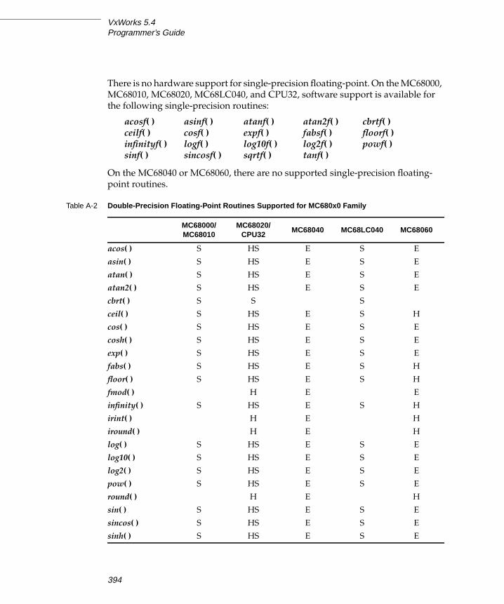
VxWorks 5.4Programmer’s Guide
There is no hardware support for single-precision floating-point. On the MC68000,
MC68010, MC68020, MC68LC040, and CPU32, software support is available for
the following single-precision routines:
On the MC68040 or MC68060, there are no supported single-precision floating-
point routines.
acosf( ) asinf( ) atanf( ) atan2f( ) cbrtf( )ceilf( ) cosf( ) expf( ) fabsf( ) floorf( )infinityf( ) logf( ) log10f( ) log2f( ) powf( )sinf( ) sincosf( ) sqrtf( ) tanf( )
Table A-2 Double-Precision Floating-Point Routines Supported for MC680x0 Family
MC68000/MC68010
MC68020/CPU32
MC68040 MC68LC040 MC68060
acos( ) S HS E S E
asin( ) S HS E S E
atan( ) S HS E S E
atan2( ) S HS E S E
cbrt( ) S S S
ceil( ) S HS E S H
cos( ) S HS E S E
cosh( ) S HS E S E
exp( ) S HS E S E
fabs( ) S HS E S H
floor( ) S HS E S H
fmod( ) H E E
infinity( ) S HS E S H
irint( ) H E H
iround( ) H E H
log( ) S HS E S E
log10( ) S HS E S E
log2( ) S HS E S E
pow( ) S HS E S E
round( ) H E H
sin( ) S HS E S E
sincos( ) S HS E S E
sinh( ) S HS E S E
394

A
AMotorola MC680x0
Floating-Point Support for MC680x0 CPUs Using MC68881/MC68882
VxWorks provides both hardware and software floating-point, in support of those
target configurations that include a floating-point coprocessor as well as those that
do not. Use the compiler option -msoft-float to generate object code that uses
software floating-point, and the compiler option -m68881 for hardware floating-
point.
Floating-Point Support for the MC68040 and MC68060
For the MC68040 and the MC68060 (but not the MC68LC040), VxWorks includes
support for MC68881/MC68882 floating-point instructions that are not directly
supported by the CPU. This emulation is provided by the Floating-Point Software
Package (FPSP) from Motorola, which is integrated into VxWorks.
The FPSP is called by special exception handlers that are invoked when one of the
unsupported instructions executes. This allows MC68881/MC68882 instructions
to be interpreted, although the exception overhead can be significant. Exception
handlers are also provided for other floating-point exceptions (for example,
floating-point division by zero, over- and underflow).
The initialization routine mathHardInit( ) installs these exception handlers; this
routine is called from usrConfig.c when you configure VxWorks for hardware
floating-point by selecting INCLUDE_HW_FP for inclusion in the project facility
VxWorks view. (It is defined by default.)
To avoid the overhead associated with unimplemented-instruction exceptions, the
floating-point libraries in VxWorks call specific routines in the FPSP directly. As a
result, application code written in C that uses transcendental functions (for
example, the sin( ) or log( ) routines) does not suffer from the exception-handling
overhead. No special changes to application source code are necessary. (However,
support is provided only for double-precision floating-point operations.)
sqrt( ) S HS E S H
tan( ) S HS E S E
tanh( ) S HS E S E
trunc( ) H E H
S = software floating-point support
H = hardware floating-point support
E = emulated hardware floating-point support
Table A-2 Double-Precision Floating-Point Routines Supported for MC680x0 Family
MC68000/MC68010
MC68020/CPU32
MC68040 MC68LC040 MC68060
395

VxWorks 5.4Programmer’s Guide
If you are using the GNU ToolKit C compiler (cc68k) distributed by Wind River
Systems, compile your code without the flag -msoft-float.
■ MC68040 Floating-Point Software Package
On the MC68040, VxWorks uses version 2.2 of the MC68040 Floating-Point
Software Package (FPSP) from Motorola. This library makes full use of the
floating-point support provided by the MC68040 hardware, as opposed to
pure software emulation. The size of this FPSP is approximately 64KB.
■ MC68060 Floating-Point Software Package
As with the MC68040, the MC68060 floating-point unit implements only a
subset of the MC68881/MC68882 instruction set. The two subsets are not
identical (see §6.5.1 Unimplemented Floating-Point Instructions in the MC68060Microprocessors User’s Manual); hence the MC68060 has its own FPSP. VxWorks
uses version B1 of the MC68060 Floating-Point Software Package from
Motorola. The size of this FPSP is approximately 84KB.
Floating-Point Support for the MC68LC040
While the MC68LC040 is a derivative of the MC68040 (implementing the same
integer unit and memory management unit), it has no floating-point unit.
Applications for the MC68LC040 must use software floating-point emulation. Use
the compiler option -msoft-float to generate object code that uses software
floating-point. Be sure to specify a CPU value of MC68LC040 when building
VxWorks (see Defining the CPU Type, p.384).
Memory Layout
The VxWorks memory layout is the same for all MC680x0 processors, except that
the MC68060 has no interrupt stack. Figure A-1 shows memory layout, labeled as
follows:
Interrupt Vector Table Table of exception/interrupt vectors.
SM Anchor Anchor for the shared memory network (if there is
shared memory on the board).
Boot Line ASCII string of boot parameters.
Exception Message ASCII string of the fatal exception message.
Initial Stack Initial stack for usrInit( ), until usrRoot( ) gets allocated
stack.
396

A
AMotorola MC680x0
All addresses shown in Figure A-1 are relative to the start of memory for a
particular target board. The start of memory (corresponding to 0x0 in the memory-
layout diagram) is defined as LOCAL_MEM_LOCAL_ADRS under
INCLUDE_MEMORY_CONFIG for each target.
System Image VxWorks itself (three sections: text, data, bss). The entry
point for VxWorks is at the start of this region.
WDB Memory Pool Size depends on the macro WDB_POOL_SIZE which
defaults to one-sixteenth of the system memory pool.
This space is used by the target server to support host-
based tools. Modify WDB_POOL_SIZE under
INCLUDE_WDB.
Interrupt Stack Stack for interrupt handlers (where present). Size is
defined by ISR_STACK_SIZE under INCLUDE_KERNEL.
Location depends on system image size.
System Memory Pool Size depends on size of the system image and (on the all
but MC68060) the interrupt stack. The sysMemTop( )routine returns the end of the free memory pool.
397

VxWorks 5.4Programmer’s Guide
Figure A-1 VxWorks System Memory Layout (MC680x0)
+0x0000 LOCAL_MEM_LOCAL_ADRS
+400+500+600+700+800+900
c00
+1000
Address
Initial Stack
Interrupt Vector Table( 1KB )
Exception Message
Boot Line
SM Anchor( Bus Control Latch - HKV2F only )
System Image
text
data
bss
Interrupt Stack
System Memory Pool
sysMemTop()
= Available
= Reserved
KEY
(not available on MC68060)
WDB Memory Pool_end
398

BSun SPARC, SPARClite
B.1 Introduction
This appendix provides information specific to VxWorks development on Sun
SPARC and SPARClite targets. It includes the following topics:
■ Building Applications: how to compile modules for your target architecture.
■ Interface Changes: information on changes or additions to particular VxWorks
features to support the Sun processors.
■ Architecture Considerations: special features and limitations of the Sun
processors, including information specific to the SPARClite and a figure
showing the VxWorks memory layout for these processors.
For general information on the Tornado development environment’s cross-
development tools, see the Tornado User’s Guide: Projects.
B.2 Building Applications
The Tornado 2.0 project facility is correctly preconfigured for building WRS BSPs.
However, if you choose not to use the project facility or if you need to customize
your build, you may need the information in the following sections. This includes
a configuration constant, an environment variable, and compiler options that
together specify the information the GNU toolkit requires to compile correctly for
SPARC and SPARClite targets.
399

VxWorks 5.4Programmer’s Guide
Defining the CPU Type
Setting the preprocessor variable CPU ensures that VxWorks and your applications
build with the appropriate architecture-specific features enabled. Define this
variable to SPARC for both the SPARC and SPARClite processors.
For example, to define CPU for a SPARC on the compiler command line, specify the
following command-line option when you invoke the compiler:
-DCPU=SPARC
To provide the same information in a header or source file instead, include the
following line in the file:
#define CPU SPARC
Configuring the GNU ToolKit Environment
Tornado includes the GNU compiler and associated tools. Tornado is configured
to use these tools by default. No change is required to the execution path, because
the compilation chain is installed in the same bin directory as the other Tornado
executables.
Compiling C or C++ Modules
The following is an example of a compiler command line for SPARClite cross-
development. The file to be compiled in this example has a base name of applic.
% ccsparc -DCPU=SPARC -I $WIND_BASE/target/h -O2 -nostdinc \-fno-builtin -msparclite -msoft-float -c applic. language_id
The options shown in the example have the following meanings:1
-DCPU=SPARCRequired; defines the CPU type. Use SPARClite for SPARClite processors.
-I $WIND_BASE/target/hRequired; includes VxWorks header files. (Additional -I flags may be included
to specify other header files.)
1. For more information on these and other compiler options, see the GNU ToolKit User’s Guide.
WRS supports compiler options used in building WRS software; a list of these options is
included in the Guide. Other options are not supported, although they are available with the
tools as shipped.
400

B
BSun SPARC, SPARClite
-O2 Optional; performs level 2 optimization.
-nostdincRequired; searches only the directory(ies) specified with the -I flag (see above)
and the current directory for header files. Does not search host-system include
files.
-fno-builtinRequired; uses library calls even for common library subroutines.
-msparcliteRequired for SPARClite; generates SPARClite-specific code.
-msoft-floatOptional; generates software floating point library calls, rather than hardware
floating point instructions. For more information, see USS Floating-PointEmulation Library, p.413,
-c Required; specifies that the module is to be compiled only, and not linked for
execution under the host.
applic.language_idRequired; the file(s) to compile. For C compilation, specify a suffix of .c. For
C++ compilation, specify a suffix of .cpp. The output is an unlinked object
module in a.out format with the suffix .o; for the example, the output is
applic.o.
During C++ compilation, the compiled object module (applic.o) is munched.
Munching is the process of scanning an object module for non-local static
objects, and generating data structures that VxWorks can use to call the objects’
constructors and destructors. See the VxWorks Programmer’s Guide: C++Development for details
B.3 Interface Variations
This section describes particular routines that are specific to SPARC targets in one
of the following ways:
■ available only for SPARC or SPARClite targets
■ parameters specific to SPARC or SPARClite targets
401

VxWorks 5.4Programmer’s Guide
■ special restrictions or characteristics on SPARC or SPARClite targets
For complete documentation on these routines, see the reference entries.
bALib
The following buffer-manipulation routines provided by bALib exploit the
SPARC LDD and STD instructions.
bzeroDoubles( )Zeroes out a buffer, 256 bytes at a time.
bfillDoubles( )Fills a buffer with a specified eight-byte pattern.
bcopyDoubles( )Copies one buffer to another, eight bytes at a time.
cacheMb930Lib
The library cacheMb930Lib contains routines that allow you to initialize, lock, and
clear the Fujitsu MB86930 (SPARClite) cache. For more information, see the
manual pages and Instruction and Data Cache Locking, p.412.
cacheMicroSparcLib
The library cacheMicroSparcLib contains routines that allow you to initialize,
flush, and clear the MicroSparc I and II caches. For more information, see the
manual pages.
dbgLib
If you are using the target shell, note the following architecture-specific
information on routines in the dbgLib:
■ Optional Parameter for c( ) and s( )
The SPARC versions of c( ) (continue) and s( ) (single-step) can take a second
address parameter, addr1. With this parameter, you can set nPC as well as the PC.
Note that if addr is NULL, addr1 is ignored.
NOTE: Unless otherwise noted, the information in this section applies to both the
SPARC and SPARClite. For SPARClite-specific information, see SPARCliteOverview, p.412.
402

B
BSun SPARC, SPARClite
■ Restrictions on cret( )
In VxWorks for SPARC, cret( ) cannot determine the correct return address.
Because the actual return address is determined by code within the routine, only
the calling address is known. With C code in general, the calling instruction is a
CALL and routines return with the following:
retrestore
This is the assumption made by cret( ) when it places a breakpoint at the return
address of the current subroutine and continues execution. Note that returns other
than %i7 + 8 result in cret( ) setting an incorrect breakpoint value and continuing.
■ Restrictions on so( )
The so( ) routine single-steps a task stopped at a breakpoint, but steps over a
subroutine. However, in the SPARC version, if the next instruction is a CALL or
JMPL x, %o7, the routine breaks at the second instruction following the subroutine
(that is, the first instruction following the delay slot’s instruction). In general, the
delay slot loads parameters for the subroutine. This loading can have unintended
consequences if the delay slot is also a transfer of control.
■ Trace Routine, tt( )
In general, a task trace works for all non-leaf C-language routines and any
assembly language routines that contain the standard prologue and epilogue:
save %sp, -STACK_FRAME_SIZE, %sp...retrestore
Although the tt( ) routine works correctly in general, note the following caveats:
– Routines written in assembly or other languages, strange entries in routines,
or tasks with corrupted stacks, can result in confusing trace information.
– All parameters are assumed to be 32-bit quantities.
– The cross-compiler does not handle structures passed as parameters correctly.
– The current trace-back tag generated by C compilers is limited to 16
parameters; thus, tt( ) does not report the value of parameters above 16.
However, this does not mean that your application cannot use routines with
more than 16 parameters.
403

VxWorks 5.4Programmer’s Guide
– If the routine changes the values of its local registers between the time it is
called and the time it calls the next level down (or, at the lowest level, the time
the task is suspended), tt( ) reports the changed values. It has no way to locate
the original values.
– If the routine changes the values of registers i0 through i5 between the time it
is called and the time it calls the next level down (or, at the lowest level, the
time the task is suspended), tt( ) reports the changed values. It has no way to
locate the original values.
– If you attempt a tt( ) of a routine between the time the routine is called and the
time its initial save is finished, you can expect strange results.
dbgArchLib
If you are using the target shell, the following architecture-specific show routines
are available if INCLUDE_DEBUG is defined:
psrShow( )Displays the symbolic meaning of a specified PSR value on the standard
output device.
fsrShow( )Displays the symbolic meaning of a specified FSR value on the standard
output device.
fppArchLib
The SPARC version of fppArchLib saves and restores a math coprocessor context
appropriate to the SPARC floating-point architecture standard.
intArchLib
intLevelSet( ) parameters
The SPARC version of intLevelSet( ) takes an argument from 0 to 15.
intLock( ) returns
The SPARC version of intLock( ) returns an interrupt level.
ioMmuMicroSparcLib
The library ioMmuMicroSparcLib contains routines that allow you to initialize
and map memory in the microSPARC I/O MMU. For more information, see the
manual pages.
404

B
BSun SPARC, SPARClite
mathALib
Because the overall SPARC architecture includes hardware floating-point support,
while the SPARClite variant does not, VxWorks includes mathALib hardware
floating-point support for SPARC and software floating-point support for
SPARClite.
■ SPARC
On SPARC targets, the following mathALib routines are available. Note that these
are all double-precision routines; no single-precision routines are supported for
SPARC:
■ SPARClite
On SPARClite targets, the following mathALib routines are supported (for
information about how to use this support, see USS Floating-Point EmulationLibrary, p.413):
– Double-precision routines:
– Single-precision routines:
vxALib
The test-and-set primitive vxTas( ) provides a C-callable interface to the SPARC
ldstub instruction.
vxLib
The routine vxMemProbeAsi( ) probes addresses in SPARC ASI space.
acos( ) asin( ) atan( ) atan2( ) cbrt( ) ceil( ) cos( )cosh( ) exp( ) fabs( ) floor( ) fmod( ) irint( ) iround( )log( ) log10( ) pow( ) round( ) sin( ) sinh( ) sqrt( )tan( ) tanh( ) trunc( )
acos( ) asin( ) atan( ) atan2( ) ceil( ) cos( ) cosh( )exp( ) fabs( ) floor( ) fmod( ) frexp( ) ldexp( ) log( )log10( ) pow( ) sin( ) sinh( ) sqrt( ) tan( ) tanh( )
acosf( ) asinf( ) atanf( ) atan2f( ) ceilf( ) cosf( ) coshf( )expf( ) fabsf( ) floorf( ) fmodf( ) logf( ) log10f( ) modf( )powf( ) sinf( ) sinhf( ) sqrtf( ) tanf( ) tanhf( )
405

VxWorks 5.4Programmer’s Guide
a.out-Specific Tools for SPARC and SPARClite
The following tools are specific to the a.out format. For more information, see the
reference entries for each tool.
hexconverts an a.out-format object file into Motorola hex records. The syntax is:
hex [-a adrs] [-l ] [-v ] [-p PC] [-s SP] file
aoutToBinextracts text and data segments from an a.out file and writes it to standard
output as a simple binary image. The syntax is:
aoutToBin < inFile > outfile
xsymextracts the symbol table from an a.out file. The syntax is:
xsym < objMod > symTbl
B.4 Architecture Considerations
This section describes the following characteristics of the SPARC and SPARClite
architectures that you should keep in mind as you write a VxWorks application:
■ Reserved registers■ Processor mode■ Vector table initialization■ Double-word Integers■ Interrupt handling■ Floating-point support■ Stack pointer usage■ SPARClite overview■ Memory layout
406

B
BSun SPARC, SPARClite
Reserved Registers
Following the SPARC specification (Appendix D, Software Considerations, in TheSPARC Architecture Manual, Version 8 from Sun Microsystems), registers g5, g6, and
g7 are reserved for VxWorks kernel use. Avoid using these registers in your
applications.
Processor Mode
VxWorks for SPARC and SPARClite always runs in Supervisor mode.
Vector Table Initialization
After the VxWorks for SPARC or SPARClite has completed initialization, traps are
enabled and the PIL (Processor Interrupt Level) is set to zero. All 15 interrupt levels
are active with the coprocessor enables set according to hardware availability and
application use.
The TBR (Trap Base Register) points to the active vector table at address 0x1000 in
local memory.
Make sure that vectors are not reserved for the processor or the kernel before
acquiring them for an application.
Double-word Integers: long long
The double-word integer long long is not supported, except as an artifact of your
particular architecture and compiler. For more information about handling
unsupported features, please see the Customer Support User’s Guide.
Interrupt Handling
For VxWorks for SPARC and SPARClite, an interrupt stack allows all interrupt
processing to be performed on a separate stack. The interrupt stack is implemented
in software because the SPARC family does not support such a stack in hardware.
407

VxWorks 5.4Programmer’s Guide
SPARC Interrupts
The SPARC microprocessor allows 15 levels of interrupts. The level is encoded by
external hardware on the four interrupt signal lines. The integer unit (CPU)
decodes this level and passes control directly to the entry in the vector table at an
offset of 0x100 plus the interrupt level times 16 bytes. This corresponds to vectors
16 through 31 (addresses 0x100 to 0x1F0). Each 16-byte entry in the vector table
contains up to four instructions. Typically, control passes to an interrupt service
routine (ISR) with a call or branch instruction.
The SPARC uses auto-vectored interrupts. The chip does not perform any type of
interrupt acknowledge (IACK) cycle. The address in the Trap Base Register (TBR)
concatenated with the interrupt level vector displacement allows the SPARC to
begin interrupt processing.
The alternative is vectored interrupts. The CPU responds to the interrupt with an
IACK cycle so that an interrupt controller chip or individual device can return a
value that clears and identifies the source of the interrupt. This is extremely useful
for multiple sources of interrupts on a single-interrupt level.
The ability to perform an interrupt acknowledge cycle is a function of the
microprocessor (not the software or board-level hardware). However, a target
board can synthesize an IACK cycle by accessing an area created in its address
space. This is often necessary to clear the interrupt pending bit in an interrupting
device. An IACK cycle also differs from a normal read cycle in that the value
returned is an interrupt vector. This vector is used to select an offset in the vector
table that has the device’s ISR connected to that table entry.
VxWorks allows an application to connect ISRs to vectors with the routine
intConnect( ). A stub is built dynamically that calls an interrupt entry routine, calls
the ISR, and then calls an exit routine. The SPARC, like other RISC processors,
delegates to software the task of building an exception stack frame (ESF) to save
volatile information. The kernel builds up two types of exception stack frames: one
for interrupts and one for all other exceptions. The code execution sequence
following an interrupt is as follows:
1. Vector table
2. Exception stack frame building
3. Overflow exception handling
4. Interrupt entry code
5. ISR
6. Interrupt exit code
7. Rescheduling, if the interrupt added work for the kernel (such as a semGive( ))
408

B
BSun SPARC, SPARClite
Vectored Interrupts
The SPARC kernel was designed to handle vectored interrupts as an option.
Because this implementation varies with every target board, the kernel must work
with the board support package (BSP). The implementation of vectored interrupts
on a processor that does not support them must be done in software.
A table in the BSP allows an IACK for each of the 15 interrupt levels. A NULL (0)
entry corresponds to no interrupt acknowledge. If an IACK is required, the table
entry corresponds to a routine that performs the necessary operations. Because the
SPARC vector table contains 256 entries, a byte-sized vector can select any
exception handler.
Note that the microprocessor, the board, and the kernel reserve certain vector table
entries. The kernel appends this vector to the TBR and continues execution with
the selected ISR. All checking for the IACK condition and performing of the
operation is done by the kernel and is transparent. The interrupt connection
mechanism is the same, and checking for and clearing the pending interrupt is
done before the ISR attached by intConnect( ) is called.
The following shows the structure used on the SPARCengine 1E (also known as a
Sun 1E) SPARC board in installDir/target/config/sun1e/sysLib.c. It illustrates the
use of vectored interrupts for VME, but does not require an IACK cycle for local
(on-board) interrupts:
extern sysVmeAck(); /* IACK Leaf Functions, code in sysALib */
int (*sysIntAckTable [16])() ={NULL, /* Reserved for Kernel */NULL, /* Interrupt Level 1 - Software 1 */sysVmeAck, /* Interrupt Level 2 - VME 1 */sysVmeAck, /* Interrupt Level 3 - VME 2 */NULL, /* Interrupt Level 4 - SCSI */sysVmeAck, /* Interrupt Level 5 - VME 3 */NULL, /* Interrupt Level 6 - Ethernet */NULL, /* Interrupt Level 7 - P2 Bus */sysVmeAck, /* Interrupt Level 8 - VME 4 */sysVmeAck, /* Interrupt Level 9 - VME 5 */NULL, /* Interrupt Level 10 - Timer 0 */sysVmeAck, /* Interrupt Level 11 - VME 6 */NULL, /* Interrupt Level 12 - Serial Ports */NULL, /* Interrupt Level 13 - Mailbox */NULL, /* Interrupt Level 14 - Timer 1 */NULL /* Interrupt Level 15 - NMI */};
The performance penalty for this added feature is negligible. When vectored
interrupts are used, this penalty increases, because an operation is being handled
409

VxWorks 5.4Programmer’s Guide
in software that the SPARC microprocessor was not designed to do. There are some
restrictions on these vector routines because they are called in a critical section of
code. Again, the Sun 1E SPARC board is used as an example. Note that you must
use special “leaf” procedures.
The corresponding code for the function table is in
installDir/target/config/sun1e/sysALib.s:
/* IACK Function Call Template/* Input: %l5 - return address/* Volatile: %l4, %l6 (DO NOT USE OTHER REGISTERS !!!)/* Return: %l5 - vector table index */
.global _sysVmeAck
_sysVmeAck:sethi %hi(SUN_VME_ACK),%l6 /* VMEbus IACK - 0xFFD18001 */or %l6,%lo(SUN_VME_ACK),%l6rd %tbr,%l4 /* Extract interrupt level */and %l4,0x00F0,%l4add %l4,0x0010,%l4 /* Sun 1E to VME level conversion */srl %l4,5,%l4 /* Add 1, divide by 2 (no remainder) */sll %l4,1,%l4 /* Multiply VME level by 2 */ldub [%l6 + %l4],%l4 /* VMEbus IACK and get vector */jmpl %l5,%g0 /* Return address - leaf routine */mov %l4,%l5 /* Interrupt vector to %l5 */
VMEbus Interrupt Handling
SPARC uses fifteen interrupt levels instead of the seven used by VMEbus. The
mapping of the seven VMEbus interrupts to the fifteen SPARC levels is board
dependent. VMEbus interrupts must be acknowledged.
Floating-Point Support
Floating-Point Contexts
A task can be spawned with floating-point support by setting the VX_FP_TASKoption. This causes switch hooks to initialize, save, and restore a floating-point
context. This option increases the task’s context switch time and memory
consumption, so only spawn tasks with VX_FP_TASK if they must perform
floating-point operations.
The floating-point data registers are initialized to NaN (Not-a-Number), which is
0xFFFFFFFF. You can change the FSR’s (Floating-point Status Register) value using
the global variable fppFsrDefault.
410

B
BSun SPARC, SPARClite
Floating-Point Exceptions
The following are SPARC floating-point exceptions (most are deferred):
– FPU Disabled (or not present)
– Unfinished Operation
– Unimplemented Operation
– Sequence Error
– Invalid Operation
– Overflow
– Underflow
– Divide-by-Zero
– Inexact
■ Exception Options
The application can configure the types of floating-point exceptions that VxWorks
handles. The ideal solution is to not generate any floating-point exceptions in the
application tasks. However, a more realistic scheme is to mask all exceptions
globally (all tasks) in the TEM (Trap Enable Mask) field of the FSR (Floating-point
Status Register). Alternatively, this can be done locally (on a per task basis) as tasks
are spawned and the FSR is initialized. In addition to global and local masks,
individual exceptions (invalid operation, overflow, underflow, divide-by-zero,
inexact) can be masked in the TEM. The masked exception continues to accrue (for
example, become more inexact, continue to overflow, and so on). The default for
VxWorks is to mask only the inexact exception.
■ Exception Handlers
All floating-point exceptions (if enabled) result in the suspension of the offending
task and a message sent through the exception handling task, excTask( ). The
floating-point unit is flushed so that other tasks can still use the hardware and
continue their numeric processing.
■ Deferred Exceptions
Floating-point exceptions on the SPARC floating-point units are deferred. When
they occur in the FPU, they do not immediately interrupt the CPU (integer unit).
Instead they remain pended until they are pushed out of the queue by additional
floating-point operations or an FSR access.
If one of the last floating-point operations causes an unmasked exception before a
context switch, saving the task’s context flushes out the exception while in the
kernel. The exception handler checks for this special case and works its way back
to the kernel so that it can continue the context switch. When the task that caused
411

VxWorks 5.4Programmer’s Guide
the exception is switched back in, it continues in the exception handler and
suspends itself. The relationship between a deferred exception and a context
switch cannot be controlled due to its asynchronous nature.
■ Floating-Point Exception Simulation
SPARCmon is a product from Sun Microsystems that you can attach to the floating-
point exception vectors to handle all exception cases for the SPARC. Any floating-
point exceptions must be simulated by software and the queue flushed of all
pending operations. This simulation fixes the error that caused the exception
whenever possible, or takes some default action (for example, suspends the task).
Stack Pointer Usage
Because the stack pointer can advance without stack memory actually being
written or read, it is possible for the stack high water marker to appear below the
current stack pointer. In other words, current stack usage can be greater than the
high stack usage. This is an artifact of the SPARC architecture’s rolling register
windows.
The stack pointer is used very little. The local and output registers in each register
window perform the bulk of stack operations. The stack is used for long argument
lists, or if a window overflow exception pushes registers onto the stack.
SPARClite Overview
All information pertaining to the SPARC applies to the SPARClite, with the
addition of the architectural enhancements described in the following subsections.
Instruction and Data Cache Locking
The SPARClite allows the global and local locking of the instruction and data
caches. The ability to lock instructions and/or data in the caches allows for higher
performance and more deterministic systems. The locking must be done in such a
way that overall system performance is improved, not degraded. For a better real-
time system, call cacheMb930LockAuto( ) to enable instruction and data cache
locking. After the caches are locked, they cannot be unlocked or disabled.
To enhance performance, some of the VxWorks kernel data items are locked in the
data cache. This uses approximately 128 bytes. The remainder of the data cache is
available to the developer. Additional data can be locked in the cache using the
BSP.
412

B
BSun SPARC, SPARClite
USS Floating-Point Emulation Library
The SPARClite does not have a floating-point coprocessor; thus, the USS floating-
point emulation library is used. Using the -msparclite compile flag allows this
library to be accessed by your code for floating-point calculations.
Memory Layout
The memory layout of both the SPARC and SPARClite processors is shown in
Figure B-1. The memory layout of the microSPARC processor is in Figure B-2.
These figures contain the following labels:
All addresses shown are relative to the start of memory for a particular target
board. The start of memory (corresponding to 0x0 in the memory-layout diagram)
is defined as LOCAL_MEM_LOCAL_ADRS under INCLUDE_MEMORY_CONFIGfor each target.
SM Anchor Anchor for the shared memory network (if there is
shared memory on the board).
Boot Line ASCII string of boot parameters.
Exception Message ASCII string of the fatal exception message.
Interrupt Vector Table Table of exception/interrupt vectors.
Initial Stack Initial stack for usrInit( ), until usrRoot( ) gets allocated
stack.
System Image Entry point for VxWorks.
WDB Memory Pool Size depends on the macro WDB_POOL_SIZE which
defaults to one-sixteenth of the system memory pool.
This space is used by the target server to support host-
based tools. Modify WDB_POOL_SIZE under
INCLUDE_WDB.
Interrupt Stack Size is defined by ISR_STACK_SIZE under
INCLUDE_KERNEL. Location depends on system image
size.
System Memory Pool Size depends on size of system image and interrupt
stack. The end of the free memory pool for this board is
returned by sysMemTop( ).
413

VxWorks 5.4Programmer’s Guide
Figure B-1 VxWorks System Memory Layout (SPARC/SPARClite)
+0x0000 LOCAL_MEM_LOCAL_ADRS
+600+700+800+900
+1000
Address
Exception Message
Boot Line
SM Anchor
System Memory Pool
sysMemTop()
= Available
= Reserved
KEY
System Image
text
data
bss
+2000
Interrupt Vector Table
+3000
Initial Stack
( 4KB )
Interrupt Stack
WDB Memory Pool_end
414

B
BSun SPARC, SPARClite
Figure B-2 VxWorks System Memory Layout (microSPARC I & II)
+0x0000 LOCAL_MEM_LOCAL_ADRS
+600+700+800+900
+1000
Address
Exception Message
Boot Line
SM Anchor
Interrupt Stack
System Memory Pool
+800000 sysMemTop()
= Available
= Reserved
KEY
System Imagetext
data
bss
+2000
Interrupt Vector Table
+3000
Initial Stack
( 4KB )
+10000
+20000
Shared Memory Pool
Ethernet Buffer Pool
(64KB)
(128KB)
Additional System Memory Pool(added by ADD_MEM option)
Boot ROM / MMU Tables LOCAL_MEM_RSVD_SIZE{
WDB Memory Pool_end
415

VxWorks 5.4Programmer’s Guide
416

CIntel i960
C.1 Introduction
This appendix provides information specific to VxWorks development on Intel
i960CA, JX, KA, and KB targets. It includes the following topics:
■ Building Applications: how to compile modules for your target architecture.
■ Interface Changes: information on changes or additions to particular VxWorks
features to support the i960 processors.
■ Architecture Considerations: special features and limitations of the i960
processors.
For general information on the Tornado development environment’s cross-
development tools, see the Tornado User’s Guide: Projects.
C.2 Building Applications
The Tornado 2.0 project facility is correctly preconfigured for building WRS BSPs.
However, if you choose not to use the project facility or if you need to customize
your build, you may need the information in the following sections. This includes
a configuration constant, an environment variable, and compiler options that
together specify the information the GNU toolkit requires to compile correctly for
i960 targets.
417

VxWorks 5.4Programmer’s Guide
Defining the CPU Type
Setting the preprocessor variable CPU ensures that VxWorks and your applications
build with the appropriate architecture-specific features enabled. Define this
variable to one of the following values, to match the processor you are using:
– I960CA– I960JX– I960KA– I960KB
For example, to define CPU for a i960CA on the compiler command line, specify
the following command-line option when you invoke the compiler:
-DCPU=I960CA
To provide the same information in a header or source file instead, include the
following line in the file:
#define CPU I960CA
Configuring the GNU ToolKit Environment
Tornado includes the GNU compiler and associated tools. Tornado is configured
to use these tools by default. No change is required to the execution path, because
the compilation chain is installed in the same bin directory as the other Tornado
executables.
Compiling C or C++ Modules
The following is an example of a compiler command line for i960 cross-
development. The file to be compiled in this example has a base name of applic.
% cc960 -fno-builtin -I $WIND_BASE/target/h -0 -c -mca\-mstrict-align -fvolatile -nostdinc -DCPU=I960CA applic.c
The options shown in the example have the following meanings:1
1. For more information on these and other compiler options, see the GNU ToolKit User’s Guide.
WRS supports compiler options used in building WRS software; a list of these options is
included in the Guide. Other options are not supported, although they are available with the
tools as shipped.
418

C
CIntel i960
-fno-builtinRequired; uses library calls even for common library subroutines.
-I $WIND_BASE/target/hRequired; includes VxWorks header files. (Additional -I flags may be included
to specify other header files.)
-O Optional; performs standard optimization.
-c Required; specifies that the module is to be compiled only, and not linked for
execution under the host.
-mcaRequired for i960CA and i960JX; specifies the instruction set. For the i960KA
and KB, use -mka and -mkb, respectively.
-mstrict-alignRequired; do not permit unaligned accesses.
-fvolatileRequired; consider all memory references through pointers to be volatile.
-nostdincRequired; searches only the directory(ies) specified with the -I flag (see above)
and the current directory for header files. Does not search host-system include
files.
-DCPU=I960CARequired; defines the CPU type. If you are using an i960 processor other than
the CA, specify the appropriate value (see Defining the CPU Type, p.418).
applic.language_idRequired; the file(s) to compile. For C compilation, specify a suffix of .c. For
C++ compilation, specify a suffix of .cpp. The output is an unlinked object
module in COFF format with the suffix .o; for the example, the output is
applic.o.
During C++ compilation, the compiled object module (applic.o) is munched.
Munching is the process of scanning an object module for non-local static
objects, and generating data structures that VxWorks run-time support can use
to call the objects’ constructors and destructors. For details, see the VxWorksProgrammer’s Guide: C++ Development.
419
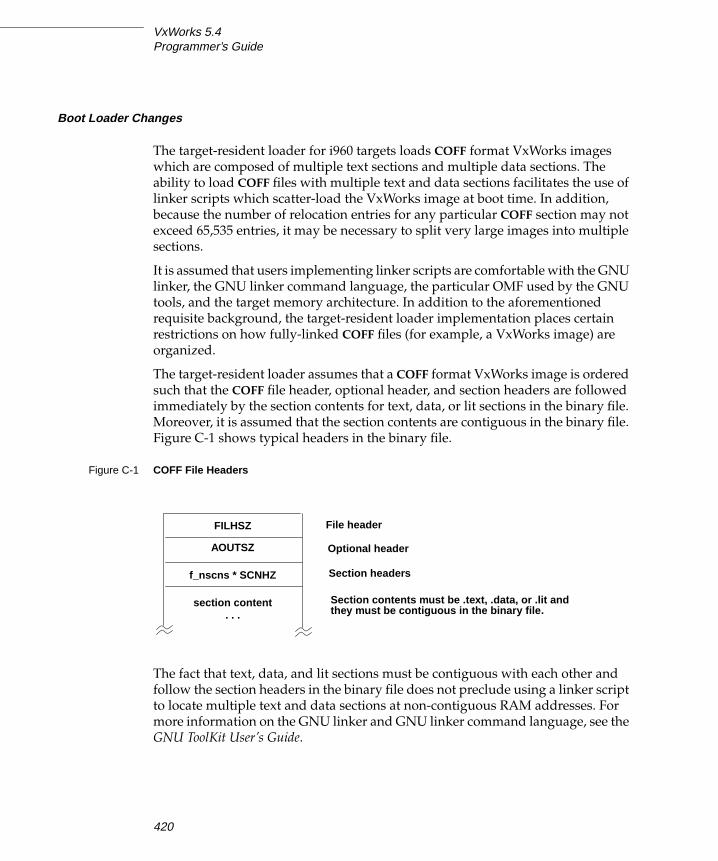
VxWorks 5.4Programmer’s Guide
Boot Loader Changes
The target-resident loader for i960 targets loads COFF format VxWorks images
which are composed of multiple text sections and multiple data sections. The
ability to load COFF files with multiple text and data sections facilitates the use of
linker scripts which scatter-load the VxWorks image at boot time. In addition,
because the number of relocation entries for any particular COFF section may not
exceed 65,535 entries, it may be necessary to split very large images into multiple
sections.
It is assumed that users implementing linker scripts are comfortable with the GNU
linker, the GNU linker command language, the particular OMF used by the GNU
tools, and the target memory architecture. In addition to the aforementioned
requisite background, the target-resident loader implementation places certain
restrictions on how fully-linked COFF files (for example, a VxWorks image) are
organized.
The target-resident loader assumes that a COFF format VxWorks image is ordered
such that the COFF file header, optional header, and section headers are followed
immediately by the section contents for text, data, or lit sections in the binary file.
Moreover, it is assumed that the section contents are contiguous in the binary file.
Figure C-1 shows typical headers in the binary file.
The fact that text, data, and lit sections must be contiguous with each other and
follow the section headers in the binary file does not preclude using a linker script
to locate multiple text and data sections at non-contiguous RAM addresses. For
more information on the GNU linker and GNU linker command language, see the
GNU ToolKit User’s Guide.
Figure C-1 COFF File Headers
FILHSZ
AOUTSZ
f_nscns * SCNHZ
section content. . .
File header
Optional header
Section headers
Section contents must be .text, .data, or .lit andthey must be contiguous in the binary file.
420

C
CIntel i960
The target-resident loader for i960 reports the sizes of individual text and data
sections in addition to the bss section when VxWorks is booted. For example, if a
multiple text section image is booted, output similar to the following might be
seen:
Attaching network interface oli0... done.Attaching network interface lo0... done.Loading... 277764 + 82348 + 66664 + 7948 + 29692Starting at 0x1000...
Attached TCP/IP interface to oli unit 0Attaching network interface lo0... done.NFS client support not included.
VxWorks
Copyright 1984-1998 Wind River Systems, Inc.
CPU: Cyclone EP960CxVxWorks: 5.4
BSP version: 1.2/0 Creation date: Feb 10 1999
WDB: Ready.
This format is a slight cosmetic modification to the section size values which WRS
boot loaders have traditionally reported as size of text + size of data + size of bss.
Reporting the size of individual text and data sections rather than summing them
up is intended to be an aid for developers working on VxWorks images which are
organized by way of a linker script. This change is not likely to be noticed when
the default VxWorks image types are used.
C.3 Interface Variations
This section describes particular routines that are specific to i960 targets in any of
the following ways:
■ available only on i960 targets
■ parameters specific to i960 targets
■ special restrictions or characteristics on i960 targets
For complete documentation on these routines, see the reference entries.
421

VxWorks 5.4Programmer’s Guide
Initialization
There are several differences in what sysInit( ) initializes and in the initialization
sequence on i960 targets.
Differences in sysInit( ) Routine
For the i960, the sysInit( ) routine initializes the system interrupt and fault tables
with default stubs, in addition to its standard functions.
ROM-Based VxWorks with i960 Targets
As with other target architectures, the routines romInit( ) and romStart( ) execute
first. Then initialization continues at the sysInit( ) call, rather than with the
usrInit( ) call as for other ROM-based targets.
Data Breakpoint Routine bh( )
In addition to being able to break at an instruction with b( ), the i960CA permits
breakpoints at a data address using bh( ). For more information, see the reference
entry for bh( ). For example, the following command from the VxWorks shell
causes a data breakpoint on any access to data address 0xFFFF:
-> bh 0xFFFF, 3
The delete-breakpoint routines, bd( ) and bdall( ), delete both instruction and data
breakpoints. Only two data breakpoints can be present in the system at one time.
Parameter Change for intLevelSet( )
The i960 version of intLevelSet( ) takes an argument from 0 to 31. Level 31 is
equivalent to locking all interrupts.
Results Change for memLib
In VxWorks for the i960, the library memLib forces both partitions and blocks
returned by malloc( ) to be 16-byte aligned.
! CAUTION: The bh( ) routine does not work reliably on instruction fetches; use b( )to break on instructions.
422

C
CIntel i960
Math Routines
Mathematics routines using software floating-point emulation are part of the
GNU/960 distribution from Cygnus, in the libraries libm.a, libg.a, and libgcc.a.
The location of these libraries is described in
installDir/target/h/make/make.I960xxgnu by the variable LIBS (where xx identifies
libraries specific to the CA, JX, KA, or KB variant of the i960 architecture).
The following double-precision floating-point routines are included in the
GNU/960 distribution from Cygnus:
The following single-precision floating-point routines are also available:
Adding in Unresolved Routines
Occasions can arise when an application requires libm.a, libg.a, and libgcc.aroutines, although the application has not been prelinked with the VxWorks image.
There are several alternatives for dealing with this situation:
■ You can compile and link a set of dummy calls with VxWorks to ensure that
the necessary routines are included in the VxWorks image.
■ You can explicitly link the appropriate archive with your application module
by using ld960.
■ You can add any unresolved reference symbols to
installDir/target/src/config/mathInit.c and rebuild VxWorks.
Floating-Point Task Option: VX_FP_TASK
The i960CA, JX, and KA processors contain no floating-point hardware; thus no
floating-point context is used. Floating-point emulation is performed in software
with the routines provided by the Cygnus libraries (see Math Routines, p.423);
therefore, the task option VX_FP_TASK is not required.
acos( ) asin( ) atan( ) atan2( ) ceil( ) cos( ) cosh( )exp( ) fabs( ) floor( ) fmod( ) log( ) log10( ) log2( )pow( ) sin( ) sinh( ) sqrt( ) tan( ) tanh( )
atanf( ) atan2( ) ceilf( ) expf( )fabsf( ) floorf( ) logf( ) log2f( )powf( ) sinf( ) sqrtf( ) tanf( )
423

VxWorks 5.4Programmer’s Guide
The i960KB has on-board floating-point hardware. The task option VX_FP_TASK is
required when spawning tasks on the i960KB processor.
COFF-Specific Tools For i960
The following tools are specific to the COFF format on i960 processors. For more
information, see the reference entries for each tool.
coffHex960converts an COFF-format object file into Motorola hex records. The syntax is:
coffHex960 [- [TD]imifile, offset] [-a offset] [-l ] file
coffToBinextracts text and data segments from a COFF file and writes it to standard
output as a simple binary image. The syntax is:
coffToBin < inFile > outfile
xsymcextracts the symbol table from a COFF file. The syntax is:
xsymc < objMod > symTbl
Limitation on d( ) in WindSh
On i960 targets not all memory is accessible from the host shell. For example, if
there is no PCI bus on an ep960cx board, addresses 0x10000000 to 0x 9fffffff are not
accessible. Although a d( ) command from the target shell can access this region,
the same command from the host can not. This is because the host shell d( )command verifies the memory using vxMemProbe( ) before displaying it, while
the target shell d( ) command does not.
A further complication occurs with ev960 boards. vxMemProbe( ) uses the bus
error signal to detect whether a region of memory is accessible or not. If this signal
is not present, as it is not on ev960 boards, vxMemProbe( ) uses sysProbeMem( ) to
detect whether the requested address is valid or not. sysProbeMem( ) determines
whether an address is between LOCAL_MEM_LOCAL_ADRS and
sysPhysMemTop or not. This means that if you want to access a new address on
ev960 boards, for example because you added a new component, you must modify
sysProbeMem( ) so that it considers your new memory zone valid.
424

C
CIntel i960
C.4 Architecture Considerations
This section describes the following characteristics of the i960 architecture that you
should keep in mind as you write a VxWorks application:
■ Byte order■ Double-word Integers■ VMEbus interrupt handling■ Memory layout
Byte Order
The i960 architecture uses little-endian byte order. For information about macros
and routines to convert byte order (from big-endian to little-endian and vice
versa), see VxWorks Network Programmer’s Guide: TCP/IP Under VxWorks.
The VxWorks loader allows object module headers to be in either big-endian or
little-endian byte order. Host utility programs can use the most convenient byte
order to process i960 objects. Object file text and data segments must be little
endian for i960 processors.
Double-word Integers: long long
The double-word integer long long is not supported, except as an artifact of your
particular architecture and compiler. For more information about handling
unsupported features, please see the Customer Support User’s Guide.
VMEbus Interrupt Handling
The i960 uses 31 interrupt levels instead of the seven used by VMEbus. The
mapping of the seven VMEbus interrupts to the 31 i960 levels is board dependent.
VMEbus interrupts must be acknowledged with sysBusIntAck( ). VxWorks does
not use the vector submitted by the interrupting device. For more information, see
the file installDir/target/h/arch/i960/ivI960.h.
425

VxWorks 5.4Programmer’s Guide
Memory Layout
The figures on the following pages show the layout of a VxWorks system in
memory for various target architectures. Areas contain the following labels:
Figure C-2 shows the memory layout for an i960CA target; Figure C-3 shows the
memory layout for an i960JX target; Figure C-4 shows the memory layout for an
i960KA or i960KB target.
All addresses shown in these figures are relative to the start of memory for a
particular target board. The start of memory (corresponding to 0x0 in the memory-
layout diagram) is defined as LOCAL_MEM_LOCAL_ADRS under
INCLUDE_MEMORY_CONFIG for each target.
Interrupt Vector Table Table of exception/interrupt vectors.
SM Anchor Anchor for the shared memory network (if there is shared
memory on the board).
Boot Line ASCII string of boot parameters.
Exception Message ASCII string of the fatal exception message.
Initial Stack Initial stack for usrInit( ), until usrRoot( ) gets allocated
stack.
System Image Entry point for VxWorks.
WDB Memory Pool Size depends on the macro WDB_POOL_SIZE which
defaults to one-sixteenth of the system memory pool. This
space is used by the target server to support host-based
tools. Modify WDB_POOL_SIZE under INCLUDE_WDB.
Interrupt Stack Location depends on system image size. Size is defined by
ISR_STACK_SIZE under INCLUDE_KERNEL.
System Memory Pool Size depends on size of system image and interrupt stack.
The end of the free memory pool for this board is returned
by sysMemTop( ).
426

C
CIntel i960
Figure C-2 VxWorks System Memory Layout (i960CA)
+0x0000 LOCAL_MEM_LOCAL_ADRS
+400
+600
+700
+800
+900
+e00
+1000
Address
Initial Stack
Exception Message
Boot Line
SM Anchor
System Image
text
data
bss
System Memory Pool
sysMemTop()
= Available
= Reserved
KEY
NMI Vector
ffffff00
Initialization Boot Record
Interrupt Vector Table
Interrupt Stack
WDB Memory Pool
_end
427

VxWorks 5.4Programmer’s Guide
Figure C-3 VxWorks System Memory Layout (i960JX)
+0x0000 LOCAL_MEM_LOCAL_ADRS
+400
+600
+800
+900
+30000
Address
Exception Message
Boot Line
System Image
text
data
bss
System Memory Pool
sysMemTop()
= Available
= Reserved
KEY
NMI Vector
ffffffd0
Initialization Boot Record
Interrupt Vector Table
Interrupt Stack
WDB Memory Pool
_end
428
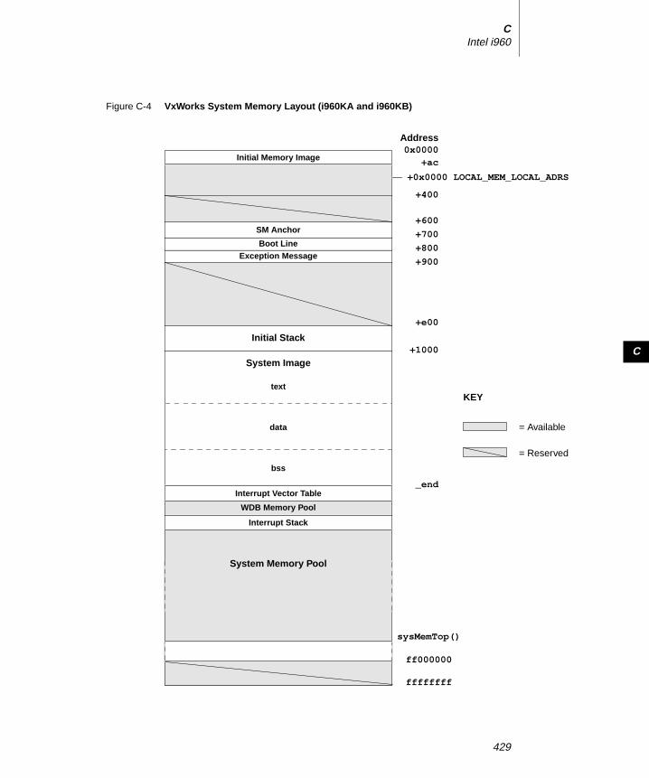
C
CIntel i960
Figure C-4 VxWorks System Memory Layout (i960KA and i960KB)
0x0000+ac
+600
+700
+800
+900
+e00
+1000
Address
Initial Stack
Exception MessageBoot Line
SM Anchor
System Image
text
data
bss
System Memory Pool
sysMemTop()
= Available
= Reserved
KEY
Initial Memory Image
Interrupt Vector Table
Interrupt Stack
ff000000
+400
ffffffff
WDB Memory Pool
_end
+0x0000 LOCAL_MEM_LOCAL_ADRS
429

VxWorks 5.4Programmer’s Guide
430

DIntel x86
D.1 Introduction
This appendix provides information specific to VxWorks development on Intel
i386, i486, Pentium, and PentiumPro (x86) targets. It includes the following topics:
■ Building Applications: how to compile modules for your target architecture.
■ Interface Changes: information on changes or additions to particular VxWorks
features to support the x86 processors.
■ Architecture Considerations: special features and limitations of the x86
processors.
■ Board Support Packages: information on specific BSPs and device drivers.
For general information on the Tornado development environment’s cross-
development tools, see the Tornado User’s Guide: Projects.
D.2 Building Applications
The Tornado 2.0 project facility is correctly preconfigured for building WRS BSPs.
However, if you choose not to use the project facility or if you need to customize
your build, you may need the information in the following sections. This includes
a configuration constant, an environment variable, and compiler options that
431

VxWorks 5.4Programmer’s Guide
together specify the information the GNU toolkit requires to compile correctly for
x86 targets.
Defining the CPU Type
Setting the preprocessor variable CPU ensures that VxWorks and your applications
build with the appropriate architecture-specific features enabled. Define this
variable to either I80386, I80486, or PENTIUM to match the processor you are using.
For example, to define CPU for an i386 on the compiler command line, specify the
following command-line option when you invoke the compiler:
-DCPU=I80386
To provide the same information in a header or source file, include the following
line in the file:
#define CPU I80386
Configuring the GNU ToolKit Environment
Tornado includes the GNU compiler and associated tools. Tornado is configured
to use these tools by default. No change is required to the execution path, because
the compilation chain is installed in the same bin directory as the other Tornado
executables.
Compiling C and C++ Modules
The following is an example of a compiler command line for Intel x86 cross-
development. The file to be compiled in this example has the base name of applic.
% cc386 -DCPU=I80386 -I $WIND_BASE/target/h -fno-builtin -0 \-mno-486 -fno-defer-pop -nostdinc -c applic. lang_id
The options shown in the example have the following meanings:1
1. For more information on these and other compiler options, see the GNU ToolKit User’s Guide.
WRS supports compiler options used in building WRS software; a list of these options is
included in the Guide. Other options are not supported, although they are available with the
tools as shipped.
432

D
DIntel x86
cc386Required; use cc386 for all supported x86 processors.
-DCPU=I80386Required; defines the CPU type for the i386. If you are using another CPU type,
specify the appropriate value (see Defining the CPU Type, p.432).
-I $WIND_BASE/target/hRequired; includes VxWorks header files. (Additional -I flags may be included
to specify other header files.)
-fno-builtinRequired; uses library calls even for common library routines.
-OOptional; performs standard optimizations. Note that optimization is not
supported for the Pentium.
-mno-486Required for the i386; generates optimized code for the i386. For the i486, the
compiler automatically generates optimized code; no additional flags are
required.
-fno-defer-popRequired; pops the arguments to each subroutine call as soon as that
subroutine returns.
-nostdincRequired; searches only the directory(ies) specified with the -I flag (see above)
and the current directory for header files. Does not search host-system include
files.
-fvolatileOptional; considers all memory references through pointers to be volatile.
-cRequired; specifies that the module is to be compiled only, and not linked for
execution under the host.
applic.lang_idRequired; the file(s) to compile. For C compilation, specify a suffix of .c. For
C++ compilation, specify a suffix of .cpp. The output is an unlinked object
module in a.out format with the suffix .o; for the example, the output is
applic.o.
During C++ compilation, the compiled object module (applic.o) is munched.
Munching is the process of scanning an object module for non-local static
433
VxWorks 5.4Programmer’s Guide
objects, and generating data structures that VxWorks run-time support can use
to call the objects’ constructors and destructors. For details, see the VxWorksProgrammer’s Guide: C++ Development.
D.3 Interface Variations
This section describes particular features and routines that are specific to x86
targets in any of the following ways:
■ available only for x86 targets
■ parameters specific to x86 targets
■ special restrictions or characteristics on x86 targets
For complete documentation, see the reference entries.
Supported Routines in mathALib
For x86 targets, the following floating-point routines are supported. These routines
are also available without a hardware floating-point processor by selecting
INCLUDE_SW_FP for inclusion in the project facility VxWorks view. For more
information about configuring the software floating-point emulation library, see
Software Floating-Point Emulation, p.448. See mathALib and the individual manual
entries for descriptions of each routine.
Architecture-Specific Global Variables
The file sysLib.c contains the global variables shown in Table D-1.
acos( ) asin( ) atan( ) atan2( ) ceil( ) cos( )exp( ) fabs( ) floor( ) fmod( ) infinity( ) irint( )iround( ) log( ) log10( ) log2( ) pow( ) round( )sin( ) sincos( ) sqrt( ) tan( ) trunc( )
434
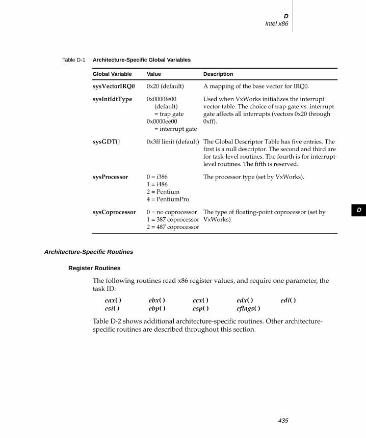
D
DIntel x86
Architecture-Specific Routines
Register Routines
The following routines read x86 register values, and require one parameter, the
task ID:
Table D-2 shows additional architecture-specific routines. Other architecture-
specific routines are described throughout this section.
Table D-1 Architecture-Specific Global Variables
Global Variable Value Description
sysVectorIRQ0 0x20 (default) A mapping of the base vector for IRQ0.
sysIntIdtType 0x0000fe00
(default)
= trap gate
0x0000ee00
= interrupt gate
Used when VxWorks initializes the interrupt
vector table. The choice of trap gate vs. interrupt
gate affects all interrupts (vectors 0x20 through
0xff).
sysGDT[] 0x3ff limit (default) The Global Descriptor Table has five entries. The
first is a null descriptor. The second and third are
for task-level routines. The fourth is for interrupt-
level routines. The fifth is reserved.
sysProcessor 0 = i386
1 = i486
2 = Pentium
4 = PentiumPro
The processor type (set by VxWorks).
sysCoprocessor 0 = no coprocessor
1 = 387 coprocessor
2 = 487 coprocessor
The type of floating-point coprocessor (set by
VxWorks).
eax( ) ebx( ) ecx( ) edx( ) edi( )esi( ) ebp( ) esp( ) eflags( )
435

VxWorks 5.4Programmer’s Guide
Table D-2 Architecture-Specific Routines
Routine Function Header Description
pentiumBts( ) STATUS pentiumBts(char * pFlag)
Execute an atomic compare-and-exchange
instruction to set a bit. (Pentium and
PentiumPro.)
pentiumBtc( ) STATUS pentiumBtc (pFlag)(char * pFlag)
Execute an atomic compare-and-exchange
instruction to clear a bit. (Pentium and
PentiumPro.)
pentiumMcaShow void pentiumMcaShow (void) Show machine check global control registers
and error reporting register banks.
pentiumMsrGet( ) void pentiumMsrGet(int address,long long int * pData)
Get the contents of the specified MSR.
(PentiumPro)
pentiumMsrSet( ) void pentiumMsrSet(int address,long long int * pData)
Set the value of the specified MSR.
(PentiumPro)
pentiumMtrrEnable( ) void pentiumMtrrEnable (void) Enable MTRR. (PentiumPro)
pentiumMtrrDisable( ) void pentiumMtrrDisable (void) Disable MTRR. (PentiumPro)
pentiumMtrrGet( ) void pentiumMtrrGet(MTRR * pMtrr)
Get MTRRs to the MTRR table specified by the
pointer. (PentiumPro)
pentiumMtrrSet( ) void pentiumMtrrSet (void)(MTRR * pMtrr)
Set MTRRs from the MTRR table specified by
the pointer. (PentiumPro)
pentiumPmcStart( ) STATUS pentiumPmcStart(int pmcEvtSel0;int pmcEvtSel1;)
Start PMC0 and PMC1. (PentiumPro)
pentiumPmcStop( ) void pentiumPmcStop (void) Stop PMC0 and PMC1. (PentiumPro)
pentiumPmcStop1( ) void pentiumPmcStop1 (void) Stop PMC1 only. (PentiumPro)
436

D
DIntel x86
pentiumPmcGet( ) void pentiumPmcGet(long long int * pPmc0;long long int * pPmc1;)
Get the contents of PMC0 and PMC1.
(PentiumPro)
pentiumPmcGet0( ) void pentiumPmcGet0(long long int * pPmc0)
Get the contents of PMC0. (PentiumPro)
pentiumPmcGet1( ) void pentiumPmcGet1(long long int * pPmc1)
Get the contents of PMC1. (PentiumPro)
pentiumPmcReset( ) void pentiumPmcReset (void) Reset PMC0 and PMC1. (PentiumPro)
pentiumPmcReset0( ) void pentiumPmcReset0 (void) Reset PMC0. (PentiumPro)
pentiumPmcReset1( ) void pentiumPmcReset1 (void) Reset PMC1. (PentiumPro)
pentiumSerialize( ) void pentiumSerialize (void) Serialize by executing the CPUID instruction.
(Pentium and PentiumPro.)
pentiumPmcShow( ) void pentiumPmcShow(BOOL zap)
Show PMC0 and PMC1, and reset them if the
parameter zap is TRUE. (Pentium and
PentiumPro.)
pentiumTlbFlush( ) void pentiumTlbFlush (void) Flush the TLBs (Translation Lookaside
Buffers). (Pentium and PentiumPro.)
pentiumTscReset( ) void pentiumTscReset (void) Reset the TSC. (PentiumPro)
pentiumTscGet32( ) void pentiumTscGet32 (void) Get the lower half of the 64-bit TSC.
(PentiumPro)
pentiumTscGet64( ) void pentiumTscGet64(long long int * pTsc)
Get the 64-bit TSC. (PentiumPro)
sysCpuProbe( ) Use CPUID to get information about the CPU.
sysInByte( ) UCHAR sysInByte(int port)
Read one byte from I/O.
sysInWord( ) USHORT sysInWord(int port)
Read one word (two bytes) from I/O.
sysInLong( ) ULONG sysInLong(int port)
Read one long word (four bytes) from I/O.
Table D-2 Architecture-Specific Routines (Continued)
Routine Function Header Description
437

VxWorks 5.4Programmer’s Guide
Breakpoints and the bh( ) Routine
VxWorks for the x86 supports both software and hardware breakpoints. When you
set a software breakpoint, VxWorks replaces an instruction with an int 3 software
interrupt instruction. VxWorks restores the original code when the breakpoint is
removed. The instruction queue is purged each time VxWorks changes an
instruction to a software break instruction.
sysOutByte( ) void sysOutByte(int port, char data)
Write one byte to I/O.
sysOutWord( ) void sysOutWord(int port, short data)
Write one word (two bytes) to I/O.
sysOutLong( ) void sysOutLong(int port, long data)
Write one long word (four bytes) to I/O.
sysInWordString( ) void sysInWordString(int port, short *address,int count)
Read word string from I/O.
sysInLongString( ) void sysInLongString(int port, short *address,int count
Read long string from I/O.
sysOutWordString( ) void sysOutWordString(int port, short *address,int count)
Write word string to I/O.
sysOutLongString( ) void sysOutLongString(int port, short *address,int count)
Write long string to I/O.
sysDelay( ) void sysDelay(void)
Allow enough recovery time for port accesses.
sysIntDisablePIC( ) STATUS sysIntDisablePIC(int intLevel)
Disable a Programmable Interrupt Controller
(PIC) interrupt level.
sysIntEnablePIC( ) STATUS sysIntEnablePIC(int intLevel)
Enable a PIC interrupt level.
sysCpuProbe( ) UINT sysCpuProbe(void)
Check for type of CPU (i386, i486, or Pentium).
Table D-2 Architecture-Specific Routines (Continued)
Routine Function Header Description
438

D
DIntel x86
A hardware breakpoint uses the processor’s debug registers to set the breakpoint.
The x86 architectures have four breakpoint registers. If you are using the target
shell, you can use the bh( ) routine to set hardware breakpoints. The routine is
declared as follows:
STATUS bh(INSTR *addr, /* where to set breakpoint, or */ /* 0 = display all breakpoints */int task, /* task to set breakpoint; */ /* 0 = set all tasks */int count, /* number of passes before hit */int type, /* breakpoint type; see below */INSTR *addr0 /* ignored for x86 targets */)
The bh( ) routine takes the following types in parameter type:
Disassembler: l( )
If you are using the target shell, note that the VxWorks disassembler l( ) does not
support 16-bit code compiled for earlier generations of 80x86 processors. However,
the disassembler does support 32-bit code for both the i386 and i486 processors.
vxMemProbe( )
The vxMemProbe( ) routine, which probes an address for a bus error, is supported
on the x86 architectures by trapping both general protection faults and page faults.
a.out-Specific Tools for x86
The following tools are specific to the a.out format for x86 processors and the PC
simulator. For more information, see the reference entries for each tool.
BRK_INST Instruction hardware breakpoint (0x1000)
BRK_DATAW1 Data write 1-byte breakpoint (0x1400)
BRK_DATAW2 Data write 2-byte breakpoint (0x1500)
BRK_DATAW4 Data write 4-byte breakpoint (0x1700)
BRK_DATARW1 Data read-write 1-byte breakpoint (0x1c00)
BRK_DATARW2 Data read-write 2-byte breakpoint (1d00)
BRK_DATARW4 Data read-write 4-byte breakpoint (1f00)
439

VxWorks 5.4Programmer’s Guide
hexDecconverts an a.out-format object file into Motorola hex records. The syntax is:
hexDec [-a adrs] [-l ] [-v ] [-p PC] [-s SP] file
aoutToBinDecextracts text and data segments from an a.out file and writes it to standard
output as a simple binary image. The syntax is:
aoutToBinDec < inFile > outfile
xsymDecextracts the symbol table from an a.out file. The syntax is:
xsymDec < objMod > symTbl
D.4 Architecture Considerations
This section describes the following characteristics of the Intel x86 architectures
that you should keep in mind as you write a VxWorks application:
■ Operating mode, privilege protection, and byte order■ Memory segmentation and the MMU■ I/O and memory mapped devices■ Memory considerations for VME■ Interrupts and exceptions■ Registers■ Counters■ Context switching■ ISA/EISA bus■ PC104 bus■ PCI bus■ Software floating-point emulation■ VxWorks memory layout
Consult Intel’s Intel486 Microprocessor Family Programmer’s Reference Manual for
details on the x86 architectures.
440

D
DIntel x86
Operating Mode, Privilege Protection, and Byte Order
VxWorks for the x86 runs in the 32-bit protected mode.
No privilege protection is used, thus there are no call gates. The privilege level is
always 0, the most privileged level (Supervisor mode).
The x86 byte order is little-endian, but network applications must convert some
data to a standard network order, which is big-endian. In particular, in network
applications, be sure to convert the port number to network byte order using
htons( ).
See VxWorks Network Programmer’s Guide: TCP/IP under VxWorks for more
information about macros and routines to convert byte order (from little-endian to
big-endian or vice versa).
Memory Segmentation
The Intel x86 processors support both I/O-mapped devices and memory-mapped
devices.
I/O Mapped Devices
For I/O mapped devices, developers may use the following routines from
installDir/target/config/bspName/sysALib.s:
Memory Mapped Devices
For memory mapped devices, there are two kinds of memory protection provided
by VxWorks: the Memory Management Unit and the Global Descriptor Table.
sysInByte( ) – input one byte from I/O space
sysOutByte( ) – output one byte to I/O space
sysInWord( ) – input one word from I/O space
sysOutWord( ) – output one word to I/O space
sysInLong( ) – input one long word from I/O space
sysOutLong( ) – output one long word to I/O space
sysInWordString( ) – input a word string from I/O space
sysOutWordString( ) – output a word string to I/O space
sysInLongString( ) – input a long string from I/O space
sysOutLongString( ) – output a long string to I/O space
441

VxWorks 5.4Programmer’s Guide
Because VxWorks operates at the highest processor privilege level, no “protection
rings” exist.
The x86 processors allow you to configure the memory space into valid and invalid
areas, even under Supervisor mode. Thus, you receive a page fault only if the
processor attempts to access addresses mapped as invalid, or addresses that have
not been mapped. Conversely, if the processor attempts to access a nonexistent
address space that has been mapped as valid, no page fault occurs.
Memory Management Unit (MMU)
If INCLUDE_MMU_BASIC is selected for inclusion in the project facility VxWorks
view, then VxWorks enables the MMU with the mmuPhysDesc[] table which
includes PCI memory mapping information. This is the default.
If you have other memory mapped devices and if INCLUDE_MMU_BASIC is
included (the default), you may need to add your device address space into the
MMU table by manually editing the MMU configuration structure
sysPhysMemDesc[] in sysLib.c. For information on editing the
sysPhysMemDesc[] structure, see 7.3 Virtual Memory Configuration, p.290. Do not
overlap any existing MMU entries, and be sure all entries are page aligned. We
recommend that you also maintain a 1:1 correlation between virtual and physical
memory, since VxWorks and all tasks use a common address space.
Attempts to access areas not mapped as valid in the MMU result in page faults.
PentiumPro MMU
PentiumPro’s enhanced MMU supports two additional page attribute bits.
The global bit (G) indicates a global page when set. When a page is marked global
and the page global enable (PGE) bit in register CR4 is set, the page-table or page-
directory entry for the page is not invalidated in the TLB when register CR3 is
loaded or a task switch occurs. This bit is provided to prevent frequently used
pages (such as pages that contain kernel or other operating system or executive
code) from being flushed from the TLB.
The page-level write-through/back bit (PWT) controls the write-through or write-
back caching policy of individual pages or page tables. When the PWT bit is set,
write-through caching is enabled for the associated page or page table. When the
bit is clear, write-back caching is enabled for the associated page and page table.
! CAUTION: The i386 MMU does not have write-protect capability.
442

D
DIntel x86
The following macros describe these attribute bits in the physical memory
descriptor table sysPhysMemDesc[] in sysLib.c.
Support is provided for two page sizes, 4KB and 4MB. The linear address for 4KB
pages is divided into three sections:
The linear address for 4MB pages is divided into two sections:
The page size is configured using VM_PAGE_SIZE. The default is 4 KB pages. If you
wish to reconfigure 4 MB pages, you must change VM_PAGE_SIZE in config.h. (See
8. Configuration and Build.)
Global Descriptor Table (GDT)
The GDT is defined as the table sysGDT[] in sysALib.s. The table has five entries:
a null entry, an entry for program code, an entry for program data, an entry for
ISRs, and a reserved entry. It is initially set so that the available memory range is
0x0-0xffffffff. For boards that support PCI, INCLUDE_PCI is defined in config.h and
VxWorks does not alter the pre-set memory range. This memory range is available
at run-time with the MMU configuration.
If INCLUDE_PCI is not defined (the default for boards that do not support PCI),
VxWorks adjusts the GDT using the sysMemTop( ) routine to check the actual
memory size during system initialization and set the table so that the available
memory range is 0x0-sysMemTop. This causes a General Protection Fault to be
generated for any memory access outside the memory range 0x0-sysMemTop.
Memory Considerations for VME
The global descriptors for x86 targets are configured for a flat 4GB memory space.
If you are running VxWorks for the x86 on a VME board, be aware that addressing
nonexistent memory or peripherals does not generate a bus error or fault.
VM_STATE_WBACK use write-back cache policy for the page
VM_STATE_WBACK_NOT use write-through cache policy for the page
VM_STATE_GLOBAL set page global bit
VM_STATE_GLOBAL_NOT not set page global bit
Page directory entry bits 22 through 31
Page table entry bits 12 through 21
Page offset bits 0 through 11
Page directory entry bits 22 through 31
Page offset bits 0 through 21
443

VxWorks 5.4Programmer’s Guide
Interrupts and Exceptions
Interrupt Descriptor Table
The Interrupt Descriptor Table (IDT) occupies the address range 0x0 to 0x800 (also
called the Interrupt Vector Table, see Figure D-2). Vector numbers 0x0 to 0x1f are
handled by the default exception handler. Vector numbers 0x20 to 0xff are handled
by the default interrupt handler.
By default, vector numbers 0x20 to 0x2f are mapped to IRQ levels 0 to 15. To
redefine the base address, edit sysVectorIRQ0 in sysLib.c.
For vector numbers 0x0 to 0x11, no task gates are used, only interrupt gates. By
default, vector numbers 0x12 to 0xff are trap gates, but this can be changed by
redefining the global variable sysIntIdtType.
The difference between an interrupt gate and a trap gate is its effect on the IF flag:
using an interrupt gate clears the IF flag, which prevents other interrupts from
interfering with the current interrupt handler.
Each vector of the IDT contains the following information:
The interrupt handler calls intEnt( ) and saves the volatile registers (eax, edx, and
ecx). It then calls the ISR, which is usually written in C. Finally, the handler restores
the saved registers and calls intExit( ).
There is no designated interrupt stack. The interrupt’s stack frame is built on the
interrupted task’s stack. Thus, each task requires extra stack space for interrupt
nesting; the amount of extra space varies, depending on your ISRs and the
potential nesting level.
Some device drivers (depending on the manufacturer, the configuration, and so
on) generate a stray interrupt on IRQ7, which is used by the parallel driver. The
global variable sysStrayIntCount (see Table D-3) is incremented each time such an
interrupt occurs, and a dummy ISR is connected to handle these interrupts.
offset: offset to the interrupt handler
selector: 0x0018, third descriptor (code) in GDT for
exception;
0x0020, fourth descriptor (code) in GDT for
interrupt.
descriptor
privilege level: 3
descriptor
present bit: 1
444

D
DIntel x86
The chip generates an exception stack frame in one of two formats, depending on
the exception type: (EIP + CS + EFLAGS) or (ERROR + EIP + CS + EFLAGS).
Machine Check Architecture (MCA)
The Pentium processor introduced a new exception called the machine-check
exception (interrupt-18). This exception is used to signal hardware-related errors,
such as a parity error on a read cycle. The PentiumPro processor extends the types
of errors that can be detected and that generate a machine- check exceptions. It also
provides a new machine-check architecture that records information about a
machine-check error and provides the basis for an extended error logging
capability.
MCA is enabled and its status registers are set to zero in sysHwInit( ). Its registers
are accessed by pentiumMsrSet( ) and pentiumMsrGet( ).
Registers
Memory Type Range Register (MTRR)
MTRR is a feature of the PentiumPro processor that allow the processor to
optimize memory operations for different types of memory, such as RAM, ROM,
frame buffer memory, and memory-mapped I/O. MTRRs configure an internal
map of how physical address ranges are mapped to various types of memory. The
processor uses this internal map to determine the cacheability of various physical
memory locations and the optimal method of accessing memory locations.
For example, if a memory location is specified in an MTRR as write-through
memory, the processor handles accesses to this location either by reading data from
that location in lines and caching the read data or by mapping all writes to that
location to the bus and updating the cache to maintain cache coherency. In
mapping the physical address space with MTRRs, the processor recognizes five
types of memory: uncacheable (UC), write-combining (WC), write-through (WT),
write-protected (WP), and write-back (WB).
The MTRR table is defined as follows:
typedef struct mtrr_fix /* MTRR - fixed range register */{char type[8]; /* address range: [0]=0-7 ... [7]=56-63 */} MTRR_FIX;
typedef struct mtrr_var /* MTRR - variable range register */{long long int base; /* base register */long long int mask; /* mask register */
445

VxWorks 5.4Programmer’s Guide
} MTRR_VAR;typedef struct mtrr /* MTRR */{int cap[2]; /* MTRR cap register */int deftype[2]; /* MTRR defType register */MTRR_FIX fix[11]; /* MTRR fixed range registers */MTRR_VAR var[8]; /* MTRR variable range registers */} MTRR;
Model Specific Register (MSR)
The PentiumPro processor implements the concept of model-specific registers
(MSRs) to control hardware functions in the processor or to monitor processor
activity. The new registers control the debug extensions, the performance counters,
the machine-check exception capability, the machine check architecture, and the
MTRRs. The MSRs can be read and written to using the RDMSR and WRMSR
instructions, respectively.
Counters
Performance Monitoring Counters (PMC)
The PentiumPro processor has two performance-monitoring counters for use in
monitoring internal hardware operations. These counters are duration or event
counters that can be programmed to count any of approximately 100 different
types of events, such as the number of instructions decoded, number of interrupts
received, or number of cache loads.
PMC is enabled in sysHwInit( ). Selected events in the default configuration are
PMC0 = number of hardware interrupts received and PMC1 = number of
misaligned data memory references.
Time Stamp Counter (TSC)
The PentiumPro processor provides a 64-bit time-stamp counter that is
incremented every processor clock cycle. The counter is incremented even when
the processor is halted by the HLT instruction or the external STPCLK# pin. The
time-stamp counter is set to 0 following a hardware reset of the processor. The
RDTSC instruction reads the time stamp counter and is guaranteed to return a
monotonically increasing unique value whenever executed, except for 64-bit
counter wraparound. Intel guarantees, architecturally, that the time-stamp counter
frequency and configuration will be such that it will not wraparound within 10
years after being reset to 0. The period for counter wrap is several thousands of
years in the PentiumPro and Pentium processors.
446
D
DIntel x86
Double-word Integers: long long
The double-word integer long long is not supported, except as an artifact of your
particular architecture and compiler. For more information about handling
unsupported features, please see the Customer Support User’s Guide.
Context Switching
Hardware multitasking and the TSS descriptor are not used. VxWorks creates a
dummy exception stack frame, loads the registers from the TCB, and then starts the
task.
ISA/EISA Bus
The optional PC-compatible hardware cards supported in this release (the
Ethernet adapter cards and the Blunk Microsystems ROM Card) use the ISA/EISA
bus architecture.
PC104 Bus
The PC104 bus is supported and tested with the NE2000-compatible Ethernet card
(4i24: Mesa Electronics). Ampro’s Ethernet card (Ethernet-II) is also supported.
PCI Bus
The PCI bus is supported and tested with the Intel EtherExpress PRO100B
Ethernet card. Several functions to access PCI configuration space are supported.
Functions addressed here include:
■ Locate the device by deviceID and vendorID.
■ Locate the device by classCode.
■ Generate the special cycle.
■ Access its configuration registers.
447

VxWorks 5.4Programmer’s Guide
Software Floating-Point Emulation
The software floating-point library is supported for the x86 architectures; select
INCLUDE_SW_FP for inclusion in the project facility VxWorks view to include the
library in your system image. This library emulates each floating point instruction,
by using the exception “Device Not Available.” For other floating-point support
information, see Supported Routines in mathALib, p.434.
VxWorks Memory Layout
Two memory layouts for the x86 are shown in the following figures: Figure D-2
illustrates the typical upper memory configuration, while Figure D-1 shows a
lower memory option. These figures contain the following labels:
Interrupt Vector Table Table of exception/interrupt vectors.
GDT Global descriptor table.
Anchor for the shared memory network (if there is
shared memory on the board).
Boot Line ASCII string of boot parameters.
Exception Message ASCII string of the fatal exception message.
FD DMA Area Diskette (floppy device) direct memory access area.
Initial Stack Initial stack for usrInit( ), until usrRoot( ) gets allocated
stack.
System Image Entry point for VxWorks.
WDB Memory Pool Size depends on the macro WDB_POOL_SIZE which
defaults to one-sixteenth of the system memory pool.
This space is used by the target server to support host-
based tools. Modify WDB_POOL_SIZE under
INCLUDE_WDB.
Interrupt Stack Size is defined by ISR_STACK_SIZE under
INCLUDE_KERNEL. Location depends on system image
size.
System Memory Pool Size depends on size of system image and interrupt
stack. The end of the free memory pool for this board is
returned by sysMemTop( ).
448

D
DIntel x86
All addresses shown in Figure D-2 are relative to the start of memory for a
particular target board. The start of memory (corresponding to 0x0 in the memory-
layout diagram) is defined as LOCAL_MEM_LOCAL_ADRS under
INCLUDE_MEMORY_CONFIG for each target.
In general, the boot image is placed in lower memory and the VxWorks image is
placed in upper memory, leaving a gap between lower and upper memory. Some
BSPs have additional configurations which must fit within their hardware
constraints. For details, see the reference entry for each specific BSP.
Figure D-1 VxWorks System Memory Layout (x86 Lower Memory)
Initial Stack
System Image
Interrupt Stack
System Memory PoolsysMemTop()
+8000
_endWDB Memory Pool
+0x0000 + LOCAL_MEM_LOCAL_ADRS
+800
+1100
+1200
Address
Interrupt Vector Table( 2KB )
= Available
KEY
GDT
SM Anchor
Exception Message
+1300Boot Line
+2000
FD DMA Area
+5000
+100000
= Reserved
(no memory)+a0000
449

VxWorks 5.4Programmer’s Guide
Figure D-2 VxWorks System Memory Layout (x86 Upper Memory)
+0x0000 + LOCAL_MEM_LOCAL_ADRS
+800
+1100
+1200
Address
Interrupt Vector Table( 2KB )
System Memory Pool
sysMemTop()
= Available
KEY
GDT
SM Anchor
Exception Message
+1300Boot Line
+2000
FD DMA Area
+5000
+100000Initial Stack
+108000
System Image
= Reserved
_end
Interrupt Stack
(no memory)+a0000
WDB Memory Pool
450

D
DIntel x86
D.5 Board Support Packages
Boot Considerations for PC Targets
For general information on booting VxWorks, see Tornado Getting Started.
This section describes how to build a boot disk, how to boot VxWorks, and how to
mount a DOS file system. VxWorks for x86 targets includes the following DOS
diskettes (in 3.5" (1.44MB) format):
■ The diskette labeled “VxWorks Utility Disk” contains the DOS executables
vxsys.com, vxcopy.exe, vxload.com, and mkboot.bat.
■ The diskette labeled “VxWorks Boot Disk” contains the VxWorks bootstrap
loader file; the minimal boot program, bootrom.sys, (renamed from
bootrom_uncmp); and standalone VxWorks, vxWorks.st. These files work for
all PC BSPs. (For additional boot images, see VxWorks Images, p.463.)
These utilities help you build new boot disks and are described in the following
subsections.
Boot Process
When a standard PC-AT computer is powered on, the system BIOS code loads and
executes the bootstrap loader. The bootstrap loader is written in 8088 16-bit assembly
language. The BIOS obtains the bootstrap loader from the boot sector, which may
be in one of several locations: a diskette, a hard disk, or some other alternatives
such as a ROM.2 When it finds the bootstrap loader, it executes it to find out where
to find the bootrom.sys file.
The VxWorks bootstrap loader must be written to the boot sector instead of the
standard bootstrap loader in order to create a VxWorks boot disk (or diskette). In
addition, you must create the appropriate bootrom.sys file. This can be a bootable
VxWorks kernel or it can be an intermediate kernel designed to load VxWorks from
another source, such as a diskette, a hard disk, ROM, or flash. The following
subsections describe how to do this from MS-DOS, from Solaris, and from
VxWorks.
NOTE: These utilities are also included in the Tornado tree at
installDir/host/x86-win32/bin.
2. You can use a boot ROM if you install the Blunk Microsystems ROM Card 1.0; see ROM Cardand EPROM Support, p.465.
451

VxWorks 5.4Programmer’s Guide
Building a Boot Disk/Diskette from MS-DOS
The VxWorks Utility Disk includes several utility programs for creating VxWorks
boot disks. These utilities write the VxWorks bootstrap loader to the boot sector,
and then copy the VxWorks executables from the host to the disk in a format
suitable for the bootstrap loader. The utilities mimic the corresponding MS-DOS
utilities, but they can be run under a DOS session of Windows, not “pure” DOS.
They are summarized as follows and described in more detail later in this section:
vxsys.cominstalls a VxWorks bootstrap loader in a disk’s boot sector.
vxcopy.execopies a VxWorks a.out executable to the boot disk in the required format.
vxload.comloads and executes VxWorks from MS-DOS (must be run under “pure” DOS).
mkboot.batan MS-DOS batch file that creates boot disks.
■ Creating a Boot Disk for PC-Compatible Targets
To create a diskette or a bootable hard disk for PC-compatible targets, follow these
steps:
1. On the development host, change to the BSP directory, for example,
config/pc386. Use make to produce the minimal boot program (the target
bootrom_uncmp) or a bootable VxWorks (the targets vxWorks_rom,
vxWorks_rom_low, or vxWorks.st_rom).3 We recommend you copy the
resulting file to a legal MS-DOS file name, such as bootrom.dat, to simplify the
rest of the process.
The commands for this sequence in a Windows DOS shell are as follows:
C:\> cd installDir\target\config\pc386C:\> make bootrom_uncmpC:\> copy bootrom_uncmp bootrom.dat
2. Transfer the executable image to a PC running MS-DOS. In many cases, the PC
is networked with the workstation, using PC-NFS or a similar networking
package. For example:
3. Before making either version of the image, make sure that DEFAULT_BOOT_LINE in
config.h is set correctly, and that the size of the boot image (text+data+bss) is less than
512KB. It cannot be larger than this, because x86 chips boot in “real” mode and therefore do
have access to all available memory until later in the boot process.
452

D
DIntel x86
C:\> copy drive:bootrom.dat c:
where drive refers to the mounted file system on your PC.
3. Use the mkboot utility (or a combination of vxsys and vxcopy) to create the
boot disk. If this boot disk is a diskette, it must be a high-density diskette. The
following example shows this step, assuming the diskette is in drive A:
C:\> mkboot a: bootrom.dat
The mkboot utility uses vxsys to create the VxWorks bootstrap loader in the
disk’s boot sector. mkboot then runs vxcopy to copy bootrom.dat to the boot
file bootrom.sys on the target disk, excluding the a.out header.
4. Check that bootrom.sys is contiguous on the boot disk, using the MS-DOS
chkdsk utility. (The mkboot utility runs chkdsk automatically.) If chkdskshows that there are non-contiguous blocks, delete all files from the disk and
repeat the vxcopy operation to ensure that MS-DOS lays down the file
contiguously.
The following example shows chkdsk output where the boot file is not
contiguous (note especially the last line of output):
C:\> chkdsk a:bootrom.sys
Volume Serial Number is 2A35-18ED1457664 bytes total disk space 895488 bytes in 11 user files 562176 bytes available on disk
512 bytes in each allocation unit 2847 total allocation units on disk 1098 available allocation units on disk
655360 total bytes memory 602400 bytes free
A:\BOOTROM.SYS Contains 2 non-contiguous blocks
5. To test your boot disk, first make sure that the correct drive holds the boot disk
(in this example case, drive A: holds the boot diskette).
6. Reboot the PC.
Depending on the configuration of your VxWorks image, if the boot is
successful, the VxWorks boot prompt appears either on the VGA console or on
the COM1 serial port. You can boot VxWorks by entering @:
[VxWorks Boot]: @
453

VxWorks 5.4Programmer’s Guide
■ The MS-DOS Boot Utilities in More Detail
vxsys drive:
This command installs a VxWorks bootstrap loader in a drive’s boot sector. The
drive can be either a diskette (drive A:), or a hard disk that is searched by the
BIOS bootstrap (drive C:).4 The VxWorks bootstrap loader searches for the file
bootrom.sys in the root directory and loads it directly into memory at 0x8000.
Execution then jumps to romInit( ) at 0x8000.
vxcopy source_file target_fileThis command copies the VxWorks image file from source_file to target_file.
Normally this copies the bootrom_uncmp output to bootrom.sys on the boot
disk. vxcopy strips the 32-byte a.out header from source_file as it copies.
mkboot drive: source_fileThis command is an MS-DOS batch file that uses vxsys to install the VxWorks
bootstrap loader in the drive’s boot sector, and then uses vxcopy to transfer
source_file to drive:bootrom.sys. It also runs the MS-DOS utility chkdsk to
check whether bootrom.sys is contiguous.
vxload [image_file]
This command is used during an MS-DOS session to load and execute the
VxWorks image (normally vxWorks.st or bootrom_uncmp). It can be more
convenient or quicker than loading the image via the PC boot cycle. vxloadtakes an optional parameter, the image file name; the default is vxWorks.st in
the current directory.
Because vxload must read the image file to memory at 0x8000, it checks to see
that this memory is not in use by MS-DOS, and generates an error if it is. If you
receive such an error, reconfigure your PC target to make the space available
by loading MS-DOS into high memory and reducing the number of device
4. For embedded applications, actual disk drives are often replaced by solid state disks.
Because there are no moving parts, boot performance and reliability are increased.
NOTE: After a bootstrap loader is installed in the disk’s boot sector, you do not
need to repeat the vxsys operation for new ROM images. Just use vxcopy to make
a new version of bootrom.sys.
! CAUTION: vxload cannot be used to load VxWorks if the MS-DOS session has a
protected mode program in use. Typical examples include the MS-DOS RAM disk
driver, vdisk.sys, and the extended memory manager, emm386.exe. To use vxload,
remove or disable such facilities.
454

D
DIntel x86
drivers. Or start vxload instead of the MS-DOS command interpreter
command.com. (If you take this approach, remember to first ensure that you
can restore your previous configuration.)
The following is a sample config.sys file that shows these suggestions:
device=c:\dos\himem.sysdos=high,umbshell=c:\vxload.com c:\bootrom.dat
The file bootrom.dat must have an a.out header, unlike the bootrom.sys file
made by mkboot.
Building a Boot Disk/Diskette from a Solaris Host
Use /usr/bin/fdformat that comes with Solaris. It requires a bootstrap loader file
called vxld.bin, which can be downloaded from WindSurf.
Copy vxld.bin to your Solaris file system, insert a 1.44 MB diskette into the Sun
diskette drive, and issue the fdformat command to format the diskette and install
the boot block.
fdformat -U -d -B vxld.bin
Formatting 1.44 MB in /vol/dev/rdiskette0/no_name#7Press return to start formatting floppy.....................................................................fdformat: using "vxld.bin" for MS-DOS boot loader
Now create the bootrom.sys:
% cd installDir/target/config/ bspName% make bootrom_uncmp% aoutToBinDec < bootrom_uncop > bootrom.sys
Copy the new bootrom.sys file to your boot diskette.
Building a Boot Disk/Diskette from VxWorks
The routine mkbootFd( ) produces a VxWorks boot diskette, and mkbootAta( )produces a VxWorks boot disk (an IDE or ATA hard disk). Both run on any
VxWorks x86 target. They are provided in
installDir/target/config/bspname/mkboot.c. Use a DOS-formatted disk or diskette.
The mkbootFd( ), mkbootAta( ), and mkbootTffs( ) routines write the boot sector
so that it contains the VxWorks bootstrap loader and make a boot image named
! CAUTION: The mkbootFd( ) routine supports only high-density diskettes.
455

VxWorks 5.4Programmer’s Guide
bootrom.sys. The boot image can be derived from one of the images listed in
VxWorks Images, p.463. Before making any version of the image, make sure that
DEFAULT_BOOT_LINE in config.h is set correctly (see Tornado User’s Guide: Setupand Startup), and that the size of the boot image (text+data+bss) is verified to be less
than 512KB. It cannot be larger than this, because it is written into lower memory.
During the booting process, the VxWorks bootstrap loader reads bootrom.sys and
then jumps to the entry point of the boot image.
The mkbootFd( ) routine requires the following parameters:
STATUS mkbootFd (int drive, int fdType, char *filename)
The first two parameters specify the drive number and diskette type, specified as
in Booting VxWorks from a Diskette, an ATA/IDE Disk, a PC Card, or a Flash File System,
p.457. The third parameter specifies the file name of the boot image.
The mkbootAta( ) routine requires the following parameters:
STATUS mkbootAta (int ctrl, int drive, char *filename)
The first two parameters specify the controller number and drive number,
specified as in Booting VxWorks from a Diskette, an ATA/IDE Disk, a PC Card, or aFlash File System, p.457. The third parameter specifies the file name of the boot
image.
The mkbootTffs( ) routine requires the following parameters:
STATUS mkbootTffs (int drive, int removeBit, char *filename)
The first two parameters specify the drive number and removable bit, specified as
in Booting VxWorks from a Diskette, an ATA/IDE Disk, a PC Card, or a Flash File System,
p.457. The third parameter specifies the file name of the boot image.
For example, to create a boot disk for the pc386 BSP if you are using a UNIX host,
first use the following commands on the host to create the mkboot.o object from
mkboot.c:
% cd installDir/target/config/pc386% make mkboot.o
Then, from the Tornado shell, move to the appropriate directory, load mkboot.o,
and then invoke mkbootFd( ), mkbootAta( ), or mkbootTffs( ). Remember to place
a formatted, empty diskette in the appropriate drive if you use mkbootFd( ).
In this example, mkbootAta( ) builds a local IDE disk on drive C: from
bootrom_uncmp with the default ataResources[] table (see ATA/IDE Disk Driver,p.471):
456

D
DIntel x86
-> cd " installDir/target/config/pc386"-> ld < mkboot.o-> mkbootAta 0,0,"bootrom_uncmp"
Booting VxWorks from a Diskette, an ATA/IDE Disk, a PC Card, or a Flash File System
Four boot devices are available in VxWorks for the x86, one for diskettes, one for
ATA/IDE hard disks, one for PCMCIA PC cards, and one for flash files. You can
also build your own VxWorks boot ROMs using optional hardware; see ROM Cardand EPROM Support, p.465. Alternatively, as with other VxWorks platforms, you
can also boot over an Ethernet (using one of the supported Ethernet cards), or over
a SLIP connection.
When booting from a diskette, an ATA/IDE disk, a PC card, or a flash file system,
first make sure that the boot device is formatted for an MS-DOS file system. The
VxWorks boot program mounts the boot device by automatically calling either
usrFdConfig( ) in usrFd.c for diskettes, usrAtaConfig( ) in usrAta.c for ATA/IDE
hard disks, usrPcmciaConfig( ) in usrPcmcia.c for PC cards, or usrTffsConfig( ) for
flash file systems. (All files are located in installDir/target/src/config.)
In each case, a mount point name is taken from the file name specified as one of the
boot parameters. You might choose diskette zero (drive A:) to be mounted as /fd0(by supplying a boot file name that begins with that string). Similarly, you might
choose ATA/IDE hard disk zero (drive C:) to be mounted as /ata0, you might
choose the PC card in socket 0 to be mounted as /pc0, or you might choose the flash
file system called drive 1 as /tffs0. In each case, the name of the directory mount
point (fd0, ata0, pc0, or tffs0 in these examples) can be any legal file name. (For
more information on usrFdConfig( ), usrAtaConfig( ), usrPcmciaConfig( ), or
usrTffsConfig( ), see Mounting a DOS File System, p.460.)
Because the PC hardware does not have a standard NVRAM interface, the only
way to change default boot parameters is to rebuild the bootstrap code with a new
! CAUTION: Because standard PC BIOS components do not support initial booting
from PCMCIA devices, systems which load VxWorks from these devices must use
a VxWorks boot disk/diskette. See Building a Boot Disk/Diskette from MS-DOS,
p.452, Building a Boot Disk/Diskette from a Solaris Host, p.455, and Building a BootDisk/Diskette from VxWorks, p.455.
! CAUTION: Because the boot program uses usrFdConfig( ) for floppy diskettes, and
because usrFdConfig( ) does not provide the DOS_VOL_CONFIG structure
required to use dosFsVolUnmount( ), you must instead use ioctl( ) with
FIOUNMOUNT before removing the floppy diskette.
457

VxWorks 5.4Programmer’s Guide
definition for DEFAULT_BOOT_LINE in config.h. See Boot Process, p.451 for
instructions on how to rebuild the bootstrap code.
■ Booting from Diskette
To boot from a diskette, specify the boot device as fd (for floppy device). First,
specify the drive number on the boot device: line of the boot parameters display.
Then, specify the diskette type (3.5" or 5.25"). The format is as follows:
boot device: fd= drive number, diskette type
drive numbera digit specifying the diskette drive:
diskette typea digit specifying the type of diskette:
Thus, to boot from drive B: with a 5.25" diskette, enter the following:
boot device: fd=1,1
The default value of the file-name boot parameter is /fd0/vxWorks.st. You can
specify another boot image; for example, assume that you have placed your
vxWorks and vxWorks.sym files in the root directory of the 5.25" diskette in drive
A: as the files A:\\_vxworks and A:\vxworks.sym, and that the mount point for
this drive is /fd0. To boot this image, enter the following in the boot parameters
display:
boot device: fd=0,1...file name: /fd0/vxworks
! CAUTION: To enable rebooting with CTRL+X, you must set some of the BSP-
specific global variables sysWarmType, sysWarmFdType, sysWarmFdDrive,
sysWarmAtaCtrl, sysWarmAtaDrive, and sysWarmTffsDrive, depending on
which boot device you use. For more information, see Table D-3.
0 = default; the first diskette drive (drive A:)1 = the second diskette drive (drive B:)
0 = default; 3.5" diskette
1 = 5.25" diskette
458

D
DIntel x86
■ Booting from ATA/IDE Disk
To boot from an ATA/IDE disk, specify the boot device as ata. First, specify the
controller number on the boot device line of the boot parameters display. Then,
specify the drive number. The format is as follows:
boot device: ata= controller number, drive number
controller numbera digit specifying the controller number:
drive numbera digit specifying the hard drive:
If your vxWorks and vxWorks.sym files are in the root directory of your IDE hard
disk drive C: as the files C:\vxworks and C:\vxworks.sym, where C: is the first
IDE disk drive on the system and the mount point for the drive is /ata0, then enter
the following in the boot parameters display:
boot device: ata=0,0...file name: /ata0/vxworks
■ Booting from PCMCIA PC Card
To boot from a PCMCIA PC card, specify the boot device as pcmcia. Specify the
socket number on the boot device: line of the boot parameters display. The format is
as follows:
boot device: pcmcia= socket number
socket numbera digit specifying the socket number:
0 = a controller described in the first entry of the ataResources table (in
the default configuration, the local IDE disk is the first controller)
1 = a controller described in the second entry of the ataResources table
(in the default configuration, the ATA PCMCIA PC card is the
second controller)
0 = the first drive on the controller (drive C: or E:)1 = the second drive on the controller (drive D: or F:)
0 = the first PCMCIA socket
1 = the second PCMCIA socket
459

VxWorks 5.4Programmer’s Guide
If your vxWorks and vxWorks.sym files are in the root directory of your ATA or
SRAM PCMCIA PC card drive E: as the files E:\vxworks and E:\vxworks.sym,
and the mount point for your PC card drive is /pc0, then enter the following:
boot device: pcmcia=0...file name: /pc0/vxworks
If you are using an Ethernet PC card, the boot device is the same and the file name
is:
file name: /usr/wind/target/config/pc386/vxWorks
■ Booting from Flash File System
To boot from an TFFS disk, specify the boot device as tffs. Specify both the drive
number and the removable bit on the boot device: line of the boot parameters
display. The format is as follows:
boot device: tffs= drive number, removable bit
drive number
a digit specifying the drive number; it should be in the range of 0 to
(noOfDrives - 1). The global variable noOfDrives holds the number of
registered drives, and is initialized by sysTffsInit( ) in tffsDrv.
removable bit
a digit specifying whether or not the drive is removable.
If your vxWorks and vxWorks.sym files are in the root directory of your TFFS
(Disk On Chip) drive E: as the file E:\vxWorks and E:\vxWorks.sym, and the
mount point for your TFFS drive is /tffs0, then enter the following:
boot device: tffs=0,0...file name: /tffs0/vxWorks
Mounting a DOS File System
You can mount a DOS file system from a diskette, an ATA/IDE disk, a PC card
(SRAM or ATA), or a flash file system to your VxWorks target.
0 = non-removable flash media
1 = removable flash media, such as a Flash PC Card
460

D
DIntel x86
Diskette
Use the routine usrFdConfig( ) to mount the file system from a diskette. It takes the
following parameters:
drive numberthe drive that contains the diskette: MS-DOS drive A: is 0; drive B: is 1.
diskette type0 (3.5" 2HD) or 1 (5.25" 2HD).
mount pointfrom where on the file system to mount, for example, /fd0/.
ATA/IDE Hard Drive
Use the routine usrAtaConfig( ) to mount the file system from an ATA/IDE disk. It
takes the following parameters:
controller numberthe controller: a controller described in the first entry of the ataResources[]table is 0; a controller described in the second entry is 1. In the default
configuration, the local IDE disk is 0; the PCMCIA ATA drive is 1.
drive numberthe drive: the first drive of the controller is 0; the second drive of the controller
is 1. In the default configuration, MS-DOS drive C: is 0; drive D: is 1.
mount pointfrom where on the file system to mount, for example, /ata0/.
PCMCIA Card
Use pccardMount( ) to mount the file system from a PC card (SRAM or ATA). This
routine differs from usrPcmciaConfig( ) in that pccardMount( ) uses the default
device. A default device is created by the enabler routine when the PC card is
initialized. The default device is removed automatically when the PC card is
removed. pccardMount( ) takes the following parameters:
socket numberthe socket that contains the PC card; the first socket is 0.
! CAUTION: Because the boot program uses usrFdConfig( ) for floppy diskettes, and
because usrFdConfig( ) does not provide the DOS_VOL_CONFIG structure
required to use dosFsVolUnmount( ), you must instead use ioctl( ) with
FIOUNMOUNT before removing the floppy diskette.
461

VxWorks 5.4Programmer’s Guide
mount pointfrom where on the file system to mount, for example, /pc0/.
Use pccardMkfs( ) to initialize a PC card and mount the file system from a PC card
(SRAM or ATA). It takes the following parameters:
socket numberthe socket that contains the PC card; the first socket is 0.
mount pointfrom where on the file system to mount, for example, /pc0/.
The pccardMount( ) and pccardMkfs( ) routines are provided in source form in
src/drv/pcmcia/pccardLib.c.
TFFS Drive
Use the routine usrTffsConfig( ) to mount the file system from an TFFS drive. It
takes the following parameters:
drive numberthe drive number in the range of 0 to (noOfDrives - 1). The global variable
noOfDrives holds a number of registered drives that is initialized in
sysTffsInit( ) in tffsDrv.
removable bitthe removable bit of the drive is 0 for non-removable flash media and 1 for
removable flash media.
mount pointfrom where on the file system to mount, for example, /tffs0/.
DMA Buffer Alignment and cacheLib
If you write your own device drivers that use direct memory access into buffers
obtained from cacheLib, the buffer must be aligned on a 64KB boundary.
Support for Third-Party BSPs
To support third party pc386 and pc486 BSPs, the global variable sysCodeSelectorand the routines sysIntVecSetEnt( ) and sysIntVecSetExit( ) are defined in
sysLib.c.
462

D
DIntel x86
VxWorks Images
The executable target bootrom_uncmp uses lower memory (0x0 - 0xa0000), while
vxWorks and vxWorks.st use upper memory (0x100000 - pcMemSize). A minimum
of 1MB of memory in upper memory is required for vxWorks and vxWorks.st.
The VxWorks makefile targets listed below are supported in these BSPs. They
should be placed on a bootable diskette by mkboot (a DOS utility) or by
mkbootFd( ) or mkbootAta( ) or mkbootTffs( ) (VxWorks utilities). The makefile
target vxWorks_rom should be downloaded by the bootrom_high bootROM
image; for information on all VxWorks makefile targets, see 8.6.2 ExecutingVxWorks from ROM, p.346:
BSP-Specific Global Variables for 386 and 486
The BSP-specific global variables shown in Table D-3 apply to pc386, pc486, and
epc4.
Configuring the Pentium BSP
The project facility configures the Pentium BSP with hardware floating point
support and user data cache support set to copyback by default. This configuration
is equivalent to the default configuration in config.h:
#undef INCLUDE_SW_FP /* Pentium has hardware FPP */#undef USER_D_CACHE_MODE /* Pentium write-back data cache support */#define USER_D_CACHE_MODE CACHE_COPYBACK#define INCLUDE_MTRR_GET /* get MTRR to sysMtrr[] */#define INCLUDE_PMC /* include PMC */
Configuring the PentiumPro BSP
The project facility configures the PentiumPro BSP automatically to use the board’s
special functionality. This configuration is equivalent to the default configuration
vxWorks_rom bootable VxWorks: upper memory
vxWorks_rom_low bootable VxWorks: lower memory
vxWorks.st_rom bootable VxWorks.st (compressed): upper memory
bootrom bootROM (compressed): lower memory
bootrom_uncmp bootROM: lower memory
bootrom_high bootROM (compressed): upper memory
463

VxWorks 5.4Programmer’s Guide
in config.h. Changes to floating point and cache support can be made in the project
facility. If you must change the default setting for other functionality, you must
change config.h. (See 8. Configuration and Build.)
#undef INCLUDE_SW_FP /* PentiumPro has hardware FPP *#undef USER_D_CACHE_MODE /* PentiumPro write-back data cache support */#define USER_D_CACHE_MODE (CACHE_COPYBACK|CACHE_SNOOP_ENABLED)#define INCLUDE_MTRR_GET /* get MTRR to sysMtrr[] */#define INCLUDE_PMC /* include PMC */#undef VIRTUAL_WIRE_MODE /* Interrupt Mode: Virtual Wire Mode */#undef SYMMETRIC_IO_MODE /* Interrupt Mode: Symmetric IO Mode */
#if defined(VIRTUAL_WIRE_MODE) || defined(SYMMETRIC_IO_MODE)#define INCLUDE_APIC_TIMER /* include Local APIC timer */#define PIT0_FOR_AUX /* use channel 0 as an Aux Timer */#endif /* defined(VIRTUAL_WIRE_MODE) || defined(SYMMETRIC_IO_MODE) */
#define INCLUDE_TIMESTAMP_TSC /* include TSC for timestamp */#define PENTIUMPRO_TSC_FREQ 0 /* auto detect TSC freq */#if FALSE#define PENTIUMPRO_TSC_FREQ 150000000 /* use specified TSC freq */#endif /* FALSE */
#define INCLUDE_MMU_PENTIUMPRO /* include 32bit MMU for PentiumPro */#ifdef INCLUDE_MMU_PENTIUMPRO
#undef VM_PAGE_SIZE /* page size could be 4KB or 4MB */
Table D-3 BSP-Specific Global Variables
Location Global Variable Value Description
sysLib.c sysWarmTypesysWarmFdTypesysWarmFdDrivesysWarmAtaCtrlsysWarmAtaDrivesysWarmTffsDrive
0 = ROMBIOS
1 (default) =
Diskette
2 = ATA
3 = TFFS
sysWarmType controls how CTRL+X is processed.
If 0, VxWorks asserts SYSRESET line, and CTRL+Xproduces cold start. If 1, VxWorks reads a boot image
from the diskette specified by sysWarmFdType and
sysWarmFdDrive, and jumps to the boot image
entry point. If 2, VxWorks reads a boot image from
the ATA/IDE disk specified by sysWarmAtaCtrland sysWarmAtaDrive and jumps to the boot image
entry point. If 3, VxWorks reads a boot image from
the TFFS Disk On Chip specified by
sysWarmTffsDrive and jumps to the boot image
entry point.
sysFdBufAddrsysFdBufSize
0x2000
0x3000
Address and size of diskette DMA buffer.
sysStrayIntCount VxWorks increments this when it catches a stray
interrupt on IRQ7.
464

D
DIntel x86
#define VM_PAGE_SIZE PAGE_SIZE_4KB /* 4KB page */#if FALSE#define VM_PAGE_SIZE PAGE_SIZE_4MB /* 4MB page */#endif /* FALSE */
#undef VM_STATE_MASK_FOR_ALL#undef VM_STATE_FOR_IO#undef VM_STATE_FOR_MEM_OS#undef VM_STATE_FOR_MEM_APPLICATION#undef VM_STATE_FOR_PCI
#define VM_STATE_MASK_FOR_ALL \VM_STATE_MASK_VALID | VM_STATE_MASK_WRITABLE | \VM_STATE_MASK_CACHEABLE | VM_STATE_MASK_WBACK | VM_STATE_MASK_GLOBAL
#define VM_STATE_FOR_IO \VM_STATE_VALID | VM_STATE_WRITABLE | \VM_STATE_CACHEABLE_NOT | VM_STATE_WBACK_NOT | VM_STATE_GLOBAL_NOT
#define VM_STATE_FOR_MEM_OS \VM_STATE_VALID | VM_STATE_WRITABLE | \VM_STATE_CACHEABLE | VM_STATE_WBACK | VM_STATE_GLOBAL_NOT
#define VM_STATE_FOR_MEM_APPLICATION \VM_STATE_VALID | VM_STATE_WRITABLE | \VM_STATE_CACHEABLE | VM_STATE_WBACK | VM_STATE_GLOBAL_NOT
#define VM_STATE_FOR_PCI \VM_STATE_VALID | VM_STATE_WRITABLE | \VM_STATE_CACHEABLE_NOT | VM_STATE_WBACK_NOT | VM_STATE_GLOBAL_NOT
#endif /* INCLUDE_MMU_PENTIUMPRO */
ROM Card and EPROM Support
A boot EPROM (type 27020 or 27040) is supported with Blunk Microsystems’ ROM
Card 1.0. For information on booting from these devices, see the Blunk
Microsystems documentation.
The following program is provided to support VxWorks with the ROM Card:
config/bspname/romcard.sa loader for code programmed in to the EPROM.
In addition, the following configurations are defined in the makefile to generate
Motorola S-record format from bootrom_uncmp or from vxWorks_boot.st:
romcard_bootrom_512.hexboot ROM image for 27040 (512 KB)
465

VxWorks 5.4Programmer’s Guide
romcard_bootrom_256.hexboot ROM image for 27020 (256 KB)
romcard_vxWorks_st_512.hexbootable VxWorks image for 27040 (512 KB)
Neither the ROM Card nor the EPROM is distributed with VxWorks. To contact
Blunk Microsystems, see their Web site at http://www.blunkmicro.com.
Device Drivers
VxWorks for the x86 includes a console driver, network drivers for several kinds
of hardware, a diskette driver, an ATA/IDE hard disk driver, and a line printer
driver.
VGA and Keyboard Drivers
The keyboard and VGA drivers are character-oriented drivers; thus, they are
treated as additional serial devices. Because the keyboard deals only with input
and the VGA deals only with output, they are integrated into a single driver in the
module installDir/target/src/drv/serial/pcConsole.c.
To include the console drivers in your configuration, select the macro
INCLUDE_PC_CONSOLE for inclusion in the project facility VxWorks view. When
this macro is defined, the serial driver automatically initializes the console drivers.
The console drivers do not change any hardware initialization that the BIOS has
done. The I/O addresses for the keyboard and the console, and the base address of
the on-board VGA memory, are defined in installDir/target/config/bspname/pc.h.
The macro PC_KBD_TYPE specifies the type of keyboard. The default is a PS/2
keyboard with 101 keys. If the keyboard is a portable PC keyboard with 83 keys,
define the macro as PC_XT_83_KBD in installDir/target/config/bspname/config.h.
In the default configuration, /tyCo/0 is serial device 1 (COM1), /tyCo/1 is serial
device 2 (COM2), and /tyCo/2 is the console.
You can define the following configuration macros for the console drivers in pc.h:
■ INCLUDE_ANSI_ESC_SEQUENCE supports the ANSI terminal escape
sequences. The VGA driver does special processing for recognized escape
sequences.
■ COMMAND_8042, DATA_8042, and STATUS_8042 refer to the I/O base
addresses of the various keyboard controller registers.
466

D
DIntel x86
■ GRAPH_ADAPTER can be set to either VGA or MONOCHROME.
Network Drivers
Several network drivers are available, corresponding to an assortment of boards
from different manufacturers. To include specific network drivers in your
configuration, see the project facility under network components.
For all network drivers, the I/O address, RAM address, RAM size, and interrupt
request (IRQ) levels are defined on the driver Params tab in the project facility (the
I/O address must match the value recorded in the EEPROM). Use the
configuration program supplied by the manufacturer to set the I/O address; in
some cases you can set IRQ levels with the same configuration program.
You can set the board-specific macro listed in Table D-4 (defined on the Params tab)
to specify whether you are using EEPROM, thin coaxial cable (BNC), twisted-pair
cable (RJ45), thick coaxial cable (AUI), or some combination (for example,
RJ45+AUI and/or RJ45+BNC). The exceptions are the Intel EtherExpress32, which
uses EEPROM only, and the Novell/Eagle NE2000, which uses a hardware jumper.
For most network drivers, a board-specific routine boardShow( ) 5 displays
statistics collected in the interrupt handler on the standard output device. This
routine requires two parameters: interface unit and zap. For all boards currently
supported, interface unit is 0; zap can be either 0 or 1. If zap is 1, all collected statistics
are cleared to zero.
Table D-4 shows the software configuration details for each network driver.
5. The prefix board is an abbreviation for the corresponding network board. For example, the
abbreviation for the 3Com EtherLink III board is elt, so the show routine is eltShow( ).
Table D-4 Network Drivers
Network Board IRQ Levels SupportedEthernetConfigurationMacro
Show Routine
SMC Elite 16 2, 3, 4, 5, 7, 9, 10, 11, 15 CONFIG_ELC elcShow*( )
SMC Elite 16 Ultra 2, 3, 5, 7, 10, 11 CONFIG_ULTRA ultraShow( )*
Intel EtherExpress† 2, 3, 4, 5, 9, 10, 11 CONFIG_EEX (none)
Intel EtherExpress32✝ 3, 5, 7, 9, 10, 11, 12, 15 (EEPROM) (none)
Intel EtherExpress PRO100B 0 - 15 (EEPROM) (none)
467

VxWorks 5.4Programmer’s Guide
Certain network boards are also configurable in hardware. Use the jumper settings
shown in Table D-5 with the network drivers supplied.
Diskette Driver
To include the diskette driver in your configuration, select the macro INCLUDE_FDfor inclusion in the project facility VxWorks view (“fd” stands for floppy disk).
When INCLUDE_FD is included, the initialization routine fdDrv( ) is called
automatically from usrRoot( ) in installDir/target/config/all/usrConfig.c. To
3Com EtherLink III 3, 5, 7, 9, 10, 11, 12, 15 CONFIG_ELT eltShow( )*
Novell/Eagle NE2000 2, 3, 4, 5, 10, 11, 12, 15 (jumper) eneShow( )*
Ampro Ethernet-II 2, 3, 10, 11 CONFIG_ESMC esmcShow( )*
* These routines are automatically included when the board is configured. When you
invoke them, their output is sent to the standard output device.
† Auto-detect mode is not supported for these boards.
Table D-5 Network Board Hardware Configuration
Network Board Jumpers Settings
SMC Elite 16 W1
W2
SOFT
NONE/SOFT
SMC Elite 16 Ultra W1 SOFT
Intel EtherExpress (none)
Intel EtherExpress32 (none)
Intel EtherExpress PRO100B (none)
3Com EtherLink III (none)
Novell/Eagle NE2000 various follow manufacturer’s instructions
Ampro Ethernet-II W1
W3
W4
PROM size: 16K or 32K
No.0: 0x300
Select IRQ-10,11
Table D-4 Network Drivers (Continued)
Network Board IRQ Levels SupportedEthernetConfigurationMacro
Show Routine
468

D
DIntel x86
change the interrupt vector and level used by fdDrv( ), edit the definitions of
FD_INT_VEC and FD_INT_LVL on the Params tab of the Properties window.
The fdDevCreate( ) routine installs a diskette device in VxWorks. You must call
fdDevCreate( ) explicitly for each diskette device you wish to install; it is not called
automatically. The fdDevCreate( ) routine requires the following parameters:
drive numberthe diskette drive that corresponds to this device: MS-DOS drive A: is 0; drive
B: is 1.
diskette type0 (3.5" 2HD) or 1 (5.25" 2HD). These numbers are indices to the structure table
fdTypes[] in installDir/target/config/bspname/sysLib.c, which is described
below.
number of blocksthe size of the device.
offsetthe number of blocks to leave unused at the start of a diskette.
As shipped, the fdTypes[] table in sysLib.c describes two diskette types: the 3.5"
1.44MB 2HD diskette and the 5.25" 1.2MB 2HD diskette. (In particular, there is no
entry for low-density diskettes.) To use another type of diskette, add the
appropriate disk descriptions to the fdTypes[] table, shown below. Note that each
entry in the table is a structure. The entry dataRate is described in more detail in
Table D-6 and the entries stepRate, headUnload, and headLoad are described in
Table D-7.
int sectors; /* number of sectors */int sectorsTrack; /* sectors per track */int heads; /* number of heads */int cylinders; /* number of cylinders */int secSize; /* 128 << secSize gives bytes per sector */char gap1; /* suggested gap value in read/write cmds */ /* to avoid splice point between data field */ /* and ID field of contiguous sections */char gap2; /* suggested gap values for format-track cmd */char dataRate; /* data transfer rate */char stepRate; /* stepping rate */char headUnload; /* head unload time */char headLoad; /* head load time */char mfm; /* 1-->MFM (double density), 0--> FM (single density) */char sk; /* if 1, skip bad sectors on read-data cmd */char *name; /* name */
469

VxWorks 5.4Programmer’s Guide
The dataRate field must have a value ranging from 0 to 3. The bit value controls
the data transfer rate by setting the configuration control register in some IBM
diskette controllers. The values correspond to transfer rates as shown in Table D-6.
The stepRate, headUnload, and headLoad parameters describe time intervals
related to physical operation of the diskette drive. The time intervals are a simple
function of the parameter value and of a multiplier corresponding to the data
transfer rate, except that 0 has a special meaning for headUnload and headLoad,
as shown in Table D-7.
Interleaving is not supported when the driver formats a diskette; the driver always
uses a 1:1 interleave. Use the MS-DOS format program to get the recommended
DOS interleave factor.
The driver uses memory area 0x2000 to 0x5000 for DMA, for the following reasons:
Table D-6 Diskette Data Transfer Rates
dataRate MFM (double density) FM (single density)
3 1Mbps invalid
0 500Kbps 250Kbps
1 300Kbps 150Kbps
2 250Kbps 125Kbps
Table D-7 Time Interval Parameters in fdTypes[]
Time (ms) by transfer rate
Description Field Value 1M 500K 300K 250K
Transfer rate multiplier (T): 1 2 3.33 4
Interval between stepper
pulses
stepRate 0 8 16 26.7 32
0–15 (8 – 0.5 × stepRate) × T
Interval from end of read or
write to head unload
headUnload 0 128 256 426 512
1–15 8 × headUnload × T
Interval from end of head
load to start of read or write
headLoad 0 128 256 426 512
1–127 headLoad × T
470

D
DIntel x86
■ The DMA chip has an addressing range of only 24 bits.
■ A buffer must fit in one page; that is, a buffer cannot cross the 64KB boundary.
Another routine associated with the diskette driver is fdRawio( ). This routine
allows you to read and write directly to the device; thus, the overhead associated
with moving data through a file system is eliminated. The fdRawio( ) routine
requires the following parameters:
drive numberthe diskette drive that corresponds to this device: MS-DOS drive A: is 0; drive
B: is 1.
diskette type0 (3.5" 2HD) or 1 (5.25" 2HD). These numbers are indices to the structure table
fdTypes[] in installDir/target/config/bspname/sysLib.c.
FD_RAW ptrpointer to the FD_RAW[] structure, where the data that is being read and
written is stored; see below.
The following is the definition of the FD_RAW[] structure:
typedef struct fdRaw{UINT cylinder; /* cylinder (0 -> (cylinders-1)) */UINT head; /* head (0 -> (heads-1)) */UINT sector; /* sector (1 -> sectorsTrack) */UINT *pBuf; /* ptr to buff (bytesSector*nSecs) */UINT nSecs; /* # of sectors (1-> sectorsTrack) */UINT direction; /* read=0, write=1 */} FD_RAW;
ATA/IDE Disk Driver
To include the ATA/IDE disk device driver in your configuration, select the macro
INCLUDE_ATA for inclusion in the project facility VxWorks view. When
INCLUDE_ATA is defined, the initialization routine ataDrv( ) is called
automatically from usrRoot( ) in usrConfig.c for the local IDE disk. To change the
interrupt vector and level and the configuration type used by ataDrv( ), edit the
definitions of the constants ATA0_INT_VEC, ATA0_INT_LVL, and ATA0_CONFIG in
pc.h. The default configuration is suitable for the i8259 interrupt controller; most
PCs use that chip. The ataDrv( ) routine requires the following parameters:
controller numberthe controller: a controller described in the first entry of the ataResources[]table is 0; a controller described in the second entry is 1. In the default
configuration, the local IDE disk is 0; the PCMCIA ATA drive is 1.
471

VxWorks 5.4Programmer’s Guide
number of drivesnumber of drives on the controller: maximum of two drives per controller is
supported.
interrupt vectorinterrupt vector
interrupt levelIRQ level
configuration typeconfiguration type
semaphore timeouttimeout value for the semaphore in the device driver.
watchdog timeouttimeout value for the watchdog in the device driver.
The ataDevCreate( ) routine installs an ATA/IDE disk device in VxWorks. You
must call ataDevCreate( ) explicitly for each local IDE disk device you wish to
install; it is not called automatically. The ataDevCreate( ) routine requires the
following parameters:
controller numberthe controller: a controller described in the first entry of the ataResources[]table is 0; a controller described in the second entry is 1. In the default
configuration, the local IDE disk is 0; the PCMCIA ATA drive is 1.
drive numberthe drive: the first drive of the controller is 0; the second drive of the controller
is 1. In the default configuration, MS-DOS drive C: is 0 on controller 0.
number of blocksthe size of the device.
offsetthe number of blocks to leave unused at the start of a disk.
If the configuration type specified with ataDrv( ) is 0, the ATA/IDE driver does not
initialize drive parameters. This is the right value for most PC hardware, where the
ROMBIOS initialization takes care of initializing the ATA/IDE drive. If you have
custom hardware and the ATA/IDE drive is not initialized, set the configuration
type to 1 to cause the driver to initialize drive parameters.
The drive parameters are the number of sectors per track, the number of heads,
and the number of cylinders. The table has two other members used by the driver:
472

D
DIntel x86
the number of bytes per sector, and the precompensation cylinder. For each drive,
the information is stored in an ATA_TYPE structure, with the following elements:
int cylinders; /* number of cylinders */int heads; /* number of heads */int sectorsTrack; /* number of sectors per track */int bytesSector; /* number of bytes per sector */int precomp; /* precompensation cylinder */
A structure for each drive is stored in the ataTypes[] table in sysLib.c. That table
has two sets of entries: the first is for drives on controller 0 (the local IDE disk) and
the second is for drives on controller 1 (the PCMCIA ATA card). The table is
defined as follows:
ATA_TYPE ataTypes[ATA_MAX_CTRLS][ATA_MAX_DRIVES] ={{{761, 8, 39, 512, 0xff}, /* ctrl 0 drive 0 */ {761, 8, 39, 512, 0xff}}, /* ctrl 0 drive 1 */{{761, 8, 39, 512, 0xff}, /* ctrl 1 drive 0 */ {761, 8, 39, 512, 0xff}}, /* ctrl 1 drive 1 */};
The ioctl( ) function FIODISKFORMAT always returns ERROR for this driver,
because ATA/IDE disks are always preformatted and bad sectors are already
mapped.
If INCLUDE_ATA_SHOW is selected for inclusion, the routine ataShow( ) displays
the table and other drive parameters on the standard output device. This routine
requires two parameters: controller number, which must be either 0 (local IDE) or 1
(PCMCIA ATA), and drive number, which must be either 0 or 1.
Another routine associated with the ATA/IDE disk driver is ataRawio( ). This
routine allows you to read and write directly to the device; thus, the overhead
associated with moving data through a file system is eliminated. The ataRawio( )routine requires the following parameters:
controller numberthe controller: a controller described in the first entry of the ataResources[]table is 0; a controller described in the second entry is 1. In the default
configuration, the local IDE disk is 0; the PCMCIA ATA drive is 1.
drive numberthe drive: the first drive of the controller is 0; the second drive of the controller
is 1. In the default configuration, MS-DOS drive C: is 0 on controller 0.
ATA_RAW ptrpointer to the ATA_RAW structure, where the data that is being read and
written is stored; see below.
473

VxWorks 5.4Programmer’s Guide
The following is the definition of the ATA_RAW structure:
typedef struct ataRaw{UINT cylinder; /* cylinder (0 -> (cylinders-1)) */UINT head; /* head (0 -> (heads-1)) */UINT sector; /* sector (1 -> sectorsTrack) */UINT *pBuf; /* ptr to buff (bytesSector*nSecs) */UINT nSecs; /* #of sectors (1 -> sectorsTrack) */UINT direction; /* read=0, write=1 */} ATA_RAW;
The resource table used by ataDrv( ), ataResources[], is defined in sysLib.c as
follows:
ATA_RESOURCE ataResources[ATA_MAX_CTRLS] ={{{5, 0,{ATA0_IO_START0, ATA0_IO_START1}, {ATA0_IO_STOP0, ATA0_IO_STOP1}, 0, 0, 0, 0, 0, 0 }IDE_LOCAL, 1, ATA0_INT_VEC, ATA0_INT_LVL, ATA0_CONFIG,ATA_SEM_TIMEOUT, ATA_WDG_TIMEOUT, 0, 0}, /* ctrl 0 */{{5, 0,{ATA1_IO_START0, ATA1_IO_START1}, {ATA1_IO_STOP0, ATA1_IO_STOP1}, 0, 0, 0, 0, 0, 0 }ATA_PCMCIA, 1, ATA1_INT_VEC, ATA1_INT_LVL, ATA1_CONFIG,ATA_SEM_TIMEOUT, ATA_WDG_TIMEOUT, 0, 0}, /* ctrl 1 */};
Each resource in the table is an ATA_RESOURCE structure, defined as follows:
typedef struct ataResource /* PCCARD ATA resources */{PCCARD_RESOURCE resource; /* must be the first member */int ctrlType; /* controller type: IDE_LOCAL */
/* or ATA_PCMCIA */int drives; /* 1,2: number of drives */int intVector; /* interrupt vector */int intLevel; /* IRQ level */int configType; /* 0,1: configuration type */int semTimeout; /* timeout seconds for sync semaphore */int wdgTimeout; /* timeout seconds for watch dog */int sockTwin; /* socket number for twin card */int pwrdown; /* power down mode */} ATA_RESOURCE;
474

D
DIntel x86
Line Printer Driver
This release of VxWorks for the x86 supports write operations to an LPT line
printer driver.
To include the line printer driver in your configuration, select the macro
INCLUDE_LPT for inclusion in the project facility VxWorks view. When
INCLUDE_LPT is included, the initialization routine lptDrv( ) is called
automatically from usrRoot( ) in usrConfig.c.
The resource table used by lptDrv( ) is stored in the structure lptResource[] insysLib.c. The resources are defined as follows:
int ioBase; /* IO base address */int intVector; /* interrupt vector */int intLevel; /* interrupt level */BOOL autofeed; /* TRUE if enable autofeed */int busyWait; /* loop count for BUSY wait */int strobeWait; /* loop count for STROBE wait */int retryCnt; /* timeout second for syncSem */
lptDrv( ) takes two arguments. The first argument is the number of channels (0, 1,
or 2). The second argument is a pointer to the resource table.
To change lptDrv( )’s interrupt vector or interrupt level, change the value of the
appropriate constant (LPT_INT_VEC or LPT_INT_LVL) in pc.h.
Many of the LPT driver’s routines are accessible only through the I/O system.
However, the following routines are available (see the manual pages for details):
lptDevCreate( )installs an LPT device into VxWorks. Call lptDevCreate( ) explicitly for each
LPT device you wish to install; it is not called automatically. This routine takes
the following parameters:
name = device name
channel = physical device channel (0, 1, or 2)
lptAutofeed( )enables or disables the autofeed feature; takes the parameter channel (0, 1, or 2).
! CAUTION: This structure applies to both ATA PCMCIA PC cards and local IDE
hard disks. For the definition of PCCARD_RESOURCE, see PCMCIA for x86 ReleaseNotes and Supplement.
475

VxWorks 5.4Programmer’s Guide
lptShow( )if INCLUDE_LPT is defined, shows driver statistics; takes the parameter
channel (0, 1, or 2).
In addition, you can perform the following ioctl( ) functions on the LPT driver:
LPT_GETSTATUSgets the value of the status register; takes an integer value where status is
stored
LPT_SETCONTROLsets the control register; takes a value for the register
Advanced Programmable Interrupt Controllers (APICs)
This module is a driver for the Intel 82093 I/O APIC (Advanced Programmable
Interrupt Controller).
The Local and I/O APICs support 240 distinct vectors in the range of 16 to 255.
Interrupt priority is implied by its vector, according to the following relationship:
priority = vector / 16
One is the lowest and 15 is the highest. Vectors 16 through 31 are reserved for
exclusive use by the processor. The remaining vectors are for general use. The
processor’s Local APIC includes an in-service entry and a holding entry for each
priority level. To avoid losing interrupts, software should allocate no more than 2
interrupt vectors per priority.
■ I/O APIC
The I/O APIC unit consists of a set of interrupt input signals, a 24-entry by 64-bit
interrupt redirection table, programmable registers, and a message unit for
sending and receiving APIC messages over the APIC bus. I/O devices inject
interrupts into the system by asserting one of the interrupt lines to the I/O APIC.
The I/O APIC selects the corresponding entry in the redirection table and uses the
information in that entry to format an interrupt request message. Each entry in the
redirection table can be individually programmed to indicate edge/level sensitive
interrupt signals, the interrupt vector and priority, the destination processor, and
how the processor is selected (statically and dynamically). The information in the
table is used to transmit a message to other APIC units (via the APIC bus).
I/O APIC is used in the symmetric I/O mode (define SYMMETRIC_IO_MODE in
config.h). The base address of I/O APIC is determined in loApicInit( ) and stored
in the global variable ioApicBase. ioApicInit( ) initializes the I/O APIC with
information stored in the redTable[]. The redTable[] has three entries: lsw,
476

D
DIntel x86
vectorNo, and mask. The lsw entry stores the least significant word of the I/O
APIC redirection table. That word indicates the trigger mode, interrupt input pin
polarity, destination mode, and delivery mode. The vectorNo entry is the vector
number of the redirection table. The mask entry should be 0; it is used by
ioApicIntLock( ) and ioApicIntUnlock( ) to hold the interrupt mask status.
ioApicShow( ) shows the contents of the I/O APIC registers.
■ Local APIC
This module is a driver for the Intel PentiumPro’s Local APIC (Advanced
Programmable Interrupt Controller).
Local APIC controls the dispatching of interrupts that it receives either locally or
from the I/O APIC to its associated processor. It provides facilities for queuing,
nesting, and masking interrupts. It handles the interrupt delivery protocol with its
local processor, accesses APIC registers, and manages interprocessor interrupts
and remote APIC register reads. A timer on the Local APIC allows local generation
of interrupts, and local interrupt pins permit local reception of processor-specific
interrupts. The Local APIC can be disabled and used in conjunction with a
standard 8259-A style interrupt controller.
The base address of the Local APIC is not fixed. The BIOS writes the base address
in some standard memory ranges as specified in Intel MP Specification Version 1.4.
The initialization routine scans certain memory regions as specified in the
specification, to determine the base addresses. It uses the LOAPIC_BASE and
IOAPIC_BASE values defined in pc.h if it is not able to find the addresses in the MP
configuration table. Local APIC is used in the virtual wire mode (define
VIRTUAL_WIRE_MODE in config.h) and the symmetric I/O mode (define
SYMMETRIC_IO_MODE in config.h), but not in the PIC Mode.
loApicInit( ) initializes the Local APIC for the interrupt mode chosen.
loApicShow( ) shows the Local APIC registers.
mpShow( ) shows the MP configuration table.
■ Local APIC Timer
This library contains routines for the timer on the Intel PentiumPro’s Local APIC.
Local APIC contains a 32-bit programmable timer for use by the local processor.
This timer is configured through the timer register in the local vector table. The
time base is derived from the processor’s bus clock, divided by a value specified in
the divide configuration register. After reset, the timer is initialized to zero. The
timer supports one-shot and periodic modes. The timer can be configured to
interrupt the local processor with an arbitrary vector.
477
VxWorks 5.4Programmer’s Guide
This library gets the system clock from the Local APIC timer and the auxiliary
clock from either RTC or PIT channel 0 (define PIT0_FOR_AUX in the BSP). The
macro TIMER_CLOCK_HZ must also be defined in pc.h to indicate the clock
frequency of the Local APIC Timer.
The macros SYS_CLK_RATE_MIN, SYS_CLK_RATE_MAX, AUX_CLK_RATE_MIN,
and AUX_CLK_RATE_MAX must be defined to provide parameter checking for the
sysAuxClkRateSet( ) and sysClkRateSet( )routines. They are located in the project
facility under INCLUDE_SYSCLK_INIT and INCLUDE_AUX_CLK.
This driver uses PentiumPro’s on-chip TSC (see Time Stamp Counter (TSC), p.446)
for the time stamp driver.
The PentiumPro processor provides a 64-bit time-stamp counter that is
incremented every processor clock cycle. The counter is incremented even when
the processor is halted by the HLT instruction or the external STPCLK# pin. The
time-stamp counter is set to 0 following a hardware reset of the processor. The
RDTSC instruction reads the time stamp counter and is guaranteed to return a
monotonically increasing unique value whenever executed, except for 64-bit
counter wraparound. Intel guarantees, architecturally, that the time-stamp counter
frequency and configuration will be such that it will not wraparound within 10
years after being reset to 0. The period for counter wrap is several thousands of
years in the PentiumPro and Pentium processors.
478

EMIPS R3000, R4000, R4650
E.1 Introduction
This appendix provides information specific to VxWorks development on MIPS
targets. It includes the following topics:
■ Building Applications: how to compile modules for your target architecture.
■ Interface Changes: information on changes or additions to particular VxWorks
features to support the MIPS processors.
■ Architecture Considerations: special features and limitations of the MIPS
processors, including a figure showing the VxWorks memory layout for these
processors.
For general information on the Tornado development environment’s cross-
development tools, see the Tornado User’s Guide: Projects.
E.2 Building Applications
The Tornado 2.0 project facility is correctly preconfigured for building WRS BSPs.
However, if you choose not to use the project facility or if you need to customize
your build, you may need the information in the following sections. This includes
a configuration constant, an environment variable, and compiler options that
together specify the information the GNU toolkit requires to compile correctly for
the MIPS targets.
479

VxWorks 5.4Programmer’s Guide
Defining the CPU Type
Setting the preprocessor variable CPU ensures that VxWorks and your applications
build with the appropriate architecture-specific features enabled. Define this
variable to be R3000 (for the MIPS R3000 or R3500), R4000 (for the R4200 or R4600),
or R4650 (for the MIPS R4640 or R4650).
For example, to define CPU for an R3500 on the compiler command line, specify
the following command-line option when you invoke the compiler:
-DCPU=R3000
To provide the same information in a header or source file, include the following
line in the file:
#define CPU R3000
All VxWorks makefiles pass along the definition of this variable to the compiler.
You can define CPU on the make command line as follows:
% make CPU=R3000 ...
You can also set the definition directly in a makefile, with the following line:
CPU=R3000
Configuring the GNU ToolKit Environment
Tornado includes the GNU compiler and associated tools. Tornado is configured
to use these tools by default. No change is required to the execution path, because
the compilation chain is installed in the same bin directory as the other Tornado
executables.
Compiling C or C++ Modules
The following is an example of a compiler command line for R3000 cross-
development. The file to be compiled in this example has a base name of applic.
% ccmips -DCPU=R3000 -I/usr/vw/h -mcpu=r3000 -O2 -funroll-loops \-nostdinc -G 0 -c applic.c
This is an example for the R4000:
% ccmips -DCPU=R4000 -I/usr/vw/h -mcpu=r4000 -mips3 -mgp32 \-mfp32 -O2 -funroll-loops -nostdinc -G 0 -c applic.c
480

E
EMIPS R3000, R4000, R4650
The options shown in the examples have the following meanings:1
-DCPU=R3000Required; defines the CPU type for the R3000 or R3500. For the R4200 or R4600,
specify R4000. For the R4640 or R4650, specify R4650.
-I $WIND_BASE/target/hRequired; gives access to the VxWorks include files. (Additional
-I flags may be included to specify other header files.)
-mcpu=r3000Required; tells the compiler to produce code for the R3000 or R3500. For the
R4200 or R4600, specify r4000. For the R4640 or R4650, specify r4650.
-mips3Required for R4000 targets (R4200 and R4600) and R4650 targets (R4640 and
R4650); tells the compiler to issue instructions from level 3 of the MIPS ISA (64-
bit instructions). This compiler option does not apply to R3000 or R3500
targets.
-mfp32Required for R4000 and R4650 targets; tells compiler to issue instructions
assuming that fp registers are 32 bits, required for compatibility with
mathALib.
-mgp32Required for R4000 and R4650 targets in code which makes calls to varargs
functions provided by VxWorks (printf( ), sprintf( ), and so forth); tells the
compiler to issue instructions assuming that all general-purpose registers are
32 bits.
-msingle-floatRequired for R4640 and R4650; tells the compiler to assume that the floating-
point processor supports only single-precision operations.
-m4650Required for R4650 targets; sets -msingle-float and -mmad2 flags.
-O2 Optional; tells the compiler to use level 2 optimization.
1. For more information on these and other compiler options, see the GNU ToolKit User’s Guide.
WRS supports compiler options used in building WRS software; a list of these options is
included in the Guide. Other options are not supported, although they are available with the
tools as shipped.
2. Consult GNU Toolkit User’s Guide.
481

VxWorks 5.4Programmer’s Guide
-funroll-loopsOptional; tells the compiler to use loop unrolling optimization.
-nostdincRequired; searches only the directories specified with the -I flag (see above)
and the current directory for header files.
-msoft-floatRequired for software emulation, tells the compiler to issue library callouts for
floating point. For more information, see Floating-Point Support, p.485.
-G 0Required; tells the compiler not to use the global pointer. For more
information, see Gprel Addressing, p.485.
-c Required; specifies that the module is to be compiled only, not linked for
execution under the host.
The output is an unlinked object module in ELF format with the suffix .o; for
the example above, the output would be applic.o.
The default for ccmips is big-endian (set explicitly with -EB) and defines MIPSEB.
Tornado does not support little-endian; do not use -EL. Users should not define
either MIPSEB or MIPSEL.
E.3 Interface Variations
This section describes particular routines and tools that are specific to MIPS targets
in any of the following ways:
■ available only on MIPS targets
■ parameters specific to MIPS targets
■ special restrictions or characteristics on MIPS targets
For complete documentation, see the reference entries for the libraries,
subroutines, and tools discussed below.
NOTE: To specify optimization for use with GDB, use the -O0 flag.
482

E
EMIPS R3000, R4000, R4650
cacheR3kLib and cacheR4kLib
The libraries cacheR3kLib and cacheR4kLib are specific to the MIPS release. They
each contain a routine that initializes the R3000 or R4000 cache library.
dbgLib
In the MIPS release, the routine tt( ) displays the first four parameters of each
subroutine call, as passed in registers a0 through a3. For routines with less than
four parameters, ignore the contents of the remaining registers.
For a complete stack trace, use GDB.
intArchLib
In the MIPS release, the routines intLevelSet( ) and intVecBaseSet( ) have no effect.
For a discussion of the MIPS interrupt architecture, see Interrupts, p.486.
mathALib
VxWorks for MIPS supports the same set of mathALib functions using either
hardware facilities or software emulation.3
The following double-precision routines are supported for MIPS architectures:
The following single-precision routines are supported for MIPS architectures:
In addition, the single precision routines fmodf( ) and powf( ) are supported for
R4650 processors only.
3. To use software emulation, compile your application with the -msoft-float compiler option
as well as selecting INCLUDE_SW_FP for inclusion in the project facility VxWorks view;
see Floating-Point Support, p.485. Use of these functions on the R4000 requires that your code
be compiled with -mfp32.
acos( ) asin( ) atan( ) atan2( ) ceil( ) cos( ) cosh( )exp( ) fabs( ) floor( ) fmod( ) log10( ) log( ) pow( )sin( ) sincos( ) sinh( ) sqrt( ) tan( ) tanh( ) trunc( )
acosf( ) asinf( ) atanf( ) atan2f( ) ceilf( ) cosf( ) coshf( )expf( ) floorf( ) logf( ) log2f( ) log10f( ) sinf( ) sinhf( )sqrtf( ) tanf( ) tanhf( ) truncf( )
483

VxWorks 5.4Programmer’s Guide
The following math routines are not supported by VxWorks for MIPS:
taskArchLib
The routine taskSRInit( ) is specific to the MIPS release. This routine allows you to
change the default status register with which a task is spawned. For more
information, see Interrupt Support Routines, p.487.
MMU Support
MIPS targets do not support memory management units (MMUs). Thus, neither
INCLUDE_MMU_BASIC or INCLUDE_MMU_FULL is included in the project facility
VxWorks view, and you do not need to define sysPhysMemDesc[] in sysLib.c. For
more information, see Virtual Memory Mapping, p.488.
ELF-specific Tools
The following tools are specific to the ELF format. For more information, see the
reference entries for each tool.
elfHexconverts an ELF-format object file into Motorola hex records. The syntax is:
elfHex [-a adrs] [-l ] [-v ] [-p PC] [-s SP] file
elfToBinextracts text and data segments from an ELF file. The syntax is:
elfToBin < inFile > outfile
elfXsymsextracts the symbol table from an ELF file. The syntax is:
elfXsyms < objMod > symTbl
cbrt( ) cbrtf( ) infinity( ) infinityf( ) irint( ) irintf( ) iround( )iroundf( ) log2( ) round( ) roundf( ) sincosf( )
484
E
EMIPS R3000, R4000, R4650
E.4 Architecture Considerations
This section describes the following characteristics of the MIPS architecture that
you should keep in mind as you write a VxWorks application:
■ Gprel addressing
■ Reserved registers
■ Floating-point support
■ Interrupts
■ Virtual memory mapping
■ 64-bit support
■ Memory layout
Gprel Addressing
The VxWorks kernel uses gprel (gp-relative) addressing. However, the VxWorks
module loader cannot dynamically load tasks that use gprel addressing.
To keep the loader from returning an error, compile application tasks with the -G 0option. This option tells the compiler not to use the global pointer.
Reserved Registers
Registers k0 and k1 are reserved for VxWorks kernel use, following standard MIPS
usage. The gp register is also reserved for the VxWorks kernel, because only the
kernel uses gprel addressing, as discussed in above. Avoid using these registers in
your applications.
Floating-Point Support
R4650
For the R4650, single precision hardware floating-point support is included by
INCLUDE_HW_FP (which is included by default in the project facility VxWorks
view). Double precision floating-point support is provided by software emulation
when you use -msoft-float. (Note that INCLUDE_SW_FP is not required with
-msoft-float for the R4650.)
485

VxWorks 5.4Programmer’s Guide
R3000 and R4000
If your MIPS board includes a floating-point coprocessor (CP1), we recommend
you use it for best performance.
However, if this chip is not available, you can use the GNU compiler -msoft-floatoption. This option keeps all floating-point values in integer registers (a pair of
them for double-precision) and emulates all floating-point arithmetic.
To use this software emulation support, select INCLUDE_SW_FP in the project
facility VxWorks view and unselect INCLUDE_HW_FP. Then, in the BSP directory,
build VxWorks with the following command:
% make [CPU= cpuType] TOOL=sfgnu
Interrupts
MIPS Interrupts
The MIPS architecture has inputs for six external hardware interrupts and two
software interrupts. In cases where the number of hardware interrupts is
insufficient, board manufacturers can multiplex several interrupts on one or more
interrupt lines.
The MIPS CPU treats exceptions and interrupts in the same way: it branches to a
common vector and provides status and cause registers that let system software
determine the CPU state. The MIPS CPU does not switch to an interrupt stack or
exception stack, nor does it generate an IACK cycle. These functions must be
implemented in software or board-level hardware (for example, the VMEbus
IACK cycle is a board-level hardware function). VxWorks for MIPS has
implemented a single interrupt stack, and uses task stacks for exception
conditions.
Because the MIPS CPU does not provide an IACK cycle, your interrupt handler
must acknowledge (or clear) the interrupt condition. If the interrupt handler does
not acknowledge the interrupt, VxWorks hangs while trying to process the
interrupt condition.
VxWorks for MIPS uses a 256-entry table of vectors. You can attach exception or
interrupt handlers to any given vector with the routines intConnect( ) and
intVecSet( ). The files installDir/target/h/arch/mips/ivMips.h and bspname.h list the
vectors used by VxWorks.
486

E
EMIPS R3000, R4000, R4650
Interrupt Support Routines
Because the MIPS architecture does not use interrupt levels, the intLevelSet( )routine is not implemented. The six external interrupts and two software
interrupts can be masked or enabled by manipulating eight bits in the status
register with intDisable( ) and intEnable( ). Be careful to pass correct arguments to
these routines, because the MIPS status register controls much more than just
interrupt generation.
For interrupt control, the routines intLock( ) and intUnlock( ) are recommended.
All interrupts are blocked when calling intLock( ). The routine intVecBaseSet( )has no meaning on the MIPS; calling it has no effect.
To change the default status register with which all tasks are spawned, use the
routine taskSRInit( ). If used, call this routine before kernelInit( ) in sysHwInit( ).taskSRInit( ) is provided in case your BSP must mask interrupts from all tasks. For
example, the FPA interrupt must be disabled for all tasks.
VMEbus Interrupt Handling
The processing of VMEbus interrupts is the only case where it is not necessary for
an interrupt handler to acknowledge the interrupt condition. If you define the
option VME_VECTORED as TRUE in config.h (and rebuild VxWorks), all VMEbus
interrupts are acknowledged by the low-level exception/interrupt handling code.
The VxWorks interrupt vector number corresponds to the VMEbus interrupt
vector returned by the VMEbus IACK cycle. With this interrupt handling scheme,
VxWorks for MIPS allows multiple VMEbus boards to share the same VMEbus
interrupt level without requiring further decoding by a user-attached interrupt
handler.
You can still bind to VMEbus interrupts without vectored interrupts enabled, as
long as the VMEbus interrupt condition is acknowledged with sysBusIntAck( ) (as
defined in sysLib.c). In this case, there is no longer a direct correlation with the
vector number returned during the VMEbus IACK cycle. The vector number used
to attach the interrupt handler corresponds to one of the seven VMEbus interrupt
levels as defined in bspname.h. The mapping of the seven VMEbus interrupts to a
single MIPS interrupt is board-dependent.
Vectored interrupts do not change the handling of any interrupt condition except
VMEbus interrupts. All the necessary interrupt-acknowledge routines are
provided in either sysLib.c or sysALib.s.
! CAUTION: Not all boards support VME-vectored interrupts. For more
information, see the BSP reference entries.
487

VxWorks 5.4Programmer’s Guide
Virtual Memory Mapping
VxWorks for MIPS operates exclusively in kernel mode and makes use of the kseg0and kseg1 address spaces. A physical addressing range of 512 MB is available. Use
of the on-chip translation lookaside buffer (TLB) is not supported.
■ kseg0 . When the most significant three bits of the virtual address are 100, the
229-byte (512 MB) kernel physical space labeled kseg0 is the virtual address
space selected. References to kseg0 are not mapped through the TLB; the
physical address selected is defined by subtracting 0x8000 0000 from the
virtual address. Caches are always enabled for accesses to these addresses.
■ kseg1. When the most significant three bits of the virtual address are 101, the
229-byte (512 MB) kernel physical space labeled kseg1 is the virtual address
space selected. References to kseg1 are not mapped through the TLB; the
physical address selected is defined by subtracting 0xa000 0000 from the
virtual address. Caches are always disabled for accesses to these addresses;
physical memory or memory-mapped I/O device registers are accessed
directly.
64-bit Support (R4000 Targets Only)
With VxWorks for MIPS, real-time applications have access to the MIPS R4000 64-
bit registers. This lets applications perform 64-bit math for enhanced performance.
To specify 64-bit integers in C, declare them as long long. Pointers, integers, and
longs are 32-bit quantities in this release of VxWorks.
Memory Layout
The memory layout of the MIPS is shown in Figure E-1. The figure contains the
following labels:
Exception Vectors Table of exception/interrupt vectors.
SM Anchor Anchor for the shared memory network (if there is
shared memory on the board).
Boot Line ASCII string of boot parameters.
Exception Message ASCII string of the fatal exception message.
488

E
EMIPS R3000, R4000, R4650
All addresses shown in Figure E-1 depend on the start of memory for a particular
target board. The start of memory is defined as LOCAL_MEM_LOCAL_ADRS under
INCLUDE_MEMORY_CONFIG for each target.
Initial Stack Initial stack for usrInit( ), until usrRoot( ) gets
allocated stack.
System Image Entry point for VxWorks.
Host Memory Pool Memory allocated by host tools. The size depends
on the system image and is defined in the macro
WDB_POOL_SIZE. Modify WDB_POOL_SIZEunder INCLUDE_WDB.
Interrupt Stack Size is defined by ISR_STACK_SIZE under
INCLUDE_KERNEL. Location depends on system
image size.
System Memory Pool Size depends on size of system image and
interrupt stack. The end of the free memory pool
for this board is returned by sysMemTop( ).
489

VxWorks 5.4Programmer’s Guide
Figure E-1 VxWorks System Memory Layout (MIPS)
80000200
80000600
80000700
80000800
80000900
80000c00
80010000
Address
Initial Stack
Exception Vectors
Exception Message
Boot Line
SM Anchor
System Image
text
data
bss
Interrupt Stack
System Memory Pool
sysMemTop()
= Available
= Reserved
KEY
0x80000000
Host Memory Poolend
490

FPowerPC
F.1 Introduction
This appendix provides information specific to VxWorks development on
PowerPC targets. It includes the following topics:
■ Building Applications: how to compile modules for your target architecture.
■ Interface Changes: information on changes or additions to particular VxWorks
features to support the PowerPC processors.
■ Architecture Considerations: special features and limitations of the PowerPC
processors, including a figure showing the VxWorks memory layout for these
processors.
For general information on the Tornado development environment’s cross-
development tools, see the Tornado User’s Guide: Projects.
F.2 Building Applications
The Tornado 2.0 project facility is correctly preconfigured for building WRS BSPs.
However, if you choose not to use the project facility or if you need to customize
NOTE: The compiler for PowerPC conforms to the Embedded Application Binary
Interface (EABI) protocol. Therefore type checking is more rigorous than for other
architectures.
491

VxWorks 5.4Programmer’s Guide
your build, you may need the information in the following sections. This includes
a configuration constant, an environment variable, and compiler options that
together specify the information the GNU toolkit requires to compile correctly for
PowerPC targets.
Defining the CPU Type
Setting the preprocessor variable CPU ensures that VxWorks and your applications
are compiled with the appropriate architecture-specific features enabled. This
variable should be set to one of the following values, depending on the processor
you are using:
– PPC403– PPC603– PPC604– PPC860
For example, to specify CPU for a PowerPC 603 on the compiler command line, use
the following command-line option when you invoke the compiler:
-DCPU=PPC603
To provide the same information in a header or source file, include the following
line in the file:
#define CPU PPC603
All VxWorks makefiles pass along the definition of this variable to the compiler.
You can define CPU on the make command line as follows:
% make CPU=PPC603 …
You can also set the definition directly in a makefile, with the following line:
CPU=PPC603
Configuring the GNU ToolKit Environment
Tornado includes the GNU compiler and associated tools. Tornado is configured
to use these tools by default. No change is required to the execution path, because
! CAUTION: If you are using a PowerPC 821 processor, define CPU to be PPC860.
492

F
FPowerPC
the compilation chain is installed in the same bin directory as the other Tornado
executables.
Compiling C and C++ Modules
The following is an example of a compiler command line for PowerPC 603 cross-
development. The file to be compiled in this example has a base name of applic.
% ccppc -O2 -mcpu=603 -I$WIND_BASE/target/h -fno-builtin \-fno-for-scope -nostdinc -DCPU=PPC603 -D_GNU_TOOL -c applic. language_id
The options shown in the example have the following meanings:
-O2Optional; performs level 2 optimization.
-mcpu=603Optional for 603 and 604; required for other processors (specify the
appropriate processor values: 601, 403, 860, or 821); instructs the compiler to
produce code for the specified PowerPC architecture. The default is 604, which
applies to 603 as well.
-I$WIND_BASE/target/hRequired; gives access to the VxWorks include files. (Additional
-I flags may be included to specify other header files.)
-fno-builtinRequired; uses library calls even for common library subroutines.
-fno-for-scopeRequired; allows the scope of variables declared within a for loop to be outside
of the for loop.
-nostdincRequired; searches only the directory or directories specified with the -I flag
(see above) and the current directory for header files. It does not search host-
system include files.
-DCPU=PPC603Required; defines the CPU type. If you are using another PowerPC processor,
specify the appropriate value (see Defining the CPU Type, p.492).
-D_GNU_TOOLRequired; defines the compilation toolkit used to compile VxWorks or
applications.
493

VxWorks 5.4Programmer’s Guide
-c Required; specifies that the module is to be compiled only, and not linked for
execution under the host.
applic.language_idRequired; specifies the file(s) to compile. For C compilation, specify a suffix of
.c. For C++ compilations, specifies a suffix of .cpp. The output is an unlinked
object module in ELF format with the suffix .o. For the example above, the
output would be applic.o.
Compiling Modules for GDB
To compile C modules for debugging in GDB, we recommend using the -gdwarfflag to generate DWARF debug information instead of the -g flag, which generates
STABS information. For example:
% ccppc -mcpu=603 -I$WIND_BASE/target/h -fno-builtin -nostdinc \-DCPU=PPC603 -c -gdwarf test.c
where $WIND_BASE is the location of your Tornado tree and -DCPU specifies the
CPU type.
The compiler does not support DWARF debug information for C++. If you are
using C++, you must use the -g flag:
% ccppc -mcpu=603 -I$WIND_BASE/target/h -fno-builtin -nostdinc \-DCPU=PPC603 -c -g test.cpp
Unsupported Features
Prefixed Underscore
In the PowerPC architecture, the compiler does not prefix underscores to symbols.
In other words, symbol is not equivalent to _symbol as it is in other architecture
implementations.
Small Data Area
The compiler supports the small data area. However, for this release of Tornado for
PowerPC, VxWorks does not support the small data area. Therefore the -msdatacompiler flag must not be used.
494

F
FPowerPC
F.3 Interface Changes
This section describes particular routines and tools that are specific to PowerPC
targets in any of the following ways:
■ available only for PowerPC targets
■ parameters specific to PowerPC targets
■ special restrictions or characteristics on PowerPC targets
For complete documentation, see the online documentation.
Memory Management Unit
VxWorks provides two levels of virtual memory support: the basic level bundled
with VxWorks, and the full level that requires the optional product VxVMI.Check
with your sales representative for the availability of VxVMI for PowerPC.
For detailed information on VxWorks MMU support, see 7. Virtual MemoryInterface. The following subsections augment the information in that chapter.
Instruction and Data MMU
The PowerPC MMU introduces a distinction between instruction and data MMU
and allows them to be separately enabled or disabled. Two parameters,
USER_I_MMU_ENABLE and USER_D_MMU_ENABLE, are enabled by default in the
Params tab of the Properties window under SELECT_MMU. To enable/disable one
or both MMUs, select the corresponding parameter and remove the TRUE.
60X Memory Mapping
The PowerPC 603 and 604 MMU supports two models for memory mapping. The
first, the BAT model, allows mapping of a memory block ranging in size from
128KB to 256MB into a BAT register. The second, the segment model, gives the
ability to map the memory in pages of 4KB. Tornado for PowerPC supports both
memory models.
■ 603/604 Block Address Translation Model
The size of a BAT register is two words of 32 bits. For the PowerPC 603 and
PowerPC 604, eight BAT registers are implemented: four for the instruction MMU
and four for the data MMU.
495

VxWorks 5.4Programmer’s Guide
The data structure sysBatDesc[], defined in sysLib.c, handles the BAT register
configuration. The registers will be set by the initialization software in the MMU
library. By default these registers are cleared and set to zero.
All the configuration constants used to fill the sysBatDesc[] are defined in
installDir/target/h/arch/ppc/mmu603Lib.h for both the PowerPC 603 and the
PowerPC 604.
■ 603/604 Segment Model
This model specifies the configuration for each memory page. The entire physical
memory is described by the data structure sysPhysMemDesc[], defined in
sysLib.c. This data structure is made up of configuration constants for each page
or group of pages. All the configuration constants defined in Table 7-1 of 7. VirtualMemory Interface are available for PowerPC virtual memory pages.
Use of the VM_STATE_CACHEABLE constant listed in Table 7-1 for each page or
group of pages, sets the cache to copy-back mode.
In addition to VM_STATE_CACHEABLE, the following additional constants are
supported:
– VM_STATE_CACHEABLE_WRITETHROUGH– VM_STATE_MEM_COHERENCY– VM_STATE_MEM_COHERENCY_NOT– VM_STATE_GUARDED– VM_STATE_GUARDED_NOT
The first constant sets the page descriptor cache mode field in cacheable write-
through mode. Cache coherency and guarded modes are controlled by the other
constants.
For more information regarding cache modes, refer to PowerPC MicroprocessorFamily: The Programming Environments.
For more information on memory page states, state flags, and state masks, see
7. Virtual Memory Interface.
The page table size depends on the total memory to be mapped. The larger the
memory to be mapped, the bigger the page table will be. The VxWorks
implementation of the segment model follows the recommendations given in
PowerPC Microprocessor Family: The Programming Environments. During MMU
library initialization, the total size of the memory to be mapped is computed,
allowing dynamic determination of the page table size. The following table shows
the correspondence between the total amount of memory to map and the page
table size.
496

F
FPowerPC
HI and HIADJ Macros
The HI and HIADJ macros are used in PowerPC assembly code. The macro HI(x) is
the simple high order 16 bits of the value x. The macro HIADJ(x) is the high order
16 bits adjusted by bit 15. If bit 15 is set, then the value is adjusted by adding 1.
The macro HIADJ(x) must be used whenever the low order 16 bits are to be used
with an instruction that interprets them as a signed quantity (for instance, addi,lwz). If the low order bits are used in an instruction that interprets them as an
unsigned quantity (for instance, ori) then the proper macro is HI, not HIADJ.
For example, addi uses a SIGNED quantity, so HIADJ is the proper macro:
lis rx, HIADJ(VALUE)addi rx, rx, LO(VALUE)
However, ori uses an UNSIGNED quantity, so HI is the proper macro:
lis rx, HI(VALUE)ori rx, rx, LO(VALUE)
Table 9-4 Page table size
Total Memory to map Page table size
8 MB or less 64 KB
16 MB 128 KB
32 MB 256 KB
64 MB 512 KB
128 MB 1 MB
256 MB 2 MB
512 MB 4 MB
1 GB 8 MB
2 GB 16 MB
4 GB 32 MB
497
VxWorks 5.4Programmer’s Guide
ELF-Specific Tools
The following tools are specific to the ELF format. For more information, see the
reference entries for each tool.
elfHexconverts an ELF-format object file into Motorola hex records. The syntax is:
elfHex [-a adrs] [-l ] [-v ] [-p PC] [-s SP] file
elfToBinextracts text and data segments from an ELF file. The syntax is:
elfToBin < inFile > outfile
elfXsymsextracts the symbol table from an ELF file. The syntax is:
elfXsyms < objMod > symTbl
F.4 Architecture Considerations
This section describes the following characteristics of the PowerPC processors that
will affect your VxWorks application:
■ supervisor/user mode■ 24-bit addressing■ byte order■ PowerPC register usage■ caches■ memory management unit (MMU)■ floating-point support■ memory layout
For a more comprehensive documentation of PowerPC architectures, see the
appropriate Motorola microprocessor user’s manual or the IBM user’s manual.
498

F
FPowerPC
Processor Mode
VxWorks always runs in Supervisor mode on processors in the PowerPC family.
24-bit Addressing
The PowerPC architecture limits its relative addressing to 24-bit offsets to conform
to the EABI (Embedded Application Binary Interface) standard.
Byte Order
The byte order used by VxWorks for the PowerPC family is big-endian.
PowerPC Register Usage
The PowerPC conventions regarding register usage, stack frame formats,
parameter passing between routines, and other factors involving code inter-
operability, are defined by the ABI (Application Binary Interface) and the EABI
(Embedded Application Binary Interface) protocols. The VxWorks
implementation for the PowerPC follows these protocols. Table F-1 shows
PowerPC register usage in VxWorks.
Table F-1 PowerPC Registers
Register Name Usage
gpr0 Volatile register which may be modified during function linkage.
gpr1 Stack frame pointer, always valid.
gpr2 Second small data area pointer register (_SDA2_BASE_).
gpr3 -gpr4 Volatile registers used for parameter passing and return value.
gpr5-gpr10 Volatile registers used for parameter passing.
gpr11-gpr12 Volatile registers that may be modified during function linkage.
gpr13 Small data area pointer register (_SDA_BASE_).
gpr14-gpr30 Non-volatile registers used for local variables.
gpr31 Used for local variables or “environment pointers.”
fpr0 Volatile floating-point register.
fpr1 Volatile floating-point register used for parameter passing and return value.
499

VxWorks 5.4Programmer’s Guide
Caches
The following subsections augment the information in 3. I/O System.
PowerPC processors contain an instruction cache and a data cache. In the default
configuration, VxWorks enables both caches. To disable the instruction cache,
highlight the USER_I_CACHE_ENABLE macro in the Params tab under
INCLUDE_CACHE_ENABLE and remove the TRUE; to disable the data cache,
highlight the USER_D_CACHE_ENABLE macro and remove the TRUE.
For most boards, the cache capabilities must be used with the MMU to resolve
cache coherency problems. The page descriptor for each page selects the cache
mode. This page descriptor is configured by filling the data structure
sysPhysMemDesc[] defined in sysLib.c. (For more information about cache
coherency, see the reference entry for cacheLib. For information about the MMU
and VxWorks virtual memory, see 7. Virtual Memory Interface. For MMU
information specific to the PowerPC family, see Memory Management Unit, p.500.)
The state of both data and instruction caches is controlled by the WIMG1
information saved either in the BAT (Block Address Translation) registers or in the
segment descriptors. Since a default cache state cannot be supplied, each cache
may be enabled separately after the corresponding MMU is turned on. For more
information on these cache control bits, refer to PowerPC Microprocessor Family: TheProgramming Environments, published jointly by Motorola and IBM.
Memory Management Unit
The PowerPC MMU architecture required some extensions to the standard
VxWorks MMU interface. See Memory Management Unit, p.495.
fpr2-fpr8 Volatile floating-point registers used for parameter passing.
fpr9-fpr13 Volatile floating-point registers.
fpr14-fpr31 Non-volatile floating-point registers used for local variables.
1. W: the WRITETHROUGH or COPYBACK attribute.
I: the inhibited attribute.
M: the memory coherency attribute
G: the guarded attribute
Table F-1 PowerPC Registers (Continued)
Register Name Usage
500

F
FPowerPC
Floating-Point Support
PowerPC 403 and 860
The PowerPC 403 and 860 do not support hardware floating-point instructions.
However, VxWorks provides a floating-point library that emulates these
mathematical functions. All ANSI floating-point functions have been optimized
using libraries from U. S. Software.
In addition, the following single-precision functions are also available:
The following floating-point functions are not available on PowerPC 403 and 860
processors:
PowerPC 60X
The following floating-point functions are available for PowerPC 60X processors:
A subset of the ANSI functions is optimized using libraries from Motorola:
acos( ) asin( ) atan( ) atan2( )ciel( ) cos( ) cosh( ) exp( )fabs( ) floor( ) fmod( ) log( )log10( ) pow( ) sin( ) sinh( )sqrt( ) tan( ) tanh( )
acosf( ) asinf( ) atanf( ) atan2f( )cielf( ) cosf( ) expf( ) fabsf( )floorf( ) fmodf( ) logf( ) log10f( )powf( ) sinf( ) sinhf( ) sqrtf( )tanf( ) tanhf( )
cbrt( ) infinity( ) irint( ) iround( )log2( ) round( ) sincos( ) trunc( )trunc( ) cbrtf( ) infinityf( ) irintf( )iroundf( ) log2f( ) roundf( ) sincosf( )truncf( )
acos( ) asin( ) atan( ) atan2( )ciel( ) cos( ) cosh( ) exp( )fabs( ) floor( ) fmod( ) log( )log10( ) pow( ) sin( ) sinh( )sqrt( ) tan( ) tanh( )
acos( ) asin( ) atan( ) atan2( )cos( ) exp( ) log( ) log10( )pow( ) sin( ) sqrt( )
501

VxWorks 5.4Programmer’s Guide
The following floating-point functions are not available on PowerPC 60X
processors:
No single-precision functions are available for 60X processors.
Handling of floating-point exceptions is supported for PowerPC 60X processors.
By default the floating-point exceptions are disabled.
To change the default for a task spawned with the VX_FP_TASK option, modify the
values of the Machine State Register (MSR) and the Floating Point Status and
Control Register (FPSCR) at the beginning of the task code.
– The MSR’s FE0 and FE1 bits select the floating-point exception mode.
– The FPSCR’s VE, OE, UE, ZE, XE, NI, and RN bits enable or disable the
corresponding floating-point exceptions and rounding mode. (See archPpc.hfor the macros PPC_FPSCR_VE and so forth.)
Register values may be accessed by the routines vxMsrGet( ), vxMsrSet( ),vxFpscrGet( ), and vxFpscrSet( ).
VxMP Support for Motorola PowerPC Boards
VxMP is an optional VxWorks component that provides shared-memory objects
dedicated to high-speed synchronization and communication between tasks
running on separate CPUs. For complete documentation of the optional
component VxMP, see 6. Shared-Memory Objects.
Normally, boards that make use of VxMP must support hardware test-and-set
(TAS: atomic read-modify-write cycle). Motorola PowerPC boards do not provide
atomic (indivisible) TAS as a hardware function. VxMP for PowerPC provides
special software routines which allow these Motorola boards to make use of VxMP.
Boards Affected
The current release of VxMP provides a software implementation of a hardware
TAS for PowerPC-based VME boards of the 1300, 1600, and 2600 families
manufactured by Motorola. No other PowerPC boards are affected.
cbrt( ) infinity( ) irint( ) iround( )log2( ) round( ) sincos( ) trunc( )trunc( ) sin( ) sqrt( )
502

F
FPowerPC
Implementation
The VxMP product for Motorola PowerPC boards has special software routines
which compensate for the lack of atomic TAS operations in the PowerPC and the
lack of atomic instruction propagation to and from these boards. This software
consists of the routines sysBusTas( ) and sysBusTasClear( ).
The software implementation uses ownership of the VME bus as a semaphore; in
other words, no TAS operation can be performed by a task until that task owns the
VME bus. When the TAS operation completes, the VME bus is released. This
method is similar to the special read-modify-write cycle on the VME bus in which
the bus is owned implicitly by the task issuing a TAS instruction. (This is the
hardware implementation employed, for example, with a 68K processor.)
However, the software implementation comes at a price. Execution is slower
because, unlike true atomic instructions, sysBusTas( ) and sysBusTasClear( )require many clock cycles to complete.
Configuring Hardware TAS
To invoke this feature, set SM_TAS_TYPE to SM_TAS_HARD on the Params tab of
the project facility under INCLUDE_SM_OBJ.
Restrictions for Multi-Board Configurations
Systems using multiple VME boards where at least one board is a Motorola
PowerPC board must have a Motorola PowerPC board as the board with a
processor ID equal to 0 (the board whose memory is allocated and shared). This is
because a TAS operation on local memory by, for example, a 68K processor does
not involve VME bus ownership and is, therefore, not atomic as seen from a
Motorola PowerPC board.
This restriction does not apply to systems that have globally shared memory
boards which are used for shared memory operations. Specifying
SM_OFF_BOARD as TRUE on the Params tab of the properties window for the
processor with ID of 0 and setting the associated parameters will enable you to
assign processor IDs in any configuration. (See 6.4.3 Initializing the Shared-Memory Objects Package, p.280.)
NOTE: Some PowerPC board manufacturers, for example Cetia, claim to equip
their boards with hardware support for true atomic operations over the VME bus.
Such boards do not need the special software written for the Motorola boards.
503
VxWorks 5.4Programmer’s Guide
Memory Layout
The VxWorks memory layout is the same for all PowerPC processors. Figure F-1
shows the memory layout, labeled as follows:
All addresses shown in Figure F-1 are relative to the start of memory for a
particular target board. The start of memory (corresponding to 0x0 in the memory-
layout diagram) is defined as LOCAL_MEM_LOCAL_ADRS under
INCLUDE_MEMORY_CONFIG for each target.
Interrupt Vector Table Table of exception/interrupt vectors.
SM Anchor Anchor for the shared memory network and VxMP
shared memory objects (if there is shared memory on the
board).
Boot Line ASCII string of boot parameters.
Exception Message ASCII string of the fatal exception message.
Initial Stack Initial stack for usrInit( ), until usrRoot( ) gets allocated
stack.
System Image VxWorks itself (three sections: text, data, bss). The entry
point for VxWorks is at the start of this region, which is
BSP dependent. The entry point for each BSP is as
follows:
cetCvme604: 0x100,000
evb403, ads850: 0x10,000
mv1603/4: 0x30,000
ultra60X: 0x10,000
Host Memory Pool Memory allocated by host tools. The size depends on the
the macro WDB_POOL_SIZE. Modify WDB_POOL_SIZEunder INCLUDE_WDB.
Interrupt Stack Size is defined by ISR_STACK_SIZE under
INCLUDE_KERNEL. Location depends on system image
size.
System Memory Pool Size depends on the size of the system image. The
sysMemTop( ) routine returns the address of the end of
the free memory pool.
504

F
FPowerPC
Figure F-1 VxWorks System Memory Layout (PowerPC)
+0x0000
+0x3000+0x4100
+0x4200
+0x4300
+0x4c00
BSP dependent value
Address
Initial Stack
Interrupt Vector Table(12KB)
Exception Message
Boot Line
SM Anchor
System Image
text
data
bss
System Memory Pool
sysMemTop()
= Available
= Reserved
KEY
LOCAL_MEM_LOCAL_ADRS
_end
Interrupt Stack
Host Memory Pool
505

VxWorks 5.4Programmer’s Guide
506

GARM
G.1 Introduction
Tornado for ARM provides the Tornado development tools and the VxWorks
RTOS for the Advanced RISC Machines (ARM) family of architectures. ARM is a
compact core which operates at a low power level. In addition to the standard 32-bit
instruction set, it is available with a 16-bit instruction set (the Thumb instruction
set), which permits applications to be developed with very compact code.
This appendix provides information specific to VxWorks development on ARM
targets. It includes the following topics:
■ Building Applications: how to compile modules for the ARM architecture.
■ Toolchain Information: updates to the assembler, CrossWind, and the included
toolchain files not yet included in GNU ToolKit or Debugging with GDB.
■ Interface Changes: information on changes or additions to particular VxWorks
features to support the ARM processors.
■ Architecture Considerations: special features and limitations of the ARM
processors, including a figure showing the VxWorks memory layout for these
processors.
For general information on the Tornado development environment’s cross-
development tools, see the Tornado User’s Guide: Projects.
507

VxWorks 5.4Programmer’s Guide
G.2 Building Applications
The Tornado 2.0 project facility is correctly preconfigured for building WRS BSPs.
However, if you choose not to use the project facility or if you need to customize
your build, you may need the information in the following sections. This includes
a configuration constant, an environment variable, and compiler options that
together specify the information the GNU toolkit requires to compile correctly for
ARM/Thumb targets.
Defining the CPU Type
Setting the preprocessor variable CPU ensures that VxWorks and your applications
build with the appropriate architecture-specific features enabled. Define this
variable to one of the following values, to match the processor you are using:
For example, to define CPU for an ARM-7TDMI on the compiler command line,
specify the following command-line option when you invoke the compiler:
-DCPU=ARM7TDMI
To provide the same information in a header or source file instead, include the
following line in the file:
#define CPU ARM7TDMI
Configuring the GNU ToolKit Environment
Tornado includes the GNU compiler and associated tools. No change is required
to the execution path, because the compilation chain is installed in the same bindirectory as the other Tornado executables. For more information, see TornadoGetting Started.
ARM7TDMI ARM-7TDMI (ARM state)
ARM7TDMI_T ARM-7TDMI (Thumb state)
ARMSA110 StrongARM-110 or StrongARM-1100
ARM710A ARM-710A
ARM810 ARM-810
508

G
GARM
Compiling C and C++ Modules
The following is an example of a compiler command line for ARM cross-
development. The file to be compiled in this example has a base name of applic.
% ccarm -DCPU=ARM7TDMI -mcpu=arm7tdmi -mno-sched-prolog \-I $WIND_BASE/target/h -fno-builtin -O2 -nostdinc -c applic. language_id
The options shown in the example have the following meanings:1
ccarmRequired; use ccarm for GNU C and C++ support.
-DCPU=ARM7TDMIRequired; defines the CPU type. See the table on page 508.
-mcpu=arm7tdmiRequired for ARM; specifies the instruction set. Use the following:
-mno-sched-prologDo not perform scheduling in function prologs and epilogs. This is required
for reliable debugging.
-I $WIND_BASE/target/hRequired; includes VxWorks header files. (Additional -I flags may be included
to specify other header files.)
-fno-builtinRequired; uses library calls even for common library subroutines.
-O2Optional; performs level 2 optimization.
1. For more information on these and other compiler options, see the GNU ToolKit User’s Guide.
WRS supports compiler options used in building WRS software; see the Guide for a list.
Other options are not supported, although they are available with the tools as shipped.
-mcpu=arm7tdmi for the ARM-7TDMI
-mcpu=arm710 for the ARM-710A
-mcpu=arm810 for the ARM-810
-mcpu=strongarm110 for the StrongARM-110 and StrongARM-1100
! CAUTION: To compile for Thumb state, do not specify -mcpu. Specify both
-mthumb and -mthumb-interwork. Although -mthumb-interwork is required in
this release in order to compile code correctly for Thumb state, the ARM interwork
feature is not supported. See Additional ARM Compiler Options, p.512.
509

VxWorks 5.4Programmer’s Guide
-nostdincRequired; searches only the directories specified with the -I flag (see above)
and the current directory for header files. Does not search host-system include
files.
-c Required; specifies that the module is to be compiled only, and not linked for
execution under the host.
applic.language_idRequired; the files to compile. For C compilation, specify a suffix of .c. For C++
compilation, specify a suffix of .cpp. The output is an unlinked object module
in COFF format with the suffix .o; for the example, the output is applic.o.
Following C++ compilation, the compiled object module (applic.o) is munched.
Munching is the process of scanning an object module for non-local static objects,
and generating data structures that VxWorks run-time support can use to call the
object constructors and destructors. See5.2.5 Munching C++ Application Modules,
p.232.
Boot Loader Changes
The target-resident loader for ARM targets loads COFF format VxWorks images
which are composed of multiple text sections and multiple data sections. The
ability to load COFF files with multiple text and data sections facilitates the use of
linker scripts which scatter-load the VxWorks image at boot time. In addition,
because the number of relocation entries for any particular COFF section may not
exceed 65,535 entries, it may be necessary to split very large images into multiple
sections.
It is assumed that users implementing linker scripts are comfortable with the GNU
linker, the GNU linker command language, the particular OMF used by the GNU
tools, and the target memory architecture. In addition to the aforementioned
requisite background, the target-resident loader implementation places certain
restrictions on how fully-linked COFF files (for example, a VxWorks image) are
organized.
The target-resident loader assumes that a COFF format VxWorks image is ordered
such that the COFF file header, optional header, and section headers are followed
immediately by the section contents for text, data, or lit sections in the binary file.
Moreover, it is assumed that the section contents are contiguous in the binary file.
Figure G-1 shows typical headers in the binary file.
The fact that text, data, and lit sections must be contiguous with each other and
follow the section headers in the binary file does not preclude using a linker script
510

G
GARM
to locate multiple text and data sections at non-contiguous RAM addresses. For
more information on the GNU linker and GNU linker command language, see the
GNU ToolKit User’s Guide.
The target-resident loader for ARM reports the sizes of individual text and data
sections in addition to the bss section when VxWorks is booted. For example, if a
multiple text section image is booted, output similar to the following might be
seen:
Attaching network interface oli0... done.Attaching network interface lo0... done.Loading... 277764 + 82348 + 66664 + 7948 + 29692Starting at 0x1000...
Attached TCP/IP interface to oli unit 0Attaching network interface lo0... done.NFS client support not included.
VxWorks
Copyright 1984-1998 Wind River Systems, Inc.
CPU: ARM PID - ARM7TDMI (Thumb)VxWorks: 5.4
BSP version: 1.2/0 Creation date: Feb 10 1999
WDB: Ready.
This format is a slight cosmetic modification to the section size values which WRS
boot loaders have traditionally reported as size of text + size of data + size of bss.
Reporting the size of individual text and data sections rather than summing them
up is intended to be an aid for developers working on VxWorks images which are
organized by way of a linker script. This change is not likely to be noticed when
the default VxWorks image types are used.
Figure G-1 COFF File Headers
FILHSZ
AOUTSZ
f_nscns * SCNHZ
section content. . .
File header
Optional header
Section headers
Section contents must be .text, .data, or .lit andthey must be contiguous in the binary file.
511

VxWorks 5.4Programmer’s Guide
G.3 Toolchain Information
Assembler Pseudo Operations
Additional ARM Compiler Options
In addition to the new ARM compiler options described in Compiling C and C++Modules, p.509, the following compiler options are added to the GNU compiler
with Tornado for ARM:
-mapcs-32Specifies the use of the 32-bit ARM Procedure Call Standard. This is the
default. Note that -mapcs-26 is not supported.
-marmGenerates plain ARM code. This is the default in all current configurations; the
option is supplied for symmetry.
-mthumbRequired to generate Thumb code. Requires an ARM CPU with Thumb
support.
-mthumb-interworkRequired to generate Thumb code.
-mapcs-frame-mapcs-leaf-frame
Creates a “stack backtrace” structure for non-leaf and leaf functions
respectively. Applies when ARM code is generated. These are the default for
ARM state and are automatically disabled when -mthumb is active.
.arm no arguments Generate ARM (32-bit) code.
.thumb no arguments Generate Thumb (16-bit) code.
.code 16 or 32 Generate 16- or 32-bit code.
.thumb_func no arguments Flag this function as a Thumb function.
! CAUTION: The -mthumb-interwork option is required to compile code for Thumb
state in this release. Although you must use this option in order to use Thumb
state, ARM interworking (switching between ARM and Thumb modes in the same
application, running ARM code under the Thumb kernel, or running Thumb code
under the ARM kernel) is not supported for this release.
512

G
GARM
-mtpcs-frame-mtpcs-leaf-frame
Create a “stack backtrace” structure for non-leaf and leaf functions
respectively. Analogous to -mapcs-frame and -mapcs-leaf-frame but apply
when -mthumb is active.
CrossWind and GDB
CrossWind for Tornado for ARM is based on GDB 4.16. The following new
debugger commands are implemented:
VxWorks-timeout argsAll VxWorks-based targets now support the option vxworks-timeout. argsrepresents the number of seconds the debugger waits for responses to RPCs.
complete argList possible completions for arg.
hbreakSet a hardware-assisted breakpoint (if applicable).
set print static-members [ on,off ]
Print static members when displaying a C++ object. The default is on.
show input-radixDisplay the current default base for numeric entry.
show output-radixDisplay the current default base for numeric display.
set output-radix baseSet the default base for numeric display. Supported choices for base are decimal
8, 10, or 16. base must itself be specified either unambiguously or using the
current default radix.
Commands whose functionality has changed in this release are as follows:
■ The watch command has been greatly expanded with regard to hardware
watchpoints (on applicable systems). New related commands include:
rwatch argsSet a watchpoint that breaks when watch args is read.
awatch argsSet watchpoint that breaks when watch args is read or written.
For more information on the watch command, see Debugging With GDB.
513

VxWorks 5.4Programmer’s Guide
■ The step command no longer steps into functions that contain no debugging
information. Use the stepi command to enter functions with no debugging
symbols.
Additionally, step only enters a subroutine if line number information exists;
otherwise, it acts like next.
G.4 Interface Variations
This section describes particular features and routines that are specific to ARM
targets in one of the following ways:
■ available only on ARM targets
■ parameters specific to ARM targets
■ special restrictions or characteristics on ARM targets.
For more complete documentation on these routines, see the reference entries.
Restrictions on cret( ) and tt( )
These routines make assumptions about the standard prologue for routines. If
routines are written in assembly language, or in another language that generates a
different prologue, unexpected results may occur.
tt( ) does not report the parameters to C functions as it cannot determine these
from the code generated by the compiler.
! CAUTION: The Thumb kernel is compiled without backtrace structures. This
means that tt( ) does not work within kernel routines and cret( ) occasionally does
the wrong thing. Thumb breakpoints and single-stepping work even if the code is
compiled without backtrace structures. One solution for debugging is to use ARM
state and then switch to Thumb state for your final debugging and production.
514

G
GARM
cacheLib
The cacheLock( ) and cacheUnlock( ) routines always return ERROR (see Caches,
p.522). Use of the cache and MMU are very closely linked on ARM processors.
Consequently, if cacheLib is used, vmLib is also required. In addition, the
cacheLib and vmLib calls need to be coordinated, see Memory Management Unit,p.524.
dbgLib
Many ARM processors have no debug or trace mode and no support for hardware-
assisted debugging. Because of this, VxWorks for ARM uses only software
breakpoints. When you set a software breakpoint, VxWorks replaces an instruction
with a known undefined instruction. VxWorks restores the original code when the
breakpoint is removed; if memory is examined or disassembled, the original code
is shown.
dbgArchLib
If you are using the target shell, note that the following additional architecture-
specific routines are available to you:
psrShow( )
Display the symbolic meaning of a specified PSR value on the standard output.
cpsr( )
Return the contents of the Current Processor Status Register (CPSR) of the
specified task.
intALib
intLock( ) and intUnlock( )
The routine intLock( ) returns the I bit from the CPSR as the lock-out key for the
interrupt level prior to the call to intLock( ). The routine intUnlock( ) takes this
value as a parameter. For ARM, these routines control the CPU interrupt mask
directly. They do not manipulate the interrupt levels in the interrupt controller
chip.
515

VxWorks 5.4Programmer’s Guide
intArchLib
ARM processors generally have no on-chip interrupt controllers to handle the
interrupts multiplexed on the IRQ pin. Control of interrupts is a BSP-specific
matter. All of these routines are connected by function pointers to routines which
must be provided in ARM BSPs by a standard interrupt controller driver. For
general information on interrupt controller drivers, see Wind Technical Note #46.
For special requirements or limitations, see the appropriate interrupt controller
device driver documents.
intLibInit( )
STATUS intLibInit( nLevels, nVecs, mode)
This routine initializes the interrupt architecture library. It is usually called from
sysHwInit2( ) in the BSP code. The mode argument specifies whether interrupts are
handled in preemptive mode (INT_PREEMPT_MODEL) or non-preemptive mode
(INT_NON_PREEMPT_MODEL).
intEnable( ) and intDisable( )
The intEnable( ) and intDisable( ) calls affect the masking of interrupts in the BSP
interrupt controller and do not affect the CPU interrupt mask.
intVecSet( ) and intVecGet( )
Not supported, not present.
intLockLevelSet( ) and intLockLevelGet( )
Not supported. Present, but not functional.
intVecBaseSet( ) and intVecBaseGet( )
Not supported. Present, but not functional.
intUninitVecSet( )
The user can use this function to install a default interrupt handler for all
uninitialized interrupt vectors. The routine is called with the vector number as a
single argument.
516

G
GARM
mmuALib
The routine mmuReadId( ) is provided on processors with MMUs to return the
processor ID (the SA-110, the SA-1100, the ARM-710A, and the ARM-810). This
routine is not available on the ARM-7TDMI, as it has no MMU to return the
processor ID.
usrLib
The interrupt stack display produced by checkStack( ) in the target shell shows
two interrupt stacks. For details, see section Interrupt stacks, p.521.
vmLib
As mentioned above for cacheLib, caching and virtual memory are linked on ARM
processors. Use of vmLib requires that cacheLib be included as well and that calls
to the two libraries be coordinated. See Memory Management Unit, p.524.
vxALib
The test-and-set primitive vxTas( ) provides a C-callable interface to the ARM
SWPB (swap byte) instruction.
vxLib
The vxMemProbe( ) routine, which probes an address for a bus error, is supported
by trapping data aborts. If the BSP hardware does not generate data aborts when
illegal addresses are accessed, vxMemProbe( ) does not return the expected results,
The BSP can provide an alternate routine by inserting the address of the alternate
routine in the global variable _func_vxMemProbeHook.
517

VxWorks 5.4Programmer’s Guide
COFF-Specific Tools For ARM
The following tools are specific to the COFF format on ARM processors. For more
information, see the reference entries for each tool.
coffHexArmconverts an COFF-format object file into Motorola hex records. The syntax is:
coffHexArm [-a offset] [-l ] file
coffArmToBinextracts text and data segments from a COFF file and writes it to standard
output as a simple binary image. The syntax is:
coffArmToBin < infile > outfile
xsymcArmextracts the symbol table from a COFF file. The syntax is:
xsymcArm < objMod > symTbl
G.5 Architecture Considerations
This section describes the following characteristics of the ARM processors that you
may need to keep in mind as you write a VxWorks application:
■ processor mode and byte order■ ARM/Thumb state■ interrupts and exceptions■ floating point support■ caches■ memory management unit■ WindView■ memory layout
For comprehensive documentation of the ARM architecture and for specific
processors, you may wish to refer to the ARM Architecture Reference Manual and the
appropriate data sheets of the processors.
518

G
GARM
Processor Mode and Byte Order
VxWorks for ARM executes mainly in 32-bit supervisor mode (SVC32). When
exceptions occur which cause the CPU to enter other modes, the kernel generally
switches to SVC32 mode for most of the processing. No code should execute in
user mode. No support is included for the 26-bit modes, which are obsolete.
ARM CPUs include some support for both little-endian and big-endian byte
orders. This release includes only support for little-endian byte order, but network
applications must convert some data to a standard network order, which is big-
endian. In particular, in network applications, be sure to convert the port number
to network byte order using htons( ).
For more information about macros and routines to convert byte order from little-
endian to big-endian or vice-versa, see the VxWorks Network Programmer’s Guide:TCP/IP Under VxWorks.
ARM/Thumb State
This release of Tornado for ARM supports both 32-bit instructions (ARM state) and
16-bit instructions (Thumb state).
Thumb Limitation
When running a Thumb kernel and using either the host or target shell, passing a
function name as a parameter to a function does not pass an address suitable for
calling. The failure is due to the fact that addresses in Thumb state must have bit
zero set, but the symbol table has bit zero clear.
Example: At the shell prompt, type the following:
-> sp func1,func2
where func1 and func2 are names of functions. Function func1 is spawned as a
task and passed the address of func2 as a parameter. Unfortunately, that address
is not suitable for use as a Thumb function pointer by func1 because, when the
shell looks up func2 in the symbol table, it gets back an address with bit zero clear.
Calling that address causes it to be entered in ARM state, not Thumb state.
The simplest workaround is to type the following:
-> sp func1,func2 | 1
519

VxWorks 5.4Programmer’s Guide
An alternative is to write func1 as follows:
extern int func2(void);int func1(void)
{return func2();}
In this case, the loader provides the correct address for func2 when the object file
is loaded. Thus func2 is entered in Thumb state as required when you type the
following:
-> sp func1
A more flexible alternative is to write func1 as follows:
int func1(FUNCPTR f){f = (FUNCPTR)((UINT32)f | 1);return f();}
This allows you to call the function successfully as follows:
-> sp func1,func2
Interrupts and Exceptions
When an ARM interrupt or exception occurs, the CPU switches to one of several
exception modes, each of which has a number of dedicated registers. In order to
make the handlers reentrant, the stub routines that VxWorks installs to trap
interrupts and exceptions switch from the exception mode to SVC mode for further
processing; the handler cannot be reentrant while executing in an exception mode
because reentry would destroy the link register. When an exception or base-level
interrupt handler is installed by a call to VxWorks, the address of the handler is
stored for use by the stub when the mode switching is complete. The handler returns
to the stub routine to restore the processor state to what it was before the exception
occurred. Exception handlers (excluding interrupt handlers) can modify the state
to be restored by changing the contents of the register set passed to the handler.
ARM processors do not, in general, have on-chip interrupt controllers. All
interrupts are multiplexed on the IRQ pin except for FIQs (see Fast Interrupt (FIQ),p.521). Therefore routines must be provided within the BSP to enable and disable
specific device interrupts, to install handlers for specific device interrupts, and to
determine the cause of the interrupt and dispatch the correct handler when an
interrupt occurs. These routines are installed by setting function pointers. For
520
G
GARM
examples, see the interrupt control modules in installDir/target/src/drv/intrCtl. Adevice driver then installs an interrupt handler by calling intConnect( ). For more
information, see Wind Technical Note #46.
Exceptions other than interrupts are handled in a similar fashion: the exception
stub switches to SVC mode and then calls any installed handler. Handlers are
installed by calls to excVecSet( ) and the addresses of installed handlers can be read
by calls to excVecGet( ).
Thumb State Interrupt Handling
When an interrupt occurs in a Thumb kernel (in other words, a kernel built with
CPU=ARM7TDMI_T) the CPU switches to ARM state. The kernel code then saves
appropriate state information and calls the interrupt demultiplexing code. This
code can, in theory, be ARM or Thumb code but only Thumb code is supported
and tested.
The interrupt demultiplexing code then calls the device-specific ISR (the routine
installed by a call to intConnect( )). Again, in theory, that code could be ARM or
Thumb code but only Thumb code is supported and tested.
Interrupt stacks
VxWorks for ARM uses a separate interrupt stack to avoid having to make task
interrupt stacks big enough to accommodate the needs of interrupt handlers. The
ARM architecture has a dedicated stack pointer for its IRQ interrupt mode.
However, because the low-level interrupt handling code must be reentrant, IRQ
mode is only used on entry and exit from the handler; an interrupt destroys the
IRQ mode link register. The majority of interrupt handling code runs in SVC mode
on a dedicated SVC-mode interrupt stack.
Fast Interrupt (FIQ)
Fast Interrupt (FIQ) is not handled by VxWorks. BSPs can use FIQ as they wish, but
VxWorks code should not be called from FIQ handlers. If this functionality is
required, the preferred mechanism is to downgrade the FIQ to an IRQ by software
access to appropriately-designed hardware which generates an IRQ. The IRQ
handler can then make the call to VxWorks.
! CAUTION: In non-Thumb kernels (kernels built with CPU=ARM7TDMI rather
than CPU=ARM7TDMI_T) only ARM code ISRs will be entered correctly.
521

VxWorks 5.4Programmer’s Guide
Floating-Point Support
In this release, no support is included for floating-point coprocessors. Support for
floating-point arithmetic is provided as part of the GNU ARM distribution from
the Free Software Foundation, in libgcc.a. The GNU implementation utilizes call-
outs rather than emulation of floating-point instructions.
On ARM, while each word of a double is stored little-endian, the most significant
word (the word containing the sign bit) is at the lower address. This is neither purebig-endian (as implemented in 68k processors) nor pure little-endian (as
implemented in x86 processors). Cygnus added a new binary floating point
format, littlebyte_bigword, to GNU libiberty and changed GDB to use this format
for ARM; this implementation is adopted for WRS ARM BSPs and for CrossWind.
This format is chosen to be consistent with the ARM hardware floating point
implementation, the ARM7500FE FPA Coprocessor Macrocell. However, since
most IEEE floating point implementations are pure big- or little-endian, shared
memory exchange of double variables is complicated by the unique cross-endianness of ARM double variables.
Caches
The ARM-7TDMI processor does not have a cache or an MMU. The ARM SA-110
processor has a 16 KB instruction cache, a 16 KB data cache, a write buffer, and an
MMU on the chip. The ARM SA-1100 has a 16 KB instruction cache, an 8 KB data cache, and
a 512 byte minicache. The ARM-710A and ARM-810 each have an 8KB mixed instruction
and data cache, with write buffer and an MMU on chip. The following subsections
augment the information in 7. Virtual Memory Interface.
For all of the ARM caches, the cache capabilities must be used with the MMU to
resolve cache coherency problems. When the MMU is enabled, the page descriptor
for each page selects the cache mode, which can be cacheable or non-cacheable.
This page descriptor is configured by filling in the sysPhysMemDesc[ ] structure
defined in the BSP installDir/target/config/bspname/sysLib.c file. (For more
information about cache coherency, see the cacheLib reference entry. For
! WARNING: On ARM processors, double variables have a different format from
IEEE double on most other processors. The bit pattern used by the ARM hardware
and software floating point implementations follows the IEEE standard; however,
the byte order is different from standard practice leading to a cross-endianimplementation. Be careful when sharing double values in memory between ARM
and other processors.
522

G
GARM
information on VxWorks’s MMU support, see 7. Virtual Memory Interface. For
MMU information specific to the ARM family, see Memory Management Unit,p.524.)
VxWorks for ARM does not support locking and unlocking of ARM caches. Not all
ARM caches support cache locking and unlocking. Thus the cacheLock( ) and
cacheUnlock( ) routines have no effect on ARM targets and always return ERROR.
The effects of the cacheClear( ) and cacheInvalidate( ) routines depend on the CPU
type and on which cache is specified.
SA-110 and SA-1100 Caches
The SA-110 and SA-1100 processors contain an instruction cache and a data cache.
By default, VxWorks uses both caches; that is, both are enabled. To disable the
instruction cache, highlight the USER_I_CACHE_ENABLE macro in the Params tab
under INCLUDE_CACHE_ENABLE and remove the TRUE; to disable the data cache,
highlight the USER_D_CACHE_ENABLE macro and remove the TRUE.
The data cache, if enabled, must be set to cacheable copyback mode. Although the
cache appears to support a write-through mode, the effect of the write-buffer is to
make this effectively a copyback mode, as all writes from the cache are buffered.
The USER_D_CACHE_MODE parameter in the Params tab under
INCLUDE_CACHE_MODE should not, therefore be changed from the default
setting of CACHE_COPYBACK.
It is not appropriate to think of the mode of the instruction cache. The instruction
cache is a read cache that is not coherent with stores to memory so code that writes
to cacheable instruction locations must ensure instruction cache validity. You
should set the USER_I_CACHE_MODE parameter in the Params tab under
INCLUDE_CACHE_MODE.to CACHE_WRITETHROUGH and not change it.
With the data cache specified, cacheClear( ) first pushes dirty data to memory and
then invalidates the cache lines, while cacheInvalidate( ) just invalidates the lines
(in which case any dirty data contained in the lines is lost).
With the instruction cache specified, both routines have the same result: they
invalidate all of the instruction cache. As the instruction cache is a separate cache
from the data cache, there can be no dirty entries in the instruction cache, so no
dirty data can be lost.
ARM-710A Caches
The ARM-710A has a combined instruction and data cache. The cache is actually a
write-through cache, but the separate write-buffer makes this a copyback cache if
the write-buffer is enabled. VxWorks uses the USER_D_CACHE_MODE parameter
523

VxWorks 5.4Programmer’s Guide
in the Params tab under INCLUDE_CACHE_MODE (which must be the same as
USER_I_CACHE_MODE) to determine whether to enable the write buffer.
With either cache specified, cacheClear( ) flushes the write-buffer and invalidates
all the ID-cache, while cacheInvalidate( ) just invalidates all the ID-cache. As the
cache is a combined, writethrough cache, no dirty data can be lost.
ARM-810 Caches
The ARM-810 has a combined instruction and data cache. Although the ARM-810
cache appears to support a write-through mode, the effect of the write-buffer is to
make this effectively a copyback mode, as all writes from the cache are buffered.
The USER_D_CACHE_MODE parameter in the Params tab under
INCLUDE_CACHE_MODE should not, therefore, be changed from the default
setting of CACHE_COPYBACK. The ARM-810 also has a Branch Prediction
capability, but this feature is not supported in this release.
The ARM-810 has a copyback, combined instruction and data cache and
invalidating a part of the cache is not possible without invalidating other,
unintended parts of the cache which might contain dirty data. Before invalidating
a cache line, others may need to be pushed to memory.
With the data cache specified, cacheClear( ) has the same effect as for the SA-110:
it first pushes dirty data to memory and then invalidates the cache lines. For
cacheInvalidate( ), unless ENTIRE_CACHE is specified, the behavior is the same as
cacheClear( ). If ENTIRE_CACHE is specified, the entire ID-cache is invalidated.
With the instruction cache specified, the behavior of the cacheClear( ) and
cacheInvalidate( ) routines is identical: both just flush the Prefetch Unit, so no
dirty data is lost from the ID-cache.
Memory Management Unit
VxWorks provides two levels of virtual memory support. The basic level is
bundled with VxWorks. The full level requires the optional product VxVMI. Both
are supported by the ARM SA-110, SA-1100, ARM-710A and ARM-810 processors;
the ARM-7TDMI supports neither since it does not have an MMU.
For detailed information on VxWorks’s MMU support, see 7. Virtual MemoryInterface. The following subsections augment the information in that chapter.
524

G
GARM
ARM Cache/MMU
The caching and memory management functions on the ARM are both provided
on-chip and are very closely interlinked. In general, caching functions on the ARM
require the MMU to be enabled. Consequently, if cache support is configured into
VxWorks, MMU support is also included by default. On the SA-110, the instruction
cache can be enabled without enabling the MMU, but no specific support for this
mode of operation is included in this release.
Only certain combinations of MMU and cache enabling are valid, and there are no
hardware interlocks to enforce this. In particular, enabling the data cache without
enabling the MMU can lead to undefined results. Consequently, if an attempt is
made to enable the data cache via cacheEnable( ) before the MMU has been
enabled, the data cache is not enabled immediately. Instead, flags are set internally
so that if the MMU is enabled later, the data cache is enabled with it. Similarly, if
the MMU is disabled, the data cache is also disabled, until the MMU is reenabled.
All memory management is performed on “small pages” which are 4 KB in size.
No use is made of the ARM concepts of “sections” or “large pages.”
Support is provided for BSPs that include separate static RAM for the MMU
translation tables. This support requires the ability to specify an alternate source of
memory other than the system memory partition. A global function pointer,
_func_armPageSource should be set by the BSP to point to a routine that returns
a memory partition identifier describing memory to be used as the source for
translation table memory. If this function pointer is NULL, the system memory
partition is used. The BSP must modify the function pointer before calling
mmuLibInit( ). The initial memory partition must be large enough for all
requirements; it does not expand dynamically or overflow into the system memory
partition if it fills.
Support is also provided for those SA-110/SA-1100 BSPs that provide a special
area in the address space to be read, to flush the data cache. All SA-110/SA-1100
BSPs must declare a pointer (sysCacheFlushReadArea) to a readable, cached block
of address space, used for nothing else. If the BSP has an area of the address space
that does not actually contain memory, but is readable, it may set the pointer to
point to that area. If it does not, it should allocate some RAM for this area. In either
case, the area must be marked as readable and cacheable in the page tables. The
declaration can be in the BSP sysLib.c file, for example:
UINT32 sysCacheFlushReadArea[D_CACHE_SIZE/sizeof(UINT32)];
or in the BSP romInit.s and sysALib.s files, for example:
.globl _sysCacheFlushReadArea
.equ _sysCacheFlushReadArea, 0x50000000
525

VxWorks 5.4Programmer’s Guide
Note that a declaration in sysLib.c of the form:
UINT32 * sysCacheFlushReadArea = (UINT32 *) 0x50000000;
cannot be used as this introduces another level of indirection, causing the wrong
address to be used for the cache flush buffer.
During certain cache/MMU operations (for example, cache flushing), interrupts
must be disabled and BSPs may wish to have control over this. The contents of the
variable cacheArchIntMask determine which interrupts are disabled. This has the
default value I_BIT | F_BIT, indicating that both IRQs and FIQs are disabled during
these operations. If a BSP requires leaving FIQs enabled, the contents of
cacheArchIntMask should be changed to I_BIT. Use extreme caution when
changing the contents of this variable from its default.
Some systems cannot provide an environment where virtual and physical
addresses are the same. (The SA-1100 CPU is an example of this.) This is
particularly important for those areas containing page tables. In order to support
these systems, the BSP must provide mapping functions to convert between
virtual and physical addresses: the global function pointers _func_armVirtToPhysand _func_armPhysToVirt should be set to point to those functions. If these
function pointers are NULL, it is assumed that virtual addresses are equal to
physical addresses in the initial mapping. The BSP must set the function pointers
before either mmuLibInit( ) or cacheLibInit( ) is called.
ARM Memory Management Units
On those ARM CPUs with MMUs, you can set a specific configuration for each
memory page. The entire physical memory is described by sysPhysMemDesc[ ],which is defined in installDir/target/config/bspname/sysLib.c. This data structure is
made up of state flags for each page or group of pages. All the state flags defined
in Page States, p.294 are available for virtual memory pages.
NOTE: The VM_STATE_CACHEABLE flag listed in Table 7-2 sets the cache to
copyback mode for each page or group of pages by setting the B and C bits in the
page tables. On the ARM-710A only, set the cache to writethrough mode using
VM_STATE_CACHEABLE_WRITETHROUGH which sets only the C bit in the page
tables.
526

G
GARM
ARM -710A
The ARM-710a has an MMU Control Register that is not readable. In order to have
access to the information, a soft copy is kept in the architecture code. This soft copy
is initialized to the symbolic constant MMU_INIT_VALUE. In all WRS ARM-710A
BSPs, the initialization code sets the MMU Control Register to this value, so that
the register and soft copy are in step.
Writers of other 710a-based BSPs must ensure that the register is set to the initial
value of the soft-copy, and that (assuming they use the VxWorks MMU/cache) no
discrepancy between the soft copy and the register is allowed to happen.
SA-1100
The SA-1100 CPU has elements of its physical address map fixed such that it is not
possible to run VxWorks on it without enabling the MMU to produce a virtual
address map of the standard form (in other words, RAM mapped over the
exception vectors). BSPs for this CPU (such as Brutus) select
INCLUDE_MMU_BASIC for inclusion by default, and use the MMU to implement
a standard VxWorks virtual address map.
The SA-1100 contains extensions to the SA-110 MMU, including a read buffer,
process ID mapping, and a minicache. No support is provided for the read buffer
or process ID mapping in this release. However, the extra state
VM_STATE_CACHEABLE_MINICACHE is available on the SA-1100, which is not
available on other ARM CPUs. Setting pages to this state using vmStateSet( )results in those pages being cached in the minicache and not in the main data
cache. Calling cacheInvalidate( ) with the parameters DATA_CACHE,
ENTIRE_CACHE invalidates the minicache and the main data cache.
NOTE: The VM_STATE_BUFFERABLE flag is also available on the ARM. Setting
pages to this state using vmStateSet( ) results in those pages being bufferable but
not cacheable (only the B bit in the page tables is set). Thus writes go through the
write buffer, but not the cache. If VM_STATE_CACHEABLE_NOT is used, pages are
set to neither cacheable nor bufferable (both the B and C bits are clear).
! WARNING: In all other respects, no support is provided for the minicache and the
user is entirely responsible for ensuring cache coherency between the minicache,
the main cache, and main memory. If no pages are marked with the flag
VM_STATE_CACHEABLE_MINICACHE, then cache coherency is handled in the
normal fashion, using the standard cacheLib( ) routines.
527

VxWorks 5.4Programmer’s Guide
Memory Layout
The VxWorks memory layout is the same for all the ARM processors. Figure G-2
shows memory layout, labeled as follows:
All addresses shown in Figure G-2 are relative to the start of memory for a
particular target board. The start of memory (corresponding to 0x0 in the memory-
layout diagram) is defined as LOCAL_MEM_LOCAL_ADRS under
INCLUDE_MEMORY_CONFIG for each target.
Vectors Table of exception/interrupt vectors.
FIQ Code Reserved for FIQ handling code.
Exception pointers Pointers to exception routines, which are used by the
vectors.
Boot Line ASCII string of boot parameters.
Exception Message ASCII string of fatal exception message.
Initial Stack Initial stack for usrInit( ), until usrRoot( ) gets allocated
stack.
System Image VxWorks itself (three sections: text, data, bss). The entry
point for VxWorks is at the start of this region.
WDB Memory Pool Size depends on the macro WDB_POOL_SIZE which
defaults to one-sixteenth of the system memory pool.
This space is used by the target server to support host-
based tools. Modify WDB_POOL_SIZE under
INCLUDE_WDB.
System Memory Pool Size depends on size of the system image.The
sysMemTop( ) routine returns the end of the free
memory pool.
NOTE: The initial stack and system image addresses are configured within the BSP.
528

G
GARM
Figure G-2 VxWorks System Memory Layout (ARM)
+0x0000 LOCAL_MEM_LOCAL_ADRS+0x0020
+0x0100
+0x0700
+0x0800
+0x0900
+0x1000
Address
Initial Stack
Vectors
Exception Message
Boot Line
System Image
text
data
bss
System Memory Pool
sysMemTop()
= Available
= Reserved
KEY
WDB Memory Pool_end
Reserved For FIQ code
Exception pointers +0x0120
RAM_LOW_ADRS
529

VxWorks 5.4Programmer’s Guide
530

HVxSim
Built-in Simulator and Optional Product
H.1 Introduction
VxSim, the VxWorks simulator, is a port of VxWorks to the various host
architectures. It provides a simulated target for use as a prototyping and test-bed
environment. In most regards, its capabilities are identical to a true VxWorks
system running on target hardware. Users link in applications and rebuild the
VxWorks image exactly as they do in any VxWorks cross-development
environment using a standard BSP.
The difference between VxSim and the VxWorks target environment is that in
VxSim the image is executed on the host machine itself as a host process. There is
no emulation of instructions, because the code is for the host’s own architecture. A
communication mechanism is provided to allow VxSim to obtain an Internet IP
address and communicate with the Tornado tools on the host (or with other nodes
on the network) using the VxWorks networking tools.
Because target hardware interaction is not possible, device driver development
may not be suitable for simulation. However, the VxWorks scheduler is
implemented in the host process, maintaining true tasking interaction with respect
to priorities and preemption. This means that any application that is written in a
portable style and with minimal hardware interaction should be portable between
VxSim and VxWorks.
The basic functionality of VxSim is included with the Tornado tools and is
preconfigured to allow immediate access to the simulated target. The optional
component of VxSim provides the simulator with networking capability.
531

VxWorks 5.4Programmer’s Guide
The key differences between VxSim and other BSPs are summarized below. For a
detailed discussion of subtle implementation differences which may affect
application development, see H.4 Architecture Considerations, p.540.
Built-In Simulator
VxSim has only a few differences from VxWorks:
Drivers
Because device drivers require direct hardware interaction, most VxWorks
device drivers are not available with VxSim.
File System
VxSim defaults to using a pass-through file system (passFs) to access files
directly on the workstation. (See the online reference for passFsLib under
VxWorks Reference Manual> Libraries.) Most VxWorks targets default to using
netDrv to access files on the host.
Networking
Networking is not available in the base product.
Optional Product
The optional VxSim component provides full network capability for your
simulator. The optional product also allows you to run more than one instance of
VxSim on your host.
In order to simulate the network IP connectivity of a VxWorks target, VxSim
includes special drivers which operate using IP addresses. The following network
interfaces are available, depending on your host type:
All interfaces provide an I/O-based interface for IP networking that allows VxSim
processes to be addressed at the IP level. When multiple programs are run, they
can send packets to each other directly. This is because the host hands the packets
back and forth; that is, the host OS effectively becomes a router with multiple
interfaces.
For more information on PPP and SLIP, see the VxWorks Networking Guide. For
information on the ULIP-specific library if_ulip, see the VxWorks Reference Manual.
ULIP User-Level Internet Protocol Solaris 2, Windows NT
PPP Point-to-Point Protocol Solaris 2
SLIP Serial Line Internet Protocol HP-UX 10
532

H
HVxSim
H.2 The Built-in Simulator
All the functionality of the built-in simulator is available with the optional
product. All the information in this section applies to both versions of VxSim. For
information specific to the optional product, see H.5 VxSim Networking Component,p.545.
Installation and Configuration
Tornado 2.0 comes configured with basic VxSim on all hosts. Installing and starting
Tornado as described in the Tornado Getting Started Guide installs and starts the
basic VxSim.
Starting VxSim
VxSim automatically starts when you request a function that requires a connection
to a target. For example, when you request download of a module, if you have not
started a target server VxSim and a target server are automatically started.
You can also start VxSim from the command line or the VxSim icon on the launcher
(UNIX) or from the Start>Run dialog box (Windows) using the command vxWorks.
Rebooting VxSim
As with other targets, you can reboot VxSim by typing CTRL+X in the shell.
Exiting VxSim
Windows: Close the VxSim window.
HP-UX: Close the VxSim window or use CTRL+\ in the VxSim window.
Solaris: Normally, CTRL+\ is mapped to SIGQUIT, which is the correct way to exit
VxSim. however, in Solaris 2.6, the default terminal does not have this mapping.
To check your mapping, use:
% stty -a
533

VxWorks 5.4Programmer’s Guide
To change it to CTRL+\, use:
% stty quit ^\
Then you can exit VxSim by typing CTRL+\ in the VxSim window.
System-Mode Debugging
System-mode debugging allows developers to suspend the entire VxWorks
operating system.1 One notable application of system mode is to debug ISRs,
which—because they run outside any task context—are not visible to debugging
tools in the default task mode. For more discussion of system mode, see the
chapters Shell and Debugger in the Tornado User’s Guide.
All three simulators are automatically configured for system mode debugging by
including the WDB pipe back end.
File Systems
VxSim can use any VxWorks file system. The default file system is the pass-
through file system, passFs, which is unique to VxSim.
passFs allows direct access to any files on the host. Essentially, the VxWorks
functions open( ), read( ), write( ), and close( ) eventually call the host equivalents
in the host library libc.a. With passFs, you can open any file available on the host,
including NFS-mounted files. By default, the INCLUDE_PASSFS macro (UNIX) or
the INCLUDE_NTPASSFS (Windows) is enabled to cause this file system to be
mounted on startup.
For more information on passFs, see the library entry for passFsLib in the VxWorksReference Manual or HTML help. For more information on other VxWorks file
systems, see 4. Local File Systems.
! CAUTION: Do not attempt to exit a VxSim session running ULIP on Solaris 2.5 or
2.6 using SIGKILL. This prevents VxSim from restarting properly.
1. System mode is sometimes also called external mode, reflecting that the target agent operates
externally to the VxWorks system in this mode.
534

H
HVxSim
H.3 Building Applications
The following sections describe how to use the VxSim compilers. The
recommended way to build VxSim modules is to use the project tool. For complete
information on this tool, see the Tornado User’s Guide: Projects. If you are using
manual methods in your project, the information required for manual builds and
loading is summarized below.
This information applies to using manual methods on both the built-in version of
VxSim and the optional networking product.
Defining the CPU Type
Setting the preprocessor variable CPU ensures that VxWorks and your applications
build with the appropriate features enabled. Define this variable to one of the
following values, to match the host you are using:
The Toolkit Environment
All VxWorks simulators use the GNU C/C++ compiler.
Compiling C and C++ Modules
Solaris
The following is an example of a compiler command line for VxSim development.
The file to be compiled in this example has a base name of applic.
% ccsimso -DCPU=SIMSPARCSOLARIS -ansi -nostdinc -g -fno-builtin \-fvolatile -DRW_MULTI_THREAD -D_REENTRANT -O2 -I. \-I /wind/target/h -c applic.c
SIMSPARCSOLARIS VxSim for Solaris
SIMHPPA VxSim for HP-UX
SIMNT VxSim for Windows NT
! CAUTION: The compiler used by the Tornado tools to compile VxSim applications
for Windows is the GNU C/C++ compiler rather than the MicroSoft tools.
535

VxWorks 5.4Programmer’s Guide
HP-UX
The following is an example of a compiler command line for VxSim development.
The file to be compiled in this example has a base name of applic.
% cchppa -g -ansi -nostdinc -DRW_MULTI_THREAD -D_REENTRANT -O2 \-fvolitile -fno-builtin -I. -I/wind/target/h -DCUP_SIMHPPA \-c applic.c
Windows
The following is an example of a compiler command line for VxSim development.
The file to be compiled in this example has a base name of applic.
% ccsimpc -DCPU=SIMNT -mpentium -ansi -nostdinc -g -nostdlib \-fno-builtin -fno-defer-pop -Wall -DRW_MULTI_THREAD \-D_REENTRANT -I. -I C:/Tornado/target/h -c applic.c
Option Definitions
The options shown in the example have the following meanings:2
ccsimsoRequired; use ccsimso for the Solaris simulator, cchppa for the HP-UX
simulator, and ccsimpc for the Windows simulator.
-DCPU=SIMNTRequired; defines the CPU type. See the table on page Defining the CPU Type,
p.535.
-mpentiumOptional for Windows only; specifies Pentium optimizations.
-ansiRecommended; supports all ANSI standard C programs.
-nostdincRequired; searches only the directories specified with the -I flag (see below)
and the current directory for header files. Does not search host-system include
files.
-O2Optional; implements optimization. Not recommended for the PC simulator.
2. For more information on these and other compiler options, see the GNU ToolKit User’s Guide.
WRS supports compiler options used in building WRS software; see the Guide for a list.
Other options are not supported, although they are available with the tools as shipped.
536

H
HVxSim
-gOptional; produces debugging information.
-nostdlibRequired for Windows; does not use the standard system startup files or
libraries when linking.
-fvolatileRequired for Solaris and HP-UX; considers all memory references through
pointers to be volatile.
-fno-builtinRequired; uses library calls even for common library subroutines.
-fno-defer-popRequired for Windows, optional for UNIX. Causes arguments to each function
call to be popped as soon as the function returns.
-WallOptional; enables most warnings.
-DRW_MULTI_THREADRequired; specifies Rogue Wave multi-threading.
-D_REENTRANTRequired; causes reentrant code to be generated.
-I $WIND_BASE/target/hRequired; includes VxWorks header files. (Additional -I flags may be included
to specify other header files.)
-c Required; specifies that the module is to be compiled only, and not linked for
execution under the host.
applic.language_idRequired; the files to compile. For C compilation, specify a suffix of .c. For C++
compilation, specify a suffix of .cpp. The output is an unlinked object module
with the suffix .o; for the example, the output is applic.o. The object module
format for each simulator is as follows:
Following C++ compilation, the compiled object module (applic.o) is munched.
Munching is the process of scanning an object module for non-local static
objects, and generating data structures that VxWorks run-time support can use
SIMSPARCSOLARIS ELFSIMHPPA SOMSIMNT a.out
537

VxWorks 5.4Programmer’s Guide
to call the object constructors and destructors. See 5.2.5 Munching C++Application Modules, p.232.
Linking an Application to VxSim
By default, applications can be loaded into VxSim while it is running.
Alternatively, the application can be statically linked to VxSim by modifying the
target makefile.
This information applies to using manual methods on both the built-in version of
VxSim and the optional networking product.
Dynamic Loading
To load your application dynamically into VxSim, follow these steps:
1. Start VxSim as described in Starting VxSim, p.533.
2. From a WindSh window, use the ld( ) function to load the application
dynamically. For example:
-> ld </usr/tony/application.ovalue = 3957696 = 0x3c63c0
A nonzero return value indicates that the load was successful.
As with VxWorks, the Tornado dynamic linker ld( ) requires a relocatable object
module. The object format is as follows:
! CAUTION: VxSim for HP-UX uses the HP native linker ld rather than the GNU
linker (ldhppa).
Table H-1 Object Formats by VxSim Host
Host Type Object Format Produced By…
Solaris 2 elf ccsimso
HP-UX som cchppa
Windows a.out ccsimpc
538

H
HVxSim
Static Linking
The other method of linking is to modify the target makefile to link the application
code statically into VxSim when VxSim is built. This method is also useful if you
have already debugged a module and you do not want to download it to the target
every time you start VxSim.
To link the application code statically into VxSim, follow these steps:
1. Add your application modules in the makefile definition of MACH_EXTRA.The makefile is ${WIND_BASE}/target/config/bspname/Makefile, where
bspname is one of solaris, hpux, or simpc:
MACH_EXTRA = application.o
If your application module is in another directory, specify the pathname.
2. Use make to rebuild VxSim with application.o linked in.
For a discussion of using BSP makefiles to incorporate application modules,
see 8. Configuration and Build.
Partial Linking
Large applications may be managed more effectively by using multiple object files.
Before downloading the application to VxSim, the objects can be combined into a
single file by performing a partial link as shown below:
% /bin/ldsimso -B immediate -N -r -o application.o module1.o \module2.o ...
% /bin/ld -B immediate -N -r -o application.o module1.o module2.o ...
% /bin/ldsimpc -B immediate -N -r -o application.o module1.o \module2.o ...
If you want to use CrossWind to debug your application on the HP-UX simulator,
you must run xlinkHppa on the partially-linked object file before downloading it
to VxWorks. For example:
% xlinkHppa application.o
For more information on xlinkHppa, see its reference entry.
539
VxWorks 5.4Programmer’s Guide
Architecture-Specific Tools
The following tools are available to extract the symbol table from an object file
created for a simulator. The syntax is:
elfXsymsis used for an ELF file for the Solaris simulator. The syntax is:
elfXsyms < objMod > symTbl
xsymHppais used for a SOM file for the HP-UX simulator. The syntax is:
xsymHppa < objMod > symTbl
No tool is required for the Windows simulator. When a symbol table is required,
the loader loads the entire executable but only the symbol table is referenced.
H.4 Architecture Considerations
The information in this section highlights differences between VxSim (both the
built-in and optional versions) and other VxWorks BSPs. These differences should
be taken into consideration as you develop applications on VxSim that will
eventually be ported to another target architecture.
VxSim uses the VxWorks scheduler, which behaves the same way as for any other
VxWorks architecture (see 2. Basic OS). The BSP is extensible; for example, pseudo-
drivers can be written for additional timers, serial drivers, and so forth.
The rest of this section discusses some details of the VxSim implementation.
Differences between VxSim and other VxWorks environments are noted where
appropriate.
Supported Configurations
Most of the optional features and device drivers for VxWorks are supported by
VxSim. The few that are not are hardware devices (SCSI, Ethernet), and ROM
configurations, and so on. The BSP makefile builds only the images vxWorks and
vxWorks.st (standalone VxWorks).
540

H
HVxSim
The BSP Directory
Aside from the following exceptions, the VxSim BSP is the same as a VxWorks BSP:
■ The sysLib.c module contains the same essential functions: sysModel( ),sysHwInit( ), and sysClkConnect( ) through sysNvRamSet( ). Because there is
no bus, sysBusToLocalAdrs( ) and related functions have no effect.
■ tyCoDrv.c ultimately calls host read( ) and write( ) routines on the process’s
true standard input and output. But all the “driver” functions and tyLib.c are
intact.
■ The configuration header config.h is minimal:
– It does not reference a bspname.h file.
– Most network devices are excluded.
– The boot line has no fixed memory location. Instead, it is stored in the
variable sysBootLine in sysLib.c.
■ The Makefile is the standard version for VxWorks BSPs. It does not build boot
ROM images (although the makefile rules remain intact); it can only build
vxWorks and vxWorks.st (standalone) images. The final linking does not
arrange for the TEXT segment to be loaded at a fixed area in RAM, but follows
the usual loading model. The makefile macro MACH_EXTRA is provided so
that users can easily link their application modules into the VxWorks image if
they are using manual build methods.
The BSP file sysLib.c can be extended to emulate the eventual target hardware
more completely.
Interrupts
Solaris and HP-UX
Host signals are used to simulate hardware interrupts. For example, VxSim uses
the SIGALRM signal to simulate system clock interrupts, the SIGPROF signal for
the auxiliary clock, and the SIGVTALRM signal for virtual timer interrupts.
Furthermore, all host file descriptors (such as standard input) are put in
asynchronous mode, so that the SIGIO signal is sent to VxSim when data becomes
ready. The signal handlers are the VxSim equivalent to Interrupt Service Routines
(ISRs) on other VxWorks targets.
You can install ISRs in VxSim to handle these “interrupts.” Not all VxWorks
functions can be called from ISRs; see 2. Basic OS.
541

VxWorks 5.4Programmer’s Guide
To run ISR code during a future system clock interrupt, use the watchdog timer
facilities. To run ISR code during auxiliary clock interrupts, use the
sysAuxClkxxx( ) functions.
Table H-2 shows how the interrupt vector table is set up.
Pseudo-drivers can be created to use these interrupts. Interrupt code must be
connected with the standard VxWorks intConnect( ) mechanism.
For example, to install an ISR that logs a message whenever host signal SIGUSR2arrives, execute the following:
-> intConnect (31, logMsg, "Help!\n")
Then send signal 31 to VxSim from a host task, for example using the host killcommand. Every time the signal is received, the ISR (logMsg( ) in this case) runs.
If a VxSim task reads from a host device, the task would normally require a
blocking read; however, this would stop the VxSim process entirely until data is
ready. The alternative is to put the device into asynchronous mode so that a SIGIOsignal is sent whenever data becomes ready. In this case, an input ISR reads the
data, puts it in a buffer, and unblocks some waiting task.
To install an ISR that runs whenever data is ready on some underlying host device,
first open the host device (use u_open( ), the underlying host routine, not the
VxSim open( ) function). Put the file descriptor in asynchronous mode, using the
VxSim-specific routine s_fdint( ) so that the host sends a SIGIO signal when data
Table H-2 Interrupt Assignments
Interrupts Assigned To
1–32 host signals
33–64 host file descriptors 1-32 (SIGIO)
! CAUTION: Do not use the preprocessor constants SIGUSR1 or SIGUSR2 for this
purpose in VxWorks applications, since those constants evaluate to the VxWorks
definitions for these signals. You need to specify your host’s signal numbers
instead.
! CAUTION: Only SIGUSR1 (16 on Solaris 2 hosts) and SIGUSR2 (17 on Solaris 2
hosts) can be used to represent user-defined interrupts.
542

H
HVxSim
is ready. Finally, connect the ISR. The following code fragment does this on one of
the host serial ports:
...fd = u_open ("/dev/ttyb", 2);s_fdint (fd, 1);intConnect (32 + fd, ISRfunc, 0);...
Since VxSim uses the task’s stack when taking interrupts, the task stacks are
artificially inflated to compensate. You may notice this if you spawn a task of a
certain size and then examine the stack size.
Windows
Windows messages are used to simulate hardware interrupts. For example, VxSim
uses messages 0xc000 - 0xc010 to simulate interrupts from ULIP, the pipe back end,
and so forth. The messages are the VxSim equivalent to Interrupt Service Routines
(ISRs) on other VxWorks targets. You can install ISRs in VxSim to handle these
“interrupts.” Not all VxWorks functions can be called from ISRs; see 2. Basic OS. To
run ISR code during a future system clock interrupt, use the watchdog timer
facilities. To run ISR code during auxiliary clock interrupts, use the
sysAuxClkxxx( ) functions.
Table H-2 shows how the message table is set up.
Pseudo-drivers can be created to use these interrupts. Interrupt code must be
connected with the standard VxWorks intConnect( ) mechanism.
For example, to install an ISR that logs a message whenever host message
WM_TIMER_CLOCK arrives, execute the following:
-> intConnect (0xc011, logMsg, "Help!\n")
Then send message 0xc011 to VxSim from a host task. Every time the message is
received, the ISR (logMsg( ) in this case) runs.
If a VxSim task reads from a host device, the task would normally block while
reading; however, this would stop the VxSim process entirely until data is ready.
Table H-3 Interrupt Assignments
Interrupts Assigned To
0xc000-0xc010 host messages
0xc011 on available for user messages
543

VxWorks 5.4Programmer’s Guide
Instead the device is put into asynchronous mode so that a message is sent
whenever data becomes ready. In this case, an input ISR reads the data, puts it in a
buffer, and unblocks some waiting task.
Since VxSim uses the task’s stack when taking interrupts, the task stacks are
artificially inflated to compensate. You may notice this if you spawn a task of a
certain size and then examine the stack size.
Clock and Timing Issues
Solaris and HP-UX
The execution times of VxSim functions are not, in general, the same as on a real
target. For example, the VxWorks intLock( ) function is normally very fast because
it just writes to the processor status register. However, under VxSim, intLock( ) is
relatively slow because it makes a host system call to mask signals.
The clock facilities are provided by the host routine setitimer( ) (ITIMER_REAL for
the system clock; ITIMER_PROF for the auxiliary clock). The problem with using
ITIMER_REAL for the system clock is that it produces inaccurate timings when
VxSim is swapped out as a host process.3 On the other hand, the timing of VxSim
is, in general, different than on an actual target, so this is not really a problem.
The BSP system clock can be configured to use the virtual timer
(ITIMER_VIRTUAL) in addition to ITIMER_REAL; see sysLib.c. In this way, when
the process is swapped out by the host, VxSim does not count wall-clock elapsed
time as part of simulated elapsed time. VxSim still uses ITIMER_REAL to keep
track of the elapsed time during the wind kernel’s idle loop. Although the addition
of ITIMER_VIRTUAL results in more accurate relative time, the problem is that the
host system becomes increasingly loaded (due to the extra signal generation) and
as a result connections to the outside world (such as the network) become delayed
and can fail.
The spy( ) facility is built on top of the auxiliary clock (ITIMER_PROF). The task
monitoring occurs during each interrupt of the auxiliary clock to see which task is
executing or if the kernel is executing. Because the profiling timer includes host
system time and user time, discrepancies can occur, especially if intensive host I/O
occurs.
3. Because VxSim is a host process, it shares resources with all other processes and is swapped
in and out. In addition, the kernel’s idle loop has been modified to suspend VxSim until a
signal arrives (rather than busy waiting), thus allowing other processes to run.
544

H
HVxSim
Windows
The execution times of VxSim functions are not, in general, the same as on a real
target. For example, the VxWorks intLock( ) function is normally very fast because
it just writes to the processor status register. However, under VxSim, intLock( ) is
relatively slow because it takes a host semaphore, allowing other processes to run.
The clock facilities are provided by the host routine settimer( ) for both the system
and auxiliary clocks. The problem with using settimer( ) for the target system clock
is that it produces inaccurate timings when VxSim is swapped out as a host
process.4 On the other hand, the timing of VxSim is, in general, different than on
an actual target, so this is not really a problem.
The spy( ) facility is built on top of the auxiliary clock. The task monitoring occurs
during each interrupt of the auxiliary clock to see which task is executing or if the
kernel is executing. Because the profiling timer includes host system time and user
time, discrepancies can occur, especially if intensive host I/O occurs.
H.5 VxSim Networking Component
This section contains information that pertains only to the VxSim optional product.
All information in previous sections also pertains to that product. The VxSim
optional product provides networking facilities. Most of the special considerations
associated with it are network considerations.
If you purchase the optional VxSim component for networking, you must take
additional configuration steps.
■ Install the optional VxSim component using SETUP, either when you install
Tornado 2.0 or at a later time. (For more information, see the Tornado GettingStarted Guide.)
■ Install the appropriate network driver on your host. (See Installing VxSimNetwork Drivers, p.546.)
4. Because VxSim is a host process, it shares resources with all other processes and is swapped
in and out. In addition, the kernel’s idle loop has been modified to suspend VxSim until a
signal arrives (rather than busy waiting), thus allowing other processes to run.
545

VxWorks 5.4Programmer’s Guide
■ Configure VxWorks to use networking, rebuild it, and download it using
either the project facility or manual methods. (See Configuring VxSim forNetworking, p.552.)
Installing VxSim Network Drivers
The SETUP tool writes the appropriate host drivers on your disk, but they must be
installed on your host operating system.
Loading ULIP on a Solaris 2 Host
Two network interfaces, ULIP and PPP, are available for Solaris 2 hosts. ULIP is
provided as the default network interface. Due to its non-portable nature, we
provide PPP as an alternative. At some point in the future, ULIP may no longer be
supported for VxSim on Solaris hosts.
Follow these steps to add the ULIP driver to your Solaris 2 host (replace the leading
path segment installDir with the path to your installed Tornado tree):
% su rootpassword:# cd installDir/host/sun4-solaris2/bin# ./installUlipSolaris# exit%
The installUlipSolaris script copies ULIP resources to system directories, installs
the loadable ULIP driver into the Solaris kernel, and creates symbolic links which
allow /etc/init.d/ulip to start and stop ULIP upon changes to the system run level5.
! WARNING: Project facility configuration and building of projects is independent
of the methods used for configuring and building applications prior to Tornado 2.0
(which included manually editing config.h and configAll.h). Use of the project
facility is the recommended, and is much simpler. However, the manual method
may still be used (see 8. Configuration and Build for details). Avoid using the two
methods together for the same project except where specific BSP and driver macros
are not available in the project facility.
! CAUTION: ULIP and PPP are not compatible with each other; you must uninstall
one before using the other. If PPP is already installed on your Solaris host, be sure
to remove it (or at least stop service with /etc/init.d/asppp stop) before loading
ULIP.
546
H
HVxSim
installUlipSolaris creates sixteen ULIP devices, /dev/ulip0 through /dev/ulip15,
and uses the host command ifconfig to configure the devices with default IP
numbers 127.0.1.0 through 127.0.1.15. You will most likely want to match these IP
addresses with host names in /etc/hosts: for example, vxsim0 through vxsim15.
You can also use the following commands to start or stop the Solaris ULIP driver
after the driver has been installed (you must have root privileges):
# /etc/init.d/ulip start
# /etc/init.d/ulip stop
installUlipSolaris allows two optional arguments:
installUlipSolaris [ basic | uninstall ]
Using installUlipSolaris with no argument sets ULIP to be installed automatically
when Solaris reboots.
basicDo not set ULIP to be installed automatically when Solaris reboots. If you
install the ULIP driver using the basic option, you must stop and start ULIP
services each time you reboot your Solaris workstation by invoking
/etc/init.d/ulip manually as shown above.
uninstallRemove the files and symbolic links created by installUlipSolaris. This script
stops the ULIP driver before uninstalling.
Loading PPP on a Solaris 2 Host
PPP is provided as a portable alternative to ULIP.
5. For more information on run levels, see the Solaris man page for init(1M).
NOTE: installUlipSolaris calls a program called configUlipSolaris and copies it
to /etc/init.d/ulip (in other words, configUlipSolaris and /etc/init.d/ulip are the
same program). If you have questions about the ULIP installation procedure, see
the reference entry for configUlipSolaris as well as for installUlipSolaris in the
VxWorks Reference Manual or the HTML online reference.
! CAUTION: Make sure all VxSim sessions are closed before running
installUlipSolaris or /etc/init.d/ulip.
547

VxWorks 5.4Programmer’s Guide
Follow these steps to add PPP support to VxSim on your Solaris host.
First, use the command pkginfo to check whether the following packages are
installed on your host:
For example:
% pkginfo | egrep ’ppp|bnu’system SUNWapppr PPP/IP Asynchronous PPP daemon configuration filessystem SUNWapppu PPP/IP Asynchronous PPP daemon and PPP login servicesystem SUNWpppk PPP/IP and IPdialup Device Driverssystem SUNWbnur Networking UUCP Utilities, (Root)system SUNWbnuu Networking UUCP Utilities, (Usr)%
If they are not already installed, mount the Solaris installation disk and change
your working directory to the location of these packages (for example, on a Solaris
2.5.1 CD-ROM they can be found in /cdrom/solaris_2_5_1_sparc/s0/Solaris_2.5.1)
and install them with the following commands:
% su rootPassword:# pkgadd -d ‘pwd‘ SUNWbnur SUNWbnuu SUNWpppk SUNWapppr SUNWapppu
Next, as root, copy installDir/target/config/solaris/asppp.cf to the /etc directory as
follows (replace the leading path segment installDir/target/ with the path to your
installed Tornado tree):
# cp installDir/target/config/solaris/asppp.cf /etc
! WARNING: The VxWorks Networking Guide states that “the PPP link can serve as
an additional network interface apart from the existing default network interface.”
This is not the case with VxSim when ULIP is used. ULIP and PPP are not
compatible with each other; you must uninstall one before using the other. If you
wish to use PPP and you have already installed ULIP, you must first uninstall ULIP
using installUlipSolaris uninstall (see Loading ULIP on a Solaris 2 Host, p.546).
SUNWapppr PPP/IP Asynchronous PPP daemon configuration files
SUNWapppu PPP/IP Asynchronous PPP daemon and PPP login service
SUNWpppk PPP/IP and IPdialup Device Drivers
SUNWbnur Networking UUCP Utilities, (Root)
SUNWbnuu Networking UUCP Utilities, (Usr)
! CAUTION: If you already have aspppd running, stop it with asppp stop before
proceeding.
548

H
HVxSim
Finally, start the PPP daemon aspppd by typing the following as root:
# /etc/init.d/asppp start
The PPP driver is now installed and running on your Solaris system, and will be
restarted automatically when Solaris reboots.
The PPP configuration assigns IP addresses 127.0.1.0 through 127.0.1.15 to sixteen
devices, and associates with them the peer system names vxsim0 through
vxsim15, respectively.
You can also use the following commands to start or stop the Solaris PPP driver
after the driver has been installed (you must have root privileges):
# /etc/init.d/asppp start
# /etc/init.d/asppp stop
Loading SLIP on a HP-UX Host
Some additional configuration of your system is required to complete the
connection. Perform the following steps to configure SLIP:
1. Update your ppl.remotes file.
HP-UX uses ppl to configure pty lines for SLIP (see the HP-UX man page for
ppl). Each SLIP line requires a ppl process. When a ppl process is initiated, its
configuration parameters are read from the configuration file
/etc/ppl/ppl.remotes.
(a) If you use none of your SLIP lines for other applications, you may replace
/etc/ppl/ppl.remotes with the provided configuration file
installDir/target/config/hpux/ppl.remotes.hpux10:
% su# cd /etc/ppl# mv ppl.remotes ppl.remotes.bak# cp installDir/target/config/hpux/ppl.remotes.hpux10 ppl.remotes
(b) If your system is already using SLIP, /etc/ppl/ppl.remotes contains
working data, not just comments and a template for future additions.
Edit /etc/ppl/ppl.remotes and import the entries from
installDir/target/config/hpux/ppl.remotes.hpux10. Be sure to adhere to
the format restrictions of the ppl.remotes file, or the PPL software can not
parse the entries.
See your system administrator with any concerns.
549
VxWorks 5.4Programmer’s Guide
2. Start the ppl process.
% su# ppl -o -t /dev/ptym/ptyr n 192.168.1. n
Each simulator should have a unique pseudo-terminal device, the second
argument of the ppl command, in the range ptyr0 to ptyr9. If one of these
pseudo-terminals is already in use, choose another set of pseudo-terminals to
use, such as ptyq0 to ptyq9. (Examine the directory /dev/ptym for the
complete collection of pseudo-terminal devices.)
The last argument to ppl is the IP address of the VxWorks target. In the case
shown above, n corresponds to the VxWorks processor number. Each
simulator must have its own ppl process. For example, to add a PPL
connection for VxWorks processor number 5, use the following command:
# ppl -o -t /dev/ptym/ptyr5 192.168.1.5
3. Enable IP packet forwarding.
By default, the VxSim BSP is built to use SLIP over the network on an HP-UX
host. To ping( ) two VxSim targets, IP packet forwarding must be enabled.
To view the current ip_forwarding flag status, use the following command:
% ndd /dev/ip ip_forwarding
To enable IP packet forwarding, set the parameter ip_forwarding in the IP
driver to one:
% ndd -set /dev/ip ip_forwarding 1
NOTE: If you use a pty group other than the default, you must redefine
SLIP_PSEUDO_TTY_PATH in config.h. This macro can not be configured using the
project facility. For this reason, while you must configure it manually, doing so
does not prevent you from using the project facility to configure the rest of your
project.
! CAUTION: HP-UX kernels allow only two SLIP network interfaces to operate at
one time. If you want to run more than two simulators, you must rebuild your
HP-UX kernel. The parameter that sets the number of interfaces is NNI in
/usr/conf/master.d/net. Do not configure more than 10 network interfaces, as this
is the maximum number allowed according to the file /usr/conf/net/if_ni.h.
NOTE: You have to be ’root’ to use ndd.
550

H
HVxSim
4. Check your network interface.
# netstat -i
For example, if you started two SLIP connections (0 and 1), you would see the
following lines in the network interface table:
Name Mtu Network Address Ipkts Ierrs Opkts Oerrs Collni0 1006 192 192.168.2.0 0 0 0 0 0ni1 1006 192 192.168.2.1 0 0 0 0 0
Installing ULIP on a Windows NT Host
For Windows hosts, the VxSim BSP includes an NDIS driver called the ULIP
driver. Follow these steps to add the ULIP driver to your Windows host.
From the Start menu select Settings>Control Panel>Network. Click the Adapters tab in
the Network window, click the Add button, and click Have Disk in the Select NetworkAdaptor window. Enter the path to the installation file, for example,
C:\Tornado\host\x86-win32\bin and click OK. Click on Ulip Virtual Adapter and
click OK (see Figure H-1). ULIP is added to the Network Adapters list.
Figure H-1 Installing the Ulip Virtual Adapter
551

VxWorks 5.4Programmer’s Guide
Click OK. The TCP/IP Properties window opens. Select Ulip Virtual Adapter in the
Adapter drop-down list. Enter an IP address of the form nn.0.0.255 (for example,
90.0.0.255). For a discussion of network addressing in general and ULIP in
particular, see IP Addressing, p.555.
Click OK and restart the computer to cause the new settings to take effect.
Configuring VxSim for Networking
As with any other BSP, adding components to VxWorks requires including them,
rebuilding VxWorks, the downloading and restarting it. The easiest method for
doing this is to use the project facility. However, if you have used manual methods
in your project, you should continue to use those methods.
For a discussion of networking as it relates to VxSim, see H.5 VxSim NetworkingComponent, p.545.
Using the Project Tool
Use the Create Project facility to create a bootable VxWorks image. On the VxWorks
tab in the Project Workspace window, select the folder called network components.Right click and select Include ‘network components’ from the context menu. Click OKto accept the defaults. Then rebuild and download VxWorks.
If you want to use multiple simulators simultaneously and you are using ULIP,
you must also locate ULIP on the list in the Include Folder and check it before
clicking OK. In this case, you must also change your target server configuration
from wdbpipe to wdbrpc before connecting it to the new VxWorks image.
If you are using PPP, be sure BSD43 Compatible Sockets is not selected in the Include
Folder.
For more information on using the configuration tool, see the Tornado User’s Guide:Projects.
Using Manual Techniques
For all hosts, be sure that INCLUDE_NETWORK is defined in config.h. If you want
to use multiple simulators simultaneously and you are using ULIP on Solaris, also
add the following to config.h:
#undef WDB_COMM_TYPE#define WDB_COMM_TYPE WDB_COMM_NETWORK
552

H
HVxSim
If you are using ULIP on Windows NT with multiple simulators, also add the
following to config.h:
#define WDB_COMM_END#define INCLUDE_NT_ULIP
If you are using PPP, be sure the following is defined in config.h:
#ifdef BSD43_COMPATIBLE#undef BSD43_COMPATIBLE#endif
Then rebuild and download VxWorks.
You must also change your target server configuration from wdbpipe to wdbrpc.
For additional information on configuring BSPs using manual methods, see the
VxWorks Networking Guide.
Running Multiple Simulators
When you install the optional VxSim component, your system is automatically
configured to run up to 16 simulators. When you start VxSim from the GUI,
vxsim0 starts. To start additional instances, use the command line or the Windows
Start>Run facility. The command takes the following forms (where n is the
processor number):
System Mode Debugging
Including the simulator networking facility means that system mode debugging
can be done without using the WDB pipe back end. SLIP, PPP, and ULIP on
Windows all allow the network connection to be used for both network packets
and host-target communications. However, special considerations apply to using
ULIP on Solaris in this way.
Although it is possible to use the network connection for system mode debugging
and use a back end other than the WDB pipe back end, the recommended method
is to use the default, WDB pipe, even when networking is installed.
UNIX: vxWorks -p n
Windows: vxWorks /p n
553

VxWorks 5.4Programmer’s Guide
ULIP on Solaris Without WDB Pipe Back End
To use system mode debugging with ULIP on Solaris and no WDB pipe back end,
you must enable a different ULIP channel for the target agent (the part of Tornado
that resides on the target) than is used by the rest of VxWorks. This allows
communications with the Tornado tools to proceed independently of the VxWorks
operating system.
Changing WDB_COMM_TYPE to WDB_COMM_ULIP enables additional ULIP
channels. This can be done either manually or using the project facility (see TornadoUser’s Guide: Projects).
With no further configuration changes, the target agent uses /dev/ulip14 and the
corresponding IP address (127.0.1.14) as its debugging channel to the Tornado host
tools. (VxWorks networking calls continue to connect to whatever ULIP channel
you specify with the -p option if you start VxSim from the command line.)
Connect the target server to your modified VxSim using the target name vxsim14.
In system mode, the target name identifies the debugging ULIP channel.
The ULIP channel corresponding to the -p option (0 by default) also remains in use
for the simulated VxWorks session, even in system mode. Thus, the IP address
corresponding to the -p option is always the IP address to communicate with
applications on the simulated VxWorks target, regardless of whether or not
system-mode debugging is in effect. The only VxSim IP traffic that uses a different
channel in system mode is between the target agent and the Tornado host tools.
If you wish to arrange another ULIP channel for system-mode debugging, change
or override the WDB_ULIP_DEV definition in
installDir/target/config/all/configAll.h, and use a target name to match.
! WARNING: A single Solaris ULIP channel cannot be used for two purposes at one
time. Thus, you must not use -p 14 with a VxSim that has system mode enabled on
the default channel. Similarly, you can only use system mode (over the default
channel) with one VxSim at a time, though you can still debug multiple VxSim
processes in task mode at the same time.
554

H
HVxSim
IP Addressing
All of the networking facilities available under VxWorks—for example, sockets,
RPC, NFS—are available with VxSim. For VxSim to communicate with the outside
world, it must have its own target IP address as provided through a network
interface.
Internet addressing is handled slightly differently among the available network
interfaces. For each VxSim process, there are three associated IP addresses:
■ Target IP – the address of each VxSim process, internal to your host.
■ Local IP – your host’s address on the VxSim network, internal to your host.
■ Host IP – your host’s address according to the network at your site.
The target IP address and the local IP address communicate according to the
protocol of the chosen network interface. The host IP address is not directly
relevant to the VxSim network.
Figure H-2 VxSim IP Addressing
VxSim
ExternalEthernet
host IP
hostULIP, PPP, SLIP
Network
Network
local IP n=1
target IP n=1
vxsim1
local IP n=0
target IP n=0
vxsim0
555

VxWorks 5.4Programmer’s Guide
Addressing is according to processor number, such that when you run VxSim with
processor number n (with the command vxWorks -p n), the network addresses
packets as shown in Table H-4.
Choosing Processor Numbers for Distinct Devices
ULIP (Solaris 2, Windows NT)
When you run VxSim with ULIP and specify processor number n (with the
command vxWorks -p n), VxSim for Solaris attaches to /dev/ulipn and uses IP
address 127.0.1.n. VxSim for Windows attaches to the IP number you specified
when installing ULIP, which must not be 127.n.n.n.
Only one process at a time can open the same ULIP device; this is enforced in the
ULIP driver. Thus, if you want multiple VxSim targets to use ULIP, you must give
each of them a distinct processor number. If another VxSim process is already
running with the same processor number, then the ULIP device cannot be opened
(ulip0 corresponds to processor 0), and the following message is displayed during
the startup of VxSim:
Solaris (0xd translates to S_errno_EACCES):
ulipInit failed, errno = 0xd
Windows NT:
Error -An Integrated Simulator is already running.Only one may be running at a time.To run multiple simulators, use the optional Full Simulator.Hit Any Key to Exit
Table H-4 VxSim Network Addressing
Network Interface Local IP Target IP
ULIP: Solaris
Windows
host IP addrhost IP addr
127.0.1.n90.0.0.n*
* Note that you can use 90.n.n.n or any other
number except 127.n.n.n for a target IP
address on a Windows host. 127 is
reserved for other purposes on Windows.
PPP 127.0.1.254 127.0.1.n
SLIP 192.168.2.n 192.168.1.n
556
H
HVxSim
When you run VxSim, usrConfig.c creates host entries for vxsim0 through
vxsim15 and adds a default route to the host.
PPP (Solaris 2)
When you run VxSim with PPP and specify processor number n (with the
command vxWorks -p n), VxSim creates a network connection to the IP address
127.0.1.n by communicating through a pipe. Normally, VxWorks uses PPP over a
serial device to connect to the host (see VxWorks Networking Guide). The only
difference with PPP is that a pipe replaces the physical serial link.
SLIP (HP-UX)
When you run VxSim with SLIP and specify processor number n (with the
command vxWorks -p n), VxSim creates a network connection to the IP address
specified when you started the ppl process (192.168.1.n) by attaching to a ptydevice (see Loading SLIP on a HP-UX Host, p.549). Normally, VxWorks uses SLIP
over a serial device to connect to the host (see VxWorks Networking Guide). The only
difference with VxSim is that a pty device replaces the physical serial link.
Setting Up Remote Access
You can add host-specific routing entries to the local host to allow remote hosts to
connect to a local VxSim “target.” IP addresses are set up only for the host where
the network simulation software is installed (see Setting Up Remote Access, p.557).
The network interface does not have to be installed remotely; the remote host uses
the local host as the gateway to the VxSim target.
In the example shown in Figure H-2, host1 can communicate with vxsim0 or
vxsim1 if the following steps are taken:
On UNIX, the following commands are issued on host1 (as root):
% route add host 127.0.1.0 90.0.0.1 1% route add host 127.0.1.1 90.0.0.1 1
! WARNING: The VxSim ULIP driver will not attach to a network interface if it is
already in use, that is, ul0 can be used by only one VxSim process. Use the -p flag
to run VxSim with a different processor number; see Starting VxSim, p.533.
557

VxWorks 5.4Programmer’s Guide
On Windows, the following are added to
C:\WINNT\SYSTEM32\drivers\etc\hosts:
90.0.1.0 vxsim090.0.1.1 vxsim1
ULIP is used in this example, but the concept is identical under PPP or SLIP.
Contrast Figure H-3 below with Figure H-2, p. 555, to see the way addresses are set
up, paying particular attention to the addressing algorithm described in
Table H-4.
Verify the success of the above commands by pinging vxsim0 from host1:
% ping 127.0.1.0
To allow a VxSim process on one host to communicate with a VxSim process on a
different host, you must make sure that the two VxSim processes have different IP
addresses. You must also make additional host-specific routes using unique
addresses for each process.
For example, to ping vxsim2 from host0 above, you must add an additional route
from host0 as follows:
% route add host 192.168.1.3 90.0.0.2 1
Figure H-3 Example of VxSim IP Addressing (ULIP on Solaris)
VxSim
External
Ethernet
90.0.0.1 90.0.0.2
host1host0
Network
Network
90.0.0.11
127.0.1.1
vxsim1
90.0.0.1
127.0.1.0
vxsim0
90.0.0.2
127.0.1.2
vxsim2
558

H
HVxSim
Setting up the Shared Memory Network (UNIX only)
Many VxWorks users connect multiple CPU boards through a backplane (for
example, VMEbus), which allows the boards to communicate through shared
memory. VxWorks provides a standard network driver to access this shared
memory so that all the higher level network protocols are available over the
backplane. In a typical configuration, one of the CPU boards (CPU 0)
communicates with the host using Ethernet. The rest of the CPU boards
communicate with each other and the host using the shared memory network,
using CPU 0 as a gateway to the outside world. For more information on this
configuration in a normal VxWorks environment, see VxWorks Networking Guide.
This configuration can be emulated for VxSim. Multiple VxSim processes use a
host shared-memory region as the basis for the shared memory network (see
Figure H-4).
To set this up, use a subnet mask of 0xffffff00 to create a 127.0.2.0 subnet (from the
127.0.0.0 network) for the shared memory network. The following steps are
required.
NOTE: The Solaris simulator automatically assigns addresses starting with 127.
You assign addresses for the HP-UX and Windows simulators when you install
SLIP or ULIP. Windows can not use addresses starting with 127.
Figure H-4 VxSim Shared Memory Network
127.0.1.0:ffffff00
Shared Memory Network
127.0.2.50:ffffff00 127.0.2.51:ffffff00
master
host
ULIP
90.0.0.1Ethernet
(vxsim0 ) processor 1
(UNIX)
559

VxWorks 5.4Programmer’s Guide
1. Use the bootChange( ) command from the Tornado shell to change the
following boot parameter on CPU 0. You must specify the subnet mask, as
follows:
inet on backplane (b): 127.0.2.50:ffffff00
2. Restart VxSim by typing ^X. When VxSim boots, it sets up the shared-memory
network and prints the address of the shared memory region it has created (in
the VxSim console window, with the other boot messages).
3. Start CPU 1 (vxWorks -p 1), attach the Tornado target server to it, and then use
bootChange( ) to set the following boot parameters on CPU 1. For the boot
device parameter, use the address printed in step 2. Leave the “inet on
ethernet” parameter blank by typing a period (.).
boot device : sm=sharedMemoryRegioninet on ethernet (e) : .inet on backplane (b) : 127.0.2.51:ffffff00gateway inet (g) : 127.0.2.50
4. Quit CPU 1 and restart it. When it comes up again, it should attach to the
shared memory network. To verify that everything is working correctly, ping
CPU 1 (from a shell attached to CPU 0) with the following command:
-> ping "127.0.2.51"
5. Until you configure your UNIX routing table or Windows hosts file with
information on how to reach the new subnet, you will be unable to use
network communication between CPU 1 and the host over the shared memory
network. To configure the route from UNIX, use the following commands:
% su rootpassword:# route add net 127.0.2.0 127.0.1.0 1# exit%
NOTE: Any time you need to attach a VxSim process within the subnet to the target
server, you need to specify it by its new IP address rather than by hostname. All
VxSim processors other than 0 are no longer directly accessible to the external
network; the processors use vxsim0 as the gateway. The hostnames normally
associated with VxSim IP addresses cannot be used, since the routing table entries
point to their usual IP addresses. For example, vxsim1 is normally associated with
IP address 127.0.1.1; with the shared memory network active, CPU 1 must be
addressed through the subnet as 127.0.2.51.
560

H
HVxSim
6. Verify that you can now communicate from the host to CPU 1 over the shared
memory network by using ping from the host to CPU 1.
% ping 127.0.2.51
Note that if you attempt to access CPU 1 through its normally associated IP
address, it appears to be unavailable:
% ping 127.0.1.1ping: no answer
For more information on the shared memory network and network configuration,
see VxWorks Networking Guide.
NOTE: The optional product VxMP can be used with VxSim. This product
provides shared semaphores and other shared memory objects to multiple
VxWorks targets over the backplane. VxMP is sold separately. It is not available for
the PC simulator.
561

VxWorks 5.4Programmer’s Guide
562

ICoding Conventions
I.1 Introduction
This document defines the Wind River Systems standard for all C code and for the
accompanying documentation included in source code. The conventions are
intended, in part, to encourage higher quality code; every source module is
required to have certain essential documentation, and the code and
documentation is required to be in a format that has been found to be readable and
accessible.
The conventions are also intended to provide a level of uniformity in the code
produced by different programmers. Uniformity allows programmers to work on
code written by others with less overhead in adjusting to stylistic differences. Also
it allows automated processing of the source; tools can be written to generate
reference entries, module summaries, change reports, and so on.
The conventions described here are grouped as follows:
■ File Headings. Regardless of the programming language, a single convention
specifies a heading at the top of every source file.
■ C Coding Conventions
563

VxWorks 5.4Programmer’s Guide
I.2 File Heading
Every file containing C code—whether it is a header file, a resource file, or a file
that implements a host tool, a library of routines, or an application—must contain
a standard file heading. The conventions in this section define the standard for the
heading that must come at the beginning of every source file.
The file heading consists of the blocks described below. The blocks are separated
by one or more empty lines and contain no empty lines within the block. This
facilitates automated processing of the heading.
■ Title: The title consists of a one-line comment containing the tool, library, or
applications name followed by a short description. The name must be the
same as the file name. This line will become the title of automatically generated
reference entries and indexes.
■ Copyright: The copyright consists of a single-line comment containing the
appropriate copyright information.
■ Modification History: The modification history consists of a comment block: in
C, a multi-line comment. Each entry in the modification history consists of the
version number, date of modification, initials of the programmer who made
the change, and a complete description of the change. If the modification fixes
an SPR, then the modification history must include the SPR number.
The version number is a two-digit number and a letter (for example, 03c). The
letter is incremented for internal changes, and the number is incremented for
large changes, especially those that materially affect the module’s external
interface.
The following example shows a standard file heading from a C source file:
Example I-1 Standard File Heading (C Version)
/* fooLib.c - foo subroutine library */
/* Copyright 1984-1995 Wind River Systems, Inc. */
/*modification history--------------------02a,15sep92,nfs added defines MAX_FOOS and MIN_FATS.01b,15feb86,dnw added routines fooGet() and fooPut();
added check for invalid index in fooFind().01a,10feb86,dnw written.*/
564

I
ICoding Conventions
I.3 C Coding Conventions
These conventions are divided into the following categories:
■ Module Layout■ Subroutine Layout■ Code Layout■ Naming Conventions■ Style■ Header File Layout■ Documentation Generation
I.3.1 C Module Layout
A module is any unit of code that resides in a single source file. The conventions in
this section define the standard module heading that must come at the beginning
of every source module following the standard file heading. The module heading
consists of the blocks described below; the blocks should be separated by one or
more blank lines.
After the modification history and before the first function or executable code of
the module, the following sections are included in the following order, if
appropriate:
■ General Module Documentation: The module documentation is a C comment
consisting of a complete description of the overall module purpose and
function, especially the external interface. The description includes the
heading INCLUDE FILES: followed by a list of relevant header files.
■ Includes: The include block consists of a one-line C comment containing the
word includes followed by one or more C pre-processor #include directives.
This block groups all header files included in the module in one place.
■ Defines: The defines block consists of a one-line C comment containing the
word defines followed by one or more C pre-processor #define directives. This
block groups all definitions made in the module in one place.
■ Typedefs: The typedefs block consists of a one-line C comment containing the
word typedefs followed by one or more C typedef statements, one per line. This
block groups all type definitions made in the module in one place.
■ Globals: The globals block consists of a one-line C comment containing the
word globals followed by one or more C declarations, one per line. This block
565

VxWorks 5.4Programmer’s Guide
groups together all declarations in the module that are intended to be visible
outside the module.
■ Locals: The locals block consists of a one-line C comment containing the word
locals followed by one or more C declarations, one per line. This block groups
together all declarations in the module that are intended not to be visible
outside the module.
■ Forward Declarations: The forward declarations block consists of a one-line C
comment containing the words forward declarations followed by one or more
ANSI C function prototypes, one per line. This block groups together all the
function prototype definitions required in the module. Forward declarations
must only apply to local functions; other types of functions belong in a header
file.
The format of these blocks is shown in the following example (which also includes
the file heading specified earlier).
Example I-2 C File and Module Headings
/* fooLib.c - foo subroutine library */
/* Copyright 1984-1995 Wind River Systems, Inc. */
/*modification history--------------------02a,15sep92,nfs added defines MAX_FOOS and MIN_FATS.01b,15feb86,dnw added routines fooGet() and fooPut();
added check for invalid index in fooFind().01a,10feb86,dnw written.*/
/*DESCRIPTIONThis module is an example of the Wind River Systems C coding conventions....INCLUDE FILES: fooLib.h*/
/* includes */
#include "vxWorks.h"#include "fooLib.h"
/* defines */
#define MAX_FOOS 112 /* max # of foo entries */#define MIN_FATS 2 * min # of FAT copies */
/* typedefs */
566

I
ICoding Conventions
typedef struct fooMsg /* FOO_MSG */{VOIDFUNCPTR func; /* pointer to function to invoke */int arg [FOO_MAX_ARGS]; /* args for function */} FOO_MSG;
/* globals */
char * pGlobalFoo; /* global foo table */
/* locals */
LOCAL int numFoosLost; /* count of foos lost */
/* forward declarations */
LOCAL int fooMat (list * aList, int fooBar, BOOL doFoo);FOO_MSG fooNext (void);STATUS fooPut (FOO_MSG inPar);
I.3.2 C Subroutine Layout
The following conventions define the standard layout for every subroutine.
Each subroutine is preceded by a C comment heading consisting of documentation
that includes the following blocks. There should be no blank lines in the heading,
but each block should be separated with a line containing a single asterisk (*) in the
first column.
■ Banner: This is the start of a C comment and consists of a slash character (/)followed by 75 asterisks (*) across the page.
■ Title: One line containing the routine name followed by a short, one-line
description. The routine name in the title must match the declared routine
name. This line becomes the title of automatically generated reference entries
and indexes.
■ Description: A full description of what the routine does and how to use it.
■ Returns: The word RETURNS: followed by a description of the possible result
values of the subroutine. If there is no return value (as in the case of routines
declared void), enter:
RETURNS: N/A
Mention only true returns in this section—not values copied to a buffer given
as an argument.
567

VxWorks 5.4Programmer’s Guide
■ Error Number: The word ERRNO: followed by all possible errno values
returned by the function. No description of the errno value is given, only the
errno value and only in the form of a defined constant.1
The subroutine documentation heading is terminated by the C end-of-comment
character (*/), which must appear on a single line, starting in column one.
The subroutine declaration immediately follows the subroutine heading.2 The
format of the subroutine and parameter declarations is shown in I.3.3 C DeclarationFormats, p.568.
Example I-3 Standard C Subroutine Layout:
/********************************************************************** fooGet - get an element from a foo** This routine finds the element of a specified index in a specified* foo. The value of the element found is copied to <pValue>.** RETURNS: OK, or ERROR if the element is not found.** ERRNO:* S_fooLib_BLAH* S_fooLib_GRONK*/
STATUS fooGet(FOO foo, /* foo in which to find element */int index, /* element to be found in foo */int * pValue /* where to put value */){...}
I.3.3 C Declaration Formats
Include only one declaration per line. Declarations are indented in accordance
with Indentation, p.572, and are typed at the current indentation level.
The rest of this section describes the declaration formats for variables and
subroutines.
1. A list containing the definitions of each errno is maintained and documented separately.
2. The declaration is used in the automatic generation of reference entries.
568

I
ICoding Conventions
Variables
■ For basic type variables, the type appears first on the line and is separated from
the identifier by a tab. Complete the declaration with a meaningful one-line
comment. For example:
unsigned rootMemNBytes; /* memory for TCB and root stack */int rootTaskId; /* root task ID */BOOL roundRobinOn; /* boolean for round-robin mode */
■ The * and ** pointer declarators belong with the type. For example:
FOO_NODE * pFooNode; /* foo node pointer */FOO_NODE ** ppFooNode; /* pointer to the foo node pointer */
■ Structures are formatted as follows: the keyword struct appears on the first
line with the structure tag. The opening brace appears on the next line,
followed by the elements of the structure. Each structure element is placed on
a separate line with the appropriate indentation and comment. If necessary,
the comments can extend over more than one line; see Comments, p.574, for
details. The declaration is concluded by a line containing the closing brace, the
type name, and the ending semicolon. Always define structures (and unions)
with a typedef declaration, and always include the structure tag as well as the
type name. Never use a structure (or union) definition to declare a variable
directly. The following is an example of acceptable style:
typedef struct symtab /* SYMTAB - symbol table */ { OBJ_CORE objCore; /* object maintanance */ HASH_ID nameHashId; /* hash table for names */ SEMAPHORE symMutex; /* symbol table mutual exclusion sem */ PART_ID symPartId; /* memory partition id for symbols */ BOOL sameNameOk; /* symbol table name clash policy */ int nSymbols; /* current number of symbols in table */ } SYMTAB;
This format is used for other composite type declarations such as union and
enum.
The exception to never using a structure definition to declare a variable
directly is structure definitions that contain pointers to structures, which
effectively declare another typedef. This exception allows structures to store
pointers to related structures without requiring the inclusion of a header that
defines the type.
569
VxWorks 5.4Programmer’s Guide
For example, the following compiles without including the header that defines
struct fooInfo (so long as the surrounding code never delves inside this
structure):
By contrast, the following cannot compile without including a header file to
define the type FOO_INFO:
Subroutines
There are two formats for subroutine declarations, depending on whether the
subroutine takes arguments.
■ For subroutines that take arguments, the subroutine return type and name
appear on the first line, the opening parenthesis on the next, followed by the
arguments to the routine, each on a separate line. The declaration is concluded
by a line containing the closing parenthesis. For example:
int lstFind(LIST * pList, /* list in which to search */NODE * pNode /* pointer to node to search for */)
■ For subroutines that take no parameters, the word void in parentheses is
required and appears on the same line as the subroutine return type and name.
For example:
STATUS fppProbe (void)
CORRECT: typedef struct tcbInfo{struct fooInfo * pfooInfo;...} TCB_INFO;
INCORRECT: typedef struct tcbInfo{FOO_INFO * pfooInfo;...} TCB_INFO;
570

I
ICoding Conventions
I.3.4 C Code Layout
The maximum length for any line of code is 80 characters.
The rest of this section describes the conventions for the graphic layout of C code,
and covers the following elements:
■ vertical spacing■ horizontal spacing■ indentation■ comments
Vertical Spacing
■ Use blank lines to make code more readable and to group logically related
sections of code together. Put a blank line before and after comment lines.
■ Do not put more than one declaration on a line. Each variable and function
argument must be declared on a separate line. Do not use comma-separated
lists to declare multiple identifiers.
■ Do not put more than one statement on a line. The only exceptions are the forstatement, where the initial, conditional, and loop statements can go on a
single line:
for (i = 0; i < count; i++)
or the switch statement if the actions are short and nearly identical (see the
switch statement format in Indentation, p.572).
The if statement is not an exception: the executed statement always goes on a
separate line from the conditional expression:
if (i > count)i = count;
■ Braces ({ and }) and case labels always have their own line.
Horizontal Spacing
■ Put spaces around binary operators, after commas, and before an open
parenthesis. Do not put spaces around structure members and pointer
operators. Put spaces before open brackets of array subscripts; however, if a
571

VxWorks 5.4Programmer’s Guide
subscript is only one or two characters long, the space can be omitted. For
example:
status = fooGet (foo, i + 3, &value);foo.indexpFoo->indexfooArray [(max + min) / 2]string[0]
■ Line up continuation lines with the part of the preceding line they continue:
a = (b + c) *(d + e);
status = fooList (foo, a, b, c,d, e);
if ((a == b) &&(c == d))...
Indentation
■ Indentation levels are every four characters (columns 1, 5, 9, 13, …).
■ The module and subroutine headings and the subroutine declarations start in
column one.
■ Indent one indentation level after:
– subroutine declarations
– conditionals (see below)
– looping constructs
– switch statements
– case labels
– structure definitions in a typedef
■ The else of a conditional has the same indentation as the corresponding if.
Thus the form of the conditional is:
if ( condition ){statements}
else{statements}
572

I
ICoding Conventions
The form of the conditional statement with an else if is:
if ( condition ){statements}
else if ( condition ){statements}
else{statements}
■ The general form of the switch statement is:
switch ( input ){case 'a':
...break;
case 'b':...break;
default:...break;
}
If the actions are very short and nearly identical in all cases, an alternate form
of the switch statement is acceptable:
switch ( input ){case 'a': x = aVar; break;case 'b': x = bVar; break;case 'c': x = cVar; break;default: x = defaultVar; break;}
■ Comments have the same indentation level as the section of code to which they
refer (see Comments, p.574).
■ Section braces ({ and }) have the same indentation as the code they enclose.
573

VxWorks 5.4Programmer’s Guide
Comments
■ Place comments within code so that they precede the section of code to which
they refer and have the same level of indentation. Separate such comments
from the code by a single blank line.
– Begin single-line comments with the open-comment and end with the
close-comment, as in the following:
/* This is the correct format for a single-line comment */
foo = MAX_FOO;
– Begin and end multi-line comments with the open-comment and close-
comment on separate lines, and precede each line of the comment with an
asterisk (*), as in the following:
/** This is the correct format for a multiline comment* in a section of code.*/
foo = MIN_FOO;
■ Compose multi-line comments in declarations and at the end of code
statements with one or more one-line comments, opened and closed on the
same line. For example:
int foo(int a, /* this is the correct format for a */
/* multiline comment in a declaration */BOOL b /* standard comment at the end of a line */)
{day = night; /* when necessary, a comment about a line */
/* of code can be done this way */}
I.3.5 C Naming Conventions
The following conventions define the standards for naming modules, routines,
variables, constants, macros, types, and structure and union members. The
purpose of these conventions is uniformity and readability of code.
574

I
ICoding Conventions
■ When creating names, remember that the code is written only once, but read
many times. Assign names that are meaningful and readable; avoid obscure
abbreviations.
■ Names of routines, variables, and structure and union members are composed
of upper- and lowercase characters and no underbars. Capitalize each “word”
except the first:
aVariableName
■ Names of defined types (defined with typedef), and constants and macros
(defined with #define), are all uppercase with underbars separating the words
in the name:
A_CONSTANT_VALUE
■ Every module has a short prefix (two to five characters). The prefix is attached
to the module name and all externally available routines, variables, constants,
macros, and typedefs. (Names not available externally do not follow this
convention.)
■ Names of routines follow the module-noun-verb rule. Start the routine name
with the module prefix, followed by the noun or object that the routine
manipulates. Conclude the name with the verb or action the routine performs:
■ Every header file defines a preprocessor symbol that prevents the file from
being included more than once. This symbol is formed from the header file
name by prefixing __INC and removing the dot ( .). For example, if the header
file is called fooLib.h, the multiple inclusion guard symbol is:
__INCfooLibh
■ Pointer variable names have the prefix p for each level of indirection. For
example:
FOO_NODE * pFooNode;FOO_NODE ** ppFooNode;FOO_NODE *** pppFooNode;
fooLib.c module name
fooObjFind subroutine name
fooCount variable name
FOO_MAX_COUNT constant
FOO_NODE type
fooObjFind foo - object - find
sysNvRamGet system - NVRAM - get
taskSwitchHookAdd task - switch hook - add
575

VxWorks 5.4Programmer’s Guide
I.3.6 C Style
The following conventions define additional standards of programming style:
■ Comments: Insufficiently commented code is unacceptable.
■ Numeric Constants: Use #define to define meaningful names for constants. Do
not use numeric constants in code or declarations (except for obvious uses of
small constants like 0 and 1).
■ Boolean Tests: Do not test non-booleans as you test a boolean. For example,
where x is an integer:
Similarly, do not test booleans as non-booleans. For example, where
libInstalled is declared as BOOL:
■ Private Interfaces: Private interfaces are functions and data that are internal to
an application or library and do not form part of the intended external user
interface. Place private interfaces in a header file residing in a directory named
private. End the name of the header file with an uppercase P (for private). For
example, the private function prototypes and data for the commonly used
internal functions in the library blahLib would be placed in the file
private/private/blahLibP.h.
■ Passing and Returning Structures: Always pass and return pointers to
structures. Never pass or return structures directly.
■ Return Status Values: Routines that return status values should return either
OK or ERROR (defined in vxWorks.h). The specific type of error is identified
by setting errno. Routines that do not return any values should return void.
■ Use Defined Names: Use the names defined in vxWorks.h wherever possible.
In particular, note the following definitions:
– Use TRUE and FALSE for boolean assignment.
– Use EOS for end-of-string tests.
– Use NULL for zero pointer tests.
– Use IMPORT for extern variables.
– Use LOCAL for static variables.
– Use FUNCPTR or VOIDFUNCPTR for pointer-to-function types.
CORRECT: if (x == 0)
INCORRECT: if (! x)
CORRECT: if (libInstalled)
INCORRECT: if (libInstalled == TRUE)
576

I
ICoding Conventions
I.3.7 C Header File Layout
Header files, denoted by a .h extension, contain definitions of status codes, type
definitions, function prototypes, and other declarations that are to be used
(through #include) by one or more modules. In common with other files, header
files must have a standard file heading at the top. The conventions in this section
define the header file contents that follow the standard file heading.
Structural
The following structural conventions ensure that generic header files can be used
in as wide a range of circumstances as possible, without running into problems
associated with multiple inclusion or differences between ANSI C and C++.
■ To ensure that a header file is not included more than once, the following must
bracket all code in the header file. This follows the standard file heading, with
the #endif appearing on the last line in the file.
#ifndef _ _INCfooLibh#define _ _INCfooLibh
...#endif /* _ _INCfooLibh */
See I.3.5 C Naming Conventions, p.574, for the convention for naming
preprocessor symbols used to prevent multiple inclusion.
■ To ensure C++ compatibility, header files that are compiled in both a C and
C++ environment must use the following code as a nested bracket structure,
subordinate to the statements defined above:
#ifdef _ _cplusplusextern "C" {#endif /* _ _cplusplus */
...#ifdef _ _cplusplus}#endif /* _ _cplusplus */
Order of Declaration
The following order is recommended for declarations within a header file:
(1) Statements that include other header files.
(2) Simple defines of such items as error status codes and macro definitions.
577

VxWorks 5.4Programmer’s Guide
(3) Type definitions.
(4) Function prototype declarations.
Example I-4 Sample C Header File
The following header file demonstrates the conventions described above:
/* bootLib.h - boot support subroutine library */
/* Copyright 1984-1993 Wind River Systems, Inc. */
/*modification history--------------------01g,22sep92,rrr added support for c++.01f,04jul92,jcf cleaned up.01e,26may92,rrr the tree shuffle.01d,04oct91,rrr passed through the ansification filter,
-changed VOID to void-changed copyright notice
01c,05oct90,shl added ANSI function prototypes;added copyright notice.
01b,10aug90,dnw added declaration of bootParamsErrorPrint().01a,18jul90,dnw written.*/
#ifndef _ _INCbootLibh#define _ _INCbootLibh#ifdef _ _cplusplusextern "C" {#endif /* _ _cplusplus */
/* * BOOT_PARAMS is a structure containing all the fields of the * VxWorks boot line. The routines in bootLib convert this structure * to and from the boot line ASCII string. */
/* defines */
#define BOOT_DEV_LEN 20 /* max chars in device name */#define BOOT_HOST_LEN 20 /* max chars in host name */#define BOOT_ADDR_LEN 30 /* max chars in net addr */#define BOOT_FILE_LEN 80 /* max chars in file name */#define BOOT_USR_LEN 20 /* max chars in user name */#define BOOT_PASSWORD_LEN 20 /* max chars in password */#define BOOT_OTHER_LEN 80 /* max chars in "other" field */#define BOOT_FIELD_LEN 80 /* max chars in boot field */
/* typedefs */
typedef struct bootParams /* BOOT_PARAMS */{char bootDev [BOOT_DEV_LEN]; /* boot device code */
578

I
ICoding Conventions
char hostName [BOOT_HOST_LEN]; /* name of host */char targetName [BOOT_HOST_LEN]; /* name of target */char ead [BOOT_ADDR_LEN]; /* ethernet internet addr */char bad [BOOT_ADDR_LEN]; /* backplane internet addr */char had [BOOT_ADDR_LEN]; /* host internet addr */char gad [BOOT_ADDR_LEN]; /* gateway internet addr */char bootFile [BOOT_FILE_LEN]; /* name of boot file */char startupScript [BOOT_FILE_LEN]; /* name of startup script */char usr [BOOT_USR_LEN]; /* user name */char passwd [BOOT_PASSWORD_LEN]; /* password */char other [BOOT_OTHER_LEN]; /* avail to application */int procNum; /* processor number */int flags; /* configuration flags */} BOOT_PARAMS;
/* function declarations */
extern STATUS bootBpAnchorExtract (char * string, char ** pAnchorAdrs);extern STATUS bootNetmaskExtract (char * string, int * pNetmask);extern STATUS bootScanNum (char ** ppString, int * pValue, BOOL hex);extern STATUS bootStructToString (char * paramString, BOOT_PARAMS *
pBootParams);extern char * bootStringToStruct (char * bootString, BOOT_PARAMS *
pBootParams);extern void bootParamsErrorPrint (char * bootString, char * pError);extern void bootParamsPrompt (char * string);extern void bootParamsShow (char * paramString);
#ifdef _ _cplusplus}#endif /* _ _cplusplus */
#endif /* _ _INCbootLibh */
I.3.8 Documentation Format Conventions for C
This section specifies the text-formatting conventions for source-code derived
documentation. The WRS tool refgen is used to generate reference entries (in
HTML format) for every module automatically. All modules must be able to
generate valid reference entries. This section is a summary of basic documentation
format issues; for a more detailed discussion, see the Tornado BSP Developer’s KitUser’s Guide: Documentation Guidelines.
Layout
To work with refgen, the documentation in source modules must be laid out
following a few simple principles. The file sample.c in
579
VxWorks 5.4Programmer’s Guide
installDir/target/unsupported/tools/mangen provides an example and more
information.
Lines of text should fill out the full line length (assume about 75 characters); do not
start every sentence on a new line.
Format Commands
Documentation in source modules can be formatted with UNIX nroff/troffformatting commands, including the standard man macros and several WRS
extensions to the man macros. Some examples are described in the sections below.
Such commands should be used sparingly.
Any macro (or “dot command”) must appear on a line by itself, and the dot ( . )
must be the first character on the logical line (in the case of subroutines, this is
column 3, because subroutine comment sections begin each line with an asterisk
plus a space character).
Special Elements
■ Parameters: When referring to a parameter in text, surround the name with
the angle brackets, < and >. For example, if the routine getName( ) had the
following declaration:
void getName(int tid, /* task ID */char * pTname /* task name */)
You might write something like the following:
This routine gets the name associated with a specified task ID and copiesit to <pTname>.
■ Subroutines: Include parentheses with all subroutine names, even those
generally construed as shell commands. Do not put a space between the
parentheses or after the name (unlike the WRS convention for code):
CORRECT: taskSpawn()
INCORRECT: taskSpawn (), taskSpawn( ), taskSpawn
580

I
ICoding Conventions
Note that there is one major exception to this rule. In the subroutine title, do
not include the parentheses in the name of the subroutine being defined:
Avoid using a library, driver, or routine name as the first word in a sentence,
but if you must, do not capitalize it.
■ Terminal Keys: Enter the names of terminal keys in all uppercase, as in TAB or
ESC. Prefix the names of control characters with CTRL+; for example, CTRL+C.
■ References to Publications: References to chapters of publications should take
the form Title: Chapter. For example, you might say:
For more information, see the VxWorks Programmer’s Guide: I/O System.
References to documentation volumes should be set off in italics. For general
cases, use the .I macro. However, in SEE ALSO sections, use the .pG and .tGmacros for the VxWorks Programmer’s Guide and Tornado User’s Guide,
respectively.
■ Section-Number Cross-References: Do not use the UNIX parentheses-plus-
number scheme to cross-reference the documentation sections for libraries and
routines:
CORRECT: /*************************************************** xxxFunc - do such and such
INCORRECT: /*************************************************** xxxFunc() - do such and such
CORRECT: sysLib, vxTas()
INCORRECT: sysLib(1), vxTas(2)
Table I-1 Format of Special Elements
Component Input Output (mangen + troff)
library in title sysLib.c sysLib
library in text sysLib (same)
subroutine in title sysMemTop sysMemTop()
subroutine in text sysMemTop() (same)
subroutine parameter <ptid> (same)
581

VxWorks 5.4Programmer’s Guide
Formatting Displays
■ Code: Use the .CS and .CE macros for displays of code or terminal
input/output. Introduce the display with the .CS macro; end the display with
.CE. Indent such displays by four spaces from the left margin. For example:
* .CS* struct stat statStruct;* fd = open ("file", READ);* status = ioctl (fd, FIOFSTATGET, &statStruct);* .CE
■ Board Diagrams: Use the .bS and .bE macros to display board diagrams under
the BOARD LAYOUT heading in the target.nr module for a BSP. Introduce the
display with the .bS macro; end the display with .bE.
■ Tables: Tables built with tbl are easy as long as you stick to basics, which
suffice in almost all cases. Tables always start with the .TS macro and end with
a .TE. The .TS should be followed immediately by a line of options terminated
by a semicolon ( ; ); then by one or more lines of column specification
commands followed by a dot ( . ). For more details on table commands, refer
to any UNIX documentation on tbl. The following is a basic example:
.TScenter; tab(|);lf3 lf3l l.Command | Op Code_INQUIRY | (0x12)
terminal key TAB, ESC, CTRL+C (same)
publication .I "Tornado User’s Guide" Tornado User’s Guide
VxWorks Programmer’sGuide in SEE ALSO
.pG "Configuration" VxWorks Programmer’s Guide:Configuration
Tornado User’s Guide in
SEE ALSO.tG "Cross-Development" Tornado User’s Guide: Shell
emphasis \f2must\fP must
Table I-1 Format of Special Elements
Component Input Output (mangen + troff)
582

I
ICoding Conventions
REQUEST SENSE | (0x03)TEST UNIT READY | (0x00).TE
General stylistic considerations are as follows:
– Redefine the tab character using the tab option; keyboard tabs cannot be
used by tbl tables. Typically the pipe character ( | ) is used.
– Center small tables on the page.
– Expand wide tables to the current line length.
– Make column headings bold.
– Separate column headings from the table body with a single line.
– Align columns visually.
Do not use .CS/.CE to build tables. This markup is reserved for code examples.
■ Lists: List items are easily created using the standard man macro .IP. Do not
use the .CS/.CE macros to build lists. The following is a basic example:
.IP "FIODISKFORMAT"Formats the entire disk with appropriate hardware track andsector marks..IP "FIODISKINIT"Initializes a DOS file system on the disk volume.
583

VxWorks 5.4Programmer’s Guide
584

Index
Numerics24-bit addressing (PowerPC) 499
64-bit support (MIPS R4000) 488
68000, 68K, see MC680x0
80386, see x86
80486, see x86
80960, see i960
Aa.out utilities
MC680x0 387
x86 439
abort character (target shell) (CTRL+C) 121, 372–
373
changing default 372
tty option 119
ADDED_C++FLAGS 362
ADDED_CFLAGS 362
ADDED_MODULES 362
address(es), memory
gprel (MIPS) 485
probing ASI space (SPARC) 405
Advanced Programmable Interrupt Controllers
(APIC) (x86) 476–478
I/O APIC unit 476
local APICs 477
timer functions 477
Advanced RISC Machines, see ARM
advertising (VxMP option) 257
AIO, see asynchronous I/O
aio_cancel( ) 110
AIO_CLUST_MAX 111
aio_error( ) 110
AIO_IO_PRIO_DFLT 111
AIO_IO_STACK_DFLT 111
AIO_IO_TASKS_DFLT 111
aio_read( ) 110
aio_return( ) 110
aiocb, freeing 112
aio_suspend( ) 110
testing completion 115
AIO_TASK_PRIORITY 111
AIO_TASK_STACK_SIZE 111
aio_write( ) 110
aiocb 111
see also control block (AIO)
585
NOTE: Index entries of the form “see also bootLib(1)” refer to the module’s reference entry in the VxWorksReference Manual or the equivalent entry in the Tornado Online Manuals.

VxWorks 5.4Programmer’s Guide
aioPxLib 110
aioPxLibInit( ) 110
aioShow( ) 110
aioSysDrv 111
aioSysInit( ) 111
ANSI C
buffered I/O 106–108
function prototypes 325
header files 326
libraries 13
-ansi compiler option (VxSim) 536
aoutToBin tool (MC680x0) 387
aoutToBinDec tool (x86) 440
applic compiler option
ARM 510
i960 419
MC680x0 385
PowerPC 494
SPARC 401
VxSim 537
x86 433
application modules 325–337
see also loadLib(1); unldLib(1)
building
ARM 508–511
i960 417–419
MC680x0 383–385
MIPS 479–482
PowerPC 491–494
SPARC 399–401
VxSim 535–540
x86 431–434
compiling 330–334
C 332–333
C++ 334
CPU type, defining 330–331
group numbers 336
linking 334
VxSim, to 538–539
loader 376–377
loading 335–336
make variables 359–362
makefiles
include files, using 363
module IDs 336
symbol table, target 376–377
see also symLib(1)
unloader 376–377
unloading 336
architecture-specific development
see also specific target architecturesARM 507–529
compiler invocations 332–333
CPU type, defining 330–331
i960 417–429
MC680x0 383–398
MIPS 479–490
PowerPC 491–505
SPARC/SPARClite 399–415
VxSim, simulated target 531–561
x86 431–478
archive file attribute (dosFs) 194
ARM 507–529
ARM state 519
assembler pseudo operations 512
byte order 519
caches 522–524
MMU functions, working with 525
compiler environment, configuring 508
compiler options 509
CPU type, defining 508
debugging 515
commands, CrossWind 513
exceptions, handling 520
floating-point support 522
GNU compiler options 512
interface differences, VxWorks 514–518
interrupts, handling 516, 520
loader, target-resident 510–511
memory layout, VxWorks 528
MMU 524–527
cache functions, working with 525
processor modes 519
routines, architecture-specific
cpsr( ) 515
psrShow( ) 515
Thumb state 519
virtual memory 524–527
arpShow( ) 379
arptabShow( ) 379
586

IX
Index
asynchronous I/O (POSIX) 109–117
code examples 113–117
completion, determining 115
control block 111–112
drivers 111
initializing 110–111
constants 111
multiple requests, submitting 112
routines 110–111
return values 113
status, getting 113
ATA/IDE hard disks (x86) 471–474
booting from 457, 459
dosFs file systems, mounting 461
ATA_RAW structure 473
ATA_RESOURCE structure 474
ATA0_CONFIG 471
ATA0_INT_LVL 471
ATA0_INT_VEC 471
ataDevCreate( ) (x86) 472
ataDrv( ) (x86) 471–472, 474
ataRawio( ) (x86) 473–474
ataResources[ ] table (x86) 471, 474
ataShow( ) (x86) 473
ataTypes[ ] table (x86) 473
Bbackplane network, see shared-memory networks
backspace character, see delete character
bALib (SPARC) 402
bcopyDoubles( ) (SPARC) 402
bd( ) (i960) 422
bdall( ) (i960) 422
bfillDoubles( ) (SPARC) 402
bh( )i960 422
x86 438–439
binary semaphores 49–52
BLK_DEV 160
see also block devices; direct-access devices
fields 162
block address translation (BAT) registers
(PowerPC) 495
block devices 127–138, 140, 158–173, 177
see also BLK_DEV; direct-access devices; disks;
SCSI devices; SEQ_DEV; sequential
devices
adding 145
drivers 143, 158–173
and file systems 127, 175
implementing 158–173
interface conventions 158
naming 97
RAM disks 128–129
SCSI devices 129–138
board support packages (BSP) 15, 310–313
see also BSP Porting Kit; sysALib(1); sysLib(1)
documentation 312
header file (config.h) 339
initialization modules 312
make variables 359–362
parameter variables 361
serial driver 312
system library 311
virtual memory mapping 312
x86 451–478
boards, see target board
boot ROMs
compression 365, 368
ROM-resident system images 347
SCSI booting 203
boot sector (dosFs) 178
boot utilities (x86)
DOS utilities 451, 452–455
chkdsk 453
mkboot 453, 454, 463
vxcopy 453, 454
vxload 454–455
vxsys 453, 454
VxWorks utilities
mkbootAta( ) 455–456, 463
mkbootFd( ) 455–457, 463
mkbootTffs( ) 463
bootable applications 364–368
size of 365
booting
networks, initializing 320
SCSI devices, from 203–204
587

VxWorks 5.4Programmer’s Guide
startup scripts 322
x86
ATA/IDE hard disks, from 457, 459
boot disks, building 451–455
diskettes, from 457
dosFs file systems, mounting 460–462
flash file systems, from 457, 460
mount points 457
PC targets 451–460
PCMCIA PC cards, from 457, 459
bootrom 351
bootrom.hex 203
bootrom_res 347, 351
bootrom_res_high 347
bootrom_uncmp 351
x86 465
bootrom_uncmp.hex 366
branch cache (MC68060) 391
BRANCH_CACHE 387, 391
breakpoints
i960 422
x86 438–439
bss segment 314
buffers
linear 12
see also bALib(1); bLib(1)
SPARC 402
ring 12
see also rngLib(1)
built-in functions 333
byte order
ARM 519
i960 425
PowerPC 499
shared-memory objects (VxMP option) 256
x86 441
bzeroDoubles( ) (SPARC) 402
C-c compiler option 332
ARM 510
i960 419
MC680x0 385
MIPS 482
PowerPC 494
SPARC 401
VxSim 537
x86 433
c( ) (SPARC) 402
C++ support 11, 227–254
see also Booch Components; Iostreams;
Tools.h++; Wind Foundation Classes;
Wrapper Class library; cplusLib(1)
code examples
basic implementation 240
template instantiation 235
wrapper class bindings 252
compiling application modules 230, 334
complex numbers 240
configuring 231
CrossWind (Tornado) 229
exception handling 237–239
initializing 321
Iostreams 239
munching 232, 334
Standard Template library (STL) 239
static constructors 233–234
static destructors 233–234
strings 240
symbols from C, referencing 229
template instantiation 234–236
WindSh (Tornado) 228
C++_COMPILER 360
C++_WARNINGS 360
C++FLAGS 360
cache
see also data cache; instruction cache;
cacheLib(1)
ARM 522–524
branch (MC68060) 391
coherency 155–158
copyback mode 155
PowerPC 496
writethrough mode 155
initializing 314
locking
MC68040 390
MC68060 391
588

IX
Index
SPARClite 412
MC680x0 389–392
microSPARC 402
MIPS 483
PowerPC 500
SPARClite 402, 412
CACHE_DMA_FLUSH 157
CACHE_DMA_INVALIDATE 157
CACHE_DMA_PHYS_TO_VIRT 157
CACHE_DMA_VIRT_TO_PHYS 157
CACHE_INH_IMPRECISE 391
CACHE_INH_PRECISE 391
cacheClear( ) (MC68040) 390
cacheDmaMalloc( ) 157
cacheFlush( ) 156
cacheInvalidate( ) 156
MC68040 390
cacheLibARM 515
DMA buffer alignment (x86) 462
cacheLock( )ARM 515
MC68040 390
MC68060 391
cacheMb930Lib (SPARClite) 402
cacheMb930LockAuto( ) (SPARClite) 412
cacheMicroSparcLib (microSPARC) 402
cacheR3kLib (MIPS) 483
cacheR4kLib (MIPS) 483
cacheStoreBufDisable( ) (MC68060) 391
cacheStoreBufEnable( ) (MC68060) 391
cacheUnlock( )ARM 515
MC68040 390
MC68060 391
CC_COMPILER 360
CC_DEFINES 361
CC_INCLUDE 360
CC_OPTIM 360
CC_WARNINGS 360
cc386 compiler option (x86) 433
ccarch compiler (C++) 334
ccarm compiler option (ARM) 509
cchppa compiler option (VxSim/HP-UX) 536
ccmips compiler (MIPS) 482
ccsimpc compiler option (VxSim/Windows) 536
ccsimso compiler option (VxSim/Solaris) 536
CD-ROM devices 221
CD-ROM file systems 130, 222
cdromFs file systems 9, 221
cdromFsLib 221
CFLAGS 331, 360
character devices 140, 142–144
see also drivers
adding 145
naming 97
characters, control (CTRL+x)
target shell 371
tty 120–121
checkStack( ) 86
ARM 517
MC680x0 389
chkdsk utility (x86) 453
client-server communications 78–79
CLOCK_REALTIME 92
clocks
see also system clock; clockLib(1)
POSIX 92
system 30, 322
VxSim 544
close( ) 98, 101, 150, 196, 213
fd, freeing obsolete 196
non-file-system drivers 144
closedir( ) 193
clusters (dosFs) 177
files, in 180
size, specifying 185
subdirectories, in 180
code
see also application modules; code examples;
object code; source code
C layout 571–574
conventions 563–579
interrupt service, see interrupt service routines
pure 40
shared 39
write protecting 292
code examples
asynchronous I/O (POSIX) 113–117
C++
589

VxWorks 5.4Programmer’s Guide
basic implementation 240
template instantiation 235
wrapper classes, using 252
contiguous files (dosFs) 200, 201
data cache coherency 156
address translation driver 157
dosFs file system file attributes, setting 194
drivers 141
makefiles
sample (mv147) 357
skeleton for application modules 363
message queues
attributes, examining (POSIX) 76–77
checking for waiting message
(POSIX) 72–75
POSIX 69–71
shared (VxMP option) 265
Wind 67
mutual exclusion 50–51
partitions
system (VxMP option) 271
user-created (VxMP option) 273
SCSI devices, configuring 134–138
select facility, implementing 153–155
semaphores
binary 50–51
named 63
recursive 55
shared (VxMP option) 261
unnamed (POSIX) 60
tape devices, configuring 136–137, 218
tasks
deleting safely 29
round-robin time slice (POSIX) 36
scheduling (POSIX) 35
setting priorities (POSIX) 33–34
synchronization 51–52
virtual memory (VxVMI option)
private 296
write protecting 304
watchdog timers
creating and setting 91
COFF utilities
ARM 510–511
tools 518
i960 420, 424
coffArmToBin tool (ARM) 518
coffHex960 tool (i960) 424
coffHexArm tool (ARM) 518
coffToBin tool (i960) 424
COMMAND_8042 466
compiler environment
see also GNU ToolKit User’s GuideARM 508–511
i960 417–419
MC680x0 383–385
MIPS 479–482
PowerPC 491–494
SPARC 399–401
VxSim 535–540
x86 431–434
compiler options 332–333
see also specific compiler options-c 332
-D_GNU_TOOL (PowerPC) 333
-DCPU 333
-DVX_IGNORE_GNU_LIBS (i960) 333
-fno-builtin 333
-fno-defer-pop 333
-fno-for-scope 333
-G 0 (MIPS) 333
-I 333
-m68040 (MC68040) 333
-mcpu= (MIPS) 333
-mips3 (MIPS) 333
-mno-486 (x86) 333
-msparclite (SPARClite) 333
-nostdinc 333
-O 333
-O2 333
compiling
application modules 330–334
C 332–333
C++ 230, 334
make variables 359
complete command (ARM) 513
compress tool 368
compression, boot ROM 365, 368
config.h 339–343
VxSim 541
590

IX
Index
CONFIG_ALL 338, 362
configAll.h 339–343
see also configuration
configuration 309–350
see also config.h; configAll.h; configuration
header files
alternatives 344–350
C++ support 231
disks (dosFs) 183–189
reconfiguring 187
sector values 185–186
showing current configuration 189
standard configurations 186–187
volume configuration 183–189
module (usrConfig.c) 343
option dependencies 346
options (INCLUDE constants) 340–343
project facility for, using 310
SCSI devices 129–138
shared-memory objects (VxMP option) 279–
286
signals 84
tape devices 218
virtual memory 290–292
VxSim for networking 552
VxVMI option 290–292
Wind Foundation Classes 232
configuration header files 338–343
see also INCLUDE constants
console devices 318
CONSOLE_BAUD_RATE 318
CONSOLE_TTY 318
contexts
task 20
creating 26
floating-point (SPARC) 410
switching (x86) 447
virtual memory (VxVMI option) 293–295
CONTIG_MAX 201
contiguous files
dosFs file systems 200–201
code examples 200, 201
rt11Fs file systems 205
fragmented disk space, reclaiming 208
control block (AIO) 111–112
fields 112
control characters (CTRL+x)
target shell 371
tty 120–121
conventions
C
code, layout of 571–574
documentation 579–583
file headings 566–567
header files 577–579
module headings 565–567
naming 574–575
programming style 576
routines 567–568, 570
variables, declaring 569–570
coding 563–579
device naming 97–98
documentation 17–18
file headings 564
file naming 97–98
task names 26
copyback mode, data cache 155
counters
performance-monitoring (Pentium) 446
timestamp (Pentium) 446
counting semaphores 56, 59
cplusCtors( ) 233
cplusCtorsLink( ) 233
cplusDtors( ) 233
cplusDtorsLink( ) 234
cplusStratShow( ) 233
cplusXtorSet( ) 233
cpsr( ) (ARM) 515
CPU preprocessor variable, see -DCPUCPU type, defining 330, 331
ARM 508
i960 418
MC680x0 384
MIPS 480
PowerPC 492
SPARC 400
VxSim 535
x86 432
crashes during initialization 291
creat( ) 98, 102
591

VxWorks 5.4Programmer’s Guide
cret( )ARM 514
SPARC 403
cross-development 325–368
commands 330
cross-endianness (ARM) 522
CTRL+C (abort) 121, 371–373
tty option 119
CTRL+D (end-of-file) 120
CTRL+H (delete) 120, 371
CTRL+Q (resume) 120, 371
CTRL+S (suspend) 120, 371
CTRL+U (delete line) 120, 371
CTRL+X (reboot) 120, 371
VxSim 533
customer services (WRS) 16
Dd( ) (i960) 424
-D_GNU_TOOL compiler option (PowerPC) 333,
493
-D_REENTRANT compiler option (VxSim) 537
daemons
network tNetTask 44
remote login tRlogind 44
RPC tPortmapd 45
target agent tWdbTask 44
telnet tTelnetd 44
data cache
see also cache; cacheLib(1)
coherency 155–158
code examples 156–158
device drivers 155–158
copyback mode 155
disabling for interprocessor
communication 302–303
flushing 156
invalidating 156
shared-memory objects (VxMP option) 279
writethrough mode 155
data structures, shared 45–46
data transfer rates (x86) 470
DATA_8042 466
datagrams 81
see also sockets; UDP
dbgArchLibARM 515
SPARC 404
dbgInit( )abort facility 372
dbgLibARM 515
MIPS 483
SPARC 402–404
-DCPU compiler option 333
ARM 509
i960 419
MC680x0 385
MIPS 481
PowerPC 493
SPARC 400
VxSim 536
x86 433
debugging
ARM commands 513
error status values 36–38
SCSI configuration 135
SPARC routines 402–404
target shell 371
virtual memory (VxVMI option) 306–307
VxGDB 494
VxSim, using 553–554
DEFAULT_BOOT_LINE 458
delayed tasks 21
delayed-suspended tasks 21
delete character (CTRL+H) 120, 371
delete-line character (CTRL+U) 120, 371
demangling (C++) 228
DEV_HDR 144
development environment 337
development tools, see tools, development
device descriptor 144
device header 144
device list 144
devices 96–98, 118–138, 144–146
see also block devices; character devices; drivers
and specific device typesadding 145–146
592

IX
Index
block 127–138, 140, 158–173, 177
character 140, 142–144
creating 143
NFS 125
non-NFS 126
pipes 122
RAM 128
default 97
descriptors 144
dosFs 98
and I/O system 144–146
lists 144
naming 97–98
network 124–127
NFS 98, 124–126
non-block, see character
non-NFS 98, 126–127
pipes 122–123
pseudo-memory 123–124
pty (pseudo-terminal) 118–122
RAM disk 128–129
SCSI 129–138
selecting, see select facility
serial I/O 118, 312
sockets 139
tty 312
tty (terminal) 118–122
direct-access devices 158–173
disks, changing 197
drivers
creating devices 161–163
initialization routine 160–161
installing 160
I/O control 166–167
reading blocks 163–164
ready status change 169
resetting devices 167
status, checking device 168
write protection 168
writing blocks 165
initializing
for dosFs 182–183
for rawFs 211–212
for rt11Fs 206
RAM disks 128–129
disassembler (x86) 439
diskette drivers (x86) 468–471
disks
see also block devices; dosFs file systems; rawFs
file systems; rt11Fs file systems
changing
and device drivers 169
dosFs file systems 196–201
rawFs file systems 213–215
rt11Fs file systems 208–209
clusters (dosFs) 177
files, in 180
size, specifying 185
subdirectories, in 180
configuring
standard formats (dosFs) 186–187
volumes (dosFs) 183–189
and file systems 175
initialized, using (dosFs) 188
mounting volumes 190, 212
organization
dosFs file systems 176–181
rawFs file systems 210
rt11Fs file systems 205
RAM 128–129
reconfiguring (dosFs) 187
sectors 177
synchronizing 198–199, 214–215
unmounting volumes 196, 213
displaying system information 306, 378
DMA devices 290
buffer alignment (x86) 462
documentation
conventions 17–18
C format 579–583
online reference pages (on host) 17, 312
DOS_ATTR_ARCHIVE 194
DOS_ATTR_DIRECTORY 194
DOS_ATTR_HIDDEN 193
DOS_ATTR_RDONLY 193
DOS_ATTR_SYSTEM 193
DOS_ATTR_VOL_LABEL 194
DOS_OPT_AUTOSYNC 184, 199
DOS_OPT_CHANGENOWARN 184, 198
DOS_OPT_EXPORT 184, 185
593

VxWorks 5.4Programmer’s Guide
DOS_OPT_LONGNAMES 184, 185
DOS_OPT_LOWERCASE 184, 185
DOS_VOL_CONFIG 179, 183–186
fields 183–186
DOS_VOL_DESC 187
dosFs file systems 8, 130, 176–204
see also dosFsLib(1)
auto-sync mode 199
boot sector 178
booting from, with SCSI 203–204
clusters 177
files, in 180
size, specifying 185
subdirectories, in 180
configuring
disk volume 183–189
showing current configuration 189
standard formats 186–187
contiguous files 200–201
code examples 200, 201
devices, naming 98
directory structure 191–193, 195–196
disk changes 196–201
ready-change mechanism 197
unmounting volumes 196
without notification 198
disk organization 176–181
disk volume 183–189
configuration 183–189
accessing information about 189
changing 187–188
label 181
mounting 190
FAT tables 186
file attributes 193–195
setting (code example) 194
file I/O 190
files 180
initialized disks, using 188
initializing 181, 319
and ioctl( ) requests 202–203
open( ), creating files with 101
opening an entire volume 190–191
raw mode 190–191
reconfiguring 187
root directory 179, 181
subdirectories 180, 191–193
synchronizing volumes 198–199
auto-sync mode 199
timestamp 195–196
UNIX-compatible file names, using 199
volume label 181
dosFsConfigGet( ) 189
dosFsConfigInit( ) 183
dosFsConfigShow( ) 189, 201
dosFsDateSet( ) 195
dosFsDateTimeInstall( ) 195
dosFsDevInit( ) 132, 179, 182, 187, 319
dosFsDrvNum global variable 181
dosFsInit( ) 181, 319
dosFsLibfile truncation 103
dosFsMkfs( ) 182
dosFsMkfsOptionsSet( ) 183
dosFsReadyChange( ) 197
dosFsTimeSet( ) 195
dosFsVolUnmount( ) 196
and interrupt handlers 196
dosvc_options 184
dosvc_secPerClust 185
dosvc_secPerFat 186
driver number 143
driver table 143
drivers 96–98, 118–138, 140–144
see also devices and specific driver typesAPICs (x86) 476–478
asynchronous I/O 111
ATA/IDE hard disks (x86) 471–474
block device 143, 158–173
character 142–144
code example 141
console (x86) 466
data cache coherency 155–158
diskette (x86) 468–471
and file systems 175
installing 143–145, 318, 319
interrupt service routine limitations 88
keyboard (x86) 466
libraries, support 173–174
line printer (x86) 475–476
594

IX
Index
memory 123–124
network (x86) 467–468
NFS 124–126
non-NFS network 126–127
pipe 122–123
RAM disk 128–129
SCSI 129–138
serial 312
tty 312
tty (terminal) 118–122
VGA (x86) 466
-DRW_MULTI_THREAD compiler option
(VxSim) 537
-DVX_IGNORE_GNU_LIBS compiler option
(i960) 333
DWARF debug information (PowerPC) 494
E-e _romInit entry point option 367
eax( ) (x86) 435
ebp( ) (x86) 435
ebx( ) (x86) 435
ecx( ) (x86) 435
edi( ) (x86) 435
edit mode (target shell) 371
edx( ) (x86) 435
eflags( ) (x86) 435
EISA bus (x86) 447
elcShow( ) (x86) 467
ELF utilities
MIPS 484
PowerPC 498
SPARC/SPARClite 406
elfHex tool
MIPS 484
PowerPC 498
SPARC 406
elfToBin tool
MIPS 484
PowerPC 498
SPARC 406
elfXsyms tool
MIPS 484
PowerPC 498
SPARC 406
VxSim HP-UX 540
VxSim Solaris 540
eltShow( ) (x86) 468
encryption
login password 374
end-of-file character (CTRL+D) 120
eneShow( ) (x86) 468
entry point 313
bootable applications 364
ROM-based VxWorks 349, 367
environment variables, VxWorks 337
displaying for tasks 378
UNIX
CONFIG_ALL 338
TGT_DIR 338
$WIND_BASE 338
Windows 338
envShow( ) 378
EPROM support (x86) 465
__errno( ) 36
errno 36–38, 88
and task contexts 37
example 37
return values 37–38
error status values 36–38
ESCAPE key 371
esi( ) (x86) 435
esmcShow( ) (x86) 468
esp( ) (x86) 435
exception handling 38–39
see also signals; excLib(1); sigLib(1)
ARM 520
C++ 237–239
floating-point (SPARC) 411–412
simulation 412
initializing 319
and interrupts 88–89
machine check (Pentium) 445
MC68060 and integer instructions 388
MIPS 486
signal handlers 39
task tExcTask 43
x86 444–445
595

VxWorks 5.4Programmer’s Guide
exception stack frames (ESF)
SPARC 408
x86 445
exception vector table (VxVMI option) 292
excInit( ) 319
excTask( ) 319
abort facility 372
SPARC 411
excVecInit( ) 315
exit( ) 28, 29
extern "C" (C++) 229
EXTRA_DEFINE 362
EXTRA_INCLUDE 362
Ffast interrupts (FIQ) (ARM) 521
FAT tables (dosFs) 178–179, 186
fd table 147
fd, see file descriptors
FD_CLR 104
FD_INT_LVL 469
FD_INT_VEC 469
FD_ISSET 104
FD_RAW[ ] (x86) 471
FD_SET 104
FD_ZERO 104
fdDevCreate( ) (x86) 469
fdDrv( ) (x86) 468
fdopen( ) 107
fdprintf( ) 109
fdRawio( ) (x86) 471
fdTypes[ ] (x86) 469–471
FIFO
message queues, Wind 66
POSIX 32
file allocation table, see FAT tables
file descriptors (fd) 99–108, 146–158
see also files; ioLib(1)
and device drivers 146
freeing obsolete
dosFs file systems 196
rawFs file systems 213
and I/O system 147
pending on, see select facility
standard input/output/error 99, 108
redirecting global assignments of 100
file pointers (fp) 107
file systems 8–10, 175–221
alternative 10
drivers 175
and block devices 175
CD-ROM, see cdromFs file systems
DOS, see dosFs file systems
flash, see flash file systems
and RAM disks 128
raw disk, see rawFs file systems
RT-11, see rt11Fs file systems
SCSI sequential, see tapeFs file systems
tape devices, see tapeFs file systems
files
attributes 193–195
flags (dosFs) 193–194
read-only (dosFs) 193
subdirectory flag 194
volume label (dosFs) 194
closing 101
example 150
configuration header 338–343
contiguous
dosFs file systems 200–201
rt11Fs file systems 205
creating 102
deleting 102
dosFs file systems 180
exporting to remote machines 124
I/O
and dosFs file systems 190
and rawFs file systems 212
and rt11Fs file systems 207
and tapeFs file systems 219
and I/O system 96–98, 146–150
naming 97–98
and NFS 124
opening 100–101
example 147–150
reading from 102
example 150–151
remote machines, on 124
596
IX
Index
timestamp 195–196
truncation 103
see also dosFsLib(1)
writing to 102
FIOATTRIBSET 194
FIOBAUDRATEtyLib, supported by 121
FIOBLKSIZEGET 218
FIOBLKSIZESET 218
FIOCANCELtyLib, supported by 121
FIOCONTIG 200
FIODISKCHANGE 197, 208, 214
FIODISKFORMAT 182, 206, 212
FIODISKINIT 178, 182, 188, 206
FIOFLUSH 219
pipeDrv, supported by 123
tyLib, supported by 121
FIOFSTATGETnfsDrv, supported by 126
FIOGETNAMEnfsDrv, supported by 126
pipeDrv, supported by 123
tyLib, supported by 122
FIOGETOPTIONStyLib, supported by 122
FIOLABELGET 181
FIOLABELSET 181
fioLib 108
FIOMKDIR 191
FIONMSGSpipeDrv, supported by 123
FIONREADnfsDrv, supported by 126
pipeDrv, supported by 123
tyLib, supported by 122
FIONWRITEtyLib, supported by 122
FIOREADDIR 127
nfsDrv, supported by 126
FIORMDIR 192
FIOSEEK 212
memDrv, supported by 124
nfsDrv, supported by 126
FIOSELECT 152
FIOSETOPTIONStty options 119
tyLib, supported by 122
FIOSQUEEZE 208
FIOSYNC 127, 215, 219
nfsDrv, supported by 126
FIOTRUNC 201
FIOUNMOUNT 196, 213
FIOUNSELECT 152
FIOWHEREmemDrv, supported by 124
nfsDrv, supported by 126
flags, see compiler options
flash file systems (x86)
booting from 457, 460
floating-point support
ARM 522
contexts, task (SPARC) 410
emulation library (SPARClite) 413
exceptions (SPARC) 411–412
i960 423
initializing 320
interrupt service routine limitations 88
math coprocessor, restoring (SPARC) 404
MC680x0 393–396
MIPS 483–484, 485
PowerPC 501
SPARC 404, 405, 410–412
SPARClite 404, 405, 410–412, 413
task options 27
x86 434
software emulation 448
floatInit( ) 320
flow-control characters (CTRL+Q and S) 120, 371
-fno-builtin compiler option 333
ARM 509
i960 419
MC680x0 385
PowerPC 493
SPARC 401
VxSim 537
x86 433
-fno-defer-pop compiler option 333
VxSim 537
x86 433
597

VxWorks 5.4Programmer’s Guide
-fno-exceptions compiler option (C++) 237
-fno-for-scope compiler option 333
PowerPC 493
-fno-implicit-templates compiler option 234
-fno-rtti compiler option (C++) 239
fopen( ) 107
fppArchLib 88
SPARC 404
fppFsrDefault global variable (SPARC) 410
fread( ) 107
Free Software Foundation (FSF) 329
see also GNU ToolKit User’s Guidefree( ) 88
-frepo compiler option 235
fsrShow( ) (SPARC) 404
fstat( ) 193, 194
FTP (File Transfer Protocol)
network devices for, creating 126
ftruncate( ) 103, 201
_func_vxMemProbeHook global variable 517
-funroll-loops compiler option (MIPS) 482
-fvolatile compiler option
VxSim 537
x86 433
-fvolatile compiler option (i960) 419
fwrite( ) 107
G-G 0 compiler option (MIPS) 333, 482, 485
-g compiler option
VxSim 537
GDB, see VxGDB
-gdwarf compiler option (PowerPC) 494
General Public License (GNU) 329
getc( ) 107
Global Descriptor Table (GDT) (x86) 443
global variables 40–41
x86 architecture-specific 434–435, 463–464
GNU ToolKit 329
see also compiler environment; GNU ToolKitUser’s Guide
General Public License 329
linker 334
gp-relative addressing (MIPS gprel) 485
GRAPH_ADAPTER 467
guarded mode, cache (PowerPC) 496
Hhardware
initializing 315
interrupts, see interrupt service routines
hashLibInit( ) 376
hbreak command (ARM) 513
header files 325–329
see also configuration header files; INCLUDEconstants
ANSI 326
function prototypes 325
CPU type, defining 330
hiding internal details 328
internal VxWorks 327
nested 326
private 328
searching for 326
heartbeat, shared-memory 286
troubleshooting, for 287
hex tool (MC680x0) 387
HEX_FLAGS 361
hexDec tool (x86) 440
HI macros (PowerPC) 497
HIADJ macros (PowerPC) 497
hidden files (dosFs) 193
hooks, task 31
routines callable by 31
host shell (WindSh)
i960 limits on d( ) 424
target shell, differences from 374–376
host utilities
ARM 518
i960 424
MC680x0 387
MIPS 484
PowerPC 498
SPARC/SPARClite 406
VxSim 540
x86 439
598
IX
Index
hostShow( ) 379
htonl( )shared-memory objects (VxMP option) 257
I-I compiler option 326, 333
ARM 509
i960 419
MC680x0 385
MIPS 481
PowerPC 493
SPARC 400
VxSim 537
x86 433
i386/i486, see x86
i960 417–429
see also i960CA; i960JX; i960KA/i960KB
<symbol_lcb> 425
breakpoints 422
byte order 425
COFF tools 424
compiler environment, configuring 418
compiler options 418–419
CPU type, defining 418
d( ), using 424
floating-point support 423
interface differences, VxWorks 421–424
interrupt handling, VMEbus 425
intLevelSet( ), parameter change for 422
loader, target-resident 420
and malloc( ) 422
math routines 423
and memLib 422
memory layout, VxWorks 426–429
ROM-based VxWorks 422
routines, handling unresolved 423
sysInit( ), using 422
system image, linking VxWorks 356
i960CA
see also i960
memory layout, VxWorks 427
i960JX
see also i960
memory layout, VxWorks 428
i960KA/i960KB
see also i960
memory layout, VxWorks 429
IACK
and MIPS 486, 487
and SPARC 408
IBM PC, see x86
IDE hard disks, see ATA/IDE hard disks
ifShow( ) 379
INCLUDE constants 340–343
see also specific constantsinclude files
see also header files
configuration headers 337
make facility 358
SCSI devices 129
INCLUDE_ANSI_ESC_SEQUENCE 466
INCLUDE_ANSI_STDIO 106
INCLUDE_ATA 471
INCLUDE_CACHE_ENABLE 279
INCLUDE_CDROMFS 130, 222
INCLUDE_CPLUS 231, 321
INCLUDE_CPLUS_COMPLEX 240
INCLUDE_CPLUS_COMPLEX_IO 240
INCLUDE_CPLUS_IOSTREAMS 239
INCLUDE_CPLUS_IOSTREAMS_FULL 231
INCLUDE_CPLUS_MIN 321
INCLUDE_CPLUS_STL 239
INCLUDE_CPLUS_STRING 240
INCLUDE_CPLUS_STRING_IO 240
INCLUDE_CPLUS_TOOLS 254
INCLUDE_CPLUS_VXW 251
INCLUDE_DEBUG 371
INCLUDE_DOSFS 130, 181, 319
INCLUDE_EXC_HANDLING 319
INCLUDE_EXC_TASK 319
INCLUDE_FD 468
INCLUDE_FLOATING_POINT 320
INCLUDE_HW_FP 320, 395
INCLUDE_INSTRUMENTATION 321
INCLUDE_IO_SYSTEM 318
INCLUDE_LOADER 376
INCLUDE_LOGGING 319
INCLUDE_LPT 475
599
VxWorks 5.4Programmer’s Guide
INCLUDE_MEM_SHOW 378
INCLUDE_MMU_BASIC 290, 321, 442, 484
INCLUDE_MMU_FULL 290, 321, 484
INCLUDE_MODULE_MANAGER 378
INCLUDE_MSG_Q_SHOW 264, 378
INCLUDE_NET_INIT 320
INCLUDE_NET_SHOW 378
INCLUDE_NET_SYM_TBL 376
INCLUDE_NFS 125
INCLUDE_NTPASSFS 534
INCLUDE_PASSFS 534
INCLUDE_PC_CONSOLE 466
INCLUDE_PCI 443
INCLUDE_PIPE 319
INCLUDE_POSIX_AIO 110
INCLUDE_POSIX_AIO_SYSDRV 110, 111
INCLUDE_POSIX_MEM 93
INCLUDE_POSIX_MQ 68
INCLUDE_POSIX_MQ_SHOW 78, 378
INCLUDE_POSIX_SCHED 33
INCLUDE_POSIX_SEM 58
INCLUDE_POSIX_SEM_SHOW 378
INCLUDE_POSIX_SIGNALS 84
INCLUDE_PROTECT_TEXT 290, 321
INCLUDE_PROTECT_VEC_TABLE 290, 321
INCLUDE_RAWFS 211, 319
INCLUDE_RLOGIN 373
INCLUDE_RT11FS 205, 319
INCLUDE_SCSI 129, 203
INCLUDE_SCSI_BOOT 130, 131, 203
INCLUDE_SCSI_DMA 130
INCLUDE_SCSI2 129
INCLUDE_SECURITY 374
INCLUDE_SEM_SHOW 260, 378
INCLUDE_SHELL 370
INCLUDE_SIGNALS 84, 319
INCLUDE_SM_OBJ 279, 283, 321
INCLUDE_SPY 320
INCLUDE_STANDALONE_SYM_TBL 376
INCLUDE_STARTUP_SCRIPT 322
INCLUDE_STDIO 319
INCLUDE_STDIO_SHOW 378
INCLUDE_SW_FP 320, 434, 448
INCLUDE_SYM_TBL 376
INCLUDE_TAPEFS 130, 216
INCLUDE_TASK_HOOKS_SHOW 378
INCLUDE_TASK_SHOW 378
INCLUDE_TELNET 373
INCLUDE_TIMEX 320
INCLUDE_TTY_DEV 318
INCLUDE_UNLOADER 376
INCLUDE_WATCHDOGS_SHOW 378
INCLUDE_WDB 322
inetstatShow( ) 379
initialization 313–324
see also usrConfig(1)
asynchronous I/O (POSIX) 110–111
board support package 312
C++ support 321
cache 314
dosFs file systems 181, 319
drivers 318
exception handling facilities 319
floating-point support 320
hardware 315
interrupt vectors 314
I/O system 318
kernel 315–316
logging 319
memory pool 316
MMU support 321
multitasking environment 315–316
network 320
pipes 319
rawFs file systems 211, 319
rt11Fs file systems 205, 319
SCSI interface 132
sequence of events, VxWorks 313
ROM-based 349–350
summary 322–324
sequential devices 217–218
shared-memory objects (VxMP option) 280–
284, 285, 321
standard I/O 319
sysInit( ) 313
system clock 317
tapeFs file systems 216
target agent 322
usrInit( ) 314–316
usrRoot( ) 317–322
600

IX
Index
vector tables (SPARC) 407
virtual memory (VxVMI option) 294, 321
WindView 321
installation
drivers 143–145, 318, 319
VxSim optional product 545–552
installUlipSolaris script (VxSim) 546
instantiation, template (C++) 234–236
intALib (ARM) 515
intArchLibARM 516
MIPS 483
SPARC 404
intConnect( ) 85
MIPS 486
intCount( ) 85
intDisable( )ARM 516
MIPS 487
integers
64-bit (MIPS R4000) 488
Intel 80386, see x86
Intel 80486, see x86
Intel 80960, see i960
intEnable( )ARM 516
MIPS 487
intEnt( ) (x86) 444
interleaving (x86) 470
interprocessor communication 289–307
Interrupt Descriptor Table (IDT) (x86) 444
interrupt handling
see also interrupt service routines; interrupts;
intArchLib(1); intLib(1)
application code, connecting to 85–86
callable routines 85
disks, changing
ready-change mechanism 197, 209, 214
unmounting volumes 196, 213
and exceptions 88–89
hardware, see interrupt service routines
pipes, using 123
SPARC 407–410
stacks 86
VMEbus
i960 425
MIPS 487
SPARC 410
interrupt latency 46
interrupt levels 89
interrupt masking 89
interrupt service routines (ISR) 85–90
see also interrupt handling; interrupts;
intArchLib(1); intLib(1)
limitations 87–88
logging 88
see also logLib(1)
and message queues 90
and pipes 90
routines callable from 87
and semaphores 90
shared-memory objects (VxMP option),
working with 278
and signals 82, 90
interrupt stacks 86
MC680x0 388
MIPS 486
x86 444
interrupt vector table, see Interrupt Descriptor Table
interrupts
ARM 520
locking 46
MIPS 486–487
routines, supporting 487
shared-memory objects (VxMP option) 280
SPARC 408–410
task-level code, communicating to 90
thrashing 317
vectored
initializing 314
MIPS 487
SPARC 409–410
VMEbus 86
VxSim
Solaris and HP-UX 541–543
Windows 543
x86 444–445
intertask communications 6, 45–84
601

VxWorks 5.4Programmer’s Guide
see also message queues; pipes; semaphores;
shared-memory objects; signals;
sockets; tasks; taskLib(1)
network 80–81
intExit( ) (x86) 444
intLevelSet( ) 85
i960 422
MIPS 483, 487
SPARC 404
intLibInit( ) (ARM) 516
intLock( ) 85
ARM 515
MIPS 487
SPARC 404
intLockLevelGet( ) (ARM) 516
intLockLevelSet( ) 89, 316
ARM 516
intUninitVecSet( ) (ARM) 516
intUnlock( ) 85
ARM 515
MIPS 487
intVecBaseGet( ) 85
ARM 516
intVecBaseSet( ) 85, 314
ARM 516
MIPS 483, 487
intVecGet( ) 85
ARM 516
intVecSet( ) 85
ARM 516
MIPS 486
I/O system 7, 95–174
asynchronous I/O 109–117
see also asynchronous I/O; aioPxLibbasic I/O 98–106
see also ioLib(1)
buffered I/O 106–108
control functions, see ioctl( )and devices 144–146
differences between VxWorks and host
system 139
driver writers 8
see also iosLib(1); tyLib(1)
and files 146–150
formatted I/O 108
see also ansiStdio(1); fioLib(1)
implementing 140–174
initializing 318
redirection 100
serial devices 118, 312
standard input/output/error 99, 318
standard I/O 106–108
initializing 319
ioApicBase global variable (x86) 476
ioApicIntLock( ) 477
ioctl( ) 99, 103
dosFs file system support 202–203
line printers (x86) 476
memory drivers 124
NFS client devices 125
non-NFS devices 127
pipes 123
raw file system support 215
rt11Fs file system support 209
tapeFs file system support 220–221
ttyfunctions 121
options 119
ioGlobalStdSet( ) 100, 318
ioMmuMicroSparcLib (microSPARC) 404
iosDevAdd( ) 145, 206
iosDrvInstall( ) 143, 181, 217
iosInit( ) 318
Iostreams (C++) 239
ioTaskStdSet( ) 100
ipstatShow( ) 379
ISA/EISA bus (x86) 447
ISR, see interrupt service routines
ISR_STACK_SIZE 389
Kkernel 6
see also Wind facilities
excluding facilities 344
execution, start of 314
gprel addressing (MIPS) 485
initializing 315–316
and multitasking 20
602

IX
Index
POSIX and Wind features, comparison of 20
message queues 77–78
scheduling 32–33
semaphores 59
priority levels 23
registers, reserved
MIPS 485
SPARC 407
kernelInit( ) 315–316
kernelTimeSlice( ) 22, 24
keyboard drivers (x86) 466
keyboard shortcuts
target shell 371
tty characters 120
kill( ) 82, 83
killing
target shell, see abort character
tasks 28
Ll( ) (x86) 439
latency
interrupt locks 46
preemptive locks 47
ld( ) 335–336
LD_SEND_MODULES facility 335
ldarch linker 334
flags 355
LDFLAGS 361
LIB_EXTRA 362
libraries
ANSI C 13
driver support 173–174
floating-point emulation (SPARClite) 413
general utility 11–13
hardware interface 15
line editor (target shell) 371
line mode (tty devices) 119
line printer drivers (x86) 475–476
linked lists 13
see also lstLib(1)
linking
application modules 334
dynamic (VxSim) 538
partial (VxSim) 539
static 334
VxSim 539
system image, VxWorks 355–356
flags 355–356
object modules, additional 356
lio_listio( ) 110
load command (debugger) 335–336
loader, module 376–377
loadSymTbl( ) 377
LOAPIC_BASE (x86) 477
loApicInit( )l/O APICs, using with 476
local APICs, using with 477
loApicShow( ) 477
local objects 255
LOCAL_MEM_LOCAL_ADRS 349
ARM 528
i960 426
MC680x0 397
MIPS 489
PowerPC 504
SPARC 413
x86 449
locking
cache
MC68040 390
MC68060 391
SPARClite 412
interrupts 46
page (POSIX) 93
semaphores 58
spin-lock mechanism (VxMP option) 277–278
target shell access 373
task preemptive locks 25, 47
logging facilities 12, 109
see also logLib(1)
initializing 319
and interrupt service routines 88
task tLogTask 43
login
password, encrypting 374
remote
daemon tRlogind 44
603

VxWorks 5.4Programmer’s Guide
security 374
shell, accessing target 373
logInit( ) 319
loginUserAdd( ) 374
logLib 109
logTask( ) 319
long longi960 425
MC680x0 388
MIPS 488
SPARC 407
x86 447
LPT_GETSTATUS 476
LPT_INT_LVL 475
LPT_INT_VEC 475
LPT_SETCONTROL 476
lptAutofeed( ) (x86) 475
lptDevCreate( ) (x86) 475
lptDrv( ) (x86) 475
lptResource[ ] (x86) 475
lptShow( ) (x86) 476
M-m4650 compiler option (MIPS R4650) 481
M68000 family, see MC680x0
-m68040 compiler option (MC68040) 333
-m68881 compiler option 395
MACH_EXTRA 356, 362
machine-check exceptions 445
make command (UNIX)
MIPS 480
PowerPC 492
x86 452
make facility (GNU) 352–354
Makefile (VxWorks) 352
linking system images 355
VxSim 541
makefiles 357–364
bootable applications, modifying for 364
code examples
sample (mv147) 357
skeleton for application modules 363
creating 357, 363
include files 358
rebuilding VxWorks 352–354
SIO drivers 364
variables, include file 359–362
BSP parameters, for 361
compiling, for 359
customizing run-time, for 362
makeSymTbl tool 366
malloc( ) 316
i960 422
interrupt service routine limitations 88
mangling (C++) 228
-mapcs-32 compiler option (ARM) 512
-mapcs-frame compiler option (ARM) 512
-mapcs-leaf-frame compiler option (ARM) 512
-marm compiler option (ARM) 512
math routines
see also floating-point support; mathALib(1)
i960 423
MC680x0 393–395
MIPS 483–484
SPARC 405
SPARClite 405
x86 434
mathHardInit( ) 320
MC680x0 395
mathSoftInit( ) 320
MAX_AIO_SYS_TASKS 111
MAX_LIO_CALLS 110, 111
mbufShow( ) 379
MC68040
see also MC680x0
cache 390
locking, unimplemented 390
modes 393
floating-point support 393–396
MMU 392
MC68060
see also MC680x0
buffer, FIFO 391
cache 391
branch 391
cache-inhibited precise mode 391
locking
branch 392
604

IX
Index
data and instruction 391
modes 393
floating-point support 393–396
integer instructions, emulated 388
MMU 393
address tables, searching 393
superscalar pipeline 389
MC680x0 383–398
see also MC68040; MC68LC040; MC68060
a.out tools 387
architecture-specific development 383–398
cache 389–392
branch (MC68060) 391
compiler environment, configuring 384
compiler options 384
CPU type, defining 384
floating-point support 393–396
interface differences, VxWorks 386–387
interrupt stacks 388
long long 388
MC68881/MC68882 coprocessors, using 395
memory layout, VxWorks 396–398
MMU 392–393
routines, architecture-specific
cacheStoreBufDisable( ) 391
cacheStoreBufEnable( ) 391
vxSSDisable( ) 389
vxSSEnable( ) 389
virtual memory 392–393
MC68LC040
see also MC680x0
floating-point support 396
-msoft-float compiler option 385
-mca compiler option (i960) 419
-mcpu compiler option
ARM 509
MIPS 481
PowerPC 493
-mcpu= compiler option (MIPS) 333
MEM_BLOCK_CHECK 276
memAddToPool( ) 316
memDesc.c 312
memDrv 118, 123–124
memLib (i960) 422
memory
see also memory pool; shared-memory objects;
virtual memory; memLib(1);
memPartLib(1)
allocation 12, 316
availability of, determining 316
driver 123–124
layout
ARM 528
i960 426–429
i960CA 427
i960JX 428
i960KA/i960KB 429
MC680x0 396–398
microSPARC 415
MIPS 488–490
PowerPC 504–505
SPARC/SPARClite 413–415
x86 448–450
lower memory 449
upper memory 450
loading, required for 377
locking (POSIX) 93
see also mmanPxLib(1)
paging (POSIX) 93
pool 40–41
pseudo-I/O devices 123–124
segmentation (x86) 441–443
shared-memory objects (VxMP option) 255–
287
start of, see LOCAL_MEM_LOCAL_ADRSswapping (POSIX) 93
virtual 289–307
write protecting 292, 304–306
memory management unit, see MMU
memory pool
adding to 316
initializing 316
memory type range register (MTRR) 445
memPartLib 316
memPartOptionsSet( ) 276
memPartShow( ) 378
memPartSmCreate( ) 273
memShow( ) 378
message logging, see logging facilities
message queues 65–79
605

VxWorks 5.4Programmer’s Guide
see also msgQLib(1)
client-server example 79
displaying attributes 78
and interrupt service routines 90
POSIX 68–78
see also mqPxLib(1)
attributes 75–77
code examples
attributes, examining 76–77
checking for waiting message 72–75
communicating by message
queue 69–71
notifying tasks 71–75
unlinking 69
Wind facilities, differences from 77–78
priority setting 67
shared (VxMP option) 263–268
code example 265
creating 264
local message queues, differences
from 264
Wind 66–67
code example 67
creating 66
deleting 66
receiving messages 66
sending messages 66
timing out 66
waiting tasks 66
-mfp32 compiler option (MIPS R4000, R4650) 481
-mgp32 compiler option (MIPS R4000, R4650) 481
microSPARC
see also SPARC/SPARClite
cache 402
I/O MMU 404
memory layout, VxWorks 415
MIPS 479–490
cache, initializing 483
compiler environment, configuring 480
compiler options 480–482
CPU type, defining 480
ELF tools 484
floating-point support 483–484, 485
gprel addressing 485
interface differences, VxWorks 482–484
interrupts 483, 486–487
routines, supporting 487
VMEbus 487
long long 488
math routines 483–484
memory layout, VxWorks 488–490
MMU, unsupported 484
registers, reserved 485
ROM-resident images 347
routine parameters, displaying 483
64-bit support (R4000) 488
stack traces 483
task traces 483
tasks, spawning 484
virtual memory mapping 488
and VxGDB 482, 483
-mips3 compiler option (MIPS R4000, R4650) 333,
481
-mka compiler option (i960) 419
-mkb compiler option (i960) 419
mkboot utility (x86) 453, 454, 463
mkbootAta( ) (x86) 455–457, 463
mkbootFd( ) (x86) 455–457, 463
mkbootTffs( ) (x86) 463
mlock( ) 93
mlockall( ) 93
mmanPxLib 93
MMU
see also virtual memory - VxVMI option;
vmLib(1)
address tables, searching (MC68060) 393
ARM 524–527
initializing 321
MC680x0 392–393
cache-inhibited imprecise mode 393
cache-inhibited non-serialized mode 393
states, architecture-specific 387
MIPS 484
PowerPC 495–497, 500
shared-memory objects (VxMP option) 282
using programmatically 293–307
x86 442–443
mmuALib (ARM) 517
mmuPhysDesc[ ] table (x86) 442
mmuReadId( ) (ARM) 517
606

IX
Index
-mno-486 compiler option (x86) 333, 433
-mno-sched-prolog (ARM) 509
model-specific register (MSR) (Pentium) 446
modules
see also application modules; tasks
optional (INCLUDE constants) 340–343
moduleShow( ) 378
mount points (x86) 457
mounting volumes
dosFs file systems 190
rawFs file systems 212
rt11Fs file systems 207
tapeFs file systems 171, 219
-mpentium compiler option (VxSim) 536
mpShow( ) 477
mq_close( ) 68, 69
mq_getattr( ) 68, 75
mq_notify( ) 68, 71–75
mq_open( ) 68
mq_receive( ) 68, 69
mq_send( ) 68
mq_setattr( ) 68, 75
mq_unlink( ) 68, 69
mqPxLib 68
mqPxLibInit( ) 68
mRouteShow( ) 379
-msdata compiler option (PowerPC) 494
MS-DOS
boot disks, building (x86) 452–453
file systems, see dosFs file systems
interleaving (x86) 470
msgQCreate( ) 66
msgQDelete( ) 66
msgQReceive( ) 66
msgQSend( ) 66
msgQShow( ) 264, 378
msgQSmCreate( ) 264
-msingle-float compiler option (MIPS R4650) 481
-msoft-float compiler option
MC680x0 385, 395
MIPS 482, 486
SPARC 401
-msparclite compiler option (SPARClite) 333, 401,
413
-mstrict-align compiler option (i960) 419
-mthumb compiler option (ARM) 512
-mthumb-interwork compiler option (ARM) 512
MTIOCTOP 220
-mtpcs-frame compiler option (ARM) 513
-mtpcs-leaf-frame compiler option (ARM) 513
MTWEOF 219
multitasking 6, 20–21, 39
see also taskLib(1)
example 42
munching (C++) 232, 334
munlock( ) 93
munlockall( ) 93
mutual exclusion 46–47
see also semLib(1)
code example 50–51
counting semaphores 56
interrupt locks 46
preemptive locks 47
and reentrancy 41
Wind semaphores 52–56
binary 50–51
deletion safety 54
priority inheritance 54
priority inversion 53
recursive use 55
Nname database (VxMP option) 257–258
adding objects 258
displaying 258
name mangling, see mangling
named semaphores (POSIX) 57
using 61–64
nanosleep( ) 30
using 92
netDevCreate( ) 126
netDrv 118, 126
netLibInit( ) 320
netPoolShow( ) 379
netShowInit( ) 379
netStackDataPoolShow( ) 379
netStackSysPoolShow( ) 379
network devices 124–127
607

VxWorks 5.4Programmer’s Guide
see also FTP; NFS; RSH
NFS 124–126
non-NFS 126–127
Network File System, see NFS
network task tNetTask 44
networks
drivers (x86) 467–468
excluding from VxWorks 345
initializing 320
intertask communications 80–81
show routines 379
transparency 124
NFS (Network File System)
see also nfsDrv(1); nfsLib(1)
authentication parameters 125
devices 124–126
creating 125
naming 98
open( ), creating with 101
ioctl, using 125
transparency 124
nfsAuthUnixPrompt( ) 125
nfsAuthUnixSet( ) 125
nfsDrv 118, 124
nfsMount( ) 125
non-block devices, see character devices
-nostdinc compiler option 326, 333
ARM 510
i960 419
MC680x0 385
MIPS 482
PowerPC 493
SPARC 401
VxSim 536
x86 433
-nostdlib compiler option (VxSim) 537
ntohl( )shared-memory objects (VxMP option) 257
NUM_DOSFS_FILES 181
NUM_RAWFS_FILES 211
NUM_RT11FS_FILES 205
NUM_TTY 318
O-O compiler option 333
i960 419
MC680x0 385
PowerPC 493
x86 433
O_NONBLOCK 75
-O0 compiler option (MIPS) 482
-O2 compiler option 333
ARM 509
MIPS 481
SPARC 401
VxSim 536
O_CREAT 62
O_EXCL 62
O_NONBLOCK 68
object ID (VxMP option) 257
online documentation
reference pages (on host) 17, 312
open( ) 98, 100, 191, 219
example 147
files asynchronously, accessing 110
files with, creating 101
opendir( ) 193
operating system 19–93
OPT_7_BIT 119
OPT_ABORT 119
OPT_CRMOD 119
OPT_ECHO 119
OPT_LINE 119
OPT_MON_TRAP 119
OPT_RAW 119
OPT_TANDEM 119
OPT_TERMINAL 119, 318
optimizing, see performance monitoring
optional VxWorks features (INCLUDEconstants) 340–343
optional VxWorks products
VxMP shared-memory objects 255–287
VxSim 15
VxVMI virtual memory 290–307
Wind Foundation Classes 250–254
608

IX
Index
Ppage locking 93
see also mmanPxLib(1)
page states (VxVMI option) 294
paging 93
passFs (VxSim) 534
password encryption
login 374
pause( ) 83
PC, see x86
PC_KBD_TYPE 466
PC_XT_83_KBD 466
PC104 bus (x86) 447
pc386/pc486 support (x86) 462
PCCARD_RESOURCE 475
pccardMkfs( ) 462
pccardMount( )mounting file systems from PC cards 461
PCI bus (x86) 447
PCMCIA PC cards (x86)
booting from 457, 459
dosFs file systems, mounting 461
pended tasks 21
pended-suspended tasks 21
Pentium, see x86
pentiumMsrGet( ) 445
pentiumMsrSet( ) 445
performance monitoring 13–14
see also spyLib(1); timexLib(1)
tools for, including 320
x86 counters 446
PHYS_MEM_DESC 291, 312
see also sysPhysMemDesc[ ]pipeDevCreate( ) 80, 319
pipeDrv 118, 122
pipeDrv( ) 319
pipes 79–80, 122–123
see also pipeDrv(1)
creating 122
initializing 319
interrupt handling 123
interrupt service routines 90
ioctl requests 123
select( ), using with 80
polling
shared-memory objects (VxMP option) 280
ports 15
see also sysALib(1); sysLib(1)
POSIX 6
asynchronous I/O 110–117
routines 110–111
clocks 92
see also clockLib(1)
file truncation 103
and kernel 20
memory-locking interface 93
message queues 68–78
see also message queues; mqPxLib(1)
page locking 93
see also mmanPxLib(1)
paging 93
priority numbering 32
scheduling 32–36
see also scheduling; schedPxLib(1)
semaphores 57–64
see also semaphores; semPxLib(1)
signal functions 83–84
see also signals; sigLib(1)
routines 83
swapping 93
task priority, setting 33–34
code example 33–34
timers 92
see also timerLib(1)
Wind features, differences from 20
message queues 77–78
scheduling 32–33
semaphores 59
posixPriorityNumbering global variable 32
PowerPC 491–505
architecture-specific development 491–505
byte order 499
cache 500
modes 496
compiler environment, configuring 492
compiler options 493–494
CPU type, defining 492
ELF tools 498
floating-point support 501
609

VxWorks 5.4Programmer’s Guide
GDB, compiling modules for 494
HI and HIADJ macros 497
interface differences, VxWorks 495–498
memory layout, VxWorks 504–505
memory mapping
block address translation registers 495
memory page, by 496
MMU 495–497, 500
operating mode 499
registers, using 499–500
ROM-resident images 347
shared-memory objects (VxMP option) 502–
503
small data area 494
24-bit addressing 499
underscores, handling 494
virtual memory 495–497
PPP (Point-to-Point Protocol)
installing for VxSim/Solaris2 547–549
preemptive locks 25, 47
preemptive priority scheduling 23, 35
printErr( ) 109
printErrno( ) 38
printf( ) 108
priority
inheritance 54
inversion 53
message queues 67
numbering 32
preemptive, scheduling 23, 35
scheduling parameters 35–36
task, setting
POSIX 33–34
Wind 23
privilege protection (x86) 441
processes (POSIX) 32
psrShow( )ARM 515
SPARC 404
pty devices 118–122
see also ptyDrv(1)
ptyDrv 118
pure code 40
putc( ) 107
Qqueued signals 83–84
queues
see also message queues
ordering (FIFO vs. priority) 57–66
semaphore wait 57
R-r linker option 334
-R option (TSFS) 224
R3000, see MIPS
R4000, see MIPS
R4650, see MIPS
raise( ) 83
RAM disks 128–129
see also ramDrv(1)
RAM_HIGH_ADRS 349, 361
RAM_LOW_ADRS 349, 361
entry point 313
ramDevCreate( ) 128
ramDrv 118, 123
raw mode
dosFs file systems 190
rt11Fs file systems 207
tty devices 119
rawFs file systems 209–215
see also rawFsLib(1)
disk changes 213–215
ready-change mechanism 213
unmounting volumes 213
without notification 214
disk organization 210
disk volume, mounting 212
fd, freeing obsolete 213
file I/O 212
initializing 211, 319
and ioctl( ) requests 215
and rt11Fs file systems 207–208
synchronizing disks 214–215
rawFsDevInit( ) 211, 319
rawFsDrvNum global variable 211
rawFsInit( ) 211, 320
610

IX
Index
rawFsLib 209
rawFsReadyChange( ) 214
rawFsVolUnmount( ) 213
interrupt handling 213
read( ) 99, 102
example 150
readdir( ) 193
read-only files (dosFs) 193
ready tasks 21
ready-change mechanism
dosFs file systems 197
rawFs file systems 213
rt11Fs file systems 208
reboot character (CTRL+X) 120, 371
VxSim 533
rebuilding VxWorks image 352–354
redirection 100
redTable[ ] table (x86) 476
reentrancy 39–42
reference pages
developing 579
online 17
refgen tool (WRS) 579
registers
gp (MIPS) 485
PowerPC 499–500
reserved
MIPS 485
SPARC 407
64-bit (MIPS R4000) 488
x86 445–446
routines for 435
remote login
daemon tRlogind 44
security 374
shell, accessing target 373
remove( ) 98, 102, 192
non-file-system drivers 144
reserved registers
MIPS 485
SPARC 407
restart character (target shell) (CTRL+C) 121, 372–
373
changing default 372
tty option 119
resume character (CTRL+Q) 120, 371
rewinddir( ) 193
ring buffers 12, 88, 90
see also rngLib(1)
rlogin (UNIX) 373
ROM
applications in 367–368
monitor trap (CTRL+X) 120, 371
VxWorks in 346–350, 367–368
and i960 422
ROM cards (x86) 465
ROM_LDFLAGS 361
ROM_SIZE 361, 368
ROM_TEXT_ADRS 361
romInit( ) 349, 422
romInit.o 367
romInit.s 312
romStart( ) 349, 422
root directory (dosFs) 179, 181
root task tUsrRoot 43
round-robin scheduling 23–24, 35–36
code example 36
routeShow( ) 379
routestatShow( ) 379
routines
conventions
C layout 567–568, 570
documentation 580
naming 575
RPC (Remote Procedure Calls) 81
daemon tPortmapd 45
excluding from VxWorks 345
RSH (Remote Shell protocol)
network devices for, creating 126
rt11Fs file systems 9, 204–210
see also rt11FsLib(1)
contiguous files 205
fragmented disk space, reclaiming 208
disk changes 208–209
ready-change mechanism 208
without notification 209
disk organization 205
disk volume, mounting 207
file I/O 207
initializing 205, 319
611

VxWorks 5.4Programmer’s Guide
and ioctl( ) requests 209
open( ), creating files with 101
raw mode 207–208
rt11FsDevInit( ) 132, 206, 319
rt11FsDrvNum global variable 205
rt11FsInit( ) 205, 320
rt11FsLib 205
rt11FsReadyChange( ) 208
Run-Time Type Information (RTTI) 239
-RW option (TSFS) 224
Ss( ) (SPARC) 402
scalability 2, 344–346
VxWorks features 340–343
scanf( ) 109
SCHED_FIFO 35
sched_get_priority_max( ) 33, 35
sched_get_priority_min( ) 33, 35
sched_getparam( ) 33
sched_getscheduler( ) 33, 35
SCHED_RR 35
sched_rr_get_interval( ) 33, 35–36
sched_setparam( ) 33, 34
sched_setscheduler( ) 33, 34
sched_yield( ) 33
schedPxLib 32, 33
scheduling 22–25
POSIX 32–36
see also schedPxLib(1)
algorithms 32
code example 35
FIFO 32, 35
policy, displaying current 35
preemptive priority 35
priority limits 35–36
priority numbering 32
round-robin 35–36
code example 36
routines 33
time slicing 35–36
Wind facilities, differences from 32–33
Wind
preemptive locks 25, 47
preemptive priority 23
round-robin 23–24
scripts, startup 322
SCSI devices 129–138
see also scsiLib(1)
booting from 203–204
ROM size, adjusting 131
configuring 129–138
code examples 134–138
options 132–134
constants 129
initializing support 132
libraries, supporting 131–132
SCSI bus ID
changing 138
configuring 130
SCSI-1 vs. SCSI-2 130–132, 138
tagged command queuing 133
troubleshooting 138
VxWorks image size, effecting 130
wide data transfers 134
SCSI_AUTO_CONFIG 130
SCSI_OPTIONS structure 132
scsi1Lib 131
scsi2Lib 131
scsiBlkDevCreate( ) 132
scsiCommonLib 131
scsiDirectLib 131
scsiLib 118, 131
scsiPhysDevCreate( ) 132, 203
scsiSeqDevCreate( ) 217
scsiSeqLib 131
scsiTargetOptionsSet( ) 133
security 374
TSFS 224
SEL_WAKEUP_LIST 152
SEL_WAKEUP_NODE 152
select facility 104–106
see also selectLib(1)
code example 105–106
implementing 152–155
code example 153–155
macros 104
select( ) 104–105
612

IX
Index
implementing 152–155
and pipes 80
selectLib.h 104
selNodeAdd( ) 152
selNodeDelete( ) 152
selWakeup( ) 152
selWakeupAll( ) 152
selWakeupListInit( ) 152
selWakeupType( ) 152
sem_close( ) 59, 63
SEM_DELETE_SAFE 55
sem_destroy( ) 59
sem_getvalue( ) 59
sem_init( ) 59, 60
SEM_INVERSION_SAFE 54
sem_open( ) 59, 61
sem_post( ) 59
sem_trywait( ) 59
sem_unlink( ) 59, 63
sem_wait( ) 59
semaphores 47–64
see also semLib(1)
counting 59
example 56
deleting 49, 59
and drivers 143
giving and taking 49–50, 58
and interrupt service routines 90, 88
locking 58
POSIX 57–64
see also semPxLib(1)
named 57, 61–64
code example 63
unnamed 57, 58, 59–61
code example 60
Wind facilities, differences from 59
posting 58
recursive 55
code example 55
shared (VxMP option) 259–263
code example 261
creating 260
displaying information about 260
local semaphores, differences from 260
synchronization 47, 56
code example 51–52
unlocking 58
waiting 58
Wind 47–57
binary 49–52
code example 50–51
control 48–49
counting 56
mutual exclusion 50–51, 52–56
queuing 57
synchronization 51–52
timing out 57
semBCreate( ) 48
semBSmCreate( ) (VxMP option) 260
semCCreate( ) 48
semCSmCreate( ) (VxMP option) 260
semDelete( ) 48
shared semaphores (VxMP option) 260
semFlush( ) 48, 53
semGive( ) 48
semInfo( ) 260
semMCreate( ) 48
semPxLib 58
semPxLibInit( ) 59
semShow( ) 260, 378
semTake( ) 48
SEQ_DEV 160, 217
see also sequential devices
fields 162
sequential devices 158–173
see also block devices; SEQ_DEV; tape devices;
tapeFs file systems
drivers
creating devices 161–163
erasing tapes 173
file marks, writing 169
initializing 160–161
installing 160
I/O control 166–167
loading/unloading 171
physical block limits, polling for 171
reading blocks 164–165
ready status change 169
releasing tape device access 170
reserving tape device access 170
613

VxWorks 5.4Programmer’s Guide
resetting devices 167
spacing tape media 172–173
status, checking device 168
tape volumes, mounting 171
tapes, rewinding 170
write protection 168
writing blocks 166
initializing for tapeFs 217–218
serial drivers 118, 312
set output-radix command (ARM) 513
set print static-members command (ARM) 513
shared code 39
shared data structures 45–46
shared message queues (VxMP option) 263–268
code example 265
creating 264
displaying queue status 264
local message queues, differences from 264
shared semaphores (VxMP option) 259–263
code example 261
creating 260
displaying information about 260
local semaphores, differences from 260
shared-memory allocator (VxMP option) 268–276
shared-memory anchor
shared-memory objects, configuring (VxMP
option) 279–280
shared-memory networks
shared-memory objects, working with 279
VxSim 559–561
shared-memory objects (VxMP option) 10, 255–287
see also msgQSmLib(1); semSmLib(1);
smMemLib(1); smNameLib(1);
smObjLib(1); smObjShow(1)
advertising 257
anchor, configuring shared-memory 279–280
cacheability 279, 282
configuring 279–286
constants 283
multiprocessor system 284
displaying number of used objects 283
heartbeat 286
troubleshooting, for 287
initializing 280–284, 285, 321
interrupt latency 278
interrupt service routines 278
interrupts
bus 280
mailbox 280
limitations 278–279
locking (spin-lock mechanism) 277–278
memory
allocating 268–276
running out of 278
memory layout 281
message queues, shared 263–268
see also shared message queues
code example 265
name database 257–258
object ID 257
partitions 268–276
routines 270
side effects 276
system 268–273
code example 271
user-created 269, 273–276
code example 273
polling 280
PowerPC support 502–503
semaphores, shared 259–263
see also shared semaphores (VxMP option)
code example 261
shared-memory networks, working with 279
shared-memory pool 280
shared-memory region 280
single- and multiprocessors, using with 256
system requirements 277
troubleshooting 286
types 258
shared-memory pool
address, defining (VxMP option) 280
shared-memory region (VxMP option) 280
shell task (tshell) 370
shell, see host shell; target shell
shellInit( ) 370
shellLock( ) 373
show input-radix command (ARM) 513
show output-radix command (ARM) 513
show routines 377–379
x86-specific 467
614

IX
Index
show( ) 62, 78, 378
sigaction( ) 82, 83
sigaddset( ) 83
sigblock( ) 82, 83
sigdelset( ) 83
sigemptyset( ) 83
sigfillset( ) 83
sigInit( ) 82, 319
sigismember( ) 83
SIGKILL command (VxSim) 534
sigmask( ) 83
signal handlers 82
signal( ) 83
signals 81–84
see also sigLib(1)
configuring 84
and interrupt service routines 82, 90
POSIX 83–84
queued 83–84
routines 83
signal handlers 82
UNIX BSD 82
routines 83
sigpending( ) 83
sigprocmask( ) 82, 83
sigqueue( ) 83–84
sigqueueInit( ) 84
sigsetmask( ) 82, 83
sigsuspend( ) 83
sigtimedwait( ) 84
sigvec( ) 82, 83
sigwaitinfo( ) 84
simulator, see VxSim
single-stepping (SPARC) 402–403
SIO driver makefile 364
68000, 68K, see MC680x0
64-bit support (MIPS R4000) 488
SLIP (Serial Line Internet Protocol)
installing for VxSim/HP-UX 549–551
SM_ANCHOR_ADRS 280
SM_INT_BUS 280
SM_INT_MAILBOX 280
SM_INT_NONE 280
SM_INT_TYPE 280
SM_OBJ_MAX_MEM_PART 283
SM_OBJ_MAX_MSG_Q 283
SM_OBJ_MAX_NAME 283
SM_OBJ_MAX_SEM 283
SM_OBJ_MAX_TASK 283
SM_OBJ_MAX_TRIES 278
SM_OBJ_MEM_SIZE 283
SM_OFF_BOARD 503
SM_TAS_HARD 277, 503
SM_TAS_TYPE 277, 503
small computer system interface, see SCSI devices
smCpuInfoGet( ) (VxMP option) 280
smIfVerbose global variable (VxMP) 287
smMemAddToPool( ) (VxMP option) 270
smMemCalloc( ) (VxMP option) 270
smMemFindMax( ) (VxMP option) 270
smMemFree( ) (VxMP option) 270
smMemMalloc( ) (VxMP option) 270
smMemOptionsSet( ) (VxMP option) 270, 276
smMemRealloc( ) (VxMP option) 270
smMemShow( ) (VxMP option) 270
smNameAdd( ) (VxMP option) 258
smNameFind( ) (VxMP option) 258
smNameFindByValue( ) (VxMP option) 258
smNameRemove( ) (VxMP option) 258
smNameShow( ) (VxMP option) 258
smObjAttach( ) (VxMP option) 285
smObjInit( ) (VxMP option) 285
smObjSetup( ) (VxMP option) 285
smObjShow( ) (VxMP option) 283
troubleshooting, for 287
smObjTimeoutLogEnable( ) (VxMP option) 287
so( ) (SPARC) 403
socket( ) 139
sockets 80–81
as I/O device 139
TSFS 223
source code (VxWorks)
customizing 354
SPARC/SPARClite 399–415
see also microSPARC
ASI addresses, probing 405
buffer manipulation, linear 402
cache 402
microSPARC 402
SPARClite 412
615

VxWorks 5.4Programmer’s Guide
compiler environment, configuring 400
compiler options 400–401
CPU type, defining 400
debugging 402–404
ELF tools 406
floating-point support 404, 410–412
emulation library (SPARClite) 413
I/O MMU 404
interface differences, VxWorks 401–406
interrupt handling 407–410
VMEbus 410
long long 407
math routines 405
memory layout, VxWorks 413–415
microSPARC 402, 404, 415
operating mode 407
reserved registers 407
routines, architecture-specific 405
bcopyDoubles( ) 402
bfillDoubles( ) 402
bzeroDoubles( ) 402
cacheMb930LockAuto( ) 412
fsrShow( ) 404
psrShow( ) 404
single-stepping 402–403
SPARClite enhancements 412–413
stack pointer, using the 412
task traces 403–404
test-and-set instructions 405
traps, enabling 407
vector table, initializing the 407
SPARCmon 412
spawning tasks 25–26, 42
spin-lock mechanism (VxMP option) 277–278
interrupt latency 278
sprintf( ) 108
spy utility 13, 320
see also spyLib(1)
sscanf( ) 108
stack traces (MIPS) 483
stacks
interrupt 86
no fill 27
STANDALONE flag 366
standalone VxWorks systems 366
STANDALONE_NET 366
standard file headings 564
standard I/O 99, 106–108
see also ansiStdio(1)
initializing 319
omitting 108
standard input/output/error 318
buffered I/O 108
Standard Template library (STL) 239
startup
see also initialization
entry point 313
ROM-based 367
scripts 322
VxWorks, sequence of events 313–324
ROM-based 349–350
stat( ) 193, 194
static linking 334
VxSim 539
STATUS_8042 466
_ _STDC_ _ 325
stdioShow( ) 378
step command (ARM) 514
strings, formatting 12
see also ansiStdio(1); fioLib(1)
subdirectories (dosFs) 180, 191–193
file attributes 194
subroutines, see routines
superscalar pipeline (MC68060) 389
suspended tasks 21
swapping 93
symbol table
creating VxWorks system 356
group numbers, module 336
standalone systems, in VxWorks 366
target shell 376–377
see also symLib(1)
symLibInit( ) 376
SYMMETRIC_IO_MODE (x86)
I/O APICs 476
local APICs 477
symTblCreate( ) 376
synchronization (task) 47
code example 51–52
counting semaphores, using 56
616

IX
Index
semaphores 51–52
synchronizing disks
dosFs file systems 198–199
auto-sync mode 199
rawFs file systems 214–215
sysALib.s 312
entry point 313
sysBusIntAck( ) (MIPS) 487
sysClkConnect( ) 317
sysClkRateSet( ) 317
sysCodeSelector global variable (x86) 462
sysCoprocessor global variable (x86) 435
sysCpuProbe( ) (x86) 437, 438
sysDelay( ) (x86) 438
sysFdBuf global variable (x86) 464
sysFdBufSize global variable (x86) 464
sysGDT[ ] table (x86) 435, 443
sysHwInit( ) 315
sysHwInit2( ) 317
sysInByte( ) (x86) 437
sysInit( ) 313
i960 422
sysInLong( ) (x86) 437
sysInLongString( ) (x86) 438
sysIntDisable( ) 86
sysIntDisablePIC( ) (x86) 438
sysIntEnable( ) 86
sysIntEnablePIC( ) (x86) 438
sysIntIdtType global variable (x86) 435, 444
sysIntVecSetEnt( ) (x86) 462
sysIntVecSetExit( ) (x86) 462
sysInWord( ) (x86) 437
sysInWordString( ) (x86) 438
sysLib.c 311
VxSim 541
sysMemTop( ) 316
sysOutByte( ) (x86) 438
sysOutLong( ) (x86) 438
sysOutLongString( ) (x86) 438
sysOutWord( ) (x86) 438
sysOutWordString( ) (x86) 438
sysPhysMemDesc[ ] 291, 293, 312
MC68040 390
MIPS 484
page states 291
PowerPC 496, 500
shared-memory objects (VxMP option) 282
virtual memory mapping 291
x86 442
sysProcessor global variable (x86) 435
sysScsiInit( ) 132
sysSerial.c 312
sysStrayIntCount global variable (x86) 464
system clock 30, 322
initializing 317
system files (dosFs) 193
system image 309
boot ROM
compressed 351
ROM-resident 347
uncompressed 351
building 351–357
downloading 313
excluding facilities 344–346
VxWorks 351
linking 355–356
ROMmed 351
standalone 351
x86 BSPs 463
system information, displaying 306, 377–379
system library 311
system modules, see system image
system tasks 43–45
sysVectorIRQ0 global variable (x86) 435, 444
sysWarmAtaCtrl global variable (x86) 464
sysWarmAtaDrive global variable (x86) 464
sysWarmFdDrive global variable (x86) 464
sysWarmFdType global variable (x86) 464
sysWarmTffsDrive global variable (x86) 464
sysWarmType global variable (x86) 464
TT_SM_BLOCK 258
T_SM_MSG_Q 258
T_SM_PART_ID 258
T_SM_SEM_B 258
T_SM_SEM_C 258
tape devices
617

VxWorks 5.4Programmer’s Guide
see also sequential devices; tapeFs file systems
changing 219
configuring 218
code example 136–137, 218
SCSI, supporting 130
volumes
mounting 171, 219
unmounting 219
TAPE_CONFIG 217
tapeFs file systems 130, 216–221
see also tapeFsLib(1)
configuring devices
code example 136–137, 218
file I/O 219
fixed block size transfers 218
initializing 216
and ioctl( ) requests 220–221
operating modes 219
tape changes 219
tape organization 216
tape volumes 171, 219
variable block size transfers 218
tapeFsDevInit( ) 217
tapeFsDrvNum global variable 217
tapeFsInit( ) 216
tapeFsVolUnmount( ) 219
target agent 14
initializing 322
task (tWdbTask) 14, 44
target board
see also board support packages; sysALib(1);
sysLib(1)
configuration header for 339
Target Server File System (TSFS) 222–225
error handling 224
file access permissions 224
sockets, working with 223
Windows hosts, using on 225
target shell 369–379
see also dbgLib(1); shellLib(1); symLib(1);
usrLib(1)
aborting (CTRL+C) 121, 372–373
changing default 372
tty option 119
accessing from host 373
banner, sign-on 370
control characters (CTRL+x) 371
creating 370
debugging 371
host shell, differences from 374–376
line editing 371
loader, defining module 376–377
locking access 373
remote login 373
restarting 372–373
symbol table, defining 376–377
task tShell 44
unloader, defining module 376–377
using 371
target.nr 312
TARGET_DIR 361
target-specific development
see also architecture-specific development;
specific target architecturesARM 507–529
i960 417–429
MC680x0 383–398
MIPS 479–490
PowerPC 491–505
SPARC/SPARClite 399–415
VxSim, simulated target 531–561
x86 431–478
task control blocks (TCB) 20, 28, 31, 42, 87
taskActivate( ) 26
taskArchLib (MIPS) 484
taskCreateHookAdd( ) 31
taskCreateHookDelete( ) 31
taskCreateHookShow( ) 378
taskDelay( ) 30
taskDelete( ) 28, 29
taskDeleteHookAdd( ) 31
taskDeleteHookDelete( ) 31
taskDeleteHookShow( ) 378
taskIdListGet( ) 28
taskIdSelf( ) 27
taskIdVerify( ) 27
taskInfoGet( ) 28
taskInit( ) 26
taskIsReady( ) 28
taskIsSuspended( ) 28
618

IX
Index
taskLock( ) 22
taskName( ) 27
taskNameToId( ) 27
taskOptionsGet( ) 27
taskOptionsSet( ) 27
taskPriorityGet( ) 28
taskPrioritySet( ) 22, 23
taskRegsGet( ) 28
taskRegsSet( ) 28
taskRestart( ) 30
taskResume( ) 30
tasks 20–45
blocked 25
communicating at interrupt level 123
contexts 20
creating 26
floating-point (SPARC) 410
switching (x86) 447
control blocks 20, 28, 31, 42, 87
creating 25–26
delayed 21
delayed-suspended 21
delaying 20, 21, 30, 90–91
deleting safely 28–29
code example 29
semaphores, using 54
displaying information about 28
environment variables, displaying 378
error status values 36–38
see also errnoLib(1)
exception handling 38–39
see also signals; sigLib(1); excLib(1)
tExcTask 43
executing 30
hooks 31
see also taskHookLib(1)
extending with 31–32
IDs 26
interrupt level, communicating at 90
logging (tLogTask) 43
names 26
automatic 26
network (tNetTask) 44
option parameters 27
pended 21
pended-suspended 21
priority, setting
POSIX 33–34
code example 33–34
Wind 23
ready 21
remote login (tRlogind, tRlogInTask,
tRlogOutTask) 44
root (tUsrRoot) 43
RPC server (tPortmapd) 45
scheduling
POSIX 32–36
preemptive locks 25, 47
preemptive priority 23, 35
round-robin 23–24, 35–36
Wind 22–25
shared code 39
shell (tshell) 370
and signals 39, 81–84
spawning 25–26, 42
states 21
suspended 21
suspending and resuming 30
synchronization 47
code example 51–52
counting semaphores, using 56
system 43–45
target agent (tWdbTask) 14, 44
target shell (tShell) 44
telnet (tTelnetd, tTelnetInTask,
tTelnetOutTask) 44
variables 41–42
see also taskVarLib(1)
context switching 42
taskSafe( ) 28, 29
taskShow( ) 378
taskSpawn( ) 26
taskSRInit( ) (MIPS) 484, 487
taskStatusString( ) 28
taskSuspend( ) 30
taskSwitchHookAdd( ) 31
taskSwitchHookDelete( ) 31
taskSwitchHookShow( ) 378
taskTcb( ) 28
taskUnlock( ) 22
619

VxWorks 5.4Programmer’s Guide
taskUnsafe( ) 29
taskVarAdd( ) 41
taskVarDelete( ) 41
taskVarGet( ) 41
taskVarSet( ) 41
TBR, see Trap Base Register
TCP (Transmission Control Protocol) 80
technical support (WRS) 16
telnet 373
daemon tTelnetd 44
terminal characters, see control characters
TFFS drives (x86)
dosFs file systems, mounting 462
TGT_DIR 338
thrashing 317
Thumb state (ARM) 519
interrupts, handling 521
tickAnnounce( ) 322
time slicing 24, 35–36
timeout
message queues 66
semaphores 57
timers
see also timerLib(1)
code execution 13
see also timexLib(1)
local APIC (x86) 477
message queues, for (Wind) 66
POSIX 92
semaphores, for (Wind) 57
subroutine execution 320
watchdog 90–91
see also wdLib(1)
code examples 91
timestamp 195–196
counter (Pentium) 446
tools, development 330
host
C++ support 228
target 11
see also target shell
Tools.h++ (C++) 254
training classes (WRS) 16
Trap Base Register (SPARC) 407
traps, enabling (SPARC) 407
troubleshooting
SCSI devices 138
shared-memory objects (VxMP option) 286
truncation of files 103
tt( )ARM 514
MIPS 483
SPARC 403–404
tty devices 118–122, 312
see also tyLib(1)
control characters (CTRL+x) 120–121
and ioctl( ) requests 121
line mode, selecting 119
options 119
raw mode 119
X-on/X-off 119
ttyDevCreate( ) 318
ttyDrv 118–122, 312
ttyDrv( ) 318
tuning, see performance monitoring
24-bit addressing (PowerPC) 499
tyAbortSet( ) 121, 372
tyBackspaceSet( ) 121
tyDeleteLineSet( ) 121
tyEOFSet( ) 121
tyMonitorTrapSet( ) 121
UUDP (User Datagram Protocol) 80
ULIP
debugging, system mode (Solaris) 554
installing
VxSim/Solaris2, for 546
VxSim/Windows, for 551
ultraShow( ) (x86) 467
#undef 344
unld( ) 336
unloader, module 376–377
unloading, see application modules; unldLib(1)
unnamed semaphores (POSIX) 57, 58, 59–61
-Ur compiler option (C++) 231
USER_B_CACHE_ENABLE 392
USER_D_CACHE_ENABLE 500
620

IX
Index
ARM 523
MC68040 390
USER_D_CACHE_MODEMC68040 390
USER_D_MMU_ENABLE 495
USER_I_CACHE_ENABLE 500
ARM 523
MC68040 390
USER_I_CACHE_MODEMC68040 390
USER_I_MMU_ENABLE 495
usrAtaConfig( ) (x86) 457
mounting file systems from ATA/IDE
disks 461
usrClock( ) 322
usrConfig.c 343
usrDepend.c 346
usrFdConfig( ) (x86) 457
mounting file systems from diskette 461
usrInit( ) 314–316
usrKernelInit( ) 315
usrLibARM 517
usrMmuInit( ) 294, 321
usrNetInit( ) 320
usrPcmciaConfig( ) 457
usrRoot( ) 233, 317–322
bootable applications, creating 364
usrScsiConfig( ) 132
usrSmObjInit( ) (VxMP option) 279, 280, 285, 321
usrTffsConfig( ) 457
mounting file systems from TFFS drives 462
USS floating-point emulation library 413
utilities, see COFF utilities; ELF utilities; host utilities
Vvalloc( ) (VxVMI option) 295
variables
global 40–41
x86 architecture-specific 434–435, 463–
464
static data 40–41
task 41–42
uninitialized 314
vector tables
exception, write-protecting 292
initializing (SPARC) 407
vectored interrupts
MIPS 487
SPARC 409–410
VGA drivers (x86) 466
virtual circuit protocol, see TCP
virtual memory 10, 289–307
ARM 524–527
configuration 290–292
mapping 291–292
aliasing 295
MIPS 488
MC680x0 392–393
PowerPC 495–497
VxVMI option 10, 290–307
ARM 524–527
configuration 290–292
contexts 293–295
debugging 306–307
global 293
initializing 294, 321
MC680x0 392–393
page states 294
private 295–302
code example 296
restrictions 307
vector table protection 321
write protecting 292, 304–306
code example 304
VIRTUAL_WIRE_MODE (x86) 477
VM_CONTEXT 293
VM_PAGE_SIZE 290
VM_STATE_CACHEABLE constants 294
MC68040 392
PowerPC 496
VM_STATE_GUARDED 496
VM_STATE_GUARDED_NOT 496
VM_STATE_MASK_CACHEABLE 295
VM_STATE_MASK_VALID 295
VM_STATE_MASK_WRITABLE 295
VM_STATE_MEM_COHERENCY 496
VM_STATE_MEM_COHERENCY_NOT 496
621

VxWorks 5.4Programmer’s Guide
VM_STATE_VALID 294
VM_STATE_VALID_NOT 294
VM_STATE_WRITABLE 294
VM_STATE_WRITABLE_NOT 294
vmContextCreate( ) (VxVMI option) 295
vmContextShow( ) (VxVMI option) 306
vmCurrentSet( ) (VxVMI option) 295
VME_VECTORED 487
VMEbus interrupt handling 86
i960 425
MIPS 487
SPARC 410
vmGlobalInfoGet( ) (VxVMI option) 295
vmGlobalMap( ) (VxVMI option) 293, 307
vmGlobalMapInit( ) (VxVMI option) 294
vmLib (ARM) 517
vmMap( ) (VxVMI option) 295, 307
vmStateSet( ) (VxVMI option) 295, 303, 304
volume label (dosFs) 181
adding 181
file attribute 194
volumes, see disks; tape devices
VX_FP_TASK 27
i960 423
SPARC 410
VX_NO_STACK_FILL 27
VX_PRIVATE_ENV 27
VX_UNBREAKABLE 27, 370
vxALibARM 517
SPARC 405
vxcopy utility (x86) 453, 454
vxencrypt 374
VxGDB
and MIPS 482, 483
PowerPC 494
vxLibARM 517
SPARC 405
vxload utility (x86) 454–455
vxMemProbe( )ARM 517
x86 439
vxMemProbeAsi( ) (SPARC) 405
VxMP, see shared-memory objects (VxMP option)
VxSim 15, 531–561
BSP differences 541
built-in product 532–534
clocks
Solaris and HP-UX 544
Windows 545
compiler environment, configuring 535
compiler options 535–538
CPU type, defining 535
debugging, system mode 534
exiting 533
file systems 534
interrupts
Solaris and HP-UX 541–543
Windows 543
linking applications to 538–539
dynamically 538
partial (for multiple object files) 539
statically 539
multiple simulators, running 553
networking facilities 545–561
configuring for 552
debugging, system mode 553–554
installing 545–552
PPP (Solaris 2) 547–549
SLIP (HP-UX) 549–551
ULIP (Solaris 2) 546
ULIP (Windows) 551
IP addressing 555
processor numbers, choosing 556
remote access 557
shared memory (UNIX) 559–561
object module formats 537
optional product 532
rebooting 533
SIGKILL, using 534
starting 533
unsupported features 540
vxsize command 365
vxSSDisable( ) (MC68060) 389
vxSSEnable( ) (MC68060) 389
vxsys utility (x86) 453, 454
vxTas( )ARM 517
SPARC 405
622

IX
Index
VxVMI (option) 290–307
see also virtual memory - VxVMI option;
vmLib(1)
VxWorks
customer services 16
optional products
VxMP 255–287
VxSim 15
VxVMI 290–307
Wind Foundation Classes 250–254
overview 1–18
rebuilding 352–354
scalable features (INCLUDE constants) 340–
343, 344–346
simulator (VxSim) 15, 531–561
and Tornado 2
vxWorks 351
VxWorks features 344–346
vxWorks.h 325
vxWorks.res_rom 351
vxWorks.res_rom_nosym 351, 367
vxWorks.res_rom_nosym_res_low 347
vxWorks.res_rom_res_low 347
vxWorks.st 351, 366
vxWorks.st_rom 351, 367
vxWorks.sym symbol table 357, 377
vxWorks_boot.st (x86) 465
vxWorks_low (x86) 463
vxWorks_rom 351
VxWorks-timeout command (ARM) 513
WWAIT_FOREVER 57
-Wall compiler option (VxSim) 537
watch command (ARM) 513
watchdog timers 90–91
see also wdLib(1)
code examples
creating a timer 91
wrapper classes, using 252
WDB_POOL_SIZEi960 426
MIPS 489
SPARC 413
x86 448
wdbConfig( ) 322
wdCancel( ) 91
wdCreate( ) 90, 91
wdDelete( ) 91
wdShow( ) 378
wdStart( ) 90, 91
WIMG (PowerPC) 500
Wind facilities 20
message queues 66–67
POSIX, differences from 20
message queues 77–78
scheduling 32–33
semaphores 59
scheduling 22–25
semaphores 47–57
Wind Foundation Classes (option) 11, 250–254
see also Booch Components; C++ support;
Iostreams; Tools.h++; Wrapper Class
library; cplusLib(1)
code examples
wrapper class bindings 252
configuring 232
Tools.h++ 254
VxWorks Wrapper Class library 251–254
wind kernel, see kernel
$WIND_BASE 338
WIND_UID 225
WindView
initializing 321
workQPanic 89
Wrapper Class library (C++) 251–254
code example 252
header files 251
write protection 292, 304–306
and device drivers 168
write( ) 99, 102, 123
writethrough mode, cache 155
MC68040 393
PowerPC 496
623

VxWorks 5.4Programmer’s Guide
Xx86 431–476
a.out tools 439
board support packages 451–478
booting
ATA/IDE hard disks, from 457, 459
boot disks, building 451–457
diskettes, from 457
dosFs file systems, mounting 460–462
flash file systems, from 457, 460
PC targets 451–460
PCMCIA PC cards, from 457, 459
breakpoints 438–439
BSP support, third party 462
byte order 441
compiler environment, configuring 432
compiler options 432–434
configuring
Pentium BSP 463
PentiumPro BSP 463–465
context switching 447
counters
performance-monitoring 446
timestamp 446
CPU type, defining 432
data transfer rates, diskette 470
DMA buffer alignment 462
drivers
APICs 476–478
ATA/IDE hard disks 471–474
console 466
diskette 468–471
keyboard 466
line printer 475–476
network 467–468
VGA 466
EPROM support 465
exception handling 444–445
machine-check exception 445
fdTypes[ ] 469–471
floating-point support 434
software emulation 448
Global Descriptor Table (GDT) 443
global variables 434–435, 463–464
interface differences, VxWorks 434–440
interrupts 444–445
I/O mapped devices 441
ISA/EISA bus 447
long long 447
math routines 434
memory
layout, VxWorks 448–450
mapped devices 441
segmentation 441–443
MMU 442–443
network boards in hardware, configuring 468
operating mode 441
PC compatibility 447, 451
PC104 bus 447
pc386/pc486 support 462
PCI bus 447
performance-monitoring counter 446
privilege protection 441
registers 445–446
memory type range register (MTRR) 445
model-specific register (MSR) 446
reading values, routines for 435
ROM card support 465
routines, architecture-specific 435–438
eax( ) 435
ebp( ) 435
ebx( ) 435
ecx( ) 435
edi( ) 435
edx( ) 435
eflags( ) 435
elcShow( ) 467
eltShow( ) 468
eneShow( ) 468
esi( ) 435
esmcShow( ) 468
esp( ) 435
Pentium-related (pentiumXxx( )) 436–437
sysCpuProbe( ) 437, 438
sysDelay( ) 438
sysInByte( ) 437
sysInLong( ) 437
sysInLongString( ) 438
sysIntDisablePIC( ) 438
624

IX
Index
sysIntEnablePIC( ) 438
sysInWord( ) 437
sysInWordString( ) 438
sysOutByte( ) 438
sysOutLong( ) 438
sysOutLongString( ) 438
sysOutWord( ) 438
sysOutWordString( ) 438
ultraShow( ) 467
system images, VxWorks 463
timestamp counter 446
VME-specific conditions 443
xsym tool 357
MC680x0 387
xsymc tool (i960) 424
xsymcArm tool (ARM) 518
xsymDec tool (x86) 440
Yyacc (UNIX) 370
625