Embed Size (px)
Citation preview
Programmer’sReference Manual
IntermecDirect Protocolv8.00

Intermec Printer AB
Idrottsvägen 10
P.O. Box 123
S-431 22 Mölndal
Sweden
Service support: +46 31 869500
The information contained herein is proprietary and is provided solely for the purpose of allowing customers to operate and/or service Intermec manufac-tured equipment and is not to be released, reproduced, or used for any other purpose without written permission of Intermec.
Information and specifi cations in this manual are subject to change without notice.
© 2003 by Intermec Printer AB
All Rights Reserved
EasyCoder and Fingerprint are registered trademarks of Intermec Technologies Corp. The word Intermec and the Intermec logo are trademarks of Intermec Technologies Corp.
The name Centronix is wholly owned by GENICOM Corporation.
Throughout this manual, trademarked names may be used. Rather than put a trademark (™) symbol in every occurrence of a trademarked name, we state that we are using the names only in an editorial fashion, and to the benefi t of the trademark owner, with no intention of infringement.
Intermec Direct Protocol v8.00 Programmer’s Reference Manual iii
Preface
Contents
1. Contents .................................................................................. iii
2. Introduction .............................................................................vi
1 Getting Started1. Computer Connection...............................................................2
2. Media and Ribbon Supply .........................................................2
3. Switch On the Printer ................................................................3
4. Intermec Shell Startup Program .................................................3
5. No Startup Program...................................................................3
6. Serial Communication Test ........................................................4
2 Principles of Operation1. Entering from Intermec Shell .....................................................6
2. Entering from Immediate Mode ................................................6
3. Special Intermec Direct Protocol Features ..................................6
4. Sending Instructions ..................................................................7
5. Fields .......................................................................................10
6. General Formatting Instructions ..............................................10
7. Field-Related Formatting Instructions......................................11
8. Layout Instructions ..................................................................12
9. Printable Data Instructions ......................................................12
10. Feeding and Printing Instructions ..........................................12
11. Setting Up the Printer ............................................................13
12. Reading Printer’s Status..........................................................14
13. File-Handling Instructions .....................................................14
14. Syntax Descriptions ...............................................................15
3 Label Design1. Introduction ............................................................................18
2. General Formatting Instructions ..............................................19
3. Text Fields................................................................................25
4. Bar Code Field .........................................................................28
5. Image Field ..............................................................................32
6. Box Field..................................................................................34
iv Intermec Direct Protocol v8.00 Programmer’s Reference Manual
Preface
7. Line Field.................................................................................35
8. Layout Instructions ..................................................................36
9. Printable Data Instructions ......................................................38
4 Feeding and Printing Instructions1. Media Feed ..............................................................................46
2. Label Printing ..........................................................................48
3. Batch Printing..........................................................................49
5 Setting Up the Printer1. Enabling/Disabling Intermec Direct Protocol ..........................54
2. Selecting Standard I/O Channel...............................................54
3. Setting Time and Date .............................................................55
4. Selecting Format for Time and Date ........................................55
5. Changing Separators ................................................................57
6. Creating Counters....................................................................58
7. Enabling/Disabling Label Taken Sensor ...................................59
8. Enabling/Disabling Automatic Cutting....................................59
9. Enabling/Disabling the Print Key.............................................60
10. Producing Audible Signals......................................................60
11. Formatting the Printer’s Memory ...........................................60
12. Preprocessing Input Data .......................................................61
13. Selecting Character Set...........................................................62
14. Rebooting the Printer.............................................................63
15. Setting Verbosity Level ...........................................................63
16. Selecting Type of Error Message .............................................63
17. Error Handling ......................................................................64
18. Setting Break for Batch Printing.............................................65
19. Changing the Printer’s Setup..................................................67
20. Selecting Centronics Type ......................................................69
21. Clearing Media Feed Data at Headlift ....................................69
22. Minimum Gap Length...........................................................69
23. Overriding Media Feed Setup ................................................70
6 Reading the Printer’s Status1. Introduction ............................................................................72
2. Returning Information to Host ................................................72
Intermec Direct Protocol v8.00 Programmer’s Reference Manual v
Preface
3. Reading Date and Time ...........................................................72
4. Testing the Printhead ...............................................................72
5. Reading System Counters ........................................................73
6. Reading Sensors and Straps ......................................................73
7. Reading Printer’s Status............................................................74
7 File Handling1. Reading the Printer’s Memory..................................................76
2. Removing Fonts, Images, and Files...........................................76
3. Copying Files ...........................................................................77
4. Downloading Binary Files ........................................................77
5. Downloading Image Files.........................................................77
8 Advanced Features1. Specifying Complex Bar Codes ................................................80
2. Using International Character Sets ...........................................81
9 Character Sets and Fonts1. Character Sets ..........................................................................86
2. Resident Fonts .......................................................................110
A Error Messages1. Interpretation Table................................................................112
B Reference Lists1. Instructions in Alphabetic Order............................................116
2. Instruction Syntax List ...........................................................121

vi Intermec Direct Protocol v8.00 Programmer’s Reference Manual
Preface
IntroductionIntermec Direct Protocol v8.00 is an easy-to-use printer protocol that has been developed for use with the EasyCoder PF2i, PF4i, PF4i Compact Industrial, and EasyCoder PM4i direct thermal and/or thermal transfer printers manufactured by Intermec Technologies Corp.
The Intermec Direct Protocol can be used in two ways:
• To create label layouts consisting of fi elds with fi xed or variable information. A layout can then be selected and provided with variable input from the host computer in the form of a simple string of data.
• To send input data and formatting instructions as a continuous string of data directly from the host computer.
In both cases, the Intermec Direct Protocol provides a fl exible error handler, which allows you to compose your own error messages in any language.
The Intermec Direct Protocol has been created with two main types of application in mind:
• Applications, where the end-user requires a simple printer control program, and has little or no use for the sophistication and fl ex-ibility offered by Intermec’s BASIC-inspired programming language Intermec Fingerprint, yet needs a versatile error handler.
• Applications, which are provided with a comprehensive printer control program in the host computer, making the use of Intermec Fingerprint programming more or less an overkill.
Intermec Direct Protocol v8.00 is a subset of the Intermec Fingerprint v8.00 fi rmware and can be selected using Intermec Shell v8.0.
Refer to Chapter 11 at the end of this manual for lists of the various instructions in the Intermec Direct Protocol.
We recommend that you have the following manuals accessible:
• The User’s Guide for the printer model in question.
• This Programmer’s Reference Manual.
• Intermec Fingerprint v8.00, Programmer’s Reference Manual (useful, but not necessary.)
Intermec Direct Protocol v8.00 Programmer’s Reference Manual 1
1 Getting Started
This chapter how to connect the printer to a computer using the serial interface, switch on the printer, use Intermec Shell to select the Direct Protocol, and how to check that the communication between printer and the host computer is working.
2 Intermec Direct Protocol v8.00 Programmer’s Reference Manual
Chapter 1 — Getting Started
1.1 Computer ConnectionThe Intermec Direct Protocol is included in the Intermec Fingerprint fi rmware, which is stored in the Flash SIMM package fi tted on the printer’s CPU board at delivery. No operative system, such as Microsoft Windows, is required. The printer only needs to be connected to an AC supply and to some device, which can transmit characters in ASCII format. It can be anything from a non-intelligent terminal to a main-frame computer system.
For running the printer, we recommend a computer or terminal with a screen, an alphanumeric keyboard, and a communication program, that provides two-way serial communication using RS-232.
It is possible to use a parallel communication board in the printer for receiving data. However, since the parallel interface provides one-way communication only, no data or messages can be returned to the host. For the same reason, the printer’s USB port is not recommended.
Connect the printer and host as described in the printer’s User’s Guide. If the printer has several serial communication ports, it is recommended to use the serial port "uart1:" for controlling the printer. It is possible to set up the printer’s communication protocol to fi t the host computer, as described in the User’s Guide. However, until you have become familiar with the Intermec Direct Protocol, it may be easier to adapt the host to the printer’s default setup parameters.
Default serial communication setup on "uart1:"• Baud rate: 9600• Character length: 8• Parity: None• No. of stop bits: 1• Flow control: none• New line: CR/LF (Carriage Return + Line Feed)
1.2 Media and Ribbon SupplyCheck that the printer has an ample supply of media (that is, paper or similar) and, in case of thermal transfer printing, of thermal transfer ribbon. Also check that the printer is set up accordingly in regard of media size, media type and paper type. Refer to the User’s Guide for setup and loading instructions.
Intermec Direct Protocol v8.00 Programmer’s Reference Manual 3
Chapter 1 — Getting Started
1.3 Switch On the PrinterCheck that the printhead is lowered. Switch on the power using the On/Off switch, which is fi tted on the printer’s rear plate, and check that the “Power” control lamp on the printer’s front panel lights up. Then check the display window. What happens next depends on what kind of startup program there is in the printer.
1.4 Intermec Shell Startup ProgramAfter about 30 seconds, when the printer has performed certain self-diag-nostic tests and loaded the startup program, a countdown menu will be displayed:
ENTER=SHELL 5 sec. v.8.0
This menu indicates that the printer is fi tted with the Intermec Shell startup program. Before the 5 seconds countdown is completed, you should take action as to select the Intermec Direct Protocol by means of Intermec Shell as described in the User’s Guide. Should you fail to take any action before the 5 seconds countdown runs out, you can start all over again by simply cycling the power to the printer.
Note: Once you have selected Intermec Direct Protocol, the printer will automatically enter it again at each startup, until you select another application in Intermec Shell.
1.5 Intermec FingerprintIf the printer starts up in the immediate mode of Intermec Finger-print (because you have already selected the Fingerprint application in Intermec Shell, or because the printer for some reason is not fi tted with any startup program at all), the display window should show the follow-ing message directly after power-up:
Fingerprint8.00
To use the Intermec Direct Protocol, you will have to send an INPUT ON instruction to the printer as described in Chapter 2.2.
4 Intermec Direct Protocol v8.00 Programmer’s Reference Manual
Chapter 1 — Getting Started
1.6 Serial Communications TestCheck that you have a working two-way serial communication by send-ing a simple instruction from the host to the printer. On the host, type:
? VERSION$ ↵ (↵ = Carriage Return key)
Provided you have a serial two-way communication, the printer should respond by immediately returning the version of the installed Intermec Fingerprint software to the screen of the host:
Fingerprint 8.00Ok
This indicates that the communication is working both ways.
If the communication does not work, switch off the printer and check the connection cable. Also check if the communication setup in the host corresponds to the printer’s setup and if the connection is made between the correct ports. Then try the communication test again.
Once you know that the communication is working, you may proceed by sending a line of text to make sure that characters transmitted from the terminal are interpreted as expected by the printer’s fi rmware:
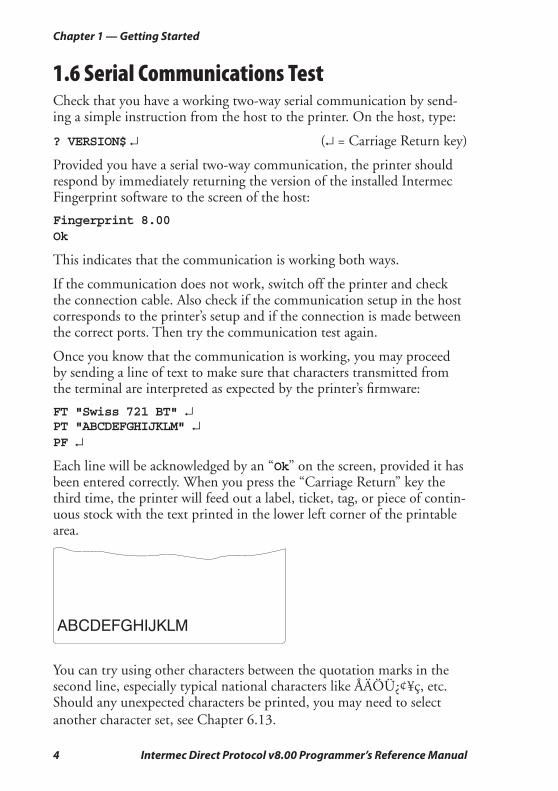
FT "Swiss 721 BT" ↵PT "ABCDEFGHIJKLM" ↵PF ↵
Each line will be acknowledged by an “Ok” on the screen, provided it has been entered correctly. When you press the “Carriage Return” key the third time, the printer will feed out a label, ticket, tag, or piece of contin-uous stock with the text printed in the lower left corner of the printable area.
ABCDEFGHIJKLM
You can try using other characters between the quotation marks in the second line, especially typical national characters like ÅÄÖÜ¿¢¥ç, etc. Should any unexpected characters be printed, you may need to select
another character set, see Chapter 6.13.

Intermec Direct Protocol v8.00 Programmer’s Reference Manual 5
2 Principles of Operation
This chapter explaines how to enter the Direct Protocol from Intermec Shell and from the Immediate Mode. It also describes the special features of the Direct Protocol and shows how to send instructions to the printer. Finally, it provides a quick overview of the instructions used for various purposes in the Direct Protocol. These are explained more comprehensively in the chapters that follow.
6 Intermec Direct Protocol v8.00 Programmer’s Reference Manual
Chapter 2 — Principles of Operation
2.1 Entering from Intermec ShellIn Intermec Shell, select the “Intermec Direct Protocol” option under the “Select Application” headline. After a few seconds, the display will show the message:
Direct Protocol 8.00
2.2 Entering from Immediate ModeIf you want to enter the Direct Protocol from the immediate mode of Intermec Fingerprint, issue the following instruction:
INPUT ON ↵ (↵ is carriage return, ASCII 13 dec. )
The display will show the message:
Direct Protocol 8.00
By default, no messages or characters will be returned to the host (see Chapter 5.15) until you leave the Intermec Direct Protocol.
2.3 Special Direct Protocol FeaturesIf you are familiar with Intermec Fingerprint, you will notice that the Intermec Direct Protocol is rather similar to the Immediate Mode. There are, however, some important differences:
• The Intermec Direct Protocol has a built-in error handler, that can indicate selected error conditions and produce error-messages of your own creation in any language you like.
• The Intermec Direct Protocol is able to receive variable input data in a special format to fi elds in a predefi ned layout.
• The Intermec Direct Protocol allows you to create counters without extensive programming.
• The Intermec Direct Protocol provides a simple way to enable the Print key to produce printouts.
• By default, verbosity is off in the Intermec Direct Protocol. While you develop your Direct Protocol fi les, we recommend setting the verbos-ity to ON using a SYSVAR (18) instruction, see Chapter 5.15.
Intermec Direct Protocol v8.00 Programmer’s Reference Manual 7
Chapter 2 — Principles of Operation
• Some instructions only work in the Intermec Direct Protocol:
COUNT&
ERROR
FORMAT INPUT
INPUT ON|OFF
LAYOUT END
LAYOUT INPUT
LAYOUT RUN
PRINT KEY ON|OFF
2.4 Sending InstructionsThe Intermec Direct Protocol allows you to send instructions to the printer in two ways:
• You can send instructions that the printer will act upon directly. This method is used for setting up the printer, for reading various data from the printer back to the host, and for managing fi les, fonts, and images.
Examples:
PRINT KEY ON ↵ (enable Print key)
? DATE$ ↵ (read printer’s calendar)
KILL "LAYOUT1" ↵ (delete a layout or fi le)
This method can also be used for creating label layouts including all the printable data as illustrated below.
• The other method is only intended for creating labels. First create a layout containing formatting instructions for a number of variable fi elds. Also include such fi elds that you do not need to change. Then send a string of printable data to the empty variable fi elds plus a print instruction. You can create a number of different layouts, select the one you need, and then add the variable data.
8 Intermec Direct Protocol v8.00 Programmer’s Reference Manual
Chapter 2 — Principles of Operation
Layout and Printable Data in One SequenceContinuous StringEnter the instructions as a continuous string, where the instructions are separated by colons (:).
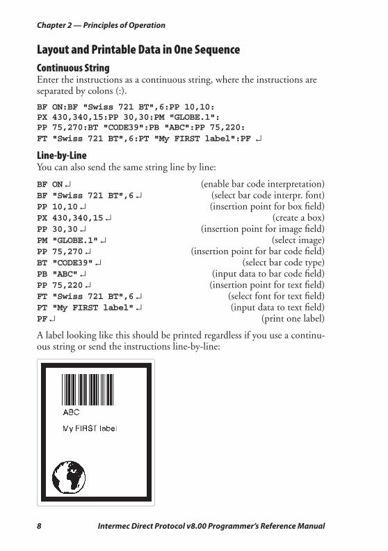
BF ON:BF "Swiss 721 BT",6:PP 10,10:PX 430,340,15:PP 30,30:PM "GLOBE.1":PP 75,270:BT "CODE39":PB "ABC":PP 75,220:FT "Swiss 721 BT",6:PT "My FIRST label":PF ↵
Line-by-LineYou can also send the same string line by line:
BF ON ↵ (enable bar code interpretation)BF "Swiss 721 BT",6 ↵ (select bar code interpr. font)PP 10,10 ↵ (insertion point for box fi eld)PX 430,340,15 ↵ (create a box)PP 30,30 ↵ (insertion point for image fi eld)PM "GLOBE.1" ↵ (select image)PP 75,270 ↵ (insertion point for bar code fi eld)BT "CODE39" ↵ (select bar code type)PB "ABC" ↵ (input data to bar code fi eld)PP 75,220 ↵ (insertion point for text fi eld)FT "Swiss 721 BT",6 ↵ (select font for text fi eld)PT "My FIRST label" ↵ (input data to text fi eld)PF ↵ (print one label)
A label looking like this should be printed regardless if you use a continu-ous string or send the instructions line-by-line:
Intermec Direct Protocol v8.00 Programmer’s Reference Manual 9
Chapter 2 — Principles of Operation
Layout and Variable Input Data in Separate SequencesAll necessary commands for setting up the printer (see Chapter 5) should be issued before the LAYOUT INPUT...LAYOUT END sequence. The only exceptions are NASC and NASCD, see Chapters 5.13 and 8.2.
Creating the LayoutLAYOUT INPUT "tmp:LABEL1" ↵ (start layout recorder)BF ON ↵ (enable bar code interpretation)BF "Swiss 721 BT",6 ↵ (select bar code interpretation font)PP 10,10 ↵ (insertion point for box fi eld)PX 430,340,15 ↵ (create a box)PP 30,30 ↵ (insertion point for image fi eld)PM "GLOBE.1" ↵ (select image)PP 75,270 ↵ (insertion point for bar code fi eld)BT "CODE39" ↵ (select bar code type)PB VAR1$ ↵ (variable input data to bar code fi eld)PP 75,220 ↵ (insertion point for text fi eld)FT "Swiss 721 BT",6 ↵ (select font for text fi eld)PT VAR2$ ↵ (variable input data to text fi eld)LAYOUT END ↵ (save layout)COPY "tmp:LABEL1","/c/LABEL1" ↵ (save layout in "/c")
The layout was created in the printer’s temporary memory ("tmp:") because it is faster and then, as a safety measure, copied to the permanent memory ("/c") which is slower but safer than ("tmp:"). The instructions could also have been sent as a continuous string rather than line-by-line.
Add Variable Data and PrintCOPY "/c/LABEL1","tmp:LABEL1" ↵ (copy layout to "tmp:")LAYOUT RUN "tmp:LABEL1" ↵ (select layout)<STX> (start of input data, ASCII 02 dec)ABC ↵ (variable input data to VAR1$)My FIRST label ↵ (variable input data to VAR2$)<EOT> (end of input data, ASCII 04 dec)PF ↵ (print one label)
This should produce a label looking exactly like the one shown on the previous page.
10 Intermec Direct Protocol v8.00 Programmer’s Reference Manual
Chapter 2 — Principles of Operation
Note: If a label has been printed using a predefi ned layout and you want to return to the method of printing labels using layout and printable data in one sequence, the predefi ned layout must fi rst be cleared from the printer’s working memory using the instruction: LAYOUT RUN ""
2.5 FieldsThe printable information on a label, ticket, tag, or piece of strip consists of various types of fi elds. A fi eld can consist of:
• A single line of text
• Several lines of text with line-wrap and hyphenation optionally sur-rounded by a box
• A bar code with or without human readable interpretation
• An image, for example picture or logotype, in bitmap format
• A box, that is a hollow square or rectangle
• A line
2.6 General Formatting InstructionsAny type of fi eld should be specifi ed in regard of:
• Position
• Alignment
• Direction
Refer to Chapter 3.2 for more information.
Intermec Direct Protocol v8.00 Programmer’s Reference Manual 11
Chapter 2 — Principles of Operation
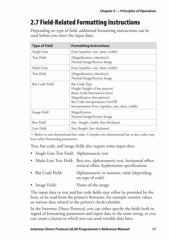
2.7 Field-Related Formatting InstructionsDepending on type of fi eld, additional formatting instructions can be used before you enter the input data:
Type of Field Formatting Instructions
Single-Line Font (typeface, size, slant, width)
Text Field [Magnifi cation, (obsolete)]
Normal Image/Inverse Image
Multi-Line Font (typeface, size, slant, width)
Text Field [Magnifi cation, (obsolete)]
Normal Image/Inverse Image
Bar Code Field1 Bar Code Type
Height (height of bar pattern)
Ratio (wide bars/narrow bars)
Magnifi cation (bar pattern)
Bar Code Interpretation On/Off
Interpretation Font (typeface, size, slant, width)
Image Field Magnifi cation
Normal Image/Inverse Image
Box Field Size (height, width, line thickness)
Line Field Size (length, line thickness)
1/. Refers to one-dimensional bar codes. Complex two-dimensional bar or dot codes may
have other formatting parameters.
Text, bar code, and image fi elds also require some input data:
• Single-Line Text Field: Alphanumeric text
• Multi-Line Text Field: Box size, alphanumeric text, horizontal offset, vertical offset, hyphenation specifi cations
• Bar Code Field: Alphanumeric or numeric value (depending on type of code)
• Image Field: Name of the image
The input data to text and bar code fi elds may either be provided by the host, or be read from the printer’s fi rmware, for example counter values or various data related to the printer’s clock/calendar.
In the Intermec Direct Protocol, you can either specify the fi elds both in regard of formatting parameters and input data in the same string, or you can create a layout to which you can send variable data later.
12 Intermec Direct Protocol v8.00 Programmer’s Reference Manual
Chapter 2 — Principles of Operation
2.8 Layout InstructionsThe layout should contain formatting parameters for all fi elds and input data to such fi elds that will always contain the same information. When the variable input data are added, they will be inserted into their respec-tive fi elds in a way similar to fi lling out a preprinted form.
When creating predefi ned layouts, you must use special instructions for:
• Clearing the working memory and starting the layout recorder.
• Saving the layout and clearing the working memory
2.9 Printable Data InstructionsDepending on type of fi eld and type of bar code, printable data to text, and bar code fi elds may consist of:
• Alphanumeric data (text)
• Numeric data
• Counter values
• Current date
• Current time
• Current date +/- nn days
• Current time +/- nn seconds
• Current week number
• Current weekday
2.10 Feeding and Printing InstructionsThere are some instructions that control the printing and media feed, for example used for:
• Printing one label or a batch of labels (or similar)
• Activating an optional paper cutter
• Speeding up batch printing
• Reprinting lost labels after interruption of batch print jobs
• Rotating the platen roller during cleaning
Intermec Direct Protocol v8.00 Programmer’s Reference Manual 13
Chapter 2 — Principles of Operation
• Feeding out an empty label, ticket, tag, or piece of strip
• Adjusting the label stop/black mark sensor
2.11 Setting Up the PrinterYou can control how the printer will work, for example:
• Enable/disable Intermec Direct Protocol
• Select standard IN and OUT channels
• Set the printer’s clock/calendar
• Set formats for the printing of date and time
• Set separators for input data strings to predefi ned layouts
• Create label counters
• Enable/disable the optional label taken sensor
• Enable/disable automatic cut-off operation
• Enable/disable Print key
• Produce audible signals
• Format the printer’s permanent memory or a memory card
• Remap certain incoming characters
• Select character set
• Restart the printer
• Select verbosity level
• Select type of error message
• Enable error handling and create customized error messages
• Select method for breaking the printing of a batch of labels
• Change the printer’s setup
14 Intermec Direct Protocol v8.00 Programmer’s Reference Manual
Chapter 2 — Principles of Operation
2.12 Reding the Printer’s StatusProvided you have a two-way serial communication between printer and host, you can read the printer’s status regarding a number of functions back to the screen of the host, for example:
• Current date and time
• Memory status
• Printhead status and characteristics
• Value of various system counters
• Status of various sensors and straps
• Software and hardware version
2.13 File-Handling InstructionsA number of instructions are used to control the printer’s memory, for example to:
• Read the number of free bytes in the printer’s memory
• Read the names of fi les, fonts, or images stored in the printer’s memory
• Remove fi les, fonts and images
• Copy fi les
• Download binary fi les
• Download .PCX fi les and convert them to images
Intermec Direct Protocol v8.00 Programmer’s Reference Manual 15
Chapter 2 — Principles of Operation
2.14 Syntax DescriptionsMany commonly used instructions have a shorthand version to mini-mize the transfer of data. In the explanations of the various instruction that follow, both the full name and the shorthand version will be shown, separated by a thin vertical line, for example:
PRPOS | PP
Unless otherwise indicated, upper- and lowercase characters can be used at will. Parameters for the instruction are shown like this:
<parameter> = numeric value"<parameter>" = alphanumeric text (enclosed by quotation marks)
• Compulsory space characters are indicated by double-headed arrows ( ↔ ).
• Square brackets [ ] indicate optional parameters.
• Vertical bars (|) separate alternatives.
• Always enter parentheses, commas, colons, semicolons, minus signs, quotation marks, and period characters exactly as shown.
• Negative values are indicated by leading minus signs (-).
The various instructions are described in as simple terms as possible. Complete syntax descriptions and comprehensive information on each instruction can be found in the Intermec Fingerprint v8.00, Programmer’s Reference Manual.
16 Intermec Direct Protocol v8.00 Programmer’s Reference Manual
Chapter 2 — Principles of Operation
Intermec Direct Protocol v8.00 Programmer’s Reference Manual 17
3 Label Design
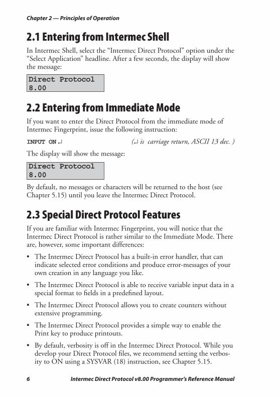
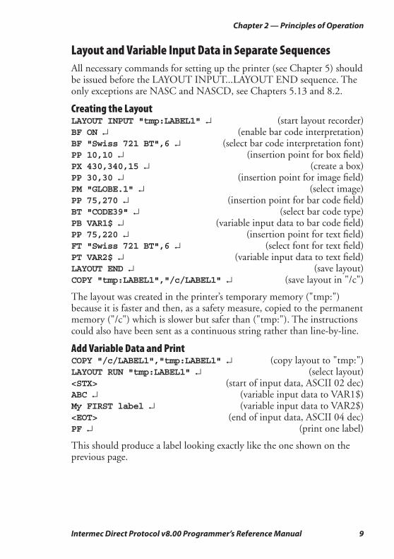
This chapter describes how a label layout is made up of various types of fi elds and explains the intructions used for creating each type of fi eld.
This is a multi-line text field with line-wrapand hyphen-ation
Multi-LineText Field
Single-LineText Field
Line Field
Image Field
Box Field
Bar Code Field(w. interpretation)
18 Intermec Direct Protocol v8.00 Programmer’s Reference Manual
Chapter 3 — Label Design
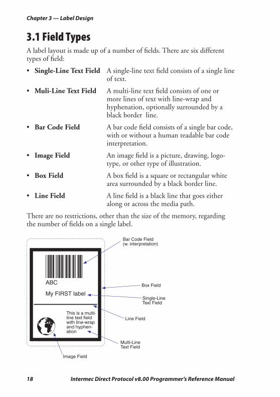
3.1 Field TypesA label layout is made up of a number of fi elds. There are six different types of fi eld:
• Single-Line Text Field A single-line text fi eld consists of a single line of text.
• Muli-Line Text Field A multi-line text fi eld consists of one or more lines of text with line-wrap and hyphenation, optionally surrounded by a black border line.
• Bar Code Field A bar code fi eld consists of a single bar code, with or without a human readable bar code interpretation.
• Image Field An image fi eld is a picture, drawing, logo-type, or other type of illustration.
• Box Field A box fi eld is a square or rectangular white area surrounded by a black border line.
• Line Field A line fi eld is a black line that goes either along or across the media path.
There are no restrictions, other than the size of the memory, regarding the number of fi elds on a single label.
Intermec Direct Protocol v8.00 Programmer’s Reference Manual 19
Chapter 3 — Label Design
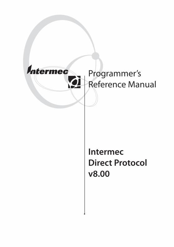
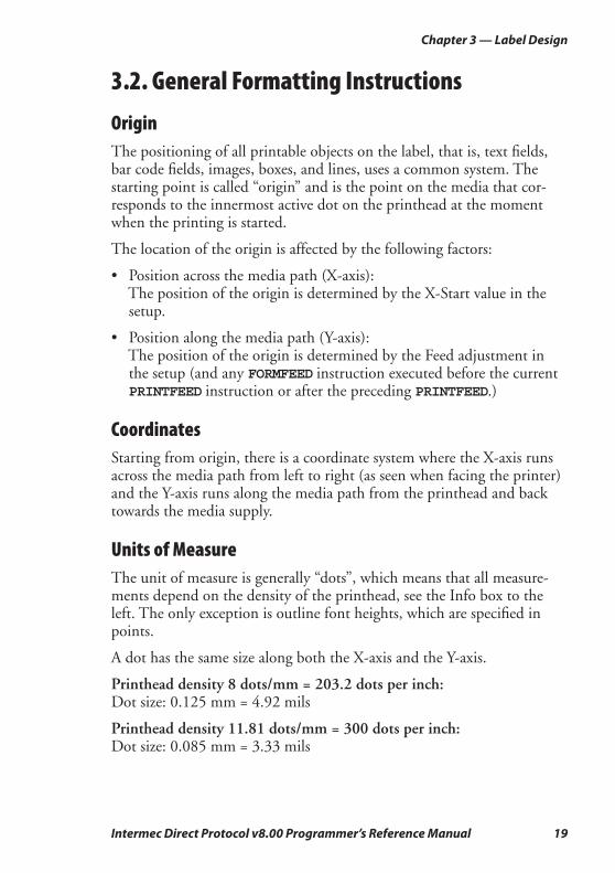
3.2. General Formatting Instructions
OriginThe positioning of all printable objects on the label, that is, text fi elds, bar code fi elds, images, boxes, and lines, uses a common system. The starting point is called “origin” and is the point on the media that cor-responds to the innermost active dot on the printhead at the moment when the printing is started.
The location of the origin is affected by the following factors:
• Position across the media path (X-axis): The position of the origin is determined by the X-Start value in the
setup.
• Position along the media path (Y-axis): The position of the origin is determined by the Feed adjustment in
the setup (and any FORMFEED instruction executed before the current PRINTFEED instruction or after the preceding PRINTFEED.)
CoordinatesStarting from origin, there is a coordinate system where the X-axis runs across the media path from left to right (as seen when facing the printer) and the Y-axis runs along the media path from the printhead and back towards the media supply.
Units of MeasureThe unit of measure is generally “dots”, which means that all measure-ments depend on the density of the printhead, see the Info box to the left. The only exception is outline font heights, which are specifi ed in points.
A dot has the same size along both the X-axis and the Y-axis.
Printhead density 8 dots/mm = 203.2 dots per inch:Dot size: 0.125 mm = 4.92 mils
Printhead density 11.81 dots/mm = 300 dots per inch:Dot size: 0.085 mm = 3.33 mils
20 Intermec Direct Protocol v8.00 Programmer’s Reference Manual
Chapter 3 — Label Design
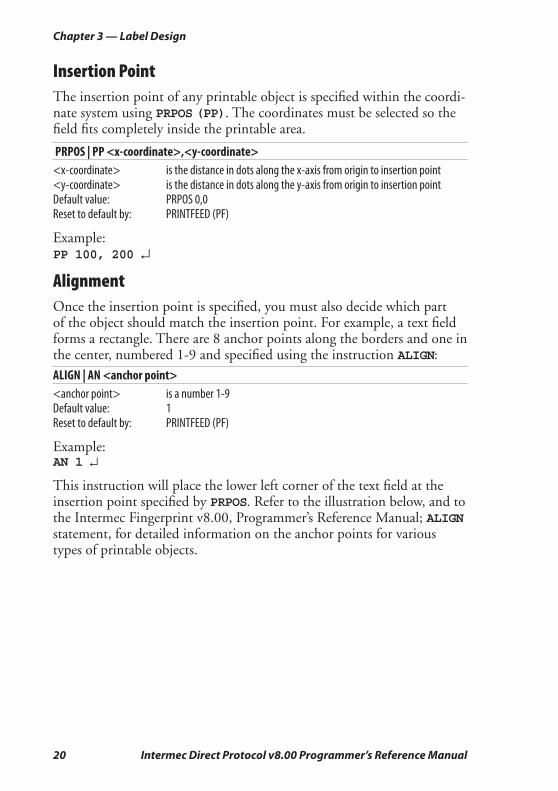
Insertion PointThe insertion point of any printable object is specifi ed within the coordi-nate system using PRPOS (PP). The coordinates must be selected so the fi eld fi ts completely inside the printable area.
PRPOS | PP <x-coordinate>,<y-coordinate><x-coordinate> is the distance in dots along the x-axis from origin to insertion point<y-coordinate> is the distance in dots along the y-axis from origin to insertion pointDefault value: PRPOS 0,0 Reset to default by: PRINTFEED (PF)
Example:PP 100, 200 ↵
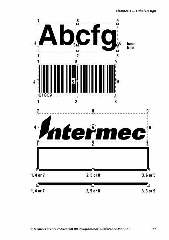
AlignmentOnce the insertion point is specifi ed, you must also decide which part of the object should match the insertion point. For example, a text fi eld forms a rectangle. There are 8 anchor points along the borders and one in the center, numbered 1-9 and specifi ed using the instruction ALIGN:
ALIGN | AN <anchor point><anchor point> is a number 1-9Default value: 1 Reset to default by: PRINTFEED (PF)
Example:AN 1 ↵
This instruction will place the lower left corner of the text fi eld at the insertion point specifi ed by PRPOS. Refer to the illustration below, and to the Intermec Fingerprint v8.00, Programmer’s Reference Manual; ALIGN statement, for detailed information on the anchor points for various types of printable objects.
Intermec Direct Protocol v8.00 Programmer’s Reference Manual 21
Chapter 3 — Label Design
22 Intermec Direct Protocol v8.00 Programmer’s Reference Manual
Chapter 3 — Label Design
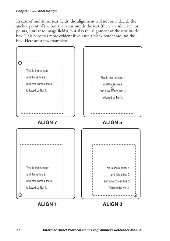
In case of multi-line text fi elds, the alignment will not only decide the anchor point of the box that sourrounds the text (there are nine anchor points, similar to image fi elds), but also the alignment of the text inside box. This becomes more evident if you use a black border around the box. Here are a few examples:
This is line number 1
and this is line 2
and now comes line 3
followed by No. 4.
ALIGN 7
This is line number 1
and this is line 2
and now comes line 3
followed by No. 4.
ALIGN 5
This is line number 1
and this is line 2
and now comes line 3
followed by No. 4.
ALIGN 1 ALIGN 3
This is line number 1
and this is line 2
and now comes line 3
followed by No. 4.
Dot-line on printhead
X-CoordinateX-start
X-C
oo
rdin
ate
Dot 0
Insertion point =Anchor point
Origin
DIR 1
DIR 2
DIR 3
DIR
4
FEED DIRECTION
Intermec Direct Protocol v8.00 Programmer’s Reference Manual 23
Chapter 3 — Label Design
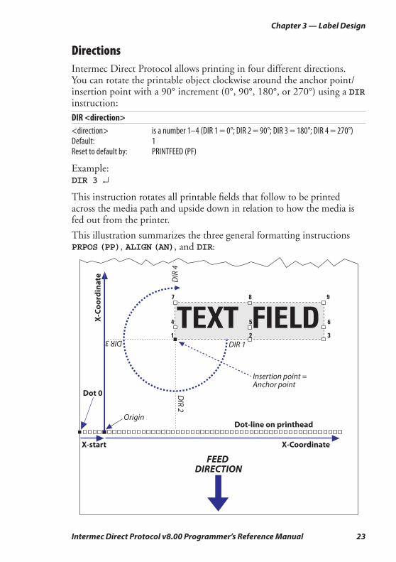
DirectionsIntermec Direct Protocol allows printing in four different directions. You can rotate the printable object clockwise around the anchor point/insertion point with a 90° increment (0°, 90°, 180°, or 270°) using a DIR instruction:
DIR <direction><direction> is a number 1–4 (DIR 1 = 0°; DIR 2 = 90°; DIR 3 = 180°; DIR 4 = 270°)Default: 1Reset to default by: PRINTFEED (PF)
Example:DIR 3 ↵
This instruction rotates all printable fi elds that follow to be printed across the media path and upside down in relation to how the media is fed out from the printer.
This illustration summarizes the three general formatting instructions PRPOS (PP), ALIGN (AN), and DIR:
24 Intermec Direct Protocol v8.00 Programmer’s Reference Manual
Chapter 3 — Label Design
Enabling/Disabling Partial FieldsNormally, any fi eld that extends outside the print window, as specifi ed by the printer’s setup in regard of media size (X-start, width, and length), will cause Error 1003 “Field out of label.” This can easily happen while you design your label layout, for example when changing the font, font size, direction, alignment, etc. Even “invisible” parts of a fi eld, for example “transparent” parts of an image may cause such errors.
If your label layout contains many fi elds, it may be diffi cult to grasp all implications of a change. However, it is possible to enable so called “par-tial fi elds.” CLIP ON/CLIP OFF is suffi cient for partial text, image, line, and box fi elds. Partial bar code fi elds may require a more complex syntax.
When partial fi elds are enabled, a fi eld that extends outside the print window will not cause Error 1003, but will be clipped at the edge of the window and not included in the printout. Thus, you can print a sample and more easily determine what is wrong.
CLIP [BARCODE [HEIGHT|INFORMATION|X|Y]] [ON|OFF]BARCODE Toggles between partial bar code enable/disable.HEIGHT clips the height of the bars.INFORMATION clips the bar code lengthwise.X clips the part of the bar code that comes outside the print window in the
X-dimension.Y clips the part of the bar code that comes outside the print window in the
Y-dimension.Default: CLIP OFF
Example:Only the last part of the text fi eld will be printed, since the fi eld is right-aligned and the insertion point is close to the left-hand edge of the print window.
CLIP ON ↵PP 350,100 ↵AN 6 ↵PT "INTERMEC PRINTERS" ↵PF ↵
XOR ModeThe instruction XORMODE controls how intersecting fi elds will be printed. At XORMODE OFF (default), the intersection will be black, and at XORMODE ON, the intersection will be white.
Intermec Direct Protocol v8.00 Programmer’s Reference Manual 25
Chapter 3 — Label Design
3.3 Text FieldsA single-line text fi eld consists of one or several alphanumeric characters on the same line. There is no practical limit other than the size of the printable area on the media. Text is not wrapped to a new line, but each line must be specifi ed as a separate text fi eld.
A multi-line text fi eld consists of one or more lines with line-wrap and hyphenation inside a visible or imaginary box
In addition to the instructions PRPOS, ALIGN, and DIR (see Chapter 3.2), a text fi eld can contain the following instructions:
Select FontThe FONT instruction specifi es the typeface, size, slant, and width of the simgle-byte Unicode font to be printed. The printer may contain vari-ous font sets, depending on market area and customer’s requirements. Double-byte Unicode fonts can be used for single-line text fi elds by means of the FONTD instruction, see Chapter 8, “Advanced Features.” Once a font has been specifi ed, it will be used in all text fi elds until a new FONT instruction is executed.
FONT | FT "<font name>"[,<size>[,<slant>[,<width>]]]<font name> is the name of a font enclosed by quotation marks. Default: "Swiss 721
BT".<size> in points (1 point = 1/72 inch ≈ 0.352 mm) (not for bitmap fonts.) Default:
12<slant> is the angle of the characters in degrees (not for bitmap fonts.) Default: 0<width> is the width in percent relative the size (not for bitmap fonts.) Default: 100
The standard set of fonts contains the following 15 typefaces from Bit-stream, Inc. The names are case-sensitive:
"Century Schoolbook BT" "DingDings SWA""Dutch 801 Roman BT" "Dutch 801 Bold BT" "Futura Light BT" "Letter Gothic 12 Pitch BT" "Monospace 821 BT" "Monospace 821 Bold BT" "OCR-A BT" "OCT-B 10 Pitch BT" "Prestige 12 Pitch Bold BT" "Swiss 721 BT""Swiss 721 Bold BT" "Swiss 721 Bold Condensed BT""Zurich Extra Condensed BT"
26 Intermec Direct Protocol v8.00 Programmer’s Reference Manual
Chapter 3 — Label Design
NORIMAGEINVIMAGE
Select Magnifi cationFonts can be magnifi ed 1-4 times independently in regard of height and width using a MAG instruction. However, for outline fonts the printout quality will be better if you use a larger font size and/or width. Use MAG in connection with bitmap fonts.
MAG <height mag>,<width mag><height mag> is the magnifi cation factor 1, 2, 3, or 4 times in regard of height.<width mag> is the magnifi cation factor 1, 2, 3, or 4 times in regard of width.Default: 1,1Reset to default by: PRINTFEED (PF).
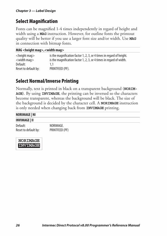
Select Normal/Inverse Printing Normally, text is printed in black on a transparent background (NORIM-AGE). By using INVIMAGE, the printing can be inversed so the characters become transparent, whereas the background will be black. The size of the background is decided by the character cell. A NORIMAGE instruction is only needed when changing back from INVIMAGE printing.
NORIMAGE | NIINVIMAGE | IIDefault: NORIMAGE. Reset to default by: PRINTFEED (PF)
Intermec Direct Protocol v8.00 Programmer’s Reference Manual 27
Chapter 3 — Label Design
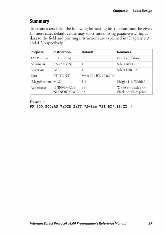
SummaryTo create a text fi eld, the following formatting instructions must be given (in most cases default values may substitute missing parameters.) Input data to the fi eld and printing instructions are explained in Chapters 3.9 and 4.2 respectively.
Purpose Instruction Default Remarks
X/Y Position PP (PRPOS) 0/0 Number of dots
Alignment AN (ALIGN) 1 Select AN 1-9
Direction DIR 1 Select DIR 1-4
Font FT (FONT) Swiss 721 BT, 12,0,100
[Magnifi cation MAG 1,1 Height 1-4, Width 1-4]
Appearance II (INVIMAGE) off White-on-black print
NI (NORIMAGE ) on Black-on-white print
Example:PP 200,500:AN 7:DIR 2:FT "Swiss 721 BT",18:II ↵
28 Intermec Direct Protocol v8.00 Programmer’s Reference Manual
Chapter 3 — Label Design
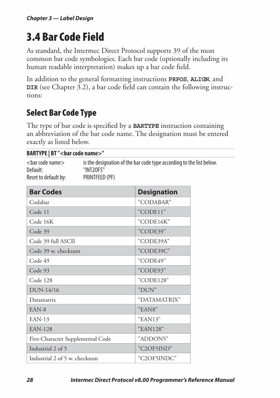
3.4 Bar Code FieldAs standard, the Intermec Direct Protocol supports 39 of the most common bar code symbologies. Each bar code (optionally including its human readable interpretation) makes up a bar code fi eld.
In addition to the general formatting instructions PRPOS, ALIGN, and DIR (see Chapter 3.2), a bar code fi eld can contain the following instruc-tions:
Select Bar Code TypeThe type of bar code is specifi ed by a BARTYPE instruction containing an abbreviation of the bar code name. The designation must be entered exactly as listed below.
BARTYPE | BT "<bar code name>"<bar code name> is the designation of the bar code type according to the list below.Default: "INT2OF5"Reset to default by: PRINTFEED (PF)
Bar Codes DesignationCodabar "CODABAR"
Code 11 "CODE11"
Code 16K "CODE16K"
Code 39 "CODE39"
Code 39 full ASCII "CODE39A"
Code 39 w. checksum "CODE39C"
Code 49 "CODE49"
Code 93 "CODE93"
Code 128 "CODE128"
DUN-14/16 "DUN"
Datamatrix "DATAMATRIX"
EAN-8 "EAN8"
EAN-13 "EAN13"
EAN-128 "EAN128"
Five-Character Supplemental Code "ADDON5"
Industrial 2 of 5 "C2OF5IND"
Industrial 2 of 5 w. checksum "C2OF5INDC"

Intermec Direct Protocol v8.00 Programmer’s Reference Manual 29
Chapter 3 — Label Design
Interleaved 2 of 5 "INT2OF5"
Interleaved 2 of 5 w. checksum "INT2OF5C"
Interleaved 2 of 5 A "I2OF5A"
Matrix 2 of 5 "C2OF5MAT"
MaxiCode "MAXICODE"
MSI (modifi ed Plessey) "MSI"
PDF 417 "PDF417"
Plessey "PLESSEY"
Postnet "POSTNET"
QR "QTCODE"
Straight 2 of 5 "C2OF5"
Two-Character Supplemental Code "ADDON2"
UCC-128 Serial Shipping Container Code "UCC128"
UPC-5 digits Add-On Code "SCCADDON"
UPC-A "UPCA"
UPC-D1 "UPCD1"
UPC-D2 "UPCD2"
UPC-D3 "UPCD3"
UPC-D4 "UPCD4"
UPC-D5 "UPCD5"
UPC-E "UPCE"
UPC Shipping Container Code "UPCSCC"
Specify Bar Code HeightThe height of the bars that make up the bar code can be specifi ed by means of the BARHEIGHT instruction.
BARHEIGHT | BH <height><height> is the height of the bars in dots. Default: 100 Reset to default by: PRINTFEED (PF)
30 Intermec Direct Protocol v8.00 Programmer’s Reference Manual
Chapter 3 — Label Design
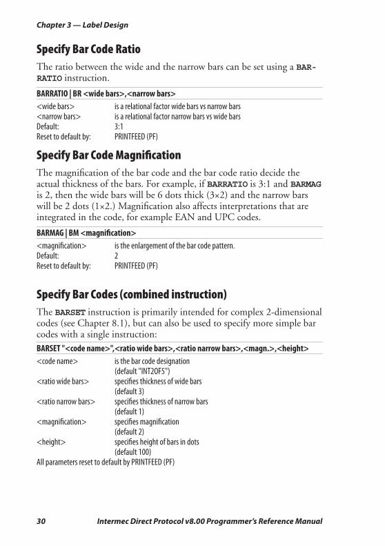
Specify Bar Code RatioThe ratio between the wide and the narrow bars can be set using a BAR-RATIO instruction.
BARRATIO | BR <wide bars>,<narrow bars><wide bars> is a relational factor wide bars vs narrow bars<narrow bars> is a relational factor narrow bars vs wide barsDefault: 3:1Reset to default by: PRINTFEED (PF)
Specify Bar Code Magnifi cationThe magnifi cation of the bar code and the bar code ratio decide the actual thickness of the bars. For example, if BARRATIO is 3:1 and BARMAG is 2, then the wide bars will be 6 dots thick (3×2) and the narrow bars will be 2 dots (1×2.) Magnifi cation also affects interpretations that are integrated in the code, for example EAN and UPC codes.
BARMAG | BM <magnifi cation><magnifi cation> is the enlargement of the bar code pattern.Default: 2Reset to default by: PRINTFEED (PF)
Specify Bar Codes (combined instruction)The BARSET instruction is primarily intended for complex 2-dimensional codes (see Chapter 8.1), but can also be used to specify more simple bar codes with a single instruction:
BARSET "<code name>",<ratio wide bars>,<ratio narrow bars>,<magn.>,<height><code name> is the bar code designation (default "INT2OF5")<ratio wide bars> specifi es thickness of wide bars (default 3)<ratio narrow bars> specifi es thickness of narrow bars (default 1)<magnifi cation> specifi es magnifi cation (default 2)<height> specifi es height of bars in dots (default 100)All parameters reset to default by PRINTFEED (PF)
Intermec Direct Protocol v8.00 Programmer’s Reference Manual 31
Chapter 3 — Label Design
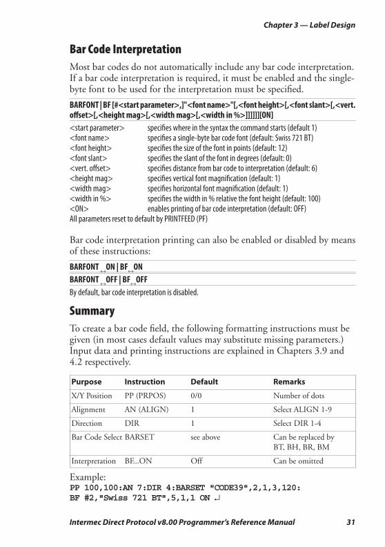
Bar Code InterpretationMost bar codes do not automatically include any bar code interpretation. If a bar code interpretation is required, it must be enabled and the single-byte font to be used for the interpretation must be specifi ed.
BARFONT | BF [#<start parameter>,]"<font name>"[,<font height>[,<font slant>[,<vert. off set>[,<height mag>[,<width mag>[,<width in %>]]]]]][ON]<start parameter> specifi es where in the syntax the command starts (default 1)<font name> specifi es a single-byte bar code font (default: Swiss 721 BT)<font height> specifi es the size of the font in points (default: 12)<font slant> specifi es the slant of the font in degrees (default: 0)<vert. off set> specifi es distance from bar code to interpretation (default: 6)<height mag> specifi es vertical font magnifi cation (default: 1)<width mag> specifi es horizontal font magnifi cation (default: 1)<width in %> specifi es the width in % relative the font height (default: 100)<ON> enables printing of bar code interpretation (default: OFF)All parameters reset to default by PRINTFEED (PF) Bar code interpretation printing can also be enabled or disabled by means of these instructions:
BARFONT ↔ON | BF↔ONBARFONT ↔OFF | BF↔OFFBy default, bar code interpretation is disabled.
SummaryTo create a bar code fi eld, the following formatting instructions must be given (in most cases default values may substitute missing parameters.) Input data and printing instructions are explained in Chapters 3.9 and 4.2 respectively.
Purpose Instruction Default Remarks
X/Y Position PP (PRPOS) 0/0 Number of dots
Alignment AN (ALIGN) 1 Select ALIGN 1-9
Direction DIR 1 Select DIR 1-4
Bar Code Select BARSET see above Can be replaced by
BT, BH, BR, BM
Interpretation BF...ON Off Can be omitted
Example:PP 100,100:AN 7:DIR 4:BARSET "CODE39",2,1,3,120:BF #2,"Swiss 721 BT",5,1,1 ON ↵
32 Intermec Direct Protocol v8.00 Programmer’s Reference Manual
Chapter 3 — Label Design
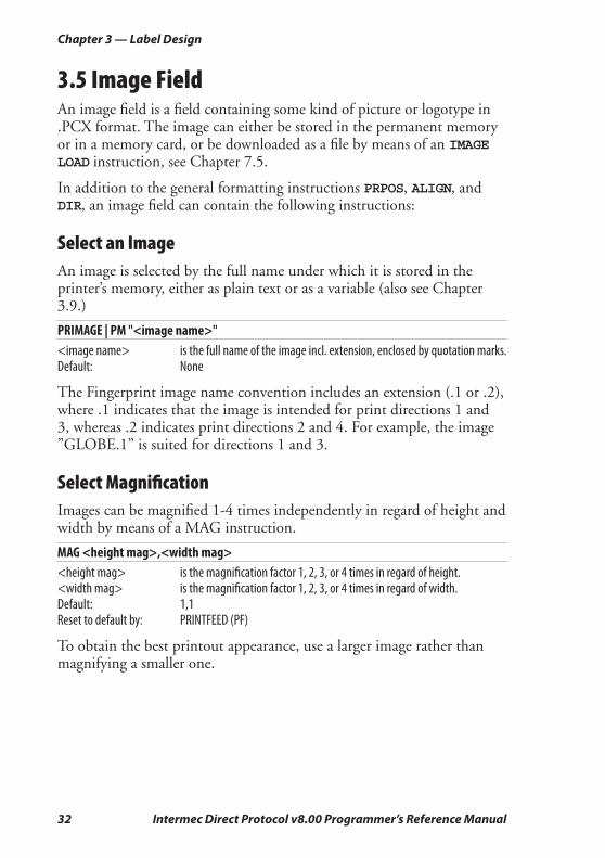
3.5 Image FieldAn image fi eld is a fi eld containing some kind of picture or logotype in .PCX format. The image can either be stored in the permanent memory or in a memory card, or be downloaded as a fi le by means of an IMAGE LOAD instruction, see Chapter 7.5.
In addition to the general formatting instructions PRPOS, ALIGN, and DIR, an image fi eld can contain the following instructions:
Select an ImageAn image is selected by the full name under which it is stored in the printer’s memory, either as plain text or as a variable (also see Chapter 3.9.)
PRIMAGE | PM "<image name>"<image name> is the full name of the image incl. extension, enclosed by quotation marks.Default: None
The Fingerprint image name convention includes an extension (.1 or .2), where .1 indicates that the image is intended for print directions 1 and 3, whereas .2 indicates print directions 2 and 4. For example, the image ”GLOBE.1” is suited for directions 1 and 3.
Select Magnifi cationImages can be magnifi ed 1-4 times independently in regard of height and width by means of a MAG instruction.
MAG <height mag>,<width mag><height mag> is the magnifi cation factor 1, 2, 3, or 4 times in regard of height.<width mag> is the magnifi cation factor 1, 2, 3, or 4 times in regard of width.Default: 1,1Reset to default by: PRINTFEED (PF)
To obtain the best printout appearance, use a larger image rather than magnifying a smaller one.

Intermec Direct Protocol v8.00 Programmer’s Reference Manual 33
Chapter 3 — Label Design
Select Normal/Inverse Printing Normally, an image is printed in black on a transparent background, just as it was created. Using INVIMAGE, the black and transparent parts can be switched. The size of the background is decided by the actual size of the image including “invisible” background. A NORIMAGE statement is only needed when changing back from INVIMAGE printing.
NORIMAGE | NIINVIMAGE| I IDefault: NORIMAGE Reset to default by: PRINTFEED (PF)
SummaryTo create an image fi eld, the following formatting instructions must be given (in most cases default values may substitute missing para-meters). Image selection by means of variable input, and printing instructions are explained in Chapters 3.9 and 4.2 respectively.
Purpose Instruction Default Remarks
X/Y Position PP (PRPOS) 0/0 Number of dots
Alignment AN (ALIGN) 1 Select ALIGN 1- 9
Direction DIR 1 Select DIR 1- 4
Magnifi cation MAG 1,1 Height 1-4, Width 1-4
Appearance II (INVIMAGE) off Black/white parts inversed
NI (NORIMAGE) on Normal (revokes INVIMAGE)
Image name PM (PRIMAGE) n.a. Full name incl. extension
Example:PP 200,500:AN 3:DIR 3:MAG 2,2:II:PM "GLOBE.1" ↵
34 Intermec Direct Protocol v8.00 Programmer’s Reference Manual
Chapter 3 — Label Design
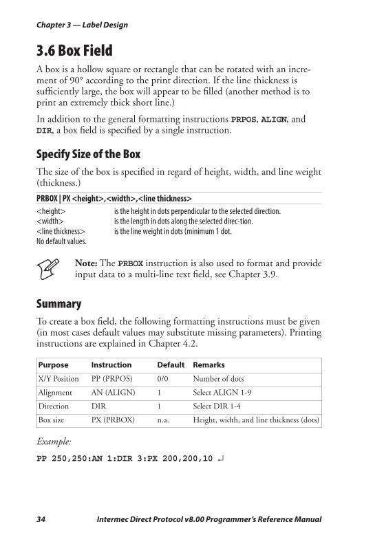
3.6 Box FieldA box is a hollow square or rectangle that can be rotated with an incre-ment of 90° according to the print direction. If the line thickness is suffi ciently large, the box will appear to be fi lled (another method is to print an extremely thick short line.)
In addition to the general formatting instructions PRPOS, ALIGN, and DIR, a box fi eld is specifi ed by a single instruction.
Specify Size of the BoxThe size of the box is specifi ed in regard of height, width, and line weight (thickness.)
PRBOX | PX <height>,<width>,<line thickness><height> is the height in dots perpendicular to the selected direction.<width> is the length in dots along the selected direc-tion.<line thickness> is the line weight in dots (minimum 1 dot. No default values.
Note: The PRBOX instruction is also used to format and provide input data to a multi-line text fi eld, see Chapter 3.9.
SummaryTo create a box fi eld, the following formatting instructions must be given (in most cases default values may substitute missing parameters). Printing instructions are explained in Chapter 4.2.
Purpose Instruction Default Remarks
X/Y Position PP (PRPOS) 0/0 Number of dots
Alignment AN (ALIGN) 1 Select ALIGN 1-9
Direction DIR 1 Select DIR 1-4
Box size PX (PRBOX) n.a. Height, width, and line thickness (dots)
Example:
PP 250,250:AN 1:DIR 3:PX 200,200,10 ↵
Intermec Direct Protocol v8.00 Programmer’s Reference Manual 35
Chapter 3 — Label Design
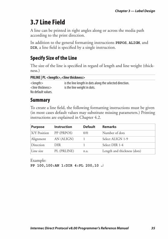
3.7 Line FieldA line can be printed in right angles along or across the media path according to the print direction.
In addition to the general formatting instructions PRPOS, ALIGN, and DIR, a line fi eld is specifi ed by a single instruction.
Specify Size of the LineThe size of the line is specifi ed in regard of length and line weight (thick-ness.)
PRLINE | PL <length>,<line thickness><length> is the line length in dots along the selected direction.<line thickness> is the line weight in dots.No default values.
SummaryTo create a line fi eld, the following formatting instructions must be given (in most cases default values may substitute missing parameters.) Printing instructions are explained in Chapter 4.2.
Purpose Instruction Default Remarks
X/Y Position PP (PRPOS) 0/0 Number of dots
Alignment AN (ALIGN) 1 Select ALIGN 1-9
Direction DIR 1 Select DIR 1-4
Line size PL (PRLINE) n.a. Length and thickness (dots)
Example:PP 100,100:AN 1:DIR 4:PL 200,10 ↵
36 Intermec Direct Protocol v8.00 Programmer’s Reference Manual
Chapter 3 — Label Design
3.8 Layout Instructions
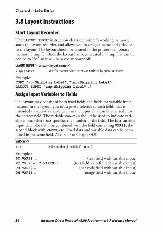
Start Layout RecorderThe LAYOUT INPUT instruction clears the printer’s working memory, starts the layout recorder, and allows you to assign a name and a device to the layout. The layout should be created in the printer’s temporary memory ("tmp:"). Once the layout has been created in "tmp:", it can be copied to "/c:" so it will be saved at power off.
LAYOUT INPUT "<tmp:><layout name>"<layout name> Max. 30 characters incl. extension enclosed by quotation marks
Example:COPY "/c/Shipping Label","tmp:Shipping Label" ↵LAYOUT INPUT "tmp:Shipping Label" ↵
Assign Input Variables to FieldsThe layout may consist of both fi xed fi elds and fi elds for variable infor-mation. In the layout, you must give a referece to each fi eld, that is intended to receive variable data, so the input data can be inserted into the correct fi eld. The variable VAR<n>$ should be used to indicate vari-able input, where <n> specifi es the number of the fi eld. The fi rst variable input data block will be combined with the fi eld containing VAR1$, the second block with VAR2$, etc. Fixed data and variable data can be com-bined in the same fi eld. Also refer to Chapter 3.9.
VAR<n>$<n> is the number of the fi eld (1-nnnn...)
Examples:PT VAR1$ ↵ (text fi eld with variable input)PT "Price: ";VAR2$ ↵ (text fi eld with fi xed & variable input)PB VAR3$ ↵ (bar code fi eld with variable input)PM VAR4$ ↵ (image fi eld with variable input)
Intermec Direct Protocol v8.00 Programmer’s Reference Manual 37
Chapter 3 — Label Design
Save the LayoutAfter having completed the layout, save it in the printer’s temporary memory ("tmp:"), turn off the layout recorder, and clear the printer’s working memory by means of a LAYOUT END instruction. The layout could then be copied to the printer’s permanent memory ("/c") so it will not be deleted when the power is switched off.
LAYOUT END
Example:LAYOUT END ↵COPY "tmp:Shipping Label","/c/Shipping Label" ↵
38 Intermec Direct Protocol v8.00 Programmer’s Reference Manual
Chapter 3 — Label Design
3.9 Printable Data Instructions
Select a LayoutBefore any variable data can be transmitted to a preprogrammed layout, the layout must be selected by means of a LAYOUT RUN instruction. If the layout has been saved in the printer’s permanent memory ("/c") as described in Chapter 3.8, it should be copied to the temporary memory ("tmp:"), and be run from there.
LAYOUT RUN "<tmp:><layout name>"<layout name> is the name given to the layout in the LAYOUT INPUT instruction and must
be enclosed by quotation marks.
Example:COPY "/c/Shipping Label","tmp:Shipping Label" ↵LAYOUT RUN "tmp:Shipping Label" ↵
Transmit Variable Data to a LayoutAfter having selecting a layout using a LAYOUT RUN instruction, you can transmit the variable data to their respective layout fi elds:
• The transmission starts with a start-of-text separator.
• Then comes a block of data to the fi eld containing VAR1$.
• A fi eld separator separates the blocks of data.
• Next block goes to the fi eld containing VAR2$.
• A fi eld separator separates the blocks of data and so on.
• The last block must also end with a fi eld separator.
• The end of transmission is indicated by an End-of text separator.
By default, the following separators should be used:
• Start separator: STX (ASCII 02 dec)
• Field separator: CR (ASCII 13 dec)
• End separator: EOT (ASCII 04 dec)
All separators can be changed at will using a FORMAT INPUT instruction, see Chapter 5.5.
Intermec Direct Protocol v8.00 Programmer’s Reference Manual 39
Chapter 3 — Label Design
<STX> <Input data to VAR1$> <CR> <Input data to VAR2$> <CR>.....<EOT>Input data must not be enclosed by quotation marks.
Example:<STX> Abcdefg <CR> 123456789 <CR> <EOT>
Note: If a label has been printed using a predefi ned layout and you want to return to the method of printing labels using layout and printable data in one sequence, the predefi ned layout must fi rst be cleared from the printer’s working memory using the instruction: LAYOUT RUN ""
Input Data to Single- and Multi-Line Text FieldsThe input data to a text fi eld is given by means of a PRTXT or PRBOX instruction. You can add various types of data to a text fi eld:
• Plain text, by typing for example "Abcdefgh" or "012345"
• Variable input data using variables, for example VAR1$
• Counter values, for example CNT1$
• Current date, using DATE$ or DATE$ ("F")
• Current time, using TIME$ or TIME$ ("F")
• The weekday of the current or specifi ed date, using WEEKDAY$
• The number of the current or specifi ed date, using WEEKNUMBER
• A future date, using DATEADD$ or DATEADD$ ("F")
• A future time, using TIMEADD$ or TIMEADD$ ("F")
PRTXT is used for single line text fi elds. You can combine different types of data in a single PRTXT instruction. The different parts are placed adja-cently by means of separating semicolons (;). Note that plain text must be enclosed by quotation marks.
PRTXT | PT "<input data>"[;"<input data>"...]
Examples:PT "Price: $1.99" ↵PT "Price: ";VAR1$;" per dozen" ↵PT "Box No. ";CNT15$;" Packed: ";DATE$ ("F") ↵PT WEEKDAY$(DATE$);", ";DATE$("F") ↵PT "Week Number ";WEEKNUMBER(DATE$) ↵PT "Expiry date: ";DATEADD$ (30,"F") ↵
40 Intermec Direct Protocol v8.00 Programmer’s Reference Manual
Chapter 3 — Label Design
PRBOX is used for multi-line text fi elds.
PRBOX | PX <box height>,<box width>,<line thickness>,"<input data>"[,<hor. off set>[,<vert. off set>[,"<line delimiter>"[,"<control string>"]]]]]<box height> is the height of the box in dots (1-6000.)<box width> is the width of the box in dots.<line thickness> is the line thickness in dots (0-6000.) <input data> is max. 20 lines of text, each with max. 300 single-byte characters. <hor. off set> is the horizontal distance between the box line and the text frame (-100 to
+100 dots.). Default: 0.<vert. off set> is the vertical distance between the boxand the text frame and between
each text line (-100 to +100 dots.) Default: 0.<line delimiter> is a string used to replace the default carriage return or line feed character.<control string> is a string for hypenation control, see Intermec Fingerprint v8.00, Program-
mer’s Reference Manual.
The height, width, and line thickness parameters are the same as when creating an ordinary box fi eld, see Chapter 3.6. However, you can set the line thickness to 0, which gives an invisible box.
The input data allow max. 20 lines with max. 300 characters on each line. Double-byte fonts cannot be used. In all other respects, this param-eter corresponds to the input data in PRTXT (PT.)
The horizontal and vertical offset is used to specify the position of the text frame in relation to the inner edge of the border line. The vertical offset also controls the line spacing, which means the distance between the bottom of the character cells on one line and the top of the character cells on the next line. Note that the alignment affects both how the box is located in relation to the insertion point and how the text frame is located in relation to the box, see Chapter 3.2.
By default, the input data wraps to a new line each time a carriage return or linefeed character is entered. You can optionally replace those charac-ters with another character or a series of characters.
By default, text lines are hyphenated from the last space or position marked by a hyphen sign (-). The hyphen sign will only be printed as the last character on a line. There are many advanced features for control-ling the hyphenation and handling of long-spelling words. Refer to the Intermec Fingerprint v8.00, Programmer’s Reference Manual for syntax and explanations of the hyphenation control string.
Intermec Direct Protocol v8.00 Programmer’s Reference Manual 41
Chapter 3 — Label Design
Input Data to Bar Code FieldsThe input data to a bar code fi eld is given using a PRBAR instruction. You can add the same types of data to a bar code fi eld as to a text fi eld, provided the type of data (numeric/alphanumeric), number of characters, etc. comply with the bar code specifi cation.
You can combine different types of data in a single PRBAR instruction. The different parts are placed adjacently by means of separating semico-lons (;). Note that alphanumeric input must be enclosed by quotation marks, whereas numeric input must not.
PRBAR | PB <input data>[;<input data>...]
Examples:PB 71543;VAR5$ ↵PB "Intermec" ↵PB DATE$;TIME$ ↵
Input Data to Image FieldsAn image can be selected either by name in plain text (for example "GLOBE.1"), or in the form of a variable (for example VAR1$), also see Chapter 3.5. Note that plain text input must be enclosed by quotation marks.
PRIMAGE | PM "<image name>"
Examples:PM VAR5$ ↵PM "LOGOTYPE.2" ↵
Input Data from CountersUsing a COUNT& instruction, various counters can be created, see Chapter 5.6. You can read the present value of a counter and use it as input data by including a reference to the counter in the PRTXT, PRBOX, or PRBAR instructions in the form of a variable.
CNT<Counter No.>$<Counter No.> is the number is assigned to the counter in the COUNT& instruction.
Example:PT "Label number: ";CNT1$ ↵PB CNT2$ ↵
42 Intermec Direct Protocol v8.00 Programmer’s Reference Manual
Chapter 3 — Label Design
Input Data from the Printer’s Clock/CalendarThe printer’s clock/calendar can be used to provide input data to text and bar code fi elds by including any of the following instructions in the PRTXT, PRBOX, or PRBAR instructions:
DATE$ Returns the current date according to the printer’s calendar in the standard format YYMMDD, where YY is the last two digits of the year, MM is the number of the month (01-12), and DD is the number of the day (01-31.)
Example:PT DATE$ ↵ DATE$ ("F") Returns the current date according to the printer’s calendar in the format specifi ed by FORMAT DATE$, see Chapter 5.4.
Example:PT DATE$("F") TIME$ Returns the current time according to the printer’s clock in the standard time format HHMMSS, where HH is the hour (00-24), MM is the minute (00-59) and SS is the second (00-59.)
Example:PT TIME$ ↵
TIME$ ("F") Returns the current time according to the printer’s clock in the format specifi ed by FORMAT TIME$, see Chapter 5.4.
Example:PT TIME$("F") ↵
WEEKDAY$ ("<date>")Returns the name of the weekday in plain text according to NAME WEEKDAY$ (see Chapter 5.4) from a given date or the current date.
<date> can be specifi ed in the standard format “YYMMDD” or by a DATE$ instruc-tion.
Examples:PT WEEKDAY$("031201") ↵PT WEEKDAY$(DATE$) ↵

Intermec Direct Protocol v8.00 Programmer’s Reference Manual 43
Chapter 3 — Label Design
WEEKNUMBER ("<date>"[,<calculating function>])Returns the weeknumber from a given date or the current date.
<date> can be specifi ed in the standard format “YYMMDD” or by a DATE$ instruc-tion. By default, the week number is calculated according to ISO 8601, but there are 14 other methods (see Intermec Fingerprint v8.00, Programmer’s Reference Manual.)
Examples:PT WEEKNUMBER("031201") ↵PT WEEKNUMBER(DATE$) ↵
DATEADD$ (["<original date>",]<number of days>[,"F"])Adds or subtracts a certain number of days to the current date or optionally to a specifi ed date.
<original date> is optional and is entered in the standard date format “YYMMDD.” Note that the original date must be enclosed by quotation marks.
<number of days> specifi es the number of days to be added to or subtracted from the current date or, optionally, the date specifi ed by <original date>. In case of subtrac-tion, the <number of days> should be preceded by a minus sign (-).
"F" is an optional fl ag specifying that the result should be returned in the format specifi ed by FORMAT DATE$ instead of the standard format “YYMMDD.”
Example:PT DATEADD$("010401",-15,"F") ↵
TIMEADD$ (["<original time>",]<number of sec’s>[,"F"])
Adds or subtracts a certain number of seconds to the current time or option-ally to a specifi ed moment of time.
<original time> is optional and is entered in the standard date format “HHMMSS.” Note that the original time must be enclosed by quotation marks.
<number of sec’s> specifi es the number of seconds to be added to or subtracted from the current time or, optionally, the moment of time specifi ed by <original time>. In case of subtraction, the <number of sec’s> should be preceded by a minus sign (-).
"F" is an optional fl ag specifying that the result should be returned in the format specifi ed by FORMAT TIME$ instead of the standard format “HHMMSS.”
Example:PT TIMEADD$("123026",100,"F") ↵

44 Intermec Direct Protocol v8.00 Programmer’s Reference Manual
Chapter 3 — Label Design

Intermec Direct Protocol v8.00 Programmer’s Reference Manual 45
4 Feeding & Printing Instructions
This chapter describes the varoius instructions used for controlling the media feed and the printing of labels.
46 Intermec Direct Protocol v8.00 Programmer’s Reference Manual
Chapter 4 — Feeding & Printing Instructions
4.1 Media FeedIn order to provide maximum fl exibility, there are several instructions for controlling the media feed and an optional paper cutter:
CLEANFEED <feed length in dots> Runs the printer’s media feed mechanism in order to facilitate cleaning of the platen roller.
FORMFEED | FF [<feed length in dots>] Feeds out a blank label or optionally feeds out (+) or pulls back (-) a certain amount of media without printing.
TESTFEED [<feed length>]Feeds out a number of blank labels, or optionally a specifi ed amount of media, while adjusting the sensitivity of the label stop/black mark sensor and detecting the front edges of the labels. If a feed length is specifi ed, make sure that at least one gap or mark passes the label stop/black mark sensor.
CUT Makes an optional paper cutter perform a cutting cycle.
The media is fed past the printhead by a rubber-coated platen roller driven by a stepper motor. The movement of the media is detected by the label stop sensor (LSS) or black mark sensor (BMS), except when various types of continuous stock are used.
The printer’s setup in regard of “Media Size; Length” and ”Media Type” is essential for how the media feed will work. There are fi ve different Media Type options (also see the User’s Guide of the printer):• Label (w gaps)• Ticket (w mark) • Ticket (w gaps)• Fix length strip• Var length strip
When a FORMFEED, TESTFEED, or PRINTFEED instruction is executed, the photoelectric label stop sensor (LSS) detects the forward edge of each new label or the forward edge of each detection gap, and the black mark sensor (BMS) detects the rear edge of each black mark, as the media is moved past the sensor.
By performing a TESTFEED operation after loading a new supply of media, the fi rmware is able to measure the distance between, for exam-ple, the forward edges of two consecutive labels, thereby determining the label length, and can adjust the media feed accordingly. The same principle applies to tickets or tags with detection gaps, and to tickets with
Intermec Direct Protocol v8.00 Programmer’s Reference Manual 47
Chapter 4 — Feeding & Printing Instructions
black marks. At the same time, the sensitivity of the sensor is adjusted according to the characteristics of the media, for example the transpar-ency of the liner.
In case of continuous stock, the LSS will only detect possible out-of-paper conditions and the amount of media feed is decided in two different ways:
• Fixed length strip The amount of media feed for each FORMFEED, TESTFEED, and PRINTFEED operation is decided by the “Media Size; Length” setup.
• Variable length strip The amount of media feed for each TESTFEED and FORMFEED opera-
tion is decided by the size of the print image. Note that “invisible” printable objects like a space character or the transparent part of an image also are included in the print image.
The Detection setup allows you to perform two global adjustments to the media feed described above: • Start Adjust • Stop Adjust
By default, both these two parameters are set to 0, which allows for proper tear-off operation when there is no requirement of printing immediately at the forward edge of the label (or the equivalent.)
• Start Adjust decides how much media will be fed out or pulled back before the FORMFEED, TESTFEED, or PRINTFEED is executed. Usually, there is a small distance between the tear bar and the printhead. Thus, if you want to start printing directly at the forward edge of the label, you must pull back the media before printing by means of a negative start adjust value.
• Stop Adjust decides how much more or less media will be fed out after the FORMFEED, TESTFEED, or PRINTFEED is executed.
If a FORMFEED instruction is issued without any specifi cation of the feed length, a complete blank label (or the equivalent) will be fed out. Do not use FORMFEED instructions with specifi ed feed length to substitute the Start- and Stopadjust setup.
The relation between media and printhead at the moment when the actual printing starts decides all positioning along the Y-axis, that is along the media path. Likewise, the relation between the media and the cutting edge when the cutter is activated decides where the media will be cut off.
48 Intermec Direct Protocol v8.00 Programmer’s Reference Manual
Chapter 4 — Feeding & Printing Instructions
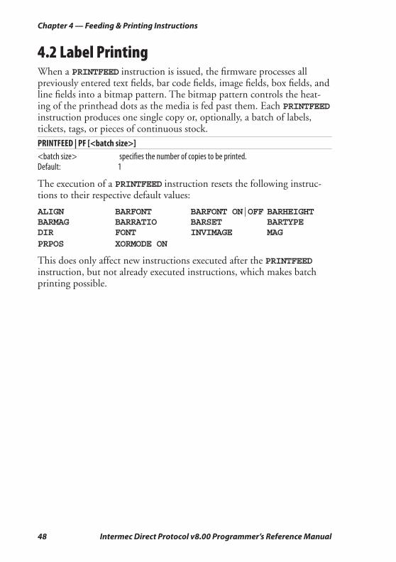
4.2 Label PrintingWhen a PRINTFEED instruction is issued, the fi rmware processes all previously entered text fi elds, bar code fi elds, image fi elds, box fi elds, and line fi elds into a bitmap pattern. The bitmap pattern controls the heat-ing of the printhead dots as the media is fed past them. Each PRINTFEED instruction produces one single copy or, optionally, a batch of labels, tickets, tags, or pieces of continuous stock.
PRINTFEED | PF [<batch size>]<batch size> specifi es the number of copies to be printed.Default: 1
The execution of a PRINTFEED instruction resets the following instruc-tions to their respective default values:
ALIGN BARFONT BARFONT ON|OFF BARHEIGHT BARMAG BARRATIO BARSET BARTYPE DIR FONT INVIMAGE MAGPRPOS XORMODE ON
This does only affect new instructions executed after the PRINTFEED instruction, but not already executed instructions, which makes batch printing possible.

Intermec Direct Protocol v8.00 Programmer’s Reference Manual 49
Chapter 4 — Feeding & Printing Instructions
4.3 Batch Printing
IntroductionThe term “Batch Printing” means the process of printing several labels without stopping the media feed motor between labels. The labels may be exact copies or differ more or less in appearance.
Before the label can be printed, the instructions must be processed into a bitmap pattern. This involves scaling of fonts and generation of bar codes. The bitmap pattern is stored in print buffers in the printer’s tem-porary memory.
The size of the print buffers is decided by the actual size of the print window according to the setup in regard of “Media Size; X-start”, “Media Size; Width”, and “Media Size; Length”.
Obviously, when the labels in a batch are very similar, it will be useful only to need to process the fi elds that differ. By editing the layout so the variable data are processed last and using the CLL and FIELD instruc-tions (see below), the time needed to process each new bitmap can be decreased, allowing a higher print speed.
By default, you can break and resume the printing of a batch of labels by pressing either the <Print> or the <Pause> keys on the printer’s built-in keyboard. Other methods for issuing a break instruction can be selected as described in Chapter 6.18.
Clearing the Image Buff erThe image buffers store the bitmap pattern of the label between pro-cessing and printing. The image buffers can be cleared partially or completely using a CLL instruction.
CLL [<fi eld>%] <fi eld> is the same alphanumeric designator as in the corresponding FIELDNO
instruction, followed by a mandatory % sign.CLL clears image buff ers completely and is useful to avoid printing a faulty label
after certain errors have occurred.CLL <fi eld>% clears image buff ers from the corresponding FIELDNO instruction to the
end of the label and is used in connection with print repetition when only part of the label should be modifi ed between the copies.

50 Intermec Direct Protocol v8.00 Programmer’s Reference Manual
Chapter 4 — Feeding & Printing Instructions
<fi eld>% = FIELDNO <fi eld> is the same alphanumeric designator as in the corresponding CLL instruction
followed by a mandatory % sign.
Example:In this example, the text “Month” is kept in the image buffer, whereas the names of the months are cleared from the image buffer, one after the other, as soon as they have been printed: FT "Swiss 721 Bold BT" ↵MAG 2,2 ↵PP 100,300 ↵PT "MONTH:" ↵PP 100,200 ↵A%=FIELDNO ↵PT "JANUARY":PF ↵CLL A% ↵PP 100,200 ↵PT "FEBRUARY":PF ↵CLL A% ↵PP 100,200 ↵PT "MARCH":PF ↵CLL A% ↵
Note: Using command abbreviations instead of full command names, for example PF instead of PRINTFEED, speeds up batch printing.
Note: If a label has been printed using a predefi ned layout and you want to return to the method of printing labels using layout and printable data in one sequence, the predefi ned layout must fi rst be cleared from the printer’s working memory using the instruction: LAYOUT RUN ""
Intermec Direct Protocol v8.00 Programmer’s Reference Manual 51
Chapter 4 — Feeding & Printing Instructions
Reprinting a Lost LabelAn out-of-paper, an out-of-ribbon condition, or a media jam may cause serious trouble when printing batches of labels, especially with consecu-tive numbering.
If the <Print> key is enabled (see PRINT KEY ON/OFF in Chapter 5.9), an identical copy of the last label in the print job can be reprinted simply by pressing the <Print> key on the printer’s front. However, if for example the printer runs out of media somewhere in the middle of a batch, a label can be lost.
The Direct Protocol detects if the bitmap pattern (print image), that represents all fi elds in the label layout and stored in the print buffer, was successfully printed or not. If not, the print image will automatically be reprinted as soon as the error has been fi xed, for example by loading a new roll of media or ribbon.
However, if the print image is shorter than the physical label and an error occurs after the print image has been printed but before the end of the physical label, the Direct Protocol still assumes that the label was success-fully printed and will not reprint it.
A work-around is to make the print image that same size (length) as the physical label by adding a fi eld close to the end of the label. The fi eld can be made “invisible” by using a single space character or by using a line, box, image, or text in combination with the INVIMAGE instruction, see Chapter 3.
Note: After an error in a batch print job, check for possible duplicate labels.
52 Intermec Direct Protocol v8.00 Programmer’s Reference Manual
Chapter 4 — Feeding & Printing Instructions
Intermec Direct Protocol v8.00 Programmer’s Reference Manual 53
5 Setting Up the Printer
This chapter describes how to use various instructions to set up the printer.
54 Intermec Direct Protocol v8.00 Programmer’s Reference Manual
Chapter 5 — Setting Up the Printer
5.1 Enabling/Disabling Direct ProtocolUnless you use Intermec Shell to select the Intermec Direct Protocol, you must issue this instruction to switch from the Intermec Fingerprint Immediate Mode to the Intermec Direct Protocol:
INPUT ON
When you start the Intermec Direct Protocol, you enable the reception of data to a layout, start up the error handler and sets the verbosity to off. The message “Direct Protocol 8.00” appears in the printer’s display.
To return from the Intermec Direct Protocol to the Immediate Mode, use this instruction:
INPUT OFF
Reception of data to layouts are disabled, the error-handler is turned off and the verbosity is reset to the level selected before last INPUT ON instruction was executed. The message “Fingerprint 8.00” appears in the display.
5.2 Selecting Standard IN/OUT ChannelBy default,the printer will scan all communication ports for incoming data and automatically switch to that port (“autohunting”). However, you can select specifi c communication channels as standard IN and OUT channels using a SETSTDIO instruction. Note that in case of paral-lel communication, the two-way communication will be lost and the printer will not be able to echo any data back to the host or returning any other data. It is possible to select different channels as standard IN and standard OUT channels.
SETSTDIO <IN channel>, <OUT channel><IN channel> and <OUT channel> can be individually specifi ed:1 = "uart1:" serial communication channel (standard)2 = "uart2:" serial communication channel (optional board)3 = "uart3:" serial communication channel (optional board)4 = "centronics:” parallel communication channel (optional board)5 = "net1:" Ethernet communication channel (optional board)6 = "usb1:" USB serial communication channel ( standard)100 = "auto" autohunting
Example:SETSTDIO 2,2 ↵
Intermec Direct Protocol v8.00 Programmer’s Reference Manual 55
Chapter 5 — Setting Up the Printer
5.3 Setting Time and DateThe printer is, or can be, provided with an internal real-time clock/calendar (RTC) which retains its setting even when the printer is switched off.
Note: If no RTC is installed, the internal clock will be used. After startup, an error will occur when trying to read the date or time before the internal clock has been manually set by means of either a DATE$ or a TIME$ variable. If only the date is set, the internal clock starts at 00:00:00 and if only the time is set, the internal clock starts at Jan 01 1980. After having set the internal clock, you can use the DATE$ and TIME$ variables the same way as when an RTC is fi tted, until a power off or REBOOT causes the date and time values to be lost.
The following instructions are used to set the clock/calendar:
DATE$ = "<YYMMDD>"<YYMMDD> is the current date in the standard format: YY = Year, last two digits, MM = Month, two digits, DD = Day, two digits Input data must be enclosed by quotation marks.
Example:DATE$ = "031201" ↵
5.4 Selecting Format for Date and TimeTIME$ = "<HHMMSS>"<HHMMSS> is the current time in the standard format: HH = Hour (00-24), MM = Minute (00-59), SS = Second (00-59) Input data must be enclosed by quotation marks.
Example:TIME$ = "131548" ↵
56 Intermec Direct Protocol v8.00 Programmer’s Reference Manual
Chapter 5 — Setting Up the Printer
The formats for printing dates and time in connection with DATE$("F"), DATEADD$("F"), TIME$("F"), and TIMEADD$("F"), see Chapter 3.9, can be specifi ed by the instructions FORMAT DATE$ and FORMAT TIME$. In both these instructions, you should enter a string of characters representing the various types of information. The order and number of the characters decides the format. You can also include separating characters like periods, slashes, colons, etc. Note that the input string must be enclosed by quotation marks.
FORMAT DATE$ "<string>"Y = Year, M = Month, D = Day (Default: YYMMDD)
Examples:FORMAT DATE$ ”YYYY.MM.DD” ↵ yields for example 2003.12.01FORMAT DATE$ ”DD/MM/YY” ↵ yields for example 01/12/03
FORMAT TIME$ "<string>"H = Hour in 24-hour cycle (one digit per H; right-justifi ed)h = Hour in 12-hour cycle (one digit per h; right-justifi ed)M = Minute (one digit per M; right-justifi ed)S = Second (one digit per S; right-justifi ed)P = AM/PM (uppercase) in 12-hour cycle (one character per P; left-justifi ed)p = am/pm (lowercase) in 12-hour cycle (one character per p; left-justifi ed)Default: HHMMSS
Examples:FORMAT TIME$ "HH:MM:SS" ↵ yields for example 14:15:37FORMAT TIME$ "HH.MM" ↵ yields for example 14.15FORMAT TIME$ "hh.MM.SS p" ↵ yields for example 02.15.37 pFORMAT TIME$ "hh.MM PP" ↵ yields for example 02.15 PM
In many cases, it is desired to have the names of months and weekdays printed in plain text rather than as a number. There are two instructions that allow you to assign names in any language to months and weekdays:
NAME DATE$<No. of month>,"<name of month>"<No. of month> is 1-12.<name of month> is the desired name enclosed with quotation marks.
Intermec Direct Protocol v8.00 Programmer’s Reference Manual 57
Chapter 5 — Setting Up the Printer
The name of the month will be printed according to the format specifi ed by FORMAT DATE$ and will be truncated at the left side.
NAME WEEKDAY$<No. of weekday>,"<name of weekday>"<No. of weekday> is 1 (Monday) - 7 (Sunday).<name of weekday> is the desired name enclosed by quotation marks.Default: Full English names in mixed upper-/lower-case characters, for example
”Monday”.
The date and time formats as well as the names of months and weekdays are not saved in the printer’s permanent memory, but must be transmit-ted to the printer after each power-up.
5.5 Changing SeparatorsWhen transmitting variable input data to a predefi ned layout, the string must contain certain separating characters. By default, you should use <STX> as start-of-text separator, <CR> as fi eld separator, and <EOT> as end-of-text separator (see Chapter 3.9.)
However, the FORMAT INPUT instructions allows you to select other characters as separators if the default separators for some reason cannot be produced, if they will interfere with the main computer system, or if they are used in input data string to, for example, bar codes. Simply insert the desired separator characters (enclosed by quotation marks) into the FORMAT INPUT instruction. Avoid using characters like XON/XOFF or ENQ/ACK, which may interfere with the communication between printer and host.
You must fi rst leave the Intermec Direct Protocol by means of an INPUT OFF instruction, change the separators using a FORMAT INPUT instruction, and then enter the Intermec Direct Protocol again by means of an INPUT OFF instruction.
FORMAT INPUT "<start separator>"[,"<end separator>"[,"<fi eld separator>"[,"<characters to be fi ltered out>"]]]
Example:INPUT OFF ↵FORMAT INPUT "#","&","@" ↵INPUT ON ↵
Note: The separators are not saved in the printer’s permanent memory, but must be transmitted to the printer after each power-up.
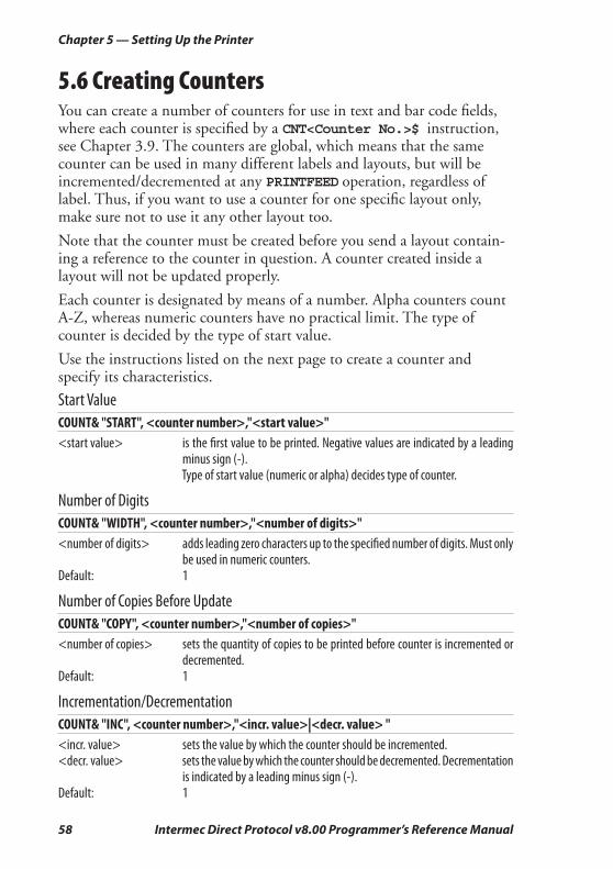
58 Intermec Direct Protocol v8.00 Programmer’s Reference Manual
Chapter 5 — Setting Up the Printer
5.6 Creating CountersYou can create a number of counters for use in text and bar code fi elds, where each counter is specifi ed by a CNT<Counter No.>$ instruction, see Chapter 3.9. The counters are global, which means that the same counter can be used in many different labels and layouts, but will be incremented/decremented at any PRINTFEED operation, regardless of label. Thus, if you want to use a counter for one specifi c layout only, make sure not to use it any other layout too.
Note that the counter must be created before you send a layout contain-ing a reference to the counter in question. A counter created inside a layout will not be updated properly.
Each counter is designated by means of a number. Alpha counters count A-Z, whereas numeric counters have no practical limit. The type of counter is decided by the type of start value.
Use the instructions listed on the next page to create a counter and specify its characteristics.
Start ValueCOUNT& "START", <counter number>,"<start value>"<start value> is the fi rst value to be printed. Negative values are indicated by a leading
minus sign (-). Type of start value (numeric or alpha) decides type of counter.
Number of DigitsCOUNT& "WIDTH", <counter number>,"<number of digits>"<number of digits> adds leading zero characters up to the specifi ed number of digits. Must only
be used in numeric counters. Default: 1
Number of Copies Before UpdateCOUNT& "COPY", <counter number>,"<number of copies>"<number of copies> sets the quantity of copies to be printed before counter is incremented or
decremented. Default: 1
Incrementation/DecrementationCOUNT& "INC", <counter number>,"<incr. value>|<decr. value> "<incr. value> sets the value by which the counter should be incremented.<decr. value> sets the value by which the counter should be decremented. Decrementation
is indicated by a leading minus sign (-). Default: 1
Intermec Direct Protocol v8.00 Programmer’s Reference Manual 59
Chapter 5 — Setting Up the Printer
Stop ValueCOUNT& "STOP", <counter number>,"<stop value>"<stop value> sets the value after which the counter should start all over again at the restart
value. Default: 2,147,483,647 (numeric) or Z (alpha)
Restart ValueCOUNT& "RESTART", <counter number>,"<restart value>"<restart value> sets at which counter value the counter should start all over
again after having exceeded the stop value.
Default 1 (numeric) or A (alpha)
Note: The counters are not saved in the printer’s permanent memory, but must be transmitted to the printer after each power-up.
5.7 Enabling/Disabling Label Taken SensorThe printers can, as an option, be fi tted with a so called label taken sensor (LTS) that detects if there is a label left in the printer’s outfeed slot and holds the printing until the label has been removed. This facility is especially useful for batch printing.
You can enable or disable this function by means of the following instruction. By default, LTS is disabled.
LTS& ON | OFF
5.8 Enabling/Disabling Automatic CuttingSome printers can, as an option, be fi tted with a paper cutter that can cut non-adhesive continuous stock or the liner between labels.
As an alternative to issuing separate CUT instructions, you can enable or disable automatic cutting in connection with each PRINTFEED opera-tion. By default, automatic cutting is disabled.
The amount of media to be fed out before automatic cutting and be pulled back afterwards can optionally be specifi ed:
CUT [<feed length>] ON | OFF<feed length> is the desired length in dots.
60 Intermec Direct Protocol v8.00 Programmer’s Reference Manual
Chapter 5 — Setting Up the Printer
5.9 Enabling/Disabling the Print KeyAll printers have a key on its front panel, usually labelled “Print”, which can be used to initiate a PRINTFEED operation.
You can enable or disable this function by means of the following instruction. By default, the <Print> key is disabled.
PRINT KEY ON | OFF
5.10 Producing Audible SignalsThe printer can emit audible signal from its built-in beeper. There are two instructions you can use for that purpose, for example to give warn-ing signals to the operator:
BEEP
Emits a short beeping sound.
SOUND <frequency in Hz>,<duration in units of 0.02 sec's>
Produces a sound of variable frequency and duration.
5.11 Formatting Printer’s MemoryBy formatting the printer’s memory, you will either erase all fi les stored in the permanent memory or all fi les except system fi les (that is fi les with names starting with a period character.) You can also format a Com-pactFlash memory card to MS-DOS format. Be careful not to use this instruction unintentionally!
FORMAT "<device>"[,<no. of entries>[,<no. of bytes>]][,A]<Device> is either "/c" or "card1:"<No. of entries> specifi es number of entries in the root directory (default 208). Only "card1:".<No. of bytes> specifi es number of bytes per sector (default 512). Only "card1:".A is a fl ag that specifi es that all fi les including system fi les should be removed.
If no such fl ag is included, system fi les will not be removed. When formatting a memory card, the "A" fl ag must be included in the instruction.
Intermec Direct Protocol v8.00 Programmer’s Reference Manual 61
Chapter 5 — Setting Up the Printer
5.12 Preprocessing Input DataAll input data to the printer come in binary form via the standard IN channel (by default "uart1:".) Characters are transmitted in ASCII format, which upon reception will be preprocessed by the printer’s fi rm-ware according to possible MAP instructions.
The MAP instruction is used to modify a character set, or to fi lter out undesired characters on a specifi ed communication channel by mapping them as NUL (ASCII 0 dec.)
If no character set (see NASC) meets your requirements completely, select the set that comes closest and modify it using MAP instructions. Mapping will be reset to normal at power-on or reboot.
MAP [<device>],<old ASCII value>, <new ASCII value><device> is optionally an IN channel other than the selected standard IN channel.<old ASCII value> is the original value of the character according to the selected character set,
see NASC.<new ASCII value> is the new ASCII value you want to assign to the character.
Example:You are using the Roman 8 character set with 7- bit communication and need to print £ characters which are not included in the 7-bit part of that character set (see Chapter 8.) Suppose you have no need for the $ char-acter. Then remap the £ character (ASCII 187 dec.) to the value of the $ character (ASCII 36 dec.):MAP 36,187 ↵

62 Intermec Direct Protocol v8.00 Programmer’s Reference Manual
Chapter 5 — Setting Up the Printer
5.13 Selecting Character SetThe NASC instruction is used to select a character set that decides how the various characters will be printed. This instruction makes it possible to adapt the printer to various national standards, see Chapter 9.
NASC <character set number><character set number> is one of the following numbers:1: Roman 8 (default) -1: PCMAP 1250: Windows Latin 233: French -2: ANSI 1251: Windows Cyrillic34: Spanish 850: MS-DOS Latin 1 1252: Windows Latin 139: Italian 851: MS-DOS Greek 1 1253: Windows Greek44: English 852: MS-DOS Latin 2 1254: Windows Latin 546: Swedish 855: MS-DOS Cyrillic 1257: Windows Baltic Rim47: Norwegian 857: MS-DOS Turkish 49: German81: Japanese Latin 351: Portuguese
Suppose you order the printer to print the character ASCII 124 dec. ASCII 124 will generate the character “|” according to the Roman 8 character set, “ù” according to the French character set and ñ according to the Spanish set, etc. The same applies to a number of special national characters, whereas digits 0-9 and characters A-Z, a-z plus most punctua-tion marks are the same in all sets.
Check the character set tables in Chapter 10 and select the set that best matches your data equipment and printout requirements.
If none of the sets matches your requirements exactly, select the one that comes closest. Then, you can make fi nal corrections by means of MAP instructions, see Chapter 6.12.
Text on labels will be printed according to the selected character set. However, instructions concerning the printable label image, that already has been processed before the NASC instruction is executed, will not be affected. This implies that labels may be multilingual.
The pattern of the bars refl ects the ASCII values of the input data and is not affected by a NASC instruction. The bar code interpretation (the human readable characters below the bar pattern) is affected by a NASC instruction. However, the interpretation of bar codes, that have been processed and are stored in the print buffer, will not be affected.

Intermec Direct Protocol v8.00 Programmer’s Reference Manual 63
Chapter 5 — Setting Up the Printer
5.14 Rebooting the PrinterAs an alternative to cucling the power to the printer using the On/Off switch, you can issue a REBOOT instruction. Any data or layout in the temporary memory, that has not been saved to the permanent memory, will be deleted and the buffers will be emptied.
REBOOT
Note: Counters, time and date formats, separators, and error messages will be lost and a number of instructions will be reset to default.
5.15 Setting the Verbosity LevelThe verbosity level controls the amount of information to be returned from print to host:
SYSVAR (18) = <value><value> = -1 All levels enabled<value> = 0 No verbosity (default)<value> = 1 Echo received characters<value> = 2 “Ok” after correct command lines<value> = 4 Echo input characters from communication port<value> = 8 Error after failed line
Bits can be combined, so for example SYSVAR(18)=3 means both “Echo received characters” and “Ok after correct command lines”.
5.16 Selecting Type of Error MessageFour types of error messages can be selected:
SYSVAR (19) = <value><value> = 1 <string> in line <line no.>, for example “Invalid font in line 10” (default)<value> = 2 Error <number> in line <line no.>: <string>, for example “Error 19 in line
10: Invalid font”<value> = 3 E<number>, for example“E19”<value> = 4 Error <number> in line <line number>, for example “Error 19 in line 10”
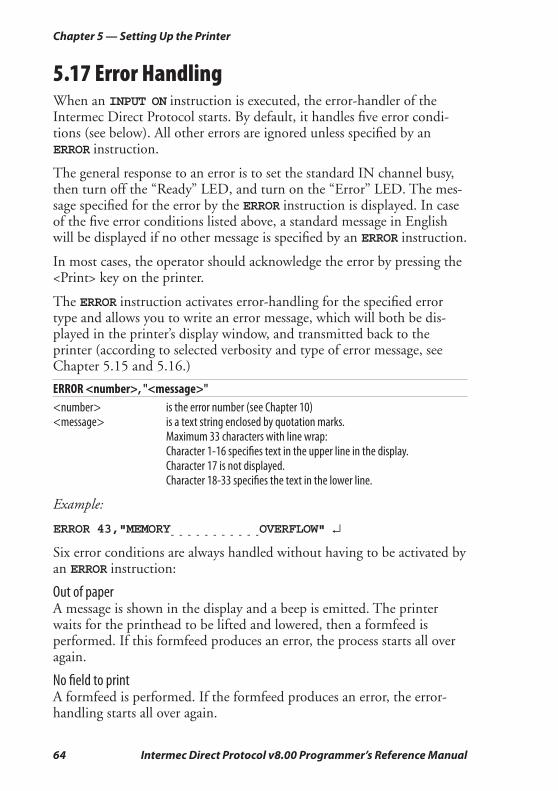
64 Intermec Direct Protocol v8.00 Programmer’s Reference Manual
Chapter 5 — Setting Up the Printer
5.17 Error HandlingWhen an INPUT ON instruction is executed, the error-handler of the Intermec Direct Protocol starts. By default, it handles fi ve error condi-tions (see below). All other errors are ignored unless specifi ed by an ERROR instruction.
The general response to an error is to set the standard IN channel busy, then turn off the “Ready” LED, and turn on the “Error” LED. The mes-sage specifi ed for the error by the ERROR instruction is displayed. In case of the fi ve error conditions listed above, a standard message in English will be displayed if no other message is specifi ed by an ERROR instruction.
In most cases, the operator should acknowledge the error by pressing the <Print> key on the printer.
The ERROR instruction activates error-handling for the specifi ed error type and allows you to write an error message, which will both be dis-played in the printer’s display window, and transmitted back to the printer (according to selected verbosity and type of error message, see Chapter 5.15 and 5.16.)
ERROR <number>, "<message>"<number> is the error number (see Chapter 10)<message> is a text string enclosed by quotation marks. Maximum 33 characters with line wrap: Character 1-16 specifi es text in the upper line in the display. Character 17 is not displayed. Character 18-33 specifi es the text in the lower line.
Example:
ERROR 43,"MEMORY- - - - - - - - - - -
OVERFLOW" ↵
Six error conditions are always handled without having to be activated by an ERROR instruction:
Out of paperA message is shown in the display and a beep is emitted. The printer waits for the printhead to be lifted and lowered, then a formfeed is performed. If this formfeed produces an error, the process starts all over again.
No fi eld to printA formfeed is performed. If the formfeed produces an error, the error-handling starts all over again.

Intermec Direct Protocol v8.00 Programmer’s Reference Manual 65
Chapter 5 — Setting Up the Printer
Head liftedA message is shown in the display and a beep is emitted. The printer waits for the printhead to be lowered, then a formfeed is performed. If the error stopped a print operation, the operation will be restarted auto-matically.
Out of transfer ribbonA message is shown in the display. The printer waits for a ribbon to be loaded. If the error stopped a print operation, the operation must be restarted.
Next label not foundA message is shown in the display. The printer perform formfeeds as long as the error remains detected. After fi ve formfeeds, the printer stops and waits for the operator to press the <Print> key.
Testfeed not doneA message is shown in the display at the fi rst attempt to print if the media type has been changed in the setup, but no TESTFEED has been performed.
Note: Error handling and error messages specifi ed by ERROR instructions are not saved in the printer’s permanent memory, but must be transmitted to the printer after each power-up.
5.18 Setting Break for Batch PrintingWhen printing large batches of labels, it is useful to be able to break the printing, if for example an error should be detected. You can break the printing either via any serial communication channel or from the print-er’s built-in keyboard (if any). By default, a break instruction is produced by simultaneously pressing the <Pause> and <Shift> keys on the printer’s keyboard.
Two instructions allow you to create other ways of issuing a break instruction. BREAK specifi es an individual break interrupt character for some serial communication channels and for the keyboard, whereas BREAK ON|OFF enables/disables break interrupt and deletes the break character for the corresponding devices.
Note: Break interrupt characters are not saved in the perma-nent memory, but must be transmitted to the printer after each power-up.
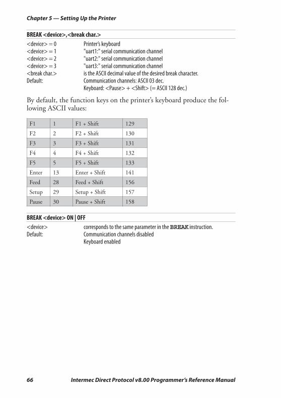
66 Intermec Direct Protocol v8.00 Programmer’s Reference Manual
Chapter 5 — Setting Up the Printer
BREAK <device>,<break char.><device> = 0 Printer’s keyboard<device> = 1 "uart1:" serial communication channel<device> = 2 "uart2:" serial communication channel<device> = 3 "uart3:" serial communication channel<break char.> is the ASCII decimal value of the desired break character.Default: Communication channels: ASCII 03 dec. Keyboard: <Pause> + <Shift> (= ASCII 128 dec.)
By default, the function keys on the printer’s keyboard produce the fol-lowing ASCII values:
F1 1 F1 + Shift 129
F2 2 F2 + Shift 130
F3 3 F3 + Shift 131
F4 4 F4 + Shift 132
F5 5 F5 + Shift 133
Enter 13 Enter + Shift 141
Feed 28 Feed + Shift 156
Setup 29 Setup + Shift 157
Pause 30 Pause + Shift 158
BREAK <device> ON | OFF<device> corresponds to the same parameter in the BREAK instruction.Default: Communication channels disabled Keyboard enabled
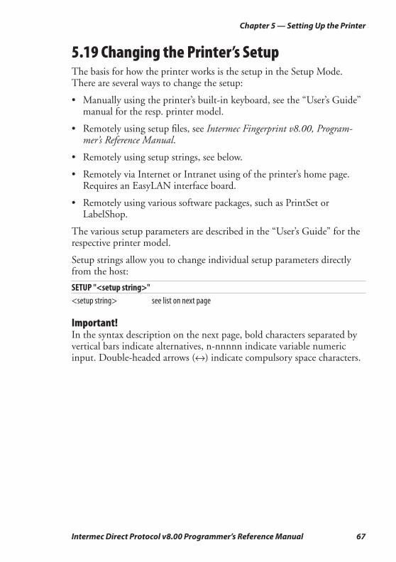
Intermec Direct Protocol v8.00 Programmer’s Reference Manual 67
Chapter 5 — Setting Up the Printer
5.19 Changing the Printer’s SetupThe basis for how the printer works is the setup in the Setup Mode. There are several ways to change the setup:
• Manually using the printer’s built-in keyboard, see the “User’s Guide” manual for the resp. printer model.
• Remotely using setup fi les, see Intermec Fingerprint v8.00, Program-mer’s Reference Manual.
• Remotely using setup strings, see below.
• Remotely via Internet or Intranet using of the printer’s home page. Requires an EasyLAN interface board.
• Remotely using various software packages, such as PrintSet or LabelShop.
The various setup parameters are described in the “User’s Guide” for the respective printer model.
Setup strings allow you to change individual setup parameters directly from the host:
SETUP "<setup string>"<setup string> see list on next page
Important!In the syntax description on the next page, bold characters separated by vertical bars indicate alternatives, n-nnnnn indicate variable numeric input. Double-headed arrows (↔) indicate compulsory space characters.

68 Intermec Direct Protocol v8.00 Programmer’s Reference Manual
Chapter 5 — Setting Up the Printer
"SER-COM,UART1|UART2|UART3,BAUDRATE,300|600|1200|2400|4800|9600|19200|38400|57600|115200""SER-COM,UART1|UART2|UART3,CHAR↔LENGTH,7|8""SER-COM,UART1|UART2|UART3,PARITY,NONE|EVEN|ODD|MARK|SPACE""SER-COM,UART1|UART2|UART3,STOPBITS,1|2""SER-COM,UART1|UART2|UART3,FLOWCONTROL,RTS/CTS,ENABLE|DISABLE" "SER-COM,UART1|UART2|UART3,FLOWCONTROL,ENQ/ACK,ENABLE|DISABLE""SER-COM,UART1|UART2|UART3,FLOWCONTROL,XON/XOFF,DATA↔FROM↔HOST,ENABLE|DISABLE" "SER-COM,UART1|UART2|UART3,FLOWCONTROL,XON/XOFF,DATA↔TO↔HOST,ENABLE|DISABLE" "SER-COM,UART2,PROT↔ADDR,ENABLE|DISABLE" "SER-COM,UART1|UART2|UART3,NEW↔LINE,CR/LF|LF|CR""SER-COM,UART1|UART2|UART3,REC↔BUF,nnnnn""SER-COM,UART1|UART2|UART3,TRANS↔BUF,nnnnn""SER-COM,UART2,PROT↔ADDR,nn""NET-COM,NET1,NEW↔LINE,CR/LF|LF|CR""NETWORK,IP↔SELECTION,DHCP+BOOTP|MANUAL|DHCP|BOOTP""NETWORK,IP↔ADDRESS,nnn.nnn.nnn.nnn" "NETWORK,NETMASK,nnn.nnn.n.n" "NETWORK,DEFAULT↔ROUTER,nnn.nnn.nnn.nnn" "NETWORK,NAME↔SERVER,nnn.nnn.nnn.nnn""FEEDADJ,STARTADJ,nnnn" (negative value allowed)"FEEDADJ,STOPADJ,nnnn" (negative value allowed)"MEDIA,MEDIA↔SIZE,XSTART,nnnn""MEDIA,MEDIA↔SIZE,WIDTH,nnnn""MEDIA,MEDIA↔SIZE,LENGTH,nnnnn""MEDIA,MEDIA↔TYPE,LABEL↔(w↔GAPS)|TICKET↔(w↔MARK)|TICKET↔(w↔GAPS)|FIX↔LENGTH↔STRIP|VAR↔LENGTH↔STRIP""MEDIA,PAPER↔TYPE,TRANSFER|DIRECT↔THERMAL""MEDIA,PAPER↔TYPE,DIRECT↔THERMAL,LABEL↔CONSTANT,nnn""MEDIA,PAPER↔TYPE,DIRECT↔THERMAL,LABEL↔FACTOR,nnn""MEDIA,PAPER↔TYPE,TRANSFER,RIBBON↔CONSTANT,nnn""MEDIA,PAPER↔TYPE,TRANSFER,RIBBON↔FACTOR,nnn""MEDIA,PAPER↔TYPE,TRANSFER,LABEL↔OFFSET,nnn""MEDIA,PAPER↔TYPE,TRANSFER,LOW↔DIAMETER,nnn" "MEDIA,CONTRAST,-10%|-8%|-6%|-4%|-2%|+0%|+2%|+4%|+6%|+8%|+10%" "MEDIA,PAPER, LOW ↔DIAMETER,nnn""PRINT↔DEFS,PRINT↔SPEED,nnn""PRINT↔DEFS,LT↔VALUE,nn"
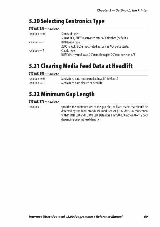
Intermec Direct Protocol v8.00 Programmer’s Reference Manual 69
Chapter 5 — Setting Up the Printer
5.20 Selecting Centronics TypeSYSVAR(25) = <value><value> = 0 Standard type: 500 ns ACK, BUSY inactivated after ACK fi nishes (default.)<value> = 1 IBM/Epson type: 2500 ns ACK, BUSY inactivated as soon as ACK pulse starts.<value>= 2 Classic type: BUSY deactivated, wait 2500 ns, then give 2500 ns pulse on ACK.
5.21 Clearing Media Feed Data at HeadliftSYSVAR(28) = <value><value> = 0 Media feed data not cleared at headlift (default.)<value> = 1 Media feed data cleared at headlift.
5.22 Minimum Gap LengthSYSVAR(37) = <value><value> specifi es the minimum size of the gap, slot, or black marks that should be
detected by the label stop/black mark sensor (1-32 dots) in connection with PRINTFEED and FORMFEED. Default is 1 mm/0.039 inches (8 or 12 dots depending on printhead density.)
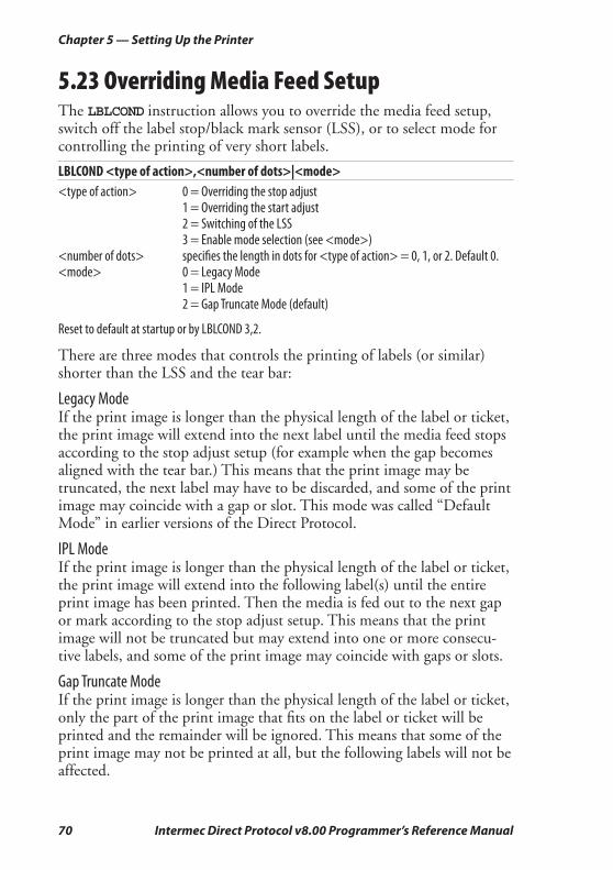
70 Intermec Direct Protocol v8.00 Programmer’s Reference Manual
Chapter 5 — Setting Up the Printer
5.23 Overriding Media Feed SetupThe LBLCOND instruction allows you to override the media feed setup, switch off the label stop/black mark sensor (LSS), or to select mode for controlling the printing of very short labels.
LBLCOND <type of action>,<number of dots>|<mode><type of action> 0 = Overriding the stop adjust 1 = Overriding the start adjust 2 = Switching of the LSS 3 = Enable mode selection (see <mode>)<number of dots> specifi es the length in dots for <type of action> = 0, 1, or 2. Default 0.<mode> 0 = Legacy Mode 1 = IPL Mode 2 = Gap Truncate Mode (default)
Reset to default at startup or by LBLCOND 3,2.
There are three modes that controls the printing of labels (or similar) shorter than the LSS and the tear bar:
Legacy ModeIf the print image is longer than the physical length of the label or ticket, the print image will extend into the next label until the media feed stops according to the stop adjust setup (for example when the gap becomes aligned with the tear bar.) This means that the print image may be truncated, the next label may have to be discarded, and some of the print image may coincide with a gap or slot. This mode was called “Default Mode” in earlier versions of the Direct Protocol.
IPL ModeIf the print image is longer than the physical length of the label or ticket, the print image will extend into the following label(s) until the entire print image has been printed. Then the media is fed out to the next gap or mark according to the stop adjust setup. This means that the print image will not be truncated but may extend into one or more consecu-tive labels, and some of the print image may coincide with gaps or slots.
Gap Truncate ModeIf the print image is longer than the physical length of the label or ticket, only the part of the print image that fi ts on the label or ticket will be printed and the remainder will be ignored. This means that some of the print image may not be printed at all, but the following labels will not be affected.
Intermec Direct Protocol v8.00 Programmer’s Reference Manual 71
6 Reading the Printer’sStatus
This chapter describes the various methods and instruction that enables the programmer to read how the printer is set up.

72 Intermec Direct Protocol v8.00 Programmer’s Reference Manual
Chapter 6 — Reading the Printer’s Status
6.1 IntroductionProvided there is a working two-way serial communication between the printer and the host computer, the printer’s status in regard of various functions can be read back to the host. Thus, the serial channel con-nected to the host must be selected standard IN/OUT channel (default, see SETSTDIO instruction in Chapter 5.2.)
6.2 Returing Information to the HostThe PRINT instruction reads the printer’s status as specifi ed by a comple-mentary instruction and returns the result on the standard OUT channel to the host, where it usually will be printed on the screen. The shorthand version of PRINT is a question mark (?.)
PRINT | ?
6.3 Reading Date and TimeThe current date and time according to the printer’s clock/calendar can be read as follows:
? DATE$ or ? DATE$("F") ? TIME$ or ? TIME$("F")
6.4 Testing the PrintheadThe thermal printhead can be tested in three ways:
? FUNCTEST$ ("HEAD")The printhead is tested for number of dots and possible faults. There are 3 possible responses:“HEAD OK, SIZE:nnn DOTS” (nnn is the number of dots)“HEAD LIFTED” (lower the printhead and try again) “FAULTY PRINTHEAD” (an error is detected)
? HEAD(<check type>)<check type> ≥ 0: returns resistance of the specifi ed dot in ohms<check type> = -1: checks printhead. Returns -1 of OK, else 0<check type>= -7: returns mean resistance of printhead in ohms
Refer to Intermec Fingerprint v8.00, Programmer’s Reference Manual.
? SYSVAR(<parameter>)<parameter> = 21 returns printhead density in dots per mm<parameter> = 22 returns the number of dots in the printhead

Intermec Direct Protocol v8.00 Programmer’s Reference Manual 73
Chapter 6 — Reading the Printer’s Status
6.5 Reading System CountersThere are a number of counters in the printer’s system, that can be read and returned to the host:
? SYSVAR (<parameter>)<parameter> = 14 returns number of errors detected since last startup<parameter> = 15 returns number of errors detected since the last executed SYSVAR(15)<parameter> = 24 returns power-up status since the last executed SYSVAR(24): 0=No; 1=Yes<parameter> = 32 returns the length of media feed. Resolution 10 meters.
Note: SYSVAR(24) is important for the operation of the Intermec Direct Protocol, since essential functions, like coun-ters, date and time formats, separators and error messages will be lost at power up and other functions will be reset to their default values. Save all such data in the host and retransmit them to the printer as soon as a power-up has been detected by a polling program taking advantage of SYSVAR(24).
6.6 Reading Sensors and StrapsThere are a number of sensors, hardware strap, and setup parameters in the printer that can be read and their status or value be returned to the host:
? SYSVAR (<parameter>)<parameter> = 18 returns selected verbosity level (see 5.15)<parameter> = 19 returns selected type of error message (see 5.16)<parameter> = 20 returns printer’s paper type setup: 0= Direct thermal or 1= Thermal transfer <parameter> = 23 returns status of the ribbon end sensors: 0=No ribbon or 1=Ribbon<parameter> = 26 returns status of the ribbon low sensor: 0=Ribbon OK or 1=Ribbon low<parameter> = 46 returns status of the paper low sensor: 0=Media OK or 1=Media low
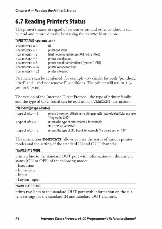
74 Intermec Direct Protocol v8.00 Programmer’s Reference Manual
Chapter 6 — Reading the Printer’s Status
6.7 Reading Printer’s StatusThe printer’s status in regard of various errors and other conditions can be read and returned to the host using the PRSTAT instruction:
? (PRSTAT AND <parameter>)<parameter> = 0 Ok<parameter> = 1 printhead lifted<parameter> = 2 label not removed (returns 0 if no LTS fi tted)<parameter> = 4 printer out of paper<parameter> = 8 printer out of transfer ribbon (returns 0 if DT)<parameter> = 16 printer voltage too high<parameter> = 32 printer is feeding
Parameters can be combined, for example <3> checks for both “printhead lifted” and “label not removed” conditions. The printer will return 1 (= yes) or 0 (= no).
The version of the Intermec Direct Protocol, the type of printer family, and the type of CPU board can be read using a VERSION$ instruction:
? VERSION$[(type of info)]<type of info> = 0 returns the version of the Intermec Fingerprint fi rmware (default), for example
“Fingerprint 8.00”<type of info> = 1 returns the type of printer family, for example “PF2i”, “PF4i”, or “PM4i”<type of info> = 2 returns the type of CPU board, for example “hardware version 4.0”
The instruction IMMEDIATE allows you see the status of various printer modes and the setting of the standard IN and OUT channels:
? IMMEDIATE MODE
prints a line to the standard OUT port with information on the current status (ON or OFF) of the following modes:- Execution- Immediate- Input- Layout Input
? IMMEDIATE STDIO
prints two lines to the standard OUT port with information on the cur-rent settings for the standard IN and standard OUT channels.

Intermec Direct Protocol v8.00 Programmer’s Reference Manual 75
7 File Handling
This chapter explains how to read the contents in the various parts of the printer’s memory and how to remove, copy, and download fi les.
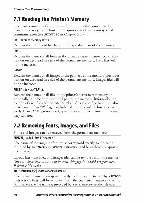
76 Intermec Direct Protocol v8.00 Programmer’s Reference Manual
Chapter 7 — File Handling
7.1 Reading the Printer’s MemoryThere are a number of instructions for returning the content in the printer’s memory to the host. This requires a working two-way serial communication (see SETSTDIO in Chapter 5.2.)
FRE ("name of memory part")
Returns the number of free bytes in the specifi ed part of the memory.
FONTS
Returns the names of all fonts in the printer’s entire memory plus infor-mation on used and free size of the permanent memory. Font fi les will not be included.
IMAGES
Returns the names of all images in the printer’s entire memory plus infor-mation on used and free size of the permanent memory. Images fi les will not be included.
FILES ["<device>"][,R][,A]
Returns the names of all fi les in the printer’s permanent memory or optionally in some other specifi ed part of the memory. Information on the size of each fi le and the total number of used and free bytes will also be returned. If an “R” fl ag is included, directories will be listed recur-sively. If an “A” fl ag is included, system fi les will also be listed, otherwise they will not.
7.2 Removing Fonts, Images, and FilesFonts and images can be removed from the permanent memory:
REMOVE↔IMAGE | FONT "<name>"
The name of the image or font must correspond exactly to the name returned by an IMAGES or FONTS instruction and be enclosed by quota-tion marks.
Layout fi les, font fi les, and images fi les can be removed from the memory (for complete description, see Intermec Fingerprint v8.00 Programmer’s Reference Manual):KILL "<fi lename>"|"<device><fi lename>"
The fi le name must correspond exactly to the name returned by a FILES instruction. Files will be removed from the permanent memory ("/c" or "c:") unless the fi le name is preceded by a reference to another device.
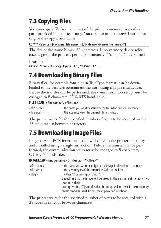
Intermec Direct Protocol v8.00 Programmer’s Reference Manual 77
Chapter 7 — File Handling
7.3 Copying FilesYou can copy a fi le from any part of the printer’s memory to another part, provided it is not read-only. You can also use the COPY instruction to give the copy a new name.
COPY "[<device>]<original fi le name>"[,"[<device>]<new fi le name>"]
The size of the name is max. 30 characters. If no memory device refer-ence is given, the printer’s permanent memory ("/c" or "c:") is assumed.
Example:COPY "card1:Logotype.1","LOGO.1" ↵
7.4 Downloading Binary FilesBinary fi les, for example font fi les in TrueType format, can be down-loaded to the printer’s permament memory using a single instruction. Before the transfer can be performed, the communication setup must be changed to 8 characters, CTS/RTS handshake.
FILE& LOAD"<fi le name>",<fi le size><fi le name> is the name you want to assign to the fi le in the printer’s memory.<fi le size> is the size in bytes of the original fi le in the host.
The printer waits for the specifi ed number of bytes to be received with a 25 sec. timeout between characters.
7.5 Downloading Image FilesImage fi les in .PCX format can be downloaded to the printer’s memory and installed using a single instruction. Before the transfer can be per-formed, the communication setup must be changed to 8 characters, CTS/RTS handshake.
IMAGE LOAD"<image name>",<fi le size>[,"<fl ag>"]<fi le name> is the name you want to assign to the image in the printer’s memory.<fi le size> is the size in bytes of the original .PCX fi le in the host.<fl ag> is either ”S” or an empty string "": S specifi es that the image will be saved in the permament memory (not
recommended); an empty string ("") specifi es that the image will be saved in the temporary
memory and thus will be deleted at power off or reboot.
The printer waits for the specifi ed number of bytes to be received with a 25 seconds timeout between characters.
78 Intermec Direct Protocol v8.00 Programmer’s Reference Manual
Chapter 7 — File Handling
Intermec Direct Protocol v8.00 Programmer’s Reference Manual 79
8 Advanced Features
This chapter gives short descriptions on how to use complex two-dimensional bar code symbologies and international character sets including double-byte fonts.
Please refer to the Intermec Fingerprint v8.00, Programmer’s Reference Manual for comprehensive descriptions and examples.
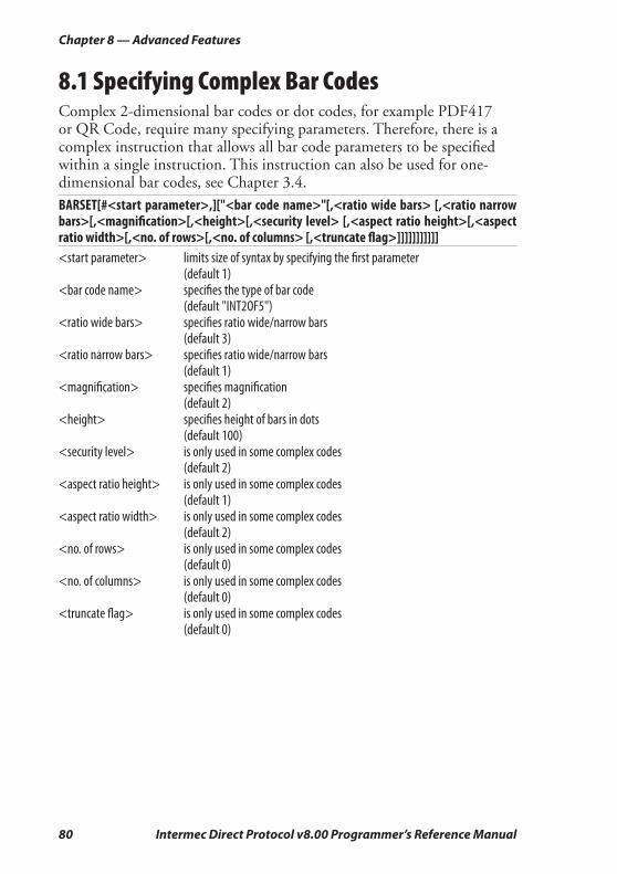
80 Intermec Direct Protocol v8.00 Programmer’s Reference Manual
Chapter 8 — Advanced Features
8.1 Specifying Complex Bar CodesComplex 2-dimensional bar codes or dot codes, for example PDF417 or QR Code, require many specifying parameters. Therefore, there is a complex instruction that allows all bar code parameters to be specifi ed within a single instruction. This instruction can also be used for one-dimensional bar codes, see Chapter 3.4.
BARSET[#<start parameter>,]["<bar code name>"[,<ratio wide bars> [,<ratio narrow bars>[,<magnifi cation>[,<height>[,<security level> [,<aspect ratio height>[,<aspect ratio width>[,<no. of rows>[,<no. of columns> [,<truncate fl ag>]]]]]]]]]]] <start parameter> limits size of syntax by specifying the fi rst parameter (default 1)<bar code name> specifi es the type of bar code (default "INT2OF5")<ratio wide bars> specifi es ratio wide/narrow bars (default 3)<ratio narrow bars> specifi es ratio wide/narrow bars (default 1)<magnifi cation> specifi es magnifi cation (default 2)<height> specifi es height of bars in dots (default 100)<security level> is only used in some complex codes (default 2)<aspect ratio height> is only used in some complex codes (default 1)<aspect ratio width> is only used in some complex codes (default 2)<no. of rows> is only used in some complex codes (default 0)<no. of columns> is only used in some complex codes (default 0)<truncate fl ag> is only used in some complex codes (default 0)
Intermec Direct Protocol v8.00 Programmer’s Reference Manual 81
Chapter 8 — Advanced Features
8.2 Using International Character SetsThe data input to text fi elds and bar codes takes the form of an ASCII string. Even compound data, such as...
PRTXT "Label No.";CNT1$;" Date ";DATE$("F")
...is expanded by the printer into a single ASCII string before any other processing occurs. This ASCII string is then converted to a string of international character codes according to the Unicode standard. Every character, whether it be a Latin “A”, Greek “alpha” or Chinese “ren”, has a unique code in this standard, called its “unicode.”.
Unicode fontsThe Intermec Direct Protocol v8.00 works with Unicode fonts in either TrueDoc or TrueType format: its font scaler accesses images of characters within these fonts according to the character’s unicode.
Some care is required when using fonts not built into the printer:
• If a font is not a Unicode font, the font scaler could access the wrong characters depending on the internal mapping table of the font.
• A font may not include all the characters in the current character set, as specifi ed by the NASC command. If a text fi eld contains a character which is not in the current font, Error 1030, “Character is missing in chosen font” will occur.
NASC and NASCD tablesThere are many national and international standards for mapping ASCII strings to strings of unicode. The Intermec Direct Protocol v8.00 pro-vides support for virtually all of these. There are two types of mappings:
• Single-byte mappings, which map one ASCII character to a unicode using Character Sets. For each NASC setting (see Chapter 5.13), there is an internally stored character set in the printer’s fi rmware.
• Double-byte mappings, which map pairs of ASCII characters to unicodes. The Intermec Direct Protocol v7.50 supports these using NASCD commands, which activate double-byte character sets. Double-byte mappings are, for example, used for large Asian character sets like BIG5, GB, JIS and Shift-JIS. Double-byte character sets are available from Intermec on special request.
82 Intermec Direct Protocol v8.00 Programmer’s Reference Manual
Chapter 8 — Advanced Features
To be exact, the double-byte mappings allow an ASCII string to contain a mixture of single-byte and double-bytes codes. The selected double-byte character set decides from which ASCII value double-byte mapping will apply. For example, in the BIG5 mapping, any ASCII character with value 160 or greater is the fi rst byte of a double-byte code, while the remaining characters form single-byte codes.
So, in BIG5, the ASCII string "<160><64><65>" splits into the double-byte code "<160><64>" and the single-byte code "<65>".
The current NASCD setting specifi es both how to divide an ASCII string into single-byte and double-byte codes and also how the double-byte codes are mapped to unicodes. whereas the current NASC setting speci-fi es how the single-byte codes are mapped to unicodes. The relevant commands are:
NASC <character set no.>
NASCD "[card1:]<fi le name>"<character set no.> is one of the values listed in chapter 6.11<"fi le name"> is the device and name of a double byte character set (normally stored in a
memory card)Default: NASC 1 (Roman 8 character set) NASCD "" (empty string; disables double-byte interpretation of ASCII
strings)
Double-byte fontsAs discussed above, the ASCII data input to text fi elds and human readable parts of bar codes can contain a mixture of single-byte and double-byte codes, which are mapped to unicodes by the NASC and NASCD settings respectively. The characters for the single-byte codes are printed using the current single-byte font, as specifi ed by the FONT com-mand (see Chapter 3.3.) The characters for the double-byte codes are printed using the current double-byte font, as specifi ed by the following command:
FONTD "<font fi le name>" [,<font size>,[<font slant>]]<font fi le name> the name of a TrueDoc or TrueType font fi le enclosed by quotation marks<font size> the height of the characters in points (a point is a standard typographic unit,
equal to 1/72 inches)<font slant> the italic angle of the characters in degrees; a positive value slants the
characters clockwise away from the vertical. Default: 0 Reset to default by: PRINTFEED|PF
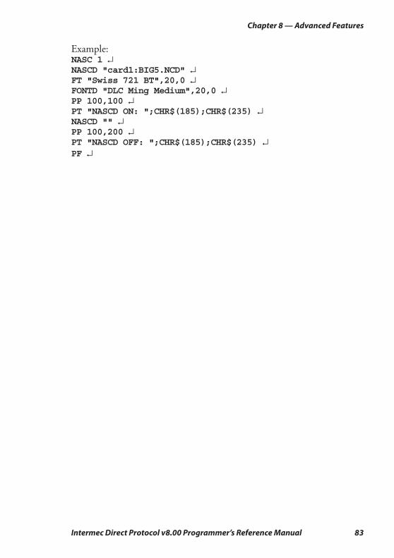
Intermec Direct Protocol v8.00 Programmer’s Reference Manual 83
Chapter 8 — Advanced Features
Example: NASC 1 ↵NASCD "card1:BIG5.NCD" ↵ FT "Swiss 721 BT",20,0 ↵ FONTD "DLC Ming Medium",20,0 ↵ PP 100,100 ↵ PT "NASCD ON: ";CHR$(185);CHR$(235) ↵NASCD "" ↵ PP 100,200 ↵ PT "NASCD OFF: ";CHR$(185);CHR$(235) ↵PF ↵

84 Intermec Direct Protocol v8.00 Programmer’s Reference Manual
Chapter 8 — Advanced Features
Intermec Direct Protocol v8.00 Programmer’s Reference Manual 85
9 Character Sets and Fonts
This chapter lists the various single-byte character sets used in Intermec Direct Protocol v8.00 and provides printout samples of the resident fonts.
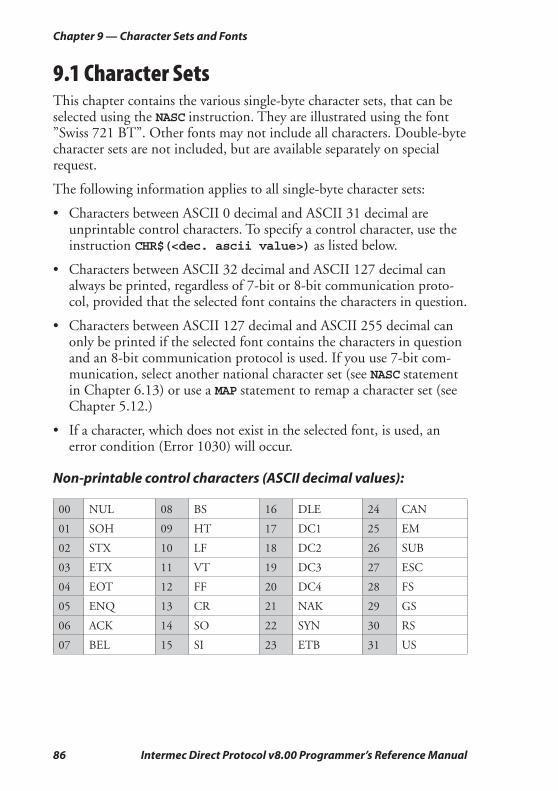
86 Intermec Direct Protocol v8.00 Programmer’s Reference Manual
Chapter 9 — Character Sets and Fonts
9.1 Character SetsThis chapter contains the various single-byte character sets, that can be selected using the NASC instruction. They are illustrated using the font ”Swiss 721 BT”. Other fonts may not include all characters. Double-byte character sets are not included, but are available separately on special request.
The following information applies to all single-byte character sets:
• Characters between ASCII 0 decimal and ASCII 31 decimal are unprintable control characters. To specify a control character, use the instruction CHR$(<dec. ascii value>) as listed below.
• Characters between ASCII 32 decimal and ASCII 127 decimal can always be printed, regardless of 7-bit or 8-bit communication proto-col, provided that the selected font contains the characters in question.
• Characters between ASCII 127 decimal and ASCII 255 decimal can only be printed if the selected font contains the characters in question and an 8-bit communication protocol is used. If you use 7-bit com-munication, select another national character set (see NASC statement in Chapter 6.13) or use a MAP statement to remap a character set (see Chapter 5.12.)
• If a character, which does not exist in the selected font, is used, an error condition (Error 1030) will occur.
Non-printable control characters (ASCII decimal values):
00 NUL 08 BS 16 DLE 24 CAN
01 SOH 09 HT 17 DC1 25 EM
02 STX 10 LF 18 DC2 26 SUB
03 ETX 11 VT 19 DC3 27 ESC
04 EOT 12 FF 20 DC4 28 FS
05 ENQ 13 CR 21 NAK 29 GS
06 ACK 14 SO 22 SYN 30 RS
07 BEL 15 SI 23 ETB 31 US

Intermec Direct Protocol v8.00 Programmer’s Reference Manual 87
Chapter 9 — Character Sets and Fonts
Roman 8 (NASC 1)
0
30
40
50
60
70
80
90
100
110
120
130
140
150
160
170
180
190
200
210
220
230
240
250
1 2 3 4 5 6 7 8 9

88 Intermec Direct Protocol v8.00 Programmer’s Reference Manual
Chapter 9 — Character Sets and Fonts
French (NASC 33)
0
30
40
50
60
70
80
90
100
110
120
130
140
150
160
170
180
190
200
210
220
230
240
250
1 2 3 4 5 6 7 8 9
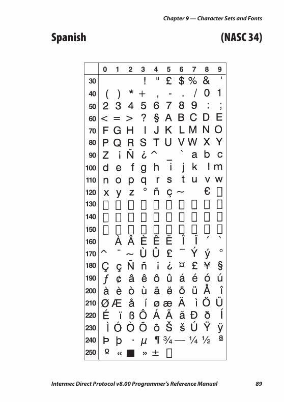
Intermec Direct Protocol v8.00 Programmer’s Reference Manual 89
Chapter 9 — Character Sets and Fonts
Spanish (NASC 34)
0
30
40
50
60
70
80
90
100
110
120
130
140
150
160
170
180
190
200
210
220
230
240
250
1 2 3 4 5 6 7 8 9

90 Intermec Direct Protocol v8.00 Programmer’s Reference Manual
Chapter 9 — Character Sets and Fonts
Italian (NASC 39)
0
30
40
50
60
70
80
90
100
110
120
130
140
150
160
170
180
190
200
210
220
230
240
250
1 2 3 4 5 6 7 8 9
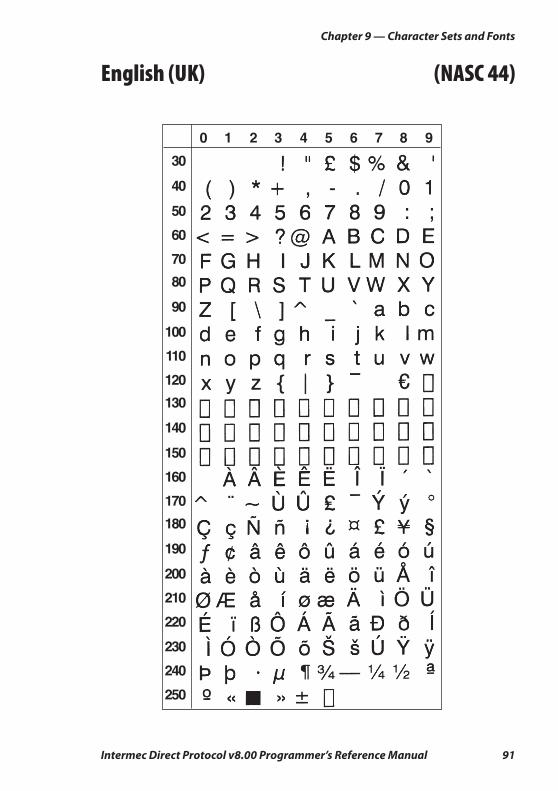
Intermec Direct Protocol v8.00 Programmer’s Reference Manual 91
Chapter 9 — Character Sets and Fonts
English (UK) (NASC 44)
0
30
40
50
60
70
80
90
100
110
120
130
140
150
160
170
180
190
200
210
220
230
240
250
1 2 3 4 5 6 7 8 9
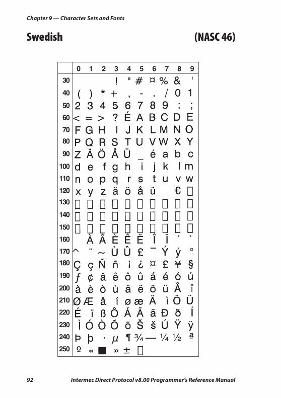
92 Intermec Direct Protocol v8.00 Programmer’s Reference Manual
Chapter 9 — Character Sets and Fonts
Swedish (NASC 46)
0
30
40
50
60
70
80
90
100
110
120
130
140
150
160
170
180
190
200
210
220
230
240
250
1 2 3 4 5 6 7 8 9
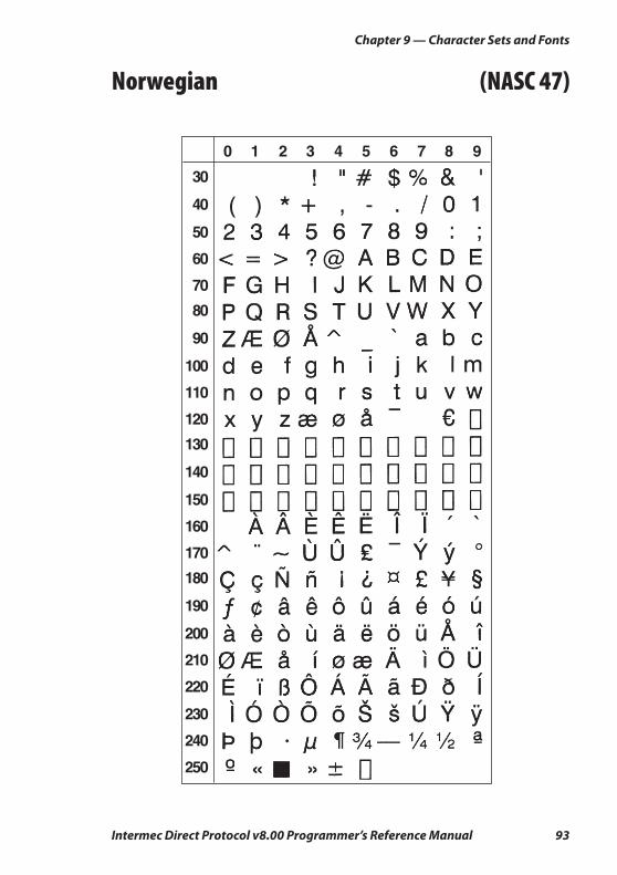
Intermec Direct Protocol v8.00 Programmer’s Reference Manual 93
Chapter 9 — Character Sets and Fonts
Norwegian (NASC 47)
0
30
40
50
60
70
80
90
100
110
120
130
140
150
160
170
180
190
200
210
220
230
240
250
1 2 3 4 5 6 7 8 9
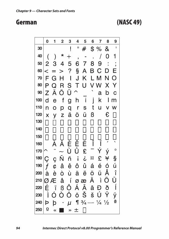
94 Intermec Direct Protocol v8.00 Programmer’s Reference Manual
Chapter 9 — Character Sets and Fonts
German (NASC 49)
0
30
40
50
60
70
80
90
100
110
120
130
140
150
160
170
180
190
200
210
220
230
240
250
1 2 3 4 5 6 7 8 9
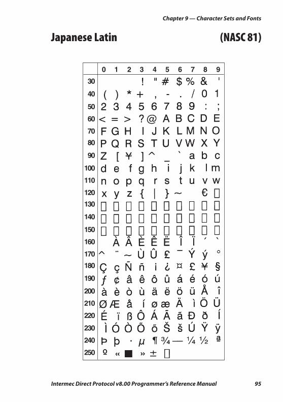
Intermec Direct Protocol v8.00 Programmer’s Reference Manual 95
Chapter 9 — Character Sets and Fonts
Japanese Latin (NASC 81)
0
30
40
50
60
70
80
90
100
110
120
130
140
150
160
170
180
190
200
210
220
230
240
250
1 2 3 4 5 6 7 8 9
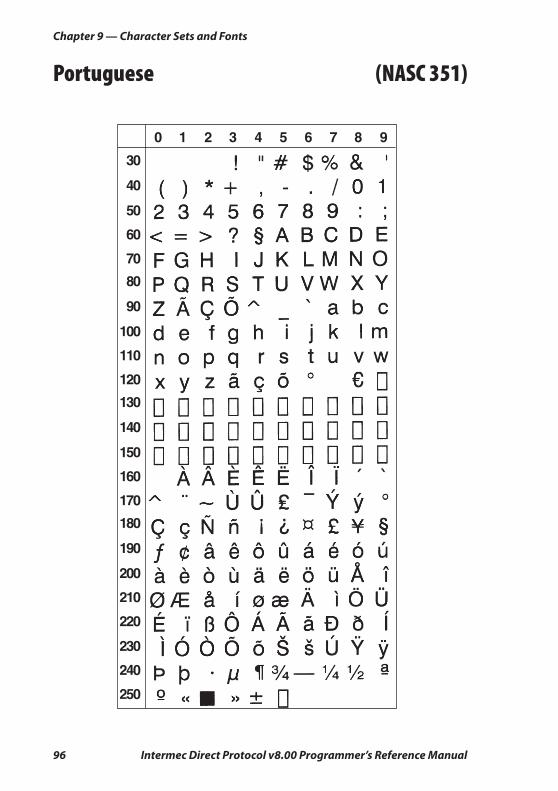
96 Intermec Direct Protocol v8.00 Programmer’s Reference Manual
Chapter 9 — Character Sets and Fonts
Portuguese (NASC 351)
0
30
40
50
60
70
80
90
100
110
120
130
140
150
160
170
180
190
200
210
220
230
240
250
1 2 3 4 5 6 7 8 9
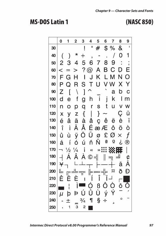
Intermec Direct Protocol v8.00 Programmer’s Reference Manual 97
Chapter 9 — Character Sets and Fonts
MS-DOS Latin 1 (NASC 850)
0
30
40
50
60
70
80
90
100
110
120
130
140
150
160
170
180
190
200
210
220
230
240
250
1 2 3 4 5 6 7 8 9
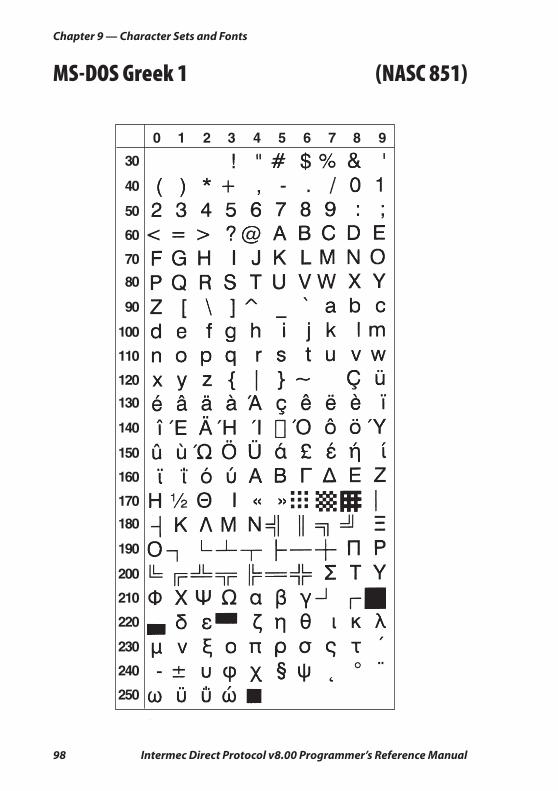
98 Intermec Direct Protocol v8.00 Programmer’s Reference Manual
Chapter 9 — Character Sets and Fonts
MS-DOS Greek 1 (NASC 851)
0
30
40
50
60
70
80
90
100
110
120
130
140
150
160
170
180
190
200
210
220
230
240
250
1 2 3 4 5 6 7 8 9
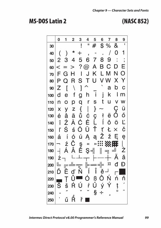
Intermec Direct Protocol v8.00 Programmer’s Reference Manual 99
Chapter 9 — Character Sets and Fonts
MS-DOS Latin 2 (NASC 852)
0
30
40
50
60
70
80
90
100
110
120
130
140
150
160
170
180
190
200
210
220
230
240
250
1 2 3 4 5 6 7 8 9
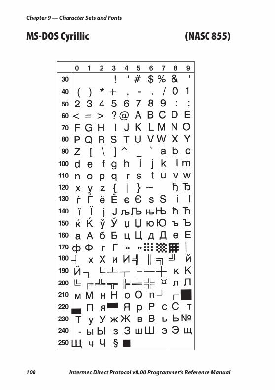
100 Intermec Direct Protocol v8.00 Programmer’s Reference Manual
Chapter 9 — Character Sets and Fonts
MS-DOS Cyrillic (NASC 855)
0
30
40
50
60
70
80
90
100
110
120
130
140
150
160
170
180
190
200
210
220
230
240
250
1 2 3 4 5 6 7 8 9
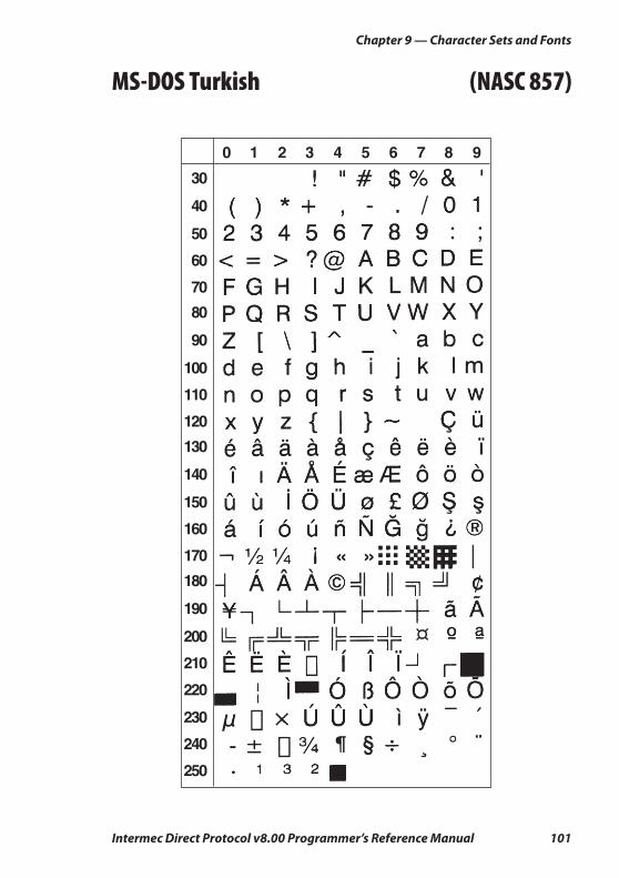
Intermec Direct Protocol v8.00 Programmer’s Reference Manual 101
Chapter 9 — Character Sets and Fonts
MS-DOS Turkish (NASC 857)
0
30
40
50
60
70
80
90
100
110
120
130
140
150
160
170
180
190
200
210
220
230
240
250
1 2 3 4 5 6 7 8 9
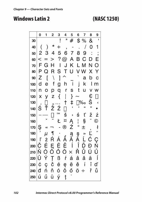
102 Intermec Direct Protocol v8.00 Programmer’s Reference Manual
Chapter 9 — Character Sets and Fonts
Windows Latin 2 (NASC 1250)
0
30
40
50
60
70
80
90
100
110
120
130
140
150
160
170
180
190
200
210
220
230
240
250
1 2 3 4 5 6 7 8 9

Intermec Direct Protocol v8.00 Programmer’s Reference Manual 103
Chapter 9 — Character Sets and Fonts
Windows Cyrillic (NASC 1251)
0
30
40
50
60
70
80
90
100
110
120
130
140
150
160
170
180
190
200
210
220
230
240
250
1 2 3 4 5 6 7 8 9

104 Intermec Direct Protocol v8.00 Programmer’s Reference Manual
Chapter 9 — Character Sets and Fonts
Windows Latin 1 (NASC 1252)
0
30
40
50
60
70
80
90
100
110
120
130
140
150
160
170
180
190
200
210
220
230
240
250
1 2 3 4 5 6 7 8 9
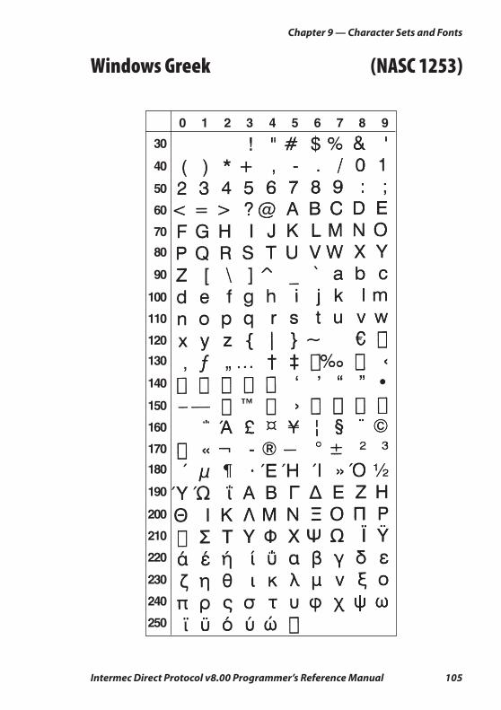
Intermec Direct Protocol v8.00 Programmer’s Reference Manual 105
Chapter 9 — Character Sets and Fonts
Windows Greek (NASC 1253)
0
30
40
50
60
70
80
90
100
110
120
130
140
150
160
170
180
190
200
210
220
230
240
250
1 2 3 4 5 6 7 8 9
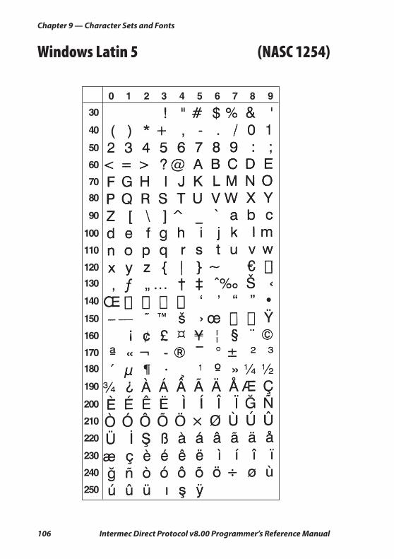
106 Intermec Direct Protocol v8.00 Programmer’s Reference Manual
Chapter 9 — Character Sets and Fonts
Windows Latin 5 (NASC 1254)
0
30
40
50
60
70
80
90
100
110
120
130
140
150
160
170
180
190
200
210
220
230
240
250
1 2 3 4 5 6 7 8 9
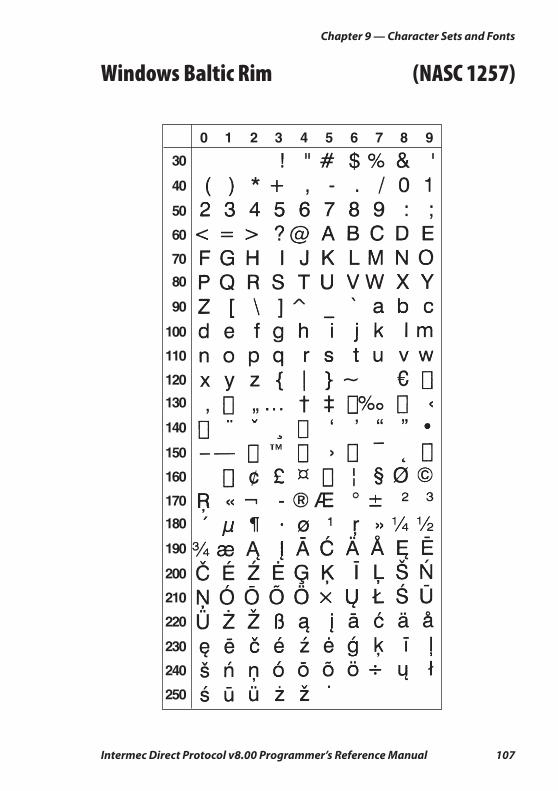
Intermec Direct Protocol v8.00 Programmer’s Reference Manual 107
Chapter 9 — Character Sets and Fonts
Windows Baltic Rim (NASC 1257)
0
30
40
50
60
70
80
90
100
110
120
130
140
150
160
170
180
190
200
210
220
230
240
250
1 2 3 4 5 6 7 8 9

108 Intermec Direct Protocol v8.00 Programmer’s Reference Manual
Chapter 9 — Character Sets and Fonts
PCMAP (NASC -1)
0
30
40
50
60
70
80
90
100
110
120
130
140
150
160
170
180
190
200
210
220
230
240
250
1 2 3 4 5 6 7 8 9
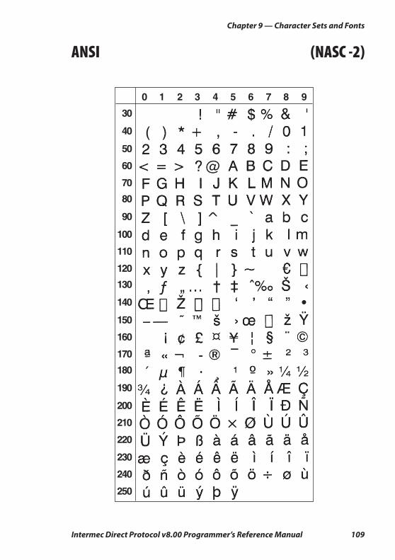
Intermec Direct Protocol v8.00 Programmer’s Reference Manual 109
Chapter 9 — Character Sets and Fonts
ANSI (NASC -2)
0
30
40
50
60
70
80
90
100
110
120
130
140
150
160
170
180
190
200
210
220
230
240
250
1 2 3 4 5 6 7 8 9
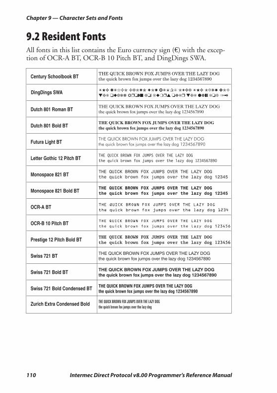
110 Intermec Direct Protocol v8.00 Programmer’s Reference Manual
Chapter 9 — Character Sets and Fonts
9.2 Resident FontsAll fonts in this list contains the Euro currency sign (€) with the excep-tion of OCR-A BT, OCR-B 10 Pitch BT, and DingDings SWA.

Intermec Direct Protocol v8.00 Programmer’s Reference Manual 111
10 Error Messages
This chapter lists the number and messages for the various errors conditions.
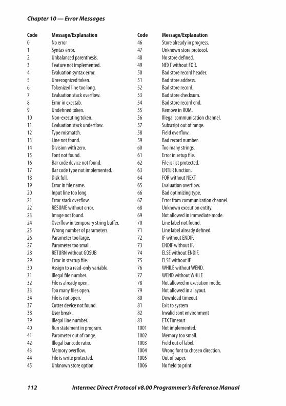
112 Intermec Direct Protocol v8.00 Programmer’s Reference Manual
Chapter 10 — Error Messages
Code Message/Explanation0 No error1 Syntax error.2 Unbalanced parenthesis.3 Feature not implemented.4 Evaluation syntax error.5 Unrecognized token.6 Tokenized line too long.7 Evaluation stack overfl ow.8 Error in exectab.9 Undefi ned token.10 Non-executing token.11 Evaluation stack underfl ow.12 Type mismatch.13 Line not found.14 Division with zero.15 Font not found.16 Bar code device not found.17 Bar code type not implemented.18 Disk full.19 Error in fi le name.20 Input line too long.21 Error stack overfl ow.22 RESUME without error.23 Image not found.24 Overfl ow in temporary string buff er.25 Wrong number of parameters.26 Parameter too large.27 Parameter too small.28 RETURN without GOSUB29 Error in startup fi le.30 Assign to a read-only variable.31 Illegal fi le number.32 File is already open.33 Too many fi les open.34 File is not open.37 Cutter device not found.38 User break.39 Illegal line number.40 Run statement in program.41 Parameter out of range.42 Illegal bar code ratio.43 Memory overfl ow.44 File is write protected.45 Unknown store option.
Code Message/Explanation46 Store already in progress.47 Unknown store protocol.48 No store defi ned.49 NEXT without FOR.50 Bad store record header.51 Bad store address.52 Bad store record.53 Bad store checksum.54 Bad store record end.55 Remove in ROM.56 Illegal communication channel.57 Subscript out of range.58 Field overfl ow.59 Bad record number.60 Too many strings.61 Error in setup fi le.62 File is list protected.63 ENTER function.64 FOR without NEXT65 Evaluation overfl ow.66 Bad optimizing type.67 Error from communication channel.68 Unknown execution entity.69 Not allowed in immediate mode.70 Line label not found.71 Line label already defi ned.72 IF without ENDIF.73 ENDIF without IF.74 ELSE without ENDIF.75 ELSE without IF.76 WHILE without WEND.77 WEND without WHILE78 Not allowed in execution mode.79 Not allowed in a layout.80 Download timeout81 Exit to system82 Invalid cont environment83 ETX Timeout1001 Not implemented.1002 Memory too small.1003 Field out of label.1004 Wrong font to chosen direction.1005 Out of paper.1006 No fi eld to print.
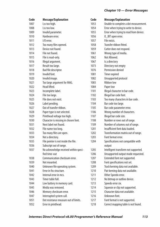
Intermec Direct Protocol v8.00 Programmer’s Reference Manual 113
Chapter 10 — Error Messages
Code Message/Explanation1007 Lss too high.1008 Lss too low.1009 Invalid parameter.1010 Hardware error.1011 I/O error.1012 Too many fi les opened.1013 Device not found.1014 File not found.1015 File is read-only.1016 Illegal argument.1017 Result too large.1018 Bad fi le descriptor.1019 Invalid font.1020 Invalid image.1021 Too large argument for MAG.1022 Head lifted.1023 Incomplete label.1024 File too large.1025 File does not exist.1026 Label pending.1027 Out of transfer ribbon.1028 Paper type is not selected.1029 Printhead voltage too high.1030 Character is missing in chosen font.1031 Next label not found.1032 File name too long.1033 Too many fi les are open.1034 Not a directory.1035 File pointer is not inside the fi le.1036 Subscript out of range.1037 No acknowledge received within speci- fi ed time-out1038 Communication checksum error.1039 Not mounted.1040 Unknown fi le operating system.1041 Error in fos structure.1042 Internal error in mcs.1043 Timer table full.1044 Low battery in memory card.1045 Media was removed.1046 Memory checksum error.1047 Interrupted system call.1051 Dot resistance measure out of limits.1052 Error in printhead.
Code Message/Explanation1053 Unable to complete a dot measurement.1054 Error when trying to write to device.1055 Error when trying to read from device.1056 O_BIT open error.1057 File exists.1058 Transfer ribbon fi tted.1059 Cutter does not respond.1061 Wrong type of media.1062 Not Allowed.1067 Is a directory1073 Directory not empty1076 Permission denied1081 Timer expired1082 Unsupported protocol1083 Ribbon low1084 Paper low1101 Illegal character in bar code.1102 Illegal bar code font.1103 Too many characters in bar code.1104 Bar code too large.1105 Bar code parameter error.1106 Wrong number of characters.1107 Illegal bar code size.1108 Number or rows out of range.1109 Number of columns out of range.1201 Insuffi cient font data loaded.1202 Transformation matrix out of range.1203 Font format error.1204 Specifi cations not compatible with output 1205 Intelligent transform not supported.1206 Unsupported output mode requested.1207 Extended font not supported.1208 Font specifi cations not set.1209 Track kerning data not available.1210 Pair kerning data not available.1211 Other Speedo error.1212 No bitmap or outline device.1213 Speedo error six.1214 Squeeze or clip not supported.1215 Character data not available.1216 Unknown font.1217 Font format is not supported.1218 Correct mapping table is not found.
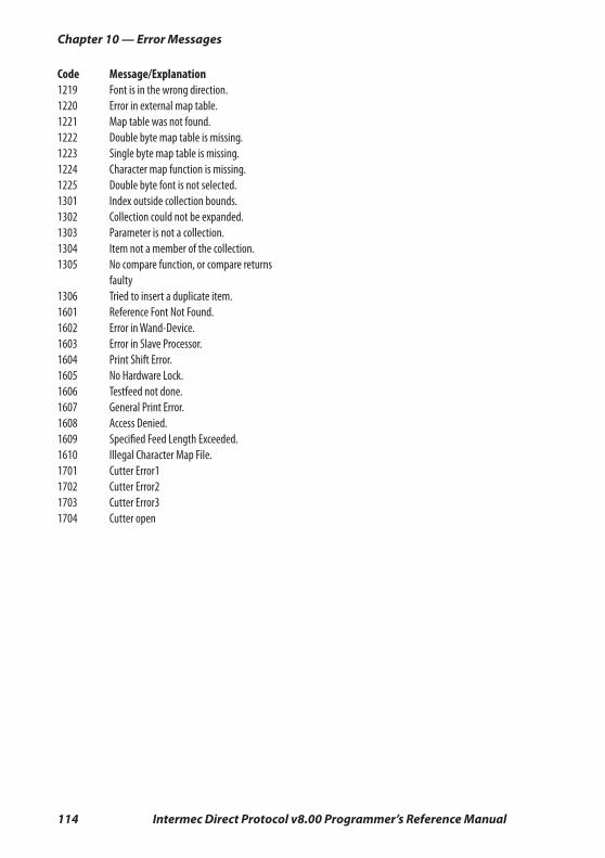
114 Intermec Direct Protocol v8.00 Programmer’s Reference Manual
Chapter 10 — Error Messages
Code Message/Explanation1219 Font is in the wrong direction.1220 Error in external map table.1221 Map table was not found.1222 Double byte map table is missing.1223 Single byte map table is missing.1224 Character map function is missing.1225 Double byte font is not selected.1301 Index outside collection bounds.1302 Collection could not be expanded.1303 Parameter is not a collection.1304 Item not a member of the collection.1305 No compare function, or compare returns faulty 1306 Tried to insert a duplicate item.1601 Reference Font Not Found.1602 Error in Wand-Device.1603 Error in Slave Processor.1604 Print Shift Error.1605 No Hardware Lock.1606 Testfeed not done.1607 General Print Error.1608 Access Denied.1609 Specifi ed Feed Length Exceeded.1610 Illegal Character Map File.1701 Cutter Error11702 Cutter Error21703 Cutter Error31704 Cutter open
Intermec Direct Protocol v8.00 Programmer’s Reference Manual 115
11 Reference Lists
This chapter lists the instructions in alphabetic order with short explanations and references to the related chapters. It also provides a shortlist of instruction syntaxes.

116 Intermec Direct Protocol v8.00 Programmer’s Reference Manual
Chapter 11 — Reference Lists
11.1 Instructions in Alphabetic OrderInstruction Chapter Purpose
ALIGN (AN) 3.2 Specifying which part (anchor point) of a text, bar code field, image field, line, or box will be positioned at the insertion point.
BARFONT (BF) 3.4 Specifying fonts for the printing of bar code interpretation.
BARFONT (BF) ON/OFF 3.4 Enabling/disabling the printing of bar code interpretation.
BARHEIGHT (BH) 3.4 Specifying the height of a bar code.
BARMAG (BM) 3.4 Specifying the magnification in regard of width of the bars in a bar code.
BARRATIO (BR) 3.4 Specifying the ratio between the wide and the narrow bars in a bar code.
BARSET 3.4, 8.1 Specifying a bar code and setting additional parameters to complex bar codes.
BARTYPE (BT) 3.4 Specifying the type of bar code.
BEEP 5.10 Ordering the printer to emit a beep.
BREAK 5.18 Specifying a break interrupt character for the keyboard or a serial communication channel.
BREAK ON/OFF 5.18 Enabling/disabling break interrupt separately for the keyboard and each serial communica-tion channel.
CLEANFEED 4.1 Running the printer’s feed mechanism.
CLIP 3.2 Enabling/disabling partial fields.
CLL 4.3 Partial or complete clearing of the print image buffer.
COPY 7.3 Copying files.
COUNT& 5.6 Creating a counter.
CUT 4.1 Activating an optional paper cutting device.
CUT ON/OFF 5.8 Enabling/disabling automatic cutting after PRINTFEED execution and optionally adjusting the media feed before and after the cutting.
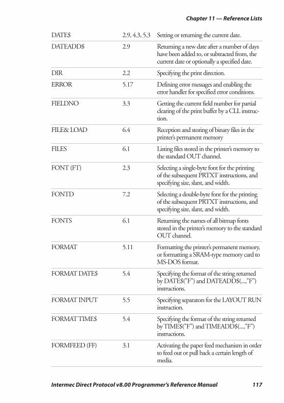
Intermec Direct Protocol v8.00 Programmer’s Reference Manual 117
Chapter 11 — Reference Lists
DATE$ 2.9, 4.3, 5.3 Setting or returning the current date.
DATEADD$ 2.9 Returning a new date after a number of days have been added to, or subtracted from, the current date or optionally a specified date.
DIR 2.2 Specifying the print direction.
ERROR 5.17 Defining error messages and enabling the error handler for specified error conditions.
FIELDNO 3.3 Getting the current field number for partial clearing of the print buffer by a CLL instruc-tion.
FILE& LOAD 6.4 Reception and storing of binary files in the printer’s permanent memory
FILES 6.1 Listing files stored in the printer’s memory to the standard OUT channel.
FONT (FT) 2.3 Selecting a single-byte font for the printing of the subsequent PRTXT instructions, and specifying size, slant, and width.
FONTD 7.2 Selecting a double-byte font for the printing of the subsequent PRTXT instructions, and specifying size, slant, and width.
FONTS 6.1 Returning the names of all bitmap fonts stored in the printer’s memory to the standard OUT channel.
FORMAT 5.11 Formatting the printer’s permanent memory, or formatting a SRAM-type memory card to MS-DOS format.
FORMAT DATE$ 5.4 Specifying the format of the string returned by DATE$("F") and DATEADD$(...,"F") instructions.
FORMAT INPUT 5.5 Specifying separators for the LAYOUT RUN instruction.
FORMAT TIME$ 5.4 Specifying the format of the string returned by TIME$(”F”) and TIMEADD$(...,"F") instructions.
FORMFEED (FF) 3.1 Activating the paper feed mechanism in order to feed out or pull back a certain length of media.
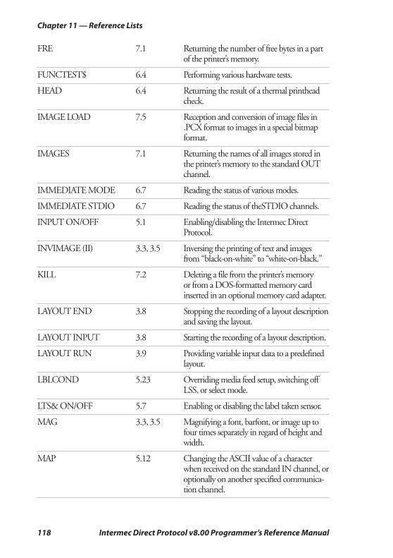
118 Intermec Direct Protocol v8.00 Programmer’s Reference Manual
Chapter 11 — Reference Lists
FRE 7.1 Returning the number of free bytes in a part of the printer’s memory.
FUNCTEST$ 6.4 Performing various hardware tests.
HEAD 6.4 Returning the result of a thermal printhead check.
IMAGE LOAD 7.5 Reception and conversion of image files in .PCX format to images in a special bitmap format.
IMAGES 7.1 Returning the names of all images stored in the printer’s memory to the standard OUT channel.
IMMEDIATE MODE 6.7 Reading the status of various modes.
IMMEDIATE STDIO 6.7 Reading the status of theSTDIO channels.
INPUT ON/OFF 5.1 Enabling/disabling the Intermec Direct Protocol.
INVIMAGE (II) 3.3, 3.5 Inversing the printing of text and images from “black-on-white” to “white-on-black.”
KILL 7.2 Deleting a file from the printer’s memory or from a DOS-formatted memory card inserted in an optional memory card adapter.
LAYOUT END 3.8 Stopping the recording of a layout description and saving the layout.
LAYOUT INPUT 3.8 Starting the recording of a layout description.
LAYOUT RUN 3.9 Providing variable input data to a predefined layout.
LBLCOND 5.23 Overriding media feed setup, switching off LSS, or select mode.
LTS& ON/OFF 5.7 Enabling or disabling the label taken sensor.
MAG 3.3, 3.5 Magnifying a font, barfont, or image up to four times separately in regard of height and width.
MAP 5.12 Changing the ASCII value of a character when received on the standard IN channel, or optionally on another specified communica-tion channel.
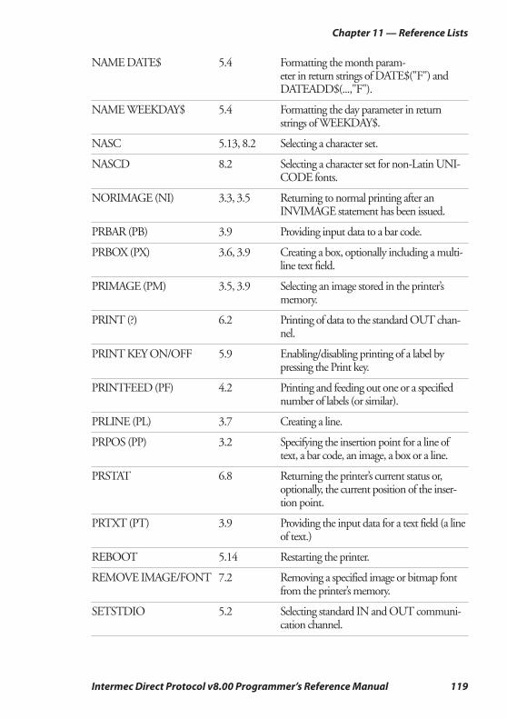
Intermec Direct Protocol v8.00 Programmer’s Reference Manual 119
Chapter 11 — Reference Lists
NAME DATE$ 5.4 Formatting the month param-eter in return strings of DATE$("F") and DATEADD$(...,"F").
NAME WEEKDAY$ 5.4 Formatting the day parameter in return strings of WEEKDAY$.
NASC 5.13, 8.2 Selecting a character set.
NASCD 8.2 Selecting a character set for non-Latin UNI-CODE fonts.
NORIMAGE (NI) 3.3, 3.5 Returning to normal printing after an INVIMAGE statement has been issued.
PRBAR (PB) 3.9 Providing input data to a bar code.
PRBOX (PX) 3.6, 3.9 Creating a box, optionally including a multi-line text field.
PRIMAGE (PM) 3.5, 3.9 Selecting an image stored in the printer’s memory.
PRINT (?) 6.2 Printing of data to the standard OUT chan-nel.
PRINT KEY ON/OFF 5.9 Enabling/disabling printing of a label by pressing the Print key.
PRINTFEED (PF) 4.2 Printing and feeding out one or a specified number of labels (or similar).
PRLINE (PL) 3.7 Creating a line.
PRPOS (PP) 3.2 Specifying the insertion point for a line of text, a bar code, an image, a box or a line.
PRSTAT 6.8 Returning the printer’s current status or, optionally, the current position of the inser-tion point.
PRTXT (PT) 3.9 Providing the input data for a text field (a line of text.)
REBOOT 5.14 Restarting the printer.
REMOVE IMAGE/FONT 7.2 Removing a specified image or bitmap font from the printer’s memory.
SETSTDIO 5.2 Selecting standard IN and OUT communi-cation channel.
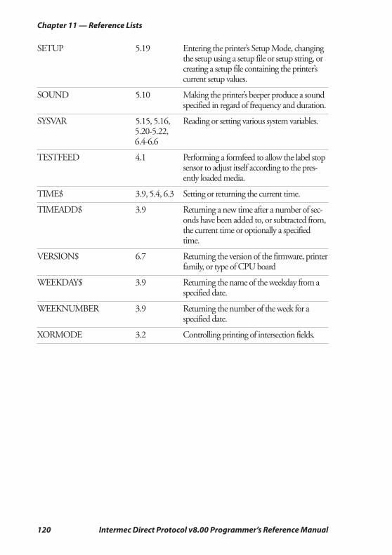
120 Intermec Direct Protocol v8.00 Programmer’s Reference Manual
Chapter 11 — Reference Lists
SETUP 5.19 Entering the printer’s Setup Mode, changing the setup using a setup file or setup string, or creating a setup file containing the printer’s current setup values.
SOUND 5.10 Making the printer’s beeper produce a sound specified in regard of frequency and duration.
SYSVAR 5.15, 5.16, Reading or setting various system variables. 5.20-5.22, 6.4-6.6
TESTFEED 4.1 Performing a formfeed to allow the label stop sensor to adjust itself according to the pres-ently loaded media.
TIME$ 3.9, 5.4, 6.3 Setting or returning the current time.
TIMEADD$ 3.9 Returning a new time after a number of sec-onds have been added to, or subtracted from, the current time or optionally a specified time.
VERSION$ 6.7 Returning the version of the firmware, printer family, or type of CPU board
WEEKDAY$ 3.9 Returning the name of the weekday from a specified date.
WEEKNUMBER 3.9 Returning the number of the week for a specified date.
XORMODE 3.2 Controlling printing of intersection fields.
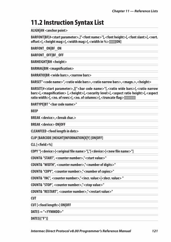
Intermec Direct Protocol v8.00 Programmer’s Reference Manual 121
Chapter 11 — Reference Lists
11.2 Instruction Syntax ListALIGN|AN <anchor point>
BARFONT|BF[#<start parameter>,]"<font name>"[,<font height>[,<font slant>[,<vert. off set>[,<height mag>[,<width mag>[,<width in %>]]]]]][ON]
BARFONT↔ON|BF↔ON
BARFONT↔OFF|BF↔OFF
BARHEIGHT|BH <height>
BARMAG|BM <magnifi cation>
BARRATIO|BR <wide bars>,<narrow bars>
BARSET"<code name>",<ratio wide bars>,<ratio narrow bars>,<magn.>,<height>
BARSET[#<start parameter>,]["<bar code name>"[,<ratio wide bars>[,<ratio narrow bars>[,<magnifi cation> [,<height>[,<security level>[,<aspect ratio height>[,<aspect ratio width>[,<no. of rows>[,<no. of columns>[,<truncate fl ag>]]]]]]]]]]]
BARTYPE|BT "<bar code name>"
BEEP
BREAK <device>,<break char.>
BREAK <device> ON|OFF
CLEANFEED <feed length in dots>
CLIP [BARCODE [HEIGHT|INFORMATION|X|Y] [ON|OFF]
CLL [<fi eld>%]
COPY "[<device>]<original fi le name>"[,"[<device>]<new fi le name>"]
COUNT& "START", <counter number>,"<start value>"
COUNT& "WIDTH", <counter number>,"<number of digits>"
COUNT& "COPY", <counter number>,"<number of copies>"
COUNT& "INC", <counter number>,"<incr. value>|<decr. value> "
COUNT& "STOP", <counter number>,"<stop value>"
COUNT& "RESTART", <counter number>,"<restart value>"
CUT
CUT [<feed length>] ON|OFF
DATE$ = "<YYMMDD>"
DATE$[("F")]
122 Intermec Direct Protocol v8.00 Programmer’s Reference Manual
Chapter 11 — Reference Lists
DATEADD$ (["<original date>",]<number of days>[,"F"])
DIR <direction>
ERROR <number>, "<message>"
<fi eld>% = FIELDNO
FILE& LOAD"<fi le name>",<fi le size>
FILES ["<device>"][,R][,A
FONT|FT "<font name>"[,<size>[,<slant>[,<width in %>]]]
FONTD "<font name>"[,<size>[,<slant>[,<width in %>]]]
FONTS
FORMAT "<device>"[,<no. of entries>[,<no. of bytes>]][,A]
FORMAT DATE$ "<string>"
FORMAT INPUT "<start separator>"[,"<end separator>"[,"<fi eld separator>"[,"<characters to be fi ltered out>"]]]
FORMAT TIME$ "<string>"
FORMFEED|FF [<feed length in dots>]
FRE (<"name of memory part">)
FUNCTEST$ ("<CARD>|<HEAD>|<KERNEL>|<ROMn>")
HEAD(<check type>)
IMAGE LOAD "<image name>",<fi le size>,["<fl ag>"]
IMAGES
IMMEDIATE MODE|STDIO
INPUT ON|OFF
INVIMAGE|II
KILL "<device><fi lename>"
LAYOUT END
LAYOUT INPUT "<tmp:><layout name>"
LAYOUT RUN "<tmp:><layout name>"
LBLCOND <type of action>,<number of dots>|<mode>
LTS& ON|OFF
MAG <height mag>,<width mag>
MAP [<device>],<old ASCII value>, <new ASCII value>
Intermec Direct Protocol v8.00 Programmer’s Reference Manual 123
Chapter 11 — Reference Lists
NAME DATE$ <No. of month>,"<name of month>"
NAME WEEKDAY$ <No. of weekday>,"<name of weekday>"
NASC <character set no.>
NASCD "[<device>]<fi le name>"
NORIMAGE|NI
PRBAR|PB <input data>[;<input data>...]
PRBOX|PX <height>,<width>,<line thickness>[,"<input data>"[,<hor. off set>[,<vert. off set>[,"<line delimiter>"[,"<control string>"]]]]]
PRIMAGE|PM "<image name>"
PRINT|?
PRINT KEY ON|OFF
PRINTFEED|PF [<batch size>]
PRLINE|PL <length>,<line thickness>
PRPOS|PP <x-coordinate>,<y-coordinate>
(PRSTAT AND <parameter>)
PRTXT|PT "<input data>"[;"<input data>"...]
REBOOT
REMOVE↔IMAGE|FONT "<name>"
SETSTDIO <IN channel>, <OUT channel>
SETUP "<setup string>"
SOUND <frequency in Hz>,<duration in units of 0.02 sec:s>
SYSVAR (<parameter>)
TESTFEED [<feed length>]
TIME$ = "<HHMMSS>"
TIME$ [("F")]
TIMEADD$ (["<original time>",]<number of sec’s>[,"F"])
VERSION$[(type of info)]
WEEKDAY$ ("<date>")
WEEKNUMBER ("<date>"[<calculating function>])
XORMODE ON|OFF

124 Intermec Direct Protocol v8.00 Programmer’s Reference Manual
Chapter 11 — Reference Lists

Intermec Printer ABIdrottsvägen 10, P.O. Box 123 S-431 22 Mölndal, Sweden
tel +46 31 869500
fax +46 31 869595
www.intermec.com
*1-960597-00*
Intermec Direct Protocol v8.00 Programmer’s Reference Manual
*1-960597-00*